applications fiber optic principles are adapted to measure
TRANSCRIPT


Applications■ Exact location of gas entries
in liquid-continuous flow and liquid entries in gas-continuous flow
■ Multiphase flow analysis inwellbores of any deviation for production monitoring and remedial decisions
■ Identification of water entriesin high-rate gas wells
■ Discrimination of condensateand gas entries
■ Verification of bubblepointpressure for single-phase fluid sampling
Benefits ■ Direct measurements of gas
and liquid
■ Measurements independent of downhole conditions and fluid properties
■ Flexibility of operations using conveyance by wireline,tractor, slickline or coiled tubing
■ Enhanced reliability
■ Improved efficiency and lessdeferred production time
■ Real-time answers for quickdecision making
Features■ Fiber optic technology
■ Downhole measurements of gas and liquid optical properties
■ Full wellbore coverage
■ Borehole fluid image orientedusing relative bearing measurement
■ Combinable with other production services
■ Data acquisition in surfacereadout or memory mode
■ LWD tool shock specifications
■ Real-time answer product withSPRINT* single-pass rate inter-pretation at wellsite
Shedding light with the GHOST GasHoldup Optical Sensor ToolWith its unique ability to directly meas-ure gas in the wellbore, the GHOST*Gas Holdup Optical Sensor Tool is theideal production logging device forlocating the first entry of liquid in agas well or first entry of gas in a liquidwell. The GHOST tool uses innovativesensing technology to enable directdetection and quantification of gas inmultiphase flows. This new tool is partof the PS Platform* tool family. Itsmeasurement complements the tradi-tional production logging measure-ments to give even greater confidencein production logging answers.Regardless of completion type or well-bore deviation, the GHOST tool, withfiber optic technology, literally shedsnew light on production logging.
Using fiber optic technologyThe GHOST tool uses the opticalproperties (refractive index) of fluidsto differentiate gas from liquid down-hole. Within the tool body, light isemitted from an LED source, travelsalong an optical fiber protected fromthe downhole environment andarrives at a needle-size probe manu-factured from sapphire. When thelight reaches the tip of the probe,some of it is transmitted through thewellbore fluids, while the remaininglight is reflected and travels backthrough the optical fiber. The reflectedlight travels through the Y coupler to areceiving photodiode and is convertedinto an electrical signal. The amountof reflection depends on the refractive
index of the medium (gas or liquid)and the shape of the probe. The probeis designed so that the amount ofreflected light is much greater whenthe probe is in gas than when it is inliquid.
In air or gas almost 100% of the lightis reflected. In liquid less than 40% ofthe light is reflected. Because the prop-erties of gas and liquid are so different,
AirGas (n = 1.1)Water (n = 1.3)Condensate (n = 1.4)Crude (n = 1.5)
Reflectedlight (%)
Refractive index
120
80
40
01 1.1 1.2 1.3 1.4 1.5 1.6
Gas or liquid bubble
Photodiode
Light source
Y coupler
Fiber optic principles are adapted to measure gas and liquid downhole. Light is injected into a sapphire probe and a photodiode measures the reflected signal.
This sapphire probe, with a 0.1-mm-diameter sensing zone, pierces potential wetting fluids and optimizes light refraction.
The response signal of the GHOST probes is high when the probes are in gas and low when in liquid.

it is relatively easy to distinguish thetwo. Although the measurable differ-ence in the refractive indices of waterand hydrocarbon liquids allows deter-mination of three phases, the relativeoptical properties are not always distinguishable in a flowing well environment.
Making independent measurements for greater accuracyLocal measurements of the four opticalprobes are made independently. Whilelogging, the probes pierce impingingdroplets of gas in a liquid-continuousphase or liquid droplets in a gas-continuous phase. A threshold set bythe software or by the field engineerdetermines the gas and liquid levelsfrom the raw waveform. All peaksabove the threshold are consideredgas, and all those below are consid-ered liquid. This direct gas and liquidholdup measurement is completelyindependent of downhole temperature,pressure, salinity, density, dielectricproperties, viscosity, resistivity, nuclearinteraction, phase velocity and welldeviation. This independence assuresaccurate answers without the needfor downhole calibration or environ-mental assumptions.
The percentage of gas at any givendepth, called gas holdup, is the ratioof time spent by the probe in gas tothe total scanning period. For a quali-tative indication of phase entries, thebubble count (number of bubblesarriving during the scanning period) is computed for each probe. Valuesfor both the ratio and count are trans-mitted uphole, and averaged outputsfor holdup and bubble count are com-puted at surface from each of the fourindividual probes.
Defining three-phase productionIn a well producing gas, oil and waterat surface, the GHOST tool was run todetermine the downhole contributionand depth of entry of each phase. Fromdata obtained in a single descent, theSPRINT real-time answer productdefined the amounts of gas, oil andwater entering the wellbore and iden-tified the entry points.
The first oil entry (A) was identifiedat the very bottom of the well using thebubble counts from the GHOST sensor
Flow
Thre
shol
d
Tim
e
Gasbubble
Water
Oilbubble
Gas and liquid bubbles are directly measured by local probes to provide individual phase holdup data.
14850
C
B
A
Density
(g/cm3)0 1
Gas Holdup
1 0
0 1
Friction CorrectedDensity (g/cm3)0 1
Water Holdup
Spinner
(rps)
(cps)
0 75
GHOST Bubble Count
0 5000
FloView Bubble Count
0 (cps) 1500
Temperature
260 (degF) 270
Gas Flow Rate
Oil Flow Rate
Water Flow Rate
GammaRay
(gAPI)0 150
FloViewWaterHoldup
0 1
FloViewBubbleCount
1
(cps) (cps)
0 0
GHOSTBubbleCount
1
GHOSTGas
Holdup
0 1
Perf
This real-time three-phase flow analysis was achieved using downhole measurements from thePS Platform tool string and GHOST tool.
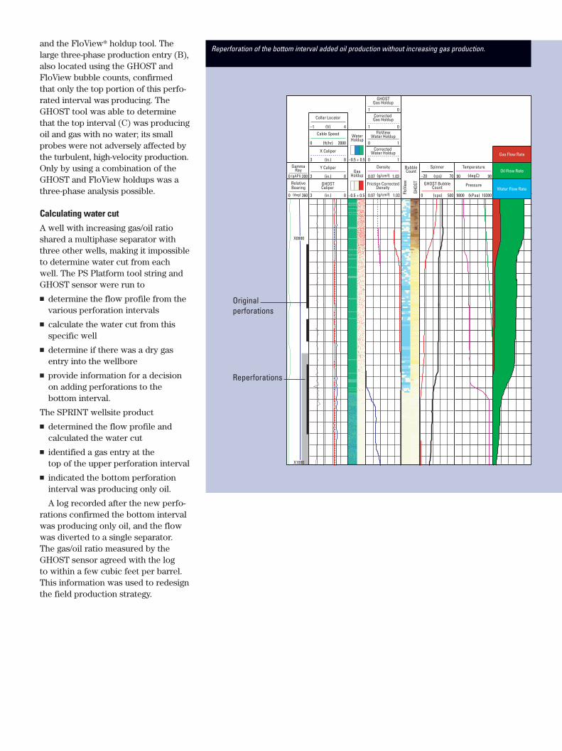
and the FloView* holdup tool. Thelarge three-phase production entry (B),also located using the GHOST andFloView bubble counts, confirmedthat only the top portion of this perfo-rated interval was producing. TheGHOST tool was able to determinethat the top interval (C) was producingoil and gas with no water; its smallprobes were not adversely affected bythe turbulent, high-velocity production.Only by using a combination of theGHOST and FloView holdups was athree-phase analysis possible.
Calculating water cutA well with increasing gas/oil ratioshared a multiphase separator withthree other wells, making it impossibleto determine water cut from eachwell. The PS Platform tool string andGHOST sensor were run to
■ determine the flow profile from thevarious perforation intervals
■ calculate the water cut from thisspecific well
■ determine if there was a dry gasentry into the wellbore
■ provide information for a decisionon adding perforations to the bottom interval.
The SPRINT wellsite product
■ determined the flow profile and calculated the water cut
■ identified a gas entry at the top of the upper perforation interval
■ indicated the bottom perforationinterval was producing only oil.
A log recorded after the new perfo-rations confirmed the bottom intervalwas producing only oil, and the flowwas diverted to a single separator.The gas/oil ratio measured by theGHOST sensor agreed with the log to within a few cubic feet per barrel.This information was used to redesignthe field production strategy.
RelativeBearing
0 360(deg)
(gAPI)
GHOSTCaliper
3 8
Density
(g/cm3)0.07 1.03
Friction CorrectedDensity
(g/cm3)0.07 1.03
GHOSTGas Holdup
1 0
FloViewWater Holdup
0 1
Corrected Gas Holdup
1 0
Corrected Water Holdup
0 1
Spinner
(rps)–20 70
GHOST BubbleCount
(cps)0 500
Gas Flow Rate
Oil Flow Rate
Water Flow RatePressure
(kPaa)9800 10300
Temperature
(degC)90 98
Y Caliper
(in.)3 8
X Caliper
3 8
Cable Speed
(ft/hr)0 2000
Collar Locator
(V)–1 4
GammaRay
0 200Gas
Holdup
WaterHoldup
BubbleCount
–0.5 + 0.5
–0.5 + 0.5 FloV
iew
GHOS
T
(in.)
(in.)
Originalperforations
Reperforations
X0900
X1000
Reperforation of the bottom interval added oil production without increasing gas production.
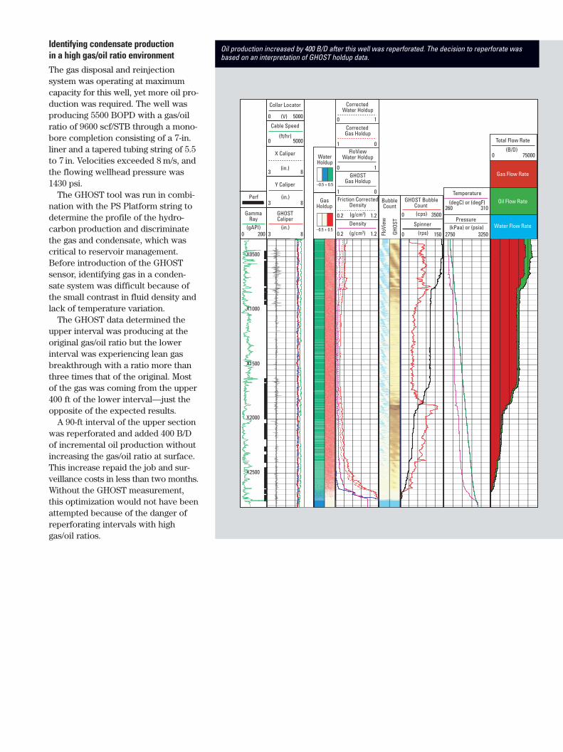
Identifying condensate production in a high gas/oil ratio environmentThe gas disposal and reinjection system was operating at maximumcapacity for this well, yet more oil pro-duction was required. The well wasproducing 5500 BOPD with a gas/oilratio of 9600 scf/STB through a mono-bore completion consisting of a 7-in.liner and a tapered tubing string of 5.5to 7 in. Velocities exceeded 8 m/s, andthe flowing wellhead pressure was1430 psi.
The GHOST tool was run in combi-nation with the PS Platform string todetermine the profile of the hydro-carbon production and discriminatethe gas and condensate, which wascritical to reservoir management.Before introduction of the GHOSTsensor, identifying gas in a conden-sate system was difficult because ofthe small contrast in fluid density andlack of temperature variation.
The GHOST data determined theupper interval was producing at theoriginal gas/oil ratio but the lowerinterval was experiencing lean gasbreakthrough with a ratio more thanthree times that of the original. Mostof the gas was coming from the upper400 ft of the lower interval—just theopposite of the expected results.
A 90-ft interval of the upper sectionwas reperforated and added 400 B/Dof incremental oil production withoutincreasing the gas/oil ratio at surface.This increase repaid the job and sur-veillance costs in less than two months.Without the GHOST measurement,this optimization would not have beenattempted because of the danger ofreperforating intervals with highgas/oil ratios.
GHOSTCaliper
3 8
Density
0.2 1.2
Friction CorrectedDensity
0.2 1.2
GHOSTGas Holdup
1 0
FloViewWater Holdup
0 1
Corrected Gas Holdup
1 0
Corrected Water Holdup
0 1
Spinner
0 150
Total Flow Rate
Gas Flow Rate
Oil Flow Rate
Water Flow Rate
0 75000
Pressure
2750 3250
Temperature
260 310
Y Caliper
3 8
X Caliper
3 8
Cable Speed
0 5000
Collar Locator
0 5000
GammaRay
0 200
GasHoldup
WaterHoldup
BubbleCount
–0.5 + 0.5
–0.5 + 0.5
FloV
iew
GHOS
T
(gAPI)
(ft/hr)
(in.)
(in.)
(in.)
(g/cm3)
(g/cm3) (rps)
(degC) or (degF)
(kPaa) or (psia)
(B/D)
(V)
GHOST BubbleCount
0 3500(cps)
Perf
X0500
X1000
X1500
X2000
X2500
Oil production increased by 400 B/D after this well was reperforated. The decision to reperforate wasbased on an interpretation of GHOST holdup data.
SMP-5762 ©Schlumberger
July 2001 *Mark of Schlumberger
www.connect.slb.com
25.4 ft[7.72 m]
8.3 ft[2.52 m]
4.8 ft[1.45 m]
7.1 ft[2.18 m]
5.2 ft[1.59 m]
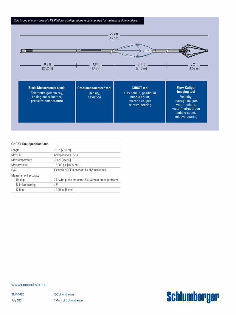
This is one of many possible PS Platform configurations recommended for multiphase flow analysis.
GHOST Tool Specifications
Length 7.1 ft [2.18 m]Max OD Collapses to 111⁄16 in.Max temperature 300°F [150°C]Max pressure 15,000 psi [1035 bar]H2S Exceeds NACE standards for H2S resistance
Measurement accuracyHoldup 7% with probe protector; 5% without probe protectorRelative bearing ±6°Caliper ±0.25 in. [5 mm]
Basic Measurement sondeTelemetry, gamma ray,casing collar locator,
pressure, temperature
Gradiomanometer* toolDensity,
deviation
GHOST toolGas holdup, gas/liquid
bubble count, average caliper, relative bearing
Flow-Caliper Imaging tool
Velocity, average caliper,
water holdup, water/hydrocarbon
bubble count, relative bearing