applications of overset grid technique to cfd simulation ... · this paper adopts overset grids to...
TRANSCRIPT

Procedia Engineering 99 ( 2015 ) 458 – 476
1877-7058 © 2015 The Authors. Published by Elsevier Ltd. This is an open access article under the CC BY-NC-ND license (http://creativecommons.org/licenses/by-nc-nd/4.0/).Peer-review under responsibility of Chinese Society of Aeronautics and Astronautics (CSAA)doi: 10.1016/j.proeng.2014.12.560
ScienceDirectAvailable online at www.sciencedirect.com
“APISAT2014”, 2014 Asia-Pacific International Symposium on Aerospace Technology, APISAT2014
Applications of Overset Grid Technique to CFD Simulation of High Mach Number Multi-body Interaction/Separation Flow
Li Xuefeia,b,* ,Liu Yuana,b,Qian Zhansena,b aAVIC Aerodynamics Research Institude, Shenyang, 110034, China
bAviation Key Laboratory of Science and Technology on High Speed and High Reynolds Number Aerodynamic Force Research, Shenyang, 110034, China
Abstract
In the design process of rocket, airplane and store separation systems, the aerodynamic of multi-body interaction flow field and the separation problems have been paid great attention by researchers, since they are directly related to the success of the mission. With high capital cost and technology risk of both flight and ground test, CFD technology has been more and more applied to resolve these problems for the rapid development of computer hardware resources. The accurate simulation of aerodynamic interactions and separating characters of a multi-body flow field with high Ma number continue to be one of the more challenging problems. This is mainly due to the inherent high unsteady and complex turbulent character of the transient flow field. This paper adopts overset grids to implement CFD analysis of these problems. Developments in strategies and software tools for overset structured grid generation are summarized firstly. The general principle and key technology of overset grids are followed. In the third part, one validation, store release of wing-pylon-store model, is implemented. Finally, stage separation of a Two-Stage-To-Orbit (TSTO) model is studied further to discuss hard predictable flow phenomenon and real physical mechanism of it. © 2014 The Authors. Published by Elsevier Ltd. Peer-review under responsibility of Chinese Society of Aeronautics and Astronautics (CSAA).
Keywords: Overset Grid, Two-Stage-to-Orbit, Stage Separation, Store Release, Aerodynamic Interaction
* Corresponding author. Tel.: +86-024-86566624
E-mail address: [email protected]
© 2015 The Authors. Published by Elsevier Ltd. This is an open access article under the CC BY-NC-ND license (http://creativecommons.org/licenses/by-nc-nd/4.0/).Peer-review under responsibility of Chinese Society of Aeronautics and Astronautics (CSAA)

459 Li Xuefei et al. / Procedia Engineering 99 ( 2015 ) 458 – 476
1. Introduction
In recent years, due to the fast development of CFD technology, the integrated simulation of CFD and flight mechanics is widely used on high Mach number multi-body interaction/separation problems study with research period and financial cost considered, such as store release, binding rocket booster separation, stage separation of multi-stage rocket, crew members launch from orbit aircraft, gasoline tank release and so on. The overset grid, generating separate grids for each part of a complex model or each model for multi-body simulation, maintains great capability on the simulation of complex models or that with big relative motion.
Technologies and software tools for overset structured grid generation have fulfilled a progress under joint efforts of international researchers for recent years, and they have been applied gradually on big complex aerospace problems. Chimera Grid Tools (CGT), developed by NASA Ames Research Center basing on over 100 grid generation Tcl script macros, is successful to be used on several complex models like Ares-I crew launch vehicle integrated stack and its Stage-Separation process, etc, for which the typical script development time is between two to four weeks and each case contains several hundred blocks with more than 100 million grid points [1]. The overset grid generation software using scripting approach holds great flexibility and efficiency of geometry modification, but it has to be manually created new scripts for new geometries with big differences of topologies compared to previous ones. Nowadays, it is also a time consuming and labor intensive work for complex overset structured grid generation, and so that much more investigations need to be carried out to improve its performance.
In this paper, we simulate high Mach number multi-body interaction/separation problems using overset structure grids to accomplish coupling calculations of flow governing equations and rigid body motion equations, offer feasible approaches to resolve these types of problems, summarize techniques and experiences in topology design and grid points distribution for overset grids, and discuss overset grid software functions in demand and investigation directions of overset grids technology in the future .
2. The general principle and key technology of overset grids
Overset grid, allowing arbitrary overlap, generates separate grids for each part of a complex model, therefore it simplifies grid generation process, but increases domain connection schemes namely grid assembly including hole-cutting and interpolation to share information. Hole–cutting can be divided into the minimum and optimum hole-cutting. The minimum approach cuts grid cells of the other grids within the wall; the optimum scheme implements hole-cutting in the flow field far from wall to ensure a good match among grids in overlapped regions, which maintains two strengths: one is to enhance simulation accuracy, if grids in the overlapped regions have big differences in size, it will get a result with low precision since coarse grids cannot capture detail flow structures. One is to increase convergence efficiency that affected much by grid transition between grids in overlapped regions.
The four criteria evaluating domain connection scheme are robustness, automation, efficiency and low memory requires in order of priority. Researchers have taken much previous efforts to develop domain connectivity algorithms and software on overset grids, such as search-based, direct-cut, and query-cut methods [2]. Alternating Digital Tree (ADT), the corner stone of this overset grid technique adopted in this paper, optimizes chimera boundary identification and hole-cutting process. It disseminates the cells of a grid in a tree structure, based on certain data such as the coordinates of cell centroid, coordinates of bounding box etc. ADT is much like an octree except that it is deemed more suitable if the data based on which the tree has to be built is n-dimensional (n>3)[3].
3. Validation
Wing-pylon-store is the standard experiment model of American Air Force [4] which holding comprehensive CTS test data to be widely used for validation of CFD simulation [5, 6]. Fig. 1 shows the geometry and coordinate system adopted in which X axis representing flow direction, Y axis being upward and Z axis directing to the inside part of the wing. The configuration consists of a 45 degree clipped delta wing with 7.620m root chord length, 6.604m semi-span, NACA 64A010 airfoil section, 57.031m2 wing area, 4.318m average aerodynamic chord length and 7.5 00 taper ratio.
The store, with 3.387m length and 907.5kg mass, has a 0.508m-diameter center column, 27.12kg•m2 moments of

460 Li Xuefei et al. / Procedia Engineering 99 ( 2015 ) 458 – 476
inertia about x axis and 488.1 kg•m2 about y and z axes. The flow conditions are as follows: Mach number 0.95, altitude 7925m. The forward ejector of 10679.4N force is applied at 1.24m from the store nose and the aft ejector of 42717.5N force is applied at 1.75m from the store nose, and both of them last 0.055s from the start. To save computing time, here only Euler simulation is performed since there are no big separations so that viscosity exerts little influence on flow.
The grid topology is showed in Fig. 2. The wing grid holds H type topology with totally 3 million cells and 112 blocks, and grids near pylon and both ends are much fine. The store grid is a "collar" mesh (O-type) possessing 76 blocks and 0.9 million cells.
Fig. 1 Wing-pylon-store geometry
Fig. 2 The grid topology
In fig.3 we can find that under gravity, ejector forces and aerodynamic forces the store gets much more downward separating distance than that of the other two directions, moves backward relative to the wing due to drag. In the separation process, the store is involved in a pitch up motion firstly and then a pitch down one, and meanwhile rolls and yaws outward of the wing. The results of numerical simulation and experiment fit very well only holding a little difference owing to Euler simulation that totally ignore viscosity impact, which indicates that the overset grid approach adopted in this study is trustworthy. Fig.4 shows surface pressure distribution of the steady simulation. Fig.5 gives us the store trajectory at various instant time and the store surface pressure distribution.
Fig. 3 (a) Linear displacement of store with time; (b) Velocity components of store with time; (c) Angular displacement of store with time; (d) Angular rates of store with time
Fig. 4 Surface pressure distribution
t(s)
XY
Z(m
)
0 0.05 0.1 0.15 0.2 0.25 0.3
-1
-0.8
-0.6
-0.4
-0.2
0
0.2
x_expy_expz_expx_numericaly_numericalz_numerical
t(s)
uv
w(m
/s)
0 0.05 0.1 0.15 0.2 0.25 0.3
-4
-3
-2
-1
0
1
u_expv_expw_expu_numericalv_numericalw_numerical
t(s)
pitc
h.y
aw.r
oll
(o)
0 0.05 0.1 0.15 0.2 0.25 0.3-12
-10
-8
-6
-4
-2
0
yaw_exppitch_exproll_expyaw_numericalpitch_numericalroll_numerical
t(s)
p.q
.r(r
ad/s
)
0 0.05 0.1 0.15 0.2 0.25 0.3
-0.5
0
0.5p_expq_expr_expp_numericalq_numericalr_numerical

461 Li Xuefei et al. / Procedia Engineering 99 ( 2015 ) 458 – 476
Fig. 5 Store trajectory at various instant of time and its surface pressure distribution
4. The stage separation of TSTO model
4.1. Geometry and grid of TSTO model
Fig. 6 shows the TSTO Two-Stage-To-Orbit model [7]. The booster and orbiter are simplified as delta wing and hemisphere-cylinder respectively. The delta wing is 200mm long and with 15 top angle. Hemisphere-cylinder, with 23mm diameter, is 130mm and 5mm far away from the delta wing of axial and radial directions respectively. The flow conditions are the same as the experiment (Table. 1).
Fig. 6 TSTO model
Table. 1 Free stream conditions of shock tunnel at Nagoya University
0P P 0T T M
4.0MPa 370.6Pa 900K 63.73K 0.02026kg/m3 8.1 TSTO three dimensional (3D) simulation has tried many overset grids, and the topology of the Fig. 7(a) is chosen
finally. Both of Euler and NS calculations adopt the same overset topology but with different grid point distributions in which NS calculation has finer grids close to the wall. To validate overset grid results, we also employ a multi-block structure grid simulation (Fig. 7(b)). All of TSTO grid details are summarized at Table. 2. In the following chapters, we just call Euler and NS steady simulations applied overset grids and the structure grid NS simulation as Case01, Case01 and Case03 for short.
Fig. 7 TSTO 3D grid topology (a) Case01/Case02; (b) Case03

462 Li Xuefei et al. / Procedia Engineering 99 ( 2015 ) 458 – 476
Table. 2 Grid parameters
Model Case Cells Blocks
TSTO 3D Inviscid(Euler)-Case01 3609538 68 Navier Stokes-Case02 4355204 68 StructureGrid-Case03 7178862 25
4.2. TSTO 3D simulation assumptions
The model investigated here only preserves the up surface for the wing. The flow field is supposed to be symmetric with respect to z=0 plane, and hence, computations are conducted for only the half domain (Z 0). The Reynolds number based on the axial offset distance(x/L=0.65) is Rex=8.30 105, thus, it is reasonable to apply laminar assumption to the boundary-layer developed on the wing.
4.3. TSTO 3D steady simulation
Fig. 8 gives the Mach number distribution on symmetry and outlet planes and surface pressure distribution of walls. In Case01, inviscid simulation maintains no shock/boundary-layer interaction, the hemisphere bow shock hitting the wing and reflecting to hemisphere-cylinder surface where the second shock reflection occurred. The results of Case02 and Case03 have a great match demonstrating that the overset grid approach of this study is reliable.

463 Li Xuefei et al. / Procedia Engineering 99 ( 2015 ) 458 – 476
Fig. 8 The Mach number distribution on symmetry and outlet planes and surface pressure distribution of walls (a)Case01; (b)Case02; (c)Case03

464 Li Xuefei et al. / Procedia Engineering 99 ( 2015 ) 458 – 476
Fig. 9 depicts pressure profiles over hemisphere-cylinder surface on symmetric plane of the above three cases and the experiment data as well. The pressure profile of Case02 is very close to that of Case03. The max pressure ratio
P/Pinf of Case02 is about 180 which is a little higher than that of Case03 160 the one most approach to the experiment data. Both the max pressure ratios of the two cases are almost 2 times as large as that of Case03, which has been also concluded by keiichi & yoshiaki in reference 7 where the comparative pressure ratio comes from a hemisphere computation without shock/shock and shock/boundary-layer interactions just like Case01. The red crosses in Fig. 10 represent the locations of max pressure, and the up one for Case02, the down one for Case03. From Fig. 9 we can see there exist pressure peaks at about X=0.35 for all the three cases. Fig. 10 showing a small separation coming into being here, it is the separating shock that may cause the pressure peak.
Fig. 9 Pressure profiles over hemisphere-cylinder surface on symmetric plane
Fig. 10 The mach number distribution on symmetry plane and the location of the max pressure (a)Case02; (b)Case03

465 Li Xuefei et al. / Procedia Engineering 99 ( 2015 ) 458 – 476
Fig. 11, with iso-surface of Mach number 7.9 along with Mach number contours at three cross-sections, illustrates detailed shock/shock interacting flow field around TSTO. Fig. 12 describes velocity vector on the symmetry plane. In the viscous simulation of Case02 and Case03, the hemisphere bow shock intersects with the oblique wing shock to form a spatial curved shock. The boundary-layer and the two shocks exert mutual influence to each other, and the flow field is very complex and unstable and presents small fluctuation which is also found from TSTO transient simulation result. The reverse flow regions exist and develop under the head of hemisphere at the scale of approximately 0.08m.
Fig. 11 Three-Dimensional view of shock/shock interacting flow field around TSTO (a)Case01; (b)Case02; (c)Case03
Fig. 12 Detailed flow structure in the vicinity of shock/shock interaction location (Z=0) (a)Case01; (b)Case02; (c)Case03

466 Li Xuefei et al. / Procedia Engineering 99 ( 2015 ) 458 – 476
4.4. TSTO 3D unsteady simulation
We implement 2.59ms unsteady simulation of TSTO using the result of Case02 as the initial condition. According to the investigation, it is non-
stable for the interaction of shocks as well as separation area, and some fluctuation is observed which is also published by other researchers with
roughly 1ms time period under the interaction of shock/shock or shock/boundary-layer conditions. It is manifest from
Fig. 13 that the fluctuation period here is around 0.4ms.

467 Li Xuefei et al. / Procedia Engineering 99 ( 2015 ) 458 – 476
Fig. 13 Aerodynamic forces and moment with time (a)Fx, Fy; (b)Mz

468 Li Xuefei et al. / Procedia Engineering 99 ( 2015 ) 458 – 476
4.5. Stage-separation of TSTO simulation
We appoint hemisphere-cylinder to move at 100m/s away from the delta wing along the positive Y axis persisting 0.56ms and 0.49ms for Euler simulation Case04 and NS simulation Case05 respectively, the former case adopting Case01 result as initial condition, and the latter choosing that of Case02.
Fig. 14 shows Mach number distribution of Case04 with the hemisphere–cylinder motion. The hemisphere-cylinder head and the wing form a contraction passage compressing and decelerating the flow again after the bow shock. As hemisphere-cylinder going up, the compressing effect progressively weakens. The bow shock is incident on the wing surface where shaping a curve reflecting shock hitting hemisphere-cylinder again, and the second space reflection occurs and then the third reflecting shock coming into being starting from the wing surface. At the beginning of the motion, the compressing effect of the contraction passage is obvious, therefore the intensity of the third reflection shock is comparatively strong, however it continuously bates for the contraction impact decreasing along with the hemisphere-cylinder movement.
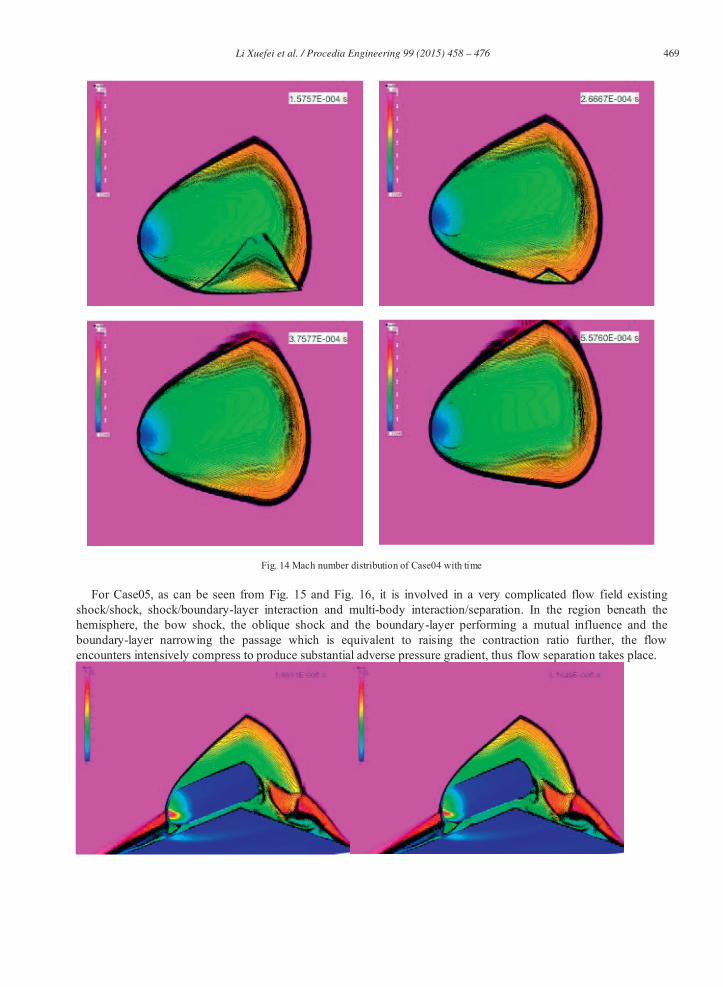
469 Li Xuefei et al. / Procedia Engineering 99 ( 2015 ) 458 – 476
Fig. 14 Mach number distribution of Case04 with time
For Case05, as can be seen from Fig. 15 and Fig. 16, it is involved in a very complicated flow field existing shock/shock, shock/boundary-layer interaction and multi-body interaction/separation. In the region beneath the hemisphere, the bow shock, the oblique shock and the boundary-layer performing a mutual influence and the boundary-layer narrowing the passage which is equivalent to raising the contraction ratio further, the flow encounters intensively compress to produce substantial adverse pressure gradient, thus flow separation takes place.

470 Li Xuefei et al. / Procedia Engineering 99 ( 2015 ) 458 – 476
Fig. 15 Mach number distribution of Case05 with time

471 Li Xuefei et al. / Procedia Engineering 99 ( 2015 ) 458 – 476
472 Li Xuefei et al. / Procedia Engineering 99 ( 2015 ) 458 – 476
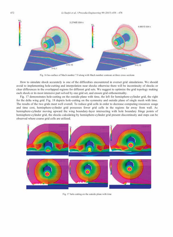
Fig. 16 Iso-surface of Mach number 7.9 along with Mach number contours at three cross-sections
How to simulate shock accurately is one of the difficulties encountered in overset grid simulations. We should avoid to implementing hole-cutting and interpolation near shocks otherwise there will be incontinuity of shocks or clear differences in the overlapped regions for different grid sets. We suggest to optimize the grid topology making each shock or its most intensive part solved by one grid set, and ensure grid orthonormality.
Fig. 17 demonstrates hole-cutting on the outside plane with time, the left for hemisphere-cylinder grid, the right for the delta wing grid. Fig. 18 depicts hole-cutting on the symmetry and outside plane of single mesh with time. The results of the two grids meet well overall. To reduce grid cells in order to decrease computing resources usage and time cost, hemisphere-cylinder grid possesses fewer grid cells in the regions far away from wall. As hemisphere-cylinder moving upward the wing boundary-layer intersecting with hole boundary fringe points of hemisphere-cylinder grid, the shocks calculating by hemisphere-cylinder grid present discontinuity and steps can be observed where coarse grid cells are utilized.
Fig. 17 hole-cutting on the outside plane with time

473 Li Xuefei et al. / Procedia Engineering 99 ( 2015 ) 458 – 476

474 Li Xuefei et al. / Procedia Engineering 99 ( 2015 ) 458 – 476
Fig. 18 the hole-cutting process with time
According to the above simulations, it is significant to the computing accuracy and convergence of the single grid topology optimization, grid transition, grid orthonormality and the scale and match quality of overlapped regions. To expand overlapped areas within some level can improve convergence. The more match of different grids in the overlapped regions, the less time consuming and more accurate result can be achieved. We should take care of grid density for the hole-cutting areas, otherwise grids after hole-cutting cannot well capture the real flow characteristics which leads distortion. Before the dynamic simulation, we should forecast moving trajectories of the models on the basis of physics law, according to which overset grid should be properly designed both of the topology and grid point distribution to improve efficiency and accuracy of the simulation.

475 Li Xuefei et al. / Procedia Engineering 99 ( 2015 ) 458 – 476
4.6. Stage-separation characters of TSTO
According to Fig. 19, drag coefficient stops decreasing and reaches a plateau at approximately 0.48 after 0.2ms as a result of the shock and boundary-layer of the wing holding little influence on the flow field around hemisphere-cylinder after that time, during which drag mostly consists of wave drag and viscous drag. The initial drag coefficient is relatively larger than the latter stable value demonstrating aerodynamic interference contributing a lot to drag.

476 Li Xuefei et al. / Procedia Engineering 99 ( 2015 ) 458 – 476
Fig. 19 Aerodynamic coefficient of hemisphere-cylinder with the motion (a) Cx; (b) Cy
At the beginning time, the compress to the flow under hemisphere-cylinder comes from two aspects: the first is posed by several shock reflections between the hemisphere-cylinder and the wing; the second is due to the contraction passage constituted by the hemisphere and delta wing and even narrowed by the existence of the boundary-layer enhancing the compress ratio. The flow on the upper side of the hemisphere-cylinder is only under the effect of the bow shock. Therefore, the hemisphere-cylinder receives lift force. When the hemisphere-cylinder moving up at 100m/s, it possesses a negative attack angle owing to the relative velocity, and hence that lift force changes direction to be negative. In the very beginning of the motion, drag coefficient experiences plummet and surge. In this study, hemisphere-cylinder maintains a velocity of 100 m/s since starting, without an accelerating phase in the real physics process, therefore, it is equivalent to receive a large instantaneous impulse for hemisphere-cylinder in the numerical simulation.
As investigation carried out above, at least two ejector forces should be load to the hemisphere-cylinder to balance the negative lift and pitching moment at the beginning of stage separation so that safe separation will be achieved.
5. Conclusion
In this work, we apply several overset grids to each model for the static and transient separation simulations, offer feasible approaches to resolve these types of problems. According to this study, we can obtain reliable and accurate flow results for the above problems using overset grids. We also find that the size of the overlapped area and the matching quality between different grids possess great influence on the convergence and accuracy of the simulation, and it is difficult to catch detail characters of shock waves for overset grids, however, we should avoid the circumstances cutting holes or interpolating data at shocks to ensure their computational accuracy.
Basing on the above investigation, we think that the future ideal overset grid tools and its generation technology should have the following attributes:
High stability of operation; High automation with few requires of the users’ experiences and time investment. It is convenient to perform
parameterized modification for an existing grid; High efficiency of operation, low require for memory. It can be applied to problems with relative motion in
which domain connectivity including hole-cutting and interpolation is implemented at every time step. General hardware platforms can be used to solve large scale engineering problems.
References
[1] William M. Chan, Developments in Strategies and Software Tools for Overset Structured Grid Generation and Connectivity, 20th AIAA Computational Fluid Dynamics Conference, AIAA 2011-3051
[2] Noah Kim and William M. Chan, Automation of Hole-Cutting for Overset Grids Using the X-rays Approach, 20th AIAA Computational Fluid Dynamics Conference, AIAA 2011-3052
[3] CFD-FASTRAN V2009.0 User Manual , ESI CFD Inc. [4] EIM E R. CFD Wing/Pylon/Finned Store mutual interference wind tunnel experiment[R]. AEDC-TSR-91-P4, 1991. [5] Meakin R L., Multiple-body proximate-flight simulation methods[R]. AIAA-2005-4621,. [6] G. Harish ,M. Pavanakumar and K. Anandhanarayanan ,Store Separation Dynamics using Grid-free Euler Solver 24th Applied Aerodynamics
Conference 5 - 8 June 2006, San Francisco, California [7] Keiichi KITAMURA, Yoshiaki NAKAMURA, An Evaluation of Euler Fluxes II: Hypersonic Surface Heating Computation, 38th Fluid
Dynamics Conference and Exhibit<BR>,AIAA 2008-4275