applications of the lm3524 nationalsemiconductor pulse ...pdf.dzsc.com/autoupload/lm3524.pdfthe...
TRANSCRIPT
Applications of the LM3524Pulse-Width-Modulator
The LM3524 Regulating Pulse-Width-Modulator is com-monly used as the control element in switching regulatorpower supplies. This is in keeping with its intended purpose.Engineers closely associate this part with switching powersupplies. Nevertheless, the flexible combination of elements(see box) within the LM3524 also allows it to be used in anumber of other applications outside the power supply area.Because the device is inexpensive and operates off asingle-sided supply, it can considerably reduce componentcount and circuit complexity in almost any application. Theconstant light intensity servo of Figure 1 furnishes a good ex-ample.
CONSTANT LIGHT INTENSITY SERVO
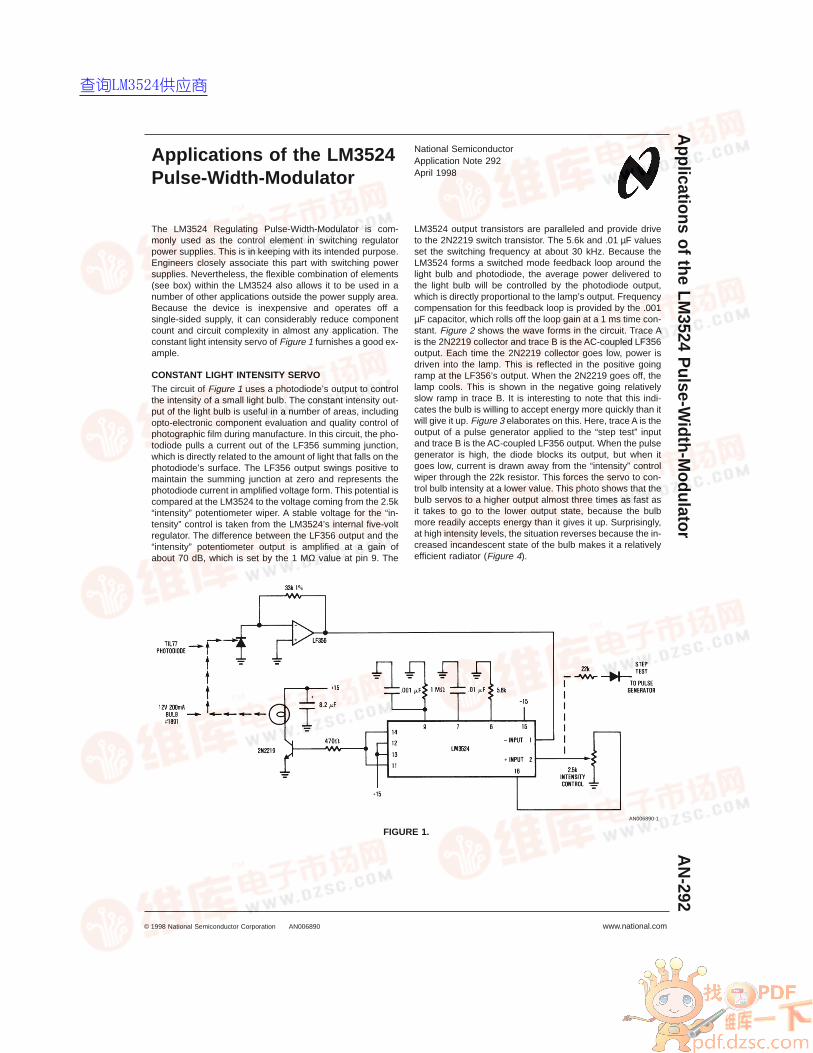
The circuit of Figure 1 uses a photodiode’s output to controlthe intensity of a small light bulb. The constant intensity out-put of the light bulb is useful in a number of areas, includingopto-electronic component evaluation and quality control ofphotographic film during manufacture. In this circuit, the pho-todiode pulls a current out of the LF356 summing junction,which is directly related to the amount of light that falls on thephotodiode’s surface. The LF356 output swings positive tomaintain the summing junction at zero and represents thephotodiode current in amplified voltage form. This potential iscompared at the LM3524 to the voltage coming from the 2.5k“intensity” potentiometer wiper. A stable voltage for the “in-tensity” control is taken from the LM3524’s internal five-voltregulator. The difference between the LF356 output and the“intensity” potentiometer output is amplified at a gain ofabout 70 dB, which is set by the 1 MΩ value at pin 9. The
LM3524 output transistors are paralleled and provide driveto the 2N2219 switch transistor. The 5.6k and .01 µF valuesset the switching frequency at about 30 kHz. Because theLM3524 forms a switched mode feedback loop around thelight bulb and photodiode, the average power delivered tothe light bulb will be controlled by the photodiode output,which is directly proportional to the lamp’s output. Frequencycompensation for this feedback loop is provided by the .001µF capacitor, which rolls off the loop gain at a 1 ms time con-stant. Figure 2 shows the wave forms in the circuit. Trace Ais the 2N2219 collector and trace B is the AC-coupled LF356output. Each time the 2N2219 collector goes low, power isdriven into the lamp. This is reflected in the positive goingramp at the LF356’s output. When the 2N2219 goes off, thelamp cools. This is shown in the negative going relativelyslow ramp in trace B. It is interesting to note that this indi-cates the bulb is willing to accept energy more quickly than itwill give it up. Figure 3 elaborates on this. Here, trace A is theoutput of a pulse generator applied to the “step test” inputand trace B is the AC-coupled LF356 output. When the pulsegenerator is high, the diode blocks its output, but when itgoes low, current is drawn away from the “intensity” controlwiper through the 22k resistor. This forces the servo to con-trol bulb intensity at a lower value. This photo shows that thebulb servos to a higher output almost three times as fast asit takes to go to the lower output state, because the bulbmore readily accepts energy than it gives it up. Surprisingly,at high intensity levels, the situation reverses because the in-creased incandescent state of the bulb makes it a relativelyefficient radiator (Figure 4).
AN006890-1
FIGURE 1.
National SemiconductorApplication Note 292April 1998
Applications
oftheLM
3524P
ulse-Width-M
odulatorA
N-292
© 1998 National Semiconductor Corporation AN006890 www.national.com
查询LM3524供应商
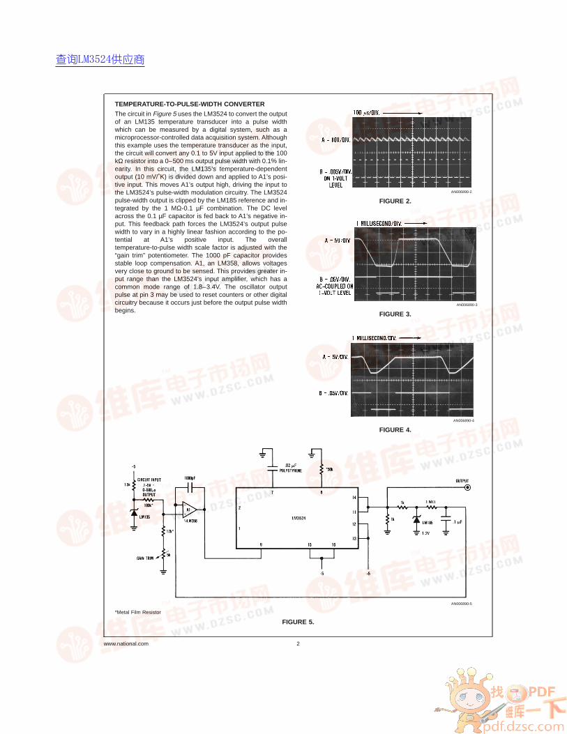
TEMPERATURE-TO-PULSE-WIDTH CONVERTER
The circuit in Figure 5 uses the LM3524 to convert the outputof an LM135 temperature transducer into a pulse widthwhich can be measured by a digital system, such as amicroprocessor-controlled data acquisition system. Althoughthis example uses the temperature transducer as the input,the circuit will convert any 0.1 to 5V input applied to the 100kΩ resistor into a 0–500 ms output pulse width with 0.1% lin-earity. In this circuit, the LM135’s temperature-dependentoutput (10 mV/˚K) is divided down and applied to A1’s posi-tive input. This moves A1’s output high, driving the input tothe LM3524’s pulse-width modulation circuitry. The LM3524pulse-width output is clipped by the LM185 reference and in-tegrated by the 1 MΩ-0.1 µF combination. The DC levelacross the 0.1 µF capacitor is fed back to A1’s negative in-put. This feedback path forces the LM3524’s output pulsewidth to vary in a highly linear fashion according to the po-tential at A1’s positive input. The overalltemperature-to-pulse width scale factor is adjusted with the“gain trim” potentiometer. The 1000 pF capacitor providesstable loop compensation. A1, an LM358, allows voltagesvery close to ground to be sensed. This provides greater in-put range than the LM3524’s input amplifier, which has acommon mode range of 1.8–3.4V. The oscillator outputpulse at pin 3 may be used to reset counters or other digitalcircuitry because it occurs just before the output pulse widthbegins.
AN006890-2
FIGURE 2.
AN006890-3
FIGURE 3.
AN006890-4
FIGURE 4.
AN006890-5
*Metal Film Resistor
FIGURE 5.
www.national.com 2
查询LM3524供应商
RTD TEMPERATURE CONTROLLER
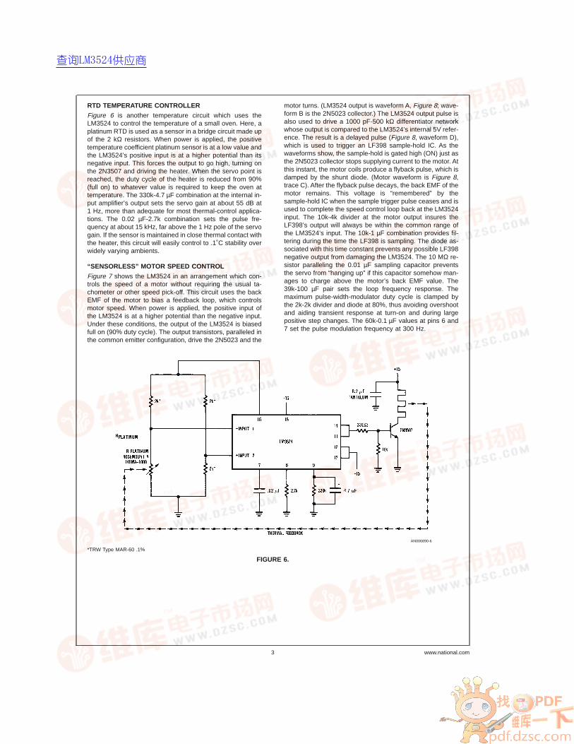
Figure 6 is another temperature circuit which uses theLM3524 to control the temperature of a small oven. Here, aplatinum RTD is used as a sensor in a bridge circuit made upof the 2 kΩ resistors. When power is applied, the positivetemperature coefficient platinum sensor is at a low value andthe LM3524’s positive input is at a higher potential than itsnegative input. This forces the output to go high, turning onthe 2N3507 and driving the heater. When the servo point isreached, the duty cycle of the heater is reduced from 90%(full on) to whatever value is required to keep the oven attemperature. The 330k-4.7 µF combination at the internal in-put amplifier’s output sets the servo gain at about 55 dB at1 Hz, more than adequate for most thermal-control applica-tions. The 0.02 µF-2.7k combination sets the pulse fre-quency at about 15 kHz, far above the 1 Hz pole of the servogain. If the sensor is maintained in close thermal contact withthe heater, this circuit will easily control to .1˚C stability overwidely varying ambients.
“SENSORLESS” MOTOR SPEED CONTROL
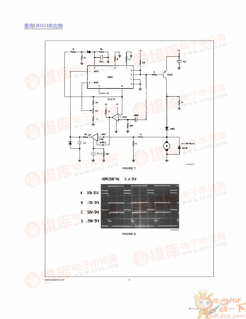
Figure 7 shows the LM3524 in an arrangement which con-trols the speed of a motor without requiring the usual ta-chometer or other speed pick-off. This circuit uses the backEMF of the motor to bias a feedback loop, which controlsmotor speed. When power is applied, the positive input ofthe LM3524 is at a higher potential than the negative input.Under these conditions, the output of the LM3524 is biasedfull on (90% duty cycle). The output transistors, paralleled inthe common emitter configuration, drive the 2N5023 and the
motor turns. (LM3524 output is waveform A, Figure 8; wave-form B is the 2N5023 collector.) The LM3524 output pulse isalso used to drive a 1000 pF-500 kΩ differentiator networkwhose output is compared to the LM3524’s internal 5V refer-ence. The result is a delayed pulse (Figure 8, waveform D),which is used to trigger an LF398 sample-hold IC. As thewaveforms show, the sample-hold is gated high (ON) just asthe 2N5023 collector stops supplying current to the motor. Atthis instant, the motor coils produce a flyback pulse, which isdamped by the shunt diode. (Motor waveform is Figure 8,trace C). After the flyback pulse decays, the back EMF of themotor remains. This voltage is “remembered” by thesample-hold IC when the sample trigger pulse ceases and isused to complete the speed control loop back at the LM3524input. The 10k-4k divider at the motor output insures theLF398’s output will always be within the common range ofthe LM3524’s input. The 10k-1 µF combination provides fil-tering during the time the LF398 is sampling. The diode as-sociated with this time constant prevents any possible LF398negative output from damaging the LM3524. The 10 MΩ re-sistor paralleling the 0.01 µF sampling capacitor preventsthe servo from “hanging up” if this capacitor somehow man-ages to charge above the motor’s back EMF value. The39k-100 µF pair sets the loop frequency response. Themaximum pulse-width-modulator duty cycle is clamped bythe 2k-2k divider and diode at 80%, thus avoiding overshootand aiding transient response at turn-on and during largepositive step changes. The 60k-0.1 µF values at pins 6 and7 set the pulse modulation frequency at 300 Hz.
AN006890-6
*TRW Type MAR-60 .1%
FIGURE 6.
3 www.national.com
查询LM3524供应商
AN006890-7
FIGURE 7.
AN006890-8
FIGURE 8.
www.national.com 4
查询LM3524供应商
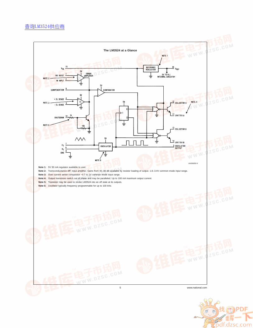
The LM3524 at a Glance
AN006890-9
Note 1: 5V 50 mA regulator available to user.
Note 2: Transconductance diff. input amplifier. Gains from 40–80 dB available by resistor loading of output. 1.8–3.4V common mode input range.
Note 3: Over current sense comparator −0.7 to 1V common mode input range.
Note 4: Output transistors switch out of phase and may be paralleled. Up to 100 mA maximum output current.
Note 5: Transistor may be used to strobe LM3524 into an off state at its outputs.
Note 6: Oscillator typically frequency programmable for up to 100 kHz.
5 www.national.com
查询LM3524供应商
LIFE SUPPORT POLICY
NATIONAL’S PRODUCTS ARE NOT AUTHORIZED FOR USE AS CRITICAL COMPONENTS IN LIFE SUPPORT DE-VICES OR SYSTEMS WITHOUT THE EXPRESS WRITTEN APPROVAL OF THE PRESIDENT OF NATIONAL SEMI-CONDUCTOR CORPORATION. As used herein:1. Life support devices or systems are devices or sys-
tems which, (a) are intended for surgical implant intothe body, or (b) support or sustain life, and whose fail-ure to perform when properly used in accordancewith instructions for use provided in the labeling, canbe reasonably expected to result in a significant injuryto the user.
2. A critical component in any component of a life supportdevice or system whose failure to perform can be rea-sonably expected to cause the failure of the life supportdevice or system, or to affect its safety or effectiveness.
National SemiconductorCorporationAmericasTel: 1-800-272-9959Fax: 1-800-737-7018Email: [email protected]
www.national.com
National SemiconductorEurope
Fax: +49 (0) 1 80-530 85 86Email: [email protected]
Deutsch Tel: +49 (0) 1 80-530 85 85English Tel: +49 (0) 1 80-532 78 32Français Tel: +49 (0) 1 80-532 93 58Italiano Tel: +49 (0) 1 80-534 16 80
National SemiconductorAsia Pacific CustomerResponse GroupTel: 65-2544466Fax: 65-2504466Email: [email protected]
National SemiconductorJapan Ltd.Tel: 81-3-5620-6175Fax: 81-3-5620-6179
AN
-292
App
licat
ions
ofth
eLM
3524
Pul
se-W
idth
-Mod
ulat
or
National does not assume any responsibility for use of any circuitry described, no circuit patent licenses are implied and National reserves the right at any time without notice to change said circuitry and specifications.
查询LM3524供应商