applied physics - situs resmi sma negeri 78 jakarta physics.pdfschaum’seasyoutlines applied...
TRANSCRIPT
SCHAUM’S Easy OUTLINES
APPLIED PHYSICS
Other Books in Schaum’sEasy Outlines Series Include:
Schaum’s Easy Outline: CalculusSchaum’s Easy Outline: College AlgebraSchaum’s Easy Outline: College MathematicsSchaum’s Easy Outline: Discrete MathematicsSchaum’s Easy Outline: Differential EquationsSchaum’s Easy Outline: Elementary AlgebraSchaum’s Easy Outline: GeometrySchaum’s Easy Outline: Linear AlgebraSchaum’s Easy Outline: Mathematical Handbook
of Formulas and TablesSchaum’s Easy Outline: PrecalculusSchaum’s Easy Outline: Probability and StatisticsSchaum’s Easy Outline: StatisticsSchaum’s Easy Outline: TrigonometrySchaum’s Easy Outline: Business StatisticsSchaum’s Easy Outline: Principles of AccountingSchaum’s Easy Outline: Principles of EconomicsSchaum’s Easy Outline: BiologySchaum’s Easy Outline: BiochemistrySchaum’s Easy Outline: Molecular and Cell BiologySchaum’s Easy Outline: College ChemistrySchaum’s Easy Outline: GeneticsSchaum’s Easy Outline: Human Anatomy
and PhysiologySchaum’s Easy Outline: Organic ChemistrySchaum’s Easy Outline: PhysicsSchaum’s Easy Outline: Programming with C++Schaum’s Easy Outline: Programming with JavaSchaum’s Easy Outline: Basic ElectricitySchaum’s Easy Outline: ElectromagneticsSchaum’s Easy Outline: Introduction to PsychologySchaum’s Easy Outline: FrenchSchaum’s Easy Outline: German Schaum’s Easy Outline: SpanishSchaum’s Easy Outline: Writing and Grammar
SCHAUM’S Easy OUTLINES
APPLIED PHYSICS
B a s e d o n S c h a u m ’ s
Out l ine o f Theory and Problems o f
Appl ied Phys ics (Third Edi t ion)
b y A r t h u r B e i s e r , Ph.D.
A b r i d g e m e n t E d i t o r
G e o r g e J . H a d e m e n o s , Ph.D.
S C H A U M ’ S O U T L I N E S E R I E SM c G R AW - H I L L
New York Chicago San Francisco Lisbon London Madrid
Mexico City Milan New Delhi San Juan
Seoul Singapore Sydney Toronto
Copyright © 2003 by The McGraw-Hill Companies, Inc. All rights reserved. Manufactured in the United States of
America. Except as permitted under the United States Copyright Act of 1976, no part of this publication may be repro-
duced or distributed in any form or by any means, or stored in a database or retrieval system, without the prior writ-
ten permission of the publisher.
0-07-142585-3
The material in this eBook also appears in the print version of this title: 0-07-139878-3.
All trademarks are trademarks of their respective owners. Rather than put a trademark symbol after every occur-
rence of a trademarked name, we use names in an editorial fashion only, and to the benefit of the trademark owner,
with no intention of infringement of the trademark. Where such designations appear in this book, they have been
printed with initial caps.
McGraw-Hill eBooks are available at special quantity discounts to use as premiums and sales promotions, or for
use in corporate training programs. For more information, please contact George Hoare, Special Sales, at
[email protected] or (212) 904-4069.
TERMS OF USEThis is a copyrighted work and The McGraw-Hill Companies, Inc. (“McGraw-Hill”) and its licensors reserve all
rights in and to the work. Use of this work is subject to these terms. Except as permitted under the Copyright Act
of 1976 and the right to store and retrieve one copy of the work, you may not decompile, disassemble, reverse engi-
neer, reproduce, modify, create derivative works based upon, transmit, distribute, disseminate, sell, publish or sub-
license the work or any part of it without McGraw-Hill’s prior consent. You may use the work for your own non-
commercial and personal use; any other use of the work is strictly prohibited. Your right to use the work may be
terminated if you fail to comply with these terms.
THE WORK IS PROVIDED “AS IS”. McGRAW-HILL AND ITS LICENSORS MAKE NO GUARANTEES OR
WARRANTIES AS TO THE ACCURACY, ADEQUACY OR COMPLETENESS OF OR RESULTS TO BE
OBTAINED FROM USING THE WORK, INCLUDING ANY INFORMATION THAT CAN BE ACCESSED
THROUGH THE WORK VIA HYPERLINK OR OTHERWISE, AND EXPRESSLY DISCLAIM ANY WAR-
RANTY, EXPRESS OR IMPLIED, INCLUDING BUT NOT LIMITED TO IMPLIED WARRANTIES OF MER-
CHANTABILITY OR FITNESS FOR A PARTICULAR PURPOSE. McGraw-Hill and its licensors do not warrant
or guarantee that the functions contained in the work will meet your requirements or that its operation will be unin-
terrupted or error free. Neither McGraw-Hill nor its licensors shall be liable to you or anyone else for any inaccu-
racy, error or omission, regardless of cause, in the work or for any damages resulting therefrom. McGraw-Hill has
no responsibility for the content of any information accessed through the work. Under no circumstances shall
McGraw-Hill and/or its licensors be liable for any indirect, incidental, special, punitive, consequential or similar
damages that result from the use of or inability to use the work, even if any of them has been advised of the possi-
bility of such damages. This limitation of liability shall apply to any claim or cause whatsoever whether such claim
or cause arises in contract, tort or otherwise.
DOI: 10.1036/0071425853

Want to learn more?
We hope you enjoy this McGraw-Hill eBook!
If you d like more information about this
book, its author, or related books and websites,
please click here.
,,
Contents
v
Chapter 1 Vectors 1Chapter 2 Motion 11Chapter 3 Newton’s Laws of Motion 19Chapter 4 Energy 28Chapter 5 Momentum 33Chapter 6 Circular Motion and Gravitation 37Chapter 7 Rotational Motion 41Chapter 8 Equilibrium 51Chapter 9 Simple Harmonic Motion 58Chapter 10 Waves and Sound 64Chapter 11 Electricity 70Chapter 12 Electric Current 75Chapter 13 Direct-Current Circuits 80Chapter 14 Capacitance 86Chapter 15 Magnetism 93Chapter 16 Electromagnetic Induction 102Chapter 17 Light 108Chapter 18 Spherical Mirrors 118Chapter 19 Lenses 124Chapter 20 Physical and Quantum Optics 131Index 135
For more information about this title, click here.
Copyright 2003 by The McGraw-Hill Companies, Inc. Click Here for Terms of Use.

This page intentionally left blank.
Chapter 1
Vectors
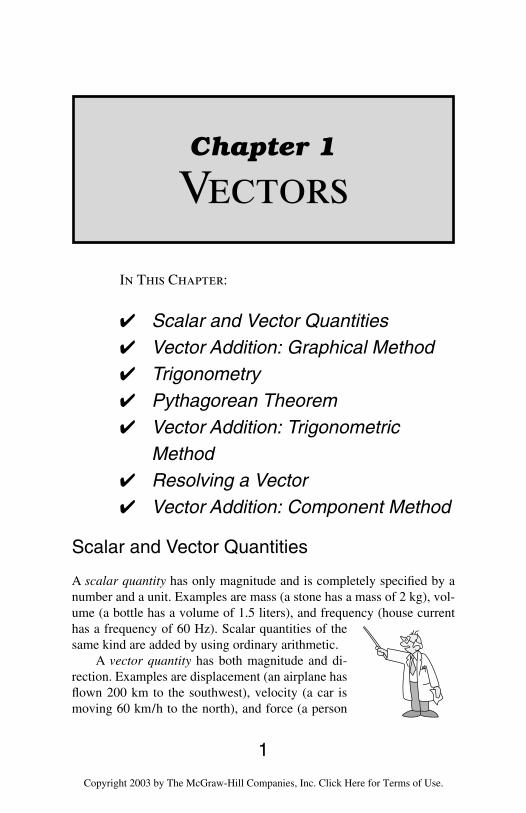
In This Chapter:
Scalar and Vector Quantities Vector Addition: Graphical Method Trigonometry Pythagorean Theorem Vector Addition: Trigonometric
Method Resolving a Vector Vector Addition: Component Method
Scalar and Vector Quantities
A scalar quantity has only magnitude and is completely specified by anumber and a unit. Examples are mass (a stone has a mass of 2 kg), vol-ume (a bottle has a volume of 1.5 liters), and frequency (house currenthas a frequency of 60 Hz). Scalar quantities of thesame kind are added by using ordinary arithmetic.
A vector quantity has both magnitude and di-rection. Examples are displacement (an airplane hasflown 200 km to the southwest), velocity (a car ismoving 60 km/h to the north), and force (a person
1
Copyright 2003 by The McGraw-Hill Companies, Inc. Click Here for Terms of Use.
applies an upward force of 25 newtons to a package). Symbols of vectorquantities are printed in boldface type (v = velocity, F = force). When vec-tor quantities of the same kind are added, their directions must be takeninto account.
Vector Addition: Graphical Method
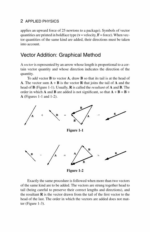
A vector is represented by an arrow whose length is proportional to a cer-tain vector quantity and whose direction indicates the direction of thequantity.
To add vector B to vector A, draw B so that its tail is at the head ofA. The vector sum A + B is the vector R that joins the tail of A and thehead of B (Figure 1-1). Usually, R is called the resultant of A and B. Theorder in which A and B are added is not significant, so that A + B = B +A (Figures 1-1 and 1-2).
2 APPLIED PHYSICS
Figure 1-1
Figure 1-2
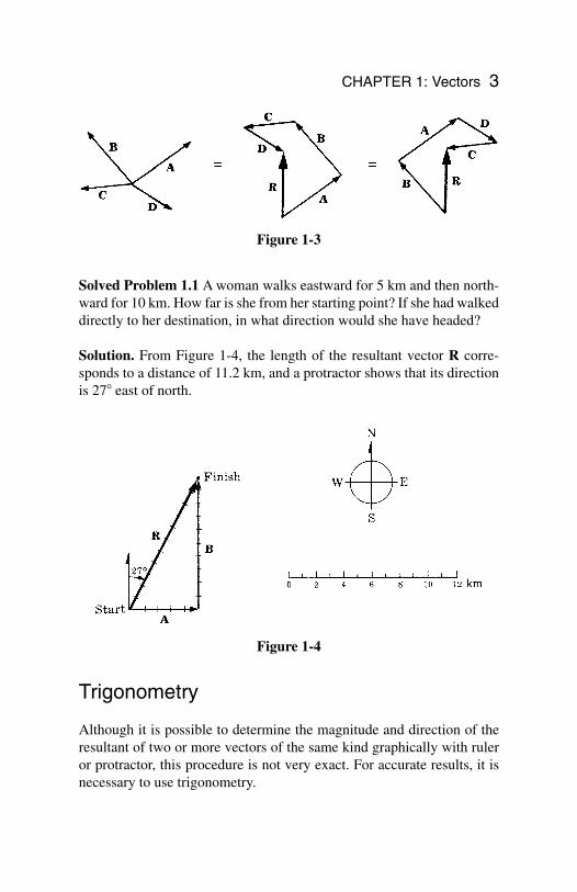
Exactly the same procedure is followed when more than two vectorsof the same kind are to be added. The vectors are strung together head totail (being careful to preserve their correct lengths and directions), andthe resultant R is the vector drawn from the tail of the first vector to thehead of the last. The order in which the vectors are added does not mat-ter (Figure 1-3).
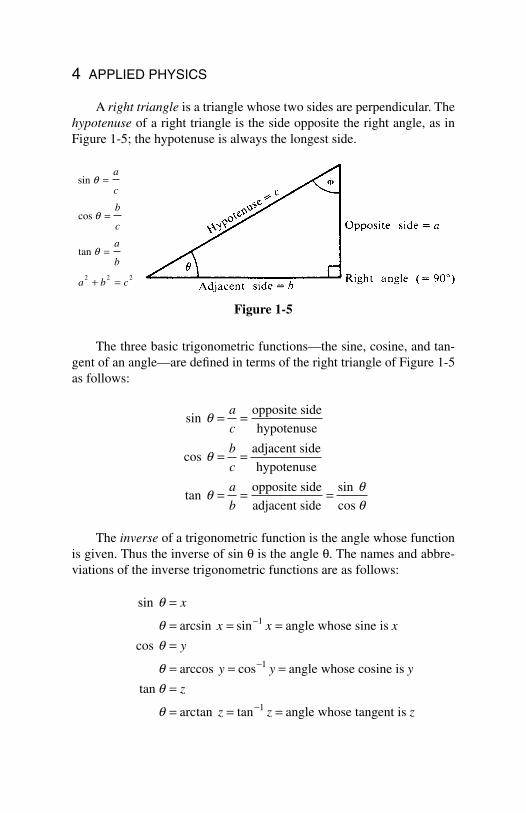
Solved Problem 1.1 A woman walks eastward for 5 km and then north-ward for 10 km. How far is she from her starting point? If she had walkeddirectly to her destination, in what direction would she have headed?
Solution. From Figure 1-4, the length of the resultant vector R corre-sponds to a distance of 11.2 km, and a protractor shows that its directionis 27 east of north.
Trigonometry
Although it is possible to determine the magnitude and direction of theresultant of two or more vectors of the same kind graphically with ruleror protractor, this procedure is not very exact. For accurate results, it isnecessary to use trigonometry.
CHAPTER 1: Vectors 3
Figure 1-3
Figure 1-4
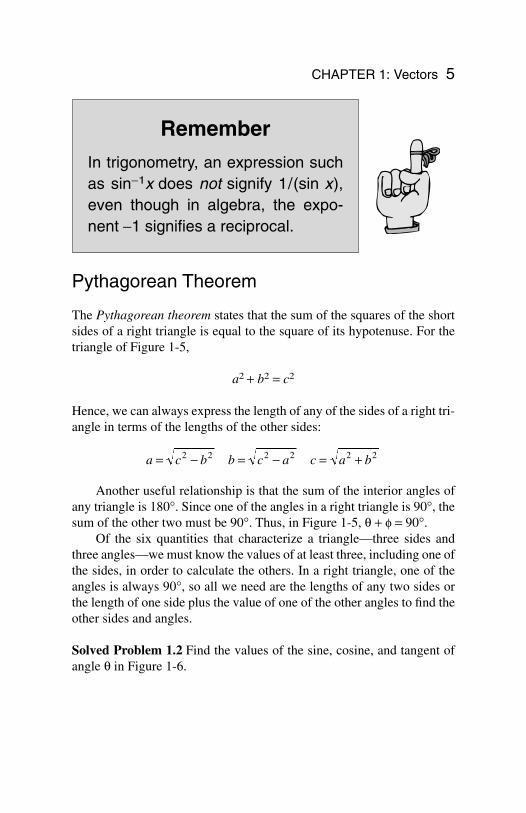
A right triangle is a triangle whose two sides are perpendicular. Thehypotenuse of a right triangle is the side opposite the right angle, as inFigure 1-5; the hypotenuse is always the longest side.
The three basic trigonometric functions—the sine, cosine, and tan-gent of an angle—are defined in terms of the right triangle of Figure 1-5as follows:
The inverse of a trigonometric function is the angle whose functionis given. Thus the inverse of sin q is the angle q. The names and abbre-viations of the inverse trigonometric functions are as follows:
sin
arcsin sin
cos
arccos cos
arctan tan
angle whose sine is
angle whose cosine is
tan
angle whose tangent is
q
q
q
q
q
q
=
= = ==
= = ==
= = =
−
−
−
x
x x x
y
y y y
z
z z z
1
1
1
sin
cos
tansin
opposite side
hypotenuse
adjacent side
hypotenuse
opposite side
adjacent side cos
q
q
q
= =
= =
= = =
a
c
b
c
a
b
4 APPLIED PHYSICS
Figure 1-5
sin
cos
tan
q
q
q
=
=
=
+ =
a
c
b
c
a
b
a b c2 2 2
Remember
In trigonometry, an expression suchas sin−1x does not signify 1/(sin x),even though in algebra, the expo-nent −1 signifies a reciprocal.
Pythagorean Theorem
The Pythagorean theorem states that the sum of the squares of the shortsides of a right triangle is equal to the square of its hypotenuse. For thetriangle of Figure 1-5,
a2 + b2 = c2
Hence, we can always express the length of any of the sides of a right tri-angle in terms of the lengths of the other sides:
Another useful relationship is that the sum of the interior angles ofany triangle is 180°. Since one of the angles in a right triangle is 90°, thesum of the other two must be 90°. Thus, in Figure 1-5, q + f = 90°.
Of the six quantities that characterize a triangle—three sides andthree angles—we must know the values of at least three, including one ofthe sides, in order to calculate the others. In a right triangle, one of theangles is always 90°, so all we need are the lengths of any two sides orthe length of one side plus the value of one of the other angles to find theother sides and angles.
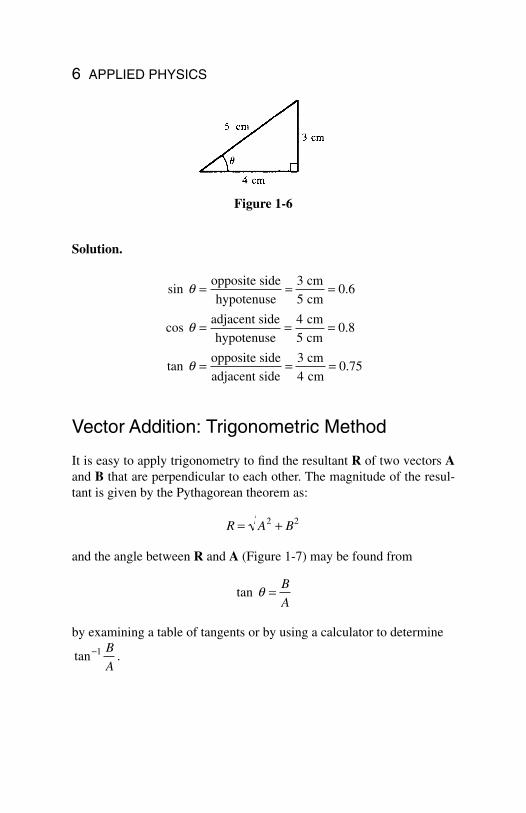
Solved Problem 1.2 Find the values of the sine, cosine, and tangent ofangle q in Figure 1-6.
a c b b c a c a b= − = − = +2 2 2 2 2 2
CHAPTER 1: Vectors 5
Solution.
Vector Addition: Trigonometric Method
It is easy to apply trigonometry to find the resultant R of two vectors Aand B that are perpendicular to each other. The magnitude of the resul-tant is given by the Pythagorean theorem as:
and the angle between R and A (Figure 1-7) may be found from
by examining a table of tangents or by using a calculator to determine
.tan−1 B
A
tan q = B
A
R A B= +2 2
sin .
cos .
tan .
opposite side
hypotenuse
cm
cm
adjacent side
hypotenuse
cm
cm
opposite side
adjacent side
cm
cm
q
q
q
= = =
= = =
= = =
3
50 6
4
50 8
3
40 75
6 APPLIED PHYSICS
Figure 1-6
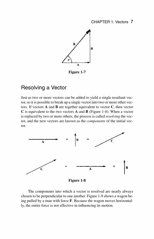
Resolving a Vector
Just as two or more vectors can be added to yield a single resultant vec-tor, so it is possible to break up a single vector into two or more other vec-tors. If vectors A and B are together equivalent to vector C, then vectorC is equivalent to the two vectors A and B (Figure 1-8). When a vectoris replaced by two or more others, the process is called resolving the vec-tor, and the new vectors are known as the components of the initial vec-tor.
The components into which a vector is resolved are nearly alwayschosen to be perpendicular to one another. Figure 1-9 shows a wagon be-ing pulled by a man with force F. Because the wagon moves horizontal-ly, the entire force is not effective in influencing its motion.
CHAPTER 1: Vectors 7
Figure 1-7
Figure 1-8
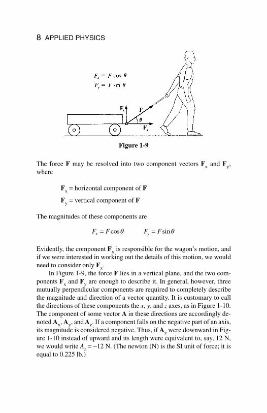
Figure 1-9
8 APPLIED PHYSICS
The force F may be resolved into two component vectors Fx and Fy,where
Fx = horizontal component of F
Fy = vertical component of F
The magnitudes of these components are
Evidently, the component Fx is responsible for the wagon’s motion, andif we were interested in working out the details of this motion, we wouldneed to consider only Fx.
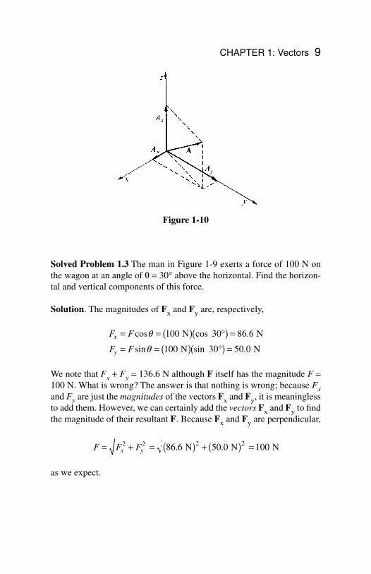
In Figure 1-9, the force F lies in a vertical plane, and the two com-ponents Fx and Fy are enough to describe it. In general, however, threemutually perpendicular components are required to completely describethe magnitude and direction of a vector quantity. It is customary to callthe directions of these components the x, y, and z axes, as in Figure 1-10.The component of some vector A in these directions are accordingly de-noted Ax, Ay, and Az. If a component falls on the negative part of an axis,its magnitude is considered negative. Thus, if Az were downward in Fig-ure 1-10 instead of upward and its length were equivalent to, say, 12 N,we would write Az = −12 N. (The newton (N) is the SI unit of force; it isequal to 0.225 lb.)
F F F Fx y= =cos sinq q
Solved Problem 1.3 The man in Figure 1-9 exerts a force of 100 N onthe wagon at an angle of q = 30° above the horizontal. Find the horizon-tal and vertical components of this force.
Solution. The magnitudes of Fx and Fy are, respectively,
We note that Fx + Fy = 136.6 N although F itself has the magnitude F =100 N. What is wrong? The answer is that nothing is wrong; because Fxand Fy are just the magnitudes of the vectors Fx and Fy, it is meaninglessto add them. However, we can certainly add the vectors Fx and Fy to findthe magnitude of their resultant F. Because Fx and Fy are perpendicular,
as we expect.
F F Fx y= + = ( ) + ( ) =2 2 2 286 6 50 0 100. . N N N
F F
F F
x
y
= = ( ) °( ) =
= = ( ) °( ) =
cos cos .
sin sin .
q
q
100 30 86 6
100 30 50 0
N N
N N
CHAPTER 1: Vectors 9
Figure 1-10
Vector Addition: Component Method
When vectors to be added are not perpendicular, themethod of addition by components described below canbe used. There do exist trigonometric procedures fordealing with oblique triangles (the law of sines and thelaw of cosines), but these are not necessary since thecomponent method is entirely general in its application.
To add two or more vectors A, B, C, … by the component method,follow this procedure:
1. Resolve the initial vectors into components in the x, y, and z di-rections.
2. Add the components in the x direction to give Rx, add the com-ponents in the y direction to give Ry, and add the components inthe z direction to give Rz. That is, the magnitudes of Rx, Ry, andRz are given by, respectively,
3. Calculate the magnitude and direction of the resultant R from itscomponents Rx, Ry, and Rz by using the Pythagorean theorem:
If the vectors being added all lie in the same plane, only two componentsneed to be considered.
R R R Rx y z= + +2 2 2
R A B C
R A B C
R A B C
x x x x
y y y y
z z z z
= + + += + + +
= + + +
L
L
L
10 APPLIED PHYSICS
Chapter 2
Motion
In This Chapter:
Velocity Acceleration Distance, Velocity, and Acceleration Acceleration of Gravity Falling Bodies Projectile Motion
Velocity
The velocity of a body is a vector quantity that describes both how fast itis moving and the direction in which it is headed.
In the case of a body traveling in a straight line, its velocity is sim-ply the rate at which it covers distance. The average velocity v of such abody when it covers the distance s in the time t is
The average velocity of a body during the time t does not complete-ly describe its motion, however, because during the time t, it may some-
vs
t=
Average velocity = distance
time
11
Copyright 2003 by The McGraw-Hill Companies, Inc. Click Here for Terms of Use.
times have gone faster than v and sometimes slower. The velocity of abody at any given moment is called its instantaneous velocity and is giv-en by
Here, Ds is the distance the body has gone in the very short time intervalDt at the specified moment. (D is the capital Greek letter delta.) Instanta-neous velocity is what a car’s speedometer indicates.
When the instantaneous velocity of a body does not change, it ismoving at constant velocity. For the case of constant velocity, the basicformula is
Solved Problem 2.1 The velocity of sound in air at sea level is about 343m/s. If a person hears a clap of thunder 3.00 s after seeing a lightningflash, how far away was the lightning?
Solution. The velocity of light is so great compared with the velocity ofsound that the time needed for the light of the flash to reach the personcan be neglected. Hence
s = vt = (343 m/s)(3.00 s) = 1029 m = 1.03 km
Acceleration
A body whose velocity is changing is accelerated. Abody is accelerated when its velocity is increasing, de-creasing, or changing its direction.
The acceleration of a body is the rate at which itsvelocity is changing. If a body moving in a straight linehas a velocity of v0 at the start of a certain time intervalt and of v at the end, its acceleration is
s vt=Distance = (constant velocity)(time)
vs
tinst = ∆∆
12 APPLIED PHYSICS
A positive acceleration means an increase in velocity; a negative accel-eration (sometimes called deceleration) means a decrease in velocity.Only constant accelerations are considered here.
The defining formula for acceleration can be rewritten to give the fi-nal velocity v of an accelerated body:
We can also solve for the time t in terms of v0, v, and a:
Velocity has the dimensions of distance/time. Acceleration has the di-mensions of velocity/time or distance/time2. A typical acceleration unitis the meter/second2 (meter per second squared). Sometimes two differ-ent time units are convenient; for instance, the acceleration of a car thatgoes from rest to 90 km/h in 10 s might be expressed as a = 9 (km/h)/s.
Solved Problem 2.2 A car starts from rest and reaches a final velocity of40 m/s in 10 s. (a) What is its acceleration? (b) If its acceleration remainsthe same, what will its velocity be 5 s later?
Solution. (a) Here v0 = 0. Hence
(b) Now v0 = 40 m/s, so
v v at= + = + = + =0 40 m/s (4 m/s2 )(5 s) 40 m/s 20 m/s 60 m/s
av
t= = =40
104
m/s
s m/s2
tv v
a= −
=
0
Timevelocity change
acceleration
v v at= += +
0
Final velocity initial velocity (acceleration)(time)
av v
t= −
=
0
Accelerationvelocity change
time
CHAPTER 2: Motion 13
Distance, Velocity, and Acceleration
Let us consider a body whose velocity is v0 when it starts to be acceler-ated at a constant rate. After time t, the final velocity of the body will be
How far does the body go during the time interval t? The average veloc-ity v of the body is
and so
Since v = v0 + at, another way to specify the distance covered during t is
If the body is accelerated from rest, v0 = 0 and
Another useful formula gives the final velocity of a body in terms ofits initial velocity, its acceleration, and the distance it has traveled duringthe acceleration:
This can be solved for the distance s to give
In the case of a body that starts from rest, v0 = 0 and
sv v
a= −2
02
2
v v as202 2= +
s at= 1
22
sv v at
t v t at= + +
= +0 0
02
2
1
2
s vtv v
t= = +
0
2
vv v= +0
2
v v at= +0
14 APPLIED PHYSICS
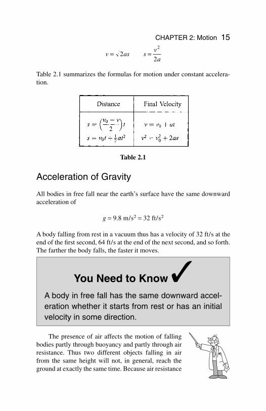
Table 2.1 summarizes the formulas for motion under constant accelera-tion.
Acceleration of Gravity
All bodies in free fall near the earth’s surface have the same downwardacceleration of
g = 9.8 m/s2 = 32 ft/s2
A body falling from rest in a vacuum thus has a velocity of 32 ft/s at theend of the first second, 64 ft/s at the end of the next second, and so forth.The farther the body falls, the faster it moves.
You Need to Know
A body in free fall has the same downward accel-eration whether it starts from rest or has an initialvelocity in some direction.
The presence of air affects the motion of fallingbodies partly through buoyancy and partly through airresistance. Thus two different objects falling in airfrom the same height will not, in general, reach theground at exactly the same time. Because air resistance
v as sv
a= =2
2
2
CHAPTER 2: Motion 15
Table 2.1
increases with velocity, eventually a falling body reaches a terminal ve-locity that depends on its mass, size, and shape, and it cannot fall anyfaster than that.
Falling Bodies
When buoyancy and air resistance can be neglected, a falling body hasthe constant acceleration g and the formulas for uniformly acceleratedmotion apply. Thus a body dropped from rest has the velocity
v = gt
after time t, and it has fallen through a vertical distance of
From the latter formula, we see that
and so the velocity of the body is related to the distance it has fallen by v = gt, or
To reach a certain height h, a body thrown upward must have the sameinitial velocity as the final velocity of a body falling from that height,namely, .
Solved Problem 2.3 What velocity must a ball have when thrown up-ward if it is to reach a height of 15 m?
Solution. The upward velocity the ball must have is the same as thedownward velocity the ball would have if dropped from that height.Hence
v gh s= = ( )( )( ) = =2 2 9 8 15 294 172. / m / s m m m / s2 2
v gh= 2
v gh= 2
th
g= 2
h gt= 1
22
16 APPLIED PHYSICS
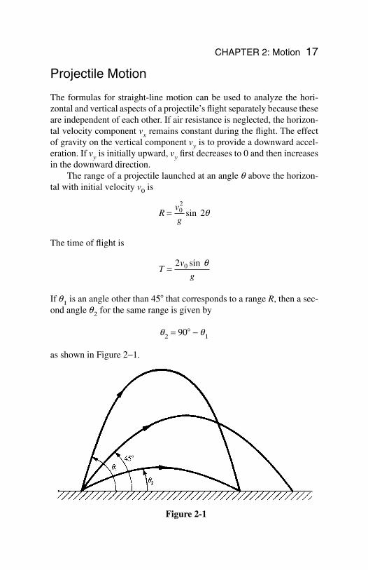
Projectile Motion
The formulas for straight-line motion can be used to analyze the hori-zontal and vertical aspects of a projectile’s flight separately because theseare independent of each other. If air resistance is neglected, the horizon-tal velocity component vx remains constant during the flight. The effectof gravity on the vertical component vy is to provide a downward accel-eration. If vy is initially upward, vy first decreases to 0 and then increasesin the downward direction.
The range of a projectile launched at an angle q above the horizon-tal with initial velocity v0 is
The time of flight is
If q1 is an angle other than 45 that corresponds to a range R, then a sec-ond angle q2 for the same range is given by
q2 = 90 − q1
as shown in Figure 2−1.
Tv
g= 2 0 sin q
Rv
g= 0
2
sin 2q
CHAPTER 2: Motion 17
Figure 2-1
Solved Problem 2.4 A football is thrown with a velocity of 10 m/s at anangle of 30 above the horizontal. (a) How far away should its intendedreceiver be? (b) What will the time of flight be?
Solution.(a)
(b)
Tv
g
s= = ( )( ) =2 2 101 020 sin (sin )
. m / s 30
9.8 m / s s
o
2
q
Rv
g= = ( )
=02 210
9 860 8 8sin
.(sin ) . 2
m / s
m / s m2q o
18 APPLIED PHYSICS
Chapter 3
Newton’s Lawsof Motion
In This Chapter:
First Law of Motion Mass Second Law of Motion Weight British System of Units Free-Body Diagrams and Tension Third Law of Motion Static and Kinetic Friction Coefficient of Friction
First Law of Motion
According to Newton’s first law of motion, if no netforce acts on it, a body at rest remains at rest and abody in motion remains in motion at constant veloci-ty (that is, at constant speed in a straight line).
This law provides a definition of force: A force isany influence that can change the velocity of a body.
Two or more forces act on a body without affect-ing its velocity if the forces cancel one another out.
19
Copyright 2003 by The McGraw-Hill Companies, Inc. Click Here for Terms of Use.
What is needed for a velocity change is a net force, or unbalanced force.To accelerate something, a net force must be applied to it. Conversely,every acceleration is due to the action of a net force.
Mass
The property a body has of resisting any change in its state of rest or uni-form motion is called inertia. The inertia of a body is related to what wethink of as the amount of matter it contains. A quantitative measure of in-ertia is mass: The more mass a body has, the less its acceleration when agiven net force acts on it. The SI unit of mass is the kilogram (kg).
Note!
A liter of water, which is 1.057 quarts, has a massof almost exactly 1 kg.
Second Law of Motion
According to Newton’s second law of motion, the net force acting on abody equals the product of the mass and the acceleration of the body. Thedirection of the force is the same as that of the acceleration.
In equation form,
Net force is sometimes designated SF, where S (Greek capital letter sig-ma) means “sum of.” The second law of motion is the key to under-standing the behavior of moving bodies since it links cause (force) andeffect (acceleration) in a definite way.
In the SI system, the unit for force is the newton (N): A newton is thatnet force which, when applied to a 1-kg mass, gives it an acceleration of1 m/s2.
F a= m
20 APPLIED PHYSICS
Solved Problem 3.1 A 10-kg body has an acceleration of 5 m/s2. Whatis the net force acting on it?
Solution.
Weight
The weight of a body is the gravitational force with which the earth at-tracts the body. If a person weighs 600 N (135 lb), this means the earthpulls that person down with a force of 600 N. Weight (a vector quantity)is different from mass (a scalar quantity), which is a measure of the re-sponse of a body to an applied force. The weight of a body varies with itslocation near the earth (or other astronomical body), whereas its mass isthe same everywhere in the universe.
The weight of a body is the force that causes it to be accelerateddownward with the acceleration of gravity g. Hence, from the second lawof motion, with F = w and a = g,
Because g is constant near the earth’s surface, the weight of a body thereis proportional to its mass—a large mass is heavier than a small one.
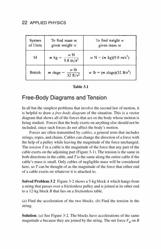
British System of Units
In the British system, the unit of mass is the slug and the unit of force isthe pound (lb). A net force of 1 lb acting on a mass of 1 slug gives it anacceleration of 1 ft/s2. Table 3.1 shows how units of mass and force inthe SI and British systems are related.
w mg==Weight (mass)(acceleration of gravity)
F ma= = ( ) =10 5 50 kg m/s N2( )
CHAPTER 3: Newton’s Laws of Motion 21
Free-Body Diagrams and Tension
In all but the simplest problems that involve the second law of motion, itis helpful to draw a free-body diagram of the situation. This is a vectordiagram that shows all of the forces that act on the body whose motion isbeing studied. Forces that the body exerts on anything else should not beincluded, since such forces do not affect the body’s motion.
Forces are often transmitted by cables, a general term that includesstrings, ropes, and chains. Cables can change the direction of a force withthe help of a pulley while leaving the magnitude of the force unchanged.The tension T in a cable is the magnitude of the force that any part of thecable exerts on the adjoining part (Figure 3-1). The tension is the same inboth directions in the cable, and T is the same along the entire cable if thecable’s mass is small. Only cables of negligible mass will be consideredhere, so T can be thought of as the magnitude of the force that either endof a cable exerts on whatever it is attached to.
Solved Problem 3.2 Figure 3-2 shows a 5-kg block A which hangs froma string that passes over a frictionless pulley and is joined at its other endto a 12-kg block B that lies on a frictionless table.
(a) Find the acceleration of the two blocks. (b) Find the tension in thestring.
Solution. (a) See Figure 3-2. The blocks have accelerations of the samemagnitude a because they are joined by the string. The net force FB on B
22 APPLIED PHYSICS
Table 3.1
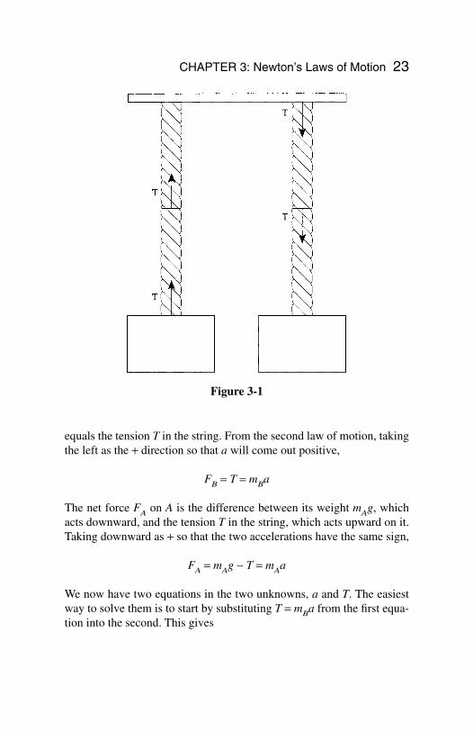
equals the tension T in the string. From the second law of motion, takingthe left as the + direction so that a will come out positive,
FB = T = mBa
The net force FA on A is the difference between its weight mAg, whichacts downward, and the tension T in the string, which acts upward on it.Taking downward as + so that the two accelerations have the same sign,
FA = mAg − T = mAa
We now have two equations in the two unknowns, a and T. The easiestway to solve them is to start by substituting T = mBa from the first equa-tion into the second. This gives
CHAPTER 3: Newton’s Laws of Motion 23
Figure 3-1
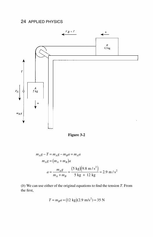
(b) We can use either of the original equations to find the tension T. Fromthe first,
T m aB= = ( ) =12 2 9 35 kg m/s N2( . )
m g T m g m a m a
m g m m a
am g
m m
A A B A
A A B
A
A B
− = − =
= +( )
=+
=( )( )
+=
5 9 8
5 122 9
kg m / s
kg kg m / s
22
..
24 APPLIED PHYSICS
Figure 3-2
Third Law of Motion
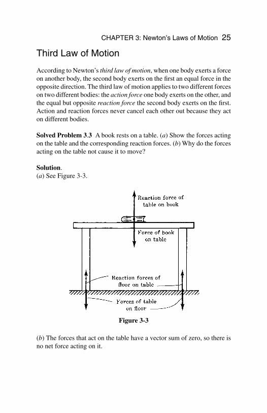
According to Newton’s third law of motion, when one body exerts a forceon another body, the second body exerts on the first an equal force in theopposite direction. The third law of motion applies to two different forceson two different bodies: the action force one body exerts on the other, andthe equal but opposite reaction force the second body exerts on the first.Action and reaction forces never cancel each other out because they acton different bodies.
Solved Problem 3.3 A book rests on a table. (a) Show the forces actingon the table and the corresponding reaction forces. (b) Why do the forcesacting on the table not cause it to move?
Solution.(a) See Figure 3-3.
(b) The forces that act on the table have a vector sum of zero, so there isno net force acting on it.
CHAPTER 3: Newton’s Laws of Motion 25
Figure 3-3
Static and Kinetic Friction
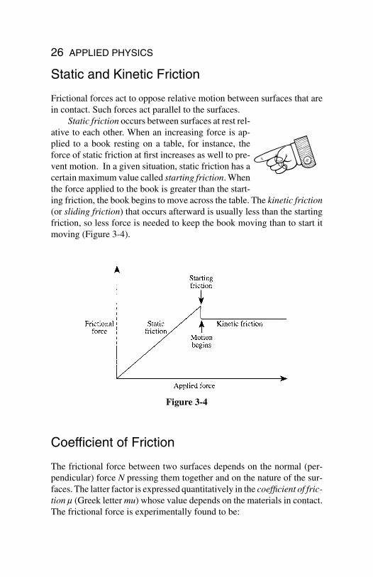
Frictional forces act to oppose relative motion between surfaces that arein contact. Such forces act parallel to the surfaces.
Static friction occurs between surfaces at rest rel-ative to each other. When an increasing force is ap-plied to a book resting on a table, for instance, theforce of static friction at first increases as well to pre-vent motion. In a given situation, static friction has acertain maximum value called starting friction. Whenthe force applied to the book is greater than the start-ing friction, the book begins to move across the table. The kinetic friction(or sliding friction) that occurs afterward is usually less than the startingfriction, so less force is needed to keep the book moving than to start itmoving (Figure 3-4).
Coefficient of Friction
The frictional force between two surfaces depends on the normal (per-pendicular) force N pressing them together and on the nature of the sur-faces. The latter factor is expressed quantitatively in the coefficient of fric-tion m (Greek letter mu) whose value depends on the materials in contact.The frictional force is experimentally found to be:
26 APPLIED PHYSICS
Figure 3-4
In the case of static friction, Ff increases as the applied force increasesuntil the limiting value of msN is reached. Thus when there is no motion,msN gives the starting frictional force, not the actual frictional force. Upto msN, the actual frictional force Ff has the same magnitude as the ap-plied force but is in the opposite direction.
When the applied force exceeds the starting frictional force msN, mo-tion begins and now the coefficient of kinetic friction mk governs the fric-tional force. In this case, mkN gives the actual amount of Ff, which nolonger depends on the applied force and is constant over a fairly widerange of relative velocities.
Solved Problem 3.4 A force of 200 N is just sufficient to start a 50-kgsteel trunk moving across a wooden floor. Find the coefficient of staticfriction.
Solution. The normal force is the trunk’s weight mg. Hence,
msF
N
F
mg= = =
( )( ) =200
9 80 41
N
50 kg m / s2..
F N
F N
f s
f k
≤
=
m
m
Static friction
Kinetic friction
CHAPTER 3: Newton’s Laws of Motion 27
Chapter 4
Energy
In This Chapter:
Work Power Kinetic Energy Potential Energy Conservation of Energy
Work
Work is a measure of the amount of change (in a general sense) that a forceproduces when it acts on a body. The change may be in the velocity ofthe body, in its position, or in its size or shape.
By definition, the work done by a force acting on a body is equal tothe product of the force and the distance through which the force acts,provided that F and s are in the same direction. Thus
W = FsWork = (force)(distance)
Work is a scalar quantity; no direction is associated with it.If F and s are not parallel but F is at the angle q with respect to s,
then
28
Copyright 2003 by The McGraw-Hill Companies, Inc. Click Here for Terms of Use.
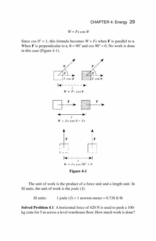
W = Fs cos q
Since cos 0 = 1, this formula becomes W = Fs when F is parallel to s.When F is perpendicular to s, q = 90 and cos 90 = 0. No work is donein this case (Figure 4-1).
CHAPTER 4: Energy 29
Figure 4-1
The unit of work is the product of a force unit and a length unit. InSI units, the unit of work is the joule (J).
SI units: 1 joule (J) = 1 newton-meter = 0.738 ft•lb
Solved Problem 4.1 A horizontal force of 420 N is used to push a 100-kg crate for 5 m across a level warehouse floor. How much work is done?
Solution. The mass of the crate does not matter here. Since the force isparallel to the displacement,
W = Fs = (420 N)(5 m) = 2100 J = 2.1 kJ
Power
Power is the rate at which work is done by a force. Thus
Remember
The more power something has, themore work it can perform in a giventime.
Two special units of power are in wide use, the watt and the horse-power, where
1 watt (W) = 1 J/s = 1.34 × 10⁻³ hp1 horsepower (hp) = 550 ftlb/s = 746 W
When a constant force F does work on a body that is moving at theconstant velocity v, if F is parallel to v, the power involved is
because s/t = v; that is
P Fv=
= ( )( )Power force velocity
PW
t
Fs
tFv= = =
PW
t=
=Powerwork done
time
30 APPLIED PHYSICS
Solved Problem 4.2 A 40-kg woman runs up a staircase 4 m high in 5 s.Find her minimum power output.
Solution. The minimum downward force the woman’s legs must exertis equal to her weight mg. Hence
Kinetic Energy
Energy is that property something has that enables it to do work. Themore energy something has, the more work it can perform. Two generalcategories of energy are kinetic energy and potential energy.
Note!
The units of energy are the same as those of work,namely the joule and the foot-pound.
The energy a body has by virtue of its motion is called kinetic ener-gy. If the body’s mass is m and its velocity is v, its kinetic energy is
Kinetic energy = KE =
Solved Problem 4.3 Find the kinetic energy of a 1000-kg car whose ve-locity is 20 m/s.
Solution. KE =
Potential Energy
The energy a body has by virtue of its position is calledpotential energy. A book held above the floor has grav-itational potential energy because the book can do workon something else as it falls; a nail held near a magnet
1
2
1
21000 20 2 102 2 5mv = ( )( ) = × kg m / s J
1
22mv
PW
t
Fs
t
mgh
t= = = =
( )( )( )=
40 9 8 4314
kg m / s m
5 s W
2.
CHAPTER 4: Energy 31
has magnetic potential energy because the nail can do work as it movestoward the magnet; the wound spring in a watch has elastic potential en-ergy because the spring can do work as it unwinds.
The gravitational potential energy of a body of mass m at a height habove a given reference level is:
Gravitational potential energy = PE = mgh
where g is the acceleration due to gravity.
Solved Problem 4.4 A 1.5-kg book is held 60 cm above a desk whosetop is 70 cm above the floor. Find the potential energy of the book (a)with respect to the desk, and (b) with respect to the floor.
Solution.
(a) Here h = 60 cm = 0.6 m, so
PE = mgh = (1.5 kg)(9.8 m/s2)(0.6 m) = 8.8 J
(b) The book is h = 60 cm + 70 cm = 130 cm = 1.3 m above the floor,so its PE with respect to the floor is
PE = mgh = (1.5 kg)(9.8 m/s2)(1.3 m) = 19.1 J
Conservation of Energy
According to the law of conservation of energy, energy cannot be creat-ed or destroyed, although it can be transformed from one kind to anoth-er. The total amount of energy in the universe is constant. A falling stoneprovides a simple example: More and more of its initial potential energyturns to kinetic energy as its velocity increases, until finally all its PE hasbecome KE when it strikes the ground. The KE of the stone is then trans-ferred to the ground as work by the impact.
In general,
Work done on an object = change in object’s KE + changein object’s PE + work done by object
Work done by an object against friction becomes heat.
32 APPLIED PHYSICS
33
Chapter 5
Momentum
In This Chapter:
Linear Momentum Impulse Conservation of Linear Momentum Collisions
Linear Momentum
Work and energy are scalar quantities that have no di-rections associated with them. When two or more bod-ies interact with one another, or a single body breaksup into two or more new bodies, the various directionsof motion cannot be related by energy considerationsalone. The vector quantities, called linear momentumand impulse, are important in analyzing such events.
The linear momentum (usually called simply momentum) of a bodyof mass m and velocity v is the product of m and v:
Momentum = mv
The units of momentum are kilogram-meters per second and slug-feet persecond. The direction of the momentum of a body is the same as the di-rection in which it is moving.
The greater the momentum of a body, the greater its tendency to con-
Copyright 2003 by The McGraw-Hill Companies, Inc. Click Here for Terms of Use.
tinue in motion. Thus, a baseball that is solidly struck by a bat (v large)is harder to stop than a baseball thrown by hand (v small), and an ironshot (m large) is harder to stop than a baseball (m small) of the same ve-locity.
Solved Problem 5.1 Find the momentum of a 50-kg boy running at 6 m/s.
Solution. The momentum can be calculated as follows:
mv = (50 kg)(6 m/s) = 300 kgm/s
Impulse
A force F that acts on a body during time t provides the body with an im-pulse of Ft:
Impulse = Ft = (force)(time interval)
You Need to Know
The units of impulse are newton-seconds andpound-seconds.
When a force acts on a body to produce a change in its momentum,the momentum change m(v2 − v1) is equal to the impulse provided by theforce. Thus
Ft = m(v2 − v1)
Impulse = momentum change
Solved Problem 5.2 A 46-g golf ball is struck by a club and flies off at70 m/s. If the head of the club was in contact with the ball for 0.5 ms,what was the average force on the ball during the impact?
34 APPLIED PHYSICS
CHAPTER 5: Momentum 35
Solution. The ball started from rest, so v1 = 0 and its momentum changeis:
m(v2 − v1) = mv2 = (0.046 kg)(70 m/s) = 3.22 kgm/s
Since 1 ms = 1 millisecond = 10−3 s, here t = 0.5 ms = 5 × 10⁻⁴ s and
Conservation of Linear Momentum
According to the law of conservation of linear momentum, when the vec-tor sum of the external forces that act on a system of bodies equals zero,the total linear momentum of the system remains constant no matter whatmomentum changes occur within the system.
Although interactions within the system maychange the distribution of the total momentum amongthe various bodies in the system, the total momentumdoes not change. Such interactions can give rise to twogeneral classes of events: explosions, in which an orig-inal single body flies apart into separate bodies, and collisions, in whichtwo or more bodies collide and either stick together or move apart, in eachcase with a redistribution of the original total momentum.
Solved Problem 5.3 A rocket explodes in midair. How does this affect(a) its total momentum and (b) its total kinetic energy?
Solution.
(a) The total momentum remains the same because no externalforces acted on the rocket.
(b) The total kinetic energy increases because the rocket fragmentsreceived additional KE from the explosion.
Fm v v
t=
−( )= ⋅
×= × =−
2 1 33 226 4 10
..
kg m / s
5 10 s N 6.4 kN4
36 APPLIED PHYSICS
Collisions
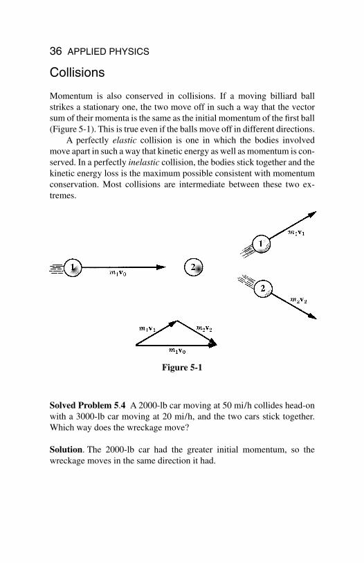
Momentum is also conserved in collisions. If a moving billiard ballstrikes a stationary one, the two move off in such a way that the vectorsum of their momenta is the same as the initial momentum of the first ball(Figure 5-1). This is true even if the balls move off in different directions.
A perfectly elastic collision is one in which the bodies involvedmove apart in such a way that kinetic energy as well as momentum is con-served. In a perfectly inelastic collision, the bodies stick together and thekinetic energy loss is the maximum possible consistent with momentumconservation. Most collisions are intermediate between these two ex-tremes.
Solved Problem 5.4 A 2000-lb car moving at 50 mi/h collides head-onwith a 3000-lb car moving at 20 mi/h, and the two cars stick together.Which way does the wreckage move?
Solution. The 2000-lb car had the greater initial momentum, so thewreckage moves in the same direction it had.
Figure 5-1
37
Chapter 6
CircularMotion andGravitation
In This Chapter:
Centripetal Acceleration Centripetal Force Motion in a Vertical Circle Gravitation Satellite Motion
Centripetal Acceleration
A body that moves in a circular path with a velocity whose magnitude isconstant is said to undergo uniform circular motion.
Although the velocity of a body in uniform circular motion is con-stant in magnitude, its direction changes continually. The body is there-fore accelerated. The direction of this centripetal acceleration is towardthe center of the circle in which the body moves, and its magnitude is
av
rc =
= ( )
2
2
Centripetal acceleration velocity of body
radius of circular path
Copyright 2003 by The McGraw-Hill Companies, Inc. Click Here for Terms of Use.
38 APPLIED PHYSICS
Note!
Because the acceleration is perpendicular to thepath followed by the body, the body’s velocitychanges only in direction, not in magnitude.
Centripetal ForceThe inward force that must be applied to keep a body moving in a circleis called centripetal force. Without centripetal force, circular motion can-not occur. Since F = ma, the magnitude of the centripetal force on a bodyin uniform circular motion is
Solved Problem 6.1 A 1000-kg car rounds a turn of radius 30 m at a ve-locity of 9 m/s. (a) How much centripetal force is required? (b) Wheredoes this force come from?
Solution.
(a)
(b) The centripetal force on a car making a turn on a level road is pro-vided by the road acting via friction on the car’s tires.
Motion in a Vertical Circle
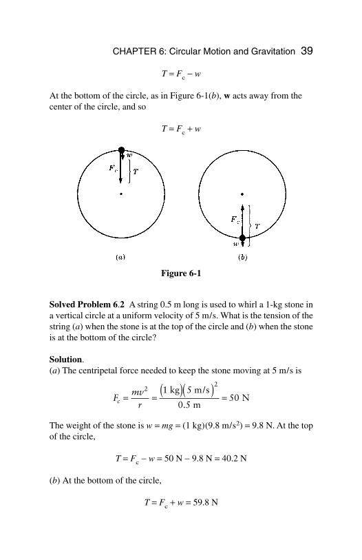
When a body moves in a vertical circle at the end of a string, the tensionT in the string varies with the body’s position. The centripetal force Fcon the body at any point is the vector sum of T and the component of thebody’s weight w toward the center of the circle. At the top of the circle,as in Figure 6-1(a), the weight w and the tension T both act toward thecenter of the circle, and so
kg m / s
m NF
mv
rc = = ( )( )=
2 21000 9
302700
Centripetal force = =Fmv
rc
2
CHAPTER 6: Circular Motion and Gravitation 39
T = Fc − w
At the bottom of the circle, as in Figure 6-1(b), w acts away from thecenter of the circle, and so
T = Fc + w
Solved Problem 6.2 A string 0.5 m long is used to whirl a 1-kg stone ina vertical circle at a uniform velocity of 5 m/s. What is the tension of thestring (a) when the stone is at the top of the circle and (b) when the stoneis at the bottom of the circle?
Solution.(a) The centripetal force needed to keep the stone moving at 5 m/s is
The weight of the stone is w = mg = (1 kg)(9.8 m/s2) = 9.8 N. At the topof the circle,
T = Fc − w = 50 N − 9.8 N = 40.2 N
(b) At the bottom of the circle,
T = Fc + w = 59.8 N
Fmv
rc = =( )( )
=2
21 5
0 550
kg m/s
m N
.
Figure 6-1
40 APPLIED PHYSICS
Gravitation
According to Newton’s law of universal gravitation, every body in theuniverse attracts every other body with a force that is directly propor-tional to each of their masses and inversely proportional to the square ofthe distance between them. In equation form,
where m1 and m2 are the masses of any two bodies, r is the distance be-tween them, and G is a constant whose values in SI and British units are,respectively,
SI units: G = 6.67 × 10⁻¹¹ N m2/kg2
British units: G = 3.34 × 10⁻⁸ lb ft2/slug2
A spherical body behaves gravitationally as though its entire mass wereconcentrated at its center.
Solved Problem 6.3 What gravitational force does a 1000-kg leadsphere exert on an identical sphere 3 m away?
Solution.
This is less than the force that would result from blowing gently on oneof the spheres. Gravitational forces are usually significant only when atleast one of the bodies has a very large mass.
Satellite Motion
Gravitation provides the centripetal forces that keep the planets in theirorbits around the sun and the moon in its orbit around the earth. The sameis true for artificial satellites put into orbit around the earth.
10 N m / kg kg kg
m
10 N
11 2 2
4
F Gm m
rg = =× ⋅( )( )( )
( )= ×
−
−
1 22
3 3
2
6 67 10 10
3
7 4
.
.
Gravitational force = =F Gm m
rg1 2
2
Chapter 7
RotationalMotion
In This Chapter:
Angular Measure Angular Velocity Angular Acceleration Moment of Inertia Torque Rotational Energy and Work Angular Momentum
Angular Measure
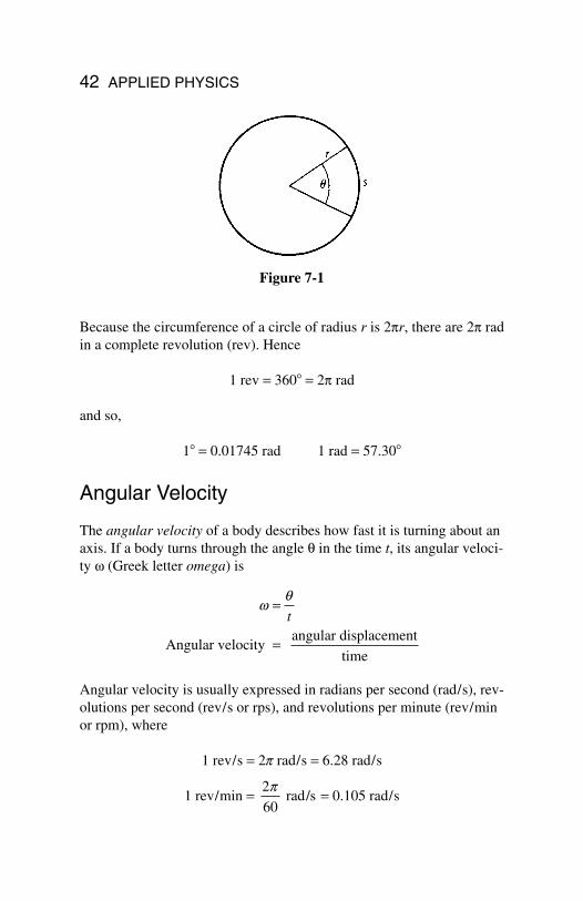
In everyday life, angles are measured in degrees, where360º equals a full turn. A more suitable unit for techni-cal purposes is the radian (rad). If a circle is drawnwhose center is at the vertex of a particular angle (Fig-ure 7-1), the angle q (Greek letter theta) in radians isequal to the ratio between the arc s cut by the angle andthe radius r of the circle:
q =
=
s
r
Angle in radians arc length
radius
41
Copyright 2003 by The McGraw-Hill Companies, Inc. Click Here for Terms of Use.
Because the circumference of a circle of radius r is 2pr, there are 2p radin a complete revolution (rev). Hence
1 rev = 360 = 2p rad
and so,
1 = 0.01745 rad 1 rad = 57.30
Angular Velocity
The angular velocity of a body describes how fast it is turning about anaxis. If a body turns through the angle q in the time t, its angular veloci-ty w (Greek letter omega) is
Angular velocity is usually expressed in radians per second (rad/s), rev-olutions per second (rev/s or rps), and revolutions per minute (rev/minor rpm), where
1 rev/s = 2p rad/s = 6.28 rad/s
1 rev/min = = 0.105 rad/s2
60
p rad/s
wq=
=
t
Angular velocity angular displacement
time
42 APPLIED PHYSICS
Figure 7-1
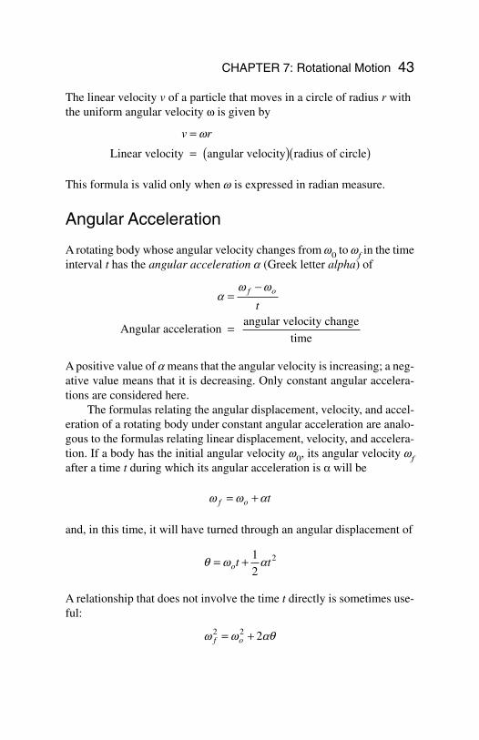
The linear velocity v of a particle that moves in a circle of radius r withthe uniform angular velocity w is given by
This formula is valid only when w is expressed in radian measure.
Angular Acceleration
A rotating body whose angular velocity changes from w0 to wf in the timeinterval t has the angular acceleration a (Greek letter alpha) of
A positive value of a means that the angular velocity is increasing; a neg-ative value means that it is decreasing. Only constant angular accelera-tions are considered here.
The formulas relating the angular displacement, velocity, and accel-eration of a rotating body under constant angular acceleration are analo-gous to the formulas relating linear displacement, velocity, and accelera-tion. If a body has the initial angular velocity w0, its angular velocity wfafter a time t during which its angular acceleration is a will be
and, in this time, it will have turned through an angular displacement of
A relationship that does not involve the time t directly is sometimes use-ful:
w w aqf o2 2 2= +
q w a= +ot t1
22
w w af o t= +
aw w
=−
=
f o
t
Angular acceleration angular velocity change
time
v r=
= ( )( )w
Linear velocity angular velocity radius of circle
CHAPTER 7: Rotational Motion 43
Solved Problem 7.1 A phonograph turntable initially rotating at 3.5 rad/smakes three complete turns before coming to a stop. (a) What is its an-gular acceleration? (b) How much time does it take to come to a stop?
Solution.(a) The angle in radians that corresponds to 3 rev is
q = (3 rev)(2p rad/rev) = 6p rad
From the formula, , we find
(b) Since wf = w0 + at, we have here
Moment of Inertia
The rotational analog of mass is a quantity called moment of inertia. Thegreater the moment of inertia of a body, the greater its resistance to achange in its angular velocity.
You Need to Know
The value of the moment of inertia I of a body abouta particular axis of rotation depends not only uponthe body’s mass but also upon how the mass is dis-tributed about the axis.
Let us imagine a rigid body divided into a great many small particleswhose masses are m1, m2, m3, … and whose distances from the axis ofrotation are respectively r1, r2, r3, … (Figure 7-2).
t f o=−
= −−
=w w
a
0 3 510 8
..
rad/s
0.325 rad /s s2
aw w
q p=
−= − ( )
( )( )= −f o
2 2 2
2
0 3 5
2 60 325
..
rad/s
rad rad/s2
w w aqf o2 2 2= +
44 APPLIED PHYSICS
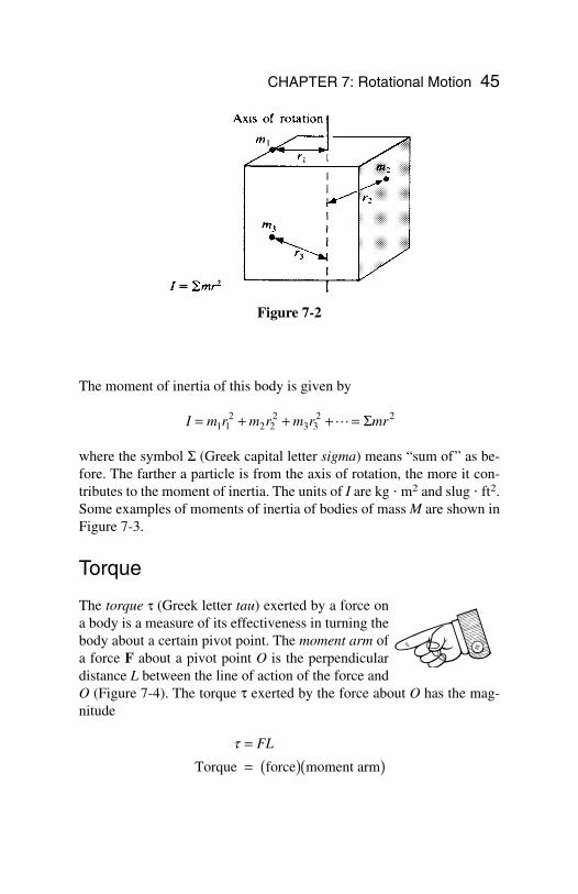
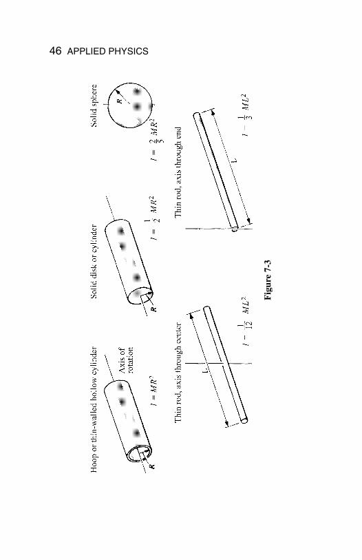
The moment of inertia of this body is given by
where the symbol S (Greek capital letter sigma) means “sum of” as be-fore. The farther a particle is from the axis of rotation, the more it con-tributes to the moment of inertia. The units of I are kg m2 and slug ft2.Some examples of moments of inertia of bodies of mass M are shown inFigure 7-3.
Torque
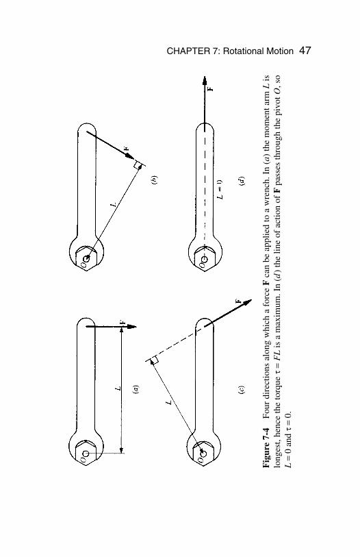
The torque t (Greek letter tau) exerted by a force ona body is a measure of its effectiveness in turning thebody about a certain pivot point. The moment arm ofa force F about a pivot point O is the perpendiculardistance L between the line of action of the force andO (Figure 7-4). The torque τ exerted by the force about O has the mag-nitude
t == ( )( )
FL
Torque force moment arm
I m r m r m r mr= + + + =1 12
2 22
3 32 2L Σ
CHAPTER 7: Rotational Motion 45
Figure 7-2
46 APPLIED PHYSICS
Fig
ure
7-3
CHAPTER 7: Rotational Motion 47
Fig
ure
7-4
Four
dir
ectio
ns a
long
whi
ch a
for
ce F
can
be a
pplie
d to
a w
renc
h. I
n ( a
) th
e m
omen
t arm
Lis
long
est,
henc
e th
e to
rque
t=
FL
is a
max
imum
. In
(d)
the
line
of a
ctio
n of
Fpa
sses
thro
ugh
the
pivo
tO, s
oL
=0
andt
=0.
The torque exerted by a force is also known as the moment of the force.A force whose line of action passes through O produces no torque aboutO because its moment arm is zero.
Torque plays the same role in rotational motion that force plays inlinear motion. A net force F acting on a body of mass m causes it to un-dergo the linear acceleration a in accordance with Newton’s second lawof motion F = ma. Similarly, a net torque t acting on a body of momentof inertia I causes it to undergo the angular acceleration a (in rad/s2) inaccordance with the formula
Remember
In the SI system, the unit of torque isnewton meter (Nm); in the Britishsystem, it is the pound foot (lbft).
Rotational Energy and Work
The kinetic energy of a body of moment of inertia I whose angular ve-locity is w (in rad/s) is
The work done by a constant torque τ that acts on a body while it ex-periences the angular displacement q rad is
W =
= ( ) ( )tq
Work torque angular displacement
KE I=
=
( ) ( )
1
22
2
w
Kinetic energy 1
2moment of inertia angular velocity
t a=
= ( ) ( )I
Torque moment of inertia angular acceleration
48 APPLIED PHYSICS
The rate at which work is being done when a torque τ acts on a bodythat rotates at the constant angular velocity w (rad/s) is
Angular Momentum
The equivalent of linear momentum in rotational motion is angular mo-mentum. The angular momentum L of a rotating body has the magnitude
The greater the angular momentum of a spinning object, such as a top,the greater its tendency to spin.
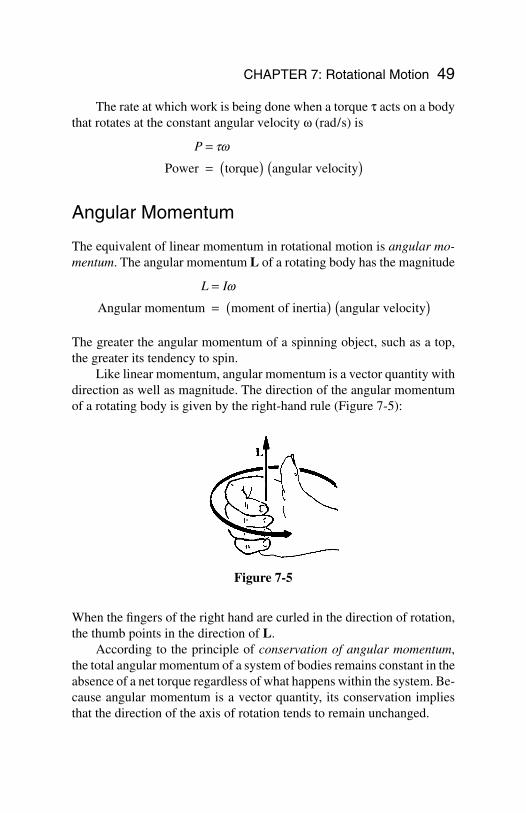
Like linear momentum, angular momentum is a vector quantity withdirection as well as magnitude. The direction of the angular momentumof a rotating body is given by the right-hand rule (Figure 7-5):
L I=
= ( ) ( )w
Angular momentum moment of inertia angular velocity
P =
= ( ) ( )tw
Power torque angular velocity
CHAPTER 7: Rotational Motion 49
Figure 7-5
When the fingers of the right hand are curled in the direction of rotation,the thumb points in the direction of L.
According to the principle of conservation of angular momentum,the total angular momentum of a system of bodies remains constant in theabsence of a net torque regardless of what happens within the system. Be-cause angular momentum is a vector quantity, its conservation impliesthat the direction of the axis of rotation tends to remain unchanged.
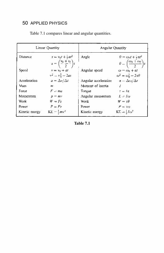
Table 7.1 compares linear and angular quantities.
50 APPLIED PHYSICS
Table 7.1
Chapter 8
Equilibrium
In This Chapter:
Translational Equilibrium Rotational Equilibrium Center of Gravity Finding a Center of Gravity
Translational Equilibrium
A body is in translational equilibrium when no netforce acts on it. Such a body is not accelerated, and itremains either at rest or in motion at constant veloci-ty along a straight line, whichever its initial state was.
A body in translational equilibrium may haveforces acting on it, but they must be such that theirvector sum is zero. Thus the condition for the transla-tional equilibrium of a body may be written
SF = 0
where the symbol S (Greek capital letter sigma) means “sum of” and Frefers to the various forces that act on the body.
The procedure for working out a problem that involves translationalequilibrium has three steps:
51
Copyright 2003 by The McGraw-Hill Companies, Inc. Click Here for Terms of Use.
1. Draw a diagram of the forces that act on the body. This is calleda free-body diagram.
2. Choose a set of coordinate axes and resolve the various forcesinto their components along these axes.
3. Set the sum of the force components along each axis equal tozero so that
Sum of x force components = SFx = 0Sum of y force components = SFy = 0Sum of z force components = SFz = 0
In this way, the vector equation SF = 0 is replaced by three scalarequations. Then solve the resulting equations for the unknown quantities.
A proper choice of directions for the axes often simplifies the calcu-lations. When all the forces lie in a plane, for instance, the coordinate sys-tem can be chosen so that the x and y axes lie in the plane; then the twoequations SFx = 0 and SFy = 0 are enough to express the condition fortranslational equilibrium.
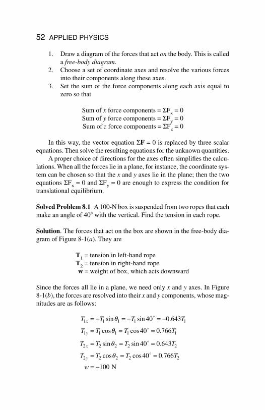
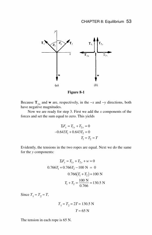
Solved Problem 8.1 A 100-N box is suspended from two ropes that eachmake an angle of 40 with the vertical. Find the tension in each rope.
Solution. The forces that act on the box are shown in the free-body dia-gram of Figure 8-1(a). They are
T1 = tension in left-hand ropeT2 = tension in right-hand ropew = weight of box, which acts downward
Since the forces all lie in a plane, we need only x and y axes. In Figure 8-1(b), the forces are resolved into their x and y components, whose mag-nitudes are as follows:
T T T T
T T T T
T T T T
T T T T
w
x
y
x
y
1 1 1 1 1
1 1 1 1 1
2 2 2 2 2
2 2 2 2 2
40 0 643
40 0 766
40 0 643
40 0 766
100
= − = − = −
= = =
= = =
= = =
= −
sin sin .
cos cos .
sin sin .
cos cos .
q
q
q
q
o
o
o
o
N
52 APPLIED PHYSICS
Because T1x and w are, respectively, in the −x and −y directions, bothhave negative magnitudes.
Now we are ready for step 3. First we add the x components of theforces and set the sum equal to zero. This yields
Evidently, the tensions in the two ropes are equal. Next we do the samefor the y components:
Since T1 = T2 = T,
T1 = T2 = 2T = 130.5 N
T = 65 N
The tension in each rope is 65 N.
ΣF T T w
T T
T
T
y y y= + + =
+ − =
+( ) =
+ = =
1 2
1 2
2
2
0
0 766 0 766 100
100
100130 5
. .
.
N 0
0.766 N
N
0.766 N
1
1
T
T
ΣF T T
T T
T T T
x x x= + =− + =
= =
1 2
1 2
1 2
0
0 643 0 643 0. .
CHAPTER 8: Equilibrium 53
Figure 8-1
Rotational Equilibrium
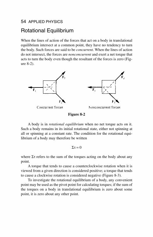
When the lines of action of the forces that act on a body in translationalequilibrium intersect at a common point, they have no tendency to turnthe body. Such forces are said to be concurrent. When the lines of actiondo not intersect, the forces are nonconcurrent and exert a net torque thatacts to turn the body even though the resultant of the forces is zero (Fig-ure 8-2).
A body is in rotational equilibrium when no net torque acts on it.Such a body remains in its initial rotational state, either not spinning atall or spinning at a constant rate. The condition for the rotational equi-librium of a body may therefore be written
St = 0
where St refers to the sum of the torques acting on the body about anypoint.
A torque that tends to cause a counterclockwise rotation when it isviewed from a given direction is considered positive; a torque that tendsto cause a clockwise rotation is considered negative (Figure 8-3).
To investigate the rotational equilibrium of a body, any convenientpoint may be used as the pivot point for calculating torques; if the sum ofthe torques on a body in translational equilibrium is zero about somepoint, it is zero about any other point.
54 APPLIED PHYSICS
Figure 8-2
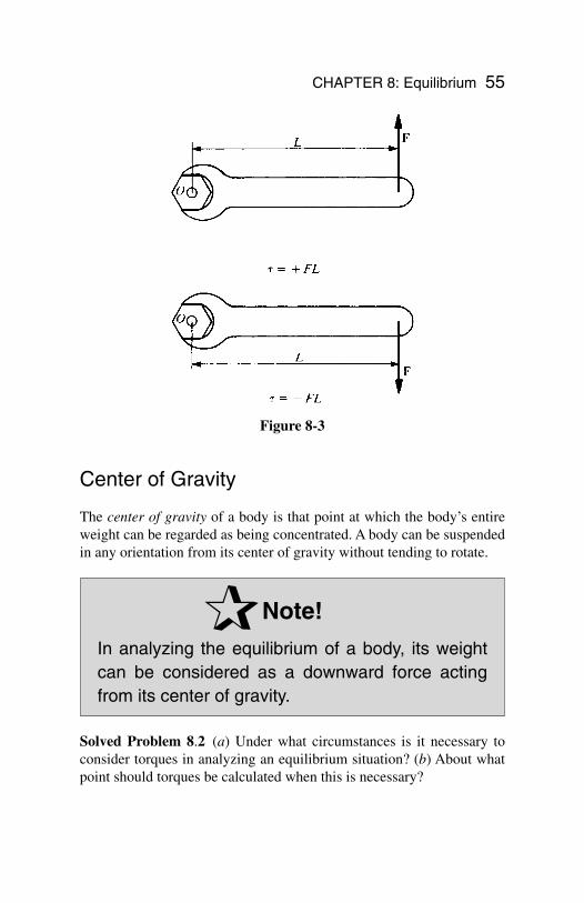
Center of Gravity
The center of gravity of a body is that point at which the body’s entireweight can be regarded as being concentrated. A body can be suspendedin any orientation from its center of gravity without tending to rotate.
Note!
In analyzing the equilibrium of a body, its weightcan be considered as a downward force actingfrom its center of gravity.
Solved Problem 8.2 (a) Under what circumstances is it necessary toconsider torques in analyzing an equilibrium situation? (b) About whatpoint should torques be calculated when this is necessary?
CHAPTER 8: Equilibrium 55
Figure 8-3
Solution. (a) Torques must be considered when the various forces thatact on the body are nonconcurrent, that is, when their lines of action donot intersect at a common point. (b) Torques may be calculated about anypoint whatever for the purpose of determining the equilibrium of thebody. Hence it makes sense to use a point that minimizes the labor in-volved, which usually is the point through which pass the maximum num-ber of lines of action of the various forces; this is because a force whoseline of action passes through a point exerts no torque about that point.
Finding a Center of Gravity
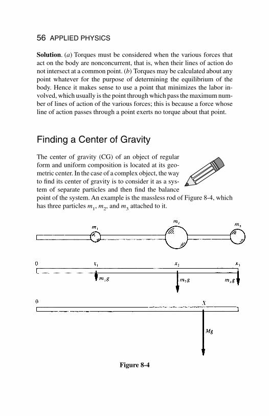
The center of gravity (CG) of an object of regularform and uniform composition is located at its geo-metric center. In the case of a complex object, the wayto find its center of gravity is to consider it as a sys-tem of separate particles and then find the balancepoint of the system. An example is the massless rod of Figure 8-4, whichhas three particles m1, m2, and m3 attached to it.
56 APPLIED PHYSICS
Figure 8-4
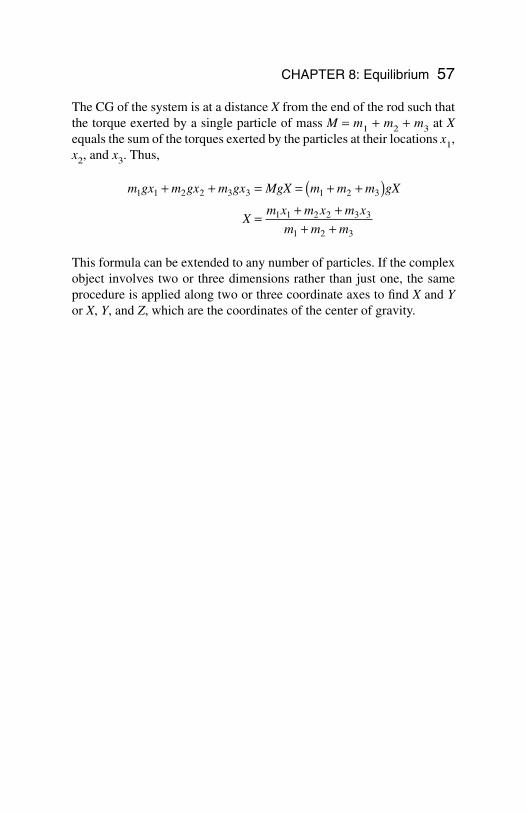
The CG of the system is at a distance X from the end of the rod such thatthe torque exerted by a single particle of mass M = m1 + m2 + m3 at Xequals the sum of the torques exerted by the particles at their locations x1,x2, and x3. Thus,
This formula can be extended to any number of particles. If the complexobject involves two or three dimensions rather than just one, the sameprocedure is applied along two or three coordinate axes to find X and Yor X, Y, and Z, which are the coordinates of the center of gravity.
m gx m gx m gx MgX m m m gX
Xm x m x m x
m m m
1 1 2 2 3 3 1 2 3
1 1 2 2 3 3
1 2 3
+ + = = + +( )= + +
+ +
CHAPTER 8: Equilibrium 57
Chapter 9
SimpleHarmonicMotion
In This Chapter:
Restoring Force Elastic Potential Energy Simple Harmonic Motion Period and Frequency Displacement, Velocity,
and Acceleration Pendulums
Restoring Force
When an elastic object such as a spring is stretched orcompressed, a restoring force appears that tries to re-turn the object to its normal length. It is this restoringforce that must be overcome by the applied force inorder to deform the object. From Hooke’s law, therestoring force Fr is proportional to the displacements provided the elastic limit is not exceeded. Hence
58
Copyright 2003 by The McGraw-Hill Companies, Inc. Click Here for Terms of Use.
The minus sign is required because the restoring force acts in the oppo-site direction to the displacement. The greater the value of the force con-stant k, the greater the restoring force for a given displacement and thegreater the applied force F = ks needed to produce the displacement.
Elastic Potential Energy
Because work must be done by an applied force to stretch or compress anobject, the object has elastic potential energy, where
When a deformed elastic object is released, its elastic potential energyturns into kinetic energy or into work done on something else.
Solved Problem 9.1 A force of 5 N compresses a spring by 4 cm. (a)Find the force constant of the spring. (b) Find the elastic potential ener-gy of the compressed spring.
Solution.
(a)
(b)
Simple Harmonic Motion
In periodic motion, a body repeats a certain motion indefinitely, alwaysreturning to its starting point after a constant time interval and then start-ing a new cycle. Simple harmonic motion is periodic motion that occurswhen the restoring force on a body displaced from an equilibrium posi-tion is proportional to the displacement and in the opposite direction. Amass m attached to a spring executes simple harmonic motion when thespring is pulled out and released. The spring’s PE becomes KE as the
PE ks= =
=1
2
1
2125 0 04 0 12 2( . . N/m)( m) J
kF
s= = =5
125 N
0.04 m N/m
PE ks= 1
22
F ksr = −= −Restoring force force constant) (displacement)(
CHAPTER 9: Simple Harmonic Motion 59
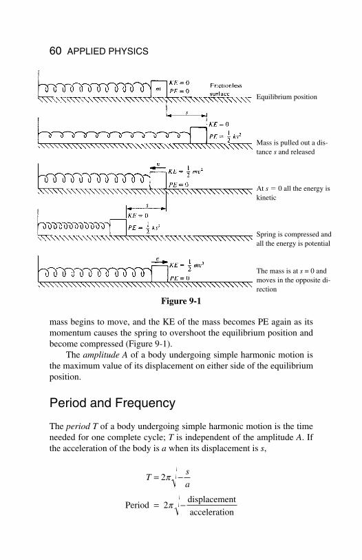
mass begins to move, and the KE of the mass becomes PE again as itsmomentum causes the spring to overshoot the equilibrium position andbecome compressed (Figure 9-1).
The amplitude A of a body undergoing simple harmonic motion isthe maximum value of its displacement on either side of the equilibriumposition.
Period and Frequency
The period T of a body undergoing simple harmonic motion is the timeneeded for one complete cycle; T is independent of the amplitude A. Ifthe acceleration of the body is a when its displacement is s,
Ts
a= −
= −
2p
pPeriod 2displacement
acceleration
60 APPLIED PHYSICS
Figure 9-1
Equilibrium position
Mass is pulled out a dis-tance s and released
At s 0 all the energy iskinetic
Spring is compressed andall the energy is potential
The mass is at s = 0 andmoves in the opposite di-rection
In the case of a body of mass m attached to a spring of force constant k,Fr = −ks = ma, and so −s/a = m/k. Hence
stretched spring
The frequency f of a body undergoing simple harmonic motion is thenumber of cycles per second it executes, so that
The unit of frequency is the hertz (Hz), where 1 Hz = 1 cycle/s.
Displacement, Velocity, and Acceleration
If t = 0 when a body undergoing simple harmonic motion is in its equi-librium position of s = 0 and is moving in the direction of increasing s,then at any time t thereafter its displacement is
s = A sin 2pft
Often, this formula is written
s = A sin wt
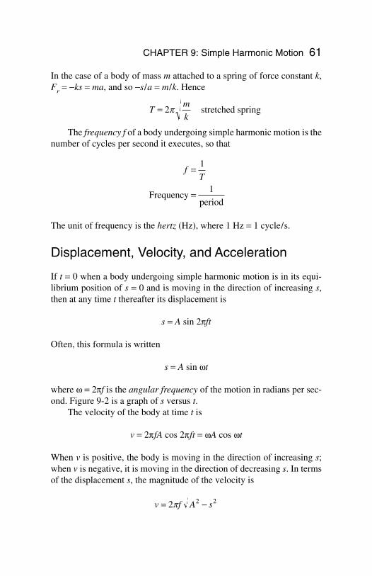
where w = 2pf is the angular frequency of the motion in radians per sec-ond. Figure 9-2 is a graph of s versus t.
The velocity of the body at time t is
v = 2pfA cos 2pft = wA cos wt
When v is positive, the body is moving in the direction of increasing s;when v is negative, it is moving in the direction of decreasing s. In termsof the displacement s, the magnitude of the velocity is
v f A s= −2 2 2p
fT
=
=
1
Frequency1
period
Tm
k= 2p
CHAPTER 9: Simple Harmonic Motion 61
The acceleration of the body at time t is
a = −4p2f 2A sin 2pft = − w2A sin wt
In terms of the displacement s, the acceleration is
a = 4p2f 2s
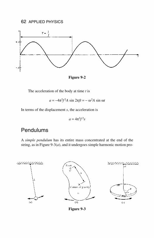
Pendulums
A simple pendulum has its entire mass concentrated at the end of thestring, as in Figure 9-3(a), and it undergoes simple harmonic motion pro-
62 APPLIED PHYSICS
Figure 9-2
Figure 9-3
vided that the arc through which it travels is only a few degrees. The pe-riod of a simple pendulum of length L is
simple pendulum
The physical pendulum of Figure 9-3(b) is an object of any kindwhich is pivoted so that it can oscillate freely. If the moment of inertia ofthe object about the pivot O is I, its mass is m, and the distance from itscenter of gravity to the pivot is h, then its period is
physical pendulum
A torsion pendulum consists of an object suspended by a wire or thinrod, as in Figure 9-3(c), which undergoes rotational simple harmonic os-cillations. From Hooke’s law, the torque t needed to twist the objectthrough an angle q is
t = Kq
provided the elastic limit is not exceeded, where K is a constant that de-pends on the material and dimensions of the wire. If I is the moment ofinertia of the object about its point of suspension, the period of the oscil-lation is
torsion pendulum
Solved Problem 9.2 A lamp is suspended from a high ceiling with a cord12 ft long. Find its period of oscillation.
Solution.
TL
g= = =2 2
12
323 85p p
ft
ft / s s2 .
TI
K= 2p
TI
mgh= 2p
TL
g= 2p
CHAPTER 9: Simple Harmonic Motion 63
Chapter 10
Waves and Sound
In This Chapter:
Waves Wave Properties Logarithms Sound Doppler Effect
Waves
A wave is, in general, a disturbance that movesthrough a medium. An exception is an electromagnet-ic wave, which can travel through a vacuum. Exam-ples are light and radio waves. A wave carries energy,but there is no transport of matter. In a periodic wave,pulses of the same kind follow one another in regularsuccession.
In a transverse wave, the particles of the medium move back andforth perpendicular to the direction of the wave. Waves that travel downa stretched string when one end is shaken are transverse (Figure 10-1).
In a longitudinal wave, the particles of the medium move back andforth in the same direction as the wave. Waves that travel down a coilspring when one end is pulled out and released are longitudinal (Figure10-2). Sound waves are also longitudinal.
64
Copyright 2003 by The McGraw-Hill Companies, Inc. Click Here for Terms of Use.
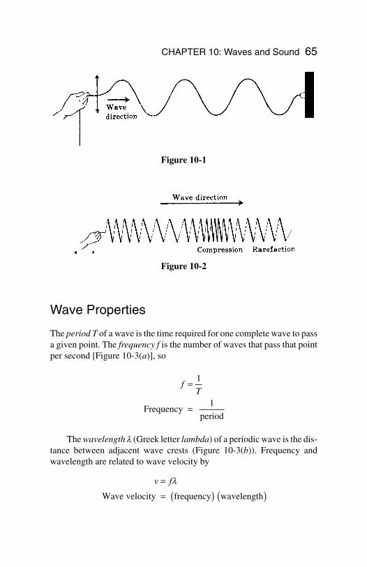
Wave Properties
The period T of a wave is the time required for one complete wave to passa given point. The frequency f is the number of waves that pass that pointper second [Figure 10-3(a)], so
The wavelength l (Greek letter lambda) of a periodic wave is the dis-tance between adjacent wave crests (Figure 10-3(b)). Frequency andwavelength are related to wave velocity by
v f=
= ( ) ( )l
Wave velocity frequency wavelength
fT
=
=
1
Frequency1
period
CHAPTER 10: Waves and Sound 65
Figure 10-1
Figure 10-2
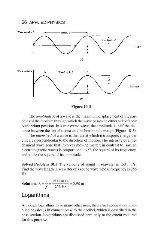
The amplitude A of a wave is the maximum displacement of the par-ticles of the medium through which the wave passes on either side of theirequilibrium position. In a transverse wave, the amplitude is half the dis-tance between the top of a crest and the bottom of a trough (Figure 10-3).
The intensity I of a wave is the rate at which it transports energy perunit area perpendicular to the direction of motion. The intensity of a me-chanical wave (one that involves moving matter, in contrast to, say, anelectromagnetic wave) is proportional to f 2, the square of its frequency,and, to A2 the square of its amplitude.
Solved Problem 10.1 The velocity of sound in seawater is 1531 m/s.Find the wavelength in seawater of a sound wave whose frequency is 256Hz.
Solution.
Logarithms
Although logarithms have many other uses, their chief application in ap-plied physics is in connection with the decibel, which is described in thenext section. Logarithms are discussed here only to the extent requiredfor this purpose.
l = = =v
f
15315 98
m / s
256 Hz m.
66 APPLIED PHYSICS
Figure 10-3
The logarithm of a number N is the power n to which 10 must beraised in order that 10n = N. That is,
N = 10n therefore log N = n
(Logarithms are not limited to a base of 10, but base-10 logarithms arethe most common and are all that are needed here.) For instance,
1000 = 103 therefore log 1000 = 30.01 = 10−2 therefore log 0.01 = −2
To find the logarithm of a number with a calculator, enter the value of thenumber and press the LOG button.
The antilogarithm of a quantity n is the number N whose logarithmit is. That is,
If log N = n then antilog n = N
To find the antilogarithm with a calculator, enter the value of the loga-rithm and press the INV LOG button.
Because of the way logarithms are defined, the logarithm of a prod-uct equals the sum of the logarithms of the factors:
log xy = log x + log y
Other useful relations are
Sound
Sound waves are longitudinal waves in which al-ternate regions of compression and rarefactionmove away from a source. Sound waves can trav-el through solids, liquids, and gases. The velocityof sound is a constant for a given material at a giv-
log log log
log log
x
yx y
x n xn
= −
=
CHAPTER 10: Waves and Sound 67
en pressure and temperature; in air at 1-atm pressure and 20 C, it is 343m/s = 1125 ft/s.
When sound waves spread out uniformly in space, their intensity de-creases inversely with the square of the distance R from their source.Thus, if the intensity of a certain sound is I1 at the distance R1, its inten-sity I2 at the distance R2 can be found from
The response of the human ear to sound intensity is not proportion-al to the intensity, so doubling the actual intensity of a certain sound doesnot lead to the sensation of a sound twice as loud but only of one that isslightly louder than the original. For this reason, the decibel (dB) scale isused for sound intensity.
An intensity of 10−12 W/m2, which is just audible, is given the val-ue 0 dB; a sound 10 times more intense is given the value 10 dB; a sound102 times more intense than 0 dB is given the value of 20 dB; a sound 103
times more intense than 0 dB is given the value of 30 dB; and so forth.More formally, the intensity I dB of a sound wave whose intensity is IW/m2 is given by
where I0 = 10−12 W/m2. Normal conversation might be 60 dB, city traf-fic noise might be 90 dB, and a jet aircraft might produce as much as 140dB (which produces damage to the ear) at a distance of 100 ft. Long-termexposure to intensity levels of over 85 dB usually leads to permanenthearing damage.
Solved Problem 10.2 How many times more intense is a 50-dB soundthan a 40-dB sound? Than a 20-dB sound?
Solution. Each interval of 10 dB represents a change in sound intensityby a factor of 10. Hence a 50-dB sound is 10 times more intense than a40-dB sound and 10 × 10 × 10 = 1000 times more intense than a 20-dBsound.
II
Io
dB 10 log =
I
I
R
R2
1
12
22=
68 APPLIED PHYSICS
Doppler Effect
When there is relative motion between a source of waves and an observ-er, the apparent frequency of the waves is different from their frequencyfS at the source. This change in frequency is called the Doppler effect.When the source approaches the observer (or vice versa), the observedfrequency is higher; when the source recedes from the observer (or viceversa), the observed frequency is lower. In the case of sound waves, thefrequency f that a listener hears is given by
sound
In this formula, v is the velocity of sound, vL is the velocity of the listen-er (considered positive for motion toward the source and negative for mo-tion away from the source), and vS is the velocity of the source (consid-ered positive for motion toward the listener and negative for motion awayfrom the listener).
The Doppler effect in electromagnetic waves (light and radio wavesare examples) obeys the formula
electromagnetic waves
Here c is the velocity of light (3.00 × 10⁸ m/s), and v is the relative ve-locity between source and observer (considered positive if they are ap-proaching and negative if they are receding).
Interesting!
Astronomers use the Doppler effect in light to de-termine the motion of stars; police use the effect inradar waves to determine vehicle velocities.
f fv c
v cS= + ( )− ( )
1
1
1 2/
/
/
f fv v
v vSL
S
= +−
CHAPTER 10: Waves and Sound 69

Chapter 11
Electricity
In This Chapter:
Electric Charge Atoms and Ions Coulomb’s Law Electric Field Electric Field Lines Potential Difference
Electric Charge
Electric charge, like mass, is one of the basic prop-erties of certain elementary particles of which allmatter is composed. There are two kinds of charge,positive charge and negative charge. The positivecharge in ordinary matter is carried by protons, thenegative charge by electrons. Charges of the samesign repel each other, charges of opposite sign attracteach other.
The unit of charge is the coulomb (C). The charge of the proton is+1.6 × 10⁻¹⁹ C, and the charge of the electron is −1.6 × 10⁻¹⁹ C. Allcharges occur in multiples of ±e = ±1.6 × 10⁻¹⁹ C.
According to the principle of conservation of charge, the net electriccharge in an isolated system always remains constant. (Net charge means
70
Copyright 2003 by The McGraw-Hill Companies, Inc. Click Here for Terms of Use.
the total positive charge minus the total negative charge.) When matter iscreated from energy, equal amounts of positive and negative charge al-ways come into being, and when matter is converted to energy, equalamounts of positive and negative charge disappear.
Atoms and Ions
An atom of any element consists of a small, positively charged nucleuswith a number of electrons some distance away. The nucleus is composedof protons (charge +e, mass = 1.673 × 10⁻²⁷ kg) and neutrons (uncharged,mass = 1.675 × 10⁻²⁷ kg). The number of protons in the nucleus is nor-mally equal to the number of electrons around it, so the atom as a wholeis electrically neutral. The forces between atoms that hold them togetheras solids and liquids are electric in origin. The mass of the electron is 9.1× 10⁻³¹ kg.
Under certain circumstances, an atom may lose one or more elec-trons and become a positive ion or it may gain one or more electrons andbecome a negative ion. Many solids consist of positive and negative ionsrather than of atoms or molecules. An example is ordinary table salt,which is made up of positive sodium ions (Na+) and negative chlorineions (Cl−).
Coulomb’s Law
The force one charge exerts on another is given by Coulomb’s law:
where q1 and q2 are the magnitudes of the charges, r is the distance be-tween them, and k is a constant whose value in free space is
k = 9.0 × 10⁹ Nm2/C2
The value of k in air is slightly greater. The constant k is sometimes re-placed by
ko
= 1
4pe
Electric force = =F kq q
r1 2
2
CHAPTER 11: Electricity 71
where ε0, the permittivity of free space, has the value
ε0 = 8.85 × 10⁻¹² C2/Nm2
(ε is the Greek letter epsilon.)
Solved Problem 11.1 Two charges, one of +5 × 10⁻⁷ C and the other −2 × 10⁻⁷ C, attract each other with a force of −100 N. How far apart arethey?
Solution. From Coulomb’s law, we have
Electric Field
An electric field is a region of space in which a charge would be actedupon by an electric force. An electric field may be produced by one ormore charges, and it may be uniform or it may vary in magnitude and/ordirection from place to place.
If a charge q at a certain point is acted on by the force F, the electricfield E at that point is defined as the ratio between F and q:
Electric field is a vector quantity whose direction is that of the force on apositive charge. The unit of E is the newton per coulomb (N/C) or, morecommonly, the equivalent unit volt per meter (V/m).
The advantage of knowing the electric field at some point is that wecan at once establish the force on any charge q placed there, which is
F E
Force charge electric field
=
= ( ) ( )q
EF
Electric field force
charge
=
=
q
rkq q
F= =
× ⋅( ) ×( ) − ×( )−
= × =
− −
−
1 29 7 79 10 5 10 2 10
100
N m / C C C
N
90 10 m 3 mm
2 2
7 2
72 APPLIED PHYSICS
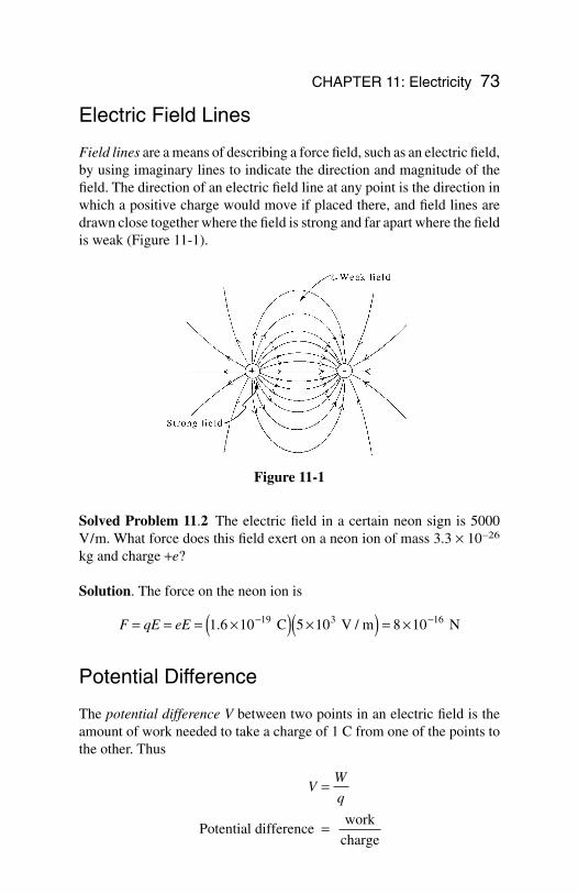
Electric Field Lines
Field lines are a means of describing a force field, such as an electric field,by using imaginary lines to indicate the direction and magnitude of thefield. The direction of an electric field line at any point is the direction inwhich a positive charge would move if placed there, and field lines aredrawn close together where the field is strong and far apart where the fieldis weak (Figure 11-1).
Solved Problem 11.2 The electric field in a certain neon sign is 5000 V/m. What force does this field exert on a neon ion of mass 3.3 × 10⁻²⁶
kg and charge +e?
Solution. The force on the neon ion is
Potential Difference
The potential difference V between two points in an electric field is theamount of work needed to take a charge of 1 C from one of the points tothe other. Thus
VW
q=
=Potential difference work
charge
F qE eE= = = ×( ) ×( ) = ×− −1 6 10 5 10 8 1019 3 16. C V / m N
CHAPTER 11: Electricity 73
Figure 11-1
The unit of potential difference is the volt (V):
The potential difference between two points in a uniform electricfield E is equal to the product of E and the distance s between the pointsin a direction parallel to E:
V = Es
Since an electric field is usually produced by applying a potential differ-ence between two metal plates s apart, this equation is most useful in theform
You Need to Know
A battery uses chemical reactions to produce a po-tential difference between its terminals; a genera-tor uses electromagnetic induction for this pur-pose.
Solved Problem 11.3 The potential difference between a certain thun-dercloud and the ground is 7 × 10⁶ V. Find the energy dissipated when acharge of 50 C is transferred from the cloud to the ground in a lightningstroke.
Solution. The energy is
W qV= = ( ) ×( ) = ×5 7 10 3 5 106 80 C V J.
EV
s=
=Electric field potential difference
distance
1 volt 1 joule
coulomb=
74 APPLIED PHYSICS
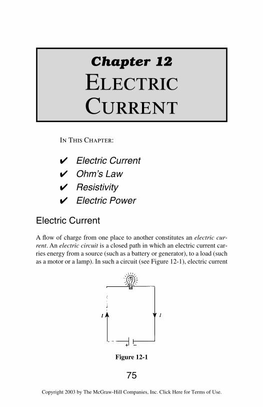
Chapter 12
ElectricCurrent
In This Chapter:
Electric Current Ohm’s Law Resistivity Electric Power
Electric Current
A flow of charge from one place to another constitutes an electric cur-rent. An electric circuit is a closed path in which an electric current car-ries energy from a source (such as a battery or generator), to a load (suchas a motor or a lamp). In such a circuit (see Figure 12-1), electric current
75
Figure 12-1
Copyright 2003 by The McGraw-Hill Companies, Inc. Click Here for Terms of Use.
is assumed to go from the positive terminal of the battery (or generator)through the circuit and back to the negative terminal of the battery. Thedirection of the current is conventionally considered to be that in whicha positive charge would have to move to produce the same effects as theactual current. Thus a current is always supposed to go from the positiveterminal of a battery to its negative terminal.
A conductor is a substance through which charge can flow easily, andan insulator is one through which charge can flow only with great diffi-culty. Metals, many liquids, and plasmas (gases whose molecules arecharged) are conductors; nonmetallic solids, certain liquids, and gaseswhose molecules are electrically neutral are insulators.
Note!
A number of substances, called semiconductors,are intermediate in their ability to conduct charge.
Electric currents in metal wires always consist of flows of electrons;such currents are assumed to occur in the direction opposite to that inwhich the electrons move. Since a positive charge going one way is, formost purposes, equivalent to a negative charge going the other way, thisassumption makes no practical difference. Both positive and negativecharges move when a current is present in a liquid or gaseous conductor.
If an amount of charge q passes a given point in a conductor in thetime interval t, the current in the conductor is
The unit of electric current is the ampere (A), where
1 ampere 1 coulomb
second=
Iq
t=
=Electric current charge
time interval
76 APPLIED PHYSICS
Ohm’s Law
For a current to exist in a conductor, there must be apotential difference between its ends, just as a dif-ference in height between source and outlet is neces-sary for a river current to exist. In the case of a metal-lic conductor, the current is proportional to theapplied potential difference: Doubling V causes I to double, tripling Vcauses I to triple, and so forth. This relationship is known as Ohm’s lawand is expressed in the form
The quantity R is a constant for a given conductor and is called its resis-tance. The unit of resistance is the ohm (W), where
The greater the resistance of a conductor, the less the current when a cer-tain potential difference is applied.
Ohm’s law is not a physical principle but is an experimental rela-tionship that most metals obey over a wide range of values of V and I.
Solved Problem 12.1 A 120-V electric heater draws a current of 25 A.What is its resistance?
Solution.
Resistivity
The resistance of a conductor that obeys Ohm’s law is given by
RL
A= r
RV
I= = =120
4 8 V
25 A A.
1 ohm 1 volt
ampere=
IV
R=
=Electric current potential difference
resistance
CHAPTER 12: Electric Current 77
where L is the length of the conductor, A is the cross-sectional area, andr (Greek letter rho), is the resistivity of the material of the conductor. InSI, the unit of resistivity is the ohm-meter.
The resistivities of most materials vary with temperature. If R is theresistance of a conductor at a particular temperature, then the change inits resistance DR when the temperature changes by DT is approximatelyproportional to both R and DT so that
DR = aRDT
The quantity a is the temperature coefficient of resistance of the materi-al.
Electric Power
The rate at which work is done to maintain an electric current is given bythe product of the current I and the potential difference V:
When I is in amperes and V is in volts, P will be in watts.If the conductor or device through which a current passes obeys
Ohm’s law, the power consumed may be expressed in the alternativeforms
Table 12.1 is a summary of the various formulas for potential differenceV, current I, resistance R, and power P that follow from Ohm’s law I =V/R and from the power formula P = VI.
Solved Problem 12.2 The current through a 50-W resistance is 2 A. Howmuch power is dissipated as heat?
Solution. P I R= = ( ) ( ) =2 22 50 A 200 WΩ
P IV I RV
R= = =2
2
P IV=
= ( ) ( )Power current potential difference
78 APPLIED PHYSICS
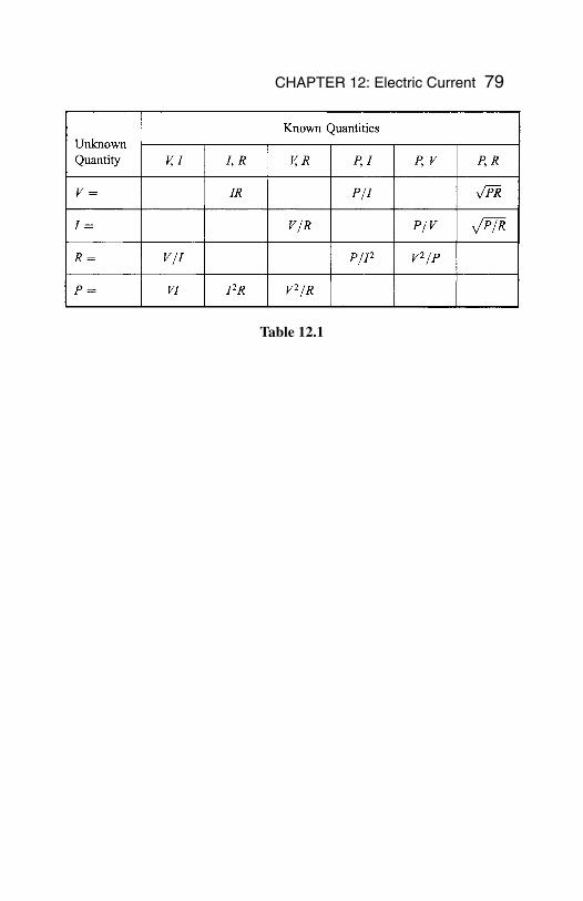
Table 12.1
CHAPTER 12: Electric Current 79
In This Chapter:
Resistors in Series Resistors in Parallel EMF and Internal Resistance Kirchhoff ’s Rules
Resistors in Series
The equivalent resistance of a set of resistors depends on the way in whichthey are connected as well as on their values. If the resistors are joined inseries, that is, consecutively (Figure 13-1), the equivalent resistance R ofthe combination is the sum of the individual resistances:
series resistors
Resistors in Parallel
In a parallel set of resistors, the corresponding terminals of the resistorsare connected (Figure 13-2). The reciprocal 1/R of the equivalent resis-tance of the combination is the sum of the reciprocals of the individualresistances:
R R R R= + + +1 2 3 L
80
Chapter 13
Direct-CurrentCircuits
Copyright 2003 by The McGraw-Hill Companies, Inc. Click Here for Terms of Use.
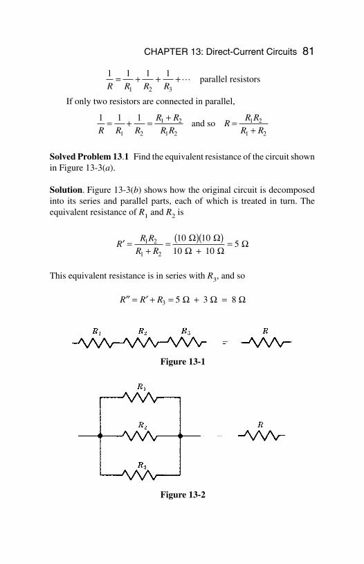
CHAPTER 13: Direct-Current Circuits 81
parallel resistors
If only two resistors are connected in parallel,
and so
Solved Problem 13.1 Find the equivalent resistance of the circuit shownin Figure 13-3(a).
Solution. Figure 13-3(b) shows how the original circuit is decomposedinto its series and parallel parts, each of which is treated in turn. Theequivalent resistance of R1 and R2 is
This equivalent resistance is in series with R3, and so
′′ = ′ + = + =R R R3 5 3 8 Ω Ω Ω
′ =+
= ( )( )+
=RR R
R R1 2
1 2
10 10
10 105
Ω ΩΩ Ω
Ω
RR R
R R=
+1 2
1 2
1 1 1
1 2
1 2
1 2R R R
R R
R R= + = +
1 1 1 1
1 2 3R R R R= + + +L
Figure 13-1
Figure 13-2
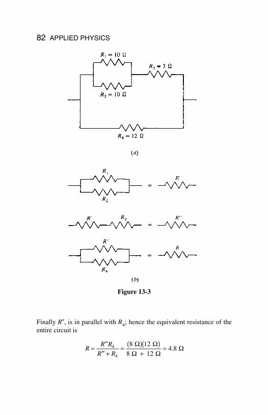
82 APPLIED PHYSICS
Finally R, is in parallel with R4; hence the equivalent resistance of theentire circuit is
RR R
R R= ′′
′′ += ( )( )
+=4
4
8 12
8 124 8
Ω ΩΩ Ω
Ω.
Figure 13-3
CHAPTER 13: Direct-Current Circuits 83
EMF and Internal Resistance
The work done per coulomb on the charge passing through a battery, gen-erator, or other source of electric energy is called the electromotive force,or emf, of the source. The emf is equal to the potential difference acrossthe terminals of the source when no current flows. When a current I flows,this potential difference is less than the emf because of the internal re-sistance of the source. If the internal resistance is r, then a potential dropof Ir occurs within the source. The terminal voltage V across a source ofemf Ve whose internal resistance is r when it provides a current of I istherefore
When a battery or generator of emf Ve is connected to an external re-sistance R, the total resistance in the circuit is R + r, and the current thatflows is
Kirchhoff ’s Rules
The current that flows in each branch of a complex circuit can be foundby applying Kirchhoff ’s rules to the circuit. The first rule applies to junc-tions of three or more wires (Figure 13-4) and is a consequence of con-servation of charge. The second rule applies to loops, which are closedconducting paths in the circuit, and is a consequence of conservation ofenergy. The rules are:
1. The sum of the currents that flow into a junction is equal to thesum of the currents that flow out of the junction.
2. The sum of the emfs around a loop is equal to the sum of the IRpotential drops around the loop.
IV
R re=+
=+
Currentemf
external resistance internal resistance
V V Ire= −= −Terminal voltage emf potential drop due to internal resistance
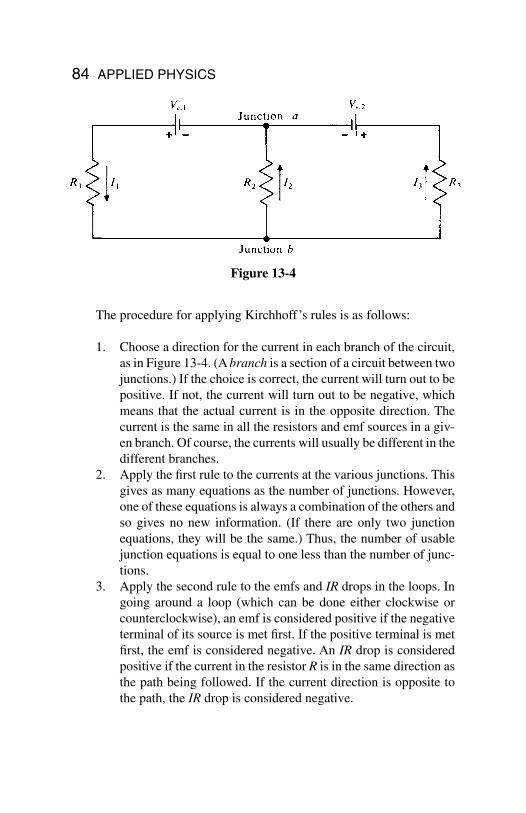
84 APPLIED PHYSICS
The procedure for applying Kirchhoff’s rules is as follows:
1. Choose a direction for the current in each branch of the circuit,as in Figure 13-4. (A branch is a section of a circuit between twojunctions.) If the choice is correct, the current will turn out to bepositive. If not, the current will turn out to be negative, whichmeans that the actual current is in the opposite direction. Thecurrent is the same in all the resistors and emf sources in a giv-en branch. Of course, the currents will usually be different in thedifferent branches.
2. Apply the first rule to the currents at the various junctions. Thisgives as many equations as the number of junctions. However,one of these equations is always a combination of the others andso gives no new information. (If there are only two junctionequations, they will be the same.) Thus, the number of usablejunction equations is equal to one less than the number of junc-tions.
3. Apply the second rule to the emfs and IR drops in the loops. Ingoing around a loop (which can be done either clockwise orcounterclockwise), an emf is considered positive if the negativeterminal of its source is met first. If the positive terminal is metfirst, the emf is considered negative. An IR drop is consideredpositive if the current in the resistor R is in the same direction asthe path being followed. If the current direction is opposite tothe path, the IR drop is considered negative.
Figure 13-4
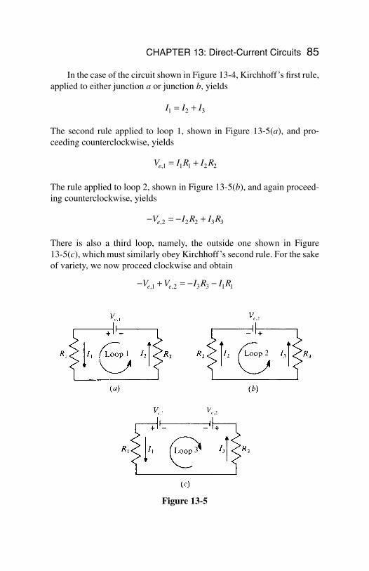
CHAPTER 13: Direct-Current Circuits 85
In the case of the circuit shown in Figure 13-4, Kirchhoff’s first rule,applied to either junction a or junction b, yields
The second rule applied to loop 1, shown in Figure 13-5(a), and pro-ceeding counterclockwise, yields
The rule applied to loop 2, shown in Figure 13-5(b), and again proceed-ing counterclockwise, yields
There is also a third loop, namely, the outside one shown in Figure 13-5(c), which must similarly obey Kirchhoff’s second rule. For the sakeof variety, we now proceed clockwise and obtain
− + = − −V V I R I Re e, ,1 2 3 3 1 1
− = − +V I R I Re,2 2 2 3 3
V I R I Re,1 1 1 2 2= +
I I I1 2 3= +
Figure 13-5
86
Chapter 14
Capacitance
In This Chapter:
Capacitance Parallel-Plate Capacitor Capacitors in Combination Energy of a Charged Capacitor Charging a Capacitor Discharging a Capacitor
Capacitance
A capacitor is a system that stores energy in the formof an electric field. In its simplest form, a capacitorconsists of a pair of parallel metal plates separatedby air or other insulating material.
The potential difference V between the plates ofa capacitor is directly proportional to the charge Q on either of them, sothe ratio Q/V is always the same for a particular capacitor. This ratio iscalled the capacitance C of the capacitor:
CQ
V=
=Capacitancecharge on either plate
potential difference between plates
Copyright 2003 by The McGraw-Hill Companies, Inc. Click Here for Terms of Use.
The unit of capacitance is the farad (F), where 1 farad = 1 coulomb/volt. Since the farad is too large for practical purposes, the microfaradand picofarad are commonly used, where
A charge of 10−6 C on each plate of 1-mF capacitor will produce apotential difference of V = Q/C = 1 V between the plates.
Parallel-Plate Capacitor
A capacitor that consists of parallel plates each of area A separated by thedistance d has a capacitance of
The constant ε0 is the permittivity of free space; its value is
The quantity K is the dielectric constant of the material between the ca-pacitor plates; the greater K is, the more effective the material is in di-minishing an electric field.
Note!
For free space, K = 1; for air, K = 1.0006; a typicalvalue for glass is K = 6; and for water, K = 80.
Capacitors in Combination
The equivalent capacitance of a set of connected capacitors is the capac-itance of the single capacitor that can replace the set without changing the
eo = × ⋅( ) = ×− −8 85 10 8 85 1012 12. / . C N m F/m2 2
C KA
do= e
1 microfarad 1 F 10 F
1 picofarad 1 F 10 F
6
12
= =
= =
−
−
m
p
CHAPTER 14: Capacitance 87
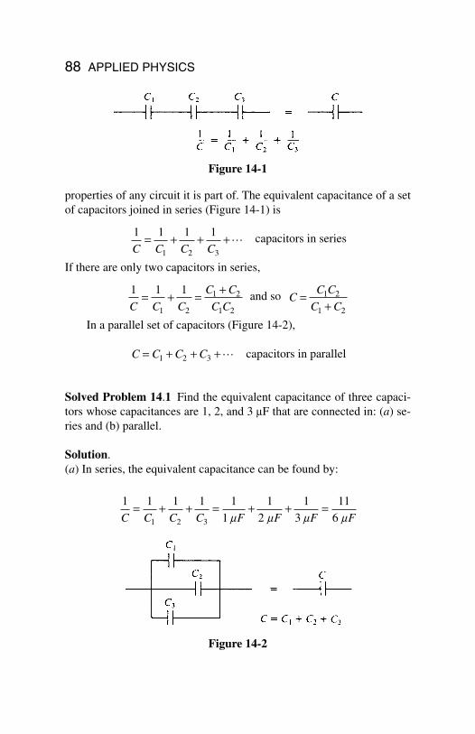
88 APPLIED PHYSICS
properties of any circuit it is part of. The equivalent capacitance of a setof capacitors joined in series (Figure 14-1) is
capacitors in series
If there are only two capacitors in series,
and so
In a parallel set of capacitors (Figure 14-2),
capacitors in parallel
Solved Problem 14.1 Find the equivalent capacitance of three capaci-tors whose capacitances are 1, 2, and 3 mF that are connected in: (a) se-ries and (b) parallel.
Solution.(a) In series, the equivalent capacitance can be found by:
1 1 1 1 1
1
1
2
1
3
11
61 2 3C C C C F F F F= + + = + + =
m m m m
C C C C= + + +1 2 3 L
CC C
C C=
+1 2
1 2
1 1 1
1 2
1 2
1 2C C C
C C
C C= + = +
1 1 1 1
1 2 3C C C C= + + +L
Figure 14-1
Figure 14-2
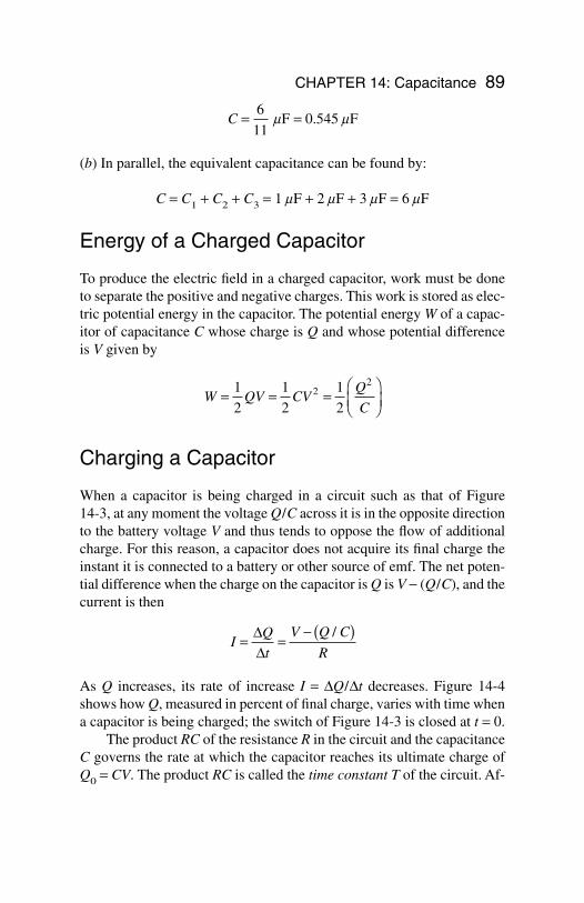
CHAPTER 14: Capacitance 89
(b) In parallel, the equivalent capacitance can be found by:
C = C1 + C2 + C3 = 1 mF + 2 mF + 3 mF = 6 mF
Energy of a Charged Capacitor
To produce the electric field in a charged capacitor, work must be doneto separate the positive and negative charges. This work is stored as elec-tric potential energy in the capacitor. The potential energy W of a capac-itor of capacitance C whose charge is Q and whose potential differenceis V given by
Charging a Capacitor
When a capacitor is being charged in a circuit such as that of Figure 14-3, at any moment the voltage Q/C across it is in the opposite directionto the battery voltage V and thus tends to oppose the flow of additionalcharge. For this reason, a capacitor does not acquire its final charge theinstant it is connected to a battery or other source of emf. The net poten-tial difference when the charge on the capacitor is Q is V − (Q/C), and thecurrent is then
As Q increases, its rate of increase I = ∆Q/∆t decreases. Figure 14-4shows how Q, measured in percent of final charge, varies with time whena capacitor is being charged; the switch of Figure 14-3 is closed at t = 0.
The product RC of the resistance R in the circuit and the capacitanceC governs the rate at which the capacitor reaches its ultimate charge ofQ0 = CV. The product RC is called the time constant T of the circuit. Af-
IQ
t
V Q C
R= =
− ( )∆∆
/
W QV CVQ
C= = =
1
2
1
2
1
22
2
C = =6
11 F 0.545 Fm m
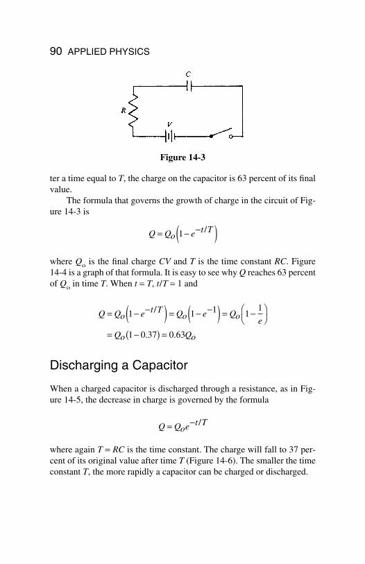
90 APPLIED PHYSICS
ter a time equal to T, the charge on the capacitor is 63 percent of its finalvalue.
The formula that governs the growth of charge in the circuit of Fig-ure 14-3 is
where Qo is the final charge CV and T is the time constant RC. Figure 14-4 is a graph of that formula. It is easy to see why Q reaches 63 percentof Qo in time T. When t = T, t/T = 1 and
Discharging a Capacitor
When a charged capacitor is discharged through a resistance, as in Fig-ure 14-5, the decrease in charge is governed by the formula
where again T = RC is the time constant. The charge will fall to 37 per-cent of its original value after time T (Figure 14-6). The smaller the timeconstant T, the more rapidly a capacitor can be charged or discharged.
Q Qoe T= −t /
Q Qo e T Qo e Qo e
Qo Qo
= − −( ) = − −( ) = −
= −( ) =
1 1 1 11
1 0 37 0 63
t /
. .
Q Qo e T= − −( )1 t /
Figure 14-3
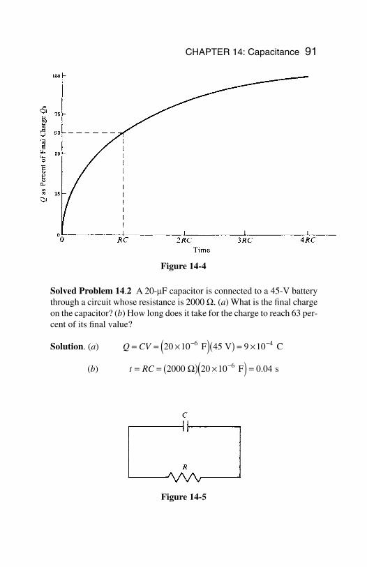
CHAPTER 14: Capacitance 91
Solved Problem 14.2 A 20-mF capacitor is connected to a 45-V batterythrough a circuit whose resistance is 2000 W. (a) What is the final chargeon the capacitor? (b) How long does it take for the charge to reach 63 per-cent of its final value?
Solution. (a)
(b) t RC= = ( ) ×( ) =−2 20 10 0 046000 F sΩ .
Q CV= = ×( )( ) = ×− −20 10 45 9 106 4 F V C
Figure 14-5
Figure 14-4
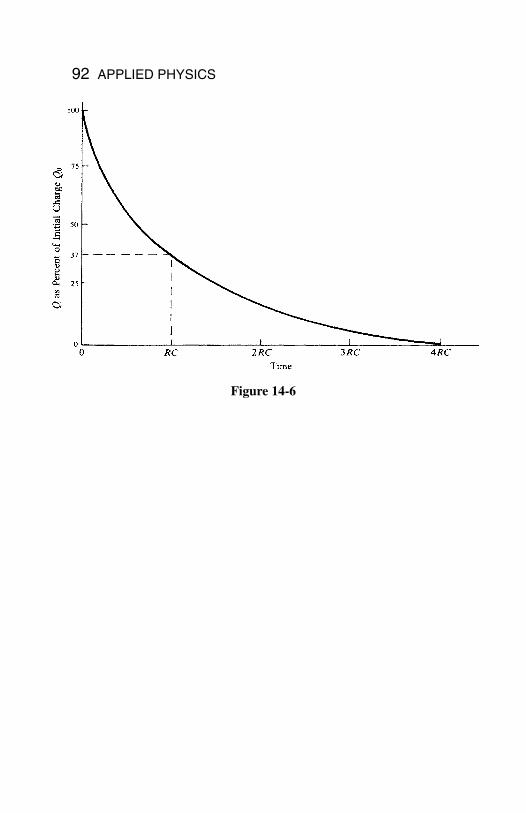
92 APPLIED PHYSICS
Figure 14-6
In This Chapter:
Nature of Magnetism Magnetic Field Magnetic Field of a Straight Current Magnetic Field of a Current Loop Earth’s Magnetic Field Magnetic Force on a Moving Charge Magnetic Force on a Current Force Between Two Currents Ferromagnetism Magnetic Intensity
Nature of Magnetism
Two electric charges at rest exert forces on each otheraccording to Coulomb’s law. When the charges are inmotion, the forces are different, and it is customary toattribute the differences to magnetic forces that occurbetween moving charges in addition to the electricforces between them. In this interpretation, the total
93
Chapter 15
Magnetism
Copyright 2003 by The McGraw-Hill Companies, Inc. Click Here for Terms of Use.
94 APPLIED PHYSICS
force on a charge Q at a certain time and place can be divided into twoparts: an electric force that depends only on the value of Q and a mag-netic force that depends on the velocity v of the charge as well as on Q.
In reality, there is only a single interaction between charges, the elec-tromagnetic interaction. The theory of relativity provides the link be-tween electric and magnetic forces: Just as the mass of an object movingwith respect to an observer is greater than when it is at rest, so the elec-tric force between two charges appears altered to an observer when thecharges are moving with respect to the observer. Magnetism is not dis-tinct from electricity in the way that, for example, gravitation is.
You Need to Know
Despite the unity of the electromagnetic interac-tion, it is convenient for many purposes to treatelectric and magnetic effects separately.
Magnetic Field
A magnetic field B is present wherever a magnetic force acts on a mov-ing charge. The direction of B at a certain place is that along which acharge can move without experiencing a magnetic force; along any oth-er direction that the charge would be acted on by such a force. The mag-nitude of B is equal numerically to the force on a charge of 1 C movingat 1 m/s perpendicular to B.
The unit of magnetic field is the tesla (T), where
The gauss (G), equal to 10−4 T, is another unit of magnetic field some-times used.
1 tesla 1newton
ampere¯meter
weber
meter= =
( )1 2
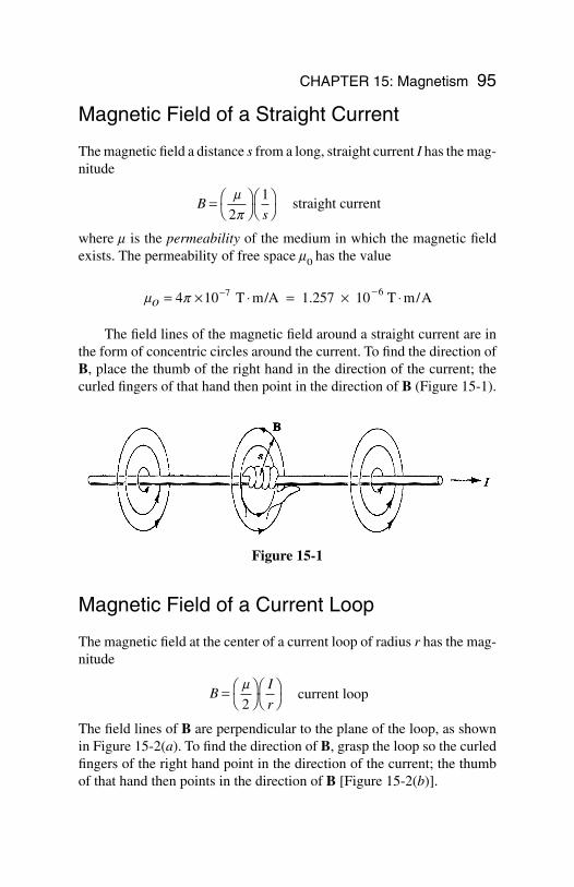
CHAPTER 15: Magnetism 95
Magnetic Field of a Straight Current
The magnetic field a distance s from a long, straight current I has the mag-nitude
straight current
where m is the permeability of the medium in which the magnetic fieldexists. The permeability of free space m0 has the value
The field lines of the magnetic field around a straight current are inthe form of concentric circles around the current. To find the direction ofB, place the thumb of the right hand in the direction of the current; thecurled fingers of that hand then point in the direction of B (Figure 15-1).
Magnetic Field of a Current Loop
The magnetic field at the center of a current loop of radius r has the mag-nitude
current loop
The field lines of B are perpendicular to the plane of the loop, as shownin Figure 15-2(a). To find the direction of B, grasp the loop so the curledfingers of the right hand point in the direction of the current; the thumbof that hand then points in the direction of B [Figure 15-2(b)].
BI
r=
m
2
m po = × ⋅ = × ⋅− −4 10 7 T m/A 1.257 10 T m/A6
Bs
=
m
p2
1
Figure 15-1
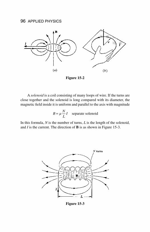
96 APPLIED PHYSICS
A solenoid is a coil consisting of many loops of wire. If the turns areclose together and the solenoid is long compared with its diameter, themagnetic field inside it is uniform and parallel to the axis with magnitude
separate solenoid
In this formula, N is the number of turns, L is the length of the solenoid,and I is the current. The direction of B is as shown in Figure 15-3.
BN
LI= m
Figure 15-2
Figure 15-3
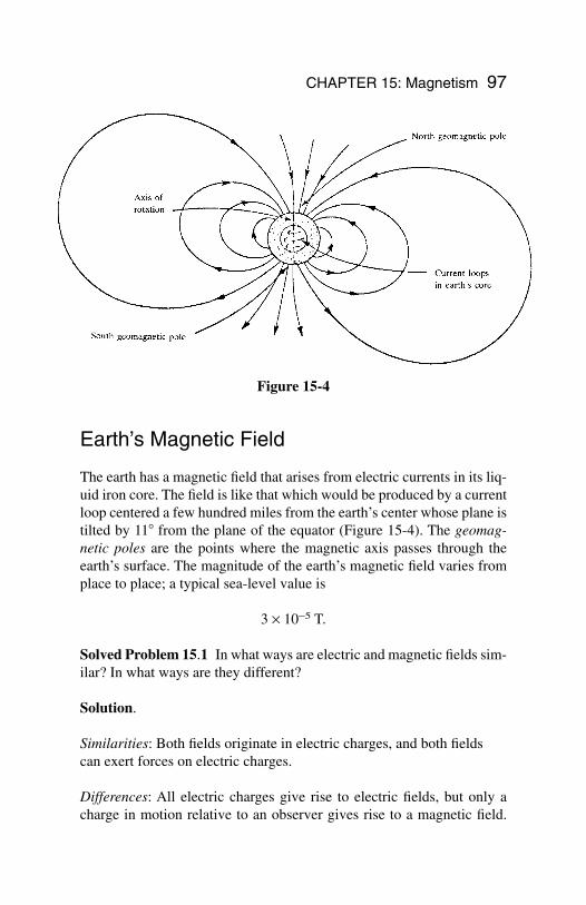
CHAPTER 15: Magnetism 97
Earth’s Magnetic Field
The earth has a magnetic field that arises from electric currents in its liq-uid iron core. The field is like that which would be produced by a currentloop centered a few hundred miles from the earth’s center whose plane istilted by 11 from the plane of the equator (Figure 15-4). The geomag-netic poles are the points where the magnetic axis passes through theearth’s surface. The magnitude of the earth’s magnetic field varies fromplace to place; a typical sea-level value is
3 × 10⁻⁵ T.
Solved Problem 15.1 In what ways are electric and magnetic fields sim-ilar? In what ways are they different?
Solution.
Similarities: Both fields originate in electric charges, and both fieldscan exert forces on electric charges.
Differences: All electric charges give rise to electric fields, but only acharge in motion relative to an observer gives rise to a magnetic field.
Figure 15-4
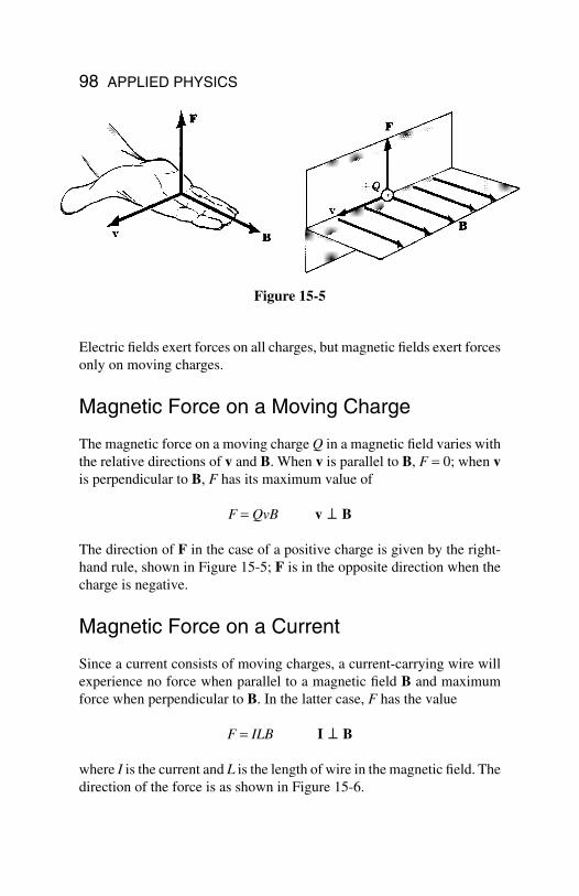
98 APPLIED PHYSICS
Electric fields exert forces on all charges, but magnetic fields exert forcesonly on moving charges.
Magnetic Force on a Moving Charge
The magnetic force on a moving charge Q in a magnetic field varies withthe relative directions of v and B. When v is parallel to B, F = 0; when vis perpendicular to B, F has its maximum value of
F = QvB v ⊥ B
The direction of F in the case of a positive charge is given by the right-hand rule, shown in Figure 15-5; F is in the opposite direction when thecharge is negative.
Magnetic Force on a Current
Since a current consists of moving charges, a current-carrying wire willexperience no force when parallel to a magnetic field B and maximumforce when perpendicular to B. In the latter case, F has the value
F = ILB I ⊥ B
where I is the current and L is the length of wire in the magnetic field. Thedirection of the force is as shown in Figure 15-6.
Figure 15-5
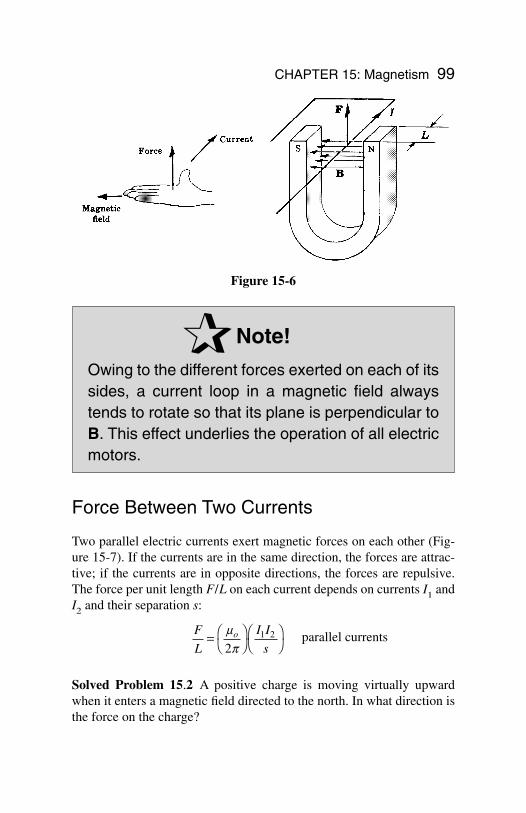
CHAPTER 15: Magnetism 99
Note!
Owing to the different forces exerted on each of itssides, a current loop in a magnetic field alwaystends to rotate so that its plane is perpendicular toB. This effect underlies the operation of all electricmotors.
Force Between Two Currents
Two parallel electric currents exert magnetic forces on each other (Fig-ure 15-7). If the currents are in the same direction, the forces are attrac-tive; if the currents are in opposite directions, the forces are repulsive.The force per unit length F/L on each current depends on currents I1 andI2 and their separation s:
parallel currents
Solved Problem 15.2 A positive charge is moving virtually upwardwhen it enters a magnetic field directed to the north. In what direction isthe force on the charge?
F
L
I I
so=
m
p21 2
Figure 15-6
Solution. To apply the right-hand rule here, the fingers of the right handare pointed north and the thumb of that hand is pointed upward. The palmof the hand faces west, which is therefore the direction of the force on thecharge.
Ferromagnetism
The magnetic field produced by a current is altered by the presence of asubstance of any kind. Usually the change, which may be an increase ora decrease in B, is very small, but in certain cases, there is an increase inB by hundreds or thousands of times. Substances that have the latter ef-fect are called ferromagnetic; iron and iron alloys are familiar examples.
Remember
An electromagnet is a solenoid witha ferromagnetic core to increase itsmagnetic field.
Ferromagnetism is a consequence of the magnetic properties of theelectrons that all atoms contain. An electron behaves in some respects asthough it is a spinning charged sphere, and it is therefore magneticallyequivalent to a tiny current loop. In most substances, the magnetic fieldsof the atomic electrons cancel, but in ferromagnetic substances, the can-cellation is not complete and each atom has a certain magnetic field of itsown. The atomic magnetic fields align themselves in groups called do-mains with an external magnetic field to produce a much stronger total B.When the external field is removed, the atomic magnetic fields may re-main aligned to produce a permanent magnet. The field of a bar magnethas the same form as that of a solenoid because both fields are due to par-allel current loops (Figure 15-7).
Magnetic Intensity
A substance that decreases the magnetic field of a current is called dia-magnetic; it has a permeability m that is less than m0. Copper and water
100 APPLIED PHYSICS
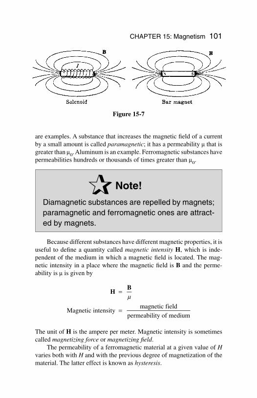
CHAPTER 15: Magnetism 101
are examples. A substance that increases the magnetic field of a currentby a small amount is called paramagnetic; it has a permeability m that isgreater than m0. Aluminum is an example. Ferromagnetic substances havepermeabilities hundreds or thousands of times greater than m0.
Note!
Diamagnetic substances are repelled by magnets;paramagnetic and ferromagnetic ones are attract-ed by magnets.
Because different substances have different magnetic properties, it isuseful to define a quantity called magnetic intensity H, which is inde-pendent of the medium in which a magnetic field is located. The mag-netic intensity in a place where the magnetic field is B and the perme-ability is m is given by
The unit of H is the ampere per meter. Magnetic intensity is sometimescalled magnetizing force or magnetizing field.
The permeability of a ferromagnetic material at a given value of Hvaries both with H and with the previous degree of magnetization of thematerial. The latter effect is known as hysteresis.
HB
Magnetic intensity magnetic field
permeability of medium
=
=
m
Figure 15-7
102
Chapter 16
Electro-magneticInduction
In This Chapter:
Electromagnetic Induction Faraday’s Law Lenz’s Law The Transformer Self-Inductance Inductors in Combination Energy of a Current-Carrying
Inductor
Electromagnetic Induction
A current is produced in a conductor whenever the cur-rent cuts across magnetic field lines, a phenomenonknown as electromagnetic induction. If the motion isparallel to the field lines of force, there is no effect.Electromagnetic induction originates in the force amagnetic field exerts on a moving charge. When a wiremoves across a magnetic field, the electrons it contains
Copyright 2003 by The McGraw-Hill Companies, Inc. Click Here for Terms of Use.
experience sideways forces that push them along the wire to cause a cur-rent. It is not even necessary for there to be relative motion of a wire anda source of magnetic field, since a magnetic field whose strength is chang-ing has moving field lines associated with it and a current will be inducedin a conductor that is in the path of these moving field lines.
When a straight conductor of length l is moving across a magneticfield B with the velocity v, the emf induced in the conductor is given by
Induced emf = Ve = Blv
when B, v, and the conductor are all perpendicular to one another.
Solved Problem 16.1 The vertical component of the earth’s magneticfield in a certain region is 3 × 10⁻⁵ T. What is the potential difference be-tween the rear wheels of a car, which are 1.5 m apart, when the car’s ve-locity is 20 m/s?
Solution. The real axle of the car may be considered as a rod of 1.5 mlong-moving perpendicular to the magnetic field’s vertical component.The potential difference between the wheels is therefore
Faraday’s Law
Figure 16-1 shows a coil (called a solenoid) of N turns that encloses anarea A. The axis of the coil is parallel to a magnetic field B. According toFaraday’s law of electromagnetic induction, the emf induced in the coilwhen the product BA changes by D(BA) in the time Dt is given by
The quantity BA is called the magnetic flux enclosed by the coil and is de-noted by the symbol F (Greek capital letter phi):
Φ =
= ( ) ( )BA
Magnetic flux magnetic field cross¯sectional area
Induced emf = = − ( )V N
BA
te∆
∆
V Blve = = × = × =− −(3 10 9 105 4 T)(1.5m)(20 m/s) V 0.9 mV
CHAPTER 16: Electromagnetic Induction 103
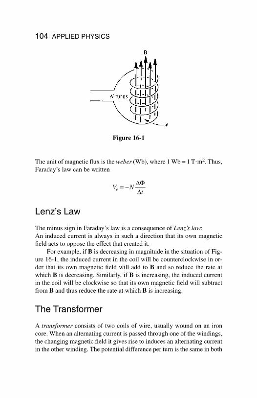
104 APPLIED PHYSICS
The unit of magnetic flux is the weber (Wb), where 1 Wb = 1 Tm2. Thus,Faraday’s law can be written
Lenz’s Law
The minus sign in Faraday’s law is a consequence of Lenz’s law:An induced current is always in such a direction that its own magneticfield acts to oppose the effect that created it.
For example, if B is decreasing in magnitude in the situation of Fig-ure 16-1, the induced current in the coil will be counterclockwise in or-der that its own magnetic field will add to B and so reduce the rate atwhich B is decreasing. Similarly, if B is increasing, the induced currentin the coil will be clockwise so that its own magnetic field will subtractfrom B and thus reduce the rate at which B is increasing.
The Transformer
A transformer consists of two coils of wire, usually wound on an ironcore. When an alternating current is passed through one of the windings,the changing magnetic field it gives rise to induces an alternating currentin the other winding. The potential difference per turn is the same in both
V Nte = − ∆
∆Φ
Figure 16-1
primary and secondary windings, so the ratio of turns in the winding de-termines the ratio of voltages across them:
Since the power I1V1 going into a transformer must equal the powerI2V2 going out, where I1 and I2 are the primary and secondary currents,respectively, the ratio of currents is inversely proportional to the ratio ofturns:
Self-Inductance
When the current in a circuit changes, the magnetic field enclosed by thecircuit also changes, and the resulting change in flux leads to a self-in-duced emf of
Here DI/Dt is the rate of change of the current, and L is a property of the circuit called its self-inductance, or, more commonly, its inductance.The minus sign indicates that the direction of Ve is such as to oppose thechange in current DI that caused it.
The unit of inductance is the henry (H). A circuit or circuit elementthat has an inductance of 1 H will have a self-induced emf of 1 V whenthe current through it changes at the rate of 1 A/s. Because the henry is arather large unit, the millihenry and microhenry are often used, where
1 millihenry = 1 mH = 10−3 H1 microhenry = 1 mH = 10−6 H
Self¯induced emf = = −V LI
te∆∆
I
I
N
N1
2
2
1
=
=Primary current
Secondary current
Secondary turns
Primary turns
V
V
N
N1
2
1
2
=
=Primary voltage
Secondary voltage
Primary turns
Secondary turns
CHAPTER 16: Electromagnetic Induction 105
106 APPLIED PHYSICS
A circuit element with inductance is called an inductor. A solenoid is anexample of an inductor. The inductance of a solenoid is
where m is the permeability of the core material, N is the number of turns,A is the cross-sectional area, and l is the length of the solenoid.
Inductors in Combination
When two or more inductors are sufficiently far apart for them not to in-teract electromagnetically, their equivalent inductances when they areconnected in series and in parallel are as follows:
inductors in series
inductors in parallel
Connecting coils in parallel reduces the total inductance to less than thatof any of the individual coils. This is rarely done because coils are rela-tively large and expensive compared with other electronic components;a coil of the required smaller inductance would nor-mally be used in the first place.
Because the magnetic field of a current-carryingcoil extends beyond the inductor itself, the total in-ductance of two or more connected coils will bechanged if they are close to one another. Dependingon how the coils are arranged, the total inductance may be larger or small-er than if the coils were farther apart. This effect is called mutual induc-tance and is not considered in the above formula.
Solved Problem 16.2 Find the equivalent inductances of a 5- and an 8-mH inductor when they are connected in (a) series and (b) parallel.
Solution.
(a) L L L= + = + =1 2 5 mH 8 mH 13 mH
1 1 1 1
1 2 3L L L L= + + +L
L L L L= + + +1 2 3 L
LN A
l= m 2
(b)
Energy of a Current-Carrying Inductor
Because a self-induced emf opposes any change in an inductor, work hasto be done against this emf to establish a current in the inductor. This workis stored as magnetic potential energy. If L is the inductance of an induc-tor, its potential energy when it carries the current I is
This energy powers the self-induced emf that opposes any decrease in thecurrent through the inductor.
W LI= 1
22
1 1 1 1
5
1
81 2L L L= + = + =
mH mH L 3.08 mH
CHAPTER 16: Electromagnetic Induction 107
108
Chapter 17
Light
In This Chapter:
Electromagnetic Waves Luminous Intensity and Flux Illumination Reflection of Light Refraction of Light Total Internal Reflection Apparent Depth
Electromagnetic Waves
Electromagnetic waves consist of coupled electric and magnetic fieldsthat vary periodically as they move through space. The electric and mag-netic fields are perpendicular to each other and to the direction in whichthe waves travel (Figure 17-1), so the waves are transverse, and the vari-ations in E and B occur simultaneously. Electromagnetic waves transportenergy and require no material medium for their passage. Radio waves,light waves, X-rays, and gamma rays are examples of electromagneticwaves, and they differ only in frequency.
Copyright 2003 by The McGraw-Hill Companies, Inc. Click Here for Terms of Use.
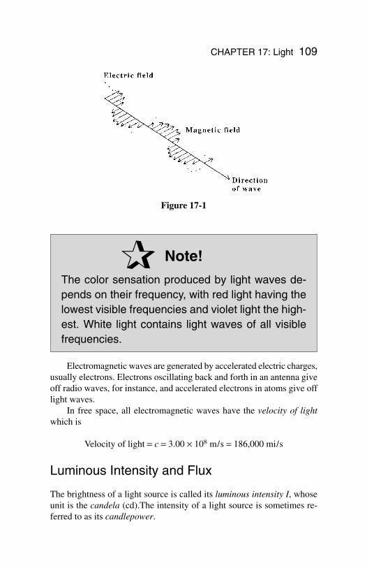
CHAPTER 17: Light 109
Note!
The color sensation produced by light waves de-pends on their frequency, with red light having thelowest visible frequencies and violet light the high-est. White light contains light waves of all visiblefrequencies.
Electromagnetic waves are generated by accelerated electric charges,usually electrons. Electrons oscillating back and forth in an antenna giveoff radio waves, for instance, and accelerated electrons in atoms give offlight waves.
In free space, all electromagnetic waves have the velocity of lightwhich is
Velocity of light = c = 3.00 × 10⁸ m/s = 186,000 mi/s
Luminous Intensity and Flux
The brightness of a light source is called its luminous intensity I, whoseunit is the candela (cd).The intensity of a light source is sometimes re-ferred to as its candlepower.
Figure 17-1
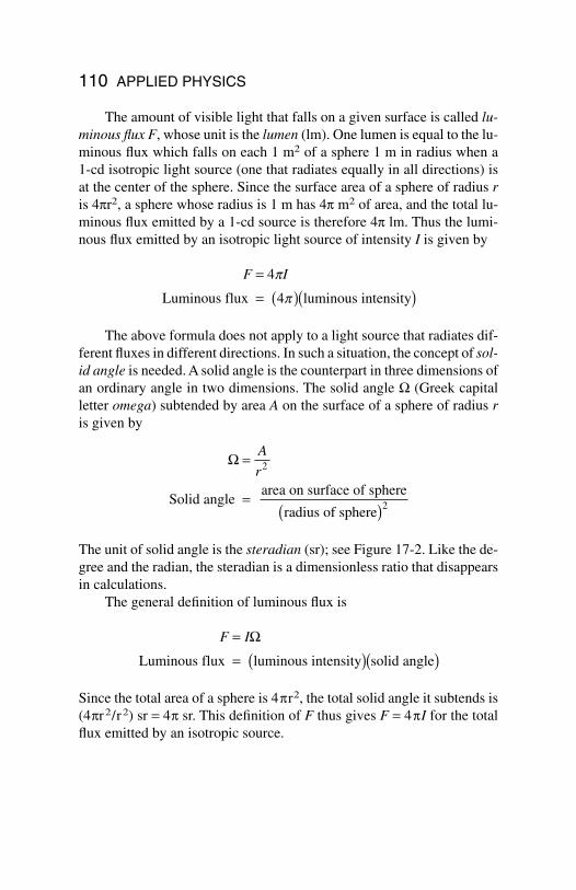
110 APPLIED PHYSICS
The amount of visible light that falls on a given surface is called lu-minous flux F, whose unit is the lumen (lm). One lumen is equal to the lu-minous flux which falls on each 1 m2 of a sphere 1 m in radius when a 1-cd isotropic light source (one that radiates equally in all directions) isat the center of the sphere. Since the surface area of a sphere of radius ris 4pr2, a sphere whose radius is 1 m has 4p m2 of area, and the total lu-minous flux emitted by a 1-cd source is therefore 4p lm. Thus the lumi-nous flux emitted by an isotropic light source of intensity I is given by
The above formula does not apply to a light source that radiates dif-ferent fluxes in different directions. In such a situation, the concept of sol-id angle is needed. A solid angle is the counterpart in three dimensions ofan ordinary angle in two dimensions. The solid angle W (Greek capitalletter omega) subtended by area A on the surface of a sphere of radius ris given by
The unit of solid angle is the steradian (sr); see Figure 17-2. Like the de-gree and the radian, the steradian is a dimensionless ratio that disappearsin calculations.
The general definition of luminous flux is
Since the total area of a sphere is 4pr2, the total solid angle it subtends is(4pr2/r2) sr = 4p sr. This definition of F thus gives F = 4pI for the totalflux emitted by an isotropic source.
F I=
= ( )( )Ω
Luminous flux luminous intensity solid angle
Ω =
=( )
A
r2
2Solid angle area on surface of sphere
radius of sphere
F I=
= ( )( )4p
pLuminous flux 4 luminous intensity
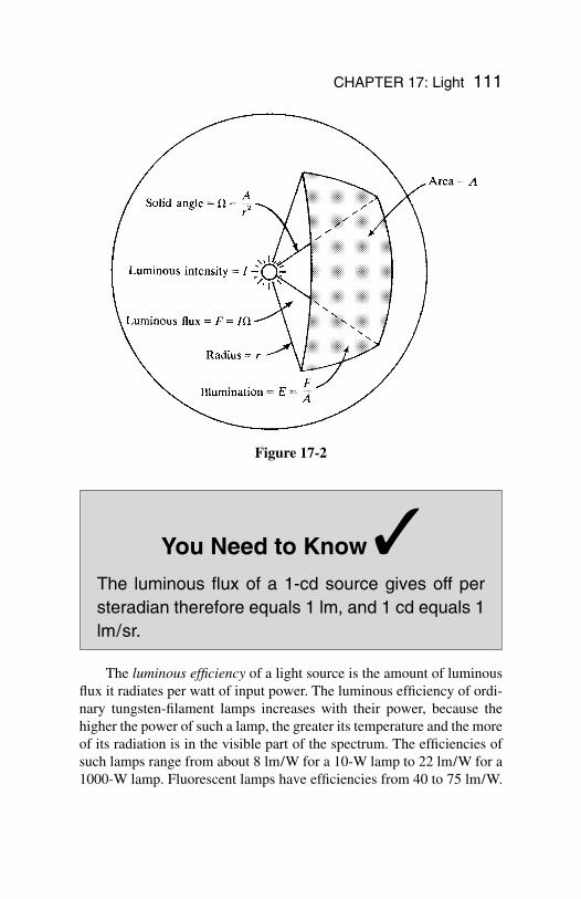
CHAPTER 17: Light 111
You Need to Know
The luminous flux of a 1-cd source gives off persteradian therefore equals 1 lm, and 1 cd equals 1lm/sr.
The luminous efficiency of a light source is the amount of luminousflux it radiates per watt of input power. The luminous efficiency of ordi-nary tungsten-filament lamps increases with their power, because thehigher the power of such a lamp, the greater its temperature and the moreof its radiation is in the visible part of the spectrum. The efficiencies ofsuch lamps range from about 8 lm/W for a 10-W lamp to 22 lm/W for a1000-W lamp. Fluorescent lamps have efficiencies from 40 to 75 lm/W.
Figure 17-2
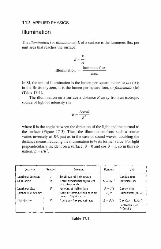
112 APPLIED PHYSICS
Illumination
The illumination (or illuminance) E of a surface is the luminous flux perunit area that reaches the surface:
In SI, the unit of illumination is the lumen per square meter, or lux (lx);in the British system, it is the lumen per square foot, or footcandle (fc)(Table 17-1).
The illumination on a surface a distance R away from an isotropicsource of light of intensity I is
where θ is the angle between the direction of the light and the normal tothe surface (Figure 17-3). Thus, the illumination from such a sourcevaries inversely as R2, just as in the case of sound waves; doubling thedistance means, reducing the illumination to ¹⁄₄ its former value. For lightperpendicularly incident on a surface, θ = 0 and cos θ = 1, so in this sit-uation, E = I/R2.
EI
R= cosq
2
EF
A=
=Illuminationluminous flux
area
Table 17.1
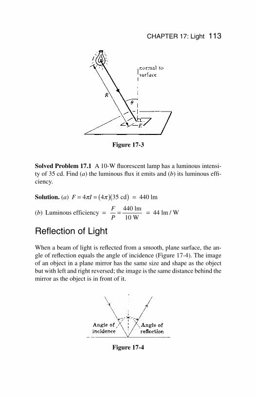
CHAPTER 17: Light 113
Solved Problem 17.1 A 10-W fluorescent lamp has a luminous intensi-ty of 35 cd. Find (a) the luminous flux it emits and (b) its luminous effi-ciency.
Solution. (a)
(b)
Reflection of Light
When a beam of light is reflected from a smooth, plane surface, the an-gle of reflection equals the angle of incidence (Figure 17-4). The imageof an object in a plane mirror has the same size and shape as the objectbut with left and right reversed; the image is the same distance behind themirror as the object is in front of it.
Luminous efficiency 440 lm
10 W 44 lm / W= = =F
P
F I= = ( )( ) =4 4 35p p cd 440 lm
Figure 17-3
Figure 17-4
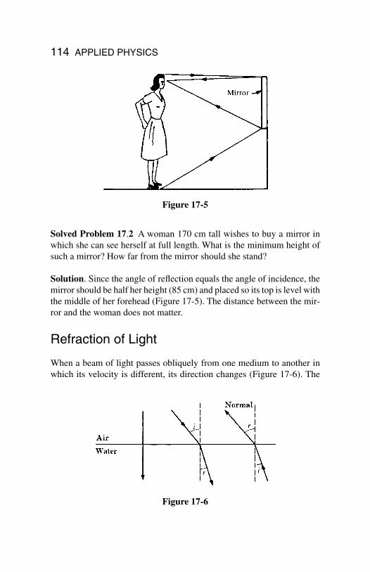
114 APPLIED PHYSICS
Solved Problem 17.2 A woman 170 cm tall wishes to buy a mirror inwhich she can see herself at full length. What is the minimum height ofsuch a mirror? How far from the mirror should she stand?
Solution. Since the angle of reflection equals the angle of incidence, themirror should be half her height (85 cm) and placed so its top is level withthe middle of her forehead (Figure 17-5). The distance between the mir-ror and the woman does not matter.
Refraction of Light
When a beam of light passes obliquely from one medium to another inwhich its velocity is different, its direction changes (Figure 17-6). The
Figure 17-5
Figure 17-6
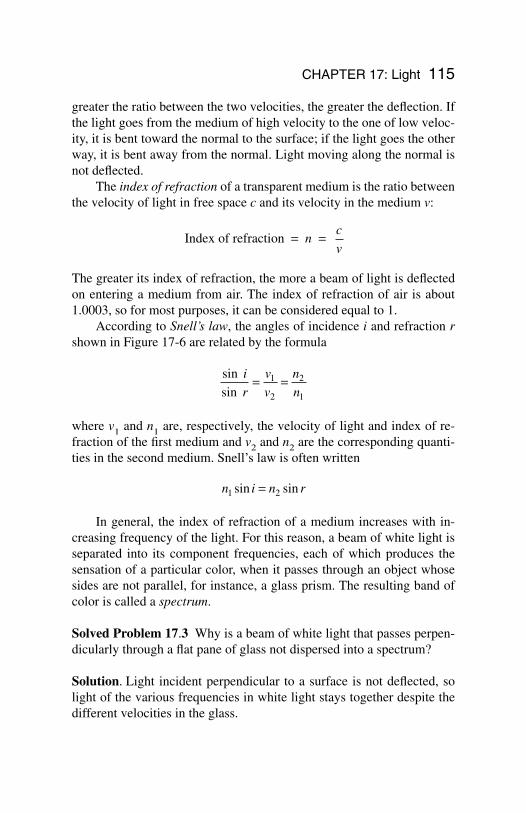
greater the ratio between the two velocities, the greater the deflection. Ifthe light goes from the medium of high velocity to the one of low veloc-ity, it is bent toward the normal to the surface; if the light goes the otherway, it is bent away from the normal. Light moving along the normal isnot deflected.
The index of refraction of a transparent medium is the ratio betweenthe velocity of light in free space c and its velocity in the medium v:
The greater its index of refraction, the more a beam of light is deflectedon entering a medium from air. The index of refraction of air is about1.0003, so for most purposes, it can be considered equal to 1.
According to Snell’s law, the angles of incidence i and refraction rshown in Figure 17-6 are related by the formula
where v1 and n1 are, respectively, the velocity of light and index of re-fraction of the first medium and v2 and n2 are the corresponding quanti-ties in the second medium. Snell’s law is often written
In general, the index of refraction of a medium increases with in-creasing frequency of the light. For this reason, a beam of white light isseparated into its component frequencies, each of which produces thesensation of a particular color, when it passes through an object whosesides are not parallel, for instance, a glass prism. The resulting band ofcolor is called a spectrum.
Solved Problem 17.3 Why is a beam of white light that passes perpen-dicularly through a flat pane of glass not dispersed into a spectrum?
Solution. Light incident perpendicular to a surface is not deflected, solight of the various frequencies in white light stays together despite thedifferent velocities in the glass.
n i n r1 2sin sin=
sin
sin
i
r
v
v
n
n= =1
2
2
1
Index of refraction = =nc
v
CHAPTER 17: Light 115
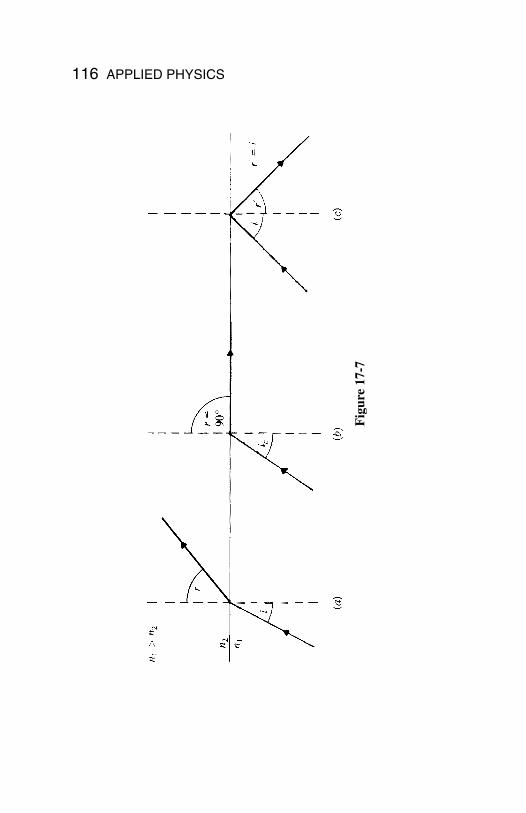
116 APPLIED PHYSICS
Fig
ure
17-7
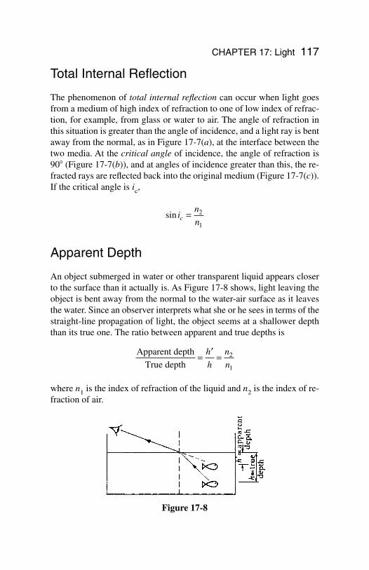
CHAPTER 17: Light 117
Total Internal Reflection
The phenomenon of total internal reflection can occur when light goesfrom a medium of high index of refraction to one of low index of refrac-tion, for example, from glass or water to air. The angle of refraction inthis situation is greater than the angle of incidence, and a light ray is bentaway from the normal, as in Figure 17-7(a), at the interface between thetwo media. At the critical angle of incidence, the angle of refraction is90 (Figure 17-7(b)), and at angles of incidence greater than this, the re-fracted rays are reflected back into the original medium (Figure 17-7(c)).If the critical angle is ic,
Apparent Depth
An object submerged in water or other transparent liquid appears closerto the surface than it actually is. As Figure 17-8 shows, light leaving theobject is bent away from the normal to the water-air surface as it leavesthe water. Since an observer interprets what she or he sees in terms of thestraight-line propagation of light, the object seems at a shallower depththan its true one. The ratio between apparent and true depths is
where n1 is the index of refraction of the liquid and n2 is the index of re-fraction of air.
Apparent depth
True depth= ′ =h
h
n
n2
1
sin in
nc = 2
1
Figure 17-8
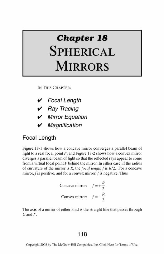
118
Chapter 18
SphericalMirrors
In This Chapter:
Focal Length Ray Tracing Mirror Equation Magnification
Focal Length
Figure 18-1 shows how a concave mirror converges a parallel beam oflight to a real focal point F, and Figure 18-2 shows how a convex mirrordiverges a parallel beam of light so that the reflected rays appear to comefrom a virtual focal point F behind the mirror. In either case, if the radiusof curvature of the mirror is R, the focal length f is R/2. For a concavemirror, f is positive, and for a convex mirror, f is negative. Thus
The axis of a mirror of either kind is the straight line that passes throughC and F.
Concave mirror:
Convex mirror:
fR
fR
= +
= −
2
2
Copyright 2003 by The McGraw-Hill Companies, Inc. Click Here for Terms of Use.
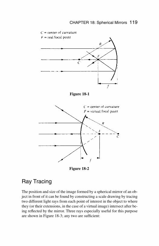
CHAPTER 18: Spherical Mirrors 119
Ray Tracing
The position and size of the image formed by a spherical mirror of an ob-ject in front of it can be found by constructing a scale drawing by tracingtwo different light rays from each point of interest in the object to wherethey (or their extensions, in the case of a virtual image) intersect after be-ing reflected by the mirror. Three rays especially useful for this purposeare shown in Figure 18-3; any two are sufficient:
Figure 18-1
Figure 18-2
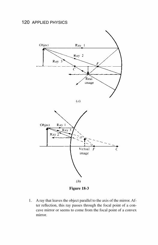
120 APPLIED PHYSICS
1. A ray that leaves the object parallel to the axis of the mirror. Af-ter reflection, this ray passes through the focal point of a con-cave mirror or seems to come from the focal point of a convexmirror.
Figure 18-3
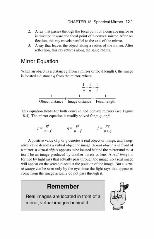
2. A ray that passes through the focal point of a concave mirror oris directed toward the focal point of a convex mirror. After re-flection, this ray travels parallel to the axis of the mirror.
3. A ray that leaves the object along a radius of the mirror. Afterreflection, this ray returns along the same radius.
Mirror Equation
When an object is a distance p from a mirror of focal length f, the imageis located a distance q from the mirror, where
This equation holds for both concave and convex mirrors (see Figure 18-4). The mirror equation is readily solved for p, q, or f :
A positive value of p or q denotes a real object or image, and a neg-ative value denotes a virtual object or image. A real object is in front ofa mirror; a virtual object appears to be located behind the mirror and mustitself be an image produced by another mirror or lens. A real image isformed by light rays that actually pass through the image, so a real imagewill appear on the screen placed at the position of the image. But a virtu-al image can be seen only by the eye since the light rays that appear tocome from the image actually do not pass through it.
Remember
Real images are located in front of amirror, virtual images behind it.
pqf
q fq
pf
p ff
pq
p q=
−=
−=
+
1 1 1
1 1 1
p q f+ =
+ =Object distance Image distance Focal length
CHAPTER 18: Spherical Mirrors 121
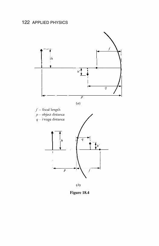
122 APPLIED PHYSICS
Figure 18.4
CHAPTER 18: Spherical Mirrors 123
Magnification
The linear magnification m of any optical system is the ratio between thesize (height or width or other transverse linear dimensions) of the imageand the size of the object. In the case of a mirror,
A positive magnification signifies an erect image, as in Figure 18-4(b); anegative one signifies an inverted image, as in Figure 18-4(a). Table 18.1is a summary of the sign conventions used in connection with sphericalmirrors.
mh
h
q
p= ′ = −
= = −Linear magnification image height
object height
image distance
object distance
Table 18.1
124
Chapter 19
Lenses
In This Chapter:
Focal Length Ray Tracing Lens Equation Magnification Lens Systems
Focal Length
Figure 19-1 shows how a converging lens brings a par-allel beam of light to a real focal point F, and Figure19-2 shows how a diverging lens spreads out a parallelbeam of light so that the refracted rays appear to comefrom a virtual focal point F. In this chapter, we consid-er only thin lenses, whose thickness can be neglectedas far as optical effects are concerned. The focal lengthf of a thin lens is given by the lensmaker’s equation:
In this equation, n is the index of refraction of the lens material relativeto the medium it is in, and R1 and R2 are the radii of curvature of the two
11
1 1
1 2fn
R R= −( ) +
Copyright 2003 by The McGraw-Hill Companies, Inc. Click Here for Terms of Use.
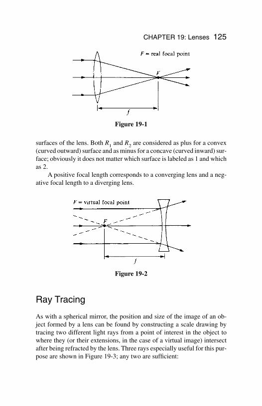
Ray Tracing
As with a spherical mirror, the position and size of the image of an ob-ject formed by a lens can be found by constructing a scale drawing bytracing two different light rays from a point of interest in the object towhere they (or their extensions, in the case of a virtual image) intersectafter being refracted by the lens. Three rays especially useful for this pur-pose are shown in Figure 19-3; any two are sufficient:
CHAPTER 19: Lenses 125
surfaces of the lens. Both R1 and R2 are considered as plus for a convex(curved outward) surface and as minus for a concave (curved inward) sur-face; obviously it does not matter which surface is labeled as 1 and whichas 2.
A positive focal length corresponds to a converging lens and a neg-ative focal length to a diverging lens.
Figure 19-1
Figure 19-2
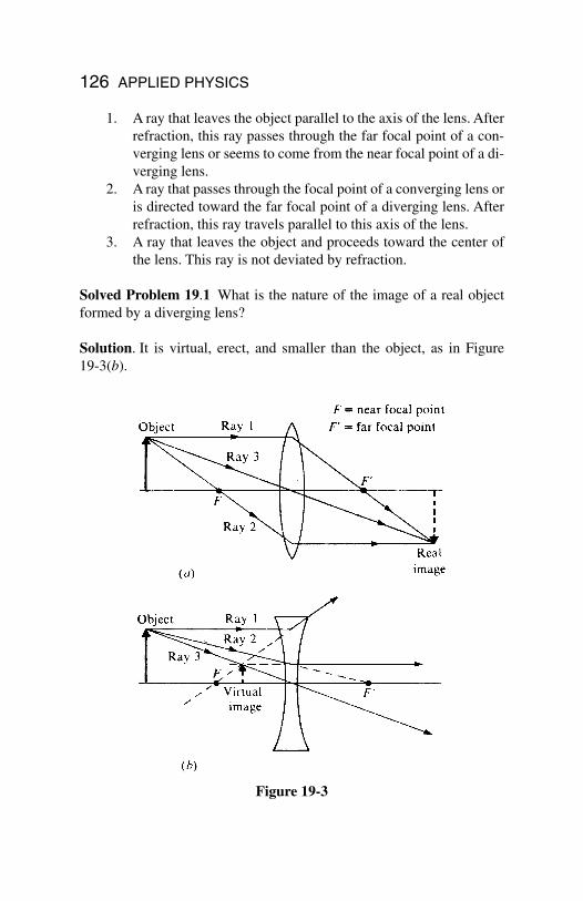
126 APPLIED PHYSICS
1. A ray that leaves the object parallel to the axis of the lens. Afterrefraction, this ray passes through the far focal point of a con-verging lens or seems to come from the near focal point of a di-verging lens.
2. A ray that passes through the focal point of a converging lens oris directed toward the far focal point of a diverging lens. Afterrefraction, this ray travels parallel to this axis of the lens.
3. A ray that leaves the object and proceeds toward the center ofthe lens. This ray is not deviated by refraction.
Solved Problem 19.1 What is the nature of the image of a real objectformed by a diverging lens?
Solution. It is virtual, erect, and smaller than the object, as in Figure 19-3(b).
Figure 19-3
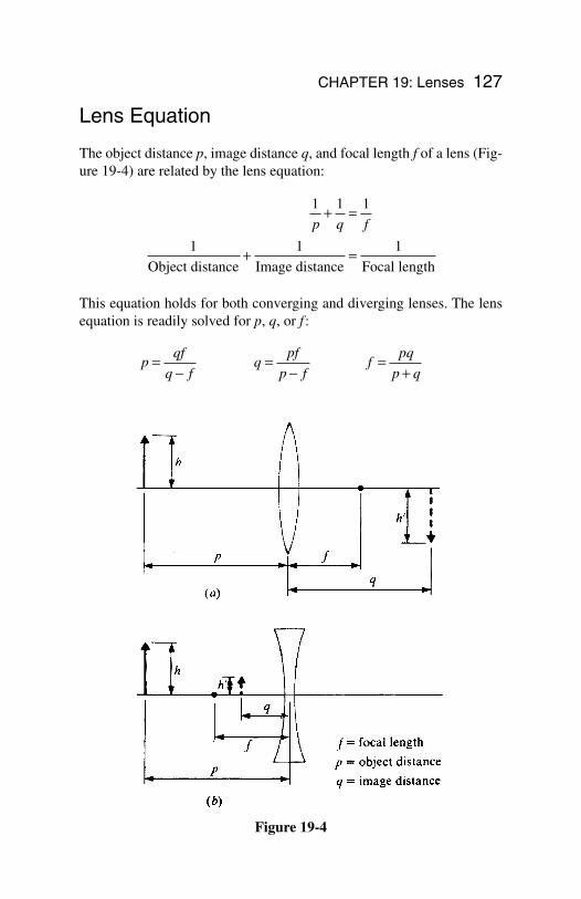
CHAPTER 19: Lenses 127
Lens Equation
The object distance p, image distance q, and focal length f of a lens (Fig-ure 19-4) are related by the lens equation:
This equation holds for both converging and diverging lenses. The lensequation is readily solved for p, q, or f :
pqf
q fq
pf
p ff
pq
p q=
−=
−=
+
1 1 1
1 1 1
p q f+ =
+ =Object distance Image distance Focal length
Figure 19-4
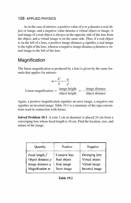
128 APPLIED PHYSICS
As in the case of mirrors, a positive value of p or q denotes a real ob-ject or image, and a negative value denotes a virtual object or image. Areal image of a real object is always on the opposite side of the lens fromthe object, and a virtual image is on the same side. Thus, if a real objectis on the left of a lens, a positive image distance q signifies a real imageto the right of the lens, whereas a negative image distance q denotes a vir-tual image to the left of the lens.
Magnification
The linear magnification m produced by a lens is given by the same for-mula that applies for mirrors:
Again, a positive magnification signifies an erect image, a negative onesignifies an inverted image. Table 19.1 is a summary of the sign conven-tions used in connection with lenses.
Solved Problem 18.1 A coin 3 cm in diameter is placed 24 cm from aconverging lens whose focal length is 16 cm. Find the location, size, andnature of the image.
mh
h
q
p= ′ = −
= = −Linear magnification image height
object height
image distance
object distance
Table 19.1
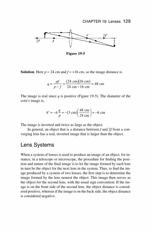
CHAPTER 19: Lenses 129
Figure 19-5
Solution. Here p = 24 cm and f = +16 cm, so the image distance is
The image is real since q is positive (Figure 19-5). The diameter of thecoin’s image is,
The image is inverted and twice as large as the object. In general, an object that is a distance between f and 2f from a con-
verging lens has a real, inverted image that is larger than the object.
Lens Systems
When a system of lenses is used to produce an image of an object, for in-stance, in a telescope or microscope, the procedure for finding the posi-tion and nature of the final image is to let the image formed by each lensin turn be the object for the next lens in the system. Thus, to find the im-age produced by a system of two lenses, the first step is to determine theimage formed by the lens nearest the object. This image then serves asthe object for the second lens, with the usual sign convention: If the im-age is on the front side of the second lens, the object distance is consid-ered positive, whereas if the image is on the back side, the object distanceis considered negative.
′ = − = −( ) = −h h
q
p3
486 cm
cm
24 cm cm
qpf
p f=
−= ( )( )
−=24 1
24 1648
cm 6 cm
cm cm cm
130 APPLIED PHYSICS
The total magnification produced by a system of lenses is equal tothe product of the magnification of the individual lenses. Thus, if the mag-nification of the objective lens of a microscope or telescope is m1 and thatof the eyepiece is m2, the total magnification is m = m1m2.
131
Chapter 20
Physical andQuantum Optics
In This Chapter:
Interference Diffraction Polarization Quantum Theory of Light X-rays
Interference
In examining the reflection and refraction of light, itis sufficient to consider light as though it consistedof rays that travel in straight lines in a uniform medi-um. The study of such phenomena, therefore, iscalled geometrical optics. Other phenomena, no-tably interference, diffraction, and polarization, canbe understood only in terms of the wave nature oflight, and the study of these phenomena is calledphysical optics.
Interference occurs when waves of the same nature from differentsources meet at the same place. In constructive interference, the wavesare in phase (“in step”) and reinforce each other; in destructive interfer-ence, the waves are out of phase and partially or completely cancel (Fig-ure 20-1). All types of waves exhibit interference under appropriate cir-
Copyright 2003 by The McGraw-Hill Companies, Inc. Click Here for Terms of Use.
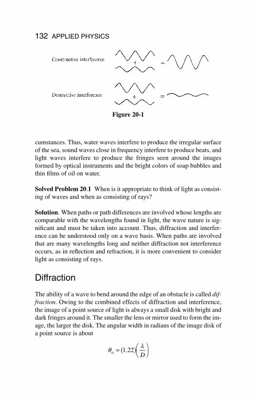
132 APPLIED PHYSICS
cumstances. Thus, water waves interfere to produce the irregular surfaceof the sea, sound waves close in frequency interfere to produce beats, andlight waves interfere to produce the fringes seen around the imagesformed by optical instruments and the bright colors of soap bubbles andthin films of oil on water.
Solved Problem 20.1 When is it appropriate to think of light as consist-ing of waves and when as consisting of rays?
Solution. When paths or path differences are involved whose lengths arecomparable with the wavelengths found in light, the wave nature is sig-nificant and must be taken into account. Thus, diffraction and interfer-ence can be understood only on a wave basis. When paths are involvedthat are many wavelengths long and neither diffraction not interferenceoccurs, as in reflection and refraction, it is more convenient to considerlight as consisting of rays.
Diffraction
The ability of a wave to bend around the edge of an obstacle is called dif-fraction. Owing to the combined effects of diffraction and interference,the image of a point source of light is always a small disk with bright anddark fringes around it. The smaller the lens or mirror used to form the im-age, the larger the disk. The angular width in radians of the image disk ofa point source is about
ql
o D= ( )
1 22.
Figure 20-1
where λ is the wavelength of the light and D is the lens or mirror diame-ter. The images of objects closer than q0 will overlap and hence cannotbe resolved no matter how great the magnification produced by the lensor mirror. In the case of a telescope or microscope, D refers to the diam-eter of the objective lens. If two objects d0 apart that can just be resolvedat a distance L from the observer, the angle in radians between them is q0= d0/L, so the above formula can be rewritten in the form
Polarization
A polarized beam of light is one in which the electric fields of the wavesare all in the same direction. If the electric fields are in random directions(though, of course, always in a plane perpendicular to the direction ofpropagation), the beam is unpolarized.
You Need to Know
Various substances affect differently light with dif-ferent directions of polarization, and these sub-stances can be used to prepare devices that per-mit only light polarized in a certain direction to passthrough them.
Quantum Theory of Light
Certain features of the behavior of light can be explained only on the ba-sis that light consists of individual quanta, or photons. The energy of aphoton of light whose frequency is f is
Quantum energy = E = hf
where h is Planck’s constant:
Resolving power = = ( )d
L
Do 1 22.l
CHAPTER 20: Physical and Quantum Optics 133
Planck’s constant = h = 6.63 × 10⁻³⁴ Js
A photon has most of the properties associated with particles—it is lo-calized in space and possesses energy and momentum—but it has nomass. Photons travel with the velocity of light.
The electromagnetic and quantum theories of light complement eachother: Under some circumstances, light exhibits a wave character, underother circumstances, it exhibits a particle character. Both are aspects ofthe same basic phenomenon.
X-Rays
X-rays are high frequency electromagnetic waves produced when fastelectrons impinge on a target. If the electrons are accelerated through apotential difference of V, each electron has the energy KE = eV. If all thisenergy goes into creating an X-ray photon, then
eV = hfElectron kinetic energy = X-ray photon energy
and the frequency of the X-rays is f = eV/h.
134 APPLIED PHYSICS
Index
Acceleration, 12–16, 61–62angular, 43–44centripetal, 37–38
Action force, 25Amperes, 76Amplitude of waves, 66Angular acceleration, 43–44Angular measure, 41–42Angular momentum, 49Angular velocity, 42–43Antilogarithms, 67Apparent depth, 117Atoms, 71Average velocity, 11–12
British system of units, 21–22
Candlepower, 109Canelas, 109Capacitance, 86–92Capacitors, 86–92Center of gravity, 55–57Centripetal acceleration, 37–38Centripetal force, 38Charged capacitors, 89–90Circuits:
direct-current, 80–85electric, 75–76
Circular motion, 37–40Coefficient of friction, 26–27Collisions, 36Components, 7–8Concurrent forces, 54Conductors, 76Conservation of angular momentum, 49Conservation of charge, 70–71Conservation of energy, 32Conservation of linear momentum, 35Constant velocity, 12Constructive interference, 131–132
Cosines, 4law, 10
Coulombs, 70Coulomb’s law, 71–72Critical angles, 117Current loops, 95–97
Deceleration, 13Decibels, 68Destructive interference, 131–132Diamagnetic substances, 100–101Diffraction, 132–133Direct-current circuits, 80–85Displacement, 61–62Distance, 14–15Doppler effect, 69
Earth’s magnetic field, 97–98Elastic collisions, 36Elastic potential energy, 59Electric charge, 70–71Electric circuits, 75–76Electric current, 75–79Electric field lines, 73Electric fields, 72–73Electricity, 70–74Electric power, 78–79Electromagnetic induction, 102–107Electromagnetic interaction, 94Electromagnetic waves, 64, 108–109Electromotive force (EMF), 83Electrons, 70EMF (electromotive force), 83Energy, 28–32, 31–32, 48–49, 59Equilibrium, 51–57Equivalent capacitance, 87–89
Falling bodies, 16Faraday’s Law, 103–104Farads, 87
135
Copyright 2003 by The McGraw-Hill Companies, Inc. Click Here for Terms of Use.
Ferromagnetism, 100Field lines, 73Focal length, 118–119Footcandles, 112Foot pounds, 31Force, 19–20, 25, 38, 54Free-body diagrams, 22–24, 52Frequency of simple harmonic motion, 61Friction, 26–27
Gamma rays, 108Gausses, 94Geomagnetic poles, 97Geometrical optics, 131Graphical method of vector addition, 2–3Gravitation, 40Gravity, 15–16
Henrys, 105Horsepower, 30Hypotenuses, 4Hysteresis, 101
Illumination, 112–113Iluminance, 112–113Impulse, 33–35Index of refraction, 115Inductors, 106–107Inelastic collisions, 36Inertia, 20, 44–45Instantaneous velocity, 12Insulators, 76Intensity of waves, 66Interference, 131–132Internal resistance, 83Inverses, 4Ions, 71
Joules, 29, 31Junctions, 83
Kilogram-meters per second, 33Kilograms, 20Kinetic energy, 31Kinetic friction, 26Kirchhoff’s rules, 83–85
Law of conservation of energy, 32Law of conservation of linear momentum,
35Law of cosines, 10Law of sines, 10Laws:
conservation of energy, 32conservation of linear momentum, 35cosines, 10Coulomb’s, 71Faraday’s, 103–104Kirchhoff’s rules, 83–85Lenz’s, 104Newton’s first of motion, 19–20Newton’s second of motion, 20–21Newton’s third of motion, 25Newton’s universal gravitation, 40Ohm’s, 77sines, 10Snell’s, 115
Lens equation, 127–128Lenses, 124–130Lensmaker’s equation, 124–125Lenz’s law, 104Light, 108–117Light waves, 108–109Linear magnification, 123Linear momentum, 33–35Logarithms, 66–67Longitudinal waves, 64Loops, 83, 95–97Lumens, 110Luminous efficiency, 111Luminous flux, 110–111Luminous intensity, 109Luxes, 112
Magnetic fields, 94–98Magnetic flux, 103–104Magnetic forces, 93–94, 98–100Magnetic intensity, 100–101Magnetism, 93–101Magnetizing field, 101Magnetizing force, 101Magnification, 123, 128–129Mass, 20
136 APPLIED PHYSICS
Microfarad, 87Microhenrys, 105Millihenrys, 105Mirrors, 118–123Moment arms of the force, 45–48Moment of inertia, 44–45Moments of force, 48Momentum, 33–36Motion, 11–18, 41–50, 59–61
circular, 37–40uniform circular, 37
Moving charges, 98
Negative charge, 70Negative ion, 71Net charge, 70–71Net force, 20Newton-seconds, 34Newton’s laws:
first law of motion, 19–20second law of motion, 20–21third of motion, 25universal gravitation, 40
Newtons (units of force), 20Nonconcurrent forces, 54Nucleus, 71
Ohm’s law, 77Optics, 131–134
Parallel-plate capacitors, 87Parallel resistors, 80–82Paramagnetic substances, 101Pendulums, 62–63Periodic motion, 59–61Periodic waves, 64Period of simple harmonic motion, 60–61Permanent magnets, 100Permeability, 95Permittivity of free space, 72Photons, 133Physical optics, 131–134Physical pendulums, 63Picofarad, 92Planck’s constant, 133–134Plasmas, 76
Polarization, 133Positive charge, 70Positive ion, 71Potential difference, 73–74Potential energy, 31–32, 59Pounds, 21–22Pound-seconds, 34Power, 30–31Projectile motion, 17–18Protons, 70Pythagorean theorem, 5–6
Quanta, 133Quantities, 1Quantum optics, 133–134Quantum theory of light, 133–134
Radians, 41–42Radio waves, 108Ray tracing, 119–121, 125–126Reaction force, 25Real images, 121Real objects, 121Reflection of light, 113–114Refraction of light, 114–115Resistance, 77Resistivity, 77–78Resistors, 80–83Resolving a vector, 7–9Restoring force, 58–59Resultants, 2Right triangles, 4Rotational energy, 48–49Rotational equilibrium, 54–55Rotational motion, 41–50
Satellite motion, 40Scalars, 1–2Self-induced emf, 105Self-inductance, 105–106Semiconductors, 76Series, 80Simple harmonic motion, 58–63Simple pendulums, 62–63Sines, 4
law, 10
INDEX 137
SI (Standard International system ofunits), 21–22
Sliding friction, 26Slug-feet per second, 33Slugs, 21–22Snell’s law, 115Solenoids, 96, 103Solid angles, 110Sound waves, 67–69Spectrums, 115–116Spherical mirrors, 118–123Standard International system of units
(SI), 21–22Starting friction, 26Static friction, 26Steradians, 110Straight current, 95Systems of units, 21–22
Tangents, 4Temperature of coefficient of resistance,
78Tension, 22–24Terminal velocity, 16Teslas, 94Thin lenses, 124Torque, 45–48Torsion pendulums, 63
Total internal reflection, 117Transformers, 104–105Transitional equilibrium, 51–53Transverse waves, 64Trigonometry, 3–5, 6
Unbalanced force, 20Uniform circular motion, 37Units, 21–22
Vector addition:component method, 10graphical method, 2–3trigonometric method, 6
Vectors, 1–10Velocity, 11–16, 42–43, 61–62, 109Virtual images, 121Virtual objects, 121
Watts, 30Wavelengths, 65–66Waves, 64–69, 108–109Webers, 104Weight, 21Work, 28–30, 48–49
X-rays, 108, 134
138 APPLIED PHYSICS