applying erasure codes for fault tolerance in...
TRANSCRIPT

Applying Erasure Codes for Fault Tolerance in Cloud-RAID
Maxim Schnjakin, Tobias Metzke, Christoph MeinelHasso Plattner Institute
Potsdam University, GermanyProf.Dr-Helmert-Str. 2-3, 14482 Potsdam, Germany{maxim.schnjakin, office-meinel}@hpi.uni-potsdam.de
Abstract—Public cloud storage services enable organizationsto manage data with low operational expenses. However, thebenefits come along with challenges and open issues such assecurity and reliability. In our work, we presented a systemthat improves availability, confidentiality and reliability of datastored in the cloud. To achieve this objective, we encrypt user’sdata and make use of erasure codes to stripe data across cloudstorage providers.
In this paper we focus on the need to identify an algorithmfor encoding and reassembling the data from the clouds.Erasure codes have been introduces more than three decadesago. Due to new technology trends and powerful hardware,new codes as well as improvements on classic codes havebeen developed recently. Therefore, we provide an overviewof the current state of erasure codes. Further, we introducethe relevant codes in detail and compare them on the basisof identified criteria that are relevant to their application in acloud context. Furthermore, we take a look at the current opensource libraries, that support the discussed algorithms. Thecomparative study will help us to identity the best algorithmfor our Cloud-RAID system.
I. INTRODUCTION
The usage of computing resources as pay-as-you-gomodel enables service users to convert fixed IT cost intoa variable cost based on actual consumption. Therefore, nu-merous researchers argue for the benefits of cloud computingfocusing on the economic value [1], [2].
However, despite of the non-contentious financial advan-tages cloud computing raises questions about privacy, secu-rity and reliability. Among available cloud offerings, storageservices reveal an increasing level of market competition.According to iSuppli [3] global cloud storage revenue is setto rise to $5 billion in 2013, up from $1.6 billion in 2009.One reason is the ever increasing amount of data which issupposed to outpace the growth of storage capacity.
For a customer (service) to depend solely on one cloudstorage provider has its limitations and risks. In general,vendors do not provide far reaching security guaranteesregarding the data retention [4]. Placement of data in thecloud removes the physical control that a data owner hasover data. So there is a risk that a service provider mightshare corporate data with a marketing company or use thedata in a way the client never intended. Further, customers
of a particular provider might experience vendor lock-in. Inthe context of cloud computing, it is a risk for a customerto become dependent on a provider for its services.
In our previous work [5], [6] and [7] we presented anapproach that deals with the mentioned problems by sepa-rating data into unrecognizable slices, that are distributed todifferent providers. It is important to note, that only a subsetof the providers needs to be available in order to reconstructthe original data.
To achieve this goal, we aim to utilize erasure codes.In order to find the best algorithm for our application,we conduct a comparative analysis on relevant algorithms.Erasure codes have been around since the 1960s already andoriginate in information theory rather than engineering [8].In general, the algorithms have not been widely applied upto some years ago. This is mainly due to the fact that the firstalgorithms have been based on Galois field operations whichhave not been well supported by CPUs and therefore werenot applicable for large data sets. However, recent hardwareand software development [9] enabled the support for fastcalculations of required operations and paved the way forthe usage of erasure codes.
In recent years, the number of new erasure coding tech-niques has been rising fast. New codes have been createdout of the need for simpler erasure codes based on CPU-supported operations in earlier years. Furthermore, new era-sure codes adapted to the characteristics of new technologytrends like Multicore and Multinode Systems, Big Data,and Cloud Computing. While some codes focus more onbetter encoding and decoding performance compared to thefirst erasure codes, others aim to reduce the repair traffic.A comprehensive overview of the existing erasure codesand their characteristics is needed. This paper provides anoverview of the status quo of relevant erasure codes andhelps us by the identification of an appropriate algorithmfor our system.
The contributions of this paper comprise:• An overview of new and classic erasure codes. In
general, erasure algorithms can be distinguished by theintention to reduce the so-called storage overhead andby the intention to reduce the repair traffic. This paper

provides an introduction to a number of selected codes.• A direct comparison of relevant erasure algorithms.
We have identified several criteria to enable a directcomparison between listed codes (with regard to therequirements of our system).
• An overview of available erasure implementations. Sev-eral frameworks for erasure coding exist nowadays; thispaper introduces those that are widely used and freelyavailable while also highlighting the implemented era-sure codes.
The remainder of this paper is structured as follows: insections III and IV we introduce the general architectureof our application and describe the creteria needed forthe comparison of the presented algorithms. Section Vafterwards provides an overview of the selected erasurecodes and describes their characteristics. Then, in Section VIwe present a list of open source erasure code frameworks.Finally, in Section VIII we conclude with a discussion ofthe implications of the conducted survey to the Cloud-RAIDsystem.
II. RELATED WORK
Erasure codes have been evaluated on a variety of metricsand criteria, such as the CPU impact of encoding anddecoding [10], [11]. The coding and decoding performanceof different erasure codes can vary significantly. Concerningthe performance of the codes, the overview presented in thispaper does not provide any formulas, experiment results orcalculations. Providing generic formulas is rather complex,since the performance of the codes is highly dependenton the specific configurations of the codes, the librariesused for the experiments, and the specific scenarios forencoding and decoding (e.g. the number of failed chunksfor decoding). Furthermore, several performance evaluationshave been already conducted [12], [13], [14] for all the codespresented in this paper.
However, in our specific use case the performance ofindividual algorithms plays a role that is certainly important,but not decisive: in our tests presented in [6] and [5] weobserved, that the average performance overhead caused bydata encoding is less than 2% of the amount of time for datatransfer to a cloud provider. With this, encoding is dominatedby the transmission times and can be neglected. Here, thestorage overhead and the I/O traffic are more important, asthe values are associated with costs. There has been somework lowering I/O costs in erasure-based systems. As statedin chapter V, Rotated RD codes have been designed to lowerI/O costs on recovery. However, in this paper we do notintend to improve a specific algorithm, but to undertake acomparative analysis on relevant algorithms.
III. MOTIVATION
The ground of our approach is to find a balance betweenbenefiting from the cloud’s nature of pay-per-use and en-
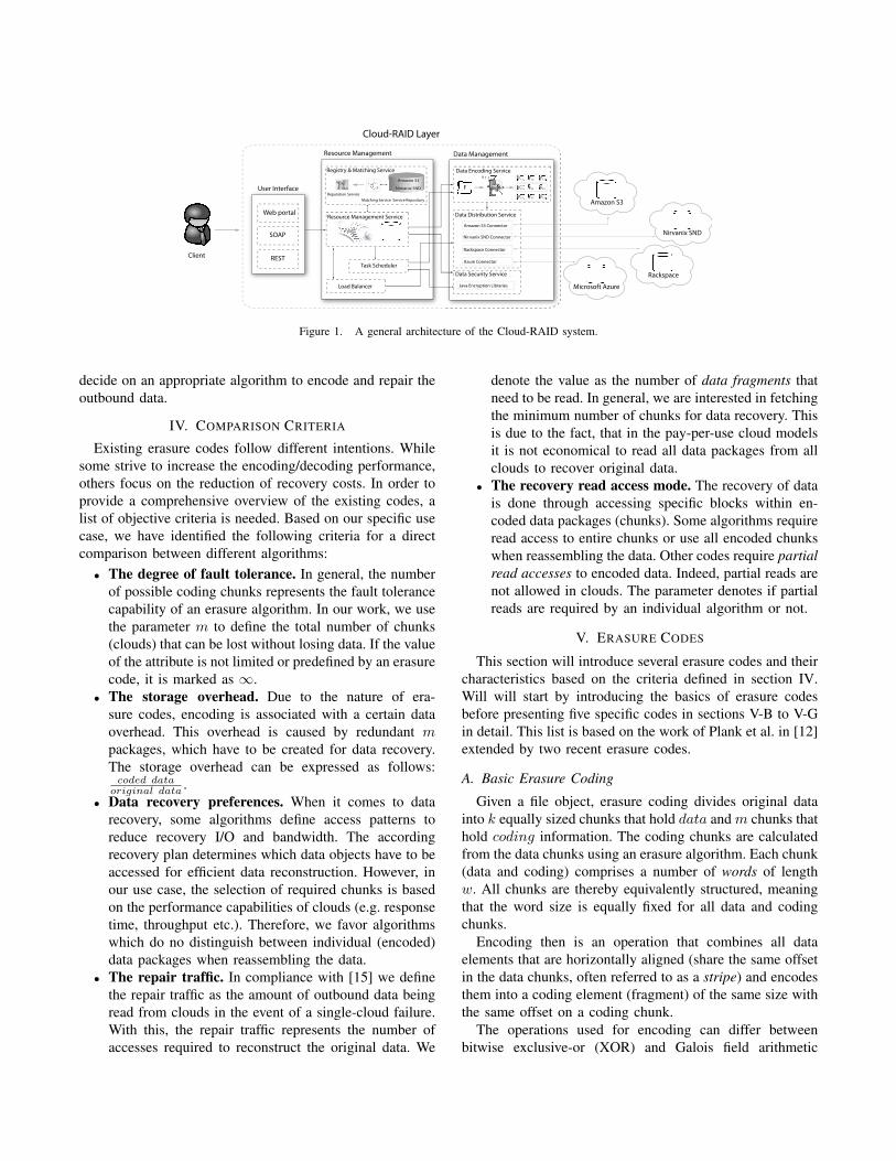
suring the availability of the company’s data. As mentionedabove, the basic idea is not to depend on solely one storageprovider but to spread the data across multiple providersusing redundancy to tolerate possible failures. The approachis similar to a service-oriented version of RAID. WhileRAID manages sector redundancy dynamically across hard-drives, our approach manages file distribution across cloudstorage providers. We carry the principle of the RAID-technology to cloud infrastructure. In order to achieve ourgoal we foster the usage of erasure coding techniques. Thesystem has a number of core components that contain thelogic and management layers required to encapsulate thefunctionality of different storage providers. Our architecture(see Figure 1) includes the following main components:• User Interface Module. The interface presents the user
a cohesive view on his data and available features. Hereusers can manage their data and specify requirementsregarding the data retention (quality of service param-eters).
• Resource Management Module. This system com-ponent is responsible for intelligent deployment ofdata based on users’ requirements. The component issupported by:
– a registry and matching service: assigns storagerepositories based on users requirements (for ex-ample physical location of the service, costs andperformance expectations). Monitors the perfor-mance of participating providers and ensures thatthey are meeting the agreed SLAs
– a resource management service: takes operationaldecisions regarding the content storage
– a task scheduler service: has the ability to schedulethe launch of operations at peak-off hours or afterspecified time intervals.
• Data Management Module. This component handlesdata management on behalf of the resource manage-ment module and is mainly supported by:
– a data encoding service: this component is respon-sible for striping and encoding of user’s content
– a data distribution service: spreads the encodeddata packages across multiple providers. Sinceeach storage service is only accessible through aunique API, the service utilizes storage ”service-connectors”, which provide an abstraction layer forthe communication to storage repositories
– a security service: manages the security function-ality based on a user’s requirements (encryption,secret key management).
With this, we consider a distributed multiple cloud storagesetting from user’s perspective, such as we stripe dataover multiple clouds. Interested readers will find morebackground information in our previous work [5],[6]. Inthe following, we will analyze existing erasure codes to
Cloud-RAID Layer
Client
User Interface
Web portal
REST
SOAP
Resource Management
Registry & Matching Service
Reputation Service
Matching Service
Amazon S3
Nirnanix SND...
Service Repository
Resource Management Service
Task Scheduler
Data Management
Data Distribution Service
Amazon S3 Connector
Nirvanix SND Connector
Rackspace Connector
Azure Connector
Data Encoding Service
F
F3,1 F3,2 F3,3
Amazon S3
Nirvanix SND
RackspaceData Security Service
Java Encryption Libraries
F2,1 F2,2 F2,3
F1,1 F1,2 F1,3
Load Balancer Microsoft Azure
Figure 1. A general architecture of the Cloud-RAID system.
decide on an appropriate algorithm to encode and repair theoutbound data.
IV. COMPARISON CRITERIA
Existing erasure codes follow different intentions. Whilesome strive to increase the encoding/decoding performance,others focus on the reduction of recovery costs. In order toprovide a comprehensive overview of the existing codes, alist of objective criteria is needed. Based on our specific usecase, we have identified the following criteria for a directcomparison between different algorithms:• The degree of fault tolerance. In general, the number
of possible coding chunks represents the fault tolerancecapability of an erasure algorithm. In our work, we usethe parameter m to define the total number of chunks(clouds) that can be lost without losing data. If the valueof the attribute is not limited or predefined by an erasurecode, it is marked as ∞.
• The storage overhead. Due to the nature of era-sure codes, encoding is associated with a certain dataoverhead. This overhead is caused by redundant mpackages, which have to be created for data recovery.The storage overhead can be expressed as follows:
coded dataoriginal data .
• Data recovery preferences. When it comes to datarecovery, some algorithms define access patterns toreduce recovery I/O and bandwidth. The accordingrecovery plan determines which data objects have to beaccessed for efficient data reconstruction. However, inour use case, the selection of required chunks is basedon the performance capabilities of clouds (e.g. responsetime, throughput etc.). Therefore, we favor algorithmswhich do no distinguish between individual (encoded)data packages when reassembling the data.
• The repair traffic. In compliance with [15] we definethe repair traffic as the amount of outbound data beingread from clouds in the event of a single-cloud failure.With this, the repair traffic represents the number ofaccesses required to reconstruct the original data. We
denote the value as the number of data fragments thatneed to be read. In general, we are interested in fetchingthe minimum number of chunks for data recovery. Thisis due to the fact, that in the pay-per-use cloud modelsit is not economical to read all data packages from allclouds to recover original data.
• The recovery read access mode. The recovery of datais done through accessing specific blocks within en-coded data packages (chunks). Some algorithms requireread access to entire chunks or use all encoded chunkswhen reassembling the data. Other codes require partialread accesses to encoded data. Indeed, partial reads arenot allowed in clouds. The parameter denotes if partialreads are required by an individual algorithm or not.
V. ERASURE CODES
This section will introduce several erasure codes and theircharacteristics based on the criteria defined in section IV.Will will start by introducing the basics of erasure codesbefore presenting five specific codes in sections V-B to V-Gin detail. This list is based on the work of Plank et al. in [12]extended by two recent erasure codes.
A. Basic Erasure Coding
Given a file object, erasure coding divides original datainto k equally sized chunks that hold data and m chunks thathold coding information. The coding chunks are calculatedfrom the data chunks using an erasure algorithm. Each chunk(data and coding) comprises a number of words of lengthw. All chunks are thereby equivalently structured, meaningthat the word size is equally fixed for all data and codingchunks.
Encoding then is an operation that combines all dataelements that are horizontally aligned (share the same offsetin the data chunks, often referred to as a stripe) and encodesthem into a coding element (fragment) of the same size withthe same offset on a coding chunk.
The operations used for encoding can differ betweenbitwise exclusive-or (XOR) and Galois field arithmetic

(GF (2w)). While XOR operations can be executed fast onCPUs, GF (2w) multiplications traditionally perform worse.However, new libraries like the one provided by Plank etal. [9] offer support for fast computations of these operationswith modern CPUs as well.
In summary, erasure algorithms map a data object brokeninto k equal-size original chunks onto a larger set on nchunks of the same size in such a way, that the originalchunks can be recovered from any n − k = m chunks.Erasure codes that only need any arbitrary k out of n chunksfor the recovery of original data are called maximum distanceseparable codes (MDS codes) [16]. Similar to Plank etal. [12], we are only interested in MDS codes. Furthermore,we focus only on horizontal codes where chunks hold eitheroriginal data or parity data. The so called vertical codesare not considered in our work, as they allow chunks tohold both kinds of data. This means vertical codes operateon all encoded chunks to restore the original data, whereashorizontal codes require the minimum number of k arbitrarychunks to achieve the same goal.
B. Reed-Solomon
Reed-Solomon codes [8] (RS codes) have the longesthistory among erasure codes. They originate in informationtheory and operate on w-bit words. The used word size w isonly limited by the total number of chunks n which is notallowed to be greater than 2w +1. Except for this restriction,the word size can be freely determined by a user. Typically,the chosen size corresponds to machine word boundaries(8, 16, 32, 64) for good performance and w = 8 for bestperformance.
Further, the total number of encoded chunks can bedefined arbitrarily. Each RS configuration is denoted as (k,m)and increases the storage costs by a factor of m
k . Notethat m=1 represents a simple replication, and RAID level6 can be described by (k=4, m=2). In the example, thealgorithm calculates n=6 chunks, any k=4 chunks of whichare sufficient to reconstruct the object, resulting in a totaloverhead of 2
4 = 50%.RS codes treat each word of length w as a number be-
tween 0 and 2w−1 and operate on these numbers with Galoisfield arithmetic (GF (2w)). The algebraic structure definesaddition, multiplication and division on words and producesa closed and well-behaved system [16]. Addition in GF (2w)is equivalent to XOR operation, multiplication however is farmore complex. It is usually implemented with multiplicationtables or discrete logarithm tables and considered expensivein terms of computation time. However, as mentioned inSection V-A, new libraries enable the fast computation ofthese operations nowadays.
Encoding with RS codes requires the multiplication of aGenerator matrix GT (derived from a Vandermonde matrix)with individual data words of a single stripe. The operationcreates a codeword which comprises k data elements and m
coding elements. The latter are stored on dedicated codingchunks. The procedure has to be executed for each stripe.Figure 2 illustrates the encoding process of a single stripe.
254 FAST ’09: 7th USENIX Conference on File and Storage Technologies USENIX Association
2 Nomenclature and Erasure Codes
It is an unfortunate consequence of the history of era-
sure coding research that there is no unified nomencla-
ture for erasure coding. We borrow terminology mostly
from Hafner et al [14], but try to conform to more classic
coding terminology (e.g. [5, 21]) when appropriate.
Our storage system is composed of an array of ndisks, each of which is the same size. Of these n disks, kof them hold data and the remaining m hold coding in-
formation, often termed parity, which is calculated from
the data. We label the data disks D0, . . . , Dk−1 and the
parity disks C0, . . . , Cm−1. A typical system is pictured
in Figure 1.
Figure 1: A typical storage system with erasure coding.
We are concerned with Maximum Distance Separa-
ble (MDS) codes, which have the property that if any mdisks fail, the original data may be reconstructed [21].
When encoding, one partitions each disk into strips of
a fixed size. Each parity strip is encoded using one
strip from each data disk, and the collection of k + mstrips that encode together is called a stripe. Thus, as
in Figure 1, one may view each disk as a collection of
strips, and one may view the entire system as a collec-
tion of stripes. Stripes are each encoded independently,
and therefore if one desires to rotate the data and parity
among the n disks for load balancing, one may do so by
switching the disks’ identities for each stripe.
2.1 Reed-Solomon (RS) Codes
Reed-Solomon codes [28] have the longest history. The
strip unit is a w-bit word, where w must be large enough
that n ≤ 2w + 1. So that words may be manipulated
efficiently, w is typically constrained so that words fall
on machine word boundaries: w ∈ {8, 16, 32, 64}. How-
ever, as long as n ≤ 2w + 1, the value of w may be
chosen at the discretion of the user. Most implementa-
tions choose w = 8, since their systems contain fewer
than 256 disks, and w = 8 performs the best. Reed-
Solomon codes treat each word as a number between 0
and 2w − 1, and operate on these numbers with Galois
Field arithmetic (GF (2w)), which defines addition, mul-
tiplication and division on these words such that the sys-
tem is closed and well-behaved [21].
The act of encoding with Reed-Solomon codes is sim-
ple linear algebra. A Generator Matrix is constructed
from a Vandermonde matrix, and this matrix is multiplied
by the k data words to create a codeword composed of
the k data and m coding words. We picture the process
in Figure 2 (note, we draw the transpose of the Generator
Matrix to make the picture clearer).
Figure 2: Reed-Solomon coding for k = 4 and m = 2.
Each element is a number between 0 and 2w − 1.
When disks fail, one decodes by deleting rows of GT ,
inverting it, and multiplying the inverse by the surviving
words. This process is equivalent to solving a set of inde-
pendent linear equations. The construction of GT from
the Vandermonde matrix ensures that the matrix inver-
sion is always successful.
In GF (2w), addition is equivalent to bitwise
exclusive-or (XOR), and multiplication is more com-
plex, typically implemented with multiplication tables
or discrete logarithm tables [11]. For this reason, Reed-
Solomon codes are considered expensive. There are sev-
eral open-source implementations of RS coding, which
we detail in Section 3.
2.2 Cauchy Reed-Solomon (CRS) Codes
CRS codes [6] modify RS codes in two ways. First,
they employ a different construction of the Generator
matrix using Cauchy matrices instead of Vandermonde
matrices. Second, they eliminate the expensive multipli-
cations of RS codes by converting them to extra XOR
operations. Note, this second modification can apply to
Vandermonde-based RS codes as well. This modifica-
tion transforms GT from a n × k matrix of w-bit words
to a wn×wk matrix of bits. As with RS coding, w must
be selected so that n ≤ 2w + 1.
Instead of operating on single words, CRS coding op-
erates on entire strips. In particular, strips are partitioned
into w packets, and these packets may be large. The act
of coding now involves only XOR operations – a coding
packet is constructed as the XOR of all data packets that
Figure 2. Reed-Solomon Encoding with k=4 and m=2.
However, data recovery is comparable to the encodingprocess and is realised by a stripe-by-stripe recalculation ofexisting chunks. This requires the elimination of those stripsin the GT matrix that correspond to the lost data chunk.Then, the resulting matrix has to be inverted and multipliedby k arbitrarily chosen data fragments that have not beenlost.
The amount of data needed for the recovery of a singlechunk always equals k×chunk size, since k out of n chunksare needed to reconstuct the data. In terms of data elementsthat have to be read, RS codes always need to access k ×d chunk size
word size e elements.The use of a Vandermonde matrix for the construction of
GT ensures that the inversion of the latter is always possible.The inversion, however, is a rather expensive operation interms of computation time.
Overall, the Reed-Solomon codes are the most flexibleerasure codes in terms of word size and coding chunks, witha rather weak performance compared to other codes intro-duced in the following sections. However, they describe themost generic family of codes that can be used for a variety ofapplications and have been employed in many fields such asdeep-space communication, consumer electronics (e.g. CDs,DVDs, Blu-ray discs), in data transmission technologies (e.g.DSL) and in RAID-6 storage systems.
C. Cauchy-Reed-Solomon
Cauchy Reed-Solomon (CRS) codes [17] differ from RSalgorithms in two ways: i) The GT matrix is created by theusage of Cauchy matrices instead of Vandermonde matrices,and ii) they employ XOR operations instead of expensiveGF (2w) multiplications. Similar to RS codes, the totalnumber of coding chunks (defined by the parameter m)can be chosen freely. The produced storage overhead isequivalent to RS codes.
To eliminate multiplications, CRS codes transform theGT matrix from a n × k matrix of w-bit words to awn×wk matrix of bits. This new matrix is then multipliednot by single data words of w-bit size but strips of w data

fragments. For performance reasons, the size of a fragmentshould be a multiple of the machine’s word size. Each ofthe k data chunks now consists of several strips, each stripcontaining w fragments. The w is not constrained to themachine’s word size and can be defined freely (as long asn ≤ 2w). Encoding and decoding still happens stripe-by-stripe - whereby each stripe consists now not of single datawords but strips. Note, the modification of the matrix is alsopossible for Vandermonde matrices.
Encoding needs only XOR operations in order to computecoding data. A coding fragment is created as the XORedresult of all data fragments that have a one-bit in the codingchunk’s line of GT . Figure 3 illustrates how the last codingfragment is created by XORing all data fragments that havea one bit in the last line of GT .
USENIX Association FAST ’09: 7th USENIX Conference on File and Storage Technologies 255
have a one bit in the coding packet’s row of GT . The
process is depicted in Figure 3, which illustrates how the
last coding packet is created as the XOR of the six data
packets identified by the last row of GT .
Figure 3: CRS example for k = 4 and m = 2.
To make XORs efficient, the packet size must be a
multiple of the machine’s word size. The strip size is
therefore equal to w times the packet size. Since w no
longer relates to the machine word sizes, w is not con-
strained to [8, 16, 32, 64]; instead, any value of w may be
selected as long as n ≤ 2w.
Decoding in CRS is analogous to RS coding — all
rows of GT corresponding to failed packets are deleted,
and the matrix is inverted and employed to recalculate
the lost data.
Since the performance of CRS coding is directly re-
lated to the number of ones in GT , there has been re-
search on constructing Cauchy matrices that have fewer
ones than the original CRS constructions [27]. The Jera-
sure library [26] uses additional matrix transformations
to improve these matrices further. Additionally, in the
restricted case when m = 2, the Jerasure library uses re-
sults of a previous enumeration of all Cauchy matrices to
employ provably optimal matrices for all w ≤ 32 [26].
2.3 EVENODD and RDP
EVENODD [4] and RDP [8] are two codes developed for
the special case of RAID-6, which is when m = 2. Con-
ventionally in RAID-6, the first parity drive is labeled P ,
and the second is labeled Q. The P drive is equivalent to
the parity drive in a RAID-4 system, and the Q drive is
defined by parity equations that have distinct patterns.
Although their original specifications use different
terms, EVENODD and RDP fit the same paradigm as
CRS coding, with strips being composed of w packets.
In EVENODD, w is constrained such that k + 1 ≤ wand w+1 is a prime number. In RDP, w+1 must be prime
and k ≤ w. Both codes perform the best when (w−k) is
minimized. In particular, RDP achieves optimal encod-
ing and decoding performance of (k−1) XOR operations
per coding word when k = w or k +1 = w. Both codes’
performance decreases as (w − k) increases.
2.4 Minimal Density RAID-6 Codes
If we encode using a Generator bit-matrix for RAID-
6, the matrix is quite constrained. In particular, the
first kw rows of GT compose an identity matrix, and in
order for the P drive to be straight parity, the next wrows must contain k identity matrices. The only flex-
ibility in a RAID-6 specification is the composition of
the last w rows. In [5], Blaum and Roth demonstrate
that when k ≤ w, these remaining w rows must have
at least kw + k − 1 ones for the code to be MDS. We
term MDS matrices that achieve this lower bound Mini-
mal Density codes.
There are three different constructions of Minimal
Density codes for different values of w:
• Blaum-Roth codes when w + 1 is prime [5].
• Liberation codes when w is prime [25].
• The Liber8tion code when w = 8 [24].
These codes share the same performance characteris-
tics. They encode with (k − 1) + k−12w XOR operations
per coding word. Thus, they perform better when wis large, achieving asymptotic optimality as w → ∞.
Their decoding performance is slightly worse, and re-
quires a technique called Code-Specific Hybrid Recon-
struction [14] to achieve near-optimal performance [25].
The Minimal Density codes also achieve near-optimal
updating performance when individual pieces of data are
modified [27]. This performance is significantly better
than EVENODD and RDP, which are worse by a factor
of roughly 1.5 [25].
2.5 Anvin’s RAID-6 Optimization
In 2007, Anvin posted an optimization of RS encoding
for RAID-6 [2]. For this optimization, the row of GT
corresponding to the P drive contains all ones, so that
the P drive may be parity. The row corresponding to
the Q drive contains the number 2 i in GF (2w) in col-
umn i (zero-indexed), so that the contents of the Q drive
may be calculated by successively XOR-ing drive i’sdata into the Q drive and multiplying that sum by two.
Since multiplication by two may be implemented much
faster than general multiplication in GF (2w), this op-
timizes the performance of encoding over standard RS
implementations. Decoding remains unoptimized.
3 Open Source Libraries
We test five open source erasure coding libraries. These
are all freely available libraries from various sources
on the Internet, and range from brief proofs of concept
Figure 3. Cauchy Reed-Solomon Encoding with n=4 and m=2.
The recovery of lost data with CRS codes is handledanalogously to RS codes: all rows of GT corresponding tofailed chunks have to be deleted, then the matrix needs to beinverted and multiplied by k existing data chunks. With this,the recovery process requires the same data fragments as RScodes. The total number of read operations on fragment levelcan be smaller due to possibly larger CRS fragment sizes(in comparison to RS word sizes).
Despite the potential performance gain through the elimi-nation of GF (2w) multiplications, the performance of CRScodes is highly dependent on the number of ones in GT .The more one-bits the generator matrix consists of, the moredata fragments have to be XORed, which results in a weakerencoding performance. Research on the creation of optimalmatrices for CRS codes [18] yielded matrices with fewerones than the original Cauchy matrices. Some libraries (e.gthe Jerasure library, see Section VI) optimize these matriceseven further to achieve better performance for en-/decoding.
D. EVEN/ODD and RDPEVEN/ODD [19] and RDP[20] are special-purpose
RAID-6 erasure codes. Therefore, the number of codingchunks always equals to m = 2. The coding chunks arecalled parity chunks P and Q. The storage overhead of bothcodes is only dependent on the number of data chunks, sincem is fixed. Therefore, the caused storage overhead can becalculated as follows: 2
k .Analogously to CRS codes, EVEN/ODD and RDP operate
on strips with w packets. While EVEN/ODD constraints w
so that n + 1 ≤ w, RDP expects n ≤ w. Both algorithmsdefine w + 1 to be a prime number.
The P-drive is calculated by XORing all strips of onestripe in order to create a parity strip. The Q-drive, however,is constructed differently with specific parity equations forboth codes (see Figure 4). While RDP reuses the P-drive tocalculate the Q-drive, EVEN/ODD employs a special patternwith an intermediate result.
When restoring lost data, EVEN/ODD and RDP workwith one parity drive (restoring one failed data chunk) ora combination of parity drives and special patterns similarto the ones shown in Figure 4. The amount of data neededfor the recovery is comparable to CRS, since RDP andEVEN/ODD work with similar strip and fragment defini-tions. Further, the algorithms belong to MDS codes family,which means that the recovery process requires any arbitraryk out of k + 2 encoded data chunks.
Figure 4. The Q-drive calculation patterns of EVEN/ODD (left) and RDP(right).
According to [19] the total number of operations neededto encode and decode data is provably lower for RDP andEVEN/ODD compared to standard RS and CRS codes.However, in contrast to RS and CRS codes EVEN/ODDand RDP are under patent protection, which means thatthe implementation of the algorithms is not available to thepublic (see Section VI).
E. Minimal DensityIn case of RAID-6 specifications, the used GT bit-matrix
(see CRS codes) is quite constrained. The number of codingchunks is fixed to m = 2, which results in a w(k + 2) ×wk matrix. The first wn rows of this matrix form a fixedidentity matrix and represent the original data in the resultingcodeword when encoding this data (see Figure 3).
The next w rows comprise the k identity matrices thatbuild the P-drive and are therefore fixed either. The com-position of the last w rows of GT is the only flexible partfor a RAID-6 specification. In case of k ≤ w, the minimalnumber of ones in these rows is given by kw + k − 1 [21].Minimal Density (MD) codes are using matrices that achievethis lower bound for RAID-6 configurations.
MD codes can therefore be seen as an optimized codefamily of CRS codes for RAID-6 specifications. Thus, MDcodes share basic characteristics (e.g. storage overhead) withother RAID-6 codes like EVEN/ODD and RDP.
Three different constructions of MD codes exist, depend-ing on the size of the parameter w:

• Blaum-Roth codes for w + 1 being a prime num-ber [21],
• Liberation codes for w being a prime number [22] and• Liber8tion codes for w = 8 [23].As Plank et al. [12] state, MD codes encode with
k − 1 + k−12w XOR operations per coding word. Thus,
the algorithms perform better with a higher value of theparameter w. For decoding, MD codes require Code-SpecificHybrid Reconstruction in order to achieve a near-optimalperformance. Overall, as shown in [12], these code performbetter than CRS codes for RAID-6 specifications.
F. Rotated Reed-Solomon
Rotated RS codes [13] have been designed to reducebandwidth and I/O needed for the recovery of lost data.In particular, these codes optimize the performance of de-graded reads in single chunk failure scenarios. Since 99.75%of recovery scenarios deal with single chunk failures, asSchroeder et al. [24] discovered, Khan et al. [13] optimizedtheir codes for this particular use case. The authors buildon classic RS codes and modify the way of encoding datato allow faster recovery by reusing and therefore accessingless data fragments. Beyond that the algiorithms share allcharacteristics (namely storage overhead, performance, andconfigurability) with classic RS codes.
However, Rotated RS codes are not generally MDS codes.In [13] Khan et al. present several constraints that arenecessary for these codes to belong to the family of MDScodes. These limitations comprise m ∈ {2, 3}, k ≤ 36 andw ∈ {4, 8, 16}. Research on general MDS constructions ofRotated RS codes is still ongoing.
As depicted in Figure 5, encoding with rotated RS codesmodifies classic RS coding in two ways: i) single-row stripesof w-bit sized data words are transformed into r multi-rowstripes of bit-words (r and w may be different), and ii)XORing the encoded data fragments (symbols) is not donewithin one row but across adjacent rows.
different disks in the storage system. In other words, ifone is reading three symbols starting with symbol d0,0,then those three symbols are d0,0, d1,0 and d2,0, comingfrom three different disk drives.
To evaluate degraded reads, we assume that an appli-cation desires to read B symbols starting at symbol dx,y ,and that data disk f has failed. We determine the penaltyof the failure to be the number of symbols required toperform the read, minus B.
There are many cases that can arise from the differ-ing values of B, f , x and y. To illustrate, first supposethat B < k (which is a partial read case) and that none ofthe symbols to be read reside on disk f . Then the failuredoes not impact the read operation — it takes exactly Bsymbols to complete the read, and the penalty is zero.
As a second case, consider when B = kr and dx,y =d0,0. Then we are reading exactly one stripe in its en-tirety. In this case, we have to read the (k−1)r non-faileddata symbols to fulfill the read request. Therefore, wemay recover very easily from the P drive by reading allof its symbols and decoding. The read requires kr = Bsymbols. Once again, the penalty is zero.
However, consider the case when B = k, f = 0, anddx,y = d1,0. Symbols d1,0 through dk−1,0 are non-failedand must be read. Symbol d0,1 must also be read and itis failed. If we use the P drive to recover, then we needto read d1,1 through dk−1,0 and c0,1. The total symbolsread is 2k− 1: the failure has induced a penalty of k− 1symbols.
In all of these cases, the degraded read is containedby one stripe. If the read spans two stripes, then wecan calculate the penalty as the sum of the penalties ofthe read in each stripe. If the read spans more than twostripes, then we only need to calculate the penalties in thefirst and last stripe. This is because, as described above,whole-stripe degraded reads incur no penalty.
When we perform a degraded read within a stripe, wemodify our algorithm slightly. For each non-failed datasymbol that must be read, we set its bit in the state of thestarting node Z to one. For example, in Figure 4, sup-pose we are performing a degraded read where B = 2,f = 0 and dx,y = d0,0. There is one failed bit: F = d0,0.Since d1,0 = R2 must be read, the starting state Z of theshortest path graph is labeled 00100000. The algorithmcorrectly identifies that only c0,0 needs to be read to re-cover d0,0 and complete the read.
5 Rotated Reed-Solomon Codes
Before performing analyses of failed disk reconstructionand degraded reads, we present two instances of a newerasure code, called the Rotated Reed-Solomon code.These codes have been designed to be MDS codes thatoptimize the performance of degraded reads for single
disk failures. The general formulation and theoreticalevaluation of these codes is beyond the scope of this pa-per; instead, we present instances for m ∈ {2, 3}.
Figure 6: A Reed-Solomon code for k = 6 and m =3. Symbols must be w-bit words such that w ≥ 4, andarithmetic is over GF (2w).
The most intuitive way to present a Rotated Reed-Solomon code is as a modification to a standard Reed-Solomon code. We present such a code for m ≤ 3 inEquation 1. As with all Reed-Solomon codes, r = 1.
for 0 ≤ j < 3, cj,0 =k−1∑
i=0
(2j
)idi,0 (1)
This is an MDS code so long as k, m, r and w adhereto some constraints, which we detail at the end of thissection. This code is attractive because one may imple-ment encoding with XOR and multiplication by two andfour in GF (2w), which are all very fast operations. Forexample, the m = 2 version of this code lies at the heartof the Linux RAID-6 coding engine [1].
We present the code pictorally in Figure 6. A chainof circles denotes taking the XOR of di,0; a chain of tri-angles denotes taking the XOR of 2idi,0, and a chain ofsquares denotes taking the XOR of 4idi,0. To convert thiscode into a Rotated Reed-Solomon code, we allow r totake on any positive value, and define the coding symbolswith Equation 2.
cj,b =
kjm −1∑
i=0
(2j)idi,(b+1)%r +k−1∑
i= kjm
(2j)idi,b. (2)
Intuitively, the Rotated Reed-Solomon code convertsthe one-row code in Figure 6 into a multi-row code,and then the equations for coding disks 1 and 2 aresplit across adjacent rows. We draw the Rotated Reed-Solomon codes for k = 6 and m = {2, 3} and r = 3 inFigures 7 and 8.
These codes have been designed to improve thepenalty of degraded reads. Consider a RAID-6 systemthat performs a degraded read of four symbols startingat d5,0 when disk 5 has failed. If we reconstruct from
7
Figure 7: A Rotated Reed-Solomon code for k = 6, m =2 and r = 3.
the P drive, we need to read d0,0 through d4,0 plus c0,0
to reconstruct d5,0. Then we read the non-failed sym-bols d0,1, d1,1 and d2,1. The penalty is 5 symbols. WithRotated Reed-Solomon coding, d5,0, d0,1, d1,1 and d2,1
all participate in the equation for c1,0. Therefore, byreading c1,0, d0,1, d1,1, d2,1, d3,0 and d4,0, one both de-codes d5,0 and reads the symbols that were required tobe read. The penalty is only two symbols.
Figure 8: A Rotated Reed-Solomon code for k = 6, m =3 and r = 3.
With whole disk reconstruction, when r is an evennumber, one can reconstruct any failed data disk by read-ing r
2 (k + d kme) symbols. The process is exemplified
for k = 6, m = 3 and r = 4 in Figure 9. The first datadisk has failed, and the symbols required to reconstructeach of the failed symbols is darkened and annotatedwith the equation that is used for reconstruction. Eachpair of reconstructed symbols in this example shares fourdata symbols for reconstruction. Thus, the whole recon-struction process requires a total of 16 symbols, as op-posed to 24 when reading from the P Drive.
The process is similar for the other data drives. Re-constructing failed coding drives, however does not have
Figure 9: Reconstructing disk 0 when it fails, using Ro-tated Reed-Solomon coding for k = 6, m = 3, r = 4.
the same benefits. We are unaware at present of howto reconstruct a coding drive with fewer than the maxi-mum kr symbols.
As an aside, when more than one disk fails, RotatedReed-Solomon codes may require much more computa-tion to recover than other codes, due to the use of matrixinversion for recovery. We view this property as less im-portant, since multiple disk failures are rare occurrencesin practical storage systems, and computational overheadis less important than the I/O impact of recovery.
5.1 MDS ConstraintsThe Rotated Reed-Solomon code specified above in Sec-tion 5 is not MDS in general. In other words, there aresettings of k, m, w and r which cannot tolerate the fail-ure of any m disks. Below, we detail ways to constrainthese variables so that the Rotated Reed-Solomon codeis MDS. Each of these settings has been verified by test-ing all combinations of m failures to make sure that theymay be tolerated. They cover a wide variety of systemsizes, certainly much larger than those in use today.
The constraints are as follows:
m ∈ {2, 3}k ≤ 36, and k + m ≤ 2w + 1
w ∈ {4, 8, 16}r ∈ {2, 4, 8, 16, 32}
Moreover, when w = 16, r may be any value lessthan or equal to 48, except 15, 30 and 45. It is a matter offuture research to derive general-purpose MDS construc-tions of Rotated Reed-Solomon codes.
6 Analysis of Reconstruction
We evaluate the minimum number of symbols required torecover a failed disk in erasure coding systems with a va-riety of erasure codes. We restrict our attention to MDScodes, and systems with six data disks and either two or
8
Figure 5. Encoding of classic RS (left) and Rotated RS (right) codes withn = 6 and m = 3
Except these two modifications, the encoding operationshares all characteristics with classic RS encoding (e.g.performance, storage overhead). As shown in Figure 6, thedecoding operation benefits from the rotated encoding interms of read accesses. With this, the recovery of singlechunk failures gains in performance. The number of datasymbols that have to be accessed is reduced by a particular
pattern of XORing between adjacent rows. In the providedexample, the behavior leads to three different recovery pathsthrough the original data for each data bit. The procedurewould correspond to one path in classic RS codes (repeatedthree times).
Figure 7: A Rotated Reed-Solomon code for k = 6, m =2 and r = 3.
the P drive, we need to read d0,0 through d4,0 plus c0,0
to reconstruct d5,0. Then we read the non-failed sym-bols d0,1, d1,1 and d2,1. The penalty is 5 symbols. WithRotated Reed-Solomon coding, d5,0, d0,1, d1,1 and d2,1
all participate in the equation for c1,0. Therefore, byreading c1,0, d0,1, d1,1, d2,1, d3,0 and d4,0, one both de-codes d5,0 and reads the symbols that were required tobe read. The penalty is only two symbols.
Figure 8: A Rotated Reed-Solomon code for k = 6, m =3 and r = 3.
With whole disk reconstruction, when r is an evennumber, one can reconstruct any failed data disk by read-ing r
2 (k + d kme) symbols. The process is exemplified
for k = 6, m = 3 and r = 4 in Figure 9. The first datadisk has failed, and the symbols required to reconstructeach of the failed symbols is darkened and annotatedwith the equation that is used for reconstruction. Eachpair of reconstructed symbols in this example shares fourdata symbols for reconstruction. Thus, the whole recon-struction process requires a total of 16 symbols, as op-posed to 24 when reading from the P Drive.
The process is similar for the other data drives. Re-constructing failed coding drives, however does not have
Figure 9: Reconstructing disk 0 when it fails, using Ro-tated Reed-Solomon coding for k = 6, m = 3, r = 4.
the same benefits. We are unaware at present of howto reconstruct a coding drive with fewer than the maxi-mum kr symbols.
As an aside, when more than one disk fails, RotatedReed-Solomon codes may require much more computa-tion to recover than other codes, due to the use of matrixinversion for recovery. We view this property as less im-portant, since multiple disk failures are rare occurrencesin practical storage systems, and computational overheadis less important than the I/O impact of recovery.
5.1 MDS ConstraintsThe Rotated Reed-Solomon code specified above in Sec-tion 5 is not MDS in general. In other words, there aresettings of k, m, w and r which cannot tolerate the fail-ure of any m disks. Below, we detail ways to constrainthese variables so that the Rotated Reed-Solomon codeis MDS. Each of these settings has been verified by test-ing all combinations of m failures to make sure that theymay be tolerated. They cover a wide variety of systemsizes, certainly much larger than those in use today.
The constraints are as follows:
m ∈ {2, 3}k ≤ 36, and k + m ≤ 2w + 1
w ∈ {4, 8, 16}r ∈ {2, 4, 8, 16, 32}
Moreover, when w = 16, r may be any value lessthan or equal to 48, except 15, 30 and 45. It is a matter offuture research to derive general-purpose MDS construc-tions of Rotated Reed-Solomon codes.
6 Analysis of Reconstruction
We evaluate the minimum number of symbols required torecover a failed disk in erasure coding systems with a va-riety of erasure codes. We restrict our attention to MDScodes, and systems with six data disks and either two or
8
Figure 6. Recovery of first data chunk with Rotated RS codes with n = 6and m = 3
In [13] Khan et al. state that the reconstruction of a wholechunk, when r is even, requires exactly r
2 (k + d kme) data
fragments to be read, in comparison to rk data fragmentsthat RS codes need to access. In the example provided inFigure 6, Rotated RS codes need to read 16 fragmetns, whileRS codes would need to access 24. Note, the Rotated RScodes are the only codes presented so far that perform partialreads on encoded chunks to improve the performance of thealgorithm. The improvement is based on the ability to accesschunks more specifically data objects on bit-level withoutreading the remaining bits of the proper data word. However,this might not be applicable in a context of cloud storage,where partial reads (or writes) are not allowed.
Concerning the number of reads, Rotated RS access sevenchunks in the recovery scenario presented in Figure 6 andtherefore perform more accesses than classic RS codes.Furthermore, encoded chunks can not be selected arbitrarybut provided by the code. This means, the individual chunkscan not be considered to be equal.
G. Local Reconstruction
Local Reconstruction Codes (LRC)[14] have been createdto reduce the bandwidth in I/O for data recovery processes.The algorithms are build on classic RS codes and introducelocal parities that serve as additional coding chunks forspecific data groups. These parities reduce the averagenumber of data fragments which have to be accessed in theevent of a recovery.
Encoding with LRC differs from RS encoding in threeways: i) the original data chunks are divided into a specifiednumber of l groups, ii) coding chunks are divided into globaland local parities, and iii) data chunks are encoded onto allglobal and one local parity. An exemplary configuration ofLRC(6,2,2) is shown in Figure 7.
However, LRC is not MDS in general. Huang et al.[14] prove, that LRC is nonetheless Maximally Recoverable(MR). In comparison to MDS, MR code compensates up
of the data fragments. In addition, we want to reducestorage costs down to 1.33x of the original data usingerasure coding. This could be accomplished using thestandard approach of Reed-Solomon codes [13] wherewe would have (12, 4), which is 12 data fragments and4 code fragments. This means that to do the reconstruc-tion we would need to read from a set of 12 fragments.This i) greatly increases the chance of hitting a hot stor-age node, andii) increases the network costs and I/Osand adds latency to read that many fragments to do thereconstruction. Therefore, we want to design a new fam-ily of codes to use for WAS that provides the followingcharacteristics:
1. Reduce the minimal number of fragments that needto be read from to reconstruct a data fragment. Thisprovides the following benefits:i) reduces the net-work overhead and number of I/Os to perform a re-construction;ii) reduces the time it takes to performthe reconstruction since fewer fragments need to beread. We have found the time to perform the re-construction is often dominated by the slowest frag-ments (the stragglers) to be read from.
2. Provide significant reduction in storage overheadto 1.33x while maintaining higher durability than asystem that keeps 3 replicas for the data.
In this paper, we introduce Local Reconstruction Codes(LRC) that provide the above properties. In addition, wedescribe our erasure coding implementation and impor-tant design decisions.
2 Local Reconstruction CodesIn this section, we illustrate LRC and its properties
through small examples, which are shorter codes (thushigher overhead) than what we use in production, in or-der to simplify the description of LRC .
2.1 DefinitionWe start with a Reed-Solomon code example to ex-
plain the concept ofreconstruction cost. A (6, 3) Reed-Solomon code contains 6 data fragments and 3 parityfragments, where each parity is computed from all the6 data fragments. When any data fragment becomes un-available, no matter which data and parity fragments areused for reconstruction, 6 fragments are always required.We definereconstruction cost as the number of frag-ments required to reconstruct an unavailabledata frag-ment. Here, the reconstruction cost equals to 6.
The goal of LRC is to reduce the reconstruction cost.It achieves this by computing some of the parities froma subset of the data fragments. Continuing the examplewith 6 data fragments, LRC generates 4 (instead of 3)parities. The first two parities (denoted asp0 andp1) areglobal parities and are computed fromall the data frag-ments. But, for the other two parities, LRC divides the
x0 y0x1 x2 y2y1
p0
p1
pypx
Figure 1:A (6, 2, 2) LRC Example. (k = 6 data frag-ments,l = 2 local parities andr = 2 global parities.)
data fragments into two equal size groups and computesone local parity for each group. For convenience, wename the 6 data fragments (x0, x1 andx2) and (y0, y1
andy2). Then, local paritypx is computed from the 3data fragments in one group (x0, x1 andx2), and localparitypy from the 3 data fragments in another group (y0,y1 andy2).
Now, let’s walk through reconstructingx0. Instead ofreadingp0 (or p1) and the other 5 data fragments (x1,x2, y0, y1 andy2), it is more efficient to readpx and twodata fragments (x1 andx2) to computex0. It is easy toverify that the reconstruction ofany single data fragmentrequires only 3 fragments, half the number required bythe Reed-Solomon code.
This LRC example adds one more parity than theReed-Solomon one, so it might appear that LRC reducesreconstruction cost at the expense of higher storage over-head. In practice, however, these two examples achievecompletely different trade-off points in the design space,as described in Section 3.3. In addition, LRC providesmore options than Reed-Solomon code, in terms of trad-ing off storage overhead and reconstruction cost.
We now formally define Local Reconstruction Codes.A (k, l, r) LRC dividesk data fragments intol groups,with k/l data fragments in each group. It computes onelocal parity within each group. In addition, it computesr global parities from all the data fragments. Letn bethe total number of fragments (data + parity). Thenn =k + l + r. Hence, the normalized storage overhead isn/k = 1 + (l + r)/k. The LRC in our example is a(6, 2, 2) LRC with storage cost of1 + 4/6 = 1.67x, asillustrated in Figure 1.
2.2 Fault ToleranceThus far, we have only defined which data fragments
are used to compute each parity in LRC. To completethe code definition, we also need to determinecodingequations, that is, how the parities are computed fromthe data fragments. We choose the coding equations suchthat LRC can achieve theMaximally Recoverable (MR)property [14], which means it can decode any failure pat-tern which is information-theoretically decodable.
Let’s first explain the Maximally Recoverable prop-erty. Given the (6, 2, 2) LRC example, it contains 4 par-ity fragments and can tolerateup to 4 failures. However,
2
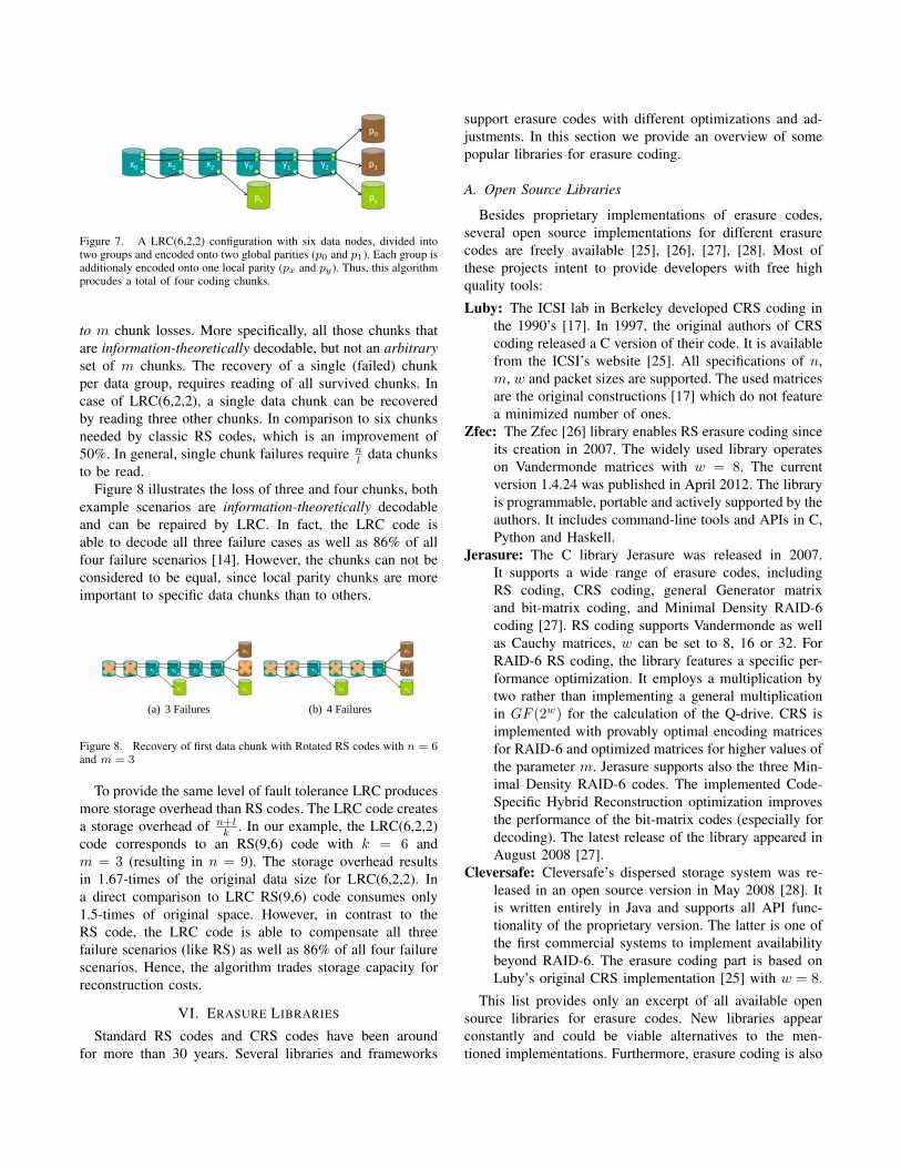
Figure 7. A LRC(6,2,2) configuration with six data nodes, divided intotwo groups and encoded onto two global parities (p0 and p1). Each group isadditionaly encoded onto one local parity (px and py). Thus, this algorithmprocudes a total of four coding chunks.
to m chunk losses. More specifically, all those chunks thatare information-theoretically decodable, but not an arbitraryset of m chunks. The recovery of a single (failed) chunkper data group, requires reading of all survived chunks. Incase of LRC(6,2,2), a single data chunk can be recoveredby reading three other chunks. In comparison to six chunksneeded by classic RS codes, which is an improvement of50%. In general, single chunk failures require n
l data chunksto be read.
Figure 8 illustrates the loss of three and four chunks, bothexample scenarios are information-theoretically decodableand can be repaired by LRC. In fact, the LRC code isable to decode all three failure cases as well as 86% of allfour failure scenarios [14]. However, the chunks can not beconsidered to be equal, since local parity chunks are moreimportant to specific data chunks than to others.
x0 y0x1 x2 y2y1
p0
p1
pypx
(a) 3 Failures
x0 y0x1 x2 y2y1
p0
p1
pypx
(b) 4 Failures
Figure 2: Decoding 3 and 4 Failures in LRC.
LRC is not Maximum Distance Separable [12] and there-fore cannot toleratearbitrary 4 failures. For instance, saythe 4 failures arex1, x2, x3 andpx. This failure patternis non-decodable because there are only two parities -the global parities - that can help to decode the 3 miss-ing data fragments. The other local paritypy is uselessin this example. It isimpossible to decode 3 data frag-ments from merely 2 parity fragments, regardless of cod-ing equations. These types of failure patterns are calledinformation-theoretically non-decodable.
Failure patterns that are possible to reconstruct arecalledinformation-theoretically decodable. For instance,the 3-failure pattern in Figure 2(a) and the 4-failure pat-tern in Figure 2(b) are both information-theoretically de-codable. For these two failure patterns, it is possible toconstruct coding equations such that it is equivalent tosolving 3 unknowns using 3 linearly independent equa-tions in Figure 2(a) and 4 unknowns using 4 linearly in-dependent equations in Figure 2(b).
Conceivably, it is not difficult to construct a set of cod-ing equations that can decode a specific failure pattern.However, the real challenge is to construct asingle set ofcoding equations that achieves theMaximally Recover-able (MR) property [14], or being able to decode all theinformation-theoretically decodable failure patterns – theexact goal of LRC.
2.2.1 Constructing Coding EquationsIt turns out that the LRC can tolerate arbitrary 3 fail-
ures by choosing the following two sets of coding coeffi-cients (α’s andβ’s) for groupx and groupy, respectively.We skip the proofs due to space limitation. Let
qx,0 = α0x0 + α1x1 + α2x2 (1)
qx,1 = α20x0 + α2
1x1 + α22x2 (2)
qx,2 = x0 + x1 + x2 (3)
and
qy,0 = β0y0 + β1y1 + β2y2 (4)
qy,1 = β20y0 + β2
1y1 + β22y2 (5)
qy,2 = y0 + y1 + y2. (6)
Then, the LRC coding equations are as follows:
p0 = qx,0 + qy,0, p1 = qx,1 + qy,1, (7)
px = qx,2, py = qy,2. (8)
Next, we determine the values ofα’s andβ’s so thatthe LRC can decode all information-theoretically decod-able 4 failures. We focus on non-trivial cases as follows:
1. None of the four parities fails. The four failuresare equally divided between groupx and groupy.Hence, we have four equations whose coefficientsare given by the matrix, which result in the follow-ing determinant:
G =
1 1 0 00 0 1 1αi αj βs βt
α2i α2
j β2s β2
t
Det(G) = (αj − αi)(βt − βs)(αi + αj − βs − βt).
2. Only one of px and py fails. Assumepy fails. Forthe remaining three failures, two are in groupx andthe third one in groupy. We now have three equa-tions with coefficients given by
G′ =
1 1 0αi αj βs
α2i α2
j β2s
Det(G′) = βs(αj − αi)(βs − αj − αi).
3. Both px and py fail. In addition, the remaining twofailures are divided between groupx and groupy.We have two equations with coefficients given by
G′′ =(
αi βs
α2i β2
s
)
Det(G′′) = αiβs(βs − αi).
To ensure all the cases are decodable, all the matricesG, G′ andG′′ should be non-singular, which leads to thefollowing conditions:
αi, αj , βs, βt 6= 0 (9)
αi, αj 6= βs, βt (10)
αi + αj 6= βs + βt (11)
One way to fulfill these conditions is to assign toα’sand β’s the elements from a finite field GF(24) [12],where every element in the field is represented by 4 bits.α’s are chosen among the elements whose lower order 2bits are zero. Similarly,β’s are chosen among the ele-ments whose higher order 2 bits are zero. That way, thelower order 2 bits ofα’s (and the sum ofα’s) are alwayszero, and the higher order 2 bits ofβ’s (and the sum ofβ’s) are always zero. Hence, they will never be equal andall the above conditions are satisfied.
This way of constructing coding equations requires avery small finite field and makes implementation practi-cal. It is a critical improvement over our own Pyramid
3
Figure 8. Recovery of first data chunk with Rotated RS codes with n = 6and m = 3
To provide the same level of fault tolerance LRC producesmore storage overhead than RS codes. The LRC code createsa storage overhead of n+l
k . In our example, the LRC(6,2,2)code corresponds to an RS(9,6) code with k = 6 andm = 3 (resulting in n = 9). The storage overhead resultsin 1.67-times of the original data size for LRC(6,2,2). Ina direct comparison to LRC RS(9,6) code consumes only1.5-times of original space. However, in contrast to theRS code, the LRC code is able to compensate all threefailure scenarios (like RS) as well as 86% of all four failurescenarios. Hence, the algorithm trades storage capacity forreconstruction costs.
VI. ERASURE LIBRARIES
Standard RS codes and CRS codes have been aroundfor more than 30 years. Several libraries and frameworks
support erasure codes with different optimizations and ad-justments. In this section we provide an overview of somepopular libraries for erasure coding.
A. Open Source Libraries
Besides proprietary implementations of erasure codes,several open source implementations for different erasurecodes are freely available [25], [26], [27], [28]. Most ofthese projects intent to provide developers with free highquality tools:
Luby: The ICSI lab in Berkeley developed CRS coding inthe 1990’s [17]. In 1997, the original authors of CRScoding released a C version of their code. It is availablefrom the ICSI’s website [25]. All specifications of n,m, w and packet sizes are supported. The used matricesare the original constructions [17] which do not featurea minimized number of ones.
Zfec: The Zfec [26] library enables RS erasure coding sinceits creation in 2007. The widely used library operateson Vandermonde matrices with w = 8. The currentversion 1.4.24 was published in April 2012. The libraryis programmable, portable and actively supported by theauthors. It includes command-line tools and APIs in C,Python and Haskell.
Jerasure: The C library Jerasure was released in 2007.It supports a wide range of erasure codes, includingRS coding, CRS coding, general Generator matrixand bit-matrix coding, and Minimal Density RAID-6coding [27]. RS coding supports Vandermonde as wellas Cauchy matrices, w can be set to 8, 16 or 32. ForRAID-6 RS coding, the library features a specific per-formance optimization. It employs a multiplication bytwo rather than implementing a general multiplicationin GF (2w) for the calculation of the Q-drive. CRS isimplemented with provably optimal encoding matricesfor RAID-6 and optimized matrices for higher values ofthe parameter m. Jerasure supports also the three Min-imal Density RAID-6 codes. The implemented Code-Specific Hybrid Reconstruction optimization improvesthe performance of the bit-matrix codes (especially fordecoding). The latest release of the library appeared inAugust 2008 [27].
Cleversafe: Cleversafe’s dispersed storage system was re-leased in an open source version in May 2008 [28]. Itis written entirely in Java and supports all API func-tionality of the proprietary version. The latter is one ofthe first commercial systems to implement availabilitybeyond RAID-6. The erasure coding part is based onLuby’s original CRS implementation [25] with w = 8.
This list provides only an excerpt of all available opensource libraries for erasure codes. New libraries appearconstantly and could be viable alternatives to the men-tioned implementations. Furthermore, erasure coding is also

included in frameworks like the Hadoop Distributed FileSystem (HDFS)1 that is publicly available and extendible.
B. Erasure Codes Coverage
As stated above, there is a wide range of proprietaryand open source libraries for erasure codes. However, thelibraries implement different algrithms and are optimizedfor different use cases. Proof of concept frameworks asfor example Luby implements only CRS codes in a basicmanner, whereas current and actively supported libraries likeJerasure and zfec support a higher number of codes andenable individual configurations.
Table I provides an overview of the codes presented inSection V and the libraries that implement them. Codesimplemented by other libraries are supported by at least oneopen source application that is publicly available, includingthe libraries introduced before.
Jerasure zfec Luby other
RS X X – XCRS X – X XEVEN/ODD & RDP – – – –Minimal Density X – – XRotated RS – – – XLocally Repairable – – – X
Table IOVERVIEW OF ERASURE CODES AND THE LIBRARIES IMPLEMENTING
THEM.
The overview clearly shows that classic RS codes arewell supported by various libraries. According to [12] zfecoutperforms all presented libraries when it comes to classicRS coding. CRS codes are by all open source libraries.However, Jerasure operates on optimized matrices for CRScodes and is one of the most sophisticated libraries for CRScoding. Besides, Jerasure is one of the few implementationsfor Minimal Density codes. Rotated RS codes as well asLRC are not supported by major libraries so far.
VII. COMPARISON
This section summarizes the characteristics of the pre-sented erasure codes and enables a direct comparison amongthe examined algorithms. The basis for the comparison isgiven by the criteria described in Section IV.
Concerning the flexibility of the codes, Table II clearlyshows that the RAID-6 specific EVEN/ODD, RDP andMinimal Density codes are more constrained when it comesto the number of coding chunks and therefore the levelof fault-tolerance. The storage overhead produced by thesecodes equals to the more flexible codes (e.g. RS, CRS) forthe same level of fault tolerance. Nevertheless, they can onlytolerate a failure of two arbitrarily chunks at best.
1see http://hadoop.apache.org/docs/stable/file system shell.html
The RAID-6 as well as the RS and CRS codes are moreflexible than Rotated RS and LRC codes concerning thechoice of chunks needed for data recovery. While LRC andRotated RS somehow predefine the particular chunks forthe data recovery to reduce bandwidth and I/Os, all othercodes work with arbitrarily selected chunks and consider allchunks to be equal.
To reduce time and cost, the recovery process shouldconsicer as few unique data chunks as possible. However,RS codes have not been designed for efficiency in recoveryscenarios but rather for an improvement of the availabilityof data at low storage overhead. Therefore, the recoveryperformance of the algorithms is rather weak compared toalmost all other codes presented in this paper. The numberof fragments needed to be accessed for the recovery of asingle chunk can be calculated with the following equation:n ∗ d chunk size
word size e. Other algorithms focus on the reductionof the total number of chunks that have to be accessed.For example, the recovery of a single chunk with LRCrequires a total of n
l ∗d chunk sizeword size e read accesses. Rotated RS
codes reduce the number of reads by reusing the accessedfragments and require only r
2 (n+d nme)∗ d chunk size
word size e readsfor the recovery of a single chunk (if r is even). The totalnumber of reads with CRS and the RAID-6 codes dependson the number and the type (data or parity) of failed chunks.In general, they use less fragments than RS codes but morethan Rotated RS and LRC algorithms.
Specific to Rotated RS codes is the access pattern used fordata recovery: these codes rely on the ability to access data(partially) on bit-level to improve encoding performance. Asstated in Section V-F, this is not necessarily desirable.
codingchunks
storageoverhead
equalchunks
partialread
opensource
RS ∞ n \ k X – XCRS ∞ n \ k X – XEVEN/ODD & RDP 2 n \ k X – –Minimal Density 2 n \ k X – XRotated RS ∞ n \ k – X XLocal Reconstruction ∞ n + l \ k – – X
Table IIOVERVIEW OF ERASURE CODES AND THEIR CHARACTERISTICS.
However, the major findings can be summarized as fol-lows: i) RAID-6 specific codes perform best in encoding anddecoding in RAID-6 scenarios, ii) CRS codes perform betterin encoding and decoding than RS codes in most cases, iii)Rotated RS codes use significantly less fragments for datarecovery than most presented codes for m ≥ 3, and iv) LRCcan achieve up to 50% savings in terms of read accessesand traffic consumption for recovery compared to RS codes.Despite all encoding and decoding experiments, Huang etal.[14] state that in modern data-centered applications thatoperate on Exabytes of data, the speed of encoding and

decoding can somehow be neglected compared to the timeand cost of the transmission of data itself. These statementsare consistent with the results of our experiments presentedin [6] and [5]
VIII. CONCLUSION
In this paper, we conducted a survey on the existingerasure codes and libraries to identify the best algorithmfor the Cloud-RAID application. To this end we identifieddetermining criteria with reference to our use case.
EVEN/ODD and RDP codes can not be applied in ourimplementation. On the one hand, there is no publiclyavailable implementation of the algorithms, as the codes areunder patent protection. On the other hand, we want thenumber of coding chunks to be freely selectable. This isdue to fact, that Cloud-RAID assigns the coding parametersbased on user’s requirements on the availability of hosteddata. With this constraint, Minimal Density codes are notapplicable for our specific use case. We also can not benefitfrom the advantages of Rotated Reed-Solomon codes, ascloud storage services do not allow partial reads on dataobjects in general.
To assert the feasibility of the remaining algorithmswe have to consider the cost structure of cloud storageservices. Vendors differ in pricing scheme and performancecharacteristics. Some providers charge a flat monthly fee,others negotiate contracts with individual clients. However,in general pricing depends on the amount of data storedand bandwidth consumed in transfers. Higher consumptionresults in increased costs. Therefore we prefer algorithmscausing only minimal overhead in terms of storage andtraffic I/O. Hence, Cauchy Reed-Solomon (CRS) and classicReed-Solomon (RS) codes seem to be the optimal choice, asthey cause less storage overhead than Local ReconstructionCodes (LRC). Due to the better encoding and decodingperformance of CRS in comparison to RS, we decided touse CRS codes in our application. However, in case of ratherread- than than write-oriented usage scenarios, LRC mightbe the superior choice to CRS codes as they are able toreduce the volume of transferred data by 50%. Therefore,the implementation of LRC also be considered within thescope of future work and enhancement of Cloud-RAID.
REFERENCES
[1] Nicholas Carr. The Big Switch. Norton, 2008.
[2] Michael Armbrust, Armando Fox, Rean Griffith, Anthony D.Joseph, Randy Katz, Andy Konwinski, Gunho Lee, DavidPatterson, Ariel Rabkin, Ion Stoica, and Matei Zaharia. Aview of cloud computing. Commun. ACM, 53(4):50–58, April2010. ISSN 0001-0782. URL http://doi.acm.org/10.1145/1721654.1721672.
[3] Jeffrey Burt. Future for cloud computinglooks good, report says. online, 2009. URLhttp://www.eweek.com/c/a/Cloud-Computing/Future-for-Cloud-Computing-Looks-Good-Report-850563/.
[4] Ponemon Institute. Security of cloud computing providersstudy. online, April, 2011. URL http://www.ca.com/˜/media/Files/IndustryResearch/security-of-cloud-computing-providers-final-april-2011.pdf.
[5] Maxim Schnjakin, Dimitri Korsch, Martin Schoenberg, andChristoph Meinel. Implementation of a secure and reliablestorage above the untrusted clouds. Proceedings of 8th In-ternational Conference on Computer Science and Education(ICCSE 2013), 2013.
[6] Maxim Schnjakin and Christoph Meinel. Implementation ofcloud-raid: A secure and reliable storage above the clouds.Proceedings of 8th International Conference on Grid andPervasive Computing (GPC 2013), 2013.
[7] Maxim Schnjakin and Christoph Meinel. Evaluation of cloud-raid: A secure and reliable storage above the clouds. Pro-ceedings of the 22th International Conference on ComputerCommunications and Networks (ICCCN 2013), 2013.
[8] Irving S Reed and Gustave Solomon. Polynomial codes overcertain finite fields. Journal of the Society for Industrial &Applied Mathematics, 8(2):300–304, 1960.
[9] JS Plank, KM Greenan, EL Miller, and WB Houston. GF-Complete: A comprehensive open source library for GaloisField arithmetic. Technical report, Technical Report UT-CS-13-703, University of Tennessee, 2013.
[10] Blaum M., J. Brady, J. Bruck, and Jai Menon. Evenodd:an efficient scheme for tolerating double disk failures in raidarchitectures. Computers, IEEE Transactions on, 44(2):192–202, 1995. ISSN 0018-9340.
[11] James S. Plank, Jianqiang Luo, Catherine D. Schuman, LihaoXu, and Zooko Wilcox-O’Hearn. A performance evaluationand examination of open-source erasure coding libraries forstorage. In Proccedings of the 7th conference on File andstorage technologies, FAST ’09, pages 253–265. USENIXAssociation, Berkeley, CA, USA, 2009. URL http://dl.acm.org/citation.cfm?id=1525908.1525927.
[12] James S Plank, Jianqiang Luo, Catherine D Schuman, LihaoXu, Zooko Wilcox-O’Hearn, et al. A Performance Evaluationand Examination of Open-Source Erasure Coding Librariesfor Storage. In FAST, volume 9, pages 253–265, 2009.
[13] Osama Khan, Randal Burns, James Plank, William Pierce,and Cheng Huang. Rethinking erasure codes for cloud filesystems: Minimizing I/O for recovery and degraded reads. InProc. of USENIX FAST, 2012.
[14] Cheng Huang, Huseyin Simitci, Yikang Xu, Aaron Ogus,Brad Calder, Parikshit Gopalan, Jin Li, Sergey Yekhanin, et al.Erasure coding in windows azure storage. In USENIX ATC,2012.
[15] Hu Yuchong, Henry CH Chen, Patrick PC Lee, and YangTang. Nccloud: Applying network coding for the storagerepair in a cloud-of-clouds. In USENIX FAST, 2012.
[16] Florence Jessie MacWilliams and Neil James AlexanderSloane. The Theory of Error-correcting Codes: Part 2,volume 16. Elsevier, 1977.
[17] Johannes Bloemer, Malik Kalfane, Richard Karp, MarekKarpinski, Michael Luby, and David Zuckerman. An XOR-based erasure-resilient coding scheme. 1995.
[18] James S Plank and Lihao Xu. Optimizing Cauchy Reed-Solomon codes for fault-tolerant network storage applica-tions. In Network Computing and Applications, 2006. NCA2006. Fifth IEEE International Symposium on, pages 173–180. IEEE, 2006.
[19] M. Blaum, J. Brady, J. Bruck, and J. Menon. EVENODD: anoptimal scheme for tolerating double disk failures in RAIDarchitectures. In Proceedings of the 21st annual internationalsymposium on Computer architecture, ISCA ’94, pages 245–254. IEEE Computer Society Press, Los Alamitos, CA, USA,1994. ISBN 0-8186-5510-0. URL http://dx.doi.org/10.1145/191995.192033.
[20] Peter Corbett, Bob English, Atul Goel, Tomislav Grcanac,Steven Kleiman, James Leong, and Sunitha Sankar. Row-diagonal parity for double disk failure correction. In Pro-ceedings of the 3rd USENIX Conference on File and StorageTechnologies, pages 1–14, 2004.
[21] Mario Blaum and Ron M Roth. On lowest density MDScodes. Information Theory, IEEE Transactions on, 45(1):46–59, 1999.
[22] James S. Plank. The RAID-6 Liberation codes. In InFAST-2008: 6th Usenix Conference on File and StorageTechnologies, pages 97–110, 2008.
[23] James S Plank. A new minimum density RAID-6 code with aword size of eight. In Network Computing and Applications,2008. NCA’08. Seventh IEEE International Symposium on,pages 85–92. IEEE, 2008.
[24] Bianca Schroeder and Garth A Gibson. Disk failures in thereal world: What does an MTTF of 1, 000, 000 hours meanto you? In FAST, volume 7, page 1, 2007.
[25] M. Luby. Code for Cauchy Reed-Solomon coding. Website,1997. Open Source Code Distribution, available at http://www.icsi.berkeley.edu/∼luby/cauchy.tar.uu.
[26] Zooko Wilcox-O’Hearn. zfec 1.4.24. Website, 2012. OpenSource Code Distribution, available at https://pypi.python.org/pypi/zfec.
[27] James S Plank, Scott Simmerman, and Catherine D Schuman.Jerasure: A library in C/C++ facilitating erasure coding forstorage applications-Version 1.2. University of Tennessee,Tech. Rep. CS-08-627, 23, 2008.
[28] Cleversafe Inc. Cleversafe Dispersed Storage. Website,2008. Open Source Code Distribution, available at http://www.cleversafe.org/downloads.