approximate load balance based on id/locator split routing architecture 1 sanqi zhou, jia chen,...
TRANSCRIPT

1
Approximate Load Balance Based on ID/Locator Split Routing
Architecture
Sanqi Zhou, Jia Chen, Hongbin Luo, Hongke Zhang
Beijing JiaoTong University

2
• Motivation• DHT based ID/Locator Split Routing• Multipath Method• SLUBP Algorithm• Evaluation• Conclusions

3
Motivation• Issues of Internet: Scalability, Multihome, Mobility, etc.• To solve the above problems, some ID/Locator split architectures
are proposed.– LISP, SHIM6, HIP, etc.
• It is possible to improve the traffic engineering by implementing a multipath method based on the ID/Locator splitting.– QoS– Budget of customers and operators– Load balance (Considered in this paper)
• In most previous works, they build a centralized system to achieve traffic engineering– D. Saucerz, et. al. [1], S. Paul , et. al. [2]– A. Sridharan , et. al. [3], Z. Wang , et. al. [4]
• In some other proposals, the solutions lead to high time complexity– D. Saucerz, et. al. [5]

4
Motivation
• The target of this paper:• Achieving load balance based on the
ID/Locator splitting while– 1, by using a distributed system,– 2, keeping reasonable time complexity.

5
DHT based ID/Locator Split Routing
R1 R2
R3
H2H1H2
R2 H2 H1H1 Data
Data
R2 Regi ster [H2, R2]To R3 Accordi ng to
One-hop DHT
R1
R1 Lookup for H2Accordi ng toOne-hop DHT
H2 H1 Data
R3 Response R1wi th [H2, R2]
R1 Forward to R2H1 Send Data H2 Rcv Data
f rom R2
1
2
34
5
Router
Control messageData packet
Host
6
AS
Step1-Step6: How to get the mapping information and forward the packet from one host to another.

6
Multipath method
• The packet forwarding proccess:
AS
A
B
C
D
E
F
G
HsHd
A1
A2
A3A4
B1
G2
D2D1
C3
C2C1
B3
B2
G3G1
F3
F2
F1
E3
E2E1
Data1
Data2
HdHsData1
HdHsData2HdHsData1
HdHsData2
Protocol val ue of the ori gi nal I P header (e. g. , Protocol = x)
Protocol = x
Protocol = x Protocol = x
Protocol = x
I P address i n I P header
I P address between I P header and data fi el d (e. g. , F3)
7
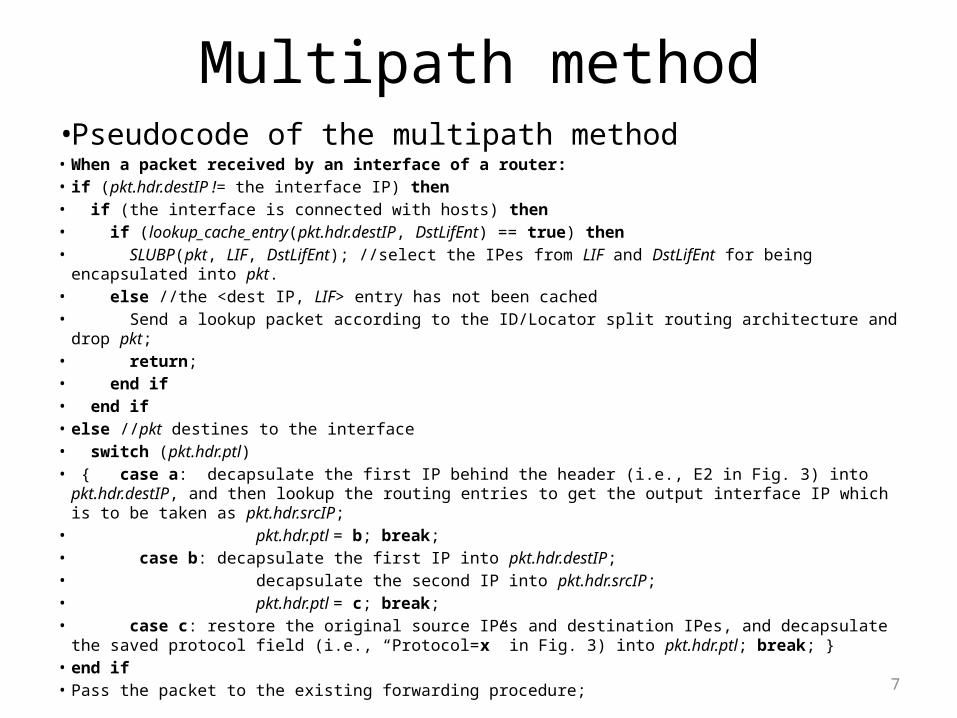
Multipath method• Pseudocode of the multipath method• When a packet received by an interface of a router:• if (pkt.hdr.destIP != the interface IP) then• if (the interface is connected with hosts) then• if (lookup_cache_entry(pkt.hdr.destIP, DstLifEnt) == true) then• SLUBP(pkt, LIF, DstLifEnt); //select the IPes from LIF and DstLifEnt for being encapsulated into pkt.• else //the <dest IP, LIF> entry has not been cached• Send a lookup packet according to the ID/Locator split routing architecture and drop pkt;• return;• end if• end if• else //pkt destines to the interface• switch (pkt.hdr.ptl)• { case a: decapsulate the first IP behind the header (i.e., E2 in Fig. 3) into pkt.hdr.destIP, and then
lookup the routing entries to get the output interface IP which is to be taken as pkt.hdr.srcIP;• pkt.hdr.ptl = b; break;• case b: decapsulate the first IP into pkt.hdr.destIP;• decapsulate the second IP into pkt.hdr.srcIP;• pkt.hdr.ptl = c; break;• case c: restore the original source IPes and destination IPes, and decapsulate the saved protocol field
(i.e., “Protocol=x” in Fig. 3) into pkt.hdr.ptl; break; }• end if• Pass the packet to the existing forwarding procedure;

8
SLUBP Algorithm• Basic principle
– Choose the interfaces on the src router, src router neighbor, dst router, dst router neighbor, which own the minimum link utilization currently to forward the packets.
• (a) Single Path Routing (b) SLUBP
3
2
1
Router
Host
3
2
1
Packet sent by host 1 wi th n Bytes
Packet sent by host 2 wi th n Bytes
n
200
n
500
200
400500
300400
300
Router

9
SLUBP Algorithm• Time Complexity
– The worst O(SLUBP) is O(m3log2Npkt).• m - neighbors per router• Npkt - the number of packets in Tinterval which is used to calculate the
link utilization (LU).
– To our knowledge, the maximum bandwidth of a router interface today is less than 160Gbps [6]. Assuming Tinterval is 1 second (long enough to calculate the current traffic rate and LU), due to the IP packet size is at least 20Bytes, Npkt is less than 230. Thus in the extreme condition, O(SLUBP) is still very small (less than 30m3). Compared to LP and NLP which is usually a non-polynomial (NP) or high order polynomial (P) problem, SLUBP is a low order P problem thus can run in realtime.

10
Evaluation• Environment (NS2)
– 144 Scenarios made up of• Router Topology: 4 types (random X 2, power law X 2)• Routers per Topo: 100• Num. of hosts: 400 or 100• Traffic src distribution: Uniform, EXP, Pareto• Traffic src type: CBR, EXP, Pareto• Schedule Algorithm: NONE, RR, SLUBP

11
Evaluation• Scenarios
• Topologies
Dimensions CaseSynthetic Topology randloose randtight powloose powtight
Host Number 100 400Host Dist Uniform Exponential Pareto
Traffic Dist Uniform Exponential ParetoTraffic Source Type Constant Bit Rate (CBR) ParetoSchedule Algorithm NONE Round Robin (RR) SLUBP
Name Topology Router# Link# Prob. One-Deg.randloose Pure-random 100 148 0.03 Randomrandtight Pure-random 100 489 0.1 Randompowloose Power Law 100 150 0.03 0.2powtight Power Law 100 495 0.1 0.2
12
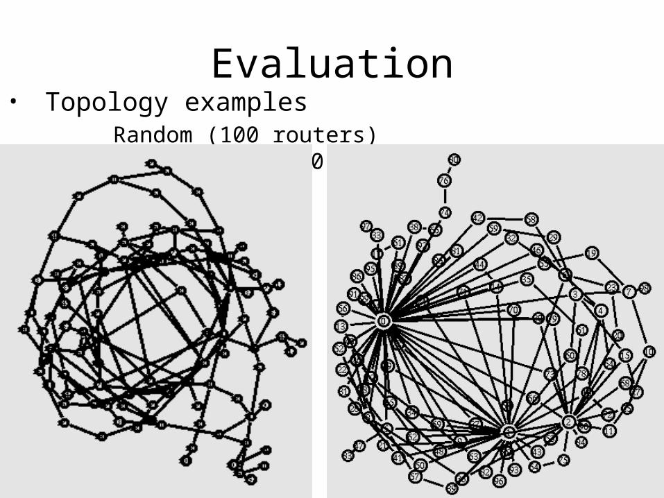
Evaluation• Topology examples Random (100 routers) Power law (100 routers)

13
Evaluation• Performance
– NLU: Normalized link utilization.
– LNR: Link number ratio, actually the probability density of NLU.
( ) ( )i ilink j link j jNLU Trf max TrfLU
0,1 ,
# ( )( )
#
k
k
k
NLUNLU
TopoNLU k N
link jj
linkLNR

14
Evaluation• link number ratio (LNR)
0 0.2 0.4 0.6 0.8 1-0.1
0
0.1
0.2
0.3
0.4
NLU
LN
R
NONERRSLUBP
randloose
0 0.2 0.4 0.6 0.8 1-0.1
0
0.1
0.2
0.3
0.4
NLU
LN
R
NONERRSLUBP
randtight

15
Evaluation• link number ratio (LNR)
0 0.2 0.4 0.6 0.8 1-0.1
0
0.1
0.2
0.3
0.4
NLU
LN
R
NONERRSLUBP
powloose
0 0.2 0.4 0.6 0.8 1-0.1
0
0.1
0.2
0.3
0.4
NLU
LN
R
NONERRSLUBP
powtight

16
Evaluation
Mean and Standard Deviation(STDEV) of NLU
TopologyMean STDEV
NONE RR SLUBP NONE RR SLUBP
randloose 0.181 0.269 0.279 0.204 0.210 0.229
randtight 0.122 0.284 0.325 0.195 0.170 0.151
powloose 0.157 0.164 0.198 0.264 0.168 0.180
powtight 0.107 0.228 0.268 0.227 0.216 0.226

17
Conclusions• Achieving load balance based on the ID/Locator split
routing architecture– The average improving of NLU mean and STDEV of the 4 topologies
are 75.2% and -12.8% when using RR, and are 99.6% and -10.6% when using SLUBP.
– The NLU mean of SLUBP increases much more than RR (24.4%) while the STDEV decreases only a little less than RR (2.2%).
• The forwarding path is selected by each router locally other than using a central controller.
• The time complexity of SLUBP is the order of polynomial, and is much faster than the linear programming (LP) and non-linear programming (NLP).

18
References• [1] D. Saucez, et. al., “Interdomain Traffic Engineering in a Locator/Identifier Separation
Context”, Proc. INM, Oct. 2008.• [2] S. Paul, et. al., "An Identifier/Locator Split Architecture for Exploring Path Diversity
through Site Multi-homing - A Hybrid Host-Network Cooperative Approach" Proc., IEEE ICC 2010.
• [3] A. Sridharan, R. Guerin, and C. Diot, “Achieving near-optimal traffic engineering solutions for current OSPF/IS-IS networks”, IEEE/ACM Trans. on Networking, Apr. 2005.
• [4] Z. Wang, Y. Wang, and L. Zhang, “Internet traffic engineering without full mesh overlaying”, Proc. IEEE INFOCOM 2001.
• [5] M. Antic et. al., “Two Phase Load Balanced Routing using OSPF”, IEEE Jour. of Selected Area in Comm., Jan. 2010.
• [6] Cisco, U.S. [Online] http://www.cisco.com/en/US/prod/collateral/ routers/ps5763/CRS-FP-140_DS.pdf.

19
Thank you!