aps-500 smart alternator regulator user guide - white box version · 2020-02-20 · aps-500-can...
TRANSCRIPT

APS-5
00-CAN
A
LTE
RN
ATO
R R
EG
ULA
TOR
Q
UIC
K S
TAR
T G
UID
E
Copyright 2020, American Power Systems, Inc.
Thank you for purchasing American Power Systems, Inc.'s APS-500-CAN Advanced Alternator Regulator. The APS-500-CAN provides unexcelled control over alternator-based charging by utilizing system voltage, current monitoring and alternator and battery temperature to ensure the safest and most powerful charging possible.
This Quick Start Guide is intended to provide the installer and user with the basic information required to ensure that the APS-500-CAN is properly connected and configured to deliver optimal charging performance in most applications.
This guide will provide instructions to configure the regulator to provide intelligent charge control for a variety of battery types and battery capacities. In addition to it’s onboard DIP switch controls, the APS-500-CAN can be connected to a PC via a built-in USB terminal to access a broad range of advanced configuration options. These advanced configuration controls are discussed in the APS-500-CAN Communications and Programming Guide.
CONTENTSSafety Considerations 2 .............................................................
Configuring for Alternator Polarity 2 ........................................
Locating and Mounting Regulator 3 .........................................
Wiring Harness Installation 3-6 .................................................
Configuring with DIP Switches 7-8 ............................................
Connecting to CAN Enabled System 8 .....................................
LED Status and Advisory Codes 9-11 .......................................

APS-500-CAN ALTERNATOR REGULATOR
QUICK START GUIDE
SAFETY CONSIDERATIONS The APS-500-CAN Alternator Regulator is part of a complex electrical system. A trained and licensed automotive or marine electrician is strongly recommended for its installation. Please note that an improperly installed electrical system components can result in severe damage to property and serious personal injury. Failure to properly install the APS-500-CAN Alternator Regulator, its wiring, and improper configuration may void the regulator’s warranty in addition to damaging other system components. American Power Systems, Inc. is not liable for damage or injury resulting from improperly installed, configured, or modified applications of its charge control products. The following safety precautions are recommended:
• Electrical and mechanical system installation or repair should NEVER be attempted when fatigued or while using alcohol or medication that can impair judgment or motor skills
• Ensure that all jewelry and loose clothing is removed prior to work around engine or mechanical equipment.
• Use the proper tool for the job being done.• Turn off switches and disconnect your batteries prior to installing your APS-500-CAN Alternator
Regulator or other electrical system components. Failure to do so may cause damage or injury.
• Ensure that your alternator is designed to be used with an external voltage regulator. Determine whether the alternator is designed for positive (p-type) or negative (n-type) field excitation and be sure that the regulator’s wiring harness is compatible for the alternator type.
• Read the manual!• If you are not familiar with charging system installation and operation, please consider leaving the
job to a licensed and experienced technician.
CONFIGURING FOR ALTERNATOR POLARITY The APS-500-CAN Alternator Regulator is designed for use with any positively or negatively excited alternator that’s configured for external voltage regulation. The regulator’s field output polarity is determined by the wiring harness used. If your alternator is equipped for positive (A-type) regulation, the APS-500-CAN should be equipped with the APS-500-CAN/PH wiring harness. If the alternator is designed for negative (B-type) field excitation, the APS-500-CAN/NH wiring harness should be used.
While many aftermarket alternators are designed for external regulation, most factory-installed alternators are equipped with single-stage internal regulators. In most cases, the alternator can be modified to support external regulation, which requires disabling the internal regulator and diode trio, and ensuring that one of the alternator’s brushes is connected to the alternator’s ground connection and the alternator’s other brush can be connected to the external regulator’s field wire. If you are unsure of your alternator’s polarity or regulation, please consult with an electrical service shop.
Page 2

LOCATING AND MOUNTING REGULATOR Housed in a powdercoated, diecast aluminum case, the APS-500-CAN is designed to meet or exceed IP67 environmental water resistance standards. Although the enclosure and external wiringconnectors are designed to be waterproof, we recommend finding a mounting location for the regulator that’s well protected from excessive moisture, or exposure to high or low temperature extremes. The regulator’s footprint is approximately 3-7/8” x 7” (98mm x 178mm), and is designed for mounting on a bulkhead or other flat surface.
Four 3/16” diameter holes located on the flanges at each end of the regulator are provided for mounting. If the regulator is installed in an engine compartment or other location where exposure to moisture may occur, mount the regulator with the terminal connectors facing downward to provide protection from water intrusion.
The APS-500-CAN features a waterproof window on its cover that allows viewing of an onboard LED which provides a range of operational codes. When placing the regulator, consider a location where the bezel can be easily seen if monitoring is desired. For more information, see the LED Display Codes section in this guide.
Page 3
WIRING HARNESS INSTALLATION The APS-500-CAN utilizes a high quality, industrial grade Ampseal connector system to provide a waterproof pairing between the regulator and wiring harness, along with sealed RJ45 connectors for
CAN bus system connection. Matching p-type (APS-500-CAN/PH) or n-type (APS-500-CAN/NH) harnesses are ordered separately, depending on the field polarity of the alternator being used. Wiring harnesses are 60” long, and feature three wiring legs sheathed in expandable braid covering. One leg of the harness provides wires which are typically connected at the
alternator, and include wires for alternator positive (power), alternator negative (ground), field, and stator (AC/tach output). A built-in
alternator temperature sensor cable is built into the alternator wiring leg. The second wiring leg is directed to the battery bank, and includes positive and negative voltage sense wires, positive and negative current sense wires for connection to a shunt, and a 2-wire cable with a Superseal-type connector for use with an optional battery temperature sensor (APS-500-CAN/BT-K).
The third leg of the wiring harness carries three wires which typically are connected at the panel; an ignition wire which connects to the ignition switch or other switched voltage source, the lamp wire, which provides a signal for a warning lamp and the function-in wire which can be used to initiate small engine mode and other custom functions.
APS-500-CAN ALTERNATOR REGULATOR
QUICK START GUIDE

Page 4
WIRING HARNESS INSTALLATION (CONTINUED) Once the regulator has been mounted in an appropriate location, the wiring harness can be connected. Two tabs on the wiring plug must be aligned with the slots on the harness connector. The harness connector will click into place when properly inserted.
1 2 3
4
9
10 12 1311
5 6 7
8
To Dash
To Alternator
To Battery
As noted previously, the wiring is clustered in three groups: dash, alternator, and battery. Recommended connection points for the first leg wires are described as follows: 1) Ignition – The brown 16-gauge wire in
the dash leg of the wiring harness provides a switched source of power for the regulator. This wire must see at least 8.5 volts to turn the APS-500-CAN on. This wire can be connected to the ON side of the ignition switch, to an oil pressure switch, or another circuit which is only activated when the engine is running. A switched ignition wire may be available at the alternator from the engine’s wiring loom.
2) Lamp – The orange 16-gauge dash lamp wire provides a ground source to create a complete circuit at a warning light or audible alarm if an alarm condition is active. See Error/Alarm codes for a list of activating conditions.
3) Function In – The white 16-gauge Function In can be configured to provide a number ofcustom controls which can be activated by connecting the wire to >8.5VDC+ via a toggle or other ON/OFF type switch. In default mode, the Function In mode will enable equalize mode when the regulator is configured for lead acid batteries. When the APS-500-CAN is configured for LiFeP04 batteries (see DIP switch instructions), Function In will force the system to float.
APS-500-CAN ALTERNATOR REGULATOR
QUICK START GUIDE

WIRING HARNESS INSTALLATION (CONTINUED) The second leg of the wiring harness provides the necessary connection points at the alternator being controlled by the APS-500-CAN. Recommended connection points for the wires are described as follows:
4) Alternator Negative – The black 16-gauge alternator negative (ground) wire must be connected at the alternator’s ground terminal. If the alternator case provides connection to system ground, connect the black wire to the alternator’s mounting bolt. Be sure that the terminal connector provides a clean connection to bare metal that’s free of paint, corrosion or other materials that could affect a solid continuity to ground.
5) Alternator Positive – The red 16-gauge alternator positive (power) wire provides the source of positive voltage required to operate the APS-500-CAN alternator regulator. This wire should be connected directly to the positive output post of the alternator. The power wire should be fused at 10 amps, or 15 amps on an extra large case alternator. An inline fuse holder is included with the wiring harness.
6) Field – The blue 16-gauge field wire carries field current from the regulator to the alternator. Polarity will vary based on the alternator or wiring harness being used.
7) Stator (AC Tap) – The yellow 16-gauge stator wire provides a source signal from the alternator, indicating the speed of rotation. This wire can be connected directly to the alternator’s stator(AC) output, or can be spliced into the alternator’s tach output.
8) Alternator Temperature Sensor – The gray two-conductor cable includes a temperature sensor embedded in a tinned battery lug. The alternator temperature sensor enables theAPS-500-CAN to reduce field output if the ambient temperature at the alternator exceeds a set temperature. This protects the alternator and reduces losses of efficiency under extended loads. The alternator temperature sensor should be mounted on a rear case bolt or on one of the alternator’s ground terminal bolts. This sensor is not connected electrically to the alternator.
The third leg of the wiring harness provides the necessary connection points to monitor voltage and current at the battery bank being charged. Recommended connection points for the wires are described as follows:
9) Battery Temperature Sensor Terminal – The grey two-conductor cable is terminated with aSuperseal-type connector which mates with the optional Battery Temperature Sensor Kit(APS-500-CAN/BT-K). When used in conjunction with the optional battery temperature sensor, this cable enables the regulator to determine the ambient temperature of the batteries, and modify charging voltage for batteries above or below the standard value of 25°C. Should the value detected at the battery exceed 52°C, the regulator will discontinue charging.
Page 5
APS-500-CAN ALTERNATOR REGULATOR
QUICK START GUIDE

Page 6
WIRING HARNESS INSTALLATION (CONTINUED) 10) Negative Battery Sense – The black with yellow tracer, 16-gauge negative wire must be
connected to the negative post of the battery being charged. In multiple battery banks, thesense wire should be located at the same post as the cable connected to ship’s ground.
11) Positive Battery Sense – The red with yellow tracer, 16-gauge positive wire must beconnected to the charge side of the fuse inline on the positive cable near the battery, or onthe positive post of the battery if no fuse is present. The positive sense wire is connecteddirectly to a “hot” source, and should be fused at 3 amps. An inline fuse holder is includedwith the wiring harness.
12) Current Sense High – The purple 16-gauge wire connects to the “high” side of a currentshunt. The default current shunt rating is 500A/50mV.
13) Current Sense Low – The grey 16-gauge wire connects to the “low” side of a current shunt.The default current shunt rating is 500A/50mV.
SHIP’S GROUND
ALTERNATOR
RECOMMENDED PLACEMENT OF CURRENT SENSE WIRES, DEPENDING ON SHUNT PLACEMENT.
APS-500-CAN ALTERNATOR REGULATOR
QUICK START GUIDE
Page 7
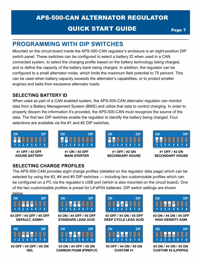
PROGRAMMING WITH DIP SWITCHES Mounted on the circuit board inside the APS-500-CAN regulator’s enclosure is an eight-position DIP switch panel. These switches can be configured to select a battery ID when used in a CAN connected system, to select the charging profile based on the battery technology being charged, and to define the capacity of the battery bank being charged. In addition, the regulator can be configured to a small alternator mode, which limits the maximum field potential to 75 percent. This can be used when battery capacity exceeds the alternator’s capabilities, or to protect smaller engines and belts from excessive alternator loads.
SELECTING BATTERY ID When used as part of a CAN enabled system, the APS-500-CAN alternator regulator can monitor data from a Battery Management System (BMS) and utilize that data to control charging. In order to properly discern the information it’s provided, the APS-500-CAN must recognize the source of the data. The first two DIP switches enable the regulator to identify the battery being charged. Four selections are available via the #1 and #2 DIP switches.
1 2 3 4 5 6 7 8
ON DIP
1 2 3 4 5 6 7 8
ON DIP
1 2 3 4 5 6 7 8
ON DIP
1 2 3 4 5 6 7 8
ON DIP
#1 OFF / #2 OFF HOUSE BATTERY
#1 ON / #2 OFF MAIN STARTER
#1 OFF / #2 ON SECONDARY HOUSE
#1 OFF / #2 ON SECONDARY HOUSE
SELECTING CHARGE PROFILES The APS-500-CAN provides eight charge profiles (detailed on the regulator data page) which can be selected by using the #3, #4 and #5 DIP switches — including two customizable profiles which can be configured on a PC via the regulator’s USB port (which is also mounted on the circuit board). One of the two customizable profiles is preset for LiFeP04 batteries. DIP switch settings are shown below.
1 2 3 4 5 6 7 8
ON DIP
1 2 3 4 5 6 7 8
ON DIP
1 2 3 4 5 6 7 8
ON DIP
1 2 3 4 5 6 7 8
ON DIP
1 2 3 4 5 6 7 8
ON DIP
1 2 3 4 5 6 7 8
ON DIP
1 2 3 4 5 6 7 8
ON DIP
1 2 3 4 5 6 7 8
ON DIP
#3 OFF / #4 OFF / #5 OFF DEFAULT, AGM#1
#3 ON / #4 OFF / #5 OFF STANDARD LEAD ACID
#3 OFF / #4 ON / #5 OFF DEEP CYCLE LEAD ACID
#3 ON / #4 ON / #5 OFF HIGH DENSITY AGM
#3 OFF / #4 OFF / #5 ON GEL
#3 ON / #4 OFF / #5 ON CARBON FOAM (FIREFLY)
#3 OFF / #4 ON / #5 ON CUSTOM #1
#3 ON / #4 ON / #5 ON CUSTOM #2 (LIFEP04)
APS-500-CAN ALTERNATOR REGULATOR
QUICK START GUIDE
Page 8
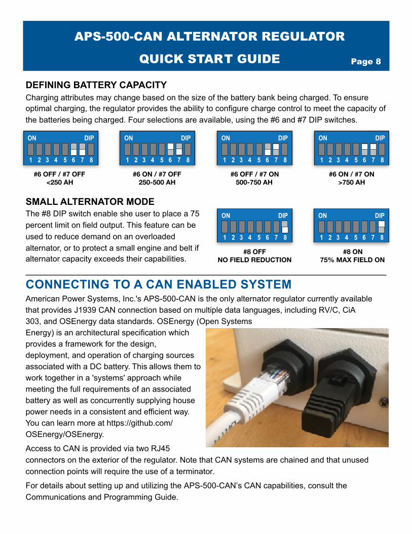
DEFINING BATTERY CAPACITY Charging attributes may change based on the size of the battery bank being charged. To ensure optimal charging, the regulator provides the ability to configure charge control to meet the capacity of the batteries being charged. Four selections are available, using the #6 and #7 DIP switches.
1 2 3 4 5 6 7 8
ON DIP
1 2 3 4 5 6 7 8
ON DIP
1 2 3 4 5 6 7 8
ON DIP
1 2 3 4 5 6 7 8
ON DIP
#6 OFF / #7 OFF <250 AH
#6 ON / #7 OFF 250-500 AH
#6 OFF / #7 ON 500-750 AH
#6 ON / #7 ON >750 AH
SMALL ALTERNATOR MODE The #8 DIP switch enable she user to place a 75 percent limit on field output. This feature can be used to reduce demand on an overloaded alternator, or to protect a small engine and belt if alternator capacity exceeds their capabilities.
1 2 3 4 5 6 7 8
ON DIP
1 2 3 4 5 6 7 8
ON DIP
#8 OFF NO FIELD REDUCTION
#8 ON 75% MAX FIELD ON
CONNECTING TO A CAN ENABLED SYSTEM American Power Systems, Inc.'s APS-500-CAN is the only alternator regulator currently available that provides J1939 CAN connection based on multiple data languages, including RV/C, CiA 303, and OSEnergy data standards. OSEnergy (Open Systems Energy) is an architectural specification which provides a framework for the design, deployment, and operation of charging sources associated with a DC battery. This allows them to work together in a 'systems' approach while meeting the full requirements of an associated battery as well as concurrently supplying house power needs in a consistent and efficient way. You can learn more at https://github.com/OSEnergy/OSEnergy.
Access to CAN is provided via two RJ45 connectors on the exterior of the regulator. Note that CAN systems are chained and that unused connection points will require the use of a terminator.
For details about setting up and utilizing the APS-500-CAN’s CAN capabilities, consult the Communications and Programming Guide.
APS-500-CAN ALTERNATOR REGULATOR
QUICK START GUIDE

Page 9
LED STATUS AND ADVISORY CODES The APS-500-CAN Alternator Regulator is equipped with a bright, multi-color LED which provides a range of operational and advisory codes. The LED is visible via a waterproof bezel located on near the lower left corner of the label on the regulator’s cover. There are three modes of information provided: Standard Operation, indicated by a green flashing pattern; Error/Advisory mode, indicated by a flashing red pattern; and Sync mode, indicated by a flashing orange/yellow pattern.
STANDARD OPERATION MODE (GREEN FLASHING LED) During normal operations, the APS-500-CAN will display one of five status messages, indicating the regulator’s operational status. Message codes are as follows:
ERROR/ADVISORY MODE (RED FLASHING LED) Should the APS-500-CAN determine that a condition is outside of normal limits, it will display a red flashing LED pattern, followed by a series of flashes indicating the type of fault occurring. Most errors are hard-faults, indicating a condition which the APS-500-CAN Alternator Regulator is unable to decipher and as such will shut down until corrected, in order to prevent any potential systems or battery damage. A few errors will attempt to auto-restart to see if the failing condition clears (example, error low battery voltage). When a fault is detected, the APS-500-CAN will flash the “Error” code twice, followed by a a series of flashes indicating the fault/error number. Note: the LED will only indicate the most recent fault detected.
Error code information provided here reflects the most commonly-found regulator or system faults. The Programming and Communications Guide provides more in depth information about error/advisory issues, and will be updated as needed, to reflect new or revised error messages. Entry into error/advisory mode is indicated as shown below:
APS-500-CAN ALTERNATOR REGULATOR
QUICK START GUIDE

Page 10
ERROR/ADVISORY CODES (INDICATED BY RED FLASHING LED) As noted previously, error/advisory codes may reflect a fault at the regulator, or a more universal system fault. Some faults may result with an auto-restart by the regulator (such as low system voltage). Other faults may cause the regulator to freeze up until the condition is corrected. Note: the error/advisory code will flash the first digit of the code, then the last digit of the code, with a short space in between. In other words, a Code 23 would be shown as two red flashes, space, three red flashes. If the code you see is not listed here, refer to the Programming and Communications Guide.
Error Code Description
12 Battery temperature exceeded limit
13 Battery voltage exceeded upper limit
14 Battery voltage below lower limit
21 Alternator temperature exceeded limit
22 Alternator rpms above expected value
23 Alternator #2 temperature exceeded limit
24 Alternator temperature exceeded limit during ramp
31 Global Variable charging state has some unsupported value in check_for_faults
32 Global Variable charging state has some unsupported value in manage_alt
33 Global Variable cpIndex has some unsupported value in calculate_alt_targets
34 Global Variable cpIndex has some unsupported value in check_for_faults
35 Global Variable SystemAmpMult has some unsupported value in check_for_faults
41 Internal Field FET temperature exceed limit.
42 A 'Required' sensor is missing, and WS500 is configured to FAULT out
51 A CAN message was received that the battery charging bus has been disconnected
52 We have noted that a command has been sent asking for the battery bus to be disconnected
53 Battery Instance number is out of range (needs to be from 1..100)
APS-500-CAN ALTERNATOR REGULATOR
QUICK START GUIDE
Page 11
SYNC MODE (INDICATED BY ORANGE FLASHING LED) In applications where the APS-500-CAN is taking commands from a BMS or from another APS-500-CAN alternator regulator, such as a twin engine application, where two alternators are being used to charge the same battery bank, the APS-500-CAN may be placed in a sync (or slave) mode, where its operation is being guided by another device. When the regulator defers to another in this mode, it will indicate that it is acting as a slave by flashing yellowish orange on the LED.
APS-500-CAN ALTERNATOR REGULATOR
QUICK START GUIDE

Page 12
Preset Charging ProfilesCharge Mode Default/
AGM #1Standard
FLADeep
Cycle FLAHigh Density
AGMGel Carbon
FoamCustom #1 Custom #2
Delay Time (Sec.) 30 Sec.Bulk/Absorption — Bulk Phase is typically when the largest amount of energy is placed into the battery. By following up with a current tapering Acceptance phase, batteries may be safely and full charged.
Target Voltage 14.1 14.8 14.6 14.7 14.1 14.4 14.4 13.8Exit Current 3% 1% 1% 0.6% 1% 1.4% 3% 3%
Maximum Time Before Exit 6 Hrs. 3 Hrs. 4.5 Hrs. 4.5 Hrs. 6 Hrs. 6 Hrs. 6 Hrs. 1 Hr.
Overcharge — Some battery manufactures follow the Acceptance Phase by a low-current Overcharge or Finish phase. This is to in effect ‘polish off’ the final charge in a safe and controlled manner.
Current Limit
Not Applicable
Not Applicable
Not Applicable Not Applicable Not
ApplicableNot
Applicable
1%Not
ApplicableExit Voltage 15.30
Maximum Time Before Exit 3 hrs
Float — Once a battery has been charged to its target SOC, Float is used to allow the Alternator to supply energy for ongoing loads while preserving the battery’s charge. If a large load is placed on the system, a new recharge cycle may occur.
Target Voltage 13.4 13.5 13.2 13.4 13.5 13.4 13.1 13.36
Exit Current -2% -2% -2% -2% -2% -4% -2% 0%Exit Voltage 12.8 12.8 12.8 12.8 12.8 12.0 12.8 12.9
Post Float — In some deployments it is desired to fully turn off charging once the battery has reached its SOC goal. Post Float allows for this complete turnoff, while still monitoring for conditions which would warrant a new charge cycle.
Target Voltage
Not Applicable
Not Applicable
Not Applicable Not Applicable Not
ApplicableNot
ApplicableNot
ApplicableNot
ApplicableExit Current
Maximum Time Before Exit
Equalization — Periodically batteries may want to have a maintenance charge applied, typical to provide some type fo cell to cell balancing. For Charge Profiles 1..7, Equalize mode may be enabled via the Feature-in port, while for charge profile #8 it may only be activated by $FRM:E
Target Voltage
Not Applicable
Not Applicable
15.3
Not Applicable Not Applicable
14.4 15.3 14.6
Current Limit 5% n/a 3% 3%Exit Current n/a 0.6% n/a 1.8%Max Time
Before Exit 3 Hrs. 3 Hrs. 3 Hrs. 1 Hr.
Low Voltage Alarm 8vHigh Voltage Alarm 16.5v (18v if in Equalize mode)Battery Temperature Compensation (Per deg C)
-24mV -30mV -30mV -24mV -30mV -24mV -30mV n/a
Min Charge Temp -45c -45c -45c -45c -45c -20c -45c 0cMax Charge Temp 45c 45c 45c 45c 45c 50c 45c 40c
APS-500-CAN ALTERNATOR REGULATOR
QUICK START GUIDE