aq12pgge as09p8gb aq12pbge as09p8ge sh12zpg … · r22+bldc d lower temperature model l r407c c...
TRANSCRIPT

AQ12PGGEAQ12PBGESH12ZPGSH12ZPGAAS12PGGBAS12PGGEAS12PBGEAQ09P8GEAQ09PBGESH09ZPGSH09ZPGA
AS09P8GBAS09P8GEAS09PBGEAQ07P8GEAQ07PBGESH07ZPGSH07ZPGAAS07P8GBAS07P8GEAS07PBGEAS07P8GD
MODEL LINE-UP 1
SEPECIFICATIONS 7
OUTLINE & DIMENTION 17
PERFORMANCE DATA 23
INSTALLATION 29
FEATURES & OPERATION 47
DIAGRAM 65
TROUBLESHOOTING 81
CONTENTS
DB98_12818A(1)_CO(letter) 4/17/03 1:51 PM Page 1

Model Line-Up
1-1. Model Identification
1-2. Model Line-Up
1
DB98_12818A(1)AS12PGGE_1~28 4/17/03 5:22 PM Page 1

DB98_12818A(1)AS12PGGE_1~28 4/17/03 5:22 PM Page 2

SAMSUNG | 3
MODEL LINE-UP 1
1-1. Model Identification
# Tech
General
Tropical T
INV+R22 V
R22+BLDC D
Low Temp. L
R407c C
R410a A
R410a+BLDC B
* Rating Voltage
115V, 60Hz A
220V, 60Hz B
208~230V, 60Hz C
200~220V, 50Hz D
220~240V, 50Hz E
( Serial Version
Basic None
M/R R
Specification change
^ Used
PD(‘00R) 1
PD_MR(‘00R) 2
MD(‘00R) 3
MD_MR(‘00R) 4
PD2 5
PD2_MR 6
MD2 7
MD2_MR 8
PD3 9
PD3MR 0
Active A
Active + MR B
INV C
C Specification+MR D
Active2 E
G Mold G
& P/J Name
V2 M
R R
T2 T
Fashion F
V3 C
B B
G G
Used Q
Used V
Used A
% Design of Grille type
S/S Stand A
Smile B
C&C C
V-Lip D
G Premium Model P
G Standard Model S
G Standard ModelK
(KL Grille)
Interior I
GE E
KLIMAT Y
Sub_Set
Set None
Indoor I
Outdoor X
! Set Initial
Set A
Indoor A
Outdoor U
@ Mode
H/P Q
C/O S
$ Capacity
Btu
“30” HP Mark
I A Q V 09 A 1 M E /
! @ # $ % ^ & * ( )
Model Name
Model Code
Model Identification
1
Wall Mounted Type Air Conditioner
Standard type
DB98_12818A(1)AS12PGGE_1~28 4/17/03 5:22 PM Page 3

4 | SAMSUNG
MODEL LINE-UP1Model Identification (Cont.)
& Half finished products
Indoor None
Outdoor X
* Serial Version
Basic None
Specification change A
^ Option (Outdoor unit sash)
PD 1
PD_MR 2
MD 3
MD_MR 4
PD2 5
PD2_MR 6
MD2 7
MD2_MR 8
PD3 9
PD3_MR 0
Active A
A Specification+MR B
INV(VSash) C
C Specification+MR D
G Mold G
Active2 E
! Products
Separated type S
# Capa
Btu
@ Function
H/P H
C/O C
$ Tech
Normal Z
Tropical T
INV+R22 V
R22+BLDC D
Lower temperature model L
R407c C
R410a A
R410a+BLDC B
S H 09 Z A 1 X /
! @ # $ % ^ & * (
Model Name
Model Code
% Design of Grille type
S/S Standard A
Smile B
C&C C
V-Lip D
G Premium Model P
G Standard Model S
G Standard ModelK
(KL Grille)
Interior I
Fashion F
GE E
KLIMAT Y
Wall Mounted Type Air Conditioner
Separated type of export model for EU in private
DB98_12818A(1)AS12PGGE_1~28 4/17/03 5:22 PM Page 4

SAMSUNG | 5
MODEL LINE-UP 1Model Identification (Cont.)
$ Division
Export None
Domestic -
% High pressure pipeOuter diameter
1/4" 14
3/8" 38
^ Low pressureOuter diameter
1/2" 12
3/4" 34
3/8" 38
5/8" 58
! Piping division
Initial F
@ Products
Export RAC S
Domestic RAC R
PAC P
Cassette B
Common Duct D
Ceiling F
DPM M
F S 14 38-C N A
! @ % ^# $ & *
Model Name
Model Code
Piping(Parts Box)
# Function
ExportH/P H
C/O C
H/P H
C/O CDomestic
Oil G
Multi M
& Voltage type
Export NONE
Indoor NDomestic
Outdoor X
* Version
Basic A
New1 B
... ...
‘01R Standard Z
DB98_12818A(1)AS12PGGE_1~28 4/17/03 5:22 PM Page 5

6 | SAMSUNG
MODEL LINE-UP1
1-2. Model Line-Up (2003R)
Model Line-Up
AS07PBGE
AS09PBGE
AS12PBGE
AS07P8GB
AS07P8GE
AS07P8GD
AS09P8GB
AS09P8GE
AS12PGGB
AS12PGGE
AQ07PBGE
AQ09PBGE
AQ12PBGE
AQ07P8GE
SH07ZPG
SH07ZPGA
AQ09P8GE
SH09ZPG
SH09ZPGA
AQ12PGGE
SH12ZPG
SH12ZPGA
7K FSC1438Z
FSC1438Z
FSC1412Z
FSC1438Z
FSC1438Z
FSC1412Z
FSH1438Z
FSH1438Z
FSH1412Z
FSH1438Z
FSH1438Z
FSH1412Z
9K
12K
7K
9K
12K
7K
9K
12K
7K
9K
12K
A
(STEEL)
B
(MOLD)
COOLING
ONLY
HEAT PUMP
D
(MOLD)
C
(STEEL)
US07PBGE
US09PBGE
US12PBGE
US07P8GB
US07P8GE
US07P8GD
US09P8GB
US09P8GE
US12PGGB
US12PGGE
UQ07PBGE
UQ09PBGE
UQ12PBGE
UQ07P8GE
SH07ZPGX
SH07ZPGAX
UQ09P8GE
SH09ZPGX
SH09ZPGAX
UQ12PGGE
SH12ZPGX
SH12ZPGAX
Indoor Unit Outdoor Unit Piping Unit
DB98_12818A(1)AS12PGGE_1~28 4/17/03 5:22 PM Page 6

Specifications
2-1. Heat Pump
2-2. Cooling Only
2
DB98_12818A(1)AS12PGGE_1~28 4/17/03 5:22 PM Page 7

DB98_12818A(1)AS12PGGE_1~28 4/17/03 5:22 PM Page 8

SAMSUNG | 9
SPECIFICATIONS 2
2-1. Heat Pump
Heat Pump
Perfor-mance
Power
Size
Model
Item
Type
Cooling -
Heating -
Dehumidifying |/h
Air volumeCooling
m3/minHeating
NoiseCooling
dBHeating
Energy efficiency ratioCooling
HeatingW/W
Power V-Hz
Power ConsumptionCooling
WHeating
Operating CurrentCooling
AHeating
Power factorCooling
%Heating
Starting current A
Length m
Power cord Number of core wire
Capacity A
Outer Width x Height mm
Dimension x Depth inch
Weight kg
Refrigerant pipeLiquid mm x L(MT)
GAS mm x L(MT)
Drain hose D x L(mm)
Type
Compressor Motor Type
Rated output
Type
Blower Motor Type
Rated output W
Heat exchanger
Refrigerant control unit
Freezer oil capacity cc
Refrigerant to change(R-22) g
Protection device(OLP)
Cooling test Condition
Maximum operation Condition
AQ12PGGE AQ12PBGE
Indoor unit Outdoor unit Indoor unit Outdoor unit
Wall-mounted
12,000BTU/h
13,000BTU/h
1.9
8.0 24
8.6 24
40 50
40 50
2.97
3.25
1-220 / 240-50
1180
1170
5.3
5.1
96.8
99.7
32.0
-
-
250V-10 / 16A
890x285x179 695x530x280
35.0x11.2x7.0 27.4x20.9x11.0
8.5 33.0
ø6.35 x 5
ø12.7 x 5
ø18 x 2000
Rotary
- -
- -
Cross-flow Propeller
steel steel
15 25
2ROW 12STEP 1ROW 20STEP
CAPILLARY TUBE
600
820
RAC 12074-9622
Wall-mounted
12,000BTU/h
13,000BTU/h
1.9
8.0 24
8.6 24
40 50
40 50
2.97
3.30
1-220 / 240-50
1180
1150
5.2
6.1
98.7
98.0
32.0
-
-
250V-10 / 16A
890x285x179 740x530x230
35.0x11.2x7.0 29.1x20.9x9.1
8.5 35.0
ø6.35 x 5
ø12.7 x 5
ø18 x 2000
Rotary
- -
- -
Cross-flow Propeller
steel steel
15 25
2ROW 12STEP 2ROW 24STEP
CAPILLARY TUBE
600
910
RAC 12074-9622
INDOOR UNIT : DB27˚C WB19˚C OUTDOOR UNIT : DB35˚C WB24˚C
INDOOR UNIT : DB32˚C WB23˚C OUTDOOR UNIT : DB43˚C WB26˚C
DB98_12818A(1)AS12PGGE_1~28 4/17/03 5:22 PM Page 9

10 | SAMSUNG
SPECIFICATIONS2
Heat Pump (Cont.)
Perfor-mance
Power
Size
Model
Item
Type
Cooling-
( ) : RUSSIA, CIS
Heating-
( ) : RUSSIA, CIS
Dehumidifying |/h
Air volumeCooling
m3/minHeating
Noise CoolingdB
( ) : EUROVENT Heating
Energy efficiency ratioCooling
HeatingW/W
Power V-Hz
Power ConsumptionCooling
WHeating
Operating CurrentCooling
AHeating
Power factorCooling
%Heating
Starting current A
Length m
Power cord Number of core wire
Capacity A
Outer Width x Height mm
Dimension x Depth inch
Weight kg
Refrigerant pipeLiquid mm x L(MT)
GAS mm x L(MT)
Drain hose D x L(mm)
Type
Compressor Motor Type
Rated output
Type
Blower Motor Type
Rated output W
Heat exchanger
Refrigerant control unit
Freezer oil capacity cc
Refrigerant to change(R-22) g
Protection device(OLP)
Cooling test Condition
Maximum operation Condition
SH12ZPGSH12ZPGA AQ09P8GE AQ09PBGE
Indoor unit Outdoor unit Indoor unit Outdoor unit Indoor unit Outdoor unit
Wall-mounted
3.5kW
(11,990)BTU/h
3.8kW
(11,990)BTU/h
1.9
8.2 24
9.1 24
42(53) 50(63)
42(53) 50(63)
3.21
3.41
1-220 / 240-50
1090
1115
5.0
5.0
94.8
97.0
32.0
-
-
250V-10 / 16A
890x285x179 695x530x280
35.0x11.2x7.0 27.4x20.9x11.0
8.5 33.0
ø6.35 x 5
ø12.7 x 5
ø18 x 2000
Rotary
- -
- -
Cross-flow Propeller
steel steel
15 25
2ROW 12STEP 2ROW 24STEP
CAPILLARY TUBE
410
980
RAC 12123-9622
Wall-mounted
9,200BTU/h
10,000BTU/h
1.4
6.4 19
7.0 19
38 48
38 48
2.81
3.22
1-220 / 240-50
960
900
4.4
4.0
94.9
97.8
21.0
-
-
250V-10 / 16A
795x 258x179 660x475x242
31.3 x10.2 x7.0 26.0x18.7 x9.5
7.5 26.3
ø6.35 x 5
ø9.52 x 5
ø18 x 2000
Rotary
- -
- -
Cross-flow Propeller
steel steel
11 20
2ROW 10STEP 1ROW 18STEP
CAPILLARY TUBE
360
660
RAC 12110-9622
Wall-mounted
9,000BTU/h
10,000BTU/h
1.4
6.4 24
7.0 24
38 48
38 48
2.74
3.22
1-220 / 240-50
950
900
4.2
4.1
98.3
95.4
21.0
-
-
250V-10 / 16A
795x 258x179 740 x530 x 230
31.3 x10.2 x7.0 29.1 x 20.9 x 9.1
7.5 26.5
ø6.35 x 5
ø9.52 x 5
ø18 x 2000
Rotary
- -
- -
Cross-flow Propeller
steel steel
11 25
2ROW 10STEP 1ROW 24STEP
CAPILLARY TUBE
360
580
RAC 12110-9622
INDOOR UNIT : DB27˚C WB19˚C OUTDOOR UNIT : DB35˚C WB24˚C
INDOOR UNIT : DB32˚C WB23˚C OUTDOOR UNIT : DB43˚C WB26˚C
Heat Pump (Cont.)
DB98_12818A(1)AS12PGGE_1~28 4/17/03 5:22 PM Page 10

SAMSUNG | 11
SPECIFICATIONS 2
SH09ZPGSH09ZPGA AQ07P8GE AQ07PBGE SH07ZPG
SH07ZPGA
Indoor unit Outdoor unit Indoor unit Outdoor unit Indoor unit Outdoor unit Indoor unit Outdoor unit
Wall-mounted
2.6kW
(8,990)BTU/h
2.9kW
(8,990)BTU/h
1.4
6.6 24
7.1 24
39(50) 48(58)
39(50) 48(58)
3.21
3.33
1-220 / 240-50
810
870
3.7
3.9
95.2
97.0
21.0
-
-
250V-10 / 16A
795x258x179 695x530x280
31.3x10.2x7.0 27.4x20.9x11.0
7.5 28.0
ø6.35 x 5
ø9.52 x 5
ø18 x 2000
Rotary
- -
- -
Cross-flow Propeller
steel steel
11 25
2ROW 10STEP 1ROW 20STEP
CAPILLARY TUBE
360
740
RAC 12054-9622
Wall-mounted
7,500BTU/h
8,000BTU/h
0.9
6.2 19
6.2 19
36 47
36 47
2.86
3.29
1-220 / 240-50
770
700
3.3
3.1
99.9
98.2
18.0
-
-
250V-10 / 16A
795x258x179 660x475x242
31.3x10.2x7.0 26.0x18.7x9.5
7.5 25.6
ø6.35 x 5
ø9.52 x 5
ø18 x 2000
Rotary
- -
- -
Cross-flow Propeller
steel steel
11 20
2ROW 10STEP 1ROW 18STEP
CAPILLARY TUBE
360
620
RAC 12144-9622
Wall-mounted
7,800BTU/h
8,200BTU/h
0.9
6.2 24
6.2 24
36 47
36 47
3.07
3.43
1-220 / 240-50
750
700
3.3
3.1
98.8
98.2
17.0
-
-
250V-10 / 16A
795x258x179 740x530x230
31.3x10.2x7.0 29.1x20.9x9.1
7.5 26.1
ø6.35 x 5
ø9.52 x 5
ø18 x 2000
Rotary
- -
- -
Cross-flow Propeller
steel steel
11 20
2ROW 10STEP 1ROW 18STEP
CAPILLARY TUBE
360
640
RAC 12144-9622
Wall-mounted
2.3kW
(7,500)BTU/h
2.4kW
(8,200)BTU/h
0.9
6.2 24
6.5 24
36(47) 47(47)
36(57) 47(57)
3.22
3.43
1-220 / 240-50
715
700
3.2
3.2
97.1
95.1
18.0
-
-
250V-10 / 16A
795x258x179 695x530x280
31.3x10.2x7.0 27.4x20.9x11.0
7.5 27.5
ø6.35 x 5
ø9.52 x 5
ø18 x 2000
Rotary
- -
- -
Cross-flow Propeller
steel steel
11 25
2ROW 10STEP 1ROW 20STEP
CAPILLARY TUBE
360
700
RAC 12144-9622
INDOOR UNIT : DB27˚C WB19˚C OUTDOOR UNIT : DB35˚C WB24˚C
INDOOR UNIT : DB32˚C WB23˚C OUTDOOR UNIT : DB43˚C WB26˚C
Heat Pump (Cont.)
DB98_12818A(1)AS12PGGE_1~28 4/17/03 5:22 PM Page 11

12 | SAMSUNG
SPECIFICATIONS2
2-2. Cooling Only
Cooling Only
Size
Model
Item
Type
Cooling -
Dehumidifying \/h
Air volume Cooling m3/min
Noise Cooling dB
Energy efficiency ratio Cooling W/W
Power V-Hz
Power Consumption Cooling W
Operating Current Cooling A
Power factor Cooling %
Starting current A
Length m
Power cord Number of core wire
Capacity A
Outer Width x Height mm
Dimension x Depth inch
Weight kg
Refrigerant pipe Liquid mm x L(MT)
GAS mm x L(MT)
Drain hose D x L(mm)
Type
Compressor Motor Type
Rated output
Type
Blower Motor Type
Rated output W
Heat exchanger
Refrigerant control unit
Freezer oil capacity cc
Refrigerant to change(R-22) g
Protection device(OLP)
Cooling test Condition
Maximum operation Condition
AS12PGGB(Latain America) AS12PGGB(Tiwan)
Indoor unit Outdoor unit Indoor unit Outdoor unit
Wall-mounted
12,500BTU/h
1.9
8.0 24
40 50
3.05
1-220-60
1200
5.6
97.4
30.0
-
-
250V-10 / 16A
890x 285x 179 695 x530 x280
35.0x 11.2 x7.0 27.4x 20.9x 11.0
8.5 29.1
ø6.35 x 5
ø12.7 x 5
ø18 x 2000
Rotary
- -
- -
Cross-flow Propeller
steel steel
15 25
2ROW 12STEP 1ROW 20STEP
CAPILLARY TUBE
360
720
RAC 12074-9622
Wall-mounted
3.6kW
1.9
8.0 24
40 50
2.98
1-220-60
1210
5.6
98.2
30.0
-
-
250V-10 / 16A
890 x285x 179 695 x530 x280
35.0x 11.2 x7.0 27.4x 20.9x 11.0
8.5 29.1
ø6.35 x 5
ø12.7 x 5
ø18 x 2000
Rotary
- -
- -
Cross-flow Propeller
steel steel
15 25
2ROW 12STEP 1ROW 20STEP
CAPILLARY TUBE
360
720
RAC 12074-9622
INDOOR UNIT : DB27˚C WB19˚C
INDOOR UNIT : DB32˚C WB23˚C
OUTDOOR UNIT : DB35˚C WB24˚C
OUTDOOR UNIT : DB43˚C WB26˚C
Perfor-mance
Power
DB98_12818A(1)AS12PGGE_1~28 4/17/03 5:22 PM Page 12

SAMSUNG | 13
SPECIFICATIONS 2Cooling Only (Cont.)
AS12PGGE AS12PBGE AS09P8GB(Latain America) AS09P8GB(Tiwan)
Indoor unit Outdoor unit Indoor unit Outdoor unit Indoor unit Outdoor unit Indoor unit Outdoor unit
Wall-mounted
12,500BTU/h
1.9
8.0 24
40 50
3.10
1-220 / 240-50
1180
5.4
95.0
32.0
-
-
250V-10 / 16A
890 x285 x179 695 x530 x280
35.0 x11.2x 7.0 27.4x 20.9x 11.0
8.5 32.5
ø6.35 x 5
ø12.7 x 5
ø18 x 2000
Rotary
- -
- -
Cross-flow Propeller
steel steel
15 25
2ROW 12STEP 1ROW 20STEP
CAPILLARY TUBE
600
820
RAC 12074-9622
Wall-mounted
12,500BTU/h
1.9
8.0 24
40 50
3.20
1-220 / 240-50
1100
5.0
95.7
32.0
-
-
250V-10 / 16A
890x 285x 179 740x 530x230
35.0x 11.2 x7.0 29.1 x20.9x 9.1
8.5 34.5
ø6.35 x 5
ø12.7 x 5
ø18 x 2000
Rotary
- -
- -
Cross-flow Propeller
steel steel
15 25
2ROW 12STEP 2ROW 24STEP
CAPILLARY TUBE
600
840
RAC 12074-9622
Wall-mounted
9,500BTU/h
1.4
6.4 19
38 48
2.96
1-220-60
940
4.4
97.1
22.0
-
-
250V-10 / 16A
795 x258 x179 660 x475 x242
31.3x 10.2x 7.0 26.0x 18.7x9.5
7.5 25.7
ø6.35 x 5
ø9.52 x 5
ø18 x 2000
Rotary
- -
- -
Cross-flow Propeller
steel steel
11 20
2ROW 10STEP 1ROW 18STEP
CAPILLARY TUBE
360
615
RAC 12067-9622
Wall-mounted
2.8kW
1.4
6.4 19
38 48
2.98
1-220-60
940
4.4
97.1
22.0
-
-
250V-10 / 16A
795x 258x 179 660 x475 x242
31.3 x10.2 x7.0 26.0x 18.7x 9.5
7.5 25.7
ø6.35 x 5
ø9.52 x 5
ø18 x 2000
Rotary
- -
- -
Cross-flow Propeller
steel steel
11 20
2ROW 10STEP 1ROW 18STEP
CAPILLARY TUBE
360
615
RAC 12067-9622
INDOOR UNIT : DB27˚C WB19˚C
INDOOR UNIT : DB32˚C WB23˚C
OUTDOOR UNIT : DB35˚C WB24˚C
OUTDOOR UNIT : DB43˚C WB26˚C
DB98_12818A(1)AS12PGGE_1~28 4/17/03 5:22 PM Page 13

14 | SAMSUNG
SPECIFICATIONS2
Cooling Only (Cont.)
Size
Model
Item
Type
Cooling -
Dehumidifying \/h
Air volume Cooling m3/min
Noise Cooling dB
Energy efficiency ratio Cooling W/W
Power V-Hz
Power Consumption Cooling W
Operating Current Cooling A
Power factor Cooling %
Starting current A
Length m
Power cord Number of core wire
Capacity A
Outer Width x Height mm
Dimension x Depth inch
Weight kg
Refrigerant pipe Liquid mm x L(MT)
GAS mm x L(MT)
Drain hose D x L(mm)
Type
Compressor Motor Type
Rated output
Type
Blower Motor Type
Rated output W
Heat exchanger
Refrigerant control unit
Freezer oil capacity cc
Refrigerant to change(R-22) g
Protection device(OLP)
Cooling test Condition
Maximum operation Condition
AS09P8GE AS09PBGE
Indoor unit Outdoor unit Indoor unit Outdoor unit
Wall-mounted
9,200BTU/h
1.4
6.6 19
39 48
2.81
1-220 / 240-50
960
4.4
94.9
21.0
-
-
250V-10 / 16A
795x 258x 179 660x 475x 242
31.3 x10.2 x7.0 26.0x18.7 x9.5
7.5 25.8
ø6.35 x 5
ø9.52 x 5
ø18 x 2000
Rotary
- -
- -
Cross-flow Propeller
steel steel
11 20
2ROW 10STEP 1ROW 18STEP
CAPILLARY TUBE
360
660
RAC 12110-9622
Wall-mounted
9,200BTU/h
1.4
6.4 24
38 50
2.84
1-220 / 240-50
950
4.2
98.3
21.0
-
-
250V-10 / 16A
795x 258x 179 740x 530x 230
31.3 x10.2 x7.0 29.1x20.9 x9.1
7.5 26.1
ø6.35 x 5
ø9.52 x 5
ø18 x 2000
Rotary
- -
- -
Cross-flow Propeller
steel steel
11 25
2ROW 10STEP 1ROW 24STEP
CAPILLARY TUBE
360
520
RAC 12110-9622
INDOOR UNIT : DB27˚C WB19˚C
INDOOR UNIT : DB32˚C WB23˚C
OUTDOOR UNIT : DB35˚C WB24˚C
OUTDOOR UNIT : DB43˚C WB26˚C
Cooling Only (Cont.)
Perfor-mance
Power
DB98_12818A(1)AS12PGGE_1~28 4/17/03 5:22 PM Page 14

SAMSUNG | 15
SPECIFICATIONS 2Cooling Only (Cont.)
AS07P8GB AS07P8GE AS07PBGE AS07P8GD
Indoor unit Outdoor unit Indoor unit Outdoor unit Indoor unit Outdoor unit Indoor unit Outdoor unit
Wall-mounted
7,500BTU/h
0.9
6.0 19
35 47
3.38
1-220-60
650
3.4
98.5
14.0
-
-
250V-10 / 16A
795x258 x179 660 x475 x242
31.3 x10.2x 7.0 26.0x 18.7x 9.5
7.5 25.1
ø6.35 x 5
ø9.52 x 5
ø18 x 2000
Rotary
- -
- -
Cross-flow Propeller
steel steel
11 20
2ROW 10STEP 1ROW 18STEP
CAPILLARY TUBE
280
630
RAC 12043-9622
Wall-mounted
7,800BTU/h
0.9
6.2 19
36 47
2.97
1-220 / 240-50
770
3.4
98.5
17.0
-
-
250V-10 / 16A
795 x258 x179 660x 475x 242
31.3x 10.2x7.0 26.0x18.7 x9.5
7.5 25.1
ø6.35 x 5
ø9.52 x 5
ø18 x 2000
Rotary
- -
- -
Cross-flow Propeller
steel steel
11 20
2ROW 10STEP 1ROW 18STEP
CAPILLARY TUBE
360
650
RAC 12144-9622
Wall-mounted
7,800BTU/h
0.9
6.2 24
36 47
3.27
1-220 / 240-50
700
3.2
95.1
17.0
-
-
250V-10 / 16A
795x 258x179 740 x530 x230
31.3 x10.2 x7.0 29.1x 20.9x 9.1
7.5 25.6
ø6.35 x 5
ø9.52 x 5
ø18 x 2000
Rotary
- -
- -
Cross-flow Propeller
steel steel
11 25
2ROW 10STEP 1ROW 24STEP
CAPILLARY TUBE
360
490
RAC 12144-9622
Wall-mounted
7,000BTU/h
0.9
5.6 19
35 47
3.48
1-200 / 220-50
590
2.8
91.6
16.5
-
-
250V-10 / 16A
795 x258 x179 660 x475x 242
31.3x 10.2x7.0 26.0x18.7 x9.5
7.5 25.1
ø6.35 x 5
ø9.52 x 5
ø18 x 2000
Rotary
- -
- -
Cross-flow Propeller
steel steel
11 20
2ROW 10STEP 1ROW 18STEP
CAPILLARY TUBE
280
600
RAC 12086-9622
INDOOR UNIT : DB27˚C WB19˚C
INDOOR UNIT : DB32˚C WB23˚C
OUTDOOR UNIT : DB35˚C WB24˚C
OUTDOOR UNIT : DB43˚C WB26˚C
DB98_12818A(1)AS12PGGE_1~28 4/17/03 5:22 PM Page 15

MEMO
16 | SAMSUNG
DB98_12818A(1)AS12PGGE_1~28 4/17/03 5:22 PM Page 16

Outline & Dimension
3-1. Indoor Unit
3-2. Outdoor Unit
3
DB98_12818A(1)AS12PGGE_1~28 4/17/03 5:22 PM Page 17

DB98_12818A(1)AS12PGGE_1~28 4/17/03 5:22 PM Page 18

SAMSUNG | 19
OUTLINE & DIMENSION 3
3-1. Indoor Unit
Indoor Unit
C
60
19
275252
100 158
60
45
275252
90 165
A
B
Air in
(Front view)
(Rear view)
(Remote control)
Type A B C
7K / 9K 795 258 179
12K 890 285 179
Air out
(Installation plate)
225915
4
7K/9K
18K/24K
12K
DB98_12818A(1)AS12PGGE_1~28 4/17/03 5:22 PM Page 19
20 | SAMSUNG
OUTLINE & DIMENSION3
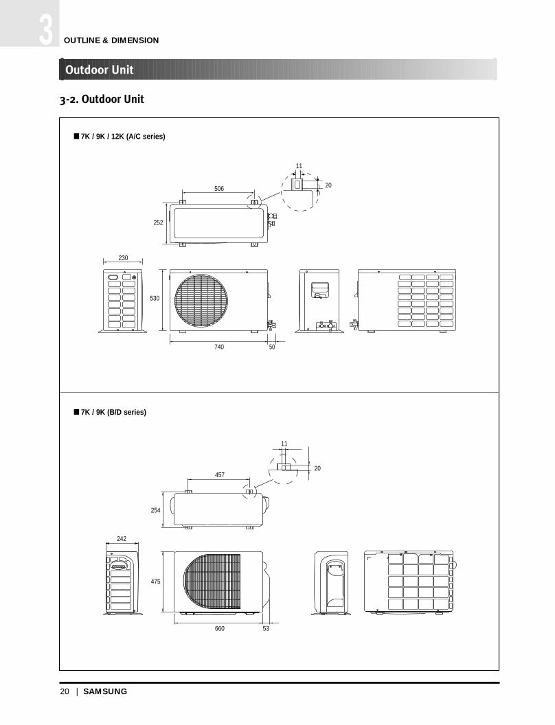
3-2. Outdoor Unit
506
11
20
252
230
530
740 50
457
11
20
475
254
242
660 53
7K / 9K / 12K (A/C series)
7K / 9K (B/D series)
Outdoor Unit
DB98_12818A(1)AS12PGGE_1~28 4/17/03 5:22 PM Page 20

SAMSUNG | 21
OUTLINE & DIMENSION 3Outdoor Unit (Cont.)
489
11
20
300
530
280
695 60
12K (B/D series)
DB98_12818A(1)AS12PGGE_1~28 4/17/03 5:22 PM Page 21

MEMO
22 | SAMSUNG
DB98_12818A(1)AS12PGGE_1~28 4/17/03 5:22 PM Page 22

Performance Data
4-1. Performance Data
4
DB98_12818A(1)AS12PGGE_1~28 4/17/03 5:22 PM Page 23

DB98_12818A(1)AS12PGGE_1~28 4/17/03 5:22 PM Page 24

SAMSUNG | 25
PERFORMANCE DATA 14
4-1. Performance Data
4-1-1. Capacity
Performance Data
7,000BTU
9,000BTU
<Cooling> <Heating>
<Cooling> <Heating>
DB98_12818A(1)AS12PGGE_1~28 4/17/03 5:22 PM Page 25

26 | SAMSUNG
4
4-1-1. Capacity (Cont.)
12,000BTU<Cooling> <Heating>
Performance Data (Cont.)
PERFORMANCE DATA
DB98_12818A(1)AS12PGGE_1~28 4/17/03 5:22 PM Page 26

SAMSUNG | 27
PERFORMANCE DATA 4
4-1-2. Cooling Capacity Correction Factors
Performance Data (Cont.)
DB98_12818A(1)AS12PGGE_1~28 4/17/03 5:22 PM Page 27

MEMO
28 | SAMSUNG
DB98_12818A(1)AS12PGGE_1~28 4/17/03 5:22 PM Page 28

Installation
5-1. Selecting Area for Installation
5-2. Installation Diagram of Indoor Unit and Outdoor Unit
5-3. Performing Leak Tests
5-4. Placing the Indoor Unit in Position
5-5. Checking and Testing Oeprations
5
DB98_12818A(1)_29~64 4/17/03 5:23 PM Page 29

DB98_12818A(1)_29~64 4/17/03 5:23 PM Page 30
SAMSUNG | 31
INSTALLATION 5
Select an area for installation that is suitable to customer’s needs.
5-1. Selecting Area for Installation
5-1-1. Indoor Unit
1. Make sure that you install the indoor unit in an area providing good ventilation.
It must not be blocked by an obstacle affecting the airflow near the air inlet and the air outlet.
2. Make sure that you install the indoor unit in an area allowing good air handling and endurance of vibration of the indoor unit.
3. Make sure that you install the indoor unit in an area where there is no source of heat or vapor nearby.
4. Make sure that you install the indoor unit in an area from which hot or cool air is spread evenly in a room.
5. Make sure that you install the indoor unit in an area away from TVs, audio units, cordless phones, fluorescent lighting fixtures and other
electrical appliances (at least 1 meter).
6. Make sure that you install the indoor unit in an area which provides easy pipe connection with the outdoor unit, and easy drainage for
condensed water.
7. Make sure that you install the indoor unit in an area which is large enough to accomodate the measurements shown in figure on the
next page.
Selecting Area for Installation
CAUTION
• It is harmful to the air conditioner if it is used in the following environments: greasy areas (including areas nearmachines), salty areas such as coast areas, areas where sulfuric gas is present such as hot spring areas. Contact your dealer for advice.
DB98_12818A(1)_29~64 4/17/03 5:23 PM Page 31

32 | SAMSUNG
INSTALLATION5Selecting Area for Installation (Cont.)
5-1-2. Outdoor Unit
1. Make sure that you install the outdoor unit in area not exposed to the rain or direct sun light.(Install a separate sunblind if exposed to
direct sun light.)
2. Make sure that you install the outdoor unit in area allowing the good air moment, not amplifying noise or vibration, especially to avoid
disturbing neighbours. (Fix the unit firmly if it is mounted in a high place.)
3. Make sure that you install the outdoor unit in area providing the good ventilation and which is not dusty. It must not be blocked by any
obstacle affecting the airflow near the air inlet and the air outlet.
4. Make sure that you install the outdoor unit in area free from animals or plants.
5. Make sure that you install the outdoor unit in area not blocking the traffic.
6. Make sure that you install the outdoor unit in area easy to drain condensed water from the indoor unit.
7. Make sure that you install the outdoor unit in area which provides easy connection within the maximum allowable length of a coolant
pipe.
8. Make sure that you install the outdoor unit in an area which is large enough to accommodate the measurements shown in figure on the
next page.
5-1-3. Remote Control Unit
1. Make sure that you use the remote control unit in an area free from obstacles such as curtains etc, which may block signals from the
remote control unit.
2. Make sure that you put the remote control unit in an area not exposed to direct sunlight, and where there is no source of heat.
3. Make sure that you use the remote control unit in an area away from TVs, audio units, cordless phones, fluorescent lighting fixtures and
other electrical appliances (at least 1 meter).
MODEL
07 / 09
12
A
7.5
7.5
B
20
30
If you have used...
More than “A” metres ofpiping
“B”g of refrigeranr (R22)must be added for eachextra meter.
Less than “A” meresof piping
The purge time is ormal.
Then...
DB98_12818A(1)_29~64 4/17/03 5:23 PM Page 32

SAMSUNG | 33
INSTALLATION 5
5-2. Installation Diagram of Indoor Unit and Outdoor Unit
125 mmor more
300 mm or more
125 mmor more
600 mmminimum
300 mmminimum
300 mmminimum
600 mmminimum
15metresmaximum
7metres maximum
Installation Diagram of Indoor Unit and Outdoor Unit
Cut the piping holesloped slightly
A Indoor unit gas leak test
Vinyl tapePiping
Indoor unit
B Drain hose installation
Cut the piping holesloped slightly
Piping may be laid to the rear, left, right or down.
• Wrap the refrigerant pipes and the drain hose upin the absorbent pad and the vinyl tape.
• Triply wind the pipes and hose to the end of theindoor unit with the absorbent pad (make intervalsof 20mm)
* The designs of the unit and Connectionvalue are subject to Change according to the model.
Right
Rear Rear
Left
3
1
2
DB98_12818A(1)_29~64 4/17/03 5:23 PM Page 33

34 | SAMSUNG
INSTALLATION5Installation Diagram of Indoor Unit and Outdoor Unit (Cont.)
5-2-1. Fixing the Installation Plate
1. Determine the position of the pipe and drain hose hole refering to the right figure and drill the hole with an inner diameter of 65mmso that it slants slightly downwards.
2. If you are fixing the indoor unit to a… Then follow Steps…
Wall 3.
Window frame 4 to 6.
3. Fix the installation plate to the wall in a manner appropriate to the weight of the indoor unit.
If you are mounting the plate on a concrete wall with anchor bolts, anchor bolts must not be projected by more than 20mm.
4. Determine the position of the wooden uprights to be attached to the window frame.
5. Attach the wooden upright to the window frame in a manner appropriate to the weight of the indoor unit.
6. Using tapped screws, attach the installation plate to the wooden upright, as illustrated in the last figure opposite.
5-2-2. Purging the Unit
On delivery, the indoor unit is loaded with an inert gas. All this gas must therefore be purged before connecting the assembly piping. To purge the inert gas, proceed as follows.
Unscrew the cap at the end of each pipe.
To prevent dirt or foreign objects from getting into the pipes during installation, do NOT remove caps completely until you are ready to connect the piping.
Result All inert gas escapes from the indoor unit.
30m
m
Installation plate
Pipe hole(Ø65mm)
60
19
275252
100 158
(Unit : mm)7K/9K
60
45
275252
90 165
12K
DB98_12818A(1)_29~64 4/17/03 5:23 PM Page 34

SAMSUNG | 35
INSTALLATION 5Installation Diagram of Indoor Unit and Outdoor Unit (Cont.)
5-2-3. Connecting the Assembly Cable (Cooling Only)
The outdoor unit is powered from the indoor unit via the assembly cable. (7K/9K/12K)
5-2-4. Connecting the Assembly Cable (Heat Pump)
The outdoor unit is powered from the indoor unit via the assembly cable. (7K/9K/12K)
1. Extend the assembly cable if necessary.
2. Open the front grille by pulling on the tab on the lower right and left sides of the indoor unit.
3. Remove the screw securing the connector cover.
4. Pass the assembly cable through the rear of the indoor unit and connect the assembly cable to terminals. Each wire is labelled with the corresponding terminal number.
5. Firmly fix the ass’y cable with clamp wire holder.
6. Pass the other end of the cable through the 65mm hole in the wall.
7. Replace the connector cover, carefully tightening the screw.
8. Close the front grille.
9. For further details on how to plug the other end of the assembly cable into the outdoor unit.
E
E
N1 1
N11N1
1N1
N1 1 2 3
Indoorunit
Outdoor unit
1. Extend the assembly cable if necessary.
2. Open the front grille by pulling on the tabs on the lower right and left sides of the indoor unit.
3. Remove the screw securing the connector cover.
4. Pass the assembly cable through the rear of the indoor unit and connect the assembly cable to terminals Each wire is labelled with the corresponding terminal number.
5. Pass the other end of the cable through the 65 mm hole in the wall.
6. Replace the connector cover, carefully tightening the screw.
7. Close the front grille.
8. For further details on how to plug the other end of the assembly cable into the outdoor unit.
N1 1 2
N1 1 2 3
3
E2 31N1
E2 31
1
N1N1
N1
Indoorunit
Outdoor unit
DB98_12818A(1)_29~64 4/17/03 5:23 PM Page 35

36 | SAMSUNG
INSTALLATION5Installation Diagram of Indoor Unit and Outdoor Unit (Cont.)
5-2-5. Installing and Connecting the Indoor Unit Drain Hose
Care must be taken when installing the drain hose for the indoor unit to ensure that any condensed water is correctly drained out-side. When passing the drain hose through the 65mm hole drilled in the wall, check that none of the following situation occur.
The hose must NOT slope upwards.
The end of the drainhose must NOT beplaced in water.
Do NOT bend the hose in different directions.
Keep a clearance of atleast 5cm between theend of the hose and theground.
5cm less
Do NOT place theend of the drain hosein a hollow.
1. If necessary, connect the 2-meter extension to the drain hose.
2. If you are using the extension, insulate the inside part of the extensiondrain hose with a shield.
3. Pass the drain hose under the refrigerant piping, taking care to keep thedrain hose tight.
4. Pass the drain hose through the hole in the wall, making sure that it is sloping downwards, as shown in the illustrations above.
The hose will be fixed permanently into position once the whole installation has been tested for gas leaks.
Shield
Drain hose Extension drain hose
To install the drain hose, proceed as follows
DB98_12818A(1)_29~64 4/17/03 5:23 PM Page 36

SAMSUNG | 37
INSTALLATION 5Installation Diagram of Indoor Unit and Outdoor Unit (Cont.)
5-2-6. Flare Modification
TOOLS USED
FLARE MODIFICATION PROCEDURE
1. Cut the pipe using a pipe cutter.
2. Remove burrs at the tip of the pipe cut.
3. Insert a flare nut into the pipe and modify flare.
90
D
A
Oblique Roughness Burr
Pipe
Reamer
* Unproper flaring
Inclined Surfacedamaged
Cracked Uneventhickness
CAUTION
• Burrs not removed may result in leakage of gas.
Outer diameter A(mm)
ø6.35mm 1.3
ø9.52mm 1.8
ø12.7mm 2.0
DB98_12818A(1)_29~64 4/17/03 5:23 PM Page 37

38 | SAMSUNG
INSTALLATION5Installation Diagram of Indoor Unit and Outdoor Unit (Cont.)
5-2-7. Air-Purge Procedure
The outdoor unit is loaded with sufficient R-22 refrigerant for 5 metres of piping. The air in the indoor unit and in the pipe must bepurged. If air remains in the refrigeration pipes, it will affect the compressor, reduce to cooling/heating capacity and could lead toa malfuction. Refrigerant for air purging is not charged in the outdoor unit. Use Vacuum Pump as shown at the figure.
A
B
C
D
Outdoor unit Indoor unit
Gas pipe side
Liquid pipe side
VacuumPump
1. Connect each assembly pipe to the appropriate valve on the outdoor unit and tighten the flare nut.
2. Referring to the illustration opposite, tighten the flare nut first manually and then with a wrench, applying the following torque.
3. Connect the charging hose of low pressure side of manifold gauge to the packedvalve having a service port as shown at the figure.
4. Open the valve of the low pressure side of manifold gauge counterclockwise.
5. Purge the air from the system using vacuum pump for about 10 minutes. Close the valve of the low pressure side of manifold gauge
clockwise. Make sure that pressure gauge show -0.1MPa(-76cmHg)
after about 10minutes.This procedure is very important in order to avoid gas leak.
Turn off the vacuum pump Remove the hose of the low pressure side of manifold gauge.
* The designs and shape are subject tochange according to the model.
Adding RefrigerantRefrigerant must be added if the piping measures more than 5 metres in length.This operation can only be performed by a qualified refrigeration specialist.
If you have used... Then...
More than “A” metres “B” of refrigerant (R-22) of piping must be added for each
extra meter.
Less than “A” metres The purge time is normal.of piping
Refer to the Service Manual for more details on this operation.
6.35mm
9.52mm
12.70mm
144~176
333~407
504~616
Outer Diameter Torque(kg.cm)
MODEL A B
07/09 7.5 20
12 7.5 30
DB98_12818A(1)_29~64 4/17/03 5:23 PM Page 38

SAMSUNG | 39
INSTALLATION 5Installation Diagram of Indoor Unit and Outdoor Unit (Cont.)
6. Set valve cork of both liquid side and gas side of packed valve to the openposition.
7. Mount the valve stem nuts and the service port cap to the valve, and tightenthem at the torque of 18N.m with a torque wrench.
8. Check for gas leakage. At this time, especially check for gas leakage from 3-way valve’s stem nuts,
and from the service port cap.
B(liquid)
Stem capValve stem
A(gas)
DB98_12818A(1)_29~64 4/17/03 5:23 PM Page 39

40 | SAMSUNG
INSTALLATION5Installation Diagram of Indoor Unit and Outdoor Unit (Cont.)
5-2-8. Refrigerant Refill
Refill an air-conditioner with refrigerant when refrigerant has been leaked at installing or using.
2
Turn the 3-way valve clockwise to close,connect the pressure gauge (low pressure side)to the service valve, and open the 3-way valve again.
1 Purge air(for new installation only).
3 Connect the tank to refill with refrigerant
4 Set the unit to cool operation mode.
5
Check the pressure indicated by the pressuregauge(low pressure side).
* Standard pressure is should be 4.5~5.5kg/cm2
in a regular, high operation mode.
6
Open the refrigerant tank and fill with refrigerantuntil the rated pressure is reached.
* It is recommended not to pour the refrigerant intoo quickly, but gradually while operating a pres-sure valve.
7 Stop operation of the air conditioner.
8Close the 3-way valve, disconnect the pressuregauge, and open the 3-way valve again.
9 Close the cap of each valve.
R-22
Suspension hook
Highpressuregauge
Handwheel
Finger tightfittings
Connected tohigh pressureside
Chargingline
For mountingother and ofhose whennot in use
Compoundgauge
DB98_12818A(1)_29~64 4/17/03 5:23 PM Page 40

SAMSUNG | 41
INSTALLATION 5Installation Diagram of Indoor Unit and Outdoor Unit (Cont.)
5-2-9. Refrigerant Adjustment
5-2-10. Flare Nut Fixing Torque
It would be the best choice to use the standard tube length to keep the basic quality of Room Air conditioner, for example cooling and heating capacity, sound level, vibration level, and reliability.But, according to a certain different installation condition, the connection tube length could be changed in the recommendation length that is shown above.In this case, installer should keep the installation condition to keep the quality of Room Air conditioner.
Refrigerant should be charged additionally as written above according to the change of the length of the connection tube. It needs to affect the decrease in cooling and heating capacity or of the reliability of compressor that may be caused by a lack of refrigerant.
Installation position difference between the indoor unit and the outdoor unit should not exceed over than “B” meters.
When the connection pipe is been extended longer than 5 meters, it might need to change the diameter of the electrical wire to a larger size in order to keep a voltage drop for starting room air conditioner is not less than 85% of the rated voltage. And then, a voltage meter will be useful to check the rate of the voltage drop.
Class At installation At service
ConnectionPipe Length
Standard5m
Max.~15m
(24K : 20m)
Air-PurgeMethod
Refer to thedetailed Air-PurgeProcedure
RefrigerantAdjustment
Unnecessary
Add “A” of refrigerant (R-22) for every 1m.
Air-PurgeMethod
Purge air using avacuum pumpor an additionalrefrigerant cylinder.
RefrigerantQuantity
refer tospecification sheet
Add “A” of refrigerant (R-22) for every 1m.
MODEL
7K/ 9K
12K
“A”
20(g/m)
30(g/m)
“B”
7.5
7.5
Outer diameter
ø 6.35 mm(Liquid Side)
ø 9.52 mm(Gas Side)
ø 12.7 mm(Gas Side)
160
300
500
200
350
550
Fixing Torque Final Torque
Torque (kg-cm)
DB98_12818A(1)_29~64 4/17/03 5:23 PM Page 41

42 | SAMSUNG
INSTALLATION5Installation Diagram of Indoor Unit and Outdoor Unit (Cont.)
5-2-11. “Pump down” Procedure
Pump down will be carried out when an evaporator is replaced or when the unit is relocated in another area.
1Remove the caps from the 2-way valve and the3-way valve.
3Set the unit to cool operation mode.(Check if the compressor is operating.)
2
Turn the 3-way valve clockwise to close andconnect a pressure gauge (low pressure side) to the service valve, and open the 3-way valveagain.
4 Turn the 2-way valve clockwise to close.
6 Stop operation of the air conditioner.
7 Close the cap of each valve.
5When the pressure gauge indicates "0" turn the3-way valve clockwise to close.
2-Way Valve
3-Way Valve
Relocation of the Air Conditioner
• Refer to this procedure when the unit is relocated.
1. Carry out the pump down procedure (refer to the details of 'pump down').
2. Remove the power cord.
3. Disconnect the assembly cable from the indoor and outdoor units.
4. Remove the flare nut connecting the indoor unit and the pipe.At this time, cover the pipe of the indoor unit and the other pipe using a cap or vinyl plug to avoid foreign material entering.
5. Disconnect the pipe connected to the outdoor unit.At this time, cover the valve of the outdoor unit and the other pipe using a cap or vinyl plug to avoid foreign material entering.
6. Make sure you do not bend the connection pipes in the middle and store together with the cables.
7. Move the indoor and outdoor units to a new location.
8. Remove the mounting plate for the indoor unit and move it to a new location.
DB98_12818A(1)_29~64 4/17/03 5:23 PM Page 42

SAMSUNG | 43
INSTALLATION 5
5-3. Performing Leak Tests
Before completing the installation (insulation of the cable, hose and piping and fixing of the indoor unit to the installation plate), you must check that there are no gas leaks.
Performing Leak Tests
To check for gas leaks on the... Then, using a leak detector, check the...
Indoor unit Flare nuts at the end of sections C and D.
Outdoor unit Valves on sections A and B.
C D
B
A
The designs and shape are subject to change according to the model.
DB98_12818A(1)_29~64 4/17/03 5:23 PM Page 43
44 | SAMSUNG
INSTALLATION5
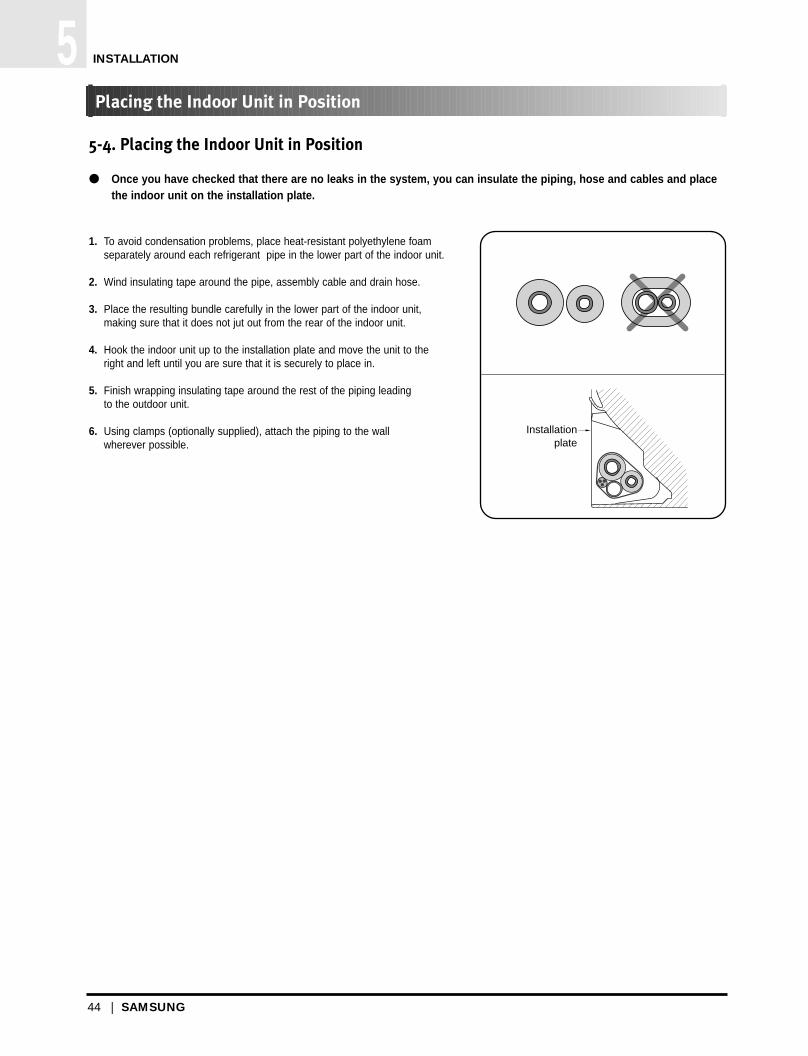
5-4. Placing the Indoor Unit in Position
Once you have checked that there are no leaks in the system, you can insulate the piping, hose and cables and placethe indoor unit on the installation plate.
1. To avoid condensation problems, place heat-resistant polyethylene foam separately around each refrigerant pipe in the lower part of the indoor unit.
2. Wind insulating tape around the pipe, assembly cable and drain hose.
3. Place the resulting bundle carefully in the lower part of the indoor unit,making sure that it does not jut out from the rear of the indoor unit.
4. Hook the indoor unit up to the installation plate and move the unit to the right and left until you are sure that it is securely to place in.
5. Finish wrapping insulating tape around the rest of the piping leading to the outdoor unit.
6. Using clamps (optionally supplied), attach the piping to the wall wherever possible.
Placing the Indoor Unit in Position
Installation plate
DB98_12818A(1)_29~64 4/17/03 5:23 PM Page 44

SAMSUNG | 45
INSTALLATION 5
5-5. Checking and Testing Operations
To complete the installation, perform the following checks and tests to ensure that the air conditioner is operating correctly.
Checking and Testing Operations
1. Review all the following elements in the installation:
Installation site strength Piping connection tightness to detect any gas leakages Connection wiring Heat-resistant insulation of the piping Drainage Earthing wire connection Correct operations (follow the steps below)
2. Press the On/Off button.
3. Press the button.
4. Air flow direction
Press the button and check that the air flow blades work properly.
Result The indicator lights on the indoor unit flash at half-second intervals.
While the indoor unit opens, the indoor unit fan runs to start.
Result The outdoor unit operates in cooling or heating mode as following theroom temperature.
DB98_12818A(1)_29~64 4/17/03 5:49 PM Page 45

MEMO
46 | SAMSUNG
DB98_12818A(1)_29~64 4/17/03 5:23 PM Page 46

Features & Operation
6-1. The Feature of key in Remote Control
6-2. Details for Operation Property
6-3. Operating Recommendations
6-4. Temperature and Humidity Ranges
6-5. Pressure Graph
6
DB98_12818A(1)_29~64 4/17/03 5:23 PM Page 47

DB98_12818A(1)_29~64 4/17/03 5:23 PM Page 48

SAMSUNG | 49
FEATURES & OPERATION 6
6-1. The Feature of key in Remote Control
The Feature of key in Remote Control
Swing button.It adjusts the airflow to upward and downward.
Turbo button.The air conditioner cools or heats the room as quickly as possible.After 30minutes, the air conditioner is reset automatically to the previous mode.
Energy saving button.If you wish to save energy when using your air conditioner, select the Energy savingmode with the button.
Temperature adjustment button(DOWN).To decrease the temperature by the pressing the temperature button.
Temperature adjustment button(UP).To increase the temperature by the pressing the temperature button.
FUNCTION OF KEY
Sleep button. The sleep timer can be used when you are cooling or heating your room toswitch the air conditioner off automatically after a period of six hours.
On/Off button. Press the button to stop or run the air conditioner.
Fan speed adjustment button.Each time you press this button, FAN SPEED is changed in the following order.
NAMED OF KEYNO
1
2
3
4
5
6
7
8
Mode selection button. Each time you press this buttonMode is changed in the following order
√√ In case of Heat pump model
√√ In case of Cooling only model
: Auto Mode : Fan Only
: Cool Mode : Heat Mode
: Dry Mode
Low Medium High
Automatic(rotated : )
(On/Off)
(UP)
(DOWN)
DB98_12818A(1)_29~64 4/17/03 5:23 PM Page 49
50 | SAMSUNG
FEATURES & OPERATION6The Feature of key of Remote Control (Cont.)
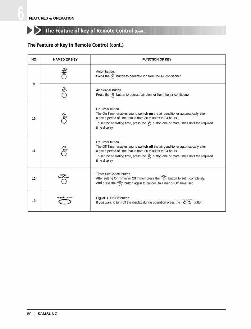
The Feature of key in Remote Control (cont.)
FUNCTION OF KEY
Anion button.Press the button to generate ion from the air conditioner.
On Timer button.The On Timer enables you to switch on the air conditioner automatically aftera given period of time that is from 30 minutes to 24 hours.
To set the operating time, press the button one or more times until the requiredtime display.
Off Timer button.The Off Timer enables you to switch off the air conditioner automatically aftera given period of time that is from 30 minutes to 24 hours.
To set the operating time, press the button one or more times until the requiredtime display.
Timer Set/Cancel button. After setting On Timer or Off Timer, press the button to set it completely.And press the button again to cancel On Timer or Off Timer set.
Digital On/Off button.If you want to turn off the display during operation press the button.
NAMED OF KEYNO
9
10
11
12
13
Air cleaner button.Press the button to operate air cleaner from the air conditioner.
DB98_12818A(1)_29~64 4/17/03 5:24 PM Page 50

SAMSUNG | 51
FEATURES & OPERATION 6
6-2. Details for Operation Property
1. AUTO MODE : In this mode, operation mode(COOL, HEAT)
is selected automatically by the room temperature of initial
operation.√√ In case of Heat pump model.
√√ In case of Cooling only model.
∆T= -1°C, -2°C, 0°C, +1°C, +2°C
∆T is controlled by setting temperature up/down key of
remote control
2. COOL MODE : The unit operates according to the difference
between the setting and room temperature. (18°C~30°C)
3. HEAT MODE(In case of Heat pump model) :
The unit operates according to the difference between the
setting and room temperature.(16°C~30°C)
*Prevention against cold wind : In order to prevent the cool
air from flowing out at the heat mode, the indoor fan does
not operate or operates very slowly in the following cases.
At this time, the indoor heat exchanger will be preheating.
- For 3~5 minutes after the initial operation
- For deicing operation
- The operation of an indoor fan in accordance with the
temperature of an indoor heat exchanger
*High temperature release function : It is a function to detect
an outdoor overload by the sensor of an indoor heat
exchanger and to turn the outdoor fan or the compressor
ON/OFF for safety.
*Deice : Deicing operation is controlled by indoor unit's
heat exchanger temperature and accumulating time of
compressor's operation.
Deice ends by sensing of the processing time by deice
condition.
4. DRY MODE : Has 3 states, each determined by room
temperature.
The unit operates in DRY mode.
*Compressor ON/OFF Time is controlled compulsorily(can
not set up the fan speed, always breeze).
*Protective function : Low temperature release. (Prevention
against freeze)
5. TURBO MODE : This mode is available in AUTO, COOL,
HEAT, DRY, FAN MODE.
When this button is pressed at first, the air conditioner is
operated “powerful” state for 30 minutes regardless of the
set temperature, room temperature.
When this button is pressed again, or when the operating
time is 30 minutes, turbo operation mode is canceled and
returned to the previous mode.
*But, if you press the TURBO button in DRY or FAN mode
that is changed with AUTO mode automatically.
6. SLEEP MODE : Sleep mode is available only in COOL or
HEAT mode.
The operation will stop after 6 hours.
*In COOL mode : The setting temperature is automatically
raised by 1°C each 1hourWhen the temperature has been
raised by total of 2°C, that temperature is maintained.
*In HEAT mode : The setting temperature is automatically
dropped by 1°C each 1hour.
When the temperature has been dropped by total of 2°C,
that temperature is maintained.
7. FAN SPEED : Manual (3 step), Auto (4 step)
Fan speed automatically varies depending on both the
difference between setting and the room temperature.
8. COMPULSORY OPERATION :
For operating the air conditioner without the remote control.
*The operating is the same function that AUTO MODE in the
remote control.
Room Temp Operation Type
Tr ≥ 21°C+∆T Cool Operation (Set Temp:24˚C+∆T)
21°C +∆T>Tr Heat Operation (Set Temp:22˚C+∆T)
Operation Type Room Temp.
Cool OperationTr ≥ 25°C+∆T Compressor ON
Tr ≤ 24°C+∆T Compressor OFF
The temperature of indoor heat exchanger
below 28˚C
28˚C~below 34˚C
34˚C~below 40˚C
above 40˚C
Indoor fan speed
off
LL Speed
L Speed
Setting Speed
Details for Operation Property
DB98_12818A(1)_29~64 4/17/03 5:24 PM Page 51

52 | SAMSUNG
FEATURES & OPERATION6Details for Operation Property (Cont.)
9. SWING : BLADE-H is rotated vertically by the stepping
motor.
*Swing Set : Press the button under the remote control
is displayed on LCD the and the blades move up and
down. If the one more time press the button, blades
location is stop.
10. SETTING THE ON/OFF TIMER. :
*ON TIMER : The On Timer enables you to switch on the
air conditioner automatically after a given period of time.
You can set the period of time from 30 minutes to 24 hours.
*OFF TIMER : The Off Timer enables you to switch off the
air conditioner automatically after a given period of time.
You can set the period of time from 30 minutes to 24 hours.
11. SELF DIAGNOSIS
12. BUZZER SOUND : Whenever the On/Off button is pressed
or whenever change occurs to the condition which is set up
or select, the compulsory operation mode, buzzer is sound-
ed "beep".
Indoor unit room temperature sensorerror (open or short)
Description
Set off Operating
LAMP of Display Monitor
Indoor unit heat exchanger tempera-ture sensor error (open or short)
Indoor fan motor malfunction
EEPROM error
Option error (option wasn’t set up oroption data error)
OFF E1
OFF E2
OFF E3
OFF E6
All lampblinking
All lampblinking
DISPLAY:
ERROR DISPLAY PART:
DB98_12818A(1)_29~64 4/17/03 5:52 PM Page 52

SAMSUNG | 53
FEATURES & OPERATION 6
6-2-1. Cooling Mode Operating
When selecting the Cooling Mode Operation, the unit will operate according to the setting by the remote controller and theoperation is as well as the following. Room temperature can beset in 1°C steps in the range of 18 to 30°C.
6-2-2. Heating Mode Operation(In case of Heat pump model)
When selecting the Heating Mode Operation, the unit will operate according to the setting by the remote controller and theoperation is as well as the following. Room temperature can beset in 1°C steps in the range of 16 to 30°C.
6-2-3. Automatic Operation
When Automatic operation is set by the remote controller, the air conditioner senses the room temperature then automatically selects the operation mode and setting temperature.
1. In case of Heat pump model.
1. In case that Room Temp. ≥ 21°C + ∆T, the unit is operated in the Cool Mode.1. In case that Room Temp. < 21°C + ∆T, the unit is operated in the Heat Mode.1. ∆T means that user is able to change setting temperature within ±2°C.
2. In case of Cooling only model.
1. In case the Room Temp. ≥ 25°C + ∆T, the unit is operated Compressor.1. In case the Room Temp. ≤ 24°C + ∆T, the unit is not operated Compressor.1. ∆T means that user is able to change setting temperature within ±2°C.
♦ Ts means Remote Controller setting Temperature
Room Temp.(°C)
Ts+1
Ts
CompressorON
OFF
ON
Time
Room Temp.(°C)
Ts+5
Ts+3
CompressorON
OFF
ON
Time
Operating Mode Setting Temp. Remarks
Room Temp ≥ 21°C + ∆T Cooling Tsp = 24°C + ∆T ∆T = -2, -1, 0, 1, 2°CRoom Temp < 21°C + ∆T Heating Tsp = 22°C + ∆T
Operating Type Room Temp. Remarks
Cool OperationTr ≥ 25°C + ∆T Compressor ON
∆T = -2, -1, 0, 1, 2°CTr ≤ 24°C + ∆T Compressor OFF
Details for Operation Property (Cont.)
DB98_12818A(1)_29~64 4/17/03 5:24 PM Page 53

54 | SAMSUNG
FEATURES & OPERATION6Details for Operation Property (Cont.)
6-2-4. Sleeping Operation
AT COOLING MODE
When you set the sleep mode, the following movement will startto avoid over cooling. The indoor fan speed is fixed by setting the remote controller. The setting temperature will rise by 1°C at the starting of
operation and by 1°C one hour later. The operation will stop after 6 hours.
AT HEATING MODE
When you set the sleep mode, the following movement will start to avoid overheating. The indoor fan speed is fixed by setting the remote
controller. The setting temperature will be dropped by 1°C at the
starting of operation and by 1°C one hour later. The operation will stop after 6 hours.
6-2-5. Turbo Operation (Cooling or Heating Mode)
If turbo operation is selected during heating or cooling mode, compressor is operated for 30minutes regardless of room temperature. After 30minutes of turbo operation the unit will operate in normal state
Start Stop
1°C up
1°C up
1h
1h
Ts
Ts+1
Ts+2
6h
Start Stop
6hr
1°C down
1°C down
Ts+2Ts+1
Ts+3
Ts+4
Ts+3
Ts+5
1h1h
<Indoor FAN Speed>
<COMP_or Control>
<Operation MODE>
Setting Speed Setting Speed
High(HEAT)Turbo(COOL)
30 min
TURBO Operation
TURBO OperationStart
TURBO OperationEnd
COMP_or ON
DB98_12818A(1)_29~64 4/17/03 5:24 PM Page 54

SAMSUNG | 55
FEATURES & OPERATION 6Details for Operation Property (Cont.)
6-2-6. Energy saving operation control
In case of Cooling Only model
The Energy saving mode is applicable to only in both the COOL mode and AUTO mode.
In case of Heat Pump model
The Energy saving mode is applicable to only in the COOL mode.
Energy saving operation specification- If you select the Energy saving mode during automatic operation, the setting temperature(Ts) will be fixed to "the standard value
+2°C"(26°C).- If you select the Energy saving mode during cooling operation, you may set the room temperature from "26°C to 30°C",
but if you hope to control the room temperature below 26°C in the Energy saving mode, the room temperature will be compelledto be 26°C.
- If you select the Energy saving mode, the up/down louver will enter the "Swing" status.
- OPERATION PATTERN A : In the Energy saving mode when Room Temperature(Tr) equals to the SettingTemperature(Ts) or over.
- OPERATION PATTERN B : In the Energy saving mode when Room Temperature(Tr) is below the SettingTemperature(Ts).
Tg +ß
Tg
Temperature
Energy savingmode
General operation mode
Energy saving mode starting→
Ts+1
Ts
OFFON
Time
COMP_or
Tg +ßTg +ß
Tg
Tg←Tg+α
Tg←Tg+α
Temperature
Energy savingmode
General operationmode
Energy savingmode starting
Energy savingpattern mode B
Change the Energy savingpattern A.
→ →
Energy saving Ts+1
Energy saving Ts
TrTs
OFFON
Time
COMP_or
DB98_12818A(1)_29~64 4/17/03 5:24 PM Page 55

56 | SAMSUNG
FEATURES & OPERATION6Details for Operation Property (Cont.)
6-2-7. Oxygen generator control(Optional)
If you press the 'Oxygen GENERATOR' button in the remote control, it will output the Oxygen Generator Control signal. The 'Oxygen GENERATOR' may be selected in all operation status(on or off) If you select the 'Oxygen' function during operation off, the system will enter the FAN mode, Oxygen function on,
and low fan speed.
6-2-8. Air cleaner control(Optional)
If you press the 'AIR CLEANER' button in the remote control, it will output the Air Cleaner Control signal The 'AIR CLEANER' may be selected in all operation status(on or off) If you select the 'AIR CLEANER' function after the above operation finishes, the system will enter the FAN mode,
AIR CLEANER function on, and low fan speed.
6-2-9. Anion generator control(Optional)
If you press the 'ANION GENERATOR' button in the remote control, it will output the ANION GENERATOR Control signal The 'ANION GENETOR' may be selected in all operation status(on or off) If you select the 'ANION GENERATOR' function after the above operation finishes, the system will enter the FAN mode,
ANION GENERATOR function on, and low fan speed.
Oxygen generatorFunction Selection
Oxygen generatorcontrol signal
Air cleanerFunction Selection
Air cleanercontrol signal
Anoin generatorFunction Selection
Anoin generatorcontrol signal
DB98_12818A(1)_29~64 4/17/03 5:24 PM Page 56

SAMSUNG | 57
FEATURES & OPERATION 6Details for Operation Property (Cont.)
6-2-10. Indoor fan control in the Heating Mode
Indoor fan is controlled depending on the temperature of indoor heat exchanger in the heating mode.
INDOOR FAN CONTROL
The temperature of indoor heat exchanger Indoor fan speed
below 28°C off
28°C ~ below 34°C LL speed
34°C ~ below 40°C L speed
above 40°C setting speed
When compressor is on
40°C
34°C
28°C
20°C
Setting speed
L Speed
LL Speed
OFF
CompressorOFF OFF
UL
ON
When compressor is off
When compressor begins operating
The temperature of indoor heat exchanger Indoor fan speed
above 20°C UL speed
below 20°C off
after 10 minutes when compressor stops operating off
When compressor stops operating
DB98_12818A(1)_29~64 4/17/03 5:24 PM Page 57

58 | SAMSUNG
FEATURES & OPERATION6Details for Operation Property (Cont.)
6-2-11. Overload protection control
AT HEATING MODE
If indoor heat exchanger temp. is over 53°C, outdoor fan turns off.
If indoor heat exchanger temp. is over 60°C, outdoor compressor stops and Indoor fan speed is low.
After compressor and fan are off if indoor heat exchanger temp. is below 50°C, indoor fan and outdoor compressor and outdoor fan operate normally.
Indoor Heat Exchanger Temp.
60˚C + offset
53˚C + offset50˚C + offset
Compressor
Outdoor Fan
Indoor Fan
ON ON
Time
ON
OFF
OFF
Low Speed
3min Delay
2Sec
ON
Setting Speed
*offset = 0, 1, 2, 3˚C
DB98_12818A(1)_29~64 4/17/03 5:24 PM Page 58

SAMSUNG | 59
FEATURES & OPERATION 6Details for Operation Property (Cont.)
6-2-12. Low Temp Release
AT COOLING MODE
If the temperature of indoor heat exchanger is below -1°C for over 6minutes, the outdoor fan turns off.
If the temperature of indoor heat exchanger increase over 5°C during the first protection function, the first freezing protection function is released and the outdoor fan turns on.
If the temperature of indoor heat exchanger increase over 0°C during 6 minutes counting, 6 minutes counter is cleared.
If the temperature of indoor heat exchanger maintains for a minute at -4°C during the 6 minutes counting, switch off the compressor.
If the compressor is off by Low Temp. Release, 5 minutes release is impossible.
Operating Pattern
Indoor Heat exchanger Temp.(˚C)
5[˚C]
0[˚C]
-1[˚C]
6min COUNTON
COUNTON
COUNTOFF
6min 6min Low temp.releaseON
Low temp.releaseOFF
6min 3sec
2sec
ON ONOFF
ON ONOFF
Setting Fan speed Setting Fan speed"LL"
COMP_or
Outdoor FAN
Indoor FAN
*LL = Low FAN speed – 35rpm
DB98_12818A(1)_29~64 4/17/03 5:24 PM Page 59

60 | SAMSUNG
FEATURES & OPERATION6Details for Operation Property (Cont.)
6-2-13. Defrost control
Defrost operation is controlled by sensing the temperature of indoor heat exchanger.
How to sense defrost conditionsA condition
The temperature of indoor heat exchanger is checked in intervals of 1 minute. In case the temperature of indoor heat exchanger drops morethan 0.5°C for 6 minutes, it is considered as one cycle. If it happens 3 times continuously, It is said that “ A condition” is satisfied.
B condition
If the temperature of indoor heat exchanger is below about 40±3°C when the compressor is on, it is considered as defrost “B condition”
C condition
When the accumulating time of compressor ON is over 20 minutes.
D condition
When the accumulating time of compressor ON is over 3Hr.
E condition
When operating time of compressor without stopping is over 6 minutes.
F condition
If the compressor is off(thermo off) when the temperature of indoor heat exchanger is below about 46°C, it is considered as one cycle.If it happens 2 times continuously, It is said that “F condition” is satisfied.
G condition
When the accumulating time of compressor ON is over 90 minutes.
Defrost operation conditionsA B C condition orB D E conditionF G conditionDefrost time : 5~8 minutes
DB98_12818A(1)_29~64 4/17/03 5:24 PM Page 60

SAMSUNG | 61
FEATURES & OPERATION 6Details for Operation Property (Cont.)
Operation pattern
Defrost
Compressor
Outdoor Fan
4Way Valve
Indoor Fan
ON ON
ON
ON
55sec
1min
Defrost Time
OFF
OFF
OFF
ON
ON
more than 58sec
2sec
55sec
1min
Low Speed
Thermo ON
Setting Speed
OFF
OFF
ON
DB98_12818A(1)_29~64 4/17/03 5:24 PM Page 61

62 | SAMSUNG
FEATURES & OPERATION6
6-3. Operating Recommendations
Here are a few recommendations that you should follow when using your air conditioner.
Operating Recommendations
Topic Recommendation
Heating performances The heat pump absorbs heat from outside air and brings it indoors.
If the temperature of the outside air drops, the air conditioner will heat less. If you find
that the room is not warm enough, use an additional heating appliance.
Warm air circulation The air conditioner circulates warm air to heat your room; as a result, some time will be
required after starting the air conditioner to warm the entire room. If necessary, set the air
conditioner going a short time before you wish to use the room.
Frost When outside temperatures are low and humidity is high, frost may form in the outdoor
unit when heating with your air conditioner.
If this happens:
The heating operation is stopped.
The Deice mode is triggered automatically for about seven minutes
The OPERATION indicator on the indoor unit lights up red.
No intervention is required from you; after about seven minutes, the air conditioner
starts operating again normally.
High indoor and outdoor If both the indoor and outdoor temperatures are high and you select the
temperatures the Heat mode, the outdoor unit’s fan and compressor may stop.
This is normal; simply wait until the air conditioner switches on again.
Power failure If a power failure occurs when the air conditioner is operating, the unit is switched off.
When the power returns, you must press to restart it.
DB98_12818A(1)_29~64 4/17/03 5:24 PM Page 62

SAMSUNG | 63
FEATURES & OPERATION 6
6-4. Temperature and Humidity Ranges
The following table indicates the temperature and humidity ranges within which the air conditioner can be used.
Temperature and Humidity Ranges
If the air conditioner is used at... Then...
High temperatures The automatic protection feature may be triggered and the air conditioner stopped.
Low temperatures A water leakage or some other malfunction may happen if the heat exchanger freezes.
High humidity levels Water may condense on and drip from the surface of the indoor unit if it is used for long periods.
Mode Outdoor Temperature Indoor Temperature Indoor Humidity
Heating 0°C to 24°C approx. 27°C or less -
Cooling 21°C to 43°C approx 18°C to 32°C approx. 80% or less
Drying 18°C to 43°C approx. 18°C to 32°C approx. -
If the heating operation is used at below 0°C(outdoor temperature) then, does not have a full capacity.
If the cooling operation is used at over 33°C(indoor temperature) then, does not have a full capacity.
DB98_12818A(1)_29~64 4/17/03 5:24 PM Page 63

64 | SAMSUNG
FEATURES & OPERATION6
6-5. Pressure Graph
7K BTU
9K BTU
12K BTU
20 25 30 35 40 45
32.4/24.0
30.6/22.5
28.8/21.0
27.0/19.0
24.0/17.0
21.5/15.0
7
6
5
4
Outdoor inlet air D.B. temp (˚C)
Indo
or in
let a
ir D
.B. t
emp
(˚C
)
Low
pre
ssur
e (k
g/cm
2 G)
Low
pre
ssur
e (k
g/cm
2 G)
Low
pre
ssur
e (k
g/cm
2 G)
20 25 30 35 40 45
32.4/24.0
30.6/22.5
28.8/21.0
27.0/19.0
24.0/17.0
21.5/15.0
6.5
5.5
4.5
3.5
Outdoor inlet air D.B. temp (˚C)
Indo
or in
let a
ir D
.B. t
emp
(˚C
)
20 25 30 35 40 45
32.4/24.0
30.6/22.5
28.8/21.0
27.0/19.0
24.0/17.0
21.5/15.0
6.5
5.5
4.5
3.5
Outdoor inlet air D.B. temp (˚C)
Indo
or in
let a
ir D
.B. t
emp
(˚C
)
Pressure Graph
DB98_12818A(1)_29~64 4/17/03 5:24 PM Page 64

Diagram
7-1. Refrigerating Cycle Block Diagram
7-2. Circuit Diagram
7
DB98_12818A(1)_65~108 4/17/03 5:29 PM Page 65

DB98_12818A(1)_65~108 4/17/03 5:29 PM Page 66

SAMSUNG | 67
DIAGRAM 7
7-1. Refrigerating Cycle Block Diagram
7-1-1. Cooling Only
7K / 9K
Refrigerating Cycle Block Diagram
(A Series)PREMIUM 7000 / 9000BTU COOLING ONLY
Valve-4 Way
Valve Packed 3/8"Valve Packed 1/4"
Air-inAir-in
Capi
DB98_12818A(1)_65~108 4/17/03 5:29 PM Page 67

68 | SAMSUNG
DIAGRAM7Refrigerating Cycle Block Diagram (Cont.)
(B Series)
Valve-4 Way
Valve Packed 3/8"Valve Packed 1/4"
Air-in
Capi
9000 BTU 7000 BTU
PREMIUM 7000 / 9000BTU COOLING ONLY
(Including AS07P8GD) (Except AS07P8GD)
DB98_12818A(1)_65~108 4/17/03 5:29 PM Page 68

SAMSUNG | 69
DIAGRAM 7Refrigerating Cycle Block Diagram (Cont.)
12K
(A Series)PREMIUM 12000BTU COOLING ONLY
Valve-4 Way
Valve Packed 1/2"Valve Packed 1/4"
Air-in
Capi
DB98_12818A(1)_65~108 4/17/03 5:29 PM Page 69

70 | SAMSUNG
DIAGRAM7Refrigerating Cycle Block Diagram (Cont.)
(B Series)PREMIUM 12000BTU COOLING ONLY
Valve-4 Way
Valve Packed 1/2"
Valve Packed 1/4"
Air-in
Capi
DB98_12818A(1)_65~108 4/17/03 5:29 PM Page 70

SAMSUNG | 71
DIAGRAM 7Refrigerating Cycle Block Diagram (Cont.)
7-1-2. Heat Pump
7K / 9K
(C Series)PREMIUM 7000 / 9000BTU HEAT PUMP
Valve-4 Way
Valve Packed 3/8"Valve Packed 1/4"
Air-in
Capi
7000, 9000 BTU
DB98_12818A(1)_65~108 4/17/03 5:29 PM Page 71

72 | SAMSUNG
DIAGRAM7Refrigerating Cycle Block Diagram (Cont.)
(D Series)PREMIUM 7000 / 9000BTU HEAT PUMP
(Except SH07ZPG(A) and SH09ZPG(A))
Valve-4 Way
Valve Packed 3/8"
Valve Packed 1/4"
Air-in
Capi
9000 BTU 7000 BTU
DB98_12818A(1)_65~108 4/17/03 5:29 PM Page 72

SAMSUNG | 73
DIAGRAM 7Refrigerating Cycle Block Diagram (Cont.)
12K
(C Series)PREMIUM 12000BTU HEAT PUMP
Valve-4 Way
Valve Packed 1/2"Valve Packed 1/4"
Air-in
C-Capi
Check-Valve
H-Capi
DB98_12818A(1)_65~108 4/17/03 5:29 PM Page 73

74 | SAMSUNG
DIAGRAM7
(D Series)PREMIUM 12000BTU HEAT PUMP
(Except SH12ZPG(A))PREMIUM 7000/9000BTU HEAT PUMP
(Only SH09ZPG(A) and SH07ZPG(A))
Valve-4 Way
Valve Packed 1/4"Valve Packed 1/2" 12KBTUValve Packed 3/8" 7K/9KBTU
Air-in
C-CapiH-Capi
Check-Valve
Refrigerating Cycle Block Diagram (Cont.)
DB98_12818A(1)_65~108 4/17/03 5:29 PM Page 74

SAMSUNG | 75
DIAGRAM 7Refrigerating Cycle Block Diagram (Cont.)
(D Series)PREMIUM 12000BTU HEAT PUMP
(Only SH12ZPG(A))
Valve-4 Way
Valve Packed 1/4"Valve Packed 1/2"
Air-in
C-CapiH-Capi
Check-Valve
DB98_12818A(1)_65~108 4/17/03 5:29 PM Page 75

76 | SAMSUNG
DIAGRAM7
7-2. Circuit Diagram
7-2-1. 7K / 9K
Indoor Unit
Circuit Diagram
DB98_12818A(1)_65~108 4/17/03 5:29 PM Page 76

SAMSUNG | 77
DIAGRAM 7
7-2-2. 12K
Indoor Unit(AC-PART)
Circuit Diagram (Cont.)
DB98_12818A(1)_65~108 4/17/03 5:29 PM Page 77

78 | SAMSUNG
DIAGRAM7
Indoor Unit(DC-PART)
Circuit Diagram (Cont.)
DB98_12818A(1)_65~108 4/17/03 5:29 PM Page 78

SAMSUNG | 79
DIAGRAM 7Circuit Diagram (Cont.)
OUTDOOR UNIT
7K / 9K / 12K(Cooling only model)
(A series)
(B series)
DIAGRAM-OUTDOOR
C1 : MOTOR CAPACITOR FM : FAN MOTOR S : SPARK KILLER
C2 : COMP CAPACITOR O.L.P : OVER LOAD PROTECTOR Code No : DB98-09522A
DIAGRAM-OUTDOOR
C1 : MOTOR CAPACITOR
C2 : COMP CAPACITOR Code No : DB68-01625A
DB98_12818A(1)_65~108 4/17/03 5:53 PM Page 79

80 | SAMSUNG
DIAGRAM7Circuit Diagram (Cont.)
OUTDOOR UNIT
7K / 9K / 12K(Heat pump model)
(C series)
(D series)
DIAGRAM-OUTDOOR
C1 : MOTOR CAPACITOR FM : FAN MOTOR S : SPARK KILLER
C2 : COMP CAPACITOR O.L.P : OVER LOAD PROTECTOR Code No : DB68-02773A
DIAGRAM-OUTDOOR
C1 : MOTOR CAPACITOR FM : FAN MOTOR
C2 : COMP CAPACITOR O.L.P : OVER LOAD PROTECTOR Code No : DB98-11762A
DB98_12818A(1)_65~108 4/17/03 5:53 PM Page 80
Troubleshooting
8-1. Troubleshooting for Non Inverter Cooling Only (7K/9K)
8-2. Troubleshooting for Non Inverter Heat Pump (7K/9K)
8-3. Troubleshooting for Non Inverter Cooling Only (12K)
8-4. Troubleshooting for Non Inverter Heat Pump (12K)
8-5. Set up the Model Option
8
DB98_12818A(1)_65~108 4/17/03 5:29 PM Page 81

82 | SAMSUNG
DB98_12818A(1)_65~108 4/17/03 5:29 PM Page 82

SAMSUNG | 83
1TROUBLESHOOTING 8
8-1. Troubleshooting for Non Inverter Coolin Only (7K/9K)
8-1-1. Items to be checked first
1) The input voltage should be rating voltage ±10% range. The airconditioner may not operate properly if the voltage is out of this range.
2) Is the link cable linking the indoor unit and the outdoor unit linked properly?The indoor unit and the outdoor unit shall be linked by 3 cables. Check the terminals if the indoor unit and outdoor unit are properly linked by the same number of cables.Otherwise the airconditioner may not operate properly.
3) When a problem occurs due to the contents illustrated in the table below it is a symptom not related to the malfunction of the airconditioner.
4) Indoor unit observes operation condition of the air conditioner, and displays self diagnosis details on the display panel.
Troubleshooting for Non Inverter Cooling Only (7K/9K)
NO Operation of air conditioner
1 The OPERATION indication LED( ) blinks when apower plug of the indoor unit is plugged in for the first time.
2 In a COOL operation mode, the compressor does notoperate at a room temperature higher than the settingtemperature that the IN DOOR FAN should operate.
3 Fan speed setting is not allowed in AUTO or DRY mode.
4 Compressor stops operation intermittently in DRY mode.
5 Timer LED of the indoor unit lights up and theair conditioner does not operate.
6 The compressor stops intermittently in a COOL mode or DRY mode, and fan speed of the indoor unit decreases.
It indicates power is on. The LED stops blinking if the operationON/OFF button on the remote control unit is pushed.
In happens after a delay of 3 minutes when the compressor is reoperated. The same phenomenon occurs when a power is on.As a phenomenon that the compressor is reoperated after a delayof 3 minutes, the indoor fan is adjusted automatically with reference to a temperature of the air blew
The speed of the indoor fan is set to LL in DRY mode.Fan speed is selected automatically in AUTO mode.
Compressor operation is controlled automatically in DRY modedepending on the room temperature and humidity.
Timer is being activated and the unit is in ready mode.The unit operates normally if the timer operation is cancelled.
The compressor stops intermittently or the fan speed of the indoorunit decreases to prevent inside/outside air frozen depending on theinside/outside air temperature.
Explanation
Indoor unit room temperature sensor error (open or short)
Indoor unit heat exchanger temperature sensor error(open or short)
Indoor FAN MOTOR error : Keep the RPM value 450 below for 15 seconds
EEPROM error
Error in option In case of No option set-up In case of option data error
Error ModeDISPLAY 7-SEGMENT
Operation Off Operation On
OFF
OFF
OFF
OFF
All lamp blinking
E1
E2
E3
E6
All lamp blinking
Remark
DB98_12818A(1)_65~108 4/17/03 5:29 PM Page 83

84 | SAMSUNG
8 TROUBLESHOOTING
Troubleshooting for Non Inverter Cooling Only (7K/9K) (Cont.)
8-1-2. Fault Diagnosis by Symptom
No Power (completely dead)-Initial diagnosis
1) Checklist :(1) Is input voltage normal? (2) Is AC power linked correctly?(3) Is input voltage of DC regulator IC KA7805 (IC02) normal? (11VDC-12.5VDC)(4) Is output voltage of DC regulator IC KA7805 (IC02) normal? (4.5VDC-5.5VDC)
2) Troubleshooting procedure
Unplug the power cord andplug it after 5 seconds
Press the power button on theremote control unit to
operate the air conditioner
Check whether two wiresof power cord are
connected correctly to theterminal block and control board.
Check whether the fuse on the control board is normal.
F701: 3.15[A]/250[V]
Check the output of SMPSon the control board.
Input power: AC230±15%[V]IC02 Input: DC 12[V]IC02 output: DC 5[V]
Check the setting temperature
Check the indoor unitcontrol board
Check the display board
Reconnect wires correctly
Replace fuse
Replace the control board
operate
does not operate
YES
YES
YES
NO
NO
NO
DB98_12818A(1)_65~108 4/17/03 5:29 PM Page 84

SAMSUNG | 85
1TROUBLESHOOTING 8Troubleshooting for Non Inverter Cooling Only (7K/9K) (Cont.)
When the Indoor Unit Fan Does Not Operate. (Initial Diagnosis)
1) Checklist :(1) Is the indoor unit fan motor properly connected with the connector (CN72)?(2) Is the AC voltage correct?(3) Is HALL IC in indoor fan motor properly connected with the connector (CN44)?(4) Is the running capacitor (CR71) properly connected with PCB board?
2) Troubleshooting procedure
After unplugging out the power cord shouldbe reconnected within five seconds.
Does the OPERATION lamp blink?
Does the Solid State Relay(SS71) workproperly?
Is the supply voltage of the fanmotor sufficient?
Test rod location
PCB CN72 Condition
Fan operate About AC 180V
Normalvoltage
pin #3 and #5
YES
YES
YES
NO
NO
NO
Check as in the procedur “NO power parts”
Micom is out of order.
Micom shoud be replaced
PCB isout of order.
PCB should bereplaced.
Replace MotorFan-Capacitor
Fan motorshould be replaced.
Fan motoris out of order.
Motor Fan-Capacitor is out of orderYES
-
Test rod location
+
SS71- SS71- 12V
NormalVoltage
DB98_12818A(1)_65~108 4/17/03 5:29 PM Page 85

86 | SAMSUNG
8 TROUBLESHOOTING
Troubleshooting for Non Inverter Cooling Only (7K/9K) (Cont.)
When the Outdoor Unit Does Not Operate. (Initial Diagnosis)
1) Checklist :(1) Is input voltage normal?(2) Is the set temperature of the remote control higher than room temperature in COOL mode?(3) Is the POWER IN connector (CN71) linked correctly?(4) Is the outdoor unit properly connected with the TERMINAL BLOCK connector(N(1), 1)?
2) Troubleshooting procedure
After unplugging out the power cord should be reconnected within five seconds.
Does the STD lamp blink
YES
YES
NO
NO
NO
NO
YES
YES
Outdoor unit isout of order.
Power relay isout of order
Power relay should bereplaced.
PCB should bechecked.
Micom is out of order.
PCB should bechecked.
Room temperature sensor isout of order
Check as in the procedure "No Power parts"
Is the room sensor normal register?
10°C 20°C 30°C
17.96kΩ 12.09kΩ 8.3kΩ
Does the timer lamp blink during operation ?
Is the power relay RY71 operated by adjusting theroom temperature?
Is rating voltage ±10% range applied relay between Terminalblock No. N(1) and No. 1
Test rod location Normal
+ - Condition Voltage
IC4 Pin No.38 GND RY71 ON DC 4.8V
#
!
@
!
@
#
NO
YES
DB98_12818A(1)_65~108 4/17/03 5:29 PM Page 86

SAMSUNG | 87
1TROUBLESHOOTING 8Troubleshooting for Non Inverter Cooling Only (7K/9K) (Cont.)
When the UP/DOWN Louver Moter Does Not Operate. (Initial Diagnosis)
1) Checklist :(1) Is input voltage normal? (2) Is the UP/DOWN louver motor properly connected with the connector (CN61)?
2) Troubleshooting procedure
In the mode, When there is no cool air current. Check this first;
(1) Is the set temperature of Remote Control lower than room temperature in Cool mode?(2) Is the Indoor PCB properly connected with the CN71 connector?
Remove power cord and plug in again in approx. 5 seconds.
Is STD lamp blinking?
Does operation start when swing button of theremote control unit pushed?
Voltage at pin #57~#60 of micom (IC04)change?(Squarewave)
Volatge at pin #16 of IC06 (ULN2003A) and #10~#12 ofIC08 (ULN2003A) change?(Squarewave)
UP/DOWN louver motor is faulty.
Driver IC06/08 (ULN2003A) is faulty.
Micom (IC04) is faulty.
Normal
Check as in the procedure "No Power parts".
After training on, the Cooling operationshould start in five minutes.
Is the number #38 of Micom (IC04) DC 5.0 V?
Is the number checking #11 of IC05 (ULN2003A) LOW?
RY71 or Cable Check.
NO
YES
NO
NO
YESNormal
Abnormal Micom
Abnormal IC05
PCB should be replaced.
YES
YES
YES
NO
NO
YES
NO
NO
DB98_12818A(1)_65~108 4/17/03 5:29 PM Page 87

88 | SAMSUNG
8Troubleshooting for Non Inverter Heat Pump (7K/9K)
8-2. Troubleshooting for Non Inverter Heat Pump (7K/9K)
8-2-1. Items to be checked first
1) The input voltage should be rating voltage ±10% range. The airconditioner may not operate properly if the voltage is out of this range.
2) Is the link cable linking the indoor unit and the outdoor unit linked properly?The indoor unit and the outdoor unit shall be linked by 5 cables. Check the terminals if the indoor unit and outdoor unit are properly linked by the same number of cables.Otherwise the airconditioner may not operate properly.
3) When a problem occurs due to the contents illustrated in the table below it is a symptom not related to the malfunction of the airconditioner.
4) Indoor unit observes operation condition of the air conditioner, and displays self diagnosis details on the display panel.
NO Operation of air conditioner
1 The OPERATION indication LED( ) blinks when apower plug of the indoor unit is plugged in for the first time.
2 In a COOL operation mode, the compressor does not operateat a room temperature higher than the setting temperature that the IN DOOR FAN should operate.In a HEAT operation mode, the compressor does not operate at a room temperature lower than the setting temperaturethat indoor fan should operate.
3 Fan speed setting is not allowed in AUTO( ) or DRY( ) mode.
4 Compressor stops operation intermittently in DRY( ) mode.
5 Compressor of the outdoor unit is operating although it is turned offin a HEAT mode.
6 Timer LED of the indoor unit lights up and the air conditioner doesnot operate.
7 The compressor and indoor fan stop intermittently in HEAT mode.
8 Indoor fan and outdoor fan stop operation intermittently in a HEAT mode.
9 The compressor stops intermittently in a COOL mode or DRYmode, and fan speed of the indoor unit decreases.
It indicates power is on. The LED stops blinking if the operation ON/OFFbutton on the remote control unit is pushed.
In happens after a delay of 3 minutes when the compressor is reoperated.The same phenomenon occurs when a power is on.As a phenomenon that the compressor is reoperated after a delay of 3 minutes, the indoor fan is adjusted automatically with reference to a temperature of the air blew
The speed of the indoor fan is set to LL in DRY mode.Fan speed is selected automatically in AUTO mode.
Compressor operation is controlled automatically in DRY mode dependingon the room temperature and humidity.
When the unit is turned off while de-ice is activated, the compressor contin-ues operation for up to 9 minutes (maximum) until the deice is completed.
Timer is being activated and the unit is in ready mode.The unit operates normally if the timer operation is cancelled.
The compressor and indoor fan stop intermittently if room temperatureexceeds a setting temperature in order to protect the compressor from overheated air in a HEAT mode.
The compressor operates in a reverse cycle to remove exterior ice in a HEAT mode, and indoor fan and outdoor fan do not operate intermittently for within 20% of the total heater operation
The compressor stops intermittently or the fan speed of the indoor unitdecreases to prevent inside/outside air frozen depending on the inside/out-side air temperature.
Explanation
TROUBLESHOOTING
Indoor unit room temperature sensor error (open or short)
Indoor unit heat exchanger temperature sensor error(open or short)
Indoor FAN MOTOR error : Keep the RPM value 450 below for 15 seconds
EEPROM error
Error in option In case of No option set-up In case of option data error
Error ModeDISPLAY 7-SEGMENT
Operation Off Operation On
OFF
OFF
OFF
OFF
All lamp blinking
E1
E2
E3
E6
All lamp blinking
Remark
DB98_12818A(1)_65~108 4/17/03 5:29 PM Page 88

SAMSUNG | 89
1TROUBLESHOOTING 8Troubleshooting for Non Inverter Heat Pump (7K/9K) (Cont.)
8-2-2. Fault Diagnosis by Symptom
No Power (completely dead)-Initial diagnosis
1) Checklist :(1) Is input voltage normal? (2) Is AC power linked correctly?(3) Is input voltage of DC regulator IC KA7805 (IC02) normal? (11VDC-12.5VDC)(4) Is output voltage of DC regulator IC KA7805 (IC02) normal? (4.5VDC-5.5VDC)
2) Troubleshooting procedure
Unplug the power cord andplug it after 5 seconds
Press the Power Button on theremote control unit to
operate the air conditioner
Check whether two wiresof power cord are
connected correctly to theterminal block and control board.
Check whether the fuse on thecontrol board is normal.
F701: 3.15[A]/250[V]
Check the output of SMPSon the control board.
Input power: AC230±15%[V]IC02 Input: DC 12[V]IC02 output: DC 5[V]
Check the setting temperature
Check the indoor unitcontrol board
Check the display board
Reconnect wires correctly
Replace fuse
Replace the control board
operate
does not operate
YES
YES
YES
NO
NO
NO
DB98_12818A(1)_65~108 4/17/03 5:29 PM Page 89

90 | SAMSUNG
8Troubleshooting for Non Inverter Heat Pump (7K/9K) (Cont.)
When the Indoor Unit Fan Does Not Operate. (Initial Diagnosis)
1) Checklist :(1) Is the indoor unit fan motor properly connected with the connector (CN72)?(2) Is the AC voltage correct?(3) Is HALL IC in indoor fan motor properly connected with the connector (CN44)?(4) Is the running capacitor (CR71) properly connected with PCB board?
2) Troubleshooting procedure
After unplugging out the power cord shouldbe reconnected within five seconds.
Does the OPERATION lamp blink?
Does the Solid State Relay(SS71) workproperly?
Is the supply voltage of the fanmotor sufficient?
Test rod location
PCB CN72 Condition
Fan operate About AC 180V
Normalvoltage
pin #3 and #5
YES
YES
YES
YES
NO
NO
NOCheck as in the procedur “NO power parts”
PCB isout of order.
PCB should bereplaced.
Replace MotorFan-Capacitor
Fan motorshould be replaced.
Fan motoris out of order.
Motor Fan-Capacitor is out of order
-
Test rod location
+
SS71- SS71- 12V
NormalVoltage
Micom is out of order.
Micomshoud be replaced
TROUBLESHOOTING
DB98_12818A(1)_65~108 4/17/03 5:29 PM Page 90

SAMSUNG | 91
1TROUBLESHOOTING 8Troubleshooting for Non Inverter Heat Pump (7K/9K) (Cont.)
When the Outdoor Unit Does Not Operate. (Initial Diagnosis)
1) Checklist :(1) Is input voltage normal?(2) Is the set temperature of the remote control higher than room temperature in COOL mode?(3) Is the set temperature of the remote control lower than room temperature in HEAT mode?(4) Is the POWER IN connector (CN71) linked correctly?(5) Is the outdoor unit properly connected with the TERMINAL BLOCK connector(N(1), 1, 2, 3)?
2) Troubleshooting procedure
After unplugging out the power cord should be reconnected within five seconds.
Does the OPERATION lamp blink
YES
NO
YES
NO
NO
NO
YES
YES
Outdoor unit isout of order.
Power relay isout of order
Power relay should bereplaced.
PCB should bechecked.
Micom is out of order.
PCB should bechecked.
Room temperature sensor isout of order
Check as in the procedure "No Power parts"
Is the room sensor normal register?
10°C 20°C 30°C
17.96kΩ 12.09kΩ 8.3kΩ
Does the timer lamp blink during operation ?
Is the power relay RY71 operated by adjusting theroom temperature?
Is rating voltage ±10% range applied relay betweenTerminal block No. N(1) and No. 1
Test rod location Normal
+ - Condition Voltage
IC4 Pin No.38 GND RY71 ON DC 4.8V
#
!
!
@
#
@
NO
YES
DB98_12818A(1)_65~108 4/17/03 5:29 PM Page 91

92 | SAMSUNG
8Troubleshooting for Non Inverter Heat Pump (7K/9K/12K) (Cont.)
When the UP/DOWN Louver Moter Does Not Operate. (Initial Diagnosis)
1) Checklist :(1) Is input voltage normal? (2) Is the UP/DOWN louver motor properly connected with the connector (CN61)?
2) Troubleshooting procedure
In the mode, When there is no warm air current. Check this fist;
(1) Is the set temperature of Remote Control lower than room temperature in Heat mode?
(2) Is the Indoor PCB properly connected with the CN71 connector?
Remove power cord and plug in again in approx. 5 seconds.
Is STD lamp blinking?
Does operation start when swing button of the remote control unit pushed?
Voltage at pin #57~#60 of micom (ICO4) change?(Squarewave)
Volatge at pin #16 of IC06 (ULN2003A) and #10~#12 ofIC08 (ULN2003A) change?(Squarewave)
UP/DOWN louver motor is faulty.
Driver IC06/08 (ULN2003A) is faulty.
Micom (IC04) is faulty.
Normal
Check as in the procedure"No Power parts".
After training on, the heating operation should start in five minutes.
Is the munber #38 of Micom (IC04) DC 5.0 V?
Is the munber checking #11 of IC05 (ULN2003A) LOW?
Is the voltage between CN71 #1 and CN71 #5 rating voltage ±10% range
Abnormal 4way valve of Outdoor Unit.or connecting Cable
4 way valve should be replacedor connecting Cable Check.
NO
YES
YES
YES
NO
NO
NO
YESNormal
Abnormal Micom
Abnormal IC05
Abnormal RY73
PCB should be replaced.
YES
NO
NO
YES
NO
NO
YES
YES
TROUBLESHOOTING
DB98_12818A(1)_65~108 4/17/03 5:29 PM Page 92

SAMSUNG | 93
1TROUBLESHOOTING 8Troubleshooting for Non Inverter Cooling Only (12K)
8-3. Troubleshooting for Non Inverter Cooling Only (12K)
8-3-1. Items to be checked first
1) The input voltage should be rating voltage ±10% range. The airconditioner may not operate properly if the voltage is out of this range.
2) Is the link cable linking the indoor unit and the outdoor unit linked properly?The indoor unit and the outdoor unit shall be linked by 3 cables. Check the terminals if the indoor unit and outdoor unit are properly linked by the same number of cables.Otherwise the airconditioner may not operate properly.
3) When a problem occurs due to the contents illustrated in the table below it is a symptom not related to the malfunction of the airconditioner.
4) Indoor unit observes operation condition of the air conditioner, and displays self diagnosis details on the display panel.
NO Operation of air conditioner
1 The OPERATION indication LED( ) blinks when apower plug of the indoor unit is plugged in for the first time.
2 In a COOL operation mode, the compressor does notoperate at a room temperature higher than the settingtemperature that the IN DOOR FAN should operate.
3 Fan speed setting is not allowed in AUTO or DRY mode.
4 Compressor stops operation intermittently in DRY mode.
5 The compressor stops intermittently in a COOL mode or DRYmode, and fan speed of the indoor unit decreases.
It indicates power is on. The LED stops blinking if the operationON/OFF button on the remote control unit is pushed.
In happens after a delay of 3 minutes when the compressor is reoperated. The same phenomenon occurs when a power is on.As a phenomenon that the compressor is reoperated after a delay of 3 minutes, the indoor fan is adjusted automatically with reference to a temperature of the air blew
The speed of the indoor fan is set to LL in DRY mode.Fan speed is selected automatically in AUTO mode.
Compressor operation is controlled automatically in DRY modedepending on the room temperature and humidity.
The compressor stops intermittently or the fan speed of the indoorunit decreases to prevent inside/outside air frozen depending onthe inside/outside air temperature.
Explanation
Indoor unit room temperature sensor error (open or short)
Indoor unit heat exchanger temperature sensor error(open or short)
Indoor FAN MOTOR error : Keep the RPM value 450 below for 15 seconds
EEPROM error
Error in option In case of No option set-up In case of option data error
Error ModeDISPLAY 7-SEGMENT
Operation Off Operation On
OFF
OFF
OFF
OFF
All lamp blinking
E1
E2
E3
E6
All lamp blinking
Remark
DB98_12818A(1)_65~108 4/17/03 5:29 PM Page 93

94 | SAMSUNG
8 TROUBLESHOOTING
Troubleshooting for Non Inverter Cooling Only (12K) (Cont.)
8-3-2. Fault Diagnosis by Symptom
No Power (completely dead)-Initial diagnosis
1) Checklist :(1) Is input voltage normal? the rating voltage ±10% range.(2) Is AC power linked correctly?(3) Are connections between primary side, secondary side of the power transformer and PCB good.(4) Is input voltage of DC regulator IC KA7805 (IC02) normal? (11VDC-12.5VDC)(5) Is output voltage of DC regulator IC KA7805 (IC02) normal? (4.5VDC-5.5VDC)
2) Troubleshooting procedure
Unplug the power cord andplug it after 5 seconds
Press the power button on the rernotecontrol unit to operate the
air conditioner
Check whether two wiresof power cord are
connected correctly to theterminal block and control board.
Check whether the fuse on the control board is normal.
F701: 3.15[A]/250[V]
Check the output of SMPSon the control board.
Input power: AC230±15%[V]IC02 Input: DC 12[V]IC02 output: DC 5[V]
Check the setting temperature
Check the indoor unitcontrol board
Check the display board
Reconnect wires correctly
Replace fuse
Replace the control board
operate
does not operate
YES
YES
YES
NO
NO
NO
DB98_12818A(1)_65~108 4/17/03 5:29 PM Page 94

SAMSUNG | 95
1TROUBLESHOOTING 8Troubleshooting for Non Inverter Cooling Only (12K) (Cont.)
When the Indoor Unit Fan Does Not Operate. (Initial Diagnosis)
1) Checklist :(1) Is the indoor unit fan motor properly connected with the connector (CN72)?(2) Is the AC voltage correct?(3) Is HALL IC in indoor fan motor properly connected with the connector (CN44)?(4) Is the running capacitor properly connected with PCB board?
2) Troubleshooting procedure
After unplugging out the power cord shouldbe reconnected within five seconds.
Does the OPERATION lamp blink?
Does the Solid State Relay(SS71) workproperly?
Is the supply voltage of the fanmotor sufficient?
Test rod location
PCB CN72 Condition
Fan operate About AC 180V
Normalvoltage
pin3, pin5
YES
YES
YES
NO
NO
NO
Check as in the procedur “NO power parts”
PCB isout of order.
Refer to replace PCB module
Replace MotorFan-Capacitor
Fan motorshould be replaced.
Fan motoris out of order.
Motor Fan-Capacitor is out of orderYES
-
Test rod location
+
SS71+ SS71- 12V
NormalVoltage
Micom is out of order.
Micomshoud be replaced
DB98_12818A(1)_65~108 4/17/03 5:29 PM Page 95

96 | SAMSUNG
8 TROUBLESHOOTING
Troubleshooting for Non Inverter Cooling Only (12K) (Cont.)
When the Outdoor Unit Does Not Operate. (Initial Diagnosis)
1) Checklist :(1) Is input voltage normal?(2) Is the set temperature of the remote control higher than room temperature in COOL mode?(3) Is the POWER IN connector (CN71) linked correctly?(4) Is the outdoor unit properly connected with the TERMINAL BLOCK connector(N(1), 1)?
2) Troubleshooting procedure
After unplugging out the power cord should be reconnected within five seconds.
Does the OPERATION lamp blink
YES
YES
NO
NO
NO
NO
YES
YES
Outdoor unit isout of order.
Power relay isout of order
Power relay should bereplaced.
PCB should bechecked.
Micom is out of order.
PCB should bechecked.
Room temperature sensor isout of order
Check as in the procedure "No Power parts"
Is the room sensor normal register?
10°C 20°C 30°C
17.96kΩ 12.09kΩ 8.3kΩ
Does the timer lamp blink during operation ?
Is the power relay RY71 operated by adjusting theroom temperature?
Is rating voltage ±10% range applied relay between Terminalblock No. N(1) and No. 1
Test rod location Normal
+ - Condition Voltage
IC4 Pin No.38 GND RY71 ON DC 4.8V
#
!
@
!
@
#
NO
YES
DB98_12818A(1)_65~108 4/17/03 5:29 PM Page 96

When the UP/DOWN Louver Moter Does Not Operate. (Initial Diagnosis)
1) Checklist :(1) Is input voltage normal? (input voltage ±10% range)(2) Is the UP/DOWN louver motor properly connected with the connector (CN61)?
2) Troubleshooting procedure
In the mode, When there is no cool air current. Check this first;
(1) Is the set temperature of Remote Control lower than room temperature in Cool mode?(2) Is the Indoor PCB properly connected with the CN71 connector?
After training on, the Cooling operationshould start in five minutes.
Is the munber #38 of Micom (IC04) DC 5.0 V?
Is the munber checking #11 of IC05 (ULN2003A) LOW?
RY71 or Cable Check.
NO
YES
NO
NO
YESNormal
Abnormal Micom
Abnormal IC05
PCB should be replaced.
SAMSUNG | 97
1TROUBLESHOOTING 8Troubleshooting for Non Inverter Cooling Only (12K) (Cont.)
Remove power cord and plug in again in approx. 5 seconds.
Is operating lamp blinking?
Does operation start when swing button of theremote control unit pushed?
Voltage at pin #57~#60 of micom (ICO4) change?(Squarewave)
Volatge at pin #16 of IC06 (ULN2003A) #10~#12 of IC08 (ULN2003A) change?(Squarewave)
UP/DOWN louver motor is faulty.
Driver IC06/08 (ULN2003A) is faulty.
Micom (IC04) is faulty.
Normal
Check as in the procedure"No Power parts".
YES
YES
YES
NO
NO
NO
NO
YES
DB98_12818A(1)_65~108 4/17/03 5:29 PM Page 97

98 | SAMSUNG
8Troubleshooting for Non Inverter Heat Pump (12K)
8-4. Troubleshooting for Non Inverter Heat Pump (12K)
8-4-1. Items to be checked first
1) The input voltage should be rating voltage ±10% range. The airconditioner may not operate properly if the voltage is out of this range.
2) Is the link cable linking the indoor unit and the outdoor unit linked properly?The indoor unit and the outdoor unit shall be linked by 6 cables. Check the terminals if the indoor unit and outdoor unit are properly linked by the same number of cables.Otherwise the airconditioner may not operate properly.
3) When a problem occurs due to the contents illustrated in the table below it is a symptom not related to the malfunction of the airconditioner.
4) Indoor unit observes operation condition of the air conditioner, and displays self diagnosis details on the display panel.
NO Operation of air conditioner
1 The OPERATION indication LED( ) blinks when apower plug of the indoor unit is plugged in for the first time.
2 In a COOL operation mode, the compressor does not operate at a room temperature higher than the setting temperature that the INDOOR FAN should operate.In a HEAT operation mode, the compressor does not operate at a room temperature lower than the setting temperature that indoor fan should operate.
3 Fan speed setting is not allowed in AUTO or DRY mode.
4 Compressor stops operation intermittently in DRY mode.
5 Compressor of the outdoor unit is operating although it isturned off in a HEAT mode.
6 Timer LED of the indoor unit lights up and theair conditioner does not operate.
7 The compressor and indoor fan stop intermittently in HEAT mode.
8 Indoor fan and outdoor fan stop operation intermittently in a HEAT mode.
9 The compressor stops intermittently in a COOL mode or DRYmode, and fan speed of the indoor unit decreases.
It indicates power is on. The LED stops blinking if the operation ON/OFF but-ton on the remote control unit is pushed.
In happens after a delay of 3 minutes when the compressor is reoperated.The same phenomenon occurs when a power is on.As a phenomenon that the compressor is reoperated after a delay of 3 minutes, the indoor fan is adjusted automatically with reference to a temperature of the air blew
The speed of the indoor fan is set to LL in DRY mode.Fan speed is selected automatically in AUTO mode.
Compressor operation is controlled automatically in DRY mode depending onthe room temperature and humidity.
When the unit is turned off while de-ice is activated, the compressor contin-ues operation for up to 9 minutes (maximum) until the deice is completed.
Timer is being activated and the unit is in ready mode.The unit operates normally if the timer operation is cancelled.
The compressor and indoor fan stop intermittently if room temperatureexceeds a setting temperature in order to protect the compressor from over-heated air in a HEAT mode.
The compressor operates in a reverse cycle to remove exterior ice in a HEATmode, and indoor fan and outdoor fan do not operate intermittently for within20% of the total heater operation
The compressor stops intermittently or the fan speed of the indoor unitdecreases to prevent inside/outside air frozen depending on the inside/out-side air temperature.
Explanation
TROUBLESHOOTING
Indoor unit room temperature sensor error (open or short)
Indoor unit heat exchanger temperature sensor error(open or short)
Indoor FAN MOTOR error : Keep the RPM value 450 below for 15 seconds
EEPROM error
Error in option
In case of No option set-up
In case of option data error
Error ModeDISPLAY 7-SEGMENT
Operation Off Operation On
OFF
OFF
OFF
OFF
All lamp blinking
All lamp blinking
All lamp blinking
E1
E2
E3
E6
All lamp blinking
All lamp blinking
All lamp blinking
Remark
DB98_12818A(1)_65~108 4/17/03 5:29 PM Page 98

SAMSUNG | 99
1TROUBLESHOOTING 8Troubleshooting for Non Inverter Heat Pump (12K) (Cont.)
8-4-2. Fault Diagnosis by Symptom
No Power (completely dead)-Initial diagnosis
1) Checklist :(1) Is input voltage normal? (the rating voltage ±10% range)(2) Is AC power linked correctly?(3) Are connections between primary side, secondary side of the power transformer and PCB good.(4) Is input voltage of DC regulator IC KA7805 (IC02) normal? (11VDC-12.5VDC)(5) Is input voltage of DC regulator IC KA7805 (IC02) normal? (4.5VDC-5.5VDC)
2) Troubleshooting procedure
Unplug the power cord andplug it after 5 seconds
Press the power button on theremote control unit to
operate the air conditioner
Check whether two wiresof power cord are
connected correctly to theterminal block and control board.
Check whether the fuse on the control board is normal.
F701: 3.15[A]/250[V]F702: 1[A]/250[V]
Check the output of SMPSon the control board.
Input power: AC230515%[V]IC02 Input: DC 12[V]IC02 output: DC 5[V]
Check the setting temperature
Check the indoor unitcontrol board
Check the display board
Reconnect wires correctly
Replace fuse
Replace the control board
operate
does not operate
YES
YES
YES
NO
NO
NO
DB98_12818A(1)_65~108 4/17/03 5:29 PM Page 99

100 | SAMSUNG
8 TROUBLESHOOTING
Troubleshooting for Non Inverter Heat Pump (12K) (Cont.)
8-4-2. Fault Diagnosis by Symptom
No Power (completely dead)-Initial diagnosis
1) Checklist :(1) Is input voltage normal? (the rating voltage ±10% range)(2) Is AC power linked correctly?(3) Are connections between primary side, secondary side of the power transformer and PCB good.(4) Is input voltage of DC regulator IC KA7805 (IC02) normal? (11VDC-12.5VDC)(5) Is input voltage of DC regulator IC KA7805 (IC02) normal? (4.5VDC-5.5VDC)
2) Troubleshooting procedure
Unplug the power cord andplug it after 5 seconds
Press the Power Button on theremote control unit to
operate the air conditioner
Check whether two wiresof power cord are
connected correctly to theterminal block and contrrol board.
Check whether the fuse on the control board is normal.
F701: 3.15[A]/250[V]F702: 1[A]/250[V]
Check the output of SMPSon the control board.
Input power: AC230515%[V]IC02 Input: DC 12[V]IC02 output: DC 5[V]
Check the setting temperature
Check the indoor unitcontrol board
Check the display board
Reconnect wires correctly
Replace fuse
Replace the control board
operate
does not operate
YES
YES
YES
NO
NO
NO
DB98_12818A(1)_65~108 4/17/03 5:29 PM Page 100

SAMSUNG | 101
1TROUBLESHOOTING 8Troubleshooting for Non Inverter Heat Pump (12K) (Cont.)
When the Indoor Unit Fan Does Not Operate. (Initial Diagnosis)
1) Checklist :(1) Is the indoor unit fan motor properly connected with the connector (CN72)?(2) Is the AC voltage correct?(3) Is HALL IC in indoor fan motor properly connected with the connector (CN44)?(4) Is the running capacitor properly connected with PCB board?
2) Troubleshooting procedure
After unplugging out the power cord shouldbe reconnected within five seconds.
Does the OPERATION lamp blink?
Does the Solid State Relay(SS71) workproperly?
Is the supply voltage of the fanmotor sufficient?
Test rod location
PCB CN73 Condition
Fan operate About AC 180V
Normalvoltage
Pin #3 andPin #5
YES
YES
YES
YES
NO
NO
NO
Check as in the procedur “NO power parts”
PCB isout of order.
Refer to replace PCBmodule
Replace MotorFan-Capacitor
Fan motorshould be replaced.
Fan motoris out of order.
Motor Fan-Capacitor is out of order
-
Test rod location
+
SS71+ SS71- 12V
NormalVoltage
Micom is out of order.
Micomshoud be replaced
DB98_12818A(1)_65~108 4/17/03 5:29 PM Page 101

102 | SAMSUNG
8 TROUBLESHOOTING
Troubleshooting for Non Inverter Heat Pump (12K) (Cont.)
When the Outdoor Unit Does Not Operate. (Initial Diagnosis)
1) Checklist :(1) Is input voltage normal? (the rating voltage ±10% range)(2) Is the set temperature of the remote control higher than room temperature in COOL mode?(3) Is the set temperature of the remote control lower than room temperature in HEAT mode?(4) Is the POWER IN connector (CN71) linked correctly?(5) Is the outdoor unit properly connected with the TERMINAL BLOCK connector(N(1), 1, 2, 3)?
2) Troubleshooting procedure
After unplugging out the power cord should be reconnected within five seconds.
Does the OPERATION lamp blink
YES
YES
NO
NO
NO
NO
YES
YES
Outdoor unit isout of order.
Power relay isout of order
Power relay should bereplaced.
PCB should bechecked.
Micom is out of order.
PCB should bechecked.
Room temperature sensor isout of order
Check as in the procedure "No Power parts"
Is the room sensor normal register?
10°C 20°C 30°C
17.96kΩ 12.09kΩ 8.3kΩ
Does the timer lamp blink during operation ?
Is the power relay RY71 operated by adjusting theroom temperature?
Is rating voltage ±10% range applied relay between Terminalblock No. N(1) and No. 1
Test rod location Normal
+ - Condition Voltage
IC4 Pin No.38 GND RY71 ON DC 4.8V
#
!
@
!
@
#
NO
YES
DB98_12818A(1)_65~108 4/17/03 5:29 PM Page 102
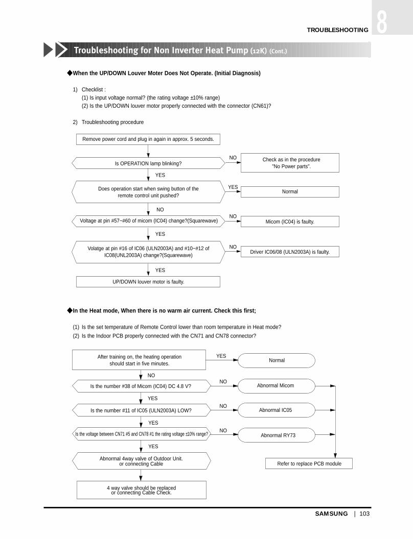
SAMSUNG | 103
1TROUBLESHOOTING 8Troubleshooting for Non Inverter Heat Pump (12K) (Cont.)
When the UP/DOWN Louver Moter Does Not Operate. (Initial Diagnosis)
1) Checklist :(1) Is input voltage normal? (the rating voltage ±10% range)(2) Is the UP/DOWN louver motor properly connected with the connector (CN61)?
2) Troubleshooting procedure
In the Heat mode, When there is no warm air current. Check this first;
(1) Is the set temperature of Remote Control lower than room temperature in Heat mode?
(2) Is the Indoor PCB properly connected with the CN71 and CN78 connector?
Remove power cord and plug in again in approx. 5 seconds.
Is OPERATION lamp blinking?
YES
NO
NO
YES
NO
NO
YES
YES
Does operation start when swing button of the remote control unit pushed?
Voltage at pin #57~#60 of micom (IC04) change?(Squarewave)
Volatge at pin #16 of IC06 (ULN2003A) and #10~#12 ofIC08(UNL2003A) change?(Squarewave)
UP/DOWN louver motor is faulty.
Driver IC06/08 (ULN2003A) is faulty.
Micom (IC04) is faulty.
Normal
Check as in the procedure"No Power parts".
After training on, the heating operation should start in five minutes.
Is the number #38 of Micom (IC04) DC 4.8 V?
Is the number #11 of IC05 (ULN2003A) LOW?
Is the voltage between CN71 #5 and CN78 #1 the rating voltage ±10% range?
Abnormal 4way valve of Outdoor Unit.or connecting Cable
4 way valve should be replacedor connecting Cable Check.
NO
YES
YES
YES
NO
NO
NO
YESNormal
Abnormal Micom
Abnormal IC05
Abnormal RY73
Refer to replace PCB module
DB98_12818A(1)_65~108 4/17/03 5:29 PM Page 103

104 | SAMSUNG
8Set up the model Option
8-5. Set up the Model Option
Step 1 : Preparing the remocon to main PBA option set
1st Remove the battery from the remocon.
2nd Press the temperature raise/down button simultaneously and insert the battery again.
3rd Make sure the remocon display shown as .
Step 2 : Second stage preparation of the remocon option set.
Note ; In case the wrong letter has been selected, continue to press the button until the correct letter appears.
1st If the first stage number “ ” appears on the display, proceed to the second stage.
2nd Every time the ! and & button, “ ” and “ ” each continue to appear.
3rd Whenever pressing the @, #, $, %, ^, *, (, ), 1, 2 button, the number increases from
0~9(0123456789) and A, b, c, d, E, F each time.
TROUBLESHOOTING
! If the first number is , it is correct otherwise press until
appear.
@ When pressing the button ~ appear on the display, select one of them.
# When pressing the button ~ appear on the display, select one of them.
$ When pressing the button ~ appear on the display, select one of them.
% When pressing the button ~ appear on the display, select one of them.
^ When pressing the button ~ appear on the display, select one of them.
DB98_12818A(1)_65~108 4/17/03 5:29 PM Page 104

SAMSUNG | 105
1TROUBLESHOOTING 8Set up the Model Option (Cont.)
Step 3 : Reconfirming option set after completion
(in case of ex. 017d25-17021d)
After pressing selector for the mode, the display shown as .
After pressing selector for the mode, the display shown as .
Step 4 : Pressing the ON/OFF button ( )When pressing the operation ON/OFF key with the direction of remote controller for unit, the sound “Ding” or “Diriring” is
heard and the OPERATION LED lamp is flickering at the same time, then the input of option is completed.
(If the diriring sound isn’t heard, try again pressing the ON/OFF button.)
Step 5 : Unit operation test-runFirst, Remove the battery from the remote controller.
Second, Re-insert the battery into the remote controller.
Third, Press ON/OFF key with the direction of remote controller for set.
! If the first number is , it is correct otherwise press until
appear.
@ When pressing the button ~ appear on the display, selectone of them.
# When pressing the button ~ appear on the display, selectone of them.
$ When pressing the button ~ appear on the display, select oneof them.
% When pressing the button ~ appear on the display, select oneof them.
^ When pressing the button ~ appear on the display, select oneof them.
Error Mode :
1st If all lamps of indoor unit are flickering, Plug out and plug in again and pressing ON/OFF key to retry.
2nd If the unit is not working properly or all lamps are continuously flickering after setting the option code, seeif the correct option code is set up for it’s model.
DB98_12818A(1)_65~108 4/17/03 5:29 PM Page 105

106 | SAMSUNG
8Set up the Model Option (Cont.)
<Table of the option code>
Non Inverter (7K/ 9K/ 12K)
TROUBLESHOOTING
MODEL
SH12ZPG
AQ12P GE
AS12P G
SH09ZPG
AQ09P8GE
AQ09PBGE
AS09P G
SH07ZPG
AQ07P8GE
AQ07PBGE
AS07P G
OPTION CODE
067066-170362
067065-170362
060000-170384
026566-170340
026064-170340
026065-170340
020000-170340
026065-17022E
026064-17022E
026065-17022E
020000-17022E
DB98_12818A(1)_65~108 4/17/03 5:29 PM Page 106

MEMO
SAMSUNG | 107
DB98_12818A(1)_65~108 4/17/03 5:29 PM Page 107

MEMO
108 | SAMSUNG
DB98_12818A(1)_65~108 4/17/03 5:29 PM Page 108

© Samsung Electronics Co., Ltd. Apr. 2003.Printed in Korea.Code No. DB98-12818A(1)
ELECTRONICS
DB98_12818A(1)_CO(letter) 4/17/03 1:51 PM Page 2