aqci f user - aquatrac instruments: cooling tower and ... the bottom left & right mounting...
TRANSCRIPT

SlimFlex
Water Treatment ControllerFor Cooling Towers
Measures Conductivity, Temperature,Make-up Water Meter and Flowswitch
Controls the Bleed Solenoid,Inhibitor and two Biocide Pumps
Includes CTF, Conductivity-Temperature-Flowswitch Sensor
Part No. CO-IN-TB-TB
SlimFlex: Water Treatment Controller
AQCI_F_User 05/05 2
CONTENTS
Safety
1. INSTALLATION1.1 Sample Piping1.2 Controller Enclosure1.3 Conductivity–Flowswitch Sensor1.4 Water Meter1.5 Pumps and Bleed Solenoid
2. START-UP2.1 Power-up Display & Keypad2.2 Bleed Mode: Conductivity Setpoints2.3 Inhibitor Feed Mode: Setpoints, Feed Limits2.4 Verify Conductivity Sensor2.5 Check Flowswitch & Install Water Meter2.6 Plug-in Pumps and Bleed Solenoid2.7 Check Controls
3. OPERATION3.1 Conductivity Sensor3.2 Bleed Controls3.3 Make-up Meter3.4 Inhibitor Controls3.5 Biocide Events3.6 System–Alarms3.7 Password
4. MAINTENANCE4.1 Guidelines4.2 Spare Parts4.3 Technical Support
APPENDICESA. INSTALLB. SPECIFICATIONSC. HARDWIRINGD. ‘CL’ 4-20mA OUTPUT OptionE. ‘AR’ ALARM RELAY OptionF. ‘LB’ LAN - BROWSER Option
SlimFlex: Water Treatment Controller
AQCI_F_User 05/05 3
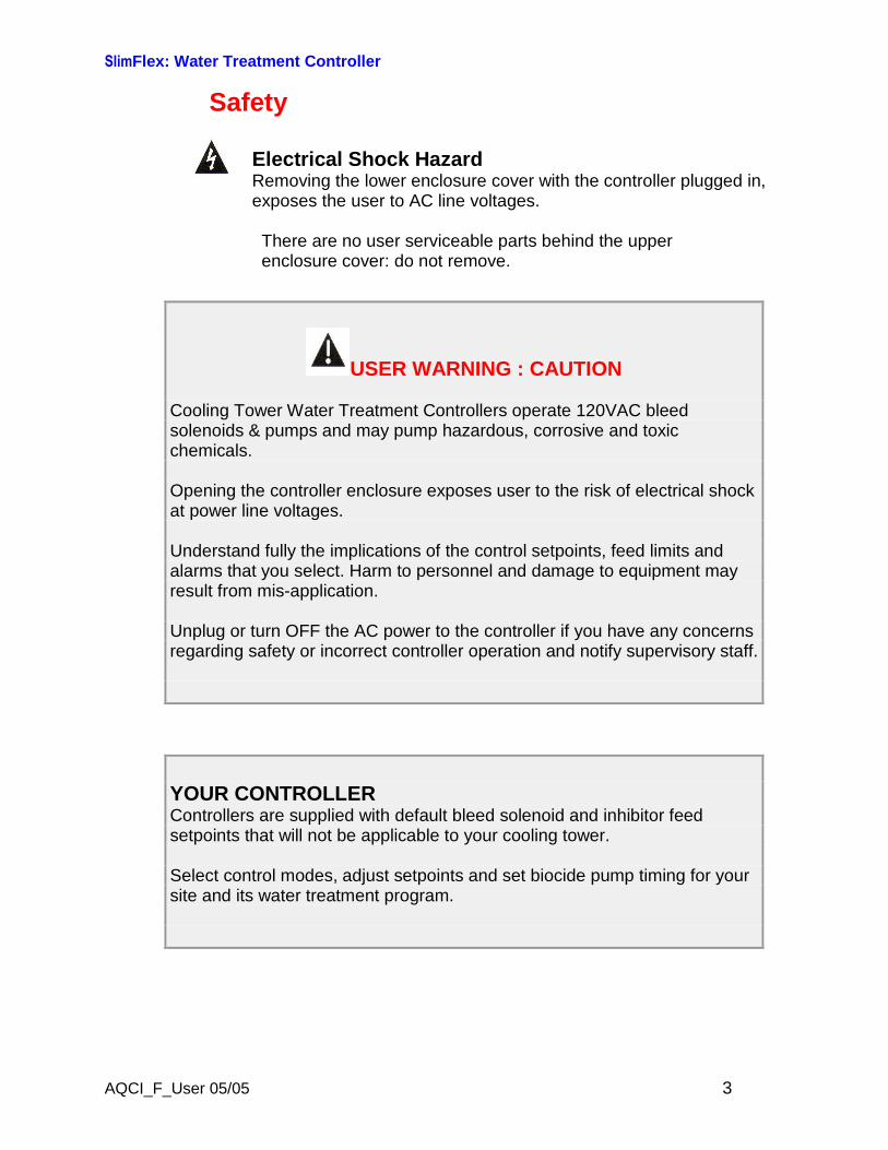
Safety
Electrical Shock HazardRemoving the lower enclosure cover with the controller plugged in,exposes the user to AC line voltages.
There are no user serviceable parts behind the upperenclosure cover: do not remove.
USER WARNING : CAUTION
Cooling Tower Water Treatment Controllers operate 120VAC bleedsolenoids & pumps and may pump hazardous, corrosive and toxicchemicals.
Opening the controller enclosure exposes user to the risk of electrical shockat power line voltages.
Understand fully the implications of the control setpoints, feed limits andalarms that you select. Harm to personnel and damage to equipment mayresult from mis-application.
Unplug or turn OFF the AC power to the controller if you have any concernsregarding safety or incorrect controller operation and notify supervisory staff.
YOUR CONTROLLERControllers are supplied with default bleed solenoid and inhibitor feedsetpoints that will not be applicable to your cooling tower.
Select control modes, adjust setpoints and set biocide pump timing for yoursite and its water treatment program.
SlimFlex: Water Treatment Controller
AQCI_F_User 05/05 4
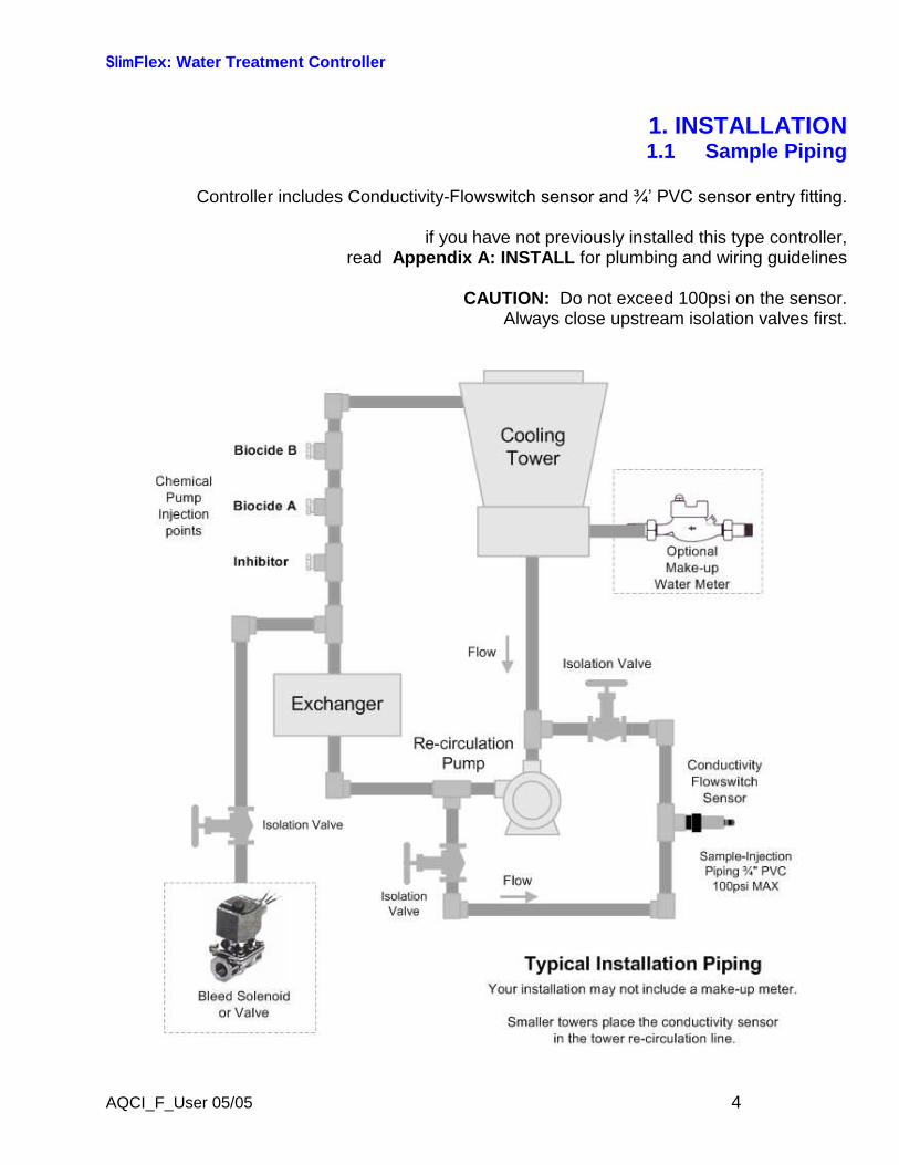
1. INSTALLATION1.1 Sample Piping
Controller includes Conductivity-Flowswitch sensor and ¾’ PVC sensor entry fitting.
if you have not previously installed this type controller,read Appendix A: INSTALL for plumbing and wiring guidelines
CAUTION: Do not exceed 100psi on the sensor.Always close upstream isolation valves first.

SlimFlex: Water Treatment Controller
AQCI_F_User 05/05 5
1.2 Controller Enclosure
Remove the lower, controller enclosure cover.Hang the controller on a single #8-#10 screw located 60”, 150cm. above the floor
Install the bottom left & right mounting screws through the existing enclosure holes locatedbehind the lower cover.
ChemicalInjectionpoints
Flow
Sensor
Plugs, wiring& tubing not
shown
Inhibitor
Biocide A
Biocide B
Chemical Feed Pumps
Typical Equipment Layout
Pump Shelf
Controller
Although sensor cables and pump tubing may be extended, ease of servicing occurs whenwater treatment components are located in the same area.
Ensure that the lower enclosure cover is installed when not terminating sensor and watermeter wiring.
SlimFlex: Water Treatment Controller
AQCI_F_User 05/05 6
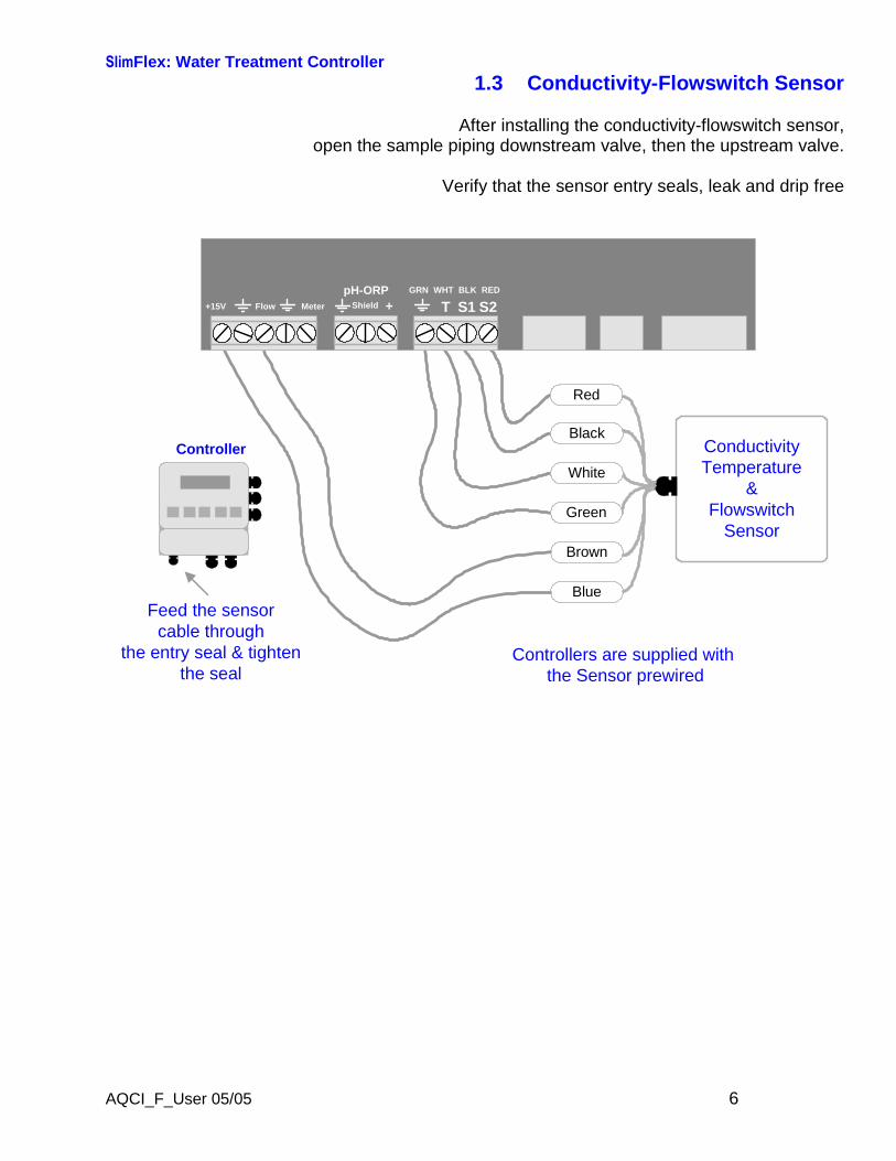
1.3 Conductivity-Flowswitch Sensor
After installing the conductivity-flowswitch sensor,open the sample piping downstream valve, then the upstream valve.
Verify that the sensor entry seals, leak and drip free
ConductivityTemperature
&Flowswitch
Sensor
Red
BlackController
Feed the sensorcable through
the entry seal & tightenthe seal
MeterFlow+15V TGRN WHT BLK RED
S1 S2pH-ORP
Shield +
Blue
Brown
White
Green
Controllers are supplied withthe Sensor prewired
SlimFlex: Water Treatment Controller
AQCI_F_User 05/05 7
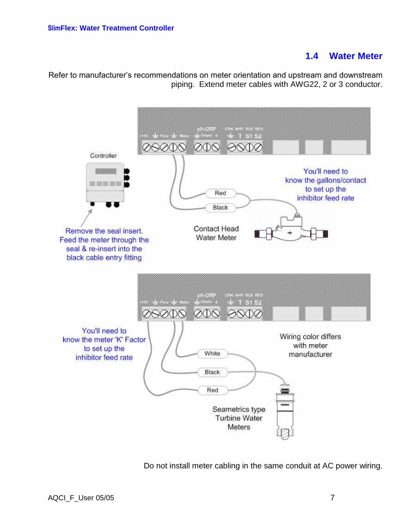
1.4 Water Meter
Refer to manufacturer’s recommendations on meter orientation and upstream and downstream piping. Extend meter cables with AWG22, 2 or 3 conductor.
Do not install meter cabling in the same conduit at AC power wiring.
SlimFlex: Water Treatment Controller
AQCI_F_User 05/05 8
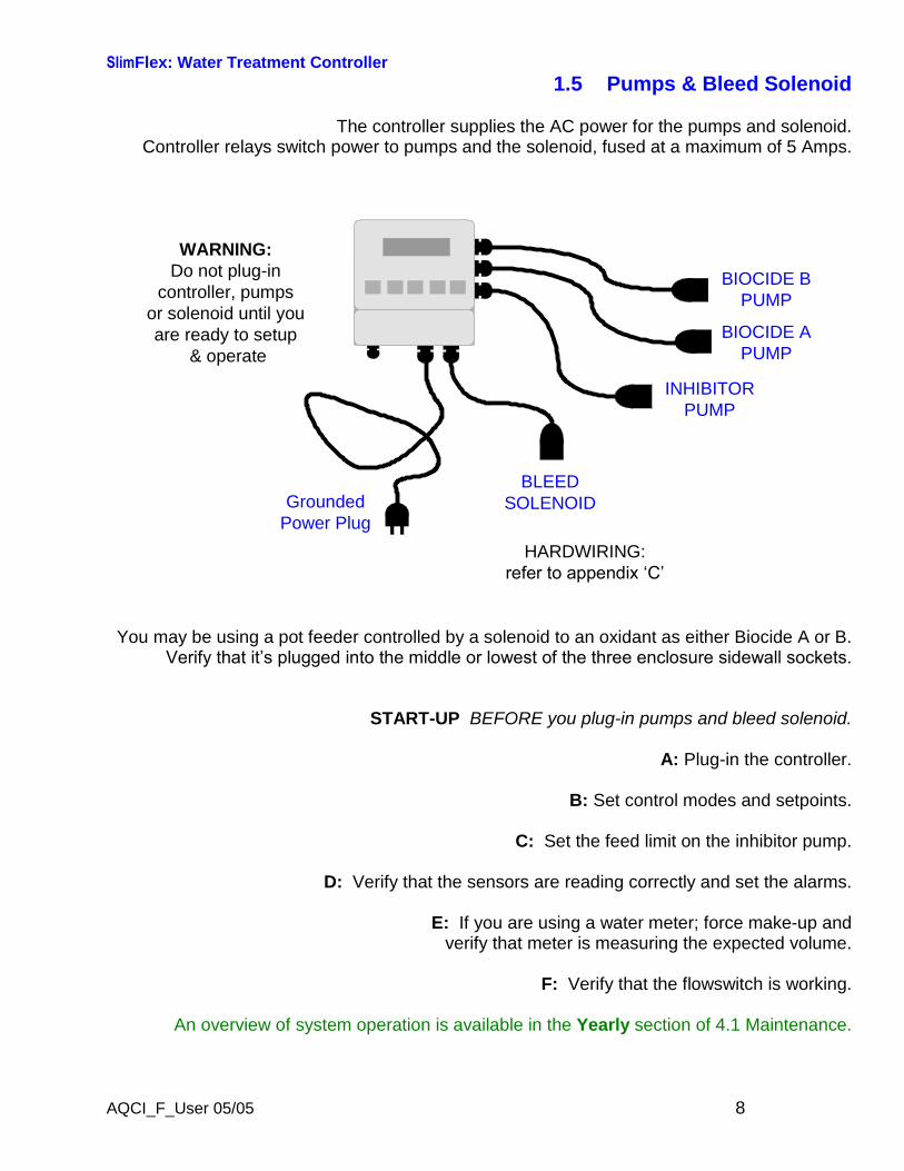
1.5 Pumps & Bleed Solenoid
The controller supplies the AC power for the pumps and solenoid.Controller relays switch power to pumps and the solenoid, fused at a maximum of 5 Amps.
GroundedPower Plug
HARDWIRING:refer to appendix ‘C’
INHIBITORPUMP
BIOCIDE APUMP
BIOCIDE BPUMP
BLEEDSOLENOID
WARNING:Do not plug-in
controller, pumpsor solenoid until youare ready to setup
& operate
You may be using a pot feeder controlled by a solenoid to an oxidant as either Biocide A or B.Verify that it’s plugged into the middle or lowest of the three enclosure sidewall sockets.
START-UP BEFORE you plug-in pumps and bleed solenoid.
A: Plug-in the controller.
B: Set control modes and setpoints.
C: Set the feed limit on the inhibitor pump.
D: Verify that the sensors are reading correctly and set the alarms.
E: If you are using a water meter; force make-up andverify that meter is measuring the expected volume.
F: Verify that the flowswitch is working.
An overview of system operation is available in the Yearly section of 4.1 Maintenance.
SlimFlex: Water Treatment Controller
AQCI_F_User 05/05 9
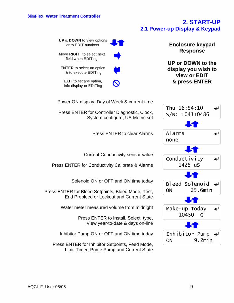
2. START-UP2.1 Power-up Display & Keypad
UP & DOWN to view optionsor to EDIT numbers
Move RIGHT to select nextfield when EDITing
ENTER to select an option& to execute EDITing
EXIT to escape option,info display or EDITing
Power ON display: Day of Week & current time
Press ENTER for Controller Diagnostic, Clock,System configure, US-Metric set
Press ENTER to clear Alarms
Current Conductivity sensor value
Press ENTER for Conductivity Calibrate & Alarms
Solenoid ON or OFF and ON time today
Press ENTER for Bleed Setpoints, Bleed Mode, Test,End Prebleed or Lockout and Current State
Water meter measured volume from midnight
Press ENTER to Install, Select type,View year-to-date & days on-line
Inhibitor Pump ON or OFF and ON time today
Press ENTER for Inhibitor Setpoints, Feed Mode,Limit Timer, Prime Pump and Current State
Enclosure keypadResponse
UP or DOWN to thedisplay you wish to
view or EDIT& press ENTER
Thu 16:54:10S/N: T041T0486
Alarmsnone
Conductivity1425 uS
Bleed SolenoidON 25.6min
Make-up Today10450 G
Inhibitor PumpON 9.2min
SlimFlex: Water Treatment Controller
AQCI_F_User 05/05 10
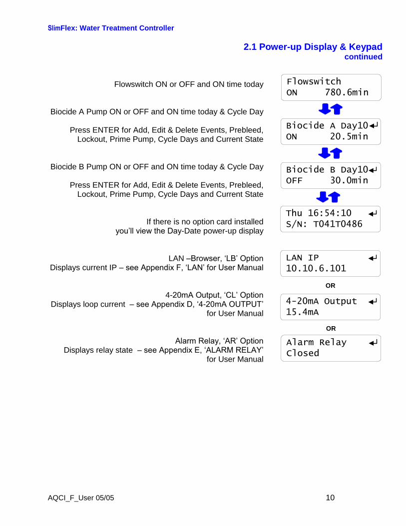
2.1 Power-up Display & Keypadcontinued
Flowswitch ON or OFF and ON time today
Biocide A Pump ON or OFF and ON time today & Cycle Day
Press ENTER for Add, Edit & Delete Events, Prebleed,Lockout, Prime Pump, Cycle Days and Current State
Biocide B Pump ON or OFF and ON time today & Cycle Day
Press ENTER for Add, Edit & Delete Events, Prebleed,Lockout, Prime Pump, Cycle Days and Current State
If there is no option card installedyou’ll view the Day-Date power-up display
LAN–Browser, ‘LB’ OptionDisplays current IP– see Appendix F, ‘LAN’ for User Manual
4-20mA Output, ‘CL’ Option Displays loop current – see Appendix D, ‘4-20mA OUTPUT’
for User Manual
Alarm Relay, ‘AR’ OptionDisplays relay state – see Appendix E, ‘ALARM RELAY’
for User Manual
Thu 16:54:10S/N: T041T0486
LAN IP10.10.6.101
4-20mA Output15.4mA
Alarm RelayClosed
OR
OR
Biocide B Day10OFF 30.0min
Biocide A Day10ON 20.5min
FlowswitchON 780.6min

SlimFlex: Water Treatment Controller
AQCI_F_User 05/05 11
2.2 Bleed Mode: Conductivity Setpoints
The factory default is ‘Bleed on Conductivity’Refer to 3.2 Bleed Controls
to select one of three Bleed Modes
Press UP or DOWN until you see‘Bleed Solenoid’ & press ENTER
Press ENTER to view or adjust Setpoints
Displays current bleed setpoints,Varies with Bleed Mode
Press ENTER adjust Turn ON,or DOWN & ENTER for TurnOFF
Press UP-DOWN to adjust and RIGHT to move the cursor.Press EXIT to leave the Setpoints unchanged
Press ENTER, displays current setpoints.
If you make Turn ON less than TurnOFF,the setpoints will be switched.
SetpointsBleed Mode
Turn ON 1150TurnOFF 1140
Edit & EnterTurn ON 11 80
Turn ON 1180TurnOFF 1140
then
Bleed SolenoidON 564.2min
Sidebar: The difference between Turn ON & TurnOFF, the ‘deadband’, is usually set to 10uS.If you are watching the tower conductivity as the sump float turns the make-up water ON &OFF, you’ll observe the operational deadband exceeds 10uS.
Delays in starting and stopping the make-up due to sump float trip points, increases theoperational deadband beyond the controller ON–OFF setpoints.
SlimFlex: Water Treatment Controller
AQCI_F_User 05/05 12
2.3 Inhibitor Feed Mode: Setpoints, Feed Limits
The factory default is ‘Bleed & Feed’Refer to 3.6 Inhibitor Controls
to select one of four Feed Modes
Press UP or DOWN until you see‘Inhibitor Pump’ & press ENTER
Press ENTER to view or adjust Setpoints
Displays current feed setpoints,Inhibitor will be on for 32% of the time that the Bleed
Solenoid is ON; 96 seconds in every 5 minutes
Press ENTER adjust % of Bleed Time,
Press UP-DOWN to adjust and RIGHT to move the cursor.Press EXIT to leave the Setpoint unchanged
Press ENTER, displays current setpoint,90 seconds in every 5 minutes
SetpointsFeed Mode
Bleed & Feed32% each 5min
Edit & Enter30% each 5min
Bleed & Feed30% each 5min
then
Inhibitor PumpON 48.1min
Sidebar: Bleed & Feed is the most common but usually not the best way to feed inhibitor.
If you are not bleed limited, use Bleed then Feed mode to reduce inhibitor use.
If you are using a make-up water meter to control inhibitor feed, the controller will delayfeeding when the bleed valve is ON to avoid pumping inhibitor down the drain.
SlimFlex: Water Treatment Controller
AQCI_F_User 05/05 13
2.3 Inhibitor Feed Mode: Setpoints, Feed Limitscontinued
The Inhibitor feed limit timer turns OFF the inhibitor pump toprevent overfeeding.
The factory default feed limit 180 Minutes/Day.
Press UP or DOWN until you see‘Inhibitor Pump’ & press ENTER.
Press DOWN until Limit Timer.Press ENTER to view or adjust Limit Timer.
Displays feed limit in minutes,?157 indexes more explanation @ www.aquatrac.com
Press ENTER adjust Feed Limit,
Press UP-DOWN to adjust and RIGHT to move the cursor.Press EXIT to leave the Feed Limit unchanged
Press ENTER, displays current setpoint,210 minutes/day
Limit TimerPrime Pump
Day Limit ?157180 min/day
Edit & Enter210 min/day
Day Limit ?157210 min/day
then
Inhibitor PumpON 48.1min
HELP: ?157 and other help numbers display wherever more explanation is available atwww.aquatrac.com.
If you are using water treatment controls for the first time, the language and application ofsome of the controller options and settings requires more detail than a 2 line display candeliver.
SlimFlex: Water Treatment Controller
AQCI_F_User 05/05 14
2.4 Verify Conductivity Sensor
Open the downstream, then the upstream sample lineisolation valves, immersing the conductivity sensor
Press UP or DOWN until you see Day & Time.Press ENTER.
Press ENTER & then press ENTERto view temperature at the conductivity sensor.
If the GREEN & WHITE wires are connected to the controllerterminals, you’ll view the current temperature.‘Fault’ indicates a wiring or sensor problem.
‘Fault’ automatically removes conductivity temperature compensation.
Key EXIT twice to return to Day & Time
Press DOWN until you see Conductivity.Sample the tower water & verify that the displayed
conductivity matches the measured conductivity.
Adjust the displayed conductivity by pressing ENTER twice.
Press UP-DOWN to adjust and RIGHT to move the cursor.Press EXIT to leave Conductivity unchanged.
You’ll see this screen if the sensor is fouled, miswired, not immersed or you keyed incorrectly.
Press ENTER to ignore or EXIT to return to Factory Default.
?141 indexes more explanation @ www.aquatrac.com
Displays the current, calibrated conductivity.
Verify Temperature
Temperature ?10187F
Current StateAdjust Clock
Thu 16:54:10S/N: T041T0486
Calibrate Conductivity
CalibrateAlarms
Edit & ENTER1883 uS
Advice ?141Fails Calibrate
Conductivity1883 uS
then
Conductivity1425 uS
SlimFlex: Water Treatment Controller
AQCI_F_User 05/05 15
2.5 Check Flowswitch & Install Water Meter
Open the downstream, then the upstream sample lineisolation valves, immersing the conductivity sensor
Press UP - DOWN until you see Flowswitch.Displays ON or OFF and the total minutes ON from midnight.
NOTE: An OFF flowswitch stops all pumpsand the bleed solenoid.
The flowswitch can be bypassed by jumpering the Flowterminal to ground.
The factory default water meter isa 100 Gallons/contact contact head meter
Press UP - DOWN until you see Make-up Today.Displays make-up volume from midnight.
Press ENTER twice to view or change meter type.
Key ENTER to view or change the gallons/contact.Metric users will view volumes in ‘L’iters & L/Contact
Press UP-DOWN to adjust and RIGHT to move the cursor.Press EXIT to leave Gallons/contact unchanged.
ENTER or EXIT displays the current meter type.
Flowswitch
FlowswitchON 780.6min
Contact HeadWatermeter
Contact HeadPaddlewheel
G/Contact100
Edit & ENTER50
then
Contact HeadPaddlewheel
Make-up Today38200 G
Meter TypeYear-to-Date
Sidebar: 2 wire meters are usually Contact Head & 3 wire meters are usually, but not alwaysTurbine or Paddlewheel.
SlimFlex: Water Treatment Controller
AQCI_F_User 05/05 16
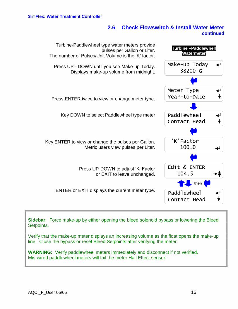
2.6 Check Flowswitch & Install Water Metercontinued
Turbine-Paddlewheel type water meters providepulses per Gallon or Liter.
The number of Pulses/Unit Volume is the ‘K’ factor.
Press UP - DOWN until you see Make-up Today.Displays make-up volume from midnight.
Press ENTER twice to view or change meter type.
Key DOWN to select Paddlewheel type meter
Key ENTER to view or change the pulses per Gallon.Metric users view pulses per Liter.
Press UP-DOWN to adjust ‘K’ Factor or EXIT to leave unchanged.
ENTER or EXIT displays the current meter type.
Turbine–PaddlewhellWatermeter
PaddlewheelContact Head
‘K’Factor100.0
Edit & ENTER104.5
then
PaddlewheelContact Head
Make-up Today38200 G
Meter TypeYear-to-Date
Sidebar: Force make-up by either opening the bleed solenoid bypass or lowering the BleedSetpoints.
Verify that the make-up meter displays an increasing volume as the float opens the make-upline. Close the bypass or reset Bleed Setpoints after verifying the meter.
WARNING: Verify paddlewheel meters immediately and disconnect if not verified.Mis-wired paddlewheel meters will fail the meter Hall Effect sensor.
SlimFlex: Water Treatment Controller
AQCI_F_User 05/05 17
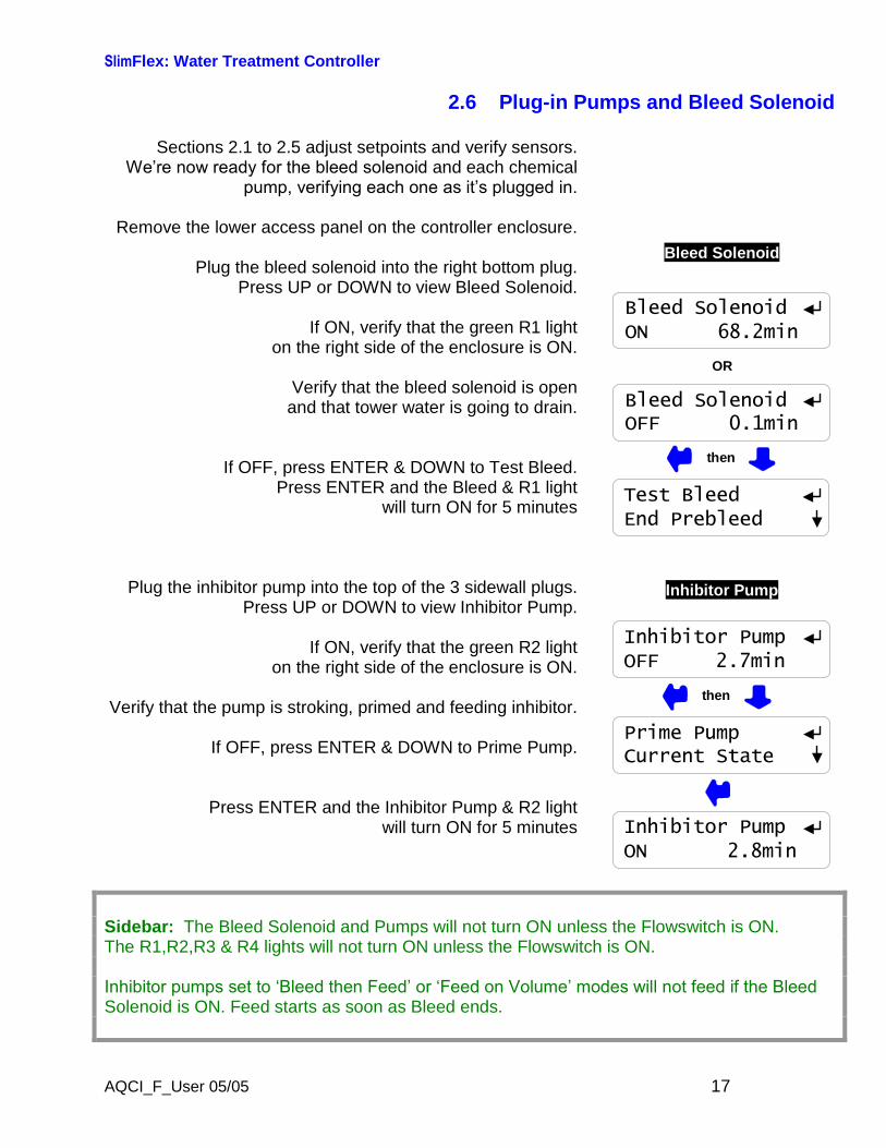
2.6 Plug-in Pumps and Bleed Solenoid
Sections 2.1 to 2.5 adjust setpoints and verify sensors.We’re now ready for the bleed solenoidand each chemical
pump, verifying each one as it’s plugged in.
Remove the lower access panel on the controller enclosure.
Plug the bleed solenoid into the right bottom plug.Press UP or DOWN to view Bleed Solenoid.
If ON, verify that the green R1 lighton the right side of the enclosure is ON.
Verify that the bleed solenoid is openand that tower water is going to drain.
If OFF, press ENTER & DOWN to Test Bleed.Press ENTER and the Bleed & R1 light
will turn ON for 5 minutes
Plug the inhibitor pump into the top of the 3 sidewall plugs.Press UP or DOWN to view Inhibitor Pump.
If ON, verify that the green R2 lighton the right side of the enclosure is ON.
Verify that the pump is stroking, primed and feeding inhibitor.
If OFF, press ENTER & DOWN to Prime Pump.
Press ENTER and the Inhibitor Pump & R2 lightwill turn ON for 5 minutes
Bleed Solenoid
Test BleedEnd Prebleed
Bleed SolenoidOFF 0.1min
then
Bleed SolenoidON 68.2min
OR
Inhibitor Pump
Prime PumpCurrent State
Inhibitor PumpON 2.8min
Inhibitor PumpOFF 2.7min
then
Sidebar: The Bleed Solenoid and Pumps will not turn ON unless the Flowswitch is ON.The R1,R2,R3 & R4 lights will not turn ON unless the Flowswitch is ON.
Inhibitor pumps set to ‘Bleed then Feed’ or ‘Feed on Volume’ modes will not feed if the Bleed Solenoid is ON. Feed starts as soon as Bleed ends.
SlimFlex: Water Treatment Controller
AQCI_F_User 05/05 18
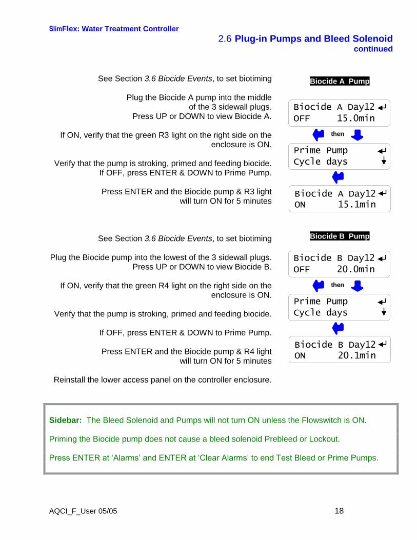
2.6 Plug-in Pumps and Bleed Solenoidcontinued
See Section 3.6 Biocide Events, to set biotiming
Plug the Biocide A pump into the middleof the 3 sidewall plugs.
Press UP or DOWN to view Biocide A.
If ON, verify that the green R3 light on the right side on theenclosure is ON.
Verify that the pump is stroking, primed and feeding biocide.If OFF, press ENTER & DOWN to Prime Pump.
Press ENTER and the Biocide pump & R3 lightwill turn ON for 5 minutes
See Section 3.6 Biocide Events, to set biotiming
Plug the Biocide pump into the lowest of the 3 sidewall plugs.Press UP or DOWN to view Biocide B.
If ON, verify that the green R4 light on the right side on theenclosure is ON.
Verify that the pump is stroking, primed and feeding biocide.
If OFF, press ENTER & DOWN to Prime Pump.
Press ENTER and the Biocide pump & R4 lightwill turn ON for 5 minutes
Reinstall the lower access panel on the controller enclosure.
Biocide A Pump
Biocide A Day12OFF 15.0min
Prime PumpCycle days
then
Biocide A Day12ON 15.1min
Biocide B Pump
Biocide B Day12OFF 20.0min
Prime PumpCycle days
then
Biocide B Day12ON 20.1min
Sidebar: The Bleed Solenoid and Pumps will not turn ON unless the Flowswitch is ON.
Priming the Biocide pump does not cause a bleed solenoid Prebleed or Lockout.
Press ENTER at ‘Alarms’ and ENTER at ‘Clear Alarms’ to end Test Bleed or Prime Pumps.

SlimFlex: Water Treatment Controller
AQCI_F_User 05/05 19
2.7 Check Controls
Verify that the controls work in the waythat you expect for this site.
Watch the Conductivity increase as the tower operates.
The Bleed Solenoid will turn ON as the conductivity exceedsthe Turn ON setpoint.
As the tower makes up, the Conductivity will fall below theTurnOFF setpoint and the Bleed Solenoid will turn OFF.
Verifying a Bleed controlled by a Make-up Meter orPercentage time differs.
If the Inhibitor feed mode is set to ‘Bleed & Feed’, the Inhibitor Pump will turn ON when the Bleed turns ON.
If the % of each 5 minutes is set to less than 100%, theInhibitor Pump will turn ON & OFF while the Bleed in ON.
If the Inhibitor feed mode is set ‘Bleed then Feed’, the Inhibitor Pump will always be OFF when the Bleed is ON
& will turn ON as soon as the bleed turns OFF.
If the inhibitor pump is set to ‘Feed on Volume’ , the inhibitor pump will turn ON after measuring Make-up.
If the Bleed is ON, the Inhibitor Pump will wait until the Bleedturns OFF before turning ON.
Conductivity & Bleed
Conductivity1425 uS
Bleed SolenoidON 564.2min
Water Meter or Bleed& Inhibitor Pump
Bleed SolenoidON 564.2min
Make-up Today38200 G
Inhibitor PumpON 48.1min
Inhibitor PumpON 124.8min
Sidebar: The Bleed Solenoid and Pumps will not turn ON unless the Flowswitch is ON.The Inhibitor Pump turns OFF if the daily Feed Limit is exceeded.Increase the Limit Timer to allow the pump to turn ON.
Bleed Solenoids may turn OFF if Biocide is set to Prebleed and a timed event is scheduled.Bleed Solenoids may not turn ON if Biocide is set to Lockout and a timed event has started.
SlimFlex: Water Treatment Controller
AQCI_F_User 05/05 20
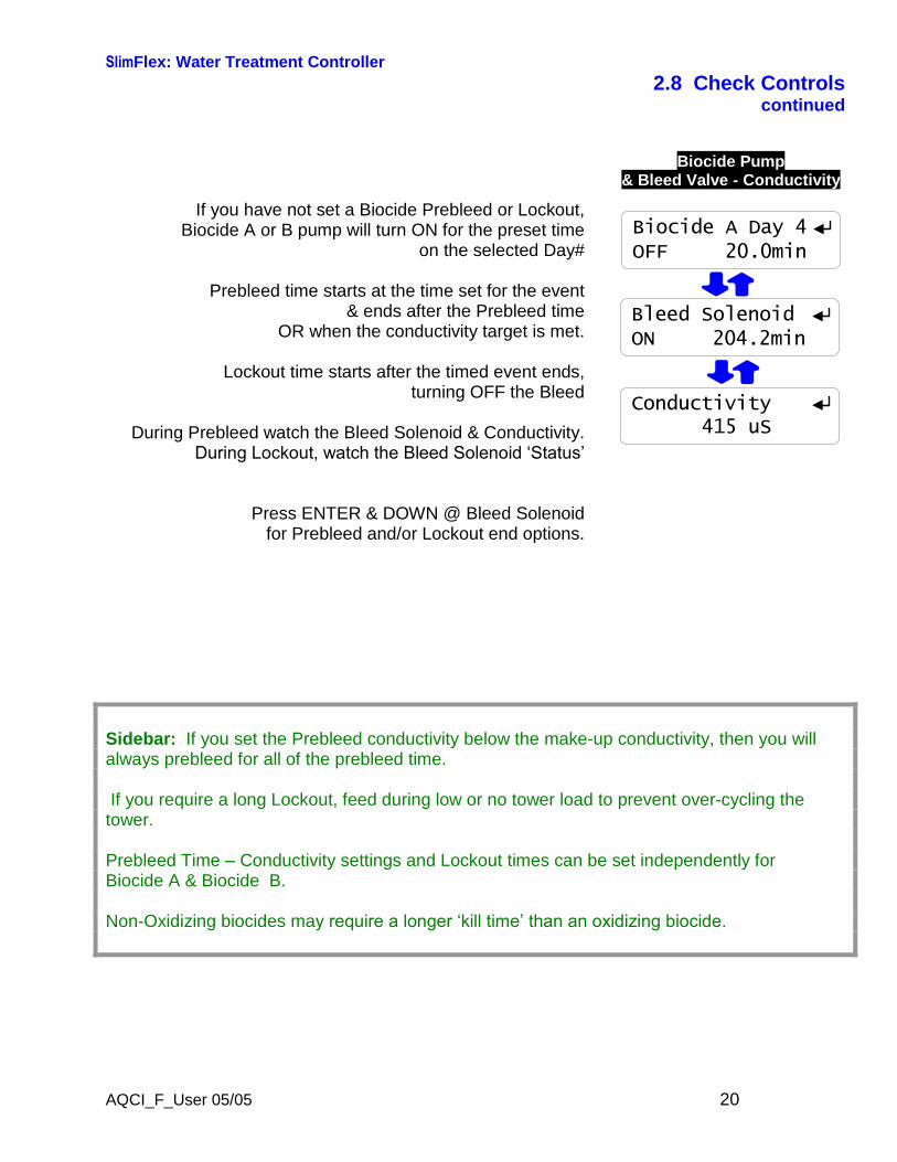
2.8 Check Controlscontinued
If you have not set a Biocide Prebleed or Lockout,Biocide A or B pump will turn ON for the preset time
on the selected Day#
Prebleed time starts at the time set for the event& ends after the Prebleed time
OR when the conductivity target is met.
Lockout time starts after the timed event ends,turning OFF the Bleed
During Prebleed watch the Bleed Solenoid & Conductivity.During Lockout, watch the Bleed Solenoid ‘Status’
Press ENTER & DOWN @ Bleed Solenoidfor Prebleed and/or Lockout end options.
Biocide Pump& Bleed Valve - Conductivity
Biocide A Day 4OFF 20.0min
Conductivity415 uS
Bleed SolenoidON 204.2min
Sidebar: If you set the Prebleed conductivity below the make-up conductivity, then you willalways prebleed for all of the prebleed time.
If you require a long Lockout, feed during low or no tower load to prevent over-cycling thetower.
Prebleed Time–Conductivity settings and Lockout times can be set independently forBiocide A & Biocide B.
Non-Oxidizing biocides may require a longer ‘kill time’ than an oxidizing biocide.
SlimFlex: Water Treatment Controller
AQCI_F_User 05/05 21
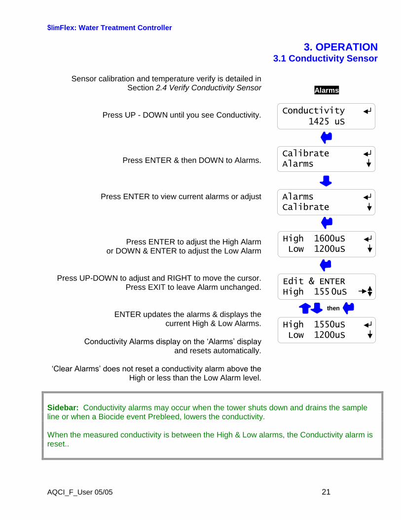
3. OPERATION3.1 Conductivity Sensor
Sensor calibration and temperature verify is detailed inSection 2.4 Verify Conductivity Sensor
Press UP - DOWN until you see Conductivity.
Press ENTER & then DOWN to Alarms.
Press ENTER to view current alarms or adjust
Press ENTER to adjust the High Alarmor DOWN & ENTER to adjust the Low Alarm
Press UP-DOWN to adjust and RIGHT to move the cursor.Press EXIT to leave Alarm unchanged.
ENTER updates the alarms & displays thecurrent High & Low Alarms.
Conductivity Alarms display on the ‘Alarms’ display and resets automatically.
‘Clear Alarms’ does not reset a conductivity alarm above the High or less than the Low Alarm level.
Alarms
CalibrateAlarms
AlarmsCalibrate
Conductivity1425 uS
High 1600uSLow 1200uS
Edit & ENTERHigh 1550uS
High 1550uSLow 1200uS
then
Sidebar: Conductivity alarms may occur when the tower shuts down and drains the sampleline or when a Biocide event Prebleed, lowers the conductivity.
When the measured conductivity is between the High & Low alarms, the Conductivity alarm isreset..
SlimFlex: Water Treatment Controller
AQCI_F_User 05/05 22
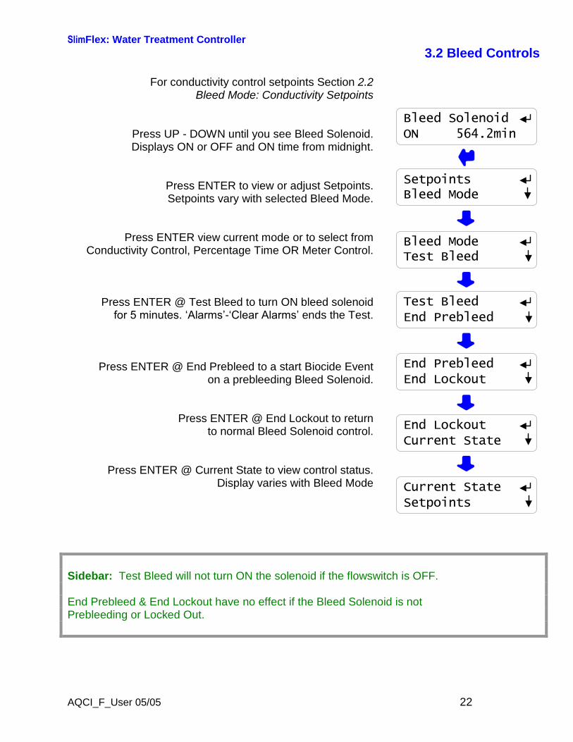
3.2 Bleed Controls
For conductivity control setpoints Section 2.2Bleed Mode: Conductivity Setpoints
Press UP - DOWN until you see Bleed Solenoid.Displays ON or OFF and ON time from midnight.
Press ENTER to view or adjust Setpoints.Setpoints vary with selected Bleed Mode.
Press ENTER view current mode or to select fromConductivity Control, Percentage Time OR Meter Control.
Press ENTER @ Test Bleed to turn ON bleed solenoidfor 5 minutes. ‘Alarms’-‘Clear Alarms’ends the Test.
Press ENTER @ End Prebleed to a start Biocide Eventon a prebleeding Bleed Solenoid.
Press ENTER @ End Lockout to returnto normal Bleed Solenoid control.
Press ENTER @ Current State to view control status.Display varies with Bleed Mode
SetpointsBleed Mode
Bleed ModeTest Bleed
Test BleedEnd Prebleed
End PrebleedEnd Lockout
End LockoutCurrent State
Current StateSetpoints
Bleed SolenoidON 564.2min
Sidebar: Test Bleed will not turn ON the solenoid if the flowswitch is OFF.
End Prebleed & End Lockout have no effect if the Bleed Solenoid is notPrebleeding or Locked Out.

SlimFlex: Water Treatment Controller
AQCI_F_User 05/05 23
3.2 Bleed ControlsContinued
Bleed Solenoid Bleed Modes
Press ENTER then DOWN @ Bleed Solenoid
Press ENTER @ Bleed Mode to view current mode and toselect a new mode
Most cooling towers operate with Conductivity Control.Bleed solenoid opens at TurnON conductivity setpoint and
closes at TurnOFF setpoint
Meter Control Measures a user set volume onthe Make-up water meter then turns ON
the bleed solenoid for a user set time.For example:
Measure 100 Gallons of make-up & bleed for 10 seconds.
Percentage Time turns ON the bleed solenoidfor a user set % of 5 minutes.
NOTE: If you change the Bleed Mode, press UP to Setpoints& ENTER to adjust for the new Bleed Mode.
Bleed ModeTest Bleed
Conduct.ControlMeter Control
Meter ControlConduct.Control
Percentage TimeMeter Control
Bleed SolenoidON 564.2min
then
then
SetpointsBleed Mode
Sidebar: ‘Meter Control’ mode is used where sensor foulingfrom silica or organicscontinuously fouls the conductivity sensor.
‘Percentage Time’ mode is used short term to bleed while replacing a sensor or installing a water meter.

SlimFlex: Water Treatment Controller
AQCI_F_User 05/05 24
3.2 Bleed ControlsContinued
Current State of the Bleed Solenoid Control
Press ENTER then UP @ Bleed Solenoid
Press ENTER @ Current State
If bleed ON, displays TurnOFF setpoint,975 & currentconductivity,993
If bleed OFF, displays TurnOFF setpoint,1000& current conductivity,993
If bleed ON, displays Owes 101 sec ?122& ON ENTER=Stop
If bleed OFF, displays turn-on volume, 10400& current volume 10,200
If bleed ON, displays Owes 41 sec ?123 & ON ENTER=StopSeconds count down to zero & bleed turns OFF.
If bleed OFF, displays seconds to turn ON.Seconds count down to zero & bleed turns ON.
Current StateSetpoints
Off@ 975 ?121ON 993uS
On @10400 G ?122OFF 10200 G
Mode = Conductivity Control
Mode = Water Meter Control
On in 221sec?123OFF
Mode = % Time Control
Bleed SolenoidON 564.2min
then
HELP: ?121,122 & ?123 and other help numbers display wherever more explanation isavailable at www.aquatrac.com.
ON ENTER=Stop ends the current feed cycle or %Time ON period.
SlimFlex: Water Treatment Controller
AQCI_F_User 05/05 25
3.3 Make-up Meter
Meter type selection & installation detailed inSection 2.5 Check Flowswitch & Install Water Meter
Press UP - DOWN until you see ‘Make-up Today’& press ENTER .
Press ENTER to view current type or to selectContact Head or Paddlewheel water meter.
Key DOWN & ENTER for volume this year.
Key DOWN & ENTER for days on-line this year
Key ENTER to reset Year-to-Date, Days OnLineand Make-up Today to zero.
Warning: Cannot Undo
Volume this year to date.Displays in ‘L’iters if metric selected.
Days controller installed and operating this year.Does not count the days that controller power is OFF.
Press EXIT to return to previous display
Year-to-DateDays Online
Make-up Today38200 G
Meter TypeYear-to-Date
Days OnlineZero Meter?
Zero Meter?Meter Type
Year-to-Date?192765200 G
Days Online ?193215
Sidebar: Year-to-Date volume divided by Days OnLine is average usage, a figure of merit fora tower tonnage.
HELP: ?192 & ?193 and other help numbers display wherever more explanation is available atwww.aquatrac.com.
SlimFlex: Water Treatment Controller
AQCI_F_User 05/05 26
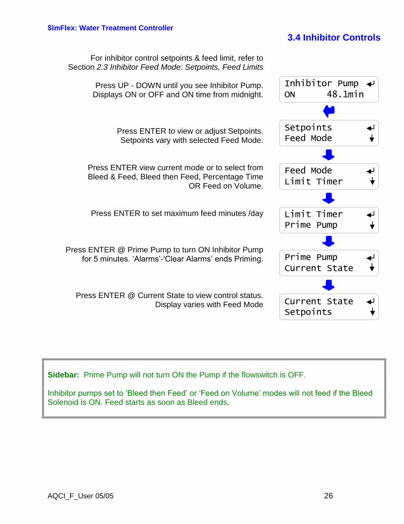
3.4 Inhibitor Controls
For inhibitor control setpoints & feed limit, refer toSection 2.3 Inhibitor Feed Mode: Setpoints, Feed Limits
Press UP - DOWN until you see Inhibitor Pump.Displays ON or OFF and ON time from midnight.
Press ENTER to view or adjust Setpoints.Setpoints vary with selected Feed Mode.
Press ENTER view current mode or to select fromBleed & Feed, Bleed then Feed, Percentage Time
OR Feed on Volume.
Press ENTER to set maximum feed minutes /day
Press ENTER @ Prime Pump to turn ON Inhibitor Pumpfor 5 minutes. ‘Alarms’-‘Clear Alarms’ ends Priming.
Press ENTER @ Current State to view control status.Display varies with Feed Mode
SetpointsFeed Mode
Feed ModeLimit Timer
Limit TimerPrime Pump
Prime PumpCurrent State
Current StateSetpoints
Inhibitor PumpON 48.1min
Sidebar: Prime Pump will not turn ON the Pump if the flowswitch is OFF.
Inhibitor pumps set to ‘Bleed then Feed’ or ‘Feed on Volume’ modes will not feed if the Bleed Solenoid is ON. Feed starts as soon as Bleed ends.
SlimFlex: Water Treatment Controller
AQCI_F_User 05/05 27
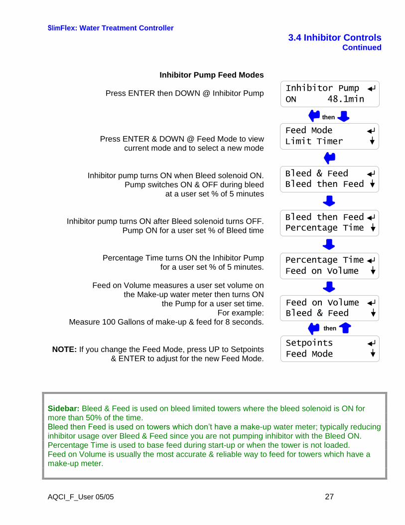
3.4 Inhibitor ControlsContinued
Inhibitor Pump Feed Modes
Press ENTER then DOWN @ Inhibitor Pump
Press ENTER & DOWN @ Feed Mode to viewcurrent mode and to select a new mode
Inhibitor pump turns ON when Bleed solenoid ON.Pump switches ON & OFF during bleed
at a user set % of 5 minutes
Inhibitor pump turns ON after Bleed solenoid turns OFF.Pump ON for a user set % of Bleed time
Percentage Time turns ON the Inhibitor Pumpfor a user set % of 5 minutes.
Feed on Volume measures a user set volume onthe Make-up water meter then turns ON
the Pump for a user set time.For example:
Measure 100 Gallons of make-up & feed for 8 seconds.
NOTE: If you change the Feed Mode, press UP to Setpoints& ENTER to adjust for the new Feed Mode.
Feed ModeLimit Timer
Bleed & FeedBleed then Feed
Bleed then FeedPercentage Time
Percentage TimeFeed on Volume
Feed on VolumeBleed & Feed
then
Inhibitor PumpON 48.1min
then
SetpointsFeed Mode
Sidebar: Bleed & Feed is used on bleed limited towers where the bleed solenoid is ON formore than 50% of the time.Bleed then Feed is used on towers which don’t have a make-up water meter; typically reducinginhibitor usage over Bleed & Feed since you are not pumping inhibitor with the Bleed ON.Percentage Time is used to base feed during start-up or when the tower is not loaded.Feed on Volume is usually the most accurate & reliable way to feed for towers which have amake-up meter.
SlimFlex: Water Treatment Controller
AQCI_F_User 05/05 28
3.4 Inhibitor ControlsContinued
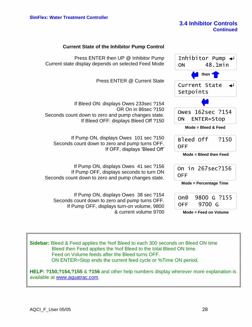
Current State of the Inhibitor Pump Control
Press ENTER then UP @ Inhibitor PumpCurrent state display depends on selected Feed Mode
Press ENTER @ Current State
If Bleed ON: displays Owes 233sec ?154OR On in 86sec ?150
Seconds count down to zero and pump changes state.If Bleed OFF: displays Bleed Off ?150
If Pump ON, displays Owes 101 sec ?150Seconds count down to zero and pump turns OFF.
If OFF, displays ‘Bleed Off’
If Pump ON, displays Owes 41 sec ?156If Pump OFF, displays seconds to turn ON
Seconds count down to zero and pump changes state.
If Pump ON, displays Owes 38 sec ?154Seconds count down to zero and pump turns OFF.
If Pump OFF, displays turn-on volume, 9800& current volume 9700
Current StateSetpoints
Owes 162sec ?154ON ENTER=Stop
Bleed Off ?150OFF
Mode = Bleed & Feed
Mode = Bleed then Feed
On in 267sec?156OFF
Mode = Percentage Time
On@ 9800 G ?155OFF 9700 G
Mode = Feed on Volume
Inhibitor PumpON 48.1min
then
Sidebar: Bleed & Feed applies the %of Bleed to each 300 seconds on Bleed ON timeBleed then Feed applies the %of Bleed to the total Bleed ON time.Feed on Volume feeds after the Bleed turns OFF.ON ENTER=Stop ends the current feed cycle or %Time ON period.
HELP: ?150,?154,?155 & ?156 and other help numbers display wherever more explanation isavailable at www.aquatrac.com.
SlimFlex: Water Treatment Controller
AQCI_F_User 05/05 29
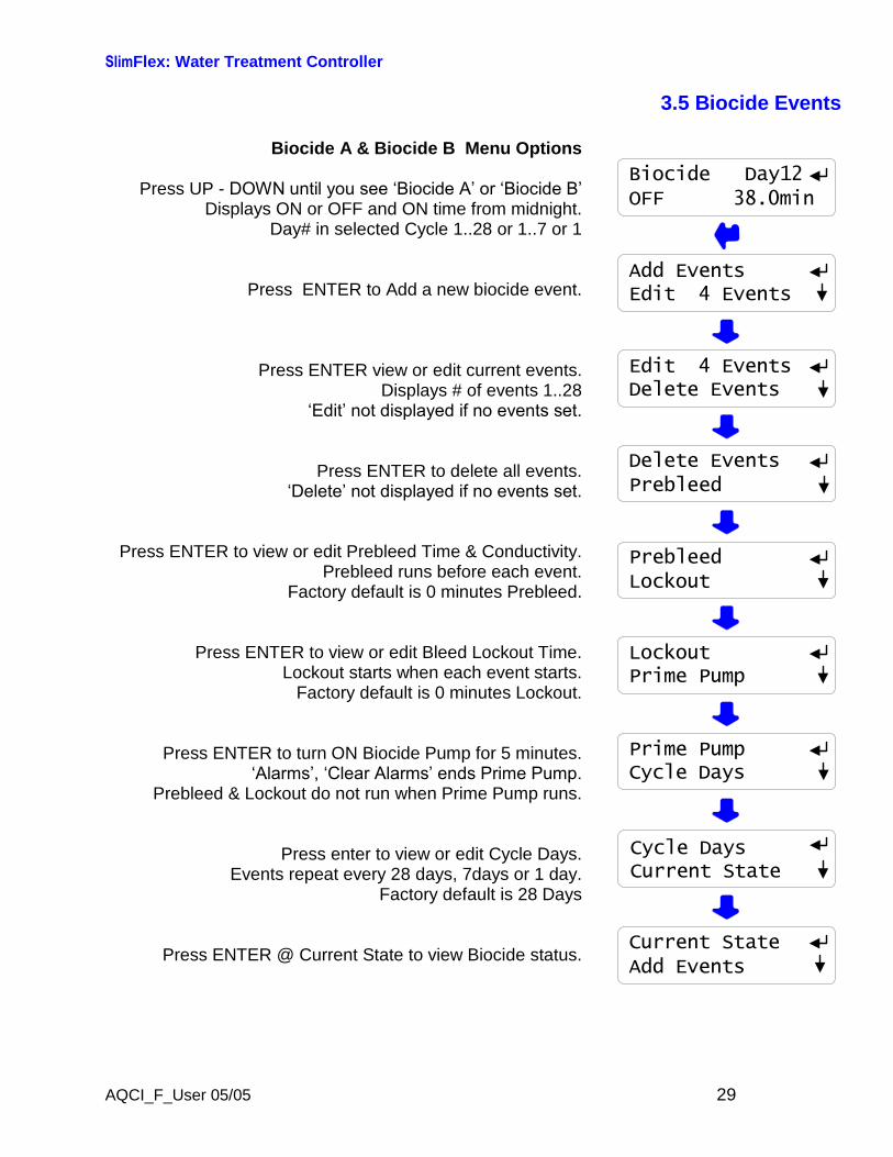
3.5 Biocide Events
Biocide A & Biocide B Menu Options
Press UP - DOWN until you see ‘Biocide A’ or ‘Biocide B’Displays ON or OFF and ON time from midnight.
Day# in selected Cycle 1..28 or 1..7 or 1
Press ENTER to Add a new biocide event.
Press ENTER view or edit current events.Displays # of events 1..28
‘Edit’ not displayed if no events set.
Press ENTER to delete all events.‘Delete’ not displayed if no events set.
Press ENTER to view or edit Prebleed Time & Conductivity.Prebleed runs before each event.
Factory default is 0 minutes Prebleed.
Press ENTER to view or edit Bleed Lockout Time.Lockout starts when each event starts.
Factory default is 0 minutes Lockout.
Press ENTER to turn ON Biocide Pump for 5 minutes.‘Alarms’, ‘Clear Alarms’ ends Prime Pump.
Prebleed & Lockout do not run when Prime Pump runs.
Press enter to view or edit Cycle Days.Events repeat every 28 days, 7days or 1 day.
Factory default is 28 Days
Press ENTER @ Current State to view Biocide status.
Cycle DaysCurrent State
Current StateAdd Events
Prime PumpCycle Days
LockoutPrime Pump
PrebleedLockout
Delete EventsPrebleed
Edit 4 EventsDelete Events
Add EventsEdit 4 Events
Biocide Day12OFF 38.0min
SlimFlex: Water Treatment Controller
AQCI_F_User 05/05 30
3.5 Biocide Eventscontinued
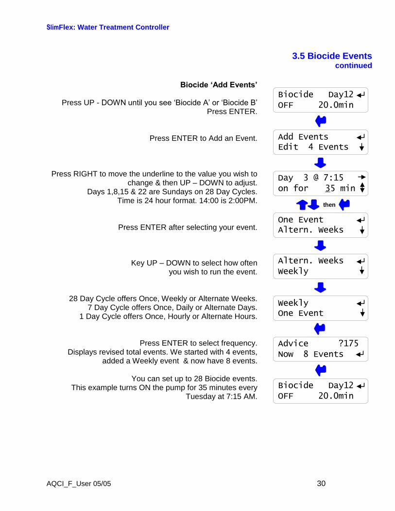
Biocide ‘Add Events’
Press UP - DOWN until you see ‘Biocide A’ or ‘Biocide B’Press ENTER.
Press ENTER to Add an Event.
Press RIGHT to move the underline to the value you wish tochange & then UP–DOWN to adjust.
Days 1,8,15 & 22 are Sundays on 28 Day Cycles.Time is 24 hour format. 14:00 is 2:00PM.
Press ENTER after selecting your event.
Key UP–DOWN to select how oftenyou wish to run the event.
28 Day Cycle offers Once, Weekly or Alternate Weeks.7 Day Cycle offers Once, Daily or Alternate Days.
1 Day Cycle offers Once, Hourly or Alternate Hours.
Press ENTER to select frequency.Displays revised total events. We started with 4 events,
added a Weekly event & now have 8 events.
You can set up to 28 Biocide events.This example turns ON the pump for 35 minutes every
Tuesday at 7:15 AM.
Add EventsEdit 4 Events
Day 3 @ 7:15on for 35 min
One EventAltern. Weeks
Altern. WeeksWeekly
WeeklyOne Event
Advice ?175Now 8 Events
Biocide Day12OFF 20.0min
then
Biocide Day12OFF 20.0min
SlimFlex: Water Treatment Controller
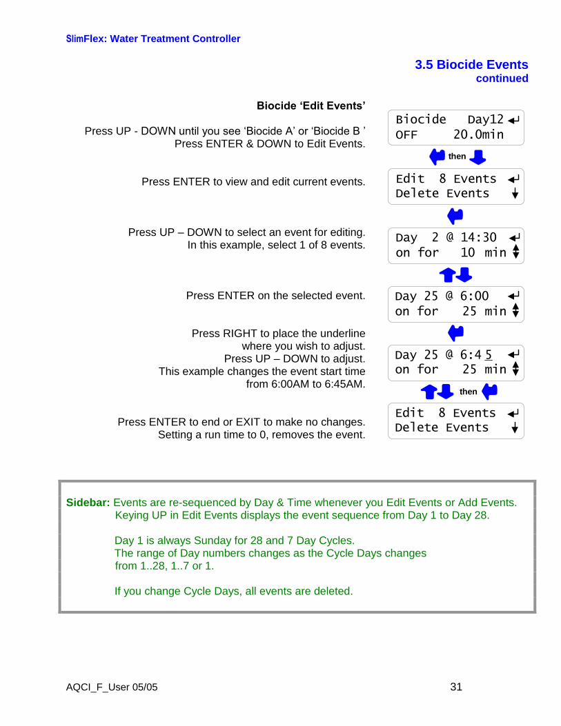
AQCI_F_User 05/05 31
3.5 Biocide Eventscontinued
Biocide ‘Edit Events’
Press UP - DOWN until you see ‘Biocide A’ or ‘Biocide B ’Press ENTER & DOWN to Edit Events.
Press ENTER to view and edit current events.
Press UP–DOWN to select an event for editing.In this example, select 1 of 8 events.
Press ENTER on the selected event.
Press RIGHT to place the underlinewhere you wish to adjust.
Press UP–DOWN to adjust.This example changes the event start time
from 6:00AM to 6:45AM.
Press ENTER to end or EXIT to make no changes.Setting a run time to 0, removes the event.
Day 2 @ 14:30on for 10 min
Day 25 @ 6:00on for 25 min
then
Day 25 @ 6:4 5on for 25 min
Edit 8 EventsDelete Events
Edit 8 EventsDelete Events
then
Biocide Day12OFF 20.0min
Sidebar: Events are re-sequenced by Day & Time whenever you Edit Events or Add Events.Keying UP in Edit Events displays the event sequence from Day 1 to Day 28.
Day 1 is always Sunday for 28 and 7 Day Cycles.The range of Day numbers changes as the Cycle Days changesfrom 1..28, 1..7 or 1.
If you change Cycle Days, all events are deleted.
SlimFlex: Water Treatment Controller
AQCI_F_User 05/05 32
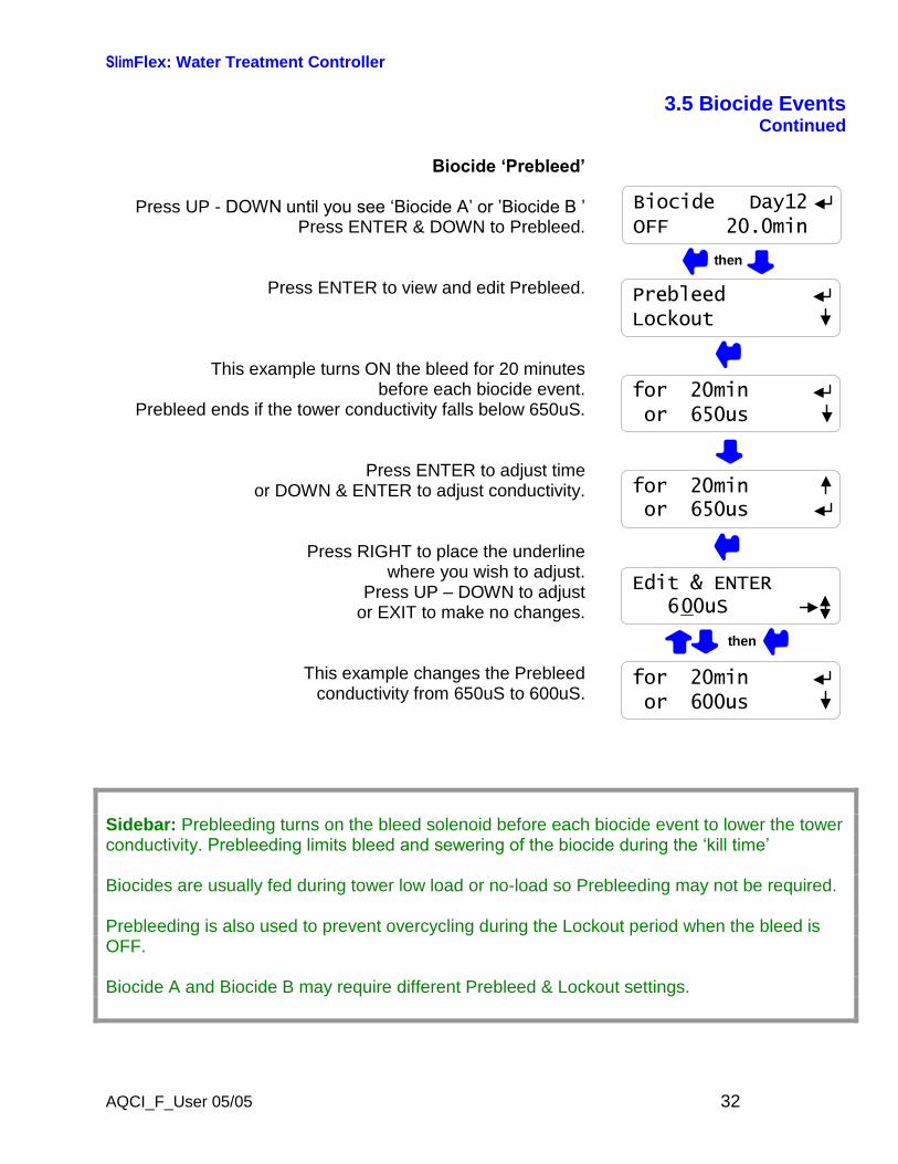
3.5 Biocide EventsContinued
Biocide ‘Prebleed’
Press UP - DOWN until you see ‘Biocide A’ or ’Biocide B ’Press ENTER & DOWN to Prebleed.
Press ENTER to view and edit Prebleed.
This example turns ON the bleed for 20 minutesbefore each biocide event.
Prebleed ends if the tower conductivity falls below 650uS.
Press ENTER to adjust timeor DOWN & ENTER to adjust conductivity.
Press RIGHT to place the underlinewhere you wish to adjust.
Press UP–DOWN to adjustor EXIT to make no changes.
This example changes the Prebleedconductivity from 650uS to 600uS.
for 20minor 650us
for 20minor 650us
for 20minor 600us
Edit & ENTER600uS
then
PrebleedLockout
Biocide Day12OFF 20.0min
then
Sidebar: Prebleeding turns on the bleed solenoid before each biocide event to lower the towerconductivity. Prebleeding limits bleed and sewering of the biocide during the ‘kill time’
Biocides are usually fed during tower low load or no-load so Prebleeding may not be required.
Prebleeding is also used to prevent overcycling during the Lockout period when the bleed isOFF.
Biocide A and Biocide B may require different Prebleed & Lockout settings.

SlimFlex: Water Treatment Controller
AQCI_F_User 05/05 33
3.5 Biocide Eventscontinued
Biocide ‘Lockout’Press UP - DOWN until you see ‘Biocide A’ or ‘Biocide B’
Press ENTER & DOWN to Lockout.
Press ENTER to view and edit Lockout time.Press ENTER to edit or press EXIT.
Factory default Lockout is set to 0 minutes.Press ENTER to adjust.
Press RIGHT to place the underlinewhere you wish to adjust.
Press UP–DOWN to adjustor EXIT to make no changes.
Biocide ‘Cycle Days’Press UP - DOWN until you see ‘Biocide’
Press ENTER & DOWN to Cycle Days.
Press ENTER to view and edit Cycle Days.Press ENTER to edit or press EXIT.
Key UP–DOWN to select 28,7 or 1 day& then press ENTER.
Changing Cycle Days deletes existing events.
Biocide events repeat every 28, 7 or 1 day.
Lockout ?1740 min
Edit & ENTER120 min
then
LockoutPrime Pump
Biocide Day12OFF 20.0min
then
Cycle daysCurrent State
1 Day7 Days
28 Days1 Day
Cycle DaysCurrent State
Sidebar: Lockout prevents the bleed solenoid from turning ON during the biocide ‘kill time’ andsewering the biocide.Lockout is usually used with Prebleed to prevent tower overcycling during the Lockout period.
Non-Oxidizing biocides typically use a 28 or 7 Day cycle.Oxidizing biocides typically use a 7 or 1 day cycle.
SlimFlex: Water Treatment Controller
AQCI_F_User 05/05 34
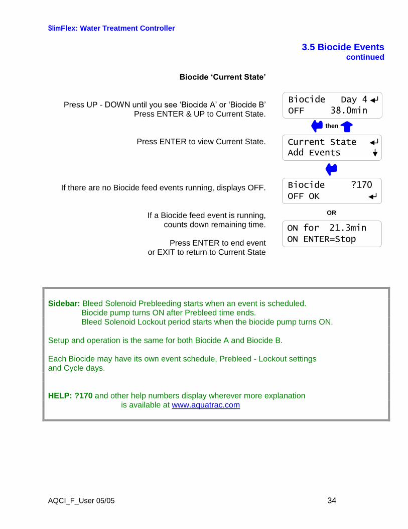
3.5 Biocide Eventscontinued
Biocide ‘Current State’
Press UP - DOWN until you see ‘Biocide A’ or ‘Biocide B’Press ENTER & UP to Current State.
Press ENTER to view Current State.
If there are no Biocide feed events running, displays OFF.
If a Biocide feed event is running,counts down remaining time.
Press ENTER to end eventor EXIT to return to Current State
Biocide ?170OFF OK
ON for 21.3minON ENTER=Stop
Current StateAdd Events
OR
Biocide Day 4OFF 38.0min
then
Sidebar: Bleed Solenoid Prebleeding starts when an event is scheduled.Biocide pump turns ON after Prebleed time ends.Bleed Solenoid Lockout period starts when the biocide pump turns ON.
Setup and operation is the same for both Biocide A and Biocide B.
Each Biocide may have its own event schedule, Prebleed - Lockout settingsand Cycle days.
HELP: ?170 and other help numbers display wherever more explanationis available at www.aquatrac.com
SlimFlex: Water Treatment Controller
AQCI_F_User 05/05 35
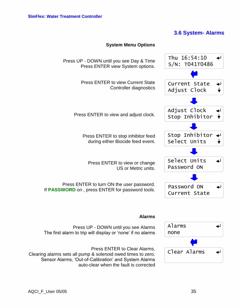
3.6 System- Alarms
System Menu Options
Press UP - DOWN until you see Day & TimePress ENTER view System options.
Press ENTER to view Current StateController diagnostics
Press ENTER to view and adjust clock.
Press ENTER to stop inhibitor feedduring either Biocide feed event.
Press ENTER to view or changeUS or Metric units.
Press ENTER to turn ON the user password.If PASSWORD on , press ENTER for password tools.
Alarms
Press UP - DOWN until you see AlarmsThe first alarm to trip will display or ‘none’ if no alarms
Press ENTER to Clear Alarms.Clearing alarms sets all pump & solenoid owed times to zero.
Sensor Alarms, ‘Out-of-Calibration’ and System Alarms auto-clear when the fault is corrected
Current StateAdjust Clock
Stop InhibitorSelect Units
Adjust ClockStop Inhibitor
Thu 16:54:10S/N: T041T0486
Select UnitsPassword ON
Password ONCurrent State
Alarmsnone
Clear Alarms
SlimFlex: Water Treatment Controller
AQCI_F_User 05/05 36
3.6 System- Alarmscontinued
System : Current State
Press UP - DOWN until you see Day & TimePress ENTER view System options.
Press ENTER to view Current StateController diagnostics
Temperature at the conductivity sensor.Press ENTER to adjust.
Displays ‘Fault’ if not used to compensate conductivity,Indicates wiring or sensor problem.
Power used for paddlewheel water metersand to power 4-20mA current loops
Alarms on short circuits, recovers when wiring corrected.
Internal power used or bleed solenoid and pump relays.Always 11.7 to 12.3.
Alarms on fault.
Conductivity sensor drive, 70-80mV or 950–1050mVas sensor drive auto-ranges.
Alarms and cannot measure conductivity if out of range.
H-ORP sensor offset, 2475 to 2525mVAlarms and cannot measure any sensors if out of range.
Internal diagnostic.Checks that user setpoints being saved & that the Clocks
are operating,
Temperature ?10187F
Ext. Power ?10215.6 VDC
Relay Power ?10312.1 VDC
Drive ?10773.3 mV
Measure ?1052502.3 mV
State ?106244:163:1
Current StateAdjust Clock
Thu 16:54:10S/N: T041T0486
Sidebar: System: Diagnostics verifies the controller operation & alerts you to wiring problemswith conductivity temperature, paddlewheel water meters and controller powered 4-20mAcurrent loops.
SlimFlex: Water Treatment Controller
AQCI_F_User 05/05 37
3.6 System- Alarmscontinued
System : Adjust Clock
Press UP - DOWN until you see Day & TimePress ENTER & DOWN to Adjust Clock.
Press ENTER to view or adjust current Date & Time.Press EXIT to leave changed
or RIGHT to move the underline.Press UP–DOWN to EDIT.
After ENTER, press UP-DOWN to select day of the week.
Day of the week is important for Biocide eventswhich use Sunday as Day 1.
System : Stop Inhibitor
Press UP - DOWN until you see Day & TimePress ENTER & DOWN to Stop Inhibitor.
Press ENTER to view or adjust currentInhibitor feed sequence.
‘No Bioblock’ is the Factory Default.‘Biofeed Blocks’ stops the Inhibitor Pump whenever the
‘Biocide A’ or ‘Biocide B’ pump is ON.
Today isTue
Tue 15:03:31S/N T044T9999
Stop InhibitorSelect Units
No BioblockBiofeed Blocks
Biofeed BlocksNo Bioblock
Adjust ClockStop Inhibitor
DD/MM/YY HH:MM23/07/04 15:03
then
then
Sidebar: Sites where Biocides are fed into the same sample-feed piping as the Inhibitor maycause jelling or inhibitor degradation.
Blocking the inhibitor pump prevents product mixing in the sample-feed piping.
SlimFlex: Water Treatment Controller
AQCI_F_User 05/05 38
3.6 System- Alarmscontinued
System : Select Units
Press UP - DOWN until you see Day & TimePress ENTER & DOWN to Select Units
Press ENTER to view or adjust current Select Units.
Press EXIT to leave changedOr DOWN to change.
Key ENTER to:Set to U.S. units, degrees Fahrenheit & Gallons or
Set to Metric, degrees Centigrade & Liters
System : Adjust Temperature
Press UP - DOWN until you see Day & TimePress ENTER twice to adjust Temperature
Press UP–DOWN to EDIT or RIGHT to move the underlinePress EXIT to leave changed or
ENTER to change the temperature
A Temperature displaying Fault cannot be adjusted.
Temperature cannot be adjusted more than+/-18F or +-/10C from the factory default.
Press EXIT on this message to return to Temperature factorydefault setting.
Select UnitsCurrent State
Deg F, GallonsDeg C Liters
Deg C LitersDeg F, Gallons
Thu 16:54:10S/N: T041T0486
then
Edit & ENTER092F
Advice ?108Fails Calibrate
then
Temperature ?10187F
Sidebar: Select Units changes make-up meter units, year-to-date units and volume percontact units.
Temperature compensation of conductivity, switches automatically between C & F as does theSystem:Current State display of temperature.NOTE: If you adjust the Temperature, you’ll need to re-calibrate conductivity
SlimFlex: Water Treatment Controller
AQCI_F_User 05/05 39
3.7 Password
Password is turned OFF in new controllers
Press UP - DOWN until you see Day & Time
Press ENTER & UP to select Password ON
If you press ENTER you’ll be prompted for a password then next time you press ENTER.
Press UP or DOWN to view the current state of the controller.Any ENTER key will prompt for the password,
displaying the default password 123.
Use the UP, DOWN & RIGHT keys to enter a password thenkey ENTER.
A correct password displays, Password OK.Press any key to start operating the controller.
Current StateAdjust Clock
Thu 16:54:10S/N: T041T0486
Password ONCurrent State
Password ON
Enter Password0000123
then
Advice ?110Password OK
OR
Advice ?111Wrong Password
Turning ON Password
Sidebar: When you first select Password ON, the default password is 123.
Whenever you Enter Password the controller displays the default password.If you have not changed the default password, press ENTER to log in.
SlimFlex: Water Treatment Controller
AQCI_F_User 05/05 40
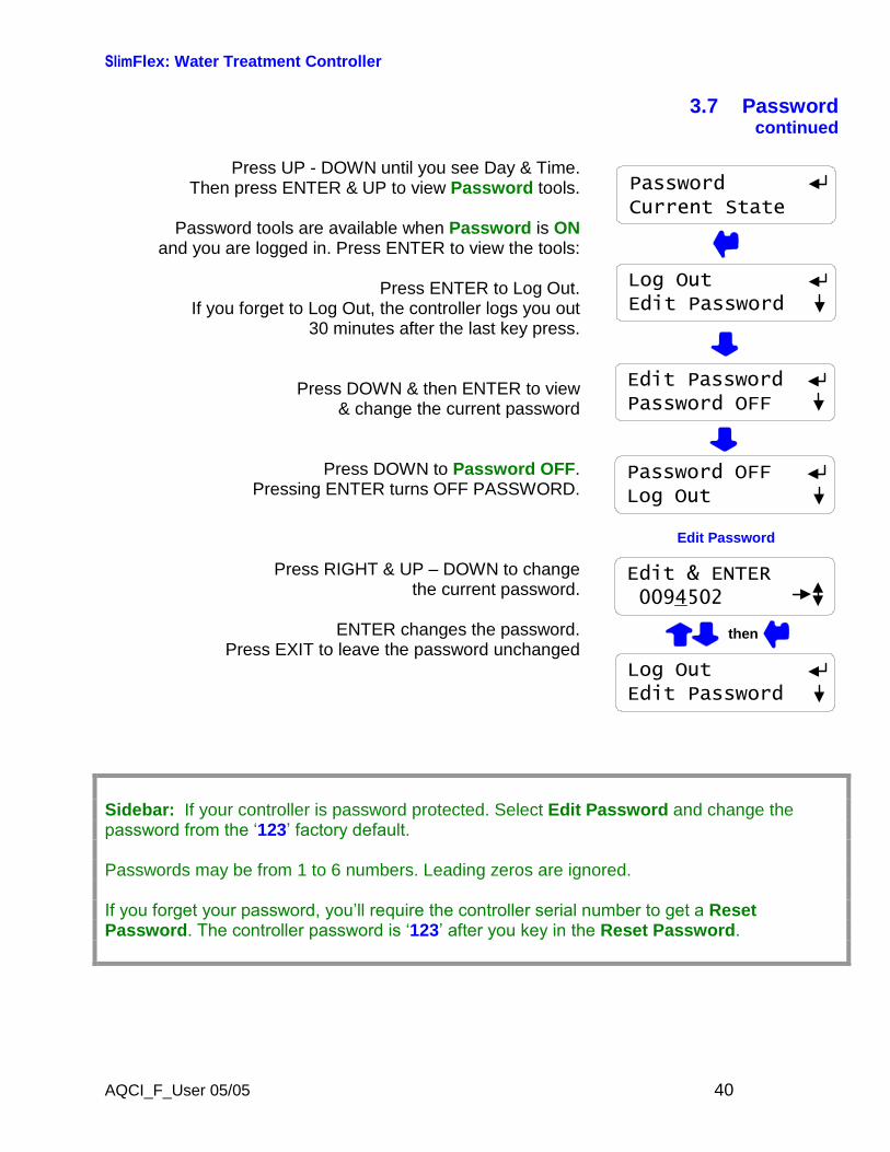
3.7 Passwordcontinued
Press UP - DOWN until you see Day & Time.Then press ENTER & UP to view Password tools.
Password tools are available when Password is ONand you are logged in. Press ENTER to view the tools:
Press ENTER to Log Out.If you forget to Log Out, the controller logs you out
30 minutes after the last key press.
Press DOWN & then ENTER to view& change the current password
Press DOWN to Password OFF.Pressing ENTER turns OFF PASSWORD.
Press RIGHT & UP–DOWN to changethe current password.
ENTER changes the password.Press EXIT to leave the password unchanged
Password OFFLog Out
Edit PasswordPassword OFF
PasswordCurrent State
Edit Password
Edit & ENTER0094502
then
Log OutEdit Password
Log OutEdit Password
Sidebar: If your controller is password protected. Select Edit Password and change thepassword from the ‘123’ factory default.
Passwords may be from 1 to 6 numbers. Leading zeros are ignored.
If you forget your password, you’ll require the controller serial number to get a ResetPassword. The controller password is ‘123’ after you key in the Reset Password.
SlimFlex: Water Treatment Controller
AQCI_F_User 05/05 41
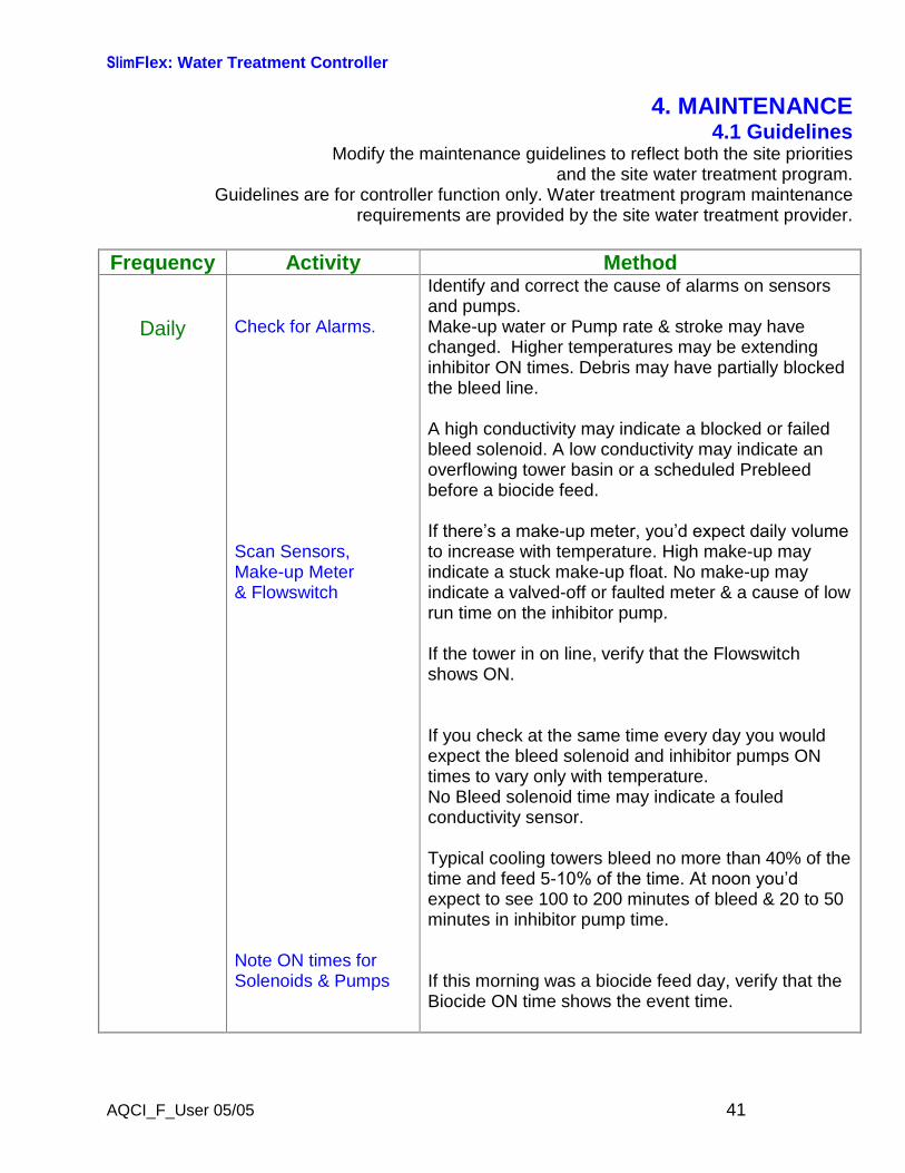
4. MAINTENANCE4.1 Guidelines
Modify the maintenance guidelines to reflect both the site prioritiesand the site water treatment program.
Guidelines are for controller function only. Water treatment program maintenancerequirements are provided by the site water treatment provider.
Frequency Activity Method
Daily Check for Alarms.
Scan Sensors,Make-up Meter& Flowswitch
Note ON times forSolenoids & Pumps
Identify and correct the cause of alarms on sensorsand pumps.Make-up water or Pump rate & stroke may havechanged. Higher temperatures may be extendinginhibitor ON times. Debris may have partially blockedthe bleed line.
A high conductivity may indicate a blocked or failedbleed solenoid. A low conductivity may indicate anoverflowing tower basin or a scheduled Prebleedbefore a biocide feed.
If there’s a make-up meter, you’d expect daily volume to increase with temperature. High make-up mayindicate a stuck make-up float. No make-up mayindicate a valved-off or faulted meter & a cause of lowrun time on the inhibitor pump.
If the tower in on line, verify that the Flowswitchshows ON.
If you check at the same time every day you wouldexpect the bleed solenoid and inhibitor pumps ONtimes to vary only with temperature.No Bleed solenoid time may indicate a fouledconductivity sensor.
Typical cooling towers bleed no more than 40% of thetime and feed 5-10% of the time. At noon you’d expect to see 100 to 200 minutes of bleed & 20 to 50minutes in inhibitor pump time.
If this morning was a biocide feed day, verify that theBiocide ON time shows the event time.
SlimFlex: Water Treatment Controller
AQCI_F_User 05/05 42
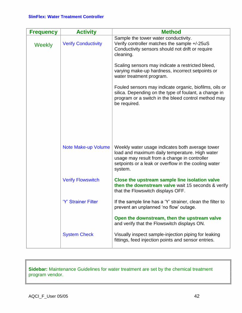
Frequency Activity Method
Weekly Verify Conductivity
Note Make-up Volume
Verify Flowswitch
‘Y’ Strainer Filter
System Check
Sample the tower water conductivity.Verify controller matches the sample +/-25uSConductivity sensors should not drift or requirecleaning.
Scaling sensors may indicate a restricted bleed,varying make-up hardness, incorrect setpoints orwater treatment program.
Fouled sensors may indicate organic, biofilms, oils orsilica. Depending on the type of foulant, a change inprogram or a switch in the bleed control method maybe required.
Weekly water usage indicates both average towerload and maximum daily temperature. High waterusage may result from a change in controllersetpoints or a leak or overflow in the cooling watersystem.
Close the upstream sample line isolation valvethen the downstream valve wait 15 seconds & verifythat the Flowswitch displays OFF.
If the sample line has a ‘Y’strainer, clean the filter toprevent an unplanned ‘no flow’ outage.
Open the downstream, then the upstream valveand verify that the Flowswitch displays ON.
Visually inspect sample-injection piping for leakingfittings, feed injection points and sensor entries.
Sidebar: Maintenance Guidelines for water treatment are set by the chemical treatmentprogram vendor.

SlimFlex: Water Treatment Controller
AQCI_F_User 05/05 43
Frequency Activity Method
Yearly Calibrate ConductivityTester
Observe a BleedControl Cycle
Verify Water Meter
Verify the conductivity tester annually with acalibration solution using a solution that’s as close as possible to the controller conductivity setpoints.Replace outdated calibration solutions.
Observe as the tower cycles up and the conductivityexceeds the Turn ON setpoint. Observe theunobstructed flow from the bleed line, if its visible.
Note the conductivity when the float opens the make-up line. Verify that the bleed solenoid shuts off flowwhen the conductivity falls below the lower setpoint.
Note the conductivity when the float closes the make-up line. Verify that the difference between Make-upON & OFF conductivities is greater than thedifference between Setpoint TurnON & TurnOFFconductivities.Optimal control occurs when the bleed setpointdeadband (TurnON–TurnOFF) in less than themake-up float ON-OFF conductivity difference.
If a make-up water meter is installed, verify that thecontroller measures an increase in make-up volumewhile the make-up float opens the make-up line.
Is the expected volume measured for the size of theline and the float ON time?If not, the meter Volume/Contact or ‘K’ factor may have been set incorrectly or the water meter mayhave been cabled in a common conduit with ACpower.
SlimFlex: Water Treatment Controller
AQCI_F_User 05/05 44
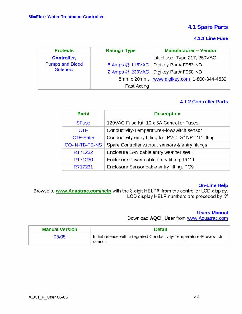
4.1 Spare Parts
4.1.1 Line Fuse
Protects Rating / Type Manufacturer–Vendor
Controller,Pumps and Bleed
Solenoid5 Amps @ 115VAC2 Amps @ 230VAC
5mm x 20mm,Fast Acting
Littlelfuse, Type 217, 250VACDigikey Part# F953-NDDigikey Part# F950-NDwww.digikey.com 1-800-344-4539
4.1.2 Controller Parts
Part# Description
SFuse 120VAC Fuse Kit, 10 x 5A Controller Fuses,
CTF Conductivity-Temperature-Flowswitch sensor
CTF-Entry Conductivity entry fitting for PVC ¾” NPT ‘T’ fitting
CO-IN-TB-TB-NS Spare Controller without sensors & entry fittings
R171232 Enclosure LAN cable entry weather seal
R171230 Enclosure Power cable entry fitting, PG11
R717231 Enclosure Sensor cable entry fitting, PG9
On-Line HelpBrowse to www.Aquatrac.com/help with the 3 digit HELP#’ from the controller LCD display.
LCD display HELP numbers are preceded by ‘?’
Users ManualDownload AQCI_User from www.Aquatrac.com
Manual Version Detail
05/05 Initial release with integrated Conductivity-Temperature-Flowswitchsensor.
SlimFlex: Water Treatment Controller
AQCI_F_User 05/05 45
Appendix A: INSTALLA.1 PLUMBINGTypical sample-chemical injection piping operates at 40-60psi and is plumbed in SCH80 PVC.Sample piping is usually fed from the discharge side of the re-circulation pump, returning toeither the suction side of the pump or to the tower basin.Ensure that the sample piping flow exceeds 1 GPM and that the sample stream represents thetower water.Avoid sample piping which drains whenever the tower is off-line. Solids will accumulate on thesensors requiring re-calibration and cleaning.A backcheck may be required at some sites to prevent reverse flow through the injection-sensor piping when the recirculation pump is OFF.‘Y’ strainers in the sample loop are not recommended unless the debris will mechanicallydamage the conductivity sensor or flowswitch. Strainer filters are usually the first location toplug, turning OFF pumps and the bleed solenoid on no flow.NEW CONSTRUCTION: After pressure testing, valve OFF the sample piping during post-construction re-circulation piping cleaning and passivation.
A.2 SENSORSConductivity-Flowswitch sensors may be installed in any orientation which allows them to beremoved for cleaning. Do not hang conductivity sensors in metallic tower sumps.Water meter and sensor wiring cannot be installed in the same conduit as 120VAC power,pump or solenoid wiring. Even a short section of shared conduit may cause operationalproblems.CTF type sensor wires may be extended up to 50 feet using 6 conductor AWG22 cable.Always splice sensor wires in an electrical fitting to allow both inspection and sensor servicing.Extend the conductivity sensor using the same colors as the sensor to avoid wiring errors atthe controller terminals.Contact head water meters are not polarized, simplifying cable extension.CAUTION: Three wire turbine-paddlewheel meters are polarity sensitive and can bepermanently damaged by miswiring. Wait until you are ready to start-up the controller beforeconnecting this type of meter to the controller. Meter wiring errors are easily detected andcorrected at start-up.
A.3 CHEMICAL INJECTIONInject water treatment chemicals downstream of sensors as recommended by the chemicalsupplier.Do not inject bleach or other oxidants upstream of a recirculating pump or condenser–heatexchanger.Bleach is frequently injected into the tower sump or into the recirculation line using a quill.
SlimFlex: Water Treatment Controller
AQCI_F_User 05/05 46
A.4 BLEED LOCATIONThe optimum bleed solenoid location is after the condenser–heat exchanger.Never install the bleed on the sample line, upstream of the sensors and flowswitch.If you are installing a bleed solenoid on the tower sump, ensure that the head or pressure atthe bleed solenoid is sufficient to operate the solenoid.Verify that the solenoid is sized for the maximum tower load at the target cycles, on the hottestday of summer. If the bleed is on for more than 50% of the time, inhibitor feed options will belimited.
A.5 MAKE-UP METEREnsure that the meter manufacturer’s recommendations for orientation and upstream and downstream piping are observed.Orientation may be limited for contact head meters, while straight upstream and downstreampiping is required to prevent errors in turbine-paddlewheel meters.Contact head meters have a Gallon/Contact or Liter/Contact rating. In some meters this valuecan be altered by moving magnets or gears. Typical meters are rated 10, 50 & 100Gallons/contact.Turbine-Paddlewheel meters have a ‘K’ Factor which is the number of pulses / Gallon orpulses/Liter. Some manufacturers have both nominal values listed by meter size andcalibration values on the meter body.Take the time to get the meter volume/contact or ‘K’ factor correct, since most meters are used to control inhibitor feed and inhibitor ppm errors result when meters are incorrectly configured.
A.6 CONTROLLER ENCLOSUREThe optimum location for sensors, controller, chemical pumps and drums is as close togetheras access allows. You’ll be able to see where all the wires, plugs and tubing goes, watchpumps turn ON as you prime, grab samples to calibrate sensors…If you have the space; sample piping on the left, pumps & drums on the right with the controllerin the middle.Wall mount the controller enclosure at eye height for a 5’ to 5’6” person so that an operator does not have to reach over drums or pumps to use the controller key pad.
In areas with daily ambient temperatures over 100F, 40C, locate the controller out of directsunlight or beneath a sunshade. Internal temperatures over 115F, 45C will degrade thecontroller display.
Do not punch conduit access holes in the top of the enclosure to avoid condensation damageto the controller electronics.Plug the controller into an ‘Always ON’ utility outlet. Maximum controller current @ 120VAC is5 Amps.
SlimFlex: Water Treatment Controller
AQCI_F_User 05/05 47
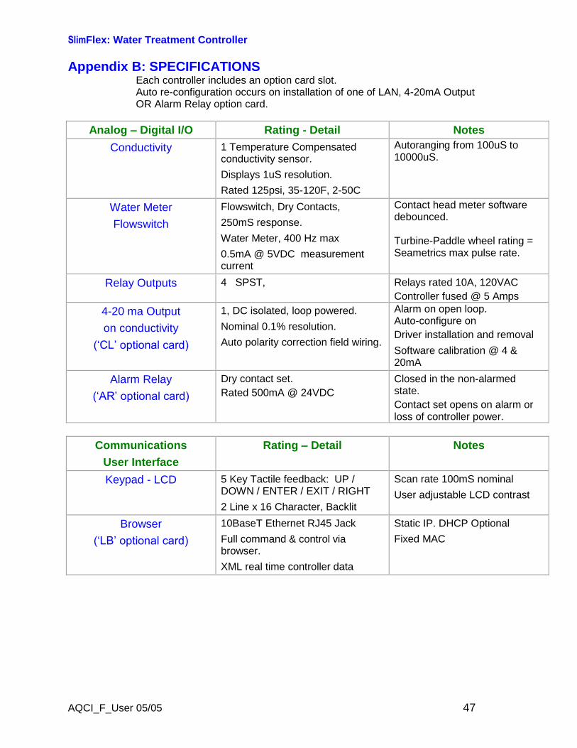
Appendix B: SPECIFICATIONSEach controller includes an option card slot.Auto re-configuration occurs on installation of one of LAN, 4-20mA OutputOR Alarm Relay option card.
Analog–Digital I/O Rating - Detail Notes
Conductivity 1 Temperature Compensatedconductivity sensor.Displays 1uS resolution.Rated 125psi, 35-120F, 2-50C
Autoranging from 100uS to10000uS.
Water MeterFlowswitch
Flowswitch, Dry Contacts,250mS response.Water Meter, 400 Hz max0.5mA @ 5VDC measurementcurrent
Contact head meter softwaredebounced.
Turbine-Paddle wheel rating =Seametrics max pulse rate.
Relay Outputs 4 SPST, Relays rated 10A, 120VACController fused @ 5 Amps
4-20 ma Outputon conductivity(‘CL’ optional card)
1, DC isolated, loop powered.Nominal 0.1% resolution.Auto polarity correction field wiring.
Alarm on open loop.Auto-configure onDriver installation and removal
Software calibration @ 4 &20mA
Alarm Relay(‘AR’ optional card)
Dry contact set.Rated 500mA @ 24VDC
Closed in the non-alarmedstate.Contact set opens on alarm orloss of controller power.
CommunicationsUser Interface
Rating–Detail Notes
Keypad - LCD 5 Key Tactile feedback: UP /DOWN / ENTER / EXIT / RIGHT2 Line x 16 Character, Backlit
Scan rate 100mS nominalUser adjustable LCD contrast
Browser(‘LB’ optional card)
10BaseT Ethernet RJ45 JackFull command & control viabrowser.XML real time controller data
Static IP. DHCP OptionalFixed MAC
SlimFlex: Water Treatment Controller
AQCI_F_User 05/05 48
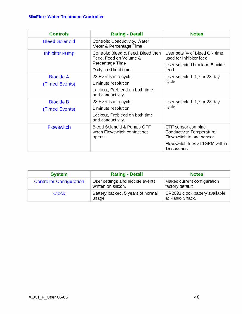
Controls Rating - Detail Notes
Bleed Solenoid Controls: Conductivity, WaterMeter & Percentage Time.
Inhibitor Pump Controls: Bleed & Feed, Bleed thenFeed, Feed on Volume &Percentage TimeDaily feed limit timer.
User sets % of Bleed ON timeused for Inhibitor feed.
User selected block on Biocidefeed.
Biocide A(Timed Events)
28 Events in a cycle.1 minute resolutionLockout, Prebleed on both timeand conductivity.
User selected 1,7 or 28 daycycle.
Biocide B(Timed Events)
28 Events in a cycle.1 minute resolutionLockout, Prebleed on both timeand conductivity.
User selected 1,7 or 28 daycycle.
Flowswitch Bleed Solenoid & Pumps OFFwhen Flowswitch contact setopens.
CTF sensor combineConductivity-Temperature-Flowswitch in one sensor.Flowswitch trips at 1GPM within15 seconds.
System Rating - Detail Notes
Controller Configuration User settings and biocide eventswritten on silicon.
Makes current configurationfactory default.
Clock Battery backed, 5 years of normalusage.
CR2032 clock battery availableat Radio Shack.
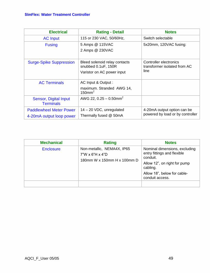
SlimFlex: Water Treatment Controller
AQCI_F_User 05/05 49
Electrical Rating - Detail Notes
AC Input 115 or 230 VAC, 50/60Hz, Switch selectable
Fusing 5 Amps @ 115VAC2 Amps @ 230VAC
5x20mm, 120VAC fusing:
Surge-Spike Suppression Bleed solenoid relay contactssnubbed 0.1uF, 150RVaristor on AC power input
Controller electronicstransformer isolated from ACline
AC Terminals AC Input & Output :
maximum. Stranded AWG 14,150mm2
Sensor, Digital InputTerminals
AWG 22, 0.25–0.50mm2
Paddlewheel Meter Power4-20mA output loop power
14–20 VDC, unregulatedThermally fused @ 50mA
4-20mA output option can bepowered by load or by controller
Mechanical Rating Notes
Enclosure Non-metallic, NEMA4X, IP657”W x 6”H x 4”D 180mm W x 150mm H x 100mm D
Nominal dimensions, excludingentry fittings and flexibleconduit.Allow 12”, on right for pump cabling.Allow 18”, below for cable-conduit access.
SlimFlex: Water Treatment Controller
AQCI_F_User 05/05 50
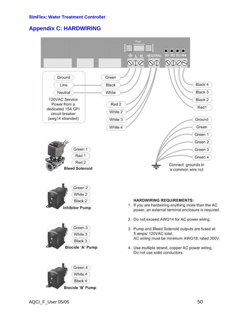
Appendix C: HARDWIRING
SlimFlex: Water Treatment Controller
AQCI_F_User 05/05 51
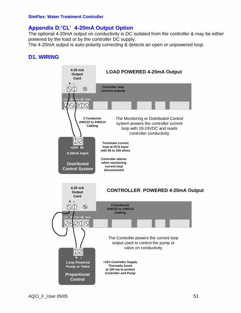
Appendix D:’CL’ 4-20mA Output OptionThe optional 4-20mA output on conductivity is DC isolated from the controller & may be eitherpowered by the load or by the controller DC supply.The 4-20mA output is auto-polarity correcting & detects an open or unpowered loop.
D1. WIRING
+24V IN
DistributedControl System
4-20mA Input
Terminate currentloop at DCS input
with 50 to 250 ohms
2 ConductorAWG22 to AWG14
Cabling
The Monitoring or Distributed Controlsystem powers the controller current
loop with 18-24VDC and readscontroller conductivity
Controller alarmswhen monitoring
current loopdisconnected
LOAD POWERED 4-20mA Output
MeterFlow+15V
+ -
4-20 mAOutputCard
Controller autocorrects polarity
+15V Controller SupplyThermally fused
at 100 ma to protectController and Pump
+ -Loop PoweredPump or Valve
ProportionalControl
The Controller powers the current loopoutput used to control the pump or
valve on conductivity
CONTROLLER POWERED 4-20mA Output
MeterFlow+15V
+ -
4-20 mAOutputCard
2 ConductorAWG22 to AWG14
Cabling

SlimFlex: Water Treatment Controller
AQCI_F_User 05/05 52
Appendix D: ‘CL’ 4-20mA Output OptionD.2 VIEW & ADJUST SPAN
The displayed value of the 4-20mAloop currentdepends on both the conductivity and the Span
If the current loop output is disconnected you’ll see this display in place of the mA level.
Press ENTER @ Select Span to view or adjust the SpanSpan sets the conductivity at 4mA & at 20mA
Press ENTER @ Trim Zero to calibrate the 4mA level
Press ENTER @ Trim Span to calibrate the 20mA level
View & Adjust Span
Press ENTER @ 4-20mA Output& then DOWN to Select Span
Press ENTER.
Displays current Span.Press ENTER to adjust 4mA level
or DOWN & ENTER to adjust 20mA level.
Press RIGHT to place the underlineunder the digit you wish to adjust.
Press UP–DOWN to adjust.
ENTER updates the Span.EXIT leaves Span unchanged
Select SpanTrim Zero
Trim ZeroTrim Span
Trim SpanSelect Span
4-20mA Output15.4mA
OR
4-20mA OutputDisconnected!
Select SpanTrim Zero
Edit & ENTER4mA= 2500uS
then
4mA= 100uS20mA= 5000uS
4mA= 2500uS20mA= 5000uS
SlimFlex: Water Treatment Controller
AQCI_F_User 05/05 53
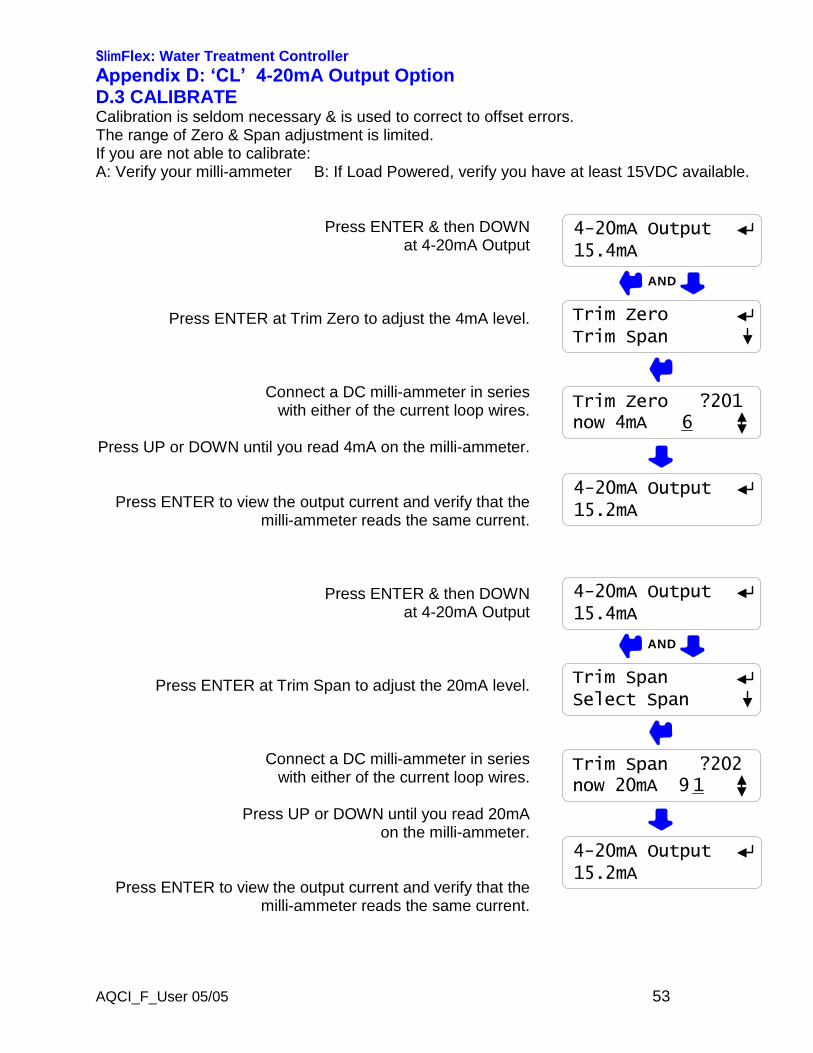
Appendix D: ‘CL’ 4-20mA Output OptionD.3 CALIBRATECalibration is seldom necessary & is used to correct to offset errors.The range of Zero & Span adjustment is limited.If you are not able to calibrate:A: Verify your milli-ammeter B: If Load Powered, verify you have at least 15VDC available.
Press ENTER & then DOWNat 4-20mA Output
Press ENTER at Trim Zero to adjust the 4mA level.
Connect a DC milli-ammeter in serieswith either of the current loop wires.
Press UP or DOWN until you read 4mA on the milli-ammeter.
Press ENTER to view the output current and verify that themilli-ammeter reads the same current.
Press ENTER & then DOWNat 4-20mA Output
Press ENTER at Trim Span to adjust the 20mA level.
Connect a DC milli-ammeter in serieswith either of the current loop wires.
Press UP or DOWN until you read 20mAon the milli-ammeter.
Press ENTER to view the output current and verify that themilli-ammeter reads the same current.
4-20mA Output15.4mA
Trim ZeroTrim Span
Trim Zero ?201now 4mA 6
AND
4-20mA Output15.2mA
4-20mA Output15.4mA
Trim SpanSelect Span
Trim Span ?202now 20mA 9 1
AND
4-20mA Output15.2mA
SlimFlex: Water Treatment Controller
AQCI_F_User 05/05 54
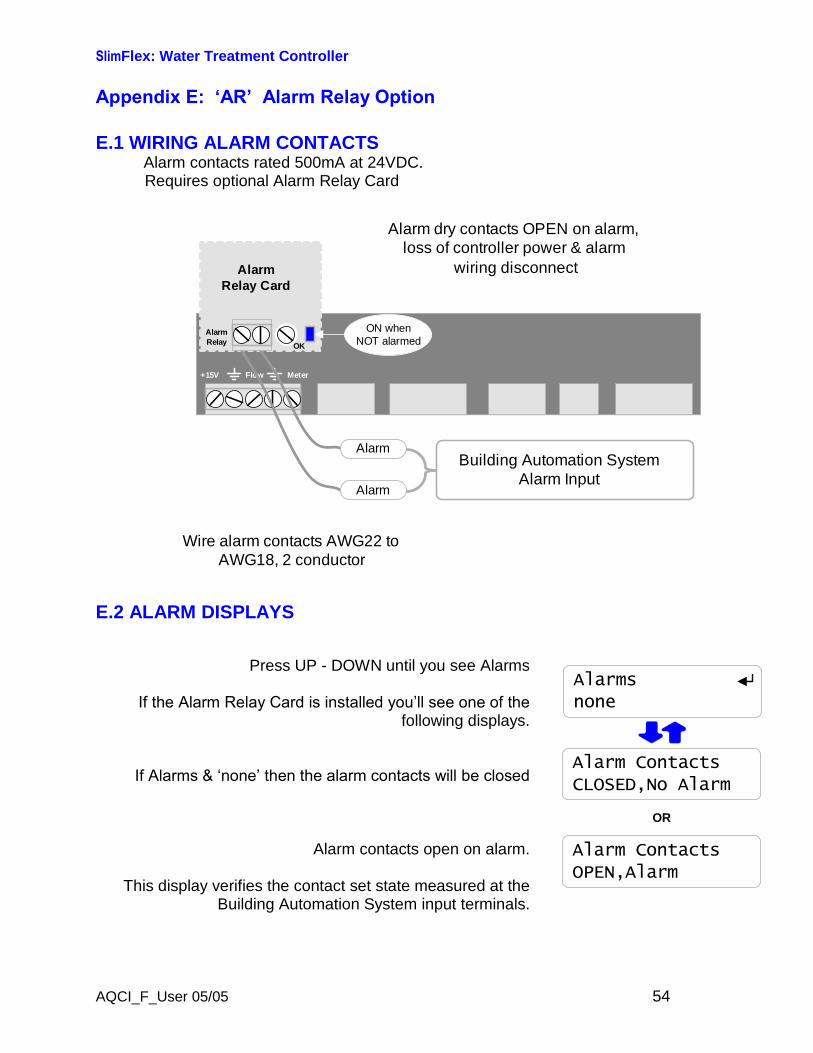
Appendix E: ‘AR’ Alarm Relay Option
E.1 WIRING ALARM CONTACTSAlarm contacts rated 500mA at 24VDC.Requires optional Alarm Relay Card
MeterFlow+15V
AlarmRelay
AlarmRelay Card
OK
ON whenNOT alarmed
Alarm dry contacts OPEN on alarm,loss of controller power & alarm
wiring disconnect
Alarm
Alarm
Building Automation SystemAlarm Input
Wire alarm contacts AWG22 toAWG18, 2 conductor
E.2 ALARM DISPLAYS
Press UP - DOWN until you see Alarms
If the Alarm Relay Card is installed you’ll see one of the following displays.
If Alarms & ‘none’ then the alarm contacts will be closed
Alarm contacts open on alarm.
This display verifies the contact set state measured at theBuilding Automation System input terminals.
Alarm ContactsCLOSED,No Alarm
Alarm ContactsOPEN,Alarm
OR
Alarmsnone
SlimFlex: Water Treatment Controller
AQCI_F_User 05/05 55
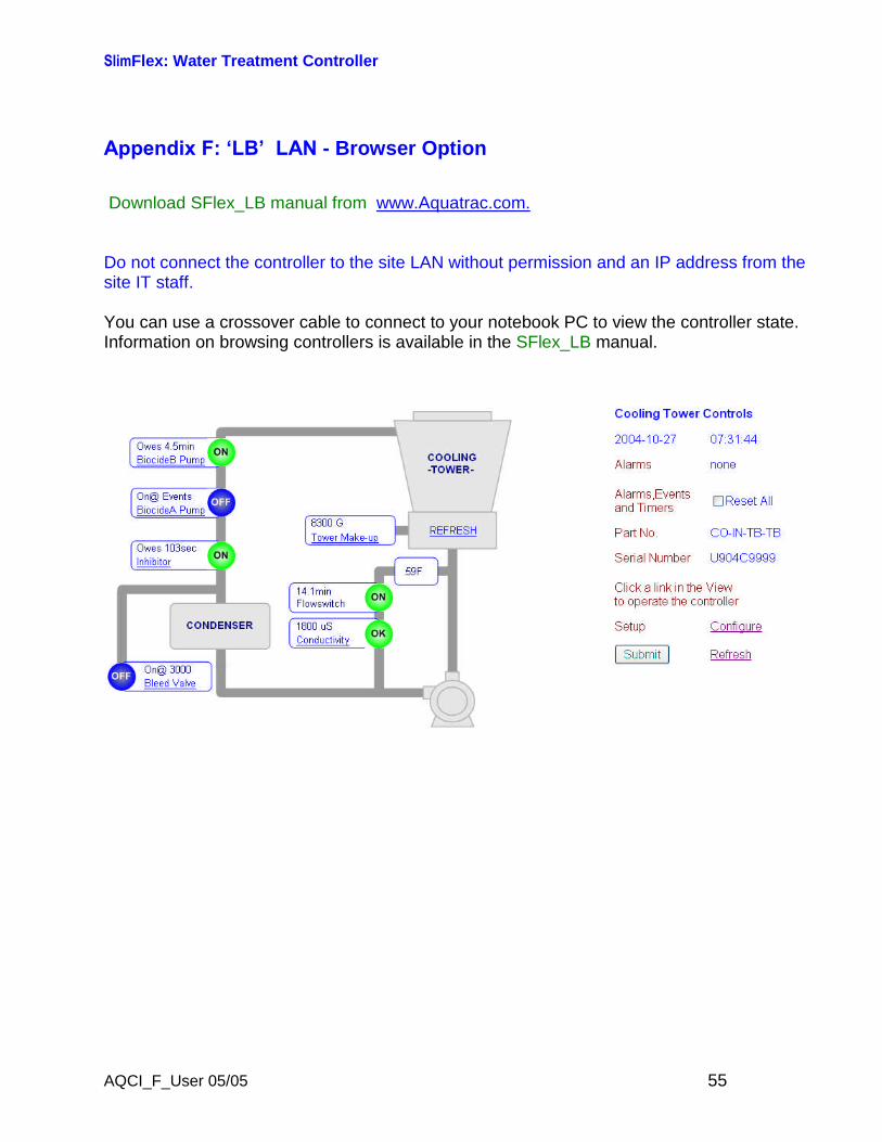
Appendix F: ‘LB’ LAN - Browser Option
Download SFlex_LB manual from www.Aquatrac.com.
Do not connect the controller to the site LAN without permission and an IP address from thesite IT staff.
You can use a crossover cable to connect to your notebook PC to view the controller state.Information on browsing controllers is available in the SFlex_LB manual.