aquacheck logger basic iii - zendesk · the aquacheck basic iii data logger functions are accessed...
TRANSCRIPT

AAAQQQUUUAAACCCHHHEEECCCKKK BBBAAASSSIIICCC IIIIIIIII LLLOOOGGGGGGEEERRR
Instruction Manual
- 6100-LME
AQUACHECK BASIC III DATA LOGGER
Supplied by AquaCheck
AquaCheck P.O. BOX 2414 DURBANVILLE, 7551 Tel: (021) 970 5140 Fax: (021) 975 1254 [email protected]
S0360 Ver 1.0
Note: On-going product development at
AquaCheck may lead to changes in the specifications of this product.
Warranty: This product is guaranteed for a period of 12
months from date of purchase. The warranty applies to manufacturing or component defects which may cause the unit to malfunction under specified conditions. The guarantee does not cover damage due to abuse, tampering or improper installation.
Disclaimer: AquaCheck will not be held liable for any
consequential damage or loss arising resulting from product malfunction.

TABLE OF CONTENTS
1. INTRODUCTION ............................................................................................. 1
2. INSTALLATION .............................................................................................. 1
2.1 GENERAL ................................................................................................... 1
3. COMMISSIONING .......................................................................................... 4
3.1 MENUS ..................................................................................................... 4
3.2 INTRODUCTION ....................................................................................... 6
3.3 THE STEPS OF COMMISSIONING .......................................................... 6
4. COMMISSIONING STEPS IN DETAIL ........................................................... 7
4.1 CHARGE THE LOGGER’S BATTERY. ................................................................. 7
4.2 RECORD THE UNIQUE ID OF EACH BASIC IIW PROBE OR PRO II. ...................... 7
4.3 PROGRAM THE ID’S INTO THE LOGGER ........................................................... 8
4.4 PROGRAM THE CURRENT TIME AND DATE INTO THE LOGGER ............................ 9
4.5 PERFORM A PROFILE LOG ON ALL PROGRAMMED PROFILES ........................... 10
5. ADDITIONAL FEATURES ............................................................................ 11
5.1 SINGLE LOG .............................................................................................. 11
5.2 CLEAR ALL LOGS ....................................................................................... 12
5.3 VIEW STATS .............................................................................................. 12
5.3 VIEW STATS .............................................................................................. 13
5.4 PRO II OVER THE AIR FIRMWARE UPGRADE ................................................. 13
5.5 UTILITIES .................................................................................................. 14
5.4 TROUBLE SHOOTING .................................................................................. 19


1
1. INTRODUCTION The AquaCheck II data logger is a component of the AquaCheck soil moisture management system. A typical soil moisture system consists of soil moisture probes and a Data logger. The probe data (soil moisture and temperature) are relayed to a wireless hand-held logger via a proprietary telemetry system. The logged data is then downloaded to a PC which processes the data for trending display via a PC application (CropGraph/Plant-Plus).
2. INSTALLATION
2.1 GENERAL Below is a description of each of the Soil moisture monitoring components: 1. Aquacheck soil moisture Basic probe with integrated wireless module:
The above shows the Aquacheck basic probe with a battery pack, integrated wireless module and dust cover fitted. To gain access to the ID of the module, twist and slide off the dust cover from the probe assembly.
Radios & Probes Logger PC Application
Cloud App

2
2. Aquacheck soil moisture probe with external radio fitted (RF PRO II): The PRO II module is fitted with a bracket, ready for mounting on a pole. The PRO II communicates with the soil moisture probe via a wireless network. The PRO II RTU (remote transmission unit) can also be connected
to all the previous generation probes (ACB I & II) via direct cable link between the RTU and the probe.
The standard PRO II is fitted with a high gain omni-directional antenna. An input for a rain gauge is available as an ordering option. The high gain antenna provides for longer transmission distances between the RF logger/base stations. For even longer transmission distances, an optional Yagi antenna is available as an ordering option. The above shows an Aquacheck Basic II fitted with a battery pack and integrated wireless module and the PRO II fitted with an omni-directional antenna. To gain access to the ID of the module, twist and slide off the dust cover from the probe assembly. Although the AquaCheck Basic III data logger can communicate directly with the probe, in the above example the PRO II communicates with other PRO II’s and one can then download all the data from one location. With the new ACBIIW version probe, the ID on the probe itself is used for data collecting purposes and therefore should be used as an input ID in the applicable logger menu. The same ID is used for the block/site setup in the PC software. If the ACBIIW probe is linked to a PRO II RTU, the RTU ID is then utilised when setting up the logger, but the probe’s ID is used for setup in the PC software as the data of the Probe is ‘routed’ via the PRO II RTU. If a ‘wired probe’ (earlier generation Aquacheck Probe) is connected to a PRO II RTU, then the RTU ID is should be used for both the logger setup and the block/site setup in the PC software.

3
3. AquaCheck Basic III data logger.
The AquaCheck Basic III data logger as shown above is fitted with the following: a. Internal antenna b. 2 lines x 16 character Back light LCD Dot matrix display c. Mini USB socket for an optional charger, charging the battery via a
computer's USB port and downloading data to a P.C. d. Numeric keypad e. Rechargeable internal Lithium Polymer battery f. Internal Radio to communicate with PRO II’s and Basic IIW soil
moisture probes. g. Databank with a capacity for 15000 logs. h. Download cable(mini USB) is supplied with the logger.
4
3. COMMISSIONING 3.1 MENUS
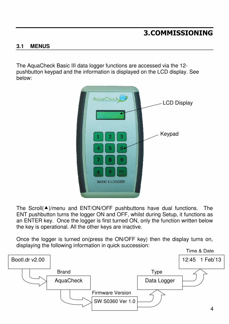
The AquaCheck Basic III data logger functions are accessed via the 12-pushbutton keypad and the information is displayed on the LCD display. See below: LCD Display Keypad The Scroll(�)/menu and ENT/ON/OFF pushbuttons have dual functions. The ENT pushbutton turns the logger ON and OFF, whilst during Setup, it functions as an ENTER key. Once the logger is first turned ON, only the function written below the key is operational. All the other keys are inactive. Once the logger is turned on(press the ON/OFF key) then the display turns on, displaying the following information in quick succession:
Bootl.dr v2.00
AquaCheck
SW S0360 Ver 1.0
Data Logger
12:45 1 Feb’13
Firmware Version
Type
Time & Date
Brand

5
Once the time and date is displayed, press the Menu key to gain access to the logger functions. (Always ensure that the date/time is current as incorrect time & date will render data logging incorrectly) The functions can be scrolled and the menu is circular as displayed below:
Each item on the screen flashes. Pressing the �/Scroll key at this time selects the next menu item. Press ENT to execute the menu function.
Example: To set the time and date, follow the steps below:
a. Turn on the Logger. and wait for the time and
date to be displayed b. Press the MENU/� key. c. Then press the MENU/� key until the ‘Set Time &
Date’ screen is displayed:
The shaded area indicates flashing.
To change the time to 17:00, now press
The display will now show:
Using the numeric keypad, edit the date in the same manner as shown in the time setting example. Once completed, press the ENT key. The display will now show:
Press the MENU/� key until ‘Exit’ is displayed, then press Enter. Pressing Enter again will turn off the logger.
Set Time 16:35 Set Time & Date ENT
1 7 0 0
Set Time 17:00 Date: 01/02/13 ENT
Set Time & Date
Press Menu
Profile Log
16:45 1 Feb‘13
Single Log �
�
Clear All Logs
�
View Stats
�
Set Time & Date
�
Profile Setup
�
PRO II Firmware
�
Utilities �
Exit

6
3.2 INTRODUCTION
The BASIC II probes and PRO II’s transmit the logged soil moisture data to the logger via a radio link. The radio module inside the probe and PRO II units are normally turned off to preserve battery power, and is turned on once every 15 seconds to listen for the presence of a polling signal from a logger. In the absence of a Logger, the radio modules return to standby mode. When a logger or base station is introduced, the data, time and date is then synchronised. The logger is configurable allowing one to insert a probe ID in any of 120 profiles. One then associates a profile with a probe ID. A profile log downloads only the latest data – data since the previous download. With a profile log, the date/time is automatically set(synchronised) on the probe/PRO II during the download session. (If the date/time on the logger is incorrect, an incorrect date/time will be passed on the
probe/PRO II). In the event that one wants access to all the stored data on a probe or PRO II, then the data is downloaded by means of a single ID log, and all stored data on the device is then downloaded to the Logger.
3.3 THE STEPS OF COMMISSIONING 1. Charge the logger’s battery. 2. Before installing any probes and PRO II’s, populate the profile numbers on
the logger with the unique ID of each probe/PRO II, whichever is applicable. 3. Program each ID’s therefore into a profile on the logger 4. Set the current Time and Date on the Logger 5. Perform a profile log on all of the probes/PRO II’s. This will synchronise the
time and date with each device and download the unread data. 6. We recommend that the entire network be set up and tested prior to
attempting any installation, thus confirming that each probe and PRO II RTU are active, time and date is current and that the data retrieved from each probe/PRO II is current and that the data is valid.

7
4. COMMISSIONING STEPS IN DETAIL
4.1 Charge the logger’s battery.
Plug the cable into the logger and then plug the other end of the cable into a powered PC's USB port. After a few seconds, the display will read:
The battery indicator in the screen will cycle through 'empty' to 'full' during the charging cycle. The battery voltage is continuously monitored and once the battery is fully charged, then the display will read: ‘Charge Complete’ and the battery indicator will stop cycling. Unplug the cable from the logger and then from the PC. After a few seconds, the logger will turn itself off.
4.2 Record the unique ID of each Basic IIW probe or PRO II. 1. With the new ACBIIW version probe, the ID on the probe itself is used for
data collecting purposes and therefore should be used as the input ID in the applicable logger menu. The same ID is used for the block/site setup with the applicable PC software.
2. If the ACBIIW probe is linked to a PRO II RTU, the RTU ID (PRO II) is used when configuring the logger, as the probe’s data is ‘routed’ via the RTU. When configuring the applicable PC software, then the probe ID should be used when configuring the database.
3. If a ‘wired’ probe(earlier generation AquaCheck Probe) is connected to a PRO II RTU via a cable, then the RTU ID (PRO II) is used for both the logger configuration as well as the database setup on the applicable PC software.
16:45 1 Feb ‘13 . Charging..
8
Profile: 1 ID1: 20397
ENT
Profile Setup
Repeat for other ID’s
ENT
Profile: 000 Profile Setup
Profile: 001
0 0
Key in Profile no.
ENT
Profile: 1 ID1: 00000
2 0 3 7
Key in Device ID
1
9
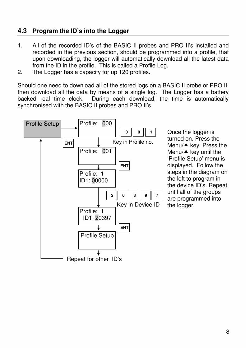
4.3 Program the ID’s into the Logger 1. All of the recorded ID’s of the BASIC II probes and PRO II’s installed and
recorded in the previous section, should be programmed into a profile, that upon downloading, the logger will automatically download all the latest data from the ID in the profile. This is called a Profile Log.
2. The Logger has a capacity for up 120 profiles. Should one need to download all of the stored logs on a BASIC II probe or PRO II, then download all the data by means of a single log. The Logger has a battery backed real time clock. During each download, the time is automatically synchronised with the BASIC II probes and PRO II’s.
Once the logger is turned on. Press the Menu/� key. Press the Menu/� key until the ‘Profile Setup’ menu is displayed. Follow the steps in the diagram on the left to program in the device ID’s. Repeat until all of the groups are programmed into the logger

9
4.4 Program the current Time and Date into the Logger
Turn on the Logger and then press the Menu/� key. Press the Menu/� key until the ‘Set Time & Date’ menu is displayed
Example: To change the time from 16:35 to 17:00
Set Time: 16:35 Set Time & Date
ENT
1 7 0 0
Set Time: 17:00
Date: 01/01/12
ENT
Key in using numeric keypad
To change Date from 01/01/12
to 02/10/13
0 2 1 0 1 3
Date: 02/10/13 Key in using numeric keypad
ENT
Press Menu
Profile Log
16:45 1 Feb'13
Single Log �
�
Clear All logs
�
View Stats
�
Set Time & Date
�
Profile Setup
�
PRO II Firmware �
Utilities
�
Exit

10
4.5 Perform a Profile Log on all Programmed Profiles
Profile logging allows one to collect the data from BASIC II probes and PRO II’s in close proximity of the point of logging and only the unread data is retrieved. To do a Profile log, follow the instructions below:
Profile Log
ENT
Profile: 000
0 0
Key in using numeric keypad
Profile: 001
Scanning 39 Profile: 001
ENT
ID:20397 [77%] Loading: 143
Load Completed
Remaining logs to download
Press Menu
Profile Log
16:45 1 Feb'13
Single Log �
�
Clear All logs
�
View Stats
�
Set Time & Date
�
Profile Setup
�
PRO II Firmware �
Utilities
�
Exit
1
Display shows ‘Scanning profile 002’ and a count-
down timer displaying the
remaining scan time before
reporting a ‘No Probe’ message’
Signal Strength
Download Completed Press Enter to continue

11
Press Menu
Profile Log
16:45 1 Feb'13
Single Log �
�
Clear All logs
�
View Stats
�
Set Time & Date
�
Profile Setup
�
PRO II Firmware �
Utilities �
Exit
5. ADDITIONAL FEATURES
5.1 Single Log One can access all of the stored logs on a probe by means of a single log. An ACBIIW probe can store 2048 logs while a PRO II RTU can store 15000 logs. Please note that due to the amount of data involved; it can take a couple of minutes to download the data. Follow the steps below to retrieve the data:
Single Log
ENT
Log ID: 00000 0 5
Key in using numeric keypad
Log ID: 05655
Scanning 40
ENT
ID: 5655 [73%] Loading: 9
Load Completed Download Completed Press Enter to continue
6
Scanning Log ID 5655 counting down in
seconds
5
Signal Strength
When downloading all of the stored logs, the logger starts with the 1st log and counts up
NOTE: Frequent use of the Single Log function will result in excessive battery drain on both the Logger, probe/PRO II RTU.
5

12
5.2 Clear All Logs Once all of the data is downloaded to a PC, the databank of the logger should be cleared. To clear the databank please follow the instructions below:
Clear All Logs
ENT
Confirm? [No ]
Confirm? [Yes]
ENT
����
Press Menu
Profile Log
16:45 1 Feb'13
Single Log �
�
Clear All logs
�
View Stats �
Set Time & Date
�
Profile Setup
�
PRO II Firmware �
Utilities
�
Exit

13
5.3 View Stats
In order to keep track of the logging of data, one can view the quantity of stored logs in the logger’s memory. This is a useful feature if one wants to know specifically how many logs were downloaded from a profile or ID. View the quantity of logs as follows:
View Stats
ENT
Total Logs: 1095
ENT
Press Menu
Profile Log
16:45 1 Feb'13
Single Log �
�
Clear all logs
�
View Stats
�
Set Time & Date
�
Profile Setup
�
PRO II Firmware
�
Utilities
�
Exit

14
5.4 PRO II Over the air Firmware upgrade
The Logger has the capability to perform over the air download of PRO II firmware. Please ensure that the firmware destined for the PRO II is uploaded into the Logger’s memory. To initiate a firmware update to a PRO II, one needs to know the ID of the PRO II. Access the download menu as follows:
PRO II Firmware
Press Menu
Profile Log
16:45 1 Feb'13
Single Log �
�
Clear all logs �
View Stats �
Set Time & Date �
Profile Setup �
PRO II Firmware �
Utilities �
Exit
ENT
PRO II ID: 00000
3 0
PRO II ID: 30209
Scanning 40
ENT
2 0 9
Firmware ->PRO II 6%
Load Completed
Download progress indication
Upon the successful firmware upgrade ‘Load Completed’
Is displayed
Key ID in using numeric keypad

15
Utilities ENT
Status Request
Logging Interval
Moisture
Exit
�
�
�
�
5.5 Utilities
Utilities main menu The Logger is equipped with various utilities for quick diagnostics, probe and PRO II setup without the aid of a laptop computer. The following over the air utilities are available:
1. Status information, displaying the quantity of logs and data logging interval.
2. Changing of logging interval. 3. Take a soil moisture reading from a wireless
probe and display up to 6 moisture values. Access the Utilities menus as follows:
Press Menu
Profile Log
16:45 1 Feb'13
Single Log �
�
Clear all logs �
View Stats �
Set Time & Date �
Profile Setup �
PRO II Firmware �
Utilities �
Exit

16
Utilities ENT
Status Request
Logging Interval
Moisture
Exit
�
�
�
�
Status request
A status request reports the quantity of unread logs and the logging interval of the device.
From the Status Request menu, follow the steps below:
Status Request
Log ID: 00000
2 0
Log ID: 20609
Scanning 40
ENT
Probe:20609 [30m] Logs: 1988
6 0 9
ENT
Key ID in using numeric keypad
Logging interval
Quantity of unread logs
Device type

17
Changing the Logging Interval
The data logging interval of a wireless Probe can be changed over the air. Access the Logging Interval menu from the main Utilities menu as follows:
Utilities ENT
Status Request
Logging Interval
Moisture
Exit �
�
�
�
Logging Interval
Log ID: 00000
2 0
Log ID: 20609
Scanning 40
ENT
Probe: 20609 [05m]
6 0 9
ENT
Intv. [05mins]
�
ENT
Key in ID using numeric keypad
Select the desired logging frequency of
the probe [0,5,10,15,30,60] ENT
Logger will display the new logging interval

18
Taking Soil Moisture Readings
Please note that one can only take soil moisture readings from a Wireless Probe. Access the Soil Moisture menu from the Utilities menu as follows:
Utilities ENT
Status Request
Logging Interval
Moisture
Exit
Moisture
Log ID: 00000
2 0
Log ID: 20609
Scanning 40
ENT
Moist(1-3) 36.32, 38.10 , 39.21
6 0 9
ENT
Moist(4-6) 37.92 36.73 , 36.45
ENT
Key ID in using numeric keypad
Logger will display the first three
moisture readings
Press enter key to view the next
three moisture readings

19
5.4 Trouble shooting
Symptom Possible Cause Solution Display Dim Battery depleted Charge battery After a group log, the logger displays ‘No Probes’
1. Logger out of range 2. Probe ID incorrect
1. Move closer to the device. Keep the logger upright with the antenna pointing upwards to the sky when doing a log.
2. Verify the device ID
During a Profile log, Logger finds probe and starts download, afterwards, displaying ‘No Reply’
1. Logger out of range or reception is poor.
2. Battery on device is marginal or flat
1. Move closer to the device. Keep the logger upright with the antenna pointing upwards to the sky when doing a log.
2. Check battery voltage on device. Voltage should be more that 3.3 volts
Logger Displays ‘Profile Empty’ when trying a profile log
Device ID is not programmed into group
Record device ID and program the ID into the profile.
NOTE:
It is highly recommended to use the available RF Utility Tool when installing ACBIIW probes. For a PRO II RTU installation in any combination of ACBIIW, ACB I or II probes, and the RF Utility tool is mandatory as it is used to configure the PRO II RTU.