aquatique - shower right showers/brochures/install_aquatique... · aquatique shower kits...
TRANSCRIPT
Aquatique shower kits installation guide page 1
Aquatique®
Shower headsFixed and adjustable height heads

Aquatique shower kits installation guide page 2
Components
Aquatique adjustable height shower kit concealed Chrome 560.01 / Gold 560.04
Aquatique adjustable height shower kit exposed Chrome 561.01 / Gold 561.04
Aquatique 5” drencher concealed Chrome 550.01 / Gold 550.04
Literature not shown

Aquatique shower kits installation guide page 3
Components
Aquatique 8” drencher concealed Chrome 580.01 / Gold 580.04
Aquatique 8” drencher exposed Chrome 581.01 / Gold 581.04
Aquatique 5” drencher exposed Chrome 551.01 / Gold 551.04
Literature not shown

Aquatique shower kits installation guide page 4
Important information
IntroductionThe Aquatique range of shower heads has been designed for use with the Aquatique Thermo shower valves. Please select from
the following options:
Option 1. Adjustable height head. Choose from adjustable height head concealed or exposed (compatible with any water system).
Option 2. 5” drencher head. Choose from exposed or concealed (compatible with most water systems – if fitting with a com-
bination boiler, the appliance must have a minimum domestic hot water rating of 24kW (80,000 BTu) and be of the type fitted
with a modulating gas valve. If in any doubt, please contact the appliance manufacturer before installation commences).
Option 3. 8” drencher head. Choose from exposed or concealed (compatible with high pressure or boosted systems only).
The installation of this shower head with anything other than an Aqualisa shower valve may result in poor shower performance.
If you have any questions regarding the specification of compatible shower heads or at any stage during installation then
please contact the Aqualisa customer helpline on 01959 560010 for advice.
Safety informationThis product must be installed by a competent person in accordance with all relevant current Water Supply Regulations.
FlushingSome modern fluxes can be extremely corrosive and, if left in contact, will attack the working parts of this unit. All soldering
must be completed and the pipe work thoroughly flushed out in accordance with current Water Supply Regulations prior to
connection of the product.
ConnectionsThe Aqualisa shower head range is suitable for use with 15mm British Standard copper tube. Tube should be cut using a rotary
type cutter and lubricated using a silicone-based lubricant or petroleum jelly (Vaseline or similar) prior to insertion of the fit-
ting. Supply lines must be flushed clear of any debris before installation of this unit.
Stored water capacitiesThe minimum capacity of the cold storage cistern should not be less than 225 litres (50 gallons). The capacity of the hot cylin-
der must be capable of meeting the anticipated demand.
SitingFor optimum performance, with gravity fed systems, the distance between the bottom of the storage cistern and the shower
head should not be less than 1m (when using an adjustable height shower kit). If using a drencher head, the highest point of
the pipe work must be not less than 1m below the underside of the cistern.

Aquatique shower kits installation guide page 5
Step-by-step instructions
In addition to the guide below it is essential that the written instructions
overleaf are read and understood and that you have all the necessary
components (shown overleaf) before commencing installation. Failure to
install the product in accordance with these instructions may adversely affect
the warranty terms and conditions. Do not undertake any part of this
installation unless you are competent to do so. Prior to starting ensure that
you are familiar with the necessary plumbing regulations required to install
the product correctly and safely.
The adjustable height heads are available to be fitted with either concealed
or exposed shower valves. A wall outlet assembly is supplied with the
concealed version shower head for installation with a concealed valve
whereas the exposed version is supplied with a ⁄÷™” connector to replace
the ‹÷¢” connector fitted to the exposed valve as standard.
!
Adjustable height head installation
Exposed system installation
If fitting an exposed valve and suitable adjustable height head, it will be
necessary to reverse the valve outlet and outlet plug and replace the ‹÷¢” valve
outlet with the ⁄÷™” outlet connector supplied complete with the shower head.
!
Unscrew and remove the ‹÷¢” outlet connector positioned at the top of the
valve using a 12mm hexagonal key or radiator key.1
Remove the outlet plug from the bottom of the valve using a snug fitting
screwdriver taking care to avoid any damage to the plated surfaces. Refit in
the top of the valve.
2
Fit the ⁄÷™” connector supplied with shower kit into the bottom of the shower
valve using a 12mm hexagonal key or radiator valve key taking care not to
overtighten.
3

Aquatique shower kits installation guide page 6
Loosen the handset holder knob and pass the
rail through the handset holder ensuring the
holder is on the left.
4
Place the rail ends into position and place the
assembly in the desired location on the wall
and mark the two fixing positions in each rail
end. One end of the rail features a cut out
which locates into the relevant rail end locking
the rail in position ensuring it cannot rotate.
5
Drill and plug the four holes using the fixings
provided, and secure the rail assembly to the
wall.
6
7
Connect the other end of the hose to the
valve outlet ensuring the hose washer is in
position.
8
Connect the shower handset to the hose,
ensuring the hose washer is fitted and place in
the handset holder.
THE FRICTION OF THE HANDSET HOLDER
IS FACTORY SET AND SHOULD NOT BE
ADJUSTED.
!

Aquatique shower kits installation guide page 7
Run a 22mm outlet pipe from the shower valve to the preferred position for
the wall outlet assembly. The pipe must terminate with a suitable ‹÷¢” BSP
female fitting.
1
Concealed system installation
The concealed shower valve is supplied with the ‹÷¢” BSP outlet positioned at
the top of the valve and a blanking plug at the bottom. The outlet and plug
can be reversed if required. The wall outlet is supplied with a ‹÷¢” BSP male
threaded connection 48mm long.
!
If the shower system is being built into a solid
wall, secure the pipe work to the rear of the
chase using suitable fixings. Fill in the chase
using suitable non-setting infill material.
If the shower installation is of a panel mounted
type installation, secure the wall outlet assembly
to the panel using the nut and washer provided.
2
Place the rail ends into position and place the assembly in the desired
location on the wall and mark the two fixing positions in each rail end.
One end of the rail features a cut out which locates into the relevant rail end
locking the rail in position ensuring it cannot rotate.
4
Loosen the handset holder knob and pass the
rail through the handset holder ensuring the
holder is on the left.
3
Drill and plug the four holes using the fixings
provided, and secure the rail assembly to the
wall.
5

In addition to the guide below it is essential that the written instructions
overleaf are read and understood and that you have all the necessary
components (shown overleaf) before commencing installation. Failure to
install the product in accordance with these instructions may adversely affect
the warranty terms and conditions. Do not undertake any part of this
installation unless you are competent to do so. Prior to starting ensure that
you are familiar with the necessary plumbing regulations required to install
the product correctly and safely.
!
Drencher head concealed
Connect the shower handset to the hose,
ensuring the hose washer is fitted and place
in the handset holder.
6
Connect the other end of the hose to the wall outlet ensuring the hose
washer is in position.7
If the shower system is being built into a solid
wall, secure the pipe work to the rear of the
chase using suitable fixings. Fill in the chase
using suitable non-setting infill material.
If the shower installation is of a panel mounted
type installation, secure the wall outlet assembly
to the panel using the nut and washer provided.
2
Run a 22mm outlet pipe from the shower valve to the preferred position for
the wall outlet assembly. The pipe must terminate with a suitable ‹÷¢” BSP
female fitting.
1
If the assembly is to be fixed prior to tiling, the
depth of the tiles must be taken into
consideration.
!
Screw the shower arm cover plate flush to
the finished wall surface and seal using a
thin bead of silicone if necessary.
3
THE FRICTION OF THE HANDSET HOLDER
IS FACTORY SET AND SHOULD NOT BE
ADJUSTED.
!

Aquatique shower kits installation guide page 9
Screw the 5” or 8” shower head to the
shower head arm taking care not to damage
the plated surfaces. Carefully tighten the
shower head with a suitable spanner or a
tool with smooth jaws just sufficiently to
lock the head in position.
4
In addition to the guide below it is essential that the written instructions
overleaf are read and understood and that you have all the necessary
components (shown overleaf) before commencing installation. Failure to
install the product in accordance with these instructions may adversely affect
the warranty terms and conditions. Do not undertake any part of this
installation unless you are competent to do so. Prior to starting ensure that
you are familiar with the necessary plumbing regulations required to install
the product correctly and safely.
!
Drencher head exposed
Screw the formed shower arm to the riser
tube. The riser tube can be shortened if
required by trimming the plain end using a
rotary type cutter.
1
Locate the riser tube into the ‹÷¢” valve outlet and place in the required
position against the wall face.3
Carefully slide the fixing bracket up the riser
tube until the joint is hidden.2
Mark the required fixings holes and remove the riser tube assembly from the
valve. Drill and plug the holes using the fixings provided, ensuring no debris
enters the shower valve.
4

Aquatique shower kits installation guide page 10
Carefully tighten the ‹÷¢” nut using either 31mm A/F spanner or a tool
with smooth jaws just sufficiently to compress the ‘O’ ring and achieve a
watertight seal.
6
Carefully slide the plated ‹÷¢” nut and
‘O’ ring onto the riser tube and locate the
assembly into the ‹÷¢” valve outlet.
Fix the wall stay to the wall using the screws
provided.
5
Tighten the locking screw in the side of the
wall stay using the hexagonal key provided.7
Screw the 5” or 8” shower head to the
shower head arm taking care not to damage
the plated surfaces. Carefully tighten the
shower head with a suitable spanner or a
tool with smooth jaws just sufficiently to
lock the head in position.
8
Aquatique shower kits installation guide page 11
After installation...
User guide
Run through the valve operation with the purchaser and hand them this guide.
Complete and post the Aquatique shower head guarantee card or register online at www.aqualisa.co.uk.
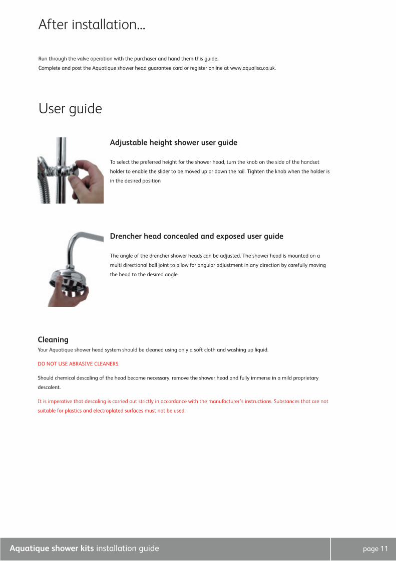
Adjustable height shower user guide
To select the preferred height for the shower head, turn the knob on the side of the handset
holder to enable the slider to be moved up or down the rail. Tighten the knob when the holder is
in the desired position
Drencher head concealed and exposed user guide
The angle of the drencher shower heads can be adjusted. The shower head is mounted on a
multi directional ball joint to allow for angular adjustment in any direction by carefully moving
the head to the desired angle.
CleaningYour Aquatique shower head system should be cleaned using only a soft cloth and washing up liquid.
DO NOT USE ABRASIVE CLEANERS.
Should chemical descaling of the head become necessary, remove the shower head and fully immerse in a mild proprietary
descalent.
It is imperative that descaling is carried out strictly in accordance with the manufacturer’s instructions. Substances that are not
suitable for plastics and electroplated surfaces must not be used.

Aqualisa Products Limited
The Flyer’s Way
Westerham Kent TN16 1DE
Sales enquiries: 01959 560010
Republic of Ireland 01-864-3363
Customer helpline: 01959 560010
Republic of Ireland 01-844-3212
Brochure Hotline: 0800 652 3669
Website: www.aqualisa.co.uk
Email: [email protected]
Please note that calls may be recorded for training and quality purposes
The company reserves the right to alter, change or modify the product specifications without prior warning
® Registered Trademark Aqualisa Products Limited