ar20852 the secret to landscape modeling with revit
TRANSCRIPT

Page 1
AR20852
The Secret to Landscape Modeling with Revit Raquel Bascones-Recio Populous
Description
Globally, the construction industry is transferring over to BIM at an accelerated pace. Governments are starting to include BIM as a requirement for their contracts. Landscape architects and urban designers around the world are wondering how to transition to a BIM environment to avoid being left behind.
Building Information Modelling. Its own name relates exclusively to building design, so the main questions is: Can landscape architects and landscape designers work with Revit? The answer is absolutely YES!
This lecture will describe the basic workflows for modelling hard and soft landscape elements and topography using Revit. We will also explore the main difficulties and how to overcome them. You will discover how you can get your landscape designs built in Revit and get the most from the software.
Learning Objectives
Identify the difficulties of modelling landscape designs with Revit and how to remedy them
Use Revit to build Hard Landscape elements
Discover ways to model Soft Landscape elements
Learn how to make Topography work for you in Revit

Page 2
Your AU Expert
Raquel studied her Master in Architecture at the Technical University of Madrid. Then she worked as an Architect in a small practice in Madrid, mostly focus in residential and conservation architecture. In 2011 she won a runner-up award in the Europan 11 competition for European young architects.
Her interest in sustainable urban design, accessibility and public realm design led her to study a Master in Landscape Architecture and Gardening. She improved her planting design skills working with the curator of the Royal Botanic Garden in Madrid.
In 2013 Raquel moved to London and worked on several sports, public realm, resort and masterplanning projects including the Al Wakrah Stadium in Qatar, Qatar Public Realm, Four Seasons Montenegro and North West Cambridge development.
Raquel joined Populous in 2015 to lead the transition to BIM in the Landscape Team. She has been working closely with the BIM Manager to develop best practices and protocols for Landscape, as well as managing the BIM models.
Raquel’s interest is the relationship between Architecture, Urbanism and Landscape and how the three disciplines must work together to design better and more livable greener cities.

Page 3
INDEX
1. INTRODUCTION
2. BIM FOR LANDSCAPE? REALLY?
3. SETTING OUT A LANDSCAPE REVIT MODEL
4. HARD LANDSCAPE ELEMENTS 4.1 Paving 4.2 Grading and Levels 4.3 Drainage 4.4 Kerbs (Curbs) 4.5 Stairs 4.6 Ramps 4.7 Railings 4.8 Walls 4.9 Fences and Gates 4.10 Water Features
5. SOFT LANDSCAPE ELEMENTS
5.1 Model and representation. 3D vs 2D 5.2 Tree planting 5.3 Shrubs and Groundcovers 5.4 Planting Plans
6. URBAN FURNITURE
7. SCHEDULES
7.1 Hard Landscape 7.2 Soft Landscape
8. TOPOGRAPHY 8.1 Toposurfaces: Constraints 8.2 Creating toposurfaces 8.3 Site tools 8.4 Modifying toposurfaces 8.5 Cut and fill
Page 4
1. INTRODUCTION
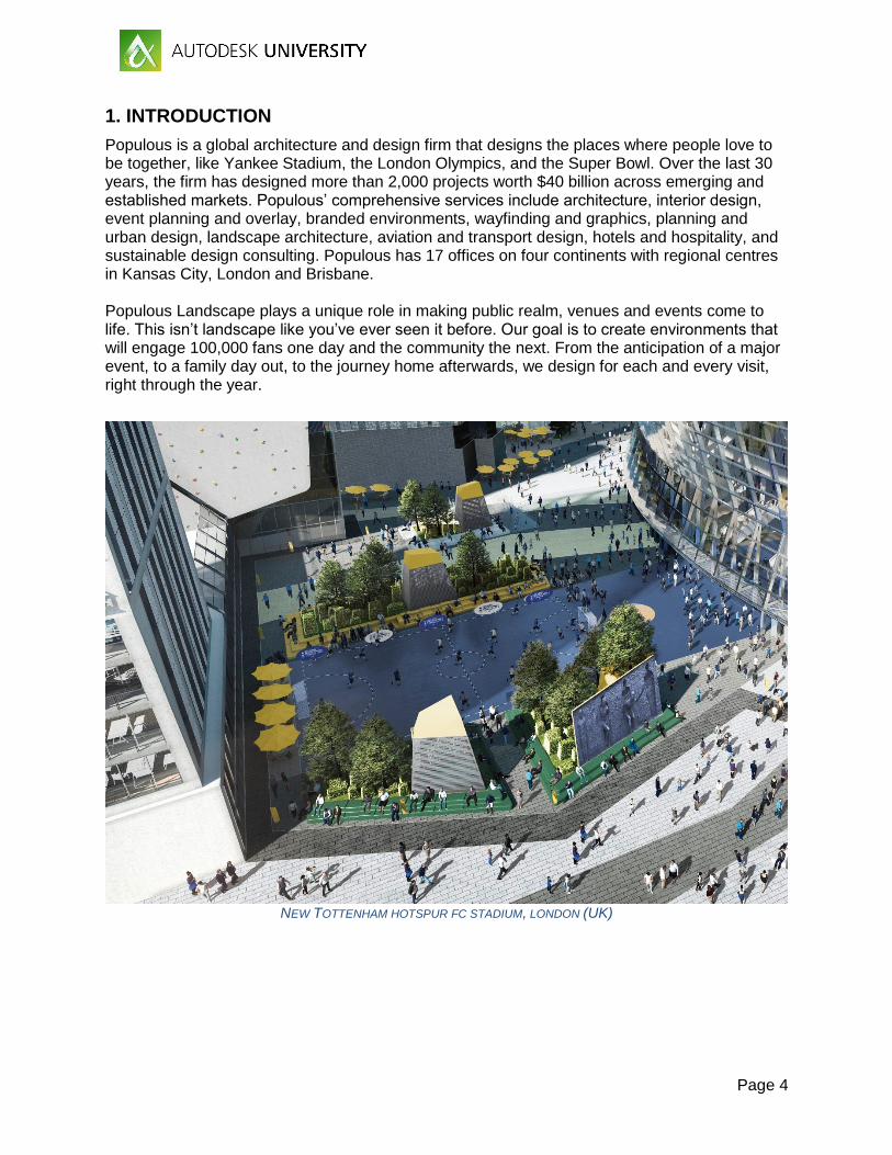
Populous is a global architecture and design firm that designs the places where people love to be together, like Yankee Stadium, the London Olympics, and the Super Bowl. Over the last 30 years, the firm has designed more than 2,000 projects worth $40 billion across emerging and established markets. Populous’ comprehensive services include architecture, interior design, event planning and overlay, branded environments, wayfinding and graphics, planning and urban design, landscape architecture, aviation and transport design, hotels and hospitality, and sustainable design consulting. Populous has 17 offices on four continents with regional centres in Kansas City, London and Brisbane. Populous Landscape plays a unique role in making public realm, venues and events come to life. This isn’t landscape like you’ve ever seen it before. Our goal is to create environments that will engage 100,000 fans one day and the community the next. From the anticipation of a major event, to a family day out, to the journey home afterwards, we design for each and every visit, right through the year.
NEW TOTTENHAM HOTSPUR FC STADIUM, LONDON (UK)

Page 5
2. BIM FOR LANDSCAPE? REALLY?
Why using BIM for Landscape? BIM stands for Building Information Modeling. As you may think, why then try to use BIM for Landscape if it is “Building” focused? BIM is more than using certain software, BIM is a method or a process to develop projects regardless whether the result is a building or a garden. The key and revolutionary points of BIM are collaboration and data. So, with the AEC industry fast transitioning to BIM, why should not Landscape Architects embrace this new process? On top of the many architects, engineers, clients and contractors asking for BIM compliant models, the UK government got also in the discussion. All the industries within the “built environment sector” are required to implement BIM Level 2 by law. As of April 2016, BIM Level 2 is mandatory for every centrally procured development project in the UK, so this sector includes utilities, construction and transport infrastructure.
Revit for Landscape After deciding on moving to BIM, our Landscape team had to choose a suitable software for use in our BIM Landscape projects. Carefully studying pros and cons, it was decided that Revit was the most suitable software for us. Although, as one can expect, there are some benefits and challenges using any software, including Revit for Landscape. BENEFITS
Company experience working with Revit (Architecture team)
Team background based on Autocad software
Software used by most Architects and Engineers
Parametric design
Unified software that allows to have views, sheets, 3D model and schedules in the same file
Render and visualization capabilities
CHALLENGES
No Landscape-specific build-in tools or workflows
No interoperability with Civil 3D
Difficulties working with Topography
Many sub consultants still working on 2D information (i.e. Irrigation, Water Features)

Page 6
3. SETTING OUT A LANDSCAPE REVIT MODEL
First thing to do when modeling your landscape design in Revit is, of course to open a new project file.
Then a window will prompt you to select a template. As expected, no landscape/site template is built in the software.

Page 7
Pick a default template, you can later create your own landscape template to improve your workflow. Each landscape project’s model will be different as scale, use, location, design, phase, etc. really determine your model’s needs. As a basic guideline you will need to create the following views:
Floorplans (per level): o General Arrangement o Grading and Levels o Hard Landscape and Furniture o Soft Landscape
Sections: o Site wide sections o Detail sections
One of the most important things to define from day 1 is the collaboration. Most of you will be working with teams, so you need to have a central file that can be accessed by several users. Worksets are key for collaboration. The following list is a basic guideline that will need to be increased/refined for each specific project: (Codes are indicative, they will need to follow your company’s policy)
Site o S-01 Components o S-02 Existing Topography o S-03 Proposed Topography o S-04 Existing Planting o S-05 Entourage o S-06 Masses
Hard Landscape o HL-01 Paving o HL-02 Stairs, Ramps and Railings o HL-03 Walls and Fences o HL-04 Furniture
Soft Landscape o SL-01 Trees o SL-02 Planting

Page 8
4. HARD LANSCAPE ELEMENTS
4.1 Paving
Floor vs Roof Paving is the most common hard landscape element. As there is no specific tool in Revit to create paving, we need to turn to Architectural tools. There are two tools that, in principle, could act as paving elements: Floor and Roof. Floor
Can be a host for families
Top face matches level of creation
Shape can be edited
Match architectural floors Roof
Can't be a host for families
Top face doesn't match level of creation
Shape can be edited In order to create a new external paving, you need to create a new floor family type. The best way to do this is to duplicate an existing floor, rename and change properties. You can add as many layers as you need to describe your paving material. To add a new floor in your model, just go to Architecture tab, Floors, select the floor type and sketch the boundary of your hard paving.
Representing paving in 2D plans Now you are able to model your paving in Revit, but, how to represent it in your hard landscape plans? Working in 2D environments, we use hatches to easily differentiate between paving types.

Page 9
We can still make "hatches" in Revit - they are called Filled Patterns and are PAT files loaded in our Revit model. There are two types of Filled Patterns: Model and Drafting. Model patterns have a fixed size, so if you change the scale in your view the pattern will adjust and be smaller or bigger. Drafting patterns, unlike the previous, will keep the same size no matter the scale of the view. Depending on how you would like to filled patterns to behave, you should choose model or drafting; there is no fixed solution. Model patterns are perfect for representing finishes at their real size like tiles, slabs, blocks, flags, etc. However, it won't be readable at large or small scales. On the other hand, drafting patterns keep readable for every scale but the size is not fixed. Both model and drafting patterns can be applied in two different ways: as a material property (surface pattern) or as a filled region. The main difference is that as a material property it will be a model element rather than being a view specific element in the case of filled regions. There is no right or wrong in using one or the other, or even combining both to create your Hard Landscape Plan. It will all depend on your project needs.
Special paving: Warning paving Tactile, hazard or warning paving warns visually impaired people of a hazard and to proceed with caution. Warning paving, either blister or corduroy, is a requirement for any public realm project. Warning paving needs to be placed next to crossings and steps to comply with local accessibility standards. In principle you could think to use the same workflow as explained before, but it has some problems. Warning or hazard paving is usually a small area in relationship with the overall paving. If your paving is shaped for drainage, you will need to reshape the edges of this paving every time you update you main paving. Also, as a floor you would only apply a surface pattern not a 3D texture. The workaround I use is to create a face-based family. Remember to make it face-based and not floor-based so it follows the slope on your paving. Firstly, you need to open a new Generic Model Face-Based family. I advise modelling a single paving unit following the standard dimensions, 400x400mm, as in our example. Using extrusions, model your unit. One square base and the top extrusions (domes or half cylinders). Remember to match the base with the top face of the given extrusion.

Page 10

Page 11
The most efficient practice is to have both types (blister and corduroy) in the same family. Create two new visibility parameters and assign them to the top extrusions.
Once you have set up your new visibility parameters, create two types: Blister and Corduroy. Check the right visibility parameter for each.

Page 12
Now you can load the family into your project file. Host the family to the paving and copy the unit as many times as needed.
In section you can check how your blister paving is aligned with the floor, even though this is sloping. You can also see that the blister units and your base paving are clashing and this area will be counted twice in your schedule. To solve this you will need to create a vertical opening. Go to Architecture>Vertical and sketch the shape of the opening to match your warning paving. Remember to lock the sketch so if you move the warning paving, the opening will follow.

Page 13
4.2 Grading & Levels
In the previous section we have covered how to build paving using the Floor tool. All the floors we created are flat at the level they were modeled. Unlike in Architecture, paving in Landscape is rarely flat. Falls and slopes are needed to provide drainage and match existing levels.
In order to modify a floor just simple select it to open the specific tools. Six options will open:
Edit boundary: This tool allows you to modify the shape of your floor. Please be careful if you have already shaped your floor, as if you delete/add segments, this will be set by default to elevation 0,0 from the level of the floor. So if you would like to keep the shape modifications, just move the line without deleting.
Modify sub-elements: This tool allows you to change the relative elevation of the floor elements (points, segments and split lines). So you can create slopes and falls. Use negative numbers to move down your points or segments.
Add point: When modifying sub-elements in a floor, you can only edit the segments and points that create the boundary unless you add more points with this tool. While in this mode, Revit doesn't snap to model elements, just detail/model lines. So I advise to sketch first where you would like to place your points. Once created you can modify their elevation using the "Modify sub-elements" tool.
Add split lines: With this tool you can add lines to create ridges and valleys. Creating a split line also creates two points (beginning and end). As it happens using "Add point", Revit doesn't snap to model elements, just detail/model lines. So I advise sketching first where you would like to place your split lines. Once created you can modify their elevation using the "Modify sub-elements" tool. You can modify the elevation of the whole split line or the two points independently.
Pick supports: Only for floors above structure. Not commonly used for Landscape.
Reset shape: This button will reset your floor to its origin, removing all the modifications and resulting in a flat floor.
4.3 Drainage
Drainage is a tricky subject as it is a joint design between Civil Engineers and Landscape Architects. The responsibility to model it in Revit will depend on each BIM execution plan. In most cases, Landscape Architects are responsible modelling surface drainage elements while Civil Engineers model underground drainage elements. Gratings and gullies can easily be made with floor based families. The challenge comes when modelling linear drainage systems that need to follow the paving levels. The best workaround is to create in-place masses, as described below.

Page 14
Drainage in-place We need to create a new “Model in-place” component. Under the Architecture tab to go Component>Model in-place
A window will open prompting you to choose Family Category and Parameters. This is an important step as you will need it to schedule your drainage.
There is not a family category for drainage so you will need to select what you think will work better in your project: Specialty Equipment, Plumbing Fixtures, etc. Next, you need to name your component:

Page 15
And then you will be in the massing environment. The best workflow I have found is to model a sweep with your slot drain profile. Firstly, select your path. Remember to have the 3D edge on, so if your floor is not flat, your sweep will follow the grading.
Then accept and select your profile. You can sketch it or load an existing profile.

Page 16
You will then get a nice slot drain:
4.4 Kerbs (Curbs)
As with paving, there is no specific tool in Revit to create kerbs. We need to become creative and use the Architectural tools in a different way.
There are several ways to create kerbs, depending on whether you used roofs or floors to model your paving.
Fascia (Roof)
Gutter (Roof)
Page 17
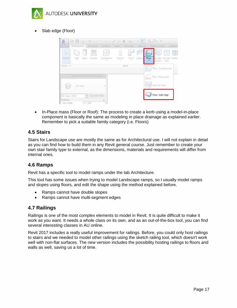
Slab edge (Floor)
In-Place mass (Floor or Roof): The process to create a kerb using a model-in-place component is basically the same as modeling in place drainage as explained earlier. Remember to pick a suitable family category (i.e. Floors)
4.5 Stairs
Stairs for Landscape use are mostly the same as for Architectural use. I will not explain in detail as you can find how to build them in any Revit general course. Just remember to create your own stair family type to external, as the dimensions, materials and requirements will differ from internal ones.
4.6 Ramps
Revit has a specific tool to model ramps under the tab Architecture.
This tool has some issues when trying to model Landscape ramps, so I usually model ramps and slopes using floors, and edit the shape using the method explained before.
Ramps cannot have double slopes
Ramps cannot have multi-segment edges
4.7 Railings
Railings is one of the most complex elements to model in Revit. It is quite difficult to make it work as you want. It needs a whole class on its own, and as an out-of-the-box tool, you can find several interesting classes in AU online.
Revit 2017 includes a really useful improvement for railings. Before, you could only host railings to stairs and we needed to model other railings using the sketch railing tool, which doesn't work well with non-flat surfaces. The new version includes the possibility hosting railings to floors and walls as well, saving us a lot of time.

Page 18
4.8 Walls
Walls are widely used in Landscape: retaining walls, planter walls, balustrades, etc. Fortunately, we can use the Architectural wall tool to model landscape walls. You can find more information on walls on any general Revit course.
4.9 Fences and Gates
There is no specific tool for fence creation in Revit, so again, we need to use a workaround to create our fences and gates.
What we found most useful to create fences is using the curtain wall tool. You can find the curtain wall under the Architecture tab.
In essence, a curtain wall is a combination of panels, vertical mullions and horizontal mullions. Any wall can be used as panels or even we can create curtain walls without panels selecting empty in the properties. With some creativity we can model almost any fence you can design. Let's see some examples.
Round vertical posts fence
ROUND VERTICAL POST FENCE (CURTAIN WALL)

Page 19
TYPE PROPERTIES
Timber posts fence
TIMBER POSTS FENCE (CURTAIN WALL)

Page 20
TYPE PROPERTIES
Wire mesh fence
WIRE MESH FENCE (CURTAIN WALL)

Page 21
TYPE PROPERTIES WIRED MESH FENCE
WIRED MESH WALL: STRUCTURE

Page 22
Gates In order to create a gate in a "fence" (curtain wall), you will need to proceed as you would do with a regular curtain wall. First, create a new curtain wall door type with the properties you want your gate to have.
Then, hover over your fence and tab to select the panel you want to turn into a gate. Unpin it and change the type selector to the curtain wall door (your gate). Select the horizontal mullion under your gate and delete it.
WIRED MESH DOUBLE GATE: TYPE PROPERTIES
Page 23
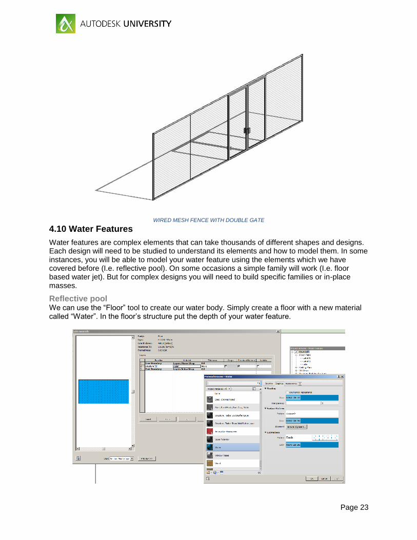
WIRED MESH FENCE WITH DOUBLE GATE
4.10 Water Features
Water features are complex elements that can take thousands of different shapes and designs. Each design will need to be studied to understand its elements and how to model them. In some instances, you will be able to model your water feature using the elements which we have covered before (I.e. reflective pool). On some occasions a simple family will work (I.e. floor based water jet). But for complex designs you will need to build specific families or in-place masses.
Reflective pool We can use the “Floor” tool to create our water body. Simply create a floor with a new material called “Water”. In the floor’s structure put the depth of your water feature.

Page 24
WATER “FLOOR”: ASSEMBLY AND WATER MATERIAL
WATER FEATURE WITH SEATING WALL

Page 25
5. SOFT LANDSCAPE ELEMENTS
5.1 Model and representation. 3D vs 2D.
Soft Landscape elements need to be represented in your model in different ways. In principle there are three basic ways to model soft elements that can be used in a combined way to achieve your needs.
Firstly, you can use RPC families to model your trees and planting. We are "lucky" as Revit build-in library has RPC planting families. RPC are basically used for render purposes. They look nice when rendered but not in 3D views or elevation. It gives you basic information regarding species and size. Also you will find only some species.
RPC TREE: ELEVATION, PLAN AND RENDERED VIEW
As I said at the beginning, BIM is all about information and collaboration. When working with other consultants, like architects or civil or structural engineers, you will need to provide a bit more information about your planting: soil depth, rootball size, shape, size, weight, area covered, etc. So 3D massing trees are needed to communicate these properties of your proposed planting.
Finally, you will need to create your 2D plans from Revit. And so, you need nice trees and planting in plan and elevation to illustrate them.
5.2 Tree planting
As stated in the previous section, we have three "options" or possible results when modelling trees: trees for render, massing trees for 3D models and trees for 2D plans. I tend to use the second and third options because, as I said earlier, we can include more useful information than using RPC families.
So firstly, we need to create our custom made family. We can combine both 3D massing tree and 2D line representation in one single family.

Page 26
Tree family Start your family using a planting family template. Start modeling a base tree with extrusions. For the level the information we need to share, I usually create three masses: rootball, trunk and crown. The shape will depend on the species you are trying to model. Then, you need to decide which parameters your will add. You could use the following as an indication:
TREE FAMILY TYPES AND PARAMETERS
Some of these parameters will need to be placed in the extrusion sketch to make them work (i.e. rootball height and radius). Next, create as many types as you need depending on species and dimensions. Assign values for the parameters and check if they work properly. As a result you have a nice 3D tree family.

Page 27
However, in plan view it would be really difficult to differentiate between types as they will basically be three concentric circles with different radius. We can then use 2D lines to make them more appealing and also easy to identify with a legend. We need to draw these 2D lines in plan using symbolic lines (Annotate>Symbolic lines), that way they will only be seen on perpendicular views to them. We also need to check the visibility settings for our extrusions so they are not seen on plan.
VISIBILITY SETTINGS
TREE FAMILY PLACED IN PROJECT: 3D AND PLAN VIEWS

Page 28
Although this method could also be used for sections/elevations, symbolic lines are only seen on perpendicular views, so it is not really efficient. So I tend to keep the 3D massing trees for positioning and place elevation/section trees as detail items to achieve nicer drawings.
5.3 Shrubs & Groundcovers
For shrubs and groundcovers, the most important information to provide for other consultants is area and soil depth. Before BIM, we rarely drew every single plant except in really detailed planting plans. Commonly we used hatches to indicate areas with same specie/mix and density. So, in Revit, we should try to avoid cluttering our model placing each one and single plant but rather putting what it is relevant. In big projects, using individual elements for each plant will make the model incredibly enormous and therefore lowering the performance.
The most effective workaround that we have found is to create floors. It can look a bit strange to use a typical hard element to create a soft element, but it has proved to be the most effective way to provide the information needed.
To proceed, create a new floor type and edit its structure. Create new materials for planting, top soil and sub soil. You can be as specific as your project needs, adding as many layers as you need to detail (i.e. mulching, root barrier, drainage, waterproofing, etc.) Assign the layers their thickness. Planting layer will be as thick as the height of your planting. When placing the floor, remember to offset the floor from the level at the same height as your planting mix. In this way you will get your top soil to match your level.
PLANTING “FLOOR” WITH STRUCTURE AND SECTION
Specimen shrubs Specimen shrubs need to be as detailed as tree planting. Exact location, height, girth, rootball size and depth must be included. It is best practice to create a shrub family following the indications given for tree families.

Page 29
5.4 Planting Plans
Planting plans are one of the most important documents in a Landscape Architectural project. They specify what, where and how many plants/trees need to be placed. Planting plans are specific to Landscape projects, so there is no tool in Revit to make them.
Tree planting and specimen shrub plans Creating a tree planting plan in Revit is not much different from other 2D software. Go to your soft landscape view and draw arcs with details lines joining the tree/shrub centres of the same species. To tag the group of trees you will need to create a custom planting tag. There is no way for Revit to count the trees joined by arcs and share this number in a tag, so you will need to add it manually. Open a new family and choose the generic tag as template. Remember to change the category to planting. Create your tag by putting a label with your parameters.
I usually add two parameters to my label: Mark and Type Name. Mark is where I will manually add the number of trees/plants in the group. Type Name is given by the family and I tend to use the Scientific Name. So your plan will look like this:

Page 30
This task can be really tedious for big projects, but can easily be automatic using Dynamo BIM (advanced users).
Understory planting plans As explained earlier, I use floors as a workaround to represent planting areas and their soil depths and planting height. We can use the floor surface pattern to identify the planting mix/species combined with a legend. Also, we can customize a tag in a similar way to how we did for the tree planting. Basically, we need to follow the same steps but, this time, we will pick the Floor category instead of Planting. This is because we want to find out the area and that parameter is not available for the Planting category. Note: You can only add the Area parameter if using Revit 2017.

Page 31
As with trees, we can use the Mark parameter to add the number of plants. Revit cannot automatically fill this parameter so we need to do it manually. We can use a working schedule to work out the numbers (see section 7.2).

Page 32
6. URBAN FURNITURE
Modeling urban furniture in Revit doesn't differ much from regular furniture modeling. Benches, litter bins, lighting poles, signage, cycle racks, play equipment etc. The in-build library is quite small regarding urban furniture, but anything can be built using the family editor.
I will not explain in detail how to build families in Revit as that is covered in other general courses. However, there are some specific notes for urban furniture:
Most urban furniture is floor hosted, like benches. Sometimes this can be problematic when you have shape edited floors. Do not use face based families as you would get sloping benches!
Be careful with the “Level of detail” (LOD). Too much detail makes your model bigger and slower.
Downloading families from suppliers is tempting, but be careful. Usually they come with too much information and they can really break your model. If you need to use these families, try to purge them as much as possible and always try them out before loading into your model.

Page 33
7. SCHEDULES
Making schedules is one of the benefits of using Revit. It is where data and geometry meet. In many Revit templates you can find preset schedules for Architecture like room sheets or door schedules. We will need to build our own Landscape schedules. As you know, the most used schedules for Landscape Architects are Hard Landscape and Soft Landscape Schedules.
7.1 Hard Landscape Schedule
In the Hard Landscape schedule we need to collate all information regarding materials. It will change depending on the phase you are working on but basically will include material, size, colour, pattern, finish and indicative supplier/manufacturer. Often Hard Landscape and Furniture elements are combined in a single schedule. First, we need to create a new schedule either from the view tab or the project browser. In order to show all the categories in one schedule (walls, furniture, floors, etc.) you need to select a “Material Takeoff”. If you open a new “Schedule/Quantities” you will not be able to show host categories in the same schedule.

Page 34
Then you will need to choose the category. As several different categories will often be included (i.e. floors, walls, etc), let’s select multi category.
Next step you will need to select the fields for your schedule. You can check that not all of what you need are in the list, so you can add them using the “Add parameter” button. Press ok and you will get your material schedule. It will need some sorting and formatting to get it nice and tidy. You will also need to fill in the gaps.

Page 35
8.1 Soft Landscape Schedules
For Soft Landscape, I work with three different schedules: Trees, Specimen Shrubs and Understory. This distinction is based on the fact that we model them in different ways. While we use planting families for our trees and shrubs, we use floors as a workaround for representing understory planting.
Tree and Specimen Shrub Schedules The workflow is similar to Hard Landscape Schedules as explained before. As now we are only using one category (Planting), we are going to use Schedule instead of Material Takeoff. Create a new category and select Planting as category.
Then, the schedule properties window will open. You can easily check that the list of available parameters for planting is not different from other elements. We do not have any planting specific parameter as size, common name, scientific name, spacing, girth, height, pot size, etc. You can deal with this in two ways: select any parameters and rename them editing your schedule or create new parameters using this window.

Page 36
If you used the scientific name to identify the types in your tree family, that column will be automatically filled as well as count. Remember to uncheck “Itemize every item” and sort by type to group by species.
Once you have renamed your parameters (columns headings), you will need to manually input the values.
Understory Planting Schedule As highlighted earlier, we use floors as a workaround for understory planting. So, our schedule now will be a floor category schedule.
All floors will appear in your schedule. You only want your “soft” floors to appear, not paving so the best thing is sort them out using one parameter that can be the same for all your soft floors (i.e. Manufacturer = Nursery). As we did with trees, renaming of parameters is needed. Unlike trees, the automatic count parameter will not show the real number of trees, but the number of floors. We need to add what Revit calls “Calculated parameter”. To determine your number of plants you need the spacing and area data. The area is automatically calculated by Revit, but you will need to input the spacing (rename or add this parameter as it is not built-in, it needs to be a number not text parameter).
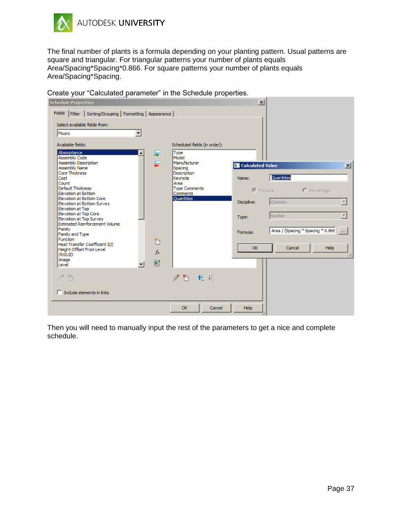
Page 37
The final number of plants is a formula depending on your planting pattern. Usual patterns are square and triangular. For triangular patterns your number of plants equals Area/Spacing*Spacing*0.866. For square patterns your number of plants equals Area/Spacing*Spacing. Create your “Calculated parameter” in the Schedule properties.
Then you will need to manually input the rest of the parameters to get a nice and complete schedule.

Page 38
8. TOPOGRAPHY
8.1 Toposurface: Constraints
Topography is one of the few landscape elements that has its own tools in Revit. Under the tab "Massing and site" we can find the topography tools, called in Revit "Toposurface". Toposurface is a strange element that doesn't behave like the rest of the Revit elements.
The main issues are:
Toposurfaces are made with one single material that extends infinity. There is no way to control layers, materials or depths. You can only change the colour at the top surface.
Only a few families (mostly entourage families) can be hosted by a toposurface
No voids can be opened
No specific tools to model water bodies
No interaction with hard landscape elements
Revit creates Toposurface based on triangles not contours
No interoperability between Revit and Civil 3D
Toposurface can't be smoothed
No grading tools Due to all the precedent points, working with toposurfaces in Revit can be a time consuming and frustrating task. Let's see how to try to get your toposurfaces to do their job.
8.2 Creating toposurfaces
In the Massing and Site tab you will find three methods to create a toposurface:
Place points: You will need to manually add points at its elevation. It can be really tedious work for big projects. It works well for small areas.
Create from imports>Select import instance: Revit will create the toposurface using the points from an import instance. You can select one or several layers, so make sure those only contain the appropriate geometry.
Create from imports>Point file: Revit will create the toposurface using the points from the file. Not many surveys contain this document, so it is not very commonly used.
The most common method to create toposurfaces is using import instances, usually Autocad files (*.dwg) created from Autocad or Civil 3D.
As I mentioned earlier, Revit triangulates the given points to create the toposurface regardless of whether they are given via contours or points. Revit selects the closest points to model the

Page 39
triangles so, when using contours, most of the times the resulting toposurface is not accurate enough.
The best workflow is to ask the civil engineer to export a TINN surface from Civil 3D to a dwg file, so you can select the vertex as points when creating the toposurface. The result will be way more accurate.
8.3 Site tools
In the Massing and Site tab we can find two groups of site tools: model site and modify site.
We have already covered the Toposurface creation but there are others tools that will be useful in landscape projects.
Building Pad Building Pad is a tool to create platforms at a certain level on your toposurface. It automatically adjusts the surrounding topography to match this boundary. When pushing the button you will be directed to the sketch mode where you can draw the boundary of your pad:

Page 40
In the properties window we can select the level where the building pad will sit and if we want it offset from that level:
We have the option of sloping the building pad using the slope arrow. We can only define one arrow per pad, and the grading will be defined either by the slope or the height at the tail:
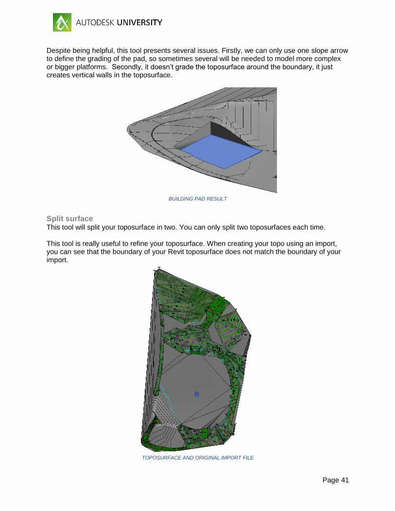
Page 41
Despite being helpful, this tool presents several issues. Firstly, we can only use one slope arrow to define the grading of the pad, so sometimes several will be needed to model more complex or bigger platforms. Secondly, it doesn’t grade the toposurface around the boundary, it just creates vertical walls in the toposurface.
BUILDING PAD RESULT
Split surface This tool will split your toposurface in two. You can only split two toposurfaces each time. This tool is really useful to refine your toposurface. When creating your topo using an import, you can see that the boundary of your Revit toposurface does not match the boundary of your import.
TOPOSURFACE AND ORIGINAL IMPORT FILE

Page 42
When pushing the Split Surface button we will be in the sketch mode. Draw your boundary matching the surplus toposurface.
Press accept and you will have two separate surfaces. Delete the one outside the boundary.
Repeat the process as necessary to refine your edge. Remember that you can only split the surface in two each time.

Page 43
The split surface tool can also be used to model roads in a masterplan by dividing the toposurface. Only do this once your toposurface is finish. First, sketch your road layout using detail lines, it will help you with the splitting. Then, you can start splitting -always remember that only can be split in two surfaces each time.
Changing the surface material you will have a first (and rough) road design.
It can be used for early stages of the design, but later on you will need to add more details including kerbs and footpaths. This can be easily done using split surface as well.
Page 44
You can also work with the levels to make a level difference between the road and the footpath. This can be easily done by moving your road surface down by the kerb height. Use a section or elevation view to do it. You can check back in a 3D view that there is now a gap between your footpath and your road, that is where you need to model your kerb and gutter. Split the footpath surfaces in three parts, two of them offset from the road edge 150 and 350 mm. Change them to a different material. Now move down the surfaces next to the road to match its level (so, move them the kerb height). If you go to your 3D again, you can see that the gap is now between the kerb and the gutter. Now split the kerb and gutter by an offset of 20 mm from the shared edge. Merge both surfaces to get a nice kerb.
Merge surface This tool is the opposite of the previous one. It will merge two adjacent toposurfaces in one.
Subregion Subregion allows to create a surface within your toposurface without splitting it. You can change the material of the subregion but, unlike split surfaces, the subregion will change if the toposurface changes. The subregion button leads you to a sketch mode where you can draw your subregion. It needs to be closed in loops but not necessary inside your topo, it will adjust the border.

Page 45
SKETCH MODE FOR SUBREGION CREATION
Selecting your subregion, you can change the material in the properties window.
SUBREGION AND TOPOSURFACE WITH DIFFERENT MATERIALS
If a subregion is deleted, you still have your original toposurface.
8.4 Modifying toposurfaces
Once we have created our base toposurface, Revit has some built-in tools that allow us to modify it.
First we need to select the toposurface to open the modify-surface menu. One button will appear: “Edit surface”

Page 46
By pressing that button new options will open and the vertex of the triangulated toposurface will be highlighted:
Once in the edit Surface mode, we can select the points that build our toposurface and edit their elevation or even delete or move them.

Page 47
Place points You can place new points in your surface to refine it or to adjust to your proposed levels.
Points can be placed referencing to absolute elevation or relative to surface. This means that if I place a point at elevation 0.0 relative to surface, it will actually sit on the toposurface. Placing point can be a bit tedious for big masterplan or landscape projects, but it gives you more control on the grading than creating building pads. In order to create a platform, first create an array of points at 0,0 elevation from your surface delimiting the area which you need to transform. Any topo outside this boundary and including the points will remain the same. It is good practice to first draw detail lines to guide the placing.
These outer points elevation will stay undisturbed and we will create a platform inside controlling the grading. The more points the better to preserve the topo around your area.

Page 48
Create from import You can modify your toposurface using an import. As with creating the surface, you can select the layers that you need. Then Revit will use the new points and the existing ones to create the new surface.
Simplify Surface Simplify surface will reduce the number of points of your surface to make it simpler. You can select the level of accuracy.

Page 49
8.5 Cut and fill
Revit can calculate approximate volumes for cut and fill. In order to do this, you need to have two toposurfaces in two different phases. The latest toposurface needs to lie within the previous toposurface. To find out the cut/fill volumes just select the surface in the latest phase and check its element properties.