ara n-frm samplerarainstruments.com/wp-content/uploads/n-frm_manual.pdf · section page 5....
TRANSCRIPT

ARA N-FRM Sampler
Operation Manual April 15, 2017

TABLE OF CONTENTS
SECTION PAGE
1. INTRODUCTION 1
1.1. Principles of Operation 2
1.2. Particulate Matter Sampling 2
2. HARDWARE DESCRIPTION 3
2.1. PM 10 Inlet 3
2.2. PM 2.5 Cyclone 3
2.3. Filter Holder 3
2.4. Flow Control System 3
3. INITIAL SETUP 4
3.1. Basic Assembly 4
3.2. Deployment 5
3.3. Power Source 6
3.3.1. Batteries 6
3.3.2. AC Power Supply 7
3.3.3. Using Batteries and AC Power Supply 7
3.4. Powering N-FRM Sampler On/Off 7
3.5. Navigation 7
3.6. Sleep Mode 7
3.7. Setting Time and Date 7
3.8. Installing a Filter 8
4. OPERATIONAL OVERVIEW 9
4.1. Home Screen 9
4.2. Operational Modes 9
4.2.1. Mode: Off 9
4.2.2. Mode: On 9
4.2.3. Mode: Met 9
4.2.4. Mode: Program 9
4.2.5. Mode: Sector 9
4.2.6. Mode: Remote 9
4.3. Data 10
4.4. Setup 10

SECTION PAGE
5. OPERATING THE N-FRM SAMPLER 12
5.1. User-Defined Programming 12
5.1.1. Creating a Program to Operate at a Specific Time 12
5.1.2. Running a Program 12
5.1.3. Ending a Program 13
5.2. Meteorological Functions 13
5.2.1. Sector Mode (Directional Sampling) 13
5.2.2. Start a Sector Run 13
5.3. Real-Time Particulate (RTP) Profiler 14
5.3.1. Accuracy 14
5.3.2. Calibrating the RTP Profiler 14
5.4. View Summaries 15
5.5. Export Data 15
6. MAINTENANCE 17
6.1. Servicing Schedule 17
6.2. Service Water Trap 17
6.3. Clean PM10 Inlet, PM2.5 Cyclone, and Filter Holder 17
6.3.1. Cleaning PM2.5 Cyclone 18
6.3.2. Cleaning PM10 Inlet 19
6.3.3. Cleaning Filter Holder 20
6.4. Clean RTP Profiler Filter 21
6.5. Replace O-Rings 21
6.6. Pump Rebuild 21
6.7. Leak Check 22
7. CALIBRATION 22
8. TROUBLESHOOTING 23
9. WARRANTY POLICY 24
10. PARTS LIST 25
APPENDIX A: Calibration Using an ARA FTS Flow Calibrator 29
QUALITY CONTROL FORM 32

ARA Instruments N-FRM Sampler Manual 1
1 INTRODUCTION
ARA Instruments Mission
Our mission at ARA Instruments is to help environmental professionals make important air quality
decisions by providing them with cost effective, accurate, and reliable instrumentation. Our air samplers
and calibration instruments are used in outdoor ambient air quality applications as well as indoor and
industrial uses.
Overview
In response to the need for a low cost alternative to traditional site-based particulate monitors, ARA
Instruments introduced a sampler that establishes a new class of air sampler we call “Near FRM” (N-
FRM). The ARA N-FRM Sampler is a portable, rapidly deployable, battery powered particulate sampling
and monitoring device that delivers Federal Reference Method (FRM) level of performance. It integrates
with many additional components for unmatched versatility. The compact sampler collects 24-hour TSP,
PM10, or PM2.5 filter samples and can simultaneously measure local meteorological parameters. It can
also be equipped with a Real-Time Particulate (RTP) Profiler to log temporal particulate variations. For
added versatility, the N-FRM Sampler can be operated in directional wind sampling mode or
meteorological mode.
The N-FRM Sampler offers near FRM performance, while costing a fraction of traditional site-based air
samplers. Its compact size and battery-powered function, gives the N-FRM Sampler many advantages
over traditional air samplers. Deployment and relocation is quick and easy, and allows monitoring in
locations that are inaccessible with traditional air samplers. Flexible mounting options allow for stand–
alone support or the use of existing poles and structures. The ability of the N-FRM to operate on
rechargeable batteries also significantly reduces the cost of establishing a monitoring site.
The N-FRM is designed for easy operation and maintenance. The intuitive user interface makes
programming and calibrating the sampler simple. PM10 and PM2.5 inlets are field serviceable and
require only monthly cleanings. Filter holders accept standard 47mm FRM cassettes for easy handling of
various filter media. Batteries can be recharged in approximately 1-hour. Data log files with 5-min
averages for all sensors can easily be downloaded to a USB Flash drive.
Cities and governments are deploying networks of N-FRM Samplers to survey unmonitored areas and
validate permanent Reference Method equipment. Researchers and consultants use the N-FRM in air
quality studies and environmental impact assessments. They are also utilized in industrial pollution
applications, such as mines and quarries, and in large construction projects for fence line and roadside
monitoring. The small and quiet N-FRM air sampler is also a great tool for indoor and industrial
workplace sampling that requires high accuracy.
Better than FRM
The N-FRM sampler was designed to be the most versatile and cost-effective solution for air pollution
research applications. Traditional filter based sampling methods provide an accurate measurement of
particulate matter at a fixed location over a 24-hour period, and are used to determine compliance with
national air quality standards. However, adding real-time meteorological and PM data gives air quality
professionals a higher understanding of the data, which is crucial to designing effective control
strategies. The N-FRM has the capability of directional air sampling for fence line, roadside, or single
source impact air quality investigations. Additionally, the N-FRM can be used to “saturate” a study area
with multiple samplers to obtain an accurate picture of spatial particulate distribution.

ARA Instruments N-FRM Sampler Manual 2
1.1 Principles of Operation
The N-FRM Sampler is specifically designed to meet the US-EPA operational specifications for PM10 and
PM2.5 air sampling. To meet the EPA specifications, the N-FRM Sampler is designed to operate at 16.7
LPM and collect 24-hour samples to compare to EPA National Ambient Air Quality Standards. The ARA
N-FRM Sampler is a microprocessor-controlled portable air sampler, which can be operated manually or
programmed to collect scheduled samples. As specified by the EPA, all critical air sampling parameters
are continuously monitored and logged as time indexed 5-min averages to validate the sample. These
parameters include: flow rate, temperature, barometric pressure, and accumulated volume. Other
sampler related performance parameters are also logged. If the N-FRM Sampler is equipped with the
Real-Time Particulate (RTP) Profiler and meteorological sensors, then PM10, PM2.5, wind speed, and
wind direction are also included in the data record.
The N-FRM sampler can be easily deployed. It can be mounted on a variety of structures using our
universal mounting bracket that can be screwed, clamped, or attached to utility poles, trees, fence
posts, etc. Another option is to use a freestanding tripod.
The N-FRM Sampler is equipped to operate from either AC or DC power sources. In the DC mode, the
sampler operates from an internal battery pack. A charged battery pack is capable of operating the
sampler for about 30-40 hours. This robust capacity allows the sampler to be used in cold weather and
high altitude applications. A charger is supplied so the batteries can be re-charged in approximately one
hour.
1.2 Particulate Matter Sampling
The N-FRM Sampler can be set up for TSP, PM10, or PM2.5 particulate sampling by configuring the
sampling inlet components prior to the filter medium. To measure TSP, the omnidirectional Louvered
Inlet is all that is required. For PM10 sampling, an FRM style inertial separator (PM10 Impactor) is
added. To collect PM2.5, the sharp-cut ARA VIS-A Cyclone is attached, which physically selects particles
2.5 microns and below. Common N-FRM inlet configurations are shown in FIG. 1.
The N-FRM inertial separators (PM10 Impactor) are designed to operate at a nominal sampling rate of 1
cubic meter per hour (16.7 liters per minute). The N-FRM Sampler incorporates a microprocessor-based
active flow control to maintain the sampling rate as ambient conditions and filter loading changes. The
sampling rate is monitored and adjusted several times a second and logged at 5-min intervals along with
all other important sampling parameters.
To allow for unattended operation, the N-FRM Sampler is easily programmed to initiate and stop
sampling. For each sampling event, the N-FRM Sampler generates a summary of important sampling
parameters such as start and stop times, total sampling volume, and average ambient temperature and
pressure as well as 5-min averages of all ambient and sampler operational parameters. The logged data
file can be easily downloaded to a USB flash drive by the operator. The “csv” (comma separated value )
file can easily be imported into a spreadsheet.

ARA Instruments N-FRM Sampler Manual 3
2 Hardware Description
2.1 PM10 Inlet
The ARA omnidirectional PM10 Inlet is a compact version of the EPA
prescribed Reference Method Inlet. It features a screened inlet, wind
deflector, and precision PM10 inertial separator (impactor) with
moisture trap. The PM10 Inlet is designed to operate at 1 cubic meter
per hour (16.67 LPM). The inlet can be used alone for PM10 sampling
or in combination with the ARA VIS-A sharp-cut vortex inversion
separator for PM2.5.
2.2 PM2.5 Cyclone
The ARA VIS-A (Vortex Inversion Separator) is a precision engineered
and compact sharp-cut cyclone fitted to the N-FRM inlet that
physically selects particles 2.5 microns and below. This ensures
precise measurement of only the PM2.5 size fraction. The PM2.5
separator is designed to operate at 1 cubic meter per hour (16.67
LPM) and requires the ARA PM10 omnidirectional inlet to collect
accurate PM2.5 samples.
2.3 Filter Holder
The aluminum filter holder is precisely manufactured for a tight seal
and no contamination of the filter media. The filter holder is
designed to use common EPA specified 47mm cassettes for PM2.5
sampling.
2.4 Flow Control System
The N-FRM Sampler incorporates a microprocessor-based active flow control to maintain the sampling
rate as ambient conditions and filter loading changes. The sampling rate is monitored and adjusted
several times a second and logged at 5-min intervals along with all other important sampling
parameters. Under normal conditions the active flow control will maintain the sampling well within +/-
2%. If the sampling rate cannot be maintained within +/- 5% a flow error is generated and logged, and if
the error continues for 5-minutes the sampler will shut down.

ARA Instruments N-FRM Sampler Manual 4
3 Initial Setup
3.1. Basic Assembly
When the N-FRM Sampler arrives, please check to ensure all parts are accounted for and that no items
were damaged during shipping. Please contact ARA Instruments immediately to report any damaged or
missing parts.
Assemble the inlet for the desired sampling particle size. The configurations for TSP, PM10, and PM2.5
are shown in Figure 1.
Figure 1. PM 2.5, PM 10, and TSP Configurations

ARA Instruments N-FRM Sampler Manual 5
3.2 Deployment
The N-FRM Sampler is designed for easy
deployment. Most air sampling siting guidelines
recommend samples be taken in the normal
breathing zone 3-5 meters above ground. To
meet these requirements, the N-FRM can be
mounted on a Tripod or affixed to a stationary
object like a fence post or utility pole using the
Universal Mount Bracket. Both accessories are
available form ARA. The Universal Mount
(Figure 2) and Tripod (Figure 3) are shown to
the right.
Figure 2 Figure 3
The N-FRM is designed for secure mounting on any vertical round tubing support of 1.25 – 1.375 inches
in diameter (30-35mm). A clamp screw located inside the sampler secures the N-FRM to the support
(Figure 4). Using the 3/16” Hex L-Wrench located on the battery holder, tighten the clamp screw to
secure (Figure 5).
Figure 4 Figure 5
Clamp Screw Hex L-Wrench

ARA Instruments N-FRM Sampler Manual 6
3.3 Power Source
3.3.1 Batteries
Each N-FRM Sampler is equipped with two 18V/5Ah
DeWalt lithium-ion batteries.
Check Battery Charge
Each battery has a Charge Gauge on the front,
consisting of three green LED lights and a button. Press
and hold the Charge Gauge button. The LED lights will
illuminate designating the level of charge left. See
Figure 4 to determine if your batteries need to be charged. Figure 4. Battery Charge Levels
Charge Batteries
Plug the charger into an appropriate AC outlet.
Insert the battery into the charger as shown in Figure 5.
The red charging light will blink continuously, indicating
the charging process has started. Batteries should be fully
charged within 1 hour.
Completion of the charging cycle is indicated by the red
light remaining ON continuously. The battery is fully
charged and may be used at this time or left in the
charger.
The charger is designed to detect certain problems that
can arise. Problems are indicated by the red charging light
flashing at a fast rate. Try a different battery to determine
if the charger is working properly. If the new battery
charges correctly, then the original battery is defective
and cannot be used. Figure 5. Battery Charger
Please read all of the DeWalt instructions for the batteries and
charger included with your sampler for more details about
charging and storing batteries.
Install Batteries
Insert two charged batteries into the ARA N-FRM Battery
Holder as shown in Figure 6. Make sure the batteries are fully
seated and latched to the Battery Holder.
Insert the Battery Holder into the ARA N-FRM.
Figure 6. Battery Inserted Into Holder

ARA Instruments N-FRM Sampler Manual 7
3.3.2 AC Power Supply
Each N-FRM Sampler is also equipped with a 120/240V AC Power Supply to be used when an
outlet is available.
3.3.3 Using Batteries and AC Power Supply
The AC Power Supply does not charge the batteries. The batteries can only be charged with the
included Dewalt Battery Charger.
When both the AC Power Supply and Batteries are connected, the N-FRM Sampler will run off
the 24V AC Power Supply. If the AC Power Supply is interrupted, the Batteries will take over until
AC Power Supply is restored.
3.4 Powering N-FRM Sampler On/Off
Place the Power ON/OFF Rocker switch at the lower right of the front panel of the air sampler in the ON
position. The Sampler will boot up into the Home Screen. The default operational mode is MODE:OFF.
3.5 Navigation
Navigate through the menus by rotating the selector knob to highlight a desired selection. Press the
knob to select. The menu system is intuitive, especially to those with air sampling experience. To exit
any menu, rotate the selector knob to highlight the top item of all menus and select EXIT. MODE: OFF
takes you back to the Home Screen.
3.6 Sleep Mode
The N-FRM Sampler enters power saving “sleep mode” after a few minutes of no input from the
selector knob. In this mode, the LCD screen is blank. To wake up the N-FRM Sampler, press and
hold the selector knob for 3-seconds.
3.7 Setting Time and Date
On the Home Screen, confirm that the date and time are accurate. If necessary, follow these steps to set
the correct Time and Date:
• Select SETUP from the Home Screen
• Scroll down, highlight SYSTEM SETUP and select
• Scroll down, highlight DATE/TIME and select
• Scroll down until the Day is highlighted and select
• Rotate the selector knob until the correct date is highlighted and select
• Repeat for Month, Year, Hour, Minute, and Second
• Select DATE/TIME:EXIT
• Select YES to save Date/Time
• Select SYSTEM:EXIT and then SETUP:EXIT to return to Home Screen

ARA Instruments N-FRM Sampler Manual 8
3.8 Installing a Filter
Note: This procedure should take place in a laboratory or clean area. Contact and handling of all
filter media should be limited to the non-exposed outer edge with smooth tipped forceps (non-
serrated) or plastic tipped forceps. Filter media should never be handled with fingers.
• Unscrew the Filter Holder Top from the Filter Holder Bottom
• Remove Filter Cassette
• Use ARA Cassette Separator to open the cassette. The top and bottom of the Filter Cassette
are machined for a press fit. The Filter Cassette Top has a large beveled interior edge. See
Figure 7 for appropriate use of Cassette Separator.
Warning: Manually prying the cassette apart with fingers can result in the cassette violently
opening, causing damage to filter media or support screen.
Figure 7. Open 47mm Cassette
• With forceps, place a pre-weighed, clean filter media onto the Support Screen in the Filter
Cassette Bottom. Install the Filter Cassette Top, firmly and evenly pressing down to
complete the assembly.
• Place the Filter Cassette into the Filter Holder and reassemble by firmly screwing together
the Filter Holder Top and Filter Holder Bottom.
Note: Cassettes can be handled with fingers. Make sure not to touch filter media.

ARA Instruments N-FRM Sampler Manual 9
4 Operational Overview
4.1 Home Screen
Once the N-FRM Sampler is powered ON, the Home
Screen appears. The Home Screen displays the Time,
Temperature, Barometric Pressure, Wind Speed,
Battery Voltage, and Hour Meter (Total Pump
Operating Hours).
There are three menu selections across the top of the
Home Screen: OFF, DATA, SETUP. These are the
Administrative Modes.
4.2 Operational Modes
4.2.1 Mode: OFF
When the N-FRM Sampler is powered on, Mode: OFF is the default setting.
Select this administrative mode to move between the Operational Modes: OFF, ON, MET,
PROGRAM, SECTOR and REMOTE.
4.2.2 Mode: ON
Select to manually turn the N-FRM pump ON.
4.2.3 Mode: MET
Select to view and log current meteorological parameters and particle sensor data if the Wind
Sensor and RTP Profiler are installed. In this mode, data logging begins after 5 minutes. The
pump will not run in MET MODE.
4.2.4 Mode: PROGRAM
Select to set the sampler to run at user-defined parameters: time, date, duration, interval, and
flow rate. This mode logs all standard parameters, in addition to real-time particle data and
meteorological data (if installed).
4.2.5 Mode: SECTOR
Select to set the pump to run only when the wind direction is from a user-defined sector. Mode:
SECTOR is only applicable when the Wind Sensor is installed.
4.2.6 Mode: REMOTE
Select this mode to set the sampler to run only when remote jumper connections are shorted.

ARA Instruments N-FRM Sampler Manual 10
4.3 Data
The DATA administrative mode allows the user to view or erase summaries of the last few sampling
events.
VIEW SUMMARIES – In this selection, the last 3 sampling events are stored and organized by
Start Time. The summary data for each event is viewed by scrolling down the LCD screen. To
change and view other events, scroll and select ST (start time and date). Each press of the
selector knob changes the event data to view.
EXPORT LOG – Scrolling to the bottom of the VIEW SUMMARIES screen and selecting EXPORT
LOG allows the user to export a summary, including 5-minute averages of sensor data and
sampling parameters of the selected event to a USB flash drive.
ERASE ALL SUMMARIES – Selecting this option allows the user to erase all sampling event data.
Note: It is not necessary to erase summaries. The newest sampling event will overwrite the
oldest summary data once the maximum has been reached.
4.4 Setup
The SETUP administrative mode has various options relating to the sampler program and system setup.
SET PROGRAM: Allows the user to set the program for the next sampler run. Instructions that are more
specific can be found in Section 5.1.1.
CLEAR ALL DATA: Will delete all sampler runtime data.
EXPORT SETUP: Using USB drive, the user can download sampler settings.
IMPORT PROGAM: A program may be imported from the USB drive.
SYSTEM INFO: Lists sampler information, including the Serial Number and latest Firmware version.
UPDATE FIRMWARE: With the correct file on a USB drive the user can update the firmware of the
sampler. The latest firmware is available on the ARA Instruments website – www.arainstruments.com
SYSTEM SETUP: This menu allows the user to set the date and time and other sampler parameters.
DATE/TIME: User can set the current date and time. Note: When the sampler battery is
removed, the sampler will hold the current date and time for approximately two weeks.
FLOW RATE: User can turn the pump on and off and set the flow rate. This mode is useful for
flow audits and calibration. There is a user adjustable SLOPE and INT (Intercept) if flow
calibration is needed.
AMBIENT TEMPERATURE: This mode allows the user to turn ON or OFF the ambient
temperature sensor if desired. If turned OFF the sampler defaults to a user adjustable, standard
temperature of 25° C. The user can also enter an offset for calibration purposes.
BAROMETRIC PRESSURE: This mode allows the user to turn ON or OFF the ambient pressure
sensor. If turned OFF the sampler defaults to a user adjustable, standard pressure of 760
mmHg. The user can also enter an offset for calibration purposes.

ARA Instruments N-FRM Sampler Manual 11
STANDARD TEMP PRESS: This mode allows the user to adjust the standard temperature and
pressure used to calculate “standard” flow and volume, and also the default conditions if the
temperature and/or ambient pressure sensors are turned off.
LCD BRIGHTNESS: Allows adjustment of the LCD backlight.
RESTORE DEFAULTS: Will set sampler back to factory defaults (be cautious in using this option
since it will erase all calibration data).
BLUETOOTH CONTROL: For future use.
PARTICLE COUNTER: The N-FRM Sampler comes with default mass values for PM2.5 and PM10
particulates. Users can adjust these values proportionally to match their local aerosol
characteristics.
BOOT HISTORY: This mode is for troubleshooting firmware issues.
REBOOT: Will reboot the sampler.

ARA Instruments N-FRM Sampler Manual 12
5 Operating the N-FRM Sampler
5.1 User-Defined Programming
5.1.1 Creating a Program to Operate at a Specific Time Interval
There are two methods to view the SET PROGRAM screen.
Method 1: On the Home Screen, highlight SETUP and select by pushing the selector
knob. Scroll down to SET PROGRAM and select.
Method 2: On the Home Screen, highlight MODE: OFF and select. Rotate the knob until
MODE: PROGRAM is highlighted and select. Scroll down to ST (start date and time) and
select to open the SET PROGRAM page.
You can now select the fields you desire to edit as you setup the sampler to run:
CLEAR PROGRAM: Select this option if you want to clear the current program. This is not
necessary but can be helpful if you plan to change most of the parameters.
SAMPLE ID: A unique 4-digit ID can be entered but is not necessary. Sometimes used to
identify site or filter media.
START: Select this option to enter the Start Date and Time. Scroll to the field that you
would like to edit and push to edit. Turn the selector knob to choose the desired date
or time variable, then select and continue to scroll through the fields until the START
Date and Time are set as desired.
DURATION: Select this option to enter the duration of the sample event. Enter hours
and minutes by turning the selector knob and pushing to edit the desired field.
INTERVAL: This option is used to setup a repeating sample event. Enter the hours and
minutes from the end of the programmed run that you would like the event to repeat.
An entry of 72:00 would repeat the sample every 72 hours. For a single non-repeating
event set the INTERVAL to 00:00.
SET FLOW: Use this field to set the desired flow for the programmed event. The
nominal flow rate for ARA PM10 and PM2.5 inertial separators is 16.7 LPM.
SECTOR: This field can be set to have the sample event turn off and on when the wind
direction is in a desired sector.
5.1.2 Running a Program
To activate the sampler at the programmed time and interval the sampler must be set to the
Program Operational Mode.
On the Home Screen, select MODE: OFF. Rotate the knob until MODE: PROGRAM is highlighted
and select.
The LCD screen displays TM (current date and time) and ST (start date and time) of the
programmed event. Confirm that these parameters are correct and leave the sampler in
Program Mode.

ARA Instruments N-FRM Sampler Manual 13
5.1.3 Ending a Program
After a programmed sampling event, the sampler remains in MODE: PROGRAM unless manually
changed.
Highlight MODE: PROGRAM at the top of the LCD screen and select. Rotate the selector knob
until MODE: OFF is highlighted and select. The Home Screen will appear.
5.2 Meteorological Functions
If the Wind Sensor is installed, the N-FRM Sampler will log 5-minute averages of wind speed and wind
direction throughout any run in any Operational Mode (MODE:ON, MODE:MET, MODE:PROGRAM,
MODE:SECTOR, and MODE:REMOTE).
Note: In order for wind speed and wind direction to be recorded in the data file, the wind speed must be
greater than 0.5 m/s.
If the user only wants sampling to occur at defined wind directions, MODE: SECTOR must be used:
5.2.1 Sector Mode (Directional Sampling)
From the Home Screen, select SETUP. Scroll down and select SET PROGRAM. Enter desired start
time, duration, and flow rate as explained in Section 5.1.1. At the bottom of the menu, the user
can set the SECTOR of wind direction at which the sampler will turn on and log data.
The alpha (α) value is the centerline azimuth direction, and the theta (θ) value is the size of the
central angle. For example, if the sector azimuth (α) was set to 90 degrees, and the central
angle (θ) was set to 40 degrees the sampler would turn on only when the wind direction was
between 70 and 110 degrees.
5.2.2 Start a Sector Run
From the Home Screen, select MODE: OFF. Turn the selector knob and select MODE: SECTOR.
The N-FRM Sampler will begin testing at the date and time defined in the SET PROGRAM menu.
In this mode, sampling will only occur when the wind is within the prescribed sector for 5
minutes, at a wind speed above 0.5 m/s.

ARA Instruments N-FRM Sampler Manual 14
5.3 Real-Time Particulate (RTP) Profiler
If the Real-Time Particulate Profiler is installed, the N-FRM Sampler will log real-time particulate data
throughout any run using any Operational Mode (MODE:ON, MODE:MET, MODE:PROGRAM,
MODE:SECTOR, and MODE:REMOTE).
5.3.1 Accuracy
The RTP Profiler uses a low-cost light scattering sensor. It is intended to be used as a profiler to
show trends during the sample run. Because it is an inexpensive optical sensor, it does have
sensitivity and response limitations.
On the 5-min data output file, P1 and P2 correlates to PM2.5 and PM10 raw output data
(counts/0.01 cubic feet). A zero (0) value indicates a count below the sensor’s limit of sensitivity.
The sensor is most accurate when PM2.5 concentrations are greater than 10 µg/m3 and
accuracy can be improved by calibrating the sensor for local aerosol conditions.
5.3.2 Calibrating the RTP Profiler
The N-FRM Sampler comes with default mass values for PM2.5 and PM10 particulates. Users
can adjust these values proportionally to match their local aerosol characteristics, which can
greatly improve accuracy.
Adjustments can be made by calculating a new default mass value for PM2.5 or PM10:
1. Perform a standard PM2.5 (or PM10) 24-hour sample run, while simultaneously running the
RTP Profiler.
2. On the data output file, determine the PM2.5 Average by calculating the average of all
5-minute data in the PM2.5 column.
3. Determine the correction factor:
Correction Factor = _Filter Method Concentration (µg/m3)_
Sensor PM2.5 Average (µg/m3)
4. On the sampler, select SETUP from the Home Screen. Select SYSTEM SETUP, scroll down,
and select PARTICLE COUNTER. The default mass values can be adjusted under PM2.5M and
PM10M. (Note: The default nominal mass value is 4 for PM2.5M and 64 for PM10M)
5. Determine the new PM2.5M Conversion Value:
PM2.5M Conversion Value = Correction Factor * Current PM2.5M Conversion Value
6. Highlight and select PM2.5M on the Sampler and enter the new PM2.5M Conversion Value.
To improve accuracy:
• Use a data set with PM2.5 concentrations greater than 10 µg/m3.
• Avoid using data below the sensor’s limit of sensitivity (P1=0).
• Repeat this process using multiple sample runs.

ARA Instruments N-FRM Sampler Manual 15
5.4 View Summaries
A summary of the programmed event can be viewed and downloaded by selecting DATA from the Home
Screen. Scroll down until VIEW SUMMARIES is highlighted and select. The LCD screen shows the ST
(start date and time) of the last programmed event and the important sample parameters. Note:
Repeated selecting of ST will scroll through the last three sample events.
• Sample Duration, hrs:min
• Sample Volume, cubic meters (at sampling conditions)
• Average Sample Flow Rate, LPM
• Average Ambient Temperature, °C
• Average Barometric Pressure, mm-Hg
• Error Codes, if any
• Sample Volume, cubic meters (at standard conditions for PM10 sampling)
• Starting Battery Voltage
• Ending Battery Voltage
5.5 Export Data
In the VIEW SUMMARIES menu, select EXPORT LOG. Follow the prompts and insert a USB Flash Drive.
Warning: The USB port has low power capabilities. Plugging in devices other than USB Flash Drives,
such as cell phone chargers and portable hard drives, can damage the port. The best option for data
removal is using a USB 2.0 Flash Drive.
The LOG file is a CSV (Comma Separated Value) file suitable for import into a Spreadsheet Program for
viewing, printing, and analyzing. In addition to the summary of key sampling parameters at the top, the
file contains time delimited 5-minute averages of all sensors for analysis and sample validation. See
Figure 8 for an N-FRM Sampler CSV file imported into Excel.
Figure 8. CSV file imported into Excel

ARA Instruments N-FRM Sampler Manual 16
The LOG file name is an 8-digit number designated as ‘NNNNJJJH’.
NNNN = Last 4 digits of Sampler serial number
JJJ = Start day of sampling event , Julian Day Number (Example: February 5th = 36)
H = Start hour of sampling event, Letter (Example: 2 a.m. = B) The following is a description of the sampling parameters found in the exported LOG file:
PARAMETER DESCRIPTION DATE Sample Date (Day-Month-Year)
TIME Sample Time Interval (5 minute averages)
SECONDS Interval Time (seconds)
LPM_SET Set Flow Rate ( actual liters per minute)
LPM_ACT Actual Flow Rate (actual liters per minute)
VOL_M3 Actual Volume (cubic meters, accumulated)
VOL_STD Volume Using Standard Conditions (cubic meters, accumulated)
TEMP_EXT External Temperature (degrees Celsius)
MMHG Barometric Pressure (mmHg)
WIND_AZ Wind Azimuth (degrees)
WIND_MPS Wind Speed (meters per second)
VOLTS Battery Voltage
AMPS Battery Amps
TEMP_INT Internal Temperature (degrees Celsius)
P1 Raw Sensor Output (counts/.01 cubic feet)
P2 Raw Sensor Output (counts/.01 cubic feet)
PM2.5 Estimated Concentration (micrograms per cubic meter)
PM10 Estimated Concentration (micrograms per cubic meter)
FLAGS NONE – No errors during sampling B – Battery failed, not enough voltage F – Flow rate could not be maintained W – Wind direction is in programmed sector A – Amps are too high. Possible pump failure.

ARA Instruments N-FRM Sampler Manual 17
6 Maintenance
6.1 Servicing Schedule
Frequency Maintenance
Weekly: Service Water Trap
Monthly: Clean PM10 Inlet, PM2.5 Cyclone, Filter Holder, and RTP Profiler Filter
Inspect O-Rings
Perform Leak Check
Perform flow, temperature, pressure, and clock verification
Annually: Replace PM10 Inlet, PM2.5 Cyclone, and Filter Holder O-Rings
Pump Rebuild
Perform flow, temperature, and pressure calibrations
6.2 Service Water Trap
Water Trap should be serviced weekly during regular sampling use. Unscrew the Water Trap Plug from
the Impactor and remove any moisture that has been collected.
6.3 Clean PM10 Inlet, PM2.5 Cyclone, and Filter Holder
Supplies needed:
• 7/64” hex driver
• Phillips screwdriver
• Lint-free wipes
• Silicone lubricant or Armor-All
• Mild soap and warm water

ARA Instruments N-FRM Sampler Manual 18
6.3.1 Cleaning PM2.5 Cyclone
1. Using a 7/64” Hex Driver, remove the Cyclone Bypass
2. Carefully unscrew the Collection Cup and Cone
3. Remove all O-rings (take note of which O-rings fit to each part)
4. Soak the Cyclone Body, Bypass, Cone, and Cup in warm water with mild soap
5. Remove any visible deposits with a lint-free wipe
6. Rinse all parts with residue-free water or distilled water
7. Set out parts to air dry (a rinse with acetone or ethanol will speed the drying process)
8. Inspect O-rings for wear and replace as needed
9. Lubricate all O-rings with silicone lubricant
10. Reassemble cyclone parts in reverse order
Note: Do NOT use any abrasive cleaning pads. Cyclones are precision manufactured parts and their
performance may be altered by very minor scratches.

ARA Instruments N-FRM Sampler Manual 19
6.3.2 Cleaning PM10 Inlet
1. Unscrew Adaptor, Impactor Bottom, Impactor Top, PM 10 Jet, Water Trap Plug, and Louvered
Inlet
2. Using a Phillips screwdriver, remove the three (3) screws securing the upper louvered disc and
cone
3. Remove the louvered upper disc, cone, and screen (it is not necessary to remove standoffs)
4. Remove all O-rings (take note of which O-rings fit to each part)
5. Soak all parts in warm water with mild soap
6. Remove any visible deposits with a lint-free wipe
7. Rinse with reside-free water or distilled water
8. Set out parts to air dry
9. Inspect O-rings for wear and replace as needed
10. Lubricate all O-rings with silicone lubricant
11. Reassemble cyclone parts in reverse order
Note: Do NOT use any abrasive cleaning pads. All parts are precision manufactured and their
performance may be altered by very minor scratches.

ARA Instruments N-FRM Sampler Manual 20
6.3.3 Cleaning Filter Holder
1. Unscrew Filter Holder Top from Filter Holder Bottom
2. Remove 47mm Cassette
3. Using an ARA Cassette Separator, carefully separate the 47mm Cassette into two pieces and
remove the filter screen
4. Soak Filter Holder Top, Filter Holder Bottom, Cassette Top, Cassette Bottom, and filter screen in
warm water with mild soap
5. Remove any visible deposits with a lint-free wipe
6. Rinse with residue-free water or distilled water
7. Set out parts to air dry
8. Inspect O-rings for wear and replace as needed
9. Only lubricate the bottom two (2) O-rings which secure the Filter Holder to the sampler with
silicone lubricant
10. Do NOT lubricate the two (2) O-rings securing the 47mm Cassette, as it may contaminate the
sample
11. Reassemble filter holder parts in reverse order
Note: Do NOT use any abrasive cleaning pads. All parts are precision manufactured and their
performance may be altered by very minor scratches.
DO NOT LUBRICATE

ARA Instruments N-FRM Sampler Manual 21
6.4 Clean RTP Profiler Filter
1. Loosen and remove thumb screws on RTP Profiler plate
2. Lift up entire RTP Profiler mount box
3. Using a Phillips screwdriver, remove the screw attaching the RTP Profiler manifold to the Pump
4. Separate the two sides of the RTP Profiler manifold to access the filter
5. Rinse filter in warm water
6. Reassemble RTP Profiler manifold and mount box in reverse order
6.5 Replace O-Rings
PM10 Inlet, PM2.5 Cyclone, and Filter Holder O-rings should be replaced yearly. Be sure to lubricate any
O-rings with a silicone lubricant before assembling. The only exception are the Filter Holder O-rings
securing the 47mm cassette. These should NOT be lubricated as the grease may contaminate the
sample. They are manufactured from fluoropolymer materials that do not require lubrication. Contact
ARA Instruments for information on replacement O-ring kits.
6.6 Pump Rebuild
Pumps should be rebuilt after one (1) year of sampling or approximately 5000 hours of sampling.
Diaphragms, valves, and bearing should be replaced. Contact ARA Instruments about purchasing a pump
rebuild kit with detailed instructions. Pumps may also be rebuilt and assessed at our facility.
UNSCREW

ARA Instruments N-FRM Sampler Manual 22
6.7 Leak Check
From the Home Screen, select MODE:OFF. Scroll and select MODE:ON to turn on the pump. Once the
flow rate is steady, cover the inlet completely. On the Home Screen, the Indicated Flow should be
reading 0.00 to indicate that there are no leaks.
Note: Checking for leaks using this procedure can damage filter media. If you are leak checking with the
filter holder on, be sure to remove the filter media.
7 Calibration
In conformance with US-EPA guidance, we recommend ARA N-FRM Samplers be calibrated yearly.
Please contact ARA Instruments for more information on calibration services.
Calibration Using an ARA FTS Flow Calibrator can be found in Appendix A.

ARA Instruments N-FRM Sampler Manual 23
8 Troubleshooting
Problem In MODE: PROGRAM, the N-FRM Sampler will not start at the defined time and date. The Actual Flow Rate is much lower than the Set Flow Rate. The screen is blank but the power switch is still ON. When a programmed run begins, the sampler doesn’t turn on or consistently stalls.
Solution The N-FRM Sampler time and date may be incorrect. On the Home Screen, verify that the Date and Time are correct. These parameters are only stored in the N-FRM Sampler for a few weeks so they may need to be defined again. To make changes, select SETUP –> SYSTEM SETUP –> DATE/TIME. There may be a leak. Contact ARA Instruments on how to do a leak check. The pump diaphragms and valves may also be dirty. See Section 6 to determine proper cleaning techniques. The Sampler will go into Sleep Mode after a period of inactivity to conserve battery power. Push down on the selector knob for a few seconds and the screen will become active. On the SET PROGRAM screen, ensure that a value has been given to the Duration.

ARA Instruments N-FRM Sampler Manual 24
9 Warranty Policy
At ARA Instruments we pride ourselves on high quality workmanship and materials. All equipment
manufactured by ARA Instruments is under warranty for one year, from the date of shipment, for parts
and labor. Equipment not manufactured by ARA Instruments is covered by the warranty of its
manufacturer, which includes Lithium-Ion Batteries and Chargers.
At our discretion, ARA Instruments will either repair or replace defective equipment at no charge during
the warranty period for equipment proven defective at our facility. Acknowledgement and approval
must be received from ARA Instruments prior to shipping equipment (prepaid) to our facility.
If the purchaser, its employees, or other users do not handle, operate, and install the equipment
according to our instruction, the purchaser will assume all liability for its consequences and the warranty
will be void. ARA Instruments is not liable for loss, damage, or injury to property or persons for the
installation, operation, use, misuse, nonuse, repair, or replacement of equipment.
Upon use of this equipment, the purchaser agrees to all terms issued in this warranty. No other express
warranty is given by ARA Instruments.
If equipment becomes damaged or defective, please consider the following:
• Call ARA Instruments about the problem
• Obtain approval from an ARA Instruments technician to return damaged equipment
• Package equipment very carefully with sturdy packaging
• Include a packing slip with all items clearly marked
• Include Name, Address, and Phone Number
Ship To:
ARA Instruments
90 Hillview 1 – Bldg 2 Eugene, OR 97408, USA
541.844.1686 [email protected]

ARA Instruments N-FRM Sampler Manual 25
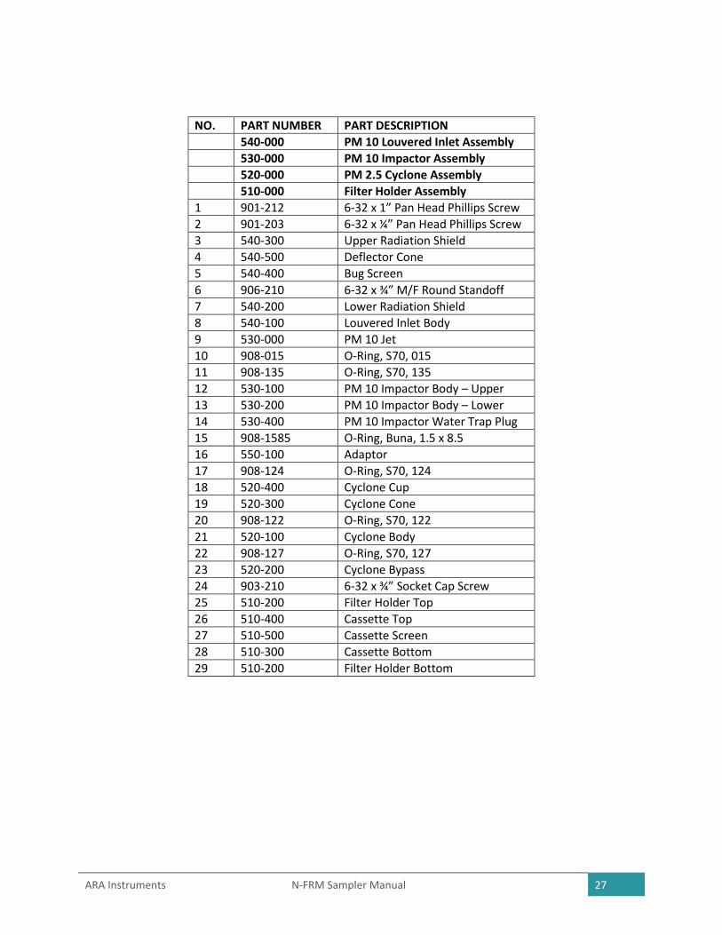
10 Parts List

ARA Instruments N-FRM Sampler Manual 26
PM 10 Louvered Inlet Assembly PM 10 Impactor Assembly
PN 540-000 PN 520-000
PM 2.5 Cyclone Assembly and Adaptor Filter Holder Assembly
PN 520-000 PN 510-000
ARA Instruments N-FRM Sampler Manual 27
NO. PART NUMBER PART DESCRIPTION
540-000 PM 10 Louvered Inlet Assembly
530-000 PM 10 Impactor Assembly
520-000 PM 2.5 Cyclone Assembly
510-000 Filter Holder Assembly
1 901-212 6-32 x 1” Pan Head Phillips Screw
2 901-203 6-32 x ¼” Pan Head Phillips Screw
3 540-300 Upper Radiation Shield
4 540-500 Deflector Cone
5 540-400 Bug Screen
6 906-210 6-32 x ¾” M/F Round Standoff
7 540-200 Lower Radiation Shield
8 540-100 Louvered Inlet Body
9 530-000 PM 10 Jet
10 908-015 O-Ring, S70, 015
11 908-135 O-Ring, S70, 135
12 530-100 PM 10 Impactor Body – Upper
13 530-200 PM 10 Impactor Body – Lower
14 530-400 PM 10 Impactor Water Trap Plug
15 908-1585 O-Ring, Buna, 1.5 x 8.5
16 550-100 Adaptor
17 908-124 O-Ring, S70, 124
18 520-400 Cyclone Cup
19 520-300 Cyclone Cone
20 908-122 O-Ring, S70, 122
21 520-100 Cyclone Body
22 908-127 O-Ring, S70, 127
23 520-200 Cyclone Bypass
24 903-210 6-32 x ¾” Socket Cap Screw
25 510-200 Filter Holder Top
26 510-400 Cassette Top
27 510-500 Cassette Screen
28 510-300 Cassette Bottom
29 510-200 Filter Holder Bottom

ARA Instruments N-FRM Sampler Manual 28
195 Pump Assembly
PN 195-000
NO. PART NUMBER PART DESCRIPTION
195-000 195 Pump Assembly
1 195-020/195-030 Pump Head (Right and Left)
2 195-100 Pump Valve
3 195-040 Pump Cylinder
4 195-140 Motor
5 195-080 .05 Cam
6 907-102 4-40 x 3/16” Set Screw
7 195-150 Bearing
8 911-300 5/16” C-Clip
9 195-130 Pump Mount Bracket
10 195-010 Pump Body
11 903-500 3mm x 8mm Socket Cap Screw
12 195-090 Pump Cover
13 195-050 Yoke
14 195-070 Piston Bottom
15 195-100 Pump Diaphragm
16 195-060 Piston Top
17 902-207 6-32 x ½” Flat Head Phillips Screw
18 903-216 6-32 x 1 ¼ ” Socket Cap Screw

ARA Instruments N-FRM Sampler Manual 29
Appendix A: Calibration Using an ARA FTS Flow Calibrator
Use the Quality Control Form located on the last page to record data easily in the field.
Calibrate Temperature
On the N-FRM Sampler Home Screen select SETUP and
then select SYSTEM SETUP. Scroll down and select
AMBIENT TEMPERATURE and then select OFFSET.
Change the value to 0.000 and select YES to save
changes.
Place the tip of the FTS Temperature Sensor into the
louvers and attach the clip onto the N-FRM Sampler
temperature radiation shield. Allow the sensors enough
time to equilibrate before recording the Indicated
Temperature (sampler) and Actual Temperature (FTS).
Determine the difference between the Indicated
Temperature and Actual Temperature to be used as the
offset value.
OFFSET = (FTS Temp) – (N-FRM Temp)
On the N-FRM Sampler Home Screen select SETUP and then select SYSTEM SETUP. Scroll down and
select AMBIENT TEMPERATURE and then select OFFSET. Change the value to the desired offset,
calculated above and select YES to save changes.
Calibrate Barometric Pressure
On the N-FRM Sampler Home Screen select SETUP and then select SYSTEM SETUP. Scroll down and
select BAROMETRIC PRESSURE and then select OFFSET. Change the value to 0.000 and select YES to
save changes.
Record the Indicated Barometric Pressure (N-FRM) and the Actual Barometric Pressure (FTS). Determine
the difference between the Indicated Barometric Pressure and the Actual Barometric Pressure to be
used as the offset value.
OFFSET = (FTS Barometric Pressure) – (N-FRM Barometric Pressure)
On the N-FRM Sampler Home Screen select SETUP and then select SYSTEM SETUP. Scroll down and
select BAROMETRIC PRESSURE and then select OFFSET. Change the value to the desired offset,
calculated above and select YES to save changes.

ARA Instruments N-FRM Sampler Manual 30
Calibrate Flow Rate
To calibrate an N-FRM Sampler, a multi-point calibration must be performed in order to determine the
calibration factors. These values can then be entered manually into the N-FRM Sampler.
FTS Calibrator:
• Select MODE:HOME and rotate the selector knob to select MODE:FLOW
• With no flow running through the VFD, select ZERO to zero the sensors
• After using the ZERO function, AMB FLOW, and STD FLOW should be 0.00 LPM. If not, select ZERO again to re-initialize the sensors.
• Connect the FRM adapter to the sampler inlet. The other end of the hose should be connected to the VFD outlet (right side).
N-FRM Sampler:
• From the Home Screen select SETUP
• Scroll down, select SYSTEM SETUP, and then select FLOW RATE
• Select SLOPE, turn knob to set slope to 1.000, and select YES to save changes
• Select INTERCEPT, turn knob to set intercept to 0.000 and select YES to save changes
• Select SET FLOW and adjust to 14.5 and select YES to save changes
• Select PUMP:OFF to turn the pump ON
• Allow the pump to run for a few minutes until the FTS Gas Temperature stabilizes
• Record the IND. FLOW from the N-FRM Sampler and the AMB. FLOW from the FTS Flow Calibrator
• Repeat the above steps, adjusting the SET FLOW to 15.5, 16.5, 17.5, and 18.5.
Calculations:
For easy calculations, our Calibration Worksheet Excel file is available for download on the Support page on our website, www.arainstruments.com/support, or you can create your own.
Input the Indicated Flow Rate and Actual Flow Rate values into the spreadsheet. Determine the Slope and Intercept.
Figure 9. Determine Slope and Intercept in Excel.

ARA Instruments N-FRM Sampler Manual 31
Change the Slope and Intercept on the N-FRM Sampler:
• From the Home Screen select SETUP
• Scroll down, select SYSTEM SETUP, and then select FLOW RATE
• Select SLOPE and turn knob to desired value
• Select YES to save changes
• Select INTERCEPT and turn knob to desired value
• Select YES to save changes

QUALITY CONTROL FORM
SITE INFORMATION
Location:_________________ Sampler:______________________________ Serial No:___________
Tech:____________________ Flow Rate Standard:_____________________ Serial No:___________
Date:____________________ Temperature Standard:__________________ Serial No:___________
Time:____________________ Pressure Standard:______________________ Serial No:___________ MAINTENANCE SCHEDULE
Weekly: Service Water Trap
Monthly: Clean PM10 Inlet, PM2.5 Cyclone, Filter Holder, and RTP Profiler Filter
Inspect O-Rings
Perform Leak Check
Perform flow, temperature, pressure, and clock verification
Annually: Replace PM10 Inlet, PM2.5 Cyclone, and Filter Holder O-Rings
Rebuild Pump
Perform flow, temperature, and pressure calibrations
AUDIT RESULTS
ACTION INDICATED (Sampler)
ACTUAL (FTS)
% DIFFERENCE CONTROL LIMITS
Flow Rate (LPM) 4%
Ambient Temp. (°C) ± 2°C
Barometric Pressure (mmHg) ±10 mmHg
Clock Time ±2 min/mo
Leak Check 0.00 LPM
Comments:______________________________________________________________________________________________________________________________________________________________________________________________________________________________________________________ MULTI-POINT CALIBRATION
SET FLOW (LPM)
INDICATED FLOW (Sampler)
ACTUAL FLOW (FTS)
14.5
15.5
16.5
17.5
18.5
INITIAL FINAL
SLOPE:
INTERCEPT: