arbitrary waveform generator - test equipment center · data sheet figure1: 5gb/s pre/de-emphasized...
TRANSCRIPT

Arbitrary Waveform GeneratorAWG7102 • AWG7101 • AWG7052 • AWG7051 Data Sheet
Features & Benefits10 GS/s (20 GS/s) and 5 GS/s Models1 or 2 Arbitrary Waveform Outputs
Accurate Timing with only 20 psp-p Total Jitter (at 10-12 BER, Typical)45 ps Tr/Tf (20% to 80%)±100 ps Range (1 ps Resolution) Interchannel Skew Control
2 or 4 Variable-level Marker OutputsAccurate Timing with only 30 psp-p Total Jitter (at 10-12 BER, Typical)45 ps Tr/Tf (20% to 80%)Up to 300 ps Range (1 ps Resolution) Delay Control
Vertical Resolution up to 10 bit Available: 10 bits (No Marker Output) or8 bits (with Two Marker Outputs)Up to 64 M (64,800,000) Point Record Length Provides Longer DataStreamsDown to 100 fs Resolution Edge Timing Shift ControlSequencing Creates Infinite Waveform Loops, Jumps, and ConditionalBranchesReal-time Sequencing Creates Infinite Waveform Loops, Jumps, andConditional BranchesIntuitive User Interface Shortens Test TimeIntegrated PC Supports Network Integration and Provides a Built-inDVD, Removable Hard Drive, LAN, and USB Ports
ApplicationsDisk Drive (Magnetic/Optical) Read/Write:
Up to 5 Gb/s Data Rate (2 Points/Cell) or 50 ps Timing Resolution
Telecom/Data Communications:Up to 10 Gb/s Data Rate (Binary, Pre/De-emphasis, and MultilevelLogic)
Wireless Communications:Up to 5 GHz (4 Waveform Points/Cycle) Arbitrary RF/IF andWide-bandwidth Modulation I and Q Baseband Signals
Mixed-signal Design and Test:2-channel Analog plus 4-channel Marker Outputs
High-speed, Low-jitter Data/Pulse and Clock Source
Real-world, Ideal, or Distorted Signal Generation – Including All theGlitches, Anomalies, and Impairments
Enhanced/Corrupted Playback of DSO Captured Signals
Waveform Vectors Imported from Third-party Tools such as MATLAB,MathCAD, Excel, and Others
The AWG7000 Series of Arbitrary WaveformGenerators Delivers the Industry’s BestMixed-signal Stimulus Solution forEver-increasingMeasurement ChallengesThe AWG7000 Series Arbitrary Waveform Generator delivers a uniquecombination of superior signal stimulus, unrivaled sample rate, bandwidthand signal fidelity, and uncompromised usability.This family offers the industry’s best solution to the challenging signalstimulus issues faced by designers verifying, characterizing, and debuggingsophisticated electronic designs.With sample rates from 5 GS/s to 20 GS/s (10 bits), together with 1 to2 output channels, the toughest measurement challenges in the diskdrive, communications, digital consumer, and semiconductor design/testindustries can be easily solved.The open Windows (Windows XP)-based instruments deliver ease of useand allow connectivity with peripherals and compatibility with third-partysoftware.
Data Sheet
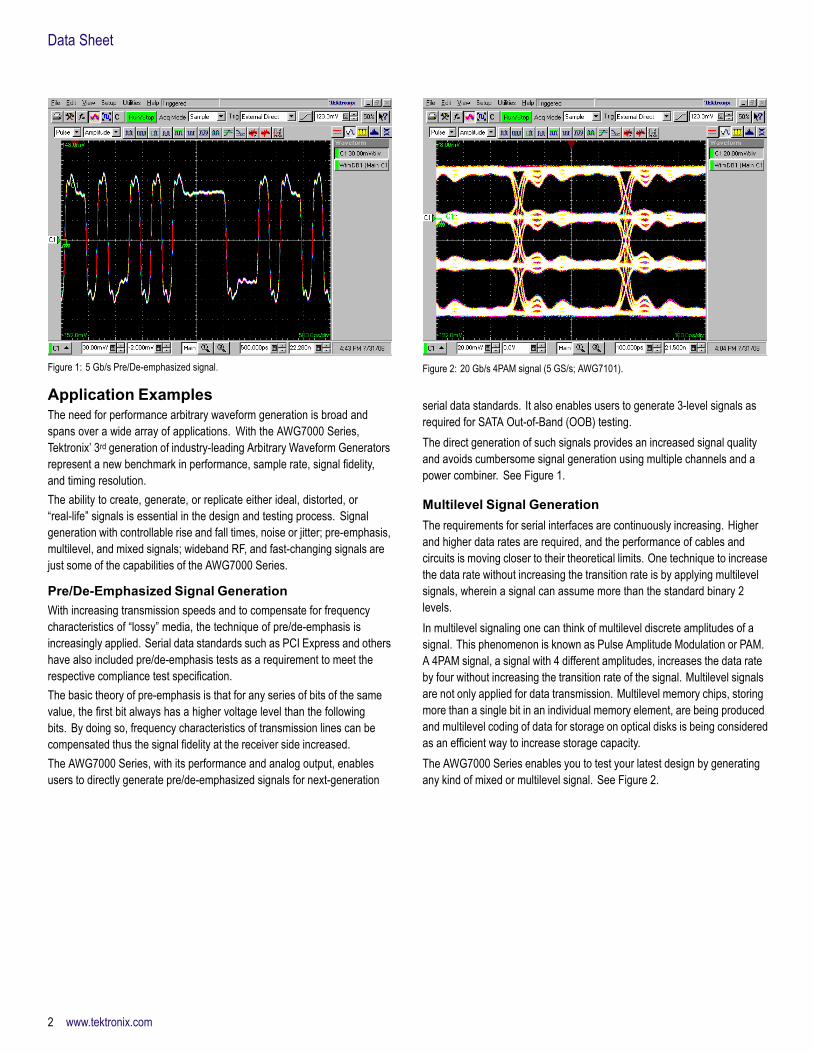
Figure 1: 5 Gb/s Pre/De-emphasized signal.
Application ExamplesThe need for performance arbitrary waveform generation is broad andspans over a wide array of applications. With the AWG7000 Series,Tektronix’ 3rd generation of industry-leading Arbitrary Waveform Generatorsrepresent a new benchmark in performance, sample rate, signal fidelity,and timing resolution.The ability to create, generate, or replicate either ideal, distorted, or“real-life” signals is essential in the design and testing process. Signalgeneration with controllable rise and fall times, noise or jitter; pre-emphasis,multilevel, and mixed signals; wideband RF, and fast-changing signals arejust some of the capabilities of the AWG7000 Series.
Pre/De-Emphasized Signal GenerationWith increasing transmission speeds and to compensate for frequencycharacteristics of “lossy” media, the technique of pre/de-emphasis isincreasingly applied. Serial data standards such as PCI Express and othershave also included pre/de-emphasis tests as a requirement to meet therespective compliance test specification.The basic theory of pre-emphasis is that for any series of bits of the samevalue, the first bit always has a higher voltage level than the followingbits. By doing so, frequency characteristics of transmission lines can becompensated thus the signal fidelity at the receiver side increased.The AWG7000 Series, with its performance and analog output, enablesusers to directly generate pre/de-emphasized signals for next-generation
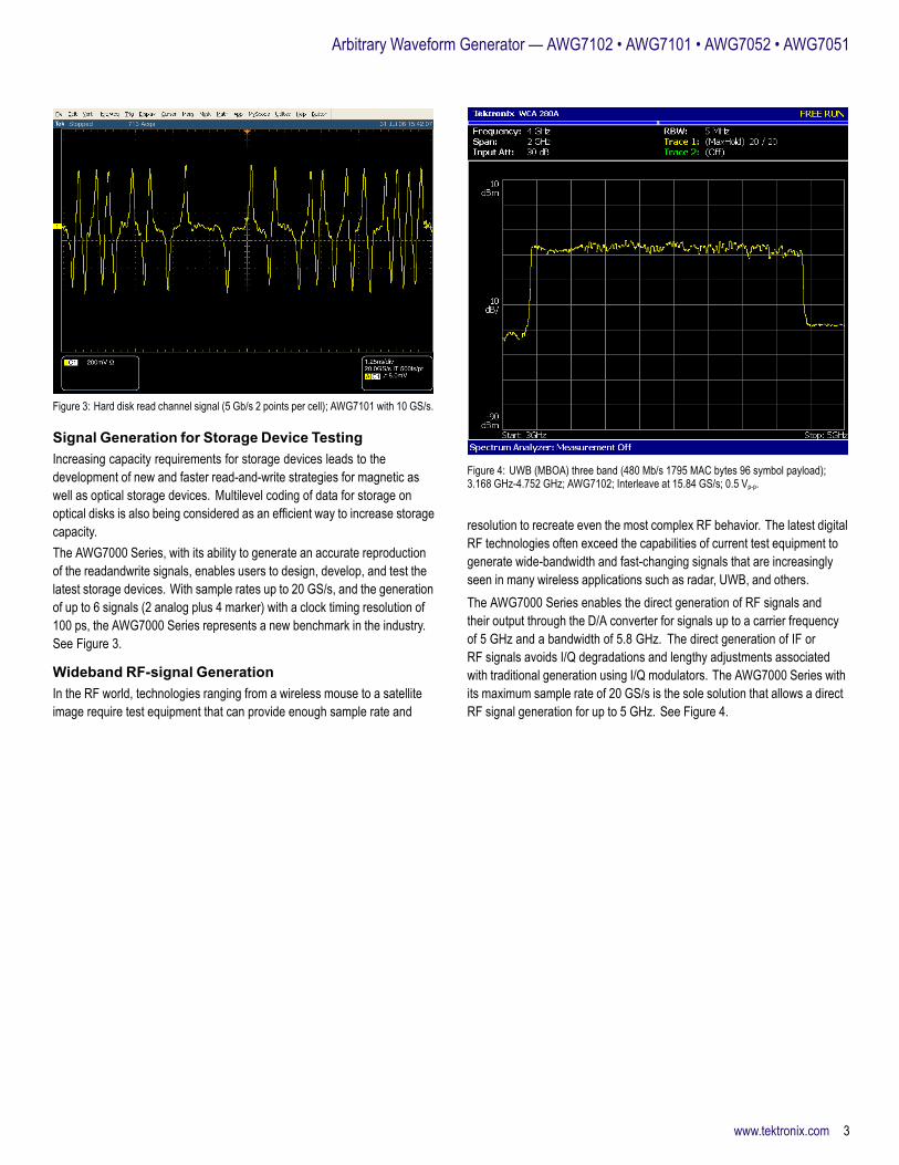
Figure 2: 20 Gb/s 4PAM signal (5 GS/s; AWG7101).
serial data standards. It also enables users to generate 3-level signals asrequired for SATA Out-of-Band (OOB) testing.The direct generation of such signals provides an increased signal qualityand avoids cumbersome signal generation using multiple channels and apower combiner. See Figure 1.
Multilevel Signal GenerationThe requirements for serial interfaces are continuously increasing. Higherand higher data rates are required, and the performance of cables andcircuits is moving closer to their theoretical limits. One technique to increasethe data rate without increasing the transition rate is by applying multilevelsignals, wherein a signal can assume more than the standard binary 2levels.In multilevel signaling one can think of multilevel discrete amplitudes of asignal. This phenomenon is known as Pulse Amplitude Modulation or PAM.A 4PAM signal, a signal with 4 different amplitudes, increases the data rateby four without increasing the transition rate of the signal. Multilevel signalsare not only applied for data transmission. Multilevel memory chips, storingmore than a single bit in an individual memory element, are being producedand multilevel coding of data for storage on optical disks is being consideredas an efficient way to increase storage capacity.The AWG7000 Series enables you to test your latest design by generatingany kind of mixed or multilevel signal. See Figure 2.
2 www.tektronix.com
Arbitrary Waveform Generator — AWG7102 • AWG7101 • AWG7052 • AWG7051
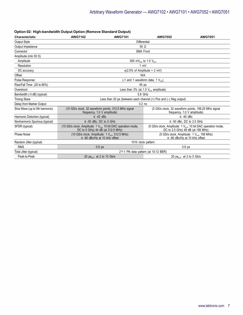
Figure 3: Hard disk read channel signal (5 Gb/s 2 points per cell); AWG7101 with 10 GS/s.
Signal Generation for Storage Device TestingIncreasing capacity requirements for storage devices leads to thedevelopment of new and faster read-and-write strategies for magnetic aswell as optical storage devices. Multilevel coding of data for storage onoptical disks is also being considered as an efficient way to increase storagecapacity.The AWG7000 Series, with its ability to generate an accurate reproductionof the readandwrite signals, enables users to design, develop, and test thelatest storage devices. With sample rates up to 20 GS/s, and the generationof up to 6 signals (2 analog plus 4 marker) with a clock timing resolution of100 ps, the AWG7000 Series represents a new benchmark in the industry.See Figure 3.
Wideband RF-signal GenerationIn the RF world, technologies ranging from a wireless mouse to a satelliteimage require test equipment that can provide enough sample rate and
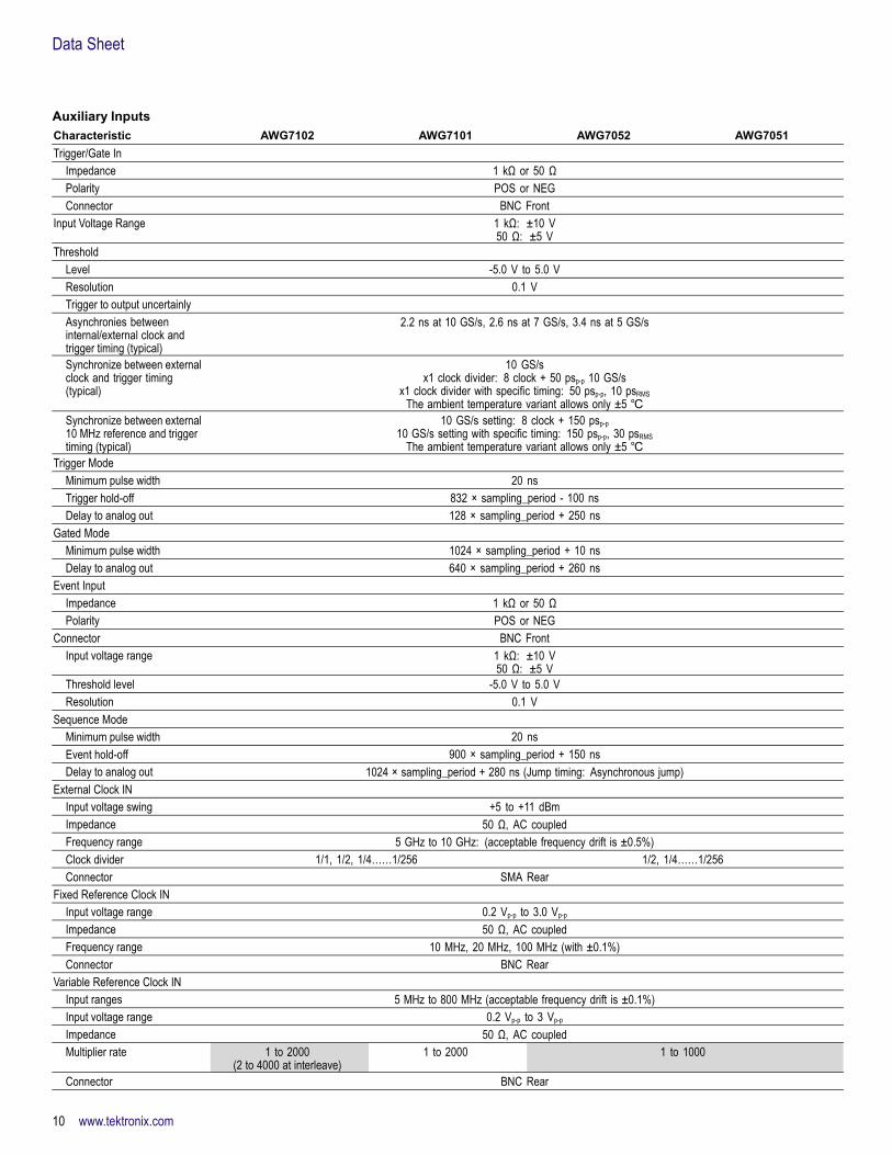
Figure 4: UWB (MBOA) three band (480 Mb/s 1795 MAC bytes 96 symbol payload);3.168 GHz-4.752 GHz; AWG7102; Interleave at 15.84 GS/s; 0.5 Vp-p.
resolution to recreate even the most complex RF behavior. The latest digitalRF technologies often exceed the capabilities of current test equipment togenerate wide-bandwidth and fast-changing signals that are increasinglyseen in many wireless applications such as radar, UWB, and others.The AWG7000 Series enables the direct generation of RF signals andtheir output through the D/A converter for signals up to a carrier frequencyof 5 GHz and a bandwidth of 5.8 GHz. The direct generation of IF orRF signals avoids I/Q degradations and lengthy adjustments associatedwith traditional generation using I/Q modulators. The AWG7000 Series withits maximum sample rate of 20 GS/s is the sole solution that allows a directRF signal generation for up to 5 GHz. See Figure 4.
www.tektronix.com 3

Data Sheet
Additional Software Application ToolsExtendingWaveformGeneration
RFXpress (RFX100)RFXpress is a software package that synthesizes digitally modulatedbaseband, IF, and RF signals. It takes IQ, IF, and RF signal generation tothe next level and fully exploits the wideband signal generation capabilitiesof Arbitrary Waveform Generators (AWGs). Supporting a wide range ofmodulations, as well as the symbol map functions, the software allows youto define your own modulation.UWB-WiMedia signal creation, a software module for RFXpress, has thecapability to digitally synthesize and generate RF signals in Band Groups 1and 2 of the UWB spectrum. As per the latest WiMedia specification, signalswill band hop in real-time over 1.5 GHz modulation bandwidth including all
the different preamble synchronization sequences, cover sequences, TFCs,and band groups. All six band groups (BG1 to BG6) can be generatedwith band hopping in either IQ or IF. The conformance mode enables youto generate all signals that conform to WiMedia’s specifications, while thecustom mode allows you to adjust the signals for stress and margin testing.
SerialXpress® (SDX100)SerialXpress enables creation of exact waveforms required forthorough and repeatable design validation, margin/characterization, andconformance testing of high-speed serial data receivers. It considerablysimplifies the signal creation and Jitter simulations, thus reducing overalldevelopment and test time. In addition to supporting generation of Jitter(Random, Periodic (sinusoidal), ISI, and DCD) SerialXpress also supportsSSC, pre-emphasis, and noise addition. This allows the user to create acombination of various impairments simultaneously to stress the receiver.Both RFXpress and SerialXpress are powerful easy-to-use softwarepackages to synthesize RF and high-speed serial data signals respectivelyfor arbitrary waveform generators (AWG). It runs as an integral part of theAWG7000 Series arbitrary waveform generators or from an external PC.
4 www.tektronix.com

Arbitrary Waveform Generator — AWG7102 • AWG7101 • AWG7052 • AWG7051
CharacteristicsArbitrary WaveformsCharacteristic AWG7102 AWG7101 AWG7052 AWG7051Waveform Length 2 to 32,400,000 points (or 2
to 64,800,000 points, Option01) in multiples of 64
Interleave:2 to 64,800,000 points (or 2
to 129,600,000 points, Option01) in multiples of 128
2 to 32,400,000 points (or 2 to 64,800,000 points, Option 01) in multiples of 64
Number of Waveforms 1 to 16,000Sequence Length 1 to 4,000 stepsSequence Repeat Counter 1 to 65,536 or infiniteSequence Control Repeat count, Wait for Trigger, Go-to-N, and JumpJump Mode Synchronous and AsynchronousRun Modes
Continuous Waveform is iteratively output. If a sequence is defined, the sequence order and repeat functions are appliedTriggered Waveform is output only once when an external, internal, GPIB, LAN, or manual trigger is receivedGated Waveform begins output when gate is true and resets to beginning when falseSequence Waveform is output as defined by the sequenceInterleave operation Up to 20 GS/s sample rate
(Option 06)N/A
Clock GeneratorSampling frequency 10 MS/s to 10 GS/s
(10 GS/s to 20 GS/s at interleave)10 MS/s to 10 GS/s 10 MS/s to 5 GS/s
Resolution 8 digitsInternal Clock
Accuracy Within ±(1 ppm + Aging)Aging: within ±1 ppm/year
Clock phase noise < -90 dBc/Hz at 100 kHz offsetInternal Trigger GeneratorInternal Trigger Rate
Range 1.0 μs to 10.0 sResolution 3 digits, 0.1 μs minimum
Skew Control Between OutputsRange -100 ps to +100 ps N/A -100 ps to +100 ps N/AResolution 1 ps N/A 1 ps N/ASkew accuracy ±(10% of setting +10 ps) N/A ±(10% of setting +10 ps) N/A
www.tektronix.com 5

Data Sheet
Main Arbitrary Waveform OutputCharacteristic AWG7102 AWG7101 AWG7052 AWG7051Digital to Analog Converter
Resolution 10 bit (no marker output) or 8 bit (2 ch markets available): each channel selectableStandard Output (into 50 Ω)
Number of arb outputs 2 1 2 1Output style DifferentialOutput impedance 50 ΩConnector SMA Front
AmplitudeAmplitude
Normal 50 mVp-p to 2.0 Vp-p
Direct 50 mV to 1.0 Vp-p
Resolution 1 mVDC accuracy ±(3.0% of Amplitude + 2 mV) at offset = 0 V
OffsetRange
Normal -0.5 V to +0.5 VDirect N/A
Resolution 1 mVAccuracy ±(2% of offset ±10 mV) at minimum amplitudePulse response (-1 and 1 waveform data, 0 V offset, through filter at 1 Vp-p)
Rise/Fall Time (20 to 80%)Normal 350 ps (at 2 0 Vp-p)Direct 75 ps (at 1.0 Vp-p)
Overshoot Less than 10% (at 1.0 Vp-p amplitude)Bandwidth (-3 dB) (typical)
Normal 750 MHzDirect 3.5 GHz
Timing skew Less than 20 ps (Direct output; between each channel (+) Pos and (–) Neg output)Low-pass filter
Normal 50 MHz, 200 MHz (Bessel type)Direct N/A
Delay from marker output Normal: 50 MHz (9.7 ns), 200 MHz (3.9 ns), Through (2.1 ns), Direct (0.5 ns)Sine wave (up to 5th harmonic) (10 GS/s clock, 32 waveform points, 312.5 MHz signal
frequency, 1.0 V amplitude)(5 GS/s clock, 32 waveform points, 156.25 MHz signal
frequency, 1.0 V amplitude)Harmonic distortion (typical)
Normal ≤ -35 dBc ≤ -40 dBcDirect ≤ -42 dBc ≤ -45 dBc
Nonharmonic spurious (typical)Normal ≤ -50 dBc (DC to 5 GHz) ≤ -50 dBc (DC to 2.5 GHz)
SFDR (typical) (10 GS/s clock, Amplitude: 1 Vp-p, Offset: 0 V, filter: “through,”10 bit DAC operation mode, DC to 5 GHz)
(5 GS/s clock, Amplitude: 1 Vp-p, Offset: 0 V, filter: “through,”10 bit DAC operation mode, DC to 2.5 GHz)
Normal 45 dB 51 dBDirect 45 dB (at 312.5 MHz) 51 dB (at 156 MHz)
Phase noise (10 GS/s clock, Amplitude: 1 Vp-p, Offset: 0 V, 312.5 MHz)≤ -90 dBc/Hz at 10 kHz offset
(5 GS/s clock, Amplitude: 1 Vp-p, Offset: 0 V, 156 MHz)≤ -90 dBc/Hz at 10 kHz offset
Random Jitter (typical) 1010 clock patternRMS
Normal 1.6 ps 1.6 psDirect 0.9 ps 0.9 ps
Total Jitter (typical) 215-1 PN data pattern (at 10-12 BER)Peak-to-Peak
Normal 50 ps at 0.5 Gb/s 50 ps at 0.5 Gb/sDirect 30 ps at 1 to 6 Gb/s 30 ps at 1 to 5 Gb/s
6 www.tektronix.com
Arbitrary Waveform Generator — AWG7102 • AWG7101 • AWG7052 • AWG7051
Option 02: High-bandwidth Output Option (Remove Standard Output)Characteristic AWG7102 AWG7101 AWG7052 AWG7051Output Style DifferentialOutput Impedance 50 ΩConnector SMA FrontAmplitude (into 50 Ω)
Amplitude 500 mVp-p to 1.0 Vp-p
Resolution 1 mVDC accuracy ±(2.0% of Amplitude + 2 mV)
Offset N/APulse Response (-1 and 1 waveform data, 1 Vp-p)Rise/Fall Time: (20 to 80%) 45 psOvershoot Less than 3% (at 1.0 Vp-p amplitude)Bandwidth (-3 dB) (typical) 5.8 GHzTiming Skew Less than 20 ps (between each channel (+) Pos and (–) Neg output)Delay from Marker Output 0.2 nsSine Wave (up to 5th harmonic) (10 GS/s clock, 32 waveform points, 312.5 MHz signal
frequency, 1.0 V amplitude)(5 GS/s clock, 32 waveform points, 156.25 MHz signal
frequency, 1.0 V amplitude)Harmonic Distortion (typical) ≤ -42 dBc ≤ -45 dBcNonharmonic Spurious (typical) ≤ -50 dBc, DC to 5 GHz ≤ -50 dBc, DC to 2.5 GHzSFDR (typical) (10 GS/s clock, Amplitude: 1 Vp-p, 10 bit DAC operation mode,
DC to 5 GHz) 44 dB (at 312.5 MHz)(5 GS/s clock, Amplitude: 1 Vp-p, 10 bit DAC operation mode,
DC to 2.5 GHz) 48 dB (at 156 MHz)Phase Noise (10 GS/s clock, Amplitude: 1 Vp-p, 312.5 MHz)
≤ -90 dBc/Hz at 10 kHz offset(5 GS/s clock, Amplitude: 1 Vp-p, 156 MHz)
≤ -90 dBc/Hz at 10 kHz offsetRandom Jitter (typical) 1010 clock pattern
RMS 0.9 ps 0.9 psTotal Jitter (typical) 215-1 PN data pattern (at 10-12 BER)
Peak-to-Peak 20 psp-p: at 2 to 10 Gb/s 20 psp-p: at 2 to 5 Gb/s
www.tektronix.com 7

Data Sheet
Option 06: Interleaved High-bandwidth Output in Addition to Option 02 (Remove Standard Output)Available for only AWG7102Characteristic DescriptionOutput Style DifferentialOutput Impedance 50 ΩConnector SMA FrontZeroing Control On or OffAmplitude (into 50 Ω)
Amplitude Zeroing On: 250 mVp-p to 0.5 Vp-pZeroing Off: 500 mVp-p to 1.0 Vp-p
Resolution 1 mVDC accuracy (typical) ±(8.0% of Amplitude + 2 mV) at offset = 0 V
Offset N/APulse Response
Rise/Fall time: (20 to 80%) 45 psOvershoot Less than 10% (at 1.0 Vp-p amplitude)Bandwidth (-3 dB) (typical) 5.8 GHzDelay from Marker Output 1.0 nsSine Wave (up to 5th harmonic) (20 GS/s clock, 32 waveform points, 625 MHz signal frequency)Harmonics Distortion Zeroing On: ≤ -40 dBc (0.5 Vp-p)
Zeroing Off: ≤ -40 dBc (1 Vp-p)Nonharmonic Spurious DC to 5 GHz
Zeroing On: ≤ -45 dBc (0.5 Vp-p)Zeroing Off: ≤ -45 dBc (1 Vp-p)
SFDR (typical) (20 GS/s clock, 10 bit DAC operation mode, DC to 10 GHz)2.5 GHz –Zeroing On: 30 dBZeroing Off: 40 dB
Phase Noise (20 GS/s clock, 625 MHz)At 10 kHz offset –Zeroing On: ≤ -85 dBc/Hz (0.5 Vp-p)Zeroing Off: ≤ -85 dBc/Hz (1 Vp-p)
8 www.tektronix.com

Arbitrary Waveform Generator — AWG7102 • AWG7101 • AWG7052 • AWG7051
Auxiliary OutputsCharacteristic AWG7102 AWG7101 AWG7052 AWG7051Marker Output
Number of outputs 4 (2 per channel) 2 4 (2 per channel) 2Output style DifferentialOutput impedance 50 ΩConnector SMA Front
Level (into 50 Ω) (Twice for Hi_Z Input)Output window -1.4 V to +1.4 VAmplitude 0.5 Vp-p to 1.4 Vp-p
Resolution 10 mVExternal termination -2.8 V to +2.8 VLevel accuracy ±(10% of setting + 50 mV)Rise/Fall time (20% to 80%) 45 ps (1.0 Vp-p, Hi +1.0 V, Lo 0 V)
Marker Timing SkewIntra Skew <13 ps (between each channel (+) Pos and (–) Neg output) (typical)In same channel <30 ps (between Marker 1 and Marker 2 output) (typical)
Delay Control Between MarkersRange 0 to 300 psResolution 1 psAccuracy ±(5% of setting + 50 ps)
Random Jitter (typical) 1010 clock patternRMS 1 ps 1 ps
Total Jitter (typical) 215-1 PN data pattern (at 10-12 BER)Peak-to-Peak 30 psp-p 30 psp-p
10 MHz Reference OutAmplitude 1.2 Vp-p into 50 Ω. Max 2.5 Vp-p openImpedance 50 Ω, AC couplingConnector BNC Rear
DC OutputsNumber of outputs 4: Independently controlled outputsRange -3.0 to +5.0 VResolution 10 mVMax. current ±30 mAConnector 2×4 Pin Header on front panel
www.tektronix.com 9
Data Sheet
Auxiliary InputsCharacteristic AWG7102 AWG7101 AWG7052 AWG7051Trigger/Gate In
Impedance 1 kΩ or 50 ΩPolarity POS or NEGConnector BNC Front
Input Voltage Range 1 kΩ: ±10 V50 Ω: ±5 V
ThresholdLevel -5.0 V to 5.0 VResolution 0.1 VTrigger to output uncertainlyAsynchronies betweeninternal/external clock andtrigger timing (typical)
2.2 ns at 10 GS/s, 2.6 ns at 7 GS/s, 3.4 ns at 5 GS/s
Synchronize between externalclock and trigger timing(typical)
10 GS/sx1 clock divider: 8 clock + 50 psp-p 10 GS/s
x1 clock divider with specific timing: 50 psp-p, 10 psRMSThe ambient temperature variant allows only ±5
Synchronize between external10 MHz reference and triggertiming (typical)
10 GS/s setting: 8 clock + 150 psp-p10 GS/s setting with specific timing: 150 psp-p, 30 psRMS
The ambient temperature variant allows only ±5 Trigger Mode
Minimum pulse width 20 nsTrigger hold-off 832 × sampling_period - 100 nsDelay to analog out 128 × sampling_period + 250 ns
Gated ModeMinimum pulse width 1024 × sampling_period + 10 nsDelay to analog out 640 × sampling_period + 260 ns
Event InputImpedance 1 kΩ or 50 ΩPolarity POS or NEG
Connector BNC FrontInput voltage range 1 kΩ: ±10 V
50 Ω: ±5 VThreshold level -5.0 V to 5.0 VResolution 0.1 V
Sequence ModeMinimum pulse width 20 nsEvent hold-off 900 × sampling_period + 150 nsDelay to analog out 1024 × sampling_period + 280 ns (Jump timing: Asynchronous jump)
External Clock INInput voltage swing +5 to +11 dBmImpedance 50 Ω, AC coupledFrequency range 5 GHz to 10 GHz: (acceptable frequency drift is ±0.5%)Clock divider 1/1, 1/2, 1/4……1/256 1/2, 1/4……1/256Connector SMA Rear
Fixed Reference Clock INInput voltage range 0.2 Vp-p to 3.0 Vp-p
Impedance 50 Ω, AC coupledFrequency range 10 MHz, 20 MHz, 100 MHz (with ±0.1%)Connector BNC Rear
Variable Reference Clock INInput ranges 5 MHz to 800 MHz (acceptable frequency drift is ±0.1%)Input voltage range 0.2 Vp-p to 3 Vp-p
Impedance 50 Ω, AC coupledMultiplier rate 1 to 2000
(2 to 4000 at interleave)1 to 2000 1 to 1000
Connector BNC Rear
10 www.tektronix.com

Arbitrary Waveform Generator — AWG7102 • AWG7101 • AWG7052 • AWG7051
AWG7000 Series Common FeaturesCharacteristic Description
Tektronix DPO7000/TDS5000/6000/7000 (*.wfm),TDS3000 (*.ISF)AWG400s/500s/610/615/710/710B (*.wfm, *.pat, *.seq)
Waveform File ImportCapability
Text data file (third-party software creation waveformdata: MATLAB, MathCad, Excel)
S/W Driver for Third-partyS/W
IVI-COM driver
Instrument Control / Data Transfer PortsGPIB*1 Remote control and data transfer. (Conforms to
IEEE-Std 488.1, compatible with IEEE 488.2 andSCPI-1999.0)
Ethernet(10/100/1000Base-T)*1
Remote control and data transfer. (Conforms to IEEE802.3). RJ-45
Computer system andperipherals
Windows XP Professional, 512 MB SDRAM, 20 GBremovable Hard Drive at rear (available front mountkit), CD-RW/DVD drive at front, included USB compactkeyboard and mouse
PC I/O ports USB 2.0 compliant ports (6 total, 2 front, 4 rear),PS/2 mouse and keyboard connectors (rear panel),RJ-45 Ethernet connector (rear panel) supports10/100/1000Base-T, XGA out
Display 10.4 inch, LCD color display with touchscreen, 1024(H) × 768 (V) (XGA)
Power Supply 100 to 240 VAC, 47 to 63 HzPower consumption 450 W
Safety UL61010-1,CAN/CSA-22.2, No.61010-1-04,EN61010-1, IEC61010-1
Emissions EN 55011 (Class A), IEC61000-3-2, IEC61000-3-3Immunity IEC61326, IEC61000-4-2/3/4/5/6/8/11Regional Certifications
Europe EN61326Australia /New Zealand
AS/NZS 2064
*1 Supported by MATLAB software through MATLAB Instrument Control Toolbox.
Physical CharacteristicsDimension mm in.Height 245 9.6Width 465 18.0Length 500 19.7Weight (approx.) kg lb.Net 19 41.9Net with Package 28 61.7Mechanical Cooling Required ClearanceTop and Bottom 2 cm 0.8 in.Side 15 cm 6 in.Rear 7.5 cm 3 in.
EnvironmentalCharacteristic Operation NonoperationTemperature +10 °C to +40 °C -20 °C to +60 °CHumidity 5% to 80% relative
humidity (% RH) at upto +30 °C
5% to 45% RH above+30 °C up to +50 °C
5% to 90% relativehumidity (% RH) at up
to +30 °C5% to 45% RH above+30 °C up to +50 °C
Altitude Up to 3,048 meters(10,000 feet)
Up to 12,192 meters(40,000 feet)
Random Vibration 0.27 GRMS, 5 to 500 Hz,10 minutes per axis
2.28 GRMS, 5 to 500 Hz,10 minutes per axis
Sine Vibration 0.33 mmp-p (0.013 in.p-p)constant displacement,
5 to 55 Hz
—
Mechanical Shock Half-sine mechanicalshocks, 30 g peak
amplitude 11 ms duration,3 drops in each direction
of each axis
—
AWG7101AWG7102AWG7052AWG7051
AWG7101AWG7051AWG7052
AWG7102
Standard Option 02 Option 06 (Including Option 02)
Characteristic
Normal Out Direct Out High Bandwidth High Bandwidthwithout Interleave
High Bandwidth withInterleave, ZeroingOff, (Zeroing On)
Maximum Amplitude 2 Vp-p 1 Vp-p 1 Vp-p 1 Vp-p 1 Vp-p (0.5 Vp-p )Minimum Amplitude 50 mVp-p 50 mVp-p 500 mVp-p 500 mVp-p 500 mVp-p (250 mVp-p)Offset ±500 mV N/A N/A N/A N/ATr/Tf (20 to 80%) 350 ps 75 ps 45 ps 45 ps 45 psOutput Bandwidth 750 MHz 3.5 GHz 5.8 GHz 5.8 GHz 5.8 GHz
www.tektronix.com 11

Data Sheet
Ordering InformationArbitrary Waveform Generator MainframeAWG710210.0 GS/s (20 GS/s interleaved), 8/10 bit, 32 M point, 2-channel arbitrary waveformgenerator.
AWG710110.0 GS/s, 8/10 bit, 32 M point, 1-channel arbitrary waveform generator.
AWG70525.0 GS/s, 8/10 bit, 32 M point, 2-channel arbitrary waveform generator.
AWG70515.0 GS/s, 8/10 bit, 32 M point, 1-channel arbitrary waveform generator.All Models Include: Accessory pouch, front cover, USB mouse, compact USBkeyboard, lead set for DC Output, stylus for touchscreen (2 each), Windows XPoperating system restore DVD and instructions, AWG7000 Series product softwareCD and instructions, Document CD with Browser, Quick Start User Manual,registration card, Certificate of Calibration, power cable, 50 Ω SMA Terminator (3each) (015-1022-xx).Please specify power cord and language option when ordering.
Instrument Options
Product OptionsOption DescriptionAWG7102Opt. 01 Waveform Length Expansion (from 32 M to 64 M)Opt. 06 High-bandwidth output with 20 GS/s interleaved
including Opt. 02 features (alternative for standardoutput)
AWG7101, AWG7052, AWG7051Opt. 01 Waveform Length Expansion (from 32 M to 64 M)Opt. 02 High-bandwidth output (alternative for standard output)
Common OptionsOption DescriptionInternational Power PlugsOpt. A0 North AmericaOpt. A1 Universal EUROOpt. A2 United KingdomOpt. A3 AustraliaOpt. A5 SwitzerlandOpt. A6 JapanOpt. A10 ChinaOpt. A11 IndiaOpt. A99 No power cord or AC adapterLanguage OptionsOpt. L0 EnglishOpt. L5 Japanese
ServiceThe following service options and programs are available for AWG7000s(AWG7102, AWG7101, AWG7052, AWG7051).Option DescriptionService Option: (for example, AWG7102 Opt. C3)Opt. CA1 A single calibration eventOpt. C3 Calibration Service 3 YearsOpt. C5 Calibration Service 5 YearsOpt. D1 Calibration Data ReportOpt. D3 Calibration Data Report 3 Years (with Opt. C3)Opt. D5 Calibration Data Report 5 Years (with Opt. C5)Opt. R3 Repair Service 3 YearsOpt. R5 Repair Service 5 YearsService Post-sales Offering: (for example, AWG7102-CA1).CA1 A single calibration eventR3DW Repair service coverage 3 yearsR5DW Repair service coverage 5 yearsR2PW Repair service coverage 2 years post warrantyR1PW Repair service coverage 1 year post warranty
Product UpgradeProduct Ordering Options DescriptionAWG7102 AWG70UP Opt. M12AWG7052 AWG70UP Opt. M02AWG7101 AWG70UP Opt. M11AWG7051 AWG70UP Opt. M01
Waveform LengthExpansion 32 M
point to 64 M point.
12 www.tektronix.com
Arbitrary Waveform Generator — AWG7102 • AWG7101 • AWG7052 • AWG7051
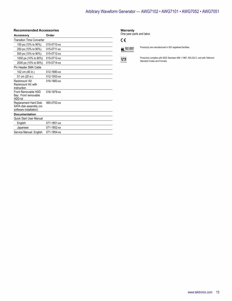
Recommended AccessoriesAccessory OrderTransition Time Converter
150 ps (10% to 90%) 015-0710-xx250 ps (10% to 90%) 015-0711-xx500 ps (10% to 90%) 015-0712-xx1000 ps (10% to 90%) 015-0713-xx2000 ps (10% to 90%) 015-0714-xx
Pin Header SMA Cable102 cm (40 in.) 012-1690-xx51 cm (20 in.) 012-1503-xx
Rackmount Kit:Rackmount Kit withinstruction
016-1983-xx
Front Removable HDDBay: Front removableHDD kit
016-1979-xx
Replacement Hard Disk:SATA disk assembly (nosoftware installation)
065-0753-xx
DocumentationQuick Start User Manual
English 071-1851-xxJapanese 071-1852-xx
Service Manual: English 071-1854-xx
WarrantyOne-year parts and labor.
Product(s) are manufactured in ISO registered facilities.
Product(s) complies with IEEE Standard 488.1-1987, RS-232-C, and with TektronixStandard Codes and Formats.
www.tektronix.com 13
Data Sheet Contact Tektronix:ASEAN / Australasia (65) 6356 3900
Austria +41 52 675 3777
Balkans, Israel, South Africa and other ISE Countries +41 52 675 3777
Belgium 07 81 60166
Brazil +55 (11) 40669400
Canada 1 (800) 661-5625
Central East Europe, Ukraine, and the Baltics +41 52 675 3777
Central Europe & Greece +41 52 675 3777
Denmark +45 80 88 1401
Finland +41 52 675 3777
France +33 (0) 1 69 86 81 81
Germany +49 (221) 94 77 400
Hong Kong (852) 2585-6688
India (91) 80-42922600
Italy +39 (02) 25086 1
Japan 81 (3) 6714-3010
Luxembourg +44 (0) 1344 392400
Mexico, Central/South America & Caribbean 52 (55) 54247900
Middle East, Asia, and North Africa +41 52 675 3777
The Netherlands 090 02 021797
Norway 800 16098
People’s Republic of China 86 (10) 6235 1230
Poland +41 52 675 3777
Portugal 80 08 12370
Republic of Korea 82 (2) 6917-5000
Russia & CIS +7 (495) 7484900
South Africa +27 11 206 8360
Spain (+34) 901 988 054
Sweden 020 08 80371
Switzerland +41 52 675 3777
Taiwan 886 (2) 2722-9622
United Kingdom & Ireland +44 (0) 1344 392400
USA 1 (800) 426-2200
For other areas contact Tektronix, Inc at: 1 (503) 627-7111
Updated 30 October 2008
For Further Information. Tektronix maintains a comprehensive, constantly expandingcollection of application notes, technical briefs and other resources to help engineers workingon the cutting edge of technology. Please visit www.tektronix.com
Copyright © Tektronix, Inc. All rights reserved. Tektronix products are covered by U.S. and foreign patents,issued and pending. Information in this publication supersedes that in all previously published material.Specification and price change privileges reserved. TEKTRONIX and TEK are registered trademarks ofTektronix, Inc. All other trade names referenced are the service marks, trademarks, or registered trademarksof their respective companies.
17 Jul 2009 76W-19779-3
www.tektronix.com