arc welder - white international · this symbol is used throughout the manual whenever ... cooling...
TRANSCRIPT

Page 1
RXT140P
Protect yourself and others by observing all safety information, warnings, and cautions. Failure to comply with instructions could result in personal injury and/or damage to product or property.
Please retain instructions for future reference.
ARC Welder
General instruction for installation use and maintenance

Page 2
RXT140P
IMPORTANT Please read all of the safety and operating instructions carefully before using this product. Please pay particular attention to all sections of this manual that carry warning symbols and notices.
WARNING! This is a Warning symbol. This symbol is used throughout the manual whenever there is a risk of personal injury. Ensure that these warnings are read and under-stood at all times.
CAUTION! This is a Caution symbol. This symbol is used throughout the user guide when-ever there is a risk of damaging your product. Ensure that these warnings are read and understood at all times.
GENERAL DESCRIPTION This unit is a limited duty power source for manual arc welding. The power for the arc comes from by a transformer with a magnetic shunt so that the welding current output can be adjusted.
It is suitable for welding up to 6mm in mild steel.
Each unit is fitted with a thermal protector which switches off the welder if the transformer overheats and self-resets when its temperature has cooled to a normal level. A yellow pilot lamp in the front panel will light to indicate thermal protection intervention. Values of “tw” and “tr” shown on the specification plate of the welder indicate average welding time and rest time when used for that welding current and welding rod combination.
Item Smart-130BS (RXT140P) Input Power V 240 AC Frequency Hz 50 Phase No. 1
Rated No-load Voltage V 48V AC
Effective Input Current A 9.9Amps Rated Duty Cycle % 10 Output current A 55—130A
Insulation Grade H
Cooling Type Fan Cooled
Case Protection Class IP21S (Not suitable for use in rain)
External Dimension: L x W x H cm 40cm x 22cm x 28cm
Weight kg 13.2kg
PRODUCT SPECIFICATION
Note: This unit is suitable for connection to standard domestic 10amp power outlet.
Page 3
RXT140P
The user of this welder is responsible for his own and the safety of others. It is most impor-tant to read, learn and respect the rules in this user guide. When using this welder, basic safety precautions, including the following, should be followed to reduce the risk of fire, electric shock and personal injury. Make sure that you have read all of these instructions before using this welder. Keep this booklet in a safe place for future ref-erence. Persons who are not familiar with this booklet should not use the welder.
TRAINING The operator should be properly trained to use the welding machine safely and should be in-formed about the risks relating to arc welding procedures. This manual does not attempt to cover welding technique. Training should be sought from qualified/experienced personnel on this aspect especially for any welds requiring high integrity for safety.
SERIOUS FIRE RISK The welding process produces sparks, droplets of fused metal, metal projectiles and fumes. This constitutes a serious fire risk. Make sure that the area around the work piece is clear of all inflammable materials. It is advisable to have a fire extinguisher to hand.
WORK AREA Ensure a clear work area with unrestricted movement for the operator. Always maintain easy access to the On/Off switch and the mains supply.
THE WORK PIECE The work piece will remain at a high temperature for a relatively long period. Do not touch the weld or the work piece unless you are wearing welding gloves. Always use pliers or tongs. Never touch the welded material with bare hands until it has been allowed to cool.
WARNING! SAFETY INSTRUCTIONS
VENTILATE THE WORK AREA Arc welding (especially using fluxed core wire) emits fumes which can be dangerous. Make sure that the work area is well ventilated.
WELDING SURFACES Do not weld on containers or pipes that hold, or have held, flammable liquids or com-
bustible gases. Do not weld coated, painted or varnished surfaces as the coatings may ignite and or can
give off dangerous fumes.
CONSIDER WORK AREA ENVIRONMENT Do not expose the welder to rain. Do not use it in damp, or wet locations. Keep the work area well lit.
AVOID ELECTRICAL CONTACT Use adequate electrical insulation with regard to the electrode, the work piece and any acces-sible) earthed metal parts in the vicinity. Avoid direct contact with the welding circuit. The no load voltage between the earth clamp and the torch can be dangerous under certain circum-stances.
EXTENSION LEADS In general these are best avoided. If used however make sure that the extension lead used with the welder is of a suitable current rating and has an earth connection. If using the welder outdoors make sure that the extension cable is suitable for outdoor use. Always keep cables and extension leads away from the welding zone and any hot materials.
FOR ADDITIONAL PROTECTION FROM ELECTRIC SHOCK It is recommended that this tool be used in conjunction with a residual current device (RCD) with a rated residual current of 30mA or less.
Page 4
RXT140P
SAFETY INSTRUCTIONS … cont
CHECK DAMAGED PARTS Before further use of the welder, any part that is damaged should be carefully checked to de-termine that it will operate properly and perform its intended function. Check for breakage of parts and any other conditions that may affect its operation. Any part that is damaged should be properly repaired, or replaced, by an authorised service centre.
ALWAYS USE THE WELDING MASK Under no circumstances should the welder be operated unless the welding mask is protecting the eyes and face. There is a serious risk of eye damage if the mask is not used. The sparks and metal projectiles can cause serious damage to the eyes and face. The light radiation pro-duced by the arc can cause damage to eyesight and burns on the skin. Never remove the welding mask whilst welding. Move the torch away from the work piece and release the trig-ger switch before removing the welding mask.
SAFETY GLASSES After welding use safety glasses when brushing, chipping grinding the slag from the weld.
OTHER PERSONS Ensure that other persons are screened from the welding arc and are at least 15 metres away from the work piece. Always ensure that the welding arc is screened from onlookers, or peo-ple just passing by. Use screens if necessary, or non reflecting curtains.
KEEP CHILDREN AND ANIMALS AWAY Do not let children or animals have access to the welding equipment or to the work area.
SWITCHING OFF When you have finished welding switch off the welder. Do not put the torch down with the welder switch On and with the wire fitted. When leaving the welder unattended, move the On/Off switch to the Off position and disconnect the welder from the mains supply. Do not leave hot material unattended after welding.
WELDING CABLES Keep the welding cables, earth clamp and torch in good condition. Failure to can result in poor welding quality and could be dangerous in structural situations.
DRESS PROPERLY Use protective gloves and fire resistant protective clothing when using the welder. Avoid ex-posing skin to the ultraviolet rays produced by the arc.
VENTILATE THE WELDER There must always be a sufficient air passage around the welder to allow for the cooling of the transformer. If the cooling process is obstructed the welder will overheat and the overload cut out protector will activate and cut off the welding current. If the overload cut out protector activates leave the welder for at least 15 minutes to cool down before further use.
IMPROPER USE Do not use this welder for pipe thawing.
HANDLING Ensure the handle is correctly fitted and always use safe lifting practices when lifting.

Page 5
RXT140P
ADDITIONAL PRECAUTIONS
WELDING OPERATIONS: In environments with increased risk of electric shock; In confined spaces; In the presence of flammable or explosive materials; MUST BE evaluated in advance by an “expert supervisor” and must always be carried out in the presence of other people trained to intervene in emergencies. POSITION and HANDLING Position the welding machine on a horizontal surface that is able to support the weight: otherwise (e.g. inclined or uneven floors etc.) there is danger of over-turning. The welder MUST NOT be supported by the operator (e.g using belts). The operator MUST NOT BE ALLOWED to weld in raised positions unless safety platforms are used. VOLTAGE BETWEEN ELECTRODE HOLDERS OR TORCHES: Working with more than one welding machine on a single piece or on pieces that are connected may generate a dangerous accumulation of no-load voltage be-tween two different electrode holders or torches, the value of which may reach double the allowed limit.
IMPROPER USE: It is hazardous to use the welding machine for any work other than that for which it was designed. Example do not use this welder for pipe thawing. The safety guards and moving parts of the covering of the welding machine and of the wire feeder should be in their proper positions before connecting the welding machine to the power supply. WARNING! Any manual operation carried out on the moving parts of the wire feeder, for example: Replacing rollers and/or the wire guide; Inserting wire in the rollers; Loading the wire reel; Cleaning the rollers and the area underneath them. Should be carried out with the welding machine switched off and disconnected from the power supply outlet . Never lift the welding machine when connected to the mains supply.
Page 6
RXT140P
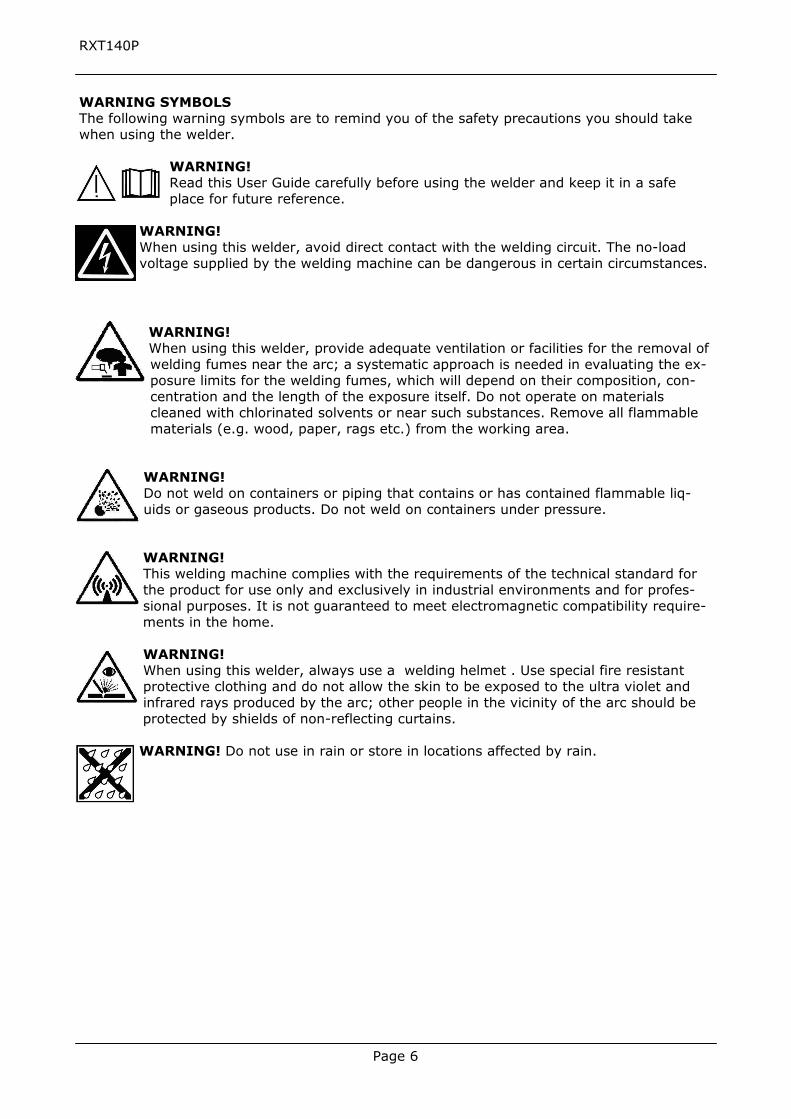
WARNING SYMBOLS The following warning symbols are to remind you of the safety precautions you should take when using the welder.
WARNING! Read this User Guide carefully before using the welder and keep it in a safe place for future reference.
WARNING! When using this welder, avoid direct contact with the welding circuit. The no-load voltage supplied by the welding machine can be dangerous in certain circumstances.
WARNING! When using this welder, provide adequate ventilation or facilities for the removal of welding fumes near the arc; a systematic approach is needed in evaluating the ex-posure limits for the welding fumes, which will depend on their composition, con-centration and the length of the exposure itself. Do not operate on materials cleaned with chlorinated solvents or near such substances. Remove all flammable materials (e.g. wood, paper, rags etc.) from the working area.
WARNING! Do not weld on containers or piping that contains or has contained flammable liq-uids or gaseous products. Do not weld on containers under pressure. WARNING! This welding machine complies with the requirements of the technical standard for the product for use only and exclusively in industrial environments and for profes-sional purposes. It is not guaranteed to meet electromagnetic compatibility require-ments in the home. WARNING! When using this welder, always use a welding helmet . Use special fire resistant protective clothing and do not allow the skin to be exposed to the ultra violet and infrared rays produced by the arc; other people in the vicinity of the arc should be protected by shields of non-reflecting curtains. WARNING! Do not use in rain or store in locations affected by rain.

Page 7
RXT140P
Single phase transformer Three pin attachment plug
U1 Rated input voltage
Uo Open circuit voltage I1 MAX Maximum input current
50 Hz Rated input frequency IP21S Degree of protection against intrusion of water and solid bodies
Curve of static output current (dropping, con-stant current) Class H Insulation class of transformer
Manual metal arc welding with covered elec-trodes Ø mm Electrode size
I2 Conventional output current range
Tw Average load time (welding time) in seconds
Tr Average reset time (rest time) in seconds
THE RATING PLATE The rating plate is fitted to the front of the welder and displays the following symbols and information.
C-Tick mark
A/13158EA Australian electrical safetyapproval

Page 8
RXT140P
1) On/off switchWhen the switch is in the “ O” position means the power OFF . When the switch in the “1” position means the power is ON
2) Output power Adjust the Knob according to the metal thickness. ( also see 6 below)
3) Electrode holder
4) Earth cableUse earth clamp to connect earth cable with work piece
5) Overload lightIf welding a long time the duty cycle may be exceeded, the overload lamp will turn ON(orange) and the machine will stop working until the unit has cooled.
6) Welding Current indicator windowShows the current welding current setting.
5
6
1
2
4
3

Page 9
RXT140P
WELDING PROCEDURE Before commencing, make sure that your hand held welding mask or welding hel-met is in position to protect your eyes. It is also advisable to wear gloves and cloth-ing, which cover the hands and arms to prevent flash burns.
1. Striking Arc. This is done by bringing the electrode into contact with the workpiece using a light tapping action and withdrawing to create a gap of 1/16” –1/18” (1.5 mm – 3.00 mm.).
2. Maintaining Arc. Having created an arc, all that is necessary to maintain it is toproceed steadily in one direction keeping the gap between the electrode andthe work piece constant. The electric current will flow through the electrode,across the arc gap, and in doing so will melt the electrode core wire and pro-tective flux. The electrode length will gradually decrease as the metal is trans-ferred to the work piece under a protective slag formed by the flux. This slagcan then be removed when cooled by lightly tapping with a pointed tool or awelders chipping hammer.
3. To stop welding, all that is required is to withdraw the electrode from the workpiece - thus breaking the circuit. Be careful with the end of the electrode, as itwill be hot! Provided the current setting is correct, the surface of the workpiece will also melt by the intensity of the electric arc. A degree of“penetration” is thereby obtained and a complete “fusion” of the work pieceand the deposited electrodes met
4. Selection of electrode. There is no hard and fast rule by which a particulargauge of electrode is selected. Usually this is determined by, the type of weldrequired and the thickness of the work piece. E.g. a butt weld in1/16” (1.5mm.) sheet metal can be done by a 1.6mm or 2.0mm electrode, thedifference being that the 2.0mm electrode will do the job quicker. The tablebelow Gives guidance as to which electrode is most suitable according to thematerial thickness. This table is only a guide, and values given are an indica-tion only.
ELECTRODE SIZE MATERIAL THICKNESS
Inches MM Inches MM
5/64 2 1/16 – 3/32 1.6 – 2.5
3/32 2.5 3/32 – 5/32 2.5 – 4.0
1/8 3.2 5/32 – 15/64 4.0 – 6.0
(Weld Current)
60A
80A
115A

Page 10
RXT140P
THERMOSTATIC PROTECTION This welder is automatically protected from overheating by a thermal overload cut out protec-tor. If the transformer overheats the overload cut out protector will activate and cut off. The amber light will illuminate to show that the cut out has operated. After cooling the protector will reconnect the supply circuit and the welder will be ready for further use. NOTE: If the duty cycle of the machine is exceeded the thermostatic protection will activate.
MAINTENANCE
WARNING! Before starting any cleaning, or maintenance procedures on the welding ma-chine, make sure that it is switched Off and disconnected from the mains supply.
There are no user serviceable parts inside the welder. Refer to qualified service personnel if any internal maintenance is required.

Page 11
RXT140P
WARRANTYOur goods come with guarantees that cannot be excluded under the Australian Consumer Law. You are entitled to a replacement or refund for a major failure and for compensation for any other reasonably foreseeable loss or damage. You are also entitled to have the goods repaired or replaced if the goods fail to be of acceptable quality and the failure does not amount to a major failure.This product is guaranteed against faulty materials and workmanship for 24 months from the date of purchase. Please retain your receipt as proof of purchase. This warranty does not cover defects caused by or resulting from:(a) misuse, abuse or neglect;(b) trade, professional or hire use;(c) repairs attempted by anyone other than our authorised repair centres; or(d) damage caused by foreign objects, substances or accident.
WARRANTY EXCLUSIONSWear parts or service related parts required when performing normal and regular maintenance of this product are not covered by warranty unless it is found to be defective by an Authorised Service Centre.
Distributed in Australia by White International Pty LtdInquiries phone 1800 251 338
The White International policy is one of continuous improvement and the company reserves the right to alter designs, colours and specifications without notice.
Note: Consumable items such as clamps and electrode holders not covered by warranty.