archimate, bpmn and uml: an approach to … bpmn and uml: an approach to harmonizing the notations c...
TRANSCRIPT
ArchiMate, BPMN and UML: An
approach to harmonizing the
notations
www.orbussoftware.com
+44 (0) 870 991 1851
Michelle van den Berg
Business Architecture Consultant
Real IRM Solutions
Email: [email protected]
Website: www.realirm.com
White Paper

Page 2
10 Steps to follow before Initiating a TOGAF® 9 Project or Initiative
ArchiMate, BPMN and UML: An approach to harmonizing the notations
C o p y r i g h t R e a l I R M 2 0 1 2
Introduction
John Zachman said that if something becomes so complex that you cannot remember how it works,
you need to write it down. So “writing it down” is exactly the exercise many organizations in the
information age embarks on. And in most cases an Enterprise Architecture (EA) philosophy is
adopted by the organization to assist with methods and techniques for making explicit the elements
of the organization, and how these elements relate to each other.
One of the most common challenges when embarking on an EA drive is the use of standard
representations and descriptions of organizational elements. And usually the first organizational
elements to attract questions about representation is the business process element; “What notation
will be used to model processes? Will it be IDEF, BPMN, EPC or some hybrid?” With so many
notations to choose from, uncertainty is common and is driven by the quest for finding the best
notation to serve the purposes of the organization.
The selection is mostly impacted by the individuals in the team as some notations are better known
than others and modelers have more exposure and experience with one specific notation rather
than with a number of notations. With ArchiMate being added to the mix, the selection is wider and
needs some consideration.
The purpose of this white paper is to introduce three modeling notations for modeling business
process and application in particular and to find a way to use it in harmony with each other. Some
knowledge of Enterprise Architecture terminology is assumed in this white paper.
The ArchiMate modeling language is the new kid on the block, and this paper will consider it with
established process modeling notation BPMN and software development notation UML. This will be
done by looking at the various meta-models1 for each notation.
Overview of ArchiMate 2.0
ArchiMate Core Concepts
ArchiMate is an open and independent visual design language for Enterprise Architecture; a notation
for describing, analyzing and visualizing relationships amongst business domains. Now in its second
version, the ArchiMate language defines three primary layers; Business, Application and Technology,
and describes various cross layer dependencies. These layers are segmented into Active, Passive and
Behavioural elements, which serve to govern connections and relationships between the layers.
Associated with these layers are viewpoints of various stakeholders in an organization.
1 A meta-model is defined as an explicit model of the concepts and relationships between those concepts
required to develop models
Page 3
10 Steps to follow before Initiating a TOGAF® 9 Project or Initiative
ArchiMate, BPMN and UML: An approach to harmonizing the notations
C o p y r i g h t R e a l I R M 2 0 1 2
ArchiMate Meta-Models
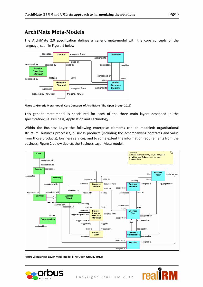
The ArchiMate 2.0 specification defines a generic meta-model with the core concepts of the
language, seen in Figure 1 below.
Figure 1: Generic Meta-model, Core Concepts of ArchiMate (The Open Group, 2012)
This generic meta-model is specialized for each of the three main layers described in the
specification; i.e. Business, Application and Technology.
Within the Business Layer the following enterprise elements can be modeled: organizational
structure, business processes, business products (including the accompanying contracts and value
from those products), business services, and to some extent the information requirements from the
business. Figure 2 below depicts the Business Layer Meta-model.
Figure 2: Business Layer Meta-model (The Open Group, 2012)

Page 4
10 Steps to follow before Initiating a TOGAF® 9 Project or Initiative
ArchiMate, BPMN and UML: An approach to harmonizing the notations
C o p y r i g h t R e a l I R M 2 0 1 2
Within the Application Layer the following enterprise elements can be modeled: the applications
(including the structure of those applications) supporting the business, as well as the application
services offered by those applications. Figure 3 below depicts the Application Layer Meta-model.
Figure 3: Application Layer Meta-model (The Open Group, 2012)
In the Technology Layer, the following enterprise elements can be modeled: the infrastructure
services and components needed for the application layer, including the hardware and software
elements of the organization and how they are connected. Figure 4 below depicts the Technology
Layer Meta-model.
Figure 4: Technology Layer Meta-model (The Open Group, 2012)
Viewpoints
The ArchiMate 2.0 specification defines a number of viewpoints used to deliver the Enterprise
Architecture. Viewpoints are aimed at particular types of stakeholders with typical concerns and
consist of preselected sets of ArchiMate concepts for creating diagrams to convey information
Page 5
10 Steps to follow before Initiating a TOGAF® 9 Project or Initiative
ArchiMate, BPMN and UML: An approach to harmonizing the notations
C o p y r i g h t R e a l I R M 2 0 1 2
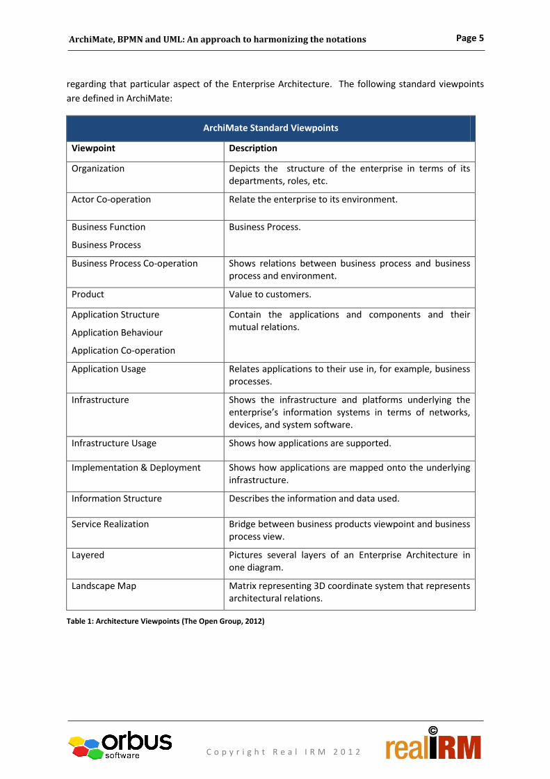
regarding that particular aspect of the Enterprise Architecture. The following standard viewpoints
are defined in ArchiMate:
ArchiMate Standard Viewpoints
Viewpoint Description
Organization Depicts the structure of the enterprise in terms of its departments, roles, etc.
Actor Co-operation Relate the enterprise to its environment.
Business Function
Business Process
Business Process.
Business Process Co-operation Shows relations between business process and business process and environment.
Product Value to customers.
Application Structure
Application Behaviour
Application Co-operation
Contain the applications and components and their mutual relations.
Application Usage Relates applications to their use in, for example, business processes.
Infrastructure Shows the infrastructure and platforms underlying the enterprise’s information systems in terms of networks, devices, and system software.
Infrastructure Usage Shows how applications are supported.
Implementation & Deployment Shows how applications are mapped onto the underlying infrastructure.
Information Structure Describes the information and data used.
Service Realization Bridge between business products viewpoint and business process view.
Layered Pictures several layers of an Enterprise Architecture in one diagram.
Landscape Map Matrix representing 3D coordinate system that represents architectural relations.
Table 1: Architecture Viewpoints (The Open Group, 2012)
Page 6
10 Steps to follow before Initiating a TOGAF® 9 Project or Initiative
ArchiMate, BPMN and UML: An approach to harmonizing the notations
C o p y r i g h t R e a l I R M 2 0 1 2
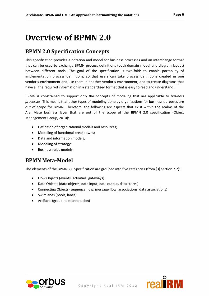
Overview of BPMN 2.0
BPMN 2.0 Specification Concepts
This specification provides a notation and model for business processes and an interchange format
that can be used to exchange BPMN process definitions (both domain model and diagram layout)
between different tools. The goal of the specification is two-fold: to enable portability of
implementation process definitions, so that users can take process definitions created in one
vendor’s environment and use them in another vendor’s environment; and to create diagrams that
have all the required information in a standardised format that is easy to read and understand.
BPMN is constrained to support only the concepts of modeling that are applicable to business
processes. This means that other types of modeling done by organizations for business purposes are
out of scope for BPMN. Therefore, the following are aspects that exist within the realms of the
ArchiMate business layer that are out of the scope of the BPMN 2.0 specification (Object
Management Group, 2010):
Definition of organizational models and resources;
Modeling of functional breakdowns;
Data and information models;
Modeling of strategy;
Business rules models.
BPMN Meta-Model
The elements of the BPMN 2.0 Specification are grouped into five categories (from [3] section 7.2):
Flow Objects (events, activities, gateways)
Data Objects (data objects, data input, data output, data stores)
Connecting Objects (sequence flow, message flow, associations, data associations)
Swimlanes (pools, lanes)
Artifacts (group, text annotation)

Page 7
10 Steps to follow before Initiating a TOGAF® 9 Project or Initiative
ArchiMate, BPMN and UML: An approach to harmonizing the notations
C o p y r i g h t R e a l I R M 2 0 1 2
Figure 5 below depicts the elements in the BPMN 2.0 meta-model:
Figure 5: BPMN 2.0 Meta-model
BPMN Diagram Types
The BPMN elements can be used to create the following main types of diagrams (Object
Management Group, 2010):
Processes (which can be internal executable or non-executable as well a public processes);
Choreographies;
Collaborations
Internal processes are those processes internal to an organization also referred to as workflow.
Some internal processes can be modeled to show how they could be executed by automating the
steps using a system, while others are modeled to document their process flow, whether it is a
manual or system supported process.
Public processes model the interaction between processes and participants. Only the activities that
show the communication between processes are modeled in the Public Process, all the other
activities are modeled in the Internal Process.
Choreographies look similar to Internal Processes but here the activities are “interactions that
represent a set (one or more) of message exchanges” between participants (Object Management
Group, 2010).
Collaborations are used to model the interactions between business entities. It includes Pools which
represents the participants of the process and the flow of messages between these participants. The
public process can be modeled in a Pool or it can be left empty. Collaborations can consist of any
combination of Pools, processes, and choreographies.
ActivityEvent Gatewaytriggers
caused by
Message
sequencescontains
Pool
contained in
contains contains
is associated with
is associated with
flows between
is sub-divided by
GroupData Object
Lane
uses / produces
sub-divides
used by/ produced by
controls sequence of
is controlled by
Text Annotation
is associated with

Page 8
10 Steps to follow before Initiating a TOGAF® 9 Project or Initiative
ArchiMate, BPMN and UML: An approach to harmonizing the notations
C o p y r i g h t R e a l I R M 2 0 1 2
These main diagram types mentioned above are similar to the viewpoint concept specified in
ArchiMate 2.0 in the sense that these are the types of diagrams (or views) that can be created using
this notation, although they are not nearly as detailed and specific as in ArchiMate 2.0. While these
diagram types are explained in terms of what the diagram entails, no examples are given, whereas
the ArchiMate viewpoints are categorized according to their purpose and context and are explained
with an example of how the different elements are connected to each other.

Page 9
10 Steps to follow before Initiating a TOGAF® 9 Project or Initiative
ArchiMate, BPMN and UML: An approach to harmonizing the notations
C o p y r i g h t R e a l I R M 2 0 1 2
Overview of the UML 2.0 Specification
UML Specification Structure
The Unified Modeling Language (UML) specification is a visual language to model artefacts of
applications (Object Management Group, 2010).
The UML specification is divided into two segments:
UML Infrastructure;
UML Superstructure.
The UML Infrastructure segment describes the basic elements that make up the language and is
aimed at what is required from modeling tools to comply with the specification (Tutorials Point,
2012). For this reason, this paper will not look at the UML Infrastructure segment.
The UML Superstructure segment describes the user elements of the language, i.e. those elements
that the users will use to create UML diagrams (Tutorials Point, 2012).
UML Meta-Model
UML elements are categorized as either Behavioural: used to depict behaviour of applications; or
Structural; used to depict how the application is constructed. There are two fundamental
assumptions when it comes to modeling behaviour in UML (Object Management Group, 2011):
1. “All behaviour in a modeled system is ultimately caused by actions executed by so-called
“active” objects”.
2. “UML behavioural semantics only deal with event-driven, or discrete, behaviours”.
The UML specification covers six semantic areas and Figure 6 below shows how they relate to each
other –the upper layers depend on the items in the lower layers but not the other way around
(Object Management Group, 2011). This means that there is no disembodied behaviour in UML and
all behaviour is the consequence of structural objects (Object Management Group, 2011).
Figure 6: A schematic of the UML semantic areas and their dependencies

Page 10
10 Steps to follow before Initiating a TOGAF® 9 Project or Initiative
ArchiMate, BPMN and UML: An approach to harmonizing the notations
C o p y r i g h t R e a l I R M 2 0 1 2
The elements used to create UML models can be depicted in a meta-model, as shown in Figure 7
below.
Figure 7: UML 2.0 Meta-model
UML Diagram Types
There are 13 diagrams specified in UML and they can be divided into three categories (Scott W.
Ambler and Associates, 2012):
Behaviour diagrams, used to model behavioural aspects of an application. This includes the
Activity, State Machine, and Use Case diagrams.
Interaction diagrams, a subset of behavioural diagrams, which focus on showing how objects
interact with each other. This includes the Communication (previously collaboration),
Interaction Overview, Sequence and Timing diagrams.
Structure diagrams, used to model the different elements of a specification that are
irrespective of time. This includes the Class, Composite Structure, Component, Deployment,
Object and Package diagrams.
Activity diagrams emphasize the sequence and conditions for coordinating lower-level behaviours
(Object Management Group, 2011). They are also called control flow and object flow models.
State Machine diagrams model the state of a single object and respond to events arriving at that
event.
Attribute
realised by
Class associates
Interface
realises
Operation
is associated with
realised by
Object
linkrealises
Component
is dependant on
realised by
Is linked bylinksCollaboration
links
Is linked by
links
deploysNode
is deployed on
connects
is associated with
is associated with
is associated with
is associated with
Package
Is dependent on
GuardState
Transition
Action
causes
is caused by
is described by
describes
is triggered by
triggers
is changed by
changes
Initial State Final State
State/Value Timeline
Events
is point on
has
has
transitions through
shows transition of
is applicable to
Timing Constraint
Time Observation
applies to
is applicable to
sends/receives
is sent/ received
by
Message
Actor
Use Case
System Boundary Box
contains
is grouped in
groups
is contained in
is associated with
is associated with
is associated with
Ending PointFrame
Decision Point
Start Point
caused by
caused by
triggers
triggers
is described by
describes
causes
caused by
Interaction Frame
Interaction Occurrence
is sent/ received by
Lifeline
sends/receives
is applicable to
Activity
Parallel Bar
Fork Join
Swimlane
Action Object
triggers
triggers
caused by
causes
caused byshows sequence of
sequenced by
performs
performed by
is actedon byact on
sequenced by
is triggered by
Page 11
10 Steps to follow before Initiating a TOGAF® 9 Project or Initiative
ArchiMate, BPMN and UML: An approach to harmonizing the notations
C o p y r i g h t R e a l I R M 2 0 1 2
Use Case diagrams are used to capture the requirements of an application; what it is supposed to do
(Object Management Group, 2011).
Communication diagrams show instances of classes, their interrelationships, and the message flow
between them; typically focused on the structural organization of objects that send and receive
messages (Tutorials Point, 2012).
Interaction Overview diagrams define interactions through a variant of Activity Diagrams, in a way
that promotes overview of the control flow (Object Management Group, 2011).
Sequence Diagrams focus on the Message interchange between a number of Lifelines (Object
Management Group, 2011).
Timing diagrams show interactions when a primary purpose of the diagram is to reason about time
(Object Management Group, 2011).
Class diagrams show the static view of an application; they are used to describe the different
aspects of a system and also for constructing executable code of the software application (Tutorials
Point, 2012).
Composite Structure diagrams depict the internal structure of a classifier (Object Management
Group, 2011) such as a class, component, or use case. They also show the interaction points of the
classifier to other parts of the system (Tutorials Point, 2012).
Component diagrams model the application components, their interrelationships, interactions, and
their public interfaces (Tutorials Point, 2012).
Deployment diagrams show the allocation of artefacts to nodes according to the deployments
defined between them (Object Management Group, 2011). This includes nodes, either hardware or
software execution environments, as well as the middleware connecting them (Tutorials Point,
2012).
Object diagrams depict objects and their relationships at a point in time, typically a special case of
either a class diagram or a communication diagram (Tutorials Point, 2012).
Package diagrams show how model elements are organized into packages as well as the
dependencies between packages (Tutorials Point, 2012).
By using these diagrams, specific aspects of an application can be visualized, described and
documented according to a standard that has been designed specifically for this purpose. For each
diagram, the perfect set of concepts has been selected to be relevant in a specific context.

Page 12
10 Steps to follow before Initiating a TOGAF® 9 Project or Initiative
ArchiMate, BPMN and UML: An approach to harmonizing the notations
C o p y r i g h t R e a l I R M 2 0 1 2
Using ArchiMate, BPMN and UML in
Harmony
BPMN and UML notations will most likely be used in organizations that go to the trouble of defining
their process architecture and application designs. From an EA perspective, these types of exercises
produce outputs that are not useful for our stakeholders expecting to be informed on concepts and
scope rather than on the detail of implementation or design.
For that reason an approach to harmonize the ArchiMate, BPMN and UML modeling notations are
proposed. The harmonization involves using the specific modeling notation for its intended use and
playing to its strengths. ArchiMate models the concepts (the architecture) well, whereas BPMN
models the implementation processes and UML the software designs.
What remains is to detail how these languages and their meta-models will co-exist and in
harmonizing, add value to the organization.
Recommended Approach to Harmonization
The harmonization approach assumes a repository-based modeling tool that can accommodate all
three notations, and people with the relevant skills in the various notations.
In addition, the Zachman principle of maintaining primitives before creating composite models is a
prerequisite. A primitive model or list describes a singular aspect (element) of the organization
(without relating it to anything) for example: role, organization unit, risk, control, application, data
entity. A composite model on the other hand is specifically focused on showing how things
interrelate and will therefore always consist of a combination of primitives that relate to each other.
When you create composite models (relating these different elements together) you can reuse
objects created and maintained in the primitive models/lists. This will enable easier re-use and
maintenance of objects.
Use ArchiMate for all the high-level modeling as defined in the business architecture layer, creating
your organization chart, strategy models, functional decomposition, etc. using the ArchiMate
notation. ArchiMate is useful here since it contains the constructs to create these views and BPMN
doesn’t (see BPMN 2.0 Specification Concepts).

Page 13
10 Steps to follow before Initiating a TOGAF® 9 Project or Initiative
ArchiMate, BPMN and UML: An approach to harmonizing the notations
C o p y r i g h t R e a l I R M 2 0 1 2
Figure 8: Example ArchiMate Models
When it comes to defining process models, it is recommended that a process levelling approach is
used which ensures that process models are created for a specific audience, keeping in mind what
the focus of that specific stakeholder is (Viljoen, 2012). This is the first suggested integration point
between ArchiMate and BPMN. Use ArchiMate for the high-level processes (level 0 through 3 in the
example) and BPMN for the more detailed operational processes (level 4 in the example below).
Figure 9: Example Showing Integration between ArchiMate and BPMN
To model the Application Architecture, ArchiMate can also be used to model the contextual and
conceptual definition of applications, and then link the more specialised UML notation below the
conceptual layer to create the models describing the structure or behaviour of specific applications.
Finance
ManagerAccountant
Finance Department
HR Manager IR Manager
Human Resources Department
Organisation
Organisation Chart
Role List
ApproverPersonnel
Administrator
Sales
AssistantData Capturer
Head Office Local Office
Regional Office
Location Hierarchy
Project
initiation
Project
Planning and
Design
Project
Execution
and
Construction
Project
Monitoring
and
Controlling
Project
Completion
Project Management
Functional Decomposition
InvoiceLeave
Request Form
Annual Sales
Figures
Report
Insurance
Policy
Document
Document List
Insurance
Policy
Client
Policy
Description
Policy Terms
And
Conditions
Client Contact
Details
Order Order Line
High-level InformationClassification
Reduce
workload
employees
Improve
portfolio
management
Assign
personal
assistant
Provide online
portfolio
service
!Systems should
be customer
facing
Improve
portfolio
management
--
++
-- ++
+
Motivation Model
Support the Business
Provide IT Services
Provide HR Services
Provide Financial Services
Recruit Employees
Reward Employees
Develop Talent
Identify Vacancies
Advertise Vacancy
Screen Candidates
Interview Candidates
Offer Job
HR
Ma
na
ge
rH
R A
ss
ista
nt
Candidate
CVs
Received
Review
Candidate CV
Determine If
Shortlist
Candidate
Shortlist
Candidate
Not Shortlist
Candidate
Add
Candidate To
Shortlist
Determine If
More CVs To
Review
No More CVs
To ReviewMore CVs To
Review
Arrange
Interview With
Shortlist
Candidates
Interview
Candidates
Interview
Arranged
With Shortlist
Candidates
L0
L1
L2
L3
L4
Page 14
10 Steps to follow before Initiating a TOGAF® 9 Project or Initiative
ArchiMate, BPMN and UML: An approach to harmonizing the notations
C o p y r i g h t R e a l I R M 2 0 1 2
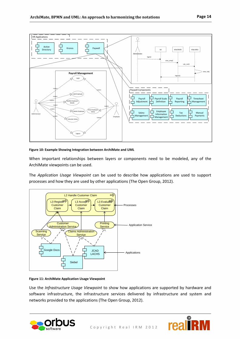
Figure 10: Example Showing Integration between ArchiMate and UML
When important relationships between layers or components need to be modeled, any of the
ArchiMate viewpoints can be used.
The Application Usage Viewpoint can be used to describe how applications are used to support
processes and how they are used by other applications (The Open Group, 2012).
Figure 11: ArchiMate Application Usage Viewpoint
Use the Infrastructure Usage Viewpoint to show how applications are supported by hardware and
software infrastructure, the infrastructure services delivered by infrastructure and system and
networks provided to the applications (The Open Group, 2012).
HR Applications
PaywellKronosActive
Directory
Login
Administrator
Employee
Add Employee
Modify EmployeeDetails
Delete Employee
Calculate Salary
Logout
View EmployeeSalary
«uses»
«uses»
«uses»
«uses»
«uses»
«uses»
«uses»
«uses»
«uses»
Payroll Management
Administrator
sys emp details emp salary
login()
view_emp()
calc_net()
view_sal()
logout()
Paywell Components
Payroll Adjustment
Payroll Scale Definition
Payroll Reporting
Timesheet Management
Salary Management
Employee Information
Management
Tax Deductions
Manual Payments
L3 Register
Customer
Claim
L3 Accept
Customer
Claim
L3 Evaluate
Customer
Claim
L2 Handle Customer Claim
Scanning
Service
Customer
Administration Service
Claims Administration
Service
Printing
Service
Google Docs
Siebel
JCAD
LACHS
Processes
Application Service
Applications

Page 15
10 Steps to follow before Initiating a TOGAF® 9 Project or Initiative
ArchiMate, BPMN and UML: An approach to harmonizing the notations
C o p y r i g h t R e a l I R M 2 0 1 2
Figure 12: ArchiMate Infrastructure Usage Viewpoint Example
Although a UML Deployment diagram can be created, the ArchiMate Implementation and
Deployment Viewpoint is suggested for defining context and scope. The advantage of the ArchiMate
viewpoint being that it stays at the concept level (rather than drill into detail) to inform the
organization at the same time as promoting the re-use of application and infrastructure
components.
Figure 13: ArchiMate Implementation and Deployment Viewpoint Example
Considering the meta-models in context to each other, the ArchiMate Business Layer and BPMN
meta-models can be harmonized or linked in the following way:
QuickBooks SiebelJCAD
LACHS
Messaging
Service
Data Access
Service
Message
QueingDBMS
Mainframe
Applications
Infrastructure Service
Node
System Software
Applications
Device
Node
System SoftwareOS/390
Mainframe
Workstation5
SC.exe
Siebel
Siebel Server
Siebel Client
100 Mbit/s LAN
Artefact

Page 16
10 Steps to follow before Initiating a TOGAF® 9 Project or Initiative
ArchiMate, BPMN and UML: An approach to harmonizing the notations
C o p y r i g h t R e a l I R M 2 0 1 2
Figure 14: Combined ArchiMate Business Layer and BPMN Meta-Models
ActivityEvent Gatewaytriggers
caused by
Message
sequencescontains
Pool
contained in
contains contains
is associated with
is associated with
flows between
is sub-divided by
GroupData Object
Lane
uses / produces
sub-divides
used by/ produced by
controls sequence of
is controlled by
Text Annotation
is associated with
Assignment/Decomposition

Page 17
10 Steps to follow before Initiating a TOGAF® 9 Project or Initiative
ArchiMate, BPMN and UML: An approach to harmonizing the notations
C o p y r i g h t R e a l I R M 2 0 1 2
The ArchiMate Application Layer and UML meta-models can be linked as follows:
Figure 15: Combined ArchiMate Application Layer and UML Meta-Models
This could typically be achieved by a hyperlink to another area of the modeling tool or possibly a drill
through within the same diagram type depending on the specific tool.
Attribute
realised by
Class associates
Interface
realises
Operation
is associated with
realised by
Object
linkrealises
Component
is dependant on
realised by
Is linked bylinksCollaboration
links
Is linked by
links
deploysNode
is deployed on
connects
is associated with
is associated with
is associated with
is associated with
Package
Is dependent on
GuardState
Transition
Action
causes
is caused by
is described by
describes
is triggered by
triggers
is changed by
changes
Initial State Final State
State/Value Timeline
Events
is point on
has
has
transitions through
shows transition of
is applicable to
Timing Constraint
Time Observation
applies to
is applicable to
sends/receives
is sent/ received
by
Message
Actor
Use Case
System Boundary Box
contains
is grouped in
groups
is contained in
is associated with
is associated with
is associated with
Ending PointFrame
Decision Point
Start Point
caused by
caused by
triggers
triggers
is described by
describes
causes
caused by
Interaction Frame
Interaction Occurrence
is sent/ received by
Lifeline
sends/receives
is applicable to
Activity
Parallel Bar
Fork Join
Swimlane
Action Object
triggers
triggers
caused by
causes
caused byshows sequence of
sequenced by
performs
performed by
is actedon byact on
sequenced by
is triggered by
Assignment/Decomposition
Page 18
10 Steps to follow before Initiating a TOGAF® 9 Project or Initiative
ArchiMate, BPMN and UML: An approach to harmonizing the notations
C o p y r i g h t R e a l I R M 2 0 1 2
Conclusion
Understanding each of the notations discussed above and their defined concepts will enable
Enterprise Architects to select the relevant aspects of each notation that will work for their specific
Enterprise Architecture initiatives. This will ensure that the Enterprise Architectures are built using
fit-for-purpose notations: when processes are defined, a standard notation is used which was
originally designed to define processes; when describing application behaviour, a standard notation
is used which was designed for describing applications; and when describing the Enterprise
Architecture on a high level and how the different elements impact each other, a standard notation
is used which was designed for that.
Designing and building an Enterprise Architecture in this way will ensure that it is appropriate and
relevant to the audience it was intended for.
Page 19
10 Steps to follow before Initiating a TOGAF® 9 Project or Initiative
ArchiMate, BPMN and UML: An approach to harmonizing the notations
C o p y r i g h t R e a l I R M 2 0 1 2
Bibliography nithi032. (n.d.). Case Tools. Retrieved from Scribd: http://www.scribd.com/doc/49864869/85/Use-case-diagram-
for-payroll-system
Object Management Group. (2010). Business Process Model and Notation (BPMN) v 2.0.
Object Management Group. (2011). OMG Unified Modeling LanguageTM (OMG UML), Superstructure v 2.4.1.
Scott W. Ambler and Associates. (2012). Introduction to the Diagrams of UML 2.0. Retrieved from Agile
Modelling: http://www.agilemodeling.com/essays/umlDiagrams.htm
Stein, D. S. (n.d.). BPMN EPC Semantic Comparison. ARIS BPM Blog. Retrieved from
http://www.ariscommunity.com/users/sstein/2010-04-15-epc-vs-bpmn-perfect-flamewar
The Open Group. (2012). ArchiMate 2.0 Specification. Van Haarem Publishers.
Tutorials Point. (2012). UML 2.0 Overview. Retrieved from Tutorials Point:
http://www.tutorialspoint.com/uml/uml_2_overview.htm
Tutorials Point. (2012). UML Class Diagram. Retrieved from Tutorials Point :
http://www.tutorialspoint.com/uml/uml_class_diagram.htm
Viljoen, S. (2012). Reflections on Business Process Levelling. Retrieved from Orbus Software:
http://www.orbussoftware.com/downloads/white-papers/reflections-on-business-process-leveling
© Copyright 2012 Orbus Software. All rights reserved.
No part of this publication may be reproduced, resold, stored in a retrieval system, or distributed in any form or by any means, electronic,
mechanical, photocopying, recording, or otherwise, without the prior permission of the copyright owner.
Such requests for permission or any other comments relating to the material contained in this document may be submitted to:
Orbus Software
3rd Floor
111 Buckingham Palace Road
London
SW1W 0SR
United Kingdom
or by electronic mail to: marketing@orbussoftware