archimate - uml modeling tools for business, software
TRANSCRIPT

ArchiMate
ENTERPRISE ARCHITECT
User Guide Series
Author: Sparx Systems
Date: 2021-09-02
Version: 15.2
CREATED WITH

Table of Contents
ArchiMate 4Getting Started 6Introduction to ArchiMate 7Using ArchiMate with Enterprise Architecture 10Architecture Views and Viewpoints 13
Overview of Views and Viewpoints 14Basic Viewpoints 17
Organization Viewpoint 18Application Structure Viewpoint 19Information Structure Viewpoint 20Technology Viewpoint 21Layered Viewpoint 22Physical Viewpoint 24Product Viewpoint 25Application Usage Viewpoint 26Technology Usage Viewpoint 27Business Process Cooperation Viewpoint 28Application Cooperation Viewpoint 29Service Realization Viewpoint 30Implementation and Deployment Viewpoint 31
Motivation Viewpoints 32Stakeholder Viewpoint 33Goal Realization Viewpoint 34Requirements Realization Viewpoint 35Motivation Viewpoint 36
Strategy Viewpoints 37Strategy Viewpoint 38Capability Map Viewpoint 39Value Stream Viewpoint 40Outcome Realization Viewpoint 41Resource Map Viewpoint 42
Implementation and Migration Viewpoints 43Project Viewpoint 44Migration Viewpoint 45Implementation and Migration Viewpoint 46
The ArchiMate Language 47Language Definitions 49Language Structure 56Generic Metamodel 57Elements 58
Changing Element Presentation 59Motivation Elements 63
Motivation Example Diagrams 65Strategy Layer Elements 68
Strategy Layer Example Diagrams 69Business Layer Elements 70
Business Layer Example Diagrams 72

Application Layer Elements 73Application Layer Example Diagrams 75
Technology Layer Elements 76Technology Examples 78
Physical Layer Elements 79Physical Examples 80
Implementation and Migration Layer Elements 81Implementation and Migration Example 82
Composite Elements 83Relationships 84
Relationships Overview 86Structural Relationships 89Dependency Relationships 90Dynamic Relationships 91Other Relationships 92Relationship Connectors 93
Alignment between Layers 94Customizing the ArchiMate Language 96
Example Profile 99Exchanging ArchiMate Models 100
Generate Model Exchange File 101Import ArchiMate Model Exchange File 103
Migrate to the Latest ArchiMate Version 105

ArchiMate 2 September, 2021
ArchiMate
Create and Visualize Enterprise Architecture Models, Views and Viewpoints
The MDG Technology for ArchiMate®3.1 is one of the Enterprise Architecture tools integrated with EnterpriseArchitect.
ArchiMate® is an open-standard enterprise architecture language managed by The Open Group, based on the IEEE 1471standard. It is "a visual language with a set of default iconography for describing, analyzing, and communicating manyconcerns of Enterprise Architectures as they change over time." It is used by a variety of modelers and stakeholders;Enterprise Architects will create and maintain models but a range of other stakeholders will view the models andrepresentations of them. These include Solution Architects, Business Analysts, Executives and Business line managers,just to mention a few. The language is used to represent elements from all layers and aspects of an organization, fromDrivers and stakeholders to Devices and Networks.
Overview of Topics
The table below lists the main topics that describe the implementation of the ArchiMate language in Enterprise Architect.The architect will learn how to start modeling with ArchiMate and will be introduced to the features available within thetool to create expressive and powerful diagrams and views with ArchiMate. Further topics will describe the creation ofViews and Viewpoints and how to create diagrams that contain elements and relationships and will detail all theseconcepts. Later topics discuss the migration from earlier versions of the language to the latest version and also how toexchange models.
Brief Introduction This topic provides an introduction to ArchiMate in Enterprise Architect anddiscusses its relevance and importance in creating and maintaining EnterpriseArchitecture models.
Getting Started This topic provides the information needed to immediately start modeling withArchiMate, including the ArchiMate perspective and the Model Wizard patterns.
Using ArchiMate This topic covers the basic tool features to create Packages, diagrams and elements,including showing how existing and new elements can be added to diagrams.
Views and Viewpoints This topic describes the archimate views and viewpoints giving examples of eachviewpoint available for immediate creation from the model wizard pattern tool.
ArchiMate Language This topic describes the ArchiMate Language, including the language definitions,structure and metamodel, and the concepts, divided into elements and relationships.
This topic describes the principles and mechanisms for extending the language to
(c) Sparx Systems 2021 Page 4 of 108 Created with Enterprise Architect

ArchiMate 2 September, 2021
Customising the Language add industry- or organization-specific information in the form of properties, to bothelements and connectors.
Exchanging Models This topic describes the exchange of ArchiMate models created in EnterpriseArchitect with other tools, enabling models to be both imported and exported usingthe xml-based exchange format.
Version Migration This topic describes how to upgrade models containing elements, relationships anddiagrams from one version of ArchiMate to a later version.
(c) Sparx Systems 2021 Page 5 of 108 Created with Enterprise Architect

ArchiMate 2 September, 2021
Getting Started
Welcome to the ArchiMate language, fully integrated with Enterprise Architect. The tool not only supports all of thelanguage features, including productivity features, but also provides a powerful collaboration platform that will allowarchitects and others from management down to development and support teams to view and contribute to thearchitecture and the value it brings to the organization.
About ArchiMate
ArchiMate is a technical standard managed by The Open Group; it is partly inspired by and based on the concepts of theIEEE 1471 standard (Recommended Practice for Architecture Description of Software-Intensive Systems). Work beganon the standard as early as 2002 in the Netherlands by a project team from the Telematica Instituut in association with anumber of Dutch partners from government, industry and academia. It has evolved significantly and has become ageneral purpose standard that is used for analyzing, specifying and documenting architectures at any level from strategyto deployment.
Enterprise Architect has supported modeling in ArchiMate for a number of years; the current version of EnterpriseArchitect supports ArchiMate 3.1 and all its syntax, semantics and viewpoints.
Objectives
"The standard is the specification of the ArchiMate Enterprise Architecture modeling language, a visual language with aset of default iconography for describing, analyzing, and communicating many concerns of Enterprise Architectures asthey change over time. The standard provides a set of entities and relationships with their corresponding iconography forthe representation of Architecture Descriptions." ArchiMate ® 3.1 Specification p.1
Value
The language has been developed with a recognition of the varied stakeholder groups both technical and non-technicalthat need to interact with the architecture and has provided a large number of features that support this varied group andtheir need to communicate and collaborate. The language provides:
a uniform representation for diagrams that describe Enterprise Architectures,·views and viewpoint to address stakeholder specific concerns,·mechanisms to visualize interrelated architectures including different domains,·syntactic devices for structuring mechanism for architecture domains, layers, and aspects,·visual devices that allow language elements to be presented with tailored notations for stakeholder groups,·support for conceptualization by relation abstract and concrete concepts using realization,·service-orientation to distinguish and relate the Business, Application, and Technology Layers of Enterprise·Architectures
(c) Sparx Systems 2021 Page 6 of 108 Created with Enterprise Architect

ArchiMate 2 September, 2021
Introduction to ArchiMate
Enterprise Architect supports a wide range of languages and frameworks, which are all available within the tooldepending on the edition that you are running. This provides great flexibility as it allows languages to be used incombination; for example, even though most of your architecture might be developed using ArchiMate there could beoccasions when you need to create a Mind Map to document a stakeholder workshop or run a simulation of a BusinessProcess to fully understand it. The tool provides a series of Perspectives that let you select a single aspect, language ordiscipline within the tool, allowing you to focus, but when you need to you can simply switch to an alternativeperspective.
ArchiMate Perspective
The ArchiMate perspective allows you to focus on architecture analysis and modeling using the ArchiMate language. Toswitch to the ArchiMate perspective you need to:
1. Click the Perspective Selector in the top right corner of the application title bar.
2. Select Enterprise Architecture > ArchiMate from the drop down
Enterprise Architect now will allow you to focus on modeling with ArchiMate and will limit the available diagrams andtoolbox and language features to the ArchiMate technology. It will also open the Model Wizard, allowing you tokick-start your modeling with a series of pre-built patterns that fully supports the ArchiMate Viewpoint mechanism.
Model Wizard Patterns
The Model Wizard is a productivity tool that allows you to create compliant model content based on the chosenexample viewpoint, selected from these viewpoint groups:
Basic Viewpoints·Motivation Viewpoints·Strategy Viewpoints·Implementation and Migration Viewpoints·
The patterns contained in the Model Wizard window are fully documented and provide valuable information thatdescribe the viewpoint and how it can be used.
Basic Viewpoints
(c) Sparx Systems 2021 Page 7 of 108 Created with Enterprise Architect

ArchiMate 2 September, 2021
Figure: Showing the basic viewpoint with elements from a number of layers.
Motivation Viewpoints
Figure: Showing the viewpoints in the Motivation group that relate elements such as Stakeholders and Drivers.
Strategy Viewpoints
Figure: Showing the viewpoints in the Strategy group showing elements such as Capabilities and Resources.
Implementation and Migration Viewpoints
(c) Sparx Systems 2021 Page 8 of 108 Created with Enterprise Architect

ArchiMate 2 September, 2021
Figure: Showing the viewpoints in the Implementation and Migration group using elements such as Gap and Plateau.
The pattern documentation provides a detailed description of the pattern (in this case a viewpoint) and an examplediagram that shows the user what will be generated, including the model content and details of how to use the pattern.This illustration shows the documentation for one of the most important Strategy Viewpoints - the Capability Mapviewpoint, which allows Business Architects to create a structured overview of the capabilities of the enterprise.
The documentation clearly describes the viewpoint and provides images that not only show the diagrams that will becreated, but also show a screenshot of the Browser window, the elements that would be created and the resultingrepository structure. The discussion provides tips that will help the business architect work with the pattern, includingnext steps and how to manipulate the pattern elements. There is also a list of Help topics and a set of tools that can beused when working with the pattern.
(c) Sparx Systems 2021 Page 9 of 108 Created with Enterprise Architect

ArchiMate 2 September, 2021
Using ArchiMate with Enterprise Architecture
With the ArchiMate perspective selected, as shown in the Getting Started topic, all of the language features such asconcepts, diagrams and views and viewpoints will be available to the modeler. Enterprise Architect also provides a wayof creating a repository structure using Packages that will act as the containers for the elements and diagrams that youcreate to describe your enterprise. There is also a wide range of tools that are useful for working with ArchiMate modelsincluding diagram filters, legends, notes and tools for navigating and searching, which will be useful as your models getlarger.
Our world has fundamentally shifted to architects working together, often in distributed settings, and this is important asEnterprise Architecture models often grow organically with a number of architects contributing to a central model.Enterprise Architect is essentially a collaboration platform that allows architects and other stakeholders and contributorsto work together, sharing ideas and using the discussion, review and other collaboration features to ensure that robustand relevant architectures are created.
Adding Diagrams
Diagrams are one of the most powerful ways of communicating with other team members and with stakeholders whohave an interest in the enterprise architecture. Diagrams can be created in three different ways:
An empty diagram can be created and existing elements can be added from the Browser window, or new elements·and connectors can be added from the Diagram Toolbox
A diagram can be created from a user-defined pattern that also contains elements and connectors·In the next section we will also explore another method by which a diagram can be created using the model wizard tool.As a modeler you are likely to use all of these methods at different times, depending on the circumstances and themodeling context. To create a new ArchiMate diagram you can use one of these methods, ensuring that you have chosenthe ArchiMate perspective.
Figure: New Diagram dialog showing the ArchiMate diagram types
Access
Ribbon Design > Diagram> Add
Context Menu Browser window | Right-click on Package | Add a Diagram...
Keyboard Shortcuts <Ctrl> + <Insert>
(c) Sparx Systems 2021 Page 10 of 108 Created with Enterprise Architect

ArchiMate 2 September, 2021
Creating a Package Structure
There are two approaches to creating a suitable Package structure within Enterprise Architect, both of which mimic theenterprise architecture methods.
An initial well developed Package structure that is changed very little through the course of model development for·an initiative
A skeleton model that contains the main Packages and is augmented as new needs are understood, and changed·significantly during an initiative
Either of these methods can be used, or a team could consider a hybrid approach; either way new Packages need to becreated in Enterprise Architect that will act as the containers for new elements and diagrams.
Figure: Showing the Package structure in the 'Project' tab of the Browser window.
Adding Views and Viewpoints
The ArchiMate language defines a series of example viewpoints designed to provide representations that are meaningfuland relevant to a variety of stakeholders. These viewpoints are made available in Enterprise Architect through the ModelWizard patterns, which provide a way of creating both repository content and diagrams that show how the elements areconnected by relationships. Thus new diagrams can be created.
A diagram and its elements and connectors can be added using the Model Wizard pattern feature·
Figure: Showing the Model Wizard window and the Stakeholder Viewpoint in the Motivation group
(c) Sparx Systems 2021 Page 11 of 108 Created with Enterprise Architect

ArchiMate 2 September, 2021
Adding Elements and Relationships
Elements can be added to the model directly without the need for a diagram to be created, but it is far more common for adiagram to be the device that is used to add both elements and connectors to the model. Diagrams can be built up with acombination of:
Existing elements dragged from the Browser·New elements (or Relationships) dragged from the Diagram Toolbox pages·
Adding Elements from the Browser
This diagram shows how elements can be added from the Browser window by dragging and dropping them onto thecurrent open diagram canvas.
Figure: Showing an existing element being dragged from the Browser window
Adding Elements from the Toolbox
This diagram shows how elements can be added from the Toolbox pages by dragging and dropping elements (orrelationships) onto the current open diagram canvas.
Figure: Showing an existing element being dragged from a Toolbox page
Changing Elements and Relationships
Any element or relationship can be changed including its name and properties. When a change is made to an element inany location, for example in a diagram this change will be reflected in any other diagrams (view) that contains theelement or relationship.
(c) Sparx Systems 2021 Page 12 of 108 Created with Enterprise Architect

ArchiMate 2 September, 2021
Architecture Views and Viewpoints
The Architecture Views and Viewpoints are a powerful mechanism to provide stakeholders with relevant and meaningfulvisualization of the Enterprise Architecture that has been created in the repository. Every stakeholder - or, morecommonly, a stakeholder group - will typically have different concerns and interests and so the View and Viewpointmechanism provides a robust way of ensuring that they get value from the work that has been done to articulate theEnterprise Architecture. Essentially, a View is what you see when 'looking' from a particular standpoint (Viewpoint).
(c) Sparx Systems 2021 Page 13 of 108 Created with Enterprise Architect
ArchiMate 2 September, 2021
Overview of Views and Viewpoints
The tool has built-in support in a number of different places for the Viewpoint mechanism. Two of the most importantplaces are the:
Model Wizard Views and Viewpoints for ArchiMate·Diagram Views available from the Diagram window·
Creating Views Using the Toolbox
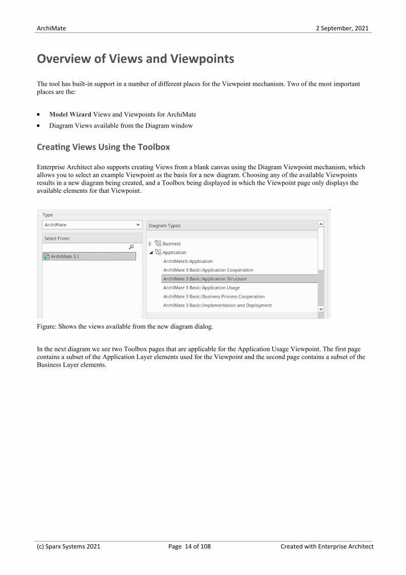
Enterprise Architect also supports creating Views from a blank canvas using the Diagram Viewpoint mechanism, whichallows you to select an example Viewpoint as the basis for a new diagram. Choosing any of the available Viewpointsresults in a new diagram being created, and a Toolbox being displayed in which the Viewpoint page only displays theavailable elements for that Viewpoint.
Figure: Shows the views available from the new diagram dialog.
In the next diagram we see two Toolbox pages that are applicable for the Application Usage Viewpoint. The first pagecontains a subset of the Application Layer elements used for the Viewpoint and the second page contains a subset of theBusiness Layer elements.
(c) Sparx Systems 2021 Page 14 of 108 Created with Enterprise Architect

ArchiMate 2 September, 2021
Figure: Showing the toolboxes that list the available elements and relationships for the selected viewpoint.
Elements can be dragged and dropped from the Toolbox pages to the open diagram, which will create a new element andadd it to the open diagram. Applicable elements can also be dragged onto the diagram from the Browser window, whichallows existing elements that have been created or used in other diagrams to be added to the current diagram. Forexample, an Application Service and a Business Process might have been created at an earlier time and these could beadded to a diagram that contains a new Application Component added to an Application Usage Viewpoint.
In this diagram we see that a modeler outside the Enterprise Architect group has created a UML Realization relationshipfrom a UML Component in the Implementation model to an ArchiMate Component, thus linking the two differentdisciplines without breaking any ArchiMate language syntax rules.
Customer RelationshipManagement System
Sypro Customer ProfileSystem
tagsPersistence = MySQLTechnology = Java (Spring)Vendor = In-House
Enterprise Architecture (ArchiMate)
Implementation (Unified Modeling
Language)
Figure: Showing how ArchiMate elements can be linked to model elements
(c) Sparx Systems 2021 Page 15 of 108 Created with Enterprise Architect

ArchiMate 2 September, 2021
Creating Views Using the Wizard
Enterprise Architect has full support for the views and viewpoints and has a powerful Model Wizard patterns whereeach viewpoint has been conveniently created and can be injected into the repository at any location. This image showsthe icon to select in the Browser window toolbar to open the Model Wizard.
Tracking Elements beteen Views
Enterprise has a number of windows that allow elements to be tracked between views and more broadly between anydiagrams that contain the elements. This can be achieved by using the element's context menu and selecting 'Find in allDiagrams'. When selected, and when an elements does appear in multiple views, a window will provide a list of all theviews that contain the element.
(c) Sparx Systems 2021 Page 16 of 108 Created with Enterprise Architect

ArchiMate 2 September, 2021
Basic Viewpoints
The basic Viewpoints are a reference or starting point for architectural descriptions and for creating meaningful anduseful models. They act as a catalyst for an architect, allowing that person to get some modeled content down, thusremoving the 'canvas-fright' syndrome that tends to paralyze progress. They are useful in supporting peer reviews,fostering organizational standards and helping novice modelers or newcomers to a domain. The ArchiMate specificationhas included all the Viewpoints as examples and it is well to remember that they should be tailored to suit thestakeholders who will ultimately need to digest the material. The basic Viewpoints are primarily intended for thearchitecture community. Some Viewpoints are limited to a single layer while others can contain elements from multiplelayers.
Table of Basic Viewpoints
The following table list the example Basic Viewpoints.
Name Description
Organization Structure of the enterprise in terms of roles, departments, etc.
Application Structure Shows the structure of a typical application in terms of its constituents.
Information Structure Shows the structure of the information used in the enterprise.
Technology Infrastructure and platforms underlying the enterprise’s information systems interms of networks, devices, and system software.
Layered Provides overview of architecture(s).
Physical Physical environment and how this relates to IT infrastructure.
Product Shows the contents of products.
Application Usage Relates applications to their use in, for example, business processes.
Technology Usage Shows how technology is used by applications.
Business ProcessCooperation
Shows the relationships between various business processes.
Application Cooperation Shows application components and their mutual relationships.
Service Realization Shows how services are realized by the requisite behavior.
Implementation andDeployment
Shows how applications are mapped onto the underlying technology.
(c) Sparx Systems 2021 Page 17 of 108 Created with Enterprise Architect

ArchiMate 2 September, 2021
Organization Viewpoint
The organization viewpoint focuses on the (internal) organization of a company, department, network of companies, orof another organizational entity. It is possible to present models in this viewpoint as nested block diagrams, but also in amore traditional way, such as organizational charts. The organization viewpoint is very useful in identifyingcompetencies, authority, and responsibilities in an organization.
The following image shows a diagram created from the Viewpoint Pattern that is a built-in part of the Model Patternfacility.
Business Actor A
Business Actor A.1
Business Actor A.1.1 Business Actor A.1.2 Business Actor A.1.3 Business Actor A.1.4
Business Actor A.2
Business Actor A.2.1 Business Actor A.2.2 Business Actor A.2.3 Business Actor A.2.4
Business Actor A.3
Business Actor A.3.1 Business Actor A.3.2 Business Actor A.3.3 Business Actor A.3.4
Figure: Showing the Organization viewpoint
(c) Sparx Systems 2021 Page 18 of 108 Created with Enterprise Architect

ArchiMate 2 September, 2021
Application Structure Viewpoint
The application structure viewpoint shows the structure of one or more applications or components. This viewpoint isuseful in designing or understanding the main structure of applications or components and the associated data; e.g., tobreak down the structure of the system under construction, or to identify legacy application components that are suitablefor migration/integration.
The following image shows a diagram created from the Viewpoint Pattern that is a built-in part of the Model Patternfacility.
ApplicationComponent B
ApplicationCollaboration A
Data Object A
ApplicationComponent C
Application InterfaceA
ApplicationComponent A
Data Object B
Figure: Showing the Application Structure viewpoint
(c) Sparx Systems 2021 Page 19 of 108 Created with Enterprise Architect

ArchiMate 2 September, 2021
Information Structure Viewpoint
The Information Structure Viewpoint pattern creates elements that show the structure of the information used in theenterprise or in a specific business process or application, in terms of data types or information elements. It will assist invisualizing the information from the business level through the application level down to the infrastructure elements thatimplement databases and other persistent stores.
Figure: Showing the Information Structure Viewpoint viewpoint
(c) Sparx Systems 2021 Page 20 of 108 Created with Enterprise Architect

ArchiMate 2 September, 2021
Technology Viewpoint
The Technology Viewpoint pattern creates elements and a diagram that describes the software and hardware technologyelements supporting the Application Layer, such as physical devices, networks, or system software such as middlewareoperating systems, databases and other containers.
Scope: Technology layer - Multiple aspects
The following image shows a diagram created from the Viewpoint Pattern that is a built-in part of the Model Patternfacility.
Figure: Showing the Technology Viewpoint
(c) Sparx Systems 2021 Page 21 of 108 Created with Enterprise Architect

ArchiMate 2 September, 2021
Layered Viewpoint
The Layered Viewpoint pattern creates a number of elements and diagrams that allow the visualization of multiple layersof an Enterprise Architecture in a single diagram. The partitioning which uses the Grouping element allows therepresentation of elements such as Business Processes in dedicated layers and elements such as Application Services inservices layers. Any number of layers can be included but the diagram is most expressive when dedicated and servicelayers are interleaved.
The following image shows a diagram created from the Viewpoint Pattern that is a built-in part of the Model Patternfacility.
(c) Sparx Systems 2021 Page 22 of 108 Created with Enterprise Architect

ArchiMate 2 September, 2021
Technology Service A Technology Service B
ApplicationComponent A
ApplicationComponent B
Application Service A Application Service B
ApplicationComponent C
1.0 Business Process
1.1 BusinessProcess
1.2 BusinessProcess
1.3 BusinessProcess
1.4 BusinessProcess
Technology Service C
ApplicationComponent D
Business Service A Business Service B Business Service C
Application Services
Business Role A Business Actor A
Business Services
Business Processes
Actors and Roles
Application Components
Technology Services
Node A
Technology
System Software A.1
Node B
System Software B.1
System Software A.2 System Software B.2
Figure: Showing the Layered Viewpoint
(c) Sparx Systems 2021 Page 23 of 108 Created with Enterprise Architect

ArchiMate 2 September, 2021
Physical Viewpoint
The Physical Viewpoint pattern creates elements and diagrams that contains equipment (one or more physical machines,tools, or instruments) that can create, use, store, move, or transform materials. It also describes how the equipment isconnected via the distribution network and allows the visualization of other active elements that are assigned to theequipment.
Figure: Showing the Physical Viewpoint
(c) Sparx Systems 2021 Page 24 of 108 Created with Enterprise Architect

ArchiMate 2 September, 2021
Product Viewpoint
The Product Viewpoint pattern creates elements and a diagram that describe the value that the products offer to externalparties such as customers or other stakeholders It allows them to visualize one or more products' composition in terms oftheir constituent business, application, or technology services and any number of contracts or other agreements. Thechannels (interfaces) through which this product is offered, and the events associated with the product can also berepresented in this viewpoint.
Figure: Showing the Physical Viewpoint
(c) Sparx Systems 2021 Page 25 of 108 Created with Enterprise Architect

ArchiMate 2 September, 2021
Application Usage Viewpoint
The Application Usage Viewpoint pattern creates elements and a diagram that describes how application services and theapplications that realize them are used to support any number of business processes. It can also show the relationshipbetween that applications that implement the services.
Figure: Showing the Application Usage Viewpoint
(c) Sparx Systems 2021 Page 26 of 108 Created with Enterprise Architect

ArchiMate 2 September, 2021
Technology Usage Viewpoint
The Technology Usage Viewpoint pattern creates elements that show how applications are supported by the software andhardware technology: the technology services are delivered by the devices; system software and networks are providedto the applications. This viewpoint plays an important role in the analysis of performance and scalability, since it relatesthe physical infrastructure to the logical world of applications.
Figure: Showing the Technology Usage Viewpoint
(c) Sparx Systems 2021 Page 27 of 108 Created with Enterprise Architect

ArchiMate 2 September, 2021
Business Process Cooperation Viewpoint
The Business Process Cooperation Viewpoint pattern creates elements and a diagram that describe the business processesshowing how they relate to each other and also with their environment. This includes relationships with BusinessServices and Business Objects and the Roles and Actors that perform the processes or who are affected by them.
Figure: Showing the Business Process Cooperation Viewpoint
(c) Sparx Systems 2021 Page 28 of 108 Created with Enterprise Architect

ArchiMate 2 September, 2021
Application Cooperation Viewpoint
The Application Cooperation Viewpoint pattern creates elements a diagram that describe the relationships betweenapplications components and their locations, the services they provide or utilize and the information that flows betweenthem.
Figure: Showing the Application Cooperation Viewpoint
(c) Sparx Systems 2021 Page 29 of 108 Created with Enterprise Architect

ArchiMate 2 September, 2021
Service Realization Viewpoint
The Service Realization Viewpoint pattern creates elements that show how one or more business services are realized bythe underlying processes (and sometimes by application components). Thus, it forms the bridge between the businessproducts viewpoint and the business process view. It provides a “view from the outside” on one or more businessprocesses.
Figure: Showing the Service Realization Viewpoint
(c) Sparx Systems 2021 Page 30 of 108 Created with Enterprise Architect

ArchiMate 2 September, 2021
Implementation and Deployment Viewpoint
The Implementation and Deployment Viewpoint pattern creates elements and a diagram that relate programs and projectsto the parts of the architecture that they implement. This view allows modeling of the scope of programs, projects andproject activities in terms of the plateaus that are realized or the individual architecture elements that are affected. Inaddition, the way the elements are affected can be indicated by annotating the relationships.
Figure: Showing the Implementation and Deployment Viewpoint
(c) Sparx Systems 2021 Page 31 of 108 Created with Enterprise Architect

ArchiMate 2 September, 2021
Motivation Viewpoints
Table of Motivation Viewpoints
Name Description
Stakeholder Focuses on modeling the stakeholders, drivers, the assessments of these drivers, andthe initial goals to address these drivers and assessments.
Goal Realization Focuses on modeling and analyzing the influence relationships between goals (andrequirements).
Requirements Realization Focuses on modeling the realization of requirements and constraints by means ofcore elements, such as actors, services, processes, application components, etc.
Motivation Covers the entire motivational aspect and allows use of all motivational elements.
(c) Sparx Systems 2021 Page 32 of 108 Created with Enterprise Architect

ArchiMate 2 September, 2021
Stakeholder Viewpoint
The Stakeholder Viewpoint pattern creates stakeholders, the internal and external drivers for change, and the assessments(in terms of strengths, weaknesses, opportunities, and threats) of these drivers. Also, the links to the initial (high-level)goals that address these concerns and assessments can be described. These goals form the basis for the requirementsengineering process, including goal refinement, contribution and conflict analysis, and the derivation of requirementsthat realize the goals.
Figure: Showing the Stakeholder Viewpoint
(c) Sparx Systems 2021 Page 33 of 108 Created with Enterprise Architect

ArchiMate 2 September, 2021
Goal Realization Viewpoint
The Goal Realization Viewpoint pattern creates elements and a diagram that models the relationships between goalsincluding the decomposition to sub-goals. The goals are realized by an Outcome which is realized by a Principle whichbehaves like a more abstract and broader requirement. Finally the Principle is realized by a Requirement indicatingspecific properties that the system must exhibit.
Figure: Showing the Goal Realization Viewpoint
(c) Sparx Systems 2021 Page 34 of 108 Created with Enterprise Architect

ArchiMate 2 September, 2021
Requirements Realization Viewpoint
The Requirements Realization Viewpoint pattern creates elements and a diagram that model the realization of Goals intoRequirements and Constraints and then how these Requirements are realized by core elements such as Business andApplication Services. Color has been introduced to add appeal to the diagram and to distinguish the element types.
Figure: Showing the Requirements Realization Viewpoint
(c) Sparx Systems 2021 Page 35 of 108 Created with Enterprise Architect

ArchiMate 2 September, 2021
Motivation Viewpoint
The Motivation Viewpoint pattern creates elements and a diagram that completely covers the motivational aspect from agiven stakeholder's perspective defining a Driver, an Assessment, a number of Goals and the Principle that is applied andthe Requirements and Constrains that are needed to qualify the Principle.
Figure: Showing the Requirements Realization Viewpoint
(c) Sparx Systems 2021 Page 36 of 108 Created with Enterprise Architect

ArchiMate 2 September, 2021
Strategy Viewpoints
Table of Strategy Viewpoints
Strategy Provides a high-level strategic overview of the strategies of the enterprise, itscapabilities, value streams, and resources, and the envisaged outcomes.
Capability Map Provides an overview of the capabilities of the enterprise.
Value Stream Shows an overview of value-creating steps in the enterprise and the capabilities thatsupport these.
Outcome Realization Describes how high-level, business-oriented results are produced by the capabilitiesand resources of the enterprise.
Resource Map Provides a structured overview of the resources of the enterprise.
(c) Sparx Systems 2021 Page 37 of 108 Created with Enterprise Architect

ArchiMate 2 September, 2021
Strategy Viewpoint
The Strategy Viewpoint pattern creates elements and a diagram that models the strategic intent of an organization byarticulating a Course of Action and the Capabilities and Resources needed to achieve it providing a modeled Outcome.
Figure: Showing the Strategy Viewpoint
(c) Sparx Systems 2021 Page 38 of 108 Created with Enterprise Architect

ArchiMate 2 September, 2021
Capability Map Viewpoint
The Capability Map Viewpoint pattern creates elements and a diagram that allows Capabilities to be visualized in anested hierarchy. The Capabilities are also nested in a hierarchy in the Project Browser allowing groups of them to beeasily moved from one location to another. Color has been used to convey the levels of the hierarchy.
Figure: Showing the Capability Map Viewpoint
(c) Sparx Systems 2021 Page 39 of 108 Created with Enterprise Architect

ArchiMate 2 September, 2021
Value Stream Viewpoint
The value stream viewpoint allows the Business Architect to create a structured overview of a value stream, thecapabilities supporting the stages in that value stream, the value created, and the stakeholders involved.
The following image shows a diagram created from the Viewpoint Pattern that is a built-in part of the Model Patternfacility.
Value Stream A
Value StreamA.1
Value StreamA.2
Value StreamA.3
Requirement A Outcome A
Stakeholder A
Figure: Showing the Value Stream Viewpoint
(c) Sparx Systems 2021 Page 40 of 108 Created with Enterprise Architect

ArchiMate 2 September, 2021
Outcome Realization Viewpoint
The Outcome Realization Viewpoint pattern creates elements and a diagram that model how core elements deliver thehigh level business value. The diagram is useful to show how the strategic level business elements such as Value andOutcomes are realized by the underlying elements that deliver that value such as Capabilities, Services and Components.
Figure: Showing the Outcome Realization Viewpoint
(c) Sparx Systems 2021 Page 41 of 108 Created with Enterprise Architect

ArchiMate 2 September, 2021
Resource Map Viewpoint
The Resource Map Viewpoint pattern creates a number of Resource elements nested into three layers . It permits aBusiness Architect or other stakeholder to create a structured overview of the resources available to an enterprise. Themap commonly shows two or three levels of resources across an entire enterprise.
Figure: Showing the Resource Map Viewpoint
(c) Sparx Systems 2021 Page 42 of 108 Created with Enterprise Architect

ArchiMate 2 September, 2021
Implementation and Migration Viewpoints
The Implementation and Migration Viewpoints are designed to allow the modeler to create relevant and meaningfulviews of the implementation and migration aspects of the architectures including such things as change and transitions.
Table of Implementation and Migration
Project Primarily used to model the management of architecture change.
Migration Used to model the transition from an existing architecture to a target architecture.
Implementation andMigration
Used to model the relationships between the programs and projects and the parts ofthe architecture that they implement.
(c) Sparx Systems 2021 Page 43 of 108 Created with Enterprise Architect

ArchiMate 2 September, 2021
Project Viewpoint
The Project Viewpoint pattern creates elements and diagrams that contains elements that model the management ofarchitecture change. This includes the transition from a baseline to a target enterprise architecture is complex and can beconstrained by Portfolio Management, Project Management and a number of other disciplines.
Figure: Showing the Project Viewpoint
(c) Sparx Systems 2021 Page 44 of 108 Created with Enterprise Architect

ArchiMate 2 September, 2021
Migration Viewpoint
The Migration Viewpoint pattern creates elements and a diagram that model the transition from a baseline to a targetenterprise architecture. The Plateau represents a relatively stable state of the architecture that exists during a limitedperiod of time, whereas the Gap represents a statement of the difference between the two states.
Figure: Showing the Migration Viewpoint
(c) Sparx Systems 2021 Page 45 of 108 Created with Enterprise Architect

ArchiMate 2 September, 2021
Implementation and Migration Viewpoint
The Implementation and Migration Viewpoint pattern creates elements and a diagram that model relate programs andprojects to the parts of the architecture that they implement. This view allows modeling of the scope of programs,projects, project activities in terms of the plateaus that are realized or the individual architecture elements that areaffected.
Figure: Showing the Implementation and Migration Viewpoint
(c) Sparx Systems 2021 Page 46 of 108 Created with Enterprise Architect

ArchiMate 2 September, 2021
The ArchiMate Language
Enterprise Architect provides a highly compliant implementation of the ArchiMate standard, allowing EnterpriseArchitects and others to create rigorous and expressive models of enterprise architecture concerns, from the level ofstakeholders and their interests right down to the virtual or physical devices that ultimately provide the computationalpower to run the enterprise and deliver valued services and outcomes to customers.
The language is deliberately pragmatic and has as a design consideration the need for the syntax and symbols to becompact and succinct, but at the same time provide the expressive power to capture and communicate structural andbehavioral aspects of the model. The Enterprise Architect platform, with WebEA and Prolaborate, allows teams to createvisualizations curated for any stakeholder group, from senior executives down to implementation staff.
ArchiMate
Business ProcessModel and Notation
(BPMN)
Unifed ModelingLanguage (UML)
Business MotivationModel (BMM)
Decision Model andNotation (DMN)
The Open GroupArchitecture
Framework (TOGAF)Zachman Framework
Figure: Showing the relationship between ArchiMate and other modeling languages.
Enterprise Architect implements a large number of other standards, and models produced by other teams can beconnected to the Enterprise Architecture models described with ArchiMate, thus creating a tapestry of interwoventhreads. For example, ArchiMate deliberately takes a birds-eye view of process models, leaving out much of the detailsand concentrating on conveying the value and how it relates to Business Functions and Services, Roles and Actors.These models can be connected to more detailed models described the use of Business Process Model and Notation(BPMN). The same is true with respect to application models that, in ArchiMate, are quite high level and intentionallyleave out implementation details such as protocols, ports and message flow. These latter details can be modeled using theUnified Modeling Language (UML) and again connected to the ArchiMate Application Components to create expressivemodels allowing drill-down and drill-up from any modeling context.
Customer RelationshipManagement System
Sypro Customer ProfileSystem
tagsPersistence = MySQLTechnology = Java (Spring)Vendor = In-House
Enterprise Architecture (ArchiMate)
Implementation (Unified Modeling
Language)
Figure: The relationship created between an ArchiMate application component and a UML component
(c) Sparx Systems 2021 Page 47 of 108 Created with Enterprise Architect

ArchiMate 2 September, 2021
(c) Sparx Systems 2021 Page 48 of 108 Created with Enterprise Architect

ArchiMate 2 September, 2021
Language Definitions
Enterprise Architect fully implements the ArchiMate language and supports all the language concepts and definitions,allowing Business, Application, Technology and Security Architects and others - including Geospatial Architects - tocreate highly expressive and compliant language models, views and other powerful visualizations of the enterprisesunder discussion.
ArchiMate Core Framework
The reference structure used to classify elements of the ArchiMate core language is implemented in EnterpriseArchitecture in its core internal metamodel. It consists of three layers and three aspects (including the physical) and theextended framework contains a number of extra layers and aspects. as extensions. These core and extended anguageelements are visible in the tool in the form of the Diagram list and tool boxes corresponding to the layers and in theelement representations with their various forms including the icon format. The following diagram has been created inEnterprise Architect to demonstrate the structure of the language
Figure: Showing the layers and aspects of the core framework
ArchiMate Core Language
The central part of the ArchiMate language that defines the concepts to model Enterprise Architectures has been builtinto the ArchiMate profile and meta model defined within the MDG Technology inside the tool. The user can access allof the defined ArchiMate language concepts and features, including elements, relationships, relationship connectors andViewpoints from a series of user-friendly tool features.
Architecture View
A representation of a system from the perspective of a related set of concerns typically relating to a single stakeholder orstakeholder group. Enterprise Architect supports this concept with a range of different product tools and mechanisms.The most important ones are:
Diagrams - any number of diagrams can be created that can display particular elements, properties with selected·themes and presentation styles and also restricted using filters
(c) Sparx Systems 2021 Page 49 of 108 Created with Enterprise Architect

ArchiMate 2 September, 2021
Matrices - elements and their relationships can be displayed in a matrix showing which elements are connected by·relationships
Textual - there are a number of tools - including list views, specification views and documents - that allow elements·and relationships to be presented in textual form, creating compelling narratives
There is also a Model Wizard pattern tool that allows any of the ArchiMate example Viewpoints to be created. Thisillustration shows the mechanism to switch between alternative views of the same underlying model content.
Figure: Showing the tool options to switch views
Architecture Viewpoint
A specification of the conventions for a particular kind of architecture view. Enterprise Architect provides a powerfulproductivity and compliance tool called Model Wizard patterns that allows all the example ArchiMate viewpoints to becreated from well defined and described patterns built into the ArchiMate perspective. This diagram shows the result ofusing the Wizard to create a Technology Usage Viewpoint.
Figure: Showing the Technology Usage Viewpoint
Aspect
(c) Sparx Systems 2021 Page 50 of 108 Created with Enterprise Architect
ArchiMate 2 September, 2021
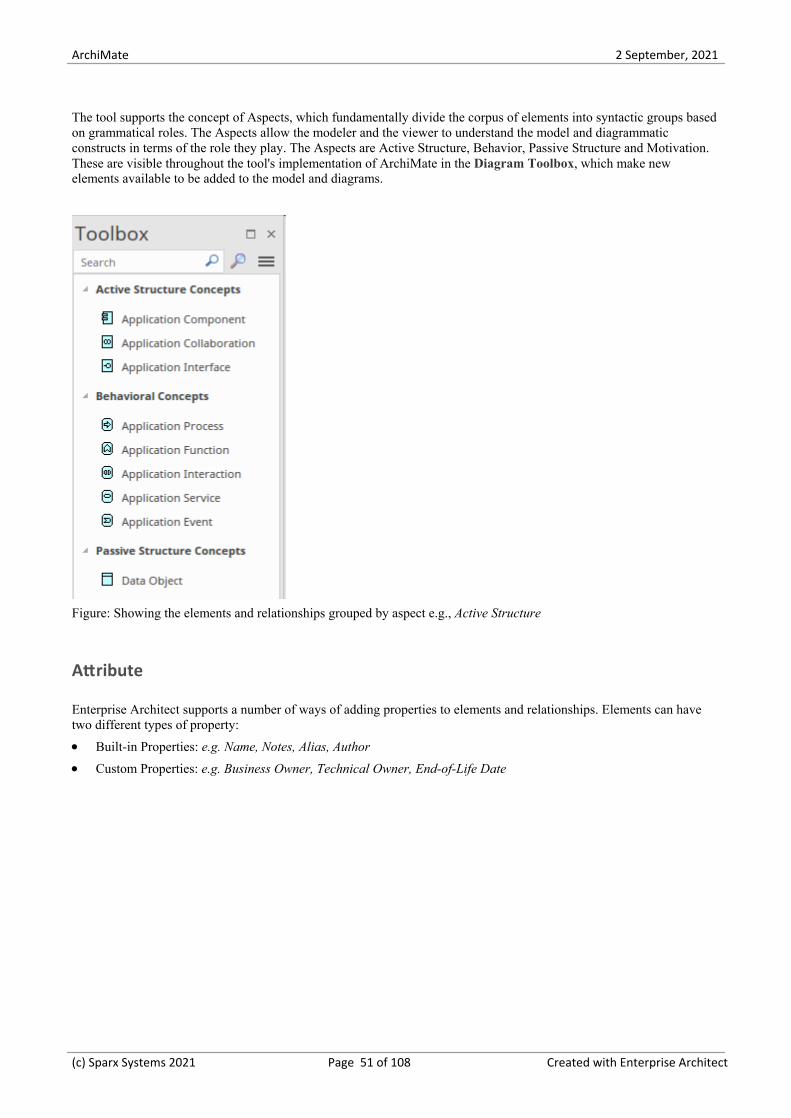
The tool supports the concept of Aspects, which fundamentally divide the corpus of elements into syntactic groups basedon grammatical roles. The Aspects allow the modeler and the viewer to understand the model and diagrammaticconstructs in terms of the role they play. The Aspects are Active Structure, Behavior, Passive Structure and Motivation.These are visible throughout the tool's implementation of ArchiMate in the Diagram Toolbox, which make newelements available to be added to the model and diagrams.
Figure: Showing the elements and relationships grouped by aspect e.g., Active Structure
Attribute
Enterprise Architect supports a number of ways of adding properties to elements and relationships. Elements can havetwo different types of property:
Built-in Properties: e.g. Name, Notes, Alias, Author·Custom Properties: e.g. Business Owner, Technical Owner, End-of-Life Date·
(c) Sparx Systems 2021 Page 51 of 108 Created with Enterprise Architect

ArchiMate 2 September, 2021
Figure: Showing the element Properties window
It is common for an Enterprise Architecture function or practice to add organization-specific properties that help in theanalysis of business, application and technology architectures. These can be added as Tagged Values either directly to anelement, or more robustly using the profile system that allows the creation and augmentation of elements as a new typethat results in a fully compliant ArchiMate element with the additional properties.
Composite Element
The tool supports the creation of the two Composite Elements namely: Grouping and Location which allow aggregationrelationships to other elements typically from multiple aspects or layers of the language.
Claims
Claims Service
Evaluate Claim Process Claim
Claim File
Figure: Showing the Grouping element
Core Element
Enterprise Architect supports all the core elements defined in the ArchiMate specification, in all aspects and all layersincluding the extensions.
(c) Sparx Systems 2021 Page 52 of 108 Created with Enterprise Architect

ArchiMate 2 September, 2021
Element
The tool supports the creation and modification of all the ArchiMate elements across all layers and aspects, and providesmechanisms to place these elements onto diagrams that comply with the example viewpoints, including allowing them toparticipate in relationships with other elements (and, in some cases, other relationships) in accordance with the definedcombinational rules. Elements, along with Relationships and Relationship Connectors, are the most primitive type ofconcept in the ArchiMate metamodel and are used to define and describe the constituent parts of Enterprise Architecturesand their unique set of characteristics.
Product A
Contract A
Business Service A Business Service B Business Service C
Value A
Business Interface A Business Interface B Business Interface C
Application Service A Application Service B
Value B Contract B
Business Actor A Business Actor B Business Actor C
Figure: Showing the Product Viewpoint
In this diagram we see elements from a number of different layers, using a number of different relationships, includingnesting as an alternative. Some of the elements are presented using their rectangular style and others (e.g. ApplicationServices) are presented using their icon style. The style can be toggled in Enterprise Architect to suit the audience andstakeholders.
Layer
Enterprise Architect is a powerful platform for architectural description and visualization and supports a variety ofdomain architects which are represented in the language and the tool by the concept of a layers. These domain specificmodels can be articulated with each other without ambiguity and are visible in the tool in the form of diagrams and theiraccompanying toolboxes.
(c) Sparx Systems 2021 Page 53 of 108 Created with Enterprise Architect
ArchiMate 2 September, 2021
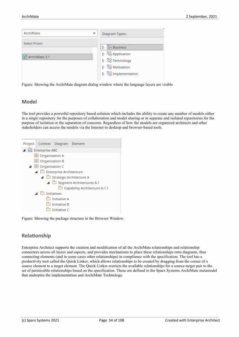
Figure: Showing the ArchiMate diagram dialog window where the language layers are visible
Model
The tool provides a powerful repository based solution which includes the ability to create any number of models eitherin a single repository for the purposes of collaboration and model sharing or in separate and isolated repositories for thepurpose of isolation or the separation of concerns. Regardless of how the models are organized architects and otherstakeholders can access the models via the Internet in desktop and browser-based tools.
Figure: Showing the package structure in the Browser Window.
Relationship
Enterprise Architect supports the creation and modification of all the ArchiMate relationships and relationshipconnectors across all layers and aspects, and provides mechanisms to place these relationships onto diagrams, thusconnecting elements (and in some cases other relationships) in compliance with the specification. The tool has aproductivity tool called the Quick Linker, which allows relationships to be created by dragging from the corner of asource element to a target element. The Quick Linker restricts the available relationships for a source-target pair to theset of permissible relationships based on the specification. These are defined in the Sparx Systems ArchiMate metamodelthat underpins the implementation and ArchiMate Technology.
(c) Sparx Systems 2021 Page 54 of 108 Created with Enterprise Architect

ArchiMate 2 September, 2021
Figure: Example Quick Linker menu showing the restricted set of relationships for the elements
(c) Sparx Systems 2021 Page 55 of 108 Created with Enterprise Architect

ArchiMate 2 September, 2021
Language Structure
When you create architectures in Enterprise Architect you are fundamentally creating ArchiMate Models that are madeup of a collection of the following concepts:
Elements·Relationships·Relationship Connectors·
These are indicated in this metamodel diagram.
Elements of one of four types can be created and will appear in the Browser window:
Structure Elements·Behavior Elements·Motivation Elements·Composite Elements·
(c) Sparx Systems 2021 Page 56 of 108 Created with Enterprise Architect

ArchiMate 2 September, 2021
Generic Metamodel
The main hierarchy of behavior and structure elements of the ArchiMate language is shown in this diagram. All theelements in this model have italic names, indicating that they are abstract and do not themselves participate in models.They are represented as independent of the layers of the framework as they can apply across all layers. The mostfundamental division of the language elements is into Behavior and Structure elements.
Figure: Showing the fundamental hierarchy of the ArchiMate elements.
Elements such as an Application Component - which is a type of Active Structure element - and Application Process -which is a type of behavior element - are added to models of architecture.
(c) Sparx Systems 2021 Page 57 of 108 Created with Enterprise Architect

ArchiMate 2 September, 2021
Elements
Enterprise Architect provides a rich and powerful user interface for working with elements. It allows all the ArchiMateelements across all aspects and layers to be created, managed and visualized. This includes these types of elementcorresponding to the ArchiMate Toolbox pages.
Motivation (Aspect) Elements1.
Strategy (Layer) Elements2.
Business (Layer) Elements3.
Application (Layer) Elements4.
Technology (Layer) Elements5.
Implementation and Migration (Layer) Elements6.
Composite Elements7.
(c) Sparx Systems 2021 Page 58 of 108 Created with Enterprise Architect

ArchiMate 2 September, 2021
Changing Element Presentation
An Enterprise Architect will typically need to provide different visualizations for different groups of stakeholders, and adiagram that is suitable for one group might not be appropriate for another. Enterprise Architect provides a wide range ofways for working with elements and diagrams, including how the elements are presented and visualized in differentdiagrams and different windows within the product.
Enterprise Architect has great flexibility and, because the tool is implemented using a robust relational databaseback-end, when changes are made to a single element on a diagram or any other view the changes can be automaticallyapplied to all places in diagrams or other windows where the element appears. This applies to element properties, namechanges and other fundamental aspects of the element. When the appearance (such as color and style) of an element ischanged a modeler has a choice of:
Changing the diagram Object style (just applies to the current diagram)·Changing the default element appearance (applies to the current diagram AND on all other diagrams)·
Changing Size, Proportion and Color
Any of the standard ArchiMate elements can be changed to different sizes, proportions and colors without affecting themeaning or syntax of the diagrams. Enterprise Architect provides great flexibility for changing both the elements and thediagram styles and themes. This illustration shows two different diagrams where the same elements have been renderedin different sizes, proportions and colors.
Changes on a Single Diagram
Changes can be made to the style of an object (element) on a single diagram; once the diagram is opened and the objectis selected there are a number of places where the element style can be changed. These changes will only apply to theselected element in the diagram and other diagrams that contain the element will not be changed in any way. In the nextsection we will see how, if required, the changes can be made to update all other diagrams.
The options to change the style are available from a number of locations, including the ribbons and the element quickstyle icon that is displayed when the element is selected in the diagram. This illustration shows the options availablefrom the diagram.
(c) Sparx Systems 2021 Page 59 of 108 Created with Enterprise Architect

ArchiMate 2 September, 2021
Changes on All Diagrams
Changes can be made to the style of an object (element) on all diagrams; once the diagram is opened and the object isselected there are a number of places where the element style can be changed. These changes will apply to the selectedelement in the diagram, and all other diagrams that contain the element will also be changed in any way.
The options to change the style are available from a number of locations, including the ribbons and the elementquick-style icon that is displayed when the element is selected in the diagram. This illustration shows the optionsavailable from the diagram.
Element Usage
Elements from the repository can participate in any number of views. They also have significance in the null case wherethey do not appear in any views. The inclusion of a variety of elements on a given diagram and the inclusion of a givenelement on multiple diagrams are what gives the language its expressive power. Enterprise Architect supports all theselanguage mechanisms and also allows you to locate the different diagrams that contain a particular element.
(c) Sparx Systems 2021 Page 60 of 108 Created with Enterprise Architect

ArchiMate 2 September, 2021
Selecting this option provides a list of all the diagrams that contain the element, allowing you to hyperlink and open anyof the listed diagrams. This provides a convenient way to understand the basis for the element's usage, as the diagram'stype and name are included in the table of usages.
Rectangular and Icon Views
The ArchiMate language provides the flexibility of displaying a number of elements either as rectangles with a smallicon in the top right hand corner, or in Icon view where the whole element takes on the Icon shape. As an Icon, whereverpossible the name of the element is placed inside the shape, but with some Icons there is no room and the name ispositioned underneath the element. Not all elements have an Icon representation and in these cases the icon view cannotbe selected.
The tool makes it easy to toggle between the two views, but care must be taken as the geometry of the element willchange as the icons are typically smaller than the rectangular representation.
(c) Sparx Systems 2021 Page 61 of 108 Created with Enterprise Architect

ArchiMate 2 September, 2021
To show an element using rectangle notation, either:
Click on the element in the diagram and on the rectangle icon that displays on the right of the element, or·Right-click on the element on the diagram and select the 'Advanced | Use Rectangle Notation' context menu option·
This displays the element as a rectangle, by default displaying an ArchiMate icon in the top right corner of the element(where the language defines an icon).
The setting only applies to the selected element, and can be toggled on and off either by:
Clicking on the icon again·Deselecting the context menu option, or·Selecting the reciprocal context menu option such as 'Use Circle Notation' or 'Use Actor Notation'·
(c) Sparx Systems 2021 Page 62 of 108 Created with Enterprise Architect

ArchiMate 2 September, 2021
Motivation Elements
Motivation Elements
A driver represents an external or internal condition that motivates an organization to define its goals and implement thechanges necessary to achieve them.
Stakeholder A stakeholder represents the role of an individual, team, or organization (or classesthereof) that represents their interests in the effects of the architecture. The imagedemonstrates both standard and alternative element notation.
Driver A driver represents an external or internal condition that motivates an organizationto define its goals and implement the changes necessary to achieve them.
Assessment An assessment represents the result of an analysis of the state of affairs of theenterprise with respect to some driver.
Goal A goal represents a high-level statement of intent, direction, or desired end state foran organization and its stakeholders.
Outcome An outcome represents an end result.
Principle A principle represents a statement of intent defining a general property that appliesto any system in a certain context in the architecture.
Requirement A requirement represents a statement of need defining a property that applies to aspecific system as described by the architecture.
(c) Sparx Systems 2021 Page 63 of 108 Created with Enterprise Architect

ArchiMate 2 September, 2021
Constraint A constraint represents a factor that limits the realization of goals.
Meaning Meaning represents the knowledge or expertise present in, or the interpretationgiven to, a concept in a particular context.
Value Value represents the relative worth, utility, or importance of a concept.
(c) Sparx Systems 2021 Page 64 of 108 Created with Enterprise Architect

ArchiMate 2 September, 2021
Motivation Example Diagrams
Using Enterprise Architect a modeler can create any number of diagrams using the ArchiMate diagrams and Toolboxpalettes. The motivation elements can be connected together to create expressive narratives that describe an EnterpriseArchitecture and the motivation for making business or technology changes articulated in other parts of the architecture.These diagrams have been taken from the Open Group's ArchiMate Specification.
Goal, Outcome, Principle, Requirement, and Constraint
This diagram is concerned with the relationship between Goals, Principles, Requirements, and Constraints. The goal“Improve Profitability of Service Offering” is realized by the outcome “Increased Profit by 10% in Next Fiscal Year”and “Reduced Cost of Customer Acquisition by 25%”. We see the use of the influence relationship between outcomeswith the indicator of (+) or (-) effect. The outcomes are in turn influenced by a number of principles and the principlesare realized by a number of requirements. We also see the use of the OR Junction in the bottom left of the diagram.
Respond to ChangingCustomer Needs,
Preference and ExpectationsQuickly and Efficiently
Services Shall Be AccessibleThrough Mobile Browsers
Mobile Applications ShallRun On All Popular Mobile
Platforms
Serve Customers WheneverThey Need Our Help
Serve Customers WhereverThey Are
Reduced Cost of CustomerAcquisition by 25%
Increased TechnologyExpenditure by 10%
Increased Revenue by 20%in Next Fiscal Year
Increased Market Share by10% in Next Fiscal Year
Increased Profit by 10% inNext Fiscal Year
Improve Profitability ofService Offering
Mobile Applications Shall beBuilt with Cross Platform
Frameworks
++
+
++
+ +
++
Figure: Example diagram from the ArchiMate Specification showing
(c) Sparx Systems 2021 Page 65 of 108 Created with Enterprise Architect

ArchiMate 2 September, 2021
Stakeholder, Driver, and Assessment
This diagram is concerned with Drivers and the Stakeholders that are concerned about them, which in this example are atthe executive level. We see that the Driver entitle Profitability has been decomposed into two other drivers namely:Revenue and Costs. Assessments have been associated with the Drivers which paint a clear picture of the state of theorganization. Influence relationship (which can be drawn between any two motivation elements) show how theassessments are related to each other. The (+) indicating a positive influence and (-) indicating a negative influence. Thisis example 18 in the Motivation Chapter of the specification.
Chief ExecutiveOfficer (CEO)
Chief MarketingOfficer (CMO)
Chief Financial Officer(CFO)
Market Share Profitability
Revenue Cost
Market Share IsDeclining
Revenue is Declining Profitability IsDeclining
Cost of Acquiring NewCustomers is Increasing
Competitors areIncluding Advanced
Features in theirService Offerings
Discounts Provided toRemain Competitive
+ ++
-+
+
+
Figure: Example diagram from the ArchiMate Specification showing
Meaning and Value
This diagram is concerned with stakeholders and the value they derive from the system. The notification message hasbeen specialized into three different types. Meanings have been associated with the messages:
A “Confirmation Of Receipt" message” has the meaning “Claim Has Been Received”·A “Review Complete" message has the meaning “Claim Review Complete”·A “Payment Complete" message” has the meaning “Claim Has Been Paid”·
(c) Sparx Systems 2021 Page 66 of 108 Created with Enterprise Architect

ArchiMate 2 September, 2021
Insurer Customer
Cost Efficiency Being InformedPeace of Mind
Certainty
Confirmation ofReceipt Message
Review CompleteMessage
Payment CompleteMessage
Message
Claim has beenReceived
Claim ReveiwComplete
Claim has beenPaid
Push Notification
Figure: Example diagram from the ArchiMate Specification showing how Meaning and Value are used.
(c) Sparx Systems 2021 Page 67 of 108 Created with Enterprise Architect

ArchiMate 2 September, 2021
Strategy Layer Elements
Table of Strategy Elements
Capability A capability represents an ability that an active structure element, such as anorganization, person, or system, possesses.
Value Stream A value stream represents a sequence of activities that create an overall result for acustomer, stakeholder, or end user.
Course of Action A course of action represents an approach or plan for configuring some capabilitiesand resources of the enterprise, undertaken to achieve a goal.
Resource A resource represents an asset owned or controlled by an individual ororganization.
(c) Sparx Systems 2021 Page 68 of 108 Created with Enterprise Architect

ArchiMate 2 September, 2021
Strategy Layer Example Diagrams
Capability, Resource,and Course of Action
This diagram is concerned with an overarching Goal to Increase Profit that is made up of two other Goals (these could beconsidered to be Objectives) namely Decrease Costs and Increase Revenue. Then two Outcomes are modeled thatinfluence the delivery of the Goals. The business architect has modeled two Course of Action elements that influencethese Outcomes. The Course of Action elements are Realized by two Capabilities one of which has two ResourcesAssigned at Headquarters.
Increase Profit
Decrease Costs Increase Revenue
Decreased Costs Loss of Customers
OperationalizeExcellence
Centralize IT Systems Standardize Products
IT Management &Operations
Product Management
Headquarters
Human Resources IT Resources
Figure: Example diagram from the ArchiMate Specification showing Capabilities, Courses of Actions and Resources.
(c) Sparx Systems 2021 Page 69 of 108 Created with Enterprise Architect

ArchiMate 2 September, 2021
Business Layer Elements
Table of Business Layer Elements
Business Actor A business actor represents a business entity that is capable of performingbehavior.
Business Role A business role represents the responsibility for performing specific behavior, towhich an actor can be assigned, or the part an actor plays in a particular action orevent.
Business Collaboration A business collaboration represents an aggregate of two or more business internalactive structure elements that work together to perform collective behavior.
Business Interface A business interface represents a point of access where a business service is madeavailable to the environment.
Business Process A business process represents a sequence of business behaviors that achieves aspecific result such as a defined set of products or business services.
Business Function A business function represents a collection of business behaviors based on a chosenset of criteria (typically required business resources and/or competencies), closelyaligned to an organization, but not necessarily explicitly governed by theorganization.
Business Interaction A business interaction represents a unit of collective business behavior performedby (a collaboration of) two or more business actors, business roles, or businesscollaborations.
Business Event A business event represents an organizational state change.
(c) Sparx Systems 2021 Page 70 of 108 Created with Enterprise Architect

ArchiMate 2 September, 2021
Business Service A business service represents explicitly defined behavior that a business role,business actor, or business collaboration exposes to its environment.
Business Object A business object represents a concept used within a particular business domain.
Contract A contract represents a formal or informal specification of an agreement between aprovider and a consumer that specifies the rights and obligations associated with aproduct and establishes functional and non-functional parameters for interaction.
Representation A representation represents a perceptible form of the information carried by abusiness object.
Product A product represents a coherent collection of services and/or passive structureelements, accompanied by a contract/set of agreements, which is offered as a wholeto (internal or external) customers.
(c) Sparx Systems 2021 Page 71 of 108 Created with Enterprise Architect

ArchiMate 2 September, 2021
Business Layer Example Diagrams
Business Objects, Representations and Contract
This diagram is concerned with the Business Passive Structure elements. It shows how an Insurance Claim can beRealized by a number of different representations. An Insurance Policy modeled using a Contract element is Realized bya Policy Summary, which is a Representation. All of the representations include this element, as indicated by the use ofthe Aggregation relationship.
Claim
Insurance Policy
Claim File Summary Claim LetterSubmission Form
Policy Summary
Figure: Example diagram from the ArchiMate Specification, showing Business Objects, Representations and Contracts
(c) Sparx Systems 2021 Page 72 of 108 Created with Enterprise Architect

ArchiMate 2 September, 2021
Application Layer Elements
Table of Application Layer Elements
Application Component An application component represents an encapsulation of application functionalityaligned to implementation structure, which is modular and replaceable.
Application Collaboration An application collaboration represents an aggregate of two or more applicationinternal active structure elements that work together to perform collectiveapplication behavior.
Application Interface An application interface represents a point of access where application services aremade available to a user, another application component, or a node.
Application Function An application function represents automated behavior that can be performed by anapplication component.
Application Interaction An application interaction represents a unit of collective application behaviorperformed by (a collaboration of) two or more application components.
Application Process An application process represents a sequence of application behaviors that achievesa specific result.
Application Event An application event represents an application state change.
Application Service An application service represents an explicitly defined exposed applicationbehavior.
(c) Sparx Systems 2021 Page 73 of 108 Created with Enterprise Architect
ArchiMate 2 September, 2021
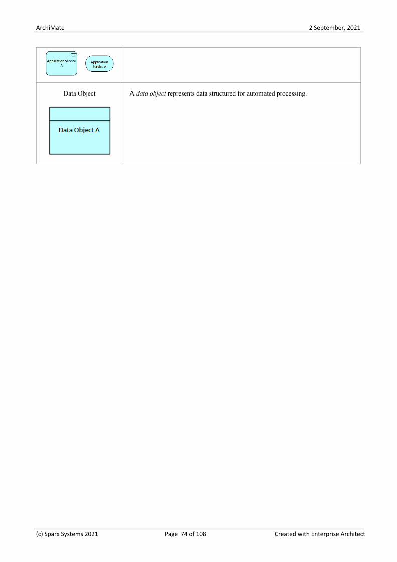
Data Object A data object represents data structured for automated processing.
(c) Sparx Systems 2021 Page 74 of 108 Created with Enterprise Architect

ArchiMate 2 September, 2021
Application Layer Example Diagrams
Application Components, Interfaces and Collaborations
This diagram demonstrates the use of Application Components, Application Interfaces and Application CollaborationsThe Online Travel Insurance Sales Collaboration is aggregated of a Quotation and Purchase system modeled asApplication Components. The Collaboration is composed of a Web Service Interface which in turn Serves the TravelWebsite.
Web ServicesInterface
Online TravelInsurance Sales
PurchaseQuotation
Travel Website
Figure: Example diagram from the ArchiMate Specification showing Application Components, Interfaces andCollaborations
(c) Sparx Systems 2021 Page 75 of 108 Created with Enterprise Architect

ArchiMate 2 September, 2021
Technology Layer Elements
Example 31: Technology Behavior Elements
Technology Elements
Node A node represents a computational or physical resource that hosts, manipulates, orinteracts with other computational or physical resources.
Device A device represents a physical IT resource upon which system software andartifacts can be stored or deployed for execution.
System Software System software represents software that provides or contributes to an environmentfor storing, executing, and using software or data deployed within it.
Technology Collaboration A technology collaboration represents an aggregate of two or more technologyinternal active structure elements that work together to perform collectivetechnology behavior.
Technology Interface A technology interface represents a point of access where technology servicesoffered by a node can be accessed.
Path A path represents a link between two or more nodes, through which these nodes canexchange data, energy, or material.
Communication Network A communication network represents a set of structures that connects nodes for
(c) Sparx Systems 2021 Page 76 of 108 Created with Enterprise Architect

ArchiMate 2 September, 2021
transmission, routing, and reception of data.
Technology Function A technology function represents a collection of technology behavior that can beperformed by a node.
Technology Process A technology process represents a sequence of technology behaviors that achieves aspecific result.
Technology Interaction A technology interaction represents a unit of collective technology behaviorperformed by (a collaboration of) two or more nodes.
Technology Event A technology event represents a technology state change.
Technology Service A technology service represents an explicitly defined exposed technology behavior.
Artifact An artifact represents a piece of data that is used or produced in a softwaredevelopment process, or by deployment and operation of an IT system.
(c) Sparx Systems 2021 Page 77 of 108 Created with Enterprise Architect

ArchiMate 2 September, 2021
Technology Examples
Technology Functions, Interfaces, Processes and Events
This diagrams concerns Technology Functions, Interfaces, Processes and Events. The Technology Architect has modeledthe Replicate Remote Data Process and the Technology Services and Functions that are required to support the Service.The Database Replication Function is composed of four other Functions that are represented using the 'nested'visualization option. The Composition relationships still exist between each of the four Technology Functions and theDatabase Replication function they are just suppressed in the diagram.
Database Replication
AdministrateReplication
Handle Local Updates
Handle RemoteUpdates
Monitor ReplicationStatus
Database UpdateReplication
Replicate RemoteData
Database Update
Figure: Example diagram from the ArchiMate Specification showing Technology Functions, Interfaces, Processes andEvents.
(c) Sparx Systems 2021 Page 78 of 108 Created with Enterprise Architect

ArchiMate 2 September, 2021
Physical Layer Elements
Table of Physical Elements
Equipment Equipment represents one or more physical machines, tools, or instruments that cancreate, use, store, move, or transform materials.
Facility A Facility represents a physical structure or environment.
Distribution Network A Distribution Network represents a physical network used to transport materials orenergy.
Material Material represents tangible physical matter or energy.
(c) Sparx Systems 2021 Page 79 of 108 Created with Enterprise Architect

ArchiMate 2 September, 2021
Physical Examples
This diagram is concerned with Physical things that are important to the Architecture, including Facilities, Equipment,Distribution Networks and Material. We see two other elements that the modeler has used; one is Path from theTechnology Layer and the other is Location, which is a Composite element. The diagram describes what is beingproduced at a Manufacturing Plant modeled as a Facility, and the logistics in the form of Shipping of overseas items andtrucking for domestic items to move the assembled items to local and national Distribution Centers.
Manufacturing Plant
Assembly Line
Preassembled CircuitBoard
Plastic Case
Internal Antenna
National DistributionCenter
Local Ditribution CenterVehicle TelematicsAppliance
Overseas Shipping Local Trucking
Intermodal Freight
Figure: Example diagram from the ArchiMate Specification showing Facilities, Equipment, Material and DistributionNetworks.
(c) Sparx Systems 2021 Page 80 of 108 Created with Enterprise Architect

ArchiMate 2 September, 2021
Implementation and Migration Layer Elements
Table of Implementation and Migration Elements
Work Package A Work Package represents a series of actions identified and designed to achievespecific results within specified time and resource constraints.
Deliverable A Deliverable represents a precisely-defined result of a Work Package.
Implementation Event An Implementation Event represents a state change related to implementation ormigration.
Plateau A Plateau represents a relatively stable state of the architecture that exists during alimited period of time.
Gap A Gap represents a statement of difference between two plateaus.
(c) Sparx Systems 2021 Page 81 of 108 Created with Enterprise Architect
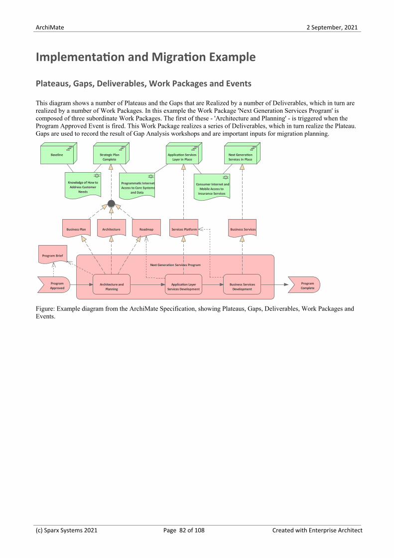
ArchiMate 2 September, 2021
Implementation and Migration Example
Plateaus, Gaps, Deliverables, Work Packages and Events
This diagram shows a number of Plateaus and the Gaps that are Realized by a number of Deliverables, which in turn arerealized by a number of Work Packages. In this example the Work Package 'Next Generation Services Program' iscomposed of three subordinate Work Packages. The first of these - 'Architecture and Planning' - is triggered when theProgram Approved Event is fired. This Work Package realizes a series of Deliverables, which in turn realize the Plateau.Gaps are used to record the result of Gap Analysis workshops and are important inputs for migration planning.
Baseline Strategic PlanComplete
Application ServicesLayer in Place
Next GenerationServices in Place
Knowledge of How toAddress Customer
Needs
Programmatic InternetAccess to Core Systems
and Data
Consumer Internet andMobile Access to
Insurance Services
Business Plan Architecture Roadmap Services Platform Business Services
Next Generation Services Program
Architecture andPlanning
Application LayerServices Development
Business ServicesDevelopment
ProgramApproved
ProgramComplete
Program Brief
Figure: Example diagram from the ArchiMate Specification, showing Plateaus, Gaps, Deliverables, Work Packages andEvents.
(c) Sparx Systems 2021 Page 82 of 108 Created with Enterprise Architect

ArchiMate 2 September, 2021
Composite Elements
Composite elements are special elements that consist of other concepts, from one or - more typically - multiple aspects orlayers of the ArchiMate language. There are two composite elements, as described in this table. Composite elements canthemselves aggregate or compose other composite elements, leading to a hierarchy of these elements.
Table of Composite Elements
Grouping The Grouping element aggregates or composes concepts that belong together basedon some common characteristic.
Location A Location represents a conceptual or physical place or position where concepts arelocated (e.g. structure elements) or performed (e.g. behavior elements).
(c) Sparx Systems 2021 Page 83 of 108 Created with Enterprise Architect

ArchiMate 2 September, 2021
Relationships
Relationships are an important part of the ArchiMate language; they bind elements to other elements and - in some cases- other relationships. Enterprise Architects allows relationships to be created in a number of ways; in this section we willdiscuss three of the main ways of creating relationships.
Creating Relationships - Toolbox
Relationships can be selected from the diagrams toolbox pages which are specific to the diagram or view that is beingconstructed. The relationship appear in a toolbox page beneath the elements and can be dragged between any twoelements or in some cases between an element and a relationship. The relationships can be used with any pair ofelements in the repository.
Creating Relationships - Quick Linker
Relationships can be drawn between two elements or an element and another relationship directly in a diagram, using theelement or relationship Quick Linker. The drawing of a relationship is initiated by dragging the small vertical arrow thatis positioned at the top right of an element or in the center of a relationship. The allowable elements will be displayedwhen the linker is drawn to target a diagram object.
(c) Sparx Systems 2021 Page 84 of 108 Created with Enterprise Architect

ArchiMate 2 September, 2021
Creating Relationships - Matrix
Relationships can be created using the matrix which is a powerful tool for visualizing the relationship between two setsof elements in a spreadsheet like appearance. The matrix displays the two sets of element based on the package locationand their type. The type of relationship can be specified which then displays an arrow which indicates pairs of elementsone from x-axis and one from the y-axis are related by the specified relationship. A new relationship can be added byright-clicking in an empty cell and selecting 'Create new relationship'.
(c) Sparx Systems 2021 Page 85 of 108 Created with Enterprise Architect

ArchiMate 2 September, 2021
Relationships Overview
Enterprise Architect is a powerful language-compliant platform that makes it easy to create industry standard EnterpriseArchitecture diagrams using ArchiMate. The tool allows the modeler to work with relationships flexibly, includingbeing able to change the styles of the connectors while at the same time maintaining the rules and constraints of theArchiMate language, including restricting what elements can be connected together.
Allowable Element Relationships
The compliance has been achieved by building the ArchiMate facility on top of a flexible and compliant meta-model thatimplements the relationship table specified in Appendix B of the ArchiMate Specification. This ensures that if thespecification changes it is simply a matter of updating the metamodel and all aspects of the tool will reflect the change.This makes it easy for the user to create first-class and compliant models as the interface restricts the availablerelationships when attempting to draw a connection between two elements in a diagram canvas.
In this example we see a modeler using the Quick Linker (a fast way of connecting elements) to create a relationshipfrom a Business Actor to a Business Function. Once the relationship is dropped onto the target a menu is opened thatdisplays the allowed relationships between the two element types based on the direction of the connection.
In this diagram we see that the user has selected the assignment connector, as this is an allowed relationship from aBusiness Actor to a Business Function.
(c) Sparx Systems 2021 Page 86 of 108 Created with Enterprise Architect

ArchiMate 2 September, 2021
Changing Size Colour and Style
Any of the standard ArchiMate relationships can be changed to different sizes and colors without affecting the meaningor syntax of the diagrams. Enterprise Architect provides great flexibility for changing the relationships and elements, andthe diagram styles and themes. This illustration shows two different diagrams where the same relationship has beenrendered in a different line width and color.
The options to change the style of a relationship are available from a number of locations, including the ribbons and theelement Quick Style icon that is displayed when the relationship's context menu is selected in the diagram. Thisillustration shows the options available from the diagram.
Nesting
Enterprise Architect allows elements to be nested as an alternative way of representing relationships. This is a powerfuland compact notation for some diagrams, alleviating the issue of some stakeholders finding the ArchiMate visual syntaxdifficult to interpret. It does, however, introduce ambiguities when the diagrams are viewed outside the tool. This is anissue with the ArchiMate language itself rather than being any limitation of the tool, and while the diagrams are beingviewed inside Enterprise Architect the ambiguities can always be resolved. Enterprise Architect allows nested views tobe created and visualized, providing a number of ways to remove the ambiguities by use of other windows that can beopened in the workspace; these clearly indicate the type of relationship implied by the element nesting.
To create nested elements, the relationships between elements must already exist or first be created. A modeler can thenuse drag-and-drop to nest one or more elements inside another element. Enterprise Architect hides the relationships in
(c) Sparx Systems 2021 Page 87 of 108 Created with Enterprise Architect

ArchiMate 2 September, 2021
the diagram but they are visible through a number of other workspace windows, including the Traceability window, theRelationships window and the 'Details' tab of the Inspector window. This illustration shows the Traceability windowwhen the containing element is selected, clearly showing the Composition relationships that exist in the model; these arenot displayed as direct relationships in the diagram but are indicated by the nesting.
Connecting to Other Relationships
Enterprise Architect, in compliance with the ArchiMate specification, allows you to connect one end of certainrelationships to other relationships. This is powerful device to express particular modeling concepts; for example, thedata that is transmitted between two elements such as two Application Components or Business Functions. This diagramshows two examples where this feature has been used.
Claims
Claims Service
Evaluate Claim Process Claim
Claim File
(c) Sparx Systems 2021 Page 88 of 108 Created with Enterprise Architect

ArchiMate 2 September, 2021
Structural Relationships
Structural relationships depict the “static” coherence within an architecture. There is always an element at the uniting end(from end) of the relationship, for the assignment and realization relationships it can be an element or a relationshipsconnector. The uniting end (to end) of the relationship typically connects to an element but in some circumstances it canbe a another relationship or relationship connector. These relationships are not only about how things are structured butalso about responsibility for the performance of behavior, storage, or execution or the representation of how a moreconcrete element plays a critical role in the creation, achievement, sustenance, or operation. This table describes thestructural relationships.
Structural Relationships
Composition The composition relationship represents that an element consists of one or moreother concepts.
Aggregation The aggregation relationship represents that an element combines one or moreother concepts.
Assignment The assignment relationship represents the allocation of responsibility, performanceof behavior, storage, or execution.
Realization The realization relationship represents that an entity plays a critical role in thecreation, achievement, sustenance, or operation of a more abstract entity.
(c) Sparx Systems 2021 Page 89 of 108 Created with Enterprise Architect

ArchiMate 2 September, 2021
Dependency Relationships
Dependency relationships describe how elements support or are used by other elements. They can indicated direction inthe form of an arrowhead at one end of the line - the direction is optional for some relationships () and mandatory forothers (Influence). Four types of dependency relationship are distinguished as indicated in this table.
Dependency Relationships
Serving The serving relationship represents that an element provides its functionality toanother element.
Access The access relationship represents the ability of behavior and active structureelements to observe or act upon passive structure elements.
Influence The influence relationship represents that an element affects the implementation orachievement of some motivation element.
Association An association relationship represents an unspecified relationship, or one that is notrepresented by another ArchiMate relationship.
(c) Sparx Systems 2021 Page 90 of 108 Created with Enterprise Architect

ArchiMate 2 September, 2021
Dynamic Relationships
The dynamic relationships describe temporal dependencies between elements within the architecture. They are oftenmistakenly interpreted as causal relationships implying that the element at the tail end of the relationship somehowcauses the element at the arrow end to 'fire' - this is not correct. In the case of the Flow relationship an item can betransmitted between the two connected elements. Two types of dynamic relationship are distinguished as indicated in thistable.
Dynamic Relationships
Triggering The triggering relationship represents a temporal or causal relationship betweenelements.
Flow The flow relationship represents transfer from one element to another.
(c) Sparx Systems 2021 Page 91 of 108 Created with Enterprise Architect

ArchiMate 2 September, 2021
Other Relationships
The other relationships category is a catch all label for relationships that don't fit into the other categories. There is onlyone relationship in this category entitled Specialization which is a directed relationship of family meaning that theelement at the tail end is a more specific than the element at the arrow-end of the relationship.
Other Relationships
Specialization The specialization relationship represents that an element is a particular kind ofanother element.
(c) Sparx Systems 2021 Page 92 of 108 Created with Enterprise Architect

ArchiMate 2 September, 2021
Relationship Connectors
A junction is used in a number of situations to connect relationships of the same type. A path with junctions that connectrelationships of this type is only allowed between two concepts, if a direct relationship of that type between theseconcepts is also permitted. Simply put, you cannot use junctions to create relationships between concepts that wouldotherwise not be allowed.
Connectors
Junction (AND) A junction is used to connect relationships of the same type to indicate that allconnectors on the multiple side(s) of the junction will be invoked.
Junction (OR) A junction is used to connect relationships of the same type to indicate that one(and only one) connector on the multiple side(s) of the junction will be invoked.
(c) Sparx Systems 2021 Page 93 of 108 Created with Enterprise Architect

ArchiMate 2 September, 2021
Alignment between Layers
The ArchiMate language is divided into a number of layers which is a useful mechanism to separate the concerns ofvarious disciplines (e.g. Business from Application layers). This creates a division in the models that are created and sowe need a mechanism to bridge this separation so that we can ensure that the elements and relationships created in onelayer are able to be visualized in relation to the elements in the layer above or below. (e.g. elements in the business layershould be able to connect to elements in the strategic layer above and the application layer below.)
ArchiMate has two important relationships that are useful for this purpose.
Serving Relationship
Serving relationships can be used to connect an application layer element to a business layer element for examplebetween an application service and the different types of business behavior elements such as business processes andfunctions, and between application interfaces and business roles. The relationships can also be drawn in the oppositedirection between business services and application behavior elements, and between business interface and applicationcomponent. These relationships represent the behavioral and structural aspects of the support of the business byapplications.
Client Registration
Onboard Customer
Realization Relationship
Realization relationships can be used to connect an application layer element to a business layer element for example anapplication process or function can be said to realize a business process or function, or a data object or a technologyobject can be said to realize a business object, so as to indicate that the data object is a digital representation of thecorresponding business object, or the technology object is a physical representation of the business object. Therelationship is always drawn in the direction from the lower layer with the arrow pointing to the higher layer.
(c) Sparx Systems 2021 Page 94 of 108 Created with Enterprise Architect

ArchiMate 2 September, 2021
Customer Registration
Client Registration
(c) Sparx Systems 2021 Page 95 of 108 Created with Enterprise Architect

ArchiMate 2 September, 2021
Customizing the ArchiMate Language
Enterprise Architect provides a powerful capability to customize language using its profile system which is part of asophisticated feature to create Model Driven Generation extensions to the tool. These extensions can be designed andbuilt within the tool and the resulting technology can be imported into the tool making customizations available toEnterprise Architects and other repository users.
A typical usage scenario would be that a team might want to categorize their Application Portfolio based on a range ofcriteria and be able to analyze architectures based on the applications to answer questions like:
What are the set of technologies underpinning our mission critical systems·Which applications run on a cloud platform·Which Business Capabilities would be compromised if Vendor A became insolvent·
This would require the provision and maintenance of properties for each application. This can be done using the profilesystem where any number of properties can be added to an ArchiMate element or connector and the customized elementcan be added to custom toolboxes. The elements and connectors are then available to the architect for modeling and oncethe properties are populated with organization specific data reports and visualizations can be created that use theproperties.
In this diagram we see the customization of an ArchiMate Application Component as part of the creation of a profile. Wesee that the user defined Application Component is a specialization of the standard ArchiMate element (indicated by thetriangular arrow-headed relationship). We also see that the specialized element has a number of added properties such asBusiness Owner, Technical Owner and Deployment Type. These are user defined properties and provide the mechanismfor adding organization specific information that will help in an architectures analysis to answer questions like thosepresented earlier.
Changing Element Default Appearance
Enterprise Architect allows the appearance of elements in diagrams to be altered to suit the intended audience. When
(c) Sparx Systems 2021 Page 96 of 108 Created with Enterprise Architect
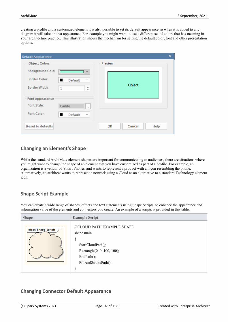
ArchiMate 2 September, 2021
creating a profile and a customized element it is also possible to set its default appearance so when it is added to anydiagram it will take on that appearance. For example you might want to use a different set of colors that has meaning inyour architecture practice. This illustration shows the mechanism for setting the default color, font and other presentationoptions.
Changing an Element's Shape
While the standard ArchiMate element shapes are important for communicating to audiences, there are situations whereyou might want to change the shape of an element that you have customized as part of a profile. For example, anorganization is a vendor of 'Smart Phones' and wants to represent a product with an icon resembling the phone.Alternatively, an architect wants to represent a network using a Cloud as an alternative to a standard Technology elementicon.
Shape Script Example
You can create a wide range of shapes, effects and text statements using Shape Scripts, to enhance the appearance andinformation value of the elements and connectors you create. An example of a scripts is provided in this table.
Shape Example Script
// CLOUD PATH EXAMPLE SHAPE
shape main
{
StartCloudPath();
Rectangle(0, 0, 100, 100);
EndPath();
FillAndStrokePath();
}
Changing Connector Default Appearance
(c) Sparx Systems 2021 Page 97 of 108 Created with Enterprise Architect

ArchiMate 2 September, 2021
Enterprise Architect allows the appearance of connectors in diagrams to be altered to suit the intended audience. Whencreating a profile and a customized connector it is also possible to set its default appearance so when it is added to anydiagram it will take on that appearance. For example you might want to use a different set of colors that has meaning inyour architecture practice. This illustration shows the mechanism for setting the default color, font and other presentationoptions.
Creating Proprietary Elements and Relationships
In addition to customizing existing ArchiMate elements as described earlier, it is possible to add completely new andproprietary elements and connectors, as long as they don't have any conflicting or obstructing meaning with respect tothe corpus of ArchiMate elements and customizations. An example of this is in the Security Architecture Domain, wherean architect might want to have an element that represents a Security Policy.
(c) Sparx Systems 2021 Page 98 of 108 Created with Enterprise Architect
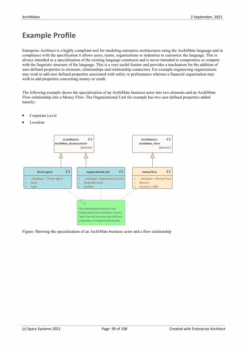
ArchiMate 2 September, 2021
Example Profile
Enterprise Architect is a highly compliant tool for modeling enterprise architectures using the ArchiMate language and incompliance with the specification it allows users, teams, organizations or industries to customize the language. This isalways intended as a specialization of the existing language constructs and is never intended to compromise or competewith the linguistic structure of the language. This is a very useful feature and provides a mechanism for the addition ofuser-defined properties to elements, relationships and relationship connectors. For example engineering organizationsmay wish to add user defined properties associated with safety or performance whereas a financial organization maywish to add properties concerning money or credit.
The following example shows the specialization of an ArchiMate business actor into two elements and an ArchiMateFlow relationship into a Money Flow. The Organizational Unit for example has two user defined properties addednamely:
Corporate Level·Location·
ArchiMate3::ArchiMate_BusinessActor
{abstract}
threat agent
+ _metatype = Threat Agent+ Level+ Type
organizational unit
+ _metatype = Organizational Unit+ Corporate Level+ Location
The stereotyped elements and relationships have attributes (Level, Type) that will become user defined properties in the generated profile.
ArchiMate3::ArchiMate_Flow
{abstract}
money flow
+ _metatype = Money Flow+ Amount+ Currency = NZD
Figure: Showing the specialization of an ArchiMate business actor and a flow relationship
(c) Sparx Systems 2021 Page 99 of 108 Created with Enterprise Architect

ArchiMate 2 September, 2021
Exchanging ArchiMate Models
Enterprise Architect supports model exchange in accordance with the specification and allows architects and others toexport and import models that comply with the exchange file format. Enterprise Architect is a powerful tool and its pricepoint, flexible licensing model and browser-based access (to the Pro Cloud Server) allows the tool to be made availableto a large number of users from interdisciplinary teams.
The tool provides these two exchange options:
Generate Model Exchange File -allowing models to be exported from Enterprise Architect·Import Model Exchange File - allowing models to be imported into Enterprise Architect·
(c) Sparx Systems 2021 Page 100 of 108 Created with Enterprise Architect
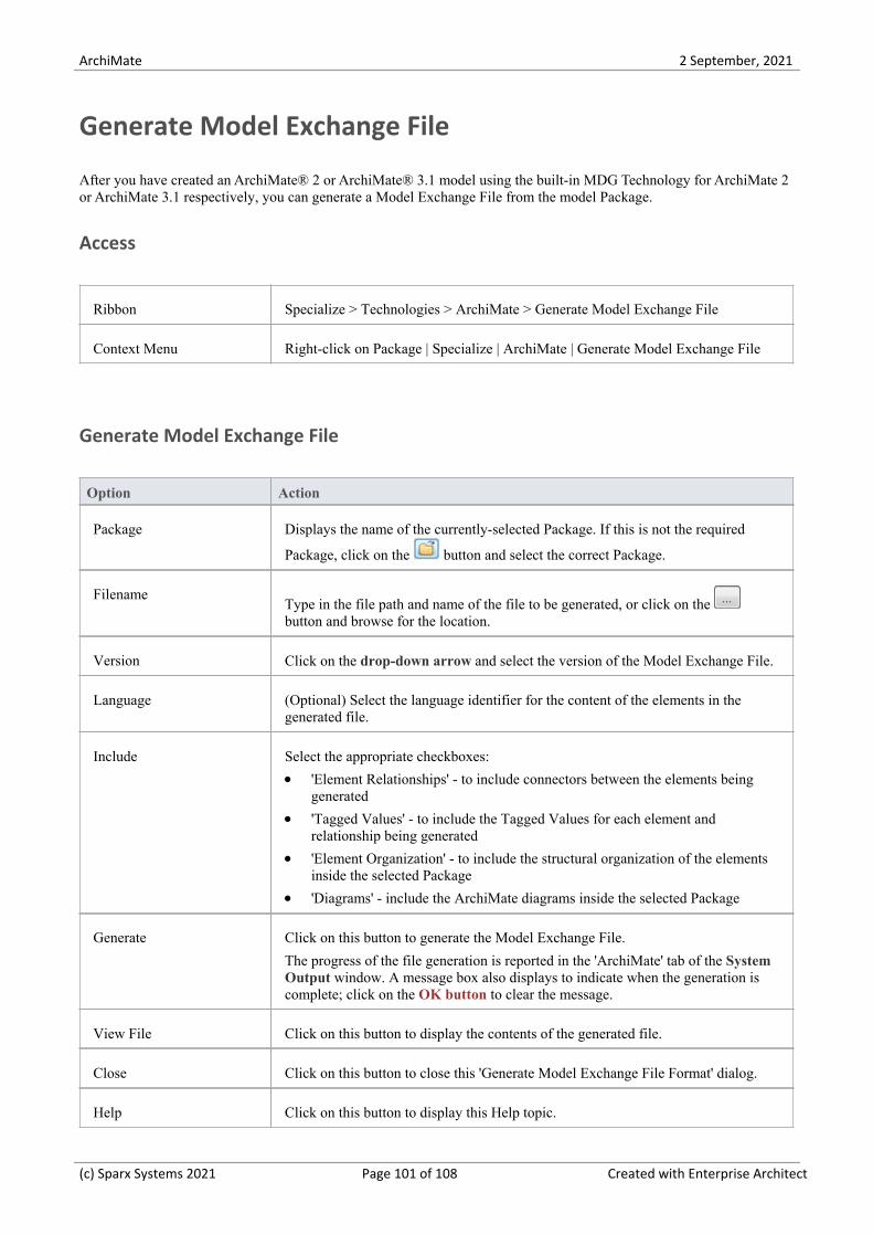
ArchiMate 2 September, 2021
Generate Model Exchange File
After you have created an ArchiMate® 2 or ArchiMate® 3.1 model using the built-in MDG Technology for ArchiMate 2or ArchiMate 3.1 respectively, you can generate a Model Exchange File from the model Package.
Access
Ribbon Specialize > Technologies > ArchiMate > Generate Model Exchange File
Context Menu Right-click on Package | Specialize | ArchiMate | Generate Model Exchange File
Generate Model Exchange File
Option Action
Package Displays the name of the currently-selected Package. If this is not the required
Package, click on the button and select the correct Package.
FilenameType in the file path and name of the file to be generated, or click on the button and browse for the location.
Version Click on the drop-down arrow and select the version of the Model Exchange File.
Language (Optional) Select the language identifier for the content of the elements in thegenerated file.
Include Select the appropriate checkboxes:
'Element Relationships' - to include connectors between the elements being·generated
'Tagged Values' - to include the Tagged Values for each element and·relationship being generated
'Element Organization' - to include the structural organization of the elements·inside the selected Package
'Diagrams' - include the ArchiMate diagrams inside the selected Package·
Generate Click on this button to generate the Model Exchange File.
The progress of the file generation is reported in the 'ArchiMate' tab of the SystemOutput window. A message box also displays to indicate when the generation iscomplete; click on the OK button to clear the message.
View File Click on this button to display the contents of the generated file.
Close Click on this button to close this 'Generate Model Exchange File Format' dialog.
Help Click on this button to display this Help topic.
(c) Sparx Systems 2021 Page 101 of 108 Created with Enterprise Architect

ArchiMate 2 September, 2021
Notes
This facility is available in the Professional, Corporate, Unified and Ultimate Editions of Enterprise Architect·The 'Language' field displays the 2-letter codes from the Language Subtag Registry:· http://www.iana.org/assignments/language-subtag-registry/language-subtag-registry
The Model Exchange File generated by Enterprise Architect adheres to The Open Group Specified Schema·Generated elements and diagrams will be displayed in the System Output window – double-click on an item in the·System Output window to highlight it in the Browser window
Elements, connectors and diagrams that are not from the built-in MDG Technology for ArchiMate 2 or ArchiMate·3.1 will be ignored during generation
The Network and Communication Path connectors from the 'ArchiMate 2::Technology' toolbox in Enterprise·Architect will not currently be generated as they do not have any mapping in The Open Group Specified Schema
The Technology <object> elements, Path connector, Communication Network connector and Distribution Network·connector from the 'ArchiMate 3.1 Technology' toolbox in Enterprise Architect will not currently be generated asthey do not have any mapping in The Open Group Specified Schema
(c) Sparx Systems 2021 Page 102 of 108 Created with Enterprise Architect

ArchiMate 2 September, 2021
Import ArchiMate Model Exchange File
If you have a valid ArchiMate® 2 or ArchiMate® 3.1 Model Exchange File, you can import it into your EnterpriseArchitect project as a UML model.
Access
Ribbon Specialize > Technologies > ArchiMate > Import Model Exchange File
Context Menu Right-click on Package | Specialize | ArchiMate | Import Model Exchange File
Import Model Exchange File
Option Action
Package Displays the name of the currently-selected Package.
If this is not the required Package, click on the button to select the PackageBrowser and select the correct Package.
FilenameType in the file path of the file to be imported, or click on the button andbrowse for the location.
Connector Style Select one of these styles to set on the imported connectors:
Orthogonal – Rounded (rounded corners)·Orthogonal – Square (square corners)·Custom·
View File Click on this button to open and view the file to be imported.
Import Click on this button to import the selected Model Exchange file into the specifiedPackage.
The progress of the file import is reported in the 'ArchiMate' tab of the SystemOutput window. A message box also displays to indicate when the import iscomplete; click on the OK button to clear the message.
Close Click on this button to close the dialog.
Help Click on this button to display this Help topic.
Notes
This facility is available in the Professional, Corporate, Unified and Ultimate Editions of Enterprise Architect·
(c) Sparx Systems 2021 Page 103 of 108 Created with Enterprise Architect

ArchiMate 2 September, 2021
The Model Exchange File should adhere to The Open Group Specified Schema·Elements, connectors and diagrams that are not specified in The Open Group Schema will be ignored during import·Imported elements and diagrams will be displayed in the System Output window – double-click on an item in this·window to highlight it in the Browser window
(c) Sparx Systems 2021 Page 104 of 108 Created with Enterprise Architect
ArchiMate 2 September, 2021
Migrate to the Latest ArchiMate Version
If you have created a model under one version of ArchiMate, you can migrate all or part of it to a later version; forexample, migrate the model from ArchiMate 2 to ArchiMate 3.1. You perform the migration using the AutomationProject Interface function Migrate(), which updates the Tagged Values and, if required, stereotypes to the later version ofArchiMate for all elements, attributes, connectors and diagrams under the selected Package or element.
When you migrate your model, you must have both releases of the Technology enabled; when the migration is complete,disable the older release of the Technology.
Migrate ArchiMate 2 model to ArchiMate 3.1
The MDG Technology for ArchiMate 3.1 has a migration script built into it, to upgrade a model built for ArchiMate 2 toArchiMate 3.1. To execute this script:
Select the 'Specialize > Tools > Scripting' ribbon option.1.
Expand the ArchiMate® 3.1 folder.2.
Right-click on the 'Migrate ArchiMate 2 to ArchiMate 3' script.3.
Click on the 'Run Script' option from the context menu.4.
Monitor the execution of the script in the System Output window.5.
When the script has finished executing, disable the ArchiMate 2 technology.
Notes (Migrate ArchiMate 2 to ArchiMate 3.1)
If you want to migrate from an ArchiMate model to an ArchiMate 3.1 model, you must do so in two stages: from·ArchiMate to ArchiMate 2, and from ArchiMate 2 to ArchiMate 3.1
Migrate ArchiMate model to ArchiMate 2
You must create a script to call the Migrate() function to migrate a Package or element to ArchiMate 2: this is a VBscript example of such a script:
Sub MigrateElement (sGUID, lngPackageID)
Dim proj as EA.Project
set proj = Repository.GetProjectInterface
proj.Migrate sGUID, "ArchiMate", "ArchiMate 2"
'refresh the model
If lngPackageID<>0 Then
Repository.RefreshModelView (lngPackageID)
End If
End Sub
Sub MigrateSelectedItem
Dim selType
Dim selElement as EA.Element
Dim selPackage as EA.Package
(c) Sparx Systems 2021 Page 105 of 108 Created with Enterprise Architect

ArchiMate 2 September, 2021
selType = GetTreeSelectedItemType
If selType = 4 Then 'means Element
set selElement = GetTreeSelectedObject
MigrateElement selElement.ElementGUID, selElement.PackageID
MsgBox "Element Migration Completed",0,"ArchiMate 2 Migration"
ElseIf selType = 5 Then 'means Package
set selPackage = GetTreeSelectedObject
MigrateElement selPackage.PackageGUID, selPackage.PackageID
MsgBox "Package Migration Completed",0,"ArchiMate 2 Migration"
Else
MsgBox "Select a Package or Element in the Browser window to initiate migration",0,"ArchiMate 2 Migration"
End If
End Sub
Sub Main
MigrateSelectedItem
End Sub
Main
Notes (Migrate ArchiMate to ArchiMate 2)
All diagrams are converted to Business Layer diagrams·Collaboration elements are converted to Business Collaboration or Application Collaboration depending on the·value of the 'collaborationtype' Tagged Value
Object elements are converted to Business Object, Contract or Data Object depending on the value of the 'objecttype'·Tagged Value
Interface elements are converted to Business Interface, Application Interface or Infrastructure Interface depending·on the value of the 'interfacetype' Tagged Value
Function elements are converted to Business Function or Application Function depending on the value of the·'functiontype' Tagged Value
Interaction elements are converted to Business Interaction or Application Interaction depending on the value of the·'interactiontype' Tagged Value
Service elements are converted to Business Service, Application Service or Infrastructure Service depending on the·value of the 'servicetype' Tagged Value
The 'iconstyle' Tagged Value is removed and the 'Use Rectangle Notation' menu option is set on or off as appropriate·Process elements become Business Process elements·Event elements become Business Event elements·Actor elements become Business Actor elements·Role elements become Business Role elements·Component elements become Application Component elements·Software elements become System Software elements·Specialisation connectors become Specialization connectors·Realisation connectors become Realization connectors·Network Connector connectors become Network·Node elements now extend UML Class elements·
(c) Sparx Systems 2021 Page 106 of 108 Created with Enterprise Architect

ArchiMate 2 September, 2021
Software elements now extend UML Class elements·Junction elements now extend UML Decision elements·
(c) Sparx Systems 2021 Page 107 of 108 Created with Enterprise Architect
ArchiMate 2 September, 2021
(c) Sparx Systems 2021 Page 108 of 108 Created with Enterprise Architect