architecting command and control capability in the ... · architecting command and control...
TRANSCRIPT

11th ICCRTS COALITION COMMAND AND CONTROL IN THE NETWORKED ERA
Architecting Command and Control Capability in the Networked Era
Topics: C2 Architecture, C2 Analysis, C2 Concepts and Organisations
David Cropley Systems Engineering and Evaluation Centre, University of South Australia
Mawson Lakes SA 5095, Australia Telephone: 61 8 8302 3301
E-mail Address: [email protected]
Yi Yue
Land Operations Division, Defence Science and Technology Organisation PO Box 1500, Edinburgh SA 5111 Australia
Telephone: 61 8 8259 5687 E-mail Address: [email protected]
Stephen Cook
Centre of Excellence in Defence and Industry Systems Capability, University of South Australia, Mawson Lakes SA 5095, Australia
Telephone: 61 8 8302 3818 E-mail Address: [email protected]
Point of Contact: Yi Yue

ARCHITECTING COMMAND AND CONTROL CAPABILITY IN THE NETWORKED ERA
David H Cropley*, Yi Yue# and Stephen C Cook&
* Systems Engineering and Evaluation Centre, University of South Australia Mawson Lakes SA 5095, Australia
# Land Operations Division, Defence Science and Technology Organisation PO Box 1500, Edinburgh SA 5111 Australia
& Centre of Excellence in Defence and Industry Systems Capability, University of South Australia, Mawson Lakes SA 5095, Australia
Abstract. It has been widely recognised that to meet the challenges of developing Command and Control (C2) capability in the networked era, a rigorous design approach needs to be taken. The mandates of US DoD Architecture Framework (DoDAF) and its Australian variant – the Defence Architecture Framework (DAF) are the reflection of this trend. However, these frameworks only define the architecture products that are needed and do not recommend a methodology for architecting. Even though a few techniques are presented in DoDAF Deskbook, it lacks a systematic comparison and evaluation of various approaches. This paper seeks to redress this deficiency by firstly describing a framework for the rational, reasoned and traceable selection of a hybrid development methodology and, then by addressing the problem of integrating the candidate methodologies into a single, unified hybrid methodology that will meets the specific needs of the Australian Land C2 capability development context. The specific methodology developed in this paper could be described as a soft mantle with a hard systems core. Differing from other soft systems/object-oriented approaches, this paper establishes a mapping from component methodologies of the hybrid to DoDAF products via a common UML modelling medium.
INTRODUCTION
In the paper On Identifying a Methodology for Land C2 Architecture Development [1] the authors set out to provide a reasoned, rational and traceable process for assembling a hybrid methodology that will facilitate the creation of a Land C2 Architecture. The rationale for the work described in [1] was a perception that there is no single, optimal development methodology for the creation of a C2 capability, even though such a system may be considered an information system. The authors [1] hypothesised that a hybrid of existing methodologies could be created that would better address the particular needs of C2 system development. The creation of such a hybrid would, however, require a structured process. The process for assembling a hybrid development methodology was achieved through the application of a framework, based on the work of Avison and Fitzgerald [2], for the analysis of a range of information system development methodologies. This is described in detail in [1]. What was not addressed in [1], however, was the mechanism by which such a hybrid methodology could move from the theoretical to the practical. In [1] the authors set out to show that a hybrid could be created in a systematic and rigorous manner, but the paper did not suggest how the hybrid would be implemented. That question must be addressed before a hybrid methodology for architecting a Land C2 system, or indeed any C2 architecture, can be

implemented. A key question that arises in the consideration of how to implement the hybrid is that of the interfaces between the methodologies (referred to as the component methodologies) that are combined in the hybrid. In [1] the authors adopted Avison and Fitzgerald’s model of a system lifecycle [2], and identified five key phases of development: Strategy, Feasibility, Analysis, Logical Design and Evaluation. The manner in which the components of a hybrid are linked together will determine the success or failure of the hybrid. For example, how can the output of a Soft Systems Methodology (SSM) process applied to the Strategy phase of architecture development be adapted to act as a suitable input to a Structured Systems Analysis and Design Methodology (SSADM) process for the subsequent Feasibility phase of development? The purpose of the present paper is to suggest how the selected hybrid methodology might be implemented. In other words, it seeks to answer the question of how the component methodologies in the hybrid can be integrated as a single methodology. The present paper also addresses the question of how the hybrid methodology might be used. Before addressing the question of the integration of component methodologies in the hybrid, a summary of the findings of the preceding paper [1] is given. In that paper a framework developed by Avison and Fitzgerald [2] was adapted to give a figure of merit for each of thirteen candidate methodologies across a wide range of criteria. The conclusions of that paper, summarised below in table 1, were that:
1. A hybrid methodology for Land C2 Architecture development can be formulated, and, 2. This hybrid methodology is better able to address the range of criteria needed for Land
C2 Architecture development than any single (component) methodology on its own. In this paper, the authors extend this argument to C2 systems more generally. In fact, two candidate hybrid methodologies, both equally suited to C2 Architecture development, were formulated. These two candidates differed in terms of their underlying philosophical approaches. One followed a traditional ‘hard’ systems paradigm, while the other followed an object-oriented, soft systems paradigm. The two candidate hybrid methodologies derived in [1] and summarised in table 1 are:
• Information Engineering (IE) + Structured Systems Analysis and Design Methodology (SSADM).
• Soft Systems Methodology (SSM) + the Rational Unified Process (RUP) + Structured Systems Analysis and Design Methodology (SSADM).
The latter, softer, object-oriented candidate was preferred by the authors. Full details of the formulation of the two candidate hybrid methodologies are given in [1]. Table 1 outlines a number of Framework Elements used by Avison and Fitzgerald [2] to compare methodologies. Each of the thirteen candidate methodologies is grouped into one of six categories (“Process”, “Blended” etc) based on its foundational characteristics. In [1] the authors used a simple ranking system to assign a score to each methodology based on its perceived strength against each framework element. The results shown in table 1 show only the final qualitative rankings and give a summary indication of the methodologies that were assessed as strongest in each framework element. A complete description of the analysis is available in [1].

What was not addressed in [1] was how the component methodologies can be combined in such a way as to produce a single, unified hybrid methodology. The risk inherent in the approach set out in the previous paper is that, without a clear means for interfacing and unifying the components, the resultant hybrid methodology will be disjointed and ineffective. The task of integrating the component methodologies is central to producing an effective hybrid methodology.
Table 1: Summary of Favoured C2 Methodologies for each Framework Element [1]
Methodologies and their Focus Areas
Process
Blended Object-oriented
People Organisational RAD
Framework Elements
STRADIS YSM JSD SSADM Merise IE OOA RUP ETHICS SSM PI ISAC DSDM
Paradigm a a
Objectives a a a a a a a a
Domain a a a
Target a a a a a a a
Model a a a a a a a a Techniques a a Tools a a a a a a a a a
Scope (hybrids)
a *,#
a*
a#
a#
Bold ticks represent methodologies that scored strongly against the framework elements while small ticks represent methodologies that scored weakly against the same criteria. No tick represents the failure of a methodology to adequately address a given framework element. * = hybrid option 1, # = hybrid option 2.
THE PREFERRED HYBRID METHODOLOGY
Based on the results developed in [1] the preferred hybrid methodology for C2 Architecture development can be represented as shown in figure 1. The five phases that are deemed critical to architecture development (those that are relevant to conceptual design) are shown with the component methodology selected as most appropriate to that phase [1]. In two of the phases, Analysis and Logical Design, more than one component methodology scored equally highly. The choice of which of the components should be preferred in these phases, for use in the hybrid, must be resolved before the question of integration is answered.
Strategy
SSM
Feasibility
SSADM
Analysis
SSM SSADM
Logical Design
SSADM
RUP
Evaluation
RUP RUP
i/p o/p
Figure 1: Hybrid Methodology: Phases and Components

The analysis method used in [1] provided no definitive answer to the question of which of the components should be preferred. For this reason an additional, intuitive layer of analysis was also necessary. Two paradigms were used to guide the development of the hybrid methodology: either a soft systems approach or a hard systems approach. The authors’ preference was to incorporate soft systems approaches where possible and this dictated the choice of component methodologies. Of the three components, the SSADM methodology that appears as the preferred component for the Feasibility phase is the ‘hardest’ of the choices. It would therefore be logical, for the purpose of maintaining the philosophical ‘flavour’ of this hybrid, to select from either SSM or RUP for the Analysis and Logical Design phases. This argument must be tempered with the recommendation that it would be logical to minimise the number of changes between component methodologies, from one phase to the next, in the interests of improving and simplifying the integration of the components. Both aims – philosophical approach and simplicity of integration – are satisfied by the configuration shown in figure 2.
Figure 2: The “Soft” Hybrid Methodology
The preferred hybrid configuration shown in figure 2 maintains the soft, object-oriented focus that is dictated by the selection process summarised in figure 1. Soft Systems Methodology (SSM) provides the front-end of the hybrid in the Strategy phase. Structured Systems Analysis and Design Methodology (SSADM) is used to accomplish the Feasibility phase, while the object-oriented, Rational Unified Process (RUP) is the preferred approach for the latter phases of the hybrid. Figure 2 represents the final result of the process described in [1].
REPRESENTING THE C2 ARCHITECTURE
At this point it is necessary to return to the problem of how the C2 Architecture is expressed or represented. The US Department of Defense Architecture Framework (DoDAF) [3] or its Australian variant – the Defence Architecture Framework (DAF) provides a convenient means for describing architectures that result from any development process. The products described in the Architecture Framework are a means for describing the various features of an architecture [4]. Figure 3 illustrates the role of the DoDAF in relation to the parts of an architecture, available architecture analysis tools, and the DoDAF products (TV-n, SV-n, OV-n). The desired end state of any development process is that the proposed hybrid methodology should generate a detailed description of the proposed C2 architecture. It is logical that this should take the form of a set of DoDAF architecture products as illustrated in figure 4. The method required to transition between the component methodologies and the DoDAF medium is examined next.
Strategy
SSM
Feasibility
SSADM
Analysis Logical Design
RUP
Evaluation
RUP RUP

System Architecture e.g. Land C2
TV-n SV-n
DoDAF Architecture Frameworks
System Architect (Popkin)
Architecture Analysis Tools
Components Functions Interfaces Constraints Relationships Design
Principles
Support/ implement
Document/ describe
Is one example of many
Implements the Is one example of many
Collectively form the
Comprise the
OV-n
Figure 3: Architectures, Architecture Frameworks and Tools
Strategy
SSM
Feasibility
SSADM
AnalysisLogical Design
RUP
Evaluation
RUP RUP
C2 Architecture Description -DoDAF/DAF
Products (TV-n, SV-n, OV-n) o/p
i/p
Figure 4: Hybrid Methodology Output – A C2 Architecture Description
OPTIONS FOR COMPONENT INTEGRATION
Having resolved the options for the components in the Analysis and Logical Design phases (figure 2), and having established a single medium for representing the resultant C2 Architecture (figure 4), the question of what options exist for the integration of the preferred component methodologies into a single, unified hybrid methodology can be addressed. In essence, a mapping between the component methodologies and the DoDAF products must be established. The question that is asked here is: how can SSM, SSADM and RUP be used to generate DoDAF products? This is a question which the DoDAF itself does not attempt to answer.

Component Integration Two approaches to the integration of the component methodologies are apparent. The first - direct integration - represented in figure 5, requires the output of each preceding phase to be translated, or otherwise made ‘readable’, for the following phase. This approach ignores the role of the DoDAF as a common medium for representing the C2 Architecture. Thus, for the Strategy phase, the output of the SSM applied to this phase would be translated into a form suitable as input for the application of SSADM in the Feasibility phase. Similarly the output of the SSADM applied to the Feasibility phase would be translated into a form suitable as input to the RUP in the Analysis phase.
Feasibility
SSADM
Strategy
SSM
Analysis
RUP SSM o/p SSADM i/p
SSADM o/p RUP i/p
Figure 5: Direct Integration: Translating Component Outputs
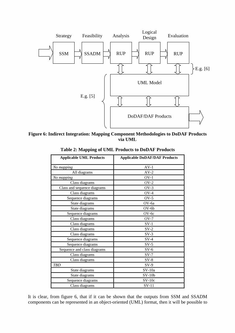
This description highlights the inherent difficulty of a hybrid methodology. That is, how can a single, consistent model of the evolving conceptual design (the C2 Architecture) be achieved across three different methodological processes (and possibly three different tools)? The second approach to the integration of component methodologies into a single, unified hybrid methodology is derived both from an examination of the components of the hybrid, and also the role of the DoDAF in describing and representing architectures in general (as shown in figure 3). This indirect approach is aided by, for example, [5] where it is showed that a mapping between prescribed architecture products (TV-n, SV-n and OV-n) in the DoDAF and the object-oriented domain represented in the Unified Modelling Language (UML) is possible. This mapping establishes an immediate connection between the latter phases (Analysis, Logical Design and Evaluation) of the hybrid methodology, the preferred component methodology for those phases (the object-oriented RUP methodology) and the leading format for representing and describing C2 architectures (the DoDAF). Figure 6 shows an evolving solution to the problem of unifying the components of the hybrid methodology. The mapping between the UML and DoDAF/DAF products, established by [5] is summarised in Table 2. The relationship between RUP and the UML is described by, for example, [6].
Strategy
SSM
Feasibility
SSADM
Analysis Logical Design
RUP
Evaluation
RUP RUP
UML Model
DoDAF/DAF Products
E.g. [5]
E.g. [6]
Figure 6: Indirect Integration: Mapping Component Methodologies to DoDAF Products
via UML
Table 2: Mapping of UML Products to DoDAF Products Applicable UML Products
Applicable DoDAF/DAF Products
No mapping AV-1 All diagrams AV-2
No mapping OV-1 Class diagrams OV-2
Class and sequence diagrams OV-3 Class diagrams OV-4
Sequence diagrams OV-5 State diagrams OV-6a State diagrams OV-6b
Sequence diagrams OV-6c Class diagrams OV-7 Class diagrams SV-1 Class diagrams SV-2 Class diagrams SV-3
Sequence diagrams SV-4 Sequence diagrams SV-5
Sequence and class diagrams SV-6 Class diagrams SV-7 Class diagrams SV-8
TBD SV-9 State diagrams SV-10a State diagrams SV-10b
Sequence diagrams SV-10c Class diagrams SV-11
It is clear, from figure 6, that if it can be shown that the outputs from SSM and SSADM components can be represented in an object-oriented (UML) format, then it will be possible to

unify the hybrid C2 Architecture development methodology in a Common UML Architecture Model (figure 7). The end state of the C2 Architecture development process is a set of DoDAF products, derived from a Common UML Model that was generated from the activities of the component methodologies. The components methodologies build the common UML model, which can then be used to generate DoDAF products.
Figure 7: Fully Integrated Hybrid Methodology
Furthermore, the Com ping to the range of DoDAF/DAF technical-, system -n, SV-n, OV-n) as
odology can be described. 2. That it is desirable to express that in the form of DoDAF products.
use of a Common UML
rise the hybrid.
The ke L Architecture Model is the extant mapping of
oDAF products to UML diagrams established by [5], summarised in table 2.
mponent methodologies and the DoDAF products. The nature of the common UML model is that is
mon UML Architecture Model gives a direct map- and operational-view products (TV
shown in table 2. This has the added advantage that it provides a solution to the limitation of the architecture framework whereby no guidance is given on how to design or implement a specific architecture [3]. The hybrid C2 Architecture methodology, therefore, provides a mechanism for the implementation of the DoDAF/DAF. The hypotheses posed in this paper are:
1. A specific, preferred hybrid meth
3. The components of that hybrid can be integrated through theArchitecture Model.
4. This provides a common language for linking the inputs and outputs of the different components that comp
5. This makes it possible to envisage a single, unified hybrid rather than a series of linked, but disjointed, components.
y to establishing this Common UMD
Evolving UML Model The role of the common UML model is to act as an interface between the co
Strategy
SSM
Feasibility Analysis
SSADM
Logical Design
RUP
Evaluation
RUP RUP
Common UML Architecture Model
C2 Architecture Description - DoDAF/DAF Products (TV-n, SV-n, OV-n)
I/P
O/P

grows, or evolves, as the hybrid methodology is implemented (figure 8). Each component
Before the hybrid ping of component methodologies to Common UML Architecture Modeillustrate the proposed ween the component
ess and lifecycle stages and UML
SteThe and
ea e can ontribute to the Common UML Architecture Model of the C2 Architecture (figure 7).
methodology contributes to, and can draw on, the evolving common UML model elements. This obviates the need for a direct mapping from one component methodology to another – the mapping takes place through the common UML medium. There still remains, however, a need to establish a mapping from the Strategy and Feasibility phases to UML before this approach can be implemented.
Figure 8: The Evolving Common UML Model
LINKING COMPONENTS TO THE UML
methodology can be used, a complete mapl must be established. Figures 7 and 8
role of the UML model as a link betmethodologies and the DoDAF products. [5], figure 6, show that for the latter phases of the hybrid methodology, this link is firmly established. However, for the initial phases, Strategy and Feasibility, there is no immediately apparent link between the components (SSM and SSADM) and medium of the UML. In order for the hybrid methodology to be fully realisable, this link must be established. To establish a link between the phases of the hybrid methodology (based on [2]) and the UML this report recognises that three elements are necessary:
1. A mapping of hybrid methodology phases to traditional SE lifecycle and process stages.
2. Extant mappings of systems engineering procproducts.
3. The resultant mapping between hybrid methodology phases and UML products.
p 1, in effect, states that A=B. Step 2 states that B=C. Step 3 states that, therefore, A=C. third step in the sequence thus establishes that all phases (including Strategysibility) of the hybrid methodology can generate UML outputs and thereforF
c
Strategy
SSM
Feasibility Analysis
SSADM
Logical Design
RUP
Evaluation
RUP RUP
C2 Architecture Description - DoDAF/DAF Products (TV-n, SV-n, OV-n)
I/P
O/P

Mapping Hybrid Phases to SE Lifecycle and Process Stages In order to show that SSM and SSADM can be mapped to the UML and therefore, by virtue of [5]’s mapping, to the DoDAF/DAF, it is necessary first to show that the methodology phases can be linked to the Common UML Model. To do this it is first necessary to revisit a
;
om tailored specifications and standards;
model of the systems engineering process. [7] sets out a clear, and widely accepted, model of the systems engineering lifecycle. In their model, the Conceptual Design lifecycle phase that is illustrated (figure 9) is driven by a statement of the user/stakeholder/customer need.
Figure 9: Conceptual Design phase [7]
The input that drives this conceptual design phase, the user/customer/stakeholder need, has been expressed more generally as part of the process input for the systems engineering process [8]. This process input includes:
Requirements Analysis
Functional Analysis
Requirements Allocation
Trade-Off Studies
Synthesis
Evaluation
Conceptual Design Activities: • Need Identification; • Requirements Analysis;
Process Inputs
• Operational Requirements; • Maintenance & Support
Concept; • Evaluation of Feasible
Technology Applications; • Selection of Technical
Approach; • Functional Definition of
Systems; • System/Program Planning.
Process Outputs
Feedback
• The user/customer/other stakeholder needs/desires/goals/requirements. These can be decomposed into:
o Uses/missions; o Measures of Effectivenesso Environments; o Constraints; o Prior outputs; o Requirements fr
o Requirements from contracts/other agreements. • The y base.
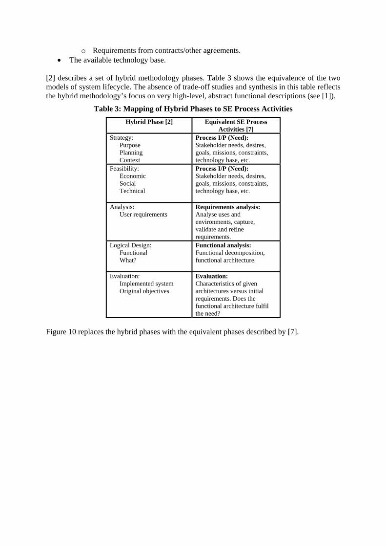
[2] describes a set of hybrid methodology phases. Table 3 shows the equivalence of the two models of t s in this table reflects the hybrid t ctional descriptions (see [1]).
ybrid Phases to SE Process Activities
available technolog
sys em lifecycle. The absence of trade-off studies and synthesime hodology’s focus on very high-level, abstract fun
Table 3: Mapping of HHybrid Phase [2] Equivalent SE Process
Activities [7] Strategy: Purpose
Process I/P (Need): Stakeholder needs, desires,
Planning Context
goals, missions, constraints, technology base, etc.
Feasi Economic
ProStakehol res,
raints,
bility:
Social Technical
cess I/P (Need): der needs, desi
goals, missions, consttechnology base, etc.
Analysis: User requirements
is:
Requirements analysAnalyse uses and environments, capture, validate and refine requirements.
Logical Design: nal
Functional analysis: ,
ture. Functio What?
Functional decompositionfunctional architec
Evaluation: Implemented system
ctives of given
lfil the need?
Original obje
Evaluation: Characteristicsarchitectures versus initial requirements. Does the functional architecture fu
Figure 10 replaces th e eq ed by [7]. e hybrid phases with th uivalent phases describ

Process Input
SSM SSADM
Requirements Analysis
Functional Analysis
RUP
Evaluation
RUP RUP
Common UML Architecture Model
C2 Architecture Description - DoDAF/DAF Products (TV-n, SV-n, OV-n)
I/P
O/P
Figure 10: Integrated Hybrid Methodology (Blanchard and Fabrycky Lifecycle Phases)
Mapping SE Lifecycle and Process Stages to the UML On the basis of a number of sources in the literature, for example [9], it is possible to map UML products to generic system lifecycle phases and therefore to the [2] hybrid lifecycle phases. These sources make it possible to link UML and the Blanchard and Fabrycky notion of a conceptual model. [9] describes a system development process, GRAPPLE (Guidelines for Rapid Application Engineering), that is based on the precursors to the Rational Unified Process (RUP). GRAPPLE utilises five ‘segments’ that cut across the activities of [7]’s system lifecycle. In effect, the GRAPPLE segments (Requirements Gathering, Analysis, Design, Development and Deployment) represent a condensed system lifecycle. In GRAPPLE, a single lifecycle phase incorporates the activities that, in [7], take place at increasing levels of detail, across five lifecycle phases. Hence the emphasis, in GRAPPLE, is on rapid development (stemming from the pressures of software development). [10]’s process provides a link between the lifecycle activities described in [7] and the UML. Figure 10 is based on the mapping of segments to UML diagrams described in [9]. Reference [9] defines the segments as follows:
• Requirement Gathering – The user need. The business processes that are the subject of system design. User domain analysis. Cooperating systems. System requirements – what do users want the system to do?
• Analysis – Deeper analysis of the requirements gathering phase data. System usage. Interactions in the system.
• Design – Design of the solution system based on analysis results. Iterative with analysis segment.
• Development – Build solution system. • Deployment – Fielding of the solution system.

The latter two stages, Development and Deployment, do not generate UML products and are outside of the scope of hybrid methodology.
• Use Case, • Sequence, • Collaboration, • Class, • State
•
Requirements
Analysis
Design
Development Deployment
Object, • Activity, • Component, • Deployment
GRAPPLE
• Package, • Class, • Deployment, • Activity, • Use Cases
Figure 11: GRAPPLE Segments and Equivalent UML Diagrams (from [9])
The applicability of object-oriented approaches to the systems engineering process is supported through a selection of methods including the Rational Unified Process for Systems Engineering (RUP SE), [10], Object Oriented Systems Engineering Method (OOSEM), [11], and [12]’s paper describing the unification of the UML with Systems Engineering. Table 4 illustrates the mapping of UML to SE process activities.
Table 4: Mapping of UML to SE Process Activities Equivalent SE Process
Activities Applicable UML Products
Process I/P (Need) Activity Diagram (what is the business process that is targeted?), Class Diagram (domain analysis – classes, objects, attributes?), Deployment Diagram (interacting sibling systems). Package Diagram (what the users want the system to do – top-level system functions – packages are collections of use cases). Use Case (requirements)
Requirements Analysis Use Case Diagrams (details of high-level functions from packages, actors and dependencies for each use case from packages, text description of steps in each use case), Refined Class Diagram (details of associations, classes, multiplicities etc.), State Diagrams (changes of state), Sequence/Collaboration Diagrams (How objects interact including state changes).
Functional Analysis Object diagrams, Activity diagrams, Component diagrams, Deployment diagrams.
Evaluation Not needed here

Hybrid Phases to UML Mapping each of the phases of the hybrid methodology can be
rid Methodology Phases to UML Hybrid cts
Tables 3 and 4 thus establish thatmapped to the UML. In particular, the first two hybrid phases, Strategy and Feasibility, can now be shown to map to UML diagrams.
Table 5: Mapping of HybMethodology Phase [2] Applicable UML Produ
Strategy: Purpose Planning Context Feasibility: Economic Social Technical
Activity Diagram (what is the business process that is targeted?), Class Diagram (domain analysis – classes, objects, attributes?), Deployment Diagram (interacting sibling systems). Package Diag
ram (what the users want the system to
– top-level system functions – packages are collection do
s of use cases). Use Case Diagram (requirements).
A
nalysis: User re
quirements
Use Case Diagrams (details of high-packages, actors and dependencies f
level functions from or each use case
from packages, text description of steps in each use case), Refined Class Diagram (details of associations, classes, multiplicities etc.), State Diagrams (changes ostate),
f Sequence/Collaboration Diagrams (How objects
interact including state changes). Logical Design: Functional What?
Object diagrams, Activity diagrams, Component diagrams, Deployment diagrams.
E
valuation:
L model. Implemented system
Original objectives
Utilises the evolved UM
able 5 establishes the traceable linking of hybrid methodology phases to UML diagrams for
IMPLEMENTING THE HYBRID METHODOLOGY
Unlike the latter tion), where the
Tall phases of the hybrid. This key step makes it possible to use the component methodologies to generate an evolving common UML Architecture Model that is directly mapped to DoDAF products.
hybrid methodology phases (Analysis through to Evaluachosen component methodology (RUP) is directly compatible with the UML, the component methodologies chosen for the Strategy and Feasibility phases do not directly produce an output compatible with the UML. [13] Discusses methods for transitioning the output of SSM to OOA (UML). Tables 2 and 3 establish that these phases are compatible with the UML, and it is the task of the chosen component methodology to present its output in the required UML form. By establishing the link between phase and UML, it is possible to prescribe the required UML output for each phase, and to populate the relevant UML diagram on the basis of the component methodology output.

Strategy Feasibility
SSM SSADM
Common UML Architecture Model
C2 Architecture Description - DoDAF/DAF Products (TV-n, SV-n, OV-n)
I/P
• Activity diagram, • Class diagram, • Deployment diagram, • Package diagram.
Figure 12: Component Outputs and the UML Architecture Model
HYBRID COMPONENTS
Having settled on the choice of the appropriate hybrid, it is then necessary to examine the components of that hybrid in greater detail. This is a precursor to plugging them together. We need to know about each component in more detail in order to be able to examine the interfaces that will need to be created between, for example, SSM and SSADM. This will also be done with particular reference to the three lifecycle phases that paper [1] identified as critical to the C2 architecting domain (strategy, feasibility and evaluation).
Soft Systems Methodology The SSM (Soft Systems Methodology) developed in the UK in 1972 by Checkland [14] resulted from an inadequacy of hard systems thinking to deal with the complexity and behaviours of socio-technical systems which are predominantly human centric in nature. SSM is a dynamic process of exploratory inquiry, learning and purposeful action to improve the problem situation. Checkland’s methodology prescribes a process of seven steps shown in figure 13. The SSM approach considers both the logical and the cultural aspects of the socio-technical system and brings in human perception, ownership and power issues through the concepts of CATWOE (Customers, Actors, Transformation process, Weltanschauung ‘world view’, Owners(s), Environmental constraints) and the development of Root definitions and conceptual models of the system or Holons. The cultural aspects of the system are examined though a sequence of Intervention, Social System and Political System analyses. According to [14] the advantages of using SSM to conduct information requirements analysis include:
• “An explicit, organised and defensible way of reconciling different and/or conflicting perspectives;

• The means to build a model of business processes appropriate to the users within the area of concern”.
This paper has recommended using SSM products “as an initial analysis for systems development projects using structured methods such as SSADM (Structured Systems Analysis and Design Methodology)”. Checkland’s SSM that produces models representing logically derived sets of linked dependant activities in terms of “what” the system must do rather than “how” it might do it, was chosen and Information Systems Methodology (ISM) was used to develop the activity model. (An overview of this information-oriented version of SSM, which is particularly applicable for information requirements analysis and information audit, is shown in Figure 13.) ISM starts by using “Rich Pictures” to express what were considered important points about the situation to be modelled within a free-form cartoon style diagram. Then a Root Definition is derived for each system to be modelled and elaborated against Customer, Actors, Transformation, Weltanschauung, Owner and Environment (CATWOE). Based on these Root Definitions, a conceptual model is built. This model can be further decomposed to higher resolution models in a hierarchy, where root definitions for activities in lower level models are derived in the similar manner.
Real World
Systems Thinking About the Real
World
Find out about the situation
Express the situation
Compare to achieve an
accommodation of views
Map organisational
structure
Map current information
provision and compare against
requirements
Define potential primary task root
definitions relevant to the organisation
or unit under review
Develop conceptual
models
Derive information categories
Map activity to activity
information flows
Iterate
Figure 13: An overview of SSM/ISM
These models are then validated and amended. The activities in the lowest level models are evaluated to identify those activities that can be expected to have the greatest business benefit from IS support to prioritise development work. The evaluation is based on three criteria:
• Contribution to Operational/Military Capability (mission effectiveness, essential needs, responsiveness and command and control);
• Frequency of occurrence; • Information content.

The perceived strength of SSM is in relation to the strategy phase of the proposed hybrid methodology for C2 architecting.
The Rational Unified Process In order to move from the conceptual world back to reality, analyses need to be carried out to gain insight and address the problematic situation. The analysis process involves mapping both current and planned systems and information categories (information required for the activity to take place, information produced as an output of the activity and information required as a measure of performance of the activity) to the activities to be performed. A gap and overlap analysis follows. The technique used to associate information categories with activities is the “Use Case” technique from the Object Oriented Design method. The nouns identified in the Use Case description are the required information categories. It is the strength of RUP in relation to the evaluation of system options that will augment the hybrid C2 methodology.
Structured Systems Analysis and Design Methodology SSADM was developed by UK consultants Learmonth and Burchett management Systems (LBMS) and the Central Computing and Telecommunications Agency (CCTA) under the auspices of the UK Civil Service. In use since 1981, it emphasises data modelling. SSADM provides strong guidance for its implementation and features comprehensive documentation. SSADM mandates five modules and a total of seven stages, and has been designed to work closely with the PRINCE project management method. The five modules of SSADM are:
1. Feasibility study. 2. Requirement analysis. 3. Requirements specification. 4. Logical system specification. 5. Physical design.
In the context of the soft hybrid methodology proposed in this paper, the particular strength of SSADM is the first module, feasibility.
SUMMARY
This paper has sought to redress the deficiency of a lack of a systematic comparison and evaluation of approaches for architecting C2 systems by firstly describing a framework for the rational, reasoned and traceable selection of a hybrid development methodology and, then addressing the problem of integrating the candidate methodologies into a single, unified hybrid methodology that will meet the specific needs of the C2 capability development context. The specific hybrid methodology developed in this paper could be described as a soft mantle with a hard systems core. Differing from other soft systems/object-oriented approaches, this paper establishes a mapping from component methodologies of the hybrid to DoDAF products via a common UML modelling medium. The present paper has maintained a focus on defining the hybrid C2 methodology to a point where it can be used for a practical development purpose. The report has established a mapping from component methodologies of the hybrid to DoDAF products via a common UML model. Other soft systems/object-oriented approaches [13] have focused on how methodologies such as SSM can generate appropriate object-oriented products. This papers changes that focus to

one of creating a common modelling medium for all methodologies, and assumes that the question of expressing the output of any given methodology in UML form is comparatively simple.
REFERENCES [1] Cropley, D. H., Yue, Y. and Cook, S. C. On Identifying a Methodology for Land C2
Architecture Development, Land Warfare Conference, Adelaide, Australia, October 2003.
[2] Avison, D. E. and Fitzgerald, D. 2003. Information Systems Development:
Methodologies, Techniques and Tools, McGraw Hill Book Company Europe. Third edition.
[3] DoD Architecture Framework, Version 1.0, US Department of Defense, February
2004. [4] Haynes, D.2003. Properties of Architecture Analysis Tools, DSTO research report. [5] Bienvenu, M. P., Shin, I. and Levis, A. H., 2000. C4ISR Architectures: III. An Object-
Oriented Approach for Architectural Design, Syst Eng 3, 288-312. [6] Larman, C., 2002, Applying UML and Patterns – An introduction to object-oriented
analysis and design and the Unified Process, Prentice Hall International, Inc. [7] Blanchard, B., and Fabrycky, W. 1998. Systems Engineering and Analysis. Upper
Saddle River, NJ, Prentice Hall. [8] Halligan, R. Systems Engineering for Defence, Aerospace and Other Technology-
Based Sectors, Course notes 1998. [9] Schmueller, J. 2002. Teach Yourself UML, Second edition. Sams Publishing, Indiana,
USA. [10] Rational, 2002. Rational Unified Process for Systems Engineering, RUP SE 1.1.
Rational Software White Paper. [11] Lykins, H., Friedenthal, S., Meilich, A. 2000. Adapting UML for an Object Oriented
Systems Engineering Method (OOSEM). Proceedings of the INCOSE 10th Annual International Symposium. Minneapolis, USA.
[12] Jorgensen, R, 2002. Model-Based Systems Engineering and Object-Oriented Software
Engineering: An Integrated Approach. Proceedings of the INCOSE 12th Annual International Symposium. Las Vegas, USA.
[13] Lane, C. M. and Galvin K., 1999. Methods for Transitioning from Soft Systems
Methodology (SSM) Models to Object Oriented Analysis (OOA), Developed to Support the Army Operational Architecture (AOA) and an Example of its Application, Proceedings of the 1999 Command and Control Research and Technology Symposium, United States Naval War College, Newport, RI, USA, June 29-July 1, 1999.

[14] Checkland, P. B., 1993. Systems Thinking, Systems Practice. John Wiley and Sons,
1993.
AUTHOR BIOGRAPHIES
Associate Professor David Cropley is the Director of the Systems Engineering and Evaluation Centre at the University of South Australia. Among his research interests are knowledge management, command and control, and creativity in engineering.
Dr Yi Yue is a senior research scientist of Land Operations Division, DSTO. Her research interests include command and control architecture, systems methodologies, and land tactical information management.
Professor Stephen Cook is the DSTO Professor of Systems Engineering and Chief Executive of the Center of Excellence in Defence and Industry Systems Capability. His research interests include improving the capability of Australian industry to provide complex system solutions, systems approaches for defence capability development, acquisition improvement, and the derivation of a theoretical framework to support the coherent teaching of systems engineering.