architecture and design - vmwarepubs.vmware.com/vmware-validated-design-41/topic/com.vmware.i… ·...
TRANSCRIPT

Architecture and Design22 AUG 2017VMware Validated Design 4.1VMware Validated Design for Management and WorkloadConsolidation 4.1
Architecture and Design
VMware, Inc. 2
You can find the most up-to-date technical documentation on the VMware website at:
https://docs.vmware.com/
If you have comments about this documentation, submit your feedback to
Copyright © 2016, 2017 VMware, Inc. All rights reserved. Copyright and trademark information.
VMware, Inc.3401 Hillview Ave.Palo Alto, CA 94304www.vmware.com
Contents
About Architecture and Design for Consolidated SDDC 5
1 Architecture Overview for Consolidated SDDC 6
Physical Infrastructure Architecture for Consolidated SDDC 8
Pod Architecture for Consolidated SDDC 8
Pod Types for Consolidated SDDC 9
Physical Network Architecture for Consolidated SDDC 10
Availability Zones and Regions for Consolidated SDDC 14
Virtual Infrastructure Architecture for Consolidated SDDC 16
Virtual Infrastructure Overview for Consolidated SDDC 16
Network Virtualization Components for Consolidated SDDC 18
Network Virtualization Services for Consolidated SDDC 18
Cloud Management Platform Architecture for Consolidated SDDC 21
vRealize Automation Architecture for Consolidated SDDC 22
vRealize Business for Cloud Architecture for Consolidated SDDC 25
Operations Architecture for Consolidated SDDC 28
Operations Management Architecture for Consolidated SDDC 28
Logging Architecturefor Consolidated SDDC 32
Data Protection and Backup Architecture for Consolidated SDDC 37
vSphere Update Manager Architecture for Consolidated SDDC 38
2 Detailed Design for Consolidated SDDC 42
Physical Infrastructure Design for Consolidated SDDC 43
Physical Design Fundamentals for Consolidated SDDC 43
Physical Networking Design for Consolidated SDDC 47
Physical Storage Design for Consolidated SDDC 52
Virtual Infrastructure Design for Consolidated SDDC 59
ESXi Design for Consolidated SDDC 60
vCenter Server Design for Consolidated SDDC 63
Virtualization Network Design for Consolidated SDDC 73
NSX Design for Consolidated SDDC 84
Shared Storage Design for Consolidated SDDC 105
Cloud Management Platform Design for Consolidated SDDC 123
vRealize Automation Design for Consolidated SDDC 124
vRealize Business for Cloud Design for Consolidated SDDC 151
vRealize Orchestrator Design for Consolidated SDDC 152
Operations Infrastructure Design for Consolidated SDDC 158
vRealize Operations Manager Design for Consolidated SDDC 159
VMware, Inc. 3

vRealize Log Insight Design for Consolidated SDDC 174
vSphere Data Protection Design for Consolidated SDDC 189
vSphere Update Manager Design for Consolidated SDDC 195
Architecture and Design
VMware, Inc. 4

About Architecture and Design forConsolidated SDDC
The Architecture and Design document for the VMware Validated Design for Management and WorkloadConsolidation contains a validated model of a consolidated pod implementation of a VMware ValidatedDesign, and provides a detailed design of each management component of the data center stack.
Chapter 1 Architecture Overview for Consolidated SDDC discusses the building blocks and the mainprinciples of each SDDC management layer. Chapter 2 Detailed Design for Consolidated SDDC providesthe available design options according to the design objective, and a set of design decisions to justifyselecting the path for building each SDDC component.
This document refers to the VMware Validated Design for Management and Workload Consolidation asthe Consolidated SDDC.
Intended AudienceVMware Validated Design Architecture and Design is intended for cloud architects, infrastructureadministrators, and cloud administrators who are familiar with and want to use VMware software to deployin a short time and manage an SDDC that meets the requirements for capacity, scalability, backup andrestore, and extensibility for disaster recovery support.
Required VMware SoftwareVMware Validated Design Architecture and Design is compliant and validated with certain productversions. See VMware Validated Design Release Notes for more information about supported productversions.
VMware, Inc. 5

Architecture Overview forConsolidated SDDC 1The VMware Validated Design for a Consolidated Software-Defined Data Center (Consolidated SDDC)enables an IT organization to automate the provisioning of common repeatable requests and to respondto business needs with more agility and predictability. Traditionally this has been referred to as IaaS, orInfrastructure as a Service, however the VMware Validated Design for a Consolidated Software-DefinedData Center extends the typical IaaS solution to include a broader and more complete IT solution.
The VMware Validated Design architecture is based on a number of layers and modules, which allowsinterchangeable components be part of the end solution or outcome such as the SDDC. If a particularcomponent design does not fit a business or technical requirement for whatever reason, it should bepossible for the component to be swapped out for another similar one. The VMware Validated Designsare one way of putting an architecture together. They are rigorously tested to ensure stability, scalabilityand compatibility. Ultimately, the system is designed in such a way as to ensure the desired IT outcomewill be achieved.
Figure 1‑1. Architecture Overview
ServiceManagement
Portfolio Management
OperationsManagement
CloudManagement
Layer
Service Catalog
Self-Service Portal
Orchestration
BusinessContinuity
Backup & Restore
Hypervisor
Pools of Resources
Virtualization Control
VirtualInfrastructure
Layer
Compute
Storage
Network
PhysicalLayer
Security
Compliance
Risk
Governance
VMware, Inc. 6
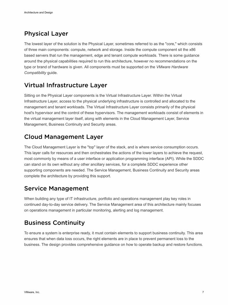
Physical LayerThe lowest layer of the solution is the Physical Layer, sometimes referred to as the "core," which consistsof three main components: compute, network and storage. Inside the compute component sit the x86based servers that run the management, edge and tenant compute workloads. There is some guidancearound the physical capabilities required to run this architecture, however no recommendations on thetype or brand of hardware is given. All components must be supported on the VMware HardwareCompatibility guide.
Virtual Infrastructure LayerSitting on the Physical Layer components is the Virtual Infrastructure Layer. Within the VirtualInfrastructure Layer, access to the physical underlying infrastructure is controlled and allocated to themanagement and tenant workloads. The Virtual Infrastructure Layer consists primarily of the physicalhost's hypervisor and the control of these hypervisors. The management workloads consist of elements inthe virtual management layer itself, along with elements in the Cloud Management Layer, ServiceManagement, Business Continuity and Security areas.
Cloud Management LayerThe Cloud Management Layer is the "top" layer of the stack, and is where service consumption occurs.This layer calls for resources and then orchestrates the actions of the lower layers to achieve the request,most commonly by means of a user interface or application programming interface (API). While the SDDCcan stand on its own without any other ancillary services, for a complete SDDC experience othersupporting components are needed. The Service Management, Business Continuity and Security areascomplete the architecture by providing this support.
Service ManagementWhen building any type of IT infrastructure, portfolio and operations management play key roles incontinued day-to-day service delivery. The Service Management area of this architecture mainly focuseson operations management in particular monitoring, alerting and log management.
Business ContinuityTo ensure a system is enterprise ready, it must contain elements to support business continuity. This areaensures that when data loss occurs, the right elements are in place to prevent permanent loss to thebusiness. The design provides comprehensive guidance on how to operate backup and restore functions.
Architecture and Design
VMware, Inc. 7
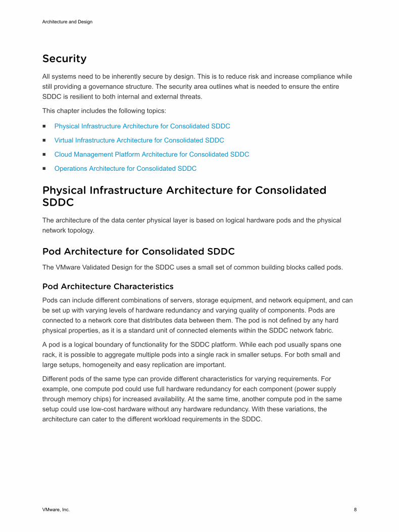
SecurityAll systems need to be inherently secure by design. This is to reduce risk and increase compliance whilestill providing a governance structure. The security area outlines what is needed to ensure the entireSDDC is resilient to both internal and external threats.
This chapter includes the following topics:
n Physical Infrastructure Architecture for Consolidated SDDC
n Virtual Infrastructure Architecture for Consolidated SDDC
n Cloud Management Platform Architecture for Consolidated SDDC
n Operations Architecture for Consolidated SDDC
Physical Infrastructure Architecture for ConsolidatedSDDCThe architecture of the data center physical layer is based on logical hardware pods and the physicalnetwork topology.
Pod Architecture for Consolidated SDDCThe VMware Validated Design for the SDDC uses a small set of common building blocks called pods.
Pod Architecture CharacteristicsPods can include different combinations of servers, storage equipment, and network equipment, and canbe set up with varying levels of hardware redundancy and varying quality of components. Pods areconnected to a network core that distributes data between them. The pod is not defined by any hardphysical properties, as it is a standard unit of connected elements within the SDDC network fabric.
A pod is a logical boundary of functionality for the SDDC platform. While each pod usually spans onerack, it is possible to aggregate multiple pods into a single rack in smaller setups. For both small andlarge setups, homogeneity and easy replication are important.
Different pods of the same type can provide different characteristics for varying requirements. Forexample, one compute pod could use full hardware redundancy for each component (power supplythrough memory chips) for increased availability. At the same time, another compute pod in the samesetup could use low-cost hardware without any hardware redundancy. With these variations, thearchitecture can cater to the different workload requirements in the SDDC.
Architecture and Design
VMware, Inc. 8

Pod to Rack MappingPods are not mapped one-to-one to data center racks. While a pod is an atomic unit of a repeatablebuilding block, a rack is merely a unit of size. Because pods can have different sizes, how pods aremapped to data center racks depends on the use case.
One Pod in One Rack One pod can occupy exactly one rack.
Multiple Pods in OneRack
Two or more pods can occupy a single rack, for example, one managementpod and one shared edge and compute pod can be deployed to a singlerack.
Single Pod AcrossMultiple Racks
A single pod can stretch across multiple adjacent racks. For example, astorage pod with filer heads and disk shelves can span more than one rackor a compute pod that has more hosts then a single rack can support.
Note In a Layer 3 Leaf/Spine physical network topology the consolidated pod cannot span racks. This isdue to VLAN backed virtual machines migrating to a different rack where that IP subnet is not availabledue to layer 2 termination at the Top of Rack switch. To learn about consolidated pods, see Pod Types forConsolidated SDDC.
Pod Types for Consolidated SDDCThe Consolidated SDDC differentiates between the consolidated pod and storage pod.
Figure 1‑2. Pods in the Consolidated Software-Defined Data CenterLAN
ToR Switch
ToRSwitch
Consolidated pod(min 4 ESXi hosts)
Secondarystorage
External connection
Architecture and Design
VMware, Inc. 9
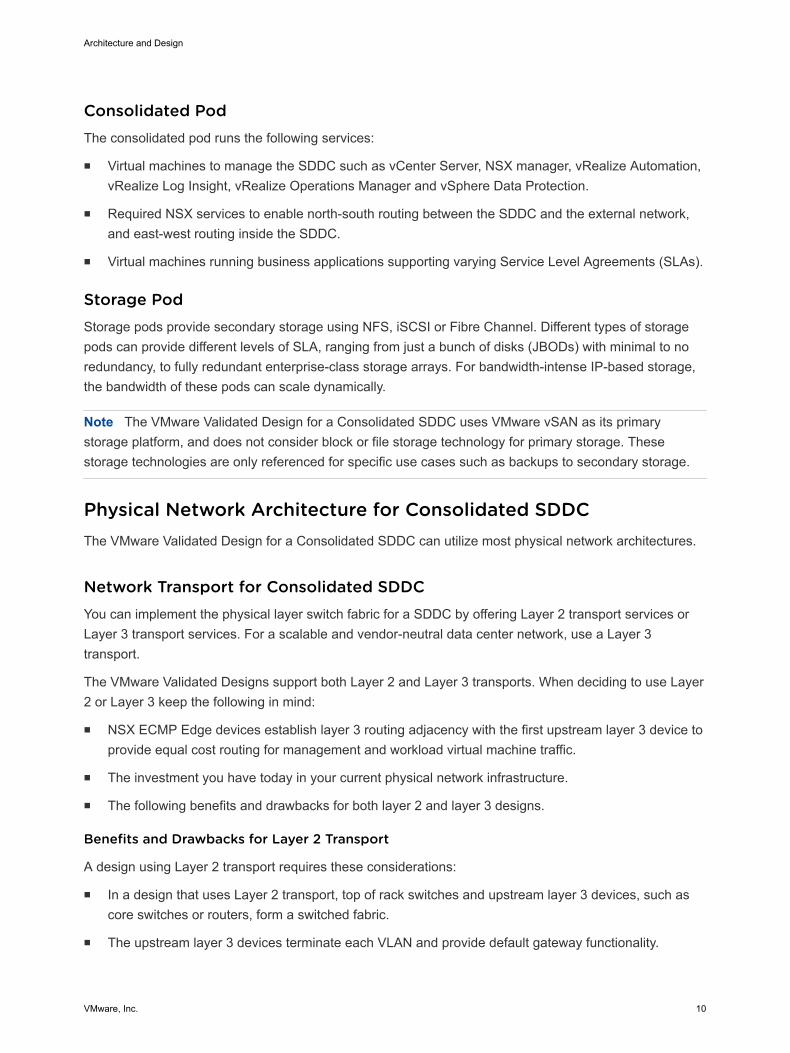
Consolidated PodThe consolidated pod runs the following services:
n Virtual machines to manage the SDDC such as vCenter Server, NSX manager, vRealize Automation,vRealize Log Insight, vRealize Operations Manager and vSphere Data Protection.
n Required NSX services to enable north-south routing between the SDDC and the external network,and east-west routing inside the SDDC.
n Virtual machines running business applications supporting varying Service Level Agreements (SLAs).
Storage PodStorage pods provide secondary storage using NFS, iSCSI or Fibre Channel. Different types of storagepods can provide different levels of SLA, ranging from just a bunch of disks (JBODs) with minimal to noredundancy, to fully redundant enterprise-class storage arrays. For bandwidth-intense IP-based storage,the bandwidth of these pods can scale dynamically.
Note The VMware Validated Design for a Consolidated SDDC uses VMware vSAN as its primarystorage platform, and does not consider block or file storage technology for primary storage. Thesestorage technologies are only referenced for specific use cases such as backups to secondary storage.
Physical Network Architecture for Consolidated SDDCThe VMware Validated Design for a Consolidated SDDC can utilize most physical network architectures.
Network Transport for Consolidated SDDCYou can implement the physical layer switch fabric for a SDDC by offering Layer 2 transport services orLayer 3 transport services. For a scalable and vendor-neutral data center network, use a Layer 3transport.
The VMware Validated Designs support both Layer 2 and Layer 3 transports. When deciding to use Layer2 or Layer 3 keep the following in mind:
n NSX ECMP Edge devices establish layer 3 routing adjacency with the first upstream layer 3 device toprovide equal cost routing for management and workload virtual machine traffic.
n The investment you have today in your current physical network infrastructure.
n The following benefits and drawbacks for both layer 2 and layer 3 designs.
Benefits and Drawbacks for Layer 2 Transport
A design using Layer 2 transport requires these considerations:
n In a design that uses Layer 2 transport, top of rack switches and upstream layer 3 devices, such ascore switches or routers, form a switched fabric.
n The upstream layer 3 devices terminate each VLAN and provide default gateway functionality.
Architecture and Design
VMware, Inc. 10
n Uplinks from the top of rack switch to the upstream layer 3 devices are 802.1Q trunks carrying allrequired VLANs.
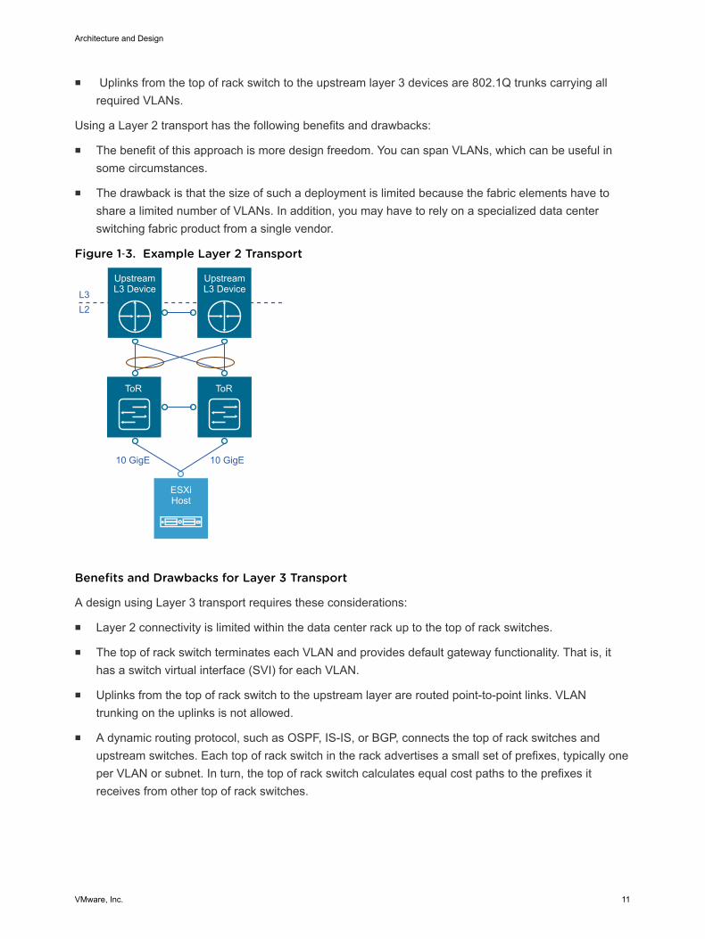
Using a Layer 2 transport has the following benefits and drawbacks:
n The benefit of this approach is more design freedom. You can span VLANs, which can be useful insome circumstances.
n The drawback is that the size of such a deployment is limited because the fabric elements have toshare a limited number of VLANs. In addition, you may have to rely on a specialized data centerswitching fabric product from a single vendor.
Figure 1‑3. Example Layer 2 Transport
ToR ToR
ESXiHost
Upstream L3 DeviceL3
10 GigE 10 GigE
L2
Upstream L3 Device
Benefits and Drawbacks for Layer 3 Transport
A design using Layer 3 transport requires these considerations:
n Layer 2 connectivity is limited within the data center rack up to the top of rack switches.
n The top of rack switch terminates each VLAN and provides default gateway functionality. That is, ithas a switch virtual interface (SVI) for each VLAN.
n Uplinks from the top of rack switch to the upstream layer are routed point-to-point links. VLANtrunking on the uplinks is not allowed.
n A dynamic routing protocol, such as OSPF, IS-IS, or BGP, connects the top of rack switches andupstream switches. Each top of rack switch in the rack advertises a small set of prefixes, typically oneper VLAN or subnet. In turn, the top of rack switch calculates equal cost paths to the prefixes itreceives from other top of rack switches.
Architecture and Design
VMware, Inc. 11

Using Layer 3 routing has the following benefits and drawbacks:
n The benefit is that you can chose from a wide array of Layer 3 capable switch products for thephysical switching fabric. You can mix switches from different vendors due to general interoperabilitybetween implementation of OSPF, IS-IS or BGP. This approach is typically more cost effectivebecause it makes use of only the basic functionality of the physical switches.
n A design restriction, and thereby a drawback of using Layer 3 routing, is that VLANs are restricted toa single rack. This can affect, vSphere Fault Tolerance, and storage networks. This limitation can beovercome by the use of Layer 2 bridging in NSX.
Figure 1‑4. Example Layer 3 Transport
ToR
L3
ESXiHost
UpstreamSwitch
UpstreamSwitch
WAN/MPLSInternet
WAN/MPLSInternet
ToR
L2
10 GigE10 GigE
Infrastructure Network Architecture for Consolidated SDDCA key goal of network virtualization is to provide a virtual-to-physical network abstraction.
To achieve this, the physical fabric must provide a robust IP transport with the following characteristics:
n Simplicity
n Scalability
n High bandwidth
n Fault-tolerant transport
n Support for different levels of quality of service (QoS)
Simplicity and Scalability for Consolidated SDDC
Simplicity and scalability are the first and most critical requirements for networking.
Architecture and Design
VMware, Inc. 12
Simplicity
Configuration of the switches inside a data center must be simple. General or global configuration suchas AAA, SNMP, syslog, NTP, and others should be replicated line by line, independent of the position ofthe switches. A central management capability to configure all switches at once is an alternative.
Configurations that are unique to the switches such as multi-chassis link aggregation groups, VLAN IDs,and dynamic routing protocol configuration, should be kept to a minimum.
Scalability
Scalability factors include, but are not limited to, the following:
n Number of racks supported in a fabric.
n Amount of bandwidth between any two racks in a data center.
n Number of paths between racks.
The total number of ports available across all switches and the oversubscription that is acceptabledetermine the number of racks supported in a fabric. Different racks may host different types ofinfrastructure, which can result in different bandwidth requirements.
n Racks with IP storage systems might attract or source more traffic than other racks.
n Compute racks, such as racks hosting hypervisors with workloads or virtual machines, might havedifferent bandwidth requirements than the shared edge and compute rack, which providesconnectivity to the outside world.
Link speed and the number of links vary to satisfy different bandwidth demands. You can vary them foreach rack.
Quality of Service Differentiation for Consolidated SDDC
Virtualized environments carry different types of traffic, including tenant, storage and management traffic,across the switching infrastructure. Each traffic type has different characteristics and makes differentdemands on the physical switching infrastructure.
n Management traffic, although typically low in volume, is critical for controlling physical and virtualnetwork state.
n IP storage traffic is typically high in volume and generally stays within a data center.
For virtualized environments, the hypervisor sets the QoS values for the different traffic types. Thephysical switching infrastructure has to trust the values set by the hypervisor. No reclassification isnecessary at the server-facing port of a top of rack switch. If there is a congestion point in the physicalswitching infrastructure, the QoS values determine how the physical network sequences, prioritizes, orpotentially drops traffic.
Architecture and Design
VMware, Inc. 13
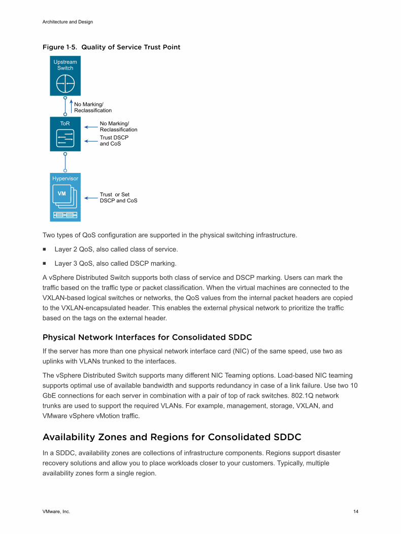
Figure 1‑5. Quality of Service Trust Point
ToR
Hypervisor
Upstream Switch
No Marking/Reclassification
No Marking/ReclassificationTrust DSCPand CoS
Trust or SetDSCP and CoS
Upstream L3 Device
Two types of QoS configuration are supported in the physical switching infrastructure.
n Layer 2 QoS, also called class of service.
n Layer 3 QoS, also called DSCP marking.
A vSphere Distributed Switch supports both class of service and DSCP marking. Users can mark thetraffic based on the traffic type or packet classification. When the virtual machines are connected to theVXLAN-based logical switches or networks, the QoS values from the internal packet headers are copiedto the VXLAN-encapsulated header. This enables the external physical network to prioritize the trafficbased on the tags on the external header.
Physical Network Interfaces for Consolidated SDDCIf the server has more than one physical network interface card (NIC) of the same speed, use two asuplinks with VLANs trunked to the interfaces.
The vSphere Distributed Switch supports many different NIC Teaming options. Load-based NIC teamingsupports optimal use of available bandwidth and supports redundancy in case of a link failure. Use two 10GbE connections for each server in combination with a pair of top of rack switches. 802.1Q networktrunks are used to support the required VLANs. For example, management, storage, VXLAN, andVMware vSphere vMotion traffic.
Availability Zones and Regions for Consolidated SDDCIn a SDDC, availability zones are collections of infrastructure components. Regions support disasterrecovery solutions and allow you to place workloads closer to your customers. Typically, multipleavailability zones form a single region.
Architecture and Design
VMware, Inc. 14
The VMware Validated Design for Consolidated SDDC uses a single region with one availability zone. Ifyou require a multi-region design refer to the VMware Validated Design for Software-Defined Data Center.
Availability Zones for Consolidated SDDCEach availability zone is isolated from other availability zones to stop the propagation of failure or outageacross zone boundaries.
Note The Consolidated SDDC supports only a single availability zone. Refer to the VMware ValidatedDesign for Software-Defined Data Center if you require multiple availability zones.
Together, multiple availability zones provide continuous availability through redundancy, helping to avoidoutages and improve SLAs. An outage that is caused by external factors (such as power, cooling, andphysical integrity) affects only one zone. Those factors most likely do not lead to an outage in other zonesexcept in the case of major disasters.
Each availability zone runs on its own physically distinct, independent infrastructure, and is engineered tobe highly reliable. Each zone should have independent power supply, cooling system, network, andsecurity. Common points of failures within a physical data center, like generators and cooling equipment,should not be shared across availability zones. Additionally, these zones should be physically separate sothat even uncommon disasters affect only a single availability zone. Availability zones are usually eithertwo distinct data centers within metro distance (latency in the single digit range) or two safety/fire sectors(data halls) within the same large scale data center.
Multiple availability zones (usually two) belong to a single region. The physical distance betweenavailability zones can be up to approximately 50 kilometers (30 miles), which offers low, single-digitlatency and large bandwidth by using dark fiber between the zones. The Consolidated SDDC architectureallows for equipment in the availability zones to operate in an active/active manner as a single virtual datacenter.
You can operate workloads across multiple availability zones within the same region as if they were partof a single virtual data center. This supports an architecture with very high availability that is suitable formission critical applications. When the distance between two locations of equipment becomes too large,these locations can no longer function as two availability zones within the same region, and need to betreated as separate regions.
Regions for Consolidated SDDCMultiple regions support placing workloads closer to your customers, for example, by operating oneregion on the US east coast and one region on the US west coast, or operating a region in Europe andanother region in the US.
Note The 'VMware Validated Design for Management and Workload Consolidation (ConsolidatedSDDC) supports only a single region. Refer to the VMware Validated Design for Software-Defined DataCenter if you require multiple regions.
Architecture and Design
VMware, Inc. 15
Regions are helpful in several ways.
n Regions can support disaster recovery solutions: One region can be the primary site and anotherregion can be the recovery site.
n You can use multiple regions to address data privacy laws and restrictions in certain countries bykeeping tenant data within a region in the same country.
The distance between regions can be rather large. This design uses one example region, San Francisco(SFO).
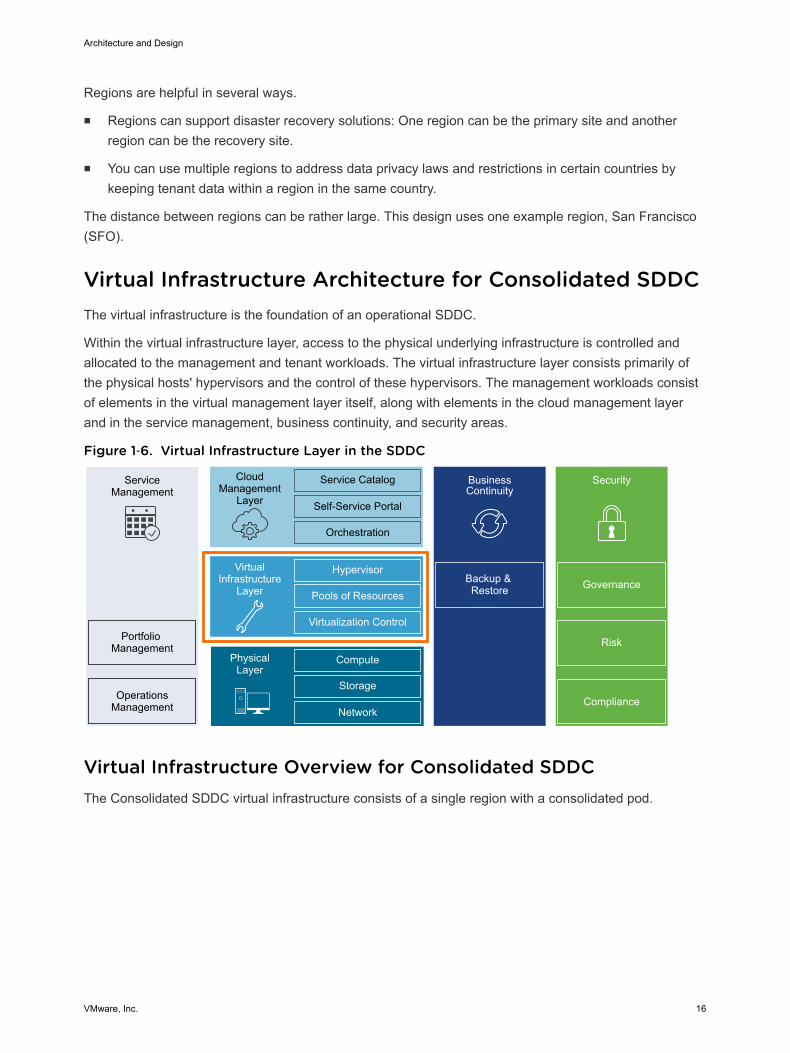
Virtual Infrastructure Architecture for Consolidated SDDCThe virtual infrastructure is the foundation of an operational SDDC.
Within the virtual infrastructure layer, access to the physical underlying infrastructure is controlled andallocated to the management and tenant workloads. The virtual infrastructure layer consists primarily ofthe physical hosts' hypervisors and the control of these hypervisors. The management workloads consistof elements in the virtual management layer itself, along with elements in the cloud management layerand in the service management, business continuity, and security areas.
Figure 1‑6. Virtual Infrastructure Layer in the SDDC
ServiceManagement
Portfolio Management
OperationsManagement
CloudManagement
Layer
Service Catalog
Self-Service Portal
Orchestration
BusinessContinuity
Backup & Restore
Hypervisor
Pools of Resources
Virtualization Control
VirtualInfrastructure
Layer
Compute
Storage
Network
PhysicalLayer
Security
Compliance
Risk
Governance
Virtual Infrastructure Overview for Consolidated SDDCThe Consolidated SDDC virtual infrastructure consists of a single region with a consolidated pod.
Architecture and Design
VMware, Inc. 16
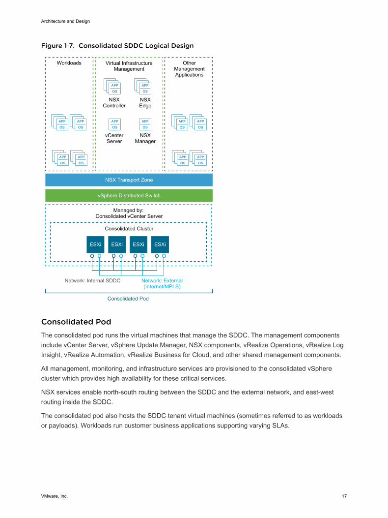
Figure 1‑7. Consolidated SDDC Logical Design
APP
OSAPP
OS
APP
OSAPP
OS
APP
OSAPP
OS
APP
OSAPP
OS
ESXi
APP
OSAPP
OS
APP
OSAPP
OS
Virtual InfrastructureManagement
NSXController
OtherManagementApplications
NSXEdge
NSXManager
ESXi ESXi ESXi
Workloads
NSX Transport Zone
vSphere Distributed Switch
Consolidated Cluster
Managed by: Consolidated vCenter Server
Network: External(Internet/MPLS)
Network: Internal SDDC
Consolidated Pod
vCenterServer
Consolidated PodThe consolidated pod runs the virtual machines that manage the SDDC. The management componentsinclude vCenter Server, vSphere Update Manager, NSX components, vRealize Operations, vRealize LogInsight, vRealize Automation, vRealize Business for Cloud, and other shared management components.
All management, monitoring, and infrastructure services are provisioned to the consolidated vSpherecluster which provides high availability for these critical services.
NSX services enable north-south routing between the SDDC and the external network, and east-westrouting inside the SDDC.
The consolidated pod also hosts the SDDC tenant virtual machines (sometimes referred to as workloadsor payloads). Workloads run customer business applications supporting varying SLAs.
Architecture and Design
VMware, Inc. 17
Network Virtualization Components for Consolidated SDDCVMware NSX for vSphere, the network virtualization platform, is a key solution in the SDDC architecture.The NSX for vSphere platform consists of several components that are relevant to the networkvirtualization design.
NSX for vSphere PlatformNSX for vSphere creates a network virtualization layer. All virtual networks are created on top of this layer,which is an abstraction between the physical and virtual networks. Several components are required tocreate this network virtualization layer:
n vCenter Server
n NSX Manager
n NSX Controller
n NSX Virtual Switch
These components are separated into different planes to create communications boundaries and provideisolation of workload data from system control messages.
Data plane Workload data is contained wholly within the data plane. NSX logicalswitches segregate unrelated workload data. The data is carried overdesignated transport networks in the physical network. The NSX VirtualSwitch, distributed routing, and the distributed firewall are also implementedin the data plane.
Control plane Network virtualization control messages are located in the control plane.Control plane communication should be carried on secure physicalnetworks (VLANs) that are isolated from the transport networks that areused for the data plane. Control messages are used to set up networkingattributes on NSX Virtual Switch instances, as well as to configure andmanage disaster recovery and distributed firewall components on eachESXi host.
Management plane The network virtualization orchestration happens in the management plane.In this layer, cloud management platforms such as VMware vRealize®
Automation™ can request, consume, and destroy networking resources forvirtual workloads. Communication is directed from the cloud managementplatform to vCenter Server to create and manage virtual machines, and toNSX Manager to consume networking resources.
Network Virtualization Services for Consolidated SDDCNetwork virtualization services include logical switches, logical routers, logical firewalls, and othercomponents of NSX for vSphere.
Architecture and Design
VMware, Inc. 18
Logical SwitchesNSX for vSphere logical switches create logically abstracted segments to which tenant virtual machinescan connect. A single logical switch is mapped to a unique VXLAN segment ID and is distributed acrossthe ESXi hypervisors within a transport zone. This allows line-rate switching in the hypervisor withoutcreating constraints of VLAN sprawl or spanning tree issues.
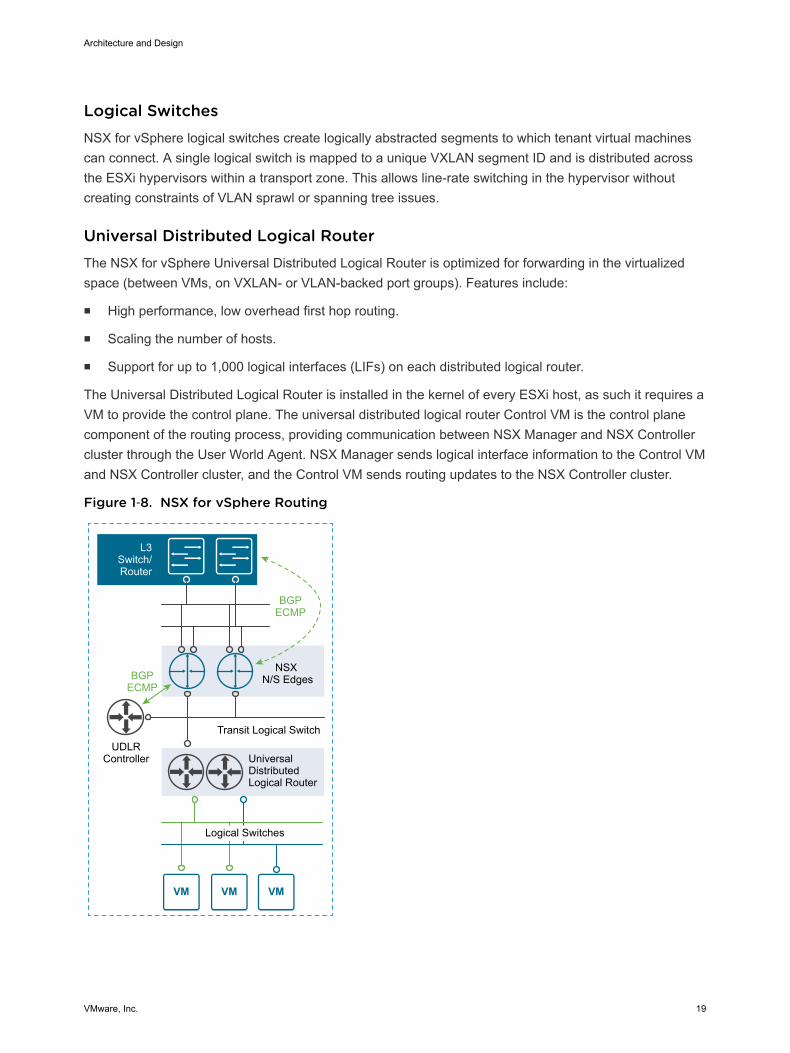
Universal Distributed Logical RouterThe NSX for vSphere Universal Distributed Logical Router is optimized for forwarding in the virtualizedspace (between VMs, on VXLAN- or VLAN-backed port groups). Features include:
n High performance, low overhead first hop routing.
n Scaling the number of hosts.
n Support for up to 1,000 logical interfaces (LIFs) on each distributed logical router.
The Universal Distributed Logical Router is installed in the kernel of every ESXi host, as such it requires aVM to provide the control plane. The universal distributed logical router Control VM is the control planecomponent of the routing process, providing communication between NSX Manager and NSX Controllercluster through the User World Agent. NSX Manager sends logical interface information to the Control VMand NSX Controller cluster, and the Control VM sends routing updates to the NSX Controller cluster.
Figure 1‑8. NSX for vSphere Routing
Transit Logical Switch
Universal Distributed Logical Router
Logical Switches
NSX N/S Edges
UDLRController
BGPECMP
BGPECMP
L3Switch/Router
Architecture and Design
VMware, Inc. 19
Designated InstanceThe designated instance is responsible for resolving ARP on a VLAN LIF. There is one designatedinstance per VLAN LIF. The selection of an ESXi host as a designated instance is performedautomatically by the NSX Controller cluster and that information is pushed to all other hosts. Any ARPrequests sent by the distributed logical router on the same subnet are handled by the same host. In caseof host failure, the controller selects a new host as the designated instance and makes that informationavailable to other hosts.
User World AgentUser World Agent (UWA) is a TCP and SSL client that enables communication between the ESXi hostsand NSX Controller nodes, and the retrieval of information from NSX Manager through interaction withthe message bus agent.
Edge Services GatewayWhile the Universal Logical Router provides VM to VM or east-west routing, the NSX Edge servicesgateway provides north-south connectivity, by peering with upstream layer 3 devices, thereby enablingtenants to access external networks.
Logical FirewallNSX for vSphere Logical Firewall provides security mechanisms for dynamic virtual data centers.
n The Distributed Firewall allows you to segment virtual data center entities like virtual machines.Segmentation can be based on VM names and attributes, user identity, vCenter objects like datacenters, and hosts, or can be based on traditional networking attributes like IP addresses, portgroups, and so on.
n The Edge Firewall component helps you meet key perimeter security requirements, such as buildingDMZs based on IP/VLAN constructs, tenant-to-tenant isolation in multi-tenant virtual data centers,Network Address Translation (NAT), partner (extranet) VPNs, and user-based SSL VPNs.
The Flow Monitoring feature displays network activity between virtual machines at the application protocollevel. You can use this information to audit network traffic, define and refine firewall policies, and identifythreats to your network.
Logical Virtual Private Networks (VPNs)SSL VPN-Plus allows remote users to access private corporate applications. IPSec VPN offers site-to-siteconnectivity between an NSX Edge instance and remote sites. L2 VPN allows you to extend yourdatacenter by allowing virtual machines to retain network connectivity across geographical boundaries.
Architecture and Design
VMware, Inc. 20
Logical Load BalancerThe NSX Edge load balancer enables network traffic to follow multiple paths to a specific destination. Itdistributes incoming service requests evenly among multiple servers in such a way that the loaddistribution is transparent to users. Load balancing thus helps in achieving optimal resource utilization,maximizing throughput, minimizing response time, and avoiding overload. NSX Edge provides loadbalancing up to Layer 7.
Service ComposerService Composer helps you provision and assign network and security services to applications in avirtual infrastructure. You map these services to a security group, and the services are applied to thevirtual machines in the security group.
Data Security provides visibility into sensitive data that are stored within your organization's virtualizedand cloud environments. Based on the violations that are reported by the NSX for vSphere Data Securitycomponent, NSX security or enterprise administrators can ensure that sensitive data is adequatelyprotected and assess compliance with regulations around the world.
NSX for vSphere ExtensibilityVMware partners integrate their solutions with the NSX for vSphere platform to enable an integratedexperience across the entire SDDC. Data center operators can provision complex, multi-tier virtualnetworks in seconds, independent of the underlying network topology or components.
Cloud Management Platform Architecture forConsolidated SDDCThe Cloud Management Platform (CMP) is the primary consumption portal for the entire Software-DefinedData Center (SDDC). Within the SDDC, you use vRealize Automation to author, administer, and consumeVM templates and blueprints.
Architecture and Design
VMware, Inc. 21
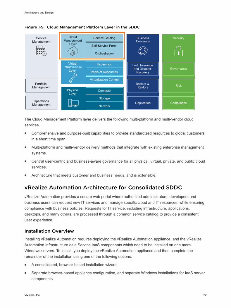
Figure 1‑9. Cloud Management Platform Layer in the SDDC
ServiceManagement
Portfolio Management
OperationsManagement
CloudManagement
Layer
Service Catalog
Self-Service Portal
Orchestration
BusinessContinuity
Fault Tolerance and Disaster
Recovery
Backup & Restore
Hypervisor
Pools of Resources
Virtualization Control
VirtualInfrastructure
Layer
Compute
Storage
Network
PhysicalLayer
Security
Replication Compliance
Risk
Governance
The Cloud Management Platform layer delivers the following multi-platform and multi-vendor cloudservices.
n Comprehensive and purpose-built capabilities to provide standardized resources to global customersin a short time span.
n Multi-platform and multi-vendor delivery methods that integrate with existing enterprise managementsystems.
n Central user-centric and business-aware governance for all physical, virtual, private, and public cloudservices.
n Architecture that meets customer and business needs, and is extensible.
vRealize Automation Architecture for Consolidated SDDCvRealize Automation provides a secure web portal where authorized administrators, developers andbusiness users can request new IT services and manage specific cloud and IT resources, while ensuringcompliance with business policies. Requests for IT service, including infrastructure, applications,desktops, and many others, are processed through a common service catalog to provide a consistentuser experience.
Installation OverviewInstalling vRealize Automation requires deploying the vRealize Automation appliance, and the vRealizeAutomation Infrastructure as a Service IaaS components which need to be installed on one moreWindows servers. To install, you deploy the vRealize Automation appliance and then complete theremainder of the installation using one of the following options:
n A consolidated, browser-based installation wizard.
n Separate browser-based appliance configuration, and separate Windows installations for IaaS servercomponents.
Architecture and Design
VMware, Inc. 22

n A command line based, silent installer that accepts configuration input from an answer properties file.
n An installation REST API that accepts JSON formatted input.
ArchitecturevRealize Automation provides self-service provisioning, IT services delivery and life-cycle management ofcloud services across a wide range of multi-vendor, virtual, physical and cloud platforms though a flexibleand robust distributed architecture. The two main functional elements of the architecture are the vRealizeAutomation server and the Infrastructure as a Service Components (IaaS).
Figure 1‑10. vRealize Automation Architecture
ModelManager
ProxyAgent
vRealize Automation
Appliance
vRealize Automation Services
PostgreSQL Database
vRealizeOrchestrator
VMware Identity Manager
IaaS Components
MS SQL
ExternalService
ExternalService
ExternalService
DEMOrchestrator
WebServer
DEMWorker
ManagerService
Managers Web Serverand DB Access Agents
vRealize AutomationServer Appliance
The vRealize Automation server is deployed as a preconfigured Linuxvirtual appliance. The vRealize Automation server appliance is delivered asan open virtualization file (.OVF) that you deploy on existing virtualizedinfrastructure such as vSphere. It performs the following functions:
n vRealize Automation product portal, where users log to access self-service provisioning and management of cloud services.
n Single sign-on (SSO) for user authorization and authentication.
n Management interface for vRealize Automation appliance settings.
Embedded vRealizeOrchestrator
The vRealize Automation appliance contains a preconfigured instance ofvRealize Orchestrator. vRealize Automation uses vRealize Orchestratorworkflows and actions to extend its capabilities.
Architecture and Design
VMware, Inc. 23

PostgreSQL Database vRealize Server uses a preconfigured PostgreSQL database that isincluded in the vRealize Automation appliance. This database is also usedby the instance of vRealize Orchestrator within the vRealize Automationappliance.
Infrastructure as aService
vRealize Automation IaaS consists of one or more Microsoft Windowsservers that work together to model and provision systems in private,public, or hybrid cloud infrastructures.
Model Manager vRealize Automation uses models to facilitate integration with externalsystems and databases. The models implement business logic used by theDistributed Execution Manager (DEM).
The Model Manager provides services and utilities for persisting,versioning, securing, and distributing model elements. Model Manager ishosted on one of the IaaS web servers and communicates with DEMs, theSQL Server database, and the product interface web site.
IaaS Web Server The IaaS web server provides infrastructure administration and serviceauthoring to the vRealize Automation product interface. The web servercomponent communicates with the Manager Service, which providesupdates from the DEM, SQL Server database, and agents.
Manager Service Windows service that coordinates communication between IaaS DEMs, theSQL Server database, agents, and SMTP. The Manager Servicecommunicates with the web server through the Model Manager, and mustbe run under a domain account with administrator privileges on all IaaSWindows servers.
Distributed ExecutionManager Orchestrator
Distributed Execution Managers execute the business logic of custommodels, interacting with the PostgreSQL database and external databasesand systems as required. The DEM Orchestrator is responsible formonitoring DEM Worker instances, pre-processing workflows for execution,and scheduling workflows.
Distributed ExecutionManager Worker
The vRealize Automation IaaS DEM Worker executes provisioning and de-provisioning tasks initiated by the vRealize Automation portal. DEMWorkers also communicate with specific infrastructure endpoints.
Architecture and Design
VMware, Inc. 24
Proxy Agents vRealize Automation IaaS uses agents to integrate with external systemsand to manage information among vRealize Automation components. Forexample, vSphere proxy agent sends commands to and collects data froma vSphere ESX Server for the VMs provisioned by vRealize Automation.
VMware IdentityManager
VMware Identity Manager is the primary identity provider for vRealizeAutomation and manages user authentication, roles, permissions, andoverall access into vRealize Automation by means of federated identitybrokering. vRealize Automation supports the following authenticationmethods using VMware Identity Manager:
n Username/Password is a single factor password authentication usingbasic Active Directory configuration for local users
n Kerberos
n Smart Card/Certificate
n RSA SecurID
n RADIUS
n RSA Adaptive Authentication
n SAML Authentication
Consolidated vRealize Automation DeploymentThe scope of the design for the Consolidated SDDC uses the vRealize Automation appliance in a smallscale, distributed deployment designed to maintain the ability to scale-up to the larger VMware ValidatedDesign for Software-Defined Data Center. This is achieved by the use of a load balancer which isconfigured such that, the appliance cluster running a single node can be scaled for use with two or moreappliances, the IaaS web server cluster running a single node can be scaled for use with two or moreservers, and the IaaS Manager Server cluster running a single node for use with two servers.
vRealize Business for Cloud Architecture for Consolidated SDDCVMware vRealize Business for Cloud automates cloud costing, consumption analysis and comparison,delivering the insight you need to efficiently deploy and manage cloud environments.
vRealize Business for Cloud tracks and manages the costs of private and public cloud resources from asingle dashboard. It offers a comprehensive way to see, plan and manage your cloud costs. vRealizeBusiness is tightly integrated with vRealize Automation. The architecture illustrates the main componentsof vRealize Business for Cloud, the server, FactsRepo inventory service, data transformation service,data collection services, and reference database.
Architecture and Design
VMware, Inc. 25
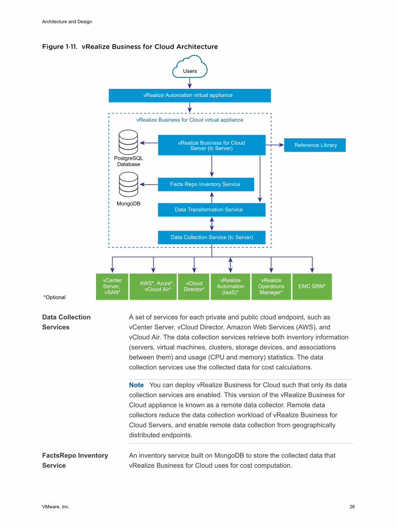
Figure 1‑11. vRealize Business for Cloud Architecture
vRealize Business for Cloud virtual appliance
vRealize Automation virtual appliance
Users
vRealize Business for CloudServer (tc Server)
Facts Repo Inventory Service
PostgreSQLDatabase
Reference Library
MongoDBData Transformation Service
Data Collection Service (tc Server)
*Optional
vCenterServer, vSAN*
AWS*, Azure*, vCloud Air*
vCloudDirector*
vRealizeAutomation
(IaaS)*
vRealizeOperations Manager*
EMC SRM*
Data CollectionServices
A set of services for each private and public cloud endpoint, such asvCenter Server, vCloud Director, Amazon Web Services (AWS), andvCloud Air. The data collection services retrieve both inventory information(servers, virtual machines, clusters, storage devices, and associationsbetween them) and usage (CPU and memory) statistics. The datacollection services use the collected data for cost calculations.
Note You can deploy vRealize Business for Cloud such that only its datacollection services are enabled. This version of the vRealize Business forCloud appliance is known as a remote data collector. Remote datacollectors reduce the data collection workload of vRealize Business forCloud Servers, and enable remote data collection from geographicallydistributed endpoints.
FactsRepo InventoryService
An inventory service built on MongoDB to store the collected data thatvRealize Business for Cloud uses for cost computation.
Architecture and Design
VMware, Inc. 26
Data TransformationService
Converts source specific data from the data collection services into datastructures for consumption by the FactsRepo inventory service. The datatransformation service serves as is a single point of aggregation of datafrom all data collectors.
vRealize Business forCloud Server
A web application that runs on Pivotal tc Server. vRealize Business forCloud has multiple data collection services that run periodically, collectinginventory information and statistics, which is in turn stored in a PostgreSQLdatabase as the persistent data store. Data collected from the datacollection services is used for cost calculations.
Reference Database Responsible for providing default, out-of-the-box costs for each of thesupported cost drivers. The reference database is updated automatically ormanually, and you can download the latest data set and import it intovRealize Business for Cloud. The new values affect cost calculation. Thereference data used depends on the currency you select at the time ofinstallation.
Important You cannot change the currency configuration after deployingvRealize Business for Cloud.
Communicationbetween Server andReference Database
The reference database is a compressed and encrypted file, which you candownload and install manually or update automatically. You can update themost current version of reference database. For more information, see Update the Reference Database for vRealize Business for Cloud.
Other Sources ofInformation
These information sources are optional, and are used only if installed andconfigured. The sources include vRealize Automation, vCloud Director,vRealize Operations Manager, Amazon Web Services (AWS), MicrosoftAzure, and vCloud Air, and EMC Storage Resource Manager (SRM).
vRealize Business forCloud OperationalModel
vRealize Business for Cloud continuously collects data from externalsources, and periodically updates the FactsRepo inventory service. Youcan view the collected data using the vRealize Business for Clouddashboard or generate a report. The data synchronization and updatesoccur at regular intervals, however, you can manually trigger the datacollection process when inventory changes occur. For example, inresponse to the initialization of the system, or addition of a private, public,or hybrid cloud account.
vRealize Business forCloud DeploymentModel
The scope of the design for the Consolidated SDDC uses a deploymentmodel consisting of a two virtual machines: a single vRealize Business forCloud Server appliance and a single vRealize Business for Cloud remotedata collector. The remote data collector provides the flexibility to expand toa two pod design.
Architecture and Design
VMware, Inc. 27
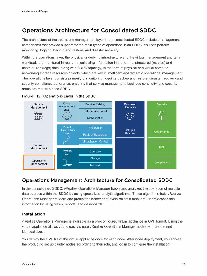
Operations Architecture for Consolidated SDDCThe architecture of the operations management layer in the consolidated SDDC includes managementcomponents that provide support for the main types of operations in an SDDC. You can performmonitoring, logging, backup and restore, and disaster recovery.
Within the operations layer, the physical underlying infrastructure and the virtual management and tenantworkloads are monitored in real-time, collecting information in the form of structured (metrics) andunstructured (logs) data, along with SDDC topology, in the form of physical and virtual compute,networking storage resources objects, which are key in intelligent and dynamic operational management.The operations layer consists primarily of monitoring, logging, backup and restore, disaster recovery andsecurity compliance adherence, ensuring that service management, business continuity, and securityareas are met within the SDDC.
Figure 1‑12. Operations Layer in the SDDC
ServiceManagement
Portfolio Management
OperationsManagement
CloudManagement
Layer
Service Catalog
Self-Service Portal
Orchestration
BusinessContinuity
Backup & Restore
Hypervisor
Pools of Resources
Virtualization Control
VirtualInfrastructure
Layer
Compute
Storage
Network
PhysicalLayer
Security
Compliance
Risk
Governance
Operations Management Architecture for Consolidated SDDCIn the consolidated SDDC, vRealize Operations Manager tracks and analyzes the operation of multipledata sources within the SDDC by using specialized analytic algorithms. These algorithms help vRealizeOperations Manager to learn and predict the behavior of every object it monitors. Users access thisinformation by using views, reports, and dashboards.
InstallationvRealize Operations Manager is available as a pre-configured virtual appliance in OVF format. Using thevirtual appliance allows you to easily create vRealize Operations Manager nodes with pre-definedidentical sizes.
You deploy the OVF file of the virtual appliance once for each node. After node deployment, you accessthe product to set up cluster nodes according to their role, and log in to configure the installation.
Architecture and Design
VMware, Inc. 28

ArchitecturevRealize Operations Manager contains functional elements that collaborate for data analysis and storage,and support creating clusters of nodes with different roles.
Figure 1‑13. vRealize Operations Manager Architecture
Remote Collector Node
Product/Admin UISuite API
Collector
Master Node
Product/Admin UISuite API
CommonDatabases
ReplicationDatabase
Collector
Data Node
Product/Admin UISuite API
CommonDatabases
Collector
Master Replica Node
Product/Admin UISuite API
CommonDatabases
ReplicationDatabase
Collector
Transaction Locator
Transaction Service
Analytics
Types of NodesFor high availability and scalability, you can deploy several vRealize Operations Manager instances in acluster to track, analyze, and predict the operation of monitored systems where they can have either ofthe following roles.
Master Node Required initial node in the cluster. In large-scale environments, managesall other nodes. In small-scale environments, the master node is the singlestandalone vRealize Operations Manager node.
Master Replica Node Optional. Enables high availability of the master node.
Architecture and Design
VMware, Inc. 29
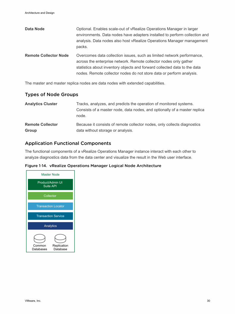
Data Node Optional. Enables scale-out of vRealize Operations Manager in largerenvironments. Data nodes have adapters installed to perform collection andanalysis. Data nodes also host vRealize Operations Manager managementpacks.
Remote Collector Node Overcomes data collection issues, such as limited network performance,across the enterprise network. Remote collector nodes only gatherstatistics about inventory objects and forward collected data to the datanodes. Remote collector nodes do not store data or perform analysis.
The master and master replica nodes are data nodes with extended capabilities.
Types of Node Groups
Analytics Cluster Tracks, analyzes, and predicts the operation of monitored systems.Consists of a master node, data nodes, and optionally of a master replicanode.
Remote CollectorGroup
Because it consists of remote collector nodes, only collects diagnosticsdata without storage or analysis.
Application Functional Components The functional components of a vRealize Operations Manager instance interact with each other toanalyze diagnostics data from the data center and visualize the result in the Web user interface.
Figure 1‑14. vRealize Operations Manager Logical Node Architecture
Master Node
Product/Admin UISuite API
CommonDatabases
ReplicationDatabase
Collector
Transaction Locator
Transaction Service
Analytics
Architecture and Design
VMware, Inc. 30
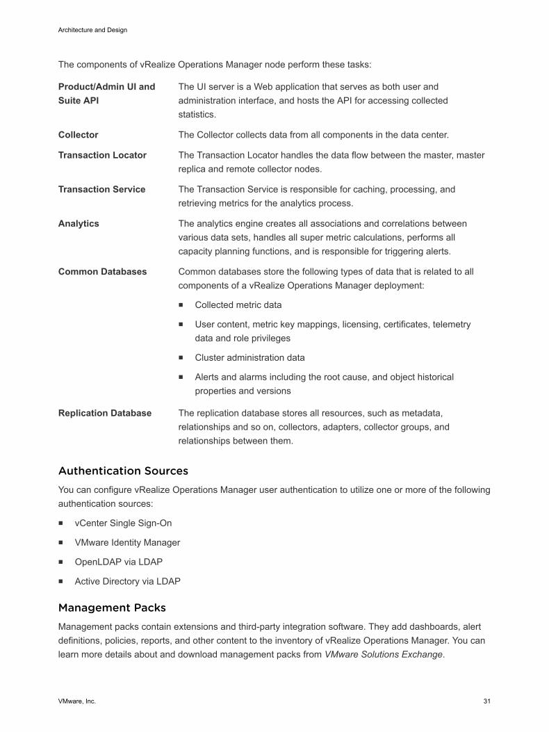
The components of vRealize Operations Manager node perform these tasks:
Product/Admin UI andSuite API
The UI server is a Web application that serves as both user andadministration interface, and hosts the API for accessing collectedstatistics.
Collector The Collector collects data from all components in the data center.
Transaction Locator The Transaction Locator handles the data flow between the master, masterreplica and remote collector nodes.
Transaction Service The Transaction Service is responsible for caching, processing, andretrieving metrics for the analytics process.
Analytics The analytics engine creates all associations and correlations betweenvarious data sets, handles all super metric calculations, performs allcapacity planning functions, and is responsible for triggering alerts.
Common Databases Common databases store the following types of data that is related to allcomponents of a vRealize Operations Manager deployment:
n Collected metric data
n User content, metric key mappings, licensing, certificates, telemetrydata and role privileges
n Cluster administration data
n Alerts and alarms including the root cause, and object historicalproperties and versions
Replication Database The replication database stores all resources, such as metadata,relationships and so on, collectors, adapters, collector groups, andrelationships between them.
Authentication SourcesYou can configure vRealize Operations Manager user authentication to utilize one or more of the followingauthentication sources:
n vCenter Single Sign-On
n VMware Identity Manager
n OpenLDAP via LDAP
n Active Directory via LDAP
Management PacksManagement packs contain extensions and third-party integration software. They add dashboards, alertdefinitions, policies, reports, and other content to the inventory of vRealize Operations Manager. You canlearn more details about and download management packs from VMware Solutions Exchange.
Architecture and Design
VMware, Inc. 31
Consolidated vRealize Operations Manager DeploymentBecause of its scope, the VMware Validated Design for Workload and Management Consolidationimplements a small-scale vRealize Operations Manager deployment. This implementation is designed tomaintain the ability to scale up to the larger VMware Validated Design for Software-Defined Data Center.The validated design uses a load balancer for the analytics cluster that runs on a single node and a one-node remote collector group. By using this configuration, you can scale out the cluster and remotecollector group as required while minimizing downtime.
Logging Architecturefor Consolidated SDDCIn the consolidated SDDC, vRealize Log Insight provides real-time log management and log analysis withmachine learning-based intelligent grouping, high-performance searching, and troubleshooting acrossphysical, virtual, and cloud environments.
OverviewvRealize Log Insight collects data from ESXi hosts using the syslog protocol. It connects to other VMwareproducts, like vCenter Server, to collect events, tasks, and alarm data. vRealize Log Insight alsointegrates with vRealize Operations Manager to send notification events and enable launch in context.vRealize Log Insight also functions as a collection and analysis point for any system that is capable ofsending syslog data.
In addition to syslog data, to collect logs, you can install an ingestion agent on Linux or Windows serversor you can use the pre-installed agent on certain VMware products. This agent approach is useful forcustom application logs and operating systems that do not natively support the syslog protocol, such asWindows.
DeploymentModelsYou can deploy vRealize Log Insight as a virtual appliance in one of the following configurations:
n Standalone master node.
n Cluster of one master and at least two worker nodes. You can establish high availability by using theintegrated load balancer (ILB).
The compute and storage resources of the vRealize Log Insight instances can scale up as growthdemands.
ArchitectureThe architecture of vRealize Log Insight in the SDDC enables several channels for the collection of logmessages.
Architecture and Design
VMware, Inc. 32
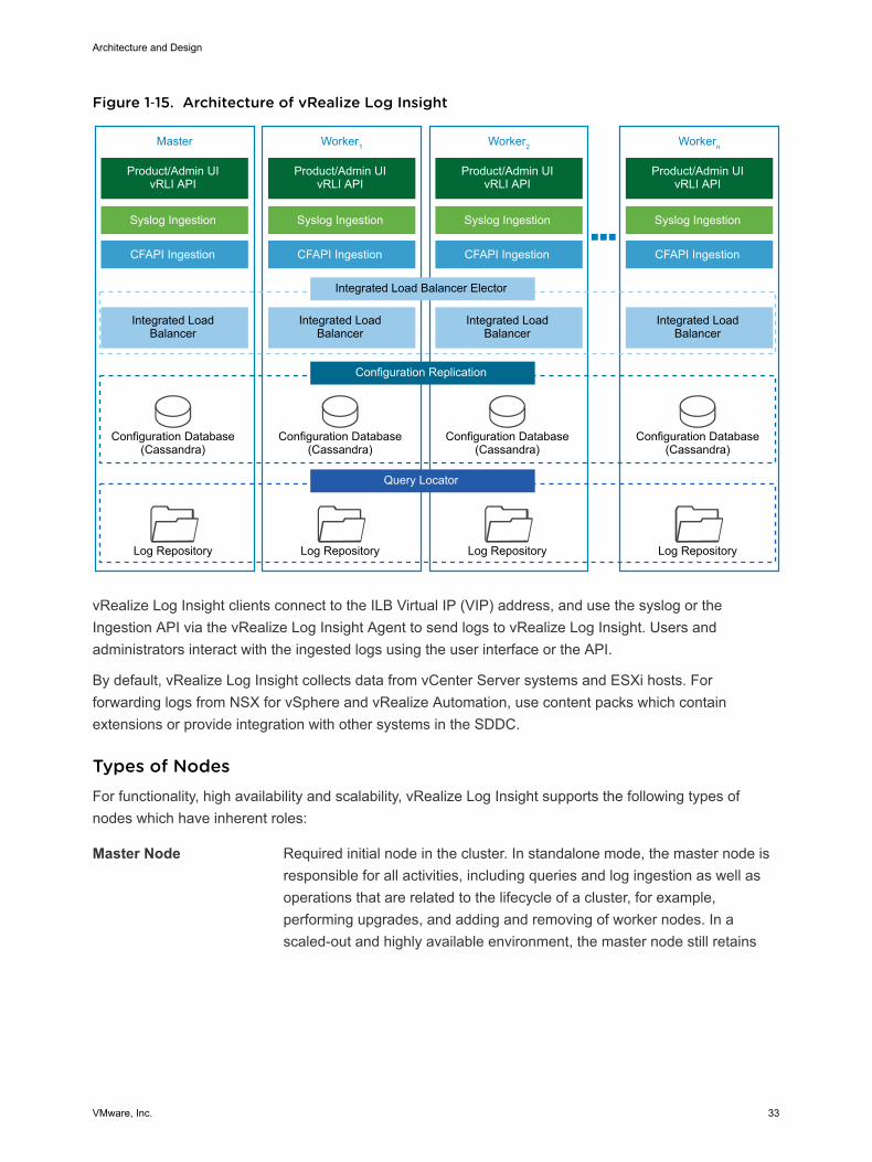
Figure 1‑15. Architecture of vRealize Log Insight
Master
Product/Admin UIvRLI API
Integrated Load Balancer
Configuration Database(Cassandra)
Log Repository
Integrated Load Balancer Elector
Configuration Replication
Query Locator
Syslog Ingestion
CFAPI Ingestion
Worker1
Product/Admin UIvRLI API
Integrated Load Balancer
Configuration Database(Cassandra)
Log Repository
Syslog Ingestion
CFAPI Ingestion
Worker2
Product/Admin UIvRLI API
Integrated Load Balancer
Configuration Database(Cassandra)
Log Repository
Syslog Ingestion
CFAPI Ingestion
Workern
Product/Admin UIvRLI API
Integrated Load Balancer
Configuration Database(Cassandra)
Log Repository
Syslog Ingestion
CFAPI Ingestion
vRealize Log Insight clients connect to the ILB Virtual IP (VIP) address, and use the syslog or theIngestion API via the vRealize Log Insight Agent to send logs to vRealize Log Insight. Users andadministrators interact with the ingested logs using the user interface or the API.
By default, vRealize Log Insight collects data from vCenter Server systems and ESXi hosts. Forforwarding logs from NSX for vSphere and vRealize Automation, use content packs which containextensions or provide integration with other systems in the SDDC.
Types of NodesFor functionality, high availability and scalability, vRealize Log Insight supports the following types ofnodes which have inherent roles:
Master Node Required initial node in the cluster. In standalone mode, the master node isresponsible for all activities, including queries and log ingestion as well asoperations that are related to the lifecycle of a cluster, for example,performing upgrades, and adding and removing of worker nodes. In ascaled-out and highly available environment, the master node still retains
Architecture and Design
VMware, Inc. 33
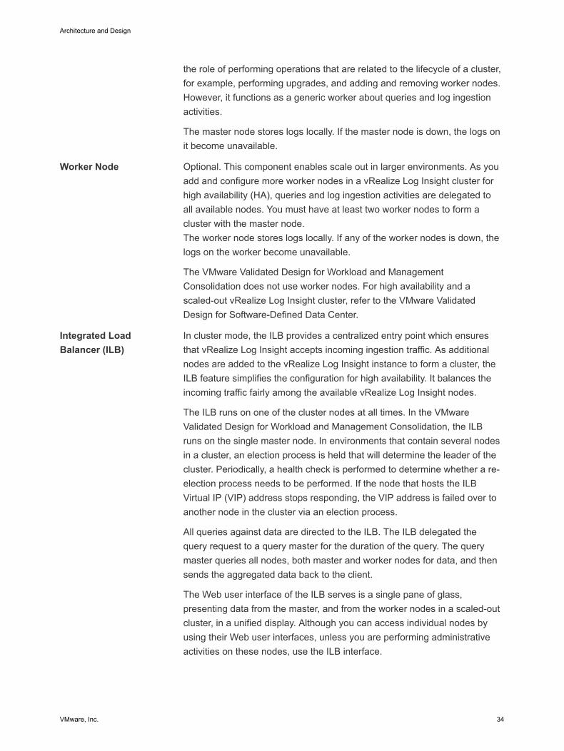
the role of performing operations that are related to the lifecycle of a cluster,for example, performing upgrades, and adding and removing worker nodes.However, it functions as a generic worker about queries and log ingestionactivities.
The master node stores logs locally. If the master node is down, the logs onit become unavailable.
Worker Node Optional. This component enables scale out in larger environments. As youadd and configure more worker nodes in a vRealize Log Insight cluster forhigh availability (HA), queries and log ingestion activities are delegated toall available nodes. You must have at least two worker nodes to form acluster with the master node.The worker node stores logs locally. If any of the worker nodes is down, thelogs on the worker become unavailable.
The VMware Validated Design for Workload and ManagementConsolidation does not use worker nodes. For high availability and ascaled-out vRealize Log Insight cluster, refer to the VMware ValidatedDesign for Software-Defined Data Center.
Integrated LoadBalancer (ILB)
In cluster mode, the ILB provides a centralized entry point which ensuresthat vRealize Log Insight accepts incoming ingestion traffic. As additionalnodes are added to the vRealize Log Insight instance to form a cluster, theILB feature simplifies the configuration for high availability. It balances theincoming traffic fairly among the available vRealize Log Insight nodes.
The ILB runs on one of the cluster nodes at all times. In the VMwareValidated Design for Workload and Management Consolidation, the ILBruns on the single master node. In environments that contain several nodesin a cluster, an election process is held that will determine the leader of thecluster. Periodically, a health check is performed to determine whether a re-election process needs to be performed. If the node that hosts the ILBVirtual IP (VIP) address stops responding, the VIP address is failed over toanother node in the cluster via an election process.
All queries against data are directed to the ILB. The ILB delegated thequery request to a query master for the duration of the query. The querymaster queries all nodes, both master and worker nodes for data, and thensends the aggregated data back to the client.
The Web user interface of the ILB serves is a single pane of glass,presenting data from the master, and from the worker nodes in a scaled-outcluster, in a unified display. Although you can access individual nodes byusing their Web user interfaces, unless you are performing administrativeactivities on these nodes, use the ILB interface.
Architecture and Design
VMware, Inc. 34
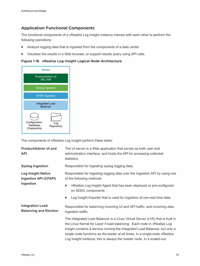
Application Functional ComponentsThe functional components of a vRealize Log Insight instance interact with each other to perform thefollowing operations:
n Analyze logging data that is ingested from the components of a data center
n Visualize the results in a Web browser, or support results query using API calls.
Figure 1‑16. vRealize Log Insight Logical Node Architecture
Master
Product/Admin UIvRLI API
Integrated Load Balancer
Configuration Database
(Cassandra)
LogRepository
Syslog Ingestion
CFAPI Ingestion
The components of vRealize Log Insight perform these tasks:
Product/Admin UI andAPI
The UI server is a Web application that serves as both user andadministration interface, and hosts the API for accessing collectedstatistics.
Syslog Ingestion Responsible for ingesting syslog logging data.
Log Insight NativeIngestion API (CFAPI)Ingestion
Responsible for ingesting logging data over the Ingestion API by using oneof the following methods:
n vRealize Log Insight Agent that has been deployed or pre-configuredon SDDC components .
n Log Insight Importer that is used for ingestion of non-real time data.
Integration LoadBalancing and Election
Responsible for balancing incoming UI and API traffic, and incoming dataingestion traffic.
The Integrated Load Balancer is a Linux Virtual Server (LVS) that is built inthe Linux Kernel for Layer 4 load balancing . Each node in vRealize LogInsight contains a service running the Integrated Load Balancer, but only asingle node functions as the leader at all times. In a single-node vRealizeLog Insight instance, this is always the master node. In a scaled-out
Architecture and Design
VMware, Inc. 35
vRealize Log Insight cluster, this role can be inherited by any of theavailable nodes during the election process. The leader periodicallyperforms health checks to determine whether a re-election process isrequired for the cluster.
Configuration Database Stores configuration information about the vRealize Log Insight nodes andcluster. The information that is stored in the database is periodicallyreplicated to all available vRealize Log Insight nodes.
Log Repository Stores logging data that is ingested in vRealize Log Insight. The loggingrepository is local to each node and not replicated. If a node is offline orremoved, the logging data which is stored on that node becomesinaccessible. In environments where an ILB is configured, incoming loggingdata is evenly distributed across all available nodes.
When a query arrives from the ILB, the vRealize Log Insight node holdingthe ILB leader role delegates the query to any of the available nodes in thecluster.
Authentication SourcesYou can configure one or more of the following authentication models on vRealize Log Insight:
n Microsoft Active Directory
n Local Accounts
n VMware Identity Manager
Content PacksContent packs help extend Log Insight with valuable troubleshooting information by providing structureand meaning to raw log data that is collected from either a vRealize Log Insight agent, vRealize LogInsight Importer or a Syslog Stream. Content packs can contain vRealize Log Insight agentconfigurations, providing out-of-the-box parsing capabilities for standard logging directories and loggingformats, along with dashboards, extracted fields, alert definitions, query lists, and saved queries from thelog data related to a specific product in vRealize Log Insight. For details about and to download contentpacks, see Log Insight Content Pack Marketplace or the VMware Solutions Exchange.
Integration with vRealize Operations ManagerThe integration of vRealize Log Insight with vRealize Operations Manager provides data from multiplesources to a central place for monitoring the SDDC. The integration has the following advantages:
n vRealize Log Insight sends notification events to vRealize Operations Manager.
n vRealize Operations Manager can provide the inventory map of any vSphere object to vRealize LogInsight. In this way, you can view log messages from vRealize Log Insight in the vRealize OperationsManager Web user interface, taking you either directly to the object itself or to the location of theobject within the environment.
Architecture and Design
VMware, Inc. 36
n Access to the vRealize Log Insight user interface is embedded in the vRealize Operations Manageruser interface .
ArchivingvRealize Log Insight supports data archiving on an NFS shared storage that the vRealize Log Insightnodes can access. However, vRealize Log Insight does not manage the NFS mount used for archivingpurposes nor does it perform cleanup of the archival files. If the NFS mount for archiving does not haveenough free space or is unavailable for a period of time greater than the retention period of the virtualappliance, vRealize Log Insight stops ingesting new data until the NFS mount has enough free space,becomes available, or archiving is disabled. System notifications from vRealize Log Insight sends you anemail when the NFS mount is about to run out of space or is unavailable if enabled.
BackupYou back up vRealize Log Insight using traditional virtual machine backup solutions that are compatiblewith vSphere Storage APIs for Data Protection (VADP) such as vSphere Data Protection.
Consolidated vRealize Log Insight DeploymentBecause of its scope, the VMware Validated Design for Workload and Management Consolidationimplements a small-scale vRealize Log Insight deployment. This implementation is designed to maintainthe ability to scale up to the larger VMware Validated Design for Software-Defined Data Center. Thevalidated design uses an integrated load balancer on top of the single master node so that you can scaleout the cluster as required while minimizing downtime.
Data Protection and Backup Architecture for Consolidated SDDCIn the consolidated SDDC, you can use a backup solution that is based on the VMware vSphere StorageAPIs – Data Protection (VADP), such as vSphere Data Protection, to protect the data of your SDDCmanagement components, and of the tenant workloads that run on the consolidated pod.
Data protection solutions provide the following functions in the SDDC:
n Backup and restore virtual machines.
n Organize virtual machines to groups by VMware product.
n Store data according to company retention policies.
n Inform administrators about backup and restore activities through reports.
n Schedule regular backups during non-peak periods.
ArchitecturevSphere Data Protection instance provide data protection for the products that implement themanagement capabilities of the SDDC.
Architecture and Design
VMware, Inc. 37
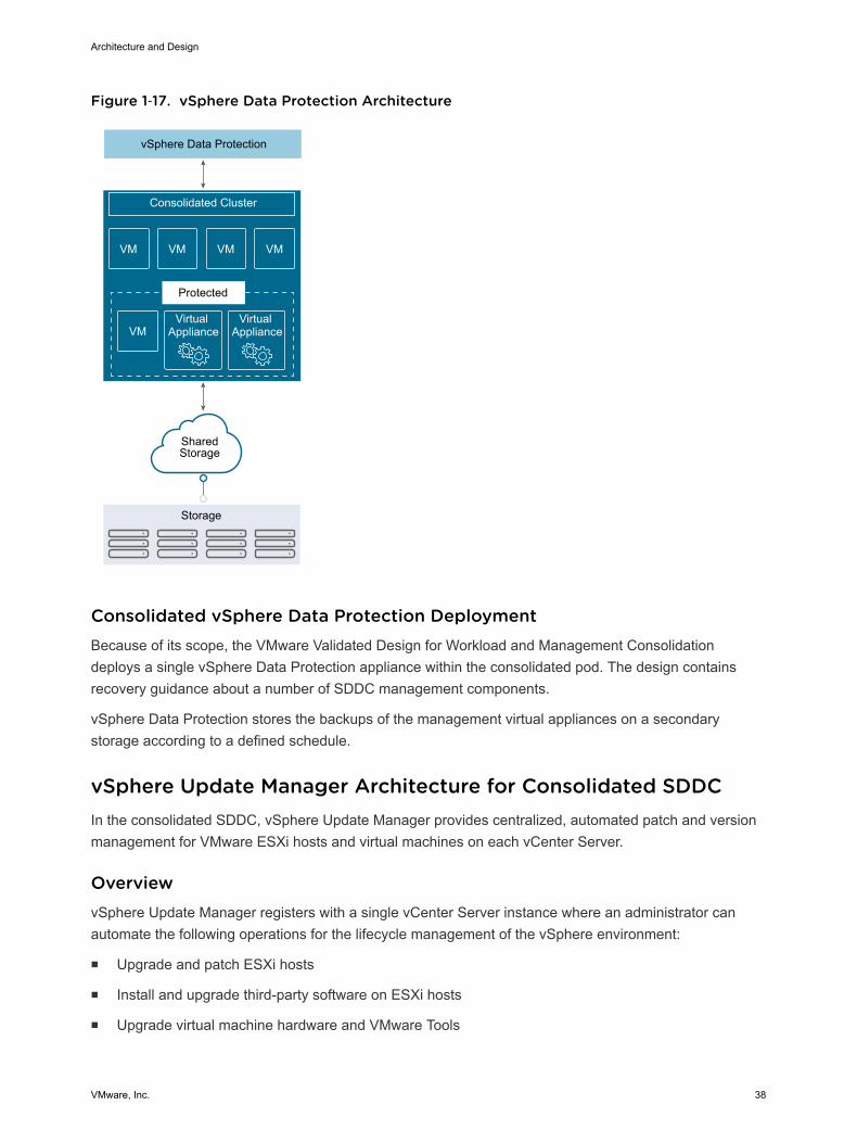
Figure 1‑17. vSphere Data Protection Architecture
VMVMVMVM
VMVirtual
ApplianceVirtual
Appliance
vSphere Data Protection
Consolidated Cluster
Storage
Protected
SharedStorage
Consolidated vSphere Data Protection DeploymentBecause of its scope, the VMware Validated Design for Workload and Management Consolidationdeploys a single vSphere Data Protection appliance within the consolidated pod. The design containsrecovery guidance about a number of SDDC management components.
vSphere Data Protection stores the backups of the management virtual appliances on a secondarystorage according to a defined schedule.
vSphere Update Manager Architecture for Consolidated SDDCIn the consolidated SDDC, vSphere Update Manager provides centralized, automated patch and versionmanagement for VMware ESXi hosts and virtual machines on each vCenter Server.
OverviewvSphere Update Manager registers with a single vCenter Server instance where an administrator canautomate the following operations for the lifecycle management of the vSphere environment:
n Upgrade and patch ESXi hosts
n Install and upgrade third-party software on ESXi hosts
n Upgrade virtual machine hardware and VMware Tools
Architecture and Design
VMware, Inc. 38
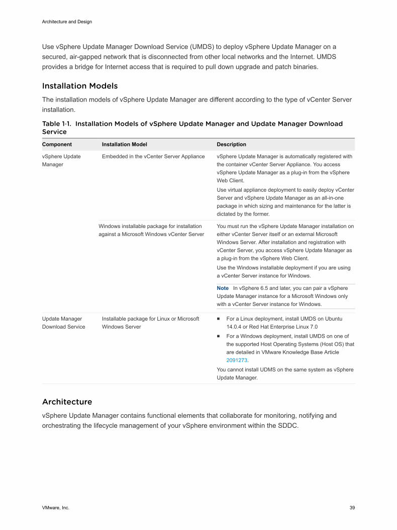
Use vSphere Update Manager Download Service (UMDS) to deploy vSphere Update Manager on asecured, air-gapped network that is disconnected from other local networks and the Internet. UMDSprovides a bridge for Internet access that is required to pull down upgrade and patch binaries.
Installation ModelsThe installation models of vSphere Update Manager are different according to the type of vCenter Serverinstallation.
Table 1‑1. Installation Models of vSphere Update Manager and Update Manager DownloadService
Component Installation Model Description
vSphere UpdateManager
Embedded in the vCenter Server Appliance vSphere Update Manager is automatically registered withthe container vCenter Server Appliance. You accessvSphere Update Manager as a plug-in from the vSphereWeb Client.
Use virtual appliance deployment to easily deploy vCenterServer and vSphere Update Manager as an all-in-onepackage in which sizing and maintenance for the latter isdictated by the former.
Windows installable package for installationagainst a Microsoft Windows vCenter Server
You must run the vSphere Update Manager installation oneither vCenter Server itself or an external MicrosoftWindows Server. After installation and registration withvCenter Server, you access vSphere Update Manager asa plug-in from the vSphere Web Client.
Use the Windows installable deployment if you are usinga vCenter Server instance for Windows.
Note In vSphere 6.5 and later, you can pair a vSphereUpdate Manager instance for a Microsoft Windows onlywith a vCenter Server instance for Windows.
Update ManagerDownload Service
Installable package for Linux or MicrosoftWindows Server
n For a Linux deployment, install UMDS on Ubuntu14.0.4 or Red Hat Enterprise Linux 7.0
n For a Windows deployment, install UMDS on one ofthe supported Host Operating Systems (Host OS) thatare detailed in VMware Knowledge Base Article 2091273.
You cannot install UDMS on the same system as vSphereUpdate Manager.
ArchitecturevSphere Update Manager contains functional elements that collaborate for monitoring, notifying andorchestrating the lifecycle management of your vSphere environment within the SDDC.
Architecture and Design
VMware, Inc. 39

Figure 1‑18. vSphere Update Manager and Update Manager Download Service Architecture
vSphere Update Manager
Web Server
Remote Devices Server
Consolidated vCenter Server
vSphere Update Manager Node
PatchRepository
Consolidated Cluster
Database
Update Manager Download
Web Server
Update Manager Download Service
PatchRepository
Database
Types of NodesFor functionality and scalability, vSphere Update Manager and Update Manager Download Serviceperform the following roles:
vSphere UpdateManager
Required node for integrated, automated lifecycle management of vSpherecomponents. In environments ranging from a single to multiple vCenterServer instances, vSphere Update Manager is paired in a 1:1 relationship.
Update ManagerDownload Service
In a secure environment in which vCenter Server and vSphere UpdateManager are in an air gap from Internet access, provides the bridge forvSphere Update Manager to receive its patch and update binaries. Inaddition, you can use UMDS to aggregate downloaded binary data, such aspatch metadata, patch binaries, and notifications, that can be sharedacross multiple instances of vSphere Update Manager to manage thelifecycle of multiple vSphere environments.
BackupYou back up vSphere Update Manager, either as an embedded service on the vCenter Server Applianceor deployed separately on a Microsoft Windows Server virtual machine, and UMDS using traditionalvirtual machine backup solutions that are based on the software that is compatible with vSphere StorageAPIs for Data Protection (VADP) such as vSphere Data Protection.
Architecture and Design
VMware, Inc. 40

Consolidated vCenter Server DeploymentBecause of its scope, the VMware Validated Design for Workload and Management Consolidationimplements vSphere Update Manager and UMDS in a single-region design. This implementation isdesigned to provide a secure method for downloading patch binaries while maintaining the ability to scaleup to the larger VMware Validated Design for Software-Defined Data Center.
Figure 1‑19. Single-Region Interaction between vSphere Update Manager and UpdateManager Download Service
Update ManagerDownload Service
Platform Services Controller Appliance
vSphere UpdateManager
ConsolidatedvCenter Server
Appliance
Internet
Architecture and Design
VMware, Inc. 41
Detailed Design forConsolidated SDDC 2The Consolidated Software-Defined Data Center (Consolidated SDDC) detailed design considers bothphysical and virtual infrastructure design. It includes numbered design decisions and the justification andimplications of each decision.
Each section also includes detailed discussion and diagrams.
Physical InfrastructureDesign
Focuses on the three main pillars of any data center, compute, storage andnetwork. In this section you find information about availability zones andregions. The section also provides details on the rack and podconfiguration, and on physical hosts and the associated storage andnetwork configurations.
Virtual InfrastructureDesign
Provides details on the core virtualization software configuration. Thissection has information on the ESXi hypervisor, vCenter Server, the virtualnetwork design including VMware NSX, and on software-defined storagefor VMware vSAN. This section also includes details on business continuity(backup and restore) and on disaster recovery.
Cloud ManagementPlatform Design
Contains information on the consumption and orchestration layer of theSDDC stack, which uses vRealize Automation and vRealize Orchestrator.IT organizations can use the fully distributed and scalable architecture tostreamline their provisioning and decommissioning operations.
OperationsInfrastructure Design
Explains how to architect, install, and configure vRealize OperationsManager and vRealize Log Insight. You learn how to ensure that servicemanagement within the SDDC is comprehensive. This section ties directlyinto the Operational Guidance section.
This chapter includes the following topics:
n Physical Infrastructure Design for Consolidated SDDC
n Virtual Infrastructure Design for Consolidated SDDC
n Cloud Management Platform Design for Consolidated SDDC
n Operations Infrastructure Design for Consolidated SDDC
VMware, Inc. 42
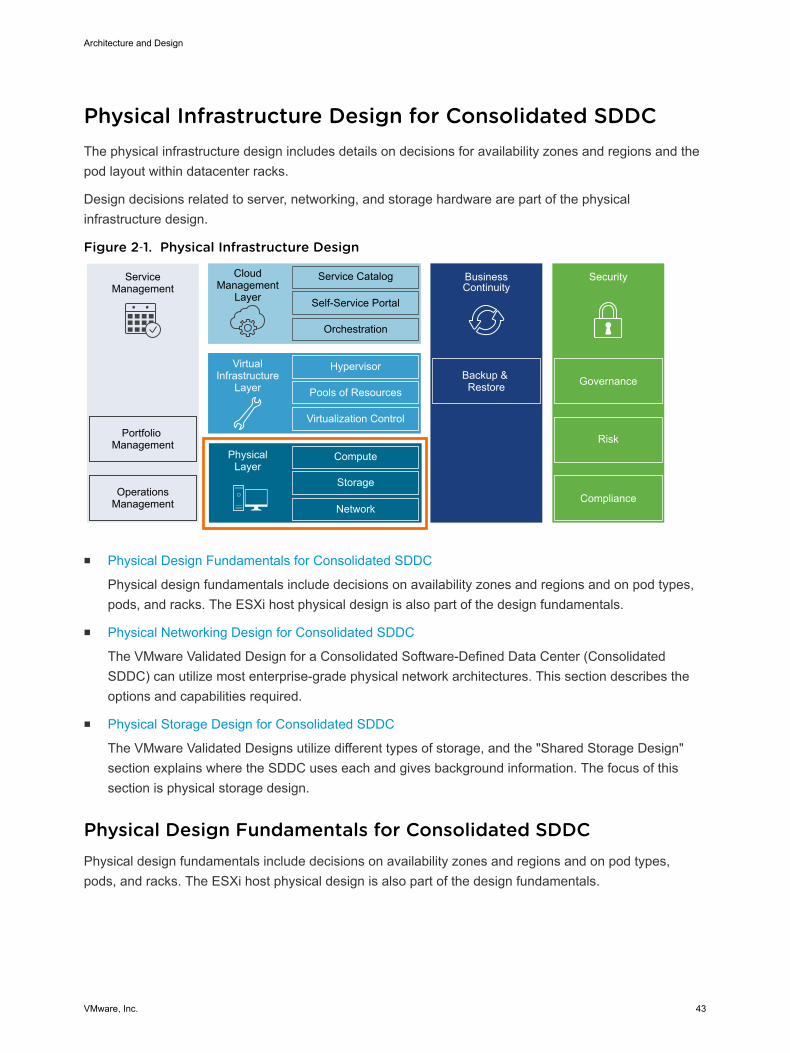
Physical Infrastructure Design for Consolidated SDDCThe physical infrastructure design includes details on decisions for availability zones and regions and thepod layout within datacenter racks.
Design decisions related to server, networking, and storage hardware are part of the physicalinfrastructure design.
Figure 2‑1. Physical Infrastructure Design
ServiceManagement
Portfolio Management
OperationsManagement
CloudManagement
Layer
Service Catalog
Self-Service Portal
Orchestration
BusinessContinuity
Backup & Restore
Hypervisor
Pools of Resources
Virtualization Control
VirtualInfrastructure
Layer
Compute
Storage
Network
PhysicalLayer
Security
Compliance
Risk
Governance
n Physical Design Fundamentals for Consolidated SDDC
Physical design fundamentals include decisions on availability zones and regions and on pod types,pods, and racks. The ESXi host physical design is also part of the design fundamentals.
n Physical Networking Design for Consolidated SDDC
The VMware Validated Design for a Consolidated Software-Defined Data Center (ConsolidatedSDDC) can utilize most enterprise-grade physical network architectures. This section describes theoptions and capabilities required.
n Physical Storage Design for Consolidated SDDC
The VMware Validated Designs utilize different types of storage, and the "Shared Storage Design"section explains where the SDDC uses each and gives background information. The focus of thissection is physical storage design.
Physical Design Fundamentals for Consolidated SDDCPhysical design fundamentals include decisions on availability zones and regions and on pod types,pods, and racks. The ESXi host physical design is also part of the design fundamentals.
Architecture and Design
VMware, Inc. 43
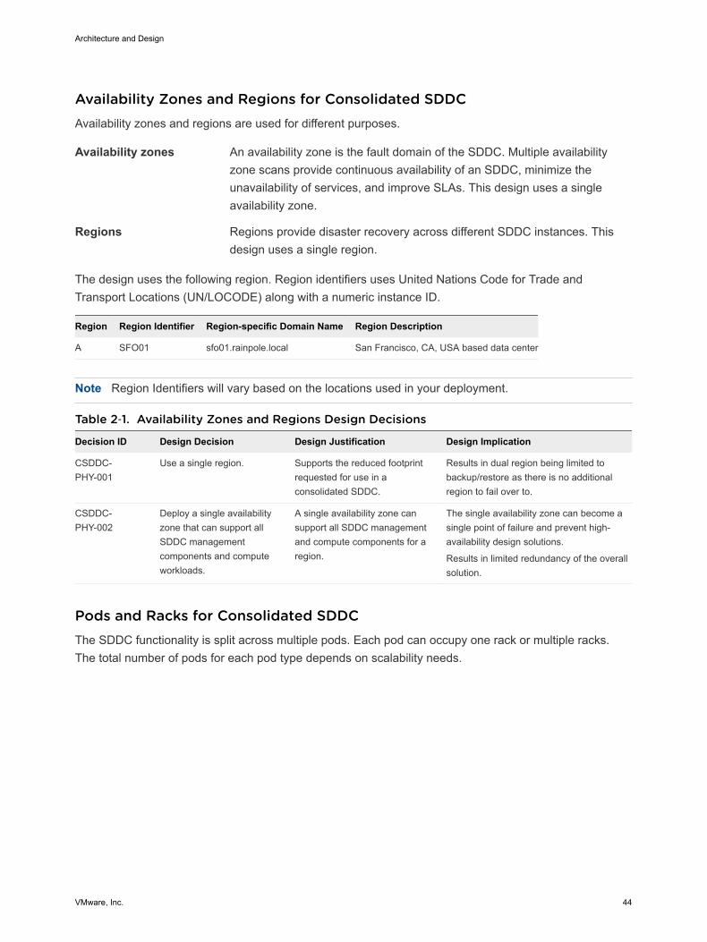
Availability Zones and Regions for Consolidated SDDCAvailability zones and regions are used for different purposes.
Availability zones An availability zone is the fault domain of the SDDC. Multiple availabilityzone scans provide continuous availability of an SDDC, minimize theunavailability of services, and improve SLAs. This design uses a singleavailability zone.
Regions Regions provide disaster recovery across different SDDC instances. Thisdesign uses a single region.
The design uses the following region. Region identifiers uses United Nations Code for Trade andTransport Locations (UN/LOCODE) along with a numeric instance ID.
Region Region Identifier Region-specific Domain Name Region Description
A SFO01 sfo01.rainpole.local San Francisco, CA, USA based data center
Note Region Identifiers will vary based on the locations used in your deployment.
Table 2‑1. Availability Zones and Regions Design Decisions
Decision ID Design Decision Design Justification Design Implication
CSDDC-PHY-001
Use a single region. Supports the reduced footprintrequested for use in aconsolidated SDDC.
Results in dual region being limited tobackup/restore as there is no additionalregion to fail over to.
CSDDC-PHY-002
Deploy a single availabilityzone that can support allSDDC managementcomponents and computeworkloads.
A single availability zone cansupport all SDDC managementand compute components for aregion.
The single availability zone can become asingle point of failure and prevent high-availability design solutions.
Results in limited redundancy of the overallsolution.
Pods and Racks for Consolidated SDDCThe SDDC functionality is split across multiple pods. Each pod can occupy one rack or multiple racks.The total number of pods for each pod type depends on scalability needs.
Architecture and Design
VMware, Inc. 44
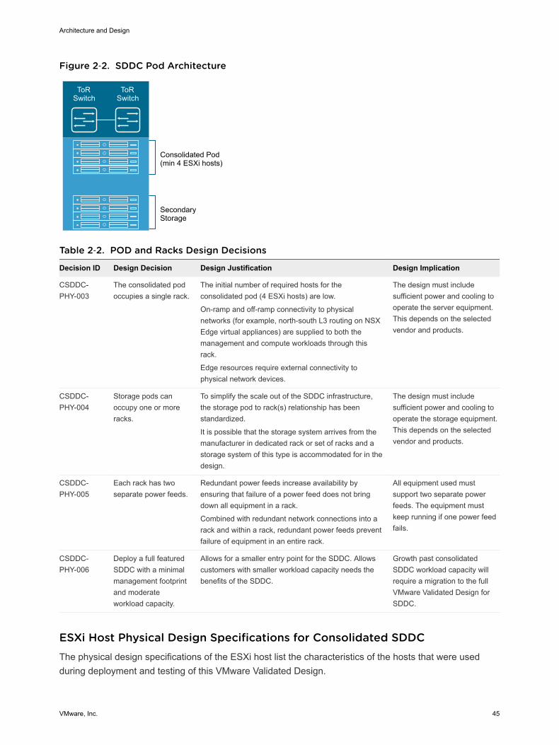
Figure 2‑2. SDDC Pod Architecture
ToR Switch
ToR Switch
Consolidated Pod(min 4 ESXi hosts)
SecondaryStorage
Table 2‑2. POD and Racks Design Decisions
Decision ID Design Decision Design Justification Design Implication
CSDDC-PHY-003
The consolidated podoccupies a single rack.
The initial number of required hosts for theconsolidated pod (4 ESXi hosts) are low.
On-ramp and off-ramp connectivity to physicalnetworks (for example, north-south L3 routing on NSXEdge virtual appliances) are supplied to both themanagement and compute workloads through thisrack.
Edge resources require external connectivity tophysical network devices.
The design must includesufficient power and cooling tooperate the server equipment.This depends on the selectedvendor and products.
CSDDC-PHY-004
Storage pods canoccupy one or moreracks.
To simplify the scale out of the SDDC infrastructure,the storage pod to rack(s) relationship has beenstandardized.
It is possible that the storage system arrives from themanufacturer in dedicated rack or set of racks and astorage system of this type is accommodated for in thedesign.
The design must includesufficient power and cooling tooperate the storage equipment.This depends on the selectedvendor and products.
CSDDC-PHY-005
Each rack has twoseparate power feeds.
Redundant power feeds increase availability byensuring that failure of a power feed does not bringdown all equipment in a rack.
Combined with redundant network connections into arack and within a rack, redundant power feeds preventfailure of equipment in an entire rack.
All equipment used mustsupport two separate powerfeeds. The equipment mustkeep running if one power feedfails.
CSDDC-PHY-006
Deploy a full featuredSDDC with a minimalmanagement footprintand moderateworkload capacity.
Allows for a smaller entry point for the SDDC. Allowscustomers with smaller workload capacity needs thebenefits of the SDDC.
Growth past consolidatedSDDC workload capacity willrequire a migration to the fullVMware Validated Design forSDDC.
ESXi Host Physical Design Specifications for Consolidated SDDCThe physical design specifications of the ESXi host list the characteristics of the hosts that were usedduring deployment and testing of this VMware Validated Design.
Architecture and Design
VMware, Inc. 45
Physical Design Specification Fundamentals
The configuration and assembly process for each system is standardized, with all components installedthe same manner on each host. Standardizing the entire physical configuration of the ESXi hosts iscritical to providing an easily manageable and supportable infrastructure because standardizationeliminates variability. Consistent PCI card slot location, especially for network controllers, is essential foraccurate alignment of physical to virtual I/O resources. Deploy ESXi hosts with identical configuration,including identical storage, and networking configurations, across all cluster members. Identicalconfigurations ensure an even balance of virtual machine storage components across storage andcompute resources.
Select all ESXi host hardware, including CPUs following the VMware Compatibility Guide.
The sizing of the physical servers for the ESXi hosts for the consolidated pod has special considerationbecause it is based on the VMware document VMware Virtual SAN Ready Nodes, as the consolidatedpod uses VMware vSAN.
n An average sized VM has two vCPUs with 4 GB of RAM.
n A standard 2U server can host 60 average-sized VMs on a single ESXi host.
Table 2‑3. ESXi Host Design Decisions
Decision ID Design Decision Design Justification Design Implication
CSDDC-PHY-007
Use vSAN Ready Nodes. Using a vSAN Ready Node ensuresseamless compatibility with vSAN duringthe deployment.
Might limit hardware choices.
CSDDC-PHY-008
All nodes must have uniformconfigurations across agiven cluster.
A balanced cluster delivers morepredictable performance even duringhardware failures. In addition, performanceimpact during resync/rebuild is minimalwhen the cluster is balanced.
Vendor sourcing, budgeting andprocurement considerations foruniform server nodes will beapplied on a per cluster basis.
ESXi Host Memory
The amount of memory required will vary depending on the workloads. When sizing memory it's importantto remember the admission control setting (n+1) which reserves one hosts resources for fail over.
Note See the VMware vSAN 6.5 Design and Sizing Guide for more information about disk groups,including design and sizing guidance. The number of disk groups and disks that an ESXi host managesdetermines memory requirements. 32 GB of RAM is required to support the maximum number of diskgroups.
Architecture and Design
VMware, Inc. 46
Table 2‑4. Host Memory Design Decision
Decision ID Design Decision Design Justification Design Implication
CSDDC-PHY-009
Ensure each ESXi host in theConsolidated pod has aminimum of 192 GB RAM.
The management and edge VMs in this pod require atotal 87 GB RAM from the cluster.
The remaining RAM is to support workload virtualmachines.
Ensures enough RAM is available to grow to a two poddesign at a later time and re-use hardware for the sharededge and compute pod.
Might limit hardwarechoices.
Host Boot Device Background Considerations
Minimum boot disk size for ESXi in SCSI-based devices (SAS / SATA / SAN) is greater than 5 GB. ESXican be deployed using stateful local SAN SCSI boot devices, or by using vSphere Auto Deploy.
What is supported depends on the version of vSAN that you are using:
n vSAN does not support stateless vSphere Auto Deploy
n vSAN 5.5 and greater supports USB/SD embedded devices for ESXi boot device (4 GB or greater).
n Since vSAN 6.0, there is an option to use SATADOM as a supported boot device.
See the VMware vSAN 6.5 Design and Sizing Guide to choose the option that best fits your hardware.
Physical Networking Design for Consolidated SDDCThe VMware Validated Design for a Consolidated Software-Defined Data Center (Consolidated SDDC)can utilize most enterprise-grade physical network architectures. This section describes the options andcapabilities required.
Switch Types and Network Connectivity for Consolidated SDDCSetup of the physical environment requires careful consideration. Follow best practices for physicalswitches, switch connectivity, VLANs and subnets, and access port settings.
Top of Rack Physical Switches
When configuring Top of Rack (ToR) switches, consider the following best practices.
n Configure redundant physical switches to enhance availability.
n Configure switch ports that connect to ESXi hosts manually as trunk ports. Virtual switches arepassive devices and do not send or receive trunking protocols, such as Dynamic Trunking Protocol(DTP).
n Modify the Spanning Tree Protocol (STP) on any port that is connected to an ESXi NIC to reduce thetime it takes to transition ports over to the forwarding state, for example using the Trunk PortFastfeature found in a Cisco physical switch.
Architecture and Design
VMware, Inc. 47

n Provide DHCP or DHCP Helper capabilities on all VLANs that are used by Management and VXLANVMkernel ports. This setup simplifies the configuration by using DHCP to assign IP address based onthe IP subnet in use.
n Configure jumbo frames on all switch ports, inter-switch link (ISL) and switched virtual interfaces(SVI's).
Top of Rack Connectivity and Network Settings
Each ESXi host is connected redundantly to the SDDC network fabric ToR switches by means of two 10GbE ports. Configure the ToR switches to provide all necessary VLANs via an 802.1Q trunk. Theseredundant connections are not part of an ether-channel (LAG/vPC) but use features in the vSphereDistributed Switch and NSX for vSphere to guarantee no physical interface is overrun and redundantpaths are used as long as they are available.
Figure 2‑3. Host to ToR connectivity
ToR ToR
ESXiHost
10 GigE 10 GigE
VLANs and Subnets
Each ESXi host uses VLANs and corresponding subnets.
Follow these guidelines.
n Use only /24 subnets to reduce confusion and mistakes when dealing with IPv4 subnetting.
n Use the IP address .253 as the (floating) interface with .251 and .252 for Virtual Router RedundancyProtocol (VRPP) or Hot Standby Routing Protocol (HSRP).
n Use the RFC1918 IPv4 address space for these subnets and allocate one octet by region andanother octet by function. For example, the mapping 172.regionid.function.0/24 results in thefollowing sample subnets.
Note The following VLANs and IP subnets are meant as samples. Your actual implementation dependson your environment.
Architecture and Design
VMware, Inc. 48
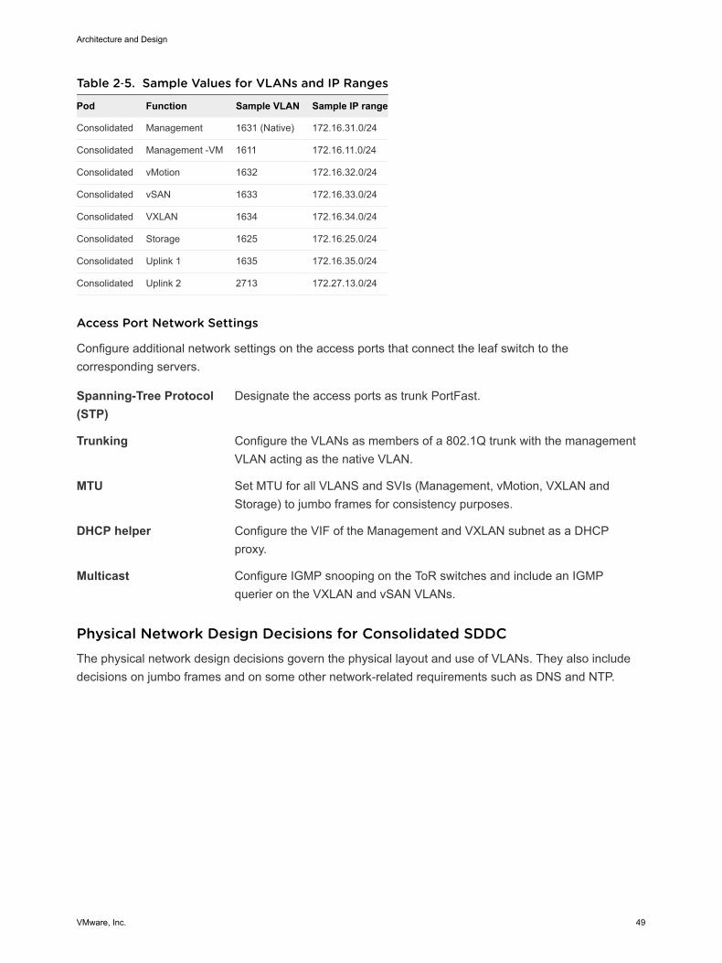
Table 2‑5. Sample Values for VLANs and IP Ranges
Pod Function Sample VLAN Sample IP range
Consolidated Management 1631 (Native) 172.16.31.0/24
Consolidated Management -VM 1611 172.16.11.0/24
Consolidated vMotion 1632 172.16.32.0/24
Consolidated vSAN 1633 172.16.33.0/24
Consolidated VXLAN 1634 172.16.34.0/24
Consolidated Storage 1625 172.16.25.0/24
Consolidated Uplink 1 1635 172.16.35.0/24
Consolidated Uplink 2 2713 172.27.13.0/24
Access Port Network Settings
Configure additional network settings on the access ports that connect the leaf switch to thecorresponding servers.
Spanning-Tree Protocol(STP)
Designate the access ports as trunk PortFast.
Trunking Configure the VLANs as members of a 802.1Q trunk with the managementVLAN acting as the native VLAN.
MTU Set MTU for all VLANS and SVIs (Management, vMotion, VXLAN andStorage) to jumbo frames for consistency purposes.
DHCP helper Configure the VIF of the Management and VXLAN subnet as a DHCPproxy.
Multicast Configure IGMP snooping on the ToR switches and include an IGMPquerier on the VXLAN and vSAN VLANs.
Physical Network Design Decisions for Consolidated SDDCThe physical network design decisions govern the physical layout and use of VLANs. They also includedecisions on jumbo frames and on some other network-related requirements such as DNS and NTP.
Architecture and Design
VMware, Inc. 49
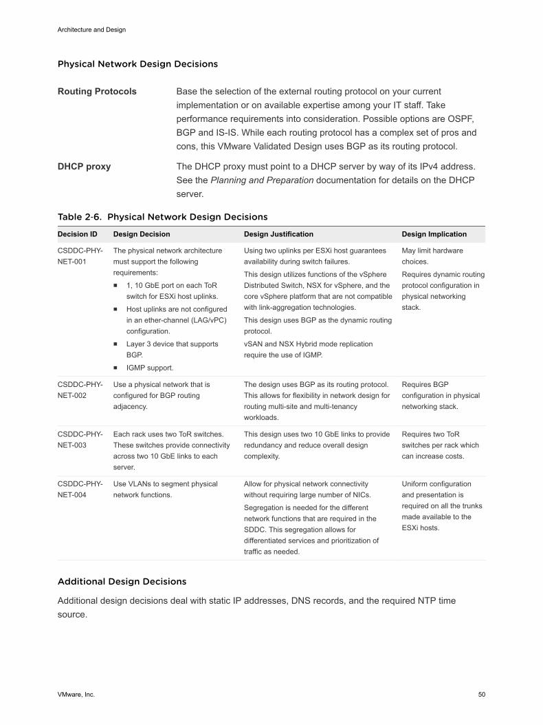
Physical Network Design Decisions
Routing Protocols Base the selection of the external routing protocol on your currentimplementation or on available expertise among your IT staff. Takeperformance requirements into consideration. Possible options are OSPF,BGP and IS-IS. While each routing protocol has a complex set of pros andcons, this VMware Validated Design uses BGP as its routing protocol.
DHCP proxy The DHCP proxy must point to a DHCP server by way of its IPv4 address.See the Planning and Preparation documentation for details on the DHCPserver.
Table 2‑6. Physical Network Design Decisions
Decision ID Design Decision Design Justification Design Implication
CSDDC-PHY-NET-001
The physical network architecturemust support the followingrequirements:n 1, 10 GbE port on each ToR
switch for ESXi host uplinks.n Host uplinks are not configured
in an ether-channel (LAG/vPC)configuration.
n Layer 3 device that supportsBGP.
n IGMP support.
Using two uplinks per ESXi host guaranteesavailability during switch failures.
This design utilizes functions of the vSphereDistributed Switch, NSX for vSphere, and thecore vSphere platform that are not compatiblewith link-aggregation technologies.
This design uses BGP as the dynamic routingprotocol.
vSAN and NSX Hybrid mode replicationrequire the use of IGMP.
May limit hardwarechoices.
Requires dynamic routingprotocol configuration inphysical networkingstack.
CSDDC-PHY-NET-002
Use a physical network that isconfigured for BGP routingadjacency.
The design uses BGP as its routing protocol.This allows for flexibility in network design forrouting multi-site and multi-tenancyworkloads.
Requires BGPconfiguration in physicalnetworking stack.
CSDDC-PHY-NET-003
Each rack uses two ToR switches.These switches provide connectivityacross two 10 GbE links to eachserver.
This design uses two 10 GbE links to provideredundancy and reduce overall designcomplexity.
Requires two ToRswitches per rack whichcan increase costs.
CSDDC-PHY-NET-004
Use VLANs to segment physicalnetwork functions.
Allow for physical network connectivitywithout requiring large number of NICs.
Segregation is needed for the differentnetwork functions that are required in theSDDC. This segregation allows fordifferentiated services and prioritization oftraffic as needed.
Uniform configurationand presentation isrequired on all the trunksmade available to theESXi hosts.
Additional Design Decisions
Additional design decisions deal with static IP addresses, DNS records, and the required NTP timesource.
Architecture and Design
VMware, Inc. 50
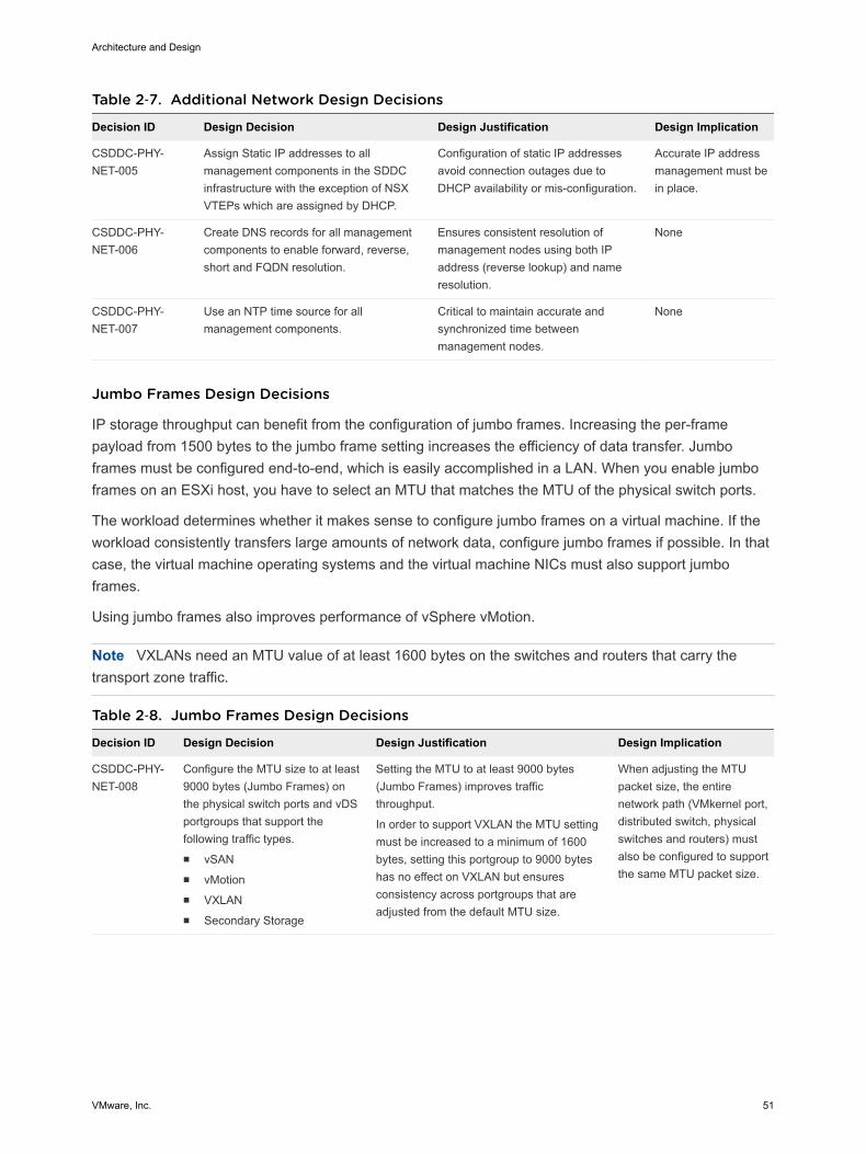
Table 2‑7. Additional Network Design Decisions
Decision ID Design Decision Design Justification Design Implication
CSDDC-PHY-NET-005
Assign Static IP addresses to allmanagement components in the SDDCinfrastructure with the exception of NSXVTEPs which are assigned by DHCP.
Configuration of static IP addressesavoid connection outages due toDHCP availability or mis-configuration.
Accurate IP addressmanagement must bein place.
CSDDC-PHY-NET-006
Create DNS records for all managementcomponents to enable forward, reverse,short and FQDN resolution.
Ensures consistent resolution ofmanagement nodes using both IPaddress (reverse lookup) and nameresolution.
None
CSDDC-PHY-NET-007
Use an NTP time source for allmanagement components.
Critical to maintain accurate andsynchronized time betweenmanagement nodes.
None
Jumbo Frames Design Decisions
IP storage throughput can benefit from the configuration of jumbo frames. Increasing the per-framepayload from 1500 bytes to the jumbo frame setting increases the efficiency of data transfer. Jumboframes must be configured end-to-end, which is easily accomplished in a LAN. When you enable jumboframes on an ESXi host, you have to select an MTU that matches the MTU of the physical switch ports.
The workload determines whether it makes sense to configure jumbo frames on a virtual machine. If theworkload consistently transfers large amounts of network data, configure jumbo frames if possible. In thatcase, the virtual machine operating systems and the virtual machine NICs must also support jumboframes.
Using jumbo frames also improves performance of vSphere vMotion.
Note VXLANs need an MTU value of at least 1600 bytes on the switches and routers that carry thetransport zone traffic.
Table 2‑8. Jumbo Frames Design Decisions
Decision ID Design Decision Design Justification Design Implication
CSDDC-PHY-NET-008
Configure the MTU size to at least9000 bytes (Jumbo Frames) onthe physical switch ports and vDSportgroups that support thefollowing traffic types. n vSANn vMotionn VXLANn Secondary Storage
Setting the MTU to at least 9000 bytes(Jumbo Frames) improves trafficthroughput.
In order to support VXLAN the MTU settingmust be increased to a minimum of 1600bytes, setting this portgroup to 9000 byteshas no effect on VXLAN but ensuresconsistency across portgroups that areadjusted from the default MTU size.
When adjusting the MTUpacket size, the entirenetwork path (VMkernel port,distributed switch, physicalswitches and routers) mustalso be configured to supportthe same MTU packet size.
Architecture and Design
VMware, Inc. 51

Physical Storage Design for Consolidated SDDCThe VMware Validated Designs utilize different types of storage, and the "Shared Storage Design" sectionexplains where the SDDC uses each and gives background information. The focus of this section isphysical storage design.
All functional testing and validation of the designs is done using vSAN. Although the VMware ValidatedDesigns highly recommend the use of vSAN, any supported storage solution may be utilized.
If a storage solution other than vSAN is chosen, you must take into account that all the design,deployment, and day 2 guidance in the VMware Validated Design applies under the context of vSAN andadjust appropriately. Your storage design must match or exceed the capacity and performancecapabilities of the vSAN configuration in the designs.
vSAN Physical Design for Consolidated SDDCSoftware-defined storage is a key technology in the SDDC. This design uses VMware Virtual SAN (vSAN)to implement software-defined storage.
vSAN is a fully integrated hypervisor-converged storage software. vSAN creates a cluster of server harddisk drives and solid state drives, and presents a flash-optimized, highly resilient, shared storagedatastore to hosts and virtual machines. vSAN allows you to control capacity, performance, andavailability on a per virtual machine disk basis through the use of storage policies.
Requirements and Dependencies
The software-defined storage module has the following requirements and options.
n Minimum of 3 hosts providing storage resources to the vSAN cluster.
n vSAN is configured as hybrid storage or all-flash storage.
n A vSAN hybrid storage configuration requires both magnetic devices and flash caching devices.
n An All-Flash vSAN configuration requires flash disks for both the caching and capacity tiers.
n Each ESXi host that provides storage resources to the cluster must meet the following requirements.
n Minimum of one SSD. The SSD flash cache tier should be at least 10% of the size of the HDDcapacity tier.
n Minimum of two HHDs, for hybrid, or two additional flash devices for an all-flash configuration.
n RAID controller compatible with vSAN.
n 10 Gbps network for vSAN traffic with Multicast enabled.
n vSphere High Availability Isolation Response set to power off virtual machines. With this setting,no possibility of split brain conditions in case of isolation or network partition exists. In a split-braincondition, the virtual machine might be powered on by two hosts by mistake. See design decisionCSDDC-VI-VC-007 for more details.
Architecture and Design
VMware, Inc. 52
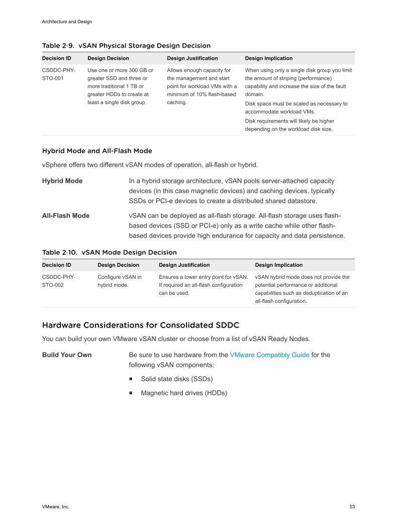
Table 2‑9. vSAN Physical Storage Design Decision
Decision ID Design Decision Design Justification Design Implication
CSDDC-PHY-STO-001
Use one or more 300 GB orgreater SSD and three ormore traditional 1 TB orgreater HDDs to create atleast a single disk group.
Allows enough capacity forthe management and startpoint for workload VMs with aminimum of 10% flash-basedcaching.
When using only a single disk group you limitthe amount of striping (performance)capability and increase the size of the faultdomain.
Disk space must be scaled as necessary toaccommodate workload VMs.
Disk requirements will likely be higherdepending on the workload disk size.
Hybrid Mode and All-Flash Mode
vSphere offers two different vSAN modes of operation, all-flash or hybrid.
Hybrid Mode In a hybrid storage architecture, vSAN pools server-attached capacitydevices (in this case magnetic devices) and caching devices, typicallySSDs or PCI-e devices to create a distributed shared datastore.
All-Flash Mode vSAN can be deployed as all-flash storage. All-flash storage uses flash-based devices (SSD or PCI-e) only as a write cache while other flash-based devices provide high endurance for capacity and data persistence.
Table 2‑10. vSAN Mode Design Decision
Decision ID Design Decision Design Justification Design Implication
CSDDC-PHY-STO-002
Configure vSAN inhybrid mode.
Ensures a lower entry point for vSAN.If required an all-flash configurationcan be used.
vSAN hybrid mode does not provide thepotential performance or additionalcapabilities such as deduplication of anall-flash configuration.
Hardware Considerations for Consolidated SDDCYou can build your own VMware vSAN cluster or choose from a list of vSAN Ready Nodes.
Build Your Own Be sure to use hardware from the VMware Compatibly Guide for thefollowing vSAN components:
n Solid state disks (SSDs)
n Magnetic hard drives (HDDs)
Architecture and Design
VMware, Inc. 53

n I/O controllers, including vSAN certified driver/firmware combinations
Use VMware vSANReady Nodes
A vSAN Ready Node is a validated server configuration in a tested, certifiedhardware form factor for vSAN deployment, jointly recommended by theserver OEM and VMware. See the VMware Compatibility Guide. The vSANReady Node documentation provides examples of standardizedconfigurations, including the numbers of VMs supported and estimatednumber of 4K IOPS delivered.
As per design decision CSDDC-PHY-007, the VMware Validated Design uses vSAN Ready Nodes.
Solid State Disk Characteristics for Consolidated SDDC
In a VMware vSAN configuration, the solid state disks (SSDs) are used for the vSAN caching layer forhybrid deployments and for the capacity layer for all flash.
n For a hybrid deployment, the use of the SSD is split between a non-volatile write cache(approximately 30%) and a read buffer (approximately 70%). As a result, the endurance and thenumber of I/O operations per second that the SSD can sustain are important performance factors.
n For an all-flash model, endurance and performance have the same criteria. However many morewrite operations are held by the caching tier, thus elongating or extending the life of the SSDcapacity-tier.
SSD Endurance
This VMware Validated Design uses class D endurance class SSDs for the caching tier.
SDDC Endurance Design Decision Background
For endurance of the SSDs used for vSAN, standard industry write metrics are the primarymeasurements used to gauge the reliability of the drive. No standard metric exists across all vendors,however, Drive Writes per Day (DWPD) or Petabytes Written (PBW) are the measurements normallyused.
For vSphere 5.5, the endurance class was based on Drive Writes Per Day (DWPD). For VMware vSAN6.0 and later, the endurance class has been updated to use Terabytes Written (TBW), based on thevendor’s drive warranty. TBW can be used for VMware vSAN 5.5, VMware vSAN 6.0 and VMware vSAN6.5 and is reflected in the VMware Compatibility Guide.
The reasoning behind using TBW is that VMware provides the flexibility to use larger capacity drives withlower DWPD specifications.
If a SSD vendor uses Drive Writes Per Day as a measurement, you can calculate endurance in TerabytesWritten (TBW) with the following equation.
TBW (over 5 years) = Drive Size x DWPD x 365 x 5
Architecture and Design
VMware, Inc. 54
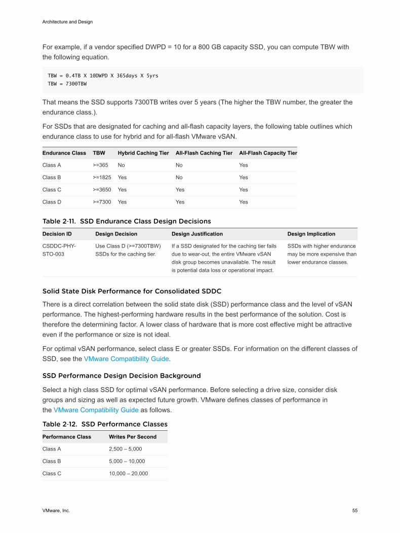
For example, if a vendor specified DWPD = 10 for a 800 GB capacity SSD, you can compute TBW withthe following equation.
TBW = 0.4TB X 10DWPD X 365days X 5yrs
TBW = 7300TBW
That means the SSD supports 7300TB writes over 5 years (The higher the TBW number, the greater theendurance class.).
For SSDs that are designated for caching and all-flash capacity layers, the following table outlines whichendurance class to use for hybrid and for all-flash VMware vSAN.
Endurance Class TBW Hybrid Caching Tier All-Flash Caching Tier All-Flash Capacity Tier
Class A >=365 No No Yes
Class B >=1825 Yes No Yes
Class C >=3650 Yes Yes Yes
Class D >=7300 Yes Yes Yes
Table 2‑11. SSD Endurance Class Design Decisions
Decision ID Design Decision Design Justification Design Implication
CSDDC-PHY-STO-003
Use Class D (>=7300TBW)SSDs for the caching tier.
If a SSD designated for the caching tier failsdue to wear-out, the entire VMware vSANdisk group becomes unavailable. The resultis potential data loss or operational impact.
SSDs with higher endurancemay be more expensive thanlower endurance classes.
Solid State Disk Performance for Consolidated SDDC
There is a direct correlation between the solid state disk (SSD) performance class and the level of vSANperformance. The highest-performing hardware results in the best performance of the solution. Cost istherefore the determining factor. A lower class of hardware that is more cost effective might be attractiveeven if the performance or size is not ideal.
For optimal vSAN performance, select class E or greater SSDs. For information on the different classes ofSSD, see the VMware Compatibility Guide.
SSD Performance Design Decision Background
Select a high class SSD for optimal vSAN performance. Before selecting a drive size, consider diskgroups and sizing as well as expected future growth. VMware defines classes of performance inthe VMware Compatibility Guide as follows.
Table 2‑12. SSD Performance Classes
Performance Class Writes Per Second
Class A 2,500 – 5,000
Class B 5,000 – 10,000
Class C 10,000 – 20,000
Architecture and Design
VMware, Inc. 55
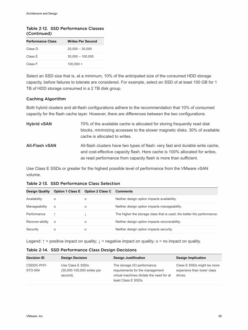
Table 2‑12. SSD Performance Classes(Continued)
Performance Class Writes Per Second
Class D 20,000 – 30,000
Class E 30,000 – 100,000
Class F 100,000 +
Select an SSD size that is, at a minimum, 10% of the anticipated size of the consumed HDD storagecapacity, before failures to tolerate are considered. For example, select an SSD of at least 100 GB for 1TB of HDD storage consumed in a 2 TB disk group.
Caching Algorithm
Both hybrid clusters and all-flash configurations adhere to the recommendation that 10% of consumedcapacity for the flash cache layer. However, there are differences between the two configurations.
Hybrid vSAN 70% of the available cache is allocated for storing frequently read diskblocks, minimizing accesses to the slower magnetic disks. 30% of availablecache is allocated to writes.
All-Flash vSAN All-flash clusters have two types of flash: very fast and durable write cache,and cost-effective capacity flash. Here cache is 100% allocated for writes,as read performance from capacity flash is more than sufficient.
Use Class E SSDs or greater for the highest possible level of performance from the VMware vSANvolume.
Table 2‑13. SSD Performance Class Selection
Design Quality Option 1 Class E Option 2 Class C Comments
Availability o o Neither design option impacts availability.
Manageability o o Neither design option impacts manageability.
Performance ↑ ↓ The higher the storage class that is used, the better the performance.
Recover-ability o o Neither design option impacts recoverability.
Security o o Neither design option impacts security.
Legend: ↑ = positive impact on quality; ↓ = negative impact on quality; o = no impact on quality.
Table 2‑14. SSD Performance Class Design Decisions
Decision ID Design Decision Design Justification Design Implication
CSDDC-PHY-STO-004
Use Class E SSDs(30,000-100,000 writes persecond).
The storage I/O performancerequirements for the managementvirtual machines dictate the need for atleast Class E SSDs.
Class E SSDs might be moreexpensive than lower classdrives.
Architecture and Design
VMware, Inc. 56

Magnetic Hard Disk Drives Characteristics for Consolidated SDDC
The hard disk drives (HDDs) in a VMware vSAN environment have two different purposes, capacity andobject stripe width.
Capacity Magnetic disks, or HDDs, unlike caching-tier SSDs, make up the capacityof a vSAN datastore
Stripe Width You can define stripe width at the virtual machine policy layer. vSAN mightuse additional stripes when making capacity and placement decisionsoutside a storage policy.
vSAN supports these disk types:
n Serial Attached SCSI (SAS)
n Near Line Serial Attached SCSI (NL-SCSI). NL-SAS can be thought of as enterprise SATA drives butwith a SAS interface.
n Serial Advanced Technology Attachment (SATA). Use SATA magnetic disks only in capacity-centricenvironments where performance is not prioritized.
SAS and NL-SAS get you the best results. This VMware Validated Design uses 10,000 RPM drives toachieve a balance between cost and availability.
HDD Capacity, Cost, and Availability Background Considerations
You can achieve the best results with SAS and NL-SAS.
The VMware vSAN design must consider the number of magnetic disks required for the capacity layer,and how well the capacity layer will perform.
n SATA disks typically provide more capacity per individual drive, and tend to be less expensive thanSAS drives. However the trade off is performance, because SATA performance is not as good asSAS performance due to lower rotational speeds (typically 7200RPM)
n Choose SAS magnetic disks instead of SATA magnetic disks in environments where performance iscritical.
Consider that failure of a larger capacity drive has operational impact on the availability and recovery ofmore components.
Rotational Speed (RPM) Background Considerations
HDDs tend to be more reliable, but that comes at a cost. SAS disks can be available up to 15,000 RPMspeeds.
Table 2‑15. vSAN HDD Environmental Characteristics
Characteristic Revolutions per Minute (RPM)
Capacity 7,200
Performance 10,000
Additional Performance 15,000
Architecture and Design
VMware, Inc. 57
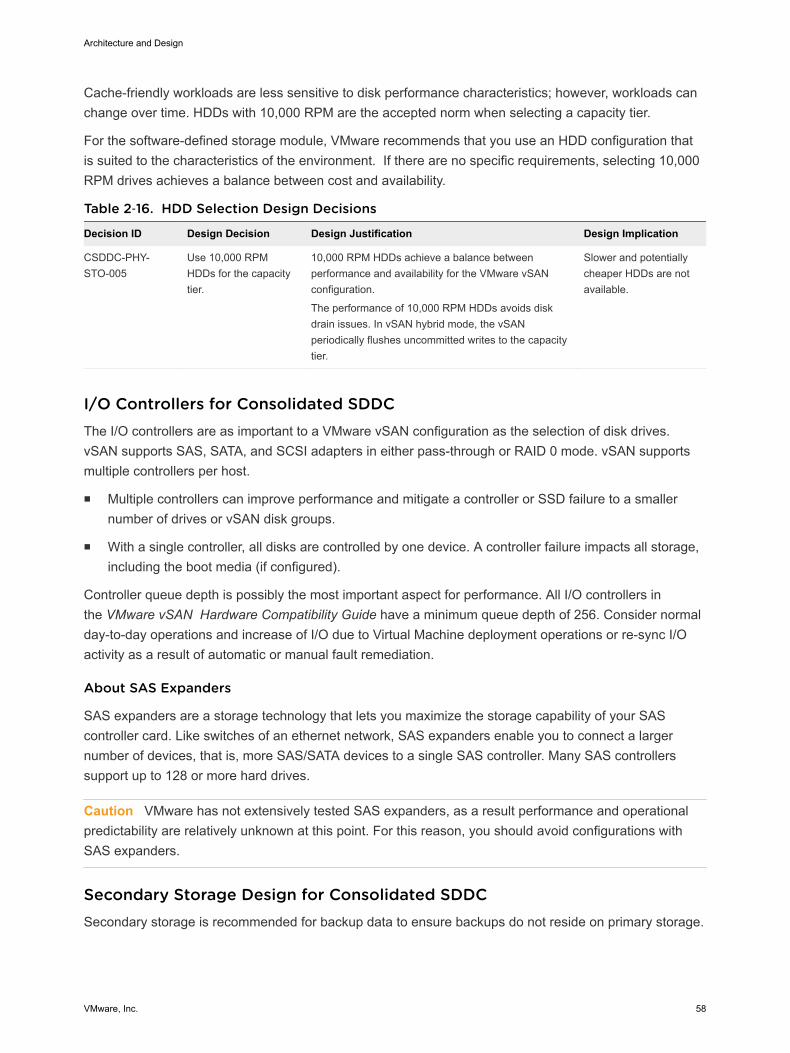
Cache-friendly workloads are less sensitive to disk performance characteristics; however, workloads canchange over time. HDDs with 10,000 RPM are the accepted norm when selecting a capacity tier.
For the software-defined storage module, VMware recommends that you use an HDD configuration thatis suited to the characteristics of the environment. If there are no specific requirements, selecting 10,000RPM drives achieves a balance between cost and availability.
Table 2‑16. HDD Selection Design Decisions
Decision ID Design Decision Design Justification Design Implication
CSDDC-PHY-STO-005
Use 10,000 RPMHDDs for the capacitytier.
10,000 RPM HDDs achieve a balance betweenperformance and availability for the VMware vSANconfiguration.
The performance of 10,000 RPM HDDs avoids diskdrain issues. In vSAN hybrid mode, the vSANperiodically flushes uncommitted writes to the capacitytier.
Slower and potentiallycheaper HDDs are notavailable.
I/O Controllers for Consolidated SDDCThe I/O controllers are as important to a VMware vSAN configuration as the selection of disk drives.vSAN supports SAS, SATA, and SCSI adapters in either pass-through or RAID 0 mode. vSAN supportsmultiple controllers per host.
n Multiple controllers can improve performance and mitigate a controller or SSD failure to a smallernumber of drives or vSAN disk groups.
n With a single controller, all disks are controlled by one device. A controller failure impacts all storage,including the boot media (if configured).
Controller queue depth is possibly the most important aspect for performance. All I/O controllers inthe VMware vSAN Hardware Compatibility Guide have a minimum queue depth of 256. Consider normalday-to-day operations and increase of I/O due to Virtual Machine deployment operations or re-sync I/Oactivity as a result of automatic or manual fault remediation.
About SAS Expanders
SAS expanders are a storage technology that lets you maximize the storage capability of your SAScontroller card. Like switches of an ethernet network, SAS expanders enable you to connect a largernumber of devices, that is, more SAS/SATA devices to a single SAS controller. Many SAS controllerssupport up to 128 or more hard drives.
Caution VMware has not extensively tested SAS expanders, as a result performance and operationalpredictability are relatively unknown at this point. For this reason, you should avoid configurations withSAS expanders.
Secondary Storage Design for Consolidated SDDCSecondary storage is recommended for backup data to ensure backups do not reside on primary storage.
Architecture and Design
VMware, Inc. 58
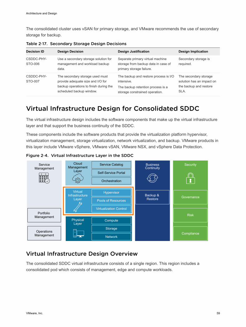
The consolidated cluster uses vSAN for primary storage, and VMware recommends the use of secondarystorage for backup.
Table 2‑17. Secondary Storage Design Decisions
Decision ID Design Decision Design Justification Design Implication
CSDDC-PHY-STO-006
Use a secondary storage solution formanagement and workload backupdata.
Separate primary virtual machinestorage from backup data in case ofprimary storage failure.
Secondary storage isrequired.
CSDDC-PHY-STO-007
The secondary storage used mustprovide adequate size and I/O forbackup operations to finish during thescheduled backup window.
The backup and restore process is I/Ointensive.
The backup retention process is astorage constrained operation.
The secondary storagesolution has an impact onthe backup and restoreSLA.
Virtual Infrastructure Design for Consolidated SDDCThe virtual infrastructure design includes the software components that make up the virtual infrastructurelayer and that support the business continuity of the SDDC.
These components include the software products that provide the virtualization platform hypervisor,virtualization management, storage virtualization, network virtualization, and backup. VMware products inthis layer include VMware vSphere, VMware vSAN, VMware NSX, and vSphere Data Protection.
Figure 2‑4. Virtual Infrastructure Layer in the SDDC
ServiceManagement
Portfolio Management
OperationsManagement
CloudManagement
Layer
Service Catalog
Self-Service Portal
Orchestration
BusinessContinuity
Backup & Restore
Hypervisor
Pools of Resources
Virtualization Control
VirtualInfrastructure
Layer
Compute
Storage
Network
PhysicalLayer
Security
Compliance
Risk
Governance
Virtual Infrastructure Design OverviewThe consolidated SDDC virtual infrastructure consists of a single region. This region includes aconsolidated pod which consists of management, edge and compute workloads.
Architecture and Design
VMware, Inc. 59

Figure 2‑5. SDDC Logical Design
APP
OSAPP
OS
APP
OSAPP
OS
APP
OSAPP
OS
APP
OSAPP
OS
ESXi
APP
OSAPP
OS
APP
OSAPP
OS
Virtual InfrastructureManagement
NSXController
OtherManagementApplications
NSXEdge
NSXManager
ESXi ESXi ESXi
Workloads
NSX Transport Zone
vSphere Distributed Switch
Consolidated Cluster
Managed by: Consolidated vCenter Server
Network: External(Internet/MPLS)
Network: Internal SDDC
Consolidated Pod
vCenterServer
Consolidated PodThe consolidated pod runs the following services:
n Virtual machines to manage the SDDC such as vCenter Server, NSX Manager, vRealize Automation,vRealize Log Insight, vRealize Operations Manager and vSphere Data Protection.
n Required NSX services to enable north-south routing between the SDDC and the external network,and east-west routing inside the SDDC.
n SDDC tenant virtual machines to support workloads of different Service Level Agreements (SLAs).
Because this pod supports all SDDC, network, and production workloads, it is important to ensure highlyavailable physical components such as HVAC, power feeds and power supplies.
ESXi Design for Consolidated SDDCThe ESXi design includes design decisions for boot options, user access, and the virtual machine swapconfiguration.
Architecture and Design
VMware, Inc. 60

ESXi Hardware RequirementsYou can find the ESXi hardware requirements in Physical Design Fundamentals. The following designoutlines the design of the ESXi configuration.
ESXi Manual Install and Boot OptionsYou can install or boot ESXi 6.5 from the following storage systems:
SATA disk drives SATA disk drives connected behind supported SAS controllers or supportedon-board SATA controllers.
Serial-attached SCSI(SAS) disk drives
Supported for installing ESXi.
SAN Dedicated SAN disk on Fibre Channel or iSCSI. Supported for installingESXi.
USB devices Supported for installing ESXi. 16 GB or larger SD card is recommended.
FCoE (Fibre Channelover Ethernet)
Supported for installing ESXi.
PXE boot Supported for stateless caching or stateful installs using vSphere AutoDeploy.
ESXi can boot from a disk larger than 2 TB if the system firmware and the firmware on any add-in cardsupport it. See the vendor documentation.
ESXi Boot Disk and Scratch ConfigurationFor new installations of ESXi, the installer creates a 4 GB VFAT scratch partition. ESXi uses this scratchpartition to store log files persistently. By default, vm-support output, which is used by VMware totroubleshoot issues on the ESXi host, is also stored on the scratch partition.
An ESXi installation on USB media does not configure a default scratch partition. VMware recommendsthat you specify a scratch partition on a shared datastore and configure remote syslog logging for thehost.
Table 2‑18. ESXi Boot Disk Design Decision
Decision ID Design Decision Design Justification Design Implication
CSDDC-VI-ESXi-001
Install and configure all ESXihosts to boot using a SDdevice of 16 GB or greater.
SD cards are an inexpensive and easy toconfigure option for installing ESXi.
Using SD cards allows allocation of all localHDDs to a VMware vSAN storage system.
When you use SD cardsESXi logs are not retainedlocally.
ESXi Host AccessAfter installation, ESXi hosts are added to a VMware vCenter Server system and managed through thatvCenter Server system.
Architecture and Design
VMware, Inc. 61
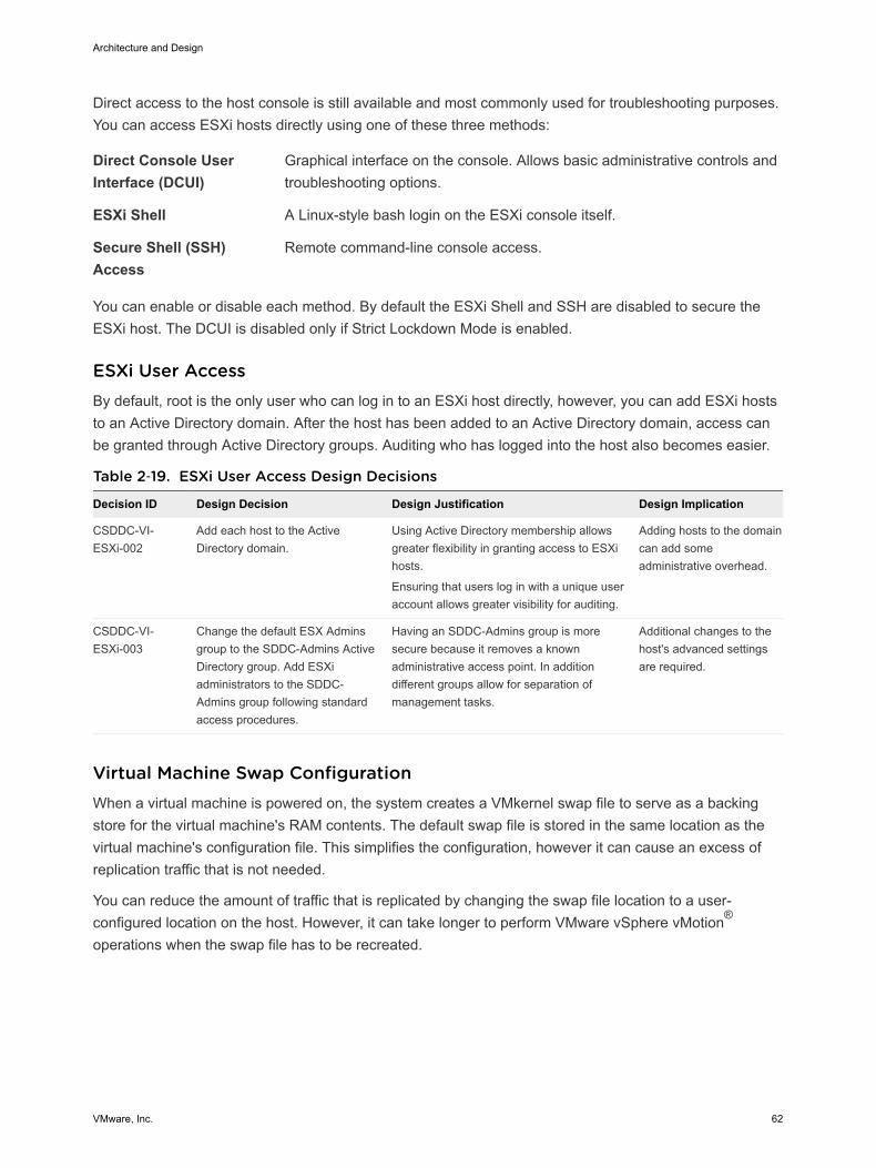
Direct access to the host console is still available and most commonly used for troubleshooting purposes.You can access ESXi hosts directly using one of these three methods:
Direct Console UserInterface (DCUI)
Graphical interface on the console. Allows basic administrative controls andtroubleshooting options.
ESXi Shell A Linux-style bash login on the ESXi console itself.
Secure Shell (SSH)Access
Remote command-line console access.
You can enable or disable each method. By default the ESXi Shell and SSH are disabled to secure theESXi host. The DCUI is disabled only if Strict Lockdown Mode is enabled.
ESXi User AccessBy default, root is the only user who can log in to an ESXi host directly, however, you can add ESXi hoststo an Active Directory domain. After the host has been added to an Active Directory domain, access canbe granted through Active Directory groups. Auditing who has logged into the host also becomes easier.
Table 2‑19. ESXi User Access Design Decisions
Decision ID Design Decision Design Justification Design Implication
CSDDC-VI-ESXi-002
Add each host to the ActiveDirectory domain.
Using Active Directory membership allowsgreater flexibility in granting access to ESXihosts.
Ensuring that users log in with a unique useraccount allows greater visibility for auditing.
Adding hosts to the domaincan add someadministrative overhead.
CSDDC-VI-ESXi-003
Change the default ESX Adminsgroup to the SDDC-Admins ActiveDirectory group. Add ESXiadministrators to the SDDC-Admins group following standardaccess procedures.
Having an SDDC-Admins group is moresecure because it removes a knownadministrative access point. In additiondifferent groups allow for separation ofmanagement tasks.
Additional changes to thehost's advanced settingsare required.
Virtual Machine Swap ConfigurationWhen a virtual machine is powered on, the system creates a VMkernel swap file to serve as a backingstore for the virtual machine's RAM contents. The default swap file is stored in the same location as thevirtual machine's configuration file. This simplifies the configuration, however it can cause an excess ofreplication traffic that is not needed.
You can reduce the amount of traffic that is replicated by changing the swap file location to a user-configured location on the host. However, it can take longer to perform VMware vSphere vMotion®
operations when the swap file has to be recreated.
Architecture and Design
VMware, Inc. 62

Table 2‑20. Other ESXi Host Design Decisions
Decision ID Design Decision Design Justification Design Implication
CSDDC-VI-ESXi-004
Configure all ESXi hosts tosynchronize time with thecentral NTP servers.
Ensures consistent timebetween the individual SDDCcomponents.
All firewalls located between the ESXihost and the NTP servers have to allowNTP traffic on the required networkports.
vCenter Server Design for Consolidated SDDCThe vCenter Server design includes both the design for the vCenter Server instance and the VMwarePlatform Services Controller instance.
A Platform Services Controller groups a set of infrastructure services including vCenter Single Sign-On,License service, Lookup Service, and VMware Certificate Authority (VMCA). You can deploy the PlatformServices Controller and the associated vCenter Server system on the same virtual machine(embeddedPlatform Services Controller) or on different virtual machines (external Platform Services Controller).
n vCenter Server Deployment for Consolidated SDDC
The design decisions for vCenter Server deployment discuss the number of vCenter Server andPlatform Services Controller instances, the type of installation, and the topology.
n vCenter Server Networking for Consolidated SDDC
As specified in the physical networking design, all vCenter Server systems must use static IPaddresses and host names. The IP addresses must have valid (internal) DNS registration includingreverse name resolution.
n vCenter Server Redundancy for Consolidated SDDC
Protecting the vCenter Server system is important because it is the central point of management andmonitoring for the SDDC. How you protect vCenter Server depends on maximum downtimetolerated, and on whether failover automation is required.
n vCenter Server Appliance Sizing for Consolidated SDDC
The following tables outline minimum hardware requirements for the vCenter Server appliance.
n vSphere Cluster Design for Consolidated SDDC
The cluster design must take into account the workload that the cluster must handle.
n vCenter Server Customization for Consolidated SDDC
vCenter Server supports a rich set of customization options, including monitoring, virtual machinefault tolerance, and so on. For each feature, this VMware Validated Design specifies the designdecisions.
n Use of Transport Layer Security (TLS) Certificates for Consolidated SDDC
By default vSphere 6.5 uses TLS/SSL certificates that are signed by VMCA (VMware CertificateAuthority). By default, these certificates are not trusted by end-user devices or browsers. It is asecurity best practice to replace at least user-facing certificates with certificates that are signed by athird-party or enterprise Certificate Authority (CA). Certificates for machine-to-machinecommunication can remain as VMCA-signed certificates.
Architecture and Design
VMware, Inc. 63
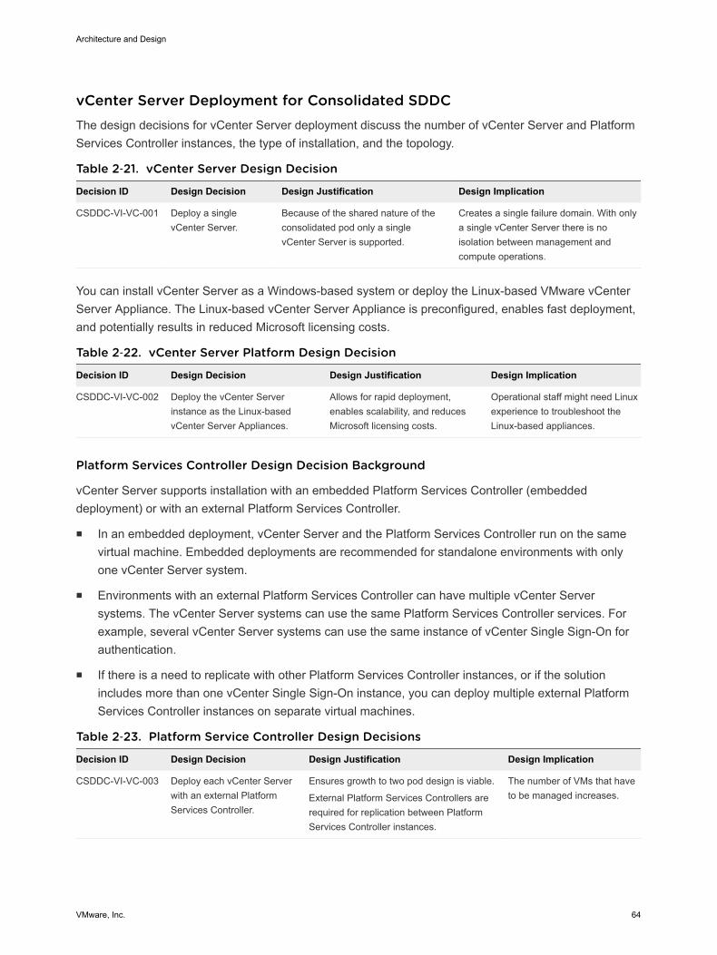
vCenter Server Deployment for Consolidated SDDCThe design decisions for vCenter Server deployment discuss the number of vCenter Server and PlatformServices Controller instances, the type of installation, and the topology.
Table 2‑21. vCenter Server Design Decision
Decision ID Design Decision Design Justification Design Implication
CSDDC-VI-VC-001 Deploy a singlevCenter Server.
Because of the shared nature of theconsolidated pod only a singlevCenter Server is supported.
Creates a single failure domain. With onlya single vCenter Server there is noisolation between management andcompute operations.
You can install vCenter Server as a Windows-based system or deploy the Linux-based VMware vCenterServer Appliance. The Linux-based vCenter Server Appliance is preconfigured, enables fast deployment,and potentially results in reduced Microsoft licensing costs.
Table 2‑22. vCenter Server Platform Design Decision
Decision ID Design Decision Design Justification Design Implication
CSDDC-VI-VC-002 Deploy the vCenter Serverinstance as the Linux-basedvCenter Server Appliances.
Allows for rapid deployment,enables scalability, and reducesMicrosoft licensing costs.
Operational staff might need Linuxexperience to troubleshoot theLinux-based appliances.
Platform Services Controller Design Decision Background
vCenter Server supports installation with an embedded Platform Services Controller (embeddeddeployment) or with an external Platform Services Controller.
n In an embedded deployment, vCenter Server and the Platform Services Controller run on the samevirtual machine. Embedded deployments are recommended for standalone environments with onlyone vCenter Server system.
n Environments with an external Platform Services Controller can have multiple vCenter Serversystems. The vCenter Server systems can use the same Platform Services Controller services. Forexample, several vCenter Server systems can use the same instance of vCenter Single Sign-On forauthentication.
n If there is a need to replicate with other Platform Services Controller instances, or if the solutionincludes more than one vCenter Single Sign-On instance, you can deploy multiple external PlatformServices Controller instances on separate virtual machines.
Table 2‑23. Platform Service Controller Design Decisions
Decision ID Design Decision Design Justification Design Implication
CSDDC-VI-VC-003 Deploy each vCenter Serverwith an external PlatformServices Controller.
Ensures growth to two pod design is viable.
External Platform Services Controllers arerequired for replication between PlatformServices Controller instances.
The number of VMs that haveto be managed increases.
Architecture and Design
VMware, Inc. 64

Figure 2‑6. vCenter Server and Platform Services Controller Deployment Model
ConsolidatedvCenter Server
Appliance
Platform Services Controller Appliance
Region A: SFO
vCenter Server Networking for Consolidated SDDCAs specified in the physical networking design, all vCenter Server systems must use static IP addressesand host names. The IP addresses must have valid (internal) DNS registration including reverse nameresolution.
The vCenter Server systems must maintain network connections to the following components:
n All VMware vSphere Client and vSphere Web Client user interfaces.
n Systems running vCenter Server add-on modules.
n Each ESXi host.
vCenter Server Redundancy for Consolidated SDDCProtecting the vCenter Server system is important because it is the central point of management andmonitoring for the SDDC. How you protect vCenter Server depends on maximum downtime tolerated, andon whether failover automation is required.
The following table lists methods available for protecting the vCenter Server system and the vCenterServer Appliance.
Table 2‑24. Methods for Protecting vCenter Server System and the vCenter Server Appliance
Redundancy Method
Protects vCenterServer system(Windows)
Protects PlatformServices Controller(Windows)
Protects vCenterServer (Appliance)
Protects PlatformServices Controller(Appliance)
Automated protection usingvSphere HA.
Yes Yes Yes Yes
Manual configuration andmanual failover. For example,using a cold standby.
Yes Yes Yes Yes
Architecture and Design
VMware, Inc. 65

Table 2‑24. Methods for Protecting vCenter Server System and the vCenter Server Appliance(Continued)
Redundancy Method
Protects vCenterServer system(Windows)
Protects PlatformServices Controller(Windows)
Protects vCenterServer (Appliance)
Protects PlatformServices Controller(Appliance)
HA Cluster with external loadbalancer
Not Available Yes Not Available Yes
vCenter Server HA Not Available Not Available Yes Not Available
Table 2‑25. vCenter Server Protection Design Decision
Decision ID Design Decision Design Justification Design Implication
CSDDC-VI-VC-004 Protect all vCenter Server andPlatform Services Controllerappliances by using vSphere HA.
Supports availability objectives forvCenter Server appliances without arequired manual intervention during afailure event.
vCenter Server will beunavailable during a vSphereHA failover.
vCenter Server Appliance Sizing for Consolidated SDDCThe following tables outline minimum hardware requirements for the vCenter Server appliance.
Table 2‑26. Logical Specification for the vCenter Server Appliance
Attribute Specification
vCenter Server version 6.5 (vCenter Server Appliance)
Physical or virtual system Virtual (appliance)
Appliance Size Small (up to 100 hosts / 1,000 VMs)
Platform Services Controller External
Number of CPUs 4
Memory 16 GB
Disk Space 290 GB
Table 2‑27. vCenter Server Appliance Sizing Design Decisions
Decision ID Design Decision Design Justification Design Implication
CSDDC-VI-VC-005
Configure the vCenterServer Appliance with atleast the small sizesetting.
Based on the number of hosts andvirtual machines in a consolidated pod,a vCenter Server Appliance installedwith the small size setting is sufficient.
If the size of the environment growspast 100 hosts or 1000 virtualmachines, the vCenter ServerAppliance size will need to beincreased.
vSphere Cluster Design for Consolidated SDDCThe cluster design must take into account the workload that the cluster must handle.
Architecture and Design
VMware, Inc. 66
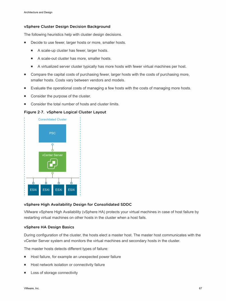
vSphere Cluster Design Decision Background
The following heuristics help with cluster design decisions.
n Decide to use fewer, larger hosts or more, smaller hosts.
n A scale-up cluster has fewer, larger hosts.
n A scale-out cluster has more, smaller hosts.
n A virtualized server cluster typically has more hosts with fewer virtual machines per host.
n Compare the capital costs of purchasing fewer, larger hosts with the costs of purchasing more,smaller hosts. Costs vary between vendors and models.
n Evaluate the operational costs of managing a few hosts with the costs of managing more hosts.
n Consider the purpose of the cluster.
n Consider the total number of hosts and cluster limits.
Figure 2‑7. vSphere Logical Cluster Layout
vCenter Server
PSC
ESXi ESXi ESXi ESXi
Consolidated Cluster
vSphere High Availability Design for Consolidated SDDC
VMware vSphere High Availability (vSphere HA) protects your virtual machines in case of host failure byrestarting virtual machines on other hosts in the cluster when a host fails.
vSphere HA Design Basics
During configuration of the cluster, the hosts elect a master host. The master host communicates with thevCenter Server system and monitors the virtual machines and secondary hosts in the cluster.
The master hosts detects different types of failure:
n Host failure, for example an unexpected power failure
n Host network isolation or connectivity failure
n Loss of storage connectivity
Architecture and Design
VMware, Inc. 67
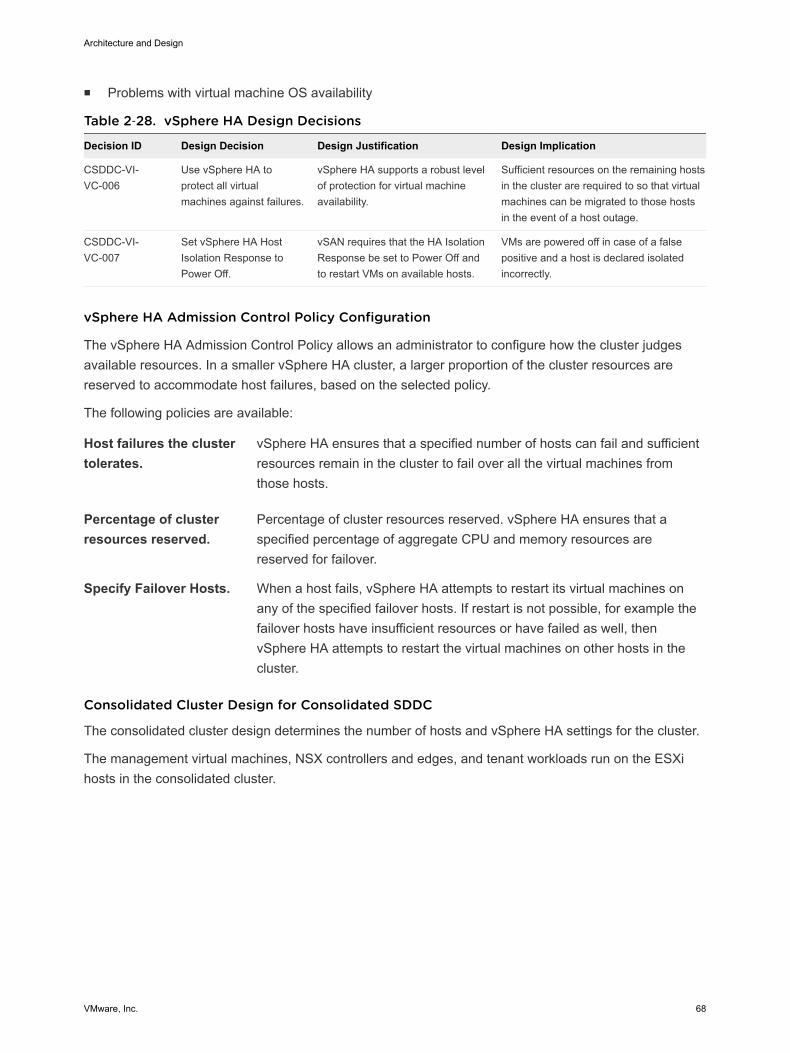
n Problems with virtual machine OS availability
Table 2‑28. vSphere HA Design Decisions
Decision ID Design Decision Design Justification Design Implication
CSDDC-VI-VC-006
Use vSphere HA toprotect all virtualmachines against failures.
vSphere HA supports a robust levelof protection for virtual machineavailability.
Sufficient resources on the remaining hostsin the cluster are required to so that virtualmachines can be migrated to those hostsin the event of a host outage.
CSDDC-VI-VC-007
Set vSphere HA HostIsolation Response toPower Off.
vSAN requires that the HA IsolationResponse be set to Power Off andto restart VMs on available hosts.
VMs are powered off in case of a falsepositive and a host is declared isolatedincorrectly.
vSphere HA Admission Control Policy Configuration
The vSphere HA Admission Control Policy allows an administrator to configure how the cluster judgesavailable resources. In a smaller vSphere HA cluster, a larger proportion of the cluster resources arereserved to accommodate host failures, based on the selected policy.
The following policies are available:
Host failures the clustertolerates.
vSphere HA ensures that a specified number of hosts can fail and sufficientresources remain in the cluster to fail over all the virtual machines fromthose hosts.
Percentage of clusterresources reserved.
Percentage of cluster resources reserved. vSphere HA ensures that aspecified percentage of aggregate CPU and memory resources arereserved for failover.
Specify Failover Hosts. When a host fails, vSphere HA attempts to restart its virtual machines onany of the specified failover hosts. If restart is not possible, for example thefailover hosts have insufficient resources or have failed as well, thenvSphere HA attempts to restart the virtual machines on other hosts in thecluster.
Consolidated Cluster Design for Consolidated SDDC
The consolidated cluster design determines the number of hosts and vSphere HA settings for the cluster.
The management virtual machines, NSX controllers and edges, and tenant workloads run on the ESXihosts in the consolidated cluster.
Architecture and Design
VMware, Inc. 68

Figure 2‑8. Consolidated Cluster Resource Pools
vC NSX vRA
vDP vRB vROPs
vRLI
Management: Reservation
SDDC Edge: Reservation
ESG Control VMControllers
User Defined Edge: Share
Compute: Share
ESG LB
vSphere Host(s)
vSphere Cluster
Architecture and Design
VMware, Inc. 69
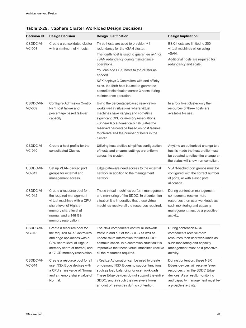
Table 2‑29. vSphere Cluster Workload Design Decisions
Decision ID Design Decision Design Justification Design Implication
CSDDC-VI-VC-008
Create a consolidated clusterwith a minimum of 4 hosts.
Three hosts are used to provide n+1redundancy for the vSAN cluster.
The fourth host is used to guarantee n+1 forvSAN redundancy during maintenanceoperations.
You can add ESXi hosts to the cluster asneeded.
NSX deploys 3 Controllers with anti-affinityrules. the forth host is used to guaranteecontroller distribution across 3 hosts duringmaintenance operation.
ESXi hosts are limited to 200virtual machines when usingvSAN.
Additional hosts are required forredundancy and scale.
CSDDC-VI-VC-009
Configure Admission Controlfor 1 host failure andpercentage based failovercapacity.
Using the percentage-based reservationworks well in situations where virtualmachines have varying and sometimesignificant CPU or memory reservations.vSphere 6.5 automatically calculates thereserved percentage based on host failuresto tolerate and the number of hosts in thecluster.
In a four host cluster only theresources of three hosts areavailable for use.
CSDDC-VI-VC-010
Create a host profile for theconsolidated Cluster.
Utilizing host profiles simplifies configurationof hosts and ensures settings are uniformacross the cluster.
Anytime an authorized change to ahost is made the host profile mustbe updated to reflect the change orthe status will show non-compliant.
CSDDC-VI-VC-011
Set up VLAN-backed portgroups for external andmanagement access.
Edge gateways need access to the externalnetwork in addition to the managementnetwork.
VLAN-backed port groups must beconfigured with the correct numberof ports, or with elastic portallocation.
CSDDC-VI-VC-012
Create a resource pool forthe required managementvirtual machines with a CPUshare level of High, amemory share level ofnormal, and a 146 GBmemory reservation.
These virtual machines perform managementand monitoring of the SDDC. In a contentionsituation it is imperative that these virtualmachines receive all the resources required.
During contention managementcomponents receive moreresources then user workloads assuch monitoring and capacitymanagement must be a proactiveactivity.
CSDDC-VI-VC-013
Create a resource pool forthe required NSX Controllersand edge appliances with aCPU share level of High, amemory share of normal, anda 17 GB memory reservation.
The NSX components control all networktraffic in and out of the SDDC as well asupdate route information for inter-SDDCcommunication. In a contention situation it isimperative that these virtual machines receiveall the resources required.
During contention NSXcomponents receive moreresources then user workloads assuch monitoring and capacitymanagement must be a proactiveactivity.
CSDDC-VI-VC-014
Create a resource pool for alluser NSX Edge devices witha CPU share value of Normaland a memory share value ofNormal.
vRealize Automation can be used to createon-demand NSX Edges to support functionssuch as load balancing for user workloads.These Edge devices do not support the entireSDDC, and as such they receive a loweramount of resources during contention.
During contention, these NSXEdges devices will receive fewerresources than the SDDC Edgedevices. As a result, monitoringand capacity management must bea proactive activity.
Architecture and Design
VMware, Inc. 70
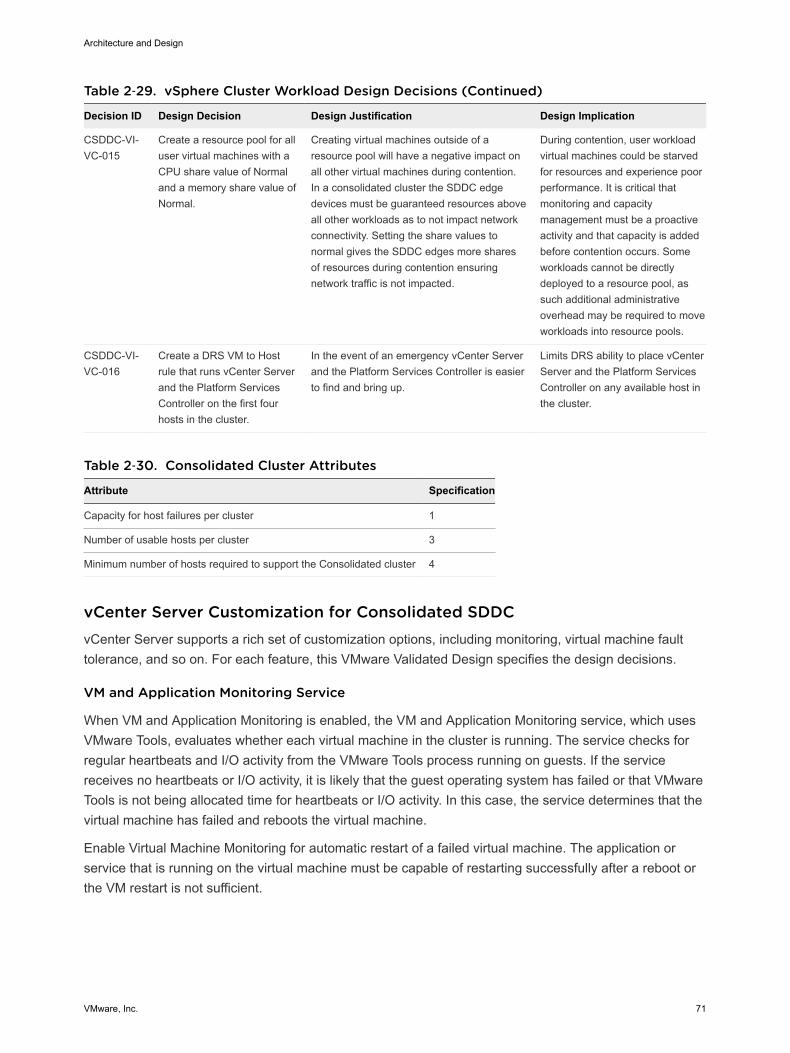
Table 2‑29. vSphere Cluster Workload Design Decisions (Continued)
Decision ID Design Decision Design Justification Design Implication
CSDDC-VI-VC-015
Create a resource pool for alluser virtual machines with aCPU share value of Normaland a memory share value ofNormal.
Creating virtual machines outside of aresource pool will have a negative impact onall other virtual machines during contention.In a consolidated cluster the SDDC edgedevices must be guaranteed resources aboveall other workloads as to not impact networkconnectivity. Setting the share values tonormal gives the SDDC edges more sharesof resources during contention ensuringnetwork traffic is not impacted.
During contention, user workloadvirtual machines could be starvedfor resources and experience poorperformance. It is critical thatmonitoring and capacitymanagement must be a proactiveactivity and that capacity is addedbefore contention occurs. Someworkloads cannot be directlydeployed to a resource pool, assuch additional administrativeoverhead may be required to moveworkloads into resource pools.
CSDDC-VI-VC-016
Create a DRS VM to Hostrule that runs vCenter Serverand the Platform ServicesController on the first fourhosts in the cluster.
In the event of an emergency vCenter Serverand the Platform Services Controller is easierto find and bring up.
Limits DRS ability to place vCenterServer and the Platform ServicesController on any available host inthe cluster.
Table 2‑30. Consolidated Cluster Attributes
Attribute Specification
Capacity for host failures per cluster 1
Number of usable hosts per cluster 3
Minimum number of hosts required to support the Consolidated cluster 4
vCenter Server Customization for Consolidated SDDCvCenter Server supports a rich set of customization options, including monitoring, virtual machine faulttolerance, and so on. For each feature, this VMware Validated Design specifies the design decisions.
VM and Application Monitoring Service
When VM and Application Monitoring is enabled, the VM and Application Monitoring service, which usesVMware Tools, evaluates whether each virtual machine in the cluster is running. The service checks forregular heartbeats and I/O activity from the VMware Tools process running on guests. If the servicereceives no heartbeats or I/O activity, it is likely that the guest operating system has failed or that VMwareTools is not being allocated time for heartbeats or I/O activity. In this case, the service determines that thevirtual machine has failed and reboots the virtual machine.
Enable Virtual Machine Monitoring for automatic restart of a failed virtual machine. The application orservice that is running on the virtual machine must be capable of restarting successfully after a reboot orthe VM restart is not sufficient.
Architecture and Design
VMware, Inc. 71

Table 2‑31. Monitor Virtual Machines Design Decision
Decision ID Design Decision Design Justification Design Implication
CSDDC-VI-VC-017
Enable Virtual MachineMonitoring.
Virtual Machine Monitoring providesadequate in-guest protection for mostVM workloads.
There is no downside to enablingVirtual Machine Monitoring.
CSDDC-VI-VC-018
Create Virtual MachineGroups for use in startuprules.
By creating Virtual Machine groups,rules can be created to configure thestartup order of the SDDCmanagement components.
Creating the groups is a manual taskand adds administrative overhead.
Additionally removing and re-addingthese virtual machines from vCenterinventory will remove the objects fromtheir group associations.
CSDDC-VI-VC-019
Create Virtual Machine rulesto specify the startup orderof the SDDC managementcomponents.
The rules enforce the startup order ofvirtual machine groups to ensure thecorrect startup order of the SDDCmanagement components.
Creating the rules is a manual taskand adds administrative overhead.
VMware vSphere Distributed Resource Scheduling (DRS)
vSphere Distributed Resource Scheduling provides load balancing of a cluster by migrating workloadsfrom heavily loaded hosts to less utilized hosts in the cluster. DRS supports manual and automaticmodes.
Manual Recommendations are made but an administrator needs to confirm thechanges
Automatic Automatic management can be set to five different levels. At the lowestsetting, workloads are placed automatically at power on and only migratedto fulfill certain criteria, such as entering maintenance mode. At the highestlevel, any migration that would provide a slight improvement in balancingwill be executed.
Table 2‑32. vSphere Distributed Resource Scheduling Design Decision
Decision ID Design Decision Design Justification Design Implication
CSDDC-VI-VC-020 Enable DRS and set it to FullyAutomated, with the defaultsetting (medium).
The default settings provide thebest trade-off between loadbalancing and excessive migrationwith vMotion events.
In the event of a vCenter outage,mapping from virtual machines toESXi hosts might be more difficult todetermine.
Enhanced vMotion Compatibility (EVC)
EVC works by masking certain features of newer CPUs to allow migration between hosts containing olderCPUs. EVC works only with CPUs from the same manufacturer and there are limits to the versiondifference gaps between the CPU families.
If you set EVC during cluster creation, you can add hosts with newer CPUs at a later date withoutdisruption. You can use EVC for a rolling upgrade of all hardware with zero downtime.
Set EVC to the highest level possible with the current CPUs in use.
Architecture and Design
VMware, Inc. 72
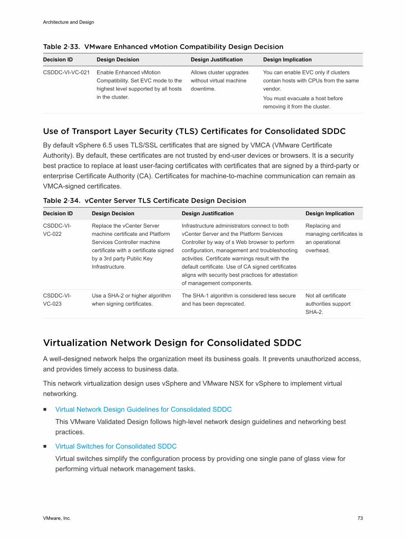
Table 2‑33. VMware Enhanced vMotion Compatibility Design Decision
Decision ID Design Decision Design Justification Design Implication
CSDDC-VI-VC-021 Enable Enhanced vMotionCompatibility. Set EVC mode to thehighest level supported by all hostsin the cluster.
Allows cluster upgradeswithout virtual machinedowntime.
You can enable EVC only if clusterscontain hosts with CPUs from the samevendor.
You must evacuate a host beforeremoving it from the cluster.
Use of Transport Layer Security (TLS) Certificates for Consolidated SDDCBy default vSphere 6.5 uses TLS/SSL certificates that are signed by VMCA (VMware CertificateAuthority). By default, these certificates are not trusted by end-user devices or browsers. It is a securitybest practice to replace at least user-facing certificates with certificates that are signed by a third-party orenterprise Certificate Authority (CA). Certificates for machine-to-machine communication can remain asVMCA-signed certificates.
Table 2‑34. vCenter Server TLS Certificate Design Decision
Decision ID Design Decision Design Justification Design Implication
CSDDC-VI-VC-022
Replace the vCenter Servermachine certificate and PlatformServices Controller machinecertificate with a certificate signedby a 3rd party Public KeyInfrastructure.
Infrastructure administrators connect to bothvCenter Server and the Platform ServicesController by way of s Web browser to performconfiguration, management and troubleshootingactivities. Certificate warnings result with thedefault certificate. Use of CA signed certificatesaligns with security best practices for attestationof management components.
Replacing andmanaging certificates isan operationaloverhead.
CSDDC-VI-VC-023
Use a SHA-2 or higher algorithmwhen signing certificates.
The SHA-1 algorithm is considered less secureand has been deprecated.
Not all certificateauthorities supportSHA-2.
Virtualization Network Design for Consolidated SDDCA well-designed network helps the organization meet its business goals. It prevents unauthorized access,and provides timely access to business data.
This network virtualization design uses vSphere and VMware NSX for vSphere to implement virtualnetworking.
n Virtual Network Design Guidelines for Consolidated SDDC
This VMware Validated Design follows high-level network design guidelines and networking bestpractices.
n Virtual Switches for Consolidated SDDC
Virtual switches simplify the configuration process by providing one single pane of glass view forperforming virtual network management tasks.
Architecture and Design
VMware, Inc. 73
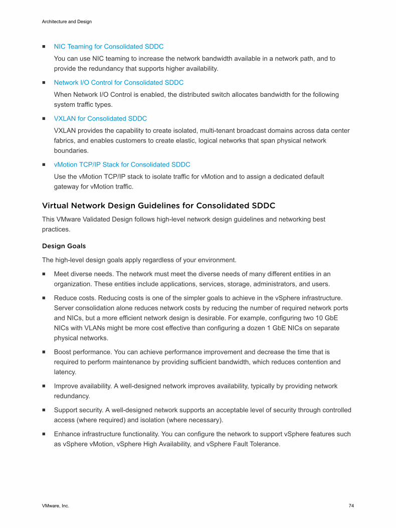
n NIC Teaming for Consolidated SDDC
You can use NIC teaming to increase the network bandwidth available in a network path, and toprovide the redundancy that supports higher availability.
n Network I/O Control for Consolidated SDDC
When Network I/O Control is enabled, the distributed switch allocates bandwidth for the followingsystem traffic types.
n VXLAN for Consolidated SDDC
VXLAN provides the capability to create isolated, multi-tenant broadcast domains across data centerfabrics, and enables customers to create elastic, logical networks that span physical networkboundaries.
n vMotion TCP/IP Stack for Consolidated SDDC
Use the vMotion TCP/IP stack to isolate traffic for vMotion and to assign a dedicated defaultgateway for vMotion traffic.
Virtual Network Design Guidelines for Consolidated SDDCThis VMware Validated Design follows high-level network design guidelines and networking bestpractices.
Design Goals
The high-level design goals apply regardless of your environment.
n Meet diverse needs. The network must meet the diverse needs of many different entities in anorganization. These entities include applications, services, storage, administrators, and users.
n Reduce costs. Reducing costs is one of the simpler goals to achieve in the vSphere infrastructure.Server consolidation alone reduces network costs by reducing the number of required network portsand NICs, but a more efficient network design is desirable. For example, configuring two 10 GbENICs with VLANs might be more cost effective than configuring a dozen 1 GbE NICs on separatephysical networks.
n Boost performance. You can achieve performance improvement and decrease the time that isrequired to perform maintenance by providing sufficient bandwidth, which reduces contention andlatency.
n Improve availability. A well-designed network improves availability, typically by providing networkredundancy.
n Support security. A well-designed network supports an acceptable level of security through controlledaccess (where required) and isolation (where necessary).
n Enhance infrastructure functionality. You can configure the network to support vSphere features suchas vSphere vMotion, vSphere High Availability, and vSphere Fault Tolerance.
Architecture and Design
VMware, Inc. 74
Best Practices
Follow networking best practices throughout your environment.
n Separate network services from one another to achieve greater security and better performance.
n Use Network I/O Control and traffic shaping to guarantee bandwidth to critical virtual machines.During network contention these critical virtual machines will receive a higher percentage of thebandwidth.
n Separate network services on a single vSphere Distributed Switch by attaching them to port groupswith different VLAN IDs.
n Keep vSphere vMotion traffic on a separate network. When migration with vMotion occurs, thecontents of the guest operating system’s memory is transmitted over the network. You can putvSphere vMotion on a separate network by using a dedicated vSphere vMotion VLAN.
n When using passthrough devices with a Linux kernel version 2.6.20 or earlier guest OS, avoid MSIand MSI-X modes because these modes have significant performance impact.
n For best performance, use VMXNET3 virtual NICs.
n Ensure that physical network adapters that are connected to the same vSphere Standard Switch orvSphere Distributed Switch are also connected to the same physical network.
Network Segmentation and VLANs
Separating different types of traffic is required to reduce contention and latency. Separate networks arealso required for access security.
High latency on any network can negatively affect performance. Some components are more sensitive tohigh latency than others. For example, reducing latency is important on the IP storage and the vSphereFault Tolerance logging network because latency on these networks can negatively affect theperformance of multiple virtual machines.
Depending on the application or service, high latency on specific virtual machine networks can alsonegatively affect performance. Use information gathered from the current state analysis and frominterviews with key stakeholder and SMEs to determine which workloads and networks are especiallysensitive to high latency.
Virtual Networks
Determine the number of networks or VLANs that are required depending on the type of traffic.
n vSphere operational traffic.
n Management
n vMotion
n vSAN
n Secondary Storage
n VXLAN
Architecture and Design
VMware, Inc. 75
n Traffic that supports the organization’s services and applications.
Virtual Switches for Consolidated SDDCVirtual switches simplify the configuration process by providing one single pane of glass view forperforming virtual network management tasks.
Virtual Switch Design Background for Consolidated SDDC
A vSphere Distributed Switch (distributed switch) offers several enhancements over standard virtualswitches.
Note Centralized management
Because distributed switches are created and managed centrally on a vCenter Server system, they makethe switch configuration more consistent across ESXi hosts. Centralized management saves time,reduces mistakes, and lowers operational costs.
Note Additional features
Distributed switches offer features that are not available on standard virtual switches. Some of thesefeatures can be useful to the applications and services that are running in the organization’sinfrastructure. For example, NetFlow and port mirroring provide monitoring and troubleshootingcapabilities to the virtual infrastructure.
Note Distributed switches are not manageable when vCenter Server is unavailable. vCenter Servertherefore becomes a tier one application.
Health Check for Consolidated SDDC
The health check service helps identify and troubleshoot configuration errors in vSphere distributedswitches.
Health check helps identify the following common configuration errors.
n Mismatched VLAN trunks between an ESXi host and the physical switches it's connected to.
n Mismatched MTU settings between physical network adapters, distributed switches, and physicalswitch ports.
n Mismatched virtual switch teaming policies for the physical switch port-channel settings.
Architecture and Design
VMware, Inc. 76

Health check monitors VLAN, MTU, and teaming policies.
VLANs Checks whether the VLAN settings on the distributed switch match thetrunk port configuration on the connected physical switch ports.
MTU For each VLAN, health check determines whether the physical accessswitch port's MTU jumbo frame setting matches the distributed switch MTUsetting.
Teaming policies Health check determines whether the connected access ports of thephysical switch that participate in an EtherChannel are paired withdistributed ports whose teaming policy is IP hash.
Health check is limited to the access switch port to which the ESXi hosts' NICs connects.
Design ID Design Decision Design Justification Design Implication
CSDDC-VI-Net-001
Enable vSphereDistributed SwitchHealth Check on thevirtual distributedswitch..
vSphere Distributed Switch HealthCheck ensures all VLANS are trunkedto all hosts attached to the vSphereDistributed Switch and ensures MTUsizes match the physical network.
You must have a minimum of two physicaluplinks to use this feature.
A MAC address is assigned per VLAN per ESXiHost. With a large number of customer workloadVLANs and a large number hosts, switch CAMtables may overflow.
Note For VLAN and MTU checks, at least two physical NICs for the distributed switch are required. Fora teaming policy check, at least two physical NICs and two hosts are required when applying the policy.
Number of Virtual Switches for Consolidated SDDC
You create a single vSphere Distributed Switch, and for each type of network traffic, configure a singleportgroup to simplify configuration and monitoring.
Table 2‑35. Virtual Switch Design Decisions
Decision ID Design Decision Design Justification Design Implication
CSDDC-VI-Net-002 Use the vSphere DistributedSwitch (VDS).
vSphere Distributed Switchessimplify management.
Migration from a VSS to a VDS requires aminimum of two physical NICs to maintainredundancy.
Consolidated Cluster Distributed Switch for Consolidated SDDC
The consolidated cluster uses a single vSphere Distributed Switch with the following configurationsettings.
Architecture and Design
VMware, Inc. 77
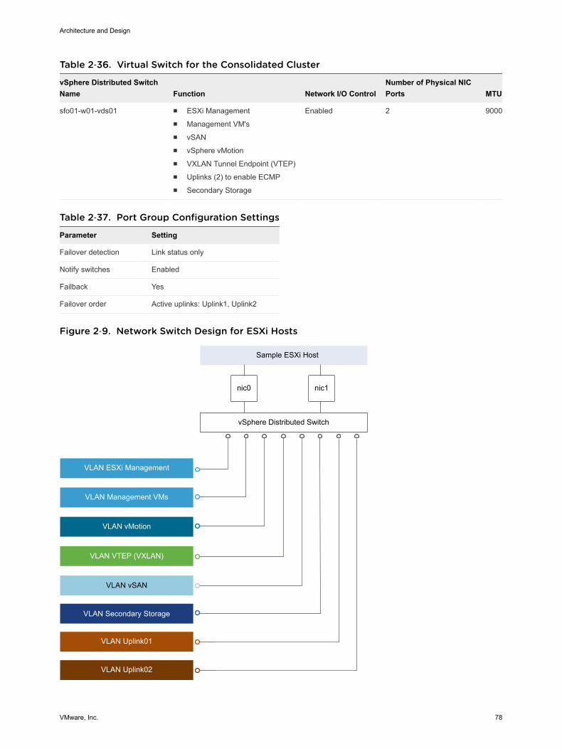
Table 2‑36. Virtual Switch for the Consolidated Cluster
vSphere Distributed SwitchName Function Network I/O Control
Number of Physical NICPorts MTU
sfo01-w01-vds01 n ESXi Managementn Management VM'sn vSANn vSphere vMotionn VXLAN Tunnel Endpoint (VTEP)n Uplinks (2) to enable ECMPn Secondary Storage
Enabled 2 9000
Table 2‑37. Port Group Configuration Settings
Parameter Setting
Failover detection Link status only
Notify switches Enabled
Failback Yes
Failover order Active uplinks: Uplink1, Uplink2
Figure 2‑9. Network Switch Design for ESXi Hosts
VLAN Secondary Storage
nic0 nic1
VLAN vSAN
VLAN Management VMs
VLAN vMotion
VLAN VTEP (VXLAN)
Sample ESXi Host
vSphere Distributed Switch
VLAN ESXi Management
VLAN Uplink01
VLAN Uplink02
Architecture and Design
VMware, Inc. 78

This section expands on the logical network design by providing details on the physical NIC layout andphysical network attributes.
Table 2‑38. Virtual Switch by Physical/Virtual NIC
vSphere Distributed Switch vmnic Function
sfo01-w01-vds01 0 Uplink
sfo01-w01-vds01 1 Uplink
Note The following VLANs are meant as samples. Your actual implementation depends on yourenvironment.
Table 2‑39. Virtual Switch Port Groups and VLANs
vSphere DistributedSwitch Port Group Name Teaming Policy Active Uplinks VLAN ID
sfo01-w01-vds01 sfo01-w01-vds01-Management Route based on physical NIC load 0, 1 1631
sfo01-w01-vds01 sfo01-w01-vds01-Management -VM
Route based on physical NIC load 0, 1 1611
sfo01-w01-vds01 sfo01-w01-vds01-vMotion Route based on physical NIC load 0, 1 1632
sfo01-w01-vds01 sfo01-w01-vds01-vSAN Route based on physical NIC load 0, 1 1633
sfo01-w01-vds01 Auto Generated (NSX VTEP) Route based on SRC-ID 0, 1 1634
sfo01-w01-vds01 sfo01-w01-vds01-Storage(optional)
Route based on physical NIC load 0, 1 1625
sfo01-w01-vds01 sfo01-w01-vds01-Uplink01 Route based on physical NIC load 0, 1 1635
sfo01-w01-vds01 sfo01-w01-vds01-Uplink02 Route based on physical NIC load 0, 1 2713
Table 2‑40. VMkernel Adapter
vSphere Distributed Switch Network Label Connected Port Group Enabled Services MTU
sfo01-w01-vds01 Management sfo01-w01-vds01-Management Management Traffic 1500 (Default)
sfo01-w01-vds01 vMotion sfo01-w01-vds01-vMotion vMotion Traffic 9000
sfo01-w01-vds01 vSAN sfo01-w01-vds01-VSAN vSAN 9000
sfo01-w01-vds01 VTEP Auto Generated (NSX VTEP) - 9000
sfo01-w01-vds01 Storage sfo01-w01-vds01-Storage (optional) - 9000
For more information on the physical network design specifications, see Physical Networking Design forConsolidated SDDC.
NIC Teaming for Consolidated SDDCYou can use NIC teaming to increase the network bandwidth available in a network path, and to providethe redundancy that supports higher availability.
Architecture and Design
VMware, Inc. 79

Benefits and Overview
NIC teaming helps avoid a single point of failure and provides options for load balancing of traffic. Tofurther reduce the risk of a single point of failure, build NIC teams by using ports from multiple NIC andmotherboard interfaces.
Create a single virtual switch with teamed NICs across separate physical switches.
This VMware Validated Design uses an active-active configuration using the route that is based onphysical NIC load algorithm for teaming. In this configuration, idle network cards do not wait for a failureto occur, and they aggregate bandwidth.
NIC Teaming Design Background
For a predictable level of performance, use multiple network adapters in one of the followingconfigurations.
n An active-passive configuration that uses explicit failover when connected to two separate switches.
n An active-active configuration in which two or more physical NICs in the server are assigned theactive role.
This validated design uses an active-active configuration.
Table 2‑41. NIC Teaming and Policy
Design Quality Active-Active Active-Passive Comments
Availability ↑ ↑ Using teaming regardless of the option increases the availability of theenvironment.
Manageability o o Neither design option impacts manageability.
Performance ↑ o An active-active configuration can send traffic across either NIC, therebyincreasing the available bandwidth. This configuration provides a benefit ifthe NICs are being shared among traffic types and Network I/O Control isused.
Recoverability o o Neither design option impacts recoverability.
Security o o Neither design option impacts security.
Legend: ↑ = positive impact on quality; ↓ = negative impact on quality; o = no impact on quality.
Table 2‑42. NIC Teaming Design Decision
Decision ID Design Decision Design Justification Design Implication
CSDDC-VI-Net-003
Use the Route based on physicalNIC load teaming algorithm for allport groups except for ones thatcarry VXLAN traffic.
VTEP kernel ports and VXLANtraffic will use Route based on SRC-ID.
Reduce complexity of the network designby not relying on any physical networkcapabilities (such as link aggregationgroups) while increasing resiliency andperformance.
Some physical network switches do notsupport dynamic routing protocols over linkaggregation groups.
NSX does not supportRoute based on physicalNIC load therefore twodifferent algorithms arenecessary.
Architecture and Design
VMware, Inc. 80
Network I/O Control for Consolidated SDDCWhen Network I/O Control is enabled, the distributed switch allocates bandwidth for the following systemtraffic types.
n Fault tolerance traffic
n iSCSI traffic
n vSphere vMotion traffic
n Management traffic
n VMware vSphere Replication traffic
n NFS traffic
n vSAN traffic
n vSphere Data Protection backup traffic
n Virtual machine traffic
How Network I/O Control Works
Network I/O Control enforces the share value specified for the different traffic types only when there isnetwork contention. When contention occurs Network I/O Control applies the share values set to eachtraffic type. As a result, less important traffic, as defined by the share percentage, will be throttled,allowing more important traffic types to gain access to more network resources.
Network I/O Control also allows the reservation of bandwidth for system traffic based on the capacity ofthe physical adapters on a host, and enables fine-grained resource control at the virtual machine networkadapter level. Resource control is similar to the model for vCenter CPU and memory reservations.
Network I/O Control Heuristics
The following heuristics can help with design decisions.
Shares vs. Limits When you use bandwidth allocation, consider using shares instead of limits.Limits impose hard limits on the amount of bandwidth used by a traffic floweven when network bandwidth is available.
Limits on CertainResource Pools
Consider imposing limits on a given resource pool. For example, if you puta limit on vSphere vMotion traffic, you can benefit in situations wheremultiple vSphere vMotion data transfers, initiated on different hosts at thesame time, result in oversubscription at the physical network level. Bylimiting the available bandwidth for vSphere vMotion at the ESXi host level,you can prevent performance degradation for other traffic.
Architecture and Design
VMware, Inc. 81
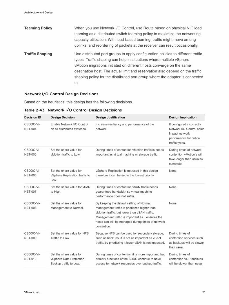
Teaming Policy When you use Network I/O Control, use Route based on physical NIC loadteaming as a distributed switch teaming policy to maximize the networkingcapacity utilization. With load-based teaming, traffic might move amonguplinks, and reordering of packets at the receiver can result occasionally.
Traffic Shaping Use distributed port groups to apply configuration policies to different traffictypes. Traffic shaping can help in situations where multiple vSpherevMotion migrations initiated on different hosts converge on the samedestination host. The actual limit and reservation also depend on the trafficshaping policy for the distributed port group where the adapter is connectedto.
Network I/O Control Design Decisions
Based on the heuristics, this design has the following decisions.
Table 2‑43. Network I/O Control Design Decisions
Decision ID Design Decision Design Justification Design Implication
CSDDC-VI-NET-004
Enable Network I/O Controlon all distributed switches.
Increase resiliency and performance of thenetwork.
If configured incorrectlyNetwork I/O Control couldimpact networkperformance for criticaltraffic types.
CSDDC-VI-NET-005
Set the share value forvMotion traffic to Low.
During times of contention vMotion traffic is not asimportant as virtual machine or storage traffic.
During times of networkcontention vMotion's willtake longer then usual tocomplete.
CSDDC-VI-NET-006
Set the share value forvSphere Replication traffic toLow.
vSphere Replication is not used in this designtherefore it can be set to the lowest priority.
None.
CSDDC-VI-NET-007
Set the share value for vSANto High.
During times of contention vSAN traffic needsguaranteed bandwidth so virtual machineperformance does not suffer.
None.
CSDDC-VI-NET-008
Set the share value forManagement to Normal.
By keeping the default setting of Normal,management traffic is prioritized higher thanvMotion traffic, but lower then vSAN traffic.Management traffic is important as it ensures thehosts can still be managed during times of networkcontention.
None.
CSDDC-VI-NET-009
Set the share value for NFSTraffic to Low.
Because NFS can be used for secondary storage,such as backups, it is not as important as vSANtraffic, by prioritizing it lower vSAN is not impacted.
During times ofcontention services suchas backups will be slowerthan usual.
CSDDC-VI-NET-010
Set the share value forvSphere Data ProtectionBackup traffic to Low.
During times of contention it is more important thatprimary functions of the SDDC continue to haveaccess to network resources over backup traffic.
During times ofcontention VDP backupswill be slower than usual.
Architecture and Design
VMware, Inc. 82
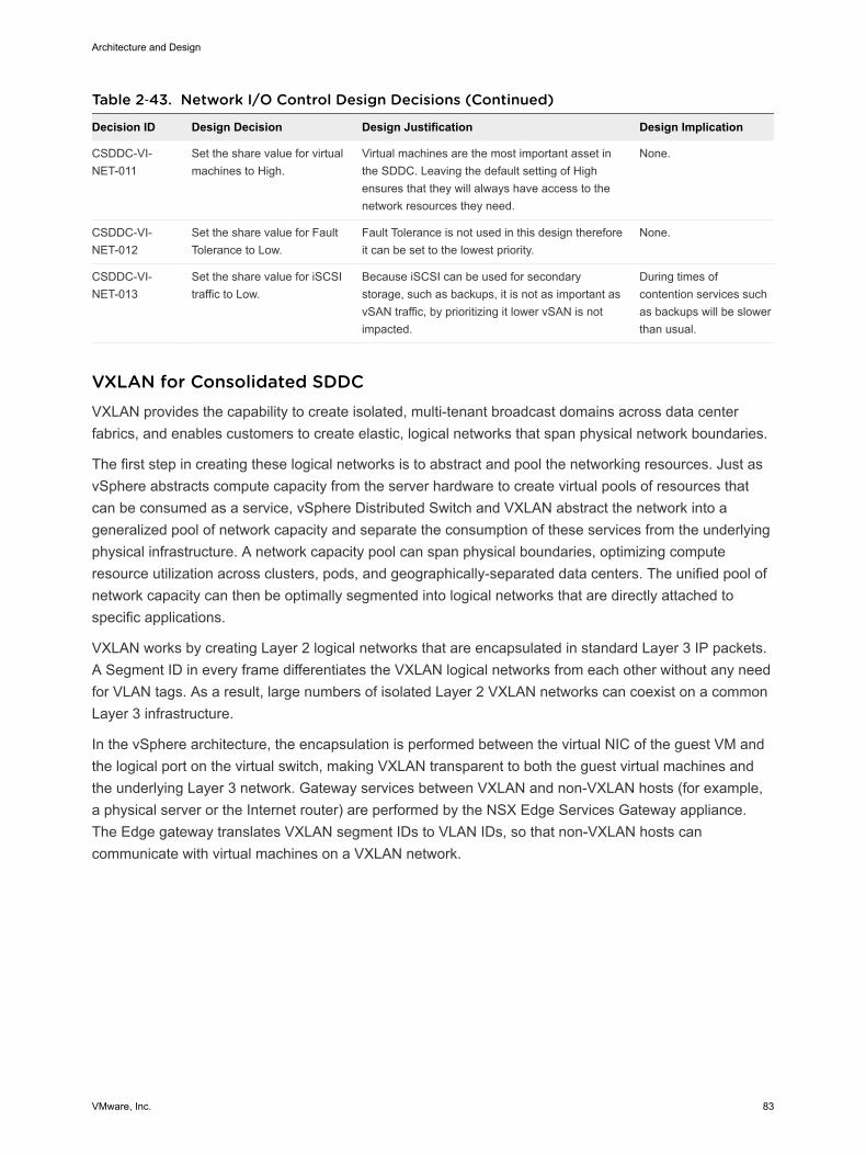
Table 2‑43. Network I/O Control Design Decisions (Continued)
Decision ID Design Decision Design Justification Design Implication
CSDDC-VI-NET-011
Set the share value for virtualmachines to High.
Virtual machines are the most important asset inthe SDDC. Leaving the default setting of Highensures that they will always have access to thenetwork resources they need.
None.
CSDDC-VI-NET-012
Set the share value for FaultTolerance to Low.
Fault Tolerance is not used in this design thereforeit can be set to the lowest priority.
None.
CSDDC-VI-NET-013
Set the share value for iSCSItraffic to Low.
Because iSCSI can be used for secondarystorage, such as backups, it is not as important asvSAN traffic, by prioritizing it lower vSAN is notimpacted.
During times ofcontention services suchas backups will be slowerthan usual.
VXLAN for Consolidated SDDCVXLAN provides the capability to create isolated, multi-tenant broadcast domains across data centerfabrics, and enables customers to create elastic, logical networks that span physical network boundaries.
The first step in creating these logical networks is to abstract and pool the networking resources. Just asvSphere abstracts compute capacity from the server hardware to create virtual pools of resources thatcan be consumed as a service, vSphere Distributed Switch and VXLAN abstract the network into ageneralized pool of network capacity and separate the consumption of these services from the underlyingphysical infrastructure. A network capacity pool can span physical boundaries, optimizing computeresource utilization across clusters, pods, and geographically-separated data centers. The unified pool ofnetwork capacity can then be optimally segmented into logical networks that are directly attached tospecific applications.
VXLAN works by creating Layer 2 logical networks that are encapsulated in standard Layer 3 IP packets.A Segment ID in every frame differentiates the VXLAN logical networks from each other without any needfor VLAN tags. As a result, large numbers of isolated Layer 2 VXLAN networks can coexist on a commonLayer 3 infrastructure.
In the vSphere architecture, the encapsulation is performed between the virtual NIC of the guest VM andthe logical port on the virtual switch, making VXLAN transparent to both the guest virtual machines andthe underlying Layer 3 network. Gateway services between VXLAN and non-VXLAN hosts (for example,a physical server or the Internet router) are performed by the NSX Edge Services Gateway appliance.The Edge gateway translates VXLAN segment IDs to VLAN IDs, so that non-VXLAN hosts cancommunicate with virtual machines on a VXLAN network.
Architecture and Design
VMware, Inc. 83
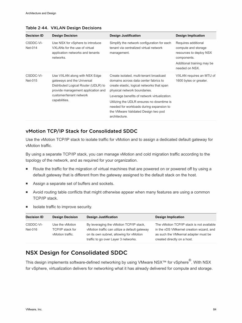
Table 2‑44. VXLAN Design Decisions
Decision ID Design Decision Design Justification Design Implication
CSDDC-VI-Net-014
Use NSX for vSphere to introduceVXLANs for the use of virtualapplication networks and tenantsnetworks.
Simplify the network configuration for eachtenant via centralized virtual networkmanagement.
Requires additionalcompute and storageresources to deploy NSXcomponents.
Additional training may beneeded on NSX.
CSDDC-VI-Net-015
Use VXLAN along with NSX Edgegateways and the UniversalDistributed Logical Router (UDLR) toprovide management application andcustomer/tenant networkcapabilities.
Create isolated, multi-tenant broadcastdomains across data center fabrics tocreate elastic, logical networks that spanphysical network boundaries.
Leverage benefits of network virtualization.
Utilizing the UDLR ensures no downtime isneeded for workloads during expansion tothe VMware Validated Design two podarchitecture.
VXLAN requires an MTU of1600 bytes or greater.
vMotion TCP/IP Stack for Consolidated SDDCUse the vMotion TCP/IP stack to isolate traffic for vMotion and to assign a dedicated default gateway forvMotion traffic.
By using a separate TCP/IP stack, you can manage vMotion and cold migration traffic according to thetopology of the network, and as required for your organization.
n Route the traffic for the migration of virtual machines that are powered on or powered off by using adefault gateway that is different from the gateway assigned to the default stack on the host.
n Assign a separate set of buffers and sockets.
n Avoid routing table conflicts that might otherwise appear when many features are using a commonTCP/IP stack.
n Isolate traffic to improve security.
Decision ID Design Decision Design Justification Design Implication
CSDDC-VI-Net-016
Use the vMotionTCP/IP stack forvMotion traffic.
By leveraging the vMotion TCP/IP stack,vMotion traffic can utilize a default gatewayon its own subnet, allowing for vMotiontraffic to go over Layer 3 networks.
The vMotion TCP/IP stack is not availablein the vDS VMkernel creation wizard, andas such the VMkernal adapter must becreated directly on a host.
NSX Design for Consolidated SDDCThis design implements software-defined networking by using VMware NSX™ for vSphere®. With NSXfor vSphere, virtualization delivers for networking what it has already delivered for compute and storage.
Architecture and Design
VMware, Inc. 84
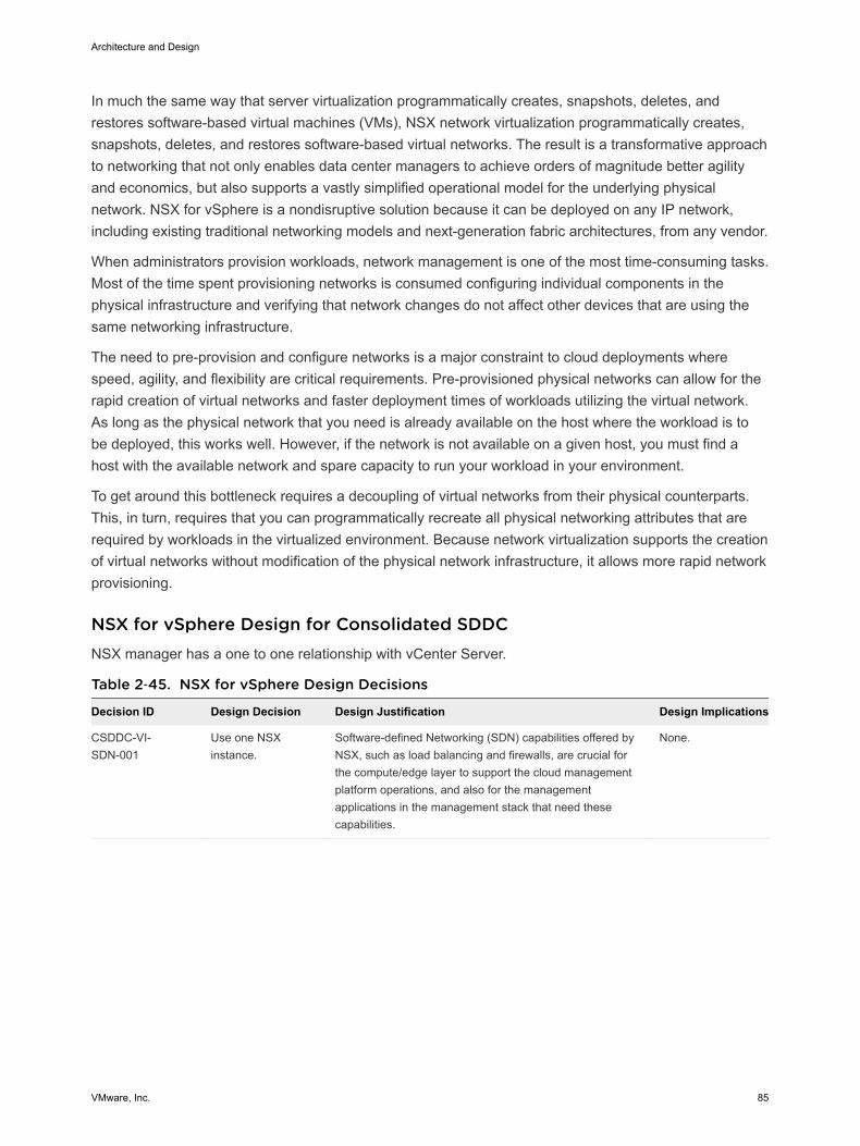
In much the same way that server virtualization programmatically creates, snapshots, deletes, andrestores software-based virtual machines (VMs), NSX network virtualization programmatically creates,snapshots, deletes, and restores software-based virtual networks. The result is a transformative approachto networking that not only enables data center managers to achieve orders of magnitude better agilityand economics, but also supports a vastly simplified operational model for the underlying physicalnetwork. NSX for vSphere is a nondisruptive solution because it can be deployed on any IP network,including existing traditional networking models and next-generation fabric architectures, from any vendor.
When administrators provision workloads, network management is one of the most time-consuming tasks.Most of the time spent provisioning networks is consumed configuring individual components in thephysical infrastructure and verifying that network changes do not affect other devices that are using thesame networking infrastructure.
The need to pre-provision and configure networks is a major constraint to cloud deployments wherespeed, agility, and flexibility are critical requirements. Pre-provisioned physical networks can allow for therapid creation of virtual networks and faster deployment times of workloads utilizing the virtual network.As long as the physical network that you need is already available on the host where the workload is tobe deployed, this works well. However, if the network is not available on a given host, you must find ahost with the available network and spare capacity to run your workload in your environment.
To get around this bottleneck requires a decoupling of virtual networks from their physical counterparts.This, in turn, requires that you can programmatically recreate all physical networking attributes that arerequired by workloads in the virtualized environment. Because network virtualization supports the creationof virtual networks without modification of the physical network infrastructure, it allows more rapid networkprovisioning.
NSX for vSphere Design for Consolidated SDDCNSX manager has a one to one relationship with vCenter Server.
Table 2‑45. NSX for vSphere Design Decisions
Decision ID Design Decision Design Justification Design Implications
CSDDC-VI-SDN-001
Use one NSXinstance.
Software-defined Networking (SDN) capabilities offered byNSX, such as load balancing and firewalls, are crucial forthe compute/edge layer to support the cloud managementplatform operations, and also for the managementapplications in the management stack that need thesecapabilities.
None.
Architecture and Design
VMware, Inc. 85

Figure 2‑10. Architecture of NSX for vSphere
NSX Components for Consolidated SDDCThe following sections describe the components in the solution and how they are relevant to the networkvirtualization design.
Consumption Layer
NSX for vSphere can be consumed by the cloud management platform (CMP), represented by vRealizeAutomation, by using the NSX REST API and the vSphere Web Client.
Cloud Management Platform
NSX for vSphere is consumed by vRealize Automation. NSX offers self-service provisioning of virtualnetworks and related features from a service portal. Details of the service requests and their orchestrationcan be referenced in the Cloud Management Platform Design.
API
NSX for vSphere offers a powerful management interface through its REST API.
n A client can read an object by making an HTTP GET request to the object’s resource URL.
n A client can write (create or modify) an object with an HTTP PUT or POST request that includes anew or changed XML document for the object.
n A client can delete an object with an HTTP DELETE request.
vSphere Web Client
The NSX Manager component provides a networking and security plug-in within the vSphere Web Client.This plug-in provides an interface to consuming virtualized networking from the NSX Manager for usersthat have sufficient privileges.
Architecture and Design
VMware, Inc. 86

Table 2‑46. Consumption Method Design Decisions
Decision ID Design Decision Design Justification Design Implications
CSDDC-VI-SDN-002
End user access isaccomplished by using vRealizeAutomation services.
Administrative access uses boththe vSphere Web Client and theNSX REST API.
vRealize Automation services are usedfor the customer-facing portal. ThevSphere Web Client consumes NSX forvSphere resources through the Networkand Security plug-in. The NSX REST APIoffers the potential of scripting repeatingactions and operations.
Customers typically interact onlyindirectly with NSX from thevRealize Automation portal.Administrators interact with NSXfrom the vSphere Web Clientand API.
NSX Manager
NSX Manager provides the centralized management plane for NSX for vSphere and has a one-to-onemapping to vCenter Server workloads.
NSX Manager performs the following functions.
n Provides the single point of configuration and the REST API entry-points for NSX in a vSphereenvironment.
n Deploys NSX Controller clusters, Edge distributed routers, and Edge service gateways in the form ofOVF appliances, guest introspection services, and so on.
n Prepares ESXi hosts for NSX by installing VXLAN, distributed routing and firewall kernel modules,and the User World Agent (UWA).
n Communicates with NSX Controller clusters over REST and with hosts over the RabbitMQ messagebus. This internal message bus is specific to NSX for vSphere and does not require setup ofadditional services.
n Generates certificates for the NSX Controller instances and ESXi hosts to secure control planecommunications with mutual authentication.
NSX Controller
An NSX Controller performs the following functions.
n Provides the control plane to distribute VXLAN and logical routing information to ESXi hosts.
n Includes nodes that are clustered for scale-out and high availability.
n Slices network information across cluster nodes for redundancy.
n Removes requirement of VXLAN Layer 3 multicast in the physical network.
n Provides ARP suppression of broadcast traffic in VXLAN networks.
NSX control plane communication occurs over the management network.
Architecture and Design
VMware, Inc. 87
Table 2‑47. NSX Controller Design Decision
Decision ID Design Decision Design Justification Design Implications
CSDDC-VI-SDN-003 Deploy NSX Controller instances inUniversal Cluster mode with threemembers to provide high availabilityand scale.
The high availability of NSX Controllerreduces the downtime period in case offailure of one physical host.
None.
NSX VirtualSwitch
The NSX data plane consists of the NSX virtual switch. This virtual switch is based on the vSphereDistributed Switch (VDS)with additional components to enable rich services. The add-on NSXcomponents include kernel modules (VIBs) which run within the hypervisor kernel and provide servicessuch as distributed logical router (DLR) and distributed firewall (DFW), and VXLAN capabilities.
The NSX virtual switch abstracts the physical network and provides access-level switching in thehypervisor. It is central to network virtualization because it enables logical networks that are independentof physical constructs such as VLAN. Using an NSX virtual switch includes several benefits.
n Supports overlay networking and centralized network configuration. Overlay networking enables thefollowing capabilities.
n Facilitates massive scale of hypervisors.
n Because the NSX virtual switch is based on VDS, it provides a comprehensive toolkit for trafficmanagement, monitoring, and troubleshooting within a virtual network through features such as portmirroring, NetFlow/IPFIX, configuration backup and restore, network health check, QoS, and more.
Logical Switching
NSX logical switches create logically abstracted segments to which tenant virtual machines can beconnected. A single logical switch is mapped to a unique VXLAN segment and is distributed across theESXi hypervisors within a transport zone. The logical switch allows line-rate switching in the hypervisorwithout the constraints of VLAN sprawl or spanning tree issues.
Distributed Logical Router
The NSX distributed logical router (DLR) is optimized for forwarding in the virtualized space, that is,forwarding between VMs on VXLAN- or VLAN-backed port groups. DLR has the following characteristics.
n High performance, low overhead first hop routing
n Scales with number of hosts
n Up to 1,000 Logical Interfaces (LIFs) on each DLR
Distributed Logical Router Control Virtual Machine
The distributed logical router control virtual machine is the control plane component of the routingprocess, providing communication between NSX Manager and the NSX Controller cluster through theUser World Agent (UWA). NSX Manager sends logical interface information to the control virtual machineand the NSX Controller cluster, and the control virtual machine sends routing updates to the NSXController cluster.
Architecture and Design
VMware, Inc. 88
User World Agent
The User World Agent (UWA) is a TCP (SSL) client that facilitates communication between the ESXihosts and the NSX Controller instances as well as the retrieval of information from the NSX Manager viainteraction with the message bus agent.
VXLAN Tunnel Endpoint
VXLAN Tunnel Endpoints (VTEPs) are instantiated within the vSphere Distributed Switch to which theESXi hosts that are prepared for NSX for vSphere are connected. VTEPs are responsible forencapsulating VXLAN traffic as frames in UDP packets and for the corresponding decapsulation. VTEPstake the form of one or more VMkernel ports with IP addresses and are used both to exchange packetswith other VTEPs and to join IP multicast groups via Internet Group Membership Protocol (IGMP). If youuse multiple VTEPs, then you must select a teaming method.
Edge Services Gateway
The NSX Edge services gateways (ESGs) primary function is north/south communication, but it alsooffers support for Layer 2, Layer 3, perimeter firewall, load balancing and other services such as SSL-VPN and DHCP-relay.
Distributed Firewall
NSX includes a distributed kernel-level firewall known as the distributed firewall. Security enforcement isdone at the kernel and VM network adapter level. The security enforcement implementation enablesfirewall rule enforcement in a highly scalable manner without creating bottlenecks on physical appliances.The distributed firewall has minimal CPU overhead and can perform at line rate.
The flow monitoring feature of the distributed firewall displays network activity between virtual machinesat the application protocol level. This information can be used to audit network traffic, define and refinefirewall policies, and identify botnets.
Logical Load Balancer
The NSX logical load balancer provides load balancing services up to Layer 7, allowing distribution oftraffic across multiple servers to achieve optimal resource utilization and availability. The logical loadbalancer is a service provided by the NSX Edge service gateway.
NSX for vSphere Requirements for Consolidated SDDCNSX for vSphere requirements impact both physical and virtual networks.
Physical Network Requirements
Physical requirements determine the MTU size for networks that carry VLAN traffic, dynamic routingsupport, type synchronization through an NTP server, and forward and reverse DNS resolution.
Architecture and Design
VMware, Inc. 89
Requirement Comments
Any network that carries VXLAN traffic must havean MTU size of 1600 or greater.
VXLAN packets cannot be fragmented. The MTU size must be large enoughto support extra encapsulation overhead.
This design uses jumbo frames, MTU size of 9000, for VXLAN traffic.
For the hybrid replication mode, Internet GroupManagement Protocol (IGMP) snooping must beenabled on the Layer 2 switches to which ESXihosts that participate in VXLAN are attached.IGMP querier must be enabled on the connectedrouter or Layer 3 switch.
IGMP snooping on Layer 2 switches is a requirement of the hybrid replicationmode. Hybrid replication mode is the recommended replication mode forbroadcast, unknown unicast, and multicast (BUM) traffic when deploying intoan environment with large scale-out potential. The traditional requirement forProtocol Independent Multicast (PIM) is removed.
Dynamic routing support on the upstream Layer 3data center switches must be enabled.
Enable a dynamic routing protocol supported by NSX on the upstream datacenter switches to establish dynamic routing adjacency with the ESGs.
NTP server must be available. The NSX Manager requires NTP settings that synchronize it with the rest ofthe vSphere environment. Drift can cause problems with authentication. TheNSX Manager must be in sync with the vCenter Single Sign-On service on thePlatform Services Controller.
Forward and reverse DNS resolution for allmanagement VMs must be established.
The NSX Controller nodes do not require DNS entries.
NSX Component Specifications
The following table lists the components involved in the NSX for vSphere solution and the requirementsfor installing and running them. The compute and storage requirements have been taken into accountwhen sizing resources to support the NSX for vSphere solution.
Note NSX ESG sizing can vary with tenant requirements, so all options are listed.
VM vCPU Memory Storage Quantity per Stack Instance
NSX Manager 4 16 GB 60 GB 1
NSX Controller 4 4 GB 20 GB 3
NSX ESG 1 (Compact)
2 (Large)
4 (Quad Large)
6 (X-Large)
512 MB (Compact)
1 GB (Large)
1 GB (Quad Large)
8 GB (X-Large)
512 MB
512 MB
512 MB
4.5 GB (X-Large)
(+4 GB with swap)
Optional component. Deployment of the NSXESG varies per use case.
DLR control VM 1 512 MB 512 MB Optional component. Varies with use case.Typically 2 per HA pair.
Guest introspection 2 1 GB 4 GB Optional component. 1 per ESXi host.
NSX data security 1 512 MB 6 GB Optional component.1 per ESXi host.
NSX Edge Service Gateway Sizing
The Quad Large model is suitable for high performance firewall abilities and the X-Large is suitable forboth high performance load balancing and routing.
Architecture and Design
VMware, Inc. 90

You can convert between NSX Edge service gateway sizes upon demand using a non-disruptive upgradeprocess, so the recommendation is to begin with the Large model and scale up if necessary. A Large NSXEdge service gateway is suitable for medium firewall performance but as detailed later, the NSX Edgeservice gateway does not perform the majority of firewall functions.
Note Edge service gateway throughput is influenced by characteristics such as uplink speed and WANcircuits. An adaptable approach, that is, converting as necessary, is recommended.
Table 2‑48. NSX Edge Service Gateway Sizing Design Decision
Decision ID Design Decision Design Justification Design Implications
CSDDC-VI-SDN-004 Use large size NSX Edgeservice gateways.
The large size provides all the performancecharacteristics needed even in the event of a failure.
A larger size would also provide the performancerequired but at the expense of extra resources thatwouldn't be used.
None.
Network Virtualization Conceptual Design for Consolidated SDDCThis conceptual design provides you with an understanding of the network virtualization design.
The network virtualization conceptual design includes a perimeter firewall, a provider logical router, andthe NSX for vSphere Logical Router. It also includes the external network, internal tenant network, andinternal non-tenant network.
Note In this document, tenant refers to a tenant of the cloud management platform within thecompute/edge stack, or to a management application within the management stack.
Architecture and Design
VMware, Inc. 91
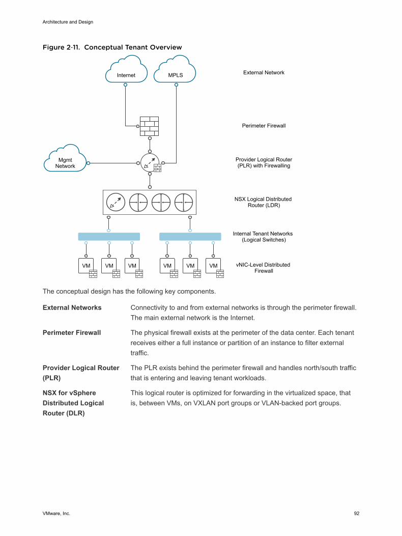
Figure 2‑11. Conceptual Tenant Overview
VM VMVM VM VMVM
Internet MPLS
MgmtNetwork
External Network
Perimeter Firewall
Provider Logical Router(PLR) with Firewalling
NSX Logical Distributed Router (LDR)
Internal Tenant Networks (Logical Switches)
vNIC-Level Distributed Firewall
The conceptual design has the following key components.
External Networks Connectivity to and from external networks is through the perimeter firewall.The main external network is the Internet.
Perimeter Firewall The physical firewall exists at the perimeter of the data center. Each tenantreceives either a full instance or partition of an instance to filter externaltraffic.
Provider Logical Router(PLR)
The PLR exists behind the perimeter firewall and handles north/south trafficthat is entering and leaving tenant workloads.
NSX for vSphereDistributed LogicalRouter (DLR)
This logical router is optimized for forwarding in the virtualized space, thatis, between VMs, on VXLAN port groups or VLAN-backed port groups.
Architecture and Design
VMware, Inc. 92

Internal Non-TenantNetwork
A single management network, which sits behind the perimeter firewall butnot behind the PLR. Enables customers to manage the tenantenvironments.
Internal TenantNetworks
Connectivity for the main tenant workload. These networks are connectedto a DLR, which sits behind the PLR. These networks take the form ofVXLAN-based NSX for vSphere logical switches. Tenant virtual machineworkloads will be directly attached to these networks.
Cluster Design for NSX for vSphere for Consolidated SDDCFollowing the vSphere design, the NSX for vSphere design consists of a single consolidated stackproviding services for management components and workloads.
Consolidated Stack
In the converted stack, the underlying hosts are prepared for NSX for vSphere. The Consolidated stackhas these components.
n NSX Manager instance.
n NSX Controller cluster.
n NSX ESG for north/south routing.
n NSX DLR for east/west routing.
n NSX ESG load balancers for workloads, where required.
Table 2‑49. vSphere Cluster Design Decisions
Decision ID Design Decision Design Justification Design Implications
CSDDC-VI-SDN-005
For the Consolidated stack,do not use a dedicatededge cluster.
Simplifies configuration andminimizes the number of hostsrequired for initial deployment.
The NSX Controller instances, NSX Edgeservices gateways, and DLR control VMsare deployed in the converted cluster.
The shared nature of the cluster willrequire the cluster to be scaled out ascompute workloads are added so as to notimpact network performance.
CSDDC-VI-SDN-006
Apply vSphere DistributedResource Scheduler (DRS)anti-affinity rules to the NSXcomponents.
Using DRS preventscontrollers from running on thesame ESXi host and therebyrisking their high availabilitycapability.
Additional configuration is required to setup anti-affinity rules.
Architecture and Design
VMware, Inc. 93
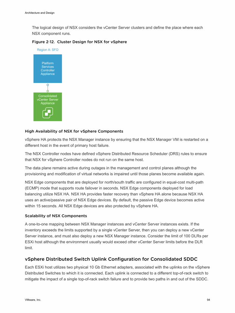
The logical design of NSX considers the vCenter Server clusters and define the place where eachNSX component runs.
Figure 2‑12. Cluster Design for NSX for vSphere
ConsolidatedvCenter Server
Appliance
Platform Services Controller Appliance
Region A: SFO
High Availability of NSX for vSphere Components
vSphere HA protects the NSX Manager instance by ensuring that the NSX Manager VM is restarted on adifferent host in the event of primary host failure.
The NSX Controller nodes have defined vSphere Distributed Resource Scheduler (DRS) rules to ensurethat NSX for vSphere Controller nodes do not run on the same host.
The data plane remains active during outages in the management and control planes although theprovisioning and modification of virtual networks is impaired until those planes become available again.
NSX Edge components that are deployed for north/south traffic are configured in equal-cost multi-path(ECMP) mode that supports route failover in seconds. NSX Edge components deployed for loadbalancing utilize NSX HA. NSX HA provides faster recovery than vSphere HA alone because NSX HAuses an active/passive pair of NSX Edge devices. By default, the passive Edge device becomes activewithin 15 seconds. All NSX Edge devices are also protected by vSphere HA.
Scalability of NSX Components
A one-to-one mapping between NSX Manager instances and vCenter Server instances exists. If theinventory exceeds the limits supported by a single vCenter Server, then you can deploy a new vCenterServer instance, and must also deploy a new NSX Manager instance. Consider the limit of 100 DLRs perESXi host although the environment usually would exceed other vCenter Server limits before the DLRlimit.
vSphere Distributed Switch Uplink Configuration for Consolidated SDDCEach ESXi host utilizes two physical 10 Gb Ethernet adapters, associated with the uplinks on the vSphereDistributed Switches to which it is connected. Each uplink is connected to a different top-of-rack switch tomitigate the impact of a single top-of-rack switch failure and to provide two paths in and out of the SDDC.
Architecture and Design
VMware, Inc. 94
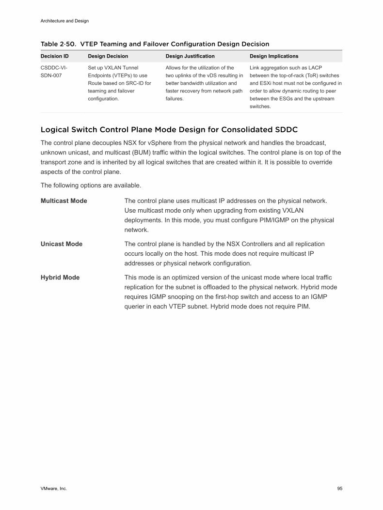
Table 2‑50. VTEP Teaming and Failover Configuration Design Decision
Decision ID Design Decision Design Justification Design Implications
CSDDC-VI-SDN-007
Set up VXLAN TunnelEndpoints (VTEPs) to useRoute based on SRC-ID forteaming and failoverconfiguration.
Allows for the utilization of thetwo uplinks of the vDS resulting inbetter bandwidth utilization andfaster recovery from network pathfailures.
Link aggregation such as LACPbetween the top-of-rack (ToR) switchesand ESXi host must not be configured inorder to allow dynamic routing to peerbetween the ESGs and the upstreamswitches.
Logical Switch Control Plane Mode Design for Consolidated SDDCThe control plane decouples NSX for vSphere from the physical network and handles the broadcast,unknown unicast, and multicast (BUM) traffic within the logical switches. The control plane is on top of thetransport zone and is inherited by all logical switches that are created within it. It is possible to overrideaspects of the control plane.
The following options are available.
Multicast Mode The control plane uses multicast IP addresses on the physical network.Use multicast mode only when upgrading from existing VXLANdeployments. In this mode, you must configure PIM/IGMP on the physicalnetwork.
Unicast Mode The control plane is handled by the NSX Controllers and all replicationoccurs locally on the host. This mode does not require multicast IPaddresses or physical network configuration.
Hybrid Mode This mode is an optimized version of the unicast mode where local trafficreplication for the subnet is offloaded to the physical network. Hybrid moderequires IGMP snooping on the first-hop switch and access to an IGMPquerier in each VTEP subnet. Hybrid mode does not require PIM.
Architecture and Design
VMware, Inc. 95

Figure 2‑13. Logical Switch Control Plane in Hybrid Mode
VM1 VM2
vSphere Distributed Switch
ESXi Host
VXLAN 5001
VTEP1 10.20.10.10
ESXi HostVTEP2 10.20.10.11
VM3
ESXi HostVTEP3 10.20.11.10
VM4
ESXi HostVTEP4 10.20.11.11
MTEP VTEP MTEP VTEP
L2 - IGMP L2 - IGMP
Multicast TrafficUnicast Traffic
ControllerCluster
Legend:
VXLAN Transport Network
This design uses hybrid mode for control plane replication.
Table 2‑51. Logical Switch Control Plane Mode Design Decision
Decision ID Design Decision Design Justification Design Implications
CSDDC-VI-SDN-008
Use hybrid mode forcontrol planereplication.
Offloading multicast processing to the physicalnetwork reduces pressure on VTEPs as theenvironment scales out. For largeenvironments, hybrid mode is preferable tounicast mode. Multicast mode is used onlywhen migrating from existing VXLAN solutions.
IGMP snooping must beenabled on the ToR physicalswitch and an IGMP queriermust be available.
Transport Zone Design for Consolidated SDDCA transport zone is used to define the scope of a VXLAN overlay network and can span one or moreclusters within one vCenter Server domain. One or more transport zones can be configured in an NSX forvSphere solution. A transport zone is not meant to delineate a security boundary.
Architecture and Design
VMware, Inc. 96
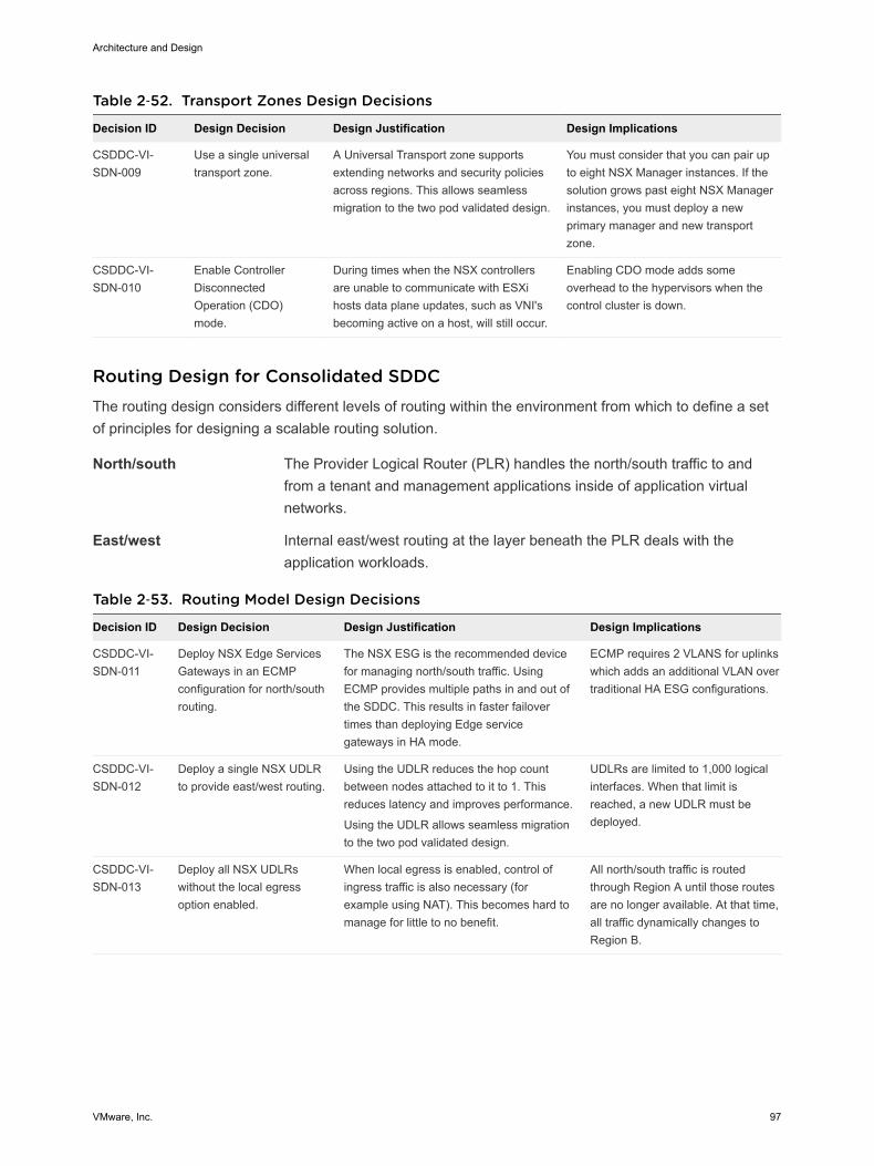
Table 2‑52. Transport Zones Design Decisions
Decision ID Design Decision Design Justification Design Implications
CSDDC-VI-SDN-009
Use a single universaltransport zone.
A Universal Transport zone supportsextending networks and security policiesacross regions. This allows seamlessmigration to the two pod validated design.
You must consider that you can pair upto eight NSX Manager instances. If thesolution grows past eight NSX Managerinstances, you must deploy a newprimary manager and new transportzone.
CSDDC-VI-SDN-010
Enable ControllerDisconnectedOperation (CDO)mode.
During times when the NSX controllersare unable to communicate with ESXihosts data plane updates, such as VNI'sbecoming active on a host, will still occur.
Enabling CDO mode adds someoverhead to the hypervisors when thecontrol cluster is down.
Routing Design for Consolidated SDDCThe routing design considers different levels of routing within the environment from which to define a setof principles for designing a scalable routing solution.
North/south The Provider Logical Router (PLR) handles the north/south traffic to andfrom a tenant and management applications inside of application virtualnetworks.
East/west Internal east/west routing at the layer beneath the PLR deals with theapplication workloads.
Table 2‑53. Routing Model Design Decisions
Decision ID Design Decision Design Justification Design Implications
CSDDC-VI-SDN-011
Deploy NSX Edge ServicesGateways in an ECMPconfiguration for north/southrouting.
The NSX ESG is the recommended devicefor managing north/south traffic. UsingECMP provides multiple paths in and out ofthe SDDC. This results in faster failovertimes than deploying Edge servicegateways in HA mode.
ECMP requires 2 VLANS for uplinkswhich adds an additional VLAN overtraditional HA ESG configurations.
CSDDC-VI-SDN-012
Deploy a single NSX UDLRto provide east/west routing.
Using the UDLR reduces the hop countbetween nodes attached to it to 1. Thisreduces latency and improves performance.
Using the UDLR allows seamless migrationto the two pod validated design.
UDLRs are limited to 1,000 logicalinterfaces. When that limit isreached, a new UDLR must bedeployed.
CSDDC-VI-SDN-013
Deploy all NSX UDLRswithout the local egressoption enabled.
When local egress is enabled, control ofingress traffic is also necessary (forexample using NAT). This becomes hard tomanage for little to no benefit.
All north/south traffic is routedthrough Region A until those routesare no longer available. At that time,all traffic dynamically changes toRegion B.
Architecture and Design
VMware, Inc. 97
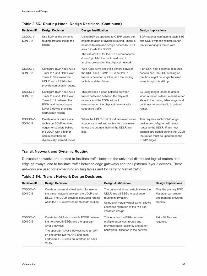
Table 2‑53. Routing Model Design Decisions (Continued)
Decision ID Design Decision Design Justification Design Implications
CSDDC-VI-SDN-014
Use BGP as the dynamicrouting protocol inside theSDDC.
Using BGP as opposed to OSPF eases theimplementation of dynamic routing. There isno need to plan and design access to OSPFarea 0 inside the SDDC.
The use of BGP for the SDDC componentsdoesn't prohibit the continued use ofanother protocol on the physical network.
BGP requires configuring each ESGand UDLR with the remote routerthat it exchanges routes with.
CSDDC-VI-SDN-015
Configure BGP Keep AliveTimer to 1 and Hold DownTimer to 3 between theUDLR and all ESGs thatprovide north/south routing.
With Keep Alive and Hold Timers betweenthe UDLR and ECMP ESGs set low, afailure is detected quicker, and the routingtable is updated faster.
If an ESXi host becomes resourceconstrained, the ESG running onthat host might no longer be usedeven though it is still up.
CSDDC-VI-SDN-016
Configure BGP Keep AliveTimer to 4 and Hold DownTimer to 12 between theESGs and the upstreamLayer 3 device providingnorth/south routing.
This provides a good balance betweenfailure detection between the physicalnetwork and the ESGs withoutoverburdening the physical network withkeep alive traffic.
By using longer timers to detectwhen a router is dead, a dead routerstays in the routing table longer andcontinues to send traffic to a deadrouter.
CSDDC-VI-SDN-017
Create one or more staticroutes on ECMP enablededges for subnets behindthe UDLR with a higheradmin cost then thedynamically learned routes.
When the UDLR control VM fails over routeradjacency is lost and routes from upstreamdevices to subnets behind the UDLR arelost.
This requires each ECMP edgedevice be configured with staticroutes to the UDLR. If any newsubnets are added behind the UDLRthe routes must be updated on theECMP edges.
Transit Network and Dynamic Routing
Dedicated networks are needed to facilitate traffic between the universal distributed logical routers andedge gateways, and to facilitate traffic between edge gateways and the upstream layer 3 devices. Thesenetworks are used for exchanging routing tables and for carrying transit traffic.
Table 2‑54. Transit Network Design Decisions
Decision ID Design Decision Design Justification Design Implications
CSDDC-VI-SDN-018
Create a universal virtual switch for use asthe transit network between the UDLR andESGs. The UDLR provides east/west routingwhile the ESG's provide north/south routing.
The universal virtual switch allows theUDLR and all ESGs to exchangerouting information.
Using a universal virtual switch allowsseamless migration to the two podvalidated design.
Only the primary NSXManager can createand manage universalobjects.
CSDDC-VI-SDN-019
Create two VLANs to enable ECMP betweenthe north/south ESGs and the upstreamlayer 3 devices.
The upstream layer 3 devices have an SVIon one of the two VLANS and eachnorth/south ESG has an interface on eachVLAN.
This enables the ESGs to havemultiple equal-cost routes andprovides more resiliency and betterbandwidth utilization in the network.
Extra VLANs arerequired.
Architecture and Design
VMware, Inc. 98

Firewall Logical Design for Consolidated SDDCThe NSX Distributed Firewall is used to protect all management applications. To secure the SDDC, onlyother solutions in the SDDC and approved administration IPs can directly communicate with individualcomponents. External facing portals are accessible via a load balancer virtual IP (VIP). This simplifies thedesign by having a single point of administration for all firewall rules. The firewall on individual ESGs isset to allow all traffic. An exception are ESGs that provide ECMP services, which require the firewall to bedisabled.
Table 2‑55. Firewall Design Decisions
Decision ID Design Decision Design Justification Design Implications
CSDDC-VI-SDN-020
For all ESGs deployed as loadbalancers, set the default firewallrule to allow all traffic.
Restricting and granting access ishandled by the distributed firewall.
Explicit rules to allow access tomanagement applications mustbe defined in the distributedfirewall.
CSDDC-VI-SDN-021
For all ESGs deployed as ECMPnorth/south routers, disable thefirewall.
Use of ECMP on the ESGs is arequirement. Leaving the firewallenabled, even in allow all trafficmode, results in sporadic networkconnectivity.
Services such as NAT and loadbalancing can not be used whenthe firewall is disabled.
CSDDC-VI-SDN-022
Configure the Distributed Firewallto limit access to administrativeinterfaces on the managementvirtual applications.
To ensure only authorizedadministrators can access theadministrative interfaces ofmanagement applications.
Maintaining firewall rules addsadministrative overhead.
Load Balancer Design for Consolidated SDDCThe ESG implements load balancing within NSX for vSphere.
The ESG has both a Layer 4 and a Layer 7 engine that offer different features, which are summarized inthe following table.
Feature Layer 4 Engine Layer 7 Engine
Protocols TCP TCP
HTTP
HTTPS (SSL Pass-through)
HTTPS (SSL Offload)
Load balancing method Round Robin
Source IP Hash
Least Connection
Round Robin
Source IP Hash
Least Connection
URI
Health checks TCP TCP
HTTP (GET, OPTION, POST)
HTTPS (GET, OPTION, POST)
Architecture and Design
VMware, Inc. 99
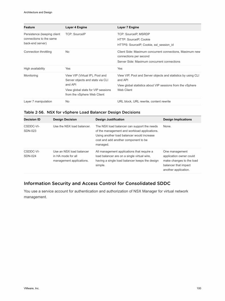
Feature Layer 4 Engine Layer 7 Engine
Persistence (keeping clientconnections to the sameback-end server)
TCP: SourceIP TCP: SourceIP, MSRDP
HTTP: SourceIP, Cookie
HTTPS: SourceIP, Cookie, ssl_session_id
Connection throttling No Client Side: Maximum concurrent connections, Maximum newconnections per second
Server Side: Maximum concurrent connections
High availability Yes Yes
Monitoring View VIP (Virtual IP), Pool andServer objects and stats via CLIand API
View global stats for VIP sessionsfrom the vSphere Web Client
View VIP, Pool and Server objects and statistics by using CLIand API
View global statistics about VIP sessions from the vSphereWeb Client
Layer 7 manipulation No URL block, URL rewrite, content rewrite
Table 2‑56. NSX for vSphere Load Balancer Design Decisions
Decision ID Design Decision Design Justification Design Implications
CSDDC-VI-SDN-023
Use the NSX load balancer. The NSX load balancer can support the needsof the management and workload applications.Using another load balancer would increasecost and add another component to bemanaged.
None.
CSDDC-VI-SDN-024
Use an NSX load balancerin HA mode for allmanagement applications.
All management applications that require aload balancer are on a single virtual wire,having a single load balancer keeps the designsimple.
One managementapplication owner couldmake changes to the loadbalancer that impactanother application.
Information Security and Access Control for Consolidated SDDCYou use a service account for authentication and authorization of NSX Manager for virtual networkmanagement.
Architecture and Design
VMware, Inc. 100
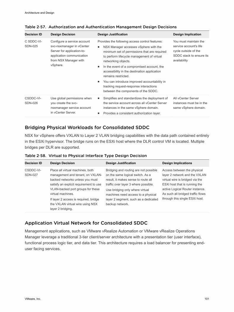
Table 2‑57. Authorization and Authentication Management Design Decisions
Decision ID Design Decision Design Justification Design Implication
C SDDC-VI-SDN-025
Configure a service accountsvc-nsxmanager in vCenterServer for application-to-application communicationfrom NSX Manager withvSphere.
Provides the following access control features:n NSX Manager accesses vSphere with the
minimum set of permissions that are requiredto perform lifecycle management of virtualnetworking objects.
n In the event of a compromised account, theaccessibility in the destination applicationremains restricted.
n You can introduce improved accountability intracking request-response interactionsbetween the components of the SDDC.
You must maintain theservice account's lifecycle outside of theSDDC stack to ensure itsavailability
CSDDC-VI-SDN-026
Use global permissions whenyou create the svc-nsxmanager service accountin vCenter Server.
n Simplifies and standardizes the deployment ofthe service account across all vCenter Serverinstances in the same vSphere domain.
n Provides a consistent authorization layer.
All vCenter Serverinstances must be in thesame vSphere domain.
Bridging Physical Workloads for Consolidated SDDCNSX for vSphere offers VXLAN to Layer 2 VLAN bridging capabilities with the data path contained entirelyin the ESXi hypervisor. The bridge runs on the ESXi host where the DLR control VM is located. Multiplebridges per DLR are supported.
Table 2‑58. Virtual to Physical Interface Type Design Decision
Decision ID Design Decision Design Justification Design Implications
CSDDC-VI-SDN-027
Place all virtual machines, bothmanagement and tenant, on VXLAN-backed networks unless you mustsatisfy an explicit requirement to useVLAN-backed port groups for thesevirtual machines.
If layer 2 access is required, bridgethe VXLAN virtual wire using NSXlayer 2 bridging.
Bridging and routing are not possibleon the same logical switch. As aresult, it makes sense to route alltraffic over layer 3 where possible.
Use bridging only where virtualmachines need access to a physicallayer 2 segment, such as a dedicatedbackup network.
Access between the physicallayer 2 network and the VXLANvirtual wire is bridged via theESXi host that is running theactive Logical Router instance.As such all bridged traffic flowsthrough this single ESXi host.
Application Virtual Network for Consolidated SDDCManagement applications, such as VMware vRealize Automation or VMware vRealize OperationsManager leverage a traditional 3-tier client/server architecture with a presentation tier (user interface),functional process logic tier, and data tier. This architecture requires a load balancer for presenting end-user facing services.
Architecture and Design
VMware, Inc. 101
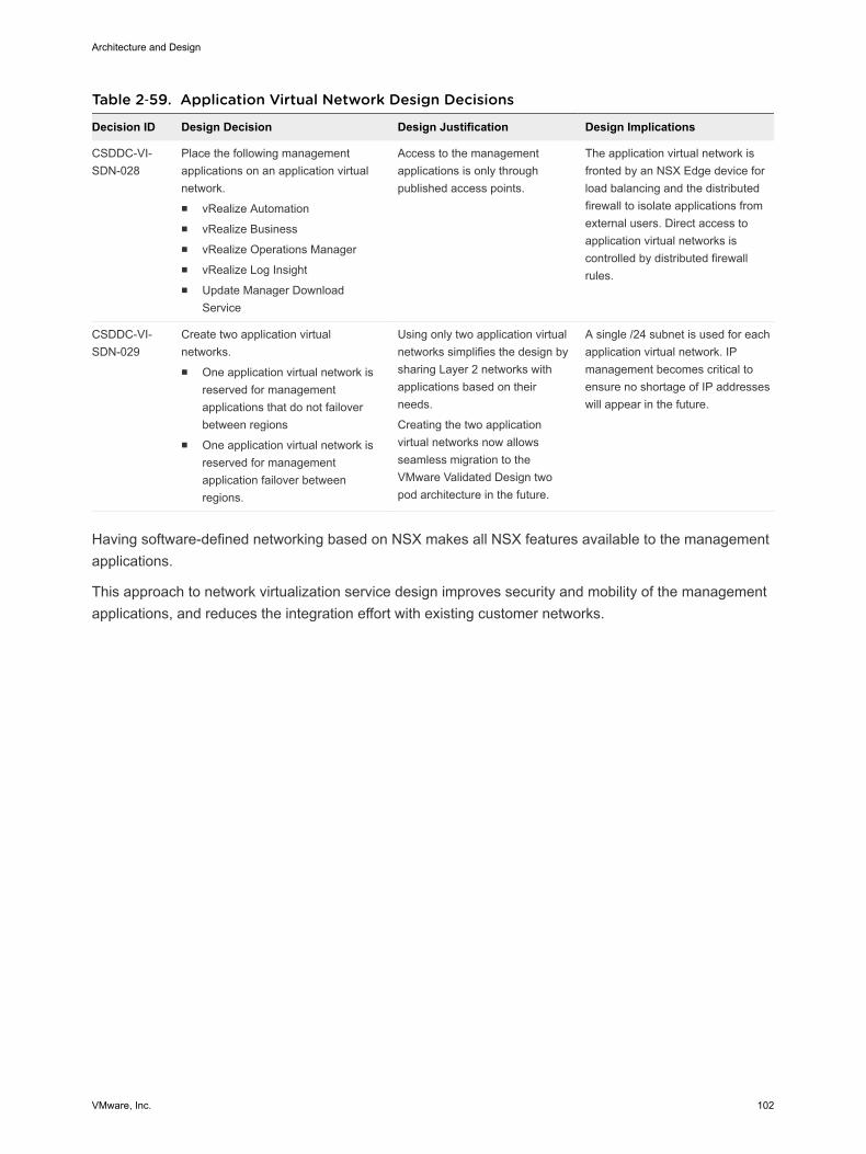
Table 2‑59. Application Virtual Network Design Decisions
Decision ID Design Decision Design Justification Design Implications
CSDDC-VI-SDN-028
Place the following managementapplications on an application virtualnetwork.n vRealize Automationn vRealize Businessn vRealize Operations Managern vRealize Log Insightn Update Manager Download
Service
Access to the managementapplications is only throughpublished access points.
The application virtual network isfronted by an NSX Edge device forload balancing and the distributedfirewall to isolate applications fromexternal users. Direct access toapplication virtual networks iscontrolled by distributed firewallrules.
CSDDC-VI-SDN-029
Create two application virtualnetworks.n One application virtual network is
reserved for managementapplications that do not failoverbetween regions
n One application virtual network isreserved for managementapplication failover betweenregions.
Using only two application virtualnetworks simplifies the design bysharing Layer 2 networks withapplications based on theirneeds.
Creating the two applicationvirtual networks now allowsseamless migration to theVMware Validated Design twopod architecture in the future.
A single /24 subnet is used for eachapplication virtual network. IPmanagement becomes critical toensure no shortage of IP addresseswill appear in the future.
Having software-defined networking based on NSX makes all NSX features available to the managementapplications.
This approach to network virtualization service design improves security and mobility of the managementapplications, and reduces the integration effort with existing customer networks.
Architecture and Design
VMware, Inc. 102

Figure 2‑14. Application Virtual Network Components and Design
PSC
OSSRM
OSVC
OSVDP
OS
ECMPESGs
ToR Switches
Internet/EnterpriseNetwork
Mgmt-Management
Compute-Management
Legend:
192.168.11/24
Transit Networks
Management Application
vRLIUMDSvRA/vRB
vROps
ESGLoadBalancer
Mgmt-xRegion01-VXLAN
192.168.31/24
Mgmt-RegionА01-VXLAN
Universal Distributed Logical Router
Edge-Management
Certain configuration choices might later facilitate the tenant onboarding process.
n Create the primary NSX ESG to act as the tenant PLR and the logical switch that forms the transitnetwork for use in connecting to the UDLR.
n Connect the primary NSX ESG uplinks to the external networks.
n Connect the primary NSX ESG internal interface to the transit network.
n Create the NSX UDLR to provide routing capabilities for tenant internal networks and connect theUDLR uplink to the transit network.
n Create any tenant networks that are known up front and connect them to the UDLR.
Architecture and Design
VMware, Inc. 103
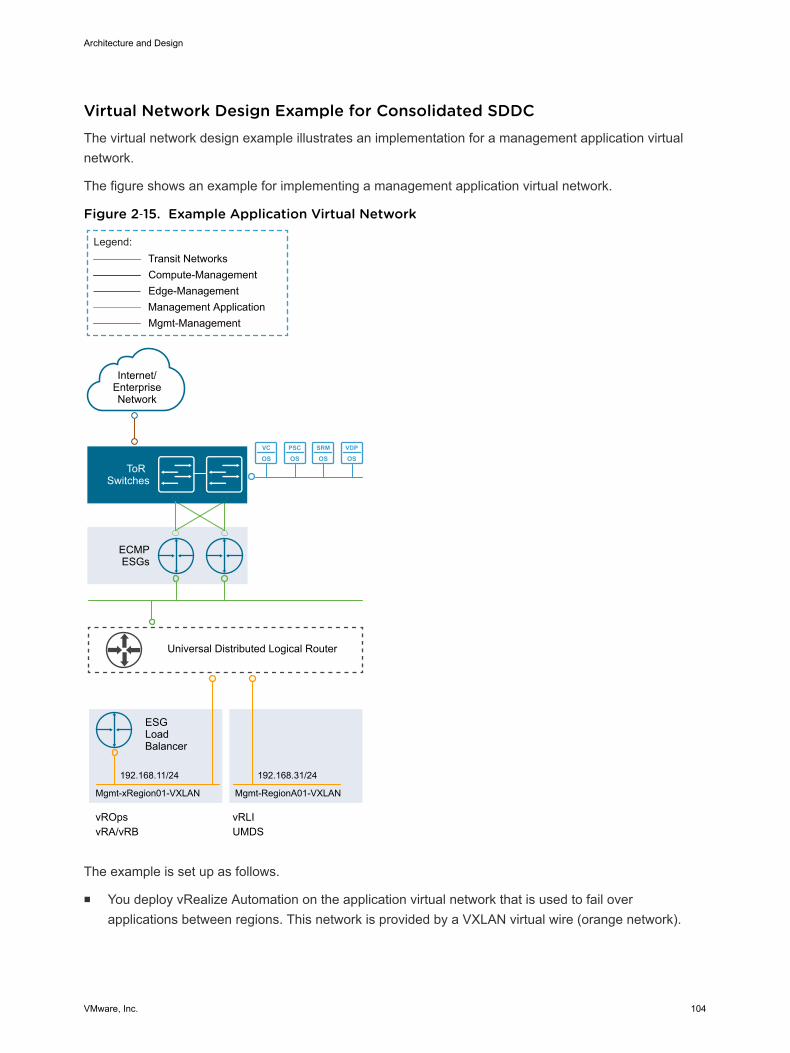
Virtual Network Design Example for Consolidated SDDCThe virtual network design example illustrates an implementation for a management application virtualnetwork.
The figure shows an example for implementing a management application virtual network.
Figure 2‑15. Example Application Virtual Network
PSC
OSSRM
OSVC
OSVDP
OS
ECMPESGs
ToR Switches
Internet/EnterpriseNetwork
Mgmt-Management
Compute-Management
Legend:
192.168.11/24
Transit Networks
Management Application
vRLIUMDSvRA/vRB
vROps
ESGLoadBalancer
Mgmt-xRegion01-VXLAN
192.168.31/24
Mgmt-RegionА01-VXLAN
Universal Distributed Logical Router
Edge-Management
The example is set up as follows.
n You deploy vRealize Automation on the application virtual network that is used to fail overapplications between regions. This network is provided by a VXLAN virtual wire (orange network).
Architecture and Design
VMware, Inc. 104
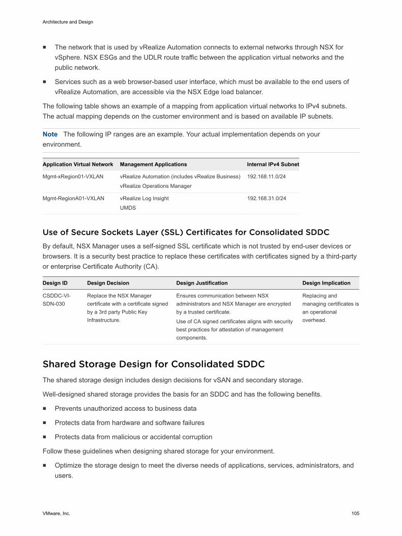
n The network that is used by vRealize Automation connects to external networks through NSX forvSphere. NSX ESGs and the UDLR route traffic between the application virtual networks and thepublic network.
n Services such as a web browser-based user interface, which must be available to the end users ofvRealize Automation, are accessible via the NSX Edge load balancer.
The following table shows an example of a mapping from application virtual networks to IPv4 subnets.The actual mapping depends on the customer environment and is based on available IP subnets.
Note The following IP ranges are an example. Your actual implementation depends on yourenvironment.
Application Virtual Network Management Applications Internal IPv4 Subnet
Mgmt-xRegion01-VXLAN vRealize Automation (includes vRealize Business)
vRealize Operations Manager
192.168.11.0/24
Mgmt-RegionA01-VXLAN vRealize Log Insight
UMDS
192.168.31.0/24
Use of Secure Sockets Layer (SSL) Certificates for Consolidated SDDCBy default, NSX Manager uses a self-signed SSL certificate which is not trusted by end-user devices orbrowsers. It is a security best practice to replace these certificates with certificates signed by a third-partyor enterprise Certificate Authority (CA).
Design ID Design Decision Design Justification Design Implication
CSDDC-VI-SDN-030
Replace the NSX Managercertificate with a certificate signedby a 3rd party Public KeyInfrastructure.
Ensures communication between NSXadministrators and NSX Manager are encryptedby a trusted certificate.
Use of CA signed certificates aligns with securitybest practices for attestation of managementcomponents.
Replacing andmanaging certificates isan operationaloverhead.
Shared Storage Design for Consolidated SDDCThe shared storage design includes design decisions for vSAN and secondary storage.
Well-designed shared storage provides the basis for an SDDC and has the following benefits.
n Prevents unauthorized access to business data
n Protects data from hardware and software failures
n Protects data from malicious or accidental corruption
Follow these guidelines when designing shared storage for your environment.
n Optimize the storage design to meet the diverse needs of applications, services, administrators, andusers.
Architecture and Design
VMware, Inc. 105
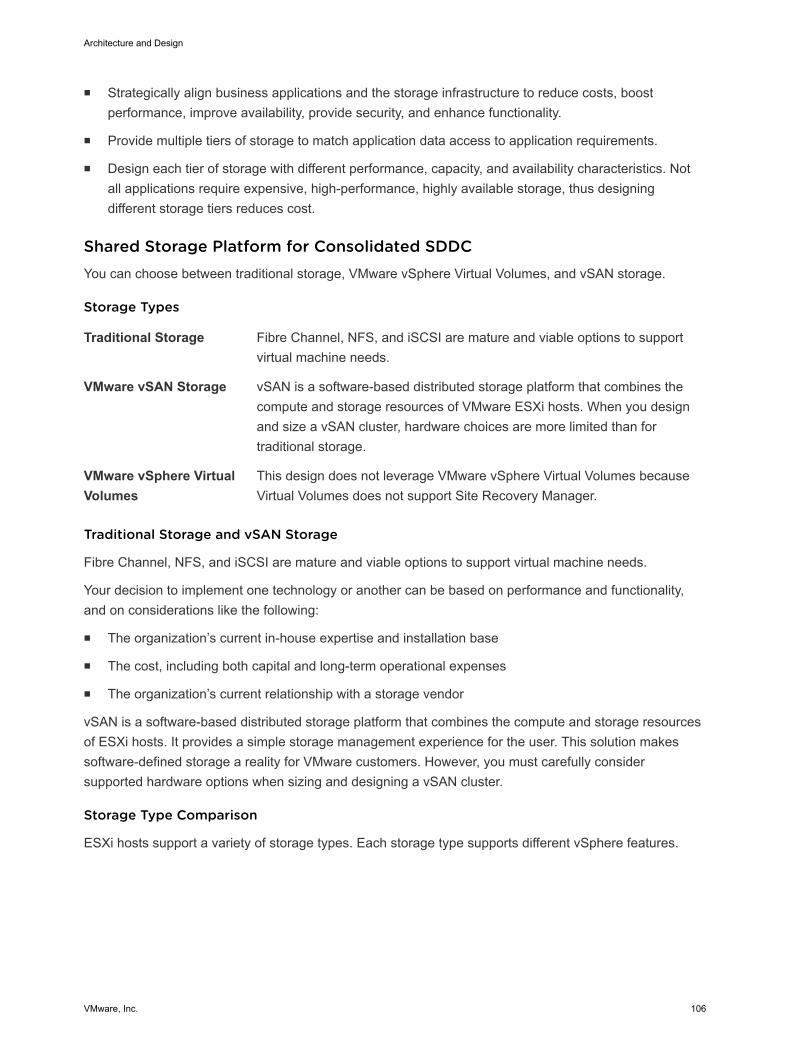
n Strategically align business applications and the storage infrastructure to reduce costs, boostperformance, improve availability, provide security, and enhance functionality.
n Provide multiple tiers of storage to match application data access to application requirements.
n Design each tier of storage with different performance, capacity, and availability characteristics. Notall applications require expensive, high-performance, highly available storage, thus designingdifferent storage tiers reduces cost.
Shared Storage Platform for Consolidated SDDCYou can choose between traditional storage, VMware vSphere Virtual Volumes, and vSAN storage.
Storage Types
Traditional Storage Fibre Channel, NFS, and iSCSI are mature and viable options to supportvirtual machine needs.
VMware vSAN Storage vSAN is a software-based distributed storage platform that combines thecompute and storage resources of VMware ESXi hosts. When you designand size a vSAN cluster, hardware choices are more limited than fortraditional storage.
VMware vSphere VirtualVolumes
This design does not leverage VMware vSphere Virtual Volumes becauseVirtual Volumes does not support Site Recovery Manager.
Traditional Storage and vSAN Storage
Fibre Channel, NFS, and iSCSI are mature and viable options to support virtual machine needs.
Your decision to implement one technology or another can be based on performance and functionality,and on considerations like the following:
n The organization’s current in-house expertise and installation base
n The cost, including both capital and long-term operational expenses
n The organization’s current relationship with a storage vendor
vSAN is a software-based distributed storage platform that combines the compute and storage resourcesof ESXi hosts. It provides a simple storage management experience for the user. This solution makessoftware-defined storage a reality for VMware customers. However, you must carefully considersupported hardware options when sizing and designing a vSAN cluster.
Storage Type Comparison
ESXi hosts support a variety of storage types. Each storage type supports different vSphere features.
Architecture and Design
VMware, Inc. 106
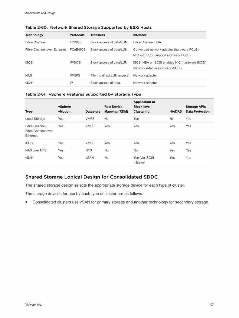
Table 2‑60. Network Shared Storage Supported by ESXi Hosts
Technology Protocols Transfers Interface
Fibre Channel FC/SCSI Block access of data/LUN Fibre Channel HBA
Fibre Channel over Ethernet FCoE/SCSI Block access of data/LUN Converged network adapter (hardware FCoE)
NIC with FCoE support (software FCoE)
iSCSI IP/SCSI Block access of data/LUN iSCSI HBA or iSCSI enabled NIC (hardware iSCSI)
Network Adapter (software iSCSI)
NAS IP/NFS File (no direct LUN access) Network adapter
vSAN IP Block access of data Network adapter
Table 2‑61. vSphere Features Supported by Storage Type
TypevSpherevMotion Datastore
Raw DeviceMapping (RDM)
Application orBlock-levelClustering HA/DRS
Storage APIsData Protection
Local Storage Yes VMFS No Yes No Yes
Fibre Channel /Fibre Channel overEthernet
Yes VMFS Yes Yes Yes Yes
iSCSI Yes VMFS Yes Yes Yes Yes
NAS over NFS Yes NFS No No Yes Yes
vSAN Yes vSAN No Yes (via iSCSIInitiator)
Yes Yes
Shared Storage Logical Design for Consolidated SDDCThe shared storage design selects the appropriate storage device for each type of cluster.
The storage devices for use by each type of cluster are as follows.
n Consolidated clusters use vSAN for primary storage and another technology for secondary storage.
Architecture and Design
VMware, Inc. 107

Figure 2‑16. Logical Storage Design
Virtual Appliance
Virtual Appliance
Virtual Appliance
Virtual Appliance
Virtual Appliance
Virtual Appliance
Consolidated Cluster
ESXi Host
Shared Datastores
Mgmt Monitoring Portals
Software-Defined Storage
Policy-Based Storage ManagementVirtualized Data Services
Hypervisor Storage Abstraction
SAN or NAS or DAS(3rd party or VMware vSAN)
Physical Disks
SSD FC15K FC10K SATA SSD FC15K FC10K SATA
VMDKs
Swap Files + Logs
1500GB
200GB
2048GB
Sample LUN
Architecture and Design
VMware, Inc. 108

Table 2‑62. Storage Type Design Decisions
Decision ID Design Decision Design Justification Design Implication
CSDDC-VI-STORAGE-001
In the Consolidated cluster, usevSAN and secondary sharedstorage:n Use vSAN as the primary
shared storage platform.n Use a secondary shared
storage platform for backupdata.
vSAN as the primary shared storagesolution can take advantage of morecost-effective local storage.
Secondary storage is used primarily forarchival and the need to maintainhistorical data.
The use of two differentstorage technologiesincreases the complexityand operational overhead.
CSDDC-VI-STORAGE-002
Ensure that at least 20% of freespace is always available on allnon-vSAN datastores.
If the datastore runs out of free space,applications and services within theSDDC, such as backups will fail. Toprevent this, maintain adequate freespace.
Monitoring and capacitymanagement are critical,and must be proactivelyperformed.
n Use vSAN as the primary shared storage platform.
n Use a secondary shared storage platform for backup data.
Storage Tiering for Consolidated SDDC
Today’s enterprise-class storage arrays contain multiple drive types and protection mechanisms. Thestorage, server, and application administrators face challenges when selecting the correct storageconfiguration for each application being deployed in the environment. Virtualization can make thisproblem more challenging by consolidating many different application workloads onto a small number oflarge devices. Given this challenge, administrators might use single storage type for every type ofworkload without regard to the needs of the particular workload. However, not all application workloadshave the same requirements, and storage tiering allows for these differences by creating multiple levels ofstorage with varying degrees of performance, reliability and cost, depending on the application workloadneeds.
The most mission-critical data typically represents the smallest amount of data and offline data representsthe largest amount. Details differ for different organizations.
To determine the storage tier for application data, determine the storage characteristics of the applicationor service.
n I/O operations per second (IOPS) requirements
n Megabytes per second (MBps) requirements
n Capacity requirements
n Availability requirements
n Latency requirements
After you determine the information for each application, you can move the application to the storage tierwith matching characteristics.
n Consider any existing service-level agreements (SLAs).
Architecture and Design
VMware, Inc. 109
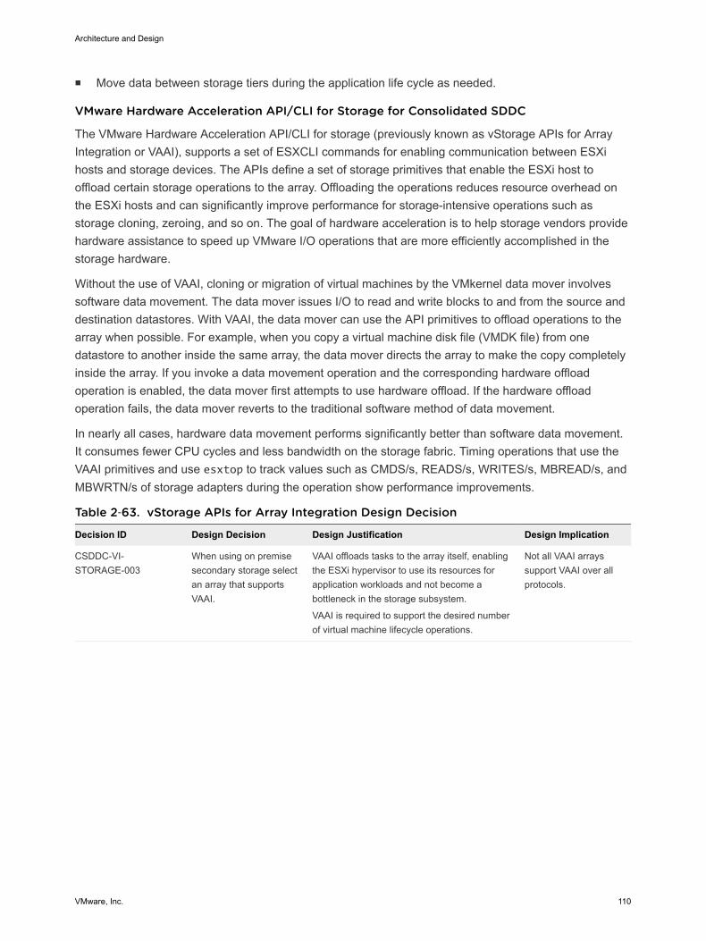
n Move data between storage tiers during the application life cycle as needed.
VMware Hardware Acceleration API/CLI for Storage for Consolidated SDDC
The VMware Hardware Acceleration API/CLI for storage (previously known as vStorage APIs for ArrayIntegration or VAAI), supports a set of ESXCLI commands for enabling communication between ESXihosts and storage devices. The APIs define a set of storage primitives that enable the ESXi host tooffload certain storage operations to the array. Offloading the operations reduces resource overhead onthe ESXi hosts and can significantly improve performance for storage-intensive operations such asstorage cloning, zeroing, and so on. The goal of hardware acceleration is to help storage vendors providehardware assistance to speed up VMware I/O operations that are more efficiently accomplished in thestorage hardware.
Without the use of VAAI, cloning or migration of virtual machines by the VMkernel data mover involvessoftware data movement. The data mover issues I/O to read and write blocks to and from the source anddestination datastores. With VAAI, the data mover can use the API primitives to offload operations to thearray when possible. For example, when you copy a virtual machine disk file (VMDK file) from onedatastore to another inside the same array, the data mover directs the array to make the copy completelyinside the array. If you invoke a data movement operation and the corresponding hardware offloadoperation is enabled, the data mover first attempts to use hardware offload. If the hardware offloadoperation fails, the data mover reverts to the traditional software method of data movement.
In nearly all cases, hardware data movement performs significantly better than software data movement.It consumes fewer CPU cycles and less bandwidth on the storage fabric. Timing operations that use theVAAI primitives and use esxtop to track values such as CMDS/s, READS/s, WRITES/s, MBREAD/s, andMBWRTN/s of storage adapters during the operation show performance improvements.
Table 2‑63. vStorage APIs for Array Integration Design Decision
Decision ID Design Decision Design Justification Design Implication
CSDDC-VI-STORAGE-003
When using on premisesecondary storage selectan array that supportsVAAI.
VAAI offloads tasks to the array itself, enablingthe ESXi hypervisor to use its resources forapplication workloads and not become abottleneck in the storage subsystem.
VAAI is required to support the desired numberof virtual machine lifecycle operations.
Not all VAAI arrayssupport VAAI over allprotocols.
Architecture and Design
VMware, Inc. 110
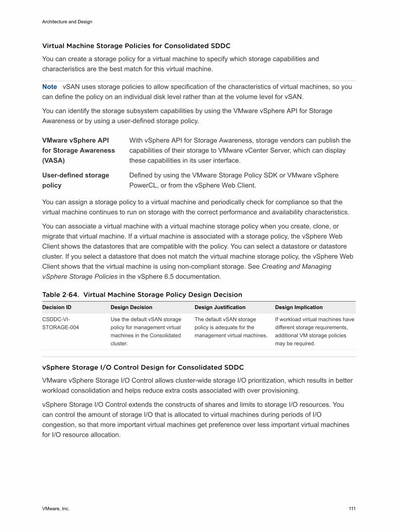
Virtual Machine Storage Policies for Consolidated SDDC
You can create a storage policy for a virtual machine to specify which storage capabilities andcharacteristics are the best match for this virtual machine.
Note vSAN uses storage policies to allow specification of the characteristics of virtual machines, so youcan define the policy on an individual disk level rather than at the volume level for vSAN.
You can identify the storage subsystem capabilities by using the VMware vSphere API for StorageAwareness or by using a user-defined storage policy.
VMware vSphere APIfor Storage Awareness(VASA)
With vSphere API for Storage Awareness, storage vendors can publish thecapabilities of their storage to VMware vCenter Server, which can displaythese capabilities in its user interface.
User-defined storagepolicy
Defined by using the VMware Storage Policy SDK or VMware vSpherePowerCL, or from the vSphere Web Client.
You can assign a storage policy to a virtual machine and periodically check for compliance so that thevirtual machine continues to run on storage with the correct performance and availability characteristics.
You can associate a virtual machine with a virtual machine storage policy when you create, clone, ormigrate that virtual machine. If a virtual machine is associated with a storage policy, the vSphere WebClient shows the datastores that are compatible with the policy. You can select a datastore or datastorecluster. If you select a datastore that does not match the virtual machine storage policy, the vSphere WebClient shows that the virtual machine is using non-compliant storage. See Creating and ManagingvSphere Storage Policies in the vSphere 6.5 documentation.
Table 2‑64. Virtual Machine Storage Policy Design Decision
Decision ID Design Decision Design Justification Design Implication
CSDDC-VI-STORAGE-004
Use the default vSAN storagepolicy for management virtualmachines in the Consolidatedcluster.
The default vSAN storagepolicy is adequate for themanagement virtual machines.
If workload virtual machines havedifferent storage requirements,additional VM storage policiesmay be required.
vSphere Storage I/O Control Design for Consolidated SDDC
VMware vSphere Storage I/O Control allows cluster-wide storage I/O prioritization, which results in betterworkload consolidation and helps reduce extra costs associated with over provisioning.
vSphere Storage I/O Control extends the constructs of shares and limits to storage I/O resources. Youcan control the amount of storage I/O that is allocated to virtual machines during periods of I/Ocongestion, so that more important virtual machines get preference over less important virtual machinesfor I/O resource allocation.
Architecture and Design
VMware, Inc. 111

When vSphere Storage I/O Control is enabled on a datastore, the ESXi host monitors the device latencywhen communicating with that datastore. When device latency exceeds a threshold, the datastore isconsidered to be congested and each virtual machine that accesses that datastore is allocated I/Oresources in proportion to their shares. Shares are set on a per-virtual machine basis and can beadjusted.
vSphere Storage I/O Control has several requirements, limitations, and constraints.
n Datastores that are enabled with vSphere Storage I/O Control must be managed by a single vCenterServer system.
n Storage I/O Control is supported on Fibre Channel-connected, iSCSI-connected, and NFS-connectedstorage. RDM is not supported.
n Storage I/O Control does not support datastores with multiple extents.
n Before using vSphere Storage I/O Control on datastores that are backed by arrays with automatedstorage tiering capabilities, check the VMware Compatibility Guide whether the storage array hasbeen certified a compatible with vSphere Storage I/O Control.
Table 2‑65. Storage I/O Control Design Decisions
Decision ID Design Decision Design Justification Design Implication
CSDDC-VI-STORAGE-005
Enable Storage I/OControl with the defaultvalues on all non vSANdatastores.
Storage I/O Control ensures thatall virtual machines on adatastore receive an equalamount of I/O.
Virtual machines that use more I/Oare throttled to allow other virtualmachines access to the datastoreonly when contention occurs on thedatastore.
Datastore Cluster Design for Consolidated SDDCA datastore cluster is a collection of datastores with shared resources and a shared managementinterface. Datastore clusters are to datastores what clusters are to ESXi hosts. After you create adatastore cluster, you can use vSphere Storage DRS to manage storage resources.
vSphere datastore clusters group similar datastores into a pool of storage resources. When vSphereStorage DRS is enabled on a datastore cluster, vSphere automates the process of initial virtual machinefile placement and balances storage resources across the cluster to avoid bottlenecks. vSphere StorageDRS considers datastore space usage and I/O load when making migration recommendations.
When you add a datastore to a datastore cluster, the datastore's resources become part of the datastorecluster's resources. The following resource management capabilities are also available for each datastorecluster.
Architecture and Design
VMware, Inc. 112
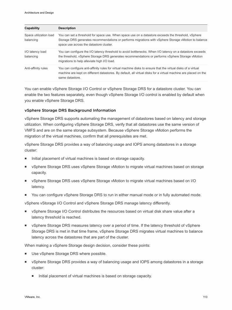
Capability Description
Space utilization loadbalancing
You can set a threshold for space use. When space use on a datastore exceeds the threshold, vSphereStorage DRS generates recommendations or performs migrations with vSphere Storage vMotion to balancespace use across the datastore cluster.
I/O latency loadbalancing
You can configure the I/O latency threshold to avoid bottlenecks. When I/O latency on a datastore exceedsthe threshold, vSphere Storage DRS generates recommendations or performs vSphere Storage vMotionmigrations to help alleviate high I/O load.
Anti-affinity rules You can configure anti-affinity rules for virtual machine disks to ensure that the virtual disks of a virtualmachine are kept on different datastores. By default, all virtual disks for a virtual machine are placed on thesame datastore.
You can enable vSphere Storage I/O Control or vSphere Storage DRS for a datastore cluster. You canenable the two features separately, even though vSphere Storage I/O control is enabled by default whenyou enable vSphere Storage DRS.
vSphere Storage DRS Background Information
vSphere Storage DRS supports automating the management of datastores based on latency and storageutilization. When configuring vSphere Storage DRS, verify that all datastores use the same version ofVMFS and are on the same storage subsystem. Because vSphere Storage vMotion performs themigration of the virtual machines, confirm that all prerequisites are met.
vSphere Storage DRS provides a way of balancing usage and IOPS among datastores in a storagecluster:
n Initial placement of virtual machines is based on storage capacity.
n vSphere Storage DRS uses vSphere Storage vMotion to migrate virtual machines based on storagecapacity.
n vSphere Storage DRS uses vSphere Storage vMotion to migrate virtual machines based on I/Olatency.
n You can configure vSphere Storage DRS to run in either manual mode or in fully automated mode.
vSphere vStorage I/O Control and vSphere Storage DRS manage latency differently.
n vSphere Storage I/O Control distributes the resources based on virtual disk share value after alatency threshold is reached.
n vSphere Storage DRS measures latency over a period of time. If the latency threshold of vSphereStorage DRS is met in that time frame, vSphere Storage DRS migrates virtual machines to balancelatency across the datastores that are part of the cluster.
When making a vSphere Storage design decision, consider these points:
n Use vSphere Storage DRS where possible.
n vSphere Storage DRS provides a way of balancing usage and IOPS among datastores in a storagecluster:
n Initial placement of virtual machines is based on storage capacity.
Architecture and Design
VMware, Inc. 113
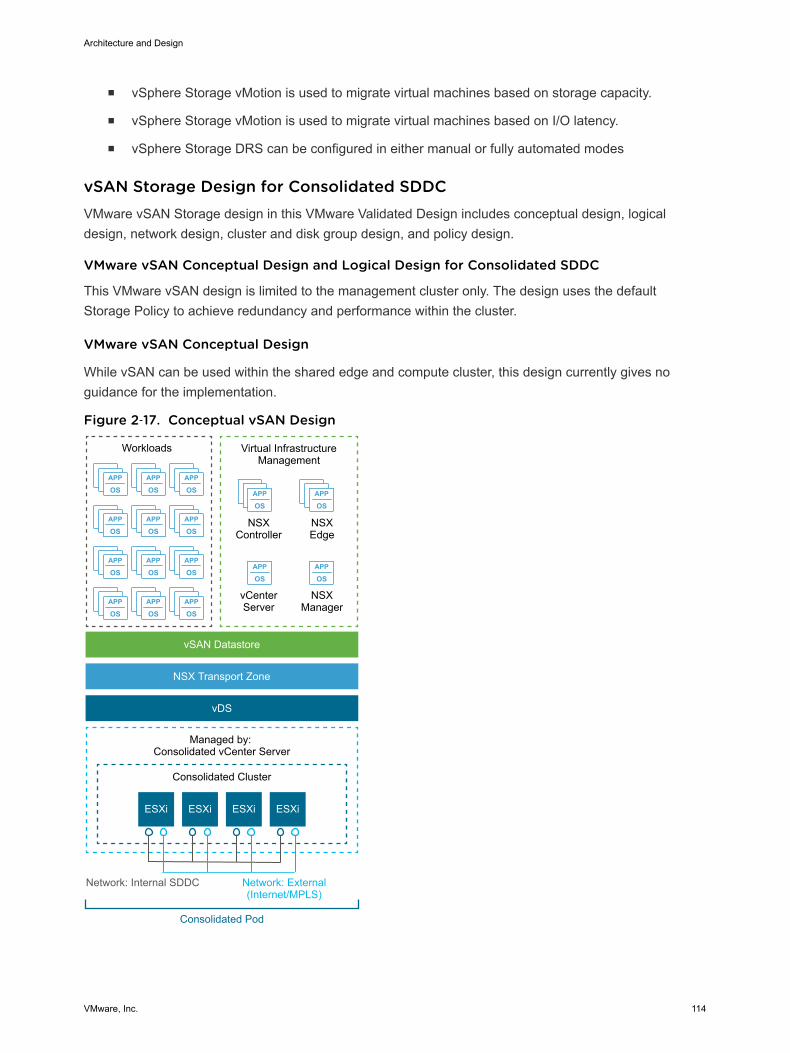
n vSphere Storage vMotion is used to migrate virtual machines based on storage capacity.
n vSphere Storage vMotion is used to migrate virtual machines based on I/O latency.
n vSphere Storage DRS can be configured in either manual or fully automated modes
vSAN Storage Design for Consolidated SDDCVMware vSAN Storage design in this VMware Validated Design includes conceptual design, logicaldesign, network design, cluster and disk group design, and policy design.
VMware vSAN Conceptual Design and Logical Design for Consolidated SDDC
This VMware vSAN design is limited to the management cluster only. The design uses the defaultStorage Policy to achieve redundancy and performance within the cluster.
VMware vSAN Conceptual Design
While vSAN can be used within the shared edge and compute cluster, this design currently gives noguidance for the implementation.
Figure 2‑17. Conceptual vSAN Design
APP
OSAPP
OS
APP
OSAPP
OS
APP
OSAPP
OSAPP
OS
APP
OSAPP
OSAPP
OS
APP
OSAPP
OSAPP
OS
APP
OSAPP
OSAPP
OS
ESXiESXi ESXi ESXi
Virtual InfrastructureManagement
NSXController
NSXEdge
NSXManager
Workloads
vSAN Datastore
NSX Transport Zone
Consolidated Cluster
Managed by: Consolidated vCenter Server
Network: External(Internet/MPLS)
Network: Internal SDDC
Consolidated Pod
vCenterServer
vDS
Architecture and Design
VMware, Inc. 114

vSAN Logical Design
In a cluster that is managed by vCenter Server, you can manage software-defined storage resources justas you can manage compute resources. Instead of CPU or memory reservations, limits, and shares, youcan define storage policies and assign them to virtual machines. The policies specify the characteristicsof the storage and can be changed as business requirements change.
VMware vSAN Network Design for Consolidated SDDC
When performing network configuration, you have to consider the traffic and decide how to isolate vSANtraffic.
n Consider how much replication and communication traffic is running between hosts. With VMwarevSAN, the amount of traffic depends on the number of VMs that are running in the cluster, and onhow write-intensive the I/O is for the applications running in the VMs.
n Isolate vSAN traffic on its own Layer 2 network segment. You can do this with dedicated switches orports, or by using a VLAN.
The vSAN VMkernel port group is created as part of cluster creation. Configure this port group on allhosts in a cluster, even for hosts that are not contributing storage resources to the cluster.
The following diagram illustrates the logical design of the network.
Figure 2‑18. VMware vSAN Conceptual Network
VM VM VM
ESXi Host ESXi Host ESXi Host
ESXi Host ESXi Host
vSAN Datastore
vSAN-Enabled Clusters
vSAN Network (VLAN)
Management Network (VLAN)
vMotion Network (VLAN)
Virtual Machine Network(s) (VLAN)
Architecture and Design
VMware, Inc. 115
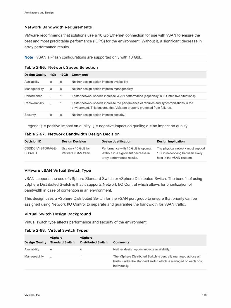
Network Bandwidth Requirements
VMware recommends that solutions use a 10 Gb Ethernet connection for use with vSAN to ensure thebest and most predictable performance (IOPS) for the environment. Without it, a significant decrease inarray performance results.
Note vSAN all-flash configurations are supported only with 10 GbE.
Table 2‑66. Network Speed Selection
Design Quality 1Gb 10Gb Comments
Availability o o Neither design option impacts availability.
Manageability o o Neither design option impacts manageability.
Performance ↓ ↑ Faster network speeds increase vSAN performance (especially in I/O intensive situations).
Recoverability ↓ ↑ Faster network speeds increase the performance of rebuilds and synchronizations in theenvironment. This ensures that VMs are properly protected from failures.
Security o o Neither design option impacts security.
Legend: ↑ = positive impact on quality; ↓ = negative impact on quality; o = no impact on quality.
Table 2‑67. Network Bandwidth Design Decision
Decision ID Design Decision Design Justification Design Implication
CSDDC-VI-STORAGE-SDS-001
Use only 10 GbE forVMware vSAN traffic.
Performance with 10 GbE is optimal.Without it, a significant decrease inarray performance results.
The physical network must support10 Gb networking between everyhost in the vSAN clusters.
VMware vSAN Virtual Switch Type
vSAN supports the use of vSphere Standard Switch or vSphere Distributed Switch. The benefit of usingvSphere Distributed Switch is that it supports Network I/O Control which allows for prioritization ofbandwidth in case of contention in an environment.
This design uses a vSphere Distributed Switch for the vSAN port group to ensure that priority can beassigned using Network I/O Control to separate and guarantee the bandwidth for vSAN traffic.
Virtual Switch Design Background
Virtual switch type affects performance and security of the environment.
Table 2‑68. Virtual Switch Types
Design QualityvSphereStandard Switch
vSphereDistributed Switch Comments
Availability o o Neither design option impacts availability.
Manageability ↓ ↑ The vSphere Distributed Switch is centrally managed across allhosts, unlike the standard switch which is managed on each hostindividually.
Architecture and Design
VMware, Inc. 116

Table 2‑68. Virtual Switch Types (Continued)
Design QualityvSphereStandard Switch
vSphereDistributed Switch Comments
Performance ↓ ↑ The vSphere Distributed Switch has added controls, such asNetwork I/O Control, which you can use to guarantee performancefor vSAN traffic.
Recoverability ↓ ↑ The vSphere Distributed Switch configuration can be backed upand restored, the standard switch does not have this functionality.
Security ↓ ↑ The vSphere Distributed Switch has added built-in security controlsto help protect traffic.
Legend: ↑ = positive impact on quality; ↓ = negative impact on quality; o = no impact on quality.
Table 2‑69. Virtual Switch Design Decision
Decision ID Design Decision Design Justification Design Implication
CSDDC-VI-STORAGE-SDS-002
Use the existing vSphereDistributed Switch instance.
Provide guaranteed performance forvSAN traffic in case of contention byusing existing networking components.
All traffic paths are sharedover common uplinks.
Jumbo Frames
VMware vSAN supports jumbo frames for vSAN traffic.
A VMware vSAN design should use jumbo frames only if the physical environment is already configuredto support them, they are part of the existing design, or if the underlying configuration does not create asignificant amount of added complexity to the design.
Table 2‑70. Jumbo Frames Design Decision
Decision ID Design Decision Design Justification Design Implication
CSDDC-VI-STORAGE-SDS-003
Configure jumbo frames onthe VLAN dedicated to vSANtraffic.
Jumbo frames are already used toimprove performance of vSpherevMotion and support VXLAN traffic.
Every device in the networkmust support jumbo frames.
VLANs
VMware recommends isolating VMware vSAN traffic on its own VLAN. When a design uses multiplevSAN clusters, each cluster should use a dedicated VLAN or segment for its traffic. This approachprevents interference between clusters and helps with troubleshooting cluster configuration.
Table 2‑71. VLAN Design Decision
Decision ID Design Decision Design Justification Design Implication
CSDDC-VI-STORAGE-SDS-004
Use a dedicated VLAN forvSAN traffic for each vSANenabled cluster.
VLANs ensure trafficisolation.
VLANs span only a single pod.
A sufficient number of VLANs are availablewithin the consolidated pod and should beused for traffic segregation.
Architecture and Design
VMware, Inc. 117

Multicast Requirements
VMware vSAN requires that IP multicast is enabled on the Layer 2 physical network segment that is usedfor intra-cluster communication. All VMkernel ports on the vSAN network subscribe to a multicast groupusing Internet Group Management Protocol (IGMP).
A default multicast address is assigned to each vSAN cluster at the time of creation. IGMP (v3) snoopingis used to limit Layer 2 multicast traffic to specific port groups. As per the Physical Network Design, IGMPsnooping is configured with an IGMP snooping querier to limit the physical switch ports that participate inthe multicast group to only vSAN VMkernel port uplinks. In some cases, an IGMP snooping querier canbe associated with a specific VLAN. However, vendor implementations might differ.
Cluster and Disk Group Design for Consolidated SDDC
When considering the cluster and disk group design, you have to decide on the vSAN datastore size,number of hosts per cluster, number of disk groups per host, and the vSAN policy.
VMware vSAN Datastore Size
The size of the VMware vSAN datastore depends on the requirements for the datastore. Consider costversus availability to provide the appropriate sizing.
Table 2‑72. VMware vSAN Datastore Design Decision
Decision ID Design Decision Design Justification Design Implication
CSDDC-VI-STORAGE-SDS-005
Provide the consolidated cluster withenough vSAN space to runmanagement and workloads virtualmachines with FTT=1.
Management virtual machines requirea maximum of 4 TB.
TB of storage when using FTT=1.
None
CSDDC-VI-STORAGE-SDS-006
On all VSAN datastores , ensure thatat least 30% of free space is alwaysavailable.
When vSAN reaches 80% usage a re-balance task is started which can beresource intensive.
Increases the amountof available storageneeded.
Number of Hosts Per Cluster
The number of hosts in the cluster depends on these factors:
n Amount of available space on the vSAN datastore
n Number of failures you can tolerate in the cluster
For example, if the vSAN cluster has only 3 ESXi hosts, only a single failure is supported. If a higher levelof availability is required, additional hosts are required.
Cluster Size Design Background
Table 2‑73. Number of Hosts Per Cluster
Design Quality 3 Hosts 32 Hosts 64 Hosts Comments
Availability ↓ ↑ ↑↑ The more hosts that are available in the cluster, the more failures the clustercan tolerate.
Manageability ↓ ↑ ↑ The more hosts in the cluster, the more virtual machines can be in the vSANenvironment.
Architecture and Design
VMware, Inc. 118
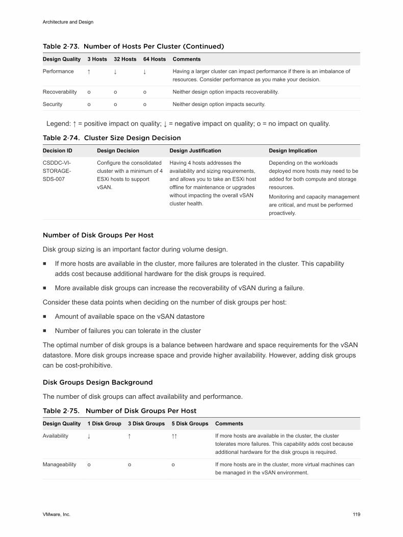
Table 2‑73. Number of Hosts Per Cluster (Continued)
Design Quality 3 Hosts 32 Hosts 64 Hosts Comments
Performance ↑ ↓ ↓ Having a larger cluster can impact performance if there is an imbalance ofresources. Consider performance as you make your decision.
Recoverability o o o Neither design option impacts recoverability.
Security o o o Neither design option impacts security.
Legend: ↑ = positive impact on quality; ↓ = negative impact on quality; o = no impact on quality.
Table 2‑74. Cluster Size Design Decision
Decision ID Design Decision Design Justification Design Implication
CSDDC-VI-STORAGE-SDS-007
Configure the consolidatedcluster with a minimum of 4ESXi hosts to supportvSAN.
Having 4 hosts addresses theavailability and sizing requirements,and allows you to take an ESXi hostoffline for maintenance or upgradeswithout impacting the overall vSANcluster health.
Depending on the workloadsdeployed more hosts may need to beadded for both compute and storageresources.
Monitoring and capacity managementare critical, and must be performedproactively.
Number of Disk Groups Per Host
Disk group sizing is an important factor during volume design.
n If more hosts are available in the cluster, more failures are tolerated in the cluster. This capabilityadds cost because additional hardware for the disk groups is required.
n More available disk groups can increase the recoverability of vSAN during a failure.
Consider these data points when deciding on the number of disk groups per host:
n Amount of available space on the vSAN datastore
n Number of failures you can tolerate in the cluster
The optimal number of disk groups is a balance between hardware and space requirements for the vSANdatastore. More disk groups increase space and provide higher availability. However, adding disk groupscan be cost-prohibitive.
Disk Groups Design Background
The number of disk groups can affect availability and performance.
Table 2‑75. Number of Disk Groups Per Host
Design Quality 1 Disk Group 3 Disk Groups 5 Disk Groups Comments
Availability ↓ ↑ ↑↑ If more hosts are available in the cluster, the clustertolerates more failures. This capability adds cost becauseadditional hardware for the disk groups is required.
Manageability o o o If more hosts are in the cluster, more virtual machines canbe managed in the vSAN environment.
Architecture and Design
VMware, Inc. 119
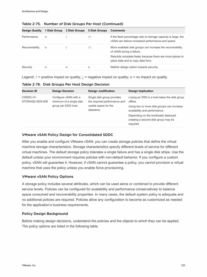
Table 2‑75. Number of Disk Groups Per Host (Continued)
Design Quality 1 Disk Group 3 Disk Groups 5 Disk Groups Comments
Performance o ↑ ↑↑ If the flash percentage ratio to storage capacity is large, thevSAN can deliver increased performance and speed.
Recoverability o ↑ ↑↑ More available disk groups can increase the recoverabilityof vSAN during a failure.
Rebuilds complete faster because there are more places toplace data and to copy data from.
Security o o o Neither design option impacts security.
Legend: ↑ = positive impact on quality; ↓ = negative impact on quality; o = no impact on quality.
Table 2‑76. Disk Groups Per Host Design Decision
Decision ID Design Decision Design Justification Design Implication
CSDDC-VI-STORAGE-SDS-008
Configure vSAN with aminimum of a single diskgroup per ESXi host.
Single disk group providesthe required performance andusable space for thedatastore.
Losing an SSD in a host takes the disk groupoffline.
Using two or more disk groups can increaseavailability and performance.
Depending on the workloads deployedcreating a second disk group may berequired.
VMware vSAN Policy Design for Consolidated SDDC
After you enable and configure VMware vSAN, you can create storage policies that define the virtualmachine storage characteristics. Storage characteristics specify different levels of service for differentvirtual machines. The default storage policy tolerates a single failure and has a single disk stripe. Use thedefault unless your environment requires policies with non-default behavior. If you configure a custompolicy, vSAN will guarantee it. However, if vSAN cannot guarantee a policy, you cannot provision a virtualmachine that uses the policy unless you enable force provisioning.
VMware vSAN Policy Options
A storage policy includes several attributes, which can be used alone or combined to provide differentservice levels. Policies can be configured for availability and performance conservatively to balancespace consumed and recoverability properties. In many cases, the default system policy is adequate andno additional policies are required. Policies allow any configuration to become as customized as neededfor the application’s business requirements.
Policy Design Background
Before making design decisions, understand the policies and the objects to which they can be applied.The policy options are listed in the following table.
Architecture and Design
VMware, Inc. 120
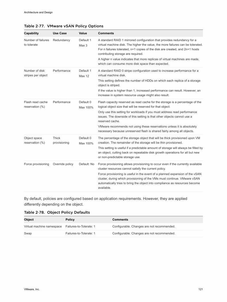
Table 2‑77. VMware vSAN Policy Options
Capability Use Case Value Comments
Number of failuresto tolerate
Redundancy Default 1
Max 3
A standard RAID 1 mirrored configuration that provides redundancy for avirtual machine disk. The higher the value, the more failures can be tolerated.For n failures tolerated, n+1 copies of the disk are created, and 2n+1 hostscontributing storage are required.
A higher n value indicates that more replicas of virtual machines are made,which can consume more disk space than expected.
Number of diskstripes per object
Performance Default 1
Max 12
A standard RAID 0 stripe configuration used to increase performance for avirtual machine disk.
This setting defines the number of HDDs on which each replica of a storageobject is striped.
If the value is higher than 1, increased performance can result. However, anincrease in system resource usage might also result.
Flash read cachereservation (%)
Performance Default 0
Max 100%
Flash capacity reserved as read cache for the storage is a percentage of thelogical object size that will be reserved for that object.
Only use this setting for workloads if you must address read performanceissues. The downside of this setting is that other objects cannot use areserved cache.
VMware recommends not using these reservations unless it is absolutelynecessary because unreserved flash is shared fairly among all objects.
Object spacereservation (%)
Thickprovisioning
Default 0
Max 100%
The percentage of the storage object that will be thick provisioned upon VMcreation. The remainder of the storage will be thin provisioned.
This setting is useful if a predictable amount of storage will always be filled byan object, cutting back on repeatable disk growth operations for all but newor non-predictable storage use.
Force provisioning Override policy Default: No Force provisioning allows provisioning to occur even if the currently availablecluster resources cannot satisfy the current policy.
Force provisioning is useful in the event of a planned expansion of the vSANcluster, during which provisioning of the VMs must continue. VMware vSANautomatically tries to bring the object into compliance as resources becomeavailable.
By default, policies are configured based on application requirements. However, they are applieddifferently depending on the object.
Table 2‑78. Object Policy Defaults
Object Policy Comments
Virtual machine namespace Failures-to-Tolerate: 1 Configurable. Changes are not recommended.
Swap Failures-to-Tolerate: 1 Configurable. Changes are not recommended.
Architecture and Design
VMware, Inc. 121
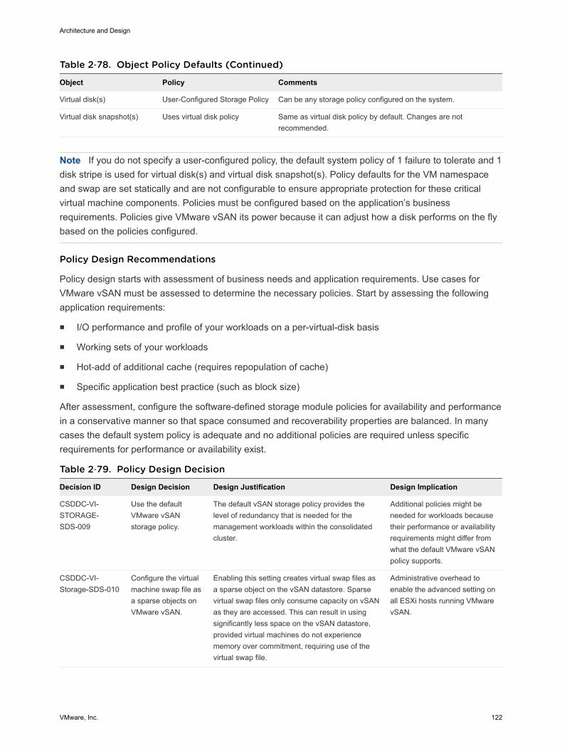
Table 2‑78. Object Policy Defaults (Continued)
Object Policy Comments
Virtual disk(s) User-Configured Storage Policy Can be any storage policy configured on the system.
Virtual disk snapshot(s) Uses virtual disk policy Same as virtual disk policy by default. Changes are notrecommended.
Note If you do not specify a user-configured policy, the default system policy of 1 failure to tolerate and 1disk stripe is used for virtual disk(s) and virtual disk snapshot(s). Policy defaults for the VM namespaceand swap are set statically and are not configurable to ensure appropriate protection for these criticalvirtual machine components. Policies must be configured based on the application’s businessrequirements. Policies give VMware vSAN its power because it can adjust how a disk performs on the flybased on the policies configured.
Policy Design Recommendations
Policy design starts with assessment of business needs and application requirements. Use cases forVMware vSAN must be assessed to determine the necessary policies. Start by assessing the followingapplication requirements:
n I/O performance and profile of your workloads on a per-virtual-disk basis
n Working sets of your workloads
n Hot-add of additional cache (requires repopulation of cache)
n Specific application best practice (such as block size)
After assessment, configure the software-defined storage module policies for availability and performancein a conservative manner so that space consumed and recoverability properties are balanced. In manycases the default system policy is adequate and no additional policies are required unless specificrequirements for performance or availability exist.
Table 2‑79. Policy Design Decision
Decision ID Design Decision Design Justification Design Implication
CSDDC-VI-STORAGE-SDS-009
Use the defaultVMware vSANstorage policy.
The default vSAN storage policy provides thelevel of redundancy that is needed for themanagement workloads within the consolidatedcluster.
Additional policies might beneeded for workloads becausetheir performance or availabilityrequirements might differ fromwhat the default VMware vSANpolicy supports.
CSDDC-VI-Storage-SDS-010
Configure the virtualmachine swap file asa sparse objects onVMware vSAN.
Enabling this setting creates virtual swap files asa sparse object on the vSAN datastore. Sparsevirtual swap files only consume capacity on vSANas they are accessed. This can result in usingsignificantly less space on the vSAN datastore,provided virtual machines do not experiencememory over commitment, requiring use of thevirtual swap file.
Administrative overhead toenable the advanced setting onall ESXi hosts running VMwarevSAN.
Architecture and Design
VMware, Inc. 122

Cloud Management Platform Design for ConsolidatedSDDCThe Cloud Management Platform (CMP) layer is the management component of the Software DefinedData Center (SDDC). The CMP layer allows you to deliver tenants with automated workload provisioningby using a self-service portal.
The CMP layer includes the following components and functionality.
Figure 2‑19. The Cloud Management Platform Layer Within the Software-Defined DataCenter
ServiceManagement
Portfolio Management
OperationsManagement
CloudManagement
Layer
Service Catalog
Self-Service Portal
Orchestration
BusinessContinuity
Fault Tolerance and Disaster
Recovery
Backup & Restore
Hypervisor
Pools of Resources
Virtualization Control
VirtualInfrastructure
Layer
Compute
Storage
Network
PhysicalLayer
Security
Replication Compliance
Risk
Governance
Service Catalog A self-service portal where users can browse and request the IT servicesand resources they need, such a virtual machine or a machine on AmazonWeb Services (AWS). When you request a service catalog item youprovision the item to the designated cloud environment.
Self-Service Portal Provides a unified interface for consuming IT services. Users can browsethe service catalog to request IT services and resources, track theirrequests, and manage their provisioned items.
Orchestration Provides automated workflows used to deploy service catalog itemsrequested by users. You use the workflows to create and run automated,configurable processes to manage your SDDC infrastructure, as well asother VMware and third-party technologies.
vRealize Automation provides the self-service portal and the servicecatalog. Orchestration is enabled by an instance of vRealize Orchestratorinternal to vRealize Automation.
Architecture and Design
VMware, Inc. 123
vRealize Automation Design for Consolidated SDDCVMware vRealize Automation provides a service catalog from which tenants can deploy applications, anda portal that lets you deliver a personalized, self-service experience to end users. The following sectionsdescribe the detailed design for vRealization Automation within the cloud management layer of theConsolidated SDDC.
vRealize Automation Logical Design for Consolidated SDDCvRealize Automation provides several extensibility options designed to support a variety of use cases andintegrations.
The following diagram illustrates vRealize Automation internal components, and the integration of thosecomponents with other external components and the supporting infrastructure of the Consolidated SDDC.
Architecture and Design
VMware, Inc. 124
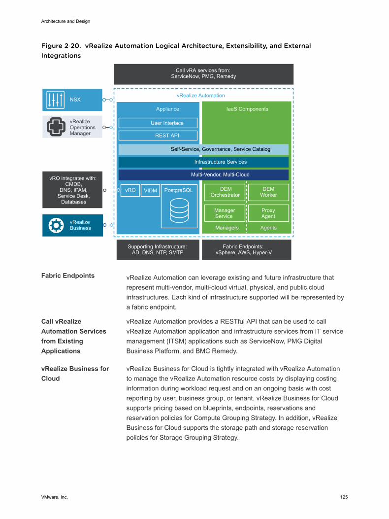
Figure 2‑20. vRealize Automation Logical Architecture, Extensibility, and ExternalIntegrations
PostgreSQL vRO VIDM
Call vRA services from: ServiceNow, PMG, Remedy
Supporting Infrastructure: AD, DNS, NTP, SMTP
Fabric Endpoints: vSphere, AWS, Hyper-V
ProxyAgent
vRealize Automation
Appliance
User Interface
IaaS Components
DEMOrchestrator
DEMWorker
ManagerService
Managers Agents
REST API
vRealizeBusiness
vRealizeOperationsManager
Self-Service, Governance, Service Catalog
Infrastructure Services
Multi-Vendor, Multi-CloudvRO integrates with:
CMDB,DNS, IPAM,
Service Desk, Databases
NSX
Fabric Endpoints vRealize Automation can leverage existing and future infrastructure thatrepresent multi-vendor, multi-cloud virtual, physical, and public cloudinfrastructures. Each kind of infrastructure supported will be represented bya fabric endpoint.
Call vRealizeAutomation Servicesfrom ExistingApplications
vRealize Automation provides a RESTful API that can be used to callvRealize Automation application and infrastructure services from IT servicemanagement (ITSM) applications such as ServiceNow, PMG DigitalBusiness Platform, and BMC Remedy.
vRealize Business forCloud
vRealize Business for Cloud is tightly integrated with vRealize Automationto manage the vRealize Automation resource costs by displaying costinginformation during workload request and on an ongoing basis with costreporting by user, business group, or tenant. vRealize Business for Cloudsupports pricing based on blueprints, endpoints, reservations andreservation policies for Compute Grouping Strategy. In addition, vRealizeBusiness for Cloud supports the storage path and storage reservationpolicies for Storage Grouping Strategy.
Architecture and Design
VMware, Inc. 125

vRealize OperationsManagement
The vRealize Automation management pack for vRealize OperationManager provides the comprehensive visibility into both performance andcapacity metrics of a vRealize Automation tenant’s business groups andunderlying cloud infrastructure. By combining these new metrics with thecustom dashboard capabilities of vRealize Operations, you gain a greatlevel of flexibility and insight when monitoring these complex environments.
SupportingInfrastructure
vRealize Automation integrates with the following supporting infrastructure:
n Microsoft SQL Server to store data relating to the vRealize AutomationIaaS elements.
n NTP server with which to synchronize the time between the vRealizeAutomation components.
n Active Directory supports vRealize Automation tenant userauthentication and authorization.
n SMTP sends and receives notification emails for various actions thatcan be executed within the vRealize Automation console.
NSX NSX and vRealize Automation integration provides several options fordesigning and authoring blueprints with the networking and securityfeatures provided by NSX, and takes full advantage of all the NSX networkconstructs such as switches, routers, and firewalls. This integration allowsyou to use an on-demand load balancer, on-demand NAT network, on-demand routed network and on-demand security groups within a blueprint,which is automatically provisioned by vRealize Automation when theblueprint is requested. The integration with NSX eliminates the need fornetworking to be provisioned as a separate activity outside vRealizeAutomation.
Cloud Management Platform Usage Model
The Cloud Management Platform (CMP), of which vRealize Automation is a central component, enablesa usage model that includes interaction between users, the CMP itself, the supporting infrastructure, andthe provisioning infrastructure. The following diagram illustrates the usage model of the CMP in relation tothese elements.
Architecture and Design
VMware, Inc. 126

Figure 2‑21. vRealize Automation Usage Model
Compute
Business Group(s)
Rainpole End User 1Production Workload
Rainpole End User 2Test/Dev Workload
Fabric Group(s)
Cloud Management PortalVM Templates and Blueprints
Tenant Access
Administration of virtualand cloud resources
Internal Virtual Resources
Network Storage Compute
External Cloud Resources
Network Storage
Cloud Admin
Admin Access
Blueprints
App and ServicesAuthoring
Cloud Admin
App Authoring
The following table lists the vRealize Automation elements, and the components that in turn compriseeach of these elements.
Element Components
Users Cloud administrators Tenant, group, fabric, infrastructure, service, and other administrators asdefined by business policies and organizational structure.
Cloud (or tenant) users Users within an organization that can provision virtual machines and directlyperform operations on them at the level of the operating system.
Tools andsupportinginfrastructure
VM templates and blueprints are the building blocks that provide the foundation of the cloud. VM templatesare used to author the blueprints that tenants (end users) use to provision their cloud workloads.
Architecture and Design
VMware, Inc. 127
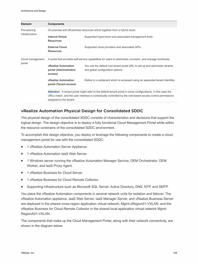
Element Components
Provisioninginfrastructure
On-premise and off-premise resources which together form a hybrid cloud.
Internal VirtualResources
Supported hypervisors and associated management tools.
External CloudResources
Supported cloud providers and associated APIs.
Cloud managementportal
A portal that provides self-service capabilities for users to administer, provision, and manage workloads.
vRealize Automationportal (Administrativeaccess)
You use the default root tenant portal URL to set-up and administer tenantsand global configuration options.
vRealize Automationportal (Tenant access)
Refers to a subtenant which is accessed using an appended tenant identifier.
Attention A tenant portal might refer to the default tenant portal in some configurations. In this case theURLs match, and the user interface is contextually controlled by the role-based access control permissionsassigned to the tenant.
vRealize Automation Physical Design for Consolidated SDDCThe physical design of the consolidated SDDC consists of characteristics and decisions that support thelogical design. The design objective is to deploy a fully functional Cloud Management Portal while withinthe resource constrains of the consolidated SDDC environment.
To accomplish this design objective, you deploy or leverage the following components to create a cloudmanagement portal for use with the consolidated SDDC.
n 1 vRealize Automation Server Appliance.
n 1 vRealize Automation IaaS Web Server.
n 1 Windows server running the vRealize Automation Manager Service, DEM Orchestrator, DEMWorker, and IaaS Proxy Agent.
n 1 vRealize Business for Cloud Server.
n 1 vRealize Business for Cloud Remote Collector.
n Supporting infrastructure such as Microsoft SQL Server, Active Directory, DNS, NTP, and SMTP.
You place the vRealize Automation components in several network units for isolation and failover. ThevRealize Automation appliance, IaaS Web Server, IaaS Manager Server, and vRealize Business Serverare deployed in the shared cross-region application virtual network, Mgmt-xRegion01-VXLAN, and thevRealize Business for Cloud Remote Collector in the shared local application virtual network Mgmt-RegionA01-VXLAN.
The components that make up the Cloud Management Portal, along with their network connectivity, areshown in the diagram below.
Architecture and Design
VMware, Inc. 128
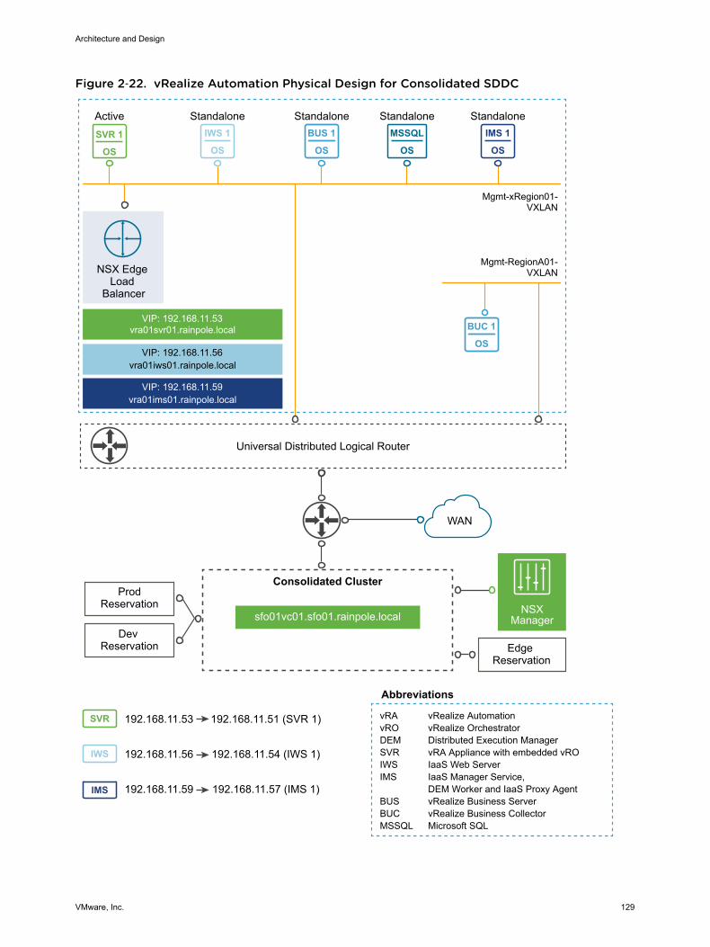
Figure 2‑22. vRealize Automation Physical Design for Consolidated SDDC
IWS 1
OS
MSSQL
OS
IMS 1
OS
IWS
IMS
SVR
BUC 1
OS
BUS 1
OSSVR 1
OS
Universal Distributed Logical Router
VIP: 192.168.11.53vra01svr01.rainpole.local
VIP: 192.168.11.56vra01iws01.rainpole.local
VIP: 192.168.11.59vra01ims01.rainpole.local
Active Standalone Standalone Standalone Standalone
Mgmt-xRegion01-VXLAN
NSX Edge Load
Balancer
Edge Reservation
WAN
Abbreviations
vRA vRealize AutomationvRO vRealize OrchestratorDEM Distributed Execution ManagerSVR vRA Appliance with embedded vROIWS IaaS Web ServerIMS IaaS Manager Service, DEM Worker and IaaS Proxy AgentBUS vRealize Business ServerBUC vRealize Business CollectorMSSQL Microsoft SQL
sfo01vc01.sfo01.rainpole.local
Consolidated Cluster
NSXManager
Dev Reservation
ProdReservation
192.168.11.56
192.168.11.59
192.168.11.53 192.168.11.51 (SVR 1)
192.168.11.54 (IWS 1)
192.168.11.57 (IMS 1)
Mgmt-RegionA01-VXLAN
Architecture and Design
VMware, Inc. 129

Deployment Considerations for Consolidated SDDC
This design uses NSX logical switches to abstract the vRealize Automation application and its supportingservices. This abstraction allows the application to be hosted in any given region regardless of theunderlying physical infrastructure such as network subnets, compute hardware, or storage types.
Table 2‑80. vRealize Automation topology Design Decision
Decision ID Design Decision Design Justification Design Implication
CSDDC-CMP-001
Use a single vRealizeAutomation installation tomanage the consolidatedpod.
You can use the single vRealize Automation instance forfuture expansion to the two pod design.
CSDDC-CMP-002
Deploy vRealize Automationin Enterprise Installationmode with no HA.
This design allows for a fully functional cloudmanagement portal with an embedded vRealizeOrchestrator while satisfying the minimal footprintrequirements of the consolidated pod. The design alsoensures that future expansion to a two pod design isviable.
Using an NSX load balancer simplifies vRealizeAutomation deployment, and any subsequent scale outand integration.
Relies on vSphereHA for applicationavailability.
Table 2‑81. vRealize Automation IaaS AD Requirement
Decision ID Design Decision Design Justification Design Implication
CSDDC-CMP-003 vRealize Automation IaaS VMsare joined to Active Directory.
This is a requirement for use withvRealize Automation.
Active Directory access must beprovided using dedicated serviceaccounts.
vRealize Automation Appliance Deployment for Consolidated SDDC
The vRealize Automation virtual appliance includes a self-service portal, an embedded vRealizeOrchestrator instance, and database services. The self-service portal allows for the provisioning andmanagement of cloud services, as well as providing for the authoring of blueprints, administration, andgovernance. The vRealize Automation virtual appliance uses an embedded PostgreSQL database forcatalog persistence and database replication.
Table 2‑82. vRealize Automation Virtual Appliance Design Decisions
Decision ID Design Decision Design Justification Design Implication
CSDDC-CMP-004 Deploy a single instance of thevRealize Automationappliance.
A single instance provides fullprovisioning capabilities for theconsolidated pod while maintaining aminimal footprint.
Relies on vSphere HA forapplication availability.
CSDDC-CMP-005 During deployment, configurethe vRealize Automationappliances with 18 GB vRAM.
Supports deployment of vRealizeAutomation in environments with up to25,000 Active Directory users.
In environments with more then25,000 Active Directory users ofvRealize Automation, you mustincrease vRAM to 22 GB.
Architecture and Design
VMware, Inc. 130
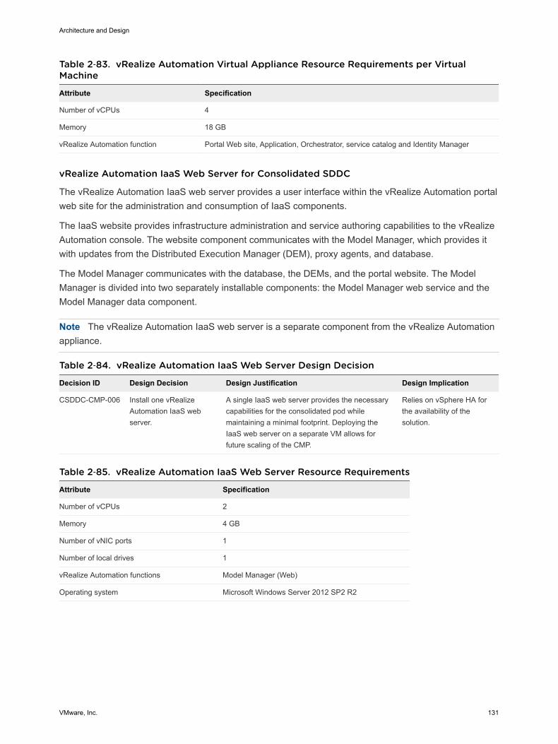
Table 2‑83. vRealize Automation Virtual Appliance Resource Requirements per VirtualMachine
Attribute Specification
Number of vCPUs 4
Memory 18 GB
vRealize Automation function Portal Web site, Application, Orchestrator, service catalog and Identity Manager
vRealize Automation IaaS Web Server for Consolidated SDDC
The vRealize Automation IaaS web server provides a user interface within the vRealize Automation portalweb site for the administration and consumption of IaaS components.
The IaaS website provides infrastructure administration and service authoring capabilities to the vRealizeAutomation console. The website component communicates with the Model Manager, which provides itwith updates from the Distributed Execution Manager (DEM), proxy agents, and database.
The Model Manager communicates with the database, the DEMs, and the portal website. The ModelManager is divided into two separately installable components: the Model Manager web service and theModel Manager data component.
Note The vRealize Automation IaaS web server is a separate component from the vRealize Automationappliance.
Table 2‑84. vRealize Automation IaaS Web Server Design Decision
Decision ID Design Decision Design Justification Design Implication
CSDDC-CMP-006 Install one vRealizeAutomation IaaS webserver.
A single IaaS web server provides the necessarycapabilities for the consolidated pod whilemaintaining a minimal footprint. Deploying theIaaS web server on a separate VM allows forfuture scaling of the CMP.
Relies on vSphere HA forthe availability of thesolution.
Table 2‑85. vRealize Automation IaaS Web Server Resource Requirements
Attribute Specification
Number of vCPUs 2
Memory 4 GB
Number of vNIC ports 1
Number of local drives 1
vRealize Automation functions Model Manager (Web)
Operating system Microsoft Windows Server 2012 SP2 R2
Architecture and Design
VMware, Inc. 131
vRealize Automation IaaS Manager Service, DEM Orchestrator, DEM Worker and IaaS ProxyAgent for Consolidated SDDC
The vRealize Automation IaaS Manager Service and Distributed Execution Management (DEM) serverare at the core of the vRealize Automation IaaS platform. The vRealize Automation IaaS ManagerService and DEM server supports several functions.
n Manages the integration of vRealize Automation IaaS with external systems and databases.
n Provides business logic to the DEMs.
n Manages business logic and execution policies.
n Maintains all workflows and their supporting constructs.
A DEM server runs the business logic of custom models by interacting with other vRealize Automationcomponents as required.
Each DEM instance acts in either an Orchestrator role or a Worker role. The DEM Orchestrator monitorsthe status of the DEM Workers. If a DEM worker stops or loses the connection to the Model Manager, theDEM Orchestrator puts the workflow back in the queue. It manages the scheduled workflows by creatingnew workflow instances at the scheduled time and allows only one instance of a particular scheduledworkflow to run at a given time. It also preprocesses workflows before execution. Preprocessing includeschecking preconditions for workflows and creating the workflow's execution history.
vRealize Automation IaaS DEM Workers are responsible for the executing provisioning anddeprovisioning tasks initiated by the vRealize Automation portal. DEM Workers are also utilized tocommunicate with specific infrastructure endpoints.
The vRealize Automation IaaS Proxy Agent is a windows service used to communicate with specificinfrastructure endpoints. In this design, the vSphere Proxy agent is utilized to communicate with vCenter.
The IaaS Proxy Agent server provides the following functions:
n vRealize Automation IaaS Proxy Agent can interact with different types of infrastructure components.For this design, only the vSphere Proxy agent is used.
n vRealize Automation does not itself virtualize resources, but works with vSphere to provision andmanage the virtual machines. It uses vSphere Proxy agents to send commands to and collect datafrom vSphere.
Note The vRealize Automation IaaS Manager, DEM Orchestrator, DEM Worker and IaaS Proxy Agentare separate services, but in this design they are all installed on the same virtual machine.
Architecture and Design
VMware, Inc. 132

Table 2‑86. vRealize Automation IaaS Model Manager and DEM Orchestrator Server DesignDecision
Decision ID Design Decision Design Justification Design Implication
CSDDC-CMP-007 Deploy one virtual machine to runthe vRealize AutomationManager Service, the DEMOrchestrator, the DEM Worker,and IaaS Proxy Agent services.
Co-locating the Manager service, DEMOrchestrator, DEM Worker and the IaaSProxy Agent on a single VM provides theminimal footprint required for theconsolidated pod. This design also providesfor future expansion of the CMP to providefull application level HA.
Relies on vSphere HA forhigh availability of theapplication.
Table 2‑87. vRealize Automation IaaS Model Manager and DEM Orchestrator ServerResource Requirements per Virtual Machine
Attribute Specification
Number of vCPUs 4
Memory 8 GB
Number of vNIC ports 1
Number of local drives 1
vRealize Automation functions Manager Service, DEM Orchestrator, DEM Worker and IaaS ProxyAgent.
Operating system Microsoft Windows Server 2012 SP2 R2
Load Balancer for Consolidated SDDC
Session persistence of a load balancer allows the same server to serve all requests after a session isestablished with that server. Session persistence is enabled on the load balancer to direct subsequentrequests from each unique session to the same vRealize Automation server in the load balancer pool.
Table 2‑88. Load Balancer Design Decisions
Decision ID Design Decision Design Justification Design Implication
CSDDC-CMP-008
Set up an NSX edge device for loadbalancing the vRealize Automationservices.
Enabling this design with a load balancer allowsfor a future expansion of the CMP withapplication-level HA.
You must use NSX tosupport this loadbalancingconfiguration.
CSDDC-CMP-009
Configure a load balancer for use byvRealize Automation ServerAppliance, Remote Console Proxy,and IaaS Web to use the round-robinalgorithm with Source-IP basedpersistence and a 1800 secondtimeout.
The round-robin algorithm provides a goodbalance of clients between both appliances,while Source-IP ensures that individual clientsremain connected to the same appliance. The1800 second timeout aligns with the vRealizeAutomation Appliance Server sessions timeoutvalue. Sessions that transfer to a differentvRealize Automation appliance may result in apoor user experience.
None
CSDDC-CMP-010
Configure load balancer for vRealizeAutomation IaaS Manager Service toutilize round-robin algorithm withoutpersistence.
The Manager Service does not need sessionpersistence.
None
Architecture and Design
VMware, Inc. 133

Consider the following load balancer characteristics for vRealize Automation.
Table 2‑89. Load Balancer Application Profile Characteristics
Server Role Type Enable SSL Pass-through Persistence Expires in (Seconds)
vRealize Automation - Persistence HTTPS (443) Enabled Source IP 1800
vRealize Automation HTTPS (443) Enabled
Table 2‑90. Load Balancer Service Monitoring Characteristics
Monitor Interval TimeoutMaxRetries Type Expected Method URL Receive
vRealizeAutomationAppliance
3 10 3 HTTPS 204 GET /vcac/services/api/health
vRealizeAutomationIaaS Web
3 10 3 HTTPS GET /wapi/api/status/web REGISTERED
vRealizeAutomationIaaS Manager
3 10 3 HTTPS GET /VMPSProvision ProvisionService
EmbeddedvRealizeOrchestratorControl Center
3 10 3 HTTPS GET /vco-controlcenter/docs
Table 2‑91. Load Balancer Pool Characteristics
Server Role Algorithm Monitor Members Port Monitor Port
vRealize AutomationAppliance
Round Robin vRealize AutomationAppliance monitor
vRealize AutomationAppliance nodes
443 443
vRealize Automation RemoteConsole Proxy
Round Robin vRealize AutomationAppliance monitor
vRealize AutomationAppliance nodes
8444 443
vRealize Automation IaaSWeb
Round Robin vRealize Automation IaaSWeb monitor
IaaS web nodes 443 443
vRealize Automation IaaSManager
Round Robin vRealize Automation IaaSManager monitor
IaaS Manager nodes 443 443
Embedded vRealizeOrchestrator Control Center
Round Robin Embedded vRealizeOrchestrator Control Centermonitor
vRealize AutomationAppliance nodes
8283 8283
Table 2‑92. Virtual Server Characteristics
Protocol Port Default Pool Application Profile
HTTPS 443 vRealize Automation Appliance Pool vRealize Automation - Persistence Profile
HTTPS 443 vRealize Automation IaaS Web Pool vRealize Automation - Persistence Profile
HTTPS 443 vRealize Automation IaaS Manager Pool vRealize Automation Profile
Architecture and Design
VMware, Inc. 134

Table 2‑92. Virtual Server Characteristics (Continued)
Protocol Port Default Pool Application Profile
HTTPS 8444 vRealize Automation Remote Console Proxy Pool vRealize Automation - Persistence Profile
HTTPS 8283 Embedded vRealize Orchestrator Control Center Pool vRealize Automation - Persistence Profile
Information Security and Access Control in vRealize Automation for Consolidated SDDC
You use a service account for authentication and authorization of vRealize Automation to both vCenterServer and vRealize Operations Manager for orchestrating and creating virtual objects in the SDDC.
Table 2‑93. Authorization and Authentication Management for vRealize Automation DesignDecisions
Decision ID Design Decision Design Justification Design Implication
CSDDC-CMP-011
Configure the service accountsvc-vra in vCenter Server forapplication-to-applicationcommunication from vRealizeAutomation with vSphere.
You can introduce improved accountabilityin tracking request-response interactionsbetween the components of the SDDC.
You must maintain the serviceaccount's life cycle outside ofthe SDDC stack to ensure itsavailability
CSDDC-CMP-012
Use local permissions when youcreate the svc-vra serviceaccount in vCenter Server.
The use of local permissions ensures thatonly the Compute vCenter Server instancesare valid and accessible endpoints fromvRealize Automation.
If you deploy more ComputevCenter Server instances, youmust ensure that the serviceaccount has been assignedlocal permissions in eachvCenter Server so that thisvCenter Server is a viableendpoint within vRealizeAutomation.
CSDDC-CMP-013
Configure the service accountsvc-vra-vrops on vRealizeOperations Manager forapplication-to-applicationcommunication from vRealizeAutomation for collecting healthand resource metrics for tenantworkload reclamation.
n vRealize Automation accessesvRealize Operations Manager with theminimum set of permissions that arerequired for collecting metrics todetermine the workloads that arepotential candidates for reclamation.
n In the event of a compromised account,the accessibility in the destinationapplication remains restricted.
n You can introduce improvedaccountability in tracking request-response interactions between thecomponents of the SDDC.
You must maintain the serviceaccount's life cycle outside ofthe SDDC stack to ensure itsavailability.
vRealize Automation Supporting Infrastructure for Consolidated SDDCTo satisfy the requirements of this SDDC design, you configure additional components for vRealizeAutomation such as database servers for highly available database service, email server for notification,and vRealize Business for cost management.
Architecture and Design
VMware, Inc. 135
Microsoft SQL Server Database for Consolidated SDDC
vRealize Automation uses a Microsoft SQL Server database to store data relating to the vRealizeAutomation IaaS elements including information about the machines that vRealize Automation manages.
Table 2‑94. vRealize Automation SQL Database Design Decisions
Decision ID Design Decision Design Justification Design Implication
CSDDC-CMP-014
Set up a Microsoft SQL serverthat supports the availability andI/O needs of vRealizeAutomation.
A dedicated or shared SQL server can beused so long as it meets the requirementsof vRealize Automation.
Requires additional resourcesfor managing Microsoft SQL andlicenses.
CSDDC-CMP-015
Use the existing cross-regionapplication virtual network forthe Microsoft SQL server.
Provides a consistent deployment modelfor management applications and ensuresgrowth to two pod design is viable.
Requires implementation of NSXto support this networkconfiguration.
CSDDC-CMP-016
Set up Microsoft SQL serverwith separate OS volumes forSQL Data, Transaction Logs,TempDB, and Backup.
While each organization might have theirown best practices in the deployment andconfiguration of Microsoft SQL server,high level best practices recommendseparation of database data files anddatabase transaction logs.
Requires consultation with theMicrosoft SQL databaseadministrators of theorganization for guidance aboutproduction deployment in yourenvironment.
Table 2‑95. vRealize Automation SQL Database Server Resource Requirements per VM
Attribute Specification
Number of vCPUs 8
Memory 16 GB
Number of vNIC ports 1
Number of local drives 1
40 GB (D:) (Application)
40 GB (E:) Database Data
20 GB (F:) Database Log
20 GB (G:) TempDB
80 GB (H:) Backup
vRealize Automation functions Microsoft SQL Server Database
Microsoft SQL Version SQL Server 2012
Microsoft SQL Database Version SQL Server 2012 (110)
Operating system Microsoft Windows Server 2012 R2
PostgreSQL Database Server for Consolidated SDDC
The vRealize Automation appliance uses a PostgreSQL database server to maintain the vRealizeAutomation portal elements and services, the information about the catalog items that the appliancemanages and the vRealize Orchestrator (embedded instance) configuration and workflows.
Architecture and Design
VMware, Inc. 136

Table 2‑96. vRealize Automation PostgreSQL Database Design Decision
Decision ID Design Decision Design Justification Design Implication
CSDDC-CMP-017 Use the embedded PostgreSQLdatabase within the vRealizeAutomation appliance.
Simplifies the design and enables replication ofthe database across the two vRealize Automationappliances for a future full HA implementation.
None.
Notification Email Server for Consolidated SDDC
vRealize Automation notification emails are sent using SMTP. These emails include notification ofmachine creation, expiration, and the notification of approvals received by users. vRealize Automationsupports both anonymous connections to the SMTP server and connections using basic authentication.vRealize Automation also supports communication with or without SSL.
You create a global, inbound email server to handle inbound email notifications, such as approvalresponses. Only one, global inbound email server, which appears as the default for all tenants, is needed.The email server provides accounts that you can customize for each user, providing separate emailaccounts, usernames, and passwords. Each tenant can override these settings. If tenant administratorsdo not override these settings before enabling notifications, vRealize Automation uses the globallyconfigured email server. The server supports both the POP and the IMAP protocol, with or without SSLcertificates.
Notifications for Consolidated SDDC
System administrators configure default settings for both the outbound and inbound emails servers usedto send system notifications. Systems administrators can create only one of each type of server thatappears as the default for all tenants. If tenant administrators do not override these settings beforeenabling notifications, vRealize Automation uses the globally configured email server.
System administrators create a global outbound email server to process outbound email notifications, anda global inbound email server to process inbound email notifications, such as responses to approvals.
Table 2‑97. vRealize Automation Email Server Configuration
Decision ID Design Decision Design Justification Design Implication
CSDDC-CMP-018
Configure vRealize Automation to use aglobal outbound email server to handleoutbound email notifications and aglobal inbound email server to handleinbound email notifications, such asapproval responses.
Requirement to integratevRealize Automationapprovals and systemnotifications throughemails.
Must prepare the SMTP/IMAP serverand necessary firewall access andcreate a mailbox for inbound emails(IMAP), and anonymous access canbe used with outbound emails.
vRealize Automation Cloud Tenant Design for Consolidated SDDCA tenant is an organizational unit within a vRealize Automation deployment, and can represent a businessunit within an enterprise, or a company that subscribes to cloud services from a service provider. Eachtenant has its own dedicated configuration, although some system-level configuration is shared acrosstenants.
Architecture and Design
VMware, Inc. 137
Comparison of Single-Tenant and Multi-Tenant Deployments for Consolidated SDDC
vRealize Automation supports deployments with a single tenant or multiple tenants. System-wideconfiguration is always performed using the default tenant, and can then be applied to one or moretenants. For example, system-wide configuration might specify defaults for branding and notificationproviders.
Infrastructure configuration, including the infrastructure sources that are available for provisioning, can beconfigured in any tenant and is shared among all tenants. The infrastructure resources, such as cloud orvirtual compute resources or physical machines, can be divided into fabric groups managed by fabricadministrators. The resources in each fabric group can be allocated to business groups within eachtenant by using reservations.
Default-TenantDeployment
In a default-tenant deployment, all configuration occurs in the defaulttenant. Tenant administrators can manage users and groups, and configuretenant-specific branding, notifications, business policies, and catalogofferings. All users log in to the vRealize Automation console at the sameURL, but the features available to them are determined by their roles.
Single-TenantDeployment
In a single-tenant deployment, the system administrator creates a singlenew tenant for the organization that use the same vRealize Automationinstance. Tenant users log in to the vRealize Automation console at a URLspecific to their tenant. Tenant-level configuration is segregated from thedefault tenant, although users with system-wide roles can view andmanage both configurations. The IaaS administrator for the organizationtenant creates fabric groups and appoints fabric administrators. Fabricadministrators can create reservations for business groups in theorganization tenant.
Multi-TenantDeployment
In a multi-tenant deployment, the system administrator creates new tenantsfor each organization that uses the same vRealize Automation instance.Tenant users log in to the vRealize Automation console at a URL specific totheir tenant. Tenant-level configuration is segregated from other tenantsand from the default tenant, although users with system-wide roles canview and manage configuration across multiple tenants. The IaaSadministrator for each tenant creates fabric groups and appoints fabricadministrators to their respective tenants. Although fabric administratorscan create reservations for business groups in any tenant, in this scenariothey typically create and manage reservations within their own tenants. Ifthe same identity store is configured in multiple tenants, the same userscan be designated as IaaS administrators or fabric administrators for eachtenant.
Tenant Design for Consolidated SDDC
This design deploys a single tenant containing two business groups.
n The first business group is designated for production workloads provisioning.
Architecture and Design
VMware, Inc. 138

n The second business group is designated for development workloads provisioning.
Tenant administrators manage users and groups, configure tenant-specific branding, notifications,business policies, and catalog offerings. All users log in to the vRealize Automation console at the sameURL, but the features available to them are determined by their roles.
Figure 2‑23. Rainpole Cloud Automation Tenant Design for Consolidated SDDC
Production Business Group
Rainpole Tenanthttps://vra.mycompany.com/vcac/org/rainpole
Business Group Manager
Development Business Group
TenantAdminBusiness Group
Manager
Fabric Admin
IaaSAdmin
ProdReservation
DevReservation
EdgeReservation
Fabric Group
Consolidated SDDCData Center Infrastructure Fabric
https://vra.mycompany.com/vcac
• Tenant Creation• System Branding• System Notification Providers• Event LogsSystem Admin
Default Tenant
Table 2‑98. Tenant Design Decisions
Decision ID Design Decision Design Justification Design Implication
CSDDC-CMP-019
Uses vRealize Automation businessgroups for separate business units(instead of separate tenants).
Using separate business groups allowstransparency across environments, andsome level of sharing resources andservices such as blueprints.
Some elements, such asproperty groups, arevisible to both businessgroups.
CSDDC-CMP-020
Create a single fabric group for theconsolidated pod. Each of the businessgroups have reservations into this fabricgroup.
Provides future isolation of fabricresources and potential delegation ofduty to independent fabricadministrators.
None.
Architecture and Design
VMware, Inc. 139
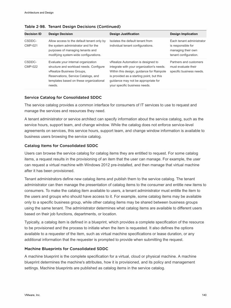
Table 2‑98. Tenant Design Decisions (Continued)
Decision ID Design Decision Design Justification Design Implication
CSDDC-CMP-021
Allow access to the default tenant only bythe system administrator and for thepurposes of managing tenants andmodifying system-wide configurations.
Isolates the default tenant fromindividual tenant configurations.
Each tenant administratoris responsible formanaging their owntenant configuration.
CSDDC-CMP-022
Evaluate your internal organizationstructure and workload needs. ConfigurevRealize Business Groups,Reservations, Service Catalogs, andtemplates based on these organizationalneeds.
vRealize Automation is designed tointegrate with your organization's needs.Within this design, guidance for Rainpoleis provided as a starting point, but thisguidance may not be appropriate foryour specific business needs.
Partners and customersmust evaluate theirspecific business needs.
Service Catalog for Consolidated SDDC
The service catalog provides a common interface for consumers of IT services to use to request andmanage the services and resources they need.
A tenant administrator or service architect can specify information about the service catalog, such as theservice hours, support team, and change window. While the catalog does not enforce service-levelagreements on services, this service hours, support team, and change window information is available tobusiness users browsing the service catalog.
Catalog Items for Consolidated SDDC
Users can browse the service catalog for catalog items they are entitled to request. For some catalogitems, a request results in the provisioning of an item that the user can manage. For example, the usercan request a virtual machine with Windows 2012 pre-installed, and then manage that virtual machineafter it has been provisioned.
Tenant administrators define new catalog items and publish them to the service catalog. The tenantadministrator can then manage the presentation of catalog items to the consumer and entitle new items toconsumers. To make the catalog item available to users, a tenant administrator must entitle the item tothe users and groups who should have access to it. For example, some catalog items may be availableonly to a specific business group, while other catalog items may be shared between business groupsusing the same tenant. The administrator determines what catalog items are available to different usersbased on their job functions, departments, or location.
Typically, a catalog item is defined in a blueprint, which provides a complete specification of the resourceto be provisioned and the process to initiate when the item is requested. It also defines the optionsavailable to a requester of the item, such as virtual machine specifications or lease duration, or anyadditional information that the requester is prompted to provide when submitting the request.
Machine Blueprints for Consolidated SDDC
A machine blueprint is the complete specification for a virtual, cloud or physical machine. A machineblueprint determines the machine's attributes, how it is provisioned, and its policy and managementsettings. Machine blueprints are published as catalog items in the service catalog.
Architecture and Design
VMware, Inc. 140
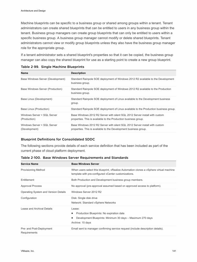
Machine blueprints can be specific to a business group or shared among groups within a tenant. Tenantadministrators can create shared blueprints that can be entitled to users in any business group within thetenant. Business group managers can create group blueprints that can only be entitled to users within aspecific business group. A business group manager cannot modify or delete shared blueprints. Tenantadministrators cannot view or modify group blueprints unless they also have the business group managerrole for the appropriate group.
If a tenant administrator sets a shared blueprint's properties so that it can be copied, the business groupmanager can also copy the shared blueprint for use as a starting point to create a new group blueprint.
Table 2‑99. Single Machine Blueprints
Name Description
Base Windows Server (Development) Standard Rainpole SOE deployment of Windows 2012 R2 available to the Developmentbusiness group.
Base Windows Server (Production) Standard Rainpole SOE deployment of Windows 2012 R2 available to the Productionbusiness group.
Base Linux (Development) Standard Rainpole SOE deployment of Linux available to the Development businessgroup.
Base Linux (Production) Standard Rainpole SOE deployment of Linux available to the Production business group.
Windows Server + SQL Server(Production)
Base Windows 2012 R2 Server with silent SQL 2012 Server install with customproperties. This is available to the Production business group.
Windows Server + SQL Server(Development)
Base Windows 2012 R2 Server with silent SQL 2012 Server install with customproperties. This is available to the Development business group.
Blueprint Definitions for Consolidated SDDC
The following sections provide details of each service definition that has been included as part of thecurrent phase of cloud platform deployment.
Table 2‑100. Base Windows Server Requirements and Standards
Service Name Base Windows Server
Provisioning Method When users select this blueprint, vRealize Automation clones a vSphere virtual machinetemplate with pre-configured vCenter customizations.
Entitlement Both Production and Development business group members.
Approval Process No approval (pre-approval assumed based on approved access to platform).
Operating System and Version Details Windows Server 2012 R2
Configuration Disk: Single disk drive
Network: Standard vSphere Networks
Lease and Archival Details Lease:n Production Blueprints: No expiration daten Development Blueprints: Minimum 30 days – Maximum 270 days
Archive: 15 days
Pre- and Post-DeploymentRequirements
Email sent to manager confirming service request (include description details).
Architecture and Design
VMware, Inc. 141
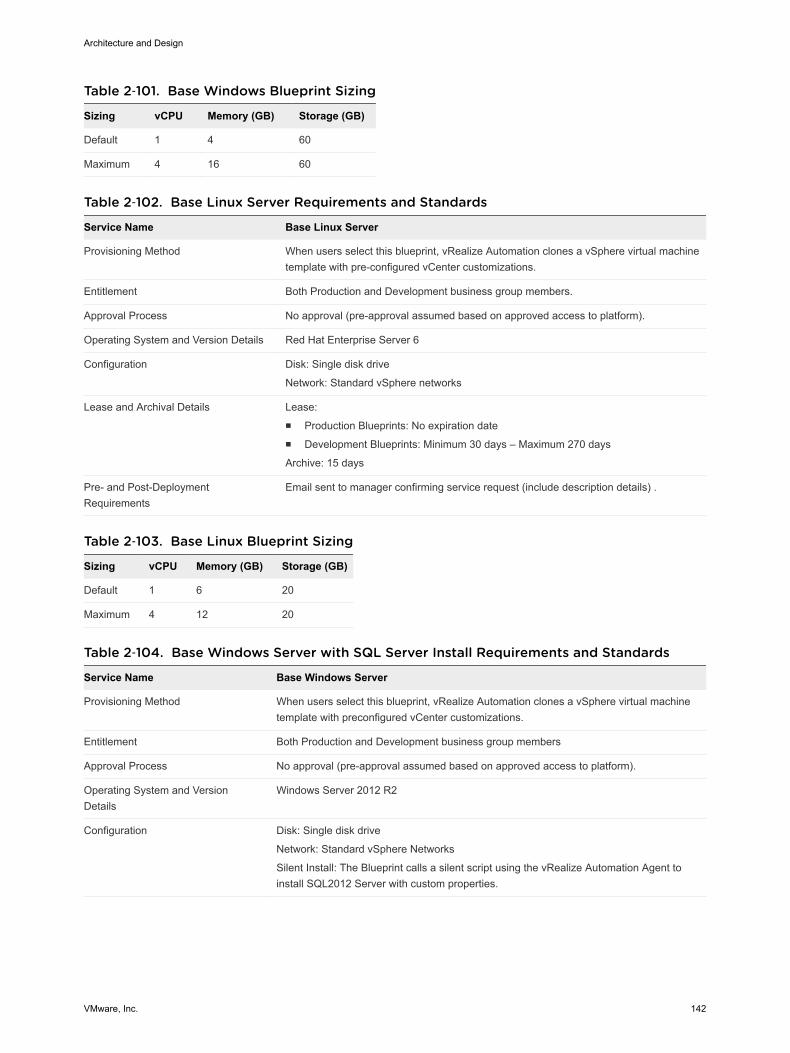
Table 2‑101. Base Windows Blueprint Sizing
Sizing vCPU Memory (GB) Storage (GB)
Default 1 4 60
Maximum 4 16 60
Table 2‑102. Base Linux Server Requirements and Standards
Service Name Base Linux Server
Provisioning Method When users select this blueprint, vRealize Automation clones a vSphere virtual machinetemplate with pre-configured vCenter customizations.
Entitlement Both Production and Development business group members.
Approval Process No approval (pre-approval assumed based on approved access to platform).
Operating System and Version Details Red Hat Enterprise Server 6
Configuration Disk: Single disk drive
Network: Standard vSphere networks
Lease and Archival Details Lease:n Production Blueprints: No expiration daten Development Blueprints: Minimum 30 days – Maximum 270 days
Archive: 15 days
Pre- and Post-DeploymentRequirements
Email sent to manager confirming service request (include description details) .
Table 2‑103. Base Linux Blueprint Sizing
Sizing vCPU Memory (GB) Storage (GB)
Default 1 6 20
Maximum 4 12 20
Table 2‑104. Base Windows Server with SQL Server Install Requirements and Standards
Service Name Base Windows Server
Provisioning Method When users select this blueprint, vRealize Automation clones a vSphere virtual machinetemplate with preconfigured vCenter customizations.
Entitlement Both Production and Development business group members
Approval Process No approval (pre-approval assumed based on approved access to platform).
Operating System and VersionDetails
Windows Server 2012 R2
Configuration Disk: Single disk drive
Network: Standard vSphere Networks
Silent Install: The Blueprint calls a silent script using the vRealize Automation Agent toinstall SQL2012 Server with custom properties.
Architecture and Design
VMware, Inc. 142
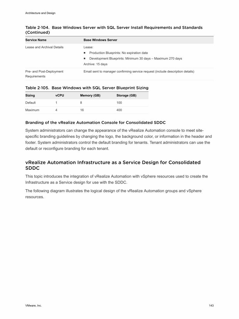
Table 2‑104. Base Windows Server with SQL Server Install Requirements and Standards(Continued)
Service Name Base Windows Server
Lease and Archival Details Lease:n Production Blueprints: No expiration daten Development Blueprints: Minimum 30 days – Maximum 270 days
Archive: 15 days
Pre- and Post-DeploymentRequirements
Email sent to manager confirming service request (include description details)
Table 2‑105. Base Windows with SQL Server Blueprint Sizing
Sizing vCPU Memory (GB) Storage (GB)
Default 1 8 100
Maximum 4 16 400
Branding of the vRealize Automation Console for Consolidated SDDC
System administrators can change the appearance of the vRealize Automation console to meet site-specific branding guidelines by changing the logo, the background color, or information in the header andfooter. System administrators control the default branding for tenants. Tenant administrators can use thedefault or reconfigure branding for each tenant.
vRealize Automation Infrastructure as a Service Design for ConsolidatedSDDCThis topic introduces the integration of vRealize Automation with vSphere resources used to create theInfrastructure as a Service design for use with the SDDC.
The following diagram illustrates the logical design of the vRealize Automation groups and vSphereresources.
Architecture and Design
VMware, Inc. 143
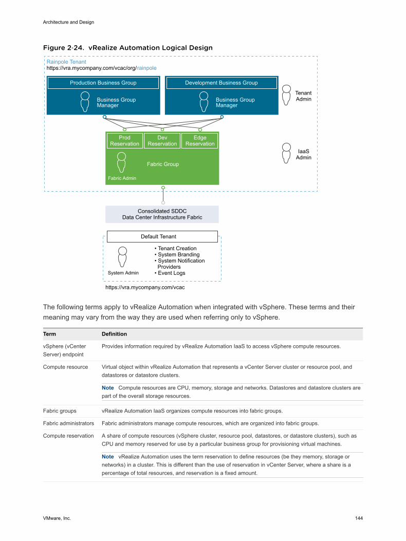
Figure 2‑24. vRealize Automation Logical Design
Production Business Group
Rainpole Tenanthttps://vra.mycompany.com/vcac/org/rainpole
Business Group Manager
Development Business Group
TenantAdminBusiness Group
Manager
Fabric Admin
IaaSAdmin
ProdReservation
DevReservation
EdgeReservation
Fabric Group
Consolidated SDDCData Center Infrastructure Fabric
https://vra.mycompany.com/vcac
• Tenant Creation• System Branding• System Notification Providers• Event LogsSystem Admin
Default Tenant
The following terms apply to vRealize Automation when integrated with vSphere. These terms and theirmeaning may vary from the way they are used when referring only to vSphere.
Term Definition
vSphere (vCenterServer) endpoint
Provides information required by vRealize Automation IaaS to access vSphere compute resources.
Compute resource Virtual object within vRealize Automation that represents a vCenter Server cluster or resource pool, anddatastores or datastore clusters.
Note Compute resources are CPU, memory, storage and networks. Datastores and datastore clusters arepart of the overall storage resources.
Fabric groups vRealize Automation IaaS organizes compute resources into fabric groups.
Fabric administrators Fabric administrators manage compute resources, which are organized into fabric groups.
Compute reservation A share of compute resources (vSphere cluster, resource pool, datastores, or datastore clusters), such asCPU and memory reserved for use by a particular business group for provisioning virtual machines.
Note vRealize Automation uses the term reservation to define resources (be they memory, storage ornetworks) in a cluster. This is different than the use of reservation in vCenter Server, where a share is apercentage of total resources, and reservation is a fixed amount.
Architecture and Design
VMware, Inc. 144

Term Definition
Storage reservation Similar to compute reservation (see above), but pertaining only to a share of the available storageresources. In this context, you specify a storage reservation in terms of gigabytes from an existing LUN orDatastore.
Business groups A collection of virtual machine consumers, usually corresponding to an organization's business units ordepartments. Only users in the business group can request virtual machines.
Reservation policy vRealize Automation IaaS determines its reservation (also called virtual reservation) from which a particularvirtual machine is provisioned. The reservation policy is a logical label or a pointer to the originalreservation. Each virtual reservation can be added to one reservation policy.
Blueprint The complete specification for a virtual machine, determining the machine attributes, the manner in which itis provisioned, and its policy and management settings.
Blueprint allows the users of a business group to create virtual machines on a virtual reservation (computeresource) based on the reservation policy, and using platform and cloning types. It also lets you specify oradd machine resources and build profiles.
Figure 2‑25 shows the logical design constructs discussed in the previous section as they apply to adeployment of vRealize Automation integrated with vSphere in the consolidated SDDC.
Architecture and Design
VMware, Inc. 145
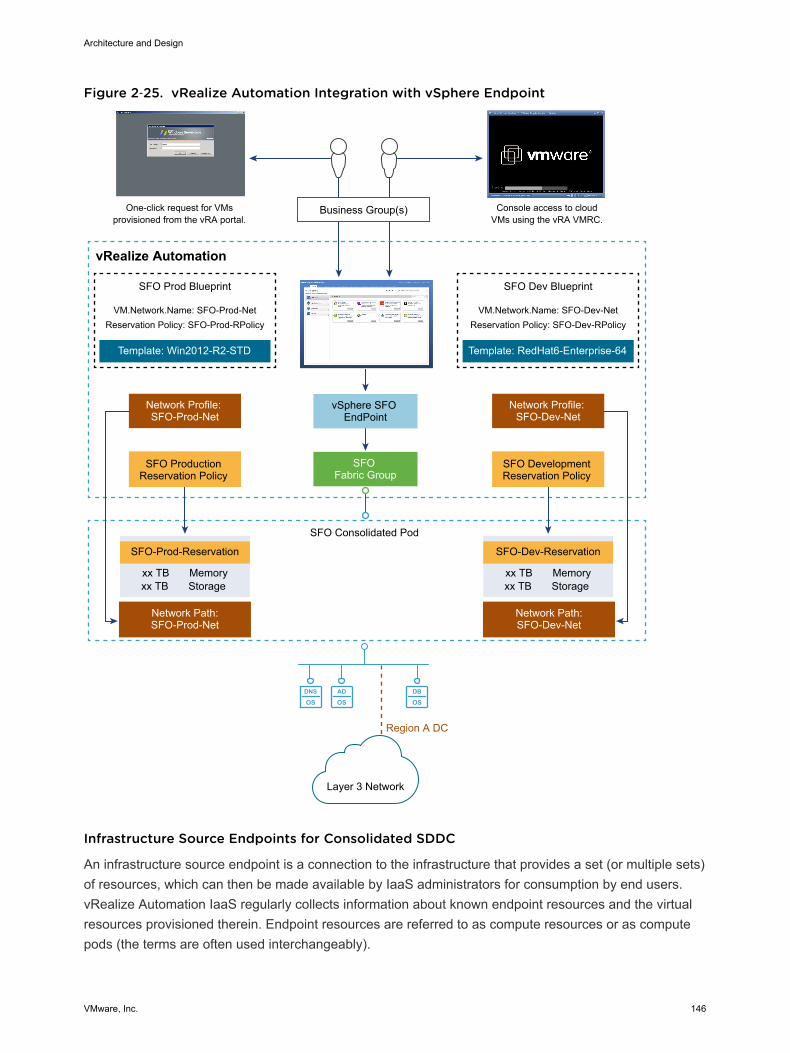
Figure 2‑25. vRealize Automation Integration with vSphere Endpoint
DNS
OSAD
OSDB
OS
Business Group(s)One-click request for VMsprovisioned from the vRA portal.
Console access to cloudVMs using the vRA VMRC.
vSphere SFO EndPoint
SFO Fabric Group
SFO Prod Blueprint
VM.Network.Name: SFO-Prod-NetReservation Policy: SFO-Prod-RPolicy
Template: Win2012-R2-STD
Network Profile: SFO-Prod-Net
vRealize Automation
Network Path:SFO-Prod-Net
SFO-Prod-Reservation
SFO Consolidated Pod
xx TB Memoryxx TB Storage
Layer 3 Network
Region A DC
SFO Dev Blueprint
VM.Network.Name: SFO-Dev-NetReservation Policy: SFO-Dev-RPolicy
Template: RedHat6-Enterprise-64
Network Profile: SFO-Dev-Net
SFO Development Reservation Policy
Network Path:SFO-Dev-Net
SFO-Dev-Reservation
xx TB Memoryxx TB Storage
SFO Production Reservation Policy
Infrastructure Source Endpoints for Consolidated SDDC
An infrastructure source endpoint is a connection to the infrastructure that provides a set (or multiple sets)of resources, which can then be made available by IaaS administrators for consumption by end users.vRealize Automation IaaS regularly collects information about known endpoint resources and the virtualresources provisioned therein. Endpoint resources are referred to as compute resources or as computepods (the terms are often used interchangeably).
Architecture and Design
VMware, Inc. 146
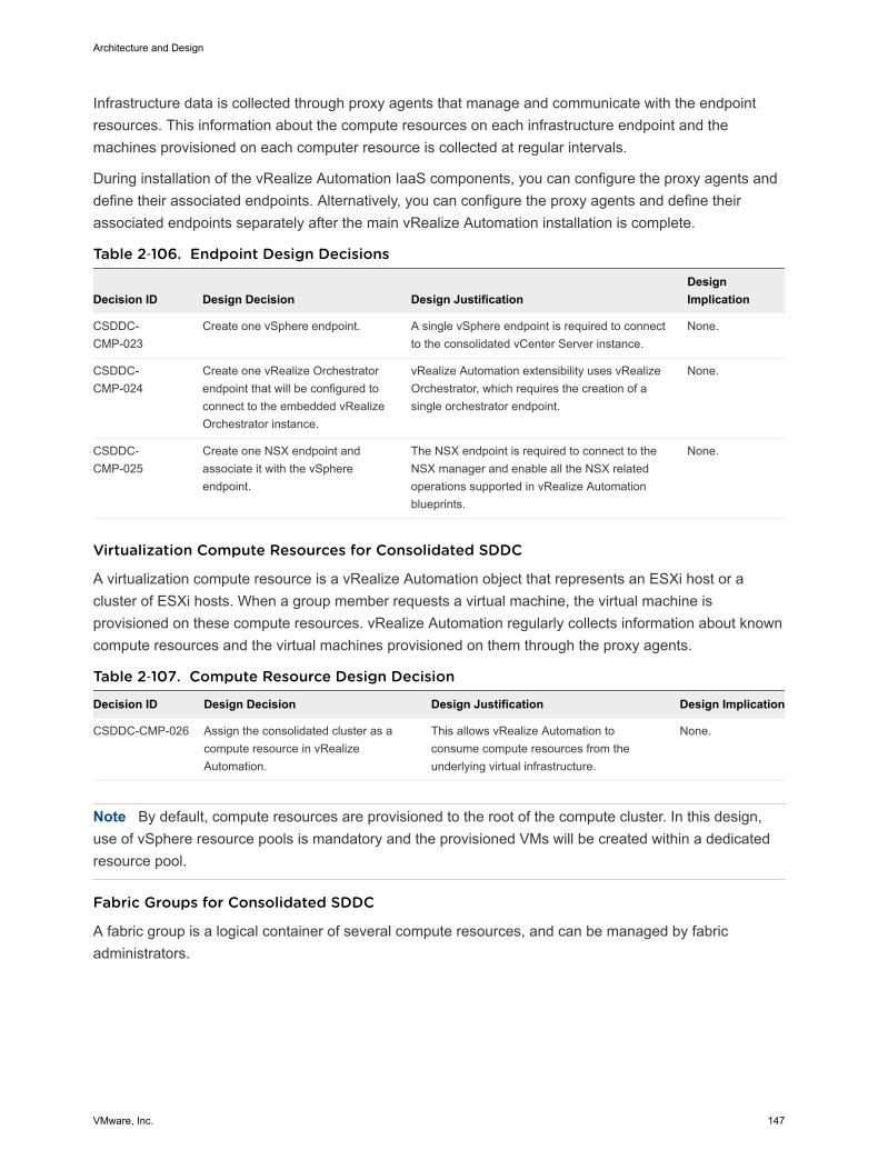
Infrastructure data is collected through proxy agents that manage and communicate with the endpointresources. This information about the compute resources on each infrastructure endpoint and themachines provisioned on each computer resource is collected at regular intervals.
During installation of the vRealize Automation IaaS components, you can configure the proxy agents anddefine their associated endpoints. Alternatively, you can configure the proxy agents and define theirassociated endpoints separately after the main vRealize Automation installation is complete.
Table 2‑106. Endpoint Design Decisions
Decision ID Design Decision Design JustificationDesignImplication
CSDDC-CMP-023
Create one vSphere endpoint. A single vSphere endpoint is required to connectto the consolidated vCenter Server instance.
None.
CSDDC-CMP-024
Create one vRealize Orchestratorendpoint that will be configured toconnect to the embedded vRealizeOrchestrator instance.
vRealize Automation extensibility uses vRealizeOrchestrator, which requires the creation of asingle orchestrator endpoint.
None.
CSDDC-CMP-025
Create one NSX endpoint andassociate it with the vSphereendpoint.
The NSX endpoint is required to connect to theNSX manager and enable all the NSX relatedoperations supported in vRealize Automationblueprints.
None.
Virtualization Compute Resources for Consolidated SDDC
A virtualization compute resource is a vRealize Automation object that represents an ESXi host or acluster of ESXi hosts. When a group member requests a virtual machine, the virtual machine isprovisioned on these compute resources. vRealize Automation regularly collects information about knowncompute resources and the virtual machines provisioned on them through the proxy agents.
Table 2‑107. Compute Resource Design Decision
Decision ID Design Decision Design Justification Design Implication
CSDDC-CMP-026 Assign the consolidated cluster as acompute resource in vRealizeAutomation.
This allows vRealize Automation toconsume compute resources from theunderlying virtual infrastructure.
None.
Note By default, compute resources are provisioned to the root of the compute cluster. In this design,use of vSphere resource pools is mandatory and the provisioned VMs will be created within a dedicatedresource pool.
Fabric Groups for Consolidated SDDC
A fabric group is a logical container of several compute resources, and can be managed by fabricadministrators.
Architecture and Design
VMware, Inc. 147

Table 2‑108. Fabric Group Design Decisions
Decision ID Design Decision Design Justification Design Implication
CSDDC-CMP-027 Create a fabric group and include allthe compute resources within theconsolidated cluster in this group.
IaaS administrators can organize virtualizationcompute resources and cloud endpoints intofabric groups by type and intent. This designrequires a single fabric group.
None.
Business Groups for Consolidated SDDC
A business group is a collection of machine consumers, often corresponding to a line of business,department, or other organizational unit. To request machines, a vRealize Automation user must belongto at least one business group. Each group has access to a set of local blueprints used to requestmachines.
Business groups have the following characteristics:
n A group must have at least one business group manager, who maintains blueprints for the group andapproves machine requests.
n Groups can contain support users, who can request and manage machines on behalf of other groupmembers.
n A vRealize Automation user can be a member of more than one Business group, and can havedifferent roles in each group.
Reservations for Consolidated SDDC
A reservation is a share of one compute resource's available memory, CPU and storage reserved for useby a particular fabric group. Each reservation is for one fabric group only but the relationship is many-to-many. A fabric group might have multiple reservations on one compute resource, or reservations onmultiple compute resources, or both.
Consolidated Cluster and Resource Pools
While reservations provide a method to allocate a portion of the cluster memory or storage withinvRealize Automation, reservations do not control how CPU and memory is allocated during periods ofcontention on the underlying vSphere compute resources. vSphere Resource Pools are utilized to controlthe allocation of CPU and memory during time of resource contention on the underlying host. To fullyutilize this, all VMs must be deployed into one of four resource pools: sfo01-w01rp-sddc-edge, sfo01-w01rp-sddc-mgmt, sfo01-w01rp-user-edge, and sfo01-w01rp-user-vm.
Resource pools in the consolidated pod
n sfo01-w01rp-sddc-edge is dedicated for datacenter level NSX Edge components and should notcontain any user workloads.
n sfo01-w01rp-sddc-mgmt is dedicated for management VMs in the consolidated SDDCimplementation.
n sfo01-w01rp-user-edge is dedicated for any statically or dynamically deployed NSX components suchas NSX Edge gateways or Load Balancers which serve specific customer workloads.
Architecture and Design
VMware, Inc. 148
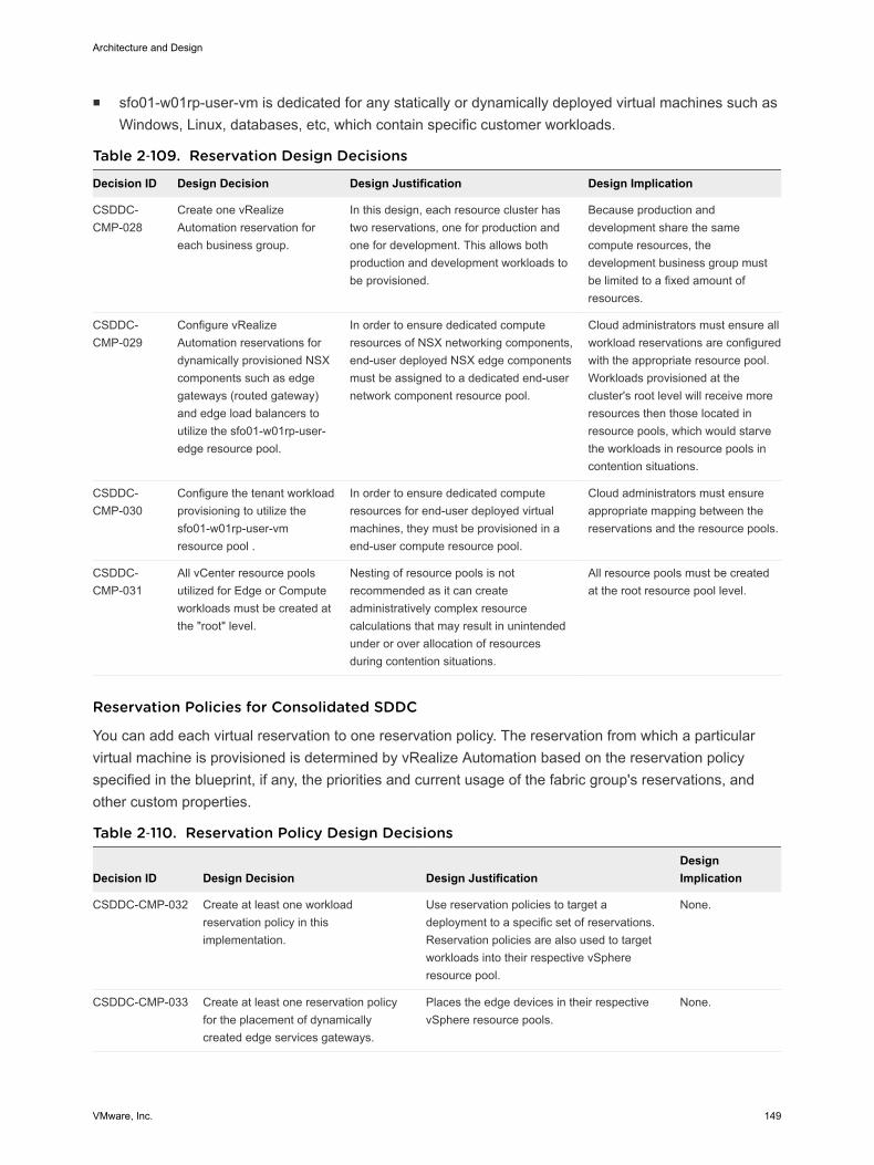
n sfo01-w01rp-user-vm is dedicated for any statically or dynamically deployed virtual machines such asWindows, Linux, databases, etc, which contain specific customer workloads.
Table 2‑109. Reservation Design Decisions
Decision ID Design Decision Design Justification Design Implication
CSDDC-CMP-028
Create one vRealizeAutomation reservation foreach business group.
In this design, each resource cluster hastwo reservations, one for production andone for development. This allows bothproduction and development workloads tobe provisioned.
Because production anddevelopment share the samecompute resources, thedevelopment business group mustbe limited to a fixed amount ofresources.
CSDDC-CMP-029
Configure vRealizeAutomation reservations fordynamically provisioned NSXcomponents such as edgegateways (routed gateway)and edge load balancers toutilize the sfo01-w01rp-user-edge resource pool.
In order to ensure dedicated computeresources of NSX networking components,end-user deployed NSX edge componentsmust be assigned to a dedicated end-usernetwork component resource pool.
Cloud administrators must ensure allworkload reservations are configuredwith the appropriate resource pool.Workloads provisioned at thecluster's root level will receive moreresources then those located inresource pools, which would starvethe workloads in resource pools incontention situations.
CSDDC-CMP-030
Configure the tenant workloadprovisioning to utilize thesfo01-w01rp-user-vmresource pool .
In order to ensure dedicated computeresources for end-user deployed virtualmachines, they must be provisioned in aend-user compute resource pool.
Cloud administrators must ensureappropriate mapping between thereservations and the resource pools.
CSDDC-CMP-031
All vCenter resource poolsutilized for Edge or Computeworkloads must be created atthe "root" level.
Nesting of resource pools is notrecommended as it can createadministratively complex resourcecalculations that may result in unintendedunder or over allocation of resourcesduring contention situations.
All resource pools must be createdat the root resource pool level.
Reservation Policies for Consolidated SDDC
You can add each virtual reservation to one reservation policy. The reservation from which a particularvirtual machine is provisioned is determined by vRealize Automation based on the reservation policyspecified in the blueprint, if any, the priorities and current usage of the fabric group's reservations, andother custom properties.
Table 2‑110. Reservation Policy Design Decisions
Decision ID Design Decision Design JustificationDesignImplication
CSDDC-CMP-032 Create at least one workloadreservation policy in thisimplementation.
Use reservation policies to target adeployment to a specific set of reservations.Reservation policies are also used to targetworkloads into their respective vSphereresource pool.
None.
CSDDC-CMP-033 Create at least one reservation policyfor the placement of dynamicallycreated edge services gateways.
Places the edge devices in their respectivevSphere resource pools.
None.
Architecture and Design
VMware, Inc. 149

A storage reservation policy is a set of datastores that can be assigned to a machine blueprint to restrictdisk provisioning to only those datastores. Storage reservation policies are created and associated withthe appropriate datastores and assigned to reservations.
Table 2‑111. Storage Reservation Policy Design Decisions
Decision ID Design Decision Design Justification Design Implication
CSDDC-CMP-034 Within this design,storage tiers are notused.
The underlying physicalstorage design does not usestorage tiers.
Both business groups will have access to thesame storage.
For customers who utilize multiple datastoreswith different storage capabilities will need toevaluate the usage of vRealize AutomationStorage Reservation Policies.
VMware Identity Manager for Consolidated SDDC
The VMware Identity Manager is integrated directly into the vRealize Automation appliance and providestenant identity management.
The VMware Identity Manager service synchronizes directly with the Rainpole Active Directory domain.Important users and groups are synced with the Identity Manager. Authentication always takes placeagainst the Active Directory domain, but searches are made against the local Active Directory mirror onthe vRealize Automation appliance.
Table 2‑112. Active Directory Authentication Decision
Decision ID Design Decision Design Justification Design Implication
CSDDC-CMP-035
Choose Active Directory withIntegrated WindowsAuthentication as the DirectoryService connection option.
Rainpole uses a single-forest, multiple-domain Active Directory environment.
Integrated Windows Authenticationsupports establishing trust relationships in amulti-domain or multi-forest Active Directoryenvironment.
Requires that the vRealizeAutomation appliance isjoined to the Active Directorydomain.
By default, the vRealize Automation appliance is initially configured with 18 GB of memory, which isenough to support a small Active Directory environment. An Active Directory environment is consideredsmall if it fewer than 25,000 users in the organizational unit (OU) have to be synced. An Active Directoryenvironment with more than 25,000 users is considered large and needs additional memory and CPU.See the vRealize Automation sizing guidelines for details.
The connector is a component of the vRealize Automation service and performs the synchronization ofusers and groups between Active Directory and the vRealize Automation service. In addition, theconnector is the default identity provider and authenticates users to the service.
Architecture and Design
VMware, Inc. 150
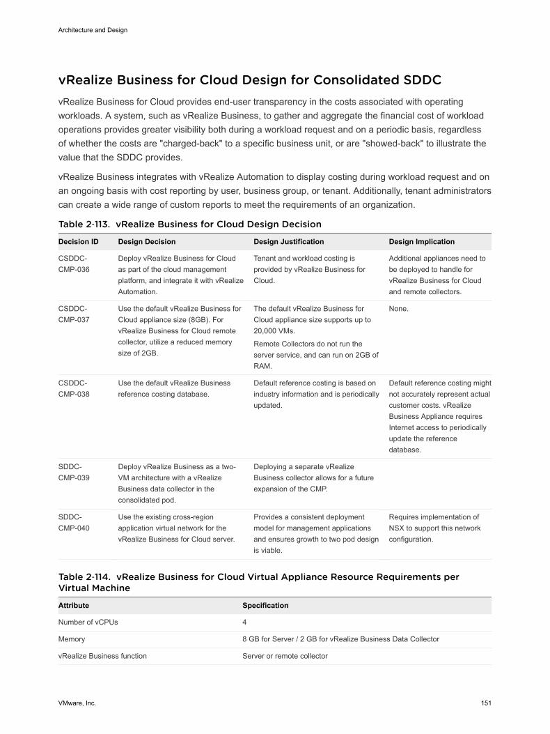
vRealize Business for Cloud Design for Consolidated SDDCvRealize Business for Cloud provides end-user transparency in the costs associated with operatingworkloads. A system, such as vRealize Business, to gather and aggregate the financial cost of workloadoperations provides greater visibility both during a workload request and on a periodic basis, regardlessof whether the costs are "charged-back" to a specific business unit, or are "showed-back" to illustrate thevalue that the SDDC provides.
vRealize Business integrates with vRealize Automation to display costing during workload request and onan ongoing basis with cost reporting by user, business group, or tenant. Additionally, tenant administratorscan create a wide range of custom reports to meet the requirements of an organization.
Table 2‑113. vRealize Business for Cloud Design Decision
Decision ID Design Decision Design Justification Design Implication
CSDDC-CMP-036
Deploy vRealize Business for Cloudas part of the cloud managementplatform, and integrate it with vRealizeAutomation.
Tenant and workload costing isprovided by vRealize Business forCloud.
Additional appliances need tobe deployed to handle forvRealize Business for Cloudand remote collectors.
CSDDC-CMP-037
Use the default vRealize Business forCloud appliance size (8GB). ForvRealize Business for Cloud remotecollector, utilize a reduced memorysize of 2GB.
The default vRealize Business forCloud appliance size supports up to20,000 VMs.
Remote Collectors do not run theserver service, and can run on 2GB ofRAM.
None.
CSDDC-CMP-038
Use the default vRealize Businessreference costing database.
Default reference costing is based onindustry information and is periodicallyupdated.
Default reference costing mightnot accurately represent actualcustomer costs. vRealizeBusiness Appliance requiresInternet access to periodicallyupdate the referencedatabase.
SDDC-CMP-039
Deploy vRealize Business as a two-VM architecture with a vRealizeBusiness data collector in theconsolidated pod.
Deploying a separate vRealizeBusiness collector allows for a futureexpansion of the CMP.
SDDC-CMP-040
Use the existing cross-regionapplication virtual network for thevRealize Business for Cloud server.
Provides a consistent deploymentmodel for management applicationsand ensures growth to two pod designis viable.
Requires implementation ofNSX to support this networkconfiguration.
Table 2‑114. vRealize Business for Cloud Virtual Appliance Resource Requirements perVirtual Machine
Attribute Specification
Number of vCPUs 4
Memory 8 GB for Server / 2 GB for vRealize Business Data Collector
vRealize Business function Server or remote collector
Architecture and Design
VMware, Inc. 151

vRealize Orchestrator Design for Consolidated SDDCVMware vRealize Orchestrator is a development and process automation platform that provides a libraryof extensible workflows to allow you to create and run automated, configurable processes to manage theVMware vSphere infrastructure as well as other VMware and third-party technologies.
In this VMware Validated Design, vRealize Automation uses the vRealize Orchestrator plug-in to connectto vCenter Server for customized virtual machine provisioning and post-provisioning actions.
vRealize Orchestrator Logical Design for Consolidated SDDCThis VMware Validated Design uses the vRealize Orchestrator instance that is embedded within thevRealize Automation appliance, instead of using a dedicated or external vRealize Orchestrator instance.
Table 2‑115. vRealize Orchestrator Deployment Design Decision
Decision ID Design Decision Design Justification Design Implication
CSDDC-CMP-VRO-01
Use the vRealizeOrchestrator instance thatis embedded within thevRealize Automationappliance.
The use of embedded vRealize Orchestratorprovides the following advantages:n Faster time to value.n Reduced number of appliances to manage.n Easier upgrade path and better support-
ability.n Performance improvements.n Removes the need for an external database.
Overall simplification of thedesign leading to a reducednumber of appliances andenhanced support-ability.
vRealize Orchestrator Authentication for Consolidated SDDC
The embedded vRealize Orchestrator only supports the following authentication method:
n vRealize Automation Authentication
Architecture and Design
VMware, Inc. 152
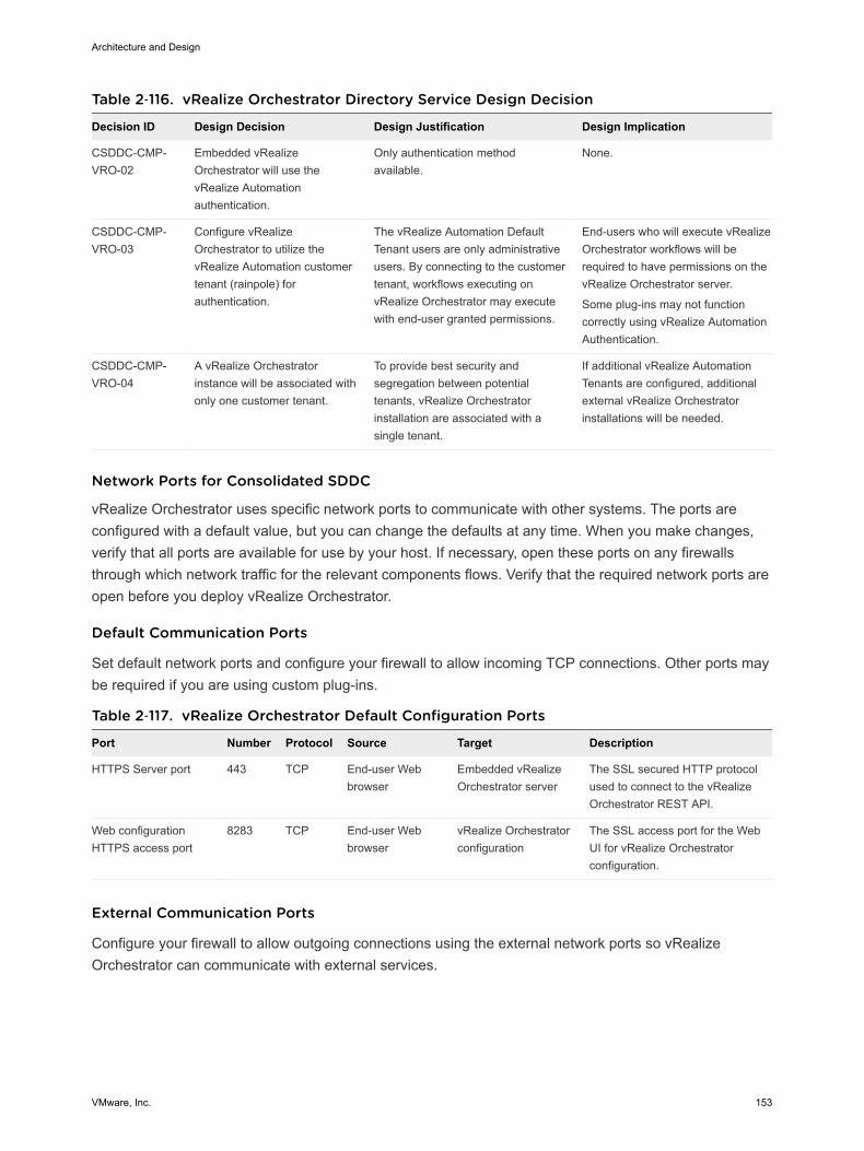
Table 2‑116. vRealize Orchestrator Directory Service Design Decision
Decision ID Design Decision Design Justification Design Implication
CSDDC-CMP-VRO-02
Embedded vRealizeOrchestrator will use thevRealize Automationauthentication.
Only authentication methodavailable.
None.
CSDDC-CMP-VRO-03
Configure vRealizeOrchestrator to utilize thevRealize Automation customertenant (rainpole) forauthentication.
The vRealize Automation DefaultTenant users are only administrativeusers. By connecting to the customertenant, workflows executing onvRealize Orchestrator may executewith end-user granted permissions.
End-users who will execute vRealizeOrchestrator workflows will berequired to have permissions on thevRealize Orchestrator server.
Some plug-ins may not functioncorrectly using vRealize AutomationAuthentication.
CSDDC-CMP-VRO-04
A vRealize Orchestratorinstance will be associated withonly one customer tenant.
To provide best security andsegregation between potentialtenants, vRealize Orchestratorinstallation are associated with asingle tenant.
If additional vRealize AutomationTenants are configured, additionalexternal vRealize Orchestratorinstallations will be needed.
Network Ports for Consolidated SDDC
vRealize Orchestrator uses specific network ports to communicate with other systems. The ports areconfigured with a default value, but you can change the defaults at any time. When you make changes,verify that all ports are available for use by your host. If necessary, open these ports on any firewallsthrough which network traffic for the relevant components flows. Verify that the required network ports areopen before you deploy vRealize Orchestrator.
Default Communication Ports
Set default network ports and configure your firewall to allow incoming TCP connections. Other ports maybe required if you are using custom plug-ins.
Table 2‑117. vRealize Orchestrator Default Configuration Ports
Port Number Protocol Source Target Description
HTTPS Server port 443 TCP End-user Webbrowser
Embedded vRealizeOrchestrator server
The SSL secured HTTP protocolused to connect to the vRealizeOrchestrator REST API.
Web configurationHTTPS access port
8283 TCP End-user Webbrowser
vRealize Orchestratorconfiguration
The SSL access port for the WebUI for vRealize Orchestratorconfiguration.
External Communication Ports
Configure your firewall to allow outgoing connections using the external network ports so vRealizeOrchestrator can communicate with external services.
Architecture and Design
VMware, Inc. 153

Table 2‑118. vRealize Orchestrator Default External Communication Ports
Port Number Protocol Source Target Description
LDAP 389 TCP vRealizeOrchestrator server
LDAP server Lookup port of your LDAP authenticationserver.
LDAP using SSL 636 TCP vRealizeOrchestrator server
LDAP server Lookup port of your secure LDAPauthentication server.
LDAP using GlobalCatalog
3268 TCP vRealizeOrchestrator server
Global Catalogserver
Port to which Microsoft Global Catalogserver queries are directed.
DNS 53 TCP vRealizeOrchestrator server
DNS server Name resolution
VMware vCenter™Single Sign-Onserver
7444 TCP vRealizeOrchestrator server
vCenter SingleSign-On server
Port used to communicate with thevCenter Single Sign-On server.
SQL Server 1433 TCP vRealizeOrchestrator server
Microsoft SQLserver
Port used to communicate with theMicrosoft SQL Server or SQL ServerExpress instances that are configured asthe vRealize Orchestrator database.
PostgreSQL 5432 TCP vRealizeOrchestrator server
PostgreSQL server Port used to communicate with thePostgreSQL Server that is configured asthe vRealize Orchestrator database.
Oracle 1521 TCP vRealizeOrchestrator server
Oracle DB server Port used to communicate with theOracle Database Server that isconfigured as the vRealize Orchestratordatabase.
SMTP Server port 25 TCP vRealizeOrchestrator server
SMTP Server Port used for email notifications.
vCenter ServerAPI port
443 TCP vRealizeOrchestrator server
VMware vCenterserver
The vCenter Server API communicationport used by vRealize Orchestrator toobtain virtual infrastructure and virtualmachine information from theorchestrated vCenter Server instances.
vCenter Server 80 TCP vRealizeOrchestrator server
vCenter Server Port used to tunnel HTTPScommunication.
VMware ESXi 443 TCP vRealizeOrchestrator server
ESXi hosts (Optional) Workflows using the vCenterGuest Operations API need directconnection between vRealizeOrchestrator and the ESXi hosts the VMis running on.
vRealize Orchestrator Server Mode for Consolidated SDDC
vRealize Orchestrator supports standalone mode and cluster mode. In this design, the embeddedvRealize Orchestrator runs in standalone mode.
Architecture and Design
VMware, Inc. 154
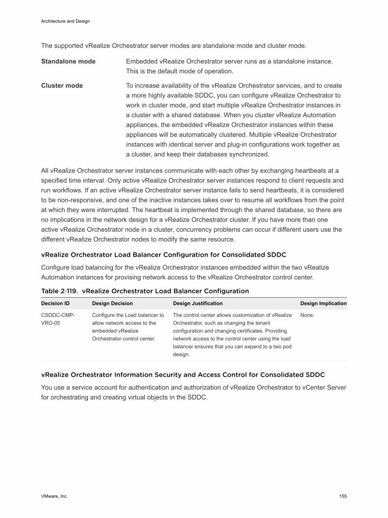
The supported vRealize Orchestrator server modes are standalone mode and cluster mode.
Standalone mode Embedded vRealize Orchestrator server runs as a standalone instance.This is the default mode of operation.
Cluster mode To increase availability of the vRealize Orchestrator services, and to createa more highly available SDDC, you can configure vRealize Orchestrator towork in cluster mode, and start multiple vRealize Orchestrator instances ina cluster with a shared database. When you cluster vRealize Automationappliances, the embedded vRealize Orchestrator instances within theseappliances will be automatically clustered. Multiple vRealize Orchestratorinstances with identical server and plug-in configurations work together asa cluster, and keep their databases synchronized.
All vRealize Orchestrator server instances communicate with each other by exchanging heartbeats at aspecified time interval. Only active vRealize Orchestrator server instances respond to client requests andrun workflows. If an active vRealize Orchestrator server instance fails to send heartbeats, it is consideredto be non-responsive, and one of the inactive instances takes over to resume all workflows from the pointat which they were interrupted. The heartbeat is implemented through the shared database, so there areno implications in the network design for a vRealize Orchestrator cluster. If you have more than oneactive vRealize Orchestrator node in a cluster, concurrency problems can occur if different users use thedifferent vRealize Orchestrator nodes to modify the same resource.
vRealize Orchestrator Load Balancer Configuration for Consolidated SDDC
Configure load balancing for the vRealize Orchestrator instances embedded within the two vRealizeAutomation instances for provising network access to the vRealize Orchestrator control center.
Table 2‑119. vRealize Orchestrator Load Balancer Configuration
Decision ID Design Decision Design Justification Design Implication
CSDDC-CMP-VRO-05
Configure the Load balancer toallow network access to theembedded vRealizeOrchestrator control center.
The control center allows customization of vRealizeOrchestrator, such as changing the tenantconfiguration and changing certificates. Providingnetwork access to the control center using the loadbalancer ensures that you can expand to a two poddesign.
None.
vRealize Orchestrator Information Security and Access Control for Consolidated SDDC
You use a service account for authentication and authorization of vRealize Orchestrator to vCenter Serverfor orchestrating and creating virtual objects in the SDDC.
Architecture and Design
VMware, Inc. 155
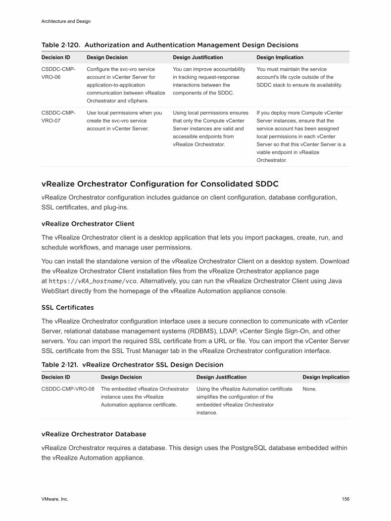
Table 2‑120. Authorization and Authentication Management Design Decisions
Decision ID Design Decision Design Justification Design Implication
CSDDC-CMP-VRO-06
Configure the svc-vro serviceaccount in vCenter Server forapplication-to-applicationcommunication between vRealizeOrchestrator and vSphere.
You can improve accountabilityin tracking request-responseinteractions between thecomponents of the SDDC.
You must maintain the serviceaccount's life cycle outside of theSDDC stack to ensure its availability.
CSDDC-CMP-VRO-07
Use local permissions when youcreate the svc-vro serviceaccount in vCenter Server.
Using local permissions ensuresthat only the Compute vCenterServer instances are valid andaccessible endpoints fromvRealize Orchestrator.
If you deploy more Compute vCenterServer instances, ensure that theservice account has been assignedlocal permissions in each vCenterServer so that this vCenter Server is aviable endpoint in vRealizeOrchestrator.
vRealize Orchestrator Configuration for Consolidated SDDCvRealize Orchestrator configuration includes guidance on client configuration, database configuration,SSL certificates, and plug-ins.
vRealize Orchestrator Client
The vRealize Orchestrator client is a desktop application that lets you import packages, create, run, andschedule workflows, and manage user permissions.
You can install the standalone version of the vRealize Orchestrator Client on a desktop system. Downloadthe vRealize Orchestrator Client installation files from the vRealize Orchestrator appliance pageat https://vRA_hostname/vco. Alternatively, you can run the vRealize Orchestrator Client using JavaWebStart directly from the homepage of the vRealize Automation appliance console.
SSL Certificates
The vRealize Orchestrator configuration interface uses a secure connection to communicate with vCenterServer, relational database management systems (RDBMS), LDAP, vCenter Single Sign-On, and otherservers. You can import the required SSL certificate from a URL or file. You can import the vCenter ServerSSL certificate from the SSL Trust Manager tab in the vRealize Orchestrator configuration interface.
Table 2‑121. vRealize Orchestrator SSL Design Decision
Decision ID Design Decision Design Justification Design Implication
CSDDC-CMP-VRO-08 The embedded vRealize Orchestratorinstance uses the vRealizeAutomation appliance certificate.
Using the vRealize Automation certificatesimplifies the configuration of theembedded vRealize Orchestratorinstance.
None.
vRealize Orchestrator Database
vRealize Orchestrator requires a database. This design uses the PostgreSQL database embedded withinthe vRealize Automation appliance.
Architecture and Design
VMware, Inc. 156
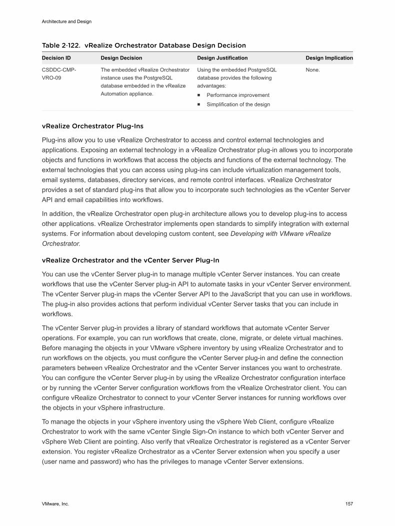
Table 2‑122. vRealize Orchestrator Database Design Decision
Decision ID Design Decision Design Justification Design Implication
CSDDC-CMP-VRO-09
The embedded vRealize Orchestratorinstance uses the PostgreSQLdatabase embedded in the vRealizeAutomation appliance.
Using the embedded PostgreSQLdatabase provides the followingadvantages:n Performance improvementn Simplification of the design
None.
vRealize Orchestrator Plug-Ins
Plug-ins allow you to use vRealize Orchestrator to access and control external technologies andapplications. Exposing an external technology in a vRealize Orchestrator plug-in allows you to incorporateobjects and functions in workflows that access the objects and functions of the external technology. Theexternal technologies that you can access using plug-ins can include virtualization management tools,email systems, databases, directory services, and remote control interfaces. vRealize Orchestratorprovides a set of standard plug-ins that allow you to incorporate such technologies as the vCenter ServerAPI and email capabilities into workflows.
In addition, the vRealize Orchestrator open plug-in architecture allows you to develop plug-ins to accessother applications. vRealize Orchestrator implements open standards to simplify integration with externalsystems. For information about developing custom content, see Developing with VMware vRealizeOrchestrator.
vRealize Orchestrator and the vCenter Server Plug-In
You can use the vCenter Server plug-in to manage multiple vCenter Server instances. You can createworkflows that use the vCenter Server plug-in API to automate tasks in your vCenter Server environment.The vCenter Server plug-in maps the vCenter Server API to the JavaScript that you can use in workflows.The plug-in also provides actions that perform individual vCenter Server tasks that you can include inworkflows.
The vCenter Server plug-in provides a library of standard workflows that automate vCenter Serveroperations. For example, you can run workflows that create, clone, migrate, or delete virtual machines.Before managing the objects in your VMware vSphere inventory by using vRealize Orchestrator and torun workflows on the objects, you must configure the vCenter Server plug-in and define the connectionparameters between vRealize Orchestrator and the vCenter Server instances you want to orchestrate.You can configure the vCenter Server plug-in by using the vRealize Orchestrator configuration interfaceor by running the vCenter Server configuration workflows from the vRealize Orchestrator client. You canconfigure vRealize Orchestrator to connect to your vCenter Server instances for running workflows overthe objects in your vSphere infrastructure.
To manage the objects in your vSphere inventory using the vSphere Web Client, configure vRealizeOrchestrator to work with the same vCenter Single Sign-On instance to which both vCenter Server andvSphere Web Client are pointing. Also verify that vRealize Orchestrator is registered as a vCenter Serverextension. You register vRealize Orchestrator as a vCenter Server extension when you specify a user(user name and password) who has the privileges to manage vCenter Server extensions.
Architecture and Design
VMware, Inc. 157
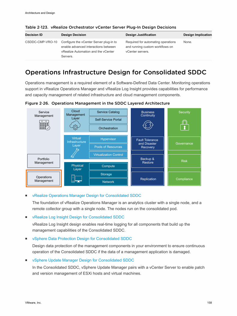
Table 2‑123. vRealize Orchestrator vCenter Server Plug-In Design Decisions
Decision ID Design Decision Design Justification Design Implication
CSDDC-CMP-VRO-10 Configure the vCenter Server plug-in toenable advanced interactions betweenvRealize Automation and the vCenterServers.
Required for automating operationsand running custom workflows onvCenter servers.
None.
Operations Infrastructure Design for Consolidated SDDCOperations management is a required element of a Software-Defined Data Center. Monitoring operationssupport in vRealize Operations Manager and vRealize Log Insight provides capabilities for performanceand capacity management of related infrastructure and cloud management components.
Figure 2‑26. Operations Management in the SDDC Layered Architecture
ServiceManagement
Portfolio Management
OperationsManagement
CloudManagement
Layer
Service Catalog
Self-Service Portal
Orchestration
BusinessContinuity
Fault Tolerance and Disaster
Recovery
Backup & Restore
Hypervisor
Pools of Resources
Virtualization Control
VirtualInfrastructure
Layer
Compute
Storage
Network
PhysicalLayer
Security
Replication Compliance
Risk
Governance
n vRealize Operations Manager Design for Consolidated SDDC
The foundation of vRealize Operations Manager is an analytics cluster with a single node, and aremote collector group with a single node. The nodes run on the consolidated pod.
n vRealize Log Insight Design for Consolidated SDDC
vRealize Log Insight design enables real-time logging for all components that build up themanagement capabilities of the Consolidated SDDC.
n vSphere Data Protection Design for Consolidated SDDC
Design data protection of the management components in your environment to ensure continuousoperation of the Consolidated SDDC if the data of a management application is damaged.
n vSphere Update Manager Design for Consolidated SDDC
In the Consolidated SDDC, vSphere Update Manager pairs with a vCenter Server to enable patchand version management of ESXi hosts and virtual machines.
Architecture and Design
VMware, Inc. 158
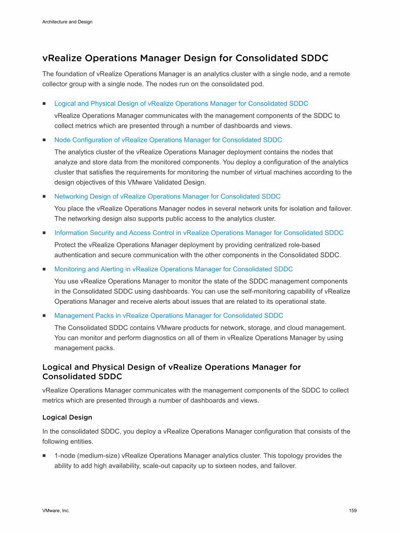
vRealize Operations Manager Design for Consolidated SDDCThe foundation of vRealize Operations Manager is an analytics cluster with a single node, and a remotecollector group with a single node. The nodes run on the consolidated pod.
n Logical and Physical Design of vRealize Operations Manager for Consolidated SDDC
vRealize Operations Manager communicates with the management components of the SDDC tocollect metrics which are presented through a number of dashboards and views.
n Node Configuration of vRealize Operations Manager for Consolidated SDDC
The analytics cluster of the vRealize Operations Manager deployment contains the nodes thatanalyze and store data from the monitored components. You deploy a configuration of the analyticscluster that satisfies the requirements for monitoring the number of virtual machines according to thedesign objectives of this VMware Validated Design.
n Networking Design of vRealize Operations Manager for Consolidated SDDC
You place the vRealize Operations Manager nodes in several network units for isolation and failover.The networking design also supports public access to the analytics cluster.
n Information Security and Access Control in vRealize Operations Manager for Consolidated SDDC
Protect the vRealize Operations Manager deployment by providing centralized role-basedauthentication and secure communication with the other components in the Consolidated SDDC.
n Monitoring and Alerting in vRealize Operations Manager for Consolidated SDDC
You use vRealize Operations Manager to monitor the state of the SDDC management componentsin the Consolidated SDDC using dashboards. You can use the self-monitoring capability of vRealizeOperations Manager and receive alerts about issues that are related to its operational state.
n Management Packs in vRealize Operations Manager for Consolidated SDDC
The Consolidated SDDC contains VMware products for network, storage, and cloud management.You can monitor and perform diagnostics on all of them in vRealize Operations Manager by usingmanagement packs.
Logical and Physical Design of vRealize Operations Manager forConsolidated SDDCvRealize Operations Manager communicates with the management components of the SDDC to collectmetrics which are presented through a number of dashboards and views.
Logical Design
In the consolidated SDDC, you deploy a vRealize Operations Manager configuration that consists of thefollowing entities.
n 1-node (medium-size) vRealize Operations Manager analytics cluster. This topology provides theability to add high availability, scale-out capacity up to sixteen nodes, and failover.
Architecture and Design
VMware, Inc. 159
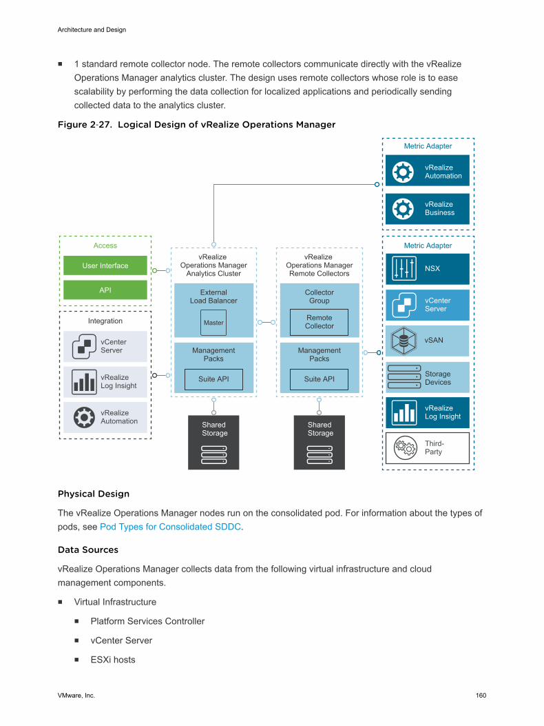
n 1 standard remote collector node. The remote collectors communicate directly with the vRealizeOperations Manager analytics cluster. The design uses remote collectors whose role is to easescalability by performing the data collection for localized applications and periodically sendingcollected data to the analytics cluster.
Figure 2‑27. Logical Design of vRealize Operations Manager
Metric Adapter
vRealize Operations Manager
Analytics Cluster
Integration
ExternalLoad Balancer
vCenter Server
Access
User Interface
API
vRealizeLog Insight
vRealizeAutomation
Metric Adapter
vCenter Server
NSX
vRealizeLog Insight
Third-Party
vRealizeBusiness
vRealizeAutomation
Master
ManagementPacks
Suite API
Shared Storage
vRealize Operations ManagerRemote Collectors
CollectorGroup
ManagementPacks
Suite API
Remote Collector
Shared Storage
StorageDevices
vSAN
Physical Design
The vRealize Operations Manager nodes run on the consolidated pod. For information about the types ofpods, see Pod Types for Consolidated SDDC.
Data Sources
vRealize Operations Manager collects data from the following virtual infrastructure and cloudmanagement components.
n Virtual Infrastructure
n Platform Services Controller
n vCenter Server
n ESXi hosts
Architecture and Design
VMware, Inc. 160
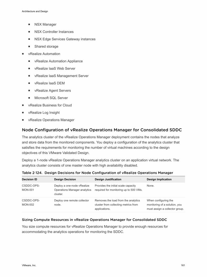
n NSX Manager
n NSX Controller Instances
n NSX Edge Services Gateway instances
n Shared storage
n vRealize Automation
n vRealize Automation Appliance
n vRealize IaaS Web Server
n vRealize IaaS Management Server
n vRealize IaaS DEM
n vRealize Agent Servers
n Microsoft SQL Server
n vRealize Business for Cloud
n vRealize Log Insight
n vRealize Operations Manager
Node Configuration of vRealize Operations Manager for Consolidated SDDCThe analytics cluster of the vRealize Operations Manager deployment contains the nodes that analyzeand store data from the monitored components. You deploy a configuration of the analytics cluster thatsatisfies the requirements for monitoring the number of virtual machines according to the designobjectives of this VMware Validated Design.
Deploy a 1-node vRealize Operations Manager analytics cluster on an application virtual network. Theanalytics cluster consists of one master node with high availability disabled.
Table 2‑124. Design Decisions for Node Configuration of vRealize Operations Manager
Decision ID Design Decision Design Justification Design Implication
CSDDC-OPS-MON-001
Deploy a one-node vRealizeOperations Manager analyticscluster.
Provides the initial scale capacityrequired for monitoring up to 500 VMs.
None.
CSDDC-OPS-MON-002
Deploy one remote collectornode.
Removes the load from the analyticscluster from collecting metrics fromapplications.
When configuring themonitoring of a solution, youmust assign a collector group.
Sizing Compute Resources in vRealize Operations Manager for Consolidated SDDC
You size compute resources for vRealize Operations Manager to provide enough resources foraccommodating the analytics operations for monitoring the SDDC.
Architecture and Design
VMware, Inc. 161
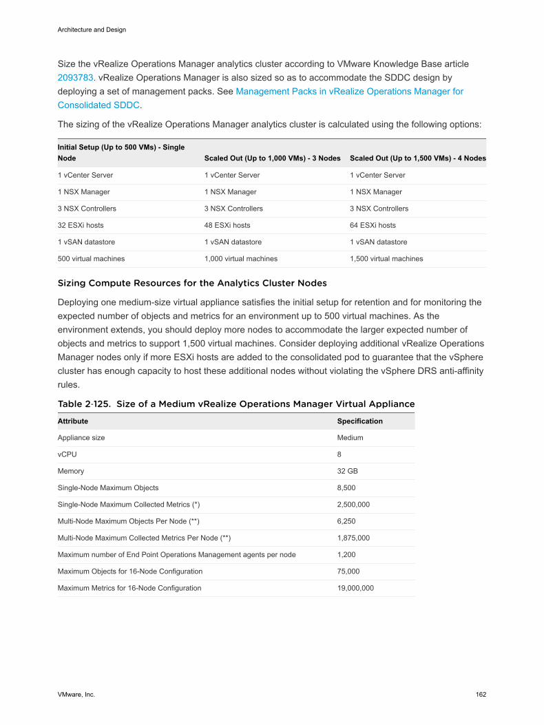
Size the vRealize Operations Manager analytics cluster according to VMware Knowledge Base article 2093783. vRealize Operations Manager is also sized so as to accommodate the SDDC design bydeploying a set of management packs. See Management Packs in vRealize Operations Manager forConsolidated SDDC.
The sizing of the vRealize Operations Manager analytics cluster is calculated using the following options:
Initial Setup (Up to 500 VMs) - SingleNode Scaled Out (Up to 1,000 VMs) - 3 Nodes Scaled Out (Up to 1,500 VMs) - 4 Nodes
1 vCenter Server 1 vCenter Server 1 vCenter Server
1 NSX Manager 1 NSX Manager 1 NSX Manager
3 NSX Controllers 3 NSX Controllers 3 NSX Controllers
32 ESXi hosts 48 ESXi hosts 64 ESXi hosts
1 vSAN datastore 1 vSAN datastore 1 vSAN datastore
500 virtual machines 1,000 virtual machines 1,500 virtual machines
Sizing Compute Resources for the Analytics Cluster Nodes
Deploying one medium-size virtual appliance satisfies the initial setup for retention and for monitoring theexpected number of objects and metrics for an environment up to 500 virtual machines. As theenvironment extends, you should deploy more nodes to accommodate the larger expected number ofobjects and metrics to support 1,500 virtual machines. Consider deploying additional vRealize OperationsManager nodes only if more ESXi hosts are added to the consolidated pod to guarantee that the vSpherecluster has enough capacity to host these additional nodes without violating the vSphere DRS anti-affinityrules.
Table 2‑125. Size of a Medium vRealize Operations Manager Virtual Appliance
Attribute Specification
Appliance size Medium
vCPU 8
Memory 32 GB
Single-Node Maximum Objects 8,500
Single-Node Maximum Collected Metrics (*) 2,500,000
Multi-Node Maximum Objects Per Node (**) 6,250
Multi-Node Maximum Collected Metrics Per Node (**) 1,875,000
Maximum number of End Point Operations Management agents per node 1,200
Maximum Objects for 16-Node Configuration 75,000
Maximum Metrics for 16-Node Configuration 19,000,000
Architecture and Design
VMware, Inc. 162
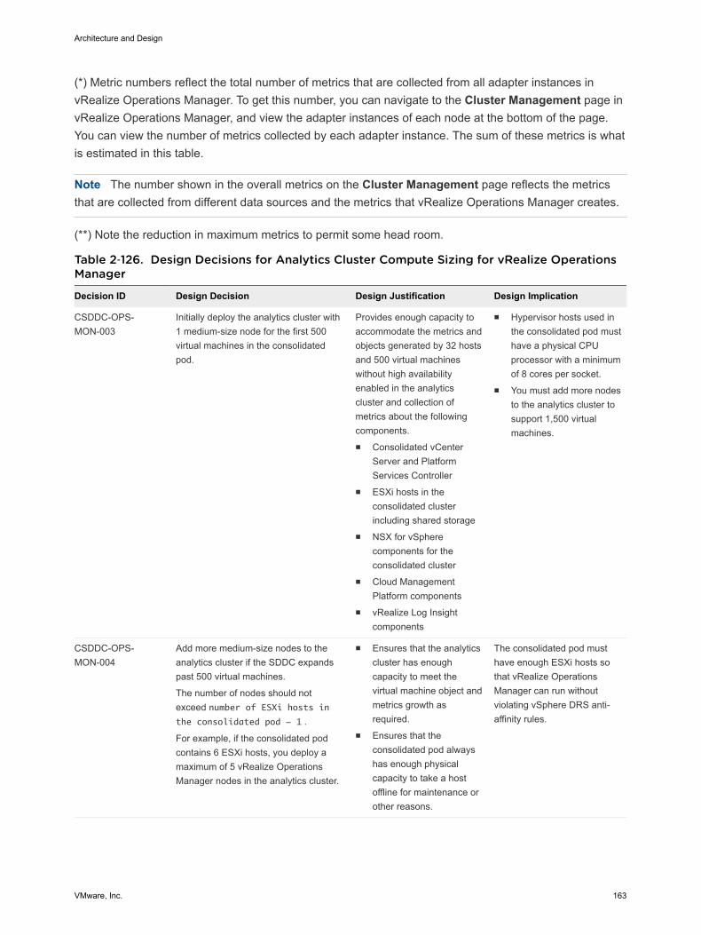
(*) Metric numbers reflect the total number of metrics that are collected from all adapter instances invRealize Operations Manager. To get this number, you can navigate to the Cluster Management page invRealize Operations Manager, and view the adapter instances of each node at the bottom of the page.You can view the number of metrics collected by each adapter instance. The sum of these metrics is whatis estimated in this table.
Note The number shown in the overall metrics on the Cluster Management page reflects the metricsthat are collected from different data sources and the metrics that vRealize Operations Manager creates.
(**) Note the reduction in maximum metrics to permit some head room.
Table 2‑126. Design Decisions for Analytics Cluster Compute Sizing for vRealize OperationsManager
Decision ID Design Decision Design Justification Design Implication
CSDDC-OPS-MON-003
Initially deploy the analytics cluster with1 medium-size node for the first 500virtual machines in the consolidatedpod.
Provides enough capacity toaccommodate the metrics andobjects generated by 32 hostsand 500 virtual machineswithout high availabilityenabled in the analyticscluster and collection ofmetrics about the followingcomponents.n Consolidated vCenter
Server and PlatformServices Controller
n ESXi hosts in theconsolidated clusterincluding shared storage
n NSX for vSpherecomponents for theconsolidated cluster
n Cloud ManagementPlatform components
n vRealize Log Insightcomponents
n Hypervisor hosts used inthe consolidated pod musthave a physical CPUprocessor with a minimumof 8 cores per socket.
n You must add more nodesto the analytics cluster tosupport 1,500 virtualmachines.
CSDDC-OPS-MON-004
Add more medium-size nodes to theanalytics cluster if the SDDC expandspast 500 virtual machines.
The number of nodes should notexceed number of ESXi hosts inthe consolidated pod - 1 .
For example, if the consolidated podcontains 6 ESXi hosts, you deploy amaximum of 5 vRealize OperationsManager nodes in the analytics cluster.
n Ensures that the analyticscluster has enoughcapacity to meet thevirtual machine object andmetrics growth asrequired.
n Ensures that theconsolidated pod alwayshas enough physicalcapacity to take a hostoffline for maintenance orother reasons.
The consolidated pod musthave enough ESXi hosts sothat vRealize OperationsManager can run withoutviolating vSphere DRS anti-affinity rules.
Architecture and Design
VMware, Inc. 163
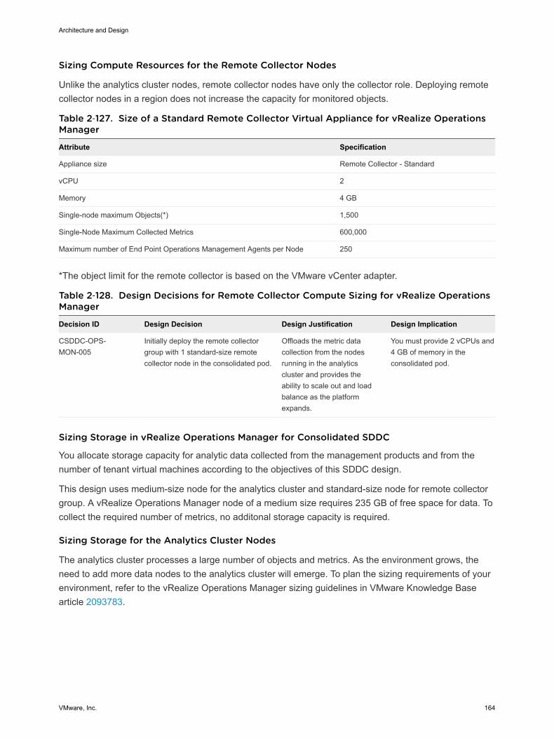
Sizing Compute Resources for the Remote Collector Nodes
Unlike the analytics cluster nodes, remote collector nodes have only the collector role. Deploying remotecollector nodes in a region does not increase the capacity for monitored objects.
Table 2‑127. Size of a Standard Remote Collector Virtual Appliance for vRealize OperationsManager
Attribute Specification
Appliance size Remote Collector - Standard
vCPU 2
Memory 4 GB
Single-node maximum Objects(*) 1,500
Single-Node Maximum Collected Metrics 600,000
Maximum number of End Point Operations Management Agents per Node 250
*The object limit for the remote collector is based on the VMware vCenter adapter.
Table 2‑128. Design Decisions for Remote Collector Compute Sizing for vRealize OperationsManager
Decision ID Design Decision Design Justification Design Implication
CSDDC-OPS-MON-005
Initially deploy the remote collectorgroup with 1 standard-size remotecollector node in the consolidated pod.
Offloads the metric datacollection from the nodesrunning in the analyticscluster and provides theability to scale out and loadbalance as the platformexpands.
You must provide 2 vCPUs and4 GB of memory in theconsolidated pod.
Sizing Storage in vRealize Operations Manager for Consolidated SDDC
You allocate storage capacity for analytic data collected from the management products and from thenumber of tenant virtual machines according to the objectives of this SDDC design.
This design uses medium-size node for the analytics cluster and standard-size node for remote collectorgroup. A vRealize Operations Manager node of a medium size requires 235 GB of free space for data. Tocollect the required number of metrics, no additonal storage capacity is required.
Sizing Storage for the Analytics Cluster Nodes
The analytics cluster processes a large number of objects and metrics. As the environment grows, theneed to add more data nodes to the analytics cluster will emerge. To plan the sizing requirements of yourenvironment, refer to the vRealize Operations Manager sizing guidelines in VMware Knowledge Basearticle 2093783.
Architecture and Design
VMware, Inc. 164

Table 2‑129. Analytics Cluster Storage Sizing for vRealize Operations Manager DesignDecision
Decision ID Design Decision Design Justification Design Implication
CSDDC-OPS-MON-006
Do not add additionalstorage to the analyticscluster node.
Based on the sizing calaculator thedefault capacity of a medium nideprovides enough storage to collect metricdata for the initial 500 virtual machines.
As the platform scales you mayneed to revisit the storagecapacity of the node.
Sizing Storage for the Remote Collector Nodes
Deploy the remote collector node with thin-provisioned disks. Because remote collectors do not performanalytics operations or store data, the default VMDK size is sufficient.
Table 2‑130. Remote Collector Storage Sizing for vRealize Operations Manager DesignDecision
Decision ID Design Decision Design Justification Design Implication
CSDDC-OPS-MON-007 No additional storage is required forthe remote collectors.
Remote collectors do not perform analyticsoperations or store data on disk.
None.
Networking Design of vRealize Operations Manager for Consolidated SDDCYou place the vRealize Operations Manager nodes in several network units for isolation and failover. Thenetworking design also supports public access to the analytics cluster.
For secure access, load balancing and portability, the vRealize Operations Manager analytics cluster isdeployed in the shared cross-region application virtual network Mgmt-xRegion01-VXLAN, and the remotecollector group in the shared local application virtual network Mgmt-RegionA01-VXLAN.
Architecture and Design
VMware, Inc. 165
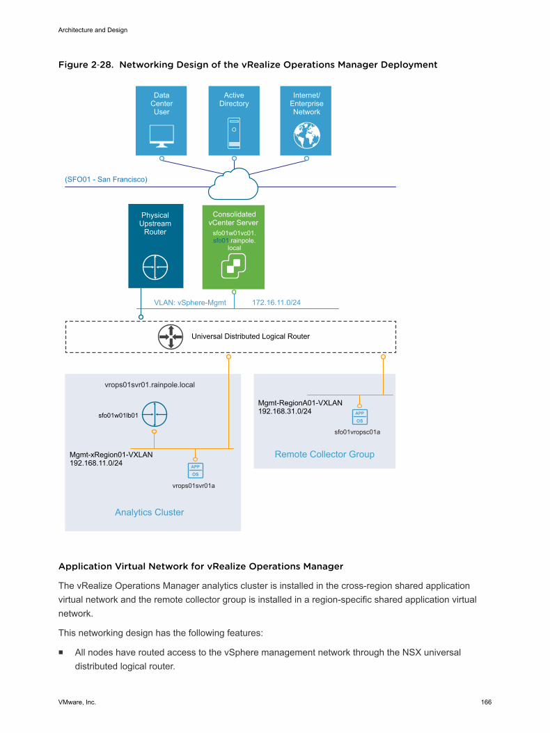
Figure 2‑28. Networking Design of the vRealize Operations Manager Deployment
APP
OS
APP
OS
Universal Distributed Logical Router
DataCenterUser
ActiveDirectory
Internet/EnterpriseNetwork
(SFO01 - San Francisco)
VLAN: vSphere-Mgmt 172.16.11.0/24
ConsolidatedvCenter Server
sfo01w01vc01.sfo01.rainpole.
local
vrops01svr01a
sfo01vropsc01a
Mgmt-xRegion01-VXLAN192.168.11.0/24
Mgmt-RegionA01-VXLAN192.168.31.0/24
vrops01svr01.rainpole.local
Analytics Cluster
Remote Collector Group
PhysicalUpstream
Router
sfo01w01lb01
Application Virtual Network for vRealize Operations Manager
The vRealize Operations Manager analytics cluster is installed in the cross-region shared applicationvirtual network and the remote collector group is installed in a region-specific shared application virtualnetwork.
This networking design has the following features:
n All nodes have routed access to the vSphere management network through the NSX universaldistributed logical router.
Architecture and Design
VMware, Inc. 166

n Routing to the vSphere management network and other external networks is dynamic, and is basedon the Border Gateway Protocol (BGP).
For more information about the networking configuration of the application isolated network, see Virtualization Network Design for Consolidated SDDC and NSX Design for Consolidated SDDC.
Table 2‑131. Design Decisions about the Application Virtual Network for vRealize OperationsManager
Decision ID Design Decision Design Justification Design Implication
CSDDC-OPS-MON-008
Use the existing cross-regionapplication virtual network forthe vRealize OperationsManager analytics cluster.
Provides a consistent deploymentmodel for management applicationsand ensures that growth to a two-pod design is supported.
You must use an implementationin NSX to support this networkconfiguration.
CSDDC-OPS-MON-009
Use the existing region-specificapplication virtual network forvRealize Operations Managerremote collector group.
Ensures collection of metrics locallyin a region in the event of a networkoutage.
You must use an implementationin NSX to support this networkconfiguration.
IP Subnets for vRealize Operations Manager
You can allocate the following example subnets for the vRealize Operations Manager deployment.
Table 2‑132. IP Subnets in the Application Virtual Networks for vRealize Operations Manager
vRealize Operations Manager Cluster Type IP Subnet
Analytics cluster in consolidated pod 192.168.11.0/24
Remote collector group in consolidated pod 192.168.31.0/24
Table 2‑133. Design Decision about IP Subnets for vRealize Operations Manager
Decision ID Design Decision Design Justification Design Implication
CSDDC-OPS-MON-010
Allocate separate subnetsfor each application virtualnetwork.
Placing the remote collectors on their ownsubnet enables them to communicate withthe analytics cluster and not be a part of afuture failover group.
You must have an allocationof dedicated IP subnets.
DNS Names for vRealize Operations Manager
The FQDNs of the vRealize Operations Manager nodes follow certain domain name resolution:
n The analytics cluster node IP addresses and a load balancer virtual IP address (VIP) are associatedwith names that have the root domain suffix rainpole.local.
From the public network, users access vRealize Operations Manager using the VIP address, thetraffic to which is handled by the NSX Edge services gateway.
n Name resolution for the IP addresses of the remote collector group node uses a region-specific suffix,for example, sfo01.rainpole.local.
Architecture and Design
VMware, Inc. 167
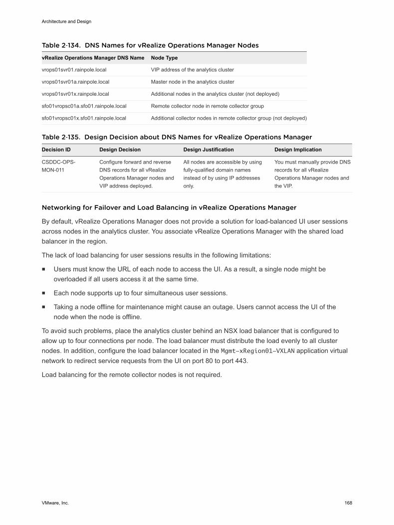
Table 2‑134. DNS Names for vRealize Operations Manager Nodes
vRealize Operations Manager DNS Name Node Type
vrops01svr01.rainpole.local VIP address of the analytics cluster
vrops01svr01a.rainpole.local Master node in the analytics cluster
vrops01svr01x.rainpole.local Additional nodes in the analytics cluster (not deployed)
sfo01vropsc01a.sfo01.rainpole.local Remote collector node in remote collector group
sfo01vropsc01x.sfo01.rainpole.local Additional collector nodes in remote collector group (not deployed)
Table 2‑135. Design Decision about DNS Names for vRealize Operations Manager
Decision ID Design Decision Design Justification Design Implication
CSDDC-OPS-MON-011
Configure forward and reverseDNS records for all vRealizeOperations Manager nodes andVIP address deployed.
All nodes are accessible by usingfully-qualified domain namesinstead of by using IP addressesonly.
You must manually provide DNSrecords for all vRealizeOperations Manager nodes andthe VIP.
Networking for Failover and Load Balancing in vRealize Operations Manager
By default, vRealize Operations Manager does not provide a solution for load-balanced UI user sessionsacross nodes in the analytics cluster. You associate vRealize Operations Manager with the shared loadbalancer in the region.
The lack of load balancing for user sessions results in the following limitations:
n Users must know the URL of each node to access the UI. As a result, a single node might beoverloaded if all users access it at the same time.
n Each node supports up to four simultaneous user sessions.
n Taking a node offline for maintenance might cause an outage. Users cannot access the UI of thenode when the node is offline.
To avoid such problems, place the analytics cluster behind an NSX load balancer that is configured toallow up to four connections per node. The load balancer must distribute the load evenly to all clusternodes. In addition, configure the load balancer located in the Mgmt-xRegion01-VXLAN application virtualnetwork to redirect service requests from the UI on port 80 to port 443.
Load balancing for the remote collector nodes is not required.
Architecture and Design
VMware, Inc. 168
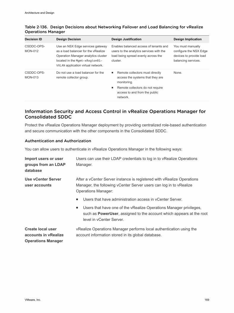
Table 2‑136. Design Decisions about Networking Failover and Load Balancing for vRealizeOperations Manager
Decision ID Design Decision Design Justification Design Implication
CSDDC-OPS-MON-012
Use an NSX Edge services gatewayas a load balancer for the vRealizeOperation Manager analytics clusterlocated in the Mgmt-xRegion01-VXLAN application virtual network.
Enables balanced access of tenants andusers to the analytics services with theload being spread evenly across thecluster.
You must manuallyconfigure the NSX Edgedevices to provide loadbalancing services.
CSDDC-OPS-MON-013
Do not use a load balancer for theremote collector group.
n Remote collectors must directlyaccess the systems that they aremonitoring.
n Remote collectors do not requireaccess to and from the publicnetwork.
None.
Information Security and Access Control in vRealize Operations Manager forConsolidated SDDCProtect the vRealize Operations Manager deployment by providing centralized role-based authenticationand secure communication with the other components in the Consolidated SDDC.
Authentication and Authorization
You can allow users to authenticate in vRealize Operations Manager in the following ways:
Import users or usergroups from an LDAPdatabase
Users can use their LDAP credentials to log in to vRealize OperationsManager.
Use vCenter Serveruser accounts
After a vCenter Server instance is registered with vRealize OperationsManager, the following vCenter Server users can log in to vRealizeOperations Manager:
n Users that have administration access in vCenter Server.
n Users that have one of the vRealize Operations Manager privileges,such as PowerUser, assigned to the account which appears at the rootlevel in vCenter Server.
Create local useraccounts in vRealizeOperations Manager
vRealize Operations Manager performs local authentication using theaccount information stored in its global database.
Architecture and Design
VMware, Inc. 169

Table 2‑137. Design Decisions about Authorization and Authentication Management forvRealize Operations Manager
Decision ID Design Decision Design Justification Design Implication
CSDDC-OPS-MON-014
Use Active Directoryauthentication.
n Provides access to vRealize OperationsManager by using standard Active Directoryaccounts.
n Ensures that authentication is available even ifvCenter Server becomes unavailable.
You must manually configurethe Active Directoryauthentication.
CSDDC-OPS-MON-015
Configure a service accountsvc-vrops-vsphere in vCenterServer for application-to-application communicationfrom vRealize OperationsManager with vSphere.
Provides the following access control features:n The adapter in vRealize Operations Manager
accesses vSphere with the minimum set ofpermissions that are required to collectmetrics about vSphere inventory objects.
n In the event of a compromised account, theaccessibility in the destination applicationremains restricted.
n You can introduce improved accountability intracking request-response interactionsbetween the components of the SDDC.
You must maintain the serviceaccount's life cycle outside ofthe SDDC stack to ensure itsavailability.
CSDDC-OPS-MON-016
Configure a service accountsvc-vrops-nsx in vCenterServer for application-to-application communicationfrom vRealize OperationsManager with NSX forvSphere.
Provides the following access control features:n The adapter in vRealize Operations Manager
accesses NSX for vSphere with the minimumset of permissions that are required formetrics collection and topology mapping.
n In the event of a compromised account, theaccessibility in the destination applicationremains restricted.
n You can introduce improved accountability intracking request-response interactionsbetween the components of the SDDC.
You must maintain the serviceaccount's life cycle outside ofthe SDDC stack to ensure itsavailability.
CSDDC-OPS-MON-017
Configure a service accountsvc-vrops-mpsd in vCenterServer for application-to-application communicationfrom the Storage DevicesAdapter in vRealizeOperations Manager withvSphere.
Provides the following access control features:n The adapter in vRealize Operations Manager
accesses vSphere with the minimum set ofpermissions that are required to collectmetrics about vSphere inventory objects.
n In the event of a compromised account, theaccessibility in the destination applicationremains restricted.
n You can introduce improved accountability intracking request-response interactionsbetween the components of the SDDC.
You must maintain the serviceaccount's life cycle outside ofthe SDDC stack to ensure itsavailability.
Architecture and Design
VMware, Inc. 170
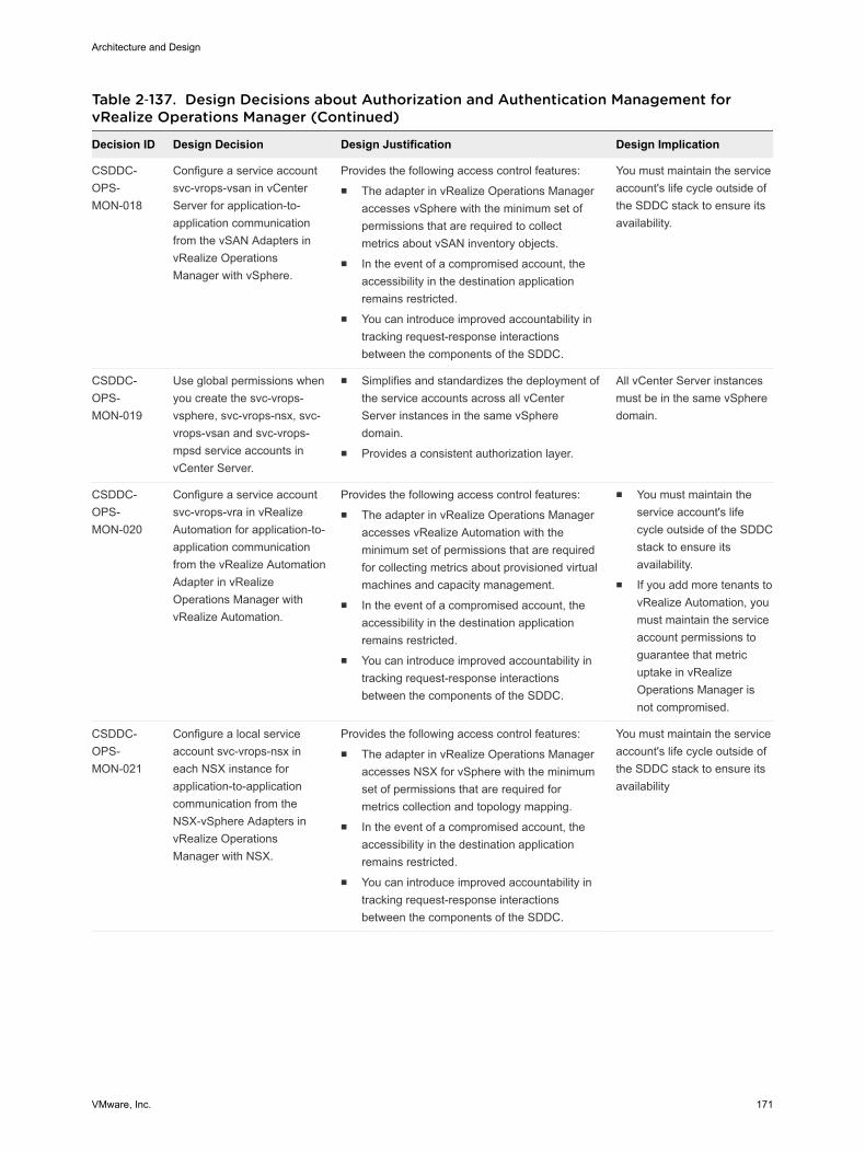
Table 2‑137. Design Decisions about Authorization and Authentication Management forvRealize Operations Manager (Continued)
Decision ID Design Decision Design Justification Design Implication
CSDDC-OPS-MON-018
Configure a service accountsvc-vrops-vsan in vCenterServer for application-to-application communicationfrom the vSAN Adapters invRealize OperationsManager with vSphere.
Provides the following access control features:n The adapter in vRealize Operations Manager
accesses vSphere with the minimum set ofpermissions that are required to collectmetrics about vSAN inventory objects.
n In the event of a compromised account, theaccessibility in the destination applicationremains restricted.
n You can introduce improved accountability intracking request-response interactionsbetween the components of the SDDC.
You must maintain the serviceaccount's life cycle outside ofthe SDDC stack to ensure itsavailability.
CSDDC-OPS-MON-019
Use global permissions whenyou create the svc-vrops-vsphere, svc-vrops-nsx, svc-vrops-vsan and svc-vrops-mpsd service accounts invCenter Server.
n Simplifies and standardizes the deployment ofthe service accounts across all vCenterServer instances in the same vSpheredomain.
n Provides a consistent authorization layer.
All vCenter Server instancesmust be in the same vSpheredomain.
CSDDC-OPS-MON-020
Configure a service accountsvc-vrops-vra in vRealizeAutomation for application-to-application communicationfrom the vRealize AutomationAdapter in vRealizeOperations Manager withvRealize Automation.
Provides the following access control features:n The adapter in vRealize Operations Manager
accesses vRealize Automation with theminimum set of permissions that are requiredfor collecting metrics about provisioned virtualmachines and capacity management.
n In the event of a compromised account, theaccessibility in the destination applicationremains restricted.
n You can introduce improved accountability intracking request-response interactionsbetween the components of the SDDC.
n You must maintain theservice account's lifecycle outside of the SDDCstack to ensure itsavailability.
n If you add more tenants tovRealize Automation, youmust maintain the serviceaccount permissions toguarantee that metricuptake in vRealizeOperations Manager isnot compromised.
CSDDC-OPS-MON-021
Configure a local serviceaccount svc-vrops-nsx ineach NSX instance forapplication-to-applicationcommunication from theNSX-vSphere Adapters invRealize OperationsManager with NSX.
Provides the following access control features:n The adapter in vRealize Operations Manager
accesses NSX for vSphere with the minimumset of permissions that are required formetrics collection and topology mapping.
n In the event of a compromised account, theaccessibility in the destination applicationremains restricted.
n You can introduce improved accountability intracking request-response interactionsbetween the components of the SDDC.
You must maintain the serviceaccount's life cycle outside ofthe SDDC stack to ensure itsavailability
Architecture and Design
VMware, Inc. 171
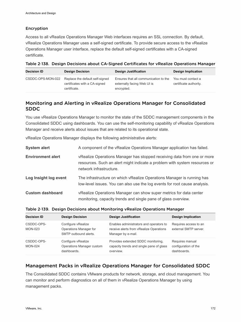
Encryption
Access to all vRealize Operations Manager Web interfaces requires an SSL connection. By default,vRealize Operations Manager uses a self-signed certificate. To provide secure access to the vRealizeOperations Manager user interface, replace the default self-signed certificates with a CA-signedcertificate.
Table 2‑138. Design Decisions about CA-Signed Certificates for vRealize Operations Manager
Decision ID Design Decision Design Justification Design Implication
CSDDC-OPS-MON-022 Replace the default self-signedcertificates with a CA-signedcertificate.
Ensures that all communication to theexternally facing Web UI isencrypted.
You must contact acertificate authority.
Monitoring and Alerting in vRealize Operations Manager for ConsolidatedSDDCYou use vRealize Operations Manager to monitor the state of the SDDC management components in theConsolidated SDDC using dashboards. You can use the self-monitoring capability of vRealize OperationsManager and receive alerts about issues that are related to its operational state.
vRealize Operations Manager displays the following administrative alerts:
System alert A component of the vRealize Operations Manager application has failed.
Environment alert vRealize Operations Manager has stopped receiving data from one or moreresources. Such an alert might indicate a problem with system resources ornetwork infrastructure.
Log Insight log event The infrastructure on which vRealize Operations Manager is running haslow-level issues. You can also use the log events for root cause analysis.
Custom dashboard vRealize Operations Manager can show super metrics for data centermonitoring, capacity trends and single pane of glass overview.
Table 2‑139. Design Decisions about Monitoring vRealize Operations Manager
Decision ID Design Decision Design Justification Design Implication
CSDDC-OPS-MON-023
Configure vRealizeOperations Manager forSMTP outbound alerts.
Enables administrators and operators toreceive alerts from vRealize OperationsManager by e-mail.
Requires access to anexternal SMTP server.
CSDDC-OPS-MON-024
Configure vRealizeOperations Manager customdashboards.
Provides extended SDDC monitoring,capacity trends and single pane of glassoverview.
Requires manualconfiguration of thedashboards.
Management Packs in vRealize Operations Manager for Consolidated SDDCThe Consolidated SDDC contains VMware products for network, storage, and cloud management. Youcan monitor and perform diagnostics on all of them in vRealize Operations Manager by usingmanagement packs.
Architecture and Design
VMware, Inc. 172
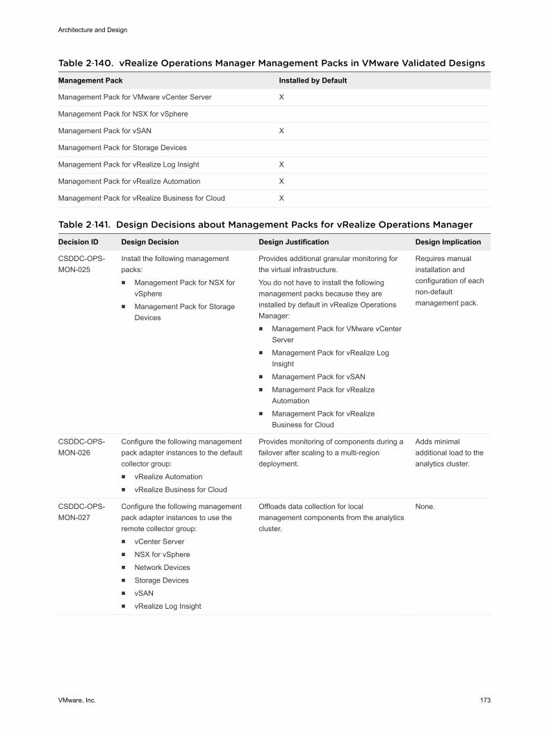
Table 2‑140. vRealize Operations Manager Management Packs in VMware Validated Designs
Management Pack Installed by Default
Management Pack for VMware vCenter Server X
Management Pack for NSX for vSphere
Management Pack for vSAN X
Management Pack for Storage Devices
Management Pack for vRealize Log Insight X
Management Pack for vRealize Automation X
Management Pack for vRealize Business for Cloud X
Table 2‑141. Design Decisions about Management Packs for vRealize Operations Manager
Decision ID Design Decision Design Justification Design Implication
CSDDC-OPS-MON-025
Install the following managementpacks:n Management Pack for NSX for
vSpheren Management Pack for Storage
Devices
Provides additional granular monitoring forthe virtual infrastructure.
You do not have to install the followingmanagement packs because they areinstalled by default in vRealize OperationsManager:n Management Pack for VMware vCenter
Servern Management Pack for vRealize Log
Insightn Management Pack for vSANn Management Pack for vRealize
Automationn Management Pack for vRealize
Business for Cloud
Requires manualinstallation andconfiguration of eachnon-defaultmanagement pack.
CSDDC-OPS-MON-026
Configure the following managementpack adapter instances to the defaultcollector group:n vRealize Automationn vRealize Business for Cloud
Provides monitoring of components during afailover after scaling to a multi-regiondeployment.
Adds minimaladditional load to theanalytics cluster.
CSDDC-OPS-MON-027
Configure the following managementpack adapter instances to use theremote collector group:n vCenter Servern NSX for vSpheren Network Devicesn Storage Devicesn vSANn vRealize Log Insight
Offloads data collection for localmanagement components from the analyticscluster.
None.
Architecture and Design
VMware, Inc. 173

vRealize Log Insight Design for Consolidated SDDCvRealize Log Insight design enables real-time logging for all components that build up the managementcapabilities of the Consolidated SDDC.
Logical Design and Data Sources of vRealize Log Insight for ConsolidatedSDDCIn the Consolidated SDDC, vRealize Log Insight collects log events from all management components inthe SDDC.
Logical Design
In the VMware Validated Design for Workload and Management Consolidation, deploy a single vRealizeLog Insight instance that consists of a single master node. This configuration allows for the requiredfunctionality and the log ingestion rates generated from the management components
Figure 2‑29. Logical Design of vRealize Log Insight
MasterIntegration
vRealize Log Insight
Log ArchiveNFS
Export
SharedStorage
Content Packs
Ingestion API Syslog
IntegratedLoad Balancer
vSphere
vRealize Operations Manager
vRealize Operations Manager
Access
User Interface
API
Logging Clients
vCenter Server
ESXi
NSX
Third-Party
PlatformServices Controller
vRealizeAutomation
Sources of Log Data
vRealize Log Insight collects logs to provide monitoring information about the SDDC from a centrallocation.
Architecture and Design
VMware, Inc. 174
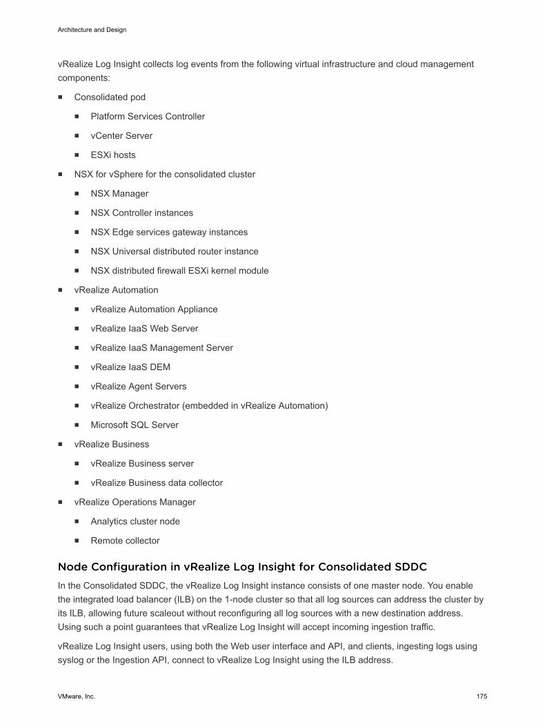
vRealize Log Insight collects log events from the following virtual infrastructure and cloud managementcomponents:
n Consolidated pod
n Platform Services Controller
n vCenter Server
n ESXi hosts
n NSX for vSphere for the consolidated cluster
n NSX Manager
n NSX Controller instances
n NSX Edge services gateway instances
n NSX Universal distributed router instance
n NSX distributed firewall ESXi kernel module
n vRealize Automation
n vRealize Automation Appliance
n vRealize IaaS Web Server
n vRealize IaaS Management Server
n vRealize IaaS DEM
n vRealize Agent Servers
n vRealize Orchestrator (embedded in vRealize Automation)
n Microsoft SQL Server
n vRealize Business
n vRealize Business server
n vRealize Business data collector
n vRealize Operations Manager
n Analytics cluster node
n Remote collector
Node Configuration in vRealize Log Insight for Consolidated SDDCIn the Consolidated SDDC, the vRealize Log Insight instance consists of one master node. You enablethe integrated load balancer (ILB) on the 1-node cluster so that all log sources can address the cluster byits ILB, allowing future scaleout without reconfiguring all log sources with a new destination address.Using such a point guarantees that vRealize Log Insight will accept incoming ingestion traffic.
vRealize Log Insight users, using both the Web user interface and API, and clients, ingesting logs usingsyslog or the Ingestion API, connect to vRealize Log Insight using the ILB address.
Architecture and Design
VMware, Inc. 175

vRealize Log Insight cluster can scale out to 12 nodes, that is, one master and 11 worker nodes.
Table 2‑142. Design Decisions about Node Configuration for vRealize Log Insight
Decision ID Design Decision Design Justification Design Implication
CSDDC-OPS-LOG-001
Deploy a singlevRealize Log Insightmaster node with anintegrated loadbalancer.
n Deploys a resource-aware logging platform.
Because of the minimal sizing requirements of theconsolidated pod, only a single vRealize Log Insightnode is required to accommodate the number ofexpected logging sources.
n Ensures that growth to the VMware Validated Designtwo-pod architecture is supported.
n Using the integrated load balancer simplifies the LogInsight deployment and subsequent integration.
n Using the integrated load balancer simplifies the LogInsight scale-out operations reducing the need toreconfigure existing logging sources.
Creates a single failuredomain. The singlevRealize Log Insightnode must use vSphereHA for availability.
Sizing Compute and Storage Resources in vRealize Log Insight forConsolidated SDDCTo accommodate all log data from the products in the Consolidated SDDC, you must size the computeresources and storage for the vRealize Log Insight nodes properly.
By default, the vRealize Log Insight virtual appliance uses the predefined values for small configurations,which has 4 vCPUs, 8 GB of virtual memory, and 530.5 GB of disk space provisioned. vRealize LogInsight uses 100 GB of the disk space to store raw data, index, metadata, and other information.
Sizing Compute Resources for vRealize Log Insight Nodes
Select a size for the vRealize Log Insight node so as to collect and store log data from the SDDCmanagement components and tenant workloads according to the objectives of this design.
Table 2‑143. Compute Resources for a vRealize Log Insight Small-Size Node
Attribute Specification
Appliance size Small
Number of CPUs 4
Memory 8 GB
Disk Capacity 530.5 GB (490 GB for event storage)
IOPS 500 IOPS
Amount of processed log data when using log ingestion 30 GB/day of processing per node
Number of processed log messages 2,000 event/second of processing per node
Environment Up to 100 syslog connections per node
Architecture and Design
VMware, Inc. 176
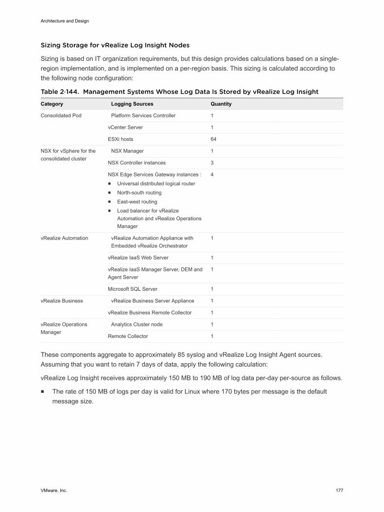
Sizing Storage for vRealize Log Insight Nodes
Sizing is based on IT organization requirements, but this design provides calculations based on a single-region implementation, and is implemented on a per-region basis. This sizing is calculated according tothe following node configuration:
Table 2‑144. Management Systems Whose Log Data Is Stored by vRealize Log Insight
Category Logging Sources Quantity
Consolidated Pod Platform Services Controller 1
vCenter Server 1
ESXi hosts 64
NSX for vSphere for theconsolidated cluster
NSX Manager 1
NSX Controller instances 3
NSX Edge Services Gateway instances :n Universal distributed logical routern North-south routingn East-west routingn Load balancer for vRealize
Automation and vRealize OperationsManager
4
vRealize Automation vRealize Automation Appliance withEmbedded vRealize Orchestrator
1
vRealize IaaS Web Server 1
vRealize IaaS Manager Server, DEM andAgent Server
1
Microsoft SQL Server 1
vRealize Business vRealize Business Server Appliance 1
vRealize Business Remote Collector 1
vRealize OperationsManager
Analytics Cluster node 1
Remote Collector 1
These components aggregate to approximately 85 syslog and vRealize Log Insight Agent sources.Assuming that you want to retain 7 days of data, apply the following calculation:
vRealize Log Insight receives approximately 150 MB to 190 MB of log data per-day per-source as follows.
n The rate of 150 MB of logs per day is valid for Linux where 170 bytes per message is the defaultmessage size.
Architecture and Design
VMware, Inc. 177

n The rate of 190 MB of logs per day is valid for Windows where 220 bytes per message is the defaultmessage size.
170 bytes per message * 10 messages per second * 86400 seconds per day = 150 MB of logs per-day per-
source (Linux)
220 bytes per message * 10 messages per second * 86400 seconds per day = 190 MB of logs per-day per-
source (Windows)
In this validated design, to simplify calculation, all calculations have been done using the large 220 bytesize which results in 190 MB of log data expected per-day per-source.
Calculate the storage space required for a single day for log data using the following equation:
85 sources * 190 MB of logs per-day per-source * 1e-9 GB per Byte ≈ 16 GB disk space per-day
Based on the amount of data stored in a single day, in order to size the Appliance for 7 days of logretention, use the following equations:
(16 GB * 7 days) / 1 appliance ≈ 112 GB disk space per vRealize Log Insight node
For 85 logging sources, at a basal rate of approximately 190 MB of logs that are ingested per-day per-source over 7 days, you need the following storage space:
112 GB * 1.7 indexing overhead ≈ 190 GB per vRealize Log Insight node
Based on this example, the storage space that is allocated per small-size vRealize Log Insight virtualappliance is enough to monitor the SDDC.
Consider the following approaches when you must increase the vRealize Log Insight capacity:
n If you must maintain a log data retention for more than 7 days in your SDDC, you can add morestorage to the master node by adding a new virtual hard disk. vRealize Log Insight supports virtualhard disks of up to 2 TB. If you must add more than 2 TB to a virtual appliance, add another virtualhard disk.
When you add storage so that you can increase the retention period, extend the storage for all virtualappliances. Only add new virtual hard disks to increase the storage. Do not extend existing retentionvirtual disks. Once provisioned, do not reduce the size or remove virtual disks to avoid data loss.
n If you must monitor more components by using log ingestion and exceed the number of syslogconnections or ingestion limits defined in this design, you can do the following:
n Increase the size of the vRealize Log Insight node, to a medium or large deployment size asdefined in the vRealize Log Insight documentation.
n Deploy more vRealize Log Insight virtual appliances to scale your environment out. vRealize LogInsight can scale up to 12 nodes in an HA cluster.
Architecture and Design
VMware, Inc. 178

Table 2‑145. Design Decisions about the Compute Resources for the vRealize Log InsightNodes
Decision ID Design Decision Design Justification Design Implication
CSDDC-OPS-LOG-002
Deploy vRealizeLog Insight nodesof small size.
Accommodates the number of expected syslog andvRealize Log Insight Agent connections from the followingSDDC components.n Consolidated vCenter Server and Platform Services
Controllern ESXi hosts in the consolidated clustern NSX for vSphere components for the consolidated
clustern vRealize Automation componentsn vRealize Business componentsn vRealize Operations Manager components
These sources generate approximately 85 syslog andvRealize Log Insight Agent sources.
Using a small-size appliance ensures that the storagespace for the vRealize Log Insight cluster is sufficient for 7days of data retention.
If you configure Log Insightto monitor additional loggingsources, you must increasethe size of the master nodeor add more worker nodes.
Networking Design of vRealize Log Insight for Consolidated SDDCYou place the vRealize Log Insight node in an application virtual network for isolation. The networkingdesign also supports public access to the vRealize Log Insight cluster. For secure access and co-localization, the vRealize Log Insight node are deployed in the shared region-specific application virtualnetwork Mgmt-RegionA01-VXLAN.
Architecture and Design
VMware, Inc. 179
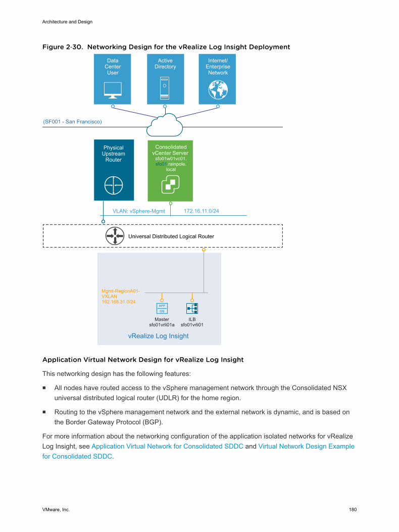
Figure 2‑30. Networking Design for the vRealize Log Insight Deployment
APP
OS
Universal Distributed Logical Router
DataCenterUser
ActiveDirectory
Internet/EnterpriseNetwork
(SF001 - San Francisco)
VLAN: vSphere-Mgmt 172.16.11.0/24
ConsolidatedvCenter Server
sfo01w01vc01.sfo01.rainpole.
local
PhysicalUpstream
Router
Mgmt-RegionA01-VXLAN192.168.31.0/24
vRealize Log Insight
Mastersfo01vrli01a
ILBsfo01vrli01
Application Virtual Network Design for vRealize Log Insight
This networking design has the following features:
n All nodes have routed access to the vSphere management network through the Consolidated NSXuniversal distributed logical router (UDLR) for the home region.
n Routing to the vSphere management network and the external network is dynamic, and is based onthe Border Gateway Protocol (BGP).
For more information about the networking configuration of the application isolated networks for vRealizeLog Insight, see Application Virtual Network for Consolidated SDDC and Virtual Network Design Examplefor Consolidated SDDC.
Architecture and Design
VMware, Inc. 180
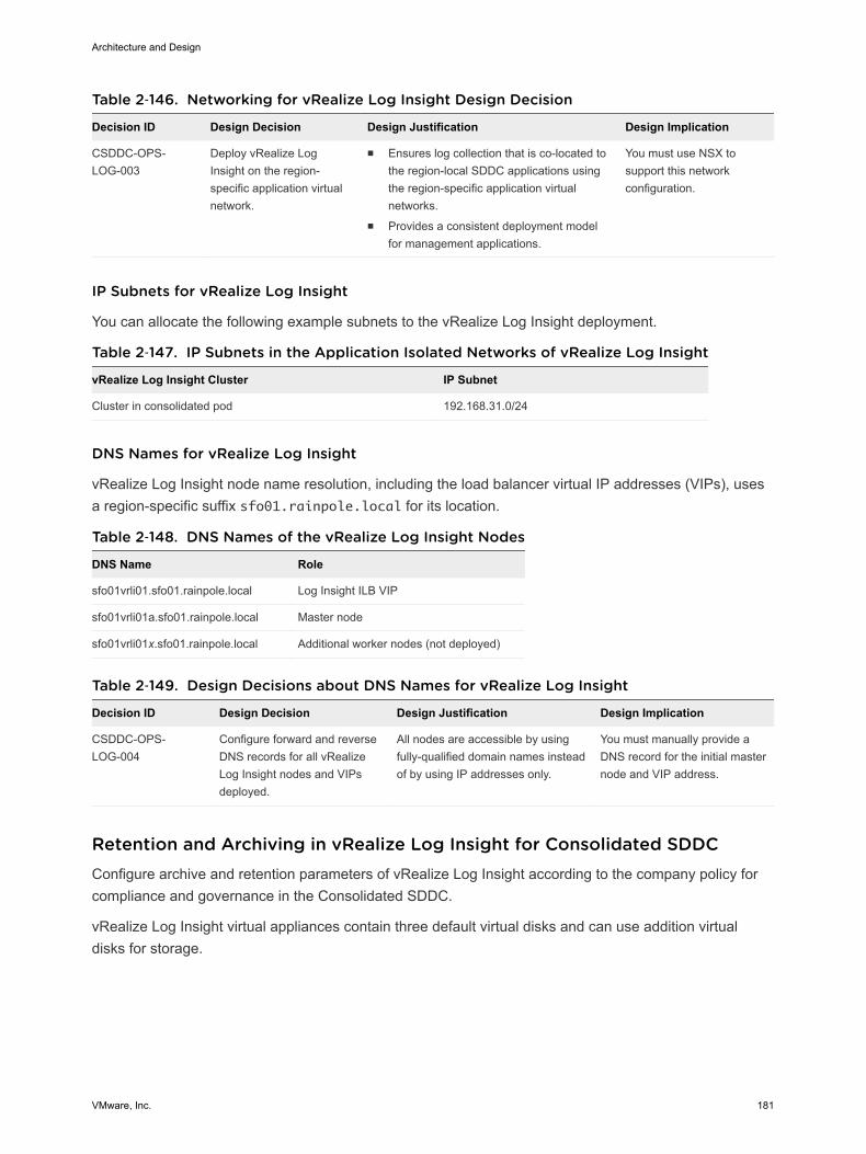
Table 2‑146. Networking for vRealize Log Insight Design Decision
Decision ID Design Decision Design Justification Design Implication
CSDDC-OPS-LOG-003
Deploy vRealize LogInsight on the region-specific application virtualnetwork.
n Ensures log collection that is co-located tothe region-local SDDC applications usingthe region-specific application virtualnetworks.
n Provides a consistent deployment modelfor management applications.
You must use NSX tosupport this networkconfiguration.
IP Subnets for vRealize Log Insight
You can allocate the following example subnets to the vRealize Log Insight deployment.
Table 2‑147. IP Subnets in the Application Isolated Networks of vRealize Log Insight
vRealize Log Insight Cluster IP Subnet
Cluster in consolidated pod 192.168.31.0/24
DNS Names for vRealize Log Insight
vRealize Log Insight node name resolution, including the load balancer virtual IP addresses (VIPs), usesa region-specific suffix sfo01.rainpole.local for its location.
Table 2‑148. DNS Names of the vRealize Log Insight Nodes
DNS Name Role
sfo01vrli01.sfo01.rainpole.local Log Insight ILB VIP
sfo01vrli01a.sfo01.rainpole.local Master node
sfo01vrli01x.sfo01.rainpole.local Additional worker nodes (not deployed)
Table 2‑149. Design Decisions about DNS Names for vRealize Log Insight
Decision ID Design Decision Design Justification Design Implication
CSDDC-OPS-LOG-004
Configure forward and reverseDNS records for all vRealizeLog Insight nodes and VIPsdeployed.
All nodes are accessible by usingfully-qualified domain names insteadof by using IP addresses only.
You must manually provide aDNS record for the initial masternode and VIP address.
Retention and Archiving in vRealize Log Insight for Consolidated SDDCConfigure archive and retention parameters of vRealize Log Insight according to the company policy forcompliance and governance in the Consolidated SDDC.
vRealize Log Insight virtual appliances contain three default virtual disks and can use addition virtualdisks for storage.
Architecture and Design
VMware, Inc. 181
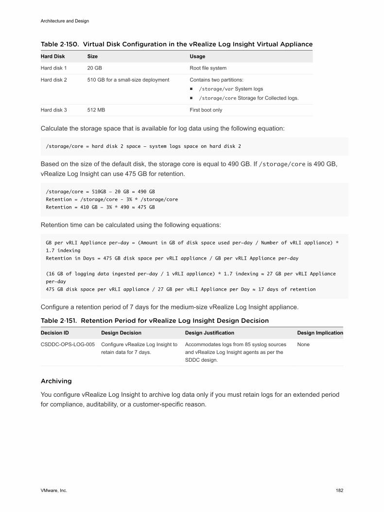
Table 2‑150. Virtual Disk Configuration in the vRealize Log Insight Virtual Appliance
Hard Disk Size Usage
Hard disk 1 20 GB Root file system
Hard disk 2 510 GB for a small-size deployment Contains two partitions:n /storage/var System logsn /storage/core Storage for Collected logs.
Hard disk 3 512 MB First boot only
Calculate the storage space that is available for log data using the following equation:
/storage/core = hard disk 2 space - system logs space on hard disk 2
Based on the size of the default disk, the storage core is equal to 490 GB. If /storage/core is 490 GB,vRealize Log Insight can use 475 GB for retention.
/storage/core = 510GB - 20 GB = 490 GB
Retention = /storage/core – 3% * /storage/core
Retention = 410 GB - 3% * 490 ≈ 475 GB
Retention time can be calculated using the following equations:
GB per vRLI Appliance per-day = (Amount in GB of disk space used per-day / Number of vRLI appliance) *
1.7 indexing
Retention in Days = 475 GB disk space per vRLI appliance / GB per vRLI Appliance per-day
(16 GB of logging data ingested per-day / 1 vRLI appliance) * 1.7 indexing ≈ 27 GB per vRLI Appliance
per-day
475 GB disk space per vRLI appliance / 27 GB per vRLI Appliance per Day ≈ 17 days of retention
Configure a retention period of 7 days for the medium-size vRealize Log Insight appliance.
Table 2‑151. Retention Period for vRealize Log Insight Design Decision
Decision ID Design Decision Design Justification Design Implication
CSDDC-OPS-LOG-005 Configure vRealize Log Insight toretain data for 7 days.
Accommodates logs from 85 syslog sourcesand vRealize Log Insight agents as per theSDDC design.
None
Archiving
You configure vRealize Log Insight to archive log data only if you must retain logs for an extended periodfor compliance, auditability, or a customer-specific reason.
Architecture and Design
VMware, Inc. 182

Attribute of Log Archiving Description
Archiving period vRealize Log Insight archives log messages as soon aspossible. At the same time, the logs are retained on the virtualappliance until the free local space is almost filled. Data existson both the vRealize Log Insight appliance and the archivelocation for most of the retention period. The archiving periodmust be longer than the retention period.
Archive location The archive location must be on an NFS version 3 sharedstorage. The archive location must be available and must haveenough capacity to accommodate the archives.
Apply an archive policy of 90 days for the small-size vRealize Log Insight appliance. The vRealize LogInsight appliance will use approximately 250 GB of shared storage calculated via the following:
(190 GB storage per vRLI Appliance * 1 vRLI Appliance) / 90 days Archiving Duration * 7 days Retention
Duration * 10% ≈ 250 GB
According to the business compliance regulations of your organization, these sizes might change.
Table 2‑152. Log Archive Policy for vRealize Log Insight Design Decision
Decision ID Design Decision Design Justification Design Implication
CSDDC-OPS-LOG-006
Allocate a minimumof 250 GB of NFSversion 3 sharedstorage to thevRealize Log Insightinstance.
Accommodates logarchiving from 85logging sources for 90days.
n You must manually maintain the vRealize Log Insightarchive objects stored on the NFS store, selectivelycleaning the datastore as more space is required.
n You must increase the size of the NFS shared storage ifyou configure vRealize Log Insight to monitor morelogging sources or add more vRealize Log Insightworkers.
n You must enforce the archive policy directly on the sharedstorage.
n If the NFS mount does not have enough free space or isunavailable for a period greater than the retention periodof the virtual appliance, vRealize Log Insight stopsingesting new data until the NFS mount has enough freespace, becomes available, or archiving is disabled.
Alerting in vRealize Log Insight for Consolidated SDDCvRealize Log Insight supports alerts that trigger notifications about its health.
Architecture and Design
VMware, Inc. 183
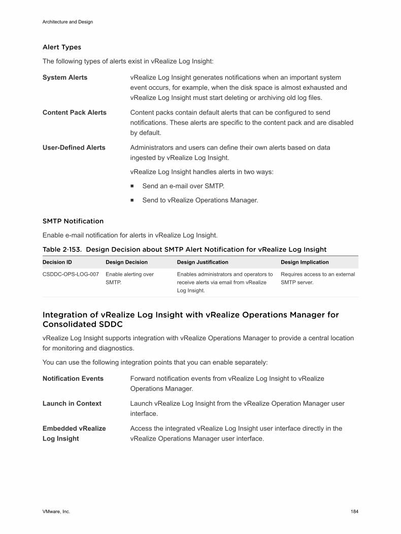
Alert Types
The following types of alerts exist in vRealize Log Insight:
System Alerts vRealize Log Insight generates notifications when an important systemevent occurs, for example, when the disk space is almost exhausted andvRealize Log Insight must start deleting or archiving old log files.
Content Pack Alerts Content packs contain default alerts that can be configured to sendnotifications. These alerts are specific to the content pack and are disabledby default.
User-Defined Alerts Administrators and users can define their own alerts based on dataingested by vRealize Log Insight.
vRealize Log Insight handles alerts in two ways:
n Send an e-mail over SMTP.
n Send to vRealize Operations Manager.
SMTP Notification
Enable e-mail notification for alerts in vRealize Log Insight.
Table 2‑153. Design Decision about SMTP Alert Notification for vRealize Log Insight
Decision ID Design Decision Design Justification Design Implication
CSDDC-OPS-LOG-007 Enable alerting overSMTP.
Enables administrators and operators toreceive alerts via email from vRealizeLog Insight.
Requires access to an externalSMTP server.
Integration of vRealize Log Insight with vRealize Operations Manager forConsolidated SDDCvRealize Log Insight supports integration with vRealize Operations Manager to provide a central locationfor monitoring and diagnostics.
You can use the following integration points that you can enable separately:
Notification Events Forward notification events from vRealize Log Insight to vRealizeOperations Manager.
Launch in Context Launch vRealize Log Insight from the vRealize Operation Manager userinterface.
Embedded vRealizeLog Insight
Access the integrated vRealize Log Insight user interface directly in thevRealize Operations Manager user interface.
Architecture and Design
VMware, Inc. 184

Table 2‑154. Design Decisions about Integration of vRealize Log Insight with vRealizeOperations Manager
Decision ID Design Decision Design Justification Design Implication
CSDDC-OPS-LOG-008
Forward alerts to vRealizeOperations Manager.
Provides monitoring and alerting informationthat is pushed from vRealize Log Insight tovRealize Operations Manager forcentralized administration.
None.
CSDDC-OPS-LOG-009
Allow for Launch InContext with vRealizeOperation Manager.
Provides the ability to access vRealize LogInsight for context-based monitoring of anobject in vRealize Operations Manager.
You can register only onevRealize Log Insight cluster withvRealize Operations Managerfor Launch in Context at a time.
CSDDC-OPS-LOG-010
Enable embeddedvRealize Log Insight userinterface in vRealizeOperations Manager.
Provides the ability to centrally accessvRealize Log Insight user interface forimproved context-based monitoring on anobject in vRealize Operations Manager.
You can register only onevRealize Log Insight cluster withvRealize Operations Manager ata time.
Information Security and Access Control in vRealize Log Insight forConsolidated SDDCProtect the vRealize Log Insight deployment by providing centralized role-based authentication andsecure communication with the other components in the Consolidated SDDC.
Authentication
Enable role-based access control in vRealize Log Insight by using the existing rainpole.local ActiveDirectory domain.
Table 2‑155. Design Decisions about Authorization and Authentication Management forvRealize Log Insight
Decision ID Design Decision Design Justification Design Implication
CSDDC-OPS-LOG-011
Use Active Directory forauthentication.
Provides fine-grained role and privilege-basedaccess for administrator and operator roles.
You must provide accessto the Active Directoryfrom all Log Insightnodes.
SDDC-OPS-LOG-012
Configure a service accountsvc-vrli on vCenter Server forapplication-to-applicationcommunication from vRealizeLog Insight with vSphere.
Provides the following access control features:n vRealize Log Insight accesses vSphere with
the minimum set of permissions that arerequired to collect vCenter Server events,tasks, and alarms, and to configure ESXi hostsfor syslog forwarding.
n In the event of a compromised account, theaccessibility in the destination applicationremains restricted.
n You can introduce improved accountability intracking request-response interactionsbetween the components of the SDDC.
You must maintain theservice account's lifecycle outside of theSDDC stack to ensure itsavailability.
Architecture and Design
VMware, Inc. 185
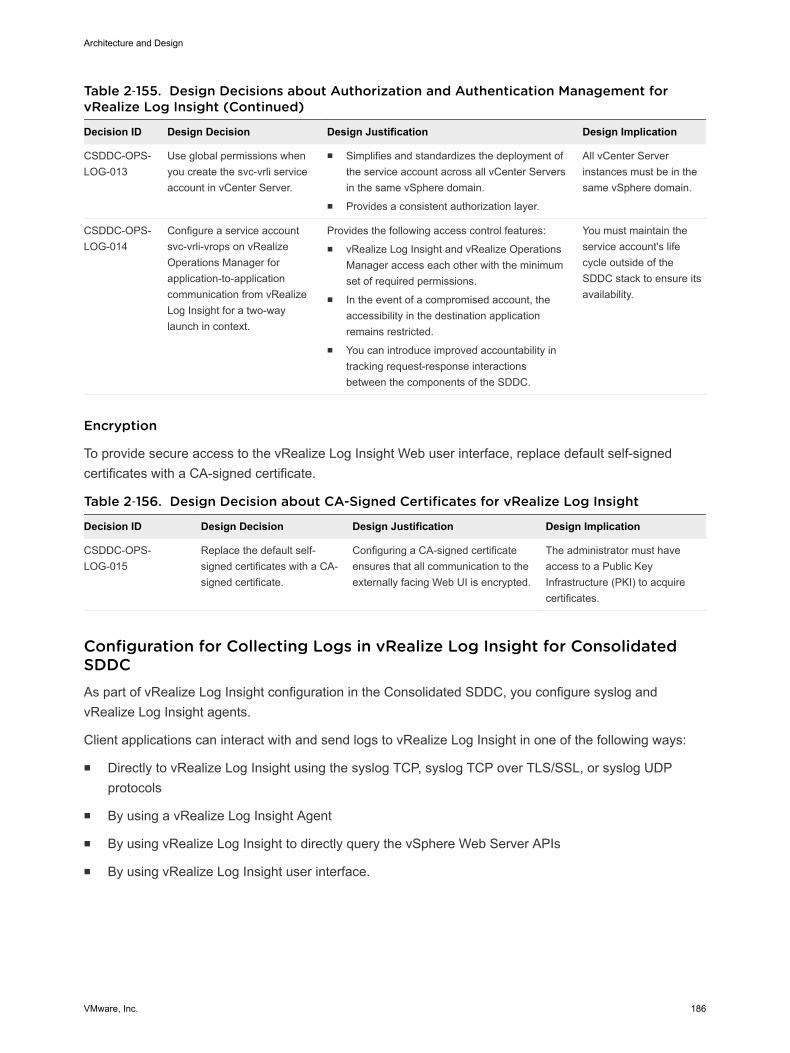
Table 2‑155. Design Decisions about Authorization and Authentication Management forvRealize Log Insight (Continued)
Decision ID Design Decision Design Justification Design Implication
CSDDC-OPS-LOG-013
Use global permissions whenyou create the svc-vrli serviceaccount in vCenter Server.
n Simplifies and standardizes the deployment ofthe service account across all vCenter Serversin the same vSphere domain.
n Provides a consistent authorization layer.
All vCenter Serverinstances must be in thesame vSphere domain.
CSDDC-OPS-LOG-014
Configure a service accountsvc-vrli-vrops on vRealizeOperations Manager forapplication-to-applicationcommunication from vRealizeLog Insight for a two-waylaunch in context.
Provides the following access control features:n vRealize Log Insight and vRealize Operations
Manager access each other with the minimumset of required permissions.
n In the event of a compromised account, theaccessibility in the destination applicationremains restricted.
n You can introduce improved accountability intracking request-response interactionsbetween the components of the SDDC.
You must maintain theservice account's lifecycle outside of theSDDC stack to ensure itsavailability.
Encryption
To provide secure access to the vRealize Log Insight Web user interface, replace default self-signedcertificates with a CA-signed certificate.
Table 2‑156. Design Decision about CA-Signed Certificates for vRealize Log Insight
Decision ID Design Decision Design Justification Design Implication
CSDDC-OPS-LOG-015
Replace the default self-signed certificates with a CA-signed certificate.
Configuring a CA-signed certificateensures that all communication to theexternally facing Web UI is encrypted.
The administrator must haveaccess to a Public KeyInfrastructure (PKI) to acquirecertificates.
Configuration for Collecting Logs in vRealize Log Insight for ConsolidatedSDDCAs part of vRealize Log Insight configuration in the Consolidated SDDC, you configure syslog andvRealize Log Insight agents.
Client applications can interact with and send logs to vRealize Log Insight in one of the following ways:
n Directly to vRealize Log Insight using the syslog TCP, syslog TCP over TLS/SSL, or syslog UDPprotocols
n By using a vRealize Log Insight Agent
n By using vRealize Log Insight to directly query the vSphere Web Server APIs
n By using vRealize Log Insight user interface.
Architecture and Design
VMware, Inc. 186

Table 2‑157. Design Decisions about Direct Log Communication to vRealize Log Insight
Decision ID Design Decision Design Justification Design Implication
CSDDC-OPS-LOG-016
Configure syslog sources andvRealize Log Insight Agents tosend log data directly to thevirtual IP (VIP) address of thevRealize Log Insight integratedload balancer (ILB).
n Allows for future scale-outwithout reconfiguring all logsources with a new destinationaddress.
n Simplifies the configuration of logsources within the SDDC.
n You must configure the IntegratedLoad Balancer on the vRealize LogInsight cluster.
n You must configure logging sourcesto forward data to the vRealize LogInsight VIP.
CSDDC-OPS-LOG-017
Deploy and configure thevRealize Log Insight agent forthe vRealize AutomationWindows servers.
n Microsoft Windows does notnatively support syslog.
n vRealize Automation requiresthe use of agents to collect allvRealize Automation logs.
You must manually install and configurethe agents on several nodes.
CSDDC-OPS-LOG-018
Configure the vRealize LogInsight agent on the vRealizeAutomation appliance.
Simplifies configuration of logsources within the SDDC that arepre-packaged with the vRealize LogInsight agent.
You must configure the vRealize LogInsight agent to forward logs to thevRealize Log Insight VIP.
CSDDC-OPS-LOG-019
Configure the vRealize LogInsight agent for the vRealizeBusiness appliances including:n Server appliancen Data collectors
Simplifies configuration of logsources within the SDDC that arepre-packaged with the vRealize LogInsight agent.
You must configure the vRealize LogInsight agent to forward logs to thevRealize Log Insight VIP.
CSDDC-OPS-LOG-020
Configure the vRealize LogInsight agent for the vRealizeOperation Manager appliancesincluding:n Analytics nodesn Remote collectors
Simplifies configuration of logsources within the SDDC that arepre-packaged with the vRealize LogInsight agent.
You must configure the vRealize LogInsight agent to forward logs to thevRealize Log Insight VIP.
CSDDC-OPS-LOG-021
Configure the NSX for vSpherecomponents as direct syslogsources for vRealize LogInsight including:n NSX Managern NSX Controllersn NSX Edge services
gateways
Simplifies configuration of logsources within the SDDC that aresyslog-capable.
n You must manually configure syslogsources to forward logs to thevRealize Log Insight VIP.
n Not all operating system-level eventsare forwarded to vRealize LogInsight.
CSDDC-OPS-LOG-022
Configure vCenter ServerAppliance instances andPlatform Services Controllerappliances as direct syslogsources for vRealize LogInsight.
Simplifies configuration of logsources within the SDDC that aresyslog-capable.
n You must manually configure syslogsources to forward logs to thevRealize Log Insight VIP.
n Certain dashboards within vRealizeLog Insight require the use of thevRealize Log Insight Agent deployedon the Platform Services Controllerand vCenter Server to populatewidgets.
n Not all operating system-level eventsare forwarded to vRealize LogInsight.
Architecture and Design
VMware, Inc. 187
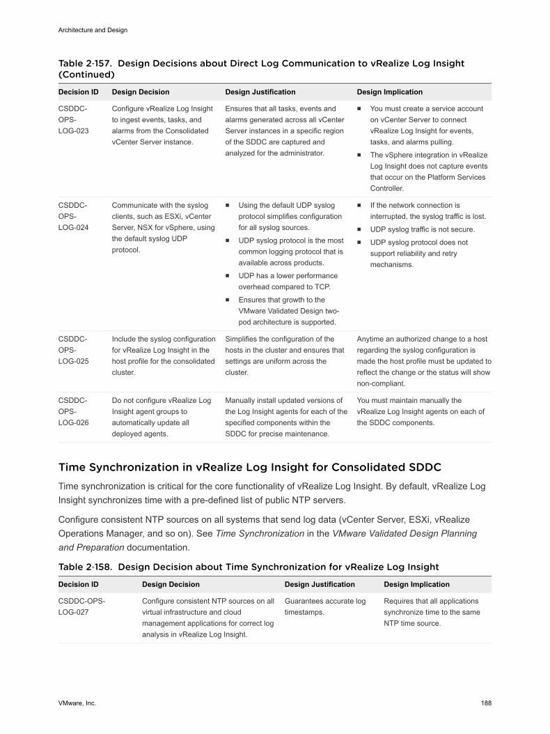
Table 2‑157. Design Decisions about Direct Log Communication to vRealize Log Insight(Continued)
Decision ID Design Decision Design Justification Design Implication
CSDDC-OPS-LOG-023
Configure vRealize Log Insightto ingest events, tasks, andalarms from the ConsolidatedvCenter Server instance.
Ensures that all tasks, events andalarms generated across all vCenterServer instances in a specific regionof the SDDC are captured andanalyzed for the administrator.
n You must create a service accounton vCenter Server to connectvRealize Log Insight for events,tasks, and alarms pulling.
n The vSphere integration in vRealizeLog Insight does not capture eventsthat occur on the Platform ServicesController.
CSDDC-OPS-LOG-024
Communicate with the syslogclients, such as ESXi, vCenterServer, NSX for vSphere, usingthe default syslog UDPprotocol.
n Using the default UDP syslogprotocol simplifies configurationfor all syslog sources.
n UDP syslog protocol is the mostcommon logging protocol that isavailable across products.
n UDP has a lower performanceoverhead compared to TCP.
n Ensures that growth to theVMware Validated Design two-pod architecture is supported.
n If the network connection isinterrupted, the syslog traffic is lost.
n UDP syslog traffic is not secure.n UDP syslog protocol does not
support reliability and retrymechanisms.
CSDDC-OPS-LOG-025
Include the syslog configurationfor vRealize Log Insight in thehost profile for the consolidatedcluster.
Simplifies the configuration of thehosts in the cluster and ensures thatsettings are uniform across thecluster.
Anytime an authorized change to a hostregarding the syslog configuration ismade the host profile must be updated toreflect the change or the status will shownon-compliant.
CSDDC-OPS-LOG-026
Do not configure vRealize LogInsight agent groups toautomatically update alldeployed agents.
Manually install updated versions ofthe Log Insight agents for each of thespecified components within theSDDC for precise maintenance.
You must maintain manually thevRealize Log Insight agents on each ofthe SDDC components.
Time Synchronization in vRealize Log Insight for Consolidated SDDCTime synchronization is critical for the core functionality of vRealize Log Insight. By default, vRealize LogInsight synchronizes time with a pre-defined list of public NTP servers.
Configure consistent NTP sources on all systems that send log data (vCenter Server, ESXi, vRealizeOperations Manager, and so on). See Time Synchronization in the VMware Validated Design Planningand Preparation documentation.
Table 2‑158. Design Decision about Time Synchronization for vRealize Log Insight
Decision ID Design Decision Design Justification Design Implication
CSDDC-OPS-LOG-027
Configure consistent NTP sources on allvirtual infrastructure and cloudmanagement applications for correct loganalysis in vRealize Log Insight.
Guarantees accurate logtimestamps.
Requires that all applicationssynchronize time to the sameNTP time source.
Architecture and Design
VMware, Inc. 188
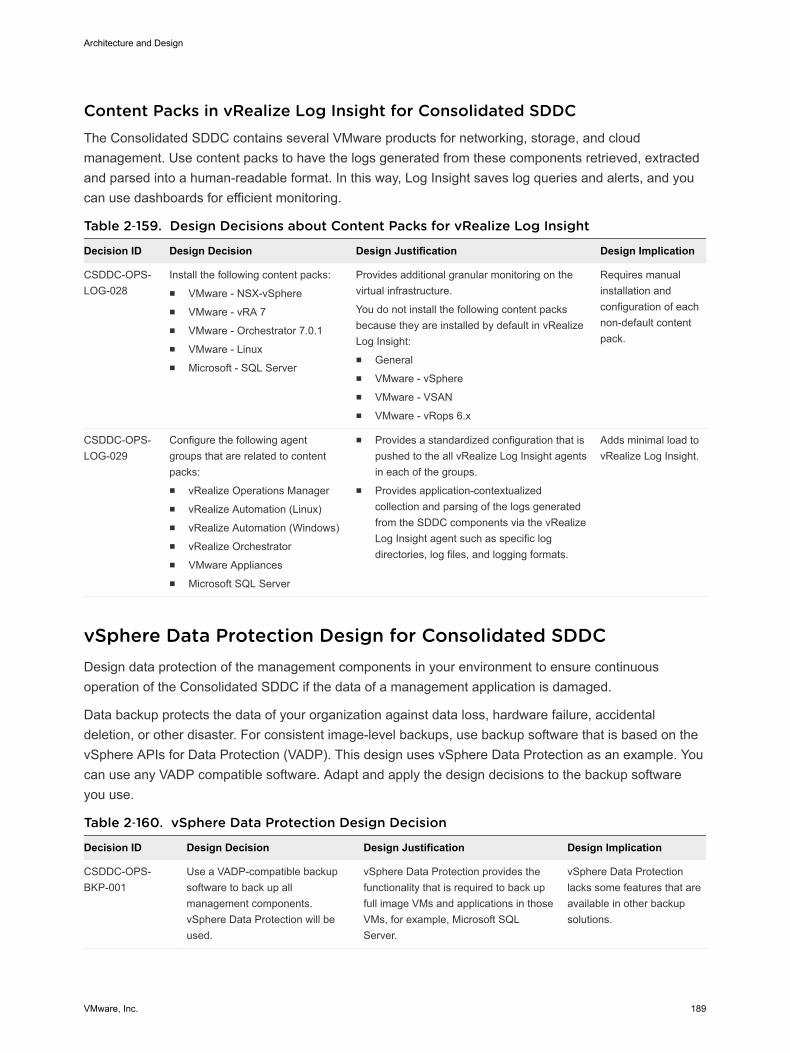
Content Packs in vRealize Log Insight for Consolidated SDDCThe Consolidated SDDC contains several VMware products for networking, storage, and cloudmanagement. Use content packs to have the logs generated from these components retrieved, extractedand parsed into a human-readable format. In this way, Log Insight saves log queries and alerts, and youcan use dashboards for efficient monitoring.
Table 2‑159. Design Decisions about Content Packs for vRealize Log Insight
Decision ID Design Decision Design Justification Design Implication
CSDDC-OPS-LOG-028
Install the following content packs:n VMware - NSX-vSpheren VMware - vRA 7n VMware - Orchestrator 7.0.1n VMware - Linuxn Microsoft - SQL Server
Provides additional granular monitoring on thevirtual infrastructure.
You do not install the following content packsbecause they are installed by default in vRealizeLog Insight:n Generaln VMware - vSpheren VMware - VSANn VMware - vRops 6.x
Requires manualinstallation andconfiguration of eachnon-default contentpack.
CSDDC-OPS-LOG-029
Configure the following agentgroups that are related to contentpacks:n vRealize Operations Managern vRealize Automation (Linux)n vRealize Automation (Windows)n vRealize Orchestratorn VMware Appliancesn Microsoft SQL Server
n Provides a standardized configuration that ispushed to the all vRealize Log Insight agentsin each of the groups.
n Provides application-contextualizedcollection and parsing of the logs generatedfrom the SDDC components via the vRealizeLog Insight agent such as specific logdirectories, log files, and logging formats.
Adds minimal load tovRealize Log Insight.
vSphere Data Protection Design for Consolidated SDDCDesign data protection of the management components in your environment to ensure continuousoperation of the Consolidated SDDC if the data of a management application is damaged.
Data backup protects the data of your organization against data loss, hardware failure, accidentaldeletion, or other disaster. For consistent image-level backups, use backup software that is based on thevSphere APIs for Data Protection (VADP). This design uses vSphere Data Protection as an example. Youcan use any VADP compatible software. Adapt and apply the design decisions to the backup softwareyou use.
Table 2‑160. vSphere Data Protection Design Decision
Decision ID Design Decision Design Justification Design Implication
CSDDC-OPS-BKP-001
Use a VADP-compatible backupsoftware to back up allmanagement components.vSphere Data Protection will beused.
vSphere Data Protection provides thefunctionality that is required to back upfull image VMs and applications in thoseVMs, for example, Microsoft SQLServer.
vSphere Data Protectionlacks some features that areavailable in other backupsolutions.
Architecture and Design
VMware, Inc. 189
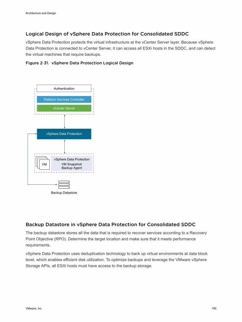
Logical Design of vSphere Data Protection for Consolidated SDDCvSphere Data Protection protects the virtual infrastructure at the vCenter Server layer. Because vSphereData Protection is connected to vCenter Server, it can access all ESXi hosts in the SDDC, and can detectthe virtual machines that require backups.
Figure 2‑31. vSphere Data Protection Logical Design
VM
Authentication
Platform Services Controller
vCenter Server
vSphere Data Protection
vSphere Data ProtectionVM Snapshot/Backup Agent
Backup Datastore
Backup Datastore in vSphere Data Protection for Consolidated SDDCThe backup datastore stores all the data that is required to recover services according to a RecoveryPoint Objective (RPO). Determine the target location and make sure that it meets performancerequirements.
vSphere Data Protection uses deduplication technology to back up virtual environments at data blocklevel, which enables efficient disk utilization. To optimize backups and leverage the VMware vSphereStorage APIs, all ESXi hosts must have access to the backup storage.
Architecture and Design
VMware, Inc. 190
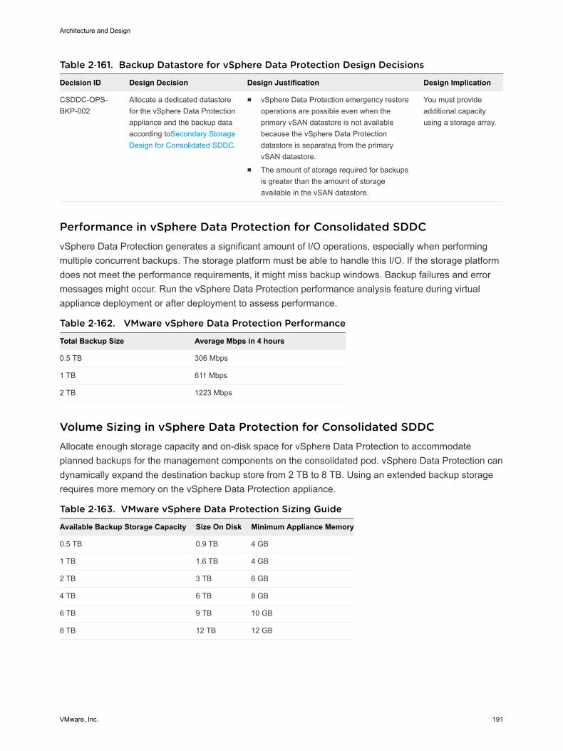
Table 2‑161. Backup Datastore for vSphere Data Protection Design Decisions
Decision ID Design Decision Design Justification Design Implication
CSDDC-OPS-BKP-002
Allocate a dedicated datastorefor the vSphere Data Protectionappliance and the backup dataaccording toSecondary StorageDesign for Consolidated SDDC.
n vSphere Data Protection emergency restoreoperations are possible even when theprimary vSAN datastore is not availablebecause the vSphere Data Protectiondatastore is separateд from the primaryvSAN datastore.
n The amount of storage required for backupsis greater than the amount of storageavailable in the vSAN datastore.
You must provideadditional capacityusing a storage array.
Performance in vSphere Data Protection for Consolidated SDDCvSphere Data Protection generates a significant amount of I/O operations, especially when performingmultiple concurrent backups. The storage platform must be able to handle this I/O. If the storage platformdoes not meet the performance requirements, it might miss backup windows. Backup failures and errormessages might occur. Run the vSphere Data Protection performance analysis feature during virtualappliance deployment or after deployment to assess performance.
Table 2‑162. VMware vSphere Data Protection Performance
Total Backup Size Average Mbps in 4 hours
0.5 TB 306 Mbps
1 TB 611 Mbps
2 TB 1223 Mbps
Volume Sizing in vSphere Data Protection for Consolidated SDDCAllocate enough storage capacity and on-disk space for vSphere Data Protection to accommodateplanned backups for the management components on the consolidated pod. vSphere Data Protection candynamically expand the destination backup store from 2 TB to 8 TB. Using an extended backup storagerequires more memory on the vSphere Data Protection appliance.
Table 2‑163. VMware vSphere Data Protection Sizing Guide
Available Backup Storage Capacity Size On Disk Minimum Appliance Memory
0.5 TB 0.9 TB 4 GB
1 TB 1.6 TB 4 GB
2 TB 3 TB 6 GB
4 TB 6 TB 8 GB
6 TB 9 TB 10 GB
8 TB 12 TB 12 GB
Architecture and Design
VMware, Inc. 191

Table 2‑164. Design Decisions about VMware Backup Store Size
Decision ID Design Decision Design Justification Design Implication
CSDDC-OPS-BKP-003
Deploy the vSphere DataProtection virtual appliance initiallyfor 4 TB of available backupstorage capacity and 6 TB on-disksize.
Handles the backup of themanagement stack. The managementstack currently consumesapproximately 2 TB of disk space,uncompressed and withoutdeduplication.
You must provide morestorage to accommodateincreased disk requirements.
Backup Policies in vSphere Data Protection for Consolidated SDDCUse vSphere Data Protection backup policies to specify virtual machine backup options, the schedulewindow, and retention policies.
Virtual Machine Backup Options
vSphere Data Protection provides the following options for a virtual machine backup:
HotAdd Provides full image backups of virtual machines, regardless of the guestoperating system.
n The virtual machine base disk is attached directly to vSphere DataProtection to back up data. vSphere Data Protection uses ChangedBlock Tracking to detect and back up blocks that are altered.
n The backup and restore performance is faster because the data flow isthrough the VMkernel layer instead of over a network connection.
n A quiesced snapshot can be used to redirect the I/O of a virtualmachine disk .vmdk file.
n HotAdd does not work in multi-writer disk mode.
Network Block Device(NBD)
Transfers virtual machine data across the network to allow vSphere DataProtection to back up the data.
n The performance of the virtual machine network traffic might be lower.
n NBD takes a quiesced snapshot. As a result, it might interrupt the I/Ooperations of the virtual machine to swap the .vmdk file or consolidatethe data after the backup is complete.
n The time to complete the virtual machine backup might be longer thanthe backup window.
n NBD does not work in multi-writer disk mode.
vSphere DataProtection Agent InsideGuest OS
Provides backup of certain applications that are running in the guestoperating system through an installed backup agent.
n Enables application-consistent backup and recovery with MicrosoftSQL Server, Microsoft SharePoint, and Microsoft Exchange support.
Architecture and Design
VMware, Inc. 192
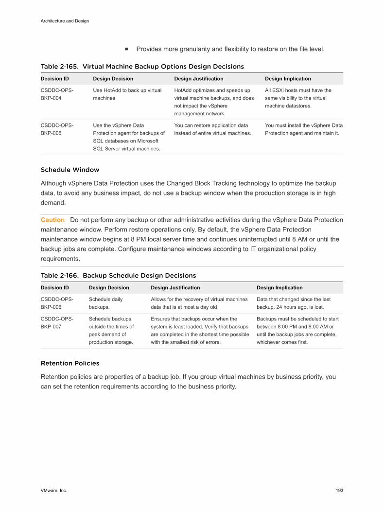
n Provides more granularity and flexibility to restore on the file level.
Table 2‑165. Virtual Machine Backup Options Design Decisions
Decision ID Design Decision Design Justification Design Implication
CSDDC-OPS-BKP-004
Use HotAdd to back up virtualmachines.
HotAdd optimizes and speeds upvirtual machine backups, and doesnot impact the vSpheremanagement network.
All ESXi hosts must have thesame visibility to the virtualmachine datastores.
CSDDC-OPS-BKP-005
Use the vSphere DataProtection agent for backups ofSQL databases on MicrosoftSQL Server virtual machines.
You can restore application datainstead of entire virtual machines.
You must install the vSphere DataProtection agent and maintain it.
Schedule Window
Although vSphere Data Protection uses the Changed Block Tracking technology to optimize the backupdata, to avoid any business impact, do not use a backup window when the production storage is in highdemand.
Caution Do not perform any backup or other administrative activities during the vSphere Data Protectionmaintenance window. Perform restore operations only. By default, the vSphere Data Protectionmaintenance window begins at 8 PM local server time and continues uninterrupted until 8 AM or until thebackup jobs are complete. Configure maintenance windows according to IT organizational policyrequirements.
Table 2‑166. Backup Schedule Design Decisions
Decision ID Design Decision Design Justification Design Implication
CSDDC-OPS-BKP-006
Schedule dailybackups.
Allows for the recovery of virtual machinesdata that is at most a day old
Data that changed since the lastbackup, 24 hours ago, is lost.
CSDDC-OPS-BKP-007
Schedule backupsoutside the times ofpeak demand ofproduction storage.
Ensures that backups occur when thesystem is least loaded. Verify that backupsare completed in the shortest time possiblewith the smallest risk of errors.
Backups must be scheduled to startbetween 8:00 PM and 8:00 AM oruntil the backup jobs are complete,whichever comes first.
Retention Policies
Retention policies are properties of a backup job. If you group virtual machines by business priority, youcan set the retention requirements according to the business priority.
Architecture and Design
VMware, Inc. 193

Table 2‑167. Retention Policies Design Decision
Decision ID Design Decision Design Justification Design Implication
CSDDC-OPS-BKP-008
Retain backups for atleast 3 days.
Keeping 3 days of backups enablesadministrators to restore the managementapplications to a state within the last 72hours.
Depending on the rate of change invirtual machines, backup retentionpolicy can increase the storage targetsize.
CSDDC-OPS-BKP-009
Retain backups forcross-region replicatedbackup jobs for atleast 1 day.
Keeping 1 day of a backup for replicated jobsenables administrators, in the event of adisaster recovery situation in which failoverwas unsuccessful, to restore their region-independent applications to a state within thelast 24 hours.
Data that has changed since the lastbackup, 24 hours ago, is lost. This dataloss also increases the storagerequirements for vSphere DataProtection in a multi-regionconfiguration.
Information Security and Access Control in vSphere Data Protection forConsolidated SDDCUse a service account for authentication and authorization of vSphere Data Protection for backup andrestore operations.
Table 2‑168. Authorization and Authentication Management for vSphere Data ProtectionDesign Decisions
Decision ID Design Decision Design Justification Design Implication
CSDDC-OPS-BKP-010
Configure a service accountsvc-vdp in vCenter Server forapplication-to-applicationcommunication from vSphereData Protection with vSphere.
Provides the following access control features:n vSphere Data Protection accesses
vSphere with the minimum set ofpermissions that are required to performbackup and restore operations.
n In the event of a compromised account, theaccessibility in the destination applicationremains restricted.
n You can introduce improved accountabilityin tracking request-response interactionsbetween the components of the SDDC.
You must maintain the serviceaccount's life cycle outside ofthe SDDC stack to ensure itsavailability.
CSDDC-OPS-BKP-011
Use global permissions whenyou create the svc-vdpservice account in vCenterServer.
n Simplifies and standardizes thedeployment of the service account acrossall vCenter Server instances in the samevSphere domain.
n Provides a consistent authorization layer.
When the SDDC platformscales out, all vCenter Serverinstances must be in thesame vSphere domain so thatthey can pick up globalpermissions.
Component Backup Jobs in vSphere Data Protection for Consolidated SDDCYou can configure backup for each SDDC management component separately. For this scenario, norequirement to back up the entire SDDC exists, and this design does not imply such an operation.
Some products can perform internal configuration backups. Use those products in addition to the wholevirtual machine component backup as appropriate.
Architecture and Design
VMware, Inc. 194
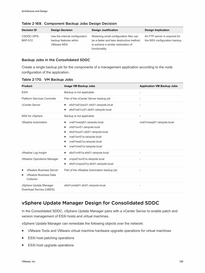
Table 2‑169. Component Backup Jobs Design Decision
Decision ID Design Decision Design Justification Design Implication
CSDDC-OPS-BKP-012
Use the internal configurationbackup features withinVMware NSX.
Restoring small configuration files canbe a faster and less destructive methodto achieve a similar restoration offunctionality.
An FTP server is required forthe NSX configuration backup.
Backup Jobs in the Consolidated SDDC
Create a single backup job for the components of a management application according to the nodeconfiguration of the application.
Table 2‑170. VM Backup Jobs
Product Image VM Backup Jobs Application VM Backup Jobs
ESXi Backup is not applicable -
Platform Services Controller Part of the vCenter Server backup job -
vCenter Server n sfo01w01psc01.sfo01.rainpole.localn sfo01w01vc01.sfo01.rainpole.local
-
NSX for vSphere Backup is not applicable -
vRealize Automation n vra01mssql01.rainpole.localn vrb01svr01.rainpole.localn sfo01buc01.sfo01.rainpole.localn vra01svr01a.rainpole.localn vra01iws01a.rainpole.localn vra01ims01a.rainpole.local
vra01mssql01.rainpole.local
vRealize Log Insight n sfo01vrli01a.sfo01.rainpole.local -
vRealize Operations Manager n vrops01svr01a.rainpole.localn sfo01vropsc01a.sfo01.rainpole.local
-
n vRealize Business Servern vRealize Business Data
Collector
Part of the vRealize Automation backup job -
vSphere Update ManagerDownload Service (UMDS)
sfo01umds01.sfo01.rainpole.local -
vSphere Update Manager Design for Consolidated SDDCIn the Consolidated SDDC, vSphere Update Manager pairs with a vCenter Server to enable patch andversion management of ESXi hosts and virtual machines.
vSphere Update Manager can remediate the following objects over the network:
n VMware Tools and VMware virtual machine hardware upgrade operations for virtual machines
n ESXi host patching operations
n ESXi host upgrade operations
Architecture and Design
VMware, Inc. 195
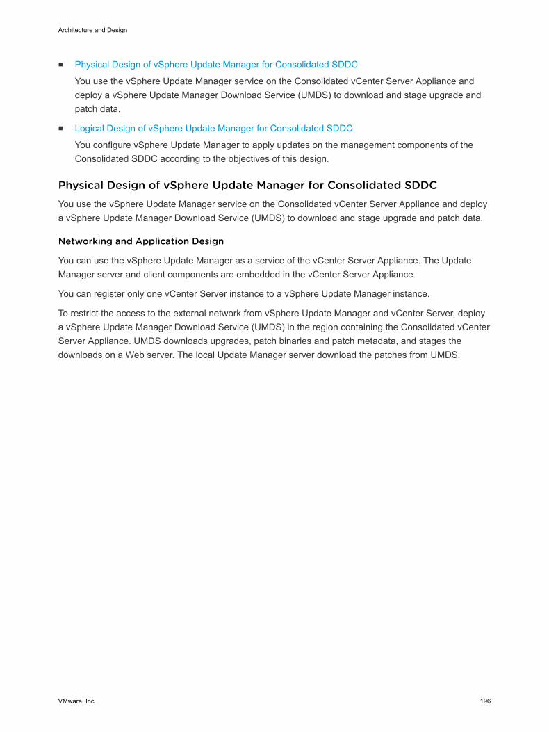
n Physical Design of vSphere Update Manager for Consolidated SDDC
You use the vSphere Update Manager service on the Consolidated vCenter Server Appliance anddeploy a vSphere Update Manager Download Service (UMDS) to download and stage upgrade andpatch data.
n Logical Design of vSphere Update Manager for Consolidated SDDC
You configure vSphere Update Manager to apply updates on the management components of theConsolidated SDDC according to the objectives of this design.
Physical Design of vSphere Update Manager for Consolidated SDDCYou use the vSphere Update Manager service on the Consolidated vCenter Server Appliance and deploya vSphere Update Manager Download Service (UMDS) to download and stage upgrade and patch data.
Networking and Application Design
You can use the vSphere Update Manager as a service of the vCenter Server Appliance. The UpdateManager server and client components are embedded in the vCenter Server Appliance.
You can register only one vCenter Server instance to a vSphere Update Manager instance.
To restrict the access to the external network from vSphere Update Manager and vCenter Server, deploya vSphere Update Manager Download Service (UMDS) in the region containing the Consolidated vCenterServer Appliance. UMDS downloads upgrades, patch binaries and patch metadata, and stages thedownloads on a Web server. The local Update Manager server download the patches from UMDS.
Architecture and Design
VMware, Inc. 196
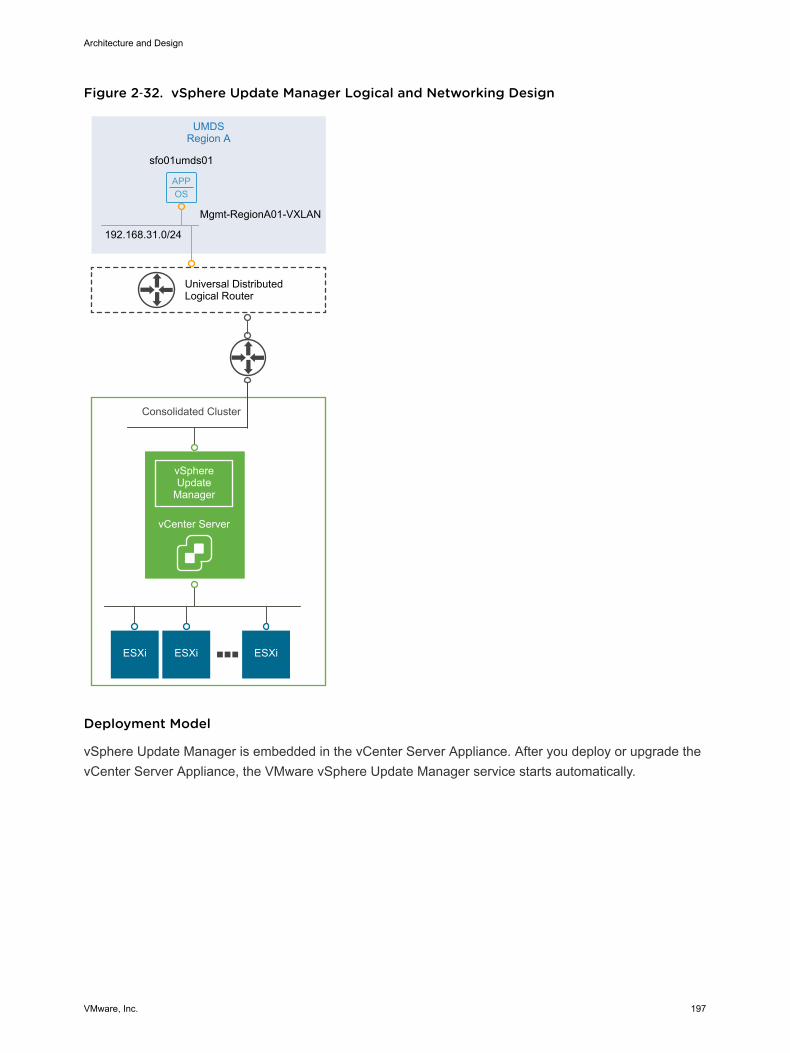
Figure 2‑32. vSphere Update Manager Logical and Networking Design
APPOS
ESXi ESXi ESXi
UMDSRegion A
Consolidated Cluster
192.168.31.0/24
Mgmt-RegionA01-VXLAN
sfo01umds01
Universal DistributedLogical Router
vSphereUpdate
Manager
vCenter Server
Deployment Model
vSphere Update Manager is embedded in the vCenter Server Appliance. After you deploy or upgrade thevCenter Server Appliance, the VMware vSphere Update Manager service starts automatically.
Architecture and Design
VMware, Inc. 197
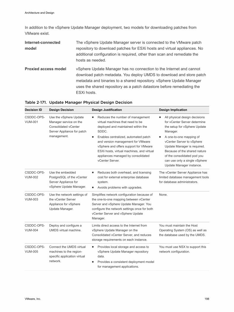
In addition to the vSphere Update Manager deployment, two models for downloading patches fromVMware exist.
Internet-connectedmodel
The vSphere Update Manager server is connected to the VMware patchrepository to download patches for ESXi hosts and virtual appliances. Noadditional configuration is required, other than scan and remediate thehosts as needed.
Proxied access model vSphere Update Manager has no connection to the Internet and cannotdownload patch metadata. You deploy UMDS to download and store patchmetadata and binaries to a shared repository. vSphere Update Manageruses the shared repository as a patch datastore before remediating theESXi hosts.
Table 2‑171. Update Manager Physical Design Decision
Decision ID Design Decision Design Justification Design Implication
CSDDC-OPS-VUM-001
Use the vSphere UpdateManager service on theConsolidated vCenterServer Appliance for patchmanagement.
n Reduces the number of managementvirtual machines that need to bedeployed and maintained within theSDDC.
n Enables centralized, automated patchand version management for VMwarevSphere and offers support for VMwareESXi hosts, virtual machines, and virtualappliances managed by consolidatedvCenter Server.
n All physical design decisionsfor vCenter Server determinethe setup for vSphere UpdateManager.
n A one-to-one mapping ofvCenter Server to vSphereUpdate Manager is required.Because of the shared natureof the consolidated pod youcan use only a single vSphereUpdate Manager instance.
CSDDC-OPS-VUM-002
Use the embeddedPostgreSQL of the vCenterServer Appliance forvSphere Update Manager.
n Reduces both overhead, and licensingcost for external enterprise databasesystem.
n Avoids problems with upgrades.
The vCenter Server Appliance haslimited database management toolsfor database administrators.
CSDDC-OPS-VUM-003
Use the network settings ofthe vCenter ServerAppliance for vSphereUpdate Manager.
Simplifies network configuration because ofthe one-to-one mapping between vCenterServer and vSphere Update Manager. Youconfigure the network settings once for bothvCenter Server and vSphere UpdateManager.
None.
CSDDC-OPS-VUM-004
Deploy and configure aUMDS virtual machine.
Limits direct access to the Internet fromvSphere Update Manager on theConsolidated vCenter Server, and reducesstorage requirements on each instance.
You must maintain the HostOperating System (OS) as well asthe database used by the UMDS.
CSDDC-OPS-VUM-005
Connect the UMDS virtualmachines to the region-specific application virtualnetwork.
n Provides local storage and access tovSphere Update Manager repositorydata.
n Provides a consistent deployment modelfor management applications.
You must use NSX to support thisnetwork configuration.
Architecture and Design
VMware, Inc. 198
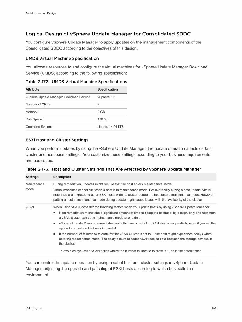
Logical Design of vSphere Update Manager for Consolidated SDDCYou configure vSphere Update Manager to apply updates on the management components of theConsolidated SDDC according to the objectives of this design.
UMDS Virtual Machine Specification
You allocate resources to and configure the virtual machines for vSphere Update Manager DownloadService (UMDS) according to the following specification:
Table 2‑172. UMDS Virtual Machine Specifications
Attribute Specification
vSphere Update Manager Download Service vSphere 6.5
Number of CPUs 2
Memory 2 GB
Disk Space 120 GB
Operating System Ubuntu 14.04 LTS
ESXi Host and Cluster Settings
When you perform updates by using the vSphere Update Manager, the update operation affects certaincluster and host base settings . You customize these settings according to your business requirementsand use cases.
Table 2‑173. Host and Cluster Settings That Are Affected by vSphere Update Manager
Settings Description
Maintenancemode
During remediation, updates might require that the host enters maintenance mode.
Virtual machines cannot run when a host is in maintenance mode. For availability during a host update, virtualmachines are migrated to other ESXi hosts within a cluster before the host enters maintenance mode. However,putting a host in maintenance mode during update might cause issues with the availability of the cluster.
vSAN When using vSAN, consider the following factors when you update hosts by using vSphere Update Manager:n Host remediation might take a significant amount of time to complete because, by design, only one host from
a vSAN cluster can be in maintenance mode at one time.n vSphere Update Manager remediates hosts that are a part of a vSAN cluster sequentially, even if you set the
option to remediate the hosts in parallel.n If the number of failures to tolerate for the vSAN cluster is set to 0, the host might experience delays when
entering maintenance mode. The delay occurs because vSAN copies data between the storage devices inthe cluster.
To avoid delays, set a vSAN policy where the number failures to tolerate is 1, as is the default case.
You can control the update operation by using a set of host and cluster settings in vSphere UpdateManager, adjusting the upgrade and patching of ESXi hosts according to which best suits theenvironment.
Architecture and Design
VMware, Inc. 199
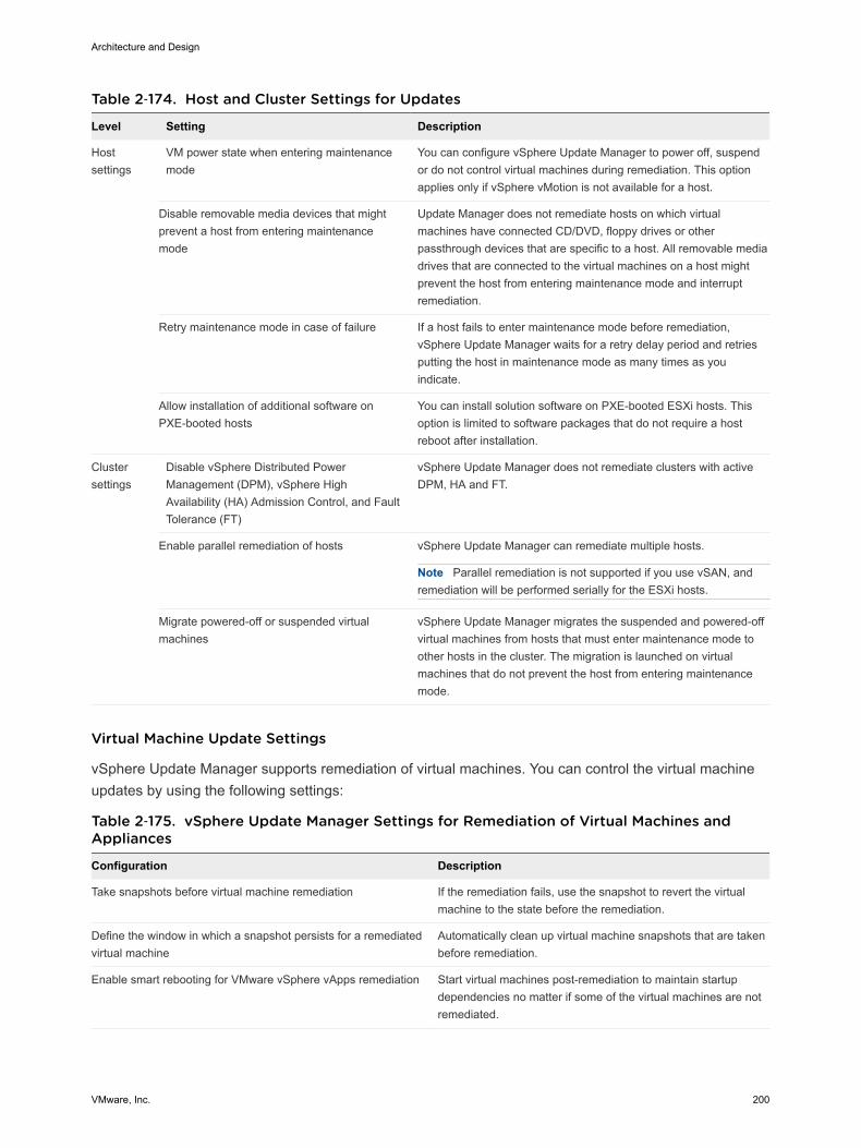
Table 2‑174. Host and Cluster Settings for Updates
Level Setting Description
Hostsettings
VM power state when entering maintenancemode
You can configure vSphere Update Manager to power off, suspendor do not control virtual machines during remediation. This optionapplies only if vSphere vMotion is not available for a host.
Disable removable media devices that mightprevent a host from entering maintenancemode
Update Manager does not remediate hosts on which virtualmachines have connected CD/DVD, floppy drives or otherpassthrough devices that are specific to a host. All removable mediadrives that are connected to the virtual machines on a host mightprevent the host from entering maintenance mode and interruptremediation.
Retry maintenance mode in case of failure If a host fails to enter maintenance mode before remediation,vSphere Update Manager waits for a retry delay period and retriesputting the host in maintenance mode as many times as youindicate.
Allow installation of additional software onPXE-booted hosts
You can install solution software on PXE-booted ESXi hosts. Thisoption is limited to software packages that do not require a hostreboot after installation.
Clustersettings
Disable vSphere Distributed PowerManagement (DPM), vSphere HighAvailability (HA) Admission Control, and FaultTolerance (FT)
vSphere Update Manager does not remediate clusters with activeDPM, HA and FT.
Enable parallel remediation of hosts vSphere Update Manager can remediate multiple hosts.
Note Parallel remediation is not supported if you use vSAN, andremediation will be performed serially for the ESXi hosts.
Migrate powered-off or suspended virtualmachines
vSphere Update Manager migrates the suspended and powered-offvirtual machines from hosts that must enter maintenance mode toother hosts in the cluster. The migration is launched on virtualmachines that do not prevent the host from entering maintenancemode.
Virtual Machine Update Settings
vSphere Update Manager supports remediation of virtual machines. You can control the virtual machineupdates by using the following settings:
Table 2‑175. vSphere Update Manager Settings for Remediation of Virtual Machines andAppliances
Configuration Description
Take snapshots before virtual machine remediation If the remediation fails, use the snapshot to revert the virtualmachine to the state before the remediation.
Define the window in which a snapshot persists for a remediatedvirtual machine
Automatically clean up virtual machine snapshots that are takenbefore remediation.
Enable smart rebooting for VMware vSphere vApps remediation Start virtual machines post-remediation to maintain startupdependencies no matter if some of the virtual machines are notremediated.
Architecture and Design
VMware, Inc. 200
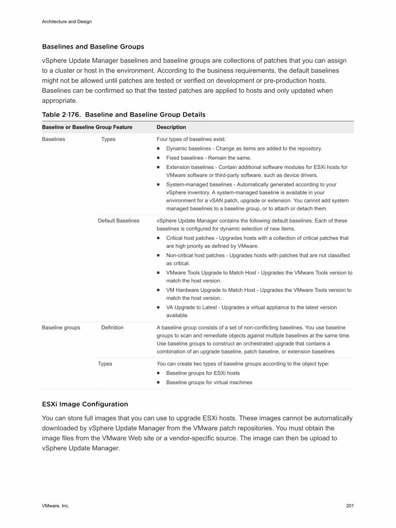
Baselines and Baseline Groups
vSphere Update Manager baselines and baseline groups are collections of patches that you can assignto a cluster or host in the environment. According to the business requirements, the default baselinesmight not be allowed until patches are tested or verified on development or pre-production hosts.Baselines can be confirmed so that the tested patches are applied to hosts and only updated whenappropriate.
Table 2‑176. Baseline and Baseline Group Details
Baseline or Baseline Group Feature Description
Baselines Types Four types of baselines exist:n Dynamic baselines - Change as items are added to the repository.n Fixed baselines - Remain the same.n Extension baselines - Contain additional software modules for ESXi hosts for
VMware software or third-party software, such as device drivers.n System-managed baselines - Automatically generated according to your
vSphere inventory. A system-managed baseline is available in yourenvironment for a vSAN patch, upgrade or extension. You cannot add systemmanaged baselines to a baseline group, or to attach or detach them.
Default Baselines vSphere Update Manager contains the following default baselines. Each of thesebaselines is configured for dynamic selection of new items.n Critical host patches - Upgrades hosts with a collection of critical patches that
are high priority as defined by VMware.n Non-critical host patches - Upgrades hosts with patches that are not classified
as critical.n VMware Tools Upgrade to Match Host - Upgrades the VMware Tools version to
match the host version.n VM Hardware Upgrade to Match Host - Upgrades the VMware Tools version to
match the host version.n VA Upgrade to Latest - Upgrades a virtual appliance to the latest version
available.
Baseline groups Definition A baseline group consists of a set of non-conflicting baselines. You use baselinegroups to scan and remediate objects against multiple baselines at the same time.Use baseline groups to construct an orchestrated upgrade that contains acombination of an upgrade baseline, patch baseline, or extension baselines
Types You can create two types of baseline groups according to the object type:n Baseline groups for ESXi hostsn Baseline groups for virtual machines
ESXi Image Configuration
You can store full images that you can use to upgrade ESXi hosts. These images cannot be automaticallydownloaded by vSphere Update Manager from the VMware patch repositories. You must obtain theimage files from the VMware Web site or a vendor-specific source. The image can then be upload tovSphere Update Manager.
Architecture and Design
VMware, Inc. 201
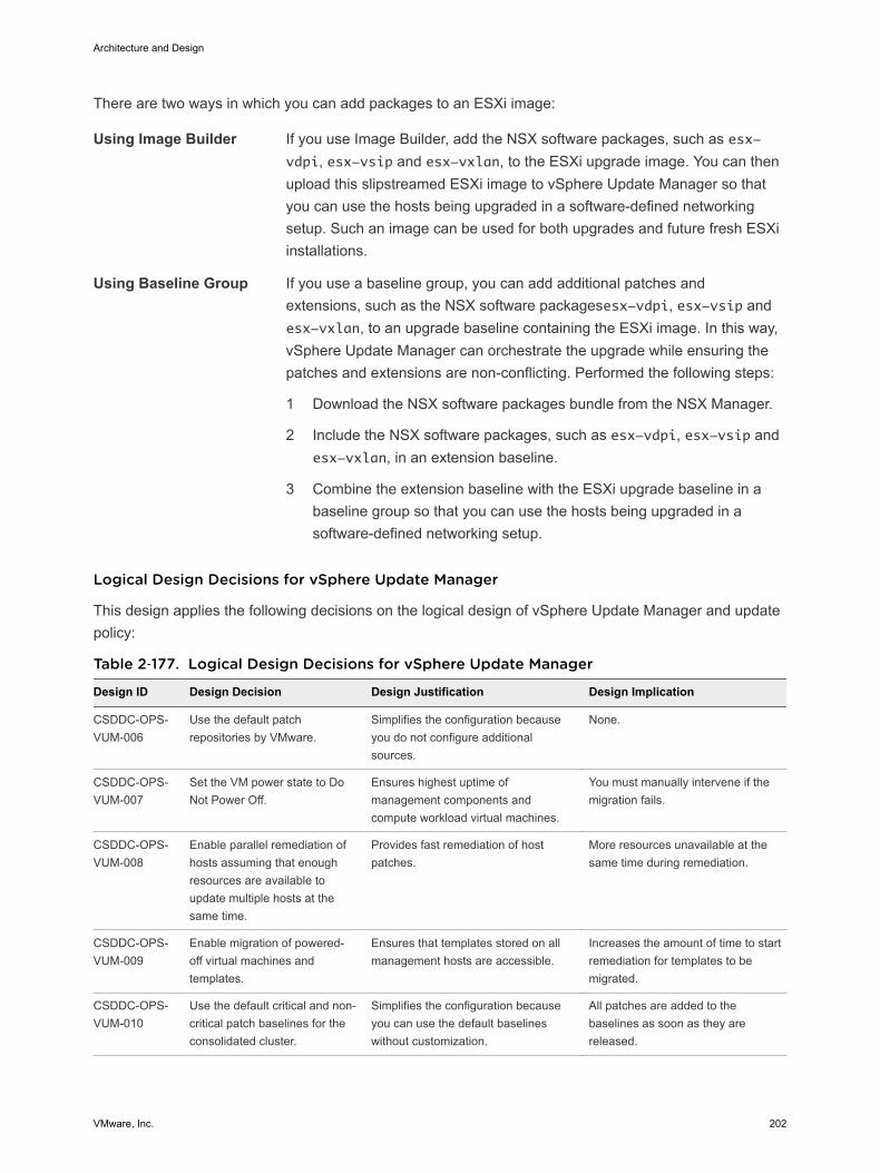
There are two ways in which you can add packages to an ESXi image:
Using Image Builder If you use Image Builder, add the NSX software packages, such as esx-vdpi, esx-vsip and esx-vxlan, to the ESXi upgrade image. You can thenupload this slipstreamed ESXi image to vSphere Update Manager so thatyou can use the hosts being upgraded in a software-defined networkingsetup. Such an image can be used for both upgrades and future fresh ESXiinstallations.
Using Baseline Group If you use a baseline group, you can add additional patches andextensions, such as the NSX software packagesesx-vdpi, esx-vsip andesx-vxlan, to an upgrade baseline containing the ESXi image. In this way,vSphere Update Manager can orchestrate the upgrade while ensuring thepatches and extensions are non-conflicting. Performed the following steps:
1 Download the NSX software packages bundle from the NSX Manager.
2 Include the NSX software packages, such as esx-vdpi, esx-vsip andesx-vxlan, in an extension baseline.
3 Combine the extension baseline with the ESXi upgrade baseline in abaseline group so that you can use the hosts being upgraded in asoftware-defined networking setup.
Logical Design Decisions for vSphere Update Manager
This design applies the following decisions on the logical design of vSphere Update Manager and updatepolicy:
Table 2‑177. Logical Design Decisions for vSphere Update Manager
Design ID Design Decision Design Justification Design Implication
CSDDC-OPS-VUM-006
Use the default patchrepositories by VMware.
Simplifies the configuration becauseyou do not configure additionalsources.
None.
CSDDC-OPS-VUM-007
Set the VM power state to DoNot Power Off.
Ensures highest uptime ofmanagement components andcompute workload virtual machines.
You must manually intervene if themigration fails.
CSDDC-OPS-VUM-008
Enable parallel remediation ofhosts assuming that enoughresources are available toupdate multiple hosts at thesame time.
Provides fast remediation of hostpatches.
More resources unavailable at thesame time during remediation.
CSDDC-OPS-VUM-009
Enable migration of powered-off virtual machines andtemplates.
Ensures that templates stored on allmanagement hosts are accessible.
Increases the amount of time to startremediation for templates to bemigrated.
CSDDC-OPS-VUM-010
Use the default critical and non-critical patch baselines for theconsolidated cluster.
Simplifies the configuration becauseyou can use the default baselineswithout customization.
All patches are added to thebaselines as soon as they arereleased.
Architecture and Design
VMware, Inc. 202
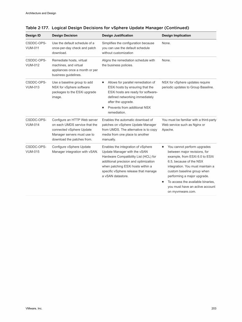
Table 2‑177. Logical Design Decisions for vSphere Update Manager (Continued)
Design ID Design Decision Design Justification Design Implication
CSDDC-OPS-VUM-011
Use the default schedule of aonce-per-day check and patchdownload.
Simplifies the configuration becauseyou can use the default schedulewithout customization
None.
CSDDC-OPS-VUM-012
Remediate hosts, virtualmachines, and virtualappliances once a month or perbusiness guidelines.
Aligns the remediation schedule withthe business policies.
None.
CSDDC-OPS-VUM-013
Use a baseline group to addNSX for vSphere softwarepackages to the ESXi upgradeimage.
n Allows for parallel remediation ofESXi hosts by ensuring that theESXi hosts are ready for software-defined networking immediatelyafter the upgrade.
n Prevents from additional NSXremediation.
NSX for vSphere updates requireperiodic updates to Group Baseline.
CSDDC-OPS-VUM-014
Configure an HTTP Web serveron each UMDS service that theconnected vSphere UpdateManager servers must use todownload the patches from.
Enables the automatic download ofpatches on vSphere Update Managerfrom UMDS. The alternative is to copymedia from one place to anothermanually.
You must be familiar with a third-partyWeb service such as Nginx orApache.
CSDDC-OPS-VUM-015
Configure vSphere UpdateManager integration with vSAN.
Enables the integration of vSphereUpdate Manager with the vSANHardware Compatibility List (HCL) foradditional precision and optimizationwhen patching ESXi hosts within aspecific vSphere release that managea vSAN datastore.
n You cannot perform upgradesbetween major revisions, forexample, from ESXi 6.0 to ESXi6.5, because of the NSXintegration. You must maintain acustom baseline group whenperforming a major upgrade.
n To access the available binaries,you must have an active accounton myvmware.com.
Architecture and Design
VMware, Inc. 203