architecture-based veri cation of software-intensive systems
TRANSCRIPT

Architecture-Based Veri�cation ofSoftware-Intensive Systems
Master thesisAuthor: Andreas Johnsen
Supervisor: Jayakanth SrinivasanExaminer: Kristina Lundqvist
Mälardalen University
School of Innovation, Design and Engineering2010 Jan 20
Västerås Sweden

Abstract
Development of software-intensive systems such as embedded systems for telecom-munications, avionics and automotives occurs under severe quality, schedule and budgetconstraints. As the size and complexity of software-intensive systems increase dramati-cally, the problems originating from the design and speci�cation of the system architecturebecomes increasingly signi�cant. Architecture-based development approaches promise toimprove the e�ciency of software-intensive system development processes by reducingcosts and time, while increasing quality. This paradox is partially explained by the factthat the system architecture abstracts away unnecessary details, so that developers canconcentrate both on the system as a whole, and on its individual pieces, whether it'sthe components, the components' interfaces, or connections among components. Theuse of architecture description languages (ADLs) provides an important basis for veri-�cation since it describes how the system should behave, in a high level view and in aform where automated tests can be generated. Analysis and testing based on architecturespeci�cations allow detection of problems and faults early in the development process,even before the implementation phase, thereby reducing a signi�cant amount of costsand time. Furthermore, tests derived from the architecture speci�cation can later be ap-plied to the implementation to see the conformance of the implementation with respectto the speci�cation. This thesis extends the knowledge base in the area of architecture-based veri�cation. In this thesis report, an airplane control system is speci�ed using theArchitecture Analysis and Description Language (AADL). This speci�cation will serveas a starting point of a system development process where developed architecture-basedveri�cation algorithms are applied.

Contents
1 Introduction 21.1 Background . . . . . . . . . . . . . . . . . . . . . . . . . . . . . . . . . . . . . . 21.2 Purpose . . . . . . . . . . . . . . . . . . . . . . . . . . . . . . . . . . . . . . . . 41.3 Problem Formulation . . . . . . . . . . . . . . . . . . . . . . . . . . . . . . . . . 4
2 Related Work 62.1 Deriving Tests From Software Architectures . . . . . . . . . . . . . . . . . . . . 62.2 Using Software Architecture for Code Testing . . . . . . . . . . . . . . . . . . . 72.3 Speci�cation-based Testing of Reactive Software: Tools and Experiments . . . . 72.4 Towards Software Architecture-based Regression Testing . . . . . . . . . . . . . 82.5 Speci�cation-based Test Oracles for Reactive Systems . . . . . . . . . . . . . . 82.6 Approaches to Speci�cation-based Testing . . . . . . . . . . . . . . . . . . . . . 92.7 UML-based Integration Testing for Component-based Software . . . . . . . . . 92.8 Testing: a Roadmap . . . . . . . . . . . . . . . . . . . . . . . . . . . . . . . . . 92.9 An Overview of Integration Testing Techniques for Object-oriented Programs . 102.10 Selecting and Using Data for Integration Testing . . . . . . . . . . . . . . . . . 112.11 Design Complexity Measurement and Testing . . . . . . . . . . . . . . . . . . . 112.12 Automatically Generating Test Data from a Boolean Speci�cation . . . . . . . . 12
3 Architecture-based Veri�cation Algorithms 133.1 What Should Be Tested and How Should it Be Tested? . . . . . . . . . . . . . . 133.2 Facilitate Regression Testing . . . . . . . . . . . . . . . . . . . . . . . . . . . . . 173.3 Overview of Uppaal . . . . . . . . . . . . . . . . . . . . . . . . . . . . . . . . . 173.4 Overview of Junit . . . . . . . . . . . . . . . . . . . . . . . . . . . . . . . . . . . 20
4 The Architecture Analysis and Design Language 224.1 An Overview of the SAE AADL . . . . . . . . . . . . . . . . . . . . . . . . . . . 22
4.1.1 Component Type . . . . . . . . . . . . . . . . . . . . . . . . . . . . . . . 244.1.2 Component Implementation . . . . . . . . . . . . . . . . . . . . . . . . . 26
5 A Flight Control System AADL Speci�cation 315.1 Basic Concepts of Flight Control Systems . . . . . . . . . . . . . . . . . . . . . 315.2 The AADL Speci�cation . . . . . . . . . . . . . . . . . . . . . . . . . . . . . . . 325.3 Speci�cation Veri�cation . . . . . . . . . . . . . . . . . . . . . . . . . . . . . . . 39
5.3.1 Applying Architecture-based Testing Criteria . . . . . . . . . . . . . . . 405.3.2 Veri�cation Using Uppaal . . . . . . . . . . . . . . . . . . . . . . . . . . 42
6 Implementing the AADL Flight Control speci�cation in Java 546.1 Java Implementation . . . . . . . . . . . . . . . . . . . . . . . . . . . . . . . . . 546.2 Unit Testing with Junit . . . . . . . . . . . . . . . . . . . . . . . . . . . . . . . 586.3 Architecture-based Testing of the Implementation upon Junit . . . . . . . . . . 61
7 The Re�ned Flight Control System 637.1 Re�ned Implementation . . . . . . . . . . . . . . . . . . . . . . . . . . . . . . . 637.2 Re�ning the AADL Speci�cation . . . . . . . . . . . . . . . . . . . . . . . . . . 657.3 Architecture-based Testing of the Re�ned Implementation . . . . . . . . . . . . 66

8 Summary and Conclusions 69
9 Future Work 71
A Architecture-based Testing Paths 75
B Architecture-based Uppaal Queries 80
List of Figures
1 Development Process [28] . . . . . . . . . . . . . . . . . . . . . . . . . . . . . . 22 Waterfall Model . . . . . . . . . . . . . . . . . . . . . . . . . . . . . . . . . . . . 33 Architecture-based Development Model . . . . . . . . . . . . . . . . . . . . . . 44 The Uppaal concept . . . . . . . . . . . . . . . . . . . . . . . . . . . . . . . . . 185 The Viking Problem . . . . . . . . . . . . . . . . . . . . . . . . . . . . . . . . . 196 Junit Test Case Example . . . . . . . . . . . . . . . . . . . . . . . . . . . . . . 217 Junit Test Result . . . . . . . . . . . . . . . . . . . . . . . . . . . . . . . . . . . 218 Example of a Port Declaration . . . . . . . . . . . . . . . . . . . . . . . . . . . 249 Example of a Busaccess Declaration . . . . . . . . . . . . . . . . . . . . . . . . 2510 Example of a Flow Declaration . . . . . . . . . . . . . . . . . . . . . . . . . . . 2511 Example of Subcomponents Declaration . . . . . . . . . . . . . . . . . . . . . . 2712 Example of Connection Declaration . . . . . . . . . . . . . . . . . . . . . . . . . 2813 Example of Modes Declaration . . . . . . . . . . . . . . . . . . . . . . . . . . . 2914 Example of a Call Statement . . . . . . . . . . . . . . . . . . . . . . . . . . . . 3015 Airplane rudders: ailerons (blue), vertical �n rudder (red), elevator (yellow) . . 3116 Speci�ed Actuators . . . . . . . . . . . . . . . . . . . . . . . . . . . . . . . . . . 3317 Speci�ed Sensors . . . . . . . . . . . . . . . . . . . . . . . . . . . . . . . . . . . 3418 Speci�ed Threads . . . . . . . . . . . . . . . . . . . . . . . . . . . . . . . . . . . 3519 Speci�ed Process . . . . . . . . . . . . . . . . . . . . . . . . . . . . . . . . . . . 3720 Speci�ed Application System . . . . . . . . . . . . . . . . . . . . . . . . . . . . 3821 Speci�ed Execution Platform System . . . . . . . . . . . . . . . . . . . . . . . . 3922 Speci�ed System . . . . . . . . . . . . . . . . . . . . . . . . . . . . . . . . . . . 3923 AADL Graphical Representation . . . . . . . . . . . . . . . . . . . . . . . . . . 4124 Global Variables . . . . . . . . . . . . . . . . . . . . . . . . . . . . . . . . . . . 4325 Yoke Automaton . . . . . . . . . . . . . . . . . . . . . . . . . . . . . . . . . . . 4426 Pedals Automaton . . . . . . . . . . . . . . . . . . . . . . . . . . . . . . . . . . 4527 Throttle Automaton . . . . . . . . . . . . . . . . . . . . . . . . . . . . . . . . . 4528 Autopilot Button Automaton . . . . . . . . . . . . . . . . . . . . . . . . . . . . 4629 Autopilot Setting Automaton . . . . . . . . . . . . . . . . . . . . . . . . . . . . 4630 Steering Control Thread Automaton . . . . . . . . . . . . . . . . . . . . . . . . 4731 Engine Control Thread Automaton . . . . . . . . . . . . . . . . . . . . . . . . . 4832 Autopilot Setting Control Thread Automaton . . . . . . . . . . . . . . . . . . . 4833 LeftAileron Automaton . . . . . . . . . . . . . . . . . . . . . . . . . . . . . . . 4934 Engine Automaton . . . . . . . . . . . . . . . . . . . . . . . . . . . . . . . . . . 4935 Uppaal Veri�cation . . . . . . . . . . . . . . . . . . . . . . . . . . . . . . . . . . 5236 System Class Instance Variables . . . . . . . . . . . . . . . . . . . . . . . . . . . 5537 addPort() method . . . . . . . . . . . . . . . . . . . . . . . . . . . . . . . . . . 55

38 addPortConnection() method . . . . . . . . . . . . . . . . . . . . . . . . . . . . 5739 Flight control system creation . . . . . . . . . . . . . . . . . . . . . . . . . . . . 5840 setUp() and tearDown() . . . . . . . . . . . . . . . . . . . . . . . . . . . . . . . 5941 TestAddPort() . . . . . . . . . . . . . . . . . . . . . . . . . . . . . . . . . . . . 5942 TestAddPortConnection() . . . . . . . . . . . . . . . . . . . . . . . . . . . . . . 6043 Running the Test Suite . . . . . . . . . . . . . . . . . . . . . . . . . . . . . . . . 6044 Architecture-based Test Case . . . . . . . . . . . . . . . . . . . . . . . . . . . . 6145 GUI of the Re�ned Flight Control System . . . . . . . . . . . . . . . . . . . . . 6546 Signal Properties . . . . . . . . . . . . . . . . . . . . . . . . . . . . . . . . . . . 6647 Thread Dispatch Properties . . . . . . . . . . . . . . . . . . . . . . . . . . . . . 6648 Code Coverage of Test Case, statements covered by green color were executed . 6849 AADL Graphical Representation . . . . . . . . . . . . . . . . . . . . . . . . . . 75
List of Tables
1 Architecture-based Testing Criteria . . . . . . . . . . . . . . . . . . . . . . . . . 152 What Should Be Tested and How Should it Be Tested . . . . . . . . . . . . . . 17

1 Introduction
1.1 Background
Software-intensive systems are systems where software interacts with sensors, actuators, de-vices, other systems and people [27]. Examples of such systems are embedded systems foravionics, automotives and telecommunications. What these systems have in common is thatthey are rapidly growing in complexity and often operating in dynamic non-deterministic envi-ronments. Because of the growing complexity of these systems, development process elementssuch as cost, time and quality are increasingly important. Therefore, the major question ishow to optimize development processes in order to reduce cost and time without losing qualityor even better, increasing quality. An optimal development process would roughly speakingbe, in a technical point of view, a process where system components are created and formed toan error free system. In today's reality, this is not the case as illustrated in Figure 1 (althoughthe �gure is derived from an old investigation, the underlying message is still up-to-date). The�gure illustrates a development process of a system where introduced errors (in %), detectederrors (in %) and cost of correction per error (in Deutsche Mark) are represented by threegraphs. As shown by the graphs, the majority of errors are introduced early in the process(note that errors are introduced before the programming phase) whereas the majority of errorsare detected late in the process. Since time and consequently cost of correcting errors increasedramatically the later they are detected, prediction of possible errors is one of the main issuesfor developers.
Figure 1: Development Process [28]
The solution to the problem of costly and time consuming error correction is to somehowmove the detected errors graph as close as possible to the introduced errors graph sincecost of correction is low where the majority of errors are introduced. Errors and problemsare detected late in development processes where developers use strategies similar to thetraditional waterfall model (shown in Figure 2) where the majority of testing activities takesplace at the end of the process [29].
2

Figure 2: Waterfall Model
Architecture-based development approaches (shown in Figure 3), where a system archi-tecture is modeled, analyzed and tested before implemented in order to predict if the systemwill satisfy the requirements, promise to improve the e�ciency of software-intensive systemdevelopment processes by reducing cost and time, while increasing quality since analysis andtesting of architecture models (speci�cations) allow detection of errors early in the process. Inorder to preserve the usefulness of a well modeled and veri�ed system architecture, an imple-mentation of the system must be implemented in conformance with the model. Consequently,architecture-based development approaches do not only deal with testing of a system model,but also testing of an implementation, to verify its conformance with the model. Architecture-based testing of the implementation is feasible by generating test cases from the architecturemodel which can be mapped and applied to the implementation. Test cases must be mappedto the implementation since there is a traceability problem between a model and its imple-mentation. A system architecture abstracts away unnecessary details, so that developers canconcentrate both on the system as a whole, and on its individual pieces, whether it's thecomponents, the components' interfaces, or connections among components. System architec-tures can be speci�ed (modeled) by Architecture Description Languages (ADLs) which serveas a mutual communication blueprint and provide an important base for veri�cation and earlydesign decisions since they describe how the systems should behave at a high abstraction level.
3

Figure 3: Architecture-based Development Model
1.2 Purpose
The purpose of this thesis is to extend the knowledge base in the area of architecture-basedveri�cation (testing from speci�cations) of software intensive systems by literature and casestudies, in order to perform future research within the area. The importance is to get familiarwith the state of the art research about testing from speci�cations, as well as its background.This includes gaining knowledge about modeling veri�cation tools and architecture speci�ca-tion languages. The study should result in the ability to develop veri�cation algorithms thate�ectively can be applied to a development process of a system, which has its origins in anarchitecture speci�cation that later progresses to an implementation.
1.3 Problem Formulation
Tasks that have to be done in order to achieve the purpose of the thesis are:
� Detailed literature review on software testing, focused on model based testing and inte-gration testing.
� Participate in a modeling and veri�cation of embedded systems course at MälardalensUniversity (Västerås, Sweden) in parallel with the thesis work to further give ideas andtechniques that can be used in the thesis.
� Study the Junit testing framework and develop testing skills using it in order to buildarchitecture-based testing upon the unit testing framework.
� Study the Architecture Analysis and Design Language (AADL) and build a suitablespeci�cation of a system.
4
� Use knowledge described above to develop algorithms for architecture-based veri�cation.
� Complete a case study where developed algorithms are applied to a system developmentprocess. The process will have its origins from the AADL system speci�cation and laterprogresses into a Java implementation.
5

2 Related Work
The underlying goal of the thesis was to extend the knowledge base in architecture-basedveri�cation of software intensive systems. The �rst step to achieve this goal was to study theoverall area of software testing and the state of the art research about testing from speci�-cations as well as the background of testing from speci�cations. I studied the overall area ofsoftware testing by reading the book �Art of Software Testing� [4], which not only deals withtesting techniques but also how psychology in�uence testing. To be able to perform a casestudy about architecture-based veri�cation I was handed, by my supervisor, a list of papersfocused on model based testing and integration testing. These papers gave me valuable ideasabout di�erent testing techniques that could be used during the thesis, which will be describedin section 3. In this chapter, I summarize some papers to give the reader an insight of myliterature studies and a better understanding of my work. Note that some of the summarizedpapers below present large and complex research projects and thus can the summaries be hardto thoroughly understand.
2.1 Deriving Tests From Software Architectures
Jin Z. and O�ut J. presents in [24] an architecture-based testing technique to test software.Software architectures abstract away details from applications so the applications can beviewed as sets of components with connectors that describe the interactions among compo-nents. The architecture of a system generally contains of four elements: components, inter-faces, connectors and con�gurations. Components are computational units in a system thatinteracts through their interfaces where interfaces are logical points of interactions betweena component or connector and its environment. Connectors are de�ned as the interactionswithin the architecture whereas con�gurations de�ne how each element is combined to form anarchitecture. Architecture description languages are used to model software architecture foranalysis and development. The authors distinguish architecture testing from system testingbecause system testing test the overall system to see if it meets its requirements while architec-ture testing attempts to test the interactions/relations among components at the architecturelevel. Their approach de�nes general testing criteria that de�ne the test requirements, whichare used to generate test inputs. Their technique generates test criteria from traditionaldata-�ow and control-�ow criteria by using properties from data �ow and control �ow, at thearchitecture-level. The properties are data �ow reachability, control �ow reachability, connec-tivity and concurrency.Data �ow reachability: �A data element should be able to reach its designated target
component from its source component through the connectors. The data element
should reach the target component without having its value modi�ed.�
Control �ow reachability: �Every architecture element should be able to reach its des-
ignated next element on its control thread.�
Connectivity: �A component or connector interface with either no next element or
no previous element is said to be �dangling�. Dangling components and connector
interfaces indicate potential problems because they may not be connected to other
components or connectors, which causes a discontinuity in the data or control
�ow.�
Concurrency: �Interactions that in isolation are deadlock free can interact in such
a way as to cause a deadlock situation. The system should be deadlock free.�
6

From these properties they de�ne �ve general architecture-based test criteria that they applyon a behavioral graph derived from the ADL Wright. When applying the criteria on the graph,test paths are derived. These tests can later be applied to the implementation, by mappingthe architecture description to the implementation.
2.2 Using Software Architecture for Code Testing
In paper [16], Miccini H. et al. presents a fully developed approach, which uses a softwarearchitecture as a reference model for testing the conformance of the implementation withrespect to the architecture speci�cation (architecture reference model). Their goal is "to
provide a test manager with a systematic method to extract suitable test classes
for higher levels of testing and to re�ne them into concrete tests at the code level" .Their approach to software architecture conformance testing is based on four steps. The �rststep is to look at the software architecture dynamics, which is modeled by Labeled TransitionSystems (LTSs), and de�ne di�erent "obs-functions" (observation-functions) over the softwarearchitecture model. Obs-functions abstract away actions (labels) that are uninteresting in aparticular testing criterion. The second step is to apply the obs-functions to the LTS whichderives a suitable LTS abstraction, called Abstract LTS (ALTS). ALTS is a reduced LTS, thatby concentrating on relevant features and abstracting away those who are not, o�ers a speci�cview of the software architectural dynamics. The third step is to derive an adequate set oftests from the ALTS. This is done by deriving a set of paths that appropriately covers theALTS according to the testing criterion. Although an ALTS has relative small dimensions, atester has to carefully derive paths since an ALTS just specify behavioral of the architectureat a higher abstraction level. One complete path in an ALTS corresponds to several possiblepaths in the LTS, which corresponds to several possible architectural tests. The fourth andlast step is to run these high level tests on the implementation by converting the architecturaltests into code-level tests, to see if the implementation conforms to its architecture model. Ifsome interactions speci�ed in the architectural level isn't allowed in the implementation, theimplementation doesn't conform the architecture model.
2.3 Speci�cation-based Testing of Reactive Software: Tools and Experi-
ments
Jagadeesan L. J. et al. describes in paper [11] a speci�cation-based testing tool they havebuilt for automatic testing of reactive system software, which often is safety-critical software.Their tool tests the applications for violations of safety properties expressed in temporallogic. Speci�cation-based testing is a typical approach for testing of telephone switchingsystems, which are reactive systems. So by applying their tool on several implementationsof an "automatic protection switching system", they were able to asses the suitability andadvantages of their approach. Their tool contains of �nite state machine oracles that areproduced by speci�cations of the safety properties (expressed in temporal logic). The statemachines generates inputs to the reactive system to see if the output of the system violatesthe safety properties. The testing process between the system and the oracle state machine isgenerated and coordinated by a test harness that is produced automatically from the safetyproperty and a description of the I/O signals. Their tool automatically alert and informthe user if a violation of the safety property has occurred. It is shown that their tool ishighly e�ective at �nding defects in the implementation but it still needs some work before
7

an industrial study can be made.
2.4 Towards Software Architecture-based Regression Testing
In paper [15], Muccini H. et al. explores how regression testing, at the software-architecturelevel, can be systematically used in order to reduce cost of retesting modi�ed systems. Ingeneral, the authors describe two goals, 1) how existing implementation-level test cases can bereused to test the conformance between modi�ed code and the architectural speci�cations, and2) how to reuse architecture-level test cases to test the conformance of the source code withrespect to the evolved software architecture. Their approach to address both goals relies onintegrating code-level regression testing with architecture-based regression testing. They useselective testing technique for code-level regression testing and use the same logical steps forarchitecture-based regression testing. The �rst goal is achieved by the following basic steps.The �rst step is to represent the program P and the modi�ed program P' into graphs whichis a common approach for regression testing.The second step is to compare the graphs and look for changes in nodes and edges.The third step is to build a test history report that records which nodes and edges in graphP has been covered by the original test cases during their execution over P.The last step is to select test cases for P' by the information gathered in the second and thirdstep. The idea here is if execution of P on a test case t ε T covers a node that is modi�ed inP', then t needs to be retested on P'.The second goal is achieved by following steps.The �rst step is to create a new software architecture speci�cation for the evolved architectureS�.The second step involves earlier applied testing criterion on S now applied to S� which abstractsthe software speci�cation, in order to show only behaviors/components one want to test.The third step is to compare the original architecture speci�cation with the modi�ed and lookfor topologic and behavioral changes.The fourth step is to select architectural test cases (ATCs) for S�. Here the idea is that thoseATCs from the original software architecture that are a�ected by the modi�cation are retestedin P� which is the implementation for S�.The �fth step is to map the ATCs into code-level test cases to be able to create test cases T� forS�. The last step is to run T� over P� and evaluate the result of the software architecture-basedregression testing.
2.5 Speci�cation-based Test Oracles for Reactive Systems
Output from a test execution is typically examined by someone visually, to determine if thesystem behaved correctly. In paper [18], Richardson, D. J. et al. presents a speci�cation-basedtesting approach that they are developing, to be applicable on several language paradigms andseveral speci�cation languages. The approach is to derive test oracles from multi-speci�cationsin conjunction with testing to represent an oracle for each test class speci�ed by a testingcriterion. Derivation of test oracles from speci�cations entails in mapping test data, which isin the implementation name space, to the oracle name space (the speci�cation name space).Execution of the test data produces an execution pro�le which is produced by the test monitor.The test monitor requirements are determined by the requirements of the oracles derivedfrom each speci�cation language. These requirements are control points and data states to be
8

mapped, re�ected in the mappings for each speci�cation. The execution pro�le is then veri�edby the oracles related to test classes that are satis�ed by the test data. Their approach isillustrated by testing of an elevator system implemented in Ada, speci�ed in Real-time intervallogic (describes temporal logic) and Z (describes scheduling of services).
2.6 Approaches to Speci�cation-based Testing
Paper [17] by Richardson D. et al. propose four approaches to speci�cation-based testing by ex-tending fault- and error-based techniques, which are implementation-based testing techniques,to be applicable to formal speci�cation languages. So the methodology of their approach is tocombine implementation-based and speci�cation-based to derive a "new" (paper written 1989)speci�cation-based testing technique. The four approaches are named speci�cation/error-based testing, speci�cation/fault-based testing, oracle/error-based testing and oracle/fault-based testing. Speci�cation/error-based testing and speci�cation/fault-based testing are test-ing techniques, which goal is to detect errors/faults in speci�cations or errors/faults thatderives from misunderstanding a speci�cation, by applying fault- and error-based techniqueto the speci�cation and implementation. Oracle/error-based testing and oracle/fault-basedtesting on the other hand treats the speci�cation as an oracle to be violated by applyingerror- and fault-based technique to the implementation.
2.7 UML-based Integration Testing for Component-based Software
In paper [20] Wu Y. et al. presents a model for describing component-based software, whensource code are not available, by using UML collaboration and sequence diagrams to representinteractions among di�erent objects in a component. The model combines statechart diagramswith collaboration diagrams to give a further precise model of a component's behavior. Theypropose a test model to test interfaces, events, context-dependence relationships and content-dependence relationships. Interfaces of components are access points that provide di�erentoperations of the component. Each interface of an integrated environment should be testedat least once. Events invoke interfaces in response to the incident and can be triggered by adi�erent interface through an explicit user input or through an exception. Their test modelpresents that every event in the system has to be covered by some test. Context-dependencerelationships are relationships where an event e1 triggers, directly or indirectly, an event e2.Content-dependence relationships are relationships between two interfaces that have a data-dependence relationship. Although interfaces and events speci�cation can be obtained withoutsource code, information for content- and context-dependence relationships is not available.These two elements are important for component integration testing and e�ective in �ndingfaults. So by using the UML based diagrams to capture component relations, these twoelements can be examined.
2.8 Testing: a Roadmap
In report [9] Harrold M.J. brie�y presents the state of the art (paper written year 2000) ofsoftware testing and also gives some directions in what should be developed. They representa roadmap for testing that leads to the destination: "providing practical methods, tools,
and processes that can help software engineers develop high-quality software" .The roadmap contains of seven di�erent areas: testing component-based systems, testingbased on precode artifacts, testing evolving software, demonstrating e�ectiveness of testing
9

techniques, establishing e�ective processes for testing, using testing artifacts and other testingtechniques. The "testing component-based systems" section informs the problem of increasinguse of component-based systems. The issue is the availability of the components source code.The component provider has access to the source code but the component user typicallydoes not. Standards for representing, computing and storing testing information about acomponent should be developed. The "testing based on precode artifacts" section discussesthe use of software's architecture for testing. Increased size and complexity of software systemshas led to emerging of formal speci�cations for software architectures. E�ective architecturetesting techniques such as regression testing, assess testability, integration and unit testing arebeing developed and can facilitate dynamic analysis. The "testing evolving software" sectiondescribes how regression testing can be more e�cient and e�ective. Regression testing standsfor as much as one-third of the total cost of a system development. To make regression testingmore e�cient we need to develop techniques that can be applied on di�erent abstractions ofsoftware such as its architecture or requirements. We also need to develop techniques that canreduce test suites to a desired coverage of the code. Techniques for assessing the testabilityof both software and test suites, to be able to evaluate alternative designs, also have to bedeveloped. The "using testing artifacts" section describes how artifacts from testing such asexecution traces of the software's execution with test cases can be stored for retesting modi�edsoftware. The paper ends with some points to improve development of e�cient methods andtools. Software technology takes as much time as 18 years on average to be transferred intopractice. This time can be shorted by researchers working with the industry by developmethods and tools that implement the techniques and can be used to show their e�ciency.Industrial systems are large and complex so an important criterion is that these tools andmethods can be scalable to large systems.
2.9 An Overview of Integration Testing Techniques for Object-oriented
Programs
In paper [6] Chan W.K. et al. gives an overview of the "current" (written 2002) work ofintegration testing for object-oriented programs. The paper covers state-based testing, event-based testing, fault-based testing, deterministic techniques, reachability techniques and formaltechniques. Object-oriented programs can be tested at four di�erent abstraction levels and thispaper focus on testing of the cluster level since the implementation- and class-level have beenwidely studied. The cluster level concerns about the integration of classes and mostly focusedon synchronization of components and interclass method invocation. The brie�y explainedtesting techniques are:
� State-based testing models an integrating system by interacting �nite state machines.The models can then be veri�ed for selected properties such as "deadlock free".
� Event-based techniques views on the relationships between pairs of synchronizationevents. In this testing paradigm, relationships between events build a testing frame-work (harness) to check for violations.
� Mutation testing (fault based testing) is a testing approach where the programs aremodi�ed (mutated) according speci�c mutation rules. Then the mutants (modi�ed pro-gram) are tested to verify that di�erent results are obtained from the same test cases.This approach is successfully applied to an imperative program paradigm but need some
10

further work to be able to apply it on an objective-oriented paradigm for integrationtesting.
� Deterministic testing is a technique that forces the synchronization to be executed in acertain order. A deterministic oracle checks the deterministic result.
� UML-based techniques contains of useful diagrams, which express the relationships be-tween method invocations, for integration testing.
� Data �ow analysis is proposed to address the concern of whether variables are appropri-ately created and used. Data �ow analysis can be dynamically approached by insertingprobes to be able to analyze the actions on variables during program execution.
The techniques explained are mostly extended techniques used in the imperative program-ming paradigm.
2.10 Selecting and Using Data for Integration Testing
Harrold M.J and So�a M.L describes in [10] a testing tool for integration testing based ondata-�ow testing. Integration testing is testing of a modular program that contains proce-dures that interact with other procedures. Not only does the programs procedures need to beunit tested, errors can still exist in the procedures interfaces. Their approach for integrationtesting is to extend data�ow testing (de�nition-use pairs) to interprocedural testing by devel-oping both an analyze technique and a testing technique. The analyze technique computesthe required information about the interprocedural dependencies of de�nition-use pairs, forboth direct and indirect dependencies (one procedure "A" can have direct dependencies witha procedure "B" that has direct dependencies with another procedure "C", which means thatprocedure "A" has indirect dependencies with "C") . The method for computing interprod-ucal dependencies has four steps, namely 1) abstract control-�ow and data�ow information,2) represent interpocedural control �ow and data �ow, 3) get interpocedural information, 4)compute interprocedural de�nition-use information. The testing technique uses the informa-tion from the analyze technique to select and execute subpaths across procedure boundaries,to determine if there is a de�nition-clear subpath from the de�nition to the use. The techniqueof their tool supports recursive procedures.
2.11 Design Complexity Measurement and Testing
In article [14], McCabe T.J. and Butler C.W. proposes three design metrics, module designcomplexity, design complexity and integration complexity that are derived from the mathemat-ical technique "cyclomatic complexity" to be applicable on architectural design of a system.The concept of these design metrics is to calculate the design complexity and drive a testingprocess. They also propose a structured integration testing methodology that utilizes thedesign metrics to produce a testing strategy from the design speci�cation. Design metrics areimportant for software engineers to consider the design complexity and understand the impli-cation of it. Cyclomatic complexity is a measure, derived from a �owgraph, of the number ofbasis paths through a program (number of decision statements plus one). Module design com-plexity is a design metric which is de�ned as the cyclomatic complexity of its reduced graph ofa component. There are four reduction rules that are performed to eliminate complexity in thegraph that doesn't in�uence the interrelationship between design modules. Design complexity
11

metric can be calculated from a structured component chart when the module design complex-ity of each individual component has been determined. Design complexity is de�ned as thesum of its own module design complexity and its descendant's module design complexity. Thethird and last design metric, integration complexity, is a metric that quanti�es a basis set oftests that should be done to qualify the design. Integration complexity is in general de�ned asthe design complexity minus the number of modules plus one. The testing methodology theypropose, which uses the described metrics, can be applied at two levels, module integrationtesting and design integration testing. Module integration testing is testing of a module andits immediate subordinates. It describes the amount of tests required to qualify a module'sintegration with subordinate modules. Design integration testing determines the amount ofe�ort for testing a design.
2.12 Automatically Generating Test Data from a Boolean Speci�cation
In paper [19], Weyuker E. et al. presents a tool they have developed that automaticallygenerates test sets to test implementation faults that they call "variable negation faults". Thetest sets are automatically generated, independent of the format, from a Boolean speci�cation.This is done by the tool converting the Boolean speci�cation formulae to disjunctive normalform, also known as sum-of-products form. The resulting formulae is then used to generatetest cases. Their strategy, which is a non-deterministic strategy, is to select test cases thatdemonstrate the meaningful impact of each literal occurrence on each possible value of aBoolean formula. Literals are each occurrence of a variable or its negation in a Booleanformula and a literal is said to have a meaningful impact on the value of a Boolean formulaif a change of the literal's value, and no change to any other literal, would result in a changeof the formula's value. Their strategy can be viewed in another way, if there are no test casesthat demonstrate the meaningful impact on the formula's value for a given literal occurrence,a literal can be changed without any noticeable e�ect and thus the implementation can bewrong and would go undetected. To assess the e�ectiveness of their tool they use mutationanalysis which is a fault-based testing technique. The approach is to mutant the programby doing small syntactic changes that can represent typical faults, which should produce adi�erent output for the same input. If the test data can detect the faults in the mutants itwould indicate an e�ective testing strategy.
12
3 Architecture-based Veri�cation Algorithms
Several ideas and testing techniques caught my interest while I was studying literature toget into the subject, where some of them seemed to be more applicable for the thesis thanothers. Additionally, I participated in a Ph.D. course "Modeling and Veri�cation of Real-timeSystems" while working on the thesis, which also gave me valuable techniques and ideas touse. This chapter describes developed veri�cation algorithms used in the thesis, by answeringtwo questions: what should be tested and how should it be tested?
3.1 What Should Be Tested and How Should it Be Tested?
Architecture-based testing, by Jin Z. and O�ut J.[24], deals with testing of interactions at thearchitecture level. Based on traditional data-�ow and control-�ow testing criteria, they de�nearchitectural properties that should be tested:
� Data �ow reachability: A data element should be able to reach its designed component,from its source component, unmodi�ed.
� Control �ow reachability: An architecture element should reach its next element on itscontrol thread.
� Connectivity: A component interface with no next or previous element may not beconnected to other components, where "dangling" components can cause problems.
� Concurrency: deadlock free.
From these properties they de�ne architecture relations which are used to de�ne testingpaths whereas the testing paths are used to de�ne architecture-based testing criteria. Thesetesting criteria with underlying test paths and relations are de�ned for general ADLs, whichcan be interpreted to conform a speci�c ADL. Since these criteria will be applied to an AADLspeci�cation, interpretation must be performed in conformance with the AADL standard.The de�ned criteria for general ADLs take into consideration that connectors have explicitinterfaces, which is something that the AADL standard does not support (overview of AADLin section 4). Therefore, interfaces of connectors in following de�nitions below are seen asimplicit interfaces. De�ned relations and properties based on data transfer, control transferand execution sequencing rules (interfaces that have execution rules such as parallel or sequenceexecution) are:
1. Component/Connector_Internal_Transfer_Relation: exists if there is a data or controltransfer between two interfaces of a component/connector.
2. Component/Connector_Internal_Sequencing_Relation: exists if two or more interfacesof a component/connector have to execute by rules such as parallel or sequence execution.
3. Component/Connector_Internal_Relation: exists if relations 1 or 2 exist between in-terfaces of a component/connector.
4. Component_Connector_Relation: exists if an interface of a component is coupled withan interface of a connector.
13

5. Direct_Component_Relation: exists if there is a Connector_Internal_Relation betweencomponents A and B where A and B have Component_Connector_Relations to theconnector.
6. Indirect_Compoent_Relation: exists between components A and C if there is a Di-rect_Component_Relation between A and B as well as between B and C where aComponent_Internal_Relation in B connects the direct component relations.
From these relations and properties, six testing paths are derived:
1. Comonent/Connector_Internal_Transfer_Path: If a component/connector has a Com-ponent/Connector_Internal_Transfer_Relation, there exists a path between two inter-faces of the component/connector.
2. Component/Connector_Internal_Sequencing_Path: If a component/connector has aComponent/Connector_Internal_Sequencing_Relation, there exists a path between twointerfaces of the component/connector
3. Component/Connector_to_Connector/Component_Path: If a component and connec-tor have a Component_Connector_Relation, there exists a path from the component/-connecotr to the connector/component.
4. Direct_Component_to_Component_Path: If two components have aDirect_Component_Relation, there exists a path between the components via a con-nector.
5. Indirect_Component_to_Component_Path: If two components A and C have an In-direct_Component_Relation, there exist a path from A to C via a component B andtwo connectors (A-connector1-B-connector2-C).
6. All_Connected_Component_Path: If four ore more components are connected throughrelations, there exists a path through all components via connectors.
These paths, which identify architectural relations and properties, are testing require-ments in order to assure interactions behavior of the architecture. Jin and O�ut de�ne �vearchitecture-based testing criteria which when applied to ADL speci�cations derives testingpaths where the criteria requires a test suite to fully exercise all identi�ed paths (relations andproperties). The architecture-based testing criteria are shown in Table 1.
14

Table 1: Architecture-based Testing CriteriaArchitecture-based testing criteria Requires
Individual_Component_Interface Tests to cover all Component_Internal_Coverage _Transfer_Paths and Component_Internal
_Sequencing_Paths
Individual_Connector_Interface Tests to cover all Connector_Internal_Coverage _Transfer_Paths and Connector_Internal
_Sequencing_Paths
All_direct_Component_to Tests to cover all Component/Connector_Component_Coverage _to_Connector/Component_Paths and Direct
_Component_to_Component_Paths
All_indirect_Component_to Tests to cover all Indirect_Component_to_Component_Coverage _Component_Paths
All_Connected_Component Tests to cover all All_Connected_Component_Coverage _Paths
As described above, paths for testing and simulation are derived when these testing cri-teria are applied to an ADL speci�cation. The idea of derived paths is to test and simulatethe paths to look for behaviors that oppose relations that generated the paths. For exam-ple, if a path is derived from a data transfer relation, testing of the path entails in lookingfor behaviors that oppose the data to reach its designated element from its source elementunmodi�ed. Furthermore, these tests can later be applied to the implementation-level wherepaths are exercised by generated inputs instead of simulations.
Miccini H. et al. [16] tests the conformance of an implementation with respect to a model(modeled by labeled transition systems) by testing if interactions speci�ed in the model areallowed in the implementation. Since this is precisely what is done when test paths describedabove are applied to the implementation level, it can be used for conformance testing. Testsderived from the architecture level have to be converted to be applicable on the implementa-tion level, since there is a traceability problem between a speci�cation and its implementation.This problem is controlled in the thesis by using equal name space at both levels. Structuraltesting of Java implementations is feasible by the Junit framework described in chapter 4.3.
Ouimet M. describes in [21] the importance of a speci�cation's completeness and consis-tency properties. Ouimet M. describes criteria, for an embedded system speci�cation to becomplete and consistent, as:
"In the context of the speci�cation of embedded systems, completeness of the
speci�cation is de�ned as the speci�cation having a response for every possible
class of inputs. In the same context, consistency is de�ned as the speci�cation
being free of contradictory behavior" .
15

Ouimet applies these criteria to models speci�ed by the Timed Abstract State Machine(TASM) language which is a language that extends the theory of abstract state machines withtime. In the context of abstract state machines, completeness is de�ned as
"a rule will be enabled for every possible combination of its monitored vari-
ables" whereas consistency is de�ned as "no state having more than one transition
enabled at the same time" [21], i.e. no more than one rule is enabled at the same time. State machine transitions may haverules with guards where a transition is enabled when the rule's guard evaluates to the Booleanvalue true.
As mentioned before, I participated in a course "Modeling and Veri�cation of Real-timeSystems" where we studied how to use the model checker Uppaal (overview of Uppaal de-scribed in section 3.3) for veri�cation of real-time systems. In Uppaal are systems modeledby timed �nite state automata and veri�ed by branching temporal logics, or ComputationalTree Logic (CTL) to be speci�c. A model is veri�ed by giving CTL queries in form of pathformulae and state formulae [22]. As the names states, state formulae are expressions thatdescribe properties of individual states while path formulae are expressions that describe prop-erties of paths. Path formulae can be dived into reachability, safety and liveness properties.Reachability property formulae test whether a formula can be satis�ed by a reachable statealong some path. Safety property formulae test whether "something bad will never happen"whereas liveness property formulae test whether "something will eventually happen" [22]. Forexample, a �ight control system model could be tested by asking if it's possible to be in asituation where the autopilot controls the plane incorrect and can't be disengaged, or askingif the auto pilot engage button is pressed results in that the plane will eventually be auto-matically controlled, which are safety and liveness properties respectively. These formulae aremore thoroughly explained in section 3.3.
In order to link completeness and consistency with architecture-based veri�cation and theUppaal toolbox, an architecture speci�cation speci�ed in AADL could be translated to au-tomata/automaton (�nite abstract state machines) in Uppaal to be veri�ed for completenessand consistency using CTL. Furthermore, Uppaal provides easy deadlock checking which canbe used to verify the translated speci�cation for concurrency properties.
Properties that should be tested and how these properties should be tested are summarizedin the following table:
16

Table 2: What Should Be Tested and How Should it Be Tested
Property Veri�cation technique
Data �ow reachability Apply architecture-based testing criteria to the AADLspeci�cation
Control �ow reachability Apply architecture-based testing criteria to the AADLspeci�cation
Connectivity Apply architecture-based testing criteria to the AADLspeci�cation
Concurrency 1)Apply architecture-based testing criteria to the AADLspeci�cation, 2) Translate the AADL speci�cation to anUppaal model and use CTL to verify the property
Completeness Translate the AADL speci�cation to an Uppaal model and useCTL to verify the property
Consistency Translate the AADL speci�cation to an Uppaal model and useCTL to verify the property
Conformance Apply test paths, derived form the AADL speci�cation(when the architecture-based criteria are applied to the speci�cation),to the implementation
3.2 Facilitate Regression Testing
Muccini H. et al. describes in [15] the importance of regression testing at the architecture levelin order to reduce cost of retesting modi�ed systems. The underlying problem of their workis the phenomenon of "architectural drift". They explain that during system developmentit's common to change the implementation, due to tight deadlines, without updating thearchitecture according to the implementation. When the architecture drifts out of conformancewith the implementation, many bene�ts of an architecture speci�cation are lost. Therefore,modi�cations and re�nements of an architecture-speci�cation/implementation should resultin an update of the implementation/architecture-speci�cation to preserve the valuable use ofan architecture speci�cation.
3.3 Overview of Uppaal
Uppaal (freely downloaded at www.uppaal.com), developed by Uppsala University and Aal-borg University, is a toolbox for modeling and veri�cation of real-time systems. The basicconcept of the Uppaal tool box, shown in Figure 4, is to model a system by timed automata(timed �nite-state machines) and to verify model requirements by the Uppaal query language,which is a subset of CTL.
17

Figure 4: The Uppaal concept
As mentioned, systems are modeled by timed automata where an automaton consists ofnodes (states, locations in Uppaal), edges (transitions) and labels (alphabet). Time is modeledby clock variables where all clocks progress synchronously and evaluates to real numbers [22].In Uppaal, timed automata are extended by discrete variables that can be read, assigned orused for arithmetic operations. Edges can be labeled with events in terms of synchronizations,timing constraints in terms of constraints on clock variables and data variables in terms oftransition guards and variable assignments. Since a system can be modeled by several au-tomata, transitions in di�erent automata can be synchronized using Uppaal channels.
A state of a system is de�ned by "the locations of all automata, the clock con-
straints, and the values of the discrete variables" [22]. Locations (nodes) can bedeclared with invariants and stated as urgent or committed. Invariants are atomic properties(e.g. x<10) that invariantly holds within a location. In an urgent location, time isn't allowedto progress which is semantically equivalent with having an invariant cl<=0 in a locationwhere "cl" is a clock and is reset by all ingoing edges to the location. In a committed location,time isn't allowed to progress and the next transition must involve one of its outgoing edges.As an example of an Uppaal model, we will look at the so called "Vikings problem". FourVikings with one torch are supposed to traverse a damaged bridge in the middle of the nightin order to get away from the unsafe side to the safe side of the bridge. Since it's dark and thebridge is damaged, a maximum number of two Vikings can traverse the bridge simultaneouslyby using the torch. The Vikings traverse the bridge in di�erent time units where Viking 1needs 5, Viking 2 needs 10, Viking 3 needs 20 and Viking 4 needs 25 time units. Since there isonly one torch, two Vikings traverse the bridge together and consequently the time needed isequal to the slowest Viking. Remember there is only one torch, so in order to get all Vikingsat the safe side the torch must be carried back by a Viking so two more Vikings can traversethe bridge to the safe side. The underlying question is if all Vikings can be at the safe sidewithin 60 time units. A Uppaal model of this system is partly shown in Figure 5.
� Automaton "A" represents one Viking (all Vikings are modeled by four automata similarto automaton "A" where they di�er only by the variable delay) and automaton "B"
18

represents the torch.
� The automata synchronize by two channels "take" and "release" to model a Vikingtaking or releasing the torch. A channel name with an exclamation mark represents the"sender" where a question mark represents the "receiver", i.e. "take!" can synchronizewith "take?".
� "L" is a global integer variable (reached by all automata) that can be assigned the value0 or 1 to model which side the torch is at where the value 0 represents the unsafe sideand 1 represents the safe side.
� "y" is a local clock (reached by one automaton/Viking) that is used with the local integerconstant "delay" to model time needed to traverse the bridge. "delay" is assigned to thevalue 5, 10, 20 or 25 depending on which Viking the automaton represents.
� "unsafe", "safe", "free", "two" and "one" are names of locations where the "unsafe" and"safe" locations represents which side of the bridge the Viking is at. Locations "free","two" and "one" represents the torch being held by zero, one or two Vikings.
Figure 5: The Viking Problem
The query language used to verify models is a subset of CTL which contains path- andstate-formulae. A State formula can be evaluated to valid or invalid for a state without lookingat the model's behavior to or from the state. A state formula is an atomic proposition such as"x==4" or "x>0" where these formulae are valid in a state whenever "x equals four" or "x isgreater than zero". Path formulae can be divided into reachability, safety and liveness proper-ties where these formulae use atomic propositions in order to verify properties along paths ofa model. A Reachability formula tests whether a state formula "q" can be valid in a reachablestate. Reachability properties are veri�ed using temporal operators "E" (pronounced "forsome path" or "exist one path") and "<>" (also denoted as "F", pronounced "eventually").So, in order to verify if state formula "q" is reachable in a model we simple check it by theformula E<> q (pronounced "for some path eventually q holds"). The Vikings problem de-scribed above can now be tested by using the reachability formula "E<> (Viking1.safe andViking2.safe and Viking3.safe and Viking4.safe and time<=60)" where time is a global clockand never reset. Safety formula test whether "something bad will never happen", which can bepositively formulated as "something good is always true". Safety properties are veri�ed using
19

temporal operators "A" (pronounced "for all paths"), "E" and [] (also denoted as "G", pro-nounced "always" or "globally"). Formula A[] q (pronounced "for all paths globally q holds")is used if the property should hold in all states for all paths whereas formula E[] q (pronounced"for some path globally q holds") is used if the property should hold for all states in at leastone path. Liveness formula tests whether "something will eventually happen", where theseproperties are tested by using temporal operators A, <> and �> (pronounced "leads to").Formula A<> q (pronounced "for all paths eventually q holds") tests whether q will eventuallyhold in all paths whereas p �> q (pronounced "whenever p holds eventually q holds") testswhether q eventually holds whenever p holds. The Uppaal query language is extended witheasy deadlock checking where a special deadlock state formula can be used with reachabilityand safety formulae.
3.4 Overview of Junit
Junit is a unit-level testing framework for writing automated test cases. The frameworkcontains tools for creation, execution and result of repeatable unit tests where related testscan be grouped together in order to give a manageable structure [23]. The Junit frameworkcontains of the following concepts:
� Test case: a related set of tests written as methods
� Test �xture: objects that a test case need to run
� Test suite: a related set of test cases
Optimally, a test case should be written for each Java class. A test case is created bydeclaring a class as a subclass of the junit.framework.TestCase class. In order to create par-ticular tests, a test �xture and test methods have to be declared. A test �xture is created bycreating objects within a method named setUp() where objects that aren't garbage collectedhave to be released within a method named tearDown(). Tests are created by declaring meth-ods whose names start with "test" while the testing is carried out by using di�erent assertmethods provided by the Junit framework. Furthermore, Junit handles exceptions to pass orfail tests.
As an example, we will look at a simple test case of the java.util.Stack class shown in Fig-ure 6. The TestStack class is a test case since it is a subclass of the junit.framework.TestCaseclass. The test �xture, which is set up by the test case setUp() method, is an instance of theclass under test. Since the object will be garbage collected we don't need to release it by thetearDown() method. The stack class is generic and in this example chosen to contain Stringobjects. Finally, in the testPush() test method, we simply test the stack class' push() methodby checking if a string object can be pushed on the stack. This is tested by the assertEquals()method, which checks that the value of the test variable is equal to the peeked value. As canbe seen, messages can be added to the assert method so faults easily can be distinguished ifseveral assert methods are used in the same test.
20

Figure 6: Junit Test Case Example
Test cases such as the test case described above, can be executed alone or as a part of atest suite by the Junit GUI. An example of the result, after running the test case, is shown inFigure 7.
Figure 7: Junit Test Result
21

4 The Architecture Analysis and Design Language
AADL by Feiler et al. [1][2] was released and published as a Society of Automotive Engineers(SAE) Standard AS5506, in November 2004. It is a textual and graphical language usedto model, specify and analyze software- and hardware-architectures of real-time, embeddedand high dependability systems. The AADL language is based on a component-connectorparadigm that describes components, component interfaces and the interaction between com-ponents. A system is modeled as a hierarchy of components where components that representthe application software are mapped onto the components that represent the hardware plat-form. Properties can be associated with di�erent AADL elements (e.g. components, subcom-ponents, features, connections etc.) to provide descriptive information about the respectiveAADL element. Changes to the runtime architecture can be described by modes and transi-tions of modes. Timing and performance are modeled by explicit properties (such as deadlines,worst-case execution time, arrival rate, period etc.) associated with components and de�nedconcurrency and interaction semantics. Detailed description about abstract paths of informa-tion through a system can be de�ned and analyzed as a �ow path.
AADL models can be developed by the OSATE environment (can be found throughhttp://www.aadl.info) which is an Eclipse-based open-source tool.
4.1 An Overview of the SAE AADL
The AADL language describes system component abstractions including software and hard-ware to, by Feiler et al. p. 4 [1]:
� "Specify and analyze real-time embedded systems, complex systems of sys-
tems, and specialized performance capability systems"
� "Map software onto computational hardware elements"
A component is modeled by a component type and a component implementation. The com-ponent type speci�es the external interfaces of the component in which other components caninteract through. Since the component type only speci�es the functional external interfaces,and no internal interfaces or operations, it can be viewed as a "black-box". The componenttype consists of an identi�er, features, extends, �ows and properties. These elements and subclauses will be described later. The component implementation speci�es the internal structureof a component and must be coupled to a component type. The component implementationcan be viewed as a "white-box" since it shows the internal structure of a component. A com-ponent implementation consists of an identi�er, extends, re�nes, subcomponents, connections,call sequences, modes, �ows and properties. These elements and sub clauses will be explainedlater.
The AADL language de�nes ten types of component abstractions which can be dividedinto three groups:
Application software
� Process: represents a protected address space containing of threads. Process compo-nents can have thread, thread group and data components as subcomponents. A process
22

must have at least one thread as subcomponent to represent an actively executing com-ponent.
� Thread: represents a schedulable concurrent unit of sequential executed source code.Execution properties can be associated with a thread such as dispatch protocol andtiming. For instance a thread can have a scheduling related dispatch protocol propertythat is assigned periodic (other supported protocols are: aperiodic, sporadic and back-ground), meaning that repeated dispatches occurs in speci�ed time intervals. A threadcan have data components as subcomponents.
� Thread group: represents an abstraction for organization of thread and data com-ponents. A thread group doesn't represent a unit of execution, it represents a singlereference to a group of threads that have common characteristics. Thread group canhave thread, data and other thread groups as subcomponents.
� Data: represents data types and data abstractions in source text (target programminglanguage). Data types are used to type ports which are interaction points to othercomponents. Data can have data components as subcomponents.
� Subprogram: represents a callable piece of sequentially executed source code thatoperates on data or provides functions to the component that call it. Subprograms arenot used as subcomponents, they are reached by call declarations with parameters inthreads or subprograms. Subprogram can't have any subcomponents.
Hardware/Execution platform
� Processor: represents hardware with associated software that schedules and executesthreads. Processors can have memory subcomponents.
� Memory: represents a storage component for executable code and data. Memorycomponents include abstractions of complex storage such as disks as well as randomlyaccessible storage such as RAM. Memory can have memory subcomponents.
� Bus: represents a component that can exchange control and data between processors,memories and devices. It's a communication channel that interconnects execution plat-form components. Processor, memory, device and system components can be connectedto a bus by require bus access declarations. Furthermore, other bus components canbe directly connected to a bus by an access statement. Bus components can't have anysubcomponents.
� Device: represents abstraction of a component that interfaces the external environmentsuch as sensors and actuators. Devices may be a simple unit or a complex systemthat may internally have processors, memory and software. The internal system of adevice can be modeled by a system component associated with the device through an"Implemented_as" property. Devices are physically connected to processors via busesand logically connected to application software components. Device components can'thave any subcomponents.
Generic/Composite
� System: represents an assembly of software, hardware and system components and thuscan have such subcomponents.
23

4.1.1 Component Type
A component type declaration is a component's externally visible interface and is declaredwith a unique identi�er. The interface contains partly of a "features" sub clause which con-tains of named interaction points used to exchange data and control to other components.The "features" sub clause contains of four di�erent AADL elements, two of them explainedthoroughly:
� Ports: represents a communication interface where components exchange directionaldata, events or both data and events. A port can either be a data port, an event port oran event data port. Data port represents an interface for communication of a data typewhere the connection between data ports can be immediate or delayed but not queued.Event port represents an interface for communication of events where communicationbetween event ports may be queued. Event data port represents communication of datathat associated with an event. Ports are directional and can either be an in port, anout port or an in out port. In port denotes a component's input, out port denotes acomponent's output and in out port denotes both a component's input and output wherethe input and output can be connected to di�erent components. An example of an outdata port as a feature of a device component named "yoke" is shown in Figure 8. Thereare two di�erent component type declarations in the Figure, one data component andone device component. Out data port, in yoke device features, is named "yoke_status"and receives "yoke_type" data type.
Figure 8: Example of a Port Declaration
� Data/Bus Access: supports modeling of interfaces for access to static data and mod-eling of hardware components communicating through buses. Access declarations arenamed and can either be declared with a provides or requires statement. A providesstatement denotes that a component provides access to a speci�c data or bus compo-nent that is internal to it. A requires statement denotes that a component requiresaccess to a data or bus component that is external to it. An example of bus accessdeclarations is shown in Figure 9. There are three component types in the Figure: buscomponent named "ARINC_629", memory component named "SDRAM" and processorcomponent named "PENTIUM". The connectivity of the execution platform throughthe bus is declared by require bus access statements in the memory and processor com-ponent features. Both access statements require bus access to the "ARINC_629" buscomponent and are identi�ed as "controller_cpu" and "controller_memory".
24

Figure 9: Example of a Busaccess Declaration
� Subprogram: represents an entry point into source text that operates on the compo-nent.
� Parameter: represents call and return data values that are transmitted into and outof a subprogram component.
A component type also contains of "�ows", "extends" and "properties" sub clauses. A�ow is logical �ow of control and data through components, port connections and data accessconnections to support analysis such as timing, latency, reliability etc. Flows can be declaredwith relevant properties in a component by specifying weather the component is a �ow source(i.e. the �ow begins in the component), a �ow sink (i.e. the �ow ends in the component),or a �ow path (i.e. there exist a �ow through a component from an in port to an out port).End-to-end �ow declarations are also supported to specify a complete �ow path through asequence of components, port connections and data access connections. Component type�ow declarations specify externally visible �ow through a component's port and data accessfeatures. An example of a �ow declaration is shown in Figure 10. The declaration speci�esthat a logical �ow of data starts (�ow source) in the device component named "throttle".The �ow is named "�ow1" and goes through out data port named "throttle_status" whichtransmits "throttle_type" data type. The �ow is associated with a property which will bedescribed later.
Figure 10: Example of a Flow Declaration
A component type can inherit characteristics from another component type (i.e. a sub-class of the original component) by the "extends" sub clause. By declaring a component typeas an extension of another component type allows modeling of interface variations of related
25

components.
"Properties" sub clause provides property declarations, which is information about AADLelements and in this case, as a sub clause of a component type, information about the compo-nent type. Other elements that can be associated with property declarations are: componentimplementations, subcomponents, features, connections, �ows, modes, mode transitions, sub-program calls and packages. A property has a name, a type and a value. The name of theproperty speci�es the identi�er to it along with information about to which AADL elementsit applies. The property type speci�es a set of values that is accepted for a given propertyand each property must be assigned a value or a list of values. There are built-in predeclaredproperties in the language but creation of new properties is supported. An example of a prop-erty statement is shown in Figure 10. The property name is "Latency", property type is timeand the property value is "10 Ms". This property speci�es that it takes ten milliseconds untilan output is available at the out port when the throttle is adjusted.
4.1.2 Component Implementation
A component implementation declaration represents the internal structure in terms of sub-components and their connections, �ow sequences, properties, component modes and modetransitions. Component implementations are coupled with a component type by writing theassociated component type identi�er with the component implementation identi�er separatedby a dot. A component type can have zero, one or several component implementations. Thecomponent implementation "subcomponents" sub clause represents a component's internalcomponents. These internal components can themselves have subcomponents which results ina hierarchy that eventually describes a whole system. An example of a subcomponents decla-ration is shown in Figure 11. The Figure describes a component implementation, identi�ed as"impl", of a component type identi�ed as "ac_computer" (component type "ac_computer"is not shown in the �gure) and three component types: "PENTIUM", "SDRAM" and "AR-INC_629". The component implementation "impl" describes the internal structure of a sys-tem component. The "subcomponents" sub clause speci�es three subcomponents: "SDRAM","ARINC_629" and "PENTIUM", which are identi�ed in the component implementation as"airplane_memory", "airplane_bus" and "airplane_processor" respectively.
26

Figure 11: Example of Subcomponents Declaration
Components interact through interface elements speci�ed in the "features" sub clause(sub clause of a component type). The connections between interface elements are explicitlydeclared within a component implementation sub clause named "connections". Connectionshave an identi�er, descriptor, source and destination. There are three types of connections:port connections, component access connections and parameter connections. The descriptorspeci�es whether the connection is a port (data, event or data event port), an access (bus ordata access) or parameter connection. Port connections represent directional transfer of dataand control between components with port relations. An example of data port connectionsis shown in Figure 12. The system implementation "ac_application.impl" consists of threesubcomponents: "airplane_control.impl", "throttle" and "engine". The component typesfor these components are shown in the �gure. The connection declarations states that, 1)there is a data port connection named "C1" from out data port "throttle_status" in device"THROTTLE" to in data port "throttle_status" in process "AC", 2) there is a data portconnection named "C2" from out data port "engine_setting" in process "AC" to in data port"enginge_setting" in device "ENGINE".
27

Figure 12: Example of Connection Declaration
A Component Access connection represents the path from the component providing ac-cess to the component requiring access. An example of a bus access connection is shownin Figure 11. Within the system component "ac_computer.impl" there are three subcom-ponents: a processor, a memory and a bus component where the processor and memorycomponent requires bus access to the bus component. The connection paths are declared inthe connection sub clause and states that, 1) there is a bus access path named "C1" from "air-plane_bus" ("ARINC_629") to the requires bus access feature named "controller_memory"in "airplane_memory" ("SDRAM") component, 2) there is a bus access in path named"C2" from "airplane_bus" to the requires bus access feature named "controller_cpu" in "air-plane_processor" "(PENTIUM)" component .
Parameter connections represent �ow of data into and out of subprograms and data �owthrough a sequence of subprogram calls. Parameter connections can be declared between sub-program parameters or between a data port and a subprogram parameter.
Components can have di�erent states, within a state machine abstraction, with speci�ccon�guration of contained components, connections and property value associations. Thesealternative states are represented by modes in component implementations. A component'sstate machine abstraction must contain at least two modes where one mode must be declaredas the initial mode. Each mode must have an explicitly de�ned con�guration and an eventthat cause transition to another mode. An example of a state machine abstraction is shown inFigure 13. The process component "control" has one in data port, one out data port and onein event port. In the "control" implementation, there are two declared thread subcomponents("AUT" and "MAN") and two declared modes: "manualmode", which is speci�ed to be theinitial mode, and "automode". In "manuelmode" the process implementation is con�gured
28

to have connections "C1" and "C2" while in automode it is con�gured to have connections"C3" and "C4". Transition from "manualmode" to "automode" and vice versa occurs by the"trigger" in event port.
Figure 13: Example of Modes Declaration
Subprogram components are not declared as subcomponents, they are accessed throughcall statements. Subprograms are callable pieces of sequentially executed source code thatoperates on data or provides functions to the component that call it. Calls are declared inthe component implementation "calls" sub clause. An example of a call statement is shownin Figure 14. The �gure consists of one thread "example.impl" that calls a subprogram"tank.temp" where the identi�er of the call is "get_temp".
29
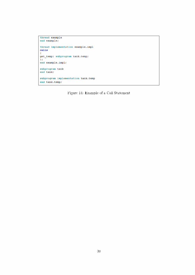
Figure 14: Example of a Call Statement
30

5 A Flight Control System AADL Speci�cation
One task of the thesis was to develop an AADL speci�cation of a software-intensive system andto use the speci�cation for architecture-based veri�cation. Since AADL originates from the�eld of avionics, development of a �ight control system was chosen. Instead of doing extensiveresearch about how di�erent systems control airplanes, basic concepts of how di�erent ruddersand engine are controlled were derived by surveying the book "Understading Flight" [25], andadding some auto pilot features. From these basic concepts, described in section 5.1, an AADL�y-by-wire �ight control system was speci�ed, which is described in section 5.2.
5.1 Basic Concepts of Flight Control Systems
An airplane typically has four di�erent rudders, as shown in Figure 15, that are controlledby the pilot: one on each wing called ailerons (blue), one on the horizontal stabilizer calledelevator (yellow) and one on the vertical stabilizer called vertical �n rudder (red). The leftand right aileron moves up and down in opposite directions and controls the rolling movementof the plane. For example, if the right aileron is moved down and consequently the left aileronis moved up, the lift power of the right wing increases while it decreases on the left wingand as a result the airplane rolls to the left. The elevator can be moved up or down andcontrols upward or downward movements of the plane. An upward or downward movementof the elevator forces the nose of the airplane to lift or lower respectively, which changes thelift power of the wings. A Lift of the nose results in increasing lift power of the wings anddecreasing lift power when the nose is lowered. The vertical �n rudder can be moved left orright in order to control left or right yaw movement of the airplane. A left or right movementof the vertical �n rudder forces the nose to the left or right respectively and consequently theplane turns (yaws) to the left or right.
Figure 15: Airplane rudders: ailerons (blue), vertical �n rudder (red), elevator (yellow)
31

In order to perform e�cient and safe maneuvering of a plane these rudders are often usedsimultaneously. Each rudder is controlled by the pilot from the cockpit typically by a yokeand two pedals. The yoke controls ailerons and elevator while the pedals control the vertical�n rudder. A yoke can be turned left or right and moved forward or backward. Left and rightturning movements of the yoke control the ailerons where a left turn of the yoke rolls the planeto the left (left aileron up and right aileron down) while a right turn of the yoke rolls the planeto the right (left aileron down and right aileron up). Forward and backward movements of theyoke control the elevator where a forward movement lowers the nose (elevator down) whereasa backward movement lifts the nose (elevator up). The pedals control the vertical �n rudderin a contradictory manner, i.e. both pedals can't be pressed at the same time. If left pedal ispressed the airplane yaws to the left (vertical �n left) whereas the airplane yaws to the right(vertical �n right) when right pedal is pressed.
One more vital airplane control element is the power produced by the airplane engine.Power produced by the engine is typically controlled by a throttle lever which can be movedforward to increase engine power or moved backward to decrease engine power.
Flight control systems are commonly built on mechanical or hydro-mechanical links be-tween the control devices (e.g. yoke) and the controlled elements (e.g. ailerons) through cablesand hydraulics. But since these systems aren't software-intensive systems I had to take anotherapproach. Instead, I considered a �y-by-wire system which controls the plane by electricalsignals through sensors, actuators and computers, which indeed is a software-intensive system.The basic concept of a �y-by-wire system is that pilot commands (e.g. sensor data from yoke)are read by a computer which computes output signals, transmitted by wire, to di�erent actua-tors [25]. Actuators convert electrical signals into mechanical actions such as moving a rudder.
In addition, �ight control systems usually have auto pilot systems where it is possibleto set course, height and speed. The auto pilot system is enabled by the autopilot engagebutton and controls the plane according to the settings without any interactions with the pilot.
From these basic concepts I developed a �ight control system speci�cation (model) withoutany detailed research about such systems.
5.2 The AADL Speci�cation
As described in the previous chapter, �y-by-wire �ight control systems contain of some basicelements, i.e. di�erent sensors that are read by a computer which controls di�erent actuators.Sensors and actuators are modeled by device components where the internal complexity of thedevice typically isn't modeled. Since these elements are main parts of a �ight control systemit's bene�cial to model them �rst. Speci�ed actuators are each rudder and the engine, shownin Figure 16. Each actuator has a speci�ed input data port from where input signals arederived. Ports are typed with generic data types such as "aileron_type" where declarationsof these data types are left out in the �gure. For the purpose of testing, engine component isspeci�ed with a �ow sink declaration (�ow ends in the component). Since it's possible to testtime constraints on �ow paths by the OSATE environment (methods for �ow testing by theOSATE environment are described in [26]) an end to end �ow path from the throttle leverto the engine is speci�ed with time constraint properties (latency). In this particular case,
32

the latency property speci�es that it takes 450 milliseconds from the point where input datais available to the point where the engine power is set according to the input. As describedabove, this �ow latency property isn't based on any reason other than to have a �ow path totest, i.e. property value is set to a "random" value.
Figure 16: Speci�ed Actuators
Speci�ed main sensor parts are yoke, pedals and throttle as well as additional sensors suchas course sensor, height sensor, speed sensor, autopilot button and autopilot setting panel,shown in Figure 17. Course, height and speed sensors are important navigation instrumentsfor pilots but they are not included in the control system for that intention. In order to controlthe airplane by the autopilot, according to the autopilot settings, these sensors are vital. Eachsensor has out data ports except for the "auto_pilot_button" (device "auto_pilot") whichhas an out event port. When the "auto_pilot_button" is pressed it should trigger a changeof mode in the system, i.e. from manual mode to autopilot mode or vice versa.
33

Figure 17: Speci�ed Sensors
Reading of sensors and calculation of output to actuators are controlled by software exe-cuted on a computer. The software is speci�ed by three threads within one process. Threaddeclarations are shown in Figure 18, where thread identi�ed as "steering_control" derivesinput from yoke and pedals (in manual mode) and produces output the each rudder. Thread"engine_control" derives input from the throttle lever (in manual mode) and produces outputto the engine. Since there is an explicit end-to-end data �ow from the throttle lever to theengine, which goes through the "engine_control" thread, a �ow path is declared. The lastthread, which is named "ap_setting_control" is the thread that indirectly controls the planein autopilot mode. Each thread has an in event port where events from the autopilot buttonis received. These events control the threads weather they should operate in manual modeor autopilot mode (speci�cation described below). In autopilot mode, "steering_control" and
34

"engine_control" will get input from "ap_setting_control", instead of di�erent sensors (e.g.yoke). "Ap_setting_control" derives input from autopilot setting panel, course sensor, heightsensor and speed sensor. "Ap_setting_control" produces output on four ports that are typedwith the same data types as yoke-, pedals- and throttle-device ports (which feed data to "steer-ing_control and engine_control"). This means that "steering_control" and "engine_control"can be connected with "ap_setting_control" (in autopilot mode) since they have ports withsame data types. Speci�cation of connections in di�erent modes is described below.
Figure 18: Speci�ed Threads
Declaration of the process named "airplane_control" containing the three threads is partlyshown in Figure 19. Until now there have not been any component implementation decla-
35

rations. Since "airplane_control" has three threads as subcomponents, it's declared in thecomponent implementation "airplane_control.impl". The interfaces of the process contain allports needed by the contained threads. For example, "steering_control" thread (Figure 18)has an in data port named "yoke_status" with data type "yoke_type". Since the port derivesdata produced by a component outside of the process component, there must be an interfaceof the process so the connection can be established, i.e. "airplane_control" must have anin data port with data type "yoke_type" (port identi�ed as "yoke_status"). Furthermore,the process implementation contains declarations of connections, �ows and modes. There aretwo modes declared, "manual_pilot" and "auto_pilot", where manual pilot is declared as theinitial mode and change of modes are triggered by events derived on the "airplane_control"process port named "auto_pilot_button" (which described below is connected to the autopi-lot button device). Connection declarations connect process interface ports and subcomponentinterface ports as intended where some connections depend on modes. For example, as men-tioned before, "steering_control" thread should derive input from yoke and pedals in manualmode whereas in autopilot mode input should be derived by the "ap_setting_control" thread.This can be re�ected in connections identi�ed as "C1" and "C16". Connection "C1" speci�esthat in "manual_pilot" mode "steering_control" (identi�ed as "S_C" in the process imple-menatation) interface port identi�ed as "yoke_status" is connected with process interface portidenti�ed as "yoke_status" (which can be seen below is connected with the yoke). On theother hand, connection "C16" speci�es that in "auto_pilot" mode "steering_control" port"yoke_status" is connected to "ap_setting_control" interface port "yoke_status". The �owpath through the process is declared in both the component type and component implementa-tion. Flow path declaration in the component type speci�es that there is a �ow path between"throttle_status" and "engine_setting" interface ports, whereas �ow path declaration in thecomponent implementation speci�es how this path is connected in the internal structure (viasubcomponents).
36

Figure 19: Speci�ed Process
Software and device components described above can now be formed into a subsystemof the �ight control system as shown in Figure 20. The system component identi�ed as"ac_application" connects the process and all devices as intended. The component type con-tains of a require bus access interface so devices can be bound to a bus (execution platformdescribed below). Since the explicit data �ow from the throttle to the engine starts and endswithin the component, there is an end-to-end �ow declaration in the component implemen-tation. The end-to-end data �ow latency property speci�es a latency requirement where thetotal latency of all components in the speci�ed data �ow shouldn't exceed 900 milliseconds.
37

Figure 20: Speci�ed Application System
In order to complete the �ight control system, software and device components must bemapped to an execution platform, which is speci�ed as another subsystem of the completesystem. The execution platform system identi�ed as "ac_computer" and its subcomponentsare shown in Figure 21. Subcomponents of the execution platform are: one processor compo-nent identi�ed as "PENTIUM", one memory component identi�ed as "SDRAM" and one buscomponent identi�ed as "ARINC_629".The system implementation consists of two bus accessconnections ("C1" and "C2"), which connects memory and processor to the bus. Furthermore,"ac_computer" component provides bus access so devices, which are outside of the systemcomponent, can be connected to the bus.
38

Figure 21: Speci�ed Execution Platform System
Systems "ac_application" and "ac_computer" can now be declared as subcomponents ina system component to complete the �ight control system, as shown in Figure 22.
Figure 22: Speci�ed System
5.3 Speci�cation Veri�cation
In this section, we will look at derived test paths for simulation when architecture-basedtesting criteria (shown in Table 1) are applied to the speci�cation. We will also look at atranslation of the speci�cation into timed automata in Uppaal (presented in secion 5.3.2) inorder to apply veri�cation algorithms for completeness, consistency and concurrency.
39

5.3.1 Applying Architecture-based Testing Criteria
Test paths are easiest derived by looking at the textual representation in conjunction with agraphical representation of the AADL speci�cation. A graphical representation of the speci-�ed software and devices is shown in Figure 23. As an example of how to derive test paths,consider Direct_Component_to_Component_Path (described in section 3.1) which is de-�ned to be a path if two components "A" and "B" have a Direct_Component_Relation. ADirect_Component_Relation exists if there is a Connector_Internal_Relation between com-ponents A and B where A and B have Component_Connector_Relations to the connector.A Component_Connector_Relation exists if an interface of a component is coupled with aninterface of a connector (note that connectors don't have explicit interfaces in AADL so thiscan be interpreted as coupled with a connector) while a Connector_Internal_Relation existsif there is a data-transfer, a control transfer or a sequencing-rule relation between interfacesof a connector. Since the yoke device and steering_control thread are connected by con-nection 1 (Figure 23) and there is a data transfer (of yoke_type data type) from yoke tosteering_control through connection 1, there is a Direct_Component_to_Component_Path.At the speci�cation-level, these paths are for simulation and testing where the architecture-based criteria (shown in Table 1) require all test paths to be fully exercised. All derived pathscan be seen in appendix A.
40

Figure 23: AADL Graphical Representation
Instead of simulating every single path (there are more than �fty of them) it is feasibleto derive a set of suitable paths that can be exercised so all paths are covered. Derivingsuitable paths entails in extracting as much properties and relations a tester can handle si-multaneously without slacking assurance that underlying paths will be fully exercised. Forexample, consider the All_Connected_Component_Path containing components connectedby connections 1-4-10-11-13. The path contains following test cases:Test case 1: If autopilot button isn't pressed (In manual mode), steering control gets datainput from yoke and produces output to left/right aileron and elevator. Since there are nospeci�ed execution rules in this path, there is nothing that contradicts data and control �owreachability properties which also results in that there are no concurrency property problems.Test case 2: If autopilot button is pressed (In autopilot mode), steering control doesn't getdata input from yoke. This path can be concluded as the path in test case 1 except that this
41

path has a security problem since there should be some relation that forces steering control toget data input from the yoke if it is moved in autopilot mode. The pilot should always havethe highest control priority for safety reasons.
These test cases cover several others paths such as for example the Component/Connec-tor_Internal_Transfer_Path from yoke_status input interface to rudders output interfacesof steering control. All simulated paths can be found in appendix A.
The results from simulations of test paths showed few problems in the �ight control systemspeci�cation. The majority of problems in the system were mainly because of missing safetyrelations between the autopilot mode and the manualpilot mode (control �ow properties).Since the �ight control system consists of many devices where the internal behaviors of thesedevices were not modeled, there are little execution rule properties, apart from AADL threadexecution semantics, that could contradict the tested properties (shown in Table 2). The �ightcontrol system speci�cation could be much more re�ned with behavioral annexes, speci�edruntime execution by subprograms and speci�ed internal behavior of devices, and thus wouldbe a more appropriate model for veri�cation by the architecture-based testing criteria.
5.3.2 Veri�cation Using Uppaal
One milestone of the architecture-based veri�cation algorithms is to use the Uppaal toolboxto verify the speci�cation for completeness, consistency and having the property of beingdeadlock free (concurrency). Although architecture-based criteria applied to the speci�cationin previous section verify concurrency properties, modeling and veri�cation of a system inUppaal without deadlock checking would be inadequate because of the fact that the propertyis easily veri�ed.
The AADL �ight control speci�cation is translated to the Uppaal toolbox by �nite stateautomata where an AADL component abstraction is represented by an automaton. To startwith, we will look at global variables (reached by all automata), shown in Figure 24, to geta better understanding of the model. The �rst �ve variables (yokelr, yokefb, pedals, throttle,apbutton) represent connections between steering control thread, engine control thread andits input devices (sensors) where arrays are used for appending size to the integer variables.For example, yokelr represents a connection of yoke left and right movement signals andis an integer that can be assigned the value -1, 0 or 1 which represent left, neutral andright movements of the yoke respectively. The following four variables represent connectionbetween the autopilot control thread and the autopilot setting device. These variables aresimilar to the ones explained but there is one crucial di�erence. These variables represent aconnection of course, height and speed signals and have nothing to do with output signalsof other devices. The boolean variable "autopilot" is used for thread synchronization. Thelast seven statements are declaration of channels where leftaileron, rightaileron, vertical�n,elevator and engine channels represent connections between steering control thread, enginecontrol thread and its output devices (actuators). These channels are arrays of channels torepresent di�erent states of the devices. For example, leftaileron channel number 1 (wich isindexed zero) represent a signal which should result in that the leftaileron is positioned todecrease the lifting power ( "upper state") whereas the other two represent a neutral anda lower state (increasing lifting power) of the left aileron. Note that any value described
42

by the �rst four variables corresponds to the right behavior according to the channels if thevalue is added by one. For example, if yokelr has the value -1, which means that the yokeis turned to the left, left aileron should be moved upward whereas right aileron should bemoved downward. If we now add the value -1 with 1 and looks at the corresponding channels(leftaileron[0], rightaileron [0] etc.), we get the correct behavior. All other variables that willappear in this section are local variables and can only be reached by a single automaton.
Figure 24: Global Variables
The yoke is modeled by an automaton with nine locations, shown in Figure 25, whichrepresents all possible positions (locations) and movements (edges) of the yoke. To easilyunderstand the model one can think of a "x and y" coordinate system where the abscissa(x-axel) and ordinate (y-axel) have its origo (x = 0, y = 0) in the center state. The centerstate represents that the yoke left/right turning movements and forward/backward movementare both in neutral state. Therefore, every edge into to center location have an update on theyokefb and yokelr variables where these are assigned the value 0. With the coordinate systemand its origo in mind, following rules can be applied:
� Every location that has an intersection with zero value location on the abscissa representa neutral turning movement of the yoke
� Every location on the positive side of the abscissa represent a right turning movementof the yoke
� Every location on the negative side of the abscissa represent a left turning movement ofthe yoke
� Every location that has an intersection with zero value location on the ordinate representa neutral forward/backward movement of the yoke
43

� Every location on the positive side of the ordinate represent a forward movement of theyoke
� Every location on the negative side of the ordinate represent a backward movement ofthe yoke
All edges update the yokefb and yokelr variables according to the locations.
Figure 25: Yoke Automaton
The pedals (shown in Figure 26), throttle (shown in Figure 27) and autopilot button(shown in Figure 28) components are modeled in similar fashion (assigning global variablescorresponding to locations and not anything to do with the coordinate system) as the yokeexcept that the throttle is slightly di�erent since it was speci�ed with a signal latency (10milliseconds) property in the AADL speci�cation. Consequently, edges to other locations areadded with an extra location and edge in order to model the latency. For example, if theautomaton is in location "Neutral" and a transition to the "Pushed" location is taken, theautomaton needs to visit the "Delay1" location along the path. The edge to the delay locationresets a local clock whereas the edge away from the location has a guard which states that theclock must be bigger or equal to the latency. In order to force the automaton to the "Pushed"
44

location when the clock is equal to latency, an invariant which states that the clock must besmaller or equal to the latency is declared in the location.
Figure 26: Pedals Automaton
Figure 27: Throttle Automaton
45

Figure 28: Autopilot Button Automaton
The autopilot setting component is modeled by a single location as shown in Figure 29. Theidea here is, because of the simplicity and correctness, to model every possible combinationof outputs from the device by model an edge for each possible value that can be assigned toeach variable.
Figure 29: Autopilot Setting Automaton
The steering control thread is modeled by an automaton where the initially location is"Waiting for Dispatch" and contains of two di�erent paths, as shown in Figure 30. Thepaths represent manual mode (rightmost side) and autopilot mode (leftmost side) as speci�edin the speci�cation. The initial location is added with an invariant using a local clock toforce the automaton into action. If the autopilot button isn't pressed (button can be pressedat the exact time when the thread dispatches which is synchronized with the other threadsthrough the boolean variable "autopilot" and "apbutton" in order to prevent steering control
46

and engine control to dispatch in di�erent modes) when the thread dispatches, inputs fromdevices (sensors) are collected to produce output to actuators in form of synchronization withchannels. Note that locations are declared as committed in order to represent data beingobtained simultaneously. On the other hand, if autopilot mode is engaged by the autopilotbutton and autopilot setting control thread has set the "autopilot" variable to true (as seenbelow), the other path will be taken. As can be seen, this path uses the same variables forinput as the manual mode path, but since threads are synchronized (shown below), autopilotcontrol thread temporarily uses these variables for communication. Engine control thread ismodeled in similar fashion as shown in Figure 31.
Figure 30: Steering Control Thread Automaton
47

Figure 31: Engine Control Thread Automaton
Autopilot setting control thread, shown in Figure 32, is modeled as the other threadswith two paths where one simply resets the local clock and the other is used for providingdata to other threads when the system is in autopilot mode. Whenever the automaton goesinto autopilot mode, it waits for synchronization with the other threads. When threads aresynchronized, setting control thread collects inputs and produces output by temporarily usingvariables which are restored with default values before the thread is �nished. Some locationsof the automaton are provided with invariants for guaranteed progress.
Figure 32: Autopilot Setting Control Thread Automaton
Rudders and engine components are modeled in similar fashion where each device is rep-resented by an automaton such as the left aileron automaton shown in Figure 33. Locations
48
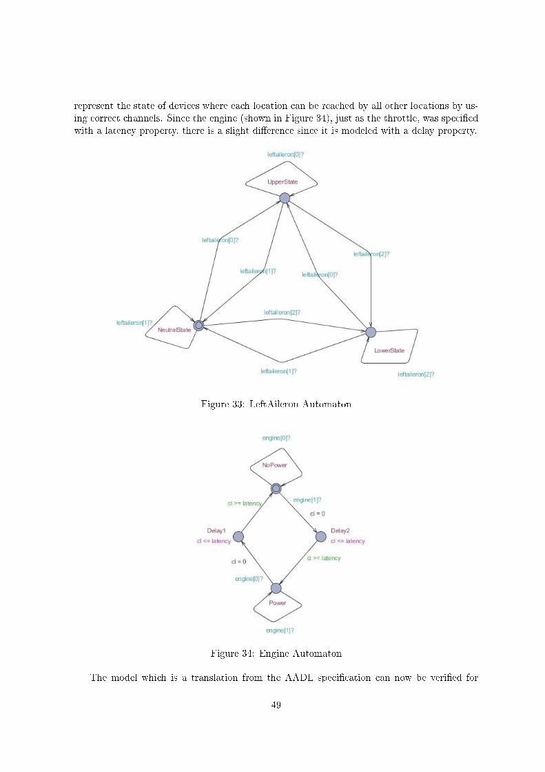
represent the state of devices where each location can be reached by all other locations by us-ing correct channels. Since the engine (shown in Figure 34), just as the throttle, was speci�edwith a latency property, there is a slight di�erence since it is modeled with a delay property.
Figure 33: LeftAileron Automaton
Figure 34: Engine Automaton
The model which is a translation from the AADL speci�cation can now be veri�ed for
49

completeness, consistency and concurrency (deadlock free) as described in the developed al-gorithms explained in section 3.1. Completeness was described as the speci�cation havingresponse for all possible inputs whereas consistency was described as the speci�cation beingfree of contradictory behavioral. And in the context of abstract state machines, completenesswas de�ned as
"a rule will be enabled for every possible combination of its monitored vari-
ables"
whereas consistency was de�ned as"no state having more than one transition enabled at the same time" [21].
In the context of Uppaal, completeness is then de�ned as a guard will be enabled for everypossible combination of its monitored variables which can be stronger interpreted as the rightoutcome will be produced for every possible input. In the case of the �ight control model,monitored variables are those who are assigned by yoke, pedals, throttle, autopilot buttonand autopilot setting automata. Therefore, to verify the completeness of the model, queriesthat completely covers all possible inputs with the correct behavioral have to be asked to theUppaal tool box. As an example of how these queries are created, we will look at inputsproduced by the pedals device.
Possible inputs (via the global "pedals" variable) produced by the pedals are:
� pedals = 0 (i.e. no pedals are pressed) which is equal as the pedals automaton being inlocation "Neutral"
� pedals = -1 (i.e. left pedal is pressed) which is equal as the pedals automaton being inlocation "LeftPressed"
� pedals = 1 (i.e. right pedal is pressed) which is equal as the pedals automaton being inlocation "RightPressed"
Correct outcome of these inputs are (outcome ordered in relation to input):
� Vertical �n automaton being in location "NeutralState"
� Vertical �n automaton being in location "LeftState"
� Vertical �n automaton being in location "RightState"
Since completeness properties are on the form "something will eventually happen" or tobe more speci�c "an input leads to correct outcome", it is a liveness property which can beveri�ed by using the temporal operator "�>". Therefore, a query as "whenever pedals are inthe "Neutral" location then eventually the vertical �n will be in the "Neutralstate" location"or by using the Uppaal query language "ThePedals.Neutral �> TheVerticalFin.NeutralState",seems like a proper query in order to verify the �rst input with the �rst outcome shown in thepointlists above. But a veri�cation of this property will get a "property not satis�ed" result bythe tool box. The property is not satis�ed because of the fact that input devices aren't modeledwith time constraints except for the throttle which was speci�ed with a latency property in theAADL speci�cation. This means that, according to the model, pedals output can be changed"in�nitly" many times before the steering control thread dispaptches since time doesn't elapseduring changes of the outputs. Consequently, the query must be extended with the fact that
50

the steering control thread must dispatch with the pedals being in the "Neutral" location.The proper query is "ThePedals.Neutral and TheSteeringControlThread.GetInputsAndSync�> TheVerticalFin.NeutralState" which result is "property satis�ed" when asked to the Uppaltoolbox.
Veri�cation of input from autopilot setting device with correct outcome is far more com-plex since synchronization between threads depends on several clock constraints, variablesand channels. But instead of simply verifying that any guard will be enabled by an inputfor autopilot setting, completeness properties can be checked by dividing queries to easilychecked parts which can be synthesized to a conclusion. For example, an input from theautopilot setting can be veri�ed to lead to the correct outcome by checking if: the locationwhere inputs are gained by the autopilot control thread (which involves the autopilot button)and the location where steering control thread and engine control thread gains input fromthe autopilot control thread where synchronization with actuators takes place, can be reached("E<> (TheAPSettingControlThread.WaitForSyncWithSteeringAndReadSensorValues andTheEngineControlThread.WaitingForSync and TheSteeringControlThread.WaitingForSync)").This doesn't ensure that values of variables have been correctly communicated because of thenature of the query. To ensure correct values, a trace of the path can be analyzed.
During the process of gaining knowledge about the Uppaal toolbox, it came to my mindthat consistency involves a model to be deterministic in the way that only one guard can beenabled at the same time whereas in Uppaal this isn't feasible because of the fact that theautomata theory is extended with synchronization (by channels) possibilities where severalguards can be enabled at the same time. Therefore, consistency veri�cation of the Uppaalmodel is discarded since the subject needs a more thorough investigation.
Concurrency properties are simply checked by querying in the form "for all paths globallynot deadlock" which in Uppaal syntax is "A[] not deadlock".
All architecture-based queries with results can be found in appendix B.
51

Figure 35: Uppaal Veri�cation
The results of the veri�cation were that the model was complete in the context of a guardbeing enabled in response of every possible input. The stronger completeness veri�cation,which was in the context of the right outcome of every possible input, showed the model tonot be complete because of the latency property in the engine automata. Whenever the engineautomaton was synchronized by the engine control thread in order to change the state of theengine, it was possible to reach a deadlocked state. Since the latency was speci�ed to 450milliseconds and the period of threads was 100 milliseconds, it is possible for the engine con-trol thread to reach a location where the next edge involves synchronization with the enginethat may still be in a delay location. The deadlock occur since the particular location of thethread is committed which means that the next transition must involve an edge of the thread
52

(and time isn't allowed to progress) which involve synhronization (through channel an notsynchronization of threads) with the engine whereas the engine can't support this because it'sstuck in the delay location. This also answers results of the concurrency property (deadlockfree) veri�cation.
The architecture-based testing criteria applied to the AADL �ight control system speci-�cation (described in section 5.3.1) could be applied to the translated Uppaal model insteadof the AADL model in order to do make the veri�cation approach more formal and partlyautomated. This approach was discarded because of schedule constraints but will be a topicfor future research.
53

6 Implementing the AADL Flight Control speci�cation in Java
Architecture-based veri�cation involves testing of the implementation that is implemented tosatisfy the speci�cation. In this chapter we will look at a Java implementation of the �ightcontrol speci�cation. In order to implement the AADL speci�cation in Java, which containsspeci�cation of both hardware and software, the abstraction level of the implementation isanalogous to the speci�cation. The underlying idea is to translate the AADL speci�cation toexecutable Java code and thereby making it possible to execute test cases derived from thearchitecture.
6.1 Java Implementation
To simplify understanding of the Java program, AADL component abstractions (e.g. device),component type subclause elements (e.g. data port) and component implementation subclauseelements (e.g. connections) corresponds to a java class. Component abstraction classes haveinstance variables referenced to tables that correspond to each component type subclause andcomponent implementation subclause. To illustrate an example, we can create a device com-ponent object and a data port object which we can added to the device component featuresdata port table and thus representing a device component with one interface data port.
To start with, we will look at the java class that represents an AADL interface port. ThePort class contains of "get methods" and instance variables representing AADL port attributeswhich are set by the constructor. The instance variables are able to contain information abouta port's identi�er, direction (e.g. out port), connection descriptor (data or event port) anddata type where the data type is a reference variable while others are simple variables (e.g.String variable). Since AADL ports are typed by data components, data type variable is areference variable which can reference to a data component object. Methods of the port classare "get methods" from where information about a port's attributes can be obtained.
AADL data access and bus access component features are implemented in similar way asports. Data access and bus access classes have instance variables able to contain informationabout identi�er, direction (provides or requires) and bus or data object to access.
Connections between ports, data accesses and port accesses are implemented as threedi�erent classes. The port connection class has three instance variables representing portconnection attributes and thus they are able to contain information about a port connec-tion's identi�er, source port and destination port. The port connection constructor executesa checking algorithm before instance variables are assigned since a connection between portsis constrained to be between ports with the same connection descriptor and data type.
Data access connection and bus access connection classes are implemented analogous toport connections except for the checking algorithms which checks if the source data/bus ac-cess object is a "provides access" and that the destination data/bus access is a "require access".
In order to assure semantics of AADL in the implementation, further checking of connec-tions has to be carried out which will be described below.
54

As described above, each component abstraction corresponds to a Java class where theseclasses are implemented in similar fashion but di�ers according to the AADL standard. Wewill look at the system component class which context is applicable to each other componentabstraction class.
The system class has instance variables that correspond to AADL component type andcomponent implementation subclauses except for one containing the system identi�er. Eachinstance variable (a few of them illustrated in Figure 36) is referenced to a hashmap wherekeys are subclause element identi�ers (a String) and values are subclause element objects (e.g.ports).
Figure 36: System Class Instance Variables
Initially, a system object has an identi�er and no other elements when it's created. Otherelements (e.g. subcomponents) are added to the system component by using its "add" meth-ods. For example, we will look at the addPort() and addPortConnection () methods. TheaddPort() method, shown in Figure 37, acquires a port object as parameter which is checkedbefore added to the "port_tab" hashmap. The method simple checks if there already existsa port in the system component feature with same identi�er as the parameter port object. Ifthere is no such port, the parameter port is added to the hashmap.
Figure 37: addPort() method
According to the addPort() method, it's possible to add the same port object to the port
55

hashmap that may already been added to another component since it's not checked. Insteadof preventing this kind of behavior, the program allows use of the same port object in di�erentcomponents but the program doesn't allow connection among port objects that are used morethan once, as will be described below. The addPortConnection() method, partially shownin Figure 38, acquires a port connection object which is checked before added to the portconnection hashmap. The checking algorithm checks whether each of the two ports in theconnection exists only once in the system or its subcomponents, if directions of ports areaccurate and if there doesn't already exist a port connection with the same identi�er. Theseconstraints can be checked by going through the system's and its subcomponets port hashmap,as partially shown in Figure 38. While going through the hashmaps (i.e. going through theentries of the hashmaps), each hashmap value is compared to the source and destination portof the connection object. If one of them is referenced to the same object as the hasmap value,an integer variable, "found1" or "found2", is increased by one and another integer variable,"component_level1" or "component_level2", is set to indicate whether the found port is afeature of the system component or its subcomponents (value 0 indicates component level whilevalue 1 indicates subcomponent level). When the algorithm terminates, variables "found1"and "found2" should have the value one. If ports are found in di�erent component levels, theymust have the same direction whereas connection between ports in the same component levelmust be from an out port to an in port.
56

Figure 38: addPortConnection() method
Java classes described above can now be used to develop the speci�c �ight control system.Creation of the system simply involves creation of objects according to the speci�cation, whichis partially shown in Figure 39.
57

Figure 39: Flight control system creation
The implementation described above can easily be veri�ed by hand not to conform thespeci�cation since all AADL elements used in the speci�cation aren't implemented. For ex-ample, properties can't be associated with di�erent AADL elements. This can partially beexplained with the decision of implementing another re�ned implementation, explained in sec-tion 7, instead of re�ning the �rst one. We will now look at automated testing of the programin order to assure correct behavior and conformance of the implementation with respect tothe speci�cation. A part of the test cases involves unit testing by the JUnit framework wherethe other part involves architecture-based testing built upon the JUnit framework. We willnow look at the former part whereas the later is described in section 6.3.
6.2 Unit Testing with Junit
A JUnit test suite has been developed to assure correct behavior of the implementation. Thetest suite contains of test cases where a test case is a related set of tests of a particular Javaclass. Since most classes are built on the same context, i.e. they have the same behavior,I didn't create a test case for all sixteen classes. As an example of how to assure some ofthe behaviors described above, we will look at the test case for the system component class."TestSystem" class (shown in Figure 40), which is a Junit test case, contains tests to assurethe behavior of the system class. The test case has one �xture object, an instance of the classunder test, which is required by the tests to run. The �xture object is set up by the setUp()method shown in Figure 40. The resource is released by the teardown() method, which isn'trequired in this case since it will be automatically garbage-collected anyway.
58

Figure 40: setUp() and tearDown()
The test case consists partially of two tests, "testAddPort()" and "testAddPortConnec-tion()", which test the behavioral of the addPort() and addPortConnection() methods in thesystem class. The testAddPort(), shown in Figure 41, tests whether it's possible to add a portto the system and that it isn't possible to add two ports with the same identi�er. For example,to test if it's possible to add a port we start with creating a port which then is added to thesystem �xture object. The assertSame() method is then used to assert that the created portexists in the system.
Figure 41: TestAddPort()
The testAddPortConnection(), partly shown in Figure 42, tests whether, 1) a connectionbetween two ports can be added even though the ports are not added in the system or itssubcomponents, 2) a connection can be added when ports are added to the component, 3) aconnection can be added even though one of the ports in the connection is added as featurein two components, 4) a connection can be added between two ports in the same componentlevel even though the source port isn't an out port and destination port isn't an in port, 5) aconnection between two ports in di�erent component levels even though they don't have thesame direction.
59

Figure 42: TestAddPortConnection()
These automated tests revealed some faults in the implementation that had been over-looked. The tests were passed, shown in Figure 43, without any errors or failures after somesmall changes in the implementation.
Figure 43: Running the Test Suite
60

6.3 Architecture-based Testing of the Implementation upon Junit
As Jin Z. and O�ut J. describes in [24], derived testing paths from the speci�cation (describedin section 5.3.1) should be fully exercised in the implementation by a set of inputs. This is notfeasible in this particular case because the implementation is a straight translation from AADLto Java, i.e. the implementation have the same abstraction level as the speci�cation. Instead,relations and properties expressed in the speci�cation can be tested for existence in terms ofconnections. This is done by using the Junit framework where a test case (partly shown inFigure 44) is written for the HWSW class which describes the �ight control system. The testcase simply consists of one �xture object, which is an instance of the HWSW class, and onetest method. The test method consists of an algorithm which starts with asserting existenceof connections (by using identi�ers since the same namespace is used in the implementationas in the speci�cation) in the top component and later through its subcomponents until thebottom components are reached. The testHWSW() method starts with asserting existence ofthe busaccess connection "C1" in the top system component HWSW. This connection shouldexist in the implementation since there is such a connection in the top system componentof the AADL �ight control system speci�cation, as shown in Figure 22. Since there areno more connections in the top component, the algorithm proceeds by deriving the systemsubcomponents ("ac_application" and "ac_computer") of the top system component whereconnections in these components will be asserted for existence. The algorithm proceeds inthis manner until all the components' connections have been asserted for existence accordingto the AADL speci�cation.
Figure 44: Architecture-based Test Case
The test case revealed some faults in the HWSW class where a few architecture elementswere incorrectly created or mistakenly not created according to the speci�cation and therefore
61

the implementation didn't conform the speci�cation . For example, the connection from theengine setting out data port in engine control thread to the engine setting out data port inthe airplane control process was mistakenly not created in the system, which results in thatan architectural data �ow reachability property failed.
62

7 The Re�ned Flight Control System
Since the Java implementation of the AADL �ight control speci�cation was implemented ata high abstraction level, creating static objects according to the speci�cation, there were nofunctionalities or meaningful execution in the program that could react on any kind of inputfor the purpose of testing. What I mean with no functionalities or meaningful executionis that the implementation didn't capture the meaning of how the system should behaveaccording to the speci�cation. For example, it's not possible to produce any input to thesystem that will start execution and communication of components that eventually will controlthe airplane according to the input. To be able to perform more sophisticated testing, theimplementation had to be re�ned to a lower abstraction level by creating functionalities andmeaningful execution of objects that responds and relies on interactions between objects.In addition, a second thought had to be considered, about how much re�nement needed tobe carried out to produce an enough useful application. Because of the complexity of areal �ight control system a re�nement to a low abstraction level would acquire too muchtime and would be out of scope of this thesis. So the aim of the re�nement is to lowerthe abstraction level just enough to provide useful functionalities and in the same time besimple to implement. Instead of re�ning the implementation by extensions and developmentI chose to develop a new application independently of the old application since the programwas entirely built on semantics of the AADL standard which would be complex to re�ne to alower abstraction level. Because of the fact that I have implemented an AADL speci�cation(which describes both hardware and software) in Java, there would be inadequate to re�ne theexecution platform abstraction of the implementation. Therefore I discarded the executionplatform (processor, bus and memory) in the re�nement and defend myself by saying witha smile "the re�ned application is actually executed on my computer, which has a Pentiumprocessor, bus and RAM memory, as in the speci�cation". So by looking at the device-application part of the speci�cation which contains of devices, process and threads I developeda new re�ned application explained in section 7.1. Under the development of the re�nedapplication new architectural elements, properties and con�gurations were extracted from theapplication which weren't speci�ed in the AADL speci�cation. Consequently, the speci�cationwas also re�ned (explained in chapter 8.2) to conform the re�ned implementation.
7.1 Re�ned Implementation
The device-application system of the AADL speci�cation, which contains of a process withthree concurrently executed threads and several devices (abstractions of sensors, actuators andhardware), can be re�ected in the re�ned application as Java threads [3] and simulations ofdevices. There are three Java threads in the re�ned application namely: SteeringControl, En-gineControl, APSettingControl and thirteen simulated devices namely: Yoke, Pedals, Throttle,APButton, APSetting, CourseSensor, HeightSensor, SpeedSensor, LeftAileron, RightAileron,VerticalFin, Elevator and Engine.
The concurrent threads are synchronous communicated through a BlockingQueue object [3]which is a Java standard class for communication between Java threads. When the auto pilotbutton device is pressed (system enters auto pilot mode), SteeringControl and EngineControluse this communication queue to get inputs produced by the APSettingControl thread in-stead of di�erent devices as when auto pilot button isn't pressed (system is in manual mode).
63

SteeringControl is a thread that dispatches periodically, and in manual mode, interacts withsimulated devices such as Yoke and Pedals to get inputs that will be analyzed to produce out-puts to devices such as LeftAileron, RightAileron, VerticalFin and Elevator. EngineControlacts in the same manner as SteeringControl except that, in manual mode, gets input from thesimulated Throttle and produces output to the simulated Engine. APSettingControl threaddispatches aperiodically which means that it dispatches by an event-trigger. Whenever anauto pilot setting (instance variables in APSetting) is changed, an event is produced to triggerthe APSettingControl thread and consequently updates the BlockingQueue with new steeringand engine settings.
Devices in the AADL speci�cation are implemented in the re�ned application as dynamicgraphical objects in a JFrame window, which also is the application's Ggraphical User Inter-face (GUI), represented in Figure 45. Devices that produce inputs to the threads are: Yoke,Pedals, Throttle, APButton, APSetting, CourseSensor, HeightSensor and SpeedSensor. Yokecontrols LeftAileron, RightAileron and Elevator and is simulated by two JSlider objects thatrepresent forward and backward as well as left and right turning movements of the yoke. EachJSlider can be moved, by the application user, to di�erent integer values in the range of -10to +10, which represents the voltage V of the output signals of the Yoke. The extreme values-10 and +10 represent maximum movements in opposite directions. Pedals and Throttle sim-ulations, which controls VerticalFin and Engine respectively, work in the same logic. Pedalscontains of two JSliders (one for each pedal) where each can have signal values between 0and +10. Throttle contains of one JSlider that can have signal values between 0 and +10.CourseSensor, HeightSensor and SpeedSensor are "simulated" by JLabes which shows thecurrent course (degrees), height (meters) and speed (kmh) of the airplane. These sensors werespeci�ed in the speci�cation to produce input to the APSettingControl thread for calculationof how to regulate steering elements according to auto pilot settings (wanted course, heightand speed). Doable simulations of these sensors would be extremely complicated since theydepend on several complex factors. For this reason, I chose to simplify the auto pilot modeby not implement the phase from when the autopilot button is pressed to the point where theairplane is regulated according to the auto pilot settings. So when the auto pilot button ispressed you magically appear in the right course, height and speed (sensors are set accordingto the auto pilot settings). In manual mode are the sensors a�ected by simple mathematicalalgorithms that depend on settings of steering elements. APbutton and APSetting devicesare simulated by JToggleButton and JSpinners [3] respectively. JToggleButton is simple abutton that can be pressed to go into auto pilot mode (from manual mode) or pressed to gointo manual mode (from auto pilot mode). JSpinners allows the user to set course, height andspeed to a particular value setting.
Devices (actuators) that are direct a�ected by controlling threads and indirect a�ectedby devices (sensors) explained above are: LeftAileron, RightAileron, VerticalFin, Elevatorand Engine. All these devices are simulated by JSliders which represent the "position" ofeach steering element except for the Engine which represent amount of power produced bythe engine. For example, if the yoke is moved forward to the value 10 (tip the nose of theairplane) the Elevator's position will decrease to the value -10 (fully tilted down).
64

Figure 45: GUI of the Re�ned Flight Control System
As explained in section 3.2, modi�cations and re�nements of an implementation shouldresult in an update of the architecture-speci�cation to preserve the valuable use of an archi-tecture speci�cation. And since the re�ned implementation extracted new properties, whichwere not speci�ed in the speci�cation, the AADL �ight control speci�cation was consequentlyre�ned which is explained in following section.
7.2 Re�ning the AADL Speci�cation
During re�nements of the implementation new architecture properties emerged that were notspeci�ed in the AADL speci�cation and consequently the architecture speci�cation should beupdated with the new properties in order to preserve regression testing. Devices (yoke, pedals,throttle lever, rudders and engine) were implemented with signal properties that simulated asignal voltage with the range from -10V to + 10V or 0V to +10V. Sensor signals for auto pilotcontrol were implemented with km/h, degrees and meter units for speed, course and heightrespectively. These properties can be speci�ed by specifying signal properties and add themto the current data ports. Speci�ed signal properties and an example of updated data portsare shown in Figure 46.
65

Figure 46: Signal Properties
Steering control and engine control threads were implemented with periodical dispatchproperties with a period of 100 ms whereas autopilot control thread was implemented with anaperiodical dispatch (triggered by an event) property. Since these properties weren't speci�edin the speci�cation, they too was updated as shown by steering control thread in Figure 47.
Figure 47: Thread Dispatch Properties
7.3 Architecture-based Testing of the Re�ned Implementation
Paths derived from the speci�cation (explained in section 5.3.1) can now be exercised by aset of inputs to the �ight control program. Path executions are analyzed by a code cover-age tool Eclemma (www.eclemma.org), which is used to determine results of test case inputs.As an example of applying paths to the implementation, we will look at test case 1 of theAll_Connected_Component_Path that was simulated in section 5.3.1.
66

Test case 1: If autopilot button isn't pressed (In manual mode), steering control threadgets data input (voltage signal) from yoke and produces output to left/right aileron andelevator. A positive/negative voltage input from yoke "left-right turn" to steering controlresults in equal voltage output to ailerons where left aileron gets a positive value whereasright aileron gets a negative value. A postitive/negative voltage input form yoke "forward-backward" to steering control results in equal negative/positive output voltage value to theelevator.The test case can be applied to the implementation by following input signals:
� Autopilot button set to manual mode (not pressed)
� Yoke "left-right turn" set randomly between -10 and +10
� Yoke "forward-backward" set randomly between -10 and +10
Note that the path should be more extensively tested than setting yoke output randomly.For example, the test case can be extended with boundary value analysis but because of thesimplicity of the program I discarded such techniques as being con�dent that if one combina-tion of input signals works, they all work.
The expected result of the inputs is that the path described in test case 1 should be fullyexercised (which can be argued impossible since input signals are randomly set), i.e. all foundrelations in the path, according to the speci�cation, should be executed in the implementation.
The result of the test case, based on inputs and outputs of the program as well as codecoverage analysis (partly shown in Figure 48), was that all relations were found in the imple-mentation.
67

Figure 48: Code Coverage of Test Case, statements covered by green color were executed
Testing of all paths can be found in appendix A. Almost all paths were fully exercisedin the �ight control program except for a couple of test cases where failures of these testcases were known beforehand but anyway result in that the re�ned implementation doesn'tconform the speci�cation. For example, autopilot setting control thread didn't get input (data�ow reachability property) from course, height and speed sensor as expected in a test path.Since regulation of the plane from the point where auto pilot button is engaged to the pointwhere the plane is regulated according to the auto pilot settings was not implemented in theapplication, the relations doesn't exist in the implementation.
68

8 Summary and Conclusions
Development processes of software-intensive systems acts under severe budget, schedule andquality constraints where architecture-based approaches promise to improve the process bymaking it more predictable with early error detection and design decision. The purpose ofthis thesis was to extend the knowledge base within the area of architecture-based veri�cationof software intensive systems by literature and case studies. The underlying problem was todevelop veri�cation algorithms, by studying literature and tools such as AADL, Uppaal andJunit, in order to be applicable on a case study enclosing a development process originatingfrom a system speci�cation and later progressed to an implementation. In this work, an AADL�ight control system speci�cation was built to serve as base for the development process. Be-fore the process progress to an implementation, developed veri�cation algorithms are appliedto the speci�cation. The architecture-based veri�cation algorithms were derived from data-�ow reachability, control-�ow reachability, connectivity, concurrency, completeness and con-formance properties. Furthermore, the algorithms considered issues concerning architecture-based regression testing. Data-�ow reachability, control-�ow reachaibility, connectivity andconcurrency properties were assessed by derived architecture-level criteria which could beapplied to both the speci�cation-level and the implementation-level. In order to apply veri�-cation for concurrency (deadlock free) and completeness properties, algorithms were supportedby using the Uppaal tool box where the speci�cation was modeled by �nite state automataand veri�ed by temporal logic. The process was progressed by a Java implementation, as atranslation from AADL semantics to a Java program, of the �ight control system speci�cationwhere a Junit test suite was developed to verify correct behavior and to apply architecture-level criteria. Since the implementation was implemented at a high abstraction level, creatingstatic objects with no meaningful functionalities that could respond to inputs, a re�nementto a lower abstraction level was required to perform more sophisticated testing. Consequently(in the purpose of developing knowledge and not to produce an error free implementation),a re�ned implementation was developed that could be veri�ed by test case inputs and thecode coverage tool Eclemma. Developed architecture-level testing criteria were shown to ef-fectively �nding problems and faults in both the speci�cation and its implementation sincewhen applied, they command all architectural relations and properties to be fully simulatedand tested. The testing criteria were also indirectly used as a base for conformance testing,where the results of all testing paths showed that both implementations didn't conform withthe speci�cation. These criteria should have been applied to the translated speci�cation (Up-paal model), instead of directly to the original, in order to make the veri�cation algorithmsmore formal and partly automated. Algorithms supported by the Uppaal toolbox, which ini-tially were intended to verify the speci�cation for completeness, concurrency and consistency,were feasible by a translation from AADL to �nite-state automata. Because of the fact thatthe Uppaal modeling language extends �nite-state automata theory with synchronization be-tween automata, knowledge about speci�cation concurrency properties wasn't su�cient to beapplicable on the translated model (which uses synchronization properties) and consequentlywas discarded whereas the topic will be more carefully analyzed in a future research. Thetranslated speci�cation was veri�ed to be complete whereas concurrency veri�cation showedthe speci�cation to not be free from deadlock because of speci�ed timing constraint properties.However, one can question the conclusions that the AADL speci�cation was complete but notfree from deadlock because a timed automata model of the speci�cation was complete but notfree from deadlock. The conclusions certainly rely on how the speci�cation is modeled since
69

an informal translation is easily done with extended or lost properties. Since the translation inthis work was made by an informal approach, there are no underlying proofs that the AADLspeci�cation actually is complete and not free from deadlock. As far as known, there are noformal methods to do this translation which is an interesting topic for future research. As tosummarize this section, it can be stated that derived veri�cation algorithms resulted in thatimportant test cases resulted in a successful test run, in the context of a problem or an errorwas found, which is a positive outcome since testing is about exposing the presence of faultsand not the absence.
70

9 Future Work
The purpose of this thesis was to extend the knowledge base within the area of architecture-based veri�cation in order to perform future research within the area. Consequently, one im-plicit task of the thesis was to �nd interesting topics for future work. The area of architecture-based veri�cation is quite large with several interesting topics for future research but the topicsthat are closest related to the thesis work are as follow:
� Re�ne the AADL �ightcontrol system speci�cation with behavioral annexes, speci�edruntime execution by subprogram components and speci�ed internal behavior of devices
� How to perform consistency veri�cation of Uppaal models
� Develop a tool for formal and automated translation from AADL to Uppaal
� How to perform automated simulations (in Uppaal) of test paths when architecture-based testing criteria are applied to Uppaal models
� Develop algorithms for architecture-based regression testing
71

References
1. Feiler, P.H., D.P. Gluch and J.J. Hudak, (2006), � The Architecture Analysis and De-sign Language (AADL): An Introduction�, Technical Report CMU/SEI-2006-TN-011, Soft-ware Engineering Institute Carnegie Mellon University Pittsburgh, PA 15213
2. Feiler, P.H. and J.J. Hudak, (2007), �Developing AADL Models for Control Systems:A Practitioner's Guide�, Technical Report CMU/SEI-2007-TR-014, Software Engineering In-stitute Carnegie Mellon University Pittsburgh, PA 15213
3. Skansholm, J., (2005), �Java direkt med swing�, ISBN 91-44-03843-7, Studentlitteratur,Lund, p. 171-230 and 403-404
4. Myers, G.J., C. Sandler and T. Badgett, (2004), "Art of Software Testing", John Wil-ley & Sons
5. Avritzer, A. and E. R. Weyuker (1995). "The automatic generation of load test suitesand the assessment oft he resulting software.", IEEE Transactions on Software Engineering*21*(9): 705-716
6. Chan, W. K., T. Y. Chen, et al., (2002), �An overview of integration testing techniquesfor object oriented programs�, International Association for Computer and Information Science
7. Duesterwald, E., R. Gupta, et al., (1996), �A demand-driven analyzer for data �ow testingat the integration level�, IEEE Computer Society Washington, DC, USA
8. Harrold, M. J., (1998), �Architecture-based regression testing of evolving systems�
9. Harrold, M. J., (2000), �Testing: a roadmap�, ACM New York, NY, USA
10. Harrold, M. J. and M. L. So�a, (1991), "Selecting and using data for integration testing"IEEE software *8*(2): 58-65
11. Jagadeesan, L. J., A. Porter, et al., (1997), �Speci�cation-based testing of reactive soft-ware: tools and experiments: experience report�, ACM New York, NY, US
12. Leung, H. K. N., L. White, et al., (1990), �A study of integration testing and soft-ware regression at theintegration level�
13. Linnenkugel, U. and M. Mullerburg, (1990), �Test data selection criteria for (software)integration testing�
14. McCabe, T. J. and C. W. Butler, (1989), "Design complexity measurement and test-ing"

15. Muccini, H., M. S. Dias, et al. (2005). "Towards software architecture-based regres-sion testing" ACM SIGSOFT Software Engineering Notes *30*(4): 1-7
16. Muccini, H., P. Inverardi, et al. (2004). "Using software architecture for code test-ing", IEEE Transactions on Software Engineering *30*(3): 160-171
17. Richardson, D., O. O'Malley, et al., (1989), "Approaches to speci�cation-based test-ing", ACM SIGSOFT Software Engineering Notes *14*(8): 86-96
18. Richardson, D. J., S. L. Aha, et al., (1992), �Speci�cation-based test oracles for reac-tive systems�, ACM New York, NY, USA
19. Weyuker, E., T. Goradia, et al., (1994), "Automatically generating test data from aboolean speci�cation" IEEE Transactions on Software Engineering *20*(5): 353-363
20.Wu, Y., M. H. Chen, et al., (2003), "UML-based integration testing for component-basedsoftware" Lecture Notes in Computer Science: 251-260
21. Ouimet, M., (2008), �A Formal Framework for Speci�cation-Based Real-Time SystemEngineering�, Massachusetts Institute of Technology. Dept. of Aeronautics and Astronautics,p. 123-131.
22. Behrmann, G., D. Alexandre, et al., (2004), �A Tutorial on Uppaal�, Aalborg Univer-sity, Dept. of Computer Science
23. Hightower, R, W. Onstine, et al., (2004), �Professional Java Tools for Extreme Pro-gramming : Ant, XDoclet, Junit, Cactus, and Maven�, John Wiley & Sons, Incorporated, p.221-262
24. Zhenyi, J and J. O�utt, (2001), �Deriving tests from software architectures�, The TwelfthIEEE International Symposium on Software Reliability Engineering (ISSRE '01), p. 308-313
25. Anderson, David F, (2001), �Understanding Flight�, The McGraw-Hill Companies, ISBN:9780071363778 9780071386661
26. The SEI AADL Team, (2006), �An Extensible Open Source AADL Tool Environment(OSATE)�, Software Engineering Institute, found at URL: http://www.aadl.info
27. Wirsing, M., et al., (2006), �Report of the Beyond the Horizon Thematic Group 6 on Soft-ware Intensive Systems�, found at URL: ftp://ftp.cordis.europa.eu/pub/ist/docs/fet/strat-6.pdf (18-01-2010)
28. Katoen, J-P., (Semester 1998/1999), "Concepts, Algorithms, and Tools for Model Check-ing", Friedrich-Alexander-University of Erlangen-Nurnberg, Lecture Notes of the Course "Mech-anised Validation of Parallel Systems" (course number 10359), p. 18

29. Pettersson, P., (2009, November), PhD course: Modeling and Veri�cation of Real-time Sys-tem, Malardalen University, Vasteras, Sweden, URL: http://www.idt.mdh.se/∼ppn02/gradu/mvrts09/(course webpage)

A Architecture-based Testing Paths
Figure 49: AADL Graphical Representation
All paths:
Component (Connector) internal transfer paths:
1. Connections 1 to 172. steering control (yoke status ' left/right aileron and elevator setting3. steering control(left/right pedals status ' vertical �n setting)4. steering control (ap_setting data type ' left/right aileron, vertical �n and elevator setting)5. engine control (throttle status ' engine setting)

6. engine control (ap setting data type ' engine setting)7. ap setting data type (input from ap setting control ' output to steering and engine control)8. ap setting control (ap setting, course, height and speed ' output to ap setting data type)
Component (Connector) internal sequencing paths:
9. All interfaces has sequencing rules since they all have data or control transfer
Direct component to component paths:
10. components associated with connections 1 to 17Indirect component to component path:
11. 1-1012. 1-1113. 1-1314. 2-1215. 1-416. 2-417. 16-418. 3-1419. 3-520. 17-521. 15-1622. 15-1723. 17-1424. 16-1025. 16-1126. 16-1227. 16-1328. 6-1529. 7-1530. 8-1531. 9-15
All connected components path (These can be divided to several sub paths!):
32. 1-2-4-10-11-12-1333. 6-7-8-9-4-15-16-10-11-12-1234. 6-7-8-9-4-15-17-1435. 3-5-14
Path All connected components paths: 1-4-10-11-13
Test case1: If autopilot button isn't pressed (In manual mode), steering control gets datainput from yoke and produces output to left/right aileron and elevator.

Test case 2: If autopilot button is pressed (In autopilot mode), steering control doesn't getdata input from yoke. This path has a security problem since there should be some relationthat forces steering control to get data input from the yoke if it is moved in autopilot mode.The pilot should always have the highest control priority for safety reasons.Test cases cover paths: 1(connections 1,4,10,11,13), 2, 10(components associated with connec-tions 1,4,10,11,13),11,12,13,15
Implementation testing
Test case 1: Input signals: autopilot button not pressed, yoke "left-right" set randomly be-tween -10 and +10, yoke "forward-backward" set randomly between -10 and +10.Expected result: Path described in test case 1 should be fully exercised in the implementationi.e. all found relations in the path, according to the speci�cation, should be executed in theimplementation.Actual result: All identi�ed relations in the path were fully exercised.Test case 2: Input signals: autopilot button pressed, yoke "left-right" set randomly between-10 and +10, yoke "forward-backward" set somewhere between -10 and +10.Expected result: Path described in test case 2 should be fully exercised in the implementation.Actual result: All identi�ed relations were fully exercised.
Path Indirect component to component paths: 2-4-12
Test case1: If autopilot button isn't pressed (In manual mode), steering control gets inputfrom pedals (left and right pedal) and produces output to vertical �nTest case 2: If autopilot button is pressed (In autopilot mode), steering control doesn't getinput from pedals This path has a security problem since there should be some relation thatforces steering control to get data input from pedals if they are moved in autopilot mode.Test cases cover paths: 1(connections 2, 4, 12), 3, 10(components associated with connections2, 4, 12),14, 16
Implementation testing
Test case 1: Input signals: autopilot button not pressed, pedals set randomly between 0and +10.Expected result: Path described in test case 1 should be fully exercised in the implementation.Actual result: All identi�ed relations in the path were not fully exercised. Since the pedalshave a type of contradictory behavior, i.e. both pedals cannot be pressed at the same time,steering control �rst get data input from the left pedal and if the data indicates that it ispressed steering control doesn't need to get data input from right pedal. So to fully exercisethe path I needed to either set both pedals to 0 or set the right pedal between 1 and +10.Test case 2: Input signals: autopilot button pressed, pedals set randomly between 0 and +10.Expected result: Path described in test case 2 should be fully exercised in the implementation.Actual result: All identi�ed relations were fully exercised.

Path Indirect component to component paths: 3-5-14
Test case1: If autopilot button isn't pressed (In manual mode), engine gets input from throttleand produces output to engineTest case 2: If autopilot button is pressed (In autopilot mode), engine control doesn't getinput from throttle. This path has a security problem since there should be some relationthat forces engine control to get data input from the throttle if it is moved in autopilot mode.Test cases cover paths: 1(connections 3, 5, 14), 5, 10(components associated with connections3, 5, 14), 18, 19
Implementation testing
Test case 1: Input signals: autopilot button not pressed, throttle set randomly between 0and +10.Expected result: Path described in test case 1 should be fully exercised in the implementation.Actual result: All identi�ed relations in the path were fully exercised.Test case 2: Input signals: autopilot button pressed, throttle set randomly between 0 and+10.Expected result: Path described in test case 2 should be fully exercised in the implementation.Actual result: All identi�ed relations were fully exercised.
Path All connected components paths: 6-7-8-9-15
Test case1: autopilot setting control dispatches by an event (auto pilot button) and getsinput from auto pilot setting device , course sensor, height sensor and speed sensor and pro-duces yoke, pedals and throttle output to ap_setting data type which is and abstract datatype in source text.Test case2: autopilot setting control don't dispatch when auto pilot button isn't pressed.Test cases cover paths: 1(connections 6, 7, 8, 9, 15), 8, 10(components associated with con-nections 6, 7, 8, 9, 15), 28, 29, 30, 31
Implementation testing
Test case 1: Input signals: auto pilot settings are randomly set, auto pilot is pressed todispatch the autopilot setting control.Expected result: Path described in test case 1 should be fully exercised in the implementation.Actual result: All identi�ed relations in the path were not fully exercised. Autopilot settingcontrol didn't get input from course, height and speed sensor. Since regulation of the planefrom the point when auto pilot button is set to the point where the plane is regulated accord-ing to the auto pilot settings was not implemented in the application, the relations doesn'texist in the implementation.Test case 2: Input signals: auto pilot settings are randomly set, auto pilot is not pressed.Expected result: Path described in test case 2 should be fully exercised in the implementation.Actual result: All identi�ed relations in the path were fully exercised.

Path All connected components paths: 4-16-10-11-12-13
Test case1: If autopilot button is pressed (In autopilot mode), steering control gets inputfrom ap_setting data type and produces output to left/right aileron, vertical �n and elevatorTest case 2: If autopilot button isn't pressed (In manual mode), steering control doesn't getinput from ap_setting data type.Test cases cover paths: 1(connections 4, 16, 10, 11, 12, 13), 4, 10(components associated withconnections 4, 16, 10, 11, 12, 13), 21, 24, 25, 26, 27
Implementation testing
Test case 1: Input signals: course and height auto pilot settings are randomly set, autopilot button is pressed.Expected result: Path described in test case 1 should be fully exercised in the implementation.Actual result: All identi�ed relations in the path were fully exercised.Test case 2: Input signals: course and height auto pilot settings are randomly set, auto pilotis not pressed.Expected result: Path described in test case 2 should be fully exercised in the implementation.Actual result: All identi�ed relations in the path were fully exercised.
Path All connected components paths: 5-17-14
Test case1: If autopilot button is pressed (In autopilot mode), engine control gets inputfrom ap_setting data type and produces output to engine.Test case 2: If autopilot button isn't pressed (In manual mode), engine control doesn't getinput from ap_setting data type.Test cases cover paths: 1(connections 5, 17, 14), 6, 10(components associated with connections5, 17, 14), 20, 23, 22
Implementation testing
Test case 1: Input signals: speed auto pilot settings are randomly set, auto pilot buttonis pressed.Expected result: Path described in test case 1 should be fully exercised in the implementation.Actual result: All identi�ed relations in the path were fully exercised.Test case 2: Input signals: speed auto pilot settings are randomly set, auto pilot is not pressed.Expected result: Path described in test case 2 should be fully exercised in the implementation.Actual result: All identi�ed relations in the path were fully exercised.
Total test cases covers paths: 7, 9, 17, 32, 33, 34, 35, 36

B Architecture-based Uppaal Queries
Architecture-based queries
Property:TheYoke.NeutralNeutral and TheSteeringControlThread.GetInputsAndSync �>TheLeftAileron.NeutralState and TheRightAileron.NeutralState andTheElevator.NeutralStateSatis�ed
Property:TheYoke.NeutralLeft and TheSteeringControlThread.GetInputsAndSync �>TheLeftAileron.UpperState and TheRightAileron.LowerState andTheElevator.NeutralStateSatis�ed
Property:TheYoke.ForwardLeft and TheSteeringControlThread.GetInputsAndSync �>TheLeftAileron.UpperState and TheRightAileron.LowerState andTheElevator.LowerStateSatis�ed
Property:TheYoke.ForwardNeutral and TheSteeringControlThread.GetInputsAndSync �>TheLeftAileron.NeutralState and TheRightAileron.NeutralState andTheElevator.LowerStateSatis�ed
Property:TheYoke.ForwardRight and TheSteeringControlThread.GetInputsAndSync �>TheLeftAileron.LowerState and TheRightAileron.UpperState andTheElevator.LowerStateSatis�ed
Property:TheYoke.NeutralRight and TheSteeringControlThread.GetInputsAndSync �>TheLeftAileron.LowerState and TheRightAileron.UpperState andTheElevator.NeutralStateSatis�ed

Property:TheYoke.BackwardRight and TheSteeringControlThread.GetInputsAndSync �>TheLeftAileron.LowerState and TheRightAileron.UpperState andTheElevator.UpperStateSatis�ed
Property:TheYoke.BackwardNeutral and TheSteeringControlThread.GetInputsAndSync �>TheLeftAileron.NeutralState and TheRightAileron.NeutralState andTheElevator.UpperStateSatis�ed
Property:TheYoke.BackwardLeft and TheSteeringControlThread.GetInputsAndSync �>TheLeftAileron.UpperState and TheRightAileron.LowerState andTheElevator.UpperStateSatis�ed
Property:ThePedals.Neutral and TheSteeringControlThread.GetInputsAndSync �>TheVerticalFin.NeutralStateSatis�ed
Property:ThePedals.LeftPressed and TheSteeringControlThread.GetInputsAndSync �>TheVerticalFin.LeftStateSatis�ed
Property:ThePedals.RightPressed and TheSteeringControlThread.GetInputsAndSync �>TheVerticalFin.RightStateSatis�ed
Property:TheThrottle.Neutral and TheEngineControlThread.GetInputsAndSync �>TheEngine.NoPowerSatis�ed
Property:TheThrottle.Neutral and TheEngineControlThread.GetInputsAndSync �>

TheEngine.NoPower or TheEngine.Delay1Satis�ed
Property:TheThrottle.Pushed and TheEngineControlThread.GetInputsAndSync �>TheEngine.PowerSatis�ed
Property:TheThrottle.Pushed and TheEngineControlThread.GetInputsAndSync �>TheEngine.Power or TheEngine.Delay2Not Satis�ed
Property:E<> TheSteeringControlThread.WaitingForSyncSatis�ed
Property:E<> TheEngineControlThread.WaitingForSyncSatis�ed
Property:E<> (TheAPSettingControlThread.WaitForSyncWithSteeringAndReadSensorValues andTheEngineControlThread.WaitingForSync and TheSteeringControlThread.WaitingForSync)Satis�ed
Property:E<> TheAPSettingControlThread.WaitForSyncWithEngineSatis�ed
Property:A[] not deadlockNot Satis�ed