architecture - university of california, berkeleyee122/sp04/architecture.pdfnetwork architecture...
TRANSCRIPT
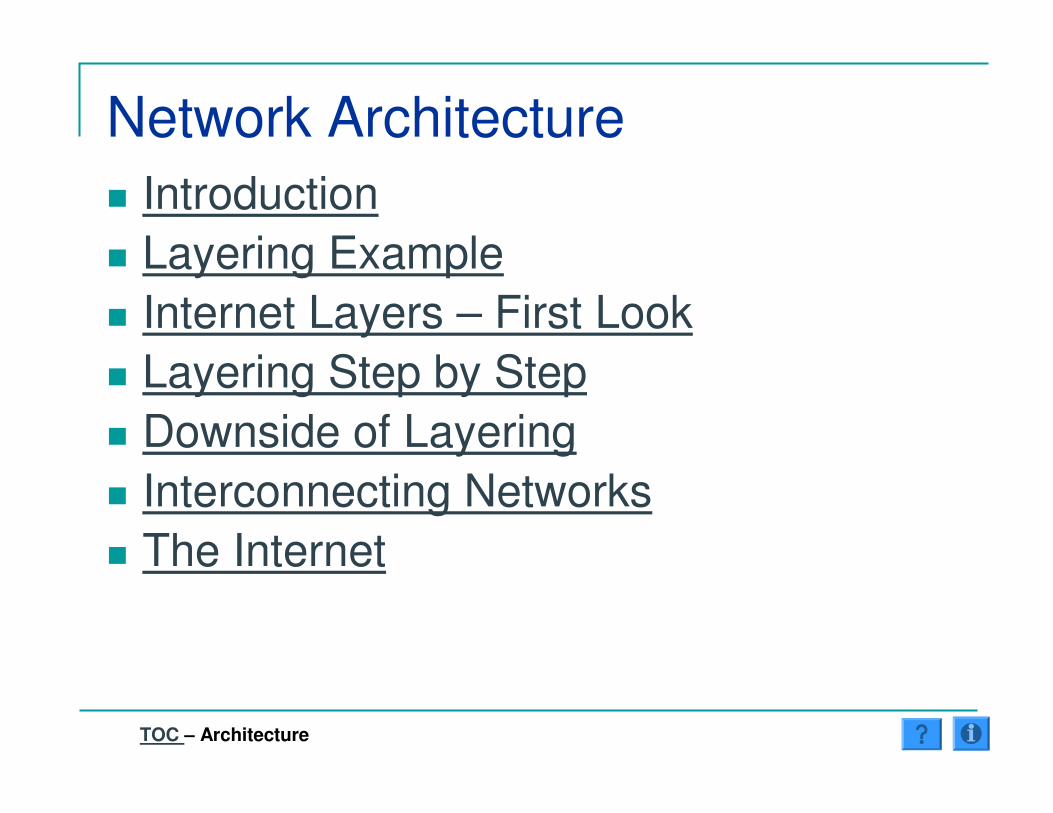
Network Architecture� Introduction� Layering Example� Internet Layers – First Look� Layering Step by Step� Downside of Layering� Interconnecting Networks� The Internet
TOC – Architecture

Introduction� Issues:
� Inter-operability� Extensibility
� Applications & Technologies� Scalability
� Internet Solution:� Layered Architecture� End-to-End Principle� Hierachical Addressing & Naming
TOC – Architecture ���� Introduction

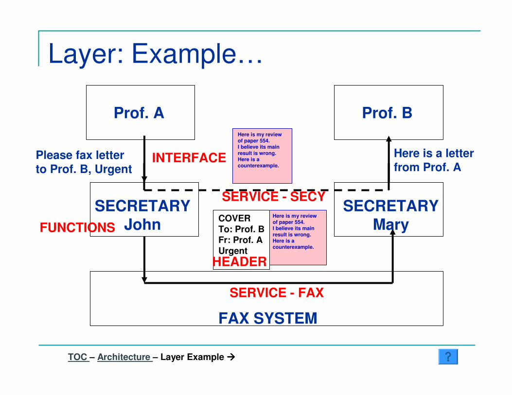
Layer: Example…
TOC – Architecture – Layer Example ����
FAX SYSTEM
SECRETARYJohn
SECRETARYMary
Prof. A Prof. B
Please fax letterto Prof. B, Urgent
Here is a letter from Prof. A
Here is my review of paper 554.I believe its main result is wrong.Here is a counterexample.
Here is my review of paper 554.I believe its main result is wrong.Here is a counterexample.
COVERTo: Prof. BFr: Prof. AUrgent
Here is my review of paper 554.I believe its main result is wrong.Here is a counterexample.
COVERTo: Prof. BFr: Prof. AUrgent
Layer: Example…
TOC – Architecture – Layer Example ����
FAX SYSTEM
SECRETARYJohn
SECRETARYMary
Prof. A Prof. B
Please fax letterto Prof. B, Urgent
Here is a letter from Prof. A
INTERFACE
FUNCTIONS
HEADER
SERVICE - SECY
SERVICE - FAX
Here is my review of paper 554.I believe its main result is wrong.Here is a counterexample.
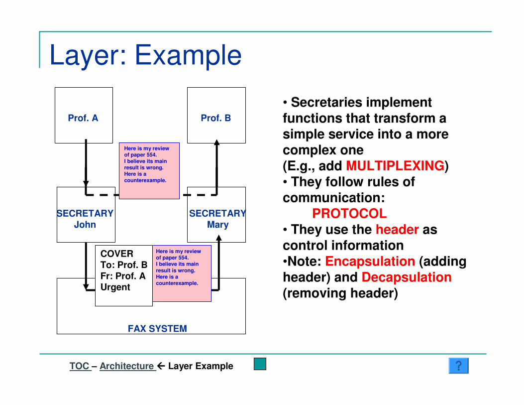
Layer: Example
TOC – Architecture ���� Layer Example
FAX SYSTEM
SECRETARYJohn
SECRETARYMary
Prof. A Prof. B• Secretaries implement functions that transform a simple service into a more complex one(E.g., add MULTIPLEXING)• They follow rules of communication:
PROTOCOL• They use the header as control information•Note: Encapsulation (adding header) and Decapsulation(removing header)
Here is my review of paper 554.I believe its main result is wrong.Here is a counterexample.
Here is my review of paper 554.I believe its main result is wrong.Here is a counterexample.
COVERTo: Prof. BFr: Prof. AUrgent

Internet Layers - Intro
TOC – Architecture – Internet Layers: Intro
� Browsing� Services� Names� Examples� Specifications� Encapsulation� Functions

Browsing� Name � IP Address � Connect; Get; Close � Supervise Connection� Forward Packets Across Many Links� Transmit Packets on Each Link� Transmit Bits on Each Medium
TOC – Architecture – Internet Layers: Intro ���� Browsing
1
2
3
4
5
H H
R R
� DSN Servers� End hosts 5� End hosts 4� Routers 3� Link/LAN 2� Transceivers 1
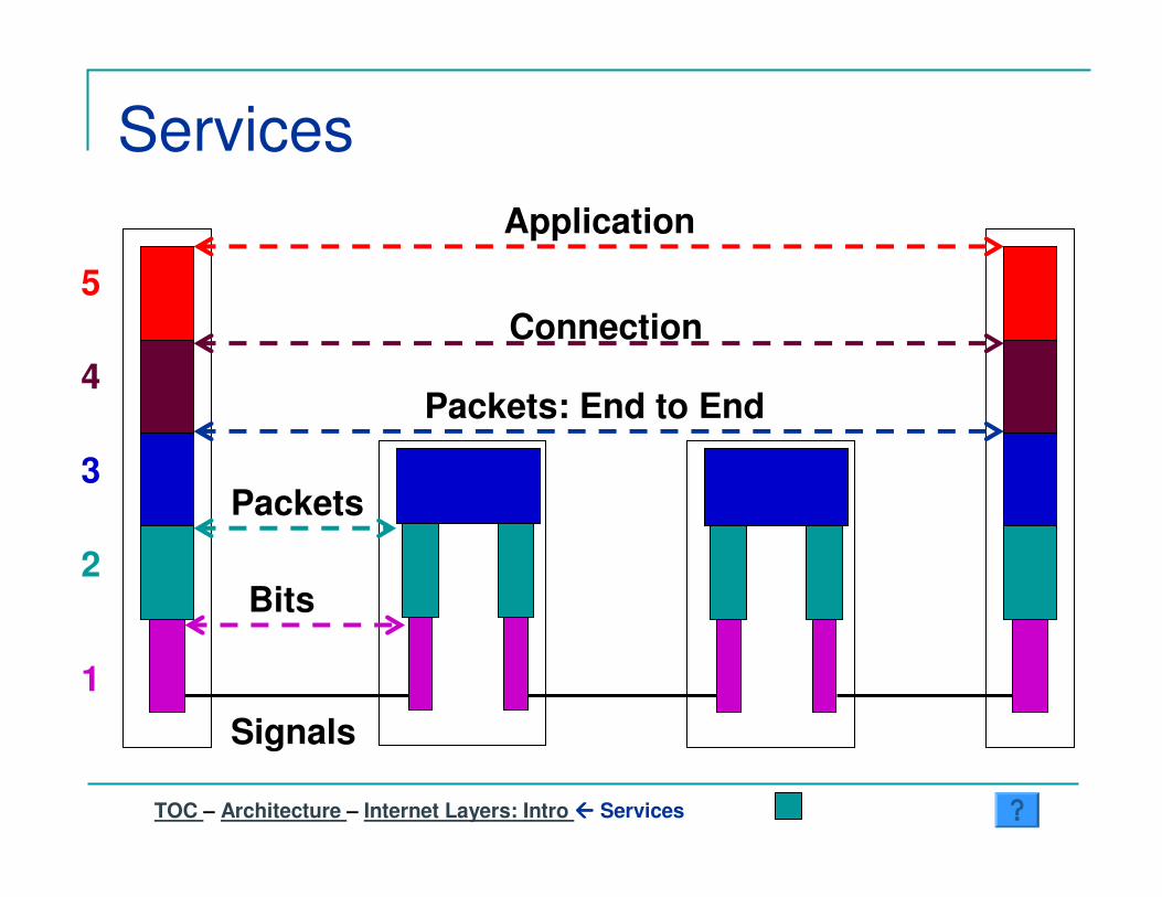
Services
TOC – Architecture – Internet Layers: Intro ���� Services
1
2
3
4
5
Signals
Bits
Packets: End to End
Connection
Application
Packets
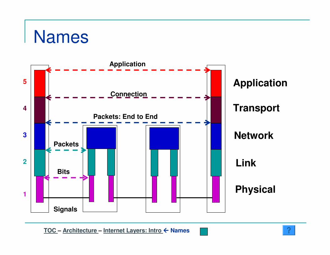
Names
TOC – Architecture – Internet Layers: Intro ���� Names
1
2
3
4
5
Signals
Bits
Packets: End to End
Connection
Application
Packets
Physical
Link
Network
Transport
Application
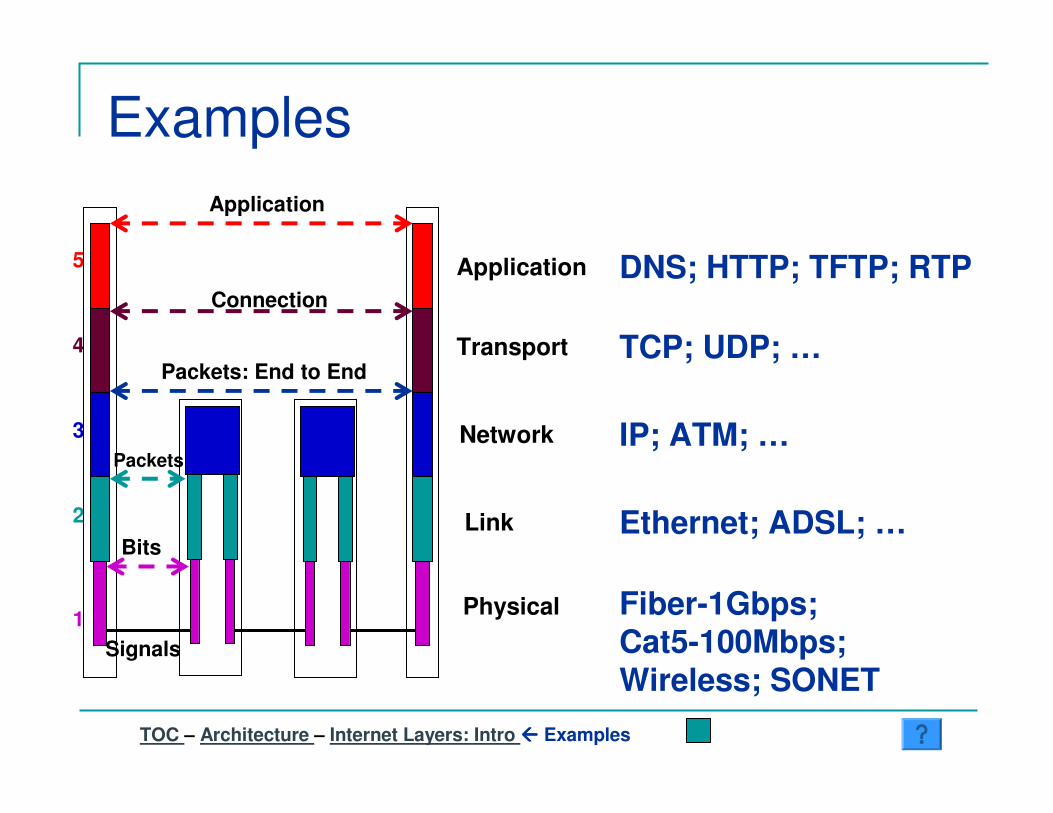
Examples
TOC – Architecture – Internet Layers: Intro ���� Examples
1
2
3
4
5
Signals
Bits
Packets: End to End
Connection
Application
Packets
Physical
Link
Network
Transport
Application
Fiber-1Gbps; Cat5-100Mbps;Wireless; SONET
Ethernet; ADSL; …
IP; ATM; …
TCP; UDP; …
DNS; HTTP; TFTP; RTP
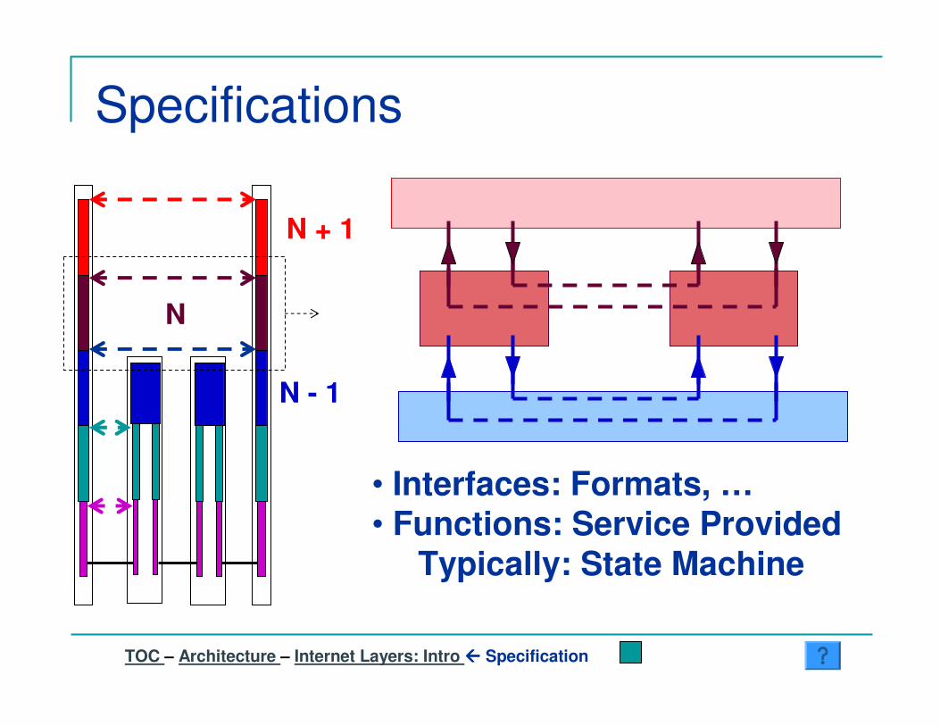
Specifications
TOC – Architecture – Internet Layers: Intro ���� Specification
N
N - 1
N + 1
• Interfaces: Formats, …• Functions: Service Provided
Typically: State Machine
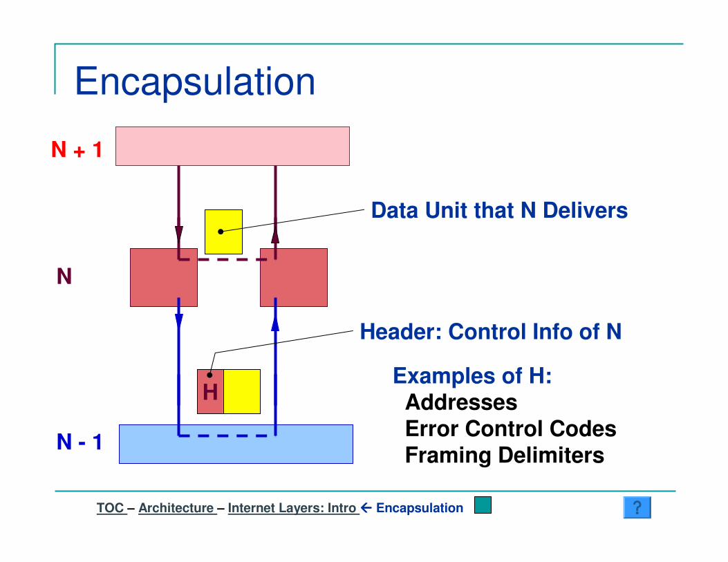
Encapsulation
TOC – Architecture – Internet Layers: Intro ���� Encapsulation
N + 1
N
N - 1
H
Data Unit that N Delivers
Header: Control Info of N
Examples of H:AddressesError Control CodesFraming Delimiters

Functions
TOC – Architecture ���� Internet Layers: Intro – Functions
APP
TRAN
NET
LINK
PHY Modulation; Demodulation
Framing; Error Coding;Local Addressing; Switching
Global Addressing; Routing;Forwarding
Multiplexing; Flow Control;Congestion Control
Set Up Connections; Presentation; …

Layers Step By Step� Physical� Data Link� Network� Transport� Application� DNS
TOC – Architecture – Layers Step By Step

Physical
�������������������� ���������������������� �
��������������������� ��������
In the beginning were two computers…
TOC – Architecture – Layers Step By Step – Physical

��������������������� �������������������������
Physical
ModemRS232-CInterface
Interface wires
Modem RS232-CInterface
Interface wires
Synchronous unreliable bit pipe
Physical Medium
Physical Medium � Virtual Bit Pipe
1011011Example: Manchester Encoding
TOC – Architecture – Layers Step By Step ���� Physical
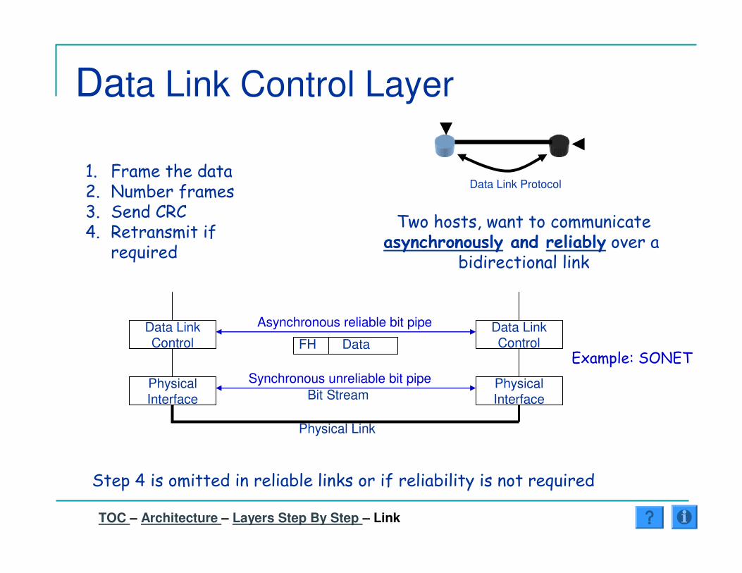
Data Link Control Layer
Data Link Protocol
��������������������� ���������������� ����� ���� ������
���������������
PhysicalInterface
PhysicalInterface
Synchronous unreliable bit pipe
Data LinkControl
Data LinkControl
Asynchronous reliable bit pipe
Physical Link
FH Data
Bit Stream
�� ����������!� " �����#����$� % ����&�'� &���������#�
��( ����
% ����'�������������������������������#��������������������( ����
)*����+�% , " )�
TOC – Architecture – Layers Step By Step – Link

Data Link Control Layer What about a broadcast system?
� Example: Satellite, ethernet, 802.11� Individual transmissions can interfere and destroy
many frames� A multiaccess protocol is required to try and avoid
these collisions or the link will be too unreliable� Example: TDM, CSMA� Makes the bit-pipe provided by the physical layer look
“intermittent” to the DLC� Protocol must interface with Physical and DLC layers� By convention the Multiaccess Control Layer (MAC) is
considered a “sub-layer” of the DLC
TOC – Architecture – Layers Step By Step – Link
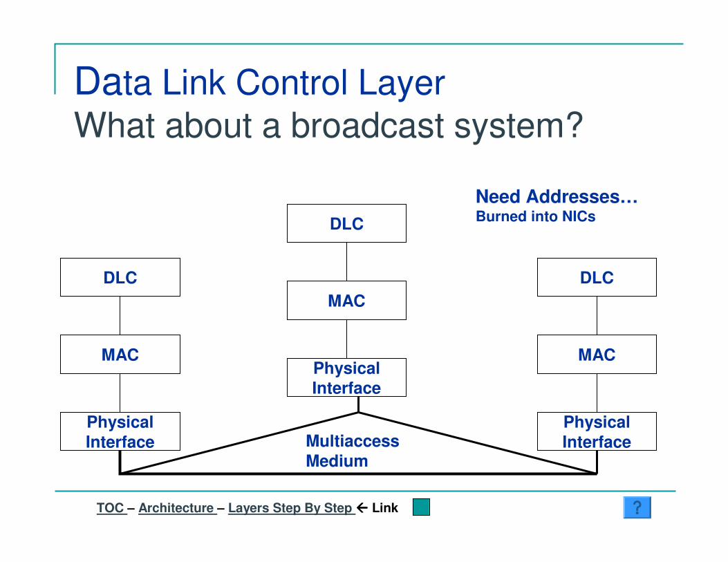
Data Link Control Layer What about a broadcast system?
PhysicalInterface
PhysicalInterfaceMultiaccess
Medium
PhysicalInterface
MAC MAC
MACDLC
DLC
DLC
Need Addresses…Burned into NICs
TOC – Architecture – Layers Step By Step ���� Link

Network Layer: Routing
A B
" ������� ���-� ����# �����./���������� ���������� ���������
Routing information must be contained in a message unlessit is part of a circuit…Network addressing and protocol required to accomplishdelivery over multiple hops
C D
E
TOC – Architecture – Layers Step By Step – Network

Network Layer: Complexity
A B
������������-����. ������������� ���������#����������������*��������������������������
��������������#��������# ���������������������#���������������
C D
E
Topology discoveryLink State monitoringForwardingBuffer management
TOC – Architecture – Layers Step By Step – Network
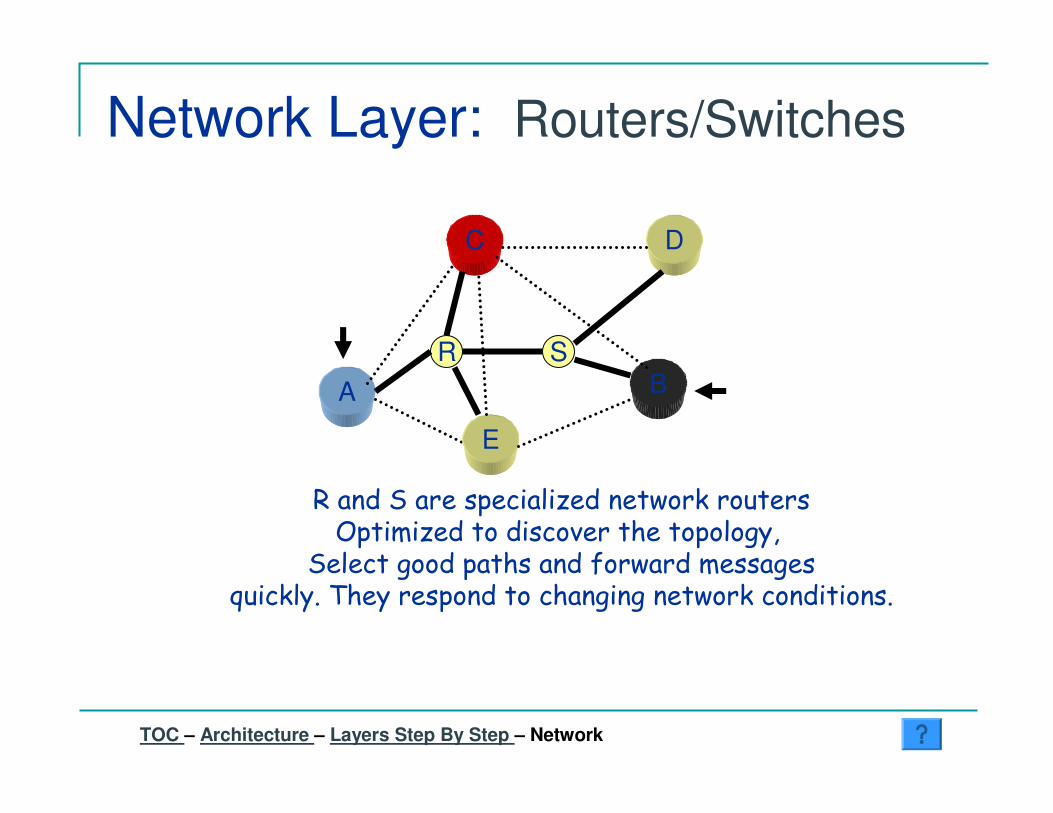
Network Layer: Routers/Switches
A B
& ���% �����������0������������ ����, �����0�����������������������������
% ������������������#�������������( ��������������������������������������������
C D
E
R S
TOC – Architecture – Layers Step By Step – Network

Network Layer
PhysicalInterface
PhysicalInterface
Synchronous unreliable bit pipe
Data LinkControl
Data LinkControl
Asynchronous reliable bit pipe
Physical Link
Network NetworkAsynchronous path
FH Data
PhysicalInterface
Synchronous unreliable bit pipe
Data LinkControl
Asynchronous reliable bit pipe
Physical Link
NetworkAsynchronous path
FH Data
PH Data PH Data
)*�����+�12��� �3
TOC – Architecture – Layers Step By Step ���� Network

Transport Layer
A B
C D
E
a b c
APP
x y z
APP
������������������������������������������������������������1��������������������������
���������������������-�������. ������� ��
TOC – Architecture – Layers Step By Step – Transport

Transport Layer
PhysicalInterface
PhysicalInterface
Synchronous unreliable bit pipe
Data LinkControl
Data LinkControl
Asynchronous reliable bit pipe
Physical Link
Network NetworkAsynchronous routed path
FH Data
PhysicalInterface
Synchronous unreliable bit pipe
Data LinkControl
Asynchronous reliable bit pipe
Physical Link
NetworkAsynchronous routed path
FH Data
Transport Transport
PH Data PH Data
TH Data
End Node Subnet Node End Node
)*�����+���2��4 5 2
TOC – Architecture – Layers Step By Step ���� Transport
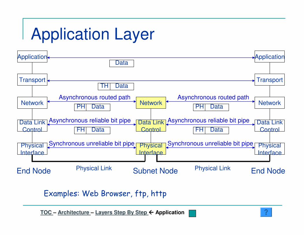
Application Layer
)*�����+�6 ���7��������#��������
PhysicalInterface
PhysicalInterface
Synchronous unreliable bit pipe
Data LinkControl
Data LinkControl
Asynchronous reliable bit pipe
Physical Link
Network NetworkAsynchronous routed path
FH Data
PhysicalInterface
Synchronous unreliable bit pipe
Data LinkControl
Asynchronous reliable bit pipe
Physical Link
NetworkAsynchronous routed path
FH Data
Transport Transport
PH Data PH Data
TH Data
End Node Subnet Node End Node
Application ApplicationData
TOC – Architecture – Layers Step By Step ���� Application

Network Directory Servers
A B
8 �����������������������������������������������#�� ���� �������������������������������� ��
�������������������1���������������������5 " %
C D
E
R S
X
TOC – Architecture � Layers Step By Step – DNS

Encapsulation
PhysicalInterface
PhysicalInterface
Synchronous unreliable bit pipe
Data LinkControl
Data LinkControl
Asynchronous reliable bit pipe
Physical Link
Network NetworkAsynchronous routed path
TH Data
PhysicalInterface
Synchronous unreliable bit pipe
Data LinkControl
Asynchronous reliable bit pipe
Physical Link
NetworkAsynchronous routed path
Transport Transport
PH TH Data
End Node Subnet Node End Node
PH TH Data
FH PH TH Data FH PH TH Data
)��������9 �����������������������
Application Application
Data
TOC – Architecture – Layers Step By Step – Encapsulation

The downside of layering
� Efficiency� Suboptimal network behavior
� TCP and wireless links
� Redundant Implementation� Fragmentation and reassembly� Multiple address spaces
� Confusion in actual networks� Layer 2 , Layer 4 and Layer 4-7 switches� What layer does the function “security” belong to?� Network devices (such as routers) may run application
protocols
TOC – Architecture ���� Downside

Inter-Connecting NetworksIP1 | IP4 | Data
A
B
TOC – Architecture ���� Interconnecting
R
PCKT=
IP1E1
IP2E2
IP3E3
IP4E4
E1 | E2 | PCKT
E3 | E4 | PCKT
Destination – Next HopIP4 E4
“A”- Addresses
“B”- AddressesGlobal Address
Router R sees network B as a direct link
The Internet� Overview� Minimal Router State� Layering� End-to-End Argument� Success� Caveats
TOC – Architecture - Internet
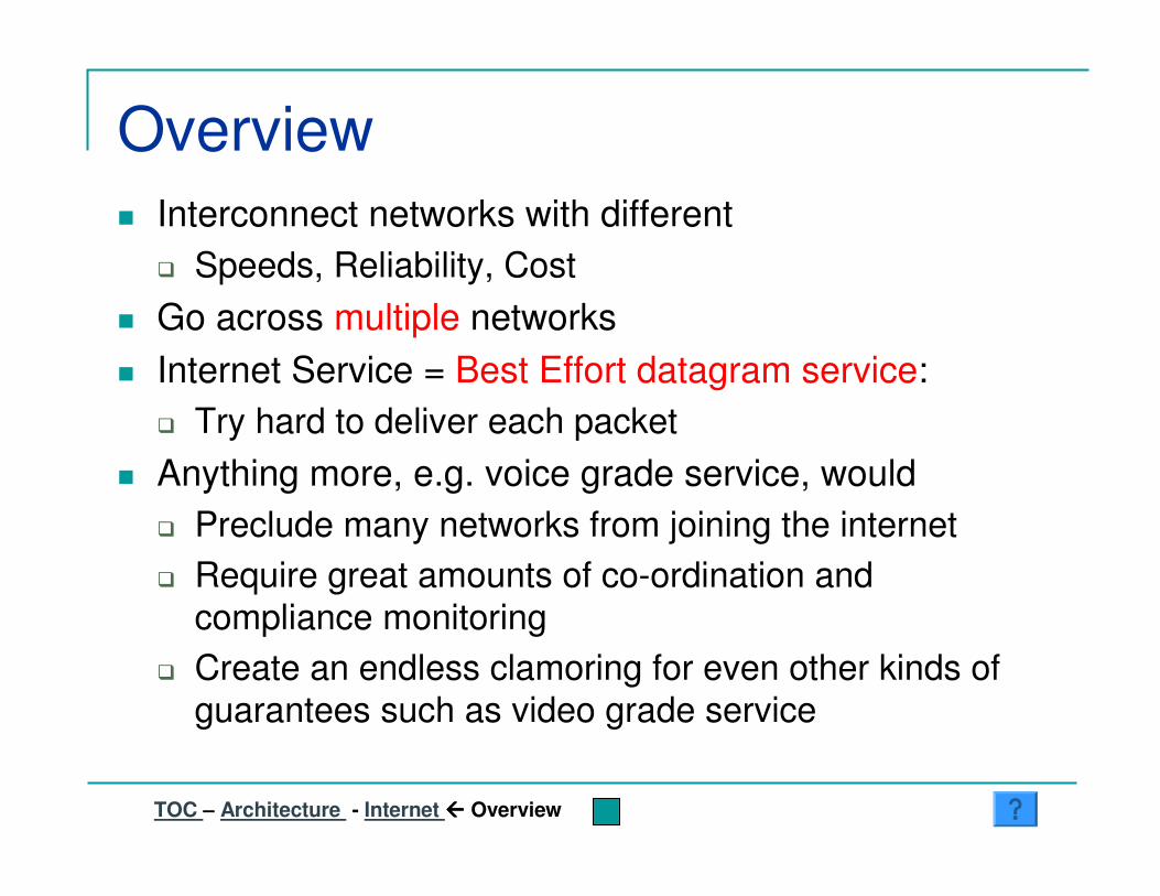
Overview� Interconnect networks with different
� Speeds, Reliability, Cost � Go across multiple networks� Internet Service = Best Effort datagram service:
� Try hard to deliver each packet� Anything more, e.g. voice grade service, would
� Preclude many networks from joining the internet� Require great amounts of co-ordination and
compliance monitoring� Create an endless clamoring for even other kinds of
guarantees such as video grade service
TOC – Architecture - Internet ���� Overview

Case for minimal router state� Adding connection state to routers creates problems
in the presence of failures…� How to clean up the “bad state”?
� Scaling router state with number of transport connections would be very expensive
� Adding connection state in only some routers might not be good enough� What if many congested routers did not implement state
� So: The internet provides datagram service. Under this constraint, the internet is designed to support as many different types of applications as possible.
TOC – Architecture - Internet ���� Minimal State

Layering� Almost Any kind of
application can write directly on IP� Including new transport
protocols� IP cannot be avoided� As long as the routers
speak IP, any application that can make do with datagram service can be written and implemented on the end devices.� No co-ordination, standards
activity etc. is required!!
Network
IP
TCP UDP
Application
BGP HTTP RTP TFTP
TCP UDP
IP
Ethernet FDDI Token Etc.
TOC – Architecture - Internet ���� Layering

End-to-End Argument(Saltzer, Reed and Clark 1984)� Implement a network function at the end
hosts unless it cannot be implemented correctly in this manner.
OR� “Don’t implement a function at the lower
levels of the system unless it can be completely implemented at this level”(Peterson and Davie)
TOC – Architecture - Internet ���� E2E Argument

Success
TOC – Architecture - Internet - Success
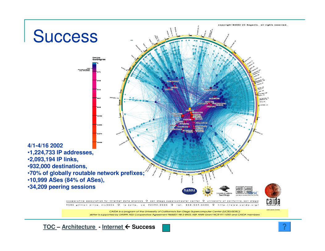
4/1-4/16 2002•1,224,733 IP addresses, •2,093,194 IP links, •932,000 destinations, •70% of globally routable network prefixes; •10,999 ASes (84% of ASes),•34,209 peering sessions
TOC – Architecture - Internet ���� Success
Success
Caveats
� Internet is actually a lot more complicated and messy than today’s lecture would suggest
� The end-to-end argument is being subverted and under attack
� The internet does a poor job of supporting high performance traffic such as voice and video
� The phone network is hardly going away…� We will deal with these issues in much more detail
towards the end of the course
TOC – Architecture ���� Internet - Caveats