arduino mechatronics manual -...
TRANSCRIPT
Arduino Mechatronics Manual
Georgia Institute of Technology | ME2110: Creative Decisions and Design | 4-11-2019
Contents
Getting Started 2
Setup Steps 2
Install Arduino IDE 2
Windows Installation 2
Mac OS X Installation 3
Communicating With The Arduino 4
Introduction 5
Install necessary libraries from GitHub 5
The Arduino UNO 7
Why the Arduino? 7
The ME 2110 Arduino Interface Board 8
Writing an Arduino Sketch 9
Arduino programming basics 9
Syntax 9
If-else Conditions 10
Loops 10
Polling 10
Using the ME2110 Library 11
Callable Functions and Variables 12
Miscellaneous 14
Electromechanical Components 15
Digital vs Analog Signals 15
Sensors 16
Switches 16
IR Distance Sensor 17
Potentiometer 18
Encoder 19
Actuators 20
DC Motors 20
Solenoids 22
Pneumatics 23
Example Sketch 25
Reference 28
1

Getting Started This section will give quick references on how to get started with the Arduino Uno. However, to understand the Arduino Uno and how it is being used in ME2110, you must read through the rest of the manual. Setup Steps
Download Arduino software (IDE) Connect your Arduino to your computer Download necessary libraries
Install Arduino IDE The Arduino IDE (Integrated Development Environment) allows you to write programs and upload them to your Arduino. Have your Arduino board and USB cable near your computer. Do not plug them in yet. Download the latest version of the IDE from: arduino.cc/download Windows Installation
1. After finishing the download, navigate to your download path and double-click on “arduino-1.x.x-rx-windows.exe” (where the x depends on the version you downloaded). If a security warning window shows up, click on”Run” or “Allow” and accept the License Agreement. Click on “next” to choose the folder to install the IDE and click on “Install”.
2. Connect the Arduino board to the computer using a proper USB cable. The board will automatically draw power from the USB connection of the computer and the green LED (labeled ON) will turn on.
3. Windows should initiate its driver installation process when the board is plugged in. In some cases your computer won’t be able to find the drivers by itself. If so, you need to point it to the proper folder.
Windows XP: If Windows Update asks about the path for the software, select “Yes, for this time only” and the “Install from a list or specific location”
Other: A popup window asks you to install the driver automatically or to look for it in the computer, choose to look for the driver on your computer.
4. If the installation doesn’t start automatically, click on the Start Menu and open the device manager.
5. Look for the Arduino device under the category “Other Devices” or “Unknown Devices” and select “Update Driver” or “Update Driver Software” clicking with the right button of the mouse.
6. Click on “browse” and select the “Drivers” folder (not the folder “FTDI USB Drivers”) in the Arduino software IDE folder. Press “OK” and “Next”. If a dialog box about a test on the Windows Logo shows up, click on “Continue Anyway”. Windows will now install the driver.
7. In the “Device Manager”, under “Ports (COM & LPT)”, you should see a port similar to “Arduino Uno (COM4)”.
2

Mac OS X Installation
1. If you are using 10.8 (Mountain Lion) or later, go to System Preferences and open the “Security & Privacy” panel. In the “General” tab, under the heading “Allow applications downloaded from”, click the toggle for “Anywhere”.
2. Once the Arduino software IDE has finished downloading, double-click on the .zip file to expand the application
3. Coopy the Arduino application to the Applications folder, or anywhere else you wish to install the software.
4. Connect your Arduino board to the computer with the USB cable. The board will be automatically powered from the USB connection and the green LED (labeled ON) will turn on.
5. You do not need to install any drivers to work with the board. 6. Depending on the version of the OS X that you are running, you might get a dialog
box asking if you wish to open the “system Preferences”. Click the “Network Preferences” button and click “Apply”.
7. The board will show up as “Not Configured”, but it is already working. You can quit System Preferences.
3

Communicating With The Arduino After the Arduino software IDE has been installed, you can now upload a program.
1. Open the Arduino IDE and appropriate program you would like to upload to the microcontroller.
2. Ensure that the correct Board Type has been selected under “Tools” (1) 3. Ensure that the correct Communication Port has been selected. (2)
4. Use the button to verify the code does not have syntax or build errors. (3)
5. Use the button to upload the code to the Arduino. This will also verify the code, so Step 4 is optional.
Sample Arduino IDE Window
4
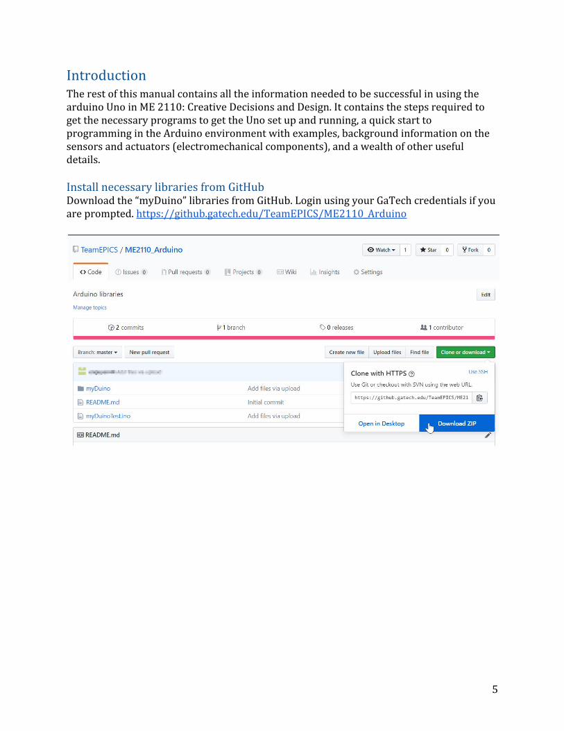
Introduction The rest of this manual contains all the information needed to be successful in using the arduino Uno in ME 2110: Creative Decisions and Design. It contains the steps required to get the necessary programs to get the Uno set up and running, a quick start to programming in the Arduino environment with examples, background information on the sensors and actuators (electromechanical components), and a wealth of other useful details. Install necessary libraries from GitHub Download the “myDuino” libraries from GitHub. Login using your GaTech credentials if you are prompted. https://github.gatech.edu/TeamEPICS/ME2110_Arduino
5
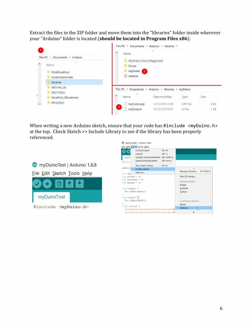
Extract the files in the ZIP folder and move them into the “libraries” folder inside wherever your “Arduino” folder is located (should be located in Program Files x86).
When writing a new Arduino sketch, ensure that your code has #include <myDuino.h> at the top. Check Sketch >> Include Library to see if the library has been properly referenced.
6
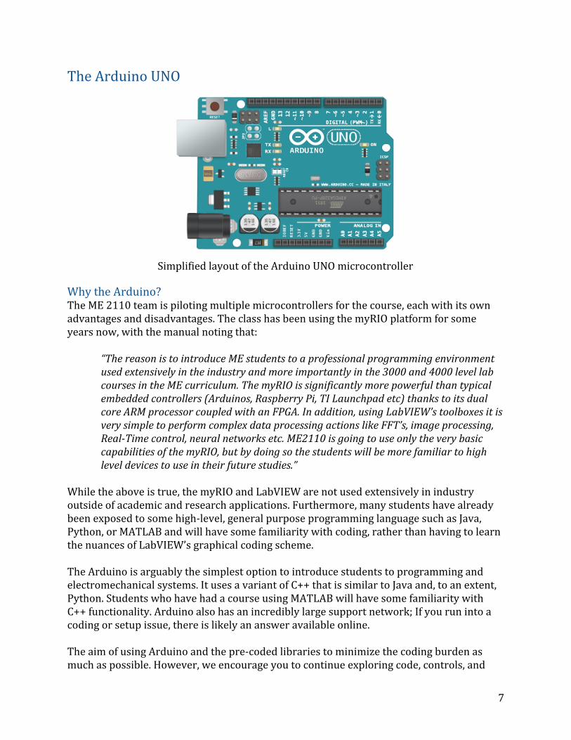
The Arduino UNO
Simplified layout of the Arduino UNO microcontroller
Why the Arduino? The ME 2110 team is piloting multiple microcontrollers for the course, each with its own advantages and disadvantages. The class has been using the myRIO platform for some years now, with the manual noting that:
“The reason is to introduce ME students to a professional programming environment used extensively in the industry and more importantly in the 3000 and 4000 level lab courses in the ME curriculum. The myRIO is significantly more powerful than typical embedded controllers (Arduinos, Raspberry Pi, TI Launchpad etc) thanks to its dual core ARM processor coupled with an FPGA. In addition, using LabVIEW’s toolboxes it is very simple to perform complex data processing actions like FFT’s, image processing, Real-Time control, neural networks etc. ME2110 is going to use only the very basic capabilities of the myRIO, but by doing so the students will be more familiar to high level devices to use in their future studies.”
While the above is true, the myRIO and LabVIEW are not used extensively in industry outside of academic and research applications. Furthermore, many students have already been exposed to some high-level, general purpose programming language such as Java, Python, or MATLAB and will have some familiarity with coding, rather than having to learn the nuances of LabVIEW’s graphical coding scheme. The Arduino is arguably the simplest option to introduce students to programming and electromechanical systems. It uses a variant of C++ that is similar to Java and, to an extent, Python. Students who have had a course using MATLAB will have some familiarity with C++ functionality. Arduino also has an incredibly large support network; If you run into a coding or setup issue, there is likely an answer available online. The aim of using Arduino and the pre-coded libraries to minimize the coding burden as much as possible. However, we encourage you to continue exploring code, controls, and
7
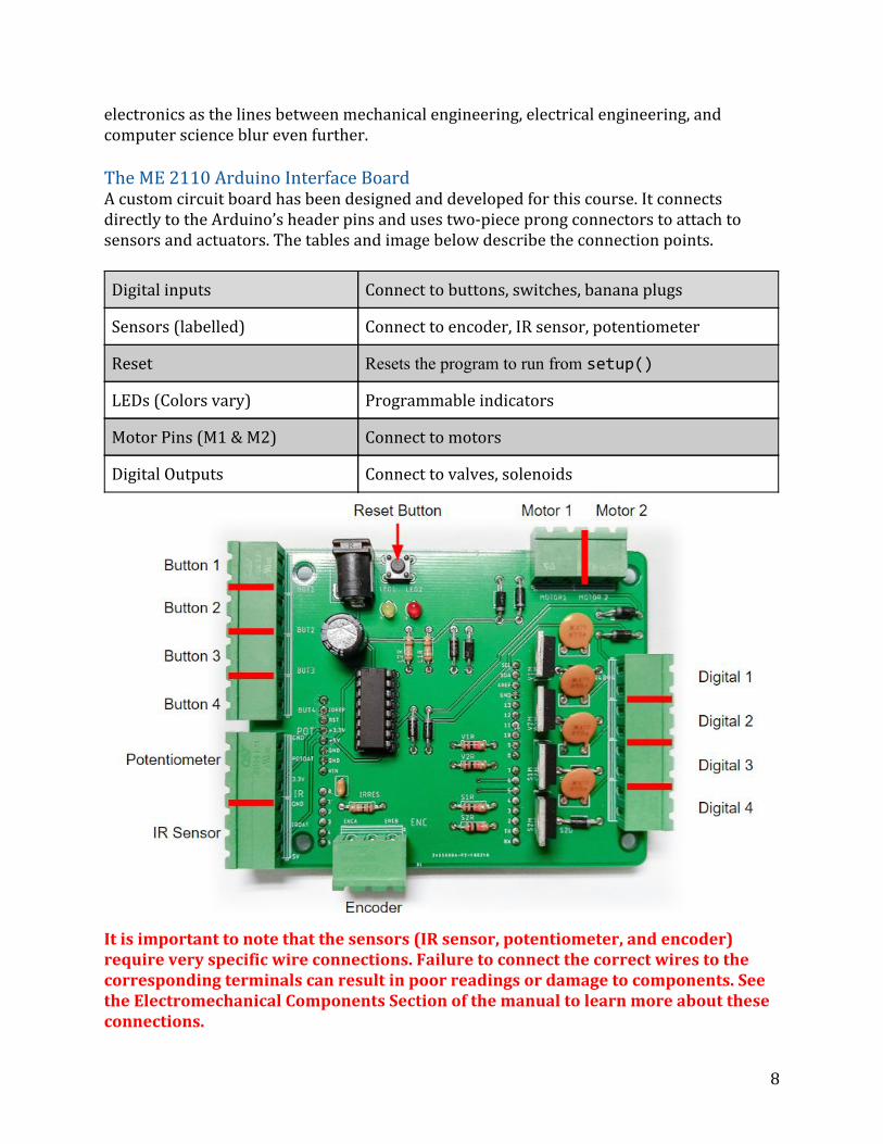
electronics as the lines between mechanical engineering, electrical engineering, and computer science blur even further. The ME 2110 Arduino Interface Board A custom circuit board has been designed and developed for this course. It connects directly to the Arduino’s header pins and uses two-piece prong connectors to attach to sensors and actuators. The tables and image below describe the connection points.
Digital inputs Connect to buttons, switches, banana plugs
Sensors (labelled) Connect to encoder, IR sensor, potentiometer
Reset Resets the program to run from setup()
LEDs (Colors vary) Programmable indicators
Motor Pins (M1 & M2) Connect to motors
Digital Outputs Connect to valves, solenoids
It is important to note that the sensors (IR sensor, potentiometer, and encoder) require very specific wire connections. Failure to connect the correct wires to the corresponding terminals can result in poor readings or damage to components. See the Electromechanical Components Section of the manual to learn more about these connections.
8
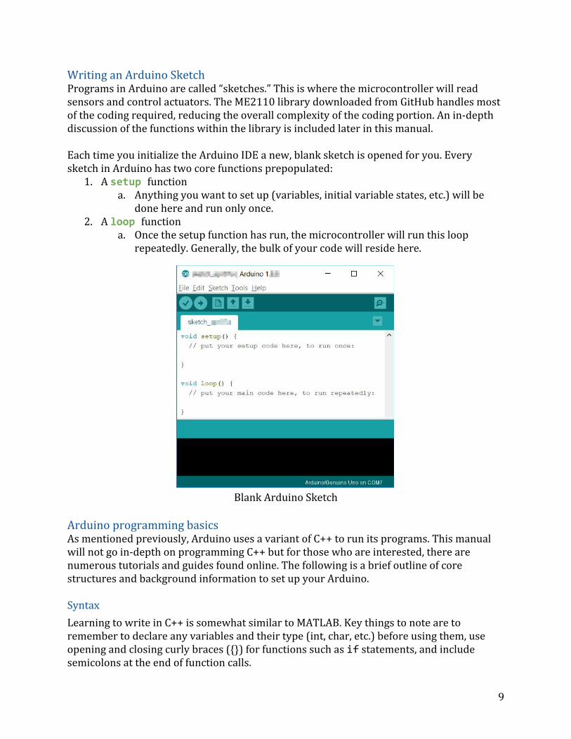
Writing an Arduino Sketch Programs in Arduino are called “sketches.” This is where the microcontroller will read sensors and control actuators. The ME2110 library downloaded from GitHub handles most of the coding required, reducing the overall complexity of the coding portion. An in-depth discussion of the functions within the library is included later in this manual. Each time you initialize the Arduino IDE a new, blank sketch is opened for you. Every sketch in Arduino has two core functions prepopulated:
1. A setup function a. Anything you want to set up (variables, initial variable states, etc.) will be
done here and run only once. 2. A loop function
a. Once the setup function has run, the microcontroller will run this loop repeatedly. Generally, the bulk of your code will reside here.
Blank Arduino Sketch
Arduino programming basics As mentioned previously, Arduino uses a variant of C++ to run its programs. This manual will not go in-depth on programming C++ but for those who are interested, there are numerous tutorials and guides found online. The following is a brief outline of core structures and background information to set up your Arduino. Syntax
Learning to write in C++ is somewhat similar to MATLAB. Key things to note are to remember to declare any variables and their type (int, char, etc.) before using them, use opening and closing curly braces () for functions such as if statements, and include semicolons at the end of function calls.
9
If-else Conditions
An if statement is one of the basic logic building blocks - it is one of the ways you can use Python to make decisions. The basic layout of an if statement in English can be viewed as:
If this condition has been met, then do task 1. If this other condition has been met, do task 2. Otherwise do task 3.
Programmatically it can be represented in pseudocode as:
if (condition == True) do task 1;
else if (other condition == True) do task 2;
else do task 3;
You can use multiple conditions to be met using and and or between conditions. More details can be found in the link below. https://www.arduino.cc/reference/en/language/structure/control-structure/if/ Loops
Loops are an implementation of “if-else” statements. The code inside a loop will be run continuously until a number of iterations have passed (for loop) or until a condition is no longer true (while loop). The loop function that almost every Arduino program uses is an example of an infinite while loop. An example of a for loop could be:
Do task 1 until the 5 iterations have passed
Programmatically:
for (int i = 0; i <= 5; i++) do task 1;
Learn more about for loops and while loops in the links below. https://www.arduino.cc/reference/en/language/structure/control-structure/for/ https://www.arduino.cc/reference/en/language/structure/control-structure/while/ Polling
Polling is a method of actively checking to see if the status of something has changed. A popular analogy of polling is that you order an item from online shopping and continually check the door to see if it has arrived. While relatively inefficient, it is useful for reliably checking whether or not a status has changed.
10
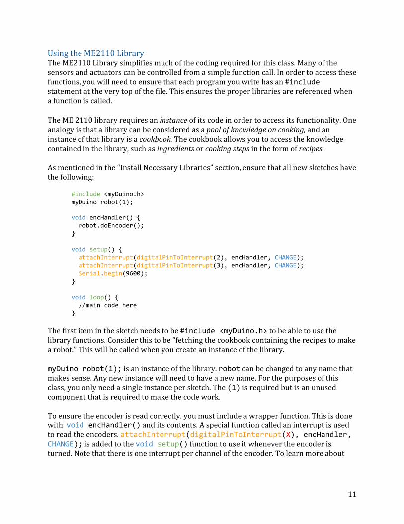
Using the ME2110 Library The ME2110 Library simplifies much of the coding required for this class. Many of the sensors and actuators can be controlled from a simple function call. In order to access these functions, you will need to ensure that each program you write has an #include statement at the very top of the file. This ensures the proper libraries are referenced when a function is called. The ME 2110 library requires an instance of its code in order to access its functionality. One analogy is that a library can be considered as a pool of knowledge on cooking, and an instance of that library is a cookbook. The cookbook allows you to access the knowledge contained in the library, such as ingredients or cooking steps in the form of recipes. As mentioned in the “Install Necessary Libraries” section, ensure that all new sketches have the following:
#include <myDuino.h> myDuino robot(1); void encHandler() robot.doEncoder(); void setup() attachInterrupt(digitalPinToInterrupt(2), encHandler, CHANGE); attachInterrupt(digitalPinToInterrupt(3), encHandler, CHANGE); Serial.begin(9600); void loop() //main code here
The first item in the sketch needs to be #include <myDuino.h> to be able to use the library functions. Consider this to be “fetching the cookbook containing the recipes to make a robot.” This will be called when you create an instance of the library. myDuino robot(1); is an instance of the library. robot can be changed to any name that makes sense. Any new instance will need to have a new name. For the purposes of this class, you only need a single instance per sketch. The (1) is required but is an unused component that is required to make the code work. To ensure the encoder is read correctly, you must include a wrapper function. This is done with void encHandler() and its contents. A special function called an interrupt is used to read the encoders. attachInterrupt(digitalPinToInterrupt(X), encHandler, CHANGE); is added to the void setup() function to use it whenever the encoder is turned. Note that there is one interrupt per channel of the encoder. To learn more about
11
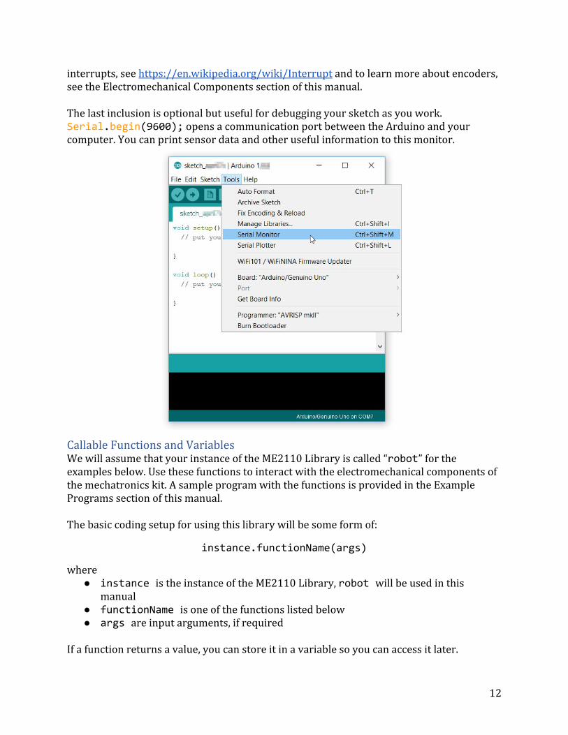
interrupts, see https://en.wikipedia.org/wiki/Interrupt and to learn more about encoders, see the Electromechanical Components section of this manual. The last inclusion is optional but useful for debugging your sketch as you work. Serial.begin(9600); opens a communication port between the Arduino and your computer. You can print sensor data and other useful information to this monitor.
Callable Functions and Variables We will assume that your instance of the ME2110 Library is called “robot” for the examples below. Use these functions to interact with the electromechanical components of the mechatronics kit. A sample program with the functions is provided in the Example Programs section of this manual. The basic coding setup for using this library will be some form of:
instance.functionName(args)
where instance is the instance of the ME2110 Library, robot will be used in this
manual functionName is one of the functions listed below args are input arguments, if required
If a function returns a value, you can store it in a variable so you can access it later.
12
robot.readButton(int pin);
Input arguments: 1, 2, 3, or 4 Returns: 0 or 1
0 = button is pressed; 1 = button is released Purpose: Retrieves current value of a button. Note the inverted logic.
robot.readIR();
Input arguments: None Returns: integer value between 0-1023
0= very far away, 1023 = very close Purpose: retrieves IR sensor readings
robot.readPOT();
Input arguments: None Returns: integer value between 0-1023
0 = minimum voltage; 1023 = maximum voltage Purpose: Retrieves potentiometer output
robot.doEncoder();
Input arguments: None Returns: None Purpose: Wrapper function for encoder functionality. Do not use in loop() code.
robot.encoderCount(); Input arguments: None Returns: Signed integer Purpose: Retrieves current count of encoder
robot.encoderDir(); Input arguments: None Returns: 1 (Clockwise) or -1 (Anticlockwise) Purpose: Indicates which direction the encoder is being turned
robot.LED(int pin, int onOFF); Input arguments:
pin: 1 or 2 onOFF: 0 (off) or 1 (on)
Returns: None Purpose: Turns a specified LED on or off
robot.digital(int pin, int onOFF); Input arguments:
pin: 1, 2, 3, or 4 onOFF: 0 (off) or 1 (on)
Returns: None
13
Purpose: Turns a specified digital output on or off
robot.moveMotor(int mot, int dir, int spd); Input arguments:
mot: 1 or 2 (which motor) dir: 1 (forward) or 2 (backward) spd: 0(stopped) to 255 (full speed)
Returns: None Purpose: Turns a specific motor one direction at a specified speed
Miscellaneous millis()
Returns number of milliseconds since program started running.
14
Electromechanical Components This section will describe the various sensors and actuators included in the mechatronics kit. The sensors used in ME2110 include switches, an infrared distance sensor, a potentiometer and an encoder. The actuators include DC motors and DC solenoids.
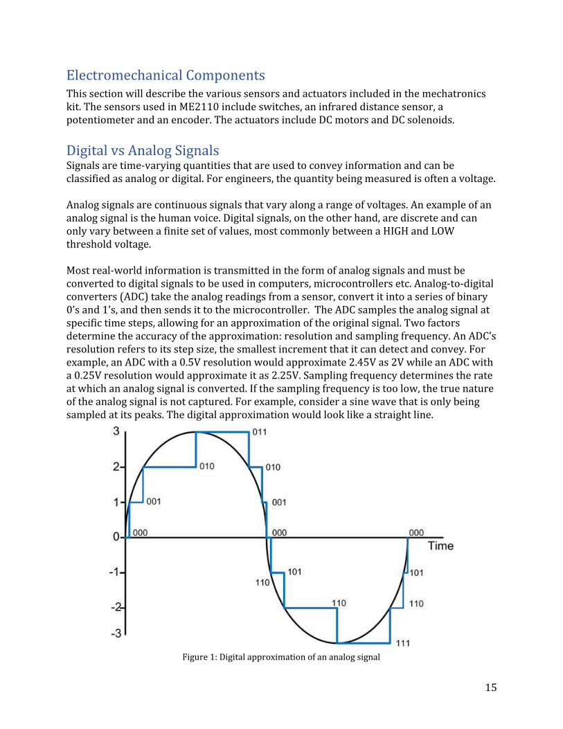
Digital vs Analog Signals Signals are time-varying quantities that are used to convey information and can be classified as analog or digital. For engineers, the quantity being measured is often a voltage. Analog signals are continuous signals that vary along a range of voltages. An example of an analog signal is the human voice. Digital signals, on the other hand, are discrete and can only vary between a finite set of values, most commonly between a HIGH and LOW threshold voltage. Most real-world information is transmitted in the form of analog signals and must be converted to digital signals to be used in computers, microcontrollers etc. Analog-to-digital converters (ADC) take the analog readings from a sensor, convert it into a series of binary 0’s and 1’s, and then sends it to the microcontroller. The ADC samples the analog signal at specific time steps, allowing for an approximation of the original signal. Two factors determine the accuracy of the approximation: resolution and sampling frequency. An ADC’s resolution refers to its step size, the smallest increment that it can detect and convey. For example, an ADC with a 0.5V resolution would approximate 2.45V as 2V while an ADC with a 0.25V resolution would approximate it as 2.25V. Sampling frequency determines the rate at which an analog signal is converted. If the sampling frequency is too low, the true nature of the analog signal is not captured. For example, consider a sine wave that is only being sampled at its peaks. The digital approximation would look like a straight line.
Figure 1: Digital approximation of an analog signal
15
Sensors
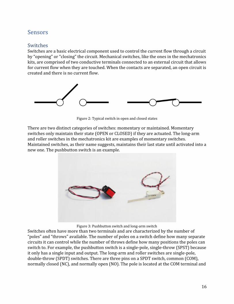
Switches Switches are a basic electrical component used to control the current flow through a circuit by “opening” or “closing” the circuit. Mechanical switches, like the ones in the mechatronics kits, are comprised of two conductive terminals connected to an external circuit that allows for current flow when they are touched. When the contacts are separated, an open circuit is created and there is no current flow.
Figure 2: Typical switch in open and closed states
There are two distinct categories of switches: momentary or maintained. Momentary switches only maintain their state (OPEN or CLOSED) if they are actuated. The long-arm and roller switches in the mechatronics kit are examples of momentary switches. Maintained switches, as their name suggests, maintains their last state until activated into a new one. The pushbutton switch is an example.
Figure 3: Pushbutton switch and long-arm switch
Switches often have more than two terminals and are characterized by the number of “poles” and “throws” available. The number of poles on a switch define how many separate circuits it can control while the number of throws define how many positions the poles can switch to. For example, the pushbutton switch is a single-pole, single-throw (SPST) because it only has a single input and output. The long-arm and roller switches are single-pole, double-throw (SPDT) switches. There are three pins on a SPDT switch, common (COM), normally closed (NC), and normally open (NO). The pole is located at the COM terminal and
16
can be connected to either the NC or NO terminals. The names of the NO and NC terminals describe their default state.
Figure 4: Diagram of single-pole, double throw (SPDT) switch For the ME2110, switches are typically used as SPST digital inputs (HIGH or LOW). When the switch is actuated and the circuit is closed, the microcontroller will read a HIGH and vice versa. This is known as positive logic. If the switches were wired for negative logic, the microcontroller would read a LOW when the circuit was closed. To properly connect the long-arm and roller switches, solder leads onto the COM and NO terminal pins while leaving the NC terminal unattached.
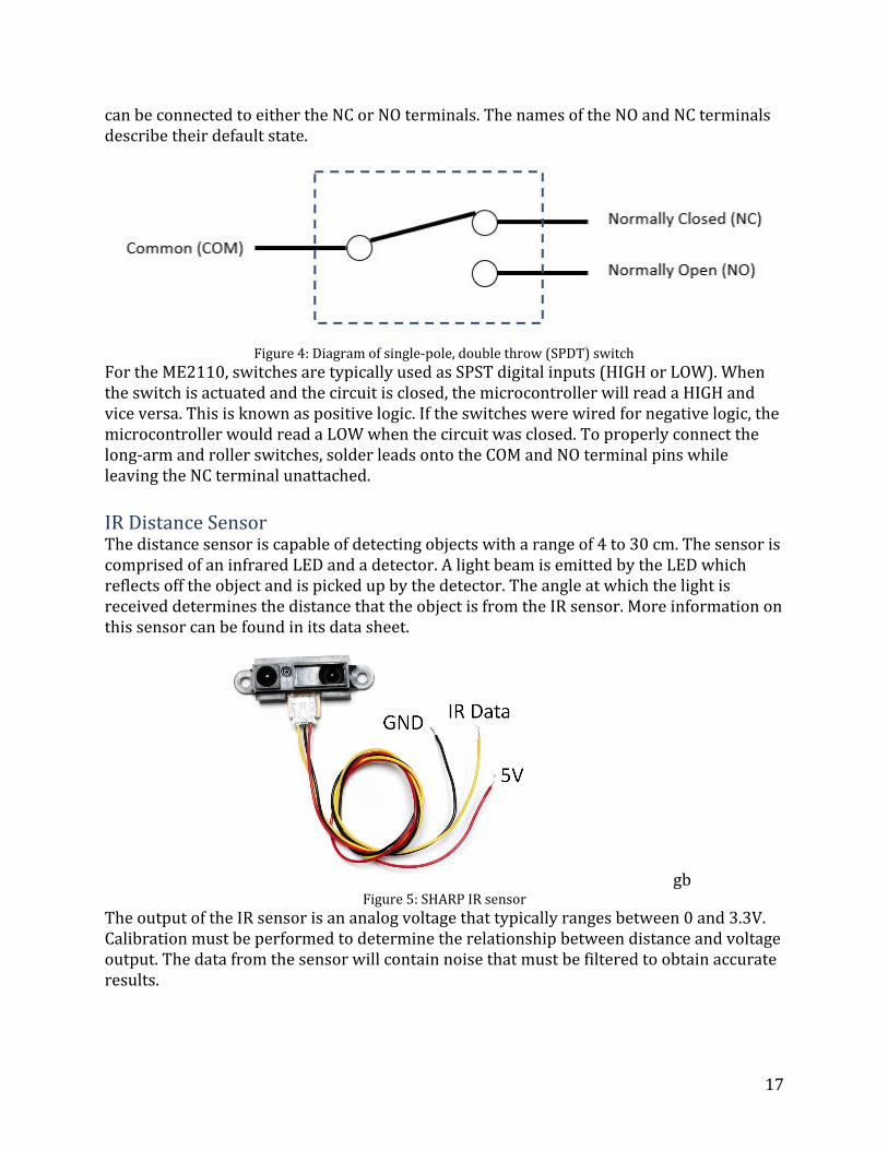
IR Distance Sensor The distance sensor is capable of detecting objects with a range of 4 to 30 cm. The sensor is comprised of an infrared LED and a detector. A light beam is emitted by the LED which reflects off the object and is picked up by the detector. The angle at which the light is received determines the distance that the object is from the IR sensor. More information on this sensor can be found in its data sheet.
gb Figure 5: SHARP IR sensor
The output of the IR sensor is an analog voltage that typically ranges between 0 and 3.3V. Calibration must be performed to determine the relationship between distance and voltage output. The data from the sensor will contain noise that must be filtered to obtain accurate results.
17
Potentiometer A rotary potentiometer is a resistive device that can be used as a variable resistor or a voltage divider. In ME2110, it will primarily function as a voltage divider.
Figure 6: 5kΩ rotary potentiometer
To understand how a potentiometer works, consider a simple resistor. As electrons flow through a resistor, some of them collide with the atoms of the material, impeding the flow of current. The longer the distance the electrons must travel, the more the flow of electrons is impeded. In potentiometers, this distance can be determined by the location of the “wiper”, a conductive band that provides a path of less resistance for the electrons. Current flows into the potentiometer, along the resistive path and then out of the wiper. The resistance of a potentiometer varies between ~0 and its rated resistance. The potentiometers in the mechatronics kits are 5kΩ. In a rotary potentiometer, the resistive material is shaped in an arc and the wiper is moved along it by the rotating knob. By placing a fixed voltage difference between Terminals A and B, a variable voltage can be obtained by rotating the wiper. Derivations for the voltage divider equation and its importance in electronics can be found online.
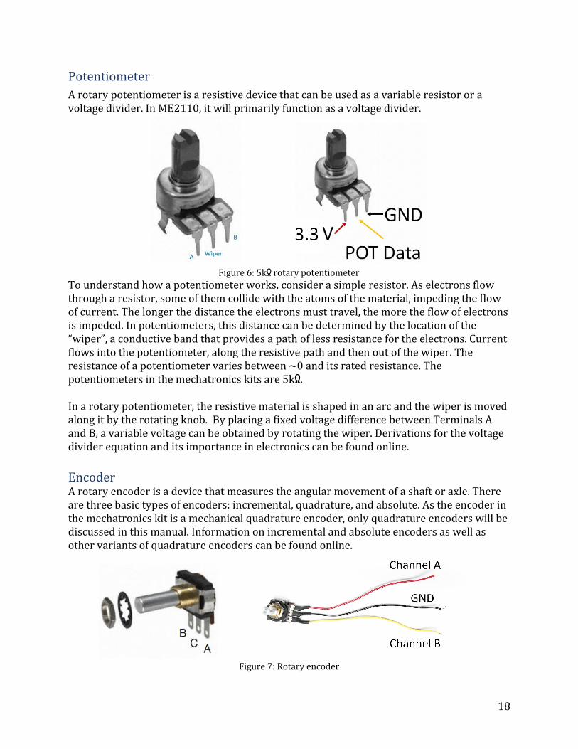
Encoder A rotary encoder is a device that measures the angular movement of a shaft or axle. There are three basic types of encoders: incremental, quadrature, and absolute. As the encoder in the mechatronics kit is a mechanical quadrature encoder, only quadrature encoders will be discussed in this manual. Information on incremental and absolute encoders as well as other variants of quadrature encoders can be found online.
Figure 7: Rotary encoder
18
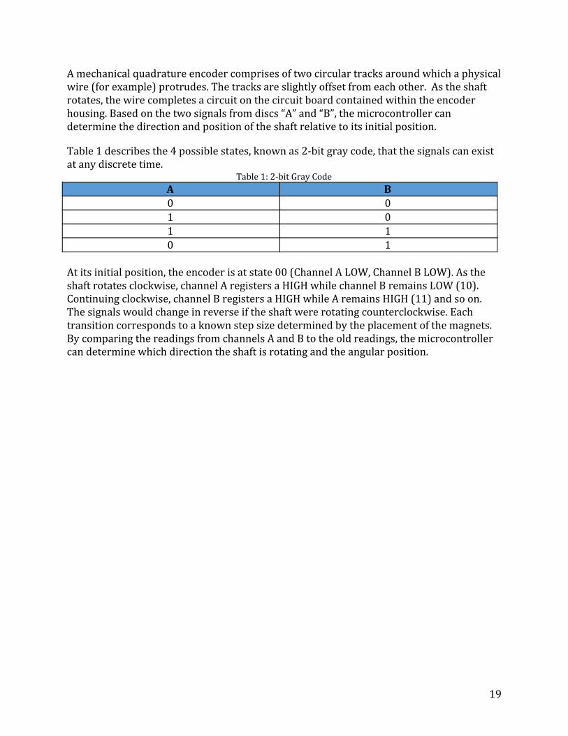
A mechanical quadrature encoder comprises of two circular tracks around which a physical wire (for example) protrudes. The tracks are slightly offset from each other. As the shaft rotates, the wire completes a circuit on the circuit board contained within the encoder housing. Based on the two signals from discs “A” and “B”, the microcontroller can determine the direction and position of the shaft relative to its initial position. Table 1 describes the 4 possible states, known as 2-bit gray code, that the signals can exist at any discrete time.
Table 1: 2-bit Gray Code
A B 0 0 1 0 1 1 0 1
At its initial position, the encoder is at state 00 (Channel A LOW, Channel B LOW). As the shaft rotates clockwise, channel A registers a HIGH while channel B remains LOW (10). Continuing clockwise, channel B registers a HIGH while A remains HIGH (11) and so on. The signals would change in reverse if the shaft were rotating counterclockwise. Each transition corresponds to a known step size determined by the placement of the magnets. By comparing the readings from channels A and B to the old readings, the microcontroller can determine which direction the shaft is rotating and the angular position.
19
Actuators
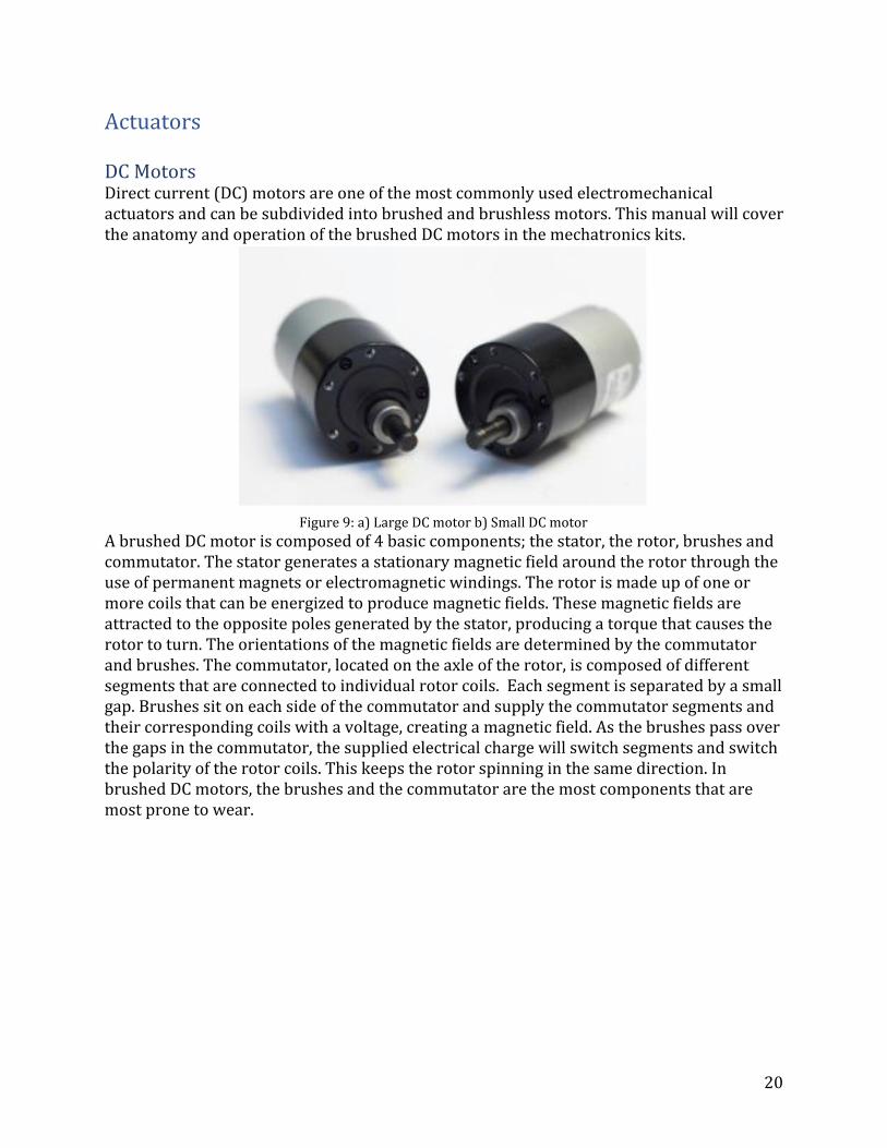
DC Motors Direct current (DC) motors are one of the most commonly used electromechanical actuators and can be subdivided into brushed and brushless motors. This manual will cover the anatomy and operation of the brushed DC motors in the mechatronics kits.
Figure 9: a) Large DC motor b) Small DC motor
A brushed DC motor is composed of 4 basic components; the stator, the rotor, brushes and commutator. The stator generates a stationary magnetic field around the rotor through the use of permanent magnets or electromagnetic windings. The rotor is made up of one or more coils that can be energized to produce magnetic fields. These magnetic fields are attracted to the opposite poles generated by the stator, producing a torque that causes the rotor to turn. The orientations of the magnetic fields are determined by the commutator and brushes. The commutator, located on the axle of the rotor, is composed of different segments that are connected to individual rotor coils. Each segment is separated by a small gap. Brushes sit on each side of the commutator and supply the commutator segments and their corresponding coils with a voltage, creating a magnetic field. As the brushes pass over the gaps in the commutator, the supplied electrical charge will switch segments and switch the polarity of the rotor coils. This keeps the rotor spinning in the same direction. In brushed DC motors, the brushes and the commutator are the most components that are most prone to wear.
20
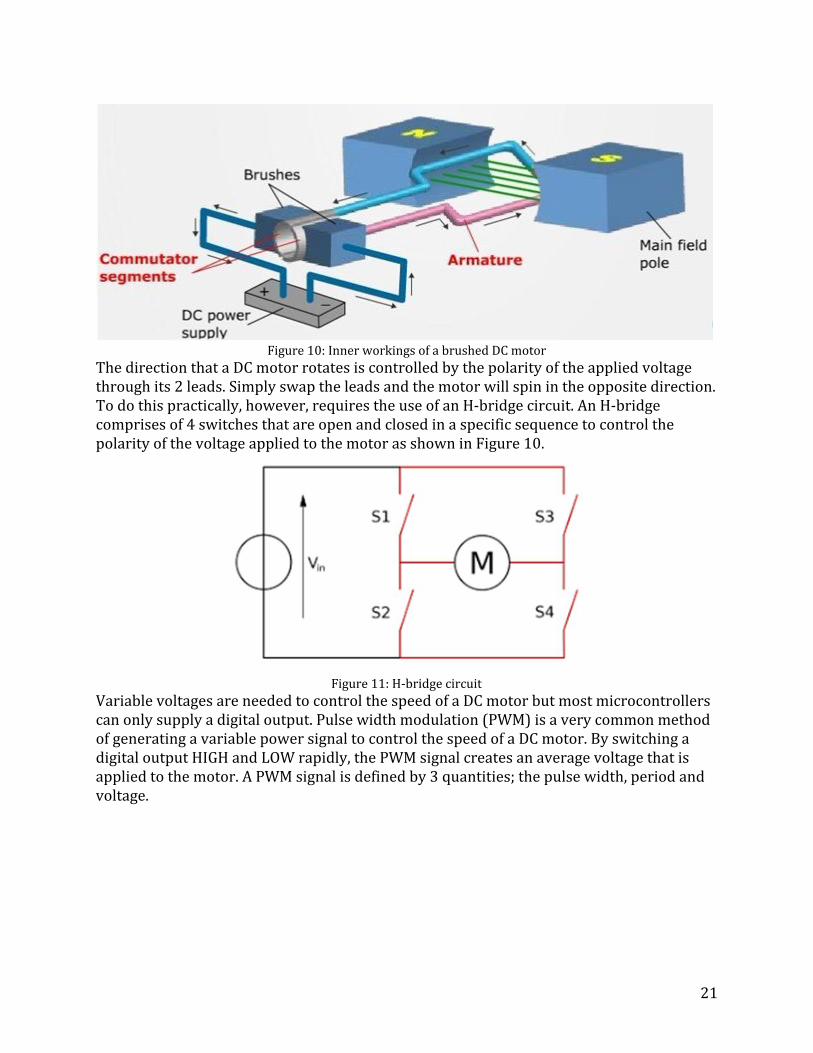
Figure 10: Inner workings of a brushed DC motor The direction that a DC motor rotates is controlled by the polarity of the applied voltage through its 2 leads. Simply swap the leads and the motor will spin in the opposite direction. To do this practically, however, requires the use of an H-bridge circuit. An H-bridge comprises of 4 switches that are open and closed in a specific sequence to control the polarity of the voltage applied to the motor as shown in Figure 10.
Figure 11: H-bridge circuit
Variable voltages are needed to control the speed of a DC motor but most microcontrollers can only supply a digital output. Pulse width modulation (PWM) is a very common method of generating a variable power signal to control the speed of a DC motor. By switching a digital output HIGH and LOW rapidly, the PWM signal creates an average voltage that is applied to the motor. A PWM signal is defined by 3 quantities; the pulse width, period and voltage.
21
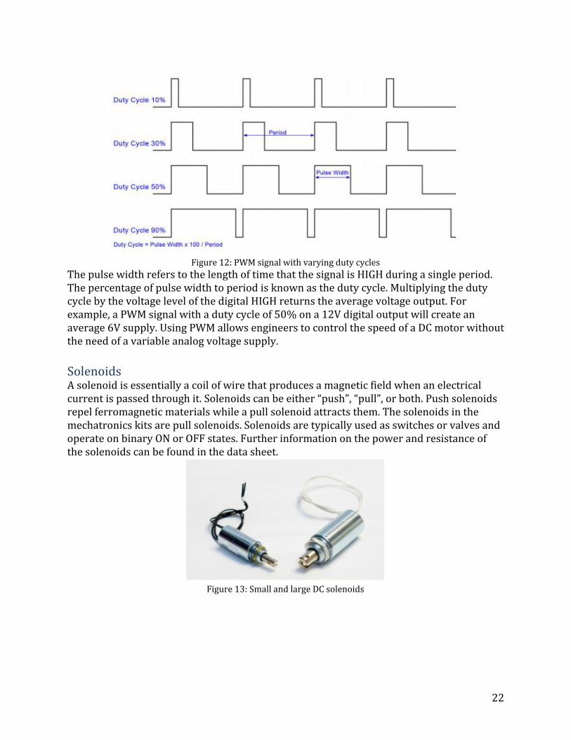
Figure 12: PWM signal with varying duty cycles The pulse width refers to the length of time that the signal is HIGH during a single period. The percentage of pulse width to period is known as the duty cycle. Multiplying the duty cycle by the voltage level of the digital HIGH returns the average voltage output. For example, a PWM signal with a duty cycle of 50% on a 12V digital output will create an average 6V supply. Using PWM allows engineers to control the speed of a DC motor without the need of a variable analog voltage supply.
Solenoids A solenoid is essentially a coil of wire that produces a magnetic field when an electrical current is passed through it. Solenoids can be either “push”, “pull”, or both. Push solenoids repel ferromagnetic materials while a pull solenoid attracts them. The solenoids in the mechatronics kits are pull solenoids. Solenoids are typically used as switches or valves and operate on binary ON or OFF states. Further information on the power and resistance of the solenoids can be found in the data sheet.
Figure 13: Small and large DC solenoids
22
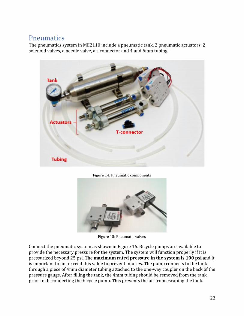
Pneumatics The pneumatics system in ME2110 include a pneumatic tank, 2 pneumatic actuators, 2 solenoid valves, a needle valve, a t-connector and 4 and 6mm tubing.
Figure 14: Pneumatic components
Figure 15: Pneumatic valves
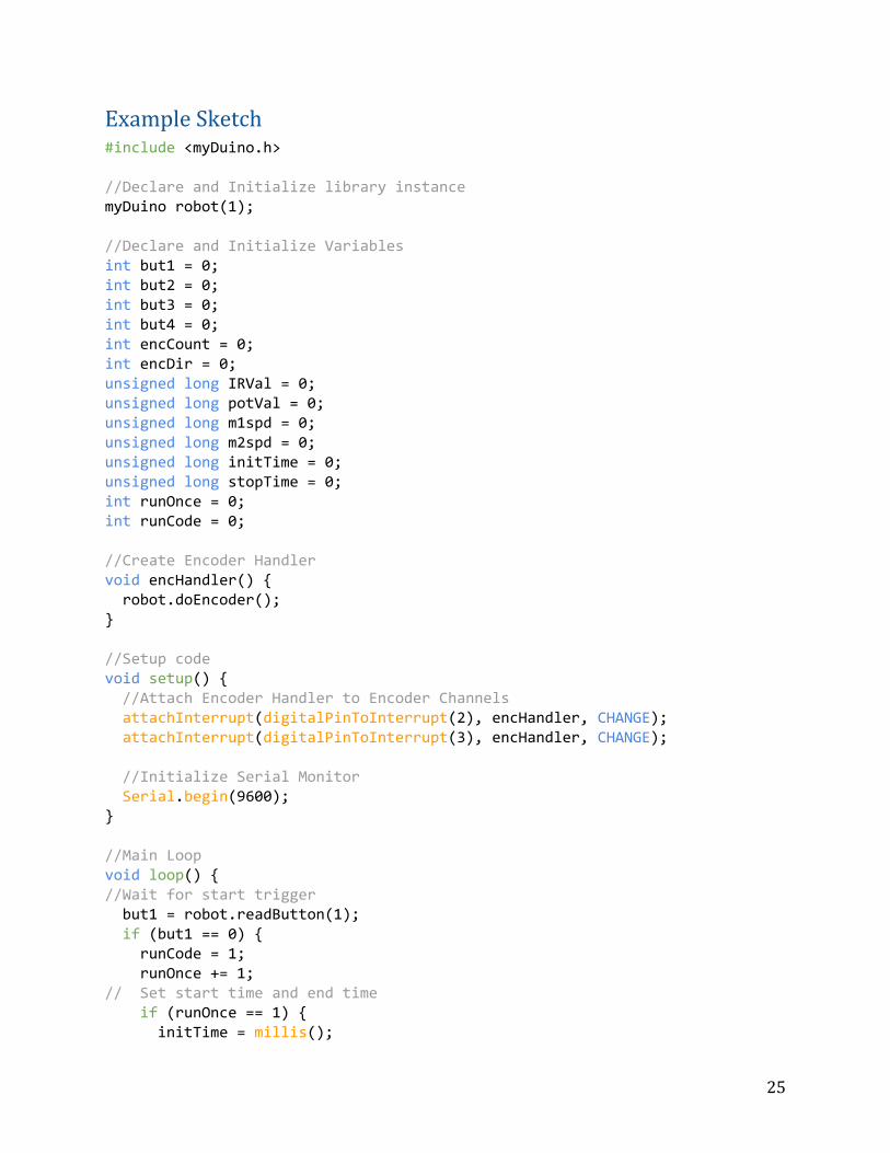
Connect the pneumatic system as shown in Figure 16. Bicycle pumps are available to provide the necessary pressure for the system. The system will function properly if it is pressurized beyond 25 psi. The maximum rated pressure in the system is 100 psi and it is important to not exceed this value to prevent injuries. The pump connects to the tank through a piece of 4mm diameter tubing attached to the one-way coupler on the back of the pressure gauge. After filling the tank, the 4mm tubing should be removed from the tank prior to disconnecting the bicycle pump. This prevents the air from escaping the tank.
23
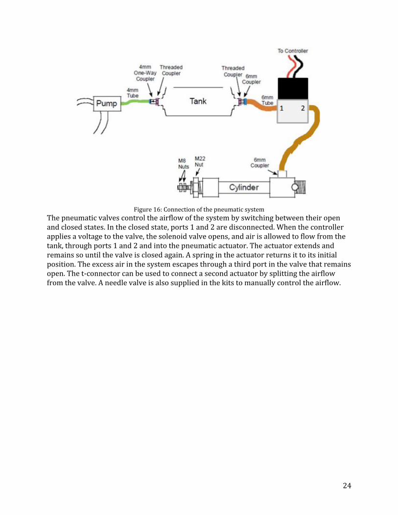
Figure 16: Connection of the pneumatic system
The pneumatic valves control the airflow of the system by switching between their open and closed states. In the closed state, ports 1 and 2 are disconnected. When the controller applies a voltage to the valve, the solenoid valve opens, and air is allowed to flow from the tank, through ports 1 and 2 and into the pneumatic actuator. The actuator extends and remains so until the valve is closed again. A spring in the actuator returns it to its initial position. The excess air in the system escapes through a third port in the valve that remains open. The t-connector can be used to connect a second actuator by splitting the airflow from the valve. A needle valve is also supplied in the kits to manually control the airflow.
24
Example Sketch #include <myDuino.h> //Declare and Initialize library instance myDuino robot(1); //Declare and Initialize Variables int but1 = 0; int but2 = 0; int but3 = 0; int but4 = 0; int encCount = 0; int encDir = 0; unsigned long IRVal = 0; unsigned long potVal = 0; unsigned long m1spd = 0; unsigned long m2spd = 0; unsigned long initTime = 0; unsigned long stopTime = 0; int runOnce = 0; int runCode = 0; //Create Encoder Handler void encHandler() robot.doEncoder(); //Setup code void setup() //Attach Encoder Handler to Encoder Channels attachInterrupt(digitalPinToInterrupt(2), encHandler, CHANGE); attachInterrupt(digitalPinToInterrupt(3), encHandler, CHANGE); //Initialize Serial Monitor Serial.begin(9600); //Main Loop void loop() //Wait for start trigger but1 = robot.readButton(1); if (but1 == 0) runCode = 1; runOnce += 1; // Set start time and end time if (runOnce == 1) initTime = millis();
25
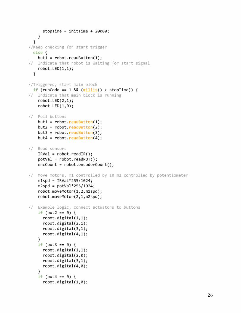
stopTime = initTime + 20000; //Keep checking for start trigger else but1 = robot.readButton(1); // Indicate that robot is waiting for start signal robot.LED(1,1); //Triggered, start main block if (runCode == 1 && (millis() < stopTime)) // Indicate that main block is running robot.LED(2,1); robot.LED(1,0); // Poll buttons but1 = robot.readButton(1); but2 = robot.readButton(2); but3 = robot.readButton(3); but4 = robot.readButton(4); // Read sensors IRVal = robot.readIR(); potVal = robot.readPOT(); encCount = robot.encoderCount(); // Move motors, m1 controlled by IR m2 controlled by potentiometer m1spd = IRVal*255/1024; m2spd = potVal*255/1024; robot.moveMotor(1,2,m1spd); robot.moveMotor(2,1,m2spd); // Example logic, connect actuators to buttons if (but2 == 0) robot.digital(1,1); robot.digital(2,1); robot.digital(3,1); robot.digital(4,1); if (but3 == 0) robot.digital(1,1); robot.digital(2,0); robot.digital(3,1); robot.digital(4,0); if (but4 == 0) robot.digital(1,0);
26
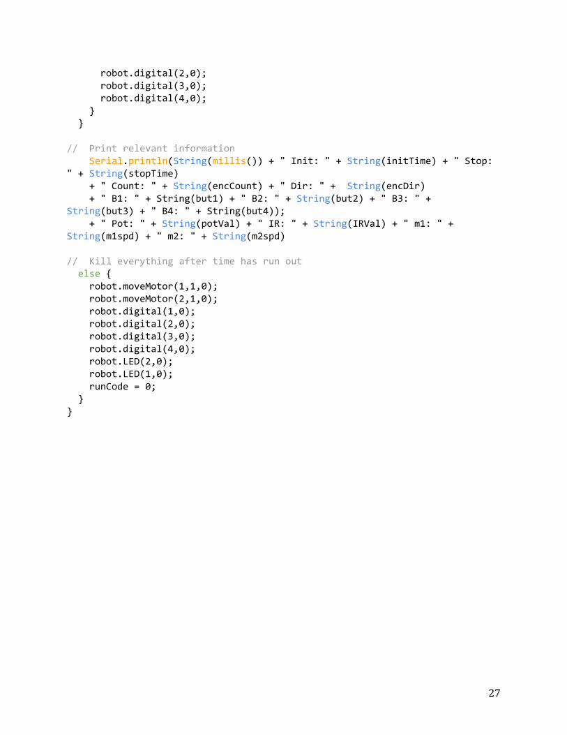
robot.digital(2,0); robot.digital(3,0); robot.digital(4,0); // Print relevant information Serial.println(String(millis()) + " Init: " + String(initTime) + " Stop: " + String(stopTime) + " Count: " + String(encCount) + " Dir: " + String(encDir) + " B1: " + String(but1) + " B2: " + String(but2) + " B3: " + String(but3) + " B4: " + String(but4)); + " Pot: " + String(potVal) + " IR: " + String(IRVal) + " m1: " + String(m1spd) + " m2: " + String(m2spd) // Kill everything after time has run out else robot.moveMotor(1,1,0); robot.moveMotor(2,1,0); robot.digital(1,0); robot.digital(2,0); robot.digital(3,0); robot.digital(4,0); robot.LED(2,0); robot.LED(1,0); runCode = 0;
27
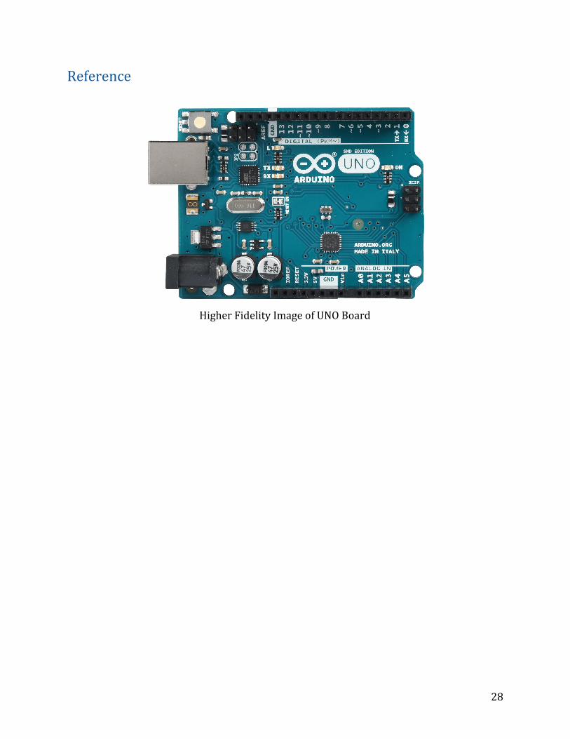
Reference
Higher Fidelity Image of UNO Board
28
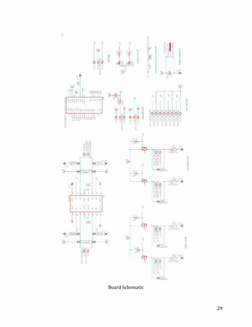
Board Schematic
29
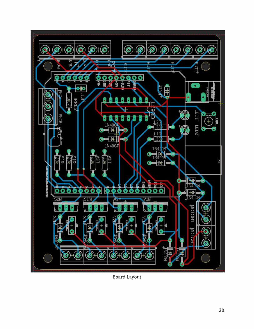
Board Layout
30