arduino programming part 7: flow charts and top-down...
TRANSCRIPT

Arduino ProgrammingPart 7: Flow charts and
Top-down designEAS 199B, Winter 2013
Gerald RecktenwaldPortland State University
Wednesday, February 20, 2013

Arduino Programming Part 7: EAS 199B
Goals
Introduce flow charts❖ A tool for developing algorithms❖ A tool for documenting algorithms❖ A visual method of communicating about any sequential or
iterative process ❖ Great for visual learners!
Top-down design❖ One technique for creating a plan for large, multi-step problems❖ Not tied to flow charts, but can be used effectively with flow
charts
2
Wednesday, February 20, 2013
Arduino Programming Part 7: EAS 199B
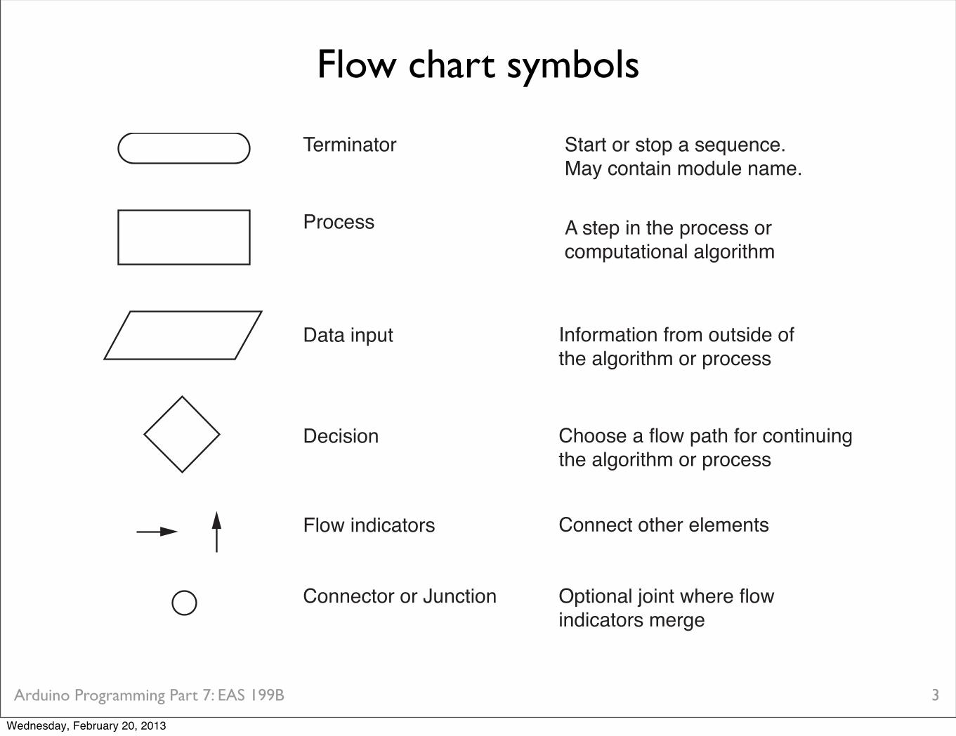
Flow chart symbols
3
Terminator Start or stop a sequence.May contain module name.
A step in the process orcomputational algorithm
Information from outside of the algorithm or process
Choose a flow path for continuingthe algorithm or process
Connect other elements
Optional joint where flowindicators merge
Process
Decision
Connector or Junction
Data input
Flow indicators
Wednesday, February 20, 2013

Arduino Programming Part 7: EAS 199B
Exercise 1
Draw the flow chart to read and display the salinity value on the LCD monitor
Keep it simple❖ 5 or so symbols (not counting arrows)❖ Describe only the high level actions
4
Wednesday, February 20, 2013

Arduino Programming Part 7: EAS 199B
Exercise 1
5
Your answer goes here.
Wednesday, February 20, 2013

Arduino Programming Part 7: EAS 199B
Exercise 1
6
Read and display salinity
Specify constants
Initialize LCD
Read salinity
Display value to LCD
Wednesday, February 20, 2013

Arduino Programming Part 7: EAS 199B
Exercise 2
Expand the “Read salinity” step in another flow chart❖ Keep it simple❖ “analog data” is an external input
7
analoginput
Read and display salinity
Specify constants
Initialize LCD
Read salinity
Display value to LCD
Wednesday, February 20, 2013

Arduino Programming Part 7: EAS 199B
Exercise 2
8
Your answer goes here.
Wednesday, February 20, 2013

Arduino Programming Part 7: EAS 199B
Exercise 2
9
Read salinity
Turn on power
Wait
Read analog input
Turn off power
Stop
output pin,input pin
analog value
Wednesday, February 20, 2013

Arduino Programming Part 7: EAS 199B
Read salinity
Turn on power
Wait
Read analog input
Turn off power
Stop
output pin,input pin
analog value
Exercise 3
Expand the “Read analog input” step in another flow chart❖ Compute the average of n readings❖ “analog data” is an external input
10
Wednesday, February 20, 2013

Arduino Programming Part 7: EAS 199B
Exercise 3
11
Your answer goes here.
Wednesday, February 20, 2013

Arduino Programming Part 7: EAS 199B
Exercise 3
12
Read average analog input
Initialize: sum=0, counter=0
Read analog input
Average = sum/n
Stop
n readings,input pin
analog value
Add to sum, increment counter
Counter<n? yes
no
Wednesday, February 20, 2013

Arduino Programming Part 7: EAS 199B
Top-down design
1. Start with a general statement of the solutiona. List the main stepsb. Don’t worry yet about details
2. Pick one of the stepsa. Break this step into a manageable number of sub-stepsb. Don’t worry about too many of the detailsc. Apply step 2 to one of steps just generated
13
Wednesday, February 20, 2013

Arduino Programming Part 7: EAS 199B
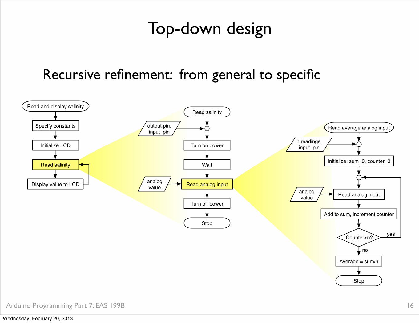
Recursive refinement: from general to specific
Top-down design
14
Read and display salinity
Specify constants
Initialize LCD
Read salinity
Display value to LCD
Wednesday, February 20, 2013

Arduino Programming Part 7: EAS 199B
Recursive refinement: from general to specific
Top-down design
15
Read and display salinity
Specify constants
Initialize LCD
Read salinity
Display value to LCD
Read salinity
Turn on power
Wait
Read analog input
Turn off power
Stop
output pin,input pin
analog value
Wednesday, February 20, 2013
Arduino Programming Part 7: EAS 199B
Recursive refinement: from general to specific
Top-down design
16
Read and display salinity
Specify constants
Initialize LCD
Read salinity
Display value to LCD
Read salinity
Turn on power
Wait
Read analog input
Turn off power
Stop
output pin,input pin
analog value
Read average analog input
Initialize: sum=0, counter=0
Read analog input
Average = sum/n
Stop
n readings,input pin
analog value
Add to sum, increment counter
Counter<n? yes
no
Wednesday, February 20, 2013
Arduino Programming Part 7: EAS 199B
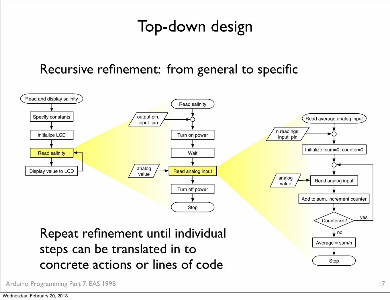
Recursive refinement: from general to specific
Top-down design
17
Read and display salinity
Specify constants
Initialize LCD
Read salinity
Display value to LCD
Read salinity
Turn on power
Wait
Read analog input
Turn off power
Stop
output pin,input pin
analog value
Read average analog input
Initialize: sum=0, counter=0
Read analog input
Average = sum/n
Stop
n readings,input pin
analog value
Add to sum, increment counter
Counter<n? yes
noRepeat refinement until individual steps can be translated in to concrete actions or lines of code
Wednesday, February 20, 2013
Arduino Programming Part 7: EAS 199B
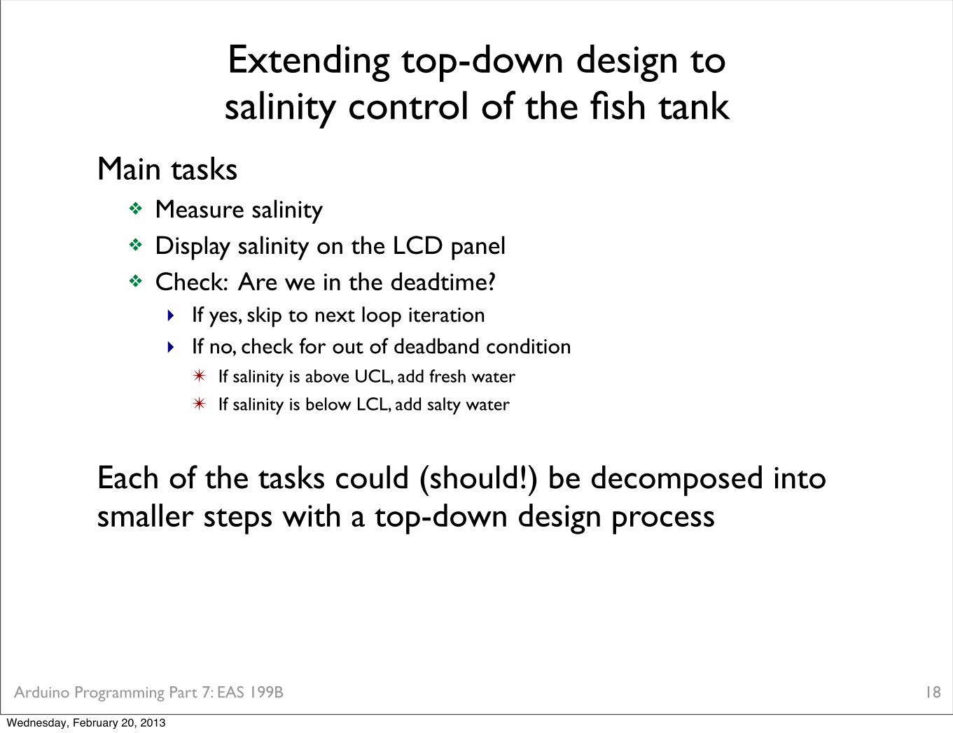
Extending top-down design tosalinity control of the fish tank
Main tasks❖ Measure salinity❖ Display salinity on the LCD panel❖ Check: Are we in the deadtime?
‣ If yes, skip to next loop iteration‣ If no, check for out of deadband condition
✴ If salinity is above UCL, add fresh water
✴ If salinity is below LCL, add salty water
Each of the tasks could (should!) be decomposed into smaller steps with a top-down design process
18
Wednesday, February 20, 2013

Arduino Programming Part 7: EAS 199B
Core control algorithm
19
// File: wait_for_deadtime.ino//// Structure of salinity control code to implement a deadtime during which// no salinity correction is made. This code is incomplete and will not compile.
unsigned long last_salinity_update; // Time of last correction
void setup() { Serial.begin(9600); last_salinity_update = millis(); // Initial value; change later}
void loop() { float LCL, UCL, salinity; int deadtime = ... ;
salinity = salinity_reading( ... ); update_LCD( ... );
// -- Check for deadtime if ( ( millis() – last_salinity_update ) > deadtime ) {
if ( salinity>UCL ) { // add DI water: several missing steps last_salinity_update = millis(); }
if ( salinity<LCL ) { // add salty water: several missing steps last_salinity_update = millis(); } }}
Wednesday, February 20, 2013

Arduino Programming Part 7: EAS 199B
Core control algorithm: managing deadtime
20
Global (and persistent) value to remember time of last change to the system
Set initial value. Update again later
Don’t even consider making changes whilewe are in the deadtime. “In the deadtime” means “current time minus time of last system change” is greater than deadtime
Update the “time of last system change” every time the salinity is changed
// File: wait_for_deadtime.ino//// Structure of salinity control code to implement a deadtime during which// no salinity correction is made. This code is incomplete and will not compile.
unsigned long last_salinity_update;
void setup() { Serial.begin(9600); last_salinity_update = millis(); }
void loop() { float LCL, UCL, salinity; int deadtime = ... ;
salinity = salinity_reading( ... ); update_LCD( ... );
// -- Check for deadtime if ( ( millis() – last_salinity_update ) > deadtime ) {
if ( salinity>UCL ) { // add DI water: several missing steps last_salinity_update = millis(); }
if ( salinity<LCL ) { // add salty water: several missing steps last_salinity_update = millis(); } }}
Wednesday, February 20, 2013

Arduino Programming Part 7: EAS 199B
// File: wait_for_deadtime.ino//// Structure of salinity control code to implement a deadtime during which// no salinity correction is made. This code is incomplete and will not compile.
unsigned long last_salinity_update;
void setup() { Serial.begin(9600); last_salinity_update = millis(); }
void loop() { float LCL, UCL, salinity; int deadtime = ... ;
salinity = salinity_reading( ... ); update_LCD( ... );
// -- Check for deadtime if ( ( millis() – last_salinity_update ) > deadtime ) {
if ( salinity>UCL ) { // add DI water: several missing steps last_salinity_update = millis(); }
if ( salinity<LCL ) { // add salty water: several missing steps last_salinity_update = millis(); } }}
Core control algorithm: task decomposition
21
1. Function to read salinity sensor and convert reading to mass fraction.
2. Function to update LCD
3. Function to determine size of the correction and open the valve. One function could handle both corrections if you design it to use the right input arguments
Wednesday, February 20, 2013
Arduino Programming Part 7: EAS 199B
Recommendations
22
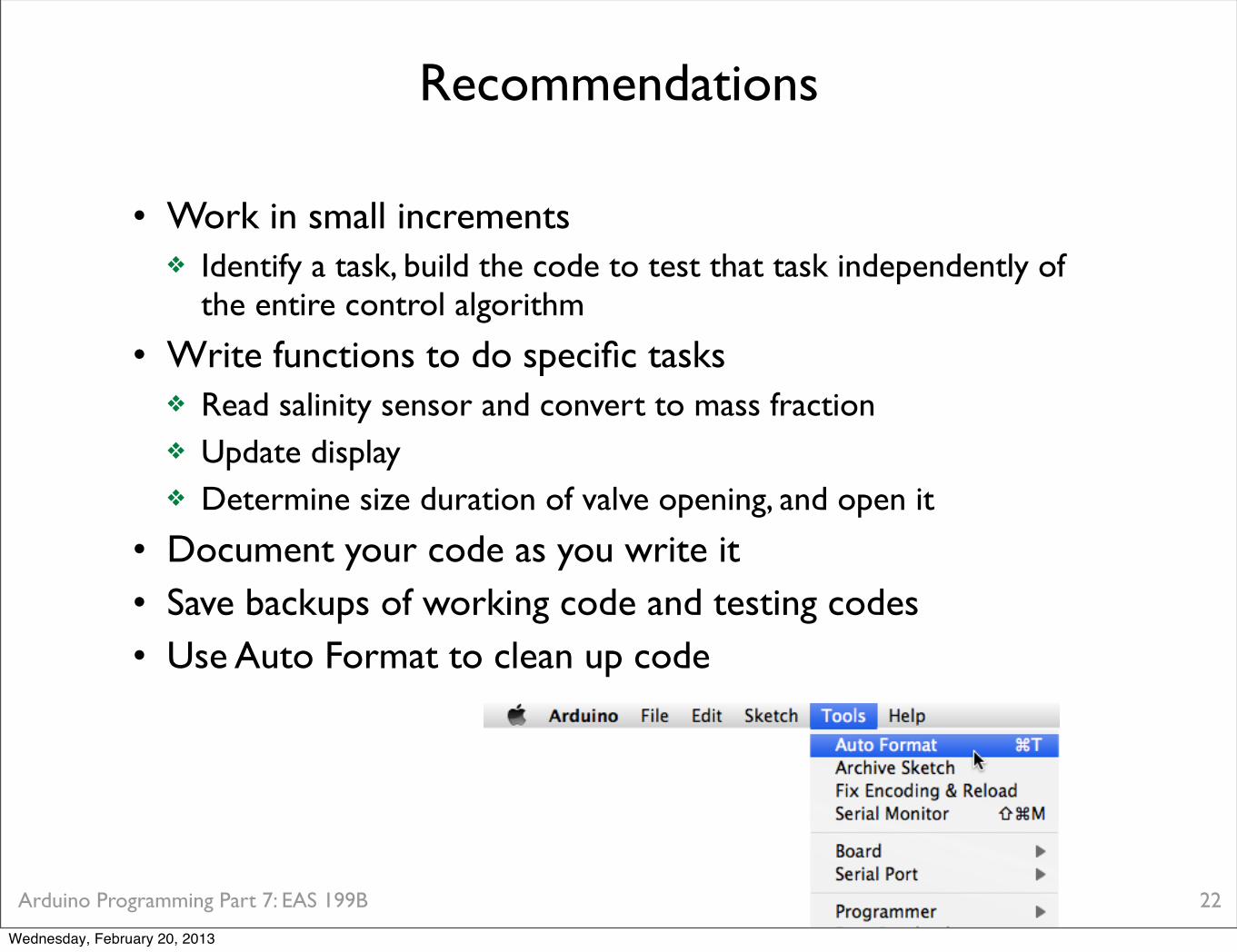
• Work in small increments❖ Identify a task, build the code to test that task independently of
the entire control algorithm
• Write functions to do specific tasks❖ Read salinity sensor and convert to mass fraction❖ Update display❖ Determine size duration of valve opening, and open it
• Document your code as you write it• Save backups of working code and testing codes• Use Auto Format to clean up code
Wednesday, February 20, 2013