arduino skill kit demo description
TRANSCRIPT

Shenzhen Yuejiang Technology Co., Ltd
Arduino Skill Kit Demo
Description
Demo Description
Issue: V1.0
Date: 2018-08-03
Arduino Skill Kit Demo Description
Issue V1.0 (2018-08-03) Demo Description Copyright © Yuejiang Technology Co., Ltd
i
Copyright © ShenZhen Yuejiang Technology Co., Ltd 2018. All rights reserved.
No part of this document may be reproduced or transmitted in any form or by any means
without prior written consent of Yuejiang Technology Co., Ltd
Disclaimer
To the maximum extent permitted by applicable law, the products described (including its
hardware, software and firmware, etc.) in this document are provided AS IS, which may have flaws,
errors or faults. Yuejiang makes no warranties of any kind, express or implied, including but not
limited to, merchantability, satisfaction of quality, fitness for a particular purpose and non-
infringement of third party rights. In no event will Yuejiang be liable for any special, incidental,
consequential or indirect damages resulting from the use of our products and documents.
Before using our product, please thoroughly read and understand the contents of this document
and related technical documents that are published online, to ensure that the robotic arm is used on
the premise of fully understanding the robotic arm and related knowledge. Please use this document
with technical guidance from professionals. Even if follow this document or any other related
instructions, Damages or losses will be happen in the using process, Dobot shall not be considered
as a guarantee regarding to all security information contained in this document.
The user has the responsibility to make sure following the relevant practical laws and
regulations of the country, in order that there is no significant danger in the use of the robotic arm.
Shenzhen Yuejiang Technology Co., Ltd
Address: Building NO.3, Tongfuyu Industrial Town, Nanshan District, Shenzhen, China
Website: www.dobot.cchttp://cn.dobot.cc/

Arduino Skill Kit Demo Description Preface
Issue V1.0 (2018-08-03) Demo Description Copyright © Yuejiang Technology Co., Ltd
ii
Preface
Purpose
This Document describes the functions, technical specifications, installation guide and system
commissioning of Dobot M1, making it easy for users to fully understand and use it.
Intended Audience
This document is intended for:
Customer Engineer
Sales Engineer
Installation and Commissioning Engineer
Technical Support Engineer
Change History
Date Change Description
2018/01/31 The first release
Symbol Conventions
The symbols that may be founded in this document are defined as follows.
Symbol Description
DANGER
Indicates a hazard with a high level of risk which, if not
avoided, could result in death or serious injury
WARNING
Indicates a hazard with a medium level or low level of
risk which, if not avoided, could result in minor or
moderate injury, robotic arm damage
NOTICE
Indicates a potentially hazardous situation which, if not
avoided, can result in robotic arm damage, data loss, or
unanticipated result
NOTE Provides additional information to emphasize or
supplement important points in the main text

Arduino Skill Kit Demo Description Contents
Issue V1.0 (2018-08-03) Demo Description Copyright © Yuejiang Technology Co., Ltd
iii
Contents
Introduction .............................................................................................................. 1
Overview ........................................................................................................................... 1
Software Environment ...................................................................................................... 1
FlickerLED Demo .................................................................................................... 4
Introduction ....................................................................................................................... 4
Hardware Connection ....................................................................................................... 4
Realization Process ........................................................................................................... 4
Critical Code Description ................................................................................................. 4
AlarmLED Demo ..................................................................................................... 6
Introduction ....................................................................................................................... 6
Hardware Connection ....................................................................................................... 6
Realization Process ........................................................................................................... 6
Critical Code Description ................................................................................................. 7
AdjustLED Demo ..................................................................................................... 9
Introduction ....................................................................................................................... 9
Hardware Connection ....................................................................................................... 9
Realization Process ........................................................................................................... 9
Critical Code Description ................................................................................................. 9
Button Demo ........................................................................................................... 12
Introduction ..................................................................................................................... 12
Hardware Connection ..................................................................................................... 12
Realization Process ......................................................................................................... 12
Critical Code Description ............................................................................................... 13
SeedVoiceLED Demo ............................................................................................. 15
Introduction ..................................................................................................................... 15
Hardware Connection ..................................................................................................... 15
Realization Process ......................................................................................................... 15
Critical Code Description ............................................................................................... 16
MoveBlock Demo ................................................................................................... 19
Introduction ..................................................................................................................... 19
Hardware Connection ..................................................................................................... 19
Realization Process ......................................................................................................... 19
Critical Code Demo ........................................................................................................ 20
SeedVoiceDobot Demo ........................................................................................... 23
Introduction ..................................................................................................................... 23
Hardware Connection ..................................................................................................... 23
Realization Process ......................................................................................................... 23
Critical Code Description ............................................................................................... 25
JoyStick Demo ........................................................................................................ 27
Introduction ..................................................................................................................... 27
Hardware Connection ..................................................................................................... 27
Realization Process ......................................................................................................... 27
Arduino Skill Kit Demo Description Contents
Issue V1.0 (2018-08-03) Demo Description Copyright © Yuejiang Technology Co., Ltd
iv
DobotPixy Demo ................................................................................................... 29
Introduction ..................................................................................................................... 29
Hardware Connection ..................................................................................................... 29
Critical Code Process ...................................................................................................... 29
Realization Process ......................................................................................................... 32
Critical Code Description ............................................................................................... 32
Common Function Description ..................................................... 36
Installing Suction Cup Kit............................................................. 48
Pixy Install and Configure Pixy .................................................... 51
Multiplexed I/O Interface Description ......................................... 55
Arduino Skill Kit Demo Description 1 Introduction
Issue V1.0 (2018-08-03) Demo Description Copyright © Yuejiang Technology Co., Ltd
1
Introduction
Overview
Arduino skill kit includes Arduino Mega2560 controller board, LED indicators, buttons, Grove
speech recognizer and Pixy vision sensor, of which the demos are based on the Arduino Mega2560
controller board and developed by Dobot. This document describes the connection of each module,
the realization processes with these demos, making the makers and the non-electronic professional
electronic enthusiasts get started quickly and inspire their creative thinking.
Software Environment
Arduino is an open-source platform used for building electronics projects, consisting Arduino
IDE and its core libraries. Please download Arduino 1.8.2, of which the path is
https://www.arduino.cc/en/Main/OldSoftwareReleases#previous.
After Installing the Arduino IDE, you need to configure it, the steps are shown as follows.

Arduino Skill Kit Demo Description 1 Introduction
Issue V1.0 (2018-08-03) Demo Description Copyright © Yuejiang Technology Co., Ltd
2
Figure 1.1 Add Dobot library
NOTE
In Arduino demos, the Dobot Magician, Pixy vision sensor may be used, so you need to
add their APIs to load them into Arduino.
NOTICE
In Arduino demos, if the Dobot Magician or Pixy vision sensor is used, please open the
corresponding demo with Arduino IDE and select the corresponding library on the
Sketch > Include Library menu. If the speech recognizer is used, please select

Arduino Skill Kit Demo Description 1 Introduction
Issue V1.0 (2018-08-03) Demo Description Copyright © Yuejiang Technology Co., Ltd
3
SoftwareSerial on the Sketch > Include Library menu to build software serial
communication.

Arduino Skill Kit Demo Description 2 FlickerLED Demo
Issue V1.0 (2018-08-03) Demo Description Copyright © Yuejiang Technology Co., Ltd
4
FlickerLED Demo
Introduction
This Demo uses Arduino to turn on and off LED indicator.
Hardware Connection
The LED indicator and Arduino Mega2560 controller board are required in this demo.Figure
2.1 shows its connection process.
Figure 2.1 FlickerLED Connection
Realization Process
Figure 2.2 shows its realization process.
Figure 2.2 Realization process
Critical Code Description
Define the pin of which LED indicator is connected to Arduino and set to output

Arduino Skill Kit Demo Description 2 FlickerLED Demo
Issue V1.0 (2018-08-03) Demo Description Copyright © Yuejiang Technology Co., Ltd
5
pin.
Program 2.1 Initialization
int LED1 = 9; //LED connects to the 9 pin
void setup(){
pinMode(LED1,OUTPUT); //Set the 9 pin to OUTPUT
}
Set the pin to HIGH or LOW to turn on and off the LED indicator.
Program 2.2 Set High/Low level
void loop(){
digitalWrite(LED1,HIGH); //turn on the LED1
delay(500); //delay
digitalWrite(LED1,LOW); //turn off the LED1
delay(500); //delay
}
Arduino Skill Kit Demo Description 3 AlarmLED Demo
Issue V1.0 (2018-08-03) Demo Description Copyright © Yuejiang Technology Co., Ltd
6
AlarmLED Demo
Introduction
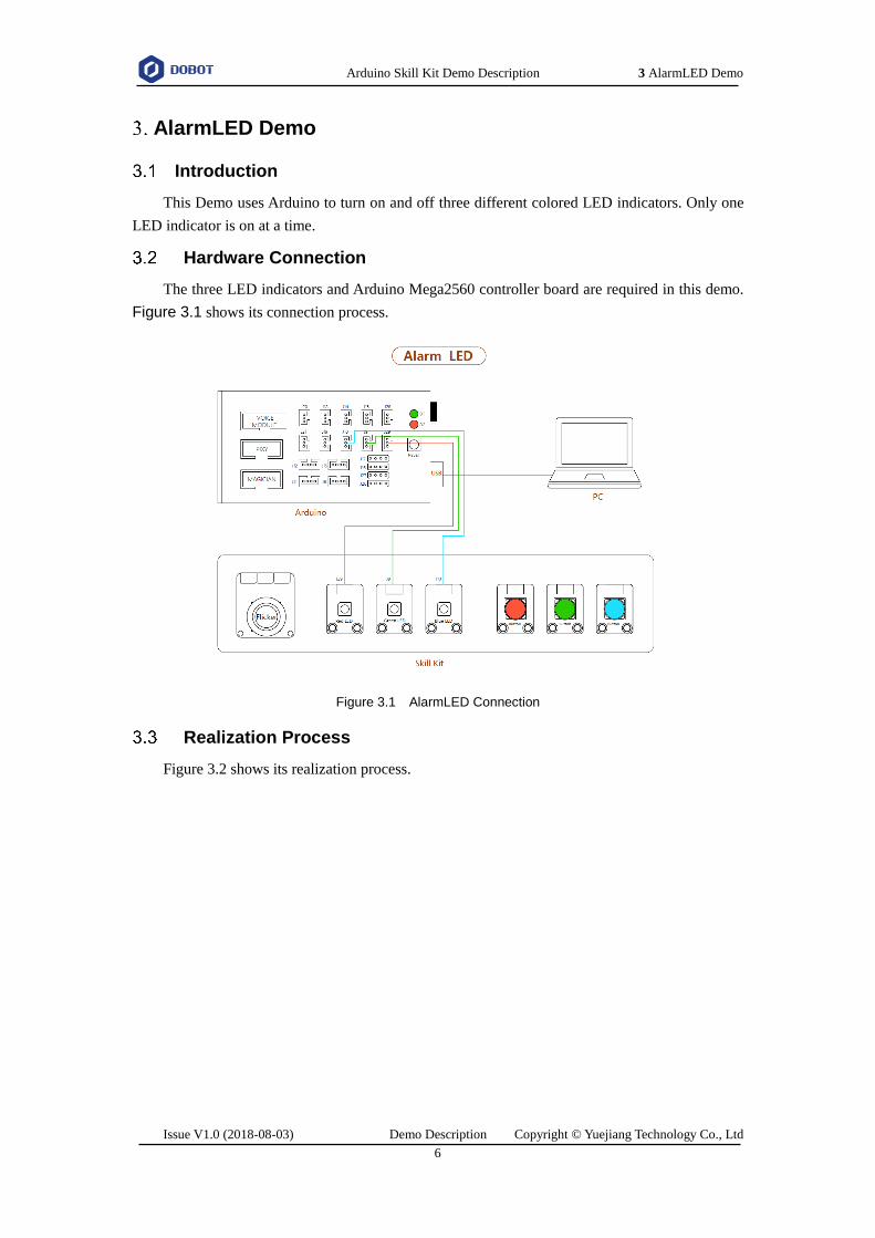
This Demo uses Arduino to turn on and off three different colored LED indicators. Only one
LED indicator is on at a time.
Hardware Connection
The three LED indicators and Arduino Mega2560 controller board are required in this demo.
Figure 3.1 shows its connection process.
Figure 3.1 AlarmLED Connection
Realization Process
Figure 3.2 shows its realization process.

Arduino Skill Kit Demo Description 3 AlarmLED Demo
Issue V1.0 (2018-08-03) Demo Description Copyright © Yuejiang Technology Co., Ltd
7
Figure 3.2 Realization process
Critical Code Description
Define the pins of which LED indicators are connected to Arduino and set to output
pins.
Program 3.1 Initialization
#define Red_LED 9 //Red_LED connects to the 9 pin
#define Green_LED A1 //Green_LED connects to the A1 pin
#define Blue_LED A3 //Blue_LED connects to the A3 pin
void setup() {
pinMode(Red_LED,OUTPUT); //Set the 9 pin to OUTPUT
pinMode(Green_LED,OUTPUT); //Set the A1 pin to OUTPUT
pinMode(Blue_LED,OUTPUT); //Set the A3 pin to OUTPUT
digitalWrite(Red_LED,LOW); //Set the 9 pin to LOW
digitalWrite(Green_LED,LOW); //Set the A1 pin to LOW
digitalWrite Blue_LED,LOW); //Set the A3 pin to LOW

Arduino Skill Kit Demo Description 3 AlarmLED Demo
Issue V1.0 (2018-08-03) Demo Description Copyright © Yuejiang Technology Co., Ltd
8
}
Set the pins to HIGH or LOW to turn on and off the three LED indicators.
Program 3.2 Set High/Low level
void loop() {
digitalWrite(Red_LED,HIGH);
delay(300);
digitalWrite(Red_LED,LOW);
digitalWrite(Green_LED,HIGH);
delay(300);
digitalWrite(Green_LED,LOW);
digitalWrite(Blue_LED HIGH);
delay(300);
digitalWrite(Blue_LED,LOW);
}

Arduino Skill Kit Demo Description 4 AdjustLED Demo
Issue V1.0 (2018-08-03) Demo Description Copyright © Yuejiang Technology Co., Ltd
9
AdjustLED Demo
Introduction
This demo uses joystick to control the brightness of the LED indicator.
Hardware Connection
The LED indicator, joystick and Arduino Mega2560 are required in this demo. Figure 4.1
shows its connection process.
Figure 4.1 AdjustLED Connection
Realization Process
This demo controls the brightness of the LED indicator by moving joystick along X-axis.
Figure 4.2 shows its realization process.
Figure 4.2 Realization process
Critical Code Description

Arduino Skill Kit Demo Description 4 AdjustLED Demo
Issue V1.0 (2018-08-03) Demo Description Copyright © Yuejiang Technology Co., Ltd
10
Define the pins of which LED indicator and joystick are connected to Arduino.
The PWM interface on the Arduino Mega2560 controller board is used when
adjusting the brightness.
Program 4.1 Initialization
#define LED 9 //LED connects to the 9 pin
#define JoyStick_X 7 //JoyStick X connects to the A7 pin
Define the brightness variation frequency of LED indicator.
NOTE
When moving joystick along X-axis or Y-axis, the analog values change from 0 to 1023,
as shown in Figure 4.3. The homing position of the joystick is at (x,y: 512,508).
Figure 4.3 Analog value range
Program 4.2 Define the brightness variation of LED indicator
if(x > 520) // JoyStick moves along X-axis in the positive
//direction, increase the/brightness. You can customize
//the threshold. In this demo, we set to 520
i = i + 0.1;
else if(x < 500) //JoyStick moves along X-axis in negative direction,
//decrease the brightness
i = i - 0.1;
if(i >= 255) // The brightness range of LED is from 0 to 255
i = 255;
else if(i < 0)
i = 0;
else

Arduino Skill Kit Demo Description 4 AdjustLED Demo
Issue V1.0 (2018-08-03) Demo Description Copyright © Yuejiang Technology Co., Ltd
11
i = i;
Adjust the brightness of the LED indicator over joystick.
Program 4.3 Adjust the brightness of the LED indicator over joystick
analogWrite(LED,i); //Adjust the brightness of the LED indicator

Arduino Skill Kit Demo Description 5 Button Demo
Issue V1.0 (2018-08-03) Demo Description Copyright © Yuejiang Technology Co., Ltd
12
Button Demo
Introduction
This demo uses three different colored buttons to turn on and off the corresponding colored
LED indicators respectively.
Hardware Connection
The three buttons, three LED indicators and Arduino Mega250 are required in this demo.
Figure 5.1 shows its connection process.
Figure 5.1 ButtonLED Connection
Realization Process
Figure 5.2 shows its realization process.

Arduino Skill Kit Demo Description 5 Button Demo
Issue V1.0 (2018-08-03) Demo Description Copyright © Yuejiang Technology Co., Ltd
13
Figure 5.2 Realization process
Critical Code Description
Define the pins of which LED indicators and buttons are connected to Arduino.
Program 5.1 Define the pins that LED indicators and buttons are connected
#define Red_LED 9 //Red LED connects to the 9 pin
#define Green_LED A1 //Green LED connects to the A1 pin
#define Blue_LED A3 //Blue LED connects to the A3 pin
#define Red_button A0 // Red_button connects to the A0 pin
#define Green_button A2 //Green_button connects to the A2 pin
#define Blue_button A4 // Blue_button connects to the A4 pin
Set the pins to INPUT or OUTPUT.
Program 5.2 Configure the pins as inputs and outputs
pinMode(Red_LED, OUTPUT); // Set the 9 pin to OUTPUT
pinMode(Green_LED, OUTPUT); // Set the A1 pin to OUTPUT
pinMode(Bule_LED, OUTPUT); // Set the A3 pin to OUTPUT

Arduino Skill Kit Demo Description 5 Button Demo
Issue V1.0 (2018-08-03) Demo Description Copyright © Yuejiang Technology Co., Ltd
14
pinMode(Red_button, INPUT); // Set the A0 pin to INPUT
pinMode(Green_button, INPUT); // Set the A2 pin to INPUT
pinMode(Blue_button, INPUT); // Set the A4 pin to INPUT
Use buttons to turn on and off the LED indicators.
Program 5.3 Use buttons to turn on and off the LED indicators
int val1 = digitalRead(Red_button); //Get the value of the A0 pin
int val2 = digitalRead(Green_button); //Get the value of the A2 pin
int val3 = digitalRead(Blue_button); //Get the value of the A4 pin
if (val1 == 1) { //Press the Red button
digitalWrite(Red_LED, 1); // turn on the Red LED
}
else {
digitalWrite(Red_LED, 0); // turn off the Red LED
}
……
…..

Arduino Skill Kit Demo Description 6 SeedVoiceLED Demo
Issue V1.0 (2018-08-03) Demo Description Copyright © Yuejiang Technology Co., Ltd
15
SeedVoiceLED Demo
Introduction
The demo uses Grove speech recognizer to turn on and off three different colored LED
indicators (Red, Green, and Blue).
Hardware Connection
The speech recognizer, three LED indicators and Arduino Mega2560 are required in this demo.
Figure 6.1 shows its realization process.
Figure 6.1 SeedVoiceLED Connection
Realization Process
Figure 6.2 shows its realization process.
NOTE
Please speak out the command Hicell to wake up the Grove speech recognizer before
using it. If successful, the LED on the speech recognizer will turn red. Then, you can
speak out the command word. If the command word is detected, the LED will turn blue.

Arduino Skill Kit Demo Description 6 SeedVoiceLED Demo
Issue V1.0 (2018-08-03) Demo Description Copyright © Yuejiang Technology Co., Ltd
16
Figure 6.2 Realization process
Critical Code Description
Before debugging this demo, please select SoftwareSerial library on the Sketch > Include
Library menu.
Define the pins of which the LED indicators and the Grove speech recognizer are
connected to Arduino.
Program 6.1 Define the pins that the LED indicators and Grove speech recognizer are connected
#define SOFTSERIAL_RX_PIN A11 //connect to the A11 pin
#define SOFTSERIAL_TX_PIN 14 //connect to the 14 pin
#define Red_LED 9 //Red LED connects to the 9 pin
#define Green_LED A1 //Green LED connects to the A1 pin
#define Blue_LED A3 //Blue LED connects to the A3 pin
Control the LED indicator by voice commands.
Program 6.2 Control the LED indicator by voice commands
void loop()
{
char cmd;
if(softSerial.available())

Arduino Skill Kit Demo Description 6 SeedVoiceLED Demo
Issue V1.0 (2018-08-03) Demo Description Copyright © Yuejiang Technology Co., Ltd
17
{
cmd = softSerial.read();
switch(cmd)
{
case 1:
digitalWrite(Red_LED,HIGH); //turn on the Red LED
digitalWrite(Green_LED,HIGH); //turn on the Green LED
digitalWrite(Blue_LED,HIGH); //turn on the Blue LED
Serial.println(voiceBuffer[cmd - 1]);
break;
case 2:
digitalWrite(Red_LED,LOW); //turn off the Red LED
digitalWrite(Green_LED,LOW); //turn off the Green LED
digitalWrite(Blue_LED,LOW); //turn off the Blue LED
Serial.println(voiceBuffer[cmd - 1]);
break;
}
}
}
NOTICE
Grove speech recognizer only supports 22 voice commands without user-defined. The
commands with values are as shown in Program 6.3.
Program 6.3 Command description
const char *voiceBuffer[] =
{
"Turn on the light", //return 1
"Turn off the light", //return 2
"Play music", //return 3
"Pause", //return 4
"Next", //return 5
"Previous", //return 6
"Up", //return 7
"Down", //return 8
"Turn on the TV", //return 9

Arduino Skill Kit Demo Description 6 SeedVoiceLED Demo
Issue V1.0 (2018-08-03) Demo Description Copyright © Yuejiang Technology Co., Ltd
18
"Turn off the TV", //return 10
"Increase temperature", //return 11
"Decrease temperature", //return 12
"What's the time", //return 13
"Open the door", //return 14
"Close the door", //return 15
"Left", //return 16
"Right", //return 17
"Stop", //return 18
"Start", //return 19
"Mode 1", //return 20
"Mode 2", //return 21
"Go", //return 22
};

Arduino Skill Kit Demo Description 7 MoveBlock Demo
Issue V1.0 (2018-08-03) Demo Description Copyright © Yuejiang Technology Co., Ltd
19
MoveBlock Demo
Introduction
The demo uses Arduino to control Dobot Magician for picking and placing cubes.
Hardware Connection
Arduino Mega2560, Dobot Magician and suction cup kit are required in this demo. Figure 7.1
shows its connection process.
Figure 7.1 MoveBlock Connection
For details how to connect Dobot Magician and suction cup kit, please see Appendix B
Installing Suction Cup Kit.
Realization Process
If the cube is moved from point A to point B and then from point B back to point A with
multiple times. Figure 7.2 shows its realization process.

Arduino Skill Kit Demo Description 7 MoveBlock Demo
Issue V1.0 (2018-08-03) Demo Description Copyright © Yuejiang Technology Co., Ltd
20
Figure 7.2 Realization process
Critical Code Demo
Dobot Magician communicates with Arduino over UART interface (10 PIN) on the base of the
Dobot Magician, using the Dobot protocol. We have provided Dobot library which encapsulates
part of the Dobot Magician APIs, being called directly to control Dobot Magician. Before debugging
this Demo, please select the Dobot library on the Sketch > Include Library menu.
NOTICE
Please long press the Key button on the back of base of Dobot Magician to operate
homing before debugging this Demo.
Before debugging this Demo, please connect Dobot Magician and DobotStudio and operate
homing. And then press the Unlock key on the Forearm and drag Dobot Magician to move to the
positions where the cube is to be placed (A point and B point), then record their Cartesian
coordinates from the operation panel pane of DobotStudio page to write in this demo for picking
and placing cube.

Arduino Skill Kit Demo Description 7 MoveBlock Demo
Issue V1.0 (2018-08-03) Demo Description Copyright © Yuejiang Technology Co., Ltd
21
\
Figure 7.3 Obtain Cartesian coordinates
Define the coordinates of point A and point B
The coordinates can be obtained from the Operation Panel of DobotStudio page.
Program 7.1 Define the coordinates of point A and point B
//Coordinates of A point
#define block_positio_X 263 //X-coordinate of A point
#define block_position_Y 3 //Y-coordinate of A point
#define block_position_Z -40 //Z-coordinate of A point
#define block_position_R 0 //R-coordinate of A point
//Coordinates of B point

Arduino Skill Kit Demo Description 7 MoveBlock Demo
Issue V1.0 (2018-08-03) Demo Description Copyright © Yuejiang Technology Co., Ltd
22
#define Des_position_X 207 //X-coordinate of B point
#define Des_position_Y -171 //Y-coordinate of B point
#define Des_position_Z -46 //Z-coordinate of B point
#define Des_position_R 0 // R-coordinate of B point
Dobot Magician moves from point A to point B with multiple times.
Program 7.2 Dobot Magician moves from point A to point B with multiple times
while(count > 0)
{
Dobot_SetPTPCmdEx(JUMP_XYZ,block_position_X, block_position_Y,
block_position_Z, block_position_R); //Move to point A
Dobot_SetEndEffectorSuctionCupEx(true); //Turn on air pump to pick up cube
Dobot_SetPTPCmdEx((JUMP_XYZ,block_position_X, block_position_Y,-4, block_position_R);
//Lift a certain height
Dobot_SetPTPCmdEx(JUMP_XYZ, Des_position_X, Des_position_Y,
Des_position_Z, Des_position_R); //Move to point B
Dobot_SetEndEffectorSuctionCupEx(false); //Turn off air pump to place cube
Dobot_SetPTPCmdEx(JUMP_XYZ, Des_position_X, Des_position_Y, -20, Des_position_R);
//Lift a certain height
Dobot_SetPTPCmdEx(MOVJ_XYZ, 178, -4, 40, 0); //Move back to the initial position
Dobot_SetPTPCmdEx(JUMP_XYZ, Des_position_X, Des_position_Y,
Des_position_Z, Des_position_R); //Move to point B
Dobot_SetEndEffectorSuctionCupEx(true); //Turn on air pump to pick up cube
Dobot_SetPTPCmdEx(MOVL_XYZ, Des_position_X, Des_position_Y, -10, Des_position_R);
//Lift a certain height
Dobot_SetPTPCmdEx(JUMP_XYZ,block_position_X, block_position_Y,
block_position_Z, block_position_R); //Move to point A
Dobot_SetEndEffectorSuctionCupEx(false); //Turn off air pump to place cube
Dobot_SetPTPCmdEx(MOVJ_XYZ, 178, -4, 40, 0); //Move back to the initial position
count--;
}

Arduino Skill Kit Demo Description 8 SeedVoiceDobot Demo
Issue V1.0 (2018-08-03) Demo Description Copyright © Yuejiang Technology Co., Ltd
23
SeedVoiceDobot Demo
Introduction
This demo uses Grove speech recognizer to control the Dobot Magician movement and the air
pump start-stop.
Hardware Connection
Grove speech recognizer, Dobot Magician, air pump and Arduino Mega2560 are required in
this demo. The connection between Dobot Magician and Arduino is shown in Figure 8.1.
Figure 8.1 SeedVoiceDobot Connection
The connection between Dobot Magician and air pump is shown in Figure 8.2.
Figure 8.2 Air pump Connection
Realization Process
In this demo, we use Grove speech recognizer to control Dobot Magician and air pumps. Figure
8.3 shows the realization process.

Arduino Skill Kit Demo Description 8 SeedVoiceDobot Demo
Issue V1.0 (2018-08-03) Demo Description Copyright © Yuejiang Technology Co., Ltd
24
NOTE
Please speak out the command Hicell to wake up the speech recognizer before using it.
If successful, the LED on the speech recognizer will turn red. Then, you can speak out
the command word. If the command word is detected, the LED will turn blue.
Figure 8.3 Realization process

Arduino Skill Kit Demo Description 8 SeedVoiceDobot Demo
Issue V1.0 (2018-08-03) Demo Description Copyright © Yuejiang Technology Co., Ltd
25
Critical Code Description
This demo uses Grove speech recognizer to control Dobot Magician, the Dobot library and
SoftwareSerial library need to be called. Before debugging this Demo, please select Dobot and
SoftwareSerial on the Sketch > Include Library menu.
NOTICE
Please long press the Key button on the back of base of Dobot Magician to operate
homing before debugging this Demo.
Define the pins of which the Grove speech recognizer is connected to Arduino.
Program 8.1 Define the pins that the Grove speech recognizer are connected
#define SOFTSERIAL_RX_PIN A11 //connect to the A11 pin
#define SOFTSERIAL_TX_PIN 14 //connect to the 14 pin
Move Dobot Magician by voice commands.
Program 8.2 Move Dobot Magician by voice commands
if(softSerial.available())
{
cmd = softSerial.read();
switch(cmd)
{
case 7:
Dobot_SetPTPCmdEx(MOVL_INC,0,0,30,0); //magician moves upward
Serial.println(voiceBuffer[cmd - 1]);
break;
case 8:
Dobot_SetPTPCmdEx(MOVL_INC,0,0,-30,0); //magician moves downward
Serial.println(voiceBuffer[cmd - 1]);
Break;
……
……
}
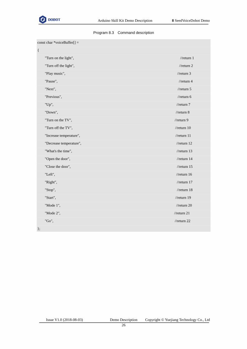
NOTICE
Grove speech recognizer only supports 22 voice commands without user-defined. The
commands and their return values are as shown in Program 8.3.
Arduino Skill Kit Demo Description 8 SeedVoiceDobot Demo
Issue V1.0 (2018-08-03) Demo Description Copyright © Yuejiang Technology Co., Ltd
26
Program 8.3 Command description
const char *voiceBuffer[] =
{
"Turn on the light", //return 1
"Turn off the light", //return 2
"Play music", //return 3
"Pause", //return 4
"Next", //return 5
"Previous", //return 6
"Up", //return 7
"Down", //return 8
"Turn on the TV", //return 9
"Turn off the TV", //return 10
"Increase temperature", //return 11
"Decrease temperature", //return 12
"What's the time", //return 13
"Open the door", //return 14
"Close the door", //return 15
"Left", //return 16
"Right", //return 17
"Stop", //return 18
"Start", //return 19
"Mode 1", //return 20
"Mode 2", //return 21
"Go", //return 22
};

Arduino Skill Kit Demo Description 9 JoyStick Demo
Issue V1.0 (2018-08-03) Demo Description Copyright © Yuejiang Technology Co., Ltd
27
JoyStick Demo
Introduction
This demo uses joystick and three buttons to control the Dobot Magician movement and the
air pump start-stop.
Hardware Connection
Joystick module, button, Dobot Magician, air pump, and Arduino Mega2560 are required in
this demo. The connections between them are shown in Figure 9.1.
Figure 9.1 JoyStick Connection
The connection between Dobot Magician and air pump is shown in Figure 9.2.
Figure 9.2 Air pump Connection
Realization Process
In this demo, we move Dobot Magician forward, backward, left and right by moving joystick
along X-axis or Y-axis, control the moving speed by joystick button, move Dobot Magician upward
by red button , move Dobot Magician downward by green button and control the air pump start-stop
by blue button. Figure 9.3 shows its realization process.

Arduino Skill Kit Demo Description 9 JoyStick Demo
Issue V1.0 (2018-08-03) Demo Description Copyright © Yuejiang Technology Co., Ltd
28
Figure 9.3 Realization process
Arduino Skill Kit Demo Description 10 DobotPixy Demo
Issue V1.0 (2018-08-03) Demo Description Copyright © Yuejiang Technology Co., Ltd
29
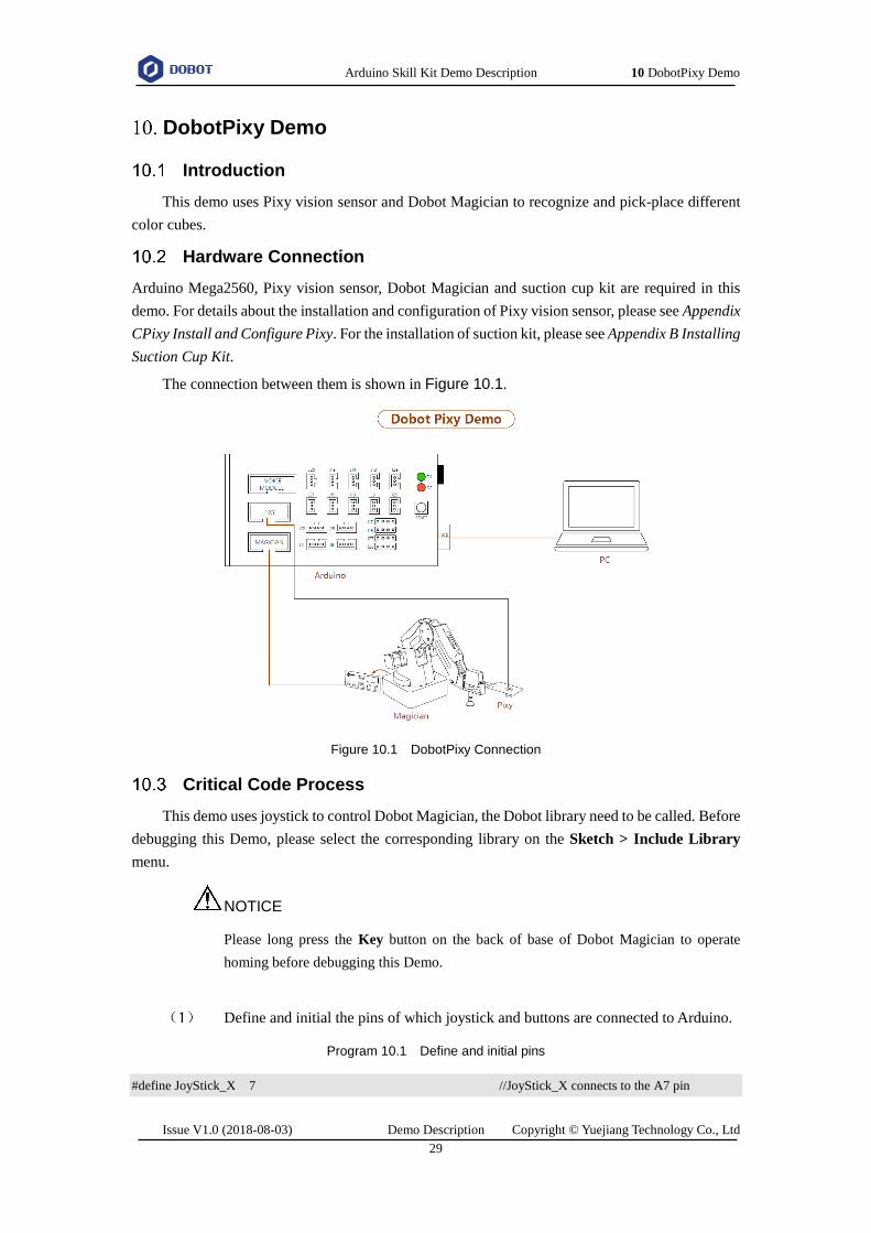
DobotPixy Demo
Introduction
This demo uses Pixy vision sensor and Dobot Magician to recognize and pick-place different
color cubes.
Hardware Connection
Arduino Mega2560, Pixy vision sensor, Dobot Magician and suction cup kit are required in this
demo. For details about the installation and configuration of Pixy vision sensor, please see Appendix
CPixy Install and Configure Pixy. For the installation of suction kit, please see Appendix B Installing
Suction Cup Kit.
The connection between them is shown in Figure 10.1.
Figure 10.1 DobotPixy Connection
Critical Code Process
This demo uses joystick to control Dobot Magician, the Dobot library need to be called. Before
debugging this Demo, please select the corresponding library on the Sketch > Include Library
menu.
NOTICE
Please long press the Key button on the back of base of Dobot Magician to operate
homing before debugging this Demo.
Define and initial the pins of which joystick and buttons are connected to Arduino.
Program 10.1 Define and initial pins
#define JoyStick_X 7 //JoyStick_X connects to the A7 pin

Arduino Skill Kit Demo Description 10 DobotPixy Demo
Issue V1.0 (2018-08-03) Demo Description Copyright © Yuejiang Technology Co., Ltd
30
#define JoyStick_Y 6 // JoyStick_Y connects to the A6 pin
#define JoyStick_Z A5 // JoyStick_Z connects to the A5 pin
#define Red_button A0 //Red_button connects to the A0 pin
#define Green_button A2 // Green_button connects to the A2 pin
#define Blue_button A4 // Blue_button connects to the A4 pin
int flag = 0; //Blue_button flag
int Zflag = 1; //JoyStick_Z flag
void setup()
{
Dobot_Init(); //Initial Dobot
pinMode(JoyStick_Z, INPUT);
pinMode(Red_button, INPUT);
pinMode(Green_button, INPUT);
pinMode(Blue_button, INPUT);
Serial.begin(115200); //115200 bps
Dobot_SetPTPCmdEx(MOVJ_XYZ, 178, 0, 12, 0); //Initial position, obtained from the
//Operatioan Panel of DobotStudio page
Serial.println("ok");
}
Define the moving direction of Dobot Magician and the air pump start-stop based on the moving
direction of joystick and buttons.
NOTE
When moving joystick along X-axis or Y-axis, the analog values change from 0 to 1023,
as shown Figure 10.2. The homing position of the joystick is at (x,y: 512,508).
Figure 10.2 Value range

Arduino Skill Kit Demo Description 10 DobotPixy Demo
Issue V1.0 (2018-08-03) Demo Description Copyright © Yuejiang Technology Co., Ltd
31
Program 10.2 Define the moving direction of Dobot Magician based on joystick and buttons
int x = 0,y = 0,z = 0,b1 = 0,b2 = 0,b3 = 0;
int direction = 0; //The direction of JoyStick
x = analogRead(JoyStick_X);
y = analogRead(JoyStick_Y);
z = digitalRead(JoyStick_Z);
b1 = digitalRead(Red_button);
b2 = digitalRead(Green_button);
b3 = digitalRead(Blue_button);
if(y > 600){ //JoyStick moves alongt Y-axis in the positive direction
//You can customizethe threshold. In this demo, we set to 520
direction = 1;
}
else if(y < 400){ // JoyStick moves alongt Y-axis in the negative direction
direction = 2;
}
…...
……
switch(direction){
case 1:
Serial.println("forward");
Dobot_SetPTPCmdEx(MOVL_INC,20,0,0,0); //Dobot Magician moves forward
Serial.print("x=");
Serial.println(x);
Serial.print("y=");
Serial.println(y);
break;
case 2:
Serial.println("backwardss");
Dobot_SetPTPCmdEx(MOVL_INC,-20,0,0,0); // Dobot Magician moves backward
Serial.print("x=");
Serial.println(x);
Serial.print("y=");
Serial.println(y);
break;
……
……

Arduino Skill Kit Demo Description 10 DobotPixy Demo
Issue V1.0 (2018-08-03) Demo Description Copyright © Yuejiang Technology Co., Ltd
32
}
Realization Process
If there are eight cubes with different colors (red, yellow, green, blue), each color has two
cubes. Place these cubes in the visual range (the Pixy vision sensor is installed on the end of Dobot
Magician). After a color is detected by Pixy vision sensor, Dobot Magician will pick and place the
corresponding cubes. Figure 10.3 shows its realization process.
Figure 10.3 Realization process
Critical Code Description
This demo uses Pixy vision sensor and Dobot Magician to pick and place cubes. The Dobot
library and Pixy library need to be called. Before debugging this Demo, please select Dobot and
Pixy on the Sketch > Include Library menu.
NOTICE
Please long press the Key button on the back of base of Dobot Magician to operate

Arduino Skill Kit Demo Description 10 DobotPixy Demo
Issue V1.0 (2018-08-03) Demo Description Copyright © Yuejiang Technology Co., Ltd
33
homing before debugging this Demo.
Define the coordinates of cubes that are to be placed
The coordinates can be obtained from the Operation Panel of DobotStudio page.
Program 10.3 Define the coordinates of point A and point B
//Point position coordinate
#define Red_position_X 175 // X-coordinate of red cube that is to be placed
#define Red_position_Y -179 // Y-coordinate of red cube that is to be placed
#define Red_position_Z -46 // Z-coordinate of red cube that is to be placed
#define Red_position_R 0 // R-coordinate of red cube that is to be placed
#define Yellow_position_X 50 // X-coordinate of yellow cube that is to be placed
#define Yellow_position_Y -179 // Y-coordinate of yellow cube that is to be placed
#define Yellow_position_Z -46 // Z-coordinate of yellowcube that is to be placed
#define Yellow_position_R 0 / R-coordinate of yellow cube that is to be placed
……
……
Declare a vision recognition object.
Program 10.4 Declare a vision recognition object
PixyI2C pixy; // Pixy object
Initial Dobot Magician.
Program 10.5 Initialization
Dobot_Init();
Serial.begin(115200);
Serial.print("Starting...\n");
Obtain Rotation matrix RT with the image coordinates A[𝑥1 𝑥2 𝑥3
𝑦1 𝑦2 𝑦3
1 1 1] and the corresponding
Cartesian coordinates B[𝑥1
′ 𝑥2′ 𝑥3
′
𝑦1′ 𝑦2
′ 𝑦3′
1 1 1
] of three points, so that after the image coordinates of a
cube are obtained by the Pixy vision sensor, the corresponding Cartesian coordinates can be
calculated with the RT matrix, where Dobot Magician will move to, as shown in. The formula
is 𝐁 = 𝑹𝑻𝑨.

Arduino Skill Kit Demo Description 10 DobotPixy Demo
Issue V1.0 (2018-08-03) Demo Description Copyright © Yuejiang Technology Co., Ltd
34
Program 10.6 Obtain Rotation matrix
CalcInvMat(pixyPoint, inv_pixy);
MatMultiMat(dobotPoint, inv_pixy, RT);
Set the camera position to recognize cubes.
Program 10.7 Set the camera position
Dobot_SetPTPCmdEx(MOVJ_XYZ, 178, -4, 40, 0); //Set the camera position, obtained
//from the Operation Panel of
//DobotStudio page
Obtain the number of cubes Pixy has detected. You can then look in the pixy.blocks[] array for
information about each detected object (one array member for each detected object.) Each array
member (i) contains the following fields.
pixy.blocks[i].signature: The signature number (color) of the detected cube (1-7).
pixy.blocks[i].x: The X-coordinate of the center of the detected object (0-319).
pixy.blocks[i].y: The Y-coordinate of the center of the detected object (0-319).
pixy.blocks[i].width: The width of the detected cube (1-320).
pixy.blocks[i].height: The height of the detected cube (1-200).
Program 10.8 Obtain the number of cubes and their data
blocks = pixy.getBlocks();
Obtain the corresponding Cartesian coordinates where Dobobt Magician will move to, for picking
and placing this cube, based on the image coordinates of the first cube and the rotation matrix.
Program 10.9 corresponding Cartesian coordinates
transForm(pixy.blocks[0].x,pixy.blocks[0].y);
Pick and place cubes. If there are multiple cubes in the same color, these cubes will be piled when
placing.
When setting the placement of the cubes, please connect Dobot Magician and
DobotStudio. And press the Unlock key on the Forearm and drag Dobot Magician
to move to the positions where the cube is to be placed, then record their Cartesian
coordinates from sssssssthe operation panel pane of DobotStudio page to write in
this demo for picking and placing cube.
Program 10.10 Pick and place cubes
Dobot_SetPTPCmdEx(JUMP_XYZ, Coordinate[0], Coordinate[1], -46, 0);
Dobot_SetEndEffectorSuctionCupEx(true); //Turn on air pump

Arduino Skill Kit Demo Description 10 DobotPixy Demo
Issue V1.0 (2018-08-03) Demo Description Copyright © Yuejiang Technology Co., Ltd
35
Dobot_SetPTPCmdEx(MOVL_XYZ, Coordinate[0], Coordinate[1], 50, 0);
//place Point
if(gRed == 0){
Dobot_SetPTPCmdEx(JUMP_XYZ, Red_position_X, Red_position_Y, Red_position_Z, Red_position_R);
//Move to the setting position
}
else{
Dobot_SetPTPCmdEx(JUMP_XYZ, Red_position_X, Red_position_Y,
Red_position_Z+25*gRed, Red_position_R); // Multiple cubes are piled when placing
}
Dobot_SetEndEffectorSuctionCupEx(false); //Turn off air pump
Dobot_SetPTPCmdEx(JUMP_XYZ, Red_position_X, Red_position_Y, 50, 0); //Lift to a certain height
gRed++;

Arduino Skill Kit Demo Description 10 DobotPixy Demo
Issue V1.0 (2018-08-03) Demo Description Copyright © Yuejiang Technology Co., Ltd
36
Common Function Description
Common Function of Arduino
Arduino demo is developed based on Arduino Mega2560 and the Arduino APIs need to be
called. This topic describes the common functions that are used in Arduino demo.
Attached table 1 Set the specified pin to INPUT or OUTPUT
Attached table 2 Set the specified digital pin to HIGH or LOW
Attached table 3 Read the specified digital pin
Attached table 4 Write the specified analog pin
Prototype void pinMode(uint8_t pin, uint8_t mode)
Description Set the specified digital pin to INPUT or OUTPUT
Parameter pin: Pin number of the pin
mode: INPUT or OUTPUT
Return None
Prototype void digitalWrite( uint8_t pin, uint8_t value)
Description Set the specified digital pin to HIGH or LOW
Parameter pin: Pin number of the pin
mode: HIGH or LOW
Return None
Prototype int digitalRead( uint8_t pin)
Description Read the specified digital pin
Parameter pin: Pin number of the pin
Return HIGH or LOW
Prototype void analogWrite( uint8_t pin, int value)
Description Write the specified analog pin for controlling the brightness of LED indicator or
the motor speed
Parameter pin: Pin number of the pin
value: 0-255. 0: OFF; 255: ON

Arduino Skill Kit Demo Description 10 DobotPixy Demo
Issue V1.0 (2018-08-03) Demo Description Copyright © Yuejiang Technology Co., Ltd
37
Attached table 5 Read the specified analog pin
Pixy Common Function of Pixy
When the Pixy vision sensor is used in Arduino demo, the Pixy APIs need to be called. This
topic describes the common functions in Arduino demo.
Attached table 6 Return the number of cubes Pixy has detected
Common Function of Dobot Magician
Dobot Magician communicates with Arduino over UART interface (10 PIN) on the base of the
Dobot Magician, using the Dobot protocol. We have provided Dobot library which encapsulates part
of the Dobot Magician API, being called directly to control Dobot Magician. This topic describes
the common functions that are used in Arduino demo. For details about Dobot Magician API, please
see Dobot Magician API Description.
Return None
Prototype int analogRead( uint8_t pin)
Description Read the specified analog pin
Parameter pin: Pin number of the pin
Return 0-1023
Prototype uint16_t getBlocks()
Description Obtain the number of cubes Pixy has detected. You can then look in the
pixy.blocks[] array for information about each detected object (one array
member for each detected object.) Each array member (i) contains the following
fields
pixy.blocks[i].signature: The signature number (color) of the detected
cube (1-7)
pixy.blocks[i].x: The X-coordinate of the center of the detected object (0-
319)
pixy.blocks[i].y: The Y-coordinate of the center of the detected object (0-
319)
pixy.blocks[i].width: The width of the detected cube (1-320)
pixy.blocks[i].height: The height of the detected cube (1-200)
Parameter None
Return Return the number of cubes Pixy has detected

Arduino Skill Kit Demo Description 10 DobotPixy Demo
Issue V1.0 (2018-08-03) Demo Description Copyright © Yuejiang Technology Co., Ltd
38
Attached table 7 Set the motion mode and the target coordinates
Attached table 8 Control the start-stop of air pump
Prototype void Dobot_SetPTPCmdEx( uint8_t Model, float x, float y, float z, float r)
Description Set the motion mode and the target coordinates
Parameter Details for Model:
enum {
JUMP_XYZ, //JUMP mode, (x,y,z,r) is the target point in Cartesian
coordinate system
MOVJ_XYZ, //MOVJ mode, (x,y,z,r) is the target point in Cartesian
coordinate system
MOVL_XYZ, //MOVL mode, (x,y,z,r) is the target point in Cartesian
coordinate system
JUMP_ANGLE, //JUMP mode, (x,y,z,r) is the target point in Joint
coordinate system
MOVJ_ANGLE, //MOVJ mode, (x,y,z,r) is the target point in Joint
coordinate system
MOVL_ANGLE, //MOVL mode, (x,y,z,r) is the target point in Joint
coordinate system
MOVJ_INC, //MOVJ mode, (x,y,z,r) is the angle increment in
Joint coordinate system
MOVL_INC, //MOVL mode, (x,y,z,r) is the Cartesian coordinate
increment in Joint coordinate system
MOVJ_XYZ_INC, //MOVJ mode, (x,y,z,r) is the Cartesian coordinate
increment in Cartesian coordinate system
JUMP_MOVL_XYZ, //JUMP mode, (x,y,z,r) is the Cartesian coordinate
increment in Cartesian coordinate system
};
x、y、z、r : Coordinate parameters in PTP mode. (x,y,z,r) can be set to Cartesian
coordinate, joints angle, or increment of them
Return None
Prototype void Dobot_SetEndEffectorSuctionCupEx(bool issuck)
Description Control the start-stop of the air pump
Parameter Issuck: Whether to turn on the air pump. true: Turn on; false: Turn off
Return None

Arduino Skill Kit Demo Description 10 DobotPixy Demo
Issue V1.0 (2018-08-03) Demo Description Copyright © Yuejiang Technology Co., Ltd
39
Attached table 9 Set the speed ratio and acceleration ratio of Dobot Magician
Attached table 10 Get the real-time pose of Dobot
Attached table 11 Get the device clock
Prototype void Dobot_SetJOGCommonParamsEx(float velocityRatio, float
accelerationRatio)
Description Set the speed ratio and acceleration ratio of Dobot Magician
Parameter velocityRatio: Speed ratio
accelerationRatio: Acceleration ratio
Return None
Prototype float Dobot_GetPoseEx(uint8_t temp)
Description Get the real-time pose of Dobot
Parameter temp: Cartesian coordinate system axis
Details for temp:
enum{
X,…….//X axis
Y,…….//Y axis
Z,…….//Z axis
R,…….//R axis
JOINT1,…….//joint axis 1
JOINT2,…….//joint axis 2
JOINT3,…….//joint axis 3
JOINT4,…….//joint axis 4
};
Return Return the value of axis or joint angle
Prototype uint32_t Dobot_GetDeviceTimeEx(void)
Description Get the device clock
Parameter None
Return Return the device clock

Arduino Skill Kit Demo Description 10 DobotPixy Demo
Issue V1.0 (2018-08-03) Demo Description Copyright © Yuejiang Technology Co., Ltd
40
Attached table 12 Set the sliding rail status
Attached table 13 Execute the homing function
Attached table 14 Set the offset of end-effector
Attached table 15 Enable laser
Attached table 16 Set gripper status
Prototype void Dobot_SetDeviceWIthLEx(bool isWithL)
Description Set the Sliding rail status
Parameter isWithL: 0:Disabled, 1:Enabled
Return None
Prototype Void Dobot_SetHOMECmdEx( void )
Description Execute the homing function
Parameter None
Return None
Prototype void Dobot_SetEndEffectorParamsEx(float x,float y, float z)
Description Set the offset of the end-effector. If the end-effector is installed, this API is required
Parameter x: the X-axis offset of end-effector
y: the Y-axis offset of end-effector
z: the Z-axis offset of end-effector
Return None
Prototype void Dobot_SetEndEffectorLaserEx (uint8_t isEnable, float power)
Description Enable laser
Parameter isEnable: Control laser. 0: Disabled, 1: Enabled
power: PWM duty cycle:0-100
Return None
Prototype void Dobot_SetEndEffectorGripperEx(bool isEnable,bool isGriped)
Description Set gripper status

Arduino Skill Kit Demo Description 10 DobotPixy Demo
Issue V1.0 (2018-08-03) Demo Description Copyright © Yuejiang Technology Co., Ltd
41
Attached table 17 Set the velocity and acceleration of the joints coordinate axis in jogging mode
Attached table 18 Execute the jogging command
Parameter isEnable: Control end-effector. 0: Disabled, 1: Enabled
isGriped: Control the gripper to grab or release. 0:Released, 1: Grabbed
Return None
Prototype void Dobot_SetJOGJointParamsEx(float velocityJ1,float accelerationJ1,float
velocityJ2,float accelerationJ2,float velocityJ3,float accelerationJ3,float
velocityJ4,float accelerationJ4)
Description Set the velocity and acceleration of the joints coordinate axis in jogging mode
Parameter velocityJ1、velocityJ2、velocityJ3、velocityJ4: joints velocity in jogging mode
accelerationJ1、accelerationJ2、accelerationJ3、accelerationJ4: joints acceleration
in jogging mode
Return None
Prototype void Dobot_SetJOGCmdEx(uint8_t model)
Description Execute the Jogging command. Please call this API after setting the related
parameters of jogging
Parameter model : Jogging command
Details for model:
enum {
AP_DOWN, ……//X+/Joint1+
AN_DOWN, ……//X-/Joint1-
BP_DOWN, …… //Y+/Joint2+
BN_DOWN, …… //Y-/Joint2-
CP_DOWN, …… //Z+/Joint3+
CN_DOWN, …… //Z-/Joint3-
DP_DOWN, ……//R+/Joint4+
DN_DOWN, …… //R-/Joint4-
LP_DOWN, ……//L+
LN_DOWN ……//L-
};
Return None

Arduino Skill Kit Demo Description 10 DobotPixy Demo
Issue V1.0 (2018-08-03) Demo Description Copyright © Yuejiang Technology Co., Ltd
42
Attached table 19 Set the velocity ratio and the acceleration ratio in PTP mode
Attached table 20 Set the velocity and acceleration of the joint coordinate axis in PTP mode
Attached table 21 Set the velocity and acceleration of sliding rail in PTP mode
Attached table 22 Set the lifting height in JUMP mode
Prototype void Dobot_SetPTPCommonParamsEx(float velocityRatio,float accelerationRatio)
Description Set the velocity ratio and the acceleration ratio in PTP mode
Parameter velocityRatio: velocity ratio in PTP mode
accelerationRatio: velocity acceleration in PTP mode
Return None
Prototype void Dobot_SetPTPJointParamsEx(float velocityJ1,float accelerationJ1,float
velocityJ2,float accelerationJ2,float velocityJ3,float accelerationJ3,float
velocityJ4,float accelerationJ4)
Description Set the velocity and acceleration of the joint coordinate axis in PTP mode
Parameter velocityJ1、velocityJ2、velocityJ3、velocityJ4: Joint velocity in PTP mode
accelerationJ1、accelerationJ2、accelerationJ3、accelerationJ4: Joint acceleration in
PTP mode
Return None
Prototype void Dobot_SetPTPLParamsEx( float velocityRatio, float accelerationRatio)
Description Set the velocity and acceleration of sliding rail in PTP mode
Parameter velocityRatio: Sliding rail velocity in PTP mode
accelerationRatio: Sliding rail acceleration in PTP mode
Return None
Prototype void Dobot_SetPTPJumpParamsEx( float jumpHeight)
Description Set the lifting height in JUMP mode
Parameter jumpHeight: The lifting height
Return None
Arduino Skill Kit Demo Description 10 DobotPixy Demo
Issue V1.0 (2018-08-03) Demo Description Copyright © Yuejiang Technology Co., Ltd
43
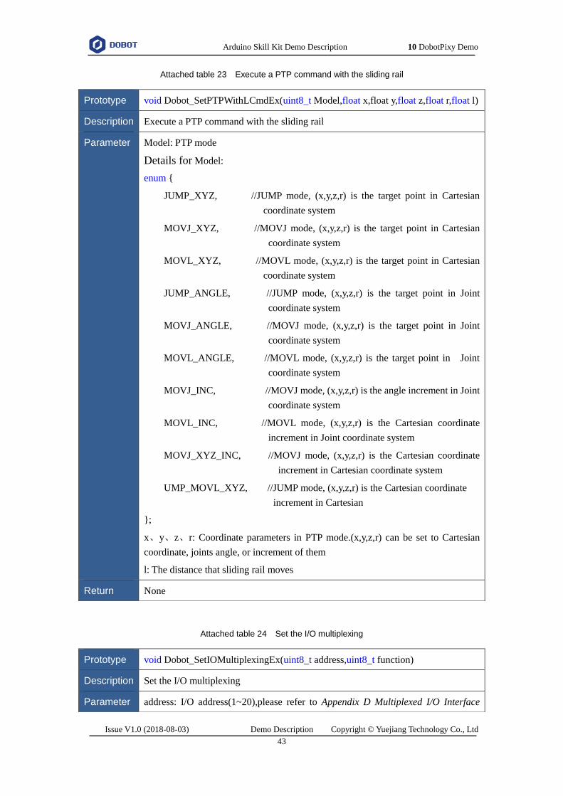
Attached table 23 Execute a PTP command with the sliding rail
Attached table 24 Set the I/O multiplexing
Prototype void Dobot_SetPTPWithLCmdEx(uint8_t Model,float x,float y,float z,float r,float l)
Description Execute a PTP command with the sliding rail
Parameter Model: PTP mode
Details for Model:
enum {
JUMP_XYZ, //JUMP mode, (x,y,z,r) is the target point in Cartesian
coordinate system
MOVJ_XYZ, //MOVJ mode, (x,y,z,r) is the target point in Cartesian
coordinate system
MOVL_XYZ, //MOVL mode, (x,y,z,r) is the target point in Cartesian
coordinate system
JUMP_ANGLE, //JUMP mode, (x,y,z,r) is the target point in Joint
coordinate system
MOVJ_ANGLE, //MOVJ mode, (x,y,z,r) is the target point in Joint
coordinate system
MOVL_ANGLE, //MOVL mode, (x,y,z,r) is the target point in Joint
coordinate system
MOVJ_INC, //MOVJ mode, (x,y,z,r) is the angle increment in Joint
coordinate system
MOVL_INC, //MOVL mode, (x,y,z,r) is the Cartesian coordinate
increment in Joint coordinate system
MOVJ_XYZ_INC, //MOVJ mode, (x,y,z,r) is the Cartesian coordinate
increment in Cartesian coordinate system
UMP_MOVL_XYZ, //JUMP mode, (x,y,z,r) is the Cartesian coordinate
increment in Cartesian
};
x、y、z、r: Coordinate parameters in PTP mode.(x,y,z,r) can be set to Cartesian
coordinate, joints angle, or increment of them
l: The distance that sliding rail moves
Return None
Prototype void Dobot_SetIOMultiplexingEx(uint8_t address,uint8_t function)
Description Set the I/O multiplexing
Parameter address: I/O address(1~20),please refer to Appendix D Multiplexed I/O Interface

Arduino Skill Kit Demo Description 10 DobotPixy Demo
Issue V1.0 (2018-08-03) Demo Description Copyright © Yuejiang Technology Co., Ltd
44
Attached table 25 Set I/O output
Attached table 26 Set PWM output
Attached table 27 Get I/O input
Description for details
function: I/O multiplexing function
Details for function:
typedef enum {
IOFunctionDummy; //Invalid
IOFunctionDO; // I/O output
IOFunctionPWM; // PWM output
IOFunctionDI; //I/O input
IOFunctionADC; //A/D input
IOFunctionDIPU; //Pull-up input
IOFunctionDIPD //Pull-down input
}
Return None
Prototype void Dobot_SetIODOEx(uint8_t address,uint8_t value)
Description Set I/O output
Parameter address: /O address(1~20)
value: Low level(0), High level(1)
Return None
Prototype void Dobot_SetIOPWMEx( uint8_t address, float freq, float duty)
Description Set PWM output
Parameter address: I/O address(1~20)
freq: PWM frequency(10HZ~1MHz )
duty: PWM duty circle(0~100)
Return None
Prototype uint8_t Dobot_GetIODIEx( uint8_t address)
Description Get I/O input

Arduino Skill Kit Demo Description 10 DobotPixy Demo
Issue V1.0 (2018-08-03) Demo Description Copyright © Yuejiang Technology Co., Ltd
45
Attached table 28 Get A/D input
Attached table 29 Set the velocity of extended motor
Attached table 30 Set the velocity and movement distance of extended motor
Attached table 31 Enable the color sensor
Parameter address: I/O address(1~20)
Return return I/O input
Prototype uint16_t Dobot_GetIOADCEx( uint8_t address)
Description Get A/D input
Parameter address: I/O address(1~20 )
Return Return A/D input
Prototype void Dobot_SetEMotorEx( uint8_t address, uint8_t enable, uint32_t speed)
Description Set the velocity of extended motor
Parameter address: Motor index. 0:Stepper1, 1:Stepper2
enable: Control motor. 0:Disabled, 1:Enabled
speed: Motor velocity(Pulse number per second)
Return None
Prototype void Dobot_SetEMotorSEx( uint8_t address, uint8_t enable, uint32_t speed, uint32_t
deltaPulse)
Description Set the velocity and movement distance of extended motor, The Dobot will move for
some distance at a constant velocity after calling this API
Parameter address: Motor index. 0:Stepper1, 1:Stepper2
enable: Control motor.。0:Disabled, 1:Enabled
speed: Control motor(Pulse number per second)
deltaPulse: The distance that motor moves(Pulse number)
Return None
Prototype void Dobot_SetColorSensorEx( uint8_t enable, uint8_t port)

Arduino Skill Kit Demo Description 10 DobotPixy Demo
Issue V1.0 (2018-08-03) Demo Description Copyright © Yuejiang Technology Co., Ltd
46
Attached table 32 Get the color sensor value
Attached table 33 Set the losing-step threshold
Attached table 34 Execute losing-step command
Description Enable the color sensor
Parameter enable: 0:Disabled, 1:Enabled
port: the Dobot interface that the color sensor is connected to. Please select the
corresponding interface
Details for port:
enum {
IF_PORT_GP1;
IF_PORT_GP2;
IF_PORT_GP4;
IF_PORT_GP5;
};
Return None
Prototype uint8_t Dobot_GetColorSensorEx( uint8_t color)
Description Get the color sensor value
Parameter color: 0:Red, 1:Green, 2:Blue
Return Retun the color sensor value
Prototype void Dobot_SetLostStepSetEx(float lostStepValue)
Description Set the losing-step threshold. If you do not call this API, the default threshold is 5
Parameter lostStepValue: losing-step threshold
Return None
Prototype void Dobot_SetLostStepCmdEx( void )
Description Execute losing-step command
Parameter None
Return None

Arduino Skill Kit Demo Description 10 DobotPixy Demo
Issue V1.0 (2018-08-03) Demo Description Copyright © Yuejiang Technology Co., Ltd
47
Attached table 35 Set the IR sensor
Attached table 36 Get the IR sensor value
Prototype void Dobot_SetIRSwitchEx( uint8_t enable, uint8_t port)
Description Set the IR sensor
Parameter enable: 0:Disabled, 1:Enabled
port: the Dobot interface that the IR sensor is connected to. Please select the
corresponding interface
Details for port:
enum {
IF_PORT_GP1;
IF_PORT_GP2;
IF_PORT_GP4;
IF_PORT_GP5;
};
Return None
Prototype uint8_t GetIRSwitchEx( uint8_t port)
Description Get the IR sensor value
Parameter port: the Dobot interface that the IR sensor is connected to. Please select the
corresponding interface
Details for port:
enum {
IF_PORT_GP1;
IF_PORT_GP2;
IF_PORT_GP4;
IF_PORT_GP5;
};
Return Return the IR sensor value

Arduino Skill Kit Demo Description 10 DobotPixy Demo
Issue V1.0 (2018-08-03) Demo Description Copyright © Yuejiang Technology Co., Ltd
48
Installing Suction Cup Kit
Procedure
When picking and placing cubes with Dobot Magician, the suction cup kit should be installed
on the end of the Dobot Magician
Attached figure 1 Connect the air pump to the Dobot Magician
Attached figure 2 Install a suction cup kit

Arduino Skill Kit Demo Description 10 DobotPixy Demo
Issue V1.0 (2018-08-03) Demo Description Copyright © Yuejiang Technology Co., Ltd
49
Attached figure 3 Install an air tube
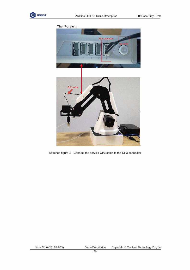
Arduino Skill Kit Demo Description 10 DobotPixy Demo
Issue V1.0 (2018-08-03) Demo Description Copyright © Yuejiang Technology Co., Ltd
50
Attached figure 4 Connect the servo’s GP3 cable to the GP3 connector

Arduino Skill Kit Demo Description 10 DobotPixy Demo
Issue V1.0 (2018-08-03) Demo Description Copyright © Yuejiang Technology Co., Ltd
51
Pixy Install and Configure Pixy
Before debugging the DobotPixy Demo, you need to install and configure the Pixy vision
sensor.
Prerequisites
The PixyMon has been installed, which is obtained from arduino kit/PixyMon.
The suction kit has been installed on the end of Dobot Magician.
The cubes have been obtained.
Procedure
Attached figure 5 loosen the screws

Arduino Skill Kit Demo Description 10 DobotPixy Demo
Issue V1.0 (2018-08-03) Demo Description Copyright © Yuejiang Technology Co., Ltd
52
Attached figure 6 Install Pixy vision sensor
For each color, set signature once. Pixy can only set 7 signature labels.

Arduino Skill Kit Demo Description 10 DobotPixy Demo
Issue V1.0 (2018-08-03) Demo Description Copyright © Yuejiang Technology Co., Ltd
53
Attached figure 7 Set signature number
Attached figure 8 shows the setting result.
Attached figure 8 Setting result

Arduino Skill Kit Demo Description 10 DobotPixy Demo
Issue V1.0 (2018-08-03) Demo Description Copyright © Yuejiang Technology Co., Ltd
54
The Configure page is displayed.
Attached figure 9 Set Data out port

Arduino Skill Kit Demo Description 10 DobotPixy Demo
Issue V1.0 (2018-08-03) Demo Description Copyright © Yuejiang Technology Co., Ltd
55
Multiplexed I/O Interface Description
Multiplexed UART Interface Description
Attached figure 10 shows the UART interface on the base, Attached table 37 lists the
multiplexed I/O description.
Attached figure 10 UART interface
Attached table 37 Multiplex I/O Description
I/O addressing Voltage Level Output PWM Level Input ADC
18 3.3V √ - √ -
19 3.3V √ - √ -
20 3.3V √ - √ -
Multiplexed Peripheral Interface Description
Attached figure 11 shows the peripheral interface on the base, and Attached table 38 lists the
multiplexed I/O description.

Arduino Skill Kit Demo Description 10 DobotPixy Demo
Issue V1.0 (2018-08-03) Demo Description Copyright © Yuejiang Technology Co., Ltd
56
Attached figure 11 Peripheral Interface
Attached table 38 Multiplexed I/O Description
I/O addressing Voltage Level Output PWM Level Input ADC
10 5V √ - - -
11 3.3V √ √ √ -
12 3.3V √ - √ √
13 5V √ - - -
14 3.3V √ √ √ -
15 3.3V √ - √ √
16 12V √ - - -
17 12V √ - - -
Multiplexed Forearm I/O Interface Description
Attached figure 12 shows the peripheral interface on the Forearm, Attached table 39 lists
the multiplexed I/O description.

Arduino Skill Kit Demo Description 10 DobotPixy Demo
Issue V1.0 (2018-08-03) Demo Description Copyright © Yuejiang Technology Co., Ltd
57
Attached figure 12 Peripheral interface in the Forearm
Attached table 39 Multiplexed I/O description
I/O addressing Voltage Level Output PWM Level Input ADC
1 3.3V √ - √ √
2 12V √ - - -
3 12V √ - - -
4 3.3V √ √ √ -
5 3.3V √ - √ √
6 3.3V √ √ √ -
7 3.3V √ - √ √
8 3.3V √ √ √ -
9 3.3V √ - √ √