arduino temperature-monitoring systems for the...
TRANSCRIPT

H-SC Journal of Sciences (2015) Vol. IV Vincent et al.
http://sciencejournal.hsc.edu/
Arduino Temperature-Monitoring Systems for the Hampden-Sydney College Energy Research Lab Benjamin Branch Edward Vincent ‘16, Zachary Ryan Carter ’17, and Stanley A. Cheyne Department of Physics & Astronomy, Hampden-Sydney College, Hampden-Sydney, VA 23943
Two temperature-monitoring systems were designed and tested for the Hampden-Sydney Energy Research Lab. The first system implements thermocouples in order to monitor the heat transfer through the concrete as it cures. The other system uses thermistors to monitor the inside and outside temperatures of the building. Both systems incorporate a microprocessor, a Wi-Fi shield, an SQL database, and an online website that displays the data. In the future, these systems should be improved by increasing their accuracy as well as exploring completely wireless capabilities.
Introduction
Beginning in August of 2014, the Energy
Research Laboratory was built at Hampden-Sydney College through funding from Steve Huff’s Pensmore Foundation. Huff, an alumnus of Hampden-Sydney College from the Class of 1973, is the chairman of both the Pensmore Foundation and of TF Forming Systems. The former explores efficient construction systems while the latter manufactures energy-efficient and disaster-resistant insulated concrete [1,2]. The H-SC lab is modeled after Huff’s Pensmore Mansion located in the Ozark Mountains of Missouri. Both buildings utilize TF Forming Systems’ insulated concrete, which is strengthened by the embedment of small, stainless steel helix fibers. The ultimate objective of this long- term project is to test the walls’ thermal mass by resourcefully maintaining appropriate internal temperatures.
Figure 1: This is a picture of the TF Forming Systems’ concrete mixture containing stainless steel helix fibers.
Figure 2: This is an image of the recent construction of the Energy Research Lab.
The purpose of our short-term project is to develop and test temperature-monitoring systems, designed specifically for the Hampden-Sydney Energy Research Lab. Previously, a research team developed a thermocouple system to monitor the internal temperature of the concrete as it cures. Our team further enhanced this system as well as designed and constructed a thermistor system to monitor the lab’s internal and external temperatures. Both systems implement an Arduino microprocessor to wirelessly transmit measurements to a database, where an online website then retrieves and displays that data.
Theory
Thermocouples consist of two different
conductors joined together at a common junction. They produce a small voltage that varies with temperature and thus are commonly utilized as temperature monitors. There are several types of thermocouples, but the most common is Type K, which uses chromium and alumel as the conductors and provides the widest range of temperatures. The

H-SC Journal of Sciences (2015) Vol. IV Vincent et al.
http://sciencejournal.hsc.edu/
voltage v (V) is related to the temperature T (°C) by the equation
𝑇 = 𝑎!𝑣!!
!!!
,
where the coefficients an are constants.
n
an
0
0.226584602
1
24152.109
2
67233.4248
3
2210340.682
4
-860963914.9
5
4.83506 x 10¹⁰
Table 1: The table above shows the first six constants specific to the Type K thermocouple [3].
Thermistors are resistors whose resistance varies with temperature. Thus, they are also commonly used to monitor temperature. The resistance R (Ω) is related to the temperature T (°C) by the Steinhart-Hart equation
𝑇 = 𝐴 + 𝐵 ln𝑅𝑅!
+ 𝐶 ln𝑅𝑅!
!
+ 𝐷 ln𝑅𝑅!
! !!
− 273,
where RT is the reference resistance at 25 °C
and the coefficients A, B, C and D are parameters specific to the thermistor [4]. Experimental Procedure
In the summer of 2014, the energy research team developed an end-‐to-‐end system that consists of a temperature-‐monitoring device, an SQL database, and an online website to display the data. The monitoring device uses Type K thermocouples integrated into a circuit that is attached to a microprocessor, which connects to a Wi-‐Fi shield. Code that controls the microprocessor was written by gathering information from a collection of online sources [5]. The circuit consists of instrumentation
amplifiers to amplify the small voltage that the thermocouples produce as well as voltage dividers in order to offset the output voltage. This system was designed to monitor the heat transfer through the lab walls as the concrete cured.
Figure 3: This is the schematic for the amplifier section of the thermocouple system [6]
Figure 4: This is the circuit board for the amplifier section of the thermocouple system corresponding to the schematic.
H-SC Journal of Sciences (2015) Vol. IV Vincent et al.
http://sciencejournal.hsc.edu/
Figure 5: Above is the schematic for the voltage offset section of the thermocouple system [6].
Figure 6: The image of the corresponding circuit board for the voltage offset section of the thermocouple system.
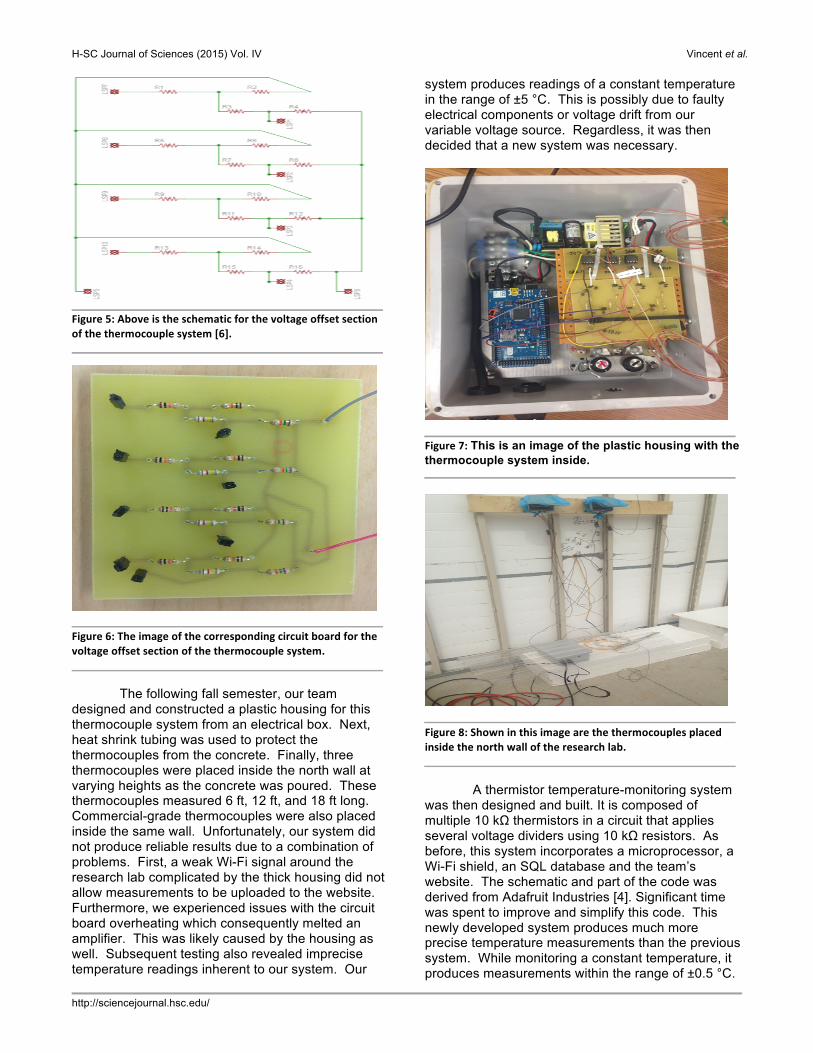
The following fall semester, our team designed and constructed a plastic housing for this thermocouple system from an electrical box. Next, heat shrink tubing was used to protect the thermocouples from the concrete. Finally, three thermocouples were placed inside the north wall at varying heights as the concrete was poured. These thermocouples measured 6 ft, 12 ft, and 18 ft long. Commercial-grade thermocouples were also placed inside the same wall. Unfortunately, our system did not produce reliable results due to a combination of problems. First, a weak Wi-Fi signal around the research lab complicated by the thick housing did not allow measurements to be uploaded to the website. Furthermore, we experienced issues with the circuit board overheating which consequently melted an amplifier. This was likely caused by the housing as well. Subsequent testing also revealed imprecise temperature readings inherent to our system. Our
system produces readings of a constant temperature in the range of ±5 °C. This is possibly due to faulty electrical components or voltage drift from our variable voltage source. Regardless, it was then decided that a new system was necessary.
Figure 7: This is an image of the plastic housing with the thermocouple system inside.
Figure 8: Shown in this image are the thermocouples placed inside the north wall of the research lab.
A thermistor temperature-monitoring system was then designed and built. It is composed of multiple 10 kΩ thermistors in a circuit that applies several voltage dividers using 10 kΩ resistors. As before, this system incorporates a microprocessor, a Wi-Fi shield, an SQL database and the team’s website. The schematic and part of the code was derived from Adafruit Industries [4]. Significant time was spent to improve and simplify this code. This newly developed system produces much more precise temperature measurements than the previous system. While monitoring a constant temperature, it produces measurements within the range of ±0.5 °C.
H-SC Journal of Sciences (2015) Vol. IV Vincent et al.
http://sciencejournal.hsc.edu/
We also confirmed that this improved system functions properly within the necessary range of temperatures (-10 °C to 50 °C) by testing it at the extremes. We originally intended for this thermistor system to fully replace the thermocouple system. However, it seems likely that the weight of the concrete will crush the thermistors when placed inside the walls. Therefore, this system will instead be used to monitor the temperature both inside and outside the lab.
Figure 9: Displayed above is both the schematic for the thermistor system [6].
Figure 10: Displayed above is an image of the circuit board for the thermistor system.
Results and Discussion Results from the commercial thermocouples are being withheld until further analysis can be completed. We are still waiting for a router to be placed inside the lab, which will provide us with the
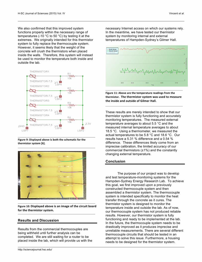
necessary Internet access on which our systems rely. In the meantime, we have tested our thermistor system by monitoring internal and external temperatures of Hampden-Sydney’s Gilmer Hall.
Figure 11: Above are the temperature readings from the thermistor. The thermistor system was used to measure the inside and outside of Gilmer Hall.
These results are merely intended to show that our thermistor system is fully functioning and accurately monitoring temperatures. The measured external temperature averages to about 5.5 °C and the measured internal temperature averages to about 18.5 °C. Using a thermometer, we measured the actual temperatures to be 5.8 °C and 18.6 °C. Our results have a 5.31 % difference and a 0.54 % difference. These differences likely come from an imprecise calibration, the limited accuracy of our commercial thermistors (±1%) and the constantly changing external temperature.
Conclusion
The purpose of our project was to develop and test temperature-monitoring systems for the Hampden-Sydney Energy Research Lab. To achieve this goal, we first improved upon a previously constructed thermocouple system and then assembled a thermistor system. The thermocouple system is intended specifically to monitor the heat transfer through the concrete as it cures. The thermistor system is designed to monitor the temperature inside and outside the lab. As of now, our thermocouple system has not produced reliable results. However, our thermistor system is fully functioning and ready to be implemented at the lab. In the future, the thermocouple system needs to be drastically improved as it produces imprecise and unreliable measurements. There are several different thermocouple circuits that should be tested in an attempt to solve this issue. Furthermore, a housing needs to be designed for the thermistor system.

H-SC Journal of Sciences (2015) Vol. IV Vincent et al.
http://sciencejournal.hsc.edu/
Lastly, it is desirable to pursue the possibility of wirelessly powering the circuit boards using radio waves. This relatively new technology would drastically improve our system, although further research is still needed.
References
[1] TF Forming Systems, <http://www.tfsystem.com/Home.aspx> (September 2014).
[2] Pensmore Foundation, <http://www.pensmore.org> (September 2014).
[3] “Type K Thermocouple,” Ohio University, 2012, <http://www.ohio.edu/people/bayless/seniorlab/thermocouple.pdf> (October 2014).
[4] "Using a Thermistor," Adafruit, 29 July 2012, <https://learn.adafruit.com/thermistor/using-a-thermistor> (October 2014).
[5] Keith Hawe. "Arduino Temperature Logger to MySQL," Keith's Blog, 13 June 2013, <http://khawe-mind-dump.blogspot.com/2013/06/arduino-temperature-logger-to-mysql.html> (September 2014).
[6] CadSoft Eagle Design Software, <http://www.cadsoftusa.com/> (October 2014).