are laser scanners replaceable by kinect sensors in ... laser scanners replaceable by kinect sensors...
TRANSCRIPT
Are laser scanners replaceable by Kinect sensors in roboticapplications?
Sebastian Zug, Felix Penzlin, Andre Dietrich, Tran Tuan Nguyen, Sven AlbertUniversitat Magdeburg
Department for Distributed SystemsUniversitatsplatz 2,39106 Magdeburg
Email: {zug, penzlin, dietrich}@ovgu.de{tran.nguyen,sven.albert}@st.ovgu.de
Abstract—Laser scanners are omnipresent in robotic applications.Their measurements are used in many scenarios for robust map building,localization, collision avoidance, etc. But regarding the required precisemeasurement and mechanical system a laser scanner is quite expensive.Hence the robotic community is looking for alternative sensors. Since2010 a new 3D sensor system – Microsoft Kinect [1] – developed forcomputer games is available and applied in robotic applications. Withan appropriate filter tool-chain its output can be mapped to a 2D laserscanner measurement. The reduced data set is ready to be processed bythe established algorithms and methods developed for laser scanners. Butwill the Kinect sensor replace laser scanners in robotic applications?
This paper compares the technical parameters of the new sensor withestablished laser scanners. Afterwards we investigate the possibilities andlimits of a Kinect for three common robotic applications – map building,localization and obstacle avoidance.
I. INTRODUCTION
Each robotic application requires a reliable perception of theenvironment. The effort increases with the complexity of the tasks. Ina well defined scenario without unexpected situations (encapsulatedindustrial manipulators) a limited sensor configuration guarantees acorrect and reliable behavior. An autonomously navigating systemwhich moves in complex (everyday) scenarios and interacts withhumans has to monitor much more aspects of the environment. Therelated tasks in service robot applications demand different sensorrequirements. For a collision avoidance a complete coverage of thearea around the robot is important. In contrast, many localizationalgorithms do not need a complete “panorama view” but depend onrepresentative number of samples. As a last example, the sensors ofa gripper have to provide a precise contour of the object that has tobe manipulated.
In many scenarios a laser scanner system can (partially) fulfillthese different perception needs. The combination of a distance sensor(mostly time-of-flight method) with an actuator (one to three degreesof freedom) allows to reproduce the environment in 2D, 21/2Dor 3D representations. The measurement distance ranges betweena few millimeters and 10 km for geodetic systems. A permanentimprovement of the sensor and the mechanical system allows anincreased measurement precision, resolution and scan frequency.Hence, some systems for 3D scans generate such a large amountof data – 800.000 points/sec – that an online processing is notpossible [2]. A detailed introduction into the functional principle oflaser scanners is given in [3].
In navigation scenarios with ground driven mobile platforms 2Dlaser scanners are commonly used. With the assumption of height-independent obstacles, these sensors provide all information to derivean appropriate geometric map of the environment that is ready forlocalization, trajectory planning and movement tasks. As describedin [4] a large number of algorithms and processing concepts for
filtering, map generation, localization or obstacle avoidance exist.Tab. I summarizes the technical properties of two popular scannertypes for robotic applications – the SICK LMS200 [5] and the URG-04LX-UG01 [6] manufactured by Hokuyo. Obviously, the SICK laserscanner provides a larger measurement range, precision and resolutionbut the benefits are bought dearly with a higher power consumptionand an extended geometric size. A detailed statistical analysis of themeasurement behavior is done by Ye and Borenstein [7] for a SICKLMS 200 and by Kneip et al. [8] for the Hokuyo sensor.
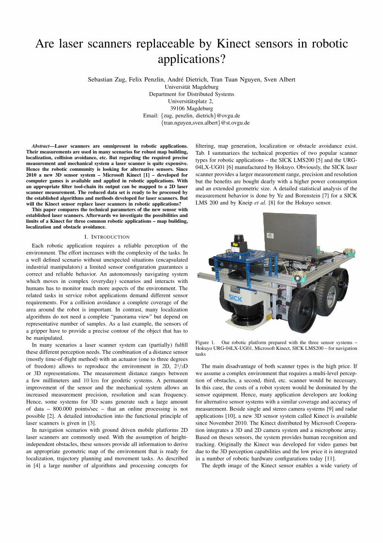
Figure 1. Our robotic platform prepared with the three sensor systems –Hokuyo URG-04LX-UG01, Microsoft Kinect, SICK LMS200 – for navigationtasks
The main disadvantage of both scanner types is the high price. Ifwe assume a complex environment that requires a multi-level percep-tion of obstacles, a second, third, etc. scanner would be necessary.In this case, the costs of a robot system would be dominated by thesensor equipment. Hence, many application developers are lookingfor alternative sensor systems with a similar coverage and accuracy ofmeasurement. Beside single and stereo camera systems [9] and radarapplications [10], a new 3D sensor system called Kinect is availablesince November 2010. The Kinect distributed by Microsoft Coopera-tion integrates a 3D and 2D camera system and a microphone array.Based on theses sensors, the system provides human recognition andtracking. Originally the Kinect was developed for video games butdue to the 3D perception capabilities and the low price it is integratedin a number of robotic hardware configurations today [11].
The depth image of the Kinect sensor enables a wide variety of

processing strategies for robot navigation in 2D or 3D. The applica-bility of navigation tasks based on 3D data sets is shown in differentpublications for the Kinect sensor [12, 13]. But the huge amount ofdata is reliant on a high performance computer for processing. TheKinect sensor generates a data stream of approximately 17.5 MB/s(640x480x2 Byte x30 fps). For instance, as described by Endres etal. [14] and similar by Henry et al. [15] none of the common used 3DSimultaneous Mapping and Localization (SLAM) algorithms is ableto follow the sample rate of the Kinect sensor (30 Hz). A navigationstack using a reduced data set can be implemented on an embeddedhardware without Graphics Processing Unit (GPU) support. Hence,in this paper we focus on a selective processing of Kinect’s output. Ifa single horizontal line is isolated from the measurement set, it canbe transformed into a laser scanner output. Following this approach,an expensive laser scanner can be replaced by a cheap 3D sensorsystem. Ideally, the applicability of the navigation algorithms tailoredfor laser scanners should not be affected by this replacement besidesome parameter adaptations.
The aim of this paper is a navigation task oriented comparison ofthe Kinect sensor with a common used laser scanner. We choose theHokuyo URG-04LX-UG01, with a similar range and measurementaccuracy for our investigation. A SICK LMS200 with a much betterperformance is additionally included as a reference. The completeexperimental setup that combines the three sensors on a mobileplatform is shown in Fig. 1.
A similar investigation is described in [16] but the focus is onthe spatial registration of construction sites. Rafibakhsh et al. argue,that the Kinect cannot take over the tasks of high-end terrestrial laserscanners. But they realize a high potential related to the low price, theincreased resolution and depth accuracy in multi-Kinect systems andthe possibility of an online modeling of the environment. The authorsof [17] describe an experimental setup for an evaluation of the angularand linear resolution of different sensors – Kinect, Hokuyo URG-04LX (more precise version of the URG-04LX-UG01) and AsusXtion. The sensors are oriented on a board with holes of differentsizes (2.5 mm-10 cm). The authors present a detailed analysis of thedetectability of a certain size related to the measurement distance andorientation.
The paper is organized as follows. The subsequent section ad-dresses the technical parameters of the Kinect sensor compares themwith the Hokuyo and SICK laser scanner. Beside we discuss possibledisturbances and interferences for both sensor types. Sec. IV investi-gates the behavior of the sensors in three typical robotic applications:Obstacle avoidance, map building and localization. Finally we wantto give an answer to the title question and describe future work.
II. TECHNICAL COMPARISON
A. Functional principle and main properties of the Kinect
The Kinect transmits an infrared pattern generated with a diffrac-tion grating and receives the reflections of the environment using anIR camera. A pseudo-stochastic distribution allows an assignment ofa subset of dots to a specific area. For performance reasons 3 differentlight densities are implemented. The highest level is reached by ninecalibration dots to provide a fast raw localization. The processingunit compares the position of the reflected dots on the baselinewith a reference pattern that was generated as a reference distanceand is stored in the memory of Kinect’s processor. For each dota 11 bit value is calculated. A “0” indicates an invalid or out ofrange measurement while all other values represent the correspondingdistances in a non-linear relation. Accordingly, the depth resolutionof the Kinect is varying between 0.25 cm (d =0.8 m) and 4.8 cm
(d =4 m). The minimum distance of 0.8 m is fix but a maximumrange is not implemented in the Kinect sensor. Different authorsrecommend to reject distance values larger than 3 m [18] or 4.6 m[19] due to the uncertainty level in the software. We will discuss aboutthe accuracy of Kinect measurements more detailed in followingparagraphs.
Tab. I compares the technical parameters of the Kinect sensor withthe two common used laser scanners. Obviously, the SICK laserscanner is in a different league compared to the Kinect and Hokuyosensors. It provides a significantly higher performance related torange and precision. Additionally, the SICK firmware allows aspecific adaptation of the sensor for a specific application (range,resolution, measurement angle, etc.). Neither the Kinect nor theHokuyo sensor provides such a detailed configurability. Hence, thissystem is not comparable directly with the Kinect sensor but itscapabilities are used as a reference for the following investigations.A detailed discussion of the SICK LMS200 is given by Ye andBorenstein [7].
A more suitable competitor for the Kinect is the HokuyoURG-04LX-UG01, a simplified and cheaper version of the URG-04LX [20]. This laser scanner has a maximum range and accuracycomparable to the Kinect sensor. One important difference is the sizeof the dead zones. The Kinect cannot differ infrared dots on closeobstacles due to blooming effects. Hence, the sensor is not able tomonitor the immediate environment of a robot. The new version ofthe Kinect – Kinect for Windows – reduces the dead zone by the halfwhile running in a special close area mode. In this case the resolutionand the maximum range are reduced.
Related to the different operation principle the laser scanner pro-vides a larger measurement angle. Like many laser scanner devices,the Hokuyo delivers its measurement in a polar coordinate system,with a constant angular resolution. In contrast, the output of theKinect sensor bases on a Cartesian system and depends on thedistance and deviation to the zero axis. It is noticeable that thenominal angular resolution of the Kinect is much smaller than thevalue of the Hokuyo sensor. Additionally, the distance resolution ofthe Kinect sensor is variable, too.
Table ICOMPARISON OF TECHNICAL PARAMETERS OF THE MICROSOFT KINECT,
HOKUYO URG-04LX AND SICK LMS200
SensorsKinect Hokuyo SICK
Maximum range [m] 3-6 4 8-80Dead range [m] 0.8/0.4 0.06 0.07Horizontal angle [◦] 57 240 100-180Distance resolution [mm] 2.5-48 1 1-10Angular resolution [◦] ≈ 0.097 0.3515 0.25-1Accuracy [mm] +/-6 +/-30
(1m) (1m)+/-130 +/-120 +/-10(4m) (4m) (10m)
Geometry [mm] 65x290x70 50x50x70 155x156x210Weight [kg] 0.55 0.16 4.5Power voltage [V] 12 5 24Power consumption [W] 5 4 30Refresh rate [Hz] 30 10 18-75Output data [kB/s] 18000 5.4 500Interfaces USB USB RS232,
RS422approx. costs $ 150 1000 5000
It is difficult to compare the accuracy of both sensors due tothe different fault models. The data sheet of the Hokuyo scanner

describes a constant error of +/-30 mm for distances smaller than1 m. For larger ranges a proportional offset of 3 % has to beconsidered. The capabilities of the Kinect related to the accuracy wereanalyzed in [18]. The author derives a polynomial relation betweenmeasurement distance and standard deviation of the depth result. Fora range of 400 cm, σK reaches 2.5 cm. If a normal distribution isassumed, each measurement is located in a window of +/-7.5 cm. Forreaching this noise level the user has to calibrate its Kinect sensor[18]. It is remarkable that for distances smaller than 1.5 m the Kinectprovides a higher accuracy than the laser scanner. If the object is outof this range the Hokuyo sensor generates the better results.
As shown in Tab. 1, the Kinect sensor is much larger than theHokuyo sensor. An additional challenge is the required power supplyvoltage of 12 V. The laser scanner operates with the power level ofa USB connection.
In comparisons, the SICK sensor needs a 6 times higher powersupply. But it outputs data in a significant higher frequency (usingthe lowest angular resolution). Accordingly, the output data rate ismuch higher for the SICK LMS200 scanner. Related to the 3Drepresentation the Kinect generates a data stream of 17.5 MB/s. Therequired performance for filtering and feature extraction limits itsapplicability in embedded devices. Consequently, the Kinect is muchcheaper than the Hokuyo sensor but cannot be integrated in a smallsize (8-Bit) application.
III. DISTURBANCES FOR KINECT MEASUREMENTS
Chiu et al. [21] and Khoshelham [18] list a number of disturbancetypes responsible for Kinect faults. We want to address the mostimportant in the following paragraphs.
A. Parallax Problem
Related to the displacement between infrared transmitter andcamera parts of the environment are “visible” for one of the interfacesonly. If the camera monitors a surface that cannot be reached by theinfrared pattern the Kinect produces a gap in the point cloud. Thesame result occurs in the contrary case if the dots are not in the lineof sight of the camera. The effect of the parallax problem is amplifiedby reflective surfaces.
The laser scanners described in this paper combine the transmitterand receiver component point symmetric. Due to the missing dis-placement a parallax problem cannot appear.
B. Obstacle material
In Chiu et al. [21] the authors examine different material propertiesthat make a correct depth measurement difficult. They define 3categories affecting the detectability and/or measurement accuracy.The first one is the surface color. We found out that a dark areadisturbs both sensor types. For the Hokuyo sensor the deviation canreach up to 2 cm. The effect on the Kinect is much smaller.
As expected, both sensors have large problems to perceive re-flective surfaces. Especially chrome-plated furniture legs are mostlyinvisible. The same was measurered for the last category, transparentmaterials made from glass or plastic. In both cases a redundant sensorwith a non-optical measurement principle is needed. Very detaileddiscussions about the effect of obstacle surfaces are described in [22,23].
C. External disturbances
Due to the operating principle of the Kinect sensor a correctmeasurement depends on the lighting conditions. If the transmittedinfrared pattern is superimposed by strong ambient light, the laserdots appear in low contrast and the camera reaches its saturation
level. Consequently, the noise level and the probability of outliersincreases significantly [18]. A similar effect occurs when a lightsource is shinning into the infrared camera itself. Hence, for outdoorrobotics the Kinect seems to be not suitable [19]. The integrated web-cam should be used to evaluate the lighting conditions in order tominimize this influence.
The data sheet of the Hokuyo laser scanner describes a similarbehaviour of the laser scanner. It emphasizes that this sensor is madefor indoor applications only [6].
D. Interference
The functional principle of the Kinect sensors results in interfer-ence between multiple sensors of this type. If the two infrared patternsare projected on the same area, the processing units cannot separateindividual points or are not able to assign them to the correct sensor.Obviously, the disturbance is most significant when both sensorsare assembled with a similar orientation. A partial overlapping oftwo sensors generates complex areas of incorrect measurements. Theeffect is determined by the geometrical relation of the sensors and bythe distance and orientation of the obstacles. The worst case occursif the calibration dots (the nine brighter ones) are in conflict.
The interference problem was investigated by Rafibakhsh et al. [16]in detail. At the end an angle of 35◦ is recommended between twoKinect sensors mounted on the same height in order to minimizeinterferences. Two approaches [24, 25] have been presented thatreduce the effect of interference by exploiting motion blur. Letsassume there is a first sensor looking at a plane in front of it. Thewhole sensor moves translationally in parallel to the plane. As theprojector and the camera are coupled and therefore perform the samemovement, the motion doesn’t effect the depth image. A secondsensor viewing the infrared pattern of the first sensor notices thatthe pattern is blurred by the motion of the first sensor. In general, theaccuracy suffers because instead of a translational motion, the motionblur is induced by vibration, but the degradation is negligible. Anothersolution to the problem is presented in [26]. Mechanical shutters infront of each sensor prevents interference. In a two sensor setup thecloud of one sensor is only updated when the other sensor returns atleast 90% zeros.
For redundant laser scanner systems interference phenomenas haveto be considered, too. If two SICK sensors are operating closetogether with a similar orientation, it is recommended to synchronizeboth sensors with a Master/Slave protocol [5]. With this configurationthe mirrors are maintained in a orientation displaced by 180◦ relativeto each other. More than two sensors are not supported. Hokuyorecommends to implement different mirror frequencies for multiplescanner scenarios.
IV. APPLICATION ORIENTED COMPARISON
Many robotic applications integrate laser scanners with three ele-mentary purposes: obstacle detection, map building and localization.Precondition of all scenarios is reliable and precise measurement ofthe environment, but with different focuses.
For the further experiments we transform the Kinect output intoa laser scanner measurement. A Point Cloud Filter implemented inROS extracts a single horizontal scan with a height of one dot.
A. Obstacle Detection for collision avoidance
One important aspect of the environment monitoring is the avoid-ance of collisions. The main challenge here is a complete coverageof all objects close to the robot. A non-observance of an obstacle canoccur due to two main reasons:

• An obstacle is overlooked because of the geometrical configu-ration of sensor’s monitoring area:
– In the simplest case the obstacle is not in range or angleof the sensor system. A scanner with a large opening anglehas an advantage here.
– If an object is tall compared to the sensor resolution, itcan probably not be detected. The sensor system has to beselected according to the environment conditions.
• The already mentioned measurement disturbances (total re-flections, transparent objects, etc.) make a correct perceptiondifficult and probably lead to danger situation.
For this section we compared the theoretical and practical resolutionof the Kinect and Hokuyo scanner. Afterwards, the detection capa-bilities were tested with different obstacle types.
The Hokuyo sensor shows due to its point symmetric operatingprinciple a constant angular resolution of 0.3515◦. The theoreticalgap between two ideal laser beams depends on the measurementdistance dm and can be calculated as visible in Fig. 2. Close to themaximum range the theoretical value of an invisible object is around2.4 cm. The Kinect emits a larger number (640) of measurement dotswith a smaller opening angle in horizontal direction. If a uniformdistribution of the measurement dots in x-direction is assumed, theangular resolution of 0.0974◦ can be calculated. Objects smaller than0.8 cm should not be perceived in a distance of 4 m. The Kinectsensor is superior from a theoretical viewpoint.
0 1 2 3 40
1
2
3
2 · tan(0.3515
2
)· dm
2 · tan(0.0974
2
)· dm
Object Distance in [m]
Invi
sibl
eO
bjec
tsi
ze[c
m] Hokuyo
Kinect
Figure 2. Theoretical size of invisible objects related to the angular resolutionfor different obstacle distances dm
As it will be shown, this theoretical model does not provide arealistic evaluation. We installed the Kinect in front of a wall withdifferent distances (100− 380 cm) and isolated a horizontal scan ofthe Kinect point cloud. Based on the number of measuements wedetermine the distribution of the distance between two neighboringdots. The minimum and maximum values are additionally depictedin Fig. 2 by error bars. The maximum value increases with largerdistance dm in a non-linear manner. For 380 cm there are gaps witha much larger size (up to 3.4 cm) than expected. Our investigation
outputs a distribution combining two aspects. Between 85 % and70 % are in a very small corridor close to the theoretical value.The other distance where distributed in a uniform manner betweenminimum and maximum values.
But for a statement about the detectability additional investigationsare necessary. We enhance the setup of the already mentioned workfrom Bernhard et al. [17] and evaluate the detection capabilities ofthe sensors with flat and round objects of different sizes. We preparea set of stripes and columns with a width/diameter from 0.5 cm to8 cm. The surfaces are covered by white paper.
Table IIOBJECT DETECTION CAPABILITIES DEPENDING ON THE OBJECT TYPE AND
SIZE
Obstactle distance dm [cm]30 100 200 300 380
minimum diameterof a column [cm]
Hokuyo 0.5 2.0 3.0 6.5 7.0Kinect - 1.0 2.0 2.5 3.0
minimum width ofa stripe [cm]
Hokuyo 0.5 2.0 3.0 6.0 7.0Kinect - 0.5 1.5 2.5 5.0
Tab. II lists the minimum object size that was detectable in a certaindistance dm to the sensor.
In a summary, the table shows two common results:• The Kinect sensor recognises obstacles larger than
0.5 cm/0.5 cm in a distance of 100 cm. The Hokuyoscanner guarantees a correct perception under this conditions.But due to the significant smaller minimum detection range itis able to detect such obstacles in distance of 30 cm.
• The Hokuyo laser scanner shows similar results for both objecttypes. The Kinect shows a more differentiated behaviour. Itsdetection capabilities depend on the opstacle shape and distance.
• The Kinect detects much smaller objects of both types. Itperceives both object types in case of a width/diameter largerthan 2 cm.
• The benefit of the Kinect correlates to the obstacle distance andincreases with higher ranges.
Based on the results of Tab. II the Kinect represents the bettercollision avoidance system. It detects smaller objects in a largerdistance. To overcome the large dead range the system should becombined with additional sensors.
High performance laser scanners offer a safety mode, whichimplies a beam conture in a way that all objects within the apexangle are detected [27]. The Hokuyo sensor does not provide thisfunction.
B. Map building
In a second scenario we investigate the map building capabilitiesof the three sensors. For this purpose we moved the robot systemdepicted in Fig. 1 in different office environments and record allsensor outputs as well as the odometry measurements. Afterwardsthe scans were merged using a Rao-Blackwellized particle filter tomerge the scans [28]. Fig. 3 shows the exemplary results for a singleroom. The occupancy grids (resolution = 2 cm) represent a part of ourlaboratory with a size of approximately 5 m x 5 m. In both figuresthe map generated based on the SICK measurements is added asreference.
As visible in Fig. 3(a), in a closed area the performance of theHokuyo sensor meets the capabilities of the SICK scanner. Only someoutliers and smaller displacements are significant. By comparing thegrids of the SICK and Kinect sensors in Fig. 3(b) three facts areremarkable:
1) The most obvious difference is the inhomogeneous distributionof the dots along the walls for the map based on Kinectmeasurements. This property is visible in Fig. 3(b) in the rightupper corner for instance. In contrast, the laser scanners gen-erate a uniform distance between neighboring measurements(Fig. 3(a)).
2) The higher accuracy of the Hokuyo sensor system providesa more precise map. Its maximum deviation from the SICKmeasurements is just 8.4 cm. The map generated out of theKinect data shows an maximum displacement of 25.2 cm.

max(∆e) = 8.4cm
std(∆e) = 1.3cm
Map basedon Hokuyo
Map basedon SICK
5m
5m
(a) Map build with the Hokuyo laser scanner
UnexploredArea
Map basedon SICK
Map basedon Kinect
max(∆e) = 25.2cm
std(∆e) = 7.0cm
(b) Map based on Kinect measurements
Figure 3. Comparison of occupancy grids generated with different sensors. The results of a SICK LMS200 were added as a reference with red dots.
3) The limited observation angle of the Kinect (57◦) – fourtimes smaller than for the Hokuyo sensor – increases the timeand movements necessary to generate a complete map of anenvironment. The two separate boxes in the center are not oronly partially detected.
Of course, the described example does not evaluate the capabilitiesof the Kinect in 2D scan matching and mapping. But the threementioned results are representative for all measurements we did.Especially for larger scenario setups than depicted in Fig. 3 the Kinectbased solution does not fulfill the requirements for SLAM application.
C. Localization
A challenging application for laser scanners on mobile platformsis self localization. Two common approaches to this problem areScan Matching [29] and Monte Carlo localization [30]. While scanmatching looks for a transformation of the actual laser scan that bestfits the map, for example by iterative closest point-algorithm, MonteCarlo localization uses particle filter. A large number of hypotheticalconfigurations is generated and based on the scan data a probabilityfor each configuration is computed. In first measurements the Hokuyolaser scanner has shown better results than the Kinect sensor. Asboth approaches heavily depend on the features of the scene, a widehorizontal scan angle is essential for a reliable localization. Regardingthe characteristics of the sensors shown in Tab. I the Hokuyo laserscanner is much superior to the Kinect senor in terms of scan angle.
V. CONCLUSION AND FUTURE WORK
The contribution of this paper can be divided in two parts.Firstly, we present a comprehensive summary of the fundamentaltechnical parameters Tab. I of the Kinect and comparable laserscanners. Generally it allows a fast evaluation of the applicabilityof a certain system related to geometrical, electrical, measurement,etc. properties. The second contribution addresses the replacementof laser scanners by a Kinect in robotic specific applications. Herewe assume the extraction of just a horizontal scan from the Kinectoutput to simulate a laser scanner. With this method the establishedalgorithms for laser scanners could be used.
The general question formulated in the title of this paper can beanswered with “No”. Laser scanner systems meet the requirementsof (robotic) scenarios more than a single Kinect. The most important
disadvantage of a Kinect sensor related to comparable laser scannersystems is the small monitoring angle. It limits the capabilities formapping and localization tasks significantly. In case of an obsta-cle detection application the Kinect is more reliable under certainconditions than the common used Hokuyo scanner. Related to thecosts, it can be argued that the cheaper Kinect needs a more powerfulprocessing platform than the more expensive laser scanner.
The future work of our group related to the Kinect sensor will befocused on the following goals:
• At the moment we use just one of the 480 lines of the Kinectoutput. Multiple measurements merged into one simulated laserscan should stabilize the output. The precondition for such anextension is a homogeneous environment in a certain verticalinterval. Adaptive filter strategies should provide a flexibledefinition of the scan height.
• The timing of the perception and processing were actuallyconsidered with regard to the sensor refresh-rate only. For anestimation of real-time capabilities the whole process includingtransmission and filtering has to be evaluated.
• With the Asus Xtion a further sensor with same physicalprinciple will be available. We will consider this device aswell as the Kinect version 2 announced for 2013 in furtherinvestigations. Additionally, we will enhance the selection ofsensors with stereo-camera systems.
ACKNOWLEDGMENT
This work has partially supported by the EU under the FP7-ICTprogramme, through project 288195 “Kernel-based ARchitecture forsafetY-critical cONtrol” (KARYON) and by the German Ministry ofEducation and research within the project ViERforES-II (grant no.01IM10002B).
REFERENCES
[1] Microsoft Cooperation, Kinect for Windows, Developers Web-site, Website, 2011. [Online]. Available: availableon\url{http://www.microsoft.com/en-us/kinectforwindows/}20.06.2012.
[2] S. Buckley, “Laser scanning for the environmental sciences,”The Photogrammetric Record, vol. 25, no. 129, pp. 84–85,2010.
[3] G. F. Marshall, Handbook of optical and laser scanning,2nd ed., ser. Optical Engineering. CRC Press, 2011, p. 792.

[4] D. Carmer and L. Peterson, “Laser radar in robotics,” Pro-ceedings of the IEEE, vol. 84, no. 2, pp. 299 –320, 1996.
[5] Sick AG, LMS200/211/221/291 Laser Measurement Systems -Data sheets, Website, 2011. [Online]. Available: availableon\url{https://www.mysick.com/saqqara/im0012759.pdf}2.02.2011.
[6] Hokuyo Automatic Cooperation, Hokuyo URG-04LX-UG01datasheet, available on http://www.hokuyo- aut.jp/02sensor/07scanner / download / data / URG - 04LX UG01 spec . pdf,20.06.2012.
[7] C. Ye and J. Borenstein, “Characterization of a 2d laserscanner for mobile robot obstacle negotiation,” in Robotics andAutomation, 2002. Proceedings. ICRA’02. IEEE InternationalConference on, IEEE, vol. 3, 2002, pp. 2512–2518.
[8] L. Kneip, F. Tache, G. Caprari, and R. Siegwart, “Characteriza-tion of the compact hokuyo urg-04lx 2d laser range scanner,” inRobotics and Automation, 2009. ICRA’09. IEEE InternationalConference on, IEEE, 2009, pp. 1447–1454.
[9] D. Kriegman, E. Triendl, and T. Binford, “Stereo visionand navigation in buildings for mobile robots,” Robotics andAutomation, IEEE Transactions on, vol. 5, no. 6, pp. 792–803,1989.
[10] D. An and H. Wang, “VPH: A new laser radar based obstacleavoidance method for intelligent mobile robots,” in IntelligentControl and Automation, 2004. WCICA 2004. Fifth WorldCongress on, IEEE, vol. 5, 2004, pp. 4681–4685.
[11] Willow Garage Inc., KTurtleBot Webpage, Website: http : / /www.willowgarage.com/turtlebot, 27.06.2012, 2005.
[12] S. Hochdorfer and C. Schlegel, “6 dof slam using a tofcamera: the challenge of a continuously growing number oflandmarks,” in Intelligent Robots and Systems (IROS), 2010IEEE/RSJ International Conference on, Oct. 2010, pp. 3981–3986.
[13] J. Weingarten and R. Siegwart, “Ekf-based 3d slam for struc-tured environment reconstruction,” in Intelligent Robots andSystems, 2005. (IROS 2005). 2005 IEEE/RSJ InternationalConference on, Aug. 2005, pp. 3834 –3839.
[14] F. Endres, J. Hess, N. Engelhard, J. Sturm, D. Cremers, andW. Burgard, “An evaluation of the RGB-D SLAM system,”in Proc. of the IEEE Int. Conf. on Robotics and Automation(ICRA), St. Paul, MA, USA, May 2012.
[15] P. Henry, M. Krainin, E. Herbst, X. Ren, and D. Fox, “RGB-D mapping: Using depth cameras for dense 3D modeling ofindoor environments,” in the 12th International Symposium onExperimental Robotics (ISER), New Delhi, India, Dec. 2010.
[16] N. Rafibakhsh, J. Gong, M. Siddiqui, C. Gordon, and H. Lee,“Analysis of xbox kinect sensor data for use on constructionsites: depth accuracy and sensor interference assessment,” inConstruction Research 2012, Congress on, May 2012.
[17] T. Bernhard, A. Chintalapally, and D. Zukowski, “A compara-tive study of structured light and laser range finding devices,”Correll Lab, Department of Computer Science, University ofColorado at Boulder, available on http://correll.cs.colorado.edu/wp-content/uploads/bernhard.pdf, May 2012.
[18] K. Khoshelham, “Accuracy analysis of kinect depth data,”in ISPRS Workshop Laser Scanning, International Society forPhotogrammetry and Remote Sensing, vol. 38, 2011, p. 1.
[19] M. Viager, “Analysis of Kinect for mobile robots,” availableon http : / / blog . mivia . dk / 2011 / 06 / my - kinect - datasheet/23.05.2012, Individual course report, Technical University ofDenmark (DTU), Kgs. Lyngby, Denmark, Mar. 2011.
[20] Hokuyo Automatic Cooperation, Hokuyo URG-04LXdatasheet, available on http : / / www . hokuyo - aut . jp /02sensor / 07scanner / download / data / URG - 04LX spec . pdf,20.06.2012.
[21] W.-C. Chiu, U. Blanke, and M. Fritz, “Improving the kinectby cross-modal stereo,” in Proceedings of the British MachineVision Conference, http://dx.doi.org/10.5244/C.25.116, BMVAPress, 2011, pp. 116.1–116.10.
[22] T. Voegtle, I. Schwab, and T. Landes, “Influences of differentmaterials on the measurements of a terrestrial laser scanner(tls),” in Proc. of the XXI Congress, The International Societyfor Photogrammetry and Remote Sensing, ISPRS2008, vol. 37,2008, pp. 1061–1066.
[23] W. Boehler, M. Bordas Vicent, and A. Marbs, “Investigat-ing laser scanner accuracy,” The International Archives ofPhotogrammetry, Remote Sensing and Spatial InformationSciences, vol. 34, no. Part 5, pp. 696–701, 2003.
[24] D. A. Butler, S. Izadi, O. Hilliges, D. Molyneaux, S. Hodges,and D. Kim, “Shake’n’sense: reducing interference for over-lapping structured light depth cameras,” in Proceedings of the2012 ACM annual conference on Human Factors in ComputingSystems, ser. CHI ’12, Austin, Texas, USA: ACM, 2012,pp. 1933–1936. [Online]. Available: http : / /doi .acm.org/10.1145/2208276.2208335.
[25] A. Maimone and H. Fuchs, “Reducing interference betweenmultiple structured light depth sensors using motion,” in Vir-tual Reality Workshops (VR), IEEE, 2012, pp. 51–54.
[26] J. Kramer, N. Burrus, F. Echtler, H. C. Daniel, and M. Parker,“Multiple kinects,” in Hacking the Kinect, Apress, 2012,pp. 207–246.
[27] A. Nuchter, 3D robotic mapping: the simultaneous localizationand mapping problem with six degrees of freedom, ser. Tractsin advanced Robotics. Springer Verlag, 2009, vol. 52.
[28] G. Grisetti, C. Stachniss, and W. Burgard, “Improved tech-niques for grid mapping with rao-blackwellized particle fil-ters,” Robotics, IEEE Transactions on, vol. 23, no. 1, pp. 34–46, 2007.
[29] F. Lu and E. Milios, “Robot pose estimation in unknown envi-ronments by matching 2d range scans,” J. Intell. Robotics Syst.,vol. 18, no. 3, pp. 249–275, Mar. 1997. [Online]. Available:http://dx.doi.org/10.1023/A:1007957421070.
[30] F. Dellaert, D. Fox, W. Burgard, and S. Thrun, “Montecarlo localization for mobile robots,” in IEEE InternationalConference on Robotics and Automation (ICRA99), 1999.