area lighting - chm industries lighting 682-286-0046 ph 682-286-0086 fx [email protected]
TRANSCRIPT


General
A steel pole must support the weight of the fixtures, mounting brackets and other equipment which will mount on it, and be able to withstand the effect of the maximum wind velocity. Poles will be selected based on the total EPA (Effective Projected Area) and weight each pole will hold in a given wind area. Before choosing a pole, total up the maximum EPA and the weight of all the fixtures, mounting brackets and other equipment you plan to mount on the structure. Maximum Expected Wind Velocities
Enclosed on the next page is the 50-year mean recurrence Isotach national wind velocity map, which is an aid in the selection of a pole with regard to its geographic location. Refer to the map to find the maximum expected wind condition for the area you will be installing the poles. Velocities recorded on the map are expected Isotach values and do not include the 1.3 gust factor. Poles are designed for maximum gust velocities 30% greater than the mile per hour (MPH) value given on the map. Please contact CHM Industries for areas where unusual wind conditions exist such as mountain areas, natural terrains acting as funnels, or hurricane regions. These areas may require the use of a greater Isotach value which is not shown on the map. Step-by-Step Instructions for Selecting Poles
1. Choose the specific quantity and type of fixture(s) you plan to use on each pole. 2. Pick the appropriate mounting brackets and accessories. 3. Calculate the system EPA by multiplying the fixture EPA by the quantity of fixtures. Then
add in the EPA of the mounting brackets. This will be your system EPA. 4. Calculate the system weight by multiplying the number of fixtures by the weight of each
fixture. Then add in the weight of the brackets and/or accessories. This will be your system weight.
5. Check the wind velocity map to find the MPH of the geographic region where the poles will be installed.
6. Once the system EPA and system weight have been determined, you can choose the required pole(s). Locate and determine on the steel pole chart the desired pole heights. Start with the lightest pole in each of the pole height sections and check your load requirements with the appropriate wind speed in your area. In the EPA capacity section, which denotes system EPA’s and system weights in the different wind speed areas, be sure the total weight and EPA of the lighting equipment does not exceed the maximum. Listed will be the appropriate catalog number for ordering. At the end of the catalog number indicate the finish: (G) for galvanizing and (PC) for powder coat (specify color).
7. If you are adding any options or accessories, add the indicated letter(s) to the end of the listed catalog number.
These ordering methods are guidelines only. CHM Industries takes no responsibility for the system design and recommends you consult a qualified professional for verification when purchasing any material from this catalog.
ORD
ERING
GU
IDELIN
ESORDERING GUIDELINES

WIN
D V
ELOC
ITY MA
PNATIONAL WIND VELOCITY MAP
NOTES:
1. This map shows the maximum steady wind expected within a 50 year period of recurrence at an elevation of 30 feet above the ground.
2. Caution is advised in using wind velocity contours in special wind areas such as mountainous areas and areas around the Great Lakes.
3. Hawaii has a 80 mph wind velocity. 4. Puerto Rico has a 95 mph wind velocity. 5. This map is intended as a general guide. Check your
local area for unique wind conditions.

Pole Shaft
The pole shaft is a one section design fabricated from standard 11 gauge (0.1196”) or 7 gauge (0.1793”) steel. The pole shaft is fabricated from high strength, low alloy steel conforming to ASTM A-595, with a minimum yield strength of 55,000psi. Each pole has a full-length longitudinal weld and is cylindrical in cross-section having a uniform taper rate of 0.14” of diameter change per foot of length. Base Plate
The base plate is fabricated from a structural quality, hot rolled carbon steel plate that meets or exceeds ASTM A-572 with a minimum yield strength of 42,000psi. The base plate telescopes the pole shaft and is circumferential welded top and bottom. The base plate has slotted bolt holes for a 1/2” variation in the anchor bolt setting. Full Base Cover
A full base cover is standard for all poles. The cover is fabricated from Galvaneal Steel and finished to match the pole. It is a two piece design, with anti-lift tabs, secured together with two rivets. Hand Hole
A 3” x 5” hand hole, hand hole cover, attaching hardware, and ground lug comes standard on all poles unless otherwise specified. The oval reinforced hand hole, having a nominal 3” x 5” x 3/16” wall will be installed 18” above the base plate. A ground lug will be welded either on the hand hole frame or on the inside of the pole depending on the design. Anchor Bolts
Anchor bolts are fabricated from a commercial quality hot rolled carbon steel bar that meets or exceeds minimum yield strength of 55,000psi. Anchor bolts are sized according to each pole design and are furnished with 2 galvanized hex nuts and 2 galvanized flat washers. Anchor bolts for galvanized steel poles shall be fully galvanized to ASTM A-153. Anchor bolts will ship with the poles unless otherwise noted. Pole Top
Each pole will be provided with either a removable pole cap or 2 3/8” OD x 5” tenon top (other size tenons are available). The pole top assembly is determined by the type of brackets and/or fixtures to be supplied on each pole. Design
The selection of the correct pole design is predicated by the specific loading requirements of each application. The poles located in the steel pole charts are designed to withstand dead loads and theoretical dynamic loads developed by sustained winds of 80mph through 100mph time the 1.3 gust factor (Commercial Grade Design Criteria). Effective Projected Area (EPA) is the actual adjusted projected area of the fixtures and mounting equipment taking into account the appropriate shape factor to result in an area having a coefficient of drag equal to unity (1.0). The combined EPA and weight of the luminaire, light support brackets, platforms and any other attachments cannot exceed the rated EPA or allowable weight on that pole. Finish
Standard finishes available are galvanized and powder coat. Reference the “Standard Finishes” section for more information on these applications and a list of available colors.
STEEL P
OLES
ROUND TAPERED STEEL POLE SPECIFICATIONS

ROUND TAPERED
STEEL POLE STRUCTURE DATA
Pole Shaft Data Base Plate Data Anchor Bolt Data Nominal Mounting
Height (ft)
Catalog Number
Wall Thickness
(in)
Base O.D. (in)
Top O.D. (in)
Bolt Circle (in)
Width (in)
Thk (in)
Dia x Lgth x Hk
(in) Anchor Bolt Template
Gross Weight (lbs)
20 RT1-200-066-16A 0.1196 6.6 3.8 10.0 13.0 0.75 1.0 x 36 x 4 BCT-04-100-1000 171
25 RT1-250-066-16A 0.1196 6.6 3.1 10.0 13.0 0.75 1.0 x 36 x 4 BCT-04-100-1000 193
30
RT1-300-066-16A RT1-300-075-16A RT1-300-080-16A RT1-300-080-17A
0.1196 0.1196 0.1196 0.1793
6.6 7.5 8.0 8.0
2.4 3.3 3.8 3.8
10.0 11.0 11.5 12.0
13.0 14.0 14.5 15.5
0.75 0.75 0.75 1.0
1.0 x 36 x 4 1.0 x 36 x 4 1.0 x 36 x 4
1.25 x 42 x 6
BCT-04-100-1000 BCT-04-100-1100 BCT-04-100-1150 BCT-04-125-1200
211 252 272 406
35 RT1-350-080-16A RT1-350-090-16A RT1-350-090-17A
0.1196 0.1196 0.1793
8.0 9.0 9.0
3.1 4.1 4.1
11.5 12.5 13.5
14.5 15.5 17.0
0.75 0.75 1.0
1.0 x 36 x 4 1.0 x 36 x 4
1.25 x 42 x 6
BCT-04-100-1150 BCT-04-100-1250 BCT-04-125-1350
298 350 521
39 RT1-390-080-16A RT1-390-090-16A RT1-390-090-17A
0.1196 0.1196 0.1793
8.0 9.0 9.0
2.6 3.6 3.6
11.5 12.5 13.5
14.5 15.5 17.0
0.75 0.75 1.0
1.0 x 36 x 4 1.0 x 36 x 4
1.25 x 42 x 6
BCT-04-100-1150 BCT-04-100-1250 BCT-04-125-1350
312 370 544
NOTE: Gross Weight is a nominal value which includes the pole shaft and base plate only.
ROUND TAPERED STEEL POLE LOADING CAPAC IT I ES
80 MPH
w/1.3 Gust 90 MPH
w/1.3 Gust 100 MPH
w/1.3 Gust Nominal Mounting
Height (ft)
Catalog Number Max
EPA (ft2)
Max Weight (lbs)
Max EPA (ft2)
Max Weight (lbs)
Max EPA (ft2)
Max Weight (lbs)
20 RT1-200-066-16A 23.3 583 17.5 438 13.3 333
25 RT1-250-066-16A 16.3 408 12 300 8.8 220
30
RT1-300-066-16A RT1-300-075-16A RT1-300-080-16A RT1-300-080-17A
11.8 16.1 18.7 37.6
294 403 468 940
8.5 11.6 13.5 28.8
213 289 338 720
5.9 8.2 9.5 22.2
149 204 238 555
35 RT1-350-080-16A RT1-350-090-16A RT1-350-090-17A
14.1 20.6 40.0
353 515
1000
9.8 15.8 31.8
244 395 795
6.5 12.4 25.8
163 310 645
39 RT1-390-080-16A RT1-390-090-16A RT1-390-090-17A
11.4 15.0 31.8
286 375 795
7.6 10.1 24.4
190 253 610
4.8 6.4 18.3
120 160 458
NOTE: Maximum EPA and Weight values are calculated based on top mounted fixtures having the center of the load located 2’ above nominal mounting height.
STEEL P
OLES

STEEL P
OLES

Pole Shaft
The pole shaft is fabricated from weldable grade carbon steel structural tubing which has uniform wall thickness of 11 gauge (0.1196”) or 7 gauge (0.1793”). The pole shaft material conforms to ASTM A-500 Grade B with minimum yield strength of 42,000psi. Each section is one-piece construction with a full-length longitudinal weld and is uniformly square in cross-section with flat sides, small corner radii and excellent torsional properties. Base Plate
The base plate is fabricated from a structural quality hot rolled carbon steel plate that meets or exceeds ASTM A-572 with a minimum yield strength of 42,000psi. The base plate telescopes the pole shaft and is circumferential welded top and bottom. The base plate has slotted bolt holes for a 1/2” variation in the anchor bolt setting. Full Base Cover
A full base cover is standard for all poles. The cover is fabricated from Galvaneal Steel and finished to match the pole. It is a two piece cover, with anti-lift tabs, secured together with two rivets. Hand Hole
A 3” x 5” hand hole, hand hole cover, attaching hardware, and ground lug comes standard on all poles unless otherwise specified. The oval reinforced hand hole, having a nominal 3” x 5” x 0.237” wall, will be installed 18” above the base plate. A ground lug will be welded either on the hand hole frame or on the inside of the pole depending on the design. Anchor Bolts
Anchor bolts are fabricated from a commercial quality, hot rolled carbon steel bar that meets or exceeds minimum yield strength of 55,000psi. Anchor bolts are sized according to each pole design and are furnished with 2 galvanized hex nuts and 2 galvanized flat washers. Anchor bolts for galvanized steel poles shall be fully galvanized to ASTM A-153. Anchor bolts will ship with the poles unless otherwise noted. Pole Top
Each pole assembly is provided with either a 2 3/8” OD x 5” tenon (other size tenons are available) or a removable pole cap. The pole top assembly is determined by the type of brackets and/or fixtures to be supplied on each pole. Design
The selection of the correct pole design is predicated by the specific loading requirements of each application. The poles located in the steel pole charts are designed to withstand dead loads and theoretical dynamic loads developed by sustained winds of 80mph through 100mph times the 1.3 gust factor (Commercial Grade Design Criteria). Effective Projected Area (EPA) is the actual adjusted projected area of the fixtures and mounting equipment taking into account the appropriate shape factor to result in an area having a coefficient of drag equal to unity (1.0). The combined EPA and weight of the luminaire, light support brackets, platforms and any other attachments cannot exceed the rated EPA or allowable weight on that pole. Finish
Standard finishes available are galvanized and powder coat. Reference the “Standard Finishes” section for more information on these applications and a list of available colors.
STEEL P
OLES
SQUARE NON-TAPERED STEEL POLE SPECIFICATIONS

SQUARE NON-TAPERED STEEL POLE STRUCTURE DATA
Pole Shaft Data Base Plate Data Anchor Bolt Data
Nominal Mounting
Height (ft)
Catalog Number
Wall Thickness
(in)
Base O.D. (in)
Top O.D. (in)
Bolt
Circle (in)
Width (in)
Thk (in)
Dia x Lgth x Hk
(in) Anchor Bolt Template
Gross Weight (lbs)
10 SNT1-100-040-16A 0.1196 4 4 8.5 11.0 0.75 0.75 x 30 x 3 BCT-04-075-0850 92
12 SNT1-120-040-16A 0.1196 4 4 8.5 11.0 0.75 0.75 x 30 x 3 BCT-04-075-0850 105
14 SNT1-140-040-16A 0.1196 4 4 8.5 11.0 0.75 0.75 x 30 x 3 BCT-04-075-0850 118
16 SNT1-160-040-16A 0.1196 4 4 8.5 11.0 0.75 0.75 x 30 x 3 BCT-04-075-0850 131
18 SNT1-180-040-16A 0.1196 4 4 8.5 11.0 0.75 0.75 x 30 x 3 BCT-04-075-0850 144
20
SNT1-200-040-16A SNT1-200-040-17A SNT1-200-050-16A SNT1-200-050-17A
0.1196 0.1793 0.1196 0.1793
4 4 5 5
4 4 5 5
8.5 8.5
10.0 10.5
11.0 11.0 12.5 13.5
0.75 0.75 0.75 1.0
0.75 x 30 x 3 0.75 x 30 x 3 0.75 x 30 x 3 1.0 x 36 x 4
BCT-04-075-0850 BCT-04-075-0850 BCT-04-075-1000 BCT-04-100-1050
157 217 198 293
25
SNT1-250-040-16A SNT1-250-040-17A SNT1-250-050-16A SNT1-250-050-17A
0.1196 0.1793 0.1196 0.1793
4 4 5 5
4 4 5 5
8.5 8.5
10.0 10.5
11.0 11.0 12.5 13.5
0.75 0.75 0.75 1.0
0.75 x 30 x 3 0.75 x 30 x 3 0.75 x 30 x 3 1.0 x 36 x 4
BCT-04-075-0850 BCT-04-075-0850 BCT-04-075-1000 BCT-04-100-1050
190 265 239 354
30
SNT1-300-040-17A SNT1-300-050-16A SNT1-300-050-17A SNT1-300-060-16A SNT1-300-060-17A
0.1793 0.1196 0.1793 0.1196 0.1793
4 5 5 6 6
4 5 5 6 6
8.5 10.0 10.5 10.5 11.0
11.0 12.5 13.5 13.5 14.0
0.75 0.75 1.0 1.0 1.0
0.75 x 30 x 3 0.75 x 30 x 3 1.0 x 36 x 4 1.0 x 36 x 4 1.0 x 36 x 4
BCT-04-075-0850 BCT-04-075-1000 BCT-04-100-1050 BCT-04-100-1050 BCT-04-100-1100
313 280 414 350 493
35 SNT1-350-050-17A SNT1-350-060-17A
0.1793 0.1793
5 6
5 6
10.5 11.0
13.5 14.0
1.0 1.0
1.0 x 36 x 4 1.0 x 36 x 4
BCT-04-100-1050 BCT-04-100-1100
474 566
39 SNT1-390-060-17A 0.1793 6 6 11.0 14.0 1.0 1.0 x 36 x 4 BCT-04-100-1100 624
NOTE: Gross Weight is a nominal value which includes the pole shaft and base plate only.
SQUARE NON-TAPERED STEEL POLE LOADING CAPAC IT I ES
80 MPH
w/1.3 Gust 90 MPH
w/1.3 Gust 100 MPH
w/1.3 Gust Nominal Mounting
Height (ft)
Catalog Number Max
EPA (ft2)
Max Weight (lbs)
Max EPA (ft2)
Max Weight (lbs)
Max EPA (ft2)
Max Weight (lbs)
10 SNT1-100-040-16A 27.4 686 21.1 528 16.6 415
12 SNT1-120-040-16A 21.7 542 16.5 413 12.7 318
14 SNT1-140-040-16A 17.4 434 13 325 9.8 245
16 SNT1-160-040-16A 14.0 350 10.2 255 7.5 188
18 SNT1-180-040-16A 11.3 283 8.1 201 5.6 140
20
SNT1-200-040-16A SNT1-200-040-17A SNT1-200-050-16A SNT1-200-050-17A
9.1 15.3 16.5 26.8
228 383 411 670
6.2 11.2 11.7 20.0
155 279 293 500
4.0 8.1 8.3 15.1
100 203 208 378
25
SNT1-250-040-16A SNT1-250-040-17A SNT1-250-050-16A SNT1-250-050-17A
4.9 9.7 10.0 18.1
123 243 250 453
2.6 6.5 6.4 12.9
66 161 160 321
1.0 4.1 3.7 8.9
25 103 93 224
30
SNT1-300-040-17A SNT1-300-050-16A SNT1-300-050-17A SNT1-300-060-16A SNT1-300-060-17A
5.7 5.5 12.0 8.3 20.3
143 138 300 208
5066
3.0 2.5 7.7 4.3 13.9
76 63 193 108 348
1.2 0.3 4.6 1.4 9.3
29 8
114 36 233
35 SNT1-350-050-17A SNT1-350-060-17A
7.3 13.7
183 343
3.8 8.4
95 210
1.2 4.6
29 114
39 SNT1-390-060-17A 9.5 238 4.9 123 1.5 36
NOTE: Maximum EPA and Weight values are calculated based on top mounted fixtures having the center of the load located 2’ above nominal mounting height.
STEEL P
OLES

STEEL P
OLES

Catalog Number Description
4UP1-19 48" (1) arm upsweep 4UP1-28 48" (2) arm upsweep at 180° 4UP1-32 48" (3) arm upsweep at 120° 4UP1-49 48" (4) arm upsweep at 90° 6UP1-19 72" (1) arm upsweep 6UP1-28 72" (2) arm upsweep at 180° 6UP1-32 72" (3) arm upsweep at 120° 8UP1-19 96" (1) arm upsweep 8UP1-28 96" (2) arm upsweep at 180° 10UP1-19 120" (1) arm upsweep
Note: 36” standard rise for all upsweep arms, unless otherwise requested.
STEEL B
RAC
KETS
UPSWEEP ARMS

Catalog Number Description
RBH1-28 24" (2) bullhorn at 180° with tenon mount RBH1-38 30” (3) bullhorn at 180° with tenon mount RBH1-29 24" (2) bullhorn at 90° with tenon mount RBH1-32 24" (3) bullhorn at 120° with tenon mount RBH1-39 24" (3) bullhorn at 90° with tenon mount RBH1-42 24" (3) bullhorn at 120°, (1) center with tenon mount RBH1-48 45" (4) bullhorn at 180° with tenon mount RBH1-49 24" (4) bullhorn at 90° with tenon mount RBH1-58 60" (5) bullhorn at 180° with tenon mount RBH1-59 24" (4) bullhorn at 90°, (1) center with tenon mount RBS1-19 18" (1) bullhorn with side mount RBS1-20 45" (2) bullhorn at 180° with side mount
STEEL B
RAC
KETS
BULLHORNS

Catalog Number Description
RSA1-19 18" (1) spoke arm with tenon mount RSA1-28 18" (2) spoke arm at 180° with tenon mount RSA1-29 24" (2) spoke arm at 90° with tenon mount RSA1-32 18" (3) spoke arm at 120° with tenon mount RSA1-39 24" (3) spoke arm at 90° with tenon mount RSA1-42 18" (3) spoke arm at 120°, (1) center with tenon mount RSA1-49 24" (4) spoke arm at 90° with tenon mount RSA1-59 24" (4) spoke arm at 90°, (1) center with tenon mount
STEEL B
RAC
KETS
SPOKE ARMS
STA
ND
ARD
FIN
ISHES
GALVANIZING
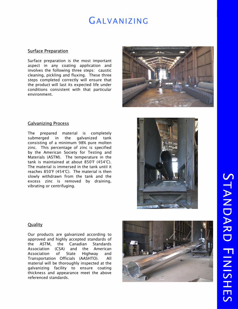
Surface Preparation Surface preparation is the most important aspect in any coating application and involves the following three steps: caustic cleaning, pickling and fluxing. These three steps completed correctly will ensure that the product will last its expected life under conditions consistent with that particular environment. Galvanizing Process The prepared material is completely submerged in the galvanized tank consisting of a minimum 98% pure molten zinc. This percentage of zinc is specified by the American Society for Testing and Materials (ASTM). The temperature in the tank is maintained at about 850°F (454°C). The material is immersed in the tank until it reaches 850°F (454°C). The material is then slowly withdrawn from the tank and the excess zinc is removed by draining, vibrating or centrifuging. Quality Our products are galvanized according to approved and highly accepted standards of the ASTM, the Canadian Standards Association (CSA) and the American Association of State Highway and Transportation Officials (AASHTO). All material will be thoroughly inspected at the galvanizing facility to ensure coating thickness and appearance meet the above referenced standards.

Black
White
Silver
Gray
Platinum
Bronze
STA
ND
ARD
FIN
ISHES
POWDER COAT FINISH
Surface Preparation Prior to beginning the powder coat process, each shaft section is completely cleaned using a system called steel shot blasting. Steel shot blasting is the process by which each section is sent through a wheelabrator. The wheelabrator provides a massive blasting of No. 280 steel shot directed at the surface to be cleaned. This process meets the Steel Structures Painting Council Surface Preparation Specification No. 6 (SSPC-SP6). Powder Coat Application Electrostatic spraying is the most common method for applying powder. The powder is fed pneumatically from a reservoir to a spray gun where a low amperage, high voltage charge is imparted to the particles. The parts to be coated are grounded so the charged particle will seek the oppositely-charged metal surface. This method will produce a uniform, monolithic, fusion-bonded finish. The powder coated steel parts will then go through an oven where the resins, pigments and other reactive agents cross link to produce a high molecular weight binder system, resulting in a tough durable coating. Quality Powder coating was developed for outstanding weather ability, toughness and architectural aesthetics. The high molecular weight of powder coatingprovides better corrosion, impact, chip and scratch resistance versus using the brush on paint method. CHM Industries will provide a protective foam wrap on each pole section to protect the surface during the shipping process.
The colors above are ONLY shown to give the viewer an overview of the color selections available. Due to variances in computer monitors, video cards and color printers, the actual colors may vary and these files
should not be used to make your final selection. Please contact CHM Industries to request an actual powder coated metal sample.
Dark Bronze

The following terms and conditions apply to all equipment, goods, components, and services (hereafter “Products”) provided by CHM Industries, Inc. d/b/a Keystone Industries, Carolina High Mast, or CHM Sports Lighting (“CHM”). Acceptance of this order by CHM is expressly conditioned upon these terms and conditions and those included in the Limited Warranty, and Purchaser agrees that such terms and conditions and Limited Warranty are the basis of the bargain of the parties and the pricing of the Products. If these terms and conditions differ in any way from Purchaser’s order or if transmission of these terms and conditions to Purchaser constitutes or is construed as an acceptance of Purchaser’s order, then additional or different terms or conditions set forth in Purchaser’s purchase order or similar communication are objected to and will not be binding upon CHM unless specifically assented to in writing by an officer of CHM. In any event, Purchaser’s acceptance of the ordered Products shall constitute and manifest Purchaser’s assent to these terms and conditions.
1. P R I C E S A N D T E R M S : All prices by CHM are payable and due in U.S. Dollar. Prices do not include any present or future sales, excise, value-added or any taxes and, where applicable such items shall be billed separately and paid by Purchaser. Prices also do not include services relating to installation instruction or assistance, or any other services, unless separately quoted.
2. Q U O T A T I O N S : Prices are subject to receipt and acceptance of order within 30
days of the price quotation by CHM.
3. T E R M S O F P A Y M E N T : Unless otherwise agreed in a writing signed by CHM, Purchaser shall pay in full the amount of each invoice, within 30 days from the date of the invoice, at CHM’s principal office or such other location as CHM may specify. If payment is not made when due, Purchaser agrees to pay to CHM interest on the amount past due until paid at the rate of 1.5% per month (18% per annum) or the maximum lawful rate, whichever is less. Nothing herein shall be deemed to extend or otherwise modify Purchaser’s obligation to make payment when due.
4. C O N S T R U C T I O N : Regardless of whether CHM has been provided copies of or
access to plans, specifications, or other construction documents, CHM does not warrant or guarantee that its Products meet any terms of such documents. Unless specifically provided by CHM is a separate, written performance warranty, CHM does not verify, warrant, or guarantee compliance with design documents or specifications. If Purchaser wishes CHM to arrange for installation of Products, Purchaser will enter a separate construction agreement with CHM. CHM has no obligation to coordinate the manufacture, shipment, delivery, or installation of Products with any third-party providing work for constructions activities.
TERM
S AN
D C
ON
DITIO
NS
CHM INDUSTRIES, INC. STANDARD TERMS AND CONDITIONS

5. S E C U R I T Y I N T E R E S T : Purchaser hereby grants CHM a purchase money security interest in the Products and any proceeds thereof to secure Purchaser’s obligation to pay the full price of the Products. Such security interest shall terminate upon payment in full by Purchaser of such price. Purchaser shall execute such further documents, financing statements, and other instruments as may be requested by CHM to perfect such security interest, and Purchaser authorizes CHM to file a financing statement or a copy of these Terms and Conditions to perfect the security interest granted hereby.
6. CREDIT HOLD, C.O.C. AND PURCHASES: CHM reserves the right to place Purchaser on
credit hold when any invoice has not been paid in full 45 days after the invoice date. The credit hold will apply to existing and pending shipments and to all affiliates of Purchaser. CHM, may in its sole discretion, require that the purchase and future purchases be made on a prepaid or C.O.D. basis.
7. COSTS: If CHM is required to retain an attorney to collect balances due under this sale,
or is required to defend claims brought against it by Purchaser arising out of this sale, Purchaser shall indemnify and hold harmless CHM for all cost incurred in collecting balances due or defending such claims, including but not limited to the fee of any collection agency, reasonable attorney’s fees, and other expenses.
8. FREIGHT: All sales are priced F.O.B. destination, except that anchor bolts and
templates will be shipped at the expense of, with shipping invoiced to, Purchaser. Any reconsignment, redelivery, or storage expenses shall be the responsibility of Purchaser.
9. ROUTING, HANDLING AND STORAGE: Routing will be determined by CHM, with delivery
to the common carrier delivery point nearest to destination. Handling, unloading, storage, extra labor or mechanical facilities, and movement from the shipping destination to Purchaser’s job site required in connection therewith will be the responsibility of Purchaser.
10. TITLE, RISK OF LOSS, ACCEPTANCE, PERFORMANCE: In all cases, title to the Products
(other than anchor bolts and templates) shall pass upon delivery at destination and thereafter all risk of loss or damage shall be upon Purchaser. Title to anchor bolts and templates shall pass on delivery to the carrier. Purchaser agrees to reasonably inspect the Products within 10 days of delivery. The Products shall be accepted by Purchaser by an authorized and qualified representative after inspection at the delivery point. Purchaser agrees to accept or reject the Products in accordance with these Terms and Conditions within 10 days after the delivery date. If the Products are not in conformance with these Terms and Conditions, Purchaser shall give written notice to CHM of any claim to that effect setting forth in reasonable detail the manner in which the Products do not conform. If Purchaser retains the Products after their delivery without giving CHM such notice as required within 10 days after delivery, such failure shall constitute an irrevocable acceptance of the products by Purchaser except with the respect to defects not reasonably discoverable by such inspection. Purchaser’s sole remedy for any defects or nonconformance shall be in accordance with CHM’s written limited warranty provided to Purchaser.
TERM
S AN
D C
ON
DITIO
NS
TERM
S AN
D C
ON
DITIO
NS
If Purchaser believes that the performance or Products of CHM are defective or do not conform to this contract or other obligations, Purchaser will promptly notify CHM in writing. CHM shall be entitled to remedy any defect or non-conformance, and Purchaser shall not be entitled to withhold payment if CHM remedies the defect or non-conformance. If any defect or non-conformance poses an imminent risk of damage to life or property, Purchaser may take reasonable steps to protect life or property and shall immediately notify CHM of the situation and request immediate corrective action.
11. DELIVERY: Factory shipping dates given in advance of actual shipment are estimates by CHM and shall not be deemed to represent fixed or guaranteed shipping dates. CHM shall not be liable for a delay in deliveries. In addition to any other right which CHM may have hereunder or at law, CHM may suspend shipment of any products for which CHM has not already received payment whenever Buyer is in default under this or any other contract between CHM and Buyer. CHM shall never be liable for damages caused by any delays in delivery or Products.
12. JOB SITE VISIT TERMS: Job site visits by CHM personnel to assist with installation must be pre-arranged with CHM a minimum of two weeks in advance, if the job site is within the continental United States, or a minimum of 30 days in advance, if the job site is outside the continental United States. Purchaser will receive a written confirmation of the scheduled visit once travel arrangements have been secured and purchased by CHM. Cost of job site visits will be separately invoiced to Purchaser. If Purchaser changes the job visitation itinerary after confirmation, any additional expenses incurred by CHM due to the change will be the responsibility of, and invoiced to, Purchaser. Job site visits pursuant to this paragraph shall not create or increase any rights of purchaser beyond those expressly set forth herein. CHM is not responsible for the means or methods of any installation of its Products nor is it responsible for site safety or coordination of work activities.
13. CLAIM FOR SHORTAGES: Purchaser must present any claim for shortages in Products
provided by CHM (that are not confirmed by CHM’s shipment records) in writing to CHM within 10 days of receipt of a shipment at the designated destination. Failure to provide such notice shall be a waiver of any right to seek recovery.
14. RETURNED PRODUCTS: Specific written request must be made in advance by Purchaser
to obtain credit or replacement on Products returned, and return of Products will be the sole discretion of CHM and only upon prior written notice to Purchaser from an officer of CHM. On Products accepted for return, Purchaser must pre-pay return shipment and pay minimum restocking charge of 65% of the invoice price plus any charges necessary to rework products to a re-sellable condition. Custom fabricated Products are not subject to return.
15. CANCELLATION OR POSTPONEMENT: Written consent of CHM must be obtained prior to
a cancellation of any order. Cancellation of an order with consent of CHM will subject Purchaser to a cancellation charge based upon expenses already incurred and commitments made by CHM. If Purchaser postpones the shipment of any order more than 120 days, CHM will be entitled to adjust the price for its product as a result of any costs incurred or to reflect current market prices.
TERM
S AN
D C
ON
DITIO
NS

16. ASSIGNMENT: The delegation or assignment by Purchaser of any or all of its duties or
rights hereunder without the prior written consent of CHM shall be void.
17. CHANGES AND SERVICES: CHM reserves the right to change any feature of its published specifications without notice for any reason within CHM’s discretion. Any advice, technical assistance, or recommendations regarding its Products, provided by CHM is provided without warranty or guaranty.
18. GENERAL: No representation, affirmation of fact, course of dealing, promise or
condition in connection therewith or usage of trade not incorporated herein or in CHM’s written warranty, shall be binding upon CHM. This written contract is intended as the final expression of the contract of the parties and parol or extrinsic evidence is inadmissible to explain, vary, or contradict the express terms of this contract. No waiver, alteration, or modification of any of the provisions hereof shall be binding upon CHM unless specifically assented to in writing by an officer of CHM. The contract of the sale of goods between CHM and Purchaser shall be performed in Tarrant County, Texas. The validity, performance, and all matters relating to the interpretation and effect hereof and any amendment hereto shall be governed by the laws of the State of Texas.
19. RESOLVING DISPUTES: Any controversy or claim arising out of or relating to this
contract, or the breach thereof, shall be settled by arbitration administered by the American Arbitration Association under is Construction Industry Arbitration Rules, taking place in Tarrant County, Texas. Judgment on the award rendered by the arbitrator(s) may be entered in any court having jurisdiction thereof. The parties also expressly agree that they will cooperate in the exchange of documents and lists of witnesses (including any experts) before the arbitration as well as interviewing or deposition of witnesses. The prevailing party in any arbitration shall be entitled to recovery of its reasonable expenses from the other party incurred in enforcing these Terms and Conditions, including costs for attorney’s fees, expert witnesses, and the arbitrators of the American Arbitration Association. CHM shall not be joined in any arbitration between Purchaser and any third-party without CHM’s consent.
20. AUTHORITY: The person signing on behalf of Purchaser represents and warrants to
CHM that such person is an authorized agent of Purchaser, with full power and authority to enter into the agreement defined by these Terms and Conditions.
21. WARRANTY: The terms of the attached written warranty are material terms of the
parties’ contract and provide limitations on the parties’ rights and obligations. No action may be brought against CHM for any breach of this agreement or other cause of action more than two years after the delivery of the Products purchased under this agreement.
22. EFFECTIVE DATE: These Terms and Conditions supersede any previous issues and are
effective October 13, 2006.
TERM
S AN
D C
ON
DITIO
NS