arguing safety – a systematic approach to …arguing safety – a systematic approach to managing...
TRANSCRIPT
Arguing Safety – A Systematic Approach to
Managing Safety Cases
Timothy Patrick Kelly
Submitted for the degree of Doctor of Philosophy
University of York
Department of Computer Science
September 1998

2
For my Mum and Dad
3
Abstract
A safety case should present a clear, comprehensive and defensible argument that a
system is acceptably safe to operate within a particular context. However, many
existing safety cases, in their attempt to manage potentially complex arguments, are
poorly structured, presented and understood. This creates problems in developing and
maintaining safety cases, and in capturing successful safety arguments for use on future
projects.
This thesis defines and demonstrates a coherent approach to the development,
presentation, maintenance and reuse of the safety arguments within a safety case. This
approach is based upon a graphical technique – the Goal Structuring Notation (GSN) –
and has three strands. Firstly, a method for the use of GSN is defined together with an
approach to supporting incremental safety case development. Secondly, the thesis
presents a systematic process for the maintenance of a GSN-structured safety argument.
Thirdly, the concept of ‘Safety Case Patterns’ is defined as a means of supporting and
promoting the reuse of successful safety arguments between safety cases. Examples of
the approach are provided throughout.
Evaluation of the approach is described through tool implementation, case studies, pilot
projects and industrial project applications. Through these activities the approach has
been shown to be both a valid and capable tool for safety case management.

4
Contents
LIST OF FIGURES 11
LIST OF TABLES 15
ACKNOWLEDGEMENTS 16
AUTHORS DECLARATION 17
CHAPTER ONE: INTRODUCTION ..................................................................................19
1.1 INTRODUCTION .........................................................................................................19
1.1.1 Windscale 19
1.1.2 Flixborough 20
1.1.3 Piper Alpha 20
1.1.4 Clapham 21
1.1.5 The Way Forward 22
1.2 DEFINING THE SAFETY CASE CONCEPT ...................................................................22
1.2.1 Requirements, Argument and Evidence 24
1.2.2 Challenges of Safety Case Development 25
1.2.3 Presentation of Clear Safety Arguments 26
1.2.4 Incremental Safety Case Development 27
1.2.5 Through-life Safety Case Maintenance 28
1.2.6 Supporting Trustworthy Safety Case Reuse 28
1.3 THESIS PROPOSITION................................................................................................29
1.4 THESIS STRUCTURE ..................................................................................................29
CHAPTER TWO: SURVEY OF SAFETY CASE MANAGEMENT AND
ARGUMENTATION............................................................................................................31
2.1 INTRODUCTION .........................................................................................................31
2.2 SAFETY CASE DEVELOPMENT REQUIREMENTS........................................................32
2.2.1 Safety Case ‘Product’ Requirements 32
2.2.1.1 The Role and Purpose of the Safety Case 34
2.2.1.2 Expected Safety Case Contents 35
2.2.1.3 Safety Argument Requirements 36
2.2.2 Safety Case ‘Process’ Requirements 37
2.2.2.1 Requirements Regarding Initial Safety Case Development 37
2.2.2.2 Requirements Regarding Safety Case Maintenance 38
2.2.2.3 Guidance on Admissible Forms of Argument and Evidence 39
2.3 SAFETY CASE EXPERIENCE.......................................................................................39
2.3.1 Experiences in Safety Case Development 40
2.3.2 Experiences in Safety Case Maintenance 40
2.3.3 Experiences in Safety Case Reuse 41
5
2.4 SAFETY CASE DEVELOPMENT METHODOLOGIES.................................................... 41
2.4.1 ASAM, ASAM-II and SAM 41
2.4.2 SHIP Project 43
2.4.2.1 SHIP Safety Case Approach 43
2.4.2.2 SHIP Bayesian Belief Networks 46
2.4.3 Communication in Safety Cases - A Semantic Approach 47
2.4.4 Adelard Safety Case Development Method 47
2.4.5 SERENE Project 47
2.5 SAFETY ARGUMENTATION ....................................................................................... 48
2.5.1 Free Text (Current Practice) 48
2.5.2 Tabular Structures 49
2.5.3 Claim Structures 51
2.5.4 Traceability Matrices 52
2.5.5 Bayesian Belief Networks 53
2.5.6 Goal Structuring Notation 54
2.6 ARGUMENTATION..................................................................................................... 58
2.6.1 Formal Logic 58
2.6.2 English Syntax and Argumentation 59
2.6.3 Devices for structuring and presenting arguments 60
2.6.4 The role of graphical presentations of arguments 63
2.7 RELATED CONCEPTS ................................................................................................ 63
2.7.1 Rationale Capture 64
2.7.2 Other Goal Based Approaches 65
2.8 SUMMARY ................................................................................................................. 66
CHAPTER THREE: USING THE GOAL STRUCTURING NOTATION TO SUPPORT
SAFETY CASE DEVELOPMENT ..................................................................................... 67
3.1 INTRODUCTION......................................................................................................... 67
3.1.1 Problems Experienced with ‘Traditional’ Safety Case Development 67
3.1.2 Incremental Safety Case Development 68
3.1.3 Evolving Safety Arguments 70
3.1.4 Contributions Presented within the Chapter 71
3.2 AN OVERVIEW OF THE GOAL STRUCTURING NOTATION ........................................ 72
3.2.1 Goals 72
3.2.2 Goal Decomposition 73
3.2.3 Strategies 73
3.2.4 Solutions 74
3.2.5 Justifications 75
6
3.2.6 Assumptions 75
3.2.7 Models 76
3.3 EXTENDING THE NOTATION TO REPRESENT ‘CONTEXT’.........................................78
3.4 EVOLVING GOAL STRUCTURING FROM A NOTATION TO A METHOD.......................80
3.5 OVERVIEW AND ILLUSTRATION OF GOAL STRUCTURE DEVELOPMENT USING THE
METHOD ............................................................................................................................82
3.5.1 Step 1: Identifying Goals 82
3.5.2 Step 2: Define Basis of Goals Stated 82
3.5.3 Step 3: Identify Strategy to Support Goals 83
3.5.4 Step 4: Define basis on which strategy stated 84
3.5.5 Step 5: Elaborate Strategy 84
3.5.6 Step 6: Identify basic solution 85
3.6 EXAMPLE AREAS OF GUIDANCE PROVIDED BY GSN METHOD................................86
3.6.1 Guidance Provided on Phrasing of Goal Statements 86
3.6.2 Guidance Provided on Use of Context 87
3.6.3 Guidance Provided on Semantics of Strategy 88
3.7 USE OF CONTEXT TO INTERRELATE VIEWPOINTS....................................................91
3.8 RELATIONSHIP BETWEEN GOAL STRUCTURING METHOD AND SAFETY ARGUMENT
EVOLUTION .......................................................................................................................93
3.9 EXPERIENCE OF USING GOAL STRUCTURING IN PRESENTATION OF PRELIMINARY
SAFETY ARGUMENTS.........................................................................................................97
3.9.1 A Preliminary Safety Argument for a Distributed Aero-Engine Controller 98
3.10 NUCLEAR TRIP SYSTEM SAFETY CASE EXAMPLE ..................................................107
3.11 ROLE OF CONTRIBUTION IN SUPPORTING MAINTENANCE & REUSE .....................109
3.12 EVALUATION OF CONTRIBUTION............................................................................112
3.13 SUMMARY................................................................................................................112
CHAPTER FOUR: USING THE GOAL STRUCTURING NOTATION TO SUPPORT
SAFETY CASE MAINTENANCE.....................................................................................115
4.1 INTRODUCTION .......................................................................................................115
4.2 CURRENT PROBLEMS IN SAFETY CASE MAINTENANCE .........................................116
4.2.1 Difficulty in recognising change 116
4.2.2 Difficulty in identifying the indirect impact of change 117
4.2.3 Lack of assurance / justification of the change process 117
4.2.4 Insufficient information recorded to support the change process 118
4.2.5 Lack of a systematic process 118
4.3 APPLICATION OF GSN TO CHANGE MANAGEMENT ...............................................118
4.3.1 Dependencies in the Safety Case 119
4.3.2 Relationship between GSN and the Safety Case 121
7
4.3.3 Establishing a Safety Case Configuration Model 122
4.4 A SAFETY CASE CHANGE PROCESS ....................................................................... 122
4.4.1 Step 1: Recognise Challenges to the Validity of the Safety Case 123
4.4.2 Step 2: Expressing Challenge in Goal Structure Terms 126
4.4.2.1 Requirements Challenges Expressed in GSN Terms 127
4.4.2.2 Evidence Challenges Expressed in GSN Terms 129
4.4.2.3 Context Challenges Expressed in GSN Terms 130
4.4.2.4 Summary of Expressing Challenges in GSN Terms 131
4.4.3 Step 3: Using the Goal Structure to Identify Impact of Challenge 132
4.4.3.1 Propagation of Challenges to Goals, Strategies and Solutions 133
4.4.3.2 Propagation of Challenges to Context, Models, Justifications and
Assumptions 134
4.4.3.3 Potential vs. Actual Change Effect – The Role of the Safety Engineer 135
4.4.3.4 Propagating and Assessing Impact One Step at a Time 137
4.4.4 Step 4: Deciding Upon Action to Recover Damaged Argument 138
4.4.4.1 Side-Effects of Recovery Action 141
4.4.5 Step 5: Recover Identified Damaged Argument 141
4.5 EXAMPLES OF THE CHANGE PROCESS ................................................................... 145
4.5.1 Example 1: Challenge to validity of Timing Analysis 145
4.5.1.1 Step 1: Recognising the Challenge to the Safety Case 145
4.5.1.2 Step 2: Expressing Change in Terms of GSN Elements 145
4.5.1.3 Step 3: Use GSN to Identify Impact 146
4.5.1.4 Step 4: Decide upon Recovery Action 147
4.5.1.5 Step 2: Expressing Recovery Action in Terms of GSN Elements 148
4.5.1.6 Step 5: Recovering the Damaged Argument 148
4.5.2 Example 2: Removal of Separate PROMS 148
4.5.2.1 Step 1: Recognising the Challenge to the Safety Case 148
4.5.2.2 Step 2: Expressing Change in Terms of GSN Elements 149
4.5.2.3 Step 3: Use GSN to Identify Impact 149
4.5.2.4 Step 4: Decide upon Recovery Action 150
4.5.2.5 Step 5: Recovering the Damaged Argument 150
4.6 JUSTIFICATION OF THE CHANGE PROCESS ............................................................ 150
4.7 SUPPORTING THE CHANGE PROCESS ..................................................................... 151
4.8 SAFETY ARGUMENT DESIGN FOR CHANGE............................................................ 152
4.8.1 Safety Margin 153
4.8.2 Diverse Argument 154
8
4.9 LIMITATIONS OF THE APPROACH ...........................................................................155
4.9.1 Reliance upon correspondence between safety argument and safety case 155
4.9.2 Influence of dependencies external to the safety argument 155
4.10 CONCLUSIONS .........................................................................................................157
CHAPTER FIVE: SAFETY CASE PATTERNS - USING THE GOAL STRUCTURING
NOTATION TO SUPPORT SAFETY CASE REUSE ......................................................159
5.1 INTRODUCTION .......................................................................................................159
5.2 THE PROBLEMS OF INFORMAL SAFETY CASE MATERIAL REUSE..........................159
5.3 PATTERNS................................................................................................................162
5.4 DESIGN PATTERNS ..................................................................................................162
5.4.1 A Brief History of Design Patterns 163
5.5 PATTERN REPRESENTATION ...................................................................................164
5.6 SAFETY CASE PATTERNS ........................................................................................165
5.7 REPRESENTING SAFETY CASE PATTERNS DIAGRAMMATICALLY ..........................166
5.7.1 Extending the GSN to Support Structural Abstraction 167
5.7.1.1 Extending the GSN to Support Multiplicity 167
5.7.1.2 Extending the GSN to Support Optionality 168
5.7.2 Representation of Entity Abstraction in the GSN 169
5.7.3 Combining Entity and Structural Abstraction Extensions 171
5.8 DOCUMENTING SAFETY CASE PATTERNS...............................................................172
5.8.1 Pattern Name 175
5.8.2 Intent 175
5.8.3 Also Known As 175
5.8.4 Motivation 175
5.8.5 Structure 175
5.8.6 Participants 176
5.8.7 Collaborations 176
5.8.8 Applicability (Necessary Context) 176
5.8.9 Consequences 176
5.8.10 Implementation 177
5.8.11 Examples 177
5.8.12 Known Uses 177
5.8.13 Related Patterns 178
5.9 AN EXAMPLE FULLY-DOCUMENTED SAFETY CASE PATTERN ...............................179
5.10 FURTHER EXAMPLE SAFETY CASE PATTERNS .......................................................183
5.11 TAXONOMY OF SAFETY CASE PATTERNS ...............................................................186
5.12 EXAMPLE SAFETY CASE PATTERN CATALOGUE....................................................187
9
5.13 A SAFETY CASE REUSE PROCESS........................................................................... 188
5.13.1 Identifying New Safety Case Patterns 189
5.13.2 Constructing New Safety Case Patterns 191
5.13.3 Reviewing Constructed Safety Case Patterns 192
5.13.4 Identifying Applicable Safety Case Patterns 193
5.13.5 Reviewing Decision to Use a Safety Case Pattern 194
5.13.6 Instantiate Pattern 194
5.13.7 Pattern Catalogue 196
5.14 SUMMARY ............................................................................................................... 196
CHAPTER SIX: EVALUATION ...................................................................................... 197
6.1 INTRODUCTION....................................................................................................... 197
6.2 FORMS OF EVALUATION APPLIED.......................................................................... 198
6.2.1 Evaluation through Tool Support 199
6.2.2 Evaluation through Peer Review 199
6.2.3 Evaluation through Case Study 200
6.2.4 Evaluation through Pilot Industrial Application 200
6.2.5 Evaluation through Real Industrial Application 200
6.3 OVERVIEW OF RESEARCH EVALUATION................................................................ 200
6.3.1 GSN Method Evaluation 201
6.3.1.1 GSN Method Evaluation: Tool Implementation 201
6.3.1.2 GSN Method Evaluation: Peer Review 202
6.3.1.3 GSN Method Evaluation: Case Study 204
6.3.1.4 GSN Method Evaluation: Pilot Industrial Application 206
6.3.1.5 GSN Method Evaluation: Real Industrial Application 209
6.3.2 Maintenance Evaluation 210
6.3.2.1 Maintenance Evaluation: Tool Implementation 210
6.3.2.2 Maintenance Evaluation: Peer Review 214
6.3.2.3 Maintenance Evaluation: Case Study 215
6.3.3 Safety Case Patterns Evaluation 215
6.3.3.1 Safety Case Patterns: Tool Implementation 215
6.3.3.2 Safety Case Patterns: Peer Review 216
6.3.3.3 Safety Case Patterns: Case Study 218
6.3.3.4 Safety Case Patterns: Pilot Industrial Application 219
6.3.3.5 Safety Case Patterns: Real Industrial Application 220
6.4 SUMMARY OF EVALUATION TO DATE.................................................................... 221
6.5 FURTHER USER EVALUATION ................................................................................ 221
10
6.6 CONCLUSIONS .........................................................................................................229
CHAPTER SEVEN: CONCLUSIONS...............................................................................231
7.1 CONCLUDING REMARKS .........................................................................................231
7.1.1 Conclusions on the Presentation and Development Contribution 231
7.1.2 Conclusions on the Maintenance Contribution 232
7.1.3 Conclusions on the Reuse Contribution 232
7.1.4 Overall Conclusions 232
7.2 FURTHER WORK AREAS .........................................................................................233
7.2.1 Application of GSN to other (non-safety) domains 233
7.2.2 Anti Safety Case Patterns 234
7.2.3 Safety Case Architectures using Safety Case Patterns? 235
7.2.4 Safety Case Patterns – Process Issues 235
7.2.5 Integrating Bayesian Belief Networks with the GSN approach 235
7.2.6 Augmentation of Change Management 236
7.2.7 Interrelation of Patterns and Change Management 236
7.2.8 Alternative syntax rules within the GSN method 236
7.3 CODA .......................................................................................................................236
APPENDIX A: NUCLEAR TRIP SYSTEM SAFETY CASE EXAMPLE 239
APPENDIX B: SAFETY CASE PATTERNS CATALOGUE 285
REFERENCES 333

11
List of Figures
Figure 1 – The Role of Safety Argumentation......................................................................... 25
Figure 2 – SHIP View of Safety Argument Structure .............................................................. 44
Figure 3 – Sketch of SHIP Bayesian Belief Network .............................................................. 46
Figure 4 – An Example Textual Safety Argument ................................................................... 48
Figure 5 – The Problems of Textual Safety Arguments ........................................................... 49
Figure 6 – An Example Claim Structured Safety Argument .................................................... 51
Figure 7 – An Example BBN for Predicting Reliability Using Process and Product Evidence . 53
Figure 8 – The Original GSN Elements .................................................................................. 56
Figure 9 – An ‘Original’ Goal Hierarchy ................................................................................ 57
Figure 10 - Example Argument expressed in Govier’s Notation.............................................. 61
Figure 11 - The Starting Point for Toulmin’s Notation ............................................................ 62
Figure 12 - The Use of Warrants in Toulmin’s Notation.......................................................... 62
Figure 13 - Toulmin’s Pattern for the Layout of Arguments .................................................... 62
Figure 14 - Decision Graph Example Using DRL ................................................................... 64
Figure 15 - A Historical View of Safety Case Development.................................................... 67
Figure 16 – An Integrated View of Safety Case Development ................................................. 69
Figure 17 – An Example Goal ................................................................................................ 72
Figure 18 – An Example Goal Decomposition ........................................................................ 73
Figure 19 – An Example Goal Decomposition using a Strategy .............................................. 73
Figure 20 – An Example Goal Solution .................................................................................. 74
Figure 21 – An Example Justification ..................................................................................... 75
Figure 22 – An Example Assumption ..................................................................................... 75
Figure 23 – An Example Reference to Model Information ...................................................... 76
Figure 24 – An Example Goal Structure ................................................................................. 77
Figure 25 - GSN Symbol for 'Context' .................................................................................... 78
Figure 26 - Example uses of GSN Context.............................................................................. 78
Figure 27 - Example Use of Context Statement....................................................................... 79
Figure 28 - The Steps of the GSN Construction Method ......................................................... 81
Figure 29 – Press Example (Step 1: Stated Goal) .................................................................... 82
Figure 30 – Press Example (Step 2: Context Added) ............................................................... 83
Figure 31 – Press Example (Step 3: Solution Strategies Identified) ......................................... 83
Figure 32 – Press Example (Step 4: Context of Strategies Defined)......................................... 84
Figure 33 – Press Example (Step 5: Elaboration of Strategies) ................................................ 85
Figure 34 – Press Example (Step 6: Supporting Evidence Identified) ...................................... 86
Figure 35 - Incorrect use of Strategy to Communicate Design Strategy ................................... 88
Figure 36 - Improved Expression of Argument Strategy over Design Strategy ........................ 89
12
Figure 37 – Comparison of Using Strategies and Goals ...........................................................90
Figure 38 – Use of Context to Refer to Design Decisions ........................................................91
Figure 39 – Product Safety Argument......................................................................................92
Figure 40 – Process Safety Argument......................................................................................94
Figure 41 – Evolution of a Goal Structure ...............................................................................95
Figure 42 - Subsystem Structure..............................................................................................99
Figure 43 - Argument for Acceptable Platform Safety ...........................................................101
Figure 44 - Argument for Sufficiently Low Risk ...................................................................103
Figure 45 - Argument for Platform Safety Properties .............................................................104
Figure 46 - Argument for Correct Timing Behaviour .............................................................105
Figure 47 - Argument for Functional Platform Safety Properties............................................106
Figure 48 - Context Change Example....................................................................................110
Figure 49 – Use of Context in Safety Case Patterns ...............................................................111
Figure 50 - Dependencies between elements of the Safety Case.............................................119
Figure 51 - Relationship between safety case elements and the GSN .....................................121
Figure 52 – A Process for Safety Case Change Management .................................................123
Figure 53 - Association between Change Types and Goal Structure Entities ..........................127
Figure 54 – Requirements Challenge Example #1..................................................................128
Figure 55 - Requirements Challenge Example #2 ..................................................................128
Figure 56 - Requirements Challenge Example #3 ..................................................................129
Figure 57 - Evidence Challenge Example #1 .........................................................................129
Figure 58 - Evidence Challenge Example #2 .........................................................................130
Figure 59 - Context Challenge Example #1 ...........................................................................130
Figure 60 - Context Challenge Example #2 ...........................................................................131
Figure 61 - Context Challenge Example #3 ...........................................................................131
Figure 62 - A Real-World Challenge Impacting many Goal Structure Elements.....................132
Figure 63 - Example Effect of Spinal Node Change...............................................................133
Figure 64 - Example Effect of Context Node Change ............................................................134
Figure 65 - Potential Impact Scenario....................................................................................136
Figure 66 – Actual Impact Scenario.......................................................................................136
Figure 67 - Impact Assessment One Step at a Time ...............................................................137
Figure 68 – An Example Impact Path ....................................................................................140
Figure 69 - The Start of the Recovery Process .......................................................................142
Figure 70 - Recovering the Safety Argument.........................................................................144
Figure 71 – Challenging the Trip System Timing Analysis Results........................................146
Figure 72 – Challenging the Trip System Timing Analysis Claim..........................................147
Figure 73 – Challenging the Concept of Separate PROMs .....................................................149
Figure 74 - Justification of 'No-Impact'..................................................................................151
13
Figure 75 - Tool Support for the Change Process .................................................................. 152
Figure 76 - Use of a Safety Margin with a Goal Structure ..................................................... 153
Figure 77 - Use of a Diverse Argument with a Goal Structure............................................... 154
Figure 78 – Safety Analysis Data Model............................................................................... 156
Figure 79 - An Alexandrian Pattern for Country Streets ........................................................ 164
Figure 80 - 'Chain of Responsibility' Class Diagram ............................................................. 165
Figure 81 – GSN Multiplicity Extensions (For Structural Abstraction).................................. 167
Figure 82 – Examples of GSN Multiplicity Extensions ......................................................... 168
Figure 83 - GSN Optionality Extensions (For Structural Abstraction) ................................... 168
Figure 84 – Example of GSN Optionality Extension ............................................................. 169
Figure 85 - GSN Extensions for Entity Abstraction............................................................... 170
Figure 86 – Example of GSN Is_A Extension ....................................................................... 170
Figure 87 - Examples of Entity Abstraction Placeholders in the GSN.................................... 171
Figure 88 - Example Use of GSN Extensions........................................................................ 172
Figure 89 - Hazard Avoidance Pattern .................................................................................. 183
Figure 90 – GSN Fault Free Software Pattern ....................................................................... 184
Figure 91 – GSN Compliance Pattern for JAR-E50(a) .......................................................... 185
Figure 92 – A Taxonomy of Safety Case Patterns ................................................................. 186
Figure 93 - A Safety Case Reuse Process.............................................................................. 190
Figure 94 - Generalisation of Goal Structures ....................................................................... 192
Figure 95 - Instantiation of a Goal Structure Pattern.............................................................. 195
Figure 96 – SAM Screen Shot (Showing Adoption of Context)............................................. 202
Figure 97 – SAM Screen Shot (Showing Use of Pattern Extensions in Incremental
Development) .............................................................................................................. 203
Figure 98 – Top Level of Integrated Modular Avionics Safety Argument.............................. 205
Figure 99 – Top Level of Decommissioning Argument ......................................................... 208
Figure 100 – Top Level of Safety Process Argument ............................................................ 211
Figure 101 – Top Level of Base Safety Report Argument ..................................................... 212
Figure 102 – Extract from Preliminary Site Safety Justification Argument ............................ 213
Figure 103 – SAM Screen Shot (Showing Support for Maintenance Process)........................ 214
Figure 104 – SAM Screen Shot (Showing Support for Safety Case Patterns)......................... 216
Figure 105 – Top Part of FMECA-to-GSN Pattern................................................................ 217
Figure 106 – Continuation of FMECA-to-GSN Pattern......................................................... 218
Figure 107 – Thesis Benefit Argument ................................................................................. 221
Figure 108 – Thesis Process Benefit Argument ..................................................................... 222
Figure 109 – Development Process Success Criteria ............................................................. 223
Figure 110 – Maintenance Process Success Criteria .............................................................. 223
Figure 111 – Reuse Process Success Criteria ........................................................................ 224

14
Figure 112 – Thesis Process Benefit Argument .....................................................................225
Figure 113 – Developed Product Success Criteria..................................................................225
Figure 114 – Maintained Product Success Criteria.................................................................226
Figure 115 – Reused Product Success Criteria .......................................................................226
Figure 116 – Safety Objective (Safe) and Argument Strategy ................................................245
Figure 117 – Functional Requirements (S.FUNC) .................................................................246
Figure 118 – Performance Requirements (S.PERF) ...............................................................247
Figure 119 – Operational and Maintenance Requirements (S.OPER).....................................247
Figure 120 – Through-Life Integrity Requirements (S.INT)...................................................248
Figure 121 – Safety Criteria (S.CRIT)...................................................................................249
Figure 122 – Trip System Architecture..................................................................................249
Figure 123 – Dynamic Check Logic for a Reactor Trip Channel ............................................251
Figure 124 – Functional Arguments (G.TRIP).......................................................................253
Figure 125 – Failure on Demand Argument (G.PFD).............................................................254
Figure 126 – Random Failures (G.PFD.RAND) ....................................................................256
Figure 127 – Incredibility of Systematic Faults (G.NO-FLT).................................................257
Figure 128 – Systematic Failures (G.PFD.SYST.1) ...............................................................258
Figure 129 – Systematic Failures (G.PFD.SYST.2) ...............................................................258
Figure 130 – Response Time Argument (G.TIM) ..................................................................259
Figure 131 – Static Timing Analysis Argument .....................................................................260
Figure 132 – Timing Test Argument (G.TIM.TEST) .............................................................260
Figure 133 – Time to Repair Argument (G.FIX)....................................................................261
Figure 134 – Spurious Trip Rate Argument (G.STR).............................................................262
Figure 135 – Testability Argument (G.TST)..........................................................................263
Figure 136 – Maintenance Error Argument (G.SEC) .............................................................264
Figure 137 – Maintenance Safeguards (G.SEC.SG)...............................................................265
Figure 138 – Update Argument (G.UPD) ..............................................................................266
Figure 139 – Anticipated Changes (G.UPD.AC)....................................................................267
Figure 140 – Changes to Data and Program (G.UPD.DATA & G.UPD.PROGRAM) ............268
Figure 141 – Safety Case Validity Argument (G.VALID)......................................................269
Figure 142 – Single Faults (G.FAULT1) ...............................................................................270
Figure 143 – Two Faults (G.FAULT2) ..................................................................................270
Figure 144 – Table of Explicit Safety Case Assumptions.......................................................280
Figure 145 – Organisation of Safety Case Patterns Catalogue................................................285
Figure 146 – Key to GSN Extensions ....................................................................................286

15
List of Tables
Table 1 – Subset of Safety Standards Studied ......................................................................... 33
Table 2 – 00-55 Guidance on Acceptable Forms of Safety Argument...................................... 39
Table 3 – SHIP: Sources of Argument and Types of Evidence ................................................ 45
Table 4 – SHIP: Safety Case Arguments for a Nuclear Pressure Vessel................................... 45
Table 5 - An Example Tabular Safety Argument..................................................................... 50
Table 6 – An Example Traceability Matrix (Design Features vs. Requirements) ..................... 52
Table 7 - Alternative Design Pattern Documentation Formats ............................................... 173
Table 8 – Levels of Research Evaluation Achieved............................................................... 201

16
Acknowledgements
I would like to thank my supervisor John McDermid, whose help, guidance and
encouragement have been invaluable.
I would also like to thank my colleagues at Rolls-Royce for their financial and
intellectual support, and for providing me with the opportunity to evaluate the research
in an industrial context.
For their friendship and many constructive comments, I would like to thank my
colleagues at York, in particular: Stephen Wilson, Mark Nicholson, David Pumfrey,
Iain Bate, Divya Prasad and John Murdoch.
Though long-gone from York, I would also like to thank Andy Vickers and Ben Whittle
for their ‘fatherly advice’ during the early stages of the research.

17
Authors Declaration
Some of the material presented within this thesis has previously been published in the
following papers:
• T. Kelly, “Literature Survey for Work on Evolvable Safety Cases,” Department of
Computer Science, University of York, York, 1st Year Qualifying Dissertation June
1995.
• S. Wilson, T. Kelly, and J. McDermid, “Safety Case Development: Current Practice,
Future Prospects,” presented at Safety and Reliability of Software Based Systems -
Twelfth Annual CSR Workshop, Bruges, Belgium, 1997.
• T. Kelly and J. McDermid, “Safety Case Construction and Reuse Using Patterns,”
presented at 16th International Conference on Computer Safety and Reliability
(SAFECOMP'97), York, 1997.
• T. Kelly, I. Bate, J. McDermid, and A. Burns, “Building a Preliminary Safety Case:
An Example from Aerospace,” presented at the Australian Workshop on Industrial
Experience with Safety Critical Systems and Software, Sydney, Australia, 1997.
• T. Kelly, J. McDermid, “Safety Case Patterns – Reusing Successful Arguments,”
presented at the IEE Colloquium on Understanding Patterns and Their Application
to System Engineering, London, 1998
All the work contained within this thesis represents the original contribution of the
author.

18

19
Chapter 1:
Introduction
1.1 Introduction
On the evening of July 6th 1988, 165 of the 226 people on board the Piper Alpha
Offshore Oil Platform died in an accident that should not have occurred. Poor advance
consideration of platform safety had resulted in ineffective safety measures and flawed
operating procedures. The Piper Alpha disaster is just one of a series of accidents that
has prompted a dramatic change in the approach being adopted to safety management.
Windscale, Flixborough, Piper Alpha and Clapham: each one of these incidents has
resulted in legislation requiring the introduction of a safety case regime within the
respective industry sector.
1.1.1 Windscale
In October 1957 a fire in the Number 1 pile at Windscale resulted in a significant
release of radioactivity (20 000 Ci of Iodine-131). The reactors at Windscale used
natural uranium as fuel, graphite as the moderator and were cooled by air. The
properties of graphite as a moderator were only just beginning to be understood at the
time of building the Windscale reactors. The moderator was found to store energy
(known as Wigner Energy) that could be spontaneously released in the form of heat.
This energy had to be routinely released through an annealing process. The storage and
release of this energy was not well understood. During one such annealing process, the
energy was released too quickly, starting a fire. The fuel in the core melted, fuel cans
burst and the uranium ignited, causing fission products to be released through the
cooling ducts to the atmosphere [1].
Following the Windscale accident a number of actions were taken. Firstly, the Nuclear
Installations (Licensing and Insurance) Act was introduced in 1959 to regulate
commercial nuclear reactor installations. As part of this Act, following
recommendations from the Fleck Committee set up as a result of the enquiry into
Windscale, the Nuclear Installations Inspectorate (NII) was established to regulate all
land-based reactors within the U.K. In order to obtain an operating licence, a set of
reports must be presented to the NII that justifies the safety of the design, construction

20
and operation of the plant. The nuclear certification process is widely cited as one of
the first examples of a safety case regime, although the term safety case was not used at
this time.
1.1.2 Flixborough
In 1974 an explosion occurred at the Nypro factory at Flixborough causing 28 deaths on
site and extensive damage and injuries in the surrounding villages. The explosion
occurred in a part of the facility involved in the production of Nylon. One of the six
reactors in a process to oxidise cyclohexane developed a crack. It was removed and
quickly replaced by a temporary pipe. After two months of operation, on 1st June, a
slight rise in pressure caused the pipe to rupture, resulting in 30-50 tonnes of highly
pressurised cyclohexane being vented to the plant within 50 seconds. The cyclohexane
then ignited causing a vapour cloud explosion that destroyed the oxidation unit,
neighbouring units and a nearby office block [2].
Following the Flixborough accident, an Advisory Committee on Major Hazards was
established within the Health and Safety Executive. The committee recommended that
regulations be established to ensure identification, assessment and management of
potential hazards in chemical installations. This recommendation resulted in the
formulation of the Hazardous Installations (Notification and Survey) Regulations.
These regulations were never enacted but instead formed the basis of a European
Community Directive produced in response to the Seveso accident that occurred in July
1976. The U.K. implementation of this directive was introduced in 1984 as the Control
of Industrial Major Accident Hazards (CIMAH) Regulations [3]. A key requirement of
the CIMAH Regulations is the production of a Safety Report (Case) that demonstrates
adequate consideration of dangerous substances, potential accidents and provision of
effective safety management systems.
1.1.3 Piper Alpha
On Piper Alpha in July 1988, a combination of poor procedures and communication
meant that a pump that was out of commission for routine maintenance was
recommisioned hurriedly and switched on. The resulting gas explosion killed two men.
This explosion would have been survivable were it not for the absence of blast walls in
the platform design. The blast started an oil fire. Again, this would have been
controllable except that adjacent platforms in the oil field continued to pump oil and gas
through the pipelines connecting the rigs to the shore, thus feeding the fire. Eventually,
21
gas lines near the oil fire ruptured creating an uncontrollable fire fed by thousands of
tonnes of pressurised gas contained within the pipelines. The crew on the platform had
been given minimal training in emergency procedures. Many of the crew assembled in
the accommodation block awaiting evacuation via the heli-pad on top of the block,
following the minimal instruction they had been given. However, following the first
gas explosion this evacuation route was unworkable. No alternative procedures were
communicated to the crew. The majority of the crew died waiting in the accomodation
block [4].
Following the Piper Alpha disaster a public enquiry chaired by Lord Cullen was
initiated. The purpose of this enquiry was both to determine the causes of the accident
and to make recommendations so that similar accidents would not occur in the future.
The findings of the enquiry are published in [4]. Heavily influenced by the experience
of the chemical industry in its use of safety cases as required by the CIMAH
Regulations, one of the main recommendations was that platform operators should be
required to submit safety cases. These purpose of these documents being to present a
clear and comprehensive argument of platform safety. As a direct result of this
recommendation, the Offshore Installations (Safety Case) Regulations were introduced
in the U.K. in 1992.
1.1.4 Clapham
In 1988 35 people were killed in a collision between two trains resulting from a
signalling failure. The signal failure was found to be caused by a wiring fault
introduced in maintenance. A wire was improperly terminated and by-passed crucial
safety interlock circuitry. The consequences of collision were particularly bad as it
involved old ‘Mark 1’ rolling stock that copes poorly with rear collisions. In such
collisions carriages of this type can easily ride over one another and slice through the
passenger space.
Although the cause of the accident at Clapham was relatively straightforward to identify
and eradicate in future installations, it was felt in the ensuing enquiry that the accident
had been symptomatic of the whole culture [5]. This thinking, together with a growing
concern for railway safety as a result of privatisation, led to the introduction of the
Railway (Safety Case) Regulations 1994 [6]. These regulations require that the railway
infrastructure controller (Railtrack) and all train and station operators must prepare
22
safety cases that demonstrate sufficient consideration of management of all credible
hazards.
1.1.5 The Way Forward
The four accidents described here have been instrumental in prompting a
reconsideration of how safety is managed in each of the respective industries. In each
of these cases, there had not been a total ignorance of safety concerns, or even a
complete absence of safety standards. Instead, the underlying problem was that the
operator had failed to demonstrate a systematic and thorough consideration of safety.
The introduction of safety standards such as those we have described are indicative of a
step change in the approach being adopted to safety regulation. Previous approaches
have focussed primarily on prescriptive safety requirements, e.g. construction codes as
described in [7]. With such approaches, operators claim safety through satisfaction of
the regulator’s requirements. With the introduction of safety cases, the responsibility is
shifted back to the operators. It is up to the operators to demonstrate that they have an
adequate argument of safety.
Despite the wide requirements for safety cases across many industries, it has been far
from clear what constitutes a ‘good’ safety case, or how to analyse and construct a
safety case. It is this deficiency that has provided motivation for, and begins to be
addressed by, this research presented in this thesis.
1.2 Defining the Safety Case Concept
In this thesis the safety case is defined in the following terms:
A safety case should communicate a clear, comprehensive and defensible
argument that a system is acceptably safe to operate in a particular context
Section 1 has shown that the concept of the ‘safety case’ has already been adopted
across many industries. Studying the safety standards relating to these sectors, it is
possible to identify a number of definitions of the safety case – some clearer than others.
The definition given above attempts to cleanly define the core concept that is in
agreement with the majority of the definitions we have discovered.
The following are important aspects of the above definition:
• ‘argument’ – Above all, the safety case exists to communicate an argument. It is
used to demonstrate how someone can reasonably conclude that a system is
23
acceptably safe from the evidence available. We return to this distinction between
argument and evidence in Section 2.1.
• ‘clear’ – A safety case is a device for communicating ideas and information, usually
to a third party (e.g. a regulator). In order to do this convincingly, it must be as clear
as possible. We return to this point in Section 3.1.
• ‘system’ – The system to which a safety case refers can be anything from a network
of pipes or a software configuration to a set of operating procedures. The concept is
not limited to consideration of conventional engineering ‘design’.
• ‘acceptably’ – Absolute safety is an unobtainable goal. Safety cases are there to
convince someone that the system is safe enough (when compared against some
definition or notion of tolerable risk).
• ‘context’ – Context-free safety is impossible to argue. Almost any system can be
unsafe if used in an inappropriate or unexpected manner. (Consider arguing the
safety of a conventional house-brick.) It is part of the job of the safety case to
define the context within which safety is to be argued.
To elaborate the concept further, it is worth examining some alternative definitions
briefly. The following definition is taken from the U.K. Ministry of Defence Ship
Safety Management System Handbook JSP 430 [8].
“A safety case is a comprehensive and structured set of safety
documentation which is aimed to ensure that the safety of a specific vessel
or equipment can be demonstrated by reference to:
• safety arrangements and organisation
• safety analyses
• compliance with the standards and best practice
• acceptance tests
• audits
• inspections
• feedback
• provision made for safe use including emergency arrangements”
24
This definition highlights two important aspects of the safety case. Firstly, it is a
document. Some standards distinguish between the safety case as a logical concept (i.e.
where the question, ‘Does this system have a safety case?’ is equivalent to asking ‘Is
this system acceptably safe?’) and the safety case as a physical artefact (sometimes
called the Safety Case Report). As is commonly done, this definition uses the term
safety case synonymously with the documentation that presents the safety case.
Secondly, it makes clear that the nature of the safety case is to refer to, and pull
together, potentially many other pieces of information (such as safety analyses). The
thesis discusses some of the challenges this presents in Section 3.1.
A more mechanistic definition of the software safety case is that used by the U.K.
Ministry of Defence Standard (DS) 00-55 [9]. Although referring to software systems,
it is not difficult to see how such a definition translates to other systems.
“The software safety case shall present a well-organised and reasoned
justification based on objective evidence, that the software does or will
satisfy the safety aspects of the Statement of Technical Requirements and the
Software Requirements Specification.”
This definition makes clear the role of the safety case in expressing satisfaction of
specific Safety Requirements or Objectives. It is rare that acceptable safety is a
completely undefined concept. Within industry sectors, and for particular classes of
system, definitions of acceptable safety have evolved. These may be expressed in terms
of prescriptive requirements, development codes or assessment principles. For
example, DS 00-55 expresses many individual requirements concerning the
development and assessment of safety critical software systems. Prescriptive
requirements are a third party expression of a high-level safety argument – where
meeting requirements implies some degree of safety. The safety case must clearly
identify and address applicable requirements.
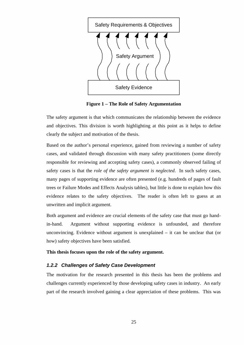
1.2.1 Requirements, Argument and Evidence
Underlying the descriptions of the safety case given in the previous section is a view of
the safety case consisting of three principal elements: Requirements, Argument and
Evidence. The relationship between these three elements is depicted in Figure 1.
25
Safety Requirements & Objectives
Safety Evidence
Safety Argument
Figure 1 – The Role of Safety Argumentation
The safety argument is that which communicates the relationship between the evidence
and objectives. This division is worth highlighting at this point as it helps to define
clearly the subject and motivation of the thesis.
Based on the author’s personal experience, gained from reviewing a number of safety
cases, and validated through discussion with many safety practitioners (some directly
responsible for reviewing and accepting safety cases), a commonly observed failing of
safety cases is that the role of the safety argument is neglected. In such safety cases,
many pages of supporting evidence are often presented (e.g. hundreds of pages of fault
trees or Failure Modes and Effects Analysis tables), but little is done to explain how this
evidence relates to the safety objectives. The reader is often left to guess at an
unwritten and implicit argument.
Both argument and evidence are crucial elements of the safety case that must go hand-
in-hand. Argument without supporting evidence is unfounded, and therefore
unconvincing. Evidence without argument is unexplained – it can be unclear that (or
how) safety objectives have been satisfied.
This thesis focuses upon the role of the safety argument.
1.2.2 Challenges of Safety Case Development
The motivation for the research presented in this thesis has been the problems and
challenges currently experienced by those developing safety cases in industry. An early
part of the research involved gaining a clear appreciation of these problems. This was
26
achieved through many discussions with engineers, by reviewing existing safety cases,
and by gaining a thorough understanding of regulatory requirements.
The following problem areas are those which are believed to be some of the most
significant limitations of current safety cases and that have specifically been
addressed in this thesis:
• Presentation of Clear Safety Arguments
• Incremental Safety Case Development
• Through-life Safety Case Maintenance
• Supporting Trustworthy Safety Case Reuse
The sections that follow provide a brief description of each of these areas.
1.2.3 Presentation of Clear Safety Arguments
The requirement that the safety case should present a clear safety argument is stated in
many of the safety standards. Both DS 00-55 [9] and 00-56 [10] emphasise that the
justification the safety case presents should be:
‘… well-organised and reasoned’
However, there are a number of factors that can make, and have made, it difficult to
achieve this goal:
• Size and complexity – The totality of evidence and argument required to meet
many of today’s certification standards can be huge. The engineer constructing the
safety case can often be left with the unenviable task of attempting to present a
safety argument that overarches thousands to tens of thousands of pages of
evidence.
• Co-ordinating and presenting results from many different sources – As
described in Section 1.2, it is within the nature of the safety case to rely upon
multiple sources of evidence and contextual material. Presenting these relationships
whilst preserving the flow and readability of the text within the safety case
document is extremely difficult. Multiple cross-references in text can be awkward.
Also, the safety case is often the product of many individuals’ efforts. To present a
coherent and consistent document that integrates the multiple contributions to the
safety case whilst preserving the structure and clarity of the safety argument can be
extremely difficult.

27
• Use of Free-format Text – As will be discussed further in Chapter Two, the
medium most commonly used at present for communicating the safety argument
within the safety case is free-format text. Although it is possible to communicate
safety arguments clearly with text, unless heavily marshalled its ‘flexibility’ can
allow unclear, ambiguous and misleading argument to be expressed. As mentioned
previously, it can be extremely difficult to clearly present complex interrelationships
and cross-references with text. This point has long been appreciated in most
engineering disciplines, where engineering drawings and design notations are
typically used to describe artefacts of any significant structural complexity.
This thesis proposes an approach to structuring and presenting clearly the safety
arguments of the safety case.
1.2.4 Incremental Safety Case Development
Historically, the production of safety cases has often been viewed as an activity to be
completed towards the end of the safety lifecycle [11]. However, it is increasingly
being recognised that in order to gain most value out of developing the safety case, and
to present the most convincing argument, safety cases should be developed
incrementally in step with system development. Safety standard DS 00-56 [10] states
the following with respect to this issue:
“The Safety Case should be initiated at the earliest possible stage in the
Safety Programme so that hazards are identified and dealt with while the
opportunities for their exclusion exist”
Similarly, the guidance provided in JSP 430 [8] states that:
“The Safety Case is to be prepared in outline at presentation of the Staff
Requirement and is to be updated at each major procurement milestone up
to and including hand-over from the procurement to the maintenance
authority … Ideally there should be a seamless development of the Safety
Case from one phase to the next”
This thesis demonstrates how the proposed approach to presenting safety
arguments respects and facilitates the incremental development of safety cases.
28
1.2.5 Through-life Safety Case Maintenance
Although safety cases are typically presented initially by an operator in order to gain
permission to commence operation of a system, once accepted there is usually a
responsibility to maintain the safety case as a ‘living document’ throughout the
operational life of the system. For example, DS 00-56 [10] states that:
“… any amendments to the deployment of the system should be examined
against the assumptions and objectives contained in the safety case.”
Similarly, JSP 430 [8] puts forward the following requirement:
“The Safety Case will be updated … to reflect changes in the design and/or
operational usage which impact on safety, or to address newly identified
hazards. The Safety Case will be a management tool for controlling safety
through life including design and operational role changes”
However, the difficulty faced in safety case maintenance is highlighted most clearly in
the following quote taken from the U.K. HSE Railways (Safety Case) Regulations 1994
[6]:
“Regulation 6(1) requires a safety case to be revised whenever appropriate,
that is whenever any of its contents would otherwise become inaccurate or
incomplete.”
The challenge lies in the phrase ‘whenever appropriate’. The task of assessing the
impact of any particular change on the safety argument to determine whether revision of
the safety case is necessary is far from straightforward. The problems of argument
scale, complexity and most importantly clarity cited in Section 2.3 hamper the
development of a systematic, efficient and effective approach to safety case
maintenance.
This thesis demonstrates how the proposed approach to presenting safety
arguments can be used to support the safety case maintenance activity.
1.2.6 Supporting Trustworthy Safety Case Reuse
Whilst the details of the arguments of the safety case (being based on specific evidence)
are likely to change from instance to instance, there is often commonality in the form of
the arguments used between safety cases. In the author’s experience, this commonality
is often exploited by safety case practitioners in the form of informal safety argument
reuse – mimicking or copying verbatim an argument observed elsewhere (or perhaps

29
used historically). Whilst there is significant benefit to be achieved through reuse – an
observable characteristic of a mature safety case development process – there are also
dangers. These may include an inappropriate reuse of arguments (possibly arising out
of a failure to understand the rationale or assumptions underlying an approach), and a
lack of traceability where arguments have been reused.
It is therefore desirable to have an approach that supports the documentation and reuse
of common safety argument approaches whilst minimising the risk of creating fallacious
arguments of safety.
This thesis proposes such an approach.
1.3 Thesis Proposition
This thesis provides a method and graphical notation for the presentation
of safety arguments. The thesis demonstrates how this approach can be
used to address the highlighted challenges of safety case development by
supporting the development, maintenance and reuse of safety arguments.
1.4 Thesis Structure
The thesis is divided into the following chapters:
Chapter Two presents a survey of the published literature on safety case development
and approaches to developing and presenting safety arguments. Through review of the
requirements regarding safety cases and safety arguments that exist with current safety
standards, and a study of published safety case development experience, the research
objectives are shown to be well founded. Early work on the Goal Structuring Notation
is identified at this point as the basis from which the research has been developed.
Chapter Three describes the contribution made by the author in defining a method for,
and extending, the Goal Structuring Notation. In particular, the chapter highlights how
the method has further defined the syntax and semantics of the notation. An illustration
of goal structure development using the method is presented. Using the extension of
context to goal structuring, we demonstrate how it becomes possible to represent the
interrelationships that exist between an evolving safety argument and alternative
development viewpoints. In particular, an illustration is given of the coupling that can
exist between the dual elements of the traditional ‘product’ safety viewpoint and
‘process’ justification.
30
Chapter Four describes how the Goal Structuring Notation can be used in support of
the Safety Case Maintenance Activity. We propose a classification of changes affecting
the safety case and show how these changes can be mapped to the elements of a goal-
structured safety argument. Having represented the challenge in terms of the goal
structure, the chapter presents a process that uses the goal structure as the basis for
assessing the impact of change on the safety argument. This process is illustrated on the
example given in Appendix A.
Chapter Five presents a novel approach to the representation and reuse of common
safety case argument structures based upon the concept of ‘Patterns’. The chapter
proposes extensions to the Goal Structuring Notation that enable the structural and
entity abstraction necessary to represent generic argument structures. In addition we
define and explain a format for the documentation of the goal-structured abstractions. A
process for the elicitation and application of ‘Safety Case Patterns’ is presented. A
number of example patterns are provided (both in this chapter and in Appendix B).
From these examples, we explain how it has been possible to evolve a taxonomy of
Safety Case Patterns.
Chapter Six describes how the proposals put forward in Chapters Three, Four and Five
have been validated and evaluated. The evaluation of the work has been based upon
case study (such as that presented in Appendix A), application on real industrial
projects, and through exposure to a wide audience of experienced safety case
practitioners.
Chapter Seven presents the conclusions that can be drawn from the thesis. It describes
the extent to which the work presented in previous chapters supports the thesis
proposition, and highlights areas of ongoing and possible future work.
The thesis also includes a number of appendices that, although provided in support of
the main chapters, can be read independently:
Appendix A provides an illustration of how the Goal Structuring Notation, as described
in Chapter 3, can be used in the presentation of a safety case document. The features of
this example are discussed in Chapter Three. The example is also used in illustration of
the approach to Safety Case Maintenance proposed in Chapter Four.
Appendix B presents examples of Safety Case Patterns (proposed in Chapter Five)
documented to date. This appendix is presented in the form of a Pattern Catalogue,
structured according the taxonomy of patterns proposed in Chapter Five.
31
Chapter 2:
Survey of Safety Case Management &
Argumentation
2.1 Introduction
Although the principles of developing and presenting safety cases are now widely
adopted and practised across many industries, there is still relatively little published
literature on the subject. This was particularly true at the time of starting the research.
This chapter provides the context for the contribution made by this thesis. The chapter
is divided into the following sections:
• Safety Case Development Requirements - Representative requirements for the
development and management of safety cases arising from current safety standards
• Safety Case Development Experience Reports - Published experiences of current
safety development practice (relevant to the thesis objectives)
• Safety Case Development Methodologies - Existing published approaches to
safety case development
• Safety Argumentation – Existing approaches to presenting safety arguments
• Argumentation - Existing approaches to argumentation
• Related Concepts – Concepts that are closely related to argumentation and the Goal
Structuring Notation
As described in Chapter One, the objectives of the thesis concern the development,
maintenance and reuse of safety arguments. There are no directly comparable results in
the areas of safety argument maintenance and reuse. The author conducted a broad
survey of change management and reuse approaches from other domains (particularly
software) in the initial stages of the research [12]. The reader is referred to this work for
a survey of these areas. Particularly relevant results from other domains that have
influenced the approach defined in this thesis are introduced within later chapters as
required.
32
2.2 Safety Case Development Requirements
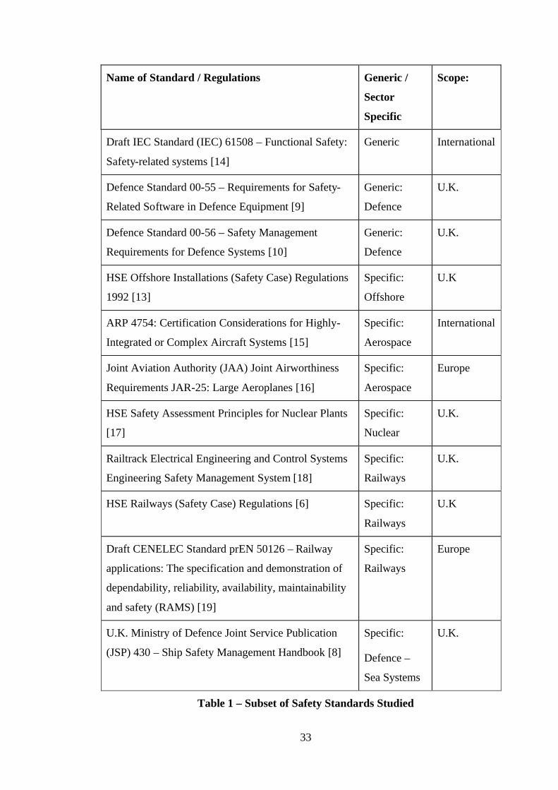
Over the course of the research the author has studied the requirements for the
production and management of safety cases that exist within a large number of current
safety standards. The majority of safety regulations and standards are defined for
specific industry sectors and countries (e.g. for Offshore Installations in the United
Kingdom [13]). In addition, there are a few industry ‘generic’ and international safety
standards (e.g. those concerning the use of software in programmable electronic
systems). Table 1 shows a representative subset of the standards studied and indicates
their scope of application.
In addition, the author has had sight of a number of company-specific safety assessment
procedures that address the production of a safety case.
The safety standards express requirements regarding safety cases in the following two
ways:
• Safety Case Product Requirements – concerning the role, content and structure of
the safety case
• Safety Case Process Requirements – concerning the safety case development and
maintenance lifecycle
The following sub-sections provide illustrative examples of these two forms of
requirement.
2.2.1 Safety Case ‘Product’ Requirements
An explicit requirement for the production of safety cases is present in a number of
safety standards. For example, the U.K. Defence Sea Systems Standard JSP 430 [8]
states the following:
“Safety Cases are required for all new ships and equipment as a means of
formally documenting the adequate control of Risk and demonstrating that
levels of risk achieved are As Low As Reasonably Practicable (ALARP).”
33
Name of Standard / Regulations Generic /
Sector
Specific
Scope:
Draft IEC Standard (IEC) 61508 – Functional Safety:
Safety-related systems [14]
Generic International
Defence Standard 00-55 – Requirements for Safety-
Related Software in Defence Equipment [9]
Generic:
Defence
U.K.
Defence Standard 00-56 – Safety Management
Requirements for Defence Systems [10]
Generic:
Defence
U.K.
HSE Offshore Installations (Safety Case) Regulations
1992 [13]
Specific:
Offshore
U.K
ARP 4754: Certification Considerations for Highly-
Integrated or Complex Aircraft Systems [15]
Specific:
Aerospace
International
Joint Aviation Authority (JAA) Joint Airworthiness
Requirements JAR-25: Large Aeroplanes [16]
Specific:
Aerospace
Europe
HSE Safety Assessment Principles for Nuclear Plants
[17]
Specific:
Nuclear
U.K.
Railtrack Electrical Engineering and Control Systems
Engineering Safety Management System [18]
Specific:
Railways
U.K.
HSE Railways (Safety Case) Regulations [6] Specific:
Railways
U.K
Draft CENELEC Standard prEN 50126 – Railway
applications: The specification and demonstration of
dependability, reliability, availability, maintainability
and safety (RAMS) [19]
Specific:
Railways
Europe
U.K. Ministry of Defence Joint Service Publication
(JSP) 430 – Ship Safety Management Handbook [8]
Specific:
Defence –
Sea Systems
U.K.
Table 1 – Subset of Safety Standards Studied
34
For U.K. Railways, the Health and Safety Executive (HSE) Railway (Safety Case)
Regulations 1994 [6] require that:
“A person in control of any railway infrastructure shall not use or permit it
to be used for the operation of trains unless
(a) he has prepared a safety case …
(b) the Executive has accepted that safety case …”
For U.K. Defence Software Systems, DS 00-55 [9] requires that:
“The Software Design Authority shall provide a Software Safety Case …”
As described in Chapter One, these requirements represent a marked shift in the
approach being adopted to the certification of safety-critical systems. Where previously
prescriptive standards were used as the main certification device, the responsibility is
now being placed with the developers to argue a safety case.
2.2.1.1 The Role and Purpose of the Safety Case
The role and purpose of the safety case is defined within a number of the standards. For
example, JSP 430 [8] states the following:
"A safety case is a comprehensive and structured set of safety
documentation which is aimed to ensure that the safety of a specific vessel
or equipment can be demonstrated by reference to: safety arrangements and
organisation; safety analyses; compliance with the standards and best
practice; acceptance tests; audits; inspections; feedback; and provision
made for safe use including emergency arrangements”
This definition highlights the role of the safety case as an integrator of many forms of
evidence. As discussed in Chapter One, this is actually one of the underlying causes of
the difficulties faced in presenting and structuring safety cases. DS 00-55 [9] provides
an alternative definition of the (software) safety case:
"The software safety case shall present a well-organised and reasoned
justification based on objective evidence, that the software does or will
satisfy the safety aspects of the Statement of Technical Requirements and the
Software Requirements specification."
35
This definition clearly highlights that the role of the safety case is provide a reasoned
argument. It also supports the view that the safety case comprises three essential
elements (requirements, argument and evidence), as presented in Chapter One.
2.2.1.2 Expected Safety Case Contents
Many of the standards (and supporting guidance) have begun to define the
expected contents of a safety case. The following is an example of the top level
headings taken from the safety case contents list given in the Railtrack Safety
Management Manual [18] as guidance on compliance with the HSE Railways
Regulations [6]:
• Executive Summary
• Introduction
• System Overview
• Safety Requirements
• Safety Management Overview
• Safety Audits and Assessments
• Safety Analysis
• Safety Engineering Overview
• Compliance with Safety Requirements
• Other Outstanding Safety Issues
• Conclusions
Similarly, DS 00-55 [9] outlines the requirements for the contents of the software
safety case under the following headings:
• System and Design Safety Aspects
• Software Safety Requirements
• Software Description
• Safety Arguments
• Safety Related System Development Process
36
• Current Status
• Change History
• Compliance with Safety Requirements
• In-Service Feedback
• Software Identification
The safety argument communicated by a safety case is the logical thread that runs
through the information presented in the separate sections. Some of the safety
standards, such as 00-55 [9], recognise the importance of presenting safety arguments
explicitly. The following section illustrates the requirements that exist within the
standards for the production and presentation of safety arguments:
2.2.1.3 Safety Argument Requirements
In addition to the general requirement present in many of the standards that the safety
argument presented by the safety case should be “well-reasoned” [10] and
“comprehensive” [8], DS 00-55 places some specific requirements on the safety
arguments presented. As shown by the headings given in the previous section, 00-55
also assigns an explicit section of the safety case to the presentation of safety
arguments. The following requirements are given regarding safety arguments:
“The Software Safety Case shall justify the achieved integrity level of the
Safety Related System (SRS) by means of a safety analysis of the SRS
Development Process supported by two or more diverse safety arguments.
The safety arguments shall include both:
a) Analytical arguments …
b) Arguments from testing …”
Part two of the standard also provides some guidance on how these arguments may be
developed and presented. The techniques that are presented are discussed in later
sections (2.5.2 and 2.5.3).
It is worth noting that although the standards make demands for clear and compelling
arguments, most offer little advice on how this is to be achieved.
37
2.2.2 Safety Case ‘Process’ Requirements
The requirements given in the safety standards regarding the processes of safety case
management are covered under the following two sub-sections:
• Requirements regarding the initial development process
• Requirements regarding the maintenance process
The author has identified no specific requirements regarding the reuse of safety case
material. However, some standards offer advice on the types of argument and evidence
to be used within the safety case. This can be viewed as a form of safety case
knowledge reuse, albeit only a weak form. An illustrative example of this kind of
guidance is presented in a third sub-section:
• Guidance on admissible forms of safety argument and evidence
2.2.2.1 Requirements Regarding Initial Safety Case Development
Chapter One stated that whereas the historical view of safety case development was that
it was an activity to be carried out towards the end of the safety lifecycle, current
thinking endorses the evolutionary development of safety cases. This view is now
represented within a number of the safety standards. For example, 00-56 [10] states the
following:
“The Safety Case should be initiated at the earliest possible stage in the
Safety Programme so that hazards are identified and dealt with while the
opportunities for their exclusion exist”
Similarly, JSP 430 [8] presents the following requirement:
“The Safety Case is to be prepared in outline at presentation of the Staff
Requirement and is to be updated at each major procurement milestone up
to and including hand-over from the procurement to the maintenance
authority … Ideally there should be a seamless development of the Safety
Case from one phase to the next”
A common approach adopted within the standards to managing the gradual
development of the safety case is to require the submission of a number of safety cases
at various stages of project development. For example, DS 00-55 [9] talks of formally
issuing at least three versions of the (Software) Safety Case:
38
• Preliminary Safety Case – produced after definition and review of the system
requirements specification.
• Interim Safety Case – produced after initial system design and preliminary
validation activities.
• Operational Safety Case – produced just prior to in-service use, including
complete evidence of having satisfied the systems requirements
Similar requirements for phased safety case production exist within 00-56 [10] and
within the civil nuclear domain [20] [21] (where the talk is of Preliminary Safety
Reports, Pre-Construction Safety Reports and Pre-Operation Safety Reports).
2.2.2.2 Requirements Regarding Safety Case Maintenance
The importance of effective safety case maintenance, as described in Chapter One, is
also highlighted in many of the standards. For example, the HSE Railway Regulations
[6] states the following:
“Regulation 6(1) requires a safety case to be revised whenever appropriate,
that is whenever any of its contents would otherwise become inaccurate or
incomplete.”
Similarly, 00-56 [10] demands that:
“… any amendments to the deployment of the system should be examined
against the assumptions and objectives contained in the safety case.”
JSP 430 [8] expresses the role of the safety case during maintenance even more
strongly, as shown in the following statement:
“The Safety Case will be updated … to reflect changes in the design and/or
operational usage which impact on safety, or to address newly identified
hazards. The Safety Case will be a management tool for controlling safety
through life including design and operational role changes”
Unfortunately (for practitioners), although the importance of, and requirements for,
safety case maintenance are expressed within the safety standards, once again little
guidance is offered on how this maintenance should be carried out. The quote from the
HSE Railway Regulations given above expresses one of the most problematic aspects of
safety case maintenance – namely the need for maintenance ‘whenever appropriate’.

39
There are many difficulties in determining the impact of a change and therefore when
revision of the safety case is appropriate.
2.2.2.3 Guidance on Admissible Forms of Argument and Evidence
Although no standards explicitly refer to the reuse of safety arguments between safety
case development, some are implicitly encouraging the adoption of standard forms of
safety argument and supporting evidence through guidance material. As stated earlier,
this can be viewed as a weak form of safety argument reuse. One such example is the
guidance given for software safety cases in Part 2 of 00-55 [9], an extract of which is
shown in the following table:
Argument Scaling with size and safety
integrity level (SIL)
Assumption and
limitations
Max
SIL
Formal
Arguments
About linear with code size.
Limited complexity of
application. Some resource
related properties or concurrent
aspects difficult to address.
Policy for formal proof vs.
rigorous argument needs careful
justification.
Evidence very strong for
properties amenable to this
approach. Very dependent
on system design. Validity
of rigorous arguments for
assurance (as opposed to
development) hard to
quantify.
4
Exhaustive
testing
Non dependent on SIL but very
sensitive to complexity or
software.
Unlikely to be practicable
except for special cases,
which may be readily
tractable by proof anyway.
4
Table 2 – 00-55 Guidance on Acceptable Forms of Safety Argument
2.3 Safety Case Experience
A number of papers have been published that present experiences of applying the safety
case concept to specific domains and projects. The following three sub-sections provide
an overview of how this experience relates to the three main themes of the thesis,
namely, safety case development, maintenance and reuse.

40
2.3.1 Experiences in Safety Case Development
Cullen in [11] cites the problems experienced when the production of a safety case for
the BNFL Sellafield Alpha Reduction Plant was initially left as a post-design activity.
He describes how after two failed attempts to produce an acceptable (certifiable) design,
an evolutionary and design-integrated approach to safety case development was
successfully adopted. (The problems cited in this paper are discussed more fully in
section 1.1. of Chapter Three).
Barker et al. in [22] describe the experience of developing a safety case for the
electronic throttle system on the Jaguar XK8 sports car. The paper concludes from the
experience that “it would be advantageous to design a skeleton safety argument as an
early deliverable, during planning stages … which could then be used to manage the
evidence gathered during development of the full argument, and to assist in its
presentation”. This view is very much in line with the objective of incremental safety
argument production as propounded in this thesis.
2.3.2 Experiences in Safety Case Maintenance
There are a number of reports that highlight some of the safety concerns associated with
maintenance. Pymm, in [23], describes the difficulty of making safety related
modifications to the computer systems of an Advanced Gas Reactor nuclear power plant
without degradation of, or challenge to, the initial safety case. In order to manage the
maintenance process he strongly advocates full documentation of the original
development process and also of the change process.
The problem of operational experience challenging the safety case is illustrated by
Hogberg in [24]. This paper describes the activities triggered by the need to re-assess
the existing safety case for five Swedish BWR (Boiling Water Reactor) power plants
after an incident challenged the original basis of that case.
Clarke, in [25] describes some of the problems encountered with performing the Long
Term Safety Review (LTSR) of the U.K.’s Magnox reactors. Specifically this report
highlights how, through lack of any maintenance of the original safety case, the safety
case has become inconsistent with current plant status and operation. He also highlights
the problems of adding to and re-evaluating a safety case that has become ‘out of date’
with respect to current safety standards. A more systematic approach to updating the
safety case, in line with the objectives of this thesis, is recommended.
41
2.3.3 Experiences in Safety Case Reuse
Although not explicitly addressing safety case reuse, concerns have been identified in
the aerospace and railways sectors regarding the reliance on existing safety arguments
for derivative systems – so called ‘Grandfather Rights’. Ford in [26] highlights the
danger in implicitly relying upon historical safety arguments that would no longer meet
current certification requirements for U.K. Railways. Learmount in [27] highlights the
similar concern being expressed in relation to airliner type certification within the civil
aerospace domain. However, Learmount also describes how these ‘grandfather rights’
are being replaced with a certification process based on a more systematic evaluation of
the differences between derivative and the original certified airframes, engines and
systems. These two papers highlight the dangers of safety case reuse (i.e. its ability to
produce successively weaker safety arguments). They illustrate that for such reuse to be
safe requires a systematic process, explicit documentation and evaluation of the
continuing applicability of the reused approach. This observation supports the
objectives of this thesis.
2.4 Safety Case Development Methodologies
This section provides an overview of past and current research concerning safety case
development. In particular, the work of the following projects is presented:
• ASAM (A Safety Argument Manager), ASAM-II and SAM
• SHIP (Safety of Hazardous Industrial Processes)
• Communication in Safety Cases
• Adelard Safety Case Development Method
• SERENE (SafEty and Risk Evaluation using bayesian NEts)
2.4.1 ASAM, ASAM-II and SAM
ASAM (A Safety Argument Manager) [28] was the first project led by the University of
York to investigate and develop an approach to structuring the logic of safety cases.
The project based its approach upon the principals of structuring arguments in the
Toulmin form (i.e. in terms of claims, warrants, backing, rebuttal etc.), as described
later in Section 2.6.3. A prototype Safety Argument Manager tool was developed that
allowed these ‘micro-arguments’ to be assembled to form an overall safety argument.
There were a number of conclusions from this project. Firstly, the Toulmin form was
42
felt to be too restrictive and unable readily to represent the forms of argument
commonly found within real safety cases. Secondly, it was felt that a safety case tool
should provide support not only for the high level argument of the safety case, but also
for the supporting evidence (particularly safety analysis techniques.) To address these
problems, the ASAM-II project was started.
ASAM-II [29-31] was a collaborative DTI-EPSRC funded project led by the University
of York in partnership with British Aerospace, Lloyds Register of Shipping and Rolls-
Royce plc. The objective of the project was to provide a structured method and
comprehensive tool support for the production of safety cases. The project focused on
the following two concepts:
• Development of a goal based notation for structuring the high level argument of the
safety case.
• Management of the interrelationships that exist between the most common safety
analysis techniques [31] (e.g. between Fault Tree Analysis and Failure Modes and
Effects Analysis).
This project initiated development of the Goal Structuring Notation (GSN), described
later in Section 2.5.6. The research described in this thesis began in 1994 whilst the
ASAM-II project was still running (the project ended in 1996). Although the basic
notation of GSN had been established, there was no method for the construction of goal
structures, the semantics of elements of the notation were poorly understood and
defined, and deficiencies were identified in GSN’s expressive power. This was the
starting point of the research identified in this thesis.
At the end of the ASAM-II project a prototype tool – SAM 3.25 – had been developed
and had already begun to incorporate some of the early results of the work presented in
this thesis (e.g. extension of the notation to include context). It was felt that with
minimal further development the SAM tool could be made into a commercial tool for
the management of safety cases. To fund and guide this further development, the tool
was passed across to York Software Engineering Ltd. who in 1997 set up the ‘SAM
Club’ – a consortium of over 20 European companies involved in the development of
safety-critical systems. The subscribing companies span a wide range of industries
(including defence, aerospace and the railways) and include GEC-Alsthom (now
Alstom), GEC-Marconi, Rolls-Royce, Defence Evaluation and Research Agency

43
(DERA), Smiths Industries, Lucas Aerospace and Siemens. The ‘SAM Club’ has
funded the development of a new version of the SAM tool – SAM 4.
The research presented in this thesis has influenced the support for GSN provided by
SAM 4. As described in Chapter Six (Evaluation), SAM 4 has provided a platform on
which tool support for the approach presented (e.g. for argument maintenance and
reuse) has been developed. The ‘SAM Club’ has also provided a forum through which
the approach defined in this thesis has been presented and evaluated. At the time of
writing the club is still active, and intends to release SAM 4 as a commercial tool during
1999.
2.4.2 SHIP Project
The SHIP project was funded under the EU Environment Programme (Major Industrial
Hazards). The objective of the project was to define an approach to assuring safety
despite the presence of design faults. There were two main strands to the project:
• Definition of the SHIP Safety Case Approach
• Use of Bayesian Belief Networks to determine quantitative software claims
The following two sub-sections describe the results of these studies:
2.4.2.1 SHIP Safety Case Approach
The SHIP model of the safety case [32] is shown in Figure 2. It defines the safety case
in terms of three elements:
• Claims about properties of the system.
• Evidence used as the basis of the safety argument.
• Argument that links the evidence to the claims via a series of inference rules.
The following three types of argument are also defined:
• Deterministic – relying upon axioms, logic and proof
• Probabilistic – relying upon probabilities and statistical analysis
• Qualitative – relying upon adherence to standards, design codes etc.
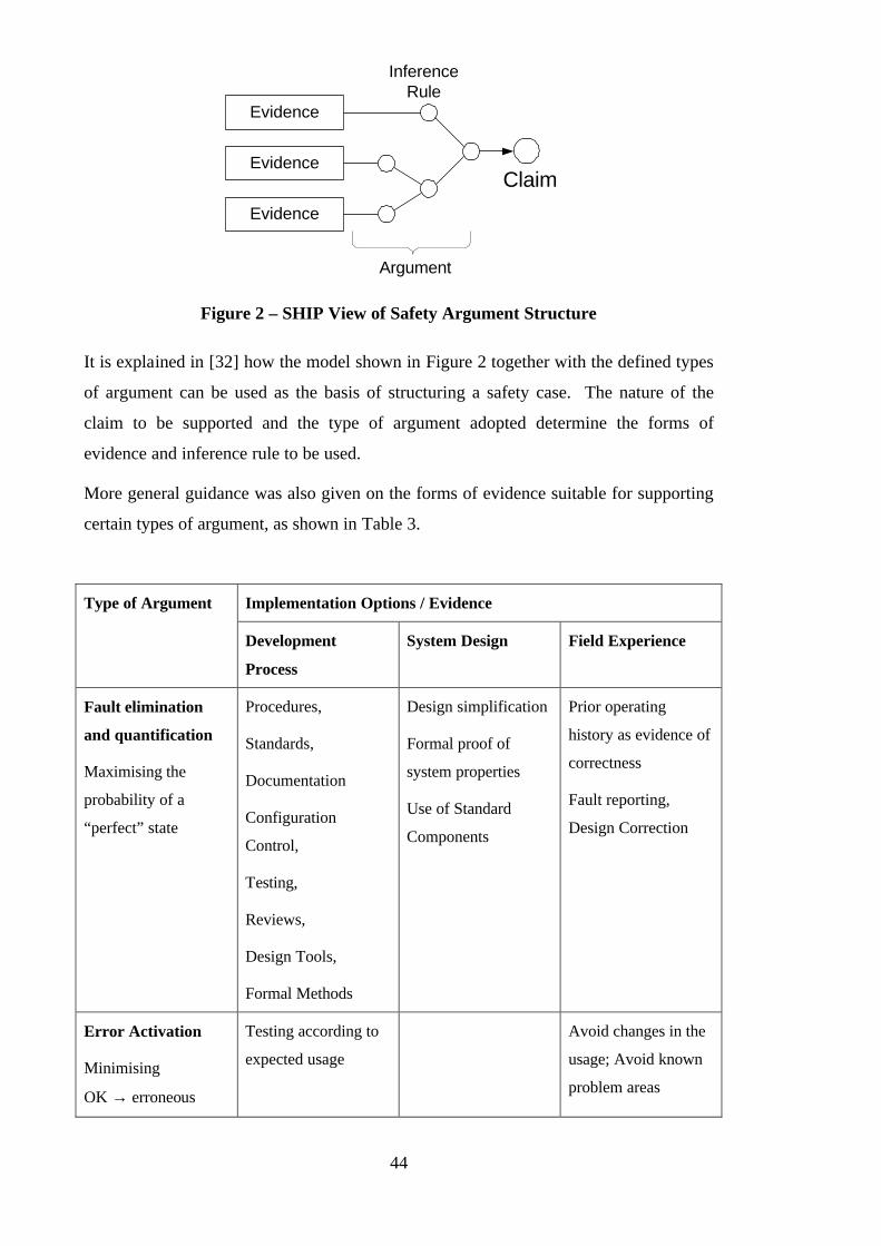
44
Evidence
Evidence
Evidence
InferenceRule
Claim
Argument
Figure 2 – SHIP View of Safety Argument Structure
It is explained in [32] how the model shown in Figure 2 together with the defined types
of argument can be used as the basis of structuring a safety case. The nature of the
claim to be supported and the type of argument adopted determine the forms of
evidence and inference rule to be used.
More general guidance was also given on the forms of evidence suitable for supporting
certain types of argument, as shown in Table 3.
Implementation Options / Evidence Type of Argument
Development
Process
System Design Field Experience
Fault elimination
and quantification
Maximising the
probability of a
“perfect” state
Procedures,
Standards,
Documentation
Configuration
Control,
Testing,
Reviews,
Design Tools,
Formal Methods
Design simplification
Formal proof of
system properties
Use of Standard
Components
Prior operating
history as evidence of
correctness
Fault reporting,
Design Correction
Error Activation
Minimising
OK → erroneous
Testing according to
expected usage
Avoid changes in the
usage; Avoid known
problem areas
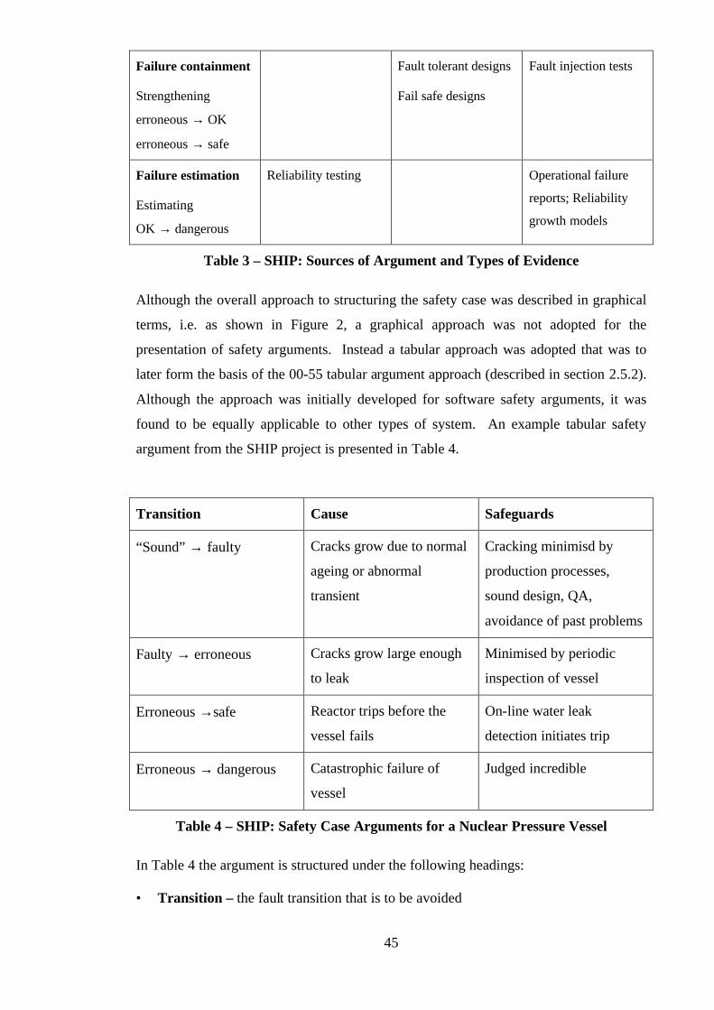
45
Failure containment
Strengthening
erroneous → OK
erroneous → safe
Fault tolerant designs
Fail safe designs
Fault injection tests
Failure estimation
Estimating
OK → dangerous
Reliability testing Operational failure
reports; Reliability
growth models
Table 3 – SHIP: Sources of Argument and Types of Evidence
Although the overall approach to structuring the safety case was described in graphical
terms, i.e. as shown in Figure 2, a graphical approach was not adopted for the
presentation of safety arguments. Instead a tabular approach was adopted that was to
later form the basis of the 00-55 tabular argument approach (described in section 2.5.2).
Although the approach was initially developed for software safety arguments, it was
found to be equally applicable to other types of system. An example tabular safety
argument from the SHIP project is presented in Table 4.
Transition Cause Safeguards
“Sound” → faulty Cracks grow due to normal
ageing or abnormal
transient
Cracking minimisd by
production processes,
sound design, QA,
avoidance of past problems
Faulty → erroneous Cracks grow large enough
to leak
Minimised by periodic
inspection of vessel
Erroneous →safe Reactor trips before the
vessel fails
On-line water leak
detection initiates trip
Erroneous → dangerous Catastrophic failure of
vessel
Judged incredible
Table 4 – SHIP: Safety Case Arguments for a Nuclear Pressure Vessel
In Table 4 the argument is structured under the following headings:
• Transition – the fault transition that is to be avoided

46
• Causes – the factors that may cause the fault transition
• Safeguards – the safeguards in place to prevent the transition or to mitigate the
effects of the transition
The advantages and disadvantages of tabular presentations of safety arguments are
discussed in Section 2.5.2.
In [32] it was recognised that, given a clear hierarchical breakdown of the argument
structure, “deviations in implementation can be analysed to see how this affects a sub-
claim, and how changes in sub-claim ‘ripple through’ the safety argument”. However,
no guidance was given on how this might be done and the idea was not explored further.
2.4.2.2 SHIP Bayesian Belief Networks
Bayesian Belief Networks (BBNs), described in more detail in section 2.5.5, were
identified on the SHIP project as a possible means of coupling qualitative evidence
regarding the software development process with quantitative failure rate evidence [33,
34]. Figure 3 provides a sketch of the SHIP BBN.
Process-relatedarguments
Number of faultsat delivery
Probability offailure ondemand
Failuresobserved inacceptance
testing
Sizes of faults atdelivery
Figure 3 – Sketch of SHIP Bayesian Belief Network
The implicit argument communicated by the above BBN is that the process-related
arguments support a claim of low number and size of faults at delivery. The low
number and size of faults at delivery support the claim of a low probability of failure on
demand. Finally, statistical testing is used to corroborate this belief. The use of BBNs
to communicate arguments in this way is discussed in Section 2.5.5.
47
2.4.3 Communication in Safety Cases - A Semantic Approach
‘Communication in Safety Cases - A Semantic Approach’ [35] was a DTI-EPSRC
funded project pursued at the University of Edinburgh. This project looked at
formalising ‘meta-level’ safety requirements in order to guide and constrain the
development of a design. In this way, Edinburgh hoped to integrate the construction of
the safety case with the design activity. The emphasis of the work, recorded in [35] was
on formalising functional requirements for elements of a system, using these
requirements to construct networks of linked elements. Cause and effect matrices can
be constructed from this network of dependencies and then used as the basis of the
system’s safety case. Unlike the approach presented in this thesis, this approach
presupposes that the system in question is amenable to formal specification and that
arguments of cause and effect are sufficient for the safety case.
2.4.4 Adelard Safety Case Development Method
The recently published Adelard Safety Case Development Manual [36] represents one
of the first attempts to present a ‘total’ safety case development methodology. With
respect to the presentation of safety arguments, it is heavily based upon the qualitative
aspects of the SHIP approach. In particular, it adopts the same view of safety argument
structure, shown in Figure 2. It also presents the tabular approach to structuring and
presenting safety arguments, as described in Section 2.5.2.
The manual offers much useful advice on the processes of constructing and maintaining
the safety case, including guidance similar to that given in 00-55 on acceptable forms of
argument and evidence (discussed in Section 2.2.2.3). However, it offers no explicit
guidance on either the incremental development of safety arguments (beyond the
principle of phased safety cases discussed in Section 2.2.2.1), or impact assessment
applied to safety arguments, or reuse of successful safety arguments.
2.4.5 SERENE Project
The SERENE (SafEty and Risk Evaluation using bayesian NEts) is a current ESPRIT
Framework IV project. The objective of the project is to develop a method for
constructing software safety arguments using Bayesian Belief Networks. At the time of
writing, no results have been published from this project.
Section 2.5.5 provides an overview of Bayesian Belief Networks and a discussion of
their capability to present safety arguments.
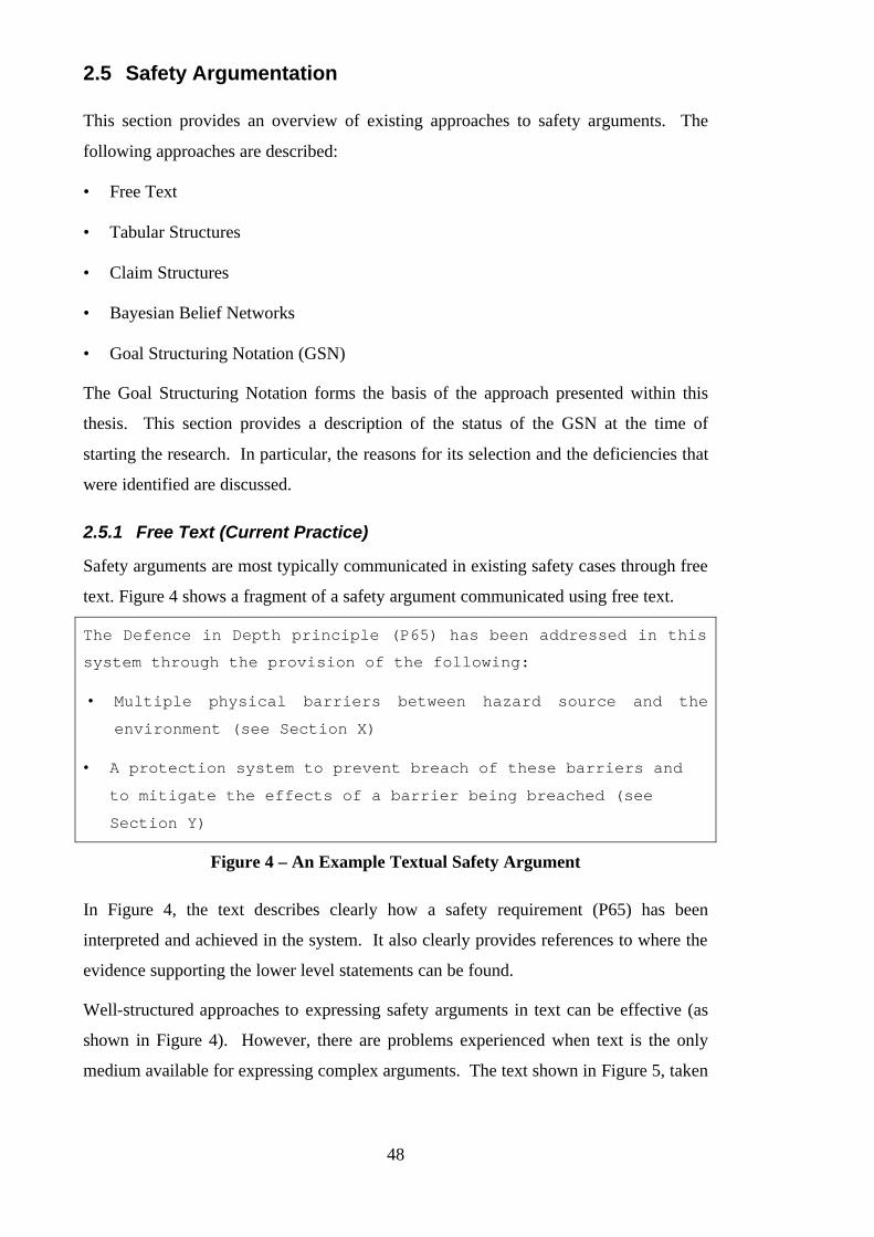
48
2.5 Safety Argumentation
This section provides an overview of existing approaches to safety arguments. The
following approaches are described:
• Free Text
• Tabular Structures
• Claim Structures
• Bayesian Belief Networks
• Goal Structuring Notation (GSN)
The Goal Structuring Notation forms the basis of the approach presented within this
thesis. This section provides a description of the status of the GSN at the time of
starting the research. In particular, the reasons for its selection and the deficiencies that
were identified are discussed.
2.5.1 Free Text (Current Practice)
Safety arguments are most typically communicated in existing safety cases through free
text. Figure 4 shows a fragment of a safety argument communicated using free text.
The Defence in Depth principle (P65) has been addressed in this
system through the provision of the following:
• Multiple physical barriers between hazard source and the
environment (see Section X)
• A protection system to prevent breach of these barriers and
to mitigate the effects of a barrier being breached (see
Section Y)
Figure 4 – An Example Textual Safety Argument
In Figure 4, the text describes clearly how a safety requirement (P65) has been
interpreted and achieved in the system. It also clearly provides references to where the
evidence supporting the lower level statements can be found.
Well-structured approaches to expressing safety arguments in text can be effective (as
shown in Figure 4). However, there are problems experienced when text is the only
medium available for expressing complex arguments. The text shown in Figure 5, taken
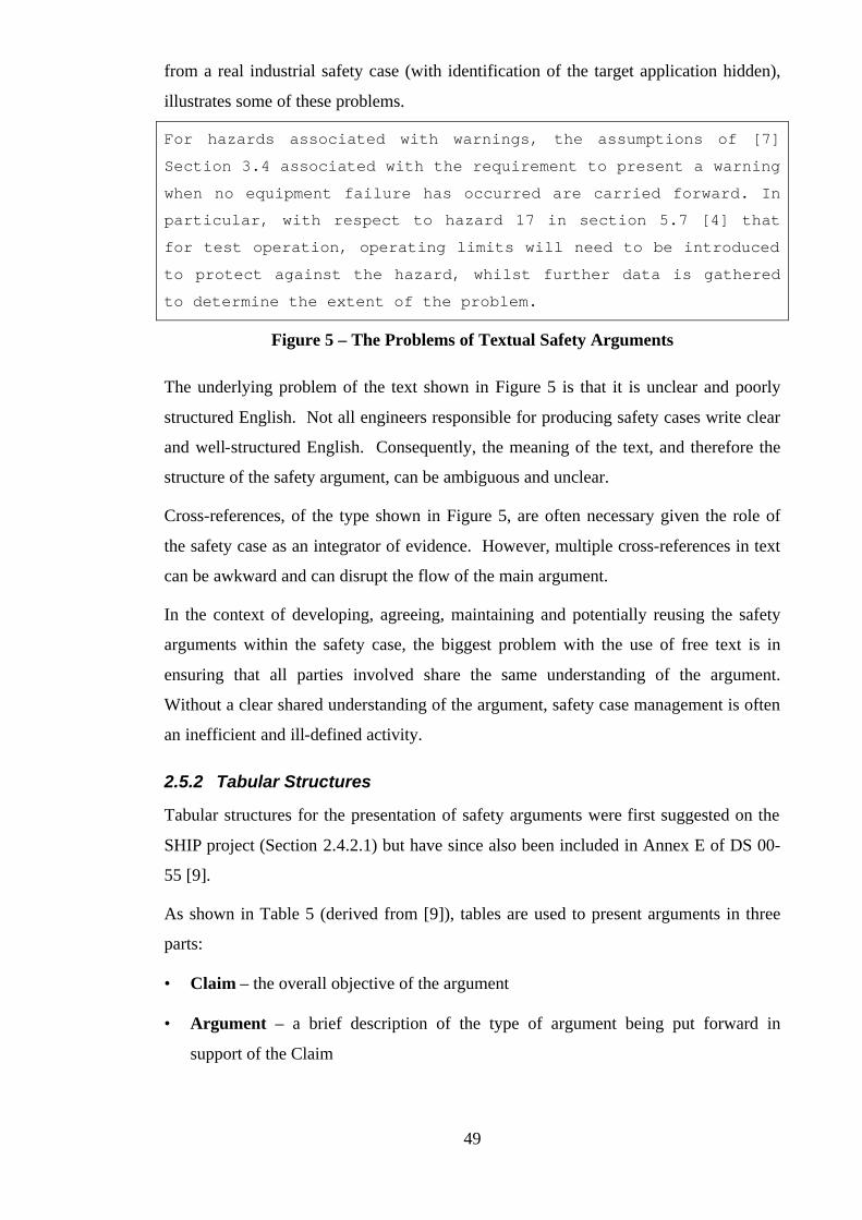
49
from a real industrial safety case (with identification of the target application hidden),
illustrates some of these problems.
For hazards associated with warnings, the assumptions of [7]
Section 3.4 associated with the requirement to present a warning
when no equipment failure has occurred are carried forward. In
particular, with respect to hazard 17 in section 5.7 [4] that
for test operation, operating limits will need to be introduced
to protect against the hazard, whilst further data is gathered
to determine the extent of the problem.
Figure 5 – The Problems of Textual Safety Arguments
The underlying problem of the text shown in Figure 5 is that it is unclear and poorly
structured English. Not all engineers responsible for producing safety cases write clear
and well-structured English. Consequently, the meaning of the text, and therefore the
structure of the safety argument, can be ambiguous and unclear.
Cross-references, of the type shown in Figure 5, are often necessary given the role of
the safety case as an integrator of evidence. However, multiple cross-references in text
can be awkward and can disrupt the flow of the main argument.
In the context of developing, agreeing, maintaining and potentially reusing the safety
arguments within the safety case, the biggest problem with the use of free text is in
ensuring that all parties involved share the same understanding of the argument.
Without a clear shared understanding of the argument, safety case management is often
an inefficient and ill-defined activity.
2.5.2 Tabular Structures
Tabular structures for the presentation of safety arguments were first suggested on the
SHIP project (Section 2.4.2.1) but have since also been included in Annex E of DS 00-
55 [9].
As shown in Table 5 (derived from [9]), tables are used to present arguments in three
parts:
• Claim – the overall objective of the argument
• Argument – a brief description of the type of argument being put forward in
support of the Claim
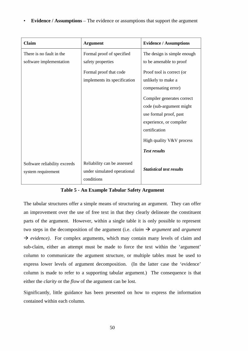
50
• Evidence / Assumptions – The evidence or assumptions that support the argument
Claim Argument Evidence / Assumptions
There is no fault in the
software implementation
Software reliability exceeds
system requirement
Formal proof of specified
safety properties
Formal proof that code
implements its specification
Reliability can be assessed
under simulated operational
conditions
The design is simple enough
to be amenable to proof
Proof tool is correct (or
unlikely to make a
compensating error)
Compiler generates correct
code (sub-argument might
use formal proof, past
experience, or compiler
certification
High quality V&V process
Test results
Statistical test results
Table 5 - An Example Tabular Safety Argument
The tabular structures offer a simple means of structuring an argument. They can offer
an improvement over the use of free text in that they clearly delineate the constituent
parts of the argument. However, within a single table it is only possible to represent
two steps in the decomposition of the argument (i.e. claim à argument and argument
à evidence). For complex arguments, which may contain many levels of claim and
sub-claim, either an attempt must be made to force the text within the ‘argument’
column to communicate the argument structure, or multiple tables must be used to
express lower levels of argument decomposition. (In the latter case the ‘evidence’
column is made to refer to a supporting tabular argument.) The consequence is that
either the clarity or the flow of the argument can be lost.
Significantly, little guidance has been presented on how to express the information
contained within each column.
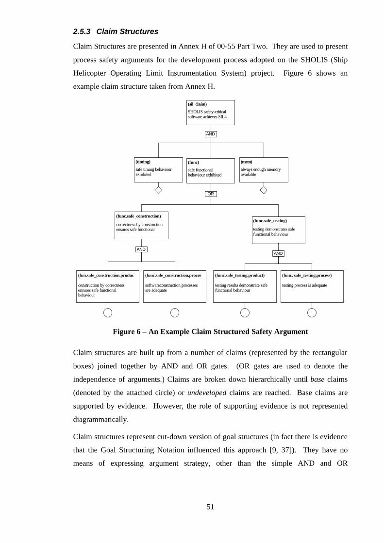
51
2.5.3 Claim Structures
Claim Structures are presented in Annex H of 00-55 Part Two. They are used to present
process safety arguments for the development process adopted on the SHOLIS (Ship
Helicopter Operating Limit Instrumentation System) project. Figure 6 shows an
example claim structure taken from Annex H.
(sil_claim)
SHOLIS safety-criticalsoftware achieves SIL4
AND
(timing)
safe timing behaviourexhibited
(func)
safe functionalbehaviour exhibited
(mem)
always enough memoryavailable
OR
(func.safe_construction)
correctness by constructionensures safe functional
(func.safe_testing)
testing demonstrates safefunctional behaviour
ANDAND
construction by correctnessensures safe functionalbehaviour
(fun.safe_construction.produc
softwareconstruction processesare adequate
(func.safe_construction.proces
testing results demonstrate safefunctional behaviour
(func.safe_testing.product)
testing process is adequate
(func. safe_testing.process)
Figure 6 – An Example Claim Structured Safety Argument
Claim structures are built up from a number of claims (represented by the rectangular
boxes) joined together by AND and OR gates. (OR gates are used to denote the
independence of arguments.) Claims are broken down hierarchically until base claims
(denoted by the attached circle) or undeveloped claims are reached. Base claims are
supported by evidence. However, the role of supporting evidence is not represented
diagrammatically.
Claim structures represent cut-down version of goal structures (in fact there is evidence
that the Goal Structuring Notation influenced this approach [9, 37]). They have no
means of expressing argument strategy, other than the simple AND and OR
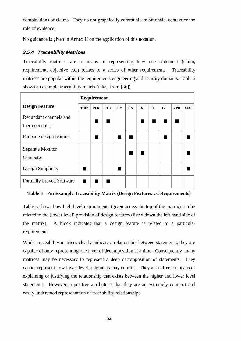
52
combinations of claims. They do not graphically communicate rationale, context or the
role of evidence.
No guidance is given in Annex H on the application of this notation.
2.5.4 Traceability Matrices
Traceability matrices are a means of representing how one statement (claim,
requirement, objective etc.) relates to a series of other requirements. Traceability
matrices are popular within the requirements engineering and security domains. Table 6
shows an example traceability matrix (taken from [36]).
Requirement
Design Feature TRIP PFD STR TIM FIX TST F1 F2 UPD SEC
Redundant channels and
thermocouples n n n n n n
Fail-safe design features n n n n n
Separate Monitor
Computer n n n
Design Simplicity n n n
Formally Proved Software n n n
Table 6 – An Example Traceability Matrix (Design Features vs. Requirements)
Table 6 shows how high level requirements (given across the top of the matrix) can be
related to the (lower level) provision of design features (listed down the left hand side of
the matrix). A block indicates that a design feature is related to a particular
requirement.
Whilst traceability matrices clearly indicate a relationship between statements, they are
capable of only representing one layer of decomposition at a time. Consequently, many
matrices may be necessary to represent a deep decomposition of statements. They
cannot represent how lower level statements may conflict. They also offer no means of
explaining or justifying the relationship that exists between the higher and lower level
statements. However, a positive attribute is that they are an extremely compact and
easily understood representation of traceability relationships.
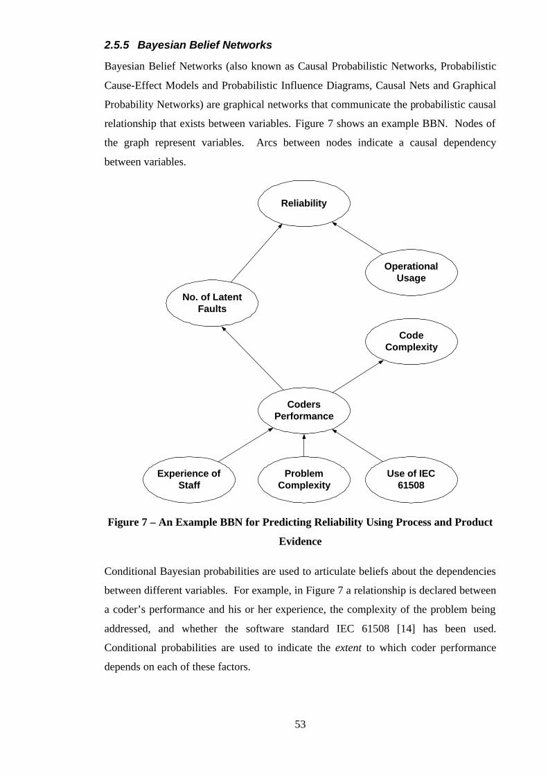
53
2.5.5 Bayesian Belief Networks
Bayesian Belief Networks (also known as Causal Probabilistic Networks, Probabilistic
Cause-Effect Models and Probabilistic Influence Diagrams, Causal Nets and Graphical
Probability Networks) are graphical networks that communicate the probabilistic causal
relationship that exists between variables. Figure 7 shows an example BBN. Nodes of
the graph represent variables. Arcs between nodes indicate a causal dependency
between variables.
Reliability
No. of LatentFaults
OperationalUsage
CodeComplexity
CodersPerformance
ProblemComplexity
Use of IEC61508
Experience ofStaff
Figure 7 – An Example BBN for Predicting Reliability Using Process and Product
Evidence
Conditional Bayesian probabilities are used to articulate beliefs about the dependencies
between different variables. For example, in Figure 7 a relationship is declared between
a coder’s performance and his or her experience, the complexity of the problem being
addressed, and whether the software standard IEC 61508 [14] has been used.
Conditional probabilities are used to indicate the extent to which coder performance
depends on each of these factors.
54
BBNs can be used to derive quantitative claims relating to the safety of a system (e.g. an
overall reliability claim). The benefit of using BBNs is that they can predict the value
of variables based upon uncertain or partial data. The drawback is in the derivation of
the conditional probabilities used to express the level of causality between variables. In
many cases determining these probabilities can be a heavily subjective exercise. If,
however, the variables are observable properties the conditional probabilities can be
improved over time, as more data becomes available.
Bayesian Belief Networks provide a means of communicating the relationship between
the claims of a safety argument [33]. However, BBNs (as a visual representation)
communicate safety arguments only implicitly (as do for example Fault Trees). For
example, the BBN shown in Figure 7 does not explicitly present claims (the nodes are
labelled as Noun-Phrases) and much of the ‘belief’ is captured in the conditional
probabilities associated with the arcs and nodes (not represented on the diagram itself).
An advantage BBNs have over pure argument representation devices (such as GSN
described in the following section) is that they provide a means of deriving a safety
argument – establishing a causal relationship between qualitative and quantitative
safety. Equally important, they provide evidence (as do fault trees, for example) that
can be used in supporting a quantitative claim within a safety argument.
The use of BBNs does not necessarily conflict with the approach suggested in this
thesis. In the ‘Further Work’ section of Chapter Seven we discuss a possible approach
to integrating the two methods.
2.5.6 Goal Structuring Notation
As described in section 2.4.1, the Goal Structuring Notation (GSN) for the presentation
of safety arguments was developed initially on the ASAM-II project. This section
provides an overview of the notation as it was defined, used and understood before the
research presented in this thesis was started, derived from [30].
Goal structuring is a graphical approach to presenting the structure of a safety argument.
Goal structures, or goal hierarchies as they were originally termed, consist of the
following elements:
• Goals
A goal is a requirement, target or constraint to be met by the system. The term goal

55
hierarchy refers to the collection of goals produced by the hierarchical
decomposition of goals into sub-goals.
• Models
A goal is couched in terms of some model of the system, or its environment. A goal
may be expressed over a number of models. This model may take a number of
forms – e.g. a plant schematic, a process description or an architectural model.
• Strategies
A goal (or set of goals can be solved by a strategy, which breaks down a goal into a
number of sub-goals. A strategy can be regarded as a rule to be invoked in the
solution of goals.
• Justifications
Strategies often need some justification for their use. A justification calls upon a
reason or evidence that supports a strategy.
• Meta-strategies
Meta-strategies record situations where there are alternative strategies for the
solution of a set of goals.
• Criteria
Criteria are used to decide whether a goal has been satisfactorily solved. They
provide measures and procedures for assessing goal satisfaction.
• Constraints
A constraint is used to restrict the way in which goals can be solved, e.g. a common
safety requirement is ‘no single point of failure shall lead to a hazard’.
• Solutions
Goals may be solved directly by solutions, rather than by decomposition into sub-
goals. Solutions will be individual pieces of analysis, evidence, results of audit
reports, or references to design material.
The graphical symbols for these elements are shown in Figure 8.

56
GOAL MODEL STRATEGY
JUSTIFICATION
J
META-STRATEGY
CRITERIA
CONSTRAINT
SOLUTION
Figure 8 – The Original GSN Elements
An example goal hierarchy (reproduced from [30]) is shown in Figure 9. (This in fact
represents one of the clearer examples in existence prior to the research presented in this
thesis.) The hierarchy sketches the safety argument for part of an Advanced Gas
Reactor nuclear trip system, and in particular addresses the avoidance of Gag Valve
Failures.
GSN was identified by the author as one of the most promising approaches to presenting
safety arguments, for the following reasons:
• It offered explicit representation of the logical flow of the safety argument (through
the directed SolvedBy relationships that are drawn between goals, strategies etc.)
• It offered explicit representation of the role of evidence (through the Solution
symbol)
• It offered explicit representation of the rationale underlying an argument (through
Justification symbol)
• No other comparable approaches to representing safety arguments existed at the
time of starting the research presented in this thesis (neither Claim Structures nor
Tabular Structures had been published at this date).
At the same time, however, we identified a number of deficiencies in the use of the
notation, including the following:
• No guidance was available on how goal structures were to be constructed (i.e. a
method). Consequently, safety engineers found the approach difficult to apply.
Also this meant that there was a large variance in how the notation was used. (It is

57
possible to observe changes of style even within Figure 9 – whereas G1 and G2
describe Verb-Phrase objectives, G3.1 and G3.2 form propositions.)
• The semantics of some elements of the notation were poorly defined. For example,
it was unclear whether strategies were meant to present the design approach (as
shown in Figure 9) or the argument approach.
• The roles of context and assumption in a safety argument were not represented
within the notation.
G1
Make nuclear plantsafe
G2
Make nuclear planthighly available
G3
Provide adequate protectionagainst consequences of
Gag Failure
G4
Maintain High Availabilityin face of Gag Failure
(M1)System Model
S1
Use Trip Systemto protect againstGag Failure
(M2)Trip System Model
J1
Similar Trip Systemssatisfactory in otherreactors
J
G3.3
Probability of Trip Systemfailing to trip on demand <
10e-5
J2JustificationArgument
J
G3.1
Spurious trip rate of TripSystem < 0.25 per year
G3.2
Availability of TripSystem >= 98.95%
Figure 9 – An ‘Original’ Goal Hierarchy
58
The starting point of the research presented in this thesis was to address the problems
that had been identified with the GSN. Having ‘fixed’ the basic notation, the research
was then able to explore the previously unaddressed issues of safety argument
maintenance and reuse.
2.6 Argumentation
This thesis is concerned with the development, presentation, maintenance and reuse of
clear arguments. This section provides an overview of argumentation approaches that
exist outside of the safety domain. In particular, the following topics are addressed:
• Formal Logic
• English syntax and argumentation
• Devices for structuring and presenting arguments
• The role of graphical presentations of arguments
Argument is a widely used device. The disciplines of philosophy and English syntax
provide insight into the structure and presentation of reasonable arguments. The
following sections describe some of the alternative approaches developed within these
domains.
2.6.1 Formal Logic
Formal Logic [38] describes acceptable forms of reasoning and offers definitions of the
basic concepts of argumentation that underlie any argument representation. This section
presents the fundamental definitions of formal logic:
In order to express an argument that reasons from premises to a conclusion, the concept
of proposition is required. A proposition is defined in formal logic to be a statement
which (a) must be either true or false, and (b) cannot be both true and false. For
example, “The sky is blue” is a valid proposition.
An argument is a collection of propositions – one of which is the conclusion, the others
being the premises for that conclusion. For example, the following is an argument:
• If it is a Bank Holiday, then it is raining
• It is a Bank Holiday
• It is raining
59
(Premises are listed above the line, the conclusion is given below the line.)
An argument is said to be valid if it is not possible for all of its premises to be true and
its conclusions false. For example, the following argument is invalid as it is possible for
the premise to be true whilst the conclusion is false:
• It is raining
• Today is Tuesday
The validity of an argument does not address whether the premises of the argument are
true. To do this, requires the definition of a sound argument. An argument is said to be
sound if it is valid and its premises are true.
A consistent argument is one where it is possible for all the propositions forming that
argument to be true together.
Propositional logic extends these basic ideas with the concept of connectives. A
connective is a term capable of joining two or more propositions to form a more
complex proposition. The standard logical connectives of propositional logic are
negation, conjunction, disjunction, implication and equivalence.
Predicate logic extends propositional logic to include the concepts of terms and
predicates. Example singular terms are ‘York’, ‘Train’, ‘Tim’. Predicates express
properties over terms. For example, in the proposition ‘Tim is happy’ the predicate ‘is
happy’ is applied to the term ‘Tim’. Predicate Logic also includes the concept of
quantification. The most commonly used quantifiers are ‘All’ (Universal
quantification) and ‘There Exists At Least One’ (Existential).
The fundamental concepts of logic described in this section have been used within the
research presented in this thesis (particularly in defining the GSN Method) to improve
the expression of arguments using goal structures.
2.6.2 English Syntax and Argumentation
The study of English syntax and Argumentation [39, 40] relates the concepts of English
Grammar to Formal Logic. It offers insight wherever text is used in presentation of an
argument.
Propositional sentences can be divided into Subjects and Predicates. (‘Subjects’ are
equivalent to ‘terms’ as defined in Formal Logic.) The subject of a propositional
sentence is usually the first Noun-phrase within that sentence. Verbs are predicators

60
within the proposition – i.e. they form the predicate. Predicates are formed from Verb-
Phrases. Consider the following sentence:
“Tim bought a computer”
The subject of the proposition is ‘Tim’, the predicate is ‘bought a computer’ and the
predicator is the verb ‘bought’.
Based upon these concepts of syntax, it becomes possible to define acceptable of
propositional sentential forms, the simplest being:
Noun-Phrase Verb-Phrase
The concepts of English Syntax and Argumentation been used within the research
presented in this thesis (particularly in defining the GSN Method) to improve the
articulation of arguments using goal structures.
2.6.3 Devices for structuring and presenting arguments
From the field of philosophy, Govier in [41] introduces a graphical notation for
constructing arguments, based on the following elements:
Single Support Pattern
1
2
One premise supports the
conclusion
Linked Support Pattern
1
3
2+
Several premises
interdependently support
the conclusion
Convergent Support
Pattern
1
4
32
Several premises
independently support the
conclusion
Using this notation, she describes how it is possible to construct diagrams for complex
arguments. Figure 10 shows an example argument composed from the above basic
forms.
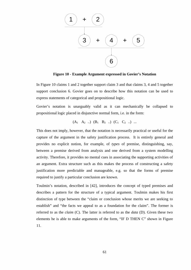
61
1
3
2+
+ 4 + 5
6
Figure 10 - Example Argument expressed in Govier’s Notation
In Figure 10 claims 1 and 2 together support claim 3 and that claims 3, 4 and 5 together
support conclusion 6. Govier goes on to describe how this notation can be used to
express statements of categorical and propositional logic.
Govier’s notation is unarguably valid as it can mechanically be collapsed to
propositional logic placed in disjunctive normal form, i.e. in the form:
(A1∧ A2∧..)∨(B1∧ B2∧..)∨(C1∧ C2∧..)∨...
This does not imply, however, that the notation is necessarily practical or useful for the
capture of the argument in the safety justification process. It is entirely general and
provides no explicit notion, for example, of types of premise, distinguishing, say,
between a premise derived from analysis and one derived from a system modelling
activity. Therefore, it provides no mental cues in associating the supporting activities of
an argument. Extra structure such as this makes the process of constructing a safety
justification more predictable and manageable, e.g. so that the forms of premise
required to justify a particular conclusion are known.
Toulmin’s notation, described in [42], introduces the concept of typed premises and
describes a pattern for the structure of a typical argument. Toulmin makes his first
distinction of type between the “claim or conclusion whose merits we are seeking to
establish” and “the facts we appeal to as a foundation for the claim”. The former is
referred to as the claim (C). The latter is referred to as the data (D). Given these two
elements he is able to make arguments of the form, “IF D THEN C” shown in Figure
11.

62
D So, C
Figure 11 - The Starting Point for Toulmin’s Notation
At this point the notation offers no more than Govier’s notation. The notation is
extended, however, by including the concept of warrant (W). The warrant for an
argument is the premise that relates data D to claim C. Figure 12 shows how warrant is
recorded in Toulmin’s notation.
D So, C
W
Since
Figure 12 - The Use of Warrants in Toulmin’s Notation
From this position, the notation is extended further to include the notion of qualifier (Q)
and rebuttable (R). The qualifier describes the degree of confidence that can be placed
on the claim. The rebuttal is a premise that describes when the claim would not be
sound. In this sense, Toulmin’s notation is predisposed towards arguments of a
categorical nature, e.g. “All apples are green, X is an apple, therefore X is green unless
X is a Red Delicious”. Figure 13 shows how the concept of qualification and rebuttal
fits into Toulmin’s notation.
D Q
W
SinceC
So
R
Unless
Figure 13 - Toulmin’s Pattern for the Layout of Arguments
It is not difficult to see that the notation Toulmin provides is simply a structuring of
formal logic. However, in providing a pattern, Toulmin has simplified the process of
constructing and managing arguments. For example, it would be easy to identify a
warrant-less argument expressed in Toulmin’s notation.

63
Both Govier’s and Toulmin’s notation can be used to express any argument. Having
been designed to be completely general, they do not explicitly capture concepts that
relate to the safety domain (such as system models). The goal structuring notation
introduced in section 2.5.6 extends this idea of a typed argument framework to present a
notation that applies particularly well to the safety justification domain.
2.6.4 The role of graphical presentations of arguments
Graphical presentation of safety arguments is at the heart of the approach presented in
this thesis. However, as shown by Govier’s notation introduced in the previous section,
it is not a new idea to present logical arguments diagrammatically.
Again from the field of Philosophy, Grennan [43] defines a graphical technique similar
to Govier’s for mapping the structure of an argument. This notation is introduced in
order to support an argument evaluation procedure. It is suggested in [43] that to
evaluate an argument effectively requires a clear and demonstrable understanding of the
elements and structure of that argument - achieved through graphical presentation.
From the field of Organsational Science, Sparrow [44] reports on a number of studies
that demonstrate the important of graphical representations in managing complexity.
Particularly, Fiol and Huff in [45] conclude that graphical representations ‘provide a
way to structure and simplify thoughts and beliefs, to make sense of them, and to
communicate information about them’. Sparrow himself suggests that, ‘Graphic
representations can both simplify ideas and facilitate the transmission of complex ideas
from individual to individual and unit to unit’.
These observations support the adoption of a graphical notation for the presentation of
safety arguments within the safety case – where both ease of evaluation and
comprehension are key problems, as described in Chapter One.
2.7 Related Concepts
This section describes concepts that relate to argumentation, and to goal structuring:
• Design Rationale Capture
• Other Goal-Based Approaches
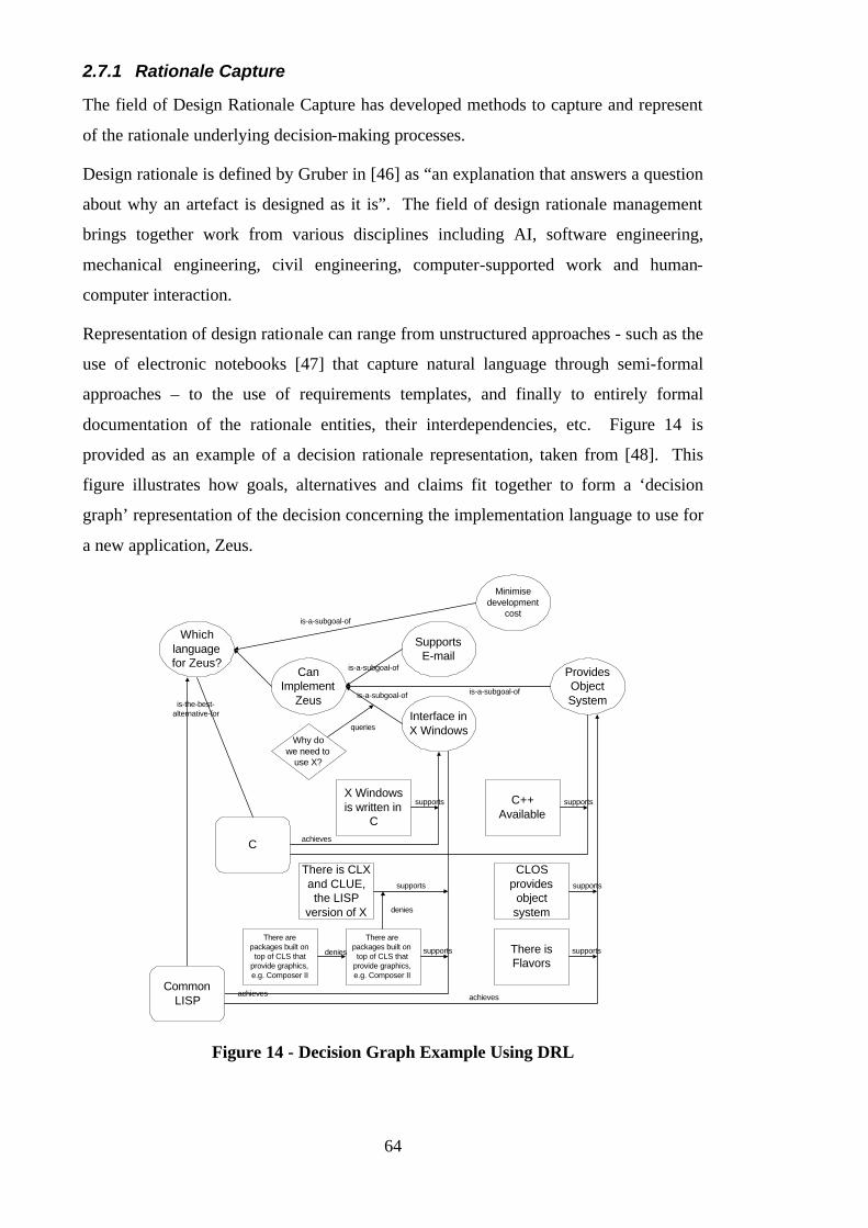
64
2.7.1 Rationale Capture
The field of Design Rationale Capture has developed methods to capture and represent
of the rationale underlying decision-making processes.
Design rationale is defined by Gruber in [46] as “an explanation that answers a question
about why an artefact is designed as it is”. The field of design rationale management
brings together work from various disciplines including AI, software engineering,
mechanical engineering, civil engineering, computer-supported work and human-
computer interaction.
Representation of design rationale can range from unstructured approaches - such as the
use of electronic notebooks [47] that capture natural language through semi-formal
approaches – to the use of requirements templates, and finally to entirely formal
documentation of the rationale entities, their interdependencies, etc. Figure 14 is
provided as an example of a decision rationale representation, taken from [48]. This
figure illustrates how goals, alternatives and claims fit together to form a ‘decision
graph’ representation of the decision concerning the implementation language to use for
a new application, Zeus.
Whichlanguagefor Zeus?
Minimisedevelopment
cost
CanImplement
Zeus
SupportsE-mail
ProvidesObjectSystem
Interface inX Windows
Why dowe need to
use X?
X Windowsis written in
C
C++Available
C
There is CLXand CLUE,the LISP
version of X
There arepackages built on
top of CLS thatprovide graphics,e.g. Composer II
CommonLISP
There arepackages built on
top of CLS thatprovide graphics,e.g. Composer II
CLOSprovides
objectsystem
There isFlavors
is-a-subgoal-of
is-a-subgoal-of
is-a-subgoal-ofis-a-subgoal-of
queries
achieves
supports
is-the-best-alternative-for
achieves achieves
supports
supports supports
supports
denies
denies
supports
Figure 14 - Decision Graph Example Using DRL
65
Other design rationale representations include decision trees [49], gIBIS [50], and
Critter [51]. For an exhaustive survey of work in the area we refer the reader to [46].
Design rationale representations communicate the rationale underlying arguments rather
than the argument itself. Consequently, they are inappropriate for presenting safety
arguments. However, representation of rationale remains an important supporting
concept for safety argumentation (to justify the argument approach presented).
2.7.2 Other Goal Based Approaches
The concept of goal decomposition has been applied in areas other than argumentation,
particularly in requirements engineering. A review of goal-driven approaches to
requirements engineering is presented in [52].
One such approach is the work of Loucopoulos et al. [53]. Loucopoulos focuses upon
using goals and goal hierarchies within information systems engineering to decompose
overall organisational objectives into the specific functions of the system that must be
implemented. The goal structures that are used consist of goals and the connectives
AND and OR to relate goals to sub-goals. Loucopoulos’ goals are stated as future
aspirations of the organisation and system. As such, they have more in common with
rationale capture than argumentation. In addition, these goal structures do not express
the concepts of strategy, solution, assumption and justification offered by the Goal
Structuring Notation (section 2.5.6) – concepts that have been found applicable in the
expression of safety arguments.
Work on the use of goal structures in requirements engineering was also carried out at
York under the DTI-SERC funded PROTEUS project [54]. A more formal
interpretation of goal structures was adopted on this project. Goals were recorded as
formal assertions that could logically be checked with respect to the given sub-goals.
There was no notion of solutions – instead, there existed axiomatic goals. Based on this
formal model, it was possible to support a calculable analysis of the effects of changing
elements of the goal structure (e.g. changing an axiomatic goal).
Because the PROTEUS work relied so heavily upon the formal basis of stating goals
and establishing formal relationships between goal and sub-goals, the change
management technique developed offers little useful advice on managing the
uncertainty of change applied to informal goal structured arguments as addressed by
this thesis.
66
2.8 Summary
This chapter has presented a survey of published literature relating to safety case
management.
The requirements identified from the safety standards, and the published experiences of
current safety case development practice, show that the research objective of supporting
the development, maintenance and reuse of safety arguments is well founded.
In the remaining sections of the survey, the work of this thesis is set clearly in the
context of existing approaches to safety case development and argumentation. In
particular, the early work on Goal Structuring Notation (GSN) is introduced as the basis
of the approach that is defined in Chapters Three, Four and Five.
No directly comparable approaches, particularly in the areas of safety case maintenance
and reuse, have been identified by this survey.

67
Chapter 3:
Using the Goal Structuring Notation to Support
Safety Case Development
3.1 Introduction
It is increasingly recognised by both safety case practitioners and many safety standards
that safety case development, contrary to what may historically have been practised,
cannot be left as an activity to be performed towards the end of the safety lifecycle. This
view of safety case production being left until all analysis and development is
completed is depicted in Figure 15.
Production ofthe Safety Case
Initial Hazard List In-service experience
Construction andDevelopment Codes
PreliminarySafety
Assessment
HazardIdentification
& RiskEstimation
ConfirmatoryAnalysis
Test andInspection
Requirements Completed System
Implementation
Design andDecomposition
Integration andTest
Safety LifecycleDesign Lifecycle
Figure 15 - A Historical View of Safety Case Development
A traditional view of the design and development lifecycle is shown on the left-hand
side of Figure 15. Running concurrently with this, shown on the right-hand side of the
diagram, is the historical view of the safety lifecycle, showing safety case development
as a discrete activity to be performed following the completion of the safety assessment
activities.
3.1.1 Problems Experienced with ‘Traditional’ Safety Case Development
The problems that have been experienced with this style of safety case development
include [11]:
• Large amounts of re-design resulting from a belated realisation that a satisfactory
safety argument cannot be constructed. In extreme cases, this has resulted in
‘finished’ products having to be completely discarded and redeveloped.
68
• Less robust safety arguments being presented in the final safety case. Safety case
developers are forced to argue over a design as it is given to them – rather than
being able to influence the design in such a way as to improve safety and improve
the nature of the safety argument. This can result in, for example, probabilistic
arguments being relied upon more heavily than deterministic arguments based upon
explicit design features (the latter being often more convincing).
• Lost safety rationale. The rationale concerning the safety aspects of the design is
best recorded at ‘design-time’. Where capture of the safety argument is left until
after design and implementation – it is possible to lose some of the safety aspects of
the design decision making process which, if available, could strengthen the final
safety case.
Unfortunately, though not surprisingly, few practitioners are prepared to publicise
failures of this style of safety case development. However, Cullen in [11] presents some
of the experiences of BNFL in producing a safety case for the Sellafield Alpha
Reduction Plant. For this plant he relates that a ‘traditional’ approach was first adopted
– where “plant design has proceeded more or less independently of the production of the
safety case”. Design progressed to the firm proposal stage before being passed to the
Safety Department. Significant safety hazards were identified with this proposal –
making it impossible to produce a convincing safety case. A re-design was therefore
required – resulting in great expense. The re-design was again developed into a firm
proposal before the safety case was considered. However, this time, other significant
problems were found with the new proposal, requiring more (expensive) re-design. It
was only on the third re-design, where consideration of the safety case was integrated
into the design requirements that an acceptable, arguably safe, design resulted [11].
3.1.2 Incremental Safety Case Development
Safety standards, such as the U.K. Defence Standards 00-56 [10] and Ship Safety
Management Handbook JSP430 [8] now require that safety case development be treated
as an evolutionary activity that is integrated with the rest of the design and safety
lifecycle. Defence Standard 00-56 states that:
“The Safety Case should be initiated at the earliest possible stage in the
Safety Programme so that hazards are identified and dealt with while the
opportunities for their exclusion exist”
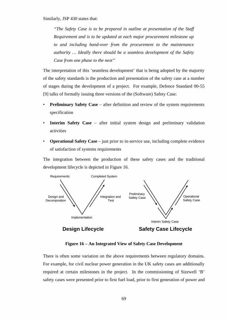
69
Similarly, JSP 430 states that:
“The Safety Case is to be prepared in outline at presentation of the Staff
Requirement and is to be updated at each major procurement milestone up
to and including hand-over from the procurement to the maintenance
authority … Ideally there should be a seamless development of the Safety
Case from one phase to the next”
The interpretation of this ‘seamless development’ that is being adopted by the majority
of the safety standards is the production and presentation of the safety case at a number
of stages during the development of a project. For example, Defence Standard 00-55
[9] talks of formally issuing three versions of the (Software) Safety Case:
• Preliminary Safety Case – after definition and review of the system requirements
specification
• Interim Safety Case – after initial system design and preliminary validation
activities
• Operational Safety Case – just prior to in-service use, including complete evidence
of satisfaction of systems requirements
The integration between the production of these safety cases and the traditional
development lifecycle is depicted in Figure 16.
Requirements Completed System
Implementation
Design andDecomposition
Integration andTest
Safety Case LifecycleDesign Lifecycle
Interim Safety Case
PreliminarySafety Case Operational
Safety Case
Figure 16 – An Integrated View of Safety Case Development
There is often some variation on the above requirements between regulatory domains.
For example, for civil nuclear power generation in the UK safety cases are additionally
required at certain milestones in the project. In the commissioning of Sizewell ‘B’
safety cases were presented prior to first fuel load, prior to first generation of power and
70
prior to being allowed to export power to the national grid [55]. However, regardless of
the specifics of numbers of safety cases and timings of submissions, the principle of
phased safety case production is increasingly being accepted as a core concept across all
domains.
3.1.3 Evolving Safety Arguments
At the heart of the concept of phased safety case production is the presentation of an
evolving safety argument. At the Preliminary Safety Case stage the aim is to present an
outline safety argument showing the principal objectives, approach to arguing safety
and the forms of evidence anticipated. At the Interim stage the argument should be
evolved to reflect the increased knowledge concerning the detailed design and
specification of the system. At the Operational stage the argument can again be evolved
further to reflect evidence concerning the system as implemented and tested.
The traditional approach to communicating safety arguments, as discussed in Chapter
Two, is to present them (sometimes only implicitly) through the text of the safety case
document itself. However, discussion between the author and a number of safety
managers and safety case practitioners has highlighted a number of problems with this
approach:
• A Document Centred Process
The safety argument is not seen to have an existence separate from the text of the
safety case document. Consequently, it is easy for the safety case development
process to become too focused on the production of the phased safety case
documents – sometimes almost missing the point of developing a clear and
comprehensive evolving safety argument. A system cannot be said to be safe
simply because a safety case document exists. Rather it depends on whether the
document contains a convincing safety argument. It is therefore desirable to have a
more explicit means of presenting, reviewing and discussing an evolving safety
argument.
• Difficulty of Document ‘Evolution’
The safety case documents presented at various stages of the project development
necessarily form ‘complete’ and rounded documents (as would be expected for
presentation to some third party). However, the safety arguments contained within
all but the final (in 00-55 terms – ‘Operational’) safety cases will be incomplete (as
described above). This dichotomy of incomplete arguments within a complete
71
document means that evolving the safety case from one phase to the next is not an
obvious process of ‘starting from where one left off’. Instead, it first requires an
‘un-picking’ and abstraction of the core safety argument from one document before
it can be used as the basis for the next. Again, this problem makes it desirable that
there is a more explicit means of representing the safety argument that is separate
from the mechanics of producing safety case documentation. This would result in a
more immediate appreciation that it is the safety argument that evolves between the
phases of the safety case rather than the documents that are being produced.
This chapter describes how the Goal Structuring Notation, introduced in the survey
presented in Chapter Two, provides such a means of explicitly developing and
presenting an evolving safety argument as part of phased safety case construction.
3.1.4 Contributions Presented within the Chapter
This chapter presents the contributions made by the author to increase the utility of the
notation in presenting evolving safety arguments. Specifically, contributions have been
made in the following three areas:
• Definition of a method for the use of Goal Structuring Notation – the provision of a
six-step process for evolving a goal structure from high-level objectives towards
concrete forms of evidence.
• Through the method definition, clarification of the syntax and semantics of the
Goal Structuring Notation.
• Extension of the notation to allow representation of safety case context.
An illustration of goal structure development using the method steps is presented.
Using the extension of context to goal structuring, the chapter describes how it becomes
possible to represent the interrelationships that exist between an evolving safety
argument and alternative development viewpoints. In particular, we illustrate the
coupling that can exist between the dual elements of the traditional ‘product’ safety
viewpoint and ‘process’ justification.
Using the contributions of both method and context, we present an example used on a
real industrial project to illustrate the application of goal structuring in presenting
preliminary safety arguments.

72
The contributions made in this chapter underpin and are utilised by the later Chapters
Four (concerning Safety Case Maintenance) and Five (concerning Safety Case Reuse).
The significance of these relationships is described at the end of this chapter.
3.2 An Overview of the Goal Structuring Notation
The Goal Structuring Notation (GSN) is a graphical notation that can be used to record
and present safety arguments – the principal components of any safety case. The
notation consists of the following core elements and construction principles:
• Goals
• Goal Decomposition
• Strategies
• Solutions
• Justifications
• Assumptions
• Models
The following subsections describe these elements.
3.2.1 Goals
Code module Ydeveloped to
Integrity Level 4procedures
Figure 17 – An Example Goal
A goal is a requirements statement – expressed as a claim concerning some aspect of the
system design, implementation, operation or maintenance. Figure 8 shows an example
goal represented in the notation.

73
3.2.2 Goal Decomposition
Code module Ydeveloped to
Integrity Level 4procedures
Code module Yspecified using
formal specificationtechnique (Z)
Timing properties ofcode module Y
verified using timinganalysis
Functionalproperties of codemodule Y verified
against formal spec.
Figure 18 – An Example Goal Decomposition
The satisfaction of a goal is often dependent on the satisfaction of derived sub-goals. In
the notation this is represented as a hierarchical decomposition.
Figure 18 shows an example of goal decomposition represented in the notation. The
directed arrow represents a SolvedBy relationship between goals. Satisfaction of the
parent goal is implied by the satisfaction of the child goals.
3.2.3 Strategies
Code module Ydeveloped to
Integrity Level 4procedures
Code module Yspecified using
formal specificationtechnique (Z)
Timing properties ofcode module Y
verified using timinganalysis
Functionalproperties of codemodule Y verified
against formal spec.
Argument byclaiming have
followed specificI.L. 4 guidelines
Figure 19 – An Example Goal Decomposition using a Strategy
Strategies can be used to add further detail to a goal decomposition. Inserted between
parent and child goals, a strategy explains how a parent goal is addressed by the child
goals presented. In this way, a strategy describes the approach adopted in solution of a
goal.
Figure 19 shows an example strategy used in a goal decomposition. In this example, the
strategy makes clear that satisfaction of the Integrity Level requirement is being argued

74
by claiming the appropriate use of specific techniques during the module development
and testing.
Where a number of (potentially conflicting) parent goals exist, a strategy can be used to
explain the trade-off represented by the child goals.
3.2.4 Solutions
Code module Yspecified using
formal specificationtechnique (Z)
Formalspecification
for codemodule Y
Figure 20 – An Example Goal Solution
Where the satisfaction of a goal does not depend on satisfaction of further sub-goals and
can be argued by appeal to some immediate source of information, it is said to have a
direct solution.
Figure 20 shows the representation of a direct solution in the notation. In this example,
the claim that formal specification has been used for specifying code module Y can be
shown to be met by referring the reader to it’s formal specification.
A solution provides the backing for stating that a requirement has been met.
Beyond these core elements the notation contains additional elements specifically
concerned with representing the rationale associated with the argument decomposition,
namely Justification and Assumption. These elements are described in the following
two sections.
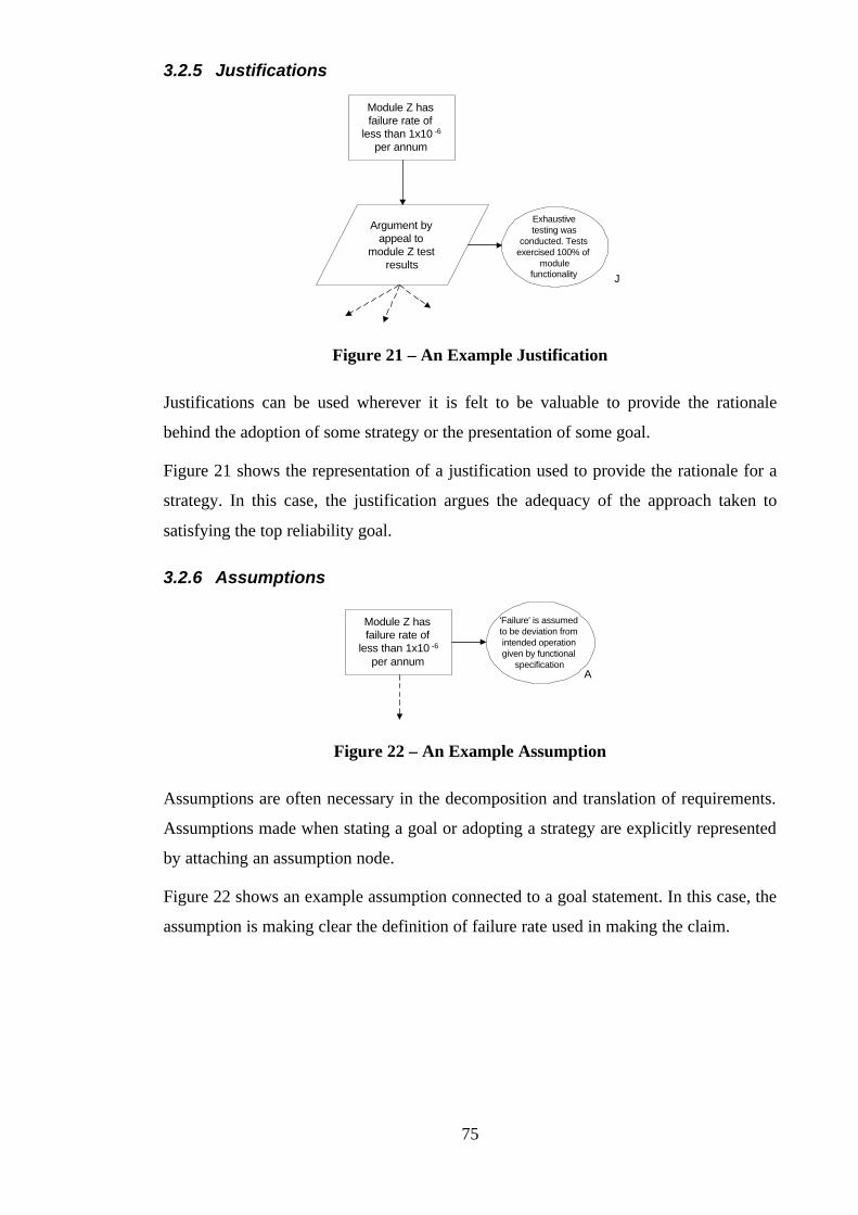
75
3.2.5 Justifications
Module Z hasfailure rate of
less than 1x10 -6
per annum
Argument byappeal to
module Z testresults
Exhaustivetesting was
conducted. Testsexercised 100% of
modulefunctionality J
Figure 21 – An Example Justification
Justifications can be used wherever it is felt to be valuable to provide the rationale
behind the adoption of some strategy or the presentation of some goal.
Figure 21 shows the representation of a justification used to provide the rationale for a
strategy. In this case, the justification argues the adequacy of the approach taken to
satisfying the top reliability goal.
3.2.6 Assumptions
Module Z hasfailure rate of
less than 1x10 -6
per annum
'Failure' is assumedto be deviation fromintended operationgiven by functional
specificationA
Figure 22 – An Example Assumption
Assumptions are often necessary in the decomposition and translation of requirements.
Assumptions made when stating a goal or adopting a strategy are explicitly represented
by attaching an assumption node.
Figure 22 shows an example assumption connected to a goal statement. In this case, the
assumption is making clear the definition of failure rate used in making the claim.
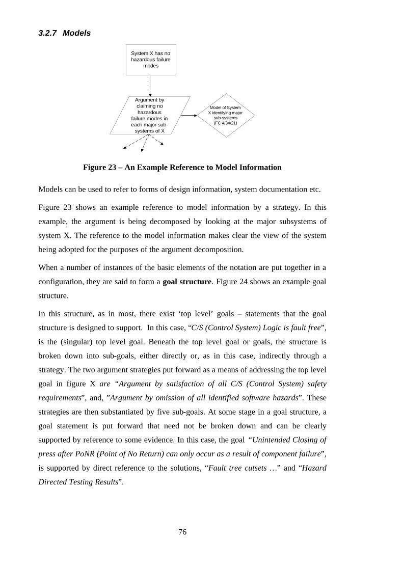
76
3.2.7 Models
Argument byclaiming nohazardous
failure modes ineach major sub-
systems of X
System X has nohazardous failure
modes
Model of SystemX identifying major
sub-systems(FC 4/34/21)
Figure 23 – An Example Reference to Model Information
Models can be used to refer to forms of design information, system documentation etc.
Figure 23 shows an example reference to model information by a strategy. In this
example, the argument is being decomposed by looking at the major subsystems of
system X. The reference to the model information makes clear the view of the system
being adopted for the purposes of the argument decomposition.
When a number of instances of the basic elements of the notation are put together in a
configuration, they are said to form a goal structure. Figure 24 shows an example goal
structure.
In this structure, as in most, there exist ‘top level’ goals – statements that the goal
structure is designed to support. In this case, “C/S (Control System) Logic is fault free”,
is the (singular) top level goal. Beneath the top level goal or goals, the structure is
broken down into sub-goals, either directly or, as in this case, indirectly through a
strategy. The two argument strategies put forward as a means of addressing the top level
goal in figure X are “Argument by satisfaction of all C/S (Control System) safety
requirements”, and, ”Argument by omission of all identified software hazards”. These
strategies are then substantiated by five sub-goals. At some stage in a goal structure, a
goal statement is put forward that need not be broken down and can be clearly
supported by reference to some evidence. In this case, the goal “Unintended Closing of
press after PoNR (Point of No Return) can only occur as a result of component failure”,
is supported by direct reference to the solutions, “Fault tree cutsets …” and “Hazard
Directed Testing Results”.

77
A goal structure does not necessarily replace the traditional form of the safety case, but
can instead be thought of as a ‘road-map’ over the existing information – removing the
burden of communicating potentially complex dependencies from the written text.
G19
C/S logic is fault free
S03
Argument byomission of allidentified softwarehazards
C13
Identifiedsoftware hazards
AddContext
G21
'Abort' Transition ofPLC state machine
includesBUTTON_IN going
FALSE
Sn04
C/S State Machine
G18
'Failure1' transitionof PLC state machine
includesBUTTON_IN
remaining TRUE
S04
Argument bysatisfaction of allC/S safetyrequirements
G17
Press controls being'jammed on' will
cause press to halt
G20
Release of controlsprior to press passingphysical PoNR will
cause press operationto abort
G38
C/S fails-safe (halts)on, and annunciates
(by soundingklaxon), all singlecomponent failures
G41
C/S state machine isan accurate
representation ofimplementation
behaviour
G42
Unintended openingof press (after PoNR)can only occur as aresult of component
failure
G43
Unintended closingof press can only
occur as a result ofcomponent failure
Sn06
Fault tree cutsets forevent 'Hand in pressdue to command error'
Sn08
Black Box TestResults
Sn15
Hazard DirectedTesting Results
Figure 24 – An Example Goal Structure
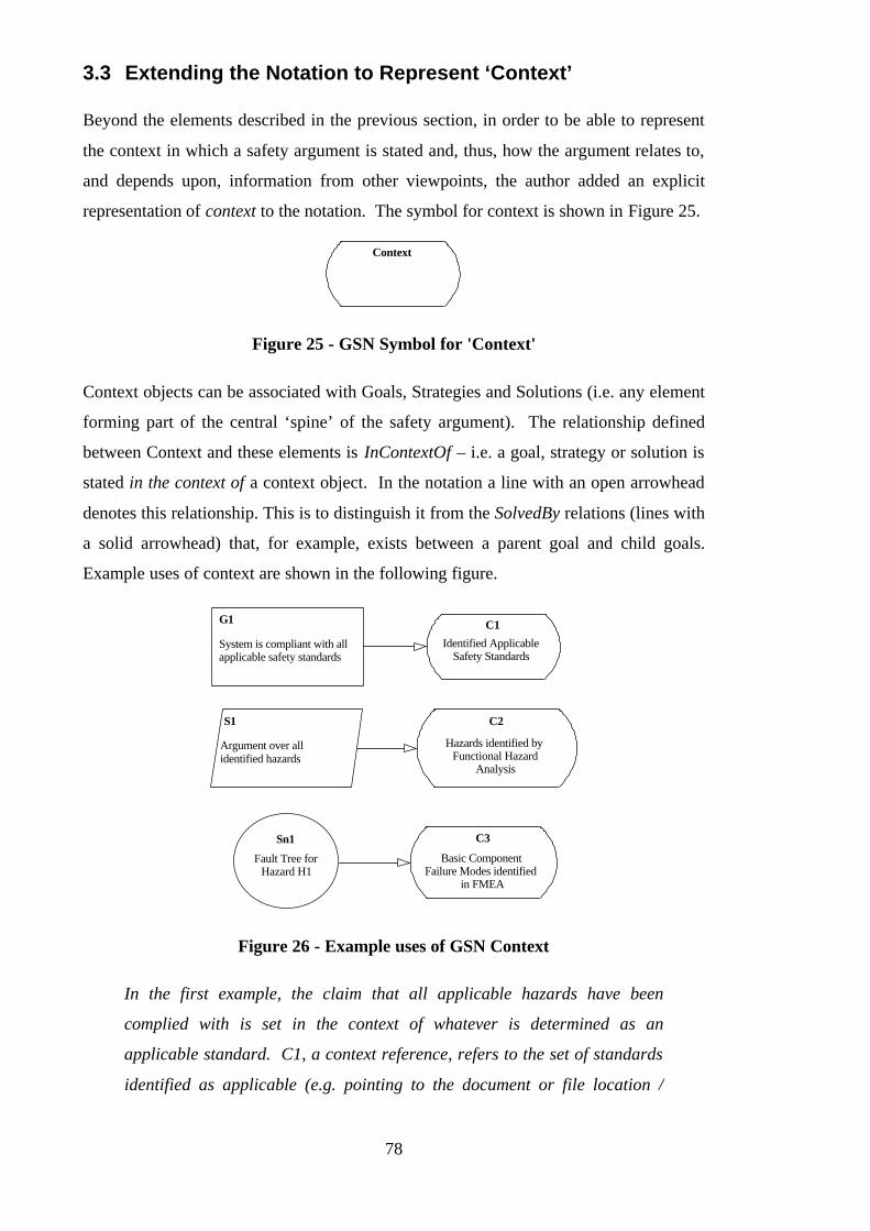
78
3.3 Extending the Notation to Represent ‘Context’
Beyond the elements described in the previous section, in order to be able to represent
the context in which a safety argument is stated and, thus, how the argument relates to,
and depends upon, information from other viewpoints, the author added an explicit
representation of context to the notation. The symbol for context is shown in Figure 25.
Context
Figure 25 - GSN Symbol for 'Context'
Context objects can be associated with Goals, Strategies and Solutions (i.e. any element
forming part of the central ‘spine’ of the safety argument). The relationship defined
between Context and these elements is InContextOf – i.e. a goal, strategy or solution is
stated in the context of a context object. In the notation a line with an open arrowhead
denotes this relationship. This is to distinguish it from the SolvedBy relations (lines with
a solid arrowhead) that, for example, exists between a parent goal and child goals.
Example uses of context are shown in the following figure.
System is compliant with allapplicable safety standards
G1 C1
Identified ApplicableSafety Standards
S1
Argument over allidentified hazards
C2
Hazards identified byFunctional Hazard
Analysis
Sn1
Fault Tree forHazard H1
C3
Basic ComponentFailure Modes identified
in FMEA
Figure 26 - Example uses of GSN Context
In the first example, the claim that all applicable hazards have been
complied with is set in the context of whatever is determined as an
applicable standard. C1, a context reference, refers to the set of standards
identified as applicable (e.g. pointing to the document or file location /
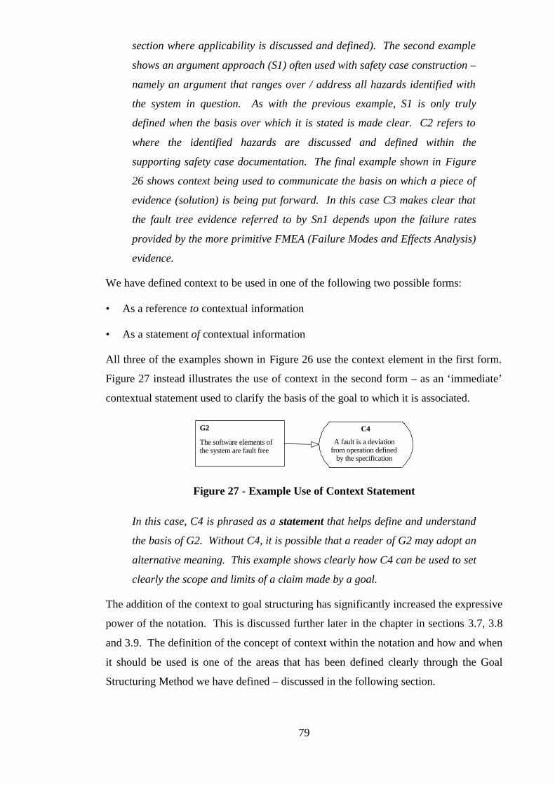
79
section where applicability is discussed and defined). The second example
shows an argument approach (S1) often used with safety case construction –
namely an argument that ranges over / address all hazards identified with
the system in question. As with the previous example, S1 is only truly
defined when the basis over which it is stated is made clear. C2 refers to
where the identified hazards are discussed and defined within the
supporting safety case documentation. The final example shown in Figure
26 shows context being used to communicate the basis on which a piece of
evidence (solution) is being put forward. In this case C3 makes clear that
the fault tree evidence referred to by Sn1 depends upon the failure rates
provided by the more primitive FMEA (Failure Modes and Effects Analysis)
evidence.
We have defined context to be used in one of the following two possible forms:
• As a reference to contextual information
• As a statement of contextual information
All three of the examples shown in Figure 26 use the context element in the first form.
Figure 27 instead illustrates the use of context in the second form – as an ‘immediate’
contextual statement used to clarify the basis of the goal to which it is associated.
The software elements ofthe system are fault free
G2 C4
A fault is a deviationfrom operation defined
by the specification
Figure 27 - Example Use of Context Statement
In this case, C4 is phrased as a statement that helps define and understand
the basis of G2. Without C4, it is possible that a reader of G2 may adopt an
alternative meaning. This example shows clearly how C4 can be used to set
clearly the scope and limits of a claim made by a goal.
The addition of the context to goal structuring has significantly increased the expressive
power of the notation. This is discussed further later in the chapter in sections 3.7, 3.8
and 3.9. The definition of the concept of context within the notation and how and when
it should be used is one of the areas that has been defined clearly through the Goal
Structuring Method we have defined – discussed in the following section.
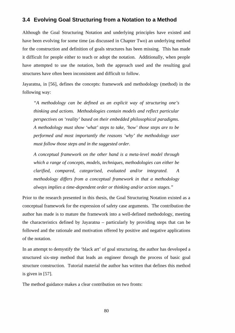
80
3.4 Evolving Goal Structuring from a Notation to a Method
Although the Goal Structuring Notation and underlying principles have existed and
have been evolving for some time (as discussed in Chapter Two) an underlying method
for the construction and definition of goals structures has been missing. This has made
it difficult for people either to teach or adopt the notation. Additionally, when people
have attempted to use the notation, both the approach used and the resulting goal
structures have often been inconsistent and difficult to follow.
Jayaratna, in [56], defines the concepts: framework and methodology (method) in the
following way:
“A methodology can be defined as an explicit way of structuring one’s
thinking and actions. Methodologies contain models and reflect particular
perspectives on ‘reality’ based on their embedded philosophical paradigms.
A methodology must show ‘what’ steps to take, ‘how’ those steps are to be
performed and most importantly the reasons ‘why’ the methodology user
must follow those steps and in the suggested order.
A conceptual framework on the other hand is a meta-level model through
which a range of concepts, models, techniques, methodologies can either be
clarified, compared, categorised, evaluated and/or integrated. A
methodology differs from a conceptual framework in that a methodology
always implies a time-dependent order or thinking and/or action stages.”
Prior to the research presented in this thesis, the Goal Structuring Notation existed as a
conceptual framework for the expression of safety case arguments. The contribution the
author has made is to mature the framework into a well-defined methodology, meeting
the characteristics defined by Jayaratna – particularly by providing steps that can be
followed and the rationale and motivation offered by positive and negative applications
of the notation.
In an attempt to demystify the ‘black art’ of goal structuring, the author has developed a
structured six-step method that leads an engineer through the process of basic goal
structure construction. Tutorial material the author has written that defines this method
is given in [57].
The method guidance makes a clear contribution on two fronts:

81
• Semantics – providing a precise definition of the meaning of the goal structuring
elements and their relationship to one another
• Syntax – providing definitive guidance on the phrasing of the goal structuring
elements and the validation of relationships between elements.
The six steps of the method are shown diagrammatically in Figure 28.
Identifygoals to besupported
Definebasis on whichgoals stated
Identifystrategy to
supportgoals
Define basison whichstrategystated
IdentifyBasic
SolutionSTOP
Step 1
Step 2
Step 3
Step 4
Step 6
Step 5 - Elaboratestrategy
Figure 28 - The Steps of the GSN Construction Method
The six steps involved in the development of a goal structure are:
Step 1 - Identify goals to be supported
Step 2 - Define basis on which goals stated
Step 3 - Identify strategy to support goals
Step 4 - Define basis on which strategy stated
Step 5 - Elaborate strategy (& therefore proceed to identify new goals – back to Step 1)
OR
Step 6 - Identify basic solution
It is not the role of this chapter to describe in detail the six steps of the goal structuring
method. For a full definition of the method, see [57]. The following section provides
an overview and illustration of goal structure development following the steps of the
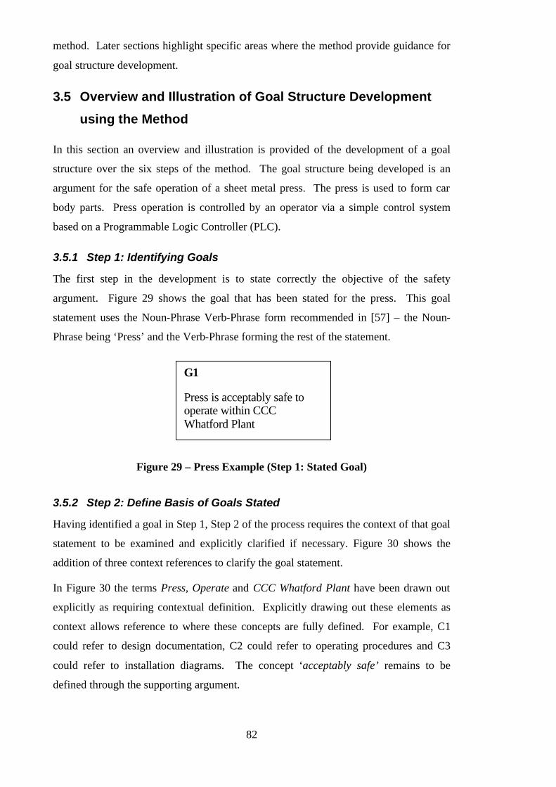
82
method. Later sections highlight specific areas where the method provide guidance for
goal structure development.
3.5 Overview and Illustration of Goal Structure Development
using the Method
In this section an overview and illustration is provided of the development of a goal
structure over the six steps of the method. The goal structure being developed is an
argument for the safe operation of a sheet metal press. The press is used to form car
body parts. Press operation is controlled by an operator via a simple control system
based on a Programmable Logic Controller (PLC).
3.5.1 Step 1: Identifying Goals
The first step in the development is to state correctly the objective of the safety
argument. Figure 29 shows the goal that has been stated for the press. This goal
statement uses the Noun-Phrase Verb-Phrase form recommended in [57] – the Noun-
Phrase being ‘Press’ and the Verb-Phrase forming the rest of the statement.
Press is acceptably safe tooperate within CCCWhatford Plant
G1
Figure 29 – Press Example (Step 1: Stated Goal)
3.5.2 Step 2: Define Basis of Goals Stated
Having identified a goal in Step 1, Step 2 of the process requires the context of that goal
statement to be examined and explicitly clarified if necessary. Figure 30 shows the
addition of three context references to clarify the goal statement.
In Figure 30 the terms Press, Operate and CCC Whatford Plant have been drawn out
explicitly as requiring contextual definition. Explicitly drawing out these elements as
context allows reference to where these concepts are fully defined. For example, C1
could refer to design documentation, C2 could refer to operating procedures and C3
could refer to installation diagrams. The concept ‘acceptably safe’ remains to be
defined through the supporting argument.

83
Press is acceptably safe tooperate within CCCWhatford Plant
G1
C1
Press Design
C2
Press Operation
C3
CCC Whatford Plant
Figure 30 – Press Example (Step 2: Context Added)
3.5.3 Step 3: Identify Strategy to Support Goals
For each identified goal, Step 3 of the method requires that an argument strategy for
supporting these goals be identified. Figure 31 shows the two peer strategies that have
been identified as approaches to arguing the acceptable safety of the press.
C3
CCC Whatford Plant
C2
Press Operation
C1
Press Design
Press is acceptably safe tooperate within CCCWhatford Plant
G1
S1
Argument by addressing allidentified operatinghazards
S2
Argument of compliancewith all applicable safetystandards & regulations
Figure 31 – Press Example (Step 3: Solution Strategies Identified)
The first strategy (S1) shown in Figure 31 is to present an argument based on having
addressed all of the operating hazards that have been identified with the press – i.e. for
each safety problem that has been identified a solution has been found. The second
strategy (S2) is to present an argument of safety based on compliance with all the safety
standards that are considered applicable for a piece of machinery of this type and
application.
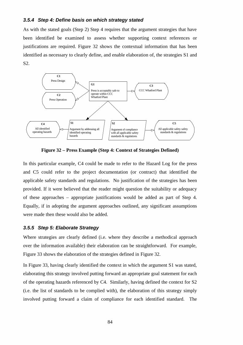
84
3.5.4 Step 4: Define basis on which strategy stated
As with the stated goals (Step 2) Step 4 requires that the argument strategies that have
been identified be examined to assess whether supporting context references or
justifications are required. Figure 32 shows the contextual information that has been
identified as necessary to clearly define, and enable elaboration of, the strategies S1 and
S2.
S2
Argument of compliancewith all applicable safetystandards & regulations
Press is acceptably safe tooperate within CCCWhatford Plant
G1
C1
Press Design
C2
Press Operation
C3
CCC Whatford Plant
S1
Argument by addressing allidentified operatinghazards
C4
All identifiedoperating hazards
C5
All applicable safety safetystandards & regulations
Figure 32 – Press Example (Step 4: Context of Strategies Defined)
In this particular example, C4 could be made to refer to the Hazard Log for the press
and C5 could refer to the project documentation (or contract) that identified the
applicable safety standards and regulations. No justification of the strategies has been
provided. If it were believed that the reader might question the suitability or adequacy
of these approaches – appropriate justifications would be added as part of Step 4.
Equally, if in adopting the argument approaches outlined, any significant assumptions
were made then these would also be added.
3.5.5 Step 5: Elaborate Strategy
Where strategies are clearly defined (i.e. where they describe a methodical approach
over the information available) their elaboration can be straightforward. For example,
Figure 33 shows the elaboration of the strategies defined in Figure 32.
In Figure 33, having clearly identified the context in which the argument S1 was stated,
elaborating this strategy involved putting forward an appropriate goal statement for each
of the operating hazards referenced by C4. Similarly, having defined the context for S2
(i.e. the list of standards to be complied with), the elaboration of this strategy simply
involved putting forward a claim of compliance for each identified standard. The

85
process of goal structure development is continued for each of the new goals (G2-G7)
identified. The goal structure continues to be developed in this way until the stage
where, in identifying a strategy to support a goal, it is recognised that no further
decomposition into sub-statements is necessary and the goal can instead be directly
supported by appeal to some evidence – i.e. we can proceed to Step 6.
C5
All applicable safetysafety standards &
regulations
C4
All identifiedoperating hazards
S1
Argument by addressing allidentified operatinghazards
S2
Argument of compliancewith all applicable safetystandards & regulations
Hazard of 'Operator HandsTrapped by Press Plunger' sufficiently mitigated
G2
Hazard of 'Operator HandsCaught in Press DriveMachinery' sufficiently mitigated
G3
Hazard of 'Operator UpperBody trapped by PressPlunger' sufficiently mitigated
G4
Press compliant with U.K.HSE Provision and Use ofWork Equipment Regulations
G5
PES element of press designcompliant with IEC1508
G7
Press compliant with U.K.enactment of EU MachineryDirective
G6
Figure 33 – Press Example (Step 5: Elaboration of Strategies)
3.5.6 Step 6: Identify basic solution
To fully ‘bottom-out’ (i.e. decompose to solution references) the illustrated goal
structure would obviously require a number of iterations of the process – decomposing
all goal claims to a level where direct reference to evidence was felt possible. However,
as an illustration of where Step 6 rather than Step 5 would be applicable, Figure 34
shows the fragment of goal structure developed to support the goal G3 identified at the
bottom of Figure 33. In this example, at the level of stating that “Motor / Clutch / Drive
Belts surrounded with safety cage” the writer has decided that no further decomposition
is necessary and that this claim can be shown to be true through reference to the “Press
Design (Safety Cage)”. Peer goals do not always require the same level of
decomposition - further argument is required to support the more complex sibling goal
G9.
86
Hazard of 'Operator Hands Caughtin Press Drive Machinery'sufficiently mitigated
G3
Motor / Clutch / Drive Beltssurrounded with safety cage
G8
Press operation will (safely)halt if safety cage tamperedwith
G9
Sn10
Press Design(Safety Cage)
More explanationrequired here
Figure 34 – Press Example (Step 6: Supporting Evidence Identified)
3.6 Example Areas of Guidance Provided by GSN Method
The following sub-sections highlight some of the specific ways in which the syntax and
semantics of GSN have been further defined through the method guidance the author
has developed [57].
3.6.1 Guidance Provided on Phrasing of Goal Statements
In Step 1 of the method (“Identifying Goals to be Supported”) specific guidance is given
on the correct phrasing of goal statements made within a goal structure. The method
defines that goals should always be stated as propositions – statements that can be said
to be true or false. More specifically, it recommends that goal statements should be of
the following form:
<Noun-Phrase><Verb-Phrase>
The Noun-Phrase part of this statement identifies the subject of the goal – i.e. that
which we are making a statement about. The Verb-Phrase part of the statement is used
to define the predicate - the predicate serves to make an assertion or denial about the
subject. The method goes on to present example Noun-Phrase Verb-Phrase constructs
that may be found within a safety argument.
The rationale behind providing this level of guidance is that many people previously
attempting to use GSN quite often ended up stating ‘Goals’ that could neither be
interpreted as objectives or logical statements within an overall argument. For example,
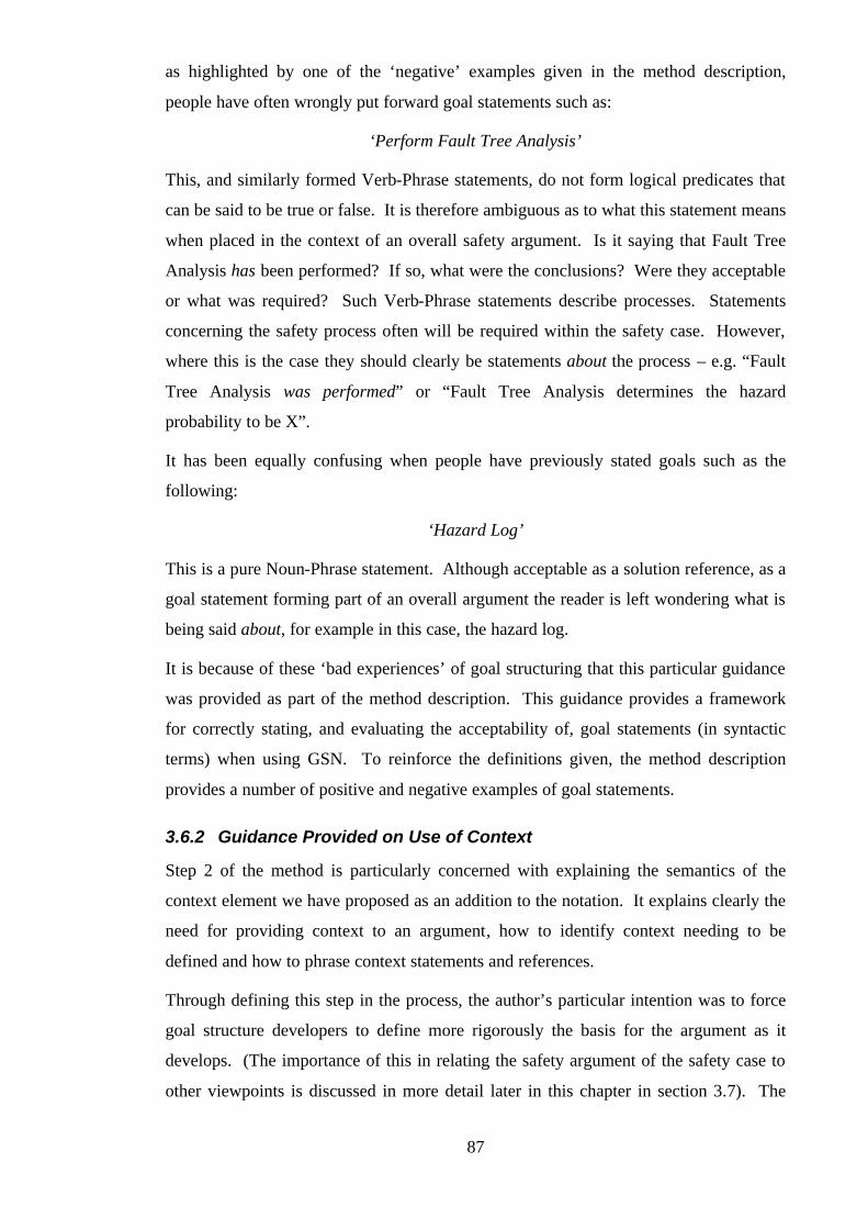
87
as highlighted by one of the ‘negative’ examples given in the method description,
people have often wrongly put forward goal statements such as:
‘Perform Fault Tree Analysis’
This, and similarly formed Verb-Phrase statements, do not form logical predicates that
can be said to be true or false. It is therefore ambiguous as to what this statement means
when placed in the context of an overall safety argument. Is it saying that Fault Tree
Analysis has been performed? If so, what were the conclusions? Were they acceptable
or what was required? Such Verb-Phrase statements describe processes. Statements
concerning the safety process often will be required within the safety case. However,
where this is the case they should clearly be statements about the process – e.g. “Fault
Tree Analysis was performed” or “Fault Tree Analysis determines the hazard
probability to be X”.
It has been equally confusing when people have previously stated goals such as the
following:
‘Hazard Log’
This is a pure Noun-Phrase statement. Although acceptable as a solution reference, as a
goal statement forming part of an overall argument the reader is left wondering what is
being said about, for example in this case, the hazard log.
It is because of these ‘bad experiences’ of goal structuring that this particular guidance
was provided as part of the method description. This guidance provides a framework
for correctly stating, and evaluating the acceptability of, goal statements (in syntactic
terms) when using GSN. To reinforce the definitions given, the method description
provides a number of positive and negative examples of goal statements.
3.6.2 Guidance Provided on Use of Context
Step 2 of the method is particularly concerned with explaining the semantics of the
context element we have proposed as an addition to the notation. It explains clearly the
need for providing context to an argument, how to identify context needing to be
defined and how to phrase context statements and references.
Through defining this step in the process, the author’s particular intention was to force
goal structure developers to define more rigorously the basis for the argument as it
develops. (The importance of this in relating the safety argument of the safety case to
other viewpoints is discussed in more detail later in this chapter in section 3.7). The

88
virtue of providing context is that it can help the engineer to understand the dependence
of a safety argument on other forms of information arising from other viewpoints. It
can also in some cases provide a transparent and systematic basis for the decomposition
of the safety argument (i.e. where an argument is structured around a defined context).
3.6.3 Guidance Provided on Semantics of Strategy
Step 3 of the method is concerned with explaining clearly the purpose and use of the
‘strategy’ element within a goal structure. Previously, in goal structures that have been
developed, there had been some confusion on the role of strategy. Some authors had
used strategy to communicate selection of (albeit safety-concerned) design strategies,
e.g. “Use of mechanical interlocks” as a strategy for dealing with a hazard as shown in
Figure 35.
Probability of Hazard H1 occuringis acceptably low
G3
Sn1
Use mechanical interlocks
Mechanical interlocks fittedare acceptably reliable
G4
Figure 35 - Incorrect use of Strategy to Communicate Design Strategy
Although it is fairly easy to see what is implied by the structure shown in Figure 35, the
purpose of strategy within the notation is to communicate the argument approach being
adopted to support claims of the safety argument, rather than to communicate design
strategy. Of course, these two views can coincide and it is possible for the argument
approach to depend heavily upon the design approach that has been adopted. It is just
so for the example shown in Figure 35. However, to make it more explicit that the use
of interlocks forms the basis of the argument strategy, the strategy could be re-
expressed in the form shown in Figure 36. An added advantage of this approach is that,
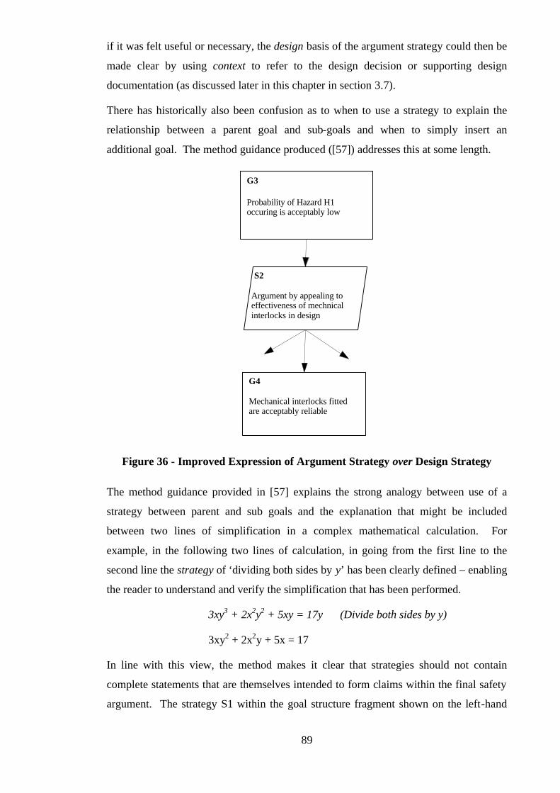
89
if it was felt useful or necessary, the design basis of the argument strategy could then be
made clear by using context to refer to the design decision or supporting design
documentation (as discussed later in this chapter in section 3.7).
There has historically also been confusion as to when to use a strategy to explain the
relationship between a parent goal and sub-goals and when to simply insert an
additional goal. The method guidance produced ([57]) addresses this at some length.
Probability of Hazard H1occuring is acceptably low
G3
S2
Argument by appealing toeffectiveness of mechnicalinterlocks in design
Mechanical interlocks fittedare acceptably reliable
G4
Figure 36 - Improved Expression of Argument Strategy over Design Strategy
The method guidance provided in [57] explains the strong analogy between use of a
strategy between parent and sub goals and the explanation that might be included
between two lines of simplification in a complex mathematical calculation. For
example, in the following two lines of calculation, in going from the first line to the
second line the strategy of ‘dividing both sides by y’ has been clearly defined – enabling
the reader to understand and verify the simplification that has been performed.
3xy3 + 2x2y2 + 5xy = 17y (Divide both sides by y)
3xy2 + 2x2y + 5x = 17
In line with this view, the method makes it clear that strategies should not contain
complete statements that are themselves intended to form claims within the final safety
argument. The strategy S1 within the goal structure fragment shown on the left-hand

90
side of Figure 37 contains the statement ‘All hazards have been removed’. This is not
expressing an argument strategy but is instead making a safety claim. If this claim is
intended to form part of the central logic of the safety argument then it would be more
appropriate to state it as a goal, as shown in the central fragment of goal structure in
Figure 37. Alternatively, if instead the purpose of making the statement was to clarify
that the argument was being structured around addressing all of the identified system
hazards in turn then it would be more appropriate to explicitly clearly state this as the
argument approach. This is shown in the goal structure fragment shown on the right
hand side of Figure 37.
System is acceptablysafe
G1
S1
All hazards have beenremoved
Hazard H1 has beenremoved
G3
System is acceptablysafe
G1
All hazards have beenremoved
G2
Hazard H1 has beenremoved
G3
System is acceptablysafe
G1
S1
Argument over allhazards
Hazard H1 has beenremoved
G3
Figure 37 – Comparison of Using Strategies and Goals
In order to guide the developer towards the correct usage of strategy, the method
recommends that strategies should be expressed in one of the following forms:
“Argument by <approach>”
“Approach over <approach>”
“Argument using <approach>”
“Argument of <approach>”
This format is intended to constrain strategy statements to descriptive Noun-Phrase
statements – the focus of these being the argument itself. This ensures that strategy
statements remain at the meta-argument level – thus reducing the likelihood of
incorrectly using strategies for statements that should be within the argument.
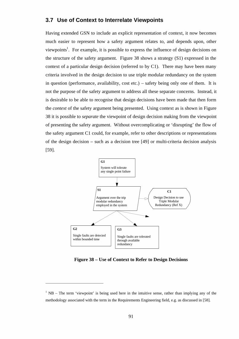
91
3.7 Use of Context to Interrelate Viewpoints
Having extended GSN to include an explicit representation of context, it now becomes
much easier to represent how a safety argument relates to, and depends upon, other
viewpoints1. For example, it is possible to express the influence of design decisions on
the structure of the safety argument. Figure 38 shows a strategy (S1) expressed in the
context of a particular design decision (referred to by C1). There may have been many
criteria involved in the design decision to use triple modular redundancy on the system
in question (performance, availability, cost etc.) – safety being only one of them. It is
not the purpose of the safety argument to address all these separate concerns. Instead, it
is desirable to be able to recognise that design decisions have been made that then form
the context of the safety argument being presented. Using context as is shown in Figure
38 it is possible to separate the viewpoint of design decision making from the viewpoint
of presenting the safety argument. Without overcomplicating or ‘disrupting’ the flow of
the safety argument C1 could, for example, refer to other descriptions or representations
of the design decision – such as a decision tree [49] or multi-criteria decision analysis
[59].
System will tolerateany single point failure
G1
C1
Design Decision to useTriple Modular
Redundancy (Ref X)
S1
Argument over the tripmodular redundancyemployed in the system
Single faults are detectedwithin bounded time
G2
Single faults are toleratedthrough availableredundancy
G3
Figure 38 – Use of Context to Refer to Design Decisions
1 NB – The term ‘viewpoint’ is being used here in the intuitive sense, rather than implying any of the
methodology associated with the term in the Requirements Engineering field, e.g. as discussed in [58].
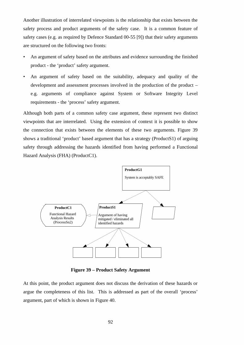
92
Another illustration of interrelated viewpoints is the relationship that exists between the
safety process and product arguments of the safety case. It is a common feature of
safety cases (e.g. as required by Defence Standard 00-55 [9]) that their safety arguments
are structured on the following two fronts:
• An argument of safety based on the attributes and evidence surrounding the finished
product - the ‘product’ safety argument.
• An argument of safety based on the suitability, adequacy and quality of the
development and assessment processes involved in the production of the product –
e.g. arguments of compliance against System or Software Integrity Level
requirements - the ‘process’ safety argument.
Although both parts of a common safety case argument, these represent two distinct
viewpoints that are interrelated. Using the extension of context it is possible to show
the connection that exists between the elements of these two arguments. Figure 39
shows a traditional ‘product’ based argument that has a strategy (ProductS1) of arguing
safety through addressing the hazards identified from having performed a Functional
Hazard Analysis (FHA) (ProductC1).
System is acceptably SAFE
ProductG1
ProductS1
Argument of havingmitigated / eliminated allidentified hazards
ProductC1
Functional HazardAnalysis Results
(ProcessSn2)
Figure 39 – Product Safety Argument
At this point, the product argument does not discuss the derivation of these hazards or
argue the completeness of this list. This is addressed as part of the overall ‘process’
argument, part of which is shown in Figure 40.

93
In Figure 40 the argument is not that the product is safe, but is instead that the process
by which the product was developed and assessed was ‘safe’ (in this case, effective in
identifying hazards). The strand of this argument shown addresses the safety claims
regarding the Hazard Identification and Assessment performed for the product
(ProcessG2). In support of ProcessG2, claims are made regarding the activities, set
clearly in the context of the information they have relied upon.
The results derived by the Preliminary Hazard Identification (PHI) activity (ProcessSn1)
are presented both as evidence to support the PHI claim (ProcessG3) and as the context
for the claim regarding the Functional Hazard Assessment (FHA) activity (ProcessG4).
The results of the FHA, put forward as evidence supporting ProcessG4, form the
context (ProductC1) of the product argument strategy (ProductS1).
As illustrated, using the representation of context within the GSN it is possible to show
how evidence used as part of the product argument was derived and also how it formed
part of the process argument. Such ‘separation of concerns’ means that arguments can
clearly focus upon one issue while being explicitly related to arguments addresses other
issues.
3.8 Relationship between Goal Structuring Method and Safety
Argument Evolution
Where development of a safety argument using goal structuring is run in parallel with
safety case development it is not expected that the method steps identified can be
performed repeatedly until all identified goals are decomposed to direct references to
supporting evidence. Instead, the goal structure will usually progress in a number of
stages. Figure 41 illustrates the evolution of a typical goal-structured safety argument.
Down the left-hand side of Figure 41 there is an indication of the levels of claim that
might stated at the different levels within a typical goal-structured safety argument.
Towards the top of the goal structure general safety objectives are stated whereas
towards the bottom the claims become increasingly focussed towards the forms of
supporting evidence that are available. Down the right-hand side, there is an indication
of the progression of the safety and design activity necessary to enable the evolution of
the goal structure. (‘NSPF’ = No Single Point of Failure)
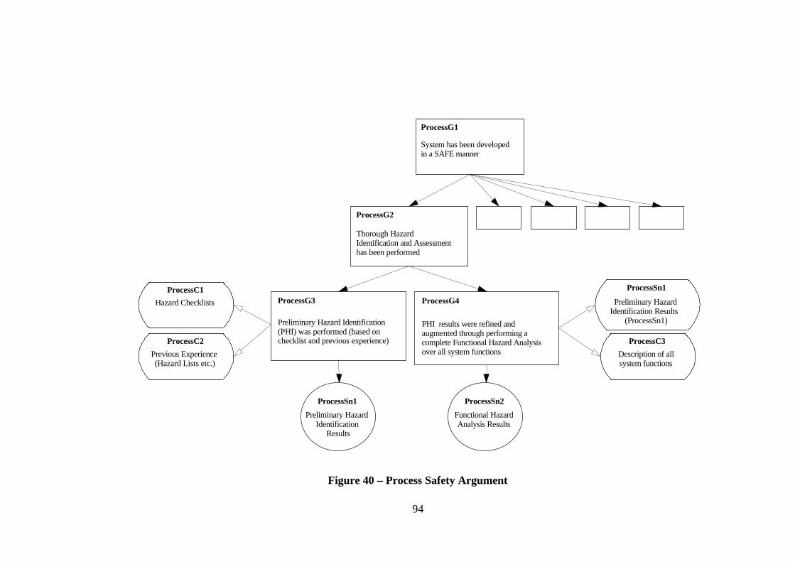
94
System has been developedin a SAFE manner
ProcessG1
Thorough HazardIdentification and Assessmenthas been performed
ProcessG2
Preliminary Hazard Identification(PHI) was performed (based onchecklist and previous experience)
ProcessG3ProcessC1
Hazard Checklists
ProcessC2
Previous Experience(Hazard Lists etc.)
PHI results were refined andaugmented through performing acomplete Functional Hazard Analysisover all system functions
ProcessG4
ProcessSn1
Preliminary HazardIdentification
Results
ProcessC3
Description of allsystem functions
ProcessSn1
Preliminary HazardIdentification Results
(ProcessSn1)
ProcessSn2
Functional HazardAnalysis Results
Figure 40 – Process Safety Argument
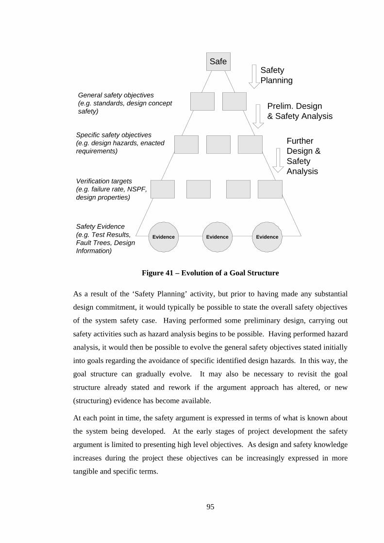
95
SafeSafetyPlanning
Prelim. Design& Safety Analysis
FurtherDesign &SafetyAnalysis
General safety objectives(e.g. standards, design conceptsafety)
Specific safety objectives(e.g. design hazards, enactedrequirements)
Verification targets(e.g. failure rate, NSPF,design properties)
Evidence Evidence Evidence
Safety Evidence(e.g. Test Results,Fault Trees, DesignInformation)
Figure 41 – Evolution of a Goal Structure
As a result of the ‘Safety Planning’ activity, but prior to having made any substantial
design commitment, it would typically be possible to state the overall safety objectives
of the system safety case. Having performed some preliminary design, carrying out
safety activities such as hazard analysis begins to be possible. Having performed hazard
analysis, it would then be possible to evolve the general safety objectives stated initially
into goals regarding the avoidance of specific identified design hazards. In this way, the
goal structure can gradually evolve. It may also be necessary to revisit the goal
structure already stated and rework if the argument approach has altered, or new
(structuring) evidence has become available.
At each point in time, the safety argument is expressed in terms of what is known about
the system being developed. At the early stages of project development the safety
argument is limited to presenting high level objectives. As design and safety knowledge
increases during the project these objectives can be increasingly expressed in more
tangible and specific terms.

96
Evolution of the safety argument following the steps of the method we have defined,
means that for a particular state of project development there will be a point at which it
is not possible to progress to the next step in the method. For example, it may be
possible to state an objective in Step 1 and to identify the context required to fully
define that objective (Step 2) – but not actually to have that information at that point in
the project. In the press example shown in Figure 30, the need for a definition of the
press design operation and plant installation may have been recognised. However, at an
early stage in the project this information may not be fully defined. In such a case, it
would be necessary for the information to be provided before one could be expected to
continue further with the safety argument. As discussed in the previous section, this use
of context shows how the safety argument (at a particular point) depends upon
information from other viewpoints – in this case the design viewpoint.
Similarly, it may be that Step1 and Step 2 can be completed (i.e. identified and context-
defined goals exist) but that a strategy for the argument cannot be identified. As
discussed in the method ([57]) argument strategies can emerge from any number of
sources (design attributes, safety evidence, ALARP – As Low As Reasonably
Practicable - analyses etc.). It is often the case that significant effort will be required
before an acceptable argument approach can be proposed. Consider again the press
example shown in Figure 31. A preliminary safety planning activity may have to be
carried out before the two strategies shown in Figure 31 can be defined.
The contribution identified in this chapter provides two particular areas of support in the
evolution of safety arguments:
• The addition of context makes it possible to see how the definition of the safety
argument relates to, and ‘waits for’, information collated from activities outside of
argument construction.
• The method defined (especially through Steps 2, 3 and 4) makes it clear at each
stage what is required in order to progress the argument further. Following
‘interruptions’ to the evolution of the argument, the method also makes explicit the
next step in development to be performed (i.e. if the development was halted after
Step 2, development begins again at Step 3).
97
3.9 Experience of Using Goal Structuring in Presentation of
Preliminary Safety Arguments
Goal Structuring has been applied in presenting Preliminary Safety Arguments on a
number of projects, including:
• Preliminary Safety Argument for a Site Safety Justification – The GSN Method
was used by Rolls-Royce Marine Power in the early stages of developing a Site
Safety Justification for a Naval Facility. In this project a daunting number of safety
requirements existed and GSN was used as part of a group exercise to help the
engineers begin to appreciate the scope of the problem, and to identify possible
argument strategies. The top layers of the safety argument were constructed as a
result of iterating through steps 1-5, but few solutions (Step 6) were provided. This
application of the GSN Method helped the project to begin to structure their
approach to constructing the site safety arguments.
• Preliminary Safety Argument for a Distributed Aero-Engine Controller - The
use of GSN in supporting an evolving safety argument was piloted for Rolls-Royce
Aerospace in developing a preliminary safety argument for a novel distributed
engine controller. The preliminary safety argument is presented later on in this
chapter in section 3.9. As with the site safety arguments, the goal structures present
the results of iterating through the GSN method steps 1-5, but given the preliminary
nature of the design, few solutions (the result of Step 6) are provided. The main
conclusions from this work were that the resulting goal structure aided the process
of agreeing the safety case, helped gain confidence in the ability to present a
complete safety case and provided tangible safety objectives for the project.
• Generic Preliminary Safety Argument for Integrated Modular Avionics (IMA)
Systems – Based on work published by Fletcher [60], the author has used goal
structuring to set out clearly the principal safety (and certification) objectives facing
Integrated Modular Avionics (IMA) systems. The structure developed was used to
communicate the safety framework in which IMA solutions are suggested.
In all these cases the arguments were truly preliminary – safety objectives remained
unsatisfied, supporting evidence was not yet available. The purpose of constructing the
arguments was, in all cases, to scope clearly the concerns of the final safety case – the
key hazards to be addressed, standards to be complied with etc. – and to begin to outline
98
the argument and evidence that would be used to address these concerns. As stated
earlier in the chapter, one of the significant benefits of the notation is that it provides
engineers with a medium for describing and discussing an evolving safety argument
quite separately from the onerous responsibility of producing certification
documentation. Chapter Six presents some additional conclusions arising out of this
evaluation of the GSN Method.
As an example of how goal structuring can be used in the early stages of an evolving
safety case, the following section describes the preliminary safety argument developed
jointly by the author with Iain Bate for a distributed aero-engine controller architecture.
It should be noted that this work has been used as a basis for a real industrial project (as
part of Rolls-Royce’s contribution to the U.K. Ministry of Defence funded HIgh
Performance Engine Control System project – HIPECS). The purpose of constructing
the preliminary safety argument was to increase confidence in the ability to certify this
type of system before committing to full-blown development of the architecture (i.e. to
reduce the project risk associated with certification).
3.9.1 A Preliminary Safety Argument for a Distributed Aero-Engine Controller
Traditionally engine controllers have been based on a centralised uni-processor
approach, with direct-wired electrical cabling to all engine sensors and actuators. There
are potential cost and weight savings that can be achieved through adopting a
distributed approach – by using ‘smart’ sensors and actuators and a common databus
rather than many individual cables. In addition, distributed processing units can provide
additional flexibility and scalability in implementing the core controller functions.
However, the distributed approach is new and therefore attracts particular scrutiny in
certification (as is commonly the case for novel concepts in the aerospace sector). For
this reason, it has been especially important to construct a clearly defined argument, at
the earliest possible opportunity, for the safety of this platform.
In this example, we purposefully provide a simplified overview of the distributed
approach, as our principal aim is to discuss the safety case. There are many complex
issues, such as vote synchronisation and processor state recovery, that are outside the
scope of this paper.
99
Title:/tmp/xfig-fig017158Creator:fig2devPreview:This EPS picture was not savedwith a preview included in it.Comment:This EPS picture will print to aPostScript printer, but not toother types of printers.
Figure 42 - Subsystem Structure
In describing the architecture, the following two terms are used:
• Component – a device that performs some function
• Subsystem – a configuration of replicated components performing identical
functions (so that faults may be tolerated)
The proposed architecture consists of a number of subsystems that together would
execute the software found on a conventional electronic engine controller. Figure 42
shows the top-level design of a single subsystem.
Each subsystem consists of the following elements:
1. Voter - An exact consensus voter that compares the output values of three or more
replicated components and can identify failures if value differences are present. In
the event of an identified failure a reset signal is sent to the corresponding
component. The component will restart, but will be taken out of service if several
resets are required in quick succession. When a component is recognised as being
out of service the voter will no longer use its output.
2. Processor - The architecture places minimal restrictions on the specific
microprocessors to be used (in order to support ‘technology transparency’ [61]).
Provided the processors have comparable throughput they may be used within a
single subsystem (as the voting logic and scheduling approach facilitates lock
stepping). Processor tasks are scheduled using the fixed priority approach [62].
3. Timing Watchdog - A countdown timer that will detect processor timing overruns.
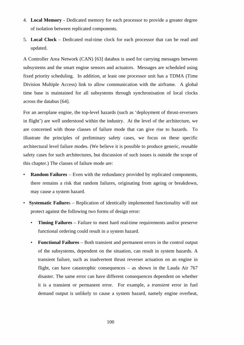
100
4. Local Memory - Dedicated memory for each processor to provide a greater degree
of isolation between replicated components.
5. Local Clock – Dedicated real-time clock for each processor that can be read and
updated.
A Controller Area Network (CAN) [63] databus is used for carrying messages between
subsystems and the smart engine sensors and actuators. Messages are scheduled using
fixed priority scheduling. In addition, at least one processor unit has a TDMA (Time
Division Multiple Access) link to allow communication with the airframe. A global
time base is maintained for all subsystems through synchronisation of local clocks
across the databus [64].
For an aeroplane engine, the top-level hazards (such as ‘deployment of thrust-reversers
in flight’) are well understood within the industry. At the level of the architecture, we
are concerned with those classes of failure mode that can give rise to hazards. To
illustrate the principles of preliminary safety cases, we focus on these specific
architectural level failure modes. (We believe it is possible to produce generic, reusable
safety cases for such architectures, but discussion of such issues is outside the scope of
this chapter.) The classes of failure mode are:
• Random Failures – Even with the redundancy provided by replicated components,
there remains a risk that random failures, originating from ageing or breakdown,
may cause a system hazard.
• Systematic Failures – Replication of identically implemented functionality will not
protect against the following two forms of design error:
• Timing Failures – Failure to meet hard real-time requirements and/or preserve
functional ordering could result in a system hazard.
• Functional Failures – Both transient and permanent errors in the control output
of the subsystems, dependent on the situation, can result in system hazards. A
transient failure, such as inadvertent thrust reverser actuation on an engine in
flight, can have catastrophic consequences – as shown in the Lauda Air 767
disaster. The same error can have different consequences dependent on whether
it is a transient or permanent error. For example, a transient error in fuel
demand output is unlikely to cause a system hazard, namely engine overheat,
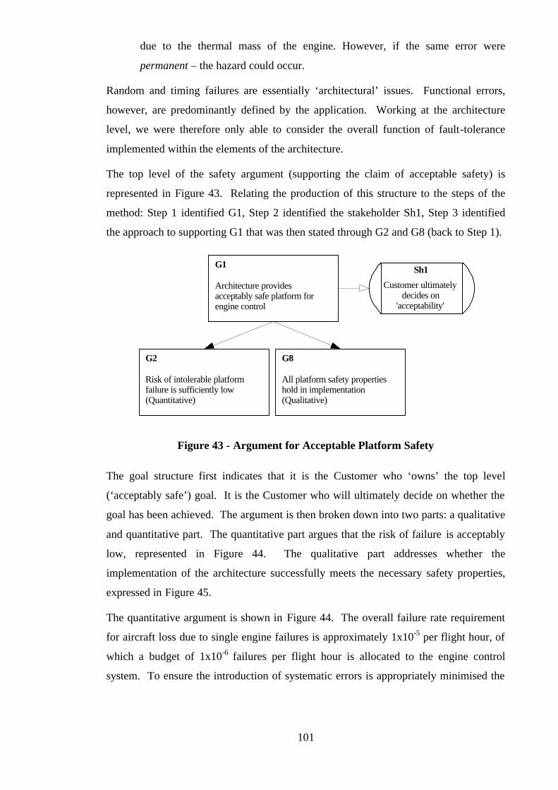
101
due to the thermal mass of the engine. However, if the same error were
permanent – the hazard could occur.
Random and timing failures are essentially ‘architectural’ issues. Functional errors,
however, are predominantly defined by the application. Working at the architecture
level, we were therefore only able to consider the overall function of fault-tolerance
implemented within the elements of the architecture.
The top level of the safety argument (supporting the claim of acceptable safety) is
represented in Figure 43. Relating the production of this structure to the steps of the
method: Step 1 identified G1, Step 2 identified the stakeholder Sh1, Step 3 identified
the approach to supporting G1 that was then stated through G2 and G8 (back to Step 1).
Architecture providesacceptably safe platform forengine control
G1
Risk of intolerable platformfailure is sufficiently low(Quantitative)
G2
All platform safety propertieshold in implementation (Qualitative)
G8
Customer ultimatelydecides on
'acceptability'
Sh1
Figure 43 - Argument for Acceptable Platform Safety
The goal structure first indicates that it is the Customer who ‘owns’ the top level
(‘acceptably safe’) goal. It is the Customer who will ultimately decide on whether the
goal has been achieved. The argument is then broken down into two parts: a qualitative
and quantitative part. The quantitative part argues that the risk of failure is acceptably
low, represented in Figure 44. The qualitative part addresses whether the
implementation of the architecture successfully meets the necessary safety properties,
expressed in Figure 45.
The quantitative argument is shown in Figure 44. The overall failure rate requirement
for aircraft loss due to single engine failures is approximately 1x10⁻⁵ per flight hour, of
which a budget of 1x10⁻⁶ failures per flight hour is allocated to the engine control
system. To ensure the introduction of systematic errors is appropriately minimised the

102
system will be developed to Development Assurance Level A (defined by the civil
aerospace development guidelines DO-178B [65]).
The qualitative argument that the safety properties of the system hold is more complex.
There are two aspects to the argument, shown in Figure 45, to address the functional
and non-functional safety properties of the system. The non-functional safety properties
of the system concern the timing and resource behaviour. (Resource exhaustion has
been identified as a potential cause of both timing and application function failures.)
Experience shows that correct resource requirements are difficult to predict, and this
frequently leads to rework being carried out to increase resource capability or to
optimise the use of resources. Our technique for addressing this problem is to make the
architecture scalable, allowing extra subsystems to be added with the minimum of
effort.
The argument of timing behaviour correctness (shown in Figure 46) consists of two
parts: whether the timing requirements are correct and whether the requirements are
satisfied. The timing requirements come from two sources, most are historical values
related to the control loops of the engine which are known to provide stable and
effective performance. The relevancy of the control timing requirements to this
particular project is first checked using extensive simulation of an engine model, and
later through extensive engine trials throughout the operating envelope. In addition,
there are design-derived requirements obtained via the hazard analysis process. An
example of this type of requirement is shown in Figure 47 through goals G24 and G25,
where a time bound for fault recovery is defined to reduce the period for which the
architecture is at risk to additional errors. To verify that the timing requirements are
met requires a deterministic scheduling policy, to allow appropriate analysis to be
performed. Our solution is to use non pre-emptive fixed priority scheduling, which has
a firm mathematical basis and determinable control flow.
103
Risk of intolerable platformfailure is sufficiently low(Quantitative)
G2
Random failure rate contributionsto intolerable platform failure aresufficiently low
G3
Systematic error contribution tointolerable platform failure issufficiently low
G4
C2
'Intolerable platform failure' =omission, commission, value ortiming failure of control output
C3
Random failure contributions(and budgets) determined
through Fault Tree Analysis oftop event 'catastrophic failure'
G5
Component reliability targetsshown to be met by ComponentFMEA tables
C1
'Sufficient' = platform meetstarget failure rate of 1 x10⁻⁶ per
flight hour
Tools, techniques and methodswere used appropriate to theseverity of identified failures
G6 C4
Worst case severity associatedwith consequences of platformfailure assessed as Catastrophic
G7
System developed to DevelopmentAssurance Level A processguidelines
Development Assurance Level Aappropriate for systems whose
consequences of failure would beCatastrophic
J1
J
Figure 44 - Argument for Sufficiently Low Risk
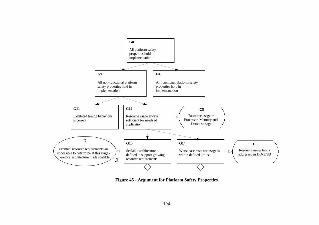
104
All platform safetyproperties hold inimplementation
G8
All non-functional platformsafety properties hold inimplementation
G9
All functional platform safetyproperties hold inimplementation
G10
Exhibited timing behaviouris correct
G11
Resource usage alwayssufficient for needs ofapplication
G12
G13
Scalable architecturedefined to support growingresource requirements
Eventual resource requirements areimpossible to determine at this stage -therefore, architecture made scalable
J2
J
G14
Worst case resource usage iswithin defined limits
C5
'Resource usage' =Processor, Memory and
Databus usage
C6
Resource usage limitsaddressed in DO-178B
Figure 45 - Argument for Platform Safety Properties
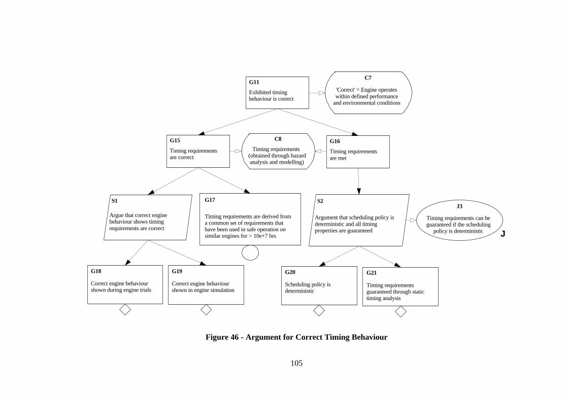
105
Timing requirementsare correct
G15
Timing requirementsare met
G16
S1
Argue that correct enginebehaviour shows timingrequirements are correct
C8
Timing requirements (obtained through hazardanalysis and modelling)
G17
Timing requirements are derived froma common set of requirements thathave been used in safe operation onsimilar engines for > 10e+7 hrs
G19
Correct engine behaviourshown in engine simulation
G18
Correct engine behaviourshown during engine trials
C7
'Correct' = Engine operateswithin defined performance
and environmental conditions
S2
Argument that scheduling policy isdeterministic and all timingproperties are guaranteed
G20
Scheduling policy isdeterministic
G21
Timing requirementsguaranteed through statictiming analysis
Timing requirements can beguaranteed if the scheduling
policy is deterministic
J3
J
Exhibited timingbehaviour is correct
G11
Figure 46 - Argument for Correct Timing Behaviour
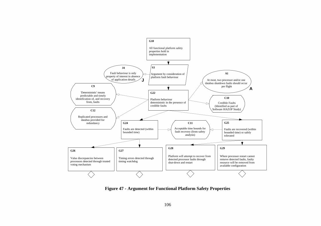
106
Platform behaviourdeterministic in the presence ofcredible faults
G22
G26
Value discrepancies betweenprocessors detected through trustedvoting mechanism
G27
Timing errors detected throughtiming watchdog
G28
Platform will attempt to recover fromdetected processor faults throughshut-down and restart
All functional platform safetyproperties hold inimplementation
G10
S3
Argument by consideration ofplatform fault behaviour
Fault behaviour is onlyproperty of interest in absence
of application details
J4
J
G29
Where processor restart cannotremove detected faults, faultyresource will be removed fromavailable configuration
Faults are detected (withinbounded time)
G24
Faults are recovered (withinbounded time) or safelytolerated
G25
C9
'Deterministic' meanspredictable and timely
identification of, and recoveryfrom, faults
C11
Acceptable time bounds forfault recovery (from safety
analysis)
C10
Credible Faults(Identified as part of
Software HAZOP Study)
A1
At most, two processor and/or onedatabus shutdown faults should occur
per flightA
C12
Replicated processors anddatabus provided for
redundancy
Figure 47 - Argument for Functional Platform Safety Properties
107
The final part of our argument is shown in Figure 47, and predominantly concerns the
fault-tolerance behaviour of the platform. The aim is to have a platform that operates
deterministically even in the presence of faults. The faults are to be identified and
recovered, where possible, within a bounded period of time (in order that overall timing
requirements can be guaranteed). Value and timing errors are identified in separate
ways, but handled in the same manner. Value errors are identified using the trusted
voting mechanism. A triplex processor architecture has been initially proposed as this
will allow the voter to additionally identify the source of detected errors. For
commercial reasons, related to the weight of cabling, only two databuses will be
provided. However, the CAN databus is considered to be highly fault tolerant in its
own right with the ability to withstand a wide variety of single and multiple errors.
Timing errors are identified using the timing watchdog. Recovery from detected
processor faults is attempted by restarting the offending processor. Where recovery
from failures is not possible, the offending component is taken out of service.
Within this section we have briefly presented a preliminary safety argument which has
derived a number of architecture dependent criteria that must be achieved if the system
is to be safe. The undeveloped goals in our safety arguments represent the criteria for
judging the appropriateness of any architecture under consideration. The criteria could
be met by a number of different architectural combinations. For example, the
component reliability requirement may be achieved using either one ultra-reliable
component, or a network of replicated components. The manner in which the
requirements are satisfied will be part of the developing system design and will be
presented in the final (operational) safety case. Production of the preliminary safety
case has increased confidence that the final certification case can be made. It can also
be used to influence the design such that the safety objectives identified can be more
easily satisfied.
3.10 Nuclear Trip System Safety Case Example
Appendix A illustrates the use of the Goal Structuring Notation in the construction and
presentation of a safety case for a Nuclear Trip System. The technical basis of the
safety case and textual description has been taken directly from an example produced by
Adelard [36]. Goal structures have been integrated with this information to
communicate the implicit structure explicitly and to improve the traceability of the
safety argument.

108
In the Adelard example, three key devices were used to communicate the flow of the
safety argument:
• Traceability Matrices (mapping requirements to design features)
• Tabular Arguments
• Cross-references within safety case text
The appendix has instead used goal structures (constructed according to the goal
structuring method defined in [57]) as the principal device for presenting the safety
arguments.
Traceability matrices were used in [36] to indicate the mapping that existed between the
overall requirements of the safety case (Appendix A section 5) and the features of the
proposed design solution (Appendix A section 6). For example, the traceability matrix
communicates that the design feature ‘Design Simplicity’ is related to the overall
response time requirement. The difficulty with this approach is that the matrix does not
(and cannot) communicate how the design feature supports or relates to the requirement.
The goal structures presented in Appendix A sections 7-11, however, perform the same
role of relating the design features (referenced using GSN context elements) to the
overall goals of the safety case but additionally (through use of an interim goal) explain
the relationship that exists between them.
Tabular arguments were used in [36] for certain aspects of the safety argument (those
addressing probability of failure on demand, timing and system updates). The
difficulties with the tabular approach to presenting safety arguments have already been
discussed in Chapter Two, section 2.5.2. The difficulty in their use here is that there is
no discipline in the expression of the arguments described under the ‘Argument’
heading. Consequently, arguments are in some cases described only very generally (e.g.
‘Hardware reliability tests’). The goal structures presented in Appendix A sections 7-11
handle the hierarchic decomposition of some of the more complex arguments more
easily. At the same time they introduce the missing discipline by forcing statements
(goals) to be properly formed as propositions, and by insisting that the role of evidence
(solutions) is stated explicitly.
The safety argument structure is also implicitly communicated in the Adelard safety
case through the use of cross-references embedded within the text. For example, the
following sentence taken from [36] contains the cross-reference that relates the
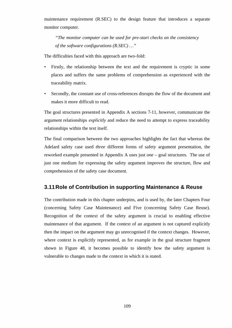
109
maintenance requirement (R.SEC) to the design feature that introduces a separate
monitor computer.
“The monitor computer can be used for pre-start checks on the consistency
of the software configurations (R.SEC) …”
The difficulties faced with this approach are two-fold:
• Firstly, the relationship between the text and the requirement is cryptic in some
places and suffers the same problems of comprehension as experienced with the
traceability matrix.
• Secondly, the constant use of cross-references disrupts the flow of the document and
makes it more difficult to read.
The goal structures presented in Appendix A sections 7-11, however, communicate the
argument relationships explicitly and reduce the need to attempt to express traceability
relationships within the text itself.
The final comparison between the two approaches highlights the fact that whereas the
Adelard safety case used three different forms of safety argument presentation, the
reworked example presented in Appendix A uses just one – goal structures. The use of
just one medium for expressing the safety argument improves the structure, flow and
comprehension of the safety case document.
3.11 Role of Contribution in supporting Maintenance & Reuse
The contribution made in this chapter underpins, and is used by, the later Chapters Four
(concerning Safety Case Maintenance) and Five (concerning Safety Case Reuse).
Recognition of the context of the safety argument is crucial to enabling effective
maintenance of that argument. If the context of an argument is not captured explicitly
then the impact on the argument may go unrecognised if the context changes. However,
where context is explicitly represented, as for example in the goal structure fragment
shown in Figure 48, it becomes possible to identify how the safety argument is
vulnerable to changes made to the context in which it is stated.

110
Aircraft safe to operate withindefined operating limits
Aircraft OperatingLimits
Figure 48 - Context Change Example
Figure 48 shows the recorded dependency between the claim regarding
aircraft safe operation and the context of the set of defined aircraft
operating limits. If these limits were changed at any time, the context
reference would be challenged (as depicted by the strike through). The
relationship between this context and associated goals would also be
challenged (as shown). From this it would it is possible to recognise that
the safety claim might be affected.
As discussed in section 3.7, context can be used within the notation to show how the
safety argument depends upon information arising from different viewpoints. Every
time this is done within a goal structure, additional information is being added that
communicates how changes arising from these viewpoints can propagate through and
impact the safety argument. For example, consider the goal structure previously shown
in Figure 38 where the dependence of the safety argument on a design decision is
represented. If the referenced decision is changed at a later stage this recorded link will
help to identify the impact on the argument strategy adopted.
Context also plays an important role in defining the applicability of the Safety Case
Patterns presented in Chapter Five. Using the representation of context it is possible to
show what information must be defined in order to construct a certain safety argument
structure. For example, in the following figure (Figure 49), (uninstantiated) context is
used to denote that in order to construct an argument structured around management of
hazards, a list of hazards must be provided. (For a full description of this pattern and
the notation used see Chapter Five.)
The role of the GSN method in supporting the work presented in Chapters Four and
Five is less immediate than that fulfilled by the introduction of context, but is
nevertheless crucial. In order to provide maximum support to the safety case
maintenance process (particularly impact analysis based on the goal structure) it is
important that the goal structure is well formed and well stated. Obeying the rules
defined by the method for the phrasing of goal statements as Noun-Phrase Verb-Phrase
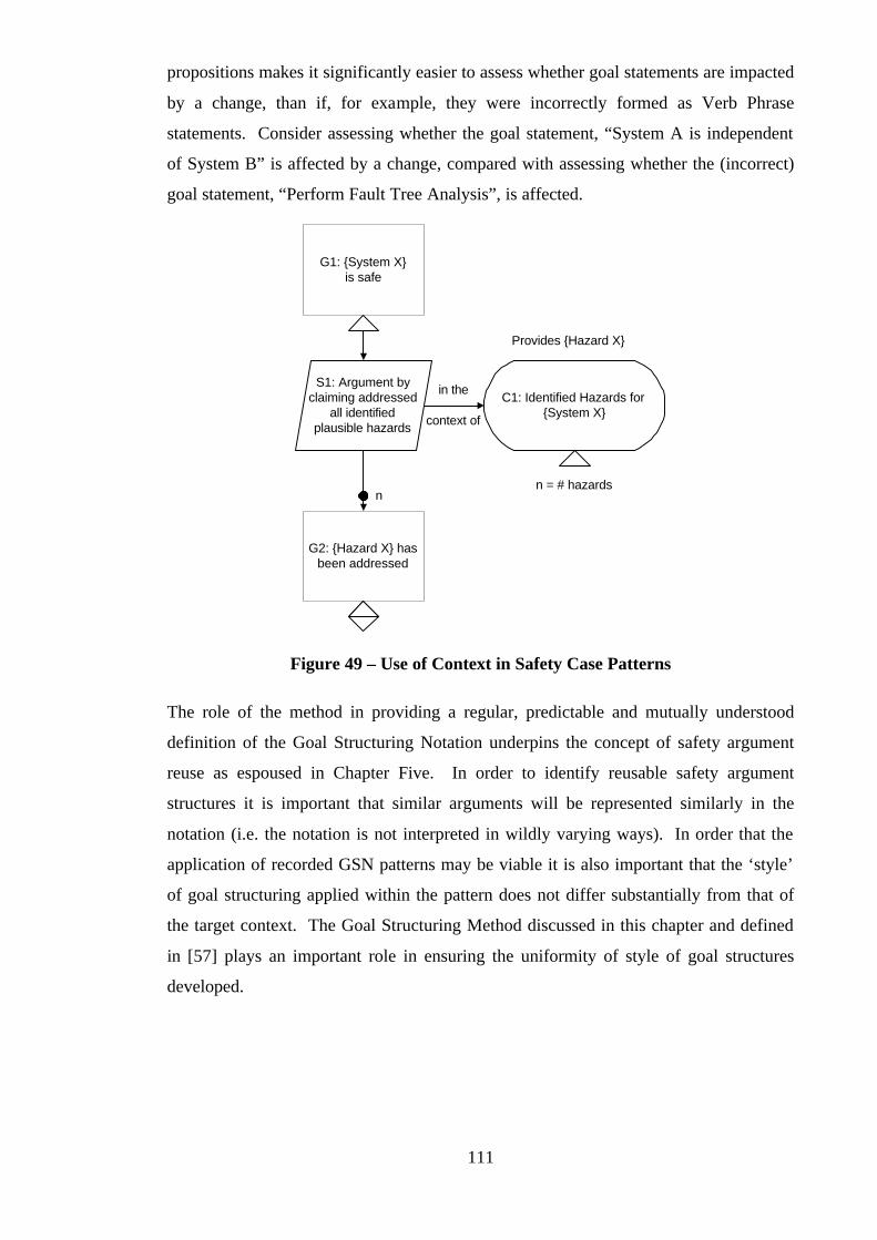
111
propositions makes it significantly easier to assess whether goal statements are impacted
by a change, than if, for example, they were incorrectly formed as Verb Phrase
statements. Consider assessing whether the goal statement, “System A is independent
of System B” is affected by a change, compared with assessing whether the (incorrect)
goal statement, “Perform Fault Tree Analysis”, is affected.
G1: {System X}is safe
S1: Argument byclaiming addressed
all identifiedplausible hazards
C1: Identified Hazards for{System X}
in the
context of
n = # hazards
Provides {Hazard X}
G2: {Hazard X} hasbeen addressed
n
Figure 49 – Use of Context in Safety Case Patterns
The role of the method in providing a regular, predictable and mutually understood
definition of the Goal Structuring Notation underpins the concept of safety argument
reuse as espoused in Chapter Five. In order to identify reusable safety argument
structures it is important that similar arguments will be represented similarly in the
notation (i.e. the notation is not interpreted in wildly varying ways). In order that the
application of recorded GSN patterns may be viable it is also important that the ‘style’
of goal structuring applied within the pattern does not differ substantially from that of
the target context. The Goal Structuring Method discussed in this chapter and defined
in [57] plays an important role in ensuring the uniformity of style of goal structures
developed.

112
3.12 Evaluation of Contribution
The evaluation of the contribution presented in this chapter is discussed fully in Chapter
Six – Evaluation. However, it is worth briefly highlighting at this point some of the
ways in which the ideas presented in this chapter have been evaluated over the course of
the research.
The extension of context to the Goal Structuring Notation has been readily and widely
adopted by all that use the notation. In addition to researchers at York, this includes
safety engineers from companies including the Rolls-Royce and British Aerospace
groups of companies, and the U.K. Defence and Evaluation Research Agency (DERA).
In particular, work performed by Rolls-Royce Marine Power (formerly Rolls-Royce and
Associates) under contract for GEC-Alsthom particularly utilised the ideas of ‘Process’
and ‘Product’ goal structures (as described in section 3.7 of this chapter) that are
interrelated through use of context references. A cross-linked goal structured safety
case and safety plan were produced that formed the basis of the project documentation
for a track-side railway system. (The guidance the author gave to this project on
applying goal structuring aided the development of the method guidance necessary to
support wider adoption of the technique.)
The Goal Structuring Method as defined in [57] has been issued as a ‘GSN Handbook’
to over twenty companies involved with the development and assessment of safety-
critical systems. Although criticism of the method was solicited, only favourable
comments have so far been received in return. In addition, presentation material written
by the author to accompany the guide presented in [57] has been used in the direct
education of over fifty safety engineers from three companies (British Rail Business
Systems, Matra BAe UK and Rolls-Royce Marine Power). The effectiveness of the
method has been shown on a number of occasions by the production of well-stated and
formed goal structures using the method independently of any ‘hands-on’ involvement
by the author or other researchers at York.
3.13 Summary
This chapter has presented the contributions the author has made to the representation of
safety case arguments using the Goal Structuring Method. To increase the expressive
power of the notation, the author has introduced the concept of argument ‘context’. To
bring GSN to maturity, from simply being a notation to becoming a structured method,

113
the author has defined a six-step process for the construction of goal structures
(presented in [57]). Building on both these contributions, the chapter has discussed how
goal structuring can be used, and has been used, to support an evolving safety argument.
In particular, the positive benefit of using GSN in presenting Preliminary Safety
Arguments has been described (including ‘real-life’ examples).
The results presented in this chapter were developed to ensure a sound basis from which
the more advanced concepts of applying GSN in safety case maintenance and in safety
case reuse could be constructed. These areas are discussed in the following two
chapters.

114
115
Chapter 4:
Using the Goal Structuring Notation to Support
Safety Case Maintenance
4.1 Introduction
In the first instance the safety case argument will typically be constructed and presented
(e.g. to a regulatory authority) prior to the system operating for the first time. The
argument is often therefore based on estimated and predicted operational behaviour
rather than observed evidence. For this reason alone, even in the absence of changes to
the system or the regulatory environment, it is almost inevitable that the safety case will
require updating throughout the operational lifetime of the system. Operational
experience must be reconciled with the predictions made in the initial safety argument.
The system operators, as the ‘owners’ of the safety case, are typically responsible not
only for its initial production but also for its maintenance throughout the lifetime of the
system. There is growing recognition in the standards that appropriate mechanisms must
be in place for the ongoing maintenance of the safety case. For example, the U.K.
Railways (Safety Case) Regulations 1994 states in Regulation 6(1) that:
“A Person who has prepared a safety case persuant to these Regulations
shall revise its contents whenever it is appropriate…”
Similarly, for developers of defence related systems in the U.K., the Ministry of
Defence Safety Standard 00-55 [9] states in section 4.7.1. that:
“After the preparation of the operational Safety Case, any amendments to
the deployment of the system should be examined against the assumptions
and objectives contained in the Safety Case.”
Although standards, such as those mentioned, demand appropriate and adequate
revision of safety cases, they offer little advice on how such operations can be carried
out. The safety case is a complex web of inter-dependent parts: safety requirements,
argument, evidence, design and process information. As such, a single change to a
safety case may necessitate many other consequential changes - creating a ‘ripple
effect’. The difficulty faced with current safety cases lies in discerning those
consequential changes through the morass of poorly structured documentation. The
116
level of assurance as to how well a safety case has been updated in the light of a change
depends largely on the degree to which the document has been understood. There is
little guarantee that all changes have been dealt with equally and systematically.
Subjectivity plays a greater role in safety case maintenance than is desirable.
This chapter begins by clarifying the key problems currently experienced with safety
case maintenance. Discussing how these problems have been addressed, the chapter
then presents the model and process we have developed for safety case change
management based on the Goal Structuring Notation.
4.2 Current Problems in Safety Case Maintenance
Working from the published literature on this topic (surveyed in Chapter Two),
discussions with Rolls-Royce safety engineers, and the author’s personal experience of
safety case management, we have identified the key problems currently being faced in
safety case maintenance as the following:
• Difficulty in recognising change
• Difficulty in identifying the indirect impact of change
• Lack of assurance / justification of the change process
• Insufficient information recorded to support the change process
• Lack of a systematic process
Together these problems result in an informal and often subjective change management
process. Given that the safety case should be maintained as a living argument that
always correctly portrays the safety of a system, this informality is a serious concern.
These problems are described in the following sections:
4.2.1 Difficulty in recognising change
The first problem in safety case maintenance is that the safety engineer sometimes fails
to recognise that a ‘real-world’ change should be considered with respect to the safety
case. Some changes, such as a minor operational role change, may seem innocuous at
first when given superficial consideration, but may actually have a significant impact
with respect to the context and argument of the safety case. The engineer must ask the
following questions:
• Does this change directly affect the objectives of the safety argument?

117
• Does this change directly affect the evidence used to support this safety
argument?
• Does this change directly affect the context (assumptions etc.) in which the
safety argument was made?
These questions can be stated effortlessly. Answering them, however, can require much
effort. The nature of current text-based safety cases is that it is often difficult to identify
the top-level objectives, evidence and context of the safety argument. Given this
starting point, it is even more difficult to identify which of these are potentially
impacted by a change.
4.2.2 Difficulty in identifying the indirect impact of change
Identifying the initial impact of a change is only the starting point of the change
management process. Safety arguments are a web of dependencies: safety claims are
put forward to satisfy safety requirements. Evidence is put forward to satisfy safety
claims. Safety claims have a defined and/or an assumed context. When just one of
these items changes, it is necessary to identify the ‘knock-on’ effects on dependent
items. Does changed evidence still support the safety claim? Does a changed safety
claim still support the safety requirement?
In order to identify these indirect effects of a change the engineer must be able to see
clearly the structure of the argument and where the dependencies lie. However, these
dependencies are often inadequately presented, or are obscured in, current text-based
safety arguments.
4.2.3 Lack of assurance / justification of the change process
Faced with a potential challenge to the safety case, those responsible for the
maintenance of the safety case must decide on an appropriate response. This response
will lie somewhere between the two extremes of doing nothing to the safety case and
doing ‘everything’ (i.e. complete safety case revision). These decisions about the level
and nature of response made to a particular challenge must be expressed explicitly and
justified in order to have confidence in the ongoing validity of the safety case. As a
consequence of the difficulties in assessing the impact of change, as described in the
previous section, difficulties are also experienced in providing a compelling justification
of when change to elements of the safety case is or isn’t necessary.
118
4.2.4 Insufficient information recorded to support the change process
The previous problems have addressed the quality of the information recorded in the
safety case. However, there is also a problem concerning the quantity of information
recorded. A well-stated safety case clearly documents the context in which the safety
argument is made – recording where information has been drawn into the argument
from other sources (e.g. other safety cases); where assumptions have been made; the
relationship between the argument and design detail. If this information simply isn’t
recorded in the safety case then recognition of the impact of any changes requires a
significant amount of detective work! In many existing safety cases, context is often
assumed knowledge, and assumptions are often implicit.
4.2.5 Lack of a systematic process
Perhaps an aggregation of the preceding problems, the most significant concern with
current maintenance strategies is that they are not systematic. Assurance in
maintenance stems from confidence in a rigorous process where all changes are
investigated methodically. However, owing predominantly to the preceding problems,
there is often insufficient, inadequate or inappropriate information to perform the
maintenance task. Consequently, the effort required for systemisation increases
dramatically and the practical demands of the situation require that ‘best-guess’ and ad-
hoc approaches be adopted instead. This introduces a degree of subjectivity into the
process that means even a basic level of repeatable and systematic analysis cannot be
guaranteed.
4.3 Application of GSN to Change Management
A fundamental concern underlying the problems of safety case maintenance identified
in the previous section is the poor perception of the individual elements of
conventionally structured safety cases and of the interdependencies that exist between
them. The Goal Structuring Notation provides a clear conceptual model of the safety
case – representing its elements and interdependencies explicitly. Using the framework
GSN provides as a basis for establishing a configuration model for safety cases, we will
now show that is possible to formulate a systematic approach to reasoning about and
handling change.
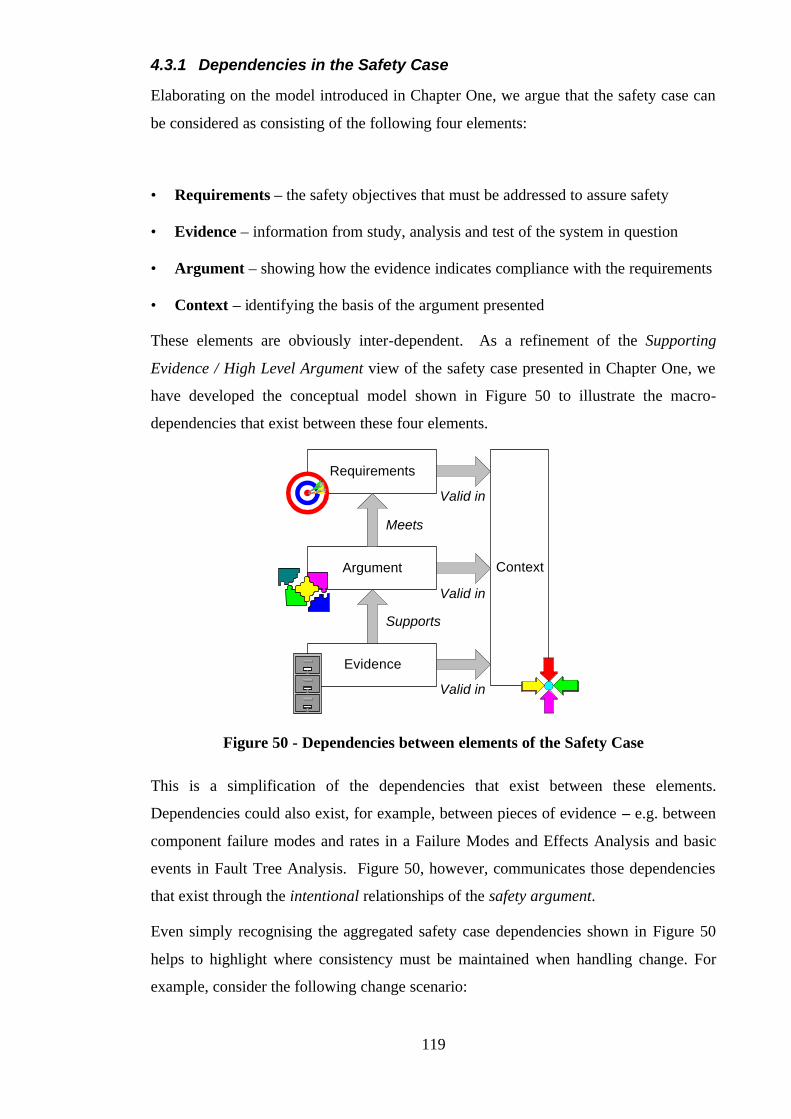
119
4.3.1 Dependencies in the Safety Case
Elaborating on the model introduced in Chapter One, we argue that the safety case can
be considered as consisting of the following four elements:
• Requirements – the safety objectives that must be addressed to assure safety
• Evidence – information from study, analysis and test of the system in question
• Argument – showing how the evidence indicates compliance with the requirements
• Context – identifying the basis of the argument presented
These elements are obviously inter-dependent. As a refinement of the Supporting
Evidence / High Level Argument view of the safety case presented in Chapter One, we
have developed the conceptual model shown in Figure 50 to illustrate the macro-
dependencies that exist between these four elements.
Requirements
Argument
Evidence
Context
Meets
Supports
Valid in
Valid in
Valid in
Figure 50 - Dependencies between elements of the Safety Case
This is a simplification of the dependencies that exist between these elements.
Dependencies could also exist, for example, between pieces of evidence – e.g. between
component failure modes and rates in a Failure Modes and Effects Analysis and basic
events in Fault Tree Analysis. Figure 50, however, communicates those dependencies
that exist through the intentional relationships of the safety argument.
Even simply recognising the aggregated safety case dependencies shown in Figure 50
helps to highlight where consistency must be maintained when handling change. For
example, consider the following change scenario:
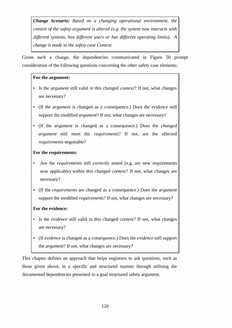
120
Change Scenario: Based on a changing operational environment, the
context of the safety argument is altered (e.g. the system now interacts with
different systems, has different users or has different operating limits). A
change is made to the safety case Context.
Given such a change, the dependencies communicated in Figure 50 prompt
consideration of the following questions concerning the other safety case elements:
For the argument:
• Is the argument still valid in this changed context? If not, what changes
are necessary?
• (If the argument is changed as a consequence.) Does the evidence still
support the modified argument? If not, what changes are necessary?
• (If the argument is changed as a consequence.) Does the changed
argument still meet the requirements? If not, are the affected
requirements negotiable?
For the requirements:
• Are the requirements still correctly stated (e.g. are new requirements
now applicable) within this changed context? If not, what changes are
necessary?
• (If the requirements are changed as a consequence.) Does the argument
support the modified requirements? If not, what changes are necessary?
For the evidence:
• Is the evidence still valid in this changed context? If not, what changes
are necessary?
• (If evidence is changed as a consequence.) Does the evidence still support
the argument? If not, what changes are necessary?
This chapter defines an approach that helps engineers to ask questions, such as
those given above, in a specific and structured manner through utilising the
documented dependencies presented in a goal structured safety argument.

121
4.3.2 Relationship between GSN and the Safety Case
The Goal Structuring Notation has been specifically defined to model the entities and
relationships shown in Figure 50. Requirements are represented in the notation as top
level Goals. Evidence is represented in the notation as Solutions. Contextual
information is represented in the notation as Context, Assumption, Justification and
Models. Argument is communicated through the structuring of Goals supported by sub-
goals (as discussed in Chapter Three). Figure 51 illustrates how a goal structure can be
divided into the four essential elements – requirements, context, evidence and argument.
Control Systemis Safe
All identifiedhazards eliminated
/ sufficientlymitigated
Softwaredeveloped to I.L.
appropriate tohazards involved
I.L. Process Guidelinesdefined by Ref X.
Hazards Identifiedfrom FHA (Ref Y)
Tolerability targets(Ref Z)
Fault TreeAnalysis
FormalVerification
ProcessEvidenceof I.L. 4
Probability of H2occurring
< 1 x 10⁻⁶ perannum
H1 has beeneliminated
Probability of H3occurring
< 1 x 10⁻³ perannum
Primary ProtectionSystem developed
to I.L. 4
SecondaryProtection Systemdeveloped to I.L. 2
ProcessEvidence of
I.L. 2
J
1x10⁻⁶ p.a.limit for
CatastrophicHazards
Requirements
Evidence
Co
nte
xt
Co
ntext
Argument
Figure 51 - Relationship between safety case elements and the GSN
Through the explicit links of a goal structure, such as those shown in Figure 50,
traceability is provided between the elements of the safety case argument. The
following relationships are communicated:
• How requirements are supported by argument claims
• How argument claims are supported by other (sub) argument claims
• The context in which argument claims are stated
• How argument claims are supported by evidence
Such relationships are also present in conventional text-only safety cases. However, it
is rare that they are communicated as clearly and explicitly as in a goal structure.

122
4.3.3 Establishing a Safety Case Configuration Model
In conventional configuration management, the ‘configuration’ refers to
“The totality and the inter-relationships of the hardware, software,
firmware, services and supplies that make up the system at a given reference
point in time” [66]
This definition can be adapted to the safety case domain. In this context, we define the
configuration as:
“The totality and the inter-relationships of the requirements, argument,
evidence and context that make up the safety argument at a given reference
point in time”
A conventional configuration model consists of two parts:
• Configuration Items (CIs): Entities within a configuration that satisfy an end use
function that can be uniquely identified at a given reference point. [66]
• Configuration Relationships (CRs): The relationships between Configuration
Items that have been established at a given stage in the development lifecycle [67]
Using the framework of the Goal Structuring Notation it is possible to relate these
concepts to the safety case domain.
• Configuration: A goal structured safety argument
• Configuration Items (CIs): Individual entities within the goal structure
representation of a safety argument – i.e. goals, strategies, solutions, contexts,
models, assumptions, justification etc.
• Configuration Relationships (CRs): The relationships established between the
elements of a goal structure – i.e. instances of the SolvedBy and InContextOf
relations. For example, these include the relationship declared between a parent
goal and a child goal, and between a goal and an associated assumption.
Using the Goal Structuring Notation as a configuration model (and therefore an
individual goal structure as a configuration), the chapter now goes on to propose a
process for managing change applied to the safety case in the following section.
4.4 A Safety Case Change Process
The safety case change activity can be thought of as consisting of two phases:

123
• The Damage Phase – Where a change is assessed for its impact on the safety
argument of the safety case
• The Recovery Phase – Once the damage has been identified, the process of
identifying a recovery action and following though the consequences of that action
in recovering the safety argument.
There is an iterative (and potentially concurrent) relationship between these two phases.
The action identified to recover the damaged part of the safety case may also result in
damage to other parts of the safety case. For any one change, several iterations of the
damage and recovery activities may be necessary to arrive again at a consistent and
correct safety case. This highlights the importance of having an efficient and systematic
process for carrying out these activities.
Using the safety case configuration model proposed in the previous section it is possible
to provide a systematic structure to the activities carried out in these two phases. This
structure is shown in Figure 52.
Damage Phase
Use GSNto Identify
Impact
Step 3
Decide uponRecovery
Action
Step 4
RecoverIdentifiedDamagedArgument
Step 5
ExpressChallenge inGSN Terms
Step 2
RecogniseChallenge toSafety Case
Step 1
Safety CaseChallenge
GSNChallenge
GSNImpact
RecoveryAction
Recovery Phase
Figure 52 – A Process for Safety Case Change Management
The following sections expand on how using GSN as a configuration model can support
the six steps identified in Figure 52.
4.4.1 Step 1: Recognise Challenges to the Validity of the Safety Case
As identified in Chapter Two, an important aspect of the through life maintenance of the
safety case is awareness of challenges that could potentially render the safety case
argument invalid – i.e. being aware of the vulnerability of the safety case argument to
external change. This point is also highlighted in [36].
124
Using the model of the safety case we proposed in Figure 50 – the role of the safety
argument within the safety case is to establish the relationship between the available
evidence, safety objectives and contextual information (such as design information).
These three elements can be viewed as the ‘givens’ of the safety argument. Challenges
to the validity of a safety argument will arise through challenging one of these givens,
i.e. something in the ‘real-world’ context (outside of the safety case) will challenge the
basis of the safety case presented. The safety case exists in a real-world context that
defines:
• Customer / Regulatory Situation – that sets the ultimate safety objectives that
must be demonstrated within the safety case, tolerability and acceptability criteria.
• Evidence Situation – which defines everything that is known about the system in
question, i.e. the results of observation, analysis and test of this and similar systems.
• Additional Contextual Information – that bounds, scopes and structures the
argument provided in the safety case, e.g. interfaces to other systems, intermediate
pieces of safety evidence (such as hazard logs).
Ultimately the safety case must be correct, consistent and complete with respect to these
three areas. For example, where the requirements listed within the safety case do not
correctly express the applicable safety requirements of the regulatory context the safety
case is invalid. Equally, where the design information used within the safety case is
inconsistent with the design of the system in operation the safety case is invalid.
Similarly, a safety case that selectively omits damaging evidence known about the
system is invalid.
The safety case will have been produced initially to present a valid safety argument with
respect to the regulations, evidence and contextual information appropriate at the time.
The difficulty in safety case maintenance is that any or all of these three elements may
change over time. For example:
• An additional regulatory requirement may be added following an operational
incident. An example of this from the civil aerospace domain would be the addition
of a regulation regarding inadvertent thrust reverser deployment (in JAR-E [68])
following the Lauda Air thrust reverser deployment in flight accident. In some
sectors, constant update of regulatory requirements is expected. Queener, in [69],

125
describes the process whereby civil nuclear reactor installations in the U.S. must
respond to changes in the NUclear REGulationS (NUREGS).
• The design of a system may be changed for perfective, corrective or adaptive
maintenance reasons or through technology obsolescence. Hogberg, in [24],
describes responding to unanticipated problems with the design of a class of nuclear
reactors. Another example is that a class of component used within the original
design may no longer be available and a replacement component type may have to
be used.
• Definitions of ‘cost-effectiveness’, ‘tolerability’, ‘negligible risk’ etc. that have been
used as the basis of the safety argument (e.g. in arguing ALARP – As Low As
Reasonably Practicable) may alter over time with changing perceptions and
available technology. Assumptions regarding the operational lifetime of a system
also form an important part of the safety case context. Such assumptions may be
challenged by a desire to extend plant life beyond the originally intended period.
Clarke, in [25], describes such a case for the life-extension of the U.K. civil Magnox
nuclear reactors.
• Operational experience may challenge the evidence used as the basis of the original
safety argument. For example, the safety case may estimate that a certain failure
mode of a component will occur at a certain rate. This rate may be brought into
question by operational data.
The starting point of a systematic process for ensuring the ongoing validity of the safety
case is the identification and recognition of such changes on a routine basis.
Operational data should be collected through in-service monitoring. This is recognised
in a number of the existing safety standards. For example, the HSE Civil Nuclear
Standards [17] contain the principle:
Maintenance, inspection and testing (Principle 329):
The requirements for in-service testing, inspection or other maintenance
procedures and frequencies for which specific claims have been made in the
safety case should be identified and included in a maintenance schedule.
To record system anomalies and updates, failure and correction maintenance action
reporting systems should be established. In Defence Standard 00-55 [9] the following
requirement is stated:
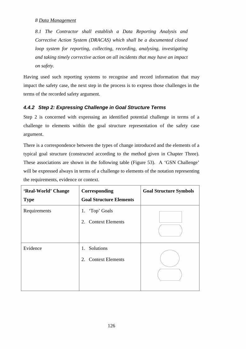
126
8 Data Management
8.1 The Contractor shall establish a Data Reporting Analysis and
Corrective Action System (DRACAS) which shall be a documented closed
loop system for reporting, collecting, recording, analysing, investigating
and taking timely corrective action on all incidents that may have an impact
on safety.
Having used such reporting systems to recognise and record information that may
impact the safety case, the next step in the process is to express those challenges in the
terms of the recorded safety argument.
4.4.2 Step 2: Expressing Challenge in Goal Structure Terms
Step 2 is concerned with expressing an identified potential challenge in terms of a
challenge to elements within the goal structure representation of the safety case
argument.
There is a correspondence between the types of change introduced and the elements of a
typical goal structure (constructed according to the method given in Chapter Three).
These associations are shown in the following table (Figure 53). A ‘GSN Challenge’
will be expressed always in terms of a challenge to elements of the notation representing
the requirements, evidence or context.
‘Real-World’ Change
Type
Corresponding
Goal Structure Elements
Goal Structure Symbols
Requirements 1. ‘Top’ Goals
2. Context Elements
Evidence 1. Solutions
2. Context Elements

127
Context 1. Context
2. Model
3. Assumption
4. Justification
A
J
Figure 53 - Association between Change Types and Goal Structure Entities
The following sections illustrate the mappings shown in the above table by providing
sketch examples of requirements, evidence and context challenges expressed in GSN
terms. It is important to realise that within this step, and therefore also in the examples
presented, the concern is to express the initial challenge to a goal structured safety
argument (i.e. the start point of impact assessment), rather than the total impact (which
will be explored in Step 3).
The convention we have introduced to denote that a GSN element or relationship is
challenged is to place a cross (×) over that item.
4.4.2.1 Requirements Challenges Expressed in GSN Terms
The following figure (Figure 54) depicts the potential challenge created when one of the
overall objectives of the safety argument is challenged. In this case, an argument was
put forward to support a DS 00-55 compliance objective. If this objective is revised
(e.g. as a result of a new issue of 00-55, or to demand instead compliance to another
standard such as DO178B [65]) then the corresponding goal must be marked as
challenged. (The figure also depicts, through the crossed SolvedBy relationships, that the
support of this claim through the existing arguments is immediately challenged.)
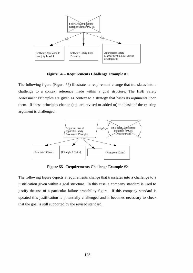
128
Software Developed toDefence Standard 00-55
Software developed toIntegrity Level 4
Software Safety CaseProduced
Appropriate SafetyManagement in place duringdevelopment
Figure 54 – Requirements Challenge Example #1
The following figure (Figure 55) illustrates a requirement change that translates into a
challenge to a context reference made within a goal structure. The HSE Safety
Assessment Principles are given as context to a strategy that bases its arguments upon
them. If these principles change (e.g. are revised or added to) the basis of the existing
argument is challenged.
Argument over allapplicable SafetyAssessment Principles
HSE Safety AssessmentPrinciples for Civil
Nuclear Plants
{Principle 1 Claim} {Principle 2 Claim} {Principle n Claim}
Figure 55 - Requirements Challenge Example #2
The following figure depicts a requirements change that translates into a challenge to a
justification given within a goal structure. In this case, a company standard is used to
justify the use of a particular failure probability figure. If this company standard is
updated this justification is potentially challenged and it becomes necessary to check
that the goal is still supported by the revised standard.

129
Hazard X occurs atacceptably low rates
Probability of Hazard Xoccurring < 1 x 10⁻⁶ peroperational hour
Definition ofHazard X
J
Company Standard defines 1x10⁻⁶ as acceptable for Major
Hazards
Figure 56 - Requirements Challenge Example #3
4.4.2.2 Evidence Challenges Expressed in GSN Terms
Figure 57 depicts a real-world evidence change that translates directly into a challenge
to a solution given within a goal structure. In this case, a fault tree is used to satisfy the
probability claim for Hazard X. If the fault tree is called into question (e.g. through
operational experience contradicting the basic fault event probabilities used, or the
implicit claims of independence) the role of this piece of evidence as a solution in the
safety argument is challenged.
Probability of Hazard Xoccuring is 1 x 10⁻⁵ peroperational hour
Fault Tree forHazard X
Figure 57 - Evidence Challenge Example #1
The following figure illustrates an evidence challenge that maps to a context reference
used within a goal structure. Evidence can be used within safety arguments not only to
support safety claims (i.e. use as a GSN solution) but also to help structure the
argument being presented (i.e. use as a GSN context reference). It is for this reason that
evidence should not be viewed as only corresponding to GSN solutions.
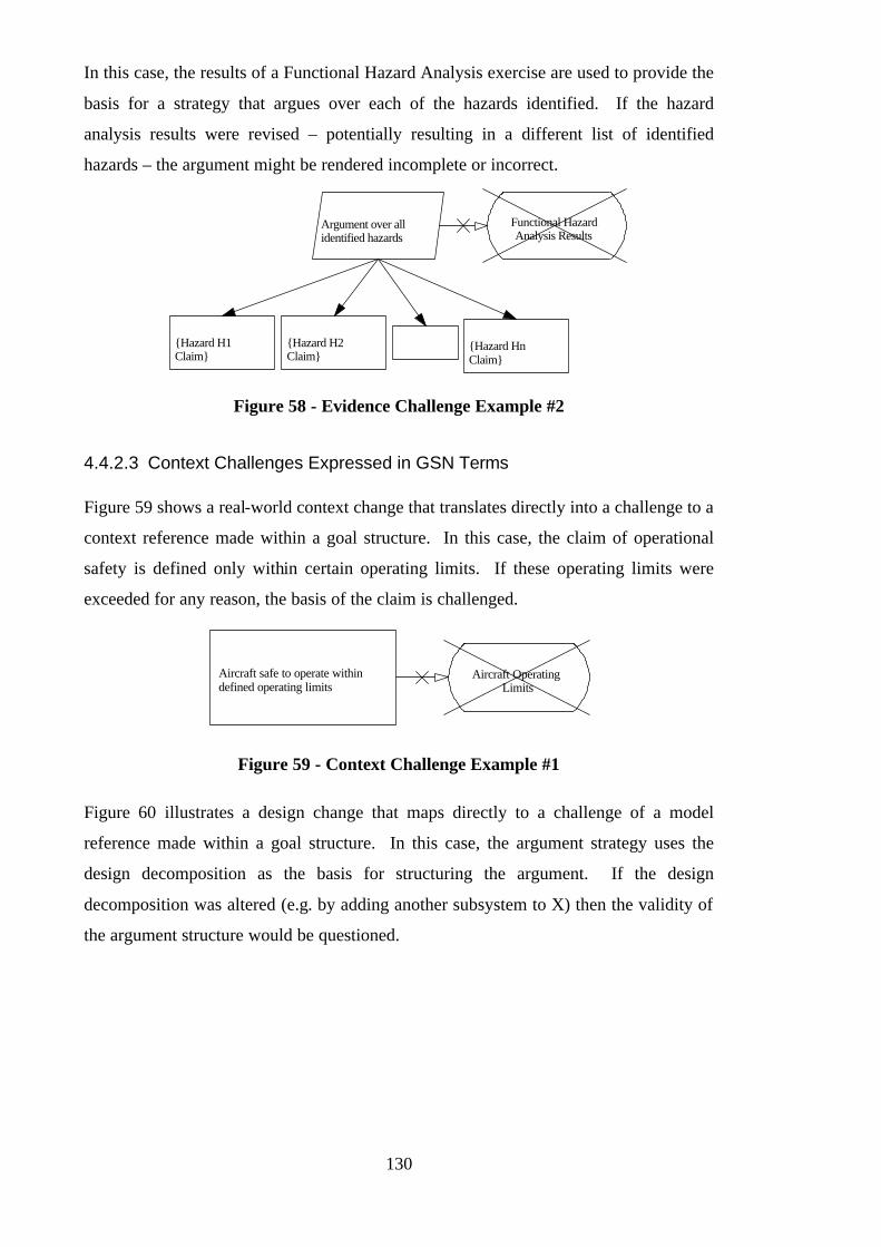
130
In this case, the results of a Functional Hazard Analysis exercise are used to provide the
basis for a strategy that argues over each of the hazards identified. If the hazard
analysis results were revised – potentially resulting in a different list of identified
hazards – the argument might be rendered incomplete or incorrect.
Argument over allidentified hazards
Functional HazardAnalysis Results
{Hazard H1Claim}
{Hazard H2Claim}
{Hazard HnClaim}
Figure 58 - Evidence Challenge Example #2
4.4.2.3 Context Challenges Expressed in GSN Terms
Figure 59 shows a real-world context change that translates directly into a challenge to a
context reference made within a goal structure. In this case, the claim of operational
safety is defined only within certain operating limits. If these operating limits were
exceeded for any reason, the basis of the claim is challenged.
Aircraft safe to operate withindefined operating limits
Aircraft OperatingLimits
Figure 59 - Context Challenge Example #1
Figure 60 illustrates a design change that maps directly to a challenge of a model
reference made within a goal structure. In this case, the argument strategy uses the
design decomposition as the basis for structuring the argument. If the design
decomposition was altered (e.g. by adding another subsystem to X) then the validity of
the argument structure would be questioned.

131
Argument over each of themajor subsystems of X
Design of X (showing majorsubsystems)
{Subsystem 1 Claim} {Subsystem 2 Claim} {Subsystem 3 Claim}
Figure 60 - Context Challenge Example #2
Figure 61 illustrates an operating context change that translates directly into a challenge
to an assumption stated within a goal structure. In this case, a safety claim is
specifically stated on the assumption that recommissioning is not required. If this
assumption was found to be wrong the claim might no longer hold – e.g. significant
personnel radiation exposure may be necessary to undo some of the decommissioning
procedures.
No radiological hazards posedby decommissioned reactorcoolant system A
There will never be arequirement to recommission
system
Figure 61 - Context Challenge Example #3
4.4.2.4 Summary of Expressing Challenges in GSN Terms
To translate a real-world challenge into a goal structure challenge it is necessary to
search the appropriate goal structure elements (indicated in Figure 53) for elements that
correspond to the real-world entity or concept being challenged. For example, where a
real-world piece of evidence is challenged, the goal structure should be examined for
solutions and contexts that correspond to the piece of evidence under question. It is
important to recognise that one real-world challenge may well translate into many goal
structure challenges. Consider, for example, the case of a hazard log update. The
hazard log may be used both as a means of structuring the safety argument (as a context
reference) as well as a source of evidence to support a goal (as a solution). This
situation is illustrated in Figure 62.
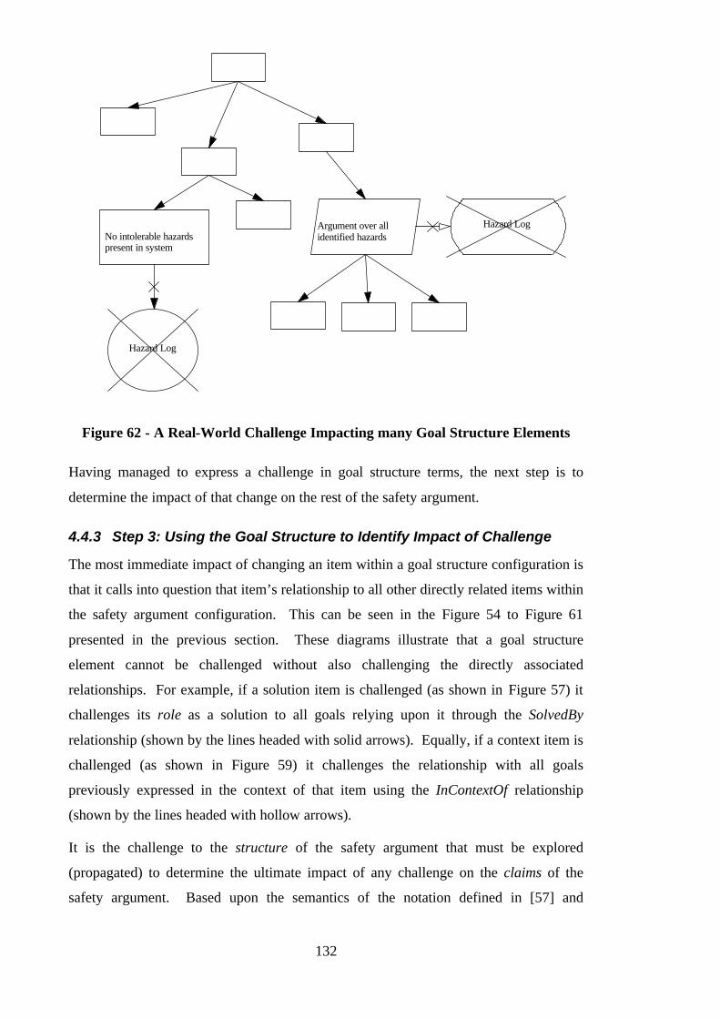
132
No intolerable hazardspresent in system
Hazard Log
Argument over allidentified hazards
Hazard Log
Figure 62 - A Real-World Challenge Impacting many Goal Structure Elements
Having managed to express a challenge in goal structure terms, the next step is to
determine the impact of that change on the rest of the safety argument.
4.4.3 Step 3: Using the Goal Structure to Identify Impact of Challenge
The most immediate impact of changing an item within a goal structure configuration is
that it calls into question that item’s relationship to all other directly related items within
the safety argument configuration. This can be seen in the Figure 54 to Figure 61
presented in the previous section. These diagrams illustrate that a goal structure
element cannot be challenged without also challenging the directly associated
relationships. For example, if a solution item is challenged (as shown in Figure 57) it
challenges its role as a solution to all goals relying upon it through the SolvedBy
relationship (shown by the lines headed with solid arrows). Equally, if a context item is
challenged (as shown in Figure 59) it challenges the relationship with all goals
previously expressed in the context of that item using the InContextOf relationship
(shown by the lines headed with hollow arrows).
It is the challenge to the structure of the safety argument that must be explored
(propagated) to determine the ultimate impact of any challenge on the claims of the
safety argument. Based upon the semantics of the notation defined in [57] and

133
described in Chapter Three, the rules for the propagation of change within a goal
structure are provided within the following sections.
4.4.3.1 Propagation of Challenges to Goals, Strategies and Solutions
Changing a goal, strategy or solution (G) within a goal structure challenges the
following relationships within the goal structure:
• The role of G as a solution of parent goals or strategies (i.e. items higher up the goal
structure). This is not a concern for the top goals of a goal structure.
• The role of G as a parent (objective) of supporting elements (i.e. to items lower
down the goal structure). This is obviously not a concern for the solution elements
of a goal structure.
• The relationship between G and its stated context (i.e. to items left and right of the
core argument)
This effect is illustrated in Figure 63. Consider the case where, as a result of a revision
of the company standard, the ‘Probability of Hazard’ goal could no longer be justified in
its current stated form. Challenging this goal also challenges its relationship to both the
parent ‘Acceptably low rates’ goal and to the supporting evidence provided (fault tree
and in-service data). If the probability claim were weakened, this may mean that the
parent goal was no longer satisfied. If the probability claim were strengthened, this may
mean that it is no longer supported by the solutions presented.
Probability of HazardX occurring< 1 x 10⁻⁶
Hazard X occurs atacceptably low rates
Fault Tree forHazard X
In ServiceData
J
Company Standard defines1x 10-6 as acceptable for
Major Hazards
CHANGED
Figure 63 - Example Effect of Spinal Node Change
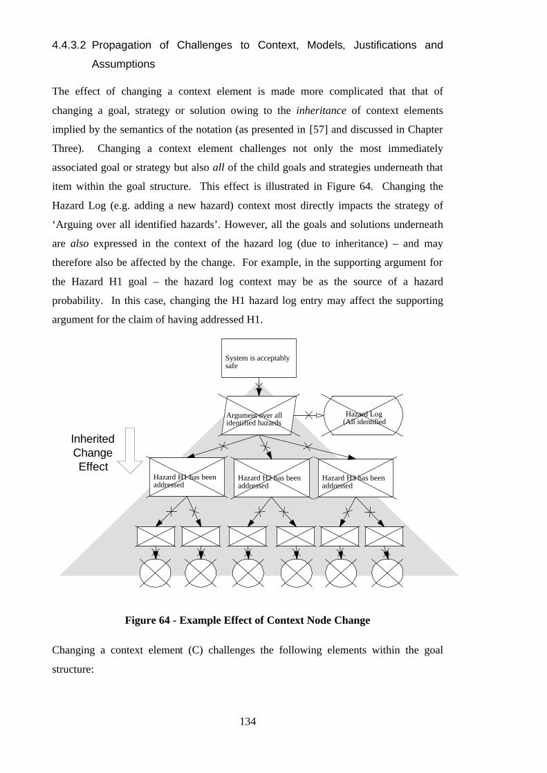
134
4.4.3.2 Propagation of Challenges to Context, Models, Justifications and
Assumptions
The effect of changing a context element is made more complicated that that of
changing a goal, strategy or solution owing to the inheritance of context elements
implied by the semantics of the notation (as presented in [57] and discussed in Chapter
Three). Changing a context element challenges not only the most immediately
associated goal or strategy but also all of the child goals and strategies underneath that
item within the goal structure. This effect is illustrated in Figure 64. Changing the
Hazard Log (e.g. adding a new hazard) context most directly impacts the strategy of
‘Arguing over all identified hazards’. However, all the goals and solutions underneath
are also expressed in the context of the hazard log (due to inheritance) – and may
therefore also be affected by the change. For example, in the supporting argument for
the Hazard H1 goal – the hazard log context may be as the source of a hazard
probability. In this case, changing the H1 hazard log entry may affect the supporting
argument for the claim of having addressed H1.
System is acceptablysafe
Argument over allidentified hazards
Hazard Log(All identified
Hazard H1 has beenaddressed
Hazard H2 has beenaddressed
Hazard H3 has beenaddressed
InheritedChangeEffect
Figure 64 - Example Effect of Context Node Change
Changing a context element (C) challenges the following elements within the goal
structure:
135
• All goals, strategies and solutions (G) that introduce C as context (through the
InContextOf relationship).
• All goals, strategies and solutions which inherit C as context (i.e. all children of G).
When a goal, strategy or solution is challenged by a context change, the rules of change
propagation for these elements (defined in the previous section) apply.
As can be seen from the examples shown in Figure 63 and Figure 64, the initial impact
of context change is potentially much wider than that of changing an element such as a
goal. Changes to goals, strategies and solutions have, at least initially, a point effect –
affecting only most immediate neighbours. Changes to context elements, however, due
to rules of inheritance within the semantics of the notation, have an area effect –
affecting whole sub-trees of the goal structure.
4.4.3.3 Potential vs. Actual Change Effect – The Role of the Safety Engineer
It should be noted that the rules we have described for the propagation of change over a
goal structure define the potential change effect rather than necessarily the actual
change effect. The approach taken is pessimistic. Based only on the semantics of the
notation, i.e. without entering into any form of semantic analysis of the goal statements,
it is possible only to flag all possible changes. The role of the safety engineer
responsible for maintaining the safety argument is then to examine each of these
potential areas of impact to decide which require further investigation and which can be
ignored (i.e. where the change can be considered benign).
Consider, for example, the situation shown in Figure 65. Operational experience may
necessitate an increase in the failure rates quoted in the Component Failure Modes and
Effects Analysis (FMEA). According to the impact rules given, a challenge to the
FMEA would potentially impact its role as a solution to both the No Single Point of
Failure claim and the Hazard Probability Claim (as indicated by the crossed
relationships). The engineer must assess both of these potential challenges and decide
whether they apply in this particular change scenario. To do this, the nature of the
change must be considered with respect to the potential challenges flagged. In this case,
for example, the FMEA failure rate change may well affect the Hazard Probability
claim. However, since no additional failure modes have been introduced or any failure
mode effects changed, the No Single Point of Failure claim is extremely unlikely to be
affected (and this challenge can be considered benign with respect to this goal).

136
No single point of failurecan lead to a hazard
Probability of hazardoccuring is tolerably low
Fault tree for hazard showsprobability is 1.4 x 10⁻⁶ perhour
Component FailureModes and Effects
Analysis
Fault Tree forHazard
Figure 65 - Potential Impact Scenario
The actual initial impact of the FMEA change would therefore be refined as illustrated
in the following figure (Figure 66).
(NB – The potential problem of additional dependencies that may exist between the
evidence solutions shown in Figure 66, but are not communicated through the argument
structure, is discussed later in Section 4.9.2.)
No single point of failurecan lead to a hazard
Probability of hazardoccuring is tolerably low
Fault tree for hazard showsprobability is 1.4 x 10⁻⁶ perhour
Component FailureModes and Effects
Analysis
Fault Tree forHazard
Figure 66 – Actual Impact Scenario
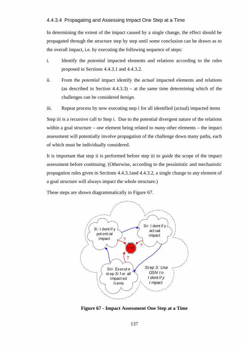
137
4.4.3.4 Propagating and Assessing Impact One Step at a Time
In determining the extent of the impact caused by a single change, the effect should be
propagated through the structure step by step until some conclusion can be drawn as to
the overall impact, i.e. by executing the following sequence of steps:
i. Identify the potential impacted elements and relations according to the rules
proposed in Sections 4.4.3.1 and 4.4.3.2.
ii. From the potential impact identify the actual impacted elements and relations
(as described in Section 4.4.3.3) – at the same time determining which of the
challenges can be considered benign.
iii. Repeat process by now executing step i for all identified (actual) impacted items
Step iii is a recursive call to Step i. Due to the potential divergent nature of the relations
within a goal structure – one element being related to many other elements – the impact
assessment will potentially involve propagation of the challenge down many paths, each
of which must be individually considered.
It is important that step ii is performed before step iii to guide the scope of the impact
assessment before continuing. (Otherwise, according to the pessimistic and mechanistic
propagation rules given in Sections 4.4.3.1and 4.4.3.2, a single change to any element of
a goal structure will always impact the whole structure.)
These steps are shown diagrammatically in Figure 67.
Step 3: UseGSN toIdentifyImpact
STOP
3ii: Identifyactualimpact
3iii: Executestep 3i for all
impacteditems
3i: Identifypotentialimpact
?
?
?
Figure 67 - Impact Assessment One Step at a Time
138
As can be seen from Figure 67 there is always the question of when to stop the impact
assessment process – i.e. how far to investigate the damage created by a particular
challenge. A particular thread of the impact assessment process can stop for any one of
the following three reasons:
• (After stage 3i) A change has no further potential impact. An obvious example of
this would be when the process has ‘run out of goal structure’ - i.e. the impact has
reached the top goal or a bottom solution.
• (After stage 3ii) A change has no further actual impact. In this case, potential
changes are highlighted but, when assessed by the safety engineer, it is possible to
say that none of these impacts actually affect the structure. For example, if a fault
tree was used as evidence to support a number of claims within the safety argument,
a change to the fault tree would potentially challenge each of those claims.
However, upon proper assessment the revised fault tree may still support the claims.
It should be noted that this is the most positive of outcomes of the impact
assessment process.
• (After stage 3iii) Actual impact has been identified, however it has been decided not
to allow the change effect to extend further. For example, this would be the case if a
challenge were identified to a goal representing a regulatory requirement. The
challenge to the goal could be identified. However, as a regulatory requirement the
goal would probably be viewed as non-negotiable and therefore the impact process
would stop at this point and the process of recovery would begin.
When further assessment of all impact paths has been terminated for one of the above
reasons it possible to describe the total impact created by the initial single challenge.
Importantly - unlike the initial challenge that was expressed in terms of affected
solutions, context and top requirements - the impact can now be expressed in terms of
the goals of the safety argument that can no longer be supported. These are the ultimate
consequences of the initial challenge (in terms of the safety argument). This
information serves as an important input to the next step – responding to the damaged
argument.
4.4.4 Step 4: Deciding Upon Action to Recover Damaged Argument
Recovery is the process of returning the safety argument to a correct, consistent and
complete state. The impact of a change (identified in Step 3) may mean that claims
139
made within the safety argument (e.g. concerning the meeting of regulatory or customer
requirements) are no longer supported. In such cases, the safety argument must be
‘repaired’ in order to bring the safety argument back to the original state of supporting
the claims.
It is necessary to decide upon an appropriate action to recover the safety argument. This
decision is set in the context of, and should be focused by, the impact that has been
identified. For example, if after Step 3 it is found that the claim that ‘No single point of
failure can lead to hazard’ can no longer be supported, then appropriate action should be
taken towards re-supporting this objective – e.g. by making a design change that
introduces redundancy.
It is important to recognise that safety (expressed in terms of the damaged argument) is
only one factor involved in the decision on the recovery action. An action could be
recommended that enabled the safety argument to be quickly restored, but damaged the
operational performance or maintenance of the systems. Many factors will typically be
involved in deciding on the recovery action – e.g. cost, expected lifetime of system,
availability, performance. This process merely serves to express the safety viewpoint as
clearly and effectively as possible.
In deciding how to recover the argument the following questions should be considered:
• Can the requirements of the safety argument be altered (e.g. weakened) such
that the safety argument still holds? Depending on who is the stakeholder of the
requirement this may or may not be possible – i.e. it may not be within the authority
of the design authority to alter the safety requirements. In some cases, however, this
option would suggest a process of negotiation with the customer regarding the
particular requirements prescribed.
• Can the context of the safety argument be altered (perhaps restricted) such
that the safety argument still holds? The safety argument may still be valid under
certain circumstances (highlighted by the impact identified in Step 3). It may
simply be possible to restrict the applicability of the safety argument to a narrower
context than that previously stated. As with the process of altering the safety
requirements, this option may involve negotiation with the customer. For example,
operating limits or restrictions may be placed on the operation of the system. The
customer must decide whether these are acceptable. Design changes that effectively
shift the system context fall into this category.
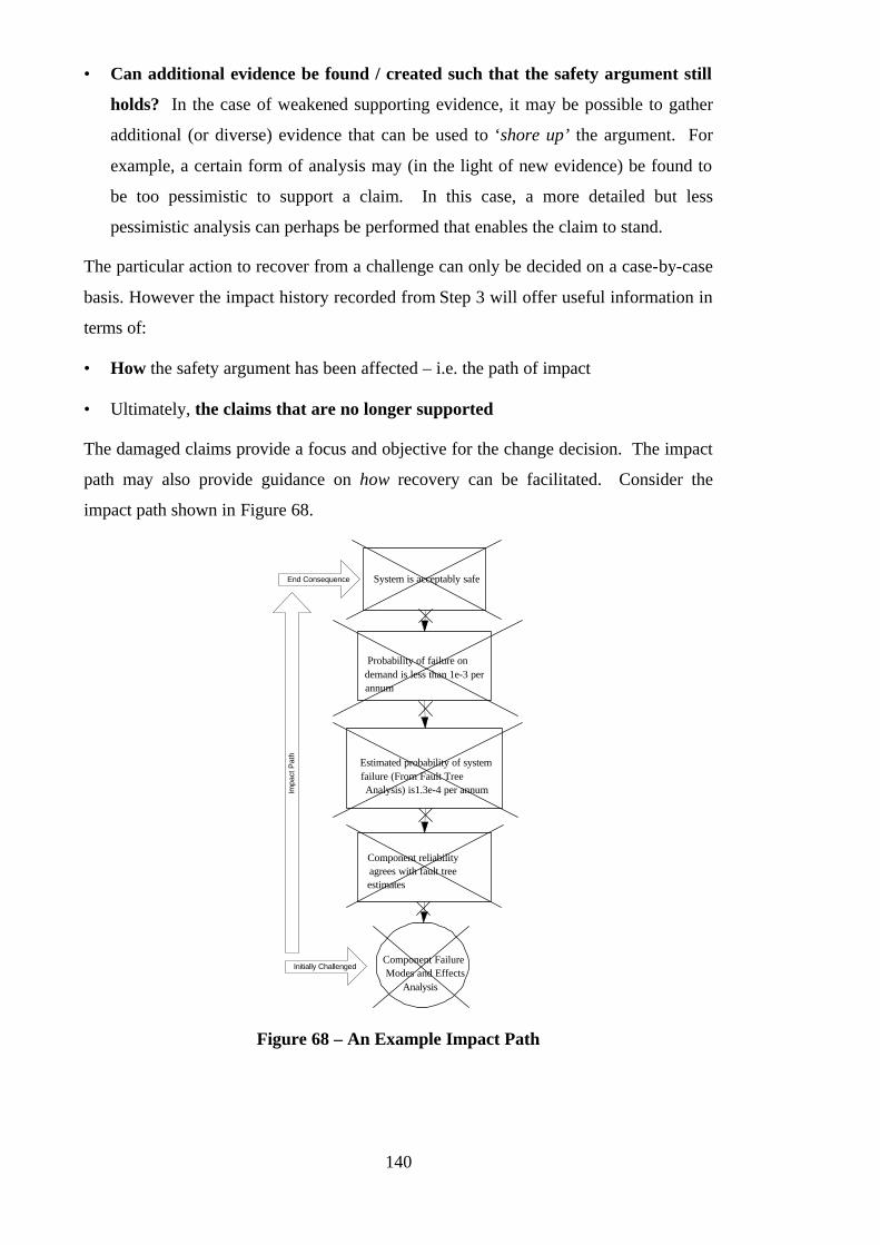
140
• Can additional evidence be found / created such that the safety argument still
holds? In the case of weakened supporting evidence, it may be possible to gather
additional (or diverse) evidence that can be used to ‘shore up’ the argument. For
example, a certain form of analysis may (in the light of new evidence) be found to
be too pessimistic to support a claim. In this case, a more detailed but less
pessimistic analysis can perhaps be performed that enables the claim to stand.
The particular action to recover from a challenge can only be decided on a case-by-case
basis. However the impact history recorded from Step 3 will offer useful information in
terms of:
• How the safety argument has been affected – i.e. the path of impact
• Ultimately, the claims that are no longer supported
The damaged claims provide a focus and objective for the change decision. The impact
path may also provide guidance on how recovery can be facilitated. Consider the
impact path shown in Figure 68.
System is acceptably safe
Probability of failure ondemand is less than 1e-3 perannum
Estimated probability of systemfailure (From Fault TreeAnalysis) is1.3e-4 per annum
Component reliabilityagrees with fault treeestimates
Component FailureModes and Effects
Analysis
Initially Challenged
Impa
ct P
ath
End Consequence
Figure 68 – An Example Impact Path
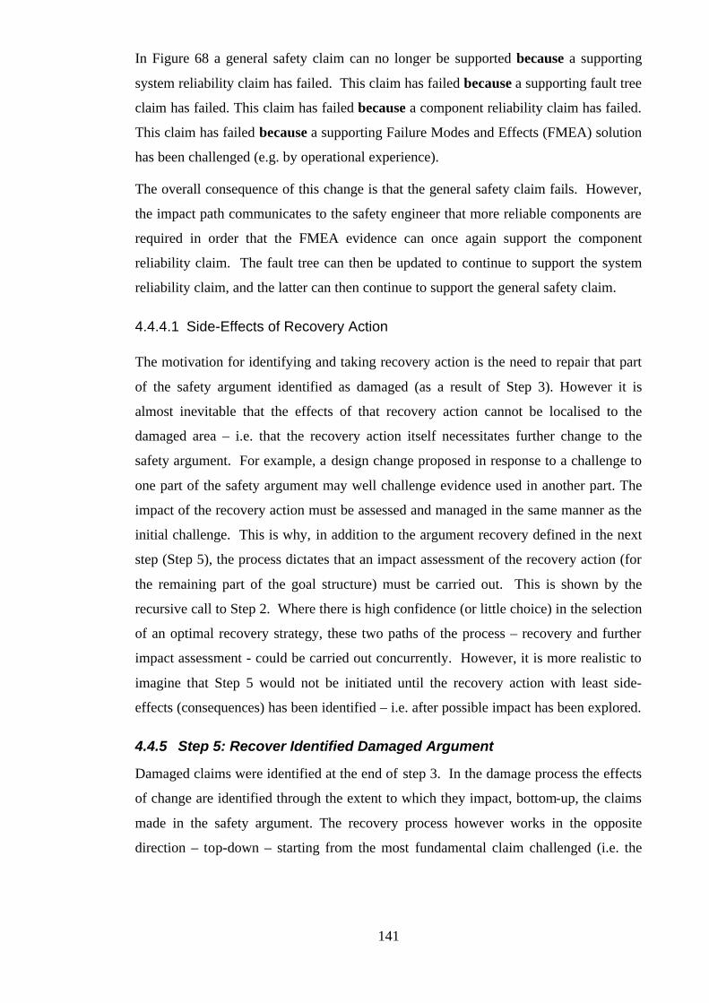
141
In Figure 68 a general safety claim can no longer be supported because a supporting
system reliability claim has failed. This claim has failed because a supporting fault tree
claim has failed. This claim has failed because a component reliability claim has failed.
This claim has failed because a supporting Failure Modes and Effects (FMEA) solution
has been challenged (e.g. by operational experience).
The overall consequence of this change is that the general safety claim fails. However,
the impact path communicates to the safety engineer that more reliable components are
required in order that the FMEA evidence can once again support the component
reliability claim. The fault tree can then be updated to continue to support the system
reliability claim, and the latter can then continue to support the general safety claim.
4.4.4.1 Side-Effects of Recovery Action
The motivation for identifying and taking recovery action is the need to repair that part
of the safety argument identified as damaged (as a result of Step 3). However it is
almost inevitable that the effects of that recovery action cannot be localised to the
damaged area – i.e. that the recovery action itself necessitates further change to the
safety argument. For example, a design change proposed in response to a challenge to
one part of the safety argument may well challenge evidence used in another part. The
impact of the recovery action must be assessed and managed in the same manner as the
initial challenge. This is why, in addition to the argument recovery defined in the next
step (Step 5), the process dictates that an impact assessment of the recovery action (for
the remaining part of the goal structure) must be carried out. This is shown by the
recursive call to Step 2. Where there is high confidence (or little choice) in the selection
of an optimal recovery strategy, these two paths of the process – recovery and further
impact assessment - could be carried out concurrently. However, it is more realistic to
imagine that Step 5 would not be initiated until the recovery action with least side-
effects (consequences) has been identified – i.e. after possible impact has been explored.
4.4.5 Step 5: Recover Identified Damaged Argument
Damaged claims were identified at the end of step 3. In the damage process the effects
of change are identified through the extent to which they impact, bottom-up, the claims
made in the safety argument. The recovery process however works in the opposite
direction – top-down – starting from the most fundamental claim challenged (i.e. the
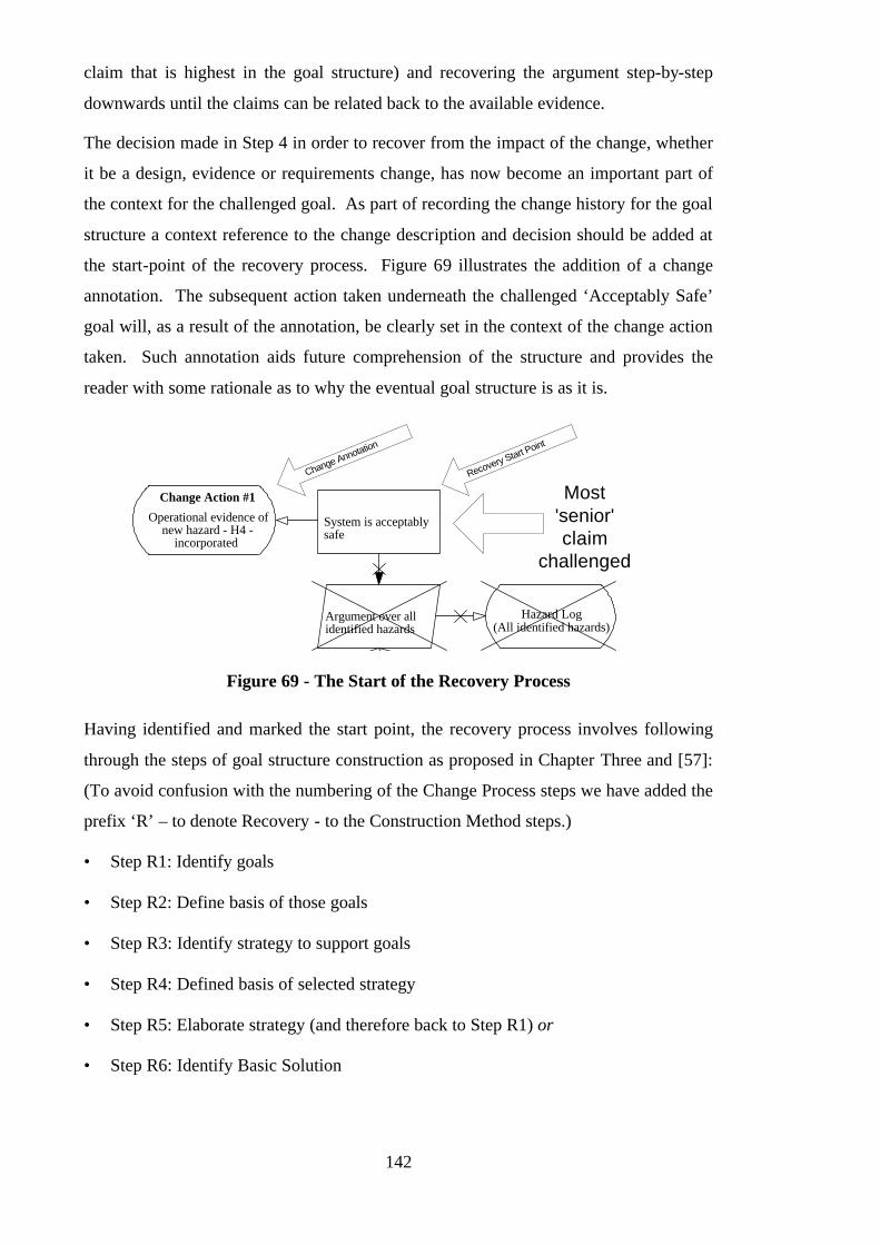
142
claim that is highest in the goal structure) and recovering the argument step-by-step
downwards until the claims can be related back to the available evidence.
The decision made in Step 4 in order to recover from the impact of the change, whether
it be a design, evidence or requirements change, has now become an important part of
the context for the challenged goal. As part of recording the change history for the goal
structure a context reference to the change description and decision should be added at
the start-point of the recovery process. Figure 69 illustrates the addition of a change
annotation. The subsequent action taken underneath the challenged ‘Acceptably Safe’
goal will, as a result of the annotation, be clearly set in the context of the change action
taken. Such annotation aids future comprehension of the structure and provides the
reader with some rationale as to why the eventual goal structure is as it is.
System is acceptablysafe
Argument over allidentified hazards
Hazard Log(All identified hazards)
Change Action #1
Operational evidence ofnew hazard - H4 -
incorporated
Most'senior'claim
challenged
Recovery Start Point
Change Annotation
Figure 69 - The Start of the Recovery Process
Having identified and marked the start point, the recovery process involves following
through the steps of goal structure construction as proposed in Chapter Three and [57]:
(To avoid confusion with the numbering of the Change Process steps we have added the
prefix ‘R’ – to denote Recovery - to the Construction Method steps.)
• Step R1: Identify goals
• Step R2: Define basis of those goals
• Step R3: Identify strategy to support goals
• Step R4: Defined basis of selected strategy
• Step R5: Elaborate strategy (and therefore back to Step R1) or
• Step R6: Identify Basic Solution
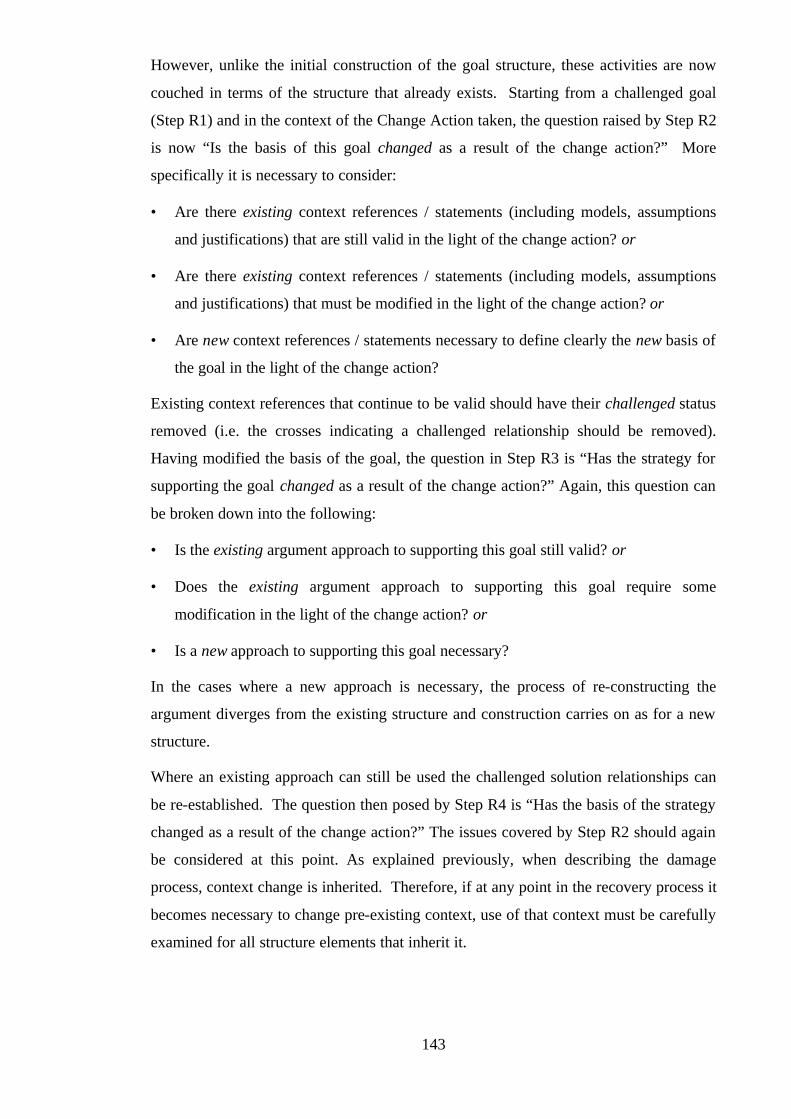
143
However, unlike the initial construction of the goal structure, these activities are now
couched in terms of the structure that already exists. Starting from a challenged goal
(Step R1) and in the context of the Change Action taken, the question raised by Step R2
is now “Is the basis of this goal changed as a result of the change action?” More
specifically it is necessary to consider:
• Are there existing context references / statements (including models, assumptions
and justifications) that are still valid in the light of the change action? or
• Are there existing context references / statements (including models, assumptions
and justifications) that must be modified in the light of the change action? or
• Are new context references / statements necessary to define clearly the new basis of
the goal in the light of the change action?
Existing context references that continue to be valid should have their challenged status
removed (i.e. the crosses indicating a challenged relationship should be removed).
Having modified the basis of the goal, the question in Step R3 is “Has the strategy for
supporting the goal changed as a result of the change action?” Again, this question can
be broken down into the following:
• Is the existing argument approach to supporting this goal still valid? or
• Does the existing argument approach to supporting this goal require some
modification in the light of the change action? or
• Is a new approach to supporting this goal necessary?
In the cases where a new approach is necessary, the process of re-constructing the
argument diverges from the existing structure and construction carries on as for a new
structure.
Where an existing approach can still be used the challenged solution relationships can
be re-established. The question then posed by Step R4 is “Has the basis of the strategy
changed as a result of the change action?” The issues covered by Step R2 should again
be considered at this point. As explained previously, when describing the damage
process, context change is inherited. Therefore, if at any point in the recovery process it
becomes necessary to change pre-existing context, use of that context must be carefully
examined for all structure elements that inherit it.
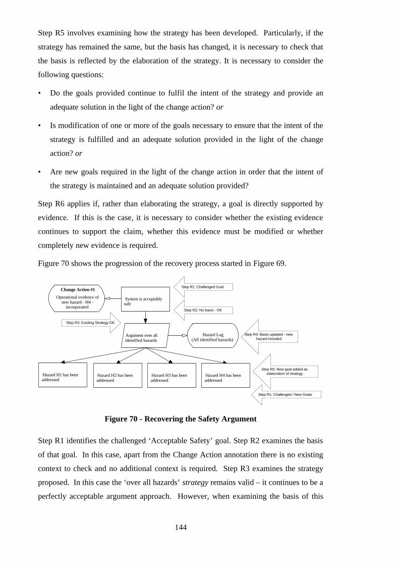
144
Step R5 involves examining how the strategy has been developed. Particularly, if the
strategy has remained the same, but the basis has changed, it is necessary to check that
the basis is reflected by the elaboration of the strategy. It is necessary to consider the
following questions:
• Do the goals provided continue to fulfil the intent of the strategy and provide an
adequate solution in the light of the change action? or
• Is modification of one or more of the goals necessary to ensure that the intent of the
strategy is fulfilled and an adequate solution provided in the light of the change
action? or
• Are new goals required in the light of the change action in order that the intent of
the strategy is maintained and an adequate solution provided?
Step R6 applies if, rather than elaborating the strategy, a goal is directly supported by
evidence. If this is the case, it is necessary to consider whether the existing evidence
continues to support the claim, whether this evidence must be modified or whether
completely new evidence is required.
Figure 70 shows the progression of the recovery process started in Figure 69.
System is acceptablysafe
Argument over allidentified hazards
Hazard Log(All identified hazards)
Hazard H1 has beenaddressed
Hazard H2 has beenaddressed
Hazard H3 has beenaddressed
Change Action #1
Operational evidence ofnew hazard - H4 -
incorporated
Step R3: Existing Strategy OK
Step R4: Basis updated - newhazard included
Hazard H4 has beenaddressed
Step R1: Challenged Goal
Step R2: No basis - OK
Step R5: New goal added aselaboration of strategy
Step R1: Challenged / New Goals
Figure 70 - Recovering the Safety Argument
Step R1 identifies the challenged ‘Acceptable Safety’ goal. Step R2 examines the basis
of that goal. In this case, apart from the Change Action annotation there is no existing
context to check and no additional context is required. Step R3 examines the strategy
proposed. In this case the ‘over all hazards’ strategy remains valid – it continues to be a
perfectly acceptable argument approach. However, when examining the basis of this

145
strategy in Step R4 it becomes clear that the Hazard Log context reference must be
updated to incorporate the new hazard identified, H4. Step R5 identifies that in order to
maintain the intent of the strategy a new goal (addressing the new hazard H4) must be
added. The recovery process then continues for each of the goals for hazards H1 to H3
and the process of constructing a new supporting argument for the H4 goal begins (i.e.
back to Step R1 of the construction method).
When following through the steps of the recovery process, it is expected that at some
point the existing argument will be deficient – e.g. a strategy will be no longer suitable,
a piece of evidence will be no longer valid, or a context reference must be changed.
This is confirmation of the impact identified by the damage process.
4.5 Examples of the Change Process
This section illustrates the application of the impact assessment process that has been
proposed in this chapter to the example safety case (for a nuclear trip system) provided
in Appendix A and two postulated challenges. Appendix A provides background on the
trip system and its associated safety arguments.
The following two changes are considered:
• Challenge to the Validity of the Timing Analysis Evidence
• Removal of Separate PROMS for Software and Trip Limits
The following subsections ‘walkthrough’ the change process for each of these changes.
4.5.1 Example 1: Challenge to validity of Timing Analysis
4.5.1.1 Step 1: Recognising the Challenge to the Safety Case
After initial acceptance of the safety argument, it is later recognised that there was a
flaw in the static timing analysis tool used to determine the worst case response time.
4.5.1.2 Step 2: Expressing Change in Terms of GSN Elements
After examining the peripheral (context, solution and top requirement) elements of the
safety argument, it is identified that this challenge directly concerns Sn3 – Timing
Analysis Results as shown in Figure 131 of Appendix A and reproduced here in the
following figure.
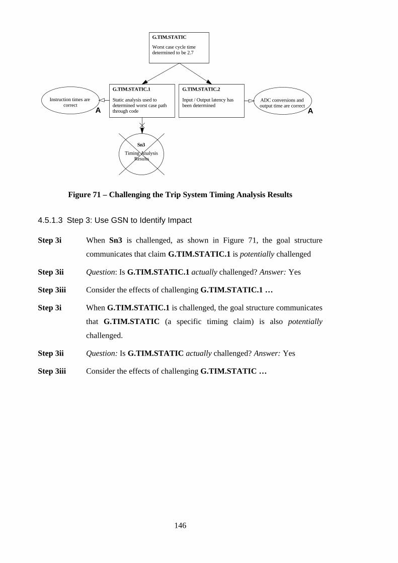
146
Worst case cycle timedetermined to be 2.7
G.TIM.STATIC
Instruction times arecorrect
AADC conversions andoutput time are correct
A
Static analysis used todetermined worst case paththrough code
G.TIM.STATIC.1
Input / Output latency hasbeen determined
G.TIM.STATIC.2
Timing AnalysisResults
Sn3
Figure 71 – Challenging the Trip System Timing Analysis Results
4.5.1.3 Step 3: Use GSN to Identify Impact
Step 3i When Sn3 is challenged, as shown in Figure 71, the goal structure
communicates that claim G.TIM.STATIC.1 is potentially challenged
Step 3ii Question: Is G.TIM.STATIC.1 actually challenged? Answer: Yes
Step 3iii Consider the effects of challenging G.TIM.STATIC.1 …
Step 3i When G.TIM.STATIC.1 is challenged, the goal structure communicates
that G.TIM.STATIC (a specific timing claim) is also potentially
challenged.
Step 3ii Question: Is G.TIM.STATIC actually challenged? Answer: Yes
Step 3iii Consider the effects of challenging G.TIM.STATIC …
147
Maximum responsetime is < 5 seconds
G.TIM
Design simplicity means that worstcase response time is bounded and canbe readily determined via timing testsor code analysis
G.TIM.DS
S6.2Fail Safe Design
Features
S6.4Design Simplicity
Worst case response timedetermined to be 2.7
G.TIM.STATIC
Worst measured time is2.4 seconds
G.TIM.TESTExcessive or infinite loops willbe detected by the reversiblecomputing implementation
G.TIM.FS
Figure 72 – Challenging the Trip System Timing Analysis Claim
Step 3i When G.TIM.STATIC is challenged, as shown in Figure 72, the goal
structure communicates that G.TIM (the overall response time
requirement) is now also potentially challenged.
Step 3ii Question: Is G.TIM actually challenged? Answer: Possibly
At this point, one observes that a diverse argument has been applied in the quantitative
claims put forward in support of G.TIM. Both analysis and test have been used. Even
though G.TIM.STATIC is questioned, there is still the test claim G.TIM.TEST claim
to support G.TIM. One observes also that a safety margin exists between the G.TIM
and G.TIM.TEST claims, which increases confidence of G.TIM.TEST being able to
support G.TIM.
4.5.1.4 Step 4: Decide upon Recovery Action
Given the diversity of the argument, it is possible to decide simply to accept the damage
created by challenging the timing analysis results. However, the remaining argument
would be weaker and more questionable. Another possibility would be to batch the
change, and recover from the timing analysis challenge at a later point in time.
If responding to the change immediately, the safety engineer must identify an approach
that will recover the damaged leg of the argument (i.e. the damaged G.TIM.STATIC,
G.TIM.STATIC.1 and Sn3 elements). The decision could be to throw it away and
replace with a completely different supporting argument – i.e. prune back the argument
to G.TIM and start again. Alternatively, the engineer could decide to replace ‘like for

148
like’ and reinstate the argument in a form similar to that used already. Given that the
challenge was due only to a flaw in the tool, reinstating the argument in the same form,
after reworking the analysis on the corrected version of the tool, is probably the most
effective option.
The safety engineer must now consider whether this action has any undesirable side-
effects on the rest of the argument, in addition to recovering the damage already
identified.
4.5.1.5 Step 2: Expressing Recovery Action in Terms of GSN Elements
An examination of the peripheral elements of the safety argument shows that the
recovery action of reworking the analysis does not necessarily damage any other
element of the argument. However, the search does highlight the assumption A10
(shown in Figure 71) that the instructions timings used in the analysis are correct. This
assumption must be preserved as the analysis is reworked.
4.5.1.6 Step 5: Recovering the Damaged Argument
After reworking the timing analysis, the safety engineer is in a position to recover the
damaged argument. Working top-down from G.TIM, he or she needs to question
whether the damaged G.TIM.STATIC goal must be restated. For example, if the new
results were to show a new worst case response time of 2.9 seconds, G.TIM.STATIC
would need to be restated accordingly. When G.TIM.STATIC has been recovered, the
engineer must next examine G.TIM.STATIC.1 and consider whether this also needs to
be restated. It does not, and so G.TIM.STATIC.1 can also be recovered. Sn3 must
now be examined to see whether it needs to be redefined. In fact, Sn3 must be altered
to refer to the new timing analysis results.
4.5.2 Example 2: Removal of Separate PROMS
4.5.2.1 Step 1: Recognising the Challenge to the Safety Case
A number of years into the operational use of the trip system, it is suggested as part of a
larger system overhaul that the trip system logic and limits should be no longer kept on
separate PROMs but instead be integrated into one unit. This has been recognised as a
potential challenge to the safety argument.

149
4.5.2.2 Step 2: Expressing Change in Terms of GSN Elements
After examining the peripheral (context, solution and top requirement) elements of the
safety argument, it is identified that this challenge directly affects the context element
S3.8 – Program and Trip Parameters in PROM, as shown in Figure 124, Figure 125,
Figure 134, Figure 136 and Figure 138 of Appendix A and shown here in the following
figure.
Design Simplicity assists inthe test and verification oftrip function
G.TRIP.DS
Software has been formallyproven to perform tripfunction as specified
G.TRIP.FP
S3.4
Design Simplicity
S3.5
Formally provedsoftware
Program and trip parameters aremaintained in separate PROMs minimisesrisk of introducing failures into tripfunction
G.TRIP.PROM
Program and TripParameters in PROM
S3.8
Mature hardware and software toolshave been used to minimise the risk ofsystematic faults within trip function
G.TRIP.MATS3.10
Mature Hardware andSoftware Tools
Trip system will correctly activate if the temperature istoo high in any gas duct
G.TRIP
Figure 73 – Challenging the Concept of Separate PROMs
4.5.2.3 Step 3: Use GSN to Identify Impact
Step 3i By challenging S3.8, as shown in Figure 124, Figure 125, Figure 134,
Figure 136 and Figure 138 of Appendix A, the goal structure
communicates that the following claims: G.TRIP.PROM,
G.PFD.PROM, G.SEC.PROM, G.UPD.PROM and G.STR.PROM
are potentially challenged

150
Step 3ii Question: Are G.TRIP.PROM, G.PFD.PROM, G.SEC.PROM,
G.UPD.PROM and G.STR.PROM actually challenged? Answer: Yes
At this point, the impact assessment is halted. Challenging the maintenance of the trip
system logic and limits on separate PROMs has been shown to damage a large number
of areas of the safety argument.
4.5.2.4 Step 4: Decide upon Recovery Action
The recovery action from this position is to preserve the trip logic and limits on separate
PROMs, i.e. keep things as they are.
4.5.2.5 Step 5: Recovering the Damaged Argument
No recovery is necessary. The importance of this example is to illustrate how the
process can be used to examine the effects of possible changes, prior to committing to
the change. In this case the change was quickly found to have a significant implication
on the structure and basis of the safety argument and therefore was decided against.
4.6 Justification of the Change Process
One of the principal benefits of using the goal structure representation of a safety
argument as the basis for maintaining the intent of the safety case is that, through use of
the process that has been proposed in this chapter, it is systematic. A key element of
this is the pessimism of the impact assessment in Steps 2 and 3. All potentially
impacted items are first highlighted. Amongst all of the potentially impacted items
there may be some items that a safety engineer will easily be able to confirm are not
affected and some that require further impact investigation. Such decisions of ‘no-
impact’ can have a significant influence on whether the full consequences of a change
are recognised. In order to maintain confidence in the change process, and rather than
leaving such decisions undocumented and unsubstantiated, it can be useful to annotate
the argument with justifications of where ‘no-impact’ decisions have been made.
Figure 74 illustrates such an annotation using the scenario described in 4.4.3.3. In this
case the FMEA change is considered to impact the fault tree claim but not the ‘no single
point of failure’ claim. The change note (added as context) makes it clear that no
impact of the change on the ‘no single point of failure claim’ was assessed and provides
the reasons for that decision.

151
No single point of failurecan lead to a hazard
Probability of hazardoccuring is tolerably low
Fault tree for hazard showsprobability is 1.4 x 10⁻⁶ perhour
Component FailureModes and Effects
Analysis
Fault Tree forHazard
Change Note #1
Claim unaffected by FMEAchange as no new failure
modes introduced
Figure 74 - Justification of 'No-Impact'
Together with the annotations of the changes that were made to the structure, these
annotations of ‘no-change’ aid future comprehension of the argument and help explain
how it has (and has not) be changed through time.
4.7 Supporting the Change Process
We have implemented all the concepts and notation required to support the change
process described in this chapter in the SAM 4 (Safety Argument Manager) tool. A
screen shot of the SAM tool support for change management is shown in Figure 75.
Using the tool it is possible to damage elements of a goal structure. The tool (using the
rules defined in Step 3) identifies the immediate effects of damaging items. For
example, when a goal is challenged all affected relations are also challenged. Following
the rules defined in Step 3, the tool pessimistically identifies all potentially affected
items. The safety engineer can then define what he or she believes the actual impact to
be by removing any of the challenges proposed. Having defined the actual impact, the
tool can be asked to propagate any individual change. Following a recovery action, the
tool can be used to step-wise repair the relationships and entities in the goal structure
and check that a change has been fully closed-out.
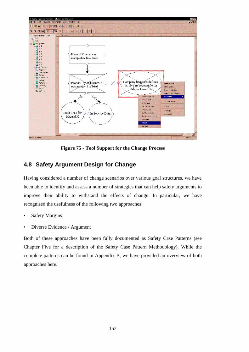
152
Figure 75 - Tool Support for the Change Process
4.8 Safety Argument Design for Change
Having considered a number of change scenarios over various goal structures, we have
been able to identify and assess a number of strategies that can help safety arguments to
improve their ability to withstand the effects of change. In particular, we have
recognised the usefulness of the following two approaches:
• Safety Margins
• Diverse Evidence / Argument
Both of these approaches have been fully documented as Safety Case Patterns (see
Chapter Five for a description of the Safety Case Pattern Methodology). While the
complete patterns can be found in Appendix B, we have provided an overview of both
approaches here.
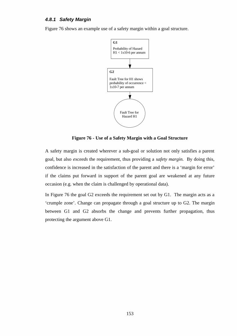
153
4.8.1 Safety Margin
Figure 76 shows an example use of a safety margin within a goal structure.
Probability of HazardH1 < 1x10⁻⁶ per annum
G1
Fault Tree for H1 showsprobability of occurrence <1x10⁻⁷ per annum
G2
Fault Tree forHazard H1
Figure 76 - Use of a Safety Margin with a Goal Structure
A safety margin is created wherever a sub-goal or solution not only satisfies a parent
goal, but also exceeds the requirement, thus providing a safety margin. By doing this,
confidence is increased in the satisfaction of the parent and there is a ‘margin for error’
if the claims put forward in support of the parent goal are weakened at any future
occasion (e.g. when the claim is challenged by operational data).
In Figure 76 the goal G2 exceeds the requirement set out by G1. The margin acts as a
‘crumple zone’. Change can propagate through a goal structure up to G2. The margin
between G1 and G2 absorbs the change and prevents further propagation, thus
protecting the argument above G1.
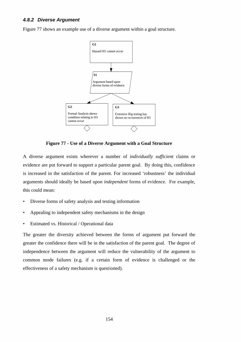
154
4.8.2 Diverse Argument
Figure 77 shows an example use of a diverse argument within a goal structure.
Hazard H1 cannot occur
G1
S1
Argument based upondiverse forms of evidence
G2
Formal Analysis showscondition relating to H1cannot occur
G3
Extensive Rig testing hasshown no occurrences of H1
Figure 77 - Use of a Diverse Argument with a Goal Structure
A diverse argument exists wherever a number of individually sufficient claims or
evidence are put forward to support a particular parent goal. By doing this, confidence
is increased in the satisfaction of the parent. For increased ‘robustness’ the individual
arguments should ideally be based upon independent forms of evidence. For example,
this could mean:
• Diverse forms of safety analysis and testing information
• Appealing to independent safety mechanisms in the design
• Estimated vs. Historical / Operational data
The greater the diversity achieved between the forms of argument put forward the
greater the confidence there will be in the satisfaction of the parent goal. The degree of
independence between the argument will reduce the vulnerability of the argument to
common mode failures (e.g. if a certain form of evidence is challenged or the
effectiveness of a safety mechanism is questioned).
155
4.9 Limitations of the Approach
The following are the principal limitations of the approach described in this chapter:
• Reliance upon correspondence between safety argument and safety case
• Influence of dependencies external to the safety argument
A brief explanation of each of these limitations is provided here.
4.9.1 Reliance upon correspondence between safety argument and safety case
The change impact assessment approach described in this chapter is couched in terms of
a safety argument recorded as a goal structure. The ability of the approach to express
accurately and fully the impact of changes on the safety case depends on the degree to
which the goal structured safety argument corresponds to the documented safety case.
The usefulness of the approach in helping to maintain the safety case document depends
on how well the relationship between the goal structure and document is understood.
Employing document references with the goal structure (e.g. labelling a goal with the
document section where that requirement is expressed) can explicitly draw out such
links and improve this situation.
4.9.2 Influence of dependencies external to the safety argument
The dependencies recorded within a goal structure are those represented in Figure 50 -
principally how requirements are supported by argument and how argument is
supported by evidence. The impact assessment approach given in this chapter uses
these dependencies to determine the impact of change on the safety argument.
However, there are other dependencies that can exist between the safety case elements
of requirements, evidence and context, for example:
• Evidence to Evidence links – one piece of evidence may depend upon another
piece of evidence, e.g. a hazard log may depend upon the results of a HAZOPS
activity, or a fault tree may use failure modes provided by a component FMEA.
These relationships are not currently communicated through a goal structured safety
argument. For example, in Figure 65, the goal structure is ‘oblivious’ to the
relationship that exists between the Component FMEA and Fault Tree solutions
provided.
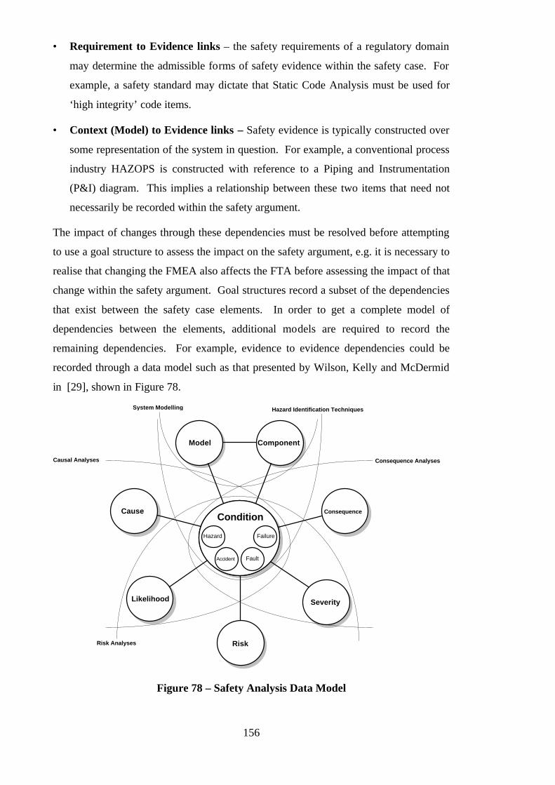
156
• Requirement to Evidence links – the safety requirements of a regulatory domain
may determine the admissible forms of safety evidence within the safety case. For
example, a safety standard may dictate that Static Code Analysis must be used for
‘high integrity’ code items.
• Context (Model) to Evidence links – Safety evidence is typically constructed over
some representation of the system in question. For example, a conventional process
industry HAZOPS is constructed with reference to a Piping and Instrumentation
(P&I) diagram. This implies a relationship between these two items that need not
necessarily be recorded within the safety argument.
The impact of changes through these dependencies must be resolved before attempting
to use a goal structure to assess the impact on the safety argument, e.g. it is necessary to
realise that changing the FMEA also affects the FTA before assessing the impact of that
change within the safety argument. Goal structures record a subset of the dependencies
that exist between the safety case elements. In order to get a complete model of
dependencies between the elements, additional models are required to record the
remaining dependencies. For example, evidence to evidence dependencies could be
recorded through a data model such as that presented by Wilson, Kelly and McDermid
in [29], shown in Figure 78.
ConditionCause Consequence
Likelihood Severity
Hazard
Accident Fault
Failure
Model Component
Consequence AnalysesCausal Analyses
System Modelling
RiskRisk Analyses
Hazard Identification Techniques
Figure 78 – Safety Analysis Data Model

157
4.10 Conclusions
This chapter presents a novel and systematic approach to the management of safety case
change. Starting from a goal structured representation of the safety argument, we have
shown how it is possible to use the recorded dependencies of the goal structure to
follow through the impact of a change and (having decided upon a corrective action or
actions) recover from change. Observed successful strategies that can be employed in
the production of safety arguments to mitigate the effects of change have been
presented. Although there are recognised limitations to the approach presented, the
principal benefit is that it provides a structured and systematic approach to reasoning
about the effects of change where previously very limited support was available.

158
159
Chapter 5:
Safety Case Patterns: Using the Goal Structuring
Notation to Support Safety Case Reuse
5.1 Introduction
Observation of a number and variety of existing safety cases, and discussion with safety
engineers, suggest that whereas the detail of the safety arguments within the safety case
is likely to change from instance to instance (being based on specific evidence), there is
often commonality between the structures of argument used in safety cases. This is
observed to be particularly true for safety cases within the same domain (e.g. aero-
engine control or nuclear power plant design). This can be attributed to the stability of
the certification requirements, forms of evidence used and maturity of knowledge in
these domains. However, commonality of approach has also been observed in safety
cases across different domains. For example, arguments structured around the ALARP
principle can be identified in safety cases from many different industrial sectors (e.g.
work machinery, nuclear installations and offshore oil and gas platforms).
Discussion with safety engineers also suggests that knowledge of how to develop and
structure safety arguments is one of the most valuable aspects of safety case
management. This knowledge can often be the product of many years’ experience and
can be said to encapsulate an element of safety case development expertise. Artefacts
that were able to capture and communicate this knowledge could therefore be said to
provide significant insight and to have inherent value.
This chapter defines the concept of Safety Case Patterns – an approach to supporting
the systematic reuse of successful safety arguments between safety cases.
5.2 The Problems of Informal Safety Case Material Reuse
Informal reuse of safety case material is already commonplace, and it is not uncommon
for a safety engineer, having recognised a similarity, to plunder a previously developed
safety case to aid in the development of a safety case in a new project. In some cases,
the engineer may believe certain elements of the two projects to be sufficiently similar

160
to actually “cut-and-paste” parts of the original documentation and subject them only to
minor review and modification.
The central role of people in the reuse of safety argument approaches is often crucial.
As described in Chapter One, many existing safety cases fail to present clearly the
structure, intent and rationale of the safety argument. Such safety cases cannot easily be
read and understood in a way that permits re-application of the approach. They require
interpretation. To understand the intent of a safety case can take many readings. To
understand the rationale behind aspects of a safety case can require a form of ‘reverse
engineering’. Safety cases with these properties are not readily amenable to reuse.
Therefore, the safety engineers who worked on a safety case form an important ‘missing
link’ in any attempt to gain value from it in future safety case developments. However,
problems are present where people are the principal medium for cross-project reuse of
safety argument approaches. Based upon observation of existing practice, the author
has identified the following specific problems:
• Arguments being reused inappropriately
If the original context of a safety argument is not fully recognised it may be applied
inappropriately in another context. An argument of safety from one context that is
not applicable in the reused context can create a false or misleading picture of a
system’s safety. Such reuse can carry “hidden assumptions” from the original
context that are inconsistent with the application context. This danger is obviously
greatest with the extreme of “cut-and-paste” reuse.
• Reuse occurring in an ad-hoc fashion
Reuse is dependent entirely on an engineer’s ability, firstly, to recognise the potential
to reuse an argument approach and, secondly, to recall the appropriate information.
Consequently, reuse often occurs in a fairly random, opportunistic, fashion and is not
carried out systematically. Opportunities to reuse an approach may be wasted.
• Loss of knowledge
A total reliance on people to achieve cross-project reuse is an admission that project
documentation is insufficient to support systematic reuse. A danger is that particular
people, the company ‘experts’, become a bottleneck on any project. Without
documentation of their experience or expertise, they become a critical resource in an
organisation. They effectively act as an ‘index’ into the organisation’s existing
documentation. If such people leave an organisation, disproportionately large
161
amounts of the organisation’s ‘corporate memory’ are lost and, as a result, less reuse
is possible.
• Lack of Consistency / Process Maturity
Without explicitly recognising and documenting the repeatable elements of safety
case development there can be no assurance that these elements are being used
consistently. If an approach is not consistently applied, it is difficult to argue that it is
mature. It is also difficult to argue how this approach has been, and will be,
improved and evolved over time.
• Lack of traceability
Informal reuse can be invisible in the final safety case produced. Often, no record is
kept of reuse from existing documentation. This lack of traceability can lead to
problems in maintaining the safety case. For example, if it were found that a
particular reused safety argument was unsound (e.g. in the light of contradictory
operational evidence), it would be necessary to locate all instances of that approach
in order to update them appropriately. With no record of where it was reused this
becomes an extremely difficult task. Reuse has the potential to propagate one error
many times. To deal with such situations requires adequate visibility and traceability
of the reuse process.
These problems can be said to stem from two underlying issues:
• No means of articulating and documenting reusable safety argument approaches.
• (As result of having no identifiable reuse assets …) No systematic process for the
reuse of safety argument approaches.
This chapter defines an approach to support expression and documentation of reusable
safety argument structures. Once these structures are “down on paper” they can begin
to be evaluated and exploited, and to form part of a systematic process.
In searching for an approach to expressing reusable arguments, the concept of
identifying and documenting ‘patterns’ was identified as an appropriate and sufficiently
expressive basis. The following section provides an overview of the general concepts
of ‘patterns’.
162
5.3 Patterns
The concept of a ‘pattern’ has application in many different contexts. The dictionary
definition of ‘pattern’ communicates just some of the many ways in which patterns are
used or understood in everyday life:
pattern n. 1. an arrangement of repeated or corresponding parts, decorative motifs, etc.:
although the notes seemed random, a careful listener could detect a pattern. 2. a
decorative design: a paisley pattern. 3. a style: various patterns of cutlery. 4. a plan or
diagram used as a guide in making something: a paper pattern for a dress. 5. a standard
way of moving, acting etc.: traffic patterns. 6. a model worthy of imitation: a pattern of
kindness. 7. a representative sample. 8. a wooden or metal shape or model used in a
foundry to make a mould. 9.a. the arrangement of marks made in a target by bullets. 10.
a diagram displaying such an arrangement. [70]
Although widely applied, published literature on patterns is largely restricted to novel
applications of the concept. The books of the architect Christopher Alexander [71-73]
are a notable and oft-cited example of such work.
In the book, “The Timeless Way of Building” [70], Alexander argues that “Beyond its
elements each building is defined by certain patterns of relationships amongst its
elements”. Alexander shows how patterns can be used to abstract away from the details
of particular buildings and capture something essential to the design (the principles
underlying the building; the reasons why elements of the building are successful or
unsuccessful) that can then be used elsewhere.
The concept of patterns as defined by Alexander was adopted by the software
community in the late 1980’s and early 90’s in the form of ‘Design Patterns’. It was
this work that particularly inspired me to apply the pattern concept to the safety case
domain. The following section briefly describes the ‘Design Patterns’ concept.
5.4 Design Patterns
Inspired by Alexander’s work, the concept of patterns and pattern languages has
received increasing interest from software designers [74-76]. Designers have turned to
patterns as a means of capturing the repeatable and successful elements of a software
design. Many have been disappointed with the unfulfilled promise of traditional
component-based (compositional) reuse and believe that successful reuse lies in the
ability to describe higher level software structures [77]: e.g. how components are
combined to achieve certain functions, principles of writing interfacing components,

163
etc. The attraction of patterns is that they offer this means of abstracting fundamental
design strategies from the details of particular designs.
5.4.1 A Brief History of Design Patterns
The idea of software Design Patterns was first suggested by Ward Cunningham and
Kent Beck in 1987 when they proposed a number of software Design Patterns to
describe elegant Smalltalk user interfaces [78]. Around the same time, James Coplien
started to document language specific (C++) patterns. These were labelled idioms at the
time, although now are commonly accepted as a form of pattern. The idioms were used
for some time within AT&T as a basis for teaching some of the core principles of C++
before eventually being published as “Idioms and Patterns as Architectural Literature”
in 1997 [79]. Independently, in 1992, work on patterns in object-objected oriented
analysis and design was published by Coad in “Object-Oriented Patterns” [76].
Although discussing the emergence of patterns at a higher level of abstraction than
Coplien’s language idioms this work shared a common heritage in Alexander’s work
and visited many of same issues. In addition to these activities, Erich Gamma, as part
of his doctoral work on object-oriented software development [80] began in 1991 to
document recurring design structures. Gamma’s work continued as part of the “Gang of
Four” (Erich Gamma, Richard Helm, Ralph Johnson and John Vlissides) and resulted in
1993 in the production of the first book on the subject – “Design Patterns – Elements of
Reusable Object-Oriented Software”. Since that time, the field of Design Patterns has
become well established and is supported by an increasing number of conferences such
as Pattern Languages of Program Design (PLoP), European Conference on Object-
Oriented Programming (ECOOP) and the ACM SIGPLAN Conference On Object-
Oriented Programming Systems, Languages and Applications (OOPSLA).
The ancestry of Design Patterns has been well documented in [81]. We refer the reader
to this source for a more detailed history.
Whether patterns are used to represent architectural idioms in building design or to
capture elements of a successful software design, some means of representing the
pattern is required. To provide the context for the representation of Safety Case
Patterns defined in this thesis, the following section describes how existing pattern
forms have been represented.

164
5.5 Pattern Representation
Alexander describes a pattern as a “solution to a problem in a context” [71]. In essential
terms, representation of a pattern will include the following elements:
• Problem
• Context
• Solution
In both Alexander’s architectural patterns and in Design Patterns, these elements are
realised through structured prose and diagrams. An example of a recorded Alexandrian
pattern (taken from [72]) is shown in Figure 79.
Diagram (Sketch) Prose
In the zone where city and country meet, place country roads at least one mile apart, so that
they enclose squares of countryside and farmland at least one square mile in area. Build homesteads along these roads, one lot deep, on
lots of at least half an acre, with the square mile of open countryside or farmland behind the
houses
Figure 79 - An Alexandrian Pattern for Country Streets
Whereas Alexander used small sketches, in Design Patterns a variety of notations have
been used to describe the structure of solutions. In the patterns described by Gamma et
al in [82], three different diagrammatic notations are used:
1. Class Diagram – depicting classes, their structure, and the static relationships
between them
2. Object Diagram - depicting a particular object structure at run-time
3. Interaction diagram - showing the flow of requests between objects
Each pattern includes, as a minimum, a class diagram. The class and object diagrams
are based on OMT (Object Modelling Technique) [83]. The interaction diagrams are
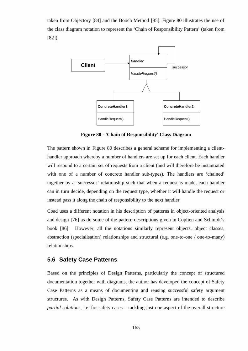
165
taken from Objectory [84] and the Booch Method [85]. Figure 80 illustrates the use of
the class diagram notation to represent the ‘Chain of Responsibility Pattern’ (taken from
[82]).
ConcreteHandler2
HandlerClient
HandleRequest()
ConcreteHandler1
HandleRequest() HandleRequest()
successor
Figure 80 - 'Chain of Responsibility' Class Diagram
The pattern shown in Figure 80 describes a general scheme for implementing a client-
handler approach whereby a number of handlers are set up for each client. Each handler
will respond to a certain set of requests from a client (and will therefore be instantiated
with one of a number of concrete handler sub-types). The handlers are ‘chained’
together by a ‘successor’ relationship such that when a request is made, each handler
can in turn decide, depending on the request type, whether it will handle the request or
instead pass it along the chain of responsibility to the next handler
Coad uses a different notation in his description of patterns in object-oriented analysis
and design [76] as do some of the pattern descriptions given in Coplien and Schmidt’s
book [86]. However, all the notations similarly represent objects, object classes,
abstraction (specialisation) relationships and structural (e.g. one-to-one / one-to-many)
relationships.
5.6 Safety Case Patterns
Based on the principles of Design Patterns, particularly the concept of structured
documentation together with diagrams, the author has developed the concept of Safety
Case Patterns as a means of documenting and reusing successful safety argument
structures. As with Design Patterns, Safety Case Patterns are intended to describe
partial solutions, i.e. for safety cases – tackling just one aspect of the overall structure
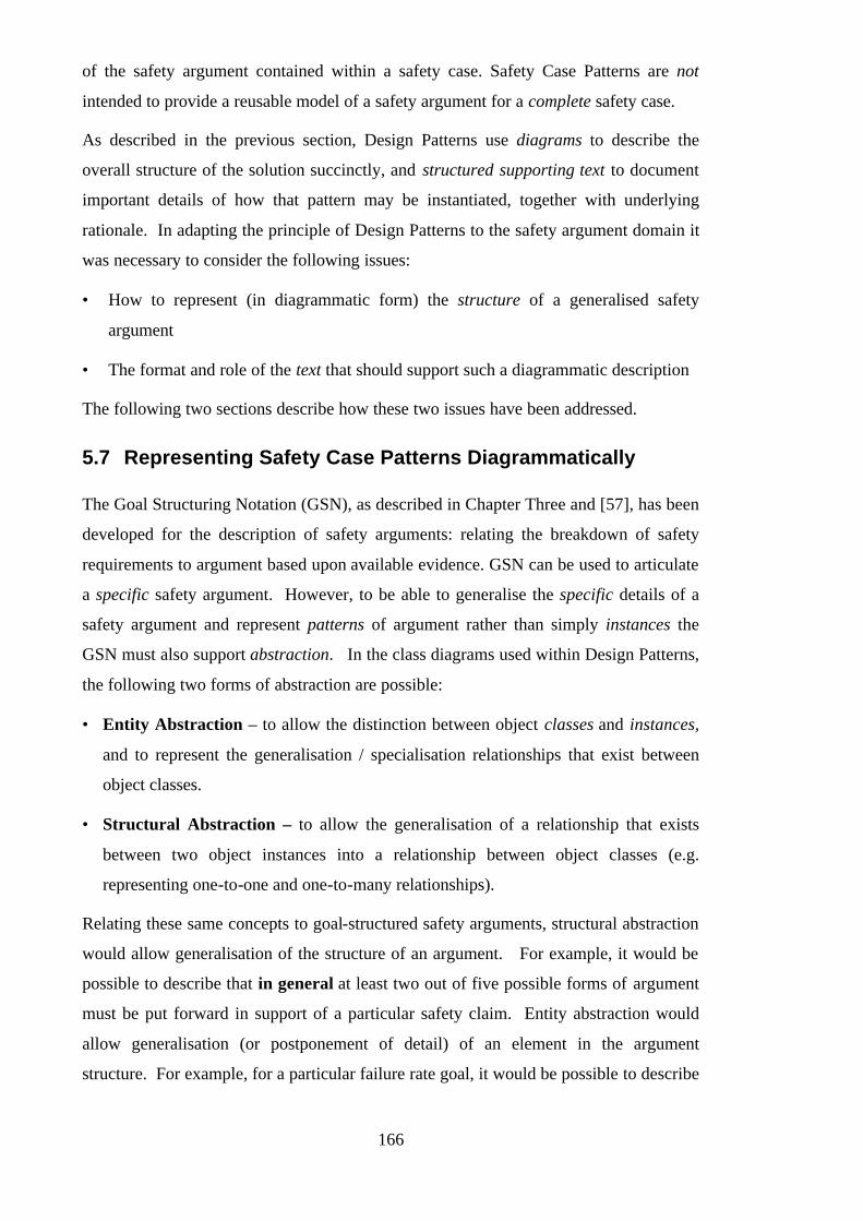
166
of the safety argument contained within a safety case. Safety Case Patterns are not
intended to provide a reusable model of a safety argument for a complete safety case.
As described in the previous section, Design Patterns use diagrams to describe the
overall structure of the solution succinctly, and structured supporting text to document
important details of how that pattern may be instantiated, together with underlying
rationale. In adapting the principle of Design Patterns to the safety argument domain it
was necessary to consider the following issues:
• How to represent (in diagrammatic form) the structure of a generalised safety
argument
• The format and role of the text that should support such a diagrammatic description
The following two sections describe how these two issues have been addressed.
5.7 Representing Safety Case Patterns Diagrammatically
The Goal Structuring Notation (GSN), as described in Chapter Three and [57], has been
developed for the description of safety arguments: relating the breakdown of safety
requirements to argument based upon available evidence. GSN can be used to articulate
a specific safety argument. However, to be able to generalise the specific details of a
safety argument and represent patterns of argument rather than simply instances the
GSN must also support abstraction. In the class diagrams used within Design Patterns,
the following two forms of abstraction are possible:
• Entity Abstraction – to allow the distinction between object classes and instances,
and to represent the generalisation / specialisation relationships that exist between
object classes.
• Structural Abstraction – to allow the generalisation of a relationship that exists
between two object instances into a relationship between object classes (e.g.
representing one-to-one and one-to-many relationships).
Relating these same concepts to goal-structured safety arguments, structural abstraction
would allow generalisation of the structure of an argument. For example, it would be
possible to describe that in general at least two out of five possible forms of argument
must be put forward in support of a particular safety claim. Entity abstraction would
allow generalisation (or postponement of detail) of an element in the argument
structure. For example, for a particular failure rate goal, it would be possible to describe

167
that in general that the solution will be “Quantitative Evidence” without specifying
whether this is specifically “Fault Tree Analysis” or “Markov Modelling”.
In order that both structural and entity abstraction can be represented in the GSN it was
necessary to extend the notation. We have defined the extensions presented in the
following two sections for this purpose.
5.7.1 Extending the GSN to Support Structural Abstraction
This section describes the extensions to GSN we have defined in order to support the
following two aspects of structural abstraction:
• Multiplicity – generalised n-ary relationships between GSN elements
• Optionality – optional and alternative relationships between GSN elements
5.7.1.1 Extending the GSN to Support Multiplicity
The extensions to GSN we have defined in Figure 81 have been adapted from the OMT
object diagram notation [83]. They enable multiplicity (an aspect of structural
abstraction) to be represented using the GSN.
Multiplicity Extensions
These symbols are defined for use as annotations on existing GSN relation types (e.g.
SolvedBy). Multiplicity symbols can be used to describe how many instances of one
entity relate to another entity.
n
A solid ball is the symbol for many (meaning zero or more).
The label next to the ball indicates the cardinality of the
relationship.
A hollow ball indicates “optional” (meaning zero or one).
A line without multiplicity symbols indicates a one to one
relationship (as in conventional GSN).
Figure 81 – GSN Multiplicity Extensions (For Structural Abstraction)
Figure 82 illustrates example uses of the GSN multiplicity extensions.
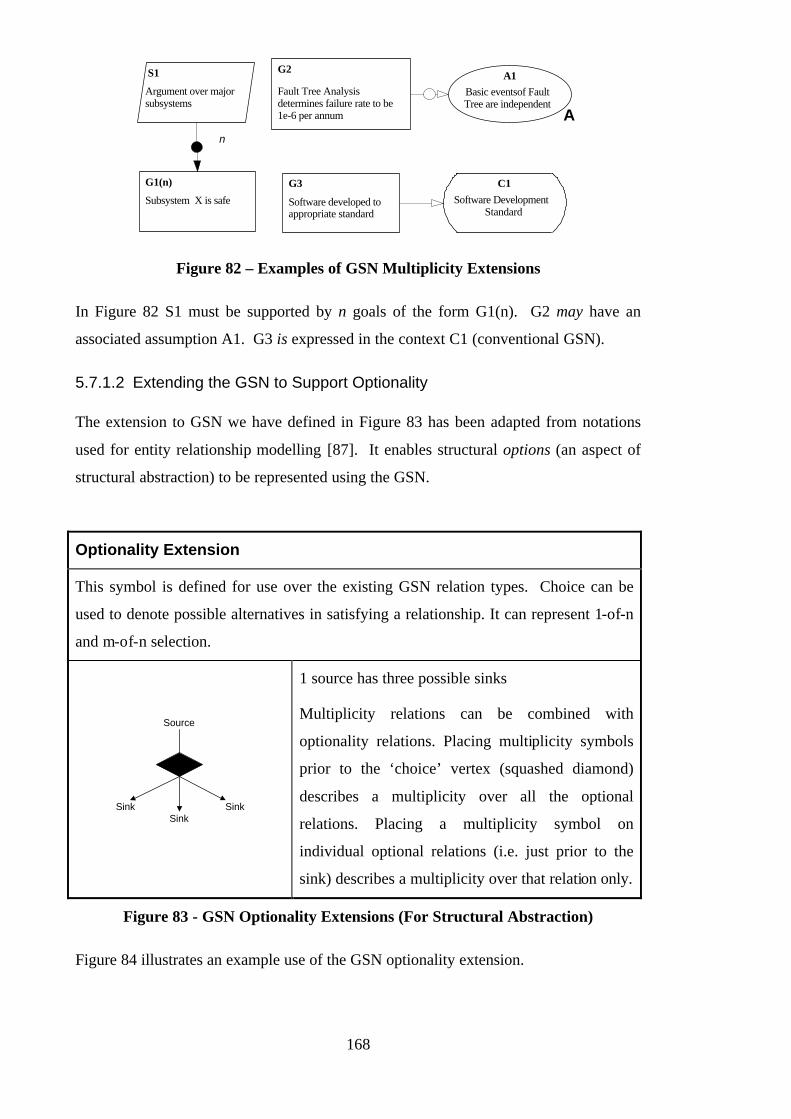
168
S1
Argument over majorsubsystems
Subsystem X is safe
G1(n)
Fault Tree Analysisdetermines failure rate to be1e-6 per annum
G2
n
A1Basic eventsof FaultTree are independent
A
Software developed toappropriate standard
G3 C1Software Development
Standard
Figure 82 – Examples of GSN Multiplicity Extensions
In Figure 82 S1 must be supported by n goals of the form G1(n). G2 may have an
associated assumption A1. G3 is expressed in the context C1 (conventional GSN).
5.7.1.2 Extending the GSN to Support Optionality
The extension to GSN we have defined in Figure 83 has been adapted from notations
used for entity relationship modelling [87]. It enables structural options (an aspect of
structural abstraction) to be represented using the GSN.
Optionality Extension
This symbol is defined for use over the existing GSN relation types. Choice can be
used to denote possible alternatives in satisfying a relationship. It can represent 1-of-n
and m-of-n selection.
Source
SinkSink Sink
1 source has three possible sinks
Multiplicity relations can be combined with
optionality relations. Placing multiplicity symbols
prior to the ‘choice’ vertex (squashed diamond)
describes a multiplicity over all the optional
relations. Placing a multiplicity symbol on
individual optional relations (i.e. just prior to the
sink) describes a multiplicity over that relation only.
Figure 83 - GSN Optionality Extensions (For Structural Abstraction)
Figure 84 illustrates an example use of the GSN optionality extension.

169
Hazard H1 has beenaddressed
G1
Hazard H1 has beeneliminated from design
G2
1 of 2
Probability of Hazard H1occuring is acceptably low
G3
Figure 84 – Example of GSN Optionality Extension
In Figure 84, G1 is supported by either stating G2 or G3.
5.7.2 Representation of Entity Abstraction in the GSN
The extensions to GSN we have defined in Figure 85 have been adapted from the OMT
object diagram notation [83] and the convention for presenting Fault Trees [88]. They
enable abstract entities to be represented using the GSN.
Entity Abstraction Extensions
Supertype GSN Element
Subtype GSN Element
Is_A Relation
The Is_A relation provides a basis for the
expression of supertype and subtype relations
between GSN entities (e.g. ‘Failure rate is less
than 1x10⁻⁶ per annum’ Is_A Failure Rate Claim)
and can therefore be used to establish type
hierarchies.
The relation can be used directly in a goal
structure pattern to denote subtype relations or
used apart from a pattern to establish type
hierarchies for a group of patterns (e.g. on a per-
project basis).

170
Uninstantiated Entity
This placeholder denotes that the attached entity
remains to be instantiated, i.e. at some later stage
the ‘abstract’ entity needs to be replaced
(instantiated) with a more concrete instance.
Instantiation may be provided either through
offering a concrete instance or subtypes denoted
by the Is_A relation.
Undeveloped Entity
This placeholder denotes that the attached entity
requires further development, i.e. at some later
stage the entity needs to be (hierarchically)
decomposed and further supported by sub-entities.
Unlike uninstantiated elements, undeveloped
elements are not replaced, they are further
elaborated in the goal structure, i.e. as with
undeveloped events in conventional Fault Tree
Notation.
Figure 85 - GSN Extensions for Entity Abstraction
Figure 86 illustrates an example use of the Is_A extension.
QuantitativeResults
Fault TreeAnalysisResults
MarkovModellingResults
TestResults
Figure 86 – Example of GSN Is_A Extension
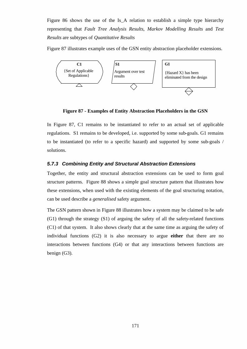
171
Figure 86 shows the use of the Is_A relation to establish a simple type hierarchy
representing that Fault Tree Analysis Results, Markov Modelling Results and Test
Results are subtypes of Quantitative Results
Figure 87 illustrates example uses of the GSN entity abstraction placeholder extensions.
Argument over testresults
S1
{Set of ApplicableRegulations}
C1 G1
{Hazard X} has beeneliminated from the design
Figure 87 - Examples of Entity Abstraction Placeholders in the GSN
In Figure 87, C1 remains to be instantiated to refer to an actual set of applicable
regulations. S1 remains to be developed, i.e. supported by some sub-goals. G1 remains
to be instantiated (to refer to a specific hazard) and supported by some sub-goals /
solutions.
5.7.3 Combining Entity and Structural Abstraction Extensions
Together, the entity and structural abstraction extensions can be used to form goal
structure patterns. Figure 88 shows a simple goal structure pattern that illustrates how
these extensions, when used with the existing elements of the goal structuring notation,
can be used describe a generalised safety argument.
The GSN pattern shown in Figure 88 illustrates how a system may be claimed to be safe
(G1) through the strategy (S1) of arguing the safety of all the safety-related functions
(C1) of that system. It also shows clearly that at the same time as arguing the safety of
individual functions (G2) it is also necessary to argue either that there are no
interactions between functions (G4) or that any interactions between functions are
benign (G3).

172
G1: {System X} is Safe
G2: {Function Y} issafe
S1: Argument byclaiming safety of all
safety-related functionsimplemented by system
C1: Safety RelatedFunctions of {System X}
(n = # functions)
n
G3: Interactionsbetween system
functions are non-hazardous
G4: All systemfunctions areindependent
(no interactions)
Provides {Function Y}
Indicates thatelement remainsto be developed
(supported)
Indicates thatelement remains
to be instantiated
Indicates a 1-to-many relationship
Indicates thatelement remains tobe instantiated andthen developed
Figure 88 - Example Use of GSN Extensions
A Safety Case Pattern is not simply a GSN Pattern as shown in Figure 88. Additionally,
there should always be a supporting pattern description. To define patterns without
clearly stating the underlying motivation and intent, and without making clear where
and (perhaps more importantly from a safety perspective) where not patterns should be
applied could result in ignorant and inappropriate use of argument patterns within new
projects. The following section describes the documentation format we have defined
for Safety Case Patterns.
5.8 Documenting Safety Case Patterns
In the Design Patterns community, based on Alexander’s principles of documenting
problem, solution and context, a number of alternative documentation structures have
been proposed and used for the description of Design Patterns. Table 7 shows some of
the documentation formats defined by different authors for the description of software
Design Patterns.
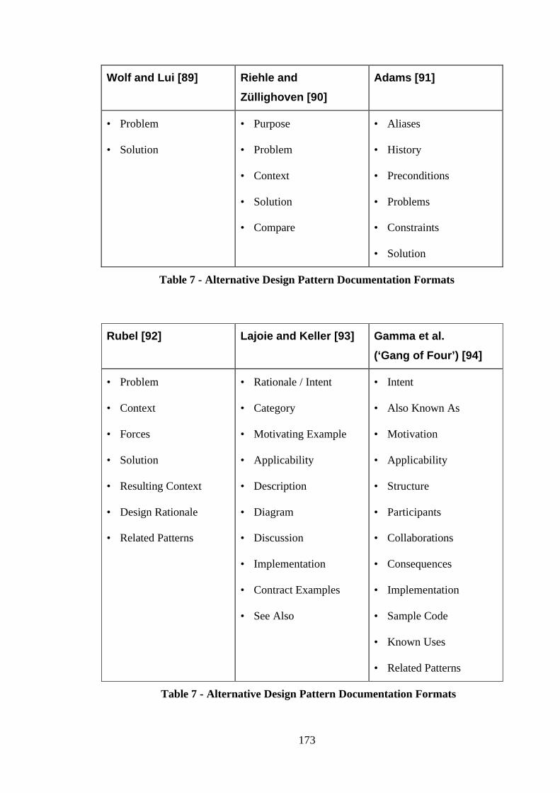
173
Wolf and Lui [89] Riehle and
Züllighoven [90]
Adams [91]
• Problem
• Solution
• Purpose
• Problem
• Context
• Solution
• Compare
• Aliases
• History
• Preconditions
• Problems
• Constraints
• Solution
Table 7 - Alternative Design Pattern Documentation Formats
Rubel [92] Lajoie and Keller [93] Gamma et al.
(‘Gang of Four’) [94]
• Problem
• Context
• Forces
• Solution
• Resulting Context
• Design Rationale
• Related Patterns
• Rationale / Intent
• Category
• Motivating Example
• Applicability
• Description
• Diagram
• Discussion
• Implementation
• Contract Examples
• See Also
• Intent
• Also Known As
• Motivation
• Applicability
• Structure
• Participants
• Collaborations
• Consequences
• Implementation
• Sample Code
• Known Uses
• Related Patterns
Table 7 - Alternative Design Pattern Documentation Formats

174
For the description of safety argument patterns, rather than necessarily defining a new
template, we first assessed the templates for Design Patterns to determine whether they
might easily be adapted to the safety argument domain. In examining the various
pattern templates, the following criteria were used to assess suitability for the
description of safety arguments:
• Freedom of pattern format from software (particularly object-oriented) specific
concepts and terms
• Explicit representation of applicability – already identified earlier in this chapter in
section 2 as being an crucial element of any form of safety case reuse
• A sufficiently defined and evocative series of headings that, whilst still allowing
some flexibility of interpretation, would ensure that key elements of required
contextual information (such as rationale) would be captured in a completed pattern
description.
The ‘Gang of Four’ documentation format met these selection criteria and through some
preliminary evaluation was found to be readily adaptable to the description of safety
argument patterns. Based on this format, we defined the following headings for the
documentation of Safety Case Patterns:
• Pattern Name
• Intent
• Also Known As
• Motivation
• Applicability (Necessary Context)
• Structure
• Participants
• Collaborations
• Consequences
• Implementation
• Example Applications
• Known Uses
• Related Patterns
The following sections describe the purpose and expected context of each of these
elements of a documented Safety Case Pattern. We originally proposed the
documentation format for Safety Case Patterns in [95]. This continues to be refined in
the light of experience of identifying and documenting new Safety Case Patterns (such
as those presented in Appendix B).

175
5.8.1 Pattern Name
The pattern name should communicate the key principle or central argument being
presented by the safety argument pattern. This will be the label by which people will
identify this pattern. Over time this name will hopefully become part of the vocabulary
through which safety engineers can quickly communicate the concepts and principles of
their safety arguments. It is therefore important to choose the pattern name carefully.
5.8.2 Intent
This statement should answer the question: what is this pattern trying to achieve? For
example, if the argument is intended to address a particular certification requirement
then this should be recorded in this section. It is important that, through reading this
section there is a clear understanding between writer and reader of the pattern as to what
is being attempted.
5.8.3 Also Known As
If the pattern could equally well be described or recognised under other names, then
these should be recorded here.
5.8.4 Motivation
This section should briefly describe why the pattern was constructed. Was it because it
was an argument that was particularly well received by the regulator and therefore
something that should be replicated where possible? Was it because there was a desire
to standardise the structure of an argument that had been previously presented in
slightly differing forms?
The motivation can be expressed in terms of previous experiences, problems etc. This
section should help engineers to interpret and apply correctly the more abstract
description of the pattern that follows.
5.8.5 Structure
It is in this section that the Goal Structuring Notation (using the extensions proposed in
Section 5.7) is used to present the structure of the argument pattern. Using the notation,
it is possible to show the requirements / claims to be addressed, the context in which
they are stated and the way in which they can be decomposed into (supported by) lower
level statements. Using the GSN pattern extensions that we have proposed, it can be
indicated clearly where the argument is complete, where information must be provided

176
(e.g. where instantiation must occur) and where the argument requires further
development. The elements of the goal structure pattern should be labelled clearly (e.g.
‘Goal G1’) such that they can be referred to by the following sections of the pattern
description.
5.8.6 Participants
This section should augment the Structural description by providing a description of
each of the elements of the goal structure pattern (i.e. the goals, the contexts, the
strategies, the solutions etc.). It is possible in this section to provide fuller description
of, for example, a safety requirement than is possible within the confines of a graphical
rendering. The element descriptions should make clear their function within the overall
argument pattern. They should also state whether the element requires development or
instantiation when the pattern is applied.
5.8.7 Collaborations
This section should describe how the different elements of the pattern (sources of
contextual information, argument strategies, goals) work together to achieve the desired
effect of the pattern – to present an effective argument. Also, when there are links
between different elements that are not communicated by the argument structure they
should be explicitly recorded here in order that they can be recognised by the safety
engineer when applying the pattern.
5.8.8 Applicability (Necessary Context)
This section should record under what circumstance this argument can and should be
applied. Of particular concern for safety arguments, this section should make clear the
assumptions and principles underlying the argument pattern such that it is never
inappropriately applied in a mismatched context. Relating specifically to the context
elements of the goal structure pattern, this section should describe what contextual
information is required (elements instantiated) in order to be able to apply the pattern.
In addition to these elements, it can also be useful to provide guidance on how to
recognise situations in which the pattern can be applied.
5.8.9 Consequences
Again, with direct reference to the elements of the structural description, this section
should make clear what work remains after having applied or carried out an argument
pattern. In particular, this should highlight where there are goals that remain to be
177
supported, or assumptions to be discharged, etc. The purpose of this section is to ensure
that an engineer applying the pattern is under no illusion as to what the pattern does and
does not do.
5.8.10 Implementation
This section should perform the following roles:
• Communicate how the application of this pattern should be carried out. This may
even extend to describing in what order elements ought to be developed.
• Communicate hints or techniques that would ease successful application of the
pattern.
• Make clear the ways in which is possible to get it wrong when applying the pattern
(possible pitfalls).
• Record common misinterpretations of the terms or concepts used in the pattern.
5.8.11 Examples
This section should provide examples that illustrate the instantiation of the pattern. If
only one example is provided then it should illustrate a typical instantiation of the
pattern. If multiple examples can be provided then illustration of atypical applications
of the pattern should also be provided.
Analogy is a key problem solving device employed by engineers [96, 97]. The provision
of examples can therefore be extremely valuable in helping an engineer to understand
how to apply the pattern in their own context.
The more abstract a pattern is, the more important it is to provide concrete examples
within this section.
5.8.12 Known Uses
This section should refer to known uses of the form of argument presented in the
pattern. As with the Examples section, giving an engineer the ability to observe how a
pattern can be applied as part of a larger safety argument within a safety case can
significantly improve understanding of how the pattern might be applied in a new
context.

178
5.8.13 Related Patterns
This section should refer to Safety Case Patterns that are related to this pattern, e.g.
patterns that share the same Intent but are admissible under different applicability
conditions (e.g. for different regulatory domains or classes of systems).
The documentation format defined by these headings, together with the diagrammatic
pattern description using GSN and the extensions we have proposed, provide a means of
describing Safety Case Patterns. The following section provides an example of a fully
documented Safety Case Pattern. (Many other documented Safety Case Patterns can be
found in Appendix B).
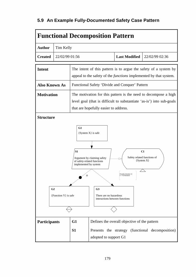
179
5.9 An Example Fully-Documented Safety Case Pattern
Functional Decomposition Pattern
Author Tim Kelly
Created 22/02/99 01:56 Last Modified 22/02/99 02:36
Intent The intent of this pattern is to argue the safety of a system by
appeal to the safety of the functions implemented by that system.
Also Known As Functional Safety ‘Divide and Conquer’ Pattern
Motivation The motivation for this pattern is the need to decompose a high
level goal (that is difficult to substantiate ‘as-is’) into sub-goals
that are hopefully easier to address.
Structure
{System X} is safe
G1
S1
Argument by claiming safetyof safety-related functionsimplemented by system
Safety related functions of{System X}
C1
G2
{Function Y} is safe
G3
There are no hazardousinteractions between functions
Provides {function Y} n = # of functionsn
Participants G1
S1
Defines the overall objective of the pattern
Presents the strategy (functional decomposition)
adopted to support G1
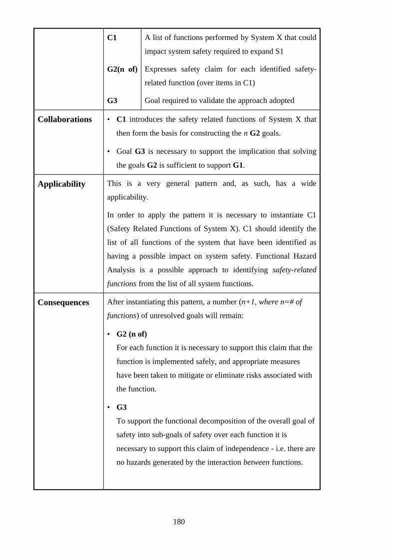
180
C1
G2(n of)
G3
A list of functions performed by System X that could
impact system safety required to expand S1
Expresses safety claim for each identified safety-
related function (over items in C1)
Goal required to validate the approach adopted
Collaborations • C1 introduces the safety related functions of System X that
then form the basis for constructing the n G2 goals.
• Goal G3 is necessary to support the implication that solving
the goals G2 is sufficient to support G1.
Applicability This is a very general pattern and, as such, has a wide
applicability.
In order to apply the pattern it is necessary to instantiate C1
(Safety Related Functions of System X). C1 should identify the
list of all functions of the system that have been identified as
having a possible impact on system safety. Functional Hazard
Analysis is a possible approach to identifying safety-related
functions from the list of all system functions.
Consequences After instantiating this pattern, a number (n+1, where n=# of
functions) of unresolved goals will remain:
• G2 (n of)
For each function it is necessary to support this claim that the
function is implemented safely, and appropriate measures
have been taken to mitigate or eliminate risks associated with
the function.
• G3
To support the functional decomposition of the overall goal of
safety into sub-goals of safety over each function it is
necessary to support this claim of independence - i.e. there are
no hazards generated by the interaction between functions.

181
Implementation In implementing this pattern it is first necessary to instantiate C1
(identify the list of system functions)
Possible Pitfalls
• Attempting to decompose G1 in sub-goals over functions (G2)
without adequately supporting the claim of independence
between functions (G3)
• Inappropriately instantiating C1 with simply safety functions
rather than safety-related functions. The distinction being that
safety functions are those functions that are obviously
concerned with achieving safety (e.g. protection mechanisms)
and safety-related functions are any functions in the system
that have been identified, e.g. through Functional Hazard
Analysis, as potentially posing a safety hazard. Safety
functions are a sub-set of safety-related functions.
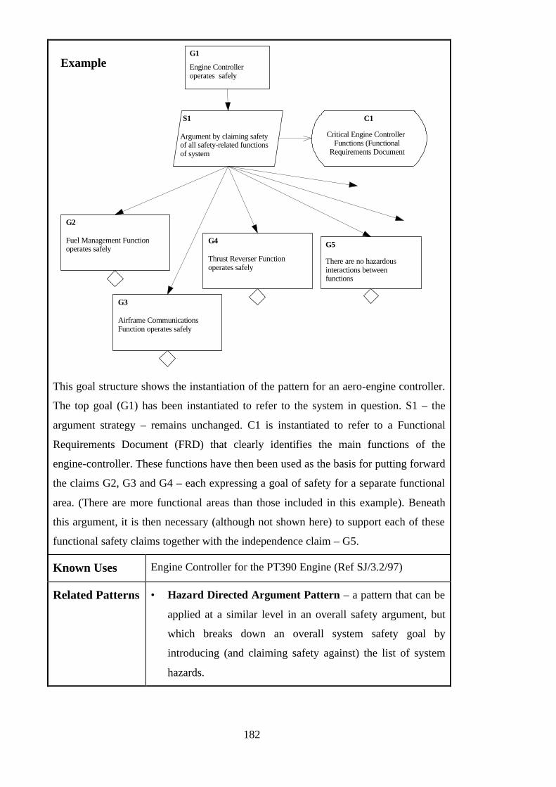
182
Engine Controlleroperates safely
G1
S1
Argument by claiming safetyof all safety-related functionsof system
C1
Critical Engine Controller Functions (Functional
Requirements Document
G2
Fuel Management Functionoperates safely
G3
Airframe CommunicationsFunction operates safely
G4
Thrust Reverser Functionoperates safely
G5
There are no hazardousinteractions betweenfunctions
This goal structure shows the instantiation of the pattern for an aero-engine controller.
The top goal (G1) has been instantiated to refer to the system in question. S1 – the
argument strategy – remains unchanged. C1 is instantiated to refer to a Functional
Requirements Document (FRD) that clearly identifies the main functions of the
engine-controller. These functions have then been used as the basis for putting forward
the claims G2, G3 and G4 – each expressing a goal of safety for a separate functional
area. (There are more functional areas than those included in this example). Beneath
this argument, it is then necessary (although not shown here) to support each of these
functional safety claims together with the independence claim – G5.
Known Uses Engine Controller for the PT390 Engine (Ref SJ/3.2/97)
Related Patterns • Hazard Directed Argument Pattern – a pattern that can be
applied at a similar level in an overall safety argument, but
which breaks down an overall system safety goal by
introducing (and claiming safety against) the list of system
hazards.
Example

183
5.10 Further Example Safety Case Patterns
Patterns can emerge at many different levels in the safety argument and at varying
degrees of specificity. At the highest level it is possible to identify a number of basic
argument structures that are used to decompose ill-defined system safety requirements.
For example, against the ultimate top level requirement …
“{System X} is acceptably safe”
… two of a number of possible argument approaches could be applied:
• Hazard Directed Argument
• Functional Decomposition Argument
The Functional Decomposition Argument Pattern has already been described in the
previous section. Figure 89 shows the GSN pattern (without supporting documentation)
representing a hazard directed argument. In this pattern, the implicit definition of ‘safe’
is ‘hazard avoidance’. The requirement G1 is addressed by arguing that all identified
hazards have been addressed (S1). This strategy can only be executed in the context of
some knowledge of plausible hazards, e.g. identified by Hazard Analysis. Given this
information (C1), identifying n hazards, n sub-goals of the form G2 can be constructed.
The argument then progresses from these ‘hazard avoidance’ goals.
G1: {System X}is safe
S1: Argument byclaiming addressed
all identifiedplausible hazards
C1: Identified Hazards for{System X}
in the
context of
n = # hazards
Provides {Hazard X}
G2: {Hazard X} hasbeen addressed
n
Figure 89 - Hazard Avoidance Pattern
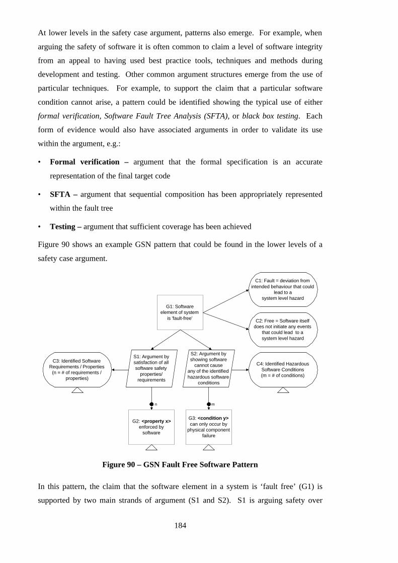
184
At lower levels in the safety case argument, patterns also emerge. For example, when
arguing the safety of software it is often common to claim a level of software integrity
from an appeal to having used best practice tools, techniques and methods during
development and testing. Other common argument structures emerge from the use of
particular techniques. For example, to support the claim that a particular software
condition cannot arise, a pattern could be identified showing the typical use of either
formal verification, Software Fault Tree Analysis (SFTA), or black box testing. Each
form of evidence would also have associated arguments in order to validate its use
within the argument, e.g.:
• Formal verification – argument that the formal specification is an accurate
representation of the final target code
• SFTA – argument that sequential composition has been appropriately represented
within the fault tree
• Testing – argument that sufficient coverage has been achieved
Figure 90 shows an example GSN pattern that could be found in the lower levels of a
safety case argument.
G2: <property x>enforced by
software
G1: Softwareelement of system
is 'fault-free'
C1: Fault = deviation fromintended behaviour that could
lead to asystem level hazard
C2: Free = Software itselfdoes not initiate any events
that could lead to asystem level hazard
S1: Argument bysatisfaction of allsoftware safety
properties/requirements
S2: Argument byshowing software
cannot causeany of the identifiedhazardous software
conditions
C4: Identified HazardousSoftware Conditions(m = # of conditions)
C3: Identified SoftwareRequirements / Properties
(n = # of requirements /properties)
n
G3: <condition y>can only occur by
physical componentfailure
m
Figure 90 – GSN Fault Free Software Pattern
In this pattern, the claim that the software element in a system is ‘fault free’ (G1) is
supported by two main strands of argument (S1 and S2). S1 is arguing safety over

185
positive properties of the software. Over a list (C3) of identified hazardous software
conditions (e.g. “Controller demands speed greater than maximum safe speed”) the m
sub-goals of the form G3 are expressed, to argue that these hazards can only occur
through physical component failures. S2 is arguing safety through avoidance of
negative properties of the software. Over a list (C4) of identified software requirements
(e.g. “Operation will not start if operator detected near machinery”) the n sub-goals of
the form G2 are expressed to argue that these properties are enforced in the software. In
order that this pattern will be appropriately applied, the context of the pattern is made
clear through the elements C1 and C2 - both defining key terms in the top-level claim.
The patterns that have been described so far in this chapter are deliberately general –
they can be readily understood and have wide applicability across technologies and
regulatory contexts. However, in well-understood and stable domains it is also possible
to identify more specific argument patterns. For example, in the civil aerospace sector
common arguments are often developed against particular individual regulations (in
Europe from the Joint Aviation Requirements) - e.g. capturing what is an acceptable
approach (‘means of compliance’) to arguing that “Thrust Reverser will not deploy
during flight”. Figure 91 shows the GSN pattern that can be used as the basis for
structuring a compliance argument with civil aerospace requirement JAR-E50(a).
Control System compliant withJAR-E50(a) CONTROLS
JAR-E50(a)
E50(a)(1)
All aircraft installationrequirements formallyidentified
E50(a)(2)
ECS designed to support selection ofprogressive amounts of thrust overwhole range of defined operatingconditions
Thrust levels
C2
E50(a)(4)
Safe engine control underall likely pilot commands
E50(a)(5)
Safe engine control under allidentified failure conditions
E50(a)(6)
Safe engine control inpresence of operation ofpermitted variables
Permitted operation ofvariables
C9
Identified failureconditions
C8
Likely pilotcommands
C7
E50(a)(3)
Selected values of relevant control params.to be maintained and engine kept withlimits over changing atmosphericconditions in defined operating range
Selected values ofrelevant control
parameters
C5
Defined engineoperating limits
C6
"Safe engine control"= ...
C1
Defined operationconditions
C3
AtmosphericOperating Conditions
C4
Figure 91 – GSN Compliance Pattern for JAR-E50(a)

186
The benefit achieved from this pattern is that, whilst decomposing the overall
requirements into sub-clauses, it clearly highlights the contextual information (C1-C9)
that is required in order to truly define (and therefore argue against) the safety
requirement.
5.11 Taxonomy of Safety Case Patterns
The author has identified and extracted a number of Safety Case Patterns from real-
world safety cases and safety standards. Many of these patterns (e.g. the ALARP
pattern) have been documented and presented in the pattern catalogue presented as
Appendix B of this thesis.
From the patterns that have already been identified it has been possible to recognise and
define a taxonomy of Safety Case Patterns. The categorisation is shown in Figure 92.
Domain SpecificDomain Independent
Top-down Bottom-up
GeneralConstruction
Top-down Bottom-up
GeneralConstruction
Figure 92 – A Taxonomy of Safety Case Patterns
Safety Case Patterns can either be specific to a particular domain or class of system (e.g.
nuclear power generation, railways, aerospace) or applicable across a number of
domains (i.e. domain independent).
Safety Case Patterns can describe the decomposition of some objective, e.g. over
functions or according to some safety principle. Such patterns are labelled as ‘Top
Down’ Safety Case Patterns. The ‘Functional Decomposition’ pattern presented in
Section 5.9 is an example of such a pattern. Alternatively, safety case patterns can
describe how an argument may be constructed from a piece of evidence (in GSN terms
187
– a Solution). These patterns are labelled as ‘Bottom Up’ Safety Case Patterns. The
‘Fault Tree Evidence’ pattern presented in Appendix B is an example of such a pattern.
Finally, Safety Case Patterns can be used to describe some general principle of safety
argument construction that is neither specifically ‘top down’ or ‘bottom up’. Such
patterns are labelled as ‘General Construction’ Safety Case Patterns. The ‘Diverse
Argument’ pattern presented in Appendix B is an example of such a pattern.
5.12 Example Safety Case Pattern Catalogue
To present further example Safety Case Patterns, and to illustrate the concept of
collating and structuring a collection of patterns to form an engineering resource, an
example Safety Case Pattern Catalogue is presented in Appendix B.
The example catalogue is structured according to the taxonomy of patterns defined in
the previous section, and contains the following patterns:
Top-Down Patterns
• ALARP (As Low As Reasonably Practicable) Argument
This pattern provides a framework for arguing that identified risks in a system have
been sufficiently addressed in accordance with the ALARP principle.
• Hazard Directed Integrity Level Argument
This pattern demonstrates an approach to arguing that a (sub)system has been
developed to an integrity level appropriate to the hazards to which the system
contributes.
• Control System Architecture Breakdown
The intent of this pattern is to illustrate a means of structuring an argument to
support a system safety goal (requirement, avoidance of hazard etc.) by
decomposition over a generic control system model.
General Construction Patterns
• Diverse Argument
The intent of this pattern is to illustrate the use of diverse arguments to instil a high
degree of confidence in the satisfaction of a goal and to present arguments that are
resilient to change and criticism.
• Safety Margin
The intent of this pattern is to illustrate the use of safety margins to instil a high
188
degree of confidence in the satisfaction of a goal and to present arguments that are
resilient to change and criticism.
Bottom-Up Patterns
• Fault Tree Evidence
The intent of this pattern is to show the nature of the claims that can be made from a
fault tree representation of the causes of a condition.
This collection of patterns represents a cross-section of the patterns that have so far been
identified within existing safety cases and safety justifications. It is not yet claimed to
be a pattern language for safety case development (i.e. it does not provide a complete
set of patterns).
The safety case concept is broad, spans many domains, and can encompass many
concepts and technologies. For this reason, the goal of producing a Safety Case Pattern
Language that can be said to be ‘complete’ may well be difficult to realise. However, it
is much more conceivable that pattern languages can be constructed within a bounded
domain. For example, the Safety Assessment Principle Patterns identified in Appendix
B could be considered to be part of an overall language that would include patterns for
each of the other 78 principles that are given in [98]. The same is true for any domain
bounded by a set of requirements – e.g. the Joint Awareness Requirements for Engines.
For some of the same reasons, it is highly conceivable that a pattern language for safety
cases could be constructed within a particular company – bounded by the regulations
that apply, the accepted practice of the company, and the forms of evidence and skills
available within that context.
5.13 A Safety Case Reuse Process
The aim in proposing Safety Case Patterns is to make the process of safety case reuse
more systematic. Figure 93 illustrates the ideal process by which Safety Case Patterns
could be used to support the safety case reuse activity.
In Figure 93 the main activities of safety case pattern reuse are identified as:
• Identifying potential Safety Case Patterns from within existing safety cases
• Defining new Safety Case Patterns
• Reviewing Constructed Patterns
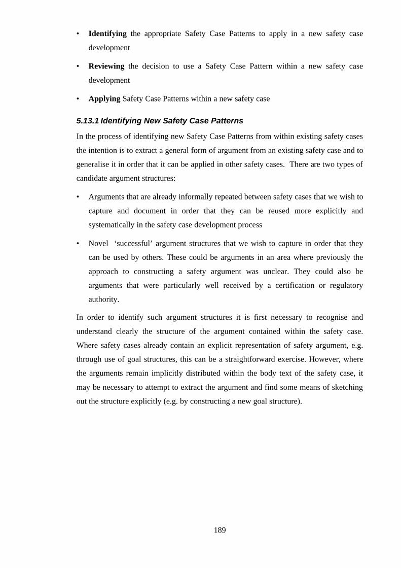
189
• Identifying the appropriate Safety Case Patterns to apply in a new safety case
development
• Reviewing the decision to use a Safety Case Pattern within a new safety case
development
• Applying Safety Case Patterns within a new safety case
5.13.1 Identifying New Safety Case Patterns
In the process of identifying new Safety Case Patterns from within existing safety cases
the intention is to extract a general form of argument from an existing safety case and to
generalise it in order that it can be applied in other safety cases. There are two types of
candidate argument structures:
• Arguments that are already informally repeated between safety cases that we wish to
capture and document in order that they can be reused more explicitly and
systematically in the safety case development process
• Novel ‘successful’ argument structures that we wish to capture in order that they
can be used by others. These could be arguments in an area where previously the
approach to constructing a safety argument was unclear. They could also be
arguments that were particularly well received by a certification or regulatory
authority.
In order to identify such argument structures it is first necessary to recognise and
understand clearly the structure of the argument contained within the safety case.
Where safety cases already contain an explicit representation of safety argument, e.g.
through use of goal structures, this can be a straightforward exercise. However, where
the arguments remain implicitly distributed within the body text of the safety case, it
may be necessary to attempt to extract the argument and find some means of sketching
out the structure explicitly (e.g. by constructing a new goal structure).
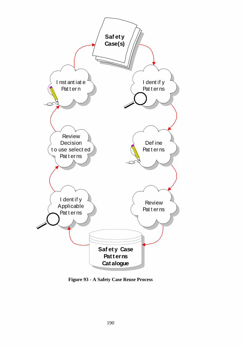
190
IdentifyApplicablePatterns
ReviewDecision
to use selectedPatterns
SafetyCase(s)
InstantiatePattern
Safety CasePatternsCatalogue
IdentifyPatterns
DefinePatterns
ReviewPatterns
Figure 93 - A Safety Case Reuse Process
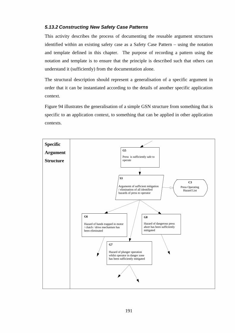
191
5.13.2 Constructing New Safety Case Patterns
This activity describes the process of documenting the reusable argument structures
identified within an existing safety case as a Safety Case Pattern – using the notation
and template defined in this chapter. The purpose of recording a pattern using the
notation and template is to ensure that the principle is described such that others can
understand it (sufficiently) from the documentation alone.
The structural description should represent a generalisation of a specific argument in
order that it can be instantiated according to the details of another specific application
context.
Figure 94 illustrates the generalisation of a simple GSN structure from something that is
specific to an application context, to something that can be applied in other application
contexts.
Specific
Argument
Structure Press is sufficiently safe tooperate
G5
S3
Argumemt of sufficient mitigation/ elimination of all identifiedhazards of press to operator
C3
Press OperatingHazard List
Hazard of hands trapped in motor/ clutch / drive mechanism hasbeen eliminated
G6
Hazard of plunger operationwhilst operator in danger zonehas been sufficiently mitigated
G7
Hazard of dangerous pressabort has been sufficientlymitigated
G8
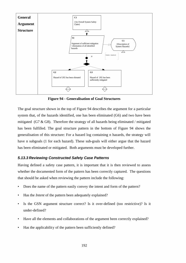
192
General
Argument
Structure
C1
{An Overall System SafetyClaim}
S1
Argument of sufficient mitigation/ elimination of all identifiedhazards
{Description ofSystem Hazards}
C1
G2
Hazard of {H} has been elimated
G3
Hazard of {H} has beensufficiently mitigated
nProvides n Hazards {H}
Figure 94 - Generalisation of Goal Structures
The goal structure shown in the top of Figure 94 describes the argument for a particular
system that, of the hazards identified, one has been eliminated (G6) and two have been
mitigated (G7 & G8). Therefore the strategy of all hazards being eliminated / mitigated
has been fulfilled. The goal structure pattern in the bottom of Figure 94 shows the
generalisation of this structure: For a hazard log containing n hazards, the strategy will
have n subgoals (1 for each hazard). These sub-goals will either argue that the hazard
has been eliminated or mitigated. Both arguments must be developed further.
5.13.3 Reviewing Constructed Safety Case Patterns
Having defined a safety case pattern, it is important that it is then reviewed to assess
whether the documented form of the pattern has been correctly captured. The questions
that should be asked when reviewing the pattern include the following:
• Does the name of the pattern easily convey the intent and form of the pattern?
• Has the Intent of the pattern been adequately explained?
• Is the GSN argument structure correct? Is it over-defined (too restrictive)? Is it
under-defined?
• Have all the elements and collaborations of the argument been correctly explained?
• Has the applicability of the pattern been sufficiently defined?

193
• Is there sufficient implementation guidance to enable someone to instantiate the
pattern?
The purpose of asking such questions is to ensure that the pattern is sufficiently well-
defined that the likelihood of it being applied inappropriately at a later stage (by
someone other than the author) is reduced to the minimum practicable. Questions of
completeness and sufficiency of documentation are subjective. The review should
therefore be performed ideally by a group formed of people who are similarly expert in
the domain from which the pattern has been identified and others who are not, but have
a knowledge about safety cases in general. At least initially, the review of the pattern
should be conducted without the involvement of the original author (in order that the
sufficiency of the documentation can be truly assessed). Following this initial review,
the author can then be involved in the discussion in order to clarify any areas of
ambiguity and to work with the reviewers to suggest ways in which the pattern may be
improved.
Following review (and modification if necessary) of the pattern it can then be added to
the pattern catalogue. The pattern catalogue is discussed in more detail in section 5.13.7.
5.13.4 Identifying Applicable Safety Case Patterns
The processes of identifying, defining and reviewing new patterns work from existing
safety case material towards the goal of extracting reusable argument structures for
future safety cases. Within the framework of the safety case development process,
therefore, one of the natural opportunities for these activities is in the ‘wash-up’
(sometimes called the ‘post-mortem’) phase of the project. The purpose of the wash-up
is to identify areas where the safety case produced is deemed to be successful, and to
capture lessons learnt from the development.
However, the ‘Identifying Applicable Safety Case Patterns’ activity (and the following
activities shown on the left-hand side of Figure 93) together correspond to the
production phase of safety case development, and in particular to the preliminary safety
case construction phase (described in Chapter Three, section 3.9). The purpose of this
first activity is to identify patterns from those previously defined and stored in the
pattern catalogue to aid in the construction of a new safety argument. The pattern
catalogue should be examined with a particular problem in mind – e.g. a safety goal that
needs to be decomposed, or a particular requirement that has to be addressed. The
objective is to nominate a pattern that:
194
• Shares the same intent as the problem that you are trying to solve
• Is suitable for application in this particular safety case development (i.e. satisfies all
documented applicability conditions).
It may be the case that more than one pattern in the catalogue matches these criteria. In
such cases, all possible patterns should be nominated for review at this stage.
5.13.5 Reviewing Decision to Use a Safety Case Pattern
The purpose of this activity is to review the decision to use the candidate patterns
identified in the previous phase. As with the review conducted in the pattern production
phase this activity should ideally be conducted by experts within the application domain
who are capable of independently assessing whether use of the nominated patterns is
appropriate in this case.
The motivation behind placing the review ahead of actual application of the pattern is to
(hopefully) reduce the possibility that wasted and inappropriate effort may be spent in
applying a pattern that is later rejected. Where there is a choice of possible approaches
(i.e. a number of possible patterns that may be applied), a secondary purpose of the
review is to decide upon the most suitable one to use.
The review activity independently revisits the questions of matching intent and
applicability that where considered when searching the pattern catalogue. In deciding
whether a pattern is applicable in a particular situation, an additional output of this
activity may also be preliminary advice on how the pattern is to be applied.
5.13.6 Instantiate Pattern
The purpose of this activity is to apply the general solution described by the pattern to
the details of the specific safety argument being constructed. The element of the pattern
description most concerned with this activity is Implementation. This section describes
how the pattern should be implemented: the contextual information that should be
provided, how goals should be instantiated etc. It is important to take note of any
Potential Pitfalls also identified by this section.
When instantiating the GSN pattern, multiplicity relations should be expanded, and
choices evaluated. Where structural abstractions have been used, concrete instances
must be provided. The GSN pattern is therefore “flattened” to the elements of existing
notation. Ideally, a record of the application of the underlying pattern should be
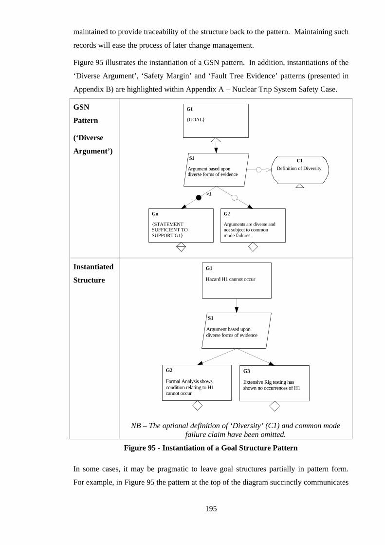
195
maintained to provide traceability of the structure back to the pattern. Maintaining such
records will ease the process of later change management.
Figure 95 illustrates the instantiation of a GSN pattern. In addition, instantiations of the
‘Diverse Argument’, ‘Safety Margin’ and ‘Fault Tree Evidence’ patterns (presented in
Appendix B) are highlighted within Appendix A – Nuclear Trip System Safety Case.
GSN
Pattern
(‘Diverse
Argument’)
G1
{GOAL}
Gn
{STATEMENTSUFFICIENT TOSUPPORT G1}
S1
Argument based upondiverse forms of evidence
>1
Definition of Diversity
C1
G2
Arguments are diverse andnot subject to commonmode failures
Instantiated
Structure Hazard H1 cannot occur
G1
S1
Argument based upondiverse forms of evidence
G2
Formal Analysis showscondition relating to H1cannot occur
G3
Extensive Rig testing hasshown no occurrences of H1
NB – The optional definition of ‘Diversity’ (C1) and common mode failure claim have been omitted.
Figure 95 - Instantiation of a Goal Structure Pattern
In some cases, it may be pragmatic to leave goal structures partially in pattern form.
For example, in Figure 95 the pattern at the top of the diagram succinctly communicates
196
the intention of the goal structure without providing large amounts of detail (e.g. as
there would be if there were fifty identified hazards). Leaving the pattern uninstantiated
may therefore provide a more appropriate level of description for some presentations of
the safety case (i.e. by presenting the argument approach adopted rather than the results
of applying that approach).
Whether fully instantiating or partially instantiating a pattern, it is important for
traceability purposes to document where the pattern has been applied in the overall
argument. In this way, if there is ever a need to identify all the places that a particular
pattern has been used (e.g. if a flaw was discovered in the pattern) then the appropriate
records exist. Of equal importance, such information allows patterns to be re-applied if
changes are ever forced upon the overall safety argument – making sure that the intent
and structure of the pattern can be preserved.
5.13.7 Pattern Catalogue
The Safety Case Pattern Catalogue, as described in section 5.12, is at the heart of the
concept of Safety Case Patterns, and is the pivot around which the safety case reuse
process is carried out. Within an organisation, it is the repository where all patterns are
stored. It is the intention that it be available as a resource to all safety case developers.
Patterns can be added into the catalogue following definition and review. It should be
possible to retrieve pattern descriptions by name, content and inter-pattern associations
(recorded in the Related Patterns field of the pattern description.
5.14 Summary
This chapter has defined the concept of Safety Case Patterns – a means of describing
generalised, reusable, safety argument structures. In order to support the presentation of
generalised arguments, we have proposed extensions to the GSN. In addition, a format
for the documentation of GSN patterns is defined. Resulting from evaluation of the
approach, a number of example patterns are presented. Based upon categorisation of
the patterns the author has identified to date, a taxonomy of Safety Case Patterns is
defined. Finally, we present a process to support the systematic reuse of safety case
arguments based upon the concept of developing a Safety Case Patterns Catalogue.
Evaluation of the approach defined in this chapter is discussed fully in Chapter Six –
Evaluation
197
Chapter 6:
Evaluation
6.1 Introduction
In Chapter One the thesis proposition was stated as the following:
This thesis provides a method and graphical notation for the presentation
of safety arguments. The thesis demonstrates how this approach can be
used to address the highlighted challenges of safety case development by
supporting the development, maintenance and reuse of safety arguments.
The challenges referred to by the proposition (and also presented in Chapter One) were
the following:
• Presentation of Clear Safety Arguments
• Incremental Safety Case Development
• Through-life Safety Case Maintenance
• Supporting Trustworthy Safety Case Reuse
The evaluation of this proposition can be considered on two levels, namely:
• Demonstrating the feasibility of the approach defined in this thesis (to support safety
case development, maintenance and reuse) and its acceptance by engineers in
industry
• Demonstrating that the approach provides some positive benefit in addressing the
problems highlighted by the proposition.
Within the time-scale of the doctoral programme the evaluation activity has focussed
upon the former of these two levels. Success at this level is an obvious precursor to
success at the latter level. The extensive application of the approach within the problem
domain also aids in the definition of the success criteria against which benefit can be
assessed (as discussed later on in the chapter in section 6.5)
Over the course of the research we have been fortunate enough to be given many
opportunities to expose and trial the approach developed in this thesis to industrial

198
safety engineers and projects. In particular, three main routes of evaluation have been
available:
• Through Rolls-Royce plc (co-sponsors of the research)
• Through presenting the approach on the High Integrity Systems Engineering Group
Safety Courses – at the time of writing this has run a total of 25 times for 435 people
representing 57 organisations.
• Through the Safety Argument Manager (SAM) Tool and the consortium of 20
European companies involved in the SAM Club – a user group set up to fund and
guide further development of the SAM tool.
The main sections of this chapter (sections 6.2 and 6.3) report the evaluation that has
been carried out using these three routes to demonstrate the feasibility of the approach
and to gain its acceptance by industry. Although within this chapter we have not sought
to quantitatively argue to benefits of adopting the approach, it should be recognised that
its acceptance by industry is at least an indication of perceived benefits. Benefits
perceived through carrying out the evaluation activity are qualitatively reported within
the chapter.
Building upon the success of this level of evaluation, section 6.5 describes how further
(quantitative) evaluation of the benefits of adopting the approach could be carried out.
6.2 Forms of Evaluation Applied
The following forms of evaluation have been applied throughout the course of the
research to evaluate the approach presented in this thesis:
• Tool Implementation
• Peer Review
• Case Study
• Pilot Industrial Application
• Evaluation through Real Industrial Application
The above list is stated in order of, what we believe to be, strength of evaluation – tool
implementation being the weakest form of evaluation, and evaluation through
application on a real industrial project being the strongest. Before presenting the
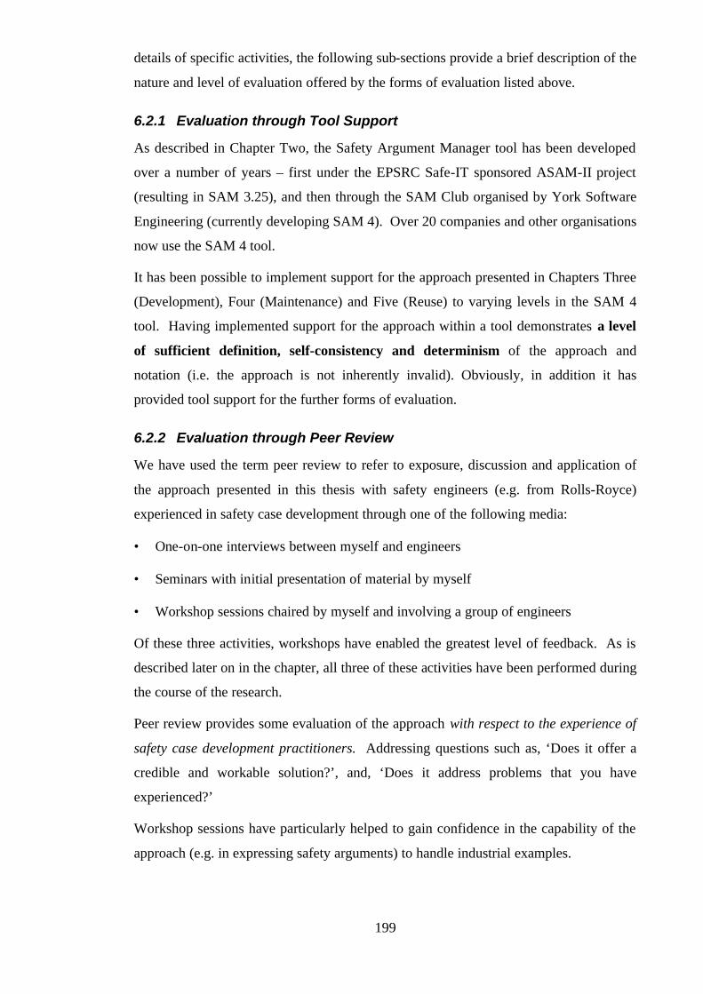
199
details of specific activities, the following sub-sections provide a brief description of the
nature and level of evaluation offered by the forms of evaluation listed above.
6.2.1 Evaluation through Tool Support
As described in Chapter Two, the Safety Argument Manager tool has been developed
over a number of years – first under the EPSRC Safe-IT sponsored ASAM-II project
(resulting in SAM 3.25), and then through the SAM Club organised by York Software
Engineering (currently developing SAM 4). Over 20 companies and other organisations
now use the SAM 4 tool.
It has been possible to implement support for the approach presented in Chapters Three
(Development), Four (Maintenance) and Five (Reuse) to varying levels in the SAM 4
tool. Having implemented support for the approach within a tool demonstrates a level
of sufficient definition, self-consistency and determinism of the approach and
notation (i.e. the approach is not inherently invalid). Obviously, in addition it has
provided tool support for the further forms of evaluation.
6.2.2 Evaluation through Peer Review
We have used the term peer review to refer to exposure, discussion and application of
the approach presented in this thesis with safety engineers (e.g. from Rolls-Royce)
experienced in safety case development through one of the following media:
• One-on-one interviews between myself and engineers
• Seminars with initial presentation of material by myself
• Workshop sessions chaired by myself and involving a group of engineers
Of these three activities, workshops have enabled the greatest level of feedback. As is
described later on in the chapter, all three of these activities have been performed during
the course of the research.
Peer review provides some evaluation of the approach with respect to the experience of
safety case development practitioners. Addressing questions such as, ‘Does it offer a
credible and workable solution?’, and, ‘Does it address problems that you have
experienced?’
Workshop sessions have particularly helped to gain confidence in the capability of the
approach (e.g. in expressing safety arguments) to handle industrial examples.
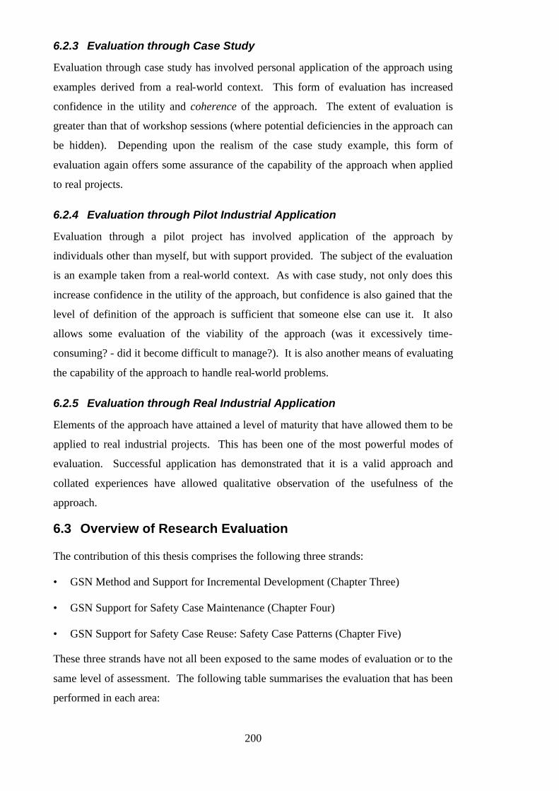
200
6.2.3 Evaluation through Case Study
Evaluation through case study has involved personal application of the approach using
examples derived from a real-world context. This form of evaluation has increased
confidence in the utility and coherence of the approach. The extent of evaluation is
greater than that of workshop sessions (where potential deficiencies in the approach can
be hidden). Depending upon the realism of the case study example, this form of
evaluation again offers some assurance of the capability of the approach when applied
to real projects.
6.2.4 Evaluation through Pilot Industrial Application
Evaluation through a pilot project has involved application of the approach by
individuals other than myself, but with support provided. The subject of the evaluation
is an example taken from a real-world context. As with case study, not only does this
increase confidence in the utility of the approach, but confidence is also gained that the
level of definition of the approach is sufficient that someone else can use it. It also
allows some evaluation of the viability of the approach (was it excessively time-
consuming? - did it become difficult to manage?). It is also another means of evaluating
the capability of the approach to handle real-world problems.
6.2.5 Evaluation through Real Industrial Application
Elements of the approach have attained a level of maturity that have allowed them to be
applied to real industrial projects. This has been one of the most powerful modes of
evaluation. Successful application has demonstrated that it is a valid approach and
collated experiences have allowed qualitative observation of the usefulness of the
approach.
6.3 Overview of Research Evaluation
The contribution of this thesis comprises the following three strands:
• GSN Method and Support for Incremental Development (Chapter Three)
• GSN Support for Safety Case Maintenance (Chapter Four)
• GSN Support for Safety Case Reuse: Safety Case Patterns (Chapter Five)
These three strands have not all been exposed to the same modes of evaluation or to the
same level of assessment. The following table summarises the evaluation that has been
performed in each area:

201
Tool
Implementation Peer Review Case Study
Pilot Industrial
Application
Real Industrial
Application
GSN Method and
Support for Inc.
Development
ü ü ü ü ü
GSN Support for
Safety Case
Maintenance
ü ü ü
Safety Case
Patterns ü ü ü ü
Level of Evaluation
Table 8 – Levels of Research Evaluation Achieved
For each of the research areas, and for each form of evaluation marked with a ‘ü’ in
Table 8, the following sections provide a specific description of the evaluation that has
been performed.
6.3.1 GSN Method Evaluation
The contribution made by the author in defining a method for, and extending, GSN was
a product of the early activities of the research. Use of the method and notation is a
precursor to the application of the more advanced concepts of maintenance support and
Safety Case Patterns. Consequently, as shown in Table 8, this strand of the research has
been subject to the most evaluation.
6.3.1.1 GSN Method Evaluation: Tool Implementation
The extension of ‘context’ to the notation was quickly adopted within the SAM 4 tool,
and has been used within almost all the goal structures produced using the tool observed
by the author. This has been taken as an indication of the concept’s usefulness!
The screen shot shown in Figure 96 shows the use of the new context symbol within the
SAM 4 tool.
202
Figure 96 – SAM Screen Shot (Showing Adoption of Context)
The support added to SAM for the GSN extensions necessary to represent GSN patterns
has also been found useful in representing an incomplete and evolving goal structure (as
described in Chapter Three). For example, it has been useful to explicitly mark a leaf
goal in a preliminary safety argument (such as the engine controller argument presented
in Chapter Three) as being ‘undeveloped’. This is shown in the SAM screen shot
(Figure 97).
6.3.1.2 GSN Method Evaluation: Peer Review
The GSN Method, as defined in [57], has been used within a number of workshop
sessions conducted by the author and involving over forty safety engineers from a
number of different companies, including:
• BR Business Systems – concerned with developing and presenting safety
arguments for railway maintenance information systems.
• Matra BAe Dynamics – concerned with developing and presenting safety
arguments for sea and land based missile systems.
• Rolls-Royce Marine Power – concerned with developing and presenting safety
arguments for nuclear propulsion systems.
203
Figure 97 – SAM Screen Shot (Showing Use of Pattern Extensions in Incremental
Development)
After having presented the principles and steps of the method the workshops have
culminated in sessions that apply the GSN method in developing a safety argument
relating to their domain. In these sessions the method has been found to work well in
structuring the group discussion – for example, in making sure that context is fully
defined (Step 2) before attempting to identify a support strategy (Step 3). Also, the
phrasing rules given in the method have helped in such sessions to force clarity and
definition of the safety arguments being developed (avoiding the mistakes described in
[57]). A recognised benefit of using the GSN in these workshops has been that it has
enabled debate and agreement on the safety argument in a way that is not possible when
there is no clear and explicit means of presenting that argument.
The GSN method guidance defined in [57] has been distributed (under the title ‘GSN
Handbook’) to all twenty companies in the SAM Club. Although criticism was
explicitly solicited, no significant problems have been identified. One area of debate has
been the recommendation made in the method regarding the tense used in phrasing
goals statements (goals to achieve vs. goals achieved). However, there have been
arguments on both sides of this issue and consequently the recommendation has been
204
left as it is (with the global caveat given in the method that other approaches are
possible).
Through peer review of the GSN terminology and concepts it has been noted that the
term ‘Goal’ can often mislead engineers as to the intent of this element of the notation –
i.e. to state logical propositions. The description of a goal alternatively as a ‘claim that
we wish to put forward’ (i.e. as done in Claim Structures [9]) has often been more
readily understood by engineers. If it weren’t the case that the terminology of the ‘Goal
Structuring Notation’ and ‘Goals’ was already well established within the companies
that use GSN it would be desirable to rename ‘Goals’ as ‘Claims’ within the notation. It
should be recognised, however, that this choice of terminology has no impact on the
semantics of the notation.
The use of goal structuring to support incremental safety case development has formed
part of the material presented by the author on the High Integrity Systems Engineering
Group Safety Courses. In particular, the application of GSN in sketching out
preliminary safety arguments is presented through the distributed engine controller
example given in Chapter Three. Use of GSN in building preliminary safety arguments
was also the subject of a reviewed paper and presentation [99]. Comments subsequently
received from experienced practitioners have indicated that GSN is achieving something
(the ability to present preliminary and incomplete argument architectures) that is
otherwise difficult to achieve as succinctly in free text.
6.3.1.3 GSN Method Evaluation: Case Study
It is difficult to demonstrate evaluation of the GSN Method (that defines a dynamic
process) by any means other than presenting the resultant (static) goal structure. The
Nuclear Trip System Case Study, although based upon an existing safety case, presents
a number of safety arguments that have been constructed according the rules of the GSN
method (particularly regarding syntax).
It is one of the underlying premises of this thesis that GSN can be used in
communicating the safety argument within the structure of a text-based safety case
document. Appendix A was constructed to demonstrate that this is possible and also to
illustrate how it can be done. A comparison of the goal structured approach used in

205
Appendix A and alternative approaches to expressing the same safety case is presented
in Chapter Three, section 8.
One observation, having constructed many goal structures using the rules defined in the
GSN method, is that it has always been possible to phrase goal statements according to
the Noun-Phrase Verb-Phrase rule. However, there are other (sometimes more natural)
sentential structures that can be used whilst still forming propositional statements. The
possible extension of the method syntax rules to include these other structures is one
area of further work, see Chapter Seven, Section 2.
As a case study using GSN to sketch an evolving safety argument, based on work
published by Fletcher [60], the author has used goal structuring to set out clearly the
principal safety (and certification) objectives facing Integrated Modular Avionics (IMA)
systems. The top level of this goal structure is shown in Figure 98.
IMA system is SAFE
G1
Adequate partioning andisolation provided betweenmodules
G2
Scheduling policy is at leastas safe as Cyclic Executive
G3
IMA Safely supportsmodules of differingintegrity
G4
Reconfiguration of modulesis safe
G5
Module replacement isperformed correctly
G6
Common Cause Failuresbetween modules aresufficiently unlikely
G7
Each moduleindependently is safe
G8
Modules combine safely
G9
Figure 98 – Top Level of Integrated Modular Avionics Safety Argument
Conclusions arising out of this and similar studies have been that presenting preliminary
arguments in this way enables engineers to reach agreement on the scope and structure
of a safety argument. In particular reducing the time and effort required in reaching that
agreement. In addition, the final agreed goal structure highlights the safety objectives to
206
be achieved in later stages of project development. For example, with the above Figure
98, everyone involved in developing such systems can appreciate the safety framework
in which IMA solutions are suggested.
During the course of the research, the author has studied a number of conventionally
(textually) presented preliminary safety arguments, specifically:
• Safety Principles Papers (within the Naval Nuclear Propulsion Domain) –
documents typically produced towards the beginning of a project that argue how the
system and project will comply with the U.K. Ministry of Defence Safety Principles
and Criteria for the Nuclear Naval Programme [98].
• Joint Airworthiness Requirements – Engines (JAR-E) Compliance Statements
(within the Civil Aerospace Domain) – again, documents typically produced
towards the beginning of a project that argue how an engine will comply with the
JAR-E.
The textual approach implicit in both these sets of documents can be contrasted with the
GSN approach suggested in Chapter Three. The following difficulties have been
identified with the former approach:
• It can present vacuous statements of compliance that simply re-express all
requirements of the form ‘X shall’ into ‘X will’.
• In later stages of the project it can be unclear what specific objectives have been put
forward in the preliminary argument.
Although it is possible in GSN terms to present vacuous compliance claims, they are
more obviously shown up as such in a goal structure (as an observable lack of ‘distance’
between requirement and claim). Following the GSN method (particularly regarding
syntax) can avoid the vague statements of some compliance claims. The explicit top-
down structure of a goal-structured preliminary safety argument, exposing undeveloped
leaf goals, also makes more obvious the claims that are still to be developed in the later
project stages.
6.3.1.4 GSN Method Evaluation: Pilot Industrial Application
The GSN Method has been applied in an industrial pilot project to rework an existing
submarine power plant decommissioning safety case and express it using GSN (using
the SAM tool). The resulting (exhaustive) goal structured argument spanned 39 A4

207
pages and contained over 154 individual goals (structured on 9 levels). The top level of
this goal structure is shown in Figure 99 (with some details masked). An internal report
[100] was written to document the project. As well as validating the method, the project
enabled a comparison between the presentation of the safety argument in its existing
(textual) form and its goal structured counterpart. Universally, company (and Ministry
of Defence) individuals who reviewed both versions (the original safety case and the
corresponding goal structure) declared the goal structure as providing a clearer
representation of the safety argument.
Clear and valid goal structures resulted from the Rolls-Royce employees’ use of the
GSN method. Over the course of the project three individuals (two engineers from
Rolls-Royce and myself) all produced separate goal structured versions of the existing
safety case. The three resulting goal structures exhibited the same goal decomposition
structures (i.e. they were of similar depth and ‘fan-out’) and used similarly phrased goal
statements. Experience suggests that without the definition and use of the GSN method,
this would have not been the case.
Company reviewers observed the benefits of the goal-structured version of the safety
argument as twofold. Firstly, although the safety requirements and safety claims of the
existing safety case were stated clearly – the relationship between them (i.e. the
structure of the safety argument) was unclear. Once the relationship had been
rediscovered, however, the goal structure communicated the relationship between
requirements, claims, and evidence explicitly. Secondly, in the existing safety case
there appeared to be elements of the document that had no role within the safety case.
The goal structure, however, through explicit context and solution references provided a
means of navigating through all of the blocks of information presented within the
document and communicating their role within the structure of the argument.
The use of GSN in supporting an evolving safety argument, as suggested in Chapter
Three, was piloted in developing a preliminary safety argument for a novel distributed
engine controller. This example is described in some detail in Chapter Three. Rolls-
Royce’s main conclusions were that the goal structure produced aided the process of
agreeing the safety case, helped gain confidence in the ability to present a complete
safety case and provided tangible safety objectives for the project. As a result of this
project, Rolls-Royce has proposed that suppliers to the project be asked to present goal
structured preliminary safety arguments in this form in the future.

208
Top
G0000
Decommissioning ofXXXXX prior to XXXX
and XXXX is safe
Strat0000
Argument bycompliance withoverall SAPsGoals
Cntx0000
NNTSP/BR3/100/94 Issue 1 Feb1994 - MoD Safety Principles andSafety Criteria for the Naval
Cntx0001Scope (S1.2)
G0001
Final Plant ConditionCompliant with General
Nuclear Safety Goal
G0002
Final Plant ConditionCompliant with Radiation
Protection Goal
G0003
Final Plant ConditionCompliant with Technical
Safety Goal
Cntx0003
Applicability andDuration (S1.3)Cntx0004
SpecificExclusions (S1.4)
G0108
Plant modification and final conditioncomplies with all applicable
principles from SAPs Document
G0109
Berthing modification and maintenanceis a Nuclear Safety Category XX system with Safety Justification
Assessment Risk - XXXX
G0110
Final Plant Conditionensures that thepotential for allidentified plant
G0013
Reactor plant monitoring provided toensure reactor safety requirements are
being met (final plant conditionmaintained) and provide early
G0119
Final Plant Condition canwithstand all internal and
external environmental hazardsconsidered to have the potential
Cntx0008
Final Plant Condition(S4)
G0125
Final Plant Condition will notcompromise nuclear safety
during the final defuel
Figure 99 – Top Level of Decommissioning Argument
209
6.3.1.5 GSN Method Evaluation: Real Industrial Application
One of the earliest applications of the GSN method was on a live project involving the
production of a safety plan and safety case for a piece of railway track-side equipment
(for GEC Alsthom). In particular, this project provided validation of the concept of
interrelating process and product goal structures, as suggested in Chapter Three. Goal
structures were used to communicate the safety argument of the safety plan (process) in
addition to the structure of the safety case (product). The outputs of the safety plan
(solutions of the process goal structure) were linked to the context and evidence
elements of the product safety argument. The top level of the safety plan goal structure
is shown in Figure 104. The safety plan document out of which Figure 100 was taken
was 165 pages long and contained 338 goals, 176 justifications, 294 context references
and 164 solutions. The goal structures were presented in 167 figures and had up to 5
layers of decomposition.
This usage of goal structuring was well received on the project. The project was multi-
national and the project participants declared that the goal structures were particularly
useful in improving understanding of the safety plan and safety case across
organisational and national boundaries.
The GSN method is currently being used to provide ‘executive summary’ goal
structures for inclusion at the beginning of a number of base safety reports for a Rolls-
Royce test facility. GSN is being adopted as it is felt that the safety argument contained
within these documents can be hard to assimilate and appreciate without spending
significant time reading through the document. A number of goal structures have
already been developed and have been thought (by the engineers and managers
involved) to address this problem successfully. Figure 101 shows an extract from one
of these goal structures (with system specific details hidden). This goal structure was
constructed in a group session involving six engineers following the steps of the GSN
method.
The GSN Method has been used in the early stages of developing a Site Safety
Justification for a Naval Facility. In this project there was a requirement to produce 8
safety cases supported by over 80 safety reports in the space of 18 months. GSN was
used as part of a group exercise to help the engineers to begin to appreciate the scope of
210
the problem, and to identify possible argument strategies. Figure 102 shows an extract
from the total goal structure constructed to represent the preliminary safety argument.
The total structure consisted of over 300 goals structured using 6 levels of
decomposition. The structure was created by a team of 4 engineers working for 1 week.
Although the goal structures produced were not evolved through the later stages of the
project, managers on the project believed that these preliminary arguments provided a
“jump start” for the safety justification effort.
Brand new safety case developments (offering true validation of the GSN approach to
incremental argument development) are few and far between. However, the GSN
approach is currently being proposed for developing the nuclear propulsion safety
arguments for the new U.K. class of submarines. If adopted, this would allow GSN to
be used ‘from cradle to grave’ and it would be possible to gain valuable experience of
the issues involved in developing a goal structured safety argument over a number of
years.
6.3.2 Maintenance Evaluation
Of the three strands of research, the use of GSN in supporting safety case maintenance
has been the most problematic to evaluate. This is due to the fact that it requires a goal-
structured safety case as a pre-requisite. It then requires a number of ‘real-world’
challenges that would normally be experienced and distributed over the total operational
life of the safety case. Consequently, as can be observed from Table 8, the strongest
form of evaluation of this aspect of the research has only been through case study. It is
hoped that during the operational life of some of the safety cases now being written by
Rolls-Royce using GSN there will be further opportunity for evaluation of the
maintenance support method.
6.3.2.1 Maintenance Evaluation: Tool Implementation
We have implemented support for the change process defined in Chapter Four within
the SAM 4 tool, as shown in Figure 103. Using the tool it is possible to follow through
the steps of damaging and repairing a goal structure. The tool supports the propagation
of a change according to the rules defined in Chapter Four.
As highlighted in Chapter Four, the assessment of the impact of a change cannot be
performed mechanically (by a tool) as it is an interactive process between the tool and
engineer. The tool pessimistically prompts the engineer to consider all potential effects
of the change. The engineer guides the tool to propagate particular impact paths.
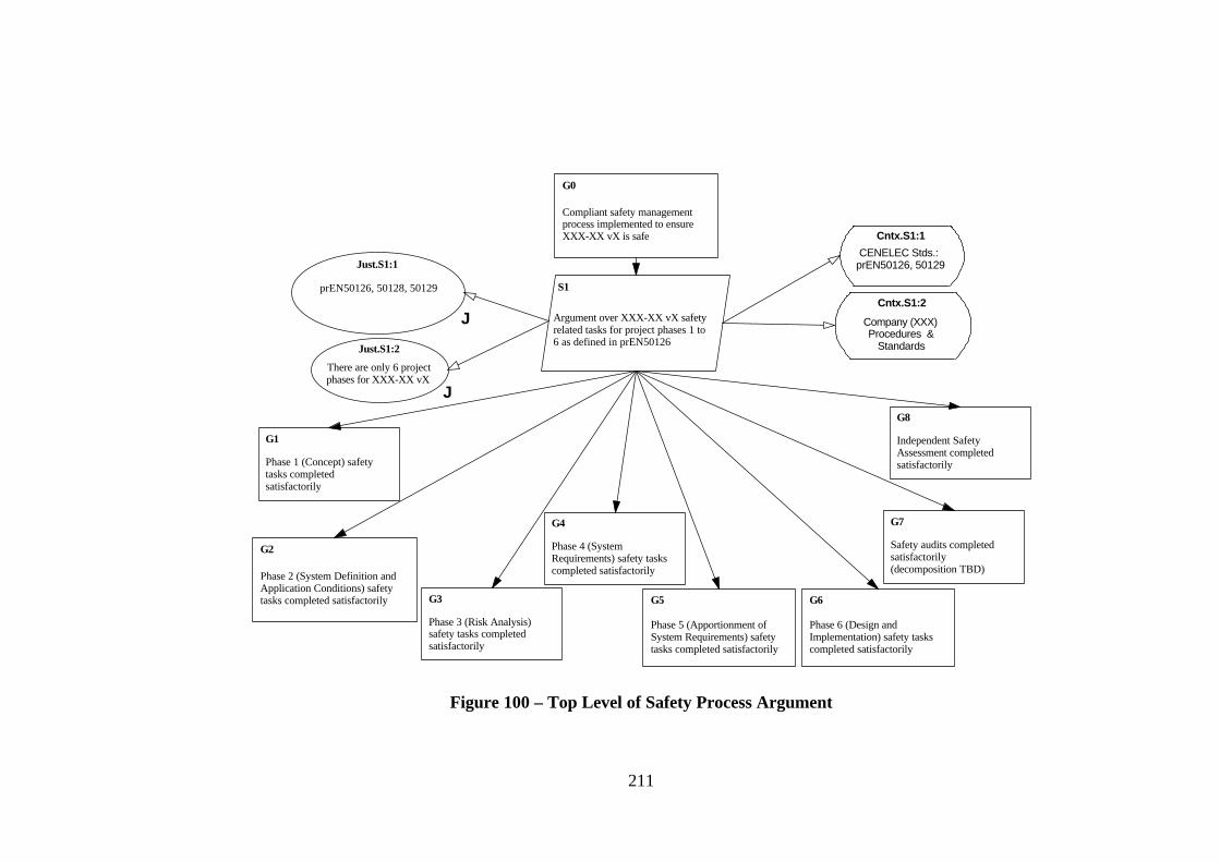
211
Compliant safety managementprocess implemented to ensureXXX-XX vX is safe
G0
S1
Argument over XXX-XX vX safetyrelated tasks for project phases 1 to6 as defined in prEN50126
Cntx.S1:1
CENELEC Stds.: prEN50126, 50129
Cntx.S1:2
Company (XXX)Procedures &
Standards
prEN50126, 50128, 50129
Just.S1:1
J
There are only 6 projectphases for XXX-XX vX
Just.S1:2
J
Phase 1 (Concept) safetytasks completedsatisfactorily
G1
Phase 2 (System Definition andApplication Conditions) safetytasks completed satisfactorily
G2
Phase 3 (Risk Analysis)safety tasks completedsatisfactorily
G3
Phase 4 (SystemRequirements) safety taskscompleted satisfactorily
G4
Phase 5 (Apportionment ofSystem Requirements) safetytasks completed satisfactorily
G5
Phase 6 (Design andImplementation) safety taskscompleted satisfactorily
G6
Safety audits completedsatisfactorily(decomposition TBD)
G7
Independent SafetyAssessment completedsatisfactorily
G8
Figure 100 – Top Level of Safety Process Argument
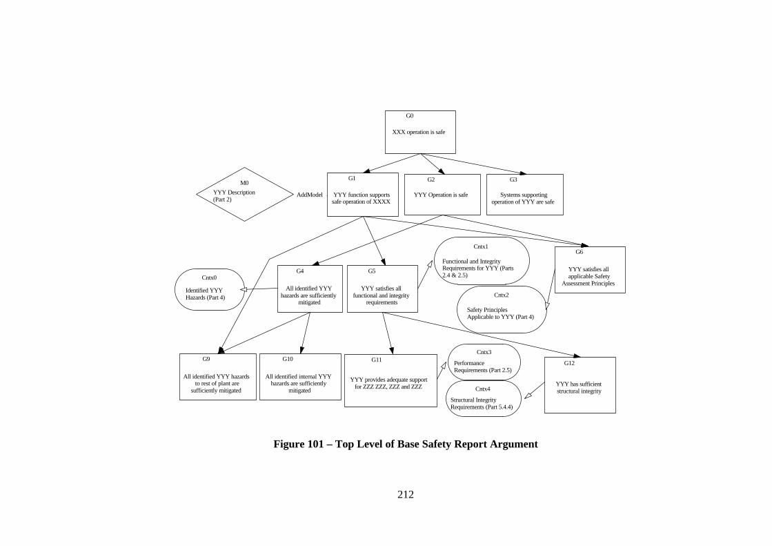
212
G0
XXX operation is safe
G1
YYY function supportssafe operation of XXXX
G2
YYY Operation is safe
G3
Systems supportingoperation of YYY are safe
M0YYY Description (Part 2)
AddModel
G4
All identified YYYhazards are sufficiently
mitigated
G5
YYY satisfies allfunctional and integrity
requirements
G6
YYY satisfies allapplicable Safety
Assessment PrinciplesCntx0
Identified YYYHazards (Part 4)
Cntx1
Functional and IntegrityRequirements for YYY (Parts2.4 & 2.5)
Cntx2
Safety PrinciplesApplicable to YYY (Part 4)
G9
All identified YYY hazardsto rest of plant are
sufficiently mitigated
G10
All identified internal YYYhazards are sufficiently
mitigated
G11
YYY provides adequate supportfor ZZZ ZZZ, ZZZ and ZZZ
G12
YYY has sufficientstructural integrity
Cntx3
PerformanceRequirements (Part 2.5)
Cntx4
Structural IntegrityRequirements (Part 5.4.4)
Figure 101 – Top Level of Base Safety Report Argument

213
G0004
Base condition andoperations comply with
MoD SPSCs
Strat0001
Argument bydividing SPSCsinto principlesand criteria
G0006
Base condition andoperations comply with
principles
G0007
Base condition andoperations comply with
criteria
J0000Approach mandatedby BR3018
J
JustifiedBy
G0008
Principles addressed at levelof 'whole-site' condition and
operation
G0009
All nuclear facilities andassociated operations comply
with principles
Cntx0005
TBD - Definintion of'Whole-site' /
Cntx0006
TBD - List of allfacilities
Figure 102 – Extract from Preliminary Site Safety Justification Argument

214
Figure 103 – SAM Screen Shot (Showing Support for Maintenance Process)
The implementation of the change process defined in Chapter Four within the tool
demonstrates that the process is workable and deterministic. (If it were not deterministic
there would have been difficulty implementing the process steps and rules within the
logic of the tool).
Implementing the change support within the tool enabled examples of the change
process to be generated from goal structures already entered into the tool (e.g. the
Appendix A Trip System Safety Arguments).
6.3.2.2 Maintenance Evaluation: Peer Review
The taxonomy of real-world challenges to the safety case (i.e. the division into
Requirements, Evidence and Context change) and the principles of using goal
structuring to support change impact analysis have been presented widely through the
HISE Group Safety Courses. This exposure, and absence of any dissenting feedback,
has helped gain confidence in the approach. However, it is recognised that this form of
exposure does not constitute a thorough evaluation of the change process.
215
6.3.2.3 Maintenance Evaluation: Case Study
The main evaluation of the change process has been through case studies of postulated
changes to existing goal structures. The challenges to the Appendix A Nuclear Trip
System Safety Case presented in Chapter Four are examples of this. The main
observation arising out of such studies has been that, although the process is workable
and systematic as a pencil-and-paper technique, it can become extremely difficult to
track and manage a change as it propagates (potentially through many paths). As a
result, tool support – such as that described previously – appears necessary for anything
other than simple goal structures and trivial changes.
The value of the change process is not fully demonstrated through the change examples
presented in Chapter Four (necessarily simple for ease of presentation). It is important
to recognise the following two issues: Firstly, the value of the technique increases with
the complexity of the underlying argument (and the consequent difficulties of
traceability). Secondly, in reality the construction of the safety argument will often be
separated from any maintenance action by a significant time period (e.g. a number of
years). To simulate the difficulty of change correctly (and hence the value of this
approach) it is almost necessary to develop a safety argument, forget it, and then attempt
maintenance. The results presented in Chapter Four should be taken as indicative rather
than definitive evaluation of the technique. However, the ‘obviousness’ of the change
examples can perhaps be taken as a positive indication of the ease of carrying out the
process some time in the future.
6.3.3 Safety Case Patterns Evaluation
6.3.3.1 Safety Case Patterns: Tool Implementation
Support has been implemented in SAM for the GSN extensions necessary to express
goal structure patterns. Using the tool it is now possible to define n-ary relations,
choices, uninstantiated and undeveloped GSN elements. GSN patterns defined within
the tool can be copied and pasted into new argument documents and instantiated.
Documentation of Safety Case Patterns is carried out using Microsoft Word, but with
the ‘Structure’ element linked from a SAM document.
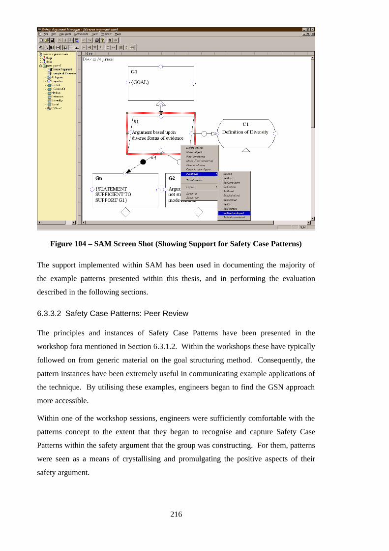
216
Figure 104 – SAM Screen Shot (Showing Support for Safety Case Patterns)
The support implemented within SAM has been used in documenting the majority of
the example patterns presented within this thesis, and in performing the evaluation
described in the following sections.
6.3.3.2 Safety Case Patterns: Peer Review
The principles and instances of Safety Case Patterns have been presented in the
workshop fora mentioned in Section 6.3.1.2. Within the workshops these have typically
followed on from generic material on the goal structuring method. Consequently, the
pattern instances have been extremely useful in communicating example applications of
the technique. By utilising these examples, engineers began to find the GSN approach
more accessible.
Within one of the workshop sessions, engineers were sufficiently comfortable with the
patterns concept to the extent that they began to recognise and capture Safety Case
Patterns within the safety argument that the group was constructing. For them, patterns
were seen as a means of crystallising and promulgating the positive aspects of their
safety argument.
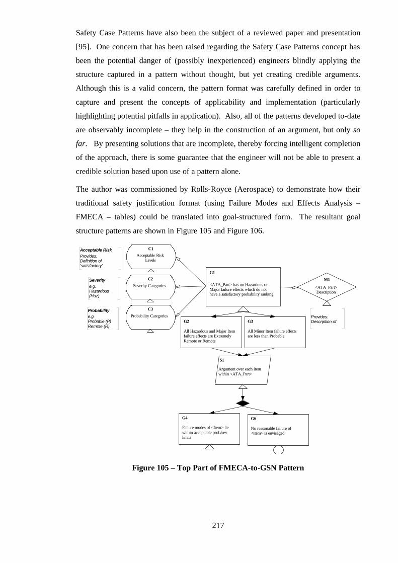
217
Safety Case Patterns have also been the subject of a reviewed paper and presentation
[95]. One concern that has been raised regarding the Safety Case Patterns concept has
been the potential danger of (possibly inexperienced) engineers blindly applying the
structure captured in a pattern without thought, but yet creating credible arguments.
Although this is a valid concern, the pattern format was carefully defined in order to
capture and present the concepts of applicability and implementation (particularly
highlighting potential pitfalls in application). Also, all of the patterns developed to-date
are observably incomplete – they help in the construction of an argument, but only so
far. By presenting solutions that are incomplete, thereby forcing intelligent completion
of the approach, there is some guarantee that the engineer will not be able to present a
credible solution based upon use of a pattern alone.
The author was commissioned by Rolls-Royce (Aerospace) to demonstrate how their
traditional safety justification format (using Failure Modes and Effects Analysis –
FMECA – tables) could be translated into goal-structured form. The resultant goal
structure patterns are shown in Figure 105 and Figure 106.
G1
<ATA_Part> has no Hazardous orMajor failure effects which do nothave a satisfactory probability ranking
Acceptable RiskLevels
C1Acceptable RiskProvides: Definition of'satisfactory'
M1
<ATA_Part>Description
Provides: Description of
Severity Categories
C2Severitye.g. Hazardous(Haz)
Probability Categories
C3Probabilitye.g. Probable (P) Remote (R)
All Hazardous and Major Itemfailure effects are ExtremelyRemote or Remote
G2
All Minor Item failure effectsare less than Probable
G3
Argument over each itemwithin <ATA_Part>
S1
G4
Failure modes of <Item> liewithin acceptable prob/sevlimits
G6
No reasonable failure of<Item> is envisaged
Figure 105 – Top Part of FMECA-to-GSN Pattern
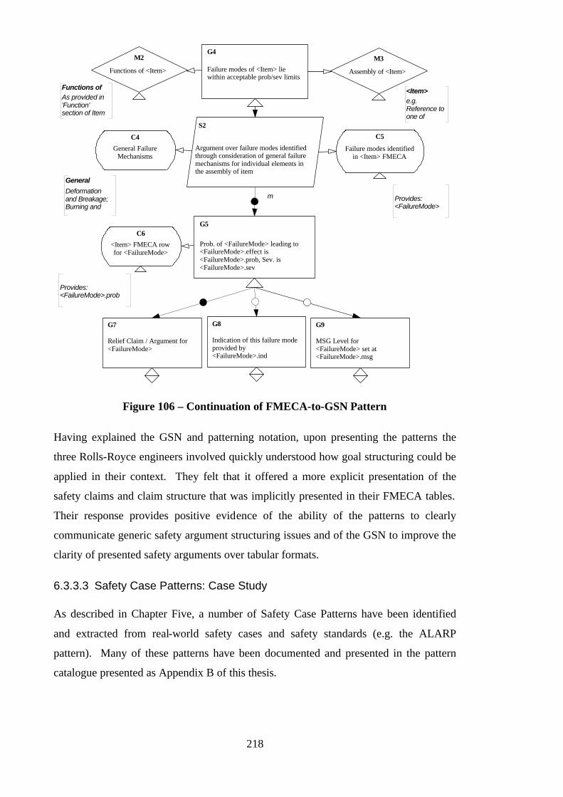
218
G4
Failure modes of <Item> liewithin acceptable prob/sev limits
M2
Functions of <Item>
S2
Argument over failure modes identifiedthrough consideration of general failuremechanisms for individual elements inthe assembly of item
Failure modes identifiedin <Item> FMECA
C5C4
General FailureMechanisms
General
Deformationand Breakage;Burning and
M3
Assembly of <Item>
<Item>e.g.Reference toone of
Functions ofAs provided in'Function'section of Item
G7
Relief Claim / Argument for<FailureMode>
Provides: <FailureMode>.prob
<Item> FMECA rowfor <FailureMode>
C6
G8
Indication of this failure modeprovided by<FailureMode>.ind
G9
MSG Level for<FailureMode> set at<FailureMode>.msg
G5
Prob. of <FailureMode> leading to<FailureMode>.effect is<FailureMode>.prob, Sev. is<FailureMode>.sev
Provides: <FailureMode>
m
Figure 106 – Continuation of FMECA-to-GSN Pattern
Having explained the GSN and patterning notation, upon presenting the patterns the
three Rolls-Royce engineers involved quickly understood how goal structuring could be
applied in their context. They felt that it offered a more explicit presentation of the
safety claims and claim structure that was implicitly presented in their FMECA tables.
Their response provides positive evidence of the ability of the patterns to clearly
communicate generic safety argument structuring issues and of the GSN to improve the
clarity of presented safety arguments over tabular formats.
6.3.3.3 Safety Case Patterns: Case Study
As described in Chapter Five, a number of Safety Case Patterns have been identified
and extracted from real-world safety cases and safety standards (e.g. the ALARP
pattern). Many of these patterns have been documented and presented in the pattern
catalogue presented as Appendix B of this thesis.
219
The emphasis so far in the patterns work has been on capturing and documenting best
practice safety arguments observed within existing safety cases. Consequently, there
has been less evaluation of the application of documented patterns in new safety cases.
However, the ALARP pattern presented in Appendix B was used as the basis of an
argument constructed for a case study conducted for the U.K. Ministry of Defence
(evaluating possible application of the ALARP principle to software systems) [101].
Also, the instances of the Diverse Evidence, Fault Tree and Safety Margin patterns
presented in Appendix B (developed from personal experience) can be identified within
the Trip System safety argument presented in Appendix A.
Experience from the ALARP and Trip System Examples has strongly suggested that
documented patterns should be used as advisory material in the structuring of new
arguments. The structures documented within the Safety Case Patterns should not be
viewed as definitive solutions, instead they should be used to inspire and guide new
structures. In this sense, Safety Case Patterns probably follow the intent of Alexandrian
patterns [72] more closely than software Design Patterns [82]. The patterns have also
been found to serve well as a reference point (e.g. in the case of ALARP arguments) for
checking the quality and completeness of new structures. Put another way, they have
been found to form a useful basis for guiding review of safety cases.
6.3.3.4 Safety Case Patterns: Pilot Industrial Application
The author is currently involved in a study for Rolls-Royce Marine Power to develop a
set of Safety Case Patterns capturing successful arguments of compliance against the 78
safety principles listed in the U.K. Ministry of Defence Safety Principles and Criteria
for the Nuclear Naval Programme [98]. This work has involved studying a number of
existing compliance arguments for different classes and levels of equipment – e.g. for
an overall site down to individual components – and attempting to extract and document
the essential principles and structure of the arguments as Safety Case Patterns. A
number of these Safety Principles Safety Case Patterns have been developed, including
the following:
• Overall Safety Principles Compliance Pattern
• Safety Principle 6 (Defence in Depth) Compliance Pattern
• Safety Principle 7 (Accident Prevention) Compliance Pattern
• Safety Principle 8 (Accident Mitigation) Compliance Pattern

220
• Safety Principle 22 (Plant Process Control Systems) Compliance Pattern
• Safety Principle 24 (Reliability Targets) Compliance Pattern
(Unfortunately, owing to the security classification of this material, only the Safety
Principle 6 pattern has been presented in Appendix B) Although a thorough peer review
of these patterns has not yet been carried out, they have been used in workshop sessions
(with groups of engineers within Rolls-Royce Marine Power) to aid in the construction
of new safety arguments. For example, the Defence in Depth pattern has been presented
and used to guide the structure developed, after identification that it applied to the
system in question.
Feedback from those engineers who have been exposed to the patterns has suggested
that there are three principal benefits of the patterns:
• As exemplar goal structures, they serve as a teaching aid to those unfamiliar with
the GSN.
• They help to prevent the engineers from omitting (or glossing over) aspects of the
compliance arguments.
• They speed up the process of developing new safety arguments by reducing time
spent in identifying an approach to structuring the argument.
There have also been some difficulties identified with the patterns developed. The
safety principles expressed in [98] are generically applicable across a wide range of
systems, and at a number of levels in the system decomposition. As such it has been
found that the unique interpretations of the principle offered by the patterns developed
can be difficult to apply in some circumstances (e.g. if attempting to apply at component
level a pattern that has been developed at ‘whole system’ level). Consequently, it has
been recognised that a number of patterns may need to be developed for each principle
– representing the different styles of interpretation possible. However, this can be seen
to be of value as it is making explicit the fact that there are multiple valid interpretations
of the principle.
6.3.3.5 Safety Case Patterns: Real Industrial Application
To some extent, the pilot project described in the previous section is also a true
industrial application. However, Safety Case Patterns have yet to be integrated as part
of the safety argument development on a live project.
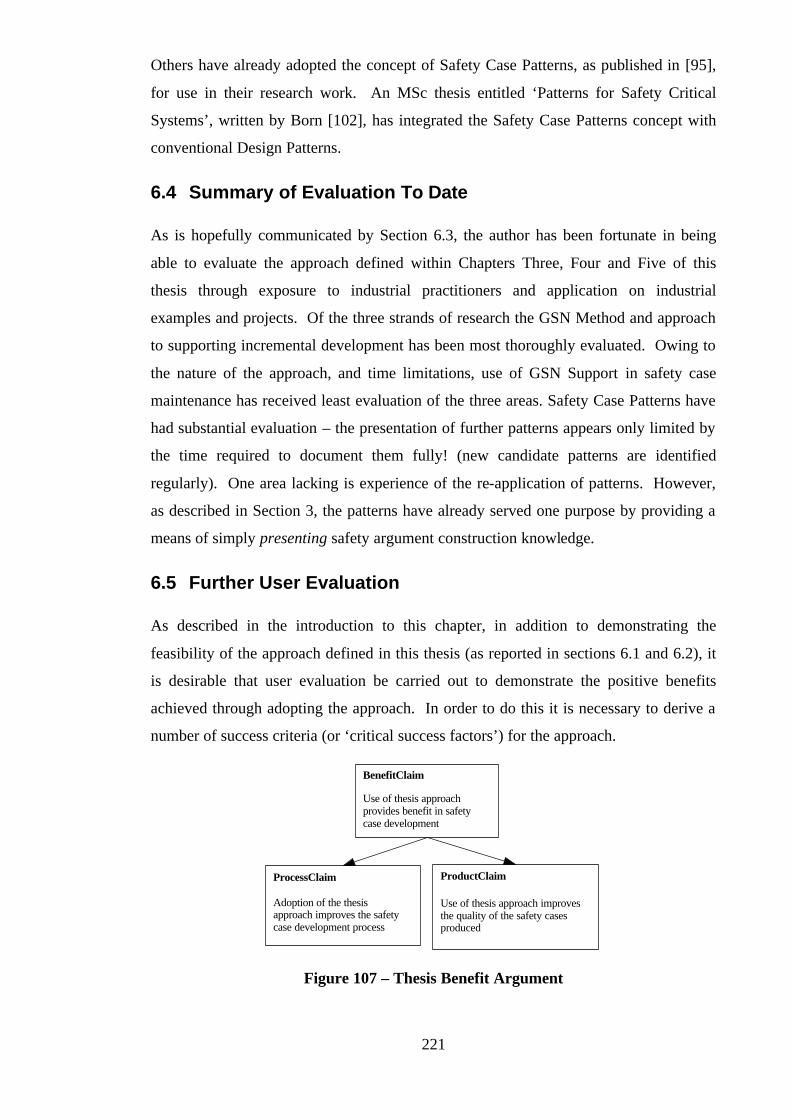
221
Others have already adopted the concept of Safety Case Patterns, as published in [95],
for use in their research work. An MSc thesis entitled ‘Patterns for Safety Critical
Systems’, written by Born [102], has integrated the Safety Case Patterns concept with
conventional Design Patterns.
6.4 Summary of Evaluation To Date
As is hopefully communicated by Section 6.3, the author has been fortunate in being
able to evaluate the approach defined within Chapters Three, Four and Five of this
thesis through exposure to industrial practitioners and application on industrial
examples and projects. Of the three strands of research the GSN Method and approach
to supporting incremental development has been most thoroughly evaluated. Owing to
the nature of the approach, and time limitations, use of GSN Support in safety case
maintenance has received least evaluation of the three areas. Safety Case Patterns have
had substantial evaluation – the presentation of further patterns appears only limited by
the time required to document them fully! (new candidate patterns are identified
regularly). One area lacking is experience of the re-application of patterns. However,
as described in Section 3, the patterns have already served one purpose by providing a
means of simply presenting safety argument construction knowledge.
6.5 Further User Evaluation
As described in the introduction to this chapter, in addition to demonstrating the
feasibility of the approach defined in this thesis (as reported in sections 6.1 and 6.2), it
is desirable that user evaluation be carried out to demonstrate the positive benefits
achieved through adopting the approach. In order to do this it is necessary to derive a
number of success criteria (or ‘critical success factors’) for the approach.
Use of thesis approachprovides benefit in safetycase development
BenefitClaim
Use of thesis approach improvesthe quality of the safety casesproduced
ProductClaim
Adoption of the thesisapproach improves the safetycase development process
ProcessClaim
Figure 107 – Thesis Benefit Argument

222
Figure 107 shows the overall claim that adopting the approach presented in this thesis
provides benefit in safety case. This claim can be broken down into two sub-claims.
The first sub-claim is that the approach improves the processes of safety case
development. The second sub-claim is that the approach improves the quality of the
safety case product. We will address the process argument first.
Adoption of the thesisapproach improves the safetycase development process
ProcessClaim
OverElements
Argument over the threeelements of the approach
ThesisApproachElements
Elements are: Support for InitialDevelopment, Support for
Maintenance, and Support forReuse
Adoption of the thesisapproach improves theinitial development process
InitDevelopmentProcess
Adoption of the thesisapproach improves themaintenance process
MaintenanceProcess
Adoption of the thesisapproach improves the reuseprocess
ReuseProcess
Figure 108 – Thesis Process Benefit Argument
Figure 108 decomposes the process benefit claim over the three elements of the thesis
approach – i.e. we are arguing an overall benefit in the process through benefits in the
specific processes of development, maintenance and reuse. These general claims can
now be decomposed to specific success criteria. Figure 109 shows the derivation of
success criteria for improvement in the development process. The following three
specific claims are put forward for the thesis approach (regarding the development
process):
• Quicker Development
• Reduction in Rework
• Reduction in Iterations to Agreement (e.g. between developer and independent
safety assessor, or developer and regulator)
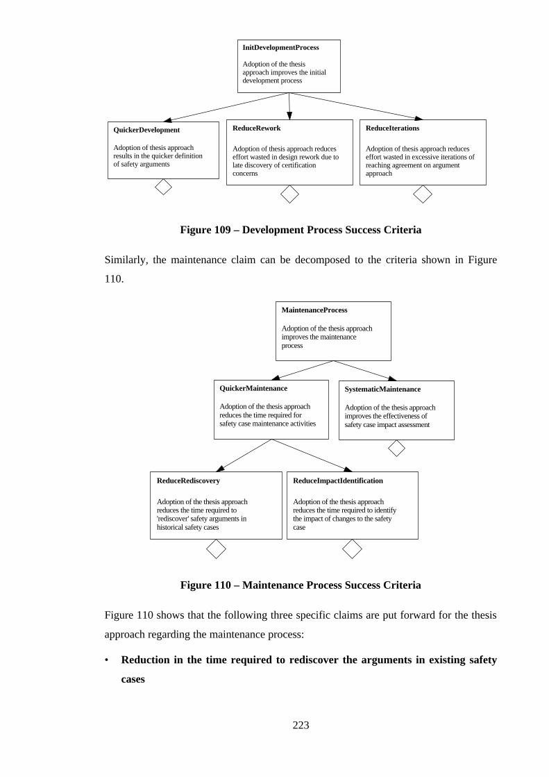
223
Adoption of the thesisapproach improves the initialdevelopment process
InitDevelopmentProcess
QuickerDevelopment
Adoption of thesis approachresults in the quicker definitionof safety arguments
ReduceRework
Adoption of thesis approach reduceseffort wasted in design rework due tolate discovery of certificationconcerns
ReduceIterations
Adoption of thesis approach reduceseffort wasted in excessive iterations ofreaching agreement on argumentapproach
Figure 109 – Development Process Success Criteria
Similarly, the maintenance claim can be decomposed to the criteria shown in Figure
110.
Adoption of the thesis approachimproves the maintenanceprocess
MaintenanceProcess
Adoption of the thesis approachreduces the time required forsafety case maintenance activities
QuickerMaintenance SystematicMaintenance
Adoption of the thesis approachimproves the effectiveness ofsafety case impact assessment
ReduceRediscovery
Adoption of the thesis approachreduces the time required to'rediscover' safety arguments inhistorical safety cases
ReduceImpactIdentification
Adoption of the thesis approachreduces the time required to identifythe impact of changes to the safetycase
Figure 110 – Maintenance Process Success Criteria
Figure 110 shows that the following three specific claims are put forward for the thesis
approach regarding the maintenance process:
• Reduction in the time required to rediscover the arguments in existing safety
cases

224
• Reduction in the time required to identify the impact of changes to the safety
case
• Improvements in the effectiveness of the impact assessment process
Figure 111 shows the derivation of the reuse related process criteria.
Adoption of the thesis approachimproves the reuse process
ReuseProcess
QuickerDevelopment
Adoption of thesis approachresults in the quicker definitionof safety arguments
Adoption of the thesis approachreduces the potential for the (process)problems of informal safety casereuse
ReducesReuseProcessProblemsInformalReuseProblems
The Problems of InformalSafety Case Reuse
(Chapter 5, Section 5.2)
ReduceAdhoc
Adoption of the thesis approachreduces the ad-hoc nature ofsafety case reuse
ReduceLossOfKnowledge
Adoption of the thesis approachreduces the risk of losing vitalsafety case development expertise
Figure 111 – Reuse Process Success Criteria
Figure 110 shows that the following three specific claims are put forward for the thesis
approach regarding the reuse process:
• Quicker Development (as also stated in Figure 109)
• Reduction in ad-hoc reuse of safety case artefacts
• Reduction in risk of losing safety case development expertise
The claim that the thesis approach benefits the safety case product can similarly be
decomposed. Figure 112 shows the first part of this decomposition (again over the three
strands of the thesis approach).
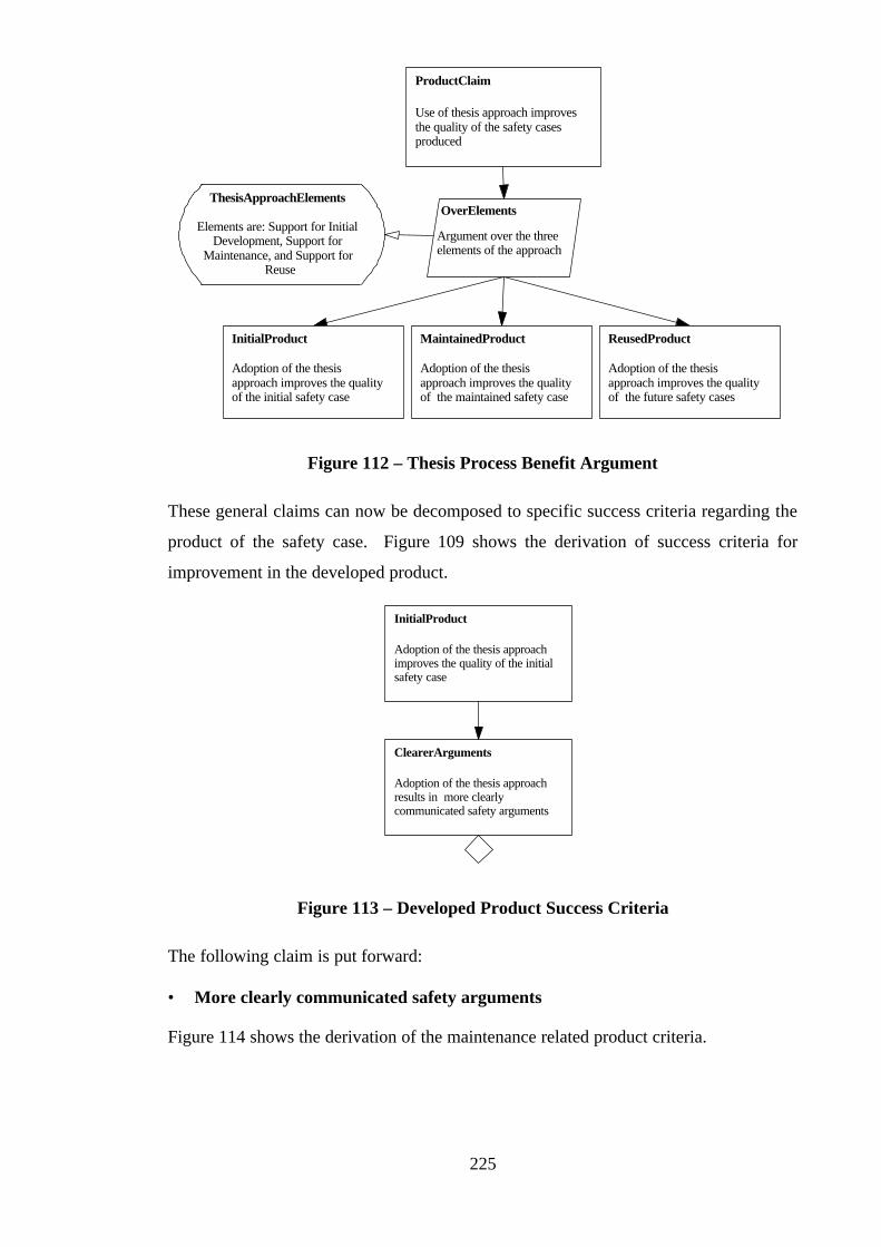
225
Use of thesis approach improvesthe quality of the safety casesproduced
ProductClaim
Adoption of the thesisapproach improves the qualityof the future safety cases
ReusedProduct
Adoption of the thesisapproach improves the qualityof the maintained safety case
MaintainedProduct
Adoption of the thesisapproach improves the qualityof the initial safety case
InitialProduct
ThesisApproachElements
Elements are: Support for InitialDevelopment, Support for
Maintenance, and Support forReuse
OverElements
Argument over the threeelements of the approach
Figure 112 – Thesis Process Benefit Argument
These general claims can now be decomposed to specific success criteria regarding the
product of the safety case. Figure 109 shows the derivation of success criteria for
improvement in the developed product.
Adoption of the thesis approachimproves the quality of the initialsafety case
InitialProduct
ClearerArguments
Adoption of the thesis approachresults in more clearlycommunicated safety arguments
Figure 113 – Developed Product Success Criteria
The following claim is put forward:
• More clearly communicated safety arguments
Figure 114 shows the derivation of the maintenance related product criteria.

226
Adoption of the thesis approachimproves the quality of themaintained safety case
MaintainedProduct
AccurateUpdate
Adoption of the thesis approachresults in the safety case being moreaccurately and completely updated inthe light of a change
Figure 114 – Maintained Product Success Criteria
The following claim is put regarding the quality of safety cases maintained using the
thesis approach:
• More accurately and completely updated safety cases
Figure 115 shows the derivation of the reuse related product criteria.
Adoption of the thesis approachimproves the quality of thefuture safety cases
ReusedProduct
InformalReuseProblems
The Problems of InformalSafety Case Reuse
(Chapter 5, Section 5.2)
Adoption of the thesis approachreduces the potential for the (prduct) problems of informal safety casereuse
ReducesReuseProductProblems
ReducesInappReuse
Adoption of the thesisapproach reducesinappropriate safety case reuse
ReducesInconsistency
Adoption of the thesis approachreduces inconsistency ofarguments between safety cases
ImprovesTraceability
Adoption of the thesis approachimproves the traceability ofreused safety case arguments
Figure 115 – Reused Product Success Criteria
Figure 115 shows that the following three specific claims are put forward for the thesis
approach regarding ‘reused’ safety cases:
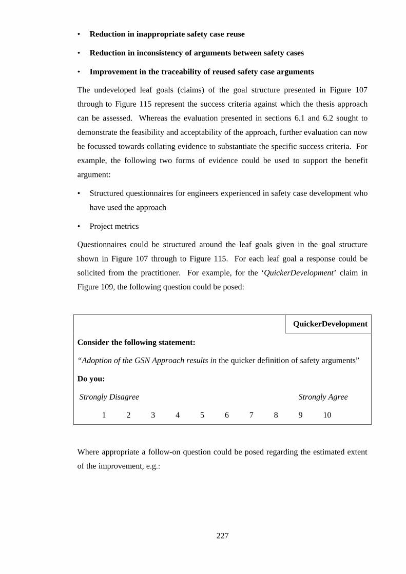
227
• Reduction in inappropriate safety case reuse
• Reduction in inconsistency of arguments between safety cases
• Improvement in the traceability of reused safety case arguments
The undeveloped leaf goals (claims) of the goal structure presented in Figure 107
through to Figure 115 represent the success criteria against which the thesis approach
can be assessed. Whereas the evaluation presented in sections 6.1 and 6.2 sought to
demonstrate the feasibility and acceptability of the approach, further evaluation can now
be focussed towards collating evidence to substantiate the specific success criteria. For
example, the following two forms of evidence could be used to support the benefit
argument:
• Structured questionnaires for engineers experienced in safety case development who
have used the approach
• Project metrics
Questionnaires could be structured around the leaf goals given in the goal structure
shown in Figure 107 through to Figure 115. For each leaf goal a response could be
solicited from the practitioner. For example, for the ‘QuickerDevelopment’ claim in
Figure 109, the following question could be posed:
QuickerDevelopment
Consider the following statement:
“Adoption of the GSN Approach results in the quicker definition of safety arguments”
Do you:
Strongly Disagree Strongly Agree
1 2 3 4 5 6 7 8 9 10
Where appropriate a follow-on question could be posed regarding the estimated extent
of the improvement, e.g.:
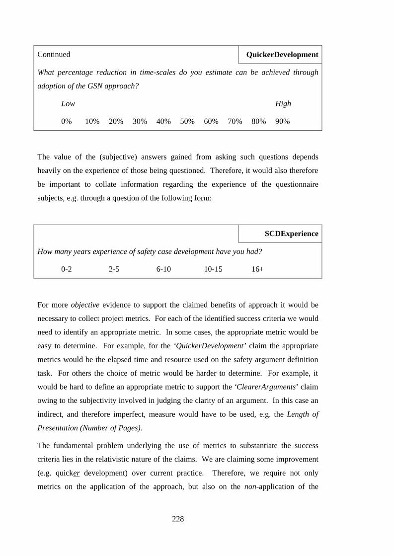
228
Continued QuickerDevelopment
What percentage reduction in time-scales do you estimate can be achieved through
adoption of the GSN approach?
Low High
0% 10% 20% 30% 40% 50% 60% 70% 80% 90%
The value of the (subjective) answers gained from asking such questions depends
heavily on the experience of those being questioned. Therefore, it would also therefore
be important to collate information regarding the experience of the questionnaire
subjects, e.g. through a question of the following form:
SCDExperience
How many years experience of safety case development have you had?
0-2 2-5 6-10 10-15 16+
For more objective evidence to support the claimed benefits of approach it would be
necessary to collect project metrics. For each of the identified success criteria we would
need to identify an appropriate metric. In some cases, the appropriate metric would be
easy to determine. For example, for the ‘QuickerDevelopment’ claim the appropriate
metrics would be the elapsed time and resource used on the safety argument definition
task. For others the choice of metric would be harder to determine. For example, it
would be hard to define an appropriate metric to support the ‘ClearerArguments’ claim
owing to the subjectivity involved in judging the clarity of an argument. In this case an
indirect, and therefore imperfect, measure would have to be used, e.g. the Length of
Presentation (Number of Pages).
The fundamental problem underlying the use of metrics to substantiate the success
criteria lies in the relativistic nature of the claims. We are claiming some improvement
(e.g. quicker development) over current practice. Therefore, we require not only
metrics on the application of the approach, but also on the non-application of the
229
approach. In an ideal world these metrics would be gained from running a project twice
- once with the approach and once without the approach. However, it is extremely
difficult to get companies such as Rolls-Royce to conduct such a study (due to the effort
involved). Therefore in reality we will be forced to make comparisons of new projects
that use the approach with similar (in terms of size, complexity, staff involved etc.) past
projects run without using the approach.
6.6 Conclusions
This chapter has reported the successful evaluation activities so far carried out
demonstrate the feasibility and acceptability of the approach defined in Chapters Three,
Four and Five of this thesis. In addition we have indicated how further evaluation of the
benefit of the approach could be conducted. Although it is has not been possible to
conduct this form of evaluation within the time-scale of the doctoral programme, we
believe that the approach has already been shown to be both a valid and capable tool for
safety case management.

230
231
Chapter 7:
Conclusions
7.1 Concluding Remarks
This thesis has defined and demonstrated a coherent approach to the development,
presentation, maintenance and reuse of the safety arguments within a safety case. This
approach is based upon a graphical technique – the Goal Structuring Notation (GSN).
Specifically, the contribution of the research presented in this thesis lies in three areas:
• Definition and evaluation of a method for the use of the GSN, and description
of an approach to supporting incremental safety case development.
• Definition and evaluation of a systematic process for the maintenance of a
GSN-structured safety argument.
• Definition and evaluation of Safety Case Patterns – a means of supporting and
promoting the reuse of successful safety arguments between safety cases.
The following sections draw some conclusions from each of these elements of the
research.
7.1.1 Conclusions on the Presentation and Development Contribution
In Chapter Two other existing approaches to presenting safety arguments are surveyed.
It is important to note that the work presented in this thesis pre-dates many of the
alternative approaches described. In some cases the principles underlying the approach
are believed to have influenced these approaches (this is known to be true, for example,
for the ‘Claim Structures’ presented in DS 00-55 [9, 37]).
Although these alternative approaches share the fundamental intent of communicating
clear safety arguments with the approach defined in this thesis in Chapter Three and
[57], their expressive power is not as great, and neither have they been subject to the
same extensive evaluation. In some cases (e.g. Tabular Presentation), the author’s
observation of examples of their application suggests that they can still suffer some of
the same problems of ambiguity and comprehension as experienced with free-form text.
As shown by some of the early experiences of presenting safety arguments using the
Toulmin notation [42] there is an important trade-off to be recognised between
232
expressive power and ease of adoption. A technique may have great expressive power,
but if it proves too complex to be easily understood and adopted by engineers for use on
real projects it is of little value. Conversely, a technique may be extremely easy to
adopt, but may offer little added value in its presentation of safety arguments. The
method defined in [57] has attempted to strike the correct balance between these two
considerations. In particular, the research has aimed to minimise unnecessary
complexity – resulting in some simplification of the original GSN concepts.
The capability of the technique to handle realistic industrial examples has been
demonstrated through the evaluation activities described in Chapter Six. Here the
observations from its exposure to a significant and representative population of
engineers show that value is added when the technique is adopted. The successful
adoption of the GSN method on industrial projects has also enabled me to gain
confidence that the techniques can be understood and utilised by others than myself.
7.1.2 Conclusions on the Maintenance Contribution
The key contribution made by the maintenance approach presented in Chapter Four is
the definition and evaluation of a systematic process for the maintenance of safety
arguments where no such systematic process previously existed. None of the alternative
approaches described in Chapter Two has been developed to the point at which any
explicit support for the maintenance of safety arguments has been defined.
7.1.3 Conclusions on the Reuse Contribution
The concept of Safety Case Patterns described in Chapter Five, to support the managed
reuse of safety arguments, is particularly novel. No comparable approaches appear to
exist. Evaluation of Safety Case Patterns in an industrial context has shown them to
achieve their intended purpose, and to be readily accepted and applied by practitioners.
7.1.4 Overall Conclusions
The presentation and management of safety arguments will always be an aspect of
safety case development where total objectivity is unattainable and subjectivity must
therefore be expected and managed. (This is due to the nature of claim and inference
and human creativity in using such devices). This thesis has aimed to define an
approach in which subjectivity has been reduced to a realistically low level, whilst
providing sufficient expressive power to support the activities of safety case
development, maintenance and reuse. Evaluation of the approach has also exhibited
233
that subjectivity is correctly restricted to, and highlighted in, the details of the
arguments presented, rather than appearing in the mechanisms through which they are
presented.
It is recognised that the management of safety arguments is only one aspect of the
overall management of the safety case. (Other important aspects include the selection
and management of supporting evidence techniques, hazard log management and
configuration management of the complex document structures produced). However, as
described in Chapter One, the presentation of a clear, comprehensive and compelling
safety argument remains the prime objective of any safety case. It is for this reason that
this thesis can be claimed to have addressed issues that are at the heart of the safety case
management process.
7.2 Further Work Areas
During the course of the research a number of areas worthy of further investigation have
been identified, these include:
• Application of GSN approach and method to other (non-safety) domains
• Development of Anti Safety Case Patterns
• Expression of Safety Case Architectures using Safety Case Patterns
• Systems engineering process issues surrounding Safety Case Patterns
• Integrating Bayesian Belief Networks with the GSN approach
• Augmentation of the change process to include version management and integration
with conventional documentation configuration management
• Tighter interrelation of pattern instantiation and change process
• Additional (alternative) syntax rules within the GSN method
A brief introduction to the further work possible in these areas is presented in the
following sections.
7.2.1 Application of GSN to other (non-safety) domains
It has been suggested many times that the Goal Structuring Notation and Method could
equally usefully be applied in articulating and managing arguments within other
234
domains. In particular the following possible applications have been suggested to the
author:
• Expressing and Maintaining Design Intent – it has been suggested that goal
structures be developed to represent how design objectives have been decomposed
and eventually satisfied by introducing particular design features or by taking
particular design decisions. Having developed this structure, the principles of
change management could be used to ensure that design intent is maintained
throughout the operational life of the design.
• Use in expressing corporate research / capability acquisition strategy – it has
been suggested that overall corporate objectives be expressed as goals. Goal
structuring could then be used to show how these objectives have been decomposed
and addressed through particular programmes and projects
• Use in a management consultancy process - ‘Issue’ diagrams are often
constructed as part of a conventional management consultancy process. These
diagrams are used in part to express arguments in support of decisions. It has been
observed that in the absence of syntax rules and a systematic basis for the expression
of such arguments, and without any pressure to provide evidence for statements, the
arguments presented are often ill-expressed and unfounded. For this application it
has been suggested that statements of decision and intended effect be expressed as
top goals with the supporting goal structure being used to express the reasons why
this decision can be expected to have this effect (and the evidence to support these
claims).
The work presented in this thesis has focussed on the use and evaluation of GSN in
supporting safety case arguments. However, investigating its wider application in the
above areas remains an interesting area for further work.
7.2.2 Anti Safety Case Patterns
The concept of Safety Case Patterns presented in Chapter Five was developed in order
to capture and promote examples of ‘best practice’ safety arguments. However, it
would also be interesting to develop the concept of ‘anti-patterns’ that communicate
weak or flawed safety arguments – such that they may be recognised and avoided in
future developments. Such patterns could be used as a basis for challenging existing
safety cases – i.e. by identifying recognised anti-patterns within the argument presented.
235
Such anti-patterns would be useful tools for safety case reviewers, and would offer more
stringent guidance than checklists or rules on the wording of goals and other elements of
GSN arguments.
7.2.3 Safety Case Architectures using Safety Case Patterns?
Building on the concept of Safety Case Patterns, it would be interesting to investigate
how patterns can be composed together to form architectural solutions to constructing
overall safety case arguments. This work may involve developing the concept of meta-
patterns – i.e. patterns that describe the application of patterns.
7.2.4 Safety Case Patterns – Process Issues
With the further industrial application of the Safety Case Patterns concept, issues arise
concerning how patterns can best be integrated into a total engineering process. In
particular, when and how should patterns be introduced into new development activities
such that they can provide maximum benefit without stifling the creation of (equally or
more useful) alternative approaches?
It would also be worthwhile to examine the relationships that exist, or could be
developed, between Safety Case Patterns and other existing (or future) forms of
engineering patterns (e.g. software Design Patterns). Relating patterns in this way
would begin to communicate the interrelationships that exist between different
development viewpoints (e.g. recognition that adoption of a particular design strategy
implies an associated safety argument approach).
7.2.5 Integrating Bayesian Belief Networks with the GSN approach
Bayesian Belief Networks (BBNs) were described briefly in chapter 2. Whereas GSN
provides a means of presenting (essentially unweighted) inferences between the claims
of a safety argument, BBNs provide a means of deriving, modelling and quantifying the
belief in the inferences between claims. Some initial thought has been given to how
these two techniques relate. This has led to the belief that a BBN used to derive a
quantitative claim (from qualitative or quantitative evidence) has a corresponding GSN
pattern. This pattern would present the ‘output’ claim supported by the ‘input’ claims
of the BBN, justified by the causal links and the conditional probabilities given in the
BBN. Further work could be done to explore this belief.
236
7.2.6 Augmentation of Change Management
The change management process defined in Chapter Four presents the rudimentary
steps of change management as an illustration of how the GSN can be used to support
systematic impact assessment. It would be possible to extend the fine-grain
configuration management approach so that it became a fine-grained version
management approach that enabled the development and maintenance of audit trails
over the goal structure, for example. Some tentative work by the author in this area has
revealed the potential complexity of the mechanisms required, but it nonetheless
remains an area worth further investigation.
7.2.7 Interrelation of Patterns and Change Management
The instantiation of Safety Case Patterns within a new safety case development has a
correspondence with the change management principles proposed. In the same way that
a challenged goal structure must go through the process of repair and recovery, an
instantiated pattern must be reconciled with its target context. The process of
reconciliation is analogous to challenging all the peripheral elements of the pattern.
Further work could be done to explore and define the relationship that exists between
the activities of reuse and change – possibly leading to a simpler and more powerful
process.
7.2.8 Alternative syntax rules within the GSN method
As already discussed in the previous chapter, evaluation of the GSN method has
identified that, although the syntax rules as defined achieve the desired intention of
restricting the phrasing of goal structures such that well-formed and logical arguments
result, they may be overly restrictive – denying other valid sentential structures. Further
study of English syntax and its use in argumentation could be undertaken to define
additional syntax rules. (However, there is a real risk that adding complexity to the
method could make it harder for practitioners to adopt.)
7.3 Coda
The ultimate ‘proof’ of the approach defined within this thesis would be that safer
systems have resulted. Although evaluation has already been extensive, there is no
direct evidence of this as yet, simply because to collate and correlate such evidence
requires more prolonged industrial exposure, and in particular more elapsed time, than
is possible within the confines of a Doctoral programme. Nevertheless, conclusions

237
from the research to date, and the level of interest shown by both industry and
certification bodies, suggest that it is not unrealistic to expect this level of contribution
in the long run.

238

239
Appendix A:
Nuclear Trip System Safety Case Example
This appendix illustrates the use of the Goal Structuring Notation in the construction
and presentation of a safety case. The technical basis of the safety case and textual
description has been taken directly from an example produced by Adelard - presented in
[36]. Goal structures have been integrated with this information to communicate the
implicit structure explicitly and to improve the traceability of the safety argument. The
safety case concerns a reactor trip system. As far as possible, the intention has been to
present requirements and safety arguments that are similar to those for real reactors.
Italics have been used to highlight text that has come directly from the Adelard
example. This shows clearly that we have used the Adelard text primarily to provide
the system description and description of supporting evidence. The presentation of the
safety requirements and safety arguments (goal structures and supporting text), although
based upon the argument communicated in the Adelard example, has been generated
anew.
In the Adelard example, three key devices were used to communicate the flow of the
safety argument:
• Traceability Matrices (mapping requirements to design features)
• Tabular Arguments
• Cross-references within safety case text
In this example, we have instead used goal structures as the principal device for
presenting the safety arguments. Discussion of the perceived benefits of adopting this
approach with this example is presented in Chapter Three, Section 3.10.
The goal structures presented in this appendix have been constructed according to the
goal structuring method defined in [57].
We have also used this safety case as the basis of two change examples given in Chapter
Four, Section 5, and to illustrate instances of some of the safety case patterns presented
in Appendix B. Footnotes are used to highlight instances of patterns that can be
observed in the safety argument.
240
Contents
1 INTRODUCTION 243
1.1 BACKGROUND .........................................................................................................243
1.2 OBJECTIVE & SCOPE ..............................................................................................243
1.3 DOCUMENT STRUCTURE .........................................................................................244
2 TRIP SYSTEM ENVIRONMENT 244
2.1 THE PLANT..............................................................................................................244
2.2 SENSORS AND ACTUATORS......................................................................................245
2.3 FAILURE MODES .....................................................................................................245
3 SAFETY ARGUMENT APPROACH 245
4 TRIP SYSTEM HAZARDS 246
5 TRIP SYSTEM REQUIREMENTS 246
5.1 FUNCTIONAL REQUIREMENTS ................................................................................246
5.2 PERFORMANCE REQUIREMENTS.............................................................................247
5.3 OPERATIONAL AND MAINTENANCE REQUIREMENTS.............................................247
5.4 THROUGH-LIFE INTEGRITY REQUIREMENTS .........................................................248
5.5 SAFETY CRITERIA ...................................................................................................249
6 TRIP SYSTEM DESIGN 249
6.1 REDUNDANT CHANNELS AND THERMOCOUPLES.....................................................250
6.2 FAIL-SAFE DESIGN FEATURES .................................................................................250
6.3 SEPARATE MONITOR COMPUTER ...........................................................................251
6.4 SIMPLICITY .............................................................................................................251
6.5 FORMALLY PROVED SOFTWARE.............................................................................252
6.6 1OO2 (1 OUT OF 2) HIGH TRIP LOGIC.....................................................................252
6.7 2OO2 (2 OUT OF 2) LOW TRIP LOGIC......................................................................252
6.8 PROGRAM AND TRIP PARAMETERS IN PROM........................................................252
6.9 MODULAR HARDWARE REPLACEMENT..................................................................252
6.10 USE OF MATURE HARDWARE AND SOFTWARE TOOLS...........................................252
6.11 ACCESS CONSTRAINTS ............................................................................................252
7 FUNCTIONAL ARGUMENTS 253
8 PERFORMANCE ARGUMENTS 254
8.1 FAILURE ON DEMAND ARGUMENT (G.PFD)...........................................................254
8.2 RESPONSE TIME ARGUMENT (G.TIM) ...................................................................259
8.3 STATIC TIMING ANALYSIS ARGUMENT (G.TIM.STAT) ........................................260
8.4 TIMING TEST & REVERSIBLE COMPUTING ARGUMENT (G.TIM.TEST &
G.TIM.FS).......................................................................................................................260
9 OPERATIONAL ARGUMENTS 261
241
9.1 TIME TO REPAIR ARGUMENT (G.FIX)................................................................... 261
9.2 SPURIOUS TRIP RATE ARGUMENT (G.STR)........................................................... 262
9.3 TESTABILITY ARGUMENT (G.TST)........................................................................ 263
10 THROUGH-LIFE INTEGRITY ARGUMENTS 263
10.1 MAINTENANCE ERROR ARGUMENT (G.SEC) ........................................................ 263
10.2 UPDATE ARGUMENT (G.UPD)................................................................................ 265
10.3 SAFETY CASE VALIDITY ARGUMENT (G.VALID) ................................................. 268
11 SAFETY CRITERIA 269
11.1 SINGLE FAULTS (G.FAULT1)................................................................................. 269
11.2 TWO FAULTS (G.FAULT2)..................................................................................... 270
12 EVIDENCE FROM THE DEVELOPMENT PROCESS 270
13 LONG-TERM SUPPORT ACTIVITIES 271
14 SUPPORTING ANALYSES 272
14.1 PROBABILISTIC FAULT TREE ANALYSIS ................................................................ 273
14.2 ANTICIPATED CHANGE ANALYSIS.......................................................................... 276
14.3 ANALYSIS OF MAINTENANCE AND OPERATIONS.................................................... 277
15 SAFETY LONG-TERM SUPPORT REQUIREMENTS 278
15.1 SUPPORT INFRASTRUCTURE................................................................................... 278
15.2 MAINTENANCE SUPPORT RISKS............................................................................. 279
15.3 REGULAR ANALYSES.............................................................................................. 279
16 ELABORATION TO SUBSYSTEM REQUIREMENTS 280
16.1 SOFTWARE FUNCTIONAL REQUIREMENTS............................................................. 281
17 CONCLUSIONS 283

242
Table of Figures
Figure 113 – Safety Objective (Safe) and Argument Strategy ................................................245
Figure 114 – Functional Requirements (S.FUNC) .................................................................246
Figure 115 – Performance Requirements (S.PERF) ...............................................................247
Figure 116 – Operational and Maintenance Requirements (S.OPER).....................................247
Figure 117 – Through-Life Integrity Requirements (S.INT)...................................................248
Figure 118 – Safety Criteria (S.CRIT)...................................................................................249
Figure 119 – Trip System Architecture..................................................................................249
Figure 120 – Dynamic Check Logic for a Reactor Trip Channel ............................................251
Figure 121 – Functional Arguments (G.TRIP).......................................................................253
Figure 122 – Failure on Demand Argument (G.PFD).............................................................254
Figure 123 – Random Failures (G.PFD.RAND) ....................................................................256
Figure 124 – Incredibility of Systematic Faults (G.NO-FLT).................................................257
Figure 125 – Systematic Failures (G.PFD.SYST.1) ...............................................................258
Figure 126 – Systematic Failures (G.PFD.SYST.2) ...............................................................258
Figure 127 – Response Time Argument (G.TIM) ..................................................................259
Figure 128 – Static Timing Analysis Argument .....................................................................260
Figure 129 – Timing Test Argument (G.TIM.TEST) .............................................................260
Figure 130 – Time to Repair Argument (G.FIX)....................................................................261
Figure 131 – Spurious Trip Rate Argument (G.STR).............................................................262
Figure 132 – Testability Argument (G.TST)..........................................................................263
Figure 133 – Maintenance Error Argument (G.SEC) .............................................................264
Figure 134 – Maintenance Safeguards (G.SEC.SG)...............................................................265
Figure 135 – Update Argument (G.UPD) ..............................................................................266
Figure 136 – Anticipated Changes (G.UPD.AC)....................................................................267
Figure 137 – Changes to Data and Program (G.UPD.DATA & G.UPD.PROGRAM) ............268
Figure 138 – Safety Case Validity Argument (G.VALID)......................................................269
Figure 139 – Single Faults (G.FAULT1) ...............................................................................270
Figure 140 – Two Faults (G.FAULT2) ..................................................................................270
Figure 141 – Table of Explicit Safety Case Assumptions.......................................................280
243
A.1 Introduction
A.1.1 Background
(The following section is taken from ‘Nuclear Reactor Engineering’ [103].)
Nuclear power generators are designed to produce heat to satisfy the demand for steam
by a turbine generator, up to a specified limit. The reactor control system, with its
automatic and manual controls, serves to maintain safe operating conditions as the
demand is varied. Because excess cooling capability is provided in the design of the
reactor system, overpower can be tolerated without causing damage to the fuel rods. If
the thermal power should exceed the limiting value or if other abnormal conditions
which might endanger the system should arise, the reactor protection system would
cause reactor trip (or "scram").
The purpose of the protection system is to shut the reactor down and maintain it in a
safe condition in the event of a system transient or malfunction that might cause damage
to the core, most likely from overheating. If sensors indicate a transient that cannot be
corrected immediately by the control system, the reactor is shut down automatically by
the protection system.
An essential requirement of the reactor protection system is that it must not fail when
needed; on the other hand, unnecessary trips must be avoided for availability / economic
reasons.
A reactor trip (or primary protection) system forms just one part of the (‘defence-in-
depth’) accident prevention measures taken in a typical reactor. Other measures include
emergency cooling, the containment offered by the reactor pressure vessel and reactor
housing, and fans and sprays to prevent over-pressurisation of the reactor coolant
circuits.
A.1.2 Objective & Scope
The objective of this document is to present the argument that the trip system design as
proposed is acceptably safe to operate as part of the overall safety measures in the
nuclear reactor.
This safety case addresses primarily the design of the trip system. Safety arguments
addressing the safety of the procedures surrounding the operation and maintenance of
the system are assumed to be outside the responsibility and scope of this document.
However, this document does appeal to the existence of such arguments. The safety
244
case also assumes a design for the broader reactor system and the results of hazard
analysis at this level to set the probabilistic failure targets used. The derivation and
justification of such information is outside the scope of this example.
As discussed in Section 16, the safety objectives laid out in this document can be further
apportioned to the subsystems of the system architecture presented. However, this is
beyond the scope of this document.
A.1.3 Document Structure
Section 2 of the document provides contextual information concerning the environment
in which the trip system is placed.
Section 3 sets out the approach that has been adopted in the presentation of the high
level safety argument for this system.
Section 4 defines the principal hazards of the trip system.
Section 5 presents the requirements that have been defined for safe operation.
Section 6 provides an overview of the trip system design – highlighting the key design
features.
Appealing to the safety aspects of the design presented, Sections 7 through 11 present
the safety arguments in support of the requirements defined in Section 5.
Process evidence required in support of the safety arguments is discussed in Section 12.
Summaries of the supporting evidence and analysis developed to support the safety
claims are presented in Sections 13, 14 and 15.
The apportionment of the safety objectives set out in this document is discussed in
Section 16.
Finally, overall conclusions on the safety of this system design are presented in Section
17.
A.2 Trip System Environment
A.2.1 The Plant
The plant is a gas-cooled nuclear reactor containing 400 fuel pins. Each pin is in a
separate gas duct and is cooled by carbon dioxide gas, and if the gas flow is restricted
in any duct the fuel pin could overheat and rupture. A reactor trip system is required to
trip the reactor if an excessive temperature is observed in any duct.
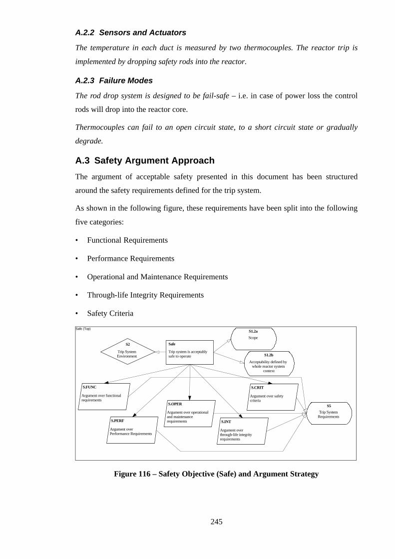
245
A.2.2 Sensors and Actuators
The temperature in each duct is measured by two thermocouples. The reactor trip is
implemented by dropping safety rods into the reactor.
A.2.3 Failure Modes
The rod drop system is designed to be fail-safe – i.e. in case of power loss the control
rods will drop into the reactor core.
Thermocouples can fail to an open circuit state, to a short circuit state or gradually
degrade.
A.3 Safety Argument Approach
The argument of acceptable safety presented in this document has been structured
around the safety requirements defined for the trip system.
As shown in the following figure, these requirements have been split into the following
five categories:
• Functional Requirements
• Performance Requirements
• Operational and Maintenance Requirements
• Through-life Integrity Requirements
• Safety Criteria
Safe (Top)
S.FUNC
Argument over functionalrequirements
S.PERF
Argument overPerformance Requirements
S.OPER
Argument over operationaland maintenancerequirements S.INT
Argument overthrough-life integrityrequirements
S.CRIT
Argument over safetycriteria
Trip system is acceptablysafe to operate
Safe
Trip SystemEnvironment
S2
S5
Trip SystemRequirements
S1.2a
Scope
S1.2b
Acceptability defined bywhole reactor system
context
Figure 116 – Safety Objective (Safe) and Argument Strategy
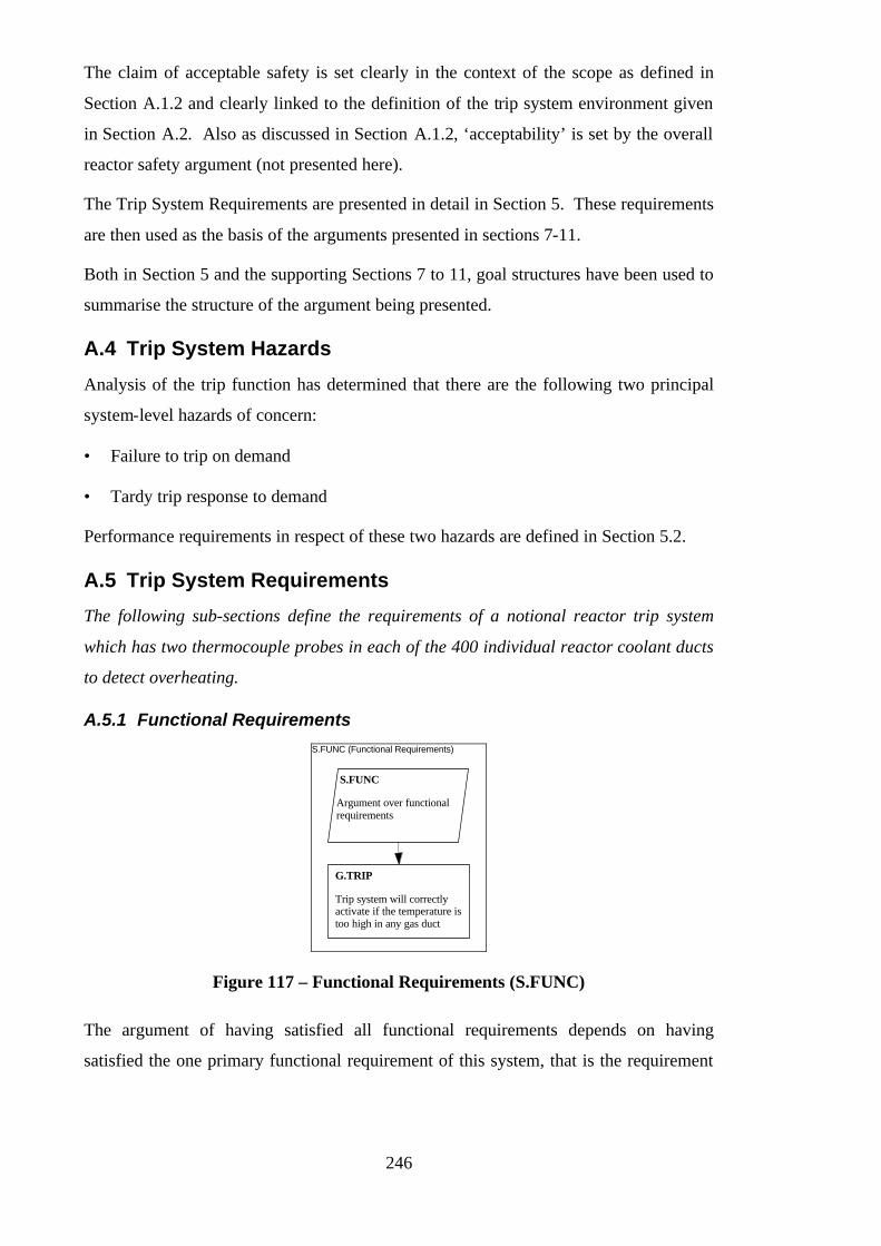
246
The claim of acceptable safety is set clearly in the context of the scope as defined in
Section A.1.2 and clearly linked to the definition of the trip system environment given
in Section A.2. Also as discussed in Section A.1.2, ‘acceptability’ is set by the overall
reactor safety argument (not presented here).
The Trip System Requirements are presented in detail in Section 5. These requirements
are then used as the basis of the arguments presented in sections 7-11.
Both in Section 5 and the supporting Sections 7 to 11, goal structures have been used to
summarise the structure of the argument being presented.
A.4 Trip System Hazards
Analysis of the trip function has determined that there are the following two principal
system-level hazards of concern:
• Failure to trip on demand
• Tardy trip response to demand
Performance requirements in respect of these two hazards are defined in Section 5.2.
A.5 Trip System Requirements
The following sub-sections define the requirements of a notional reactor trip system
which has two thermocouple probes in each of the 400 individual reactor coolant ducts
to detect overheating.
A.5.1 Functional Requirements S.FUNC (Functional Requirements)
S.FUNC
Argument over functionalrequirements
Trip system will correctly activate if the temperature istoo high in any gas duct
G.TRIP
Figure 117 – Functional Requirements (S.FUNC)
The argument of having satisfied all functional requirements depends on having
satisfied the one primary functional requirement of this system, that is the requirement
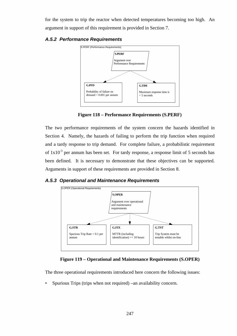
247
for the system to trip the reactor when detected temperatures becoming too high. An
argument in support of this requirement is provided in Section 7.
A.5.2 Performance Requirements S.PERF (Performance Requirements)
S.PERF
Argument overPerformance Requirements
Probability of failure ondemand < 0.001 per annum
G.PFD
Maximum response time is< 5 seconds
G.TIM
Figure 118 – Performance Requirements (S.PERF)
The two performance requirements of the system concern the hazards identified in
Section 4. Namely, the hazards of failing to perform the trip function when required
and a tardy response to trip demand. For complete failure, a probabilistic requirement
of 1x10⁻³ per annum has been set. For tardy response, a response limit of 5 seconds has
been defined. It is necessary to demonstrate that these objectives can be supported.
Arguments in support of these requirements are provided in Section 8.
A.5.3 Operational and Maintenance Requirements S.OPER (Operational Requirements)
S.OPER
Argument over operationaland maintenancerequirements
Spurious Trip Rate < 0.1 perannum
G.STR
MTTR (includingidentification) =< 10 hours
G.FIX
Trip System must betestable whilst on-line
G.TST
Figure 119 – Operational and Maintenance Requirements (S.OPER)
The three operational requirements introduced here concern the following issues:
• Spurious Trips (trips when not required) –an availability concern.
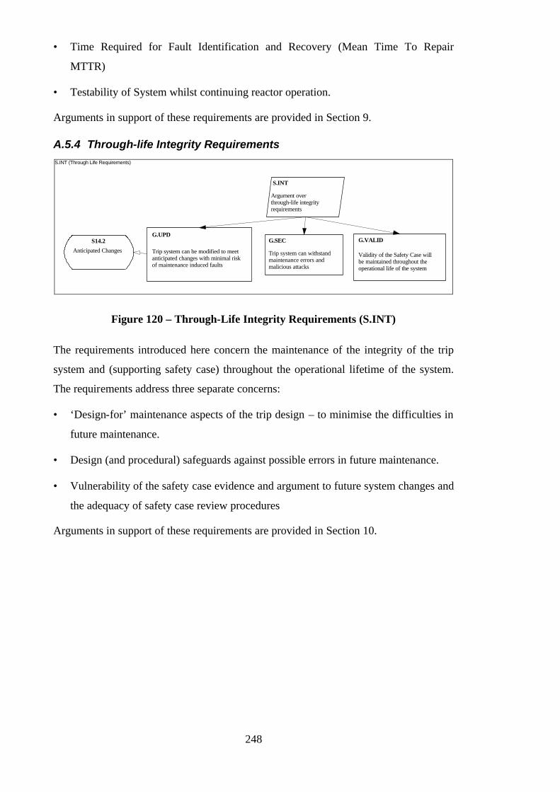
248
• Time Required for Fault Identification and Recovery (Mean Time To Repair
MTTR)
• Testability of System whilst continuing reactor operation.
Arguments in support of these requirements are provided in Section 9.
A.5.4 Through-life Integrity Requirements S.INT (Through Life Requirements)
S.INT
Argument overthrough-life integrityrequirements
Trip system can be modified to meetanticipated changes with minimal riskof maintenance induced faults
G.UPD
Trip system can withstandmaintenance errors andmalicious attacks
G.SECS14.2
Anticipated ChangesValidity of the Safety Case willbe maintained throughout theoperational life of the system
G.VALID
Figure 120 – Through-Life Integrity Requirements (S.INT)
The requirements introduced here concern the maintenance of the integrity of the trip
system and (supporting safety case) throughout the operational lifetime of the system.
The requirements address three separate concerns:
• ‘Design-for’ maintenance aspects of the trip design – to minimise the difficulties in
future maintenance.
• Design (and procedural) safeguards against possible errors in future maintenance.
• Vulnerability of the safety case evidence and argument to future system changes and
the adequacy of safety case review procedures
Arguments in support of these requirements are provided in Section 10.

249
A.5.5 Safety Criteria S.CRIT (Safety Criteria)
S.CRIT
Argument over safetycriteria
No single fault affectsavailability
G.FAULT1
No two independent faultsaffect safety
G.FAULT2
Figure 121 – Safety Criteria (S.CRIT)
Whatever design solution is proposed, it is necessary that it satisfies the safety and
availability criteria introduced in Figure 121. It is desirable that the system can tolerate
single failures without reducing the availability of the reactor. It is also desirable that
the system can tolerate two independent component failures (across the total trip
system) without compromising the safety of the trip function. Arguments that
demonstrate how these criteria have been addressed in the design as proposed in the
following section (Section 6) are given in Section 11.
A.6 Trip System Design
A system architecture has been evolved to satisfy the requirements introduced in Section
5. The system architecture is shown below in Figure 122. (PAC = Protection Algorithm
Computer, DCL = Dynamic Check Logic.)
PAC
PAC
PAC
PAC
DCL
DCL
DCL
DCL
MonitorComputer
IsolationAmplifiers
Squarewavesignal
Fail-safeguardlinelogic2oo4
Codedoutputsignal
Thermocouples
B
A
Serial lines
Figure 122 – Trip System Architecture
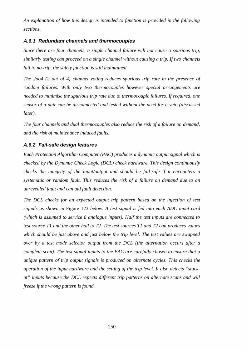
250
An explanation of how this design is intended to function is provided in the following
sections.
A.6.1 Redundant channels and thermocouples
Since there are four channels, a single channel failure will not cause a spurious trip,
similarly testing can proceed on a single channel without causing a trip. If two channels
fail to no-trip, the safety function is still maintained.
The 2oo4 (2 out of 4) channel voting reduces spurious trip rate in the presence of
random failures. With only two thermocouples however special arrangements are
needed to minimise the spurious trip rate due to thermocouple failures. If required, one
sensor of a pair can be disconnected and tested without the need for a veto (discussed
later).
The four channels and dual thermocouples also reduce the risk of a failure on demand,
and the risk of maintenance induced faults.
A.6.2 Fail-safe design features
Each Protection Algorithm Computer (PAC) produces a dynamic output signal which is
checked by the Dynamic Check Logic (DCL) check hardware. This design continuously
checks the integrity of the input/output and should be fail-safe if it encounters a
systematic or random fault. This reduces the risk of a failure on demand due to an
unrevealed fault and can aid fault detection.
The DCL checks for an expected output trip pattern based on the injection of test
signals as shown in Figure 123 below. A test signal is fed into each ADC input card
(which is assumed to service 8 analogue inputs). Half the test inputs are connected to
test source T1 and the other half to T2. The test sources T1 and T2 can produces values
which should be just above and just below the trip level. The test values are swapped
over by a test mode selector output from the DCL (the alternation occurs after a
complete scan). The test signal inputs to the PAC are carefully chosen to ensure that a
unique pattern of trip output signals is produced on alternate cycles. This checks the
operation of the input hardware and the setting of the trip level. It also detects “stuck-
at” inputs because the DCL expects different trip patterns on alternate scans and will
freeze if the wrong pattern is found.

251
PAC
DCL
TestSource
T2T1
Codedoutputsignal
Squarewavesignal
Test mode selector
800 thermocouplereadings
Figure 123 – Dynamic Check Logic for a Reactor Trip Channel
The integrity of the underlying computer hardware and compiler is checked using the
reversible computing concept (see reference [104]). This is sensitive to both systematic
faults and random failures in the hardware or faults created by the compiler and should
result in a “freeze” which is fail-safe - it would also reveal malicious program
modifications. Time overruns caused by infinite loops are also detectable by the
reversible computing technique.
A.6.3 Separate Monitor Computer
This is an example of partitioning according to criticality. The more complex, but less
critical diagnostic functions are performed on a separate system. This simplifies the
design of the trip channel. Each channel provides:
• software configuration data (limits, version numbers etc.)
• measured values and trip results
The monitor computer can be used for pre-start checks on the consistency of the
software configurations in the four channels, and for on-line diagnosis of channel
failures and failures of thermocouples. By comparing outputs from the channels it is
possible to decide whether the fault resides in a channel or the thermocouple input
system. It can also be used to monitor long term degradation of thermocouples. If these
are severe, availability can be maintained by replacement or a “veto”.
A.6.4 Simplicity
The design has no intercommunication between channels and the A/D conversion is
performed within the PAC. There is no need for interrupt handling or buffering so the
software can be implemented as a simple cyclic program. This should be easy to test,
verify and maintain.

252
Since the program is simple and cyclic, the worst-case response time is bounded, and
the worst case time is readily determined via timing tests or code analysis. The time
delays in the interfaces can also be measured to determine the overall response time.
A.6.5 Formally Proved Software
The simple cyclic program used within each PAC is amenable to formal proof.
A.6.6 1oo2 (1 out of 2) High Trip Logic
In order to minimise the risk of failing to trip on demand, either thermocouple reading
high will trip the reactor. To reduce the spurious trip rate, this design imposes a fail-
low direction on the thermocouples and buffer amplifiers. A veto for a high-failing
thermocouple forces the input low, but a double veto is fail-safe as it will cause a trip
(see below).
A.6.7 2oo2 (2 out of 2) Low Trip Logic
To ensure that the system is fail-safe if both sensors fail, the system will trip if a
thermocouple pair have readings well below the average sensor reading. This design
can withstand a transient loss of a single sensor (e.g. for repair) or a low-reading
sensor without using vetoes, this minimises the need for error-prone manual vetoes. The
sensor comparison can assist in detecting failed sensors.
A.6.8 Program and Trip Parameters in PROM
The program and trip parameters are stored in separate PROMs so changes cannot be
made without PROM-burning equipment and physical access to the machine.
Configuration errors can also be revealed by the on-line test inputs, the outputs to the
monitor computer and the periodic tests. This helps to ensure the intended trip function
is performed and reduces the risk of a failure on demand or a spurious trip.
A.6.9 Modular Hardware Replacement
Plug in cards reduce the repair time. Simple input-output interfaces can be easily
upgraded to accommodate new types of sensor.
A.6.10 Use of Mature Hardware and Software Tools
This reduces the risk of systematic faults within the system. This is an example of
avoidance of novelty.
A.6.11 Access Constraints
To limit the scope of maintenance error, all equipments are locked and can only be

253
accessed using the appropriate key (different for each channel). All plugs and sockets
are uniquely identified or physically different to prevent misconnection. An indicator
light is used to show the operators when a cabinet is unlocked.
A.7 Functional Arguments
The objective of this section is to demonstrate how the functional requirements
introduced in Section A.5.1 are supported through the design features described in
Section A.6. The following goal structure (Figure 124) summarises the argument put
forward in support of the functional requirement G.TRIP. The dependency of the
safety claims on the design features is communicated through use of context references.
For example, G.TRIP.FP is put forward in the context of the design feature described in
Section A.6.5 ‘Formally Proved Software’.
G.TRIP
Design Simplicity assists inthe test and verification oftrip function
G.TRIP.DS
Software has been formallyproven to perform tripfunction as specified
G.TRIP.FP
S6.4
Design Simplicity
S6.5
Formally provedsoftware
Program and trip parameters aremaintained in separate PROMs minimisesrisk of introducing failures into tripfunction
G.TRIP.PROM
S6.8
Program and TripParameters in PROM
Mature hardware and software toolshave been used to minimise the risk ofsystematic faults within trip function
G.TRIP.MATS6.10
Mature Hardware andSoftware Tools
Trip system will correctly activate if the temperature istoo high in any gas duct
G.TRIP
Figure 124 – Functional Arguments (G.TRIP)
Confidence in the correct execution of the trip function is gained from the following:
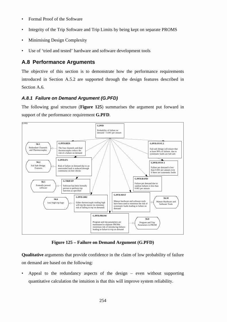
254
• Formal Proof of the Software
• Integrity of the Trip Software and Trip Limits by being kept on separate PROMS
• Minimising Design Complexity
• Use of ‘tried and tested’ hardware and software development tools
A.8 Performance Arguments
The objective of this section is to demonstrate how the performance requirements
introduced in Section A.5.2 are supported through the design features described in
Section A.6.
A.8.1 Failure on Demand Argument (G.PFD)
The following goal structure (Figure 125) summarises the argument put forward in
support of the performance requirement G.PFD.
G.PFD
Probability of failure ondemand < 0.001 per annum
G.PFD
Either thermocouple reading highwill trip the reactor (to minimiserisk of failing to trip on demand)
G.PFD.1002
Program and trip parameters aremaintained in separate PROMsminimises risk of introducing failuresleading to failure to trip on demand
G.PFD.PROM
Mature hardware and software toolshave been used to minimise the risk ofsystematic faults leading to failure ondemand
G.PFD.MAT
S6.1
Redundant Channelsand Thermocouples
S6.2
Fail Safe DesignFeatures
S6.5
Formally provedsoftware
S6.6
1oo2 high trip logic
S6.8
Program and TripParameters in PROM
S6.10
Mature Hardware andSoftware Tools
Failure per demand due torandom failures is less than0.001 per annum
G.PFD.RAND
Software has been formallyproven to perform tripfunction as specified
G.TRIP.FP
Failure per demand is lessthan 0.001 per annum evenif there are systematic faults
G.PFD.SYST.1
Fail-safe design will ensure thatat least 90% of failures due tosystematic faults are fail-safe
G.PFD.SYST.2
Risk of failure on demand due to anunrevealed fault is reduced throughcontinuous on-line checks
G.PFD.FS
The four channels and dualthermocouples reduce therisk of a failure on demand
G.PFD.RED
Figure 125 – Failure on Demand Argument (G.PFD)
Qualitative arguments that provide confidence in the claim of low probability of failure
on demand are based on the following:
• Appeal to the redundancy aspects of the design – even without supporting
quantitative calculation the intuition is that this will improve system reliability.
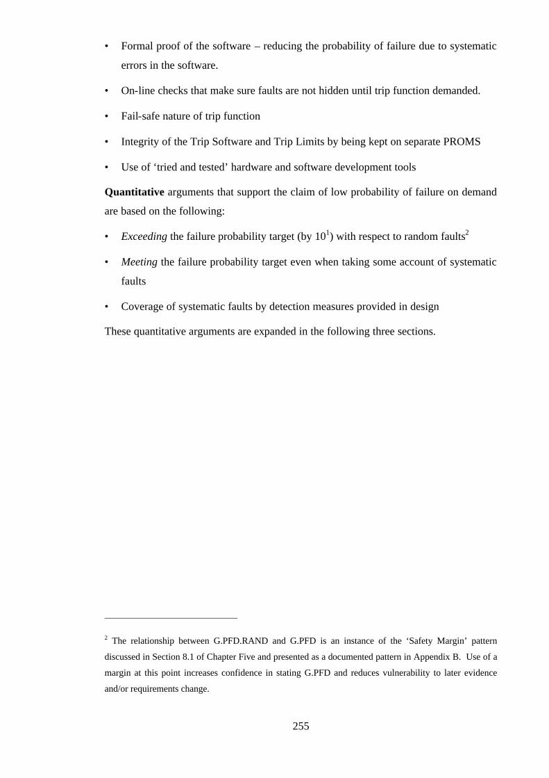
255
• Formal proof of the software – reducing the probability of failure due to systematic
errors in the software.
• On-line checks that make sure faults are not hidden until trip function demanded.
• Fail-safe nature of trip function
• Integrity of the Trip Software and Trip Limits by being kept on separate PROMS
• Use of ‘tried and tested’ hardware and software development tools
Quantitative arguments that support the claim of low probability of failure on demand
are based on the following:
• Exceeding the failure probability target (by 101) with respect to random faults2
• Meeting the failure probability target even when taking some account of systematic
faults
• Coverage of systematic faults by detection measures provided in design
These quantitative arguments are expanded in the following three sections.
2 The relationship between G.PFD.RAND and G.PFD is an instance of the ‘Safety Margin’ pattern
discussed in Section 8.1 of Chapter Five and presented as a documented pattern in Appendix B. Use of a
margin at this point increases confidence in stating G.PFD and reduces vulnerability to later evidence
and/or requirements change.
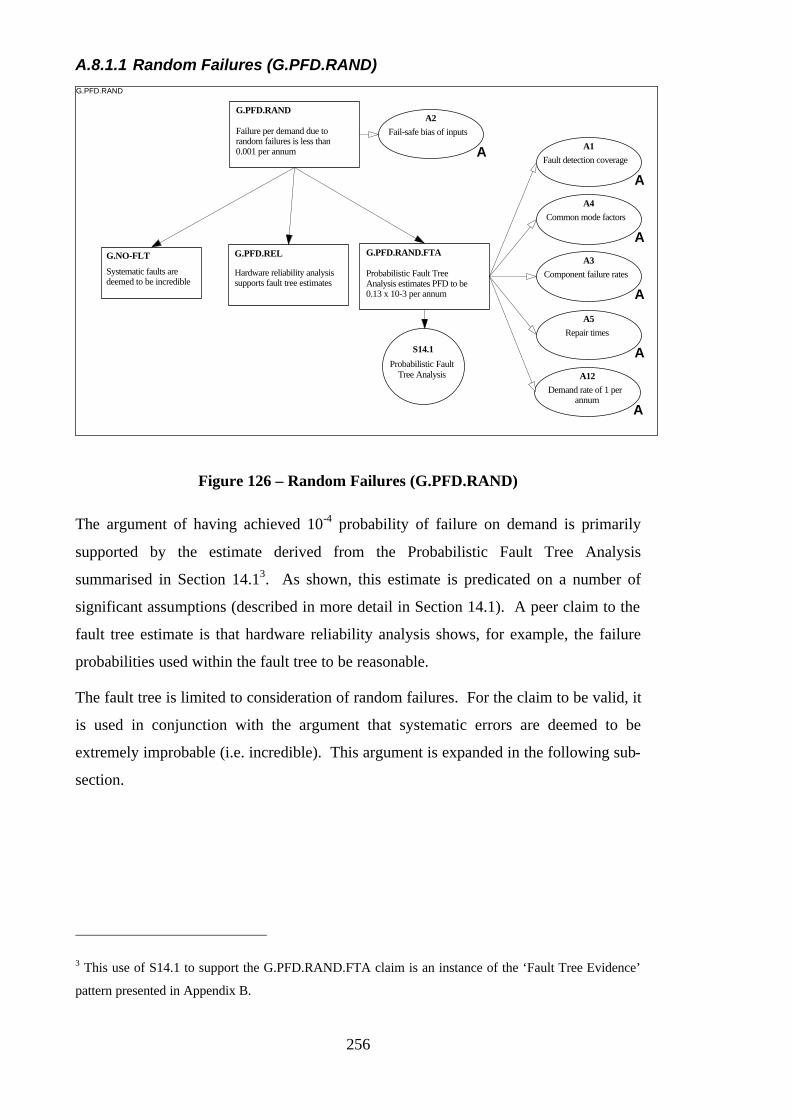
256
A.8.1.1 Random Failures (G.PFD.RAND) G.PFD.RAND
Failure per demand due torandom failures is less than0.001 per annum
G.PFD.RAND
Hardware reliability analysissupports fault tree estimates
G.PFD.REL
Probabilistic Fault TreeAnalysis estimates PFD to be0.13 x 10-3 per annum
G.PFD.RAND.FTA
A1Fault detection coverage
A
A2Fail-safe bias of inputs
A
A3Component failure rates
A
A4Common mode factors
A
A5Repair times
A
Systematic faults aredeemed to be incredible
G.NO-FLT
A12Demand rate of 1 per
annumA
S14.1
Probabilistic FaultTree Analysis
Figure 126 – Random Failures (G.PFD.RAND)
The argument of having achieved 10-4 probability of failure on demand is primarily
supported by the estimate derived from the Probabilistic Fault Tree Analysis
summarised in Section 14.13. As shown, this estimate is predicated on a number of
significant assumptions (described in more detail in Section 14.1). A peer claim to the
fault tree estimate is that hardware reliability analysis shows, for example, the failure
probabilities used within the fault tree to be reasonable.
The fault tree is limited to consideration of random failures. For the claim to be valid, it
is used in conjunction with the argument that systematic errors are deemed to be
extremely improbable (i.e. incredible). This argument is expanded in the following sub-
section.
3 This use of S14.1 to support the G.PFD.RAND.FTA claim is an instance of the ‘Fault Tree Evidence’
pattern presented in Appendix B.
257
Incredibility of Systematic Faults (G.NO-FLT)
G.NO-FLT
Software has nosystematic faults
G.NO-FLT.SW
Hardware has nosystematic flaws
G.NO-FLT.HW
Established Design impliesthere will be no systematichardware flaws
G.NO-FLT.HW.DES
Tests have not revealed anysystematic hardware flaws
G.NO-FLT.HW.TEST
A6
Inherent flaws will berevealed and removed as a
result of extensive use A
Systematic faults aredeemed to be incredible
G.NO-FLT
A7
Requirements are correct
A
A8
Functional tests can revealall compiler induced faults
A
A9
Tests will reveal all miswiringand mis-configuration
A
Code has been formallyproved
G.NO-FLT.SW.PRF
System has undergonefunctional tests to revealcompiler induced faults
G.NO-FLT.SW.TEST
Figure 127 – Incredibility of Systematic Faults (G.NO-FLT)
The argument of incredibility of systematic faults presented in
Figure 127 addresses faults both in hardware and software. For hardware, the claim is
supported by appeals to the use of an established design and having not detected any
flaws in testing. For software, the claim depends upon having formally proven the
software and the use of tests to reveal systematic errors introduced (after the
specification and coding stage) by the compiler. The assumptions associated with these
arguments are indicated in the figure.
A.8.1.2 Systematic Failures (G.PFD.SYST.1 and G.PFD.SYST.2)
The argument of having achieved 10-3 even when taking account of the possibility of
systematic failure is supported through appeal to reliability tests performed using
realistic test scenarios. This argument is depicted in Figure 128.
The assumption underlying this argument is that the test scenarios used were
sufficiently realistic that they exercised the majority of the trip system functionality.
Therefore, systematic faults likely to be experienced in operation would have been
revealed.
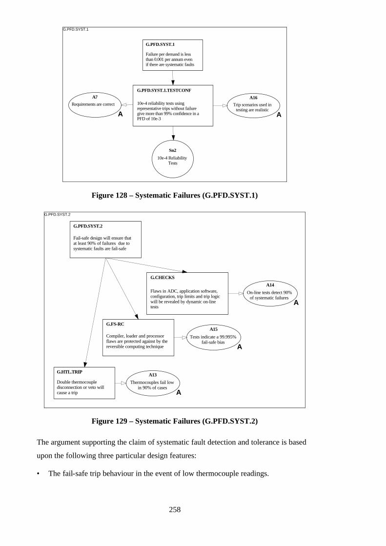
258
G.PFD.SYST.1
Failure per demand is lessthan 0.001 per annum evenif there are systematic faults
G.PFD.SYST.1
10e-4 reliability tests usingrepresentative trips without failuregive more than 99% confidence in aPFD of 10e-3
G.PFD.SYST.1.TESTCONFA7
Requirements are correct
A
A16Trip scenarios used in
testing are realisticA
Sn2
10e-4 ReliabilityTests
Figure 128 – Systematic Failures (G.PFD.SYST.1)
G.PFD.SYST.2
Fail-safe design will ensure thatat least 90% of failures due tosystematic faults are fail-safe
G.PFD.SYST.2
Flaws in ADC, application software,configuration, trip limits and trip logicwill be revealed by dynamic on-linetests
G.CHECKS
Compiler, loader and processorflaws are protected against by thereversible computing technique
G.FS-RC
Double thermocoupledisconnection or veto willcause a trip
G.HTL.TRIPA13
Thermocouples fail lowin 90% of cases
A
A14
On-line tests detect 90%of systematic failures
A
A15
Tests indicate a 99.995%fail-safe bias
A
Figure 129 – Systematic Failures (G.PFD.SYST.2)
The argument supporting the claim of systematic fault detection and tolerance is based
upon the following three particular design features:
• The fail-safe trip behaviour in the event of low thermocouple readings.

259
• The protection against systematic compiler, loader and processor flaws offered by
the use of the reversible computing technique. (This argument is expanded in [104].)
• The use of dynamic on-line checks to continually monitor the behaviour of the trip
system.
A.8.2 Response Time Argument (G.TIM)
The following goal structure (Figure 130) summarises the argument put forward in
support of the performance requirement G.TIM.
G.TIM
Maximum responsetime is < 5 seconds
G.TIM
Design simplicity means that worstcase response time is bounded and canbe readily determined via timing testsor code analysis
G.TIM.DS
S6.2
Fail Safe DesignFeatures
S6.4
Design SimplicityWorst case response timedetermined to be 2.7
G.TIM.STATIC
Worst measured time is2.4 seconds
G.TIM.TESTExcessive or infinite loops willbe detected by the reversiblecomputing implementation
G.TIM.FS
Figure 130 – Response Time Argument (G.TIM)
This argument is based upon both the worst measured and worst statically analysed
cycle times4. Coupled with these claims is an appeal to the simplicity of the trip system
design (use of a simple cyclic executive etc.) that was needed in order to make timing
analysis and testing possible. In addition, use of the reversible computer
implementation makes it possible to reveal when the trip software may have gone into
an infinite loop.
4 The use of both G.TIM.STATIC and G.TIM.TEST to support G.TIM is an instance of the ‘Diverse
Argument’ pattern discussed in Section 8.2 of Chapter Four and presented as a documented pattern in
Appendix B. Use of diverse argument at this point increases confidence in claiming G.TIM and reduces
vulnerability to later evidence and/or requirements change (as shown in Section 5.1 of Chapter Four).
The margin between the G.TIM requirement and the G.TIM.TEST and G.TIM.STATIC claims is also an
example application of the ‘Safety Margin’ pattern presented in Appendix B.

260
The timing analysis and test arguments are expanded in the following two sections.
A.8.3 Static Timing Analysis Argument (G.TIM.STAT) G.TIM.STATIC
Worst case response timedetermined to be 2.7
G.TIM.STATIC
A10
Instruction times arecorrect
A
A11
ADC conversions andoutput time are correct
A
Static analysis used todetermined worst case paththrough code
G.TIM.STATIC.1
Input / Output latency hasbeen determined
G.TIM.STATIC.2
Sn3
Satic TimingAnalysis Results
Figure 131 – Static Timing Analysis Argument
The static timing analysis argument shown in Figure 131 makes it clear that the time
given was based upon consideration of both the worst case path through the trip
function code and the time delays introduced on the inputs to, and outputs from, the
software. Both these claims rely upon assumptions regarding underlying timing data.
A.8.4 Timing Test Argument (G.TIM.TEST) G.TIM.TEST
Worst measured time is2.4 seconds
G.TIM.TEST
Sn1
Timing test results
Execution time isrelatively constant
J1
J
Figure 132 – Timing Test Argument (G.TIM.TEST)

261
The argument in Figure 132 makes it clear that the worst measured response time is
based upon timing test results. Justification for this claim stems from the cyclic nature
of the trip program and therefore that the execution time is relatively constant.
A.9 Operational Arguments
The objective of this section is to demonstrate how the operational requirements
introduced in Section A.5.3 are supported through the design features described in
Section A.6.
A.9.1 Time to Repair Argument (G.FIX)
The following goal structure (Figure 133) summarises the argument put forward in
support of the time to repair requirement G.FIX.
G.FIX
MTTR (includingidentification) =< 10 hours
G.FIX
2oo2 low trip logic sensorcomparison assists indetecting failed sensors
G.FIX.2002
Modular hardwarereplacement reduces the repairtime
G.FIX.MOD
S6.2
Fail Safe DesignFeatures
S6.3
Separate MonitorComputer
S6.7
2oo2 low trip logic
S6.9
Modular hardwarereplacement
Separate Monitor Computer enableson-line diagnosis of channel failures andfailures in the thermocouples
G.TST.SMC
Fault detection is aided by systemfailing-safe if it encounters asystematic or random fault
G.FIX.FS
Figure 133 – Time to Repair Argument (G.FIX)
The argument in support of G.FIX is based upon the two strands of adequate fault
diagnosis and ease of fix. The following claims are put forward in support of the
revelation and diagnosis of faults:
• Fail-safe behaviour – making it obvious when a fault is present
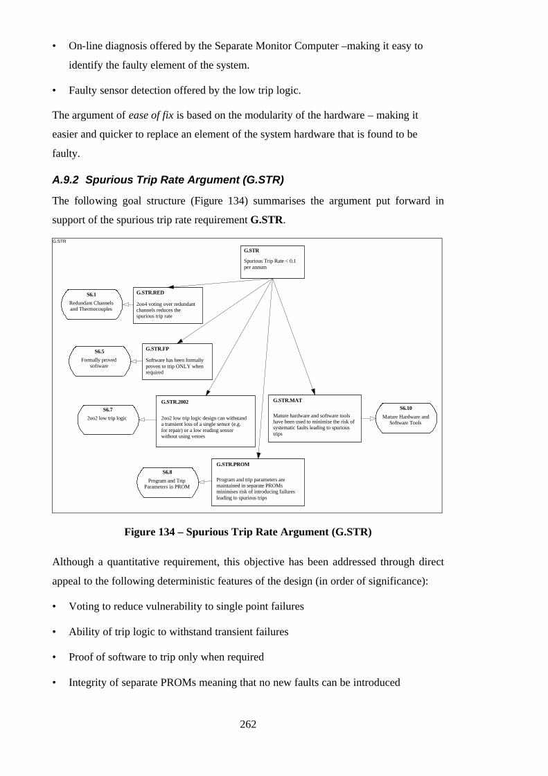
262
• On-line diagnosis offered by the Separate Monitor Computer –making it easy to
identify the faulty element of the system.
• Faulty sensor detection offered by the low trip logic.
The argument of ease of fix is based on the modularity of the hardware – making it
easier and quicker to replace an element of the system hardware that is found to be
faulty.
A.9.2 Spurious Trip Rate Argument (G.STR)
The following goal structure (Figure 134) summarises the argument put forward in
support of the spurious trip rate requirement G.STR.
G.STR
Spurious Trip Rate < 0.1per annum
G.STR
2oo4 voting over redundantchannels reduces thespurious trip rate
G.STR.RED
Software has been formallyproven to trip ONLY whenrequired
G.STR.FP
2oo2 low trip logic design can withstanda transient loss of a single sensor (e.g.for repair) or a low reading sensorwithout using vetoes
G.STR.2002
Program and trip parameters aremaintained in separate PROMsminimises risk of introducing failuresleading to spurious trips
G.STR.PROM
Mature hardware and software toolshave been used to minimise the risk ofsystematic faults leading to spurioustrips
G.STR.MAT
S6.1
Redundant Channelsand Thermocouples
S6.5
Formally provedsoftware
S6.7
2oo2 low trip logic
S6.8
Program and TripParameters in PROM
S6.10
Mature Hardware andSoftware Tools
Figure 134 – Spurious Trip Rate Argument (G.STR)
Although a quantitative requirement, this objective has been addressed through direct
appeal to the following deterministic features of the design (in order of significance):
• Voting to reduce vulnerability to single point failures
• Ability of trip logic to withstand transient failures
• Proof of software to trip only when required
• Integrity of separate PROMs meaning that no new faults can be introduced
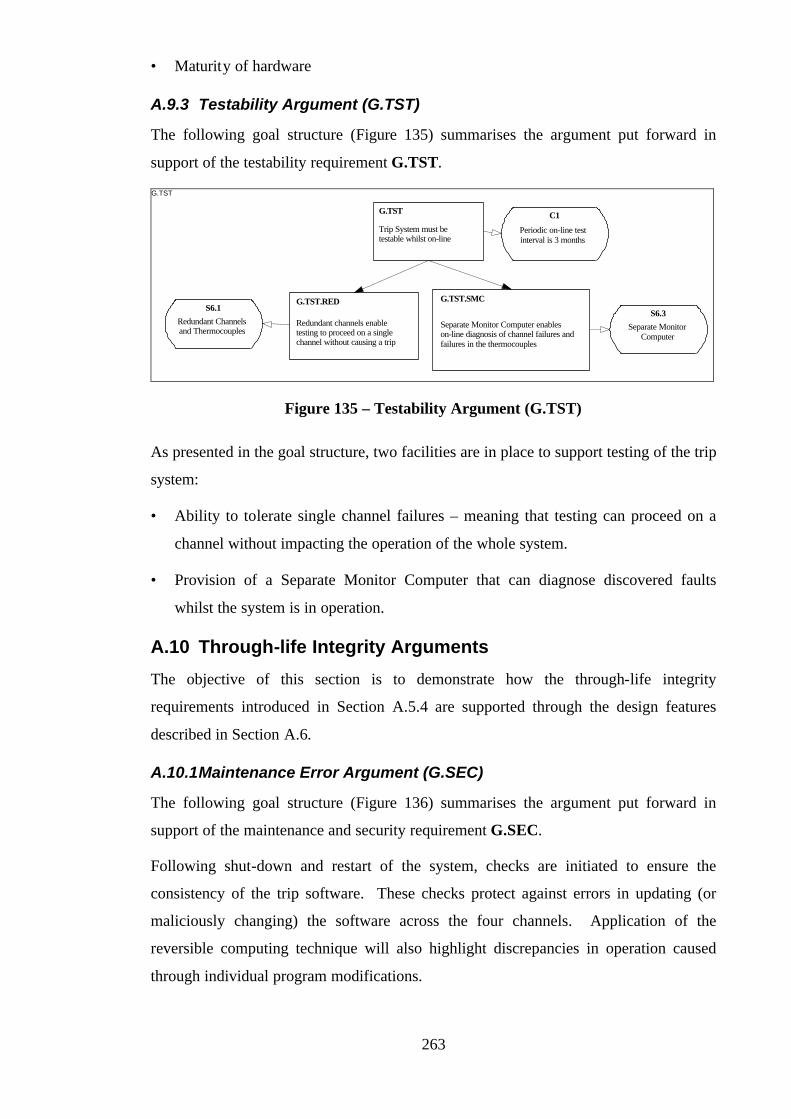
263
• Maturity of hardware
A.9.3 Testability Argument (G.TST)
The following goal structure (Figure 135) summarises the argument put forward in
support of the testability requirement G.TST.
G.TST
Trip System must betestable whilst on-line
G.TST C1
Periodic on-line testinterval is 3 months
Redundant channels enabletesting to proceed on a singlechannel without causing a trip
G.TST.RED
Separate Monitor Computer enableson-line diagnosis of channel failures andfailures in the thermocouples
G.TST.SMCS6.1
Redundant Channelsand Thermocouples
S6.3
Separate MonitorComputer
Figure 135 – Testability Argument (G.TST)
As presented in the goal structure, two facilities are in place to support testing of the trip
system:
• Ability to tolerate single channel failures – meaning that testing can proceed on a
channel without impacting the operation of the whole system.
• Provision of a Separate Monitor Computer that can diagnose discovered faults
whilst the system is in operation.
A.10 Through-life Integrity Arguments
The objective of this section is to demonstrate how the through-life integrity
requirements introduced in Section A.5.4 are supported through the design features
described in Section A.6.
A.10.1 Maintenance Error Argument (G.SEC)
The following goal structure (Figure 136) summarises the argument put forward in
support of the maintenance and security requirement G.SEC.
Following shut-down and restart of the system, checks are initiated to ensure the
consistency of the trip software. These checks protect against errors in updating (or
maliciously changing) the software across the four channels. Application of the
reversible computing technique will also highlight discrepancies in operation caused
through individual program modifications.
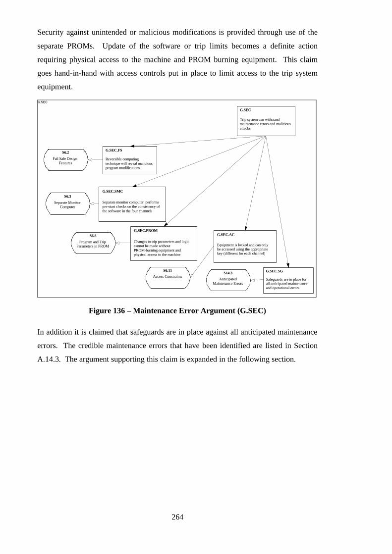
264
Security against unintended or malicious modifications is provided through use of the
separate PROMs. Update of the software or trip limits becomes a definite action
requiring physical access to the machine and PROM burning equipment. This claim
goes hand-in-hand with access controls put in place to limit access to the trip system
equipment.
G.SEC
Trip system can withstandmaintenance errors and maliciousattacks
G.SEC
Reversible computingtechnique will reveal maliciousprogram modifications
G.SEC.FS
Separate monitor computer performspre-start checks on the consistency ofthe software in the four channels
G.SEC.SMC
Changes to trip parameters and logiccannot be made withoutPROM-burning equipment andphysical access to the machine
G.SEC.PROM
Equipment is locked and can onlybe accessed using the appropriatekey (different for each channel)
G.SEC.AC
S6.2
Fail Safe DesignFeatures
S6.3
Separate MonitorComputer
S6.8
Program and TripParameters in PROM
S6.11
Access ConstraintsSafeguards are in place forall anticipated maintenanceand operational errors
G.SEC.SGS14.3
AnticipatedMaintenance Errors
Figure 136 – Maintenance Error Argument (G.SEC)
In addition it is claimed that safeguards are in place against all anticipated maintenance
errors. The credible maintenance errors that have been identified are listed in Section
A.14.3. The argument supporting this claim is expanded in the following section.

265
A.10.1.1 Maintenance Safeguards (G.SEC.SG) G.SEC.SG
Safeguards are in place forall anticipated maintenanceand operational errors
G.SEC.SG
Safeguards are in place toprotect against errors in Proof Testing
G.SEC.SG.1
Safeguards are in place toprotect against errors in Faultdiagnosis
G.SEC.SG.2
Safeguards are in place toprotect against errors in repairactivities
G.SEC.SG.3
Safeguards are in place toprotect against errors inoperating vetoes
G.SEC.SG.4
Safeguards are in place toprotect against errors inrefuelling
G.SEC.SG.5
S14.3
Analysis ofmaintenance and
operations
Figure 137 – Maintenance Safeguards (G.SEC.SG)
The argument shown in Figure 137 shows that five credible sources of maintenance
error have been identified:
• Proof Testing
• Fault Diagnosis
• Repair Activities
• Use of Channel Vetoes
• Refuelling
The safeguards in place to support this argument are presented in Section A.14.3.
A.10.2 Update Argument (G.UPD)
The following goal structure (Figure 138) summarises the argument put forward in
support of the update requirement G.UPD.

266
G.UPD
Trip system can be modified to meetanticipated changes with minimal riskof maintenance induced faults
G.UPD
Design simplicity meansthat system can be alteredeasily
G.UPD.DS
Simple input-output interfaces canbe easily upgraded to accommodatenew types of sensor
G.UPD.MOD
S6.1
Redundant Channelsand Thermocouples
S6.4
Design Simplicity
S6.9
Modular hardwarereplacement
Separate storage of program andtrip Parameters in PROM isolatesmaintenance changes
G.UPD.PROM
Sufficient protection is in placeto prevent updates of dataintroducing dangerous faults
G.UPD.DATA
S6.8
Program and TripParameters in PROM
Sufficient protection is in placeto prevent updates of programintroducing dangerous faults
G.UPD.PROGRAM
All anticipated changes canbe accommodated by designand safety case
G.UPD.AC
Redundancy in channels andthermocouples reduces susceptibilityto maintenance induced faults
G.UPD.REDS14.2
Anticipated Changes
Figure 138 – Update Argument (G.UPD)
There are three aspects to the claims presented in Figure 138. The first aspect of the
G.UPD requirement is ease of modification. In support of this, the following claims are
put forward:
• Overall design simplicity
• Particularly, simplicity of input-output interfaces
The second aspect is minimising the risk due to updates. In support of this, appeals are
made to the following:
• Protection (tolerance) offered by the redundancy built into the system
• Isolation of changes created by having separate PROMs
• Protection in place for trip data and program updates (expanded in Section A.10.2.2)
The third aspect concerns the design for change aspects of the trip design. Because the
system is designed in anticipation of certain future updates, the likelihood of
compromising the integrity of the system in making those modifications is minimised.
This claim concerning anticipated changes is elaborated in the following section.
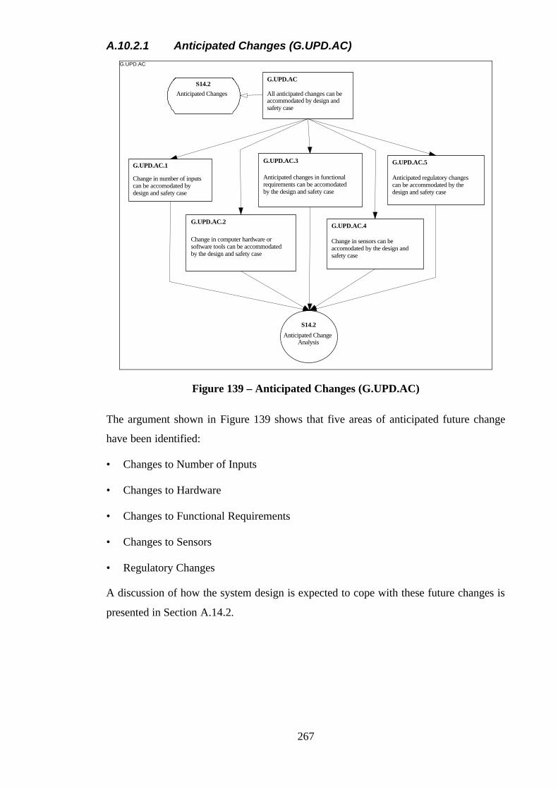
267
A.10.2.1 Anticipated Changes (G.UPD.AC) G.UPD.AC
All anticipated changes can beaccommodated by design andsafety case
G.UPD.AC
Change in number of inputscan be accomodated bydesign and safety case
G.UPD.AC.1
Change in computer hardware orsoftware tools can be accommodatedby the design and safety case
G.UPD.AC.2
Anticipated changes in functionalrequirements can be accomodatedby the design and safety case
G.UPD.AC.3
Change in sensors can beaccomodated by the design andsafety case
G.UPD.AC.4
Anticipated regulatory changescan be accommodated by thedesign and safety case
G.UPD.AC.5
S14.2
Anticipated ChangeAnalysis
S14.2Anticipated Changes
Figure 139 – Anticipated Changes (G.UPD.AC)
The argument shown in Figure 139 shows that five areas of anticipated future change
have been identified:
• Changes to Number of Inputs
• Changes to Hardware
• Changes to Functional Requirements
• Changes to Sensors
• Regulatory Changes
A discussion of how the system design is expected to cope with these future changes is
presented in Section A.14.2.

268
A.10.2.2 Changes to Data and Program (G.UPD.DATA & G.UPD.PROGRAM)
The following goal structure (Figure 140) summarises the argument put forward in
support of the trip data and program update requirements G.UPD.DATA and
G.UPD.PROGRAM.
G.UPD.DATA & G.UPD.PROGRAM
Sufficient protection is in placeto prevent updates of dataintroducing dangerous faults
G.UPD.DATA
Adequate support infrastructure is inplace to safely accommodateanticipated changes (e.g. safety casereview)
G.UPD.SUPP
Procedures are in place to testupdates to data and program
G.UPD.TEST
Sufficient protection is in place toprevent updates of programintroducing dangerous faults
G.UPD.PROGRAM
S15.1
SupportInfrastructure
Flaws in ADC, application software,configuration, trip limits and trip logicwill be revealed by dynamic on-linetests
G.CHECKS
Figure 140 – Changes to Data and Program (G.UPD.DATA &
G.UPD.PROGRAM)
Two different forms of argument are put forward in Figure 140. Firstly, an argument is
made that appropriate procedures are in place to ensure that any future change is
handled appropriately. These are supported by a definition of the required Support
Infrastructure (presented in Section A.13). Secondly, an appeal is made to the on-line
tests and checks built into the design and operation of the trip system (offered by the
reversible computing implementation and separate monitor computer).
A.10.3 Safety Case Validity Argument (G.VALID)
The following goal structure (Figure 141) presents the argument put forward in support
of the safety case validity requirement G.VALID.
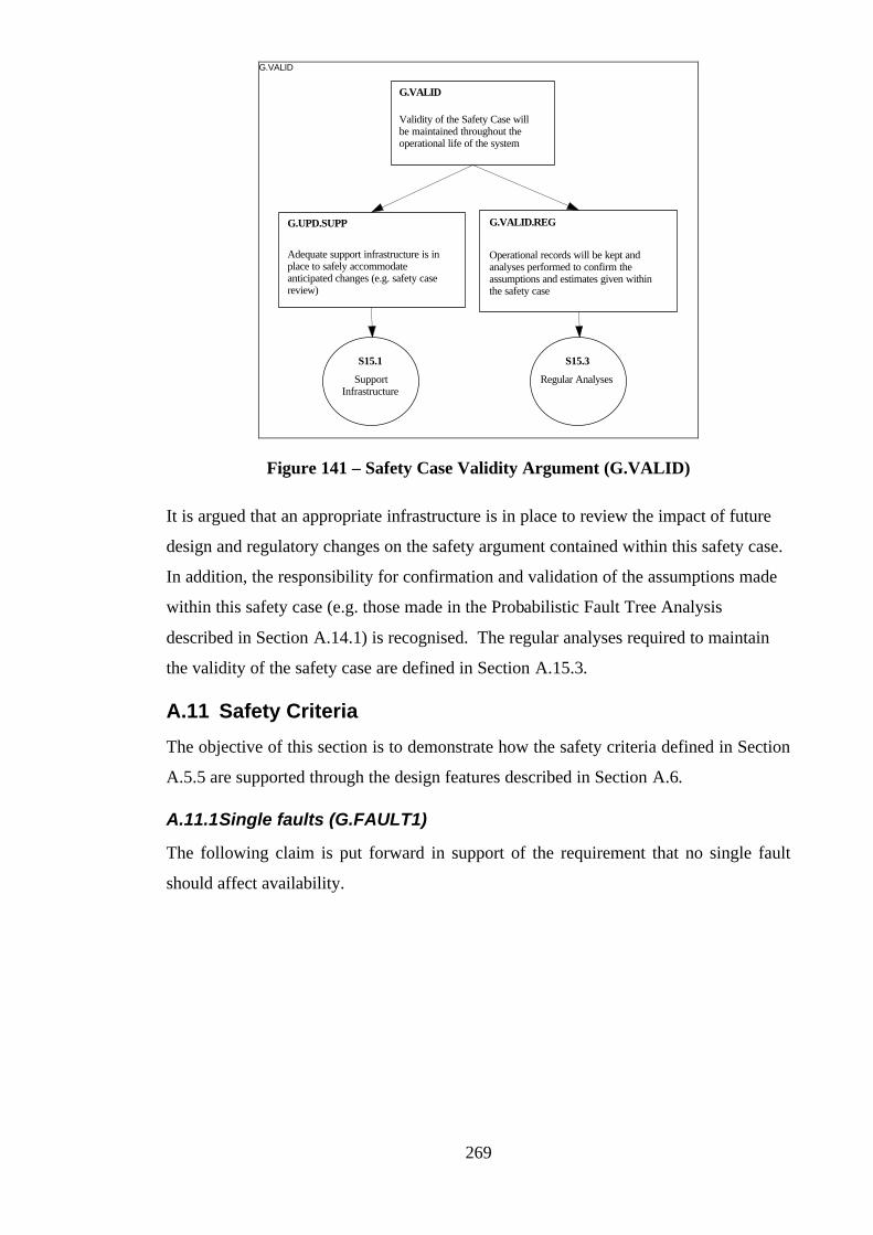
269
G.VALID
Validity of the Safety Case willbe maintained throughout theoperational life of the system
G.VALID
S15.1
SupportInfrastructure
Adequate support infrastructure is inplace to safely accommodateanticipated changes (e.g. safety casereview)
G.UPD.SUPP
Operational records will be kept andanalyses performed to confirm theassumptions and estimates given withinthe safety case
G.VALID.REG
S15.3
Regular Analyses
Figure 141 – Safety Case Validity Argument (G.VALID)
It is argued that an appropriate infrastructure is in place to review the impact of future
design and regulatory changes on the safety argument contained within this safety case.
In addition, the responsibility for confirmation and validation of the assumptions made
within this safety case (e.g. those made in the Probabilistic Fault Tree Analysis
described in Section A.14.1) is recognised. The regular analyses required to maintain
the validity of the safety case are defined in Section A.15.3.
A.11 Safety Criteria
The objective of this section is to demonstrate how the safety criteria defined in Section
A.5.5 are supported through the design features described in Section A.6.
A.11.1 Single faults (G.FAULT1)
The following claim is put forward in support of the requirement that no single fault
should affect availability.
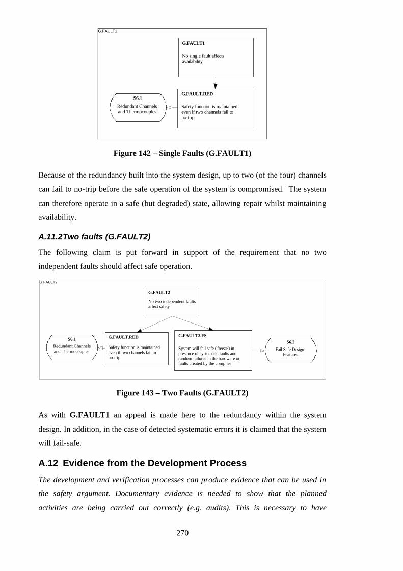
270
G.FAULT1
No single fault affectsavailability
G.FAULT1
S6.1
Redundant Channelsand Thermocouples
Safety function is maintainedeven if two channels fail tono-trip
G.FAULT.RED
Figure 142 – Single Faults (G.FAULT1)
Because of the redundancy built into the system design, up to two (of the four) channels
can fail to no-trip before the safe operation of the system is compromised. The system
can therefore operate in a safe (but degraded) state, allowing repair whilst maintaining
availability.
A.11.2 Two faults (G.FAULT2)
The following claim is put forward in support of the requirement that no two
independent faults should affect safe operation.
G.FAULT2
No two independent faultsaffect safety
G.FAULT2
Safety function is maintainedeven if two channels fail tono-trip
G.FAULT.RED
System will fail safe ('freeze') inpresence of systematic faults andrandom failures in the hardware orfaults created by the compiler
G.FAULT2.FSS6.2
Fail Safe DesignFeatures
S6.1
Redundant Channelsand Thermocouples
Figure 143 – Two Faults (G.FAULT2)
As with G.FAULT1 an appeal is made here to the redundancy within the system
design. In addition, in the case of detected systematic errors it is claimed that the system
will fail-safe.
A.12 Evidence from the Development Process
The development and verification processes can produce evidence that can be used in
the safety argument. Documentary evidence is needed to show that the planned
activities are being carried out correctly (e.g. audits). This is necessary to have
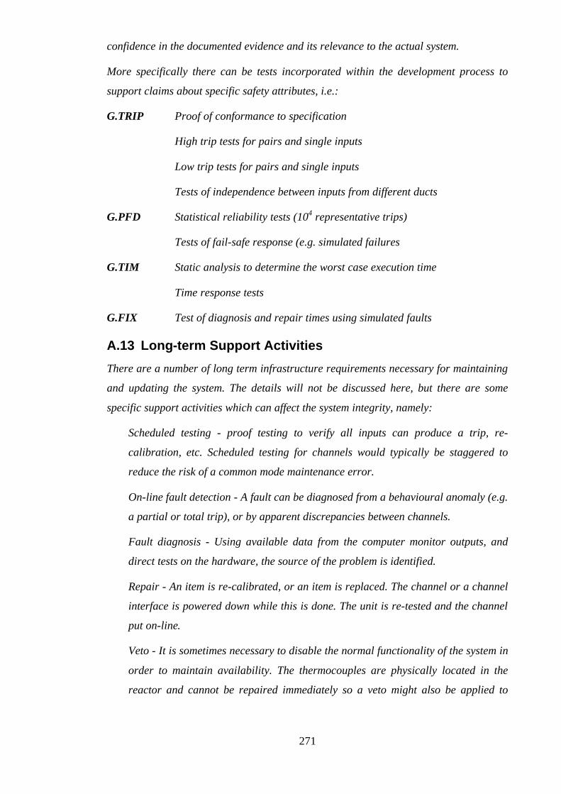
271
confidence in the documented evidence and its relevance to the actual system.
More specifically there can be tests incorporated within the development process to
support claims about specific safety attributes, i.e.:
G.TRIP Proof of conformance to specification
High trip tests for pairs and single inputs
Low trip tests for pairs and single inputs
Tests of independence between inputs from different ducts
G.PFD Statistical reliability tests (104 representative trips)
Tests of fail-safe response (e.g. simulated failures
G.TIM Static analysis to determine the worst case execution time
Time response tests
G.FIX Test of diagnosis and repair times using simulated faults
A.13 Long-term Support Activities
There are a number of long term infrastructure requirements necessary for maintaining
and updating the system. The details will not be discussed here, but there are some
specific support activities which can affect the system integrity, namely:
Scheduled testing - proof testing to verify all inputs can produce a trip, re-
calibration, etc. Scheduled testing for channels would typically be staggered to
reduce the risk of a common mode maintenance error.
On-line fault detection - A fault can be diagnosed from a behavioural anomaly (e.g.
a partial or total trip), or by apparent discrepancies between channels.
Fault diagnosis - Using available data from the computer monitor outputs, and
direct tests on the hardware, the source of the problem is identified.
Repair - An item is re-calibrated, or an item is replaced. The channel or a channel
interface is powered down while this is done. The unit is re-tested and the channel
put on-line.
Veto - It is sometimes necessary to disable the normal functionality of the system in
order to maintain availability. The thermocouples are physically located in the
reactor and cannot be repaired immediately so a veto might also be applied to

272
avoid a spurious trip if a thermocouple sensor was failing high. The trip for an
individual fuel element may also be temporarily vetoed for on-load refuelling.
Refuelling - The thermocouple connectors are disconnected on refuelling. This is
not a problem if the reactor is refuelled off-load, but disconnected thermocouples
could cause problems on start-up.
Updates - The software functionality may be changed. Changes are most likely to
be made to trip limits and scaling parameters, but in some cases the program may
be modified. The changes have to be verified off-line, and correctly installed (via
PROM replacement). The likely changes are anticipated to be:
• trip limit changes
• change in number of inputs
• change of computer hardware or software tools
• change in trip logic
• change of sensors
• regulatory changes (design criteria, or evidence)
A.14 Supporting Analyses
The safety arguments presented in Sections 7 through to 11 should refer to evidence
from supporting analyses. This evidence will change as the system is developed.
Initially the analyses may be based on initial assumptions (e.g. based on past
experience) and design targets. This can later be supplemented by test evidence and, in
some cases, there may be a requirement to gather supporting evidence during system
operation in the longer term (e.g. to confirm initial assumptions in the estimate of the
probability of failure per demand).
As can be seen from the goal structures presented, the majority of the goals put forward
remain unsupported. This is indicative of the following issues:
• Some of the goals must be decomposed further to sub-system claims (as discussed in
Section A.16).
• Some of the goals should be accepted as ‘statements of fact’ requiring no supporting
evidence.
• Not all of the supporting evidence is available at this stage.

273
The following sections present the analyses which are available to support aspects of
the safety argument presented.
A.14.1 Probabilistic Fault Tree Analysis
The evidence summarised in this section supports the probability of failure on demand
claim G.PFD.RAND.FTA shown in Figure 126 and discussed in Section A.8.1.1.
The fault tree analysis is based on a system hazard identification study (not discussed
here) which uses conventional guide words to help identify potentially dangerous
failure modes of the various system components. A fault tree is then constructed to
identify combinations of events which can cause a dangerous failure. The top event in
the tree is when the system is unavailable but the failure is unrevealed.
To be more concise, the fault tree is represented textually with the top events on the left
and sub-events indented. Terms in square brackets represent intermediate or top events,
and are expanded on the subsequent indented lines. The fault tree covers the main
safety related event - a failure to trip on demand. A similar tree could be constructed for
spurious trips.
The probabilities of the base events in the fault tree are based on estimates of hardware
reliabilities, and the likelihood of human initiated events. The assumptions on which the
analysis is based are listed first, followed by the quantitative estimates for the minimal
cut-sets contributing to the top event. Note that some events may be deemed
“incredible” (i.e. probability zero) based either on deterministic arguments or because
of the depth of defences. Even if zero, all probabilities are shown for later inspection
and independent assessment.
Assumptions
• 10% of sensor failures are unrevealed
• 10% of buffer failures are unrevealed
• Common failures are 10% of individual failures
• 10% of channel failures are unrevealed by a channel trip
• 10% of channel failures are unrevealed by the monitor
• Channel failure rate (CPU + ADC + DCL) 1 per annum
• Sensor failure rate 10-3 per annum

274
• Buffer failure rate 10-3 pa
• MTTR 10 hours
• Proof test interval 3 months
Probability Estimation
The system is unsafe if a dangerous fault exists but is unrevealed. Internal checks,
monitor checks and proof tests are the main methods for revealing failures. Systematic
faults are mainly deemed to be incredible (see the goal G.NO-FLT).
For random failures we have to include the risk of common cause failures, and the
chance they will remain undetected until the 3-monthly proof test. Taking the case of the
sensors, the basic failure rate is estimated to be 10-3 per annum. We assume that the
common mode failures are 10% of this (10-4 per annum), and 10% of these will be
undetected until the 3 monthly proof test (10-5 per annum). On average the dangerous
sensor measurement failure will be unrevealed for one and a half months (0.125 of a
year), so the probability of unrevealed unavailability is (0.125 x 10⁻⁵). The
unavailability of temperature measurements due to two unrevealed random failures in
one duct is negligible (around 10-10). Since the demand is only made on one duct, we
only need to consider the unavailability of a single duct measurement.
A similar argument can be applied to the isolation amplifiers and buffers. The dominant
factor is again common mode failure, which is assumed to affect all buffers
simultaneously, so the calculation is identical to the one used for the thermocouples.
For the hardware channel failures we assume the common mode failure rate is 10% of
the single channel failure rate (10-1 per annum). Of these 10% are unrevealed by a
channel trip (10-2 per annum), and 10% of the remainder are not detected by the
monitor (10-3 per annum). An unrevealed failure persists an average of 0.125 years, so
the overall is 12.5 x 10⁻⁵.
The probability assignments for the fault tree events are summarised below, including
those which are assumed to be incredible (probability zero).
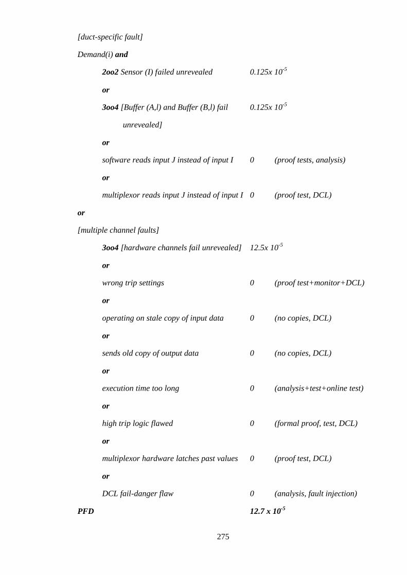
275
[duct-specific fault]
Demand(i) and
2oo2 Sensor (I) failed unrevealed 0.125x 10⁻⁵
or
3oo4 [Buffer (A,l) and Buffer (B,l) fail 0.125x 10⁻⁵
unrevealed]
or
software reads input J instead of input I 0 (proof tests, analysis)
or
multiplexor reads input J instead of input I 0 (proof test, DCL)
or
[multiple channel faults]
3oo4 [hardware channels fail unrevealed] 12.5x 10⁻⁵
or
wrong trip settings 0 (proof test+monitor+DCL)
or
operating on stale copy of input data 0 (no copies, DCL)
or
sends old copy of output data 0 (no copies, DCL)
or
execution time too long 0 (analysis+test+online test)
or
high trip logic flawed 0 (formal proof, test, DCL)
or
multiplexor hardware latches past values 0 (proof test, DCL)
or
DCL fail-danger flaw 0 (analysis, fault injection)
PFD 12.7 x 10⁻⁵
276
With an unrevealed unavailability of 0.13 x 10⁻³ and an assumed demand rate of 1 per
annum, the estimated PFD is 0.13 x 10⁻³ pa is which is well within the 10-3 pa target.
A.14.2 Anticipated Change Analysis
The evidence summarised in this section supports the claims made in the safety
argument regarding anticipated changes presented in Figure 139 and discussed in
Section A.10.2.1.
System Updates. The system and its safety case will need to be updated to respond to
functional changes, changes in technology, and regulatory requirements (R.UPD).
Potential changes to the system and their impact are discussed below:
Trip limit changes. The safety case has to justify that trip limits are valid, the changes
are correctly implemented, and do not affect the remaining software. The impact of the
change is minimised by holding the parameters on a separate PROM. The installed
parameter settings can be verified by proof testing, via the on-line test signals (each
side of the trip limit) and via the monitor output.
Change in number of inputs. No fundamental changes are required in the design or the
safety case. It may requires changes in the input-output hardware, software and DCL,
but no change in the proof, and only small changes in the program which can be
verified by proof testing and by testing in conjunction with the modified DCL.
Change of computer hardware or software tools. The fail-safe integrity checks provide
protection against flaws in the new hardware and software tools. The separate channel
structure and simple input-output interfaces permit selective upgrading on a per-
channel basis (phased commissioning).
Change in functional requirements. Would require repetition of the formal proof and
the formally developed software. Proof tools have to be available (or be re-
implementable on another system). Formal proof requires relatively scarce expertise
and could represent a risk in terms of greater implementation delays and higher update
costs. However licensing risks and the associated costs are likely to be reduced.
Change of sensors. Relatively simple technology. Changes can be accommodated by re-
scaling the buffer amplifiers or changing the scaling constants in the software.
Verifiable via proof testing, dynamic on-line tests and the monitor output.
Regulatory changes. If the requirements for diversity become more stringent, diversely
implemented channels can be used to protect against systematic hardware and software
277
flaws. This is relatively simple as each channel is independent. Diverse sensors and
buffers are also feasible. Requirements for more rigorous system testing should be
feasible as each channel is a standalone unit, and tests can be performed individually
without the need to test for intersection effects.
A.14.3 Analysis of Maintenance and Operations
The evidence summarised in this section supports the claims made in the safety
argument regarding safeguards against maintenance errors – presented in Figure 137
and discussed in Section A.10.1.1.
The possible failures that could occur in maintenance activities are enumerated by
considering a number of guide words (e.g. incomplete or wrong). The design safeguards
are identified for each case. These could well be supplemented by procedures, training,
manual records and checklists, but are not discussed below.
Proof testing Incomplete - e.g. some elements not tested, transposed - e.g. tests on
wrong channel, wrong - incorrect recalibration.
Safeguards - clear identification of channel equipment, access keys (different for
each channel), limits on amount of adjustment, cross-checking subsequent
behaviour via the monitor.
Fault diagnosis Incomplete - failure to spot discrepancy between channels, transposed -
identify correct component type but not which one (e.g. channel or thermocouple),
wrong - identification completely wrong.
Safeguards - proof tests, cross-checking subsequent behaviour via the monitor,
system trip (fail-safe, but undesirable).
Repair Incomplete - repair omitted or partially performed (e.g. not fully reconnected),
transposed - swap over connections or components, wrong - e.g. wrong component,
wrong settings. Repair on the wrong channel could cause a spurious trip if one channel
is tripped already.
Safeguards - proof tests, cross-checking subsequent behaviour via the monitor,
PROM and computer self-tests, system trip (fail-safe, but undesirable).
Veto - Incomplete e.g. sensor not vetoed on all channels, transposed- veto wrong sensor
of pair, wrong - e.g. wrong channel vetoed.
Safeguards – proof tests, cross-checking behaviour via the monitor, channel trip

278
when sensor fails low or high, avoidance of vetoes for normal operation and
designed failure modes.
Refuelling Incomplete - thermocouple left disconnected, transposed – sensor
connections transposed, wrong - bad connection (reading low, short circuit).
Safeguards - reactor start-up checks, proof tests, cross-checking behaviour via the
monitor, connection labelling.
Updates Incomplete - incomplete PROMS, transposed - PROMS in wrong order, wrong
- wrong PROM version used, update incorrect.
Safeguards - proof tests, PROM integrity checks (e.g. CRC checks across program
PROMS and parameter PROMS), version and parameter settings echoed to
monitor. Cross-checking behaviour via the monitor. Channel trip due to pattern
mismatch at DCL.
A.15 Safety long-term support requirements
A.15.1 Support Infrastructure
This section defined the support infrastructure activities, tools, skill and knowledge
required to ensure the ongoing validity of the safety case and supporting evidence. The
definition (and implementation) of this infrastructure supports the claims made in
Figure 141 and Figure 140 and discussed in Sections A.10.2.2 and A.10.3.
Activities:
• safety reviews
• problem analysis
• system/safety case redesign
Special tools/skills:
• formal proof methods
• reversible computer design
• DCL design
• test environments
• test suites
• FTA and RAMS techniques

279
Domain knowledge:
• sensor characteristics
• CMF mechanisms
Anticipated changes:
• trip parameters
• trip logic
• fault detection
• number of inputs
• processor hardware
• interface hardware
A.15.2 Maintenance Support Risks
Most of the maintenance and upgrade safety issues have been addressed in the design,
but upgrades could be hampered if there was a lack of key skills and technologies.
Replacement of obsolescent hardware does not require any unusual skills.
Reprogramming the software is mainly restricted to a re-implementation of the
reversible computer instruction set and is a relatively straightforward task. Functional
changes will require a change to the formal proof, and may be vulnerable to
obsolescence of the support tools and formal methods skills. There will be a significant
delay if the formal proof has to be re-implemented from scratch using a different formal
notations and support tools. Obsolescence of the dynamic coded logic could be a
problem, but the basic structure should be re-implementable in a new technology, and
the fail-safety can be reviewed by independent specialists and tested directly by fault
injection.
As a fall-back, the system could be re-implemented with diverse hardware and software
in the channels.
A.15.3 Regular Analyses
This section supports the claims made regarding the through life maintenance of safety
case validity presented in Figure 141 and discussed in Section A.10.3.
The safety case is predicated on a set of design assumptions about the equipment, the
operational environment and the behaviour of connected equipment. The following
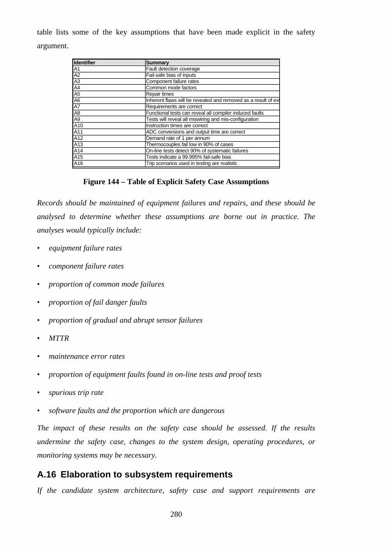
280
table lists some of the key assumptions that have been made explicit in the safety
argument.
Identifier SummaryA1 Fault detection coverageA2 Fail-safe bias of inputsA3 Component failure ratesA4 Common mode factorsA5 Repair timesA6 Inherent flaws will be revealed and removed as a result of extensive useA7 Requirements are correctA8 Functional tests can reveal all compiler induced faultsA9 Tests will reveal all miswiring and mis-configurationA10 Instruction times are correctA11 ADC conversions and output time are correctA12 Demand rate of 1 per annumA13 Thermocouples fail low in 90% of casesA14 On-line tests detect 90% of systematic failuresA15 Tests indicate a 99.995% fail-safe biasA16 Trip scenarios used in testing are realistic
Figure 144 – Table of Explicit Safety Case Assumptions
Records should be maintained of equipment failures and repairs, and these should be
analysed to determine whether these assumptions are borne out in practice. The
analyses would typically include:
• equipment failure rates
• component failure rates
• proportion of common mode failures
• proportion of fail danger faults
• proportion of gradual and abrupt sensor failures
• MTTR
• maintenance error rates
• proportion of equipment faults found in on-line tests and proof tests
• spurious trip rate
• software faults and the proportion which are dangerous
The impact of these results on the safety case should be assessed. If the results
undermine the safety case, changes to the system design, operating procedures, or
monitoring systems may be necessary.
A.16 Elaboration to subsystem requirements
If the candidate system architecture, safety case and support requirements are

281
acceptable, the design can be further elaborated into a set of design requirements for
the subsystems. In the reactor trip system there might be requirements for the following.
D.ARCH Overall system architecture apportionment of functions, overall design
safety case, design assumptions, numerical design targets, design
constraints, required safety case evidence, operation and maintenance
infrastructure, design for change, long-term support requirements.
D.ENV Requirements for environmental tests ("shake and bake") for all
hardware, maximum temperature, humidity, cooling requirements, EMI
protection.
D.POW Power supply specifications, reliability requirements.
D.DCL Specification of the DCL + fail-safety requirements.
D.INP Input specifications (number, range, isolation, etc.).
D.ADC Requirements for the ADC (number of inputs, range, speed, reliability).
D.MON Requirements for the monitor and monitor interfaces.
D.CPU Requirements for the CPU (speed, PROM capacity, RAM capacity,
input-output, etc.).
D.SW Requirements for the software.
Note that the subsystem requirements will include any evidence required for the safety
case (e.g. environmental test evidence, timing, fault tolerance tests, fault injection tests,
etc.). This evidence could be part of the subsystem deliverable.
As an example of how the subsystem requirements are elaborated, the requirements for
the software (D.SW) are given below. The requirements placed on the software are
based on an apportionment of the top-level safety functions together with additional
requirements imposed by lower level design decisions. The requirements include the
basic functional requirements for the software, specific design constraints on the
implementation method, and requirements for safety case evidence.
A.16.1 Software Functional Requirements
SW.INFO Supporting G.SEC and G.UPD. Every complete scan cycle, send the
software configuration data (number of inputs, input scale factors, trip

282
limit values, software version number and sumchecks).
SW.TRIP Supporting G.TRIP. For all inputs:
• Scan the two temperature readings (Ra, Rb) from the ADC.
• Scale the values to Ta and Tb.
• Perform 1oo2 voted high temperature trip (HiTrip = max(Ta,Tb) >
Tlimit).
• Perform 2oo2 voted low temperature trip (LoTrip = max(Ta,Tb) <
MinOpTemp)
• (MinOpTemp is MaxDiff below the median operating temperature for
all ducts).
• Send (HiTrip or LoTrip) to the DCL.
• Send Ra, Rb, HiTrip, LoTrip values to the monitor output.
SW.IO Satisfy the specified interface requirements for the ADC, DCL, and
Monitor ports (from D.DCL, D.ADC, D.MON).
SW.CHK Supporting G.MTTR. Halt if an internal failure is detected (PROM
sumcheck, RAM checks, processor, time overrun). Provide indication of
the type of fault detected.
SW.TIM Supporting G.TIM. The software scan cycle should be less than 5
seconds - including the time required for all input and output operations.
A.16.1.1 Safety case design constraints imposed on the software
SW.REV Implement the software using the reversible computer technique.
SW.FM Formal proof that code implements specification.
A.16.1.2 Safety case evidence requirements for the software development
SW.CHK.CASE Check the fault detection performance for simulated faults.
SW.TRIP.CASE Perform 104 demands on the system using realistic trip profiles.
SW.TIM.CASE Show the timing constraint is satisfied.
SW.V&V.CASE1 SW.FM.VER Provide proof script, independent
verification of proof.
283
SW.REV.CASE Demonstrate the reversible computer is
implemented correctly and formal software
is correctly mapped to reversible code.
Provide tests of fail-safe performance.
SW.V&V.CASE2 SW.TEST.CASE Show all software modules are
exhaustively tested. Show all modules
operate independently for all readings.
SW. DIV.CASE Show diverse implementations are
independent (languages, tools, staff, V&V).
SW.DES.CASE Show compliance with the implementation constraints.
SW.TOOL.CASE Provide impact analysis of faults in support tools, analysis of tool
quality (e.g. likely number of faults injected).
Software documentation/QA requirements
SW.PROCESS Provide evidence for the integrity of the delivered system and the
development process: safety plan, safety audit records, quality
plan, QA records, plans, design documents, software, proof files,
V&V records.
SW.PRODUCT Provide all necessary items for use and long-term support:
design documents, software, proof scripts, test environment,
support tools.
A.17 Conclusions
This safety case has presented the argument that the trip system design as proposed is
acceptably safe to be allowed to operate as part of the nuclear reactor protection
systems. The argument has been based upon the following key elements:
• Redundancy in the design
• Incredibility of Systematic Errors
• Probabilistic Analysis of Failure on Demand
• Fault detection, tolerance and diagnosis offered by design

284
Although incomplete (elaboration of requirements to subsystems and further evidence
being required) this document has presented the overall structure of the safety argument
and can be used as a basis of assessing adequate safety.
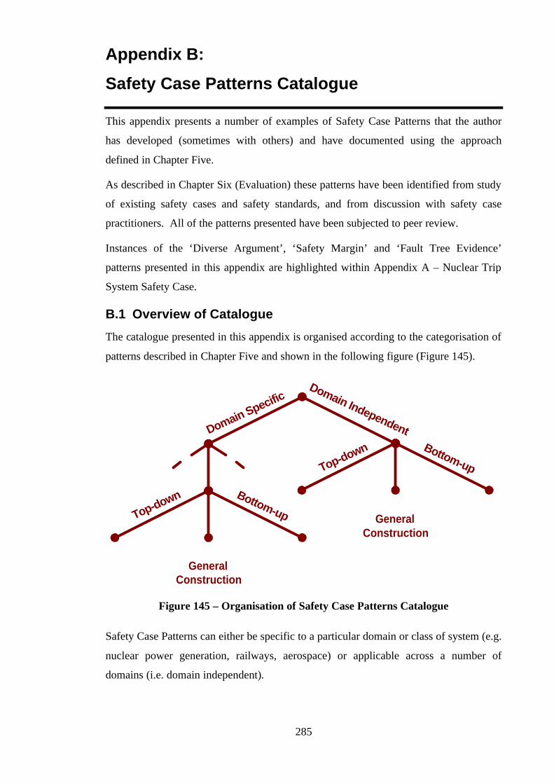
285
Appendix B:
Safety Case Patterns Catalogue
This appendix presents a number of examples of Safety Case Patterns that the author
has developed (sometimes with others) and have documented using the approach
defined in Chapter Five.
As described in Chapter Six (Evaluation) these patterns have been identified from study
of existing safety cases and safety standards, and from discussion with safety case
practitioners. All of the patterns presented have been subjected to peer review.
Instances of the ‘Diverse Argument’, ‘Safety Margin’ and ‘Fault Tree Evidence’
patterns presented in this appendix are highlighted within Appendix A – Nuclear Trip
System Safety Case.
B.1 Overview of Catalogue
The catalogue presented in this appendix is organised according to the categorisation of
patterns described in Chapter Five and shown in the following figure (Figure 145).
Domain SpecificDomain Independent
Top-down Bottom-up
GeneralConstruction
Top-down Bottom-up
GeneralConstruction
Figure 145 – Organisation of Safety Case Patterns Catalogue
Safety Case Patterns can either be specific to a particular domain or class of system (e.g.
nuclear power generation, railways, aerospace) or applicable across a number of
domains (i.e. domain independent).
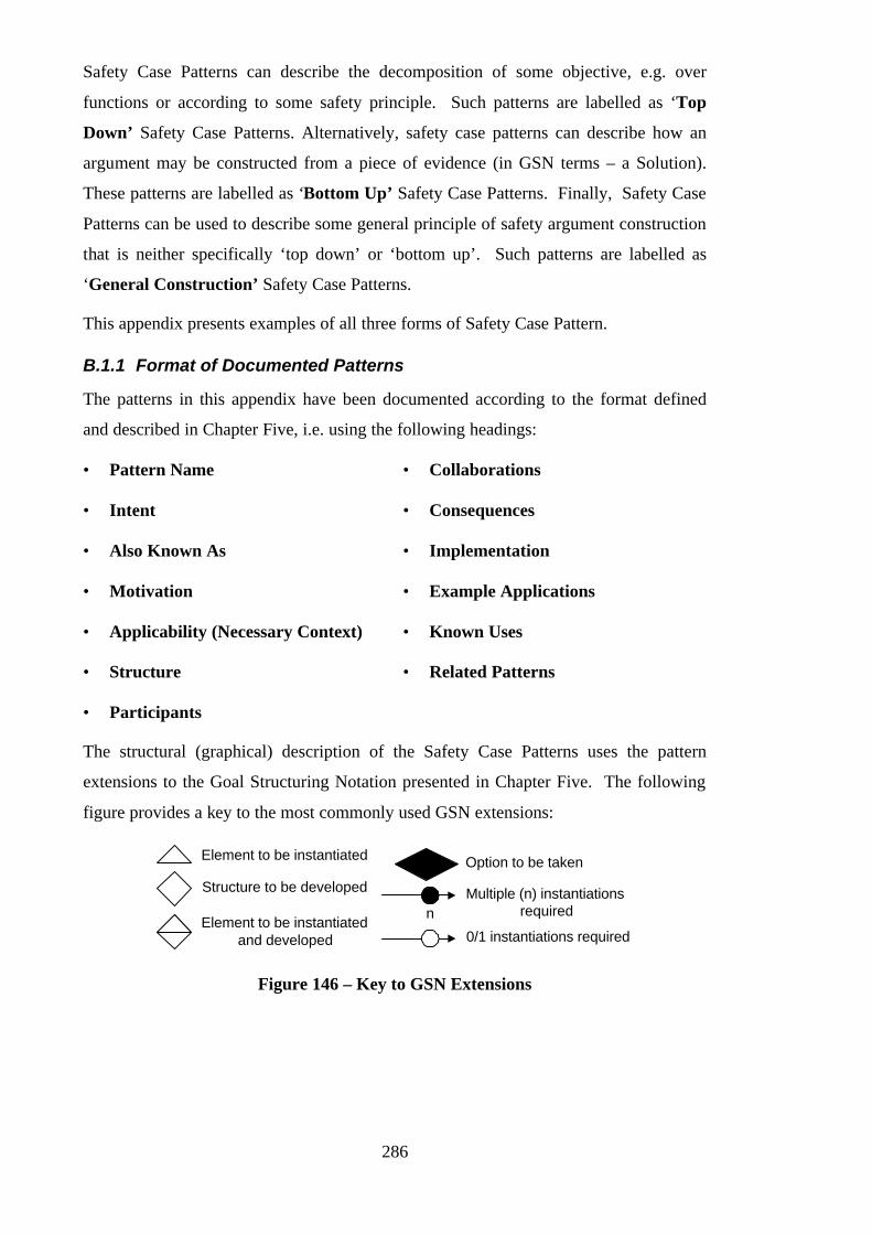
286
Safety Case Patterns can describe the decomposition of some objective, e.g. over
functions or according to some safety principle. Such patterns are labelled as ‘Top
Down’ Safety Case Patterns. Alternatively, safety case patterns can describe how an
argument may be constructed from a piece of evidence (in GSN terms – a Solution).
These patterns are labelled as ‘Bottom Up’ Safety Case Patterns. Finally, Safety Case
Patterns can be used to describe some general principle of safety argument construction
that is neither specifically ‘top down’ or ‘bottom up’. Such patterns are labelled as
‘General Construction’ Safety Case Patterns.
This appendix presents examples of all three forms of Safety Case Pattern.
B.1.1 Format of Documented Patterns
The patterns in this appendix have been documented according to the format defined
and described in Chapter Five, i.e. using the following headings:
• Pattern Name
• Intent
• Also Known As
• Motivation
• Applicability (Necessary Context)
• Structure
• Participants
• Collaborations
• Consequences
• Implementation
• Example Applications
• Known Uses
• Related Patterns
The structural (graphical) description of the Safety Case Patterns uses the pattern
extensions to the Goal Structuring Notation presented in Chapter Five. The following
figure provides a key to the most commonly used GSN extensions:
Element to be instantiated
Structure to be developed
Element to be instantiatedand developed
Option to be taken
nMultiple (n) instantiations
required
0/1 instantiations required
Figure 146 – Key to GSN Extensions
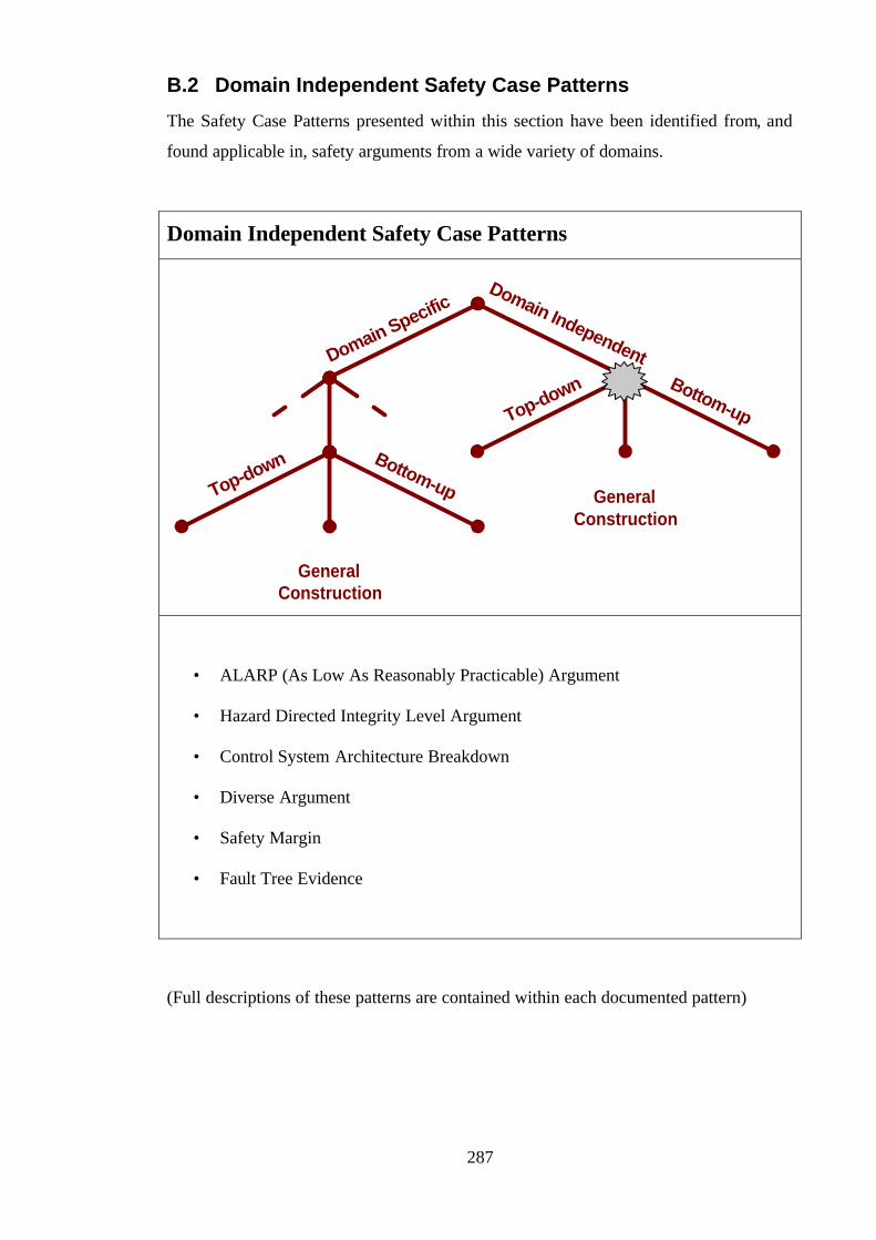
287
B.2 Domain Independent Safety Case Patterns
The Safety Case Patterns presented within this section have been identified from, and
found applicable in, safety arguments from a wide variety of domains.
Domain Independent Safety Case Patterns
Domain SpecificDomain Independent
Top-down Bottom-up
GeneralConstruction
Top-down Bottom-up
GeneralConstruction
• ALARP (As Low As Reasonably Practicable) Argument
• Hazard Directed Integrity Level Argument
• Control System Architecture Breakdown
• Diverse Argument
• Safety Margin
• Fault Tree Evidence
(Full descriptions of these patterns are contained within each documented pattern)

288
B.2.1 Domain Independent ‘Top Down’ Safety Case Patterns
Domain Independent:Top Down
Domain SpecificDomain Independent
Top-down Bottom-up
GeneralConstruction
Top-down Bottom-up
GeneralConstruction
• ALARP (As Low As Reasonably Practicable) Argument
• Hazard Directed Integrity Level Argument
• Control System Architecture Breakdown
(Full descriptions of these patterns are contained within each documented pattern)
289
ALARP (As-Low-As-Reasonably-Practicable)
Pattern
Author Tim Kelly
Created 22/02/99 01:56 Last Modified 22/02/99 02:36
Intent This pattern provides a framework for arguing that identified
risks in a system have been sufficiently addressed in accordance
with the ALARP principle.
Also Known As • Risk Reduction Argument Pattern
Motivation This pattern was developed for two reasons:
• To argue compliance with the ALARP principle at the highest
level when addressing system level hazards.
• To provide a more structured approach to presenting a
‘Hazard Avoidance’ argument (See Hazard Avoidance
Pattern) by showing differing treatment of hazards according
to their associated risk.

290
Structure
System hazardsaddressed in
accordance withALARP Principle
No intolerable riskspresent in system
All tolerable riskshave reduced as
low as reasonablypracticable
Risk associatedwith all remaining
hazards isnegligible
Identified systemhazards
Definition of'intolerable'
Definition of'tolerable'
Definition of'negligible'
System HazardLog
Risk associatedwith {Hazard X} has
been addressed
n = # hazards from'Identified System
Hazards' (previously)meeting definition of
intolerable
n>0 n=0
n
{Hazard X} hasbeen eliminated
and can no longeroccur
Risk associatedwith {Hazard X} hasbeen reduced to a
tolerable level
Risk associatedwith {Hazard X} has
been reduced aslow as reasonably
practicable
m
m = # hazards from'Identified SystemHazards' meeting
definition oftolerable
{Hazard X} isnecessarily presentin system (because
of some positivebenefit)
Measures havebeen taken to
reduce riskassociated with
{Hazard X}
Further reduction ofrisk associated with{Hazard X} requires
disproportionateexpense
Risk associatedwith {Hazard X} hasbeen shown to be
negligible
o
o = # hazards from'Identified SystemHazards' meeting
definition ofnegligible
Provides{Hazard X}
Definition of'disproportionate'
G1
G2 G3
G4
G5
G6 G7 G8G9
G10 G11 G12
C1
C2C3
C4
C5
Sn1
Participants G1 Defines the overall objective of the pattern
G2, G3, G4 Defines targets for three classes of identified
risks: negligible, tolerable, and intolerable
Sn1 Provided at this point to support the claim that
no intolerable risks have (ever) been identified
with the system

291
G6 or
G7 and G8
Claims either that hazard has been eliminated or
associated risk reduced to a tolerable level and
dealt with as a tolerable risk.
G8 Defines ALARP target for each identified
tolerable risk
G10, G11,
G12
Claims required to support ALARP target:
• Hazard only acceptable if positive benefit
achieved
• Risk reduction measures have been taken up
to the point where further measures would be
disproportionate to benefit gained.
G9 Claims for each remaining hazard that associated
risk shown to be negligible
C1 A context identifying all system hazards,
including indication of associated risks (e.g. Risk
Category from A, B, C, D).
C2, C3, C4 A workable definition of ‘intolerable’/
’tolerable’/ ’negligible’ risks that can be used as
a basis for selection from the list of hazards(e.g.
Intolerable = Risk Category A, Tolerable = Risk
Category B or C, Negligible = D).
C5 The ALARP principle relies on some
understanding of when it is no longer cost-
effective to spend further money on risk
reduction. This element, a definition of cost-
effectiveness, is therefore required.
Collaborations An important aspect of this pattern is that it divides and conquers
the goal of hazard mitigation / elimination according to the level
of risk associated with each hazard. There are three strands to the
safety argument: one tackling intolerable risks, one tackling
tolerable risk and one discounting negligible risks. To support
292
the top-level goal (G1) satisfactorily it is important that these
three strands address all identified risks. The definitions of
tolerable, intolerable and negligible (C3, C2 and C4 respectively)
should therefore be so defined as to cover and classify the range
of possible levels of risks.
It should also be noted that the definitions of negligibility (C4)
and disproportionate (C5) cannot be considered entirely
independently. It would not make sense, for example, to force
risk reduction to a level below that identified elsewhere as
negligible.
As the goal structure shows, if the means of addressing a
previously identified intolerable risk is to reduce it to a tolerable
level, then the remaining risk must be tackled as for all tolerable
risks. If the level of risk has been reduced to a negligible level,
then the hazard must be tackled as a negligible risk.
It is important that the source of Identified System Hazards (C1)
identifies the level of risk posed by a hazard in a way that
permits sub-division into the classes of risk defined by C2, C3
and C4.
Applicability This pattern is applicable in contexts where the ALARP principle
is accepted as the device for reasoning about the relative
importance of risks and the cost-effectiveness of risk reduction.
In order to apply this pattern it is necessary to have access to the
following contextual information:
• C1: Identified System Hazards
(See Participants section)
• C2, C3, C4: Definition of Intolerable / Tolerable /
Negligible Risk
(See Participants section)
These definitions are typically provided by the appropriate
regulatory authority, standards or through investigations by
safety engineers, including discussions with customers.
293
• C5: Definition of Disproportionate
(See Participants section)
Consequences After applying this pattern, there will be a number of
undeveloped goals of the form:
• G7: Risk associated with {Hazard X} has been reduced to
a tolerable level
• G9: Risk associated with {Hazard X} has been shown to be
negligible
• G6: {Hazard X} has been eliminated and can no longer
occur
• G10: {Hazard X} is necessarily present in the system
• G11: Measures have been taken to reduce risk associated
with {Hazard X}
• G12: Further reduction of risk associated with {Hazard X}
requires disproportionate expense
Implementation Implementation of this pattern involves first instantiating the
contexts C1, C2, C3, C4. In the context of the list of hazards
referenced by C1, the solutions to goals G2, G3 and G4 can be
provided. If no tolerable risks were ever present in the system,
then reference to the system hazard log (Sn1) is sufficient to
support the claim G2. However, if any intolerable risks have
been identified, it is necessary to claim (G5) that these have been
resolved through complete elimination of the hazard (G6), or
reduction to a tolerable (G7, G8) or negligible (G9) level.
For each tolerable risk identified an argument must be
constructed (G6, G10, G11, G12) to demonstrate that it has been
addressed in accordance with the ALARP principles. Measures
taken in risk reduction must be stated in support of G11. Some
evidence / argument of the non cost-effectiveness of further risk
reduction measures must be supplied in support of G12, in
accordance with the definition given by C5.

294
Evidence of risk analysis (probably based upon consideration of
probability of occurrence) is required in support of each claim of
hazards posing negligible risk (G9).
Possible Pitfalls
• Not providing complete coverage of levels of risk through
definitions C2, C3, C4
• Expressing definitions C2, C3, C4 in a way that is difficult to
apply to the information provided by C1 (and vice versa)
• Not having a commonly agreed concept of when to stop
attempting further risk reduction (C1) - this can result in a
non-uniform approach to tackling risks where significantly
different levels of effort are committed to risks at the same
level.
Examples Not available at this time
Known Uses See Industrial Press Safety Argument
Related Patterns • Hazard Mitigation Argument

295
Hazard Directed Integrity Level Argument
Author Tim Kelly, David Pumfrey
Created 20/10/97 08:56 Last Modified 22/02/99 02:36
Intent This pattern is intended to argue that a (sub)system has been
developed to an integrity level appropriate to the hazards to which
the system contributes.
Also Known As
Motivation The motivation for this pattern was to provide an argument where
the overall objective was expressed in terms of the hazards
involved and to show how this was then translated into integrity
level requirements. The top level objective, being expressed in
terms of hazards and associated hazard classes, can be more
readily integrated with an overall system level argument.
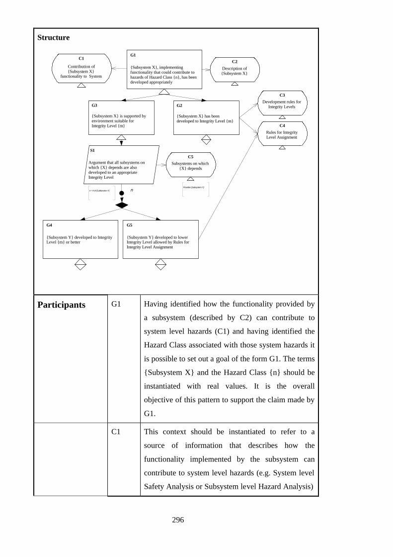
296
Structure
G1
{Subsystem X}, implementingfunctionality that could contribute to hazards of Hazard Class {n}, has beendeveloped appropriately
G2
{Subsystem X} has beendeveloped to Integrity Level {m}
Description of{Subsystem X}
C2
Rules for IntegrityLevel Assignment
C4
G3
{Subsystem X} is supported byenvironment suitable forIntegrity Level {m}
Development rules forIntegrity Levels
C3
G4
{Subsystem Y} developed to IntegrityLevel {m} or better
G5
{Subsystem Y} developed to lowerIntegrity Level allowed by Rules forIntegrity Level Assignment
S1
Argument that all subsystems onwhich {X} depends are alsodeveloped to an appropriateIntegrity Level
Subsystems on which{X} depends
C5
Provides {Subsystem Y}
n
Contribution of{Subsystem X}
functionality to System
C1
n = # of {Subfunction Y}
Participants G1 Having identified how the functionality provided by
a subsystem (described by C2) can contribute to
system level hazards (C1) and having identified the
Hazard Class associated with those system hazards it
is possible to set out a goal of the form G1. The terms
{Subsystem X} and the Hazard Class {n} should be
instantiated with real values. It is the overall
objective of this pattern to support the claim made by
G1.
C1 This context should be instantiated to refer to a
source of information that describes how the
functionality implemented by the subsystem can
contribute to system level hazards (e.g. System level
Safety Analysis or Subsystem level Hazard Analysis)
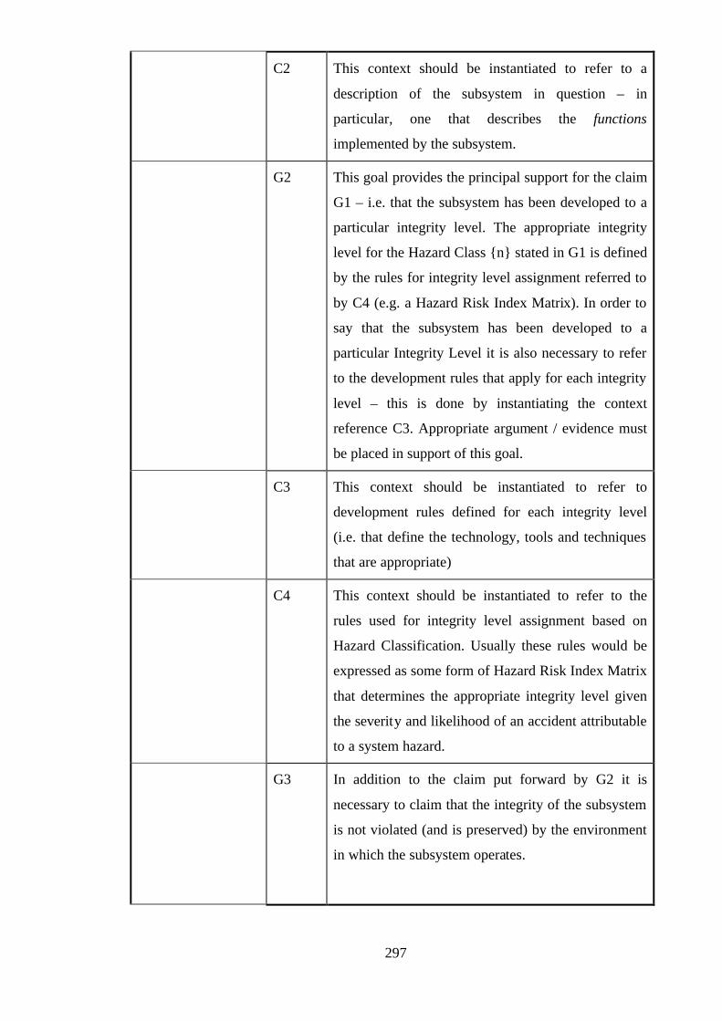
297
C2 This context should be instantiated to refer to a
description of the subsystem in question – in
particular, one that describes the functions
implemented by the subsystem.
G2 This goal provides the principal support for the claim
G1 – i.e. that the subsystem has been developed to a
particular integrity level. The appropriate integrity
level for the Hazard Class {n} stated in G1 is defined
by the rules for integrity level assignment referred to
by C4 (e.g. a Hazard Risk Index Matrix). In order to
say that the subsystem has been developed to a
particular Integrity Level it is also necessary to refer
to the development rules that apply for each integrity
level – this is done by instantiating the context
reference C3. Appropriate argument / evidence must
be placed in support of this goal.
C3 This context should be instantiated to refer to
development rules defined for each integrity level
(i.e. that define the technology, tools and techniques
that are appropriate)
C4 This context should be instantiated to refer to the
rules used for integrity level assignment based on
Hazard Classification. Usually these rules would be
expressed as some form of Hazard Risk Index Matrix
that determines the appropriate integrity level given
the severity and likelihood of an accident attributable
to a system hazard.
G3 In addition to the claim put forward by G2 it is
necessary to claim that the integrity of the subsystem
is not violated (and is preserved) by the environment
in which the subsystem operates.

298
S1 This strategy sets out the argument approach to be used in
support of G3. The strategy is to argue that all subsystems
on which the subsystem in question {Subsystem X}
depends (identfied to by the context reference C5) are
also developed to an appropriate integrity level. For each
subsystem identified it is necessary to put forward a goal
either of the form G4 – claiming that the subsystem is
developed to an integrity level the same or higher than
that of {X} – or G5 – that the subsystem is of lower
integrity but in accordance with the assignment rules
referred to by C4.
C5 This context should be instantiated as a reference to the
description of all subsystems {Y} on which the
subsystem {X} depends. An analysis of dependencies
between subsystems must be performed to provide this
information. This information could be derived from a
functional dependency diagram.
G4 This is one of the two possible claims that could be made
for a subsystem {Y} on which {X} depends. G4 claims
that {Y} is developed to the same or higher integrity level
as {X}. This claim must be substantiated by further
argument / evidence.
G5 This is one of the two possible claims that could be made
for a subsystem {Y} on which {X} depends. G5 claims
that {Y} is developed to a lower integrity level than {X}
as allowed by the rules referred to by C4.
Collaborations • C1 identifies the causal relationship between a subsystem’s
function and system level hazards – making it possible to
identify the Hazard Class that should be associated with the
subsystem.
• C3 provides rules that enables the Integrity Level claim of G2
to be derived from the Hazard Class claim of G1.
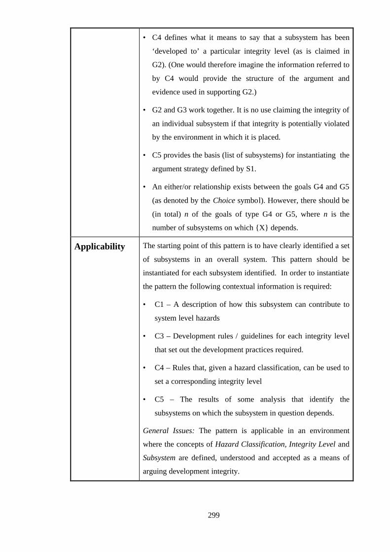
299
• C4 defines what it means to say that a subsystem has been
‘developed to’ a particular integrity level (as is claimed in
G2). (One would therefore imagine the information referred to
by C4 would provide the structure of the argument and
evidence used in supporting G2.)
• G2 and G3 work together. It is no use claiming the integrity of
an individual subsystem if that integrity is potentially violated
by the environment in which it is placed.
• C5 provides the basis (list of subsystems) for instantiating the
argument strategy defined by S1.
• An either/or relationship exists between the goals G4 and G5
(as denoted by the Choice symbol). However, there should be
(in total) n of the goals of type G4 or G5, where n is the
number of subsystems on which {X} depends.
Applicability The starting point of this pattern is to have clearly identified a set
of subsystems in an overall system. This pattern should be
instantiated for each subsystem identified. In order to instantiate
the pattern the following contextual information is required:
• C1 – A description of how this subsystem can contribute to
system level hazards
• C3 – Development rules / guidelines for each integrity level
that set out the development practices required.
• C4 – Rules that, given a hazard classification, can be used to
set a corresponding integrity level
• C5 – The results of some analysis that identify the
subsystems on which the subsystem in question depends.
General Issues: The pattern is applicable in an environment
where the concepts of Hazard Classification, Integrity Level and
Subsystem are defined, understood and accepted as a means of
arguing development integrity.
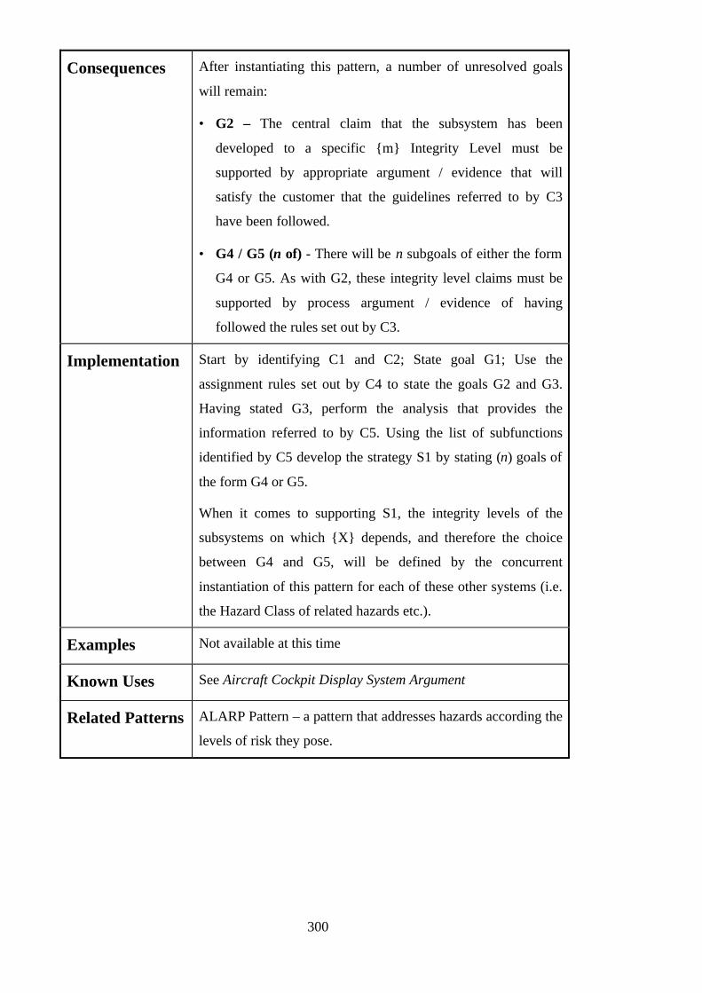
300
Consequences After instantiating this pattern, a number of unresolved goals
will remain:
• G2 – The central claim that the subsystem has been
developed to a specific {m} Integrity Level must be
supported by appropriate argument / evidence that will
satisfy the customer that the guidelines referred to by C3
have been followed.
• G4 / G5 (n of) - There will be n subgoals of either the form
G4 or G5. As with G2, these integrity level claims must be
supported by process argument / evidence of having
followed the rules set out by C3.
Implementation Start by identifying C1 and C2; State goal G1; Use the
assignment rules set out by C4 to state the goals G2 and G3.
Having stated G3, perform the analysis that provides the
information referred to by C5. Using the list of subfunctions
identified by C5 develop the strategy S1 by stating (n) goals of
the form G4 or G5.
When it comes to supporting S1, the integrity levels of the
subsystems on which {X} depends, and therefore the choice
between G4 and G5, will be defined by the concurrent
instantiation of this pattern for each of these other systems (i.e.
the Hazard Class of related hazards etc.).
Examples Not available at this time
Known Uses See Aircraft Cockpit Display System Argument
Related Patterns ALARP Pattern – a pattern that addresses hazards according the
levels of risk they pose.

301
Control System Architecture Breakdown
Argument
Author Tim Kelly, Peter Lindsay, Brenton Atchison
Created 20/10/97 08:56 Last Modified 22/02/99 02:36
Intent The intent of this pattern is to illustrate a means of structuring an
argument to support a system safety goal (requirement,
avoidance of hazard etc.) by decomposition over a generic
control system model.
Also Known As
Motivation The motivation for this pattern is the need to breakdown a high
level goal (that is difficult to substantiate ‘as-is’) into sub-goals
that are hopefully easier to address.
Structure
Argument Pattern
G1
{System Safety Goal}
S1
Argument by breakdownover control systemarchitecture elements
M1
Control SystemArchitecture
G2
{Sensor Safety Goal}
G3
{Control Logic SafetyGoal}
G4
{Actuator Safety Goal}
System Level SafetyAnalysis
C3
System Level HazardAnalysis
C1
System Level SafetyRequirements
C2
Emerging from one ofthese two contexts
Showing how sub-systemlevel behaviourcontributes to systembehaviour
Providing the model overwhich the argument isdecomposed
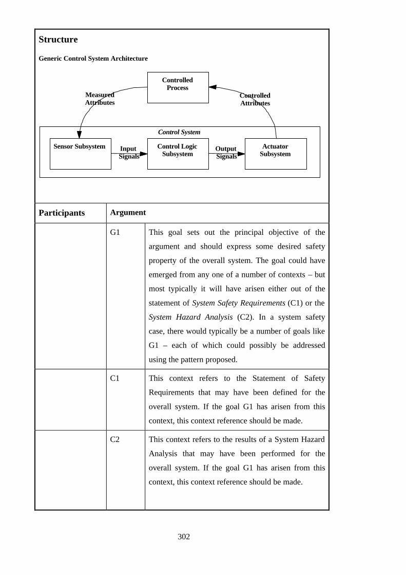
302
Structure
Generic Control System Architecture
Sensor Subsystem Control LogicSubsystem
ActuatorSubsystem
Input Signals
Output Signals
ControlledProcess
ControlledAttributes
MeasuredAttributes
Control System
Participants Argument
G1 This goal sets out the principal objective of the
argument and should express some desired safety
property of the overall system. The goal could have
emerged from any one of a number of contexts – but
most typically it will have arisen either out of the
statement of System Safety Requirements (C1) or the
System Hazard Analysis (C2). In a system safety
case, there would typically be a number of goals like
G1 – each of which could possibly be addressed
using the pattern proposed.
C1 This context refers to the Statement of Safety
Requirements that may have been defined for the
overall system. If the goal G1 has arisen from this
context, this context reference should be made.
C2 This context refers to the results of a System Hazard
Analysis that may have been performed for the
overall system. If the goal G1 has arisen from this
context, this context reference should be made.
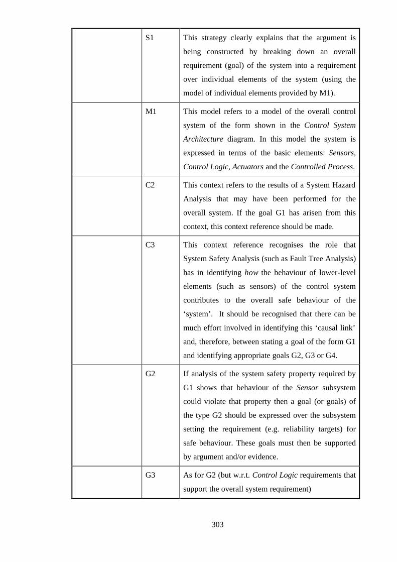
303
S1 This strategy clearly explains that the argument is
being constructed by breaking down an overall
requirement (goal) of the system into a requirement
over individual elements of the system (using the
model of individual elements provided by M1).
M1 This model refers to a model of the overall control
system of the form shown in the Control System
Architecture diagram. In this model the system is
expressed in terms of the basic elements: Sensors,
Control Logic, Actuators and the Controlled Process.
C2 This context refers to the results of a System Hazard
Analysis that may have been performed for the
overall system. If the goal G1 has arisen from this
context, this context reference should be made.
C3 This context reference recognises the role that
System Safety Analysis (such as Fault Tree Analysis)
has in identifying how the behaviour of lower-level
elements (such as sensors) of the control system
contributes to the overall safe behaviour of the
‘system’. It should be recognised that there can be
much effort involved in identifying this ‘causal link’
and, therefore, between stating a goal of the form G1
and identifying appropriate goals G2, G3 or G4.
G2 If analysis of the system safety property required by
G1 shows that behaviour of the Sensor subsystem
could violate that property then a goal (or goals) of
the type G2 should be expressed over the subsystem
setting the requirement (e.g. reliability targets) for
safe behaviour. These goals must then be supported
by argument and/or evidence.
G3 As for G2 (but w.r.t. Control Logic requirements that
support the overall system requirement)

304
G4 As for G2 (but w.r.t. Actuator requirements that
support the overall system requirement)
Collaborations • Contexts C1 and C2 provide the basis from which goals of
type G1 are stated
• Model M1 provides the terms (description of control system
elements) over which the goals G2, G3 and G4 are stated
• Context C3 provides the analysis that supports the allocation
of the overall safety requirement G1 to the control system
elements (G2, G3 and G4)
• It is possible for one goal G1 to be decomposed in any
number or configuration of the goals G2, G3 and G4 – hence
the choice and multiplicity symbols on the SolvedBy
relationship between S1 and the sub-goals.
Applicability The applicability of this pattern depends largely on whether the
model of the control system shown in Control System
Architecture is appropriate for the control system in question.
Where the control system can be decomposed into the primitive
elements – Sensor Subsystem, Control Logic Subsystem and
Actuator Subsystem – this form of argument may be used.
The starting point of the argument is the expression of a system
safety goal. This pattern assumes that this is possible – either
because there exists a System Level Statement of Safety
Requirements or System Level Hazard Analysis.
Analysis of the type suggested by C3 is also required in order to
support the decomposition. It should be recognised that where
C3 does not exist – a decomposition of this type would be
extremely difficult and (possibly) unjustified.

305
Consequences After instantiating this pattern, a number of unresolved goals will
remain:
• G2 / G3 / G4
For each safety goal expressed over the Sensors / Control
Logic / Actuators appropriate supporting argument and / or
evidence should be provided. This argument/evidence should
be one appropriate to the nature of the goal being stated – i.e.
Quantitative evidence if a quantitative requirement is
expressed, qualitative argument if a qualitative goal is
expressed.
Implementation Start by identifying C1 or C2; State goal G1; Identify / Perform
analysis C3 (also using M1); Use C3 to derive goals G2, G3 and
/ or G4.
Possible Pitfalls
• Attempting to apply pattern to a system that is not readily
expressed in term of the Control System Architecture model.
• Attempting to apply pattern where the system level safety
analysis (C3) is not available or does not clearly identify the
causal links between system and subsystem properties
• Providing goals G2, G3 and G4 that are inappropriate as
solutions to the goal G1. For example, if G1 is a quantitative
requirement – it would be normal to expect supporting goals
to be expressed in quantifiable terms.
Examples Not available at this time
Known Uses See Industrial Press Safety Argument in:
Derivation of Safety Requirements for Simple Computer Based
Systems
Brenton Atchison, Peter Lindsay
submitted to ACSC’98

306
Related Patterns Functional Decomposition Pattern – a pattern of similar style that
decomposes a system safety goal over system functions rather
than architectural elements

307
B.2.2 Domain Independent ‘General Construction’ Safety Case Patterns
Domain Independent: General Construction
Domain SpecificDomain Independent
Top-down Bottom-up
GeneralConstruction
Top-down Bottom-up
GeneralConstruction
• Diverse Argument
• Safety Margin
(Full descriptions of these patterns are contained within each documented pattern)
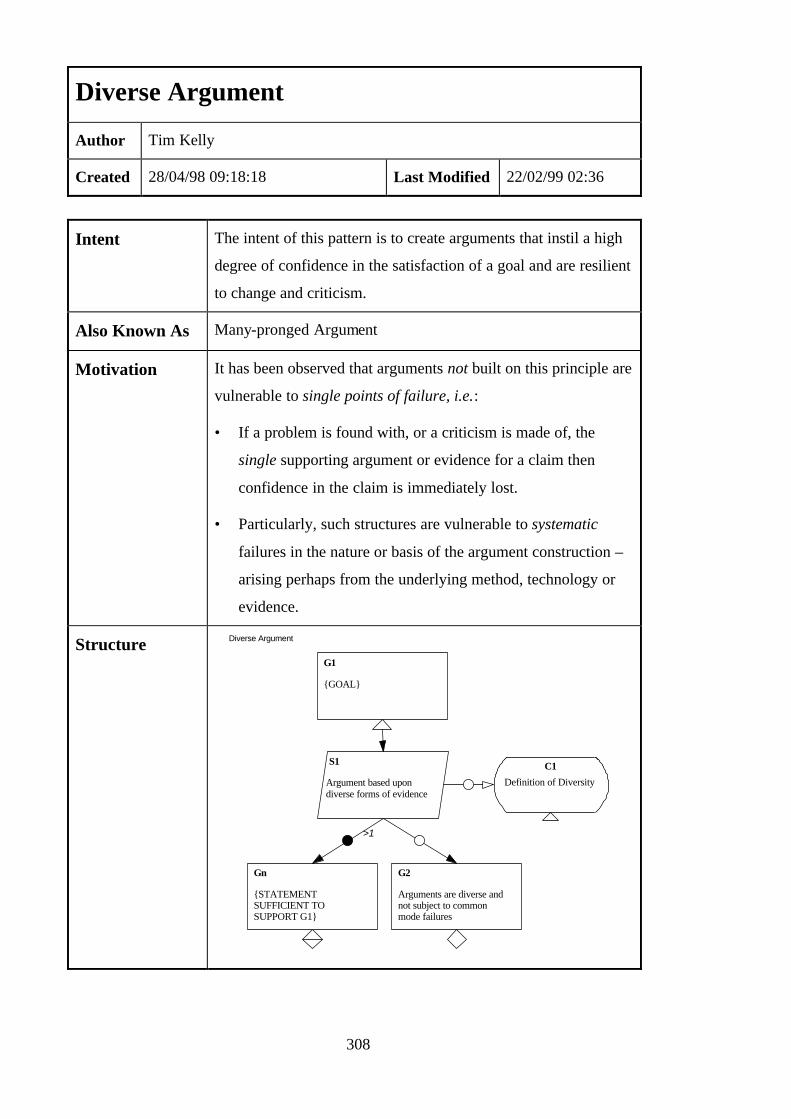
308
Diverse Argument
Author Tim Kelly
Created 28/04/98 09:18:18 Last Modified 22/02/99 02:36
Intent The intent of this pattern is to create arguments that instil a high
degree of confidence in the satisfaction of a goal and are resilient
to change and criticism.
Also Known As Many-pronged Argument
Motivation It has been observed that arguments not built on this principle are
vulnerable to single points of failure, i.e.:
• If a problem is found with, or a criticism is made of, the
single supporting argument or evidence for a claim then
confidence in the claim is immediately lost.
• Particularly, such structures are vulnerable to systematic
failures in the nature or basis of the argument construction –
arising perhaps from the underlying method, technology or
evidence.
Structure Diverse Argument
G1
{GOAL}
Gn
{STATEMENTSUFFICIENT TOSUPPORT G1}
S1
Argument based upondiverse forms of evidence
>1
Definition of Diversity
C1
G2
Arguments are diverse andnot subject to commonmode failures

309
G1 This goal sets out the principal objective of the
argument and must be instantiated with a specific
statement
S1 This strategy explains the diverse argument approach
and can be left as-is in the instantiated argument
Participants
C1 This (optional) context can be instantiated to define
clearly the definition of diversity that is being adopted
for the development of this argument – e.g. the degree
of independence being assumed. It is useful to include
this context where developer and audience of the
argument may have differing definitions.
>1
Gn
The essence of this pattern is the provision of multiple
reasons (+ supporting arguments / evidence) as to why
G1 is satisfied. Each statement Gn should individually
be sufficient to support G1. The individual arguments
should ideally be based upon independent forms of
evidence. For example, this could mean:
• Diverse forms of safety analysis & testing
information
• Appealing to independent safety mechanisms in the
design
• Estimated vs. Historical / Operational data
The greater the diversity achieved between the forms of
Gn put forward the greater the confidence there will
usually be in the satisfaction of G1. The degree of
independence between the arguments will also reduce
the vulnerability of the overall argument to common
mode failures (e.g. if a certain form of evidence is
challenged or the effectiveness of a safety mechanism is
questioned).

310
G2 This (optional) claim may be instantiated if it is felt
necessary to justify that the arguments put forward by
the goals Gn are actually diverse, independent, free from
common mode failures etc.
Collaborations • There is an implicit requirement for diversity between the
arguments headed by goals Gn
• All the goals (Gn) put forward should be focussed towards the
same objective G1
• The diversity of the goals (Gn) should agree with the
(optional) definition provided by C1
• The claim made by goal G2 concerns the diversity between
the goals (and supporting arguments) of Gn
Applicability This pattern should be used wherever possible in the construction
of a safety argument. Diversity of evidence, however, has a cost
implication. It costs money to produce multiple forms of
argument to substantiate the same claim! The pattern should
therefore be applied judiciously wherever greater confidence in a
goal is required or it is felt that, in the future, challenges may be
made to the arguments used in support of the goal.
In some safety standards, e.g. UK Defence Standard 00-55,
argument diversity is demanded. Clause 7.3.1 states that:
“The Software Safety Case shall justify the achieved
integrity level of the SRS by means of a safety
analysis of the SRS development process supported
by two or more diverse safety arguments”
Arguments based upon both analysis (e.g. proof of correctness)
and testing are demanded. This pattern is obviously applicable in
this case.
Consequences After instantiating this pattern, a number of unresolved goals will
remain:

311
• (>1 of) Gn
For each of these goals appropriate supporting argument and /
or evidence should be provided. This argument/evidence
should be one appropriate to the nature of the goal being
stated – i.e. quantitative evidence if a quantitative requirement
is expressed, qualitative argument if a qualitative goal is
expressed. The requirement for diversity and independence
should be respected as these goals are developed.
• G2
This claim of diversity between the arguments supporting the
goals Gn must be supported. Appeals could be made, for
example, to the independence of data, techniques or
technologies.
Implementation Start by defining the goal G1 (e.g. “Hazard H1 cannot occur”).
State strategy S1. If useful, instantiate the context C1 to provide
(or refer to) the definition of diversity being adopted in this
argument. Identify the diverse argument approaches used to
support G1. Define a goal Gn for each of the approaches
identified that makes clear the diversity (e.g. “Formal Analysis
shows condition relating to H1 cannot occur” and “Extensive Rig
testing has shown no occurrences of H1”). Provide supporting
arguments for each of the Gn claims put forward – making sure
that the independence in these claims is preserved. If felt
necessary or appropriate, instantiate the diversity claim G2 and
provide a supporting argument.
Possible Pitfalls
• Not selecting sufficiently diverse approaches (such that
confidence is not increased)
• Having a common dependency between the argument
approaches – e.g. reliance on a common design description,
piece of evidence, critical assumption.

312
• Stating the goals independently, but at some later point
supporting them by the same argument or piece of evidence.
• Contradicting the definition of diversity provided by the
(optional) context C1 through the claims put forward as Gn.
UK Defence Standard 00-55 Clause 7.3.3 states that:
“All the safety arguments shall be analysed for
common mode failures”
Examples Example of Diverse Argument
Hazard H1 cannot occur
G1
S1
Argument based upondiverse forms of evidence
G2
Formal Analysis showscondition relating to H1cannot occur
G3
Extensive Rig testing hasshown no occurrences of H1
Known Uses See Figure 130 of Appendix A (Nuclear Trip System Safety
Case)
Related Patterns Safety Margin – this pattern is also intended to increase
confidence and reduce vulnerability to change.
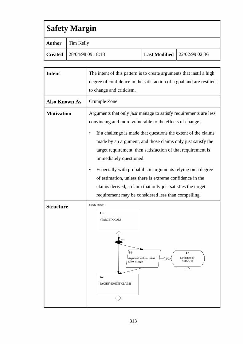
313
Safety Margin
Author Tim Kelly
Created 28/04/98 09:18:18 Last Modified 22/02/99 02:36
Intent The intent of this pattern is to create arguments that instil a high
degree of confidence in the satisfaction of a goal and are resilient
to change and criticism.
Also Known As Crumple Zone
Motivation Arguments that only just manage to satisfy requirements are less
convincing and more vulnerable to the effects of change.
• If a challenge is made that questions the extent of the claims
made by an argument, and those claims only just satisfy the
target requirement, then satisfaction of that requirement is
immediately questioned.
• Especially with probabilistic arguments relying on a degree
of estimation, unless there is extreme confidence in the
claims derived, a claim that only just satisfies the target
requirement may be considered less than compelling.
Structure Safety Margin
G1
{TARGET GOAL}
G2
{ACHIEVEMENT CLAIM}
1 of 2
S1
Argument with sufficientsafety margin
Definition ofSufficient
C1

314
G1 This goal sets out the principal objective of the
argument and must be instantiated with a specific
statement
S1 There is a choice between providing G2 as a direct
solution to G1 or providing an explicit description of
the use of a safety margin through stating this as a
strategy S1.
Participants
C1 If S1 is explicitly stated, then it can be useful to
instantiate C1 to provide the definition of ‘sufficient’
being used to describe the safety margin. Providing
such a definition aids maintenance of the intent of the
safety margin if the argument is ever challenged or
altered in the future. It also helps clarify the concept
for the reader.
G2 This goal should be instantiated to state what has been
achieved against the target set out in G1. As far as is
reasonably practicable the objective in constructing a
safety argument should be to state a goal G2 that not
only satisfies G1 but also exceeds the requirement,
thus providing a safety margin. By doing this,
confidence is increased in the satisfaction of G1 and
there is a ‘margin for error’ if the claims made by G2
have to be weakened at any future occasion (e.g. if the
claim is challenged by operational data).
The margin acts as a ‘crumple zone’. Change can
propagate through a goal structure up to G2. The
margin between G1 and G2 absorbs the change and
prevents further propagation, thus protecting the
argument above G1.
Collaborations • G2 should be stated to exceed the requirement set out by G1
• The claim expressed by G2 should be expressed in a form
congruent to the form of requirement set out in G1

315
• The margin created by the gap between G1 and G2 should
agree with the definition of ‘sufficient’ given by C1 (if
provided).
Applicability This pattern should be used wherever possible in the construction
of a safety argument. Providing a safety margin, however, has a
cost implication. It costs money (up-front) to exceed safety
requirements! The pattern should therefore be applied
judiciously wherever greater confidence in a goal is required or it
is felt that, in the future, challenges may be made to the argument
used in support of the goal. In the long-term this approach saves
time and effort by providing a barrier to change – a margin that
can be called upon as justification for not having to update parts
of the safety argument above claim G1.
This approach provides a means of reducing a safety argument’s
sensitivity to variations in evidence and mitigating uncertainty in
safety claims. UK Defence Standard 00-55 states that:
“All the safety arguments shall be analysed for …
sensitivity to variations in the evidence. The main
sources of uncertainty in the safety arguments shall
be elaborated.”
This pattern is therefore obviously applicable in cases where 00-
55 is enacted.
Consequences After instantiating this pattern, an unresolved goal will remain:
• G2
Appropriate supporting argument and / or evidence should be
provided to support this goal. This argument/evidence should
be appropriate to the nature of the goal being stated – i.e.
quantitative evidence if a quantitative requirement is
expressed, qualitative argument if a qualitative goal is
expressed.
316
Implementation Start by defining the target goal G1 (e.g. “Probability of Hazard
H1 < 1x10⁻⁶ per annum”). Decide on whether it is appropriate to
provide an explicit strategy S1 to explain the approach being
adopted or whether to simply provide a supporting claim. If S1
is used, decide on whether it is appropriate / useful to provide the
definition of a ‘sufficient’ safety margin as C1. Based on the
evidence available, state what has been achieved against this
requirement as G2 (e.g. “Fault Tree for H1 shows probability of
occurrence < 1x10⁻⁷ per annum”). The intent of the pattern is
that this claim should exceed the requirement of G1 – thus
providing a safety margin. Argument / evidence should then be
provided to support the claim made by G2.
Possible Pitfalls
• Over-engineering the system / evidence to provide an
excessive safety margin that will never be fully utilised. It
requires engineering judgement based upon experience of
‘calls to margin’ to decide upon the appropriate level of
margin to provide / allow between target and achievement.
• Offering a margin between G1 and G2 that does not agree
with the definition of a sufficient safety margin given by C1
(if provided).
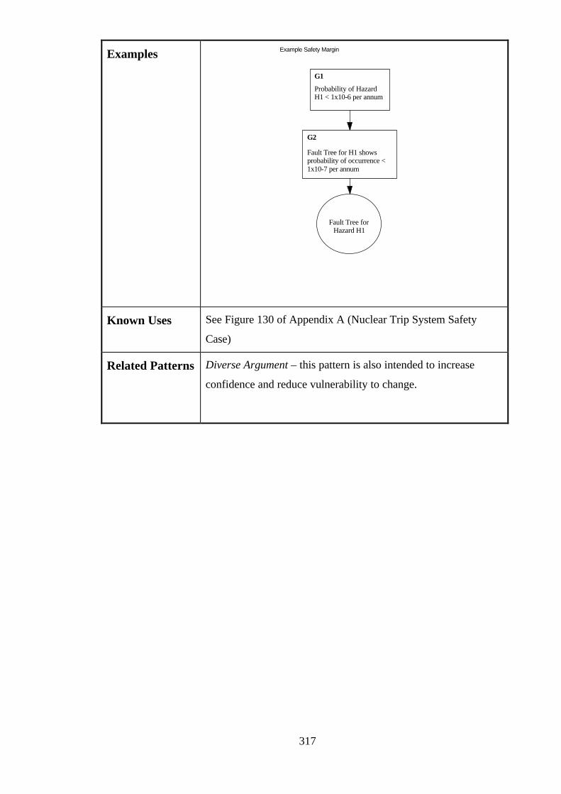
317
Examples Example Safety Margin
Probability of HazardH1 < 1x10⁻⁶ per annum
G1
Fault Tree for H1 showsprobability of occurrence <1x10⁻⁷ per annum
G2
Fault Tree forHazard H1
Known Uses See Figure 130 of Appendix A (Nuclear Trip System Safety
Case)
Related Patterns Diverse Argument – this pattern is also intended to increase
confidence and reduce vulnerability to change.
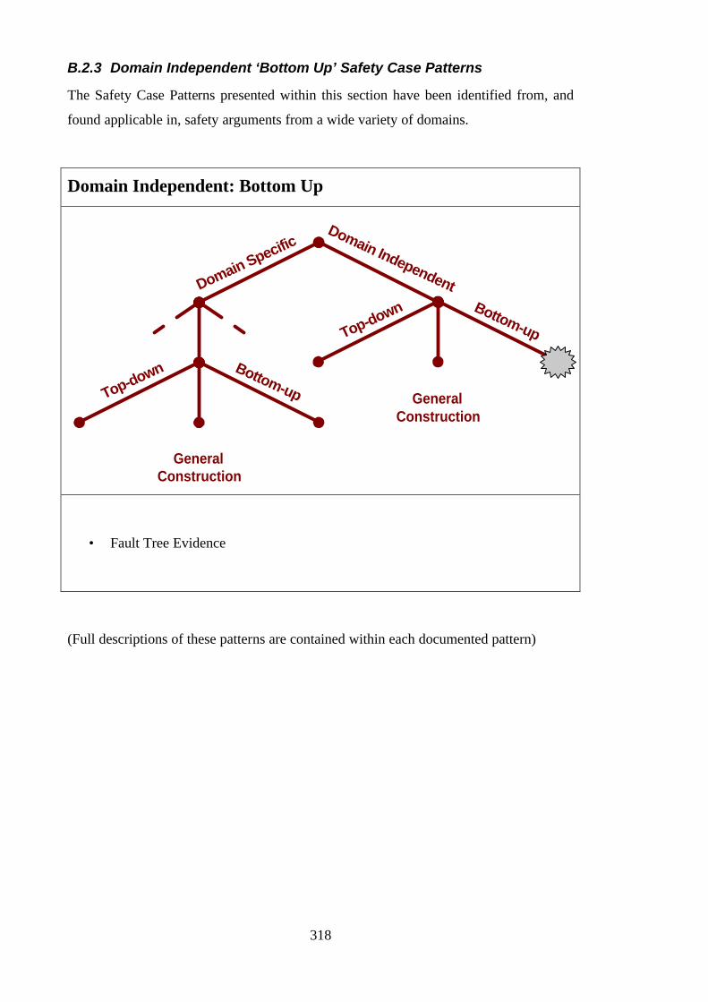
318
B.2.3 Domain Independent ‘Bottom Up’ Safety Case Patterns
The Safety Case Patterns presented within this section have been identified from, and
found applicable in, safety arguments from a wide variety of domains.
Domain Independent: Bottom Up
Domain SpecificDomain Independent
Top-down Bottom-up
GeneralConstruction
Top-down Bottom-up
GeneralConstruction
• Fault Tree Evidence
(Full descriptions of these patterns are contained within each documented pattern)
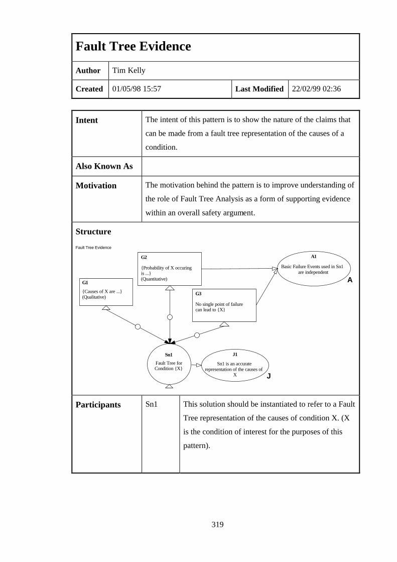
319
Fault Tree Evidence
Author Tim Kelly
Created 01/05/98 15:57 Last Modified 22/02/99 02:36
Intent The intent of this pattern is to show the nature of the claims that
can be made from a fault tree representation of the causes of a
condition.
Also Known As
Motivation The motivation behind the pattern is to improve understanding of
the role of Fault Tree Analysis as a form of supporting evidence
within an overall safety argument.
Structure
Fault Tree Evidence
Fault Tree forCondition {X}
Sn1
G1
{Causes of X are ...} (Qualitative)
G2
{Probability of X occuringis ...} (Quantitative)
G3
No single point of failurecan lead to {X}
A1
Basic Failure Events used in Sn1are independent
A
Sn1 is an accuraterepresentation of the causes of
X
J1
J
Participants Sn1 This solution should be instantiated to refer to a Fault
Tree representation of the causes of condition X. (X
is the condition of interest for the purposes of this
pattern).
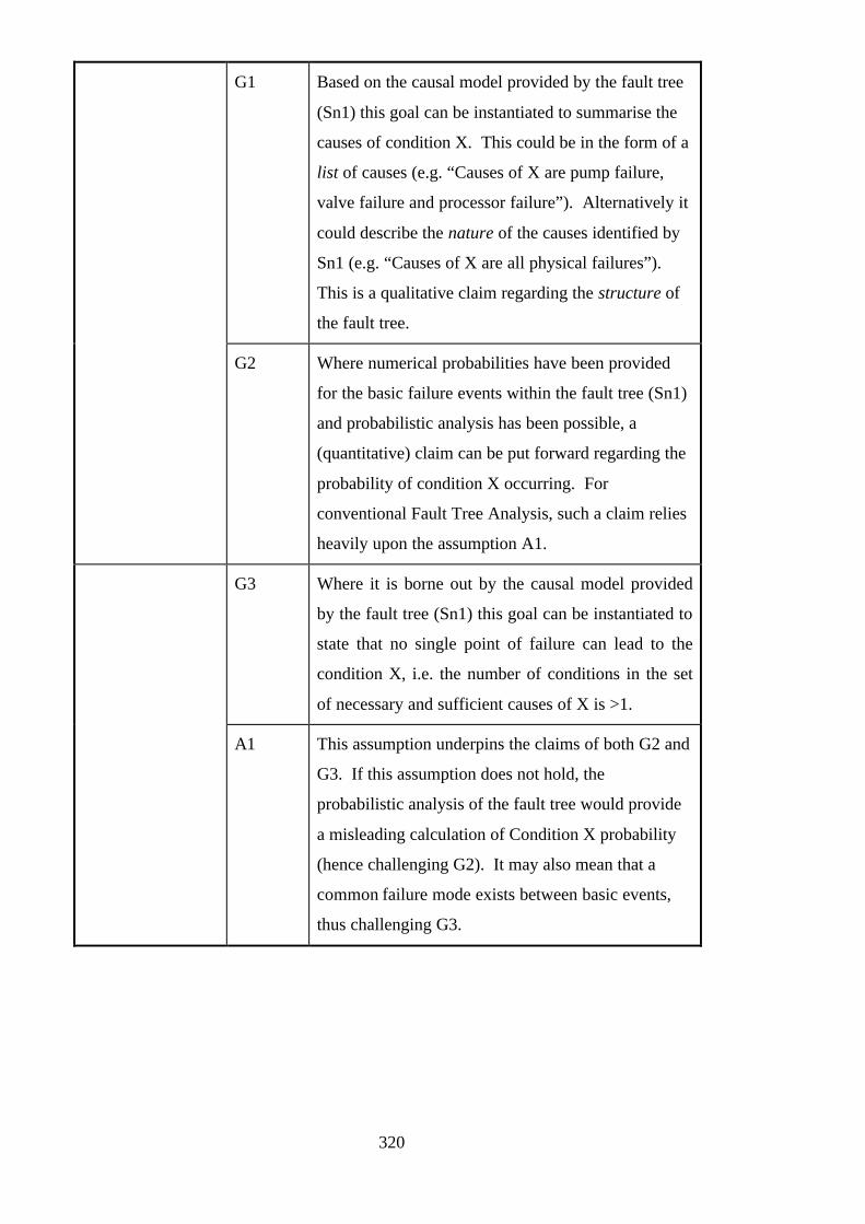
320
G1 Based on the causal model provided by the fault tree
(Sn1) this goal can be instantiated to summarise the
causes of condition X. This could be in the form of a
list of causes (e.g. “Causes of X are pump failure,
valve failure and processor failure”). Alternatively it
could describe the nature of the causes identified by
Sn1 (e.g. “Causes of X are all physical failures”).
This is a qualitative claim regarding the structure of
the fault tree.
G2 Where numerical probabilities have been provided
for the basic failure events within the fault tree (Sn1)
and probabilistic analysis has been possible, a
(quantitative) claim can be put forward regarding the
probability of condition X occurring. For
conventional Fault Tree Analysis, such a claim relies
heavily upon the assumption A1.
G3 Where it is borne out by the causal model provided
by the fault tree (Sn1) this goal can be instantiated to
state that no single point of failure can lead to the
condition X, i.e. the number of conditions in the set
of necessary and sufficient causes of X is >1.
A1 This assumption underpins the claims of both G2 and
G3. If this assumption does not hold, the
probabilistic analysis of the fault tree would provide
a misleading calculation of Condition X probability
(hence challenging G2). It may also mean that a
common failure mode exists between basic events,
thus challenging G3.
321
J1 All of the claims (G1, G2 and G3) are fallacious if
this justification does not hold. For the fault tree to
be a valid piece of supporting evidence for a safety
argument it must be true that it presents an accurate
and truthful causal model for X. For example, it
must be consistent with design descriptions,
operational evidence and other safety analyses.
Collaborations • The claim G3 can only be made if this is an observed property
of Sn1
• Claims G1 and G3 should not contradict each other
Applicability This pattern can be applied wherever:
• A fault tree for the condition exists – i.e. the skills for the
construction and validation of such a casual model are
available.
• Assumption A1 and Justification J1 can be discharged
• Fault Tree Analysis is an accepted as a form of evidence to
be used within a safety argument (i.e. it is accepted and
recognised by industry and regulatory standards)
Consequences Following use of the fault tree to support such claims it is
necessary to ensure that (through-life):
• The fault tree continues to provide an presents an accurate and
truthful causal model for condition X
• The fault tree is consistent with subsidiary forms of evidence
used in its construction (e.g. Failure Modes and Effects
Analysis tables used to provide basic failure event
information)
• Independence between the basic failure events of the fault tree
is preserved (and is not compromised through implementation
decisions or subsequent design changes).

322
Implementation • Start by instantiating Sn1 to refer to the fault tree constructed
for condition X.
• Check that the independence assumption A1 holds.
• Support justification J1 by ensuring that the validity of the
tree is checked.
• Based upon cut set analysis of the fault tree, decide whether
it is possible / appropriate to instantiate G3.
• If it is appropriate, instantiate G1 to summarise the minimal
causes identified for the tree.
• Where probabilistic analysis of the tree is possible,
summarise the results through instantiating G2.
Possible Pitfalls
• Failing to support the independence assumption A1
• Presenting a fault tree Sn1 that does not support the
justification J1. If the validity of the fault tree is not believed,
then the claims derived from that fault tree will be
questionable.
Examples Not available at this time
Known Uses See Figure 126 of Appendix A (Nuclear Trip System Safety
Case)
Related Patterns Markov Model Evidence – this pattern illustrates the claims that
can be made from a Markov Model.
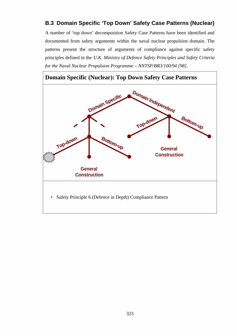
323
B.3 Domain Specific ‘Top Down’ Safety Case Patterns (Nuclear)
A number of ‘top down’ decomposition Safety Case Patterns have been identified and
documented from safety arguments within the naval nuclear propulsion domain. The
patterns present the structure of arguments of compliance against specific safety
principles defined in the U.K. Ministry of Defence Safety Principles and Safety Criteria
for the Naval Nuclear Propulsion Programme – NNTSP/BR3/100/94 [98].
Domain Specific (Nuclear): Top Down Safety Case Patterns
Domain SpecificDomain Independent
Top-down Bottom-up
GeneralConstruction
Top-down Bottom-up
GeneralConstruction
• Safety Principle 6 (Defence in Depth) Compliance Pattern
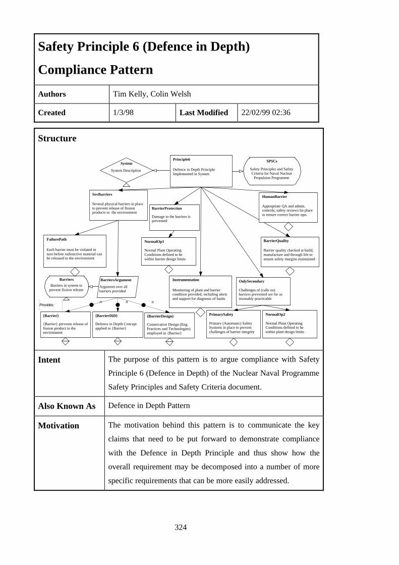
324
Safety Principle 6 (Defence in Depth)
Compliance Pattern
Authors Tim Kelly, Colin Welsh
Created 1/3/98 Last Modified 22/02/99 02:36
Structure
Defence in Depth PrincipleImplemented in System
Principle6
Several physical barriers in placeto prevent release of fissionproducts to the environment
SevBarriers
{Barrier}
{Barrier} prevents release offission product to theenvironment
Damage to the barriers isprevented
BarrierProtection
FailurePath
Each barrier must be violated inturn before radioactive material canbe released to the environment
BarriersArgument
Argument over allbarriers provided
n
Barriers in system toprevent fission release
Barriers
{BarrierDiD}
Defence in Depth Conceptapplied to {Barrier}
n
System
System Description
SPSCs
Safety Principles and SafetyCriteria for Naval Nuclear
Propulsion Programme
Provides:
PrimarySafety
Primary (Automatic) SafetySystems in place to preventchallenges of barrier integrity
Challenges of (calls on)barriers prevented are far asresonably practicable
OnlySecondary
NormalOp2
Normal Plant OperatingConditions defined to bewithin plant design limits
NormalOp1
Normal Plant OperatingConditions defined to bewithin barrier design limits
Instrumentation
Monitoring of plant and barriercondition provided, including alertsand support for diagnosis of faults
HumanBarrier
Appropriate QA and admin.controls, safety reviews lin placeto ensure correct barrier opn.
{BarrierDesign}
Conservative Design (Eng.Practices and Technologies)employed in {Barrier}
n
BarrierQuality
Barrier quality checked at build,manufacture and through life toensure safety margins maintained
Intent The purpose of this pattern is to argue compliance with Safety
Principle 6 (Defence in Depth) of the Nuclear Naval Programme
Safety Principles and Safety Criteria document.
Also Known As Defence in Depth Pattern
Motivation The motivation behind this pattern is to communicate the key
claims that need to be put forward to demonstrate compliance
with the Defence in Depth Principle and thus show how the
overall requirement may be decomposed into a number of more
specific requirements that can be more easily addressed.

325
Goal:
Principle6
This goal sets out the overall objective of
the pattern – to be able claim that the
Defence in Depth principle has been
implemented.
Model:
System
This model must be instantiated to clearly
define the basis (scope) for making the
Principle6 claim.
Context:
SPSCs
If not referred to already, this context
should be used to point to the MoD SPSCs
document – importantly this context
should identify the issue being used. This
document sets out all of the Safety
Principles (1-78).
Participants
Goal:
SevBarriers
This is the key claim of the Defence in
Depth argument – that there are multiple
barriers in place (be they engineered or
procedural) to prevent release of
radioactive material.
326
Goal:
FailurePath
This goal forms an important part of the
support argument for SevBarriers –
namely that the barriers would each have
to fail in turn for any release to the
environment to be possible. Implicit in
this goal is the idea that the barriers will
fail in a pre-defined order (i.e. primary
barrier will fail before secondary and so
on). The support argument for this goal
must address this issue. Also implied is
this goal is the concept of independence.
For the barriers to fail in turn rather than at
all once there must be no common mode
failures between barriers. For example, it
would be highly undesirable for a common
failure to knock out both primary and
secondary barriers. Such a situation would
invalidate this claim.
Strategy:
BarrierArgument
The argument approach defined by this
strategy is to argue a number of claims for
each of the barriers provided in the system
(defined by the context Barriers).
Participants
(continued)
Context:
Barriers
This context should be instantiated to refer
to design documentation / description that
clearly identifies the barriers being referred
to. For example, this context refer to a
description of 3 barriers provided – fuel
cladding, primary coolant boundary and
containment.
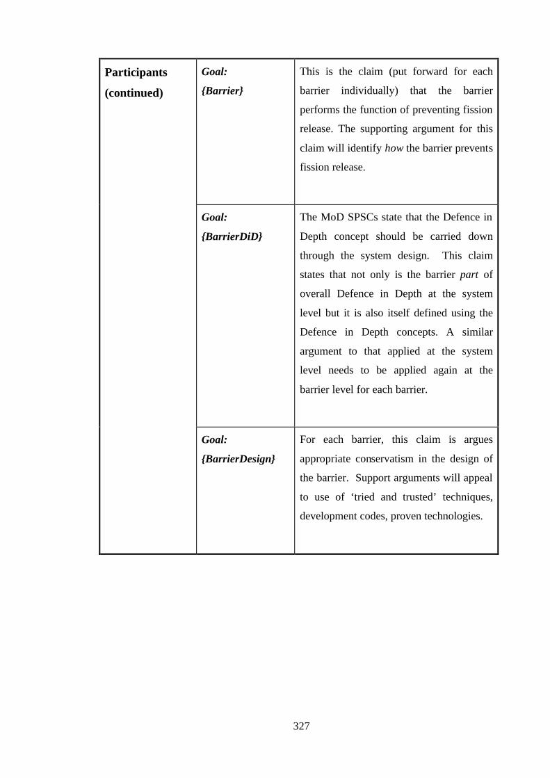
327
Goal:
{Barrier}
This is the claim (put forward for each
barrier individually) that the barrier
performs the function of preventing fission
release. The supporting argument for this
claim will identify how the barrier prevents
fission release.
Goal:
{BarrierDiD}
The MoD SPSCs state that the Defence in
Depth concept should be carried down
through the system design. This claim
states that not only is the barrier part of
overall Defence in Depth at the system
level but it is also itself defined using the
Defence in Depth concepts. A similar
argument to that applied at the system
level needs to be applied again at the
barrier level for each barrier.
Participants
(continued)
Goal:
{BarrierDesign}
For each barrier, this claim is argues
appropriate conservatism in the design of
the barrier. Support arguments will appeal
to use of ‘tried and trusted’ techniques,
development codes, proven technologies.

328
Goal:
BarrierProtection
The plant should design so as to prevent
damage to the barriers. To support this
claim may require an assessment of the
activities and equipment that could cause
damage to the barriers – e.g. activities that
could damage the integrity of plant
containment.
Goal:
NormalOp1
A key element of the support for
BarrierProtection is the claim that the
barriers are designed to cope with the
normal operating environment and limits
of the plant. A deterministic justification
should be provided that addresses both the
appropriate definition of the operating
limits and the ability of the barriers to
correct operate and function within those
limits.
Participants
(continued)
Goal:
Instrumentation
The status of the barriers should be
annunciated to the system operators at all
times. Particularly, calls on barriers should
be alerted. Instrumentation should be
sufficient to aid diagnosis of faults in
operation. The supporting argument for
this goal will identify the instrumentation
available.
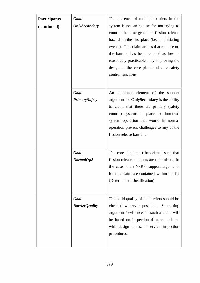
329
Goal:
OnlySecondary
The presence of multiple barriers in the
system is not an excuse for not trying to
control the emergence of fission release
hazards in the first place (i.e. the initiating
events). This claim argues that reliance on
the barriers has been reduced as low as
reasonably practicable – by improving the
design of the core plant and core safety
control functions.
Goal:
PrimarySafety
An important element of the support
argument for OnlySecondary is the ability
to claim that there are primary (safety
control) systems in place to shutdown
system operation that would in normal
operation prevent challenges to any of the
fission release barriers.
Goal:
NormalOp2
The core plant must be defined such that
fission release incidents are minimised. In
the case of an NSRP, support arguments
for this claim are contained within the DJ
(Deterministic Justification).
Participants
(continued)
Goal:
BarrierQuality
The build quality of the barriers should be
checked wherever possible. Supporting
argument / evidence for such a claim will
be based on inspection data, compliance
with design codes, in-service inspection
procedures.

330
Participants
(continued)
Goal:
HumanBarrier
Any operators in a system can be
considered to be another form of safety
barrier. By their actions they can often
determine the severity of the consequences
of an accident. As such, appropriate
controls should be in place that ensure the
correct ‘functioning’ of all human
operators. The support argument for this
claim will be based on training procedures,
operating checks, procedural safety
systems etc.
Collaborations The System model sets the overall system context. The Barriers
context identifies barriers within this system.
The Barriers context provides the basis for the decomposition of
BarriersArgument.
NormalOp1 and NormalOp2 address similar concerns. Op1
addresses barrier design limits. Op2 addresses plant design
limits. It is possible that similar (or shared) arguments will exist
to support both of these goals – e.g. a deterministic justification
for the system that includes both the core plant and barriers.
Applicability This pattern can be applied to systems that must demonstrate
satisfaction of the MoD Safety Principles and Safety Criteria for
the Nuclear Naval Programme (Principle 6). An implicit
assumption is that the system is capable of fission product
release to the environment (i.e. there is fissile material involved).
Consequences After instantiating this pattern, a number of unresolved goals will
remain:
FailurePath
{Barrier} – n of, for n barriers
{BarrierDiD} – n of, for n barriers

331
{BarrierDesign} – n of, for n barriers
Instrumentation
PrimarySafety
NormalOp1
NormalOp2
BarrierQuality
HumanBarrier
See Participants for a description of the forms of support
argument expected for each of these goals.
Implementation Start by defining system (System)
Identify the barriers in System – hence, define context Barriers.
Construct the {Barrier} arguments for each barrier, then
{BarrierDiD} and {BarrierDesign}
Provide argument for FailurePath
Provide argument for BarrierProtection and NormalOp1
Then address all remaining goals: Instrumentation,
PrimarySafety, NormalOp2, BarrierQuality and
HumanBarrier
Possible Pitfalls
Attempting to apply pattern to a system that is not readily
expressed in terms of a core plant + barriers model.
The assurance of safety achieved by having multiple barriers is
weak unless there is clear evidence of independence and absence
of common mode failures between barriers. These issues must
be addressed under FailurePath.
This pattern expresses a defence in depth argument at an overall
system level. When attempting to apply to a system that would
be considered one of the overall barrier mechanisms – it is still
worth starting from the Principle6 goal. Use the System model
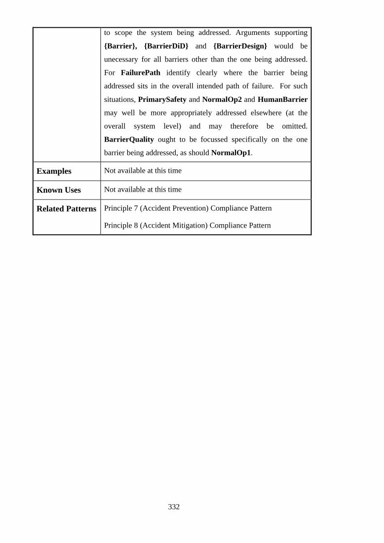
332
to scope the system being addressed. Arguments supporting
{Barrier}, {BarrierDiD} and {BarrierDesign} would be
unecessary for all barriers other than the one being addressed.
For FailurePath identify clearly where the barrier being
addressed sits in the overall intended path of failure. For such
situations, PrimarySafety and NormalOp2 and HumanBarrier
may well be more appropriately addressed elsewhere (at the
overall system level) and may therefore be omitted.
BarrierQuality ought to be focussed specifically on the one
barrier being addressed, as should NormalOp1.
Examples Not available at this time
Known Uses Not available at this time
Related Patterns Principle 7 (Accident Prevention) Compliance Pattern
Principle 8 (Accident Mitigation) Compliance Pattern

333
References
[1] L. Arnold, Windscale 1957: Anatomy of a Nuclear Accident. London:
Macmillan, 1992.
[2] T. A. Kletz, Learning from Accidents in Industry. London: Butterworths, 1988.
[3] CIMAH, “The Control of Industrial Major Accident Hazards (CIMAH)
Regulations 1984,” SI 1984/1902, 1984.
[4] W. D. Cullen, “The Public Enquiry into the Piper Alpha Disaster,” Department
of Energy, London, HMSO November 1990.
[5] C. Edwards, “Railway Safety Cases,” presented at Safety and Reliability of
Software Based Systems - Twelfth Annual CSR Workshop, Bruges, Belgium,
1997.
[6] HSE, “Railway Safety Cases - Railway (Safety Case) Regulations 1994 -
Guidance on Regulations,” Health and Safety Executive, HSE Books 1994.
[7] R. Chuse, Pressure vessels: the ASME code simplified, 7th ed. New York;
London: McGraw-Hill, 1993.
[8] MoD, “JSP 430 - Ship Safety Management System Handbook,” Ministry of
Defence January 1996.
[9] MoD, “00-55 Requirements of Safety Related Software in Defence Equipment,”
Ministry of Defence, Defence Standard August 1997.
[10] MoD, “00-56 Safety Management Requirements for Defence Systems,” Ministry
of Defence, Defence Standard December 1996.
[11] R. J. Cullen, “Safety as a Design Tool,” presented at Managing Risk in a
Changing Organisation Climate - Proceedings of the Safety and Reliability
Symposium, Swindon, U.K., 1996.
[12] T. P. Kelly, “Literature Survey for Work on Evolvable Safety Cases,”
Department of Computer Science, University of York, York, 1st Year
Qualifying Dissertation June 1995.
[13] HSE, “A guide to the Offshore Installations (Safety Case) Regulations 1992,”
Health and Safety Executive, HSE Books 1992.

334
[14] IEC, “61508 - Functional Safety of Electrical / Electronic / Programmable
Electronic Safety-Related Systems,” International Electrotechnical Commission,
Draft Standard December 1997.
[15] SAE, “ARP 4754 - Certification Considerations for Highly-Integrated or
Complex Aircraft Systems,” The Society for Automotive Engineers December
1994.
[16] JAA, “Joint Airworthiness Requirements JAR-25: Large Aeroplanes (Change
13),” Civil Aviation Authority October 1989.
[17] HSE, “Safety Assessment Principles for Nuclear Plants,” Health and Safety
Executive, HSE Books 1992.
[18] Railtrack, “Engineering Safety Management System,” Electrical Engineering
and Control Systems, Railtrack, London August 1996.
[19] CENELEC, “Railway applications The specification and demonstration of
dependability, reliability, availability, maintainability and safety (RAMS),”
European Committee for Electrotechnical Standardisation, Brussels, Draft
Standard prEN 50126, November 1995.
[20] HSE, “The Work of the HSE's Nuclear Installations Inspectorate,” Health and
Safety Executive, HSE Books 1995.
[21] S. A. Harbison, “Developments in Safety Standards and Regulations,” Nuclear
Energy, vol. 33, pp. 383-386, 1994.
[22] S. Barker, I. Kendall, and A. Darlison, “Safety Cases for Software Intensive
Systems,” presented at 16th International Conference on Computer Safety and
Reliability (SAFECOMP'97), York, 1997.
[23] P. Pymm, “Integrated Software Maintenance Environment for Safety-Related
Systems,” Measurement and Control, vol. 36, pp. 73-75, 1993.
[24] L. Hogberg, “Shutting Down 5 Reactors: Reasons Why and Lessons Learnt,”
Nuclear Europe Worldscan, vol. 14, pp. 42-43, 1994.
[25] A. W. Clarke, “Magnox Safety Review: Extending the Life of Britain's Work
Horses,” Nuclear Energy, vol. 28, pp. 215-220, 1989.
[26] R. Ford, “Traction Safety Cases - Storm Imminent,” in Modern Railways, 1996,
pp. 80-82.

335
[27] D. Learmount, “Family Ties Undone,” in Flight International, 1996, pp. 34-35.
[28] J. A. McDermid, “Support for Safety Cases and Safety Arguments using SAM,”
Reliability Engineering and System Safety, vol. 43, pp. 111-127, 1994.
[29] S. Wilson, T. P. Kelly, and J. A. McDermid, “Safety Case Development:
Current Practice, Future Prospects,” presented at Safety and Reliability of
Software Based Systems - Twelfth Annual CSR Workshop, Bruges, Belgium,
1997.
[30] S. Wilson, J. McDermid, P. Fenelon, and P. Kirkham, “No More Spineless
Safety Cases: A Structured Method and Comprehensive Tool Support for the
Production of Safety Cases,” presented at 2nd International Conference on
Control and Instrumentation in Nuclear Installations (INEC'95), Cambridge,
UK, 1995.
[31] S. Wilson and J. A. McDermid, “Integrated Analysis of Complex Safety Critical
Systems,” The Computer Journal, vol. 38, pp. 765-776, 1995.
[32] P. Bishop and R. Bloomfield, “The SHIP Safety Case Approach: A Combination
of System and Software Methods,” presented at Safety and Reliability of
Software Based Systems - Twelfth Annual CSR Workshop, Bruges, Belgium,
1997.
[33] N. Fenton, “The Role of Measurement in Software Safety Assessment,”
presented at Safety and Reliability of Software Based Systems - Twelfth Annual
CSR Workshop, Bruges, Belgium, 1997.
[34] K. A. Delic, F. Mazzanti, and L. Strigini, “Formalising a Software Safety Case
via Belief Networks,” SHIP (Assessment of the Safety of Hazardous Industrial
Processes in the Presence of Design Faults), Project Report SHIP/T046,
September 1995.
[35] J. Hesketh and D. Robertson, “Communication in Safety Cases - A Semantic
Approach,” presented at IEE Colloquium on Knowledge Based Systems for
Safety-Critical Applications, 1994.
[36] P. Bishop, R. Bloomfield, L. Emmet, C. Jones, and P. Froome, Adelard Safety
Case Development Manual. London: Adelard, 1998.

336
[37] J. A. McDermid, “Personal Communication with Praxis Critical Systems (Part
Developers of 00-55),” , 1997.
[38] M. Cass and R. Le Poidevin, A Logic Primer, 2nd ed. London: Vortext
Publishing, 1993.
[39] B. Aarts, English Syntax and Argumentation. London: Macmillan, 1997.
[40] R. Munson, The way of words: an informal logic. Boston MA: Houghton,
Mifflin, 1976.
[41] T. Govier, A Practical Study of Argument, 3rd ed. Belmont CA: Wadsworth,
1992.
[42] S. E. Toulmin, The Uses of Argument. Cambridge: Cambridge University Press,
1958.
[43] W. Grennan, Argument Evaluation. London: Lanham, 1984.
[44] J. Sparrow, Knowledge in Organisations: Access to Thinking At Work. London:
SAGE, 1998.
[45] C. Fiol and H. A, “Maps for Managers: Where are we? Where do we go from
here?,” Journal of Management Studies, vol. 29, pp. 267-286, 1992.
[46] J. Lee, “Design Rationale Capture and Use,” AI Magazine, vol. 14, pp. 24-26,
1993.
[47] F. Lakin, J. Wambaugh, L. Leifer, D. Cannon, and C. Sivard, “The Electronic
Design Notebook: Performing Medium and Processing Medium,” The Visual
Computer, vol. 5, pp. 214-226, 1989.
[48] J. Lee, “SIBYL: A Tool for Managing Group Decision Rationale,” presented at
Computer Supported Cooperative Work 1990 (CSCW 90), 1990.
[49] H. Raiffa, Decision Analysis: Addison Wesley, 1968.
[50] J. Conklin and M. Begeman, “gIBIS - A Hypertext Tool for Exploratory Policy
Discussion,” ACM Transactions on Office Information Systems, vol. 6, pp. 303-
331, 1988.
[51] S. Fickas and B. Helm, “Knowledge representation and reasoning in the design
of composite systems,” IEEE Transactions on Software Engineering, vol. 18,
pp. 470-82, 1992.

337
[52] S. Green, “Goal-driven Approaches to Requirements Engineering,” Imperial
College, University of London, London, Technical Report 1994.
[53] E. Kavalki, P. Loucopoulos, and D. Filippidou, “Using Scenarios to
Systematically Support Goal-Directed Elaboration for Information System
Requirements,” Information Systems Engineering Group, Department of
Computation, UMIST, Manchester, Technical Report ISE-96-1, 1996.
[54] D. Duffy, C. MacNish, J. McDermid, and P. Morris, “A Framework for
Requirements Analysis Using Automated Reasoning,” presented at Advanced
information systems engineering: 7th International Conference (CAiSE '95),
Jyvaskyla, Finland, 1995.
[55] IEE, Proceedings of International Conference on Sizewell B: The First Cycle.
London: IEE, 1996.
[56] N. Jayaratna, Understanding and Evaluating Methodologies: NIMSAD, A
Systematic Framework. London: McGraw-Hill, 1994.
[57] T. P. Kelly, “A Six-Step Method for the Development of Goal Structures,” York
Software Engineering, Flixborough, U.K. 1997.
[58] B. Nuseibeh, “A Multi-Perspective Framework for Method Integration,” in
Department of Computing. London: Imperial College, University of London,
1994.
[59] P. Vincke, Multicriteria Decision-Aid. Chichester: Wiley, 1992.
[60] M. Fletcher, “Certification Issues for IMA Systems,” presented at IEE Seminar
on the Certification of Ground / Air Systems, London, 1998.
[61] R. A. Edwards, “ASAAC Phase 1 Harmonized Concept Summary,” presented at
ERA Technology Avionics Conference and Exhibition, London, 1994.
[62] C. L. Liu and J. W. Layland, “Scheduling Algorithms for Multiprogramming in
a Hard Real-Time Environment,” Journal of the ACM, vol. 20, pp. 40-61, 1973.
[63] ISO, “ISO 11898 Road Vehicles - Interchange of Digital Information -
Controller Area Network,” International Standards Organisation 1993.
[64] H. Kopetz and W. Ocheneiter, “Clock Synchronisation in Distributed Real-Time
Systems,” IEEE Transactions on Computers, vol. 36, pp. 933-940, 1987.
338
[65] RTCA and EUROCAE, “Software Considerations in Airborne Systems and
Equipment Certification,” Radio Technical Commission for Aeronautics RTCA
DO-178B/EUROCAE ED-12B, 1993.
[66] M. Field and R. Foulkes, Project Management (PMT 605), Unit 7: Change
Control. Milton Keynes: The Open University, 1987.
[67] K. Ross, “Software Configuration Management in the Support of Formal
Development,” in Software Verification Research Centre, School of Information
Technology. Brisbane: University of Queensland, 1997.
[68] JAA, “Joint Airworthiness Requirements JAR-E: Engines (Change 8),” Civil
Aviation Authority May 1990.
[69] D. S. Queener, “Reports, Standards and Safety Guides,” Nuclear Safety, vol. 35,
pp. 339-44, 1994.
[70] Collins, Collins English Dictionary, 3rd ed. Glasgow: HarperCollins, 1991.
[71] C. Alexander, The Timeless Way of Building. New York: Oxford University
Press, 1979.
[72] C. Alexander, S. Ishikawa, M. Silverstein, M. Jacobson, I. Fiksdahl-King, and
A. Shlomo, A Pattern Language: Towns, Buildings, Construction. New York:
Oxford University Press, 1977.
[73] C. Alexander, M. Silverstein, A. Shlomo, S. Ishikawa, and D. Abrams, The
Oregon Experiment. New York: Oxford University Press, 1975.
[74] K. Beck, “Patterns and Software Development,” Dr. Dobbs Journal, vol. 19, pp.
18-23, 1993.
[75] G. Booch, “Patterns,” Object Magazine, vol. 3, 1993.
[76] P. Coad, “Object-Oriented Patterns,” Communications of the ACM, vol. 35, pp.
152-159, 1992.
[77] H. Mili, F. Mili, and A. Mili, “Reusing Software: Issues and Research
Directions,” IEEE Transactions on Software Engineering, vol. 21, pp. 528-562,
1995.
[78] K. Beck and W. Cunningham, “Using Pattern Languages for Object-Oriented
Programs,” presented at Conference on Object-Oriented Programming Systems,

339
Languages, and Applications (OOPSLA'87), Workshop on the Specification and
Design for Object-Oriented Programming, Orlando, Florida, 1987.
[79] J. Coplien, “Idioms and Patterns As Architectural Literature,” IEEE Software,
vol. 14, pp. 36-42, 1997.
[80] E. Gamma, “Object-Oriented Software Development based on ET++: Design
Patterns, Class Library, Tools,” in Institut fur Informatik. Zurich: University of
Zurich, 1991.
[81] B. Appleton, “Patterns and Software: Essential Concepts and Terminology,” .
http://www.enteract.com/~bradpp/docs/patterns-intro.html, 1997.
[82] E. Gamma, R. Helm, R. Johnson, and Vlissides, Design Patterns: Elements of
Reusable Object-Oriented Software. Reading, MA: Addison-Wesley, 1995.
[83] J. Rumbaugh, M. Blaha, W. Premerlani, F. Eddy, and W. Lorensen, Object-
Oriented Modelling and Design. Englewood Cliffs: Prentice-Hall, 1991.
[84] I. Jacobson, M. Christerson, P. Jonsson, and G. Overgaard, Object-Oriented
Software Engineering - A Use Case Driven Approach. Wokingham, England:
Addison-Wesley, 1992.
[85] G. Booch, Object-Oriented Analysis and Design with Applications. Redwood
City, CA: Benjamin-Cummings, 1994.
[86] J. Coplien and D. Schmidt, Pattern Languages of Program Design. Reading,
MA: Addison-Wesley, 1995.
[87] P. Chen, “The Entity Relationship Model - Towards a Unified View of Data,”
ACM Transactions on Database Systems, vol. 1, pp. 9-36, 1976.
[88] W. E. Vesely, “Fault Tree Handbook,” US Nuclear Regulatory Commission,
Washington DC, USA NUREG-0492 [0942], 1981.
[89] K. Wolf and C. Liu, “New Clients with Old Servers: A Pattern Language for
Client / Server Frameworks,” in Pattern Languages of Program Design, J.
Coplien and D. Schmidt, Eds. Reading, MA: Addison-Wesley, 1995, pp. 51-64.
[90] D. Riehle and H. Zullinghoven, “A Pattern Language for Tool Construction and
Integration Based on the Tools and Materials Metaphor,” in Pattern Languages
of Program Design, J. Coplien and D. Schmidt, Eds. Reading, MA: Addison-
Wesley, 1995, pp. 9-42.

340
[91] S. Adams, “Functionality Ala Carte,” in Pattern Languages of Program Design,
J. Coplien and D. Schmidt, Eds. Reading, MA: Addison-Wesley, 1995, pp. 7-8.
[92] B. Rubel, “Patterns for Generating a Layered Architecture,” in Pattern
Languages of Program Design, J. Coplien and D. Schmidt, Eds. Reading, MA:
Addison-Wesley, 1995, pp. 119-128.
[93] R. Lajoie and R. Keller, “Design and Reuse in Object-Oriented Frameworks:
Patterns, Contracts and Motifs in Concert,” in Object-Oriented Technology for
Database and Software Systems, V. Alagar and R. Missaoui, Eds. Singapore:
World Scientific Publishing, 1995, pp. 295-312.
[94] E. Gamma, R. Helm, R. Johnson, and J. Vlissides, “Design Patterns: Abstraction
and Reuse of Object-Oriented Design,” presented at ECOOP'93 - Object-
Oriented Programming, 7th European Conference, Kaiserslautern, Germany,
1993.
[95] T. Kelly and J. McDermid, “Safety Case Construction and Reuse Using
Patterns,” presented at 16th International Conference on Computer Safety and
Reliability (SAFECOMP'97), York, 1997.
[96] N. A. M. Maiden and A. G. Sutcliffe, “Analogically Based Reusability,”
Behavioural Information and Technology, vol. 11, pp. 79-98, 1992.
[97] N. A. M. Maiden and A. G. Sutcliffe, “People-Oriented Software Reuse: The
Very Thought,” presented at Advances in Software Reuse - Second International
Workshop on Software Reusability, Lucca, Italy, 1993.
[98] MoD, “Safety Principles and Safety Criteria for the Naval Nuclear Propulsion
Programme,” Ministry of Defence NNTSP/BR3/100/94 Issue 2, August 1996.
[99] T. Kelly, I. Bate, J. McDermid, and A. Burns, “Building a Preliminary Safety
Case: An Example from Aerospace,” presented at Australian Workshop on
Industrial Experience with Safety Critical Systems and Software, Sydney,
Australia, 1997.
[100] P. Brown, “Safety Argument Manager Assessment Report,” Rolls-Royce and
Associates Ltd., Company Report RRA 17983, February 1998.
[101] J. McDermid, “ALARP for Software: Requirements and Guidance,” McDermid
and Associates, Internal Report DMCS/079/97, May 1998.

341
[102] R. Born, “Patterns for Safety Critical Systems,” in Department of Computer
Science. York: University of York, 1998.
[103] S. Glasstone and A. Sesonke, Nuclear Reactor Engineering. New York: Van
Nostrand Reinhold, 1981.
[104] P. Bishop, “Using Reversible Computing to Achieve Fail-safety,” presented at
Eighth International Symposium on Software Reliability (ISSRE'97),
Albuquerque, New Mexico, 1997.