arihant elsys igbt driver solution - … · 2160 energy meter features maximum demand measurement...
TRANSCRIPT

masibus1
2
3
4
5
6
7
8
R Y B
+
+
+
-
-
-
TA+
TB-
RS485
RELAY
9
10
11
12
13
14
15
16
N
C/IN+
NO/IN-
NC/OP+
OP-
masibus1
2
3
4
5
6
7
8
R Y B
+
+
+
-
-
-
TA+
TB-
RS485
RELAY
9
10
11
12
13
14
15
16
N
C/IN+
NO/IN-
NC/OP+
OP-
IGBT DRIVER SOLUTION
2AP0106 -12-FRC
IGBT DRIVER
Features
Low Power dual channel driver
2X1 Watt Output Power
A gate current, +15V/-10V
Drive up to 1200V IGBT Module
Compact Plug & Play solution
Standard
Reliable & rugged design
SOFT Shut down Function
±6
Electrical interface
On board isolated DC-DC converter
Interface for 3.3V...15 V logic level
Common fault feedback signal to interface with controller
Field configurable blocking time
Safe isolation to IEC 61800-5-1, IEC-60664-1 & En50178, protection class II
User Selectable Rg
Application
solar converters
Servo Stabilizer
Industrial drives
Electric / hybrid drive commercial vehicles
Uninterrupted Power supply
Benefits
ARIHANT ELSYS
WEB: www.arihantelectricals.com
Ready to use!!!
Gate clamping & Safe Torque Operation
Switching frequency up to 50 KHz
Less than 1 uS delay time
Long service life
Primary/Sec. Supply under voltage lockout
ASIC based driver solution
Vce monitoring for short circuit protection
Superior EMC 2A
P0
10
6
2160ENERGY METER
Features
Maximum demand measurement
51 Electrical parameter display.
Low burden
It stores energy data & programmed parameter into non-volatile memory using EEPROM
Password Protection for setup parameters.
Recommended Operating condition
Power Supply & Monitoring MIN TYP MAX1. Supply Voltage Vcc to GND : 14.5 15 15.5 V
3. Under Voltage Monitor, Set Fault : 11.3 12.0 12.7 V
Logical Inputs & Outputs1. Input Bias Current : 1902. Interface Logic level : 3.3 V ..... 15.0 V logic level3. Turn-on threshold : 2.6 V4. Turn off threshold : 1.3 V5. SOx output , failure Condition : 0.7 V Max., I (SOx)<20 mA total
Short-Circuit Protection1. Vce-monitoring threshold : 9.3 V (Internally Fix)2. Available response time : 4.5
1. Primary/Secondary Under voltage monitoring.2.3. Soft Shut down, For Over Voltage protection.4. Vce monitoring for short circuit protection.5. Schmitt trigger at the Input stage, highly susceptible to noise.6. Gate clamping & Safe Torque operation.
Test voltage (50 Hz/1 sec)1. Primary to secondary side : 4.0 KV2. Secondary to secondary side : 4.0 KV
This gate driver is suited for HiPot testing. Nevertheless, it is strongly
recommended to limit the testing time to 1s slots. Excessive HiPot testing at
voltages much higher than 850V may lead to insulation degradation. No
degradation has been observed over 1 min. testing at 2500
Protection Available on driver board
Electrical Isolation
AC(eff)
2. Supply Current Icc (Without Load): 35 mA
µA
µSec (User selectable R18, R19)3. Minimum response time : 4.5 µSec4. Available blocking time : 49 mSec (User Selectable R7)5. Minimum blocking time : 9 µSec
Timing Characteristic (Input to Output of Driver board)1. Turn-on delay t : 900 nSec, Max. under No-load
2. Turn-off delay t : 900 nSec, Max. under No-load
For detail timing information of driver core, refer part specific datasheet.
Power supply reverse polarity protection.
V Each driver core
production sample shipped has undergone 100% testing at the given value or
higher for 1s.
1. Turn-on voltage, V : 15.0 V, any load condition
2. Turn-off voltage, V : -9.9 V, No load
3. Turn-off voltage, V : -8.0 V @ 1 W
4. Gate Peak Current I : ±6 Amp
5. Internal Gate resistance : 0.5 Ω
6. External Gate resistance : 2.5 Ω, Minimum7. Switching frequency F : 20 Khz / 50 Khz8. Output Power : 0.9 W, T <85 °C
: 1.0 W , T <70 °C
1. Electrical
ERROR : Low to High / High to Low (Site selectable)
Power ON: Green (Normally ON, Off during fault)
ERROR : RED (ON during Fault)
d(on)
d(off)
AC(eff)
GHx
GLx
GLx
out
amb
amb
Output Voltage / Current / Power
Interfacing with Control Circuit
LED Indication
Environmental
Mechanical Dimension
Driving Capability
Working temperature : -40 to 10 ºC
Storage temperature : -40 to 90 ºC
PCB : 90 mm X 60 mm
Mounting Hole : 80 mm X 50 mm
Enclosure : Open Frame
Weight : 0.3 Kg
The 2SC0106T drives all usual IGBT modules up to 450 A /1200 V
or 600A/600V. Driving power depends on switching frequency so
in case of any doubt during selection process pl. contact our sales
/ technical representative.
5
ORDERING CODE
IGBT up to
Technical Specification
[email protected] www.arihantelectricals.com
IGBT DRIVER SOLUTION
650 V
1200 V
01 06 -2 A P
07
12
Use of 2nd Generation Driver Core
Arihant Electricals made
Plug & Play Driver BoardPower : 1 W
6A Peak Current1200 V
Driver will be supplied with 10E Rg. (gate resistor)
For special requirement pl. specify during ordering.
STANDARD PART will be 2AP0106-12-FRC
90mm
60 mm
ARIHANT ELSYS
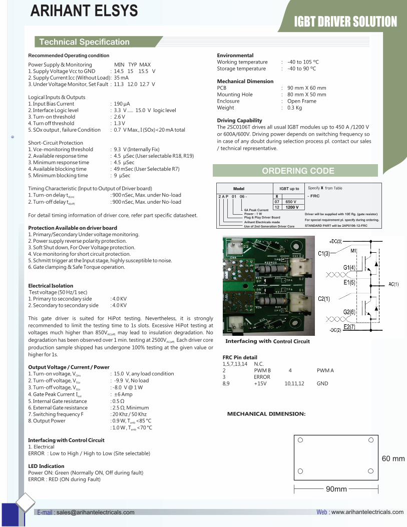
Interfacing with Control Circuit
- FRC
FRC Pin detail1,5,7,13,14 N.C.2 PWM B 4 PWM A3 ERROR8,9 +15V 10,11,12 GND
MECHANICAL DIMENSION: