arinc 600 series - mouser electronics · overview arinc 600 series benefits ..... applications
TRANSCRIPT
ARINC 600 SeriesRack & Panel Rectangular Connectors

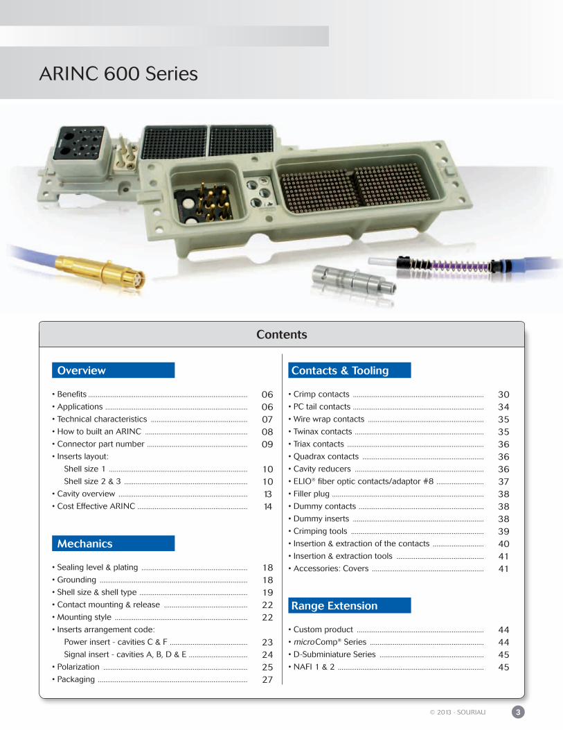
ARINC 600 Series
3© 2013 - SOURIAU
Contents
• Custom product ...................................................................
• microComp® Series ............................................................
• D-Subminiature Series .......................................................
• NAFI 1 & 2 .............................................................................
• Benefits ....................................................................................
• Applications ...........................................................................
• Technical characteristics ...................................................
• How to built an ARINC ......................................................
• Connector part number .....................................................
• Inserts layout:
Shell size 1 .........................................................................
Shell size 2 & 3 .................................................................
• Cavity overview ....................................................................
• Cost Effective ARINC ..........................................................
• Sealing level & plating ........................................................
• Grounding ..............................................................................
• Shell size & shell type .........................................................
• Contact mounting & release ............................................
• Mounting style ......................................................................
• Inserts arrangement code:
Power insert - cavities C & F .........................................
Signal insert - cavities A, B, D & E ...............................
• Polarization ............................................................................
• Packaging ...............................................................................
• Crimp contacts .....................................................................
• PC tail contacts .....................................................................
• Wire wrap contacts .............................................................
• Twinax contacts ....................................................................
• Triax contacts ........................................................................
• Quadrax contacts ................................................................
• Cavity reducers ....................................................................
• ELIO® fiber optic contacts/adaptor #8 .........................
• Filler plug ................................................................................
• Dummy contacts ..................................................................
• Dummy inserts .....................................................................
• Crimping tools ......................................................................
• Insertion & extraction of the contacts ...........................
• Insertion & extraction tools ..............................................
• Accessories: Covers ...........................................................
0606070809
10101314
1818192222
23242527
303435353636363738383839404141
44444545
Overview Contacts & Tooling
Mechanics
Range Extension

ARIN
C 600
OverviewARINC 600 Series
Benefits ...............................................................................................................................................
Applications ......................................................................................................................................
Technical characteristics ...............................................................................................................
How to built an ARINC ..................................................................................................................
Connector part number ................................................................................................................
Inserts layout: Shell Size 1 .................................................................................................................................. Shell Size 2 & 3 ..........................................................................................................................
Cavity overview ................................................................................................................................
Cost Effective ARINC .....................................................................................................................
06
06
07
08
09
1010
13
14
ARINC 600 Series
6 © 2013 - SOURIAU
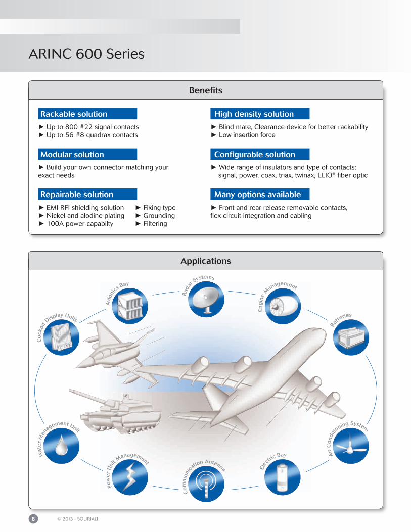
Benefits
ApplicationsEn
gin
e M
anagement
Elec
tric Bay
Ba
tteries
Co
ckpi
t Display Units
Co
mm
unic
ation Antenna
Pow
er
Uni
t Management
Wat
er
Man
agement Unit
Air
Co
nditi
oning System
Rad
ar Systems
Avi
onics
Bay
Blind mate, Clearance device for better rackability Low insertion force
Wide range of insulators and type of contacts: signal, power, coax, triax, twinax, ELIO® fiber optic
Front and rear release removable contacts,flex circuit integration and cabling
High density solution
Configurable solution
Many options available
Up to 800 #22 signal contacts Up to 56 #8 quadrax contacts
Build your own connector matching your exact needs
EMI RFI shielding solution Fixing type Nickel and alodine plating Grounding 100A power capabilty Filtering
Rackable solution
Modular solution
Repairable solution
ARINC 600 Series
7© 2013 - SOURIAU
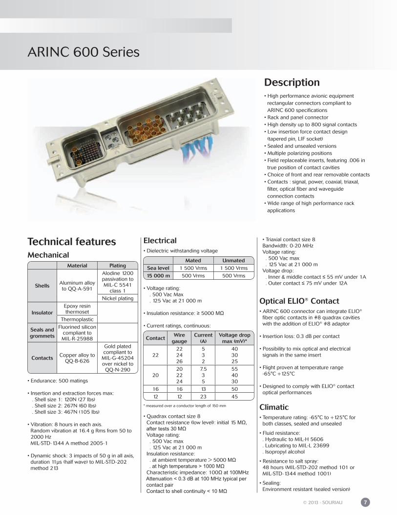
Electrical• Dielectric withstanding voltage
• Voltage rating: . 500 Vac Max . 125 Vac at 21 000 m
• Insulation resistance: ≥ 5000 MΩ
• Current ratings, continuous:
* measured over a conductor length of 150 mm
• Quadrax contact size 8 Contact resistance (low level): initial 15 MΩ, after tests 30 MΩ Voltage rating: . 500 Vac max . 125 Vac at 21 000 m Insulation resistance: . at ambient temperature > 5000 MΩ . at high temperature > 1000 MΩ Characteristic impedance: 100Ω at 100MHz Attenuation < 0.3 dB at 100 MHz typical per contact pair Contact to shell continuity < 10 MΩ
ContactWire
gaugeCurrent
(A)Voltage drop
max (mV)*
22222426
532
403025
20202224
7.535
554030
16 16 13 50
12 12 23 45
Description• High performance avionic equipment rectangular connectors compliant to ARINC 600 specifications• Rack and panel connector• High density up to 800 signal contacts• Low insertion force contact design (tapered pin, LIF socket)• Sealed and unsealed versions• Multiple polarizing positions• Field replaceable inserts, featuring .006 in true position of contact cavities• Choice of front and rear removable contacts• Contacts : signal, power, coaxial, triaxal, filter, optical fiber and waveguide connection contacts• Wide range of high performance rack applications
Technical featuresMechanical
• Endurance: 500 matings
• Insertion and extraction forces max: . Shell size 1: 120N (27 lbs) . Shell size 2: 267N (60 lbs) . Shell size 3: 467N (105 lbs)
• Vibration: 8 hours in each axis. Random vibration at 16.4 g Rms from 50 to 2000 Hz MIL-STD-1344 A method 2005-1
• Dynamic shock: 3 impacts of 50 g in all axis, duration 11μs (half wave) to MIL-STD-202 method 213
• Triaxial contact size 8 Bandwidth: 0-20 MHz Voltage rating: . 500 Vac max . 125 Vac at 21 000 m Voltage drop: . Inner & middle contact ≤ 55 mV under 1A . Outer contact ≤ 75 mV under 12A
Optical ELIO® Contact• ARINC 600 connector can integrate ELIO®
fiber optic contacts in #8 quadrax cavities with the addition of ELIO® #8 adaptor
• Insertion loss: 0.3 dB per contact
• Possibility to mix optical and electrical signals in the same insert
• Flight proven at temperature range -65°C +125°C • Designed to comply with ELIO® contact optical performances
Climatic
• Temperature rating: -65°C to +125°C for both classes, sealed and unsealed
• Fluid resistance: . Hydraulic to MIL-H 5606 . Lubricating to MIL-L 23699 . Isopropyl alcohol
• Resistance to salt spray: 48 hours (MIL-STD-202 method 101 or MIL-STD-1344 method 1001)
• Sealing: Environment resistant (sealed version)
Material Plating
Shells Aluminum alloy to QQ-A-591
Alodine 1200 passivation to MIL-C 5541
class 1
Nickel plating
InsulatorEpoxy resinthermoset
Thermoplastic
Seals and grommets
Fluorined silicon compliant to MIL-R-25988
Contacts Copper alloy to QQ-B-626
Gold plated compliant to
MIL-G-45204 over nickel to
QQ-N-290
Mated UnmatedSea level 1 500 Vrms 1 500 Vrms
15 000 m 500 Vrms 500 Vrms
ARINC 600 Series
8 © 2013 - SOURIAU
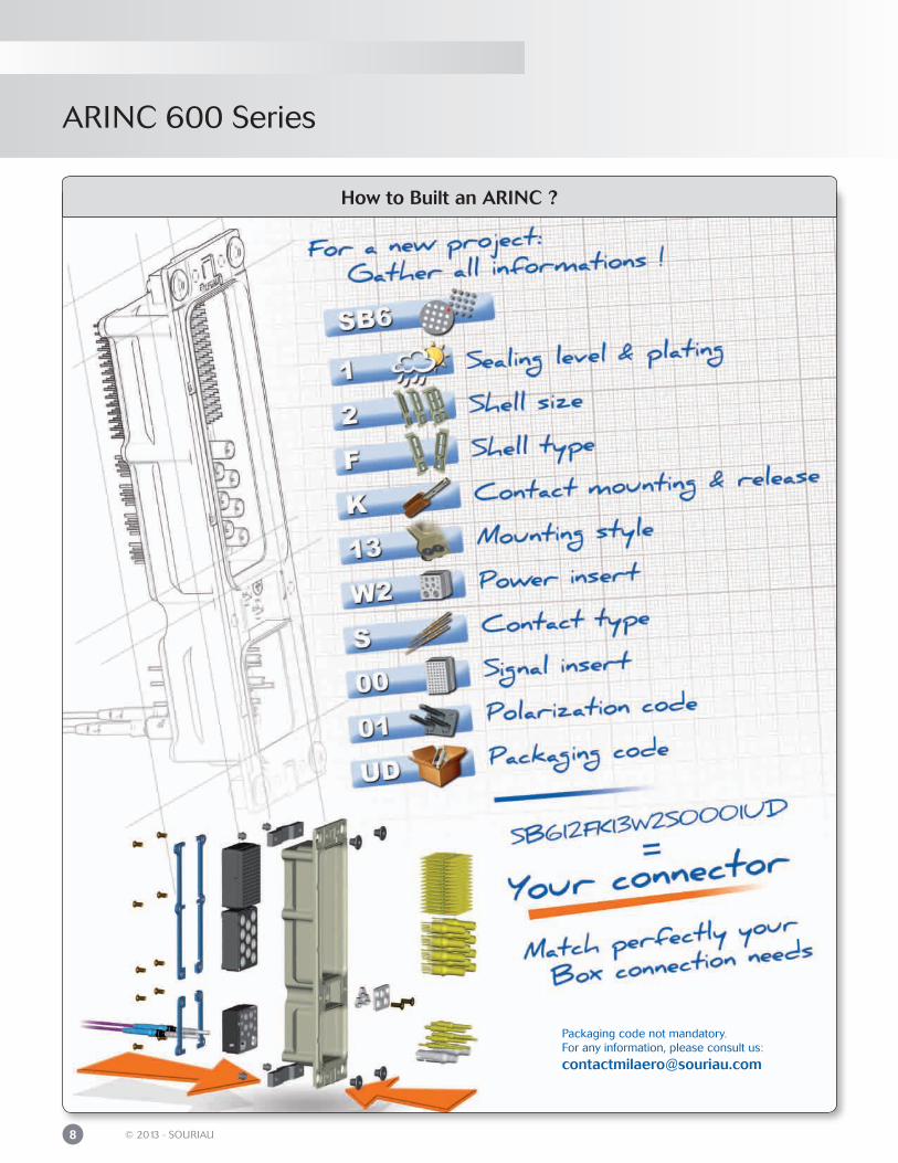
How to Built an ARINC ?
Packaging code not mandatory.For any information, please consult us:
ARINC 600 Series
9© 2013 - SOURIAU
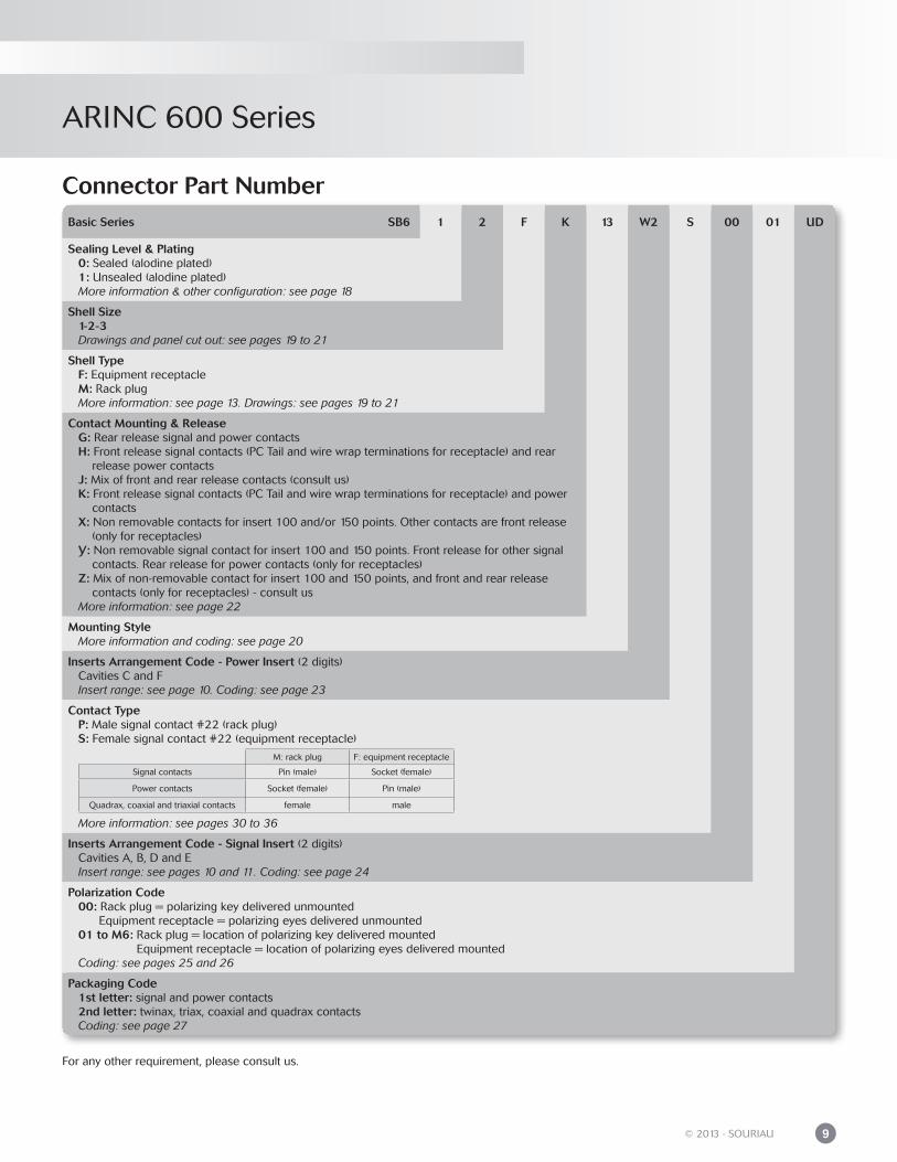
Basic Series SB6 1 2 F K 13 W2 S 00 01 UD
Sealing Level & Plating 0: Sealed (alodine plated) 1: Unsealed (alodine plated) More information & other configuration: see page 18
Shell Size 1-2-3 Drawings and panel cut out: see pages 19 to 21
Shell Type F: Equipment receptacle M: Rack plug More information: see page 13. Drawings: see pages 19 to 21
Contact Mounting & Release G: Rear release signal and power contacts H: Front release signal contacts (PC Tail and wire wrap terminations for receptacle) and rear release power contacts J: Mix of front and rear release contacts (consult us) K: Front release signal contacts (PC Tail and wire wrap terminations for receptacle) and power contacts X: Non removable contacts for insert 100 and/or 150 points. Other contacts are front release (only for receptacles) Y: Non removable signal contact for insert 100 and 150 points. Front release for other signal contacts. Rear release for power contacts (only for receptacles) Z: Mix of non-removable contact for insert 100 and 150 points, and front and rear release contacts (only for receptacles) - consult us More information: see page 22
Mounting Style More information and coding: see page 20
Inserts Arrangement Code - Power Insert (2 digits) Cavities C and F Insert range: see page 10. Coding: see page 23
Contact Type P: Male signal contact #22 (rack plug) S: Female signal contact #22 (equipment receptacle)
More information: see pages 30 to 36
Inserts Arrangement Code - Signal Insert (2 digits) Cavities A, B, D and E Insert range: see pages 10 and 11. Coding: see page 24
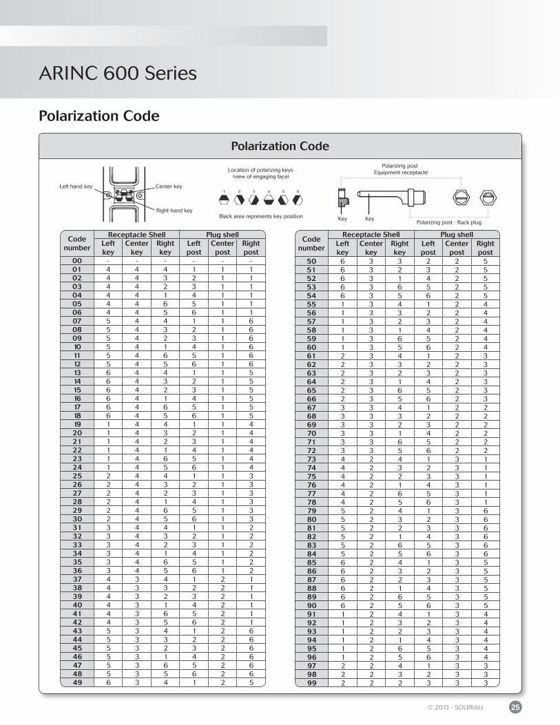
Polarization Code 00: Rack plug = polarizing key delivered unmounted Equipment receptacle = polarizing eyes delivered unmounted 01 to M6: Rack plug = location of polarizing key delivered mounted Equipment receptacle = location of polarizing eyes delivered mounted Coding: see pages 25 and 26
Packaging Code 1st letter: signal and power contacts 2nd letter: twinax, triax, coaxial and quadrax contacts Coding: see page 27
Connector Part Number
For any other requirement, please consult us.
M: rack plug F: equipment receptacle
Signal contacts Pin (male) Socket (female)
Power contacts Socket (female) Pin (male)
Quadrax, coaxial and triaxial contacts female male

ARINC 600 Series
10 © 2013 - SOURIAU
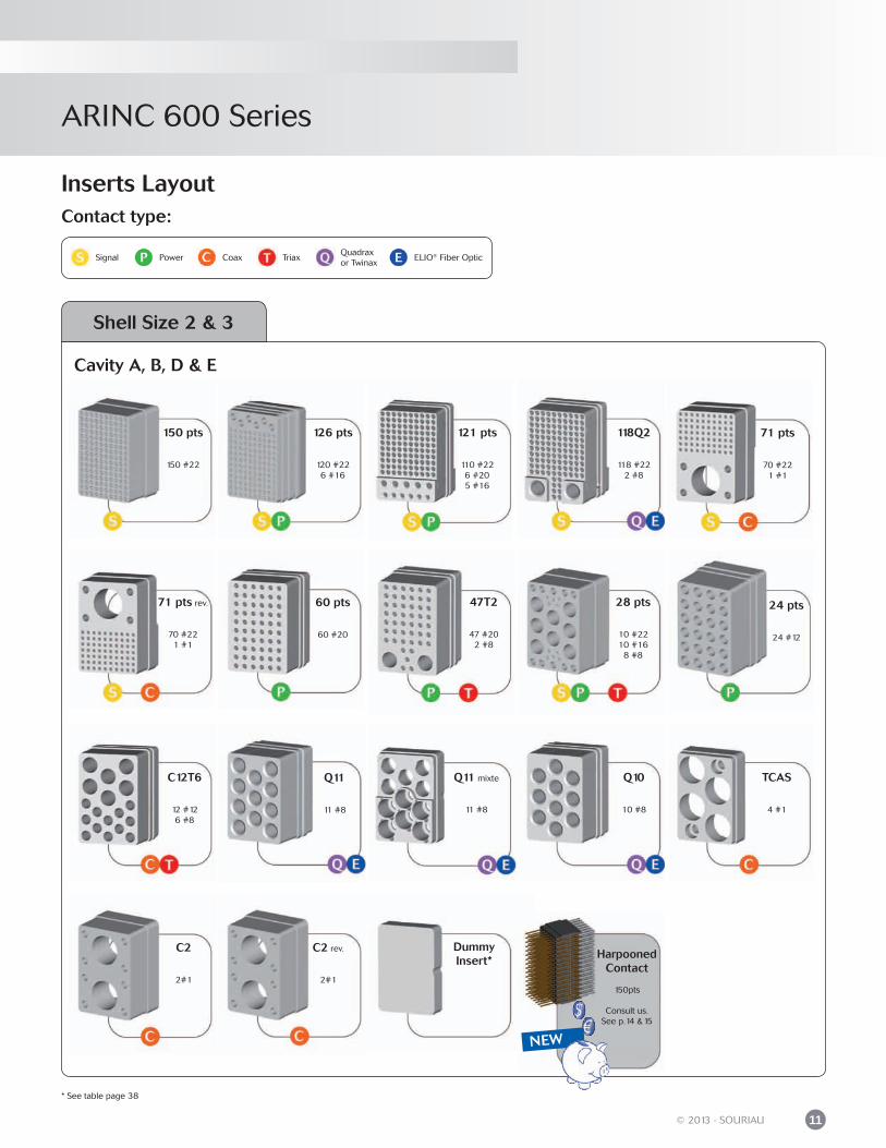
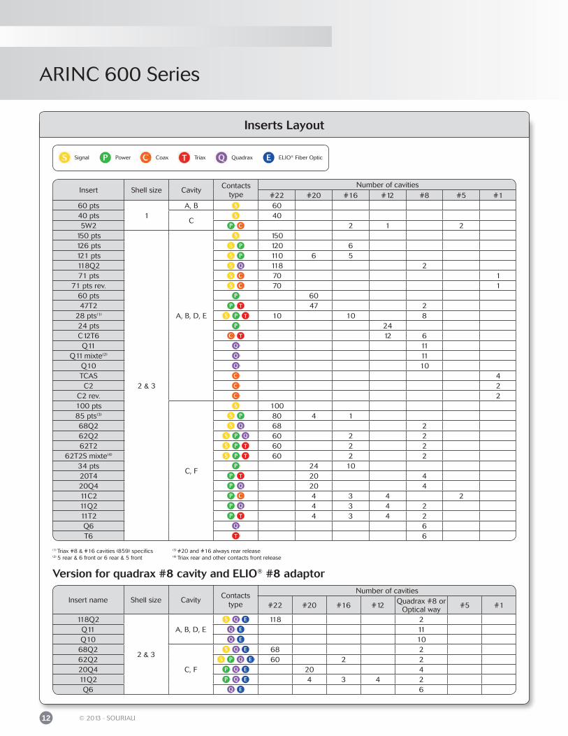
Inserts Layout
Cavity A & B Cavity C
5W2
2 #161 #122 #5
40 pts
40 #22
60 pts
60 #22
Shell Size 1
85 pts
80 #224 #201 #16
100 pts
100 #22
68Q2
68 #222 #8
62Q2
60 #222 #162 #8
62T2
60 #222 #162 #8
Cavity C & F
34 pts
24 #2010 #16
62T2S
60 #222 #162 #8
20T4
20 #204 #8
20Q4
20 #204 #8
11C2
4 #203 #164 #122 #5
11T2
4 #203 #164 #122 #8
11Q2
4 #203 #164 #122 #8
Q6
6 #8
DummyInsert*
DummyInsert*
* See table page 38
Contact type:
Shell Size 2 & 3
DummyInsert*
HarpoonedContact
100pts
Consult us.See p.14 &15NEW
Power Coax Triax ELIO® Fiber OpticSignalQuadrax or Twinax
ARINC 600 Series
11© 2013 - SOURIAU
TCAS
4 #1
24 pts
24 #12
71 pts
70 #221 #1
Cavity A, B, D & E
150 pts
150 #22
126 pts
120 #226 #16
121 pts
110 #226 #205 #16
118Q2
118 #222 #8
* See table page 38
Contact type:
Shell Size 2 & 3
Inserts Layout
60 pts
60 #20
71 pts rev.
70 #221 #1
47T2
47 #202 #8
28 pts
10 #2210 #16
8 #8
C12T6
12 #126 #8
Q11
11 #8
Q11 mixte
11 #8
Q10
10 #8
C2
2#1
C2 rev.
2#1
Power Coax Triax ELIO® Fiber OpticSignalQuadrax or Twinax
DummyInsert* Harpooned
Contact
150pts
Consult us.See p.14 &15
NEW
ARINC 600 Series
12 © 2013 - SOURIAU
Inserts Layout
(1) Triax #8 & #16 cavities (859) specifics(2) 5 rear & 6 front or 6 rear & 5 front
Insert Shell size CavityContacts
typeNumber of cavities
#22 #20 #16 #12 #8 #5 #160 pts
1A, B 60
40 ptsC
405W2 2 1 2
150 pts
2 & 3
A, B, D, E
150126 pts 120 6121 pts 110 6 5118Q2 118 271 pts 70 1
71 pts rev. 70 160 pts 6047T2 47 2
28 pts(1) 10 10 824 pts 24C12T6 12 6Q11 11
Q11 mixte(2) 11Q10 10TCAS 4C2 2
C2 rev. 2100 pts
C, F
10085 pts(3) 80 4 168Q2 68 262Q2 60 2 262T2 60 2 2
62T2S mixte(4) 60 2 234 pts 24 1020T4 20 420Q4 20 411C2 4 3 4 211Q2 4 3 4 211T2 4 3 4 2Q6 6T6 6
Insert name Shell size CavityContacts
type
Number of cavities
#22 #20 #16 #12 Quadrax #8 or Optical way #5 #1
118Q2
2 & 3
A, B, D, E118 2
Q11 11Q10 10
68Q2
C, F
68 262Q2 60 2 220Q4 20 411Q2 4 3 4 2Q6 6
(3) #20 and #16 always rear release(4) Triax rear and other contacts front release
Version for quadrax #8 cavity and ELIO® #8 adaptor
Power Coax Triax Quadrax ELIO® Fiber OpticSignal
ARINC 600 Series
13© 2013 - SOURIAU
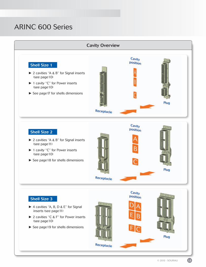
Cavity Overview
2 cavities ‘‘A & B’’ for Signal inserts (see page10)
1 cavity ‘‘C’’ for Power inserts (see page10)
See page17 for shells dimensions
2 cavities ‘‘A & B’’ for Signal inserts (see page11)
1 cavity ‘‘C’’ for Power inserts (see page10)
See page18 for shells dimensions
4 cavities ‘‘A, B, D & E’’ for Signal inserts (see page11)
2 cavities ‘‘C & F’’ for Power inserts (see page10)
See page19 for shells dimensions
Shell Size 3
Shell Size 2
Shell Size 1
ARINC 600 Series
14 © 2013 - SOURIAU
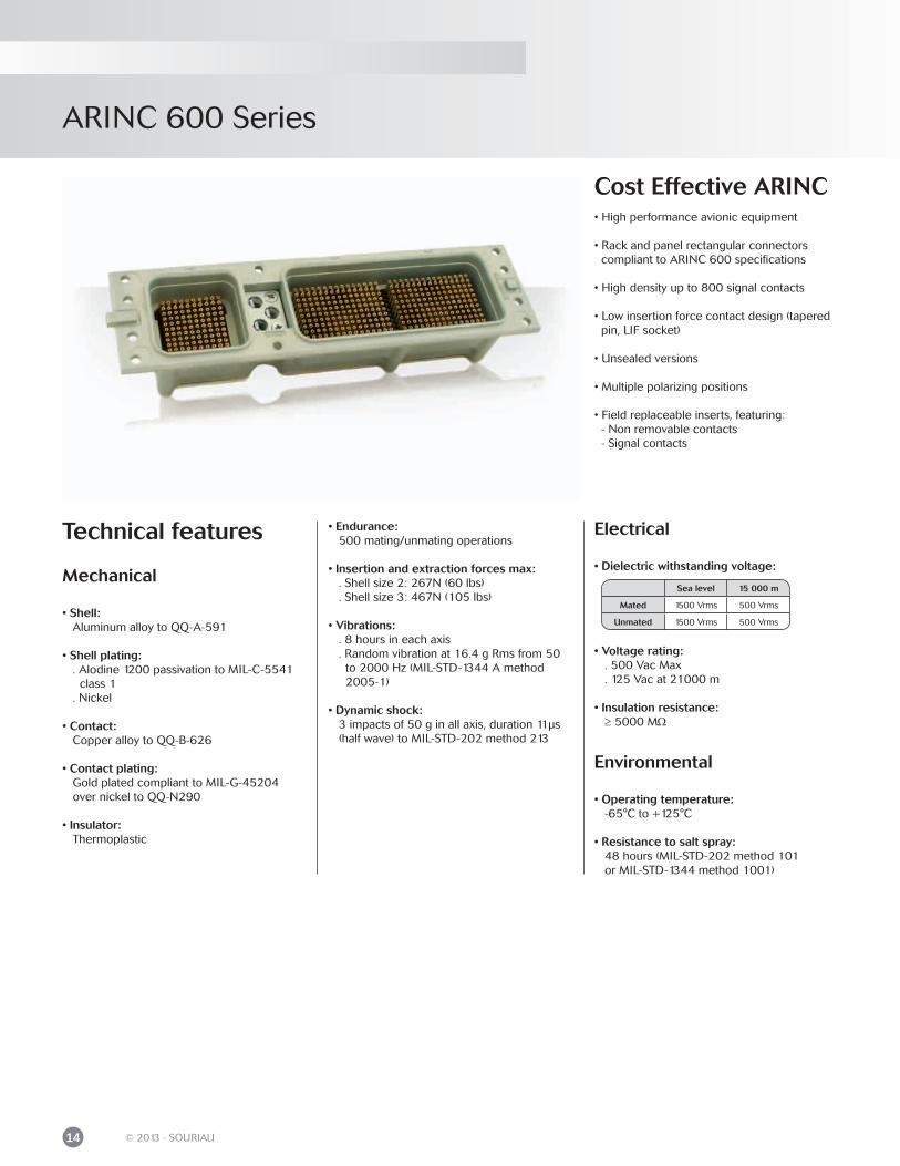
Cost Effective ARINC• High performance avionic equipment
• Rack and panel rectangular connectors compliant to ARINC 600 specifications
• High density up to 800 signal contacts
• Low insertion force contact design (tapered pin, LIF socket)
• Unsealed versions
• Multiple polarizing positions
• Field replaceable inserts, featuring: - Non removable contacts - Signal contacts
Technical features
Mechanical
• Shell: Aluminum alloy to QQ-A-591
• Shell plating: . Alodine 1200 passivation to MIL-C-5541 class 1 . Nickel
• Contact: Copper alloy to QQ-B-626
• Contact plating: Gold plated compliant to MIL-G-45204 over nickel to QQ-N290
• Insulator: Thermoplastic
• Endurance: 500 mating/unmating operations
• Insertion and extraction forces max: . Shell size 2: 267N (60 lbs) . Shell size 3: 467N (105 lbs)
• Vibrations: . 8 hours in each axis . Random vibration at 16.4 g Rms from 50 to 2000 Hz (MIL-STD-1344 A method 2005-1)
• Dynamic shock: 3 impacts of 50 g in all axis, duration 11μs (half wave) to MIL-STD-202 method 213
Sea level 15 000 m
Mated 1500 Vrms 500 Vrms
Unmated 1500 Vrms 500 Vrms
Electrical
• Dielectric withstanding voltage:
• Voltage rating: . 500 Vac Max . 125 Vac at 21000 m
• Insulation resistance: ≥ 5000 MΩ
Environmental
• Operating temperature: -65°C to +125°C
• Resistance to salt spray: 48 hours (MIL-STD-202 method 101 or MIL-STD-1344 method 1001)
ARINC 600 Series
15© 2013 - SOURIAU
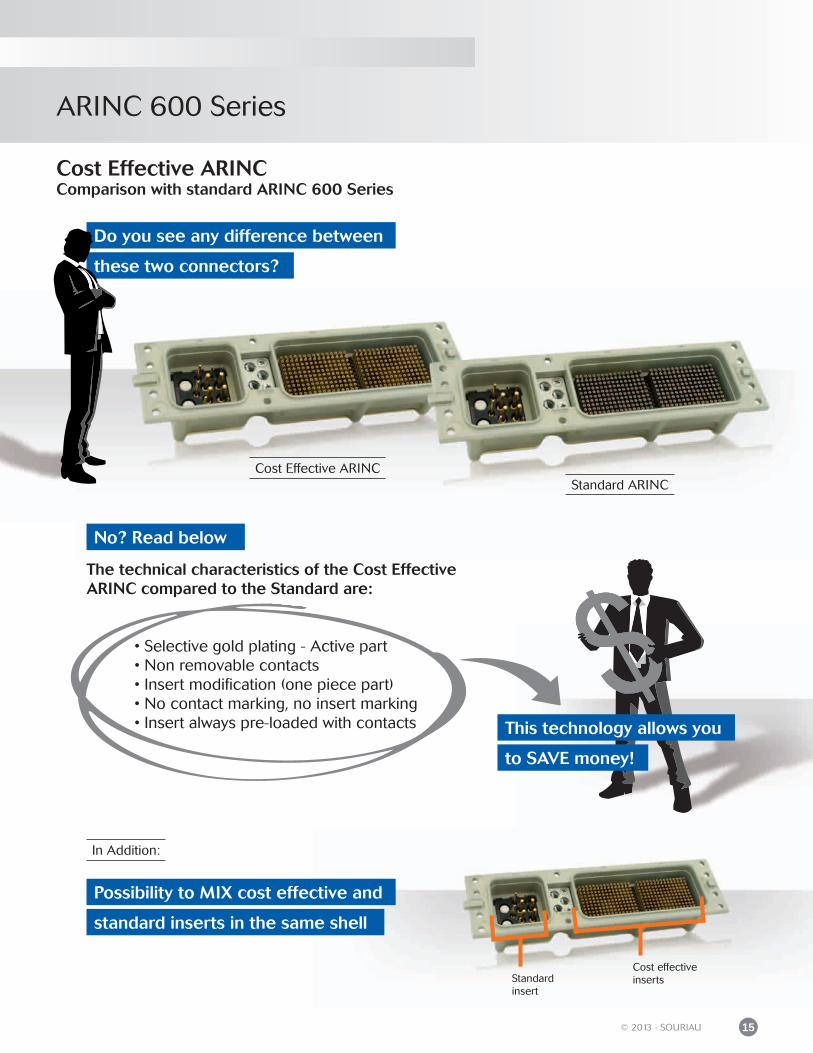
Standard insert
Cost effective inserts
Cost Effective ARINC Comparison with standard ARINC 600 Series
Do you see any difference between
these two connectors?
The technical characteristics of the Cost Effective ARINC compared to the Standard are:
• Selective gold plating - Active part • Non removable contacts • Insert modification (one piece part) • No contact marking, no insert marking • Insert always pre-loaded with contacts This technology allows you
to SAVE money!
Possibility to MIX cost effective and
standard inserts in the same shell
Cost Effective ARINCStandard ARINC
No? Read below
In Addition:

ARIN
C 600
MechanicsSealing level & plating ....................................................................................................................
Grounding ..........................................................................................................................................
Shell size & shell type ....................................................................................................................
Contact mounting & release ........................................................................................................
Mounting style ..................................................................................................................................
Inserts arrangement code: Power insert - cavities C & F .................................................................................................. Signal insert - cavities A, B, D & E ........................................................................................
Polarization ........................................................................................................................................
Packaging ..........................................................................................................................................
18
18
19
22
22
2324
25
27
ARINC 600 Series
ARINC 600 Series
18 © 2013 - SOURIAU
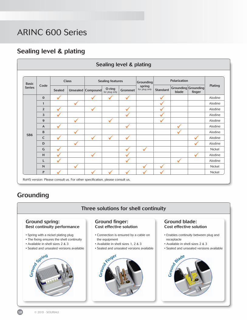
Sealing level & plating
Basic Series
CodeClass Sealing features Grounding
springfor plug only
Polarization
PlatingStandard
Grounding blade
Grounding fingerSealed Unsealed Compound O-ring
for plug onlyGrommet
SB6
0 Alodine
1 Alodine
2 Alodine
3 Alodine
9 Alodine
A Alodine
B Alodine
C Alodine
D Alodine
G Nickel
H Alodine
L Alodine
N Nickel
P Nickel
Sealing level & plating
RoHS version: Please consult us. For other specification, please consult us.
Grounding
Three solutions for shell continuity
• Spring with a nickel plating plug• The fixing ensures the shell continuity• Available in shell sizes 2 & 3• Sealed and unsealed versions available
Ground spring:Best continuity performance
• Connection is ensured by a cable on the equipment• Available in shell sizes 1, 2 & 3• Sealed and unsealed versions available
Ground finger:Cost effective solution
• Enables continuity between plug and receptacle• Available in shell sizes 2 & 3• Sealed and unsealed versions available
Ground blade:Cost effective solution
Gro
und
Blade
Gro
und
Sprin
g
Gro
und
Finger
ARINC 600 Series
19© 2013 - SOURIAU
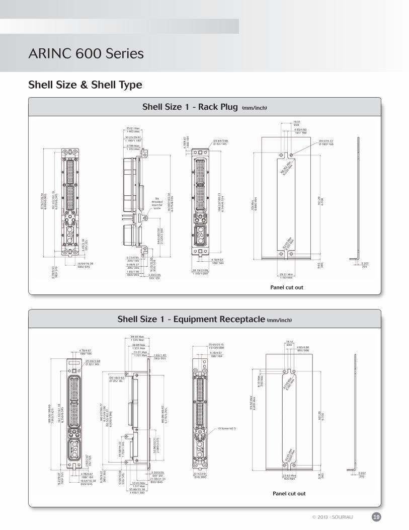
Shell Size & Shell Type
Shell Size 1 - Rack Plug (mm/inch)
Shell Size 1 - Equipment Receptacle (mm/inch)
Panel cut out
16 64/16 38665/ 645
3.4
3/3
.18
.13
5/.
125
177.
67/
176
.91
6.9
95
/6.9
65
161
.42
/161
.13
6.3
55
/6.3
45
9.7
8/9
.53
38
5/
375
35 61 Max1 402 Max
30 23/29 971 190/1 180
2799 Max1 102 Max
Six threaded insert for
screw
5 21/4 95205/ 1959 78/9 27395/ 3651 65/1 40065/ 055 3 30/3 05
130/ 120
14.1
0/1
3.5
9.5
55
/.5
35
64
.01
/63
.50
2.5
20
/2.5
00
167.
00
/16
5.5
06
.575
/6.5
55
16
6.2
2/1
65
.71
6.5
44
/6.5
24
4 78/4 67188/ 184
Ø3 84/3 68Ø 151/ 145
4.7
8/4
.67
.18
8/.
18
4
28 19/27691 110/1 090
175
Min
i6
.89
0 M
ini
161
.29
6.3
50
9.6
5.3
80
Ø4 57/4 22Ø 180/ 166
4 85/4 80191/ 189
16 51650
R3.0
5 M
axR.
120
Max
29 21 Mini1 150 Mini
5 207205
R0.7
62 M
ax
R.03
0 M
ax
Panel cut out
174
.50
Min
i6
.870
Min
i
161
.29
6.3
50
9.1
4.3
60
4 85/4 80991/ 990
16 51650
R3.0
5 M
axR.
930
Max
23 62 Mini930 Mini
5 207205
R729
Max
R.28
7 M
ax
6.1
0 M
ax.2
40
Max
25 65/25 151 010/0 990
4 78/4 67188/ 184
10 Screw M2 5
1 65/1 40065/ 055
21 59/21 34850/ 840
3 30/3 05130/ 120
39 50 Max1 555 Max
38 89 Max1 531 Max
31 01 Max1 221 Max
23 11/22 61910/ 890
35 89/35 381 413/1 393
33 45 Max1 317 Max
146
.69
/14
6.4
35
.775
/5.7
65
52
.96
/52
.71
2.0
85
/2.0
75
44
.58
/44
.32
1.7
55
/1.7
45
13.5
9/1
3.0
8.5
35
/.51
5
9.7
8/9
.27
.38
5/.
36
515
2.5
3/1
52
.27
6.0
05
/5.9
95
16
0.2
7/15
9.7
76
.31
0/6
.29
0
2.9
2/2
.67
.115
/.1
05
161
42
/161
.18
6.3
55
/6.3
45
18
9.3
6/1
88
.60
7.4
55
/7.4
25
9.2
7/9
.07
.36
5/.
35
5
Ø3 84/3 68Ø 151/ 145
4 78/4 67188/ 184
4 78/4 67188/ 184
16 64/16 38655/ 645
Ø3 18/2 92Ø 125/ 115
ARINC 600 Series
20 © 2013 - SOURIAU
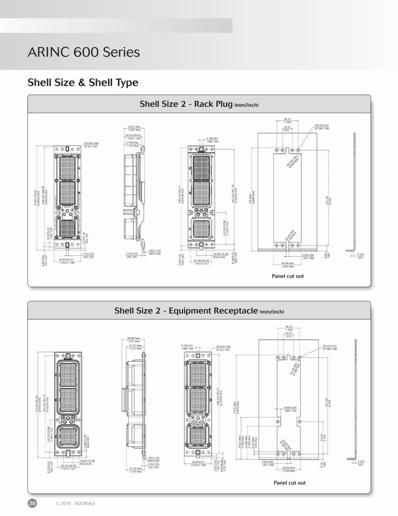
Shell Size 2 - Rack Plug (mm/inch)
Shell Size 2 - Equipment Receptacle (mm/inch)
Shell Size & Shell Type
Panel cut out
3 15/3 05124/ 120
3.4
3/3
.18
.13
5/.
125
6.3
2/6
.22
.24
9/.
24
5
587
/5.6
1.2
31
/.2
21
35 61 Max1 402 Max
30 23/29 971 190/1 180
2799 Max1 102 Max
3 30/3 05130/ 120
45 97/45 471 810/1 790
Ø3 84/3 68Ø 151/ 145
1 65/1 40065/ 056
7.4
4/7
.19
.29
3/.
28
31
66
.22
/16
5.7
16
.54
4/6
.52
4
161
.42
/161
.18
63
55
/6.3
45
16 64/16 38655/ 645
4 78/4 67188/ 184
54
.23
/53
.98
2.1
35
/2.1
25
36 36/36 091 431/1 421
175
Min
i6
.89
0 M
ini
161
.29
6.3
50
9.6
5.3
80
Ø4 57/4 22Ø 180/ 166
36 221 426
16 51650
R305
Max
R.12
0 M
ax
46 99 Mini1 850 Mini
5 207205
R0.7
65 M
ax
R.03
0 M
ax
4 85/4 80191/ 189
9.7
8/9
.53
.38
5/.
375
177.
67/
176
.91
6.9
95
/6.9
65
16
9.2
4/1
68
.99
6.6
63
/6.6
53
Panel cut out
16
6.2
2/1
65
.71
6.5
44
/6.5
24
161
29
6.3
50
9.1
4.3
60
Ø4 57/4 22Ø 180/ 166
36 221 426
R305 M
ax
R120 M
ax
5 207205
R7.2
9 M
axR.
180
Max
174
.5 M
ini
687
0 M
ini
Ø3 84/3 68Ø 151/ 145
4 78/4 67188/ 184
1 65/1 40065/ 0553 30/3 05130/ 120
38 89 Max1 531 Max
31 01 Max1 221 Max
45 97/45 471 810/1 790
33 45 Max1 317 Max
54
23
/53
.98
2.1
35
/2.1
25
11.6
8/1
1.4
3.4
60
/.4
50
177.
16
/176
.40
6.9
75
/6.9
45
9.2
7/9
.02
.36
5/.
35
5
36 35/36 091 431/1 421
16 64/16 38655/ 645
54
.10
2.1
30
38 86 Mini1 530 Mini
4 85/4 80191/ 189
6 60/5 84260/ 230
16 51650
55
.88
Min
i2
.20
0 M
ini
70
.61
Max
2.7
80
Max
6.1
0 M
ax.2
40
Max
2.9
2/2
.67
.115
/.1
05
6.9
3/6
.68
.27
3/
28
3
161
.42
/161
.12
6.3
55
/6.3
45
ARINC 600 Series
21© 2013 - SOURIAU
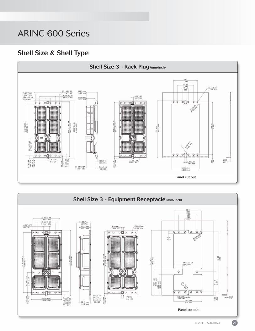
Shell Size 3 - Rack Plug (mm/inch)
Shell Size 3 - Equipment Receptacle (mm/inch)
Shell Size & Shell Type
Panel cut out
3 15/3 05124/ 120
3.4
5/3
.18
.13
5/.
125
6.3
2/6
.22
24
9/
24
5
5.8
7/5
.61
.231
/.2
21
35 61 Max1 402 Max
2799 Max1 102 Max
3 30/3 05130/ 120
83 19/82 423 275/3 245
1 65/1 40065/ 056
7.4
4/7
.19
.29
3/.
28
31
66
.22
/16
5.7
16
.54
4/6
.52
4
30 23/29 971 190/1 180
4 78/4 67188/ 184
Ø3 84/3 68Ø 151/ 145
175
Min
i6
.89
0 M
ini
161
.29
6.3
50
9.6
53
80
Ø4 57/4 22Ø 180/ 166
73 32 886
49 531 950
R3.0
5 M
ax
R.12
0 M
ax
84 07 Mini3 310 Mini
5 207205
R0.762 M
ax
R.030 Max
4 85/4 80191/ 189
177.
67/
176
.91
6.9
95
/6.9
65
16
9.2
4/1
68
.99
6.6
63
/6.6
53
16 51650
9.7
8/9
.53
.38
5/.
375
54
.23
/53
.98
2.1
35
/2.1
25
161
.54
/161
.04
6.3
60
/6.3
40
73 43/73 182 891/2 881 49 66/49 40
1 955/1 94516 64/16 38655/ 645
Panel cut out
16
6.2
2/1
65
.71
6.5
44
/6.5
24
161
.29
6.3
50
9.1
4.3
60
73 32 886
R305 M
ax
R120 M
ax
5 207205
R7.29 M
ax
R.180 Max
174
.5 M
ini
687
0 M
ini
Ø3 84/3 68Ø 151/ 145
4 78/4 67188/ 184
1 65/1 40065/ 0553 30/3 05130/ 120
38 89 Max1 531 Max
31 01 Max1 221 Max
4 78/4 67188/ 184
33 45 Max1 317 Max
54
.23
/53
.98
2.1
35
/2.1
25
11.6
8/1
1.4
3.4
60
/.4
50
9.2
7/9
.02
.36
5/.
35
5
16 64/16 38655/ 645
54
.10
2.1
30
76 2 Mini3 00 Mini
4 85/4 80191/ 189
24 38/23 62960/ 930
16 51650
55
.88
Min
i2
.20
0 M
ini
70
.61
Max
2.7
80
Max
6.1
0.2
40
6.9
3/6
.68
.27
3/.
28
3
161
42
/161
.12
6.3
55
/6.3
45
29
2/2
.67
.115
/.1
05
49 66/49 401 955/1 945
73 43/73 182 891/2 881
177.
16
/176
.40
6.9
75
/6.9
45
83 19/82 423 275/3 245
49 531 950
ARINC 600 Series
22 © 2013 - SOURIAU
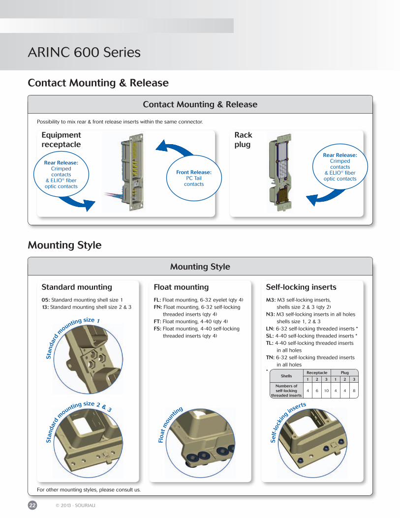
Contact Mounting & Release
Mounting Style
Possibility to mix rear & front release inserts within the same connector.
Rear Release:Crimped contacts
& ELIO® fiber optic contacts
Equipment receptacle
Rack plug
Front Release:PC Tail
contacts
Rear Release:Crimped contacts
& ELIO® fiber optic contacts
05: Standard mounting shell size 113: Standard mounting shell size 2 & 3
Standard mounting
FL: Float mounting, 6-32 eyelet (qty 4)FN: Float mounting, 6-32 self-locking threaded inserts (qty 4)FT: Float mounting, 4-40 (qty 4)FS: Float mounting, 4-40 self-locking threaded inserts (qty 4)
Float mounting
*Shells
Receptacle Plug
1 2 3 1 2 3
Numbers ofself-locking
threaded inserts4 6 10 4 4 8
M3: M3 self-locking inserts, shells size 2 & 3 (qty 2)N3: M3 self-locking inserts in all holes shells size 1, 2 & 3LN: 6-32 self-locking threaded inserts *SL: 4-40 self-locking threaded inserts *TL: 4-40 self-locking threaded inserts in all holesTN: 6-32 self-locking threaded inserts in all holes
Self-locking inserts
Sta
ndar
d m
ounting size 2 & 3
Flo
at m
ount
ing
Se
lf-lo
ckin
g inserts
Sta
ndar
d m
ounting size 1
For other mounting styles, please consult us.
Contact Mounting & Release
Mounting Style
ARINC 600 Series
23© 2013 - SOURIAU
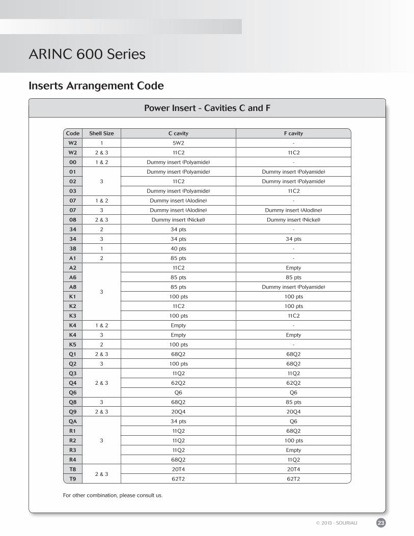
Power Insert - Cavities C and F
Inserts Arrangement Code
Code Shell Size C cavity F cavity
W2 1 5W2 -
W2 2 & 3 11C2 11C2
00 1 & 2 Dummy insert (Polyamide) -
01
3
Dummy insert (Polyamide) Dummy insert (Polyamide)
02 11C2 Dummy insert (Polyamide)
03 Dummy insert (Polyamide) 11C2
07 1 & 2 Dummy insert (Alodine) -
07 3 Dummy insert (Alodine) Dummy insert (Alodine)
08 2 & 3 Dummy insert (Nickel) Dummy insert (Nickel)
34 2 34 pts -
34 3 34 pts 34 pts
38 1 40 pts -
A1 2 85 pts -
A2
3
11C2 Empty
A6 85 pts 85 pts
A8 85 pts Dummy insert (Polyamide)
K1 100 pts 100 pts
K2 11C2 100 pts
K3 100 pts 11C2
K4 1 & 2 Empty -
K4 3 Empty Empty
K5 2 100 pts -
Q1 2 & 3 68Q2 68Q2
Q2 3 100 pts 68Q2
Q3
2 & 3
11Q2 11Q2
Q4 62Q2 62Q2
Q6 Q6 Q6
Q8 3 68Q2 85 pts
Q9 2 & 3 20Q4 20Q4
QA
3
34 pts Q6
R1 11Q2 68Q2
R2 11Q2 100 pts
R3 11Q2 Empty
R4 68Q2 11Q2
T82 & 3
20T4 20T4
T9 62T2 62T2
For other combination, please consult us.
ARINC 600 Series
24 © 2013 - SOURIAU
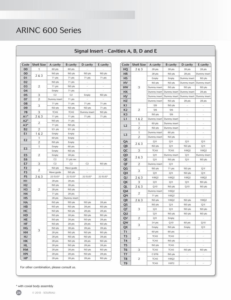
Code Shell Size A cavity B cavity D cavity E cavity
HQ 2 & 3 28 pts 28 pts 28 pts 28 pts
HR
3
28 pts 150 pts 28 pts Dummy insert
HS Empty Empty Dummy insert 150 pts
HV 150 pts 150 pts Dummy insert Dummy insert
HW Dummy insert 150 pts 150 pts 150 pts
HX Dummy insert Dummy insert Dummy insert 28 pts
HY Dummy insert Dummy insert Dummy insert Dummy insert
HZ Dummy insert 150 pts 28 pts 28 pts
K1
2
126 150 pts - -
K2 126 126 - -
K3 150 pts 126 - -
L1 1 & 2 Dummy insert Dummy insert - -
L21 60 pts Dummy insert - -
2 150 pts Dummy insert - -
L31 Dummy insert 60 pts - -
2 Dummy insert 150 pts - -
QA2 & 3
Q11 Q11 Q11 Q11
QB 150 pts Q11 150 pts Q11
QC 3 TCAS TCAS 118Q2 118Q2
QD2 & 3
Q11 Dummy insert Q11 Dummy insert
QE Q11 150 pts Q11 150 pts
QF 2 Dummy insert Q11 - -
QG3
150 pts 71 pts 150 pts Q11
QH Q11 Q11 150 pts Q11
QJ 2 & 3 118Q2 118Q2 118Q2 118Q2
QK 3 Q11 Q11 Q11 150 pts
QL 2 & 3 Q10 150 pts Q10 150 pts
QM2
Dummy insert 118Q2 - -
QN 71 pts 118Q2 - -
QR 2 & 3 150 pts 118Q2 150 pts 118Q2
QS
3
150 pts Q11 150 pts Q11
QT Q11 Q11 150 pts 150 pts
QU Q11 150 pts 150 pts 150 pts
QV 2 Q11 Empty - -
QW3
24 pts Q10 60 pts Q10
QX Empty 150 pts Empty Q11
T1
2
60 pts 60 pts - -
T3 TCAS TCAS - -
T4 TCAS 150 pts - -
T5 150 pts TCAS - -
T6 3 TCAS TCAS 150 pts 150 pts
T7
2
C12T6 150 pts - -
T8 TCAS 118Q2 - -
T9 TCAS 118T2 - -
Signal Insert - Cavities A, B, D and E
* with coxial body assembly
Code Shell Size A cavity B cavity D cavity E cavity
00 1 60 pts 60 pts - -
002 & 3
150 pts 150 pts 150 pts 150 pts
01 71 pts 71 pts 71 pts 71 pts
022
150 pts 71 pts - -
03 71 pts 150 pts - -
04 Empty 71 pts - -
05 3 C2 C2 Empty 150 pts
07 2 Dummy insert 71 pts - -
083
71 pts 71 pts 71 pts 71 pts
09 150 pts 150 pts 150 pts 71 pts
78 3 TCAS TCAS Dummy insert 150 pts
A1* 2 & 3 71 pts 71 pts 71 pts 71 pts
A2*2
150 pts 71 pts - -
A3* 71 pts 150 pts - -
B2 2 121 pts 121 pts - -
E1 1 & 2 Empty Empty - -
E21 60 pts Empty - -
2 150 pts Empty - -
E31 Empty 60 pts - -
2
Empty 150 pts - -
E5 Empty 28 pts - -
E6 C2 71 pts rev.
E7 3 C2 C2 C2 150 pts
F22
150 pts Wave guide - -
F3 Wave guide 150 pts - -
F5 2 & 3 22 ELIO® 22 ELIO® 22 ELIO® 22 ELIO®
H1
2
28 pts 28 pts - -
H2 150 pts 28 pts - -
H3 28 pts 150 pts - -
H4 71 pts 28 pts - -
H5 28 pts Dummy insert - -
HA
3
150 pts 150 pts 150 pts 28 pts
HB 150 pts 150 pts 28 pts 150 pts
HC 150 pts 150 pts 28 pts 28 pts
HD 150 pts 28 pts 150 pts 150 pts
HE 150 pts 28 pts 150 pts 28 pts
HF 150 pts 28 pts 28 pts 150 pts
HG 150 pts 28 pts 28 pts 28 pts
HH 28 pts 150 pts 150 pts 150 pts
HJ 28 pts 150 pts 150 pts 28 pts
HK 28 pts 150 pts 28 pts 150 pts
HL 28 pts 150 pts 28 pts 28 pts
HM 28 pts 28 pts 150 pts 150 pts
HN 28 pts 28 pts 150 pts 28 pts
HP 28 pts 28 pts 28 pts 150 pts
For other combination, please consult us.
ARINC 600 Series
25© 2013 - SOURIAU
Polarization Code
Left hand key Center key
Right hand key
Location of polarizing keys (view of engaging face)
Black area represents key position
Code number
Receptacle Shell Plug shellLeft key
Center key
Right key
Left post
Center post
Right post
00 - - - - - -01 4 4 4 1 1 102 4 4 3 2 1 103 4 4 2 3 1 104 4 4 1 4 1 105 4 4 6 5 1 106 4 4 5 6 1 107 5 4 4 1 1 608 5 4 3 2 1 609 5 4 2 3 1 610 5 4 1 4 1 611 5 4 6 5 1 612 5 4 5 6 1 613 6 4 4 1 1 514 6 4 3 2 1 515 6 4 2 3 1 516 6 4 1 4 1 517 6 4 6 5 1 518 6 4 5 6 1 519 1 4 4 1 1 420 1 4 3 2 1 421 1 4 2 3 1 422 1 4 1 4 1 423 1 4 6 5 1 424 1 4 5 6 1 425 2 4 4 1 1 326 2 4 3 2 1 327 2 4 2 3 1 328 2 4 1 4 1 329 2 4 6 5 1 330 2 4 5 6 1 331 3 4 4 1 1 232 3 4 3 2 1 233 3 4 2 3 1 234 3 4 1 4 1 235 3 4 6 5 1 236 3 4 5 6 1 237 4 3 4 1 2 138 4 3 3 2 2 139 4 3 2 3 2 140 4 3 1 4 2 141 4 3 6 5 2 142 4 3 5 6 2 143 5 3 4 1 2 644 5 3 3 2 2 645 5 3 2 3 2 646 5 3 1 4 2 647 5 3 6 5 2 648 5 3 5 6 2 649 6 3 4 1 2 5
Code number
Receptacle Shell Plug shellLeft key
Center key
Right key
Left post
Center post
Right post
50 6 3 3 2 2 551 6 3 2 3 2 552 6 3 1 4 2 553 6 3 6 5 2 554 6 3 5 6 2 555 1 3 4 1 2 456 1 3 3 2 2 457 1 3 2 3 2 458 1 3 1 4 2 459 1 3 6 5 2 460 1 3 5 6 2 461 2 3 4 1 2 362 2 3 3 2 2 363 2 3 2 3 2 364 2 3 1 4 2 365 2 3 6 5 2 366 2 3 5 6 2 367 3 3 4 1 2 268 3 3 3 2 2 269 3 3 2 3 2 270 3 3 1 4 2 271 3 3 6 5 2 272 3 3 5 6 2 273 4 2 4 1 3 174 4 2 3 2 3 175 4 2 2 3 3 176 4 2 1 4 3 177 4 2 6 5 3 178 4 2 5 6 3 179 5 2 4 1 3 680 5 2 3 2 3 681 5 2 2 3 3 682 5 2 1 4 3 683 5 2 6 5 3 684 5 2 5 6 3 685 6 2 4 1 3 586 6 2 3 2 3 587 6 2 2 3 3 588 6 2 1 4 3 589 6 2 6 5 3 590 6 2 5 6 3 591 1 2 4 1 3 492 1 2 3 2 3 493 1 2 2 3 3 494 1 2 1 4 3 495 1 2 6 5 3 496 1 2 5 6 3 497 2 2 4 1 3 398 2 2 3 2 3 399 2 2 2 3 3 3
Polarizing post - Rack plug
Polarizing postEquipment receptacle
Key Key
Polarization Code
ARINC 600 Series
26 © 2013 - SOURIAU
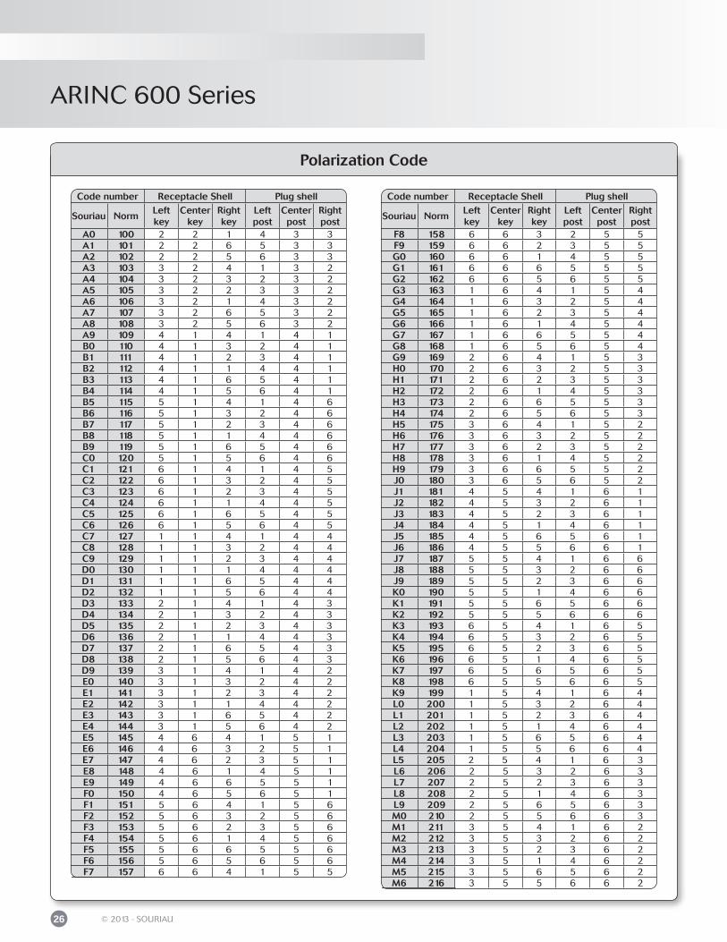
Polarization Code
Code number Receptacle Shell Plug shell
Souriau NormLeft key
Center key
Right key
Left post
Center post
Right post
A0 100 2 2 1 4 3 3A1 101 2 2 6 5 3 3A2 102 2 2 5 6 3 3A3 103 3 2 4 1 3 2A4 104 3 2 3 2 3 2A5 105 3 2 2 3 3 2A6 106 3 2 1 4 3 2A7 107 3 2 6 5 3 2A8 108 3 2 5 6 3 2A9 109 4 1 4 1 4 1B0 110 4 1 3 2 4 1B1 111 4 1 2 3 4 1B2 112 4 1 1 4 4 1B3 113 4 1 6 5 4 1B4 114 4 1 5 6 4 1B5 115 5 1 4 1 4 6B6 116 5 1 3 2 4 6B7 117 5 1 2 3 4 6B8 118 5 1 1 4 4 6B9 119 5 1 6 5 4 6C0 120 5 1 5 6 4 6C1 121 6 1 4 1 4 5C2 122 6 1 3 2 4 5C3 123 6 1 2 3 4 5C4 124 6 1 1 4 4 5C5 125 6 1 6 5 4 5C6 126 6 1 5 6 4 5C7 127 1 1 4 1 4 4C8 128 1 1 3 2 4 4C9 129 1 1 2 3 4 4D0 130 1 1 1 4 4 4D1 131 1 1 6 5 4 4D2 132 1 1 5 6 4 4D3 133 2 1 4 1 4 3D4 134 2 1 3 2 4 3D5 135 2 1 2 3 4 3D6 136 2 1 1 4 4 3D7 137 2 1 6 5 4 3D8 138 2 1 5 6 4 3D9 139 3 1 4 1 4 2E0 140 3 1 3 2 4 2E1 141 3 1 2 3 4 2E2 142 3 1 1 4 4 2E3 143 3 1 6 5 4 2E4 144 3 1 5 6 4 2E5 145 4 6 4 1 5 1E6 146 4 6 3 2 5 1E7 147 4 6 2 3 5 1E8 148 4 6 1 4 5 1E9 149 4 6 6 5 5 1F0 150 4 6 5 6 5 1F1 151 5 6 4 1 5 6F2 152 5 6 3 2 5 6F3 153 5 6 2 3 5 6F4 154 5 6 1 4 5 6F5 155 5 6 6 5 5 6F6 156 5 6 5 6 5 6F7 157 6 6 4 1 5 5
Code number Receptacle Shell Plug shell
Souriau NormLeft key
Center key
Right key
Left post
Center post
Right post
F8 158 6 6 3 2 5 5F9 159 6 6 2 3 5 5G0 160 6 6 1 4 5 5G1 161 6 6 6 5 5 5G2 162 6 6 5 6 5 5G3 163 1 6 4 1 5 4G4 164 1 6 3 2 5 4G5 165 1 6 2 3 5 4G6 166 1 6 1 4 5 4G7 167 1 6 6 5 5 4G8 168 1 6 5 6 5 4G9 169 2 6 4 1 5 3H0 170 2 6 3 2 5 3H1 171 2 6 2 3 5 3H2 172 2 6 1 4 5 3H3 173 2 6 6 5 5 3H4 174 2 6 5 6 5 3H5 175 3 6 4 1 5 2H6 176 3 6 3 2 5 2H7 177 3 6 2 3 5 2H8 178 3 6 1 4 5 2H9 179 3 6 6 5 5 2J0 180 3 6 5 6 5 2J1 181 4 5 4 1 6 1J2 182 4 5 3 2 6 1J3 183 4 5 2 3 6 1J4 184 4 5 1 4 6 1J5 185 4 5 6 5 6 1J6 186 4 5 5 6 6 1J7 187 5 5 4 1 6 6J8 188 5 5 3 2 6 6J9 189 5 5 2 3 6 6K0 190 5 5 1 4 6 6K1 191 5 5 6 5 6 6K2 192 5 5 5 6 6 6K3 193 6 5 4 1 6 5K4 194 6 5 3 2 6 5K5 195 6 5 2 3 6 5K6 196 6 5 1 4 6 5K7 197 6 5 6 5 6 5K8 198 6 5 5 6 6 5K9 199 1 5 4 1 6 4L0 200 1 5 3 2 6 4L1 201 1 5 2 3 6 4L2 202 1 5 1 4 6 4L3 203 1 5 6 5 6 4L4 204 1 5 5 6 6 4L5 205 2 5 4 1 6 3L6 206 2 5 3 2 6 3L7 207 2 5 2 3 6 3L8 208 2 5 1 4 6 3L9 209 2 5 6 5 6 3M0 210 2 5 5 6 6 3M1 211 3 5 4 1 6 2M2 212 3 5 3 2 6 2M3 213 3 5 2 3 6 2M4 214 3 5 1 4 6 2M5 215 3 5 6 5 6 2M6 216 3 5 5 6 6 2
ARINC 600 Series
27© 2013 - SOURIAU
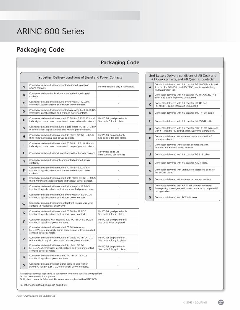
Packaging Code
Packaging code not applicable to connectors where no contacts are specified.Do not use the suffix LN together.Gold plated contacts: 0.8μ mini. Performance compliant with ARINC 600.
For other code packaging, please consult us.
1st Letter: Delivery conditions of Signal and Power Contacts
A Connector delivered with unmounted crimped signal andpower contacts.
For rear release plug & receptacle.
B Connector delivered only with unmounted crimped signal contacts.
-
C Connector delivered with mounted wire wrap L= 12.7/0.5(mm/inch) signal contacts and without power contact.
-
D Connector delivered with unmounted wire wrap L= 9.52/0.375 (mm/inch) signal contacts and crimped power contacts.
-
E Connector delivered with mounted PC Tail L= 6.35/0.25 (mm/inch) signal contacts and unmounted power crimped contacts.
For PC Tail gold plated only.See code 3 for tin plated.
G Connector delivered with mounted gold plated PC Tail L= 3.81/ 0.15 (mm/inch) signal contacts and without power contact.
-
H Connector delivered with mounted tin plated PC Tail L= 6.35/ 0.25 (mm/inch) signal and power contacts.
For PC Tail tin plated only.See code Y for gold plated.
I Connector delivered with mounted PC Tail L= 3.81/0.15 (mm/inch) signal contacts and unmounted crimped power contacts.
-
L Connector delivered without signal and without power contact.Never use code LN.If no contact, put nothing.
N Connector delivered with only unmounted crimped power contacts.
-
PConnector delivered with mounted PC Tail L= 9.52/0.375(mm/inch) signal contacts and unmounted crimped power contacts.
-
R Connector delivered with mounted gold plated PC Tail L= 9.52/ 0.375 (mm/inch) signal contacts and without power contact.
-
T Connector delivered with mounted wire wrap L= 12.7/0.5(mm/inch) signal contacts and with unmounted power contacts.
-
U Connector delivered with mounted wire wrap L= 6.35/0.25 (mm/inch) signal contacts and without power contact.
-
W Connector delivered with unmounted front release wire wrap contacts (4 wrappings: 8660-540)
-
X Connector delivered with mounted PC Tail L= 12.7/0.5(mm/inch) signal contacts and without power contact.
For PC Tail gold plated only.See code 2 for tin plated.
Y Connector supplied with mounted #22 PC Tail L= 6.35/0.25 (mm/inch) signal and power contacts.
For PC Tail gold plated only.See code H for tin plated.
1Connector delivered with mounted PC Tail wire wrapL= 9.52/0.375 (mm/inch) signal contacts and with unmounted crimped power contacts.
-
2 Connector delivered with mounted tin plated PC Tail L= 12.7/ 0.5 (mm/inch) signal contacts and without power contact.
For PC Tail tin plated only.See code X for gold plated.
3Connector delivered with mounted tin plated PC TailL= 6.35/0.25 (mm/inch) signal contacts and with unmounted crimped power contacts.
For PC Tail tin plated only.See code E for gold plated.
4 Connector delivered with tin plated PC Tail L=1 2.7/0.5(mm/inch) signal and power contacts.
-
5 Connector delivered without signal contacts and with tin plated PC Tail L= 6.35 / 0.25 (mm/inch) power contacts.
-
2nd Letter: Delivery conditions of #5 Coax and #1 Coax contacts, and #8 Quadrax contacts.
AConnector delivered with #5 coax for RG 58 C/U cable and #1 coax for RG165/U and RG 225/U cable (coaxial bodyand termination kit).
B Connector delivered with #1 coax for RG 141A/U, RG 142 and KX23 cable. Delivered unmounted.
C Connector delivered with #1 coax for UT 141 andRG 400B/U cable. Delivered unmounted.
D Connector delivered with #5 coax for 5021K1011 cable.
E Connector delivered with #1 coax for RG 393/U cable.
F Connector delivered with #5 coax for 5021K1011 cable and with #1 coax for RG 393/U cable. Delivered unmounted.
H Connector delivered without coax contact and with #5 dummy contacts.
I Connector delivered without coax contact and withmounted #5 and #12 cavity reducer.
J Connector delivered with #5 coax for RG 316 cable.
K Connector delivered with #5 coax for KX23 cable.
M Connector delivered with unmounted sealed #5 coax forRG 58C/U cable.
N Connector delivered without coax or quadrax contact.
QConnector delivered with #8 PC tail quadrax contacts:Same plating than signal and power contacts, or tin plated if not applicable.
S Connector delivered with TCAS #1 coax.
Packaging Code
Note: All dimensions are in mm/inch.

ARIN
C 600
Contacts & ToolingCrimp contacts .................................................................................................................................
PC tail contacts ................................................................................................................................
Wire wrap contacts .........................................................................................................................
Twinax contacts ...............................................................................................................................
Triax contacts ....................................................................................................................................
Quadrax contacts ............................................................................................................................
Cavity reducers ................................................................................................................................
ELIO® fiber optic contacts/adaptor #8 ....................................................................................
Filler plug ...........................................................................................................................................
Dummy contacts .............................................................................................................................
Dummy inserts .................................................................................................................................
Tooling: Crimping tools ............................................................................................................................ Insertion & extraction of the contacts ................................................................................ Insertion & extraction tools ....................................................................................................
Accessories: Covers .......................................................................................................................
30
34
35
35
36
36
36
37
38
38
38
394041
41
ARINC 600 Series
ARINC 600 Series
30 © 2013 - SOURIAU
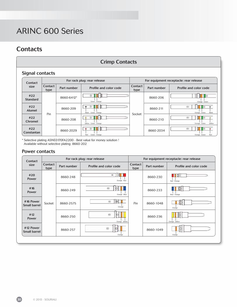
Contact size
For rack plug: rear release For equipment receptacle: rear release
Contact type
Part number Profile and color codeContact
typePart number Profile and color code
#22Standard
Pin
8660-6412*
Socket
8660-206
#22Alumel
8660-209 8660-211
#22Chromel
8660-208 8660-210
#22Constantan
8660-2029 8660-2034
Contact size
For rack plug: rear release For equipment receptacle: rear release
Contact type
Part number Profile and color codeContact
typePart number Profile and color code
#20Power
Socket
8660-248
Pin
8660-230
#16Power
8660-249 8660-233
#16 PowerSmall barrel
8660-2575 8660-1048
#12Power
8660-250 8660-236
#12 PowerSmall barrel
8660-257 8660-1049
Crimp Contacts
Contacts
Signal contacts
Power contacts
Green Orange
Black Green Orange
Yellow Green Orange
Red Green Orange
* Selective plating ASNE0170FA2200 - Best value for money solution ! Available without selective plating: 8660-202
Orange
Orange
Orange Yellow
Red Orange
Blue Orange
Orange
Orange
Orange Red
Orange Blue
Orange Yellow
Orange Green Black
Orange Green Yellow
Orange Green Red
Orange Green
ARINC 600 Series
31© 2013 - SOURIAU
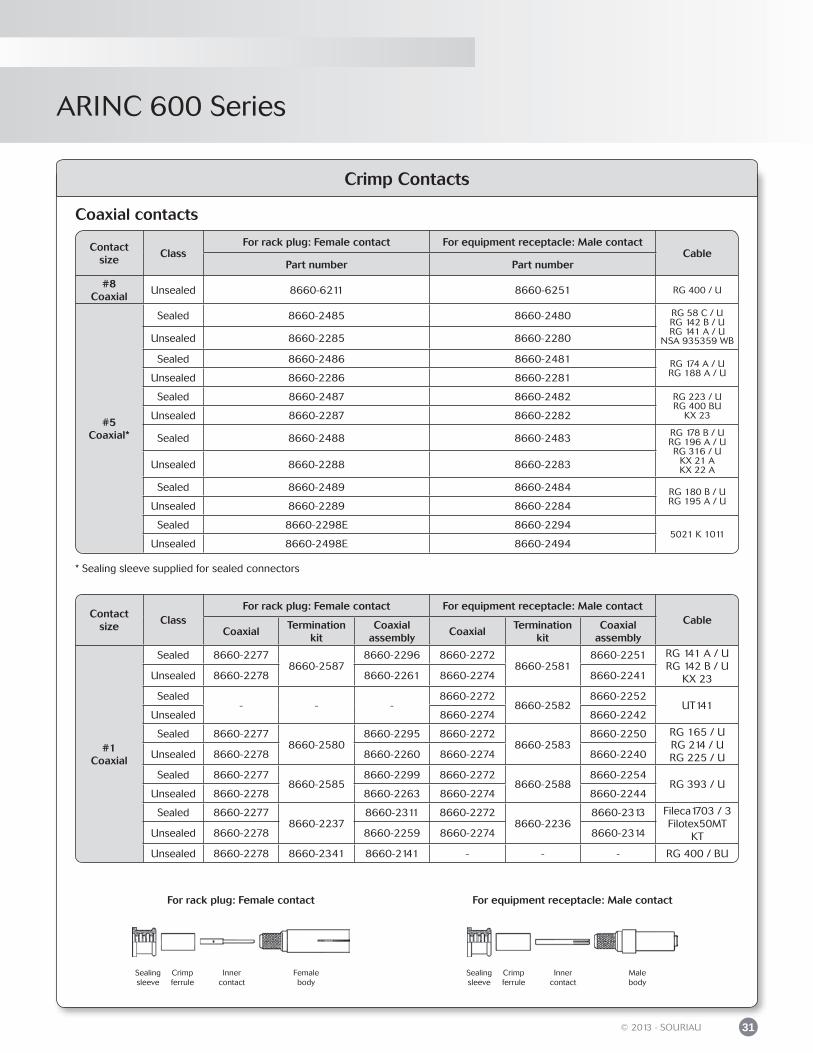
Crimp Contacts
* Sealing sleeve supplied for sealed connectors
Contact size
ClassFor rack plug: Female contact For equipment receptacle: Male contact
CablePart number Part number
#8Coaxial
Unsealed 8660-6211 8660-6251 RG 400 / U
#5Coaxial*
Sealed 8660-2485 8660-2480 RG 58 C / URG 142 B / URG 141 A / U
NSA 935359 WBUnsealed 8660-2285 8660-2280
Sealed 8660-2486 8660-2481 RG 174 A / URG 188 A / UUnsealed 8660-2286 8660-2281
Sealed 8660-2487 8660-2482 RG 223 / URG 400 BU
KX 23Unsealed 8660-2287 8660-2282
Sealed 8660-2488 8660-2483 RG 178 B / URG 196 A / URG 316 / U
KX 21 AKX 22 AUnsealed 8660-2288 8660-2283
Sealed 8660-2489 8660-2484 RG 180 B / URG 195 A / UUnsealed 8660-2289 8660-2284
Sealed 8660-2298E 8660-22945021 K 1011
Unsealed 8660-2498E 8660-2494
Coaxial contacts
For equipment receptacle: Male contact
Crimp ferrule
Inner contact
Male body
Sealingsleeve
For rack plug: Female contact
Crimp ferrule
Inner contact
Female body
Sealingsleeve
Contact size
ClassFor rack plug: Female contact For equipment receptacle: Male contact
CableCoaxial
Termination kit
Coaxialassembly
CoaxialTermination
kitCoaxial
assembly
#1Coaxial
Sealed 8660-22778660-2587
8660-2296 8660-22728660-2581
8660-2251 RG 141 A / URG 142 B / U
KX 23Unsealed 8660-2278 8660-2261 8660-2274 8660-2241
Sealed- - -
8660-22728660-2582
8660-2252UT141
Unsealed 8660-2274 8660-2242
Sealed 8660-22778660-2580
8660-2295 8660-22728660-2583
8660-2250 RG 165 / URG 214 / URG 225 / UUnsealed 8660-2278 8660-2260 8660-2274 8660-2240
Sealed 8660-22778660-2585
8660-2299 8660-22728660-2588
8660-2254RG 393 / U
Unsealed 8660-2278 8660-2263 8660-2274 8660-2244
Sealed 8660-22778660-2237
8660-2311 8660-22728660-2236
8660-2313 Fileca1703 / 3Filotex50MT
KTUnsealed 8660-2278 8660-2259 8660-2274 8660-2314
Unsealed 8660-2278 8660-2341 8660-2141 - - - RG 400 / BU
ARINC 600 Series
32 © 2013 - SOURIAU
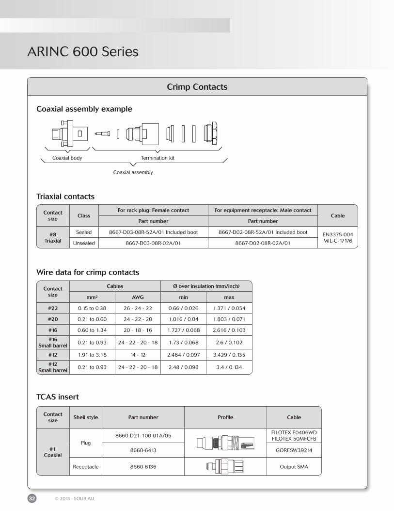
Crimp Contacts
Coaxial assembly example
Coaxial body Termination kit
Coaxial assembly
TCAS insert
Contact size
Shell style Part number Profile Cable
#1Coaxial
Plug8660-D21-100-01A/05
FILOTEX E0406WDFILOTEX 50MFCFB
8660-6413 GORESW39214
Receptacle 8660-6136 Output SMA
Wire data for crimp contacts
Contact size
Cables Ø over insulation (mm/inch)
mm² AWG min max
#22 0.15 to 0.38 26 - 24 - 22 0.66 / 0.026 1.371 / 0.054
#20 0.21 to 0.60 24 - 22 - 20 1.016 / 0.04 1.803 / 0.071
#16 0.60 to 1.34 20 - 18 - 16 1.727 / 0.068 2.616 / 0.103
#16Small barrel
0.21 to 0.93 24 - 22 - 20 - 18 1.73 / 0.068 2.6 / 0.102
#12 1.91 to 3.18 14 - 12 2.464 / 0.097 3.429 / 0.135
#12Small barrel
0.21 to 0.93 24 - 22 - 20 - 18 2.48 / 0.098 3.4 / 0.134
Triaxial contacts
Contact size
ClassFor rack plug: Female contact For equipment receptacle: Male contact
CablePart number Part number
#8Triaxial
Sealed 8667-D03-08R-52A/01 Included boot 8667-D02-08R-52A/01 Included boot EN3375-004MIL-C-17176Unsealed 8667-D03-08R-02A/01 8667-D02-08R-02A/01
ARINC 600 Series
33© 2013 - SOURIAU
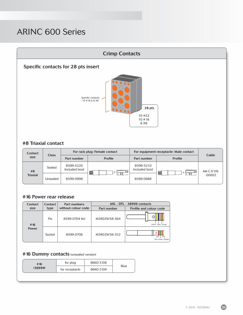
Crimp Contacts
#16 Power rear releaseContact
sizeContact
typePart numbers
without colour codeMIL - DTL - 38999 contacts
Part number Profile and colour code
#16Power
Pin 8599-0704 MJ M39029/58-364
Socket 8599-0708 M39029/56-352
+ +
Contact size
ClassFor rack plug: Female contact For equipment receptacle: Male contact
CablePart number Profile Part number Profile
#8Triaxial
Sealed8599-5220
Included boot8599-5210
Included boot Mil-C17176-00002
Unsealed 8599-0998 8599-0988
#8 Triaxial contact
Specific contacts for 28 pts insert
28 pts
10 #2210 #16
8 #8
Specific contacts10 #16 & 8 #8
#16 Dummy contacts (unsealed version)
#16(38999)
for plug 8660-3138Blue
for receptacle 8660-3139
Yellow Blue Orange
Red Green Orange
ARINC 600 Series
34 © 2013 - SOURIAU
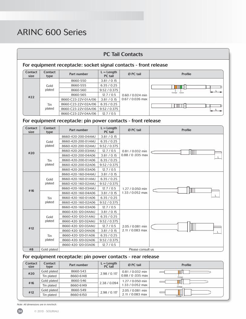
PC Tail Contacts
For equipment receptacle: socket signal contacts - front release
For equipment receptacle: pin power contacts - rear release
Contact size
Contact type
Part numberL = Length
PC tailØ PC tail Profile
#20
Goldplated
8660-420-200-04AMJ 3.81 / 0.15
0.81 / 0.032 min0.88 / 0 .035 max
8660-420-200-01AMJ 6.35 / 0.25
8660-420-200-02AMJ 9.52 / 0.375
8660-420-200-03AMJ 12.7 / 0.5
Tinplated
8660-420-200-04A06 3.81 / 0.15
8660-420-200-01A06 6.35 / 0.25
8660-420-200-02A06 9.52 / 0.375
8660-420-200-03A06 12.7 / 0.5
#16
Goldplated
8660-420-160-04AMJ 3.81 / 0.15
1.27 / 0.050 min1.33 / 0.052 max
8660-420-160-01AMJ 6.35 / 0.25
8660-420-160-02AMJ 9.52 / 0.375
8660-420-160-03AMJ 12.7 / 0.5
Tinplated
8660-420-160-04A06 3.81 / 0.15
8660-420-160-01A06 6.35 / 0.25
8660-420-160-02A06 9.52 / 0.375
8660-420-160-03A06 12.7 / 0.5
#12
Gold plated
8660-420-120-04AMJ 3.81 / 0.15
2.05 / 0.081 min2.11 / 0.083 max
8660-420-120-01AMJ 6.35 / 0.25
8660-420-120-02AMJ 9.52 / 0.375
8660-420-120-03AMJ 12.7 / 0.5
Tinplated
8660-420-120-04A06 3.81 / 0.15
8660-420-120-01A06 6.35 / 0.25
8660-420-120-02A06 9.52 / 0.375
8660-420-120-03A06 12.7 / 0.5#8 Gold plated Please consult us
For equipment receptacle: pin power contacts - front release
Contact size
Contact type Part number L = Length
PC tail Ø PC tail Profile
#20Gold plated 8660-543
2.98 / 0.1170.81 / 0.032 min0.88 / 0 .035 maxTin plated 8660-6148
#16Gold plated 8660-546
2.38 / 0.0941.27 / 0.050 min1.33 / 0.052 maxTin plated 8660-6149
#12Gold plated 8660-549
2.98 / 0.1172.05 / 0.081 min2.11 / 0.083 maxTin plated 8660-6150
Orange
Orange
Orange
L
L
L
Contact size
Contact type
Part numberL = Length
PC tailØ PC tail Profile
#22
Goldplated
8660-550 3.81 / 0.15
0.60 / 0.024 min0.67 / 0.026 max
8660-555 6.35 / 0.25
8660-560 9.52 / 0.375
8660-565 12.7 / 0.5
Tinplated
8660-C23-22V-01A/06 3.81 / 0.15
8660-C23-22V-02A/06 6.35 / 0.25
8660-C23-22V-03A/06 9.52 / 0.375
8660-C23-22V-04A/06 12.7 / 0.5
Orange Green
Note: All dimensions are in mm/inch.
ARINC 600 Series
35© 2013 - SOURIAU
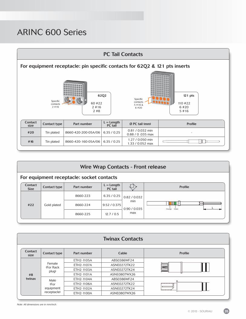
Contact size Contact type Part number L = Length
PC tail Ø PC tail (mm) Profile
#20 Tin plated 8660-420-200-05A/06 6.35 / 0.250.81 / 0.032 min0.88 / 0 .035 max
-
#16 Tin plated 8660-420-160-05A/06 6.35 / 0.251.27 / 0.050 min1.33 / 0.052 max
PC Tail Contacts
For equipment receptacle: pin specific contacts for 62Q2 & 121 pts inserts
121 pts
110 #226 #205 #16
Specificcontacts5 #16 &6 #20
62Q2
60 #222 #162 #8
Specificcontacts2 #16
Wire Wrap Contacts - Front release
Contact size
Contact type Part number Cable Profile
#8twinax
Female(For Rack
plug)
ETH2-1105A ABS0386WF24
ETH2-1107A ASNE0272TK22
ETH2-1103A ASNE0272TK24
ETH2-1101A ASNE0807WX26
Male(For
equipmentreceptacle)
ETH2-1104A ABS0386WF24
ETH2-1106A ASNE0272TK22
ETH2-1102A ASNE0272TK24
ETH2-1100A ASNE0807WX26
Twinax Contacts
For equipment receptacle: socket contacts
Contact Size
Contact type Part numberL = Length
PC tailProfile
#22 Gold plated
8660-223 6.35 / 0.25 0.82 / 0.032 min
0.90 / 0.035 max
8660-224 9.52 / 0.375
8660-225 12.7 / 0.5
Orange Green
Note: All dimensions are in mm/inch.
ARINC 600 Series
36 © 2013 - SOURIAU
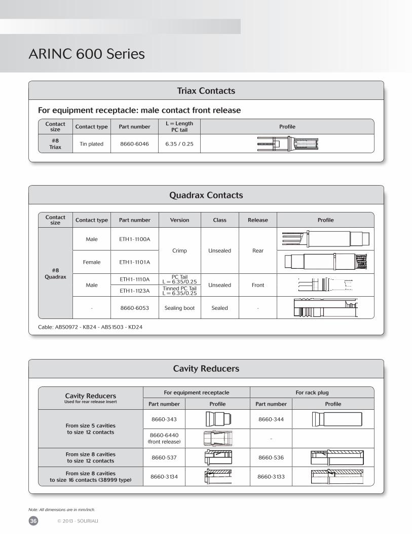
For equipment receptacle: male contact front release
Triax Contacts
Quadrax Contacts
Contact size Contact type Part number
L = LengthPC tail
Profile
#8Triax
Tin plated 8660-6046 6.35 / 0.25
Contactsize Contact type Part number Version Class Release Profile
#8Quadrax
Male ETH1-1100A
Crimp Unsealed Rear
Female ETH1-1101A
MaleETH1-1110A PC Tail
L = 6.35/0.25Unsealed Front
ETH1-1123A Tinned PC TailL = 6.35/0.25
- 8660-6053 Sealing boot Sealed -
Cavity ReducersUsed for rear release insert
For equipment receptacle For rack plug
Part number Profile Part number Profile
From size 5 cavitiesto size 12 contacts
8660-343 8660-344
8660-6440 (front release)
-
From size 8 cavitiesto size 12 contacts
8660-537 8660-536
From size 8 cavitiesto size 16 contacts (38999 type)
8660-3134 8660-3133
Cavity Reducers
Note: All dimensions are in mm/inch.
Cable: ABS0972 - KB24 - ABS1503 - KD24
ARINC 600 Series
37© 2013 - SOURIAU
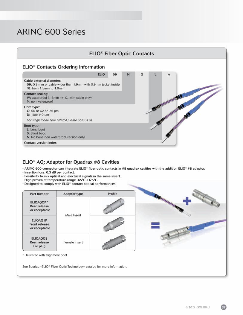
ELIO® Fiber Optic Contacts
ELIO® Contacts Ordering Information
ELIO® AQ: Adaptor for Quadrax #8 Cavities• ARINC 600 connector can integrate ELIO® fiber optic contacts in #8 quadrax cavities with the addition ELIO® #8 adaptor.• Insertion loss: 0.3 dB per contact.• Possibility to mix optical and electrical signals in the same insert.• Fligh proven at temperature range -65°C +125°C.• Designed to comply with ELIO® contact optical performances.
Part number Adaptor type Profile
ELIOAQOP *Rear release
For receptacle
Male Insert
ELIOAQ1PFront releaseFor receptacle
ELIOAQOSRear release
For plugFemale insert
* Delivered with alignment boot
ELIO 09 N G L A
Cable external diameter: 09: 0.9 mm or cable wider than 1.9mm with 0.9mm jacket inside 18: from 1.5mm to 1.9mm
Contact sealing: W: waterproof (1.8mm +/- 0.1mm cable only) N: non waterproof
Fibre type: G: 50 or 62,5/125 μm D: 100/140 μm
For singlemode fibre (9/125) please consult us.
Boot type: L: Long boot S: Short boot N: No boot (non waterproof version only)
Contact version index
See Souriau «ELIO® Fiber Optic Technology» catalog for more information.
ARINC 600 Series
38 © 2013 - SOURIAU
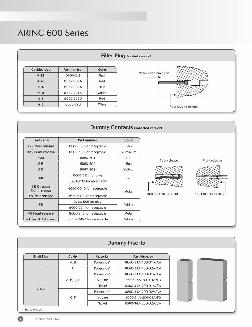
Dummy Contacts (unsealed version)
Filler Plug (sealed version)
Rear face grommet
Cavities size Part number Color
# 22 8660-212 Black
# 20 8522-389A Red
# 16 8522-390A Blue
# 12 8522-391A Yellow
# 8 8660-3035 Red
# 5 8660-726 White
Rear release
Rear face of insulator
Front release
Front face of insulator
Cavity size Part number Color
#22 Rear release 8660-500 for receptacle Black
#22 Front release 8660-499 for receptacle Aluminium
#20 8660-501 Red
#16 8660-502 Blue
#12 8660-503 Yellow
#88660-3131 for plug
Red8660-3132 for receptacle
#8 QuadraxFront release
8660-6045 for receptacleMetal
#8 Rear release 8660-6108 for receptacle
#58660-505 for plug
White8660-504 for receptacle
#5 Front release 8660-942 for receptacle Metal
#1 For TCAS insert 8660-6145A for receptacle White
Introduction direction
Dummy Inserts
Shell Size Cavity Material Part Number
1A, B Polyamide* 8660-31A-100-01A/AA
C Polyamide* 8660-31A-100-02A/AA
2 & 3
A, B, D, E
Polyamide* 8660-31A-100-01A/AA
Alodine 8660-34A-200-01A/F3
Nickel 8660-34A-200-01A/SW
C, F
Polyamide* 8660-31A-200-02A/AA
Alodine 8660-34A-200-02A/F3
Nickel 8660-34A-200-02A/SW
* Standard version
ARINC 600 Series
39© 2013 - SOURIAU
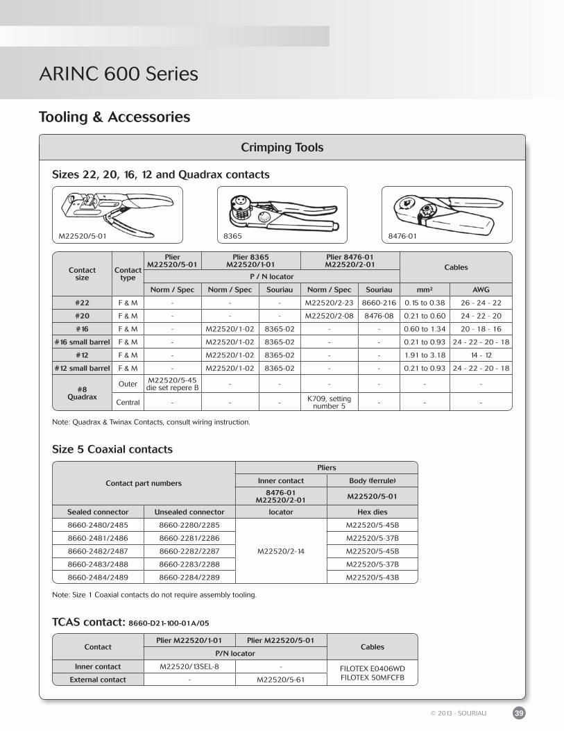
Tooling & Accessories
Crimping Tools
Sizes 22, 20, 16, 12 and Quadrax contacts
Size 5 Coaxial contacts
M22520/5-01 8365 8476-01
Contact part numbers
Pliers
Inner contact Body (ferrule)
8476-01M22520/2-01 M22520/5-01
Sealed connector Unsealed connector locator Hex dies
8660-2480/2485 8660-2280/2285
M22520/2-14
M22520/5-45B
8660-2481/2486 8660-2281/2286 M22520/5-37B
8660-2482/2487 8660-2282/2287 M22520/5-45B
8660-2483/2488 8660-2283/2288 M22520/5-37B
8660-2484/2489 8660-2284/2289 M22520/5-43B
Contactsize
Contacttype
Plier M22520/5-01
Plier 8365M22520/1-01
Plier 8476-01M22520/2-01 Cables
P / N locator
Norm / Spec Norm / Spec Souriau Norm / Spec Souriau mm² AWG
#22 F & M - - - M22520/2-23 8660-216 0.15 to 0.38 26 - 24 - 22
#20 F & M - - - M22520/2-08 8476-08 0.21 to 0.60 24 - 22 - 20
#16 F & M - M22520/1-02 8365-02 - - 0.60 to 1.34 20 - 18 - 16
#16 small barrel F & M - M22520/1-02 8365-02 - - 0.21 to 0.93 24 - 22 - 20 - 18
#12 F & M - M22520/1-02 8365-02 - - 1.91 to 3.18 14 - 12
#12 small barrel F & M - M22520/1-02 8365-02 - - 0.21 to 0.93 24 - 22 - 20 - 18
#8Quadrax
Outer M22520/5-45die set repere B - - - - - -
Central - - - K709, setting number 5 - - -
TCAS contact: 8660-D21-100-01A/05
Note: Size 1 Coaxial contacts do not require assembly tooling.
ContactPlier M22520/1-01 Plier M22520/5-01
CablesP/N locator
Inner contact M22520/13SEL-8 - FILOTEX E0406WDFILOTEX 50MFCFBExternal contact - M22520/5-61
Note: Quadrax & Twinax Contacts, consult wiring instruction.
ARINC 600 Series
40 © 2013 - SOURIAU
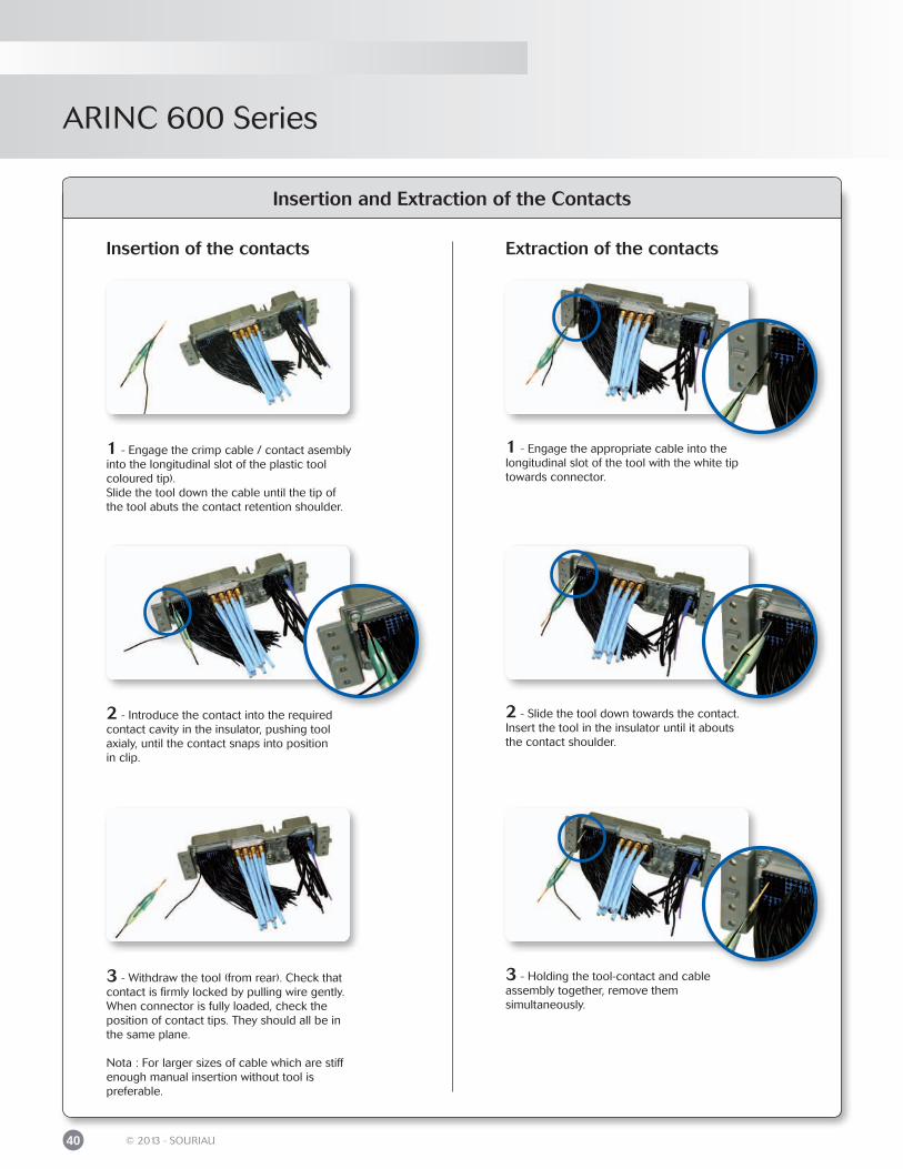
Insertion and Extraction of the Contacts
Insertion of the contacts Extraction of the contacts
1 - Engage the crimp cable / contact asembly into the longitudinal slot of the plastic toolcoloured tip).Slide the tool down the cable until the tip ofthe tool abuts the contact retention shoulder.
3 - Withdraw the tool (from rear). Check that contact is firmly locked by pulling wire gently. When connector is fully loaded, check the position of contact tips. They should all be in the same plane.
Nota : For larger sizes of cable which are stiff enough manual insertion without tool is preferable.
2 - Introduce the contact into the required contact cavity in the insulator, pushing tool axialy, until the contact snaps into positionin clip.
1 - Engage the appropriate cable into the longitudinal slot of the tool with the white tip towards connector.
2 - Slide the tool down towards the contact. Insert the tool in the insulator until it abouts the contact shoulder.
3 - Holding the tool-contact and cableassembly together, remove themsimultaneously.
ARINC 600 Series
41© 2013 - SOURIAU
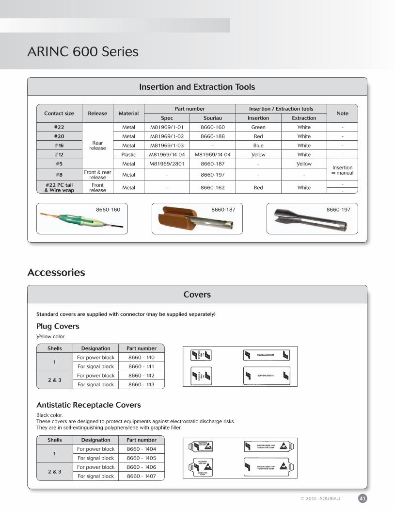
Insertion and Extraction Tools
Contact size Release MaterialPart number Insertion / Extraction tools
NoteSpec Souriau Insertion Extraction
#22
Rearrelease
Metal M81969/1-01 8660-160 Green White -
#20 Metal M81969/1-02 8660-188 Red White -
#16 Metal M81969/1-03 - Blue White -
#12 Plastic M81969/14-04 M81969/14-04 Yelow White -
#5 Metal M81969/2801 8660-187 - YellowInsertion= manual#8 Front & rear
release Metal - 8660-197 - -
#22 PC tail& Wire wrap
Frontrelease Metal - 8660-162 Red White
--
8660-187 8660-1978660-160
Covers
Plug Covers
Antistatic Receptacle Covers
Standard covers are supplied with connector (may be supplied separately)
Yellow color.
Black color.These covers are designed to protect equipments against electrostatic discharge risks.They are in self-extinguishing polyphenylene with graphite filler.
Shells Designation Part number
1For power block 8660 - 140
For signal block 8660 - 141
2 & 3For power block 8660 - 142
For signal block 8660 - 143
Shells Designation Part number
1For power block 8660 - 1404
For signal block 8660 - 1405
2 & 3For power block 8660 - 1406
For signal block 8660 - 1407
Accessories

ARIN
C 600
Range ExtensionCustom product ...............................................................................................................................
microComp® Series ........................................................................................................................
D-Subminiature Series ...................................................................................................................
NAFI 1 & 2 .........................................................................................................................................
44
44
45
45
ARINC 600 Series
ARINC 600 Series
44 © 2013 - SOURIAU
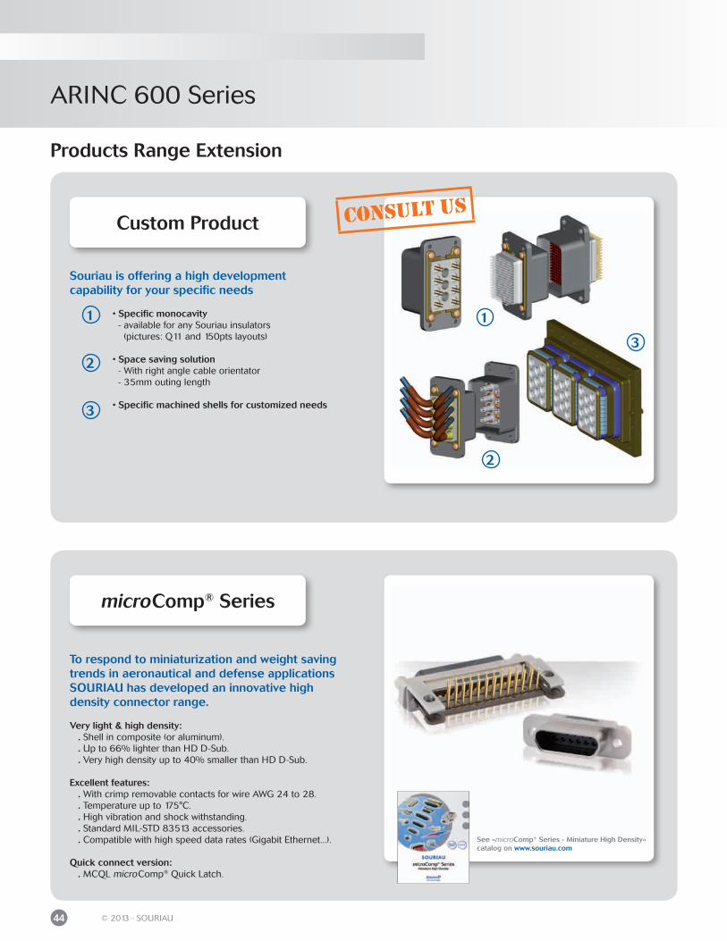
Souriau is offering a high developmentcapability for your specific needs
• Specific monocavity - available for any Souriau insulators (pictures: Q11 and 150pts layouts)
• Space saving solution - With right angle cable orientator - 35mm outing length
• Specific machined shells for customized needs
Products Range Extension
Custom Product
2
1
3
2
1
3
consult us
microComp® Series
To respond to miniaturization and weight saving trends in aeronautical and defense applications SOURIAU has developed an innovative highdensity connector range.
Very light & high density: . Shell in composite (or aluminum). . Up to 66% lighter than HD D-Sub. . Very high density up to 40% smaller than HD D-Sub.
Excellent features: . With crimp removable contacts for wire AWG 24 to 28. . Temperature up to 175°C. . High vibration and shock withstanding. . Standard MIL-STD 83513 accessories. . Compatible with high speed data rates (Gigabit Ethernet...).
Quick connect version: . MCQL microComp® Quick Latch.
See «microComp® Series - Miniature High Density» catalog on www.souriau.com
ARINC 600 Series
45© 2013 - SOURIAU
Products Range Extension
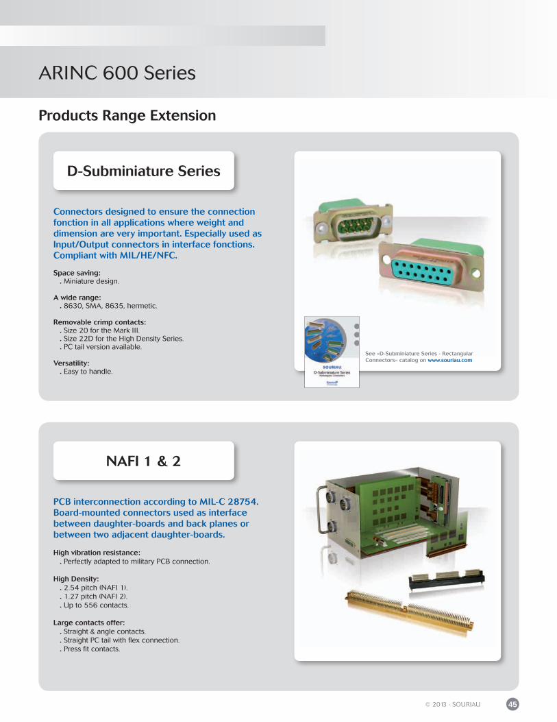
Connectors designed to ensure the connection fonction in all applications where weight and dimension are very important. Especially used as Input/Output connectors in interface fonctions. Compliant with MIL/HE/NFC.
Space saving: . Miniature design.
A wide range: . 8630, SMA, 8635, hermetic.
Removable crimp contacts: . Size 20 for the Mark III. . Size 22D for the High Density Series. . PC tail version available.
Versatility: . Easy to handle.
D-Subminiature Series
See «D-Subminiature Series - Rectangular Connectors» catalog on www.souriau.com
PCB interconnection according to MIL-C 28754. Board-mounted connectors used as interface between daughter-boards and back planes or between two adjacent daughter-boards.
High vibration resistance: . Perfectly adapted to military PCB connection.
High Density: . 2.54 pitch (NAFI 1). . 1.27 pitch (NAFI 2). . Up to 556 contacts.
Large contacts offer: . Straight & angle contacts. . Straight PC tail with flex connection. . Press fit contacts.
NAFI 1 & 2

© C
opyr
ight
SO
UR
IAU
Jul
y 2
013
- A
ll in
form
atio
n in
thi
s do
cum
ent
pres
ents
onl
y ge
nera
l par
ticul
ars
and
shal
l not
form
par
t of
any
con
trac
t. A
ll rig
hts
rese
rved
to
SOU
RIA
U fo
r ch
ange
s w
ithou
t pr
ior
notifi
catio
n or
pub
lic a
nnou
ncem
ent.
Any
dup
licat
ion
is p
rohi
bite
d, u
nles
s ap
prov
ed in
writ
ing.

Mouser Electronics
Authorized Distributor
Click to View Pricing, Inventory, Delivery & Lifecycle Information: Souriau:
8660-3132Q 8660-202 8660-250 8660-249