aristo: an augmented reality platform for …...aristo: an augmented reality platform for immersion...
TRANSCRIPT

Aristo: An Augmented Reality Platformfor Immersion and Interactivity
Zhongyang Zheng, Bo Wang, Yakun Wang, Shuang Yang, Zhongqian DongTianyang Yi, Cyrus Choi, Emily J. Chang, Edward Y. Chang
[email protected] Research, Beijing, China & San Francisco, USA
ABSTRACTThis paper introduces our augmented reality platform, Aristo, whichaims to provide users with physical feedback when interacting withvirtual objects. We use Vivepaper, a product we launched on Aristoin 2016, to illustrate the platform’s performance requirements andkey algorithms. We specifically depict Vivepaper’s tracking andgesture recognition algorithms, which involve several trade-offsbetween speed and accuracy to achieve an immersive experience.
CCS CONCEPTS•Human-centered computing→Mixed / augmented reality;• Computing methodologies→ Mixed / augmented reality;
KEYWORDSAristo; Vivepaper; augmented reality; virtual reality;
1 INTRODUCTIONAristo is our augmented reality platform, which allows users to in-teract with virtual multimedia content rendered on physical objects.For instance, a virtual book can be rendered on a piece of card stockto allow a user to select and browse content. Virtual parts renderedon cuboids can be overlaid on physical equipment (e.g., a windturbine or an engine) to train repair workers both safely and costeffectively. In general, a physical object is turned into or overlaidwith a virtual object when viewed through a head-mounted display(HMD) for interactivity.
The Aristo platform consists of three main components: an HMDwith a frontal camera, physical objects printed with visual fiducialmarkers (e.g., Figure 1(a) shows a piece of card stock as a physicalobject), and an HCI module. A user sees virtual objects on the HMDrendered upon physical objects (e.g., Figure 1(b) shows a virtualbook rendered on the physical card stock). A user can interact withvirtual objects through natural hand gestures and eye positioning,while physical objects provide feedback via grip function and tactileperception.
We have implemented two applications on the Aristo platform.The first application, Vivepaper, is a virtual book for immersive
Permission to make digital or hard copies of all or part of this work for personal orclassroom use is granted without fee provided that copies are not made or distributedfor profit or commercial advantage and that copies bear this notice and the full citationon the first page. Copyrights for components of this work owned by others than ACMmust be honored. Abstracting with credit is permitted. To copy otherwise, or republish,to post on servers or to redistribute to lists, requires prior specific permission and/or afee. Request permissions from [email protected] ’17, October 23–27, 2017, Mountain View, CA, USA© 2017 Association for Computing Machinery.ACM ISBN 978-1-4503-4906-2/17/10. . . $15.00https://doi.org/10.1145/3123266.3123308
browsing and reading. The second is a virtual workshop for trainingnovice workers. In this paper we focus on the Vivepaper applica-tion. The configuration/algorithmic differences between supportingreading and training are discussed in Section 5.
The implementation of Aristo in general, and Vivepaper specifi-cally, faces technical challenges in three areas, which our contribu-tions aim to address:
• Marker tracking. Vivepaper must track the fiducial markers on thecard stock both accurately and timely to perform pose (positionand orientation) estimation. We propose a marker-grid schemewith carefully tuned configurations to achieve both high trackingaccuracy and speed.
• Gesture recognition. A user interacts with Vivepaper using handgestures. We take advantage of the geometry of the card stockand its markers to achieve accurate hand segmentation and henceeffective gesture recognition.
• Real-time processing. Real-time tracking is an essential require-ment for any augmented reality system. Our algorithms can runcomfortably above 60fps on both desktop and mobile platforms,where a GPU is available. Note that although some markerlesstracking and gesture recognition schemes have been proposed(including our own work [9]), their high latency (a less than 60fpsframe rate) means they are not yet production ready on currentmainstream PCs and mobile devices.
Leveraging a frontal camera, we have deployed Vivepaper withVIVE on PC, Daydream on Android, and Cardboard on iOS to enablean augmented reality experience. Additionally, we have created acontent generation platform, which allows third parties to composeand upload books for users to explore. Vivepaper’s initial partnersinclude the vertical domains of education, training and tourism.
The remainder of this paper is organized as follows: Section 2details related work in computer vision and articulates the con-straints Vivepaper faces and trade-offs it makes. Section 3 depictsour marker-based tracking algorithm. Section 4 presents an effec-tive gesture recognition algorithm. We show our empirical study,which facilitates the selection of several configuration parametersto improve accuracy in both object tracking and gesture recognition.Section 5 discusses the additional configuration/algorithmic con-siderations required to support assembly line training, and offersour concluding remarks.
2 RELATEDWORKSSeveral key components of VR/AR systems are borrowed fromthe computer vision community. We divide and discuss relatedcomputer vision research in two areas: marker tracking and handsegmentation.
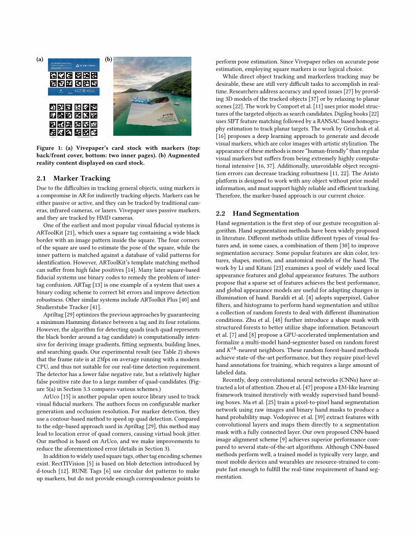
(a) (b)
Figure 1: (a) Vivepaper’s card stock with markers (top:back/front cover, bottom: two inner pages). (b) Augmentedreality content displayed on card stock.
2.1 Marker TrackingDue to the difficulties in tracking general objects, using markers isa compromise in AR for indirectly tracking objects. Markers can beeither passive or active, and they can be tracked by traditional cam-eras, infrared cameras, or lasers. Vivepaper uses passive markers,and they are tracked by HMD cameras.
One of the earliest and most popular visual fiducial systems isARToolKit [21], which uses a square tag containing a wide blackborder with an image pattern inside the square. The four cornersof the square are used to estimate the pose of the square, while theinner pattern is matched against a database of valid patterns foridentification. However, ARToolKit’s template matching methodcan suffer from high false positives [14]. Many later square-basedfiducial systems use binary codes to remedy the problem of inter-tag confusion. ARTag [13] is one example of a system that uses abinary coding scheme to correct bit errors and improve detectionrobustness. Other similar systems include ARToolkit Plus [40] andStudierstube Tracker [41].
Apriltag [29] optimizes the previous approaches by guaranteeinga minimum Hamming distance between a tag and its four rotations.However, the algorithm for detecting quads (each quad representsthe black border around a tag candidate) is computationally inten-sive for deriving image gradients, fitting segments, building lines,and searching quads. Our experimental result (see Table 2) showsthat the frame rate is at 23fps on average running with a modernCPU, and thus not suitable for our real-time detection requirement.The detector has a lower false negative rate, but a relatively higherfalse positive rate due to a large number of quad-candidates. (Fig-ure 5(a) in Section 3.3 compares various schemes.)
ArUco [15] is another popular open source library used to trackvisual fiducial markers. The authors focus on configurable markergeneration and occlusion resolution. For marker detection, theyuse a contour-based method to speed up quad detection. Comparedto the edge-based approach used in Apriltag [29], this method maylead to location error of quad corners, causing virtual book jitter.Our method is based on ArUco, and we make improvements toreduce the aforementioned error (details in Section 3).
In addition towidely used square tags, other tag encoding schemesexist. RectTIVision [5] is based on blob detection introduced byd-touch [12]. RUNE Tags [6] use circular dot patterns to makeup markers, but do not provide enough correspondence points to
perform pose estimation. Since Vivepaper relies on accurate poseestimation, employing square markers is our logical choice.
While direct object tracking and markerless tracking may bedesirable, these are still very difficult tasks to accomplish in real-time. Researchers address accuracy and speed issues [27] by provid-ing 3D models of the tracked objects [37] or by relaxing to planarscenes [22]. The work by Comport et al. [11] uses prior model struc-tures of the targeted objects as search candidates. Digilog books [22]uses SIFT feature matching followed by a RANSAC based homogra-phy estimation to track planar targets. The work by Grinchuk et al.[16] proposes a deep learning approach to generate and decodevisual markers, which are color images with artistic stylization. Theappearance of these methods is more “human-friendly” than regularvisual markers but suffers from being extremely highly computa-tional intensive [16, 37]. Additionally, unavoidable object recogni-tion errors can decrease tracking robustness [11, 22]. The Aristoplatform is designed to work with any object without prior modelinformation, and must support highly reliable and efficient tracking.Therefore, the marker-based approach is our current choice.
2.2 Hand SegmentationHand segmentation is the first step of our gesture recognition al-gorithm. Hand segmentation methods have been widely proposedin literature. Different methods utilize different types of visual fea-tures and, in some cases, a combination of them [30] to improvesegmentation accuracy. Some popular features are skin color, tex-tures, shapes, motion, and anatomical models of the hand. Thework by Li and Kitani [23] examines a pool of widely used localappearance features and global appearance features. The authorspropose that a sparse set of features achieves the best performance,and global appearance models are useful for adapting changes inillumination of hand. Baraldi et al. [4] adopts superpixel, Gaborfilters, and histograms to perform hand segmentation and utilizea collection of random forests to deal with different illuminationconditions. Zhu et al. [48] further introduce a shape mask withstructured forests to better utilize shape information. Betancourtet al. [7] and [8] propose a GPU-accelerated implementation andformalize a multi-model hand-segmenter based on random forestand Kth -nearest neighbors. These random forest-based methodsachieve state-of-the-art performance, but they require pixel-levelhand annotations for training, which requires a large amount oflabeled data.
Recently, deep convolutional neural networks (CNNs) have at-tracted a lot of attention. Zhou et al. [47] propose a EM-like learningframework trained iteratively with weakly supervised hand bound-ing boxes. Ma et al. [25] train a pixel-to-pixel hand segmentationnetwork using raw images and binary hand masks to produce ahand probability map. Vodopivec et al. [39] extract features withconvolutional layers and maps them directly to a segmentationmask with a fully connected layer. Our own proposed CNN-basedimage alignment scheme [9] achieves superior performance com-pared to several state-of-the-art algorithms. Although CNN-basedmethods perform well, a trained model is typically very large, andmost mobile devices and wearables are resource-strained to com-pute fast enough to fulfill the real-time requirement of hand seg-mentation.

Input images for hand segmentation are not limited to RGBimages. With the introduction of commodity depth cameras (e.g.Kinect), researchers can make use of the depth information. Sinhaet al. [34] perform a large blob detection in a depth range withmedian filter and depth normalization as post-processing. Kang et al.[20] propose to use depth information with random forest, and addbilateral filtering and decision adjustment for hand segmentation.Liang et al. [24] train a random regression forest using depth contextfeatures of randomly sampled pixels and fuse the information fromboth color and depth. In the commercial field, the Leap Motion [1]controller uses two monochromatic IR cameras and three infraredLEDs to capture hand and finger motions. By using depth sensors,the problem of changes in illumination can be partially alleviated.However, for the current generation of depth sensors, the depthinformation still contains substantial noise.
Instead of learning features from the foreground, there are meth-ods focusing on dealing with special backgrounds. In the VisualPanel system, Zhang et al. [45] take an arbitrary quadrangle-shapedpanel as a background and use dynamic background subtractionto segment hands out. Garrido-Jurado et al. [15] model the back-ground of markers by a mixture of two Gaussian and compute anocclusion mask by color segmentation. Ha et al. [17] and Maliket al. [26] make use of a black and white background and calculatea histogram for setting the threshold of segmentation. In our work,we also take advantage of a controlled background to yield higheraccuracy and faster speed.
Two design constraints compel us to use a rule-based algorithmfor Vivepaper instead of deep learning: compatibility with mostmodern HMDs and support of real-time performance. Since mostHMDs are only equipped with RGB cameras, we are limited tosupporting traditional RGB images. Due to the real-time perfor-mance requirement to support a 60fps frame rate, deep learningbased methods cannot be employed (although recent research hasrevealed software and hardware methods for accelerating in theclassification stage, they are at least a year away from being de-ployed with commercial HMDs). Moving objects (both the HMDand card stock) and variant features (due to illumination condi-tions, orientations, and occlusion), compounded with the 60fpsrequirement, narrow our choice algorithm to a simple and effec-tive color-based scheme. We take advantage of the geometry ofVivepaper’s card stock and the marker matrix on it to fulfill boththe accuracy and speed requirements of Vivepaper.
Some traditional augmented reading systems (e.g., [10, 32, 38])may require special physical edition for each book, with ARmarkersembedded on select pages. Instead of AR markers, a markerless ap-proach tracks images in a book (e.g., [18, 28, 33, 36]). This approachrequires designing a book with distinct images to avoid mismatch,and a time-consuming trainingmodel for each book. Vivepaper usesa generic card stock, which can render any book cover-to-cover,hence offering flexibility and convenience for content selection,delivery, and updates.
3 MARKER TRACKINGVivepaper demands fast and accurate tracking of the card stock’sposition and orientation to render selected book content accuratelyand timely on the HMD. However, both of the common open-source
tracker algorithms we evaluated (Apriltag [29] and ArUco [15]) failto fulfill our following requirements:• High decoding speed. A hand-held piece of card stock can befreely moved. In order to track this movement accurately andtimely, decoding speed must be above 60fps. Our experiment(Section 3.3.3) showed the speed of AprilTag is 23fps.
• Low jitter error. Several factors such as signal noise and low cam-era resolution can cause object tracking errors. Our experiment(Section 3.3.2) showed that ArUco suffers from high jitter error.Our proposed pipeline addresses not only the above two prob-
lems, but also the issue of occlusion. In the remainder of this section,we first depict the steps of marker tracking and highlight our nov-elty (Section 3.1). We then introduce the idea of a marker grid andpresent an algorithm to cluster markers (Section 3.2). We report ourexperiments on simulated data, which help us tune/set importantparameters to improve tracking accuracy and speed (Section 3.3).We also report our evaluations in real environments on all trackerswe studied to demonstrate that Vivepaper employs the best trackerto achieve a balance between accuracy and frame rate.
3.1 Tracking ProcessThe tracking process consists of three steps: quadrilateral (quad)detection, marker decoding, and pose estimation. Each step involvescarefully setting parameters to achieve a good balance betweenspeed and accuracy for smooth content presentation.
3.1.1 Quad Detection. Vivepaper’s card stock is printed with x×y fiducial markers (see Figure 2). As discussed in Section 2, becausewe use square markers, we refer these markers as quadrilateralsor quads. Detecting these quads is the most time-consuming stepamong the three steps. Detection errors of the corners of the quadswill be propagated to the next two steps. We analyze the substepsof the quad detector as follows:• Pre-processing. To achieve a better detection rate of the quadsunder varying illumination, for example in a slightly darker en-vironment, we perform a white balance adjustment on each cap-tured image. Then, we convert the image to grayscale and blur itusing a Gaussian filter. Lastly, adaptive thresholding is performedto create good contrast between areas of different illuminationconditions. We use functions in CUDA, OpenCL, and FastCVlibraries to speed up this pre-processing step.
• Quad extraction. Next, contours are extracted using the algorithmproposed by Suzuki et al [35]. Then, we find the convex hullsof the contours and conduct polygonal approximation to obtain4-vertex quads. (This substep was also employed in ArUco [15].)
• Corner refinement. Since the previous two steps often introducequad corner location errors, we must make the quads more reli-able. We recompute the four corners of each quad to help improvereliability by fitting new lines along the original lines of the quads.This idea draws on the experience of Apriltag2 [42], an improvedversion of the original Apriltag [29]. First, we sample some pointsalong each line, and then adjust the points to the largest gradientof the original image. The new lines are fitted to these new pointsusing the least-squares algorithm and the new corners are theintersections of the four new lines. The improved performancecan be seen from the experimental result in Figure 5(b).

3.1.2 Marker Decoding. The marker decoding step is similarto that in Apriltag and ArUco. First the quads are transformedperspectively. Then we use a spatially-varying threshold to decidethe value of the corresponding bit as stated in Apriltag [29], whichis robust to illumination. After getting the binary code of the quad,we rearrange the code to its four rotations. Then, we iterate throughall the valid codes and use a Hamming distance hash table to lookup the final ID. It should be noted that sometimes there are twoquads detected with the same ID. In this case we only keep the onewith the smaller Hamming distance or larger perimeter. To speedup this process, since the decoding process of a quad is independentof the others, we use OpenMP to parallelize computation.
3.1.3 Pose Estimation. Once a marker has been detected, withknown camera intrinsic parameters (focal length and lens type)and the physical size of the marker, we can use the principlesof trigonometry to compute the position and orientation of themarkers with respect to the camera.
Contrary to most augmented display systems where only therelative position between camera and target object is available,Vivepaper running on VIVE can obtain the world coordinate ofthe virtual book using the precise camera and HMD pose. Evenwhen tracking occasionally fails due to variations like rapid headmovement and card stock moving out of sight, the virtual book canstill be rendered by using the last known parameters.
3.2 Marker GridGenerally speaking, the larger the size of a marker, the easier it canbe tracked. However, since Vivepaper supports gesture recognitionabove these markers, a large marker can easily be partially occluded.Moreover, since the camera on a typical HMD has a smaller fieldof view compared to that of human eyes, when the card stock isbrought near the camera, some markers on the borders can be out-side of the field of view. Although using smaller markers can avoidall markers being simultaneously occluded, this approach reducestracking accuracy because smaller markers are more susceptible tocamera noise and environmental variations.
In Vivepaper, we use a matrix grid configuration (see Figure 2)to address the above large versus small marker dilemma. Our cardstock consists of two A4 (21cm × 29cm) folds (two pages). On thisavailable space, the question is then what is the required numberand size of the markers to achieve a targeted accuracy, given arange of maker-to-camera distances and possible hand occlusion.Section 3.3.1 reports our experiments and findings.
3.2.1 Marker Grid Pose Estimation. Instead of simply averagingthe poses of all the detected markers on a grid, the pose of themarker grid is determined as follows. First, we cluster the detectedmarkers into groups based on their positions. Then, to ensure thereliability of the final pose, we select a cluster that contains at leasthalf of the detected markers. Lastly, the positions of markers inthe selected cluster are averaged to estimate the virtual book’sposition. The position of the virtual book in the previous frameis used if no candidate cluster is available. The same procedure isapplied to estimate the orientation of the virtual book. With thecalculated position and orientation, the HMD renders the content
of the virtual book on its display. Experiments in Section 3.3.1 showthe effectiveness of this method.
Tomitigatemotion jumpiness, we perform aKalman filter smooth-ing on the pose of the virtual book. Such smoothing may make areal, swift movement of the card stock move slower. However, sinceswift movements are rare, the overall user experience is enhancedby making pose changes smooth.
3.2.2 Marker Grid Tracking Parameters. Table 1 lists importantparameters affecting tracking accuracy. As the value range of a pa-rameter may have physical limitations, and tradeoffs exist betweenparameters (e.g., a lower resolution image requires larger markersto achieve the same level of accuracy), we conduct an empiricalstudy to examine how these parameters affect tracking accuracy.
Table 1: List of parameters affecting tracking accuracy.Category Parameters Note
Marker
Size of card stock A4 (21cm × 29cm), standard printing size.Size and Numberof marker
Marker-grid (see Figure 2) is used to minimizethe effect of hands occlusion.
Distance andorientation
Distance between camera and hand-held cardstock is usually 0.3m to 0.6m.
Marker type We generated an Apriltag family with 36unique ids and min. hamming distance 9.
Camera Cameraresolution
For PC, with USB 2.0 camera (60MBps) in60fps, the max. resolution in uncompressedRGB channel is 612 × 460.
Noise of camera
ExternalIlluminationenvironments
Color of lighting (daylight, or fluorescent inwhite or yellow color), intensity (smooth, toostrong, or too weak), reflection of card stock.
Occlusion By handsTrackingalgorithm
See section 3.3.2 for comparison result withApriltag [29] and ArUco [15].
3.2.3 Marker Grid Real-time Tracking. Besides accuracy, real-time decoding speed is an important factor in our system, sincecomputer-generated objects must synchronize with physical ob-jects on the display. In Vivepaper, the real-time tracking of the cardstock’s position and orientation is achieved by our carefully tunedmarker decoding pipeline configuration. We additionally reimple-mented some steps of the algorithm using CUDA/OpenCL/FastCVto speed up the detection process. The performance comparison ispresented in Section 3.3.3.
3.3 ExperimentsThis section reports impacts of parameter choices on tracking per-formance via empirical studies. As previewed in the previous sec-tions, the performance factors we examined are:• The effect of marker size and number on tracking accuracy (sec-tion 3.3.1),
• The effect of choice of tracking algorithm on accuracy (sec-tion 3.3.2), and
• Validation of processing speed (section 3.3.3).We used Apriltag’s open source code [29] and the ArUco module
in OpenCV version 3.2.0 [2] to conduct empirical studies.
3.3.1 Evaluation via Simulation. In this experiment, given theconstraint of a fixed size of card stock (A4 page 21cm × 29.7cm), westudied the trade-off between the number of markers and accuracyof the algorithm under the combinations of different distances,

Figure 2: Marker grid (A4 size), configuration and markerlength, from left to right, 3x2 8.05cm, 4x3 5.67cm, 5x44.27cm, 6x4 4.06cm, 7x5 3.43cm.
occluded positions, lighting conditions, and orientations. Figure 2shows the five marker-grid configurations we studied.
The experiment was set up as follows: A simulator written inUnity3D [3] simulated what was captured by the frontal camerawith varying card-stock and hand positions, light conditions, andorientations using five different configurations of the marker grid.The simulated camera had the same intrinsic parameters as ourfrontal camera (612 × 460 resolution and focal length 289.6 pixel).Distance Study
To study the effect of different marker-grid configurations withdifferent distances, the simulator placed the card stock directlyfacing the camera (off-axis 0 deg), and then moved away from thecamera optics axis from 0.1m to 0.8m with a step size of 0.05m (15positions). For each position, we placed a virtual hand (the width ofpalm 0.14m) up-right without rotation at 0.05m on top of the cardstock. We then moved the hand from the top of the card stock toits bottom at 6 equidistant positions. At each of these positions, wealso moved the hand from left to right at 6 equidistant positions,creating 36 distinct positions. For each of the 36 hand positions,a spotlight, placed on top of the card stock z = 0.15m away, wasshined on at a random position on the card stock whose apertureangle (the width of light) was randomly set between 50 to 100deg. The spotlight procedure was repeated 37 times for each handposition. The total number of simulated settings yielded 99, 900images (5 × 15 × 36 × 37).
The images were loaded directly to our developed tracker. Asthe ground-truth of the marker position was known, we computedthe average error for different marker-grid configurations for eachdistance.
0.1 0.2 0.3 0.4 0.5 0.6 0.7 0.80
0.02
0.04
0.06
0.08
0.1
0.12
Err
or(
m)
Target distance(m)
3x2
4x3
5x4
6x4
7x5
4x3−AvgPose
(a)
0.1 0.2 0.3 0.4 0.5 0.6 0.7 0.80
10
20
30
40
50
60
70
80
90
100
De
tectio
n r
ate
(%)(
err
or
< 5
% o
f d
ista
nce
)
Target distance(m)
3x2
4x3
5x4
6x4
7x5
4x3−AvgPose
(b)
Figure 3: Distance accuracy. (a) Position error vs. distance (b)Detection rate vs. distance.
Figure 3 reports the localization accuracy and detection rate (y-axis) of the five marker-grid configurations with respect to distance(x-axis). Figure 3(a) reports error distance, the gap between theground truth position and the detected position (if the detection isdeemed successful), on the y-axis. As expected, the error increasesas the card stock moves farther away from the camera. The 3 × 2
0 10 20 30 40 50 60 70 800
0.5
1
1.5
2
2.5
Err
or(
de
gre
es)
Off−axis angle(degrees)
3x2
4x3
5x4
6x4
7x5
4x3−AvgPose
(a)
0 10 20 30 40 50 60 70 800
10
20
30
40
50
60
70
80
90
100
De
tectio
n r
ate
(%)
Off−axis angle(degrees)
3x2
4x3
5x4
6x4
7x5
4x3−AvgPose
(b)
Figure 4: Orientation accuracy. (a) Orientation error vs. off-axis angle (b) Detection rate vs. off-axis angle.
and 4 × 3 grids achieve the best accuracy. While Figure 3(a) showsthe error of the successfully detected cases, Figure 3(b) shows thesuccessful detection rate, which we define as the ratio of the errordivided by the distance (to the camera), to be within 5%. A detectionfailure could result from three factors:(1) Hand occlusion. The 3 × 2 grid suffers from the worst detection
rate due to that large markers can easily be occluded by hand.(2) Limited field of view. When the card stock is brought near the
camera (e.g., less than 0.2m), larger markers are more suscepti-ble to be out of sight.
(3) Distance away from camera. As grid-to-camera distance in-creases, detection rate decreases. Markers of smaller size (5 × 4,6 × 4 and 7 × 5) are more susceptible to longer distance.
Orientation StudyTo further study the effect of the orientation, we repeated the
same procedure with a fixed target distance (0.3m), and variedoff-axis angle, 0 to 85 deg, with a step size of 5 deg.
Figure 8 reports the localization accuracy and detection rate(y-axis) of the five marker-grid configurations with respect to ori-entation (x-axis). The error rate grows as the marker-grid rotatesaway. In terms of detection rate, the 2 × 3 grid suffers the worstperformance, while the others are more or less the same.
In both experiments, we also compared our maker-grid approachwith the average performance of tracking individual markers (theblack dash line, denoted as AvgPose in both figures). Both figuresshow that Vivepaper’s marker-grid approach enjoys the best track-ing accuracy with a 4 × 3 grid and 5.67cm marker configuration,thus being our choice of setting.
3.3.2 Evaluation in Real Environment. Oncewe determined goodparameter settings to configure the Vivepaper marker grid, we usedreal-world images to compare our tracker’s accuracy and speedwith two widely used trackers, Apriltag and ArUco. Our evaluationwas based on two factors:(1) False positive detection rate. Although using the marker grid
configuration can reduce false negatives (thanks to redundancy),false positives can still be problematic.
(2) Virtual-book jitter. Inaccuracy of the detected corner locationsof marker quads may lead to jitter in the virtual book in thevirtual display, degrading user experience.We downloaded 207, 849 images from LabelMe [31] to compare
the false positive rate between our evaluated trackers. These imagesare various indoor/outdoor photos containing no markers. If amarker is detected in an image, we consider that to be a false

0 1 2 3 40
0.2
0.4
0.6
0.8
1
1.2
1.4
1.6
1.8
2
Fals
e p
ositiv
e r
ate
(%
)
Maximum bit errors corrected
Apriltag
Aruco
Vivepaper
(a)
0 0.5 1 1.5
Vivepaper2*
Vivepaper1*
Aruco*
Apriltag*
Vivepaper2
Vivepaper1
Aruco
Apriltag
Standard deviation in corner estimation (pixels)
(b)
Figure 5: (a) False positive rates tested on LabelMe [31]. (b)Comparison of four trackers under normal condition andsuboptimal illumination conditions (*).
positive. Figure 5(a) shows that Apriltag suffers from the highestfalse positive rate, while our tracker enjoys the lowest.
Virtual-book jitter is an important performance issue for Vivepa-per. If the virtual book displayed in the virtual space keeps vibratingeven with the user holding the card stock stable, the jitter may causethe user dizziness or discomfort. The jitter problem is due to the in-accuracy of the detected corner locations of marker quads caused byimperfections in digital camera capture sensors (such as Gaussiannoise and relative low resolution).
The experiment was set up by placing the same camera used byVivepaper in an indoor environment, at three fixed locations (0.2m,0.4m, and 0.6m)with respect to a card stock, andwith three differentangles (0, 20, and −20 degrees). Hence, 9 videos were captured. Inaddition to normal lighting conditions, this process was repeated insuboptimal lighting conditions. We use the box plot [43] to analyzethe quad corner jitter of four methods: 1) Apriltag, 2) ArUco, 3)Vivepaper1 (before corner refinement), and 4) Vivepaper2 (aftercorner refinement).
Due to Gaussian noise and low resolution in camera sensors, thecorners detected at the quad detection stage may be slightly differ-ent between frames. In each video, we assume all the 24 markers(96 corners) are visible. For each corner’s coordinate we computedthe standard derivation across the 500 frames, denoted as cornerestimation error (jitter level). Ideally, this error should be zero. Wetake the corner estimation error of all the corners in the 9 videos (nomore than 96×9 values), and show each tracker’s corner estimationerror under normal and suboptimal lighting conditions in a boxplot (Figure 5(b)).
In Figure 5(b), our observations are: 1) Regarding the deviationrange of lower first and upper third quartiles, ArUco’s third quartilesis higher than those of the other methods. Apriltag is the most accu-rate method with the lowest deviation, attributed to its complicatedmethod of quad detection. 2) Regarding the minimum and maxi-mum deviation values (lower/upper ends of the whiskers), Apriltagsuffers from high false positives. Some more extreme outliers mayappear, leading to a higher deviation value than our method, whichcan be seen in Figure 5(b) where the upper ends of the whiskersof Apriltag is higher than those of our method. 3) Regarding themedian (middle band in the box), Apriltag and our method arelower than those of the other two. Vivepaper without corner refine-ment suffers from the highest deviations, and its jitter level undersuboptimal lighting conditions (denoted with *) worsens.
Although the median jitter level of our method is slightly higherthan Apriltag’s, it is small enough to provide good user experience.
Table 2: Average processing time (µs) on PC and Mobile.Libraries used to speed up: * CUDA, # OpenMP, + FastCV.
Test case Sub steps AprilTag ArUco Vivepaper(CPU only)
Vivepaper(boosted )
PC Mobile PC Mobile PC Mobile PC Mobile
6 markers(half pagecard stock)
Quad det 29, 221 102, 597 2, 944# 34, 661 8, 810 17, 396 4, 333* 6, 950+Decoding 191 942 514 15, 779 230 1, 349 108# 383Pose est. 840 3, 300 727 2, 795 1, 947 3, 224 845# 197+Total 33.1fps 9.4fps 238.9fps 18.8fps 91.0fps 45.5fps 189.2fps 132.8fps
12 markers(one pagecard stock)
Quad det 41, 627 127, 751 3, 092# 41, 134 8, 945 21, 230 4, 398* 8, 553+Decoding 414 1, 422 599 16, 225 516 1, 727 204# 726Pose est. 1, 735 7, 017 1, 201 6, 194 4, 604 6, 465 1, 566# 274+Total 22.8fps 7.3fps 204.4fps 15.7fps 71.1fps 34.0fps 162.1fps 104.7fps
24 markers(two pagescard stock)
Quad det 44, 451 124, 741 3, 759# 42, 621 9, 722 21, 419 5, 080* 7, 859+Decoding 584 1, 618 866 22, 762 884 3, 018 347# 1, 318Pose est. 2, 798 13, 201 1, 923 12, 635 8, 192 13, 136 2, 723# 1, 422+Total 20.9fps 7.2fps 152.7fps 12.8fps 53.2fps 26.6fps 122.7fps 94.3fps
Consider the deviation range (lower to upper ends of whiskers).Vivepaper’s method enjoys the smallest range and hence the moststable. Furthermore, as we will show next that when speed is con-sidered, our method runs much faster than Apriltag to support therequired 60fps.
3.3.3 Processing Time. For a real-time AR product, the process-ing time is a critical factor for good user experience. The latency ofVivepaper should be no longer than 16ms (or 60fps) or it can easilycause discomfort for the user. This section compares Vivepaper,Apriltag, and ArUco on their processing time in quad detection,marker decoding, and pose estimation.
For better speed, we implemented several substeps with CUDAon PC and FastCV on Android, as well as some parallelizable stepson OpenMP. The same techniques are also applied to speed up theperformance of detecting hand gestures. Of the latter two systems,Apriltag and ArUco have only open-sourced the CPU versions.
On the PC platform, our experiments were conducted on a com-puter with an Intel(R) Core(TM) i7-3770 working at 3.40GHz, run-ning Windows 10. The processor has four cores, each running twothreads. The DRAM size is 16GB. We took three video sequenceswith different numbers of markers, 6, 12, and 24, respectively. Ingeneral, handling more markers demands a longer processing time,especially in the last two steps of the pipeline: marker decodingand pose estimation. Each video sequence contains 5, 000 frameswith a resolution of 612×460 pixels taken by VIVE’s frontal camerain a regular indoor environment. Table 2 summarizes the results.
As shown in Table 2, Apriltag suffers from theworst performancein all test cases. ArUco and Vivepaper use a contour-based methodto detect quads, which is much faster than the edge-based methodused in Apriltag. ArUco performs even better than Vivepaper, reach-ing 204.4fps and 162.1fps. The reason our system is slower thanArUco is that we added some extra steps to improve accuracy asdescribed in Section 3.1. Nevertheless, Vivepaper is still fast enoughfor a real-time AR application. The boosted version of Vivepaperachieves more than 2× speedup compared to the original version.
On mobile, we used a state-of-the-art phone, the Google Pixel,with a Qualcomm821 (MSM8996pro) processor and 4GB DRAMrunning Android 7.1. This time, we used the phone’s camera to takethree video sequences using the same three different configurationsof markers. Each video sequence has 5, 000 frames at a resolution of800 × 600. Table 2 presents the results. It turns out that our FastCVversion enjoys a significant performance boost (3× to 4×) over theCPU version.

In summary, Vivepaper reaches 162fps on average on PC and104fps on mobile, both exceeding the 60fps speed requirement of areal-time AR system.
4 HAND GESTURESHand gestures are the most natural way for users to interact withbooks. However, reliable hand tracking and gesture recognition isstill a very challenging problem. Vivepaper simplifies the problemby focusing hand segmentation and gesture recognition in the phys-ical boundary of the card stock. In its current version, Vivepapersupports two gestures: page flipping and point-and-click. By utiliz-ing the priorly known marker-grid background, we can achievereliable hand segmentation and fingertip detection, even with acamera of 600 × 400 resolution.
4.1 Hand SegmentationWhen using skin color as the visual cue for a hand, we must con-sider various factors such as illumination, background, and cameracharacteristics [19]. For an input image Ii , we use the HSV colorspace to conduct skin color detection. As concluded in [19], thetransformation of RGB to HSV makes color identification moreinvariant to high intensities of white light and ambient light, aswell as surface orientations relative to the light source. The HLSrepresentation is as effective as HSV for color identification. Vivepa-per uses the HSV color space in the resource constrained mobileplatform, since the FastCV library provides a quick RGB to HSVconversion API.
To better separate skin from non-skin, we use a white balancingalgorithm to pre-process image Ii . The algorithm removes colorcasts caused by the light and yields I ′i . Starting from n color seeds,we use a boundary decision method for skin color detection. Weobtain the bitwise-orMi of several binary masksmn with respect ton different color seeds. After we have obtained the binary maskMi ,we use post-processing rules to remove some of the false positives,yielding M ′
i . Our post-processing takes advantage of the knownmarker-grid background. Fingertip detection and localization aresubsequently performed based on the post-processed maskM ′
i .
4.1.1 Calibration. Differences in illumination and camera char-acteristics are also issues that must be dealt with when using skincolor based methods. If a user wears a pair of gloves, the predefinedcolor seeds may fail to identify the correct hand regions. Vivepaperthus performs calibration for different users under various environ-ments beforehand. Vivepaper requests users to put their hands ona specified region of the card stock for one second and obtains ncolor seeds for hand segmentation. Once the color seeds and thelocation of a hand is identified, the changes in color due to environ-mental factors or hand movement can be subsequently captured tocalibrate color seeds dynamically.
4.1.2 Controlled Background. One of the issues for skin colorbased methods is that background colors could be similar to the skincolor, causing false positives. Therefore, Vivepaper takes advantageof a controlled background. Since the operating region of the user’shands in Vivepaper is within the boundary of the card stock, thebackground for the hands can be limited to the black and whitemarkers. We take advantage of the boundary and known color of
card stock to obtain better accuracy. First, we use the boundary ofthe card stock to remove regions with similar color to the user’sskin in the background. Second, we obtain the temporal colors ofblack and white for different illuminations and separate them fromthe skin color maskM ′
i . We also eliminate the regions of detectedmarkers with the quads of markers. In addition, processing time isreduced because we handle only the pixels within the boundary ofthe card stock.
4.1.3 Empirical Validations. To validate the practicality of ourstrategies, we set up a dataset, which was collected when users usedVivepaper. This dataset contains 600 images from one male and onefemale user, collected under white and yellow light. Additionally,for each light color we collected images under three illuminationintensities: dark, normal, and bright. For each image, we manuallylabeled a hand segmentation ground-truth. Since our main concernis the hand position inside the card stock, we labeled the card stock’sboundary in each image. We calculated both the accuracy and falsepositive rate inside the boundary.
Table 3: Hand segmentation results.Accuracy/FalsePositive Rate
CalibrationOnly
+ WhiteBalance
+ ControlledBackground
WhiteLight
Dark 0.98/0.02 0.99/0.01 0.99/0.01Normal 0.99/0.01 0.99/0.00 0.99/0.00Bright 0.99/0.01 0.99/0.01 0.99/0.01
YellowLight
Dark 0.92/0.07 0.95/0.03 0.95/0.01Normal 0.64/0.40 0.88/0.13 0.94/0.06Bright 0.92/0.09 0.91/0.08 0.93/0.06
Table 3 presents the accuracy and false positive rate of handsegmentation in three processing stages: calibration only, withwhite balancing, and with controlled background. Each stage isconducted based on the previous one. We can see from the tablethat under white light, calibration alone suffices. Under yellow light,additional processing stages can improve segmentation accuracy.The reason for this improvement is that when yellow light shineson the card stock, white colored regions on the card stock canappear to be skin color, as shown in Figure 6(c). Performing whitebalancing can partially remedy this ambiguity problem, as shownin Figure 6(d). However, there are still white colored regions on thecard stock that can be read incorrectly. A background of a similarcolor to the skin can cause segmentation confusion, as shown inFigure 6(d). When we restrict hand segmentation to be within theboundary of the card stock, the controlled background allows usto further improve segmentation accuracy under yellow light, asshown in Figure 6(e).
4.2 Fingertip DetectionAccurately locating fingertips from images is critical for recognizingthe two gestures (i.e., page flipping and point-and-click) that Vivepa-per supports. Gestures are recognized by tracking the movementof the user’s fingertip. After hand segmentation, the binary maskM ′i is obtained. We regard the top two largest contours Kj (j = 0, 1)
ofM ′i as hands. BecauseM
′i may contain a region of the arm, the
palm center of each hand is estimated using the method in [44] todistinguish between the hand and arm regions. As illustrated inFigure 7(a), the center C of the largest circle inside Kj is regarded
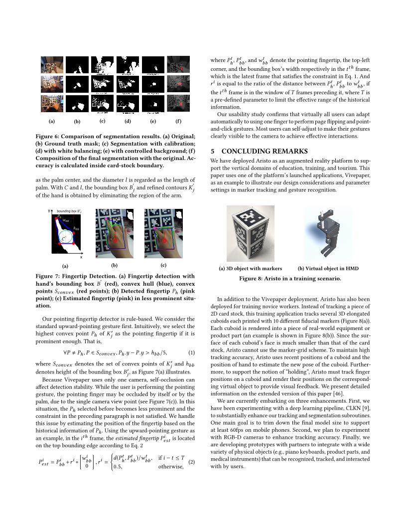
(a) (b) (c) (d) (e) (f)
Figure 6: Comparison of segmentation results. (a) Original;(b) Ground truth mask; (c) Segmentation with calibration;(d) with white balancing; (e) with controlled background; (f)Composition of the final segmentationwith the original. Ac-curacy is calculated inside card-stock boundary.
as the palm center, and the diameter l is regarded as the length ofpalm. With C and l , the bounding box B
′j and refined contours K
′j
of the hand is obtained by eliminating the region of the arm.
x
y
C
𝑃ℎ
ℎ𝑏𝑏
bounding box 𝐵′𝑗
𝑤𝑏𝑏
(a) (b) (c)
Figure 7: Fingertip Detection. (a) Fingertip detection withhand’s bounding box B
′(red), convex hull (blue), convex
points Sconvex (red points); (b) Detected fingertip Ph (pinkpoint); (c) Estimated fingertip (pink) in less prominent situ-ation.
Our pointing fingertip detector is rule-based. We consider thestandard upward-pointing gesture first. Intuitively, we select thehighest convex point Ph of K ′
j as the pointing fingertip if it isprominent enough. That is,
∀P , Ph , P ∈ Sconvex , Ph .y − P .y > hbb/5, (1)
where Sconvex denotes the set of convex points of K ′j and hbb
denotes height of the bounding box B′j , as Figure 7(a) illustrates.
Because Vivepaper uses only one camera, self-occlusion canaffect detection stability. While the user is performing the pointinggesture, the pointing finger may be occluded by itself or by thepalm, due to the single camera view point (see Figure 7(c)). In thissituation, the Ph selected before becomes less prominent and theconstraint in the preceding paragraph is not satisfied. We handlethis issue by estimating the position of the fingertip based on thehistorical information of Ph . Using the upward-pointing gesture asan example, in the ith frame, the estimated fingertip P iest is locatedon the top bounding edge according to Eq. 2
P iest = P ibb +ri ∗
[wibb0
], r i =
{d(P th , P
tbb )/w
tbb , if i − t ≤ T
0.5, otherwise,(2)
where P th , Ptbb , andw
tbb denote the pointing fingertip, the top-left
corner, and the bounding box’s width respectively in the t th frame,which is the latest frame that satisfies the constraint in Eq. 1. Andr i is equal to the ratio of the distance between P th , P
tbb to wt
bb , ifthe t th frame is in the window ofT frames preceding it, whereT isa pre-defined parameter to limit the effective range of the historicalinformation.
Our usability study confirms that virtually all users can adaptautomatically to using one finger to perform page flipping and point-and-click gestures. Most users can self-adjust to make their gesturesclearly visible to the camera to achieve effective interactions.
5 CONCLUDING REMARKSWe have deployed Aristo as an augmented reality platform to sup-port the vertical domains of education, training, and tourism. Thispaper uses one of the platform’s launched applications, Vivepaper,as an example to illustrate our design considerations and parametersettings in marker tracking and gesture recognition.
(a) 3D object with markers (b) Virtual object in HMD
Figure 8: Aristo in a training scenario.
In addition to the Vivepaper deployment, Aristo has also beendeployed for training novice workers. Instead of tracking a piece of2D card stock, this training application tracks several 3D elongatedcuboids each printed with 10 different fiducial markers (Figure 8(a)).Each cuboid is rendered into a piece of real-world equipment orproduct part (an example is shown in Figure 8(b)). Since the sur-face of each cuboid’s face is much smaller than that of the cardstock, Aristo cannot use the marker-grid scheme. To maintain hightracking accuracy, Aristo uses recent positions of a cuboid and theposition of hand to estimate the new pose of the cuboid. Further-more, to support the notion of “holding”, Aristo must track fingerpositions on a cuboid and render their positions on the correspond-ing virtual object to provide visual feedback. We present detailedinformation on the extended version of this paper [46].
We are currently embarking on three enhancements. First, wehave been experimenting with a deep learning pipeline, CLKN [9],to substantially enhance our tracking and segmentation subroutines.One main goal is to trim down the final model size to supportat least 60fps on mobile phones. Second, we plan to experimentwith RGB-D cameras to enhance tracking accuracy. Finally, weare developing prototypes with partners to integrate with a widevariety of physical objects (e.g., piano keyboards, product parts, andmedical instruments) that can be recognized, tracked, and interactedwith by users.

REFERENCES[1] 2017. Leap Motion. https://www.leapmotion.com. (2017).[2] 2017. Open Source Computer Vision Library. https://github.com/opencv. (2017).[3] 2017. Unity3D. https://unity3d.com. (2017).[4] Lorenzo Baraldi, Francesco Paci, Giuseppe Serra, Luca Benini, and Rita Cucchiara.
2014. Gesture recognition in ego-centric videos using dense trajectories andhand segmentation. In Proceedings of the IEEE Conference on Computer Vision andPattern Recognition Workshops. 688–693.
[5] Ross Bencina, Martin Kaltenbrunner, and Sergi Jorda. 2005. Improved topologicalfiducial tracking in the reactivision system. In Computer Vision and PatternRecognition-Workshops, 2005. CVPR Workshops. IEEE Computer Society Conferenceon. IEEE, 99–99.
[6] Filippo Bergamasco, Andrea Albarelli, Luca Cosmo, Emanuele Rodola, andAndreaTorsello. 2016. An accurate and robust artificial marker based on cyclic codes.IEEE transactions on pattern analysis and machine intelligence 38, 12 (2016), 2359–2373.
[7] Alejandro Betancourt, Lucio Marcenaro, Emilia Barakova, Matthias Rauterberg,and Carlo Regazzoni. 2016. GPU accelerated left/right hand-segmentation in firstperson vision. In European Conference on Computer Vision. Springer, 504–517.
[8] Alejandro Betancourt, Pietro Morerio, Emilia Barakova, Lucio Marcenaro,Matthias Rauterberg, and Carlo Regazzoni. 2017. Left/right hand segmenta-tion in egocentric videos. Computer Vision and Image Understanding 154 (2017),73–81.
[9] Che-Han Chang, Chun-Nan Chou, and Edward Y. Chang. 2017. CLKN: Cas-caded Lucas-Kanade Networks for Image Alignment. In The IEEE Conference onComputer Vision and Pattern Recognition (CVPR).
[10] Kyusung Cho, Juho Lee, JS Lee, and HS Yang. 2007. A realistic e-learning systembased on mixed reality. In 13th International Conference on Virtual Systems andMultimedia. 57–64.
[11] Andrew I Comport, Eric Marchand, Muriel Pressigout, and Francois Chaumette.2006. Real-time markerless tracking for augmented reality: the virtual visualservoing framework. IEEE Transactions on visualization and computer graphics12, 4 (2006), 615–628.
[12] Enrico Costanza and John Robinson. 2003. A Region Adjacency Tree Approachto the Detection and Design of Fiducials. (2003).
[13] Mark Fiala. 2005. ARTag, a fiducial marker system using digital techniques. InComputer Vision and Pattern Recognition, 2005. CVPR 2005. IEEE Computer SocietyConference on, Vol. 2. IEEE, 590–596.
[14] Mark Fiala. 2005. Comparing artag and artoolkit plus fiducial marker systems. InHaptic Audio Visual Environments and their Applications, 2005. IEEE InternationalWorkshop on. IEEE, 6–pp.
[15] S. Garrido-Jurado, R. Mu noz Salinas, F.J. Madrid-Cuevas, and M.J. Marín-Jiménez.2014. Automatic generation and detection of highly reliable fiducial markersunder occlusion. Pattern Recognition 47, 6 (2014), 2280 – 2292. https://doi.org/10.1016/j.patcog.2014.01.005
[16] Oleg Grinchuk, Vadim Lebedev, and Victor Lempitsky. 2016. Learnable VisualMarkers. In Advances In Neural Information Processing Systems. 4143–4151.
[17] Taejin Ha, Yeongmi Kim, Jeha Ryu, and Woontack Woo. 2006. Enhancing im-mersiveness in AR-based product design. In Advances in Artificial Reality andTele-Existence. Springer, 207–216.
[18] Taejin Ha, Youngho Lee, and Woontack Woo. 2011. Digilog book for temple belltolling experience based on interactive augmented reality. Virtual Reality 15, 4(2011), 295–309.
[19] Praveen Kakumanu, Sokratis Makrogiannis, and Nikolaos Bourbakis. 2007. Asurvey of skin-color modeling and detection methods. Pattern recognition 40, 3(2007), 1106–1122.
[20] Byeongkeun Kang, Kar-Han Tan, Hung-Shuo Tai, Daniel Tretter, and Truong QNguyen. 2016. Hand Segmentation for Hand-Object Interaction from Depth map.arXiv preprint arXiv:1603.02345 (2016).
[21] Hirokazu Kato and Mark Billinghurst. 1999. Marker tracking and hmd calibrationfor a video-based augmented reality conferencing system. In Augmented Reality,1999.(IWAR’99) Proceedings. 2nd IEEE and ACM International Workshop on. IEEE,85–94.
[22] Kiyoung Kim, Vincent Lepetit, and Woontack Woo. 2010. Scalable real-timeplanar targets tracking for digilog books. The Visual Computer 26, 6 (2010),1145–1154.
[23] Cheng Li and Kris M Kitani. 2013. Pixel-level hand detection in ego-centricvideos. In Proceedings of the IEEE Conference on Computer Vision and PatternRecognition. 3570–3577.
[24] Hui Liang, Jin Wang, Qian Sun, Yong-Jin Liu, Junsong Yuan, Jun Luo, and YingHe. 2016. Barehanded music: real-time hand interaction for virtual piano. InProceedings of the 20th ACM SIGGRAPH Symposium on Interactive 3D Graphics
and Games. ACM, 87–94.[25] Minghuang Ma, Haoqi Fan, and Kris M Kitani. 2016. Going deeper into first-
person activity recognition. In Proceedings of the IEEE Conference on ComputerVision and Pattern Recognition. 1894–1903.
[26] Shahzad Malik, Chris McDonald, and Gerhard Roth. 2002. Hand tracking forinteractive pattern-based augmented reality. In Proceedings of the 1st InternationalSymposium on Mixed and Augmented Reality. IEEE Computer Society, 117.
[27] Eric Marchand, Hideaki Uchiyama, and Fabien Spindler. 2016. Pose estimationfor augmented reality: a hands-on survey. IEEE transactions on visualization andcomputer graphics 22, 12 (2016), 2633–2651.
[28] GeorgeMargetis, Xenophon Zabulis, Panagiotis Koutlemanis, Margherita Antona,and Constantine Stephanidis. 2013. Augmented interactionwith physical books inan Ambient Intelligence learning environment. Multimedia tools and applications67, 2 (2013), 473–495.
[29] Edwin Olson. 2011. AprilTag: A robust and flexible visual fiducial system. InRobotics and Automation (ICRA), 2011 IEEE International Conference on. IEEE,3400–3407.
[30] Siddharth S Rautaray and Anupam Agrawal. 2015. Vision based hand gesturerecognition for human computer interaction: a survey. Artificial IntelligenceReview 43, 1 (2015), 1–54.
[31] Bryan C Russell, Antonio Torralba, Kevin P Murphy, and William T Freeman.2008. LabelMe: a database and web-based tool for image annotation. Internationaljournal of computer vision 77, 1-3 (2008), 157–173.
[32] Tomoki Issac Saso, Kenji Iguchi, and Masa Inakage. 2003. Little red: storytellingin mixed reality. In ACM SIGGRAPH 2003 Sketches & Applications. ACM, 1–1.
[33] Camille Scherrer, Julien Pilet, Pascal Fua, and Vincent Lepetit. 2008. The hauntedbook. In Proceedings of the 7th IEEE/ACM international Symposium on Mixed andAugmented Reality. IEEE Computer Society, 163–164.
[34] Ayan Sinha, Chiho Choi, and Karthik Ramani. 2016. Deephand: Robust hand poseestimation by completing a matrix imputed with deep features. In Proceedings ofthe IEEE Conference on Computer Vision and Pattern Recognition. 4150–4158.
[35] Satoshi Suzuki et al. 1985. Topological structural analysis of digitized binaryimages by border following. Computer vision, graphics, and image processing 30,1 (1985), 32–46.
[36] Nobuko Taketa, Kenichi Hayashi, Hirokazu Kato, and Shogo Noshida. 2007.Virtual pop-up book based on augmented reality. Human Interface and theManagement of Information. Interacting in Information Environments (2007), 475–484.
[37] Henning Tjaden, Ulrich Schwanecke, and Elmar Schömer. 2016. Real-Timemonocular segmentation and pose tracking of multiple objects. In EuropeanConference on Computer Vision. Springer, 423–438.
[38] Poonsri Vate-U-Lan. 2012. An augmented reality 3d pop-up book: the develop-ment of a multimedia project for English language teaching. In Multimedia andExpo (ICME), 2012 IEEE International Conference on. IEEE, 890–895.
[39] Tadej Vodopivec, Vincent Lepetit, and Peter Peer. 2016. Fine Hand Segmentationusing Convolutional Neural Networks. arXiv preprint arXiv:1608.07454 (2016).
[40] Daniel Wagner and Dieter Schmalstieg. 2007. ARToolKitPlus for Pose Trackingon Mobile Devices. In Computer Vision Winter Workshop Cvww.
[41] Daniel Wagner and Dieter Schmalstieg. 2009. Making augmented reality practicalon mobile phones, part 1. IEEE Computer Graphics and Applications 29, 3 (2009).
[42] John Wang and Edwin Olson. 2016. AprilTag 2: Efficient and robust fiducialdetection. In Intelligent Robots and Systems (IROS), 2016 IEEE/RSJ InternationalConference on. IEEE, 4193–4198.
[43] David F Williamson, Robert A Parker, and Juliette S Kendrick. 1989. The boxplot: a simple visual method to interpret data. Annals of internal medicine 110, 11(1989), 916–921.
[44] Zhengwei Yao, Zhigeng Pan, and Shuchang Xu. 2013. Wrist recognition andthe center of the palm estimation based on depth camera. In Virtual Reality andVisualization (ICVRV), 2013 International Conference on. IEEE, 100–105.
[45] Zhengyou Zhang, Ying Wu, Ying Shan, and Steven Shafer. 2001. Visual panel:virtual mouse, keyboard and 3D controller with an ordinary piece of paper. InProceedings of the 2001 workshop on Perceptive user interfaces. ACM, 1–8.
[46] Zhongyang Zheng, Bo Wang, Yakun Wang, Shuang Yang, Zhongqian Dong,Tianyang Yi, Cyrus Choi, Emily Chang, and Edward Y. Chang. 2017. Aristo: AnAugmented Reality Platform for Interactivity and Immersion (extended version).In HTC Technical Report.
[47] Yang Zhou, Bingbing Ni, Richang Hong, Xiaokang Yang, and Qi Tian. 2016. Cas-caded interactional targeting network for egocentric video analysis. In Proceedingsof the IEEE Conference on Computer Vision and Pattern Recognition. 1904–1913.
[48] Xiaolong Zhu, Xuhui Jia, and Kwan-Yee KWong. 2014. Pixel-level hand detectionwith shape-aware structured forests. In Asian Conference on Computer Vision.Springer, 64–78.