ariston - microgenus 2 - lets fixit - diy network, guide ... · the microgenus ii is an approved...
TRANSCRIPT

microGENUS II 24 MFFImicroGENUS II 28 MFFImicroGENUS II 31 MFFI
Installation and ServicingInstructions
Type C Boilers
G.C.N: 47-116-25 (24kW)G.C.N: 47-116-26 (28kW)G.C.N: 47-116-27 (31kW)
LEAVE THESE INSTRUCTIONS WITHTHE END-USER
Country of destination: GB, IE
12
34
56
12
3 4
56
II
E C

2
TABLE OF CONTENTS
1. GENERAL INFORMATION PAGE. 3
1.1 GENERAL INSTRUCTIONS PAGE. 31.2 OVERALL VIEW PAGE. 4
2. INSTALLATION PAGE. 4
2.1 REFERENCE STANDARDS PAGE. 52.2 SITING THE APPLIANCE PAGE. 52.3 OVERALL DIMENSIONS PAGE. 62.4 CLEARANCES PAGE. 62.5 MOUNTING THE APPLIANCE PAGE. 62.6 ELECTRICAL CONNECTION PAGE. 72.7 GAS CONNECTION PAGE. 82.8 WATER CONNECTION PAGE. 82.9 FLUE CONNECTION PAGE. 102.10 CONTROL PANEL PAGE. 182.11 DIGITAL DISPLAY AND FAULT CODES PAGE. 182.12 REMOVING THE FRONT PANEL PAGE. 192.13 ROOM THERMOSTAT
CONNECTION PAGE. 192.14 ELECTRICAL/SYSTEM DIAGRAMS PAGE. 202.15 WATER CIRCUIT DIAGRAM PAGE. 21
3. COMMISSIONING PAGE. 22
3.1 INITIAL PREPARATION PAGE. 223.2 INITIAL START-UP PAGE. 233.3 OPERATIONAL ADJUSTMENTS PAGE. 233.4 COMBUSTION ANALYSIS PAGE. 243.5 PRODUCT OF COMBUSTION
DISCHARGE MONITORING PAGE. 243.6 BOILER SAFETY SYSTEMS PAGE. 243.7 DRAINING THE SYSTEM PAGE. 263.8 COMPLETION PAGE. 263.9 OPERATIONAL CHECKS PAGE. 263.10 INSTRUCTING THE END USER PAGE. 26
4. GAS ADJUSTMENTS PAGE. 27
4.1 CHANGING THE TYPE OF GAS PAGE. 274.2 ADJUSTING THE GAS PRESSURES PAGE. 28
5. MAINTENANCE PAGE. 32
6. SERVICING INSTRUCTIONS PAGE. 33
6.1 REPLACEMENT OF PARTS PAGE. 336.2 TO GAIN GENERAL ACCESS PAGE. 33
6.2.1 REMOVING THE FRONT
PANEL PAGE. 336.2.2 REMOVING THE SEALED
CHAMBER FRONT PANEL PAGE. 346.2.3 REMOVING THE SIDE
PANELS PAGE. 346.3 ACCESS TO THE COMBUSTION
CHAMBER PAGE. 35
6.3.1 REMOVING THE
COMBUSTION CHAMBER PAGE. 356.3.2 REMOVING THE BURNER
AND JETS PAGE. 356.3.3 REMOVING THE
ELECTRODES PAGE. 356.3.4 REMOVING THE MAIN HEAT
EXCHANGER PAGE. 366.3.5 REMOVING THE AIR
PRESSURE SWITCH PAGE. 376.3.6 REMOVING THE FAN PAGE. 38
6.4 ACCESS TO THE GAS VALVE PAGE. 386.4.1 REMOVING THE SPARK
GENERATOR PAGE. 386.4.2 REMOVING THE GAS VALVE PAGE. 39
6.5 ACCESS TO THE WATER CIRCUIT PAGE. 396.5.1 REMOVING THE D.H.W. (SECONDARY)
EXCHANGER PAGE. 396.5.2 REMOVING THE PUMP
PRESSURE SWITCH PAGE. 406.5.3 REMOVING THE SAFETY
VALVE PAGE. 416.5.4 REMOVING THE AUTOMATIC
AIR VENT PAGE. 416.5.5 REMOVING THE PUMP PAGE. 426.5.6 REMOVING THE PRESSURE
GAUGE PAGE. 436.5.7 REMOVING THE EXPANSION
VESSEL PAGE. 436.5.8 REMOVING THE OVERHEAT
THERMOSTAT PAGE. 446.5.9 REMOVING THE C.H.
TEMPERATURE PROBE (N.T.C.) PAGE. 446.5.10 REMOVING THE D.H.W.
TEMPERATURE SENSOR
(N.T.C.) PAGE. 456.5.11 REMOVING THE DIVERTOR
VALVE ACTUATOR PAGE. 456.5.12 REMOVING THE D.H.W.
FLOW SWITCH PAGE. 456.6 ACCESS TO THE CONTROL SYSTEM PAGE. 46
6.6.1 CHECKING THE FUSES PAGE. 466.6.2 REMOVING THE P.C.B. PAGE. 476.6.3 REMOVING THE TIME CLOCK PAGE. 48
7. FAULT FINDING PAGE. 49
7.1 FAULT FINDING GUIDE
(FLOW-CHARTS) PAGE. 49
8. EXPLODED VIEW PAGE. 52
8.1 SHORT SPARES LIST PAGE. 53
9. TECHNICAL INFORMATION PAGE. 54

3
This manual is an integral and essential part of theproduct. It should be kept with the appliance so that it canbe consulted by the user and our authorised personnel.
Please carefully read the instructions and notices aboutthe unit contained in this manual, as they provideimportant information regarding the safe installation, useand maintenance of the product.
For operating instructions please consult the separateUsers Manual.
1. GENERAL INFORMATION1.1 GENERAL INSTRUCTIONS
Read the instructions and recommendations in theseInstallation and Servicing Instructions carefully to ensureproper installation, use and maintenance of theappliance.
Keep this manual in a safe place. You may need it for yourown reference while Servicing Technicians or yourinstaller may need to consult it in the future.
This is a combined appliance for the production of centralheating (C.H.) and domestic hot water (D.H.W.) and isintended for use in domestic properties.
This appliance must be used only for the purpose forwhich it is designed.The manufacturer declines all liability for damage causedby improper or negligent use.
No asbestos or other hazardous materials have beenused in the fabrication of this product.
Before connecting the appliance, check that theinformation shown on the data plate and the table insection 9 comply with the electric, water and gas mains ofthe property. You will find the data plate on the reverse ofthe control panel.The gas with which this appliance operates is also shownon the data label inside the boiler casing.
Do not install this appliance in a damp environment orclose to equipment which spray water or other liquids.Do not place objects on the appliance.Do not allow children or inexperienced persons to usethe appliance without supervision.
If you smell gas in the room, do not turn on or off lightswitches, use the telephone or any other object whichmight cause sparks.Open doors and windows immediately to ventilate theroom.Shut the gas mains tap (at or adjacent to the gas meter)or the valve of the gas cylinder and call your Gas Supplierimmediately.If you are going away for a long period of time, rememberto shut the mains gas tap or the gas cylinder valve.
Always disconnect the appliance either by unplugging itfrom the mains or turning off the mains switch beforecleaning the appliance or carrying out maintenance.
In the case of faults or failure, switch off the applianceand turn off the gas tap. Do not tamper with theappliance.For repairs, call your local Authorised Servicing Agentand request the use of original spare parts. For in-guarantee repairs contact MTS (GB) Limited.

4
26
25
2423
222120
1918171615
1413121110
9
876
5
43
2
1 27
LEGEND:
1. Flue Manifold2. Air Intake for Twin Pipe Flue Systems3. Fan4. Combustion Chamber Hood5. Main Heat Exchanger6. Overheat Thermostat7. Central Heating Flow Temperature Probe8. Combustion Chamber Insulation Panel9. Burner10. Detection Electrode11. Ignition Electrodes12. Motorised Valve13. Domestic Hot Water Temperature Probe14. Drain Valve15. Low Water Pressure Switch16. Secondary Heat Exchanger17. Gas Valve18. Spark Generator19. Cold Water Inlet Filter20. Pump (w/auto air vent)21. Safety Valve22. D.H.W. Flow Switch23. Combustion Chamber24. Central Heating Return Temperature Probe25. Expansion Vessel 26. Air Pressure Switch27. Combustion Analysis Test Point
1.2 OVERALL VIEW
FIG. 1.0

5
2.1 REFERENCE STANDARDS
2. INSTALLATION
The technical information and instructions providedherein below are intended for the installer / ServicingTechnician so that the unit may be installed and servicedcorrectly and safely.
The appliance is only suitable for installation in GB and IEand should be installed in accordance with the rules inforce
In GB, the installation must be carried out by a CORGIregistered installer. It must be carried out in accordancewith the relevant requirements of the Gas Safety(Installation and Use) Regulations, the appropriateBuilding Regulations either The Building Regulations(Scotland), Building Regulations (Northern Ireland), TheWater Fittings Regulations or Water byelaws in Scotland.
In GB, it is necessary to comply with the Water Supply(Water Fittings) Regulations 1999 (or for Scotland, TheWater Byelaws 2000, Scotland).
The microGENUS II is an Approved Product under theWater Regulations.
To comply with the Water Regulations your attention isdrawn to The Water Regulations guide, published by theWater Regulations Advisory Service (WRAS) gives fulldetails of the requirements. In IE, the requirements givenin the current edition of I.S.813 and the current BuildingRegulations must be followed.
Installation should also comply with the following BritishStandard Codes of PracticeIn the Republic of Ireland in accordance with the current
Building Regulations, the current ETCI rules for electricalinstallation and with the following Codes of Practice:
BS 7593:1992 Treatment of water in domestic hot watercentral heating systems
BS 5546:1990 Installation of hot water supplies fordomestic purposes
BS 5440-1:2000 FluesBS 5440-2:2000 Air supplyBS 5449:1990 Forced circulation hot water systemsBS 6798:1987 Installation of gas fired hot water boilers
of rated input not exceeding 60kWBS 6891:1989 Installation of low pressure gas pipe up to
28mmBS 7671:2001 IEE wiring regulationsBS 4814:1990 Specification for expansion vesselsBS 5482:1994 Installation of L.P.G.
I.S. 813 Domestic Gas Installations
The appliance may be installed in any room or indoorarea, although par ticular attention is drawn to therequirements of, in GB the current I.E.E. Wir ingRegulations, in Scotland, the electrical provisions of theBuilding Regulations applicable in Scotland, and for IEthe current edition of I.S. 813 and the current ETCI rules.With respect to the installation of the combined appliancein a room containing a bath or shower, the location of theboiler in a room containing a bath or shower should onlybe considered if there is no alternative.
Where a room-sealed appliance is installed in a roomcontaining a bath or shower reference must be madeto the relevant requirements. In GB this is the currentI.E.E. Wiring Regulations and Building Regulations, inIE reference should be made to the current edition ofI.S. 813 and the current ETCI rules.
If the boiler is to be fitted into a building of timber frameconstruction, reference should be made to the currentedition of the Institution of Gas Engineers PublicationIGE/UP/7 (Gas Installations in Timber Framed Housing).
The location must permit adequate space for servicingand air circulation around the appliance as indicated inSection 2.4.The location must permit the provision of an adequateflue and termination.For unusual locations special procedures may benecessary.BS 6798-1987 gives detailed guidance on this aspect.A compartment used to enclose the appliance must bedesigned specifically for this purpose. No specificventilation requirements are needed for the installationwithin a cupboard.This appliance is not suitable for outdoor installation.
The type C appliances (in which the combustioncircuit, air vent intake and combustion chamber areair-tight with respect to the room in which theappliance is installed) can be installed in any type ofroom.
Secondary ventilation is not required with this boiler. Theboiler must be installed on a solid, non-combustible,permanent wall to prevent access from the rear.
2.2 SITING THE APPLIANCE

6
After removing the boiler from its packaging, remove thetemplate from the separate box containing the connectionkit. NOTE: Pay particular attention to any test water thatmay spill from the appliance.
Place the template in the position the appliance is to bemounted and after ensuring it is hanging squarely, use itto drill the holes for the hanging bracket, connection kitand flue pipe(s) NB: For further information relating to theflue installation please refer to Section 2.9 FLUE
CONNECTION. (If the appliance is to be fitted on a wall ofcombustible material, the wall must be protected by asheet of fireproof material).If the appliance is to be fitted into a timber framedbuilding, guidance should be sought from the Institute ofGas Engineers document REF: IGE/UP/7.2.5.1. Drill the wall and plug using those supplied withthe connections kit, position the hanging bracket and
2.5 MOUNTING THE APPLIANCEFIG. 2.2
In order to allow access to the interior of the boiler formaintenance purposes, the boiler must be installed incompliance with the minimum clearances indicated in FIG. 2.2
2.4 CLEARANCES
LEGEND:
A = Central Heating Flow (3/4”)B = Domestic Hot Water Outlet (1/2”)C = Gas Inlet (3/4”)D = Domestic Cold Water Inlet (1/2”)E = Central Heating Return (3/4”)
2.3 OVERALL DIMENSIONS
FIG. 2.1

7
For safety purposes, have a competent person carefullycheck the electrical system in the property, as themanufacturer will not be held liable for damage caused bythe failure to earth the appliance properly or by anomaliesin the supply of power. Make sure that the residentialelectrical system is adequate for the maximum powerabsorbed by the unit, which is indicated on the ratingplate. In addition, check that the section of cabling isappropriate for the power absorbed by the boiler.
The boiler operates with alternating current, as indicatedin the Technical Information table in Section 10, where themaximum absorbed power is also indicated. Make surethat the connections for the neutral and live wirescorrespond to the indications in the diagram. Theappliance electrical connections are situated on thereverse of the control panel.
IMPORTANT!In the event that the power supply cord must be changed,replace it with one with the same specifications.Note: The diagrams for the electrical system are indicatedin section 2.13.
Warning, this appliance must be earthed.
External wiring to the appliance must be correctly earthedand polarised and must be carried out by a competentperson in accordance with relevant regulations and rules,in GB reference should be made to the current I.E.E.Regulations and applicable local regulations, in Scotland,the electrical provisions of the Building Regulationsapplicable in Scotland, and for IE the current edition ofI.S. 813 and the current ETCI rules.The appliance is supplied with a f ly-lead alreadyconnected, this must be connected to a 220-240v supplyfused at 3A and must facilitate complete electricalisolation of the appliance, by the use of a fused doublepole isolator having a contact separation of at least 3 mmin all poles or alternatively, by means of a 3 A fusedthree pin plug and unswitched shuttered socket outletboth complying with BS 1363.The point of connection to the Electricity supply must bereadily accessible and adjacent to the appliance unlessthe appliance is installed in a bathroom when this mustbe sited outside the bathroom (see section 2.2).
Should external controls be required, the design of theexternal electrical circuits should be undertaken by acompetent person, see Section 2.13 for fur therinformation.
2.6 ELECTRICAL CONNECTION
FIG. 2.3
secure with the wall screws supplied, assemble theconnection kit and secure to the wall. NOTE: It is highlyrecommended that a spirit level be used to position theappliance to ensure that it is perfectly level.
2.5.2. Position the appliance on the hanging bracketand connect the connection kit to the boiler connections.(see also Sections 2.7 Gas Connections, 2.8 WaterConnections & FIG. 2.3).

8
VIEW OF THE BOILER CONNECTIONS
LEGEND:
A = Central Heating FlowB = Domestic Hot Water OutletC = Gas InletD = Domestic Cold Water InletE = Central Heating ReturnF = Safety Valve OutletG = Drain valve
2.8 WATER CONNECTIONS
2.7 GAS CONNECTION
The local gas region contractor connects the gas meter tothe service pipe.If the gas supply for the boiler serves other appliancesensure that an adequate supply is available both to theboiler and the other appliances when they are in use atthe same time.Pipe work must be of an adequate size. Pipes of asmaller size than the boiler inlet connection should not beused.The gas installation should also be in accordance with therelevant standards. In GB this is BS 6891, and in IE thisis the current edition of I.S. 813.
FIG. 2.4
FIG. 2.5 KT007A
CENTRAL HEATING
Detailed recommendations are given in BS 6798:1987and BS 5449-1:1990, the following notes are given forgeneral guidance.PIPE WORK:Copper tubing to BS EN 1057:1996 is recommended forwater pipes. Jointing should be either with capillarysoldered or compression fittings.Where possible pipes should have a gradient to ensureair is carried naturally to air release points and waterflows naturally to drain taps.The appliance has a built-in automatic air release valve,however it should be ensured as far as possible that theappliance heat exchanger is not a natural collecting point for air.Except where providing useful heat, pipes should beinsulated to prevent heat loss and avoid freezing.Particular attention should be paid to pipes passingthrough ventilated spaces in roofs and under floors.BY-PASS:The appliance includes an automatic by-pass valve,which protects the main heat exchanger in case ofreduced or interrupted water circulation through theheating system, due to the closing of thermostatic valvesor radiators. SYSTEM DESIGN:This boiler is suitable only for sealed systems.DRAIN COCKS:These must be located in accessible positions to permitthe draining of the whole system and should be fitted atall low points. The taps must be at least 15mm nominalsize and manufactured in accordance with BS 2870:1980.SAFETY VALVE DISCHARGE:
A B C D
EG
F
E

9
The discharge should terminate facing downward on theexterior of the building in a position where discharging(possibly boiling water & steam) will not create danger ornuisance, but in an easily visible position, and not causedamage to electrical components and wiring.The discharge must not be over an entrance or a windowor any other type of public access.AIR RELEASE POINTS:These must be fitted at all high points where air naturallycollects and must be sited to facilitate complete filling ofthe system.The appliance has an integral sealed expansion vessel toaccommodate the increase of water volume when thesystem is heated.It can accept up to 7 litres (1.3 gal) of expansion water. Ifthe heating circuit has an unusually high water content,an additional sealed expansion vessel must be fitted, forGB refer to BS 7074 part 1 and for IE, refer to the currentedition of I.S. 813.MAINS WATER FEED - CENTRAL HEATING:A method for initially filling the heating system is suppliedwith the connection kit. The filling loop is connectedbetween the cold water inlet and the central heating flowconnections, and incorporates a non-return valve. Tooperate the filling loop, it is necessary to open bothquarter turn handles, once the required pressure hasbeen achieved, close both handles and disconnect thehose in accordance with water byelaws. NOTE: Theinstaller should ensure that there are no leaks as frequentfilling of the heating system can lead to premature scalingof the main exchanger and failure of hydrauliccomponents.DOMESTIC WATER:The domestic water must be in accordance with therelevant recommendation of BS 5546:1990. Coppertubing to BS EN 1057:1996 is recommended for watercarrying pipe work and must be used for pipe workcarrying drinking water, a scale reducer should also beused to reduce the risk of scale forming in the domesticside of the heat exchanger.
VR003A
RESIDUAL PUMP HEAD, DESIGNED TEMP RISE 20oC
28/31 kW
24 kW

10
NOTE:THE FLUE MUST NOT TERMINATE IN A PLACE LIKELY TO
CAUSE NUISANCE
2.9 FLUE CONNECTIONS
FLUE SYSTEM
The provision for satisfactory flue termination must bemade in GB this must be in accordance with BS 5440-1,for IE recommendations are given in the current edition ofI.S.813.The appliance must be installed so that the flue terminal isexposed to outside air.The terminal must not discharge into another room orspace such as an outhouse or lean-to.It is important that the position of the terminal allows afree passage of air across it at all times.The terminal should be located with due regard for thedamage or discolouration that might occur on buildings inthe vicinity and consideration must be given to adjacentboundaries.In cold or humid weather water vapour may condense onleaving the flue terminal. The effect of such “pluming”must be considered.If the terminal is less than 2 metres above a balcony,above ground or above a flat roof to which people haveaccess, then a suitable terminal guard must be fitted.When ordering a terminal guard, quote the appliancemodel number.A suitable terminal guard is available from:
TOWER FLUE COMPONENTSMorley RoadTonbridgeKent TN9 1RA
The minimum acceptable spacing from the terminal toobstructions and ventilation openings are specified in FIG.2.6.
TERMINAL POSITION mm
A - Directly above or below an openable window or other opening 300
B - Below gutters, solid pipes or drain pipes 75C - Below eaves 200D - Below balconies or car-port roof 200E - From vertical drain pipes and soil pipes 150F - From internal or external corners 300G - Above ground or balcony level 300H - From a surface facing a terminal 600I - From a terminal facing a terminal 1200J - From an opening in the car port
(e.g. door, window) into dwelling 1200K - Vertically from a terminal in the same wall 1500L - Horizontally from a terminal in the same wall 300M - Horizontally from an opening window 300N - Fixed by vertical flue terminal
FIG. 2.6 FU010D

11
Ø 60/100 mm
FIG. 2.7 FU002A/Rev.1
FITTING THE COAXIAL FLUE (HORIZONTAL)(For Telscopic, Vertical Flue and Twin Pipe Instructionssee page 12)
CONTENTS:1X SILICONE O-RING (60mm)1X ELBOW (90O)2X WALL SEALS (INTERNAL & EXTERNAL)1X ALUMINIUM FLUE PIPE INCLUDING TERMINAL (1 METRE -60/100)2X FLUE CLAMPS
8X SCREWS
2X FOAM SEALS
Once the boiler has been positioned on the wall, insertthe elbow into the socket (FIG 2.7) and rotate to therequired position. NOTE: It is possible to rotate the elbow360
oon its vertical axis.
Using the flue clamps, seals and screws supplied (FIGS
2.7 AND 2.9) secure the elbow to the boiler.
The 1 metre horizontal flue kit (705958) supplied issuitable for an exact X dimension of 823mm, and the750mm horizontal flue kit (705785) is suitable for an exactX dimension of 573mm.
Measure the distance from the face of the external wall tothe face of the flue elbow (X - FIG 2.7), add 22 mm to thismeasurement, you now have the total length of fluerequired (including the terminal), this figure must now besubtracted from 860mm, you now have the total amountto be cut from the plain end of the flue.
Cut the flue to the required length ensuring that thedistance between the inner and the outer f lue ismaintained (FIG 2.10).
FIG 2.8 FIG 2.9

12
FIG 2.12
e.g. X = 508mm + 22mm = 530mm 860 - 530 = 330mm (Length to be cut from the plain
end of the flue).
Once cut to the required length, ensure that the flue isfree from burrs and reassemble the flue. If fitting the fluefrom inside of the building attach the grey outer wall sealto the flue terminal and push through the flue through thehole, once the wall seal has passed through the hole, pullthe flue back unti l the seal is f lush with the wall.Alternatively, the flue can be installed from outside of thebuilding, the grey outer seal being fitted last.
FITTING THE TELESCOPIC FLUE KIT (HORIZONTAL)
CONTENTS:1X SILICONE O-RING (60mm)1X ELBOW (90O)2X WALL SEALS (INTERNAL & EXTERNAL)1X ALUMINIUM FLUE PIPE INCLUDING TERMINAL (TELESCOPIC -60/100)2X FLUE CLAMPS
8X SCREWS
2X FOAM SEALS
The telscopic flue is suitable for use with an exactminimum X dimension of 270mm and an exact maximumX dimension 470mm.
IMPORTANT!!Do not extend the telescopic flue to an X dimensionof more than 470mm. If longer lengths are requireduse extension pieces as necessary. Under nocircumstances must the flue be cut.The wall must then be made good around the flue(ensuring a fall of 1o is maintained away from the boiler tothe flue terminal).Once made good, place the inner (white) wall seal overthe flue and push up to the wall, secure the flue to theelbow by using the clamp supplied.
For each additional 90o elbow 1 metre must be removedfrom the total flue length (maximum 4 metres includingthe 1st elbow). For each additional 45o elbow 0.5 metremust be subtracted from the total flue length (FIG 2.13).
FITTING THE COAXIAL FLUE (VERTICAL)(For Twin Pipe Instructions see page 13)
CONTENTS:1X SILICONE O-RING (60mm)1X ELBOW (90O)2X WALL SEALS (INTERNAL & EXTERNAL)1X ALUMINIUM FLUE PIPE INCLUDING TERMINAL (TELESCOPIC -60/100)2X FLUE CLAMPS
8X SCREWS
2X FOAM SEALS
The vertical flue kit is supplied with a specially designedweather proof terminal fitted, it can be used either with aflat roof or a pitched roof. (see FIGS 2.12, 2.13).
FIG 2.11
FIG 2.10
WARNINGIF THE FLUE IS LONGER THAN 1 METRE, REMOVE THE
RESTRICTOR (FIG. 2.11). IF THE FLUE IS BETWEEN 0-1METRE THE RESTRICTOR REMAINS FITTED.SEE TABLE 2.1 (PAGE 17).

13
NOTE: MAX LENGTH = a+a+a +b+b = a+a+a+0.5+0.5COMBINED LENGTH NOT
TO EXCEED 5m
FIG 2.13
FIG 2.14
The Vertical flue kits maximum and minimum useablelengths with both flat and pitched roof flashings areindicated in (Figs. 2.14 & 2.15).
Before proceeding to f i t the f lue, ensure that themaximum flue length has not been exceeded and that allelbows and bends have been taken into consideration,the maximum flue length is 5 metres, for each additional90o elbow 1 metre must be subtracted from the total fluelength, and for each 45o 0.5 metres must be subtractedfrom the total flue length (the offset and height of 2 x45o can be seen in Fig. 2.16).
Mark the position of the flue hole in the ceiling and/or roof(see FIG. 2.14 for distance from wall to the centre ofthe flue).
Cut a 125mm diameter hole through the ceiling and/orroof and fit the flashing plate to the roof.Should it be necessary to cut the flue DO NOT cut theouter white air inlet tube, cut the aluminium exhaust flue6mm longer than the outer white air tube when used atminimum length. DO NOT cut more that 250mm from theinner aluminium exhaust flue.
To connect the vertical flue kit directly to the boiler, placethe adaptor (see FIG 2.12) (supplied with vertical flue kit)onto the exhaust manifold and secure with the clamp, thevertical flue kit must then be inserted through the roofflashing, this will ensure that the correct clearance abovethe roof is provided as the terminal is a fixed height.
Should extensions be required, they are available in 1metre (Part No. 705786), 500mm (Part No. 705790) and160mm lengths (Part No. 705812) , they must beconnected directly to the boiler and secured with theclamp supplied before connecting the adaptor to allow thevertical flue kit to be fitted. In the event that extensionpieces need to be shortened, they must only be cut atthe male end and it must be ensured that the distancebetween the inner and outer flue are kept (Fig. 2.10).
When utilising the vertical flue system, action must betaken to ensure that the flue is supported adequately toprevent the weight being transferred to the appliance flueconnection.When the flue passes through a ceiling or wooden floor,there must be an air gap of 25mm between any part ofthe flue system and any combustible material. The use ofa ceiling plate will facilitate this. Also when the fluepasses from one room to another a fire stop must befitted to prevent the passage of smoke or fire, irrespectiveof the structural material through which the flue passes.
FITTING THE FLUE (TWIN PIPE)Where it is not possible to terminate the flue within thedistance permitted for coaxial flues, the twin flue pipe canbe used by fitting a special adaptor to the flue connectorand using the aperture for the air intake located on top ofthe combustion chamber.

14
Considerations necessary for twin flue installation;
It is most important to avoid any possible condenseformation entering the appliance.
According to Table 2.1 (Page 17) decide if condensationwill form within the flue. If yes, there are two options;
1) Where condense will form but can be negated withinsulated flue, install insulated the flue with a fall of5mm in every metre away from the boiler.
2) The exhaust flue will have a fall of 3o back to the boilerand a suitable trap will be fitted on the exhaust asclose to the boiler as possible, condense will then besuitably disposed of.
Where the flue runs through cold spots, i.e. loft areas,condense is likely to be formed, therefore a fall back tothe boiler and a trap is required.Always ensure that the flue is adequately supported,avoiding low points. (MTS supply suitable clamps as PartNo. 705778).
To utilise the air intake it is necessary to:
Remove the ‘knockout’ of the air intake by cutting it with asuitable knife (FIG. 2.17).
Insert the elbow/flue pipe into the air intake until it stops.
The twin flue pipes can be fitted with or without additionalelbows and need no clamps, simply ensure that the red o-ring is inserted in the female end of the flue pipe andpush the extension piece fully into the previous section offlue pipe or elbow, check that the o-ring is not dislodgedwhen assembling the flue.
Twin pipe can also be converted back to Coaxial flue toenable vertical termination with a coaxial kit by using thepipe bridge (Twin - Coaxial Adaptor - Part No. 705767).When running the twin flue pipe vertically, a condensetrap must always be used on the exhaust pipe.
It is not recommended that the pipe bridge for horizontaltermination, however in the unlikely event that this provesto be a necessity it is extremely important that the entireflue has a fall of 3o back to the boiler, is suitably trappedand where the 60mm inner flue of the concentric terminalconnects to the pipe bridge, this point must be adequatelysealed with silicone sealant to avoid condense leakage atthis point.
NOTE: Vertical twin flue installations must have a trap onthe exhaust. MTS supply a suitable condensetrap Part No. 705774 and recommend that this beused in the event that the flue may not formcondense.
When siting the twin flue pipe, the air intake and exhaustterminals must terminate on the same wall, the centres ofthe terminal centres must be a minimum of 280 mm apart
FIG 2.15
FIG 2.16
Minimum offset distance when using 2x 45o bends
WARNINGIF THE FLUE IS LONGER THAN 1 METRE, REMOVE THE
RESTRICTOR (FIG. 2.11). IF THE FLUE IS BETWEEN 0-1METRE THE RESTRICTOR REMAINS FITTED.SEE TABLE 2.1 (PAGE 17).

15
FIG 2.18
IMPORTANT!!!WHERE CONDENSE WILL FORM WITHIN THE FLUE SYSTEM,ENSURE THERE IS A FALL BACK TO THE BOILER OF 3OAND A
SUITABLE TRAP IS FITTED AS CLOSE TO THE BOILER AS
POSSIBLE. MTS SUPPLY A SUITABLE COLLECTOR PART NO.705798 OR A CONDENSATE DISCHARGE T WITH BUILT IN TRAP
PART NO. 705774.
FIG 2.17
FIG 2.19
and the air intake must not be sited above the exhaustterminal (refer to FIG. 2.21). The air intake pipe can berun horizontally, however, the terminal and the final 1metre of flue must be installed with a fall away from theboiler to avoid rain ingress.
It is also strongly recommended that the air intake piperun be constructed of insulated pipe to prevent condenseforming on the outside of the tube.
The maximum permissible flue length for twin flue isdependent on the type of run used.
For flue runs with the intake and exhaust pipes under thesame atmospheric conditions (TYPE 4) the maximumlength is 60 metres (28kW), 46 metres (28kW) and 47metres (31kW). For runs with the terminals underdifferent atmospheric conditions (TYPE 5) the exhaustterminal must extend 0.5 metres above the ridge of theroof (this is not obligatory if the exhaust and air intakepipes are located on the same side of the building). ForTYPE 5 also, the maximum permissible combined length is59 metres (24kW), 48 metres (28kW) and 42 metres(31kW). Flue types are shown on Page 16 (FIG. 2.20).
The maximum length is reached by combining the totallengths of both the air intake and exhaust pipes.Therefore a maximum length of 40 metres for example,will allow a flue run of 20 metres for the air intake and 20metres for the exhaust pipes, also for each 90o elbow 1.3metres must be subtracted from the total length and foreach 45o elbow 1 metre must be subtracted from the totalflue length.Some of the acceptable flue configurations are detailedon page 16 (FIG. 2.20).
For further information relating to flue runs not illustrated,please contact the Technical Department on 01494539579.

16
EXHAUST
AIR INTAKE
AIR INTAKE
AIR INTAKE MUST NOT BEFITTED ABOVE THE EXHAUST
FIG 2.21
NOTE: DRAWINGS ARE INDICATIVE OF FLUEING OPTIONS ONLY.
FIG. 2.20
TYPE 1
TYPE 5TYPE 4
TYPE 3TYPE 2
NOTE: WHERE 280MM CENTRES CANNOT BE ACHEIVED, THE EXHAUST TERMINAL
CAN BE EXTENDED TO PROTRUDE FROM THE WALL BY 300MM.

17
TABLE 2.1
ExhaustType
TYPE 4
TYPE 5
Use the ø 42 mm
Restrictor
Between1m - 4 m
Between1m - 11.5 m
MaximumFlue
Length
47 m
42 m
Risk of Condensation Forming With:
Twin PipeSystemsø 80/80
2 m with a
ø 42 mmrestrictor
7.4 m with a
ø 42 mmrestrictor
2 m with a
ø 42 mmrestrictor
7.4 m with a
ø 42 mmrestrictor
ExhaustType
TYPE 1
TYPE 2
TYPE 3
Use the ø 42 mm
Restrictor
Between500 mm - 1 m
MaximumFlue
Length
4 m
5 m
Do not use theRestrictor
Between 1m - 4m
Between 1m - 5m
Risk of Condensation Forming
CoaxialSystemsø 60/100
NOT APPLICABLE NOT APPLICABLE
Standard Twin Pipe After:
7.5 m without a ø 42 mmrestrictor
7.4 m without a ø 42 mmrestrictor
7,5 m without a ø 42 mmrestrictor
7,4 m without a ø 42 mmrestrictor
Insulated Twin PipeAfter:
Do not use theRestrictor
Between 4 m - 47 m
Between 11.5 m - 42 m
ExhaustType
TYPE 4
TYPE 5
Use the ø 43 mm
Restrictor
Between1m - 14 m
Between1m - 21 m
MaximumFlue
Length
46 m
48 m
Risk of Condensation Forming With:
Twin PipeSystemsø 80/80
4 m with a
ø 43 mmrestrictor
4 m with a
ø 43 mmrestrictor
4 m with a
ø 43 mmrestrictor
4 m with a
ø 43 mmrestrictor
ExhaustType
TYPE 1
TYPE 2
TYPE 3
Use the ø 43 mm
Restrictor
Between500 mm - 1 m
MaximumFlue
Length
4 m
5 m
Do not use theRestrictor
Between 1m - 4m
Between 1m - 5m
Risk of Condensation Forming
CoaxialSystemsø 60/100
NOT APPLICABLE NOT APPLICABLE
Standard Twin Pipe After:
5 m without a ø 43 mmrestrictor
5 m without a ø 43 mmrestrictor
5 m without a ø 43 mmrestrictor
5 m without a ø 43 mmrestrictor
Insulated Twin PipeAfter:
Do not use theRestrictor
Between 14 m - 46 m
Between 21 m - 48 m
ExhaustType
TYPE 4
TYPE 5
Use the ø 41 mm
Restrictor
Between1m - 20 m
Between1m - 25 m
MaximumFlue
Length
60 m
59 m
Risk of Condensation Forming With:
Twin PipeSystemsø 80/80
3 m with a
ø 41 mmrestrictor
3 m with a
ø 41 mmrestrictor
3 m with a
ø 41 mmrestrictor
3 m with a
ø 41 mmrestrictor
ExhaustType
TYPE 1
TYPE 2
TYPE 3
Use the ø 41 mm
Restrictor
Between500 mm - 1 m
MaximumFlue
Length
4 m
5 m
Do not use theRestrictor
Between 1m - 4m
Between 1m - 5m
Risk of Condensation Forming
CoaxialSystemsø 60/100
NOT APPLICABLE NOT APPLICABLE
Standard Twin Pipe After:
4 m without a ø 41 mmrestrictor
4 m without a ø 41 mmrestrictor
4 m without a ø 41 mmrestrictor
4 m without a ø 41 mmrestrictor
Insulated Twin PipeAfter:
Do not use theRestrictor
Between 20 m - 60 m
Between 25 m - 59 m
* Where there is no risk of condense forming (and,therefore no requirement for a condense collector),ensure a minimum fall of 5mm per metre away fromthe appliance.
NOTE: UNDER SOME CIRCUMSTANCES, CONDENSE MAY FORM ATTHE EXHAUST TERMINAL, SPECIAL ATTENTION MUST BEPAID WITH REGARD TO POSSIBLE CONDENSE DRIPPINGFROM THE TERMINAL.
24 MFFI
28 MFFI
31 MFFI

18
12
3 4
56
12
3 4
56
E C
II
I J K LEGEND:
A - On/Off ButtonB - Domestic Hot Water Temperature AdjustmentC - Central Heating Temperature AdjustmentD - Reset Button/Flue Test analysis mode*E - Comfort Mode Selector F - Summer Mode LED (Green)G - Ignition/Overheat Lockout LED (Red)H - Central Heating (Winter Mode) LED (Green)I - Digital Display (Fault Code/Water Temperature)J - Time ClockK- Central Heating System Pressure Gauge
2.10 CONTROL PANEL
FIG. 2.22FR020A
* Warning the flue analysis mode must only be selected by aqualified service engineer.
DISPLAY CAUSE
AA0011 No flame after safety time (7 seconds)AA0033 The heating flow temperature exceeds
103oC during operationAA9977 Problem with the electronic monitoringAA9988 Problem with the electronic monitoringAA9999 Problem with the electronic monitoring
EE0022 Insufficient water pressureEE0044 Domestic hot water temperature probe in
open circuitEE0055 Domestic hot water temperature probe
short circuitedEE0066 Heating flow temperature probe in open
circuitEE0077 Heating flow temperature probe short
circuitedEE0088 Heating return temperature probe in open
circuitEE0099 Heating return temperature probe short
circuitedEE2200 Flame detected with gas valve closedEE2211 Error in the electrical connection (live and
neutral crossed)EE3333 The air pressure switch is
closed before the ignition sequenceEE3344 The air pressure switch does not close
when the fan runsEE9999 More than 5 RESETS of the boiler in 15
minutes.
The Control Panel has a 3 digit display, during normaloperation the display will show one of three things on thetwo right hand digits;
During Stand-by (no demand for Central Heating or D.H.W.)‘on’ will be shown on the display and no LEDs will light.
During a demand for Domestic Hot Water, the temperature ofthe outgoing hot water is displayed in oC (e.g. 38) and thesummer mode LED will light (F - FIG. 2.22).
During a demand for Central Heating, the temperature of thecentral heating flow will be displayed in oC (e.g. 65) and thecentral heating mode LED will light (H - FIG. 2.22).
During the operation of the flue analysis mode* thedisplay will show ‘sc’.
Should a fault occur the display will show the fault codeand one of two letters, for a non-volatile shutdown theletter ‘A’ will be shown followed by the two digit code forthe fault eg. ‘A02’ and the red LED (G - FIG. 2.22) willlight, a non-volatile shutdown will require the reset button(D - FIG. 2.22) to be pushed before the boiler will attemptto relight, should the boiler lockout again, the assistanceof an Authorised Service Engineer should be sought.
Should the boiler develop a fault that cannot be correctedby resetting the boiler, the letter ‘E ’ will be displayedfollowed by a two digit code (e.g. E33) indicating avolatile shutdown code, in the event of such a shutdown,the boiler will automatically resume operation once thecause behind it is resolved. Should it not the assistanceof an Authorised Service Engineer would be required.
A list of the fault codes can be found opposite.
2.11 DIGITIAL DISPLAY AND FAULT CODES
19
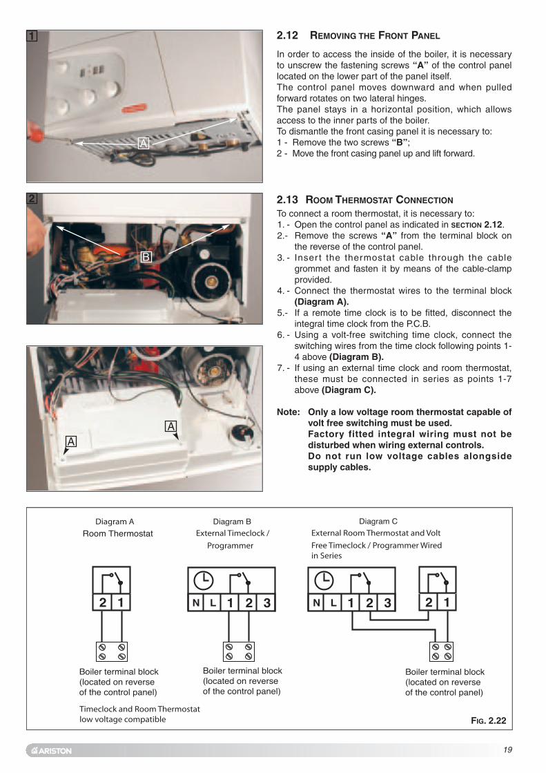
In order to access the inside of the boiler, it is necessaryto unscrew the fastening screws “A” of the control panellocated on the lower part of the panel itself.The control panel moves downward and when pulledforward rotates on two lateral hinges.The panel stays in a horizontal position, which allowsaccess to the inner parts of the boiler.To dismantle the front casing panel it is necessary to:1 - Remove the two screws “B”;2 - Move the front casing panel up and lift forward.
2.12 REMOVING THE FRONT PANEL
To connect a room thermostat, it is necessary to:1. - Open the control panel as indicated in SECTION 2.12.2.- Remove the screws “A” from the terminal block on
the reverse of the control panel.3. - Inser t the thermostat cable through the cable
grommet and fasten it by means of the cable-clampprovided.
4. - Connect the thermostat wires to the terminal block(Diagram A).
5.- If a remote time clock is to be fitted, disconnect theintegral time clock from the P.C.B.
6. - Using a volt-free switching time clock, connect theswitching wires from the time clock following points 1-4 above (Diagram B).
7. - If using an external time clock and room thermostat,these must be connected in series as points 1-7above (Diagram C).
Note: Only a low voltage room thermostat capable ofvolt free switching must be used.Factory fitted integral wiring must not bedisturbed when wiring external controls.Do not run low voltage cables alongsidesupply cables.
2.13 ROOM THERMOSTAT CONNECTION
FIG. 2.22
B
1
2
A
AA
20
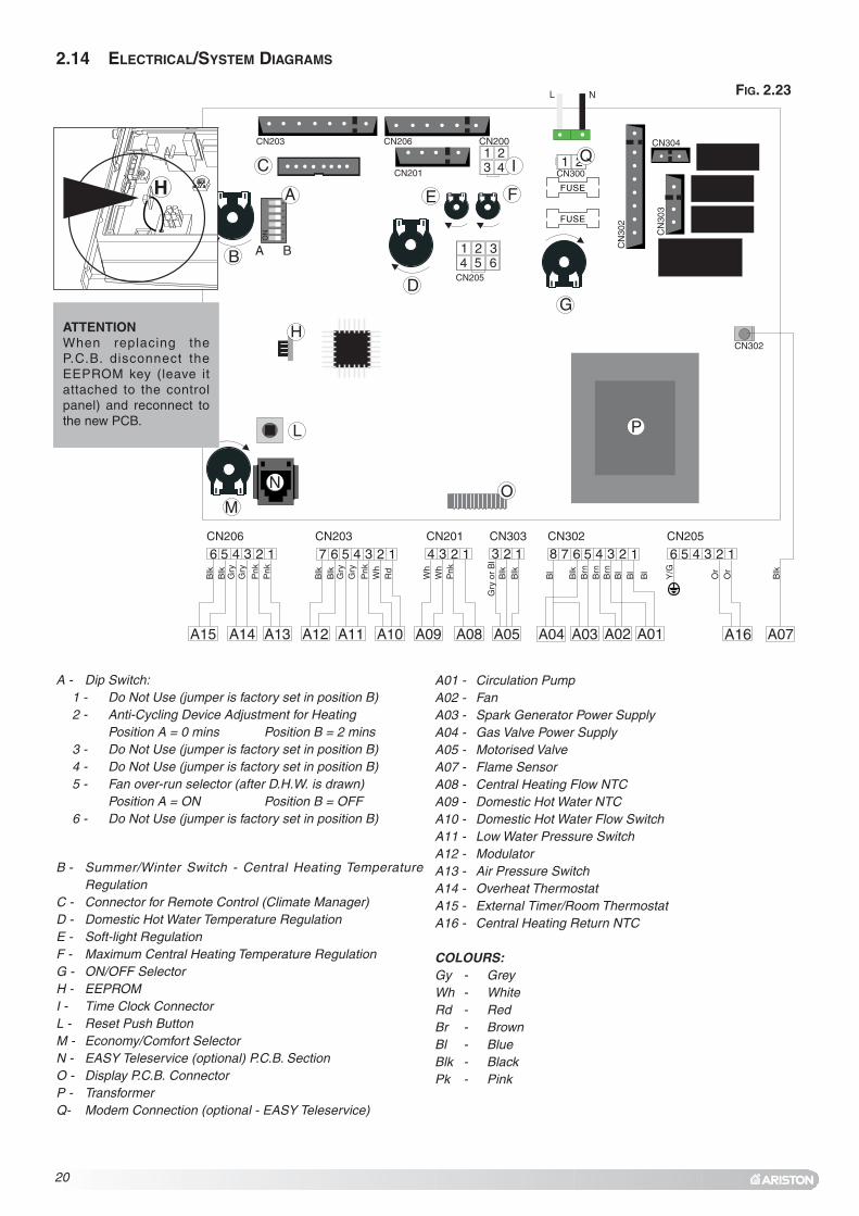
2.14 ELECTRICAL/SYSTEM DIAGRAMS
B - Summer/Winter Switch - Central Heating TemperatureRegulation
C - Connector for Remote Control (Climate Manager)D - Domestic Hot Water Temperature RegulationE - Soft-light RegulationF - Maximum Central Heating Temperature RegulationG - ON/OFF SelectorH - EEPROMI - Time Clock ConnectorL - Reset Push ButtonM - Economy/Comfort SelectorN - EASY Teleservice (optional) P.C.B. SectionO - Display P.C.B. ConnectorP - TransformerQ- Modem Connection (optional - EASY Teleservice)
A01 - Circulation PumpA02 - FanA03 - Spark Generator Power SupplyA04 - Gas Valve Power SupplyA05 - Motorised ValveA07 - Flame SensorA08 - Central Heating Flow NTCA09 - Domestic Hot Water NTCA10 - Domestic Hot Water Flow SwitchA11 - Low Water Pressure SwitchA12 - ModulatorA13 - Air Pressure SwitchA14 - Overheat ThermostatA15 - External Timer/Room ThermostatA16 - Central Heating Return NTC
COLOURS:Gy - Grey Wh - WhiteRd - RedBr - BrownBl - BlueBlk - BlackPk - Pink
A - Dip Switch:1 - Do Not Use (jumper is factory set in position B)2 - Anti-Cycling Device Adjustment for Heating
Position A = 0 mins Position B = 2 mins3 - Do Not Use (jumper is factory set in position B)4 - Do Not Use (jumper is factory set in position B)5 - Fan over-run selector (after D.H.W. is drawn)
Position A = ON Position B = OFF6 - Do Not Use (jumper is factory set in position B)
FUSE
FUSE
12
45
63
ON
5 6A B
CN203 CN206
CN206 CN205CN203 CN201 CN303 CN302
CN201 CN300
CN
302
CN
303
CN304
CN205
CN200
H
L
M
I
N O
P
Q
A16
Y/G
Blk
B
lk
Blk
Gry
Gry
Gry
Gry
Pnk
Pnk
Pnk
Pnk
Gry
or
Bl
Wh
Wh
Wh
Rd
Blk
Blk
B
lk
Blk
B
rnB
rnB
rnB
l
Bl
Bl
Bl
Blk
Or
Or
ATTENTIONWhen replacing theP.C.B. disconnect theEEPROM key (leave itattached to the controlpanel) and reconnect tothe new PCB.
H
FIG. 2.23
21
1
2
3
4
5
67
8
9
10
11A B C D E
12 13 14 15 16
1718
20
19
21
22
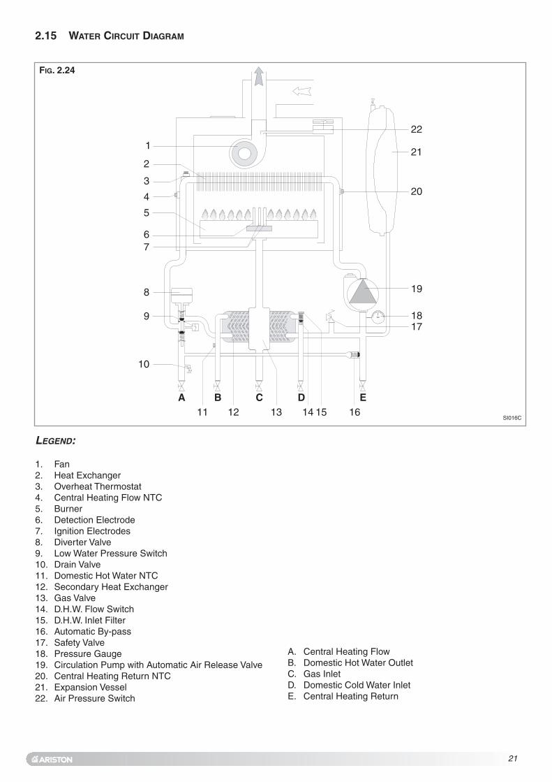
LEGEND:
1. Fan2. Heat Exchanger3. Overheat Thermostat 4. Central Heating Flow NTC5. Burner 6. Detection Electrode7. Ignition Electrodes8. Diverter Valve9. Low Water Pressure Switch10. Drain Valve11. Domestic Hot Water NTC12. Secondary Heat Exchanger13. Gas Valve14. D.H.W. Flow Switch15. D.H.W. Inlet Filter16. Automatic By-pass17. Safety Valve18. Pressure Gauge19. Circulation Pump with Automatic Air Release Valve20. Central Heating Return NTC21. Expansion Vessel22. Air Pressure Switch
2.15 WATER CIRCUIT DIAGRAM
FIG. 2.24
SI016C
A. Central Heating FlowB. Domestic Hot Water OutletC. Gas InletD. Domestic Cold Water InletE. Central Heating Return

22
MTS (GB) Limited support the initiative. Withinthe information pack you will find a copy of thelogbook. It is important that this is completed in thepresence of your customer, they are shown how to use it,and it is signed by them. Please instruct your customerthat they must have their logbook with themwhenever they contact a service engineer or us.
Preliminary electrical system checks to ensure electricalsafety must be carried out by a competent person i.e.polarity, earth continuity, resistance to earth and shortcircuit.
FILLING THE HEATING SYSTEM:Lower the control panel and remove the case panels(see SECTION 2.12 for further information).Open the central heating flow and return cocks suppliedwith the connection kit.Unscrew the cap on the automatic air release valve onefull turn and leave open permanently.Close all air release valves on the central heatingsystem.Gradually open valve(s) at the filling point (filling-loop)connection to the central heating system until water isheard to flow, do not open fully.Open each air release tap starting with the lowest pointand close them only when clear water, free of air, isvisible.
Purge the air from the pump by unscrewing thepump plug anticlockwise, also manually rotate thepump shaft in the direction indicated by the pumplabel to ensure the pump is free.
Refit the pump plug.Continue fill ing the system until at least 1.5 barregisters on the pressure gauge.Inspect the system for water soundness and remedyany leaks discovered.
FILLING OF THE D.H.W. SYSTEM:Close all hot water draw-off taps.Open the cold water inlet cock supplied with theconnection kit.Open slowly each draw-off tap and close them onlywhen clear water, free of bubbles, is visible.
GAS SUPPLY:Inspect the entire installation including the gas meterand test for soundness. The entire installation shouldbe in accordance with the relevant standards. In GBthis is BS 6891 and in IE this is the current edition ofI.S.813.
The connection to the appliance is a 15mm copper taillocated at the rear of the gas service cock (FIG. 2.5).
If the gas supply serves other appliances, ensure thatan adequate supply is available both to the boiler and
3. COMMISSIONING
3.1 INITIAL PREPARATION
the other appliances when they are in use at the sametime.
Pipework must be of an adequate size. Pipes of lessthan 22mm should not be used.
Open the gas cock (supplied with the connection kit) tothe appliance and check the gas connection on theappliance for leaks.
When the installation and filling are completed, flush thesystem while cold, refill, turn on the Central Heatingsystem (SECTION 3.2) and run it until the temperature hasreached the boiler operating temperature. The systemmust then be immediately flushed through.The flushing procedure must be in l ine with BS7593:1992 code of practice for treatment of water indomestic hot water central heating systems.During this operation, we highly recommend the use of acentral heating flushing detergent (Fernox Superfloc orequivalent), whose function is to dissolve any foreignmatter that may be in the boiler and system following theflushing procedure.Substances different from these could create seriousproblems to the pump or other components.The use of an inhibitor in the system such as Fernox MB-1 or equivalent is strongly recommended to preventcorrosion (sludge) damaging the boiler and system.Failure to carry out this procedure may invalidate theappliance warranty.

23
3.2 INITIAL START-UP
To access the areas in which adjustments are made, it isnecessary to open the control panel, as indicated inSECTION 2.12, then remove the rear inspection cover byunscrewing the two screws “A”. Access is therebyprovided to the P.C.B. and to the following components:1. The power supply cable connector;2. The fuses;3. The soft-light potentiometer the setting for which can
range from the minimum thermal power to themaximum;
4. The maximum thermal heating power potentiometeradjustable by the minimum to maximum power(already calibrated in the factory to 70% of themaximum thermal power);
5. The jumper for adjusting the ignition delay (anti-cycling) feature, which can be set from 0 to 2 minutes(set in the factory at one minute);
6. Fan/Pump Over-run (Electrical Diagram). When thejumper is set to position A the Fan and Pump over-run isactivated. (The jumper is factory set in position B)
7. The time clock connector (see pae 20).
THE CHECKS TO BE RUN BEFORE INITIAL START-UP ARE AS
FOLLOWS:1. Make sure that:
- the screw on the automatic air valve has beenloosened when the system is full;
- If the water pressure in the system is below 1.5 bar,bring it up to the appropriate level;
-Ensure that the gas cock is closed;-Make sure that the electrical connection has been
made properly and that the earth wire is connected toan efficient earthing system;
- Supply power to the boiler by turning the On/Off knob“A” (see FIG. 2.27) - “on” will appear on the display.Turn the knob “C” to maximum and switch the timeclock to constant and turn up the room stat wherefitted.After 7 seconds, the boiler will signal a shutdown dueto ignition failure. Leave the boiler as it is until all ofthe air has been bled from the system.
-Loosen the cap on the head of the pump to eliminateany air pockets;
-Repeat the procedure for bleeding the radiators of air;-Open the hot water taps for a brief period;-Check the system pressure and, if it has dropped,
open the filling loop again to bring the pressure backup to 1.5 bar.
2. Make sure that all radiator valves are open;3. Turn on the gas cock and check the seals on the
connections with an approved soap solution andeliminate any leaks.
4. Press the reset button “D” (see FIG. 2.28) the boilerwill re-attempt ignition. If the burner does not light thefirst time, wait 1 minute and repeat the procedure.
5. Check the minimum and maximum burner pressurevalues; adjust if necessary using the values indicatedin the table in SECTION 4 (Page 27).
3.3 OPERATIONAL
ADJUSTMENTS
12
3 4
56
12
3 4
56
E C
II
D
12
3 4
56
12
3 4
56
E C
IIA
C
AA
FIG. 2.27
FIG. 2.28

24
3.6 BOILER SAFETY SYSTEMS
In the boiler, it is possible to monitor the correct operationof the flue exhaust/air intake, checking for a loss ofgeneral pressure in the system. Through the use of adifferential manometer connected to the test points of thecombustion chamber, it is possible to detect the ∆P ofoperation of the air pressure switch.The value detected should not be less than 0.90 mbar (31kW) under conditions of maximum thermal power in orderfor the boiler to function properly and without interruption.
The flue connector has two apertures, readings can betaken for the temperature of the combustion by-productsand of the combustion air, as well as of theconcentrations of O2 and CO2, etc.To access these intakes it is necessary to unscrew thefront screw and remove the metal plate with sealinggasket.It is possible to activate the flue test mode (maximumoutput) by pressing and holding the RESET button “D” for10 seconds, “sscc” will be shown on the display. The boilerwill return to normal operation after 5 minutes. The boilercan be returned to normal operation sooner by switchingthe boiler off and on again.
3.4 COMBUSTION ANALYSIS
3.5 PRODUCT OF COMBUSTION
DISCHARGE MONITORING
FU008A
FU009A
The boiler is protected from malfunctioning by means ofinternal checks by the P.C.B., which brings the boiler to astop if necessary.
There are two types of shut-off:• SHUTDOWN (A)• SAFETY SHUTDOWN (E)
SHUTDOWN “AA ”This type of appliance shutdown is called “volatile”, and isindicated on the display by a number preceded by the letter(A), and by the symbol G FIG. 2.22 Page 18), asillustrated in the table below:
DISPLAY CAUSE
AA0011 No flame after safety time (7 seconds)AA0033 The heating flow temperature exceeds
103oC during operationAA9977 Problem with the electronic monitoringAA9988 Problem with the electronic monitoringAA9999 Problem with the electronic monitoring
WARNING! The boiler is still powered.
ImportantIf this shutdown occurs frequently, contact anauthorised Service Centre for assistance. For safetyreasons, the boiler will allow a maximum of 5 resetoperations to take place in 15 minutes (pressing theRESET button).If the shutdown is occasional or an isolated event, this isnot necessarily a problem.
12
3 4
56
12
3 4
56
E C
II
D

25
ANTI-FROST DEVICE:The boiler is fitted with a device which, in the event that thewater temperature falls below 3˚C, the burner ignites atthe minimum power until the boiler reaches a temperatureof approximately 33˚C in the heating circuit.This device only operates if the boiler is functioningperfectly and:- the system pressure is sufficient;- the boiler is powered electrically;- the gas is turned on.
PUMP / DIVERTER VALVE PROTECTION:To prevent the pump and diverter valve from siezing theboiler will activate the pump for 20 seconds every 21 hoursafter it’s last operation and activate the diverter valve.
SAFETY SHUTDOWN “E”In the event of a safety cut-off (displayed with the codeshown in the table), the boiler will automatically try to resetitself and relight. Should this not be the case, contact anauthorised Service Centre for assistance.
12
3 4
56
12
3 4
56
E C
II
DISPLAY CAUSE
EE0022 Insufficient water pressureEE0044 Domestic hot water temperature probe in
open circuitEE0055 Domestic hot water temperature probe
short circuitedEE0066 Heating flow temperature probe in open
circuitEE0077 Heating flow temperature probe short
circuitedEE0088 Heating return temperature probe in open
circuitEE0099 Heating return temperature probe short
circuitedEE2200 Flame detected with gas valve closedEE2211 Error in the electrical connection (live and
neutral crossed)EE3333 The air pressure switch is
closed before the ignition sequenceEE3344 The air pressure switch does not close
when the fan runsEE9999 More than 5 RESETS of the boiler in 15
minutes.

26
1. Hand over the copy of the End User Instructions suppliedwith the appliance, together with these instructions, andexplain how to use the timeclock and room thermostat.
2. Show the End User how to switch the appliance offquickly, and indicate the position of the electric supplyisolator.
3. Inform the End User of the location of all drains, isolatingvalves and air vents.
4. Explain how to turn the appliance off for both short andlong periods and advise on the precautions necessary toprevent damage in the event that the appliance isinoperative when freezing conditions occur.
5. Instruct the End User on the correct procedure forchecking and refilling the boiler.
6. Finally advise the End User that, for continued safe andefficient operation, the appliance must be serviced by acompetent person at least once a year.
3.10 INSTRUCTING THE END USER
DRAINING THE HEATING SYSTEM
The heating system must be drained as follows:- Turn off the boiler;- Attach a hose pipe and open the drain valve;- Drain the system at the lowest points (where present).
When the heating system is unused for an extendedperiod of t ime, it is recommended that you addantifreeze with an ethylene glycol base to the water inthe heating pipe work and radiators if the ambienttemperature drops below 0°C during the winter.This makes repeated draining of the entire systemunnecessary.
DRAINING THE DOMESTIC HOT WATER SYSTEM
Whenever there is the danger of the temperaturedropping below the freezing point, the domestic hotwater system must be drained as follows:
- Turn off the general water valve for the householdplumbing system;
- Turn on all the hot water taps;- Empty the remaining water from the lowest points in the
system (where present).
3.7 DRAINING THE SYSTEM
3.8 COMPLETION
For the Republic of Ireland it is necessary to complete a“Declaration of Conformity” to indicate compliance to I.S.813. An example of this is given in the current edtion of I.S.813. In addition it is necessary to complete the Log Book.
3.9 OPERATIONAL CHECKS
1. The flue system must be visibly checked for soundness.
2. On Central Heating allow the system to warm up andadjust the Central Heating temperature control knob,check the burner modulates up and down between thehigh and low settings.
3. Range rate the thermal power for Central Heating, asdetailed in SECTION 4.2, Page 29.
4. Run the Domestic Hot Water and adjust to the correctwater f low rate, adjust the Domestic Hot Watertemperature control knob to check the burner modulatesup and down between the high and low settings.
5. Balance the Central Heating system until all returntemperatures are correct and equal.
6. Turn the ON/OFF button OFF, disconnect the pressureGauge, retighten screw and relight boiler.
7. Re-examine Central Heating, Domestic Hot Water andCold Water supplies for soundness.
8. Check the appearance of the gas flame to assess theadequacy of the combustion air supply.
9. If external controls have been disconnected, reconnect and test.
10. Refit boiler casing.

27
4. GAS ADJUSTMENTS
CATEGORY II2H3+ Methane GasG20
Liquid Butane GasG30
Liquid Propane GasG31
Lower Wobbe Index (15°C;1013mbar) MJ/m3hNominal Delivery Pressure mbar
45.6720
80.5829
80.5837
0.72---
2.06 - 0.85
35.6 - 6.8
0.77---
2.31 - 0.93
36.0 - 6.0
0.80---
2.60 - 1.09
34 - 6.5
0.72---
2.09 - 0.87
28.1 - 5.0
0.77---
2.35 - 0.95
28.0 - 5.0
0.80---
2.64 - 1.10
26.8 - 5.3
1.252.80 - 1.16
---
10.3 - 2.0
1.303.15 - 1.27
---
10.8 - 2.0
1.353.54 - 1.48
---
11.5 - 2.1
microGenus II 24 MFFIMain Burner: n. 14 jets (ø) mmConsumption (15°C; 1013mbar) max - min m3/hConsumption (15°C; 1013mbar) max - min Kg/hGas Burner Pressuremax - min mbarmicroGenus II 28 MFFIMain Burner: n. 14 jets (ø) mmConsumption (15°C; 1013mbar) max - min m3/hConsumption (15°C; 1013mbar) max - min Kg/hGas Burner Pressuremax - min mbarmicroGenus II 31 MFFIMain Burner: n. 14 jets (ø) mmConsumption (15°C; 1013mbar) max - min m3/hConsumption (15°C; 1013mbar) max - min Kg/hGas Burner Pressuremax - min mbar
The boiler can be converted to use either methane(natural) gas (G20) or L.P.G. (G30 - G31) by anAuthorised Service Centre.The operations that must be performed are the following:1. Replace the jets on the main burner
(see table in section 4);2. Adjust the maximum and minimum thermal capacity
values for the boiler (see table in section 4 and 4.2 Adjusting the GasPressures);
3. Adjust the maximum thermal power setting (see tables in section 4.3 and FIG. 4.1);
4. Adjust the soft-light feature (see table below for recommended pressure andFig. 4.1);
5. Adjust the ignition delay feature for the heating systemby adjusting the Jumper as indicated in Section 2.14(FIG. 2.23). It can be set from 0 to 2 mins.).
4.1 CHANGING THE TYPE OF GAS
CATEGORYII2H3+
Methane
GasG20
LiquidButane
GasG30
LiquidPropane
GasG31
RecommendedSoft-light
Pressure (mbar)
24 kW
28 kW
31 kW
5.0
5.0
4.5
12.0
12.0
12.0
12.0
12.0
12.0
TABLE A
RECOMMENDED SOFT LIGHT PRESSURES

28
4.2 ADJUSTING THE GAS PRESSURES
Setting the minimum and the maximum power of theboiler1. Check that the supply pressure and dynamic working
pressure to the gas valve is a minimum of 20 mbar fornatural gas.
2. To do this, loosen the screw “A”.Fit the pipe of the pressure gauge to the inlet pressureconnection of the gas valve “B” and check for thecorrect standing pressure, then operate the applianceand check for the correct working pressure.When you have completed this operation, replace thescrew “A” securely into its housing to seal off the gas(check for tightness).
3. To check the pressure supplied by the gas valve to theburner, loosen the screw “C”. Fit the pipe of thepressure gauge to the pressure outlet test point of thegas valve “D”.Disconnect the compensation pipe “D1” either fromthe gas valve or from the sealed chamber.
4. Turn the On/Off knob to “ON” position -green light- andensure that the hot water temperature control knob isset to maximum.Turn on the boiler by running a hot water tap.Adjust the 10mm nut “E” on the modureg to set themaximum gas pressure, turn the nut clockwise toincrease and anti clockwise to decrease the pressureuntil the required pressure is achieved (see TABLE APage 27).
5. To set the minimum power, disconnect a supplyterminal “F1” from the modureg and adjust screw “F”(ensure that the 10mm nut is held in position). Turn thescrew clockwise to increase the pressure and anti-clockwise to decrease the pressure (displayed on thepressure gauge) corresponding to the minimum power(see TABLE A Page 27).
6. When you have completed the above operations, turnoff the hot water tap, reconnect the supply terminal tothe modureg on the gas valve, reconnect thecompensation pipe and replace the cap on the screwof the modureg.
AA
BB
C D
1
2
E
F
3
4
B
C
E
F
D
D1
F1
A

12
45
63
ON
A B
CN203 CN206
CN201
CN200
Soft-light Adjustment
Max Heating Power
29
Setting the maximum heating circuit power7. To set the maximum heating circuit power, turn the
On/Off knob to the “ON” position and set the time clockand any external controls to the “ON” position. Turn theknob of the heating thermostat clockwise to maximum.
8. Remove the inspection panel of the P.C.B. and fit asmall cross-head screwdriver in to the right handpotentiometer (see below). Turn clockwise to increasethe pressure or anti-clockwise to reduce the pressure.Adjust the setting to the required heating pressurevalue (displayed on the pressure gauge), as indicatedin the charts shown on Page 31.
9. Turn off the boiler by placing the main switch to the"OFF" position.
Setting the pressure for soft-light ignition.Disconnect the detection electrode connection close tothe P.C.B. (SECTION 6.3.3).Start the boiler and during the ignition sequence adjustthe left hand potentiometer until the gas pressurereads the required gas pressure (see the table onpage 27).Once the gas pressure is set turn off the boiler and re-connect the detection electrode to the P.C.B.NB.: It may be necessary to reset the flame failurereset a number of times during this operation.
10. Remove the pipe from the test point and tighten thescrew “C” to the pressure test point in order to seal offthe gas.
11. Carefully check the pressure test points for gas leaks(both inlet and outlet).
IMPORTANT!Whenever you disassemble and reassemble the gasconnections, always check for leaks using a leakdetection fluid.

30
NOTE: THIS TABLE CAN BE USED IN CONJUNCTION WITH THE GRAPH ON PAGE 31.
NATURAL GAS (G20)
kW 13 15 17 19 21 23 25 27 29 31
mbar 2.5 3 3.5 4.5 5.5 6.5 7.5 8.5 10 11.5
LIQUID GAS (G30)
kW 13 15 17 19 21 23 25 27 29 31
mbar 5 7 8 10 12 14 17 20 23 27
LIQUID GAS (G31)
kW 13 15 17 19 21 23 25 27 29 31
mbar 7 9 11 13 15 18 21 24 28 34
microGENUS II 31 MFFI
NATURAL GAS (G20)
kW 10 12 14 16 18 20 22 24
mbar 2.5 3 3.75 4.75 5.75 7 8 10
LIQUID GAS (G30)
kW 10 12 14 16 18 20 22 24
mbar 5.5 8 10 12.5 15.5 18.5 22 26
LIQUID GAS (G31)
kW 10 12 14 16 18 20 22 24
mbar 7 9 12 15.5 19 24 28 34
NATURAL GAS (G20)
kW 11 13 15 17 19 21 23 25 27
mbar 2 2.75 3.5 4.5 5 6 7 8.5 10
LIQUID GAS (G30)
kW 11 13 15 17 19 21 23 25 27
mbar 5 6.5 8.5 10.5 13 15.5 18.5 21 25
LIQUID GAS (G31)
kW 11 13 15 17 19 21 23 25 27
mbar 6.5 8 10 12 14.5 17.5 21 25.5 31
microGENUS II 24 MFFI
microGENUS II 28 MFFI

FIG. 4.1
Regulating the heating power fornatural gas (G20)
Regulating the heating power forbutane gas (G30)
Regulating the heating power forpropane gas (G31)
3434363638384040
modello 24
modello 28
modello 31
modello 24
modello 28
modello 31
modello 24
modello 28
modello 31
Bu
rner
pre
ssu
reB
urn
er p
ress
ure
Bu
rner
pre
ssu
re
model 24
model 28
model 31
model 24
model 28
model 31
model 24
model 28
model 31
It is recommended that the following inspections becarried out on the boiler at least once a year:1 - Check the seals for the water connections; replace
any faulty seals.2 - Check the gas seals; replace any faulty gas seals.3 - Visual check of the entire unit.4 - Visual check of the combustion process or analysis
of combustion by-products (see SECTION 3.4) andcleaning of the burner if needed.
5 - If necessary, dismantling and cleaning of thecombustion chamber.
6 - If necessary, dismantling and cleaning of the burnerjets.
7 - Visual check of the primary heat exchanger:- check for overheating in the blade assembly;- clean the exhaust fan if needed.
8 - Adjustment of the gas pressure, gas rate and soft-light, partial load and full load.
9 - Check of the heating safety systems:- safety device for maximum temperature (overheat
thermostat);- safety device for maximum pressure (safety
valve).10- Check of the gas safety systems:
- safety device for lack of gas or flame ionisation (detection electrode).
11- Check of the electrical connection (ensure itcomplies with the instructions in the manual).
12- Check of Domestic Hot Water production efficiency(flow rate and temperature)
13- General check of the combustion by-products of thedischarge/ventilation system.
14- Check of the general performance of the unit.
NOTE: THESE CHECKS ARE NOT EXHAUSTIVE
5. MAINTENANCE

2. The control rotates on two lateral hinges; the panel stays in ahorizontal position, which allows access to the inner parts ofthe boiler (FIG. 6.2);
3. Remove the screws “B” from the front panel bottom lip (FIG. 6.3);
4. Lift the front panel up and forward from the raised screws at thethe top of the casing (FIG. 6.4).
FIG. 6.3
B
FIG. 6.4
6. SERVICING INSTRUCTIONS
The life of individual components vary and they will needservicing or replacing as and when faults develop.The fault finding sequence chart in SECTION 7 will help to locatewhich component is the cause of any malfunction, andinstructions for removal, inspection and replacement of theindividual parts are given in the following pages.
6.1 REPLACEMENT OF PARTS
6.2 TO GAIN GENERAL ACCESS
All testing and maintenance operations on the boiler require thecontrol panel to be lowered. This will also require the removal ofthe casing.
6.2.1 Removing the front panel
1. Loosen the fastening screws “A” of the control panel locatedon the lower part of the panel itself. (FIG. 6.1);
A
FIG. 6.1
FIG. 6.2
To ensure efficient safe operation, it is recommended that theboiler is serviced annually by a competent person.
Before starting any servicing work, ensure both the gas andelectrical supplies to the boiler are isolated and the boileris cool.Before and after servicing, a combustion analysis should bemade via the flue sampling point (please refer to SECTION 3.4 forfurther details).
After servicing, preliminary electrical system checks must becarried out to ensure electrical safety (i.e. polarity, earthcontinuity, resistance to earth and short circuit).

6.2.2 Removing the sealed chamber front cover
1. Remove the screws “C” (FIG. 6.5);2. Lift the sealed chamber front cover from the locating pins
(FIG. 6.6).
FIG. 6.5
C C
FIG. 6.6
6.2.3 Removing the side panels
1. Remove the four screws “D” for each side panel (FIG.6.7);2. Pull the panel away from the boiler at the base, then lift the
panel up and remove from the boiler (FIG.6.8).
D
D
FIG. 6.7
FIG. 6.8
D
D

6.3.3 Removing the electrodes
Before carrying out this procedure, unscrew and slide theburner forward (see previous section).1. Remove rubber gasket “G” (FIG. 6.12);2. To remove the detection electrode disconnect the cable at
its connection point close to the P.C.B. (FIG. 6.13);3. Remove screw “H” (FIG. 6.14);4. Gently slide the electrode downward (FIG. 6.15).
FIG. 6.12
G
FIG. 6.13
6.3.2 Removing the burner and jets
1. Remove the screws “F” from the burner (FIG. 6.10);2. Remove the burner (FIG. 6.11);3. Disconnect the electrodes (see SECTION 6.3.3);4. Remove the jets using a No. 7 socket spanner;5. Replace in reverse order.
6.3.1 Removing the combustion cover
1. Remove the screws “E” (FIG. 6.9);2. Lift off the combustion cover.
6.3 ACCESS TO THE COMBUSTION CHAMBER
EE
FIG. 6.9
FIG. 6.10
Fig. 6.11
E E
F
F

To replace, repeat the steps in reverse order, payingparticular attention to the following:a - Centre the electrode in the positioning hole carefully,
otherwise the electrode may break;b -Ensure that the left hand and right hand electrodes are
located the correct way round (facing each other), togive the correct spark gap;
c - Check that the cables have been connected correctly;d -Check that the rubber gasket seals the cable/
electrode connection point completely.
FIG. 6.14
FIG. 6.15
H
1. Drain the boiler of water;2. Remove the side panels (see 6.2.3)3. Remove the overheat thermostat sensor “I” (FIG. 6.16);4. Remove the clips “J” (FIG. 6.16);5. Release the connection nut “K” (FIG. 6.17);6. Release the connection nut “L” (FIG. 6.18);7. Pull down the pipe (FIG. 6.19);4. Pull the exchanger out (FIG. 6.20).
6.3.4 Removing the main heat exchanger
FIG. 6.17
K
L
Fig. 6.16
JJ
FIG. 6.18
I

1. Disconnect the electrical connections “M” and siliconepipes “N” from their connection points (FIG. 6.21);
2. Remove screws “O” on the top of the sealed chamber(FIG. 6.22);
3. Lift out the air pressure switch (FIG. 6.23);4. Unscrew to remove the switch from the plate.
6.3.5 Removing the air pressure switch
FIG. 6.21
N
N
MFig. 6.19
Fig. 6.20
O
O
FIG. 6.22
FIG. 6.23

1. Disconnect electrical connections “P” and silicone pipe“Q” (FIG.6.24);
2. Remove screw “R” and remove the fan collar clamp “R”(FIG.6.25);
3. Remove screws “S” (FIG.6.26);4. Remove fan and mounting plate (FIG.6.27).
6.3.6 Removing the fan
FIG. 6.26
S
S
S
FIG. 6.25
R
FIG. 6.24
P
P
Q
FIG. 6.27
6.4.1. Removing the spark generator (HONEYWELL Gas Valve)
1. Disconnect ignition leads “T” by pulling upward(FIG. 6.28);
2. Remove the screw “U” (FIG. 6.29);3. Remove the spark generator by pulling forward from
the gas valve (FIG. 6.30).
FIG. 6.28
FIG. 6.29
FIG. 6.30
T
U
6.4 ACCESS TO THE GAS VALVE
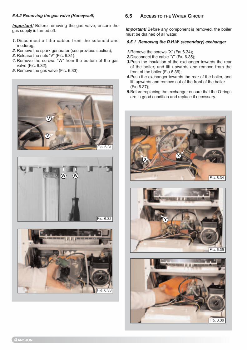
Important! Before any component is removed, the boilermust be drained of all water.
6.5.1 Removing the D.H.W. (secondary) exchanger
1.Remove the screws “X” (FIG 6.34);2.Disconnect the cable “Y” (FIG 6.35);3.Push the insulation of the exchanger towards the rear
of the boiler, and lift upwards and remove from thefront of the boiler (FIG 6.36);
4.Push the exchanger towards the rear of the boiler, andlift upwards and remove out of the front of the boiler (FIG 6.37);
5.Before replacing the exchanger ensure that the O-ringsare in good condition and replace if necessary.
6.5 ACCESS TO THE WATER CIRCUIT
FIG. 6.34
XX
FIG. 6.35
FIG. 6.36
FIG. 6.32
FIG. 6.33
WW
6.4.2 Removing the gas valve (Honeywell)
Important! Before removing the gas valve, ensure thegas supply is turned off.
1. Disconnect all the cables from the solenoid andmodureg;
2. Remove the spark generator (see previous section);3. Release the nuts “V” (FIG. 6.31);4. Remove the screws “W” from the bottom of the gas
valve (FIG. 6.32);5. Remove the gas valve (FIG. 6.33).
FIG. 6.31
V
V
Y

FIG. 6.38
Z
FIG. 6.39
FIG. 6.40
FIG. 6.37
6.5.2 Removing the pump pressure switch
1.Remove the pump pressure switch electrical connections“Z” (FIG 6.38);
2.Unscrew the pump pressure switch by using a spanner onthe nut (FIG 6.39);
3.Remove the pump pressure switch (FIG 6.40).

6.5.4 Removing the automatic air vent1. Remove the U-clip “B1” (FIG. 6.44);2. Remove valve complete with float using a screwdriver
(FIG 6.45-FIG 6.46).
FIG. 6.44
FIG. 6.45
FIG. 6.46
6.5.3 Removing the safety valve
1. Disconnect the discharge pipe work from below theboiler;
2. Unscrew the fixing screw “A1” (FIG. 6.42)3. Pull the valve upwards for removal (FIG. 6.43).
FIG. 6.41
FIG. 6.42
FIG. 6.43
A1
B1

6.5.5 Removing the pump
1. Remove the electrical connection “ C1” (FIG. 6.47);2. Release the nut “D1” (FIG. 6.48);3. Remove the retaining clip “E1” from the bottom of the
boiler (FIG. 6.49);4. Remove the screw “F1” (FIG. 6.50);5. Remove the U-clip “G1” and remove the pressure
gauge connection (FIG. 6.51);6. Remove the U-clip “H1” and remove the automatic air
vent (FIG. 6.52);7. Remove the pump.
FIG. 6.47
C1
FIG. 6.48
D1
FIG. 6.50
FIG. 6.52
FIG. 6.51
FIG. 6.49
E1
F1
G1
H1

6.5.7 Removing the expansion vessel
1. Release nut “J1” (FIG. 6.56);2. Remove back-nut “K1” (FIG. 6.57);3. Remove the expansion vessel (FIG. 6.58).
6.5.6 Removing the pressure gauge
1. Remove the U-clip “I1” (FIG. 6.53)2. Lift the pressure gauge from the rear of the control
panel using a screwdriver (FIG. 6.54-6.55).
FIG. 6.56
I1
FIG. 6.54
FIG. 6.55
J1
FIG. 6.57
FIG. 6.58
K1
FIG. 6.53

6.5.8 Removing the overheat thermostat
1. Disconnect the overheat thermostat electr icalconnections “L1” (FIG. 6.59);
2. Then remove the thermostat from its mounting byreleasing the securing clip (FIG. 6.60-6.61).
6.5.9 Removing the C.H. temperature probe (N.T.C.)
1. Pull off the electrical connector and remove the sensorprobe. (FIG. 6.62-6.63).
FIG. 6.59
FIG. 6.60
L1
FIG. 6.62
FIG. 6.63
FIG. 6.61

FIG. 6.66
FIG. 6.67
FIG. 6.68
O1
6.5.12 Removing the D.H.W. flow switch
1. Unplug the electrical connector “O1” (FIG. 6.66);2. Remove the D.H.W. flow switch using a screwdriver
(FIG. 6.67-6.68).
6.5.10 Removing the D.H.W. temperature sensor (N.T.C.)
1. Pull off the electrical connector and unscrew thesensor probe using a suitable spanner (FIG. 6.64).
FIG. 6.64
6.5.11 Removing the diverter valve actuator
1. Unplug the electrical connector “M1” (FIG. 6.65);2. Release the retaining clip “N1” and remove the divertor
valve actuator
FIG. 6.65
M1
N1

6.6 ACCESS TO THE CONTROL SYSTEM 6.6.1 Checking the fuses
1. Remove the inspection cover on the reverse of thecontrol panel and unscrew the screws “P1”(FIG. 6.69);
2. Remove the fuses (FIG. 6.70).
FIG. 6.69
FIG. 6.70
Important! Isolate the electrical supply to the boilerbefore accessing the control panel.
P1
P1

6.6.2 Removing the P.C.B.
1. Isolate electricity;2. Remove the inspection cover from the reverse of the
control panel, unscrew the screws “Q1” (FIG. 6.71);3. Unplug all electrical connections from the P.C.B (FIG.
6.72);4. Carefully unplug the EEPROM key “R1” (FIG. 6.73);5. Remove the screws “S1” (FIG. 6.74);6. Separate the facia panel from the rear of the control
panel ;7. Remove the main P.C.B., unscrew the screws “T1”
(FIG. 6.75);8. Unscew the display P.C.B. mounting screws “T2” and
disconnect the P.C.B. connection cable “T3” (FIG. 6.76);9. Remove the display P.C.B. (FIG. 6.77);10.Replace either P.C.B. in reverse order.11.Refit the EEPROM key “R1”
FIG. 6.71
Q1
Q1
FIG. 6.72
FIG. 6.73
FIG. 6.74
FIG. 6.75
S1
S1
S1
S1
FIG. 6.76
T3
T3
FIG. 6.77
R1
T1 T1 T1
T2

6.6.3 Removing the time clock
1. Disconnect the electrical connections “U1” from theclock (FIG. 6.78);
2. Remove screws “V1” (FIG. 6.78);3. Lift the time clock out from the control panel (FIG. 6.79).
FIG. 6.78
FIG. 6.79
U1
V1

7. FAULT FINDING These fault finding guides are not exhaustive. However, itis possible to detect and correct many defects by usingthe standard fault finding diagrams described in thischapter, ensure these guides are carried out in the setorder.7.1 FAULT FINDING GUIDE
(FLOW-CHARTS)
PRELIMINARY CHECKS MAKE SURE THAT:
IS THE POWER
DISPLAY ON?
POSTION OF THE
SELECTOR
NONO
NONO
CENTRAL CENTRALHEAHEATINGTING
ESTAT EHOT WATERONLY
NONO
YESYES
YESYES
YESYESYESYES
YESYES
NONO
NONONONO
NONONONO
NONO
NONO
YESYES
YESYES
YESYES
TURN ON THE ON/OFF SWITCH
IS D.H.W. BEING DRAWN?
IS D.H.W. BEING DRAWN?
FOR BOILERS WITH ELECTRONIC
ANTI-FROST DEVICE: PROTECTION IS ACTIVATED
IF HEATING TEMP IS < 5°C
FOR BOILERS WITH ELECTRONIC
ANTI-FROST DEVICE: PROTECTION IS ACTIVATED
IF HEATING TEMP IS < 5°C
MUST TIME CLOCK
AND/OR ROOM THERMOSTAT
BE ACTIVATED?
A
ECONOMY/ COMFORT SELECTOR
TEMP. C.H. < 42°C
ComfortComfort
Economy
Economy
1 - There is sufficient water in the system 2 - The gas is turned on 3 - The electrical supply is turned on
1 - Check/reset system pressure 2 - Check/restore gas supply 3 - Check/replace short- circuited heating probe 4 - Check/replace siezed pump
1 - Check/reset the system pressure 2 - Check/restore gas supply 3 - Check/replace short- circuited heating probe 4 - Check/replace siezed pump
TEMP. C.H. < 42°C
ECONOMY/ COMFORT SELECTOR
YESYES DOES AN ERROR CODE APPEAR ON THE DISPLAY?
1. Check the fuses2. Check the power supply to the control panel3. Check/replace the ON/OFF button4. Check the connection between the main and display P.C.B.s
see section 3.6 5. Check/replace the main and display P.C.B.s
To ensure that the external controls donot interfere with the fault f inding,disconnect the wires from the terminalblock on the rear of the control panel andprovide a solid l ink between theterminals.

YESYES
YESYES
NONOIS THE
PUMP RUNNING?
1. Check if there is air in the system2. Check the main circuit flow switch operation3. Check the pressure on the water gauge and fill system to 1 bar
1. Check pump cable2. Check/replace main P.C.B.
Release/replacepump
Turn theON/OFF Control Knob
POWER TOTHE PUMP?
YESYES
YESYES
ISTHE LOW WATER
PRESSURE SWITCH WORKING CORRECTLY?
E02: does not reset
NONO
NONO
A
B

1. Check the fan cable2. Replace the fan3. Replace the main P.C.B.
1. Check/replace ignition electrode2. Check ignition cable3. Check/replace the main P.C.B.
Replace the main P.C.B.
IS THE FANRUNNING?
DOES CODEE33 APPEAR?
IGNITIONSPARKS ARE GENERATED
REGULARLY?
YESYES NONO
NONO
YESYES
YESYES
NONO
1. Check the power supply of the gas valve.2. Check for an air pressure signal3. Check the gas pressure on the burner4. Check the soft-light adjustment5. Replace the gas valve6. Check/replace the main P.C.B.
1. See section 3.62. Press RESET
1. See section 3.6
IS THE BURNERALIGHT?
BOILER HAS SHUTDOWN?
YESYES
YESYES
NONO
NONO
IS THERE STILLA PROBLEM?
NORMALOPERATION
NONO
YESYES
B
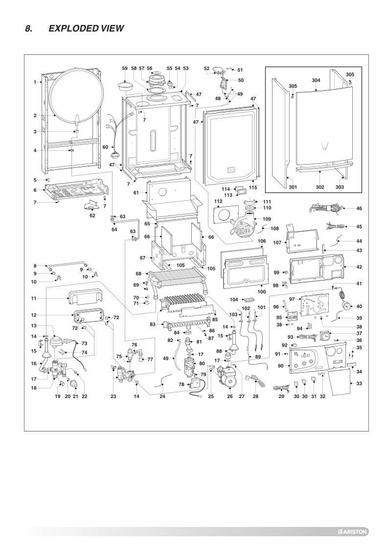
8. EXPLODED VIEW
2
3
4
1
5
7
6
17
15
104
101103
102
109
112 111110
35
5152
50
4948
114 115
113
47
301 302 303
304305
305
15
8
9
10
910
73
74
72
72
75
2219 20
18
142321
13
25 28 30 30 3126
12
11
14
16
64 63
7
5359 555758
47
54
7
56
7
47
60
7
8182
49
32
36
41
45
46
24
14
88 91
67
65
6666
105105
106
100
17
42
43
44
99
98
29
39
40
95
97
967170
68
69
3793
38 38
92
90
7
9483
85
8487
86
17
80
79
78
34
33
27
89
107
76
77
47
62 63
108
61

998616998077997147573520
65100547569390995903998458
65101427651012576510142665101417
9995996510069565100716
998484573521
6101113661010017
990686996065997077997088573528
65100249 65100244651013686510070965100871651006936510069465100692
999397651007196510142865100540
Keyno.
ARISTONPart No.Description
2913171820212223
26
374050
6368
69707475767880949597
101102103109
551
Expansion vesselO-ringMotor (3- Way valve)Gasket 3/4"Flow groupGasket 1/4"Low water pressure switchTemperature probe (D.H.W.)Return group (24 MFFI)Return group (28/31 MFFI)Pump (24 MFFI)Pump (28/31 MFFI)ClockPressure gaugeAir pressure switch (28/31 MFFI)Air pressure switch (24 MFFI)Gasket (3/8")Heat exchanger (28/31 MFFI)Heat exchanger (24 MFFI)Temperature probe & clip (C.H.)Thermostat (overheat)Fixing clip (motor)Safety valve (3 bar)Gasket (1/2")Spark generatorGas valveEEPROM key CMP3 (microGENUS II)P.C.B. (display)P.C.B. (main)Electrode (ignition R.H.)Electrode (ignition L.H.)Electrode (detection)Fan (24 MFFI)Fan (31 MFFI)Fan (28 MFFI)Flow detection kit (w/magnet)
1
1111
1111111111111
11
1
1111
111111111111
(Not Illustrated)
8.1 SHORT SPARES LIST

9. TECHNICAL INFORMATION
NameCE CertificationFlue Type
Heat Input max/min kWHeat Output max/min kWEfficiency of Nominal Heat Input %Efficiency at 30% of Nominal Heat Input %Efficiency at Minum Input %SEDBUK Rating BandHeat Loss to the Casing (∆T=50°C) %Flue Heat Loss with Burner Operating %Flue Heat Loss with Burner Off %
Gen
eral
Info
En
erg
y P
erfo
rman
ce
Max Discharge of Products of Combustion (G20) Kg/hResidual Discharge Head mbarTemp. of exhaust fumes at nominal capacity °CCO2 Content %O2 Content %CO Content ppmNox ClassMinimum Ambient Temperature °C
Em
issi
on
s
Head Loss on Water Side (max) (T=20°C) mbarResidual Head of System barExpansion Vessel Pre-load Pressure barMaximum Heating Pressure barExpansion Vessel Capacity lMaximum Water Content of System lHeating Temperature max/min °CC
entr
al H
eatin
g
Domestic Hot Water Temperature (approx) max/min °CSpecific Flow Rate (10 minutes/DT 30°C) l/minD.H.W. Flow Rate ∆T=25°C l/minD.H.W. Flow Rate ∆T=35°C l/minD.H.W. Minimum Flow Rate l/minPressure of Domestic Hot Water max/min bar
Dom
estic
Hot
Wat
er
Nominal Pressure Natural Gas (G20) mbarLPG (G30-G31) mbar
Consumption at Nominal Capacity(G20) m3/h(15°C, 1013 mbar) (G30-G31) Kg/hGas Consumption after 10 Minutes* m3
Gas
Electrical Supply (V ± 5%) V/HzPower Consumption WProtection Grade of Electrical System IPInternal Fuse Rating
Ele
ctric
al D
ata
Dry Weight KgDimensions (W/D/H) mm Maximum Flue Length (Horizontal) mMaximum Flue Length (Vertical) m
G.C. Number
microGenus II 24 MFFI0694BO4008
C12-C32-C42-C52-C82-B22-B32
29.4 / 12.224.8 / 9.7
84.381.679.6
D1.25.10.4
51.41.23106.97.157.939.3
3+5
2000.250.737
13082 / 42
56 / 3611.814.210.22.5
6 / 0.2
2028/30 - 37
2.802.09 - 2.06
0.33
230/50125X4D
2A FAST
34700x400x315
45
47-116-25
microGenus II 28 MFFI0051BO2494
C12-C32-C42-C52-C82-B22-B32
33.1 / 13.328 / 10.5
84.580.578.7
D1.15.70.4
61.90.65115.46.678.436.8
3+5
2000.250.737
13082 / 42
56 / 3613.315.911.42.5
6 / 0.2
2028/30 - 37
3.152.35 - 2.31
0.37
230/50140X4D
2A FAST
35700x400x315
45
47-116-26
*Calculated at 70% maximum output

NameCE CertificationFlue Type
Heat Input max/min kWHeat Output max/min kWEfficiency of Nominal Heat Input %Efficiency at 30% of Nominal Heat Input %Efficiency at Minum Input %SEDBUK Rating BandHeat Loss to the Casing (T=50°C) %Flue Heat Loss with Burner Operating %Flue Heat Loss with Burner Off %
Gen
eral
Info
En
erg
y P
erfo
rman
ce
Max Discharge of Products of Combustion (G20) Kg/hResidual Discharge Head mbarTemp. of exhaust fumes at nominal capacity °CCO2 Content %O2 Content %CO Content ppmNox ClassMinimum Ambient Temperature °C
Em
issi
on
s
Head Loss on Water Side (max) (T=20°C) mbarResidual Head of System barExpansion Vessel Pre-load Pressure barMaximum Heating Pressure barExpansion Vessel Capacity lMaximum Water Content of System lHeating Temperature max/min °CC
entr
al H
eatin
g
Domestic Hot Water Temperature (approx) max/min °CSpecific Flow Rate (10 minutes/DT 30°C) l/minD.H.W. Flow Rate ∆T=25°C l/minD.H.W. Flow Rate ∆T=35°C l/minD.H.W. Minimum Flow Rate l/minPressure of Domestic Hot Water max/min bar
Dom
estic
Hot
Wat
er
Nominal Pressure Natural Gas (G20) mbarLPG (G30-G31) mbar
Consumption at Nominal Capacity(G20) m3/h(15°C, 1013 mbar) (G30-G31) Kg/hGas Consumption after 10 Minutes* m3
Gas
Electrical Supply (V ± 5%) V/HzPower Consumption WProtection Grade of Electrical System IPInternal Fuse Rating
Ele
ttric
al D
ata
Dry Weight KgDimensions (W/D/H) mm Maximum Flue Length (Horizontal) mMaximum Flue Length (Vertical) m
G.C. Number
microGenus II 31 MFFI0694BO4008
C12-C32-C42-C52-C82-B22-B32
37.2 / 15.531.1 / 12.1
83.681
78.1D
1.55.70.4
64.71.6
121.27.197.860.5
3 +5
2000.250.737
13082 / 42
56 / 3614.8 17.812.72.5
6 / 0.2
2028/30 - 37
3.542.64 - 2.60
0.41
230/50165X4D
2A FAST
36700x400x315
45
47-116-27
*Calculated at 70% maximum output

0 99
84
1854
211
Edi
tion
2 0
4/04
Commercial subsidiaries: MTS (GB) Limited MTS Heating LimitedMTS Building Damastown Industrial ParkHughenden Avenue Damastown AvenueHigh Wycombe MulhuddartBucks HP13 5FT Dublin 15
Telephone: (01494) 755600 Telephone: (01) 810 3723
Fax: (01494) 459775 Fax: (01) 810 3727
Internet: www.mtsgroup.com/uk Internet: www.mtsgroup.com/ie
E-mail: [email protected] E-mail: [email protected]
Technical Advice: 0870 241 8180 Technical Advice: (01) 437 0121
Customer Service: 0870 600 9888 Customer Service: (01) 437 0121
Manufacturer: Merloni TermoSanitari SpA - Italy
12
34
56
12
3 4
56
II
E C
End User Manual
microGENUS II 24 MFFI microGENUS II 28 MFFI microGENUS II 31 MFFI
Country of destination: GB/IE

Dear Customer,
Thank you for choosing an ARISTON boiler.We guarantee that your boiler is a reliable and technically sound product.This manual provides detailed instructions and recommendations for proper installation, use and maintenance.Remember to keep this manual in a safe place for future reference i.e. by the gas meter.Your local MTS Servicing Centre is at your complete disposal for all requirements.
The guarantee on this appliance is valid for 24 months from the first day of installation.
Repairs to the electric, hydraulic or gas circuits may be carried out only by your local authorised MTS Servicing Centre.
Every attempt has been made to avoid errors of any kind in this manual, the Management invites customers to inform
of any inaccuracies which they may find. This will help to improve our service
TABLE OF CONTENTS
1. GENERAL INFORMATION page 2
Control Panel page 3
2. OPERATING INSTRUCTIONS page 3
3. USEFUL INFORMATION AND TROUBLESHOOTING page 5
4. MAINTENANCE page 6
5. CHANGE OF GAS TYPE page 6
6. MECHANICAL TIME CLOCK page 6
7. Digital Programmer page 7
IMPORTANT!
Please read this manual carefully.For additional information, please consult the “Installation and Servicing Instructions.”Make sure to keep the manuals provided with the appliance so that they can be used bythe end-user, installer or our authorised engineer.
1. GENERAL INFORMATION MTS (GB) Limited support the initiative. Your installer will give you, and show you how to use, a Log Book which will give you important information about your boiler, and heating system. Please have this Log Book to hand whenever you contact a service engineer or us. All CORGI Registered Installers carry a CORGI ID card, and have a registration number. Both should be recorded in your boiler Logbook. You can check your installer is CORGI registered by calling CORGI direct on :- (01256) 372300. This is a combined appliance for the production of Central Heating (C.H.) and Domestic Hot Water (D.H.W.). This appliance must be used only for the purpose for which it is designed. The manufacturer declines all liability for damage caused by improper or negligent use. Do not allow children or inexperienced persons to use the appliance without supervision. If you smell gas in the room, do not turn light switches on or off, use the telephone or any other object which might cause sparks. Open doors and windows immediately to ventilate the room. Shut the gas mains tap (on the gas meter) or the valve of the gas cylinder and call your Gas Supplier immediately. If you are going away for a long period of time, remember to shut the mains gas tap or the gas cylinder valve.
Before any intervention within the boiler it is first necessary to isolate the electrical supply by turning the external switch to “OFF”.
2

CONTROL PANEL
12
3 4
56
12
3 4
56
E C
II
I J K
LEGEND:
A - On/Off Switch
B - Domestic Hot Water Temperature Adjustment
C - Central Heating Temperature Adjustment
D - Reset Button
E - Comfort Mode Selector
F - Hot Water (Summer Mode LED - Green)
G - Ignition/Overheat Lockout LED (Red)
H - Central Heating (Winter Mode) LED (Green)
I - Digital Display (Fault Code/Water Temperature)
J - Time Clock
K-Central Heating System Pressure Gauge
2. OPERATING INSTRUCTIONS CAUTION
K
In the United Kingdom installation, start-up, adjustments and maintenance must be performed by a CORGI Registered Installer in accordance with the installation standards currently in effect, as well as with any and all local health and safety standards i.e.. CORGI.
In the Republic of Ireland the installation and initial start up of the appliance must be carried out by a Competent Person in accordance with the current edition of I.S.813 “Domestic Gas Installations”, the current Building Regulations, reference should also be made to the current ETCI rules for electrical installation.
HELPFUL SUGGESTIONS
To get the most out of your boiler, we have provided you with some useful advice onproper use and maintenance:- Periodically check the system pressure using the pressure gauge “D”, make sure that
the pressure is at 1.5 bar when the system is off and cool. If the pressure is below the minimum recommended value (1 bar). To refill the system, open the two black handles connected to the silver flexible hose, once the pressure gauge “K” reads 1.5 bar close the valves again.
NOTE: DO NOT UNDER ANY CIRCUMSTANCES USE THE APPLIANCE WITH THE PRESSURE GAUGE
READING ZERO.
- The outer panels of the unit's case must only be cleaned with a damp cloth. Do not use abrasive cleaners. The control panel can be wiped with either a damp or dry cloth. Spray polishes must not be used on the control panel surface or knobs. Care must be taken to prevent any liquid from entering the appliance.
PRACTICAL TIPS
- If the water is very hard, it is recommended that a water softener be added to the system so as to reduce the formation of limescale in the boiler exchangers. This will
3

M N
PL004D
PL007D
PL009D
summer
winter
PL009D
12
3 4
56
12
3 4
56
12
3 4
56
C
PL008D
12
3 4
56
12
3 4
56
12
3 4
56
C
12
3 4
56
B
PL008D
ensure that the efficiency of the unit remains the same over time, reducing gas consumption and maintenance costs.
- If the boiler should be out of use for a prolonged period, it is recommended that the electrical power supply be disconnected and that the external gas cock “M” and “N” be closed. If low temperatures are expected, the boiler and system pipe work should be drained in order to prevent frost damage.
- To improve comfort and take full advantage of the heat produced by the boiler, it is recommended that an external (room) thermostat be installed.
- It is good practice to clean and service the appliance and central heating system every year. Call an Authorised Service Centre.
IGNITION PROCEDURE
Turn the selector knob “A” to the “I” position. After a short delay the display will indicate “oonn” indicating that the boiler is ready to operate. The electronic control unit will ignite the burner, without any manual intervention but in response to the request for Domestic Hot Water or Central heating. If, after approximately 10 seconds, the burner has not ignited, the boiler safety devices will shut off the gas and the display will indicate the fault code AA0011. To reset the ignition system, the reset button “D” must be pressed and released. Should the boiler fail to ignite a second time, check that the external gas cock is open “N”. If the problem persists, contact an Authorised Service Centre.
WINTER AND SUMMER OPERATING MODES
II IIA
PL004D
In the ‘winter’ operating mode, the boiler will produce both Central Heating and Domestic Hot Water. In the ‘summer’ operating mode, the boiler will produce only Domestic Hot Water. Using the knobs on the control panel, the user can select ‘winter’ or ‘summer’ operating mode. Keeping the knob “C” at the “ ” position selects the ‘summer’ operating mode, the symbol “ “ will illuminate. ‘Winter’ operating mode may be selected by positioning the knob “C” between the min. and max. settings. The symbol “
E C E C
D PL006C
“ will illuminate.
ADJUSTING THE HEATING
It is possible to set the temperature of the Central Heating system by adjusting the knob “C”. By positioning the indicator somewhere between min. and max., a temperature may be obtained which varies from approximately 42˚C to about 82˚C. The water temperature in the Central Heating circuit may be checked on the display.
12
3 4
56
12
3 4
56
12
3 4
56
C
12
3 4
56
12
3 4
56
12
3 4
56
C
summer
winter
PL007C
EXTERNAL (ROOM) THERMOSTAT CONTROL
If an external (room) thermostat is installed, it is recommended that the temperature of the Central Heating system be set by means of the “C” knob, leaving it at max in order to obtain the best performance from the boiler and to allow the regulation of the external temperature to function efficiently.
SETTING THE HOT WATER FOR DOMESTIC USE
Both in the winter and summer mode, the temperature of the Domestic Hot Water may be adjusted by using the “B” knob. A delivery temperature for the water may be chosen in a range from 36˚C to about 56˚C, depending on the flow rate of the water and the position of the knob between the min. and max. settings. The water temperature in the primary circuit may be checked on the display.
NOTE: Should the hot water temperature be insufficientm turn the thermostat knob to maximum and reduce the flow rate at the tap. ( A high flow rate will reduce the temperature.
4

E C E CE
E C E C
PL006D
12
3 4
56
12
3 4
56
12
3 4
56
II II
PL004D
C
PL008D
A
economy confort
3. USEFUL INFORMATION AND TROUBLESHOOTING
PL007D
PL055D
PL012D
ECONOMY/COMFORT MODE
The selector knob “E” allows the user to choose the economy mode (position “E”) or thecomfort mode (position “C”).The economy mode is the normal state for the operation of the boiler, since the domesticwater is heated up only when a tap is turned on.The comfort mode is a special operating state, because the water contained in thesecondary exchanger and in the primary exchanger is kept in a pre-heated condition,thereby allowing a quicker delivery of Domestic Hot Water when required.
TURNING OFF THE CENTRAL HEATING
To turn off the Central Heating, rotate the “C” knob to the “ ” position. The boiler will stay in ‘summer’ mode, providing Domestic Hot Water on request.
TURNING OFF THE BOILER
To turn the boiler off, rotate the selector knob “A” to the “0” position (OFF); the display will go off. Close the gas cock located under the boiler and turn the electricity supply switch (located outside the boiler) to the OFF position.
BOILER SHUTDOWN SITUATIONS
The boiler is equipped with safety devices that intervene in certain situations and shut it off. Most of these situations are signalled by means of the L.E.D.s and in some circumstances the user may be able to remedy them.
SHUTDOWN DUE TO IGNITION FAILURE
This anomaly is indicated by “A 01” on the display. To reset the boiler, press and thenrelease button “D”.At this point, the electronic ignition system will attempt to light the burner again.Should the boiler fail to ignite a second time, check that the external gas cock is open. If the problem persists, contact an Authorised Service Centre.
SHUTDOWN DUE TO OVERHEATING
This anomaly is indicated by “A 03” on the display. The boiler has shutdown because the safety thermostat detected that the boiler temperature has exceeded the maximum limit. To reset, wait until the boiler has cooled and press button “D”. If the safety thermostat operates on a frequent basis, contact one of our Authorised Service Centres.
SHUTDOWN DUE TO INSUFFICIENT WATER CIRCULATION
This anomaly is indicated by “E 02” on the display. One of the possible causes of this shutdown situation could be the lack of water in the boiler or water circulation failure in the primary heating circuit. Check the system pressure on the pressure gauge “K” and, if it is less than 0.5 bar, try bringing the system pressure up to a mean value of 1.0 bar by opening the water inlet valve as instructed on page 3. Then reset by pressing button “D”.
K
OTHER SHUTDOWN SITUATIONS
Should a shutdown situation indicated on the display by the following letters and figures occur, E04, E05, E06, E07, E08, E09, E20, E33, E34 contact one of our Authorised Service Centres.
5

If instead the display shows one of the shutdown situations indicated by the following letters and figures, A64, A97, A98, A99, try resetting the boiler by pressing the reset button “D”. If the boiler shuts off again, contact one of our Authorised Service Centres.
ANTI-FROST DEVICE
The boiler is fitted with a device which, in the event that the water temperature falls below 8˚C the pump activates and runs until a temperature of 18˚C is attained. In the event that the water temperature falls below 3˚C, the diverter valve switches to Domestic Hot Water and the burner fires and runs on minimum power until a temperature of 33˚C is attained. This device is only activated when the boiler is operating perfectly and - the system pressure is sufficient; - the boiler is powered electrically; - gas is being distributed.
4. MAINTENANCE Schedule an annual maintenance check-up for the boiler with a CORGI registered Service Engineer. Correct maintenance always results in savings in the cost of running the system.
5. CHANGE OF GAS TYPE Our boilers are designed to function either with Natural Gas (methane) or L.P.G. gas. If you need to changeover from one gas to the other, one of our Authorised Service Centres should be contacted.
6. MECHANICAL TIME CLOCK NOTE: the time clock is for central heating control only. The time clock is provided with 96 switches, called riders, each of which covers a time interval of 15 minutes (four per hour). When a rider is switched from the inside (off setting) to the outside of the clock border (on setting), the circuit is closed (switch on) for a period of 15 minutes and then the boiler starts if the room thermostat (if installed) or the heating thermostat require heat (heating function on).
EXAMPLE To set the heating of your home in the time interval from 7.00 am to 9.30 am and from 7.00 pm to 10.00 pm every day:
- rotate the outer ring of the clock in a clockwise direction until the correct time of day (24h) lines up with the arrow on the clock (at approx. 2 o’clock position);
- under no circumstances should the minute hand be moved manually; - make sure all the switches, i.e. the riders, are placed on the inside of the clock border; - pull outward the riders for 7.00 am and 9.30 am, and then all riders between these two; - repeat this for 7.00 pm and 10.00 pm.
UT011Ap Other heating intervals may be set in the same way.The timer has approximately 150 hours of battery back up for power failure.
The clock is provided with a selector switch with three positions (see figure):
UT014A
UT014A
UT014A
1. Position “I” CONSTANT: in this position, the clock circuit is always closed (switch on), therefore the boiler will constantly be on and will only shut off upon the request of the room thermostat (if installed) or the heating thermostat;
2. Position “O” HEATING OFF: in this position, the clock circuit is always open (switch off) and the boiler will therefore never ignite for heating;
3. “Central” Position PROGRAMMING ACTIVE: in this position, the programming set by the user is active.
6

7. DIGITAL PROGRAMMER
Pro
g. hm
Day
Manual switch
Summer and winter time settingReset
Enter weekday/s
Enter the hours
Week- days flash
Enter minutes
Enter switching
times
Imput time
Automatic Manual Continuous Operation Operation Operation
The switching If the current You can only times corres- switching mode is return to automatic pond to the changed manually, mode from the program the next switching continuously-ON entered. time will be and continuously- carried out auto- OFF switching matically again modes by according to the pressing the " " entered switching key. program.
= ON = ON = Continuously ON
= OFF = OFF = Continuously OFF
Operating the time switch The step marked with the symbol “ ” are necessary to carry out a switching program.
Preparing for Operation Activate the “Res” switch (=RESET) to reset the time switch to its default setting (activate using a pencil or similar pointed instrument). Do this: - every time you wish to “reset” the time switch - to erase all switching times and the current time of day. After approximately two seconds the following display appears:
Enter current time and weekday - Keep the “ ” key pressed downDuring the summer time period press the +/- 1h key once.Enter the hour using the “h” keyEnter the minutes using the “m” keyEnter the day using the “Day” key1 = “Monday”..............7 = Sunday- Release the “ ” key.
Entering the switching times You have 20 memory Iocations available. Each switching time takes upone memory location.Keep pressing the “Prog” key until a free memory location is shown inthe display “– –:– –”.Programme ON or OFF with the “ ” key:“ ”= OFF; “ ”= ONEnter the hour using “h”Enter the minutes using “m”If a switching command is to be carried out every day (1 2 3 4 5 6 7)then store using the “ ” key, otherwise select the day(s) it is to becarried out by using the “Day” key.When the day seIection is left bIank, the programmed switchinginstruction operates at the same time every day1 2 3 4 5 6 = Monday – Saturday1 2 3 4 5 = Monday – Friday6 7 =Saturday – Sunday
Selection of single days: 1 = Mon. .............. 2 =Tues.Save the switching time with the “ ” key.The time switch enters the automatic operating mode and displays thecurrent time of day.
7

Begin any further entry of a switching time with the “Prog” switch. If your entry is incomplete, the segments not yet selected will blink in the display. After programming is completed, and you return the time clock to the current time display with the “ ” key, the time clock will not activate any switching instruction required for the current time. You may need to manually select the desired switching state with the “ ” key. Thereafter, as the unit encounters further switching instructions in the memory in real time, it will correctly activate all subsequent switching instructions.
Manual Override Switch “ ” With the “ ” you can change the current setting at any time. The switching program already entered is not altered.
Reading the programmed switching times Pressing the “Prog” key displays the programmed switching times until the first free memory location appears in the display “– – : – –”.
If you now press the “Prog” key once again, the number of free memory Iocations will be displayed, e.g. “18”. If all memory locations are occupied, the display “00” appears.
Changing the programmed switching times Press the “Prog” key repeatedly until the switching time you want to change is displayed. You can now enter the new data. See point “Entering the switching times”.
Notes on storing switching times: If you end your entry of the switching times by pressing the “Prog” key, then the switching time you have entered will be stored and the next memory location displayed.
In addition, a complete switching command is stored automatically after around 90 seconds provided no other key is pressed. The time switch then enters the automatic operating mode and displays the current time again. Deleting individual switching times Press the “Prog” key repeatedly until the switching time you wish to delete is shown in the display. Then set to “– –” using the “h” or “m” key and keep the “ ” key pressed down for around 3 seconds. The switching time is now erased and the current time is displayed.
AM / PM time display If you press the “+/-1h” and “h” keys at the same time, the time display switches into the AM/PM mode.
Manufacturer: Merloni TermoSanitari SpA - Italy
Commercial subsidiaries: MTS (GB) Limited MTS Heating Limited MTS Building Damastown Industrial Park Hughenden Avenue Damastown Avenue High Wycombe Mulhuddart Bucks HP13 5FT Dublin 15
Telephone: (01494) 755600 Telephone: (01) 810 3723
Fax: (01494) 459775 Fax: (01) 810 3727
Internet: www.mtsgroup.com/uk Internet: www.mtsgroup.com/ie
E-mail: [email protected] E-mail: [email protected]
Technical Advice: 0870 241 8180 Technical Advice: (01) 437 0121
Customer Service: 0870 600 9888 Customer Service: (01) 437 0121 Co
d. 0
9984
1853
000

SPARE PARTS EXPLODED VIEWGAS WALL BOILERSModelsMICROGENUS II 24 MFFI (UK)MICROGENUS II 28 MFFI (UK)MICROGENUS II 31 MFFI (UK) Edition 2 of 29 January 2004
ER
2004
2100
4210
2001
Ad
d t
o E
dit
ion
1

2
3
4
1
5
7
6
17
15
104
101103
102
109
112 111110
35
5152
50
4948
114 115
113
47
301 302 303
304305
305
15
8
9
10
910
73
74
72
72
75
2219 20
18
142321
13
25 28 30 30 3126
12
11
14
16
64 63
7
5359 555758
47
54
7
56
7
47
60
7
8182
49
32
36
41
45
46
24
14
88 91
67
65
6666
105105
106
100
17
42
43
44
99
98
29
39
40
95
97
967170
68
69
3793
38 38
92
90
7
9483
85
8487
86
17
80
79
78
34
33
27
89
107
76
77
47
62 63
108
61
MICROGENUS II 31 MFFI (UK) LPG 537528 2320402900001 F
MICROGENUS II 31 MFFI (UK) NG 537527 2320402900001 E
MICROGENUS II 28 MFFI (UK) NG 537758 2320402900001 D
MICROGENUS II 28 MFFI (UK) LPG 537757 2320402900001 C
MICROGENUS II 24 MFFI (UK) NG 537756 2320402900001 B
MICROGENUS II 24 MFFI (UK) LPG 537755 2320402900001 A
MODEL CODE SERIAL NO.VALIDITY
REF.
- 2 -
ER
2004
2100
4210
2001
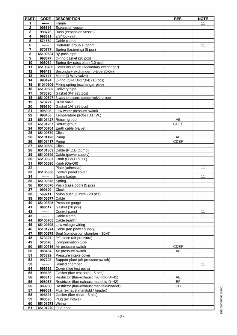
PART. CODE DESCRIPTION REF. NOTE1 112 998616 Expansion vessel3 998776 Bush (expansion vessel)4 998581 3/8" lock nut5 571562 Cable clamp6 117 570717 Spring (fastening) (5 pcs)8 65100684 By-pass pipe9 998077 O-ring gasket (20 pcs)10 998064 Spring (by-pass pipe) (10 pcs)11 65100706 Cover insulation (secondary exchanger)12 998483 Secondary exchanger (p-type 30Kw)13 997147 Motor (3-Way valve)14 998424 O-ring (C=4 D=17,04) (10 pcs)15 61010609 Fixing spring (exchanger pipe)16 65100682 Delivery pipe17 573520 Gasket 3/4" (25 pcs)18 65100547 3-way-pressure gauge valve group19 573727 Drain valve20 569390 Gasket 1/4" (25 pcs)21 995903 Low water pressure switch22 998458 Temperature probe (D.H.W.)23 65101427 Return group AB23 65101257 Return group CDEF24 65100704 Earth cable (valve)25 65100679 Clips26 65101426 Pump AB26 65101417 Pump CDEF27 65100680 Clips28 65101353 Cable (P.C.B./pump)29 65100699 Cable (power supply)30 65100687 Knob (D.W.H./C.H.)31 65100690 Knob (On-Off)32 1133 65100686 Control panel cover34 1135 65100678 Spring36 65100676 Push (case door) (5 pcs)37 999599 Clock38 569711 Nylon bush (10mm - 20 pcs)39 65100677 Cable40 65100695 Pressure gauge41 998517 Gasket (20 pcs)42 1143 1144 65100705 Cable (earth)45 65100698 Low voltage wiring46 65101274 Cable (fan power supply)47 65100879 Seal (combustion chamber - 10x6)48 573327 "Y" piece (air pressure)49 573576 Compensation tube50 65100716 Air pressure switch CDEF50 998484 Air pressure switch AB51 573329 Pressure intake cover52 997203 Support plate (air pressure switch)53 1154 998565 Cover (flue test point)55 998636 Gasket (flue test point - 5 pcs)56 995315 Restrictor (flue-exhaust manifold-D=41) AB56 998087 Restrictor (flue-exhaust manifold-D=42) EF56 999980 Restrictor (flue-exhaust manifold/header) CD57 999561 Flue (exhaust manifold / header)58 998637 Gasket (flue collar - 5 pcs)59 998595 Plug (air intake)60 65101273 Wiring61 65101270 Flue hood
- 3 -
ER
2004
2100
4210
2001
------
------
------
------
------------
------
Frame
Hydraulic group support
Plate (adhesive)
Name badge
Control panel Cable clamp
Sealed chamber

PART. CODE DESCRIPTION REF. NOTE62 65101393 Support63 573521 Gasket 3/8" (25 pcs)64 65100681 Pipe (expansion vessel)65 65100531 Panel (insulation - rear)66 992199 Panel (insulation - RH-LH Side)67 1168 61011136 Heat exchanger CDEF68 61010017 Heat exchanger AB69 990686 Temperature probe + clip (C.H. - T335D)70 996065 Thermostat (overheat- 103°C)71 65100521 Fixing spring (thermostat) 10 pcs72 573825 O-Ring (secondary exchanger - 10 pcs)73 65100700 Motor cable74 997077 Fixing clip (motor)75 997088 Safety valve (3 bar)76 573528 Gasket 1/2" (25 pcs)77 65101392 Pipe78 65100249 Spark generator79 574279 Gasket (spark generator) (5 pcs)80 65100244 Gas valve81 65101391 Pipe (gas valve/burner)82 573325 Rivet (20 pcs)83 65100717 Burner D83 65100720 Burner E83 65100714 Burner C83 65100711 Burner B83 65100526 Burner A83 65100718 Burner F84 569443 Silicone seal85 65101275 Inter ignition blade86 572138 Burner jet washer (20 pcs)87 998433 Burner jet 1.30 full kit (NG - 10 pcs) D87 65100740 Burner jet (LPG 0.80) (10 pcs) F87 998434 Burner jet 0.77 full kit (LPG - 10 pcs) C87 570251 Burner jet (LPG 0.72) (10 pcs) A87 570248 Burner jet (NG 1.25) (10 pcs) B87 65100772 Burner jet (NG 1.35 ) (10 pcs) E88 65100683 Return pipe89 996119 Cable (detection)90 65101277 Control panel91 65100688 Button (reset)92 65100689 Knob93 65101394 Connection cable (time clock)94 65101368 Module kit (EEPROM CMP3)95 65100709 P.C.B. (CMP3-display)96 65100697 Display cable97 65100871 Printed circuit board (CMP3-HS MI/MFFI)98 1199 571787 Terminal board (two pole)100 65100524 Front sealed chamber panel101 65100693 Electrode (Ignition R.H.)102 65100694 Electrode (Ignition L.H.)103 65100692 Electrode (Detection)104 998147 Ignition electrode cable rubber105 11106 65100530 Panel (insulation - front)107 65100685 Control panel cover108 65101271 Earth cable (fan)109 999397 Fan AB109 65100719 Fan EF109 65101428 Fan CD110 65100707 Gasket (fan) (5 pcs)111 998566 Fixing clamp (fan)112 999135 Panel (insulation - fan)113 998076 Gasket (sight glass)114 998075 Sight glass
- 4 -
ER
2004
2100
4210
2001
------
------
------
Combustion chamber
Terminal board
Plate (combustion chamber)

PART. CODE DESCRIPTION REF. NOTE115 999151 Panel (front - sealed chamber)
301 65101352 Case panel (L.H. side)302 998596 Insert case303 65101351 Case panel (R.H. side)304 998607 Panel (front case)305 995305 Washer (20 pcs)
701 569281 Burner jet 1.25 full kit (NG) B 12701 998433 Burner jet 1.30 full kit (NG - 10 pcs) D 12701 65100771 Burner jet 1.35 full kit (NG - 15 pcs) F 12702 569282 Burner jet 0.72 full kit (LPG) E 12702 65100739 Burner jet 0.80 full kit (LPG - 15 pcs) A 12702 998434 Burner jet 0.77 full kit (LPG - 10 pcs) C 12
NOTE DESCRIPTION11 Not supplied as a spare part12 Not illustrated
- 5 -
ER
2004
2100
4210
2001

401
402
403
code 65100547 code 65101257
503502
501
504
601
606
604
601
602
610
601
611
609603
607603
608
605
602code 65101427
553552
551
554
- 6 -
ER
2004
2100
4210
2001
PART. CODE DESCRIPTION REF. NOTE401 998974 Heating actuator bush402 998975 3-Way spring kit (D.H.W.)403 998718 3-Way spring kit (C.H.)
501 65100540 Flow detection kit with magnet502 65100541 3-Way spring kit (D.H.W.)503 65100869 Union504 65100776 Central heating by-pass kit CDEF
551 65100540 Flow detection kit with magnet552 65100541 3-Way spring kit (D.H.W.)553 65100869 Union554 998490 Central heating by-pass kit AB
601 573520 Gasket 3/4" (25 pcs)602 573528 Gasket 1/2" (25 pcs)603 573521 Gasket 3/8" (25 pcs)604 571000 Isolating valve (gas inlet)605 998406 Union 1/2" (D.H.W. outlet)606 999582 Isolating valve (3/4" return)607 990742 Tap (M/M 3/8" - C.H. flow)608 65101287 Tap (M/M 3/8" inc.non-return-C.W. inlet)609 990737 Filling loop pipe610 995485 Isolating valve 1/2" (C.W. inlet)611 995486 Isolating valve 3/4" (C.H. flow)