arizona ng9-1-1 gis - grants.az.gov · ... geographic information system (gis) data plays a...
TRANSCRIPT
1 | P a g e AZ NG9-1-1 GIS
ARIZONA NG9-1-1 GIS GUIDELINES and BEST PRACTICES
Prepared by
The Arizona 9-1-1 Program Office
As of 11/17/2017
2 | P a g e AZ NG9-1-1 GIS
Table of Contents
ACKNOWLEDGEMENTS ................................................................................................................................ 4
FOREWARD ................................................................................................................................................... 5
Purpose of the NG9-1-1 GIS Guidelines and Best Practices .................................................................... 5
Local Additions to the NG9-1-1 Documents ............................................................................................ 5
Continual Improvement ........................................................................................................................... 6
Reason for Issue/Reissue ......................................................................................................................... 6
CHAPTER 1: INTRODUCTION ........................................................................................................................ 7
CHAPTER 2: ADMINISTRATIVE GUIDELINES ................................................................................................ 9
CHAPTER 2.1: Reporting of GIS Accuracy to the Arizona 9-1-1 Program Office ................................... 10
CHAPTER 3: DEVELOPING GIS ACCURACY PROCEDURES .......................................................................... 11
CHAPTER 4: ERROR TESTING AND CORRECTION FOR 9-1-1 SYSTEMS ...................................................... 12
CHAPTER 4.1: Testing GIS Road Networks and Address Point Datasets Using the ALI Data Extract (aka Telephone Number (TN) Extract) ................................................................................................... 12
CHAPTER 4.2: Correcting TN Extract Errors ........................................................................................... 20
CHAPTER 5: ADDITIONAL QUALITY ASSURANCE TESTING ........................................................................ 23
CHAPTER 5.1: Using Address Density to Find Errors in Address Ranges .............................................. 23
CHAPTER 5.2: Validating Emergency Service Zone Boundaries ............................................................ 27
Section 5.2.1: Testing for Coincidence of Systems and County Boundaries ................................... 30
CHAPTER 5.3: Establishing Road Directionality ..................................................................................... 45
CHAPTER 5.4: Populating the Parity Right and Left Fields .................................................................... 47
CHAPTER 5.5: Checking for Ascending Address Ranges ........................................................................ 49
CHAPTER 5.6: Cross Checking Address Points and Road Segments ..................................................... 50
CHAPTER 6: DATA CREATION AND MAINTENANCE BEST PRACTICES ....................................................... 52
CHAPTER 6.1: Maintaining Unique Identifiers ...................................................................................... 52
CHAPTER 6.2: Generally Applicable Data Guidelines ............................................................................ 56
CHAPTER 6.3: Road Centerline Guidelines ............................................................................................ 58
CHAPTER 6.4 Emergency Service Boundary (ESB) Guidelines .............................................................. 62
CHAPTER 6.5: PSAP Boundary Guidelines ............................................................................................. 63
CHAPTER 6.6: Road Name Alias Table Guidelines ................................................................................. 64
CHAPTER 6.7: Site / Structure Address Point Guidelines ...................................................................... 65
CHAPTER 6.8: States or Equivalent Guidelines ...................................................................................... 66

3 | P a g e AZ NG9-1-1 GIS
CHAPTER 6.9: Counties or Equivalents .................................................................................................. 67
CHAPTER 6.10: Incorporated Municipal Boundary Guidelines ............................................................. 68
CHAPTER 6.11: Unincorporated Community Boundary Guidelines ..................................................... 69
CHAPTER 6.12: Neighborhood Boundary Guidelines ............................................................................ 70
CHAPTER 6.13: Emergency Service Zone Guidelines ............................................................................. 72
CHAPTER 6.14: Community Boundary Guidelines ................................................................................ 73
CHAPTER 7: ADDING OR EDITING METDATA ............................................................................................ 74
CHAPTER 8: IMPLEMENTING ALIAS TABLES .............................................................................................. 80
CHAPTER 9: TRANSFORMING ADDRESS DATA TO THE NG9-1-1 DATA MODEL ....................................... 82
CHAPTER 10: BACKGROUND INFORMATION FOR GUIDELINES ................................................................ 87
CHAPTER 11: ARIZONA NG9-1-1 DATA MODEL ....................................................................................... 106
CHAPTER 11.1: Emergency Service Zones (ESN/ESZ) ......................................................................... 107
CHAPTER 11.2: Community Boundaries (MSAG) ................................................................................ 108
APPENDIX A.1: EXAMPLE WORKFLOW FOR CORRECTING ERRORS IN 9-1-1 DATASETS ........................ 109
APPENDIX A.2: EXAMPLE WORKFLOW FOR ADDING NEW STREETS TO A 9-1-1 ROAD NETWORK....... 110
APPENDIX A.3: EXAMPLE WORKFLOW FOR PROCESSING ANNEXATIONS ............................................. 111
APPENDIX B.1: ADOT ROAD NETWORK SPATIAL REPRESENTATION GUIDELINES ................................. 112
APPENDIX B.2: ADOT ON/OFF RAMP NAMING GUIDELINES .................................................................. 117
APPENDIX C: ROAD CLASSIFICATION CODES ........................................................................................... 119
APPENDIX D: LOCAL 9-1-1 PROCESSES .................................................................................................... 121

4 | P a g e AZ NG9-1-1 GIS
ACKNOWLEDGEMENTS
The Arizona 9-1-1 Program Office would like to thank the AGIC 9-1-1 Working Group Technical Committee comprised of the following persons and organizations for their time and expertise in the development of this manual.
Jack Avis Pima County ITD-GIS
Brian Bond Yavapai County GIS Dept.
Brian Brady Yuma ITS-GIS
Joe Breyer Works Consulting
Judith DeLury Gila River Indian Community GIS
Matthew Deveney Gila River Indian Community GIS
Sandra Dyre Arizona 9-1-1 Program Office
Sarah Hess Pinal County IT/GIS
Tom Homan Gila County Public Works
Shea Lemar Arizona State University - ISSR
James Meyer Arizona Dept. of Transportation
Curtis Pulford Arizona State Cartographer
Gene Trobia Arizona State University
Please note that a current list of contacts, including persons in your local area, can be accessed by joining the State of Arizona AZGEO web portal, joining the 9-1-1/Public Safety group, and then clicking on the contacts link in that Group’s home page. https://azgeo.az.gov/azgeo/

5 | P a g e AZ NG9-1-1 GIS
FOREWARD
Purpose of the NG9-1-1 GIS Guidelines and Best Practices Next Generation 9-1-1 (NG9-1-1) is coming to Arizona. In NG9-1-1, Geographic Information System (GIS) data plays a critical role in many functions, and System Administrators (SA) as well as GIS data practitioners who support 9-1-1 systems will need to be aware of its impact on their data collection and maintenance procedures. The Arizona NG9-1-1 GIS Guidelines and Best Practices Manual contains a wealth of information for 9-1-1 data stewards on best practices for developing and maintaining NG9-1-1 related datasets in the State of Arizona. While the focus of the document is on the needs of 9-1-1, much of this information is potentially useful beyond 9-1-1. The document incorporates the work of the Arizona Geographic Information Council (AGIC) Data Committee 9-1-1 Working Group and its Technical 9-1-1 sub-committee, as well as being congruent with the latest available information on 9-1-1 standards from the National Emergency Number Association (NENA) and Federal Geographic Data Committee (FGDC). The hope is that 9-1-1 data practitioners will find this information useful in creating, maintaining and sharing their 9-1-1 related data sets, thereby improving inter-agency coordination in future emergencies. NG9-1-1 is a new concept and one that has not been fully implemented in its entirety. This document will require editing as NG standards are finalized and lessons are learned through real-world application. The transition from a legacy 9-1-1 environment to a NG9-1-1 environment may require some additional data elements not required in NG9-1-1 to remain in the database until a complete transition is accomplished. Updates to this and related NG9-1-1 documents will be made available to Arizona 9-1-1 GIS professionals on AZGEO (Arizona Geospatial Clearinghouse) and on the Arizona 9-1-1 website.
Local Additions to the NG9-1-1 Documents State and national requirements and/or recommendations are only a portion of what goes into the creation and maintenance of local datasets. It is important that each Arizona 9-1-1 system add to this document additional information only known at the local level in order to create an institutionally robust set of processes. Personalization of the documents can include, but are not limited to the following:
• How local data will field-map to the NG911 data schema; • What local workflows are used for error resolution and maintenance; • How GIS data is collected from and incorporated into the 9-1-1 datasets; • How validation of the GIS data occurs; • What are the appropriate reporting hierarchies; • What are the local policies and/or processes for maintenance of the 9-1-1 System.
6 | P a g e AZ NG9-1-1 GIS
A 9-1-1 system has to function regardless of who is available to perform the necessary supporting duties. Comprehensive, well-written and maintained documents help ensure consistency and resiliency of a 9-1-1 system. Through such documents, processes are known, understood and available to anyone who needs to ensure its on-going functionality. Appendix D of this document is available to compile local 9-1-1 GIS processes.
Continual Improvement It is the hope of the Arizona 9-1-1 Program Office that this document is used, corrected, discussed, and shared among Arizona 9-1-1 and GIS data practitioners. If used in this manner, it can facilitate the evolution of data sets in a manner more compatible with needs of the future NG9-1-1 system. In order to keep this document relevant, annual reviews will occur to incorporate new and/or modified standards.
Reason for Issue/Reissue
Document Number Approval Date Reason For Changes
AZ NG9-1-1 GIS Guidelines and Best Practices
04/04/2017 Initial Document
AZ NG9-1-1 GIS Guidelines and Best Practices
11/17/2017 Edit to Chapter 2 and addition of Chapter 2.1 to Clarify GIS Accuracy Reporting
Replace terminology “State Cartographer’s Office” to “Arizona State Land Department” due to closure of the State Cartographer’s Office in 2017.
AZ NG9-1-1 GIS Guidelines and Best Practices
[MM/DD/YYYY] [Reason for revision]

7 | P a g e AZ NG9-1-1 GIS
CHAPTER 1: INTRODUCTION
What is NG9-1-1? The National Emergency Number Association (NENA) defines Next Generation 9-1-1 (NG9-1-1) as:
An Internet Protocol (IP) based system comprised of managed Emergency Services IP networks (ESInets), functional elements (applications), and databases that replicate traditional E9-1-1 features and functions and provides additional capabilities. NG9-1-1 is designed to provide access to emergency services from all connected communications sources, and provide multimedia data capabilities for Public Safety Answering Points (PSAPs) and other emergency service organizations.
The databases within the NG9-1-1 environment are primarily GIS databases that provide critical functionality including call routing, location validation and, as it does today, 9-1-1 call mapping. In enhanced or “E” 9-1-1 services, a minimum of three (3) GIS data sets are required to assist in emergency response: road networks, Emergency Service Zones (ESZ) and MSAG Community boundaries. In E9-1-1, these data sets play an ancillary, back-end mapping role in the operation of the 9-1-1 system. In NG9-1-1, GIS data takes the lead role in emergency call handling, beginning with the routing of calls to the appropriate 9-1-1 Public Safety Answering Points (PSAP’s). PSAPs must be able to operate seamlessly across authority and even state and national boundaries. This NG capability requires additional and standardized data sets. NG Resources in Arizona There are several state and national organizations which local 9-1-1 practitioners can turn to for assistance in the implementation and operation of their systems. These include the Arizona 9-1-1 Program Office, the Arizona Geographic Information Council (AGIC) and the National Emergency Number Association (NENA). Each of these resources is described briefly below with links to further information. The Arizona 9-1-1 Program Office has oversight responsibility for the revenues that are collected through the Emergency Telecommunication Services Revolving Fund. Revenues are generated through a Telecommunication Services Excise tax rate of $0.20 per month for each activated wire, wireless and voice over internet protocol (VoIP) service account. In addition, a small percentage of the amount for prepaid wireless sales at the retail level also contribute to the fund. Collections are used to implement and operate emergency telecommunication services (9-1-1) through political sub-divisions of the state. Further information about the Arizona 9-1-1 Program Office can be found at https://aset.az.gov/arizona-9-1-1-program. The Arizona Geographic Information Council (AGIC) was established in 1989 by Executive Order 89-24 as Arizona's primary forum and oversight group for geographic information and technology issues and statewide coordination efforts. In 2009, AGIC was established in legislation with changes to the Arizona Revised Statutes Title 37. ARS 37-173 emphasized enterprise GIS, ARS 37-178 introduced language to enhance geospatial data sharing, and ARS 37-177 established AGIC in statute. AGIC coordinates the development of standards and implementation strategies, providing a framework that optimizes the

8 | P a g e AZ NG9-1-1 GIS
State's investment in geographic data and technology. Through cooperation and partnerships, AGIC facilitates the acquisition, exchange and management of geographic information and technology for the State of Arizona to benefit state agencies and the Arizona GIS community. AGIC meets on a regular basis and conducts an annual GIS conference (AGIC Education and Training Symposium) to address and coordinate statewide geographic information and technology issues, requirements and solutions. Further information about AGIC can be found at https://arcgis2.geo.az.gov/agic/about-agic. More details on the Data Committee of AGIC can be found at https://arcgis2.geo.az.gov/agic/data-committee. The AZGEO Clearinghouse is a data sharing platform, hosted by Arizona State Land Department, designed to facilitate the sharing of data among local, state and government agencies statewide. You can request a general login to AZGEO from the Arizona State Land Department and then upload and download shared data using the Data Catalog functionality. Some data is restricted by AZGEO group. Once you have a general login, you can apply for one or more interest groups that share data and information of common interest on the platform. This will give you access to any data restricted to a particular group. For the 9-1-1 community, there is already an “E9-1-1 Public Safety” group which you can request to join. Further information about AZGEO can be found at https://azgeo.az.gov/azgeo/. The National Emergency Number Association (NENA) serves the public safety community as the only professional organization solely focused on 9-1-1 policy, technology, operations, and education issues. With more than 7,000 members in 48 chapters across North America and around the globe, NENA promotes the implementation and awareness of 9-1-1 and international three-digit emergency communication systems. NENA works with public policy leaders; emergency services and telecommunications industry partners; like-minded public-safety associations; and other stakeholder groups to develop and carry out critical programs and initiatives; to facilitate the creation of an IP-based Next Generation 9-1-1 system; and to establish industry leading standards, training, and certifications. Many of the guidelines found in this User Guide come from NENA or are congruent with NENA recommendations for data creation and maintenance. Further Information about NENA can be found at http://www.nena.org/.
9 | P a g e AZ NG9-1-1 GIS
CHAPTER 2: ADMINISTRATIVE GUIDELINES The 9-1-1 System Administrators (SA) in Arizona have a critical role to play in providing support for their system’s GIS data acquisition, evaluation, correction, and reporting functions. Though much of this manual provides guidance to GIS and IT technical staff, these sections below focus on concerns of which an Administrator must be aware. Compliance with AZ 9-1-1 Data Accuracy Requirements The GIS file developed by a jurisdiction is a critical component in the delivery of 9-1-1 services. Arizona’s 9-1-1 Program Office is very interested in ensuring that the data is correct, complete and seamless within and between Arizona’s individual 9-1-1 systems. Therefore, before agreeing to reimburse the associated costs or requesting additional and/or improved services, analysis of the data for accuracy is required by the Arizona 9-1-1 Program Office. Specifically, the GIS data sets and ALI (Automatic Location Identifier) database require comparison with a match rate of 98%1, or higher. Should the 9-1-1 system fail to meet the requirements, the 9-1-1 system will have the following recourse.
• 30 days will be allowed to improve the data, after which a second comparison will be run to assess the accuracy.
• If the second comparison does not reach a minimum of 98%, the responsibility to pay the costs
associated with service will revert to the individual 9-1-1 system. Those costs will continue to fall to the individual 9-1-1 system until the prescribed requirements have been met.
“Service” applies to those services that require GIS information. For enhanced 9-1-1 (E9-1-1) systems, ‘service’ relates to Wireless Phase II. For NG9-1-1 systems that have migrated to geospatial routing, ‘service’ relates to network and Wireless Phase II.
• Obtaining the ALI database has a cost. Arizona’s 9-1-1 Program Office will pay for one per year. Any
additional ALI Data Extracts (ADE) that are required to validate data will be at the expense of the individual 9-1-1 system.
Each 9-1-1 System is required to identify a GIS and/or Map Administrator who has agreed to be responsible to oversee and manage the tasks, issues, and procedures related to GIS and 9-1-1. It is the 9-1-1 System Administrator’s task to develop, document, and monitor the procedures related to maintaining a highly accurate GIS file.
1 The National Emergency Number Association (NENA) has defined an ALI DB to GIS reconciliation accuracy of 98%. NENA 71-501, Version 1, May 26, 2009, Information Document for Synchronizing Geographic Information System Databases with MSAG & ALI
10 | P a g e AZ NG9-1-1 GIS
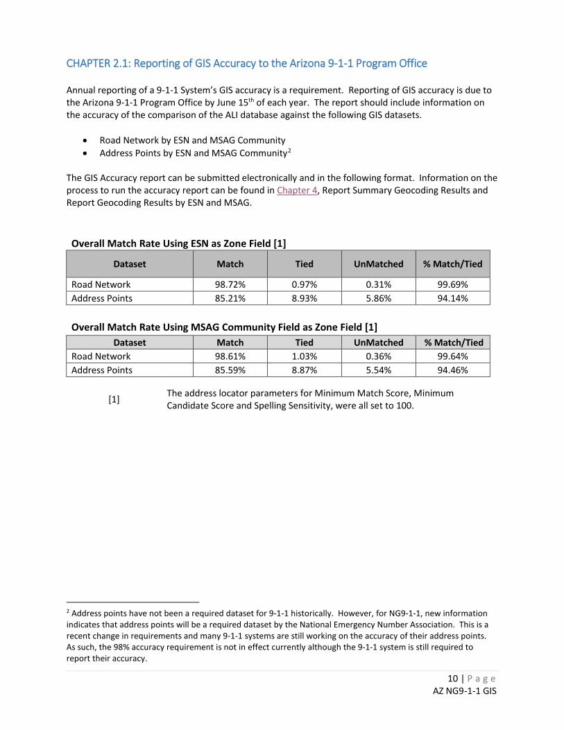
CHAPTER 2.1: Reporting of GIS Accuracy to the Arizona 9-1-1 Program Office Annual reporting of a 9-1-1 System’s GIS accuracy is a requirement. Reporting of GIS accuracy is due to the Arizona 9-1-1 Program Office by June 15th of each year. The report should include information on the accuracy of the comparison of the ALI database against the following GIS datasets.
• Road Network by ESN and MSAG Community • Address Points by ESN and MSAG Community2
The GIS Accuracy report can be submitted electronically and in the following format. Information on the process to run the accuracy report can be found in Chapter 4, Report Summary Geocoding Results and Report Geocoding Results by ESN and MSAG.
Overall Match Rate Using ESN as Zone Field [1] Dataset Match Tied UnMatched % Match/Tied
Road Network 98.72% 0.97% 0.31% 99.69% Address Points 85.21% 8.93% 5.86% 94.14%
Overall Match Rate Using MSAG Community Field as Zone Field [1] Dataset Match Tied UnMatched % Match/Tied
Road Network 98.61% 1.03% 0.36% 99.64% Address Points 85.59% 8.87% 5.54% 94.46%
[1] The address locator parameters for Minimum Match Score, Minimum Candidate Score and Spelling Sensitivity, were all set to 100.
2 Address points have not been a required dataset for 9-1-1 historically. However, for NG9-1-1, new information indicates that address points will be a required dataset by the National Emergency Number Association. This is a recent change in requirements and many 9-1-1 systems are still working on the accuracy of their address points. As such, the 98% accuracy requirement is not in effect currently although the 9-1-1 system is still required to report their accuracy.
11 | P a g e AZ NG9-1-1 GIS
CHAPTER 3: DEVELOPING GIS ACCURACY PROCEDURES
The purpose of this chapter is to assist Arizona 9-1-1 System Administrators in developing procedures that will ensure the integrity of the 9-1-1 GIS file used in the delivery of Wireless Phase II and Next Generation 9-1-1 (NG9-1-1) services. The GIS file developed by a jurisdiction is a critical component in the delivery of 9-1-1 services. Arizona’s 9-1-1 Program Office is very interested in ensuring that the data is correct, complete and seamless within and between Arizona’s individual 9-1-1 systems. Therefore, before agreeing to reimburse the associated costs or requesting additional and/or improved services, the data must be analyzed for accuracy. Specifically, the GIS data sets and ALI (Automatic Location Identification) database are compared and a match rate of 98%3, or higher, must be reached. To that end, the following steps are recommended. Develop and Document Procedures - At least two separate procedures are needed, one for correcting errors and one for adding new data. Below are some suggested items that you may want to consider when developing your procedures. Procedures used to update new information into the GIS files. • Identify the flow of information (Appendix A.2; Appendix A.3) • Train involved personnel • Determine how frequently updates will be distributed • Determine in what fashion updates will be distributed • Identify key personnel and establish their responsibilities • Establish periodic meetings with interested personnel to discuss related issues Procedures used to correct the GIS files. • Implement the use of a standardized form or reporting process • Identify and document the flow of information (Appendix A.1) • Train involved personnel • Monitor that errors are being a) reported and b) corrected • Identify key personnel and establish their responsibilities Establish a Committee - The maintenance of the GIS file is a collective effort. A committee of interested/involved personnel should be assembled periodically to discuss related issues. Your procedural document should include: • Committee members • Their title, and the agency where they report • Their contact information (office/cellular #, email address, mailing address) • Their responsibility as it relates to GIS maintenance Monitor - Describe how you will monitor to ensure that: • Errors are being reported and corrected • Streets/ranges are being updated • PSAP Boundaries as well as Emergency Service Boundaries are updated • That the PSAPs receiving the updated GIS files are loading the data in a timely fashion
3 The National Emergency Number Association (NENA) has defined an ALI DB to GIS reconciliation accuracy of 98%.

12 | P a g e AZ NG9-1-1 GIS
CHAPTER 4: ERROR TESTING AND CORRECTION FOR 9-1-1 SYSTEMS4 CHAPTER 4.1: Testing GIS Road Networks and Address Point Datasets Using the ALI Data Extract (aka Telephone Number (TN) Extract) The following procedures provide guidance on how to prepare the GIS roads and addresses for testing; how to conduct and report the test; and, in some instances, how to make corrections. Please note that the procedures outlined below are general guidelines. File names, database schemas, field names and other data specific characteristics will vary from System to System.
1. Process the TN Extract Table
Note: This dataset may be in a spreadsheet, an ArcGIS table or even a text file. It may have various names, but usually the name will have “TN” or “ADE” in the name. Further, ArcGIS (ArcMap 10.5 and earlier) has known compatibility issues with Microsoft Office Excel files. ArcGIS supports both Excel 2003 and earlier .xls files and Excel 2007 .xlsx files only. Excel 2007 files have the advantage of being able to manage much larger worksheets – 1,048,576 rows and 16,384 columns versus Excel 2003 (65,536 rows, 256 columns). It is recommended that Excel 2007 formatted files be used. If Excel 2010 or newer is installed on your machine, you will need to install the 2007 Office System Driver before you can access .xls or .xlsx files in ArcMap. For more information on ArcGIS and Excel files, please reference: http://desktop.arcgis.com/en/arcmap/latest/manage-data/tables/understanding-how-to-use-microsoft-excel-files-in-arcgis.htm
a. Copy the local TN Extract spreadsheet in the working folder using the original name or
abbreviation prepended by <911 System Name>. Note that if the number of records in a table or text file exceeds 1,048,576 rows, then import the spreadsheet into ArcGIS table format and perform the tests using that table.
i. E.g. “<911 System>_TN_TSSW.xlsx”.
b. Verify that the data is properly structured (row-column) and has, at a minimum, fields for an
address number, a street address and an Emergency Service Number (ESN). If the information is incomplete in any way, request a new copy of the file.
c. Add a header row (row of field names), if needed. Many times the spreadsheet may be
missing this information and you will have to figure out the content of the column from its values and context. Otherwise, you may have to ask the source for this information or a new file.
d. Remove blank and non-essential rows and columns from the TN spreadsheet.
i. May need to use filter option on the address number and address field(s) to search
for and delete common “junk” records. 1. “--------“ 2. “VOIP” 3. “FOREIGN EXCHANGE”
4 Special thanks to S. Hess at Pinal County GIS for providing procedures (revised 04/19/12) as input for this section.
13 | P a g e AZ NG9-1-1 GIS
4. “WIRELESS”
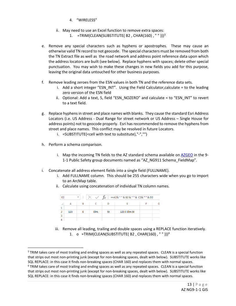
ii. May need to use an Excel function to remove extra spaces: 1. =TRIM(CLEAN(SUBSTITUTE( B2 , CHAR(160) , " " )))5
e. Remove any special characters such as hyphens or apostrophes. These may cause an
otherwise valid TN record to not geocode. The special characters must be removed from both the TN Extract file as well as the road network and address point reference data upon which the address locators are built (see below). Replace hyphens with spaces; delete other special punctuation. You may wish to make these changes in new fields you add for this purpose, leaving the original data untouched for other business purposes.
f. Remove leading zeroes from the ESN values in both TN and the reference data sets.
i. Add a short integer “ESN_INT”. Using the Field Calculator,calculate = to the leading zero version of the ESN field
ii. Optional: Add a text, 5, field “ESN_NOZERO” and calculate = to “ESN_INT” to revert to a text field.
g. Replace hyphens in street and place names with blanks. They cause the standard Esri Address
Locators (i.e. US Address - Dual Range for street network or US Address – Single House for address points) not to geocode properly. Esri has recommended to remove the hyphens from street and place names. This conflict may be resolved in future Locators.
i. =SUBSTITUTE(<cell with text to substitute),"-","")
h. Perform a schema comparison.
i. Map the incoming TN fields to the AZ standard schema available on AZGEO in the 9-1-1 Public Safety group documents named as “AZ_NG911 Schema_FieldMap”.
i. Concatenate all address element fields into a single field (FULLNAME).
i. Add FULLNAME column. This should be 255 characters wide when you go to import to an ArcMap table.
ii. Calculate using concatenation of individual TN column names.
iii. Remove all leading, trailing and double spaces using a REPLACE function iteratively. 1. o =TRIM(CLEAN(SUBSTITUTE( B2 , CHAR(160) , " " )))6
5 TRIM takes care of most trailing and ending spaces as well as any repeated spaces. CLEAN is a special function that strips out most non-printing junk (except for non-breaking spaces, dealt with below). SUBSTITUTE works like SQL REPLACE: in this case it finds non-breaking spaces (CHAR 160) and replaces them with normal spaces. 6 TRIM takes care of most trailing and ending spaces as well as any repeated spaces. CLEAN is a special function that strips out most non-printing junk (except for non-breaking spaces, dealt with below). SUBSTITUTE works like SQL REPLACE: in this case it finds non-breaking spaces (CHAR 160) and replaces them with normal spaces.
14 | P a g e AZ NG9-1-1 GIS
j. Add an AZST_ID column and calculate AZST_ID = sequential numbers beginning at 1 and
incrementing by one. This can be done by adding the AZST_ID column (assumed to be column C in this example), entering the number “1” in the first row (C1), entering the formula, “=+C1+1” in the second row (cell C2) and then copying that formula to Cell C3 and all successive rows for which you need an ID>.
k. Add an APD_SOURCE column and calculate APD_SOURCE = <SYSTEM NAME>.7
l. Delete any columns that ARE NOT: Address elements such as house number, prefix direction, prefix type, street name, street type, suffix direction, etc.; ESN – emergency service zone number; COMMUNITY – MSAG Community or other place name; STATE; ZIP5.
m. If there are multiple tabs with TN data in the spreadsheet, repeat the editing steps above for
all tabs. Be sure the same columns remain on each of the tabs and in the same order. n. If there are multiple tabs of data, add a new tab named “TN_All” and copy and paste the
records that you just standardized from each tab, one at a time, each copied below the preceding copy with no blank rows between them.
o. Save and close the spreadsheet. p. You may want to import the spreadsheet to a file geodatabase table. If the TN file has 65,536
rows or less, you can save as an .xls (Excel 97-2003) format file and read it directly from ArcGIS. If there are more than this number of rows, you have to save as an .xlsx Excel 2007 format file as described in the Notes preceding this section.
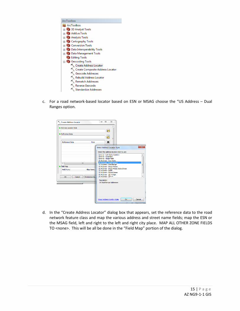
2. Build Address Locators
a. Use the “Schema_Comparison” tab of the “911 QA Report as a guide to building the address locator.
b. Using the “Create Address Locator” tool you will build four locators, one each for roads/ESN,
roads/MSAG, Add Point/ESN and Add Points/MSAG.
7 Refer to the State 9-1-1 Program spreadsheet for the official system names.
15 | P a g e AZ NG9-1-1 GIS
c. For a road network-based locator based on ESN or MSAG choose the “US Address – Dual
Ranges option.
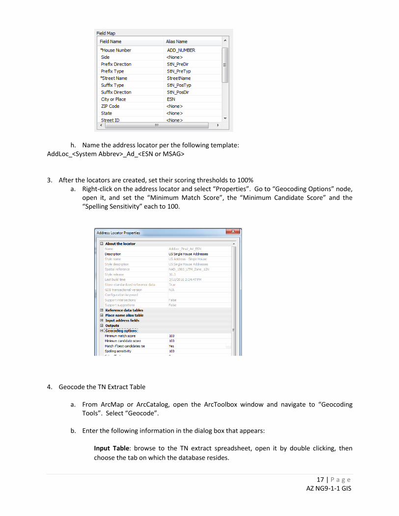
d. In the “Create Address Locator” dialog box that appears, set the reference data to the road
network feature class and map the various address and street name fields; map the ESN or the MSAG field, left and right to the left and right city place. MAP ALL OTHER ZONE FIELDS TO <none>. This will be all be done in the “Field Map” portion of the dialog.

16 | P a g e AZ NG9-1-1 GIS
e. Name the address locator per the following template: AddLoc_<System Abbrev>_St_<ESN or MSAG>
f. For Address Points based on ESN and MSAG, choose the “US Address - Single House” option.
g. In the “Create Address Locator” dialog box that appears, set the reference data to the address point feature class and map the various address and street name fields; map the ESN or the MSAG field, to the city place field in the locator template. MAP ALL OTHER ZONE FIELDS TO <none>. This will be all be done in the “Field Map” portion of the dialog.
17 | P a g e AZ NG9-1-1 GIS
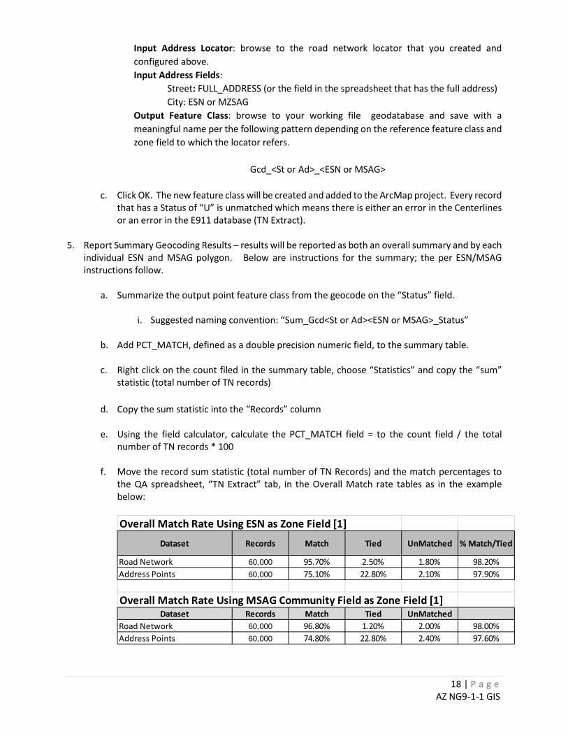
h. Name the address locator per the following template: AddLoc_<System Abbrev>_Ad_<ESN or MSAG> 3. After the locators are created, set their scoring thresholds to 100%
a. Right-click on the address locator and select “Properties”. Go to “Geocoding Options” node, open it, and set the “Minimum Match Score”, the “Minimum Candidate Score” and the “Spelling Sensitivity” each to 100.
4. Geocode the TN Extract Table
a. From ArcMap or ArcCatalog, open the ArcToolbox window and navigate to “Geocoding Tools”. Select “Geocode”.
b. Enter the following information in the dialog box that appears:
Input Table: browse to the TN extract spreadsheet, open it by double clicking, then choose the tab on which the database resides.
18 | P a g e AZ NG9-1-1 GIS
Input Address Locator: browse to the road network locator that you created and configured above. Input Address Fields:
Street: FULL_ADDRESS (or the field in the spreadsheet that has the full address) City: ESN or MZSAG
Output Feature Class: browse to your working file geodatabase and save with a meaningful name per the following pattern depending on the reference feature class and zone field to which the locator refers.
Gcd_<St or Ad>_<ESN or MSAG>
c. Click OK. The new feature class will be created and added to the ArcMap project. Every record that has a Status of “U” is unmatched which means there is either an error in the Centerlines or an error in the E911 database (TN Extract).
5. Report Summary Geocoding Results – results will be reported as both an overall summary and by each
individual ESN and MSAG polygon. Below are instructions for the summary; the per ESN/MSAG instructions follow.
a. Summarize the output point feature class from the geocode on the “Status” field.
i. Suggested naming convention: “Sum_Gcd<St or Ad><ESN or MSAG>_Status”
b. Add PCT_MATCH, defined as a double precision numeric field, to the summary table.
c. Right click on the count filed in the summary table, choose “Statistics” and copy the “sum”
statistic (total number of TN records) d. Copy the sum statistic into the “Records” column e. Using the field calculator, calculate the PCT_MATCH field = to the count field / the total
number of TN records * 100 f. Move the record sum statistic (total number of TN Records) and the match percentages to
the QA spreadsheet, “TN Extract” tab, in the Overall Match rate tables as in the example below:
Overall Match Rate Using ESN as Zone Field [1]
Dataset Records Match Tied UnMatched % Match/Tied
Road Network 60,000 95.70% 2.50% 1.80% 98.20%Address Points 60,000 75.10% 22.80% 2.10% 97.90%
Overall Match Rate Using MSAG Community Field as Zone Field [1]Dataset Records Match Tied UnMatched
Road Network 60,000 96.80% 1.20% 2.00% 98.00%Address Points 60,000 74.80% 22.80% 2.40% 97.60%
19 | P a g e AZ NG9-1-1 GIS
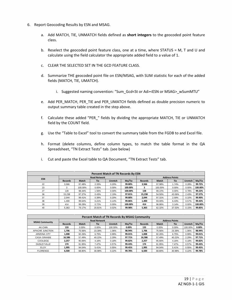
6. Report Geocoding Results by ESN and MSAG.
a. Add MATCH, TIE, UNMATCH fields defined as short integers to the geocoded point feature class.
b. Reselect the geocoded point feature class, one at a time, where STATUS = M, T and U and
calculate using the field calculator the appropriate added field to a value of 1.
c. CLEAR THE SELECTED SET IN THE GCD FEATURE CLASS.
d. Summarize THE geocoded point file on ESN/MSAG, with SUM statistic for each of the added fields (MATCH, TIE, UMATCH).
i. Suggested naming convention: “Sum_Gcd<St or Ad><ESN or MSAG>_wSumMTU”
e. Add PER_MATCH, PER_TIE and PER_UMATCH fields defined as double precision numeric to
output summary table created in the step above. f. Calculate these added "PER_" fields by dividing the appropriate MATCH, TIE or UNMATCH
field by the COUNT field.
g. Use the “Table to Excel” tool to convert the summary table from the FGDB to and Excel file. h. Format (delete columns, define column types, to match the table format in the QA
Spreadsheet, “TN Extract Tests” tab. (see below)
i. Cut and paste the Excel table to QA Document, “TN Extract Tests” tab.
Records Match Tie Unmtch Ma/Tie Records Match Tie Unmtch Ma/Tie22 3,566 97.48% 2.33% 0.20% 99.80% 3,566 97.98% 1.74% 0.28% 99.72%23 3 100.00% 0.00% 0.00% 100.00% 3 100.00% 0.00% 0.00% 100.00%27 128 98.44% 1.56% 0.00% 100.00% 128 99.22% 0.00% 0.78% 99.22%36 15,238 97.37% 0.43% 2.19% 97.81% 15,238 54.50% 43.06% 2.43% 97.57%37 2,044 99.41% 0.39% 0.20% 99.80% 2,044 97.31% 2.59% 0.10% 99.90%38 1,400 99.64% 0.21% 0.14% 99.86% 1,400 93.00% 6.43% 0.57% 99.43%39 414 99.28% 0.72% 0.00% 100.00% 414 96.86% 3.14% 0.00% 100.00%40 5,363 79.17% 20.81% 0.02% 99.98% 5,363 62.32% 37.53% 0.15% 99.85%
Percent Match of TN Records By ESNESN Road Network Address Points
Records Match Tie Unmtch Ma/Tie Records Match Tie Unmtch Ma/TieAK-CHIN 133 0.00% 0.00% 100.00% 0.00% 133 0.00% 0.00% 100.00% 0.00%
APACHE JUNCTION 1,706 75.56% 23.39% 1.06% 98.94% 1,706 75.56% 23.39% 1.06% 98.94%ARIZONA CITY 1,008 92.26% 6.75% 0.99% 99.01% 1,008 92.26% 6.75% 0.99% 99.01%CASA GRANDE 16,586 57.49% 40.22% 2.29% 97.71% 16,586 57.49% 40.22% 2.29% 97.71%
COOLIDGE 2,257 95.66% 4.16% 0.18% 99.82% 2,257 95.66% 4.16% 0.18% 99.82%DUDLEYVILLE 174 91.95% 7.47% 0.57% 99.43% 174 91.95% 7.47% 0.57% 99.43%
ELOY 1,995 94.04% 5.41% 0.55% 99.45% 1,995 94.04% 5.41% 0.55% 99.45%FLORENCE 6,500 68.80% 30.98% 0.22% 99.78% 6,500 68.80% 30.98% 0.22% 99.78%
Percent Match of TN Records By MSAG CommunityMSAG Community Road Network Address Points
20 | P a g e AZ NG9-1-1 GIS
CHAPTER 4.2: Correcting TN Extract Errors
The errors reported from TN Extract testing are an indication of a potential 9-1-1 call that either will not be able to (1) validate the location, (2) will not be routed to the correct PSAP or (3) both, unable to properly locate or route. The failure to properly locate and route a 9-1-1 call is a top priority for a 9-1-1 system. As such, a process should be identified to reconcile any errors. Resolution of Errors The resolution of errors is as essential in a NG environment as it is in today’s 9-1-1. Therefore, it is the 9-1-1 System Administrator’s responsibility to develop, document, and monitor the procedures related to the resolution of errors. Depending on the type of error, one process may not work for all local providers. In general, establishing relationships with the local addressing and GIS authorities will be necessary to the timely and accurate resolution of errors. General guidelines, along with the various NENA standards, can assist the 9-1-1 System Administrator in developing the proper workflows to address the various types of errors. Workflows should exist on how to add, change or remove roads and addresses from the 9-1-1 network. Sample Location Correction Workflow When an error is received that affects the location of a 9-1-1 call, validate the address and/or road name (to include street suffix and community) with the local Addressing Authority. Upon validation, 1. If the customer address is not valid, then
a. Replace the non-valid address with the valid address and report to the appropriate telephone company.
i. The Addressing Authority should notify the citizen of the valid address. ii. Notification to the telephone company can be a part of the Address Authority
reporting process; however, it is recommended the 9-1-1 Authority also participates in notification.
2. If the customer address is valid, then
a. Check the GIS to see if the centerline address range needs to be modified or if an edit is needed to the address point.
i. If the 9-1-1 Authority is not the data steward or custodian, work with the appropriate department and/or personnel to have the GIS updated.
1. For example, the city may maintain their own GIS and provide the GIS to the 9-1-1 Authority for consumption into the 9-1-1 system. The city GIS department would need to be contacted about the error and a desired resolution.
3. If no valid address exists, then
a. Work with the local Addressing Authority to have an address issued or to validate the address being used in the 9-1-1 system.
i. The Addressing Authority should notify the citizen and other affected agencies of the valid address.
21 | P a g e AZ NG9-1-1 GIS
ii. Notification to the telephone company can be a part of the Addressing Authority reporting process; however, it is recommended the 9-1-1 Authority also participates in notification.
b. Check the GIS to see if the centerline address range needs to be modified or if an edit is needed to the address point.
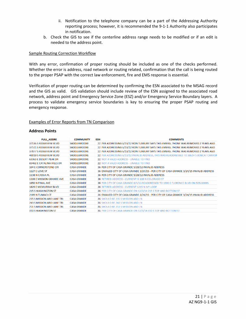
Sample Routing Correction Workflow
With any error, confirmation of proper routing should be included as one of the checks performed. Whether the error is address, road network or routing related, confirmation that the call is being routed to the proper PSAP with the correct law enforcement, fire and EMS response is essential. Verification of proper routing can be determined by confirming the ESN associated to the MSAG record and the GIS as valid. GIS validation should include review of the ESN assigned to the associated road network, address point and Emergency Service Zone (ESZ) and/or Emergency Service Boundary layers. A process to validate emergency service boundaries is key to ensuring the proper PSAP routing and emergency response.
Examples of Error Reports from TN Comparison
Address Points
22 | P a g e AZ NG9-1-1 GIS
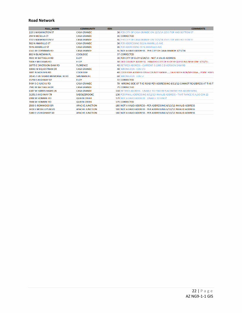
Road Network
23 | P a g e AZ NG9-1-1 GIS
CHAPTER 5: ADDITIONAL QUALITY ASSURANCE TESTING CHAPTER 5.1: Using Address Density to Find Errors in Address Ranges Address density, as used here, means the number of addresses per mile available on a road network. An unusually high or low density value may indicate an error in the To-From/Right-Left address number attributes assigned to a road segment. Generally speaking, addresses are laid out in either a grid or milepost format. Address grids define a point of origin and the number of addresses allowed per mile or other unit of measure. Typically, in urban settings, 100 address per block, 1/10 mile per block, means an address density of 1,000 per mile. This test applies specifically to geocodable road network feature classes in an Esri geodatabase format. This test does not have any use in measuring density in a milepost format. Procedure: 1. Obtain the Address Density tool zip file. This is named “AddressDensity.zip” and is available from the
Arizona 9-1-1 Program Office or from the AZGEO website. This zip file will contain the following files:
• AddressDensity.tbx ArcGIS toolbox file • CalcAddMinAddMaxDensity.py Address density calculation script
2. Install the script tool:
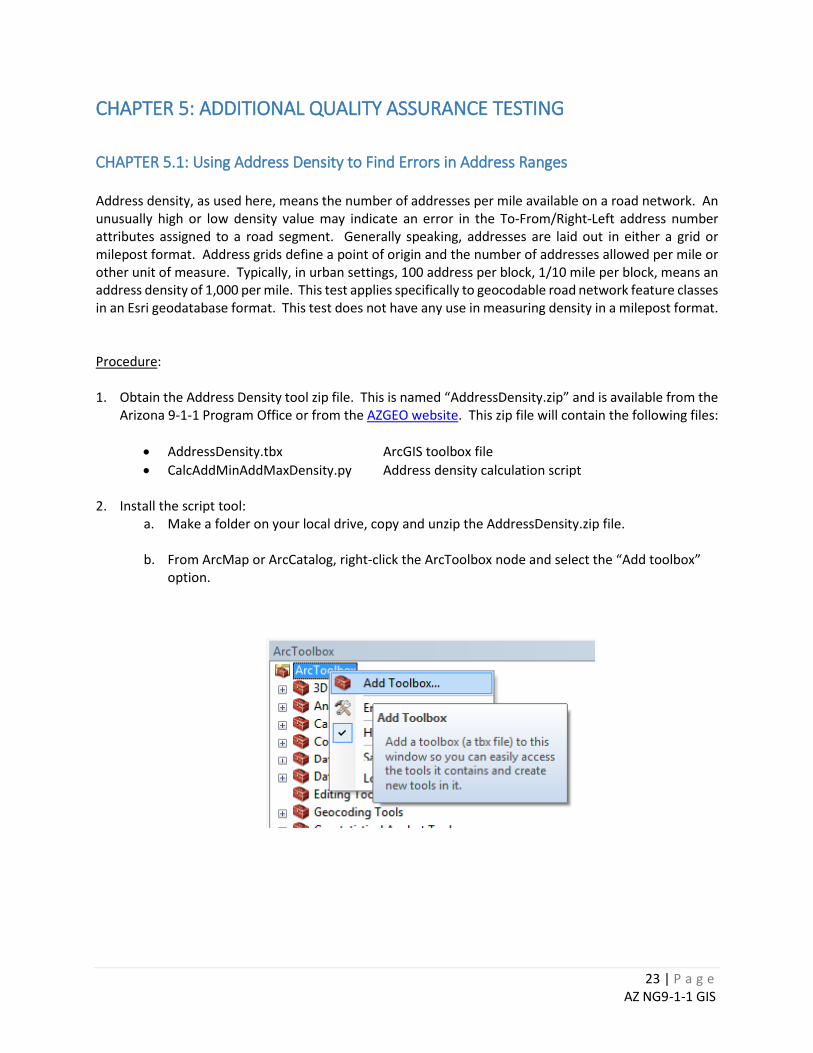
a. Make a folder on your local drive, copy and unzip the AddressDensity.zip file. b. From ArcMap or ArcCatalog, right-click the ArcToolbox node and select the “Add toolbox”
option.
24 | P a g e AZ NG9-1-1 GIS
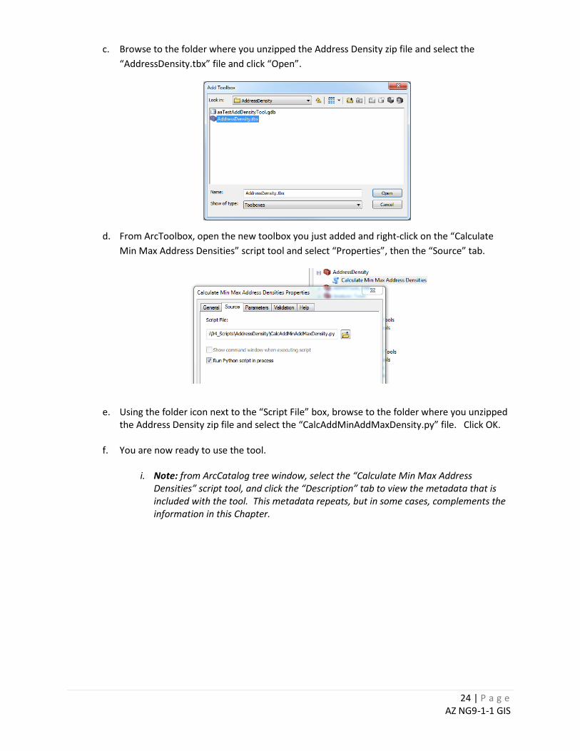
c. Browse to the folder where you unzipped the Address Density zip file and select the “AddressDensity.tbx” file and click “Open”.
d. From ArcToolbox, open the new toolbox you just added and right-click on the “Calculate Min Max Address Densities” script tool and select “Properties”, then the “Source” tab.
e. Using the folder icon next to the “Script File” box, browse to the folder where you unzipped
the Address Density zip file and select the “CalcAddMinAddMaxDensity.py” file. Click OK. f. You are now ready to use the tool.
i. Note: from ArcCatalog tree window, select the “Calculate Min Max Address Densities” script tool, and click the “Description” tab to view the metadata that is included with the tool. This metadata repeats, but in some cases, complements the information in this Chapter.
25 | P a g e AZ NG9-1-1 GIS
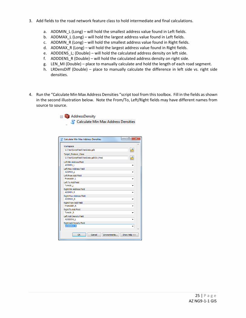
3. Add fields to the road network feature class to hold intermediate and final calculations.
a. ADDMIN_L (Long) – will hold the smallest address value found in Left fields. b. ADDMAX_L (Long) – will hold the largest address value found in Left fields. c. ADDMIN_R (Long) – will hold the smallest address value found in Right fields. d. ADDMAX_R (Long) – will hold the largest address value found in Right fields. e. ADDDENS_L; (Double) – will hold the calculated address density on left side. f. ADDDENS_R (Double) – will hold the calculated address density on right side. g. LEN_MI (Double) – place to manually calculate and hold the length of each road segment. h. LRDensDiff (Double) – place to manually calculate the difference in left side vs. right side
densities.
4. Run the “Calculate Min Max Address Densities “script tool from this toolbox. Fill in the fields as shown in the second illustration below. Note the From/To, Left/Right fields may have different names from source to source.
26 | P a g e AZ NG9-1-1 GIS
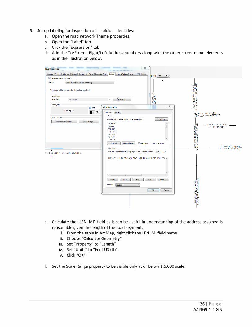
5. Set up labeling for inspection of suspicious densities: a. Open the road network Theme properties. b. Open the “Label” tab. c. Click the “Expression” tab d. Add the To/From – Right/Left Address numbers along with the other street name elements
as in the illustration below.
e. Calculate the “LEN_MI” field as it can be useful in understanding of the address assigned is
reasonable given the length of the road segment. i. From the table in ArcMap, right click the LEN_MI field name
ii. Choose “Calculate Geometry” iii. Set “Property” to “Length” iv. Set “Units” to “Feet US (ft)” v. Click “OK”
f. Set the Scale Range property to be visible only at or below 1:5,000 scale.
27 | P a g e AZ NG9-1-1 GIS
6. Inspect the densest records first.
a. Open the attribute table for the road network. b. Reselect where ADDDENS_L > 2000 OR ADDDENS_R > 2000. c. Make on the selected set visible in the table. d. Right-click on the ADDDENS_L field and select “Sort Descending”. e. Beginning at the top,
i. Select each record and double-click to zoom to the extent of selected arc. ii. Turn on the labels
iii. Check the suspicious segment for things like extra digits, or very small length with full address range.
iv. Bookmark from one to several for discussion at QA Tele-meeting.
f. Look at the LRDensDiff field for road segments where large differences exist between the address density on left and right sides. Even if there are different addressing systems on each side of a road segment, the density difference should be close to zero.
i. From the table in ArcMap, right click the “LRDensDiff” field and choose Sort Descending.
ii. Select each record and double-click to zoom to the extent of selected arc. iii. Turn on the labels iv. Check the suspicious segment for things like extra digits, or very small length with full
address range.
CHAPTER 5.2: Validating Emergency Service Zone Boundaries Overview A key feature of NG9-1-1 systems will be the GIS point-in-polygon operation for a 9-1-1 call/response task to determine the proper routing to a PSAP and/or agency. It is critical that there be no boundary ambiguity inside and among key layers that define 9-1-1 Systems, PSAP boundaries and emergency service boundaries. Gaps and overlaps within and between these various boundaries must be resolved to ensure proper call routing and emergency dispatch. Legal Research The most thorough approach to validation of emergency service boundaries (ESB) is to research the legal documents that define the law, medical and fire service agency boundaries. GIS personnel should be aware that response areas ARE NOT necessarily the legal boundaries of an emergency response agency. The former may be established by verbal or “handshake” agreements, while the latter are the legal boundaries to be validated for proper 9-1-1 system response. A legal description, for the purposes of defining ESB boundaries, can be defined as the legally binding document of the geographical description of an administrative boundary for a fire department, fire district, city or town boundary, or Certificate of Necessity (CON) for ground ambulance service.

28 | P a g e AZ NG9-1-1 GIS
CERTIFICATES OF NECESSITY (CONS)
Legal descriptions for Certificates of Necessity (CONs) are the easiest to obtain, as they are readily available from the Arizona Department of Health Services, Bureau of Emergency Medical Services & Trauma Systems website. http://www.azdhs.gov/preparedness/emergency-medical-services-trauma-system/index.php#ambulance-ground-program-con The website has copies of the legal descriptions defining the CONs as downloadable .pdf files. To locate a CON, in the table of Licensed Ground Ambulance Providers, click on the CON number to bring up the legal description. Individual and regional maps of CONs, along with individual and statewide GIS datasets of the CONs, are also available for download in shapefile or file geodatabase format. It should be noted that these GIS representations of the CON boundaries are approximate, and errors or inaccuracies may exist in the data, particularly with boundaries input into the GIS many years ago. Per ADHS, the goal was to approximate the location of the CON boundary, NOT to accurately map its legal description. Best practice is to reference the legal description directly and check it against any GIS polygon, or recreate the polygon using the legal description and the base dataset layers to which that legal description refers.
NOTE: It is important to note that a CON by definition is a transport model and may not be indicative of a first responder for emergency medical requests for all areas of Arizona. Local fire department and fire districts may provide emergency medical response as a first responder only utilizing a CON when transport is necessary. It is the discretion of the 9-1-1 System Administrator as to whether an emergency medical response boundary be identified by CON, by fire department/district response or by both. It is encouraged that the 9-1-1 System Administrator work with local emergency responders to determine the best emergency medical response boundary.
FIRE DEPARTMENTS AND FIRE DISTRICTS Most, but not all, fire departments have administrative boundaries that are defined by their jurisdictional boundary (i.e. the city or town boundary). Large municipalities generally have current and accurate GIS representations of their administrative boundaries. It may be unnecessary in these cases to research the legal boundary. It may be necessary, however, to re-digitize the boundary to the chosen base registration datasets for your Emergency Service Boundary (ESB), as the city/town may have used different registration datasets to create the boundary. Re-digitizing, or using the Erase function when appending the polygon to an existing ESB dataset, will ensure that there are no gaps or overlaps with adjacent polygons. In smaller or rural communities, this may not be the case. The fire department may not readily know its legal boundary, as they are more aware of their response area. When verifying legal boundaries for small or rural fire departments, contacting the Fire Chief is always a good starting point. He or she may be able to quickly research and locate the documents describing their legal boundary. However, in some cases, the city/town manager may need to be contacted directly. In addition, checking with the Arizona Department of Revenue, Property Tax Division may also be beneficial. Historically, they have archived many legal descriptions for cities, towns, fire departments and fire districts.

29 | P a g e AZ NG9-1-1 GIS
Legal boundaries for fire districts differ from fire departments, as they generally do not follow an existing authoritative jurisdictional boundary. In fact, they may cross city/town boundaries or may not be within the boundaries of a city or town at all. In these cases, the boundary must be obtained directly from the legal description or an existing GIS dataset (obtained from the County or fire district itself). Fire districts often have multiple annexations as an area grows, so it is important to make sure that you have the initial legal description, as well as any documentation for annexations that have occurred since their inception. Fire departments and districts may also contract their services for fire, medical or both outside of their legal response boundary. Contracted services, characterized by a contract and/or other type of legal document, can be included in the ESB as a fire and/or medical response. For data integrity and validation purposes, it is recommended that the ‘contracted’ area be defined by a separate polygon than the legal, authoritative response boundary. A process needs to be defined on how to manage contracted services as the response boundary can change with new contracts, changes in contracts and contract closure.
WHAT TO LOOK FOR IN A LEGAL DESCRIPTION Legal descriptions can vary greatly in complexity, and may or may not be accompanied by a visual representation such as a map. In fact, most written pre-1980 will not have a map of any sort. Legal descriptions can come in many forms:
Public Land Survey System (PLSS) – This is the legal land reference system used by the State of Arizona, and most of Arizona, except for major portions of the Navajo Indian Reservation, were mapped using PLSS. The State is divided into quadrants. Each quadrant is then subdivided into Townships, Ranges and ultimately sections. Common notation for PLSS can be illustrated by T1S, R2E sec. 31 – which identifies Township 1 south, Range 2 East, section 31. For more information, please reference the Arizona State Land Department webpage https://land.az.gov/mapping-services/sco/about-public-land-survey. Metes & Bounds Description – Written by a registered land surveyor, metes refers to a distance and bounds to a direction, from a designated Point of Beginning (POB). An example of metes and bounds description is: “Commencing at the Northwest corner of said Section 21; Thence South 20°30’ East, a distance of 1,120 feet” Geographic/Land Form Features – Many legal descriptions written in the early to mid/late 1900’s used geographical features or land forms to designate boundaries such as rivers, streams, and in Arizona, washes or dry river/stream beds. Roads may also be referenced, particularly State and Federal highways.
Often, particularly in smaller or rural communities, a combination of the PLSS and geographic/landforms will be used to define the legal description. The most important aspect when researching legal descriptions is to make sure you have final, legally binding description, often signed or notarized by a local official. Also, make sure that documents referencing any changes or annexations are included.
30 | P a g e AZ NG9-1-1 GIS
BASE REGISTRATION AND REFERENCE DATASETS – GETTING EVERYONE ON THE SAME PAGE
When obtaining reference datasets from a variety of sources, the dilemma of registration issues and the data not aligning properly is a concern that must be resolved for the data set. Different organizations and entities use different datasets for their base registration layers. Therefore, the polygon of a fire department/district or CON for a particular entity may not align with your existing data. As noted above, there are several ways to handle this discrepancy, all of which leads to the same goal of a seamless ESB dataset, with no gaps or overlaps for the polygons. The AZGEO Clearinghouse, a GIS dataset portal maintained by the Arizona State Land Department, is a great source for basic registration dataset layers such as PLSS, as well as city/town boundary data. https://azgeo.az.gov/azgeo/ It should be noted that all data is accepted as-is, with all errors and inaccuracies. Checking GIS data for timeliness and accuracy is always a good practice.
COMMON COUNTY BOUNDARIES
After legal descriptions, a second prong in the approach to validating ESB’s is to establish clear boundaries among adjacent 9-1-1 systems. In general, Arizona 9-1-1 System boundaries are defined largely by county boundaries. There are exceptions to a 9-1-1 system residing only within a county boundary. Some 9-1-1 systems extend beyond the county boundary due to a city’s participation in a 9-1-1 system outside of their county boundary or due to legacy call routing necessity. In these cases, the county boundary would only be applicable where the 9-1-1 System boundary coincides at the county boundary. If the 9-1-1 System boundary extends beyond the county boundary, care needs to be taken to ensure proper alignment with the authoritative feature defining the 9-1-1 system extent whether that be a city/town boundary, national park, etc. A seamless set of county boundaries is maintained by the Arizona Land Resource Information System program, within the Arizona State Land Department (ASLD). The topological checks described later in this chapter can be used to compare the 9-1-1 System boundaries with the ALRIS county boundaries to identify invalid gaps and overlaps that should be resolved. In some cases, it may be as easy as providing ALRIS with an authoritative (e.g. surveyed) county boundary for integration in the statewide county framework; in other cases, it may require some work with the adjacent counties to define a common boundary. Many of Arizona’s 9-1-1 Systems have coordinated with their adjacent 9-1-1 system(s) as part of the 9-1-1 System boundary efficiency efforts. Agreement between 9-1-1 systems has led to the snapping of their data to the current version of the statewide county boundary in order to ensure proper call routing.
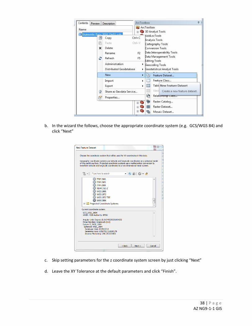
Section 5.2.1: Testing for Coincidence of Systems and County Boundaries8 You can use the topology tools available in ArcMap to find the gaps and overlaps in boundaries. The procedure below describes one way that this can be done. 1. In the working file geodatabase (FGDB), create a new feature data set named “Check”.
a. Right click on the working FGDB, select “New” and then “Feature Dataset”
8 The use of topology tools in ArcGIS requires an advanced license.
31 | P a g e AZ NG9-1-1 GIS
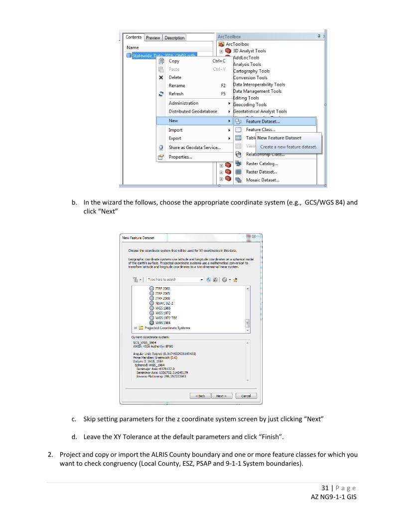
b. In the wizard the follows, choose the appropriate coordinate system (e.g., GCS/WGS 84) and click “Next”
c. Skip setting parameters for the z coordinate system screen by just clicking “Next”
d. Leave the XY Tolerance at the default parameters and click “Finish”.
2. Project and copy or import the ALRIS County boundary and one or more feature classes for which you want to check congruency (Local County, ESZ, PSAP and 9-1-1 System boundaries).
32 | P a g e AZ NG9-1-1 GIS
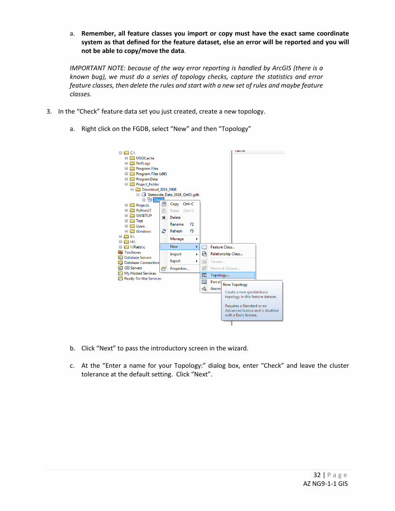
a. Remember, all feature classes you import or copy must have the exact same coordinate system as that defined for the feature dataset, else an error will be reported and you will not be able to copy/move the data.
IMPORTANT NOTE: because of the way error reporting is handled by ArcGIS (there is a known bug), we must do a series of topology checks, capture the statistics and error feature classes, then delete the rules and start with a new set of rules and maybe feature classes.
3. In the “Check” feature data set you just created, create a new topology.
a. Right click on the FGDB, select “New” and then “Topology”
b. Click “Next” to pass the introductory screen in the wizard.
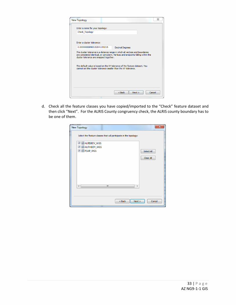
c. At the “Enter a name for your Topology:” dialog box, enter “Check” and leave the cluster tolerance at the default setting. Click “Next”.
33 | P a g e AZ NG9-1-1 GIS
d. Check all the feature classes you have copied/imported to the “Check” feature dataset and then click “Next”. For the ALRIS County congruency check, the ALRIS county boundary has to be one of them.
34 | P a g e AZ NG9-1-1 GIS
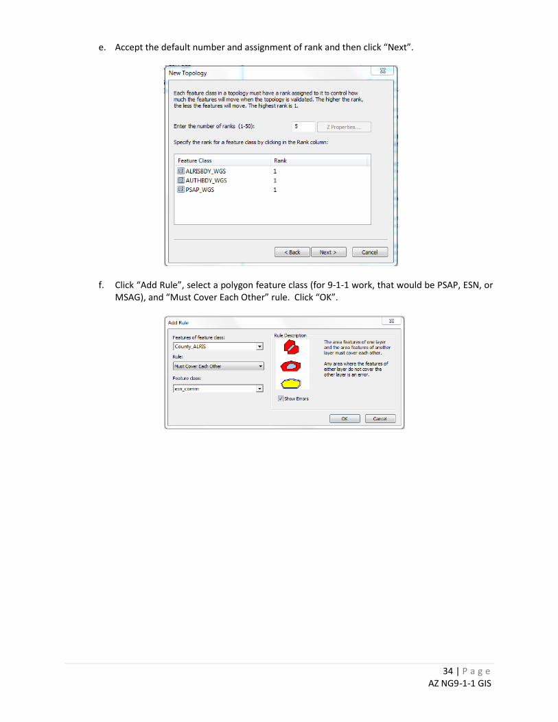
e. Accept the default number and assignment of rank and then click “Next”.
f. Click “Add Rule”, select a polygon feature class (for 9-1-1 work, that would be PSAP, ESN, or MSAG), and “Must Cover Each Other” rule. Click “OK”.
35 | P a g e AZ NG9-1-1 GIS
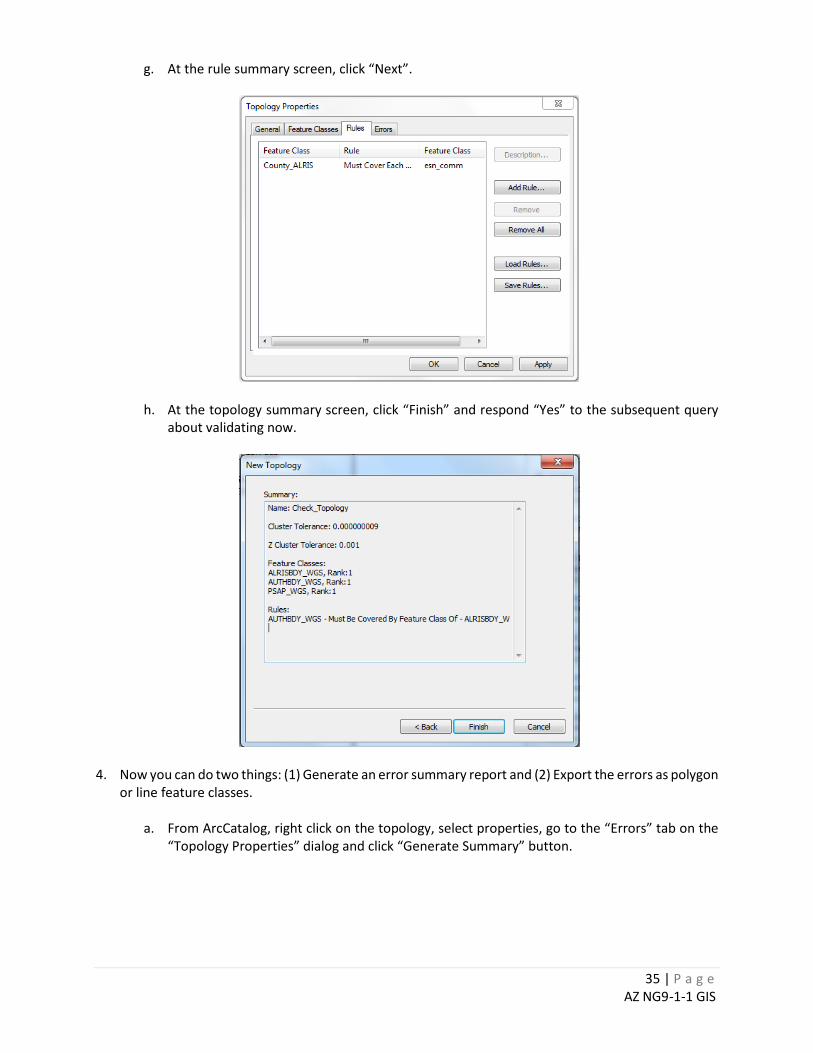
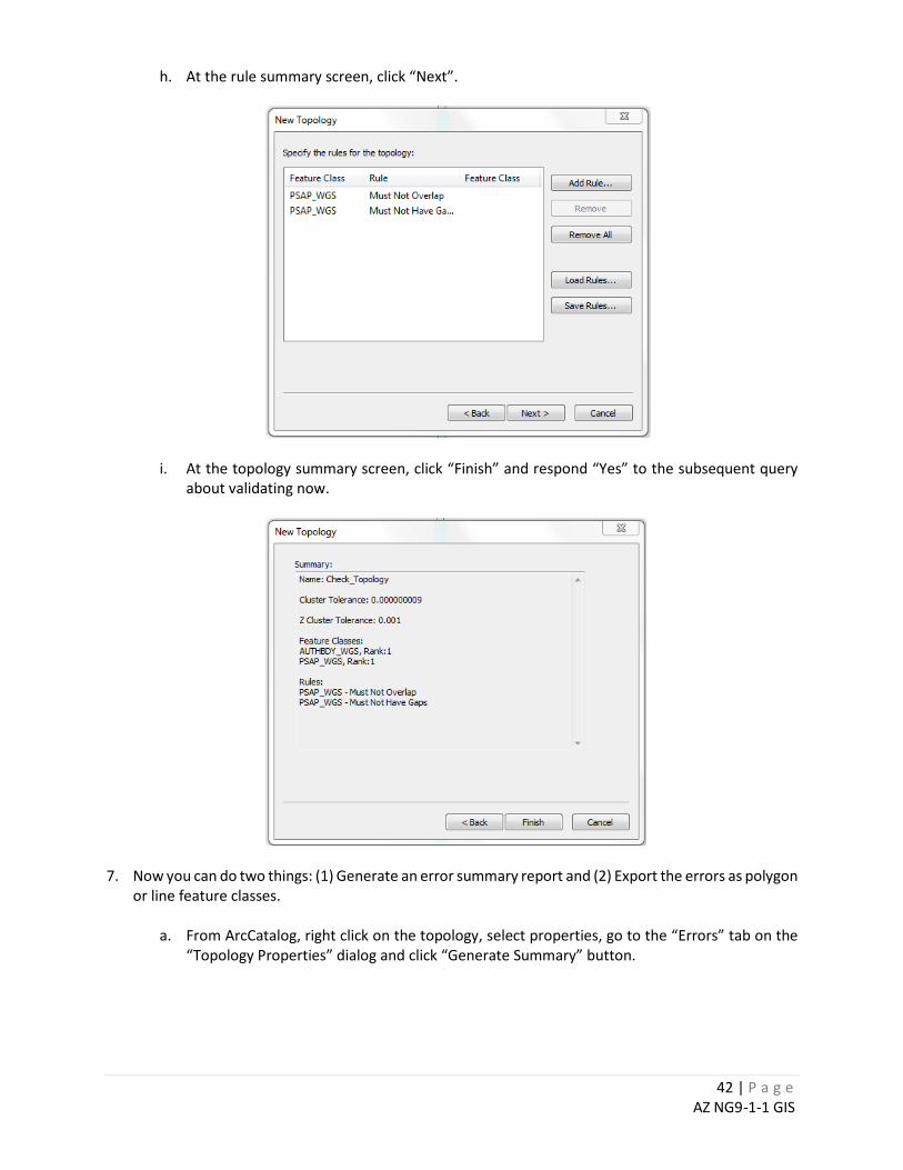
g. At the rule summary screen, click “Next”.
h. At the topology summary screen, click “Finish” and respond “Yes” to the subsequent query about validating now.
4. Now you can do two things: (1) Generate an error summary report and (2) Export the errors as polygon
or line feature classes.
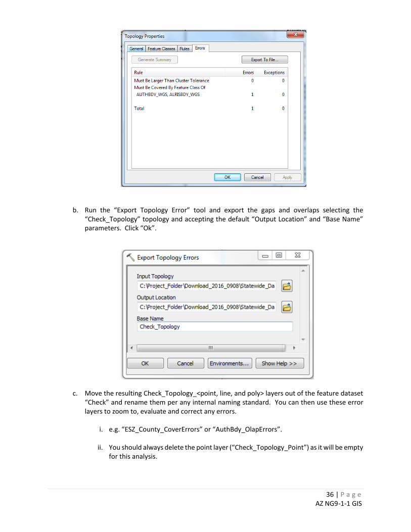
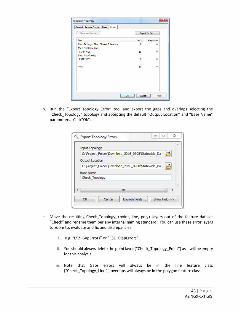
a. From ArcCatalog, right click on the topology, select properties, go to the “Errors” tab on the “Topology Properties” dialog and click “Generate Summary” button.
36 | P a g e AZ NG9-1-1 GIS
b. Run the “Export Topology Error” tool and export the gaps and overlaps selecting the “Check_Topology” topology and accepting the default “Output Location” and “Base Name” parameters. Click “Ok”.
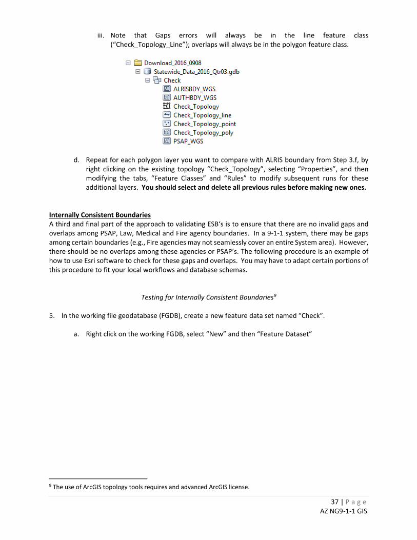
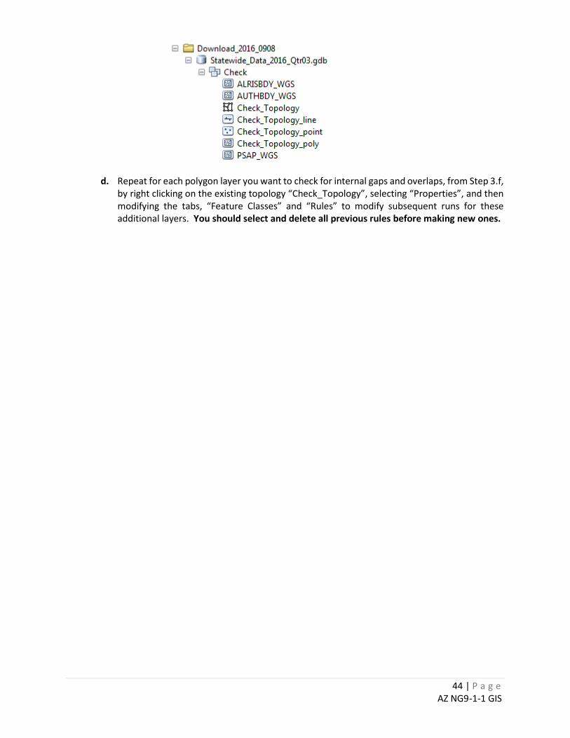
c. Move the resulting Check_Topology_<point, line, and poly> layers out of the feature dataset “Check” and rename them per any internal naming standard. You can then use these error layers to zoom to, evaluate and correct any errors.
i. e.g. “ESZ_County_CoverErrors” or “AuthBdy_OlapErrors”.
ii. You should always delete the point layer (“Check_Topology_Point”) as it will be empty
for this analysis.
37 | P a g e AZ NG9-1-1 GIS
iii. Note that Gaps errors will always be in the line feature class (“Check_Topology_Line”); overlaps will always be in the polygon feature class.
d. Repeat for each polygon layer you want to compare with ALRIS boundary from Step 3.f, by right clicking on the existing topology “Check_Topology”, selecting “Properties”, and then modifying the tabs, “Feature Classes” and “Rules” to modify subsequent runs for these additional layers. You should select and delete all previous rules before making new ones.
Internally Consistent Boundaries A third and final part of the approach to validating ESB‘s is to ensure that there are no invalid gaps and overlaps among PSAP, Law, Medical and Fire agency boundaries. In a 9-1-1 system, there may be gaps among certain boundaries (e.g., Fire agencies may not seamlessly cover an entire System area). However, there should be no overlaps among these agencies or PSAP’s. The following procedure is an example of how to use Esri software to check for these gaps and overlaps. You may have to adapt certain portions of this procedure to fit your local workflows and database schemas.
Testing for Internally Consistent Boundaries9 5. In the working file geodatabase (FGDB), create a new feature data set named “Check”.
a. Right click on the working FGDB, select “New” and then “Feature Dataset”
9 The use of ArcGIS topology tools requires and advanced ArcGIS license.
38 | P a g e AZ NG9-1-1 GIS
b. In the wizard the follows, choose the appropriate coordinate system (e.g. GCS/WGS 84) and click “Next”
c. Skip setting parameters for the z coordinate system screen by just clicking “Next”
d. Leave the XY Tolerance at the default parameters and click “Finish”.
39 | P a g e AZ NG9-1-1 GIS
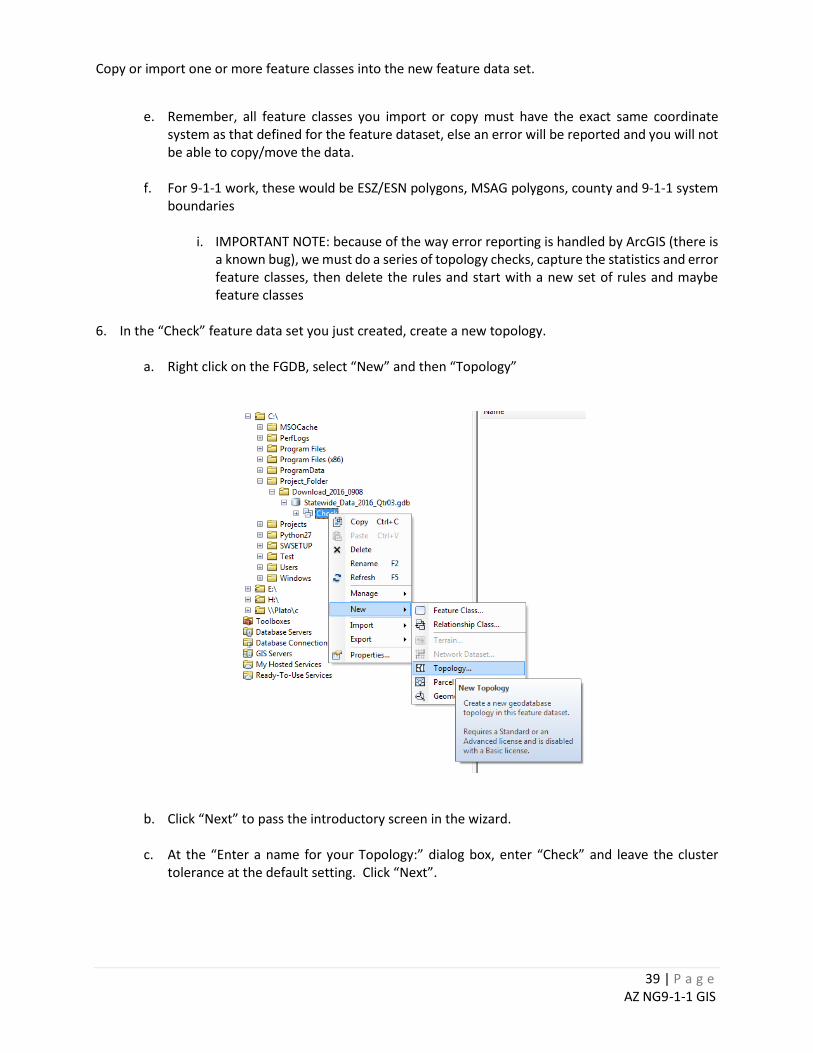
Copy or import one or more feature classes into the new feature data set.
e. Remember, all feature classes you import or copy must have the exact same coordinate
system as that defined for the feature dataset, else an error will be reported and you will not be able to copy/move the data.
f. For 9-1-1 work, these would be ESZ/ESN polygons, MSAG polygons, county and 9-1-1 system
boundaries
i. IMPORTANT NOTE: because of the way error reporting is handled by ArcGIS (there is a known bug), we must do a series of topology checks, capture the statistics and error feature classes, then delete the rules and start with a new set of rules and maybe feature classes
6. In the “Check” feature data set you just created, create a new topology.
a. Right click on the FGDB, select “New” and then “Topology”
b. Click “Next” to pass the introductory screen in the wizard.
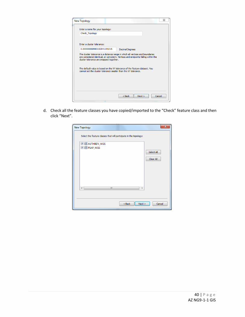
c. At the “Enter a name for your Topology:” dialog box, enter “Check” and leave the cluster tolerance at the default setting. Click “Next”.
40 | P a g e AZ NG9-1-1 GIS
d. Check all the feature classes you have copied/imported to the “Check” feature class and then click “Next”.
41 | P a g e AZ NG9-1-1 GIS
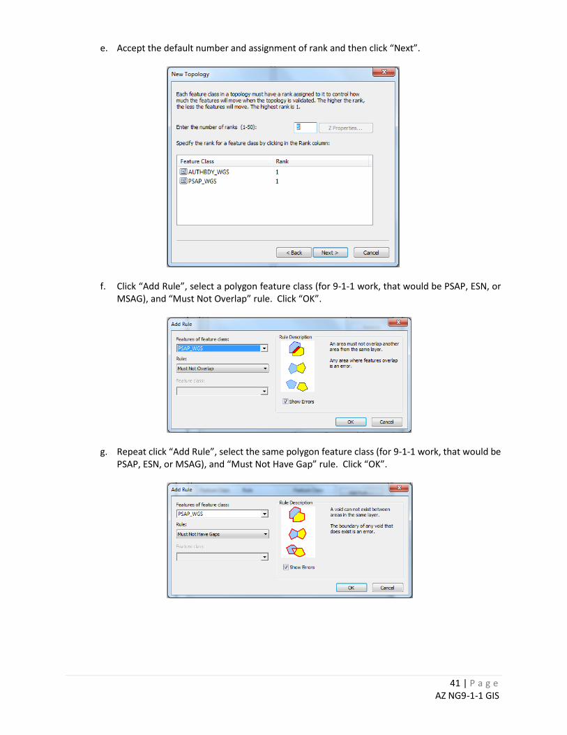
e. Accept the default number and assignment of rank and then click “Next”.
f. Click “Add Rule”, select a polygon feature class (for 9-1-1 work, that would be PSAP, ESN, or MSAG), and “Must Not Overlap” rule. Click “OK”.
g. Repeat click “Add Rule”, select the same polygon feature class (for 9-1-1 work, that would be PSAP, ESN, or MSAG), and “Must Not Have Gap” rule. Click “OK”.
42 | P a g e AZ NG9-1-1 GIS
h. At the rule summary screen, click “Next”.
i. At the topology summary screen, click “Finish” and respond “Yes” to the subsequent query about validating now.
7. Now you can do two things: (1) Generate an error summary report and (2) Export the errors as polygon
or line feature classes.
a. From ArcCatalog, right click on the topology, select properties, go to the “Errors” tab on the “Topology Properties” dialog and click “Generate Summary” button.
43 | P a g e AZ NG9-1-1 GIS
b. Run the “Export Topology Error” tool and export the gaps and overlaps selecting the “Check_Topology” topology and accepting the default “Output Location” and “Base Name” parameters. Click”Ok”.
c. Move the resulting Check_Topology_<point, line, poly> layers out of the feature dataset “Check” and rename them per any internal naming standard. You can use these error layers to zoom to, evaluate and fix and discrepancies.
i. e.g. “ESZ_GapErrors” or “ESZ_OlapErrors”.
ii. You should always delete the point layer (“Check_Topology_Point”) as it will be empty
for this analysis.
iii. Note that Gaps errors will always be in the line feature class (“Check_Topology_Line”); overlaps will always be in the polygon feature class.
44 | P a g e AZ NG9-1-1 GIS
d. Repeat for each polygon layer you want to check for internal gaps and overlaps, from Step 3.f, by right clicking on the existing topology “Check_Topology”, selecting “Properties”, and then modifying the tabs, “Feature Classes” and “Rules” to modify subsequent runs for these additional layers. You should select and delete all previous rules before making new ones.
45 | P a g e AZ NG9-1-1 GIS
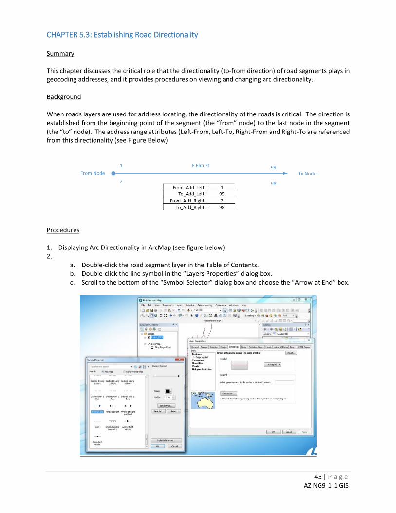
CHAPTER 5.3: Establishing Road Directionality Summary This chapter discusses the critical role that the directionality (to-from direction) of road segments plays in geocoding addresses, and it provides procedures on viewing and changing arc directionality. Background When roads layers are used for address locating, the directionality of the roads is critical. The direction is established from the beginning point of the segment (the “from” node) to the last node in the segment (the “to” node). The address range attributes (Left-From, Left-To, Right-From and Right-To are referenced from this directionality (see Figure Below)
Procedures 1. Displaying Arc Directionality in ArcMap (see figure below) 2.
a. Double-click the road segment layer in the Table of Contents. b. Double-click the line symbol in the “Layers Properties” dialog box. c. Scroll to the bottom of the “Symbol Selector” dialog box and choose the “Arrow at End” box.
46 | P a g e AZ NG9-1-1 GIS
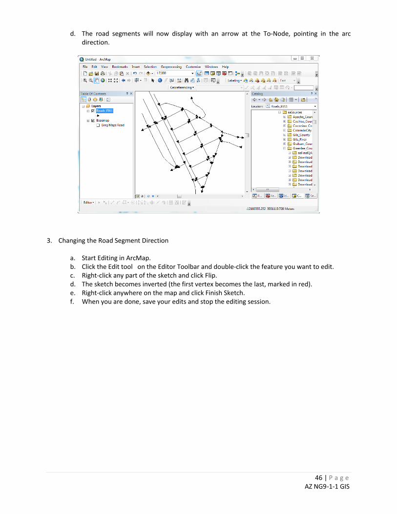
d. The road segments will now display with an arrow at the To-Node, pointing in the arc direction.
3. Changing the Road Segment Direction
a. Start Editing in ArcMap. b. Click the Edit tool on the Editor Toolbar and double-click the feature you want to edit. c. Right-click any part of the sketch and click Flip. d. The sketch becomes inverted (the first vertex becomes the last, marked in red). e. Right-click anywhere on the map and click Finish Sketch. f. When you are done, save your edits and stop the editing session.
47 | P a g e AZ NG9-1-1 GIS
CHAPTER 5.4: Populating the Parity Right and Left Fields Parity is the description of an address range on either the left or right side of a GIS road network as containing, “Odd” or “Even” numbers, or “Mixed” if both exist on that side of the road. Parity_Left and Parity_Right are required NENA NG9-1-1 fields. The NENA specified domain is as follows:
• O=Odd, • E=Even, • B=Both, • Z=Address Range 0-0 or Address Range NULL-NULL.
Parity fields are rarely used or populated by local data providers. Following is a procedure you can use to populate the parity fields. Once populated, you can evaluate the correctness of address ranges (e.g. select and evaluate road segments where PARITY_L or PARITY_R = “B”. 1. Add four fields to Road Network Feature Attribute Table
a. L_From, Text, 5 b. L_To, Text, 5 c. R_From, Text, 5 d. R_To, Text, 5
2. Calculate the parity of the From Address Left Field
a. In field calculator, enter the following expression: i. MOD ( FromAddr_L , 2) = 0 AND FromAddr_L <> 0
b. Calculate L_From = “Even” c. In field calculator, enter the following expression:
i. MOD ( FromAddr_L , 2) <> 0 AND FromAddr_L <> 0 d. Calculate L_From = “Odd” e. In field calculator, enter the following expression:
i. FromAddr_L = 0 OR FromAddr_L IS NULL f. Calculate L_From = “NoVal”
3. Calculate the parity of the To Address Left Field
a. In field calculator, enter the following expression: i. MOD ( ToAddr_L , 2) = 0 AND ToAddr_L <> 0
b. Calculate L_To = “Even” c. In field calculator, enter the following expression:
i. MOD ( ToAddr_L , 2) <> 0 AND ToAddr_L <> 0 d. Calculate L_To = “Odd” e. In field calculator, enter the following expression:
i. ToAddr_L = 0 OR ToAddr_L IS NULL f. Calculate L_To = “NoVal”
4. Calculate the parity of the From Address Right Field
a. In field calculator, enter the following expression: i. MOD ( FromAddr_R , 2) = 0 AND FromAddr_R <> 0
b. Calculate R_From = “Even” c. In field calculator, enter the following expression:
i. MOD ( FromAddr_R , 2) <> 0 AND FromAddr_R <> 0

48 | P a g e AZ NG9-1-1 GIS
d. Calculate R_From = “Odd” e. In field calculator, enter the following expression:
i. FromAddr_R = 0 OR FromAddr_R IS NULL f. Calculate R_From = “NoVal”
5. Calculate the parity of the To Address Right Field
a. In field calculator, enter the following expression: i. MOD ( ToAddr_R , 2) = 0 AND ToAddr_R <> 0
b. Calculate R_To = “Even” c. In field calculator, enter the following expression:
i. MOD ( ToAddr_R , 2) <> 0 AND ToAddr_R <> 0 d. Calculate R_To = “Odd” e. In field calculator, enter the following expression:
i. ToAddr_R = 0 OR ToAddr_R IS NULL f. Calculate R_To = “NoVal”
6. Use multiple field selections on the L-From and L_To fields to calculate Parity_L
a. L_From = 'Even' AND L_To = 'Even' i. Calculate Parity_L = “E”
b. L_From = 'Even' AND L_To = 'NoVal' i. Calculate Parity_L = “E”
c. L_From = 'NoVal' AND L_To = 'Even' i. Calculate Parity_L = “E”
d. L_From = 'Odd' AND L_To = 'Odd' i. Calculate Parity_L = “O”
e. L_From = 'Odd' AND L_To = 'NoVal' i. Calculate Parity_L = “O”
f. L_From = 'NoVal' AND L_To = 'Odd' i. Calculate Parity_L = “O”
g. L_From = 'NoVal' AND L_To = 'NoVal' i. Calculate Parity_L = “Z”
h. L_From = 'Even' AND L_To = 'Odd' i. Calculate Parity_L = “B”
i. L_From = 'Odd' AND L_To = 'Even' i. Calculate Parity_L = “B”
j. Check that every Parity_L value is a B, E, O or Z. 7. Use multiple field selections on the R-From and R_To fields to calculate Parity_R
a. R_From = 'Even' AND R_To = 'Even' i. Calculate Parity_R = “E”
b. R_From = 'Even' AND R_To = 'NoVal' i. Calculate Parity_R = “E”
c. R_From = 'NoVal' AND R_To = 'Even' i. Calculate Parity_R = “E”
d. R_From = 'Odd' AND R_To = 'Odd' i. Calculate Parity_R = “O”
e. R_From = 'Odd' AND R_To = 'NoVal' i. Calculate Parity_R = “O”
f. R_From = 'NoVal' AND R_To = 'Odd' i. Calculate Parity_R = “O”
49 | P a g e AZ NG9-1-1 GIS
g. R_From = 'NoVal' AND R_To = 'NoVal' i. Calculate R_Parity = “Z”
h. R_From = 'Even' AND R_To = 'Odd' i. Calculate Parity_R = “B”
i. R_From = 'Odd' AND R_To = 'Even' i. Calculate Parity_R = “B”
j. Check that every Parity_R value is a B, E, O or Z. CHAPTER 5.5: Checking for Ascending Address Ranges
Ascending addresses here simply means that the “from” addresses on each side of a GIS road segment are equal or smaller than the corresponding “to” addresses on the same side of the road. This is a simple query to find and evaluate potential errors:
1. From Field Calculator: a. Reselect where FromAddr_L > ToAddr_L b. Zoom to each selected feature and evaluate/fix c. Reselect where FromAddr_R > ToAddr_R d. Zoom to each selected feature and evaluate/fix.
Remember, the address ranges can be in proper ascending order, but the road segment direction can still be wrong, inverting the correct placement of address points along the road. See Chapter 5.3 for a discussion on how to evaluate and fix road directionality.
50 | P a g e AZ NG9-1-1 GIS
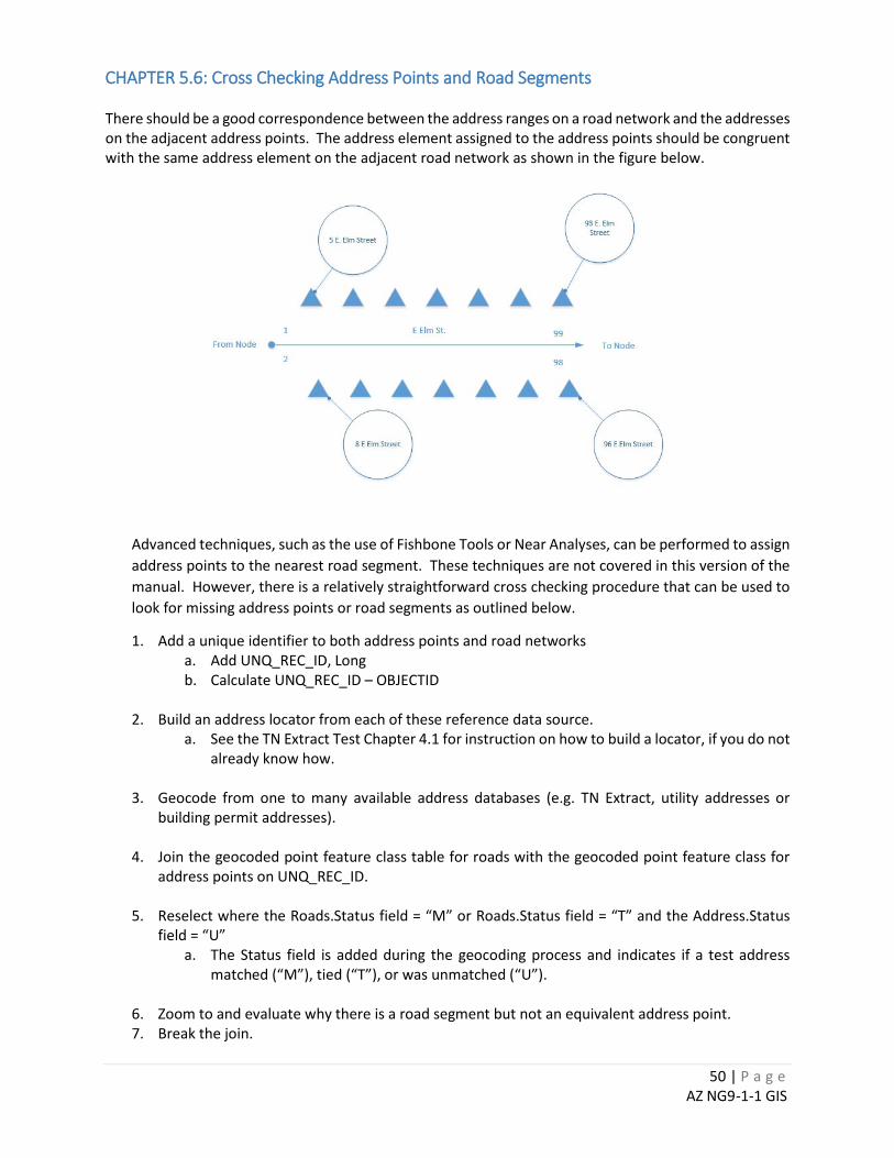
CHAPTER 5.6: Cross Checking Address Points and Road Segments There should be a good correspondence between the address ranges on a road network and the addresses on the adjacent address points. The address element assigned to the address points should be congruent with the same address element on the adjacent road network as shown in the figure below.
Advanced techniques, such as the use of Fishbone Tools or Near Analyses, can be performed to assign address points to the nearest road segment. These techniques are not covered in this version of the manual. However, there is a relatively straightforward cross checking procedure that can be used to look for missing address points or road segments as outlined below.
1. Add a unique identifier to both address points and road networks a. Add UNQ_REC_ID, Long b. Calculate UNQ_REC_ID – OBJECTID
2. Build an address locator from each of these reference data source. a. See the TN Extract Test Chapter 4.1 for instruction on how to build a locator, if you do not
already know how.
3. Geocode from one to many available address databases (e.g. TN Extract, utility addresses or building permit addresses).
4. Join the geocoded point feature class table for roads with the geocoded point feature class for
address points on UNQ_REC_ID.
5. Reselect where the Roads.Status field = “M” or Roads.Status field = “T” and the Address.Status field = “U”
a. The Status field is added during the geocoding process and indicates if a test address matched (“M”), tied (“T”), or was unmatched (“U”).
6. Zoom to and evaluate why there is a road segment but not an equivalent address point. 7. Break the join.

51 | P a g e AZ NG9-1-1 GIS
8. Join the geocoded point feature class table for address points with geocoded point feature class
for roads on UNQ_REC_ID. 9. Reselect where the Address.Status field = “M” or Address.Status field = “T” and the Roads.Status
field = “U”
10. Zoom to and evaluate why there is an address point but not an equivalent road segment.
52 | P a g e AZ NG9-1-1 GIS
CHAPTER 6: DATA CREATION AND MAINTENANCE BEST PRACTICES This chapter provides guidelines applicable to NENA-specified NG9-1-1 GIS data layers. The Guidelines below are organized by NENA-recommended data sets. These data sets are further defined and described in the latest NENA Geographic Data Model available from the Arizona 9-1-1 Program Office or online from NENA at www.nena.org.10
CHAPTER 6.1: Maintaining Unique Identifiers Overview NENA specifies that a unique ID field for all GIS data elements are required in a NG-compliant system. The unique ID field is defined by NENA as the NENA Globally Unique ID (NGUID). This unique ID will help ensure proper provisioning and incremental update of the data in the NG system. For statewide consistency, the Globally Unique ID in Arizona should be comprised of both the unique ID suffixed to a domain name that is indicative of the 9-1-1 authority. Contact the Arizona 9-1-1 Program Office regarding the domain name.
Example: [email protected] Since a 9-1-1 Authority within Arizona can be at any level of government and the responsible agency acting as the 9-1-1 Authority may change over time, it is important to identify the 9-1-1 Authority at a high level in order to prevent widespread data changes when the responsible agency changes. Following are suggested domain names for each of the 17 current 9-1-1 systems in Arizona.
Cochise911.az.gov Greenlee911.az.gov Pima911.az.gov
Coconino911.az.gov LaPaz911.az.gov Pinal911.az.gov
ColoradoCity911.az.gov MaricopaRegion911.az.gov SantaCruz911.az.gov
Gila911.az.gov Mohave911.az.gov Yavapai911.az.gov
GilaRiver911.az.gov NAUA911.az.gov Yuma911.az.gov
Graham911.az.gov
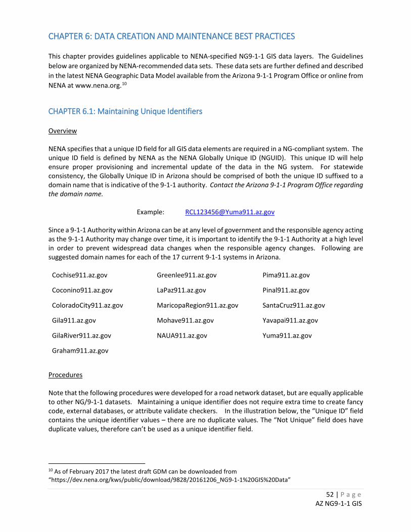
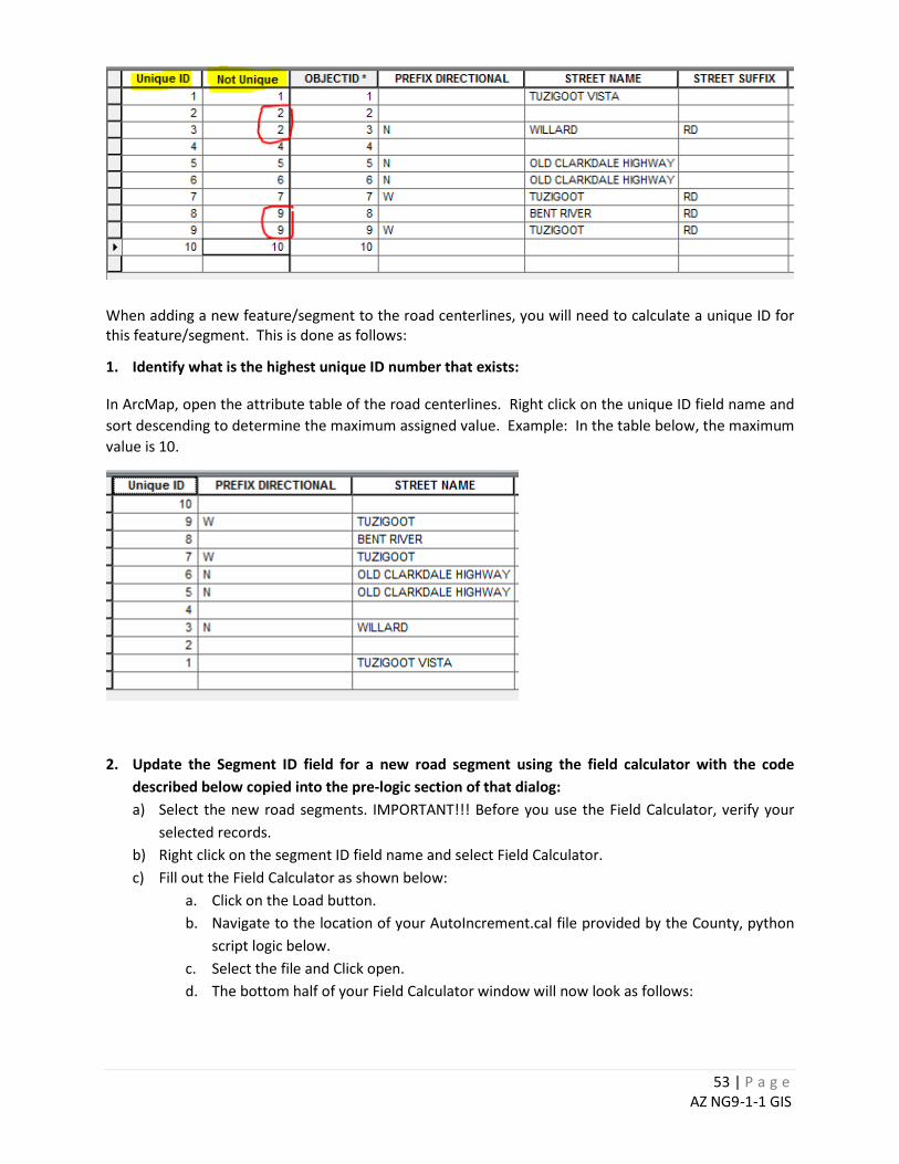
Procedures Note that the following procedures were developed for a road network dataset, but are equally applicable to other NG/9-1-1 datasets. Maintaining a unique identifier does not require extra time to create fancy code, external databases, or attribute validate checkers. In the illustration below, the “Unique ID” field contains the unique identifier values – there are no duplicate values. The “Not Unique” field does have duplicate values, therefore can’t be used as a unique identifier field.
10 As of February 2017 the latest draft GDM can be downloaded from “https://dev.nena.org/kws/public/download/9828/20161206_NG9-1-1%20GIS%20Data”
53 | P a g e AZ NG9-1-1 GIS
When adding a new feature/segment to the road centerlines, you will need to calculate a unique ID for this feature/segment. This is done as follows:
1. Identify what is the highest unique ID number that exists:
In ArcMap, open the attribute table of the road centerlines. Right click on the unique ID field name and sort descending to determine the maximum assigned value. Example: In the table below, the maximum value is 10.
2. Update the Segment ID field for a new road segment using the field calculator with the code
described below copied into the pre-logic section of that dialog: a) Select the new road segments. IMPORTANT!!! Before you use the Field Calculator, verify your
selected records. b) Right click on the segment ID field name and select Field Calculator. c) Fill out the Field Calculator as shown below:
a. Click on the Load button. b. Navigate to the location of your AutoIncrement.cal file provided by the County, python
script logic below. c. Select the file and Click open. d. The bottom half of your Field Calculator window will now look as follows:
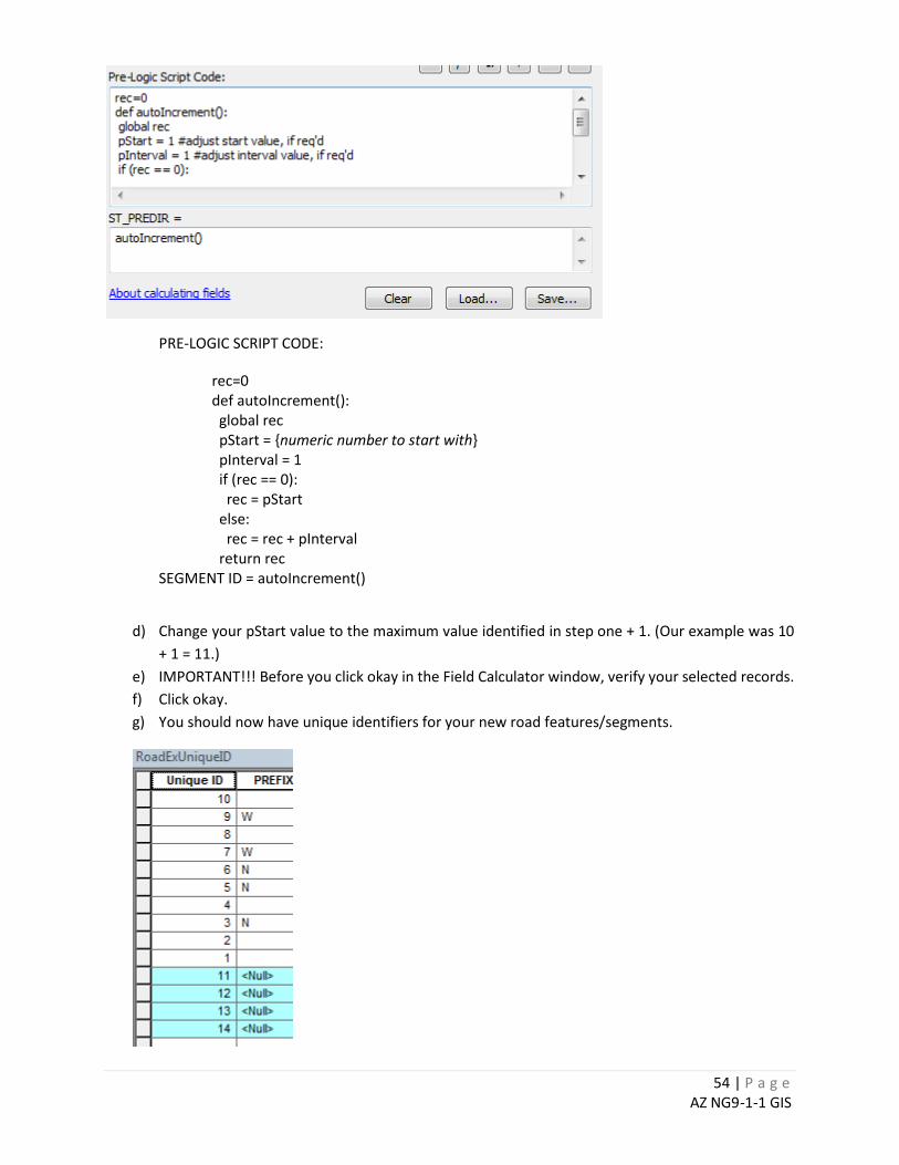
54 | P a g e AZ NG9-1-1 GIS
PRE-LOGIC SCRIPT CODE:
rec=0 def autoIncrement(): global rec pStart = {numeric number to start with} pInterval = 1 if (rec == 0): rec = pStart else: rec = rec + pInterval return rec
SEGMENT ID = autoIncrement()
d) Change your pStart value to the maximum value identified in step one + 1. (Our example was 10 + 1 = 11.)
e) IMPORTANT!!! Before you click okay in the Field Calculator window, verify your selected records. f) Click okay. g) You should now have unique identifiers for your new road features/segments.
55 | P a g e AZ NG9-1-1 GIS
3. Check Segment ID field for duplicate values: This should be done every time you send data to the County/State and also after every editing session. Duplicate Values from Split road segments.
a) Whenever a road segment is split, both segments will inherit the unique ID from the original segment. This creates unwanted duplicate id values.
To identify if there are duplicate values: b) In ArcMap, open the attribute table, right click on the unique ID field and select ‘Summarize’ in
the right click menu. Ignore Step 2 – Summary Statistics in the Summarize window. Specify your output table in step 3. (I.E. C:\Temp\SumRoadCenterlineSegmentID.dbf). Click OK in the Summarize dialog box and wait for the summary to complete. You can choose to add the output to ArcMap for viewing or you can view the resulting Summarize table in ArcCatalog.
c) Open the Resulting Summarize table, right-click on the count field name and sort in descending order. Any row that has a count value of more than one has any duplicate unique ID values.
4. To clean up duplicate values: Note: It is probable that jurisdiction will have identical segment ID. When the County/State receives data from jurisdictions, they will deal with this issue by adding a preset number to the jurisdictional value. For example, Unique ID 1 from Prescott will become 100,001 Unique ID 1 from Prescott Valley will become 200,001, etc… This will allow the County to maintain their own unique identifier for each record when combining data. If you find a duplicate segment ID in your data, go ahead and recalculate for the duplicate records with a new value. It may change a segment ID that the County/State might already have in its database but at this point it will not matter.
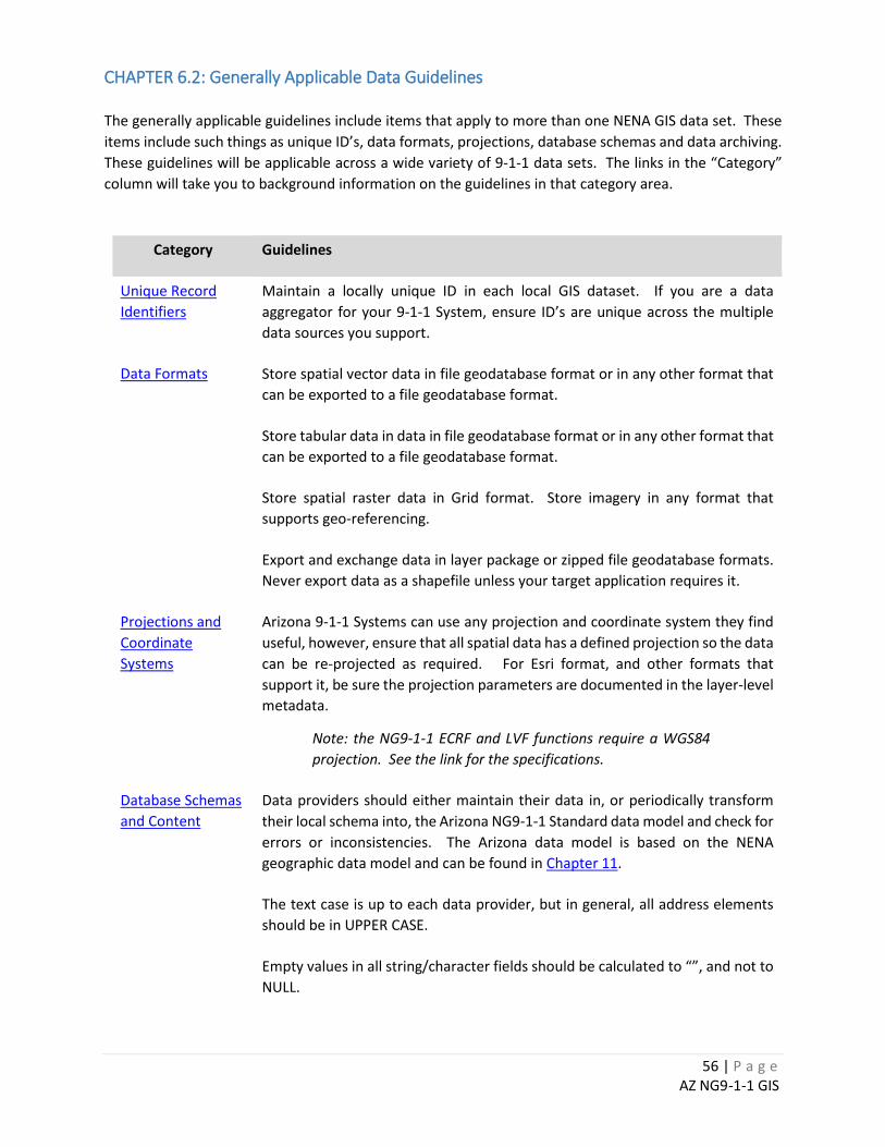
56 | P a g e AZ NG9-1-1 GIS
CHAPTER 6.2: Generally Applicable Data Guidelines The generally applicable guidelines include items that apply to more than one NENA GIS data set. These items include such things as unique ID’s, data formats, projections, database schemas and data archiving. These guidelines will be applicable across a wide variety of 9-1-1 data sets. The links in the “Category” column will take you to background information on the guidelines in that category area.
Category Guidelines
Unique Record Identifiers
Maintain a locally unique ID in each local GIS dataset. If you are a data aggregator for your 9-1-1 System, ensure ID’s are unique across the multiple data sources you support.
Data Formats Store spatial vector data in file geodatabase format or in any other format that can be exported to a file geodatabase format.
Store tabular data in data in file geodatabase format or in any other format that can be exported to a file geodatabase format.
Store spatial raster data in Grid format. Store imagery in any format that supports geo-referencing.
Export and exchange data in layer package or zipped file geodatabase formats. Never export data as a shapefile unless your target application requires it.
Projections and Coordinate Systems
Arizona 9-1-1 Systems can use any projection and coordinate system they find useful, however, ensure that all spatial data has a defined projection so the data can be re-projected as required. For Esri format, and other formats that support it, be sure the projection parameters are documented in the layer-level metadata.
Note: the NG9-1-1 ECRF and LVF functions require a WGS84 projection. See the link for the specifications.
Database Schemas and Content
Data providers should either maintain their data in, or periodically transform their local schema into, the Arizona NG9-1-1 Standard data model and check for errors or inconsistencies. The Arizona data model is based on the NENA geographic data model and can be found in Chapter 11.
The text case is up to each data provider, but in general, all address elements should be in UPPER CASE.
Empty values in all string/character fields should be calculated to “”, and not to NULL.
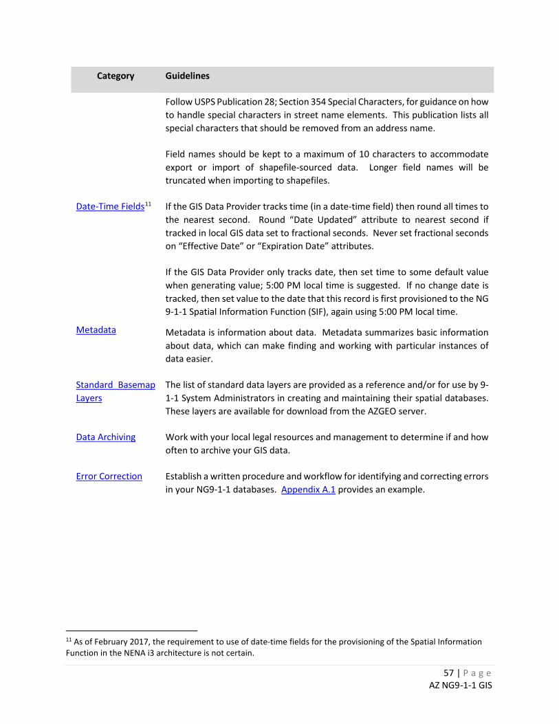
57 | P a g e AZ NG9-1-1 GIS
Category Guidelines
Follow USPS Publication 28; Section 354 Special Characters, for guidance on how to handle special characters in street name elements. This publication lists all special characters that should be removed from an address name.
Field names should be kept to a maximum of 10 characters to accommodate export or import of shapefile-sourced data. Longer field names will be truncated when importing to shapefiles.
Date-Time Fields11
Metadata
If the GIS Data Provider tracks time (in a date-time field) then round all times to the nearest second. Round “Date Updated” attribute to nearest second if tracked in local GIS data set to fractional seconds. Never set fractional seconds on “Effective Date” or “Expiration Date” attributes.
If the GIS Data Provider only tracks date, then set time to some default value when generating value; 5:00 PM local time is suggested. If no change date is tracked, then set value to the date that this record is first provisioned to the NG 9-1-1 Spatial Information Function (SIF), again using 5:00 PM local time.
Metadata is information about data. Metadata summarizes basic information about data, which can make finding and working with particular instances of data easier.
Standard Basemap Layers
The list of standard data layers are provided as a reference and/or for use by 9-1-1 System Administrators in creating and maintaining their spatial databases. These layers are available for download from the AZGEO server.
Data Archiving Work with your local legal resources and management to determine if and how often to archive your GIS data.
Error Correction Establish a written procedure and workflow for identifying and correcting errors in your NG9-1-1 databases. Appendix A.1 provides an example.
11 As of February 2017, the requirement to use of date-time fields for the provisioning of the Spatial Information Function in the NENA i3 architecture is not certain.
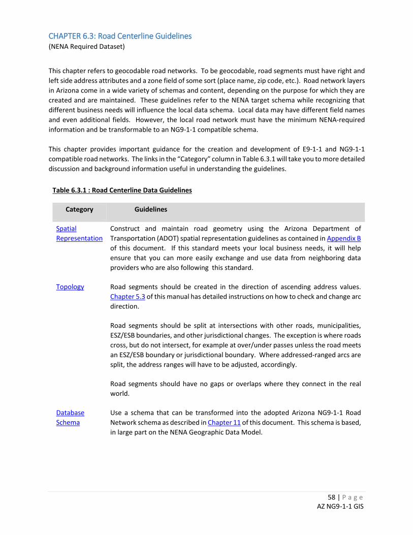
58 | P a g e AZ NG9-1-1 GIS
CHAPTER 6.3: Road Centerline Guidelines (NENA Required Dataset)
This chapter refers to geocodable road networks. To be geocodable, road segments must have right and left side address attributes and a zone field of some sort (place name, zip code, etc.). Road network layers in Arizona come in a wide variety of schemas and content, depending on the purpose for which they are created and are maintained. These guidelines refer to the NENA target schema while recognizing that different business needs will influence the local data schema. Local data may have different field names and even additional fields. However, the local road network must have the minimum NENA-required information and be transformable to an NG9-1-1 compatible schema. This chapter provides important guidance for the creation and development of E9-1-1 and NG9-1-1 compatible road networks. The links in the “Category” column in Table 6.3.1 will take you to more detailed discussion and background information useful in understanding the guidelines.
Table 6.3.1 : Road Centerline Data Guidelines
Category Guidelines
Spatial Representation
Construct and maintain road geometry using the Arizona Department of Transportation (ADOT) spatial representation guidelines as contained in Appendix B of this document. If this standard meets your local business needs, it will help ensure that you can more easily exchange and use data from neighboring data providers who are also following this standard.
Topology Road segments should be created in the direction of ascending address values. Chapter 5.3 of this manual has detailed instructions on how to check and change arc direction.
Road segments should be split at intersections with other roads, municipalities, ESZ/ESB boundaries, and other jurisdictional changes. The exception is where roads cross, but do not intersect, for example at over/under passes unless the road meets an ESZ/ESB boundary or jurisdictional boundary. Where addressed-ranged arcs are split, the address ranges will have to be adjusted, accordingly.
Road segments should have no gaps or overlaps where they connect in the real world.
Database Schema
Use a schema that can be transformed into the adopted Arizona NG9-1-1 Road Network schema as described in Chapter 11 of this document. This schema is based, in large part on the NENA Geographic Data Model.
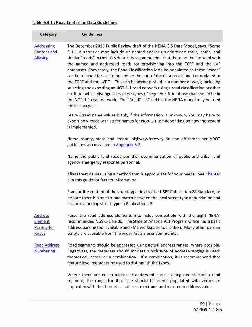
59 | P a g e AZ NG9-1-1 GIS
Table 6.3.1 : Road Centerline Data Guidelines
Category Guidelines
Addressing Content and Aliasing
The December 2016 Public Review draft of the NENA GIS Data Model, says, “Some 9-1-1 Authorities may include un-named and/or un-addressed trails, paths, and similar “roads” in their GIS data. It is recommended that these not be included with the named and addressed roads for provisioning into the ECRF and the LVF databases. Conversely, the Road Classification MAY be populated so these “roads” can be selected for exclusion and not be part of the data provisioned or updated to the ECRF and the LVF.” This can be accomplished in a number of ways; including selecting and exporting an NG9-1-1 road network using a road classification or other attribute which distinguishes these types of segments from those that should be in the NG9-1-1 road network. The “RoadClass” field in the NENA model may be used for this purpose.
Leave Street name values blank, if the information is unknown. You may have to export only roads with street names for NG9-1-1 use depending on how the system is implemented.
Name county, state and federal highway/freeway on and off-ramps per ADOT guidelines as contained in Appendix B.2.
Name the public land roads per the recommendation of public and tribal land agency emergency response personnel.
Alias street names using a method that is appropriate for your needs. See Chapter 8 in this guide for further information.
Standardize content of the street type field to the USPS Publication 28 Standard, or be sure there is a one-to-one match between the local street type abbreviation and its corresponding street type in Publication 28.
Address Element Parsing for Roads
Parse the road address elements into fields compatible with the eight NENA-recommended NG9-1-1 fields. The State of Arizona 911 Program Office has a basic address parsing tool available and FME workspace application. Many other parsing scripts are available from the wider ArcGIS user community.
Road Address Numbering
Road segments should be addressed using actual address ranges, where possible. Regardless, the metadata should indicate which type of address-ranging is used: theoretical, actual or a combination. If a combination, it is recommended that feature level metadata be used to distinguish the types.
Where there are no structures or addressed parcels along one side of a road segment, the range for that side should be either populated with zeroes or populated with the theoretical address minimum and maximum address value.
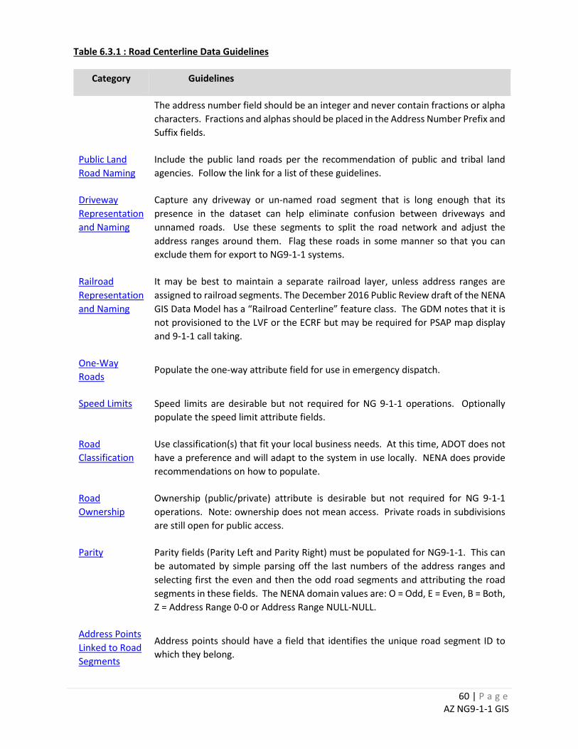
60 | P a g e AZ NG9-1-1 GIS
Table 6.3.1 : Road Centerline Data Guidelines
Category Guidelines
The address number field should be an integer and never contain fractions or alpha characters. Fractions and alphas should be placed in the Address Number Prefix and Suffix fields.
Public Land Road Naming
Include the public land roads per the recommendation of public and tribal land agencies. Follow the link for a list of these guidelines.
Driveway Representation and Naming
Capture any driveway or un-named road segment that is long enough that its presence in the dataset can help eliminate confusion between driveways and unnamed roads. Use these segments to split the road network and adjust the address ranges around them. Flag these roads in some manner so that you can exclude them for export to NG9-1-1 systems.
Railroad Representation and Naming
It may be best to maintain a separate railroad layer, unless address ranges are assigned to railroad segments. The December 2016 Public Review draft of the NENA GIS Data Model has a “Railroad Centerline” feature class. The GDM notes that it is not provisioned to the LVF or the ECRF but may be required for PSAP map display and 9-1-1 call taking.
One-Way Roads
Populate the one-way attribute field for use in emergency dispatch.
Speed Limits Speed limits are desirable but not required for NG 9-1-1 operations. Optionally populate the speed limit attribute fields.
Road Classification
Use classification(s) that fit your local business needs. At this time, ADOT does not have a preference and will adapt to the system in use locally. NENA does provide recommendations on how to populate.
Road Ownership
Ownership (public/private) attribute is desirable but not required for NG 9-1-1 operations. Note: ownership does not mean access. Private roads in subdivisions are still open for public access.
Parity Parity fields (Parity Left and Parity Right) must be populated for NG9-1-1. This can be automated by simple parsing off the last numbers of the address ranges and selecting first the even and then the odd road segments and attributing the road segments in these fields. The NENA domain values are: O = Odd, E = Even, B = Both, Z = Address Range 0-0 or Address Range NULL-NULL.
Address Points Linked to Road Segments
Address points should have a field that identifies the unique road segment ID to which they belong.

61 | P a g e AZ NG9-1-1 GIS
62 | P a g e AZ NG9-1-1 GIS
CHAPTER 6.4 Emergency Service Boundary (ESB) Guidelines (NENA Required Dataset)
The NENA NG9-1-1 Emergency Service Boundary (ESB) layers include the PSAP Boundary and Emergency Services Boundaries for Police, Fire, EMS, and others. Per the December 2016 Public Review draft NENA NG9-1-1 GIS Data Model, the PSAP boundary and Emergency Service Boundaries are required for NG9-1-1. The ESB layer is a template for the creation of all emergency service boundaries. While the PSAP, Law, Fire and EMS boundaries are required, this template can also be used for other types of emergency service boundaries such as for Poison Control and Forest Service. During the development of this part of the standard, NENA document creators have stated at various times that the emergency service boundaries can be maintained separately or within one data layer. The December 2016 Public Review draft of the NENA NG9-1-1 GIS Data Model says that there must be a separate ESB for law, fire and EMS. Whether the ESB layers have to be separate will be determined when the NENA NG9-1-1 GIS Data Model standard is finalized and contingent on actual deployment requirements. The links in the “Category” column in Table 6.4.1 will take you to more detailed discussion and background information useful in understanding the guidelines.
Table 6.4.1 Emergency Service Boundaries (ESB)
Category Guidelines
Thematic Consistency
It may be helpful from a coincident line work perspective to maintain all ESB layers as a single ESZ layer with the individual PSAP, LAW, MED and FIRE layers dissolved from the single layer.
Agency Names Agency names (e.g. law, medical and fire) should be spelled out. It is acceptable to abbreviate police and fire departments as PD and FD.
Topology The PSAP and Law layers should be seamless across each 9-1-1 Authority and across the State and should not have gaps or overlaps.
Medical and Fire boundaries may have gaps and overlaps.
Source Data Where possible, the boundaries of ESB layers should be constructed from information contained in the legal recorded documents for each agency’s boundaries.
63 | P a g e AZ NG9-1-1 GIS
CHAPTER 6.5: PSAP Boundary Guidelines (NENA Required Dataset)
This layer depicts the polygon(s) and related attribute information that defines the geographic area of all Public Safety Answering Point (PSAP) boundaries within a given 9-1-1 Authority’s geographic coverage area. The PSAP Boundary layer may have one or many PSAP Boundaries contained in the layer. Each PSAP Boundary defines the geographic area of a PSAP that has primary responsibilities for answering a 9-1-1 call.
6.5.1 PSAP Boundary (ESB)
Category Guidelines
Topology Adjoining 9-1-1 Systems should cooperate to define a common shared boundary.
Overlaps among PSAP’s in adjacent 9-1-1 Systems should not occur, and where they do, one System should be noted as the primary for both call routing and as the data authority.
64 | P a g e AZ NG9-1-1 GIS
CHAPTER 6.6: Road Name Alias Table Guidelines (NENA Strongly Recommended Dataset)
The Road Name Alias table contains alternate street names that are associated with the legal street 9-1-1 name contained in the Road Centerline layer. Alias street names are common and must be considered for incorporation. Examples include when a state route or state highway crosses into a city jurisdiction, when several streets “merge” to traverse the same road segment, or when honorary names are given to previously named and addressed roads. Many 9-1-1 Authorities will need to accommodate for alias street names during call taking and data sharing. Chapter 8 contains detailed information about how to establish alias tables. Below is some additional information.
6.6.1 Road Name Alias Table
Category Guidelines
Data Content Develop a standardized method of maintaining road name aliases.
Maintain aliases in a form that is compatible with at least export to a NG9-1-1 system.
The recorded legal road name as assigned by the local addressing authority should be the name used in the Road Centerlines data layer. However, many roads are known by more than the ‘legal’ road name, and these are known as alias road names.
65 | P a g e AZ NG9-1-1 GIS
CHAPTER 6.7: Site / Structure Address Point Guidelines (NENA Strongly Recommended Dataset)
Site/Structure address points are point features representing parcel centroids, structures on those properties, or access points to a property or structure. Sometimes all three types of points are contained in a single database. Address points have some inherent advantages over road networks for locating callers. Address points can more accurately represent the location of an emergency on a property. They can more easily handle mixed-parity situations (where both even and odd addresses can be found on the same side of the street) and can more accurately define emergency response. More information on parity can be found in Chapter 5.4 of this guide.
6.7.1 Site/Structure Address Points
Category Guideline
Spatial Representation
Maintain only one point representation for an address (e.g. parcel centroid, structure, access) or use the NENA optional field, “Placement” to document the placement method.
From the NENA documented domain:
Geocoding, Parcel, Property Access, Structure, Site, Unknown are defined and can be extended as documented in the “Placement Method” NENA Registry in Section 6.1 below. 12
Only export one of the NENA types for each address to NG9-1-1.
Add and maintain a unique road ID attribute that associates each address point to the 9-1-1 road segment ID to which it belongs.
Sub-Addressing Sub-addresses are desirable but not required for NG9-1-1. Where information exists and resources are available to maintain them, sub-addressing can allow more precise call routing and emergency dispatch.
12 For details, see Chapter 4.5 in the December 2016 Public Review draft of the NENA GIS Data Model.
66 | P a g e AZ NG9-1-1 GIS
CHAPTER 6.8: States or Equivalent Guidelines (NENA Strongly Recommended Dataset)
A state, or its equivalent, is a primary governmental division of the United States. Within Canada, the equivalents are the provinces and territories.
6.8.1 States or Equivalents
Category Guidelines
Source Use the State of Arizona boundary from the Arizona Land Department (ASLD) to define your State boundary. This boundary may be found after logging on the AZGEO and going to “https://azgeo.az.gov/azgeo/datasets/arizona-state-boundary”
If you have a local version that differs and you feel it is more spatially accurate, then please contact ASLD.
67 | P a g e AZ NG9-1-1 GIS
CHAPTER 6.9: Counties or Equivalents (Strongly Recommended)
A county or its equivalent boundary is the primary legal division of a state, province, or territory.
6.9.1 Counties or Equivalents
Category Guidelines
Source
Use the State of Arizona county boundary from the Arizona Land Department (ASLD) to define your State boundary. This boundary may be found after logging on the AZGEO and going to “https://azgeo.az.gov/azgeo/datasets/county-boundaries”
If you have a local version that differs and you feel it is more spatially accurate, then please contact ASLD.
68 | P a g e AZ NG9-1-1 GIS
CHAPTER 6.10: Incorporated Municipal Boundary Guidelines (NENA Strongly Recommended Dataset)
Incorporated Municipal boundaries are defined as the boundary of a city, town, village, borough, or similar entity that has local governmental powers and may be useful in determining jurisdictional authority for addressing and emergency response.
6.10.1 Incorporated Municipal Boundary
Category Guidelines
Source
Use the best available local source for boundaries of incorporated towns and cities.
If your boundaries differ from those available from the State Land Department, please contact ASLD to provide them with updates. The ASLD version can be found by logging on to AZGEO and going to, “https://azgeo.az.gov/azgeo/datasets/city-boundaries”.
69 | P a g e AZ NG9-1-1 GIS
CHAPTER 6.11: Unincorporated Community Boundary Guidelines (NENA Recommended Dataset)
Unincorporated boundaries may be locally recognized places, but not legally incorporated. Often Census CDB boundaries reflect such places.
6.11.1 Unincorporated Community Boundary
Category Guidelines
Content
Wikipedia may be a useful research when categorizing place names that fall into the Unincorporated Community Boundary category. Wikipedia often identifies a place name as an unincorporated community, a Census Designated Place, or a Census Place. These places are good candidates for “Unincorporated Community Boundary”. The State 9-1-1 Office may have a current table of these place names for your use on AZGEO. Before use, it is recommended that the table be reviewed for accuracy. It is not maintained with any consistent frequency.
70 | P a g e AZ NG9-1-1 GIS
CHAPTER 6.12: Neighborhood Boundary Guidelines (NENA Strongly Recommended Dataset)
The NENA Neighborhood Community Boundary allows for the definition of multiple “community” identifications such as municipal, unincorporated and neighborhood or subdivision. This allows the GIS practitioner to define further an address without restriction. In Arizona, the use of neighborhood information is very limited; therefore, this type of boundary file may not be necessary or useful. Per the December 2016 draft of the NENA GIS Data Model, this dataset is the “boundary of a neighborhood, a subdivision, or commercial area. The most intuitive way to refer to a place is often by the neighborhood name. Locations of similar sounding street names may be resolved when the neighborhood name is known. This layer is often beneficial to telecommunicators.”13 These boundaries may be defined by Homeowner or Neighborhood associations and may include unincorporated area boundaries or other areas that may or may not conform to U.S. Postal Service communities. Each community will have to decide if this NENA-defined layer makes sense for their local data model. At this time, it appears that no Arizona 9-1-1 Systems are using this feature class.
6.12.1 Neighborhood Community Boundary
Category Guidelines
Content The NENA Neighborhood Community Boundary allows for the definition of multiple “community” identifications such as municipal, unincorporated and neighborhood or subdivision. This allows the GIS practitioner to define further an address without restriction.
The creation of boundaries is not limited to emergency response, therefore, before creating a boundary you should inquire with the 9-1-1 Administrator, local Addressing Authority or other responsible divisions or departments.
Topology Neighborhoods should not overlap. Legitimate gaps are permissive.
When utilizing this boundary, care needs to be taken to ensure that there is consistency between this boundary file and any other boundary file(s).
13 The December 2016 Public Review draft of the NENA GIS Data Model.

71 | P a g e AZ NG9-1-1 GIS
72 | P a g e AZ NG9-1-1 GIS
CHAPTER 6.13: Emergency Service Zone Guidelines (Arizona Transitional Dataset)
The ESZ (also known as ESN) layer show the boundaries of emergency service zones, which are the intersection of PSAP, Law, Fire, and Medical responder boundaries. The ESZ layer will continue to be a requirement until the migration to an NG9-1-1 network is complete for all of Arizona. Maintaining an ESZ/ESN layer may assist in detecting overlaps and gaps between emergency response-boundaries.
6.13.1 Emergency Service Zones
Category Guidelines
Content Continue to maintain the ESZ/ESN layer if your System is not completely NG9-1-1 functional. Per the Emergency Service Boundary guidelines elsewhere in this document, you may wish to continue maintain your NG9-1-1 ESB layers in a single ESZ-type layer.
Topology There should be no gaps or overlaps in ESZ polygons and this layer should completely cover the 9-1-1 System boundary.
73 | P a g e AZ NG9-1-1 GIS
CHAPTER 6.14: Community Boundary Guidelines (Arizona Transitional Dataset)
This data set is referred to often as MSAG community boundaries. It can contain unofficial place names, Census Designated Places, USPS communities, or incorporated towns and cities. They are places which local emergency responders are familiar but not necessarily a formally or officially defined area. The MSAG Community name may or may not agree with a USPS name. MSAG Community Boundary layers are a transitional layer in the 9-1-1 system, going forward. In NG9-1-1, local 9-1-1 Authorities’ GIS data is used to accomplish the same functions the MSAG, ALI, and Selective Router performed in E9-1-1. Until Arizona has completely upgraded to NG9-1-1 equipment, there will be a need for the MSAG Community boundaries.
6.14.1 MSAG Community Boundaries
Category Guidelines
Community Name
Local custom should dictate the community names that are valid in an MSAG layer. As much as possible, try to stick to USPS valid zip code delivery areas.
Community Identifier
Per NENA requirements, each MSAG Community should be assigned a unique identifier.
Note: the COMM_ID field specified in the old E 9-1-1 standard was not useful and can be dropped from the NG9-1-1 schema.
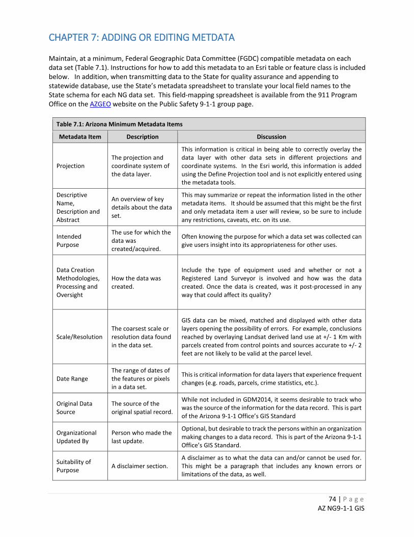
74 | P a g e AZ NG9-1-1 GIS
CHAPTER 7: ADDING OR EDITING METDATA Maintain, at a minimum, Federal Geographic Data Committee (FGDC) compatible metadata on each data set (Table 7.1). Instructions for how to add this metadata to an Esri table or feature class is included below. In addition, when transmitting data to the State for quality assurance and appending to statewide database, use the State’s metadata spreadsheet to translate your local field names to the State schema for each NG data set. This field-mapping spreadsheet is available from the 911 Program Office on the AZGEO website on the Public Safety 9-1-1 group page.
Table 7.1: Arizona Minimum Metadata Items
Metadata Item Description Discussion
Projection The projection and coordinate system of the data layer.
This information is critical in being able to correctly overlay the data layer with other data sets in different projections and coordinate systems. In the Esri world, this information is added using the Define Projection tool and is not explicitly entered using the metadata tools.
Descriptive Name, Description and Abstract
An overview of key details about the data set.
This may summarize or repeat the information listed in the other metadata items. It should be assumed that this might be the first and only metadata item a user will review, so be sure to include any restrictions, caveats, etc. on its use.
Intended Purpose
The use for which the data was created/acquired.
Often knowing the purpose for which a data set was collected can give users insight into its appropriateness for other uses.
Data Creation Methodologies, Processing and Oversight
How the data was created.
Include the type of equipment used and whether or not a Registered Land Surveyor is involved and how was the data created. Once the data is created, was it post-processed in any way that could affect its quality?
Scale/Resolution The coarsest scale or resolution data found in the data set.
GIS data can be mixed, matched and displayed with other data layers opening the possibility of errors. For example, conclusions reached by overlaying Landsat derived land use at +/- 1 Km with parcels created from control points and sources accurate to +/- 2 feet are not likely to be valid at the parcel level.
Date Range The range of dates of the features or pixels in a data set.
This is critical information for data layers that experience frequent changes (e.g. roads, parcels, crime statistics, etc.).
Original Data Source
The source of the original spatial record.
While not included in GDM2014, it seems desirable to track who was the source of the information for the data record. This is part of the Arizona 9-1-1 Office’s GIS Standard
Organizational Updated By
Person who made the last update.
Optional, but desirable to track the persons within an organization making changes to a data record. This is part of the Arizona 9-1-1 Office’s GIS Standard.
Suitability of Purpose A disclaimer section.
A disclaimer as to what the data can and/or cannot be used for. This might be a paragraph that includes any known errors or limitations of the data, as well.
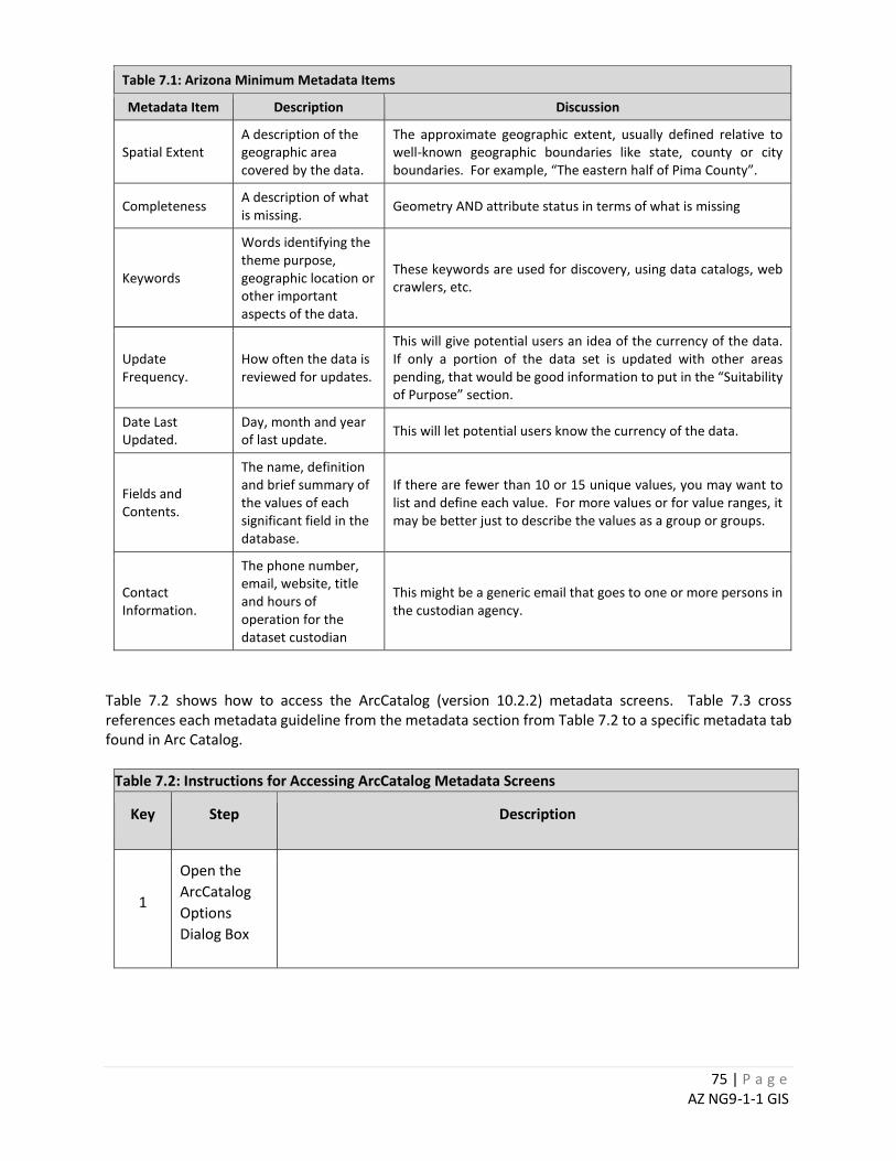
75 | P a g e AZ NG9-1-1 GIS
Table 7.1: Arizona Minimum Metadata Items
Metadata Item Description Discussion
Spatial Extent A description of the geographic area covered by the data.
The approximate geographic extent, usually defined relative to well-known geographic boundaries like state, county or city boundaries. For example, “The eastern half of Pima County”.
Completeness A description of what is missing. Geometry AND attribute status in terms of what is missing
Keywords
Words identifying the theme purpose, geographic location or other important aspects of the data.
These keywords are used for discovery, using data catalogs, web crawlers, etc.
Update Frequency.
How often the data is reviewed for updates.
This will give potential users an idea of the currency of the data. If only a portion of the data set is updated with other areas pending, that would be good information to put in the “Suitability of Purpose” section.
Date Last Updated.
Day, month and year of last update. This will let potential users know the currency of the data.
Fields and Contents.
The name, definition and brief summary of the values of each significant field in the database.
If there are fewer than 10 or 15 unique values, you may want to list and define each value. For more values or for value ranges, it may be better just to describe the values as a group or groups.
Contact Information.
The phone number, email, website, title and hours of operation for the dataset custodian
This might be a generic email that goes to one or more persons in the custodian agency.
Table 7.2 shows how to access the ArcCatalog (version 10.2.2) metadata screens. Table 7.3 cross references each metadata guideline from the metadata section from Table 7.2 to a specific metadata tab found in Arc Catalog.
Table 7.2: Instructions for Accessing ArcCatalog Metadata Screens
Key Step Description
1
Open the ArcCatalog Options Dialog Box
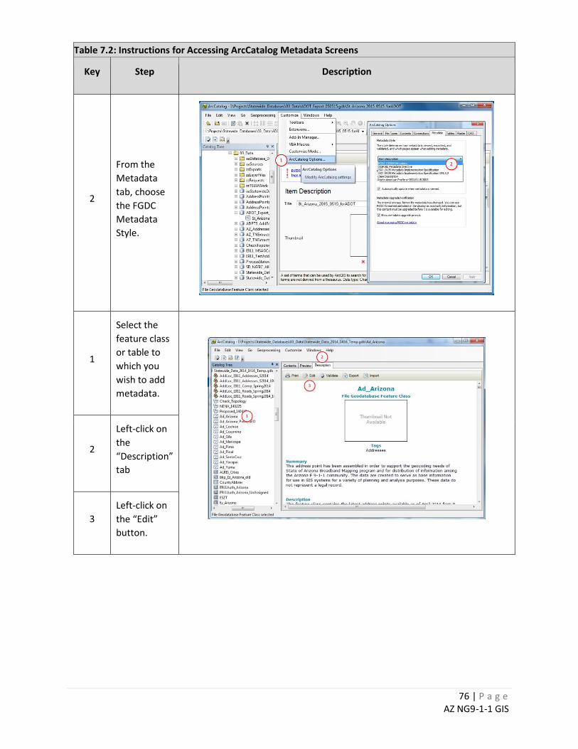
76 | P a g e AZ NG9-1-1 GIS
Table 7.2: Instructions for Accessing ArcCatalog Metadata Screens
Key Step Description
2
From the Metadata tab, choose the FGDC Metadata Style.
1
Select the feature class or table to which you wish to add metadata.
2
Left-click on the “Description” tab
3 Left-click on the “Edit” button.
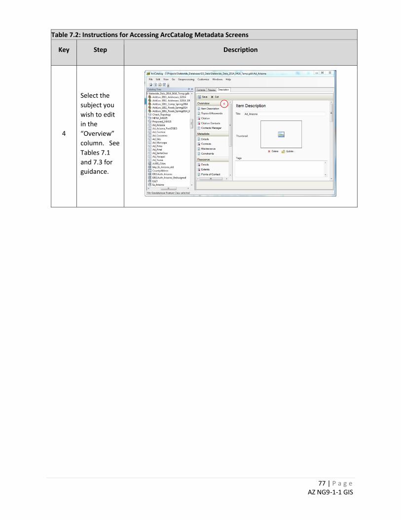
77 | P a g e AZ NG9-1-1 GIS
Table 7.2: Instructions for Accessing ArcCatalog Metadata Screens
Key Step Description
4
Select the subject you wish to edit in the “Overview” column. See Tables 7.1 and 7.3 for guidance.
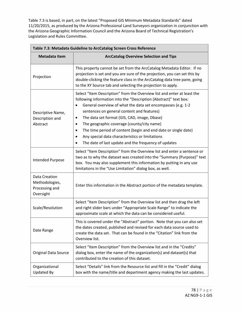
78 | P a g e AZ NG9-1-1 GIS
Table 7.3 is based, in part, on the latest “Proposed GIS Minimum Metadata Standards” dated 11/20/2015, as produced by the Arizona Professional Land Surveyors organization in conjunction with the Arizona Geographic Information Council and the Arizona Board of Technical Registration’s Legislation and Rules Committee.
Table 7.3: Metadata Guideline to ArcCatalog Screen Cross Reference
Metadata Item ArcCatalog Overview Selection and Tips
Projection
This property cannot be set from the ArcCatalog Metadata Editor. If no projection is set and you are sure of the projection, you can set this by double-clicking the feature class in the ArcCatalog data tree pane, going to the XY Source tab and selecting the projection to apply.
Descriptive Name, Description and Abstract
Select “Item Description” from the Overview list and enter at least the following information into the “Description (Abstract)” text box: • General overview of what the data set encompasses (e.g. 1-2
sentences on general content and features) • The data set format (GIS, CAD, image, Dbase) • The geographic coverage (county/city name) • The time period of content (begin and end date or single date) • Any special data characteristics or limitations • The date of last update and the frequency of updates
Intended Purpose
Select “Item Description” from the Overview list and enter a sentence or two as to why the dataset was created into the “Summary (Purpose)” text box. You may also supplement this information by putting in any use limitations in the “Use Limitation” dialog box, as well.
Data Creation Methodologies, Processing and Oversight
Enter this information in the Abstract portion of the metadata template.
Scale/Resolution Select “Item Description” from the Overview list and then drag the left and right slider bars under “Appropriate Scale Range” to indicate the approximate scale at which the data can be considered useful.
Date Range
This is covered under the “Abstract” portion. Note that you can also set the dates created, published and revised for each data source used to create the data set. That can be found in the “Citation” link from the Overview list.
Original Data Source Select “Item Description” from the Overview list and in the “Credits” dialog box, enter the name of the organization(s) and dataset(s) that contributed to the creation of this dataset.
Organizational Updated By
Select “Details” link from the Resource list and fill in the “Credit” dialog box with the name/title and department agency making the last updates.
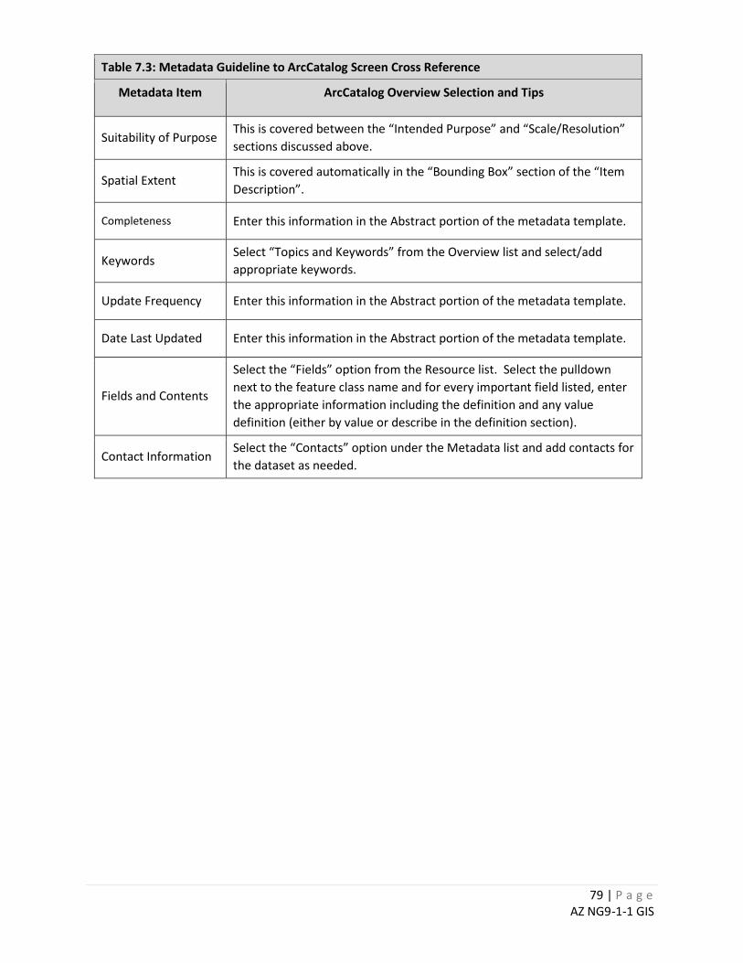
79 | P a g e AZ NG9-1-1 GIS
Table 7.3: Metadata Guideline to ArcCatalog Screen Cross Reference
Metadata Item ArcCatalog Overview Selection and Tips
Suitability of Purpose This is covered between the “Intended Purpose” and “Scale/Resolution” sections discussed above.
Spatial Extent This is covered automatically in the “Bounding Box” section of the “Item Description”.
Completeness Enter this information in the Abstract portion of the metadata template.
Keywords Select “Topics and Keywords” from the Overview list and select/add appropriate keywords.
Update Frequency Enter this information in the Abstract portion of the metadata template.
Date Last Updated Enter this information in the Abstract portion of the metadata template.
Fields and Contents
Select the “Fields” option from the Resource list. Select the pulldown next to the feature class name and for every important field listed, enter the appropriate information including the definition and any value definition (either by value or describe in the definition section).
Contact Information Select the “Contacts” option under the Metadata list and add contacts for the dataset as needed.
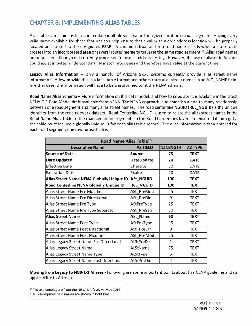
80 | P a g e AZ NG9-1-1 GIS
CHAPTER 8: IMPLEMENTING ALIAS TABLES Alias tables are a means to accommodate multiple valid name for a given location or road segment. Having every valid name available for these features can help ensure that a call with a civic address location will be properly located and routed to the designated PSAP. A common situation for a road name alias is when a state route crosses into an incorporated area or several routes merge to traverse the same road segment 14 Alias road names are requested although not currently processed for use in address testing. However, the use of aliases in Arizona could assist in better understanding TN match rate issues and therefore have value at the current time. Legacy Alias Information – Only a handful of Arizona 9-1-1 systems currently provide alias street name information. A few provide this in a local table format and others carry alias street names in an ALT_NAME field. In either case, the information will have to be transformed to fit the NENA schema. Road Name Alias Schema – More information on this data model, and how to populate it, is available in the latest NENA GIS Data Model draft available from NENA. The NENA approach is to establish a one-to-many relationship between one road segment and many alias street names. The road centerline NGUID (RCL_NGUID) is the unique identifier from the road network dataset. Road Centerline NGUID is used to relate the alias street names in the Road Name Alias Table to the road centerline segments in the Road Centerlines layer. To ensure data integrity, the table must include a globally unique ID for each alias table record. The alias information is then entered for each road segment, one row for each alias.
Road Name Alias Table15
Descriptive Name AZ FIELD AZ LENGTH AZ TYPE Source of Data Source 75 TEXT Date Updated DateUpdate 20 DATE Effective Date Effective 20 DATE Expiration Date Expire 20 DATE Alias Street Name NENA Globally Unique ID ASt_NGUID 100 TEXT Road Centerline NENA Globally Unique ID RCL_NGUID 100 TEXT Alias Street Name Pre Modifier ASt_PreMod 15 TEXT Alias Street Name Pre Directional ASt_PreDir 9 TEXT Alias Street Name Pre Type AStPreType 25 TEXT Alias Street Name Pre Type Separator ASt_PreSep 20 TEXT Alias Street Name ASt_Name 60 TEXT Alias Street Name Post Type AStPosType 15 TEXT Alias Street Name Post Directional ASt_PosDir 9 TEXT Alias Street Name Post Modifier ASt_PosMod 25 TEXT Alias Legacy Street Name Pre Directional ALStPreDir 2 TEXT Alias Legacy Street Name ALStName 75 TEXT Alias Legacy Street Name Type ALStType 5 TEXT Alias Legacy Street Name Post Directional ALStPosDir 2 TEXT
Moving from Legacy to NG9-1-1 Aliases - Following are some important points about this NENA guideline and its applicability to Arizona. 14 These examples are from the NENA Draft GDM, May 2016. 15 NENA-required field names are shown in Bold font.

81 | P a g e AZ NG9-1-1 GIS
It is not yet certain, if and how NG systems will use alias information. This functionality may not be known until vendors pilot and deploy NG systems in Arizona. Some of that work is proceeding now. In the meantime, there is no one “right way” to establish and maintain alias road or landmark names. Here are a couple of approaches:
For Systems with few alias names, maintaining a duplicate road segment(s) with the alias name(s) may be feasible and allows for a very straightforward approach to building Esri address locators. It does mean that when those aliased road segments need to me updated (e.g. split for annexations), multiple road segments will need to be edited, instead of just one.
For Systems with a large number of alias names, a relational table approach, such as suggested by NENA, may be the easiest approach. It does mean any road maintenance procedure will have to include procedures to maintain the related table information. It also means that when creating Esri address locators, using the Esri alternate Street Name table functionality will be required.
For those 9-1-1 Systems with pre-existing alias tables, it may be as simple as transforming their local table information to the schema described above. If that information is parsed differently, it may be best to append all the local address elements and re-parse to the NENA standard. To aid in the parsing, an explanation of each NENA address element field can be found in the latest December 2016 Public Review draft of the NENA GIS Data Model. Of course, both the feature and the alias table records will have to be assigned globally unique identifiers and that uniqueness will have to remain stable across all future versions of the datasets if the aliasing is to work properly. Maintaining unique identifiers is discussed in Chapter 6.1 in this guide.
For those 9-1-1 Systems using the single ALT_NAME field approach to aliasing, it may be necessary to manually parse the one to several alias street names in that field into a new related table. These names are commonly separated by a “^” or other symbol and therefore be amenable to a scripting approach.
A Word about Implementing Alias Tables in ArcGIS - Information about the Esri approach to using aliases to building address locators is discussed in more depth on-line. Below are a couple of the many links available. http://desktop.arcgis.com/en/arcmap/10.3/guide-books/geocoding/place-name-alias-table-properties.htm http://desktop.arcgis.com/en/arcmap/10.3/guide-books/geocoding/exercise-5-using-alternate-street-name-and-place-name-aliases.htm
82 | P a g e AZ NG9-1-1 GIS
CHAPTER 9: TRANSFORMING ADDRESS DATA TO THE NG9-1-1 DATA MODEL16
Summary
This chapter discusses the need and procedures for translating local 9-1-1 data into the latest NENA NG recommended schema.
Note the tool described herein is agnostic about the dataset to be appended. As long as the appropriate target feature class exists, there is a completed field mapping tab in the field mapping spreadsheet and the parameters of the tool are set consistent with that target and field map, the tool should append a road network, Emergency Service Boundary or any other data set described on a tab in the field mapping spreadsheet.
Overview Data schemas for NG9-1-1 related datasets vary greatly among the sixteen 9-1-1 systems currently active in Arizona. In most cases, these data sets were developed and are maintained for business purposes other than public safety and 9-1-1. To take advantage of these existing datasets 9-1-1 System Administrators may need to transform the data from the local data schema to one that will load properly in the NG system. The tools, procedures and various files described in this chapter can be used to transform and append one or more datasets into the NG 9-1-1 schema. The “tool” is a combination of these procedures, an ArcGIS script tool, a schema spreadsheet and a file geodatabase with empty NENA NG feature classes.
Note: There is additional information at the end of this chapter on X-RAY, an ArcGIS extension tool, used by Yuma County to transform their data as well as perform some other data schema maintenance tasks. Users may wish to apply X-RAY or other tools (e.g. FME) to the transformation task. To the extent possible, it would be helpful if authors of those other tools/approaches would share them with the broader 9-1-1 community.
The NG Transform tool runs in ArcGIS 10.x software. User copy their source data and the NENA template dataset into their working FGDB and folder, map their local fields to the equivalent NG fields in a companion field-mapping spreadsheet, and then run the script tool to perform the transform and load to the NG standard feature class.
Note: the NG schema (column A) on each dataset tab in the field-mapping spreadsheet can be modified by the user to reflect any recent changes to the NENA standard schema. The Arizona 9-1-1 Program Office should also have a current version of this spreadsheet, and users may wish to check their webpage or AZGEO Public Safety 9-1-1 Group page for the latest information.
16 As discussed in this Chapter, the procedure described here is for address points, but the tool can be used for other feature classes, as well. Advanced ArcGIS users may be familiar with the process. Detailed procedures for basic users will be included in a subsequent edition of the Best Practices Manual.
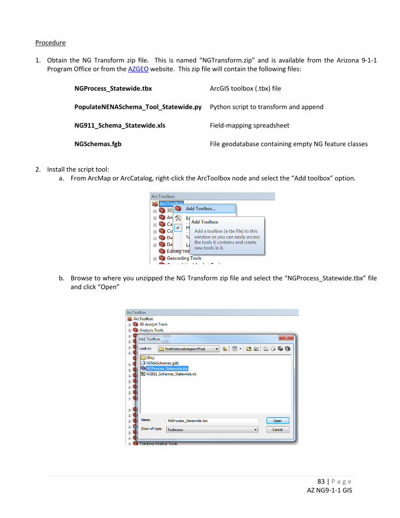
83 | P a g e AZ NG9-1-1 GIS
Procedure 1. Obtain the NG Transform zip file. This is named “NGTransform.zip” and is available from the Arizona 9-1-1
Program Office or from the AZGEO website. This zip file will contain the following files:
NGProcess_Statewide.tbx ArcGIS toolbox (.tbx) file
PopulateNENASchema_Tool_Statewide.py Python script to transform and append
NG911_Schema_Statewide.xls Field-mapping spreadsheet
NGSchemas.fgb File geodatabase containing empty NG feature classes
2. Install the script tool:
a. From ArcMap or ArcCatalog, right-click the ArcToolbox node and select the “Add toolbox” option.
b. Browse to where you unzipped the NG Transform zip file and select the “NGProcess_Statewide.tbx” file and click “Open”
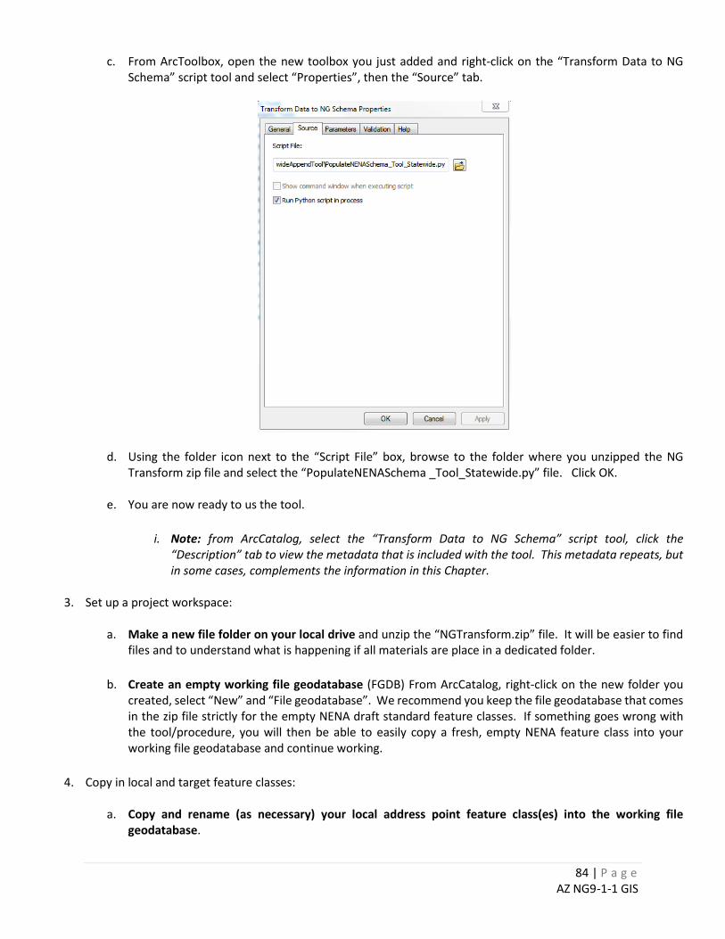
84 | P a g e AZ NG9-1-1 GIS
c. From ArcToolbox, open the new toolbox you just added and right-click on the “Transform Data to NG Schema” script tool and select “Properties”, then the “Source” tab.
d. Using the folder icon next to the “Script File” box, browse to the folder where you unzipped the NG Transform zip file and select the “PopulateNENASchema _Tool_Statewide.py” file. Click OK.
e. You are now ready to us the tool.
i. Note: from ArcCatalog, select the “Transform Data to NG Schema” script tool, click the
“Description” tab to view the metadata that is included with the tool. This metadata repeats, but in some cases, complements the information in this Chapter.
3. Set up a project workspace:
a. Make a new file folder on your local drive and unzip the “NGTransform.zip” file. It will be easier to find
files and to understand what is happening if all materials are place in a dedicated folder.
b. Create an empty working file geodatabase (FGDB) From ArcCatalog, right-click on the new folder you created, select “New” and “File geodatabase”. We recommend you keep the file geodatabase that comes in the zip file strictly for the empty NENA draft standard feature classes. If something goes wrong with the tool/procedure, you will then be able to easily copy a fresh, empty NENA feature class into your working file geodatabase and continue working.
4. Copy in local and target feature classes:
a. Copy and rename (as necessary) your local address point feature class(es) into the working file geodatabase.
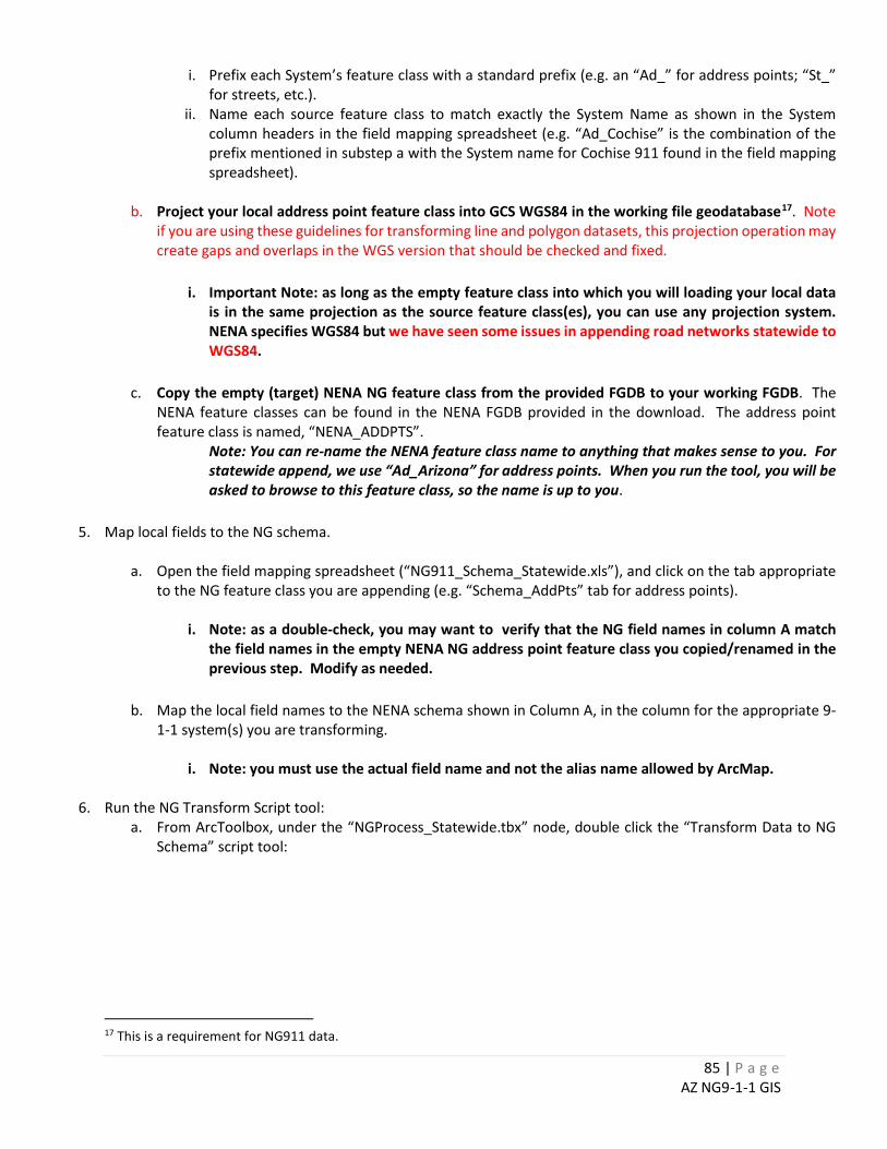
85 | P a g e AZ NG9-1-1 GIS
i. Prefix each System’s feature class with a standard prefix (e.g. an “Ad_” for address points; “St_” for streets, etc.).
ii. Name each source feature class to match exactly the System Name as shown in the System column headers in the field mapping spreadsheet (e.g. “Ad_Cochise” is the combination of the prefix mentioned in substep a with the System name for Cochise 911 found in the field mapping spreadsheet).
b. Project your local address point feature class into GCS WGS84 in the working file geodatabase17. Note
if you are using these guidelines for transforming line and polygon datasets, this projection operation may create gaps and overlaps in the WGS version that should be checked and fixed.
i. Important Note: as long as the empty feature class into which you will loading your local data is in the same projection as the source feature class(es), you can use any projection system. NENA specifies WGS84 but we have seen some issues in appending road networks statewide to WGS84.
c. Copy the empty (target) NENA NG feature class from the provided FGDB to your working FGDB. The
NENA feature classes can be found in the NENA FGDB provided in the download. The address point feature class is named, “NENA_ADDPTS”.
Note: You can re-name the NENA feature class name to anything that makes sense to you. For statewide append, we use “Ad_Arizona” for address points. When you run the tool, you will be asked to browse to this feature class, so the name is up to you.
5. Map local fields to the NG schema.
a. Open the field mapping spreadsheet (“NG911_Schema_Statewide.xls”), and click on the tab appropriate
to the NG feature class you are appending (e.g. “Schema_AddPts” tab for address points).
i. Note: as a double-check, you may want to verify that the NG field names in column A match the field names in the empty NENA NG address point feature class you copied/renamed in the previous step. Modify as needed.
b. Map the local field names to the NENA schema shown in Column A, in the column for the appropriate 9-
1-1 system(s) you are transforming.
i. Note: you must use the actual field name and not the alias name allowed by ArcMap.
6. Run the NG Transform Script tool: a. From ArcToolbox, under the “NGProcess_Statewide.tbx” node, double click the “Transform Data to NG
Schema” script tool:
17 This is a requirement for NG911 data.
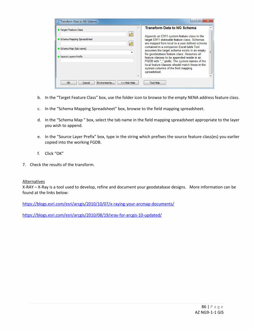
86 | P a g e AZ NG9-1-1 GIS
b. In the “Target Feature Class” box, use the folder icon to browse to the empty NENA address feature class.
c. In the “Schema Mapping Spreadsheet” box, browse to the field mapping spreadsheet.
d. In the “Schema Map ” box, select the tab name in the field mapping spreadsheet appropriate to the layer you wish to append.
e. In the “Source Layer Prefix” box, type in the string which prefixes the source feature class(es) you earlier
copied into the working FGDB.
f. Click “OK”
7. Check the results of the transform. Alternatives X-RAY – X-Ray is a tool used to develop, refine and document your geodatabase designs. More information can be found at the links below: https://blogs.esri.com/esri/arcgis/2010/10/07/x-raying-your-arcmap-documents/ https://blogs.esri.com/esri/arcgis/2010/08/19/xray-for-arcgis-10-updated/
87 | P a g e AZ NG9-1-1 GIS
CHAPTER 10: BACKGROUND INFORMATION FOR GUIDELINES
The following sections provide additional background information and discussion for each guideline category found in the previous chapter. This rationale is based, in large part, on the discussion of the AGIC Data Technical Committee.
INFORMATION RELATED TO GENERALLY APPLICABLE GUIDELINES
Unique Record Identifiers A unique identifier is a value that does not change and is never duplicated in the same field. NG9-1-1 requires a unique ID for all GIS data elements. For 9-1-1 Systems that are collecting and aggregating data from multiple data sources, this issue will be of primary concern. Unique ID’s can be generated and maintained within a GIS through a combination of a 9-1-1 Authority generated ‘Locally unique ID’ and an ‘Agency ID’ (a domain representing that authority) into a new single ID. Chapter 6.1 of this manual has suggestions for how to maintain unique ID’s based on this type of approach. In addition, there is a discussion of the use of Globally Unique ID’s (GUIDS) and “triggers”, and bits of code that can be implemented in an enterprise-level relational database management system such as SQL Server or Oracle.
There are some exceptions to this guideline: when the number of features (records) in a data set are fairly small, are not likely to change, where the value has a definite agreed upon meaning, and where that data set would be common to all GIS Data Providers. Examples include countries, states, counties (per US Census code), pre- and post-directional (e.g. N, S, E, W). The method you use to establish and maintain a locally unique ID should be documented in the metadata. The following is some sample text you might use to document your procedures.
The unique identifier for the 9-1-1 road network was originally generated from the internal ObjectID value. ObjectID’s are not a constant as an Object ID is subject to change as managed by the software. Therefore, the ObjectID within a unique ID may not correspond to the current feature ObjectID. As new features are added to the dataset, a script is run that identifies the next largest integer value and assigns that value. If an existing arc is split, all new segments are assigned the next largest integer values. Unique ID’s are never repeated.
Data Formats Data format refers to the file type in which the data is stored. Spatial data across the 17 Arizona 9-1-1 systems exists in a wide variety of Esri formats: Enterprise (SDE) Geodatabases, File Geodatabases (FGDB), Personal Geodatabases (PGDB) and shapefiles. Some Arizona data providers may also use non-Esri solutions, such as MapInfo or AutoCAD. Here are a few things to note about spatial data types:
• The Esri FGDB format may be moving to an open standard and become even more ubiquitous. • The Esri PGDB format will not be supported by Esri in future releases of their software. This
format also has file size limitations and has poor performance issues with large databases. • Shapefiles are to be avoided, even as a means to transfer data, as the export to shapefile can
truncate field names and will not preserve any domain information or complex feature types.

88 | P a g e AZ NG9-1-1 GIS
INFORMATION RELATED TO GENERALLY APPLICABLE GUIDELINES
Tabular (non-spatial) data in the 17 Arizona 9-1-1 systems exists as text, Excel, SQL Server, Oracle and many other formats. Often this tabular data can be joined to spatial data to provide more information about spatial features. A potential problem with non-database formats such as text and Excel is that the lack of enforcement for basic database structures can create data integrity issues and consequent errors.
Projection and Coordinate Systems Coordinate systems enable geographic datasets to use common locations for integration. A coordinate system is a reference system used to represent the locations of geographic features, imagery, and observations (e.g. GPS), within a common geographic framework. Each coordinate system is defined by the following:
• Its measurement framework, which is either geographic (in which spherical coordinates are measured from the earth's center) or planimetric (in which the earth's coordinates are projected onto a two-dimensional planar surface)
• Units of measurement (typically feet or meters for projected coordinate systems or decimal degrees for latitude-longitude)
• The definition of the map projection for projected coordinate systems • Other measurement system properties such as a spheroid of reference, a datum, one or more
standard parallels, a central meridian, and possible shifts in the x- and y-directions. Local data sets are best defined in projected coordinate systems specific to the extent of the data. These may include locally developed, low distortion projections. It is often preferable to use projections that match the native projections of supporting imagery (aerial photo or satellite) to speed display refresh times when using GIS software. The current State of Arizona 9-1-1 GIS Standards (Updated 8/19/10), page 6 state, “In a wireless Phase II environment, the wireless 9-1-1 caller’s XY coordinates are provided to the PSAP in a WGS 84 datum. Thus, all 9-1-1 GIS map data must utilize projections that display coordinates in a WGS 84 datum.” The December 2016 Public Review draft of the NENA GIS Data Model notes that, “While local GIS data may be kept in any projection desired, prior to loading the data into the Emergency Call Routing Function (ECRF) or the Location Validation Function (LVF) the data must be in the following projection
EPSG 4326 WGS 84 / Latlong Projection Geographic, Plate Carrée, Equidistant Cylindrical, Equirectangular Latitude of the origin 0° Longitude of the origin 0°
Scaling factor 1 False eastings 0° False northings 0° Ellipsoid WGS84 Horizontal Datum WGS84
89 | P a g e AZ NG9-1-1 GIS
INFORMATION RELATED TO GENERALLY APPLICABLE GUIDELINES
Vertical Datum WGS84 Geoid, which is equivalent to Local Mean Sea Level (MSL) Units: decimal degrees Global extent: -180, -90, 180, 90”
The Arizona State Land Department will promote WGS84 and Web Mercator for any published map services.
• WGS84 is an Earth-centered, Earth-fixed terrestrial reference system and geodetic datum. WGS84 is based on a consistent set of constants and model parameters that describe the Earth's size, shape, and gravity and geomagnetic fields.18
• Web Mercator is a variation of the Mercator projection and is the de facto standard for Web mapping applications…It is used by virtually all major online map providers, including Google Maps, Bing Maps, Mapquest, Mapbox, OpenStreetMap and many others.19
The key to the selection of any projection and coordinate system is to be able to transform your data from one projection and coordinate system to another. This requires you use a projection with well-defined parameters. Esri and other software providers have tools for defining a projection on spatial data sets. Non-Esri formats may require explicitly adding this information to metadata. In either case, you have to know the parameters of the projection, or have access to data set that has the same projection defined and from which the parameters can be copied.
Database Schemas and Content A database schema refers to the organization of data, a kind of blueprint of how a database is constructed. A schema is described in terms of tables, fields in tables and the relationships of tables to one another.20 It is assumed the local 9-1-1 authorities will maintain data in schemas custom-tailored for their local business needs. No one schema for a given data layer will ever be appropriate for all 9-1-1 Systems, for all purposes, all of the time. The Arizona NG9-1-1 database model along with various procedures and tools (some contained in this Guide) allow you to quality-assure and then export your 9-1-1 roads and address point databases to an NG9-1-1 compatible schema. The Arizona-specific portions of an NG9-1-1 data model are described in Chapter 11 with links to the NENA standard schema provided there. In terms of character case, a review of local data providers reveals that the use of upper case is a common practice. However, local authorities will have to decide based on their own target systems and other factors.
18 From https://confluence.qps.nl/pages/viewpage.action?pageId=29855173 19 From https://en.wikipedia.org/wiki/Web_Mercator 20 After http://en.wikipedia.org/wiki/Database_schema

90 | P a g e AZ NG9-1-1 GIS
INFORMATION RELATED TO GENERALLY APPLICABLE GUIDELINES
The use of nulls is to be avoided where possible, as nulls can have two meanings: (1) there is no value applicable, or (2) we don’t know what the value is. AGIC 9-1-1 Technical Committee members noted that null values can corrupt data loads into their systems, as well.21 Regarding the use of special characters in databases, the NENA NG9-1-1 Civic Location Data Exchange Format (CLDXF) Standard discusses the use of special characters found in Section 2 Introduction, 2.1 Operational Impacts Summary [page 14]:
NG9-1-1 allows for special characters and upper/lower case as legally established by the Local Addressing Authority. It is the responsibility of GIS, CAD, RMS and other software vendors to accommodate special characters and allow for case sensitive entries in Street Name and other address elements. (This does not imply that all user interfaces must be case sensitive or that systems which compare locations must be case sensitive. For example, a call taker typing in an address may not need to type correct case; however, a provisioning interface in a GIS system for entering a new address must follow the case specified by the local addressing authority.)
Grammatical marks, such as apostrophes, may be required as part of legal street name. There is no consensus among members of the AGIC 9-1-1 Technical Committee. This issue will have to wait for an Arizona NG9-1-1 pilot project to see if these create a problem.22 The reason this is important is its effect on address geocoding and its impact on legal name. Already, local testing in Arizona reveals that the use of hyphens in both road names and place names can result in an otherwise geocodable address failing the address matching process. USPS Publication 28, Section 354 provides some guidance on removing punctuation marks, though this is not an adopted NENA standard.23 Some content lend itself to standardization. The December 2016 Draft NENA NG9-1-1 GIS Data Model Public Review version provides guidance on how addresses should be parsed into the eight NENA standard fields; however NENA is silent on standard values in those address elements. USPS Publication 28, Section 355 provides some guidance on content standards, though this is not an adopted NENA standard.
Date-Time Fields The date-time guidelines are based on our current understanding of the NG9-1-1 Spatial Interface (SI) provisioning standards. There are many unknowns that might not be resolved until a pilot project is completed and we understand exactly how the SI and the ECRF and LVF function in NG9-1-1. For example, it is not clear to the AZ NG9-1-1 Technical Committee how you can plan for a lead time to put
21 From AGIC 9-1-1 Technical Committee Summary Notes, 09/11/14 22 As of February 2017, ArcGIS 10.4, the use of hyphens in both street name and place names will cause geocoding to fail for those records. We advise you replace hyphens with a space in both the TN extract and geocoding reference data. 23 http://pe.usps.gov/cpim/ftp/pubs/Pub28/pub28.pdf
91 | P a g e AZ NG9-1-1 GIS
INFORMATION RELATED TO GENERALLY APPLICABLE GUIDELINES
in the Effective Date field. General consensus is to just make both effective and expiration dates the date feature was created, down to the minute and let’s see what happens during the Yuma Pilot.
Metadata Metadata is information about data. Metadata summarizes basic information about data, which can make finding and working with particular instances of data easier. Author, date-created/date- modified and file size are examples of very basic metadata. See Chapter 8, “Implementing Alias Tables” in this Guide for more information. Metadata is critical for effective data sharing for numerous reasons.
• Firstly, it supports accessibility. Users can search the metadata to understand what a data set contains and if it will be appropriate for their purpose.
• Secondly, it supports versioning by identifying similarities and differences between versions while keeping multiple versions available for different purposes. 24
The process of creating metadata can also help data providers better understand their own data and to adjust to content and procedures as needed. Since the creation and maintenance of metadata is time-consuming, it is often ignored. The key to regular metadata creation and maintenance is simplification. Chapter 7 in this Guide explains each of the minimum recommended metadata items for Arizona NG9-1-1 data sets. The NG9-1-1 Data Committee discussed the concept of documenting spatial accuracy in the metadata at their 02/19/2015 meeting and the consensus was not to try to characterize or categorize data according to its spatial quality. Without a time-consuming and expensive study, there is no real way to know about spatial quality for most GIS data sets. Visual comparison of GIS data sets against imagery or other data sets for which good geodetic control has been established is about the best you can do. Over the years, numerous minimum standards have been developed in Arizona. The most active statewide process in Arizona is the one being conducted by Steve Whitney, GIS Manager in the Pima County Information Technology Department ([email protected]). Steve is working in coordination with the statewide Arizona Professional Land Surveyors (APLS) organization and the Arizona Geographic Information Council (AGIC) committees to promulgate and review a set of minimum standards. We recommend that you monitor the progress of this effort and incorporate consensus standards, as they are developed. You can follow the AZGEO website for further developments on minimum Arizona metadata standards ( https://azgeo.az.gov/azgeo ).
Standard Base Map Layers
24 From http://whatis.techtarget.com/definition/metadata

92 | P a g e AZ NG9-1-1 GIS
INFORMATION RELATED TO GENERALLY APPLICABLE GUIDELINES
Spatial data layers that are agreed upon in advance across 9-1-1 System boundaries can greatly simplify the process of edge-matching adjacent data sets and can minimize call routing concerns. Base layer data sets such as the Public Land Survey System (PLSS), County Boundaries, 9-1-1 Authority Boundaries, Federal and State Highways, Public Lands, Federal and State Parks and Indian Nations can provide boundaries to which local data practitioners can snap or clip their own data sets.
Data Archiving Data archiving is the process of moving data that is no longer actively used to a separate data storage device for long-term retention. Data archives consist of older data that is still important and necessary for future reference, as well as data that must be retained for regulatory compliance.25 The NENA ECRF/LVF/SI descriptions do not discuss maintaining a record of changes, only the current GIS state. This does not mean that an implementer might not archive changes. This is a very complex subject. The frequency might range from archiving every change to storing a copy of each data set once per year. There may be local rules and regulations that guide your archiving approach. At the State level, the Arizona State Land Department is currently working with the State Librarian on their spatial data archiving project. ASLD has categorized their data holdings and it is anticipated that different archiving requirements will be applied to different categories. This pending legislation will apply to state and county agencies, only. The enabling legislation looks like the following:
Pursuant to ARS §41-151.12.3, the Arizona State Library, Archives and Public Records shall, “Establish standards and procedures for the preparation of schedules providing for the retention of records on continuing value and for the prompt and orderly disposal of records no longer possessing sufficient administrative, legal or fiscal value to warrant their further keeping”.26
You should seek the advice of your legal counsel when making archiving decisions. The group consensus is that this topic is too big and too tangential to the work of the AGIC 9-1-1 Working Technical Committee to be more specific about guidelines. The consensus is to wait on developing guidelines that are more specific until more information is developed at the State level.27 For additional information regarding archiving, contact Arizona State Library, Archives and Record Management28.
Error Correction Policies
25 From http://searchdatabackup.techtarget.com/definition/data-archiving 26 From “Cartographic GIS Records – AGIC Presentation v2pptx” provided by AZ SCO, Feb 2015. 27 Technical Committee summary notes, 02/19/15. 28 https://www.azlibrary.gov/

93 | P a g e AZ NG9-1-1 GIS
INFORMATION RELATED TO GENERALLY APPLICABLE GUIDELINES
For annual certification, the State of Arizona 9-1-1 Program Office requires each 9-1-1 System to develop and implement a set of procedures for the correction of errors found in the GIS layers used for call routing and emergency dispatch. Appendix A.1 in this manual contains examples workflows for error correction.

94 | P a g e AZ NG9-1-1 GIS
INFORMATION RELATED TO ROAD NETWORK GUIDELINES
Spatial Representation of Road Networks Spatial representation refers to how real world features, such as roads, are represented in the GIS database. A four-lane, divided highway may be represented as four lines, one per lane; two lines, one per each traffic direction, or one line with no visual information as to number of lanes or direction of travel. Of course, these items can be carried in the database as attributes. There are many ways to represent a road network and the choice will depend on the various applications for which your road network will be put to use. In general, a divided highway should be represented as two roads for emergency vehicle routing purposes but are not required for geocoding. Optimizing a spatial representation or even standardizing attributes for one application may render the data unusable for another.
Topology of Road Networks Topology is a term for how features in the database are connected. In geodatabases, it refers to the arrangement that constrains how point, line, and polygon features share geometry. For example, street centerlines and census blocks share geometry in places, and adjacent census polygons share geometry at every boundary. Topological relationships are used for spatial modeling operations that do not require coordinate information29 In road networks, segment direction, another aspect of topology, is critical to proper address placement. In Esri databases, there is always a “from node” and a “to node” in line feature classes. Addresses left and right are relative to this direction and segments oriented in this fashion result in an address geocoding to the correct side of the road. Some 9-1-1 systems may reject road networks that have segments that have incorrect orientation relative to the address numbering.30 It should be noted that consistent parity, the presence of odd address numbers on one side of a road segment and even address numbers on the other, may not exist in the real world. This can be accommodated in a road network by splitting the road segment for the length of the parity change and reversing the odd and even numbers. This may not be practical where only one or two addresses along a road segment violate parity or these discrepancies are widespread. In those cases, an address point layer may be a better solution. Roads need to be split at various boundaries in order to accommodate the change in the road network attributes. For example a road segment that crosses two ESN zones, will have to be split at that boundary so that each can be assigned the appropriate ESN left and right value. The endpoints of road segments should be snapped and not overshoot or undershoot their real-world intersections. This connectivity is important should the road network be used for vehicle routing.
29 After http://support.esri.com/en/knowledgebase/GISDictionary/term/topology 30 Per T. Homan, Gila County: he has experienced this situation with Intrado.
95 | P a g e AZ NG9-1-1 GIS
INFORMATION RELATED TO ROAD NETWORK GUIDELINES
More information and guidance on this topic can be found in Appendix B.1, “ADOT Road Network Spatial Representation Guidelines”.
Database Schema for 9-1-1 Road Networks A database schema refers to the organization of data, a kind of blueprint of how a database is constructed, in terms of tables, fields in tables and the relationships of tables to one another.31 This manual assumes that each 9-1-1 Authority will define and maintain a road network with a schema tailored to their local business needs. These needs may be defined by other users of the road network in their authority area. It is imperative, however, that the local schemas be transformable into an NG9-1-1 compatible format for (a) loading into the NG9-1-1 System and (b) appending to a statewide 9-1-1 compatible road network. A complete list of fields which includes the mandatory, conditional and optional categories of fields as well as more implementation details can be found in Chapter 11 and the latest NENA NG9-1-1 GIS Data Model.
Content December 2016 Public Review draft of the NENA GIS Data Model provides guidance as to the type of roads that should be included32:
“Some 9-1-1 Authorities may include un-named and/or un-addressed trails, paths, and similar “roads” in their GIS data. It is recommended that these not be included with the named and addressed roads for provisioning into the ECRF and the LVF databases. Conversely, the Road Classification MAY be populated so these “roads” can be selected or exclusion and not be part of the data provisioned or updated to the ECRF and the LVF.”
NENA incorporated its CLDXF address content standards into the NENA GDM by reference and the former document states that street name elements cannot be blank. (pg. 49, “3.3.6.7 Mandatory/ conditional /optional: Conditional: A Street Name is required except for landmarks that have no street address (e.g. United Sates Capitol Building, Brooklyn Bridge), in which case a Landmark Name is required.” Different AZ 9-1-1 GIS data sets handle this variously; some leave it blank, some use “UNNAMED ROAD” or “UNKNOWN” to indicate there is no legal name. The AGIC NG9-1-1 Technical Committee consensus is that we should leave the value blank. If a particular type or type phrase is chosen to attribute unnamed roads, it can create problems in the dispatch center (e.g. start trying to find and address in a pull-down box for a street that begins with “UN” and a very long list will be generated).33
31 After http://en.wikipedia.org/wiki/Database_schema 32 Section 5.107, “Road Class”. 33 AGIC 9-1-1 Working Group Technical Committee summary notes, 02/19/15.
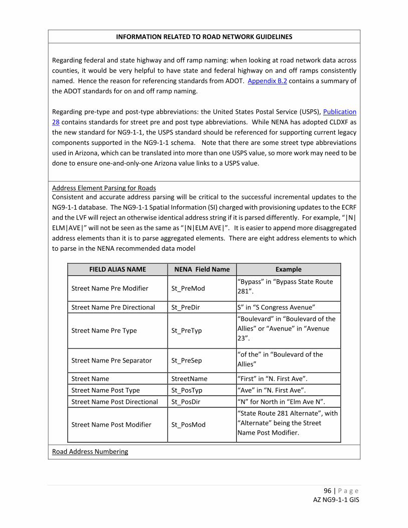
96 | P a g e AZ NG9-1-1 GIS
INFORMATION RELATED TO ROAD NETWORK GUIDELINES
Regarding federal and state highway and off ramp naming: when looking at road network data across counties, it would be very helpful to have state and federal highway on and off ramps consistently named. Hence the reason for referencing standards from ADOT. Appendix B.2 contains a summary of the ADOT standards for on and off ramp naming. Regarding pre-type and post-type abbreviations: the United States Postal Service (USPS), Publication 28 contains standards for street pre and post type abbreviations. While NENA has adopted CLDXF as the new standard for NG9-1-1, the USPS standard should be referenced for supporting current legacy components supported in the NG9-1-1 schema. Note that there are some street type abbreviations used in Arizona, which can be translated into more than one USPS value, so more work may need to be done to ensure one-and-only-one Arizona value links to a USPS value.
Address Element Parsing for Roads Consistent and accurate address parsing will be critical to the successful incremental updates to the NG9-1-1 database. The NG9-1-1 Spatial Information (SI) charged with provisioning updates to the ECRF and the LVF will reject an otherwise identical address string if it is parsed differently. For example, “|N| ELM|AVE|” will not be seen as the same as “|N|ELM AVE|”. It is easier to append more disaggregated address elements than it is to parse aggregated elements. There are eight address elements to which to parse in the NENA recommended data model
FIELD ALIAS NAME NENA Field Name Example
Street Name Pre Modifier St_PreMod “Bypass” in “Bypass State Route 281”.
Street Name Pre Directional St_PreDir S” in “S Congress Avenue”
Street Name Pre Type St_PreTyp
“Boulevard” in “Boulevard of the Allies” or “Avenue” in “Avenue 23”.
Street Name Pre Separator St_PreSep “of the” in “Boulevard of the Allies”
Street Name StreetName “First” in “N. First Ave”. Street Name Post Type St_PosTyp “Ave” in “N. First Ave”. Street Name Post Directional St_PosDir “N” for North in “Elm Ave N”.
Street Name Post Modifier St_PosMod “State Route 281 Alternate”, with “Alternate” being the Street Name Post Modifier.
Road Address Numbering
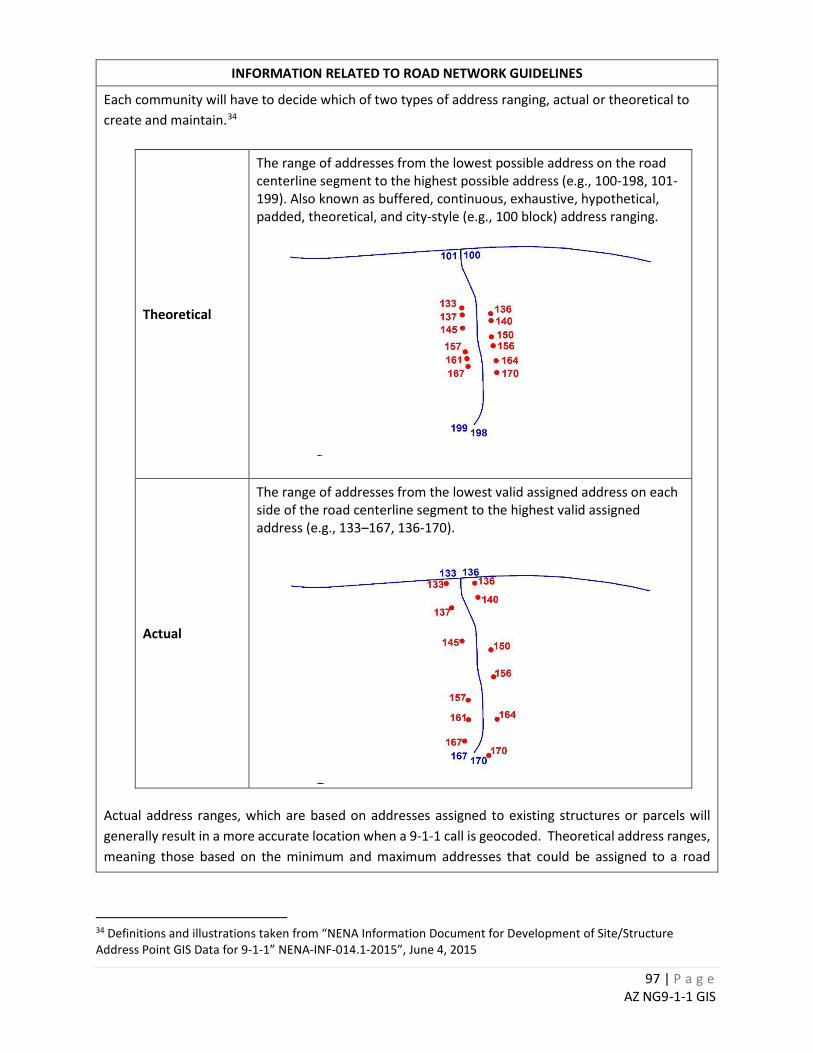
97 | P a g e AZ NG9-1-1 GIS
INFORMATION RELATED TO ROAD NETWORK GUIDELINES
Each community will have to decide which of two types of address ranging, actual or theoretical to create and maintain.34
Theoretical
The range of addresses from the lowest possible address on the road centerline segment to the highest possible address (e.g., 100-198, 101-199). Also known as buffered, continuous, exhaustive, hypothetical, padded, theoretical, and city-style (e.g., 100 block) address ranging.
Actual
The range of addresses from the lowest valid assigned address on each side of the road centerline segment to the highest valid assigned address (e.g., 133–167, 136-170).
Actual address ranges, which are based on addresses assigned to existing structures or parcels will generally result in a more accurate location when a 9-1-1 call is geocoded. Theoretical address ranges, meaning those based on the minimum and maximum addresses that could be assigned to a road
34 Definitions and illustrations taken from “NENA Information Document for Development of Site/Structure Address Point GIS Data for 9-1-1” NENA-INF-014.1-2015”, June 4, 2015
98 | P a g e AZ NG9-1-1 GIS
INFORMATION RELATED TO ROAD NETWORK GUIDELINES
segment, may distort the geocoded location, if parcels or structures are not evenly spaced along the segment. Regarding the addressing of roads that are adjacent to vacant land: arguments can be made for populating the address ranges with either zeroes or the theoretical address range based on the existing address grid, in anticipation of future development. Some AZ 9-1-1 Systems use zero ranges where there will never be development (e.g. along road medians or adjacent to protect open space). Using blank or null values for these ranges can create query problems and you may be better off using zeroes. The decision should be based on your internal business needs. Whatever system is chosen, it should be applied consistently across the entire data set and documented in the metadata.
Public Land Road Naming The State is researching and coordinating with the entire range of federal public land management agencies in Arizona to determine if they have a recommended threshold for roads to keep in the 9-1-1 database. Whatever criteria is used, it should be applied consistently across the entire data set and documented in the metadata. Statewide guidelines for each federal and tribal agency in Arizona that expressed a preference are shown in the table below.
Agency Codes to Include Notes
US Forest Service (USFS) FS <number>
E.g. FS 123 for Forest Service Road 123. Hyphens have been eliminated for Esri address locator concerns. In addition to Route Numbers (FS 123), Forest Service roads are occasionally known by alpha character names, particularly near Visitor Centers or well-known local roadways. It is recommended that the locally recognized alpha character road name be attributed as the primary ST_NAME, while the USFS Route number can be attributed in an ALIAS field.
US Bureau of Land Management (BLM)
No naming convention provided.
National Park Service (NPS) W <number>
Generally, most street names within NPS lands use alpha character road names. These follow conventional road naming standards. Only NPS Service Roads, which are not typically included in publically available road networks, are referenced by an alpha character, hyphen, and number. E.g. W-4. In the event a NPS Service Road needs to be included in a 911 road network, it is recommended that the hyphen be eliminated as noted for USFS, for consistency (W 4).

99 | P a g e AZ NG9-1-1 GIS
INFORMATION RELATED TO ROAD NETWORK GUIDELINES
Bureau of Indian Affairs (BIA)
No naming convention provided.
Driveway Representation and Naming There is a variety of approaches to handling driveways or unnamed roads across the 17 Arizona 911 Systems. For example, Pinal County 9-1-1 usually makes these long connecting segments roads, and names and addresses them. Pima County will give them an unofficial name but this can lead to push back from locals living out in these areas. It may be quite important for vehicle dispatch to have these segments in the database for routing. If they are unnamed, however, it may throw an error when trying to load them in NG9-1-1. If you can quickly select these roads in the GIS (e.g. may be as simple as selecting where the road name is empty), you can exclude them if the target application cannot use them. In the past, the Arizona 9-1-1 system recommended a minimum 100’ threshold for including driveways in the dataset. This is a somewhat arbitrary length for project purposes. Local rules should be referenced to determine the proper length to define a road versus a driveway. The purpose is to avoid confusion as to access to property especially in larger parcels in rural areas. This may require a different minimum length threshold or just a case-by-case evaluation.
Railroad Representation and Naming There are a variety of ways of representing railroads in the GIS across the 17 Arizona 9-1-1 systems. Pinal County 9-1-1 needs railroads in the road network in order to respond to calls at road-RR intersections. They have procedures for naming and ranging the RR segments. This scheme is not directly related to road addresses or the street addressing grid. The City of Yuma uses their address point layer to track the intersections of roads and railroads and does not carry railroads in their road network.
One-way Roads The consensus of the AGIC NG9-1-1 Technical Committee is that this is a very important attribute for vehicle routing and should be populated. Yuma County notes that their software requires it. The excerpt below is from the December 2016 Public Review draft of the NENA GIS Data Model. Description: The direction of traffic movement along a road in relation to the FROM node and TO node of the line segment representing the road in the GIS data. The one-way field has three possible designations: B (Both), FT (From-To) and TF (To-From).
B – Travel in both directions allowed FT – One-way traveling from FROM node to TO node TF – One way traveling from TO node to FROM Node
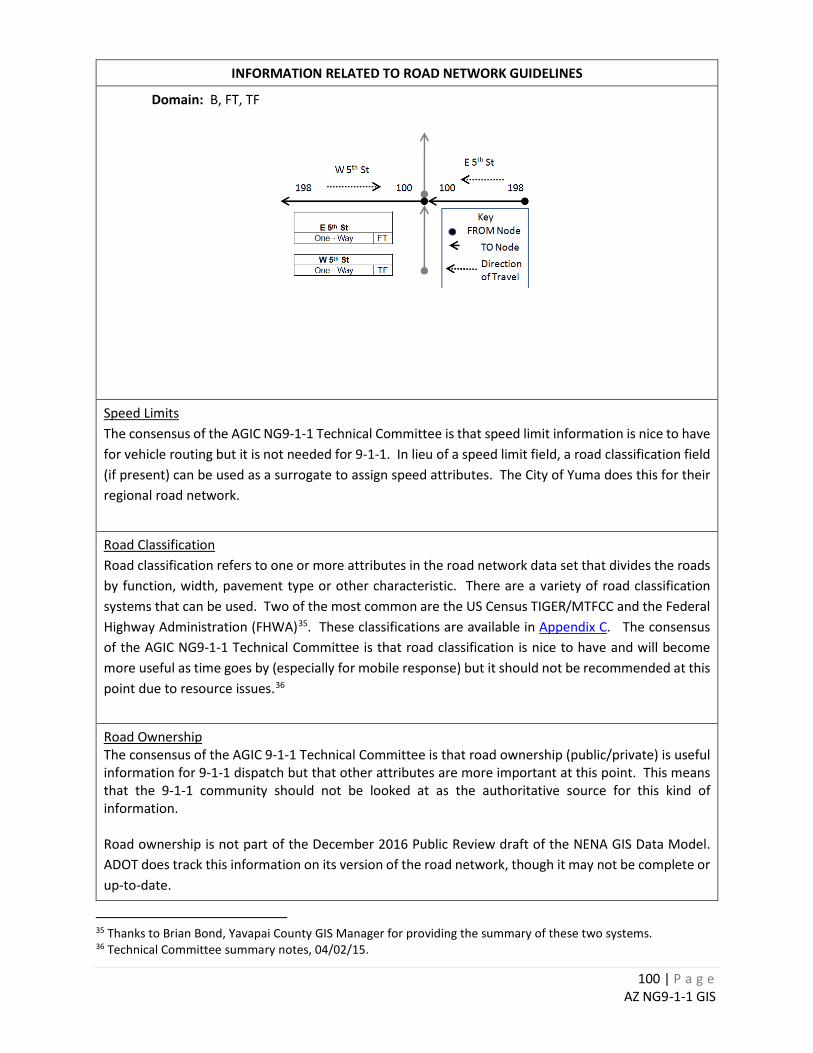
100 | P a g e AZ NG9-1-1 GIS
INFORMATION RELATED TO ROAD NETWORK GUIDELINES
Domain: B, FT, TF
Speed Limits The consensus of the AGIC NG9-1-1 Technical Committee is that speed limit information is nice to have for vehicle routing but it is not needed for 9-1-1. In lieu of a speed limit field, a road classification field (if present) can be used as a surrogate to assign speed attributes. The City of Yuma does this for their regional road network.
Road Classification Road classification refers to one or more attributes in the road network data set that divides the roads by function, width, pavement type or other characteristic. There are a variety of road classification systems that can be used. Two of the most common are the US Census TIGER/MTFCC and the Federal Highway Administration (FHWA)35. These classifications are available in Appendix C. The consensus of the AGIC NG9-1-1 Technical Committee is that road classification is nice to have and will become more useful as time goes by (especially for mobile response) but it should not be recommended at this point due to resource issues.36
Road Ownership The consensus of the AGIC 9-1-1 Technical Committee is that road ownership (public/private) is useful information for 9-1-1 dispatch but that other attributes are more important at this point. This means that the 9-1-1 community should not be looked at as the authoritative source for this kind of information. Road ownership is not part of the December 2016 Public Review draft of the NENA GIS Data Model. ADOT does track this information on its version of the road network, though it may not be complete or up-to-date.
35 Thanks to Brian Bond, Yavapai County GIS Manager for providing the summary of these two systems. 36 Technical Committee summary notes, 04/02/15.
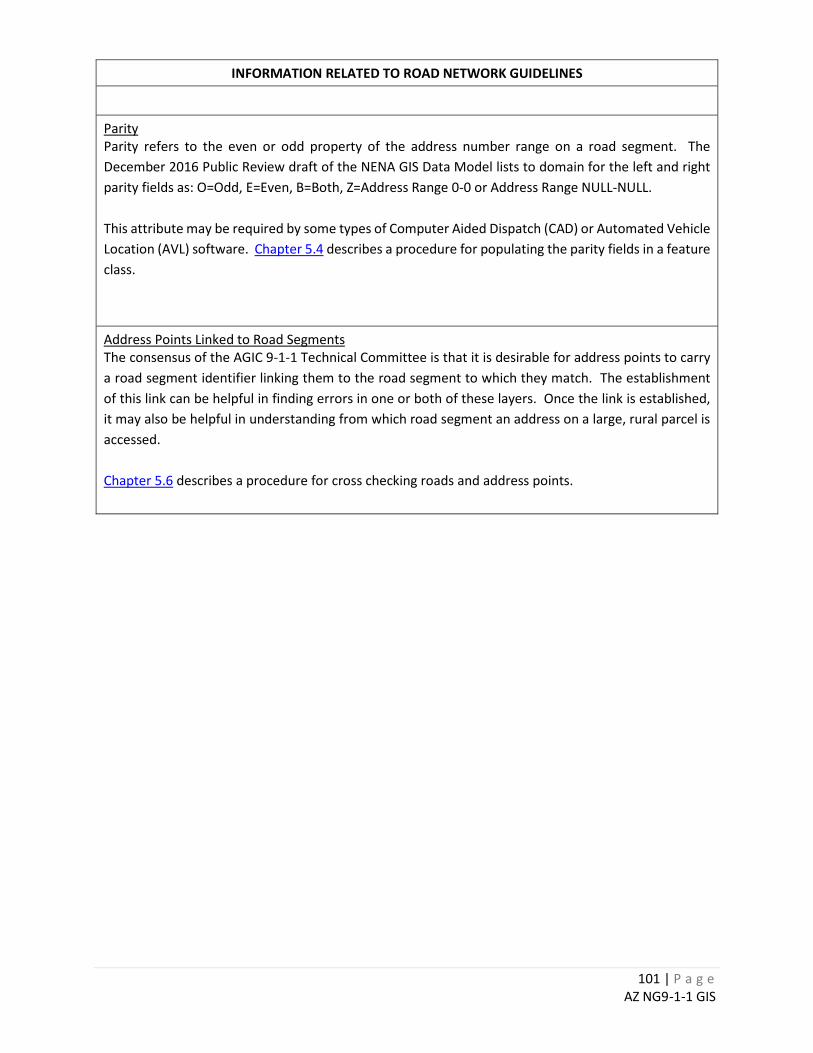
101 | P a g e AZ NG9-1-1 GIS
INFORMATION RELATED TO ROAD NETWORK GUIDELINES
Parity Parity refers to the even or odd property of the address number range on a road segment. The December 2016 Public Review draft of the NENA GIS Data Model lists to domain for the left and right parity fields as: O=Odd, E=Even, B=Both, Z=Address Range 0-0 or Address Range NULL-NULL. This attribute may be required by some types of Computer Aided Dispatch (CAD) or Automated Vehicle Location (AVL) software. Chapter 5.4 describes a procedure for populating the parity fields in a feature class.
Address Points Linked to Road Segments The consensus of the AGIC 9-1-1 Technical Committee is that it is desirable for address points to carry a road segment identifier linking them to the road segment to which they match. The establishment of this link can be helpful in finding errors in one or both of these layers. Once the link is established, it may also be helpful in understanding from which road segment an address on a large, rural parcel is accessed. Chapter 5.6 describes a procedure for cross checking roads and address points.
102 | P a g e AZ NG9-1-1 GIS
INFORMATION RELATED TO EMERGENCY SERVICE BOUNDARIES
Thematic Consistency Emergency Service Boundary (ESB) layers should be maintained in a way most consistent with local data provider workflows. Most AGIC 9-1-1 Working Group Technical Committee members maintain their ESB boundaries as a single Emergency Service Zone (ESN) layer and dissolve it into PSAP, law, fire, and medical polygons after all updates have been made. This may simplify the checking and maintenance of coincident boundaries and topology for some organizations. Care should be taken as to the unique attributes required of an ESB to ensure their incorporation.
Agency Names The ALI screen in the current E9-1-1 architecture is only 512 characters wide and it is not always practical in the legacy system to use the fully spelled agency names. While this constraint may no longer be present in an NG9-1-1 system, the constraint should be considered when deciding how to name your agency boundaries. Alternatively, confusion can occur when abbreviations are used. It is possible a lookup table between the full and abbreviated names could be implemented. If abbreviations are used, try to make them as interpretable as possible. For example, “Volunteer” could be “VOL” as opposed to “V”. Instead of “MCSO” spell out Mohave County SO or Maricopa County SO, instead of “CPD”, Cottonwood PD or Coolidge PD.
Topology ESB boundaries with gaps and overlaps may not be a problem for fire and EMS call routing, but it is critical for law enforcement. Of the three main ESB layers (Law, Medical and Fire), the law enforcement boundaries as well as the PSAP boundary must be seamless across and within 9-1-1 system(s). A “gap” indicates there is no PSAP to route a 9-1-1 call. If a PSAP polygon exists, per NENA it will have to have a Uniform Resource Identifier (URI). This means a gap filled by a polygon and attributed as “none” would not be acceptable. The NG9-1-1 architecture accommodates a threshold value (in sq. meters) in which an overlapping polygon under the threshold will be divided up automatically among the overlapping agencies by the NG9-1-1 system. It is best to be proactive about this issue and not let the system make this decision, as the division may be inaccurate based on legal response.
Source Data Emergency Service Boundaries (ESB’s) are constructed from a variety of sources (e.g. the GCDB section corner layer) and are likely to have some spatial problems. It is recommended that each local data provider decide on a hierarchy of spatially authoritative layers which will determine which layer should be aligned to which layer. There may be an authority in each 9-1-1 system (such as a county or city Surveyor or Engineer) that could weigh-in on an official county boundary as one of the base layers for constructing ESB boundaries. Many 9-1-1 systems have adopted the ALRIS County boundary as their source data. If the local boundary differs from that held in the statewide ALRIS layer, please coordinate with the Arizona State Land Department to ensure consistency.
103 | P a g e AZ NG9-1-1 GIS
INFORMATION RELATED TO SITE / STRUCTURE ADDRESS POINTS
Spatial Representation Site/structure address points represent the location of the site or a structure or the location of access to a site or structure.37 Site / structure points can also represent landmarks. The NENA GIS Data Model contains a Placement Method field to capture this information. Having an association table of address ID’s to road segment ID’s could help with quality assurance processes in both databases. It may also help with finding ingress points for large rural parcels, if that relationship could be exploited by NG9-1-1 to tell responders from which segment the property is accessed. This guideline represents the NENA standard for populating address number fields. Geocoders generally won’t interpret fractions, alpha or special characters correctly. This may result in no-match situations. The NENA GIS Data Model document defines both number prefix and number suffix fields in which these alpha or fractional address elements can be parsed. The NENA CLDXF document is the standard for address element content in an NG9-1-1 System.
Sub-Addressing Sub-addresses are used to track buildings and units that are associated with a single address. A single address can have multiple buildings and multiple units assigned to the address. The Address may also have only buildings or only units. Buildings and unit identifications can be assigned as either numerically or alphabetical. Some Sub -Address Scenarios
o Multiple buildings more than one structure with similar usage: commercial or residential. o Multiple units in buildings with similar usage: Condos, Stores, Suites. o Multiple buildings with no units: Commercial Properties, Hospitals, Campuses. o Multiple units no building or a single building: Trailer Parks, Strip Mall Units.
The December 2016 Public Review draft of the NENA GIS Data Model has fields for Building, Floor, Unit, Room and Seat. Both Pima County and Yuma County have developed schemas for handling sub-addresses. These approaches were not developed to NENA standard, but entail a more sophisticated database design (e.g. related tables) and should be exportable to a NENA standard, if required. You may wish to contact these agencies for further information.
37 December 2016 Public Review draft of the NENA GIS Data Model, Section 4.5, Site / Structure Address Points.
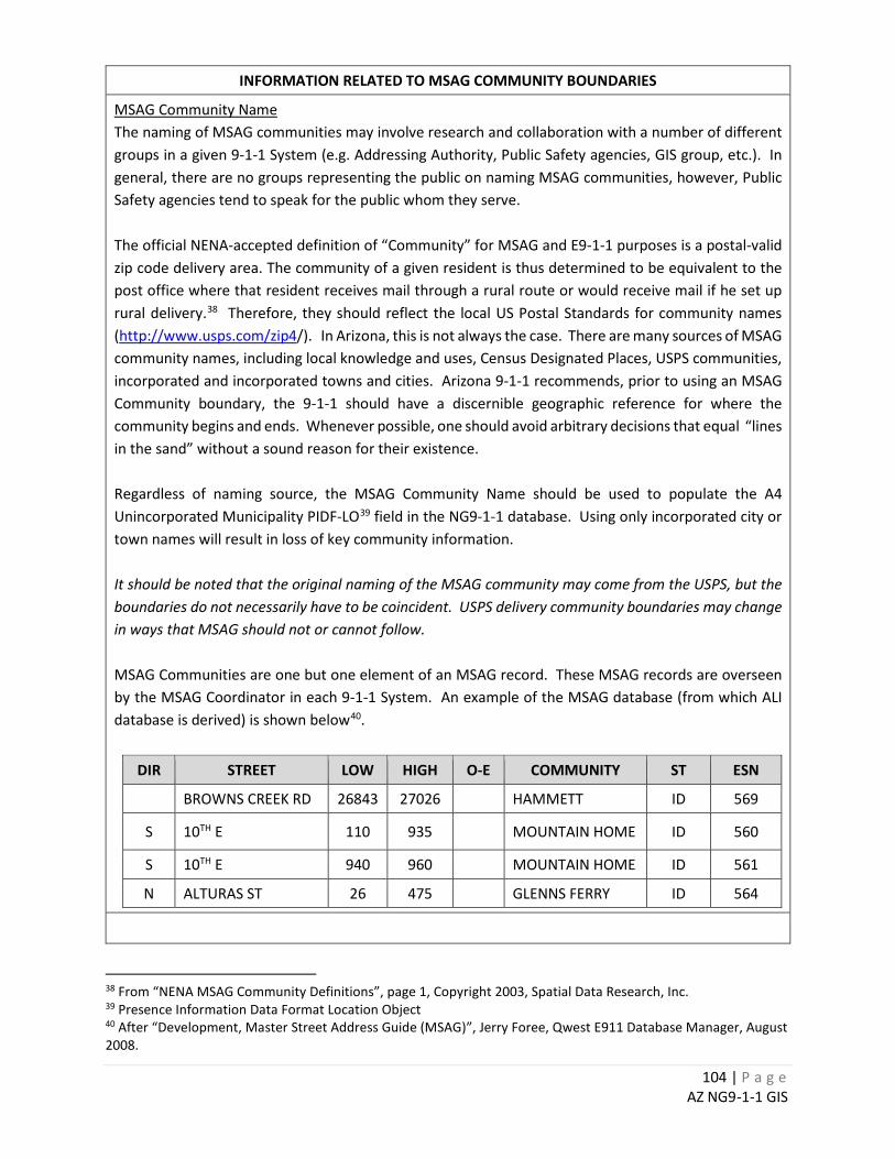
104 | P a g e AZ NG9-1-1 GIS
INFORMATION RELATED TO MSAG COMMUNITY BOUNDARIES
MSAG Community Name The naming of MSAG communities may involve research and collaboration with a number of different groups in a given 9-1-1 System (e.g. Addressing Authority, Public Safety agencies, GIS group, etc.). In general, there are no groups representing the public on naming MSAG communities, however, Public Safety agencies tend to speak for the public whom they serve. The official NENA-accepted definition of “Community” for MSAG and E9-1-1 purposes is a postal-valid zip code delivery area. The community of a given resident is thus determined to be equivalent to the post office where that resident receives mail through a rural route or would receive mail if he set up rural delivery.38 Therefore, they should reflect the local US Postal Standards for community names (http://www.usps.com/zip4/). In Arizona, this is not always the case. There are many sources of MSAG community names, including local knowledge and uses, Census Designated Places, USPS communities, incorporated and incorporated towns and cities. Arizona 9-1-1 recommends, prior to using an MSAG Community boundary, the 9-1-1 should have a discernible geographic reference for where the community begins and ends. Whenever possible, one should avoid arbitrary decisions that equal “lines in the sand” without a sound reason for their existence. Regardless of naming source, the MSAG Community Name should be used to populate the A4 Unincorporated Municipality PIDF-LO39 field in the NG9-1-1 database. Using only incorporated city or town names will result in loss of key community information. It should be noted that the original naming of the MSAG community may come from the USPS, but the boundaries do not necessarily have to be coincident. USPS delivery community boundaries may change in ways that MSAG should not or cannot follow. MSAG Communities are one but one element of an MSAG record. These MSAG records are overseen by the MSAG Coordinator in each 9-1-1 System. An example of the MSAG database (from which ALI database is derived) is shown below40.
DIR STREET LOW HIGH O-E COMMUNITY ST ESN
BROWNS CREEK RD 26843 27026 HAMMETT ID 569
S 10TH E 110 935 MOUNTAIN HOME ID 560
S 10TH E 940 960 MOUNTAIN HOME ID 561
N ALTURAS ST 26 475 GLENNS FERRY ID 564
38 From “NENA MSAG Community Definitions”, page 1, Copyright 2003, Spatial Data Research, Inc. 39 Presence Information Data Format Location Object 40 After “Development, Master Street Address Guide (MSAG)”, Jerry Foree, Qwest E911 Database Manager, August 2008.

105 | P a g e AZ NG9-1-1 GIS
MSAG Community Identifier Note: the COMM_ID field appears in the old E 9-1-1 standard and came from the previous 9-1-1 Program Manager. Its origin is a mystery. There is no standard community ID number to fit this field.
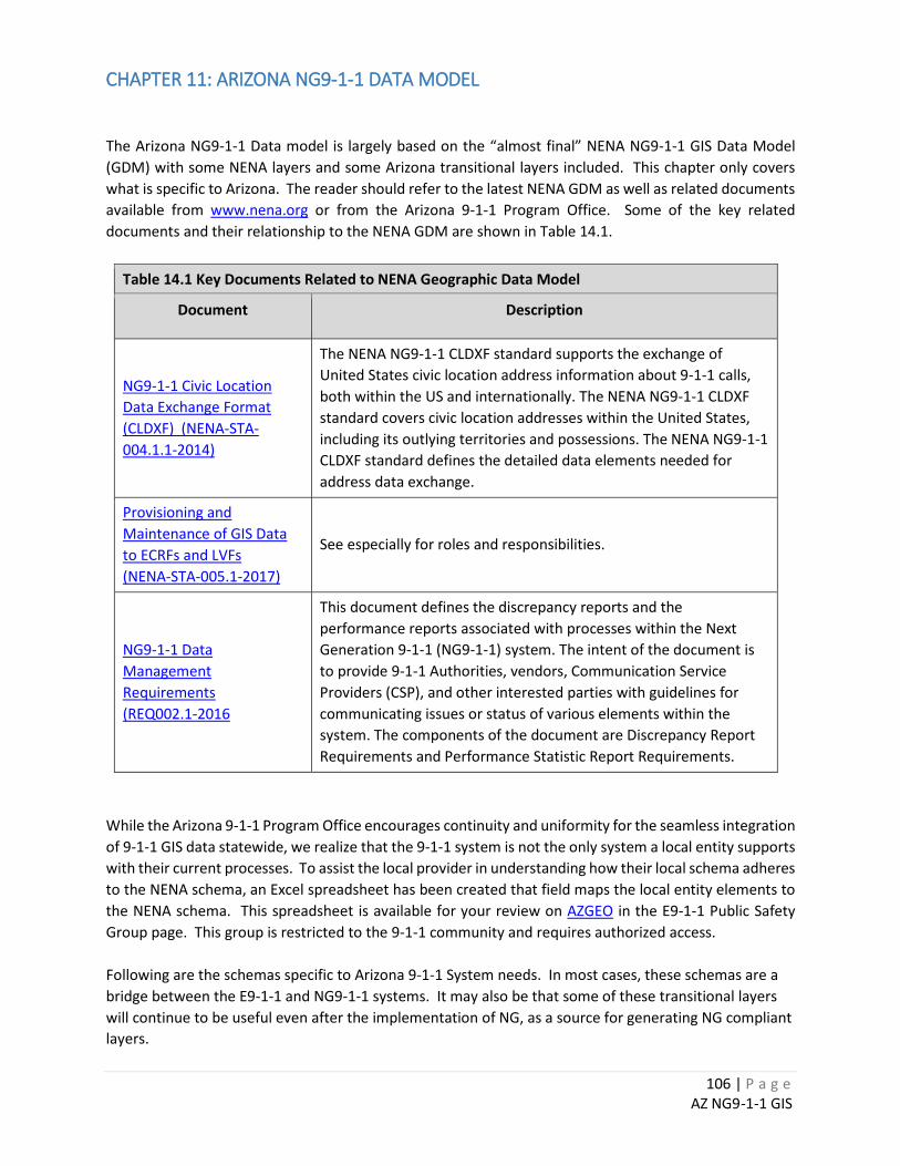
106 | P a g e AZ NG9-1-1 GIS
CHAPTER 11: ARIZONA NG9-1-1 DATA MODEL The Arizona NG9-1-1 Data model is largely based on the “almost final” NENA NG9-1-1 GIS Data Model (GDM) with some NENA layers and some Arizona transitional layers included. This chapter only covers what is specific to Arizona. The reader should refer to the latest NENA GDM as well as related documents available from www.nena.org or from the Arizona 9-1-1 Program Office. Some of the key related documents and their relationship to the NENA GDM are shown in Table 14.1.
Table 14.1 Key Documents Related to NENA Geographic Data Model
Document Description
NG9-1-1 Civic Location Data Exchange Format (CLDXF) (NENA-STA-004.1.1-2014)
The NENA NG9-1-1 CLDXF standard supports the exchange of United States civic location address information about 9-1-1 calls, both within the US and internationally. The NENA NG9-1-1 CLDXF standard covers civic location addresses within the United States, including its outlying territories and possessions. The NENA NG9-1-1 CLDXF standard defines the detailed data elements needed for address data exchange.
Provisioning and Maintenance of GIS Data to ECRFs and LVFs (NENA-STA-005.1-2017)
See especially for roles and responsibilities.
NG9-1-1 Data Management Requirements (REQ002.1-2016
This document defines the discrepancy reports and the performance reports associated with processes within the Next Generation 9-1-1 (NG9-1-1) system. The intent of the document is to provide 9-1-1 Authorities, vendors, Communication Service Providers (CSP), and other interested parties with guidelines for communicating issues or status of various elements within the system. The components of the document are Discrepancy Report Requirements and Performance Statistic Report Requirements.
While the Arizona 9-1-1 Program Office encourages continuity and uniformity for the seamless integration of 9-1-1 GIS data statewide, we realize that the 9-1-1 system is not the only system a local entity supports with their current processes. To assist the local provider in understanding how their local schema adheres to the NENA schema, an Excel spreadsheet has been created that field maps the local entity elements to the NENA schema. This spreadsheet is available for your review on AZGEO in the E9-1-1 Public Safety Group page. This group is restricted to the 9-1-1 community and requires authorized access. Following are the schemas specific to Arizona 9-1-1 System needs. In most cases, these schemas are a bridge between the E9-1-1 and NG9-1-1 systems. It may also be that some of these transitional layers will continue to be useful even after the implementation of NG, as a source for generating NG compliant layers.
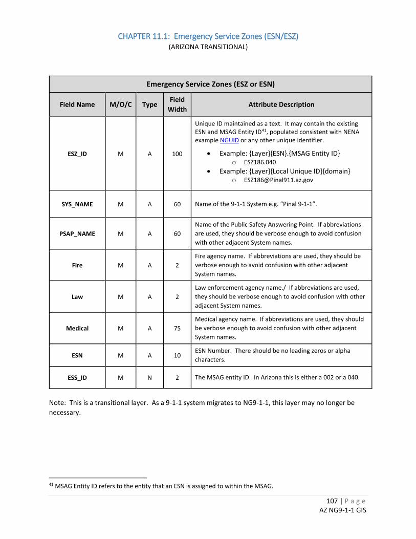
107 | P a g e AZ NG9-1-1 GIS
CHAPTER 11.1: Emergency Service Zones (ESN/ESZ) (ARIZONA TRANSITIONAL)
Emergency Service Zones (ESZ or ESN)
Field Name M/O/C Type Field
Width Attribute Description
ESZ_ID M A 100
Unique ID maintained as a text. It may contain the existing ESN and MSAG Entity ID41, populated consistent with NENA example NGUID or any other unique identifier.
• Example: {Layer}{ESN}.{MSAG Entity ID} o ESZ186.040
• Example: {Layer}{Local Unique ID}{domain} o [email protected]
SYS_NAME M A 60 Name of the 9-1-1 System e.g. “Pinal 9-1-1”.
PSAP_NAME M A 60 Name of the Public Safety Answering Point. If abbreviations are used, they should be verbose enough to avoid confusion with other adjacent System names.
Fire M A 2 Fire agency name. If abbreviations are used, they should be verbose enough to avoid confusion with other adjacent System names.
Law M A 2 Law enforcement agency name./ If abbreviations are used, they should be verbose enough to avoid confusion with other adjacent System names.
Medical M A 75 Medical agency name. If abbreviations are used, they should be verbose enough to avoid confusion with other adjacent System names.
ESN M A 10 ESN Number. There should be no leading zeros or alpha characters.
ESS_ID M N 2 The MSAG entity ID. In Arizona this is either a 002 or a 040.
Note: This is a transitional layer. As a 9-1-1 system migrates to NG9-1-1, this layer may no longer be necessary.
41 MSAG Entity ID refers to the entity that an ESN is assigned to within the MSAG.
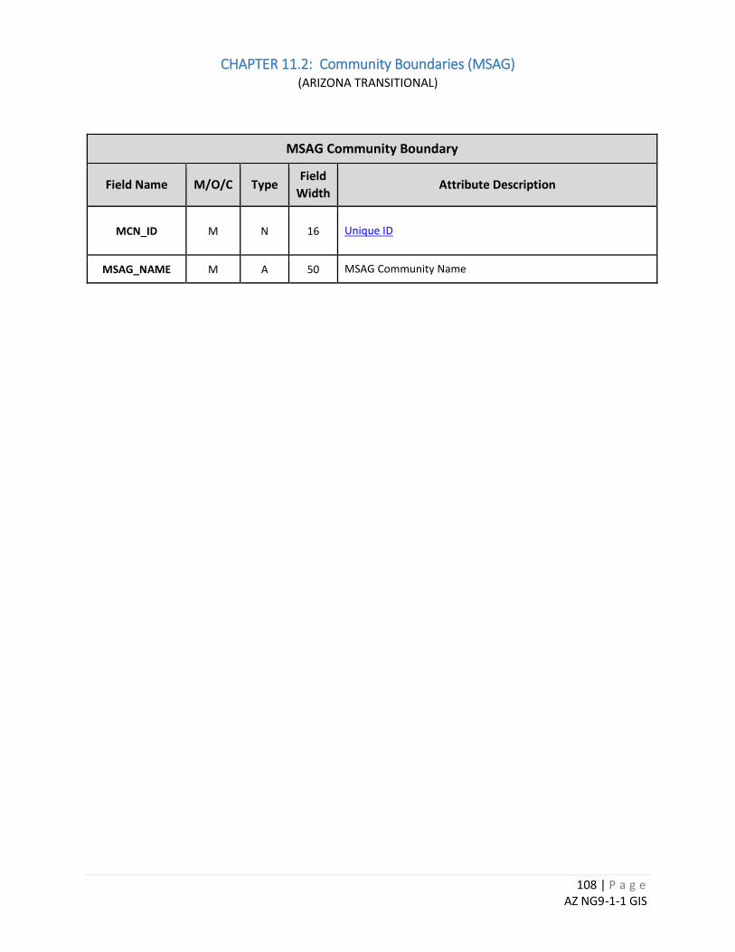
108 | P a g e AZ NG9-1-1 GIS
CHAPTER 11.2: Community Boundaries (MSAG) (ARIZONA TRANSITIONAL)
MSAG Community Boundary
Field Name M/O/C Type Field
Width Attribute Description
MCN_ID M N 16 Unique ID
MSAG_NAME M A 50 MSAG Community Name
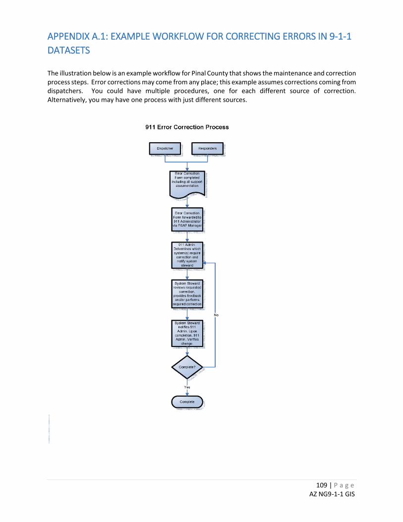
109 | P a g e AZ NG9-1-1 GIS
APPENDIX A.1: EXAMPLE WORKFLOW FOR CORRECTING ERRORS IN 9-1-1 DATASETS The illustration below is an example workflow for Pinal County that shows the maintenance and correction process steps. Error corrections may come from any place; this example assumes corrections coming from dispatchers. You could have multiple procedures, one for each different source of correction. Alternatively, you may have one process with just different sources.
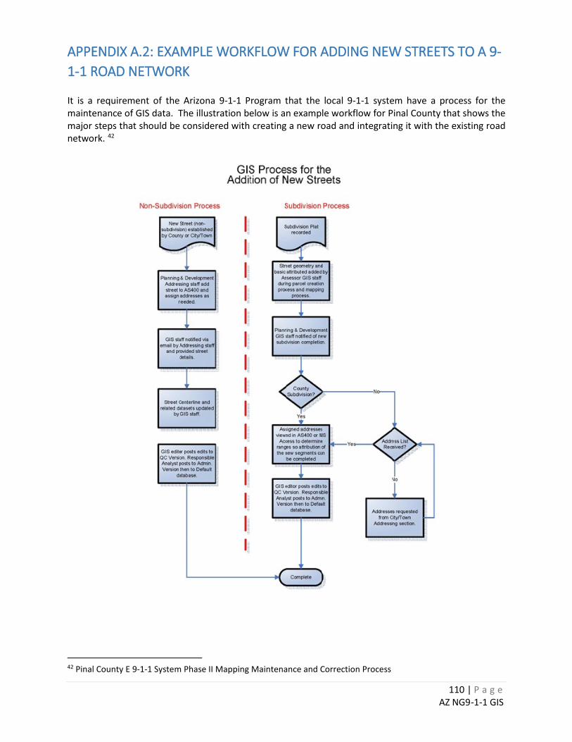
110 | P a g e AZ NG9-1-1 GIS
APPENDIX A.2: EXAMPLE WORKFLOW FOR ADDING NEW STREETS TO A 9-1-1 ROAD NETWORK It is a requirement of the Arizona 9-1-1 Program that the local 9-1-1 system have a process for the maintenance of GIS data. The illustration below is an example workflow for Pinal County that shows the major steps that should be considered with creating a new road and integrating it with the existing road network. 42
42 Pinal County E 9-1-1 System Phase II Mapping Maintenance and Correction Process
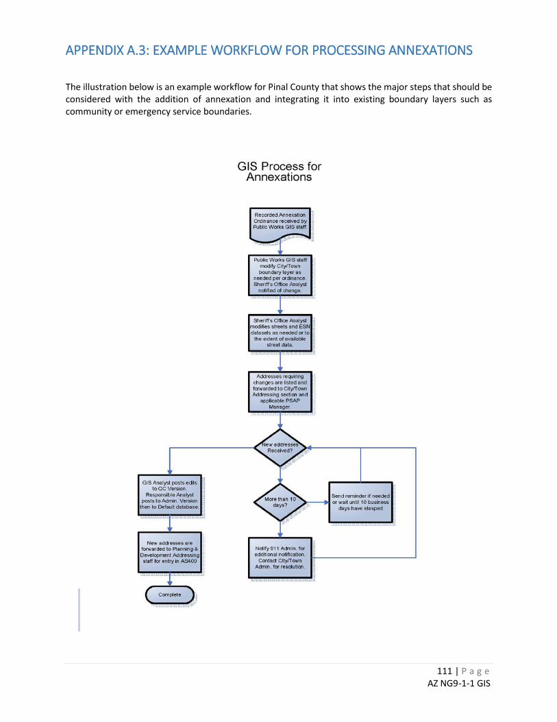
111 | P a g e AZ NG9-1-1 GIS
APPENDIX A.3: EXAMPLE WORKFLOW FOR PROCESSING ANNEXATIONS
The illustration below is an example workflow for Pinal County that shows the major steps that should be considered with the addition of annexation and integrating it into existing boundary layers such as community or emergency service boundaries.
112 | P a g e AZ NG9-1-1 GIS
APPENDIX B.1: ADOT ROAD NETWORK SPATIAL REPRESENTATION GUIDELINES43 It should be noted that these guidelines have been developed in order for road networks to have the topological and attribute consistency required for use in the State Linear Referencing System (LRS). This compatibility is very important as funding for local road improvements is based on the information provided by locals to ADOT. Based on this criticality, these spatial guidelines have been reviewed by the AGIC Data Technical Committee and found to be compatible with the needs of the 9-1-1 community as well.
• Connectivity truth is key in a Linear Referencing System (LRS). Eliminate dangles and undershoots/overshoots that are not true. The LRS Data Reviewer available from ADOT will report these issues to you for mitigation.
• Bifurcations occur whenever more than two arcs with the same name meet at a single
point. Strive to eliminate bifurcations from the beginning by calling out cardinal and non-cardinal carriageways of the same named street with different street names, or use a special field – such as LRS_FIX, (Text, 6) – to carry a descriptive qualifier that ADOT appends to the regular street name prior to building arcs into LRS routes.
• Vertex overpopulation (having 2 vertices atop each other, or so close to each other [<0.528 feet] that they don’t yield significantly different LRS measures) is an issue that Esri regards to be an “Invalid Geometry”. The LRS Data Reviewer will report on these conditions where they exist.
• Address-attributed centerlines typically have address components (DIR_PREFIX, NAME, SUFFIX, DIR_SUFFIX) as well as an amalgamative field that assembles the components. Strive to keep the amalgamative field updated if you update any component thereof.
• Gates that obstruct roadways can be modeled in the centerline file as arcs that intersect pavements at right-angles. This is helpful to keep gates and roads together so that the gates always travel when data is shared. Instruct your data users to be aware that gates are included in the centerline file. Use an appropriate Street Name on the arc that makes it obvious that the arc represents a gate.
• When transitions between divided dual centerlines and undivided single centerlines exist, model
the centerline shapes to keep the cardinal direction (yellow in example below) as close to accurate as possible – for centerline mileage is computed on cardinal directions of travel only. The non-cardinal carriage (cyan in example below) should intersect the cardinal on each end of a median-divided segment. Let the inaccuracy that accommodates connectivity be on the non-cardinal centerline. Allow the transition of the cardinal to move from center of entire roadway to center of cardinal carriageway over a distance of several hundred feet (see red arrows at 3 transitions in
43 Special thanks to J. Meyer (ADOT) and J. Breyer (Works Consulting) for their contribution of these guidelines.
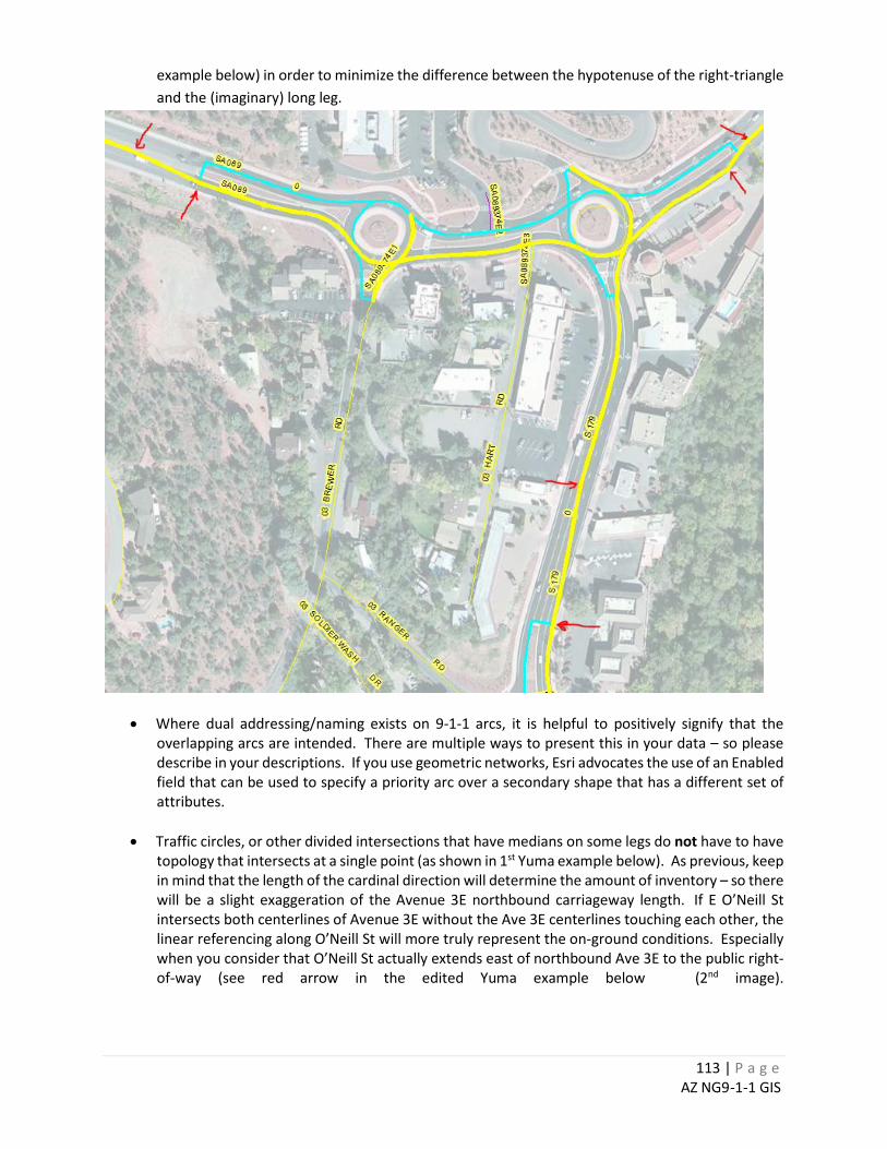
113 | P a g e AZ NG9-1-1 GIS
example below) in order to minimize the difference between the hypotenuse of the right-triangle and the (imaginary) long leg.
• Where dual addressing/naming exists on 9-1-1 arcs, it is helpful to positively signify that the overlapping arcs are intended. There are multiple ways to present this in your data – so please describe in your descriptions. If you use geometric networks, Esri advocates the use of an Enabled field that can be used to specify a priority arc over a secondary shape that has a different set of attributes.
• Traffic circles, or other divided intersections that have medians on some legs do not have to have topology that intersects at a single point (as shown in 1st Yuma example below). As previous, keep in mind that the length of the cardinal direction will determine the amount of inventory – so there will be a slight exaggeration of the Avenue 3E northbound carriageway length. If E O’Neill St intersects both centerlines of Avenue 3E without the Ave 3E centerlines touching each other, the linear referencing along O’Neill St will more truly represent the on-ground conditions. Especially when you consider that O’Neill St actually extends east of northbound Ave 3E to the public right-of-way (see red arrow in the edited Yuma example below (2nd image).
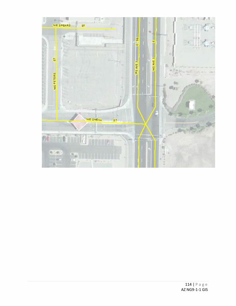
114 | P a g e AZ NG9-1-1 GIS
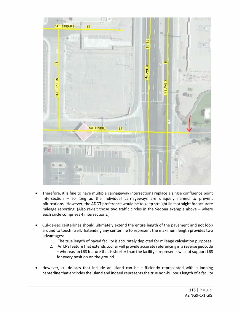
115 | P a g e AZ NG9-1-1 GIS
• Therefore, it is fine to have multiple carriageway intersections replace a single confluence point intersection – so long as the individual carriageways are uniquely named to prevent bifurcations. However, the ADOT preference would be to keep straight lines straight for accurate mileage reporting. (Also revisit those two traffic circles in the Sedona example above – where each circle comprises 4 intersections.)
• Cul-de-sac centerlines should ultimately extend the entire length of the pavement and not loop around to touch itself. Extending any centerline to represent the maximum length provides two advantages:
1. The true length of paved facility is accurately depicted for mileage calculation purposes. 2. An LRS feature that extends too far will provide accurate referencing in a reverse geocode
– whereas an LRS feature that is shorter than the facility it represents will not support LRS for every position on the ground.
• However, cul-de-sacs that include an island can be sufficiently represented with a looping
centerline that encircles the island and indeed represents the true non-bulbous length of a facility

116 | P a g e AZ NG9-1-1 GIS
that circles and intersects itself. It doesn’t hurt to error on the side of giving the road owner the benefit of more mileage to report.
• Since loops on ends of cul-de-sacs produce inherent bifurcations, you may find it preferential to
not let the loop intersect itself. However, do not strive to eliminate these types of “lollypop” bifurcations because ADOT’s procedures can accommodate this issue automatically. How you react to islands in cul-de-sacs will likely be more determined by your addressing scheme if there are houses surrounding the cul-de-sac that contains an island.
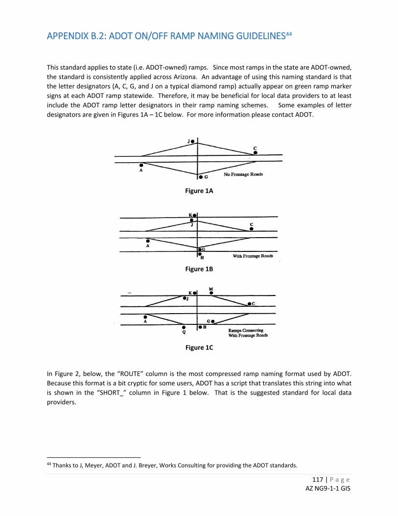
117 | P a g e AZ NG9-1-1 GIS
APPENDIX B.2: ADOT ON/OFF RAMP NAMING GUIDELINES44 This standard applies to state (i.e. ADOT-owned) ramps. Since most ramps in the state are ADOT-owned, the standard is consistently applied across Arizona. An advantage of using this naming standard is that the letter designators (A, C, G, and J on a typical diamond ramp) actually appear on green ramp marker signs at each ADOT ramp statewide. Therefore, it may be beneficial for local data providers to at least include the ADOT ramp letter designators in their ramp naming schemes. Some examples of letter designators are given in Figures 1A – 1C below. For more information please contact ADOT.
Figure 1A
Figure 1B
Figure 1C
In Figure 2, below, the “ROUTE” column is the most compressed ramp naming format used by ADOT. Because this format is a bit cryptic for some users, ADOT has a script that translates this string into what is shown in the “SHORT_” column in Figure 1 below. That is the suggested standard for local data providers.
44 Thanks to J, Meyer, ADOT and J. Breyer, Works Consulting for providing the ADOT standards.
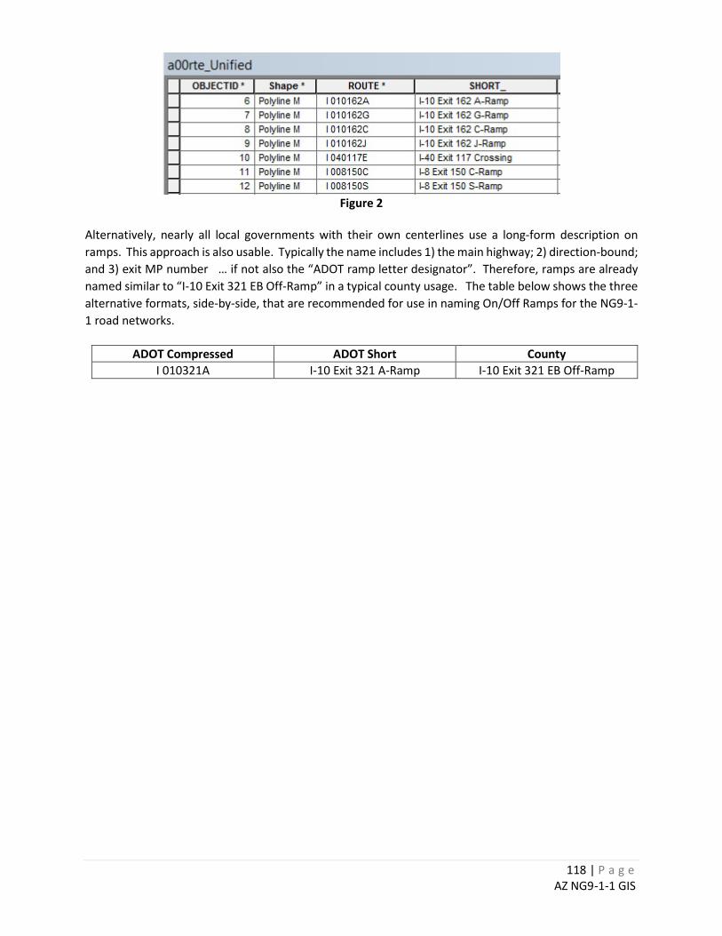
118 | P a g e AZ NG9-1-1 GIS
Figure 2
Alternatively, nearly all local governments with their own centerlines use a long-form description on ramps. This approach is also usable. Typically the name includes 1) the main highway; 2) direction-bound; and 3) exit MP number … if not also the “ADOT ramp letter designator”. Therefore, ramps are already named similar to “I-10 Exit 321 EB Off-Ramp” in a typical county usage. The table below shows the three alternative formats, side-by-side, that are recommended for use in naming On/Off Ramps for the NG9-1-1 road networks.
ADOT Compressed ADOT Short County I 010321A I-10 Exit 321 A-Ramp I-10 Exit 321 EB Off-Ramp

119 | P a g e AZ NG9-1-1 GIS
APPENDIX C: ROAD CLASSIFICATION CODES
US Census MAF/TIGER(MTFCC) Road Classification Codes
Code Class Description
S1100 Primary Road Road/Path Features
Primary roads are generally divided, limited-access highways within the interstate highway system or under state management, and are distinguished by the presence of interchanges. These highways are accessible by ramps and may include some toll highways.
S1200 Secondary Road Road/Path Features
Secondary roads are main arteries, usually in the U.S. Highway, State Highway or County Highway system. These roads have one or more lanes of traffic in each direction, may or may not be divided, and usually have at-grade intersections with many other roads and driveways. They often have both a local name and a route number.
S1400
Local Neighborhood Road, Rural Road, City Street Road/Path Features
Generally a paved non-arterial street, road, or byway that usually has a single lane of traffic in each direction. Roads in this feature class may be privately or publicly maintained. Scenic park roads would be included in this feature class, as would (depending on the region of the country) some unpaved roads.
S1500 Vehicular Trail (4WD) Road/Path Features
An unpaved dirt trail where a four-wheel drive vehicle is required. These vehicular trails are found almost exclusively in very rural areas. Minor, unpaved roads usable by ordinary cars and trucks belong in the S1400 category.
S1630 Ramp Road/Path Features
A road that allows controlled access from adjacent roads onto a limited access highway, often in the form of a cloverleaf interchange. These roads are un-addressable.
S1640
Service Drive usually along a limited access highway Road/Path Features
A road, usually paralleling a limited access highway, that provides access to structures along the highway. These roads can be named and may intersect with other roads.
S1710 Walkway/Pedestrian Trail Road/Path Features
A path that is used for walking, being either too narrow for or legally restricted from vehicular traffic.
S1720 Stairway Road/Path Features A pedestrian passageway from one level to another by a series of steps.
S1730 Alley Road/Path Features
A service road that does not generally have associated addressed structures and is usually unnamed. It is located at the rear of buildings and properties and is used for deliveries.
S1740
Private Road for service vehicles (logging, oil fields, ranches, etc.) Road/Path Features
A road within private property that is privately maintained for service, extractive, or other purposes. These roads are often unnamed.
S1750 Internal U.S. Census Bureau use Road/Path Features
Internal U.S. Census Bureau use.
S1780 Parking Lot Road Road/Path Features The main travel route for vehicles through a paved parking area.
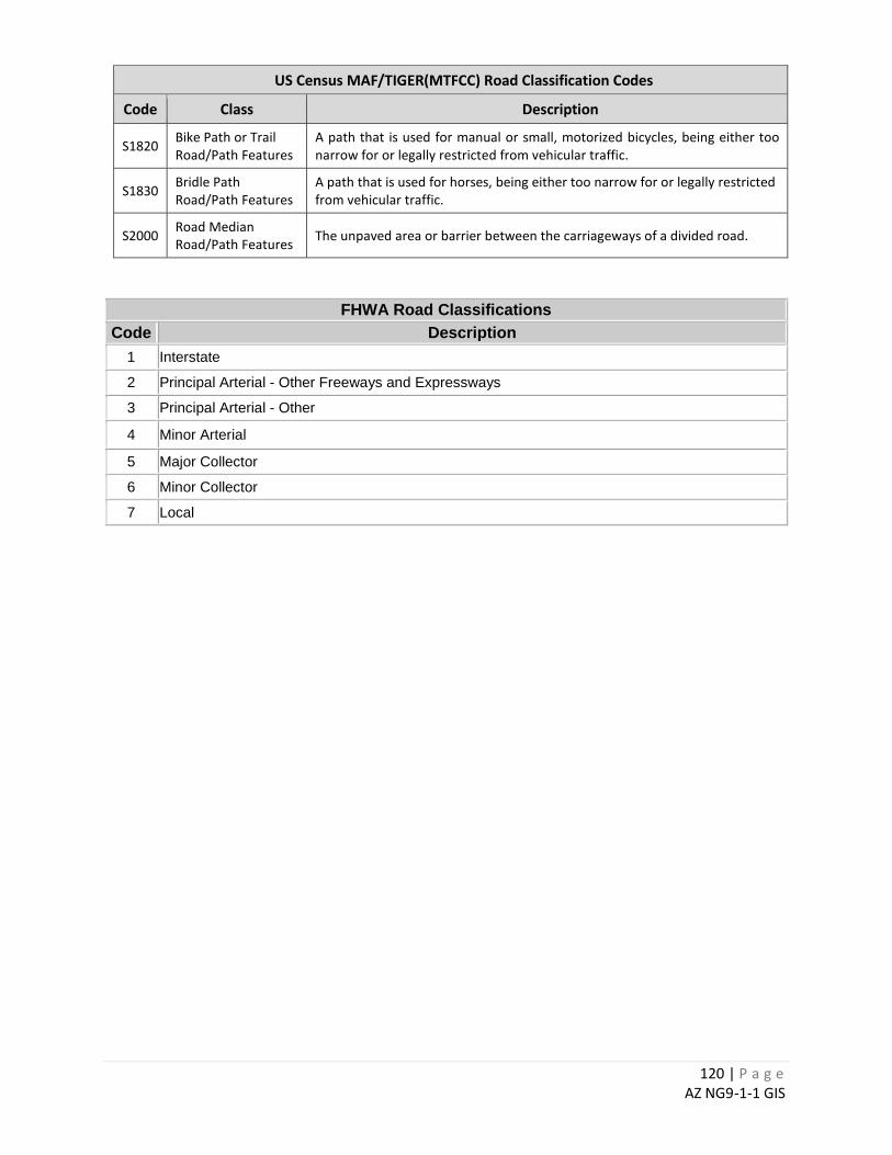
120 | P a g e AZ NG9-1-1 GIS
US Census MAF/TIGER(MTFCC) Road Classification Codes
Code Class Description
S1820 Bike Path or Trail Road/Path Features
A path that is used for manual or small, motorized bicycles, being either too narrow for or legally restricted from vehicular traffic.
S1830 Bridle Path Road/Path Features
A path that is used for horses, being either too narrow for or legally restricted from vehicular traffic.
S2000 Road Median Road/Path Features The unpaved area or barrier between the carriageways of a divided road.
FHWA Road Classifications Code Description
1 Interstate
2 Principal Arterial - Other Freeways and Expressways
3 Principal Arterial - Other
4 Minor Arterial
5 Major Collector
6 Minor Collector
7 Local

121 | P a g e AZ NG9-1-1 GIS
APPENDIX D: LOCAL 9-1-1 PROCESSES
This page left intentionally blank. For use by the local 9-1-1 Authority to document internal processes relevant to 9-1-1.