arm architecture reference manual - trinity college, dublin · 31 28 27 26 25 24 23 22 21 20 19 16...
TRANSCRIPT

ARM Instructions
ADC
ADC (Add with Carry) adds two values and the Carry flag. The first value comes from a register. The second value can be either an immediate value or a value from a register, and can be shifted before the addition.
ADC can optionally update the condition code flags, based on the result.
Syntax
ADC{<cond>}{S} <Rd>, <Rn>, <shifter_operand>
where:
<cond> Is the condition under which the instruction is executed. The conditions are defined in The condition field on page A3-3. If <cond> is omitted, the AL (always) condition is used.
S Causes the S bit (bit[20]) in the instruction to be set to 1 and specifies that the instruction updates the CPSR. If S is omitted, the S bit is set to 0 and the CPSR is not changed by the instruction. Two types of CPSR update can occur when S is specified:
• If <Rd> is not R15, the N and Z flags are set according to the result of the addition, and the C and V flags are set according to whether the addition generated a carry (unsigned overflow) and a signed overflow, respectively. The rest of the CPSR is unchanged.
• If <Rd> is R15, the SPSR of the current mode is copied to the CPSR. This form of the instruction is UNPREDICTABLE if executed in User mode or System mode, because these modes do not have an SPSR.
<Rd> Specifies the destination register.
<Rn> Specifies the register that contains the first operand.
<shifter_operand>
Specifies the second operand. The options for this operand are described in Addressing Mode 1 - Data-processing operands on page A5-2, including how each option causes the I bit (bit[25]) and the shifter_operand bits (bits[11:0]) to be set in the instruction.
If the I bit is 0 and both bit[7] and bit[4] of shifter_operand are 1, the instruction is not ADC. Instead, see Extending the instruction set on page A3-32 to determine which instruction it is.
Architecture version
All.
31 28 27 26 25 24 23 22 21 20 19 16 15 12 11 0
cond 0 0 I 0 1 0 1 S Rn Rd shifter_operand
Copyright ©1996-1998, 2000, 2004, 2005 ARM Limited. All rights reserved.

ARM Instructions
Exceptions
None.
Operation
if ConditionPassed(cond) thenRd = Rn + shifter_operand + C Flagif S == 1 and Rd == R15 then
if CurrentModeHasSPSR() thenCPSR = SPSR
else UNPREDICTABLEelse if S == 1 then
N Flag = Rd[31]Z Flag = if Rd == 0 then 1 else 0C Flag = CarryFrom(Rn + shifter_operand + C Flag)V Flag = OverflowFrom(Rn + shifter_operand + C Flag)
Usage
Use ADC to synthesize multi-word addition. If register pairs R0, R1 and R2, R3 hold 64-bit values (where R0 and R2 hold the least significant words) the following instructions leave the 64-bit sum in R4, R5:
ADDS R4,R0,R2ADC R5,R1,R3
If the second instruction is changed from:
ADC R5,R1,R3
to:
ADCS R5,R1,R3
the resulting values of the flags indicate:
N The 64-bit addition produced a negative result.
C An unsigned overflow occurred.
V A signed overflow occurred.
Z The most significant 32 bits are all zero.
The following instruction produces a single-bit Rotate Left with Extend operation (33-bit rotate through the Carry flag) on R0:
ADCS R0,R0,R0
See Data-processing operands - Rotate right with extend on page A5-17 for information on how to perform a similar rotation to the right.
Copyright ©1996-1998, 2000, 2004, 2005 ARM Limited. All rights reserved.

ARM Instructions
ADD
ADD adds two values. The first value comes from a register. The second value can be either an immediate value or a value from a register, and can be shifted before the addition.
ADD can optionally update the condition code flags, based on the result.
Syntax
ADD{<cond>}{S} <Rd>, <Rn>, <shifter_operand>
where:
<cond> Is the condition under which the instruction is executed. The condition field on page A3-3. If <cond> is omitted, the AL (always) condition is used.
S Causes the S bit (bit[20]) in the instruction to be set to 1 and specifies that the instruction updates the CPSR. If S is omitted, the S bit is set to 0 and the CPSR is not changed by the instruction. Two types of CPSR update can occur when S is specified:
• If <Rd> is not R15, the N and Z flags are set according to the result of the addition, and the C and V flags are set according to whether the addition generated a carry (unsigned overflow) and a signed overflow, respectively. The rest of the CPSR is unchanged.
• If <Rd> is R15, the SPSR of the current mode is copied to the CPSR. This form of the instruction is UNPREDICTABLE if executed in User mode or System mode, because these modes do not have an SPSR.
<Rd> Specifies the destination register.
<Rn> Specifies the register that contains the first operand.
<shifter_operand>
Specifies the second operand. The options for this operand are described in Addressing Mode 1 - Data-processing operands on page A5-2, including how each option causes the I bit (bit[25]) and the shifter_operand bits (bits[11:0]) to be set in the instruction.
If the I bit is 0 and both bit[7] and bit[4] of shifter_operand are 1, the instruction is not ADD. Instead, see Extending the instruction set on page A3-32 to determine which instruction it is.
Architecture version
All.
31 28 27 26 25 24 23 22 21 20 19 16 15 12 11 0
cond 0 0 I 0 1 0 0 S Rn Rd shifter operand
Copyright ©1996-1998, 2000, 2004, 2005 ARM Limited. All rights reserved.

ARM Instructions
Exceptions
None.
Operation
if ConditionPassed(cond) thenRd = Rn + shifter_operandif S == 1 and Rd == R15 then
if CurrentModeHasSPSR() thenCPSR = SPSR
else UNPREDICTABLEelse if S == 1 then
N Flag = Rd[31]Z Flag = if Rd == 0 then 1 else 0C Flag = CarryFrom(Rn + shifter_operand)V Flag = OverflowFrom(Rn + shifter_operand)
Usage
Use ADD to add two values together.
To increment a register value in Rx use:
ADD Rx, Rx, #1
You can perform constant multiplication of Rx by 2n+1 into Rd with:
ADD Rd, Rx, Rx, LSL #n
To form a PC-relative address use:
ADD Rd, PC, #offset
where the offset must be the difference between the required address and the address held in the PC, where the PC is the address of the ADD instruction itself plus 8 bytes.
Copyright ©1996-1998, 2000, 2004, 2005 ARM Limited. All rights reserved.

ARM Instructions
AND
AND performs a bitwise AND of two values. The first value comes from a register. The second value can be either an immediate value or a value from a register, and can be shifted before the AND operation.
AND can optionally update the condition code flags, based on the result.
Syntax
AND{<cond>}{S} <Rd>, <Rn>, <shifter_operand>
where:
<cond> Is the condition under which the instruction is executed. The conditions are defined in The condition field on page A3-3. If <cond> is omitted, the AL (always) condition is used.
S Causes the S bit (bit[20]) in the instruction to be set to 1 and specifies that the instruction updates the CPSR. If S is omitted, the S bit is set to 0 and the CPSR is not changed by the instruction. Two types of CPSR update can occur when S is specified:
• If <Rd> is not R15, the N and Z flags are set according to the result of the operation, and the C flag is set to the carry output bit generated by the shifter (see Addressing Mode 1 - Data-processing operands on page A5-2). The V flag and the rest of the CPSR are unaffected.
• If <Rd> is R15, the SPSR of the current mode is copied to the CPSR. This form of the instruction is UNPREDICTABLE if executed in User mode or System mode, because these modes do not have an SPSR.
<Rd> Specifies the destination register.
<Rn> Specifies the register that contains the first operand.
<shifter_operand>
Specifies the second operand. The options for this operand are described in Addressing Mode 1 - Data-processing operands on page A5-2, including how each option causes the I bit (bit[25]) and the shifter_operand bits (bits[11:0]) to be set in the instruction.
If the I bit is 0 and both bit[7] and bit[4] of shifter_operand are 1, the instruction is not AND. Instead, see Extending the instruction set on page A3-32 to determine which instruction it is.
Architecture version
All.
31 28 27 26 25 24 23 22 21 20 19 16 15 12 11 0
cond 0 0 I 0 0 0 0 S Rn Rd shifter_operand
Copyright ©1996-1998, 2000, 2004, 2005 ARM Limited. All rights reserved.

ARM Instructions
Exceptions
None.
Operation
if ConditionPassed(cond) then Rd = Rn AND shifter_operandif S == 1 and Rd == R15 then
if CurrentModeHasSPSR() thenCPSR = SPSR
else UNPREDICTABLEelse if S == 1 then
N Flag = Rd[31]Z Flag = if Rd == 0 then 1 else 0C Flag = shifter_carry_outV Flag = unaffected
Usage
AND is most useful for extracting a field from a register, by ANDing the register with a mask value that has 1s in the field to be extracted, and 0s elsewhere.
Copyright ©1996-1998, 2000, 2004, 2005 ARM Limited. All rights reserved.

ARM Instructions
B, BL
B (Branch) and BL (Branch and Link) cause a branch to a target address, and provide both conditional and unconditional changes to program flow.
BL also stores a return address in the link register, R14 (also known as LR).
Syntax
B{L}{<cond>} <target_address>
where:
L Causes the L bit (bit 24) in the instruction to be set to 1. The resulting instruction stores a return address in the link register (R14). If L is omitted, the L bit is 0 and the instruction simply branches without storing a return address.
<cond> Is the condition under which the instruction is executed. The conditions are defined in The condition field on page A3-3. If <cond> is omitted, the AL (always) condition is used.
<target_address>
Specifies the address to branch to. The branch target address is calculated by:
1. Sign-extending the 24-bit signed (two's complement) immediate to 30 bits.
2. Shifting the result left two bits to form a 32-bit value.
3. Adding this to the contents of the PC, which contains the address of the branch instruction plus 8 bytes.
The instruction can therefore specify a branch of approximately ±32MB (see Usage on page A4-11 for precise range).
Architecture version
All.
Exceptions
None.
31 28 27 26 25 24 23 0
cond 1 0 1 L signed_immed_24
Copyright ©1996-1998, 2000, 2004, 2005 ARM Limited. All rights reserved.

ARM Instructions
Operation
if ConditionPassed(cond) thenif L == 1 then
LR = address of the instruction after the branch instructionPC = PC + (SignExtend_30(signed_immed_24) << 2)
Usage
Use BL to perform a subroutine call. The return from subroutine is achieved by copying R14 to the PC. Typically, this is done by one of the following methods:
• Executing a BX R14 instruction, on architecture versions that support that instruction.
• Executing a MOV PC,R14 instruction.
• Storing a group of registers and R14 to the stack on subroutine entry, using an instruction of the form:
STMFD R13!,{<registers>,R14}
and then restoring the register values and returning with an instruction of the form:
LDMFD R13!,{<registers>,PC}
To calculate the correct value of signed_immed_24, the assembler (or other toolkit component) must:
1. Form the base address for this branch instruction. This is the address of the instruction, plus 8. In other words, this base address is equal to the PC value used by the instruction.
2. Subtract the base address from the target address to form a byte offset. This offset is always a multiple of four, because all ARM instructions are word-aligned.
3. If the byte offset is outside the range −33554432 to +33554428, use an alternative code-generation strategy or produce an error as appropriate.
4. Otherwise, set the signed_immed_24 field of the instruction to bits{25:2] of the byte offset.
Notes
Memory bounds Branching backwards past location zero and forwards over the end of the 32-bit address space is UNPREDICTABLE.
Copyright ©1996-1998, 2000, 2004, 2005 ARM Limited. All rights reserved.

ARM Instructions
BIC
BIC (Bit Clear) performs a bitwise AND of one value with the complement of a second value. The first value comes from a register. The second value can be either an immediate value or a value from a register, and can be shifted before the BIC operation.
BIC can optionally update the condition code flags, based on the result.
Syntax
BIC{<cond>}{S} <Rd>, <Rn>, <shifter_operand>
where:
<cond> Is the condition under which the instruction is executed. The conditions are defined in The condition field on page A3-3. If <cond> is omitted, the AL (always) condition is used.
S Causes the S bit, bit[20], in the instruction to be set to 1 and specifies that the instruction updates the CPSR. If S is omitted, the S bit is set to 0 and the CPSR is not changed by the instruction. Two types of CPSR update can occur when S is specified:
• If <Rd> is not R15, the N and Z flags are set according to the result of the operation, and the C flag is set to the carry output bit generated by the shifter (see Addressing Mode 1 - Data-processing operands on page A5-2). The V flag and the rest of the CPSR are unaffected.
• If <Rd> is R15, the SPSR of the current mode is copied to the CPSR. This form of the instruction is UNPREDICTABLE if executed in User mode or System mode, because these modes do not have an SPSR.
<Rd> Specifies the destination register.
<Rn> Specifies the register that contains the first operand.
<shifter_operand>
Specifies the second operand. The options for this operand are described in Addressing Mode 1 - Data-processing operands on page A5-2, including how each option causes the I bit (bit[25]) and the shifter_operand bits (bits[11:0]) to be set in the instruction.
If the I bit is 0 and both bit[7] and bit[4] of shifter_operand are 1, the instruction is not BIC. Instead, see Extending the instruction set on page A3-32 to determine which instruction it is.
Architecture version
All.
31 28 27 26 25 24 23 22 21 20 19 16 15 12 11 0
cond 0 0 I 1 1 1 0 S Rn Rd shifter_operand
Copyright ©1996-1998, 2000, 2004, 2005 ARM Limited. All rights reserved.

ARM Instructions
Exceptions
None.
Operation
if ConditionPassed(cond) then Rd = Rn AND NOT shifter_operandif S == 1 and Rd == R15 then
if CurrentModeHasSPSR() thenCPSR = SPSR
else UNPREDICTABLEelse if S == 1 then
N Flag = Rd[31]Z Flag = if Rd == 0 then 1 else 0C Flag = shifter_carry_outV Flag = unaffected
Usage
Use BIC to clear selected bits in a register. For each bit, BIC with 1 clears the bit, and BIC with 0 leaves it unchanged.
Copyright ©1996-1998, 2000, 2004, 2005 ARM Limited. All rights reserved.

ARM Instructions
BX
BX (Branch and Exchange) branches to an address, with an optional switch to Thumb state.
Syntax
BX{<cond>} <Rm>
where:
<cond> Is the condition under which the instruction is executed. The conditions are defined in The condition field on page A3-3. If <cond> is omitted, the AL (always) condition is used.
<Rm> Holds the value of the branch target address. Bit[0] of Rm is 0 to select a target ARM instruction, or 1 to select a target Thumb instruction.
Architecture version
Version 5 and above, and T variants of version 4. See The T and J bits on page A2-15 for further details of operation on non-T variants of version 5.
Exceptions
None.
Operation
if ConditionPassed(cond) thenCPSR T bit = Rm[0]PC = Rm AND 0xFFFFFFFE
Notes
ARM/Thumb state transfers
If Rm[1:0] == 0b10, the result is UNPREDICTABLE, as branches to non word-aligned addresses are impossible in ARM state.
Use of R15 Register 15 can be specified for <Rm>, but doing so is discouraged.
In a BX R15 instruction, R15 is read as normal for ARM code, that is, it is the address of the BX instruction itself plus 8. The result is to branch to the second following word, executing in ARM state. This is precisely the same effect that would have been obtained if a B instruction with an offset field of 0 had been executed, or an ADD PC,PC,#0 or MOV PC,PC instruction. In new code, use these instructions in preference to the more complex BX PC instruction.
31 28 27 26 25 24 23 22 21 20 19 16 15 12 11 8 7 6 5 4 3 0
cond 0 0 0 1 0 0 1 0 SBO SBO SBO 0 0 0 1 Rm
Copyright ©1996-1998, 2000, 2004, 2005 ARM Limited. All rights reserved.

ARM Instructions
CMN
CMN (Compare Negative) compares one value with the twos complement of a second value. The first value comes from a register. The second value can be either an immediate value or a value from a register, and can be shifted before the comparison.
CMN updates the condition flags, based on the result of adding the two values.
Syntax
CMN{<cond>} <Rn>, <shifter_operand>
where:
<cond> Is the condition under which the instruction is executed. The conditions are defined in The condition field on page A3-3. If <cond> is omitted, the AL (always) condition is used.
<Rn> Specifies the register that contains the first operand.
<shifter_operand>
Specifies the second operand. The options for this operand are described in Addressing Mode 1 - Data-processing operands on page A5-2, including how each option causes the I bit (bit[25]) and the shifter_operand bits (bits[11:0]) to be set in the instruction.
If the I bit is 0 and both bit[7] and bit[4] of shifter_operand are 1, the instruction is not CMN. Instead, see Multiply instruction extension space on page A3-35 to determine which instruction it is.
Architecture version
All.
Exceptions
None.
Operation
if ConditionPassed(cond) thenalu_out = Rn + shifter_operandN Flag = alu_out[31]Z Flag = if alu_out == 0 then 1 else 0C Flag = CarryFrom(Rn + shifter_operand)V Flag = OverflowFrom(Rn + shifter_operand)
31 28 27 26 25 24 23 22 21 20 19 16 15 12 11 0
cond 0 0 I 1 0 1 1 1 Rn SBZ shifter_operand
Copyright ©1996-1998, 2000, 2004, 2005 ARM Limited. All rights reserved.

ARM Instructions
Usage
CMN performs a comparison by adding the value of <shifter_operand> to the value of register <Rn>, and updates the condition code flags (based on the result). This is almost equivalent to subtracting the negative of the second operand from the first operand, and setting the flags on the result.
The difference is that the flag values generated can differ when the second operand is 0 or 0x80000000. For example, this instruction always leaves the C flag = 1:
CMP Rn, #0
and this instruction always leaves the C flag = 0:
CMN Rn, #0
Copyright ©1996-1998, 2000, 2004, 2005 ARM Limited. All rights reserved.

ARM Instructions
CMP
CMP (Compare) compares two values. The first value comes from a register. The second value can be either an immediate value or a value from a register, and can be shifted before the comparison.
CMP updates the condition flags, based on the result of subtracting the second value from the first.
Syntax
CMP{<cond>} <Rn>, <shifter_operand>
where:
<cond> Is the condition under which the instruction is executed. The conditions are defined in The condition field on page A3-3. If <cond> is omitted, the AL (always) condition is used.
<Rn> Specifies the register that contains the first operand.
<shifter_operand>
Specifies the second operand. The options for this operand are described in Addressing Mode 1 - Data-processing operands on page A5-2, including how each option causes the I bit (bit[25]) and the shifter_operand bits (bits[11:0]) to be set in the instruction.
If the I bit is 0 and both bit[7] and bit[4] of shifter_operand are 1, the instruction is not CMP. Instead, see Multiply instruction extension space on page A3-35 to determine which instruction it is.
Architecture version
All.
Exceptions
None.
Operation
if ConditionPassed(cond) thenalu_out = Rn - shifter_operandN Flag = alu_out[31]Z Flag = if alu_out == 0 then 1 else 0C Flag = NOT BorrowFrom(Rn - shifter_operand)V Flag = OverflowFrom(Rn - shifter_operand)
31 28 27 26 25 24 23 22 21 20 19 16 15 12 11 0
cond 0 0 I 1 0 1 0 1 Rn SBZ shifter_operand
Copyright ©1996-1998, 2000, 2004, 2005 ARM Limited. All rights reserved.

ARM Instructions
EOR
EOR (Exclusive OR) performs a bitwise Exclusive-OR of two values. The first value comes from a register. The second value can be either an immediate value or a value from a register, and can be shifted before the exclusive OR operation.
EOR can optionally update the condition code flags, based on the result.
Syntax
EOR{<cond>}{S} <Rd>, <Rn>, <shifter_operand>
where:
<cond> Is the condition under which the instruction is executed. The conditions are defined in The condition field on page A3-3. If <cond> is omitted, the AL (always) condition is used.
S Sets the S bit (bit[20]) in the instruction to 1 and specifies that the instruction updates the CPSR. If S is omitted, the S bit is set to 0 and the CPSR is not changed by the instruction. Two types of CPSR update can occur when S is specified:
• If <Rd> is not R15, the N and Z flags are set according to the result of the operation, and the C flag is set to the carry output bit generated by the shifter (see Addressing Mode 1 - Data-processing operands on page A5-2). The V flag and the rest of the CPSR are unaffected.
• If <Rd> is R15, the SPSR of the current mode is copied to the CPSR. This form of the instruction is UNPREDICTABLE if executed in User mode or System mode, because these modes do not have an SPSR.
<Rd> Specifies the destination register.
<Rn> Specifies the register that contains the first operand.
<shifter_operand>
Specifies the second operand. The options for this operand are described in Addressing Mode 1 - Data-processing operands on page A5-2, including how each option causes the I bit (bit[25]) and the shifter_operand bits (bits[11:0]) to be set in the instruction.
If the I bit is 0 and both bit[7] and bit[4] of shifter_operand are 1, the instruction is not EOR. Instead, see Extending the instruction set on page A3-32 to determine which instruction it is.
Architecture version
All.
31 28 27 26 25 24 23 22 21 20 19 16 15 12 11 0
cond 0 0 I 0 0 0 1 S Rn Rd shifter_operand
Copyright ©1996-1998, 2000, 2004, 2005 ARM Limited. All rights reserved.

ARM Instructions
Exceptions
None.
Operation
if ConditionPassed(cond) then Rd = Rn EOR shifter_operandif S == 1 and Rd == R15 then
if CurrentModeHasSPSR() thenCPSR = SPSR
else UNPREDICTABLEelse if S == 1 then
N Flag = Rd[31]Z Flag = if Rd == 0 then 1 else 0C Flag = shifter_carry_outV Flag = unaffected
Usage
Use EOR to invert selected bits in a register. For each bit, EOR with 1 inverts that bit, and EOR with 0 leaves it unchanged.
Copyright ©1996-1998, 2000, 2004, 2005 ARM Limited. All rights reserved.

ARM Instructions
LDM (1)
LDM (1) (Load Multiple) loads a non-empty subset, or possibly all, of the general-purpose registers from sequential memory locations. It is useful for block loads, stack operations and procedure exit sequences.
The general-purpose registers loaded can include the PC. If they do, the word loaded for the PC is treated as an address and a branch occurs to that address. In ARMv5 and above, bit[0] of the loaded value determines whether execution continues after this branch in ARM state or in Thumb state, as though a BX (loaded_value) instruction had been executed (but see also The T and J bits on page A2-15 for operation on non-T variants of ARMv5). In earlier versions of the architecture, bits[1:0] of the loaded value are ignored and execution continues in ARM state, as though the instruction MOV PC,(loaded_value) had been executed.
Syntax
LDM{<cond>}<addressing_mode> <Rn>{!}, <registers>
where:
<cond> Is the condition under which the instruction is executed. The conditions are defined in The condition field on page A3-3. If <cond> is omitted, the AL (always) condition is used.
<addressing_mode>
Is described in Addressing Mode 4 - Load and Store Multiple on page A5-41. It determines the P, U, and W bits of the instruction.
<Rn> Specifies the base register used by <addressing_mode>. Using R15 as the base register <Rn> gives an UNPREDICTABLE result.
! Sets the W bit, causing the instruction to write a modified value back to its base register Rn as specified in Addressing Mode 4 - Load and Store Multiple on page A5-41. If ! is omitted, the W bit is 0 and the instruction does not change its base register in this way. (However, if the base register is included in <registers>, it changes when a value is loaded into it.)
<registers>
Is a list of registers, separated by commas and surrounded by { and }. It specifies the set of registers to be loaded by the LDM instruction.
The registers are loaded in sequence, the lowest-numbered register from the lowest memory address (start_address), through to the highest-numbered register from the highest memory address (end_address). If the PC is specified in the register list (opcode bit[15] is set), the instruction causes a branch to the address (data) loaded into the PC.
For each of i=0 to 15, bit[i] in the register_list field of the instruction is 1 if Ri is in the list and 0 otherwise. If bits[15:0] are all zero, the result is UNPREDICTABLE.
31 28 27 26 25 24 23 22 21 20 19 16 15 0
cond 1 0 0 P U 0 W 1 Rn register_list
Copyright ©1996-1998, 2000, 2004, 2005 ARM Limited. All rights reserved.

ARM Instructions
Architecture version
All.
Exceptions
Data Abort.
Operation
MemoryAccess(B-bit, E-bit)if ConditionPassed(cond) then
address = start_address
for i = 0 to 14if register_list[i] == 1 then
Ri = Memory[address,4]address = address + 4
if register_list[15] == 1 thenvalue = Memory[address,4]if (architecture version 5 or above) then
pc = value AND 0xFFFFFFFET Bit = value[0]
elsepc = value AND 0xFFFFFFFC
address = address + 4 assert end_address == address - 4
NotesOperand restrictions
If the base register <Rn> is specified in <registers>, and base register write-back is specified, the final value of <Rn> is UNPREDICTABLE.
Data Abort For details of the effects of the instruction if a Data Abort occurs, see Effects of data-aborted instructions on page A2-21.
Non word-aligned addresses For CP15_reg1_Ubit == 0, the Load Multiple instructions ignore the least significant two bits of the address. If an implementation includes a System Control coprocessor (see Chapter B3 The System Control Coprocessor), an address with bits[1:0] != 0b00 causes an alignment exception if alignment checking is enabled.
For CP15_reg1_Ubit == 1, all non-word aligned accesses cause an alignment fault.
ARM/Thumb state transfers (ARM architecture version 5 and above) If bits[1:0] of a value loaded for R15 are 0b10, the result is UNPREDICTABLE, as branches to non word-aligned addresses are impossible in ARM state.
Time order The time order of the accesses to individual words of memory generated by this instruction is only defined in some circumstances. See Memory access restrictions on page B2-13for details.
Copyright ©1996-1998, 2000, 2004, 2005 ARM Limited. All rights reserved.

ARM Instructions
LDM (2)
LDM (2) loads User mode registers when the processor is in a privileged mode. This is useful when performing process swaps, and in instruction emulators. LDM (2) loads a non-empty subset of the User mode general-purpose registers from sequential memory locations.
Syntax
LDM{<cond>}<addressing_mode> <Rn>, <registers_without_pc>^
where:
<cond> Is the condition under which the instruction is executed. The conditions are defined in The condition field on page A3-3. If <cond> is omitted, the AL (always) condition is used.
<addressing_mode>
Is described in Addressing Mode 4 - Load and Store Multiple on page A5-41. It determines the P and U bits of the instruction. Only the forms of this addressing mode with W == 0 are available for this form of the LDM instruction.
<Rn> Specifies the base register used by <addressing_mode>. Using R15 as <Rn> gives an UNPREDICTABLE result.
<registers_without_pc>
Is a list of registers, separated by commas and surrounded by { and }. This list must not include the PC, and specifies the set of registers to be loaded by the LDM instruction.
The registers are loaded in sequence, the lowest-numbered register from the lowest memory address (start_address), through to the highest-numbered register from the highest memory address (end_address).
For each of i=0 to 14, bit[i] in the register_list field of the instruction is 1 if Ri is in the list and 0 otherwise. If bits[15:0] are all zero, the result is UNPREDICTABLE.
^ For an LDM instruction that does not load the PC, this indicates that User mode registers are to be loaded.
Architecture version
All.
Exceptions
Data Abort.
31 28 27 26 25 24 23 22 21 20 19 16 15 14 0
cond 1 0 0 P U 1 0 1 Rn 0 register_list
Copyright ©1996-1998, 2000, 2004, 2005 ARM Limited. All rights reserved.

ARM Instructions
Operation
MemoryAccess(B-bit, E-bit)if ConditionPassed(cond) then
address = start_addressfor i = 0 to 14
if register_list[i] == 1Ri_usr = Memory[address,4]address = address + 4
assert end_address == address - 4
Notes
Write-back Setting bit[21] (the W bit) has UNPREDICTABLE results.
User and System mode
This form of LDM is UNPREDICTABLE in User mode or System mode.
Base register mode The base register is read from the current processor mode registers, not the User mode registers.
Data Abort For details of the effects of the instruction if a Data Abort occurs, see Effects of data-aborted instructions on page A2-21.
Non word-aligned addresses
For CP15_reg1_Ubit == 0, the Load Multiple instructions ignore the least significant two bits of the address. If an implementation includes a System Control coprocessor (see Chapter B3 The System Control Coprocessor), an address with bits[1:0] != 0b00 causes an alignment exception if alignment checking is enabled.
For CP15_reg1_Ubit == 1, all non-word aligned accesses cause an alignment fault.
Time order The time order of the accesses to individual words of memory generated by this instruction is only defined in some circumstances. See Memory access restrictions on page B2-13 for details.
Banked registers In ARM architecture versions earlier than ARMv6, this form of LDM must not be followed by an instruction that accesses banked registers. A following NOP is a good way to ensure this.
Copyright ©1996-1998, 2000, 2004, 2005 ARM Limited. All rights reserved.

ARM Instructions
LDM (3)
LDM (3) loads a subset, or possibly all, of the general-purpose registers and the PC from sequential memory locations. Also, the SPSR of the current mode is copied to the CPSR. This is useful for returning from an exception.
The value loaded for the PC is treated as an address and a branch occurs to that address. In ARMv5 and above, and in T variants of version 4, the value copied from the SPSR T bit to the CPSR T bit determines whether execution continues after the branch in ARM state or in Thumb state (but see also The T and J bits on page A2-15 for operation on non-T variants of ARMv5). In earlier architecture versions, it continues after the branch in ARM state (the only possibility in those architecture versions).
Syntax
LDM{<cond>}<addressing_mode> <Rn>{!}, <registers_and_pc>^
where:
<cond> Is the condition under which the instruction is executed. The conditions are defined in The condition field on page A3-3. If <cond> is omitted, the AL (always) condition is used.
<addressing_mode>
Is described in Addressing Mode 4 - Load and Store Multiple on page A5-41. It determines the P, U, and W bits of the instruction.
<Rn> Specifies the base register used by <addressing_mode>. Using R15 as <Rn> gives an UNPREDICTABLE result.
! Sets the W bit, and the instruction writes a modified value back to its base register Rn (see Addressing Mode 4 - Load and Store Multiple on page A5-41). If ! is omitted, the W bit is 0 and the instruction does not change its base register in this way. (However, if the base register is included in <registers>, it changes when a value is loaded into it.)
<registers_and_pc>
Is a list of registers, separated by commas and surrounded by { and }. This list must include the PC, and specifies the set of registers to be loaded by the LDM instruction.
The registers are loaded in sequence, the lowest-numbered register from the lowest memory address (start_address), through to the highest-numbered register from the highest memory address (end_address).
For each of i=0 to 15, bit[i] in the register_list field of the instruction is 1 if Ri is in the list and 0 otherwise.
^ For an LDM instruction that loads the PC, this indicates that the SPSR of the current mode is copied to the CPSR.
Architecture version
All.
31 28 27 26 25 24 23 22 21 20 19 16 15 14 0
cond 1 0 0 P U 1 W 1 Rn 1 register_list
Copyright ©1996-1998, 2000, 2004, 2005 ARM Limited. All rights reserved.

ARM Instructions
Exceptions
Data Abort.
Operation
MemoryAccess(B-bit, E-bit)if ConditionPassed(cond) then
address = start_address
for i = 0 to 14if register_list[i] == 1 then
Ri = Memory[address,4]address = address + 4
if CurrentModeHasSPSR() thenCPSR = SPSR
else UNPREDICTABLE
value = Memory[address,4]PC = valueaddress = address + 4
assert end_address == address - 4
Notes
User and System mode
This instruction is UNPREDICTABLE in User or System mode.
Operand restrictions
If the base register <Rn> is specified in <registers_and_pc>, and base register write-back is specified, the final value of <Rn> is UNPREDICTABLE.
Data Abort For details of the effects of the instruction if a Data Abort occurs, see Effects of data-aborted instructions on page A2-21.
Non word-aligned addresses
For CP15_reg1_Ubit == 0, the Load Multiple instructions ignore the least significant two bits of the address. If an implementation includes a System Control coprocessor (see Chapter B3 The System Control Coprocessor), an address with bits[1:0] != 0b00 causes an alignment exception if alignment checking is enabled.
For CP15_reg1_Ubit == 1, all non-word aligned accesses cause an alignment fault.
Copyright ©1996-1998, 2000, 2004, 2005 ARM Limited. All rights reserved.

ARM Instructions
ARM/Thumb state transfers (ARM architecture versions 4T, 5 and above)
If the SPSR T bit is 0 and bit[1] of the value loaded into the PC is 1, the results are UNPREDICTABLE because it is not possible to branch to an ARM instruction at a non word-aligned address. Note that no special precautions against this are needed on normal exception returns, because exception entries always either set the T bit of the SPSR to 1 or bit[1] of the return link value in R14 to 0.
Time order The time order of the accesses to individual words of memory generated by this instruction is not defined. See Memory access restrictions on page B2-13 for details.
Copyright ©1996-1998, 2000, 2004, 2005 ARM Limited. All rights reserved.
ARM Instructions
LDR
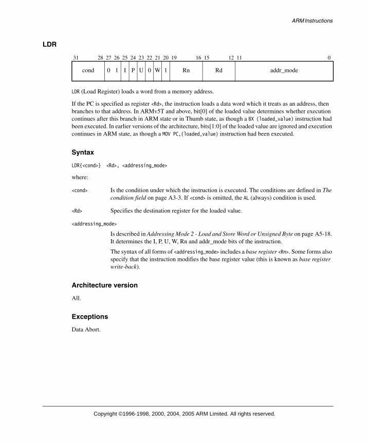
LDR (Load Register) loads a word from a memory address.
If the PC is specified as register <Rd>, the instruction loads a data word which it treats as an address, then branches to that address. In ARMv5T and above, bit[0] of the loaded value determines whether execution continues after this branch in ARM state or in Thumb state, as though a BX (loaded_value) instruction had been executed. In earlier versions of the architecture, bits[1:0] of the loaded value are ignored and execution continues in ARM state, as though a MOV PC,(loaded_value) instruction had been executed.
Syntax
LDR{<cond>} <Rd>, <addressing_mode>
where:
<cond> Is the condition under which the instruction is executed. The conditions are defined in The condition field on page A3-3. If <cond> is omitted, the AL (always) condition is used.
<Rd> Specifies the destination register for the loaded value.
<addressing_mode>
Is described in Addressing Mode 2 - Load and Store Word or Unsigned Byte on page A5-18. It determines the I, P, U, W, Rn and addr_mode bits of the instruction.
The syntax of all forms of <addressing_mode> includes a base register <Rn>. Some forms also specify that the instruction modifies the base register value (this is known as base register write-back).
Architecture version
All.
Exceptions
Data Abort.
31 28 27 26 25 24 23 22 21 20 19 16 15 12 11 0
cond 0 1 I P U 0 W 1 Rn Rd addr_mode
Copyright ©1996-1998, 2000, 2004, 2005 ARM Limited. All rights reserved.

ARM Instructions
Operation
MemoryAccess(B-bit, E-bit)if ConditionPassed(cond) then
if (CP15_reg1_Ubit == 0) thendata = Memory[address,4] Rotate_Right (8 * address[1:0])
else /* CP15_reg_Ubit == 1 */data = Memory[address,4]
if (Rd is R15) thenif (ARMv5 or above) then
PC = data AND 0xFFFFFFFET Bit = data[0]
elsePC = data AND 0xFFFFFFFC
elseRd = data
Usage
Using the PC as the base register allows PC-relative addressing, which facilitates position-independent code. Combined with a suitable addressing mode, LDR allows 32-bit memory data to be loaded into a general-purpose register where its value can be manipulated. If the destination register is the PC, this instruction loads a 32-bit address from memory and branches to that address.
To synthesize a Branch with Link, precede the LDR instruction with MOV LR, PC.
Alignment
ARMv5 and below
If the address is not word-aligned, the loaded value is rotated right by 8 times the value of bits[1:0] of the address. For a little-endian memory system, this rotation causes the addressed byte to occupy the least significant byte of the register. For a big-endian memory system, it causes the addressed byte to occupy bits[31:24] or bits[15:8] of the register, depending on whether bit[0] of the address is 0 or 1 respectively.
If an implementation includes a System Control coprocessor (see Chapter B3 The System Control Coprocessor), and alignment checking is enabled, an address with bits[1:0] != 0b00 causes an alignment exception.
ARMv6 and above
From ARMv6, a byte-invariant mixed-endian format is supported, along with an alignment-checking option. The pseudo-code for the ARMv6 case assumes that unaligned mixed-endian support is configured, with the endianness of the transfer defined by the CPSR E-bit.
For more details on endianness and alignment see Endian support on page A2-30 and Unaligned access support on page A2-38.
Copyright ©1996-1998, 2000, 2004, 2005 ARM Limited. All rights reserved.

ARM Instructions
Notes
Data Abort For details of the effects of the instruction if a Data Abort occurs, see Effects of data-aborted instructions on page A2-21.
Operand restrictions
If <addressing_mode> specifies base register write-back, and the same register is specified for <Rd> and <Rn>, the results are UNPREDICTABLE.
Use of R15 If R15 is specified for <Rd>, the value of the address of the loaded value must be word aligned. That is, address[1:0] must be 0b00. In addition, for Thumb interworking reasons, R15[1:0] must not be loaded with the value 0b10. If these constraints are not met, the result is UNPREDICTABLE.
ARM/Thumb state transfers (ARM architecture version 5 and above)
If bits[1:0] of a value loaded for R15 are 0b10, the result is UNPREDICTABLE, as branches to non word-aligned addresses are impossible in ARM state.
Copyright ©1996-1998, 2000, 2004, 2005 ARM Limited. All rights reserved.

ARM Instructions
LDRB
LDRB (Load Register Byte) loads a byte from memory and zero-extends the byte to a 32-bit word.
Syntax
LDR{<cond>}B <Rd>, <addressing_mode>
where:
<cond> Is the condition under which the instruction is executed. The conditions are defined in The condition field on page A3-3. If <cond> is omitted, the AL (always) condition is used.
<Rd> Specifies the destination register for the loaded value. If register 15 is specified for <Rd>, the result is UNPREDICTABLE.
<addressing_mode>
Is described in Addressing Mode 2 - Load and Store Word or Unsigned Byte on page A5-18. It determines the I, P, U, W, Rn and addr_mode bits of the instruction.
The syntax of all forms of <addressing_mode> includes a base register <Rn>. Some forms also specify that the instruction modifies the base register value (this is known as base register write-back).
Architecture version
All.
Exceptions
Data Abort.
Operation
MemoryAccess(B-bit, E-bit)if ConditionPassed(cond) then
Rd = Memory[address,1]
31 28 27 26 25 24 23 22 21 20 19 16 15 12 11 0
cond 0 1 I P U 1 W 1 Rn Rd addr_mode
Copyright ©1996-1998, 2000, 2004, 2005 ARM Limited. All rights reserved.

ARM Instructions
Usage
Combined with a suitable addressing mode, LDRB allows 8-bit memory data to be loaded into a general-purpose register where it can be manipulated.
Using the PC as the base register allows PC-relative addressing, to facilitate position-independent code.
Notes
Operand restrictions
If <addressing_mode> specifies base register write-back, and the same register is specified for <Rd> and <Rn>, the results are UNPREDICTABLE.
Data Abort For details of the effects of the instruction if a Data Abort occurs, see Effects of data-aborted instructions on page A2-21.
Copyright ©1996-1998, 2000, 2004, 2005 ARM Limited. All rights reserved.

ARM Instructions
LDRH
LDRH (Load Register Halfword) loads a halfword from memory and zero-extends it to a 32-bit word.
Syntax
LDR{<cond>}H <Rd>, <addressing_mode>
where:
<cond> Is the condition under which the instruction is executed. The conditions are defined in The condition field on page A3-3. If <cond> is omitted, the AL (always) condition is used.
<Rd> Specifies the destination register for the loaded value. If R15 is specified for <Rd>, the result is UNPREDICTABLE.
<addressing_mode>
Is described in Addressing Mode 3 - Miscellaneous Loads and Stores on page A5-33. It determines the P, U, I, W, Rn and addr_mode bits of the instruction.
The syntax of all forms of <addressing_mode> includes a base register <Rn>. Some forms also specify that the instruction modifies the base register value (this is known as base register write-back).
Architecture version
All.
Exceptions
Data Abort.
31 28 27 26 25 24 23 22 21 20 19 16 15 12 11 8 7 6 5 4 3 0
cond 0 0 0 P U I W 1 Rn Rd addr_mode 1 0 1 1 addr_mode
Copyright ©1996-1998, 2000, 2004, 2005 ARM Limited. All rights reserved.

ARM Instructions
Operation
MemoryAccess(B-bit, E-bit)if ConditionPassed(cond) then
if (CP15_reg1_Ubit == 0) thenif address[0] == 0 then
data = Memory[address,2]else
data = UNPREDICTABLEelse /* CP15_reg1_Ubit == 1 */
data = Memory[address,2]Rd = ZeroExtend(data[15:0])
Usage
Used with a suitable addressing mode, LDRH allows 16-bit memory data to be loaded into a general-purpose register where its value can be manipulated.
Using the PC as the base register allows PC-relative addressing to facilitate position-independent code.
Notes
Operand restrictions
If <addressing_mode> specifies base register write-back, and the same register is specified for <Rd> and <Rn>, the results are UNPREDICTABLE.
Data Abort For details of the effects of the instruction if a Data Abort occurs, see Effects of data-aborted instructions on page A2-21.
Alignment Prior to ARMv6, if the memory address is not halfword aligned, the data read from memory is UNPREDICTABLE. Alignment checking (taking a data abort when address[0] != 0), and support for a big-endian (BE-32) data format are implementation options.
From ARMv6, a byte-invariant mixed-endian format is supported, along with an alignment checking option. The pseudo-code for the ARMv6 case assumes that mixed-endian support is configured, with the endianness of the transfer defined by the CPSR E-bit.
For more details on endianness and alignment, see Endian support on page A2-30 and Unaligned access support on page A2-38.
Copyright ©1996-1998, 2000, 2004, 2005 ARM Limited. All rights reserved.

ARM Instructions
LDRSB
LDRSB (Load Register Signed Byte) loads a byte from memory and sign-extends the byte to a 32-bit word.
Syntax
LDR{<cond>}SB <Rd>, <addressing_mode>
where:
<cond> Is the condition under which the instruction is executed. The conditions are defined in The condition field on page A3-3. If <cond> is omitted, the AL (always) condition is used.
<Rd> Specifies the destination register for the loaded value. If R15 is specified for <Rd>, the result is UNPREDICTABLE.
<addressing_mode>
Is described in Addressing Mode 3 - Miscellaneous Loads and Stores on page A5-33. It determines the P, U, I, W, Rn and addr_mode bits of the instruction.
The syntax of all forms of <addressing_mode> includes a base register <Rn>. Some forms also specify that the instruction modifies the base register value (this is known as base register write-back).
Architecture version
Version 4 and above.
Exceptions
Data Abort.
Operation
MemoryAccess(B-bit, E-bit)if ConditionPassed(cond) then
data = Memory[address,1]Rd = SignExtend(data)
31 28 27 26 25 24 23 22 21 20 19 16 15 12 11 8 7 6 5 4 3 0
cond 0 0 0 P U I W 1 Rn Rd addr_mode 1 1 0 1 addr_mode
Copyright ©1996-1998, 2000, 2004, 2005 ARM Limited. All rights reserved.

ARM Instructions
Usage
Use LDRSB with a suitable addressing mode to load 8-bit signed memory data into a general-purpose register where it can be manipulated.
You can perform PC-relative addressing by using the PC as the base register. This facilitates position-independent code.
Notes
Operand restrictions
If <addressing_mode> specifies base register write-back, and the same register is specified for <Rd> and <Rn>, the results are UNPREDICTABLE.
Data Abort For details of the effects of the instruction if a Data Abort occurs, see Effects of data-aborted instructions on page A2-21.
Copyright ©1996-1998, 2000, 2004, 2005 ARM Limited. All rights reserved.
ARM Instructions
LDRSH
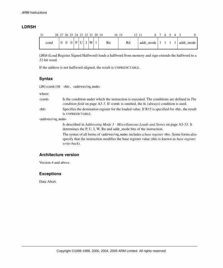
LDRSH (Load Register Signed Halfword) loads a halfword from memory and sign-extends the halfword to a 32-bit word.
If the address is not halfword-aligned, the result is UNPREDICTABLE.
Syntax
LDR{<cond>}SH <Rd>, <addressing_mode>
where:
<cond> Is the condition under which the instruction is executed. The conditions are defined in The condition field on page A3-3. If <cond> is omitted, the AL (always) condition is used.
<Rd> Specifies the destination register for the loaded value. If R15 is specified for <Rd>, the result is UNPREDICTABLE.
<addressing_mode>
Is described in Addressing Mode 3 - Miscellaneous Loads and Stores on page A5-33. It determines the P, U, I, W, Rn and addr_mode bits of the instruction.
The syntax of all forms of <addressing_mode> includes a base register <Rn>. Some forms also specify that the instruction modifies the base register value (this is known as base register write-back).
Architecture version
Version 4 and above.
Exceptions
Data Abort.
31 28 27 26 25 24 23 22 21 20 19 16 15 12 11 8 7 6 5 4 3 0
cond 0 0 0 P U I W 1 Rn Rd addr_mode 1 1 1 1 addr_mode
Copyright ©1996-1998, 2000, 2004, 2005 ARM Limited. All rights reserved.

ARM Instructions
Operation
MemoryAccess(B-bit, E-bit)if ConditionPassed(cond) then
if (CP15_reg1_Ubit == 0) thenif address[0] == 0 then
data = Memory[address,2]else
data = UNPREDICTABLEelse /* CP15_reg1_Ubit == 1 */
data = Memory[address,2]Rd = SignExtend(data[15:0])
Usage
Used with a suitable addressing mode, LDRSH allows 16-bit signed memory data to be loaded into a general-purpose register where its value can be manipulated.
Using the PC as the base register allows PC-relative addressing, which facilitates position-independent code.
Notes
Operand restrictions
If <addressing_mode> specifies base register write-back, and the same register is specified for <Rd> and <Rn>, the results are UNPREDICTABLE.
Data Abort For details of the effects of the instruction if a Data Abort occurs, see Effects of data-aborted instructions on page A2-21.
Alignment Prior to ARMv6, if the memory address is not halfword aligned, the data read from memory is UNPREDICTABLE. Alignment checking (taking a data abort when address[0] != 0), and support for a big-endian (BE-32) data format are implementation options.
From ARMv6, a byte-invariant mixed-endian format is supported, along with an alignment checking option. The pseudo-code for the ARMv6 case assumes that mixed-endian support is configured, with the endianness of the transfer defined by the CPSR E-bit.
For more details on endianness and alignment, see Endian support on page A2-30 and Unaligned access support on page A2-38.
Copyright ©1996-1998, 2000, 2004, 2005 ARM Limited. All rights reserved.

ARM Instructions
MLA
MLA (Multiply Accumulate) multiplies two signed or unsigned 32-bit values, and adds a third 32-bit value. The least significant 32 bits of the result are written to the destination register.
MLA can optionally update the condition code flags, based on the result.
Syntax
MLA{<cond>}{S} <Rd>, <Rm>, <Rs>, <Rn>
where:
<cond> Is the condition under which the instruction is executed. The conditions are defined in The condition field on page A3-3. If <cond> is omitted, the AL (always) condition is used.
S Causes the S bit (bit[20]) in the instruction to be set to 1 and specifies that the instruction updates the CPSR by setting the N and Z flags according to the result of the multiply-accumulate. If S is omitted, the S bit of the instruction is set to 0 and the entire CPSR is unaffected by the instruction.
<Rd> Specifies the destination register.
<Rm> Holds the value to be multiplied with the value of <Rs>.
<Rs> Holds the value to be multiplied with the value of <Rm>.
<Rn> Contains the value that is added to the product of <Rs> and <Rm>.
Architecture version
All.
Exceptions
None.
31 28 27 26 25 24 23 22 21 20 19 16 15 12 11 8 7 6 5 4 3 0
cond 0 0 0 0 0 0 1 S Rd Rn Rs 1 0 0 1 Rm
Copyright ©1996-1998, 2000, 2004, 2005 ARM Limited. All rights reserved.

ARM Instructions
Operation
if ConditionPassed(cond) thenRd = (Rm * Rs + Rn)[31:0]if S == 1 then
N Flag = Rd[31]Z Flag = if Rd == 0 then 1 else 0C Flag = unaffected in v5 and above, UNPREDICTABLE in v4 and earlierV Flag = unaffected
Notes
Use of R15 Specifying R15 for register <Rd>, <Rm>, <Rs>, or <Rn> has UNPREDICTABLE results.
Early termination If the multiplier implementation supports early termination, it must be implemented on the value of the <Rs> operand. The type of early termination used (signed or unsigned) is IMPLEMENTATION DEFINED.
Signed and unsigned The MLA instruction produces only the lower 32 bits of the 64-bit product. Therefore, MLA gives the same answer for multiplication of both signed and unsigned numbers.
C flag The MLAS instruction is defined to leave the C flag unchanged in ARMv5 and above. In earlier versions of the architecture, the value of the C flag was UNPREDICTABLE after an MLAS instruction.
Operand restriction Specifying the same register for <Rd> and <Rm> was previously described as producing UNPREDICTABLE results. There is no restriction in ARMv6, and it is believed that all relevant ARMv4 and ARMv5 implementations do not require this restriction either, because high performance multipliers read all their operands prior to writing back any results.
Copyright ©1996-1998, 2000, 2004, 2005 ARM Limited. All rights reserved.

ARM Instructions
MOV
MOV (Move) writes a value to the destination register. The value can be either an immediate value or a value from a register, and can be shifted before the write.
MOV can optionally update the condition code flags, based on the result.
Syntax
MOV{<cond>}{S} <Rd>, <shifter_operand>
where:
<cond> Is the condition under which the instruction is executed. The conditions are defined in The condition field on page A3-3. If <cond> is omitted, the AL (always) condition is used.
S Sets the S bit (bit[20]) in the instruction to 1 and specifies that the instruction updates the CPSR. If S is omitted, the S bit is set to 0 and the CPSR is not changed by the instruction. Two types of CPSR update can occur when S is specified:
• If <Rd> is not R15, the N and Z flags are set according to the value moved (post-shift if a shift is specified), and the C flag is set to the carry output bit generated by the shifter (see Addressing Mode 1 - Data-processing operands on page A5-2). The V flag and the rest of the CPSR are unaffected.
• If <Rd> is R15, the SPSR of the current mode is copied to the CPSR. This form of the instruction is UNPREDICTABLE if executed in User mode or System mode, because these modes do not have an SPSR.
<Rd> Specifies the destination register.
<shifter_operand>
Specifies the operand. The options for this operand are described in Addressing Mode 1 - Data-processing operands on page A5-2, including how each option causes the I bit (bit[25]) and the shifter_operand bits (bits[11:0]) to be set in the instruction.
If the I bit is 0 and both bit[7] and bit[4] of shifter_operand are 1, the instruction is not MOV. Instead, see Extending the instruction set on page A3-32 to determine which instruction it is.
Architecture version
All.
Exceptions
None.
31 28 27 26 25 24 23 22 21 20 19 16 15 12 11 0
cond 0 0 I 1 1 0 1 S SBZ Rd shifter_operand
Copyright ©1996-1998, 2000, 2004, 2005 ARM Limited. All rights reserved.

ARM Instructions
Operation
if ConditionPassed(cond) thenRd = shifter_operandif S == 1 and Rd == R15 then
if CurrentModeHasSPSR() thenCPSR = SPSR
else UNPREDICTABLEelse if S == 1 then
N Flag = Rd[31]Z Flag = if Rd == 0 then 1 else 0C Flag = shifter_carry_outV Flag = unaffected
Usage
Use MOV to:
• Move a value from one register to another.
• Put a constant value into a register.
• Perform a shift without any other arithmetic or logical operation. Use a left shift by n to multiply by 2n.
• When the PC is the destination of the instruction, a branch occurs. The instruction:MOV PC, LR
can therefore be used to return from a subroutine (see instructions B, BL on page A4-10). In T variants of architecture 4 and in architecture 5 and above, the instruction BX LR must be used in place of MOV PC, LR, as the BX instruction automatically switches back to Thumb state if appropriate (but see also The T and J bits on page A2-15 for operation on non-T variants of ARM architecture version 5).
• When the PC is the destination of the instruction and the S bit is set, a branch occurs and the SPSR of the current mode is copied to the CPSR. This means that you can use a MOVS PC, LR instruction to return from some types of exception (see Exceptions on page A2-16).
Copyright ©1996-1998, 2000, 2004, 2005 ARM Limited. All rights reserved.

ARM Instructions
MRS
MRS (Move PSR to general-purpose register) moves the value of the CPSR or the SPSR of the current mode into a general-purpose register. In the general-purpose register, the value can be examined or manipulated with normal data-processing instructions.
Syntax
MRS{<cond>} <Rd>, CPSRMRS{<cond>} <Rd>, SPSR
where:
<cond> Is the condition under which the instruction is executed. The conditions are defined in The condition field on page A3-3. If <cond> is omitted, the AL (always) condition is used.
<Rd> Specifies the destination register. If R15 is specified for <Rd>, the result is UNPREDICTABLE.
Architecture version
All.
Exceptions
None.
Operation
if ConditionPassed(cond) thenif R == 1 then
Rd = SPSRelse
Rd = CPSR
31 28 27 26 25 24 23 22 21 20 19 16 15 12 11 0
cond 0 0 0 1 0 R 0 0 SBO Rd SBZ
Copyright ©1996-1998, 2000, 2004, 2005 ARM Limited. All rights reserved.
ARM Instructions
Usage
The MRS instruction is commonly used for three purposes:
• As part of a read/modify/write sequence for updating a PSR. For more details, see MSR on page A4-76.
• When an exception occurs and there is a possibility of a nested exception of the same type occurring, the SPSR of the exception mode is in danger of being corrupted. To deal with this, the SPSR value must be saved before the nested exception can occur, and later restored in preparation for the exception return. The saving is normally done by using an MRS instruction followed by a store instruction. Restoring the SPSR uses the reverse sequence of a load instruction followed by an MSR instruction.
• In process swap code, the programmers’ model state of the process being swapped out must be saved, including relevant PSR contents, and similar state of the process being swapped in must be restored. Again, this involves the use of MRS/store and load/MSR instruction sequences.
Notes
User mode SPSR Accessing the SPSR when in User mode or System mode is UNPREDICTABLE.
Copyright ©1996-1998, 2000, 2004, 2005 ARM Limited. All rights reserved.

ARM Instructions
MSR
Immediate operand:
Register operand:
MSR (Move to Status Register from ARM Register) transfers the value of a general-purpose register or an immediate constant to the CPSR or the SPSR of the current mode.
Syntax
MSR{<cond>} CPSR_<fields>, #<immediate> MSR{<cond>} CPSR_<fields>, <Rm>MSR{<cond>} SPSR_<fields>, #<immediate> MSR{<cond>} SPSR_<fields>, <Rm>
where:
<cond> Is the condition under which the instruction is executed. The conditions are defined in The condition field on page A3-3. If <cond> is omitted, the AL (always) condition is used.
<fields> Is a sequence of one or more of the following:
c sets the control field mask bit (bit 16)
x sets the extension field mask bit (bit 17)
s sets the status field mask bit (bit 18)
f sets the flags field mask bit (bit 19).
<immediate> Is the immediate value to be transferred to the CPSR or SPSR. Allowed immediate values are 8-bit immediates (in the range 0x00 to 0xFF) and values that can be obtained by rotating them right by an even amount in the range 0 to 30. These immediate values are the same as those allowed in the immediate form as shown in Data-processing operands - Immediate on page A5-6.
<Rm> Is the general-purpose register to be transferred to the CPSR or SPSR.
Architecture version
All.
31 28 27 26 25 24 23 22 21 20 19 16 15 12 11 8 7 0
cond 0 0 1 1 0 R 1 0 field_mask SBO rotate_imm 8_bit_immediate
31 28 27 26 25 24 23 22 21 20 19 16 15 12 11 8 7 6 5 4 3 0
cond 0 0 0 1 0 R 1 0 field_mask SBO SBZ 0 0 0 0 Rm
Copyright ©1996-1998, 2000, 2004, 2005 ARM Limited. All rights reserved.

ARM Instructions
Exceptions
None.
Operation
There are four categories of PSR bits, according to rules about updating them, see Types of PSR bits on page A2-11 for details.
The pseudo-code uses four bit mask constants to identify these categories of PSR bits. The values of these masks depend on the architecture version, see Table A4-1.
if ConditionPassed(cond) thenif opcode[25] == 1 then
operand = 8_bit_immediate Rotate_Right (rotate_imm * 2)else
operand = Rmif (operand AND UnallocMask) !=0 then
UNPREDICTABLE /* Attempt to set reserved bits */byte_mask = (if field_mask[0] == 1 then 0x000000FF else 0x00000000) OR
(if field_mask[1] == 1 then 0x0000FF00 else 0x00000000) OR(if field_mask[2] == 1 then 0x00FF0000 else 0x00000000) OR(if field_mask[3] == 1 then 0xFF000000 else 0x00000000)
if R == 0 thenif InAPrivilegedMode() then
if (operand AND StateMask) != 0 thenUNPREDICTABLE /* Attempt to set non-ARM execution state */
elsemask = byte_mask AND (UserMask OR PrivMask)
elsemask = byte_mask AND UserMask
CPSR = (CPSR AND NOT mask) OR (operand AND mask)else /* R == 1 */
if CurrentModeHasSPSR() thenmask = byte_mask AND (UserMask OR PrivMask OR StateMask)SPSR = (SPSR AND NOT mask) OR (operand AND mask)
elseUNPREDICTABLE
Table A4-1 Bit mask constants
Architecture versions UnallocMask UserMask PrivMask StateMask
4 0x0FFFFF20 0xF0000000 0x0000000F 0x00000000
4T, 5T 0x0FFFFF00 0xF0000000 0x0000000F 0x00000020
5TE, 5TExP 0x07FFFF00 0xF8000000 0x0000000F 0x00000020
5TEJ 0x06FFFF00 0xF8000000 0x0000000F 0x01000020
6 0x06F0FC00 0xF80F0200 0x000001DF 0x01000020
Copyright ©1996-1998, 2000, 2004, 2005 ARM Limited. All rights reserved.

ARM Instructions
Usage
Use MSR to update the value of the condition code flags, interrupt enables, or the processor mode.
You must normally update the value of a PSR by moving the PSR to a general-purpose register (using the MRS instruction), modifying the relevant bits of the general-purpose register, and restoring the updated general-purpose register value back into the PSR (using the MSR instruction). For example, a good way to switch the ARM to Supervisor mode from another privileged mode is:
MRS R0,CPSR ; Read CPSRBIC R0,R0,#0x1F ; Modify by removing current modeORR R0,R0,#0x13 ; and substituting Supervisor modeMSR CPSR_c,R0 ; Write the result back to CPSR
For maximum efficiency, MSR instructions should only write to those fields that they can potentially change. For example, the last instruction in the above code can only change the CPSR control field, as all bits in the other fields are unchanged since they were read from the CPSR by the first instruction. So it writes to CPSR_c, not CPSR_fsxc or some other combination of fields.
However, if the only reason that an MSR instruction cannot change a field is that no bits are currently allocated to the field, then the field must be written, to ensure future compatibility.
You can use the immediate form of MSR to set any of the fields of a PSR, but you must take care to use the read-modify-write technique described above. The immediate form of the instruction is equivalent to reading the PSR concerned, replacing all the bits in the fields concerned by the corresponding bits of the immediate constant and writing the result back to the PSR. The immediate form must therefore only be used when the intention is to modify all the bits in the specified fields and, in particular, must not be used if the specified fields include any as-yet-unallocated bits. Failure to observe this rule might result in code which has unanticipated side effects on future versions of the ARM architecture.
As an exception to the above rule, it is legitimate to use the immediate form of the instruction to modify the flags byte, despite the fact that bits[26:25] of the PSRs have no allocated function at present. For example, you can use MSR to set all four flags (and clear the Q flag if the processor implements the Enhanced DSP extension):
MSR CPSR_f,#0xF0000000
Any functionality allocated to bits[26:25] in a future version of the ARM architecture will be designed so that such code does not have unexpected side effects. Several bits must not be changed to reserved values or the results are UNPREDICTABLE. For example, an attempt to write a reserved value to the mode bits (4:0), or changing the J-bit (24).
Copyright ©1996-1998, 2000, 2004, 2005 ARM Limited. All rights reserved.

ARM Instructions
Notes
The R bit Bit[22] of the instruction is 0 if the CPSR is to be written and 1 if the SPSR is to be written.
User mode CPSR
Any writes to privileged or execution state bits are ignored.
User mode SPSR
Accessing the SPSR when in User mode is UNPREDICTABLE.
System mode SPSR
Accessing the SPSR when in System mode is UNPREDICTABLE.
Obsolete field specification
The CPSR, CPSR_flg, CPSR_ctl, CPSR_all, SPSR, SPSR_flg, SPSR_ctl and SPSR_all forms of PSR field specification have been superseded by the csxf format shown on page A4-76.
CPSR, SPSR, CPSR_all and SPSR_all produce a field mask of 0b1001.
CPSR_flg and SPSR_flg produce a field mask of 0b1000.
CPSR_ctl and SPSR_ctl produce a field mask of 0b0001.
The T bit or J bit
The MSR instruction must not be used to alter the T bit or the J bit in the CPSR. If such an attempt is made, the results are UNPREDICTABLE.
Addressing modes
The immediate and register forms are specified in precisely the same way as the immediate and unshifted register forms of Addressing Mode 1 (see Addressing Mode 1 - Data-processing operands on page A5-2). All other forms of Addressing Mode 1 yield UNPREDICTABLE results.
Copyright ©1996-1998, 2000, 2004, 2005 ARM Limited. All rights reserved.

ARM Instructions
MUL
MUL (Multiply) multiplies two signed or unsigned 32-bit values. The least significant 32 bits of the result are written to the destination register.
MUL can optionally update the condition code flags, based on the result.
Syntax
MUL{<cond>}{S} <Rd>, <Rm>, <Rs>
where:
<cond> Is the condition under which the instruction is executed. The conditions are defined in The condition field on page A3-3. If <cond> is omitted, the AL (always) condition is used.
S Causes the S bit (bit[20]) in the instruction to be set to 1 and specifies that the instruction updates the CPSR by setting the N and Z flags according to the result of the multiplication. If S is omitted, the S bit of the instruction is set to 0 and the entire CPSR is unaffected by the instruction.
<Rd> Specifies the destination register for the instruction.
<Rm> Specifies the register that contains the first value to be multiplied.
<Rs> Holds the value to be multiplied with the value of <Rm>.
Architecture version
All.
Exceptions
None.
Operation
if ConditionPassed(cond) thenRd = (Rm * Rs)[31:0]if S == 1 then
N Flag = Rd[31]Z Flag = if Rd == 0 then 1 else 0C Flag = unaffected in v5 and above, UNPREDICTABLE in v4 and earlierV Flag = unaffected
31 28 27 26 25 24 23 22 21 20 19 16 15 12 11 8 7 6 5 4 3 0
cond 0 0 0 0 0 0 0 S Rd SBZ Rs 1 0 0 1 Rm
Copyright ©1996-1998, 2000, 2004, 2005 ARM Limited. All rights reserved.

ARM Instructions
Notes
Use of R15 Specifying R15 for register <Rd>, <Rm>, or <Rs> has UNPREDICTABLE results.
Early termination If the multiplier implementation supports early termination, it must be implemented on the value of the <Rs> operand. The type of early termination used (signed or unsigned) is IMPLEMENTATION DEFINED.
Signed and unsigned Because the MUL instruction produces only the lower 32 bits of the 64-bit product, MUL gives the same answer for multiplication of both signed and unsigned numbers.
C flag The MULS instruction is defined to leave the C flag unchanged in ARM architecture version 5 and above. In earlier versions of the architecture, the value of the C flag was UNPREDICTABLE after a MULS instruction.
Operand restriction Specifying the same register for <Rd> and <Rm> was previously described as producing UNPREDICTABLE results. There is no restriction in ARMv6, and it is believed all relevant ARMv4 and ARMv5 implementations do not require this restriction either, because high performance multipliers read all their operands prior to writing back any results.
Copyright ©1996-1998, 2000, 2004, 2005 ARM Limited. All rights reserved.

ARM Instructions
MVN
MVN (Move Not) generates the logical ones complement of a value. The value can be either an immediate value or a value from a register, and can be shifted before the MVN operation.
MVN can optionally update the condition code flags, based on the result.
Syntax
MVN{<cond>}{S} <Rd>, <shifter_operand>
where:
<cond> Is the condition under which the instruction is executed. The conditions are defined in The condition field on page A3-3. If <cond> is omitted, the AL (always) condition is used.
S Sets the S bit (bit[20]) in the instruction to 1 and specifies that the instruction updates the CPSR. If S is omitted, the S bit is set to 0 and the CPSR is not changed by the instruction. Two types of CPSR update can occur when S is specified:
• If <Rd> is not R15, the N and Z flags are set according to the result of the operation, and the C flag is set to the carry output bit generated by the shifter (see Addressing Mode 1 - Data-processing operands on page A5-2). The V flag and the rest of the CPSR are unaffected.
• If <Rd> is R15, the SPSR of the current mode is copied to the CPSR. This form of the instruction is UNPREDICTABLE if executed in User mode or System mode, because these modes do not have an SPSR.
<Rd> Specifies the destination register.
<shifter_operand>
Specifies the operand. The options for this operand are described in Addressing Mode 1 - Data-processing operands on page A5-2, including how each option causes the I bit (bit[25]) and the shifter_operand bits (bits[11:0]) to be set in the instruction.
If the I bit is 0 and both bit[7] and bit[4] of shifter_operand are 1, the instruction is not MVN. Instead, see Extending the instruction set on page A3-32 to determine which instruction it is.
Architecture version
All.
Exceptions
None.
31 28 27 26 25 24 23 22 21 20 19 16 15 12 11 0
cond 0 0 I 1 1 1 1 S SBZ Rd shifter_operand
Copyright ©1996-1998, 2000, 2004, 2005 ARM Limited. All rights reserved.

ARM Instructions
Operation
if ConditionPassed(cond) thenRd = NOT shifter_operandif S == 1 and Rd == R15 then
if CurrentModeHasSPSR() thenCPSR = SPSR
else UNPREDICTABLEelse if S == 1 then
N Flag = Rd[31]Z Flag = if Rd == 0 then 1 else 0C Flag = shifter_carry_outV Flag = unaffected
Usage
Use MVN to:
• form a bit mask
• take the ones complement of a value.
Copyright ©1996-1998, 2000, 2004, 2005 ARM Limited. All rights reserved.

ARM Instructions
ORR
ORR (Logical OR) performs a bitwise (inclusive) OR of two values. The first value comes from a register. The second value can be either an immediate value or a value from a register, and can be shifted before the OR operation.
ORR can optionally update the condition code flags, based on the result.
Syntax
ORR{<cond>}{S} <Rd>, <Rn>, <shifter_operand>
where:
<cond> Is the condition under which the instruction is executed. The conditions are defined in The condition field on page A3-3. If <cond> is omitted, the AL (always) condition is used.
S Sets the S bit (bit[20]) in the instruction to 1 and specifies that the instruction updates the CPSR. If S is omitted, the S bit is set to 0 and the CPSR is not changed by the instruction. Two types of CPSR update can occur when S is specified:
• If <Rd> is not R15, the N and Z flags are set according to the result of the operation, and the C flag is set to the carry output bit generated by the shifter (see Addressing Mode 1 - Data-processing operands on page A5-2). The V flag and the rest of the CPSR are unaffected.
• If <Rd> is R15, the SPSR of the current mode is copied to the CPSR. This form of the instruction is UNPREDICTABLE if executed in User mode or System mode, because these modes do not have an SPSR.
<Rd> Specifies the destination register.
<Rn> Specifies the register that contains the first operand.
<shifter_operand>
Specifies the second operand. The options for this operand are described in Addressing Mode 1 - Data-processing operands on page A5-2, including how each option causes the I bit (bit[25]) and the shifter_operand bits (bits[11:0]) to be set in the instruction.
If the I bit is 0 and both bit[7] and bit[4] of shifter_operand are 1, the instruction is not ORR. Instead, see Extending the instruction set on page A3-32 to determine which instruction it is.
Architecture version
All.
31 28 27 26 25 24 23 22 21 20 19 16 15 12 11 0
cond 0 0 I 1 1 0 0 S Rn Rd shifter_operand
Copyright ©1996-1998, 2000, 2004, 2005 ARM Limited. All rights reserved.

ARM Instructions
Exceptions
None.
Operation
if ConditionPassed(cond) then Rd = Rn OR shifter_operandif S == 1 and Rd == R15 then
if CurrentModeHasSPSR() thenCPSR = SPSR
else UNPREDICTABLEelse if S == 1 then
N Flag = Rd[31]Z Flag = if Rd == 0 then 1 else 0C Flag = shifter_carry_outV Flag = unaffected
Usage
Use ORR to set selected bits in a register. For each bit, OR with 1 sets the bit, and OR with 0 leaves it unchanged.
Copyright ©1996-1998, 2000, 2004, 2005 ARM Limited. All rights reserved.

ARM Instructions
RSB
RSB (Reverse Subtract) subtracts a value from a second value.
The first value comes from a register. The second value can be either an immediate value or a value from a register, and can be shifted before the subtraction. This is the reverse of the normal order of operands in ARM assembler language.
RSB can optionally update the condition code flags, based on the result.
Syntax
RSB{<cond>}{S} <Rd>, <Rn>, <shifter_operand>
where:
<cond> Is the condition under which the instruction is executed. The conditions are defined in The condition field on page A3-3. If <cond> is omitted, the AL (always) condition is used.
S Sets the S bit (bit[20]) in the instruction to 1 and specifies that the instruction updates the CPSR. If S is omitted, the S bit is set to 0 and the CPSR is not changed by the instruction. Two types of CPSR update can occur when S is specified:
• If <Rd> is not R15, the N and Z flags are set according to the result of the subtraction, and the C and V flags are set according to whether the subtraction generated a borrow (unsigned underflow) and a signed overflow, respectively. The rest of the CPSR is unchanged.
• If <Rd> is R15, the SPSR of the current mode is copied to the CPSR. This form of the instruction is UNPREDICTABLE if executed in User mode or System mode, because these modes do not have an SPSR.
<Rd> Specifies the destination register.
<Rn> Specifies the register that contains the second operand.
<shifter_operand>
Specifies the first operand. The options for this operand are described in Addressing Mode 1 - Data-processing operands on page A5-2, including how each option causes the I bit (bit[25]) and the shifter_operand bits (bits[11:0]) to be set in the instruction.
If the I bit is 0 and both bit[7] and bit[4] of shifter_operand are 1, the instruction is not RSB. Instead, see Extending the instruction set on page A3-32 to determine which instruction it is.
Architecture version
All.
31 28 27 26 25 24 23 22 21 20 19 16 15 12 11 0
cond 0 0 I 0 0 1 1 S Rn Rd shifter_operand
Copyright ©1996-1998, 2000, 2004, 2005 ARM Limited. All rights reserved.

ARM Instructions
Exceptions
None.
Operation
if ConditionPassed(cond) thenRd = shifter_operand - Rnif S == 1 and Rd == R15 then
if CurrentModeHasSPSR() thenCPSR = SPSR
else UNPREDICTABLEelse if S == 1 then
N Flag = Rd[31]Z Flag = if Rd == 0 then 1 else 0C Flag = NOT BorrowFrom(shifter_operand - Rn)V Flag = OverflowFrom(shifter_operand - Rn)
Usage
The following instruction stores the negation (twos complement) of Rx in Rd:
RSB Rd, Rx, #0
You can perform constant multiplication (of Rx) by 2n–1 (into Rd) with:
RSB Rd, Rx, Rx, LSL #n
Notes
C flag If S is specified, the C flag is set to:
1 if no borrow occurs
0 if a borrow does occur.
In other words, the C flag is used as a NOT(borrow) flag. This inversion of the borrow condition is used by subsequent instructions: SBC and RSC use the C flag as a NOT(borrow) operand, performing a normal subtraction if C == 1 and subtracting one more than usual if C == 0.
The HS (unsigned higher or same) and LO (unsigned lower) conditions are equivalent to CS (carry set) and CC (carry clear) respectively.
Copyright ©1996-1998, 2000, 2004, 2005 ARM Limited. All rights reserved.

ARM Instructions
RSC
RSC (Reverse Subtract with Carry) subtracts one value from another, taking account of any borrow from a preceding less significant subtraction. The normal order of the operands is reversed, to allow subtraction from a shifted register value, or from an immediate value.
RSC can optionally update the condition code flags, based on the result.
Syntax
RSC{<cond>}{S} <Rd>, <Rn>, <shifter_operand>
where:
<cond> Is the condition under which the instruction is executed. The conditions are defined in The condition field on page A3-3. If <cond> is omitted, the AL (always) condition is used.
S Sets the S bit (bit[20]) in the instruction to 1 and specifies that the instruction updates the CPSR. If S is omitted, the S bit is set to 0 and the CPSR is not changed by the instruction. Two types of CPSR update can occur when S is specified:
• If <Rd> is not R15, the N and Z flags are set according to the result of the subtraction, and the C and V flags are set according to whether the subtraction generated a borrow (unsigned underflow) and a signed overflow, respectively. The rest of the CPSR is unchanged.
• If <Rd> is R15, the SPSR of the current mode is copied to the CPSR. This form of the instruction is UNPREDICTABLE if executed in User mode or System mode, because these modes do not have an SPSR.
<Rd> Specifies the destination register.
<Rn> Specifies the register that contains the second operand.
<shifter_operand>
Specifies the first operand. The options for this operand are described in Addressing Mode 1 - Data-processing operands on page A5-2, including how each option causes the I bit (bit[25]) and the shifter_operand bits (bits[11:0]) to be set in the instruction.
If the I bit is 0 and both bit[7] and bit[4] of shifter_operand are 1, the instruction is not RSC. Instead, see Extending the instruction set on page A3-32 to determine which instruction it is.
Architecture version
All.
31 28 27 26 25 24 23 22 21 20 19 16 15 12 11 0
cond 0 0 I 0 1 1 1 S Rn Rd shifter_operand
Copyright ©1996-1998, 2000, 2004, 2005 ARM Limited. All rights reserved.

ARM Instructions
Exceptions
None.
Operation
if ConditionPassed(cond) thenRd = shifter_operand - Rn - NOT(C Flag)if S == 1 and Rd == R15 then
if CurrentModeHasSPSR() thenCPSR = SPSR
else UNPREDICTABLEelse if S == 1 then
N Flag = Rd[31]Z Flag = if Rd == 0 then 1 else 0C Flag = NOT BorrowFrom(shifter_operand - Rn - NOT(C Flag))V Flag = OverflowFrom(shifter_operand - Rn - NOT(C Flag))
Usage
Use RSC to synthesize multi-word subtraction, in cases where you need the order of the operands reversed to allow subtraction from a shifted register value, or from an immediate value.
Example
You can negate the 64-bit value in R0,R1 using the following sequence (R0 holds the least significant word), which stores the result in R2,R3:
RSBS R2,R0,#0RSC R3,R1,#0
Notes
C flag If S is specified, the C flag is set to:
1 if no borrow occurs
0 if a borrow does occur.
In other words, the C flag is used as a NOT(borrow) flag. This inversion of the borrow condition is used by subsequent instructions: SBC and RSC use the C flag as a NOT(borrow) operand, performing a normal subtraction if C == 1 and subtracting one more than usual if C == 0.
The HS (unsigned higher or same) and LO (unsigned lower) conditions are equivalent to CS (carry set) and CC (carry clear) respectively.
Copyright ©1996-1998, 2000, 2004, 2005 ARM Limited. All rights reserved.

ARM Instructions
SBC
SBC (Subtract with Carry) subtracts the value of its second operand and the value of NOT(Carry flag) from the value of its first operand. The first operand comes from a register. The second operand can be either an immediate value or a value from a register, and can be shifted before the subtraction.
Use SBC to synthesize multi-word subtraction.
SBC can optionally update the condition code flags, based on the result.
Syntax
SBC{<cond>}{S} <Rd>, <Rn>, <shifter_operand>
where:
<cond> Is the condition under which the instruction is executed. The conditions are defined in The condition field on page A3-3. If <cond> is omitted, the AL (always) condition is used.
S Sets the S bit (bit[20]) in the instruction to 1 and specifies that the instruction updates the CPSR. If S is omitted, the S bit is set to 0 and the CPSR is not changed by the instruction. Two types of CPSR update can occur when S is specified:
• If <Rd> is not R15, the N and Z flags are set according to the result of the subtraction, and the C and V flags are set according to whether the subtraction generated a borrow (unsigned underflow) and a signed overflow, respectively. The rest of the CPSR is unchanged.
• If <Rd> is R15, the SPSR of the current mode is copied to the CPSR. This form of the instruction is UNPREDICTABLE if executed in User mode or System mode, because these modes do not have an SPSR.
<Rd> Specifies the destination register.
<Rn> Specifies the register that contains the first operand.
<shifter_operand>
Specifies the second operand. The options for this operand are described in Addressing Mode 1 - Data-processing operands on page A5-2, including how each option causes the I bit (bit[25]) and the shifter_operand bits (bits[11:0]) to be set in the instruction.
If the I bit is 0 and both bit[7] and bit[4] of shifter_operand are 1, the instruction is not SBC. Instead, see Extending the instruction set on page A3-32 to determine which instruction it is.
Architecture version
All.
31 28 27 26 25 24 23 22 21 20 19 16 15 12 11 0
cond 0 0 I 0 1 1 0 S Rn Rd shifter_operand
Copyright ©1996-1998, 2000, 2004, 2005 ARM Limited. All rights reserved.

ARM Instructions
Exceptions
None.
Operation
if ConditionPassed(cond) thenRd = Rn - shifter_operand - NOT(C Flag)if S == 1 and Rd == R15 then
if CurrentModeHasSPSR() thenCPSR = SPSR
else UNPREDICTABLEelse if S == 1 then
N Flag = Rd[31]Z Flag = if Rd == 0 then 1 else 0C Flag = NOT BorrowFrom(Rn - shifter_operand - NOT(C Flag))V Flag = OverflowFrom(Rn - shifter_operand - NOT(C Flag))
Usage
If register pairs R0,R1 and R2,R3 hold 64-bit values (R0 and R2 hold the least significant words), the following instructions leave the 64-bit difference in R4,R5:
SUBS R4,R0,R2SBC R5,R1,R3
Notes
C flag If S is specified, the C flag is set to:
1 if no borrow occurs
0 if a borrow does occur.
In other words, the C flag is used as a NOT(borrow) flag. This inversion of the borrow condition is used by subsequent instructions: SBC and RSC use the C flag as a NOT(borrow) operand, performing a normal subtraction if C == 1 and subtracting one more than usual if C == 0.
The HS (unsigned higher or same) and LO (unsigned lower) conditions are equivalent to CS (carry set) and CC (carry clear) respectively.
Copyright ©1996-1998, 2000, 2004, 2005 ARM Limited. All rights reserved.

ARM Instructions
SMLAL
SMLAL (Signed Multiply Accumulate Long) multiplies two signed 32-bit values to produce a 64-bit value, and accumulates this with a 64-bit value.
SMLAL can optionally update the condition code flags, based on the result.
Syntax
SMLAL{<cond>}{S} <RdLo>, <RdHi>, <Rm>, <Rs>
where:
<cond> Is the condition under which the instruction is executed. The conditions are defined in The condition field on page A3-3. If <cond> is omitted, the AL (always) condition is used.
S Causes the S bit (bit[20]) in the instruction to be set to 1 and specifies that the instruction updates the CPSR by setting the N and Z flags according to the result of the multiply-accumulate. If S is omitted, the S bit of the instruction is set to 0 and the entire CPSR is unaffected by the instruction.
<RdLo> Supplies the lower 32 bits of the value to be added to the product of <Rm> and <Rs>, and is the destination register for the lower 32 bits of the result.
<RdHi> Supplies the upper 32 bits of the value to be added to the product of <Rm> and <Rs>, and is the destination register for the upper 32 bits of the result.
<Rm> Holds the signed value to be multiplied with the value of <Rs>.
<Rs> Holds the signed value to be multiplied with the value of <Rm>.
Architecture version
All
Exceptions
None.
31 28 27 26 25 24 23 22 21 20 19 16 15 12 11 8 7 6 5 4 3 0
cond 0 0 0 0 1 1 1 S RdHi RdLo Rs 1 0 0 1 Rm
Copyright ©1996-1998, 2000, 2004, 2005 ARM Limited. All rights reserved.

ARM Instructions
Operation
if ConditionPassed(cond) thenRdLo = (Rm * Rs)[31:0] + RdLo /* Signed multiplication */RdHi = (Rm * Rs)[63:32] + RdHi + CarryFrom((Rm * Rs)[31:0] + RdLo)if S == 1 then
N Flag = RdHi[31]Z Flag = if (RdHi == 0) and (RdLo == 0) then 1 else 0C Flag = unaffected /* See "C and V flags" note */V Flag = unaffected /* See "C and V flags" note */
Usage
SMLAL multiplies signed variables to produce a 64-bit result, which is added to the 64-bit value in the two destination general-purpose registers. The result is written back to the two destination general-purpose registers.
Notes
Use of R15 Specifying R15 for register <RdHi>, <RdLo>, <Rm>, or <Rs> has UNPREDICTABLE results.
Operand restriction <RdHi> and <RdLo> must be distinct registers, or the results are UNPREDICTABLE.
Specifying the same register for either <RdHi> and <Rm>, or <RdLo> and <Rm>, was previously described as producing UNPREDICTABLE results. There is no restriction in ARMv6, and it is believed all relevant ARMv4 and ARMv5 implementations do not require this restriction either, because high performance multipliers read all their operands prior to writing back any results.
Early termination If the multiplier implementation supports early termination, it must be implemented on the value of the <Rs> operand. The type of early termination used (signed or unsigned) is IMPLEMENTATION DEFINED.
C and V flags SMLALS is defined to leave the C and V flags unchanged in ARMv5 and above. In earlier versions of the architecture, the values of the C and V flags were UNPREDICTABLE after an SMLALS instruction.
Copyright ©1996-1998, 2000, 2004, 2005 ARM Limited. All rights reserved.

ARM Instructions
SMULL
SMULL (Signed Multiply Long) multiplies two 32-bit signed values to produce a 64-bit result.
SMULL can optionally update the condition code flags, based on the 64-bit result.
Syntax
SMULL{<cond>}{S} <RdLo>, <RdHi>, <Rm>, <Rs>
where:
<cond> Is the condition under which the instruction is executed. The conditions are defined in The condition field on page A3-3. If <cond> is omitted, the AL (always) condition is used.
S Causes the S bit (bit[20]) in the instruction to be set to 1 and specifies that the instruction updates the CPSR by setting the N and Z flags according to the result of the multiplication. If S is omitted, the S bit of the instruction is set to 0 and the entire CPSR is unaffected by the instruction.
<RdLo> Stores the lower 32 bits of the result.
<RdHi> Stores the upper 32 bits of the result.
<Rm> Holds the signed value to be multiplied with the value of <Rs>.
<Rs> Holds the signed value to be multiplied with the value of <Rm>.
Architecture version
All.
Exceptions
None.
31 28 27 26 25 24 23 22 21 20 19 16 15 12 11 8 7 6 5 4 3 0
cond 0 0 0 0 1 1 0 S RdHi RdLo Rs 1 0 0 1 Rm
Copyright ©1996-1998, 2000, 2004, 2005 ARM Limited. All rights reserved.

ARM Instructions
Operation
if ConditionPassed(cond) thenRdHi = (Rm * Rs)[63:32] /* Signed multiplication */RdLo = (Rm * Rs)[31:0]if S == 1 then
N Flag = RdHi[31]Z Flag = if (RdHi == 0) and (RdLo == 0) then 1 else 0C Flag = unaffected /* See "C and V flags" note */V Flag = unaffected /* See "C and V flags" note */
Usage
SMULL multiplies signed variables to produce a 64-bit result in two general-purpose registers.
Notes
Use of R15 Specifying R15 for register <RdHi>, <RdLo>, <Rm>, or <Rs> has UNPREDICTABLE results.
Operand restriction <RdHi> and <RdLo> must be distinct registers, or the results are UNPREDICTABLE.
Specifying the same register for either <RdHi> and <Rm>, or <RdLo> and <Rm>, was previously described as producing UNPREDICTABLE results. There is no restriction in ARMv6, and it is believed all relevant ARMv4 and ARMv5 implementations do not require this restriction either, because high performance multipliers read all their operands prior to writing back any results.
Early termination If the multiplier implementation supports early termination, it must be implemented on the value of the <Rs> operand. The type of early termination used (signed or unsigned) is IMPLEMENTATION DEFINED.
C and V flags SMULLS is defined to leave the C and V flags unchanged in ARMv5 and above. In earlier versions of the architecture, the values of the C and V flags were UNPREDICTABLE after an SMULLS instruction.
Copyright ©1996-1998, 2000, 2004, 2005 ARM Limited. All rights reserved.

ARM Instructions
STM (1)
STM (1) (Store Multiple) stores a non-empty subset (or possibly all) of the general-purpose registers to sequential memory locations.
Syntax
STM{<cond>}<addressing_mode> <Rn>{!}, <registers>
where:
<cond> Is the condition under which the instruction is executed. The conditions are defined in The condition field on page A3-3. If <cond> is omitted, the AL (always) condition is used.
<addressing_mode>
Is described in Addressing Mode 4 - Load and Store Multiple on page A5-41. It determines the P, U, and W bits of the instruction.
<Rn> Specifies the base register used by <addressing_mode>. If R15 is specified as <Rn>, the result is UNPREDICTABLE.
! Sets the W bit, causing the instruction to write a modified value back to its base register Rn as specified in Addressing Mode 4 - Load and Store Multiple on page A5-41. If ! is omitted, the W bit is 0 and the instruction does not change its base register in this way.
<registers> Is a list of registers, separated by commas and surrounded by { and }. It specifies the set of registers to be stored by the STM instruction.
The registers are stored in sequence, the lowest-numbered register to the lowest memory address (start_address), through to the highest-numbered register to the highest memory address (end_address).
For each of i=0 to 15, bit[i] in the register_list field of the instruction is 1 if Ri is in the list and 0 otherwise. If bits[15:0] are all zero, the result is UNPREDICTABLE.
If R15 is specified in <registers>, the value stored is IMPLEMENTATION DEFINED. For more details, see Reading the program counter on page A2-9.
Architecture version
All.
31 28 27 26 25 24 23 22 21 20 19 16 15 0
cond 1 0 0 P U 0 W 0 Rn register_list
Copyright ©1996-1998, 2000, 2004, 2005 ARM Limited. All rights reserved.

ARM Instructions
Exceptions
Data Abort.
Operation
MemoryAccess(B-bit, E-bit)processor_id = ExecutingProcessor()if ConditionPassed(cond) then
address = start_addressfor i = 0 to 15
if register_list[i] == 1 thenMemory[address,4] = Riaddress = address + 4if Shared(address) then /* from ARMv6 */
physical_address = TLB(address)ClearExclusiveByAddress(physical_address,processor_id,4)/* See Summary of operation on page A2-49 */
assert end_address == address - 4
Usage
STM is useful as a block store instruction (combined with LDM it allows efficient block copy) and for stack operations. A single STM used in the sequence of a procedure can push the return address and general-purpose register values on to the stack, updating the stack pointer in the process.
Notes
Operand restrictions
If <Rn> is specified in <registers> and base register write-back is specified:
• If <Rn> is the lowest-numbered register specified in <registers>, the original value of <Rn> is stored.
• Otherwise, the stored value of <Rn> is UNPREDICTABLE.
Data Abort For details of the effects of the instruction if a Data Abort occurs, see Effects of data-aborted instructions on page A2-21.
Non word-aligned addresses
For CP15_reg1_Ubit == 0, the STM[1] instruction ignores the least significant two bits of address. For CP15_reg1_Ubit == 1, all non-word aligned accesses cause an alignment fault.
Alignment If an implementation includes a System Control coprocessor (see Chapter B3 The System Control Coprocessor), and alignment checking is enabled, an address with bits[1:0] != 0b00 causes an alignment exception.
Time order The time order of the accesses to individual words of memory generated by this instruction is only defined in some circumstances. See Memory access restrictions on page B2-13 for details.
Copyright ©1996-1998, 2000, 2004, 2005 ARM Limited. All rights reserved.
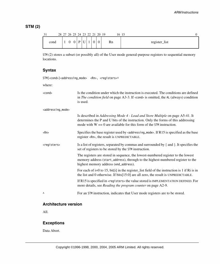
ARM Instructions
STM (2)
STM (2) stores a subset (or possibly all) of the User mode general-purpose registers to sequential memory locations.
Syntax
STM{<cond>}<addressing_mode> <Rn>, <registers>^
where:
<cond> Is the condition under which the instruction is executed. The conditions are defined in The condition field on page A3-3. If <cond> is omitted, the AL (always) condition is used.
<addressing_mode>
Is described in Addressing Mode 4 - Load and Store Multiple on page A5-41. It determines the P and U bits of the instruction. Only the forms of this addressing mode with W == 0 are available for this form of the STM instruction.
<Rn> Specifies the base register used by <addressing_mode>. If R15 is specified as the base register <Rn>, the result is UNPREDICTABLE.
<registers> Is a list of registers, separated by commas and surrounded by { and }. It specifies the set of registers to be stored by the STM instruction.
The registers are stored in sequence, the lowest-numbered register to the lowest memory address (start_address), through to the highest-numbered register to the highest memory address (end_address).
For each of i=0 to 15, bit[i] in the register_list field of the instruction is 1 if Ri is in the list and 0 otherwise. If bits[15:0] are all zero, the result is UNPREDICTABLE.
If R15 is specified in <registers> the value stored is IMPLEMENTATION DEFINED. For more details, see Reading the program counter on page A2-9.
^ For an STM instruction, indicates that User mode registers are to be stored.
Architecture version
All.
Exceptions
Data Abort.
31 28 27 26 25 24 23 22 21 20 19 16 15 0
cond 1 0 0 P U 1 0 0 Rn register_list
Copyright ©1996-1998, 2000, 2004, 2005 ARM Limited. All rights reserved.

ARM Instructions
Operation
MemoryAccess(B-bit, E-bit)processor_id = ExecutingProcessor()if ConditionPassed(cond) then
address = start_addressfor i = 0 to 15
if register_list[i] == 1Memory[address,4] = Ri_usraddress = address + 4if Shared(address) then /* from ARMv6 */
physical_address = TLB(address)ClearExclusiveByAddress(physical_address,processor_id,4)/* See Summary of operation on page A2-49 */
assert end_address == address - 4
Usage
Use STM (2) to store the User mode registers when the processor is in a privileged mode (useful when performing process swaps, and in instruction emulators).
Notes
Write-back Setting bit 21, the W bit, has UNPREDICTABLE results.
User and System mode
This instruction is UNPREDICTABLE in User or System mode.
Base register mode For the purpose of address calculation, the base register is read from the current processor mode registers, not the User mode registers.
Data Abort For details of the effects of the instruction if a Data Abort occurs, see Effects of data-aborted instructions on page A2-21.
Non word-aligned addresses
For CP15_reg1_Ubit == 0, the STM[2] instruction ignores the least significant two bits of address. For CP15_reg1_Ubit == 1, all non-word aligned accesses cause an alignment fault
Alignment If an implementation includes a System Control coprocessor (see Chapter B3 The System Control Coprocessor), and alignment checking is enabled, an address with bits[1:0] != 0b00 causes an alignment exception.
Time order The time order of the accesses to individual words of memory generated by this instruction is only defined in some circumstances. See Memory access restrictions on page B2-13 for details.
Banked registers In ARM architecture versions earlier than ARMv6, this form of STM must not be followed by an instruction that accesses banked registers (a following NOP is a good way to ensure this).
Copyright ©1996-1998, 2000, 2004, 2005 ARM Limited. All rights reserved.

ARM Instructions
STR
STR (Store Register) stores a word from a register to memory.
Syntax
STR{<cond>} <Rd>, <addressing_mode>
where:
<cond> Is the condition under which the instruction is executed. The conditions are defined in The condition field on page A3-3. If <cond> is omitted, the AL (always) condition is used.
<Rd> Specifies the source register for the operation. If R15 is specified for <Rd>, the value stored is IMPLEMENTATION DEFINED. For more details, see Reading the program counter on page A2-9.
<addressing_mode>
Is described in Addressing Mode 2 - Load and Store Word or Unsigned Byte on page A5-18. It determines the I, P, U, W, Rn and addr_mode bits of the instruction.
The syntax of all forms of <addressing_mode> includes a base register <Rn>. Some forms also specify that the instruction modifies the base register value (this is known as base register write-back).
Architecture version
All.
Exceptions
Data Abort.
Operation
MemoryAccess(B-bit, E-bit)processor_id = ExecutingProcessor()if ConditionPassed(cond) then
Memory[address,4] = Rdif Shared(address) then /* from ARMv6 */
physical_address = TLB(address)ClearExclusiveByAddress(physical_address,processor_id,4)/* See Summary of operation on page A2-49 */
31 28 27 26 25 24 23 22 21 20 19 16 15 12 11 0
cond 0 1 I P U 0 W 0 Rn Rd addr_mode
Copyright ©1996-1998, 2000, 2004, 2005 ARM Limited. All rights reserved.

ARM Instructions
Usage
Combined with a suitable addressing mode, STR stores 32-bit data from a general-purpose register into memory. Using the PC as the base register allows PC-relative addressing, which facilitates position-independent code.
Notes
Operand restrictions
If <addressing_mode> specifies base register write-back, and the same register is specified for <Rd> and <Rn>, the results are UNPREDICTABLE.
Data Abort For details of the effects of the instruction if a Data Abort occurs, see Effects of data-aborted instructions on page A2-21.
Alignment Prior to ARMv6, STR ignores the least significant two bits of the address. This is different from the LDR behavior. Alignment checking (taking a data abort when address[1:0] != 0b00), and support for a big-endian (BE-32) data format are implementation options.
From ARMv6, a byte- invariant mixed-endian format is supported, along with an alignment checking option. The pseudo-code for the ARMv6 case assumes that unaligned mixed-endian support is configured, with the endianness of the transfer defined by the CPSR E-bit.
For more details on endianness and alignment see Endian support on page A2-30and Unaligned access support on page A2-38.
Copyright ©1996-1998, 2000, 2004, 2005 ARM Limited. All rights reserved.

ARM Instructions
STRB
STRB (Store Register Byte) stores a byte from the least significant byte of a register to memory.
Syntax
STR{<cond>}B <Rd>, <addressing_mode>
where:
<cond> Is the condition under which the instruction is executed. The conditions are defined in The condition field on page A3-3. If <cond> is omitted, the AL (always) condition is used.
<Rd> Specifies the source register for the operation. If R15 is specified for <Rd>, the result is UNPREDICTABLE.
<addressing_mode>
Is described in Addressing Mode 2 - Load and Store Word or Unsigned Byte on page A5-18. It determines the I, P, U, W, Rn and addr_mode bits of the instruction.
The syntax of all forms of <addressing_mode> includes a base register <Rn>. Some forms also specify that the instruction modifies the base register value (this is known as base register write-back).
Architecture version
All.
Exceptions
Data Abort.
Operation
processor_id = ExecutingProcessor()if ConditionPassed(cond) then
Memory[address,1] = Rd[7:0]if Shared(address) then /* from ARMv6 */
physical_address = TLB(address)ClearExclusiveByAddress(physical_address,processor_id,1)/* See Summary of operation on page A2-49 */
31 28 27 26 25 24 23 22 21 20 19 16 15 12 11 0
cond 0 1 I P U 1 W 0 Rn Rd addr_mode
Copyright ©1996-1998, 2000, 2004, 2005 ARM Limited. All rights reserved.

ARM Instructions
Usage
Combined with a suitable addressing mode, STRB writes the least significant byte of a general-purpose register to memory. Using the PC as the base register allows PC-relative addressing, which facilitates position-independent code.
Notes
Operand restrictions
If <addressing_mode> specifies base register write-back, and the same register is specified for <Rd> and <Rn>, the results are UNPREDICTABLE.
Data Abort For details of the effects of the instruction if a Data Abort occurs, see Effects of data-aborted instructions on page A2-21.
Copyright ©1996-1998, 2000, 2004, 2005 ARM Limited. All rights reserved.

ARM Instructions
STRH
STRH (Store Register Halfword) stores a halfword from the least significant halfword of a register to memory. If the address is not halfword-aligned, the result is UNPREDICTABLE.
Syntax
STR{<cond>}H <Rd>, <addressing_mode>
where:
<cond> Is the condition under which the instruction is executed. The conditions are defined in The condition field on page A3-3. If <cond> is omitted, the AL (always) condition is used.
<Rd> Specifies the source register for the operation. If R15 is specified for <Rd>, the result is UNPREDICTABLE.
<addressing_mode>
Is described in Addressing Mode 3 - Miscellaneous Loads and Stores on page A5-33. It determines the P, U, I, W, Rn and addr_mode bits of the instruction.
The syntax of all forms of <addressing_mode> includes a base register <Rn>. Some forms also specify that the instruction modifies the base register value (this is known as base register write-back).
Architecture version
All.
Exceptions
Data Abort.
31 28 27 26 25 24 23 22 21 20 19 16 15 12 11 8 7 6 5 4 3 0
cond 0 0 0 P U I W 0 Rn Rd addr_mode 1 0 1 1 addr_mode
Copyright ©1996-1998, 2000, 2004, 2005 ARM Limited. All rights reserved.

ARM Instructions
Operation
MemoryAccess(B-bit, E-bit)processor_id = ExecutingProcessor()if ConditionPassed(cond) then
if (CP15_reg1_Ubit == 0) thenif address[0] == 0b0 then
Memory[address,2] = Rd[15:0]else
Memory[address,2] = UNPREDICTABLEelse /* CP15_reg1_Ubit ==1 */
Memory[address,2] = Rd[15:0]if Shared(address) then /* ARMv6 */
physical_address = TLB(address)ClearExclusiveByAddress(physical_address,processor_id,2)/* See Summary of operation on page A2-49 */
Usage
Combined with a suitable addressing mode, STRH allows 16-bit data from a general-purpose register to be stored to memory. Using the PC as the base register allows PC-relative addressing, to facilitate position-independent code.
Notes
Operand restrictions If <addressing_mode> specifies base register write-back, and the same register is specified for <Rd> and <Rn>, the results are UNPREDICTABLE.
Data Abort For details of the effects of the instruction if a Data Abort occurs, see Effects of data-aborted instructions on page A2-21.
Alignment Prior to ARMv6, if the memory address is not halfword aligned, the instruction is UNPREDICTABLE. Alignment checking (taking a data abort when address[0] != 0), and support for a big-endian (BE-32) data format are implementation options.
From ARMv6, a byte-invariant mixed-endian format is supported, along with an alignment checking option. The pseudo-code for the ARMv6 case assumes that mixed-endian support is configured, with the endianness of the transfer defined by the CPSR E-bit.
For more details on endianness and alignment, see Endian support on page A2-30 and Unaligned access support on page A2-38.
Copyright ©1996-1998, 2000, 2004, 2005 ARM Limited. All rights reserved.

ARM Instructions
SUB
SUB (Subtract) subtracts one value from a second value.
The second value comes from a register. The first value can be either an immediate value or a value from a register, and can be shifted before the subtraction.
SUB can optionally update the condition code flags, based on the result.
Syntax
SUB{<cond>}{S} <Rd>, <Rn>, <shifter_operand>
where:
<cond> Is the condition under which the instruction is executed. The conditions are defined in The condition field on page A3-3. If <cond> is omitted, the AL (always) condition is used.
S Sets the S bit (bit[20]) in the instruction to 1 and specifies that the instruction updates the CPSR. If S is omitted, the S bit is set to 0 and the CPSR is not changed by the instruction. Two types of CPSR update can occur when S is specified:
• If <Rd> is not R15, the N and Z flags are set according to the result of the subtraction, and the C and V flags are set according to whether the subtraction generated a borrow (unsigned underflow) and a signed overflow, respectively. The rest of the CPSR is unchanged.
• If <Rd> is R15, the SPSR of the current mode is copied to the CPSR. This form of the instruction is UNPREDICTABLE if executed in User mode or System mode, because these modes do not have an SPSR.
<Rd> Specifies the destination register.
<Rn> Specifies the register that contains the first operand.
<shifter_operand>
Specifies the second operand. The options for this operand are described in Addressing Mode 1 - Data-processing operands on page A5-2, including how each option causes the I bit (bit[25]) and the shifter_operand bits (bits[11:0]) to be set in the instruction.
If the I bit is 0 and both bit[7] and bit[4] of shifter_operand are 1, the instruction is not SUB. Instead, see Extending the instruction set on page A3-32 to determine which instruction it is.
Architecture version
All.
31 28 27 26 25 24 23 22 21 20 19 16 15 12 11 0
cond 0 0 I 0 0 1 0 S Rn Rd shifter_operand
Copyright ©1996-1998, 2000, 2004, 2005 ARM Limited. All rights reserved.

ARM Instructions
Exceptions
None.
Operation
if ConditionPassed(cond) thenRd = Rn - shifter_operandif S == 1 and Rd == R15 then
if CurrentModeHasSPSR() thenCPSR = SPSR
else UNPREDICTABLEelse if S == 1 then
N Flag = Rd[31]Z Flag = if Rd == 0 then 1 else 0C Flag = NOT BorrowFrom(Rn - shifter_operand)V Flag = OverflowFrom(Rn - shifter_operand)
Usage
Use SUB to subtract one value from another. To decrement a register value (in Ri) use:
SUB Ri, Ri, #1
SUBS is useful as a loop counter decrement, as the loop branch can test the flags for the appropriate termination condition, without the need for a separate compare instruction:
SUBS Ri, Ri, #1
This both decrements the loop counter in Ri and checks whether it has reached zero.
You can use SUB, with the PC as its destination register and the S bit set, to return from interrupts and various other types of exception. See Exceptions on page A2-16 for more details.
Notes
C flag If S is specified, the C flag is set to:
1 if no borrow occurs
0 if a borrow does occur.
In other words, the C flag is used as a NOT(borrow) flag. This inversion of the borrow condition is used by subsequent instructions: SBC and RSC use the C flag as a NOT(borrow) operand, performing a normal subtraction if C == 1 and subtracting one more than usual if C == 0.
The HS (unsigned higher or same) and LO (unsigned lower) conditions are equivalent to CS (carry set) and CC (carry clear) respectively.
Copyright ©1996-1998, 2000, 2004, 2005 ARM Limited. All rights reserved.

ARM Instructions
SWP
SWP (Swap) swaps a word between registers and memory. SWP loads a word from the memory address given by the value of register <Rn>. The value of register <Rm> is then stored to the memory address given by the value of <Rn>, and the original loaded value is written to register <Rd>. If the same register is specified for <Rd> and <Rm>, this instruction swaps the value of the register and the value at the memory address.
Syntax
SWP{<cond>} <Rd>, <Rm>, [<Rn>]
where:
<cond> Is the condition under which the instruction is executed. The conditions are defined in The condition field on page A3-3. If <cond> is omitted, the AL (always) condition is used.
<Rd> Specifies the destination register for the instruction.
<Rm> Contains the value that is stored to memory.
<Rn> Contains the memory address to load from.
Architecture version
All (deprecated in ARMv6).
Exceptions
Data Abort.
Operation
MemoryAccess(B-bit, E-bit)processor_id = ExecutingProcessor()if ConditionPassed(cond) then
if (CP15_reg1_Ubit == 0) thentemp = Memory[address,4] Rotate_Right (8 * address[1:0])Memory[address,4] = RmRd = temp
else /* CP15_reg1_Ubit ==1 */temp = Memory[address,4]Memory[address,4] = RmRd = temp
if Shared(address) then /* ARMv6 */
31 28 27 26 25 24 23 22 21 20 19 16 15 12 11 8 7 6 5 4 3 0
cond 0 0 0 1 0 0 0 0 Rn Rd SBZ 1 0 0 1 Rm
Copyright ©1996-1998, 2000, 2004, 2005 ARM Limited. All rights reserved.

ARM Instructions
physical_address = TLB(address)ClearExclusiveByAddress(physical_address,processor_id,4)/* See Summary of operation on page A2-49 */
Usage
You can use SWP to implement semaphores. This instruction is deprecated in ARMv6. Software should migrate to using the Load/Store exclusive instructions described in Synchronization primitives on page A2-44.
Notes
Use of R15 If R15 is specified for <Rd>, <Rn>, or <Rm>, the result is UNPREDICTABLE.
Operand restrictions
If the same register is specified as <Rn> and <Rm>, or <Rn> and <Rd>, the result is UNPREDICTABLE.
Data Abort If a precise Data Abort is signaled on either the load access or the store access, the loaded value is not written to <Rd>. If a precise Data Abort is signaled on the load access, the store access does not occur.
Alignment Prior to ARMv6, the alignment rules are the same as for an LDR on the read (see LDR on page A4-43) and an STR on the write (see STR on page A4-193). Alignment checking (taking a data abort when address[1:0] != 0b00), and support for a big-endian (BE-32) data format are implementation options.
From ARMv6, if CP15 register 1(A,U) != (0,0) and Rn[1:0] != 0b00, an alignment exception is taken. If CP15 register 1(A,U) == (0,0), the behavior is the same as the behavior before ARMv6.
For more details on endianness and alignment see Endian support on page A2-30 and Unaligned access support on page A2-38.
Memory model considerations
Swap is an atomic operation for all accesses, cached and non-cached.
The swap operation does not include any memory barrier guarantees. For example, it does not guarantee flushing of write buffers, which is an important consideration on multiprocessor systems.
Copyright ©1996-1998, 2000, 2004, 2005 ARM Limited. All rights reserved.

ARM Instructions
SWPB
SWPB (Swap Byte) swaps a byte between registers and memory. SWPB loads a byte from the memory address given by the value of register <Rn>. The value of the least significant byte of register <Rm> is stored to the memory address given by <Rn>, the original loaded value is zero-extended to a 32-bit word, and the word is written to register <Rd>. If the same register is specified for <Rd> and <Rm>, this instruction swaps the value of the least significant byte of the register and the byte value at the memory address.
Syntax
SWP{<cond>}B <Rd>, <Rm>, [<Rn>]
where:
<cond> Is the condition under which the instruction is executed. The conditions are defined in The condition field on page A3-3. If <cond> is omitted, the AL (always) condition is used.
<Rd> Specifies the destination register for the instruction.
<Rm> Contains the value that is stored to memory.
<Rn> Contains the memory address to load from.
Architecture version
All (deprecated in ARMv6).
Exceptions
Data Abort.
Operation
MemoryAccess(B-bit, E-bit)processor_id = ExecutingProcessor()if ConditionPassed(cond) then
temp = Memory[address,1]Memory[address,1] = Rm[7:0]Rd = tempif Shared(address) then /* ARMv6 */
physical_address = TLB(address)ClearExclusiveByAddress(physical_address,processor_id,1)/* See Summary of operation on page A2-49 */
31 28 27 26 25 24 23 22 21 20 19 16 15 12 11 8 7 6 5 4 3 0
cond 0 0 0 1 0 1 0 0 Rn Rd SBZ 1 0 0 1 Rm
Copyright ©1996-1998, 2000, 2004, 2005 ARM Limited. All rights reserved.

ARM Instructions
Usage
You can use SWPB to implement semaphores. This instruction is deprecated in ARMv6. Software should migrate to using the Load /Store exclusive instructions described in Synchronization primitives on page A2-44.
Notes
Use of R15 If R15 is specified for <Rd>, <Rn>, or <Rm>, the result is UNPREDICTABLE.
Operand restrictions If the same register is specified as <Rn> and <Rm>, or <Rn> and <Rd>, the result is UNPREDICTABLE.
Data Abort If a precise Data Abort is signaled on either the load access or the store access, the loaded value is not written to <Rd>. If a precise Data Abort is signaled on the load access, the store access does not occur.
Memory model considerations Swap is an atomic operation for all accesses, cached and non-cached.
The swap operation does not include any memory barrier guarantees. For example, it does not guarantee flushing of write buffers, which is an important consideration on multiprocessor systems.
Copyright ©1996-1998, 2000, 2004, 2005 ARM Limited. All rights reserved.

ARM Instructions
TEQ
TEQ (Test Equivalence) compares a register value with another arithmetic value. The condition flags are updated, based on the result of logically exclusive-ORing the two values, so that subsequent instructions can be conditionally executed.
Syntax
TEQ{<cond>} <Rn>, <shifter_operand>
where:
<cond> Is the condition under which the instruction is executed. The conditions are defined in The condition field on page A3-3. If <cond> is omitted, the AL (always) condition is used.
<Rn> Specifies the register that contains the first operand.
<shifter_operand>
Specifies the second operand. The options for this operand are described in Addressing Mode 1 - Data-processing operands on page A5-2, including how each option sets the I bit (bit[25]) and the shifter_operand bits (bits[11:0]) in the instruction.
If the I bit is 0 and both bit[7] and bit[4] of shifter_operand are 1, the instruction is not TEQ. Instead, see Multiply instruction extension space on page A3-35 to determine which instruction it is.
Architecture version
All.
Exceptions
None.
Operation
if ConditionPassed(cond) then alu_out = Rn EOR shifter_operandN Flag = alu_out[31]Z Flag = if alu_out == 0 then 1 else 0C Flag = shifter_carry_outV Flag = unaffected
31 28 27 26 25 24 23 22 21 20 19 16 15 12 11 0
cond 0 0 I 1 0 0 1 1 Rn SBZ shifter_operand
Copyright ©1996-1998, 2000, 2004, 2005 ARM Limited. All rights reserved.

ARM Instructions
Usage
Use TEQ to test if two values are equal, without affecting the V flag (as CMP does). The C flag is also unaffected in many cases. TEQ is also useful for testing whether two values have the same sign. After the comparison, the N flag is the logical Exclusive OR of the sign bits of the two operands.
Copyright ©1996-1998, 2000, 2004, 2005 ARM Limited. All rights reserved.

ARM Instructions
TST
TST (Test) compares a register value with another arithmetic value. The condition flags are updated, based on the result of logically ANDing the two values, so that subsequent instructions can be conditionally executed.
Syntax
TST{<cond>} <Rn>, <shifter_operand>
where:
<cond> Is the condition under which the instruction is executed. The conditions are defined in The condition field on page A3-3. If <cond> is omitted, the AL (always) condition is used.
<Rn> Specifies the register that contains the first operand.
<shifter_operand>
Specifies the second operand. The options for this operand are described in Addressing Mode 1 - Data-processing operands on page A5-2, including how each option causes the I bit (bit[25]) and the shifter_operand bits (bits[11:0]) to be set in the instruction.
If the I bit is 0 and both bit[7] and bit[4] of shifter_operand are 1, the instruction is not TST. Instead, see Multiply instruction extension space on page A3-35 to determine which instruction it is.
Architecture version
All.
Exceptions
None.
Operation
if ConditionPassed(cond) then alu_out = Rn AND shifter_operandN Flag = alu_out[31]Z Flag = if alu_out == 0 then 1 else 0C Flag = shifter_carry_outV Flag = unaffected
31 28 27 26 25 24 23 22 21 20 19 16 15 12 11 0
cond 0 0 I 1 0 0 0 1 Rn SBZ shifter_operand
Copyright ©1996-1998, 2000, 2004, 2005 ARM Limited. All rights reserved.

ARM Instructions
Usage
Use TST to determine whether a particular subset of register bits includes at least one set bit. A very common use for TST is to test whether a single bit is set or clear.
Copyright ©1996-1998, 2000, 2004, 2005 ARM Limited. All rights reserved.

ARM Instructions
UMLAL
UMLAL (Unsigned Multiply Accumulate Long) multiplies the unsigned value of register <Rm> with the unsigned value of register <Rs> to produce a 64-bit product. This product is added to the 64-bit value held in <RdHi> and <RdLo>, and the sum is written back to <RdHi> and <RdLo>. The condition code flags are optionally updated, based on the result.
Syntax
UMLAL{<cond>}{S} <RdLo>, <RdHi>, <Rm>, <Rs>
where:
<cond> Is the condition under which the instruction is executed. The conditions are defined in The condition field on page A3-3. If <cond> is omitted, the AL (always) condition is used.
S Causes the S bit (bit[20]) in the instruction to be set to 1 and specifies that the instruction updates the CPSR by setting the N and Z flags according to the result of the multiply-accumulate. If S is omitted, the S bit of the instruction is set to 0 and the entire CPSR is unaffected by the instruction.
<RdLo> Supplies the lower 32 bits of the value to be added to the product of <Rm> and <Rs>, and is the destination register for the lower 32 bits of the result.
<RdHi> Supplies the upper 32 bits of the value to be added to the product of <Rm> and <Rs>, and is the destination register for the upper 32 bits of the result.
<Rm> Holds the signed value to be multiplied with the value of <Rs>.
<Rs> Holds the signed value to be multiplied with the value of <Rm>.
Architecture version
All.
Exceptions
None.
31 28 27 26 25 24 23 22 21 20 19 16 15 12 11 8 7 6 5 4 3 0
cond 0 0 0 0 1 0 1 S RdHi RdLo Rs 1 0 0 1 Rm
Copyright ©1996-1998, 2000, 2004, 2005 ARM Limited. All rights reserved.

ARM Instructions
Operation
if ConditionPassed(cond) then RdLo = (Rm * Rs)[31:0] + RdLo /* Unsigned multiplication */RdHi = (Rm * Rs)[63:32] + RdHi + CarryFrom((Rm * Rs)[31:0] + RdLo)if S == 1 then
N Flag = RdHi[31]Z Flag = if (RdHi == 0) and (RdLo == 0) then 1 else 0C Flag = unaffected /* See "C and V flags" note */V Flag = unaffected /* See "C and V flags" note */
Usage
UMLAL multiplies unsigned variables to produce a 64-bit result, which is added to the 64-bit value in the two destination general-purpose registers. The result is written back to the two destination general-purpose registers.
Notes
Use of R15 Specifying R15 for register <RdHi>, <RdLo>, <Rm>, or <Rs> has UNPREDICTABLE results.
Operand restriction <RdHi> and <RdLo> must be distinct registers, or the results are UNPREDICTABLE.
Specifying the same register for either <RdHi> and <Rm>, or <RdLo> and <Rm>, was previously described as producing UNPREDICTABLE results. There is no restriction in ARMv6, and it is believed all relevant ARMv4 and ARMv5 implementations do not require this restriction either, because high performance multipliers read all their operands prior to writing back any results.
Early termination If the multiplier implementation supports early termination, it must be implemented on the value of the <Rs> operand. The type of early termination used (signed or unsigned) is IMPLEMENTATION DEFINED.
C and V flags UMLALS is defined to leave the C and V flags unchanged in ARMv5 and above. In earlier versions of the architecture, the values of the C and V flags were UNPREDICTABLE after a UMLALS instruction.
Copyright ©1996-1998, 2000, 2004, 2005 ARM Limited. All rights reserved.

ARM Instructions
UMULL
UMULL (Unsigned Multiply Long) multiplies the unsigned value of register <Rm> with the unsigned value of register <Rs> to produce a 64-bit result. The upper 32 bits of the result are stored in <RdHi>. The lower 32 bits are stored in <RdLo>. The condition code flags are optionally updated, based on the 64-bit result.
Syntax
UMULL{<cond>}{S} <RdLo>, <RdHi>, <Rm>, <Rs>
where:
<cond> Is the condition under which the instruction is executed. The conditions are defined in The condition field on page A3-3. If <cond> is omitted, the AL (always) condition is used.
S Causes the S bit (bit[20]) in the instruction to be set to 1 and specifies that the instruction updates the CPSR by setting the N and Z flags according to the result of the multiplication. If S is omitted, the S bit of the instruction is set to 0 and the entire CPSR is unaffected by the instruction.
<RdLo> Stores the lower 32 bits of the result.
<RdHi> Stores the upper 32 bits of the result.
<Rm> Holds the signed value to be multiplied with the value of <Rs>.
<Rs> Holds the signed value to be multiplied with the value of <Rm>.
Architecture version
All.
Exceptions
None.
31 28 27 26 25 24 23 22 21 20 19 16 15 12 11 8 7 6 5 4 3 0
cond 0 0 0 0 1 0 0 S RdHi RdLo Rs 1 0 0 1 Rm
Copyright ©1996-1998, 2000, 2004, 2005 ARM Limited. All rights reserved.

ARM Instructions
Operation
if ConditionPassed(cond) thenRdHi = (Rm * Rs)[63:32] /* Unsigned multiplication */RdLo = (Rm * Rs)[31:0]if S == 1 then
N Flag = RdHi[31]Z Flag = if (RdHi == 0) and (RdLo == 0) then 1 else 0C Flag = unaffected /* See "C and V flags" note */V Flag = unaffected /* See "C and V flags" note */
Usage
UMULL multiplies unsigned variables to produce a 64-bit result in two general-purpose registers.
Notes
Use of R15 Specifying R15 for register <RdHi>, <RdLo>, <Rm>, or <Rs> has UNPREDICTABLE results.
Operand restriction <RdHi> and <RdLo> must be distinct registers, or the results are UNPREDICTABLE.
Specifying the same register for either <RdHi> and <Rm>, or <RdLo> and <Rm>, was previously described as producing UNPREDICTABLE results. There is no restriction in ARMv6, and it is believed all relevant ARMv4 and ARMv5 implementations do not require this restriction either, because high performance multipliers read all their operands prior to writing back any results.
Early termination If the multiplier implementation supports early termination, it must be implemented on the value of the <Rs> operand. The type of early termination used (signed or unsigned) is IMPLEMENTATION DEFINED.
C and V flags UMULLS is defined to leave the C and V flags unchanged in ARMv5 and above. In earlier versions of the architecture, the values of the C and V flags were UNPREDICTABLE after a UMULLS instruction.
Copyright ©1996-1998, 2000, 2004, 2005 ARM Limited. All rights reserved.

ARM Addressing Modes
Addressing Mode 1 - Data-processing operands
There are 11 formats used to calculate the <shifter_operand> in an ARM data-processing instruction. The general instruction syntax is:
<opcode>{<cond>}{S} <Rd>, <Rn>, <shifter_operand>
where <shifter_operand> is one of the following:
1. #<immediate>
See Data-processing operands - Immediate on page A5-6.
2. <Rm>
See Data-processing operands - Register on page A5-8.
3. <Rm>, LSL #<shift_imm>
See Data-processing operands - Logical shift left by immediate on page A5-9.
4. <Rm>, LSL <Rs>
See Data-processing operands - Logical shift left by register on page A5-10.
5. <Rm>, LSR #<shift_imm>
See Data-processing operands - Logical shift right by immediate on page A5-11.
6. <Rm>, LSR <Rs>
See Data-processing operands - Logical shift right by register on page A5-12.
7. <Rm>, ASR #<shift_imm>
See Data-processing operands - Arithmetic shift right by immediate on page A5-13.
8. <Rm>, ASR <Rs>
See Data-processing operands - Arithmetic shift right by register on page A5-14.
9. <Rm>, ROR #<shift_imm>
See Data-processing operands - Rotate right by immediate on page A5-15.
10. <Rm>, ROR <Rs>
See Data-processing operands - Rotate right by register on page A5-16.
11. <Rm>, RRX
See Data-processing operands - Rotate right with extend on page A5-17.
Copyright ©1996-1998, 2000, 2004, 2005 ARM Limited. All rights reserved.

ARM Addressing Modes
Encoding
The following diagrams show the encodings for this addressing mode:
32-bit immediate
Immediate shifts
Register shifts
opcode Specifies the operation of the instruction.
S bit Indicates that the instruction updates the condition codes.
Rd Specifies the destination register.
Rn Specifies the first source operand register.
Bits[11:0] The fields within bits[11:0] are collectively called a shifter operand. This is described in The shifter operand on page A5-4.
Bit[25] Is referred to as the I bit, and is used to distinguish between an immediate shifter operand and a register-based shifter operand.
If all three of the following bits have the values shown, the instruction is not a data-processing instruction, but lies in the arithmetic or Load/Store instruction extension space:
bit[25] == 0bit[4] == 1bit[7] == 1
See Extending the instruction set on page A3-32 for more information.
Addressing mode 3, MCRR{2}, MRRC{2}, STC{2} are examples of instructions that reside in this space.
31 28 27 26 25 24 21 20 19 16 15 12 11 8 7 0
cond 0 0 1 opcode S Rn Rd rotate_imm immed_8
31 28 27 26 25 24 21 20 19 16 15 12 11 7 6 5 4 3 0
cond 0 0 0 opcode S Rn Rd shift_imm shift 0 Rm
31 28 27 26 25 24 21 20 19 16 15 12 11 8 7 6 5 4 3 0
cond 0 0 0 opcode S Rn Rd Rs 0 shift 1 Rm
Copyright ©1996-1998, 2000, 2004, 2005 ARM Limited. All rights reserved.

ARM Addressing Modes
The shifter operand
As well as producing the shifter operand, the shifter produces a carry-out which some instructions write into the Carry Flag. The default register operand (register Rm specified with no shift) uses the form register shift left by immediate, with the immediate set to zero.
The shifter operand takes one of the following three basic formats.
Immediate operand value
An immediate operand value is formed by rotating an 8-bit constant (in a 32-bit word) by an even number of bits (0,2,4,8...26,28,30). Therefore, each instruction contains an 8-bit constant and a 4-bit rotate to be applied to that constant.
Some valid constants are:
0xFF,0x104,0xFF0,0xFF00,0xFF000,0xFF000000,0xF000000F
Some invalid constants are:
0x101,0x102,0xFF1,0xFF04,0xFF003,0xFFFFFFFF,0xF000001F
For example:
MOV R0, #0 ; Move zero to R0ADD R3, R3, #1 ; Add one to the value of register 3CMP R7, #1000 ; Compare value of R7 with 1000BIC R9, R8, #0xFF00 ; Clear bits 8-15 of R8 and store in R9
Register operand value
A register operand value is simply the value of a register. The value of the register is used directly as the operand to the data-processing instruction. For example:
MOV R2, R0 ; Move the value of R0 to R2ADD R4, R3, R2 ; Add R2 to R3, store result in R4CMP R7, R8 ; Compare the value of R7 and R8
Copyright ©1996-1998, 2000, 2004, 2005 ARM Limited. All rights reserved.

ARM Addressing Modes
Shifted register operand value
A shifted register operand value is the value of a register, shifted (or rotated) before it is used as the data-processing operand. There are five types of shift:
ASR Arithmetic shift right
LSL Logical shift left
LSR Logical shift right
ROR Rotate right
RRX Rotate right with extend.
The number of bits to shift by is specified either as an immediate or as the value of a register. For example:
MOV R2, R0, LSL #2 ; Shift R0 left by 2, write to R2, (R2=R0x4)ADD R9, R5, R5, LSL #3 ; R9 = R5 + R5 x 8 or R9 = R5 x 9RSB R9, R5, R5, LSL #3 ; R9 = R5 x 8 - R5 or R9 = R5 x 7SUB R10, R9, R8, LSR #4 ; R10 = R9 - R8 / 16MOV R12, R4, ROR R3 ; R12 = R4 rotated right by value of R3
Copyright ©1996-1998, 2000, 2004, 2005 ARM Limited. All rights reserved.

ARM Addressing Modes
Data-processing operands - Immediate
This data-processing operand provides a constant (defined in the instruction) operand to a data-processing instruction.
The <shifter_operand> value is formed by rotating (to the right) an 8-bit immediate value to any even bit position in a 32-bit word. If the rotate immediate is zero, the carry-out from the shifter is the value of the C flag, otherwise, it is set to bit[31] of the value of <shifter_operand>.
Syntax
#<immediate>
where:
<immediate> Specifies the immediate constant wanted. It is encoded in the instruction as an 8-bit immediate (immed_8) and a 4-bit immediate (rotate_imm), so that <immediate> is equal to the result of rotating immed_8 right by (2 × rotate_imm) bits.
Operation
shifter_operand = immed_8 Rotate_Right (rotate_imm * 2)if rotate_imm == 0 then
shifter_carry_out = C flagelse /* rotate_imm != 0 */
shifter_carry_out = shifter_operand[31]
31 28 27 26 25 24 21 20 19 16 15 12 11 8 7 0
cond 0 0 1 opcode S Rn Rd rotate_imm immed_8
Copyright ©1996-1998, 2000, 2004, 2005 ARM Limited. All rights reserved.

ARM Addressing Modes
NotesLegitimate immediates
Not all 32-bit immediates are legitimate. Only those that can be formed by rotating an 8-bit immediate right by an even amount are valid 32-bit immediates for this format.
Encoding Some values of <immediate> have more than one possible encoding. For example, a value of 0x3F0 could be encoded as:
immed_8 == 0x3F, rotate_imm == 0xE
or as:
immed_8 == 0xFC, rotate_imm == 0xF
When more than one encoding is available, an assembler must choose the correct one to use, as follows:
• If <immediate> lies in the range 0 to 0xFF, an encoding with rotate_imm == 0 is available. The assembler must choose that encoding. (Choosing another encoding would affect how some instructions set the C flag.)
• Otherwise, it is recommended that the encoding with the smallest value of rotate_imm is chosen. (This choice does not affect instruction functionality.)
For more precise control of the encoding, the instruction fields can be specified directly by using the syntax: #<immed_8>, <rotate_amount>
where <rotate_amount> = 2 * rotate_imm.
Use of R15 If R15 is specified as register Rn, the value used is the address of the current instruction plus eight.
Copyright ©1996-1998, 2000, 2004, 2005 ARM Limited. All rights reserved.

ARM Addressing Modes
Data-processing operands - Register
This data-processing operand provides the value of a register directly. The carry-out from the shifter is the C flag.
Syntax
<Rm>
where:
<Rm> Specifies the register whose value is the instruction operand.
Operation
shifter_operand = Rmshifter_carry_out = C Flag
Notes
Encoding This instruction is encoded as a logical shift left by immediate (see Data-processing operands - Logical shift left by immediate on page A5-9) with a shift of zero (shift_imm == 0).
Use of R15 If R15 is specified as register Rm or Rn, the value used is the address of the current instruction plus 8.
31 28 27 26 25 24 21 20 19 16 15 12 11 10 9 8 7 6 5 4 3 0
cond 0 0 0 opcode S Rn Rd 0 0 0 0 0 0 0 0 Rm
Copyright ©1996-1998, 2000, 2004, 2005 ARM Limited. All rights reserved.

ARM Addressing Modes
Data-processing operands - Logical shift left by immediate
This data-processing operand is used to provide either the value of a register directly (lone register operand, as described in Data-processing operands - Register on page A5-8), or the value of a register shifted left (multiplied by a constant power of two).
This instruction operand is the value of register Rm, logically shifted left by an immediate value in the range 0 to 31. Zeros are inserted into the vacated bit positions. The carry-out from the shifter is the last bit shifted out, or the C flag if no shift is specified.
Syntax
<Rm>, LSL #<shift_imm>
where:
<Rm> Specifies the register whose value is to be shifted.
LSL Indicates a logical shift left.
<shift_imm> Specifies the shift. This is a value between 0 and 31.
Operation
if shift_imm == 0 then /* Register Operand */shifter_operand = Rmshifter_carry_out = C Flag
else /* shift_imm > 0 */shifter_operand = Rm Logical_Shift_Left shift_immshifter_carry_out = Rm[32 - shift_imm]
Notes
Default shift If the value of <shift_imm> == 0, the operand can be written as just <Rm> (see Data-processing operands - Register on page A5-8).
Use of R15 If R15 is specified as register Rm or Rn, the value used is the address of the current instruction plus 8.
31 28 27 26 25 24 21 20 19 16 15 12 11 7 6 5 4 3 0
cond 0 0 0 opcode S Rn Rd shift_imm 0 0 0 Rm
Copyright ©1996-1998, 2000, 2004, 2005 ARM Limited. All rights reserved.

ARM Addressing Modes
Data-processing operands - Logical shift left by register
This data-processing operand is used to provide the value of a register multiplied by a variable power of two.
This instruction operand is the value of register Rm, logically shifted left by the value in the least significant byte of register Rs. Zeros are inserted into the vacated bit positions. The carry-out from the shifter is the last bit shifted out, which is zero if the shift amount is more than 32, or the C flag if the shift amount is zero.
Syntax
<Rm>, LSL <Rs>
where:
<Rm> Specifies the register whose value is to be shifted.
LSL Indicates a logical shift left.
<Rs> Is the register containing the value of the shift.
Operation
if Rs[7:0] == 0 thenshifter_operand = Rmshifter_carry_out = C Flag
else if Rs[7:0] < 32 thenshifter_operand = Rm Logical_Shift_Left Rs[7:0]shifter_carry_out = Rm[32 - Rs[7:0]]
else if Rs[7:0] == 32 thenshifter_operand = 0shifter_carry_out = Rm[0]
else /* Rs[7:0] > 32 */shifter_operand = 0shifter_carry_out = 0
Notes
Use of R15 Specifying R15 as register Rd, register Rm, register Rn, or register Rs has UNPREDICTABLE results.
31 28 27 26 25 24 21 20 19 16 15 12 11 8 7 6 5 4 3 0
cond 0 0 0 opcode S Rn Rd Rs 0 0 0 1 Rm
Copyright ©1996-1998, 2000, 2004, 2005 ARM Limited. All rights reserved.
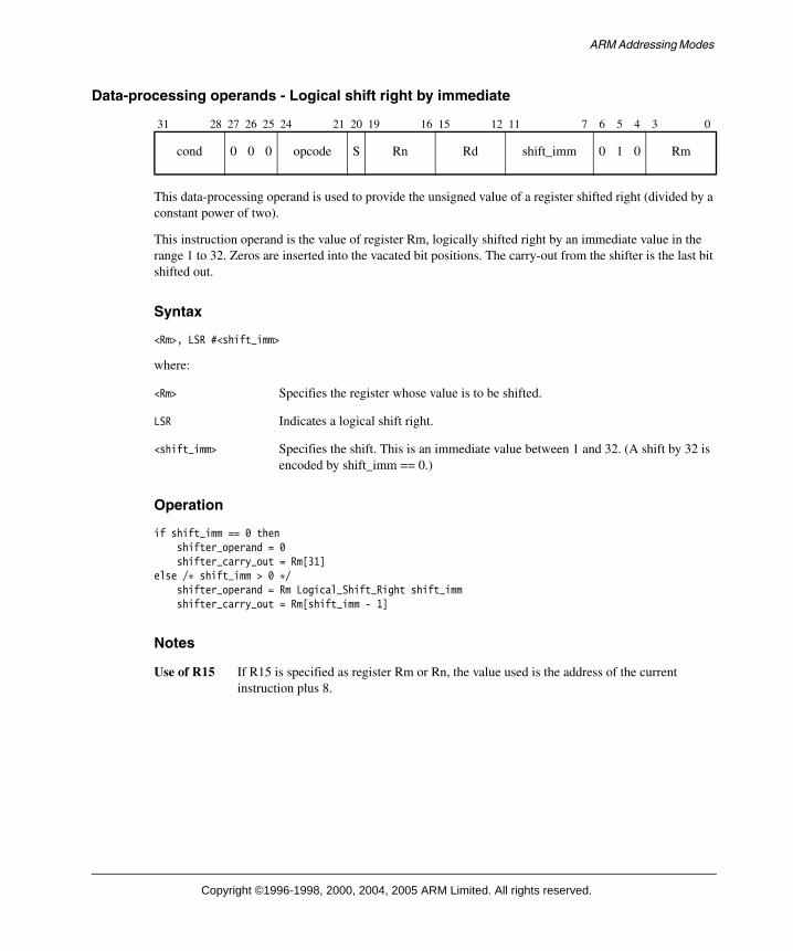
ARM Addressing Modes
Data-processing operands - Logical shift right by immediate
This data-processing operand is used to provide the unsigned value of a register shifted right (divided by a constant power of two).
This instruction operand is the value of register Rm, logically shifted right by an immediate value in the range 1 to 32. Zeros are inserted into the vacated bit positions. The carry-out from the shifter is the last bit shifted out.
Syntax
<Rm>, LSR #<shift_imm>
where:
<Rm> Specifies the register whose value is to be shifted.
LSR Indicates a logical shift right.
<shift_imm> Specifies the shift. This is an immediate value between 1 and 32. (A shift by 32 is encoded by shift_imm == 0.)
Operation
if shift_imm == 0 thenshifter_operand = 0shifter_carry_out = Rm[31]
else /* shift_imm > 0 */shifter_operand = Rm Logical_Shift_Right shift_immshifter_carry_out = Rm[shift_imm - 1]
Notes
Use of R15 If R15 is specified as register Rm or Rn, the value used is the address of the current instruction plus 8.
31 28 27 26 25 24 21 20 19 16 15 12 11 7 6 5 4 3 0
cond 0 0 0 opcode S Rn Rd shift_imm 0 1 0 Rm
Copyright ©1996-1998, 2000, 2004, 2005 ARM Limited. All rights reserved.

ARM Addressing Modes
Data-processing operands - Logical shift right by register
This data-processing operand is used to provide the unsigned value of a register shifted right (divided by a variable power of two).
It is produced by the value of register Rm, logically shifted right by the value in the least significant byte of register Rs. Zeros are inserted into the vacated bit positions. The carry-out from the shifter is the last bit shifted out, which is zero if the shift amount is more than 32, or the C flag if the shift amount is zero.
Syntax
<Rm>, LSR <Rs>
where:
<Rm> Specifies the register whose value is to be shifted.
LSR Indicates a logical shift right.
<Rs> Is the register containing the value of the shift.
Operation
if Rs[7:0] == 0 thenshifter_operand = Rmshifter_carry_out = C Flag
else if Rs[7:0] < 32 thenshifter_operand = Rm Logical_Shift_Right Rs[7:0]shifter_carry_out = Rm[Rs[7:0] - 1]
else if Rs[7:0] == 32 thenshifter_operand = 0shifter_carry_out = Rm[31]
else /* Rs[7:0] > 32 */shifter_operand = 0shifter_carry_out = 0
Notes
Use of R15 Specifying R15 as register Rd, register Rm, register Rn, or register Rs has UNPREDICTABLE results.
31 28 27 26 25 24 21 20 19 16 15 12 11 8 7 6 5 4 3 0
cond 0 0 0 opcode S Rn Rd Rs 0 0 1 1 Rm
Copyright ©1996-1998, 2000, 2004, 2005 ARM Limited. All rights reserved.

ARM Addressing Modes
Data-processing operands - Arithmetic shift right by immediate
This data-processing operand is used to provide the signed value of a register arithmetically shifted right (divided by a constant power of two).
This instruction operand is the value of register Rm, arithmetically shifted right by an immediate value in the range 1 to 32. The sign bit of Rm (Rm[31]) is inserted into the vacated bit positions. The carry-out from the shifter is the last bit shifted out.
Syntax
<Rm>, ASR #<shift_imm>
where:
<Rm> Specifies the register whose value is to be shifted.
ASR Indicates an arithmetic shift right.
<shift_imm> Specifies the shift. This is an immediate value between 1 and 32. (A shift by 32 is encoded by shift_imm == 0.)
Operation
if shift_imm == 0 thenif Rm[31] == 0 then
shifter_operand = 0shifter_carry_out = Rm[31]
else /* Rm[31] == 1 */shifter_operand = 0xFFFFFFFFshifter_carry_out = Rm[31]
else /* shift_imm > 0 */shifter_operand = Rm Arithmetic_Shift_Right <shift_imm>shifter_carry_out = Rm[shift_imm - 1]
Notes
Use of R15 If R15 is specified as register Rm or Rn, the value used is the address of the current instruction plus 8.
31 28 27 26 25 24 21 20 19 16 15 12 11 7 6 5 4 3 0
cond 0 0 0 opcode S Rn Rd shift_imm 1 0 0 Rm
Copyright ©1996-1998, 2000, 2004, 2005 ARM Limited. All rights reserved.

ARM Addressing Modes
Data-processing operands - Arithmetic shift right by register
This data-processing operand is used to provide the signed value of a register arithmetically shifted right (divided by a variable power of two).
This instruction operand is the value of register Rm arithmetically shifted right by the value in the least significant byte of register Rs. The sign bit of Rm (Rm[31]) is inserted into the vacated bit positions. The carry-out from the shifter is the last bit shifted out, which is the sign bit of Rm if the shift amount is more than 32, or the C flag if the shift amount is zero.
Syntax
<Rm>, ASR <Rs>
where:
<Rm> Specifies the register whose value is to be shifted.
ASR Indicates an arithmetic shift right.
<Rs> Is the register containing the value of the shift.
Operation
if Rs[7:0] == 0 thenshifter_operand = Rmshifter_carry_out = C Flag
else if Rs[7:0] < 32 thenshifter_operand = Rm Arithmetic_Shift_Right Rs[7:0]shifter_carry_out = Rm[Rs[7:0] - 1]
else /* Rs[7:0] >= 32 */if Rm[31] == 0 then
shifter_operand = 0shifter_carry_out = Rm[31]
else /* Rm[31] == 1 */shifter_operand = 0xFFFFFFFFshifter_carry_out = Rm[31]
Notes
Use of R15 Specifying R15 as register Rd, register Rm, register Rn, or register Rs has UNPREDICTABLE results.
31 28 27 26 25 24 21 20 19 16 15 12 11 8 7 6 5 4 3 0
cond 0 0 0 opcode S Rn Rd Rs 0 1 0 1 Rm
Copyright ©1996-1998, 2000, 2004, 2005 ARM Limited. All rights reserved.

ARM Addressing Modes
Data-processing operands - Rotate right by immediate
This data-processing operand is used to provide the value of a register rotated by a constant value.
This instruction operand is the value of register Rm rotated right by an immediate value in the range 1 to 31. As bits are rotated off the right end, they are inserted into the vacated bit positions on the left. The carry-out from the shifter is the last bit rotated off the right end.
Syntax
<Rm>, ROR #<shift_imm>
where:
<Rm> Specifies the register whose value is to be rotated.
ROR Indicates a rotate right.
<shift_imm> Specifies the rotation. This is an immediate value between 1 and 31. When shift_imm == 0, an RRX operation (rotate right with extend) is performed. This is described in Data-processing operands - Rotate right with extend on page A5-17.
Operation
if shift_imm == 0 thenSee “Data-processing operands - Rotate right with extend” on page A5-17
else /* shift_imm > 0 */shifter_operand = Rm Rotate_Right shift_immshifter_carry_out = Rm[shift_imm - 1]
Notes
Use of R15 If R15 is specified as register Rm or Rn, the value used is the address of the current instruction plus 8.
31 28 27 26 25 24 21 20 19 16 15 12 11 7 6 5 4 3 0
cond 0 0 0 opcode S Rn Rd shift_imm 1 1 0 Rm
Copyright ©1996-1998, 2000, 2004, 2005 ARM Limited. All rights reserved.

ARM Addressing Modes
Data-processing operands - Rotate right by register
This data-processing operand is used to provide the value of a register rotated by a variable value.
This instruction operand is produced by the value of register Rm rotated right by the value in the least significant byte of register Rs. As bits are rotated off the right end, they are inserted into the vacated bit positions on the left. The carry-out from the shifter is the last bit rotated off the right end, or the C flag if the shift amount is zero.
Syntax
<Rm>, ROR <Rs>
where:
<Rm> Specifies the register whose value is to be rotated.
ROR Indicates a rotate right.
<Rs> Is the register containing the value of the rotation.
Operation
if Rs[7:0] == 0 thenshifter_operand = Rmshifter_carry_out = C Flag
else if Rs[4:0] == 0 thenshifter_operand = Rm shifter_carry_out = Rm[31]
else /* Rs[4:0] > 0 */shifter_operand = Rm Rotate_Right Rs[4:0]shifter_carry_out = Rm[Rs[4:0] - 1]
Notes
Use of R15 Specifying R15 as register Rd, register Rm, register Rn, or register Rs has UNPREDICTABLE results.
31 28 27 26 25 24 21 20 19 16 15 12 11 8 7 6 5 4 3 0
cond 0 0 0 opcode S Rn Rd Rs 0 1 1 1 Rm
Copyright ©1996-1998, 2000, 2004, 2005 ARM Limited. All rights reserved.

ARM Addressing Modes
Data-processing operands - Rotate right with extend
This data-processing operand can be used to perform a 33-bit rotate right using the Carry Flag as the 33rd bit.
This instruction operand is the value of register Rm shifted right by one bit, with the Carry Flag replacing the vacated bit position. The carry-out from the shifter is the bit shifted off the right end.
Syntax
<Rm>, RRX
where:
<Rm> Specifies the register whose value is shifted right by one bit.
RRX Indicates a rotate right with extend.
Operation
shifter_operand = (C Flag Logical_Shift_Left 31) OR (Rm Logical_Shift_Right 1)shifter_carry_out = Rm[0]
Notes
Encoding The instruction encoding is in the space that would be used for ROR #0.
Use of R15 If R15 is specified as register Rm or Rn, the value used is the address of the current instruction plus 8.
ADC instruction A rotate left with extend can be performed with an ADC instruction.
ADC <Rd>, <Rm>
where <Rn> ==<Rm> for the modified operand to equal the result, or
ADC <Rd>, <Rn>, <Rm>, LSL #1
where the rotate left and extend is the second operand rather than the result.
31 28 27 26 25 24 21 20 19 16 15 12 11 10 9 8 7 6 5 4 3 0
cond 0 0 0 opcode S Rn Rd 0 0 0 0 0 1 1 0 Rm
Copyright ©1996-1998, 2000, 2004, 2005 ARM Limited. All rights reserved.

ARM Addressing Modes
Addressing Mode 2 - Load and Store Word or Unsigned Byte
There are nine formats used to calculate the address for a Load and Store Word or Unsigned Byte instruction. The general instruction syntax is:
LDR|STR{<cond>}{B}{T} <Rd>, <addressing_mode>
where <addressing_mode> is one of the nine options listed below.
All nine of the following options are available for LDR, LDRB, STR and STRB. For LDRBT, LDRT, STRBT and STRBT, only the post-indexed options (the last three in the list) are available. For the PLD instruction described in PLD on page A4-90, only the offset options (the first three in the list) are available.
1. [<Rn>, #+/-<offset_12>]
See Load and Store Word or Unsigned Byte - Immediate offset on page A5-20.
2. [<Rn>, +/-<Rm>]
See Load and Store Word or Unsigned Byte - Register offset on page A5-21.
3. [<Rn>, +/-<Rm>, <shift> #<shift_imm>]
See Load and Store Word or Unsigned Byte - Scaled register offset on page A5-22.
4. [<Rn>, #+/-<offset_12>]!
See Load and Store Word or Unsigned Byte - Immediate pre-indexed on page A5-24.
5. [<Rn>, +/-<Rm>]!
See Load and Store Word or Unsigned Byte - Register pre-indexed on page A5-25.
6. [<Rn>, +/-<Rm>, <shift> #<shift_imm>]!
See Load and Store Word or Unsigned Byte - Scaled register pre-indexed on page A5-26.
7. [<Rn>], #+/-<offset_12>
See Load and Store Word or Unsigned Byte - Immediate post-indexed on page A5-28.
8. [<Rn>], +/-<Rm>
See Load and Store Word or Unsigned Byte - Register post-indexed on page A5-30.
9. [<Rn>], +/-<Rm>, <shift> #<shift_imm>
See Load and Store Word or Unsigned Byte - Scaled register post-indexed on page A5-31.
Copyright ©1996-1998, 2000, 2004, 2005 ARM Limited. All rights reserved.

ARM Addressing Modes
Encoding
The following three diagrams show the encodings for this addressing mode:
Immediate offset/index
Register offset/index
Scaled register offset/index
The P bit Has two meanings:
P == 0 Indicates the use of post-indexed addressing. The base register value is used for the memory address, and the offset is then applied to the base register value and written back to the base register.
P == 1 Indicates the use of offset addressing or pre-indexed addressing (the W bit determines which). The memory address is generated by applying the offset to the base register value.
The U bit Indicates whether the offset is added to the base (U == 1) or is subtracted from the base (U == 0).
The B bit Distinguishes between an unsigned byte (B == 1) and a word (B == 0) access.
The W bit Has two meanings:
P == 0 If W == 0, the instruction is LDR, LDRB, STR or STRB and a normal memory access is performed. If W == 1, the instruction is LDRBT, LDRT, STRBT or STRT and an unprivileged (User mode) memory access is performed.
P == 1 If W == 0, the base register is not updated (offset addressing). If W == 1, the calculated memory address is written back to the base register (pre-indexed addressing).
The L bit Distinguishes between a Load (L == 1) and a Store (L == 0).
31 28 27 26 25 24 23 22 21 20 19 16 15 12 11 0
cond 0 1 0 P U B W L Rn Rd offset_12
31 28 27 26 25 24 23 22 21 20 19 16 15 12 11 10 9 8 7 6 5 4 3 0
cond 0 1 1 P U B W L Rn Rd 0 0 0 0 0 0 0 0 Rm
31 28 27 26 25 24 23 22 21 20 19 16 15 12 11 7 6 5 4 3 0
cond 0 1 1 P U B W L Rn Rd shift_imm shift 0 Rm
Copyright ©1996-1998, 2000, 2004, 2005 ARM Limited. All rights reserved.

ARM Addressing Modes
Load and Store Word or Unsigned Byte - Immediate offset
This addressing mode calculates an address by adding or subtracting the value of an immediate offset to or from the value of the base register Rn.
Syntax
[<Rn>, #+/-<offset_12>]
where:
<Rn> Specifies the register containing the base address.
<offset_12> Specifies the immediate offset used with the value of Rn to form the address.
Operation
if U == 1 then address = Rn + offset_12
else /* U == 0 */address = Rn - offset_12
Usage
This addressing mode is useful for accessing structure (record) fields, and accessing parameters and local variables in a stack frame. With an offset of zero, the address produced is the unaltered value of the base register Rn.
Notes
Offset of zero The syntax [<Rn>] is treated as an abbreviation for [<Rn>, #0], unless the instruction is one that only allows post-indexed addressing modes (LDRBT, LDRT, STRBT or STRT).
The B bit This bit distinguishes between an unsigned byte (B==1) and a word (B==0) access.
The L bit This bit distinguishes between a Load (L==1) and a Store (L==0) instruction.
Use of R15 If R15 is specified as register Rn, the value used is the address of the instruction plus eight.
31 28 27 26 25 24 23 22 21 20 19 16 15 12 11 0
cond 0 1 0 1 U B 0 L Rn Rd offset_12
Copyright ©1996-1998, 2000, 2004, 2005 ARM Limited. All rights reserved.

ARM Addressing Modes
Load and Store Word or Unsigned Byte - Register offset
This addressing mode calculates an address by adding or subtracting the value of the index register Rm to or from the value of the base register Rn.
Syntax
[<Rn>, +/-<Rm>]
where:
<Rn> Specifies the register containing the base address.
<Rm> Specifies the register containing the value to add to or subtract from Rn.
Operation
if U == 1 thenaddress = Rn + Rm
else /* U == 0 */address = Rn - Rm
Usage
This addressing mode is used for pointer plus offset arithmetic, and accessing a single element of an array of bytes.
Notes
Encoding This addressing mode is encoded as an LSL scaled register offset, scaled by zero.
The B bit This bit distinguishes between an unsigned byte (B==1) and a word (B==0) access.
The L bit This bit distinguishes between a Load (L==1) and a Store (L==0) instruction.
Use of R15 If R15 is specified as register Rn, the value used is the address of the instruction plus eight. Specifying R15 as register Rm has UNPREDICTABLE results.
31 28 27 26 25 24 23 22 21 20 19 16 15 12 11 10 9 8 7 6 5 4 3 0
cond 0 1 1 1 U B 0 L Rn Rd 0 0 0 0 0 0 0 0 Rm
Copyright ©1996-1998, 2000, 2004, 2005 ARM Limited. All rights reserved.

ARM Addressing Modes
Load and Store Word or Unsigned Byte - Scaled register offset
These five addressing modes calculate an address by adding or subtracting the shifted or rotated value of the index register Rm to or from the value of the base register Rn.
Syntax
One of:
[<Rn>, +/-<Rm>, LSL #<shift_imm>][<Rn>, +/-<Rm>, LSR #<shift_imm>][<Rn>, +/-<Rm>, ASR #<shift_imm>][<Rn>, +/-<Rm>, ROR #<shift_imm>][<Rn>, +/-<Rm>, RRX]
where:
<Rn> Specifies the register containing the base address.
<Rm> Specifies the register containing the offset to add to or subtract from Rn.
LSL Specifies a logical shift left.
LSR Specifies a logical shift right.
ASR Specifies an arithmetic shift right.
ROR Specifies a rotate right.
RRX Specifies a rotate right with extend.
<shift_imm> Specifies the shift or rotation.
LSL 0 to 31, encoded directly in the shift_imm field.
LSR 1 to 32. A shift amount of 32 is encoded as shift_imm == 0. Other shift amounts are encoded directly.
ASR 1 to 32. A shift amount of 32 is encoded as shift_imm == 0. Other shift amounts are encoded directly.
ROR 1 to 31, encoded directly in the shift_imm field. (The shift_imm == 0 encoding is used to specify the RRX option.)
31 28 27 26 25 24 23 22 21 20 19 16 15 12 11 7 6 5 4 3 0
cond 0 1 1 1 U B 0 L Rn Rd shift_imm shift 0 Rm
Copyright ©1996-1998, 2000, 2004, 2005 ARM Limited. All rights reserved.

ARM Addressing Modes
Operation
case shift of0b00 /* LSL */
index = Rm Logical_Shift_Left shift_imm0b01 /* LSR */
if shift_imm == 0 then /* LSR #32 */index = 0
elseindex = Rm Logical_Shift_Right shift_imm
0b10 /* ASR */if shift_imm == 0 then /* ASR #32 */
if Rm[31] == 1 thenindex = 0xFFFFFFFF
elseindex = 0
elseindex = Rm Arithmetic_Shift_Right shift_imm
0b11 /* ROR or RRX */if shift_imm == 0 then /* RRX */
index = (C Flag Logical_Shift_Left 31) OR(Rm Logical_Shift_Right 1)
else /* ROR */index = Rm Rotate_Right shift_imm
endcaseif U == 1 then
address = Rn + indexelse /* U == 0 */
address = Rn - index
Usage
These addressing modes are used for accessing a single element of an array of values larger than a byte.
Notes
The B bit This bit distinguishes between an unsigned byte (B==1) and a word (B==0) access.
The L bit This bit distinguishes between a Load (L==1) and a Store (L==0) instruction.
Use of R15 If R15 is specified as register Rn, the value used is the address of the instruction plus eight. Specifying R15 as register Rm has UNPREDICTABLE results.
Copyright ©1996-1998, 2000, 2004, 2005 ARM Limited. All rights reserved.

ARM Addressing Modes
Load and Store Word or Unsigned Byte - Immediate pre-indexed
This addressing mode calculates an address by adding or subtracting the value of an immediate offset to or from the value of the base register Rn.
If the condition specified in the instruction matches the condition code status, the calculated address is written back to the base register Rn. The conditions are defined in The condition field on page A3-3.
Syntax
[<Rn>, #+/-<offset_12>]!
where:
<Rn> Specifies the register containing the base address.
<offset_12> Specifies the immediate offset used with the value of Rn to form the address.
! Sets the W bit, causing base register update.
Operation
if U == 1 then address = Rn + offset_12
else /* if U == 0 */address = Rn - offset_12
if ConditionPassed(cond) thenRn = address
Usage
This addressing mode is used for pointer access to arrays with automatic update of the pointer value.
Notes
Offset of zero The syntax [<Rn>] must never be treated as an abbreviation for [<Rn>, #0]!.
The B bit This bit distinguishes between an unsigned byte (B==1) and a word (B==0) access.
The L bit This bit distinguishes between a Load (L==1) and a Store (L==0) instruction.
Use of R15 Specifying R15 as register Rn has UNPREDICTABLE results.
31 28 27 26 25 24 23 22 21 20 19 16 15 12 11 0
cond 0 1 0 1 U B 1 L Rn Rd offset_12
Copyright ©1996-1998, 2000, 2004, 2005 ARM Limited. All rights reserved.

ARM Addressing Modes
Load and Store Word or Unsigned Byte - Register pre-indexed
This addressing mode calculates an address by adding or subtracting the value of an index register Rm to or from the value of the base register Rn.
If the condition specified in the instruction matches the condition code status, the calculated address is written back to the base register Rn. The conditions are defined in The condition field on page A3-3.
Syntax
[<Rn>, +/-<Rm>]!
where:
<Rn> Specifies the register containing the base address.
<Rm> Specifies the register containing the offset to add to or subtract from Rn.
! Sets the W bit, causing base register update.
Operation
if U == 1 thenaddress = Rn + Rm
else /* U == 0 */address = Rn - Rm
if ConditionPassed(cond) thenRn = address
Notes
Encoding This addressing mode is encoded as an LSL scaled register offset, scaled by zero.
The B bit This bit distinguishes between an unsigned byte (B==1) and a word (B==0) access.
The L bit This bit distinguishes between a Load (L==1) and a Store (L==0) instruction.
Use of R15 Specifying R15 as register Rm or Rn has UNPREDICTABLE results.
Operand restriction There are no operand restrictions in ARMv6 and above. In earlier versions of the architecture, if the same register is specified for Rn and Rm, the result is UNPREDICTABLE.
31 28 27 26 25 24 23 22 21 20 19 16 15 12 11 10 9 8 7 6 5 4 3 0
cond 0 1 1 1 U B 1 L Rn Rd 0 0 0 0 0 0 0 0 Rm
Copyright ©1996-1998, 2000, 2004, 2005 ARM Limited. All rights reserved.

ARM Addressing Modes
Load and Store Word or Unsigned Byte - Scaled register pre-indexed
These five addressing modes calculate an address by adding or subtracting the shifted or rotated value of the index register Rm to or from the value of the base register Rn.
If the condition specified in the instruction matches the condition code status, the calculated address is written back to the base register Rn. The conditions are defined in The condition field on page A3-3.
Syntax
One of:
[<Rn>, +/-<Rm>, LSL #<shift_imm>]![<Rn>, +/-<Rm>, LSR #<shift_imm>]![<Rn>, +/-<Rm>, ASR #<shift_imm>]![<Rn>, +/-<Rm>, ROR #<shift_imm>]![<Rn>, +/-<Rm>, RRX]!
where:
<Rn> Specifies the register containing the base address.
<Rm> Specifies the register containing the offset to add to or subtract from Rn.
LSL Specifies a logical shift left.
LSR Specifies a logical shift right.
ASR Specifies an arithmetic shift right.
ROR Specifies a rotate right.
RRX Specifies a rotate right with extend.
<shift_imm> Specifies the shift or rotation.
LSL 0 to 31, encoded directly in the shift_imm field.
LSR 1 to 32. A shift amount of 32 is encoded as shift_imm == 0. Other shift amounts are encoded directly.
ASR 1 to 32. A shift amount of 32 is encoded as shift_imm == 0. Other shift amounts are encoded directly.
ROR 1 to 31, encoded directly in the shift_imm field. (The shift_imm == 0 encoding is used to specify the RRX option.)
! Sets the W bit, causing base register update.
31 28 27 26 25 24 23 22 21 20 19 16 15 12 11 7 6 5 4 3 0
cond 0 1 1 1 U B 1 L Rn Rd shift_imm shift 0 Rm
Copyright ©1996-1998, 2000, 2004, 2005 ARM Limited. All rights reserved.

ARM Addressing Modes
Operation
case shift of0b00 /* LSL */
index = Rm Logical_Shift_Left shift_imm0b01 /* LSR */
if shift_imm == 0 then /* LSR #32 */index = 0
elseindex = Rm Logical_Shift_Right shift_imm
0b10 /* ASR */if shift_imm == 0 then /* ASR #32 */
if Rm[31] == 1 thenindex = 0xFFFFFFFF
elseindex = 0
elseindex = Rm Arithmetic_Shift_Right shift_imm
0b11 /* ROR or RRX */if shift_imm == 0 then /* RRX */
index = (C Flag Logical_Shift_Left 31) OR(Rm Logical_Shift_Right 1)
else /* ROR */index = Rm Rotate_Right shift_imm
endcaseif U == 1 then
address = Rn + indexelse /* U == 0 */
address = Rn - indexif ConditionPassed(cond) then
Rn = address
Notes
The B bit This bit distinguishes between an unsigned byte (B==1) and a word (B==0) access.
The L bit This bit distinguishes between a Load (L==1) and a Store (L==0) instruction.
Use of R15 Specifying R15 as register Rm or Rn has UNPREDICTABLE results.
Operand restriction There are no operand restrictions in ARM v6 and above. In earlier versions of the architecture, if the same register is specified for Rn and Rm, the result is UNPREDICTABLE.
Copyright ©1996-1998, 2000, 2004, 2005 ARM Limited. All rights reserved.

ARM Addressing Modes
Load and Store Word or Unsigned Byte - Immediate post-indexed
This addressing mode uses the value of the base register Rn as the address for the memory access.
If the condition specified in the instruction matches the condition code status, the value of the immediate offset is added to or subtracted from the value of the base register Rn and written back to the base register Rn. The conditions are defined in The condition field on page A3-3.
Syntax
[<Rn>], #+/-<offset_12>
where:
<Rn> Specifies the register containing the base address.
<offset_12> Specifies the immediate offset used with the value of Rn to form the address.
Operation
address = Rnif ConditionPassed(cond) then
if U == 1 then Rn = Rn + offset_12
else /* U == 0 */Rn = Rn - offset_12
Usage
This addressing mode is used for pointer access to arrays with automatic update of the pointer value.
31 28 27 26 25 24 23 22 21 20 19 16 15 12 11 0
cond 0 1 0 0 U B 0 L Rn Rd offset_12
Copyright ©1996-1998, 2000, 2004, 2005 ARM Limited. All rights reserved.

ARM Addressing Modes
Notes
Post-indexed addressing modes
LDRBT, LDRT, STRBT, and STRT only support post-indexed addressing modes. They use a minor modification of the above bit pattern, where bit[21] (the W bit) is 1, not 0 as shown.
Offset of zero The syntax [<Rn>] is treated as an abbreviation for [<Rn>],#0 for instructions that only support post-indexed addressing modes (LDRBT, LDRT, STRBT, STRT), but not for other instructions.
The B bit This bit distinguishes between an unsigned byte (B==1) and a word (B==0) access.
The L bit This bit distinguishes between a Load (L==1) and a Store (L==0) instruction.
Use of R15 Specifying R15 as register Rn has UNPREDICTABLE results.
Copyright ©1996-1998, 2000, 2004, 2005 ARM Limited. All rights reserved.

ARM Addressing Modes
Load and Store Word or Unsigned Byte - Register post-indexed
This addressing mode uses the value of the base register Rn as the address for the memory access.
If the condition specified in the instruction matches the condition code status, the value of the index register Rm is added to or subtracted from the value of the base register Rn and written back to the base register Rn. The conditions are defined in The condition field on page A3-3.
Syntax
[<Rn>], +/-<Rm>
where:
<Rn> Specifies the register containing the base address.
<Rm> Specifies the register containing the offset to add to or subtract from Rn.
Operation
address = Rnif ConditionPassed(cond) then
if U == 1 thenRn = Rn + Rm
else /* U == 0 */Rn = Rn - Rm
Notes
Encoding This addressing mode is encoded as an LSL scaled register offset, scaled by zero.
Post-indexed addressing modes
LDRBT, LDRT, STRBT, and STRT only support post-indexed addressing modes. They use a minor modification of the above bit pattern, where bit[21] (the W bit) is 1, not 0 as shown.
The B bit This bit distinguishes between an unsigned byte (B==1) and a word (B==0) access.
The L bit This bit distinguishes between a Load (L==1) and a Store (L==0) instruction.
Use of R15 Specifying R15 as register Rn or Rm has UNPREDICTABLE results.
Operand restriction There are no operand restrictions in ARMv6 and above. In earlier versions of the architecture, if the same register is specified for Rn and Rm, the result is UNPREDICTABLE.
31 28 27 26 25 24 23 22 21 20 19 16 15 12 11 10 9 8 7 6 5 4 3 0
cond 0 1 1 0 U B 0 L Rn Rd 0 0 0 0 0 0 0 0 Rm
Copyright ©1996-1998, 2000, 2004, 2005 ARM Limited. All rights reserved.

ARM Addressing Modes
Load and Store Word or Unsigned Byte - Scaled register post-indexed
This addressing mode uses the value of the base register Rn as the address for the memory access.
If the condition specified in the instruction matches the condition code status, the shifted or rotated value of index register Rm is added to or subtracted from the value of the base register Rn and written back to the base register Rn. The conditions are defined in The condition field on page A3-3.
Syntax
One of:
[<Rn>], +/-<Rm>, LSL #<shift_imm>[<Rn>], +/-<Rm>, LSR #<shift_imm>[<Rn>], +/-<Rm>, ASR #<shift_imm>[<Rn>], +/-<Rm>, ROR #<shift_imm>[<Rn>], +/-<Rm>, RRX
where:
<Rn> Specifies the register containing the base address.
<Rm> Specifies the register containing the offset to add to or subtract from Rn.
LSL Specifies a logical shift left.
LSR Specifies a logical shift right.
ASR Specifies an arithmetic shift right.
ROR Specifies a rotate right.
RRX Specifies a rotate right with extend.
<shift_imm> Specifies the shift or rotation.
LSL 0 to 31, encoded directly in the shift_imm field.
LSR 1 to 32. A shift amount of 32 is encoded as shift_imm == 0. Other shift amounts are encoded directly.
ASR 1 to 32. A shift amount of 32 is encoded as shift_imm == 0. Other shift amounts are encoded directly.
ROR 1 to 31, encoded directly in the shift_imm field. (The shift_imm == 0 encoding is used to specify the RRX option.)
31 28 27 26 25 24 23 22 21 20 19 16 15 12 11 7 6 5 4 3 0
cond 0 1 1 0 U B 0 L Rn Rd shift_imm shift 0 Rm
Copyright ©1996-1998, 2000, 2004, 2005 ARM Limited. All rights reserved.

ARM Addressing Modes
Operation
address = Rncase shift of
0b00 /* LSL */index = Rm Logical_Shift_Left shift_imm
0b01 /* LSR */if shift_imm == 0 then /* LSR #32 */
index = 0else
index = Rm Logical_Shift_Right shift_imm0b10 /* ASR */
if shift_imm == 0 then /* ASR #32 */if Rm[31] == 1 then
index = 0xFFFFFFFFelse
index = 0else
index = Rm Arithmetic_Shift_Right shift_imm0b11 /* ROR or RRX */
if shift_imm == 0 then /* RRX */index = (C Flag Logical_Shift_Left 31) OR
(Rm Logical_Shift_Right 1)else /* ROR */
index = Rm Rotate_Right shift_immendcaseif ConditionPassed(cond) then
if U == 1 thenRn = Rn + index
else /* U == 0 */Rn = Rn - index
Notes
The W bit LDRBT, LDRT, STRBT, and STRT only support post-indexed addressing modes. They use a minor modification of the above bit pattern, where bit[21] (the W bit) is 1, not 0 as shown.
The B bit This bit distinguishes between an unsigned byte (B == 1) and a word (B == 0) access.
The L bit This bit distinguishes between a Load (L == 1) and a Store (L == 0) instruction.
Use of R15 Specifying R15 as register Rm or Rn has UNPREDICTABLE results.
Operand restriction There are no operand restrictions in ARMv6 and above. In earlier versions of the architecture, if the same register is specified for Rn and Rm, the result is UNPREDICTABLE.
Copyright ©1996-1998, 2000, 2004, 2005 ARM Limited. All rights reserved.

ARM Addressing Modes
Addressing Mode 3 - Miscellaneous Loads and Stores
There are six formats used to calculate the address for load and store (signed or unsigned) halfword, load signed byte, or load and store doubleword instructions. The general instruction syntax is:
LDR|STR{<cond>}H|SH|SB|D <Rd>, <addressing_mode>
where <addressing_mode> is one of the following six options:
1. [<Rn>, #+/-<offset_8>]
See Miscellaneous Loads and Stores - Immediate offset on page A5-35.
2. [<Rn>, +/-<Rm>]
See Miscellaneous Loads and Stores - Register offset on page A5-36.
3. [<Rn>, #+/-<offset_8>]!
See Miscellaneous Loads and Stores - Immediate pre-indexed on page A5-37.
4. [<Rn>, +/-<Rm>]!
See Miscellaneous Loads and Stores - Register pre-indexed on page A5-38.
5. [<Rn>], #+/-<offset_8>
See Miscellaneous Loads and Stores - Immediate post-indexed on page A5-39.
6. [<Rn>], +/-<Rm>
See Miscellaneous Loads and Stores - Register post-indexed on page A5-40.
Encoding
The following diagrams show the encodings for this addressing mode:
Immediate offset/index
Register offset/index
31 28 27 26 25 24 23 22 21 20 19 16 15 12 11 8 7 6 5 4 3 0
cond 0 0 0 P U 1 W L Rn Rd immedH 1 S H 1 ImmedL
31 28 27 26 25 24 23 22 21 20 19 16 15 12 11 8 7 6 5 4 3 0
cond 0 0 0 P U 0 W L Rn Rd SBZ 1 S H 1 Rm
Copyright ©1996-1998, 2000, 2004, 2005 ARM Limited. All rights reserved.

ARM Addressing Modes
The P bit Has two meanings:
P == 0 Indicates the use of post-indexed addressing. The base register value is used for the memory address, and the offset is then applied to the base register value and written back to the base register.
P == 1 Indicates the use of offset addressing or pre-indexed addressing (the W bit determines which). The memory address is generated by applying the offset to the base register value.
The U bit Indicates whether the offset is added to the base (U == 1) or subtracted from the base (U == 0).
The W bit Has two meanings:
P == 0 The W bit must be 0 or the instruction is UNPREDICTABLE.
P == 1 W == 1 indicates that the memory address is written back to the base register (pre-indexed addressing), and W == 0 that the base register is unchanged (offset addressing).
The L, S and H bits
These bits combine to specify signed or unsigned loads or stores, and doubleword, halfword, or byte accesses:
L=0, S=0, H=1 Store halfword.
L=0, S=1, H=0 Load doubleword.
L=0, S=1, H=1 Store doubleword.
L=1, S=0, H=1 Load unsigned halfword.
L=1, S=1, H=0 Load signed byte.
L=1, S=1, H=1 Load signed halfword.
Prior to v5TE, the bits were denoted as Load/!Store (L), Signed/!Unsigned (S) and halfword/!Byte (H) bits.
Signed bytes and halfwords can be stored with the same STRB and STRH instructions as are used for unsigned quantities, so no separate signed store instructions are provided.
Unsigned bytes
If S == 0 and H == 0, apparently indicating an unsigned byte, the instruction is not one that uses this addressing mode. Instead, it is a multiply instruction, a SWP or SWPB instruction, an LDREX or STREX instruction, or an unallocated instruction in the arithmetic or load/store instruction extension space (see Extending the instruction set on page A3-32).
Unsigned bytes are accessed by the LDRB, LDRBT, STRB and STRBT instructions, which use addressing mode 2 rather than addressing mode 3.
Signed stores If S ==1 and L == 0, apparently indicating a signed store instruction, the encoding along with the H-bit is used to support the LDRD (H == 0) and STRD (H == 1) instructions.
Copyright ©1996-1998, 2000, 2004, 2005 ARM Limited. All rights reserved.

ARM Addressing Modes
Miscellaneous Loads and Stores - Immediate offset
This addressing mode calculates an address by adding or subtracting the value of an immediate offset to or from the value of the base register Rn.
Syntax
[<Rn>, #+/-<offset_8>]
where:
<Rn> Specifies the register containing the base address.
<offset_8> Specifies the immediate offset used with the value of Rn to form the address. The offset is encoded in immedH (top 4 bits) and immedL (bottom 4 bits).
Operation
offset_8 = (immedH << 4) OR immedLif U == 1 then
address = Rn + offset_8else /* U == 0 */
address = Rn - offset_8
Usage
This addressing mode is used for accessing structure (record) fields, and accessing parameters and locals variable in a stack frame. With an offset of zero, the address produced is the unaltered value of the base register Rn.
Notes
Zero offset The syntax [<Rn>] is treated as an abbreviation for [<Rn>,#0].
The L, S and H bits The L, S and H bits are defined in Encoding on page A5-33.
Use of R15 If R15 is specified as register Rn, the value used is the address of the instruction plus eight.
31 28 27 26 25 24 23 22 21 20 19 16 15 12 11 8 7 6 5 4 3 0
cond 0 0 0 1 U 1 0 L Rn Rd immedH 1 S H 1 immedL
Copyright ©1996-1998, 2000, 2004, 2005 ARM Limited. All rights reserved.

ARM Addressing Modes
Miscellaneous Loads and Stores - Register offset
This addressing mode calculates an address by adding or subtracting the value of the index register Rm to or from the value of the base register Rn.
Syntax
[<Rn>, +/-<Rm>]
where:
<Rn> Specifies the register containing the base address.
<Rm> Specifies the register containing the offset to add to or subtract from Rn.
Operation
if U == 1 then address = Rn + Rm
else /* U == 0 */address = Rn - Rm
Usage
This addressing mode is useful for pointer plus offset arithmetic and for accessing a single element of an array.
Notes
The L, S and H bits The L, S and H bits are defined in Encoding on page A5-33.
Unsigned bytes If S == 0 and H == 0, apparently indicating an unsigned byte, the instruction is not one that uses this addressing mode. Instead, it is a multiply instruction, a SWP or SWPB instruction, or an unallocated instruction in the arithmetic or load/store instruction extension space (see Extending the instruction set on page A3-32).
Unsigned bytes are accessed by the LDRB, LDRBT, STRB and STRBT instructions, which use addressing mode 2 rather than addressing mode 3.
Use of R15 If R15 is specified as register Rn, the value used is the address of the instruction plus eight. Specifying R15 as register Rm has UNPREDICTABLE results.
31 28 27 26 25 24 23 22 21 20 19 16 15 12 11 8 7 6 5 4 3 0
cond 0 0 0 1 U 0 0 L Rn Rd SBZ 1 S H 1 Rm
Copyright ©1996-1998, 2000, 2004, 2005 ARM Limited. All rights reserved.

ARM Addressing Modes
Miscellaneous Loads and Stores - Immediate pre-indexed
This addressing mode calculates an address by adding or subtracting the value of an immediate offset to or from the value of the base register Rn.
If the condition specified in the instruction matches the condition code status, the calculated address is written back to the base register Rn. The conditions are defined in The condition field on page A3-3.
Syntax
[<Rn>, #+/-<offset_8>]!
where:
<Rn> Specifies the register containing the base address.
<offset_8> Specifies the immediate offset used with the value of Rn to form the address. The offset is encoded in immedH (top 4 bits) and immedL (bottom 4 bits).
! Sets the W bit, causing base register update.
Operation
offset_8 = (immedH << 4) OR immedLif U == 1 then
address = Rn + offset_8else /* U == 0 */
address = Rn - offset_8if ConditionPassed(cond) then
Rn = address
Usage
This addressing mode gives pointer access to arrays, with automatic update of the pointer value.
Notes
Offset of zero The syntax [<Rn>] must not be treated as an abbreviation for [<Rn>,#0]!.
The L, S and H bits The L, S and H bits are defined in Encoding on page A5-33.
Use of R15 Specifying R15 as register Rn has UNPREDICTABLE results.
31 28 27 26 25 24 23 22 21 20 19 16 15 12 11 8 7 6 5 4 3 0
cond 0 0 0 1 U 1 1 L Rn Rd immedH 1 S H 1 ImmedL
Copyright ©1996-1998, 2000, 2004, 2005 ARM Limited. All rights reserved.

ARM Addressing Modes
Miscellaneous Loads and Stores - Register pre-indexed
This addressing mode calculates an address by adding or subtracting the value of the index register Rm to or from the value of the base register Rn.
If the condition specified in the instruction matches the condition code status, the calculated address is written back to the base register Rn. The conditions are defined in The condition field on page A3-3.
Syntax
[<Rn>, +/-<Rm>]!
where:
<Rn> Specifies the register containing the base address.
<Rm> Specifies the register containing the offset to add to or subtract from Rn.
! Sets the W bit, causing base register update.
Operation
if U == 1 then address = Rn + Rm
else /* U == 0 */address = Rn - Rm
if ConditionPassed(cond) thenRn = address
Notes
The L, S and H bits The L, S and H bits are defined in Encoding on page A5-33.
Use of R15 Specifying R15 as register Rm or Rn has UNPREDICTABLE results.
Operand restriction There are no operand restrictions in ARMv6 and above. In earlier versions of the architecture, if the same register is specified for Rn and Rm, the result is UNPREDICTABLE.
31 28 27 26 25 24 23 22 21 20 19 16 15 12 11 8 7 6 5 4 3 0
cond 0 0 0 1 U 0 1 L Rn Rd SBZ 1 S H 1 Rm
Copyright ©1996-1998, 2000, 2004, 2005 ARM Limited. All rights reserved.

ARM Addressing Modes
Miscellaneous Loads and Stores - Immediate post-indexed
This addressing mode uses the value of the base register Rn as the address for the memory access.
If the condition specified in the instruction matches the condition code status, the value of the immediate offset is added to or subtracted from the value of the base register Rn and written back to the base register Rn. The conditions are defined in The condition field on page A3-3.
Syntax
[<Rn>], #+/-<offset_8>
where:
<Rn> Specifies the register containing the base address.
<offset_8> Specifies the immediate offset used with the value of Rn to form the address. The offset is encoded in immedH (top 4 bits) and immedL (bottom 4 bits).
Operation
address = Rnoffset_8 = (immedH << 4) OR immedLif ConditionPassed(cond) then
if U == 1 then Rn = Rn + offset_8
else /* U == 0 */Rn = Rn - offset_8
Usage
This addressing mode gives pointer access to arrays, with automatic update of the pointer value.
Notes
Offset of zero The syntax [<Rn>] must not be treated as an abbreviation for [<Rn>],#0.
The L, S and H bits The L, S and H bits are defined in Encoding on page A5-33.
Use of R15 Specifying R15 as register Rn has UNPREDICTABLE results.
31 28 27 26 25 24 23 22 21 20 19 16 15 12 11 8 7 6 5 4 3 0
cond 0 0 0 0 U 1 0 L Rn Rd immedH 1 S H 1 ImmedL
Copyright ©1996-1998, 2000, 2004, 2005 ARM Limited. All rights reserved.

ARM Addressing Modes
Miscellaneous Loads and Stores - Register post-indexed
This addressing mode uses the value of the base register Rn as the address for the memory access.
If the condition specified in the instruction matches the condition code status, the value of the index register Rm is added to or subtracted from the value of the base register Rn and written back to the base register Rn. The conditions are defined in The condition field on page A3-3.
Syntax
[<Rn>], +/-<Rm>
where:
<Rn> Specifies the register containing the base address.
<Rm> Specifies the register containing the offset to add to or subtract from Rn.
Operation
address = Rnif ConditionPassed(cond) then
if U == 1 then Rn = Rn + Rm
else /* U == 0 */Rn = Rn - Rm
Notes
The L, S and H bits The L, S and H bits are defined in Encoding on page A5-33.
Use of R15 Specifying R15 as register Rm or Rn has UNPREDICTABLE results.
Operand restriction There are no operand restrictions in ARMv6 and above. In earlier versions of the architecture, if the same register is specified for Rn and Rm, the result is UNPREDICTABLE.
31 28 27 26 25 24 23 22 21 20 19 16 15 12 11 8 7 6 5 4 3 0
cond 0 0 0 0 U 0 0 L Rn Rd SBZ 1 S H 1 Rm
Copyright ©1996-1998, 2000, 2004, 2005 ARM Limited. All rights reserved.

ARM Addressing Modes
Addressing Mode 4 - Load and Store Multiple
Load Multiple instructions load a subset (possibly all) of the general-purpose registers from memory. Store Multiple instructions store a subset (possibly all) of the general-purpose registers to memory.
Load and Store Multiple addressing modes produce a sequential range of addresses. The lowest-numbered register is stored at the lowest memory address and the highest-numbered register at the highest memory address.
The general instruction syntax is:
LDM|STM{<cond>}<addressing_mode> <Rn>{!}, <registers>{^}
where <addressing_mode> is one of the following four addressing modes:
1. IA (Increment After)
See Load and Store Multiple - Increment after on page A5-43.
2. IB (Increment Before)
See Load and Store Multiple - Increment before on page A5-44.
3. DA (Decrement After)
See Load and Store Multiple - Decrement after on page A5-45.
4. DB (Decrement Before)
See Load and Store Multiple - Decrement before on page A5-46.
There are also alternative mnemonics for these addressing modes, useful when LDM and STM are being used to access a stack, see Load and Store Multiple addressing modes (alternative names) on page A5-47.
Copyright ©1996-1998, 2000, 2004, 2005 ARM Limited. All rights reserved.

ARM Addressing Modes
Encoding
The following diagram shows the encoding for this addressing mode:
The P bit Has two meanings:
P==0 indicates that the word addressed by Rn is included in the range of memory locations accessed, lying at the top (U==0) or bottom (U==1) of that range.
P==1 indicates that the word addressed by Rn is excluded from the range of memory locations accessed, and lies one word beyond the top of the range (U==0) or one word below the bottom of the range (U==1).
The U bit Indicates that the transfer is made upwards (U==1) or downwards (U==0) from the base register.
The S bit For LDMs that load the PC, the S bit indicates that the CPSR is loaded from the SPSR. For LDMs that do not load the PC and all STMs, the S bit indicates that when the processor is in a privileged mode, the User mode banked registers are transferred instead of the registers of the current mode.
LDM with the S bit set is UNPREDICTABLE in User or System mode.
The W bit Indicates that the base register is updated after the transfer. The base register is incremented (U==1) or decremented (U==0) by four times the number of registers in the register list.
The L bit Distinguishes between Load (L==1) and Store (L==0) instructions.
Register list The register_list field of the instruction has one bit for each general-purpose register: bit[0] for register zero through to bit[15] for register 15 (the PC). If no bits are set, the result is UNPREDICTABLE.
The instruction syntax specifies the registers to load or store in <registers>, which is a comma-separated list of registers, surrounded by { and }.
31 28 27 26 25 24 23 22 21 20 19 16 15 0
cond 1 0 0 P U S W L Rn register list
Copyright ©1996-1998, 2000, 2004, 2005 ARM Limited. All rights reserved.

ARM Addressing Modes
Load and Store Multiple - Increment after
This addressing mode is for Load and Store Multiple instructions, and forms a range of addresses.
The first address formed is the <start_address>, and is the value of the base register Rn. Subsequent addresses are formed by incrementing the previous address by four. One address is produced for each register that is specified in <registers>.
The last address produced is the <end_address>. Its value is four less than the sum of the value of the base register and four times the number of registers specified in <registers>.
If the condition specified in the instruction matches the condition code status and the W bit is set, Rn is incremented by four times the number of registers in <registers>. The conditions are defined in The condition field on page A3-3.
Syntax
IA
See also the alternative syntax described in Load and Store Multiple addressing modes (alternative names) on page A5-47.
Operation
start_address = Rnend_address = Rn + (Number_Of_Set_Bits_In(register_list) * 4) - 4if ConditionPassed(cond) and W == 1 then
Rn = Rn + (Number_Of_Set_Bits_In(register_list) * 4)
Notes
The L bit This bit distinguishes between a Load Multiple and a Store Multiple.
The S bit For LDMs that load the PC, the S bit indicates that the CPSR is loaded from the SPSR. For LDMs that do not load the PC and all STMs, the S bit indicates that when the processor is in a privileged mode, the User mode banked registers are transferred instead of the registers of the current mode.
LDM with the S bit set is UNPREDICTABLE in User or System mode.
31 28 27 26 25 24 23 22 21 20 19 16 15 0
cond 1 0 0 0 1 S W L Rn register list
Copyright ©1996-1998, 2000, 2004, 2005 ARM Limited. All rights reserved.

ARM Addressing Modes
Load and Store Multiple - Increment before
This addressing mode is for Load and Store Multiple instructions, and forms a range of addresses.
The first address formed is the <start_address>, and is the value of the base register Rn plus four. Subsequent addresses are formed by incrementing the previous address by four. One address is produced for each register that is specified in <registers>.
The last address produced is the <end_address>. Its value is the sum of the value of the base register and four times the number of registers specified in <registers>.
If the condition specified in the instruction matches the condition code status and the W bit is set, Rn is incremented by four times the number of registers in <registers>. The conditions are defined in The condition field on page A3-3.
Syntax
IB
See also the alternative syntax described in Load and Store Multiple addressing modes (alternative names) on page A5-47.
Operation
start_address = Rn + 4end_address = Rn + (Number_Of_Set_Bits_In(register_list) * 4)if ConditionPassed(cond) and W == 1 then
Rn = Rn + (Number_Of_Set_Bits_In(register_list) * 4)
Notes
The L bit This bit distinguishes between a Load Multiple and a Store Multiple.
The S bit For LDMs that load the PC, the S bit indicates that the CPSR is loaded from the SPSR. For LDMs that do not load the PC and all STMs, the S bit indicates that when the processor is in a privileged mode, the User mode banked registers are transferred instead of the registers of the current mode.
LDM with the S bit set is UNPREDICTABLE in User or System mode.
31 28 27 26 25 24 23 22 21 20 19 16 15 0
cond 1 0 0 1 1 S W L Rn register list
Copyright ©1996-1998, 2000, 2004, 2005 ARM Limited. All rights reserved.
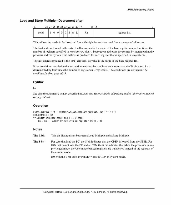
ARM Addressing Modes
Load and Store Multiple - Decrement after
This addressing mode is for Load and Store Multiple instructions, and forms a range of addresses.
The first address formed is the <start_address>, and is the value of the base register minus four times the number of registers specified in <registers>, plus 4. Subsequent addresses are formed by incrementing the previous address by four. One address is produced for each register that is specified in <registers>.
The last address produced is the <end_address>. Its value is the value of the base register Rn.
If the condition specified in the instruction matches the condition code status and the W bit is set, Rn is decremented by four times the number of registers in <registers>. The conditions are defined in The condition field on page A3-3.
Syntax
DA
See also the alternative syntax described in Load and Store Multiple addressing modes (alternative names) on page A5-47.
Operation
start_address = Rn - (Number_Of_Set_Bits_In(register_list) * 4) + 4end_address = Rnif ConditionPassed(cond) and W == 1 then
Rn = Rn - (Number_Of_Set_Bits_In(register_list) * 4)
Notes
The L bit This bit distinguishes between a Load Multiple and a Store Multiple.
The S bit For LDMs that load the PC, the S bit indicates that the CPSR is loaded from the SPSR. For LDMs that do not load the PC and all STMs, the S bit indicates that when the processor is in a privileged mode, the User mode banked registers are transferred instead of the registers of the current mode.
LDM with the S bit set is UNPREDICTABLE in User or System mode.
31 28 27 26 25 24 23 22 21 20 19 16 15 0
cond 1 0 0 0 0 S W L Rn register list
Copyright ©1996-1998, 2000, 2004, 2005 ARM Limited. All rights reserved.
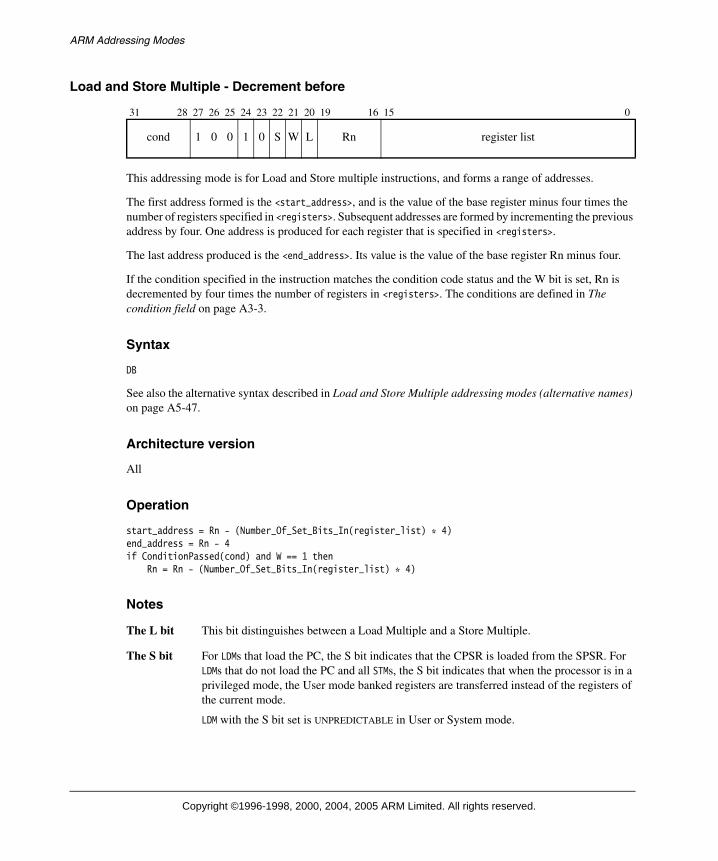
ARM Addressing Modes
Load and Store Multiple - Decrement before
This addressing mode is for Load and Store multiple instructions, and forms a range of addresses.
The first address formed is the <start_address>, and is the value of the base register minus four times the number of registers specified in <registers>. Subsequent addresses are formed by incrementing the previous address by four. One address is produced for each register that is specified in <registers>.
The last address produced is the <end_address>. Its value is the value of the base register Rn minus four.
If the condition specified in the instruction matches the condition code status and the W bit is set, Rn is decremented by four times the number of registers in <registers>. The conditions are defined in The condition field on page A3-3.
Syntax
DB
See also the alternative syntax described in Load and Store Multiple addressing modes (alternative names) on page A5-47.
Architecture version
All
Operation
start_address = Rn - (Number_Of_Set_Bits_In(register_list) * 4)end_address = Rn - 4if ConditionPassed(cond) and W == 1 then
Rn = Rn - (Number_Of_Set_Bits_In(register_list) * 4)
Notes
The L bit This bit distinguishes between a Load Multiple and a Store Multiple.
The S bit For LDMs that load the PC, the S bit indicates that the CPSR is loaded from the SPSR. For LDMs that do not load the PC and all STMs, the S bit indicates that when the processor is in a privileged mode, the User mode banked registers are transferred instead of the registers of the current mode.
LDM with the S bit set is UNPREDICTABLE in User or System mode.
31 28 27 26 25 24 23 22 21 20 19 16 15 0
cond 1 0 0 1 0 S W L Rn register list
Copyright ©1996-1998, 2000, 2004, 2005 ARM Limited. All rights reserved.

ARM Addressing Modes
Load and Store Multiple addressing modes (alternative names)
The four addressing mode names given in Addressing Mode 4 - Load and Store Multiple on page A5-41 (IA, IB, DA, DB) are most useful when a load and Store Multiple instruction is being used for block data transfer, as it is likely that the Load Multiple and Store Multiple have the same addressing mode, so that the data is stored in the same way that it was loaded.
However, if Load Multiple and Store Multiple are being used to access a stack, the data is not loaded with the same addressing mode that was used to store the data, because the load (pop) and store (push) operations must adjust the stack in opposite directions.
Stack operations
Load Multiple and Store Multiple addressing modes can be specified with an alternative syntax, which is more applicable to stack operations:
Full stacks Have stack pointers that point to the last used (full) location.
Empty stacks Have stack pointers that point to the first unused (empty) location.
Descending stacks Grow towards decreasing memory addresses (towards the bottom of memory).
Ascending stacks Grow towards increasing memory addresses (towards the top of memory).
Two attributes allow four types of stack to be defined:
• Full Descending, with the syntax FD
• Empty Descending, with the syntax ED
• Full Ascending, with the syntax FA
• Empty Ascending, with the syntax EA.
Note When defining stacks on which coprocessor data is to be placed (or might be placed in the future), programmers are advised to use the FD or EA stack types. This is because coprocessor data can be pushed to these types of stack with a single STC instruction and popped from them with a single LDC instruction. Multi-instruction sequences are required for coprocessor access to FA or ED stacks.
Table A5-1 on page A5-48 and Table A5-2 on page A5-48 show the relationship between the four types of stack, the four types of addressing mode shown above, and the L, U, and P bits in the instruction format.
Copyright ©1996-1998, 2000, 2004, 2005 ARM Limited. All rights reserved.

ARM Addressing Modes
Table A5-1 shows the relationship for LDM instructions.
Table A5-2 shows the relationship for STM instructions.
Table A5-1 LDM addressing modes
Non-stack addressing mode Stack addressing mode L bit P bit U bit
LDMDA (Decrement After) LDMFA (Full Ascending) 1 0 0
LDMIA (Increment After) LDMFD (Full Descending) 1 0 1
LDMDB (Decrement Before) LDMEA (Empty Ascending) 1 1 0
LDMIB (Increment Before) LDMED (Empty Descending) 1 1 1
Table A5-2 STM addressing modes
Non-stack addressing mode Stack addressing mode L bit P bit U bit
STMDA (Decrement After) STMED (Empty Descending) 0 0 0
STMIA (Increment After) STMEA (Empty Ascending) 0 0 1
STMDB (Decrement Before) STMFD (Full Descending) 0 1 0
STMIB (Increment Before) STMFA (Full Ascending) 0 1 1
Copyright ©1996-1998, 2000, 2004, 2005 ARM Limited. All rights reserved.

The ARM Instruction Set
Copyright © 1996-1998, 2000, 2004, 2005 ARM Limited. All rights reserved.
The condition field
Most ARM instructions can be conditionally executed, which means that they only have their normal effect on the programmers’ model state, memory and coprocessors if the N, Z, C and V flags in the CPSR satisfy a condition specified in the instruction. If the flags do not satisfy this condition, the instruction acts as a NOP: that is, execution advances to the next instruction as normal, including any relevant checks for interrupts and Prefetch Aborts, but has no other effect.
Prior to ARMv5, all ARM instructions could be conditionally executed. A few instructions have been introduced subsequently which can only be executed unconditionally. See Unconditional instruction extension space on page A3-41 for details.
Every instruction contains a 4-bit condition code field in bits 31 to 28:
This field contains one of the 16 values described in Table A3-1 on page A3-4. Most instruction mnemonics can be extended with the letters defined in the mnemonic extension field.
If the always (AL) condition is specified, the instruction is executed irrespective of the value of the condition code flags. The absence of a condition code on an instruction mnemonic implies the AL condition code.
31 28 27 0
cond

The ARM Instruction Set
Copyright © 1996-1998, 2000, 2004, 2005 ARM Limited. All rights reserved.
Condition code 0b1111
If the condition field is 0b1111, the behavior depends on the architecture version:
• In ARMv4, any instruction with a condition field of 0b1111 is UNPREDICTABLE.
• In ARMv5 and above, a condition field of 0b1111 is used to encode various additional instructions which can only be executed unconditionally (see Unconditional instruction extension space on page A3-41). All instruction encoding diagrams which show bits[31:28] as cond only match instructions in which these bits are not equal to 0b1111.
Table A3-1 Condition codes
Opcode [31:28]
Mnemonic extension
Meaning Condition flag state
0000 EQ Equal Z set
0001 NE Not equal Z clear
0010 CS/HS Carry set/unsigned higher or same C set
0011 CC/LO Carry clear/unsigned lower C clear
0100 MI Minus/negative N set
0101 PL Plus/positive or zero N clear
0110 VS Overflow V set
0111 VC No overflow V clear
1000 HI Unsigned higher C set and Z clear
1001 LS Unsigned lower or same C clear or Z set
1010 GE Signed greater than or equal N set and V set, or
N clear and V clear (N == V)
1011 LT Signed less than N set and V clear, or
N clear and V set (N != V)
1100 GT Signed greater than Z clear, and either N set and V set, or N clear and V clear (Z == 0,N == V)
1101 LE Signed less than or equal Z set, or N set and V clear, or
N clear and V set (Z == 1 or N != V)
1110 AL Always (unconditional) -
1111 - See Condition code 0b1111 -