arm cortex-m3 introduction · arm cortex-m3 introduction arm university relations. 2 agenda ... arm...
TRANSCRIPT
1
ARM Cortex-M3Introduction
ARM University Relations
2
Agenda
Cortex-M3 Overview
v7-M Architecture/Programmers Model
Data Path and Pipelines
Tools and mbed Platform
3
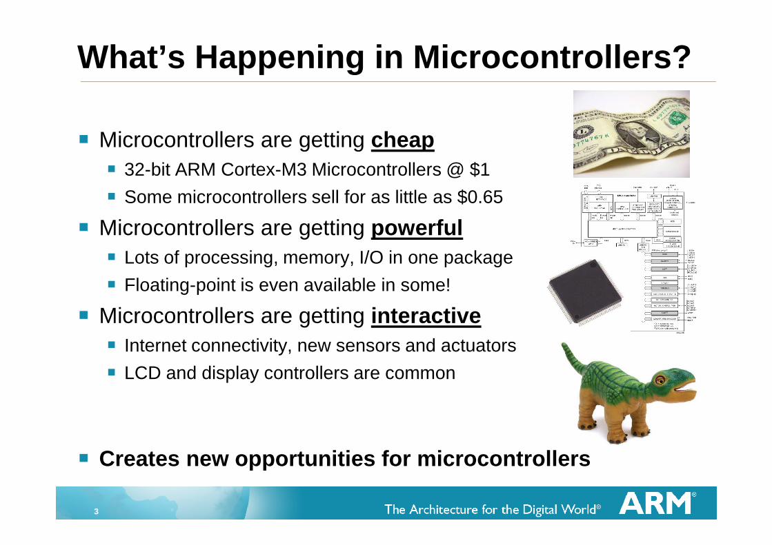
Microcontrollers are getting cheap
32-bit ARM Cortex-M3 Microcontrollers @ $1
Some microcontrollers sell for as little as $0.65
Microcontrollers are getting powerful
Lots of processing, memory, I/O in one package
Floating-point is even available in some!
Microcontrollers are getting interactive
Internet connectivity, new sensors and actuators
LCD and display controllers are common
Creates new opportunities for microcontrollers
What’s Happening in Microcontrollers?
4
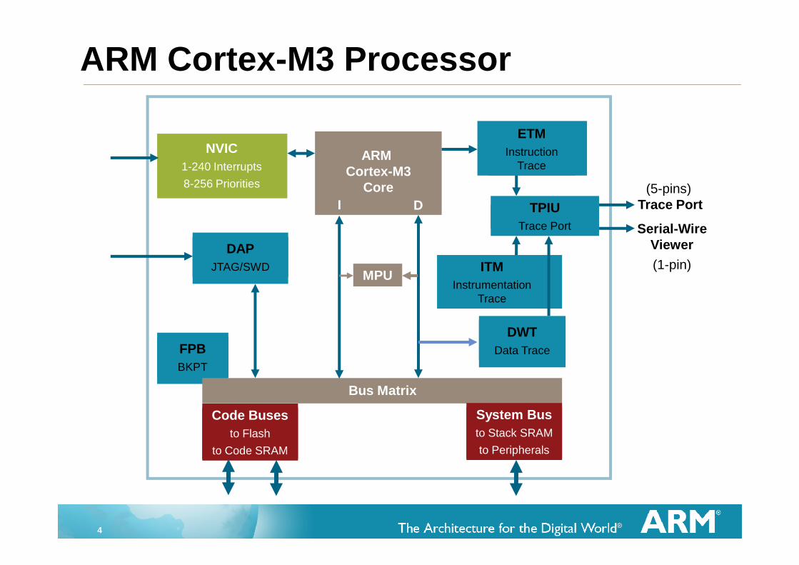
ARM Cortex-M3 Processor
FPB
BKPT
ARMCortex-M3
Core
ETM
InstructionTrace
Bus Matrix
I D
DAP
JTAG/SWD
NVIC
1-240 Interrupts
8-256 Priorities
Code Buses
to Flash
to Code SRAM
System Bus
to Stack SRAM
to Peripherals
DWT
Data Trace
ITM
InstrumentationTrace
TPIU
Trace Port Serial-WireViewer
(1-pin)
(5-pins)Trace Port
MPU

5
18 x 32-bit registers
Excellent compiler target
Reduced pin count requirements
Efficient interrupt handling
Power management
Efficient debug and development support features
Breakpoints, Watchpoints,
Flash Patch support,
Instruction Trace
Strong OS support
User/Supervisor model
OS support features
Designed to be fully programmed in C (even reset, interrupts andexceptions)
ARM Cortex-M3 Microcontroller
6
ARMv7M Architecture
No Cache - No MMU
Debug is optimized for microcontroller applications
Vector table contains addresses, not instructions
DIV instruction
Interrupts automatically save/restore state
Exceptions programmed in C (No Coprocessor 15 - All registers are memory-mapped)
Interrupt controller is part of Cortex-M3 macrocell
Fixed memory map
Bit-banding
Non-Maskable Interrupt (NMI)
Only one processor status reg
Thumb-2 processing core
Mix of 16 and 32 bit instructions for very high code density
Gives complete Thumb compatibility
ARM Cortex-M3 Microcontroller
7
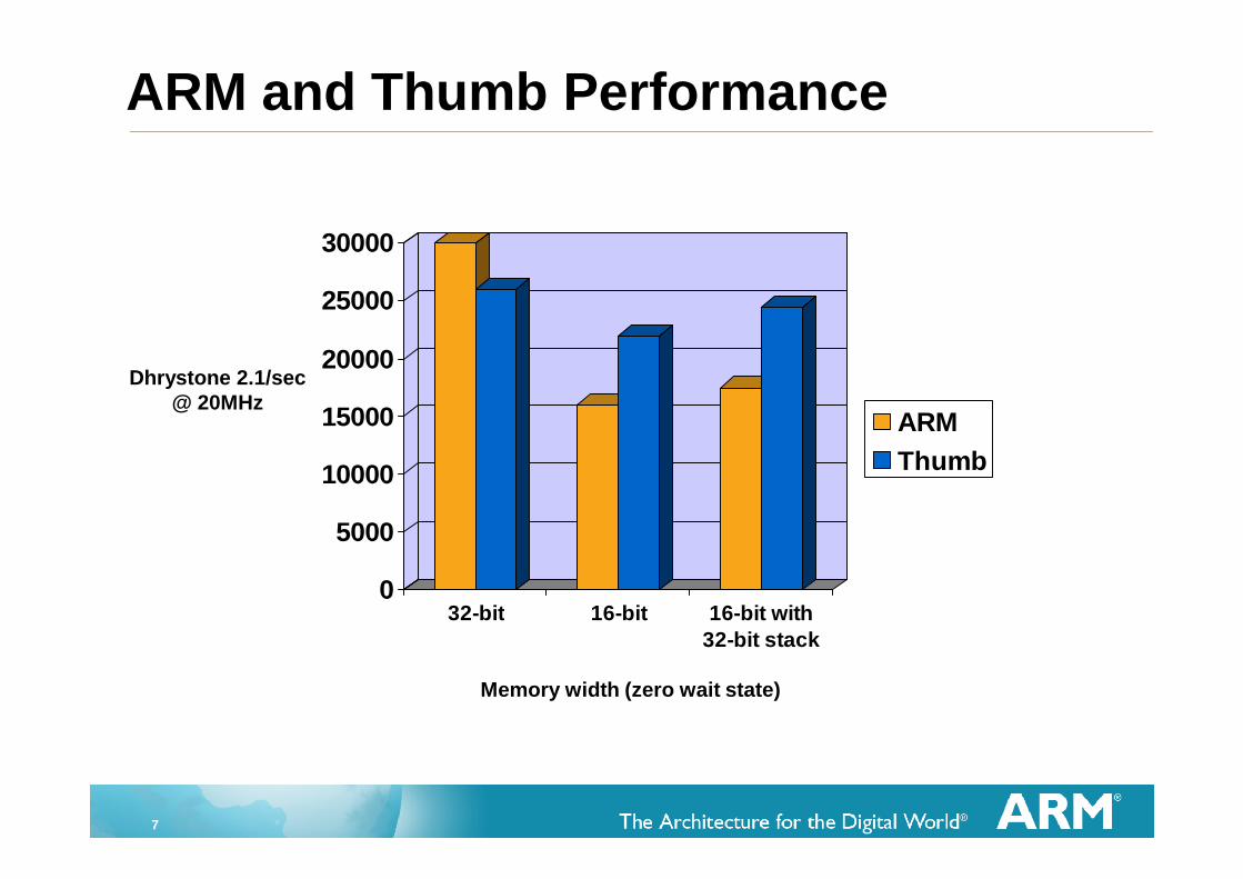
ARM and Thumb Performance
Memory width (zero wait state)
0
5000
10000
15000
20000
25000
30000
32-bit 16-bit 16-bit with
32-bit stack
ARM
Thumb
Dhrystone 2.1/sec@ 20MHz
8
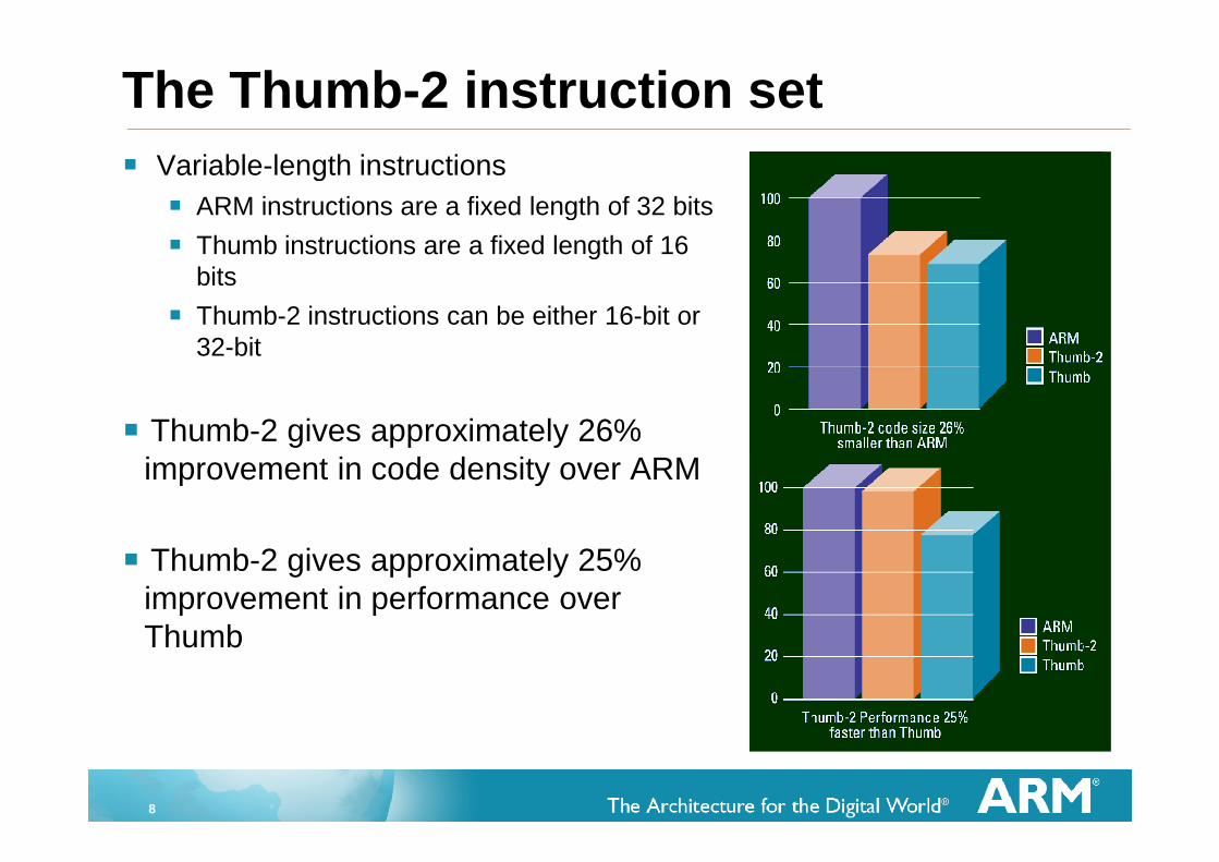
The Thumb-2 instruction set
Variable-length instructions
ARM instructions are a fixed length of 32 bits
Thumb instructions are a fixed length of 16bits
Thumb-2 instructions can be either 16-bit or32-bit
Thumb-2 gives approximately 26%improvement in code density over ARM
Thumb-2 gives approximately 25%improvement in performance overThumb
9
Agenda
Cortex-M3 Overview
v7-M Architecture/Programmers Model
Data Path and Pipelines
Tools and mbed Platform
10
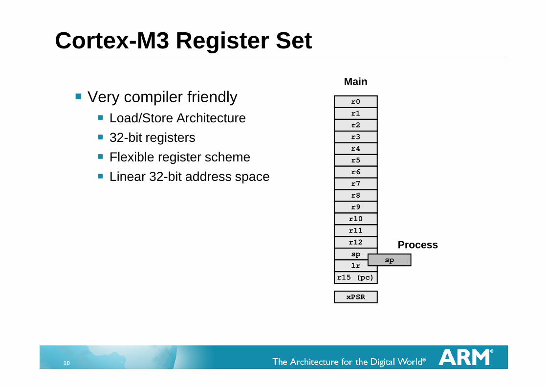
Cortex-M3 Register Set
Very compiler friendly
Load/Store Architecture
32-bit registers
Flexible register scheme
Linear 32-bit address space
Process
r8
r9
r10
r11
r12
sp
lr
r15 (pc)
xPSR
r0
r1
r2
r3
r4
r5
r6
r7
Main
sp
11
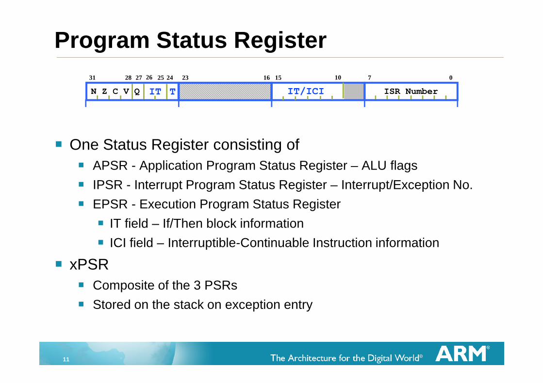
Program Status Register
One Status Register consisting of
APSR - Application Program Status Register – ALU flags
IPSR - Interrupt Program Status Register – Interrupt/Exception No.
EPSR - Execution Program Status Register
IT field – If/Then block information
ICI field – Interruptible-Continuable Instruction information
xPSR
Composite of the 3 PSRs
Stored on the stack on exception entry
IT/ICIIT
2731
N Z C V Q
28 7
ISR Number
1623 15 0242526 10
T
12
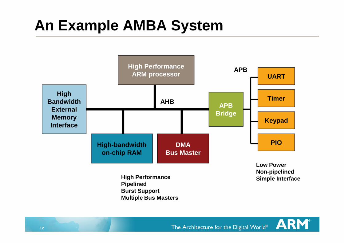
High PerformanceARM processor
High-bandwidthon-chip RAM
HighBandwidth
ExternalMemoryInterface
DMABus Master
APBBridge
Keypad
UART
PIO
TimerAHB
APB
High PerformancePipelinedBurst SupportMultiple Bus Masters
Low PowerNon-pipelinedSimple Interface
An Example AMBA System
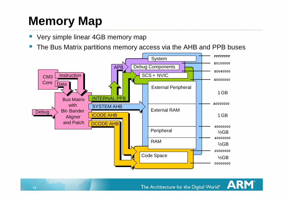
13
Memory Map Very simple linear 4GB memory map
The Bus Matrix partitions memory access via the AHB and PPB buses
DebugSYSTEM AHB
The image cannot be displayed. Your computer may not have enough memory to open the image, or the image may have been corrupt ed. Restart your computer, and then open the fileagain. If the red x still appears, you may have to delete the image and then insert it again.
Bus Matrixwith
Bit- Bander
Alignerand Patch
Code Space
RAM
Peripheral
External RAM
00000000
20000000
40000000
60000000
A0000000
E0000000
E0040000
E0100000
FFFFFFFF
SYSTEM AHB
External Peripheral
Debug Components
System
SCS + NVIC
APB
DCODE AHB
ICODE AHB
INTERNAL PPB
Debug
The image cannot be displayed. Your computer may not have enough memory to open the image,or the image may have been corrupted. Restart your computer, and then open the file again. If thered x still appears, you may have to delete the image and then insert it again.
CM3Core
Instruction
Data
½GB
½GB
½GB
1 GB
1 GB
14
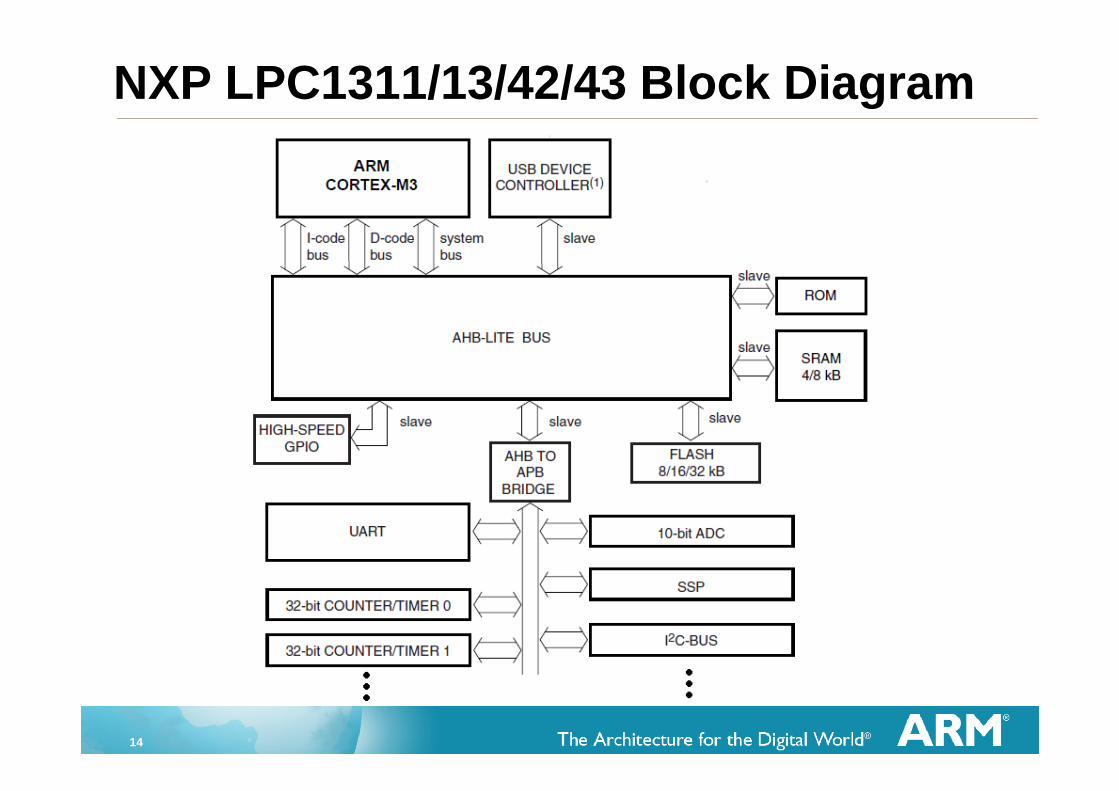
NXP LPC1311/13/42/43 Block Diagram
15
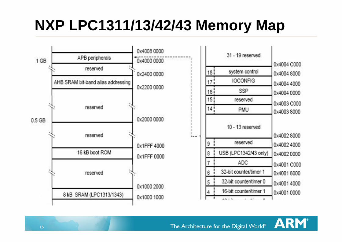
NXP LPC1311/13/42/43 Memory Map
16
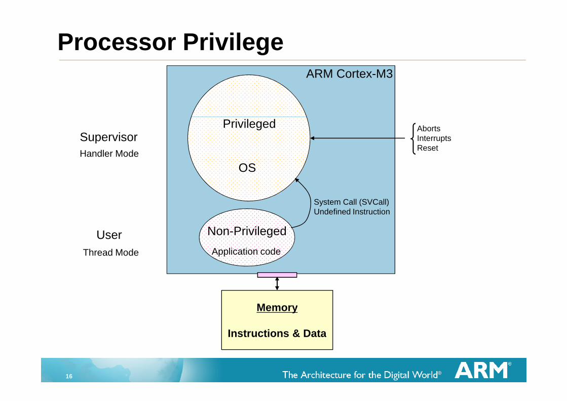
ARM Cortex-M3
Application code
OS
System Call (SVCall)Undefined Instruction
Privileged
Processor Privilege
Memory
Instructions & Data
AbortsInterruptsReset
Non-Privileged
Supervisor
User
Handler Mode
Thread Mode
17
Memory Protection Unit (MPU)
MPU provides access control for various memory regions
Zero Latency Memory Protection
8 register-stored regions
Same regions used for instructions and data
Minimum region size 32 Bytes (max 4GB)
No address translation or page tables
Configured via memory-mapped control registers
18
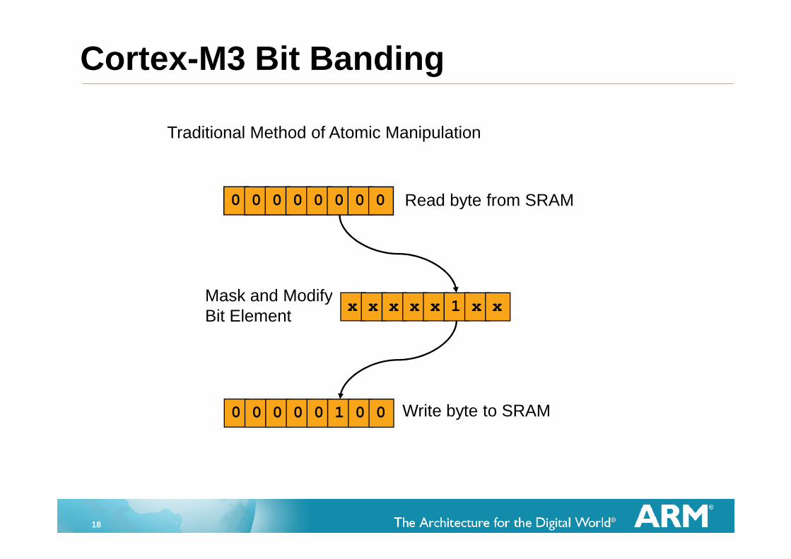
Traditional Method of Atomic Manipulation
0 0 0 0 0 0 0 0
x x x x x 1 x x
0 0 0 0 0 1 0 0
Read byte from SRAM
Mask and ModifyBit Element
Write byte to SRAM
0x02000000
0x02000000
0x02000000
Cortex-M3 Bit Banding
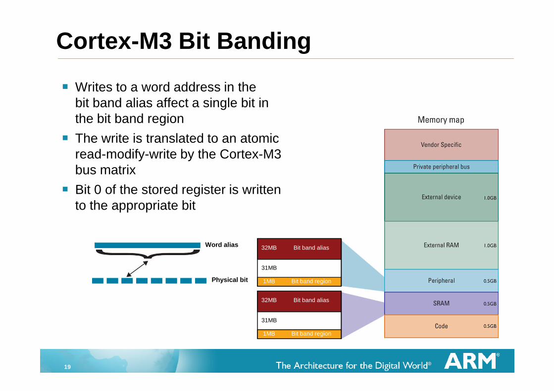
19
Word alias
Physical bit
32MB Bit band alias32MB
31MB
1MB Bit band region
Bit band alias32MB
31MB
1MB Bit band region
Writes to a word address in thebit band alias affect a single bit inthe bit band region
The write is translated to an atomicread-modify-write by the Cortex-M3bus matrix
Bit 0 of the stored register is writtento the appropriate bit
Cortex-M3 Bit Banding
20
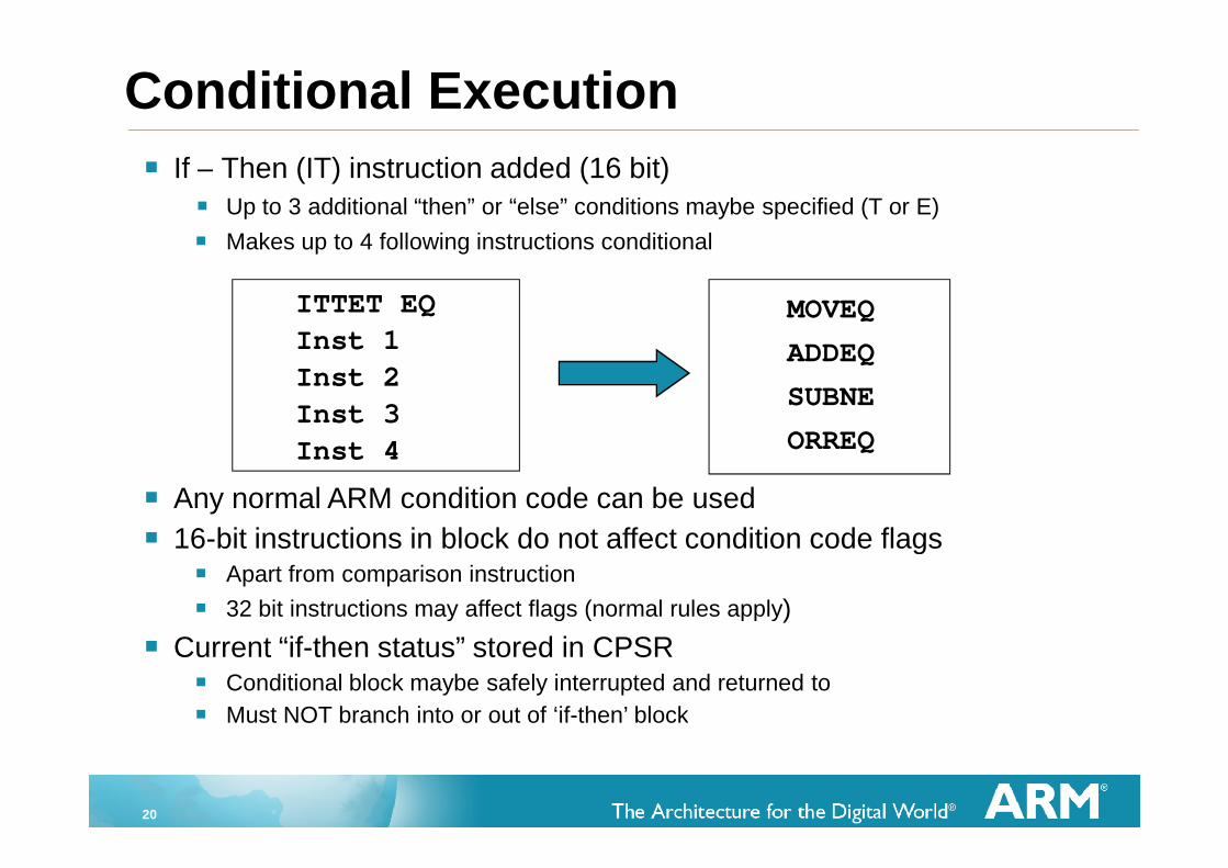
Conditional Execution
ITTET EQ
Inst 1
Inst 2
Inst 3
Inst 4
If – Then (IT) instruction added (16 bit)
Up to 3 additional “then” or “else” conditions maybe specified (T or E)
Makes up to 4 following instructions conditional
Any normal ARM condition code can be used
16-bit instructions in block do not affect condition code flags Apart from comparison instruction
32 bit instructions may affect flags (normal rules apply)
Current “if-then status” stored in CPSR Conditional block maybe safely interrupted and returned to
Must NOT branch into or out of ‘if-then’ block
MOVEQ
ADDEQ
SUBNE
ORREQ

21
Interrupt Handling One Non-Maskable Interrupt (INTNMI) supported
1-240 prioritizable interrupts supported
Interrupts can be masked
Implementation option selects number of interrupts supported
Nested Vectored Interrupt Controller (NVIC) is tightly coupled with processor core
Interrupt inputs are active HIGH
Cortex-M3Processor Core
INTNMI
NVIC
Cortex-M3
1-240 InterruptsINTISR[239:0] …
22
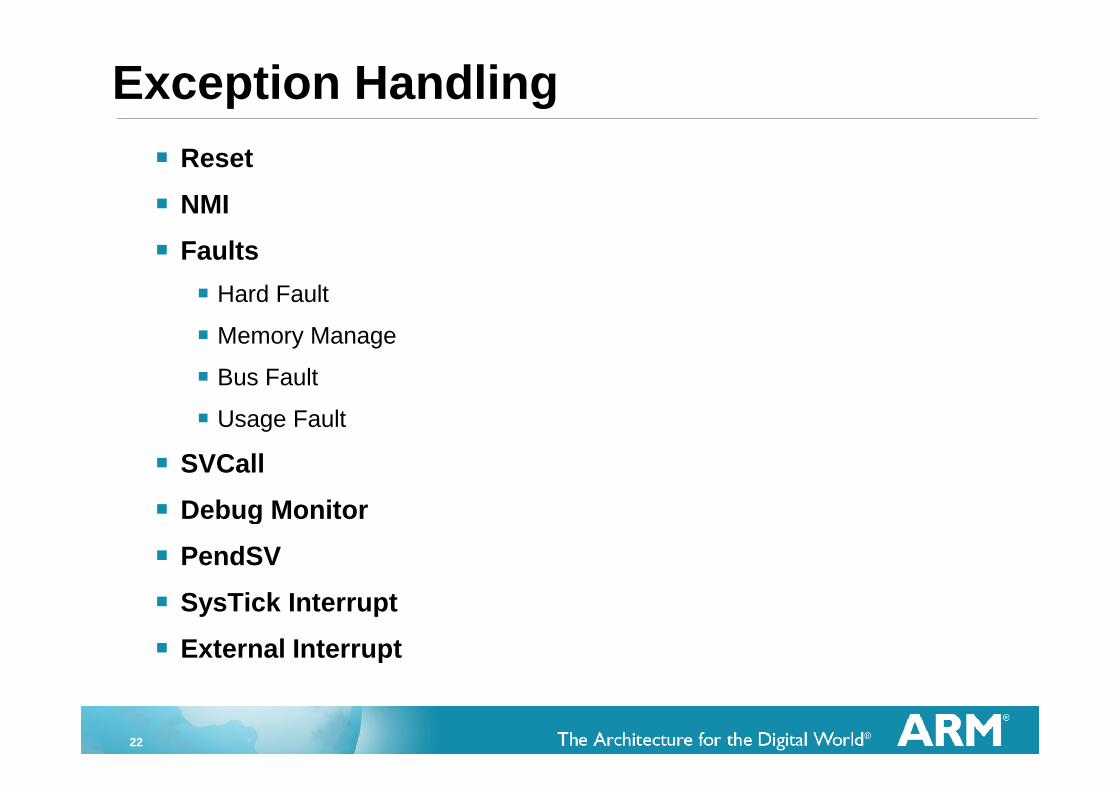
Exception Handling
Reset
NMI
Faults
Hard Fault
Memory Manage
Bus Fault
Usage Fault
SVCall
Debug Monitor
PendSV
SysTick Interrupt
External Interrupt
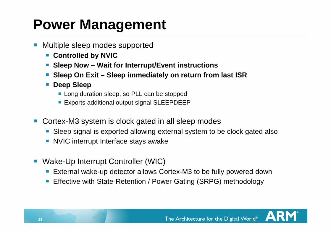
23
Multiple sleep modes supported
Controlled by NVIC
Sleep Now – Wait for Interrupt/Event instructions
Sleep On Exit – Sleep immediately on return from last ISR
Deep Sleep
Long duration sleep, so PLL can be stopped
Exports additional output signal SLEEPDEEP
Cortex-M3 system is clock gated in all sleep modes
Sleep signal is exported allowing external system to be clock gated also
NVIC interrupt Interface stays awake
Wake-Up Interrupt Controller (WIC)
External wake-up detector allows Cortex-M3 to be fully powered down
Effective with State-Retention / Power Gating (SRPG) methodology
Power Management
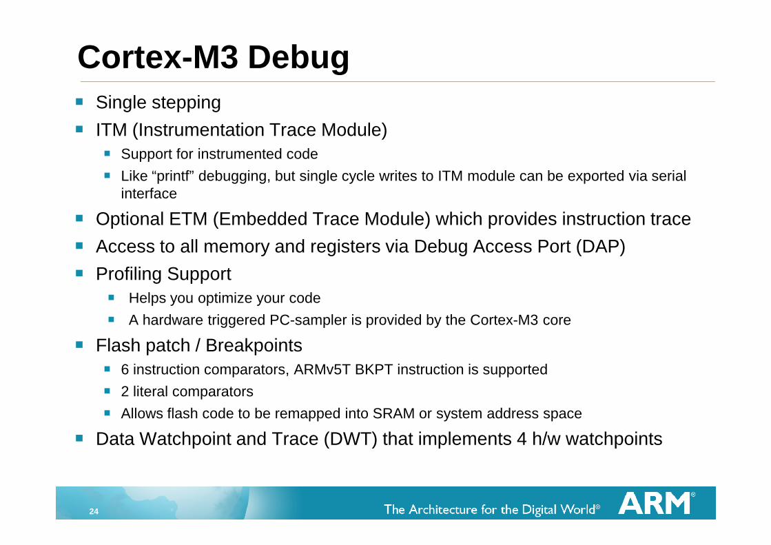
24
Single stepping
ITM (Instrumentation Trace Module)
Support for instrumented code
Like “printf” debugging, but single cycle writes to ITM module can be exported via serialinterface
Optional ETM (Embedded Trace Module) which provides instruction trace
Access to all memory and registers via Debug Access Port (DAP)
Profiling Support
Helps you optimize your code
A hardware triggered PC-sampler is provided by the Cortex-M3 core
Flash patch / Breakpoints
6 instruction comparators, ARMv5T BKPT instruction is supported
2 literal comparators
Allows flash code to be remapped into SRAM or system address space
Data Watchpoint and Trace (DWT) that implements 4 h/w watchpoints
Cortex-M3 Debug
25
Agenda
Cortex-M3 Overview
v7-M Architecture/Programmers Model
Data Path and Pipelines
Tools and mbed Platform
26
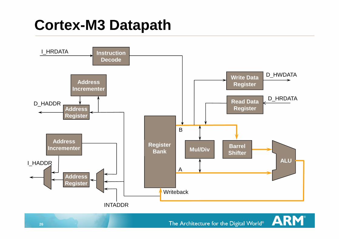
Cortex-M3 Datapath
RegisterBank Mul/Div
AddressIncrementer
ALU
B
A
INTADDR
I_HADDR
AddressRegister
BarrelShifter
Writeback
ALU
Read DataRegister
Write DataRegister
InstructionDecode
I_HRDATA
D_HWDATA
D_HRDATA
AddressIncrementer
D_HADDRAddressRegister
27
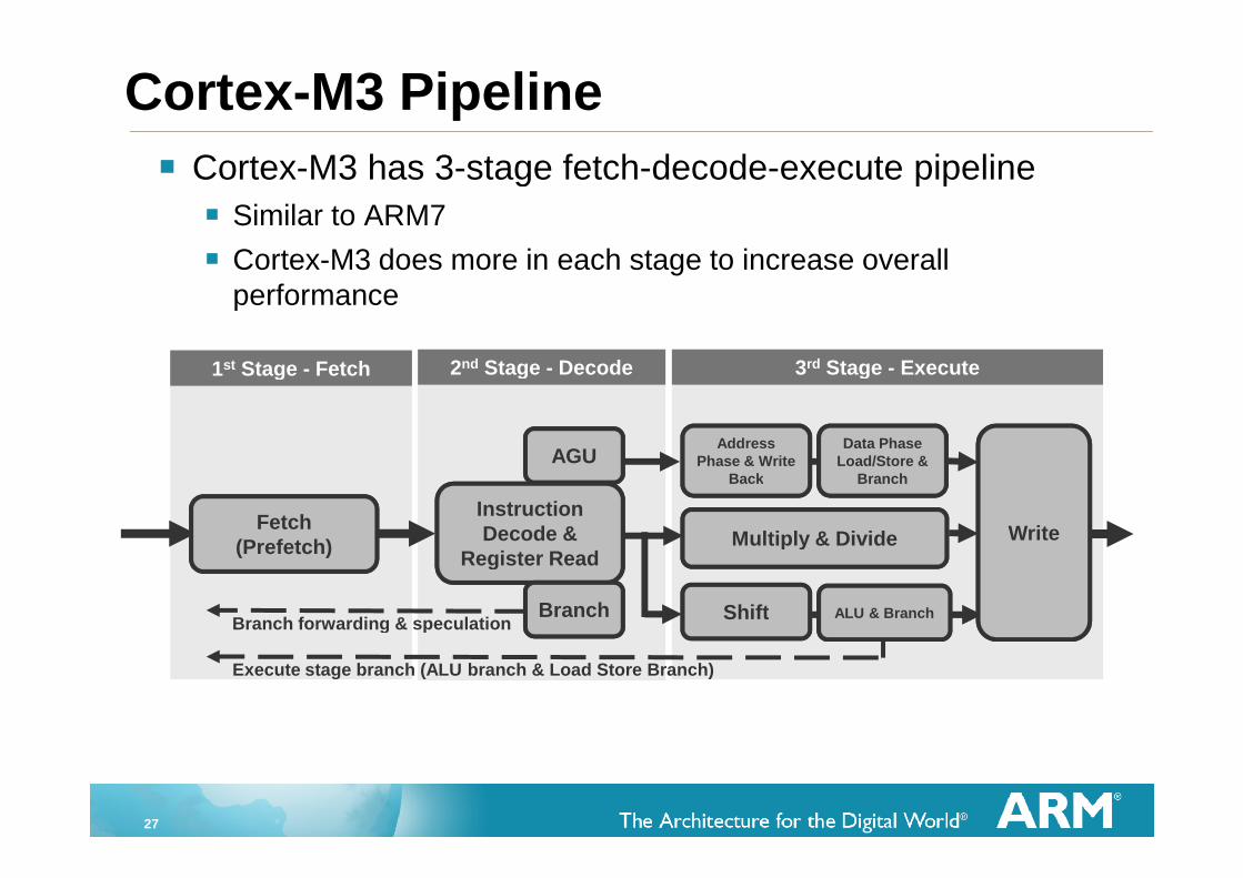
Cortex-M3 has 3-stage fetch-decode-execute pipeline
Similar to ARM7
Cortex-M3 does more in each stage to increase overallperformance
Cortex-M3 Pipeline
Branch forwarding & speculation
1st Stage - Fetch 2nd Stage - Decode 3rd Stage - Execute
Execute stage branch (ALU branch & Load Store Branch)
Fetch(Prefetch)
AGU
InstructionDecode &
Register Read
Branch
AddressPhase & Write
Back
Data PhaseLoad/Store &
Branch
Multiply & Divide
Shift ALU & Branch
Write
28
Cycle
Operation
ADD
SUB
ORR
AND
EOR
ORR
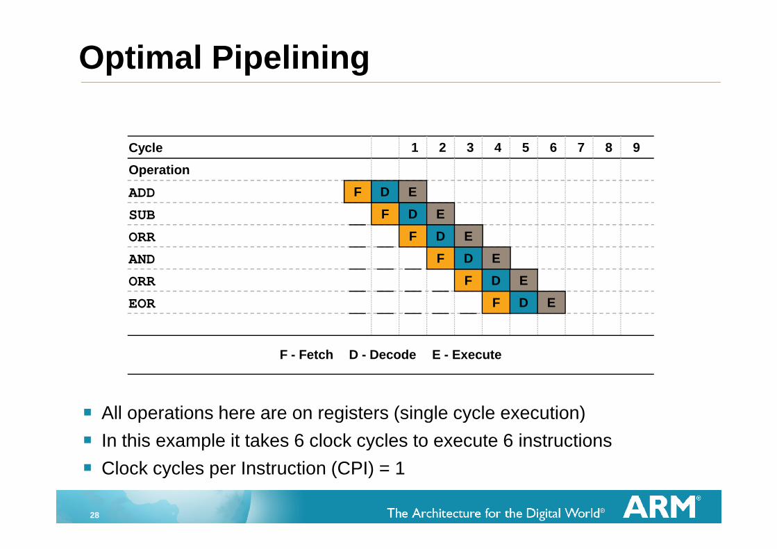
Optimal Pipelining
All operations here are on registers (single cycle execution)
In this example it takes 6 clock cycles to execute 6 instructions
Clock cycles per Instruction (CPI) = 1
1 2 3 4 5 6 7 8 9
F D E
F D E
F E
F D E
F D E
D
F D E
F - Fetch D - Decode E - Execute
29
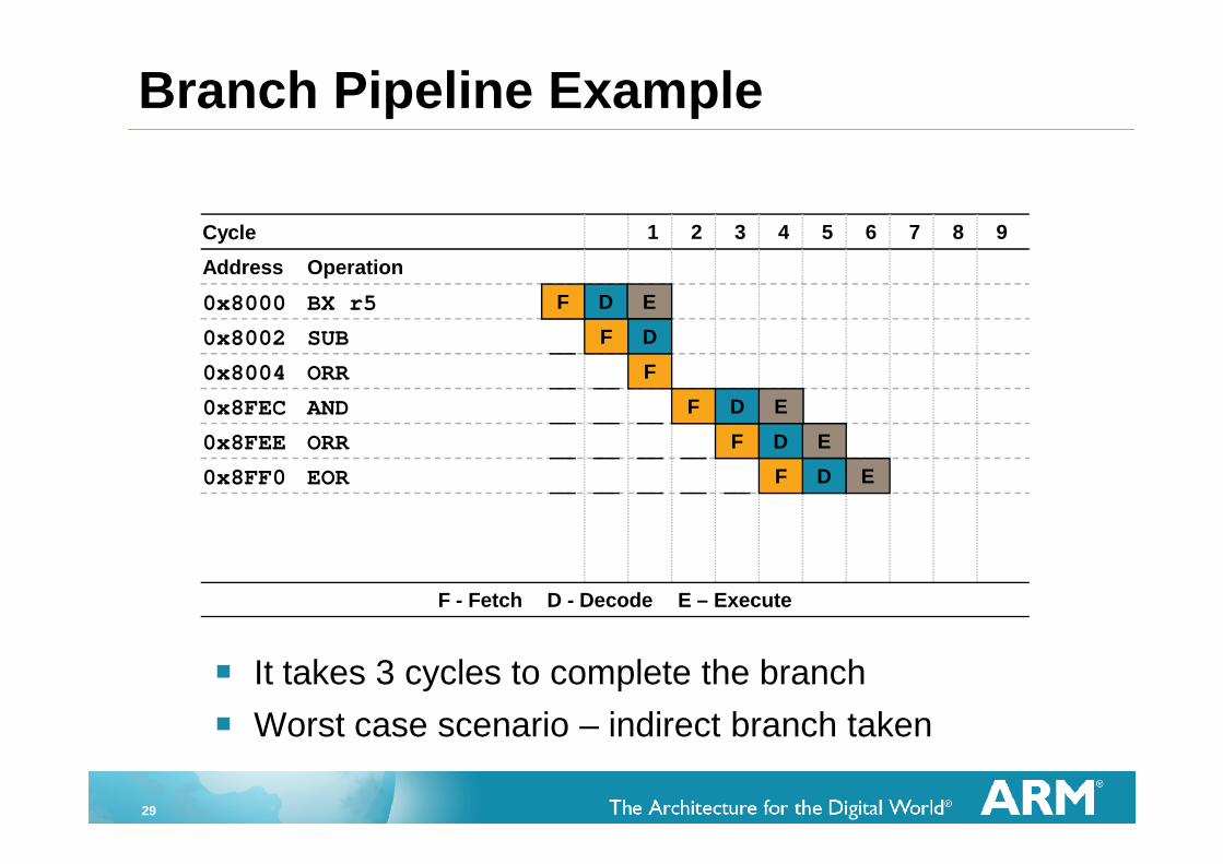
It takes 3 cycles to complete the branch
Worst case scenario – indirect branch taken
Cycle
Address Operation
0x8000 BX r5
0x8002 SUB
0x8FEE ORR
0x8FEC AND
0x8FF0 EOR
0x8004 ORR
1 2 3 4 5 6 7 8 9
F D E
F D
F E
F D E
F
D
F D E
F - Fetch D - Decode E – Execute
Branch Pipeline Example
30
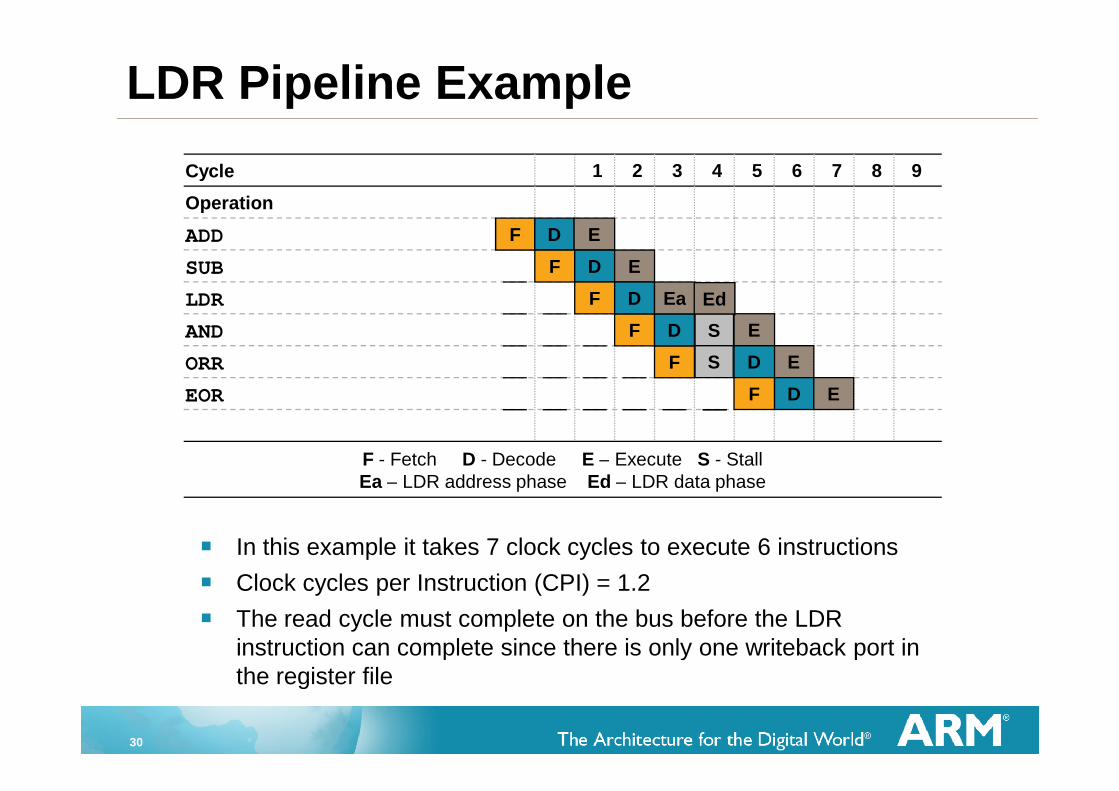
In this example it takes 7 clock cycles to execute 6 instructions
Clock cycles per Instruction (CPI) = 1.2
The read cycle must complete on the bus before the LDRinstruction can complete since there is only one writeback port inthe register file
Cycle
Operation
ADD
SUB
ORR
AND
EOR
LDR
1 2 3 4 5 6 7 8 9
F D E
F D E
F E
F D E
F D Ea
D
F D E
F - Fetch D - Decode E – Execute S - StallEa – LDR address phase Ed – LDR data phase
Ed
S
S
LDR Pipeline Example
31
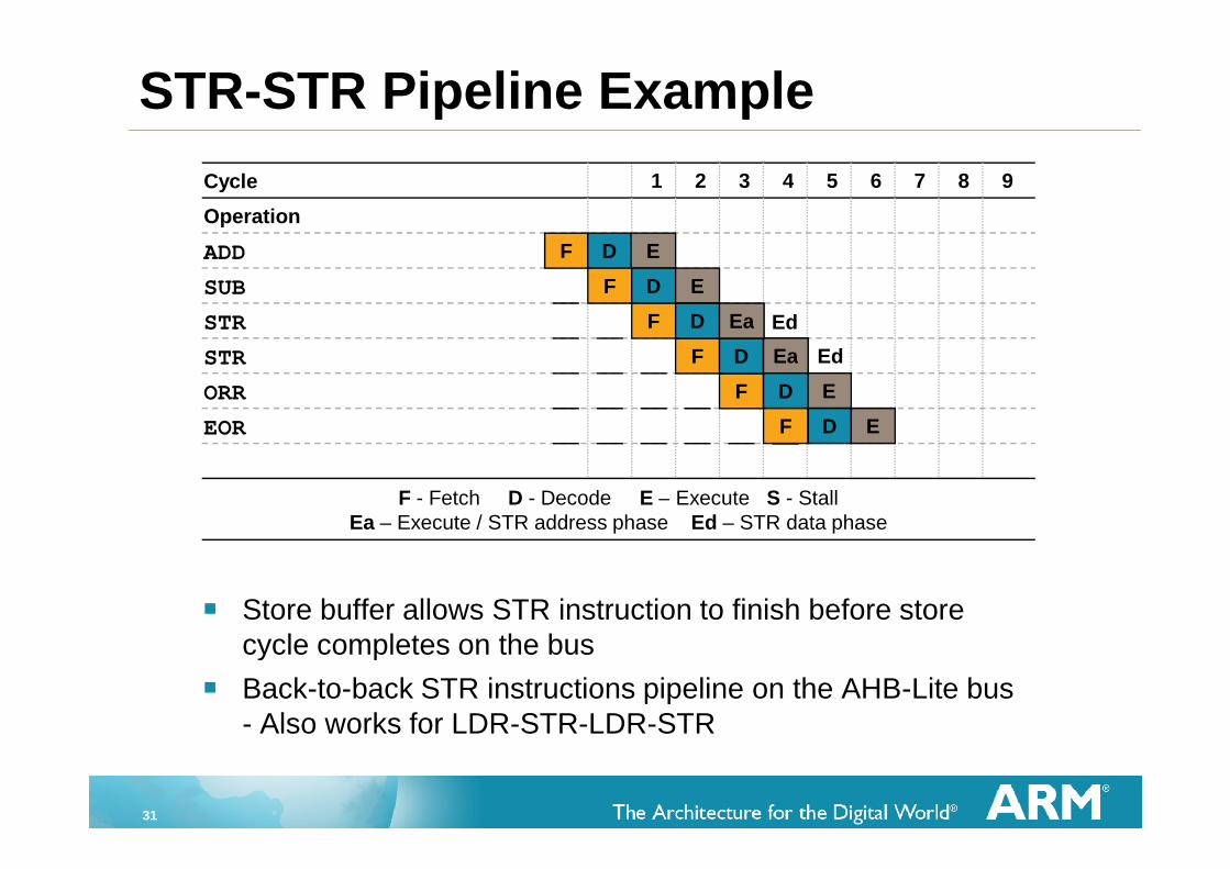
Store buffer allows STR instruction to finish before storecycle completes on the bus
Back-to-back STR instructions pipeline on the AHB-Lite bus- Also works for LDR-STR-LDR-STR
Cycle
Operation
ADD
SUB
ORR
STR
EOR
STR
1 2 3 4 5 6 7 8 9
F D E
F D E
F E
F D Ea
F D Ea
D
F D E
F - Fetch D - Decode E – Execute S - StallEa – Execute / STR address phase Ed – STR data phase
Ed
STR-STR Pipeline Example
Ed
32
Agenda
Cortex-M3 Overview
v7-M Architecture/Programmers Model
Data Path and Pipelines
Tools and mbed Platform
33
RVMDK Software Development Tools
Includes ARM macro assembler, compilers (ARM RealView C/C++Compiler, Keil CARM Compiler, or GNU compiler), ARM linker, Keil uVisionDebugger and Keil uVision IDE
Keil uVision Debugger accurately simulates on-chip peripherals (I2C, CAN,UART, SPI, Interrupts, I/O Ports, A/D and D/A converters, PWM, etc.)
Evaluation Version
16K byte object code + 16K data limitation
Some linker restrictions such as base addresses for code/constants
GNU tools provided are not restricted in any way
http://www.keil.com/demo/
34
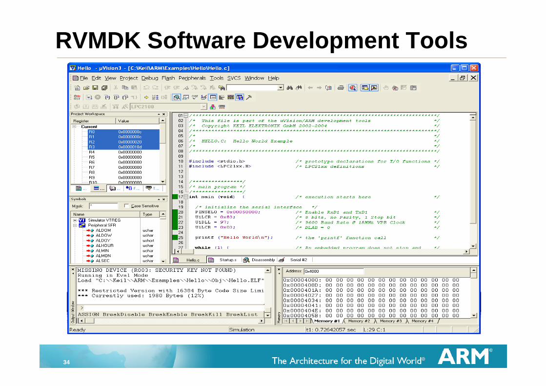
RVMDK Software Development Tools
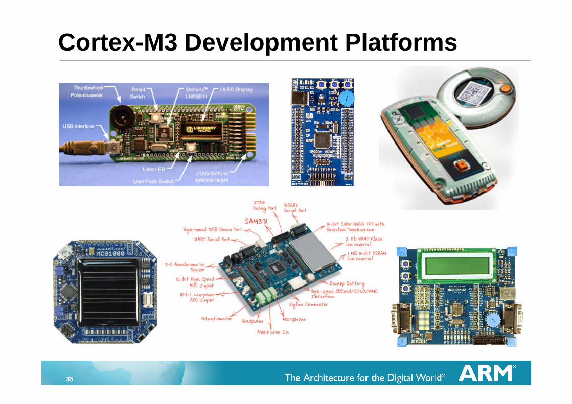
35
Cortex-M3 Development Platforms
36
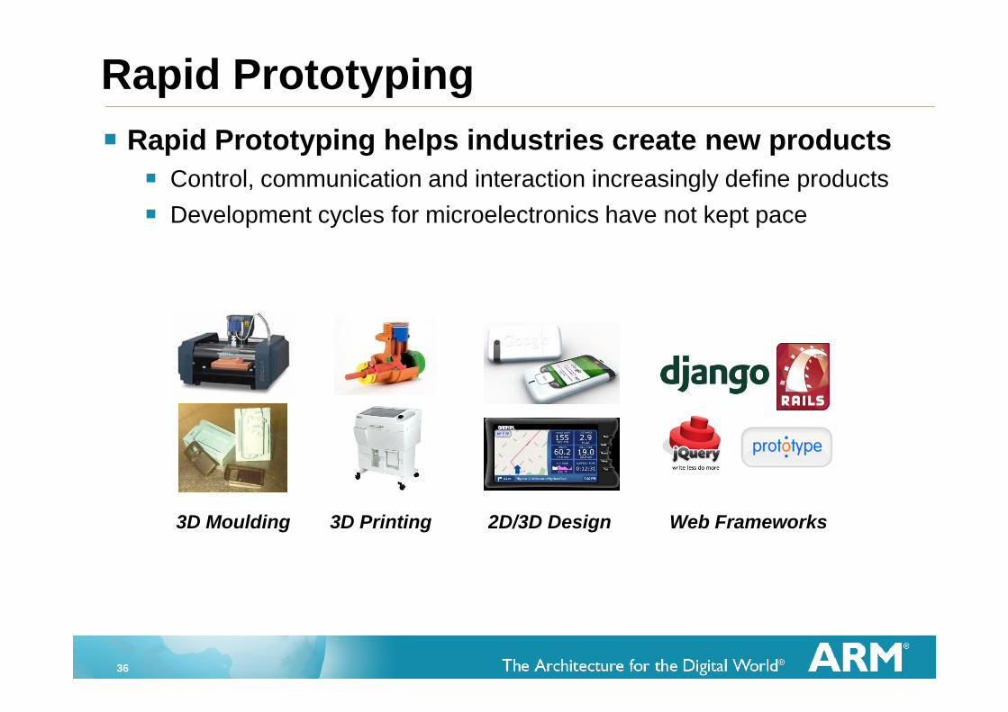
Rapid Prototyping
3D Moulding 3D Printing 2D/3D Design Web Frameworks
Rapid Prototyping helps industries create new products
Control, communication and interaction increasingly define products
Development cycles for microelectronics have not kept pace
37
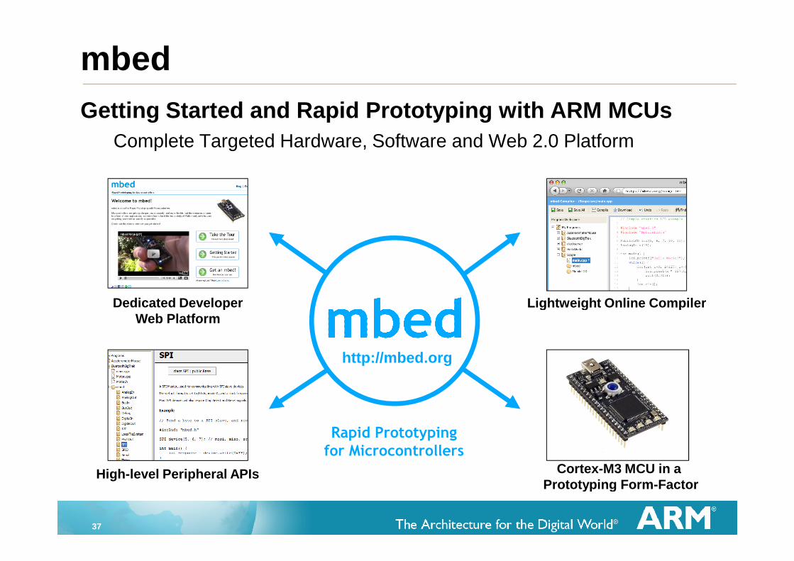
Getting Started and Rapid Prototyping with ARM MCUs
Complete Targeted Hardware, Software and Web 2.0 Platform
mbed
Lightweight Online Compiler
Cortex-M3 MCU in aPrototyping Form-Factor
Dedicated DeveloperWeb Platform
High-level Peripheral APIs
Rapid Prototypingfor Microcontrollers
http://mbed.org
38
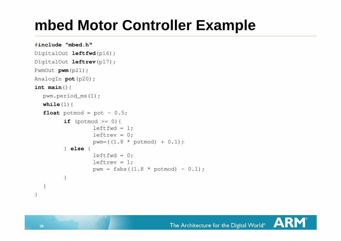
mbed Motor Controller Example#include "mbed.h“
DigitalOut leftfwd(p16);
DigitalOut leftrev(p17);
PwmOut pwm(p21);
AnalogIn pot(p20);
int main(){
pwm.period_ms(1);
while(1){
float potmod = pot - 0.5;
if (potmod >= 0){leftfwd = 1;leftrev = 0;pwm=((1.8 * potmod) + 0.1);
} else {leftfwd = 0;leftrev = 1;pwm = fabs((1.8 * potmod) - 0.1);
}
}
}
39
Documentation
ARM v7-M Architecture Reference Manual (ARM v7-MARM)
Cortex-M3 Technical Reference Manual (TRM)
ARM Debug Interface V5 Architecture Spec (ADIv5)
“The Definitive Guide To The ARM Cortex-M3” by JosephYiu (Elsevier)

40
University Resources
http://www.arm.com/support/university/
http://www.mbed.org/
http://www.keil.com/

41
Fin