armana service manual
TRANSCRIPT
Service
This Base Manual covers 22, 24, and26 Cu. Ft. Side by Side Refrigerators.
Refer to individual Technical Sheet
for specific information on models.
22, 24, & 26 Cu. Ft.Side by Side Refrigerators
This manual is to be used by qualified appliance technicians only.Amana does not assume any responsibility for property damage orpersonal injury for improper service procedures done by an
RS 1300005Revision 0
November 2001
Important Information
Pride and workmanship go into every product to provide our customers with quality products. It is possible,however, that during its lifetime a product may require service. Products should be serviced only by a qualifiedservice technician who is familiar with the safety procedures required in the repair and who is equipped with theproper tools, parts, testing instruments and the appropriate service manual. REVIEW ALL SERVICE INFORMATIONIN THE APPROPRIATE SERVICE MANUAL BEFORE BEGINNING REPAIRS.
Important Notices for Consumers and Servicers
I _, WARNINGTo avoid risk of serious injury or death, repairs should not be attempted by unauthorized personnel, dangerousconditions (such as exposure to electrical shock) may result.
CAUTIONAmana will not be responsible for any injury or property damage from improper service procedures. If performingservice on your own product, assume responsibility for any personal injury or property damage which may result.
To locate an authorized servicer, please consult your telephone book or the dealer from whom you purchased thisproduct. For further assistance, please contact:
CONSUMER AFFAIRS DEPT. ORAMANA APPLIANCES CALLAMANA, IOWA 52204
1-319-622-5511 or (1-800-843-0304)and ask forConsumer Affairs
If outside the United States contact:AMANAATTN: CONSUMER AFFAIRS DEPT.AMANA, IOWA 52204, USATelephone: (3t9) 622-5511Facsimile: (3t9) 622-2180TELEX: 4330076 AMANACABLE: "AMANA", AMANA, IOWA, USA
Recognize Safety Symbols, Words, and Labels
_IL DANGERDANGER--Immediate hazards which WILL result in severe personal injury or death.
_IL WARNINGWARNING--Hazards or unsafe practices which COULD result in severe personal injury or death.
_k, CAUTIONCAUTION--Hazards or unsafe practices which COULD result in minor personal injury or product or property
damage.
RS1300005 Rev. 0 2

Table of Contents
Important Information ................................................ 2Product Design .......................................................... 4Component Testing .................................................... 5Service Procedures ................................................. 10
Service Equipment .................................................. 10Drier Replacement ................................................... 10Refrigerant Precautions ........................................... 11Line Piercing Valves ................................................. 1tOpen Lines ............................................................. 11Compressor Operational Test ................................... 11Dehydrating Sealed Refrigeration System .................. 12Leak Testing ............................................................ 12
Testing Systems Containing aRefrigerant Charge ............................................ 12Testing Systems ContainingNo Refrigerant Charge ....................................... 12
Restrictions ............................................................. 13
Symptoms ......................................................... 13Testing for Restrictions ....................................... 13
Evacuation and Charging ......................................... 14Evacuation ........................................................ 14
Charging ........................................................... 15Refrigerant Charge ............................................ 15
HFC134a Service Information ................................... 16
Health, Safety, and Handling ............................... 16Comparison of CFC12 and HFC134a Properties .. 16
Replacement Service Compressor ............................ 17Compressor Testing Procedures ......................... 17
Brazinc ................................................................... 17
Refrigerant Flow 22, 24, 26 cu. ft .............................. 18Cabinet Air Flow 24, 26 cu. ft .................................... 19Cabinet Air Flow 22 cu. ft .......................................... 20
Ice and Water Dispenser Diagram ............................ 21Water Valves Diagram .................................................. 22Typical External Sweat Pattern .................................. 23Troubleshooting Chart ................................................ 24
System Diagnosis .................................................... 27Disassembly Procedures
Refrigerator Compartment .................................... 30Upper Light Socket & Lens ................................. 30Freezer Cold Control .......................................... 30Defrost Timer .......................................................... 30
Adaptive Defrost Control .................................... 30Damper Control ....................................................... 31Water Filter Assembly ............................................. 31Water Tank Assembly .............................................. 31Crisper Cover and Socket .................................. 31
Freezer CompartmentFreezer Light Socket .......................................... 31Auger Motor Assembly ....................................... 31Auger Motor ...................................................... 31Auger Motor Capacitor ............................................ 32Evaporator Fan Motor Assembly ......................... 32Evaporator Fan Motor and Fan Blade ..................... 32Evaporator Removal ............................................... 32Defrost Terminator (Thermostat) ......................... 32Defrost Heater ................................................... 32Ice Maker Removal ................................................. 33
Machine CompartmentWater Valves ..................................................... 33Condenser Fan motor and Blade ........................ 33
Compressor ...................................................... 33Condensate Drain Tube ..................................... 33Condensate Drain Pan ....................................... 33
Overload/Relay .................................................. 34Condenser ........................................................ 34
Bottom of Cabinet
Front Leveling Rollers ........................................ 34Rear Leveling Rollers ......................................... 34
Cabinet DoorsDoor Gaskets .................................................... 34
Dispenser Facade (Messenger Model) ................ 34Dispenser Ice Chute Door .................................. 35Dispenser Light Socket ...................................... 35Dispenser D/C Solenoid ..................................... 35Dispenser Water Tube ....................................... 35High Voltage Board (Messenger Model) .............. 35
Ice 'N Water SystemsTroubleshooting of 5 button Dispenser ................ 36Troubleshooting of Messenger Dispenser ............ 40Troubleshooting of 3 button Dispenser ................ 45
Appendix AOwner's Manual .................................................. A-2
3 RS1300005 Rev. 0

Product Design
WARNINGTo avoid risk of electrical shock, personal injury, or death, disconnect electrical power source to unit, unless testprocedures require power to be connected. Discharge capacitor through a resistor before attempting to service.Ensure all ground wires are connected before certifying unit as repaired and/or operational.
Refrigeration SystemCompressor forces high temperature vapor into fancooled tube and wire condenser where vapor is cooledand condensed into high pressure liquid by circulationof air across condenser coil. (See Refrigerant FlowDiagram, page 18)
High pressure liquid passes into post-condenser loopwhich helps to prevent condensation around freezercompartment opening and through molecular sievedrier and into capillary tube. Small inside diameter ofcapillary offers resistance, decreasing pressure, andtemperature of liquid discharged into evaporator.Capillary diameter and length is carefully sized foreach system.
Capillary enters evaporator at top back. Combinedliquid and saturated gas flows through back to bottomof coil and into suction line. Aluminium tube evaporatorcoil is located in freezer compartment wherecirculating evaporator fan moves air through coil andinto fresh food compartment.
Large surface of evaporator allows heat to beabsorbed from both fresh food and freezer
compartments by airflow over evaporator coil causingsome of the liquid to evaporate. Temperature ofevaporator tubing near end of running cycle may varyfrom -13 ° to -25°F.
Saturated gas is drawn off through suction line wheresuperheated gas enters compressor. To raisetemperature of gas, suction line is placed in heatexchange with capillary.
Temperature ControlsFreezer compartment temperature is regulated by airsensing thermostat at rear back of fresh foodcompartment which actuates compressor. Controlcapillary is inserted in well which routes capillary intofreezer. Control should be set to maintain freezer
temperature between 0° to -2°F.
Fresh food compartment temperature is regulated anair damper control governing amount of refrigeratedair entering fresh food compartment from freezer.Fresh food compartment temperature should bebetween 38° and 40°F.
Defrost Timer System (some models)Every 8 hours of compressor run time defrost timeractivates radiant electric defrost heater suspendedfrom evaporator. After 33 minutes of defrost cycletime, timer restores circuit to compressor.
Defrost terminator (thermostat) is wired in series withdefrost heater. Terminator opens and breaks circuitwhen preset high temperature is reached. Afterdefrost thermostat opens, thermostat remains openuntil end of defrost cycle when cooling cycle starts andterminator senses present low temperature andcloses.
Defrost heater is suspended on left side of evaporatorcoil and across bottom to keep defrost drain freeflowing during defrost. Defrost water is caught intrough under evaporator coil and flows through drainhole in liner and drain tubing into drain pan. Aircirculated by condenser fan over pan evaporateswater.
Adaptive Defrost System (some models)The ADC adapts the compressor run time betweendefrosts to achieve optimum defrost intervals bymonitoring the cold control and length the defrostheater is on.
RS1300005 Rev. 0 4
Component Testing
WARNING ITo avoid risk of electrical shock, personal injury, or death, disconnect electrical power source to unit, unless testprocedures require power to be connected. Discharge capacitor through a resistor before attempting to service.Ensure all ground wires are connected before certifying unit as repaired and/or operational.
ComponentCompressor
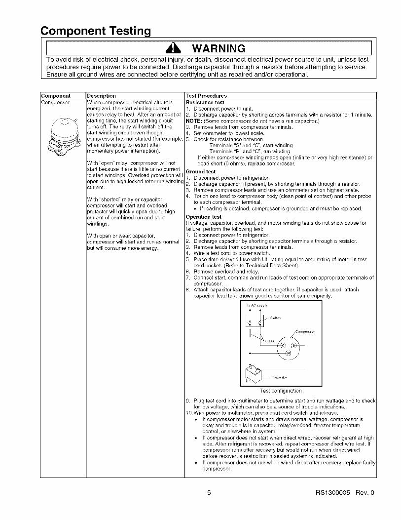
DescriptionWhen compressor electrical circuit isenergized, the start winding currentcauses relay to heat. After an amount ofstarting time, the start winding circuitturns off. The relay will switch off thestart winding circuit even thoughcompressor has not started (for example,when attempting to restart aftermomentary power interruption).
With "open" relay, compressor will notstart because there is little or no currentto start windings. Overload protection willopen due to high locked rotor run windingcurrent.
With "shorted" relay or capacitor,compressor will start and overload_rotector will quickly open due to high
current of combined run and start
windings.
With open or weak capacitor,compressor will start and run as normalbut will consume more energy.
Test ProceduresResistance test
1. Disconnect power to unit.2. Discharge capacitor by shorting across terminals with a resistor for 1 minute.NOTE: (Some compressors do not have a run capacitor.)3. Remove leads from compressor terminals.4. Set ohmmeter to lowest scale.5. Check for resistance between
Terminals "S" and "C", start windingTerminals "R" and "C", run winding
If either compressor winding reads open (infinite or very high resistance) ordead short (0 ohms), replace compressor.
Ground test
1. Disconnect power to refrigerator.2. Discharge capacitor, if present, by shorting terminals through a resistor.3. Remove compressor leads and use an ohmmeter set on highest scale.4. Touch one lead to compressor body (clean point of contact) and other probe
to each compressor terminal.• If reading is obtained, compressor is grounded and must be replaced.
Operation testIf voltage, capacitor, overload, and motor winding tests do not show cause forfailure, perform the following test:1. Disconnect power to refrigerator.2. Discharge capacitor by shorting capacitor terminals through a resistor.3. Remove leads from compressor terminals.4. Wire a test cord to power switch.5. Place time delayed fuse with UL rating equal to amp rating of motor in test
cord socket. (Refer to Technical Data Sheet)6. Remove overload and relay.7. Connect start, common and run leads of test cord on appropriate terminals of
compressor.8. Attach capacitor leads of test cord together. If capacitor is used, attach
capacitor lead to a known good capacitor of same capacity.
To AC supply
_Capacitor
Test configuration
9. Plug test cord into multimeter to determine start and run wattage and to checkfor low voltage, which can also be a source of trouble indications.
10. With power to multimeter, press start cord switch and release.• If compressor motor starts and draws normal wattage, compressor is
okay and trouble is in capacitor, relay/overload, freezer temperaturecontrol, or elsewhere in system.
• If compressor does not start when direct wired, recover refrigerant at highside. After refrigerant is recovered, repeat compressor direct wire test. Ifcompressor runs after recovery but would not run when direct wiredbefore recover, a restriction in sealed system is indicated.
• If compressor does not run when wired direct after recovery, replace faultycompressor.
5 RS1300005 Rev. 0

Component Testing
I WARNING ITo avoid risk of electrical shock, personal injury, or death, disconnect electrical power source to unit, unless testprocedures require power to be connected. Discharge capacitor through a resistor before attempting to service.Ensure all ground wires are connected before certifying unit as repaired and/or operational.
ComponentCapacitor
Condenser
DescriptionRun capacitor connects to relayterminal 3 and L side of line.
Some compressors do not require a runcapacitor; refer to the Technical DataSheet for the unit being serviced.
Test Procedures
WARNINGTo avoid electrical shock which can cause severe personal injury or death,discharge capacitor through a resistor before handling.
Condenser is a tube and wireconstruction located in machine
compartment.
Condenser is on high pressure dischargeside of compressor. Condenser functionis to transfer heat absorbed by refrigerantto ambient.
Higher pressure gas is routed tocondenser where, as gas temperature isreduced, gas condenses into a highpressure liquid state. Heat transfer takes_lace because discharged gas is at a
higher temperature than air that ispassing over condenser. It is veryimportant that adequate air flow overcondenser is maintained.
Condenser is air cooled by condenserfan motor. If efficiency of heat transferfrom condenser to surrounding air isimpaired, condensing temperaturebecomes higher. High liquid temperaturemeans liquid will not remove as muchheat during boiling in evaporator asunder normal conditions. This would be
indicated by high than normal head_ressures, long run time, and high
wattage. Remove any lint or otheraccumulation, that would restrict normalair movement through condenser.
From condenser the refrigerant flows intoa post condenser loop which helpscontrol exterior condensation on flange,center mullion, and around freezer door.Refrigerant the flows through the drier to_vaporator and into compressor throughsuction line.
1. Disconnect power to refrigerator.2. Remove capacitor cover and disconnect capacitor wires.3. Discharge capacitor by shorting across terminals with a resistor for 1 minute.4. Check resistance across capacitor terminals with ohmmeter set on "X1K"
scale.
• Good--needle swings to 0 ohms and slowly moves back to infinity.• Open--needle does not move. Replace capacitor.• Shorted--needle moves to zero and stays. Replace capacitor.• High resistance leak--needle jumps toward 0 and then moves back to
constant high resistance (not infinity).
Leaks in condenser can usually be detected by using an electronic leak detectoror soap solution. Look for signs of compressor oil when checking for leaks. Acertain amount of compressor oil is circulated with refrigerant.
Leaks in post condenser loop are rare because loop is a one-piece copper tube.
For minute leaks1. Separate condenser from rest of refrigeration system and pressurize
condenser up to a maximum of 235 PSI with a refrigerant and dry nitrogencombination.
2. Recheck for leaks.
WARNINGTo avoid severe personal injury or death from sudden eruption of highpressures gases, observe the following:
Protect against a sudden eruption if high pressures are required for leakchecking.Do not use high pressure compressed gases in refrigeration systemswithout a reliable pressure regulator and pressure relief valve in thelines.
RS1300005 Rev. 0 6

Component Testing
WARNING ITo avoid risk of electrical shock, personal injury, or death, disconnect electrical power source to unit, unless testprocedures require power to be connected. Discharge capacitor through a resistor before attempting to service.Ensure all ground wires are connected before certifying unit as repaired and/or operational.
ComponentOverload / Relay
Freezer
temperature control
DescriptionWhen voltage is connected and relay iscool, current passes through relay to startwinding.
After a short time, current heats theresistor in relay and resistance will riseblocking current flow through relay.
Start winding remains in the circuit throughrun capacitor.
Solid state relay plugs directly oncompressor start and run terminals. Relayterminals 2 and 3 are connected withinrelay. Run capacitor is connected to relayterminal 3. L2 side of 120 VAC power isconnected to relay terminal 2.Freezer temperature control is a capillarytube operating a single pole, single throwswitch.
Freezer temperature control controls runcycle through defrost timer.
Altitude AdjustmentWhen altitude adjustment is required on aG.E. control, turn altitude adjustmentscrew 1/7 turn counter clockwise for each
1,000 feet increase in altitude up to 10,000feet. One full turn equals 10,000 feetmaximum.
In most cases the need for altitude
adjustments can be avoided by simplyturning temperature control knob to coldersetting.
Optional on some models.
Test Procedures
1. Disconnect power to the refrigerator.2. Remove relay cover and disconnect leads.3. Check resistance across terminals 2 and 3 with an ohmmeter:
Normal = 3 to 12 ohmsShorted = 0 ohms
Open = infinite ohms
Check for proper calibration with thermocouple capillary in air supply well byrecording cutqn and cut-out temperatures at middle setting. Refer to tech sheetfor model being serviced for expected temperatures.
Check control contacts are opening by disconnecting electrical leads to controland turning control knob to coldest setting. Check for continuity acrossterminals.
Altitude Counter in Feet
Turn ScrewFeet AboveSea Level
2,0004,0006,0008,00010,000
Clockwise (AngularDegrees)
3O81129174216
Ice Maker
See "Ice Maker" section for serviceinformation.
ECM condenser Condenser fan moves cooling air across Check resistance across coil.motor condenser coil and compressor body.
Condenser fan motor is in parallel circuitwith compressor.
Evaporator fan moves air acrossevaporator coil and throughout refrigeratorcabinet.
Evaporator fanmotor
1. Disconnect power to unit.2. Disconnect fan motor leads.
3. Check resistance from ground connection solder. Trace to motor frame mustnot exceed .05 ohms.
4. Check for voltage at connector to motor with unit in refrigeration mode andcompressor operating.
7 RS1300005 Rev. 0

Component Testing
I WARNINGTo avoid risk of electrical shock, personal injury, or death, disconnect electrical power source to unit, unless testprocedures require power to be connected. Discharge capacitor through a resistor before attempting to service.Ensure all ground wires are connected before certifying unit as repaired and/or operational.
I
ComponentRefrigerator lightswitch
Freezer light /Interlock switch
Drier
Defrost timer
ZAdaptive defrostcontrol (ADC)
DescriptionSingle pole, single throw switchcompletes circuit for light when door isopen.
Single pole, Double throw switchcompletes circuit for light when door isopen. Completes circuit for dispenserwhen door is closed
Drier is placed at post condenser loopoutlet and passes liquefied refrigerant tocapillary.
Desiccant (20) 8 x 12 4AXH - 7 M>S> -Grams
Timer motor operates only when freezercontrol is closed.
After specified amount of actualoperating time, inner cam in timer throwsthe contacts from terminal 4, compressorcircuit, to terminal 2, defrostthermostat/defrost heater circuit.After specified defrost cycle time, timercam resets the circuitry through terminal4 to compressor.
The ADC adapts the compressor runtime between defrosts to achieve
optimum defrost intervals by monitoringthe cold control and length the defrostheater is on.
Test ProceduresCheck resistant across terminals.
Switch arm depressed"NO" terminals Open
Switch arm up"NO" terminals Closed
Check resistant across terminals.
Switch arm depressed"NO" terminals Open"NC" terminals ClosedSwitch arm not depressed"NC" terminals Open"NO" terminals Closed
Drier must be changed every time the system is opened for testing orcompressor replacement.
NOTE: Drier used in R12 sealed system is not interchangeable withdrier used in R134a sealed system. Always replace drier in R134asystem with Amana part number B2150504.
Before opening refrigeration system, recover HFC134a refrigerant for safedisposal.
1. Cut drier out of system using the following procedure. Do not unbraze drier.2. Applying heat to remove drier will drive moisture into the system.3. Score capillary tube close to drier and break.4. Reform inlet tube to drier allowing enough space for large tube cutter.5. Cut circumference of drier 1 W' below condenser inlet tube joint to drier.6. Remove drier.
7. Apply heat trap paste on post condenser tubes to protect grommets from higtheat.
8. Unbraze remaining part of drier. Remove drier from system.9. Discard drier in safe place. Do not leave drier with customer. If refrigerator is
under warranty, old drier must accompany warranty claim.
1 WARNING JTo avoid death or severe personal injury, cut drier at correct location.Cutting drier at incorrect location will allow desiccant beads to scatter. Ifspilled, completely clean area of beads.
1. To check timer motor winding, check for continuity between terminals 1 andof timer.
2. Depending on rotating position of the cam, terminal 1 of timer is common toboth terminal 2, the defrost mode, and terminal 4, the compressor mode.There should never be continuity between terminals 2 and 4.
3. With continuity between terminals 1 and 4, rotate timer knob clockwise untilaudible click is heard. When the click is heard, reading between terminals 1and 4 should be infinite and there should be continuity between terminals 1and 2.
4. Continuing to rotate time knob until a second click is heard should restorecircuit between terminals 1 and 4.
Refer to specific Technical Data Sheet with unit for troubleshooting procedure.
RS1300005 Rev. 0 8

Component Testing
WARNINGTo avoid risk of electrical shock, personal injury, or death, disconnect electrical power source to unit, unless testprocedures require power to be connected. Discharge capacitor through a resistor before attempting to service.Ensure all ground wires are connected before certifying unit as repaired and/or operational.
I
Water valve
Evaporator
Evaporator defrostheater
Thermostat
Damper Control
DescriptionControls water flow to the ice maker.
Controlled by thermostat in ice maker.
See Ice Maker Section for furtherinformation.
Inner volume of evaporator allows liquidrefrigerant discharged from capillary to9xpand into refrigerant gas.
Expansion cools evaporator tube and fintemperature to approximately -20°Ftransferring heat from freezer section torefrigerant.
Passing through suction line tocompressor, the refrigerant picks upsuperheat (a relationship betweenpressure and temperature that assurescomplete vaporization of liquidrefrigerant) as the result of capillary tubesoldered to suction line.
Refrigerant gas is pulled through suctionline by compressor, completingrefrigeration cycle.
&ctivated when defrost thermostat,defrost timer, and freezer controlcomplete circuit through heater.
Thermostat is in a series circuit withterminal 2 of defrost timer, and defrostheater. Circuit is complete if evaporatorran motor operates when cold.
Controls the circuit from freezer
thermostat through defrost terminator todefrost heater. Opens and breaks circuitwhen thermostat senses preset hightemperature.
Damper control balances the air deliverybetween refrigerator and freezercompartments providing temperaturecontrol for refrigerator.
Internal capillary activates dampercontrol and door closes restricting flow ofair from freezer compartment torefrigerator compartment.
Test Procedures
Check resistance across coil windings.
Test for leaks in evaporator with electronic leak detector or with soap solution.Compressor oil is circulated with refrigerant; check for oil when checking forleaks.
For minute leaks
1. Separate evaporator from rest of refrigeration system and pressurizeevaporator up to a maximum of 140 PSI with a refrigerant and dry nitrogencombination.
2. Recheck for leaks.
WARNINGTo avoid severe personal injury or death from sudden erruption of
high pressurres gases, observe the following:
• Protect against a sudden eruption if high pressures are requiredfor leak checking.
• Do not use high pressure compressed gases in refrigerationsystems without a reliable pressure regulator and pressure reliefvalve in the lines.
Check resistance across heater.
To check defrost system :1. Thermocouple defrost thermostat and plug refrigerator into wattmeter.2. Turn into defrost mode. Wattmeter should read specified watts (according to
Technical Data Sheet).3. When defrost thermostat reaches specified temperature +5°F (see Technical
Data Sheet), thermostat should interrupt power to heater.Test continuity across terminals.
With power off and evaporator coil below freezing, thermostat should showcontinuity when checked with ohmmeter. See "Heater, evaporator (defrost)"section for additional tests.
After defrost thermostat opens, thermostat remains open until end of defrostcycle and refrigerator starts cooling again. Defrost thermostat senses a presetlow temperature and resets (closes).
Subject capillary to appropriate temperature (refer to Technical Data Sheet formodel being serviced).
Damper door should close to within _A" of completely shut.
If altitude adjustment is required, turn altitude adjustment screw 1/8 turnclockwise for each 1,000 feet increase in altitude.
There are no electrical connections to damper control. See Technical Data Sheetfor damper specifications for unit being serviced.
9 RS1300005 Rev. 0
Service Procedures
WARNINGTo avoid risk of electrical shock, personal injury, or death, disconnect electrical power source to unit, unless testprocedures require power to be connected. Discharge capacitor through a 10,000 ohm resistor before attemptingto service. Ensure all ground wires are connected before certifying unit as repaired and/or operational.
Service EquipmentListed below is equipment needed for proper servicingof HFC134a systems. Verify equipment is confirmedby manufacturer as being compatible with HFC134aand ester oil system.
Equipment must be exclusively used for HFC134a.Exclusive use of equipment only applies to italic items.
• Evacuation pumpCheck with vacuum pump supplier to verify equipmentis compatible for HFC134a. Robinair, Model 156002 stage, 6 cubic feet per minute pump isrecommended.
• Four-way manifold gauge set, with low loss hoses• Leak detector
• Charging cylinder• Line piercing saddle valve
(Schroeder valves). Seals must be HFC134a andester oil compatible. Line piercing valves may be usedfor diagnosis but are not suitable for evacuation orcharging, due to minute holes pierced in tubing. Donot leave mechanical access valves on system.Valves eventually will leak. Molecules of HFC134a aresmaller than other refrigerants and will leak whereother refrigerants would not.Swagging toolsFlaring toolsTubing cutterFluxSiI-FosSilver solderOil for swagging and flaringUse only part # R0157532
• Copper tubingUse only part # R0174075 and # R0174076
• Dry nitrogen99.5% minimum purity, with -40°F or lower dew point
• Crimp tool• Tube bender
• Micron vacuum gauge• Process tube adaptor k#• Heat trap paste• ICI appliance grade HFCI34a
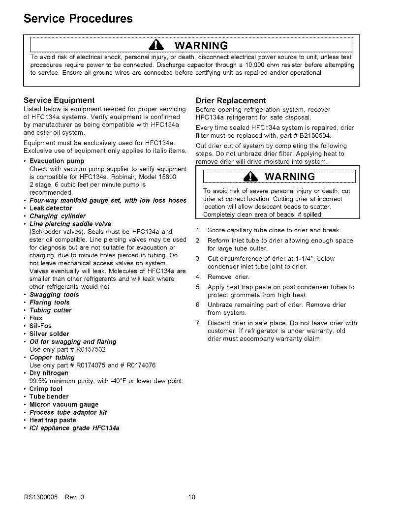
Drier ReplacementBefore opening refrigeration system, recoverHFC134a refrigerant for safe disposal.
Every time sealed HFC134a system is repaired, drierfilter must be replaced with, part # B2150504.
Cut drier out of system by completing the followingsteps. Do not unbraze drier filter. Applying heat toremove drier will drive moisture into system.
WARNING
To avoid risk of severe personal injury or death, cutdrier at correct location. Cutting drier at incorrectlocation will allow desiccant beads to scatter.
Completely clean area of beads, if spilled.
1. Score capillary tube close to drier and break.
2. Reform inlet tube to drier allowing enough spacefor large tube cutter.
3. Cut circumference of drier at 1-1/4", belowcondenser inlet tube joint to drier.
4. Remove drier.
5. Apply heat trap paste on post condenser tubes toprotect grommets from high heat.
6. Unbraze remaining part of drier. Remove drierfrom system.
7. Discard drier in safe place. Do not leave drier withcustomer. If refrigerator is under warranty, olddrier must accompany warranty claim.
RS1300005 Rev. 0 10
Service Procedures
WARNING
To avoid risk of electrical shock, personal injury, or death, disconnect electrical power source to unit, unless testprocedures require power to be connected. Discharge capacitor through a 10,000 ohm resistor before attemptingto service. Ensure all ground wires are connected before certifying unit as repaired and/or operational.
Refrigerant Precautions
WARNING ]To avoid risk of personal injury, do not allowrefrigerant to contact eyes or skin.
CAUTION ]To avoid risk of property damage, do not userefrigerant other than that shown on unit serialnumber identification plate.
NOTE: All precautionary measures recommended byrefrigerant manufacturers and suppliers applyand should be observed.
Line Piercing ValvesLine piercing valves can be used for diagnosis, butare not suitable for evacuating or charging due toholes pierced in tubing by valves.
NOTE: Do not leave line piercing valves on system.Connection between valve and tubing is nothermetically sealed. Leaks will occur.
Open LinesDuring any processing of refrigeration system, neverleave lines open to atmosphere. Open lines allow watervapor to enter system, making proper evacuation moredifficult.
Compressor Operational Test(short term testing only)
If compressor voltage, capacitor, overload, and motorwinding tests are successful (do not indicate a fault),perform the following test:
1.Disconnect power to unit.
2.Discharge capacitor by shorting capacitorterminals through a resistor.
NOTE: Not all units have run capacitor.
3.Remove leads from compressor terminals.
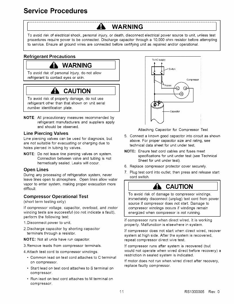
4.Attach test cord to compressor windings.
• Common lead on test cord attaches to C terminal
on compressor.
• Start lead on test cord attaches to S terminal on
compressor.
• Run lead on test cord attaches to M terminal on
compressor.
To AC supply
Switch
Compressor
Fuses
Attaching Capacitor for Compressor Test
5. Connect a known good capacitor into circuit as shownabove. For proper capacitor size and rating, seetechnical data sheet for unit under test.
NOTE: Ensure test cord cables and fuses meet
specifications for unit under test (see TechnicalSheet for unit under test).
6. Replace compressor protector cover securely.
7. Plug test cord into outlet, then press and release startcord switch.
i CAUTION ]To avoid risk of damage to compressor windings,immediately disconnect (unplug) test cord from powersource if compressor does not start. Damage tocompressor windings occurs if windings remainenergized when compressor is not running.
If compressor runs when direct wired, it is workingproperly. Malfunction is elsewhere in system.
If compressor does not start when direct wired, recoversystem at high side. After the system is recovered,repeat compressor direct wire test.
If compressor runs after system is recovered (butwould not operate when wired direct before recovery) arestriction in sealed system is indicated.
If motor does not run when wired direct after recovery,replace faulty compressor.
11 RS1300005 Rev. 0

Service Procedures
WARNINGTo avoid risk of electrical shock, personal injury, or death, disconnect electrical power source to unit, unless testprocedures require power to be connected. Discharge capacitor through a 10,000 ohm resistor before attemptingto service. Ensure all ground wires are connected before certifying unit as repaired and/or operational.
Dehydrating Sealed Refrigeration SystemMoisture in a refrigerator sealed system exposed toheat generated by the compressor and motor reactschemically with refrigerant and oil in the system andforms corrosive hydrochloric and hydrofluoric acids.These acids contribute to breakdown of motor windinginsulation and corrosion of compressor working parts,causing compressor failure.
In addition, sludge, a residue of the chemical reaction,coats all surfaces of sealed system, and will eventuallyrestrict refrigerant flow through capillary tube.
To dehydrate sealed system, evacuate system (seeparagraph Evacuation).
Leak Testing
[ DANGERTo avoid risk of serious injury or death from violentexplosions, NEVER use oxygen or acetylene forpressure testing or clean out of refrigerationsystems. Free oxygen will explode on contact withoil. Acetylene will explode spontaneously when putunder pressure.
1
Testing Systems Containing No Refrigerant Charge1. Connect cylinder of nitrogen, through gauge
manifold, to process tube of compressor and liquidline strainer.
2. Open valves on nitrogen cylinder and gauge manifold.Allow pressure to build within sealed system.
3. Check for leaks using soap suds.
If a leak is detected in a joint, do not to attempt to repairby applying additional brazing material. Joint must bedisassembled, cleaned and rebrazed. Capture refrigerantcharge (if system is charged), unbraze joint, clean allparts, then rebraze.
If leak is detected in tubing, replace tubing. If leak isdetected in either coil, replace faulty coil.
It is important to check sealed system for refrigerantleaks. Undetected leaks can lead to repeated servicecalls and eventually result in system contamination,restrictions, and premature compressor failure.
Refrigerant leaks are best detected with halide orelectronic leak detectors.
Testing Systems Containing a Refrigerant Charge1. Stop unit operation (turn refrigerator off).
2. Holding leak detector exploring tube as close tosystem tubing as possible, check all piping, joints,and fittings.
NOTE: Use soap suds on areas leak detector cannotreach or reliably test.
RS1300005 Rev. 0 12
Service Procedures
WARNINGTo avoid risk of electrical shock, personal injury, or death, disconnect electrical power source to unit, unless testprocedures require power to be connected. Discharge capacitor through a 10,000 ohm resistor before attemptingto service. Ensure all ground wires are connected before certifying unit as repaired and/or operational.
RestrictionsSymptomsRestrictions in sealed system most often occur atcapillary tube or filter drier, but can exist anywhere onliquid side of system.
Restrictions reduce refrigerant flow rate and heatremoval rate. Wattage drops because compressor isnot circulating normal amount of refrigerants.
Common causes of total restrictions are moisture,poorly soldered joints, or solid contaminants. Moisturefreezes at evaporator inlet end of capillary tube. Solidcontaminants collect in filter drier.
If restriction is on low side, suction pressure will be in avacuum and head pressure will be near normal.
If restriction is on high side, suction pressure will be ina vacuum and head pressure will be higher thannormal during pump out cycle.
Refrigeration occurs on low pressure side of partialrestriction. There will be a temperature difference atthe point of restriction. Frost and/or condensation willbe present in most case at the point of restriction.Also, system requires longer to equalize.
Slight or partial restriction can give the samesymptoms as refrigerant shortage including lower thannormal back pressure, head pressure, wattage, andwarmer temperatures.
Total restriction on the discharge side of compressor,when restriction is between compressor and first halfof condenser, results in higher than normal headpressure and wattage while low side is being pumpedout.
Testing for RestrictionsTo determine if a restriction exists:
1. Attach gauge and manifold between suction anddischarge sides of sealed system.
2. Turn unit on and allow pressure on each side tostabilize. Inspect condenser side of system. Tubingon condenser should be warm and temperatureshould be equal throughout (no sudden drops at anypoint along tubing).
• If temperature of condenser tubing is consistentthroughout, go to step 4.
• If temperature of condenser tubing drops suddenlyat any point, tubing is restricted at point oftemperature drop (if restriction is severe, frost mayform at point of restriction and extend down indirection of refrigerant flow in system). Go to step 5.
3. Visually check system for kinks in refrigeration linewhich is causing restriction. Correct kink and repeatstep 2.
4. Turn unit off and time how long it takes high and lowpressure gauges to equalize:
• If pressure equalization takes longer than 10minutes, a restriction exists in the capillary tube ordrier filter. Go to step 5.
• If pressure equalization takes less than 10 minutes,system is not restricted. Check for other possiblecauses of malfunction.
5. Recover refrigerant in sealed system.
NOTE: Before opening any refrigeration system,capture refrigerant in system for safe disposal.
6. Remove power from unit.
CAUTIONTo avoid risk of personal injury or property damage,take necessary precautions against hightemperatures required for brazing.
7. Remove and replace restricted device.
8. Evacuate sealed system.
9. Charge system to specification.
NOTE: Do not use captured or recycled refrigerant inAmana units. Captured or recycled refrigerantvoids any Amana and/or compressormanufacturer's warranty.
NOTE: Charge system with exact amount of refrigerant.Refer to unit nameplate for correct refrigerantcharge. Inaccurately charged system will causefuture problems.
13 RS1300005 Rev. 0

Service Procedures
WARNINGTo avoid risk of electrical shock, personal injury, or death, disconnect electrical power source to unit, unless testprocedures require power to be connected. Discharge capacitor through a 10,000 ohm resistor before attemptingto service. Ensure all ground wires are connected before certifying unit as repaired and/or operational.
Evacuation and Charging
1 CAUTION ]To avoid risk of fire, sealed refrigeration systemmust be air free. To avoid risk of air contamination,follow evacuation procedures exactly.
NOTE: Before opening any refrigeration system, EPAregulations require refrigerant in system to becaptured for safe disposal.
Proper evacuation of sealed refrigeration system is animportant service procedure. Usable life andoperational efficiency greatly depends upon howcompletely air, moisture and other non-condensablesare evacuated from sealed system.
Air in sealed system causes high condensingtemperature and pressure, resulting in increasedpower requirements and reduced performance.
Moisture in sealed system chemically reacts withrefrigerant and oil to form corrosive hydrofluoric andhydrochloric acids. These acids attack motor windingsand parts, causing premature breakdown.
Before opening system, evaporator coil must be atambient temperature to minimize moisture infiltrationinto system.
Evacuation
To evacuate sealed refrigeration system:
1. Connect vacuum pump, vacuum tight manifold setwith high vacuum hoses, thermocouple vacuumgauge and charging cylinder as shown in illustration.
Evacuation should be done through I.D. opening oftubes not through line piercing valve.
2. Connect low side line to compressor process tube.
3. Connect high side line to drier/process tube.
4. Evacuate both simultaneously. With valve "C" and "F"closed, open all other valves and start vacuum pump.
Low Side auge Side GaugeThermistor
Vacuum Gauge i DE
Drier/Process Tube
Compressor
_Tube
.6 cmTubing
Hose
Vacuum PumpChargingCylinder
Equipment Setup For Evacuation And Charging
5. After compound gauge (low side) drops toapproximately 29 inches gauge, open valve "C" tovacuum thermocouple gauge and take micronreading.
NOTE: A high vacuum pump can only produce a goodvacuum if oil in pump is not contaminated.
,
7.
Continue evacuating system until vacuum gaugeregisters 600 microns.
At 600 microns, close valve "A" to vacuum pump andallow micron reading in system to balance. Micronlevel will rise.
• If in 2 minutes, micron level stabilizes at 1000microns or below, system is ready to be charged.
• If micron level rises above 1000 microns and
stabilizes, open valve "A" and continue evacuating.
• If micron reading rises rapidly and does notstabilize, a leak still exists in system.
Close valve "A" to vacuum pump and valve "C" tovacuum gauge. Invert charging cylinder and opencharging cylinder valve "F" to add partial charge forleak checking. With leak detector, check manifoldconnections and system for leaks. After locatingleak, capture refrigerant, repair leak, and begin atstep 1.
RS1300005 Rev. 0 14

Service Procedures
WARNINGTo avoid risk of electrical shock, personal injury, or death, disconnect electrical power source to unit, unless testprocedures require power to be connected. Discharge capacitor through a 10,000 ohm resistor before attemptingto service. Ensure all ground wires are connected before certifying unit as repaired and/or operational.
ChargingNOTE: Do not use captured or recycled refrigerant in
Amana units. Captured or recycled refrigerantvoids any warranty.
NOTE: Charge system with exact amount of refrigerant.Refer to unit serial plate for correct refrigerantcharge. Inaccurately charged system will causefuture problems.
To charge system:
1. Close valves "A" to vacuum pump and "C" to vacuumgauge and "E" to low side manifold gauge.
2. Set scale on dial-a-charge cylinder for correspondingHFC134a pressure reading.
3. Open valve "F" to charging cylinder and let exactamount of refrigerant flow from cylinder into system.Close valve.
Low side gauge pressure should rise shortly afteropening charging cylinder valve as system pressureequalizes through capillary tube.
If pressure does not equalize, a restriction typicallyexists at capillary/drier braze joint.
4. If pressure equalizes, open valve "E" to low sidemanifold gauge and pinch off high side drier processtube.
5. Start compressor and draw remaining refrigerant fromcharging hoses and manifold into compressorthrough compressor process tube.
6. To check high side pinch-off drier process tube. Closevalve "D" to high side gauge. If high side pressurerises, repeat high side pinch-off and open valve "D".Repeat until high side pinch-off does not leak.
7. Pinch-off compressor process tube and removecharging hose. Braze stub closed while compressor isoperating.
8. Disconnect power. Remove charging hose and brazehigh side drier process tube closed.
9. Recheck for refrigerant leaks.
Refrigerant ChargeRefrigerant charge in all capillary tube systems iscritical and exact amount is required for properperformance. Factory charges are shown on serialplate.NOTE: Do not use refrigerant other than shown on
serial plate.
15 RS1300005 Rev. 0
Service Procedures
WARNINGTo avoid risk of electrical shock, personal injury, or death, disconnect electrical power source to unit, unless testprocedures require power to be connected. Discharge capacitor through a 10,000 ohm resistor before attemptingto service. Ensure all ground wires are connected before certifying unit as repaired and/or operational.
HFC134a Service Information
HFC134a is alternative refrigerant for CFC12.HFC134a has an ozone depletion potential (ODP)factor of 0.0 and a global warming potential (GWP)factor of 0.27. HFC134a is not flammable and hasacceptable toxicity levels. HFC134a is notinterchangeable with CFC12. There are significantdifferences between HFC134a and CFC12 which mustbe considered when handling and processingrefrigeration system.
Health, Safety, and HandlingHealth, safety and handling considerations forHFC134A are virtually no different than those forCFC12.
Health, Safety, andHandlinaAllowable overallexposure limitVaoor exposure to skinLiauid exposure to skinVaoor exoosure to eve
Lieuid exoosure to eve
Above minimum exposurelimit
Safety and handling
Spill management
Fire explosion hazards
Disoosal procedures
CFC12
1,000 ppm
No effectCan cause frostbiteVery sliaht eve irritantCan cause frostbite
Can cause Asphyxiation,Tachycardia, and CardiaArrhvthmiasWear appropriate skinand eye protection. Usewith adequateventilation.
Remove or extinguishignition or combustionsources. Evacuate orventilate area
May decompose ifcontact with flames andheating elements.Container may explodeif heated due to resultingpressure rise.Combustion productsare toxic.Recvcle or reclaim.
HFC134a
Same
SameSameSameSameSame
Same
Same
Same
Same
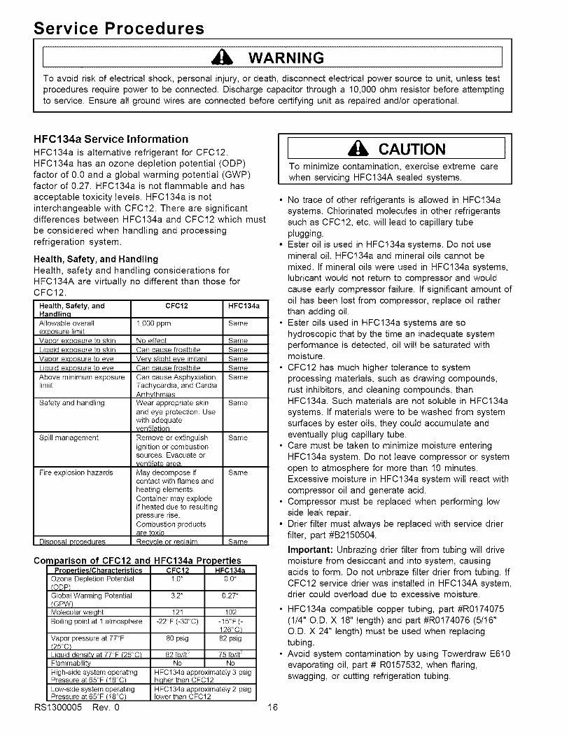
Com 3arison of CFC12 and HFC134a Propertiesi=roDerties/Characteristics CFC12 HFCI34a
Ozone Depletion Potential(QPP)GlobalWarming Potential
(GPW)Molecular weightBoiling point at 1 atmosphere
Vapor pressure at 77°F(25oc/Liauid densitv at 77°F (25°C_FlammabilityHigh-side system operatingPressure at 65°F (18°C)Low-side system operatingPressure at 65°F (18°C)
RS1300005 Rev. 0
1.0" 0.0"
3.2* 0.27*
121 102
-22°F (-30°C) -15°F (-126°C)
80 psig 82 psig
82 tb/ft _ 75 tb/ft _No No
HFC134a approximately 3 psighigher than CFC12HFC134a approximately 2 psiglower than CFC12
CAUTIONTo minimize contamination, exercise extreme carewhen servicing HFC134A sealed systems.
• No trace of other refrigerants is allowed in HFC134asystems. Chlorinated molecules in other refrigerantssuch as CFC12, etc. will lead to capillary tubeplugging.
• Ester oil is used in HFC134a systems. Do not usemineral oil. HFC134a and mineral oils cannot be
mixed. If mineral oils were used in HFC134a systems,lubricant would not return to compressor and wouldcause early compressor failure. If significant amount ofoil has been lost from compressor, replace oil ratherthan adding oil.
• Ester oils used in HFC134a systems are sohydroscopic that by the time an inadequate systemperformance is detected, oil will be saturated withmoisture.
• CFC12 has much higher tolerance to systemprocessing materials, such as drawing compounds,rust inhibitors, and cleaning compounds, thanHFC134a. Such materials are not soluble in HFC134asystems. If materials were to be washed from systemsurfaces by ester oils, they could accumulate andeventually plug capillary tube.
• Care must be taken to minimize moisture enteringHFC134a system. Do not leave compressor or systemopen to atmosphere for more than 10 minutes.Excessive moisture in HFC134a system will react withcompressor oil and generate acid.
• Compressor must be replaced when performing lowside leak repair.
• Drier filter must always be replaced with service drierfilter, part #B2150504.
Important: Unbrazing drier filter from tubing will drivemoisture from desiccant and into system, causingacids to form. Do not unbraze filter drier from tubing. IfCFC12 service drier was installed in HFC134A system,drier could overload due to excessive moisture.
• HFC134a compatible copper tubing, part #R0174075(1/4" O.D. X 18" length) and part #R0174076 (5/16"O.D. X 24" length) must be used when replacingtubing.
• Avoid system contamination by using Towerdraw E610evaporating oil, part # R0157532, when flaring,swagging, or cutting refrigeration tubing.
16
Service Procedures
WARNING
To avoid risk of electrical shock, personal injury, or death, disconnect electrical power source to unit, unless testprocedures require power to be connected. Discharge capacitor through a 10,000 ohm resistor before attemptingto service. Ensure all ground wires are connected before certifying unit as repaired and/or operational.
Replacement Service CompressorHFC134a service compressors will be charged withester oil and pressurized with dry nitrogen. Beforereplacement compressor is installed, pull out 1 rubberplug. A pop from pressure release should be heard. Ifa pop sound is not heard, do not use compressor.Positive pressure in compressor is vital to keepmoisture out of ester oil. Do not leave compressoropen to atmosphere for more than 10 minutes.
Compressor Testing Procedures
WARNING
To avoid death or severe personal injury, never useoxygen, air or acetylene for pressure testing orclean out of refrigeration system. Use of oxygen,air, or acetylene may result in violent explosion.Oxygen may explode on contact with oil andacetylene will spontaneously explode when underpressure.
Refer to Technical Data Sheet "TemperatureRelationship Chart" for operating watts, test points,and temperature relationship test for unit being tested.
• Temperature testing is accomplished by using 3 leadthermocouple temperature tester in specific locations.Test point T-1 is outlet on evaporator coil and T-2 isinlet. Test point T-3 is suction tube temperaturemidway between where armaflex ends and suctionport of compressor (approximately 12 inches fromcompressor).
• Thermocouple tips should be attached securely tospecified locations.
• Do not test during initial pull down. Allow one off cycleor balanced temperature condition to occur beforeproceeding with testing.
• Refrigerator must operate minimum of 20 minutesafter thermocouples are installed.
• Turn control to colder to obtain required on time.• Wattage reading must be recorded in conjunction with
temperature test to confirm proper operation.• Suction and head pressures are listed on
"Temperature and Relationship Chart". Normally theseare not required for diagnosis but used for confirmationon systems which have been opened.
Brazing
1 CAUTION ]To avoid risk of personal injury or property damage,take necessary precautions against hightemperatures required for brazing.
Satisfactory results require cleanliness, experience,and use of proper materials and equipment.
Connections to be brazed must be properly sized, freeof rough edges, and clean.
Generally accepted brazing materials are:• Copper to copper joints: SIL-FOS (alloy of 15
percent silver, 80 percent copper, and 5 percentphosphorous). Use without flux. Recommendedbrazing temperature is approximately 1400°F. Do notuse for copper to steel connection.
• Copper to steel joints: SILVER SOLDER (alloy of 30percent silver, 38 percent copper, 32 percent zinc).Use with fluoride based flux. Recommended brazingtemperature is approximately 1200°F.
• Steel to steel joints: SILVER SOLDER (see copperto steel joints).
• Brass to copper joints: SILVER SOLDER (seecopper to steel joints).
• Brass to steel joints: SILVER SOLDER (see copperto steel joints).
17 RS1300005 Rev. 0

Refrigerant Flow
SUCTION LINE
FLANGE
INLET
HIGHDRIER
CONDENSER
)R
IBE
COMPRESSOR DISCHARGE
22, 24, 26 cu. ft. Side by SideRefrigerant Flow Diagram
RS1300005 Rev. 0 18

Cabinet Air Flow
SIDE BY SIDEAIRFLOW DIAGRAM
FREEZER BACK(AIR BAFFLE)
EVAPORATORf
f
FAN ASSEMBLY /
LARGE BEVERAGE CHILLERAIR SUPPLY
(SOME MODELS)
BEVERAGE CHILLERAIR SUPPLY
SOME MODELS)
DELlAI R SUPPLY
REFRI GERATOR AI R
SUPPLY TUNNELTO FRESH FOOD
COMPARTMENT CONTROLS
AIR SUPPLY
(IN FOAM)
CONDENSER FAN
ASSEMBLY
CONDENSER
24, 26 cu. ft. Side by SideCabinet Air Flow Diagram
19 RS1300005 Rev. 0

Cabinet Air Flow
FREEZER BACK
(AIR BAFFLE)
REFRIGERATOR AIRCOM PARTMENT CONTROLS
SUPPLY TUNNELTO FRESH FOOD
EVAPORATORFAN ASSEMBLY
LARGE BEVERAGE CHILLERAIR SUPPLY
(SOME MODELS)EVAPORATOR _,
SMALL BEVERAGE CHILLER _!!;R
AIR SUPPLY i!!
(SOME MODELS) _!!
i
i i!!
DELl _!!AIR SUPPLY
i i!!
AIR SUPPLY
(IN FOAM)
REFRIGERATOR AIFRETURN TUNNEL
CONDENSER FANASSEMBLY
CONDENSER
22 cu. ft. Side by SideCabinet Air Flow Diagram
RS1300005 Rev, 0 20

Ice and Water Dispenser Diagram
SIDE BY SIDE ICE & WATERDISPENSER WITH FILTER
ICE FILL TUBE
\*\
'\
5/16" X 5/16"
TUBE UNION
WATERTANK
22, 24, 26 cu. ft. Model Side by SideIce and Water Flow Diagram
21 RS1300005 Rev. 0

Vater Valves Diaaram
PRIMARYSOLENOIDVALVE
BLUE COIL WATER
BROWN COIL ICEMAKER
INCOMING WATERLINE CONNECTION
1/4" O.DCOPPER TUBE
COMPRESSION FITTING
PRI MARYVALVE
OUTLETTO FILTER
BLUE STRIPE
SECONDARYVALVEINLET
FROM FILTER
YELLOW STRIPE .,."/
/
//
t
J
/'/
/
/
SECONDARY VALVE
OUTLET WATERTO WATER TANK
SECONDARYSOLENOID VALVE
BLUE COIL WATERBROWN COIL ICEMAKER
SECONDARY VALVEOUTLET TO ICEMAKER
DETAIL
22, 24, 26 cu. ft. Model Side by SideIce and Water Flow Diagram
RS1300005 Rev. 0 22

Typical External Sweat Pattern
Classification of condensation:
1 = Haze or Fog2 = Beading3 = Beads or Small Drops4 = Drops Running Together
i
IBTM
ILM
n f--i n
Conditions after 4 hourlaboratory test:
Ambient: 90°F, 84% relative humidityRefrigerator compartment at 40°FFreezer compartment at 0°F
3/ICE CHUTE
DOOR
[-7
/o.t.._....
3
kJ _
f
7" v •
23 RS1300005 Rev. 0
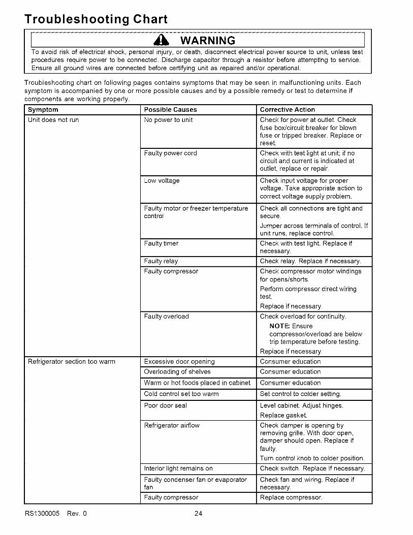
Troubleshooting Chart
WARNINGTo avoid risk of electrical shock, personal injury, or death, disconnect electrical power source to unit, unless testprocedures require power to be connected. Discharge capacitor through a resistor before attempting to service.Ensure all ground wires are connected before certifying unit as repaired and/or operational.
Troubleshooting chart on following pages contains symptoms that may be seen in malfunctioning units. Eachsymptom is accompanied by one or more possible causes and by a possible remedy or test to determine ifcomponents are working properly.
Symptom Possible Causes
Unit does not run No power to unit
Refrigerator section too warm
Faulty power cord
Low voltage
Faulty motor or freezer temperaturecontrol
Faulty timer
Faulty relay
Faulty compressor
Faulty overload
Excessive door opening
Overloading of shelves
Warm or hot foods placed in cabinet Consumer education
Cold control set too warm Set control to colder setting.
Poor door seal Level cabinet. Adjust hinges.
Replace gasket.
Refrigerator airflow Check damper is opening byremoving grille. With door open,damper should open. Replace iffaulty.
Turn control knob to colder position.
Interior light remains on Check switch. Replace if necessary.
Faulty condenser fan or evaporator Check fan and wiring. Replace iffan necessary.
Faulty compressor Replace compressor.
Corrective Action
Check for power at outlet. Checkfuse box/circuit breaker for blownfuse or tripped breaker. Replace orreset.
Check with test light at unit; if nocircuit and current is indicated atoutlet, replace or repair.
Check input voltage for propervoltage. Take appropriate action tocorrect voltage supply problem.
Check all connections are tight andsecure.
Jumper across terminals of control. Ifunit runs, replace control.
Check with test light. Replace ifnecessary.
Check relay. Replace if necessary.
Check compressor motor windingsfor opens/shorts.
Perform compressor direct wiringtest.
Replace if necessary.
Check overload for continuity.NOTE: Ensurecompressor/overload are belowtrip temperature before testing.
Replace if necessary.Consumer education
Consumer education
RS1300005 Rev. 0 24
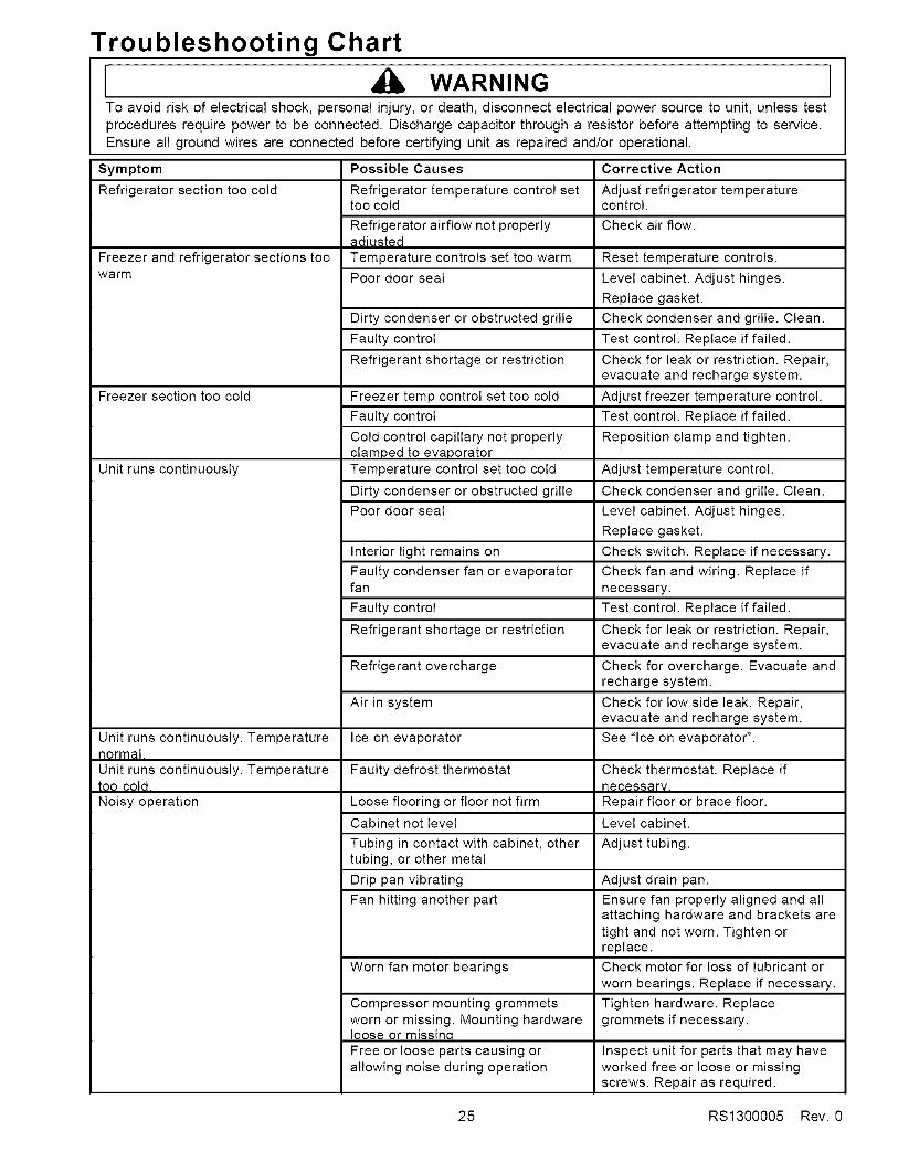
Troubleshooting Chart
WARNINGTo avoid risk of electrical shock, personal injury, or death, disconnect electrical power source to unit, unless test
procedures require power to be connected. Discharge capacitor through a resistor before attempting to service.
Ensure all ground wires are connected before certifying unit as repaired and/or operational.
Symptom
Refrigerator section too cold
Freezer and refrigerator sections toowarm
Freezer section too cold
Unit runs continuously
Unit runs continuously. Temperaturenormal.
Unit runs continuously. Temperaturetoo cold.Noisy operation
Possible Causes
Refrigerator temperature control settoo cold
Refrigerator airflow not properlyadiustedTemperature controls set too warm
Poor door seal
Dirty condenser or obstructed grille
Faulty control
Refrigerant shortage or restriction
Freezer temp control set too cold
Faulty control
Cold control capillary not properlyclamped to evaporatorTemperature control set too cold
Dirty condenser or obstructed grille
Poor door seal
Interior light remains on
Faulty condenser fan or evaporatorfan
Faulty control
Refrigerant shortage or restriction
Refrigerant overcharge
Air in system
Ice on evaporator
Faulty defrost thermostat
Loose flooring or floor not firm
Cabinet not level
Tubing in contact with cabinet, othertubing, or other metal
Drip pan vibrating
Fan hitting another part
Corrective Action
Adjust refrigerator temperaturecontrol.
Check air flow.
Reset temperature controls.
Level cabinet. Adjust hinges.
Replace gasket.
Check condenser and grille. Clean.
Test control. Replace if failed.
Check for leak or restriction. Repair,evacuate and recharge system.
Adjust freezer temperature control.
Test control. Replace if failed.
Reposition clamp and tighten.
Adjust temperature control.
Check condenser and grille. Clean.
Level cabinet. Adjust hinges.
Replace gasket.
Check switch. Replace if necessary.
Check fan and wiring. Replace if
necessary.
Test control. Replace if failed.
Check for leak or restriction. Repair,evacuate and recharge system.
Check for overcharge. Evacuate andrecharge system.
Check for low side leak. Repair,evacuate and recharge system.
See "Ice on evaporator".
Check thermostat. Replace ifnecessary.Repair floor or brace floor.
Level cabinet.
Adjust tubing.
Adjust drain pan.
Ensure fan properly aligned and allattaching hardware and brackets are
tight and not worn. Tighten orreplace.
Worn fan motor bearings Check motor for loss of lubricant orworn bearings. Replace if necessary.
Tighten hardware. Replacegrommets if necessary.
Compressor mounting grommetsworn or missing. Mounting hardwareloose or missinqFree or loose parts causing orallowing noise during operation
Inspect unit for parts that may haveworked free or loose or missingscrews. Repair as required.
25 RS1300005 Rev. 0
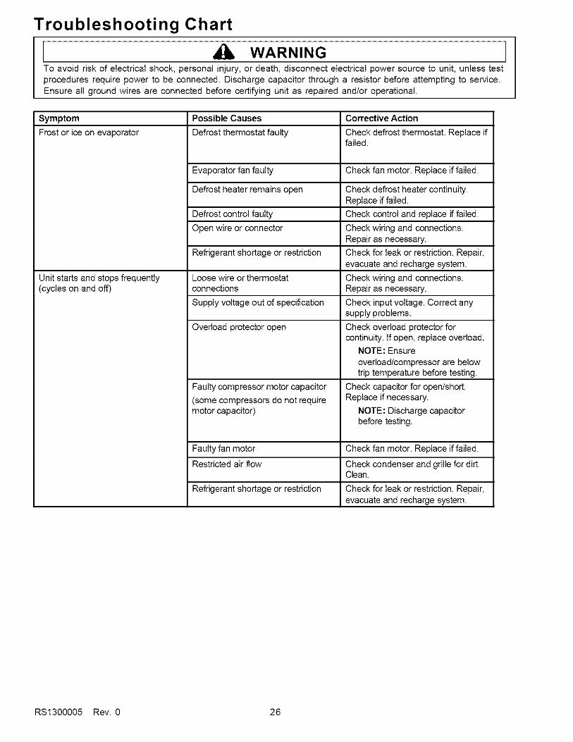
Troubleshooting Chart
WARNINGTo avoid risk of electrical shock, personal injury, or death, disconnect electrical power source to unit, unless testprocedures require power to be connected. Discharge capacitor through a resistor before attempting to service.Ensure all ground wires are connected before certifying unit as repaired and/or operational.
Symptom Possible Causes
Frost or ice on evaporator Defrost thermostat faulty
Unit starts and stops frequently(cycles on and off)
Evaporator fan faulty
Defrost heater remains open
Defrost control faulty
Open wire or connector
Refrigerant shortage or restriction
Loose wire or thermostatconnections
Supply voltage out of specification
Overload protector open
Faulty compressor motor capacitor
(some compressors do not requiremotor capacitor)
Faulty fan motor
Restricted air flow
Refrigerant shortage or restriction
Corrective Action
Check defrost thermostat. Replace iffailed.
Check fan motor. Replace if failed.
Check defrost heater continuity.Replace if failed.
Check control and replace if failed.
Check wiring and connections.Repair as necessary.
Check for leak or restriction. Repair,evacuate and recharge system.
Check wiring and connections.Repair as necessary.
Check input voltage. Correct anysupply problems.
Check overload protector forcontinuity. If open, replace overload.
NOTE: Ensureoverload/compressor are belowtrip temperature before testing.
Check capacitor for open/short.Replace if necessary.
NOTE: Discharge capacitorbefore testing.
Check fan motor. Replace if failed.
Check condenser and grille for dirt.Clean.
Check for leak or restriction. Repair,evacuate and recharge system.
RS1300005 Rev. 0 26
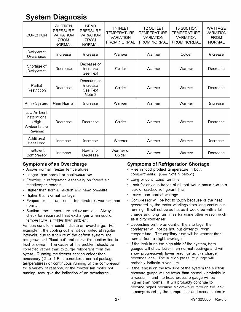
System Diagnosis
CONDITION
SUCTIONPRESSUREVARIATION
FROMNORMAL
HEADPRESSUREVARIATION
FROMNORMAL
T1 INLETTEMPERATURE
VARIATIONFROM NORMAL
T2 OUTLETTEMPERATURE
VARIATIONFROM NORMAL
T3 SUCTIONTEMPERATURE
VARIATIONFROM NORMAL
WATTAGEVARIATION
FROMNORMAL
Refrigerant Increase Increase Warmer Warmer Colder IncreaseOvercharge
Decrease orShortage of Decrease Increase Colder Warmer Warmer DecreaseRefrigerant See Text
Decrease orPartial Increase
Decrease Colder Warmer Warmer DecreaseRestriction See Text
Note 2
Air in System Near Normal Increase Warmer Warmer Warmer Increase
Colder
Low AmbientInstallations
(HighAmbients the
Reverse)
WarmerDecrease WarmerDecrease Decrease
AdditionalIncrease Increase Warmer Warmer Warmer IncreaseHeat Load
Inefficient Normal or Warmer orIncrease Warmer Warmer Decrease
Compressor Decrease Colder
Symptoms of an Overcharge• Above normal freezer temperatures.• Longer than normal or continuous run.
• Freezing in refrigerator, especially on forced airmeatkeeper models.
• Higher than normal suction and head pressure.
• Higher than normal wattage.• Evaporator inlet and outlet temperatures warmer than
normal.
• Suction tube temperature below ambient. Alwayscheck for separated heat exchanger when suctiontemperature is colder than ambient.
Various conditons could indicate an overcharge. Forexample, if the cooling coil is not defrosted at regularintervals, due to a failure of the defrost system, therefrigerant will "flood out" and cause the suction line tofrost or sweat. The cause of this problem should becorrected rather than to purge refrigerant from thesytem. Running the freezer section colder thannecessary (-2 to -1 F. is considered normal packagetemperatures) or continuous running of the compressorfor a variety of reasons, or the freezer fan motor notrunning, may give the indication of an overcharge.
Symptoms of Refrigeration Shortage• Rise in food product temperature in both
compartments. (See Note 1 below.)• Long or continuous run time.• Look for obvious traces of oil that would occur due to a
leak or cracked refrigerant line.• Lower than normal wattage.
• Compressor will be hot to touch because of the heatgenerated by the motor windings from long continuousrunning. It will not be as hot as it would be with a fullcharge and long run times for some other reason suchas a dirty condenser.
• Depending on the amount of the shortage, thecondenser will not be hot, but closer to roomtemperature. The capillary tube will be warmer thannormal from a slight shortage.
• If the leak is on the high side of the system, bothgauges will show lower than normal readings and willshow progressively lower readings as this chargebecomes less. The suction pressure guage willprobably indicate a vacuum.
• If the leak is on the low side of the system the suctionpressure guage will be lower than normal - probably ina vacuum - and the head pressure gauge will behigher than normal. It will probably continue tobecome higher because air drawn in through the leakis compressed by the compressor and accumulates in
27 RS1300005 Rev. 0

System Diagnosisthe high side (condenser) of the system.
• Only partial frosting of evaporator instead of evenfrosting of entire coil.
NOTE 1: Usually the first thing that is noticed by theuser is a rise in temperature foods. Althoughtemperatures will rise in both the freezer sectionand the food compartment, the frozen meatsand vegetables will not thaw immediately. Thecustomer doesn't associate the problem withthe freezer section and will first notice that milk
and other food beverages are not cold enough.
Under some circumstances, such as in the case offorced air meatkeeper model with a slight shortage ofrefrigerant, freezing in the food compartment may beexperienced due to the additional running time. With arefrigerant leak, however, it always gets worse and asthe refrigerant charge decreases the temperature willcontinue to rise.
With a shortage of refrigerant the capillary line will nothave a full column of liquid. As a result, there is anoticeable hissing sound in the evaporator. This shouldnot be mistaken for the regular refrigerant boilingsounds that would be considered normal.
Symptoms of a RestrictionAlways remember refrigeration (cooling) occurs on thelow pressure side of a partial restriction (obviously atotal restriction will completely stop the circulation ofrefrigerant and no cooling will take place).
Physically feel the refrigeration lines when a restrictionis suspected. The most common place for a restrictionis at the drier-filter or at the capillary tube inlet or outlet.If the restriction is not total there will be a temperaturedifference at the point of restriction, the area on theevaporator side will be cooler. In many cases frost and/or condensation will be present. A longer time isrequired for the system to equalize.
Any kinked line will cause a restriction so the entiresystem should be visually checked.
A slight restriction will give the same indications as arefrigerant shortage with lower than normal backpressure, head pressure, and wattage, warmer producttemperatures.
NOTE 2: If a total restriction is on the discharge side ofthe compressor, higher than normal headpressures and wattages would result. This istrue only while the low side is being pumped outand if the restriction was between the
compressor and the first half of the condenser.
RS1300005 Rev. 0 28
To diagnose for a restriction versus a refrigerantshortage, discharge the system, replace the drier-filter,evacuate and recharge with the specified refrigerantcharge. If the unit performs normally three possibilitiesexist: 1) refrigerant loss, 2) partially restricted drier-filter, and 3) moisture in system.
If the unit performs as it previously did you may have arestricted capillary line or condenser or kinked line.Find the point of restriction and correct it.
A restriction reduces the flow rate of the refrigerant andconsequently reduces the rate of heat removal.Complete restriction may be caused by moisture, solidcontaminants in the system, or a poorly soldered joint.Moisture freezes at the evaporator inlet end of thecapillary tube or solid contaminants collect in the drier-filter. The wattage drops because the compressor is notcirculating the usual amount of refrigerant.
As far as pressure readings are concerned, if therestriction, such as a kinked line or a joint soldered shutis anywhere on the low side, the suction pressure wouldprobably be in a vacuum while the head pressure will benear normal. If the restriction is on the high side, thesuction pressure, again, will probably be in a vacuumwhile the head pressure will be higher than normalduring the pump out period described earlier. In eithercase, it will take longer than the normal ten minutes orso for the head pressure to equalize with the low sideafter the compressor stops.
Symptoms of Air in SystemThis can result from a low side leak or improperservicing. If a leak should occur on the low side, thetemperature control would not be satisfied; thus,continuous running of the compressor would result. Thecompressor would eventually pump the low side into avacuum drawing air and moisture into the system. Airand R134A do not mix so the air pressure would beadded to the normal head pressure, resulting in higherthan normal head pressures.
One way to determine if air is in the system is to readthe head pressure gauge with the product off andevaporator and condenser at the same temperature andthen take the temperature on the condenser outlet tube.This temperature should be within 3° or 4° F. of what thePressure-Temperature Relation chart shows for thegiven idle head pressure. If the temperature of thecondenser outlet is considerably lower than the idlehead pressure of the gauge this would indicate there isair in the system.
Thorough leak checking is necessary. Correct thesource of the leak. Do not attempt to purge off the airbecause this could result in the system beingundercharged. It is best to discharge, replace drier,evacuate and recharge with the specified refrigerantcharge.

System DiagnosisSymptoms of Low or High AmbientTemperature InstallationLower ambient air temperature reduces the condensingtemperature and therefore reduces the temperature ofthe liquid entering the evaporator. The increase inrefrigeration effect due to operation in a lower ambientresults in a decrease in power consumption and runtime. At lower ambients there is a reduction in cabinetheat leak which is partially responsibile for lower powerconsumption and run time.
An increase in refrigeration effect cannot be expectedbelow a certain minimum ambient temperature. Thistemperature varies with the type and design of theproduct.
Generally speaking, ambient temperatures cannot belower than 60° F. without affecting operating efficiency.Conversely, the higher the ambient temperature thehigher the head pressure must be to raise the high siderefrigerant temperature above that of the condensingmedium. Therefore, head pressure will be higher as theambient temperature raises. Refrigerators installed inambient temperatures lower than 60° F. will not performas well because the pressures within the system aregenerally reduced and unbalanced. This means that thelower head pressure forces less liquid refrigerantthrough the capillary line. The result is the symptoms ofa refrigerant shortage. The lower the ambienttemperature the more pronounced this conditionbecomes.
When a point where the ambient temperature is belowthe cut-in of the Temperature Control is reached, thecompressor won't run.
The drain traps will freeze in ambient temperatures of32° F.
Heat Load
A greater heat load can result from the addition of morethan normal supply of foods, such as after doing theweekly shopping. Other items contributing to anadditional heat load would be excessive door openings,poor door sealing, interior light remaining on, etc.
An increase in heat being absorbed by the refrigerant inthe evaporator will affect the temperature and pressureof the gas returning to the compressor. Compartmenttemperatures, power consumption, discharge, andsuction pressures are all affected by heat load.Pressures will be higher than normal under heavy heatload.
29 RS1300005 Rev. 0
Disassembly Procedures
WARNINGTo avoid risk of electrical shock, personal injury, or death, disconnect electrical power source to unit, unless testprocedures require power to be connected. Discharge capacitor through a resistor before attempting to service.Ensure all ground wires are connected before certifying unit as repaired and/or operational.
Refrigerator Compartment
Upper Light Sockets and Lens1. Unsnap light cover from top of compartment.2. Remove screws holding light assembly to top of
cabinet.
3. Light assembly can be removed after disconnectingwires.
4. Light sockets can be removed by squeezing tabsinward to release sockets.
5. Reverse procedure to reassemble.
Light SwitchUse a taped putty knife to carefully pry light switch outof liner. When light switch is free of compartmentliner, remove wires from light switch. Remove lightswitch from unit.
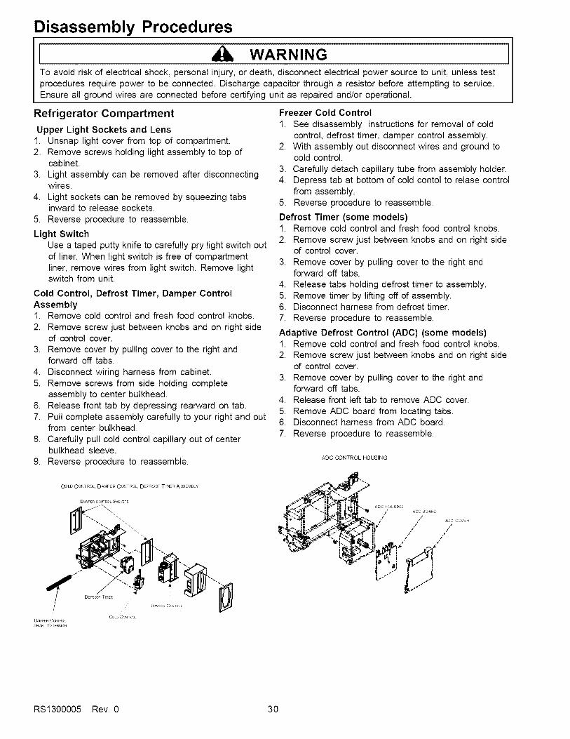
Cold Control, Defrost Timer, Damper ControlAssembly1. Remove cold control and fresh food control knobs.2. Remove screw just between knobs and on right side
of control cover.3. Remove cover by pulling cover to the right and
forward off tabs.4. Disconnect wiring harness from cabinet.5. Remove screws from side holding complete
assembly to center bulkhead.6. Release front tab by depressing rearward on tab.7. Pull complete assembly carefully to your right and out
from center bulkhead.8. Carefully pull cold control capillary out of center
bulkhead sleeve.9. Reverse procedure to reassemble.
COLD CONTROL DAMPER CONTROL DEFROST TltV£R ASSEMBLy
D ¢_PERCOkTRO£G_SKETS
Freezer Cold Control
1. See disassembly instructions for removal of coldcontrol, defrost timer, damper control assembly.
2. With assembly out disconnect wires and ground tocold control.
3. Carefully detach capillary tube from assembly holder.4. Depress tab at bottom of cold contol to relase control
from assembly.5. Reverse procedure to reassemble.
Defrost Timer (some models)1. Remove cold control and fresh food control knobs.
2. Remove screw just between knobs and on right sideof control cover.
3. Remove cover by pulling cover to the right andforward off tabs.
4. Release tabs holding defrost timer to assembly.5. Remove timer by lifting off of assembly.6. Disconnect harness from defrost timer.7. Reverse procedure to reassemble.
Adaptive Defrost Control (ADC) (some models)1. Remove cold control and fresh food control knobs.2. Remove screw just between knobs and on right side
of control cover.3. Remove cover by pulling cover to the right and
forward off tabs.4. Release front left tab to remove ADC cover,5. Remove ADC board from locating tabs.6. Disconnect harness from ADC board.7. Reverse procedure to reassemble.
ADC CONTROL HOUSING
r.. -,,-If "... |ti.0. *. ADC HOUSING_ / ADC BOARD
"_ /' / _C COVER
/" // /*
CoLo CO_TRC_DAMPER CCI_TRO
SH_FT EXTENSION
RS1300005 Rev. 0 30

Disassembly Procedures
WARNINGTo avoid risk of electrical shock, personal injury, or death, disconnect electrical power source to unit, unless testprocedures require power to be connected. Discharge capacitor through a resistor before attempting to service.Ensure all ground wires are connected before certifying unit as repaired and/or operational.
Damper Control 9. From inside of fresh food compartment pull tubing up.
2.
3.
4.5.
Remove cold control and fresh food control knobs.
Remove screw just between knobs and on right sideof control cover.
Remove cover by pulling cover to the right andforward off tabs.
Slide off styrafoam block. Retain for future use.Pull shaft extension free of control.
NOTE: Observe wide and narrow clip leg orientation ofshaft and damper cover.
6. Release side tabs holding damper control toassembly.
7. Lift damper control off of assembly
NOTE: Retain damper gasket for future use.
8. Reverse procedure to reassemble.
Water Filter Assembly
1. Remove filter cover opening cover and pulling rearleft side of cover to the left to release cover fromholding pin.
2. Filter head can be released from holding bracket byopening tabs on left side filter head and pullingdownward and to your left to release filter head.
3. Tubing needs to be disconnected from water valvesin the machine compartment. (see water valveremoval)
4. After tubing is loose from water valves pull the filterhead and tubing out the front of unit.
5. Reverse procedure to reassemble.
NOTE: Make sure to note tubing end colors whenreinstalling new head and tubing assembly.
and out of cabinet to complete removal of water tank.10.Reverse procedure to reassemble.
Crisper Light Cover and Socket1. Push down and forward on light cover and lift off tabs.2. Remove light bulb and pry socket with taped putty
knife to release socket from liner.3. Disconnect wires from socket.
4. Reverse procedure to reassemble.
Freezer Compartment
Freezer Light socket1. Remove auger ice bucket and fast freeze shelf.2. Remove auger motor assembly. (see auger motor
assembly removal.3. Remove light bulbs.4. Disconnect wiring from light sockets.5. Squeeze retaining tab to release sockets6. Reverse procedure to reassemble.
Auger Motor Assembly1. Remove auger ice bucket and fast freeze shelf.2. Remove light bulbs3. Remove two hex head screws, one from each side of
cover.4. Lift and slide assembly toward the front, disconnect
wiring harness and remove assembly.
Water Tank Assembly
1. Remove crisper drawers from fresh foodcompartment.
2. Remove hex screw holding water tank to rearbulkhead.
3. On rear of cabinent remove hex screws holdingwater valve cover plate.
4. Remove plate and tubing away from cabinet toexpose water valves and tubing.
5. Disconnect water tube from secondary valve comingfrom water tank, remove compression nut fromtubing.
6. On front of unit remove toe grill and disconnect watercoupler going to water dispenser
7. Remove compression nut from water tubing oncabinet side of connection.
8. From rear of cabinet pull water tube out of conduitgoing to dispenser.
Auger Motor1. Remove auger drive hex nut.2. Remove three hex nuts holding auger motor to
assembly.3. Disconnect wires from auger motor capacitor.4. Reverse procedure to reassemble.
31 RS1300005 Rev. 0
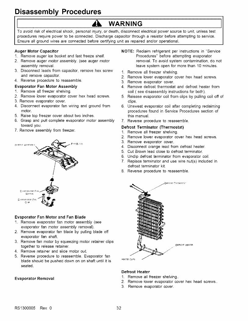
Disassembly Procedures
WARNINGTo avoid risk of electrical shock, personal injury, or death, disconnect electrical power source to unit, unless testprocedures require power to be connected. Discharge capacitor through a resistor before attempting to service.Ensure all ground wires are connected before certifying unit as repaired and/or operational.
Auger Motor Capacitor1. Remove auger ice bucket and fast freeze shelf.2. Remove auger motor assembly. (see auger motor
assembly removal.3. Disconnect leads from capacitor, remove hex screw
and remove capacitor.4. Reverse procedure to reassemble.
Evaporator Fan Motor Assembly1. Remove all freezer shelving.2. Remove lower evaporator cover hex head screws.3. Remove evaporator cover.4. Disconnect evaporator fan wiring and ground from
motor.5. Raise top freezer cover about two inches.6. Grasp and pull complete evaporator motor assembly
toward you.7. Remove assembly from freezer.
SHROUD ASSEMBLY
\FAN BLADE
/!
/
NOTE: Reclaim refrigerant per instructions in "ServiceProcedures" before attempting evaporatorremoval. To avoid system contamination, do notleave system open for more than 10 minutes.
1. Remove all freezer shelving.2. Remove lower evaporator cover hex head screws.3, Remove evaporator cover.4. Remove defrost thermostat and defrost heater from
coil ( see disassembly instructions for both).5. Release evaporator coil from clips by pulling coil off of
clips.6. Unsweat evaporator coil after completing reclaiming
procedures found in Service Procedures section ofthis manual.
7. Reverse procedure to reassemble.
Defrost Terminator (Thermostat)1. Remove all freezer shelving.2. Remove lower evaporator cover hex head screws,3. Remove evaporator cover.4. Disconnect orange lead from defrost heater.5. Cut Brown lead close to defrost terminator.
6. Unclip defrost terminator from evaporator coil.7. Replace terminator and use wire nut(s) included in
defrost terminator kit.
8. Reverse procedure to reassemble.
Evaporator Fan Motor and Fan Blade1. Remove evaporator fan motor assembly (see
evaporator fan motor assembly removal).2. Remove evaporator fan blade by pulling blade off
evaporator fan shaft.3. Remove fan motor by squeezing motor retainer clips
together to release retainer.4. Remove retainer and slide motor out.
5. Reverse procedure to reassemble. Evaporator fanblade should be pushed down on on shaft until it isseated.
Evaporator Removal
DEFROSTHEATE_
HEATER CLIps
Defrost Heater
1. Remove all freezer shelving..2. Remove lower evaporator cover hex head screws..3. Remove evaporator cover.
RS1300005 Rev. 0 32
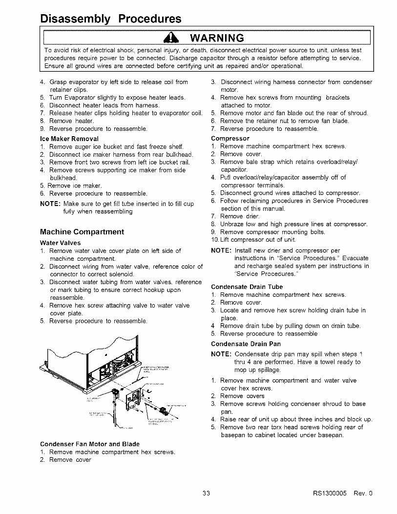
Disassembly Procedures
WARNINGTo avoid risk of electrical shock, personal injury, or death, disconnect electrical power source to unit, unless testprocedures require power to be connected. Discharge capacitor through a resistor before attempting to service.Ensure all ground wires are connected before certifying unit as repaired and/or operational.
4. Grasp evaporator by left side to release coil fromretainer clips.
5. Turn Evaporator slightly to expose heater leads.6. Disconnect heater leads from harness.7. Release heater clips holding heater to evaporator coil.8. Remove heater.9. Reverse procedure to reassemble.
Ice Maker Removal
1. Remove auger ice bucket and fast freeze shelf.2. Disconnect ice maker harness from rear bulkhead.3. Remove front two screws from left ice bucket rail.
4. Remove screws supporting ice maker from sidebulkhead.
5. Remove ice maker.
6. Reverse procedure to reassemble.
NOTE: Make sure to get fill tube inserted in to fill cupfully when reassembling
Machine Compartment
Water Valves1. Remove water valve cover plate on left side of
machine compartment.2. Disconnect wiring from water valve, reference color of
connector to correct solenoid.3. Disconnect water tubing from water valves, reference
or mark tubing to ensure correct hookup uponreassemble.
4. Remove hex screw attaching valve to water valvecover plate.
5. Reverse procedure to reassemble.
Condenser Fan Motor and Blade1. Remove machine compartment hex screws.2. Remove cover
3. Disconnect wiring harness connector from condensermotor.
4. Remove hex screws from mounting bracketsattached to motor.
5. Remove motor and fan blade out the rear of shroud.6. Remove the retainer nut to remove fan blade.7. Reverse procedure to reassemble.
Compressor1. Remove machine compartment hex screws.2. Remove cover.3. Remove bale strap which retains overload/relay/
capacitor.4. Pull overload/relay/capacitor assembly off of
compressor terminals.5. Disconnect ground wires attached to compressor.6. Follow reclaiming procedures in Service Procedures
section of this manual.7. Remove drier.
8. Unbraze low and high pressure lines at compressor.9. Remove compressor mounting bolts.10.Lift compressor out of unit.
NOTE: Install new drier and compressor perinstructions in "Service Procedures." Evacuateand recharge sealed system per instructions in"Service Procedures."
Condensate Drain Tube
1. Remove machine compartment hex screws.2. Remove cover.
3. Locate and remove hex screw holding drain tube inplace.
4 Remove drain tube by pulling down on drain tube.5. Reverse procedure to reassemble
Condensate Drain Pan
NOTE: Condensate drip pan may spill when steps 1thru 4 are performed. Have a towel ready tomop up spillage.
1. Remove machine compartment and water valvecover hex screws.
2. Remove covers
3. Remove screws holding condenser shroud to basepan.
4. Raise rear of unit up about three inches and block up.5. Remove two rear torx head screws holding rear of
basepan to cabinet located under basepan.
33 RS1300005 Rev. 0
Disassembly Procedures
{ WARNINGTo avoid risk of electrical shock, personal injury, or death, disconnect electrical power source to unit, unless testprocedures require power to be connected. Discharge capacitor through a resistor before attempting to service.Ensure all ground wires are connected before certifying unit as repaired and/or operational.
J
6. Lower cabinet back to floor after removing blocks.7. Raise cabinet off of basepan enough to allow removal
of condenser shroud, disconnect any wiring attachedto shroud to ease removal of shroud.
8. After shroud is removed bend copper tubing up out ofcondensate pan to allow removal of condensate pan.
9. Reverse procedure to reassemble.
Overload/Relay1. Remove machine compartment hex screws.2. Discharge capacitor (if unit is so equipped) through a
10.000-ohm resistor.
3. Using fingers and standard screwdriver, press andpry bale strap off the overload/relay/capacitorassembly.
4. Reverse procedure to reassemble.
Condenser Removal
NOTE: Condenser is removed by laying unit on it's backand requires at least two people to do thisprocedure.
1. Remove machine compartment hex screws.2. Remove cover.3. Remove condenser fan motor and shroud.
4. Disconnect harness plug connecting machinecompartment to cabinet.
5. Follow reclaiming procedures in Service Proceduressection of this manual.
6. Remove drier and unbraze tubing connectingmachine compartment to cabinet.
7. Disconnect all cabinet wiring from machine tray.8. With the help of second person lay unit on back on
raised surface.
9. Remove four torx head screws holding basepan tocabinet.
10. Lift and remove basepan to access condenser coil.11. Unbraze condenser coil from connecting tubing.12. Remove condenser coil by unsnapping it from
retainers in basepan.13. Reverse procedure to reassemble.
leveling roller.4. Slide leveling roller out rear of slot to remove roller.5. Reverse procedure to reassemble.
Rear Leveling Rollers1. Remove machine compartment and water valve
cover hex screws.2. Remove covers.3. Tilt unit forward lifting rear of unit up about three
inches.
4. Block unit up to keep weight off of rear levelingrollers.
5. Un screw leveling bolts from rear leveling rollers.6. Push the leveling roller out the slots in the bottom of
the unit.7. Reverse procedure to reassemble.
Cabinet Doors
Door Gaskets1. Grasp gasket in upper corners and pull gasket out of
dart retainer.2. When reinstalling door gaskets start at corners
pushing dart edge into retainer and make sure toseat gasket flush to door.
Dispenser Facade (Messenger model)1. Remove drip tray by pulling it straight out from door.2. Remove two hex screws at the bottom of facade that
were hidden by drip tray.3. Push down on facade to release retainer clips.4. Remove facade and disconnect ten pin connector
and two pin speaker connector from display board.5. Reverse procedure to reassemble.
Bottom of Cabinet
Front Leveling Rollers1. Remove toe grill and hinge caps.2. Raise and block unit up three inches off of floor.3. Screw front leveler bolts until they are loose from
RS1300005 Rev, 0 34
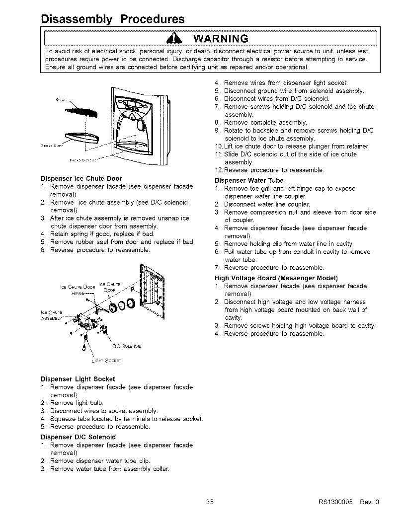
Disassembly Procedures
WARNINGTo avoid risk of electrical shock, personal injury, or death, disconnect electrical power source to unit, unless testprocedures require power to be connected. Discharge capacitor through a resistor before attempting to service.Ensure all ground wires are connected before certifying unit as repaired and/or operational.
GR LE S _M _o_ "I"_
F_CAD SCREWS "I"_'_"
Dispenser Ice Chute Door1. Remove dispenser facade (see dispenser facade
removal)2. Remove ice chute assembly (see D/C solenoid
removal)3. After ice chute assembly is removed unsnap ice
chute dispenser door from assembly.4. Retain spring if good, replace if bad.5. Remove rubber seal from door and replace if bad.6. Reverse procedure to reassemble.
i1_-""
_*,. DC SOLENOID
LIGHT SOCKET
4. Remove wires from dispenser light socket.5. Disconnect ground wire from solenoid assembly.6. Disconnect wires from D/C solenoid.7. Remove screws holding D/C solenoid and ice chute
assembly.8. Remove complete assembly.9. Rotate to backside and remove screws holding D/C
solenoid to ice chute assembly.10.Lift ice chute door to release plunger from retainer.11.Slide D/C solenoid out of the side of ice chute
assembly.12.Reverse procedure to reassemble.
Dispenser Water Tube1. Remove toe grill and left hinge cap to expose
dispenser water line coupler.2. Disconnect water line coupler.3. Remove compression nut and sleeve from door side
of coupler.4. Remove dispenser facade (see dispenser facade
removal).5. Remove holding clip from water line in cavity.6. Pull water tube up from conduit in cavity to remove
water tube.7. Reverse procedure to reassemble.
High Voltage Board (Messenger Model)1. Remove dispenser facade (see dispenser facade
removal)2. Disconnect high voltage and low voltage harness
from high voltage board mounted on back wall ofcavity.
3. Remove screws holding high voltage board to cavity.4. Reverse procedure to reassemble.
Dispenser Light Socket1. Remove dispenser facade (see dispenser facade
removal)2. Remove light bulb.3. Disconnect wires to socket assembly.4. Squeeze tabs located by terminals to release socket.5. Reverse procedure to reassemble.
Dispenser D/C Solenoid1. Remove dispenser facade (see dispenser facade
removal)2. Remove dispenser water tube clip.3. Remove water tube from assembly collar.
35 RS1300005 Rev. 0
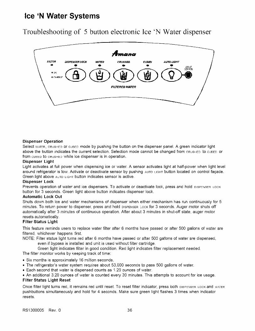
Ice 'N Water Systems
Troubleshooting of 5 button electronic Ice 'N Water dispenser
I ,4,,,=,,a ]FILTER DISPENSER LOCK WA'/I_R CRUHH _,'_ CU_ AUTO LIGHT
FILTERED WATER
Dispenser OperationSelect WATER,CRUSHEDor CUBEDmode by pushing the button on the dispenser panel. A green indicator lightabove the button indicates the current selection. Selection mode cannot be changed from CRUSHEDto CUBEDorfrom CUBEDto CRUSHEDwhile ice dispenser is in operation.Dispenser LightLight activates at full power when dispensing ice or water. A sensor activates light at half-power when light levelaround refrigerator is low. Activate or deactivate sensor by pushing AUTOLIGHTbutton located on control fa£ade.Green light above AUTOLIGHTbutton indicates sensor is active.Dispenser LockPrevents operation of water and ice dispensers. To activate or deactivate lock, press and hold D{SPENSERLOCKbutton for 3 seconds. Green light above button indicates dispenser lock.Automatic Lock OutShuts down both ice and water mechanisms of dispenser when either mechanism has run continuously for 5minutes. To return power to dispenser, press and hold DISPENSERLOCKfor 3 seconds. Auger motor shuts offautomatically after 3 minutes of continuous operation. After about 3 minutes in shut-off state, auger motorresets automatically.Filter Status Light
This feature reminds users to replace water filter after 6 months have passed or after 500 gallons of water arefiltered, whichever happens first.NOTE: Filter status light turns red after 6 months have passed or after 500 gallons of water are dispensed,
even if bypass is installed and unit is used without filter cartridge.Green light indicates filter in good condition. Red light indicates filter replacement needed.
The filter monitor works by keeping track of time:
• Six months is approximately 16 million seconds.• The refrigerator's water system requires about 53,000 seconds to pass 500 gallons of water.• Each second that water is dispensed counts as 1.20 ounces of water.• An additional 3.20 ounces of water is counted every 30 minutes. This attempts to account for ice usage.Filter Status Light Reset
Once filter light turns red, it remains red until reset. To reset filter indicator, press both DISPENSERLOCKand WATERpushbuttons simultaneously and hold for 4 seconds. Make sure green light flashes 3 times when indicatorresets.
RS1300005 Rev. 0 36

Ice 'N Water Systems
Table A: Harness 10-pin Connector Configuration
Pin Color1 GY2 BR3 BU4 OR5 BK6 RD7 YL8 VT910
SiqnalIce Door Chute SolenoidDispenser Li,qhtCrushedCubedLine OutMain ActuatorWater ValveLine In
WH Neutral
Note: All voltage measurements are referenced to line neutral or pin 10 (WH wire) of 10-pin connector.
SvmDtomNo LED Iit
No dispenser lightwhen Main or
Water dispenserswitch is pressedin Water, Crushedor Cubed mode.
Dispenser light ison without
pressing the Mainor Water dispenserswitch in Water,Crushed or Cubedmode.Water LED isilluminated but
does not dispensewater when Maindispenser switch ispressed.
Water starts to
dispense as soonas Water mode isselected without
pressing the Maindispenser switch
Possible CauseSwitch failure infreezer door.Incorrect harness
wiring,No power to the PCB.
No continuity.
Failed light bulb orPCB.
Failed Main dispenserswitch (failed short)
Failed PCB
Failed Main dispenserswitch (failed open)
No continuity
Failed Main dispenserswitch (failed short)
Failed PCB
Test Procedure
With unit powered, open freezer door. Press freezer doorswitch in. If freezer Iiaht does not turn off. switch is defective.
Verify wire color on 10-pin connector. Refer to Table A.
With unit powered, measure voltage between (WH wire) and(VT wire) pin 8 of 10-pin connector. Meter should read120VAC.
Disconnect power. Measure continuity between (BR wire) pin2 of 10-pin connector and dispenser lamp terminal.
With unit powered, press the Main dispenser switch.Measure voltage on pin 2 (BR wire) of 10-pin connector.Voltage should read 120 VAC.
Disconnect power. Remove both leads from the switch andmeasure resistance across switch terminals. Resistance
should read less than 1 _) in this position and higher than 10M_) when switch is open.With PCB powered, measure voltage on pin 3 (BU wire) of 10-pin connector. Voltage should read 0 VAC.
Disconnect power. Remove both leads from the switch andmeasure resistance across switch terminals. Resistance
should read less than 1 _) in this position and higher than !0M_) when switch is open.Disconnect power. Remove the cover of freezer door hingelocated on top of the unit and disconnect the connectors.Check OR wire (Din 4 of 10-Din connector1 for continuity.
Disconnect power. Remove both leads from the switch andmeasure resistance across switch terminals. Resistance
should read less than 1 (-) in this position and higher than !0M_) when switch is open.With PCB powered, measure voltage on pin 7 (YL wire) of 10-nin nnnn_nfnr \/nltan_ £hniiId r_ad N \/AC;
Reoair
Replaceswitch.Correct
wiring,Replace PCBif meter reads120VAC.
Repair openconnection.
Replacedispenserlight bulb ifvoltage reads120 VAC.
Replaceswitch
Replace PCB.
Replaceswitch.
Repair openconnection.
Replaceswitch.
Replace PCB.
37 RS1300005 Rev. 0
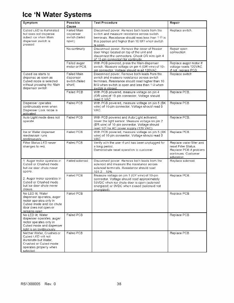
Ice 'N Water SystemsSymptom
Cubed LED is illuminated
but does not dispensecubed ice when Main
dispenser switch ispressed.
Cubed ice starts to
dispense as soon asCubed mode is selected
without pressing the Maindispenser switch
Dispenser operatescontinuously even whenDispenser Lock mode is_iv_,
Auto Lightmode does not
operate.
Ice or Water dispensermechanism runs
continuously.Filter Status LED never
changes to red.
1. Auger motor operates inCubed or Crushed modebut ice door chute never
opens.
2. Auger motor operates inCubed or Crushed modebut ice door chute nevercioses.
No LED lit, Waterdispenser operates, augermotor operates only inCubed mode and ice chute
door does not open orremains open.No LED lit, Waterdispenser operates, augermotor operates only inCubed mode and dispenserIiqht is on continuously.Neither Water, Crushed orCubed LED will notilluminate but Water,Crushed or Cubed modeoperates properly whenselected.
PossibleCauseFailed Main
dispenserswitch (failedopen)
No continuity
Failed augermotor or PCB.
Failed Main
dispenserswitch (failedshort)
Failed PCB
Failed PCB
Failed PCB
Failed PCB
Failed PCB
Failed solenoid
Failed PCB
Failed PCB
Test Procedure
Disconnect power. Remove both leads from theswitch and measure resistance across switchterminals. Resistance should read less than 1 £_ in
this position and higher than 10 M£_ when switchis open.Disconnect power. Remove the cover of freezerdoor hinge located on top of the unit anddisconnect the connectors. Check OR wire (pin 4of 10-Din connector_ for continuity.
With PCB powered, press the Main dispenserswitch. Measure voltage on pin 4 (OR wire) of 10-Din connector. Voltaae should re ad 120VAC.
Disconnect power. Remove both leads from theswitch and measure resistance across switch
terminals. Resistance should read higher than 10M£_ when switch is open and Iess than 1 £_whenswitch is closed.
With PCB powered, measure voltage on pin 4(OR wire)of 10-pin connector. Voltage shouldread 0 VAC.
With PCB powered, measure voltage on pin 5 (BKwire) of 10-pin connector. Voltage should read 0VAC.
With PCB powered and Auto Light activated,cover the light sensor. Measure voltage on pin 2(BR wire) of 10-pin connector. Voltage shouldread 1/2 the AC Dower SUDDIV(120 VAC_.
With PCB powered, measure voltage on pin 5 (BKwire) of 10-pin connector. Voltage should read 0VAC.
Verify with the user if unit has been unplugged fora long period.Demonstrate reset operation to customer.
Disconnect power. Remove both leads from thesolenoid and measure the resistance acrosssolenoid terminals. Resistance should read101.2 + 10%.
Measure voltage on pin 1 (GY wire) of 10-pinconnector. Voltage should read approximately55VDC when ice chute door is open (solenoidenergized) or 0VDC when closed (solenoid notenerqized/.
Repair
Replace switch.
Repair openconnection.
Replace auger motor ifvoltage reads 120VAC.If not. reDlace PCB.
Replace switch
Replace PCB.
Replace PCB
Replace PCB.
Replace PCB.
Replace water filter andreset Filter Status.Replace PCB if problemcontinues. Customereducation.
Replace solenoid.
Replace PCB.
Replace PCB
Failed PCB Replace PCB
Failed PCB Replace PCB
RS1300005 Rev. 0 38

Ice 'N Water SystemsSymptom
Crushed LED is illuminated
but does not dispensecrushed ice when Main
dispenser switch ispressed.
Crushed ice starts to
dispense as soon asCrushed mode is selectedwithout pressing the Maindispenser switch.
PossibleCause
Failed Main
dispenserswitch (failedopen)
No continuity
Failed augermotor or PCB.
Failed Main
dispenserswitch (failedshort)
Failed PCB
Test Procedure
Disconnect power. Remove both leads from theswitch and measure resistance across switchterminals. Resistance should read less than 1 £_ in
this position and higher than 10 M£_ when switchi_epen,Disconnect power. Remove the cover of freezerdoor hinge located on top of the unit anddisconnect the connectors. Check BU wire (pin 3of 1 0.pin connector) for continuity.
With PCB powered, press the Main dispenserswitch. Measure voltage on pin 3 (BU wire) of 10-Din connector. Voltaae should read 120VAC.
Disconnect power. Remove both leads from theswitch and measure resistance across switchterminals. Resistance should read less than 1 £_ in
this position and higher than 10 M£_ when switchis open.With PCB powered, measure voltage on pin 3 (BUwire) of 10-pin connector. Voltage should read 0VAC.
Repair
Replace switch.
Repair openconnection.
Replace auger motor ifvoltage reads 120VAC.If not. replace PCB.
Replace switch
Replace PCB.
Seconds to dispense 10 oz. waterSupply pressure 35 psig 45 psig 55 psig 75 psig
Filter model 9.0 8.0 7.0 6.0Bypass installed
Filter model 11.0 10.0 8.0 7.0New filter installed
Amana specifies a minimum supply pressure of 35 psig for water filter units. Minimum pressurerequirement ensures that water valves close and sufficient water volume is available to fill icemaker.Proper fill is 140 cc. of water in 7.5 seconds. Failure of water valves to close because of low pressure
will result in fill-tube freeze-up or dripping at cavity.
39 RS1300005 Rev. 0
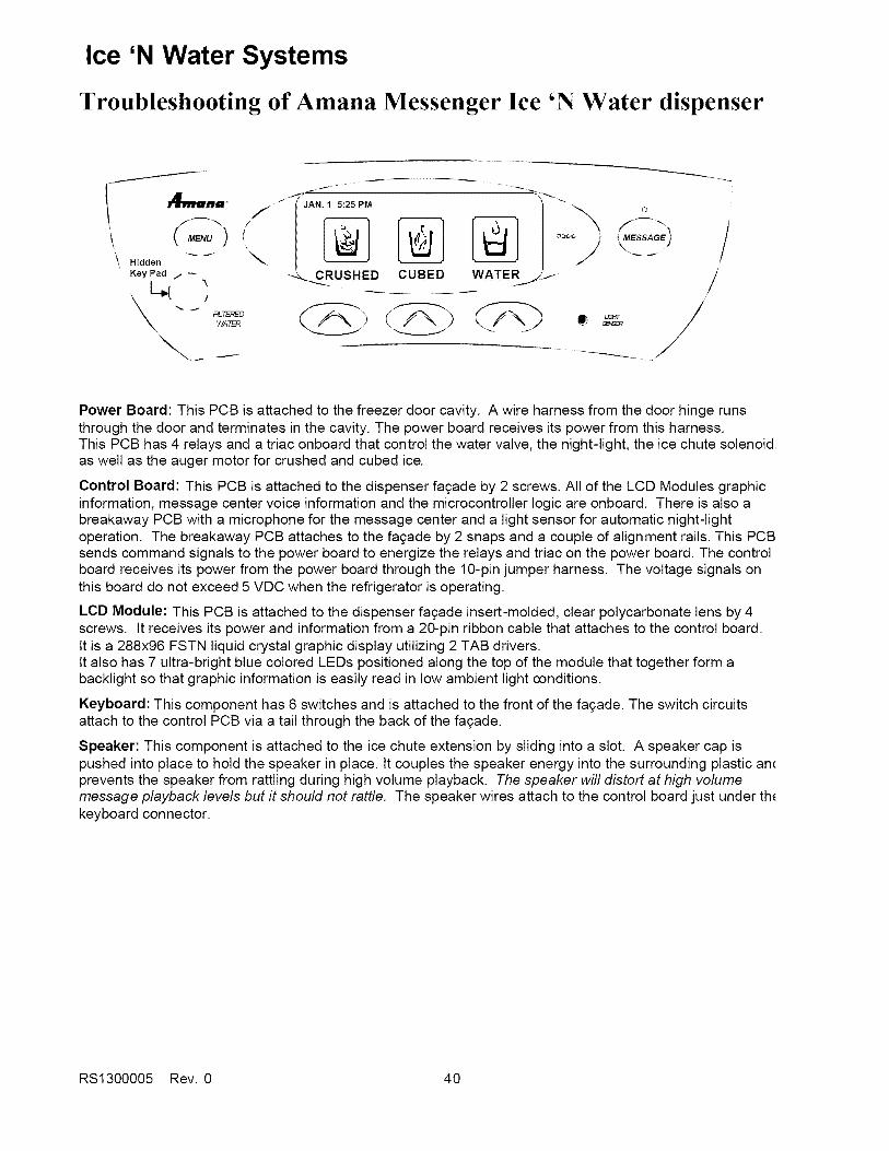
Ice 'N Water Systems
Troubleshooting of Amana Messenger Ice 'N Water dispenser
,q.,.,..=o
Hidden
Key Pad /
!
WATE_
j ,
IJANI :25P r
_._RUSHED CUBED WATER j/
Q
i MESSAGE)
//
Power Board: This PCB is attached to the freezer door cavity. A wire harness from the door hinge runsthrough the door and terminates in the cavity. The power board receives its power from this harness.This PCB has 4 relays and a triac onboard that control the water valve, the night-light, the ice chute solenoidas well as the auger motor for crushed and cubed ice.
Control Board: This PCB is attached to the dispenser fa£ade by 2 screws. All of the LCD Modules graphicinformation, message center voice information and the microcontroller logic are onboard. There is also abreakaway PCB with a microphone for the message center and a light sensor for automatic night-lightoperation. The breakaway PCB attaches to the fa£ade by 2 snaps and a couple of alignment rails. This PCBsends command signals to the power board to energize the relays and triac on the power board. The controlboard receives its power from the power board through the 10-pin jumper harness. The voltage signals onthis board do not exceed 5 VDC when the refrigerator is operating.
LCD Module: This PCB is attached to the dispenser facade insert-molded, clear polycarbonate lens by 4screws. It receives its power and information from a 20-pin ribbon cable that attaches to the control board.It is a 288x96 FSTN liquid crystal graphic display utilizing 2 TAB drivers.It also has 7 ultra-bright blue colored LEDs positioned along the top of the module that together form abacklight so that graphic information is easily read in low ambient light oonditions.
Keyboard: This component has 6 switches and is attached to the front of the fagade. The switch circuitsattach to the control PCB via a tail through the back of the fagade.
Speaker: This component is attached to the ice chute extension by slidhg into a slot. A speaker cap ispushed into place to hold the speaker in place. It couples the speaker energy into the surrounding plastic antprevents the speaker from rattling during high volume playback. The speaker will distort at high volumemessage playback levels but it should not rattle. The speaker wires attach to the control board just under th_keyboard connector.
RS1300005 Rev. 0 40

Ice 'N Water Systems
Freezer Door Harness connection to the power board:Pin Color Power Signal and State Definition
Board
Graphic
Marking
1 WH NEU
2 N/C
3 RD/WH FF
4 VT FZ
5 RD L1
6 YL WAT
7 OR CUB
8 BU CSH
DOOR CLOSED115VAC
DOOR CLOSED
g VA_
LINE NEUTRAL INPUT (TOP PIN OF
LARGE CONNECTOR}
NO CONNECTION
FRESH FOOD DOOR INPUT
FREEZER DOOR INPUT
LINE POWER INPUT
WATER SOLENOtD OUTPUT
CUBED tCE MOTOR DRIVE
CRUSHED tOE MOTOR DRIVE
0 VAC CONSTANT
DOOR OPEN0 VAC
DOOR OPEN
112YAQ115 VAC CONSTANT
VALVE ON
115 VAC
CUBE WINDING
ON 115 VAC
CRUSHED
WINDING
ON 115 VAC
SOLENOID ENERGIZED
115 VAC
NIGHT-LIGHT OFF
0 VAC
VALVE OFF
0 VAC
CUBE WINDING
OFF 0 VAC
CRUSHED WINDtNG
OFF 0 VAC
9 GY tCE tCE CHUTE SOLENOID OUTPUT SOLENOID NOT ENERGIZED
0 VAC
10 BR LIT NIGHT-LIGHT OUTPUT HALF-BRIGHT LEVEL
(BOTTOM Pt N OF LARGE 65 VACCONNECTOR) OR
FULL BRIGHT LEVEL
115 VAC
Jumper Harness from the power board header J1 to the Dispenser Switch Harness
control board header Jl:
Pin Color
I GY
BR
3 VT
4 OR
5 BU
6 RD
7 YL
8 WH
9 N/C
10 BK
KeyboardPRESS PAD NAME
MESSAGE
MENU
LEFT
CENTER
RIGHT
HIDDEN
MESSAGE LED CIRCUIT
Si£1nal
NIGHT-LIGHT (0, 2 or4 VDC) (TOP PIN OF SMALLCONNECTOR ON POWER BOARD)
Door status input (both doors open or closed - 2.0 VDC, FZ door
open - 5VDC_ FF door open - < 0.5 VDC)
Reference (2.0 - 2.5 VDC continuous)
ICE CHUTE (5VDC WHEN ENERGIZED}
CRUSHED tCE (5VDC WHEN ENERGIZED)
CUBED ICE (5VDC WHEN ENERGIZED)
WATER (5VDC WHEN ENERGIZED)
(5VDC CONSTANT)
NO CONNECTION
GROUND (BOTTOM PIN OF SMALL CONNECTOR)
switch test:
MEASURE 100 - 500 OHMS ACROSS TRACES
2AND4
3AND4
1 AND 3
1 AND 4
1 AND 5
2 AND 5
7 TO 8 (< 2 K OHMS)
8 TO 7 (INFINITE OHMS)
Pin Color Signal
1 B U DISPENSER SWITCH
2 RD WATER SWITCH
3 N/C
4 BK COMMON
41 RS1300005 Rev. 0
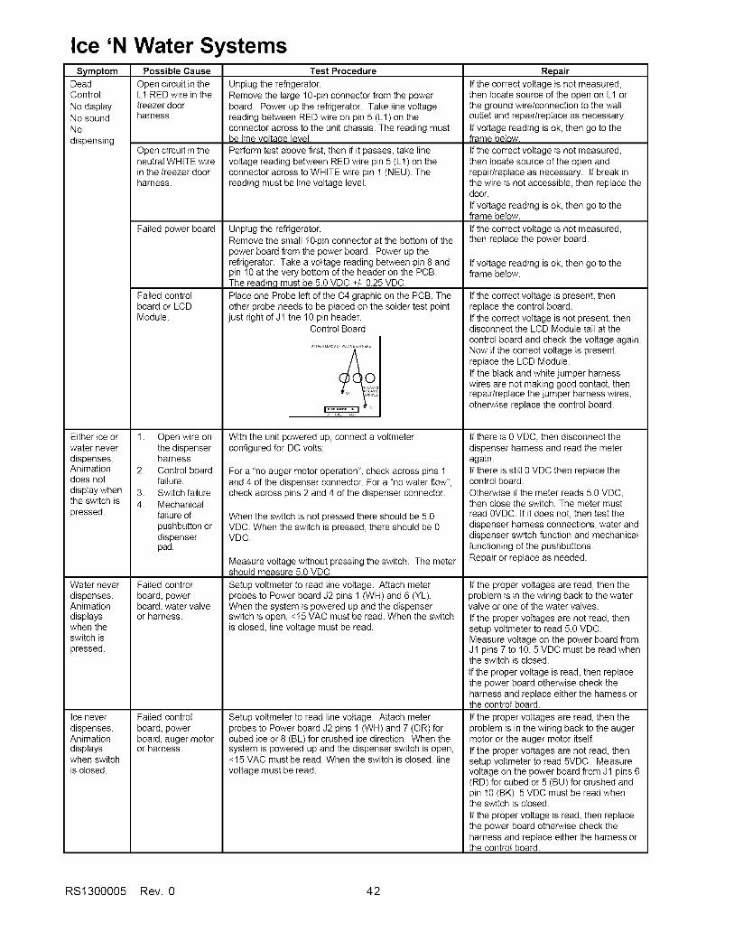
Ice 'N Water SystemsSymptom
DeadControl:
No displayNo soundNodispensing
Either ice orwater neverdispenses.Animationdoes notdisplay whenthe switch ispressed.
Water neverdispenses.Animationdisplayswhen theswitch ispressed.
Possible Cause
Open circuit in theL1 RED wire in thefreezer doorharness.
Open circuit in theneutral WHITE wirein the freezer doorharness.
Failed power board
Failed controlboard or LCDModule.
1.
2.
3.4.
Open wire onthe dispenserharnessControl boardfailure.Switch failureMechanicalfailure ofpushbatton ordispenserpad.
Failed controlboard, powerboard, watervalveor harness.
Failed controlboard, powerboa_,auger motoror harness.
Ice neverdispenses.Animationdisplayswhen switchis closed.
Test Procedure
Unplug the refrigerator.Remove the large 1g-pin connector from the powerboard. Power up the refiigerator. Take line voltagereading between RED wire on pin 5 (L1) on theconnector across to the unit chassis. The reading mustbe line voltaee level.
Perform test above first, then if it passes, take tinevoltage reading between RED wire pin 5 (L1) on theconnector across to WHITE wire pin 1 (NEU). Thereading must be tine voltage level.
Unplug the refrigerator.Remove the small 10-pin connector at the bottom of thepower board from the power board. Power up therefrigerator. Take a voltage reading between pin 8 andpin 10 at the very bottom of the header on the PCB.The reading must be 5.0 VDC +/- 0.25 VDC.Place one Probe Ieft of the C4 graphic on the PCB. Theother probe needs to be placed on the solder test pointjust right d J1 the 10 pin header.
Control Board
With the unit powered up, connect a voltmeterconfigured for DC volts:
For a "no auger motor operation", check across pins 1and 4 of the dispenser connector. For a "no water flow",check across pins 2 and 4 of the dispenser connector.
When the switch is not pressed there should be 5.0VDC. When the switch is pressed, there should be 0VDC.
Measure voltage without pressing the switch. The metershould measure 5.0 VDC.
Setup voltmeter to read line voltage. Attach meterprobes to Power board J2 pins 1 (WH) and 6 (YL).When the system is powered up and the dispenserswitch is open, <15 VAC must be read. When the switchis closed, line voltage must be read.
Setup voltmeter to read line voltage. Attach meterprobes to Power board J2 pins 1 (WH) and 7 (OR) forcubed ice or 8 (BL) for crushed ice direction. When thesystem is powered up and the dispenser switch is open,<15 VAC must be read. When the switch is closed, linevoltage must be read.
RepairIf the correct voltage is not measured,then locate source of the open on L1 orthe ground wire/connection to the waltoutlet and repair/replace as necessary.
If voltage reading is ok, then go to theframe below.
If the correct voltage is not measured,then locate source of the open andrepair/replace as necessary. If break inthe wire is not accessible, then replace thedoor.
If voltage reading is ok, then go to theframe below.
If the correct voltage is not measured,then replace the power board.
If voltage reading is ok, then go to theframe below.
If the correct voltage is present, thenreplace the control board.If the correct voltage is not present, thendisconnect the LCD Module tail at thecontrol board and check the voltage again.Now if the correct voltage is present,replace the LCD Module.If the black and white jumper harnesswires are not making good contact, thenrepair/replace the jumper harness wires,otherwise replace the control board.
If there is 0 VDC, then disconnect thedispenser harness and read the meteragain.If there is still 0 VDC then replace thecontrol board.Otherwise if the meter reads 5.0 VDC,then close the switch. The meter mustread OVDC. If it does not, then test thedispenser harness connectiors, water anddispenser switch function and mechanicalfunctioning of the pushbattons.Repair or replace as needed.
If the proper voltages are read, then theproblem is in the wiring back to the watervalve or one of the water valves.
If the proper voltages are not read, thensetup voltmeter to read 5.0 VDC.Measure voltage on the power board fromJ1 pins 7 to 10.5 VDC must be read whenthe switch is closed.
If the proper voltage is read, then replacethe power board otherwise check theharness and replace either the harness orthe controI board.
If the proper voltages are read, then theproblem is in the wiring back to the augermotor or the auger motor itself.If the proper voltages are not read, thensetup voltmeter to read 5VDC. Measurevoltage on the power board from J1 pins 6(RD) for cubed or 5 (BU) for crushed andpin 10 (BK). 5 VDC must be read whenthe switch is closed.
If the proper voltage is read, then replacethe power board otherwise check theharness and replace either the harness orthe control board.
RS1300005 Rev. 0 42
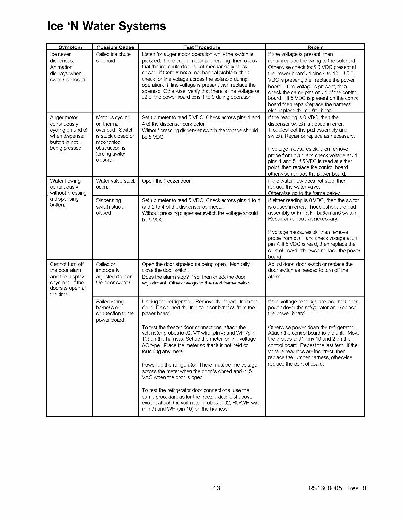
Ice 'N Water Systems
Svmotom
Ice never
dispenses.Animation
displays whenswitch is closed.
Auger motorcontinuouslycycling on and offwhen dispenserbutton is not
being pressed.
Water flowingcontinuouslywithout pressinga dispensingbutton.
Cannot turn offthe door alarm
and the displaysays one of thedoors is open allthe time.
Possible Cause
Failed ice chutesolenoid
Motor is cyclingon thermaloverload. Switch
Test Procedure
Listen for auger motor operation while the switch ispressed. If the auger motor is operating, then checkthat the ice chute door is not mechanically stuckclosed. If there is not a mechanical problem, thencheck for line voltage across the solenoid duringoperation. If line voltage is present then replace thesolenoid. Otherwise, verify that there is line voltage onJ2 of the power board pins 1 to 9 during operation.
Set up meter to read 5 VDC. Check across pins 1 and4 of the dispenser connector.Without pressing dispenser switch the voltage should
is stuck closed or be 5 VDC.mechanicalobstruction is
forcing switchclosure.
Water valve stuckopen.
Dispensingswitch stuckclosed
Failed or
improperlyadjusted door orthe door switch.
Failed wiringharness orconnection to the
power board.
Open the freezer door.
Set up meter to read 5 VDC. Check across pins 1 to 4and 2 to 4 of the dispenser connector.Without pressing dispenser switch the voltage shouldbe 5 VDC.
Open the door signaled as being open. Manuallyclose the door switch.
Does the alarm stop? If so, then check the dooradjustment. Otherwise go to the next frame below.
Unplug the refrigerator. Remove the fa(2adefrom thedoor. Disconnect the freezer door harness from the
power board.
To test the freezer door connections, attach thevoltmeter probes to J2, VT wire (pin 4) and WH (pin10) on the harness. Set up the meter for line voltageAC type. Place the meter so that it is not held ortouching any metal.
Power up the refrigerator. There must be line voltageacross the meter when the door is closed and <!5
VAC when the door is open.
To test the refrigerator door connections, use thesame procedure as for the freezer door test aboveexcept attach the voltmeter probes to J2, RD/VVHwire(pin 3) and WH (pin !0) on the harness.
Reuair
If line voltage is present, thenrepair/replace the wiring to the solenoid.Otherwise check for 5.0 VDC present atthe power board J1 pins 4 to 10. If5.0VDC is present, then replace the powerboard. If no voltage is present, thencheck the same pins on J! of the controlboard. If5 VDC is present on the controlboard then repair/replace the harness,else replace the control board.If the reading is 0 VDC, then thedispenser switch is closed in error.Troubleshoot the pad assembly andswitch. Repair or replace as necessary.
If voltage measures ok, then removeprobe from pin 1 and check voltage at J1pins 4 and 5. If 5 VDC is read at eitherpoint, then replace the control boardotherwise replace the Dower board.
If the water flow does not stop, thenreplace the water valve.Otherwise ao to the frame below.
If either reading is 0 VDC, then the switchis closed in error. Troubleshoot the padassembly or Front Fill button and switch.Repair or replace as necessary.
If voltage measures ok, then removeprobe from pin 1 and check voltage at J1pin 7. If 5 VDC is read, then replace thecontrol board otherwise replace the powerboard.
Adjust door, door switch or replace thedoor switch as needed to turn off thealarm.
If the voltage readings are incorrect, thenpower down the refrigerator and replacethe power board.
Otherwise power down the refrigerator.Attach the control board to the unit. Move
the probes to J1 pins 10 and 2 on thecontrol board. Repeat the last test. If thevoltage readings are incorrect, thenreplace the jumper harness, otherwisereplace the control board.
43 RS1300005 Rev. 0
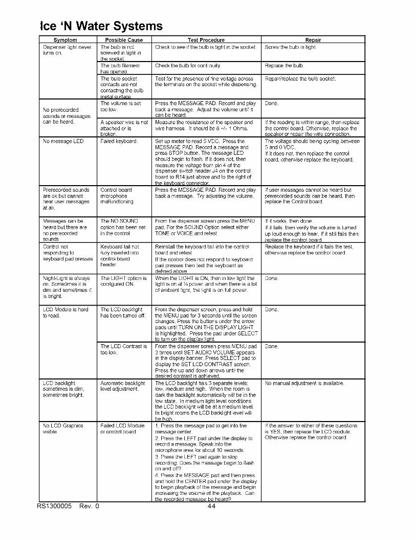
Ice 'N Water SystemsSymptom
Dispenser light neverturns on.
No prerecordedsounds or messagescan be heard.
No message LED
Prerecorded soundsare ok but cannothear user messagesat alt.
Messages can beheard but there areno prerecordedsounds
Control notresponding tokeyboard pad presses
Night-Light is alwayson. Sometimes it isdim and sometimes itis bright.
LCD Module is hardto read.
LCD backlightsometimes is dim,sometimes bright.
No LCD Graphicsvisible
Possible CauseThe butb is notscrewed in tight inthe socket.The bulb filament
has opened.The bulb socketcontacts are notcontacting the butb
The votume is settoo low.
A speaker wire is notattached or isbroken.
Failed keyboard.
Control board
microphonemalfunctioning
The NO SOUNDoption has been setin the control.
Keyboard tail notfully inserted intocontrol boardheader.
The LIGHT option isconfigured ON.
The LCD backlighthas been turned off.
The LCD Contrast istoo low.
Automatic backlightlevel adjustment.
Failed LCD Moduleor control board.
RS1300005 Rev.
Test Procedure
Check to see if the bulb is tight in the socket.
Check the bulb for continuity.
Test for the presence d tine voltage acrossthe terminals on the socket while dispensing.
RepairScrew the bulb in tight.
Replace the butb.
Repair/replace the butb socket.
Press the MESSAGE PAD. Record and play Done.back a message. Adjust the volume until itcan be heard.
Measure the resistance of the speaker andwire harness, it should be 8 +/- 1 Ohms.
Set up meter to read 5 VDC. Press theMESSAGE PAD. Record a message andpress STOP button. The message LEDshould begin to flash. If it does not, thenmeasure the voltage from pin 4 of thedispenser switch header J4 on the controlboard to R14 just above and to the right ofthe keyboard connector
Press the MESSAGE PAD. Record and playback a message. Try adjusting the volume.
From the dispenser screen press the MENUpad. For the SOUND Option select eitherTONE or VOICE and retest.
Reinstall the keyboard tail into the controlboard and retest.
If the control does not respond to keyboardpad presses then test the keyboard asdefined above.
When the LIGHT is ON, then in low light thelight is on at ½ power and when there is a lotof ambient light, the light is on full power.
From the dispenser screen, press and holdthe MENU pad for 3 seconds until the screenchanges. Press the buttons under the arrowpads until TURN ON THE DISPLAY LIGHTis highlighted. Press the pad under SELECTto turn on the display ti,qht.From the dispenser screen press MENU pad3 times until SET AUDIO VOLUME appearsin the disptay banner. Press SELECT pad todisplay the SET LCD CONTRAST screen.Press the up and down arrows untit thedesired contrast is achieved.
The LCD backtight has 3 separate levels;tow, medium and high. When the room isdark the backlight automatically wilt be in theIow state. In medium light tevet conditionsthe LCD backlight witl be at a medium level.In bright rooms the LCD backlight level wiltbe hiqh.1. Press the message pad to get into themessage center.2. Press the LEFT pad under the display torecord a message. Speak into themicrophone area for about 10 seconds.3. Press the LEFT pad again to stoprecording. Does the message begin to flashon and off?
4. Press the MESSAGE pad and then pressand hold the CENTER pad under the displayto begin playback of the message and beginincreasing the votume of the playback. Canthe recorded messaae be heard?
44
If the reading is within range, then replacethe control board. Otherwise, replace thespeaker or repair the wire connection.The voltage should being cycling between5 and 0 VDC.If it does not, then replace the controlboard, otherwise replace the keyboard.
If user messages cannot be heard butprerecorded sounds can be heard, thenreplace the Control board.
If it works, then done.If it fails, then verify the volume is turnedup loud enough to hear. If it still fails thenreplace the control board.Replace the keyboard if it fails the test,otherwise replace the control board.
Done.
Done.
Done.
No manual adjustment is available.
If the answer to either of these questionsis YES, then replace the LCD module.Otherwise replace the control board.

Ice 'N Water Systems
Troubleshooting of 3 button electronic Ice 'N Water dispenser
_1 notions
FILTEREE) [_IA TE,_
Dispenser Operation
Select WATER,CRUSHEDor CUBEDmode by pushing the button on the dispenser panel. A greenindicator light above the button indicates the current selection.Dispenser LightLight activates at full power when dispensing ice or water.
Table A: Harness 9-pin Connector Configuration
Pin
1
23
4567
89
Color
GY
BROR
BURDYLVT
Signal
Ice Door ChuteSolenoid
Dispenser LightCubed
CrushedLineMain ActuatorLine In
WH NeutralNote: All voltage measurements are referenced to line neutral or pin 9 (WH wire) of 9-pinconnector
45 RS1300005 Rev. 0
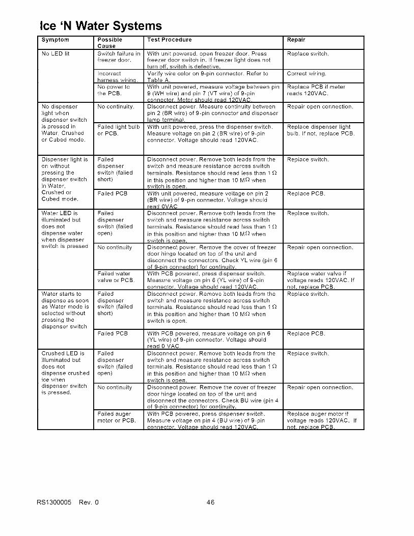
Ice 'N Water SystemsSymptom
No LED lit
No dispenserlight whendispenser switchis pressed inWater, Crushedor Cubed mode.
Dispenser light ison without
pressing thedispenser switchin Water,Crushed orCubed mode.
Water LED isilluminated butdoes not
dispense waterwhen dispenserswitch is pressed
Water starts to
dispense as soonas Water mode isselected without
pressing thedispenser switch
Crushed LED isilluminated butdoes not
dispense crushedice when
dispenser switchis pressed.
Possible Test ProcedureCause
Switch failure infreezer door.
Incorrectharness wirina.No power tothe PCB.
No continuity.
Failed light bulbor PCB.
Failed
dispenserswitch (failedshort)
Failed PCB
Failed
dispenserswitch (failedopen)
No continuity
Failed watervalve or PCB.
Failed
dispenserswitch (failedshort)
Failed PCB
Failed
dispenserswitch (failedopen)
No continuity
Failed augermotor or PCB.
With unit powered, open freezer door. Pressfreezer door switch in. If freezer light does notturn off, switch is defective.Verify wire color on 9-pin connector. Refer toTable A.
With unit powered, measure voltage between pin9 (WH wire) and pin 7 (VT wire) of 9-pinconnector. Meter should read 120VAC.
Disconnect power. Measure continuity betweenpin 2 (BR wire) of 9-pin connector and dispenserlamp terminal.
With unit powered, press the dispenser switch.Measure voltage on pin 2 (BR wire) of 9-pinconnector. Voltage should read 120VAC.
Disconnect power. Remove both leads from theswitch and measure resistance across switch
terminals. Resistance should read less than 1 £_
in this position and higher than 10 M£_ whenswitch is open.With unit powered, measure voltage on pin 2(BR wire) of 9-pin connector. Voltage shouldread 0VAC
Disconnect power. Remove both leads from theswitch and measure resistance across switchterminals. Resistance should read less than 1 £_
in this position and higher than 10 M£) whenswitch is open.Disconnect power. Remove the cover of freezerdoor hinge located on top of the unit anddisconnect the connectors. Check YL wire (pin 6of 9-Din connector1 for continuitv.
With PCB powered, press dispenser switch.Measure voltage on pin 6 (YL wire) of 9-pinconnector. Volta,qe should read 120VAC.
Disconnect power. Remove both leads from theswitch and measure resistance across switchterminals. Resistance should read less than 1 £_
in this position and higher than 10 M£_ whenswitch is open.
With PCB powered, measure voltage on pin 6(YL wire) of 9-pin connector. Voltage shouldread 0 VAC.
Disconnect power. Remove both leads from theswitch and measure resistance across switchterminals. Resistance should read less than 1 £_
in this position and higher than 10 M£_ whenswitch is open.
Disconnect power. Remove the cover of freezerdoor hinge located on top of the unit anddisconnect the connectors. Check BU wire (pin 4of 9-pin connector) for continuity.With PCB powered, press dispenser switch.Measure voltage on pin 4 (BU wire) of 9-pinconnector. Voltaae should read 120VAC.
Repair
Replace switch.
Correct wiring.
Replace PCB if meterreads 120VAC.
Repair open connection.
Replace dispenser lightbulb. If not, replace PCB.
Replace switch.
Replace PCB.
Replace switch.
Repair open connection.
Replace water vane ifvoltage reads 120VAC. Ifnot, replace PCB.
Replace switch.
Replace PCB.
Replace switch.
Repair open connection.
Replace auger motor ifvoltage reads 120VAC. Ifnot. reolace PCB.
RS1300005 Rev. 0 46
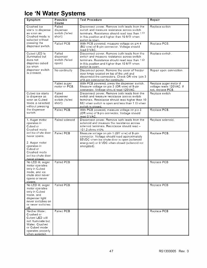
Ice 'N Water SystemsSymptom
Crushed ice
starts to dispenseas soon asCrushed mode isselected withoutpressing thedispenser switch,
Cubed LED isilluminated butdoes not
dispense cubedice when
dispenser switchis pressed.
Cubed ice starts
to dispense assoon as Cubedmode is selected
without pressingthe dispenserswitch
Possible Test ProcedureCause
Failed
dispenserswitch (failedshort)
Failed PCB
Failed
dispenserswitch (failedopen)
No continuity
Failed augermotor or PCB.
Failed
dispenserswitch (failedshort)
Repair
Replace switch
Replace PCB.
Replace switch.
Repair open connection.
Replace auger motor ifvoltage reads 120VAC. Ifnot, replace PCB.
Replace switch
Failed PCB Replace PCB.
1. Auger motor Failed solenoid Replace solenoid.operates inCubed orCrushed mode
but ice chute door Failed PCB Replace PCB.never opens.
Disconnect power. Remove both leads from theswitch and measure resistance across switchterminals. Resistance should read less than 1 _)
in this position and higher than 10 M£) whenswitch is open.With PCB powered, measure voltage on pin 4(BU wire) of 9-pin connector. Voltage shouldread 0 VAC.
Disconnect power. Remove both leads from theswitch and measure resistance across switch
terminals. Resistance should read less than 1 _)
in this position and higher than 10 M_) whenswitch is open.Disconnect power. Remove the cover of freezerdoor hinge located on top of the unit anddisconnect the connectors. Check OR wire (pin 3of 9-pin connector) for continuity.With PCB powered, press the dispenser switch.Measure voltage on pin 3 (OR wire) of 9-pinconnector. Volta,qe should read 120VAC.
Disconnect power. Remove both leads from theswitch and measure resistance across switch
terminals. Resistance should read higher than 10M£_ when switch is open and less than 1 £_ whenswitch is closed.
With PCB powered, measure voltage on pin 3(OR wire) of 9-pin connector. Voltage shouldread 0 VAC.
Disconnect power. Remove both leads from thesolenoid and measure the resistance acrosssolenoid terminals. Resistance should read-101.2 ohms +I0%
Measure voltage on pin 1 (GY wire) of 9-pinconnector. Voltage should read approximately55VDC when ice chute door is open (solenoidenergized) or 0 VDC when closed (solenoid notenergized).
2. Auger motoroperates inCubed orCrushed modebut ice chute door
never _le_e_,No LED lit, augermotor operatesonly in Cubedmode, and icechute door never
opens or nevercloses.
No LED lit, augermotor operatesonly in Cubedmode, anddispenser lightnever switches onor never switchesoff.
Neither Water,Crushed orCubed LED willnot illuminate but
Water, Crushedor Cubed mode
operates properlywhen selected.
Failed PCB
Failed PCB
Failed PCB
Replace PCB
Replace PCB
Replace PCB
47 RS1300005 Rev. 0

Appendix A
A- 1 RS1300005 Rev. 0
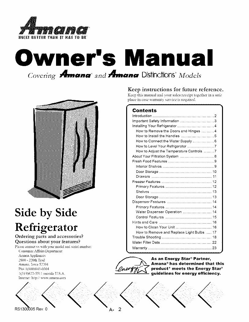
anaBUmLT BEI_ER [XAH |r HAS T& BE'
Owner's ManualCovering _nd Distinctions° Models
Keep instructions for future reference.Keep this manual and your sales receipt together in a safe
place in case warranty service is required.
Side by Side
RefrigeratorOrdering parts and accessories?
Questions about your features?Please contact us with your model and serial number:
Consumer Affairs Department
Amana Appliances
2800 - 220th Trail
Amana, Iowa 52204
Ph# 1(800)843-0304
1(319)622-5511 outside U.S.A.
Intemet: http:ii www.amana.com
ContentsIntroduction ................................................................... 2
Important Safety Information ..................................... 3
Installing Your Refrigerator ........................................ 4
How to Remove the Doors and Hinges .............. 4
How to Install the Handles .................................... 5
How to Connect the Water Supply ....................... 6
How to Level Your Refrigerator ............................. 7
How to Adjust the Temperature Controls ........... 7
About Your Filtration System ..................................... 8
Fresh Food Features .................................................. 9
Interior Shelves ........................................................ 9
Door Storage .......................................................... 10Drawers .................................................................. 11
Freezer Features ....................................................... 12
Primary Features ................................................... 12
Shelves ................................................................... 13
Door Storage .......................................................... 13
Dispenser Features ................................................. 14
Primary Features ................................................... 14
Water Dispenser Operation ................................ 14
Control Features ................................................... 15
Hints and Care .......................................................... 16
How to Clean Your Unit ........................................ 16
How to Remove and Replace Light Bulbs ....... 17
Trouble Shooting ....................................................... 18
Water Filter Data ........................................................ 22
Warranty ...................................................................... 23
As an Energy Star ® Partner,
Amana ® has determined that this
product* meets the Energy Star ®
guidelines for energy efficiency.
A- 2
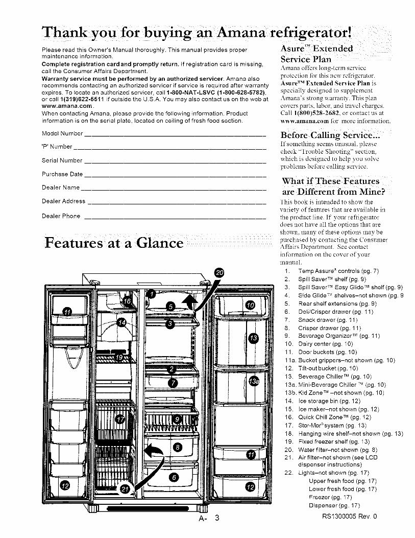
Please read this Owner's Manual thoroughly. This manual provides propermaintenance information.
Complete registration card and promptly return. If registration card is missing,call the Consumer Affairs Department.
Warranty service must be performed by an authorized servicer. Amana alsorecommends contacting an authorized servicer if service is required after warranty
expires. To locate an authorized servicer, call 1-800-NAT-LSVC (1-800-628-5782),or call 1(319)622-5511 if outside the U.S.A. You may also contact us on the web atwww.amana.com.
When contacting Amana, please provide the following information. Product
information is on the serial plate, located on ceiling of fresh food section.
Model Number
'P' Number
Serial Number
Purchase Date
Dealer Name
Dealer Address
Dealer Phone
Features ata Glance
@
A- 3
Service PlanAmana offers long-term serviceprotection t_r this new refrigerator.Asure TM Extended Service Plan isspecially designed to supplementAmana's strong warranty. This plancovers parts, labor, and travel charges.Call 1(800)528-2682, or contact us at
_vw.amana.com for more information.
Before Calling ServiCe:XIf smnething seems unusual, pleasecheck "Trouble Shooting" section,which is designed to help you solveproblems before calling service.
are Different from Mine?
This book is intended to show the
variety of features that are available in
the product line. If your refrigerator
does not have all the options that are
shown, many of these options may be
purchased by contacting the Consumer
Aflhirs Department. See contact
information on the cover of your
manual.
1. Temp Assure ® controls (pg. 7)
2. Spill Saver TM shelf (pg. 9)
3. Spill Saver TM Easy Glide TM shelf (pg. 9)
4. Side Glide TM shelves-not shown (pg. 9
5. Rear shelf extensions (pg. 9)
6. Dell/Crisper drawer (pg. 11 )
7. Snack drawer (pg. 11 )
8. Crisper drawer (pg. 11 )
9. Beverage Organizer TM (pg. 11 )
10. Dairy center (pg. 10)
11. Door buckets (pg. 10)
11 a. Bucket grippers-not shown (pg. 10)
12. Tilt-out bucket (pg. 10)
13. Beverage Chiller TM (pg. 10)
13a. Mini-Beverage Chiller TM(pg. 10)
13b. Kid Zone TM -not shown (pg. 10)
14. Ice storage bin (pg. 12)
15. Ice maker-not shown (pg. 12)
16. Quick Chill Zone TM (pg. 12)
17. Stor-Mor®system (pg. 13)
18. Hanging wire shelf-not shown (pg. 13)
19. Fixed freezer shelf (pg. 13)
20. Water filter-not shown (pg. 8)
21. Airfilter-not shown (see LCDdispenser instructions)
22. Lights-not shown (pg. 17)
Upper fresh food (pg. 17)
Lower fresh food (pg. 17)
Freezer (pg. 17)
Dispenser (pg. 17)
RS1300005 Rev. 0
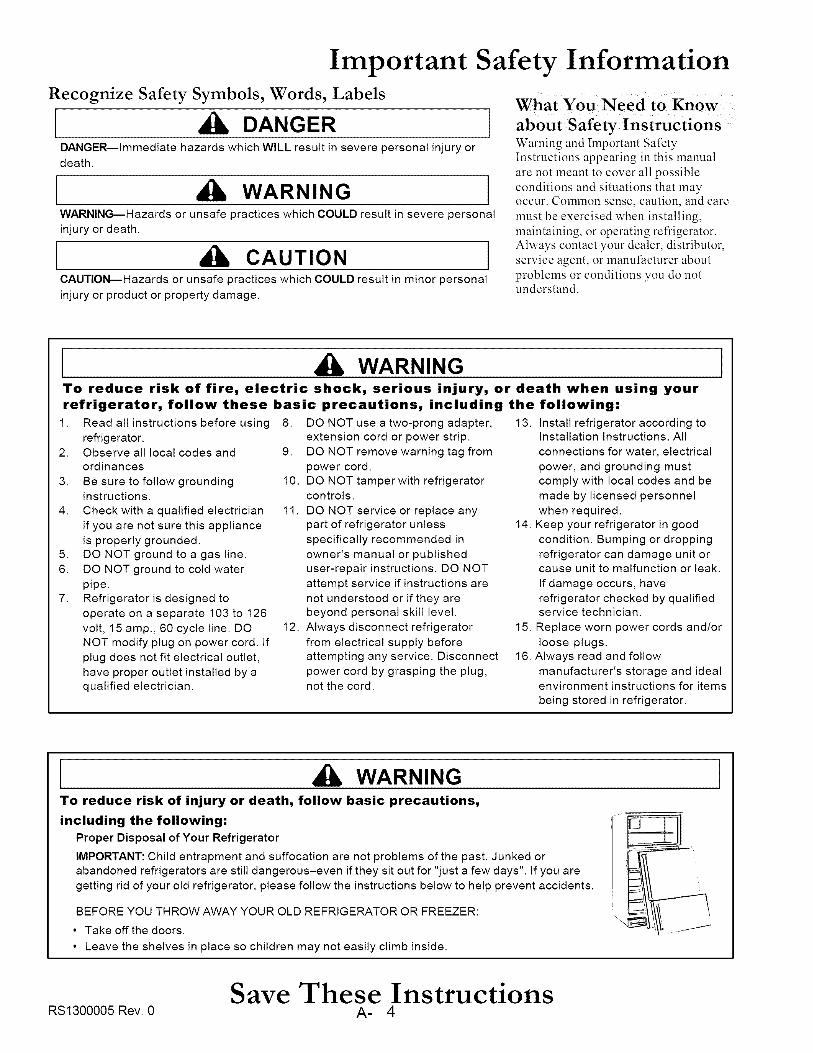
Important Safety InformationRecognize Safety Symbols, Words, Labels
DANGERDANGER---Immediate hazards which WILL result in severe personal injury or
death.
[ WARNING ]WARNING--Hazards or unsafe practices which COULD resultin severe personal
injuryor death.
[ CAUTION ]CAUTION--Hazards or unsafe practices which COULD result in minor personal
injury or product or property damage.
What You Need to Know
about safety InstruCtionsWarning and Important SafetyInstructions appearing in this manualare not meant to cover all possibleconditions and situations that may
occur. Colinilon sense, caution, and caremust be exercised when installing,maintaining, or operating refrigerator.Always contact your dealer, distributor,service agent, or manufacturer about
problems or conditions you do notunderstand.
[ WARNINGTo reduce risk of fire, electric shock, serious injury, or death when using yourrefrigerator, follow these basic precautions, including the following=
1. Read all instructions before using 8.
refrigerator.2. Observe all local codes and 9.
ordinances
3. Be sure to follow grounding 10.instructions.
4. Check with a qualified electrician 11.
if you are not sure this appliance
is properly grounded.5. DO NOT ground to a gas line.
6. DO NOT ground to cold water
pipe.7. Refrigerator is designed to
operate on a separate 103 to 126
volt, 15 amp., 60 cycle line. DO 12.NOT modify plug on power cord. If
plug does not fit electrical outlet,
have proper outlet installed by aqualified electrician.
DO NOT use a two-prong adapter,
extension cord or power strip.
DO NOT remove warning tag from
power cord.
DO NOT tamper with refrigeratorcontrols.
DO NOT service or replace any
part of refrigerator unless
specifically recommended in
owner's manual or published
user-repair instructions. DO NOT
attempt service if instructions are
not understood or if they are
beyond personal skill level.
13. install refrigerator according toinstallation Instructions. All
connections for water, electrical
power, and grounding must
comply with local codes and be
made by licensed personnel
when required.
14. Keep your refrigerator in good
condition. Bumping or dropping
refrigerator can damage unit orcause unit to malfunction or leak.
If damage occurs, have
refrigerator checked by qualifiedservice technician.
1
Always disconnect refrigerator
from electrical supply before
attempting any service. Disconnect
power cord by grasping the plug,not the cord.
15. Replace worn power cords and/or
loose plugs.
16. Always read and follow
manufacturer's storage and idealenvironment instructions for items
being stored in refrigerator.
WARNINGTo reduce risk of injury or death, follow basic precautions,
including the following:
Proper Disposal of Your Refrigerator
IMPORTANT: Child entrapment and suffocation are not problems of the past. Junked or
abandoned refrigerators are still dangerous-even if they sit out for "just a few days". If you are
getting rid of your old refrigerator, please follow the instructions below to help prevent accidents.
BEFORE YOU THROW AWAY YOUR OLD REFRIGERATOR OR FREEZER:
• Take off the doors.
• Leave the shelves in place so children may not easily climb inside.
Save These InstructionsRS1300005 Rev. 0 A- 4
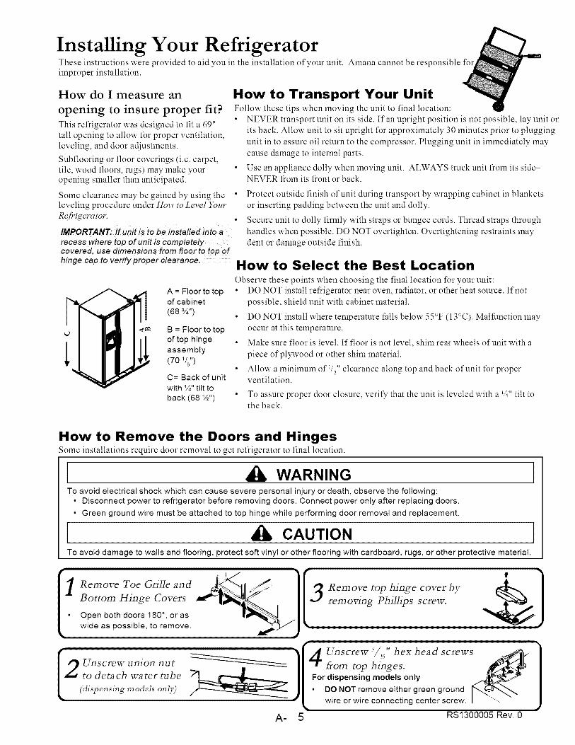
Installing Your RefrigeratorThese instructions were provided to aid you in the installation of your unit. Amana cannot be responsible t\_rimproper installation.
How do I measure an
opening to insure proper fit?
This refrigerator was designed to fit a 69"tall opening to allow for proper ventilation,leveling, and door adjustments.
Subflooring or floor coverings (i.e. carpet,tile, wood floors, rugs) may make youropening smaller than anticipated.
Some clearance may be gained by using theleveling procedure under How to Level YourRefrigerator.
IMPORTANT: If u_it is to be h_stalled h_toarecess where top of unit is completelycovered, use dimensions from floor to top of
How to Transport Your UnitFollow these tips when moving the unit to final location:• NEVER transport unit on its side. If an upright position is not possible, lay unit on
its back. Allow unit to sit upright for approximately 30 minutes prior to pluggingunit in to assure oil return to the compressor. Plugging unit in immediately maycause damage to internal parts.
• Use an appliance dolly when moving unit. ALWAYS truck unit from its sideNEVER fi:olnits front or back.
Protect outside finish of unit during transport by wrapping cabinet in blanketsor inserting padding between the unit and dolly.
Secure unit to dolly firmly with straps or bungee cords. Thread straps throughhandles when possible. DO NOT overtighten. Overtightening restraints maydent or damage outside finish.
hinge cap to verify proper clearance. How to Select the Best LocationObserve these points when choosing the final location for your unit:
V__ A = Floor to top DO NOT install refrigerator near oven, radiator, or other heat source. If not
of cabinet possible, shield unit with cabinet material.(68 ¾")
B = FIo_
L__L _ of t,_p h
asseml
(70 Vs")
DO NOT install where temperature falls below 55°F (13°C). Malfunction may
B = Floor to top occur at this temperature.of top hinge
assembly
C= Back of unit
with %" tilt to
back (68 ½")
Make sure floor is level. If floor is not level, shim rear wheels of unit with a
piece of plywood or other shim materiah
Allow a minimum of 1/2"clearance along top and back of unit t\_r properventilation.
To assure proper door closure, verity that the unit is leveled with a V4"tilt tothe back.
How to Remove the Doors and HingesSome installations require door removal to get refrigerator to final location.
WARNINGTo avoid electrical shock which can cause severe personal injury or death, observe the following:
• Disconnect power to refrigerator before removing doors. Connect power only after replacing doors.
• Green ground wire must be attached to top hinge while performing door removal and replacement.
CAUTIONTo avoid damage to walls and flooring, protect soft vinyl or other flooring with cardboard, rugs, or other protective material.
removing Phillips screw.

Installing Your RefrigeratorHow to Remove the Doors and Hinges _0_,ti_.,e_t
(,_;,pe.,i,_g moad, o.ijO . )x _ _ with doors.• Use a flat blade screwdriver
or fingernail to press junction . __,,I,_
point between two connectors _ !IY_to release.
Detatch red wire harness
(som _ m odds)Press tab on underside of
connector to release.
How to Replace the Doors
How to Install and Remove HandlesHandles are located x_ithin fresh food section of refrigerator. Trim, plugs, and accent pieces x_ill be located x_ithin theliterature assembly.
LCD and 5-button Dispenser Models (non-stainless steel)
Remove two /4 hex nut
screws from bottom of
re£rigera tot and freezer
door.
into screw holes at bottom o£handle section.
Align door handles with topand bottom sets of door clips,and slide down until screw
holes on bottom of handles
match with door screw holes.To remove a£ter initial install...
Follow steps 3 through 4 in reverse order.
NOTE; Fit may be tight. When removing handle, pu!! up andout.
Distinctions 3-button Dispenser Models
1 Rem°ve _°url/4't hex nutscrews From top andbottom o£ doors.
Align door handles withscrew holes and insert
screws removed in step 1.
Snap colored handle trim overscrew holes at top and bottom of
handles.
• Snap in trim by inserting large roundend first.
" To remove a£ter initial install...
6 Handles may need to be removed if transporting unit
through tight spaces.
• Follow steps 2 and 3 in reverse order.
IMPORTANT: To avoi d damage to handle, use a
flat blade screwdriver edge wrapped in masking
tape to remove colored handle trim.
_13UUUUb Nev. U A-
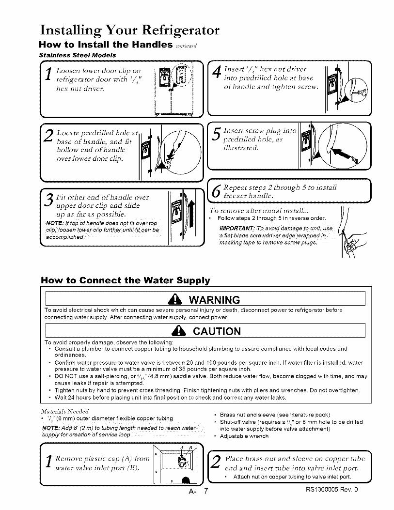
Installing Your RefrigeratorHow to Install the Handles _,o,,fi,,,,e_tStainless Steel Models
Insert I/4" hex nut driverinto predrilled hole at base
of handle and tighten screw.
5Insert screvc plug into
predrilled hole, asillustrated.
i6 Repeat steps 2 through 5 to install Ifreezer handle. JTo rein ore after initial in s tall... [
]Follow steps 2 through 5 in reverse order.
IMPORTANT: To avoid damage to unit, use
a flat blade screwdriver edge wrapped in
masking tape to remove screw plugs.
How to Connect the Water Supply
WARNINGTo avoid electrical shock which can cause severe personal injury or death, disconnect power to refrigerator before
connecting water supply. After connecting water supply, connect power.
CAUTIONTo avoid property damage, observe the following:
• Consult a plumber to connect copper tubing to household plumbing to assure compliance with local codes andordinances.
• Confirm water pressure to water valve is between 20 and 100 pounds per square inch. If water filter is installed, waterpressure to water valve must be a minimum of 35 pounds per square inch.
• DO NOT use a self-piercing, or 3/16" (4.8 mm) saddle valve. Both reduce water flow, become clogged with time, and maycause leaks if repair is attempted.
• Tighten nuts by hand to prevent cross threading. Finish tightening nuts with pliers and wrenches. Do not overtighten.
• Wait 24 hours before placing unit into final position to check and correct any water leaks.
M_teHMs Needed • Brass nut and sleeve (see literature pack)• 14 (6 ram) outer diameter flexible copper tubing
Shut-off valve (requires a 1/4" or 6 mm hole to be drilledNOTE" Add 8' (2 m) to tubing length needed to reach water into water supply before valve attachment)
supply for creation of service loop. • Adjustable wrench
A-
2Place brass nut and sleeve on copper tubeend and insert tube into valve inlet port.
Attach nut on copper tubing to valve inlet port.
7 RS1300005 Rev. 0
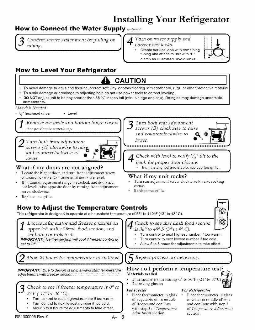
Installing Your RefrigeratorHow to Connect the Water Supply <o,,..,<._
I3 on_rm secure attachment bypulling ontubing.
[ Turn on water supply and
correct any leaks.
Create service loop with remainingtubing and attach to unit with "P"
clamp as illustrated. Avoid kinks.
How to Level Your Refrigerator
CAUTION• To avoid damage to walls and flooring, protect soft vinyl or other flooring with cardboard, rugs, or other protective material
• To avoid damage or breakage to adjusting bolt, do not use power tools to correct leveling.
• DO NOT adjust unit to be any shorter than 68 ½" inches tall (minus hinge and cap). Doing so may damage undersidecomponents.
3/[a t_dMs Needed
• 3/8"hex head driver • Level
Turn both front adjustment
screws (A) clockwise to rais&and counterclockwise to tl_lower.
What if my doors are not aligned?Locate the higher door, and turn front adjustment screwcounterclockwise. Continue until doors are level.
If bottom of adjustment range is reached, and doors arenot level raise opposite door by turning front adjustmentscrew clockwise.
Replace toe grille
3
Check with level to verify 1/4'' tilt to theback for proper door closure.
If unit is aligned and stable, replace toe grille.i
What if my unit rocks?Turn rear adjustment screw clockwise to raise rockingcorner.
Replace toe grille.
I3 1 " 2 drinking glasses
Check to see if freezer temperature is 0 ° to For Freezer
2 ° F (-17 ° to -16 ° C). *, Place thermometer in glass• Turn control to next highest number if too warm. of vegetable oil in middle• Turn control to next lowest number if too cold. of freezer and continue
• Allow 5 to 8 hours for adjustments to take effect, with step 3 of TemperatureAdjustment section.
RS1300005 Rev. 0 A- 8
For RefrigeratorPlace thennolneter in glassof water in middle of unitand continue with step 3of Temperature Adjustmentsection.
(2Allow24hoursfortemperatures tostabilize)(5Repeatprocess , asnecessary. )
IMPORrANr:Dueto designofunit,a!waysstarttomporature How do I perform a temperature test?adjustments With freezer section. Materials needed _[__.._'-)
• 10°C) _,,2 thermometers measuring -5° to 50°F (-21 ° to
How to Adjust the Temperature Controls _¢_i:rlThis refrigerator is designed to operate at a household temperature of 55 ° to 110°F (13 ° to 43 ° C).
Loca te refrigerator and Freezer controls on fA Check to see that Fresh Food section
upper left wall of fresh food section, and [ m _[.s38 ° to 40 ° F (3 ° to 4 ° C).
set both controls to 4. Turn control to next highest number if too warm.
IMPORTANT: Neither section will cool if freezer control is Turn control to next lowest number if too cold.
set to Off. Allow 5 to 8 hours for adjustments to take effect.
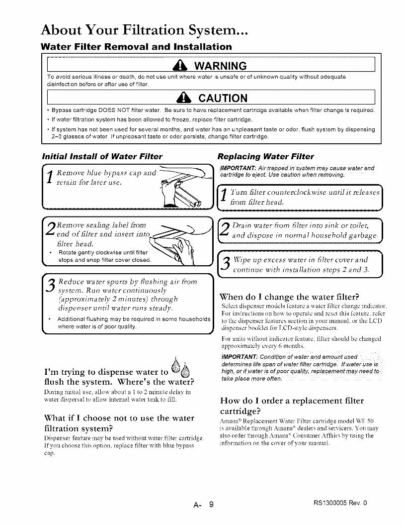
About Your Filtration System...Water Filter Removal and Installation
WARNING ITo avoid serious illness or death, do not use unit where water is unsafe or of unknown quality without adequate
disinfection before or after use of filter.
CAUnON 1• Bypass cartridge DOES NOT filter water. Be sure to have replacement cartridge available when filter change is required.
• If water filtration system has been allowed to freeze, replace filter cartridge.
• If system has not been used for several months, and water has an unpleasant taste or odor, flush system by dispensing
2-3 glasses of water. If unpleasant taste or odor persists, change filter cartridge.
Initial Install of Water Filter Replacing Water Filter
Remove blue bypass cap and cartridge to eject. Use caution when removing.
retain for later use.
Turn _lter coun terclockwise un tJl it relea sos
from _lter head.
_2Remove sealing label from _ "x _ [9 Drain water From _]ter into sink or toilet, }
end of _lter and insert Jnto_ I Lf"_ and dispose in normal household garbage.)
iterhead. I• Rotate gently clockwise until filter _"_'_ qf I
• stops and snap filter cover close& "_ '_, J Wipe up excess water in _lter cover and
Reduce water spurts by tTushing air from
system. Run water continuously
(approxim a rely 2 rain u tes) through
dispenser until water runs steady.
Additional flushing may be required in some households
where water is of poor quality.
I'm trying to dispense water to
flush the system, Where's the water?
During initial use, allow about a 1 to 2 minute delay in
water dispersal to allow internal water tank to fill.
What if I choose not to use the water
filtration system?Dispenser feature :nay be used without water filter cartridge.
If you choose this option, replace filter with blue bypass
cap.
When do I change the water filter?Select dispenser models feature a water filter change indicator.
For instructions on how to operate and reset this feature, refer
to the dispenser features section in your manual, or the LCD
dispenser booklet for LCD-style dispensers.
For units without indicator feature, filter should be changedapproximately every 6 months.
IMPORTANT: Condition of water and amount used
determines/ife span of water filter cartridge, tf water use ishigh: or if water is of poor quality, replacement may need totake place more often.
How do I order a replacement filter
cartridge?
Amana ® Replacement Water Filter cartridge model WF 50
is available through Amana _ dealers and servicers. You :nay
also order through Amana ® Consumer Aft'airs by using the
infi_rmation on the cover of your manual.
A- 9 RS1300005 Rev. 0
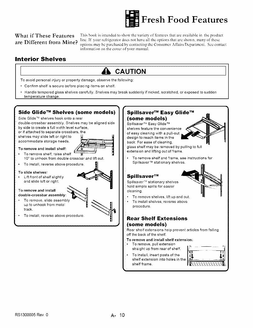
Fresh Food Features
What if These Features This book is intended to show the variety of features that are available in the product
are Different from Mine? line. If your refrigerator does not have all the options that are shown, many of theseoptions may be purchased by contacting the Consumer Affairs Department. See contactinformation on the cover of your manual.
Interior Shelves
CAUTION
To avoid personal injuryor property damage, observe the following:
• Confirm shelfissecure before placing items on shelf.
• Handle tempered glass shelves carefully.Shelves may break suddenly ifnicked, scratched, or exposed to sudden
temperature change.
Side Glide TM Shelves (some models)Side Glide TM shelves hook onto a rear
double-crossbar assembly. Shelves may be aligned side
by side to create a full width level surface,or if attached to separate crossbars, the
shelves may slide left or right to Ill WIaccommodate storage needs.
To remove and install shelf:
To remove shelf, raise shelf I,I10 ° to unhook from double crossbar and lift out.
To install, reverse above procedure.
To slide shelves:
Lift front of shelf slightlyand slide left or right.
To remove and install
double-crossbar assembh
To remove, slide assembly
up to unhook from metaltrack.
To install, reverse above procedure.
p,-
Spillsaver TM Easy Glide TM
(some models)Spillsaver TM Easy Glide TM
shelves feature the convenience
of easy cleaning with a pull-outdesign to reach items in the
back. For ease of cleaning,
glass shelf may be removed by pulling to full
extension and lifting out of frame.
• To remove shelf and frame, see instructions forSpillsaver TM stationary shelves.
Spillsaver TM
Spillsaver TM stationary shelveshold simple spills for easier
cleaning.
• To remove shelves, lift up and out.
To install shelves, reverse above
procedure.
Rear Shelf Extensions
(some models)Rear shelf extensions help prevent articles from fallingoff the back of the shelf.
To remove and install shelf extension:
• To remove, pull extension
straight up from rear of shelf.
• To install, insert posts of theshelf extension into holes in the
shelf frame.
RS1300005 Rev. 0 A- 10
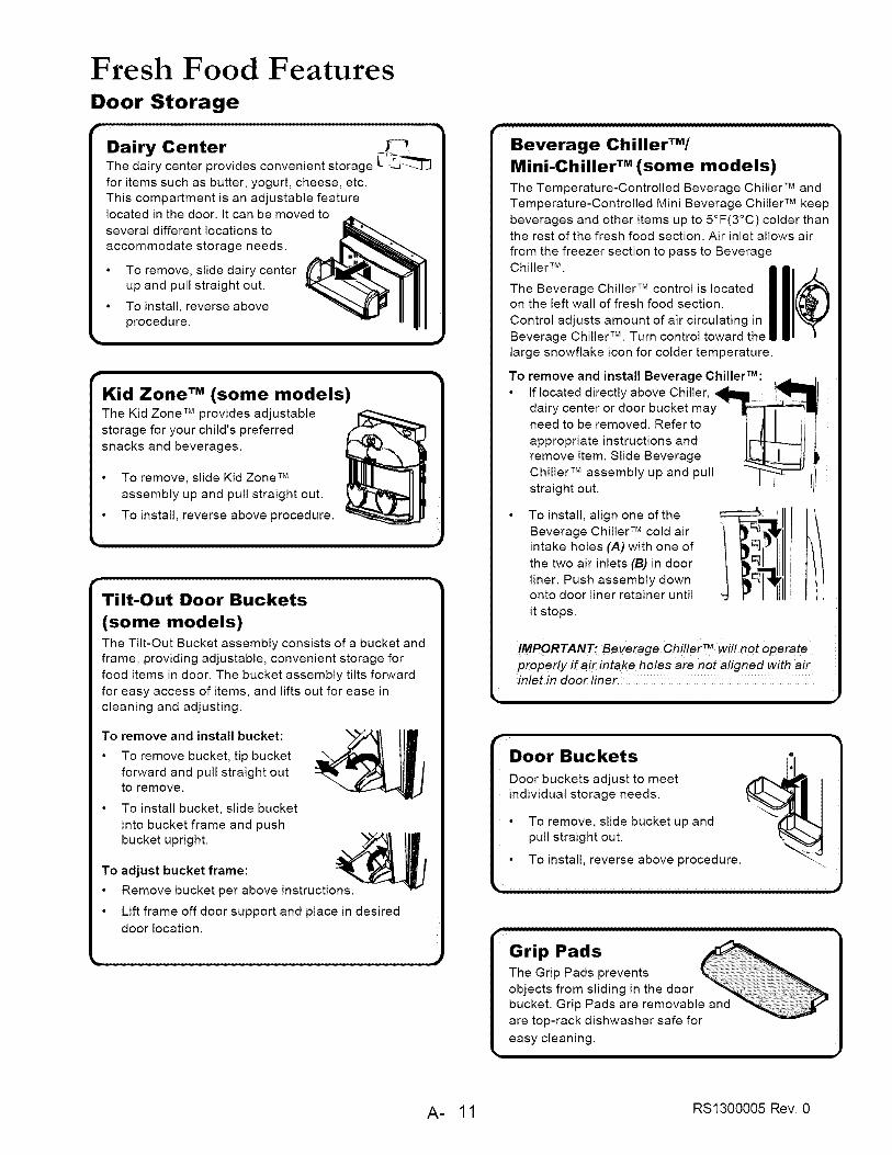
Fresh Food FeaturesDoor Storage
Dairy Center ,J_-_The dairy center provides convenient storage L -_
for items such as butter, yogurt, cheese, etc.
This compartment is an adjustable featurelocated in the door. It can be moved to
several different locations to
accommodate storage needs.
To remove, slide dairy centerup and pull straight out. !1To install, reverse above
procedure. . I
r
Kid Zone TM (some models)The Kid Zone TM provides adjustablestorage for your child's preferred
snacks and beverages.
To remove, slide Kid Zone TM
assembly up and pull straight out.
To install, reverse above procedure.
r
Tilt-Out Door Buckets
(some models)The Tilt-Out Bucket assembly consists of a bucket and
frame, providing adjustable, convenient storage for
food items in door. The bucket assembly tilts forward
for easy access of items, and lifts out for ease in
cleaning and adjusting.
To remove and install bucket:
To remove bucket, tip bucket
forward and pull straight outto remove.
To install bucket, slide bucket
into bucket frame and pushbucket upright.
To adjust bucket frame:
Remove bucket per above instructions.
Lift frame off door support and place in desired
door location.
Beverage ChillerTM/
Mini-Chiller TM (some models)
The Temperature-Controlled Beverage Chiller TM and
Temperature-Controlled Mini Beverage Chiller TM keep
beverages and other items up to 5°F(3°C) colder thanthe rest of the fresh food section. Air inlet allows air
from the freezer section to pass to BeverageChiller TM.
The Beverage Chiller TMcontrol is located I I1/€_
on the left wall of fresh food section. Illk )Control adjusts amount of air circulating in I "Beverage Chiller TM. Turn control toward the I I i_
large snowflake icon for colder temperature.
To remove and install Beverage ChillerTM:
If located directly above Chiller, _ "
dairy center or door bucket may
need to be removed. Referto I JlI ,appropriate instructions and I_lremove item. Slide Beverage _t
Chiller TM assembly up and pull_straight out.
I I
To install, align one of the
Beverage Chiller TM cold airintake holes (A) with one of
the two air inlets (13) in door
liner. Push assembly downonto door liner retainer until
it stops.
IMPORTANT: Beverage Chil!e rTM Will not operate
properly if air intake holes are not aligned with airinlet in door tiner.
Door Buckets
Door buckets adjust to meet
individual storage needs.
To remove, slide bucket up and \_:_1-L"_,]
pull straight out.
To install, reverse above procedure.
i
Grip Pads
The Grip Pads preventsobjects from sliding in the door
bucket. Grip Pads are removable and
are top-rack dishwasher safe for
easy cleaning.
A- 11 RS1300005 Rev. 0
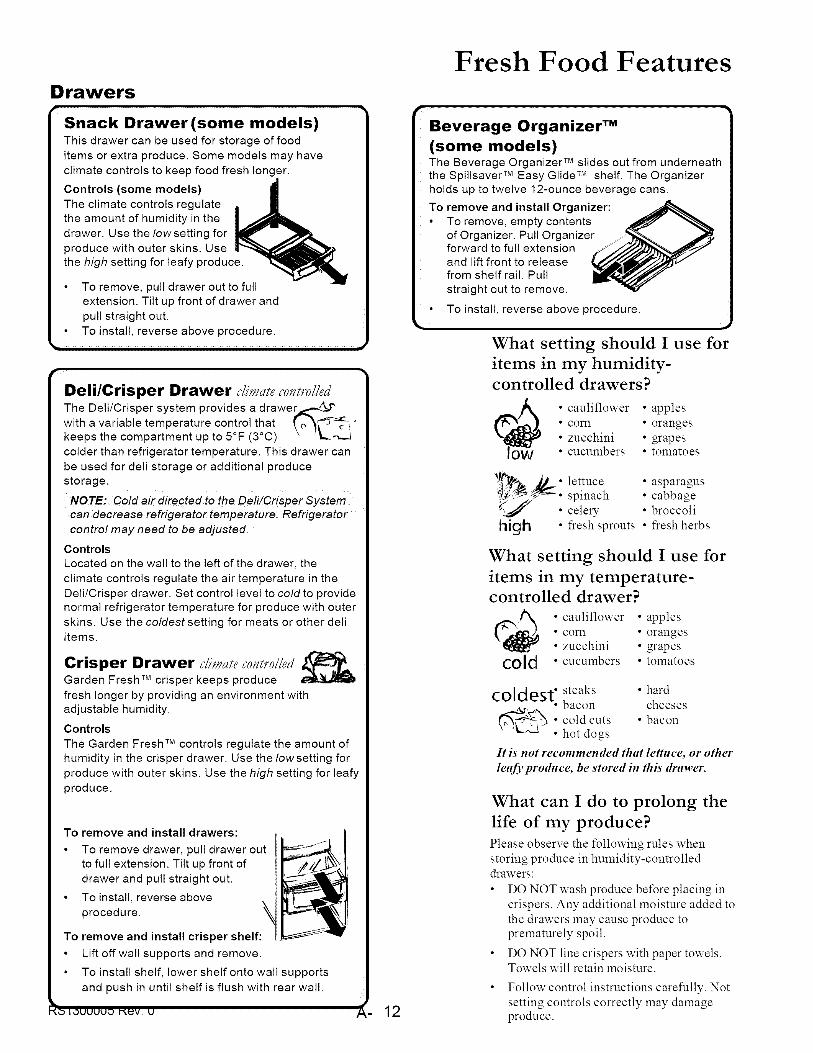
D rawers
Snack Drawer (some models)
To remove, pull drawer out to full
extension. Tilt up front of drawer and
pull straight out.
To install, reverse above procedure.
i,,-
Dell/Crisper Drawer climuh co_m'olledThe DeN/Crisper system provides a drawer_-,4_Y
with a variable temperature control that ( o_t_,'keeps the compartment up to 5°F (3°C) \ 'li_ ,-_._
colder than refrigerator temperature. This drawer can
be used for den storage or additional produce
storage.
NOTE: Cold air directed to the Dell/Crisper System
can decrease refrigerator temperature. Refrigerator
control may need to be adjusted.
Controls
Located on the wall to the left of the drawer, the
climate controls regulate the air temperature in the
DeN/Crisper drawer. Set control level to cold to provide
normal refrigerator temperature for produce with outer
sMns. Use the coldest setting for meats or other denitems.
Crisper Drawer clim_ifec'olm'olled_'_.Garden Fresh TM crisper keeps produce
fresh longer by providing an environment withadjustable humidity.
Controls
The Garden Fresh TM controls regulate the amount ofhumidity in the crisper drawer. Use the Iowsetting for
produce with outer skins. Use the high setting for leafy
produce.
To remove and install drawers:
To remove drawer, pull drawer out
to full extension. Tilt up front of
drawer and pull straight out.
To install, reverse above
procedure.
To remove and install crisper shelf:
Lift off wall supports and remove.
To instaN shelf, lower shelf onto wall supports
and push in until shelf is flush with rear wall.
I_ IOUUUUO l'_V. U 12
Fresh Food Features
Beverage Organizer TM
(some models)The Beverage Organizer TM slides out from underneaththe Spillsaver TM Easy Glide TM shelf. The Organizer
holds up to twelve 12-ounce beverage cans.
To remove and install Organizer:
• To remove, empty contentsof Organizer. Pull Organizerforward to full extensionand lift front to releasefrom shelf rail. Pull
straight out to remove.
• To install, reverse above procedure.
What setting should I use for
items in my humidity-
controlled drawers?
• cauliflower • apples
• corn • oranges• zucchini • grapes• cucumbers • tomatoes
#_,_ _ o lettuce asparagus_j • spinach • cabbagecelery- • broccoli
high • fresh sprouts • fresh herbs
What setting should I use for
items in my temperature-controlled drawer?
• cauliflower • apples• corn • oranges• zucchini • grapes
cold • cucumbers • tomatoes
col<.les,.,,.,<. steaks ° hardbacon cheeses
_&r, _.
_-_ _ " cold cuts • baconx %.J,_3
• hot dogs
It is not recommended that lettuce, or other
leafyproduce, be stored in this drawer.
What can I do to prolong the
life of my produce?Please observe the following rules when
storing produce in humidity-controlled
drawers:
• DO NOT wash produce before placing in
crispers. Any- additional moisture added to
the drawers :nay cause produce to
prematurely spoil.
• DO NOT line crispers with paper towels.
Towels will retain moisture.
• Follow control instructions carefully. Not
setting controls correctly may damageproduce.
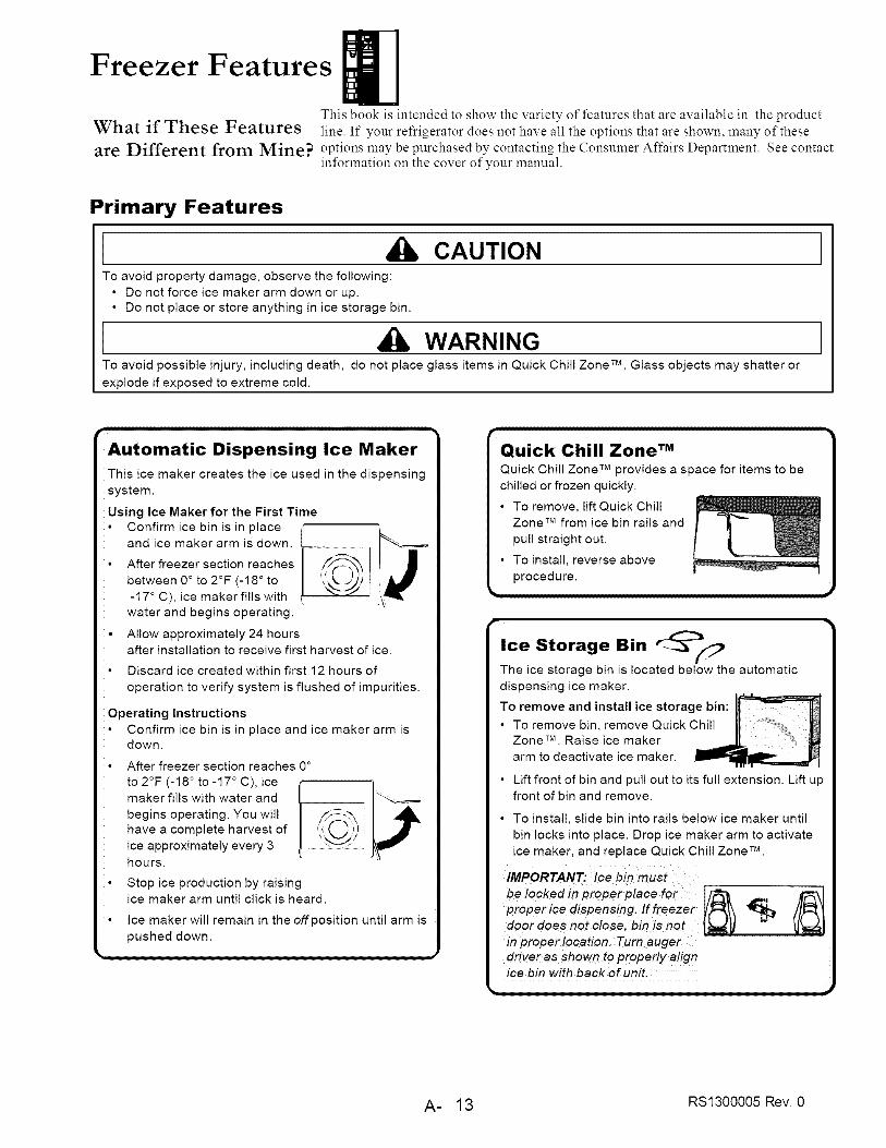
Freezer FeaturesThis book is intended to show the variety of features that are available in the product
What if These Features line. If your refrigerator does not have all the options that are shown, many of these
are Different from Mine? options may be purchased by contacting the Consumer Aft'airs Department. See contactint\_rmation on the cover of your manual.
Primary Features
CAUTIONTo avoid property damage, observe the following:
• Do not force ice maker arm down or up.• Do not place or store anything in ice storage bin.
WARNINGTo avoid possible injury, including death, do not place glass items in Quick Chill Zone TM . Glass objects may shatter or
explode if exposed to extreme cold.
Automatic Dispensing Ice Maker
This ice maker creates the ice used in the dispensing
system.
Using Ice Maker for the First Time
o
i.
Confirm ice bin is in placeand ice maker arm is down.
After freezer section reaches
between 0 ° to 2°F (-18 ° to
-17 ° C), ice maker fills with
water and begins operating.
Allow approximately 24 hoursafter installation to receive first harvest of ice.
Discard ice created within first 12 hours of
operation to verify system is flushed of impurities.
Operating Instructions
• Confirm ice bin is in place and ice maker arm isdown.
• After freezer section reaches 0 °
to 2°F (-18 ° to -17 ° C), icemaker fills with water and
begins operating. You will _--_,_have a complete harvest of _\__ _]ice approximately every 3
hours.
• Stop ice production by raisingice maker arm until click is heard.
• Ice maker will remain in the offposition until arm is
pushed down.
k
Quick Chill Zone TM
Quick Chill Zone TM provides a space for items to be
chilled or frozen quickly.
• To remove, lift Quick Chill
Zone TM from ice bin rails and
pull straight out.
• To install, reverse above
procedure.
Ice Storage Bin _2:_The ice storage bin is located below the automatic
dispensing ice maker.
To remove and install ice storage bin:
• To remove bin, remove Quick ChillZone TM. Raise ice maker
arm to deactivate ice maker.
• Lift front of bin and pull out to its full extension. Lift upfront of bin and remove.
• To install, slide bin into rails below ice maker until
bin locks into place. Drop ce maker arm to activate
ice maker, and replace Quick Chill Zone TM.
IMPORTANT: Ice bin must
be locked in proper place for Ii_t _,,,, fr'_'_lproper ice dispensing. If freezerdoor does not close, bin is not
in proper location. Turn augerdriver as shown to properly alignice bin with back of unff.
J
A- 13 RS1300005 Rev. 0

ShelvesV¸
Stor-Mor _ SystemBaskets slide out for easy access of items in back.
Shelves can be removed to meet individual storageneeds.
To remove and install Stor-Mor ®shelf: I J
• To remove, snap right side of
shelf from cabinet railing andremove from wall mounting _/clips. ,,l_/ |la
To install, reverse above procedure.
NOTE: Back Of sheffmust be flush with back of
cabinet to secure firmly in cabinet railing. Improper
alignment will cause shelf to slide.
To remove and install baskets:
To remove, pull basket forwardto full extension. Lift front handle
to release basket from rails and
remove.
Door Storage
I Door Buckets• Refer to Fresh Food section for instructions. ]
Freezer Features
Hanging Wire Shelf (some models}Hanging wire shelf provides extra storage for ice cubetrays, boxed frozen foods, ice packs, etc.
To remove shelf:
Pinch rung hook of hanging
wire shelf inward to release ,=_'_X_--%N'_,_,_
hanging wire shelf from rightside of Stor-Mor e_shelf. Shelf
will swing downward.
Press rung hook of hanging 1__1wire shelf outward to remove
shelf from freezer section.
To install shelf:
• Perform above steps in reverse order.
I ilt-Out Door Buckets 1(some models)
• Refer to Fresh Food section for instructions.
RS1300005 Rev. 0 A- 14

Dispenser FeaturesPrimary Features
I ispenser Light _ots/Jo_,_
A light activates within the dispenser area at full power when dispensing ice or water.
Front Fill Button (some models)The Front Fill button works independently of the dispenser controls, providing an up-front
alternative to the dispenser pad for dispensing water. This feature is convenient for filling
large items that will not fit into the dispenser area (i.e. sport bottles, pitchers, large pans,
coffee pots).
This feature allows added convenience of dispensing ice and water simultaneously.
To use, choose your preferred ice mode from dispenser control panel. Press container
against dispenser pad while pressing the Front Fill button.
Dispenser PadThe dispenser pad is located on the back wall of the dispensing area. When the dispenser
pad is pressed, the selection chosen on your dispenser control panel will dispense.
Removable TrayThe removable tray at the bottom of the dispenser area is designed to collect
small spills and may b e easily removed for cleaning and emptying purposes.
IMPORTANT: Removable tray does not drain , Continuous waterrunning into tray wi!! cause tray to overflow,
Water Dispenser Operation
[ CAUTIONTo avoid personal injury or property damage, observe following instructions:• Do not put fingers, hands, or any foreign object into dispenser opening.
• Do not use sharp objects to break ice.
• Do not dispense ice directly into thin glass, fine china, or delicate crystal.
NOTE: During initial use of water dispenser, allow an approximate !,2 minute delay in waterdispersal to allow interna! water tank to fill, Discard first ! 0- !4 containers of water after initially
connecting refrigerator to household water supply and extended periods of nonuse.
To use dispenser pad:
Choose water selection from dispenser control panel.
Press sturdy, wide-mouthed container against dispenser pad.
Release pressure on dispenser pad to stop water from dispensing. A small amount ofwater may continue to dispense, and collect in dispenser tray. Large spills should be wiped dry.
To use Front Fill button (some models):
Align container under Front Fill button using blue water droplet as guide.Press and hold Front Fill button.
Release button when desired fill is reached. A small amount of water may continue
to dispense, and collect in dispenser tray. Large spills should be wiped dry.
NOTE; !f wate r dispenser i s active for more than 3 minutes, an automatic lock out sensor
will shut down power to dispenser are& See Automatic Lock Out for further information.
A- 15 RS1300005 Rev. 0

Control Features
Dispenser FeaturesNOTE: These directions pertain to 5.button and 3,button controls only. if your Unit has
LCD controls, please refer to the information booklet located in your literature packet.
Nl'ttlttD _PIFN
rice Dispenser Operation _
l To dispense ice: _l Select Cubed or Crushed ice mode by pushing button on dispenser control panel. A green indicator light above button
l shows mode selection.
l " Press container against dispenser pad. When dispensing crushed ice, hold container as close to chute
l as possible t o [educe spraying. Selection mode may not be changed whil e ic e dispenser is i n 0Peration. I_ N__E; _f dispenseris active f_r m_re than 3 m_nutes_ an aut_mat_c __ck _ut sens_r _i__ shut d__n P__er I I'/ _ _, t
L to clispenser area, See Automatic Lock Out for further information, ' q _ _ i l
Dispenser Lock (some models)
To lock dispenser, press and hold Dispenser Lock button for 3 seconds. A greenindicator light above button confirms dispenser is locked.
above button will 3 out.
Filter Status Indicator Light (some models) ,,_The Filter Status Indicator Light serves as a reminder to replace the water
filter. A green light indicates that the filter is in good condition. A red lightindicates the filter should be changed. Once light turns red, it will remain "_red until function is reset. _";_
To reset indicator:
• Press and hold both Dispenser Lock and Water buttons simultaneously for 4seconds. The green Filter Status Indicator Light will flash 3 times when the functionhas successfully reset.
Auto Light (some models) .The Auto Lightfunction offers the ability to activate the dispenser light at half-power when the Light Sensor ,,,.I_-_ ,_,/':_'
detects that the light levels in room are low. {_, _ ,),._1
To activate and deactivate Auto Light:To activate, press Auto Lightbutton located on control panel. A green indicator NOTE- Dispenserlight will operatelight above button displays to show that sensor is active, whether ornotAuto Lightis selected.
To deactivate, pressAuto Lightbutton. Green indicator light will go out.• ,J
r
Sabbath ModeThis mode is intended to deactivate power to the LED and dispenser lights, ('1_') + (_:_')
while allowing the controls to remain operational.
To activate Sabbath Mode:
• Press and hold both Dispenser Lock and Auto Lightbuttons simultaneouslyfor 3 to 4 seconds. After 3 to 4 seconds, the LED and dispenser lights will turnoff. Dispenser light will not activate during dispensing while in this mode.
To deactivate Sabbath Mode:• Press and hold both Dispenser Lock and Auto Lightbuttons simultaneously for 3 to 4 seconds. After 3 to 4 seconds,
the LED and dispenser lights will activate.
_$1300005 Rev. 0 A- 16
V/h_t Js the Automatic
Lock Out £e_ture?The Automatic Lock Out feature
shuts down power to the water
and ice dispenser when eitherdispenser has run continuously
for approximately 3 minutes. If
this mode goes into effect, the
green light will activate above the
Dispenser Lock button.
To unlock dispenser:
To unlock dispenser, hold
Dispet_ser Lock button for 3seconds. Green indicator
light above button will goout.

Hints and Care
What cleaners does
f* Amana recommend for
f my stainless steel
product?Amana has a cleaner available forpurchase (Part # 31960801) through our
Consumer Affairs division.
For this, or a list of other recommended
cleaning products, please contact us at
Amana Consumer Afthirs using the
information on the cover of your Owner'sManual.
How do I remove an odor
from my refrigerator?1. Remove all food.
2. Disconnect refrigerator.
3. Clean the t_llowing itemsusing the appropriate instructions inHow to ('lean Your Unit :
• Walls, floor, and ceiling of cabinetinterior.
• Drawers, shelves, and gaskets
according to the instructions in thissection.
4. Pay special attention to clean all
crevices by completing the t\_llowing
steps:
• Dilute mild detergent and brush
solution into crevices using a plasticbristle brush.
• Let stand for 5 minutes.
• Rinse surthces with warm water. Drysurt:aces with a soft, clean cloth.
5. Wash and dry all bottles, containers, and
jars. Discard spoiled or expired items.
6. Wrap or store odor-causing foods in
tightly-sealed containers to prevent
reoccurring odors.
7. Connect power to refrigerator and return
t\_od to unit.
8. Alter 24 hours, check if odor has been
eliminated.
If odor is still present...1. Remove drawers and place on top shelf
of refrigerator.
2. Pack refrigerator and freezer sectionsincluding doors with crumpled sheetsof black and white newspaper.
3. Place charcoal briquettes randmnly oncrumpled newspaper in both freezer andrefrigerator compartments.
4. Close doors and let stand 24 48 hours.
5. Repeat steps 5 through 7.
If odor was not eliminated, contactConsumer Affairs Department using theinff_rmation in the front of your Owner'sManual.
How to Clean Your Unit
[ WARNING ]To avoid electrical shock which can cause severe personal injury or death,
disconnect power to refrigerator before cleaning. After cleaning, connect power.
[ CAUTION ]To avoid personal injury or property damage:
• Read and follow manufacturer's directions for all cleaning products.
• Do not place buckets, shelves, or accessories in dishwasher. Cracking or
warping of accessories may result
AREA
Textured Doorsand Exterior
Cabinet Interior
Stainless Steel Doors
and Exterior
IMPORTANT."
Damage to stainless steelfinish due to improper use
of cleaning products ornon -recommended
products is not coveredunder any warranty
Dispenser Controls
Door Gaskets
Condenser Coil Remo*e
toe gri/le to acce*>
Condenser Fan OutletGrille
See back of refrigerator
Accessories She/v'es,
bzmkets, drawers, erc
DO NOT USE
• Abrasive or harsh cleaners
• Ammonia• Chlorinebleach
• Concentrated detergents orsolvents
• Metal or plastic-texturedscouring pads
• Abrasive or harsh cleaners
• Ammonia
• Chlorine bleach
• Concentrated detergents orsolvents
• Metal or plastic-texturedscouring pads
• Vinegar-based product• Citrus-based cleaners
• Abrasive or harsh cleaners
• Ammonia• Chlorine bleach
• Concentrated detergents orsolvents
• Metal or plastic-texturedscouring pads
• Abrasive or harsh cleaners
• Metal or plastic-texturedscouring pads
N/A
• A Dishwasher
DO*.*
• Use 4 tablespoons (60milliliters) of baking sodadissolved in I quart (1 liter)warm soapy water.
• Rinse surfaces with cleanwarm water and dryimmediately to avoid waterspots
• Use warm, soapy water anda soft, clean cloth orsponge.
• Rinse surfaces with cleanwarm water and dryimmediately to avoid waterspots
• Use a vacuum cleaner hosenozzle
• Use a vacuum cleaner hosenozzle with brushattachment.
• Follow removal andinstallation instructions fromappropriate feature section.
• Allowitems to adjust toroom temperature.
• Dilute mild detergent anduse a soft clean cloth orsponge for cleaning.
• Use a plastic bristle brushto get into crevices
• Rinse surfaces with cleanwarm mater.
• Dry glass and clear itemsimmediately to avoid spots.
A- 17 RS1300005 Rev. 0

Hints and Care
How to Remove and Replace Light Bulbs
[ ,ilk WARNING 1To avoid electrical shock which can cause severe personal injury or death,
disconnect power to refrigerator before replacing light bulb. After replacing light
bulb, connect power.
CAUTIONTo avoid personal injury or property damage, observe the following:• Allow light bulb to cool.
• Wear gloves when replacing light bulb.
Upper fresh food section1. Locate finger gaps on each side of clear light
shield. Insert fingers and press in on each sideof shield. Pull shield down and remove.
2. Remove light bulbs.
3. Replace with appliance bulbs no greater than40 watts.
4. Replace light bulb cover by inserting front tabs of
light shield into holes in liner directly in front of light assembly.
Lower fresh food section and
Non-dispensing model freezer section1. Pinch bottom tabs (A) on light cover and pull straight
out.
2. Remove light bulb.3. Replace bulb with appliance bulb no greater than 40
watts.
B
l¸L__J
4. Insert top tabs (B) of light cover into refrigerator liner and Asnap bottom portion over light assembly.
Dispensing model freezer section1. Remove ice bin by lifting front of bin and pulling out.
2. Remove light bulb cover by pinching top tab (A) and
pulling cover out of liner.
3. Remove light bulb. Replace with appliance bulbno greater than 40 watts.
4. insert bottom tab (B) of light cover into liner and snap
top portion over light assembly.
5. Replace ice bin by sliding in until bin locks into place.
A
B
• ,d
Ice 'N Water dispenser 1 ]
1. L2c2t2oi_get:tbulb inside top edgeof dispenser frame. Unscrew I /2 Replace light bu!b with a 6-watt, 120 volt bu!b. U J
RS1300005 Rev. 0 A- 18
!I _._ \_
I ow to Get theMost Out of
J Your EnergyDollar
• When placing refrigerator into finalposition, allow t\)r 1" clearancearound the top and sides of unit to
supply ample ventilation t\)r
optimum energy efficiency.
Avoid overcrowding refrigeratorshelves. This reduces effectivity ofair circulation around food and
causes refrigerator to run longer.
Avoid adding too much warm foodto unit at one time. This overloads
compartments and slows rate ofcooling.
Do not use aluminum toil, waxpaper, or paper toweling as shelfliners. This decreases air flow and
causes unit to run less efficiently.
• A freezer that is 2/3 full runs mostefficiently.
Locate refrigerator in coolest part ofroom. Avoid areas of direct sunlight,or near heating ducts, registers, orother heat producing appliances. Ifthis is not possible, isolate exteriorby using a section of cabinet or anadded layer of insulation.
• Refer to owner's manual section on
temperature controls forrecommended control settings
Clean door gaskets every threemonths according to Owner'sManual cleaning instructions. Thiswill assure that door seals properlyand unit runs efficiently.
• Take time to organize items inrefrigerator to reduce time that dooris open.
• Be sure your doors are closingsecurely by leveling unit asinstructed in your Owner's Manual.
Clean condenser coils of asindicated in the owner's manual
every 3 months. This will increaseenergy efficiency and coolingperformance.

Trouble ShootingToday's refi'igerators have new features and are more energy efficient. Foam insulation is very energy efficient and has
NOISE l'))_ excellent insulating capabilities, however, foam insulation is not as sound absorbent. As a result, certain sounds may beunfamiliar. In time, these sounds will become familiar. Please refer to this infomlation before calling service.
TOPIC
Clicking
POSSIBLE CAUSE SOLUTION
Freezer control (.4) clicks when starting orstoppin,q compressor.
Defrost timer (B) sounds like an electricclock and snaps in and out of defrostcycle.
Freezer fan (C) and condenser fan (D)make this noise while operating.
Normal operation
Normal operation
Air rushing or Normal operationwhirring
Gurgling or Evaporator (E) and heat exchanger (F) Normal operationboiling sound refrigerant makes this noise when flowing.
Thumping Normal operationIce cubes from ice maker(some models)drop into ice bucket (13).
Dispenser ice chute (H_ closinq.
Compressor (I) makes a pulsating soundwhile running.
Refrigerator is not level.
Vibrating noise
Normal operation
Normal operation
See InstallationInstructions for details on
how to level your unit.
Buzzing Ice maker water valve (J) hookup (some Normal operationmodels) buzzes when ice maker fills withwater.
Humming Ice maker (14) is in the 'on' position without Stop sound by raising icewater connection, maker arm to 'off' position.
See Automatic Ice Makersection in your owner'smanual for details.
Normal operationIce auger (L) (some models) hums as
auger a,qitates ice during dispensing.Compresser (I) can make a high pitched
hum while operating.Solenoid valve (M) operating ice chutedoor.
Normal operation
Normal operation
O
OPERATION
Refrigerator is in defrost mode.
Control settin,qs are too low.
Freezer controls are set too low.
Freezer controland lights are on,but compressorsare not operating,
Dell/Crispersystemtemperature istoo warm
Refrigerator doesnot operate
Refrigerator stillwon't operate
Food temperatureis too cold
Drawer is improperly positioned.
Refrigerator is not plugged in.Freezer control is not on.
Fuse is blown, or circuit breaker needsto be reset.
Power outage has occurred
Unit is malfunctioning.
Condenser coils are dirty.
Refrigerator or freezer controls are set
too high.
Beverage Chiller TM (some models) isimproperly positioned.
Normal operation Wait 40 minutes to see if refrigeratorrestarts,
See section on Dell/Crisper system to adiust controls.
See controls section in owner's manual on how to adjust/our controls.
See section on Dell/Crisper system to verify drawerpositioning.
Plug in unit.
See section on controls in your owner's manual.Replace any blown fuses. Check circuit breaker and reset if
necessary.
Call local power company listing to report outage.
Unplug refrigerator and transfer food to another unit. Ifanother unit is not available, place dry ice in freezer sectionto preserve food. Warranty does not cover food loss.Contact service for assistance.
Clean according to cleaning instructions in your owner'smanual.
See controls section in owner's manual on how to adjust/our controls.
See section on Temperature-Controlled Beverage Chiller TM
to verify proper positionin¢i.
A- 19 RS1300005 Rev, 0

Trouble Shooting
TOPIC POSSIBLE CAUSE SOLUTION
Food temperatureappears too warm
Door is not closing properly.
Controls need to be adjusted.
Condenser coils are dirty.
Rear air grille is blocked.
Door has been opened frequently, orhas been opened for long periods oftime.
Refrigerator has an odor
Change air filter.
Water droplets form onoutside of refrigerator
Water droplets form oninside of refrigerator
DelilCrisper System and/orcrisper drawers do notclose freely
Food has recently been added.
Compartment is dirty or has odor-causin,q food.
Air filter (some models) needs to bechan,qed.
Check gaskets for proper seal.
Humidity levels are high.
Controls require adjustment
Humidity levels are high or door hasbeen opened frequently.
Check gaskets for proper seal.
Refrigerator is not level. See Installation Instructions for detailson how to level your unit.
Check gaskets for proper seal. Clean, if necessary, according tocleaning instructions in owner's manual.
Check for internal obstructions that are keeping door fromclosing properly (i.e. improperly closed drawers, ice buckets,oversized or improperly stored containers or foodstuffs, etc.).
See the controls section in your owner's manual for assistancein how to adiust your controls.
Clean accordinq to cIeaninq instructions in your owner's manual.
Check the positioning of food items in refrigerator to make suregrille is not blocked. Rear air grille is located behind crisperdrawers.
Reduce time door is open. Organize food items efficiently toassure door is open for as short a time as possible.
Allow interior environment to adjust for period the door has beenopen.
Allow time for recently-added food to reach refrigerator orfreezer temperature.Refer to odor removal instructions in owner's manual.
Clean, if necessary, according to cleaning instructions inowner's manual.
Normal durinq times of hiqh humidity.
See the controls section in your owner's manual for assistancein how to adjust your controls.
See the controls section in your owner's manual for assistancein how to adjust your controls.
Reduce time door is open. Organize food items efficiently toassure door is open for as short a time as possible.
Clean, if necessary, according to cleaning instructions inowner's manual.
Refer to noise section of troubleshooting guide in owner'smanual.
Refrigerator or ice maker Normal operationmake unfamiliar sounds orseems too loud
Reposition food items and containers to avoid interference withthe drawers.
Contents of drawer, or positioning ofitems in the surrounding compartment
could be obstructing drawer
Drawer is not in proper position
Refrigerator is not level.
Drawer channels are dirty or needtreatment.
Doors have been opened frequently orhave been opened for long periods oftime.
Refrigerator runs toofrequently
Humidity or heat in surrounding area ishigh.
Food has recently been added.
See section on Dell/Crisper System and/or crisper drawersection for proper placement.
See Installation Instructions for details on how to level your unit.
Clean drawer channels with warm, soapy water. Rinse and drythoroughly.
Apply a thin layer of petroleum ieIly to drawer channels.
Reduce time door is open. Organize food items efficiently toassure door is open for as short a time as possible.
Allow interior environment to adjust for period the door has beenopen.
Normal operation
Allow time for recently-added food to reach refrigerator orfreezer temperature.
Unit is exposed to heat by Evaluate your unit's environment. Unit may need to be moved toenvironment or by appliances nearby, run more efficiently.
Condenser coils are dirty. Clean according to cleaning instructions in your owner'smanual.
RS1300005 Rev. 0 A- 20

Trouble Shooting
TOPIC
Refrigerator runs toofrequently (continued)
POSSIBLE CAUSE
Controls need to be adjusted.
Door is not c(osing properly
SOLUTION
See the controls section in your owner's manual for assistance
in how to adjust your controls.
Refrigerator is not level. See Installation Instructions for details
on how to level your unit
Check for internal obstructions that are keeping door from
closing properly (i.e. improperly closed drawers, ice buckets,oversized or improperly stored containers or foodstuffs, etc.).
Check gaskets for proper seal. Clean, if necessary, according
to cleaning instructions in owner's manual.
ICE &
Water appears cloudy
Particles in water and/or ice
cubes.
Air or air bubbles in water.
Carbon dust from water filter cartridge.
This is normal when first using dispenser and wil! disappear
with use.
Initial water ejected through cartridge may contain harmless
carbon dust flushed from cartridge. Particles are safe forconsumption. Wil! disappear after the first few uses.
Particles are not harmful and naturally occur in water supplies.Concentrations of minerals in water will form
particles when water becomes frozen andmelts.
No indicator lights are lit on Freezer door is not closed. Verify that freezer door is closed. Power is removed from thedispenser control (some control when freezer door is opened.
models) Refrigerator is not plugged in. Plug in unit.
Fuse is blown, or circuit breaker needs to be Replace any blown fuses. Check circuit breakers for any
reset, tripped circuits.
Power outage has occurred. Call local power company listing to report outage.
Refrigerator is in Sabbath Mode. See dispenser control instructions for further information.
Neither ice nor water is Freezer door is not closed. Verify that freezer door is closed. Power is removed from the
dispensed when pads are control when freezer door is opened.
pushed (some models) Controls are in lock mode. See dispenser control instructions for further information.
Water tank is fi!ling. At initial use, there is an approximate 45-second delay in
dispensing while the internal water tank is filling.
Ice maker or ice maker-equipped unit has just Wait 24 hours for ice production to begin and for ice maker to
recently been installed or a large amount of ice restock after emptied.
has just been used.
Water filter is clogged or needs to be changed. Change water filter.
Ice maker is not producing Ice maker has just recently been installed or a Wait 24 hours for ice production to begin and for ice maker to
enough ice or ice is malformed large amount of ice has just been used. restock after emptied.(some models)
Water pressure is too low. Low water pressure can cause valve to leak. Water pressuremust be between 20 to 100 pounds per square inch to function
properly. A minimum pressure of 35 pounds per square inch isrecommended for units with water filters.
Water filter is clogged or needs to be changed. Change water filter.
Ice maker is not producing ice Ice maker arm is not in correct position Confirm ice maker arm is down. See Automatic Ice Maker
(some models) section in your owner's manual for details.
Household water supply is not reaching water Check water connection procedure in your Installationvalve Instructions.
Copper or plastic tubing has kinks. Turn off water supply and remove kinks. If kinks cannot be
removed, replace tubing.
Water pressure is too low. Water pressure must be between 20 to I00 pounds per square
inch to function properly. A minimum pressure of 35 pounds
per square inch is recommended for un)ts with water filters.
Check freezer temperature. See the controls sect)on )n your owner's manual for assistanceon how to adjust your controls. Freezer must be between 0 to
2°F (-I8 to-I7°C)to produce ice.
Ice bin is not installed properly See ice bin section for proper installation and alignment.
A- 21 RS1300005 Rev. 0

Trouble Shooting
TOPIC POSSIBLE CAUSE SOLUTION
Ice maker is not producingice (some models-continued)
Improper water valve was installed. Check water connection procedure in your InstallationInstructions. Self-piercing and 3116"saddle valves cause low
water pressure and may clog the line over time. Amana is notresponsible for property damage due to improperinstallation or water connection.
Unit is leaking water Plastic tubing was used to complete water Amana recommends using copper tubing for installation.connection. Plastic is less durable and can cause leakage. Amana is
not responsible for property damage due to improperinstallation or water connection.
Improper water valve was installed. Check water connection proce_Jure in your InstallationInstructions. Self-piercing and V1G"saddle valves cause lowwater pressure and may clog the line over time. Amana isnot responsible for property damage due to improperinstallation or water connection,
Ice forms in inlet tube to ice Water pressure is low. Water pressure must be between 20 to 100 pounds permaker square inch to function properly. A minimum pressure of 35
pounds per square inch is recommended for units withwater filters.
Freezer temperature is too high. See the controls section in your owner's manual forassistance on how to adjust your controls. Freezer isrecommended to be between Oto 2°F (-18 to -17°C).
Water flow is slower than Water pressure is low. Water pressure must be between 20 to 100 pounds pernormal square inch to function properly. A minimum pressure of 35
pounds per square inch is recommended for units withwater filters.
Improper water valve was installed. Check water connection proce£ture in your InstallationInstructions. Self-piercing and V16" saddle valves cause lowwater pressure and and may clog the line over time.Amana is not responsible for property damage due toimproper installation or water connection.
Copper or plastic tubing has kinks. Turn off water supply and remove kinks. If kinks cannot beremoved, replace tubing.
Water filter is clogged or needs to be Change water filter.changed.
Dispenser water is not cold Refrigerator has been recently installed Allow approximately !2 hours for water in holding tank tochill.
Water supply in holding tank has beendepleted.
Water has settle into water lines outside
holding tank and has warmed to roomtemperature.
Discard first glass of water and refill.
RS1300005 Rev. 0 A- 22

Water Filter Data
System Specification and Performance Data Sheet
Refrigerator Water Filter Cartridge Model WF50
SpecificationsService Flow Rate (Maximum) ............................................. 0.75 GPM (2.83 Limin)
Rated Service Life WF50-NI300 (Maximum) ........................ 300 gallons/1135 liters
Rated Service Life WF50-WI500 (Maximum) ....................... 500 gallons/1892 liters
Maximum Operating Temperature ........................................ 100° F/38 ° C
Minimum Pressure Requirement .......................................... 35 psi/138 kPa
Maximum Operating Pressure .............................................. 120 psi/827 kPa
General Use Conditions: Read this Performance Data Sheet and compare the capabilities of this unit with your actualwater treatment needs.
DO NOT use this product where water is microbiologically unsafe or of unknown quality without adequate disinfectionbefore or after the system. System certified for cyst reduction may be used on disinfected water that may containfilterable cysts.
The Amana _ Clean 'n Clear TM retractable water filtration system uses a WF50 replacement cartridge (see Amana _ contact
information at the front of your manual to order). Timely replacement of filter cartridge is essential for performance satisfaction
from this filtration system. Please refer to the applicable section in this owner's manual for general operation, maintenance
requirements and troubleshooting.
This systems has been tested according to ANSI/NSF 42 and 53 for reduction of the substances listedbelow. The concentration of the indicated substances in water entering the system was reduced to aconcentration less than or equal to the permissible limit for water leaving the system, as specified inANSI/NSF 42 and 53.
Performance Data*
3ubstance
_ead
_ead
2,vst
I-urbidity
_indane
Influent
Water
0.15 m,q/L
0.15 ma/L
25000 count/mL
11.8 NTU
0.00063 mu/L
Effluent
Averaue
0.001 m,q/L
0.002 malL
lcount/mL
0.12 NTU
0.00005 malL
Average%
Reduction
99.33%
98.66%
99.99%
98.98%
92.06%
Maximum
Effluent
0.001 m,q/L
0.003 me/L
3 count/mL
0.18 NTU
0.00005 mo/L
Min. Required inletReduction DH
0.010 m,q/L 6.5
0.010 ma/L 8.5
> 99.95% NA
0.5 NTU NA
0.00001 mulL NA
ktrazine
_,hlorine
=articulate**
__.4-D
ksbestos
0.0097 moiL
1.9 ma/L
286667 count/mL
291.6667 ua/L
458 MFLtmL
0.0002 me/L
0.09 ma/L
900 count/mL
45.45 ua/L
O.16 MFL/mL
97.93%
95.26%
99.68%
84.42%
99.96%
0.0006 ma/L
0.17 ma/L
2400 count/mL
100 ua/L
0.16 MFL/mL
0.003 ma/L NA
275% NA
285% NA
0.0017 ma/L NA
99% NA
* Tested using a flow rate of 0.75 GPM (2.83 L/min.) and a maximum pressure of 120 psi (827under standard laboratory conditions, however, actual performance may vary. Health ClaimPerformance tested and certified by NSF international
** Particle size range classification of test. Particles used were 0.5 -1 microns.
kPa)
California Certificate number 01-1486
A- 23 RS1300005 Rev. 0

Amana Refrigerator Warranty
First YearAmana will replace, free of charge, any part which is defective due to workmanship or materials.
Second through Fifth YearAmana will replace free of charge, any sealed system component (compressor, condenser, evaporator, drier andinterconnecting tubing) and repair any food compartment liner (exclusive of door liner) which is defective due toworkmanship or materials.
Warranty Limitations
Begins at date of original purchase.Excludes original and replacement water or air filtercartridges (if equipped with the filtration system).Original and replacement cartridges are warrantedfor 30 days, parts only, against defects of materialor workmanship.Service must be performed by an authorized Amanatechnician.
Damage due to shipping and handling is not coveredby this warranty.
Warranty Is Void If
Repairs resulting from the following:• Serial plate is defaced.• Product is used on a commercial, rental, or
leased basis.
• Product has defect or damage due to productaccident, alteration, connection to an improperelectrical supply, fire, flood, lightning, or otherconditions beyond the control of Amana.
• Product is improperly installed or used.
Owner's ResponsibilityProvide proof of purchase (sales receipt).Provide normal care and maintenance. Replaceowner replaceable items where directions appear inOwner's Manual.
Make product reasonably accessible for service.Pay premium service costs for service outsidetechnician's normal business hours.
Pay for service calls related to product installationand usage.
Amana Appliances Factory Service1-800-628-5782 inside USA
For more information,Amana Appliances Consumer ServicesAmana Appliances2800 220th TrailAmana, Iowa 522041-800-843-0304 inside USA(3t9) 622-5511 worldwidewww.amana.com
IN NO EVENT SHALLAMANA BE LIABLE FOR INCIDENTAL OR CONSEQUENTIAL DAMAGES.
This warranty gives you specific legal rights, and you may have others which vary from state to state. For example, some states
do not allow the exclusion or limitation of incidental or consequential damages, so this exclusion may not apply to you.
RS1300005 Rev. 0 A- 24
