army - fm3 04x513 - battlefield recovery and evacuation of aircraft
TRANSCRIPT
FM 3-04.513 [1-513]
BATTLEFIELD RECOVERY ANDEVACUATION OF AIRCRAFT
DISTRIBUTION RESTRICTION: Approved for public release; distribution is unlimited.
HEADQUARTERS, DEPARTMENT OF THE ARMY
i
*FM 3-04.513 (FM 1-513)Field Manual HeadquartersNo. 3-04.513 Department of the Army
Washington, DC, 27 September 2000
Battlefield Recovery andEvacuation of Aircraft
Contents
Page
PREFACE ................................................................................................................. iii
Chapter 1 BATTLEFIELD MANAGEMENT OF DOWNED AIRCRAFT ................................ 1-1
Battlefield Management ......................................................................................... 1-1Definitions .............................................................................................................. 1-2Planning Process ................................................................................................... 1-3Responsibilities for Recovery Operations.............................................................. 1-5Contingency Planning for Immediate and Delayed Aircraft Recovery Operations 1-7Maintenance − DART Team .................................................................................. 1-9DART − Specific Planning Considerations .......................................................... 1-11DART − Critical Planning Considerations ............................................................ 1-12DART − Equipment and Manning Considerations............................................... 1-13RCC – Specific Planning Considerations ............................................................ 1-14BDAR – Specific Planning Considerations .......................................................... 1-15Preparation Phase ............................................................................................... 1-17Pre-Combat Checks/Pre-Combat Inspections..................................................... 1-18Mission Execution Triggers.................................................................................. 1-21Mission End State ................................................................................................ 1-26
DISTRIBUTION RESTRICTION: Approved for public release; distribution is unlimited.______________*This publication supersedes FM 1-513, 20 May 1993.

FM 3-04.513(1-513)___________________________________________________________________________________
ii
Page
Chapter 2 GENERAL RECOVERY AND EVACUATION PROCEDURES ............................... 2-1Maintenance Evacuation ........................................................................................... 2-1Battlefield Recovery................................................................................................... 2-2Threat ........................................................................................................................ 2-2Command, Control, and Coordination....................................................................... 2-3Accident Investigation Board..................................................................................... 2-7Recovery in the Division............................................................................................ 2-7Recovery in Echelons above Division ....................................................................... 2-7Recovery in a Nuclear, Biological, and Chemical Environment ................................ 2-8Night Recovery.......................................................................................................... 2-8Recovery Methods..................................................................................................... 2-8On-Site Recovery Procedures................................................................................. 2-10Ground Crew General Procedures.......................................................................... 2-16Ground Crew Functions .......................................................................................... 2-23Ground Recovery Responsibilities .......................................................................... 2-30Post-Recovery Inspection and Packaging .............................................................. 2-30Administrative Requirements .................................................................................. 2-31
Chapter 3 AERIAL/GROUND RECOVERY EQUIPMENT ........................................................ 3-0Aerial Recovery Kit .................................................................................................... 3-0Interim-Unit Maintenance Aerial Recovery Kit .......................................................... 3-8Unit Maintenance Aerial Recovery Kit..................................................................... 3-19Helicopter Recovery Kit ........................................................................................... 3-31
Chapter 4 TYPICAL AIRCRAFT RIGGING PROCEDURES .................................................... 4-1Procedures ................................................................................................................ 4-1Rigging Aircraft for Ground Recovery ....................................................................... 4-9
Chapter 5 AIRCRAFT RECOVERY METHODS AND APPLICATIONS ................................... 5-0Aerial Recovery ......................................................................................................... 5-1Ground Recovery ...................................................................................................... 5-7
Appendix A AIRCRAFT RECOVERY AFTER ACTION SURVEY ...............................................A-0Appendix B HAND AND ARM SIGNALS .....................................................................................B-1Appendix C SAMPLE SOP FOR BATTLEFIELD AIRCRAFT RECOVERY EVACUATION..... C-1Appendix D RISK MANAGEMENT/RISK ASSESSMENT .......................................................... D-1Appendix E ENVIRONMENTAL ISSUES .....................................................................................E-1
GLOSSARY ..................................................................................................Glossary-1BIBLIOGRAPHY ..................................................................................... Bibliography-1INDEX................................................................................................................. Index-0

iii
Preface
This manual provides fundamental data for effective and safe recovery of downedaircraft and maintenance evacuation of disabled aircraft. Aircraft recovery is anoperation that results from an aircraft having experienced a reliability-induced orcombat-damage induced forced landing on the battlefield. It also may have beendisabled as the result of an accident or component/system malfunction. Theoperation includes an assessment, repair, and fly-out, if possible, or recovery byaerial or ground means to an appropriate maintenance facility for repair andeventual return to service. Maintenance evacuation is the physical act of movingaircraft from one maintenance location on the battlefield to another. Movement iseither by aerial or ground means. The move is to effect repair, cross-levelmaintenance workloads, or relieve units of disabled aircraft during tactical moves.
Aircraft recovery and maintenance evacuation are closely related since, in eachcase, the aircraft must be rigged for lift by helicopter or rigged for lift by a cranedevice and secured aboard a ground vehicle. Aircraft recovery, however, requiresextensive coordination. It is usually time sensitive to the tactical situation.Evacuation, on the other hand, may not have the same urgency. It is usuallycoordinated between maintenance activities.
This manual is only a guide and is intended for use by commanders at all levels.In actual practice, the procedures outlined might be modified or augmented toaccount for the size of the force; availability of aerial and ground assets;manpower, time and distance considerations; and above all, the tactical situation.
Recovery or evacuation by aerial means is likely to be accomplished in less time.Recovery or evacuation by ground vehicle, however, remains an option. Thepurpose of recovery or maintenance evacuation is to preclude the loss of uniqueassets on the battlefield and retain the persuasive combat power of aviation in alldimensions of the battlespace.
The airspeeds stated in this manual are airspeeds at which particular loads havedemonstrated stability in flight. Variables affect stability. For this reason, theaircrew must monitor the stability of each load and adjust airspeed accordingly.The decision for airspeed at any time during a lift operation is reserved for theaviator.
Warnings, cautions, and notes are used throughout this manual for emphasis. Awarning is an operating procedure or practice which, if not followed, could resultin personal injury or loss of life under certain conditions. A caution is an operatingprocedure or practice. If not observed, it could result in damage or destruction ofequipment under certain conditions. A note is an operating procedure, practice, orcondition that warrants special attention.
FM 3-04.513(1-513)___________________________________________________________
iv
Numerous terms, acronyms, and abbreviations are found within this manual.Users should refer to the glossary for their meaning or definition.
This manual implements STANAG 3117 (Aircraft Marshalling Signals) (Edition5).
The procedures outlined in this manual are applicable at all levels of conflict incombat environments.
The proponent of this manual is Headquarters, TRADOC. Users are encouragedto recommend changes and submit comments for improvement. Key comments tothe specific page, paragraph, and line of the text in which the change isrecommended. Provide a reason for each comment to ensure understanding andcomplete evaluation. Army units should prepare comments using DA Form 2028(Recommended Changes to Publications and Blank Forms) and forward toCommander, US Army Aviation Center, ATTN: ATZQ-TDS-DB, Fort Rucker,Alabama 36362-5263.
Unless otherwise stated, whenever the masculine gender is used, both men and women are included.
This publication has been review for operations security consideration.

1-1
Chapter 1
Battlefield Management of Downed AircraftThe loss of an aircrew and/or airframe impacts the combat capability ofaviation units. The psychological impact from the loss of an aircrew maybe a severe detriment to unit morale. High loss rates can rapidly depleteavailable operational readiness float (ORF) assets. This chapter discussesthe importance of including downed aircraft recovery missions into thebattalion and brigade staff tactical decision making process. It alsoprovides the relationship of combat search and rescue (CSAR) to downedaircraft recovery teams (DARTs), and battle damage assessment andrepair (BDAR) personnel augmentation to DART missions. In addition,this chapter discusses the role of DART (BDAR) when planning for anaircraft recovery mission.
NOTE: This FM and FM 3-04.113(1-113), Utility and Cargo Helicopter Operations, areinterrelated. CSAR information in chapter 1 of this FM is generalized from FM 3-04.113(1-113)to aid commanders in distinguishing between the roles of CSAR and DART when planning adowned aircraft recovery mission. Commanders should refer to FM 3-04.113(1-113) for specificdoctrinal guidance on CSAR missions.
BATTLEFIELD MANAGEMENT1-1. Historically, the effort at recovering aircrews or aircraft off thebattlefield has been minimal and poorly coordinated at best. Today, CSARand DART/BDAR provide the methods for retrieving aircrews and aircraft aswell as regenerating those resources necessary to maintain momentum onthe battlefield. FM 3-04.113(1-113), chapter 7, provides commandersguidance on CSAR missions. Army and Joint CSAR procedures can be foundin Joint Publication (JP) 3-50.2, Doctrine for Joint Combat Search andRescue, and in JP 3-50.21, Joint Tactics, Techniques, and Procedures forCombat Search and Rescue. Airspace control can be found in JP 3-52,Doctrine for Joint Airspace Control in the Combat Zone.
EXTRACTION/RECOVERY PRIORITIES1-2. According to FM 3-04.113(1-113), the CSAR task force (TF) commanderexecutes the extraction of personnel followed by the recovery of equipment.This is true when both personnel and equipment are at the same location.Aircraft extracting personnel (for example, UH-60 Black Hawk) should becleared into the extraction site immediately after the area has been secured.Equipment recovery operations may be conducted simultaneously with thepersonnel extraction operation or delayed until the personnel extraction hasegressed the extraction site. In either case, any aircraft ingressing theextraction/recovery site will remain off-station until specifically cleared forthe approach by the CSAR TF commander. Conversely, any aircraftegressing the extraction/recovery site will remain at the site until cleared fordeparture by the CSAR TF commander.

FM 3-04.513(1-513) _________________________________________________________________________
1-2
1-3. Simply stated, the extraction and recovery priorities are recovery of theaircrew and simultaneous evaluation of the aircraft. Determine if theaircraft is still an asset. If so, secure the aircraft or area, evacuate theaircraft, and repair the aircraft.
DEFINITIONS
1-4. Acronyms used in the battlefield management of downed aircraft aredefined as follows:
• Combat Search and Rescue (CSAR). CSAR is the successfulextraction of a downed aircrew and evacuation of the aircrew either toappropriate medical care or back to the unit. CSAR operations canbe placed into separate categories—immediate and delayed.Commanders must recognize and prepare for both immediate anddelayed types of CSAR operations.
• Downed Aircraft Recovery Team (DART). The DART teamnormally comprises selected command personnel. (These personnelinclude technical inspector, maintenance test pilot or pilot,maintenance personnel, radio operator and security force). The teamsuccessfully extracts an aircraft from a downed location to a safelocation, using aerial recovery kits, trained recovery team, andrecovery aircraft. Augmentation of the DART mission with BDARtrained repair personnel can recover downed aircraft using BDARmeasures. These measures expedite the recovery and return of aircraftto the tactical assembly area (TAA). In addition, they prevent theaircraft from falling into enemy hands and retain control of the aircraftfor future use as controlled exchange program for other aircraft andinduction into a BDAR program for eventual reintegration into thebattle.
• Battle Damage Assessment and Repair (BDAR). BDAR is the useof specialized aircraft damage assessment criteria, repair kits, andtrained personnel to modify peacetime aircraft maintenance standards.The concept includes the safe return of damaged aircraft to a safelocation and eventually to battle as soon as possible.
• Rescue Coordination Center (RCC). The Army componentcommander who plans, coordinates, and directs the execution of CSARand DART operations establishes an RCC within the commander’s areaof operations (AO). The component commander may not directlyestablish an RCC. If an RCC is not established, the Army commandermust designate an existing headquarters or staff section to perform theduties of the RCC. The RCC will� Notify the Joint Search and Rescue Center (JSRC) as soon as
possible when conducting CSAR and DART operations.� Extract information from the JSRC Evasion and Recovery (E&R)
plan that is Army specific and disseminate that information to allArmy units in theater.

_________________________________________________________________________________Chapter 1
1-3
� Request Joint Combat Search and Rescue (JCSAR) Support fromthe JSRC when Army assets cannot accomplish the CSAR
� Forward pertinent data regarding isolated personnel to the JSRC.� Develop and plan mission packages in parallel with the tactical
mission.� Manage the information flow to the two mission packages
(CSAR/DART).� Manage the information flow of the DART mission with
augmentation of BDAR personnel if require.� Integrate the enemy situation, from the TF tactical operations
center (TOC), into the downed aircraft decision making process.� Execute mission packages.
• Trigger. According to FM 6-99.1(101-5-1), a trigger is an event ortime-oriented criteria used to initiate planned actions directed towardachieving surprise and inflicting maximum destruction on the enemy.It is also a designated point or points (selected along identifiableterrain) in an engagement area (EA) used to mass fires at apredetermined range. A ‘trigger,’ as it applies to this manual, would bean event or time-oriented criteria used to initiate planned actionstoward achieving successful extraction of downed aircrew and therecovery of downed aircraft.
• Assessor. An assessor is one who can assess aircraft battle damage.One of the assessor’s primary tasks is to determine the location of thedamaged aircraft relative to the battlefield and the extent of the threat.Modern air defense threats may make aerial recovery in forward areasof the battlefield an impractical or unacceptably high risk. The abilityto determine rapidly that a one-time evacuation mission is feasible orthat a quick-fix repair is possible is important. It may prevent asituation in which the aircraft would otherwise be destroyed (in place)to prevent capture by, or compromise to, the enemy. Once the battlesubsides, maintenance decisions are based on standard operationalmaintenance practices. An assessor can be one or a combination of thefollowing: the aircrew of the downed aircraft; aircrew of anotheraircraft; the CSAR crew; the DART aircrew. The assessor’s mission isto provide the commander with an initial assessment of the downedaircraft. Based on mission, enemy, terrain and weather, troops andsupport available – time available and civilian considerations (METT-TC), the assessor can, when appropriate, provide a more detailedassessment.
PLANNING PROCESS
INITIAL CONDITIONS/PRE-CONDITIONS1-5. Aircraft recovery planning begins when the Army force deploys orimmediately after it arrives in the area of responsibility (AOR). Commandersof aviation units emphasize both the CSAR and the aircraft recovery process

FM 3-04.513(1-513) _________________________________________________________________________
1-4
while ensuring that their units are prepared if an aircraft is lost during thefight.1-6. Aircraft recovery operations are unique. Each operation is discrete andmay involve the initiative and imagination of commanders and staff tosynchronize the operation within a range of variables. Aircraft recovery onthe battlefield is a recurring maintenance function. It is usually planned for,in advance, in conjunction with other maintenance support. Recoveryoperations are planned and coordinated in detail to minimize risk. METT-TCalways influences the extent of detail and coordination. In addition, thefollowing factors are considered:
• Commander’s assessment of the threat.• Tactical situation.• Condition and location of disabled aircraft.• Disabled aircraft accessibility.• Airspace restrictions.• Recovery assets.• Air tasking order (ATO) missions.
� Type of equipment required.� Location and availability of aircraft.
• Requirements for� Fire support.� Air defense.� Engineer support.� Ground security.� Intelligence/aerial and ground surveillance.� Army Airspace Command and Control System (A2C2S).� Battlefield coordination through the S3/G3 to minimize possibility
of fratricide.1-7. C2 relationships, unit responsibilities, and coordination are planned forin advance to the extent possible and included in standing operatingprocedures (SOPs) and operations orders (OPORDs). When an aircraftbecomes disabled on the battlefield, commanders and staffs supplementpreplanning with a plan of execution. The operation is controlled at theappropriate level (normally the RCC).
1-8. Physical procedures for battlefield recovery of aircraft and maintenanceevacuation are nearly identical. Both may require the rigging of the aircraftfor lift by helicopter or lift by a crane device for placement on a groundtransport vehicle.
1-9. Recovered aircraft normally are transported from the recovery point to apreselected maintenance site without intermediate stops. Air recovery (andevacuation) capitalize on back-haul from forward areas to the extent possible.This operation reduces separate demands on aircraft, especially CH-47

_________________________________________________________________________________Chapter 1
1-5
Chinook aircraft that may be heavily committed to re-supply and othertransport missions.
RESPONSIBILITIES FOR RECOVERY OPERATIONS
AIR MISSION COMMANDER/AVIATION UNIT COMMANDER1-10. The first line of responsibility for a recovery operation is the air missioncommander/aviation unit commander. This commander may have at hisdisposal (from within the assets of the operation) on-call DART organizationsand lift assets capable of recovering the disabled aircraft. In such cases, thecommander employs those assets to assess and effect recovery within timeand tactical situation constraints.
RESCUE COORDINATION CENTER1-11. When beyond the capability of the air mission or unit commander, theresponsibility to coordinate recovery defaults to the rescue coordinationcenter (RCC). The RCC is a contingency organization in the aviation brigadeTOC. Depending on the size of the force, the RCC also may be found indivision and corps TOCs. In this case, RCC is primarily a communicationsnode for staff elements to receive voice, manual, and automated messages;coordinate resources; coordinate battlefield functions of maneuver, firesupport, air defense, intelligence, and combat service support within tacticalpriorities and the scheme of maneuver to support recovery operations. (SeeFig. 1-1.) The principal in the RCC is the staff aviation maintenance officer.
Figure 1-1. RCC Communications
Task Force CDRTOC ALOC
RCC
CSAR DART(BDAR)
The RCC closely monitors the situation and then activates according tothe TF CDR’s approved decision matrix.
RCCAVUM/AVIMTasked Aircraft & CrewsSecurity Force
RCC Communications

FM 3-04.513(1-513) _________________________________________________________________________
1-6
AIRCRAFT COMMANDER AND AIRCREW
1-12. When an aircraft is forced down, the aircraft commander, or one of hiscrew, will use the aircraft radio (if operable and the tactical situationpermits) to notify the parent AVUM commander of the problem and requestDART assistance. This information may be relayed through other aircraftoperating in the area as time and security allow. The crew takes the first stepin the assessment process by providing the AVUM commander with keycritical information on the problem. The information should include
• Critical Information:� Location of aircraft.� Assessment of site security.� Adaptability of the site, including existing weather conditions, for
the insertion of a DART team with the option of augmenting withBDAR personnel.
� An evaluation of aircraft damage, to the extent possible, so thatneeded BDAR personnel, equipment, and parts requirements canbe estimated.
� Information on crew and passenger (s) condition to determinetheir capability to assist in repairing the damage. For example,the aircraft commander may be able to fly the aircraft out,eliminating the need for an aviator as part of BDAR.
� Information provided by air traffic controllers.• Minimum Required Information for In-Flight Emergencies:
� Aircraft identification and type.� Nature of emergency.� Pilot’s desires.� Aircraft position (grid or latitude and longitude coordinates).
• Other Information. Depending on the status of aircraftcommunications, the following items or any other pertinentinformation will be obtained from the pilot or aircraft operator:� Aircraft altitude.� Fuel remaining in time.� Pilot reported weather.� Pilot capability for instrument-flight requirements (IFR) flight.� Time and place of last known position.� Heading since last known position.� Airspeed.� Navigation equipment capability.� Navigational aid (NAVAID) signals received.� Visible landmarks.� Aircraft color.
_________________________________________________________________________________Chapter 1
1-7
� Number of people on board.� Point of departure and destination.� Emergency equipment on hand.� Weapons available.
CONTINGENCY PLANNING FOR IMMEDIATE AND DELAYED AIRCRAFTRECOVERY OPERATIONS
GENERAL1-13. Aircraft recovery operations can be placed into two separate categories:Immediate or delayed. Commanders must recognize and prepare for bothtypes of recovery operations.
IMMEDIATE RECOVERY1-14. Immediate recovery of the aircraft is possible when the aircraft at thescene of the forced landing can be assessed, fixed, and returned to service, orprepared for a one-time evacuation mission to a maintenance site in aminimal amount of time. The time required to repair the aircraft or rig it forrecovery at the scene depends on the tactical situation and condition ofaircraft, which may result in a delayed recovery operation.(Example: During an air assault, an aircraft can be recovered immediatelyby having an aircraft in the flight follow a downed aircraft to rescue the flightcrew and/or assess the aircraft damage or maintenance problem. If theproblem can be fixed rapidly, the aircraft may be returned to service orprepared for a one-time evacuation mission to a maintenance site.Immediate recovery is the most effective method for recovering downedaircraft if the damage is not extensive.)
1-15. Immediate recovery is desirable because friendly aircraft usually are inthe area and enemy forces probably have not had the opportunity to react.The commander must consider certain factors when planning for immediaterecovery such as
• Continuation of Mission. Immediate recovery may take aircraftaway from the primary mission. Commanders must consider theintent of the mission and decide if it is feasible to take an aircraft awayfrom an ongoing mission to conduct immediate recovery mission. If themission is an air assault, the aviation commander must consult withthe air assault task force commander (AATFC) before executingimmediate recovery. The aviation commander may designate anaircraft, piloted by maintenance officers, to conduct immediaterecovery if required.
• Pickup Aircraft. Commander may designate specific aircraft, crewedby maintenance personnel, with the responsibility to conductimmediate recovery, or the responsibility may fall on the nearestaircraft in support of the downed aircraft. The commander mustspecify and select the aircraft to be used for immediate recovery duringthe planning process. The selected crew must receive specific, detailedinstruction on the execution of an aircraft recovery.

FM 3-04.513(1-513) _________________________________________________________________________
1-8
• Recovery Aircraft Location. The aircraft designated for immediaterecovery may be part of the mission and formation, or it may be anadditional aircraft. The recovery aircraft should be positioned where itcan best support the mission.
• Army Airspace Command and Control. Separate airspace controlmeasures may be developed to allow DART aircraft to recover theaircraft without interfering with the ongoing mission. If the DARTaircraft is designated as part of the mission fleet, effective C2 must beestablished to de-conflict aircraft.
DELAYED RECOVERY1-16. Delayed recovery is any recovery that cannot be conducted immediatelyby aircraft in the flight. Delayed recovery will be necessary when
• Utility or cargo aircraft are not available in the flight.• Enemy activity in the vicinity of the downed aircraft makes an
immediate recovery too risky.• Immediate recovery cannot be executed without adversely affecting the
mission; for example, an air assault formation, loaded with groundtroops, en route to the landing zone (LZ), with no dedicatedmaintenance aircraft.
• Location of the downed aircraft is not precisely known.• JSRC directs the unit to conduct recovery of an aircraft from another
unit, service, or coalition force.• Damage to the aircraft is extensive, rendering it unable to fly.• Location of the aircraft does not facilitate an aerial insertion/recovery.
1-17. A delayed recovery order also may be received from the JSRC to recovera downed aircraft from another unit, service, or coalition force. This operationwould be planned as a completely separate operation and may involve usingJSRC assets.1-18. Whether planning a separate CSAR mission or planning an aircraftrecovery mission, planning should include procedures for immediate anddelayed CSAR/DART. (In other words, planning for a separate CSAR missionshould include a contingency plan if an aircraft goes down while the CSARmission is being conducted.) Aircraft designated as maintenance aircraftshould be thoroughly integrated into all plans. Planning considerations foraircrews conducting a delayed recovery mission are as follows:
• Downed Aircraft Recovery. Availability of recovery aircraft andDART riggers to conduct downed aircraft recovery depends on the typeof aircraft in the formation. All aircraft have external sling-loadweight restrictions, which dictate the types of aircraft they can recover.A UH-60 Black Hawk can recover an OH-58 Kiowa, for instance, butcan not recover another UH-60 or AH-64 Apache unless the recoveredaircraft is stripped down to meet weight restrictions. The CH-47DChinook is an exception, in that the CH-47D is capable of recoveringany other Army rotary- and fixed-wing aircraft, to include another CH-47D. (See lift capability data in chap 2, paras 2-23 and 24.)
_________________________________________________________________________________Chapter 1
1-9
• Standby Personnel and Equipment. The aviation comman0dermay depend on other units to have aircraft, DART riggers, andrecovery equipment standing by for downed aircraft recovery.Equipment models will list external sling-load capabilities and weightsfor all aircraft. (See lift capability data in chap 2, paras 1-23 and 24.)
MAINTENANCE DART TEAM1-19. Aircraft recovery operations are time sensitive. Aviation unitmaintenance (AVUM) and aviation intermediate maintenance (AVIM) unitsform DARTs from within their personnel assets. These teams should beskilled in BDAR and the use of rigging kits. The typical composition of aDART includes a maintenance officer/technician, technical inspector, repairerpersonnel, and vehicle operators.
1-20. A DART may perform any of the following actions:• Assess repair requirements.• Repair the aircraft or prepare it for a one-time evacuation mission.• Recommend recovery by aerial or ground means.• Rig the aircraft for recovery.• Serve as the ground crew for helicopter lift.• Serve as the crew to secure the load aboard a vehicle.• If the aircraft is not repairable, determine which parts, subsystems, or
components can be salvaged and remove them.• Destroy, or take part in the destruction of, a disabled aircraft that is to
be abandoned (according to TM 750-244-1-5, Procedures for Destructionof Aircraft and Associated Equipment to Prevent Enemy Use).
1-21. A DART may respond to the recovery of a downed aircraft from withinthe unit, a supported unit, an adjacent unit, or any aircraft that is disabledwithin a sector. Normally, the team is transported with their equipment byair to the scene of the disabled aircraft and extracted by air upon completionof the mission.1-22. Aircraft that cannot be recovered and are in danger of enemy captureare destroyed according to TM 750-244-1-5. The authority for destructionwill be included in standing operating procedures (SOPs) and operationorders (OPORDs). If possible, aircraft are cannibalized before destruction.The corps, on a mission basis, accomplishes recovery and evacuation ofenemy, allied, and other US services aircraft using corps assets or by taskingdivision assets in sector.
1-23. Both delayed and immediate recovery missions normally are plannedas a part of all flight operations, but are especially critical for cross-forwardline of own troops (FLOT) operations. Commanders may be required to useinternal assets to conduct a delayed aircraft recovery from their own unit,with or without additional detailed planning time. General procedurestypically are covered in unit SOPs. (For example, the unit SOP may specify aradio frequency to be used, a color of light or smoke to be used for recognition,

FM 3-04.513(1-513) _________________________________________________________________________
1-10
and the last aircraft in the flight may be designated as the maintenanceaircraft.)
1-24. Once the downed aircraft has been located and secured, the air missioncommander will direct recovery aircraft to effect recovery. Ideally thedowned aircrew will have
• Dumped secure fills and data in all avionics and navigationalequipment.
• Secured the sensitive items such as documents or equipment from theaircraft. (For example, these items may include radio frequencies, callsigns, maps, graphic overlays, radio secure devices, or any classifiedmaterial.)
• Prepared the aircraft for destruction if recovery will not be feasible.• Avoided capture and reported enemy situation to friendly units.
1-25. Typically, the aircrew will be recovered either before or concurrentlywith recovery of the aircraft. When the aircraft recovery is attempted,according to the proper TM/FM, the sequence below typically occurs. Thissequence may vary depending on the number of personnel on the ground, thesize of the pickup zone (PZ), or other METT–TC factors.
• Security personnel will establish security around the downed aircraft.• Person designated and trained to rig the aircraft will be inserted. The
rigger(s) may be inserted using any one of several techniques. Therigger(s) may be landed in the PZ, rappel in on a rope lowered from theaircraft, use a “fast rope” lowered by the aircraft, lowered by forestpenetrator, or climb down a rope ladder. The rigger(s) will have a slingset appropriate for the aircraft to be recovered.
• The rigger(s) will prepare the aircraft for recovery (i.e., tie down rotorblades, attach slings, and attach a stabilizing drogue chute).
• A rigging team member will signal the recovery aircraft that he isprepared to attach the slings, and attach a stabilizing drogue chute.
• A rigging team member will signal the recovery aircraft that he isprepared to attach the sling set to the recovery aircraft.
• A rigging team member will attach the sling to the recovery aircraftand then move away from the downed aircraft.
• A rigging team member will signal to the pilot that the load is attachedand ready to be lifted.
• The pickup aircraft will lift the downed aircraft, and depart the PZ, enroute to a designated drop off point, normally the unit’s maintenancefacility.
• The rigger(s), and any other ground security and support personnel,will be recovered and all aircraft will depart the area to return to base.
1-26. Air mission commanders (AMCs) are required to submit a situationreport when the recovery is completed and the aircrew and/or aircraft aredeparting the PZ and en route to the drop off point. The report will include

_________________________________________________________________________________Chapter 1
1-11
the status of aircrew members and downed aircraft if aircraft recovery isbeing attempted.
DART – SPECIFIC PLANNING CONSIDERATIONS
DART RESPONSIBILITIES1-27. During combat operations, situations arise making the use of DARTnecessary. In such cases, the unit commander will authorize the use ofDART plans and procedures. DART is an AVUM-level responsibility, withbackup from supporting AVIM units. The concept uses specializedassessment criteria: repair kits, recovery kits, and trained personnel. TheDART team provides the means and manpower to safely return damagedaircraft to the TAA as soon as possible. The DART mission is designed tomultiply force capability in a combat environment by augmenting theexisting peacetime maintenance system.
REQUIREMENTS AND PROCEDURES1-28. The discussion below defines DART requirements and procedures atthe AVUM level. Similar actions apply to AVIM DART teams when used asbackup support.
• Team Composition and Materials. The DART team is formed fromAVUM platoon assets. A typical team includes a trained inspector fordamage assessment, two or three repairers (MOS 67/68), and amaintenance test pilot. The actual composition of a DART team, if it isan aerial recovery or BDAR mission, depends on the type and extent ofmaintenance work anticipated of that airframe.
• Revised Aircraft Recovery Criteria and Procedures. The teamuses recovery kit, airframe shipping, and BDAR manuals; and thismanual, which contains revised aircraft recovery criteria and specificprocedures. These manuals are formally processed and validatedpublications for use in combat and noncombat environments, asauthorized by the unit commander. (See the bibliography for applicablemanuals.) The manuals provide this information:� Combat damage inspection and assessment techniques.� Combat area maintenance serviceability and deferability criteria.
• Recovery Kits. The DART team should have the specially designedrecovery kits for aerial and ground aircraft recoveries. With the toolsand materials in these kits, team members can make quick combatextractions of downed aircraft. Recovery kits are aerial transportedinternally or externally (sling load) and man-portable.
• Premission Drills. Premission drills should be conducted for thefollowing tasks/teams:� Security team.� Aircraft loading/unloading on vehicle.� Repair team (BDAR).� Aircraft assessment.

FM 3-04.513(1-513) _________________________________________________________________________
1-12
INITIAL INSPECTION1-29. The AVUM unit commander authorizes dispatch (normally airlift) of aDART team with manuals, recovery kit, BDAR kits, materials, and parts, asmission necessitates, to the site. The team’s initial on-site inspectiondetermines the actual extent of damage. It also provides information neededto determine which of the following alternatives apply:
• Augmentation of the DART with BDAR personnel and equipment.• Rig aircraft for aerial or surface recovery and make necessary recovery
arrangements (repair not feasible at repair site).• Cannibalize critical components and abandon (recover at later time) or
destroy aircraft (repair or recovery not feasible). The decision todestroy an aircraft will be based on the possibility of an abandonedaircraft falling into enemy hands (according to TM 750-244-1-5).
• Clear the aircraft for immediate return to battle, deferring minordamage repairs to a later time.
• Make permanent repairs, returning the aircraft to a completelyserviceable condition.
• Make temporary repairs that will allow safe return of the aircraft tomeet immediate battle needs, deferring higher standard permanentrepairs to a later time.
• Repair the aircraft to allow a one-time evacuation mission back to amore secure and better resourced maintenance control point (MCP) ormaintenance area.
AIRCRAFT BATTLE DAMAGE ASSESSMENT1-30. A trained assessor will assess aircraft battle damage. One of theassessor’s primary tasks will determine the location of the damaged aircraftrelative to the battlefield and any immediate threat. Modern air defensethreats may make aerial recovery in forward areas of the battlefield animpractical or unacceptably high risk. The ability to determine rapidly that aone-time evacuation mission is feasible or that a quick-fix repair is possible isimportant. It may prevent a situation in which the aircraft would otherwisebe destroyed (in place) to prevent capture by, or compromise to, the enemy.Once the battle subsides, maintenance decisions are based on standardoperational maintenance practices. It must be emphasized that deferment ofmaintenance tasks is a “fly now, pay later” concept. Postponing maintenance,when feasible, will provide the combat commander with increased availabilityfor short periods only.
DART – CRITICAL PLANNING CONSIDERATIONS1-31. The DART must consider the following items and plan for themcarefully. It must be able to exit the battle area. Once the load is secured tothe transporting aircraft, the risk to the aircraft recovery team must beminimized by expediting its egress.1-32. The DART requires an armed escort, and proper coordination from thetheater RCC must be established. The DART must

_________________________________________________________________________________Chapter 1
1-13
• Have coordination for passage points if cross-FLOT.• Know the location of Level II care and communication, and be familiar
with the landing site at Level II care.• Know all airspace available and have the ability to coordinate passage
through adjacent airspace. To do this, the DART must know the� Enemy situation.� Friendly situation.� Air routes.
• Be able to react timely because, if the DART mission is� Conducted too long in time, the enemy has the potential of using
the downed aircraft as bait.� Conducted too soon in time, the enemy system that downed the
target aircraft will not be suppressed.• Coordinate with any or all available assets to assess and mitigate
enemy systems with the use of the following operations:� Suppression of enemy air defense (SEAD).� Close air support (CAS).� Escort with attack helicopter aircraft.
• Predetermine an evacuation site for the aircraft. The DART mustplace the aircraft at a location where they can work on the aircraft.The actual site does not need to be within the perimeter of therecovering unit. It can be a pre-selected site that allows access byground vehicle, and is securable for the anticipated amount of time torepair or cannibalize the aircraft.
• Determine the answer to these questions:� Has the recovered aircraft or recovering aircraft been subjected to
NBC contamination?� Has the recovered aircraft or recovering aircraft been subject to
NBC contamination?� Is the aircraft still armed and have measures been taken to de-
arm and/or safe the aircraft?� Is there fuel onboard and is the aircraft leaking fuel, oils, etc?
DART - EQUIPMENT AND MANNING CONSIDERATIONS 1-33. The aircraft will be transported either by
• Ground: Crane, lowboy trailer with tractor, personnel transportvehicles, and recovery equipment, or
• Air: UMARK, I-UMARK, HERK, or ARK system kits with recoveryaircraft.
1-34. The rigging team should be composed of a five-man team and betrained in all supported aircraft. The team will

FM 3-04.513(1-513) _________________________________________________________________________
1-14
• Be equipped to perform attachment to recovery aircraft.• Have personal protective equipment inspected, serviceable, and carried
with each member.• Have a static discharge wand inspected, serviceable, and carried with
the team.• Be trained with a recovery aircraft crew.• Have one of the team members combat-lifesaver qualified.• Under all missions, have C2 established at the RCC.
RCC – SPECIFIC PLANNING CONSIDERATIONS1-35. The decision to launch DART missions into potential hostile areaswhen aircraft are forced down is a critical one for the commander. Thisdecision must be made rapidly, but with caution. Commanders must not risklosing more aircraft and crewmembers by committing assets into a highthreat area. A commander must consider the factors of METT-TC when heplans, coordinates, and executes an immediate recovery, delayed recoverywith his own assets, or delayed recovery using joint CSAR and DART assets.
1-36. The mission dictates the size and composition of the RCC staff. TheRCC staff perform the following actions when they develop, coordinate, andexecute rescue plans. They
• Ensure that mission packages are developed and planned in parallelwith the tactical mission.
• Manage the information flow to the mission packages: CSAR/DART orseparate CSAR and DART package(s).
• Manage the information flow of the DART mission with augmentationof BDAR personnel if required.
• Integrate the enemy situation from the TF TOC into the downedaircraft decision making process.
• Receive resources from the task force; for example� Aircraft and/or crews by tasking.� Security teams by tasking.� Vehicles by tasking (if required).� Communications (radios, frequencies, and call signs).
• Manage the execution of CSAR/DART mission or separate CSAR andDART mission packages. (See Fig. 1-2.)� Determine coverage areas from the combat service support
graphics.� Determine the location on the battlefield for the AO. The
following areas need to be planned and posted on maps: CSAR -entire battlefield; DART - from the FLOT, with the possibility ofextending beyond to the TAA. Augmentation of DART withBDAR personnel usually is performed in secure or securableareas.
_________________________________________________________________________________Chapter 1
1-15
• Determine coverage schedules.• Determine resource requirements.• Can be the launch authority if so delegated.• Determine recovery sites for evacuated aircraft.• Determine disposition of downed aircraft based on METT-TC.• Advise the TF commander if destruction criteria for aircraft have been
reached. Pass information to the TF staff for destruction missionspossibly from CAS or artillery support. Confirm that destructionmissions are accomplished.
• Plan equipment for only that mission, which avoids multiple missionsituations. As decisions become more complex, requirements cannot bemet for combination missions. Plan for possible multiple missionsituations.
• Plan for security: each mission has elements of security. Protect yourforce.
• Ensure that each package has defined triggers.• Integrate missions so triggers are in place and launch decisions are
made in a timely and accurate manner. Set the conditions for success.• Ensure proper A2C2 coordination. May request a no-fire area over that
site to protect the assets that are there. May request the air corridorsforward of the FLOT to avoid already flown routes.
BDAR – SPECIFIC PLANNING CONSIDERATIONS1-37. During combat operations, situations arise that make expeditingnormal maintenance procedures imperative. In such cases, the unitcommander will authorize the use of BDAR procedures. BDAR is an AVUM-level responsibility, with backup from supporting AVIM units. These conceptsuse specialized assessment criteria, repair kits, and trained personnel. Itmodifies peacetime aircraft maintenance standards to safely return damagedaircraft to battle as soon as possible. Often, such return-to-battle repairs willbe temporary, necessitating future permanent follow-up actions when thetactical situation permits. The BDAR system is designed to multiply forcecapability in a combat environment by augmenting the existing peacetimemaintenance system.

FM 3-04.513(1-513) _________________________________________________________________________
1-16
Figure 1-2. Mission Execution Zones
1-38. The following discussion defines BDAR requirements and procedures atthe AVUM level. Similar actions apply to AVIM BDAR when used as backupsupport.
• Composition and Materials. BDAR personnel are formed fromAVUM platoon assets, which augment the DART, dependent onmission type. Typically, the BDAR personnel are from the 68/35 MOS.The actual composition of BDAR personnel and equipment depends onthe type and extent of maintenance work anticipated of that airframe.
• BDAR Manuals. BDAR will use manuals containing revised aircraftdamage assessment criteria and repair procedures. These manuals areformally processed and validated publications for use in combatenvironments only, as authorized by the unit commander. Each type ofaircraft has its own BDAR manuals that provide� Combat damage inspection and assessment techniques.� Combat area maintenance serviceability and deferability criteria.� Cannabalization techniques that permit quick, efficient removal
of critical components and structures from unrepairable and non-recoverable aircraft.
Mission Execution Zones
TAA
FEBA FLOT
CSAR
DART (BDAR)
BDARNormally
DART(BDAR)onlyconductedbased onMETT-TC
FSCL

_________________________________________________________________________________Chapter 1
1-17
• Combat Repair Kits. BDAR personnel will use specially designedcombat repair kits for repairing major aircraft systems. With the toolsand materials in these kits, personnel can make quick, temporarycombat-damage repairs. Kits are man-portable (suitcase-sized).
BDAR – EQUIPMENT AND MANNING CONSIDERATIONS1-39. The items to be considered for BDAR equipment and manning are asfollows:
• BDAR kits.• BD manuals.• AVUM and AVIM allied shop support.• Aircraft assessment according to resources available.• Minimum repairs necessary performed according to BD manuals.
PREPARATION PHASE1-40. Preparation is divided into two phases: Pre-deployment preparationand Pre-combat checks/Pre-combat inspections (PCCs/PCIs) as follows:
• Pre-deployment preparation phase, which should be integrated into theunits’ pre-accident plan, includes addressing all of the items mentionedbelow.
• Preparation for each individual mission phase, which should includePCCs/PCIs covering the same points as the pre-deploymentpreparation phase, with the addition of mission-specific variables.
DART PREPARATION1-41. The DART is prepared as indicated below. Successful DART missionsrequire team rehearsals to iron out last-minute details and any unforeseennecessary adjustments. The DART must determine that
• The aircraft assigned is available and suitable for the mission; forexample:� The hours that the aircraft is available are known.� The possible flight hours that could be consumed that day are
known. (No scheduled services should come due during thattime.)
� The performance capabilities should already be figured for thatmission day; for example, the aircraft can lift the proposed loads.
� A cargo hook is available.� The internal configuration is known.� The crew seats for the aircraft recovery crew are available.� The space for the selected type recovery kit is available.� The crew seats for security team are available.
FM 3-04.513(1-513) _________________________________________________________________________
1-18
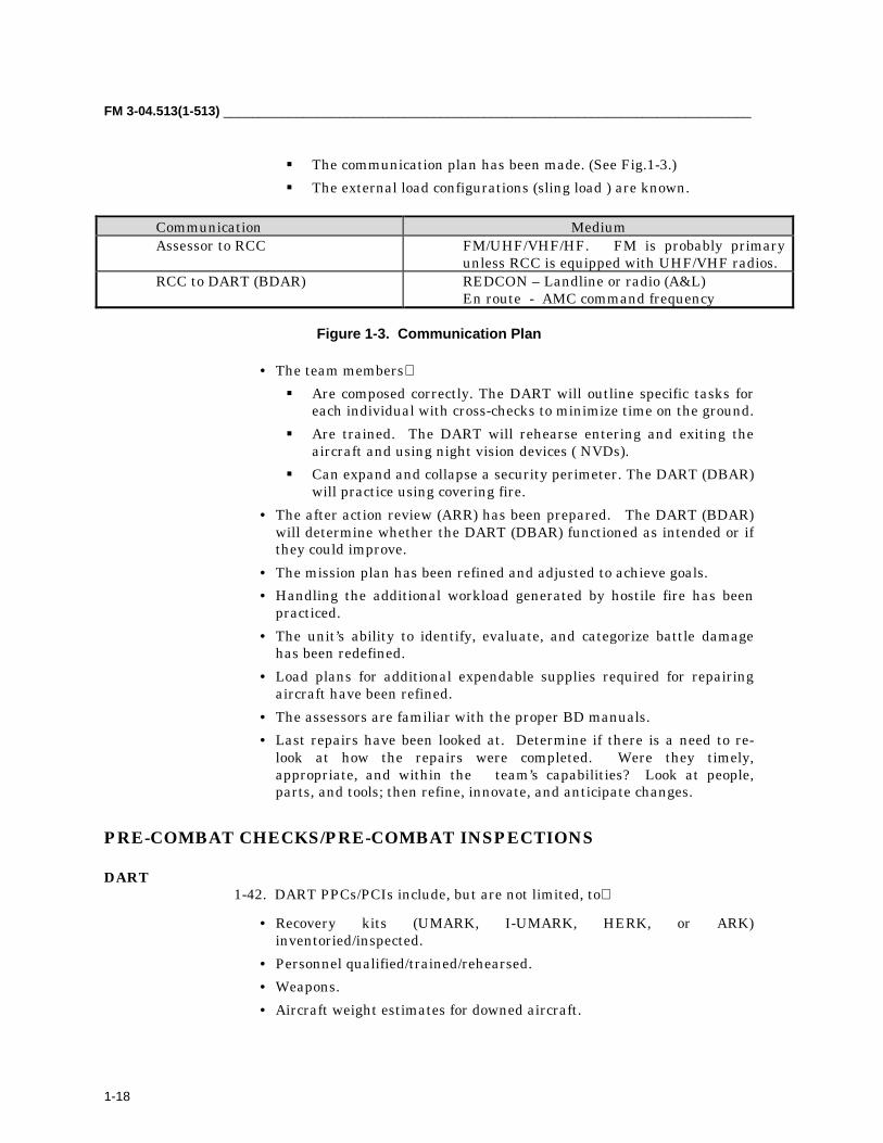
� The communication plan has been made. (See Fig.1-3.)� The external load configurations (sling load ) are known.
Communication MediumAssessor to RCC FM/UHF/VHF/HF. FM is probably primary
unless RCC is equipped with UHF/VHF radios.RCC to DART (BDAR) REDCON – Landline or radio (A&L)
En route - AMC command frequency
Figure 1-3. Communication Plan
• The team members� Are composed correctly. The DART will outline specific tasks for
each individual with cross-checks to minimize time on the ground.� Are trained. The DART will rehearse entering and exiting the
aircraft and using night vision devices ( NVDs).� Can expand and collapse a security perimeter. The DART (DBAR)
will practice using covering fire.• The after action review (ARR) has been prepared. The DART (BDAR)
will determine whether the DART (DBAR) functioned as intended or ifthey could improve.
• The mission plan has been refined and adjusted to achieve goals.• Handling the additional workload generated by hostile fire has been
practiced.• The unit’s ability to identify, evaluate, and categorize battle damage
has been redefined.• Load plans for additional expendable supplies required for repairing
aircraft have been refined.• The assessors are familiar with the proper BD manuals.• Last repairs have been looked at. Determine if there is a need to re-
look at how the repairs were completed. Were they timely,appropriate, and within the team’s capabilities? Look at people,parts, and tools; then refine, innovate, and anticipate changes.
PRE-COMBAT CHECKS/PRE-COMBAT INSPECTIONS
DART1-42. DART PPCs/PCIs include, but are not limited, to
• Recovery kits (UMARK, I-UMARK, HERK, or ARK)inventoried/inspected.
• Personnel qualified/trained/rehearsed.• Weapons.• Aircraft weight estimates for downed aircraft.

_________________________________________________________________________________Chapter 1
1-19
• Battle graphics on maps.• Safety procedures for armed downed aircraft.• Drop off areas for recovered aircraft identified.
BDAR1-43. BDAR PPCs/PCIs include but are not limited to
• Expendable supplies. Allied shops have proper expendable supplies(rivets, sheet metal stock, hydraulic lines, swedge kit, K-747 bladerepair kit, hysol products, paint , etc.).
• Personnel management. These questions pertain to BDAR personnel:� How many sheet metal personnel do I have?� How many pneudraulics personnel do I have?� Am I identifying the critically short MOSs and managing their
time for maximum effect on my fleet. Is my only engine manassigned as a driver?
� Do I have appropriate logistics assistant representatives (LARs)support for the hard decisions and for letters of exception (ifrequired)?
SANITIZATION OF AIRCRAFT1-44. Sanitization of aircraft is the process of taking the necessary measuresto ensure the area around the downed aircraft is secured and remains secure.Air or ground assets, or a combination of both, are used.
• Maintenance personnel must ensure communication equipment, maps,navigation aids, critical mission equipment are secured, zeroized, ordestroyed to prevent enemy compromise.
• Medical personnel will evacuate and treat casualties. The guards andgunners must understand the setup of their defensive perimeter.Sanitatization of the aircraft is critical in performing recoverymissions; therefore, the area around the aircraft must be secured andnecessary actions performed as outlined below:� Organize and coordinate for armed escort aircraft.� Provide a ground security team, path finders, and local unit
personnel.� If the aircraft is armed, make sure nothing is in front of the
aircraft and safe weapon systems.
1-45. This paragraph outlines the assessor actions on arrival at the downedaircraft site. (The technical inspector (TI)/maintenance test pilot(MTP)/subject matter expert (SME)) upon arrival at downed aircraft site
• Identify immediate dangers (fire, armament, fuel leakage, andelectrical sparks).
FM 3-04.513(1-513) _________________________________________________________________________
1-20
• Approach from either wing position, outside of surface danger areas,according to the applicable aircraft Aircraft Operator’s Manual(Technical Manual (TM) –10).
• Safe weapons and external stores (if applicable).� HMMS Launcher Safe/Arm to Safe (missile locking lever release).� Ground M-261 rocket pods; remove possibility of firing voltage by
disconnecting electrical cannon plug on rocket pod.� Insert wing stores ground safety pins.� On area weapon system, disconnect electrical cannon plug on
30mm/50 cal. machinegun.• Turn master arm switch in pilot station to OFF position.• Disconnect aircraft battery.• Remove KY-75 and KY-100.• Remove Kit-1C, KY-58 from avionics bay(s).• Randomize or remove M-130 control module settings.• Turn pilots’ power levers, thrust levers, or collective throttle to the
“Off” position.• Zero data, keys, and frequency fills for all radios.• Remove or zero the APX-100 transponder settings.• Remove or zero data, keys, and waypoint settings from the doppler,
global positioning system (GPS), and data transfer cartridge.• Remove all maps, kneeboards, strip maps, signal operation instructions
(SOIs) from cockpit.• Remove AN/ALQ-156 and AN/ALQ-162.• Remove AN-ALQ-136 from aircraft.• Remove or destroy AN-ALQ-144 from aircraft.• Remove AN/APR-39 and AN/AVR-2 threat signature card from
AN/APR-39 and AN/VDR-2 digital processor or comparator.• Remove the data transfer cartridge from the data transfer unit.• Continue assessment of aircraft.
1-46. Guards/Gunners (PCCs/PCIs) will ensure
• PCC/PCI weapons loads are appropriate.• PCC/PCI weapons are serviceable and test fired.• Fields of fire are interlocked.• Fields of fire are integrated with the aircraft mounted weapons (if
applicable).• Fields of fire are oriented on the most likely avenue of approach.• The security team members have rehearsed exiting the aircraft, setting
up a perimeter, and collapsing the perimeter and entering the aircraft.

_________________________________________________________________________________Chapter 1
1-21
• The security team has established C2 signals, audible or visual, for useat the downed aircraft site for communication between the teammembers, and aircrew of the recovery aircraft.
MISSION EXECUTION TRIGGERS
TRIGGERING CONDITIONS1-47. Triggering conditions for an immediate recovery operation are a visualsighting of an aircraft going down or a radio report of an aircraft within theflight going down. Immediate recovery can occur only if the friendly aviationunit has utility or cargo aircraft and or maintenance personnel within theflight designated or dedicated as maintenance aircraft. (See Fig. 1-4.)
Figure 1-4. Execution of the CSAR/DART (BDAR) Mission
1-48. Either one or two different circumstances may trigger planning fordowned aircraft recovery operations.
• Mission planning for any flight will trigger contingency planning forimmediate and/or delayed downed aircraft recovery operations by theaviation unit. Planning will be implemented if one of the aircrafttaking part in the operation goes down.
• The aviation unit may be directed by higher headquarters to conductDART (BDAR) operations to recover aircraft belonging to some otherunit, service, or coalition force. Planning for a DART (BDAR) operationalso includes contingency planning for immediate or delayed recoveryoperation for the aircraft taking part in the DART (BDAR) operation.
Mission Execution
• CSAR Trigger• DART (BDAR) Trigger
AircraftDown
AircrewRecovered
AircraftSecured
AircraftRepaired
00:00 2:00 6:00 24:00
CSAR DART
* Times are for demonstrative purposes only. Actual times will vary with METT-T.
FM 3-04.513(1-513) _________________________________________________________________________
1-22
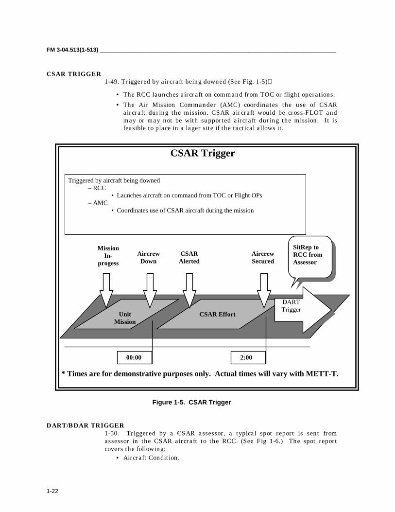
CSAR TRIGGER1-49. Triggered by aircraft being downed (See Fig. 1-5)
• The RCC launches aircraft on command from TOC or flight operations.• The Air Mission Commander (AMC) coordinates the use of CSAR
aircraft during the mission. CSAR aircraft would be cross-FLOT andmay or may not be with supported aircraft during the mission. It isfeasible to place in a lager site if the tactical allows it.
Figure 1-5. CSAR Trigger
DART/BDAR TRIGGER1-50. Triggered by a CSAR assessor, a typical spot report is sent fromassessor in the CSAR aircraft to the RCC. (See Fig 1-6.) The spot reportcovers the following:
• Aircraft Condition.
CSAR Trigger
Triggered by aircraft being downed– RCC
• Launches aircraft on command from TOC or Flight OPs– AMC
• Coordinates use of CSAR aircraft during the mission
00:00
MissionIn-
progessAircrewDown
AircrewSecured
UnitMission
CSAR Effort
CSARAlerted
DARTTrigger
SitRep toRCC fromAssessor
2:00
* Times are for demonstrative purposes only. Actual times will vary with METT-T.

_________________________________________________________________________________Chapter 1
1-23
� CAT I – Aircraft is repairable. It is possible to repair the aircrafton site by bringing resources to it. The only hindrance to thiscourse of action may be the tactical situation on the battlefield.{In other words, there is not enough time to perform the repairsbefore the amount of support (tactical) exceeds what you have onhand. For instance, do not use an infantry battalion to helpsecure the area against the enemy who is threatening whilesomeone changes the nose gearbox}.
� CAT II – The aircraft is recoverable. The aircraft still hasintrinsic value; the engines are a good example. Assume that theaircraft lost all hydraulic fluid and managed to land after furtherflight was not possible. Assume that the crew managed to get theengines shut down, but the landing was a little hard; in otherwords, no sudden stoppages were involved. In this instance, theengines are both still good as is the possibility that the nose gearbox, transmission, drive shafting, and all of the various weaponsystems sub components are also. All of those items arerecoverable. The fuselage was a little banged up on landing. Asan aircraft, the entire airframe is an asset. Probably the mostprudent decision would not be to “blow in place.” This aircraftwould be a prime candidate for an aerial recovery.
DART (BDAR) Trigger Triggered by CSAR Assessor from the CSAR team via the RCC. Triggered by the arrival or notification of aircraft being in a secured area.
2:00
AircraftSecured
CSAR Effort DART (BDAR) Effort
DART(BDAR)Alerted
SitRep toRCC fromAssessor onBDAR efforts
6:00
Figure 1-6. DART (BDAR)
DARTTrigger
24:00
AircraftReturnedTo Unit
* Times are for demonstrative purposes only. Actual times will vary with METT-T.

FM 3-04.513(1-513) _________________________________________________________________________
1-24
� CAT III – The aircraft is destroyed. Why bother risking assets?The aircraft is assessed as destroyed and the crews have beenrecovered.
• Aircraft location.• 8 to10-digit grid.• 10-digit grid for artillery destruction mission.• Triggered by the arrival or notification of the aircraft being in a
secured area.• Brief elaboration of the remaining components that are worth being
cannibalized.

_________________________________________________________________________________Chapter 1
1-25
CSAR/DART (BDAR) DECISION MATRIX
Figure 1-7. CSAR/DART (BDAR) Decision Matrix
BRIEF DART (BDAR)AND
LAUNCH
DEVELOPE PLAN CONSIDERINGTHE LOCATION, ACCESSIBILITY, TIMEAVAILABLE, WEATHER AND TYPE OF
RECOVERY ASSETS
REQUIREMENT FORINFANTRY, ENGINEER AND
FIRE SUPPORT, AIR DEFENSEAND SURVEILLANCE
ALERT/ASSEMBLEDART
BRIEF DART (BDAR) ONAIRCRAFT DAMAGE
RECOVER CREW ANDASSESS AIRCRAFT
BRIEF CSAR ANDLAUNCH
ACCEPTABLE
ALERT DART (BDAR)
BRIEF CSAR ANDSTANDBY
CONTINUE MISSION
TOO HIGH
ENEMY THREAT
NONE
MISSION IMPACT
CONTINUE MISSION / STANDBY FOR CSAR
ADVERSE
ALERT/ASSEMBLE CSAR
AIRCRAFT DOWN

FM 3-04.513(1-513) _________________________________________________________________________
1-26
MISSION END STATE
CSAR1-52. Extraction of the crew is primary; aircraft assessment is secondary.The CSAR mission is designed to
• Provide for the safe recovery of the downed aircrew.• Return the aircrews to Level II medical care if appropriate.• Re-integrate the aircrew into the unit.
DART1-53. The DART is primarily for the extraction of aircraft, not for transport ofrepair teams. The DART mission may be augmented with BDAR personnel(dependent on METT-TC) for the sole purpose of BDAR procedures. Recoverthe airframe if
• The aircraft is worth recovering.• The tactical situation allows recovery.
BDAR1-54. BDAR is not actually a mission. BDAR is a method of returning theaircraft to the commander as a resource. It
• Is preferably performed in a secured area.• Brings security to aircraft or bring aircraft to security.• Is deferment.• Is short term.• Is long term.• Is best performed where all the necessary tools and equipment are.• Is setting the conditions for success.
2-1
Chapter 2
General Recovery and Evacuation Procedures
Battlefield recovery and evacuation of aircraft places unique challengeson commanders. Planning, coordinating, and executing the safe recoveryof US Army aviation assets are vital in retaining the persuasive combatpower. This chapter focuses on general procedures used to develop,coordinate, and execute aircraft recovery and/or evacuation plans toprevent the loss of expensive assets on the battlefield.
MAINTENANCE EVACUATION2-1. Maintenance evacuation is the physical act of moving an aircraft fromone maintenance location on the battlefield to another. Movement is either byfly-out or aerial/ground recovery means. Evacuation is to effect repair, cross-level maintenance workloads, or relieve units of disabled aircraft duringtactical moves.2-2. Responsibility for coordinating the assets and manpower for anevacuation is shared. It is shared between the commander evacuating theaircraft and the commander receiving the aircraft. Normally, whenevacuation is from AVUM to AVIM, the AVIM arranges for lift helicopterassets or ground recovery assets. The evacuation may be from one AVIM toanother AVIM. If so, the receiving AVIM coordinates aerial or ground assetsbeyond the capability of the evacuating AVIM. Nonflyable aircraft may beevacuated from one AVUM to another AVUM. If so, the supporting AVIMcoordinates aerial or ground assets beyond the capability of the evacuatingand receiving AVUM. The evacuating unit normally rigs the aircraft toprepare for movement. Movement is contingent on the availability of arigging kit. Examples of rigging kits are the Aircraft Recovery Kit (ARK),Interim-Unit Maintenance Aerial Recovery Kit (I-UMARK), UnitMaintenance Aerial Recovery Kit (UMARK), or the Helicopter Recovery Kit(HERK). The evacuating unit may have no kit available. If so, it will requesta kit from the receiving or supporting unit.2-3. Maintenance evacuation on the battlefield is a recurring maintenancefunction. It usually is planned for in advance, in conjunction with othermaintenance support. Procedures to be followed, to include coordinationchains, normally are included in aviation maintenance support plans andunit SOPs.
2-4. Normally, the first team on site to a downed aircraft is the DART focusedon BDAR. Most aircraft have a BDAR technical manual. Usage of thismanual during battlefield recovery is essentially important as part of therecovery. Use of the manual ensures that the downed aircraft is efficientlyrecovered.
FM 3-04.513(1-513) _________________________________________________________________________
2-2
2-5. Physical procedures for maintenance evacuation and battlefield recoveryof aircraft are nearly identical; that is, both require the rigging of the aircraftfor lift by helicopter or lift by a crane device to the bed of a vehicle. Therefore,the remainder of this manual, as it pertains to physical procedures and theuse of rigging kits, applies to both maintenance evacuation and recovery.
BATTLEFIELD RECOVERY2-6. Battlefield aircraft recovery is an operation that results from an aircrafthaving experienced a component-failure-induced or combat-damage-inducedforced landing on the battlefield, or the aircraft is disabled because of anaccident. Based on an assessment, the aircraft might be destroyed orabandoned, repaired and flown-out, or recovered to a maintenance site eitherby aerial or ground means.
2-7. The preferred recovery method is to repair the aircraft at the scene of theforced landing. Then the aircraft is returned to service or prepared forevacuation to a maintenance site. Ground recovery remains an option toreturn an expensive asset to service when the aircraft cannot be repaired atthe site or air recovered. The time allotted to repair the aircraft at the scenedepends on the tactical situation. The next two methods (based on METT-TC)are to recover the aircraft by
• Aerial means, using rigging kits and helicopter assets of theowning unit, or assets of supporting or tasked units, or
• Ground means, which take more time and require the aircraft to be insuch a location that large tactical vehicles can approach it.
2-8. Recovery operations always require detailed coordination. Manpowerand recovery assets must be synchronized in response to time and the tacticalsituation. Extensive coordination among the battlefield functions ofmaneuver, fire support, air defense, intelligence, and combat service supportalso are often required. Command, control, and technical procedures arepreplanned; they are included in unit SOPs, contingency plans, operationorders, and air mission briefings.
2-9. Responsibility for a recovery originates with the commander of the unitto which the disabled aircraft is assigned; however, responsibility may pass toa higher echelon when it is beyond the capability of the unit to complete theoperation. A recovery operation begins when an aircraft has experienced aforced landing or is otherwise disabled on the battlefield. It ends when theaircraft has been recovered to, and is under the control of, a maintenancefacility.
THREAT2-10. Recovery operations and to a lesser degree maintenanceevacuations are easily detected and subject to attack by enemy forces,despite combat intensity. Detection can result in hostile actions aimed towardhalting or disrupting the operation, inflicting casualties, and destruction of

_________________________________________________________________________________Chapter 2
2-3
disabled aircraft and other equipment. Operations are threatened by any ofthe following:
• Ground force attack.• Artillery, rockets, and mortar fire.• Air attack.• Antiaircraft weapons and small arms fire against air and ground
equipment assets and crewmembers.• Electronic devices used to disrupt communications.• Directed energy weapons used to register fire, blind personnel, and
disrupt electronic components.• Chemical agents used to deny areas and disable personnel.• Damaged airframe used as a decoy or to contain boobytraps. The
damaged airframe could be rigged to break up in midair, harbor anexplosion aboard a vehicle, or carry harmful substances or explosivedevices to the repair facility.
• Mines and other barriers.
COMMAND, CONTROL, AND COORDINATION2-11. Maintenance evacuation is a preplanned operation. It is performed bypreparing the aircraft for a one-time evacuation mission to the receiving unitor movement by aerial or ground means. Maintenance evacuations betweenmaintenance units are coordinated between the commanders of the unitsinvolved; they are assisted in some cases by the staff maintenance officer toarrange supporting equipment assets. Evacuation of groups of aircraft oftenare driven by unit relocations on the battlefield or reconstitution of aviationunits. These evacuations would likely be controlled by the aviation brigadestaff maintenance officer/S-4 in coordination with the division and corps staff.Coordination and tasking of division and corps assets may be necessary also.
2-12. Command, control, and coordination to support aircraft recoveryoperations are planned for in advance. Planning is within the context of thesize of the force and the density of recovery assets at the disposal ofcommanders. The first commander in the chain of command who controls allthe required assets coordinates the assets and manpower for evacuation forthe recovery. When an aircraft recovery operation is required, a plan ofexecution supplements the preplanned procedures. The purpose of the plan isto synchronize personnel and equipment assets within the scheme ofmaneuver and the tactical situation. Aircraft recovery operations are timesensitive.
2-13. AVUM and AVIM maintenance units form DARTs from within theirpersonnel assets. These teams are skilled in BDAR, the use of rigging kits,and combat expedient recovery techniques (CERTs). The typical compositionof a DART includes a maintenance officer/technician, technical inspector,repairer personnel, and vehicle operators. The DART performs any of thesefunctions:

FM 3-04.513(1-513) _________________________________________________________________________
2-4
• Assesses repair requirements.• Repairs the aircraft or prepares it for a one-time evacuation mission.• Recommends recovery by aerial or ground means.• Rigs the aircraft for recovery; serves as the ground crew for helicopter
lift.• Serves as the crew to secure the load aboard a vehicle.• If the aircraft is not repairable
� Determines the parts, subsystems, or components that can besalvaged and removes them.
� Destroys, or takes part in the destruction of, a disabled aircraftthat is to be abandoned.
2-14. These teams may respond to the recovery of a downed aircraft fromwithin the unit, a supported unit, an adjacent unit, or any aircraft that isdisabled within sector. Normally, these teams are transported with theirequipment by air to the scene of the disabled aircraft. They are thenextracted by air upon completion of the mission.2-15. The first line of responsibility for a recovery operation is the air missioncommander/aviation unit commander. This commander may have at hisdisposal (from within the assets of the operation) on-call DART organizationsand lift assets capable of recovering the disabled aircraft. In such cases, thecommander employs those assets to assess and effect recovery within timeand tactical situation constraints.2-16. If beyond the capability of the air mission or unit commander, theresponsibility to coordinate recovery defaults to the RCC. The RCC is acontingency organization in the aviation brigade TOC. Depending on the sizeof the force, the RCC also may be found in division and corps TOCs. In thiscase, RCC is primarily a communications mode for staff elements to receivevoice, manual, and automated messages; coordinate resources; coordinatebattlefield functions of maneuver, fire support, air defense, intelligence andcombat service support within tactical priorities and the scheme of maneuverin support of recovery operations. The principal in the RCC is the staffmaintenance officer.2-17. Crash site preparation for aerial extraction may require coordinationwith pathfinder or engineer units.2-18. Recovery operations are unique. Each operation is discrete and mayinvolve the initiative and imagination of commanders and staff tosynchronize the operation within a range of variables.2-19. Recovered aircraft normally are transported from the recovery point toa pre-selected maintenance site without intermediate stops. Air recovery (andevacuation) capitalize on back-haul from forward areas to the extent possibleto reduce separate demands on aircraft. This is especially true of CH-47Chinook aircraft, which may be heavily committed to re-supply and othertransport missions.2-20. Ground recovery wrecker/cranes and semi-trailers are found in AVIMunits. These units deploy these assets to the scene of the disabled aircraft for

_________________________________________________________________________________Chapter 2
2-5
recovery operations or to the maintenance site for evacuations. When theAVIM unit is unable to support the required lift within assigned assets, acrane is obtained from another unit. An example is the 20-ton mobile crane,found in division and corps engineer battalions and corps ammunition units.2-21. Aircraft that cannot be recovered and are in danger of enemy captureare destroyed according to TM 750-224-1-5. The authority for destruction willbe included in SOPs and OPORDs. If possible, aircraft are cannibalizedbefore destruction.2-22. The corps, on a mission basis, accomplishes recovery and evacuation ofenemy, allied, and other US services’ aircraft using corps assets or by taskingdivision assets in sector.2-23. The helicopter lift capability data in Table 2-1 is a guide. Figures mayvary considerably, depending on mission distance (fuel load), weatherconditions, and aircraft configuration.2-24. Normally, the smallest lift helicopter is used to transport anotheraircraft during recovery or evacuation. Table 2-2 illustrates capabilities andcan be used as a general guide.
Table 2-1. Helicopter Lift Capability Data (pounds)Helicopter Lift CapabilityCH-47D (center hook) 26,000 (center hook rating only)CH-47D (tandem hook) 25,000(tandem hook rating only)CH-47D (fwd and aft hook) 17,000 (fwd and aft hook rating only)CH-47D 20,000 (actual lifting capability)UH-60L 9,000UH-60A 8,000UH-1 4,000
Table 2-2. Capabilities of Aircraft During Recovery or Evacuation
Type Aircraft Transported byOH-58A/C UH-1*, UH-60, CH-47OH-58D UH-60, CH-47UH-1 UH-60, CH-47UH-60A UH-60*, CH-47UH-60L CH-47EH-60 CH-47MH-60 CH-47AH-1 UH-60*, CH-47AH-64A/D CH-47CH-47 CH-47*RAH-66 CH-47RC-12 CH-47C-23 CH-47UC-35 CH-47*Depending on atmospheric conditions and configurations, aircraft weightmay be reduced by removing components.

FM 3-04.513(1-513) _________________________________________________________________________
2-6
2-25. Ground recovery requires wrecker/crane and semi-trailer combinations,or the palletized loading system (PLS) vehicle, which is a combinationcrane/extended flatbed. (See Table 2-3.)
Table 2-3. Wrecker/Crane and Semi-Trailer Combinations Used in Ground Recovery of Aircraft
Aircraft Wrecker/Crane Semi-trailer Source
OH-58A/C
OH-58D
UH-1
M543/M984M246*PalletizedLoading System
M543/M984M246*PalletizedLoading System
M246*PalletizedLoading System
M172/M270*PalletizedLoading System
M172/M270*PalletizedLoading System
M172/M270*PalletizedLoading System
AVUMAVIMAVIM
AVUMAVIMAVIM
AVIMAVIM
UH-60MH-60EH-60
AH-1
AH-64A/AH-64 LongBow
RAH-66
CH-47MH-47
20-ton mobile
*PalletizedLoading System
M543/M984M246*PalletizedLoading System
20-ton mobile
M543/M984M246
Normally,unrecoverablebecause of size.
M270*PalletizedLoading System
M172/M270*PalletizedLoading System
M270*PalletizedLoading System
M172/M270
Engr UnitsAVIMAVIM
AVUMAVIMAVIM
Engr UnitsAVIMAVIM
AVUMAVIM
RC-12C-23UC-35
TBDTBDTBD*Currently underdevelopment forfielding.
*Currently underdevelopment forfielding.
NOTE: Refer to TB 55-46-1, Standard Characteristics (Dimensions, Weight, and Cube) for Transportability ofMilitary Vehicles and Other Outsize/Overweight Equipment) for Alternate Ground Recovery Equipment.
_________________________________________________________________________________Chapter 2
2-7
ACCIDENT INVESTIGATION BOARD2-26. According to AR 385-40 (Accident Reporting and Records), thecommander who first becomes aware of an Army aircraft accident, places aguard at the scene. This prevents anyone from moving or disturbing theaircraft or detaching parts until it is released by the president of the AccidentInvestigation Board and by the US Army Safety Center, if taking part.
2-27. In the combat environment, it may not be possible to comply fully withthis requirement. Further, aircraft damaged as a direct result of hostile fireis considered a “combat loss,” rather than an accident.
2-28. Situation permitting, the recovery operation may not begin untilone of the following occurs:
• The commander of the unit to which the aircraft is assigned orders thatan accident investigation board, as prescribed by AR 385-40 is notrequired, or
• The president of the board releases the aircraft.
RECOVERY IN THE DIVISION2-29. The maintenance officer of the unit owning the disabled aircraftmanages aircraft recovery in the division. Organizational units prepareaircraft for recovery within their capabilities. Notification of a disabledaircraft follows normal reporting channels to the aviation battalion andaviation brigade. Additional support may be required or the recovery of theaircraft may be beyond the capabilities of the owning unit. If so, the AVIM isnotified of required support. The AVIM company is equipped with air andground recovery kits to assist with recoveries at the AVUM level.
2-30. Supporting AVIM units augment AVUM organizations as required tocomplete recovery operations. These units may be tasked to complete theoperation if the AVUM is heavily committed or preparing to move.
2-31. Aerial recovery may be required, and the tactical situation may permit.If so, the AVUM or the AVIM recovery team rig the aircraft. The recoveryteams may not be able to move the disabled aircraft. Then the maintenanceofficer or the production control officer of the supporting AVIMrequests through the division movement control center a lifting helicopterfrom the corps support command (COSCOM) movement control center.Requests are sent through the division movement control center.
2-32. Divisional units may be tasked to support recovery operations, in sector, for other than division units and for allied and other services.
RECOVERY IN ECHELONS ABOVE DIVISION2-33. The same principles apply to recovery in echelons above division as in the division.

FM 3-04.513(1-513) _________________________________________________________________________
2-8
RECOVERY IN A NUCLEAR, BIOLOGICAL, AND CHEMICALENVIRONMENT
2-34. Recovery operations in a nuclear, biological, and chemical (NBC)environment pose special risks to personnel. These risks can be minimizedthrough the recovering crew’s wearing protective clothing at the scene of thedisabled aircraft. Also, the receiving crew at the maintenance site shouldwear protective clothing because of possible contamination of the disabledaircraft, the recovering aircraft, and rigging kits. See FM 3-11.4(3-4) (NBCProtection) for information on individual and collective protection.
NIGHT RECOVERY2-35. Generally, night operations increase safety hazards and the need forsecurity. Increased risks must be weighed against the urgency consideringtime, weather, and the tactical situation. When possible, delay suchoperations until the beginning of morning twilight.
RECOVERY METHODS2-36. Three general methods used to recover and evacuate disabled aircraftare one-time evacuation mission, aerial (sling load) recovery, and surface.(See FM 3-04.500 (1-500), Army Aviation Maintenance.) The recovery officeror BDAR assessor determines the method to be used. His main concern ishow to move the aircraft to the aircraft maintenance activity without furtherdamage. Information may be needed for disassembly, packing, or shipmentof the aircraft during any phase of the mission. If so, the applicable shippingor maintenance manual is used. To ensure a successful mission, personnelshould follow the procedures below upon arrival at the site of a disabledaircraft:
• Remove occupants.• Eliminate fire and safety hazards.• Disconnect batteries.• Remove ammunition (if possible and practical).• Remove weapons (if possible and practical).• Drain fuel from aircraft, as required.
WARNING All weapons systems must be cleared before removal to avoid injury or death.

_________________________________________________________________________________Chapter 2
2-9
WARNINGAvoid contact with aviation fuel or with water contaminatedwith aviation fuel. Such contact can result in severe skinburns. In the event of skin burns/irritation, immediatelyseek medical aid. Contaminated clothing should beremoved and cleaned/discarded according to appropriatecare manuals.
EVACUATION METHOD2-37. The evacuation method is accomplished by on-site repair of thedisabled aircraft. The aircraft is prepared for a one-time evacuation missionto a regular maintenance area with a minimum flight crew (only the pilotwhen possible); the pilot should be proficient in all emergency procedures forthe particular aircraft. Advantages and disadvantages of the one-timeevacuation mission method are as follows:
• Advantages.� Speed.� Economy.� Minimum likelihood of further damage.
• Disadvantages.� Requirement for a clear takeoff path.� Possibility of unfound damage causing a crash.� Requirement for special tools and equipment.� Effects of weather conditions.
AERIAL (SLING LOAD)2-38. Aerial (sling load method) recovery and evacuation involves preparingthe disabled aircraft for movement; connecting it to a suitable lift helicopter,with component from an aerial recovery kit; and transporting it to amaintenance area. Advantages and disadvantages of the aerial (sling loadmethod) recovery/evacuation are as follows:
• Advantages.� Less disassembly required than for surface transport.� Disabled aircraft accessibility.� Faster than by surface.
• Disadvantages.� Possibility of dropping disabled aircraft/inflicting further damage.� Effect of rotor downwash on sling load.� Effects of weather conditions.� Possibility of loss or damage to lifting helicopter.� A cleared approach/departure path for recovery aircraft required.
FM 3-04.513(1-513) _________________________________________________________________________
2-10
SURFACE2-39. The surface method of recovery and evacuation involves preparing thedisabled aircraft for movement, lifting it onto a suitable transportationvehicle, and transporting it to a maintenance area. Advantages anddisadvantages of the surface recovery method are as follows:
• Advantages.� Restricts the enemy’s ability to detect movement of recovery
assets to an area relatively close to the movement routes.� Use possible when weather conditions prohibit flight.� Threat of total loss of the aircraft during transport because of
recovery and malfunction is low.• Disadvantages.
� Route security assets badly needed somewhere else may be tiedup. Time needed for surface recovery is much greater than foraerial recovery.
� Recovery personnel and equipment assets are tied up for longperiods.
� Relatively high exposure time on the battlefield with slow-movingequipment increases the threat.
� Significant amount of aircraft disassembly or modification often isrequired to adapt the aircraft to surface travel.
� Ground routes must be accessible, and meticulous reconnaissanceof the route is required.
� Loading procedures and travel on rough terrain can cause furtherdamage to the aircraft.
ON-SITE RECOVERY PROCEDURES2-40. Procedures performed at the site of the disabled aircraft include makingthe recovery area accessible, using communications correctly, and making theaircraft secure, safe, and ready for stable flight.
CONDITION OF THE PICKUP SITE2-41. The pickup site must be cleared of all trees, obstacles, and trash. Therecovery helicopter pilots must know of conditions that might restrict theirvisibility, such as dust or snow.
2-42. Trees and obstacles should be cleared from the pickup site. The treescut to clear an area must fall away from the area. This is done by appropriatetree notching or by a constraint applied to the tree using positioning strapsand rope. Tension is applied before starting the cut by stretching the nylonstraps or rope as much as possible.
2-43. The pickup area should be thoroughly policed of all trash before therecovery helicopter arrives. Items such as empty field ration cans, empty fieldration cases, small pieces of the disabled aircraft, small tree limbs, tree roots,

_________________________________________________________________________________Chapter 2
2-11
and loose recovery equipment can all become airborne missiles, whichendanger both the recovery helicopter and the ground crew.
2-44. The recovery helicopter pilots should be warned if the pickup area isdusty. This enables them to plan for a rapid climb out if visibility drops to apoint that they will lose ground reference. A variety of dust control agentsexists. However, natural turf is the best dust control measure; therefore, allpossible efforts should be made to preserve the natural turf cover whileworking in the pickup area.
2-45. Snow, like dust, is primarily dangerous to a recovery mission. Thereason is that snow can dangerously restrict the visibility of recoveryhelicopter pilots. An attempt should be made to pack the loose snow, ifpossible. In all cases, the recovery helicopter pilots should be warned of thecondition of the snow.
RADIO COMMUNICATION2-46. Communication must be established between the ground recovery crewand the recovery helicopter. The recovery helicopter usually will not proceedto the recovery site until the ground crew advises that they have rigged thedisabled aircraft, and it is ready for hookup. In a tactical situation, thisprecludes endangering the recovery helicopter for a longer period than isnecessary. In all situations, this minimizes flight time for the recoveryhelicopter. Although there maybe space for radio stowage in the recovery kitcontainer, the radio and a fresh battery must be obtained from the unitcommunications section before each mission.
2-47. The ground crew also should include a radio operator co-located withthe signalman. This individual should be in direct contact with the recoveryaircraft to advise the aircrew on the status of the aircraft extraction.
NOTE: Pilots of recovery aircraft will be taking directions from the onboard crew chief. Air-to-groundcommunications procedures should be coordinated in advance and included in the pre-mission briefto minimize confusion.
AIRCRAFT BATTERY2-48. The aircraft battery must be disconnected before performing any workon the disabled aircraft.
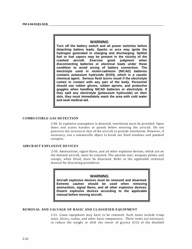
FM 3-04.513(1-513) _________________________________________________________________________
2-12
WARNINGTurn off the battery switch and all power switches beforedetaching battery leads. Sparks or arcs may ignite thehydrogen generated in charging and discharging. Spilledfuel or fuel vapors may be present in the vicinity of thecrashed aircraft. Exercise good judgment whendisconnecting batteries or electrical leads under thesecondition to avoid arcing of battery connection. Theelectrolyte used in nickel-cadmium (NICAD) batteriescontains potassium hydroxide (KOH), which is a causticchemical agent. Serious flesh burns result if the electrolytecomes in contact with any part of the body. Personnelshould use rubber gloves, rubber aprons, and protectivegoggles when handling NICAD batteries or electrolyte. Ifthey spill any electrolyte (potassium hydroxide) on theirskin, they must immediately wash the area with cold waterand seek medical aid.
COMBUSTIBLE GAS DETECTION2-49. In explosive atmosphere is detected, ventilation must be provided. Opendoors and access hatches or panels before entering the aircraft. Do notpuncture the structural skin of the aircraft to provide ventilation. However, ifnecessary, use a nonmetallic object to break out fixed windows and jammedcanopies.
AIRCRAFT EXPLOSIVE DEVICES 2-50. Ammunition, signal flares, and all other explosive devices, which are on
the downed aircraft, must be removed. The ejection seat, weapons pylons andcanopy, when fitted, must be disarmed. Refer to the applicable technicalmanual for disarming procedures.
WARNINGAircraft explosive devices must be removed and disarmed.Extreme caution should be used when removingammunition, signal flares, and all other explosive devices.Disarm explosive devices according to the applicablemanual before moving aircraft.
REMOVAL AND SALVAGE OF BASIC AND CLASSIFIED EQUIPMENT2-51. Loose equipment may have to be removed. Such items include troopseats, litters, radios, and other basic components. These items are necessaryto reduce the weight or shift the center of gravity (CG) of the disabled
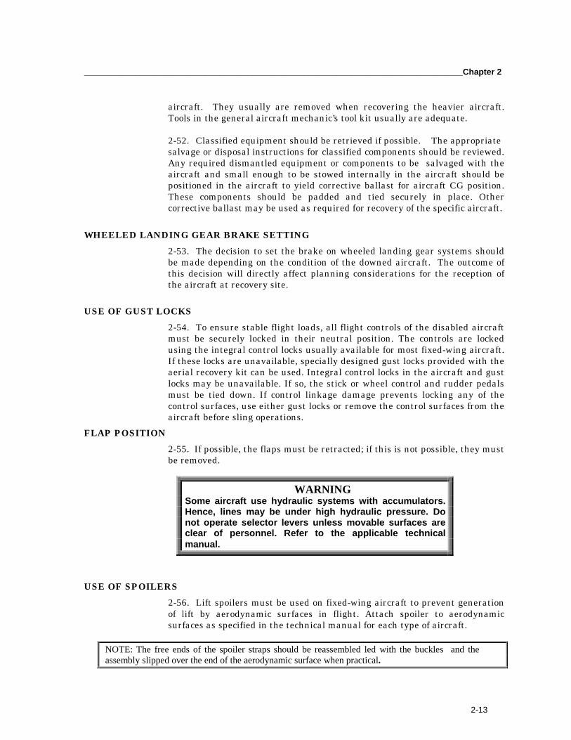
_________________________________________________________________________________Chapter 2
2-13
aircraft. They usually are removed when recovering the heavier aircraft.Tools in the general aircraft mechanic’s tool kit usually are adequate.
2-52. Classified equipment should be retrieved if possible. The appropriatesalvage or disposal instructions for classified components should be reviewed.Any required dismantled equipment or components to be salvaged with theaircraft and small enough to be stowed internally in the aircraft should bepositioned in the aircraft to yield corrective ballast for aircraft CG position.These components should be padded and tied securely in place. Othercorrective ballast may be used as required for recovery of the specific aircraft.
WHEELED LANDING GEAR BRAKE SETTING2-53. The decision to set the brake on wheeled landing gear systems shouldbe made depending on the condition of the downed aircraft. The outcome ofthis decision will directly affect planning considerations for the reception ofthe aircraft at recovery site.
USE OF GUST LOCKS2-54. To ensure stable flight loads, all flight controls of the disabled aircraftmust be securely locked in their neutral position. The controls are lockedusing the integral control locks usually available for most fixed-wing aircraft.If these locks are unavailable, specially designed gust locks provided with theaerial recovery kit can be used. Integral control locks in the aircraft and gustlocks may be unavailable. If so, the stick or wheel control and rudder pedalsmust be tied down. If control linkage damage prevents locking any of thecontrol surfaces, use either gust locks or remove the control surfaces from theaircraft before sling operations.
FLAP POSITION2-55. If possible, the flaps must be retracted; if this is not possible, they mustbe removed.
WARNINGSome aircraft use hydraulic systems with accumulators.Hence, lines may be under high hydraulic pressure. Donot operate selector levers unless movable surfaces areclear of personnel. Refer to the applicable technicalmanual.
USE OF SPOILERS2-56. Lift spoilers must be used on fixed-wing aircraft to prevent generationof lift by aerodynamic surfaces in flight. Attach spoiler to aerodynamicsurfaces as specified in the technical manual for each type of aircraft.
NOTE: The free ends of the spoiler straps should be reassembled led with the buckles and theassembly slipped over the end of the aerodynamic surface when practical.
FM 3-04.513(1-513) _________________________________________________________________________
2-14
TIE-DOWN OF PROPELLERS OR ROTORS2-57. Airplane propellers or helicopter rotors are secured to the airframe.
2-58. For two-bladed rotor system helicopters, the tail rotor blades should bealigned with the vertical fin. The main rotor blades must be aligned with thefuselage if possible. Tie-down lines become slack under air loads. Therefore,the forward and aft aligned blades must be tied down to the helicopterstructure so that the restraints will not slip off the blades when they aredeflected during flight by aerodynamic loading.
2-59. Rotor blades on helicopters with more than two main rotor blades maybe removed to prevent damage either to the disabled helicopter or therecovery helicopter and to prevent rotor blades from flexing. Also, the bladesmay be removed to attach a sling, decrease the weight to be lifted, or stabilizethe disabled helicopter. All US Army four-bladed rotor system helicoptershave been test aerial evacuated with the main rotor blades installed and tieddown.
ATTACHMENT OF DROGUE CHUTES
WARNINGDrogue chutes present a potential hazard to the liftinghelicopter during pickup and drop-off. Entangling with therotors, chafing of the shroud lines, and snagging of thechute on obstacles of the chute on obstacles representpotential hazards.
2-60. Without some types of yaw stabilization devices, recovery flight speedsare limited to 30 to 40 knots. A drogue chute can be used to provide yawstabilization and increase forward speed.
2-61. The appropriate drogue chute is attached to the tail section of therecovered aircraft. A shackle at the end of the riser line swivel generallyprovides a convenient point of attachment.
BREAKAWAY TECHNIQUE2-62. If it looks like the rigging equipment may become entangled, theaffected items should be clustered and taped together as close to the riggedaircraft as possible and individually taped to the aircraft structure itself.(Examples of affected items are bellyband sling assembly, pendant assembly,and so forth.) The breakaway technique is to secure the legs of the riggingequipment to the aircraft and/or to each other with a low-strength item (forexample, 2.0-inch pressure-sensitive tape) to hold the rigging in a desiredposition until lift-off. At lift-off, the tape breaks, and the rigging assumes itsproper flight configuration.

_________________________________________________________________________________Chapter 2
2-15
CRASH SITE HAZARDS2-63. The CH-47 is the only aircraft model that requires fuel drainage toachieve weight reduction. Fuel can be drained by using existing drain fittingsor by siphoning. If the fuel tanks and/or lines are ruptured during a crash,the remaining fuel should be drained. This prevents leaking fuel fromcreating a fire hazard in or near the maintenance facility receiving therecovered aircraft. In the case of CH-47 aircraft, contingency plans must bemade for portable, collapsible fuel cells to reduce aircraft weight for recovery.
WARNINGExercise extreme caution when de-fueling any aircraft.Fire-protective clothing, fire extinguishing equipment, andelectrical grounding apparatus must be available.
WARNINGSome particulate matter is highly toxic. The air surroundinga fuel fire, for example, contains particulate matter that, ifinhaled, can cause fluid buildup in the lungs to the extentthat death can occur.
2-64. Aircraft are manufactured from various types of materials. Of thesematerials, some can become a hazard during an aircraft accident.Contamination from fumes, toxins, liquids, composite, and solid materialscan cause serious illness or injury if protective equipment is not worn.
WARNINGExercise extreme caution when handling any aircraftmaterials. Protective clothing, gloves, respirators, andequipment must be available.
HOOKUP2-65. The ground crew must take certain precautions and perform specificfunctions when hooking up the rigged aircraft to the recovery helicopter.
FM 3-04.513(1-513) _________________________________________________________________________
2-16
WARNINGRecovery crew members may be required to stand on therigged aircraft during hookup. In this case, additionalcaution must be exercised to prevent being pinned betweenthe disabled aircraft and the recovery aircraft.
GROUND CREW GENERAL PROCEDURES2-66. Ground crew teamwork and proficiency are the most important parts ofan aerial recovery operation. How well ground crew personnel are trainedand how familiar they are with their equipment determine the final outcomeof the mission. All units should have an ongoing training program to keeptheir ground crews current on unit equipment and to train new ground crewpersonnel. The command is responsible for implementing a training programfor the ground crew.
NUMBER OF GROUND CREWS2-67. The number of personnel in a ground crew may vary depending on thesituation, type of aircraft, and size of the pickup zone. The unit commanderdetermines how many crews need to be trained. Generally, three people makeup a ground crew: the signalman, the hookup man, and an assistant. Thecommander also must provide local security for the operation. (The groundcrew is not responsible for this task.) Although each member of the crew hasspecific duties during the operation, each person should be trained in how toperform all duties.
GROUND CREW EQUIPMENT2-68. The ground crew members involved in helicopter aerial recoveryoperations are exposed to the hazards of helicopter noise and rotordownwash. Therefore, they should wear protective equipment whenperforming their duties. Depending on the mission, they may need additionalequipment. Figures 2-1 and 2-2 show the equipment that is normally needed.The national stock numbers (NSNs) help to prepare supply requisitions forthe items needed.
STATIC ELECTRICITY DISCHARGE WAND2-69. In flight, a helicopter generates and stores a charge of static electricity.When the helicopter lands, this charge is grounded. While the helicopter is inflight, however, this charge remains stored unless a path is provided tochannel it into the earth. A ground crew member provides this path bycontacting the helicopter cargo hook when it is positioned over a cargohookup point. Although this charge may not cause an electrical burn, it cancause a muscular reaction, which may, if the individual concerned is onunsure footing, result in a fall. An individual shocked by the electricity alsomay suffer delayed discomfort from muscular cramps or spasms.

_________________________________________________________________________________Chapter 2
2-17
Figure 2-1. Ground Crew Protective Equipment
NOTE: If a wand is not available, one will have to be made locally.
2-70. To prevent static electricity shock, the ground crew member uses adischarge wand to ground the cargo hook. For added protection, the groundcrew member should also wear 5000-volt shockproof gloves, if available, whenusing the wand.
2-71. The wand consists basically of an insulated plastic tube with a metalhook on one end with a wire attached leading to a ground rod. The entirelength of wire must be insulated. The wire could cause a severe shock if itcomes in contact with personnel. In use, the ground rod is driven into the
Figure 2-2. Additional Ground Crew Equipment (Depending on Mission)

FM 3-04.513(1-513) _________________________________________________________________________
2-18
2-70. To prevent static electricity shock, the ground crew member uses adischarge wand to ground the cargo hook. For added protection, the groundcrew member should also wear 5000-volt shockproof gloves, if available, whenusing the wand.2-71. The wand consists basically of an insulated plastic tube with a metalhook on one end with a wire attached leading to a ground rod. The entirelength of wire must be insulated. The wire could cause a severe shock if itcomes in contact with personnel. In use, the ground rod is driven into theearth, and a ground crew member holds the wand. As the helicopter hoversover the load, the assistant hookup man holds the wand against the cargohook; this grounds the stored electrical charge. Meanwhile, the hookup manplaces the clevis on the hook.
FIELD EXPEDIENT STATIC-DISCHARGE WAND2-72. Discharging static electricity is an important step to ensure the overallsafety of the hookup team. You can assemble a field expedient static-discharge wand using the following components:
• Grounding rod, NSN 5975-00-878-3791. You will be able to make threestatic-discharge wands from this 5/8- by 108-inch generator groundingrod.
• Grounding cable, NSN 4010-00-286-2681. If you do not want to orderthis 1000-yard roll of cable, contact the nearest petroleum handling orground power section to obtain a length of grounding cable.
• Electrical clip, NSN 5999-00-260-0447. You will receive electrical clipsfor five static-discharge wand.
• Rubber hose, NSN 4720-00-277-8985. Order enough of this 5/8-inchinside diameter rubber hose to cut a 12-inch section for each static-discharge wand.
2-73. The following steps should be taken to assemble the static-dischargewand:
• Step 1. Cut a section of grounding cable about 20 feet long. Strip 1 inchof insulation off both ends of the cable.
• Step 2. Cut a 20-inch and a 16-inch section from the generator-grounding rod. The 20-inch section will be the static-discharge wand,and the 16-inch section will be the grounding rod.
• Step 3. Clamp one end of the cable to the 20-inch section of rod about12 inches from the end of the rod (Figure 2-3).
• Step 4. Slide the section of rubber hose over the cable and ground rodso that the rod is about 1 inch from the end of the rubber hose. Fill theend of the hose with silicone sealant to provide insulation protectionfrom the bare end of the rod. If a rubber hose is not available, wrapelectrical tape or pressure-sensitive tape around the clamp and thelower portion of the rod so that the tape is about ½ inch thick (Figure2-4).
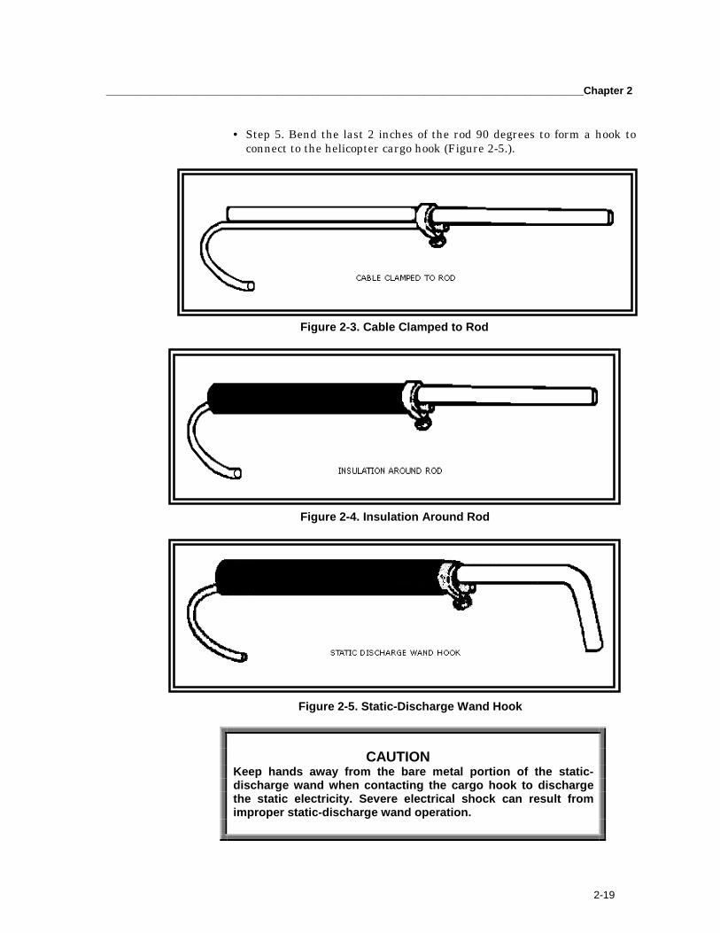
_________________________________________________________________________________Chapter 2
2-19
• Step 5. Bend the last 2 inches of the rod 90 degrees to form a hook toconnect to the helicopter cargo hook (Figure 2-5.).
Figure 2-3. Cable Clamped to Rod
Figure 2-4. Insulation Around Rod
Figure 2-5. Static-Discharge Wand Hook
CAUTIONKeep hands away from the bare metal portion of the static-discharge wand when contacting the cargo hook to dischargethe static electricity. Severe electrical shock can result fromimproper static-discharge wand operation.
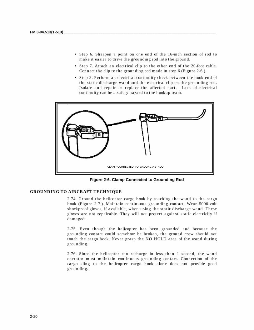
FM 3-04.513(1-513) _________________________________________________________________________
2-20
• Step 6. Sharpen a point on one end of the 16-inch section of rod tomake it easier to drive the grounding rod into the ground.
• Step 7. Attach an electrical clip to the other end of the 20-foot cable.Connect the clip to the grounding rod made in step 6 (Figure 2-6.).
• Step 8. Perform an electrical continuity check between the hook end ofthe static-discharge wand and the electrical clip on the grounding rod.Isolate and repair or replace the affected part. Lack of electricalcontinuity can be a safety hazard to the hookup team.
.
Figure 2-6. Clamp Connected to Grounding Rod
GROUNDING TO AIRCRAFT TECHNIQUE2-74. Ground the helicopter cargo hook by touching the wand to the cargohook (Figure 2-7.). Maintain continuous grounding contact. Wear 5000-voltshockproof gloves, if available, when using the static-discharge wand. Thesegloves are not repairable. They will not protect against static electricity ifdamaged.
2-75. Even though the helicopter has been grounded and because thegrounding contact could somehow be broken, the ground crew should nottouch the cargo hook. Never grasp the NO HOLD area of the wand duringgrounding.
2-76. Since the helicopter can recharge in less than 1 second, the wandoperator must maintain continuous grounding contact. Connection of thecargo sling to the helicopter cargo hook alone does not provide goodgrounding.

_________________________________________________________________________________Chapter 2
2-21
Figure 2-7. Proper Grounding Technique
WARNINGContact between the discharge wand and the cargo hookmust be maintained until the clevis is placed on the hook. Ifcontact between the wand and the hook is not maintained,the ground crew member may receive a serious shock.This does not mean the ground crew should rig a springclip to hook directly to the aircraft. If contact between thewand and the hook is broken, then contact must again bemade before touching the hook. If static shock causesunconsciousness, determine if the victim has a pulseand/or is breathing. If not, immediately begin CPR and/ormouth-to-mouth resuscitation.
WAND MAINTENANCE2-77. The grounding wand, cable, and clamp are not repairable. If the wandor the first 10 feet of cable (closest to the wand handle) is punctured orcracked, discard the wand. If either of the black plugs on the ends of thewand come out (they are allowed to rotate), discard the wand. Never attachmetallic fittings to the wand or cable. To preserve the electrical capability ofthe wand and cables, remove fuel, grease, or oil from the wand with mineral
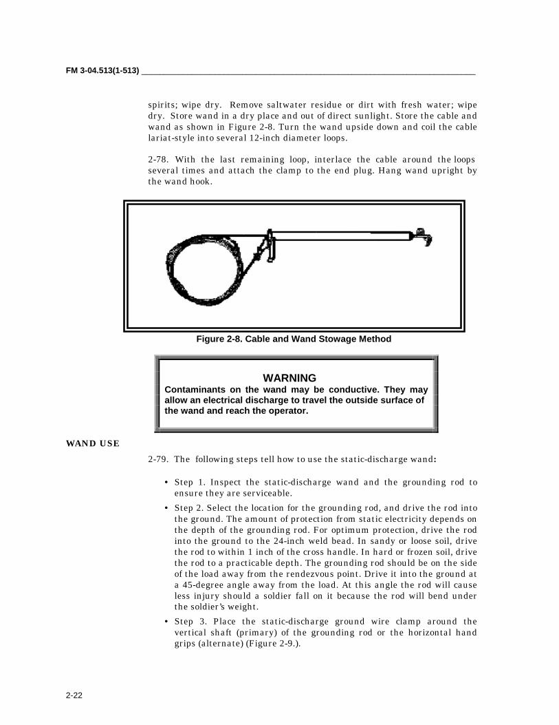
FM 3-04.513(1-513) _________________________________________________________________________
2-22
spirits; wipe dry. Remove saltwater residue or dirt with fresh water; wipedry. Store wand in a dry place and out of direct sunlight. Store the cable andwand as shown in Figure 2-8. Turn the wand upside down and coil the cablelariat-style into several 12-inch diameter loops.
2-78. With the last remaining loop, interlace the cable around the loopsseveral times and attach the clamp to the end plug. Hang wand upright bythe wand hook.
Figure 2-8. Cable and Wand Stowage Method
WARNINGContaminants on the wand may be conductive. They mayallow an electrical discharge to travel the outside surface ofthe wand and reach the operator.
WAND USE2-79. The following steps tell how to use the static-discharge wand:
• Step 1. Inspect the static-discharge wand and the grounding rod toensure they are serviceable.
• Step 2. Select the location for the grounding rod, and drive the rod intothe ground. The amount of protection from static electricity depends onthe depth of the grounding rod. For optimum protection, drive the rodinto the ground to the 24-inch weld bead. In sandy or loose soil, drivethe rod to within 1 inch of the cross handle. In hard or frozen soil, drivethe rod to a practicable depth. The grounding rod should be on the sideof the load away from the rendezvous point. Drive it into the ground ata 45-degree angle away from the load. At this angle the rod will causeless injury should a soldier fall on it because the rod will bend underthe soldier’s weight.
• Step 3. Place the static-discharge ground wire clamp around thevertical shaft (primary) of the grounding rod or the horizontal handgrips (alternate) (Figure 2-9.).
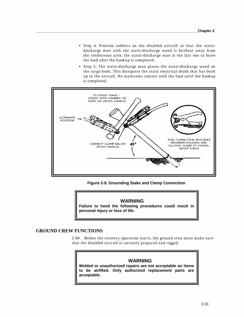
_________________________________________________________________________________Chapter 2
2-23
• Step 4. Position soldiers on the disabled aircraft so that the static-discharge man with the static-discharge wand is farthest away fromthe rendezvous area; the static-discharge man is the last one to leavethe load after the hookup is completed.
• Step 5. The static-discharge man places the static-discharge wand onthe cargo hook. This dissipates the static electrical shock that has builtup in the aircraft. He maintains contact with the load until the hookupis completed.
Figure 2-9. Grounding Stake and Clamp Connection
WARNINGFailure to heed the following procedures could result inpersonal injury or loss of life.
GROUND CREW FUNCTIONS2-80. Before the recovery operation starts, the ground crew must make surethat the disabled aircraft is correctly prepared and rigged.
WARNINGWelded or unauthorized repairs are not acceptable on itemsto be airlifted. Only authorized replacement parts areacceptable.
FM 3-04.513(1-513) _________________________________________________________________________
2-24
2-81. Break away taping is used to hold lines and sling legs in place beforethe aircraft arrives in the pickup area. Taping holds the legs. When theaircraft puts pressure on the lifting legs, the tape is pulled off or breaks awayfrom the place where it was taped. Thus, the legs or lines will carry only theirallowed weight and will not become tangled or wrapped around any objects.
2-82. The Noncommissioned Officer in Charge identifies a rendezvous pointfor his ground crew to gather after each lift is completed or during anemergency. A rendezvous point is an easily recognized point on the ground(for example, trees, bunkers, buildings, vehicles, or wooded areas) where theground crew can gather without being in danger. This point should not be ina large open area where an aircraft can make an emergency landing. Itshould be located as far away from the emergency landing area as practical.
2-83. In addition, the rendezvous point under emergency procedures, requirescoordination with the pilot of the recovery aircraft. This will inform bothteams to know which direction (clock position relative to the nose of theaircraft) the other will disperse.
2-84. The area must be policed to prevent a flying object hazard. Any objectthat the rotor wash can lift could become a missile and cause damage toequipment or injury to personnel.
NOTE: Although signal smoke is often used in the pickup zone to show wind direction and identify theproper landing zone, it can reduce the pilot’s vision. Obstructed pilot vision could result in an aircraftcrash. Smoke should only be used during the initial approach; it should be well dissipated during thelift operation.
2-85. As the helicopter approaches the pickup site, the ground crew membersput on their equipment and
• The signalman takes a position upwind from the load. This means thatthe wind should be at or blowing towards his back with the loadbetween him and the helicopter. Figure 2-10 shows the proper distancefor the signalman during a hookup using an UH-1 Huey. Distances willbe greater for larger helicopters (about 100 feet for the UH-60 and 150feet for the CH-47).
• The hookup man and static-discharge man go to their positions besideor on top of the load.
NOTE: Any extra personnel, such as equipment operators, are positioned so that they are clear of thehookup area and away from the landing and takeoff zones.
2-86. The signalman gives signal directions to the pilot as soon as the pilotcan clearly see him. He must move with the aircraft to stay within the pilot’sview. The signals must be precise to prevent any misunderstanding betweenthe signalman and the pilot. (See para entitled “Hand and Arm Signals.”)

_________________________________________________________________________________Chapter 2
2-25
Figure 2-10. During Helicopter Hookup
2-87. While the helicopter is moving, the signalman is responsible for thesafety of the hookup crew.
NOTE: During hookup of the downed aircraft, recovery personnel should maintain additionalhardware (nuts, bolts, cotter keys, and pins) with them in the event that they drop the primary devicesduring hookup.
2-88. When the aircraft is correctly positioned, the ground crew starts thehookup. The signalman must keep his eyes on the hookup team and the cargohook. Any mistakes at this point could cause a hazard to anyone below theaircraft. The pilot cannot see the hookup team during the hookup. The pilotmust concentrate on maintaining a steady hover. The hookup team must doits jobs as fast and as safely as possible. The steps for performing a hookupare as follows:
• Step 1. The signalman signals the pilot to maintain a hover once thehook is in position.
• Step 2. The static-discharge man then places the static-discharge wandon the cargo hook. The hookup man places the apex fitting on the cargohook keeping the sling legs straight.
• Step 3. The hookup man uses hand signals to let the signalman know ifthere is anything wrong with the hook or the load. After attaching theapex fitting to the cargo hook, the hookup man climbs off the aircraft.The static-discharge man then drops the static-discharge wand to theground, clear of the aircraft in the vicinity of the grounding rod. Thehookup team then departs to the rendezvous point. The signalman
FM 3-04.513(1-513) _________________________________________________________________________
2-26
gives the signal that the load is hooked up and slowly gives the pilotthe “raise up” signal.
• Step 4. As the aircraft rises, the signalman visually checks the load tomake sure the sling legs have not become entangled. Proper clusteringand taping techniques prevent the sling legs from being entangled. Thehookup team must watch the signalman to see if any problems arisewith the sling legs. If the load is correct, the signalman gives the pilotthe “thumb up” signal.
WARNINGCoordinate the evacuation route of the ground crew to arendezvous point with the liaison officer or helicopter crewbefore the start of the operation. Proper coordination willprevent any mixup. Helicopter emergency proceduresdepend on terrain, wind direction, and pilot choice. Goodprior coordination will prevent the helicopter and the groundcrew from moving in the same direction.
• Step 5. If the load is not correct (tangled sling, hook open, damagedslings, and so forth), follow these procedures:� Give the pilot the “hookup” signal followed by the “negative” or
“thumb down” signal.� Direct the aircraft downward until the hookup men can correct the
rigging.� Once the rigging has been corrected, direct the aircraft up again to
check the load before giving the “thumb up” signal.• Step 6. The signalman then makes a circular motion with his arm
extended over his head and points to the direction in which the pilotshould depart the pickup zone. When pointing, the signalman steps offin the same direction that he is pointing to make his signal morepronounced to the pilot (Figure 2-11).
EXTENDED SLING SYSTEM OPERATIONS2-89. Units may conduct aerial recovery operations with the UH-60 Black Hawkand CH-47 Chinook helicopters using the extended sling system. The groundcrew consists of the signalman and the hookup man. Since the helicopter landsbeside the load, a static-discharge man is not needed.2-90. The signalman directs the aircraft to land up-slope from the load. Thehookup man crawls under the helicopter, attaches the apex fitting to the cargohook, and boards the aircraft. The signalman and other personnel wait for theaircrew member to signal them to approach and board the aircraft. All personnelmust follow the directions from the aircrew. The aircraft crew member givesdirection to the pilot to center the aircraft over the load and to prevententanglement of the sling.
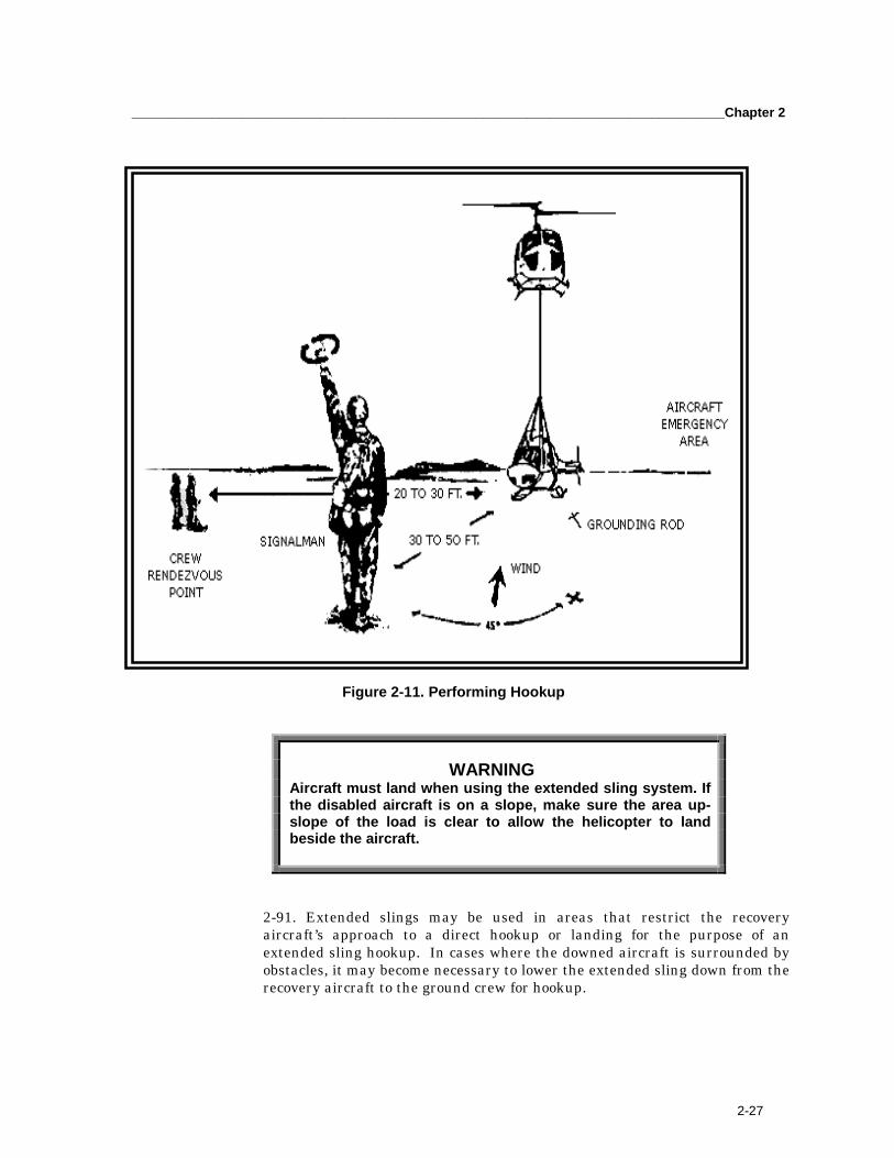
_________________________________________________________________________________Chapter 2
2-27
Step 6. The direction in which the pilot should depart the pickup zone. When pointing, the signal
Figure 2-11. Performing Hookup
WARNINGAircraft must land when using the extended sling system. Ifthe disabled aircraft is on a slope, make sure the area up-slope of the load is clear to allow the helicopter to landbeside the aircraft.
2-91. Extended slings may be used in areas that restrict the recoveryaircraft’s approach to a direct hookup or landing for the purpose of anextended sling hookup. In cases where the downed aircraft is surrounded byobstacles, it may become necessary to lower the extended sling down from therecovery aircraft to the ground crew for hookup.
FM 3-04.513(1-513) _________________________________________________________________________
2-28
RADIO SECURITY2-92. Radio security is an important part of ground crew training. In a hostilearea the safety of both the helicopter and ground crew is at stake if theenemy determines your position.
NOTE: Do not use proper names (for example, CPT Ashcom, 34th Cavalry, and so on).
2-93. Remember, the signal operating instructions (SOI) have only onepurpose: to save one’s life by keeping information from the enemy. Also,keeping radios in the frequency hopping, low-power mode, reduces theprobability of detection.
HAZARDS2-94. Along with other duties, the ground crew should also become safetyexperts. The hazards found in operating under a hovering helicopter are real.Only trained crews should be used to rig disabled aircraft and connect themto the recovery helicopter. Crew members should be aware of the electricalshock associated with connecting the web ring or the metal clevis to the cargohook. The static-discharge wand must be used when performing load hookup.
2-95. When operating in snow, dry dust, or light rain, the hookup personnelshould also know that the electrical shock might constantly be passed tothem by the snowflakes, dry dust or the rain spray. Other hazards to considerand avoid are
• Chemical hazards due to fragmented composite materials anddischarged toxic chemicals may become airborne during hookupoperations. Skin, nose, mouth, and eyes should be protected againstpotential contamination.
• Flying debris (loose items on the pickup zone or landing zone).• Entanglement in cargo slings.• Sharp objects protruding from the aircraft.• Top-heavy and unbalanced loads.• Being caught between the load and the aircraft. (Always stands or
crouches beside or on top of the load so that you can move quickly outof the way of the aircraft.)
• Protruding parts of the aircraft such as struts, wheels, and cargohooks.
• Swinging cargo hooks and cargo.• Tripping over the static-discharge wand ground cable.
WARNING Some particulate matter is highly toxic. The air surrounding a
fuel fire, for example, contains particulate matter that, if inhaled,can cause fluid buildup in the lungs to the extent that death canoccur.
_________________________________________________________________________________Chapter 2
2-29
CAUTIONS2-96. Observing the following cautions will minimize the chances of theground crew getting injured during a hookup operation. Read them andpractice them. Think of these cautions whenever you are around an aircraftand remind your fellow crew members of them.
• Stay clear of rotor blades and the tail section of the aircraft.• Use all required safety equipment.• Use all safety procedures.• Be conscious of what you are doing; what you are going to do next.• Always use the static-discharge wand when hooking up loads.
� Watch for obstacles on the ground that you could trip over.� Keep an eye on your fellow crewmembers; their safety is
important too.� Check and double-check the load.� Know your position in relation to the helicopter at all times.� Stay clear of moving cargo hooks.� Follow the SOI if used.� Follow established emergency procedures.� Do not smoke, except in designated areas.� Know where your rendezvous point is in case of an emergency.� Know the rendezvous point of recovery aircraft in case of an
emergency.
HAND AND ARM SIGNALS2-97. The correct hand and arm signals (Appendix B) must be practiced andperformed with care. There can be no misunderstanding between thesignalman and the pilot.
2-98. The best way to learn these signals is to do them. Practice each signalin front of a mirror or with a friend. Two or more people working together willspeed up this part of the ground crew training. In Appendix B, the man onthe right is using a lighted wand. This is a standard Army flashlight with aplastic wand attached to the end. Using a flashlight in decreased visibilitywill help the pilot see the signals.
ACTIONS AT THE LANDING ZONE2-99. It is just as important to plan the arrival of the downed aircraft at therecovery site as it is for its extraction. Site selection is important dependingupon the extent of damage to the downed aircraft. If the main gear isdamaged, it may become necessary to place the aircraft in a location thataffords the loading of the aircraft on some sort of ground handling equipmentfor onward movement. Equally important is availability of a groundreception crew to receive the aircraft and prevent further damage to the
FM 3-04.513(1-513) _________________________________________________________________________
2-30
downed aircraft. Reception crews require training and a briefing on theoperation, which should include oscillation control, aircraft hazards, andprocedures in case of an emergency. A brake or chock man should beincluded on the team if the brakes are not set during extraction and a droguechute is used. The drogue chute can effect the aircraft once it is on theground and poses a potential hazard. Plans for aircraft reception shouldinclude the control and quick release of the drogue chute once the aircraft ison the ground.
GROUND RECOVERY RESPONSIBILITIES2-100. Ground crew responsibilities remain basically the same despite thetype or model aircraft being ground recovered. The aircraft is assembled orcomponents are removed to accommodate loading the aircraft onto thetransport vehicle using procedures outlined in the appropriate aircraftmaintenance manual. Aircraft are rigged for lifting onto the recovery vehicleusing the equipment and procedures used for aerial recovery. The groundcrew will prepare the recovery vehicle load surface for transport of theaircraft. If the lighting gear has been severely damaged or removed from theaircraft, position cushioning material (mattresses, foam rubber matting, etc.)under the aircraft to minimize further damage.
2-101. The ground crew (maintenance personnel) assist in loading thedisabled aircraft onto the ground recovery vehicle. They hook up the liftingdevice to the equipment used to lift the aircraft. They ensure that the liftingdevice remains properly rigged as the aircraft is raised from the ground. Theground crew minimize oscillation of the aircraft as it is moved into positionover the transport vehicle and guide the aircraft into the proper position as itis lowered. They attach guide ropes to hard structures on the aircraft (towinglugs, landing gear, skids, etc.). The ropes control oscillation and positioningof the aircraft without requiring personnel to be under or in direct contactwith the aircraft.
POST-RECOVERY INSPECTION AND PACKAGING2-102. After a recovery mission is completed, the equipment is readied forthe next time it will be needed.
CLEANING OF EQUIPMENT2-103. All recovery equipment should be cleaned and dried beforerepackaging into the container. Refer to appropriate recovery kit manuals onhow to care for and inspect the equipment.
REPACKING OF DROGUE CHUTES2-104. Refer to appropriate recovery kit manuals on how to repack the droguechutes.
REMOVAL OF FLASHLIGHT AND RADIO BATTERIES2-105. Batteries should be removed from the radio and flashlights used in therecovery operation to prevent corrosion damage.

_________________________________________________________________________________Chapter 2
2-31
REPLACEMENT OF EQUIPMENT2-106. Place all components of the aerial recovery kit in their appropriatecompartment within the kit container. The kit container should then belocked and stored for a subsequent recovery mission. The tools, flashlight,radio, and so forth, used in the recovery mission should be cleaned andreturned to the appropriate location.
ADMINISTRATIVE REQUIREMENTS2-107. The goal of the US Army Aviation Center (USAAVNC) and the USArmy Aviation and Missile Command (AMCOM) is to provide timely andaccurate guidance in aircraft recovery of disabled aircraft. Therefore, uponcompletion of any aerial recovery mission, besides the data requested byAppendix A, respondents are urged to comment in detail on shortcomings orthe failure of any components of the current kit. Send the survey to theCommander, US Army Aviation Center, ATTN: ATZQ-TDS-DB, Fort Rucker,Alabama 36362-5000. The USAAVNC will forward a copy of the report, alongwith comments, to AMCOM.

3-0
Chapter 3
Aerial/Ground Recovery Equipment
This chapter discusses the types of aerial/ground, recovery/evacuationkits and equipment used to conduct downed aircraft recovery. It describesthe Aerial Recovery Kit (ARK), Interim-Unit Maintenance AerialRecovery Kit (I-UMARK), Unit Maintenance Aerial Recovery Kit(UMARK), and Helicopter Recovery Kit (HERK). It defines their purpose,use, technical characteristics, and limitations. It includes before-usepreparations and after-use inspections and packaging. For additionalinformation, refer to each recovery kit manual.
AERIAL RECOVERY KIT
PURPOSE AND USE3-1. The ARK (NSN 1670-00-264-8941, PN 1670EG109A) contains theequipment required to prepare, rig, and recover selected aircraft. The threeprime-mover helicopters are the UH-1 Huey, UH-60 Black Hawk, and CH-47Chinook.
TECHNICAL CHARACTERISTICS3-2. The kit components are packed in a bisection, watertight aluminumcontainer. The container is about 28.0 x 30.25 x 76.5 inches (Fig. 3-1). Forexternal transport, six lift grips, three on each side of the container assembly,are provided for use as tie-down or suspension points. For internal transport,skid-type feet are provided to help in positioning the container either insidean aircraft or on the ground.
3-2. 3-3. skid-type feet are provided to help in positioning t3-4. 3-5. 3-6. 3-7. 3-8. 3-9. 3-10. 3-11. 3-12. 3-13. 3-14. 3-15.
Figure 3-1. Aerial Recovery Kit Container (Part No. 1760EG120)
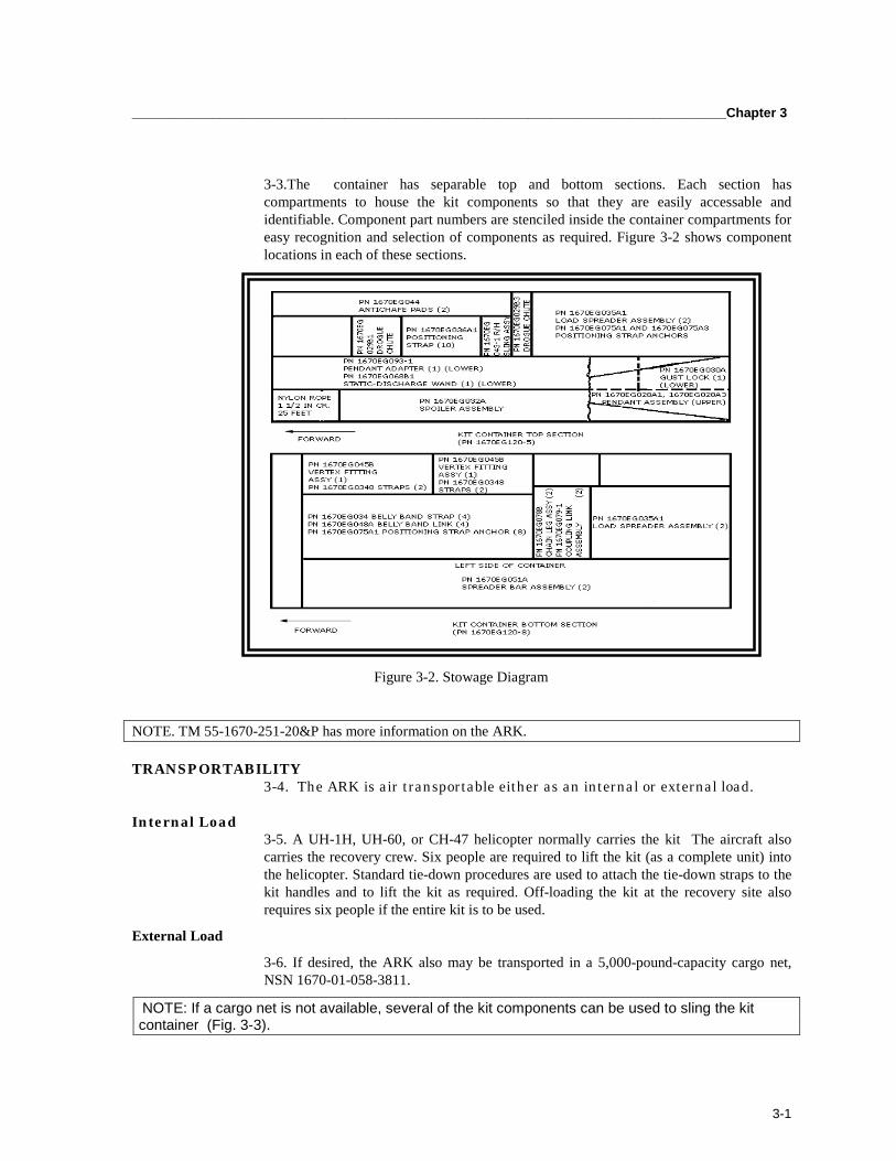
_________________________________________________________________________________Chapter 3
3-1
3-3.The container has separable top and bottom sections. Each section hascompartments to house the kit components so that they are easily accessable andidentifiable. Component part numbers are stenciled inside the container compartments foreasy recognition and selection of components as required. Figure 3-2 shows componentlocations in each of these sections.
1-1.
1-2.
1-3.
1-4.
1-5.
1-6.
1-7.
1-8.
1-9.
1-10.
1-11.
1-12.
1-13.
Figure 3-2. Stowage Diagram
NOTE. TM 55-1670-251-20&P has more information on the ARK.
TRANSPORTABILITY3-4. The ARK is air transportable either as an internal or external load.
Internal Load3-5. A UH-1H, UH-60, or CH-47 helicopter normally carries the kit The aircraft alsocarries the recovery crew. Six people are required to lift the kit (as a complete unit) intothe helicopter. Standard tie-down procedures are used to attach the tie-down straps to thekit handles and to lift the kit as required. Off-loading the kit at the recovery site alsorequires six people if the entire kit is to be used.
External Load
3-6. If desired, the ARK also may be transported in a 5,000-pound-capacity cargo net,NSN 1670-01-058-3811.
NOTE: If a cargo net is not available, several of the kit components can be used to sling the kitcontainer (Fig. 3-3).

FM 3-04.513(1-113)_________________________________________________________________________
3-2
Figure 3-3. Improvised External Rigging of the Kit Container
3-7. Before rigging, the connecting latches between the container halvesshould be checked to verify that they are attached and secure.
3-8. The kit assembly may be transported as an external sling load. If so, asmall recovery crew may be assigned, as only two people are required toprepare the kit for transport. However, before reducing the number ofpersonnel, factors such as the type of aircraft to be recovered, the type ofterrain, and the extent of damage to the disabled aircraft must be considered.
LIFT LIMITATIONS OF CRITICAL COMPONENTS3-9. When the rigging configuration is like that discussed in this manual, thecritical components of the aerial recovery kit can sustain loads of 21,600pounds. When the configuration is significantly different, capabilityexpectations should be reduced by 10 percent (down to 19,440 pounds). Thisreduction allows for additional aerodynamic drag.
DESCRIPTION OF MAJOR COMPONENTS 3-10. Major components of the ARK are discussed below.
Antichafe Pad (PN 1670EG044)3-11. The antichafe pad (Fig. 3-4) is used to maintain the spacing of, and toafford padding to, the bellyband strap assemblies in areas where they wouldnormally contact the fuselage of the slung aircraft. These pads minimize therisk of abrasion to the bellybands and damage to the aircraft being recovered.
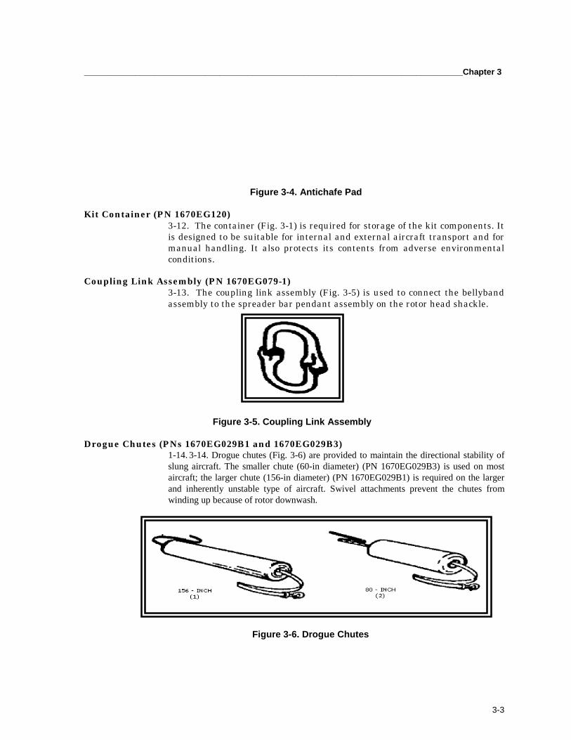
_________________________________________________________________________________Chapter 3
3-3
Figure 3-4. Antichafe Pad
Kit Container (PN 1670EG120)3-12. The container (Fig. 3-1) is required for storage of the kit components. Itis designed to be suitable for internal and external aircraft transport and formanual handling. It also protects its contents from adverse environmentalconditions.
Coupling Link Assembly (PN 1670EG079-1)3-13. The coupling link assembly (Fig. 3-5) is used to connect the bellybandassembly to the spreader bar pendant assembly on the rotor head shackle.
Figure 3-5. Coupling Link Assembly
Drogue Chutes (PNs 1670EG029B1 and 1670EG029B3)1-14. 3-14. Drogue chutes (Fig. 3-6) are provided to maintain the directional stability ofslung aircraft. The smaller chute (60-in diameter) (PN 1670EG029B3) is used on mostaircraft; the larger chute (156-in diameter) (PN 1670EG029B1) is required on the largerand inherently unstable type of aircraft. Swivel attachments prevent the chutes fromwinding up because of rotor downwash.
Figure 3-6. Drogue Chutes
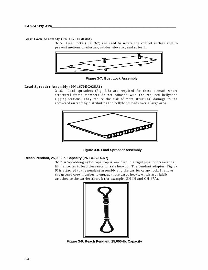
FM 3-04.513(1-113)_________________________________________________________________________
3-4
Gust Lock Assembly (PN 1670EG030A)3-15. Gust locks (Fig. 3-7) are used to secure the control surface and toprevent motions of ailerons, rudder, elevator, and so forth.
Figure 3-7. Gust Lock Assembly
Load Spreader Assembly (PN 1670EG035A1)3-16. Load spreaders (Fig. 3-8) are required for those aircraft wherestructural frame members do not coincide with the required bellybandrigging stations. They reduce the risk of more structural damage to therecovered aircraft by distributing the bellyband loads over a large area.
Figure 3-8. Load Spreader Assembly
Reach Pendant, 25,000-lb. Capacity (PN BOS-14-K7)3-17. A 5-foot-long nylon rope loop is enclosed in a rigid pipe to increase thelift helicopter to load clearance for safe hookup. The pendant adapter (Fig. 3-9) is attached to the pendant assembly and the carrier cargo hook. It allowsthe ground crew member to engage those cargo hooks, which are rigidlyattached to the carrier aircraft (for example, UH-lH and CH-47A).
Figure 3-9. Reach Pendant, 25,000-lb. Capacity
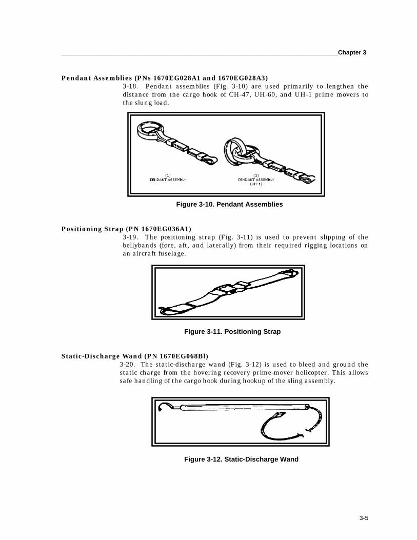
_________________________________________________________________________________Chapter 3
3-5
Pendant Assemblies (PNs 1670EG028A1 and 1670EG028A3)3-18. Pendant assemblies (Fig. 3-10) are used primarily to lengthen thedistance from the cargo hook of CH-47, UH-60, and UH-1 prime movers tothe slung load.
Figure 3-10. Pendant Assemblies
Positioning Strap (PN 1670EG036A1)3-19. The positioning strap (Fig. 3-11) is used to prevent slipping of thebellybands (fore, aft, and laterally) from their required rigging locations onan aircraft fuselage.
Figure 3-11. Positioning Strap
Static-Discharge Wand (PN 1670EG068Bl)3-20. The static-discharge wand (Fig. 3-12) is used to bleed and ground thestatic charge from the hovering recovery prime-mover helicopter. This allowssafe handling of the cargo hook during hookup of the sling assembly.
Figure 3-12. Static-Discharge Wand

FM 3-04.513(1-113)_________________________________________________________________________
3-6
Bellyband Sling Assembly (PN 1670EG057A1)3-21. Bellyband assemblies (Fig. 3-13) are used to cradle the downed aircraft.This eliminates the need for hard point attachments for the sling system.Adjustable chain leg assemblies (PN 1670EG078B) are provided for onebellyband assembly to provide a way to change its length relative to the otherband assembly so as to achieve appropriate attitude correction of therecovered aircraft.
Figure 3-13. Bellyband Sling Assembly
Rotor Head Sling Assembly (PN 1670EG043-1)3-22. The rotor head sling (Fig. 3-14) is used with the pendant assembly tofacilitate rotor head slinging of light helicopters: an alternate method tobellyband rigging.
Figure 3-14. Rotor Head Sling Arrangement
Spoiler Assembly (PN 1670EG032A)3-23. Spoilers are required to destroy undesirable lifting tendencies of thesuspended fixed-wing aircraft during forward flight (Fig. 3-15). Spoilers servean important function in preventing the slung aircraft from “flying” into therecovery helicopter.
Figure 3-15. Spoilers Installed on Damaged Fixed-Wing Aircraft

_________________________________________________________________________________Chapter 3
3-7
Spreader Bar Arrangement (PN 1670EG060B1)3-24. The spreader bar (Fig. 3-16) is used with the pendant and slingassemblies. It has two functions depending upon its orientation to therecoverable aircraft. On larger aircraft such as the CH-47, the spreader bararrangement is positioned across the fuselage. This reduces the crushingeffect of the bellybands on the fuselage by maintaining a fixed distance. Thisdistance is equal to about the width of the fuselage, between the twoconnecting ends of the bellyband assembly. For smaller aircraft, particularlyfixed-wing, the spreader bar is aligned with the centerline of the fuselage.This orientation allows for relocation of the vertex fitting on the spreader bararrangement to correct for attitude changes of the recovered aircraft. Also,the relative angle between the fore and aft bellybands is reduced.
Figure 3-16. Spreader Bar Arrangement
Positioning Strap Anchors (PNs 1670EG075A1 and 1670EG075A3)3-25. Positioning strap anchors (Fig. 3-17) provide a way to change thewebbing from two strap assemblies of three bands each to three equivalentassemblies of two bands each. The antichafe pad, to prevent abrasion of thewebbing and to afford a more uniform loading between the bellyband and theairframe, then covers the three strap legs.
Figure 3-17. Positioning Strap Anchors

FM 3-04.513(1-113)_________________________________________________________________________
3-8
BEFORE-USE PREPARATIONS3-26. Normally, not all of the suspension components and equipment in theARK are required to recover a particular aircraft. The kit components andequipment not required for a given recovery mission could be removed fromthe kit and left at the storage site. However, these components must bereplaced in the kit after completion of the mission.
AFTER-USE INSPECTIONS AND PACKING3-27. All recovery equipment should be dried, cleaned, and inspected beforerepackaging it in the container. Refer to TM 55-1670-251-20&P.
INTERIM-UNIT MAINTENANCE AERIAL RECOVERY KIT
WARNING The I-UMARK is primarily intended to recover an aircraft that has made a forced landing, is upright, and has no ob- vious damage to the rotor head, transmission, transmis- sion mounts, or serious structural damage to the tail boom assembly. If damage of this nature has occurred, the air- craft will have to be recovered with ARK (PN1670EG120 and NSN 1670-00-264-8941).
WARNING Recovery of the aircraft according to the instructions in this document may cause damage to the main rotor blades and rotor head of the recovered aircraft. Post-recovery in- spection criteria have not yet been developed. Therefore, the inspection criteria for blade strike and hard landing cited in the applicable aviation unit intermediate aircraft maintenance Instructions for those aircraft should be used to ascertain further airworthiness. If any doubt exists, the rotor components should be replaced.
NOTE: Components should be used only according to the procedures contained herein. Therecommended recovery airspeeds and maneuvers should not be exceeded.
PURPOSE AND USE
3-28. The I-UMARK, PN 81996-20090123, contains the equipment requiredto pre-rig, rig, and recover selected US Army helicopters.
TECHNICAL CHARACTERISTICS3-29. The kit components are packed in a watertight, aluminum air mobileshipping and storage container. The container has the inside dimensions of

_________________________________________________________________________________Chapter 3
3-9
45 x 40 x 20 inches. For man transportability, six large-bail lifting handlesaround the sides of the container assembly are provided. These can also beused as tie-down points for internal helicopter transport.
NOTE: Ground crew equipment, such as shockproof gloves, goggles, earplugs, static dischargewand, radios, etc., are not provided as a part of the I-UMARK hardware. Wrenches for assembling I-UMARK components are included in the kit.
3-30. The container has separable top and bottom sections. The long liftsling is wrapped in the largest loop possible around the inside of thecontainer. The OH-58D spreader bar assembly is disassembled and placed inthe center of the container. The remaining slings and components are placedin the container to best optimize space and hold the components in place. Aninventory card with component nomenclature, part number, and NSN (ifapplicable) is secured inside the lid of each kit. A copy of the operatingprocedure is included in each kit (Fig. 3-18).
Figure 3-18. I-UMARK Recovery Kit
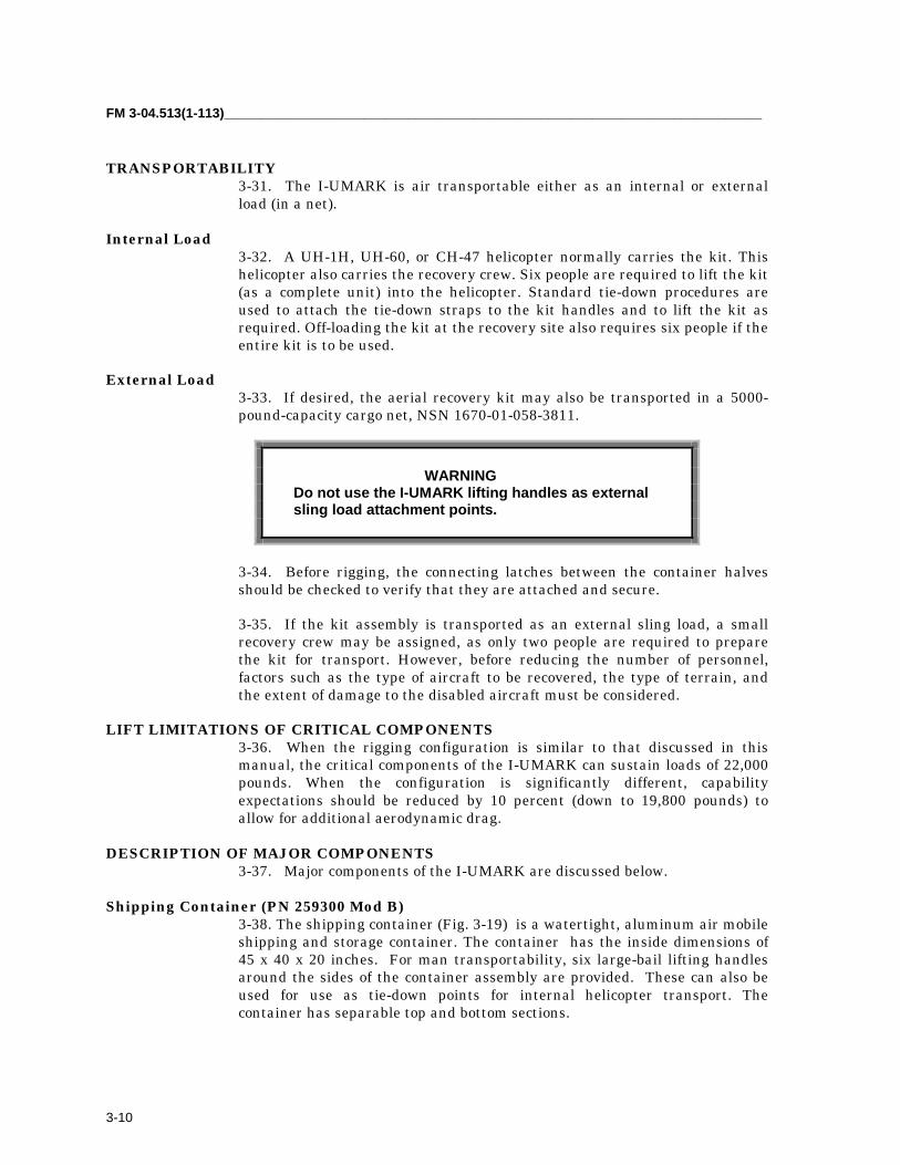
FM 3-04.513(1-113)_________________________________________________________________________
3-10
TRANSPORTABILITY3-31. The I-UMARK is air transportable either as an internal or externalload (in a net).
Internal Load3-32. A UH-1H, UH-60, or CH-47 helicopter normally carries the kit. Thishelicopter also carries the recovery crew. Six people are required to lift the kit(as a complete unit) into the helicopter. Standard tie-down procedures areused to attach the tie-down straps to the kit handles and to lift the kit asrequired. Off-loading the kit at the recovery site also requires six people if theentire kit is to be used.
External Load3-33. If desired, the aerial recovery kit may also be transported in a 5000-pound-capacity cargo net, NSN 1670-01-058-3811.
WARNING Do not use the I-UMARK lifting handles as external sling load attachment points.
3-34. Before rigging, the connecting latches between the container halvesshould be checked to verify that they are attached and secure.
3-35. If the kit assembly is transported as an external sling load, a smallrecovery crew may be assigned, as only two people are required to preparethe kit for transport. However, before reducing the number of personnel,factors such as the type of aircraft to be recovered, the type of terrain, andthe extent of damage to the disabled aircraft must be considered.
LIFT LIMITATIONS OF CRITICAL COMPONENTS3-36. When the rigging configuration is similar to that discussed in thismanual, the critical components of the I-UMARK can sustain loads of 22,000pounds. When the configuration is significantly different, capabilityexpectations should be reduced by 10 percent (down to 19,800 pounds) toallow for additional aerodynamic drag.
DESCRIPTION OF MAJOR COMPONENTS3-37. Major components of the I-UMARK are discussed below.
Shipping Container (PN 259300 Mod B)3-38. The shipping container (Fig. 3-19) is a watertight, aluminum air mobileshipping and storage container. The container has the inside dimensions of45 x 40 x 20 inches. For man transportability, six large-bail lifting handlesaround the sides of the container assembly are provided. These can also beused for use as tie-down points for internal helicopter transport. Thecontainer has separable top and bottom sections.
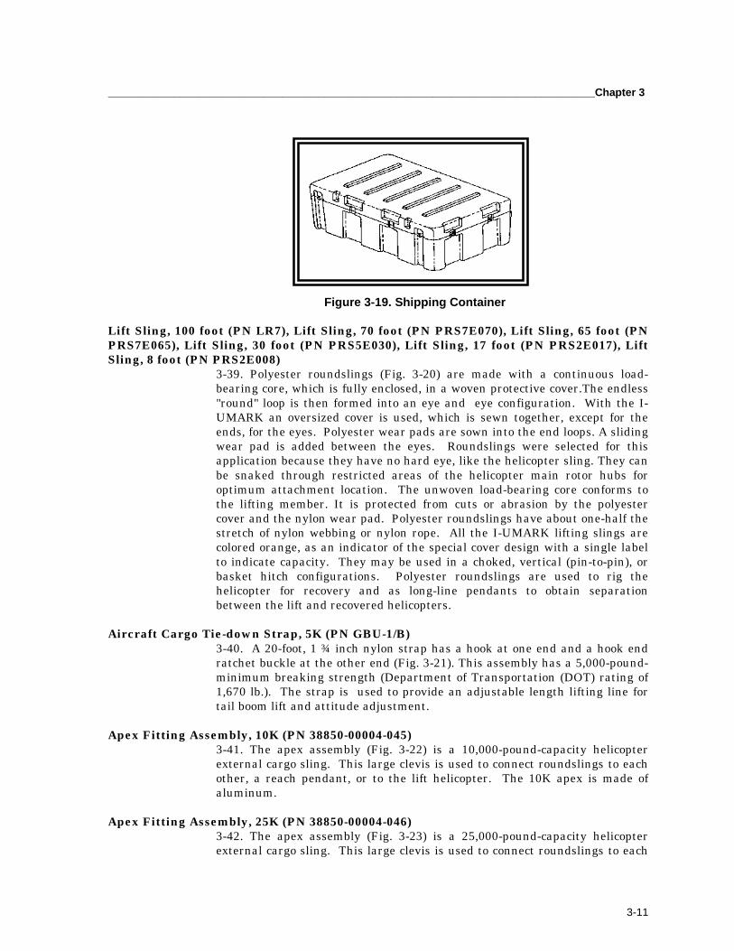
_________________________________________________________________________________Chapter 3
3-11
Figure 3-19. Shipping Container
Lift Sling, 100 foot (PN LR7), Lift Sling, 70 foot (PN PRS7E070), Lift Sling, 65 foot (PNPRS7E065), Lift Sling, 30 foot (PN PRS5E030), Lift Sling, 17 foot (PN PRS2E017), LiftSling, 8 foot (PN PRS2E008)
3-39. Polyester roundslings (Fig. 3-20) are made with a continuous load-bearing core, which is fully enclosed, in a woven protective cover.The endless"round" loop is then formed into an eye and eye configuration. With the I-UMARK an oversized cover is used, which is sewn together, except for theends, for the eyes. Polyester wear pads are sown into the end loops. A slidingwear pad is added between the eyes. Roundslings were selected for thisapplication because they have no hard eye, like the helicopter sling. They canbe snaked through restricted areas of the helicopter main rotor hubs foroptimum attachment location. The unwoven load-bearing core conforms tothe lifting member. It is protected from cuts or abrasion by the polyestercover and the nylon wear pad. Polyester roundslings have about one-half thestretch of nylon webbing or nylon rope. All the I-UMARK lifting slings arecolored orange, as an indicator of the special cover design with a single labelto indicate capacity. They may be used in a choked, vertical (pin-to-pin), orbasket hitch configurations. Polyester roundslings are used to rig thehelicopter for recovery and as long-line pendants to obtain separationbetween the lift and recovered helicopters.
Aircraft Cargo Tie-down Strap, 5K (PN GBU-1/B)3-40. A 20-foot, 1 ¾ inch nylon strap has a hook at one end and a hook endratchet buckle at the other end (Fig. 3-21). This assembly has a 5,000-pound-minimum breaking strength (Department of Transportation (DOT) rating of1,670 lb.). The strap is used to provide an adjustable length lifting line fortail boom lift and attitude adjustment.
Apex Fitting Assembly, 10K (PN 38850-00004-045)3-41. The apex assembly (Fig. 3-22) is a 10,000-pound-capacity helicopterexternal cargo sling. This large clevis is used to connect roundslings to eachother, a reach pendant, or to the lift helicopter. The 10K apex is made ofaluminum.
Apex Fitting Assembly, 25K (PN 38850-00004-046)3-42. The apex assembly (Fig. 3-23) is a 25,000-pound-capacity helicopterexternal cargo sling. This large clevis is used to connect roundslings to each
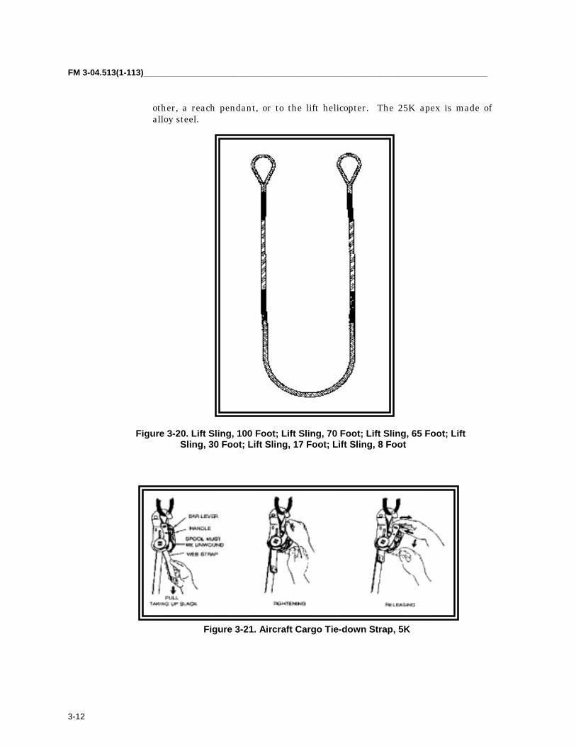
FM 3-04.513(1-113)_________________________________________________________________________
3-12
other, a reach pendant, or to the lift helicopter. The 25K apex is made ofalloy steel.
Figure 3-20. Lift Sling, 100 Foot; Lift Sling, 70 Foot; Lift Sling, 65 Foot; Lift Sling, 30 Foot; Lift Sling, 17 Foot; Lift Sling, 8 Foot
Figure 3-21. Aircraft Cargo Tie-down Strap, 5K
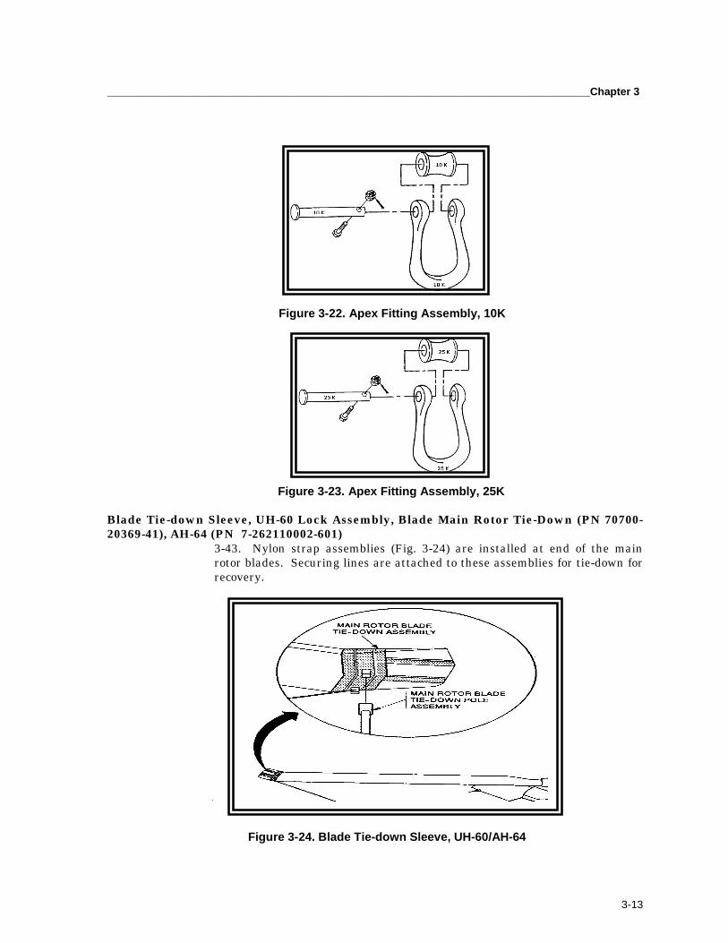
_________________________________________________________________________________Chapter 3
3-13
Figure 3-22. Apex Fitting Assembly, 10K
Figure 3-23. Apex Fitting Assembly, 25K
Blade Tie-down Sleeve, UH-60 Lock Assembly, Blade Main Rotor Tie-Down (PN 70700-20369-41), AH-64 (PN 7-262110002-601)
3-43. Nylon strap assemblies (Fig. 3-24) are installed at end of the mainrotor blades. Securing lines are attached to these assemblies for tie-down forrecovery.
Figure 3-24. Blade Tie-down Sleeve, UH-60/AH-64

FM 3-04.513(1-113)_________________________________________________________________________
3-14
Blade Tie-down Sleeve, OH-58D (PN 406-070-300-101)3-44. Nylon strap assemblies (Fig. 3-25) are installed at end of the main rotorblades. To these assemblies, securing lines are attached for tie-down forrecovery.
Figure 3-25. Blade Tie-down Sleeve, OH-58D
Air Vehicle Recovery Sling, AH-64 (PN 262110009-601)3-45. A steel cables sling (Fig. 3-26) attaches to 8 lifting lugs on the AH-64.This sling has been eliminated from more recent I-UMARK when procedureswere approved to lift the AH-64 using polyester roundslings choked aroundthe legs of the main rotor hub, similar to the UH-60 rigging.
Figure 3-26. Air Vehicle Recovery Sling, AH-64
OH-58D Hoisting Sling Assembly (PN T101284-107)3-46. This is the standard Bell nylon webbing hoisting sling (Fig. 3-27),except that the cross spreader bar is replaced with a bar especially designedto take the dynamic loads associated with aerial recovery.

_________________________________________________________________________________Chapter 3
3-15
Figure 3-27. OH-58D Hoisting Sling Assembly
Securing Line (PN MIL-R-30500)3-47. Polyester rope (Fig. 3-28) is used to tie-down main rotor blades.
Figure 3-28. Securing Line
Pressure Sensitive Tape, Roll (PN A-A-1586)3-48. Standard tape (Fig. 3-29) is used to secure lines to prevent snaggingbefore lift-off.
Figure 3-29. Pressure Sensitive Tape, Roll

FM 3-04.513(1-113)_________________________________________________________________________
3-16
Drogue Chute (PN 1670EG029B3)3-49. A specially designed parachute (Fig. 3-30) attaches to the tail wheel ofselected helicopters to improve the in-flight stability during recovery. Sameas the small drogue chute used in the old ARK.
Figure 3-30. Drogue Chute
Lifting Clevis Assembly, UH-1/AH-1/OH-58A/C (PN 204-011-178)3-50. The primary lift attachment for the AH-1/UH-1 and later OH-58A/Chelicopters (Fig. 3-31) is the lifting clevis assembly.
Figure 3-31. Lifting Clevis Assembly, UH-1/AH-1/OH-58A/C
Combination Wrench, 9/16 inch (PN GGG-W-636)3-51. Standard open-end and box-end wrenches (Fig. 3-32) are used to securethe lift bolts on the UH-1/AH-1 lifting clevis assembly and the safety bolt onthe apex fitting assembly.
Figure 3-32. Combination Wrench, 9/16 inch

_________________________________________________________________________________Chapter 3
3-17
Combination Wrench, 3/4 inch (PN GGG-W-636)3-52. Standard open-end and box-end wrenches (Fig. 3-33) are used to securethe lift bolts on the UH-1/AH-1 lifting clevis assembly and the safety bolt onthe apex fitting assembly.
Figure 3-33. Combination Wrench, 3/4 inch
I-UMARK Tool Pouch (NSN 5140-00-329-4306)3-53. This pouch (Fig. 3-34) holds the above tools.
Figure 3-34. I-UMARK Tool Pouch
I-UMARK Inventory Card (PN 1670EG20090IC)3-54. This inventory card (Fig. 3-35) provides a listing of these componentswith part numbers and NSNs when available. (No new NSNs were obtainedfor I-UMARK components. NSNs were obtained for all HERK polyesterroundslings and only already stocked items when used to make up the listingof components.)
Figure 3-35. I-UMARK Inventory Card
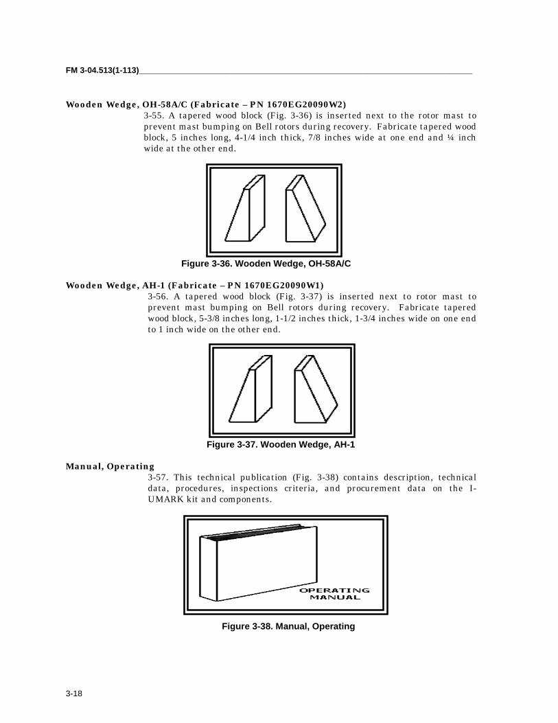
FM 3-04.513(1-113)_________________________________________________________________________
3-18
Wooden Wedge, OH-58A/C (Fabricate – PN 1670EG20090W2)3-55. A tapered wood block (Fig. 3-36) is inserted next to the rotor mast toprevent mast bumping on Bell rotors during recovery. Fabricate tapered woodblock, 5 inches long, 4-1/4 inch thick, 7/8 inches wide at one end and ¼ inchwide at the other end.
Figure 3-36. Wooden Wedge, OH-58A/C
Wooden Wedge, AH-1 (Fabricate – PN 1670EG20090W1)3-56. A tapered wood block (Fig. 3-37) is inserted next to rotor mast toprevent mast bumping on Bell rotors during recovery. Fabricate taperedwood block, 5-3/8 inches long, 1-1/2 inches thick, 1-3/4 inches wide on one endto 1 inch wide on the other end.
Figure 3-37. Wooden Wedge, AH-1
Manual, Operating3-57. This technical publication (Fig. 3-38) contains description, technicaldata, procedures, inspections criteria, and procurement data on the I-UMARK kit and components.
Figure 3-38. Manual, Operating

_________________________________________________________________________________Chapter 3
3-19
BEFORE-USE PREPARATIONS3-58. Normally, not all of the suspension components and equipment in therecovery kit are required to recover a particular aircraft. The kit componentsand equipment not required for a given recovery mission could be removedfrom the kit and left at the storage site. However, these components must bereplaced in the kit after completion of the mission.
AFTER-USE INSPECTIONS AND PACKING3-59. After a recovery mission has been completed, the I-UMARK equipmentmust be returned to a ready for issue (RFI) condition.
3-60. All recovery equipment should be dried, cleaned, and inspected beforerepackaging it in the container. TM 55-1670-251-20&P, OrganizationalMaintenance Manual (Including Repair Parts and Special Tools List) forAerial Recovery Kit, PN 167EG109A (NSN 1670-00-264-8941), describes howto care for and inspect the ARK components contained in the I-UMARK.
3-61. After completion of the cleaning and inspection for damage, allcomponents of the I-UMARK should be replaced in the I-UMARK containerin a neat and orderly fashion. Any component damaged must be replaced.The container should then be secured and stored for a subsequent recoverymission.
UNIT MAINTENANCE AERIAL RECOVERY KIT
PURPOSE AND USE3-62. The unit maintenance aerial recovery kit (UMARK) is a system ofslings, tie-downs, stabilizing equipment, and interconnecting hardware thatcan be assembled in multiple configurations to effect the safe aerial recoveryof disabled or damaged helicopters. Helicopter damage may include, but isnot limited to:
• The destruction of the main rotor head.• The main rotor shaft or mast bent, broken, or loose in the transmission.• The main transmission case cracked, broken, loose, or separated from
the airframe.• Damage to the tail boom to such an extent that it is not suitable as a
lifting point.• Bending or buckling of the airframe so as to create aerodynamic
instabilities that could result in additional damage during the recoveryflight.
• Engine(s) severely damaged or separated from the airframe.
3-63. UMARK is designed to allow three ground personnel to rig a disabledhelicopter for aerial recovery in less than 15 minutes. An exception to thistime frame would be the aerial recovery of a CH-47 helicopter, which requiresthe installation of components from two UMARK kits. The disabled or
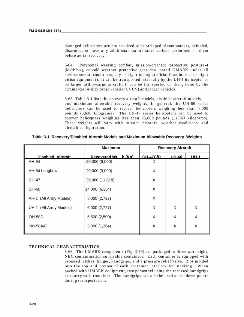
FM 3-04.513(1-113)_________________________________________________________________________
3-20
damaged helicopters are not required to be stripped of components, defueled,disarmed, or have any additional maintenance actions performed on thembefore aerial recovery.
3-64. Personnel wearing combat, mission-oriented protective posture-4(MOPP-4), or cold weather protective gear can install UMARK under allenvironmental conditions, day or night (using artificial illumination or nightvision equipment). It can be transported internally by the UH-1 helicopter oron larger utility/cargo aircraft. It can be transported on the ground by thecommercial utility cargo vehicle (CUCV) and larger vehicles.
3-65. Table 3-1 lists the recovery aircraft models, disabled aircraft models,and maximum allowable recovery weights. In general, the UH-60 serieshelicopters can be used to recover helicopters weighing less than 8,000pounds (3,636 kilograms). The CH-47 series helicopters can be used torecover helicopters weighing less than 25,000 pounds (11,363 kilograms).These weights will vary with mission distance, weather conditions, andaircraft configuration.
Table 3-1. Recovery/Disabled Aircraft Models and Maximum Allowable Recovery Weights
Maximum Recovery Aircraft
Disabled Aircraft Recovered Wt. Lb (Kg) CH-47C/D UH-60 UH-1AH-64 20,000 (9,090) X
AH-64 Longbow 20,000 (9,090) X
CH-47 26,000 (11,818) X
UH-60 14,000 (6,364) X
AH-1 (All Army Models) 8,000 (2,727) X
UH-1 (All Army Models) 6,000 (2,727) X X X
OH-58D 5,500 (2,500) X X X
OH-58A/C 3,000 (1,364) X X X
TECHNICAL CHARACTERISTICS3-66. The UMARK components (Fig. 3-39) are packaged in three watertight,NBC contamination survivable containers. Each container is equipped withrecessed latches, hinges, handgrips, and a pressure relief valve. Ribs moldedinto the top and bottom of each container interlock for stacking. Whenpacked with UMARK equipment, two personnel using the recessed handgripscan carry each container. The handgrips can also be used as tie-down pointsduring transportation.

_________________________________________________________________________________Chapter 3
3-21
Figure 3-39. UMARK Recovery Kit
3-67. The following components are included in each UMARK:
• Thirteen lightweight slings.• Three heavyweight slings.• Three box link assemblies.• Three sling link assemblies.• One cross bar assembly.• One lifting clevis assembly.• One shackle assembly.• Four blade sleeve assemblies.• Four adjustable length tie-down assemblies.• Five fixed length tie-down assemblies.• One sight wedge assembly for use on the OH-58D helicopter.• Two mast wedges (One mast wedge is used on the OH-58D helicopter;
the second mast wedge is used on the AH-1 helicopter).• One square wedges for use on the UH-1 helicopter.• One blade pole assembly.• Two CH-47 hook thimbles.• Three shipping containers.• One drogue parachute.
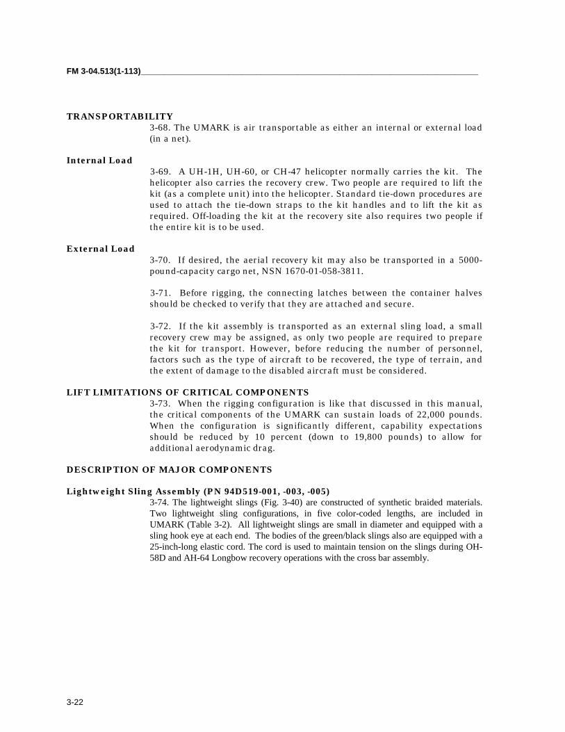
FM 3-04.513(1-113)_________________________________________________________________________
3-22
TRANSPORTABILITY3-68. The UMARK is air transportable as either an internal or external load(in a net).
Internal Load 3-69. A UH-1H, UH-60, or CH-47 helicopter normally carries the kit. The
helicopter also carries the recovery crew. Two people are required to lift thekit (as a complete unit) into the helicopter. Standard tie-down procedures areused to attach the tie-down straps to the kit handles and to lift the kit asrequired. Off-loading the kit at the recovery site also requires two people ifthe entire kit is to be used.
External Load3-70. If desired, the aerial recovery kit may also be transported in a 5000-pound-capacity cargo net, NSN 1670-01-058-3811.
3-71. Before rigging, the connecting latches between the container halvesshould be checked to verify that they are attached and secure.
3-72. If the kit assembly is transported as an external sling load, a smallrecovery crew may be assigned, as only two people are required to preparethe kit for transport. However, before reducing the number of personnel,factors such as the type of aircraft to be recovered, the type of terrain, andthe extent of damage to the disabled aircraft must be considered.
LIFT LIMITATIONS OF CRITICAL COMPONENTS3-73. When the rigging configuration is like that discussed in this manual,the critical components of the UMARK can sustain loads of 22,000 pounds.When the configuration is significantly different, capability expectationsshould be reduced by 10 percent (down to 19,800 pounds) to allow foradditional aerodynamic drag.
DESCRIPTION OF MAJOR COMPONENTS
Lightweight Sling Assembly (PN 94D519-001, -003, -005)3-74. The lightweight slings (Fig. 3-40) are constructed of synthetic braided materials.Two lightweight sling configurations, in five color-coded lengths, are included inUMARK (Table 3-2). All lightweight slings are small in diameter and equipped with asling hook eye at each end. The bodies of the green/black slings also are equipped with a25-inch-long elastic cord. The cord is used to maintain tension on the slings during OH-58D and AH-64 Longbow recovery operations with the cross bar assembly.

_________________________________________________________________________________Chapter 3
3-23
Figure 3-40. Lightweight Sling Assembly
Table 3-2. Identification Chart for Each Lightweight Sling Assembly
Color Code Length QuantityBlack/White 10 feet (120 in.) 1Green/White 12.5 feet (150 in.) 4Yellow/White 12.75 feet (153 in.) 4Red/White 17.33 feet (208 in.) 2Blue/White 30 feet (360 in.) 2
Heavyweight Sling Assembly (PN 94H520-001)3-75. The heavyweight slings (Fig. 3-41) are constructed of synthetic braidedmaterials. All three heavyweight slings included in UMARK are of largediameter and color-coded with black and white stripes. Each sling is 30 feet(360 in.) in length. The heavyweight slings are all equipped with two large-diameter hook eyes on the top end and one large-diameter hook eye on thebottom end. Besides having the same large-diameter hook eyes, one slingalso is equipped with two bridle eyes about 7 feet (84 in.) from the top end.
Figure 3-41. Heavyweight Sling AssemblyBox Link Assembly (PN 94C524-001)

FM 3-04.513(1-113)_________________________________________________________________________
3-24
3-76. A box link assembly (Fig. 3-42) is used to connect two slings in seriesconfiguration. Components of a box link assembly include the box linkhousing, two box link pins, and two quick release pins. Two holes,corresponding to the diameter of the box link pins, are drilled on the top andbottom of the box link housing. The two box link pins and the two quickrelease pins are interconnected by wire rope.
Figure 3-42. Box Link Assembly
Sling Link Assembly (PN 94D523-001)3-77. A sling link assembly (Fig. 3-43) is used to connect four slings in aseries-parallel configuration. Components of the sling link assembly includea sling link pin with attached spring lock.
Figure 3-43. Sling Link Assembly
Cross Bar Assembly (PN 94H501-001)3-78. The cross bar assembly (Fig. 3-44) is used to provide a load path around the AH-64Longbow radar antenna or the OH-58D mast-mounted sight. The cross bar assemblyconsists of a cross bar housing, four tube assemblies, and four quick release lock pins.
3-79. The metal cross bar housing is X-shaped with four arms positions 90-degrees apart. Each arm of the cross bar housing has a hole bored throughthe top and bottom surfaces. The bottom of the cross bar housing is fittedwith a foam fitting, which centers the cross bar housing on the radar antennaor sight and protects the antenna or sight during transportation of the

_________________________________________________________________________________Chapter 3
3-25
aircraft. The foam also allows for assembly of the cross bar on the antenna orsight.
3-80. Each tube assembly is fitted with a lug fitting on the outboard end.The lug fitting is equipped with a spring lock. A hole is bored through theinboard end of each tube assembly. Quick release pins are used to connectthe tube assemblies to the cross bar housing.
Figure 3-44. Cross Bar Assembly
Lifting Clevis Assembly (PN 94D509-001)3-81. During AH-1, UH-1, and OH-58A/C helicopter recovery operations, thelifting clevis assembly (Fig. 3-45) replaces slings as the primary attachmentdevices to the main rotor assembly of the disabled helicopter. Components ofthe lifting clevis assembly include a clevis subassembly, a locking pin, and aquick release pin.
3-82. The clevis subassembly consists of a clevis, two clevis pins, and a pivotblock. The clevis pins are used to attach the clevis to the pivot block. Thepivot block acts as a universal joint allowing movement in both fore-and-aftand side-to-side directions. The locking pin is used to attach lifting clevisassembly to the helicopter hub nut lug. The quick release lock pin is used tosecure the locking pin into position. Wire ropes are used to attach the lockingpin and quick release pin to the clevis subassembly.
Figure 3-45. Lifting Clevis Assembly
Shackle Assembly (PN 94D514-001)
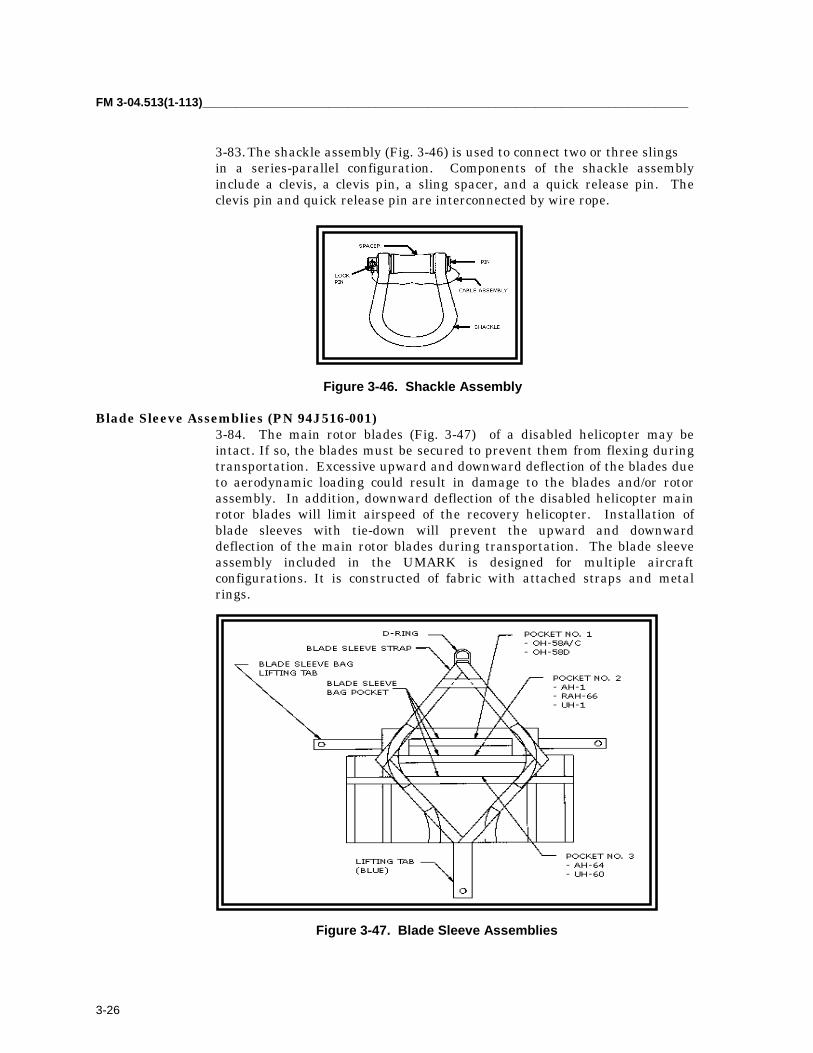
FM 3-04.513(1-113)_________________________________________________________________________
3-26
3-83. The shackle assembly (Fig. 3-46) is used to connect two or three slingsin a series-parallel configuration. Components of the shackle assemblyinclude a clevis, a clevis pin, a sling spacer, and a quick release pin. Theclevis pin and quick release pin are interconnected by wire rope.
Figure 3-46. Shackle Assembly
Blade Sleeve Assemblies (PN 94J516-001) 3-84. The main rotor blades (Fig. 3-47) of a disabled helicopter may be
intact. If so, the blades must be secured to prevent them from flexing duringtransportation. Excessive upward and downward deflection of the blades dueto aerodynamic loading could result in damage to the blades and/or rotorassembly. In addition, downward deflection of the disabled helicopter mainrotor blades will limit airspeed of the recovery helicopter. Installation ofblade sleeves with tie-down will prevent the upward and downwarddeflection of the main rotor blades during transportation. The blade sleeveassembly included in the UMARK is designed for multiple aircraftconfigurations. It is constructed of fabric with attached straps and metalrings.
Figure 3-47. Blade Sleeve Assemblies

_________________________________________________________________________________Chapter 3
3-27
Blade Pole Assembly (PN 94J531-001)3-85. The blade pole assembly (Fig. 3-48) included in the UMARK is constructed of 1-inch in diameter aluminum tubing. Matching and aligningthe poles with its color-coded stripes and inserting the three attached quickrelease pins can assemble the blade pole assembly.
Figure 3-48. Blade Sleeve Pole Assembly
Fixed-Length Tie-down Assemblies (PN 94C522-001, -011)3-86. The fixed-length, tie-down assemblies (Fig. 3-49) included in UMARKare constructed of synthetic braided material, they are 40 feet (480 in.) inlength. Two configurations are provided. Four of the tie-downs have a fusedtop end and a sling hook eye with attached snap hook at the bottom. A singletie-down has fused ends at both the top and bottom ends.
Figure 3-49. Fixed-Length, Tie-down Assemblies
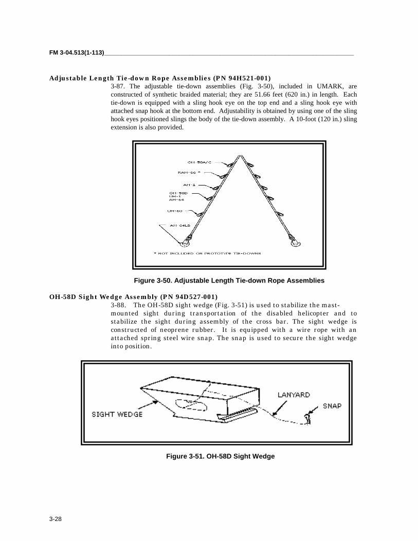
FM 3-04.513(1-113)_________________________________________________________________________
3-28
Adjustable Length Tie-down Rope Assemblies (PN 94H521-001)3-87. The adjustable tie-down assemblies (Fig. 3-50), included in UMARK, areconstructed of synthetic braided material; they are 51.66 feet (620 in.) in length. Eachtie-down is equipped with a sling hook eye on the top end and a sling hook eye withattached snap hook at the bottom end. Adjustability is obtained by using one of the slinghook eyes positioned slings the body of the tie-down assembly. A 10-foot (120 in.) slingextension is also provided.
Figure 3-50. Adjustable Length Tie-down Rope Assemblies
OH-58D Sight Wedge Assembly (PN 94D527-001)3-88. The OH-58D sight wedge (Fig. 3-51) is used to stabilize the mast-mounted sight during transportation of the disabled helicopter and tostabilize the sight during assembly of the cross bar. The sight wedge isconstructed of neoprene rubber. It is equipped with a wire rope with anattached spring steel wire snap. The snap is used to secure the sight wedgeinto position.
Figure 3-51. OH-58D Sight Wedge

_________________________________________________________________________________Chapter 3
3-29
AH-1/OH-58A/C Mast Wedges (PN 94D529-1, 94D530-1)3-89. The AH-1 and OH-58A/C mast wedges (Fig. 3-52) are circular siliconerubber tubes. They are used to position and secure the disabled helicoptermast during transportation. Two sizes are included in UMARK. The large-diameter mast wedge is used to secure the AH-1 mast; the small-diametermast wedge is used to secure the OH-58A/C masts. Each mast wedge isequipped with a wire rope on one side and a spring steel snap ring attachedwith wire rope on the opposite side. This secures the mast wedge to the mastand main rotor and prevents tilting of the main rotor during transportation.
Figure 3-52. AH-1/OH-58A/C Mast Wedges
UH-1 Square Wedge Assembly (PN 94D528-001)3-90. The UH-1 square wedges (Fig. 3-53) are installed on the main rotorstops to prevent tilting of the main rotor during transportation of thedisabled helicopter. The wedges are constructed of synthetic rubber. Onewedge is equipped with a wire rope with a spring steel snap ring attached.The second wedge is equipped with a wire rope only. The snap ring and wirerope are used to position and secure the square wedges.
Figure 3-53. UH-1 Square Wedges
Shipping Containers (PN 21-4021-0804)

FM 3-04.513(1-113)_________________________________________________________________________
3-30
3-91. The UMARK components (Fig. 3-54) are packaged in three watertight,NBC contamination survivable containers. Each container is equipped withrecessed latches, hinges, handgrips, and a pressure relief valve. Ribs moldedinto the top and bottom of each container interlock for stacking. When packedwith UMARK equipment, two personnel using the recessed handgrips cancarry each container. The handgrips can also be used as tie-down pointsduring transportation.
Figure 3-54. Shipping Containers
Drogue Parachute (PN 1670EG029B3)3-92. A drogue parachute (Fig. 3-55) is included in UMARK. The drogueparachute must be deployed during recovery operations to maintainaerodynamic stability. The drogue parachute also must be deployed whenrecovering and heavily damaged helicopter when either the vertical orhorizontal stabilizer is broken off.
Figure 3-55. Drogue Parachute

_________________________________________________________________________________Chapter 3
3-31
CH-47 Hook Thimble (PN 94C533-001)3-93. The hook thimble (Fig. 3-56) will be installed on the CH-47 cargo hook.The ultimate load is 100,000 pounds before failure. The proof load is 40,000pounds with no permanent deflection of visible damage. The hook thimble isused with 5- to 10-foot sling (PN 94H520-001).
Figure 3-56. CH-47 Hook Thimble
BEFORE-USE PREPARATIONS3-94. Normally, not all of the suspension components and equipment in therecovery kit are required to recover a particular aircraft. The kit componentsand equipment not required for a given recovery mission could be removedfrom the kit and left at the storage site. However, these components must bereplaced in the kit after completion of the mission.
AFTER-USE INSPECTIONS AND PACKING3-95. After a recovery mission has been completed, the UMARK equipmentmust be returned to a ready for issue (RFI) condition.
3-96. All recovery equipment should be dried, cleaned, and inspected beforerepackaging it in the container.
3-97. After completion of the cleaning and inspection for damage, allcomponents of the UMARK should be replaced in the UMARK container in aneat and orderly fashion. Any component damaged must be replaced. Thecontainer should then be secured and stored for a subsequent recoverymission.
HELICOPTER RECOVERY KIT
PURPOSE AND USE3-98. The HERK (Fig. 3-57) contains the equipment required to pre-rig, rig,and recover selected US Army helicopters.

FM 3-04.513(1-113)_________________________________________________________________________
3-32
TECHNICAL CHARACTERISTICS3-99. The kit components are packed in a watertight, polyethylene, airmobile shipping and storage container. The container has the dimensions of33-inch long x 21-inch wide x 22-inch high.
Figure 3-57. HERK Recovery Kit
TRANSPORTABILITY3-100. The HERK is air transportable as either an internal or external load(in a net).
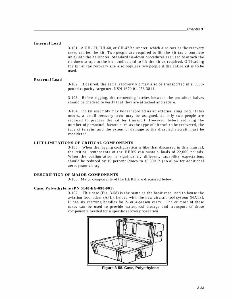
_________________________________________________________________________________Chapter 3
3-33
Internal Load3-101. A UH-1H, UH-60, or CH-47 helicopter, which also carries the recoverycrew, carries the kit. Two people are required to lift the kit (as a completeunit) into the helicopter. Standard tie-down procedures are used to attach thetie-down straps to the kit handles and to lift the kit as required. Off-loadingthe kit at the recovery site also requires two people if the entire kit is to beused.
External Load3-102. If desired, the aerial recovery kit may also be transported in a 5000-pound-capacity cargo net, NSN 1670-01-058-3811.
3-103. Before rigging, the connecting latches between the container halvesshould be checked to verify that they are attached and secure.
3-104. The kit assembly may be transported as an external sling load. If thisoccurs, a small recovery crew may be assigned, as only two people arerequired to prepare the kit for transport. However, before reducing thenumber of personnel, factors such as the type of aircraft to be recovered, thetype of terrain, and the extent of damage to the disabled aircraft must beconsidered.
LIFT LIMITATIONS OF CRITICAL COMPONENTS3-105. When the rigging configuration is like that discussed in this manual,the critical components of the HERK can sustain loads of 22,000 pounds.When the configuration is significantly different, capability expectationsshould be reduced by 10 percent (down to 19,800 lb.) to allow for additionalaerodynamic drag.
DESCRIPTION OF MAJOR COMPONENTS3-106. Major components of the HERK are discussed below.
Case, Polyethylene (PN 5140-EG-090-001)3-107. This case (Fig. 3-58) is the same as the basic case used to house theaviation foot locker (AFL), fielded with the new aircraft tool system (NATS).It has six carrying handles for 2- or 4-person carry. One or more of thesecases can be used to provide waterproof storage and transport of thosecomponents needed for a specific recovery operation.
Figure 3-58. Case, Polyethylene
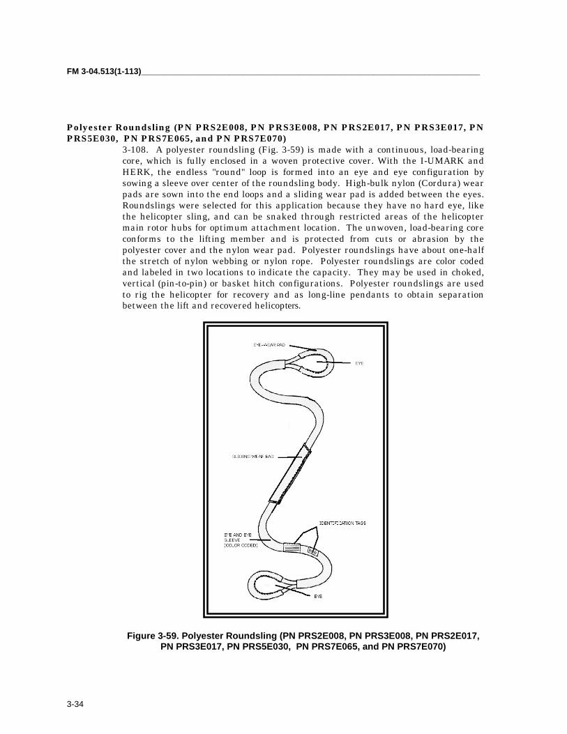
FM 3-04.513(1-113)_________________________________________________________________________
3-34
Polyester Roundsling (PN PRS2E008, PN PRS3E008, PN PRS2E017, PN PRS3E017, PNPRS5E030, PN PRS7E065, and PN PRS7E070)
3-108. A polyester roundsling (Fig. 3-59) is made with a continuous, load-bearingcore, which is fully enclosed in a woven protective cover. With the I-UMARK andHERK, the endless "round" loop is formed into an eye and eye configuration bysowing a sleeve over center of the roundsling body. High-bulk nylon (Cordura) wearpads are sown into the end loops and a sliding wear pad is added between the eyes.Roundslings were selected for this application because they have no hard eye, likethe helicopter sling, and can be snaked through restricted areas of the helicoptermain rotor hubs for optimum attachment location. The unwoven, load-bearing coreconforms to the lifting member and is protected from cuts or abrasion by thepolyester cover and the nylon wear pad. Polyester roundslings have about one-halfthe stretch of nylon webbing or nylon rope. Polyester roundslings are color codedand labeled in two locations to indicate the capacity. They may be used in choked,vertical (pin-to-pin) or basket hitch configurations. Polyester roundslings are usedto rig the helicopter for recovery and as long-line pendants to obtain separationbetween the lift and recovered helicopters.
Figure 3-59. Polyester Roundsling (PN PRS2E008, PN PRS3E008, PN PRS2E017,PN PRS3E017, PN PRS5E030, PN PRS7E065, and PN PRS7E070)

_________________________________________________________________________________Chapter 3
3-35
Apex Assembly, 10K (PN 38850-00004-045)
3-109. The apex assembly (Fig. 3-60) is a 10,000-pound-capacity helicopterexternal cargo sling. This large clevis is used to connect roundslings to eachother, a reach pendant, or to the lift helicopter. The 10K apex is made ofaluminum.
Figure 3-60. Apex Assembly
PIP Pin (PN MS17984C612) (Optional) (1.6-inch Grip)3-110. PIP (push-in-pullout) pins (Fig. 3-61) are quick-disconnect pins usedin place of nuts and bolts in applications requiring rapidattachment/installation. For helicopter hoisting and recovery operations,they may be used in place of the safety bolt to secure the apex load pin.
Figure 3-61. PIP Pin
Apex Assembly, 25K (PN 38850-0000-046)3-111. The apex assembly (Fig. 3-62) is a 25,000-pound-capacity helicopterexternal cargo sling. This large clevis is used to connect roundslings to eachother, a reach pendant, or to the lift helicopter. The 25K apex is made ofalloy steel.

FM 3-04.513(1-113)_________________________________________________________________________
3-36
Figure 3-62. Apex Assembly
PIP Pin (PN MS17984C616) (Optional) (2.0-inch Grip)3-112. PIP (push-in-pullout) pins (Fig. 3-63) are quick-disconnect pins usedin place of nuts and bolts in applications requiring rapidattachment/installation. For helicopter hoisting and recovery operations,they may be used in place of the safety bolt to secure the apex load pin.
Figure 3-63. PIP Pin
Eye Hook (PN S-320A-11)3-113. The eye hook (Fig. 3-64) is used for quick attachment of a roundslingto one or more additional roundslings. The pin of an apex assembly isattached to the eye of the hook. The HERK includes two eye hooks toexpedite hoisting of UH-60s for vessel shipment.
Figure 3-64. Eye Hook
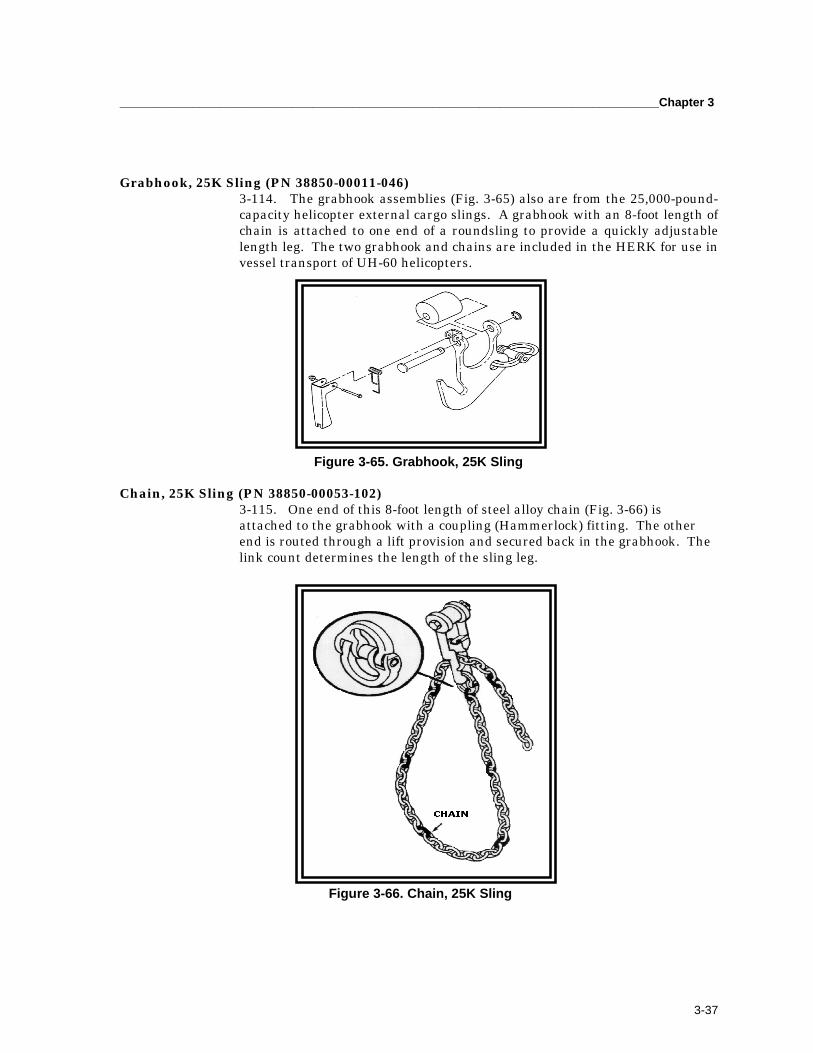
_________________________________________________________________________________Chapter 3
3-37
Grabhook, 25K Sling (PN 38850-00011-046)3-114. The grabhook assemblies (Fig. 3-65) also are from the 25,000-pound-capacity helicopter external cargo slings. A grabhook with an 8-foot length ofchain is attached to one end of a roundsling to provide a quickly adjustablelength leg. The two grabhook and chains are included in the HERK for use invessel transport of UH-60 helicopters.
Figure 3-65. Grabhook, 25K Sling
Chain, 25K Sling (PN 38850-00053-102)3-115. One end of this 8-foot length of steel alloy chain (Fig. 3-66) isattached to the grabhook with a coupling (Hammerlock) fitting. The otherend is routed through a lift provision and secured back in the grabhook. Thelink count determines the length of the sling leg.
Figure 3-66. Chain, 25K Sling

FM 3-04.513(1-113)_________________________________________________________________________
3-38
Shackle, Anchor (PN 1019515 (75535))3-116. An anchor shackle (Fig. 3-67) is a small clevis used to attach to a lift eye. Thefour anchor shackles are included in the HERK to allow attachment of polyesterroundslings to the fuselage hard point on the CH-47.
Figure 3-67. Shackle, Anchor
SUPPLEMENTAL ITEMS
SPREADER BAR (TM 1-1520-237-S, FIG. 7-6)3-117. A 3-section, aluminum tube, two inner tubes and one outer tube, with10K apex assemblies at each end (Fig. 3-68) is used to keep the lifting linefrom contacting the lifted helicopter. Principle use is vessel transport of theUH-60.
Figure 3-68. Spreader Bar

_________________________________________________________________________________Chapter 3
3-39
Lifting Clevis, AH-1/UH-1 (PN 204-011-178-1)3-118. The primary lift attachment for the AH-1/UH-1 and later OH-58A/Chelicopters is shown in Figure 3-69.
Figure 3-69. Lifting Clevis, AH-1/UH-1
Lifting Ring (PN 114E5909-8)3-119. Rings (Fig. 3-70) are screwed into the rotor masts on the CH-47 forattachment of hoisting slings when transmission mounts are intact.
Figure 3-70. Lifting Ring
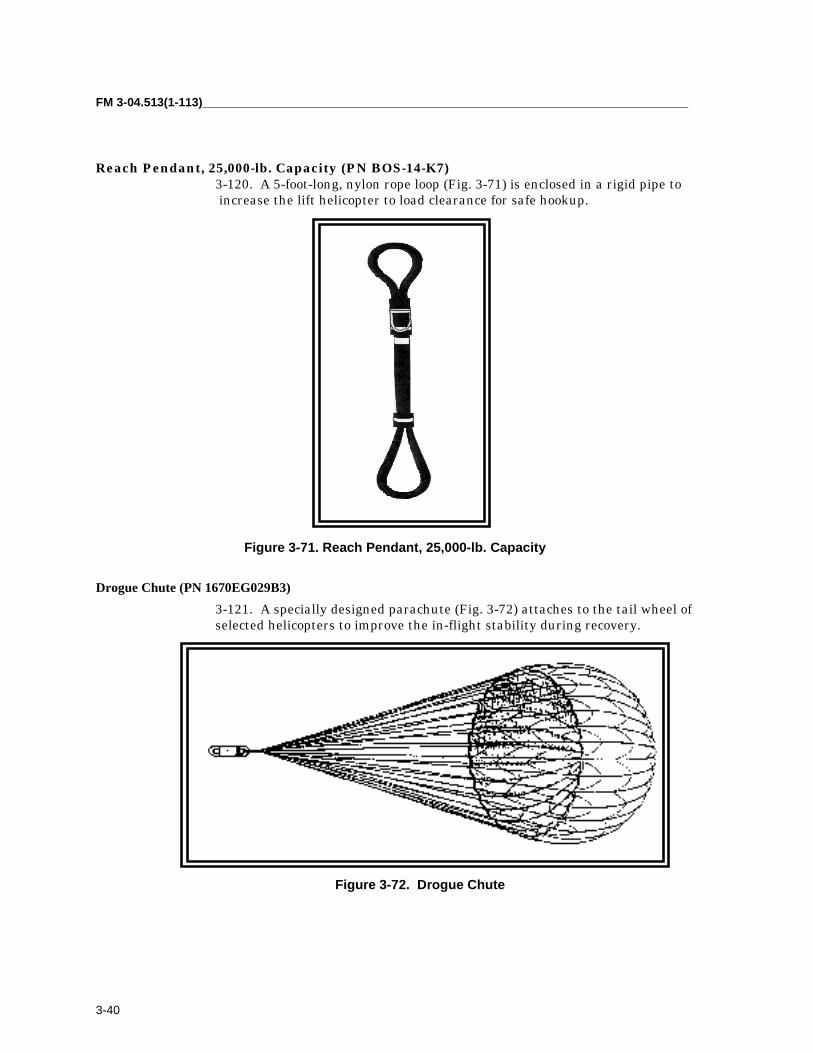
FM 3-04.513(1-113)_________________________________________________________________________
3-40
Reach Pendant, 25,000-lb. Capacity (PN BOS-14-K7)3-120. A 5-foot-long, nylon rope loop (Fig. 3-71) is enclosed in a rigid pipe to increase the lift helicopter to load clearance for safe hookup.
Figure 3-71. Reach Pendant, 25,000-lb. Capacity
Drogue Chute (PN 1670EG029B3)3-121. A specially designed parachute (Fig. 3-72) attaches to the tail wheel ofselected helicopters to improve the in-flight stability during recovery.
Figure 3-72. Drogue Chute

_________________________________________________________________________________Chapter 3
3-41
NOTES
NOTE: Vessel shipment of UH/EH/MH-60 using main rotor head rigging. Rigging instructions contained inTM 1-1520-237-S, Chapter 3, require spreader bar, eye hooks, and at least four additional roundslings be usedto expedite lift-on/lift-off operations by pre-rigging the rotor head attachment.
NOTE: Vessel shipment of UH/EH/MH-60 using fuselage hard point rigging. Rigging instructions containedin TM 1-1520-237-S, Chapter 3, require two hoisting adapters; allow rapid attachment without personnelhaving to climb on the shrink-wrapped helicopter.
NOTE: Aerial recovery of H-60 and AH-64 using main rotor head rigging. Rigging instructions for theUH/EH-60 are contained in TM 1-1520-237-S, Chapter 9. Attach to the AH-64 using rigging procedurescontained in the I-UMARK Operating Procedures, Revision A, 30 Nov 90. The mast-mounted assembly mustbe removed from the AH-64D.
NOTE: Aerial recovery of H-60 using main gear drag beam rigging. Rigging instructions are contained inTM 1-1520-237-S, Chapter 9; used if the main rotor head, transmission, or transmission mounts are damaged.
NOTE: Aerial recovery of H-60 using bellyband rigging. Rigging instructions are contained in TM 1-1520-237-S, Chapter 9; used if main rotor head, transmission, transmission mounts, and main landing gear aredamaged.
NOTE: Aerial recovery of OH-58D. Rigging instructions are contained in TM 1-1520-248-S, Chapter 9. Themast-mounted sight must be removed.
NOTE: Aerial recovery of AH-1, UH-1, and OH-58C. Rigging instructions are contained in I-UMARKOperating Procedures, Revision A, 30 Nov 99; require lifting clevis described in the applicable aircraft shippingmanual.
NOTE: Aerial recovery of CH-47 using rotor mast attachment. Rigging instructions contained in TM 1-1520-241-S, Chapter 8, require two hoisting adapters at forward and aft transmission vertical shafts. Reach pendantis used if lift CH-47 cannot land for hookup.
NOTE: Aerial recovery of CH-47 using fuselage hard points. Used in place of CH-47C Aircraft MaintenanceSling, P/N 114G1013-1, NSN 1730-00-071-1690, which is no longer produced. The reach pendant is used iflift CH-47 cannot land for hookup. Using roundslings as long-line pendants is optional. Use 10, 25K apexes toconnect pendants to end, and to attach to lift helicopter.

FM 3-04.513(1-113)_________________________________________________________________________
3-42
BEFORE-USE PREPARATIONS3-122. Normally, not all of the suspension components and equipment in therecovery kit are required to recover a particular aircraft. The kit componentsand equipment not required for a given recovery mission could be removedfrom the kit and left at the storage site. However, these components must bereplaced in the kit after completion of the mission.
AFTER-USE INSPECTIONS AND PACKING3-123. After a recovery mission has been completed, the HERK equipmentmust be returned to a ready for issue (RFI) condition.
3-124. All recovery equipment should be dried, cleaned, and inspected beforerepackaging it in the container.
3-125. After completion of the cleaning and inspection for damage, allcomponents of the HERK should be replaced in the HERK container in a neatand orderly fashion. Any component damaged must be replaced. Thecontainer should then be secured and stored for a subsequent recoverymission.

4-1
Chapter 4
Typical Aircraft Rigging Procedures
This chapter covers the typical rigging procedures used whenrecovering disabled rotary-wing and fixed-wing aircraft.Unfortunately, not all these downed aircraft are in a condition thatwill enable aerial evacuation using the I-UMARK, UMARK, or HERK.Critical attachment points and/or the airframe itself may not bestructurally sound. Therefore, ARK may be used with other recoverykits to perform the recovery. This operation will enable the return ofaircraft for logistical considerations or to complete extensive repairs.
PROCEDURES4-1. The ARK, described in chapter 3, is designed for the safe aerial recoveryof disabled aircraft using the suspension system. It also is used to rig aircraftfor ground recovery. The recovery officer or BDAR assessor determineswhich aerial recovery method to use. Care should be exercised to preventfurther structural damage. Stations given for rigging are approximate. Someminor alignment may be necessary to prevent further damage. Morepositioning of straps may be required. Load spreaders should be supportedfrom above until load is lifted.
4-2. The structure of downed aircraft may require strengthening beforeextraction. The recovery officer/BDAR assessor should evaluate the overallstructural soundness of the aircraft before extraction. The purpose of theexamination is to determine the effects of components upon compromisedstructural integrity. Components should be removed to relieve structuralstress. Compromised stringers and longerons should be reinforced orrepaired to prevent the breakup of the airframe upon extraction.
WARNING All safety precautions will be strictly followed during all recovery procedures. If safety precautions are not strictly followed, loss of life could possibly occur.
CAUTION Exercise caution when bellybanding an aircraft that has sustained crash damage because of a weakened airframe structure. BDAR assessors must pay particular attention to structural damage when performing BDAR.

FM 3-04.513(1-513)_________________________________________________________________________
4-2
CAUTIONThe maximum weight to be lifted with the aerial recovery kit
should not exceed 21,600 pounds.
CAUTIONUsing the bellyband method may cause additional sheet
metal damage.
NOTE: Whenever possible, multiple lifting systems should be used in with the bellyband method torelieve the stress and provide redundancy for the primary system.
4-3. Typical bellyband rigging procedures are as follows:
• Extend the bellyband assemblies (two each) to their full length (about33 feet each) and remove the twist from the straps.
• Attach the chain leg, the positioning strap anchor, and the couplinglinks to the bellyband links as specified for the particular aircraft to berecovered. (Fig. 4-1 shows the general assembly configuration.)
• Attach the load spreaders (four each) to the fuselage of the disabledaircraft as specified for the particular aircraft to be recovered using twopositioning straps and two positioning strap anchors (1670EG075A3)for each arrangement. (Fig. 4-2 shows the general configuration.)
• Position the bellybands at their appropriate stations. Align the indexmark on the bellyband with the fuselage centerline (Fig. 4-3). Tie thebellybands to the fuselage using a positioning strap and the positioningstrap anchor (1670EG075A1).
• Thread the bellyband straps through the positioning strap anchors(Fig. 4-1, Fig. 4-2, and Fig. 4-4).
• Attach positioning straps as required. Tighten all positioning strapsevenly. Ensure that the bellybands remain at their straps evenly andat their proper fuselage station.
• Secure the bellybands to the spreader bar or rotor head shackle asspecified for the aircraft to be recovered.
• Attach antichafe pads to the bellybands as specified under the riggingprocedures for the particular aircraft to be recovered.
• Roll all loose ends of the straps; pad and tape them as required.

_________________________________________________________________________________Chapter 4
4-3
Figure 4-1. General Arrangement of Bellyband Installations
Figure 4-2. General Arrangement of Load Spreader Installation
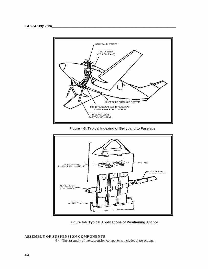
FM 3-04.513(1-513)_________________________________________________________________________
4-4
Figure 4-3. Typical Indexing of Bellyband to Fuselage
Figure 4-4. Typical Applications of Positioning Anchor
ASSEMBLY OF SUSPENSION COMPONENTS4-4. The assembly of the suspension components includes these actions:

_________________________________________________________________________________Chapter 4
4-5
• Attach the bellybands to the spreader bar shackle.• Adjust the length of the spreader bar.• Attach the pendant assemblies to the pendant adapter (primary and
alternate methods).• Install the rotor head sling.• Attach the bellyband assemblies to the lift pendant.
ATTACHING BELLYBANDS TO THE SPREADER BAR SHACKLE4-5. Figures 4-5 and 4-6 show the typical connections between the bellybandsand the spreader bar shackle. Figure 4-5 shows direct connection betweenthese two suspension components. Figure 4-6 demonstrates the use ofcoupling links, grab links, and/or the chain leg assembly in connecting thebellybands to the spreader bar. Figure 4-6 shows the coupling link assemblyconnected to the spreader bar.
Bellyband Link or Grab Link Attachment4-6. Attach the bellyband link or the grab link to the spreader bar shackle asfollows:
• Remove the quick-disconnect pin from the shackle clevis pin and slidethe clevis pin out from the forked end. Note that this also releases thespreader bar straps from the spreader bar assembly (Fig. 4-5, View A).
• Slip the spreader bar shackle through the bellyband link (Figure 4-5,View A) or through the grab link (Fig. 4-6). Note that while Figure 4-5shows two bellyband links being attached to the spreader bar shackle,there are cases in which only one bellyband link will be attached.
• Reassemble the parts to the spreader bar assembly.• Ensure that there is no twist in the spreader bar straps.
Coupling Link Attachment4-7. Attach the coupling links to the spreader bar shackle (Fig. 4-6) asfollows:
• Disengage the quick-disconnect pin of the coupling link assembly.• Remove the clevis pin from the coupling link and separate the two
links.• Pass one coupling link over the spreader bar shackle.• Mate the other link with that in the step above.• Insert the clevis pin through the coupling links and engage the quick-
disconnect pin.
ADJUSTING LENGTH OF THE SPREADER BAR4-8. Adjust the spreader bar length as follows:
• Disengage the quick-disconnect pins from the pin assembly(1670EG052A) (Fig. 4-5).

FM 3-04.513(1-513)_________________________________________________________________________
4-6
• Remove the pin assembly from the tube.• Select the correct length for the spreader bar assembly and reinstall
the pin assembly.
Figure 4-5. Typical Spreader Bar Arrangement
Figure 4-6. Typical Arrangements of Bellyband Arrangement to Spreader
Figure 4-6. Typical Arrangements of Bellyband Arrangements to Spreader Bar
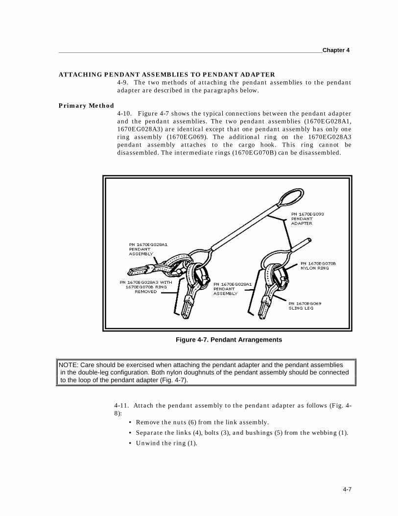
_________________________________________________________________________________Chapter 4
4-7
ATTACHING PENDANT ASSEMBLIES TO PENDANT ADAPTER4-9. The two methods of attaching the pendant assemblies to the pendantadapter are described in the paragraphs below.
Primary Method4-10. Figure 4-7 shows the typical connections between the pendant adapterand the pendant assemblies. The two pendant assemblies (1670EG028A1,1670EG028A3) are identical except that one pendant assembly has only onering assembly (1670EG069). The additional ring on the 1670EG028A3pendant assembly attaches to the cargo hook. This ring cannot bedisassembled. The intermediate rings (1670EG070B) can be disassembled.
Figure 4-7. Pendant Arrangements
NOTE: Care should be exercised when attaching the pendant adapter and the pendant assemblies in the double-leg configuration. Both nylon doughnuts of the pendant assembly should be connected to the loop of the pendant adapter (Fig. 4-7).
4-11. Attach the pendant assembly to the pendant adapter as follows (Fig. 4-8):
• Remove the nuts (6) from the link assembly.• Separate the links (4), bolts (3), and bushings (5) from the webbing (1).• Unwind the ring (1).

FM 3-04.513(1-513)_________________________________________________________________________
4-8
• Reassemble the nylon ring, but encircle both the pendant adapter loopand the sling leg loop. To assemble the ring, refer to Figure 4-8 andperform the following steps:� Lay the webbing (1) out flat with the nylon sleeve (2) over the shorter stitched end.� Slip the sling leg (7) over (1).� Form the webbing (1) into an approximate 8-inch-diameter circle
beginning from the shorter stitched end.� Wind the webbing, forming three turns. Adjust the webbing so that
the sewn loops are positioned as shown.� Thread the webbing, during winding, through the additional
suspension; that is, pendant (7) or components as required.� Insert the bushings (5) through the loops of the inner and outer
wraps.� Install the bolts (3), links (4), bushings (5), and nuts (6).
Figure 4-8. Attachment of Pendant Assemblies to Pendant Adapter
Figure 4-8. Attachment of Pendant Assemblies to Pendant Adapter

_________________________________________________________________________________Chapter 4
4-9
Alternate Method4-12. The pendant assembles can be attached to the pendant adapter using the rotor headshackle (Fig. 4-9). Use the following procedure:
• Remove the quick-disconnectg pin from the shackle pin (Fig. 4-10).• Unscrew the shackle pin and remove it from the shackle.• Place, as required, one-ring assembly or two-ring assembles of the
pendant assemblies on the shackle.• Position the loop of the pendant adapter in the rotor head shackle.• Install the shackle pin, making sure that it passes through the loop of
the pendant adapter.• Insert the quick-disconnect pin.
Figure 4-9. Typical Lift Pendant Arrangement using Rotor Head Shackle
ATTACHING BELLYBAND ASSEMBLIES TO LIFT PENDANT4-13. Figure 4-10 shows the bellyband assemblies attached to the single-leg lift pendantarrangement using the rotor head shackle. It also shows the assembly of the grab linksand the coupling links to the rotor head shackle.

FM 3-04.513(1-513)_________________________________________________________________________
4-10
Figure 4-10. Typical Attachments of Bellyband to Rotor Head Shackle
INSTALLING THE ROTOR HEAD SLING4-14. The rotor head sling arrangement may be used to lift lightweight helicopters bytheir rotor heads. Figure 4-11 shows a typical rotor head sling installation, including theuse of antichafe pads.
Figure 4-11. Typical Rotor Head Sling Installation

_________________________________________________________________________________Chapter 4
4-11
RIGGING AIRCRAFT FOR GROUND RECOVERY4-15. Rigging aircraft for ground recovery is essentially the same as foraerial recovery. The aircraft is prepared for lifting onto the transport vehicle;components (bellybands, slings, etc.) of the aerial recovery kit are used. Theonly major difference is that the device used to actually perform the lift is acrane, or similar piece of equipment, instead of a helicopter. Any disassemblyof the aircraft required because of road obstacles or size of the transportvehicle is performed using procedures outlined in the appropriate aircrafttechnical manual. Procedures outlined in the appropriate aircraft shippingmanual are used to prepare any devices (cradles, shipping skids, etc.)required for loading the aircraft onto the transport vehicle. Observe the samebasic safety procedures (disarming, disconnecting batteries, etc.) adhered toduring aerial recovery during ground recovery.
4-16. An aircraft may have severe crash damage; that is, major portions ofthe aircraft such as the engine, transmission, and rotor system were tornfrom the aircraft. If so, rigging procedures may require modification to suitthe situation. The ground personnel determine the method used to lift theaircraft. The primary concerns in this situation are to minimize furtherdamage to the aircraft and ensure the safety of the ground crew.
4-17. Nonflyable aircraft may be transported between maintenance facilitiesor moved because of relocation of the maintenance facility. When this occurs,the aircraft will be prepared and loaded for ground transport as specified inthe applicable shipping manual. The procedures outlined in shippingmanuals are used when shipping flyable aircraft over extended distances.The same procedures are effective for moving aircraft intact but not flyablebecause of maintenance. Use of these procedures will minimize the possibilityof damage to the aircraft occurring as a result of movement. Sling loading isan option in this situation; however, the chance of damage occurring to thetransported aircraft is much greater than with ground transport. Theavailability urgency of the situation and the transportation assets determinethe method of movement to be used.

5-1
Chapter 5
Aircraft Recovery Methods and Applications
This chapter covers rigging methods, configurations, and the requiredrecovery kit(s) for specified US Army rotary-wing and fixed-wing aircraft.The methods and applications in this chapter were verified as effective.However, the extent of damage to the disabled aircraft may requiremodified procedures. In all cases, the recovery helicopter should hold thedisabled aircraft at a hover before transition into flight. This ensures thata proper balance is maintained and the disabled aircraft assumes a 0- to10-degree, nose-low attitude.
When ground recovering an aircraft, the rotor head suspension method (ifauthorized) is the simplest means of loading the aircraft onto the recoveryvehicle. Aircraft damage, configuration, or limitations may preclude useof either of these methods: the rotor head suspension; hard pointattachment sling; attitude-controlled rotor head suspension; or theattitude-controlled, tandem hook, rotor head suspension. If so, load theaircraft using the bellyband method. Install lifting devices (straps,bellybands, etc.) as directed for the particular aircraft. This minimizesfurther damage to the aircraft. Modification of some procedures may berequired to accommodate boom extension of the lifting equipment. Thismeans positioning lifting eye closer to the aircraft.
AERIAL RECOVERY
RECOVERY METHODS(See table 5-1 for specific instructions for each aircraft.)
OH-58A/C5-1. The recovery methods for OH-58A/C aircraft are
• Bellyband suspension – Approved.• Rotor head suspension – Approved.• Hard point attachment sling – Not applicable to this airframe.
OH-58D5-2. The recovery methods for OH-58D aircraft are
• Bellyband suspension – Approved.• Rotor head suspension – Approved.• Hard point attachment sling – Not applicable to this airframe.

FM 3-04.513(1-513)_________________________________________________________________________
5-2
UH-1H/V/N AND EH-1H5-3. The recovery methods for UH-1H/V/N and EH-1H aircraft are
• Bellyband suspension – Approved.• Rotor head suspension – Approved.• Hard point attachment sling – Not applicable to this airframe.
UH-60A/L, EH-60L AND MH-60G/K5-4. The recovery methods for UH-60A/L, EH-60-L, and MH-60G/K aircraftare
• Bellyband suspension – Approved.• Rotor head suspension – Approved.• Hard point attachment sling – Approved.
AH-1E/F/P/S5-5. The recovery methods for AH-1E/F/P/S aircraft are
• Bellyband suspension – Approved.• Rotor head suspension – Approved.• Hard point attachment sling – Not applicable to this airframe.
AH-64A AND AH-64 LONGBOW5-6. The recovery methods for AH-64A and AH-64 LONGBOW aircraft are
• Bellyband suspension – Approved.• Hard point attachment – Not applicable to this airframe.• Attitude-controlled, rotor head suspension – Approved.• Attitude-controlled, tandem hook, rotor head suspension – Approved.
RAH-665-7. Procedures for rigging a disabled RAH-66 helicopter for recovey will bepublished at a later date.
CH-47D AND MH-47E5-8. The recovery methods for CH-47D and MH-47E aircraft are
• Rotor head suspension – Approved.• Bellyband suspension – Approved.
C-12 AND RC-125-9. The recovery method for C-12 and RC-112 aircraft is
• Bellyband suspension – Approved
C-23 SHERPA5-10. The recovery methods for C-23 Sherpa aircraft are

________________________________________________________________________________ Chapter 5
5-3
• Bellyband suspension – Approved.• Hard point attachment sling – Approved.
UC-35 CESSNA CITATION5-11. The recovery methods for UC-35 Cessna Citation aircraft are
• Bellyband suspension – Approved.• Hard point attachment sling – Approved.
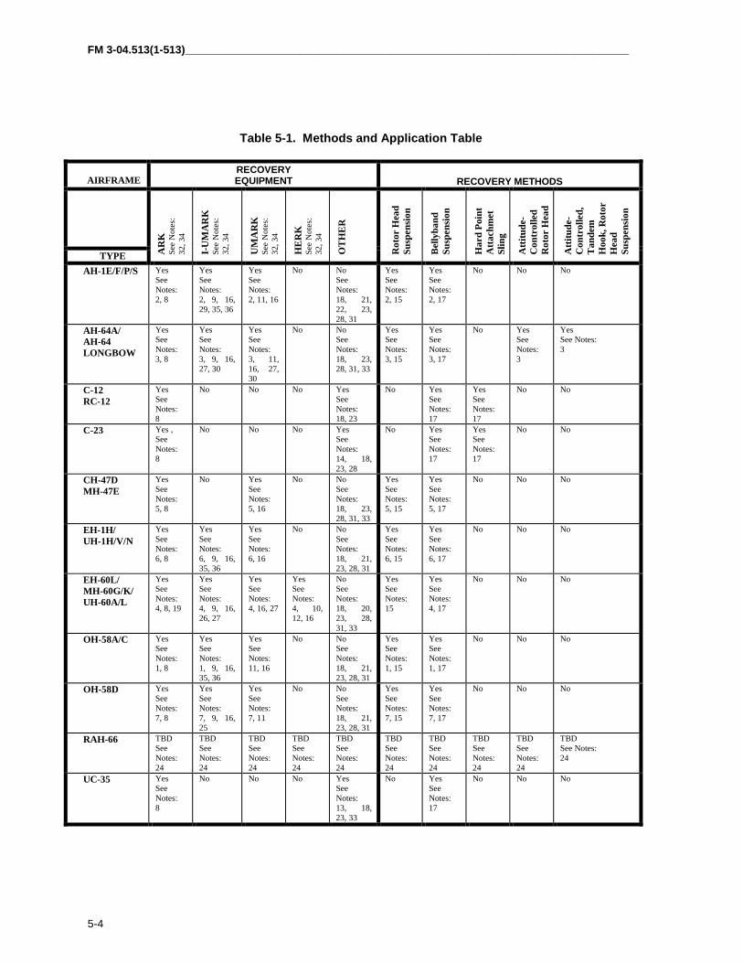
FM 3-04.513(1-513)_________________________________________________________________________
5-4
Table 5-1. Methods and Application Table
AIRFRAMERECOVERYEQUIPMENT RECOVERY METHODS
TYPE AR
KSe
e N
otes
:32
, 34
I-U
MA
RK
See
Not
es:
32, 3
4
UM
AR
KSe
e N
otes
:32
, 34
HE
RK
See
Not
es:
32, 3
4
OT
HE
R
Rot
or H
ead
Susp
ensi
on
Bel
lyba
ndSu
spen
sion
Har
d Po
int
Atta
chm
etSl
ing
Atti
tude
-C
ontr
olle
dR
otor
Hea
dS
iA
ttitu
de-
Con
trol
led,
Tan
dem
Hoo
k, R
otor
Hea
dSu
spen
sion
AH-1E/F/P/S YesSeeNotes:2, 8
YesSeeNotes:2, 9, 16,29, 35, 36
YesSeeNotes:2, 11, 16
No NoSeeNotes:18, 21,22, 23,28, 31
YesSeeNotes:2, 15
YesSeeNotes:2, 17
No No No
AH-64A/AH-64LONGBOW
YesSeeNotes:3, 8
YesSeeNotes:3, 9, 16,27, 30
YesSeeNotes:3, 11,16, 27,30
No NoSeeNotes:18, 23,28, 31, 33
YesSeeNotes:3, 15
YesSeeNotes:3, 17
No YesSeeNotes:3
YesSee Notes:3
C-12RC-12
YesSeeNotes:8
No No No YesSeeNotes:18, 23
No YesSeeNotes:17
YesSeeNotes:17
No No
C-23 Yes ,SeeNotes:8
No No No YesSeeNotes:14, 18,23, 28
No YesSeeNotes:17
YesSeeNotes:17
No No
CH-47DMH-47E
YesSeeNotes:5, 8
No YesSeeNotes:5, 16
No NoSeeNotes:18, 23,28, 31, 33
YesSeeNotes:5, 15
YesSeeNotes:5, 17
No No No
EH-1H/UH-1H/V/N
YesSeeNotes:6, 8
YesSeeNotes:6, 9, 16,35, 36
YesSeeNotes:6, 16
No NoSeeNotes:18, 21,23, 28, 31
YesSeeNotes:6, 15
YesSeeNotes:6, 17
No No No
EH-60L/MH-60G/K/UH-60A/L
YesSeeNotes:4, 8, 19
YesSeeNotes:4, 9, 16,26, 27
YesSeeNotes:4, 16, 27
YesSeeNotes:4, 10,12, 16
NoSeeNotes:18, 20,23, 28,31, 33
YesSeeNotes:15
YesSeeNotes:4, 17
No No No
OH-58A/C YesSeeNotes:1, 8
YesSeeNotes:1, 9, 16,35, 36
YesSeeNotes:11, 16
No NoSeeNotes:18, 21,23, 28, 31
YesSeeNotes:1, 15
YesSeeNotes:1, 17
No No No
OH-58D YesSeeNotes:7, 8
YesSeeNotes:7, 9, 16,25
YesSeeNotes:7, 11
No NoSeeNotes:18, 21,23, 28, 31
YesSeeNotes:7, 15
YesSeeNotes:7, 17
No No No
RAH-66 TBDSeeNotes:24
TBDSeeNotes:24
TBDSeeNotes:24
TBDSeeNotes:24
TBDSeeNotes:24
TBDSeeNotes:24
TBDSeeNotes:24
TBDSeeNotes:24
TBDSeeNotes:24
TBDSee Notes:24
UC-35 YesSeeNotes:8
No No No YesSeeNotes:13, 18,23, 33
No YesSeeNotes:17
No No No
________________________________________________________________________________ Chapter 5
5-5
NOTES
1Refer to TM 55-1520-228-23 series and recovery kit operating manuals for specific aerial/groundrecovery rigging procedures.
2Refer to TM 55-1520-234-23 series and recovery kit operating manuals for specific aerial/groundrecovery rigging procedures.
3Refer to TM 55-1520-238-S for specific aerial/ground recovery rigging procedures.
4Refer to TM 1-1520-237-S for specific aerial/ground recovery rigging procedures.
5Refer to TM 55-1520-241-S for specific aerial/ground recovery rigging procedures.
6Refer to TM 55-1520-242-S for specific aerial/ground recovery rigging procedures.
7Refer to TM 55-1520-248-S for specific aerial/ground recovery rigging procedures.
8Refer to TM 55-1670-251-20&P, Organizational Maintenance Manual (Including Repair Partsand Special Tools List) for Aerial Recovery Kit (ARK), 6 June 1975, with C4, dated 12 July 1989.
9Refer to TM, I-UMARK, Interim Unit Maintenance Aerial Recovery Kit Operating Procedures,Revision B, 30 January 1991.
10Refer to I-UMARK TM, for HERK, Helicopter Recovery Kit Operating Procedures.
11Refer to TM, Unit Maintenance Aerial Recovery (UMARK), Kaman Aerospace Corporation, 22June 1995, revised 30 April 1996, for specific aerial/ground recovery rigging procedures.
12Refer to TB 1-1520-237-20-157, Hoisting and Aerial Recovery of UH-60/EH-60 ESSS FixedProvisioned Helicopters, for specific aerial/ground recovery rigging procedures.
13Refer to Chapter 7, Lifting and Shoring, Cessna Aircraft Company, Model 560, MaintenanceManual, for specific aerial/ground recovery rigging procedures.
14Refer to C-23 Sherpa, Maintenance Manual, for specific aerial/ground recovery riggingprocedures.
15When ground recovering an aircraft, the rotor head suspension method is the simplest means ofloading the aircraft onto the recovery vehicle or to aerial recover to a designated area. If aircraftdamage, configuration or limitations preclude use of the rotor head suspension method, then theaircraft is loaded using the belly band method.
16The I-UMARK, UMARK, and HERK are intended primarily to recover aircraft that have madea forced landing; are upright; and have no obvious damage to the rotor head, transmission, transmission mounts, or serious structural damage to tailboom assembly. If damage of thisnature has occurred, aircraft will be recovered with the Aerial Recovery Kit (ARK).
17Fuselage damage may occur if the belly band method is used.
FM 3-04.513(1-513)_________________________________________________________________________
5-6
18After completion of the recovery, ensure that aircraft is firmly on the ground.
19On aircraft having the External Stores Support System (ESSS) installed, removal of the ESSSwill be required to facilitate installation of the slings.
20If hard points are damaged beyond their ability to support the weight of the helicopter, thenthe bellyband suspension can be used instead of the hard point method.
21Failure to place the collective in the full down position will result in damage to the blades.
22When the main rotor system is being tied down, the web strap on the forward and aft bladesmust be crossed then tied down. All tie-down points are the same as those on the B540 mainrotor system. If the blades are tied down so tight that there is a coning of them, damage willoccur to them. The K747 rotor blades must remain straight and level.
23Make certain that the cowlings, panels, and doors are secure before hookup.
24Method and configuration for rigging a disabled RAH-66 Comanche helicopter for recovery willbe published at a later date.
25US Army flight tests have shown that the OH-58D aircraft may be recovered with the I-UMARK. In this configuration, the aircraft is lifted by the rotor hub with slings and spreaderbar, which provides a load path around the mast turret assembly (MTA). The helicopter is flownwith the main rotor blades attached and tied down during the aerial recovery. Except inemergency conditions, the mast mounted sight on the OH-58D requires removal.
26US Army flight tests have shown that the UH-60 aircraft may be recovered with the I-UMARK.In this configuration, the aircraft is lifted by the rotor hub, with slings around each of the rotorhead hub arms. The helicopter is flown, only in emergency situations, with the main rotorblades attached and tied down during the aerial recovery.
27The position of the collective flight control and stabilizer may be left “as is” and need not be setin any special position for the I-UMARK or UMARK aerial recovery.
28Post-recovery inspection criteria have not yet been developed. Therefore, the inspection criteriafor blade strike and hard landing cited in the aviation unit and intermediate aircraftmaintenance instructions; TM 55-1520-240-23, TM 55-1520-236-23, TM 55-1520-220-23, TM 55-1520-210-23, TM 1-1520-250-23, TM 1-1520-252-23, TM 55-1520-228-23, TM 55-1520-234-23, TM1-1520-237-23, TM 1-1520-238-23, TM 55-1520-248-23 series for the OH-58A/C, AH-1, UH-60/EH-60, AH-64A/AH-64 Longbow, CH-47/MH-47, UH-1/EH-1 aircraft should be used toascertain further airworthiness. A specific aircraft inspection may be required after using therotor head suspension method. Check applicable maintenance manual, special inspectionsection. If any doubt exists, the rotor component should be replaced.
29US Army flight tests have shown that the AH-64 aircraft may be recovered with the I-MARK.In this configuration (alternate), the aircraft is lifted by the rotor head mast nut with redundantslings. The helicopter is flown with the main rotor blades attached and tied down during theaerial recovery.

_________________________________________________________________________________Chapter 5
5-7
30It is impossible to attach the AH-64 air vehicle recovery sling to the rotor hub with the air datasensor (ADS) in place. Removal of the ADS, if time permits, requires about 20 minutes. If timedoes not permit removal of the ADS, attachment of the air vehicle recovery sling will requirephysical bending of the ADS to install the air vehicle recovery sling to recover the AH-64helicopter. In addition, the removal of the fire control radar (FCR) is required on the AH-64Longbow. If the Extended Range Fuel System (ERFS) is installed, removal is required (ifpossible) because of the possibility of unusual flight characteristics.
31Exceeding the flight limits may severely damage the main rotor head and/or main rotor bladesof the recovered aircraft and requires replacement of these components. Report the amount andduration of flight limits that were exceeded to the unit that owns the recovered aircraft.
32Height of the load above the ground may be difficult to determine during low level ARK, I-UMARK, and UMARK operations because of the length of the recovery sling system. Pilotsshould exercise caution during recovery operations to ensure that the load remains clear ofobstacles.
33Except in emergency situations, the main rotor blades are to be removed from all UH- 60/EH-60, AH-64A and Longbow, and OH-58 helicopters before recovery.
34Welded or unauthorized repair parts on the ARK, I-UMARK, UMARK, and HERK componentsare not acceptable. Only authorized replacement parts are acceptable.
35US Army flight-tests have shown that the AH-1, UH-1, and OH-58A/C aircraft may berecovered with the I-UMARK. In this configuration, the rotor hub mast nut lifts the aircraft,with slings around each barrel of the rotor head. The helicopter is flown with the main rotorblades attached and tied down during the aerial recovery.
36The spacer is not used on the AH-1, UH-1, and OH-58A/C aircraft recovery and should beplaced in the I-UMARK shipping container until the aerial recovery is completed and thecomponents are inventoried and secured for future use.

FM 3-04.513(1-513)_________________________________________________________________________
5-8
GROUND RECOVERY5-12. Rigging aircraft for ground recovery is essentially the same as foraerial recovery. The aircraft is prepared for lifting onto the transport vehicleusing components (bellybands, slings, etc.) either from the ARK, I-UMARK,UMARK, or HERK recovery kit. The only major difference is that the deviceused to actually perform the lift is a crane or similar piece of equipmentinstead of a helicopter. Any disassembly of the aircraft required because ofroad obstacles or size of the transport vehicle is performed using proceduresoutlined in the appropriate aircraft technical manual. Any devices (cradles,shipping skids, etc.) required for loading the aircraft onto the transportvehicle are prepared using procedures outlined in the appropriate aircraftshipping manual. The same basic safety procedures disarming,disconnecting batteries, etc. adhered to during aerial recovery are observedduring ground recovery.
5-13. An aircraft may have severe crash damage. Major portions of theaircraft such as engine, transmission, and rotor system may be torn from theaircraft. If so, rigging procedures may require modification to suit thesituation. The ground personnel determine the method used to lift theaircraft. The primary concerns in this situation are to minimize furtherdamage to the aircraft and ensure the safety of the ground crew.
5-14. Nonflyable aircraft may be transported between maintenance facilitiesor moved because of relocation of the maintenance facility. When they are,the aircraft will be prepared and loaded for ground transport as specified inthe applicable shipping manual. The procedures outlined in shippingmanuals are designed for use when shipping flyable aircraft over extendeddistances. The same procedures are effective for moving aircraft that areintact but not flyable because of maintenance. Use of these procedures willminimize the possibility of damage to the aircraft occurring as a result of themovement. Sling loading is an option in this situation; however, the chancesof damage occurring to the transported aircraft are much greater than withground transport. The urgency of the situation and the availability oftransportation assets determine the method of movement to be used.

A-0
Appendix A
Aircraft Recovery After Action Survey
A-1, The aerial recovery after action survey should contain the followinginformation:
• Recovery unit, phone number, and e-mail address.• Date.• Type of aircraft recovered.• Type of recovery equipment used.• Condition of recovered aircraft.• Conditions at recovery site (if combat conditions, so state).• Recovery team composition (by number and military occupational specialty (MOS)).• Method of recovery (bellyband or rotor head).• Narrative of recovery (time required, failures, and shortcomings noted in equipment, remarks, recommendations).
A-2. Send the survey to—
COMMANDERUS Army Aviation CenterATTN: ATZQ-TDS-DDFort Rucker, AL 36362-5000
E-Mail: [email protected]
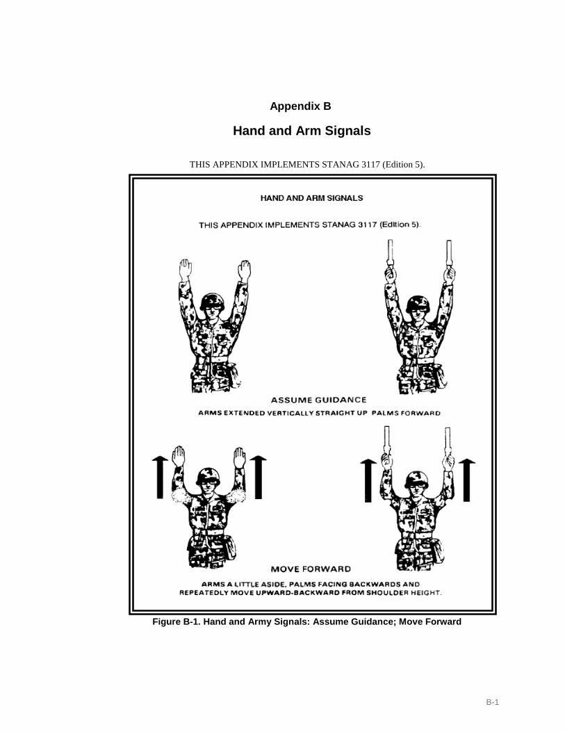
B-1
Appendix B
Hand and Arm Signals
THIS APPENDIX IMPLEMENTS STANAG 3117 (Edition 5).
Figure B-1. Hand and Army Signals: Assume Guidance; Move Forward

FM 3-04.513 (1-513)______________________________________________________
B-2
Figure B-1. Hand and Arm Signals: Assume Guidance; Move Forward
Figure B-2. Hand and Arm Signals: Move Backward; Move to Right; Move to Left

_______________________________________________________________________________Appendix B
B-3
Figure B-3. Hand and Arm Signals: Move Upwards; Move Downwards

FM 3-04.513 (1-513)______________________________________________________
B-4
Figure B-4. Hand and Arm Signals: Hover; Hookup; Affirmative Signal

_______________________________________________________________________________Appendix B
B-5
Figure B-5. Hand and Arm Signals: Negative Signal; Takeoff; Land
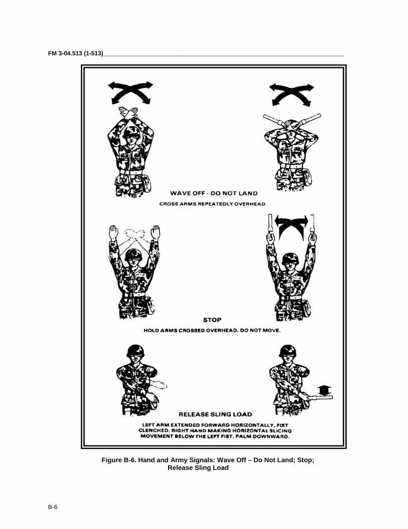
FM 3-04.513 (1-513)______________________________________________________
B-6
Figure B-6. Hand and Army Signals: Wave Off – Do Not Land; Stop;Release Sling Load

_______________________________________________________________________________Appendix B
B-7
FigurLoad Release Sling Load. Hand and Arm Signals: Wave Off - Do NotLand; Stop; Release Sling Load
Figure B-7. Hand and Arm Signals: Move Hook Down or Up (CH-54 Only); Standardization Agreement (STANAG) Hand Signals for Moving Rescue
Hoist on the CH-47

FM 3-04.513 (1-513)______________________________________________________
B-8
Figure B-8. Hand and Arm Signals: Correcting a Load

_______________________________________________________________________________Appendix B
B-9
Figure B-9. Hand and Arm Signals: An Example Series of Hand Signals for aPickup Zone, During a One-Aircraft Operation

FM 3-04.513 (1-513)______________________________________________________
B-10
Figure B-10. Hand and Arm Signals: An Example Series of Hand Signals for aLanding Zone Operation
C-1
Appendix C
Sample SOP for Battlefield Aircraft Recovery and Evacuation
This appendix can assist in developing an AVUM or AVIM SOP. It provides ageneric format and information on battlefield aircraft recovery and evacuation.Aircraft recovery is an operation that results from an aircraft being involved in aforced landing because of mechanical or battle damage. The aircraft also mayhave been disabled as the result of an accident or component/system malfunction.The operation includes an assessment, repair, and flyout if possible. It mayinclude recovery by aerial or ground means to an appropriate maintenancefacility for repair. The aircraft may eventually return to service, which isnormally conducted by the AVUM. Maintenance evacuation is the physical act ofmoving a nonflyable aircraft from one maintenance location on the battlefield toanother. Movement may be either by aerial or ground means. Evacuation is toeffect repair, cross-level maintenance workloads, or relieve units of disabledaircraft during tactical moves. The AVIM normally conducts a maintenanceevacuation.
Aircraft recovery and maintenance evacuation are closely related. In each case,the aircraft must be rigged for lift by helicopter or rigged for lift by a crane deviceand secured aboard a ground vehicle. Aircraft recovery, however, requiresextensive coordination. It is usually time sensitive to the tactical situation.Evacuation, on the other hand, may not have the same urgency. It is usuallycoordinated between maintenance activities.
This appendix is only a guide. It can be modified for both an AVUM and AVIMorganization. In actual practice, the procedures outlined might be modified oraugmented based on unit composition. The modification would account for thesize of the force; availability of aerial and ground assets; manpower; time anddistance considerations; and, above all, the tactical situation.
BATTLEFIELD AIRCRAFT RECOVERY AND EVACUATION
1. References:
a. FM 3-04.500 (1-500).
b. FM 3-04.513 (1-513).
c. TM 1-1520 series.
d. TM 55-1520 series.
e. Recovery kit manuals.

FM 3-04.513(1-513)_________________________________________________________________________
C-2
2. Purpose: To ensure required information is obtained to organize and execute
a. An aircraft recovery at the AVUM level.
b. An aircraft recovery at the AVIM level.
c. An aircraft evacuation between the AVUM and AVIM level.
d. An aircraft evacuation between an AVIM and another AVIM organization
e. An aircraft evacuation between an AVIM and a depot organization.
3. General:
a. The owning unit has primary responsibility for aircraft recovery. b. If the owning unit is unable to recover its own aircraft, aircraft recovery support
will be requested from the AVIM company.
c. The owning unit of the downed aircraft has total responsibility for security of the site.
4. Responsibilities:
a. Aviation unit maintenance (AVUM).
(1) SOP.
(2) Team.
(3) Security.
(4) Fly away.
(5) Request
b. Aviation intermediate maintenance (AVIM).
(1) SOP
(2) Backup support.
(3) Team.
(4) Security.
(5) Fly away.
(6) Request.
_______________________________________________________________________________Appendix C
C-3
c. Aviation maintenance officer (AMO).
(1) Company/Troop level.
(2) Battalion/Squadron level.
(3) Brigade/Regiment level.
(4) Division level.
(5) Corps level.
(6) Theater level.
5. Procedures:
a. AVUM:
(1) AVUM unit performing the aircraft recovery will obtain the followinginformation:
(a) Site recovery officer.
(1) Type and serial number of aircraft.
(2) Location of aircraft (six-digit grid). Eight-digit grid preferable.
(3) Air-to-air/ground frequency/call sign in effect.
(4) Type of security in the area.
(5) General condition of aircraft (crashed, precautionary landing,partially destroyed or intact).
(b) Complete a DA Form 2407 (Maintenance Request) for the aircraftrecovery with the information listed below:
(1) Type and serial number of aircraft.
(2) Location of aircraft (six-digit grid). Eight-digit grid preferable.
(3) Air-to-air/ground frequency/call sign in effect.
(4) Type security in the area.
(5) General condition of aircraft (crashed, precautionary landing,partially destroyed, or intact).
(6) Location where the aircraft is to be delivered.

FM 3-04.513(1-513)_________________________________________________________________________
C-4
(7) Release from brigade safety office or accident investigation board.
(c) Complete an aircraft recovery mission data sheet (see page C-19 for example).
(d) Turn in data sheet to the AVUM unit production control office.
(2) AVUM units requesting aircraft recovery and evacuation support submit the following information to the AVIM production control officer:
(a) Site recovery officer.
(1) Type and serial number of aircraft.
(2) Location of aircraft (six-digit grid). Eight-digit grid preferable.
(3) Air-to-air/ground frequency/call sign in effect.
(4) Type of security in the area.
(5) General condition of aircraft (crashed, precautionary landing,partially destroyed, or intact).
(b) Complete a DA Form 2407 (Maintenance Request) requesting aircraftrecovery and/or evacuation.
(1) Type and serial number of aircraft.
(2) Location of aircraft (six-digit grid). Eight-digit grid preferable.
(3) Air-to-air/ground frequency/call sign in effect.
(4) Type security in the area.
(5) General condition of aircraft (crashed, precautionary landing,partially destroyed, or intact).
(6) Location where the aircraft is to be delivered.
(7) Release from brigade safety office or accident investigation board.
(c) Complete an aircraft recovery mission data sheet. (See page C-19 forexample.)
(d) Turn in data sheet to the AVIM support unit production control office.
b. AVIM:
_______________________________________________________________________________Appendix C
C-5
(1) AVIM production control officer will obtain the following information fromthe AVUM unit requesting support for either an aircraft recovery or evacuation.
(a) Site recovery officer.
(1) Type and serial number of aircraft.
(2) Location of aircraft (six-digit grid). Eight-digit grid preferable.
(3) Air-to-air/ground frequency/call sign in effect.
(4) Type of security in the area.
(5) General condition of aircraft (crashed, precautionary landing,partially destroyed, or intact).
(b) Complete DA Form 2407 requesting aircraft recovery.
(1) Type and serial number of aircraft.
(2) Location of aircraft (six-digit grid). Eight-digit grid preferable.
(3) Air-to-air/ground frequency/call sign in effect.
(4) Type security in the area.
(5) General condition of aircraft (crashed, precautionary landing,partially destroyed, or intact).
(6) Location where the aircraft is to be delivered.
(7) Release from brigade safety office or accident investigation board.
(c) Complete an aircraft recovery mission data sheet. (See page C-19 forexample.)
(d) Develop a recovery team data sheet. (See page C-20 for example.)
6. Courses of action.
a. Abandon the aircraft. Personnel, aircraft, and equipment are highly vulnerablethroughout the recovery phase because of threat or inaccessibility.
b. Destroy the aircraft. Aircraft cannot be recovered and is in danger of enemycapture.
c. Recover and evacuate the aircraft. Move the aircraft to an occupied and the secure area or the nearest maintenance facility, incurring as little damage as possible.

FM 3-04.513(1-513)_________________________________________________________________________
C-6
7. Reasons for abandonment of aircraft.
a. Crash area is inaccessable to aircraft or surface vehicles.
b. Damaged aircraft is not worth recovering because of crash or fire damage.
c. Combat situation will endanger the safety of the recovery crew.
d. Weather conditions.
8. Procedures for abandonment.
a. Remove all classified equipment and records.
b. Remove all weapons.
c. Remove all ammunition.
d. Remove communication equipment.
e. Remove all loose equipment (first aid kits, fire extinguisher, and toolbox).
f. Remove all unit property.
g. Mark aircraft for abandonment.
h. Remove manufacturer’s data plate.
9. Destruction – Authority (SOP/OPORD) – selectively cannibalize; then destroy theaircraft.
a. Priorities of destruction.
(1) Priority must be given to destruction of classified equipment and associateddocuments.
(a) Identification, friend or foe (IFF) equipment.
(b) Classified electronics equipment – KY-58, KIT-1A/C, KY-75, KY-100,AN/ALQ-136, AN/ALQ-144, AN/APR-39, AN/AVR-2, and aircraftsurvivability equipment (ASE).
(c) Publications /Documents.
(2) When lack of time prevents complete destruction of equipment, priorityshould be given to the destruction of essential parts.
(a) Installed armament.
(b) Engine assembly.

_______________________________________________________________________________Appendix C
C-7
(c) Instruments, radios, and electronic equipment.
(d) Airframe/Flight controls.
(e) Electrical, fuel and hydraulic systems.
b. Methods of destruction.
(1) Explosives.
(2) Fire.
(3) Mechanical means.
(4) Other means.
10. Safety:
a. The owning unit is responsible for obtaining a release from the brigade safetyoffice or accident investigation board before recovery operations. If AVUM requestsAVIM support, provide copy of the release to the AVIM production control officer.
b. Night recoveries will be made only in exceptional circumstances and then onlywith the approval of the commanding officer of the AVUM company, AVIM company,or higher headquarters.
11. Priority means of recovery – Recovery officer or battle damage and assessmentrepair (BDAR) assessor determines the method to be used:
a. Flyout method: Complete on-site repair or component change, thus, returningthe downed aircraft to an operational status for a one–time flight.
b. Aerial/Ground recovery (based on METT-TC).
12. Recovery team – Downed aircraft recovery team (DART)/Augmentation of DARTwith BDAR personnel:
a. Qualified aircraft maintenance officer or maintenance test pilot.
b. Aircraft technical inspector – Performs the duties as the aircraft rigginginspector/certifier.
c. Trained aircraft mechanic/rigging crew.
d. Medical personnel (if available or needed, combat life saver).
e. Security force.
13. Organization – the size and composition of the recovery team will depend on:
FM 3-04.513(1-513)_________________________________________________________________________
C-8
a. Type and condition of disabled aircraft.
b. Method of recovery.
c. Accessability.
14. Three-phase training period.
a. Individual.
b. Group.
c. Team.
15. Receive training on team equipment:
a. Type equipment.
b. General equipment.
c. Environment.
16. Considerations.
a. Location of downed aircraft.
b. Assessment of damage to aircraft.
c. Tactical situation and proximity of the threat.
d. Time available (planning time for AVUM, preparation and rigging: 30 to 60minutes, which may vary based on METT-TC).
e. Aerial versus surface recovery.
f. Weather.
g. Assets available.
h. Fighter management.
17. Courses of action:
a. To make combat repairs, defer further maintenance, or return aircraft to service.
b. Make repairs for one-time evacuation and fly the aircraft to an appropriatemaintenance area or safe/secure area.
c. Recover the aircraft by surface means.

_______________________________________________________________________________Appendix C
C-9
d. Recover the aircraft by aerial means.
e. Selectively cannibalize, destroy, or abandon the aircraft according to pertinentSOP, Army regulations, field manuals, technical manuals, and other governingregulations.
18. Upon arrival at the site of a disabled aircraft:
a. Eliminate fire hazards.
b. Remove occupants (based upon guidance by qualified medical personnel).
c. Remove classified items and equipment records.
d. Disconnect batteries.
e. Remove weapons.
f. Remove ammunition.
g. Drain fuel, as required.
19. One-time evacuation method – The pilot should be proficient in all emergencyprocedures for that particular aircraft.
a. Advantages.
(1) Quick.
(2) Economical.
(3) Further damage to aircraft is minimized.
b. Disadvantages:
(1) Requirement for a clear takeoff path.
(2) Possibility of unseen damage caused during the crash.
(3) Requirement for special tools and equipment.
(4) Effects of weather conditions.
20. Aerial recovery/sling load:
a. Advantages of aerial recovery.
(1) Less disassembly is required than for surface transportation.

FM 3-04.513(1-513)_________________________________________________________________________
C-10
(2) Accessability of the disabled aircraft.
(3) Faster than surface.
b. Disadvantages of aerial recovery.
(1) Possibility of dropping the disabled aircraft and inflicting further damage.
(2) Effects of the rotor downwash on the sling load.
(3) Possibility of damage to the recovery helicopter because of improper riggingor equipment malfunction.
(4) Availability of recovery kits and lift assets.
21. Surface recovery – Precautions and special considerations: Air defense, minefields,likely enemy avenues of approach, perimeter defense, and convoy escort:
a. Advantages.
(1) A takeoff path is not required.
(2) The chance of total loss because of further damage to aircraft is reduced.
b. Disadvantages:
(1) Often causes damage to aircraft.
(2) Is slower than aerial recovery or flyout.
(3) Requires more disassembly.
(4) Requires accessable ground routes.
(5) Requires a more thorough reconnaissance of the route.
(6) May require increased security of the route.
(7) Requires mobile assets.
(8) Requires crane or lifting device.
22. Recovery preparations – To be performed at the site of the disabled aircraft,including making the recovery area accessable, using communications correctly, andmaking the aircraft secure, safe, and ready for recovery or flyout.
a. Accident investigation (do not recover until aircraft is released).
b. Pickup site (police area).
_______________________________________________________________________________Appendix C
C-11
c. Communications (ground, air team, aviation operations (AO) commander (Cdr)).
d. Signalman (needs to be standardized).
e. Aircraft battery.
f. Removal and salvage of equipment – loose equipment /troops seats, litters, radios,and other basic components to reduce weight or shift center of gravity (CG).Classified equipment should be retrieved if possible.
g. Fuel drainage/ventilation.
h. BDAR kits.
i. Technical manuals.
j. Expendable materials (rags, safety wire, tape, fuel and oil sample bottles, andtubes).
k. Spill response kit.
l. General mechanics tools box.
m. Special tools.
n. Technical inspector’s (TI’s) kit.
o. Parts – identify specific repair parts needed.
p. Ground guides.
23. Equipment.
a. Individual weapon with basic load.
b. Crew served weapon with basic load.
c. Nuclear, biological, and chemical (NBC) survey/decon equipment.
d. Communication equipment – ground, air, and AO Cdr.
e. Signal operating instructions (SOI).
f. Tactical maps with appropriate overlays and compass.
g. PGPS, SLUGGR/SAGGR.
h. Rations/water.
FM 3-04.513(1-513)_________________________________________________________________________
C-12
i. Pyrotechnics/signals.
j. Vehicles.
24. Aerial Recovery.
a. Load description (type aircraft).
(1) Weights.
(a) Empty.
(b) Combat.
(c) Unarmed/armed.
b. Dimensions.
(1) Length.
(2) Height.
(3) Blades – on/folded/removed.
c. Type lift aircraft.
(1) Weights.
(a) Empty.
(b) Combat.
(c) Unarmed/armed.
d. Required material from recovery kit.
(1) Aerial Recovery Kit (ARK) – Technical manual.
(2) Interim-Unit Maintenance Aerial Recovery Kit (I-UMARK) – Operator’smanual.
(3) Helicopter Recovery Kit (HERK) – Shipping manuals.
(4) Unit Maintenance Aerial Recovery Kit (UMARK) – Operator’s manual.
e. Other required materials.
(1) Tape.
(2) Tools.
_______________________________________________________________________________Appendix C
C-13
(3) Radio.
(4) Axes.
(5) Sandbags – ballast.
(6) Flashlights.
(7) Applicable technical manuals for aircraft or component disassembly.
f. Aircraft preparation – to be performed at the site of the disable aircraft.
(1) Disconnect battery.
(2) Disarm and unload weapons.
(3) Main rotor blades – remove or fold in stowed position.
(4) Secure tail rotor blades.
(5) Remove any critical components that may be damaged during recovery.
(6) Drain fuel.
g. Rigging – Breakaway technique.
(1) Bellyband suspension method.
(2) Rotor head suspension method.
(3) Hard point attachment sling.
(4) Attitude-controlled, rotor head suspension.
(5) Attitude-controlled, tandem hook, rotor head suspension.
h. Hookup
(1) Ground crew protective equipment.
(a) Identification (ID) tags.
(b) Goggles.
(c) Earplugs.
(d) Shockproof gloves.
(e) Survival knife.

FM 3-04.513(1-513)_________________________________________________________________________
C-14
(f) Helmet.
(g) Static discharge wand.
(h) Flashlight with wand.
(i) Gloves (leather, working).
(j) Smoke grenade.
(2) Ground crew function.
(a) Prepare aircraft.
(b) Approach guidance.
(c) Signal.
(d) Static discharge.
(e) Hookup.
(f) Rendezvous point.
(g) Extended sling system operations.
i. Liftoff.
(1) Flight parameters (As specified in TM and recovery aircraft - 10).
(a) Max speed – optimum speed.
(b) Max angle of bank.
(c) Rate of climb and descent.
j. After use inspection and packing.
(1) Cleaning of equipment.
(2) Repacking of drogue chute.
(3) Removal of flashlight and radio batteries.
(4) Replacement of equipment.
k. Prepare aerial recovery after action report (AAR):
(1) Recovery unit and phone number.
_______________________________________________________________________________Appendix C
C-15
(2) Date.
(3) Type of aircraft recovered.
(4) Condition of recovered aircraft.
(5) Conditions at recovery site (if combat conditions, so state).
(6) Recovery team composition (by number and MOS)
(7) Method of recovery (bellyband; rotor head; hard point attachment; attitude-controlled, rotor head suspension; or attitude-controlled, tandem hook, rotor headsuspension).
(8) Narrative of recovery (time required, failures, and shortcomings noted inequipment, remarks, recommendations).
(9) Send to
COMMANDERUS Army Aviation CenterATTN: ATZQ-TDS-DDFort Rucker, Alabama 36362-5000
25. Surface recovery.
a. Load description.
(1) Weights.
(a) Empty.
(b) Combat.
(c) Unarmed/armed.
b. Dimensions.
(1) Length.
(2) Height.
(3) Blades – on/folded/removed
c. Required material from recovery kit.
(1) Aerial Recovery Kit (ARK) – Technical manual.

FM 3-04.513(1-513)_________________________________________________________________________
C-16
(2) Interim-Unit Maintenance Aerial Recovery Kit (I-UMARK) – Operator’smanual.
(3) Helicopter Recovery Kit (HERK) – Shipping manuals.
(4) Unit Maintenance Aerial Recovery Kit (UMARK) – Operator’s manual.
d. Support equipment.
(1) Crane.
(2) Flatbed trailer.
(3) Tractor.
e. Other required materials.
(1) Tape.
(2) Tools.
(3) Radio.
(4) Axes.
(5) Sandbags – ballast.
(6) Flashlights.
(7) Applicable technical manuals for aircraft or component disassembly.
f. Aircraft preparation – to be performed at the site of the disable aircraft.
(1) Disconnect battery.
(2) Disarm and unload weapons.
(3) Main rotor blades – remove or position longitudinal.
(4) Secure tail rotor blades.
(5) Remove any critical components that may be damaged during recovery.
(6) Drain fuel.
g. Rigging – Breakaway technique.
(1) Bellyband suspension method.
(2) Rotor head suspension method.

_______________________________________________________________________________Appendix C
C-17
(3) Hard point attachment sling.
h. Hookup
(1) Ground crew protective equipment.
(a) ID tags.
(b) Goggles.
(c) Earplugs.
(d) Gloves.
(e) Survival knife.
(f) Helmet.
(h) Flashlight with wand.
i. After use inspection and packing.
(1) Cleaning of equipment.
(2) Removal of flashlight and radio batteries.
(3) Replacement of equipment.
j. Prepare surface recovery after action report (AAR):
(1) Recovery unit and phone number.
(2) Date.
(3) Type of aircraft recovered.
(4) Condition of recovered aircraft.
(5) Conditions at recovery site (if combat conditions, so state).
(6) Recovery team composition (by number and MOS)
(7) Method of recovery – Surface or aerial (bellyband; rotor head; hard pointattachment; attitude-controlled, rotor head suspension; or attitude-controlled,tandem hook, rotor head suspension).
(8) Narrative of recovery (time required, failures, and shortcomings noted inequipment, remarks, recommendations).

FM 3-04.513(1-513)_________________________________________________________________________
C-18
(9) Send to
COMMANDERUS Army Aviation CenterATTN: ATZQ-TDS-DD
Fort Rucker, Alabama 36362-5000
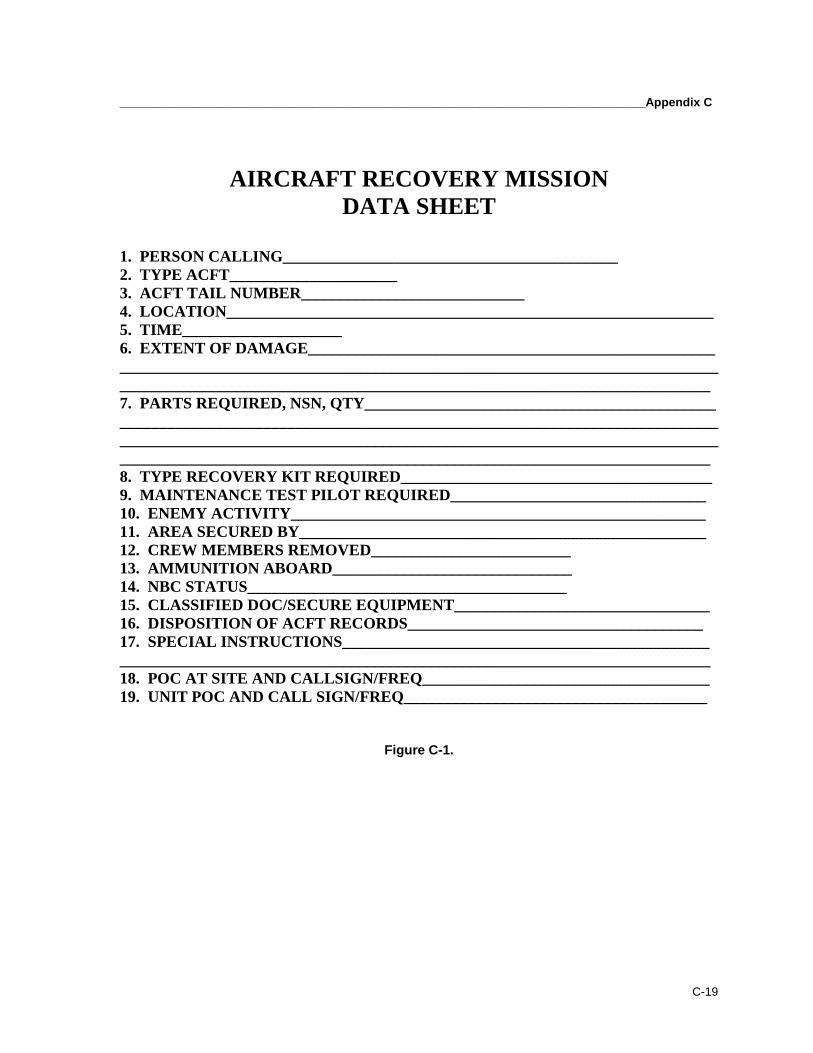
_______________________________________________________________________________Appendix C
C-19
AIRCRAFT RECOVERY MISSIONDATA SHEET
1. PERSON CALLING__________________________________________2. TYPE ACFT_____________________3. ACFT TAIL NUMBER____________________________4. LOCATION_____________________________________________________________5. TIME____________________6. EXTENT OF DAMAGE________________________________________________________________________________________________________________________________________________________________________________________________________7. PARTS REQUIRED, NSN, QTY____________________________________________________________________________________________________________________________________________________________________________________________________________________________________________________________________________8. TYPE RECOVERY KIT REQUIRED_______________________________________9. MAINTENANCE TEST PILOT REQUIRED________________________________10. ENEMY ACTIVITY____________________________________________________11. AREA SECURED BY___________________________________________________12. CREW MEMBERS REMOVED_________________________13. AMMUNITION ABOARD______________________________14. NBC STATUS________________________________________15. CLASSIFIED DOC/SECURE EQUIPMENT________________________________16. DISPOSITION OF ACFT RECORDS_____________________________________17. SPECIAL INSTRUCTIONS________________________________________________________________________________________________________________________18. POC AT SITE AND CALLSIGN/FREQ____________________________________19. UNIT POC AND CALL SIGN/FREQ______________________________________
Figure C-1.

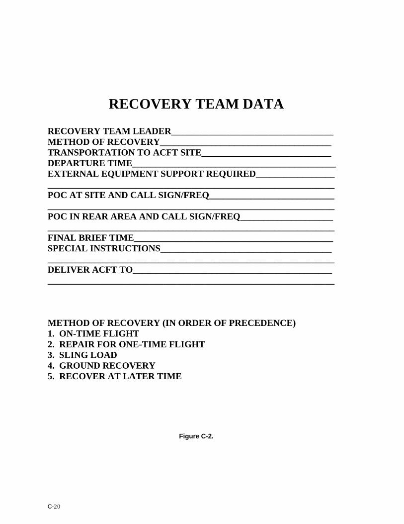
C-20
RECOVERY TEAM DATA
RECOVERY TEAM LEADER___________________________________METHOD OF RECOVERY_____________________________________TRANSPORTATION TO ACFT SITE____________________________DEPARTURE TIME____________________________________________EXTERNAL EQUIPMENT SUPPORT REQUIRED_______________________________________________________________________________POC AT SITE AND CALL SIGN/FREQ_________________________________________________________________________________________POC IN REAR AREA AND CALL SIGN/FREQ__________________________________________________________________________________FINAL BRIEF TIME___________________________________________SPECIAL INSTRUCTIONS___________________________________________________________________________________________________DELIVER ACFT TO_________________________________________________________________________________________________________
METHOD OF RECOVERY (IN ORDER OF PRECEDENCE)1. ON-TIME FLIGHT2. REPAIR FOR ONE-TIME FLIGHT3. SLING LOAD4. GROUND RECOVERY5. RECOVER AT LATER TIME
Figure C-2.
D-1
Appendix D
Risk Management/Risk Assessment
Tough, realistic training conducted to standard is the cornerstone ofArmy warfighting skills. An intense training environment stresses bothsoldiers and equipment, creating a high potential for accidents. Thepotential for an accident increases as training realism increases, just as itdoes in combat. The end result is the same; the soldier or asset is lost.Commanders must find ways to protect individuals, crews, teams, andequipment from accidents during training and combat. How well they dothis could be the decisive factor in winning or losing. Risk managementis a commonsense tool that leaders can use to make smart risk decisionsin tactical and everyday operations. It is a method of getting the job doneby identifying the areas that present the highest risk and taking action toeliminate, reduce, or control the risk. It is not complex, technical, ordifficult. It is a comparatively simple decision making process, a way ofthinking through a mission to balance mission demands against risks.
COMMAND RESPONSIBILITIESD-1. Commanders are responsible for effectively managing risk. They must
• Willingly determine the proper balance that will achieve optimumperformance from their command.
• Select the best risk-reduction options from those that the staff provides.• Accept or reject residual risk, based on perceived benefits.• Recommend appropriate control measures.• Train and motivate leaders at all levels to effectively use risk
management concepts.• Ensure that risk controls are integrated into plans and orders.• Ensure that unnecessary safety restrictions are eliminated to maximize
training and combat effectiveness.• Maintain a total commitment to mission accomplishment and the
welfare of subordinates.• Use the risk management process to identify, assess, and control
hazards for their mission.• Report risks beyond their control or authority to their superiors for
resolution.
INDIVIDUAL RESPONSIBILITIESD-2. Each individual soldier must
______________________________________________________________________________Appendix D
D-2
• Understand, accept, and implement risk reduction guidance and theconcept of risk management and assessment.
• Maintain a constant awareness of the changing risks associated withthe operation.
• Make leaders immediately aware of any unrealistic risk reductionprocedure.
• Report risks beyond their control or authority to their superiors forresolution.
FIVE-STEP RISK MANAGEMENT PROCESSD-3. Step 1. Identify Hazards.
• Identify the major events that are expected to occur during theoperation and the hazards associated with all specified and impliedtasks. The staff reviews and expands, as appropriate, the list ofhazards and major events during the training or combat scenario. Thisprocedure helps to ensure that all significant hazards have beenidentified, and the staff can determine the appropriate force protectionmeasures.
D-4. Step 2. Assess Hazards.
• Assess hazards based on their probability of occurrence and severity ofeffect. Based on this assessment, the staff can� Determine the level of risk associated with a given hazard.� Decide where or when control measures are appropriate to protect
the force.
• Use the risk assessment matrix alone or with other techniques. Riskassessment matrices provide a simple analysis method of subdividingan operation into its major operational events. In this way areas maybe discovered where the staff might eliminate or reduce risk. Each unitshould develop its own risk assessment matrix with applicable majoroperational events similar to the one shown in TC 1-210. The matrixis nearly always more effective than intuitive methods in identifyingthe extent of risk. When using a risk assessment matrix, the riskassessor must� Review each situation to ensure he has evaluated all significant
areas of concern, even if the matrix does not include them.� Use the matrix to analyze risk and target areas of concern for risk
reducing techniques.� Review individual areas of concern before recommending options.
• Use the mission, enemy, troops, terrain – time available, civilianconsiderations (METT-TC) format as another technique in the riskassessment procedure. Leaders can subjectively decide the likelihood
FM 3-04.513(1-513)_________________________________________________________________________
D-3
and extent of accidental loss based on this type of analysis. Whenusing the METT-TC format, the risk assessor must� Determine the mission’s complexity and difficulty.� Assess the enemy situation and identify specific hazards.� Consider all aspects of the terrain as well as weather and ability.� Determine the supervision required and evaluate the experience,
training, morale, and endurance of units and their equipment.� Determine the time available for planning and executing the
mission.
D-5. Step 3. Develop Controls.
• Develop control measures that reduce the risk to the mission. The staffmust� Identify hazards and assess risk.� Focus on critical events first.� Eliminate unnecessary risks.� Reduce the level of mission essential and prudent risks by applying
controls.� Develop control options that synchronize the operation to eliminate
or reduce risks.� Recommend options for the commander’s decision. Check for
residual effects before suggesting options. Visualize what willhappen once the option has been implemented. Sometimesreducing one risk will only introduce other risks.
• Leaders can detect and analyze safety restrictions that impede therealism or effectiveness of training. With proper controls in place, theserestrictions can be reduced or eliminated. Sensible consideration andconsultation with the unit’s most experienced personnel are the key.
D-6. Step 4. Implement Controls.
• Adopt, implement, and integrate specific controls into plans, operationsorders (OPORDs), standing operating procedures (SOPs), andrehearsals. Knowledge of controls, from the commander down to theindividual soldier, is essential to successfully implement and executcontrols.
D-7. Step 5. Supervise.
• The commander must enforce controls. Leaders must verify, monitor,follow-up, and appropriately correct or modify those controls that thecommander imposes on his subordinates.
• When monitoring operational activities, leaders must� Avoid administrative intrusions on their subordinates’ time.
______________________________________________________________________________Appendix D
D-4
� Go where the risks are and spend time at the heart of the action.� Analyze and think through issues, not just observe.� Work with key personnel to improve operational procedures after
the action. Leaders must not hesitate to assess imminent dangerissues on the spot.
� Fix systemic problems that are hindering combat effectiveness.� Retain and disseminate lessons learned from mishaps, near misses,
etc., to affect present and future operations.• Leaders must also balance the cost of risks with the value of the
desired outcome. They must consider and manage risks in makingsuch decisions using three general rules� Never accept an unnecessary risk. The leader who has the
authority to accept or reject a risk is responsible for protecting hissoldiers from unnecessary risks. If he can eliminate or reduce arisk and still accomplish the mission, the risk is unnecessary.
� Make risk decisions at the appropriate level. The leader who mustanswer for an accident is the person who should make the decisionto accept or reject the risk. In most cases, he will be a seniorofficer, but small-unit commanders and first-line leaders mightalso have to make risk decisions during combat. Therefore, theyshould learn to make risk decisions during training.
� Ensure that the benefits of a prudent risk outweigh the possiblecost of the risk. Leaders must understand the possible risk andhave a clear picture of the benefits to be gained from taking thatrisk.

E-1
Appendix E
Environmental Issues
This appendix discusses the Army’s environmental programs. It providesreferences for environmental issues, and regulations and publicationsgoverning environmental protection. Compliance with environmentalregulations is a command responsibility. Education and planning are keyto the successful completion of environmental missions.
AWARENESS AND COMPLIANCEENVIRONMENTAL PROGRAM REFERENCES
E-1. FM 3-100.4, AR 200-1, AR 200-2, AR 200-3, and AR 385-63 explain theArmy's environmental programs. These regulations reference additionaldocuments that should be reviewed. TC-5-400 provides a comprehensivelisting of all items of interest in the preparation for operating near andavoiding environmentally sensitive areas. Other good references (graphictraining aids) for environmental issues are:
• GTA 5-8-2, Environmental Risk Assessment.• GTA 5-8-3, Hazardous-Material-Spill Procedures.• GTA 5-8-4, The Soldier and the Environment.
ARMY ENVIRONMENTAL COMPLIANCE ASSESSMENT SYSTEME-2. Compliance with environmental regulations is a command responsibility.All maintenance units must be aware of the regulations and publicationsgoverning environmental protection. All aviation maintenance units handlehazardous waste (HW) and hazardous materials (HM). Each maintenanceunit, company and above, must designate, in writing, a hazardous wastecoordinator.E-3. The units must comply with the Environmental ComplianceAchievement Program (ECAP) protocol and will be periodically inspected.The units can attain the ECAP protocols from Department of Public Works,Education Division (DPW, ED) or by calling the Army Environmental Hotlineat 1-800-USA-3845.
E-4. Environmental awareness training should ensure all personnel know toreport any notice of tax, penalty, fee, fine, sanction, or other compliance orderarising from local, state, or federal environmental requirements or
_______________________________________________________________________________Appendix E
E-2
enforcement activities or alleged violation of any local, state, or federalenvironmental law or regulation, either to
• Commander.• DPW, ED.• Environmental Law Attorney, Office of the Staff Judge Advocate
(OSJA).
ENVIRONMENTAL COMPLIANCE OFFICER/NCOE-5. The hazardous waste coordinator also may serve as the EnvironmentalCompliance Officer/NCO within the unit or organization. This person is theunit point contact (POC) and is responsible for environmental education, SOPupdates, preparation of environmental risk assessments, incident reporting,etc. Commanders, along with the hazardous waste coordinator and theEnvironmental Compliance Officer/NCO, must
• Ensure all unit personnel have had, or are scheduled to receive, environmental awareness training. • Designate, in writing, an environmental compliance officer/HW
coordinator and ensure they are properly trained and qualified.
• Ensure the unit environmental compliance officer interfaces with appropriate environmental personnel and unit is in compliance with environmental laws and regulations. • Meet with battalion S3, S4, and installation personnel who deal with environmental issues. • Identify requirements concerning ECAP inspections that may affect the unit and how to avoid or protect environmentally sensitive areas.
• Ensure the unit SOP addresses environmental issues/procedures and coordinate environmental requirements with appropriate installation/chain of command personnel.
PLANNINGE-6. Advanced preparation is key to successful completion of missions andfor environmental awareness and protection. Environmental awareness canbe incorporated into the unit training program with minimal additionalplanning.
E-7. Hazardous waste topics can be reviewed by contacting DPW, ED, andNatural Resources Branch (NRB); Staff Judge Advocate (SJA); and/orDirectorate of Plans, Training, Mobilization, and Security (DPTMSEC),Range Control. In most cases, ED and NRB are located under DPW.
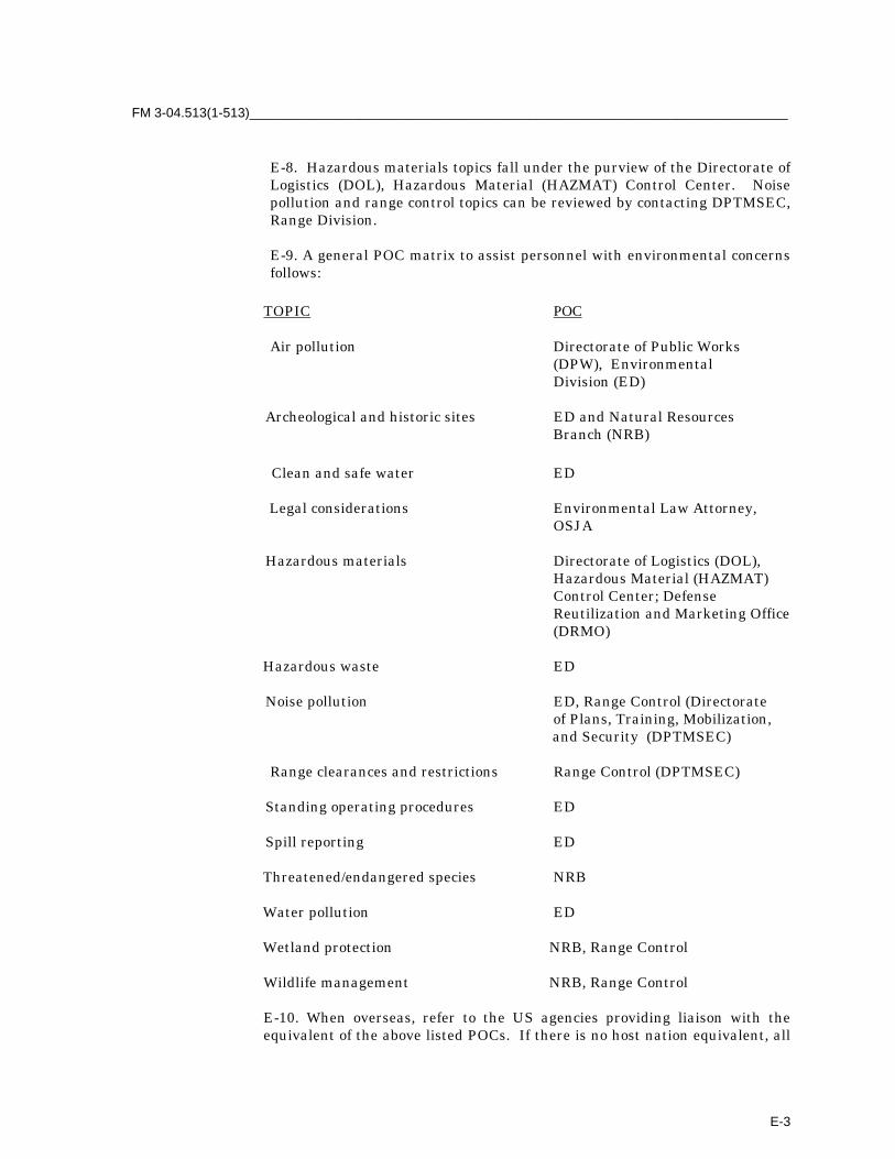
FM 3-04.513(1-513)_________________________________________________________________________
E-3
E-8. Hazardous materials topics fall under the purview of the Directorate ofLogistics (DOL), Hazardous Material (HAZMAT) Control Center. Noisepollution and range control topics can be reviewed by contacting DPTMSEC,Range Division.
E-9. A general POC matrix to assist personnel with environmental concernsfollows:
TOPIC POC
Air pollution Directorate of Public Works (DPW), Environmental Division (ED)
Archeological and historic sites ED and Natural Resources Branch (NRB)
Clean and safe water ED
Legal considerations Environmental Law Attorney,OSJA
Hazardous materials Directorate of Logistics (DOL),Hazardous Material (HAZMAT)Control Center; DefenseReutilization and Marketing Office(DRMO)
Hazardous waste ED
Noise pollution ED, Range Control (Directorateof Plans, Training, Mobilization,
and Security (DPTMSEC)
Range clearances and restrictions Range Control (DPTMSEC)
Standing operating procedures ED
Spill reporting ED
Threatened/endangered species NRB
Water pollution ED
Wetland protection NRB, Range Control
Wildlife management NRB, Range Control
E-10. When overseas, refer to the US agencies providing liaison with theequivalent of the above listed POCs. If there is no host nation equivalent, all

_______________________________________________________________________________Appendix E
E-4
training and maintenance will be conducted under US policies andrequirements. Units should coordinate with these organizations to provide abriefing before deployments.
UNIT LEVEL ENVIRONMENTAL PROGRAMSE-11. There may be several types of environmental programs at the unitlevel. Refer to TC 5-400 for more information.
• HM Programs.
• HW Programs.
• Hazardous Communications (HAZCOM) Programs.
• Pollution Prevention and Hazardous Waste Minimization (HAZMIN) Recycling Programs.
• Spill Prevention and Response Plan Programs.
Glossary-1
Glossary
A2C2 Army airspace command and control
A2C2S Army Airspace Command and Control System
AA assembly area
AAR after action review
AATFC air assault task force commander
AB air base; aviation brigade
ADS air data sensor
AIC air information center
ALOC aviation logistics operation center
AMC air mission commander
AMCOM US Army Aviation and Missile Command
AO area of operations
AOR area of responsibility
AR Army regulation
ARK Aerial Recovery Kit
ATO air tasking order
ATS air traffic services
AVIM aviation intermediate maintenance
AVUM aviation unit maintenance
BD battle damage
bde brigade
BDAR battle damage assessment and repair
bn battalion
C2 command and control
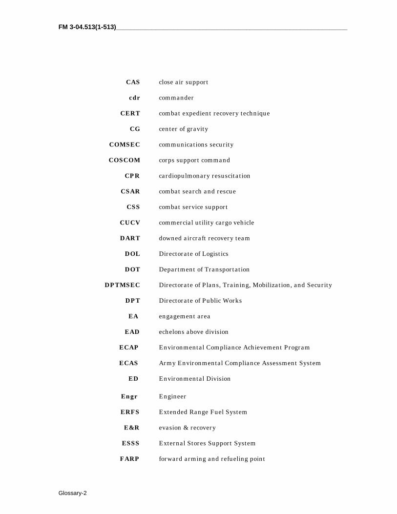
FM 3-04.513(1-513)________________________________________________________________
Glossary-2
CAS close air support
cdr commander
CERT combat expedient recovery technique
CG center of gravity
COMSEC communications security
COSCOM corps support command
CPR cardiopulmonary resuscitation
CSAR combat search and rescue
CSS combat service support
CUCV commercial utility cargo vehicle
DART downed aircraft recovery team
DOL Directorate of Logistics
DOT Department of Transportation
DPTMSEC Directorate of Plans, Training, Mobilization, and Security
DPT Directorate of Public Works
EA engagement area
EAD echelons above division
ECAP Environmental Compliance Achievement Program
ECAS Army Environmental Compliance Assessment System
ED Environmental Division
Engr Engineer
ERFS Extended Range Fuel System
E&R evasion & recovery
ESSS External Stores Support System
FARP forward arming and refueling point

_________________________________________________________________________________Glossary
Glossary-3
FCS fire control radar
FEBA forward edge of the battle area
FLOT forward line of own troops
FM field manual; frequency modulated
FS fuselage station
FSCL fire support coordination line
ft feet
GTA graphic training aid
GW gross weight
HAZCOM hazardous communications
HAZMAT hazardous material
HAZMIN hazardous waste minimization
HERK Helicopter Recovery Kit
HF high frequency
HM hazardous material
HMMS Hellfire modern missile system
HW hazardous waste
ID identification
IFR instrument-flight requirements
in inch
ISOREP isolation preparation
I-UMARK Interim-Unit Maintenance Aerial Recovery Kit
JP Joint publication
JSRC Joint Search and Rescue Center
JSCAR Joint Combat Search and Rescue
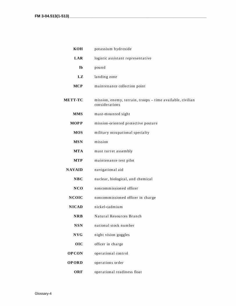
FM 3-04.513(1-513)________________________________________________________________
Glossary-4
KOH potassium hydroxide
LAR logistic assistant representative
lb pound
LZ landing zone
MCP maintenance collection point
METT-TC mission, enemy, terrain, troops – time available, civilianconsiderations
MMS mast-mounted sight
MOPP mission-oriented protective posture
MOS military occupational specialty
MSN mission
MTA mast turret assembly
MTP maintenance test pilot
NAVAID navigational aid
NBC nuclear, biological, and chemical
NCO noncommissioned officer
NCOIC noncommissioned officer in charge
NICAD nickel-cadmium
NRB Natural Resources Branch
NSN national stock number
NVG night vision goggles
OIC officer in charge
OPCON operational control
OPORD operations order
ORF operational readiness float
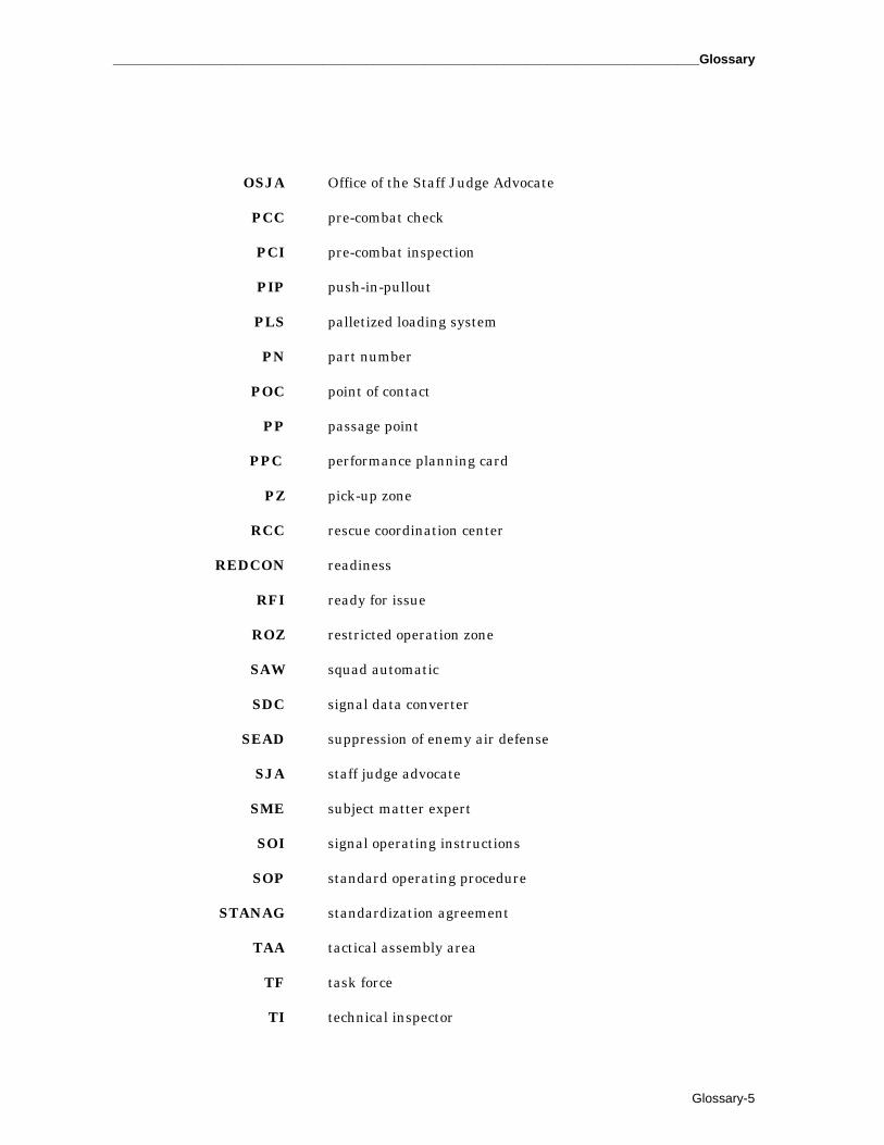
_________________________________________________________________________________Glossary
Glossary-5
OSJA Office of the Staff Judge Advocate
PCC pre-combat check
PCI pre-combat inspection
PIP push-in-pullout
PLS palletized loading system
PN part number
POC point of contact
PP passage point
PPC performance planning card
PZ pick-up zone
RCC rescue coordination center
REDCON readiness
RFI ready for issue
ROZ restricted operation zone
SAW squad automatic
SDC signal data converter
SEAD suppression of enemy air defense
SJA staff judge advocate
SME subject matter expert
SOI signal operating instructions
SOP standard operating procedure
STANAG standardization agreement
TAA tactical assembly area
TF task force
TI technical inspector

FM 3-04.513(1-513)________________________________________________________________
Glossary-6
TM training manual
TOC tactical operations center
TRADOC US Army Training and Doctrine Command
UHF ultra-high frequency
USAAVNC US Army Aviation Center
UMARK Unit Maintenance Aerial Recovery Kit
USASC US Army Safety Center
VHF very high frequency
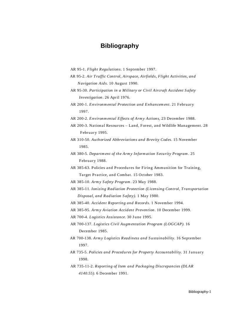
Bibliography-1
Bibliography
AR 95-1. Flight Regulations. 1 September 1997. AR 95-2. Air Traffic Control, Airspace, Airfields, Flight Activities, and
Navigation Aids. 10 August 1990.AR 95-30. Participation in a Military or Civil Aircraft Accident Safety
Investigation. 26 April 1976.AR 200-1. Environmental Protection and Enhancement. 21 February 1997.AR 200-2. Environmental Effects of Army Actions, 23 December 1988.AR 200-3. National Resources – Land, Forest, and Wildlife Management. 28 February 1995.AR 310-50. Authorized Abbreviations and Brevity Codes. 15 November 1985.AR 380-5. Department of the Army Information Security Program. 25 February 1988.AR 385-63. Policies and Procedures for Firing Ammunition for Training, Target Practice, and Combat. 15 October 1983.AR 385-10. Army Safety Program. 23 May 1988.AR 385-11. Ionizing Radiation Protection (Licensing Control, Transportation
Disposal, and Radiation Safety). 1 May 1980.AR 385-40. Accident Reporting and Records. 1 November 1994.AR 385-95. Army Aviation Accident Prevention. 10 December 1999.AR 700-4. Logistics Assistance. 30 June 1995.AR 700-137. Logistics Civil Augmentation Program (LOGCAP). 16 December 1985.
AR 700-138. Army Logistics Readiness and Sustainability. 16 September 1997. AR 735-5. Policies and Procedures for Property Accountability. 31 January 1998.
AR 735-11-2. Reporting of Item and Packaging Discrepancies (DLAR
4140.55). 6 December 1991.

FM 3-04.513(1-513) _________________________________________________________________________
Bibliography-2
AR 746-1. Packaging of Army Materiel for Shipment and Storage. October 1985. AR 750-43. Army Test, Measurement, and Diagnostic Equipment Program. November 1997. C-23 Serpa. Maintenance Manual for specific aerial/ground recovery rigging procedures. DA Pam 25-33. User’s Guide for Army Publications and Forms. 15 September 1996. DA Pam 385-1. Small Unit Safety Officer/NCO Guide. 22 September 1993.
DA Pam 385-40. Army Accident Investigation and Reporting. 1 November 1994.
DA Pam 738-750. Functional Users Manual for The Army Maintenance
Management System (TAMMS). 1 August 1994.DA Pam 738-751. Functional Users Manual for the Army Maintenance
System –Aviation (TAMMS-A). 15 March 1999.DA Pam 750-1. Leader’s Unit Level Maintenance Handbook. 15 February 1994.EM 0118. Aircraft, Fixed-Wing, C-12 Series. 01 September 1999. (Thisproduct includes the following items: TM 55-1510-218-CL, TM 55-1510-218-10, TM 55-1510-218-MTF, TM 55-1510-219-10, TM 55-1520-219-CL, TM 55-1510-219-MTF, TM 55-1510-220-10, TM 55-1510-220-MTF, TM 55-1510-221-10, TM 55-1510-221-CL, TM 55-1510-221-MTF, TM 55-1510-222-CL, TM 55-1660-245-13. 01 January 1998.)Federal Aviation Administration 7110.65L. Air Traffic Control.
FM 3-04.100(1-100). Army Aviation Operations. 21 February 1997.FM 3-04.113(1-113), Utility and Cargo Helicopter Operations.FM 3.04.120(1-120). Army Air Traffic Services Contingency and Combat
Zone Operation. 22 May 1995.FM 3.04.300(1-300). Flight Operations Procedures. 15 July 1998.FM 3.04.500(1-500). Army Aviation Maintenance. 27 January 1995.FM 3-11.3(3-3). Chemical and Biological Contamination Avoidance (FMFM
11-17). 16 November 1992.FM 3-11.100(3-4). NBC Protection (FMFM 11-9). 29 May 1992.FM 3-11.5(3-5). NBC Decontamination (FMFM 11-10).17 November 1993.

______________________________________________________________________________Bibliography
Bibliography-3
FM 3-11.100(3-100). Chemical Operations Principles and Fundamentals. 8 May 1996.FM 3-100.4. Environmental Considerations in the Army.
FM 4-30.2(9-43-1). Maintenance Operations and Procedures. 21 February 1997.
FM 4-20.12(10-67-1). Concepts and Equipment of Petroleum Operations. 2 April 1998. FM 10-450-3. Multiservice Helicopter Sling Load: Basic Operations and
Equipment. 10 April 1997.FM 3-25.60(21-60). Visual Signals. 30 September 1987.FM 4-01.9(55-9). Unit Air Movement Planning. 5 April 1993.FM 55-12. Movement of Units in Air Force Aircraft. 10 November 1989.FM 55-65. Strategic Deployment by Surface Transportation. 3 October 1995.FM 4-93.1(63-1). Support Battalions and Squadrons, Separate Brigades,
and Armored Cavalry Regiment. 30 September 1993.FM 4-93.2(63-2). Division Support Command, Armored, Infantry, and
Mechanized Infantry Divisions. 20 May 1991.FM 4-93.3 (63-3). Corps Support Command. 30 September 1993.FM 4-93.4(63-4). Combat Service Support Operations–Theater Army Area
Command. 24 September 1984.FM 4-93.11(63-11). Logistics Support Element: Tactics, Techniques, and
Procedures. 8 October 1996.FM 4-93.23(63-23). Aviation Support Battalion. 6 June 1996.FM 3-0(100-5). Operations (Final Draft). 5 August 1997.FM 6-99.1(101-5-1). Operational Terms and Symbols. 30 September 1997.FM 3-50(100-7). Decisive Force: The Army in Theater. 31 May 1995.FM 4-0(100-10). Combat Service Support. 3 October 1995.FM 4-100.2(100-10-2). Contracting Support on the Battlefield. (Final
Draft).FM 3-100.16(100-16). Army Operational Support. 31 May 1995.FM 100-XX. Contractors on the Battlefield. (Being Developed).

FM 3-04.513(1-513) _________________________________________________________________________
Bibliography-4
Joint Publication 3-50.2. Doctrine for Joint Combat Search and Rescue.
26 January 1996.Joint Publication 3-50.21. Joint Tactics, Techniques, and Procedures for
Combat Search and Rescue. 23 March 1998. Joint Publication 3-52. Doctrine for Joint Airspace Control in the Combat
Zone. 22 July 1995. Joint Publication 3-50.21. Joint Tactics, Techniques, and
Procedures for Combat Search and Rescue. 23 March 1998.SB 708-21. Federal Supply Classification: Part 1, Groups and Classes
(Cataloging Handbook H2-1). 1 January 1989.SB 708-43. Cataloging Handbook H4/H8, Commercial and Government
Entity (CAGE) Sections C and D. 1 October 1989.SB 708-48. Cataloging Handbook H4/H8, Commercial and Government
Entity (CAGE) Sections A and B. 1 October 1989.SB 725-28. Issues of Supplies and Equipment: Regulated Aviation Major
Items. 13 October 1966.SC 5180-99-A09. Sets, kits, and Outfits, Tool Kit, Aircraft Inspection:
Technical. 1 September 1998.STANAG 3117. Aircraft Marshalling Signals (Edition 5). 15 December 1994.
TB 1-1520-237-20-157. Hoisting and Aerial Recovery of UH-60/EH-60
ESSS Fixed Provisioned Helicopters, 15 November 1994.TB 5-4200-200-10. Hand Portable Fire Extinguishers Approved for Army
Users. 30 September 1991.TB 11-6140-219-35/1. Shop Maintenance of Lead-Acid Aircraft Batteries. 5 December 1969.TB 43-180. Calibration and Repair Requirements for the Maintenance of
Army Materiel. 1 May 1998.TB 43-0002-3. Maintenance Expenditure Limits for Army Aircraft. 20 August 1998.TB 43-0106. Aeronautical Equipment Army Oil Analysis Program (AOAP).
10 April 1987.TB 43-0108. Handling Storage and Disposal of Army Aircraft Components
Containing Radioactive Materials. 2 February 1979.

______________________________________________________________________________Bibliography
Bibliography-5
TB 43-0123. Aviation Electronics Configuration Directory. 1 December 1995.TB 43-0142. Safety Inspection and Testing of Lifting Devices. 28 February 1997.TB 43-0151. Inspection and Test of Air and Other Gas Compressors. 17 March 1989.TB 43-0209. Color, Marking, and Camouflage Painting of Military Vehicles,
Construction Equipment, and Materials Handling Equipment. 31 October 1990.TB 55-46-1. Standard Characteristics (Dimensions, Weight, and Cube) for
Transportability of Military Vehicles and Other Outsize/Overweight
Equipment. 1 January 1998.TB 55-1500-337-24. Phased Maintenance System for Army Aircraft. 18 May 1984.TB 55-1520-238-23. AH64A Components Requiring Maintenance
Management and Historical Data. 4 June 1984.TB 55-9150-200-24. Engine and Transmission Oils, Fuels and Additives
for Army Aircraft. 30 July 1976.TB 385-4. Safety Requirements for Maintenance of Electrical and
Electronic Equipment. 1 August 1992.TB 750-25. Maintenance of Supplies and Equipment: Army Test,
Measurement and Diagnostic Equipment (TMDE) Calibration and
Repair Support Program. 1 March 1997.TC 1-210, Aircrew Training Program Commander’s Guide to Individual and Crew Standardization, 3 October 1995.TC 5-400. Unit Leaders’ Handbook for Environmental Stewardship, 29 September 1994.TM 1-1500-204-23-1. Aviation Unit (AVUM) and Intermediate Maintenance
(AVIM) for General Aircraft Maintenance (General Maintenance and
Practices), Vol 1. 31 July 1992.TM 1-1500-204-23-2. Aviation Unit (AVUM) and Intermediate Maintenance
(AVIM) for General Aircraft Maintenance (Pneudraulics Maintenance
and Practices), Vol 2. 31 July 1992.TM 1-1500-204-23-3. Aviation Unit (AVUM) and Intermediate Maintenance
FM 3-04.513(1-513) _________________________________________________________________________
Bibliography-6
(AVIM) for General Aircraft Maintenance (Maintenance Practices for
Fuel and Oil Systems), Vol 3. 31 July 1992.TM 1-1500-204-23-4. Aviation Unit (AVUM) and Intermediate Maintenance
(AVIM) for General Aircraft Maintenance (Electrical and Instrument
Maintenance Procedures and Practices), Vol 4. 31 July 1992.TM l-1500-204-23-5. Aviation Unit (AVUM) and Intermediate Maintenance
(AVIM) for General Aircraft Maintenance (Propeller, Rotor, and
Powertrain Maintenance Practices), Vol 5. 31 July 1992.TM 1-1500-204-23-6. Aviation Unit (AVUM) and Intermediate Maintenance
(AVIM) for General Aircraft Maintenance (Hardware and Consumable
Materials), Vol 6. 31 July 1992.TM 1-1500-204-23-7. Aviation Unit (AVUM) and Intermediate Maintenance
(AVIM) for General Aircraft Maintenance (Nondestructive Testing and
Flaw Detection Procedures and Practices), Vol 7. 31 July 1992.TM 1-1500-204-23-8. Aviation Unit (AVUM) and Intermediate Maintenance
(AVIM) for General Aircraft Maintenance (Machine and Welding Shop
Practices), Vol 8. 31 July 1992.TM 1-1500-204-23-9. Aviation Unit (AVUM) and Intermediate Maintenance
(AVIM) for General Aircraft Maintenance (Tools and Ground Support
Equipment), Vol 9. 31 July 1992.TM 1-1500-204-23-10. Aviation Unit (AVUM) and Intermediate
Maintenance (AVIM) for General Aircraft Maintenance (Sheet Metal
Shop Practices), Vol 10. 31 July 1992.TM 1-1500-328-23. Aeronautical Equipment Maintenance Management
Policies and Procedures. 28 February 1995.TM 1-1520-237-BD. Aviation Unit and Intermediate Maintenance
Battlefield Damage Assessment & Repair for Army Model UH-60A,
EH-60A, and UH-60L Helicopters, 28 February 1995.TM 1-1520-237-S. Preparation for Shipment of Army Models, UH-60A Helicopter, UH-60L Helicopter, EH-60A Helicopter. 28 February 1995.TM 1-1520-237-10. Operator’s Manual for UH-60A Helicopters, UH-60L
Helicopters, and EH-60A Helicopters. 31 October 1996.TM 1-1520-237-23-1 thru –8. Aviation Unit and Intermediate
Maintenance Manual for Army Models UH-60A Helicopters, UH-60L
______________________________________________________________________________Bibliography
Bibliography-7
Helicopters, and EH-60A Helicopters. 29 May 1998.TM 1-1520-237-23P-1 thru 23P-6. Aviation Unit and Intermediate
Maintenance Repair Parts and Special Tools List for Helicopter, Utility
Tactical Transport, UH-60A, EH-60A and UH-60L. 30 June 1997.TM 1-1520-238-BD. Battle Damage Assessment and Repair for Helicopter,
Attack, AH-64A Apache, 15 March 1996.TM 1-1520-238-10. Operator’s Manual for Helicopter ,Attack, AH-64A
Apache. 31 August 1994.TM 1-1520-238-23-1 thru -9. Aviation Unit and Aviation Intermediate
Maintenance Manuals (Vol. 1-9) for Helicopter, Attack, AH-64A
Apache. 16 May 1994.TM 1-1520-238-23P-1 thru –5. Aviation Unit and Intermediate
Maintenance Repair Parts and Special Tools List for Helicopter
Attack, AH-64A Apache. 28 May 1996/28 November 1997.TM 1-1520-240-BD. Aviation Unit and Intermediate maintenance
Battlefield Damage Assessment and Repair for Army CH-47D
helicopter, 15 April 1997.TM 1-1520-248-23P. Aviation Unit and Intermediate Maintenance Repair
Parts and Special Tools List for Helicopter, Observation OH-58D. 15 December 1994.TM 1-1520-250-10. Operator’s Manual for MH-60K Helicopter. 01 June 1994.TM 1-1520-250-23-1 thru –8. Aviation Unit and Intermediate
maintenance for MH-60K Helicopter, 29 February 1996.TM 1-1520-250-23P-1 thru –3. Aviation Unit and Intermediate
Maintenance Repair Parts and Special Tools List for MH-60K
Helicopter. 30 August 1996.TM 1-1520-250-S, Preparation for Shipment of Army Model MH-60
Helicopters, 29 March 1996.TM 1-1520-251-10. Operator’s Manual for Helicopter, Attack, AH-64D
Longbow Apache. 15 March1998.TM 1-1520-252-10. Operator’s Manual for Army MH-47E Helicopter. 28 June 1995.TM 1-1520-252-23-1 thru –15. Aviation Unit and Aviation Intermediate
FM 3-04.513(1-513) _________________________________________________________________________
Bibliography-8
Maintenance Manual for MH-47E Helicopter, 28 June 1995.TM 1-1520-252-23P-1 thru 23P-4. Aviation Unit and Intermediate
Maintenance Repair Parts and Special Tools List for Helicopter, Cargo
Transport, MH-47E. 28 June 1995.TM 1-1520-252-S. Preparation for Shipment of MH-47E Helicopter, 28 June 1995.TM 1-1520-269-10. Operator’s Manual for UH-60A Helicopter, MDW
Configuration. 15 December 1997.TM 5-315. Firefighting and Rescue Procedures in Theaters of Operations. 20 April 1971.TM 9-243. Use and Care of Hand Tools and Measuring Tools. 12 December 1983.TM 9-1370-203-20-20. Unit Maintenance Manual for Military
Pyrotechnics. 19 January 1995.TM 9-1370-203-34. Direct Support and General Support Maintenance
Manual for Military Pyrotechnics. 5 March 1996.TM 9-1370-206-10. Operator’s Manual: Pyrotechnic Signals. 31 March 1991.TM 10-1670-201-23. Organizational and Direct Support Maintenance
Manual for General Maintenance of Parachutes and Other Airdrop
Equipment. 30 October 1973.TM 11-6140-203-23. Aviation Unit and Intermediate Maintenance Manual
for Aircraft Nickel-Cadmium Batteries. 15 July 1994.TM 38-230-1. Packaging of Materiel: Preservation (Vol I). 1 August 1982.TM 38-230-2. Packaging of Materiel: Packing (Vol II). 15 June 1977.TM 38-250. Packaging Hazardous Materials for Military Air Shipment. 1 March 1997.TM 55-1520-210-BD. Operator, Aviation Unit, and Aviation Intermediate
Maintenance Battlefield Damage Assessment and Repair for
Helicopter, Utility, UH-1H and UH-1V, 19 February 1991.TM 55-1520-210-10. Operator’s Manual for Army Model UH-1H/V
Helicopters. 15 February 1988.TM 55-1520-210-23 Series. Aviation Unit and Intermediate Maintenance
Instructions for Army Model UH-1H/F/EH-1H/X. 30 Sepember 1987.
______________________________________________________________________________Bibliography
Bibliography-9
TM 55-1520-210-23P-1 thru 23P-3. Aviation Unit and Intermediate
Maintenance Repair Parts and Special Tool List for Helicopter, Utility-
Tactical Transport, UH-1B, UH-1C, UH-1H, UH-1M, EH-1H and UH-
1V. 27 February 1981.TM 55-1520-220-23 Series. Aviation Unit and Intermediate Maintenance
Instructions: Army Model UH-1C/M Helicopters. 17 September 1980.TM 55-1520-228-BD. Battlefield Damage Assessment and Repair for
Helicopter, Observation OH-58A and OH-58C. 04 January 1991.TM 55-1520-228-10. Operator’s Manual for Army Model OH-58A
Helicopter. 17 January 1989.TM 55-1520-228-23 Series. Aviation Unit and Intermediate Maintenance
Manual: Army Model OH-58A and OH-58C Helicopters. 28 February 1989.TM 55-1520-228-23P. Aviation Unit and Intermediate Maintenance Repair
Parts and Special Tools List (Including Depot Maintenance Repair
Parts and Special Tools): For Helicopter Observation, OH-58A and
OH-58C. 8 September1988.TM 55-1520-234-10. Operator’s Manual for Army Model AH-1S
Helicopter. 17 November 1976.TM 55-1520-234-23 Series. Aviation Unit and Aviation Intermediate
Maintenance Manual for Helicopter, Attack AH-lS (MOD). 30 September 1976.TM 55-1520-234-23P-1 thru 23P-2. Aviation Unit and Intermediate
Maintenance Repair Parts and Special Tools List for Helicopter,
Attack, AH-1S. 15 February 1990.TM 55-1520-236-10. Operator’s Manual for Army Model AH-1P, AH-1E
and AH-1F Helicopters. 11 January 1980. TM 55-1520-236-23-1 thru -5. Aviation Unit and Intermediate
Maintenance Manual: Army Model AH-1P (PROD), AH-1E (ECAS), AH-
1F (ModernizedCobra), AH-1S (PROD), AH-1S (ECAS), and AH-1S
(Modernized Cobra) Helicopters. 8 May 1980.
TM 55-1520-236-23P-1 thru 23P-3. Aviation Unit and Intermediate
Maintenance Repair Parts and Special Tools List for Helicopter,
FM 3-04.513(1-513) _________________________________________________________________________
Bibliography-10
Attack, AH-1P, AH-1Eand AH-1F. 02 April 1987.TM 55-1520-238-S. Preparation for Shipment for Army AH-64A Helicopter. 30 September 1990.TM 55-1520-240-23-1 thru -10. Aviation Unit and Aviation Intermediate
Maintenance Manual: CH-47D Helicopter. 10 May 1983.TM 55-1520-240-23P-1 thru 23P-4. Aviation Unit and Intermediate
Maintenance Repair Parts and Special Tools List for Helicopter, Cargo
Transport, CH-47D. 01 November 1989.TM 55-1520-241-S. Preparation for Shipment of CH-47 Helicopter. 1 March 1979.TM 55-1520-242-S. Preparation for Shipment of UH-1/EH-1H Helicopter. 20 January 1981.TM 55-1520-244-BD. Operators, Aviation Unit, and Aviation Intermediate
Maintenance for Battlefield Damage Assessment and Repair for
Helicopter, Attack, AH-1E, AH-1F, AH-1. 20 November 1990.TM 55-1520-247-10. Operator’s Manual for EH-1H/X Helicopter. 05 November 1983.TM 55-1520-248-S. Preparation for Shipment of OH-58D Helicopter. 27 October 1986.TM 55-1520-248-10. Operator’s Manual for Army OH-58D Helicopters. 31 March 1992.TM 55-1520-248-23-1 thru –9. Aviation Unit and Intermediate
Maintenance Manual for Army Model OH-58D Helicopter. 12 January 1988.TM 55-1520-400-14. Transportability Guidance: Marine Transport of US
Army Helicopters. 28 April 1978.TM 55-1670-251-20&P. Organizational Maintenance Manual (Including
Repair Parts and Special Tools List) for Aerial Recovery Kit (ARK),
Part No. 167EG100A. 6 June 1975.TM 55-2620-200-24. Inspection, Maintenance Instructions, Storage, and
Disposition of Aircraft Tires and Inner Tubes. 19 January 1990.TM 743-200-1. Storage and Materials Handling. 15 January 1958.TM 750-244-1-2. Procedures for the Destruction of Life Support Equipment
to Prevent Enemy Use. 22 October 1971.

______________________________________________________________________________Bibliography
Bibliography-11
TM 750-244-1-3. Procedures for the Destruction of Aviation Ground
Support Equipment...to Prevent Enemy Use. 14 December 1971.TM 750-244-1-4. Procedures for the Destruction of Aviation Ground
Support Equipment...to Prevent Enemy Use. 12 November 1971.TM 750-244-1-5. Procedures for the Destruction of Aircraft and Associated
Equipment to Prevent Enemy Use. 12 November 1971.TM 750-245-4. Direct Support and General Support for Quality Control
Inspector’s Inspection Criteria. 25 January 1971.TM, I-UMARK, Interim Unit Maintenance Aerial Recovery Kit Procedures, Revision B, 30 January 1991.I-UMARK TM, for HERK, Helicopter Recovery Kit Operating Procedures. Lifting and Shoring, Cessna Aircraft Company, Model 560,
Maintenance manual for specific aerial/ground recovery rigging
procedures.
TM, Unit Maintenance Aerial Recovery Kit (UMARK), Kaman Aerospace Corporation, 22 June 1995, Revised 30 April 1996.TM, Lifting and Shoring, Cessna Aircraft Company, Model 560, Chapter 7,
Maintenance Manual.
TM, Sherpa, C-23, Maintenance Manual.

Index-0
IndexReferences are to paragraph numbers except for illustrations, which are listed byfigure numbers.
AAccident Investigation Board, 2-26 thru 2-28Aerial/ground recovery/ evacuation kits 3-1 thru 3- 125. See specific kit by title.
Aerial Recovery Kit, 3-1 thru 3-27 after-use inspections and
packing, 3-27 before-use preparations, 3-26 description, 3-10 thru 3- 25 lift limitations, 3-9 purpose and use, 3-1 technical characteristics, 3-2 transportability, 3-4
Aerial recovery methods/
applications, 5-1 thru 5-11.
See Table 5-1 for specific
instructions for each aircraft.
AH-1E/F/P/S, 5-5 AH-64A and AH-64 Longbow, 5-6 C-12 and RC-12, 5-9 C-23 Sherpa, 5-10 CH-47D and MH-47E, 5-8 OH-58A/C, 5-1 OH-58D, 5-2 RAH-66, 5-7
UC-35 Cessna Citation, 5-11 UH-lH/V/N and EH-1H, 5-3 UH-60 A/L, EH-60L, and MH- 60G/K, 5-4Aircraft Recovery After Action Survey, A-0Aircraft recovery operations, delayed recovery, 1-16 thru 1-18 downed aircraft recovery, 1-18 standby personnel and equipment, 1-18 immediate recovery, 1-14 thru 1-15Army Airspace Command and Control, 1-15 continuation of mission, 1-15 pickup of aircraft, 1-15 recovery aircraft location, 1-15Aircraft recovery planning Initial conditions/pre- conditions, 1-5 thru 1-9 factors considered, 1-6 requirements for, 1-6Aircraft rigging procedures aerial recovery, 4-1 thru 4- 14, 5-1 thru 5-11 bellyband method, 4-3 thru 4-14 , Fig. 4-1 thru 4-11 ground recovery, 4-15 thru 4-17, 5-12 thru 5-14 methods/application (specific aircraft), Table
5-1ARK. See Aerial Recovery Kit.Army Airspace Command and Control System (A2C2S), 1-6Assessment, threat, 1-6Assessor aircraft battle damage assessment, 1-30
definition, 1-4Aviation intermediate maintenance, composition/materials, 1-38 maintenance evacuation responsibilities, 2-2, 2- 11, 2-13, 2-29 thru 2- 30Aviation unit maintenance, composition/materials, 1-38
maintenance evacuation responsibilities, 2-2, 2-11, 2-13, 2-29 thru 2-30AVIM. See Aviation
intermediate maintenance.
AVUM. See Aviation unit
maintenance.
BBattle damage assessment
and repair (BDAR)
combat repair kits, 1-38 composition and materials, 1-38 definition, 1-4 equipment/manning, 1-39 manuals, 1-38

____________________________________________________________________________________Index
Index-1
mission end state, 1-54 mission execution zones, Fig. 1-2 planning, specific, 1-37 pre-combat checks, 1-43 pre-combat inspections, 1-
43
Battlefield aircraft recovery and
evacuation, sample SOP,
App C, 1-25
specific planning, 1-37
Battlefield management of
downed aircraft, 1-1 thru 1-
54
extraction/recovery priorities,1-2
TF commander, 1-2
Battlefield recovery, 2-6 thru 2- 9 AVIM, AVUM responsibility, 2-2, 2-11, 2-13, 2-29 thru 2-30 command, control, and coordination, 2-11 thru 2-24 maintenance evacuation 2-1 thru 2-5
C
Combat expedient recovery techniques, 2-13
Combat search and rescue (CSAR), summary para, chap 1, 1-1, 1-2, commander, task force, 1-2 definition, 1-4
CSAR/DART (BDAR)
decision matrix, Fig. 2-7 mission end state, 1-52 commander responsibilities of, 2-15 unit commander, 2-2Communication plan, Fig. 1-3, 1-41
D
Downed aircraft recovery team
(DART)
definition, 1-2equipment /manning, 1-33, 1-34functions, 2-13initial inspection, 1-29mission end state, 1-53planning critical, 1-31, 1-32 specific, 1-27 thru 1-32pre-combat checks, 1-42pre-combat inspections, 1- 42preparation, 1-41, 1-42premission drills, 1-28recovery kits, 1-28requirements/procedures, 1-28
revised aircraft recovery criteria/procedures, 1-28 team composition/ materials, 1-28
E
Environmental issues, E-1 thruE-4
Army Environmental Compliance Assessment System, E-2 through E-4 Coordinator, hazardous materials, E-2 hazardous waste, E-2 Environmental Compliance
Achievement Program (ECAP), E-3 environmental compliance officer, E-5 POCs, E-9 planning, E-6 through E-10 references, E-1 unit level programs, E-11
G
General procedures, battlefield recovery, 2-6 thru 2-9 administrative requirements, 2-107 AVIM, AVUM responsibility, 2-2 command, control, coordination, 2-11 thru 2-24 maintenance evacuation, 2-1 thru 2-5 means, aerial, 2-7 ground, 2-7 responsibility, recovery, 2-8 threat, 2-10recovery, general division, 2-29 thru 2-32 echelons above division, 2-33 night, 2-35 nuclear, biological, and chemical, 2-34 responsibility, 2-9 wrecker/crane and semi-trailer use, 2- 25, Table 2-3recovery methods, 2-36 thru 2-39 aerial (sling load), 2-38

FM 3-04.513(1-513)________________________________________________________________________
Index-2
evacuation, 2-37 surface, 2-39
Ground crew, functions 2-80 thru 2-88
Ground crew, general procedures, 2-66 thru 2- 79 equipment, 2-6
grounding technique, 2- 74 thru 2-76
maintenance, 2-77, 2-78 number, 2-67 wand field expedient static- discharge 2-72, 2-73
static electricity discharge, 2-69 thru 2-71 use, 2-79
Ground crew, ground recovery responsibilities, 2-100, 2- 101Ground crew, operations cautions, 2-96 extended sling system, 2-89 thru 2-91 hazards, 2-94 thru 95 landing zone, actions, 2- 99 security, radio, 2-92, 2- 93 signals, hand and arm, 2-97, 2-98
Ground recovery, 5-12 thru 5-14
H
Hand and arm signals, Figs. B-
1 thru B-10
Helicopter capabilities, Table 2-2 lift capabilities, Table, 2-1
Helicopter Recovery Kit, 3- 98 thru 3-125 after-use inspections and packing, 3-123 thru 3- 125 before-use preparations, 3-122 description, 3-106 thru 3- 121 lift limitations, 3-105 purpose and use, 3-98
technical characteristics, 3-99 transportability, 3-100
HERK. See Helicopter
Recovery Kit
I
Interim-Unit Maintenance Aerial Recovery Kit, 3-28 thru 3-61 after-use inspections and packing, 3-59 thru 3-61 before-use preparations, 3-58 description, 3-37 thru 3-57 lift limitations, 3-36 purpose and use, 3-28 technical characteristics, 3-29, 3-30 transportability, 3-31 thru 3-35
I-UMARK. See Interim-Unit
Maintenance Aerial RecoveryKit.
MMaintenance evacuation, 2-1 2-5 command, control, and coordination, 2-11 thru 2-24Maintenance - DART Team, 1-19 thru 1-26
METT-T, Fig. 1-4, Fig. 1-5 1-35, 1-53, 2-7
Mission execution (CSAR/DART (BDAR) triggering conditions, 1-47, 1-48 triggers, Fig. 1-4 CSAR, Fig. 1-5 zones, Fig. 1-2
OOn-site recovery procedures, 2-40 thru 2-65 aircraft battery, 2-48 breakaway technique, 2-62 brake setting, wheeled landing gear, 2-53 communication, radio, 2- 46, 2-47 detection, combustible gas, 2-49 devices, aircraft explosive, 2-50 drogue chutes, attachment, 2-60, 2-61 equipment, basic and classified, removal and salvage, 2-51, 2-52 flap position, 2-55 hazards, crash site, 2-63, 2-64

____________________________________________________________________________________Index
Index-3
hookup, 2-65 pickup site, condition of, 2-41 thru 2-45 propellers or rotors, tie- down, 2-57 thru 2-59 spoilers, use of, 2-56
P
Pendant assemblies, 4-9 thru 4-12 alternate method, 4-12, Fig. 4-9, Fig. 4-10 attaching bellyband assemblies to lift pendant, 4-13 primary method, 4-10, 4- 11, Fig. 4-7, Fig. 4-8 installing rotor head sling 4-14, Fig. 4-11
Planning process contingency , 1-13 thru 1-18 general, 1-13 delayed recovery, 1-16 thru 1-18 immediate recovery, 1-14, 1-15
initial conditions/pre- conditions, 1-5 RCC, specific, 1-35, 1-36 Fig. 1-2Pre-combat checks, 1-42,Pre-combat inspections, 1-42Preparation phase, 1-40, 1-41 Preparation, DART, 1-41
RRecovery methods, 2-36 2-39 aerial (sling load), 2-38 evacuation, 2-37 surface, 2-39
Recovery operations responsibilities, 1-10 thru 1-12 commander, air mission/
aviation unit 1-10 aircraft commander and aircrew, 1-12
Rescue coordination center, 1-11
RCC communications, Fig. 1-1
definition, 1-4 planning, specific, 1-35, 1- 36
Rigging procedures. See
aircraft rigging procedures,
aerial recovery.
See aircraft rigging
procedures, ground
recovery.
Risk management/riskassessment
process, D-3 thru D-7 responsibilities command, D-1 individual, D-2
S
Sample SOP, battlefield aircraft
recovery and evacuation,
app C, para 1-25
aircraft recovery mission data sheet, Fig. C-1 recovery team data, Fig. C- 2
Sanitization, 1-44 thru 1-46 assessor actions ( TI/MTP/ SME), 1-45
Guards/gunners (PCCs/ PCIs), 1-46
T
Threat, 2-10
Triggerdefinition, 1-4
CAT I, CAT II, CAT III, 1-50 CSAR, 1-49 DART/BDAR, 1-50, Fig. 1-6 mission execution, 1-47, 1- 48 triggering conditions, 1-47
U
UMARK. See Unit Maintenance Aerial Recovery Kit.
Unit Maintenance Aerial Recovery Kit, 3-62 thru 3- 97 after-use inspections and packing, 3-95 thru 3-97 before-use preparations, 3-94 description, 3-74 thru 3- 93 lift limitations, 3-73 purpose and use, 3-62 thru 3-65 technical characteristics, 3-66, 3-67 transportability, 3-68 thru 3-72
W
Wrecker/crane and semi- trailer use, 2-25, Fig. 2-3


FM 3-04.513 (FM 1-513)27 SEPTEMBER 2000
DISTR
Activedistribrequir
By Order of the Secretary of the Army:
ERIC K. SHINSEKIGeneral, United States Army
Chief of StaffOfficial:
AdmS
JOEL B. HUDSONinistrative Assistant to theecretary of the Army
0022901
IBUTION:
Army, Army National Guard, and U. S. Army Reserve: To beuted in accordance with the initial distribution number 114384,ements for FM 3-04.513.

PIN: 078448-000