army *tm 10-8340-224-13 air force to 35e5-6-1 navy … · army tm 10-8340-224-13 air force to 35...
TRANSCRIPT
ARMY *TM 10-8340-224-13AIR FORCE TO 35E5-6-1NAVY NAVFAC-P-337.A
TECHNICAL MANUAL
OPERATOR, UNIT, AND DIRECT SUPPORTMAINTENANCE MANUAL
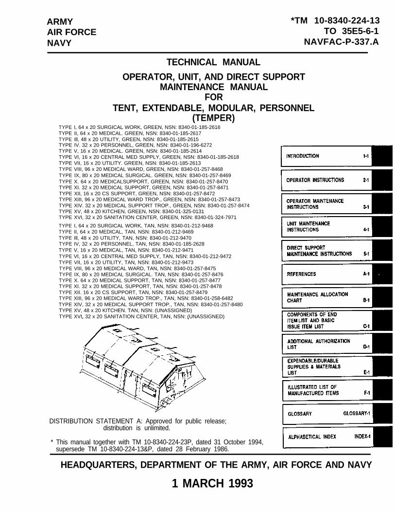
FORTENT, EXTENDABLE, MODULAR, PERSONNEL
(TEMPER)TYPE I, 64 x 20 SURGICAL WORK, GREEN, NSN: 8340-01-185-2616TYPE II, 64 x 20 MEDICAL. GREEN, NSN: 8340-01-185-2617TYPE Ill, 48 x 20 UTILITY, GREEN, NSN: 8340-01-185-2615TYPE IV. 32 x 20 PERSONNEL, GREEN, NSN: 8340-01-196-6272TYPE V, 16 x 20 MEDICAL. GREEN, NSN: 8340-01-185-2614TYPE VI, 16 x 20 CENTRAL MED SUPPLY, GREEN, NSN: 8340-01-185-2618TYPE VII, 16 x 20 UTILITY. GREEN, NSN: 8340-01-185-2613TYPE VIII, 96 x 20 MEDICAL WARD, GREEN, NSN: 8340-01-257-8468TYPE IX, 80 x 20 MEDICAL SURGICAL. GREEN, NSN: 8340-01-257-8469TYPE X. 64 x 20 MEDICALSUPPORT, GREEN, NSN: 8340-01-257-8470TYPE XI. 32 x 20 MEDICAL SUPPORT, GREEN, NSN: 8340-01-257-8471TYPE XII, 16 x 20 CS SUPPORT, GREEN, NSN: 8340-01-257-8472TYPE XIII, 96 x 20 MEDICAL WARD TROP., GREEN, NSN: 8340-01-257-8473TYPE XIV. 32 x 20 MEDICAL SUPPORT TROP., GREEN, NSN: 8340-01-257-8474TYPE XV, 48 x 20 KITCHEN, GREEN, NSN: 8340-01-325-0131TYPE XVI, 32 x 20 SANITATION CENTER, GREEN, NSN: 8340-01-324-7971
TYPE I, 64 x 20 SURGICAL WORK, TAN, NSN: 8340-01-212-9468TYPE II, 64 x 20 MEDICAL, TAN, NSN: 8340-01-212-9469TYPE Ill, 48 x 20 UTILITY, TAN, NSN: 8340-01-212-9470TYPE IV, 32 x 20 PERSONNEL, TAN, NSN: 8340-01-185-2628TYPE V, 16 x 20 MEDICAL, TAN, NSN: 8340-01-212-9471TYPE VI, 16 x 20 CENTRAL MED SUPPLY, TAN, NSN: 8340-01-212-9472TYPE VII, 16 x 20 UTILITY, TAN, NSN: 8340-01-212-9473TYPE VIII, 96 x 20 MEDICAL WARD, TAN, NSN: 8340-01-257-8475TYPE IX, 80 x 20 MEDICAL SURGICAL. TAN, NSN: 8340-01-257-8476TYPE X. 64 x 20 MEDICAL SUPPORT, TAN, NSN: 8340-01-257-8477TYPE XI. 32 x 20 MEDICAL SUPPORT, TAN, NSN: 8340-01-257-8478TYPE XII. 16 x 20 CS SUPPORT, TAN, NSN: 8340-01-257-8479TYPE XIII, 96 x 20 MEDICAL WARD TROP., TAN, NSN: 8340-01-258-6482TYPE XIV, 32 x 20 MEDICAL SUPPORT TROP., TAN, NSN: 8340-01-257-8480TYPE XV, 48 x 20 KITCHEN. TAN, NSN: (UNASSIGNED)TYPE XVI, 32 x 20 SANITATION CENTER, TAN, NSN: (UNASSIGNED)
DISTRIBUTION STATEMENT A: Approved for public release;distribution is unlimited.
* This manual together with TM 10-8340-224-23P, dated 31 October 1994,supersede TM 10-8340-224-13&P, dated 28 February 1986.
HEADQUARTERS, DEPARTMENT OF THE ARMY, AIR FORCE AND NAVY
1 MARCH 1993

CHANGE
NO. 2
TM 10-8340-224-13T.O. 35E5-6-1
NAVFAC-P-337.AC2
HEADQUARTERSDEPARTMENTS OF THE ARMY
AIR FORCE AND NAVYWASHINGTON, D.C., 13 JANUARY 1995
OPERATOR, UNIT AND DIRECT SUPPORTMAINTENANCE MANUAL
FOR
TENT, EXTENDABLE, MODULAR, PERSONNEL(TEMPER)
DISTRIBUTION STATEMENT A: Approved for public release; distribution is unlimited
TM 10-8340-224-13/T.O. 35E5-6-1/NAVFAC-P-337.A, 1 March 1993, is changed as follows:
1. Remove and insert pages as indicated below. New or changed text material is indicated by a vertical barin the margin. An illustration change is indicated by a miniature pointing hand.
Remove pages Insert pages
i and ii i and iiCover Cover
2. Retain this sheet in front of manual for reference purposes.
By Order of the Secretaries of the Army, Air Force and Navy:
Official:
Administrative Assistant to theSecretary of the Army
07858
GORDON R. SULLIVANGeneral, United States Army
Chief of Staff

TM 10-8340-224-13NAVFAC-P-337.AT.O. 35E5-6-1
C 2
MERRILL A. McPEAKGeneral, USAFChief of Staff
RONALD W. YATESGeneral, USAFCommander, Air Force Materiel Command
DAVID E. BOTTORFFRear Admiral, CEC, US NavyCommanderNavy Facilities EngineeringCommand
DISTRIBUTION:To be distributed in accordance with DA Form 12-25-E, block no. 2545, requirements for
TM 10-8340-224-13.

CHANGE
NO. 1
ARMY TM 10-8340-224-13AIR FORCE TO 35E5-6-1
NAVY NAVFAC-P-337.AC 1
HEADQUARTERSDEPARTMENTS OF THE ARMY, AIR FORCE, AND NAVY
WASHINGTON, D.C., 28 FEBRUARY 1994
OPERATOR, UNIT, AND DIRECT SUPPORTMAINTENANCE MANUAL
FORTENT, EXTENDABLE, MODULAR, PERSONNEL
(TEMPER)
DISTRIBUTION STATEMENT A: Approved for public release; distribution is unlimited.
TM 10–8340-224-13/T0 35E5-6-1/NAVFAC–P-337.A, 1 March 1993, is changed as follows:
1. Remove and insert pages as indicated below. New or changed text material isindicated by a vertical bar in the margin. An illustration change is indicatedby a miniature pointing hand.
Remove pages Insert pages
i and ii i and ii
1-3 and 1-4 1-3 and 1-45-9 and 5-10 5-9 and 5-10
2. Retain this sheet in front of manual for reference purposes.

ARMY TM 10-8340-224-13AIR FORCE TO 35 E5-6-1NAVY NAVFAC-P-337.A
C 1
By Order of the Secretaries of the Army, Air Force, and Navy:
GORDON R. SULLIVANGeneral, United States Army
Official: Chief of Staff
MILTON H. HAMILTONAdministrative Assistant to the
Secretary of the Army06138
MERRILL A. McPEAKGeneral, USAFChief of Staff
Official:
RONALD W. YATESGeneral, USAFCommander, Air Force Materiel Command
DAVID E. BOTTORFFRear Admiral, CEC, US NavyCommanderNavy Facilities EngineeringCommand
DISTRIBUTION:To be distributed in accordance with DA Form 12-25-E, block no. 2545, requirements for
TM 10-8340-224-13.
ARMY TM 10-8340–224–13AIR FORCE TO 35E5-6-1
NAVY NAVFAC-P–337.A
WARNINGS
Lethal voltage is present when light set isconnected to power source. Disconnect frompower source before inspecting or repairingany electrical component. Electrical shock ordeath may result from failure to heed thiswarning.
Lethal voltage is present when the powercontrol system is connected to power source.Disconnect from power source before inspectingor repairing any electrical component.Electrical shock or death may result fromfailure to heed this warning.
Lethal voltage is present when cables areconnected to power control system. Ensurecables are disconnected from power source whenworking with cables or fixtures. Electricalshock or death may result from failure to heedthis warning.
Seam sealer and solvent are extremelyflammable and the fumes toxic. Do not smoke oruse seam sealer or solvent near open flame.Use seam sealer and solvent with goggles andgloves, and indoors with respirator or in anopen, well ventilated area, away from sourcesof combustion. Death or severe injury mayresult from explosion or fire. Inhalation offumes may cause toxic sickness.
Frame assembly hinges can pinch or crush handsand fingers. Keep hands and fingers away fromframe assembly ridges and eaves.
Assembled tent assembly is extremely heavy.Two soldiers should be placed at each arch legto raise frame . Lift tent from correctsquatting position, using legs. Back injurycould result if lifted improperly.
Do not lock handle toward diagonal brace. Archmay collapse causing injury to personnel ordamage to equipment if improperly locked.
Two men are required to lift light set case toavoid injury to personnel.
a
ARMY TM 10-8340-224-13AIR FORCE TO 35E5-6-1NAVY NAVFAC-P-337.A
Stakes, guy lines and frame feet must be usedto prevent excessive movement of theextendable modular tents in high winds.Failure to stake and tie down tent may resultin personal injury or damage to equipment.
All tent lines and frame feet must be stakeddown. Failure to stake and tie down tent mayresult in injury to personnel and damage toequipment.
Eliminate the possibility of tripping. Clearfabric and guy lines. Injury to personnel mayresult from falls.
CAUTIONS
Do not twist or turn frame components whenhandling. Damage to equipment may result.
Do not step on tent components. Material maybe torn and dirt ground into material.
Avoid folding wall fabric into joints.Material may rip or tear if caught in joint.
Insert quick release pins towards inside oftent on end assemblies. Tent fabric may tearif inserted towards outside.
Orient hitch clip pins towards inside ofvestibule at vestibule door frame. Vestibuledoor fabric may tear if oriented towardsoutside.
Tent frame must be raised uniformly to avoidtwisting or turning. Damage to frame mayresult.
Lift door ramps prior to placing weight ondoor frame. Damage to piano hinge may result.
Clear and level ground before installingfloor. Sharp objects or depressions candamage tent floor.
Allow slack in electrical cables. Strain oncable can damage equipment.
b
ARMY TM 10-8340-224-13AIR FORCE TO 35E5–6-1
NAVY NAVFAC–P-337.A
Avoid damage to fabric and guy lines. Clearall fabric and guy lines from hinge joints.Do not stand on fabric or guy lines. Materialmay rip or lacerate.
Unpack components carefully. Improper or hastyhandling may result in damage to the TEMPERcomponents and accessories.
c/(d blank)

*ARMY TM 10-8340-224-13AIR FORCE TO 35E5-6-1
NAVY NAVFAC-P-337.A
TECHNICAL MANUAL HEADQUARTERSDEPARTMENTS OF THE ARMY,
AIR FORCE AND NAVYNO. 10-8340-224-13 WASHINGTON D.C., 1 MARCH 1993
TECHNICAL MANUAL
Operator, Unit, Direct SupportMaintenance Manual
ForTENT, EXTENDABLE, MODULAR, PERSONNEL (TEMPER)
REPORTING ERRORS AND RECOMMENDING IMPROVEMENTS
You can help improve this manual. If you find any mistakes or if you know of a way to improvethese procedures, please let us know. Mail your letter or DA Form 2028 (RecommendedChanges to Publications and Blank Forms), or DA Form 2028-2 located in the back of thismanual directly to: Commander, US Army Aviation and Troop Command, ATTN: AMSAT-I-MP,4300 Goodfellow Blvd, St. Louis, MO 63120-1798. A reply will be furnished directly to you.
DISTRIBUTION STATEMENT A: Approved for public release; distribution is unlimited.
TABLE OF CONTENTS
Chapter/Section PAGE
CHAPTER 1 INTRODUCTION . . . . . . . . . . . . . . . . . . . . . . . . . . . . . . . . . . . . . . 1-1
S e c t i o n I General Information . . . . . . . . . . . . . . . . . . . . . . . . 1-1S e c t i o n I I Equ ipment Descr ip t ion . . . . . . . . . . . . . . . . . . . . . 1-3S e c t i o n I I I Technical Principles of Operation . . . . . . . 1-18
CHAPTER 2 OPERATING INSTRUCTIONS . . . . . . . . . . . . . . . . . . . . . . . . . . 2-1
S e c t i o n I Descr ip t ion and Use o f Opera tor 's Cont ro ls andI n d i c a t o r . . . . . . . . . . . . . . . . . . . . . . . . . . . . . . . . . . . . 2-2
S e c t i o n I I Opera tor Prevent ive Main tenanceChecks and Services (PMCS) . . . . . . . . . . . . . . . 2-4
S e c t i o n I I I Operations Under Usual Conditions . . . . . . . 2-17
S e c t i o n I V Operations Under Unusual conditions . . . . 2-76
CHAPTER 3 OPERATOR MAINTENANCE INSTRUCTIONS . . . . . . . . . . . . 3-1
S e c t i o n I L u b r i c a t i n g I n s t r u c t i o n s . . . . . . . . . . . . . . . . . . 3-1S e c t i o n I I Opera tor Troub leshoot ing Procedures . . . . 3-1
S e c t i o n I I I Operator Maintenance Procedures . . . . . . . . . 3-5
* This manual together with TM 10-8340-224-23P, dated 31 October 1994, supersedeTM 10-8340-224-13&P, dated 28 February 1986.
Change 2 i

ARMY TM 10-8340-224-13AIR FORCE TO 35E5-6-1NAVY NAVFAC-P-337.A
Chapter/Section
CHAPTER 4
S e c t i o n I
S e c t i o n I I
S e c t i o n I I I
S e c t i o n I V
Sec t ion V
CHAPTER 5
S e c t i o n I
S e c t i o n I I
S e c t i o n I I I
APPENDIX A
APPENDIX B
APPENDIX C
APPENDIX D
APPENDIX E
APPENDIX F
i i
TABLE OF CONTENTS CONT'D.
Page
UNIT MAINTENANCE INSTRUCTIONS . . . . . . . . 4-1
R e p a i r P a r t s , Special Tools, TMDEand Support Eqipment . . . . . . . . . . . . . . . . . 4 -2
Service Upon Receipt . . . . . . . . . . . . . . . . . . 4-2
Un i t T roub leshoo t i ng . . . . . . . . . . . . . . . . . 4 -3
Unit Maintenance Procedures . . . . . . . . . . 4-4
Preparat ion for Storage or Shipment . . 4-11
DIRECT SUPPORT MAINTENANCEINSTRUCTIONS . . . . . . . . . . . . . . . . . . . . . . . . . 5 -1
R e p a i r P a r t s , S p e c i a l T o o l s ; T e s tMeasurement Diagnost ic Equipment(TMDE) and Support Equipment . . . . . . . . . 5-1
T roub leshoo t i ng . . . . . . . . . . . . . . . . . . . . . . 5-1
Maintenance Procedures . . . . . . . . . . . . . . . 5-2
REFERENCES . . . . . . . . . . . . . . . . . . . . . . . . . . . A-1
MAINTENANCE ALLOCATION CHART . . . . . . . . . B-1
COMPONENTS OF END ITEM ANDBASIC ISSUE ITEMS LIST . . . . . . . . . . . . . . . C-1
ADDITIONAL AUTHORIZATION LIST . . . . . . . . D-1
EXPENDABLE/DURABLE SUPPLIES ANDMATERIALS LIST . . . . . . . . . . . . . . . . . . . . . . . E-1
ILLUSTRATED LIST OFMANUFACTURED ITEMS . . . . . . . . . . . . . . . . . . . F-1
*U.S. GOVERNMENT PRINTING OFFICE: 1995-655-121/20030

Chapter/Section
ARMY TM 10-8340-224-13AIR FORCE TO 35E5-6-1
NAVY NAVFAC-P-337.A
TABLE OF CONTENTS CONT’D.
Page
GLOSSARY . . . . . . . . . . . . . . . ..GLOSSARY-1
ALPHABETICAL INDEX . . .. . . . . . . . ..INDEX-1
iii
ARMY TM 10-8340-224-13AIR FORCE TO 35E5-6-1NAVY NAVFAC-P-337.A
HOW TO USE THIS MANUAL
This manual, (TM 10-8340-224-13), contains general information,operating instructions, PMCS instructions, troubleshooting steps,and maintenance instructions for the Tent, Extendable, Modular,Personnel (TEMPER). Use the front cover index and thumb bleeds atthe edge of the pages to quickly find the sections of the manualshown on the cover.
The manual has been divided into chapters, sections andparagraphs that are numbered in sequence. Pages, paragraphs, andillustrations are numbered by chapter. For example, chapter 2,page 3 is marked 2-3; chapter 3, paragraph 5 is marked 3-5;figure 2-3 is the third illustration in chapter 2. To quicklyfind specific information, use the table of contents. Forexample, the front cover index states that chapter 1 begins onpage 1-1. The table of contents on page i tells you the exactpage where the paragraph you want is located.
iv
ARMY TM 10-8340-224-13AIR FORCE TO 35E5-6-1NAVY NAVFAC-P-337.A
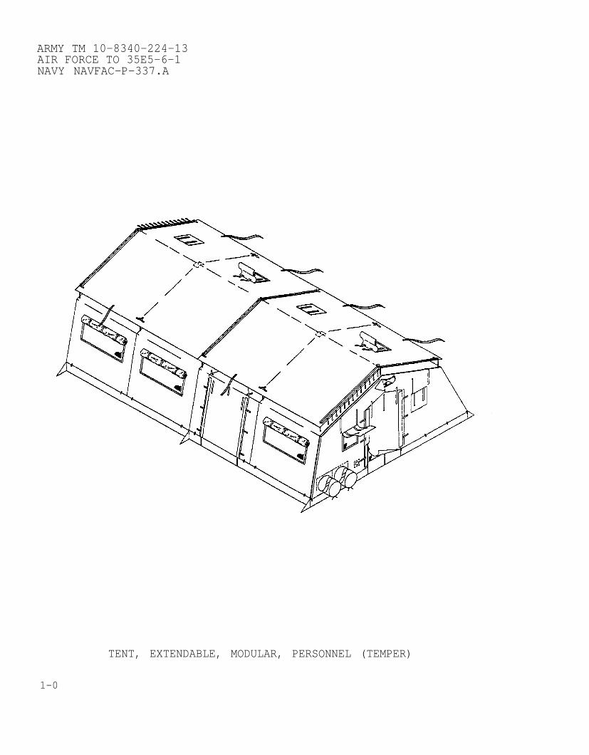
TENT, EXTENDABLE, MODULAR, PERSONNEL (TEMPER)
1-0
ARMY TM 10-8340-224-13AIR FORCE TO 35E5-6-1
NAVY NAVFAC–P–337.A
Subject
CHAPTER 1
INTRODUCTIONSection/Paragraph
General Information. . . . . . . . . . . . . . . . . . . . . . . . . . . . . . . . . . . . . . ..IScope . . . . . . . . . . . . . . . . . . . . . . . . . . . . . . . . . . . . . . . . . . .1-1Maintenance Forms and Records . . . . . . . . . . . . . . . . . . . . . . ...1-2Corrosion Prevention and Control (CPC) . . . . . . . . . . . . . . . . . . ...1-3Destruction of Material to Prevent Enemy Use . . . . . . . . . . . . . ..1-4Preparation for Storage or Shipment . .. . . . . . . . . . . . . . . . ..1–5Quality Assurance (QA) . . . . . . . . . . . . . . . . . . . . . . . . . ...1-6Reporting Equipment Improvement Recommendations (EIR) .. . ...1-7Warranty Information . .. . . . . . . . . . . . . . . . . . . . . . . . . . . . ..1–8Nomenclature Cross-Reference . .. . . . . . . . . . . . . . . . . . . . . ...1-9List of Abbreviations and Terms . . . . . . . . . . . . . . . . . . . . . ..1–10
Equipment Description . . .. . . . . . . . . . . . . . . . . . . . . . . . . . . . . . . IIEquipment Characteristics, Capabilities and Features . . . . .. ..1-11Location and Description of Major Parts . . . . . . . . . . . . . . . . ...1-12Differences Between Models . . . . . . . . . . . . . . . . . . . . . . . . . ...1-13Equipment Data . . . . . . . . . . . . . . . . . . . . . . . . . . . . . . . . . . ...1-14
Technical Principles of Operation . . . . . . . . . . . . . . . . . . . . . . . . . . ...IIIOperation of the TEMPER. . . . . . . . . . . . . . . . . . . . . . . . ...1-15
Section I. GENERAL INFORMATION1-1. SCOPE.
a. Type of Manual. Operator, Unit, and Direct SupportMaintenance Manual that provides instructions for the set-up,operation, take down, maintenance, and repair procedures forcomponents of the Tent, Extendable Modular (TEMPER).
b. Purpose of Equipment. Provide environmental protectionsupport command and control, medical, supply and personnelhousing operations.
c. Special Feature. Tent sections allow the tent layout toconfigured as necessary to suit tactical considerations.
d. Model Number and Equipment Name. Figure 1-6 shows thevarious tent configurations and nomenclature.
all
to
be
1-2. MAINTENANCE FORMS AND RECORDS. Department of the Army formsand procedures used for equipment maintenance will be thoseprescribed by DA PAM 738-750, The Army Maintenance ManagementSystem (TAMMS).
1-1
ARMY TM 10–8340–224–13AIR FORCE TO 35E5–6–1NAVY NAVFAC–P–337.A
1-3.
1-4.
1-5.
1-6.
1-7.
1-8.
1-2
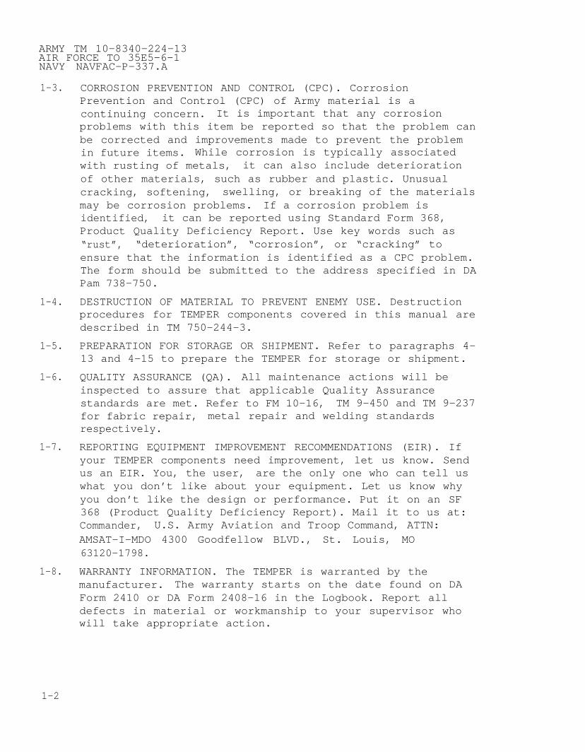
CORROSION PREVENTION AND CONTROL (CPC). CorrosionPrevention and Control (CPC) of Army material is acontinuing concern. It is important that any corrosionproblems with this item be reported so that the problem canbe corrected and improvements made to prevent the problemin future items. While corrosion is typically associatedwith rusting of metals, it can also include deteriorationof other materials, such as rubber and plastic. Unusualcracking, softening, swelling, or breaking of the materialsmay be corrosion problems. If a corrosion problem isidentified, it can be reported using Standard Form 368,Product Quality Deficiency Report. Use key words such as“rust”, “deterioration”, “corrosion”, or “cracking” toensure that the information is identified as a CPC problem.The form should be submitted to the address specified in DAPam 738–750.
DESTRUCTION OF MATERIAL TO PREVENT ENEMY USE. Destructionprocedures for TEMPER components covered in this manual aredescribed in TM 750-244-3.
PREPARATION FOR STORAGE OR SHIPMENT. Refer to paragraphs 4-13 and 4-15 to prepare the TEMPER for storage or shipment.
QUALITY ASSURANCE (QA). All maintenance actions will beinspected to assure that applicable Quality Assurancestandards are met. Refer to FM 10–16, TM 9–450 and TM 9–237for fabric repair, metal repair and welding standardsrespectively.
REPORTING EQUIPMENT IMPROVEMENT RECOMMENDATIONS (EIR). Ifyour TEMPER components need improvement, let us know. Sendus an EIR. You, the user, are the only one who can tell uswhat you don’t like about your equipment. Let us know whyyou don’t like the design or performance. Put it on an SF368 (Product Quality Deficiency Report). Mail it to us at:Commander, U.S. Army Aviation and Troop Command, ATTN:AMSAT–I–MDO 4300 Goodfellow BLVD., St. Louis, MO63120-1798.
WARRANTY INFORMATION. The TEMPER is warranted by themanufacturer. The warranty starts on the date found on DAForm 2410 or DA Form 2408–16 in the Logbook. Report alldefects in material or workmanship to your supervisor whowill take appropriate action.
ARMY TM 10-8340-224-13AIR FORCE TO 35E5-6-1
NAVY NAVFAC-P-337.A
1-9. NOMENCLATURE CROSS-REFERENCE.
COMMON NAME OFFICIAL NAME
TEMPER Tent, Extendable, Modular, Personnel
Light Set Light Set, Portable, Fluorescent, Type I
1-10. LIST OF ABBREVIATIONS AND TERMS.
CPCCu FtDS2EIRESCHZMWONBCPkg CuSq FtU/MUOCVAC
STBV-agent
Corrosion Prevention and ControlCubic Foot/FeetDecontamination Solution (ready–to–use)Equipment Improvement ReportEquipment Serviceability CriteriaHertz - Unit of frequency equal to one cycle per secondModification Work OrderNuclear, Biological, ChemicalPackage Cubic Foot/FeetSquare Foot/FeetUnit of MeasureUsable On CodeVolts Alternating Current - Measure of electricalpotentialSupertropical Bleach - Decontamination AgentVector agent
Section II. EQUIPMENT DESCRIPTION
1-11. EQUIPMENT CHARACTERISTICS, CAPABILITIES AND FEATURES. TheTEMPER is available in green or tan color for use in differenttypes of climate. Except for color, the characteristics,capabilities and features of both versions are identical.
a. Characteristics.
● Usable in a variety of climates.
● Constructed of lightweight materials.
● Deployed in forward battle areas.
● Provides blackout protection.
● Modular configuration permits layout flexibility.
1-3

ARMY TM 10-8340-224–13AIR FORCE TO 35E5-6-1NAVY NAVFAC–P–337.A
1-11. EQUIPMENT CHARACTERISTICS, CAPABILITIES AND FEATURES
b. Capabilities and Features.
CONT
Can be set up quickly under normal operating conditions.
TEMPER sections are interchangeable to form differentconfigurations.
Frame assembly consists of collapsible sections made ofaluminum tube that unfold and connect to form a singleframe.
TEMPER is made of water resistant, flame resistant,mildew resistant, polyester duck fabric.
Can be equipped with single phase or 3–phase electricalpower.
Can be heated or cooled through external sources.
Designed for steady wind of 50 mph and gusts of 65 mph.
1-12. LOCATION AND DESCRIPTION OF MAJOR PARTS.
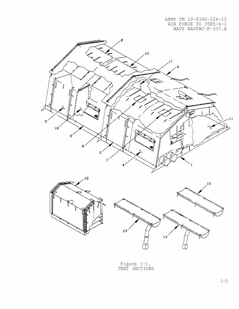
a. Tent Sections. The major components of the tent sectionsare identified in Figure 1–1, and described in paragraphs (1)through (17) below.
1–4 Change 1
ARMY TM 10-8340-224-13AIR FORCE TO 35E5-6-1
NAVY NAVFAC-P-337.A
Figure 1-1.TENT SECTIONS
1-5
ARMY TM 10-8340-224-13AIR FORCE TO 35E5-6-1NAVY NAVFAC-P-337.A
1-12. LOCATION AND DESCRIPTION OF MAJOR PARTS (CONT)
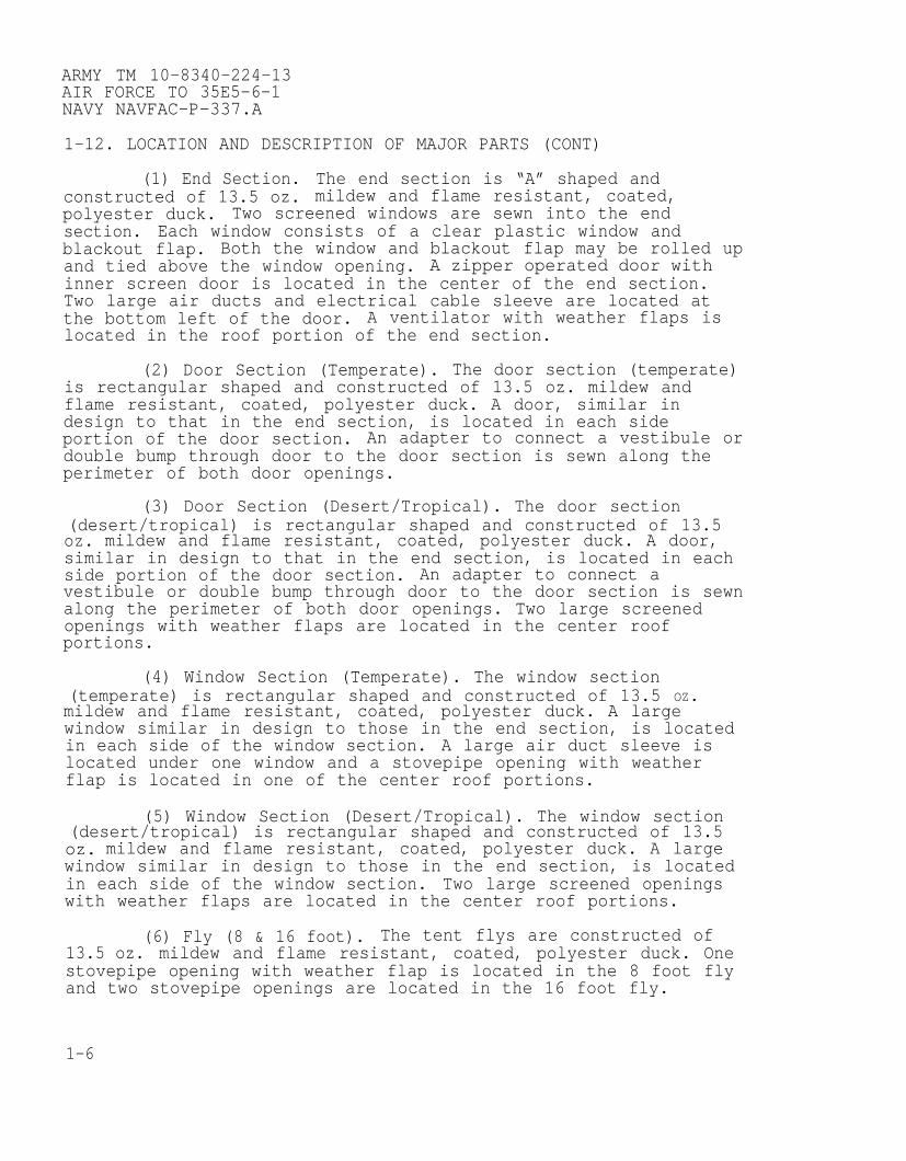
(1) End Section. The end section is “A” shaped andconstructed of 13.5 oz. mildew and flame resistant, coated,polyester duck. Two screened windows are sewn into the endsection. Each window consists of a clear plastic window andblackout flap. Both the window and blackout flap may be rolled upand tied above the window opening. A zipper operated door withinner screen door is located in the center of the end section.Two large air ducts and electrical cable sleeve are located atthe bottom left of the door. A ventilator with weather flaps islocated in the roof portion of the end section.
(2) Door Section (Temperate). The door section (temperate)is rectangular shaped and constructed of 13.5 oz. mildew andflame resistant, coated, polyester duck. A door, similar indesign to that in the end section, is located in each sideportion of the door section. An adapter to connect a vestibule ordouble bump through door to the door section is sewn along theperimeter of both door openings.
(3) Door Section (Desert/Tropical). The door section(desert/tropical) is rectangular shaped and constructed of 13.5oz. mildew and flame resistant, coated, polyester duck. A door,similar in design to that in the end section, is located in eachside portion of the door section. An adapter to connect avestibule or double bump through door to the door section is sewnalong the perimeter of both door openings. Two large screenedopenings with weather flaps are located in the center roofportions.
(4) Window Section (Temperate). The window section(temperate) is rectangular shaped and constructed of 13.5 OZ.mildew and flame resistant, coated, polyester duck. A largewindow similar in design to those in the end section, is locatedin each side of the window section. A large air duct sleeve islocated under one window and a stovepipe opening with weatherflap is located in one of the center roof portions.
(5) Window Section (Desert/Tropical). The window section(desert/tropical) is rectangular shaped and constructed of 13.5oz. mildew and flame resistant, coated, polyester duck. A largewindow similar in design to those in the end section, is locatedin each side of the window section. Two large screened openingswith weather flaps are located in the center roof portions.
(6) Fly (8 & 16 foot). The tent flys are constructed of13.5 oz. mildew and flame resistant, coated, polyester duck. Onestovepipe opening with weather flap is located in the 8 foot flyand two stovepipe openings are located in the 16 foot fly.
1-6

ARMY TM 10-8340-224-13AIR FORCE TO 35E5-6-1
NAVY NAVFAC-P-337.A
(7) End Section Liner (Temperate). The end section liner(Temperate) is constructed of 6.8 oz. flame and mildew resistant,natural color, cotton, oxford cloth. It consists of an “A” shapedend liner and an intermediate liner (Temperate) sewn together toform an end section liner. Two clear plastic windows, a dooropening with flap and an air duct opening with flap are locatedin the end liner. An additional opening with flap is providednext to the door opening for easy access to the electricaldistribution box.
(8) End Section Liner (Desert/Tropical). The end sectionliner (Desert/Tropical) is constructed of 6.8 oz. flame andmildew resistant, natural color, cotton, oxford cloth. Itconsists of an “A” shaped end liner and an intermediate liner(Desert/Tropical) sewn together to form an end section liner. Twoclear plastic windows, a door opening with flap and an air ductopening with flap are located in the end liner. An additionalopening with flap is provided next to the door opening for easyaccess to the electrical distribution box.
(9) Intermediate Liner (Temperate). The intermediate liner(temperate) is constructed of 6.8 oz. flame and mildew resistant,natural color, cotton, oxford cloth and is rectangular in shape.Two combination door/window openings are provided at oppositeends of the liner. Two stovepipe openings with weather flaps arelocated in the center roof portions. An air duct opening withweather flaps is located in one of the door/window flaps.
(10) Intermediate Liner (Desert/Tropical). Theintermediate liner (desert/tropical) is constructed of 6.8 oz.flame and mildew resistant, natural color, cotton, oxford clothand is rectangular in shape. Two combination door/window openingsare provided at opposite ends of the liner. Two large openingswith weather flaps are located in the center roof portions.
(11) Floor. Floors may be either single ply or insulated.Single-ply floors are 21 feet long and come in widths of 8, 24,and 40 feet. The 24 and 40 foot widths are used when a non-sectionalized floor is desired. Single–ply floors are black onone side and either pale green or gray on the other, depending onthe intended application. Hook and pile tape is used to attachthe floor sections together, while tie tapes are used to securethe floor to the tent frame. The insulated tent floor is 20 feetlong and 8 feet wide, and is made from 1/2 inch thick foamsandwiched between two plies of coated cloth. Hook and pile tapeis used to connect floor sections. Tie tapes are not used, sincethe insulated floor sections are simply laid on top of thesingle-ply floor.
1-7

ARMY TM 10-8340-224-13AIR FORCE TO 35E5-6-1NAVY NAVFAC-P-337.A
1-12. LOCATION AND DESCRIPTION OF MAJOR PARTS (CONT)
(12) Vestibule. The vestibule is made from 13.5 oz mildewand flame resistant, coated, polyester duck. It is supported bythree aluminum vestibule frame assemblies. Becket loops andgrommets are used to attach a removable door to the vestibule,and for attaching the other side of the vestibule to either atent end section or door section adapter. The vestibule withouta door can be used as a passageway when connecting one tent toanother.
(13) Plenum, Endwall 16 Foot. The Endwall Plenum isconstructed of coated, lightweight, nylon material. The endwallplenum consists of a horizontal body and an extension located atone end. The horizontal body is 16 feet long with a semi-cylindrical shape approximately 3 feet wide. One body section endis capped with a removable plenum cover that is attached withhook and pile fastener tape, the other body end is sealed. The 16foot body portion of all plenums contains openings with fastenertape flaps that can be opened or closed to adjust the amount ofconditioned air entering the tent. Extendable plenum sections canbe connected to the capped end, after removal of the cap, withhook and pile fastener tape. A tubular extension approximately 12inches in diameter is sewn into the plenum near the closed end.The opposite end of the extension is open. Tie lines are providedat the open end of the tubular extension to secure the plenum tothe endwall air duct. Tie tapes are provided at the plenum top tosecure it to the tent frame.
(14) Plenum, Side Entrance, 16 Foot. The side entranceplenum is constructed of the same material as the endwall plenum.The design, consisting of a horizontal body and an extension,issimilar to the endwall plenum however, it is configured to beused where air ducts enter the sidewall of the tent.
(15) Plenum, Extendable, 16 Foot. The extendable plenum isconstructed of the same material as the endwall and side entranceplenums. It is a semi-cylindrical tube 3 feet wide and 16 feetlong. Both ends are provided with hook and pile fastener tape anda cover to connect either endwall, sidewall, or additionalextendable plenums.
(16) Modesty Curtain. The modesty curtain is constructedof 6.8 oz. flame and mildew resistant, natural color, cotton,oxford cloth. The curtain consists of two identical halves and acable assembly. The curtain halves attach to the cable assemblyby snaphooks. The cable assembly attaches to the tent frame atthe eaves.
1-8

ARMY TM 10-8340-224-13AIR FORCE TO 35E5-6-1
NAVY NAVFAC-P-337.A
(17) Partition. The partition is constructed of 6.8 oz.flame and mildew resistant, natural color, cotton, oxford cloth.It has a door opening in the center and a “U” shaped opening atthe top center which allows the air plenum to pass through.
b. Frame Sections. Three unique frame sections in variousquantities compose the TEMPER Tent: End Section, Type I;Extendable Section, Type II; Extendable Door Section, Type III.Each section is composed of interchangeable major components:Arch Assembly; Header Assembly; Purlin Assembly; Eave ExtenderAssembly; Ridge Extender Assembly; Frame Sections Cover Assembly.Additionally, the Extendable Door Section incorporates twoadditional components, the Door Sill Assembly and Vestibule FrameAssembly. These major components are illustrated in Figure 1-2and described in paragraphs (1) through (8).
Figure 1-2.FRAME SECTION COMPONENTS
1-9

ARMY TM 10-8340-224-13AIR FORCE TO 35E5-6-1NAVY NAVFAC-P-337.A
1-12. LOCATION AND DESCRIPTION OF MAJOR PARTS (CONT)
(1) Arch Assembly. The arch assembly consists of twoaluminum side arch assemblies and an aluminum roof arch assembly.The arch assembly can easily be folded into a closed “W”configuration for easy handling and transport. A non-sectionalized arch assembly and a sectionalized arch assembly arecurrently fielded. The difference between both types is that thesectionalized arch assembly consists of two interlocking piecesthat are joined and held together by a quick release pin. Thenon-sectionalized arch assembly overall length is 113 inches andthe sectionalized arch assembly overall length is 98 inchesallowing easy transport by USAF aircraft.
(2) Header Assembly. The header assembly is made fromaluminum rectangular tubing with a cross section of 1 1/4 x 2 1/2inches and has an overall length of 98 inches. Steel plates areriveted to the ends to allow attachment to the arch assembly.
(3) Purlin Assembly. The purlin assembly is made fromtubular aluminum approximately 96 inches long x 1 1/2 inches indiameter. Folding diagonal braces which have “U” shaped crosssections are riveted to each end of the purlin. At the end ofeach brace is a rotating brace stud and brace shackle. The bracestud and the purlin end fitting lock into slots in the archassembly. Five purlins, one at the ridge, one at both eaves andone at each base are required to join two arch assemblies.
(4) Eave Extender Assembly. The cave extender assembly ismade from tubular aluminum with a single foot, web–reinforcedbase welded to the bottom of the center length of tubing. Twohitch clip pins are fastened to the extender.
(5) Ridge Extender Assembly. The ridge extender assemblyis made from tubular aluminum with a two-footed, web–reinforcedbase welded to the bottom of the center length of tubing. A hitchclip pin is fastened to the extender
(6) Frame Sections Cover Assembly. The frame sectionscover assembly is diaper shaped, made of heavyweight, coatedcloth with interior straps to secure frame components andexterior straps which bind the assembly together.
(7) Door Sill Assembly. The door sill assembly is madefrom tubular aluminum with a four foot long rotating door sillbolted to the center of the tubular section. Folding diagonalbraces which have a “U” shaped cross section are riveted to eachend of the door sill assembly. At the end of each brace is arotating brace stud and brace shackle. The brace stud and thedoor sill end fitting lock into slots at the base of the archassembly.
1-10
ARMY TM 10-8340-224-13AIR FORCE TO 35E5-6-1
NAVY NAVFAC-P-337.A
(8) Vestibule Frame Assembly. The vestibule assembly iscomposed of three components made of aluminum tubing: twoupright poles with attached baseplate, and a header. Holes inthe baseplate permit the assembly to be staked to the ground.Three vestibule frame assemblies are required to support avestibule with door.
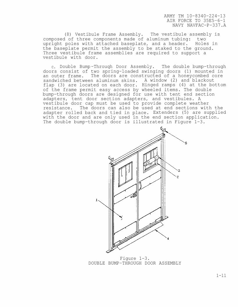
c. Double Bump-Throuqh Door Assembly. The double bump-throughdoors consist of two spring-loaded swinging doors (1) mounted inan outer frame. The doors are constructed of a honeycombed coresandwiched between aluminum skins. A window (2) and blackoutflap (3) are located on each door. Hinged ramps (4) at the bottomof the frame permit easy access by wheeled items. The doublebump-through doors are designed for use with tent end sectionadapters, tent door section adapters, and vestibules. Avestibule door cap must be used to provide complete weatherresistance. The doors can also be used at end sections with theadapter rolled back and tied in place. Extenders (5) are suppliedwith the door and are only used in the end section application.The double bump-through door is illustrated in Figure 1-3.
Figure 1-3.DOUBLE BUMP-THROUGH DOOR ASSEMBLY
1-11
ARMY TM 10-8340-224-13AIR FORCE TO 35E5-6-1NAVY NAVFAC-P–337.A
1-12. LOCATION AND DESCRIPTION OF MAJOR PARTS (CONT)
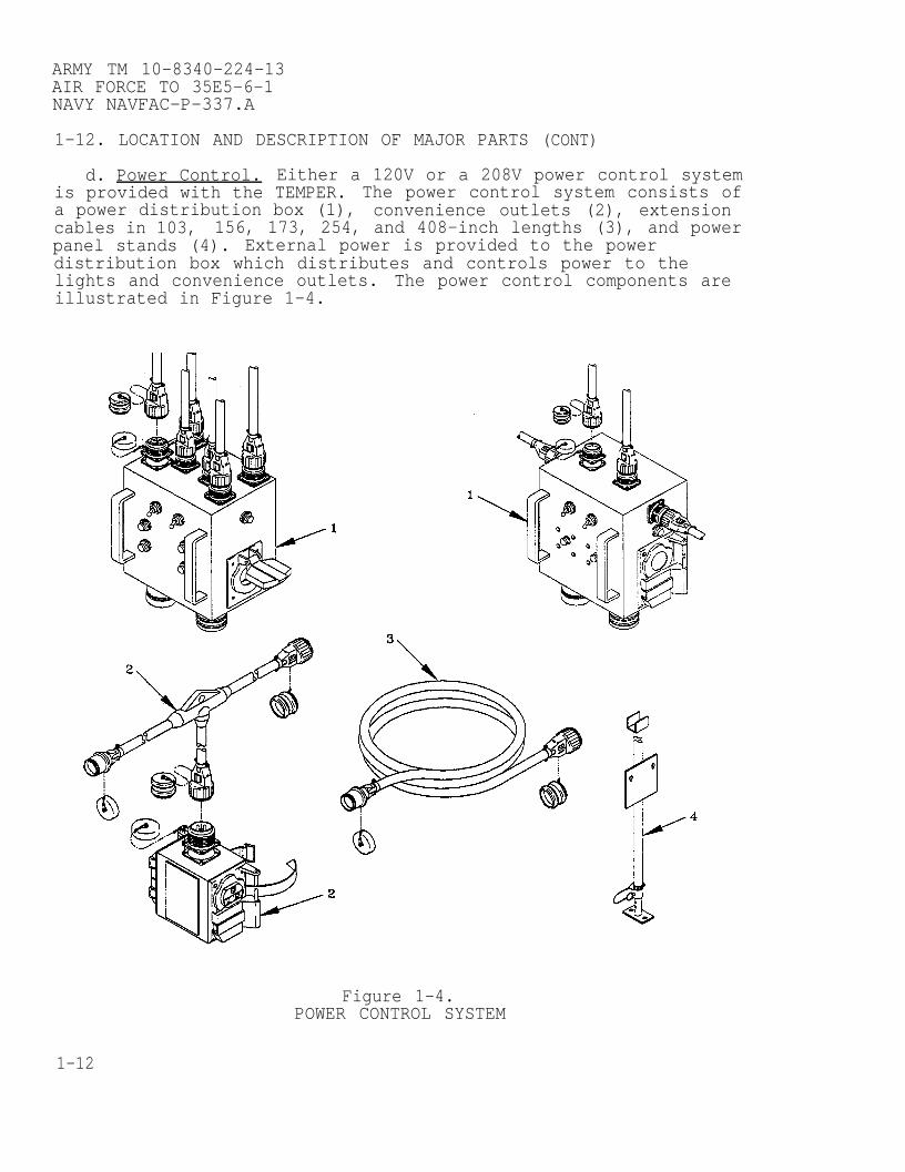
d. Power Control. Either a 120V or a 208V power control systemis provided with the TEMPER. The power control system consists ofa power distribution box (1), convenience outlets (2), extensioncables in 103, 156, 173, 254, and 408-inch lengths (3), and powerpanel stands (4). External power is provided to the powerdistribution box which distributes and controls power to thelights and convenience outlets. The power control components areillustrated in Figure 1-4.
Figure 1-4.POWER CONTROL SYSTEM
1-12

ARMY TM 10-8340-224-13AIR FORCE TO 35E5-6-1
NAVY NAVFAC-P-337.A
e. Light Set, Type I. The light set consists of a storagecontainer (1) and four luminaires (2). The storage container islined with protective foam and holds a spare lamp, spare fuse andfuseholder, and support straps in addition to the luminaires.The storage container is secured with two latches and has arubber coated, spring-actuated carrying handle at each end and inthe center. Each luminaire consists of a fluorescent lampmounted in a reinforced plastic tube with a molded cap and cableassembly at each end. The cap with the male power cable containsan On/Off switch and fuseholder. The cap with the female cableassembly contains a spare fuse. The light set is illustrated inFigure 1-5.
Figure 1-5.LIGHT SET, TYPE I
f. Light Cables, Type I & II. The Type I & II Light Cable isa set of two incandescent lights with individual streamers moldedto an electrical cable. The cable is fitted with a male andfemale plug. The light cable may be substituted for the Type ILight Set and is currently in use by the U.S. Air Force only. Thelight cable is illustrated in Figure 1-6.
Figure 1-6.LIGHT CABLES, TYPE I & II
1-13

ARMY TM 10-8340-224-13AIR FORCE TO 35E5-6-1NAVY NAVFAC-P-337.A
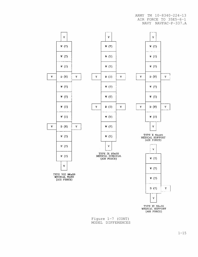
1-13. DIFFERENCES BETWEEN MODELS.
Figure 1–7MODEL DIFFERENCES
1-14
ARMY TM 10–8340–224-13AIR FORCE TO 35E5-6-1
NAVY NAVFAC-P-337.A
Figure 1-7 (CONT)MODEL DIFFERENCES
1-15

ARMY TM 10-8340-224-13AIR FORCE TO 35E5-6-1NAVY NAVFAC-P-337.A
1-13. DIFFERENCES BETWEEN MODELS (CONT)
Figure 1-7 (CONT)MODEL DIFFERENCES
1-16

ARMY TM 10-8340-224-13AIR FORCE TO 35E5-6-1
NAVY NAVFAC-P-337.A
1-14. EQUIPMENT DATA. Table 1-1. lists the dimensions, weights,quantity required, as well as packaged dimensions for theseparate TEMPER components. Class I denotes green and Class IIdenotes tan tents.
Table 1-1. Equipment Data
Tent Type
Type I, Class IType II, Class IType III, Class IType IV, Class IType V, Class IType VI, Class IType VII, Class IType VIII, Class IType IX, Class IType X, Class IType XI, Class IType XII, Class IType XIII, Class IType XIV, Class IType XV, Class IType XVI, Class I
Type I, Class IIType II, Class IIType III, Class IIType IV, Class IIType V, Class IIType VI, Class IIType VII, Class IIType VIII, Class IIType IX, Class IIType X, Class IIType XI, Class IIType XII, Class IIType XIII, Class IIType XIV, Class IIType XV, Class IIType XVI, Class II
Length
64'64'
48’32’16’16’16’96’80’64'
32’16’96’32'48’32’
64'64’48’32'16’16’16’96’80’64’32'
16’96’32’48’32'
Weight
408639771532132811961176876
582251594391232912495826232925531751
408639771532132811961176876
582251594391232912495826232925531751
Pkg cu.
320287104173869054
46439733218194
466183158107
320287104173869054
46439733218194
466183158107
Height at Eaves 6 feet 9 inches
Height at Ridge 10 feet 1/2 inches
Width at Base 20 feet 6 inches
Power Requirements: 120/208 V
1-17
ARMY TM 10-8340-224-13AIR FORCE TO 35E5-6-1NAVY NAVFAC-P-337.A
SECTION III. TECHNICAL PRINCIPLES OF OPERATION
1-15. OPERATION OF THE TEMPER.
The Tent, Extendable, Modular, Personnel (TEMPER) is anextendable, modular, frame–supported shelter consisting of acollapsible aluminum frame covered with a coated polyesterfabric. Modules are 20 feet, 6 inches wide, and can be extendedin 8-foot increments.
The modules can be configured by using becket loops and grommetsto attach any combination of window and/or door sections, alongwith vestibules for module connections. A tent fly is used toreduce solar loading and provide increased environmentalprotection.
Single-ply and insulated floor sections and liners, modestycurtains, partitions, electrical distribution systems,fluorescent and incandescent lights, air distribution plenums,and double bump–through doors are available to allowconfigurations that satisfy user requirements.
1-18

ARMY TM 10-8340–224-13AIR FORCE TO 35E5-6-1
NAVY NAVFAC-P-337.A
CHAPTER 2
OPERATING INSTRUCTIONS
Subject Section/Paragraph
Description and Use of Operator’s Controls and Indicators. . . . . .IGeneral . . . . . . . . . . . . . . . . . . . . . . . . . . . . . . . . . . . . 2-1Operator’s Controls and Indicators . . . . . . . . . . . . . . . . . . . . . .2–2
Operator Preventive Maintenance Checks and Services (PMCS) . . .IIIntroduction . . . . . . . . . . . . . . . . . . . . . . . . . . . . . . . . . . .2–3
Operation Under Usual Conditions . . . . . . . . . . . . . . . . . . . . . . . . . . . . .IIIAssembly and Preparation for Use . . . . . . . . . . . . . . . . . . . . . . . .2–4Frame Assembly . . . . . . . . . . . . . . . . . . . . . . . . . . . . . . . . . . .2–5Initial Placement of Window and Door Sections . . . . . . . . . . . . . . . . .2–6Placement of End Section . . . . . . . . . . . . . . . . . . . . . . . . . . . .2–7Placement of Tent Flys . . . . . . . . . . . . . . . . . . . . . . . . . . . . . .2–8Becket Lacing Window and Door Sections,End Sections,and Tent Flys . . . . . . . . . . . . . . . . . . . . . . . .2–9
Install Guy Lines . . . . . . . . . . . . . . . . . . . . . . . . . . . . . .2–10Raising the Frame to Partially–Erect Position. . . . . . . . . . .2–11Components . . . . . . . . . . . . . . . . . . . . . . . . . . . . . . . . . . .2-12Install Luminaires. . . . . . . . . . . . . . . . . . . . . . . . . . . . . . . .2–13Fully Erecting the Frame . . . . . . . . . . . . . . . . . . . . . . . . . . ..2–14Final Installation of Floor and Liner. . . . . . . . . . . . . . . . . . .2–15Electrical Components . . . . . . . . . . . . . . . . . . . . . . . . . . . ..2-16Complete Becket Lacing . . . . . . . . . . . . . . . . . . . . . . . . . . . . .2–17Stakes and Guy Lines . . . . . . . . . . . . . . . . . . . . . . . . . . . . .2–18Vestibule Assembly . . . . . . . . . . . . . . . . . . . . . . . . . . . . . .2–19Install Double Bump-Through Doors in Vestibuleor Vestibule Adapter . . . . . . . . . . . . . . . . . . . . . . . . . ..2–20
Install Double Bump–Through Doors in End Section . . . . . . . .2–21Modesty Curtain . . . . . . . . . . . . . . . . . . . . . . . . . . . . ..2–22Partition . . . . . . . . . . . . . . . . . . . . . . . . . . . . . . . . . . ..2–23Operation of Doors, Windows and Vents . . . . . . . . . . . . . . . . . ..2–24Decals and Instruction Plates . . . . . . . . . . . . . . . . . . . . . . ..2–2.5Preparation for Movement . . . . . . . . . . . . . . . . . . . . . . . . . ..2–26
Operation Under Unusual Condition . . . . . . . . . . . . . . . . . . . . . . . . . . . ..IVGeneral . . . . . . . . . . . . . . . . . . . . . . . . . . . . . . . . . . . . . . ...2-27
2-1

ARMY TM 10-8340-224-13AIR FORCE TO 35E5-6-1NAVY NAVFAC-P-337.A
SECTION I
2-1. GENERAL.
DESCRIPTION AND USE OF OPERATOR’INDICATORS
The TEMPER has been designed for
S CONTROLS AND
use in forwardcombat areas and has relatively few moving parts. Electricalcontrols are found on the electrical distribution boxes for thepower control system and on the light set as described inparagraph 2-2 below.
2-2. OPERATOR’S CONTROLS AND INDICATORS. Refer to table 2-1.
Figure 2-1.ELECTRICAL DISTRIBUTION BOX CONTROLS
Table 2-1 Electrical Distribution Box Controls
Control or Indicator Function
On/Off Switch (1) Turns left or right bankelectrical circuits on oroff.
Circuit Breakers (2) Provides overload or short-circuit protection. Circuitis interrupted when breakeris out. Push to reset.
2-2
ARMY TM 10-8340-224-13AIR FORCE TO 35E5-6-1
NAVY NAVFAC-P-337.A
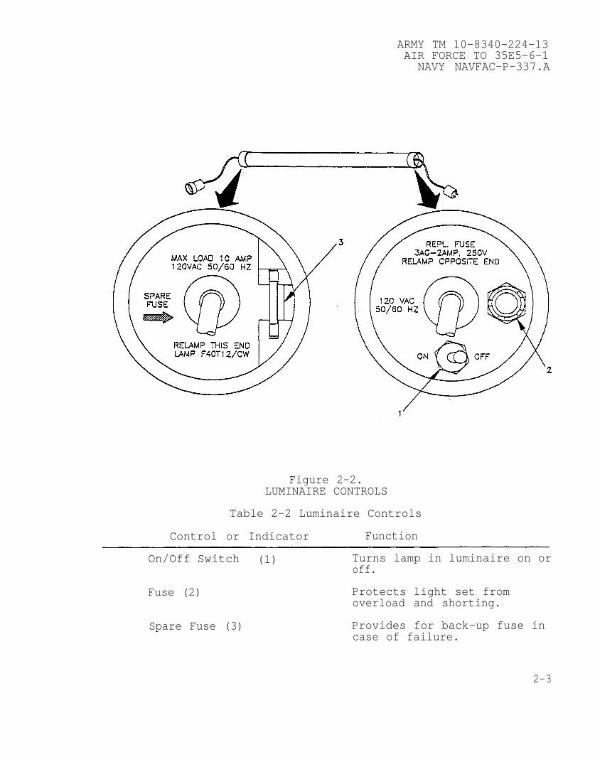
Figure 2-2.LUMINAIRE CONTROLS
Table 2-2 Luminaire Controls
Control or Indicator Function
On/Off Switch (1) Turns lamp in luminaire on oroff.
Fuse (2) Protects light set fromoverload and shorting.
Spare Fuse (3) Provides for back-up fuse incase of failure.
2-3

ARMY TM 10-8340-224-13AIR FORCE TO 35E5-6-1NAVY NAVFAC-P-337.A
SECTION II. OPERATOR PREVENTIVE MAINTENANCE CHECKS AND SERVICES(PMCS)
2-3. INTRODUCTION. The TEMPER components must be inspectedregularly to find and correct defects. Record all defects foundduring the performance of PMCS and the steps taken to correctthem on a DA Form 2404, Equipment Inspection and MaintenanceWorksheet. Instructions for reporting /correcting noteddeficiencies are contained in DA Pam 738-750
a. General. Table 2-3 (PMCS Table) has been provided so youcan keep your equipment in good operating condition and ready forits primary mission.
b. Warnings and Cautions. Always observe the WARNINGS andCAUTIONS appearing in your PMCS table. Warnings and cautionsappear before applicable procedures. You must observe theseWARNINGS and CAUTIONS to prevent serious injury to yourself andothers or to prevent your equipment from being damaged.
c. Explanation of table entries.
(1) Item number column. Numbers in this column are forreference. When completing DA Form 2404 (Equipment Inspection andMaintenance Worksheet), include the item number for thecheck/service indicating a fault. Item numbers also appear in theorder that you must do checks and services for the intervalslisted.
(2) Interval column. This column tells you when youmust do the procedure in the procedure column. BEFORE proceduresmust be done before you operate or use the equipment for itsintended mission. DURING procedures must be done during the timeyou are operating or using the equipment for its intendedmission. AFTER procedures must be done immediately after you haveoperated or used the equipment.
(3) Location, check/service column. This columnprovides the location and the item to be checked or serviced. Theitem location is underlined.
(4) Procedure column. This column gives the procedureyou must do to check or service the item listed in theCheck/Service column to know if the equipment is ready oravailable for its intended mission or for operation. You must dothe procedure at the time stated in the interval column.
2-4
ARMY TM 10-8340-224–13AIR FORCE TO 35E5–6–1
NAVY NAVFAC-P-337.A
(5) Not fully mission capable if:column. Information inthis column tells You what faults will keep your equipment frombeing capable of performing its primary mission. If you performcheck and service procedures that show faults listed in thiscolumn, do not operate the equipment. Follow standard operatingprocedures for maintaining the equipment or reporting equipmentfailure.
d. Other table entries. Be sure to observe all specialinformation and notes that appear in your table.
2-5
ARMY TM 10-8340-224-13AIR FORCE TO 35E5-6-1NAVY NAVFAC-P-337.A
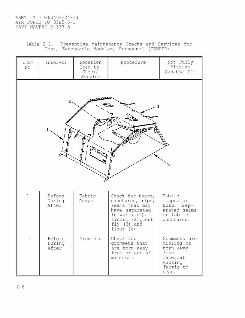
Table 2-3. Preventive Maintenance Checks and Services forTent, Extendable Modular, Personnel (TEMPER).
Item Interval Location Procedure Not FullyNo Item to Mission
Check/ Capable If:Service
1 Before Fabric Check for tears, FabricDuring Assys punctures, rips, ripped orAfter seams that may torn. Sep-
have separated arated seamsin walls (1), or fabricliners (2),tent punctures.fly (3),andfloor (4).
2 Before Grommets Check for Grommets areDuring grommets that missing orAfter are torn away torn away
from or out of frommaterial. material
causingfabric totear.
2-6
ARMY TM 10-8340-224-13AIR FORCE TO 35E5-6-1
NAVY NAVFAC-P-337.A
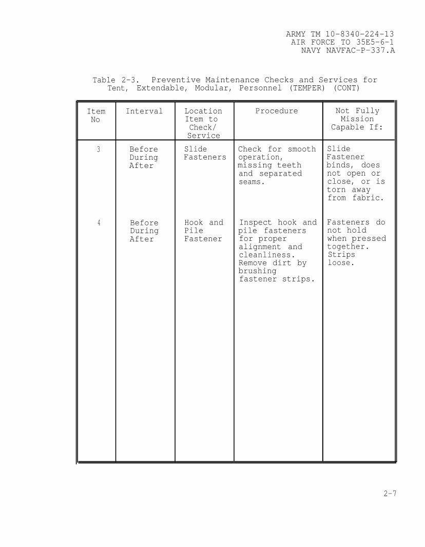
Table 2-3. Preventive Maintenance Checks and Services forTent, Extendable, Modular, Personnel (TEMPER) (CONT)
Item Interval Location Procedure Not FullyNo Item to Mission
Check/ Capable If:Service
3 Before Slide Check for smooth SlideDuring Fasteners operation, FastenerAfter missing teeth binds, does
and separated not open orseams. close, or is
torn awayfrom fabric.
4 Before Hook and Inspect hook and Fasteners doDuring Pile pile fasteners not holdAfter Fastener for proper when pressed
alignment and together.cleanliness. StripsRemove dirt by loose.brushingfastener strips.
2-7

ARMY TM 10-8340-224-13AIR FORCE TO 35E5-6-1NAVY NAVFAC-P-337.A
Table 2-3. Preventive Maintenance Checks and Services forTent, Extendable, Modular, Personnel (TEMPER) (CONT).
Item Interval Location Procedure Not FullyNo Item to Mission
Check/ Capable If:Service
5 Before Tent Lines Inspect tent Tent linesDuring lines (1) for are cut,After cuts or fraying. frayed, or
excessivelyworn.
6 During Check for andtighten loosetent lines (1).
7 Before Tent Line Inspect for Tent lineSlips broken tent line slips broken
slips (2). or missing.
8 Before Straps Check interior Straps looseAfter and exterior or missing.
straps (3,4) forfraying ortears.
2-8
ARMY TM 10-8340-224-13AIR FORCE TO 35E5-6-1
NAVY NAVFAC-P-337.A
Table 2-3. Preventive Maintenance Checks and Services forTent, Extendable, Modular, Personnel (TEMPER) (CONT).
Item Interval Location Procedure Not FullyNo Item to Mission
Check/ Capable If:Service
2-9
ARMY TM 10-8340-224-13AIR FORCE TO 35E5-6-1NAVY NAVFAC-P-337.A
Table 2-3. Preventive Maintenance Checks and Services forTent, Extendable, Modular, Personnel (TEMPER) (CONT).
Item Interval Location Procedure Not FullyNo Item to Mission
Check/ Capable If:Service
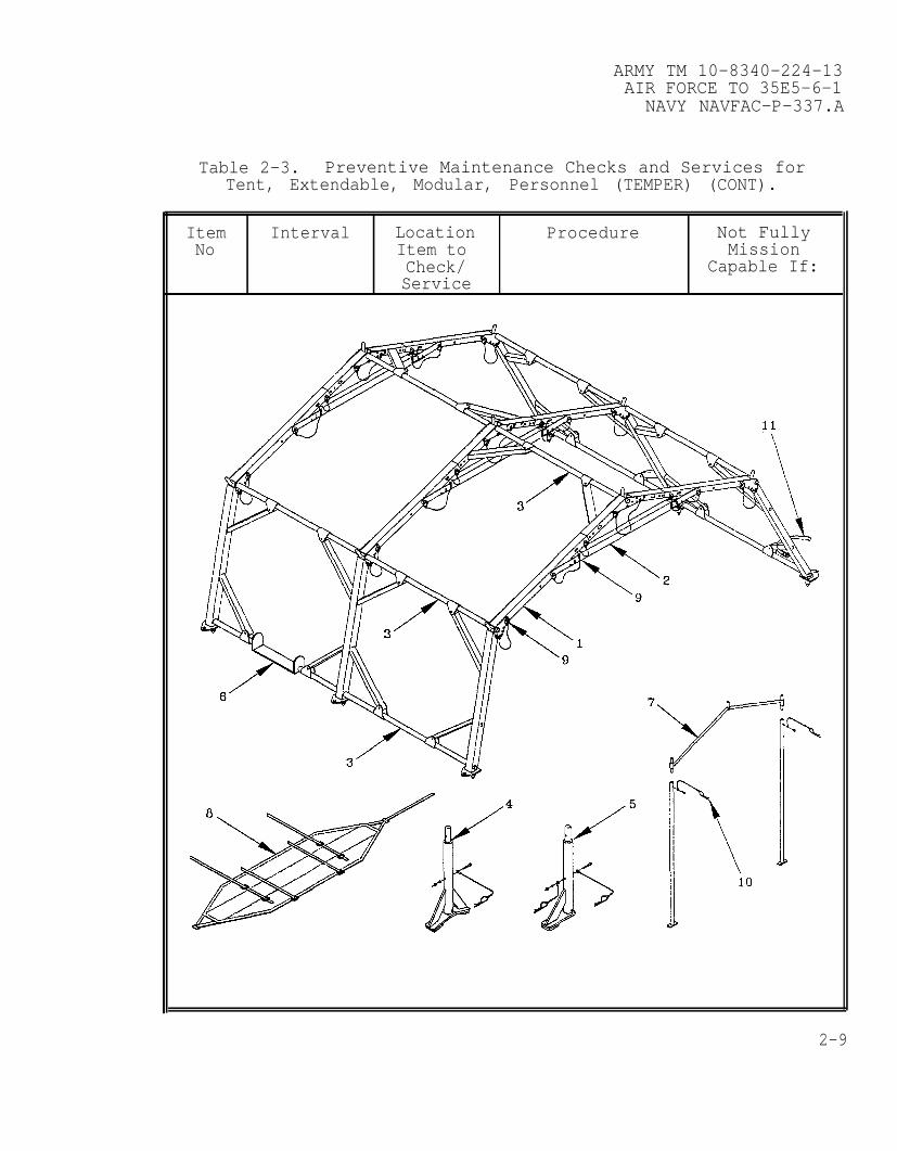
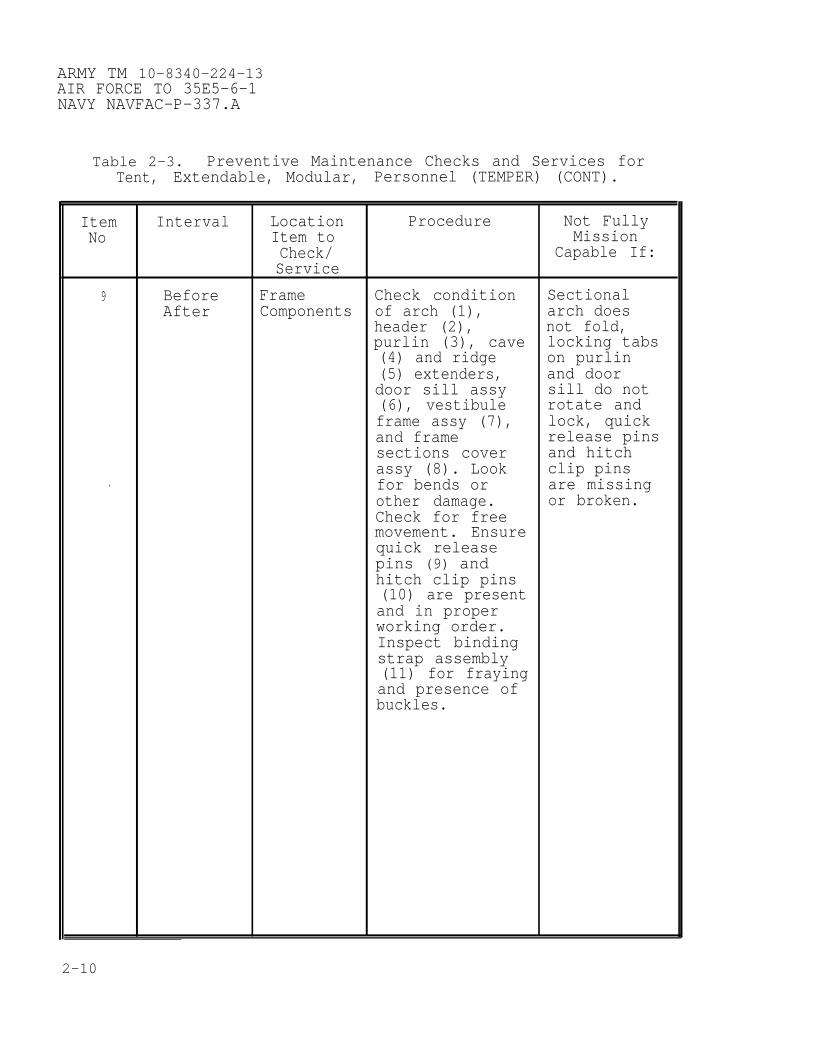
9 Before Frame Check condition SectionalAfter Components of arch (1), arch does
header (2), not fold,purlin (3), cave locking tabs(4) and ridge on purlin(5) extenders, and doordoor sill assy sill do not(6), vestibule rotate andframe assy (7), lock, quickand frame release pinssections cover and hitchassy (8). Look clip pins
. for bends or are missingother damage. or broken.Check for freemovement. Ensurequick releasepins (9) andhitch clip pins(10) are presentand in properworking order.Inspect bindingstrap assembly(11) for frayingand presence ofbuckles.
2-10
ARMY TM 10-8340-224-13AIR FORCE TO 35E5-6-1
NAVY NAVFAC-P-337.A
Table 2-3. Preventive Maintenance Checks and Services forTent, Extendable, Modular, Personnel (TEMPER) (CONT).
Item Interval Location Procedure Not FullyNo Item to Mission
Check/ Capable If:Service
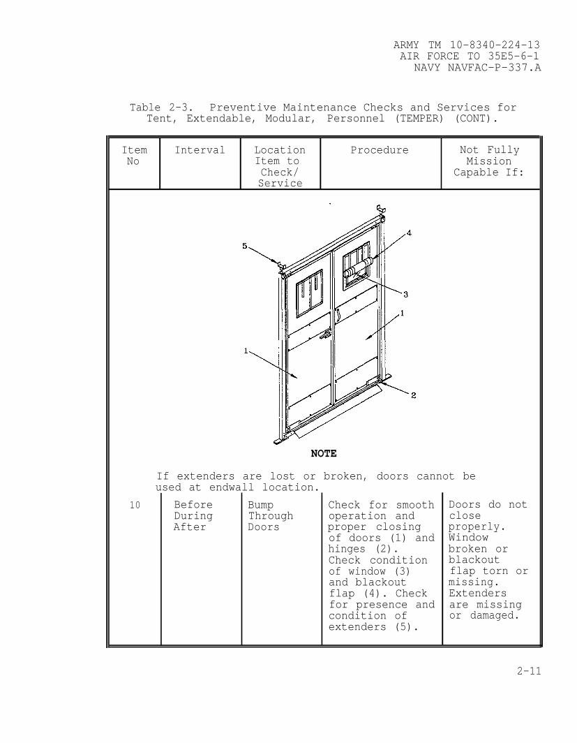
NOTE
If extenders are lost or broken, doors cannot beused at endwall location.
10 Before Bump Check for smooth Doors do notDuring Through operation and closeAfter Doors proper closing properly.
of doors (1) and Windowhinges (2). broken orCheck condition blackoutof window (3) flap torn orand blackout missing.flap (4). Check Extendersfor presence and are missingcondition of or damaged.extenders (5).
2-11

ARMY TM 10-8340-224-13AIR FORCE TO 35E5-6-1NAVY NAVFAC-P-337.A
Table 2-3. Preventive Maintenance Checks and Services forTent, Extendable, Modular, Personnel (TEMPER) (CONT)
2-12

ARMY TM 10-8340-224-13AIR FORCE TO 35E5-6-1
NAVY NAVFAC-P-337.A
Table 2-3. Preventive Maintenance Checks and Services forTent, Extendable, Modular, Personnel (TEMPER) (CONT).
Item Interval Location Procedure Not FullyNo Item to Mission
Check/ Capable If:Service
11 Before Power Check power CircuitDuring Control control breakers andAfter assemblies for toggle
damage to switches docircuit breakers not operate.(1) and toggle Coversswitches (2). missing.Push to reset Cablecircuit frayed. Burnbreakers. Check marksfor missing indicatingcovers (3) and shorts.dirt in Missing orelectrical damagedreceptacles (4) lightor plugs (5). streamer.Check cables (6) Stand hasfor fraying and damaged baseall assemblies plate orfor signs of foot. Quickshorts. Check release pindistribution box is missingstand for or notsecurity of base working.plate (7) and Tubes do notfoot (8). Ensure slidequick release freely.pin (9) ispresent and inpropercondition.Ensure outer andinner tubes(10,11) movefreely.
2-13
ARMY TM 10–8340–224–13AIR FORCE TO 35E5–6–1NAVY NAVFAC–P–337.A
Table 2–3. Preventive Maintenance Checks and Services forTent, Extendable, Modular, Personnel (TEMPER) (CONT)
Item Interval Location Procedure Not FullyNo Item to Mission
Check/ Capable If:Service
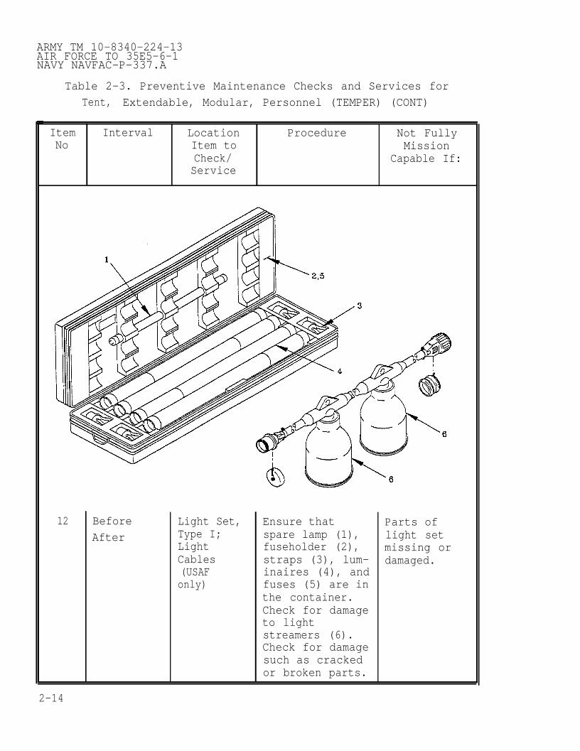
12 Before Light Set, Ensure that Parts ofAfter Type I; spare lamp (1), light set
Light fuseholder (2), missing orCables straps (3), lum– damaged.(USAF inaires (4), andonly) fuses (5) are in
the container.Check for damageto lightstreamers (6).Check for damagesuch as crackedor broken parts.
2-14

ARMY TM 10-8340-224-13AIR FORCE TO 35E5-6-1
NAVY NAVFAC-P-337.A
Table 2-3. Preventive Maintenance Checks and Services forTent, Extendable, Modular, Personnel (TEMPER) (CONT).
Item Interval Location Procedure Not FullyNo Item to Mission
Check/ Capable If:Service
WARNINGLethal voltage is present when light set is connected to powersource. Disconnect from power source before inspecting orrepairing any electrical component. Be careful not to contactelectrical connections. Electrical shock or death may resultfrom failure to heed this warning.
13 Before Luminaire Check cable Frayedassemblies (1) insulationfor cracks, or brokenbreaks, fraying plugs.insulation.
14 Before Straps Check fourstraps (2) for Broken,tears or frayed, orfraying. missing
straps.15 During Luminaire Ensure
luminaires (3) Lamps burnedoperate proper- out orly and spare flickering.lamp (4) ispresent andserviceable.
2-15
ARMY TM 10-8340-224-13AIR FORCE TO 35E5-6-1NAVY NAVFAC-P-337.A
Table 2-2. Preventive Maintenance Checks and Services forTent, Extendable, Modular, Personnel (TEMPER) (CONT).
Item Interval Location Procedure Not FullyNo Item to Mission
Check/ Capable If:Service
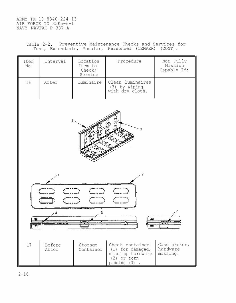
16 After Luminaire Clean luminaires(3) by wipingwith dry cloth.
17 Before Storage Check container Case broken,After Container (1) for damaged, hardware
missing hardware missing.(2) or tornpadding (3) .
2-16
ARMY TM 10-8340–224-13AIR FORCE TO 35E5-6-1
NAVY NAVFAC-P-337.A
SECTION III. OPERATION UNDER USUAL CONDITIONS
2-4. ASSEMBLY AND PREPARATION FOR USE. This section providesdetailed instructions for the erection and disassembly of theTEMPER Tent.
2-5. FRAME ASSEMBLY. The frame assemblies are erected in threestages: kneeling, partially-erect; erect. These stages permit theattachment of components without the aid of ladders. Both rigidand sectionalized arch assemblies are in use in the field. Afterinitial assembly, the sectionalized arch assembly does not varyin function from the rigid arch assembly.
WARNING
Frame assembly hinges can pinch orcrush hands and fingers. Keep handsand fingers away from frameassembly ridges and eaves.
CAUTION
Do not twist or turn framecomponents when handling. Damageto equipment may result.
Clear and level ground beforeinstalling floor. Sharp objectsor depressions can damage tentfloor.
NOTE
Erect tent from top to bottom, endsection towards opposite endsection.
2-17

ARMY TM 10-8340-224-13AIR FORCE TO 35E5-6-1NAVY NAVFAC-P-337.A
2-5. FRAME ASSEMBLY.
a. Arch Assembly.
(1)
(2)
(3)
(4)
(5)
(6)
2-18
Remove roof arch assembly (1) and side archassemblies (4) from frame sections cover assemblybundle.
Ensure all quick release pins (2) are disengaged.
CAUTION
Insert quick release pins towardsinside of tent on end assemblies.Tent fabric may tear if insertedtowards outside.
Align holes in roof arch assembly (1) with holes inridge gusset plate (3). Insert quick release pin (2).
Move side arch assembly (4) away from roof archassembly (1) .
Connect roof arch assembly (1) and side archassemblies (4) to form arch assembly (5).
Lay arch assembly (5) flat on the ground.

ARMY TM 10-8340-224-13AIR FORCE TO 35E5-6-1
NAVY NAVFAC-P-337.A
b. Header Assembly.
NOTE
The header assembly will be pinnedto the arch assembly between theridge and eave.
(1) Identify header assembly (1).
(2) Slide header assembly end plates (2) over archassembly (3).
(3) Align arch assembly (3) and header assembly end plateholes (4).
(4) Insert quick release pin (5).
(5) Lay assembly on ground.
(6) Repeat procedures a and b for each arch assembly.
2-19

ARMY TM 10-8340-224-13AIR FORCE TO 35E5-6-1NAVY NAVFAC–P-337.A
2-5. FRAME ASSEMBLY (CONT).
c. Purlin Assembly.
NOTE
Ridge, eave and base purlins areidentical. Door sill purlindiffers only in design and isfound only with Extendable DoorSection, Type III. Installationprocedure is identical.
Ensure that door sill purlin isused with door section.
An 8–foot section of the framewill be completed with fivepurlins. To add sections,continue procedures until therequired number of frame sectionshave been connected.
Alternate direction of ridgepurlin diagonalsupport.
braces for added
(1) Identify five purlins (1)(2), eaves (3) and bases
(2) Starting at the end arch,(5) upright 8 feet apart
2-20
for installation at ridge(4).
hold two arch assembliesin kneeling position.
ARMY TM 10–8340-224–13AIR FORCE TO 35E5-6-1
NAVY NAVFAC–P-337.A
NOTE
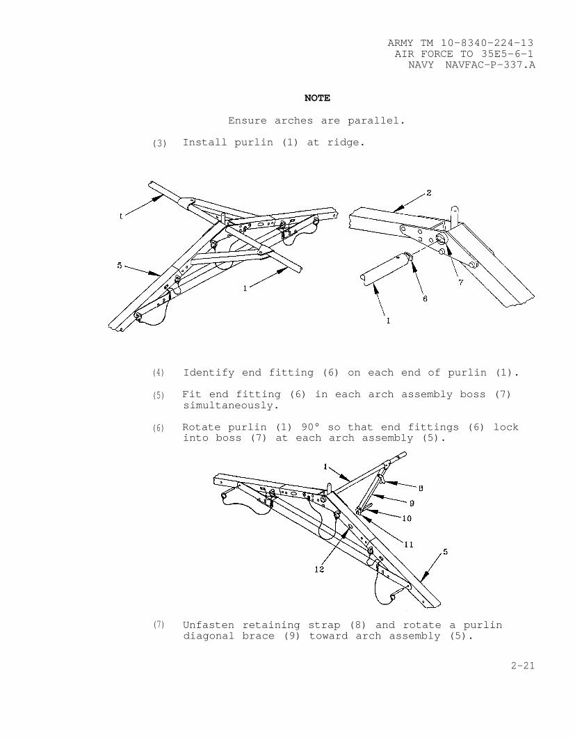
Ensure arches are parallel.
(3) Install purlin (1) at ridge.
(4)
(5)
(6)
(7)
Identify end fitting (6) on each end of purlin (1).
Fit end fitting (6) in each arch assembly boss (7)simultaneously.
Rotate purlin (1) 90° so that end fittings (6) lockinto boss (7) at each arch assembly (5).
Unfasten retaining strap (8) and rotate a purlindiagonal brace (9) toward arch assembly (5).
2-21
ARMY TM 10-8340-224-13AIR FORCE TO 35E5-6-1NAVY NAVFAC-P-337.A
2-5. FRAME ASSEMBLY (CONT).
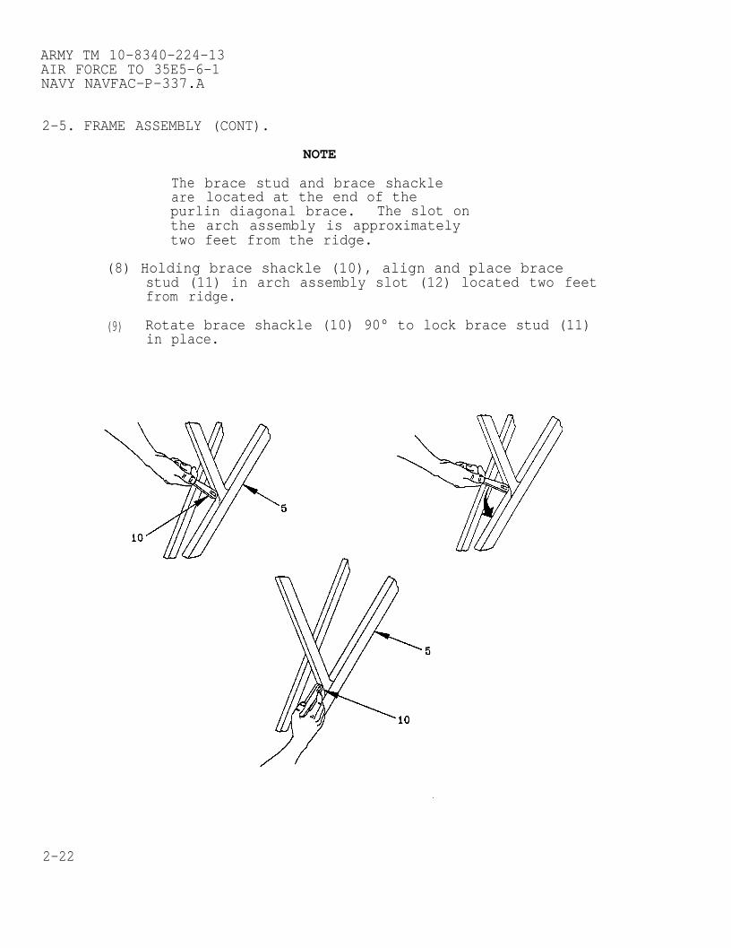
Theare
NOTE
brace stud and brace shacklelocated at the end of the
purlin diagonal brace. The slot onthe arch assembly is approximatelytwo feet from the ridge.
(8) Holding brace shackle (10), align and place bracestud (11) in arch assembly slot (12) located two feetfrom ridge.
(9) Rotate brace shackle (10) 90° to lock brace stud (11)in place.
2-22
ARMY TM 10-8340-224-13AIR FORCE TO 35E5-6-1
NAVY NAVFAC-P-337.A
WARNING
Do not lock brace shackle towardpurlin diagonal brace. Archassembly may collapse causinginjury to personnel or damage toequipment if improperly locked.
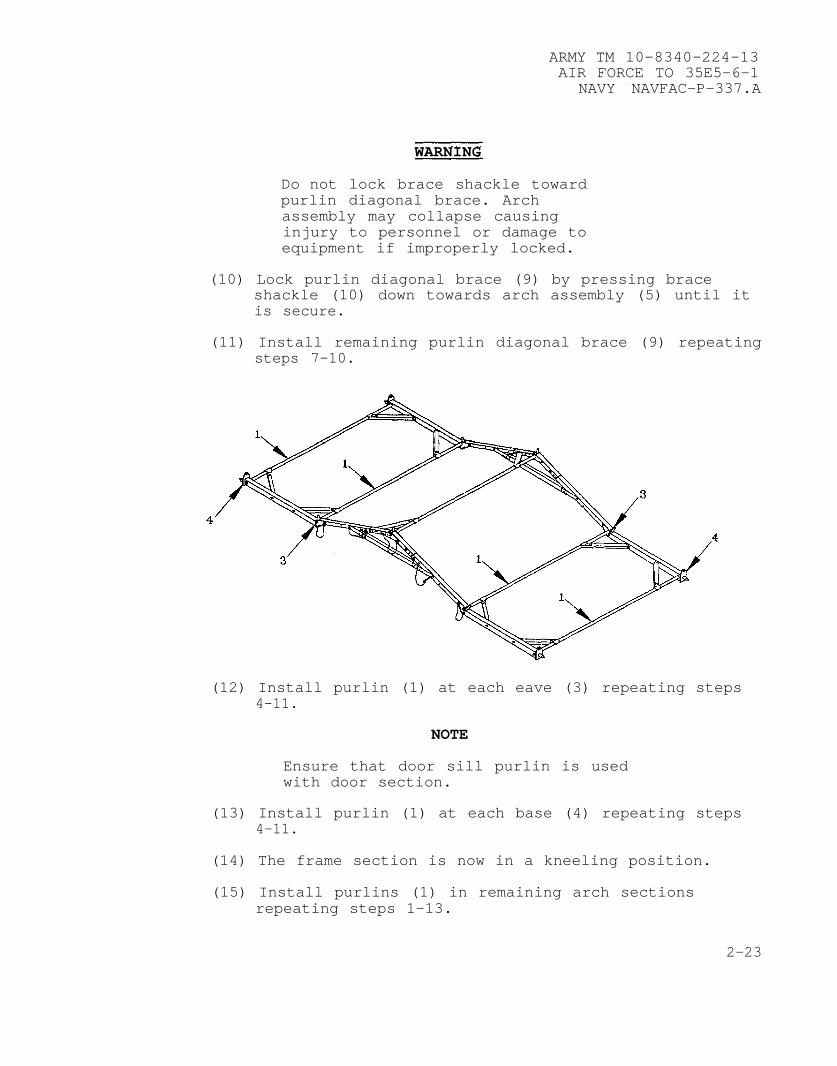
(10) Lock purlin diagonal brace (9) by pressing braceshackle (10) down towards arch assembly (5) until itis secure.
(11) Install remaining purlin diagonal brace (9) repeatingsteps 7-10.
(12) Install purlin (1) at each eave (3) repeating steps4-11.
NOTE
Ensure that door sill purlin is usedwith door section.
(13) Install purlin (1) at each base (4) repeating steps4-11.
(14) The frame section is now in a kneeling position.
(15) Install purlins (1) in remaining arch sectionsrepeating steps 1–13.
2-23
ARMY TM 10-8340-224-13AIR FORCE TO 35E5-6-1NAVY NAVFAC-P-337.A
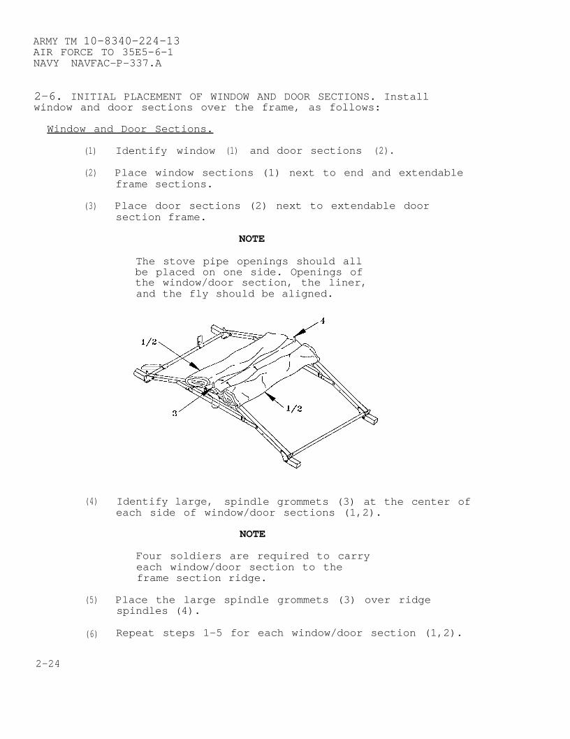
2-6. INITIAL PLACEMENT OF WINDOW AND DOOR SECTIONS. Installwindow and door sections over the frame, as follows:
Window and Door Sections.
(1) Identify window (1) and door sections (2).
(2) Place window sections (1) next to end and extendableframe sections.
(3) Place door sections (2) next to extendable doorsection frame.
NOTE
The stove pipe openings should allbe placed on one side. Openings ofthe window/door section, the liner,and the fly should be aligned.
(4) Identify large, spindle grommets (3) at the center ofeach side of window/door sections (1,2).
NOTE
Four soldiers are required to carryeach window/door section to theframe section ridge.
(5) Place the large spindle grommets (3) over ridgespindles (4).
(6) Repeat steps 1-5 for each window/door section (1,2).
2-24
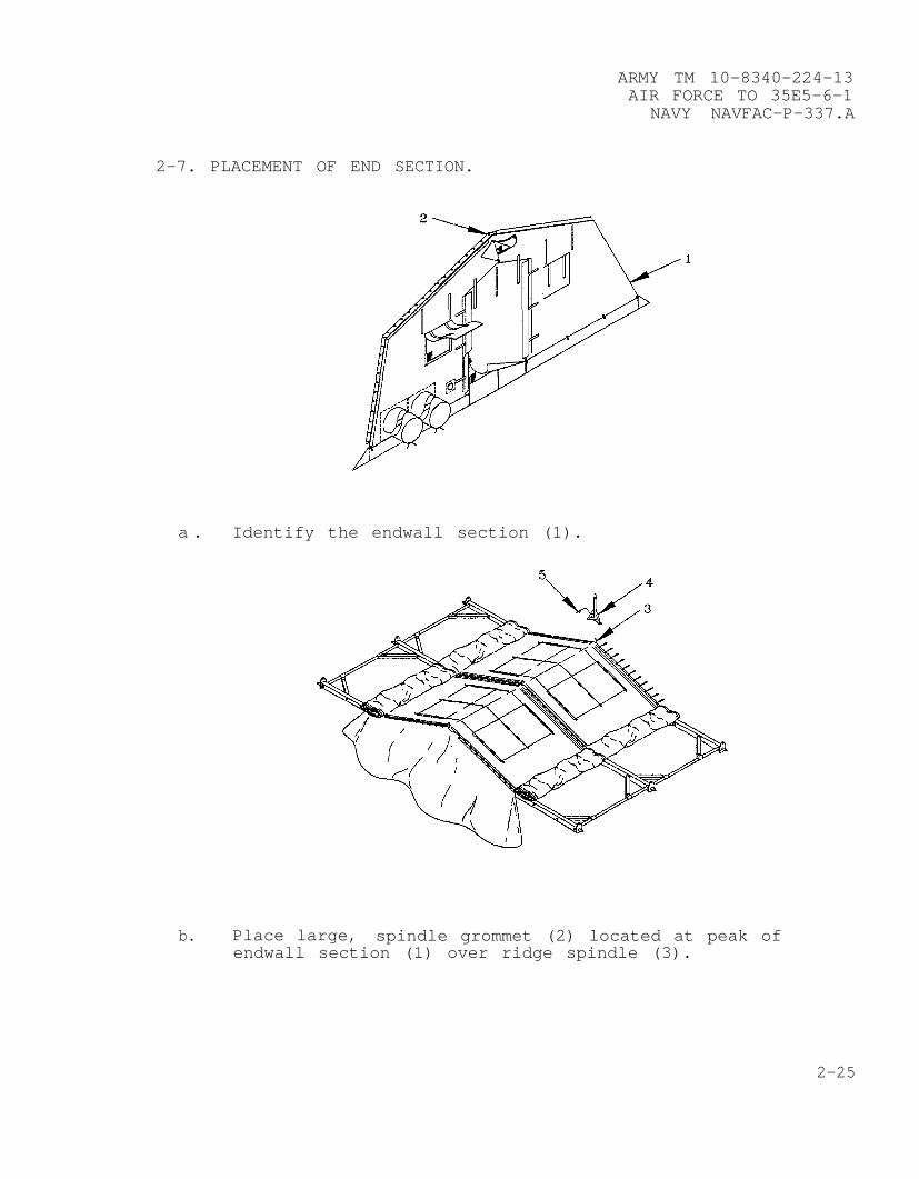
2-7. PLACEMENT OF END
ARMY TM 10-8340-224-13AIR FORCE TO 35E5-6-1
NAVY NAVFAC-P-337.A
SECTION.
a . Identify the endwall section (1).
b. Place large, spindle grommet (2) located at peak ofendwall section (1) over ridge spindle (3).
2-25
ARMY TM 10-8340-224-13AIR FORCE TO 35E5-6-1NAVY NAVFAC-P-337.A
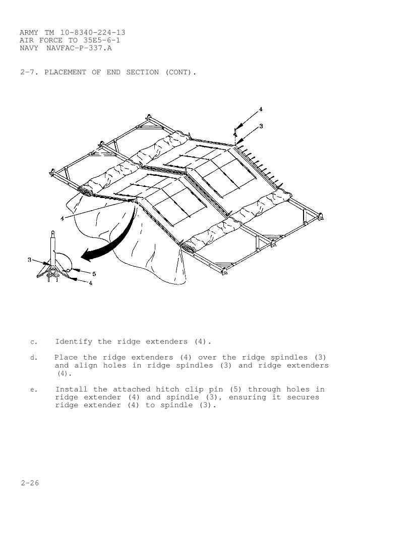
2-7. PLACEMENT OF END SECTION (CONT).
c. Identify the ridge extenders (4).
d. Place the ridge extenders (4) over the ridge spindles (3)and align holes in ridge spindles (3) and ridge extenders(4).
e. Install the attached hitch clip pin (5) through holes inridge extender (4) and spindle (3), ensuring it securesridge extender (4) to spindle (3).
2-26
ARMY TM 10-8340-224-13AIR FORCE TO 35E5-6-1
NAVY NAVFAC-P-337.A
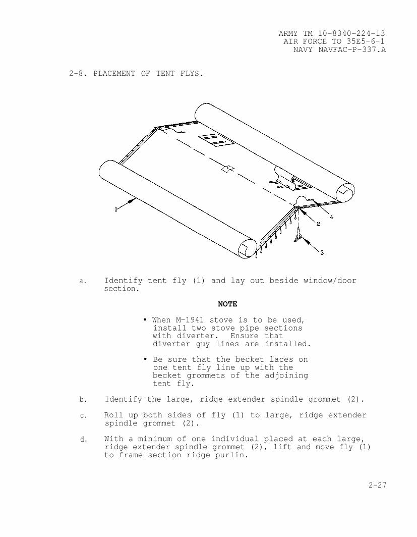
2-8. PLACEMENT OF TENT FLYS.
a. Identify tent fly (1) and lay out beside window/doorsection.
NOTE
When M-1941 stove is to be used,install two stove pipe sectionswith diverter. Ensure thatdiverter guy lines are installed.
Be sure that the becket laces onone tent fly line up with thebecket grommets of the adjoiningtent fly.
b. Identify the large, ridge extender spindle grommet (2).
c. Roll up both sides of fly (1) to large, ridge extenderspindle grommet (2).
d. With a minimum of one individual placed at each large,ridge extender spindle grommet (2), lift and move fly (1)to frame section ridge purlin.
2-27

ARMY TM 10-8340-224-13AIR FORCE TO 35E5-6-1NAVY NAVFAC-P-337.A
2-8. PLACEMENT OF TENT FLYS (CONT).
e. Place the large, ridge extender spindle grommets (2) onthe ridge extender spindles (3).
f. Place the fly hitch clip pins (4) through the holes in theridge extender spindles (3) which protrude through thelarge, ridge extender spindle grommets (2).
2-9. BECKET LACING WINDOW AND DOOR SECTIONS, END SECTIONS, ANDTENT FLYS. At this point, lacing together of window and doorsections, window/door and end sections, and tent flys may beaccomplished simultaneously. Begin all lacing from the ridge lineand work to the eave. Start lacing the window and door sectiontogether first, working slightly ahead of the tent fly, rollingmaterial towards the cave as you progress. Lacing of the endsection and window/door section can proceed independently of thewindow/door sections and tent fly. Becket lacing procedure is thesame throughout the erection process and is accomplished asfollows:
CAUTION
Do not step on tent components.Material may be torn and dirtground into material.
2-28

a.
b.
c.
d.
e.
f.
g.
h.
i.
ARMY TM 10-8340-224-13AIR FORCE TO 35E5-6-1
NAVY NAVFAC-P-337.A
NOTE
For easier lacing, place eavegrommets with becket laces overeave spindles first, to providefabric tension, then overlapadjoining window/door section andend section cave grommet withoutlaces.
Place becket side eave grommet (1) over eave spindles (2).
Identify first becket lace (3) and becket grommet (4) nearthe ridge.
Insert first becket lace (3) through first becket grommet(4) and second becket lace (5) through second becketgrommet (6).
Insert second becket lace (5) through loop of first becketlace (3).
Pull second becket lace (5) tight away from ridge.
Insert third becket lace (7) through grommet (8) andthrough loop of second becket lace (5).
Pull third becket lace (7) tight away from ridge.
NOTE
Ensure weather flap fabric is slidunder the ridge extender brace.
Continue lacing and close hook and pile weather flap (9)until reaching last becket lace (10).
Place remaining window/door and end section cave grommetsover cave spindles.
2-29
ARMY TM 10-8340-224-13AIR FORCE TO 35E5-6-1NAVY NAVFAC-P-337.A
2-9. BECKET LACING WINDOW AND DOOR SECTIONS, END SECTIONS, ANDTENT FLYS (CONT).
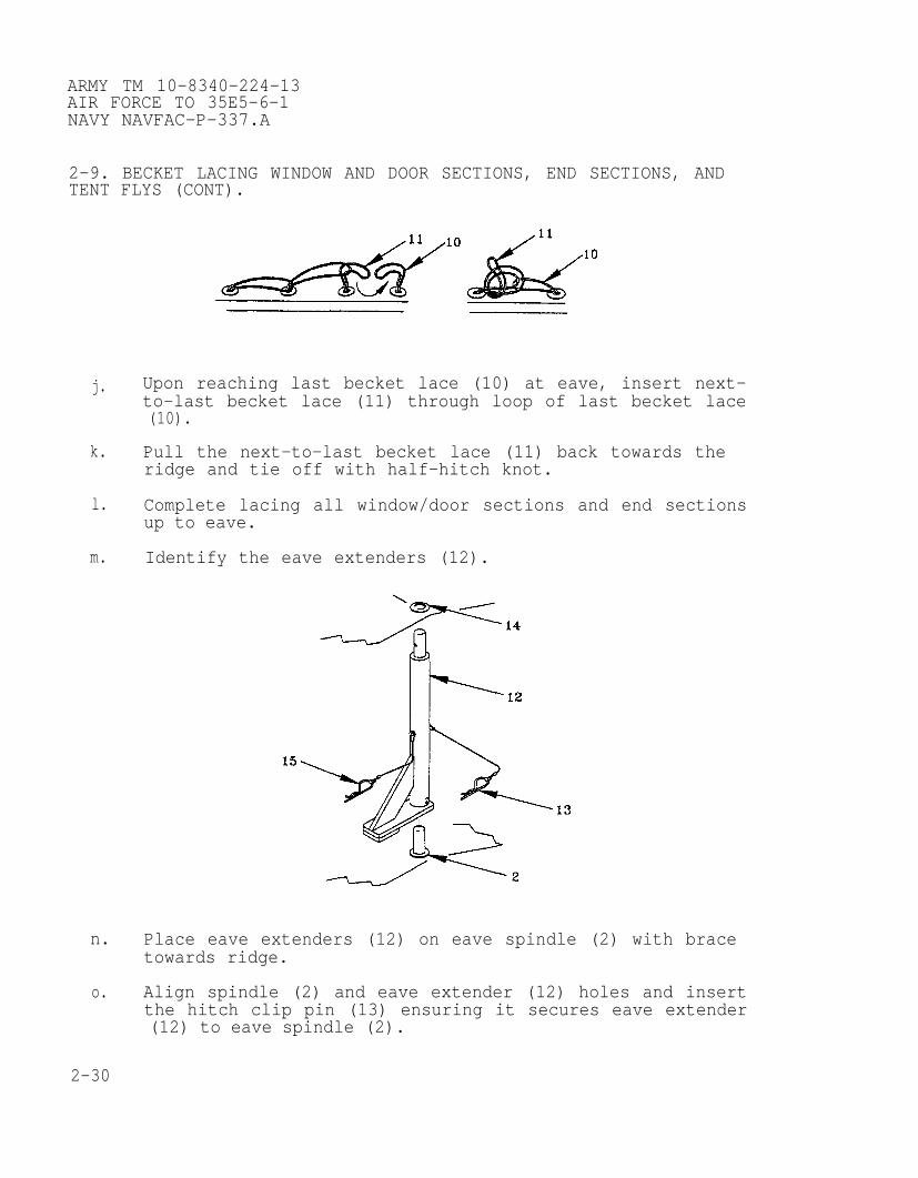
j. Upon reaching last becket lace (10) at eave, insert next-to-last becket lace (11) through loop of last becket lace(10).
k. Pull the next-to-last becket lace (11) back towards theridge and tie off with half-hitch knot.
l. Complete lacing all window/door sections and end sectionsup to eave.
m. Identify the eave extenders (12).
n. Place eave extenders (12) on eave spindle (2) with bracetowards ridge.
o. Align spindle (2) and eave extender (12) holes and insertthe hitch clip pin (13) ensuring it secures eave extender(12) to eave spindle (2).
2-30
ARMY TM 10-8340-224-13AIR FORCE TO 35E5-6-1
NAVY NAVFAC-P-337.A
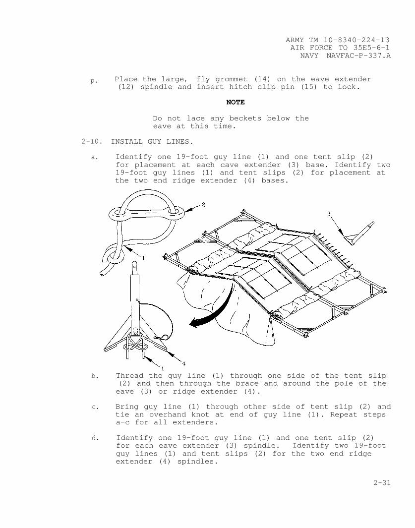
p. Place the large, fly grommet (14) on the eave extender(12) spindle and insert hitch clip pin (15) to lock.
NOTE
Do not lace any beckets below theeave at this time.
2-10. INSTALL GUY LINES.
a. Identify one 19-foot guy line (1) and one tent slip (2)for placement at each cave extender (3) base. Identify two19-foot guy lines (1) and tent slips (2) for placement atthe two end ridge extender (4) bases.
b. Thread the guy line (1) through one side of the tent slip(2) and then through the brace and around the pole of theeave (3) or ridge extender (4).
c. Bring guy line (1) through other side of tent slip (2) andtie an overhand knot at end of guy line (1). Repeat stepsa-c for all extenders.
d. Identify one 19-foot guy line (1) and one tent slip (2)for each eave extender (3) spindle. Identify two 19-footguy lines (1) and tent slips (2) for the two end ridgeextender (4) spindles.
2-31
ARMY TM 10-8340-224-13AIR FORCE TO 35E5-6-1NAVY NAVFAC-P-337.A
2-10. INSTALL GUY LINES (CONT).
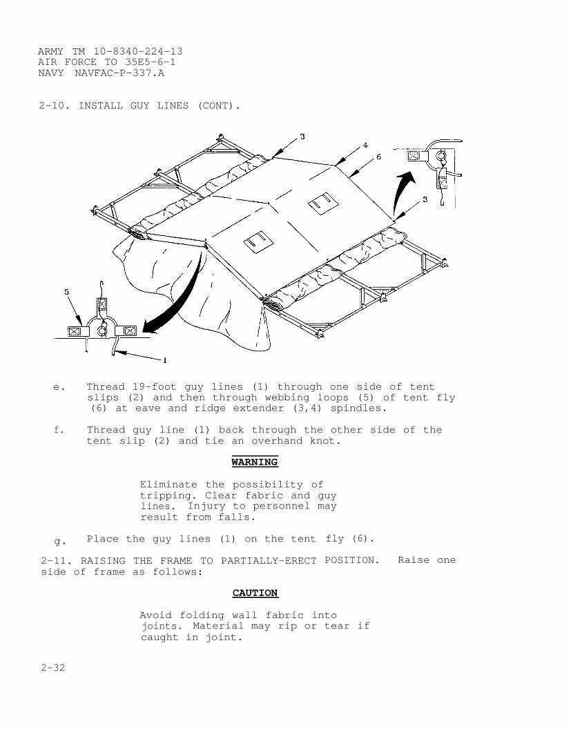
e. Thread 19-foot guy lines (1) through one side of tentslips (2) and then through webbing loops (5) of tent fly(6) at eave and ridge extender (3,4) spindles.
f. Thread guy line (1) back through the other side of thetent slip (2) and tie an overhand knot.
WARNING
Eliminate the possibility oftripping. Clear fabric and guylines. Injury to personnel mayresult from falls.
g. Place the guy lines (1) on the tent
2-11. RAISING THE FRAME TO PARTIALLY-ERECTside of frame as follows:
CAUTION
fly (6).
POSITION. Raise one
Avoid folding wall fabric intojoints. Material may rip or tear ifcaught in joint.
2-32

ARMY TM 10-8340–224-13AIR FORCE TO 35E5-6-1
NAVY NAVFAC–P–337.A
a. Fold wall fabric (1) between tent fly (2) and roof (3) toexpose eave gussets (4).
b. Identify quick release pin (5) and ensure it is hangingfree.
c. Identify the locking hole in the side arch assembly (6)and ensure it is free of debris.
WARNING
Two soldiers should be placed ateach arch leg to raise frame. Lifttent from correct squattingposition, using your legs to avoidback injury.
CAUTION
Tent frame must be raised uniformlyto avoid twisting or turning.Damage to frame can result.
2-33

ARMY TM 10-8340-224-13AIR FORCE TO 35E5-6-1NAVY NAVFAC-P-337.A
2-11. RAISING THE FRAME TO PARTIALLY-ERECT POSITION (CONT).
d. Step in next to the eave gusset (4).
WARNING
Frame assembly hinges can pinch orcrush hands and fingers. Keep handsand fingers away from frameassembly ridges and eaves.
e. Place one hand on the side arch assembly (6) and one handon the eave purlin (7) outside the diagonal brace (8).
f. Get in a stable squatting position.
g. Lift frame straight up to shoulder height, dragging sidearch assembly (6) inward.
h. Place weight of the frame on side arch assembly foot (9).
CAUTION
Insert quick release pins towardsinside of tent on end assemblies.Tent fabric may tear if insertedtowards outside.
2-34
i.
j.
k.
l.
ARMY TM 10-8340-224-13AIR FORCE TO 35E5-6-1
NAVY NAVFAC-P-337.A
Align holes of eave gusset (4) and side arch assembly (6)and install quick release pin (5).
Identify purlin flap (10) on interior of window/roofsection.
Secure purlin flap (10) to frame at eave purlin (7) usinghook and pile fasteners.
Tent is now in a partially-erect stage.
NOTE
The other side of the tent will beraised after installation ofinterior components.
2-12. COMPONENTS. While the frame is partially-erect installcomponents as follows:
NOTE
Use bow knots when tying all tietapes to prevent tie tapes frombecoming knotted and difficult tountie.
a. Single Ply Floor.
CAUTION
Clear and level ground beforeinstalling floor. Sharp objects ordepressions can damage tent floor.
NOTE
Partially install the single plyfloor to keep the liner clean whileit is being put up. Installationwill be completed when tent isfully erected.
2-35
ARMY TM 10-8340-224–13AIR FORCE TO 35E5-6-1NAVY NAVFAC-P-337.A
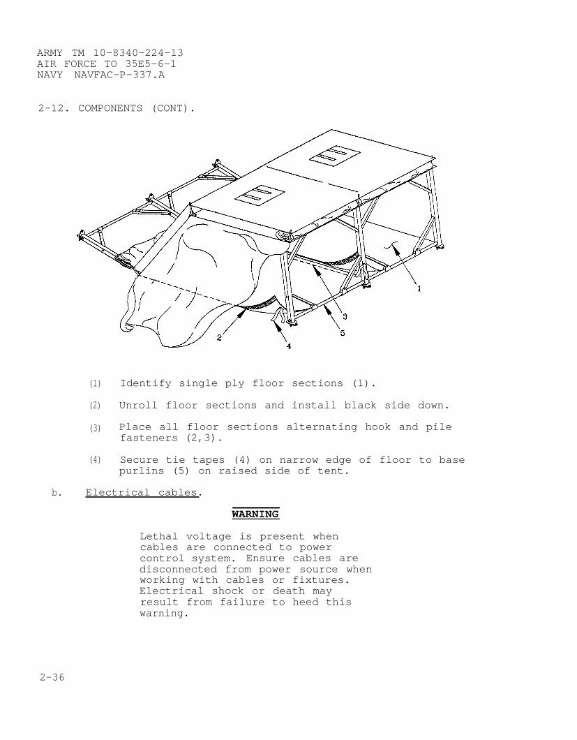
2-12. COMPONENTS (CONT).
(1) Identify single ply floor sections (1).
(2) Unroll floor sections and install black side down.
(3) Place all floor sections alternating hook and pilefasteners (2,3).
(4) Secure tie tapes (4) on narrow edge of floor to basepurlins (5) on raised side of tent.
b. Electrical cables.
WARNING
Lethal voltage is present whencables are connected to powercontrol system. Ensure cables aredisconnected from power source whenworking with cables or fixtures.Electrical shock or death mayresult from failure to heed thiswarning.
2-36

ARMY TM 10–8340-224-13AIR FORCE TO 35E5–6-1
NAVY NAVFAC–P–337.A
CAUTION
Allow slack in electrical cables.Strain on cable can damageequipment.
(1 ) Wrap light and extension (103, 156, 173 254 inch)cables (1) once around the header (2) to relievestrain.
2-37
ARMY TM 10-8340-224-13AIR FORCE TO 35E5-6-1NAVY NAVFAC-P-337.A
2-12. COMPONENTS (CONT).
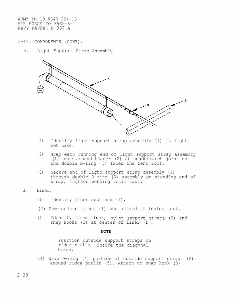
c. Light Support Strap Assembly.
(1)
(2)
(3)
Identify light support strap assembly (1) in lightset case.
Wrap each running end of light support strap assembly(1) once around header (2) at header/arch joint sothe double D-ring (3) faces the tent roof.
Secure end of light support strap assembly (1)through double D–ring (3) assembly on standing end ofstrap. Tighten webbing until taut.
d. Liner.
(1) Identify liner sections (1).
(2) Unwrap tent liner (1) and unfold it inside tent.
(3) Identify three liner, nylon support straps (2) andsnap hooks (3) at center of liner (1).
NOTE
Position outside support straps onridge purlin, inside the diagonalbrace.
(4) Wrap D-ring (4) portion of outside support straps (2)around ridge purlin (5). Attach to snap hook (3).
2-38
ARMY TM 10–8340–224–13AIR FORCE TO 35E5-6-1
NAVY NAVFAC-P-337.A
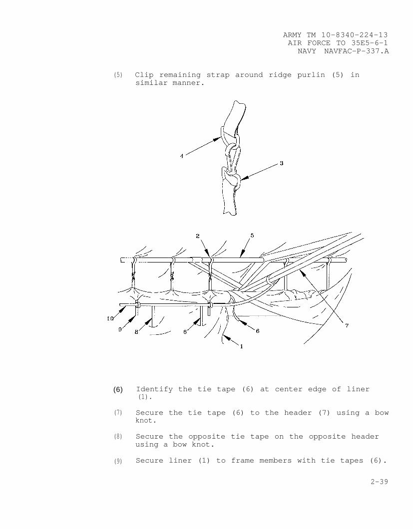
(5) Clip remaining strap around ridge purlin (5) insimilar manner.
(6)
(7)
(8)
(9)
Identify the tie tape (6) at center edge of liner(1).
Secure the tie tape (6) to the header (7) using a bowknot.
Secure the opposite tie tape on the opposite headerusing a bow knot.
Secure liner (1) to frame members with tie tapes (6).
2-39

ARMY TM 10-8340-224-13AIR FORCE TO 35E5-6-1NAVY NAVFAC-P-337.A
2-12. COMPONENTS (CONT).
(10) Place the light support strap assy hangersthrough slits in the liner (1).
(11) Secure liner tie tapes (9) to light supportassembly (10).
(8)
strap
(12) Press hook and pile fastener together between eachliner section.
e. Plenums.
(1)
(2)
(3)
(4)
(5)
Identify the endwall, sidewall and extendable plenums(1,2,3).
Tie end of endwall plenum (1) or sidewall plenum (2)through three slots in liner to frame header (4) withtie tape (5).
Connect ventilation sleeve (6) to arch assembly ateave with tie tapes (5).
Connect ventilation sleeve (6) opening to air duct(7) with drawstring.
To add extendable plenums (3), remove plenum cover(8) and attach additional extendable plenums (3)using hook and pile fasteners in similar manner.
2-40

ARMY TM 10-8340-224-13AIR FORCE TO 35E5-6-1
NAVY NAVFAC-P-337.A
(6) Continue tying tie tapes (5) to headers (4)identified every eight feet.
(7) Install plenum cover (8) on final plenum using hookand pile fasteners.
NOTE
If a plenum is needed for an 8-footsection, use a 16–foot plenum, tieit off, and tuck excess in aboveitself.
2-41
ARMY TM 10–8340-224-13AIR FORCE TO 35E5–6–1NAVY NAVFAC–P–337.A
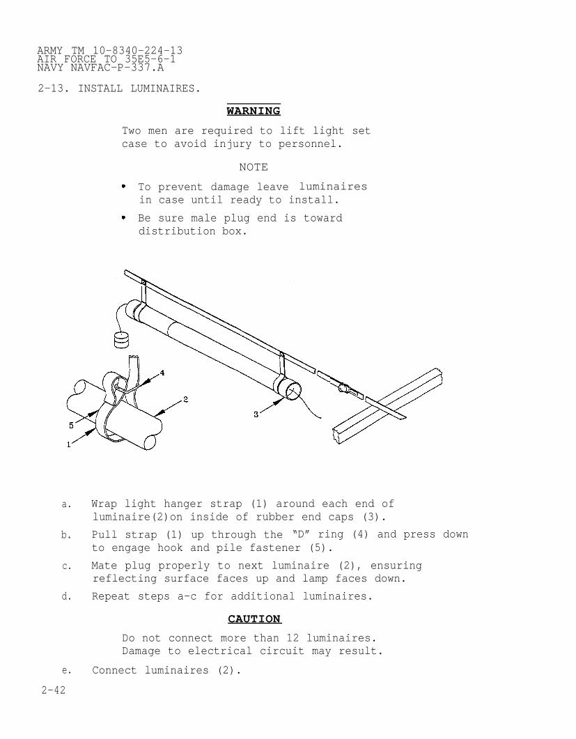
2-13. INSTALL LUMINAIRES.
WARNING
Two men are required to lift light setcase to avoid injury to personnel.
NOTE
To prevent damage leave luminairesin case until ready to install.
Be sure male plug end is towarddistribution box.
a. Wrap light hanger strap (1) around each end ofluminaire(2)on inside of rubber end caps (3).
b. Pull strap (1) up through the “D” ring (4) and press downto engage hook and pile fastener (5).
c. Mate plug properly to next luminaire (2), ensuringreflecting surface faces up and lamp faces down.
d. Repeat steps a-c for additional luminaires.
CAUTION
Do not connect more than 12 luminaires.Damage to electrical circuit may result.
e. Connect luminaires (2).
2-42
ARMY TM 10-8340-224-13AIR FORCE TO 35E5-6-1
NAVY NAVFAC–P-337.A
2-14. FULLY ERECTING THE FRAME. Raise the remaining side of theframe as follows:
CAUTION
Avoid folding wall fabric intojoints. Material may rip or tear ifcaught in joint.
a. Fold wall fabric (1) between tent fly (2) and roof (3) toexpose eave gussets (4).
b. Identify quick release pin (5) and ensure it is hangingfree.
c. Identify the locking hole in the side arch assembly (6)and ensure it is free of debris.
WARNING
Two soldiers should be placed ateach arch leg to raise frame. Lifttent from correct squattingposition, using your legs to avoidback injury.
CAUTION
Tent frame must be raised uniformlyto avoid twisting or turning.Damage to frame can result.
2-43

ARMY TM 10-8340-224-13AIR FORCE TO 35E5-6-1NAVY NAVFAC-P-337.A
2-14. FULLY ERECTING THE FRAME (CONT).
d. Step in next to the eave gusset (4).
WARNING
Frame assembly hinges can pinch orcrush hands and fingers. Keep handsand fingers away from frameassembly ridges and eaves.
e. Place one hand on the side arch assembly (6) and one handon the eave purlin (7) outside the diagonal brace (8).
f. Get in a stable squatting position.
g. Lift frame straight up to shoulder height, dragging sidearch assembly (6) inward.
h. Place weight of the frame on side arch assembly foot (9).
CAUTION
Insert quick release pins towardsinside of tent on end assemblies.Tent fabric may tear if insertedtowards outside.
2-44

i.
j.
k.
l.
ARMY TM 10-8340-224-13AIR FORCE TO 35E5-6-1
NAVY NAVFAC-P-337.A
Align holes of eave gusset (4) and side arch assembly (6)and install quick release pin (5).
Identify purlin flap (10) on interior of window/roofsection.
Secure purlin flap (10) to frame at eave purlin (7) usinghook and pile fasteners.
CAUTION
Frame bases set more than 20 feet 4inches apart may cause end sectionfasteners to tear apart.
Set frame bases 20 feet 4 inches apart.
2-15. FINAL INSTALLATION OF FLOOR AND LINER.
a.
b.
Complete securing floor tie tapes (1) to base purlin (2).
Complete securing liner tie tapes (3) to eave purlin (4)and side arch assembly (5).
2-45

ARMY TM 10-8340-224-13AIR FORCE TO 35E5-6-1NAVY NAVFAC-P-337.A
2-15. FINAL INSTALLATION OF FLOOR AND LINER (CONT).
c. Install insulated floors, if authorized as follows:
(1) Unwrap and spread out floor (1) inside tent soflat and smooth.
(2) Place one 8-foot section at end of tent.
NOTE
After installing first section ofinsulated floor, be sure to installadditional sections so that hookand pile fasteners mate properly.
it is
2-46
ARMY TM 10-8340-224-13AIR FORCE TO 35E5–6-1
NAVY NAVFAC-P-337.A
(3) Install remaining floors until all single ply floorsare covered.
2-16. ELECTRICAL COMPONENTS. Install the electrical system asfollows:
WARNING
Lethal voltage is present when thepower control system is connectedto power source. Disconnect frompower source before inspecting orrepairing any electrical component.Electrical shock or death mayresult from failure to heed thiswarning.
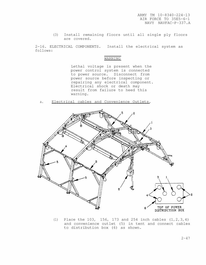
a. Electrical cables and Convenience Outlets.
(1) Place the 103, 156, 173 and 254 inch cables (1,2,3,4)and convenience outlet (5) in tent and connect cablesto distribution box (6) as shown.
2-47
ARMY TM 10-8340-224-13AIR FORCE TO 35E5-6-1NAVY NAVFAC-P–337.A
2-16. ELECTRICAL COMPONENTS (CONT).
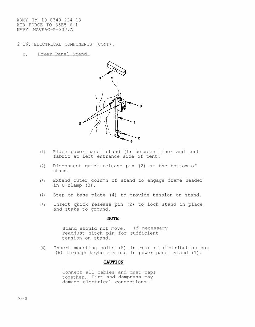
b. Power Panel Stand.
(1)
(2)
(3)
(4)
(5)
(6)
Place power panel stand (1) between liner and tentfabric at left entrance side of tent.
Disconnect quick release pin (2) at the bottom ofstand.
Extend outer column of stand to engage frame headerin U-clamp (3).
Step on base plate (4) to provide tension on stand.
Insert quick release pin (2) to lock stand in placeand stake to ground.
NOTE
Stand should not move. If necessaryreadjust hitch pin for sufficienttension on stand.
Insert mounting bolts (5) in rear of distribution box(6) through keyhole slots in power panel stand (1).
CAUTION
Connect all cables and dust capstogether. Dirt and dampness maydamage electrical connections.
2-48

ARMY TM 10-8340-224-13AIR FORCE TO 35E5-6-1
NAVY NAVFAC-P-337.A
4
(7) Connect 103,156,173 and 256 inchindicated.
2-17. COMPLETE BECKET LACING.
10
9 7
/’ TOP OF POWERDISTRIBUTION BOX
cables (7,8,9,10) as
a. Complete lacing all roof sections (1) and end sections (2)together. Secure weather seal flap (3) .
b. Pull sod cloth (4) under base purlins (5) and end wallsections (2) .
2-49

ARMY TM 10-8340-224-13AIR FORCE TO 35E5-6-1NAVY NAVFAC-P-337.A
2-18. STAKES AND GUY LINES. Secure tent to ground as follows.
Stakes and guy lines must be usedto prevent excessive movement ofthe extendable modular tents inhigh winds. Failure to stake andtie down tent may result inpersonal injury or damage toequipment.
a. Place a 24-inch woodenfrom the side and endsslant stake(s) towards
b.
c.
d.
6’ $
stake (1) approximately 10 feetof tent at each cave extender andtent.
b
Connect loop of cave extender guy line (2) to bottom notchof wooden stake (1) .
Place loop of fly guy line (3) over top notch of stake(1) .
Stake tent frame foot to ground using 12-inch steel pins(4) .
2-50

ARMY TM 10-8340-224-13AIR FORCE TO 35E5-6-1
NAVY NAVFAC-P-337.A
e. Stake foot loops (5) to ground.
f. Tighten guy lines (2,3) .
9. High wind lines (6) are secured to stake (1) at the topnotch.
2-19. VESTIBULE ASSEMBLY. When authorized, the vestibule may beused as a passageway or as an entryway. It may be connected toan endwall or a roof section doorway. Erect the vestibule asfollows for all configurations.
5\ /9 /8
4 a.
b.
c.
d.
e.
f.
9.
Unroll vestibule adapter
Identify and lay out guy
(1) tent door.
lines (2) .
Identify and lay out vestibule fabric (3) .
Identify, lay out and assemble vestibule frame sections(4) .
Open tent door and place all assembled frames inside.
Identify ridge spindle grommets (5) at one end ofvestibule (3) and vestibule adapter (1) .
Align vestibule spindle grommets (6) with vestibuleadapter spindle grommet (7) .
2-51
ARMY TM 10-8340-224-13AIR FORCE TO 35E5–6–1NAVY NAVFAC–P–337.A
2-19.
h.
i.
j.
k.
1.
m.
n.
o.
P.
s .
t.
2-52
VESTIBULE ASSEMBLY (CONT) .
Insert vestibule frame spindles (8) in vestibule adapterand vestibule spindle grommets (6,7) . Secure ridgegrommets (5) with hitch clip pins (9) .
Becket lace the vestibule fabric (3) to the adapter (1)starting at the ridge and working towards each cave. Tieoff at cave with half hitch knot. Cover with weather sealflaps (10). Install remaining hitch clip pins (9) .Complete becket lacing.
Carefully bring one completed vestibule frame (4)underneath vestibule (1) .
Place completed vestibule frame spindles (8) through threegrommets (6) at center of vestibule.
Place hitch clip pins (9) through spindles (8) .
CAUTION
Orient hitch clip pins towardsinside of vestibule at vestibuledoor frame. Vestibule door fabricmay tear if oriented towardsoutside.
Carefully bring one completed vestibule frame (4)underneath vestibule (1) .
Place completed vestibule frame spindles (8) through threegrommets (6) at end of vestibule.
Install vestibule door (11) and secure ridge hitch clippins (9).
Becket lace from ridge to cave, seal weather flap (10) ,install remaining hitch clips pins (9) and complete becketlacing.
Extend frames (4) and fabric (3) .
Install two guy lines (2) under hitch clip pins (9) oncave spindles (12) of last vestibule frame.
Place 24-inch wooden stakes (13) about 6 feet out, facingtowards vestibule door.
Tie guy lines (2) to stakes (13) and tighten.
*

.J
u.
v.
w.
x.
ARMY TM 10-8340-224-13AIR FORCE TO 35E5-6–1
NAVY NAVFAC–P-337.A
Secure vestibule fabric (3) to vestibule frame (4) withtie tapes.
Install a 12–inch steel pin (14) in base plates of endvestibule frame (4) .
Identify and install single ply floor (15) and secure withtie tapes (16) to vestibule frame (3) .
Install insulated floor (17) on top of single ply floor(15) . Secure with tie tapes (18) .
2-20. INSTALL DOUBLE BUMP-THROUGH DOORS IN VESTIBULE OR VESTIBULEADAPTER. If authorized, the bump-through doors may be installedin the vestibule doorway or vestibule adapter. Proceed asfollows to erect doors:
a. Stand the double bump-through door (1) up and lock thedoor in the closed position.
b. Loosen the set screws (2) on top of doors.
4
.--A
2-53
ARMY TM 10-8340-224-13AIR FORCE TO 35E5-6-1NAVY NAVFAC-P-3’37.A
2-20. INSTALLADAPTER (CONT)
c.
d.
e.
f.
9.
h.
i.
j.
k.
1.
m.
n.
Remove
Remove
Insert
DOUBLE BUMP-THROUGH DOORS IN VESTIBULE OR VESTIBULE.
the door extenders (3) .
NOTE
To store the door extenders, placethem in either side of the doorwaybetween the liner and the endwallor in a foot locker.
the arch (4) from the vestibule frame.
the post of the arch (4) in holes on each side ofthe top of the double bump-through doors.
Tighten the set screws (2).
Identify the triangular vestibule arch cap (5) .
Place the cap grommets (6) over the arch (4) spindles.
Press the hook fastener of the arch cap to the pilefastener of the door frame.
CAUTION
Lift door ramps prior to placingweight on door frame. Damage topiano hinge may result.
Place the double bump–through door into position.
Place the vestibule adapter and vestibule grommets (7)over the arch (4) spindles.
NOTE
Place the knot on one side or theother side of the frame so it doesnot interfere with the movement ofthe doors.
Move the door (1) to a vertical position.
Tie the tie tapes (8) to the frame of the door.
Install two guy lines (9) under hitch clip pins (10) onarch spindles, if placed at end of vestibule.
b
2-54
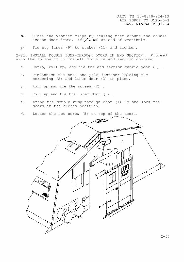
ARMY TM 10-8340-224-13AIR FORCE TO 35E5-6-1
NAVY NAVFAC-P-337.A
—o. Close the weather flaps by sealing them around the double
access door frame, if placed at end of vestibule.
4
.
P“ Tie guy lines (9) to stakes (11) and tighten.
2-21. INSTALL DOUBLE BUMP-THROUGH DOORS IN END SECTION. Proceedwith the following to install doors in end section doorway.
a. Unzip, roll up, and tie the end section fabric door (1) .
b. Disconnect the hook and pile fastener holding thescreening (2) and liner door (3) in place.
c . Roll up and tie the screen (2) .
d. Roll up and tie the liner door (3) .
e . Stand the double bump-through door (1) up and lock thedoors in the closed position.
f. Loosen the set screw (5) on top of the doors.
2-55
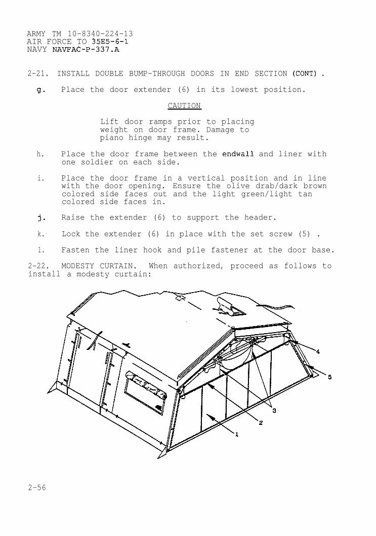
ARMY TM 10-8340-224-13AIR FORCE TO 35E5-6-1NAVY NAVFAC–P-337.A
2-21.
9.
h.
i.
j.
k.
1.
2-22.
INSTALL DOUBLE BUMP-THROUGH DOORS IN END SECTION (CONT) .
Place the door extender (6) in its lowest position.
CAUTION
Lift door ramps prior to placingweight on door frame. Damage topiano hinge may result.
Place the door frame between the endwall and liner withone soldier on each side.
Place the door frame in a vertical position and in linewith the door opening. Ensure the olive drab/dark browncolored side faces out and the light green/light tancolored side faces in.
Raise the extender (6) to support the header.
Lock the extender (6) in place with the set screw (5) .
Fasten the liner hook and pile fastener at the door base.
MODESTY CURTAIN. When authorized, proceed as follows toinstall a modesty curtain:
.
. .
2-56

a.
b.
c.
d.
e.
f.
9.
h.
i.
j.
k.
ARMY TM 10-8340-224-13AIR FORCE TO 35E5-6-1
NAVY NAVFAC-P-337.A
Lay the modesty curtain (1) out flat inside the tent.
Straighten out all the cables (2,3) used for the modestycurtain.
Separate the hook and pile fastener of the liner at thecave purlin height on both sides.
Place the horizontal cable’s (2) curved hook (4) throughthe liner and around the cave purlin next to the frame onboth sides.
Suspend curtain by locating each of the short cables (3)with squared off hooks near the center of the cable.
Separate the hook and pile fastener above the cable (3) .
Insert the cable (3) through the liner and hang it on theheader.
Close the liner around the modesty curtain cables (3) .
Locate the tie tapes (5) on each side of the modestycurtain.
Separate the liner next to the tie tapes (5) .
Tie the tie tapes (5) and secure hook and pile fastenersto the frame and close the liner around th~ tabs.
2-23. PARTITION. When authorized, install partition as follows:
2-57

ARMY TM 10-8340-224-13AIR FORCE TO 35E5-6-1NAVY NAVFAC-P-337.A
2-23. PARTITION (CONT).
a. Identify and lay out partition (1) .
b. Unfasten plenum flap (2) if plenum is installed.
c. Separate liner (3) at attachment points. ,
d. Tie the tie tapes (4) to arch assembly.
e. Seal liner (3) .
2-24. OPERATION OF DOORS, WINDOWS AND VENTS.
a.
2-58
Doors. Tent doors (1,2) are located in the center of theendwalls and on either side of a door section. A door mayalso be laced to the end of a vestibule. A door is openedby unzipping either side, rolling up, and tying with tie otapes. - Inside the fabric outer door a screened door isfastened with hook and pile fastener on either side. Italso may be rolled up and tied out of the way. ●

ARMY TM 10-8340-224-13AIR FORCE TO 35E5-6-1
NAVY NAVFAC-P-337.A
b. Windows. Windows (3) are made in three layers: a rainflap on the outside, a clear plastic window in the middle,and a screen on the inside. The rain flaps and plasticwindows are closed by hook and pile fasteners. The rainflap and the plastic window can each be held open with tietapes. Each layer must be rolled up towards the inside toprevent rain from being trapped within the folds. Tofully close the rain flap the clear window must first beunrolled and secured.
.
.——=—’ /’\
*
c. Peak Vent. The tent has a triangular vent (l.) at the peakwhich may be tied open or closed by the lines being tiedto the cave extenders on either side.
2-59

ARMY TM 10-8340-224-13AIR FORCE TO 35E5-6-1NAVY NAVFAC-P-337.A
2-24. OPERATION OF DOORS, WINDOWS AND VENTS (CONT) .
d. Roof Vent. The desert/tropical TEMPER version has vents(1) on the roof section controlled with lines from theinside of the tent. Three lines control each vent: onein the middle and one at each end. When operating thevents, control them evenly. When the vents are operatedfrom within a lined tent, disconnect the hook and piletape fastener holding the liner door closed, reach up andpull the adjustment line from the top or bottom to adjustthe vents up or down.
2-60
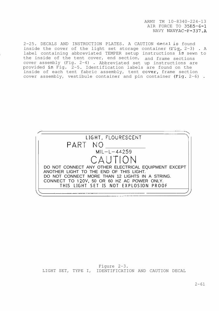
ARMY TM 10–8340–224–13
●AIR FORCE TO 35E5–6–1
NAVY NAVFAC-P–337.A
2–25. DECALS AND INSTRUCTION PLATES. A CAUTION decal is found
●inside the cover of the light set storage container (Fig. 2–3) . Alabel containing abbreviated TEMPER setup instructions is sewn tothe inside of the tent cover, end section, and frame sectionscover assembly (Fig. 2–4) . Abbreviated set up instructions areprovided in Fig. 2–5. Identification labels are found on theinside of each tent fabric assembly, tent cover, frame sectioncover assembly, vestibule container and pin container (Fig. 2–6) .
d
T
L I G H T , FLOURESCENT -7PART No
MIL–L–44259
CALJTK3NDO NOT CONNECT ANY OTHER ELECTRICAL EQUIPMENT EXCEPTANOTHER LIGHT TO THE END OF THIS LIGHT.DO NOT CONNECT MORE THAN 12 LIGHTS IN A STRING.CONNECT TO 120V$ 50 OR 60 HZ AC POWER ONLY.
T H I S L I G H T S E T I S N O T E X P L O S I O N P R O O F
Figure 2–3.LIGHT SET, TYPE I, IDENTIFICATION AND CAUTION DECAL
2-61
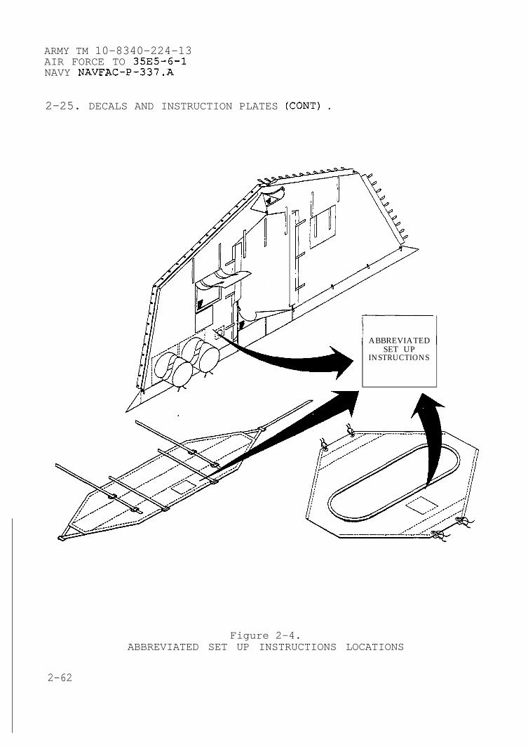
ARMY TM 10-8340-224-13AIR FORCE TO 35E5-6-1NAVY NAVFAC-P-337.A
2-25. DECALS AND INSTRUCTION PLATES (CONT) .
/AIp
I.
I ABBREVIATED ISET UP
INSTRUCTIONS
●
●
b
.
Figure 2-4.ABBREVIATED SET UP INSTRUCTIONS LOCATIONS
2-62
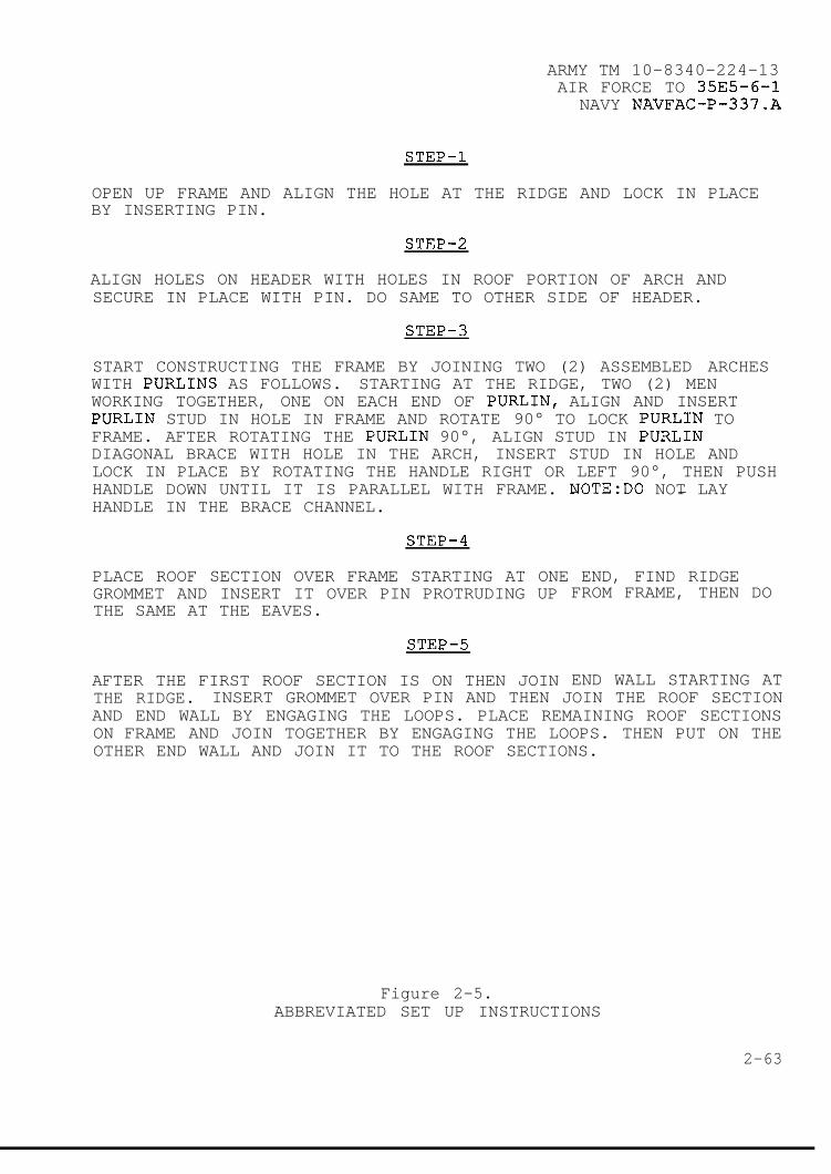
ARMY TM 10-8340-224-13AIR FORCE TO 35E5-6-1
NAVY NAVFAC-P-337.A
STEP-1
OPEN UP FRAME AND ALIGN THE HOLE AT THE RIDGE AND LOCK IN PLACEBY INSERTING PIN.
STEP-2
ALIGN HOLES ON HEADER WITH HOLES IN ROOF PORTION OF ARCH ANDSECURE IN PLACE WITH PIN. DO SAME TO OTHER SIDE OF HEADER.
STEP-3
START CONSTRUCTING THE FRAME BY JOINING TWO (2) ASSEMBLED ARCHESWITH PURLINS AS FOLLOWS. STARTING AT THE RIDGE, TWO (2) MENWORKING TOGETHER, ONE ON EACH END OF PURLIN, ALIGN AND INSERTPURLIN STUD IN HOLE IN FRAME AND ROTATE 90° TO LOCK PURLIN TOFRAME. AFTER ROTATING THE PURLIN 90°, ALIGN STUD IN PURLINDIAGONAL BRACE WITH HOLE IN THE ARCH, INSERT STUD IN HOLE ANDLOCK IN PLACE BY ROTATING THE HANDLE RIGHT OR LEFT 90°, THEN PUSHHANDLE DOWN UNTIL IT IS PARALLEL WITH FRAME. NOTE:DO NOT LAYHANDLE IN THE BRACE CHANNEL.
— — —
STEP-4
PLACE ROOF SECTION OVER FRAME STARTING AT ONE END, FIND RIDGEGROMMET AND INSERT IT OVER PIN PROTRUDING UPTHE SAME AT THE EAVES.
STEP-5
AFTER THE FIRST ROOF SECTION IS ON THEN JOIN
FROM FRAME, THEN DO
END WALL STARTING ATTHE RIDGE. INSERT GROMMET OVER PIN AND THEN JOIN THE ROOF SECTIONAND END WALL BY ENGAGING THE LOOPS. PLACE REMAINING ROOF SECTIONSON FRAME AND JOIN TOGETHER BY ENGAGING THE LOOPS. THEN PUT ON THEOTHER END WALL AND JOIN IT TO THE ROOF SECTIONS.
Figure 2-5.ABBREVIATED SET UP INSTRUCTIONS
2-63
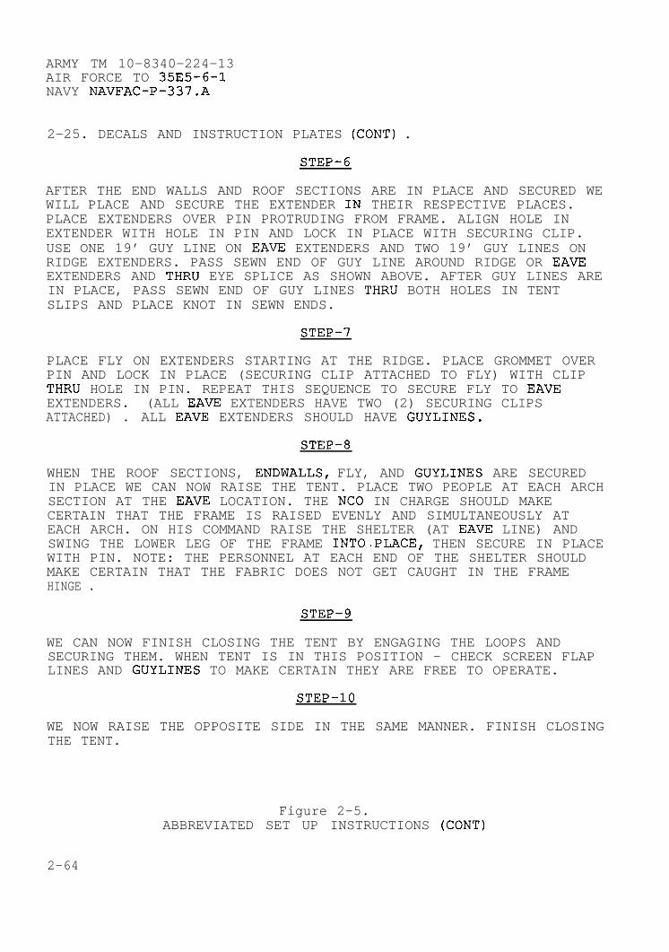
ARMY TM 10-8340-224-13AIR FORCE TO 35E5-6-1NAVY NAVFAC-P-337.A
2-25. DECALS AND INSTRUCTION PLATES (CONT) .
STEP-6
AFTER THE END WALLS AND ROOF SECTIONS ARE IN PLACE AND SECURED WE ●WILL PLACE AND SECURE THE EXTENDER IN THEIR RESPECTIVE PLACES.PLACE EXTENDERS OVER PIN PROTRUDING FROM FRAME. ALIGN HOLE INEXTENDER WITH HOLE IN PIN AND LOCK IN PLACE WITH SECURING CLIP.USE ONE 19’ GUY LINE ON EAVE EXTENDERS AND TWO 19’ GUY LINES ONRIDGE EXTENDERS. PASS SEWN END OF GUY LINE AROUND RIDGE OR EAVEEXTENDERS AND THRU EYE SPLICE AS SHOWN ABOVE. AFTER GUY LINES AREIN PLACE, PASS SEWN END OF GUY LINES THRU BOTH HOLES IN TENTSLIPS AND PLACE KNOT IN SEWN ENDS.
STEP-7
.
PLACE FLY ON EXTENDERS STARTING AT THE RIDGE. PLACE GROMMET OVERPIN AND LOCK IN PLACE (SECURING CLIP ATTACHED TO FLY) WITH CLIPTHRU HOLE IN PIN. REPEAT THIS SEQUENCE TO SECURE FLY TO EAVEEXTENDERS. (ALL EAVE EXTENDERS HAVE TWO (2) SECURING CLIPSATTACHED) . ALL EAVE EXTENDERS SHOULD HAVE GUYLINES.
STEP-8
WHEN THE ROOF SECTIONS, ENDWALLS, FLY, AND GUYLINES ARE SECUREDIN PLACE WE CAN NOW RAISE THE TENT. PLACE TWO PEOPLE AT EACH ARCH ●SECTION AT THE EAVE LOCATION. THE NCO IN CHARGE SHOULD MAKECERTAIN THAT THE FRAME IS RAISED EVENLY AND SIMULTANEOUSLY ATEACH ARCH. ON HIS COMMAND RAISE THE SHELTER (AT EAVE LINE) ANDSWING THE LOWER LEG OF THE FRAME INTO.PLACE, THEN SECURE IN PLACEWITH PIN. NOTE: THE PERSONNEL AT EACH END OF THE SHELTER SHOULDMAKE CERTAIN THAT THE FABRIC DOES NOT GET CAUGHT IN THE FRAMEHINGE .
STEP-9
WE CAN NOW FINISH CLOSING THE TENT BY ENGAGING THE LOOPS ANDSECURING THEM. WHEN TENT IS IN THIS POSITION - CHECK SCREEN FLAPLINES AND GUYLINES TO MAKE CERTAIN THEY ARE FREE TO OPERATE.
STEP-10
WE NOW RAISE THE OPPOSITE SIDE IN THE SAME MANNER. FINISH CLOSINGTHE TENT.
Figure 2-5.ABBREVIATED SET UP INSTRUCTIONS (CONT)
2-64
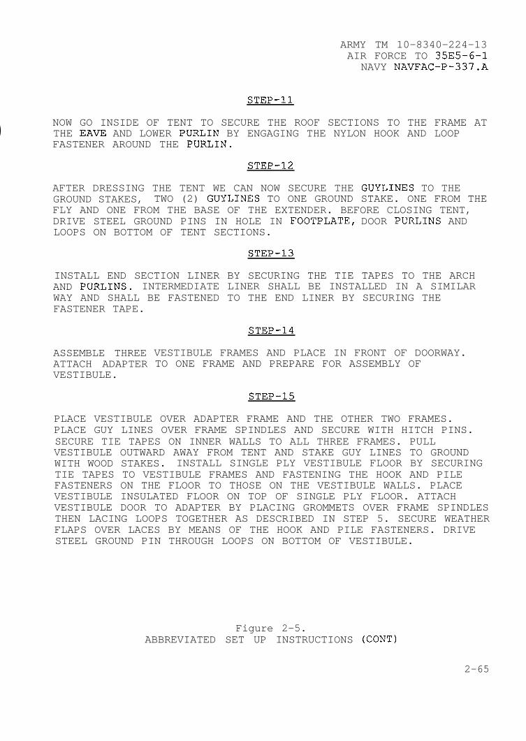
ARMY TM 10-8340-224-13AIR FORCE TO 35E5-6-1
NAVY NAVFAC-P-337.A
.
STEP-11
●NOW GO INSIDE OF TENT TO SECURE THE ROOF SECTIONS TO THE FRAME ATTHE EAVE AND LOWER PURLIN BY ENGAGING THE NYLON HOOK AND LOOPFASTENER AROUND THE PURLIN.
STEP-12
AFTER DRESSING THE TENT WE CAN NOW SECURE THE GUYLINES TO THEGROUND STAKES, TWO (2) GUYLINES TO ONE GROUND STAKE. ONE FROM THEFLY AND ONE FROM THE BASE OF THE EXTENDER. BEFORE CLOSING TENT,DRIVE STEEL GROUND PINS IN HOLE IN FOOTPLATE, DOOR PURLINS ANDLOOPS ON BOTTOM OF TENT SECTIONS.
STEP-13
INSTALL END SECTION LINER BY SECURING THE TIE TAPES TO THE ARCHAND PURLINS. INTERMEDIATE LINER SHALL BE INSTALLED IN A SIMILARWAY AND SHALL BE FASTENED TO THE END LINER BY SECURING THEFASTENER TAPE.
e ASSEMBLE THREEATTACH ADAPTERVESTIBULE.
STEP-14
VESTIBULE FRAMES AND PLACE IN FRONT OF DOORWAY.TO ONE FRAME AND PREPARE FOR ASSEMBLY OF
.
STEP-15
PLACE VESTIBULE OVER ADAPTER FRAME AND THE OTHER TWO FRAMES.PLACE GUY LINES OVER FRAME SPINDLES AND SECURE WITH HITCH PINS.SECURE TIE TAPES ON INNER WALLS TO ALL THREE FRAMES. PULLVESTIBULE OUTWARD AWAY FROM TENT AND STAKE GUY LINES TO GROUNDWITH WOOD STAKES. INSTALL SINGLE PLY VESTIBULE FLOOR BY SECURINGTIE TAPES TO VESTIBULE FRAMES AND FASTENING THE HOOK AND PILEFASTENERS ON THE FLOOR TO THOSE ON THE VESTIBULE WALLS. PLACEVESTIBULE INSULATED FLOOR ON TOP OF SINGLE PLY FLOOR. ATTACHVESTIBULE DOOR TO ADAPTER BY PLACING GROMMETS OVER FRAME SPINDLESTHEN LACING LOOPS TOGETHER AS DESCRIBED IN STEP 5. SECURE WEATHERFLAPS OVER LACES BY MEANS OF THE HOOK AND PILE FASTENERS. DRIVESTEEL GROUND PIN THROUGH LOOPS ON BOTTOM OF VESTIBULE.
Figure 2-5.ABBREVIATED SET UP INSTRUCTIONS (CONT)
2-65

ARMY TM 10-8340-224-13AIR FORCE TO 35E5-6-1NAVY NAVFAC-P-337.A
2-25. DECALS AND INSTRUCTION PLATES (CONT) .
STEP-16
INSTALL ONE OF THE SINGLE PLY TENT FLOOR SECTIONS BY ALIGNINGNOTCHES WITH FRAME MEMBERS THEN SECURING TIE TAPES TO FRAME.ADDITIONAL FLOOR SECTIONS ARE INSTALLED BY MATING THE HOOK ANDPILE FASTENERS ALONG EDGE OF FLOOR THEN SECURING TIE TAPES TOFRAME .
STEP-17
INSULATED FLOOR PANELS ARE INSTALLED BY PLACING THEM OVER THESINGLE PLY FLOOR SECTIONS AND LOCKING TOGETHER BY MATING HOOK ANDPILE FASTENERS ALONG EDGE OF FLOOR SECTIONS.
ELECTRICAL DISTRIBUTION SYSTEM
NOTE: AN ELECTRICAL DISTRIBUTION SYSTEM IS AVAILABLE FOR USE WITHTHIS TENT. THE ABOVE ILLUSTRATION DEPICTS LOCATION OF THEDISTRIBUTION BOX, LAMPS AND CONVENIENCE OUTLETS.
&
INCANDESCENT LAMPS
A LAMP CABLE ASSEMBLY IS AVAILABLE WHICH CONTAINS MOLDED SOCKETSFOR TWO INCANDESCENT LIGHT BULBS. THESE ASSEMBLIES CAN BE ●SUBSTITUTED FOR THE FLUORESCENT LIGHTS WHEN LOW LEVEL LIGHTING ISADEQUATE.
FLUORESCENT LAMPS
FOUR LUMINAIRES COME PACKED IN A FIBERGLASS CARRYING CONTAINER.EACH LUMINAIRE IS FURNISHED WITH A LIGHT SUPPORT STRAP WITH FOURATTACHED SUPPORT STRAPS. THE LIGHT SUPPORT STRAPS FASTEN OVER THEFRAME HEADER ASSEMBLY. THE LUMINAIRES ARE SUSPENDED FROM THELIGHT SUPPORT STRAP BY MEANS OF THE 2 SUPPORT STRAPS. WHEN THELINER IS INSTALLED, THE 2 STRAPS ARE PASSED THRU THE SLITS IN THELINER AND THEN ATTACHED TO THE LUMINAIRES. .
Figure 2–5.ABBREVIATED SET UP INSTRUCTIONS (CONT)
2-66

ARMY TM 10-8340-224-13AIR FORCE TO 35E5-6-1
NAVY NAVFAC-P-337.A
+
. --Z. ------ = . . . . . . . . . . . . . . . . . . . . . . .
Figure 2-6.IDENTIFICATION LABEL LOCATIONS
2-67

ARMY TM 10-8340-224-13AIR FORCE TO 35E5-6-1NAVY NAVFAC-P-337.A
2-26. PREPARATION FOR MOVEMENT. To prepare the TEMPER formovement, follow the procedures outlined in paragraphs a and bbelow. Clean and dry tent fabric sections and equipment asdescribed in paragraph 3-6. Package the tent into the transportbags as described in paragraph b below.
a. Take down procedures . First, locate the transport bags andthe light set storage container, then proceed as follows:
Fold fabric,
(1) Insulated Floors.
(a) Remove debris
NOTE
label side out.
and clean insulated floor.
(b) Disconnect hook and pile tape fasteners atinsulated floor section joints.
(c) Fold and remove individual insulated floorsections
(2) Vestibules.
(a) Remove single ply floors (1) .
(b) Release tension on all guy lines (2) and removestakes (3) .
(c) Unlace vestibule door (4) sides from vestibule(5) .
10
●
●
2-68

.
.
ARMY TM 10-8340-224-13AIR FORCE TO 35E5-6-1NAVY NAVFAC-P-337.A
(d) Untie vestibule tie tapes (6).
(e) Remove steel pins (7) in vestibule footstops andframe base plates.
(f) Collapse vestibule and position frames (8)against endwall.
(9) Remove hitch pins (9) and complete door removal.
(h) Remove frames (8) and disassemble.
(i) Open weather seal flap (10), unlace vestibule(5), remove and fold.
(3) Tent Disassembly.
7
6
2-69
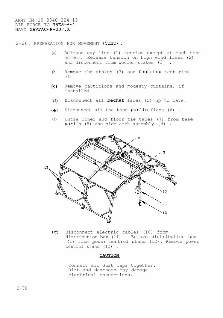
ARMY TM 10-8340-224-13AIR FORCE TO 35E5-6-1NAVY NAVFAC-P-337.A
2-26. PREPARATION FOR MOVEMENT (CONT) .
(a) Release guy line (1) tension except at each tentcorner. Release tension on high wind lines (2)and disconnect from wooden stakes (3) .
(b) Remove the stakes (3) and footstop tent pins(4) .
(c) Remove partitions and modesty curtains, ifinstalled.
(d) Disconnect all becket laces (5) up to cave.
(e) Disconnect all the base purlin flaps (6) .
(f) Untie liner and floor tie tapes (7) from basepurlin (8) and side arch assembly (9) .
(g) Disconnect electric cables (10) fromdistribution box (11) . Remove distribution box(1) from power control stand (12). Remove powercontrol stand (12) .
CAUTION
Connect all dust caps together.Dirt and dampness may damageelectrical connections.
2-70
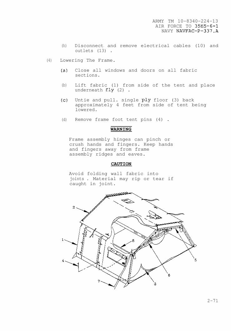
.
ARMY TM 10-8340–224-13AIR FORCE TO 35E5-6-1
NAVY NAVFAC–P-337.A
(h) Disconnect and remove electrical cables (10) andoutlets (13) .
(4) Lowering The Frame.
(a) Close all windows and doors on all fabricsections.
(b) Lift fabric (1) from side of the tent and placeunderneath fly (2) .
(c) Untie and pull. single ply floor (3) backapproximately 4 feet from side of tent beinglowered.
*(d) Remove frame foot tent pins (4) .
WARNING
Frame assembly hinges can pinch orcrush hands and fingers. Keep handsand fingers away from frameassembly ridges and eaves.
CAUTION
Avoid folding wall fabric intojoints . Material may rip or tear ifcaught in joint.
2-71

ARMY TM 10-8340-224-13AIR FORCE TO 35E5-6-1NAVY NAVFAC-P-337.A
2-26. PREPAW4TION FOR MOVEMENT (CONT).
(e) Place two soldiers at each arch (5) on side ofthe tent being lowered.
(f) On command, remove quick release pins (6)holding arches erect.
CAUTION
Do not twist or turn framecomponents when handling. Damage toequipment may result.
NOTE
If pin cannot be removed easily,loosen corner guy lines and adjustthe frame, then remove.
2-72
(9)
(h)
(i)
(j)
(k)
(1)
(m)
(n)
(o)
Relieve tension from four corner ropes.
Standing clear of tent place one hand below cavejoint of arch (5) and one on the cave purlin(8) . Swing out side frame. Extra soldiers mayassist in lowering frame.
Remove luminaires.
Remove plenums.
Remove liners.
Remove light support strap assemblies.
Untie and remove single ply floor.
Disconnect cave purlin flaps.
Repeat steps a through h to lower other side ofthe tent.
(5) Removing The Fabric.
(a) Disconnect hitch clip pins (l), remove fly (2)from cave extenders (3) and remove caveextenders (3) .
(b) Untie tie off point and disconnect becket lacing
.
.
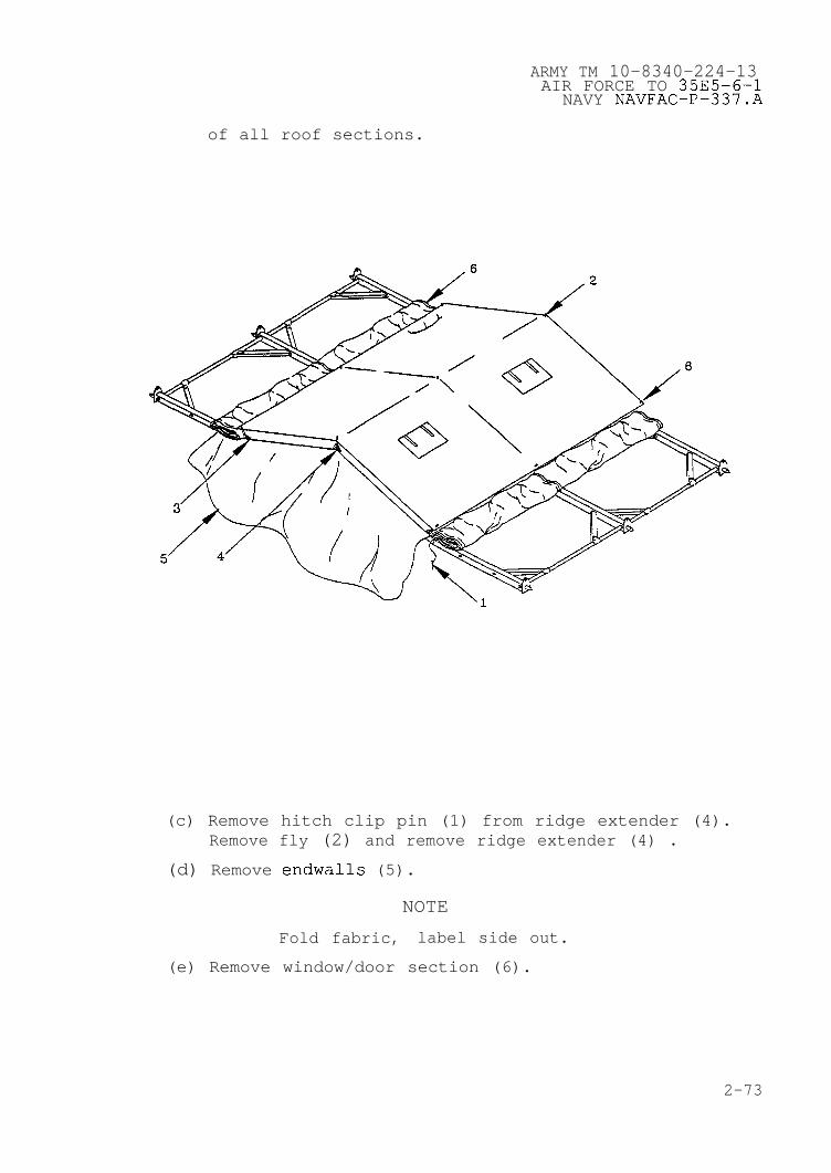
ARMY TM 10–8340–224–13AIR FORCE TO 35E5–6–1
NAVY NAVFAC–P–337.A
of all roof sections.
(c) Remove hitch clip pin (1) from ridge extender (4).Remove fly (2) and remove ridge extender (4) .
(d) Remove endwalls (5).
NOTE
Fold fabric, label side out.
(e) Remove window/door section (6).
2-73

ARMY TM 10–8340–224–13AIR FORCE TO 35E5–6–1NAVY NAVFAC–P–337.A
2–26. PREPARATION FOR MOVEMENT (CONT) .
(6) Frame Disassembly.
NOTE
Disassembly sequence is from base toridge.
(a) Disconnect each purlin diagonal brace (l), fold andsecure.
Position oneto hold archdisassembly.
WARNING
soldier at each ridge archupright during frameFailure to hold frame
Y
upright may allow frame to fall andcause injury to personnel.
(b) Rotate purlins (2) and remove.
(c) Remove headers (3).
w
.
(d) Disassemble roof arch (4) and side arch assembly(5) and fold.
(e) Pack in appropriate transport bag.
2–74

ARMY TM 10–8340–224–13AIR FORCE TO 35E5–6–1NAVY NAVFAC–P–337.A
b
b. Pac kina Instruc tions_. Pack the disassembled TEMPERcomponents into the transport bags as indicated below.
Tent cove rEnd SectionWindow SectionDoor SectionTent FlyEnd Section LinerIntermediate LinerTent FloorPartitionModesty CurtainEndwall PlenumExtendable PlenumSide Entrance Plenum
Frame Sect ions cover Assemblv(End Sect ion comw onents)Arch Assembly 2Header Assembly 2Purlin Assembly 5Eave Extender Assembly 4Ridge Extender Assembly 2
Frame Sect ions cover Assemblv(Extendab le Door Sect ion com–
Ponents)Arch Assembly 1Header Assembly 1Purlin Assembly 3Eave Extender Assembly 2Ridge Extender Assembly 1Door Sill Assembly 2Vestibule Frame Assembly 2
Vestibule Conta inerVestibuleVestibule DoorVestibule FloorVestibule Door CapVestibule Door SlidingBlackout Curtain
Frame Sections Cover As semblv(Extendable Section Com~onents)Arch Assembly 1Header Assembly 1Purlin Assembly 5Eave Extender Assembly 2Ridge Extender Assembly 1
Tent Pin Conta inerTent Pin, Steel, 12 inchTent Pin, Wood, 24 inch
2-75
ARMY TM 10-8340-224-13AIR FORCE TO 35E5–6–1NAVY NAVFAC–P–337.A
2-27.
a.
b.
c .
SECTION IV. OPERATION UNDER UNUSUAL CONDITIONS
GENERAL. While it is not possible to prepare for allunusual conditions the TEMPER will be exposed to, thefollowing information should beclimatic conditions.
O~e rat ion in Hiah Wind.
WARNING
All tent lines and frame
helpful during unusual
feet must bestaked down. Failure to stake and tiedown tent may result in injury topersonnel and damage to equipment.
(1) Replace wooden stakes with ground anchor kit.
(2) Close and fasten all windows and doors.
(3) Frequently check all tent pins and lines.
(4) Secure by placing sandbags around base of tent.
Wet Climate.
(1) If heavy rain is expected or the TEMPER is going to beset up for a long period of time, dig a trench aroundthe outside.
(2) Tent lines may shrink from dampness, so keep tent linesloose enough to prevent tent pins from being pulled outof the ground.
(3) Dry all TEMPER components before repacking.
(4) Make sure no leaks occur near the electricaldistribution set or the light set. Disconnect power ifleaks occur.
O~e rat ion in Snow/Extreme cold.
(1) Sweep snow from fly using snow rake (Appendix E, item10) .
(2) Gently push up on the roof from inside the TEMPER toremove snow that may have piled up.
*
2-76
ARMY TM 10–8340–224-13AIR FORCE TO 35E5-6–1
NAVY NAVFAC-P-337.A
(3) When erecting the TEMPER in snow conditions, gentlytamp the snow down to provide a firm surface on whichto set up.
WARNING
● All tent lines and frame feet must bestaked down. Failure to stake and tiedown tent may result in injury topersonnel and damage to equipment.
● Stay alert to moisture conditions andadjust all guy lines at tent slips asrequired before weight or shrinkagedamages tent or injures personnel.
(4) If ground is frozen too hard to drive steel tentpins, chop small holes to set them in. Fill holeswith slush or water and allow to freeze and anchorpins .
d. Extreme Heat. Roll up the endwalls and window/roof sectionfabric to provide maximum ventilation.
(1)
(2)
(3)
(4)
(5)
Open weather flaps on both sides of the section to beopened.
Untie and disconnect becket lacing as high as cavepurlin. Tie off becket lacing at cave.
Disconnect base purlin flaps from inside tent.
Open the entrance way door and tie back.
Fold and roll fabric underneath itself and towardstop. Tie with tie tape.
e. Nuclear, Biological, and Chemical (NBC) Decontamination.
(1) If chemical or biological contamination is expected,close all TEMPER openings, such as windows, doors,and stove pipe openings.
2-77

ARMY TM 10-8340-224-13AIR FORCE TO 35E5–6–1NAVY NAVFAC.-P-337.A
2-27. GENERAL (CONT).
NOTE
Perform unit level decontamination ofthe TEMPER only under supervision ofunit NBC personnel.
(2) If TEMPER is set up, decontaminate the fabric aroundthe entrance way area of nuclear, chemical orbiological contamination by applying STB slurry orbrushing with hot, soapy water.
(3) Prepare slurry by mixing approximately equal parts ofwater with STB. Scrub slurry into fabric.
NOTE
STB slurry may leave a harmless, whitechalky residue. This is not a cause forconcern.
(5) Decontaminate the remaining sections of the TEMPER bynatural methods. Expose the erected tent to the effectsof weather and aeration for approximately 2-3 days.
CAUTION
Heavy concentrations of DS2 are harmfulto the TEMPER fabric. A fine spray mistis recommended. Do not scrub with mop orbroom.
NOTE
DS2 will cause some change in fabric color.
.
.
(4) Remove slurry promptly with brush (Appendix E SectionII, Item 1) and liberal quantities of hot water andsoap (Appendix E, Section II, Item 10) then rinse withclear water.
d
.
(6) Aeration is not effective against V-agents. Ifcontaminated by V-agent entire TEMPER must bedecontaminated with DS2 slurry.
2-78
ARMY TM 10–8340–224-13AIR FORCE TO 35E5-6-1
NAVY NAVFAC–P–337.A
CHAPTER 3
8
.
OPERATOR MAINTENANCE INSTRUCTIONS
Subject Section/Paragraph
Lubricating Instructions . . . . . . . . . . . . . . . . . . . . . . . . . . . . . . . . . . ...1General . . . . . . . . . . . . . . . . . . . . . . . . . . . . . . . . . . . . . . . . . . . . ...3-1Lubrication Instructions . . . . . . . . . . . . . . . . . . . . . . . . . . . ...3-2
Troubleshooting Procedures . . . . . . . . . . . . . . . . . . . . . . . . . . . . . . . ...11General Instructions . . . . . . . . . . . . . . . . . . . . . . . . . . . . . . . ...3-3Use of Table . . . . . . . . . . . . . . . . . . . . . . . . . . . . . . . . . . . . . . . ...3-4
Operators Maintenance Procedures . . . . . . . . . . . . . . . . . . . . . . . . ...111Inspection . . . . . . . . . . . . . . . . . . . . . . . . . . . . . . . . . . . . . . . . . ...3-5Cleaning . . . . . . . . . . . . . . . . . . . . . . . . . . . . . . . . . . . . . . . . . . . ...3-6Repair of Light Set, Type I . . . . . . . . . . . . . . . . . . . . . . . . ...3-7
Section I. LUBRICATING INSTRUCTIONS
3-1. GENERAL. The TEMPER Tent is designed to be used in forwardareas and requires little lubrication. The slide fasteners arethe only components of the tent which require lubrication. Thereis’ no separate Lubrication Order for the TEMPER, therefore alllubrication instructions contained herein are mandatory and to beadhered to as specified. Lubrication materials are listed inAppendix E.
3–2. LUBRICATION PROCEDURES. Ensure slide fasteners are free fromdirt and debris. Lubricate the slide fasteners by applying sticklubricant to metal or plastic slide fasteners when they becomedifficult to operate. Operate slide fastener to ensure overalllubrication.
SECTION II. OPERATOR TROUBLESHOOTING PROCEDURES
3-3. GENERAL INSTRUCTIONS. Table 3-1 contains troubleshootinginstructions designed to aid in diagnosing unsatisfactoryoperation or failure of TEMPER components. The table lists commonmalfunctions that you may find during normal use or maintenanceof the equipment. This manual cannot list all malfunctions thatmay occur, nor all tests and inspections and corrective actions.If a malfunction is not listed or is not corrected by theprescribed action, notify unit maintenance.
3-1

ARMY TM 10-8340-224-13AIR FORCE TO 35E5-6-1NAVY NAVFAC-P-337.A
MALFUNCTION INDEX
TEMPER TroubleshootingProceduresParagraph
No power to electrical system . . . . . . . . . . . . . . . . . . . . . . . ...1Luminaires do not light . . . . . . . . . . . . . . . . . . . . . . . . . . . . . ...2Temper will not stay taut . . . . . . . . . . . . . . . . . . . . . . . . . . . ...3
3-4. USE OF TABLE. You should perform the tests/inspections andcorrective actions in the order listed.
a. Malfunction. Check for where or what the malfunction is.
b. Test or Inspection. Test or inspect the cause of themalfunction.
c . Corrective Action. Once the malfunction is determined,correct the situation.
TABLE 3–1. OPERATOR TROUBLESHOOTING
MALFUNCTIONTEST OR INSPECTION
CORRECTIVE ACTION
1. NO POWER TO ELECTRICAL SYSTEM.
Step 1. Check security of connectors.
Tighten loose connections.
Step 2. Check for overloaded sockets.
Reset circuitequipment.
Step 3. Check electricalbreakers.
Reset circuit
breakers and unplug unnecessary
distribution box for popped circuit
breakers.
If breakers continue to pop, turn power off andrefer to direct support maintenance.
3-2
ARMY TM 10–8340–224–13AIR FORCE TO 35E5-6-1
NAVY NAVFAC-P–337.A
TABLE 3-1. OPERATOR TROUBLESHOOTING (CONT)
MALFUNCTIONTEST OR INSPECTION
CORRECTIVE ACTION
2. LUMINAIRES DO NOT LIGHT.
Step 1. Check power source.
Ensure proper power source (11OV AC 50/60 HZ) isselected.
Step 2. Check to make sure all electrical connectors areproperly connected.
Connect electrical connectors.
Step 3. Check for bad fuse.
Replace fuse if necessary as described inparagraph 3-7.
Step 4. Check for burnt-out fluorescent lamp.
Replace lamp as described in paragraph 3-7.
Refer to Direct Support Maintenance if stillunable to illuminate lamp.
Step 5. Check for proper operation of On/Off switch.
Refer to Direct Support Maintenance if switch doesnot operate.
3-3

ARMY TM 10-8340-224-13AIR FORCE TO 35E5-6-1NAVY NAVFAC-P-337.A
TABLE 3-1. OPERATOR TROUBLESHOOTING (CONT)
MALFUNCTIONTEST OR INSPECTION
CORRECTIVE ACTION
3. TEMPER WILL NOT STAY TAUT.
Check tent lines (l), slips (2) and stakes (3) .
Anchor tent lines (1) securely to stakes (3) .Replace stakes (3) or lines (1) if necessary.Tighten slips (2) .
●
●
.
3-4
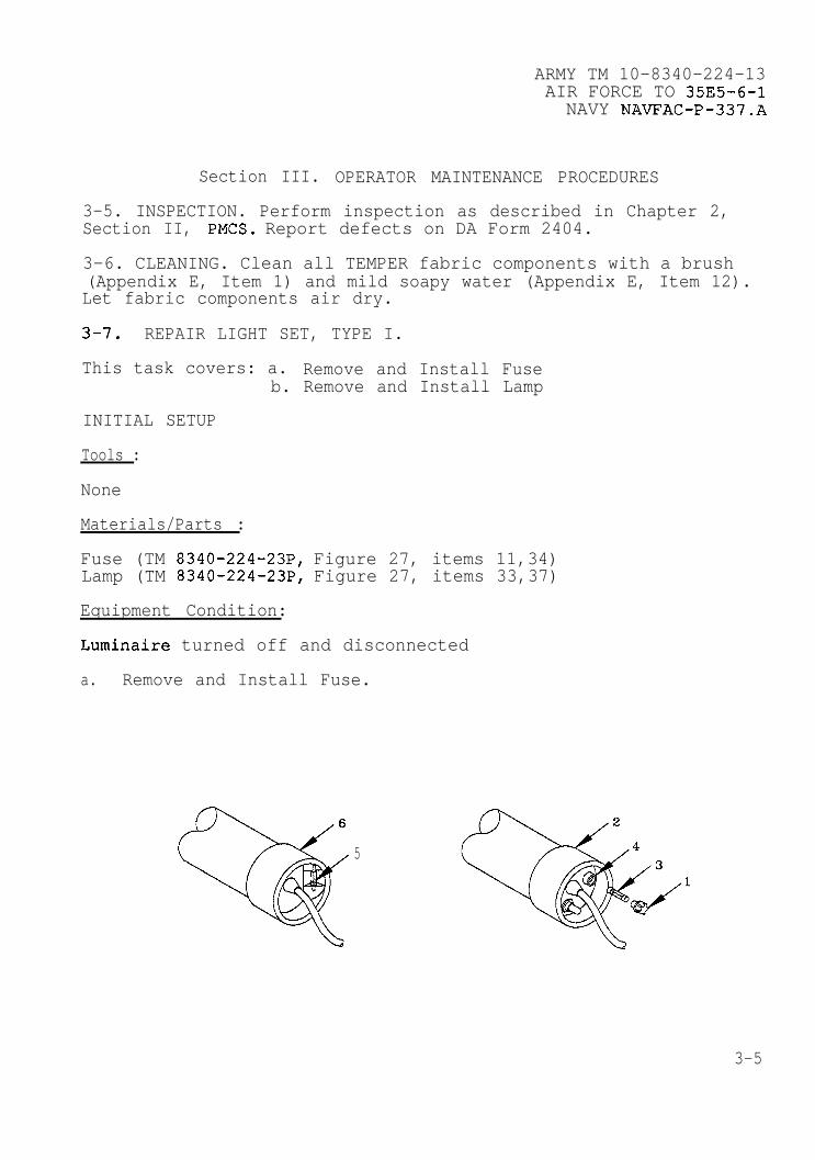
ARMY TM 10-8340-224-13AIR FORCE TO 35E5-6-1NAVY NAVFAC-P-337.A
Section III. OPERATOR MAINTENANCE PROCEDURES
3-5. INSPECTION. Perform inspection as described in Chapter 2,Section II, PMCS. Report defects on DA Form 2404.
3-6. CLEANING. Clean all TEMPER fabric components with a brush(Appendix E, Item 1) and mild soapy water (Appendix E, Item 12).Let fabric components air dry.
3-7. REPAIR LIGHT SET, TYPE I.
This task covers: a. Remove and Install Fuseb. Remove and Install Lamp
INITIAL SETUP
Tools :
None
Materials/Parts :
Fuse (TM 8340-224-23P, Figure 27, items 11,34)Lamp (TM 8340-224-23P, Figure 27, items 33,37)
Equipment Condition:
Luminaire turned off and disconnected
a. Remove and Install Fuse.
4
5
3-5
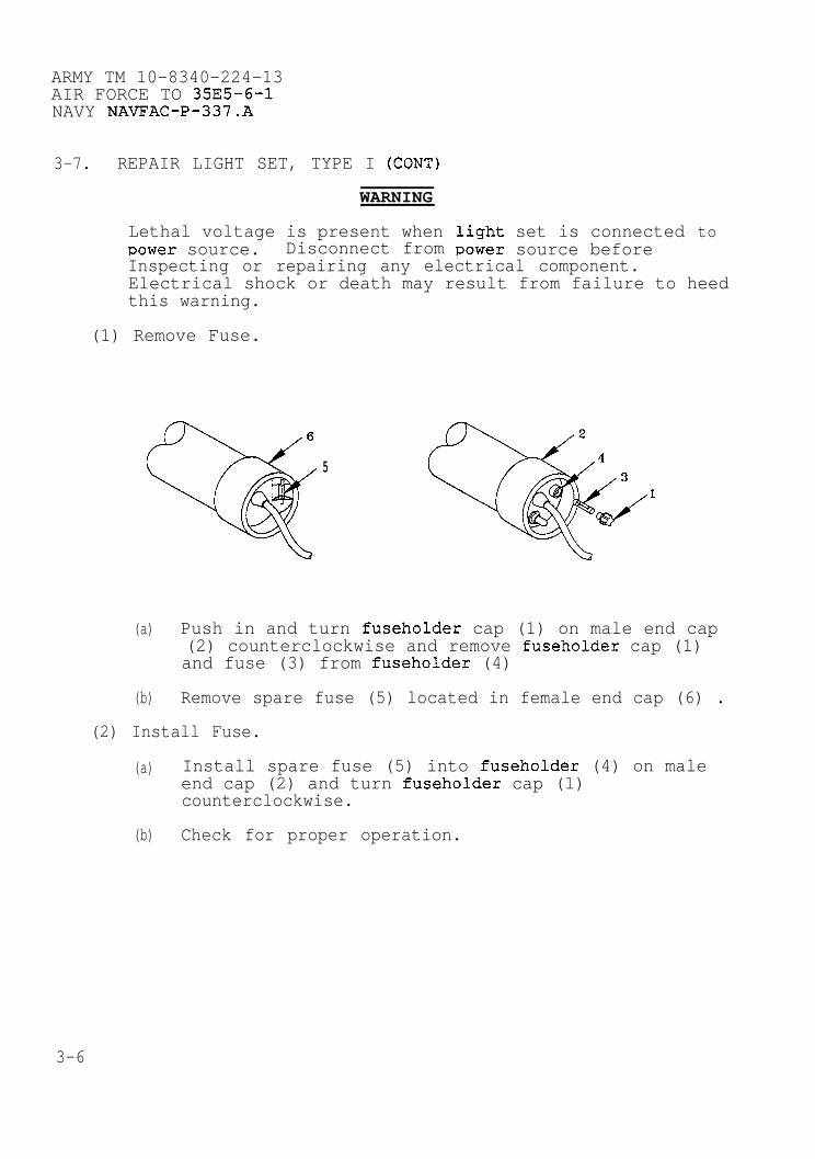
ARMY TM 10-8340-224-13AIR FORCE TO 35E5-6-1NAVY NAVFAC-P-337.A
3-7. REPAIR LIGHT SET, TYPE I (CONT)
WARNING
Lethal voltage is present whenpower source. Disconnect from
light set is connected toPower source before
Inspecting or repairing any electrical component.Electrical shock or death may result from failure to heedthis warning.
(1) Remove Fuse.
5
(a) Push in and turn fuseholder cap (1) on male end cap(2) counterclockwise and remove fuseholder cap (1)and fuse (3) from fuseholder (4)
(b) Remove spare fuse (5) located in female end cap (6) .
(2) Install Fuse.
(a) Install spare fuse (5) into fuseholder (4) on maleend cap (2) and turn fuseholder cap (1)counterclockwise.
(b) Check for proper operation.
.
3-6
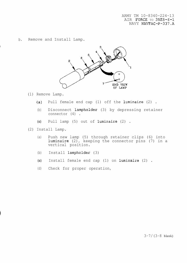
ARMY TM 10-8340-224-13AIR FORCE TO 35E5-6-INAVY NAVFAC-P-337.A
b. Remove and Install Lamp.
(1) Remove Lamp.
(a) Pull female end cap (1) off the luminaire (2) .
(b) Disconnect lampholder (3) by depressing retainerconnector (4) .
(c) Pull lamp (5) out of luminaire (2) .
(2) Install Lamp.
(a) Push new lamp (5) through retainer clips (6) intoluminaire (2), keeping the connector pins (7) in avertical position.
(b) Install lampholder (3)
(c) Install female end cap (1) on luminaire (2) .
(d) Check for proper operation,
3-7/(3-8 blank)
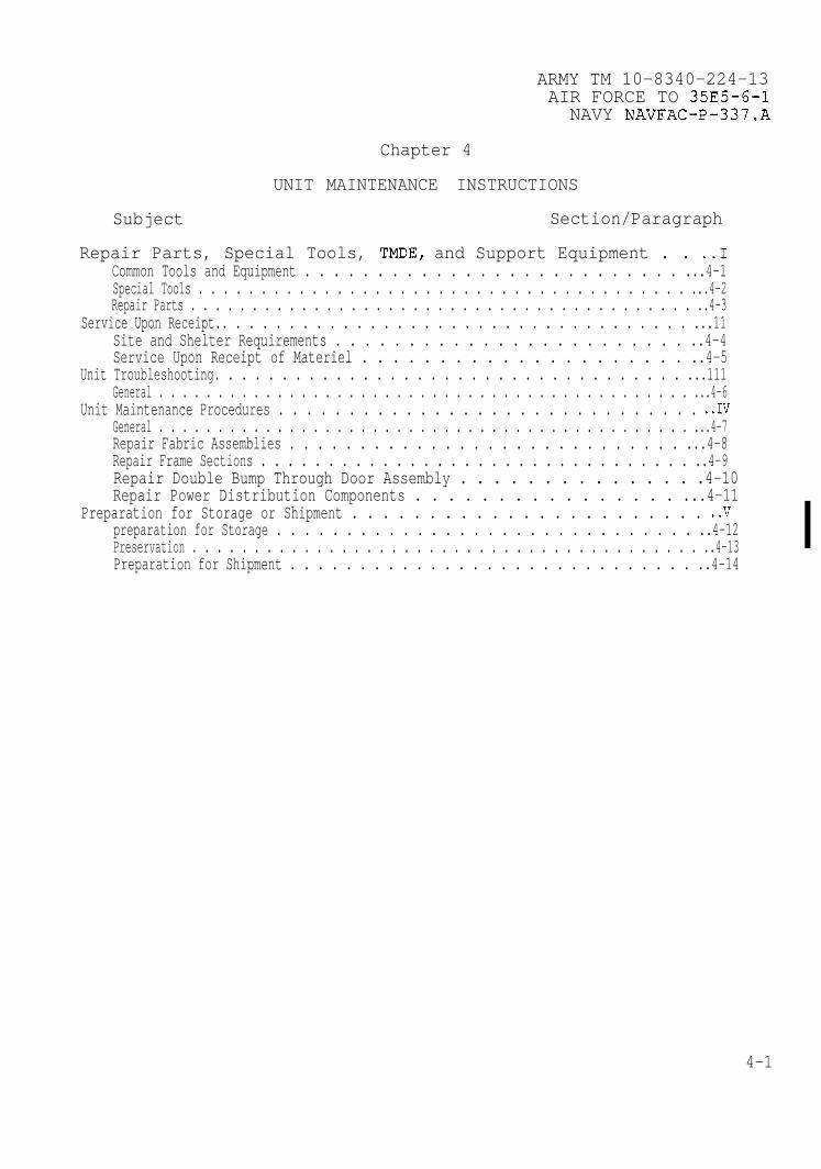
.
.
UNIT
Subject
ARMY TM 10-8340-224-13AIR FORCE TO 35E5-6-1
NAVY NAVFAC-P-337.A
Chapter 4
MAINTENANCE INSTRUCTIONS
Section/Paragraph
Repair Parts, Special Tools, TMDE, and Support Equipment . . ..ICommon Tools and Equipment . . . . . . . . . . . . . . . . . . . . . . . . . . ...4-1Special Tools . . . . . . . . . . . . . . . . . . . . . . . . . . . . . . . . . . . . . . . ...4-2Repair Parts . . . . . . . . . . . . . . . . . . . . . . . . . . . . . . . . . . . . . . . . . ..4–3
Service Upon Receipt.. . . . . . . . . . . . . . . . . . . . . . . . . . . . . . . . . . . ...11Site and Shelter Requirements . . . . . . . . . . . . . . . . . . . . . . . . ..4–4Service Upon Receipt of Materiel . . . . . . . . . . . . . . . . . . . . . ..4–5
Unit Troubleshooting. . . . . . . . . . . . . . . . . . . . . . . . . . . . . . . . . . . ...111General . . . . . . . . . . . . . . . . . . . . . . . . . . . . . . . . . . . . . . . . . . . . . ...4-6
Unit Maintenance Procedures . . . . . . . . . . . . . . . . . . . . . . . . . . . . . . ..IVGeneral . . . . . . . . . . . . . . . . . . . . . . . . . . . . . . . . . . . . . . . . . . . . . ...4-7Repair Fabric Assemblies . . . . . . . . . . . . . . . . . . . . . . . . . . . . ...4-8Repair Frame Sections . . . . . . . . . . . . . . . . . . . . . . . . . . . . . . . . ..4–9Repair Double Bump Through Door Assembly . . . . . . . . . . . . . . .4-10Repair Power Distribution Components . . . . . . . . . . . . . . . . ...4-11
Preparation for Storage or Shipment . . . . . . . . . . . . . . . . . . . . . . . ..Vpreparation for Storage . . . . . . . . . . . . . . . . . . . . . . . . . . . . . . ..4–12Preservation . . . . . . . . . . . . . . . . . . . . . . . . . . . . . . . . . . . . . . . . . ..4–13Preparation for Shipment . . . . . . . . . . . . . . . . . . . . . . . . . . . . . ..4–14
4
4-1

ARMY TM 10-8340-224-13AIR FORCE TO 35E5-6-1NAVY NAVFAC-P-337.A
Section I. REPAIR PARTS, SPECIAL TOOLS, TMDE, AND SUPPORTEQUIPMENT.
4-1. COMMON TOOLS AND EQUIPMENT. For authorized common tools andequipment, refer to the Modified Table of Organization andEquipment (MTOE) applicable to your unit.
4-2. SPECIAL TOOLS. Refer to Appendix B, Section II, Tool andTest Equipment Requirements, Maintenance Allocation Chart, foradditional tool and equipment requirements.
4-3. REPAIR PARTS. The repair parts required for unit levelmaintenance are listed and illustrated in TM 1O–834O–224-23P,Unit and Direct Support MaintenanceTools List.
Section II. SERVICE
4-4. SITE AND SHELTER REQUIREMENTS.-.. .
Repair Parts and Special
UPON RECEIPT.
When selecting a site onwhich
a.
b.
c.
d.
e.
f.
to set up the TEMPER:
Select a level area.
Ensure there is sufficient space to complex theneeded number of TEMPER sections.
The area should be accessible to tactical vehicles.
If possible, the area should be sheltered from highwinds.
Clear area of rocks and underbrush.
If necessary, dig a drainage ditch around the area toprovide adequate drainage.
4-5. SERVICE UPON RECEIPT OF MATERIEL.
a. Unpackinq. The TEMPER components, will be packaged in acleated plywood reusable shipping crate as per FED-SPEC–PPP–B-601that is 99 inches long, 20 inches wide, and 7 1/2 inches deep.The crate is strapped to a wooden pallet. Upon receipt, check fordamage. Report any damage to the carrier and your supervisor.
CAUTION
Unpack components carefully.Improper or hasty handling mayresult in damage to the TEMPERcomponents and accessories.
4-2
ARMY TM 10-8340–224–13AIR FORCE TO 35E5-6-1
NAVY NAVFAC–P–337.A
(1) Cut and remove retaining straps holding crate topallet. Remove crate from wooden pallet.
(2) Position crate to be unpacked with the top facing up.
(3) Open the crate, remove padding material, and set itaside. Do not cut, rip, or otherwise damage thepacking material.
(4) Lift the components from the crate.
b. Shipping Material. Save the shipping crate and any paddingmaterial for reuse.
c. Checking Unpacked Equipment. Inspect the unpackedcomponents for damage, completeness, and application ofapplicable Modification Work Orders (MWOs) as follows:
(1) Damage. Check the equipment for damage incurred duringshipment. Report any damage on DD Form 6, Packaging ImprovementReport. Also note damage on DA Form 2404, Equipment Inspectionand Maintenance Worksheet, and initiate corrective maintenanceprocedures in accordance with Section III of this chapter.
(2) Completeness. Inspect the contents of the shipmentagainst the packing slip to see if any items are missing (SeeAppendix C, Components of End Item). Report any discrepanciesnoted in accordance with instructions in DA Pam 738–750. Theequipment can be placed in service even if accessory or otherparts/assemblies that are not affecting proper functioning, aremissing.
(3) Modifications. Check DA Pam 25–30 to see if there isany MWO applicable to the TEMPER components you are unpacking. Ifan MWO is listed, check to see if it has been applied to theequipment. The MWO number will be shown on the case/bag near theequipment nomenclature. If a current MWO is listed in DA Pam 25–30 but there is no evidence that it has been applied to theequipment you are unpacking, note discrepancy on DA Form 2404,Equipment Inspection and Maintenance Worksheet.
Section III. UNIT TROUBLESHOOTING
4-6. GENERAL. Table 4–1 lists common malfunctions of theequipment and contains instructions for unit personnel diagnosingand correcting each malfunction. Perform the indicated steps inthe order listed.
4-3
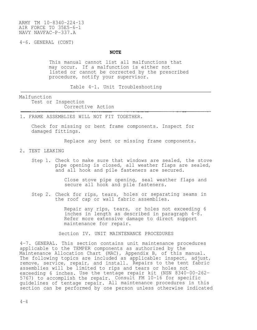
ARMY TM 10-8340-224-13AIR FORCE TO 35E5-6-1NAVY NAVFAC-P-337.A
4-6. GENERAL (CONT)
NOTE
This manual cannot list all malfunctions thatmay occur. If a malfunction is either notlisted or cannot be corrected by the prescribedprocedure, notify your supervisor.
Table 4-1. Unit Troubleshooting
MalfunctionTest or Inspection
Corrective Action
1. FRAME ASSEMBLIES WILL NOT FIT TOGETHER.
Check for missing or bent frame components. Inspect fordamaged fittings.
Replace
2. TENT LEAKING
any bent or missing frame components.
Step 1. Check to make sure that windows are sealed, the stovepipe opening is closed, all weather flaps are sealed,and all hook and pile fasteners are secured.
Close stove pipe opening, seal weather flaps andsecure all hook and pile fasteners.
Step 2. Check for rips, tears, holes or separating seams inthe roof cap or wall fabric assemblies.
Repair any rips, tears, or holes not exceeding 6inches in length as described in paragraph 4-8.Refer more extensive damage to direct supportmaintenance for repair.
Section IV. UNIT MAINTENANCE PROCEDURES
4-7. GENERAL. This section contains unit maintenance proceduresapplicable to the TEMPER components as authorized by theMaintenance Allocation Chart (MAC), Appendix B, of this manual.The following topics are included as applicable: inspect, adjust,remove, service, repair, and install. Repairs to the tent fabricassemblies will be limited to rips and tears or holes notexceeding 6 inches. Use the tentage repair kit (NSN 8340-00-262-5767) to accomplish the repair. Consult FM 10-16 for specificguidelines of tentage repair. All maintenance procedures in thissection can be performed by one person unless otherwise indicated
4-4
ARMY TM 10–8340–224–13AIR FORCE TO 35E5–6–1
NAVY NAVFAC–P-337.A
at the initial setup. Read all warnings, cautions, notes andinstructions carefully before performing the procedures. Read andunderstand all warnings at the front of this manual.
PROCEDURE PARAGRAPH
Repair Fabric Assemblies . . . . . . . . . . . . . . . . . . . . . . . . . . . . . . . . . . . . 4-8Repair Frame Sections . . . . . . . . . . . . . . . . . . . . . . . . . . . . . . . . . . . . . . . . . . 4-9Repair Double Bump Through Door Assembly . . . . . . . . . . . . . . . . 4–10Repair Power Distribution Components . . . . . . . . . . . . . . . . . . . . . . . . 4–11
4-8 REPAIR FABRIC ASSEMBLIES.
This task covers: Repair of Fabric Assemblies.
INITIAL SETUP
Tools:
Brush (Appendix B, Section III, Item 2)Tentage Repair Kit (Appendix B, Section III, Item 1)
Materials/Parts:
Denatured Alcohol (Appendix E, Section II, Item 3)Gloves, Latex–Nitrile (Appendix E, Section II, Item 5)K–Kote Seam Sealer (Appendix E, Section II, Item 8)Respirator, Air Filtering (Appendix E, Section II, Item 11)Wiping Rags (Appendix E, Section II, Item 17)
Equipment Conditions:
Although the fabric assemblies can be repaired while the tent isin use, it is recommended that the fabric be repaired when thetent is not in use, since repairs are easier when the fabricassemblies are separated. The fabric assemblies should be cleanand dry.
4-5

ARMY TM 10-8340-224-13AIR FORCE TO 35E5-6-1NAVY NAVFAC-P-337.A
4-8 REPAIR FABRIC ASSEMBLIES (CONT)
Repair Fabric Assemblies
Repair the following fabric assemblies, as required:
End SectionDoor SectionWindow SectionTent FlyEnd Section LinerIntermediate Section LinerTent FloorsVestibule ContainerPin ContainerPlenumModesty CurtainFrame Sections Cover Assembly
Repair all rips, tears, or holes up to 6 inches in length bysewing or patching using the tools and materials in the tentagerepair kit. Replace missing or deformed grommets. Replace tietape, tent lines, and slips as necessary. Follow the proceduresin FM 10-16 to make these repairs. Turn in fabric assemblies todirect support maintenance to repair/replace buckle assemblies,straps, chape and tears, holes 6 inches or larger, and rippedseams.
Apply seam sealer to repaired areas as follows:
WARNING
Seam sealer and solvent are extremelyflammable and the fumes toxic. Do not smokeor use seam sealer or solvent near openflame. Use seam sealer and solvent withgoggles and gloves, and indoors withrespirator or in an open, well ventilatedarea away from sources of combustion. Deathor severe injury may result from explosion orfire. Inhalation of fumes may cause toxicsickness.
NOTE
Tent may be erected or fabric assembliesmay be removed and laid flat.
Do not use a foam brush. Use a bristlebrush only.
4-6
(1)
(2)
(3)
(4)
(5)
ARMY TM 10-8340–224-13AIR FORCE TO 35E5-6-1
NAVY NAVFAC-P-337.A
Sealer may be applied to outside or insideof fabric assemblies.
Sealer should only be applied to newstitches, patches, etc., or those areasthat have shown water leakage.
Two light coats of sealant are moreeffective than one thick coat. Do not useexcessive amounts of sealer, as this doesnot increase effectiveness and will givethe tent a poor appearance.
Do not leave original sealer containeropen, as sealer will thicken and becomeunusable. Limit the amount of timecontainer is open.
Surface to be sealed should be cleaned as thoroughly aspractical and completely dry before applying sealer.
Pour small amount of sealer into a clean container andimmediately reseal the gallon container.
Apply sealer to stitching or repair tooverlapping seam stitching or edges of
Allow first coat to dry to the touch.
Apply second coat as described in step
be sealed,repair by 1/2”.
(3).
4-9. REPAIR FRAME
This task covers:
INITIAL SETUP
Tools:
Tool Kit, General
Materials/Parts:
Quick Release Pin
SECTIONS.
Remove and Install Quick Release Pin withLanyard Assembly
Mechanics (Appendix B, Section III, Item 3)
with Lanyard Assembly (TM 10-8340–224-23P,Figure 13, Item 5; Figure 14, Item 2)
Screw, Tapping-Thread (TM 10-8340-224-23P, Figure 13, Item 7;Figure 14, Item 3; Figure 19, Item 5)
4-7
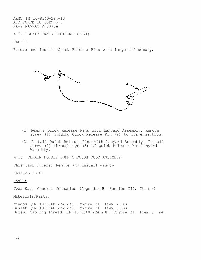
ARMY TM 10-8340-224-13AIR FORCE TO 35E5-6-1NAVY NAVFAC-P-337.A
4-9. REPAIR FRAME SECTIONS (CONT)
REPAIR
Remove and Install Quick Release Pins with Lanyard Assembly.
(1) Remove Quick Release Pins with Lanyard Assembly. Removescrew (1) holding Quick Release Pin (2) to frame section.
(2) Install Quick Release Pins with Lanyard Assembly. Installscrew (1) through eye (3) of Quick Release Pin LanyardAssembly.
4-10. REPAIR DOUBLE BUMP THROUGH DOOR ASSEMBLY.
This task covers: Remove and install window.
INITIAL SETUP
Tools:
Tool Kit, General Mechanics (Appendix B, Section III, Item 3)
Materials/Parts:
Window (TM 10-8340-224-23P, Figure 21, Item 7,18)Gasket (TM 10-8340-224-23P, Figure 21, Item 6,17)Screw, Tapping-Thread (TM 10-8340-224-23P, Figure 21, Item 6, 24)
4-8
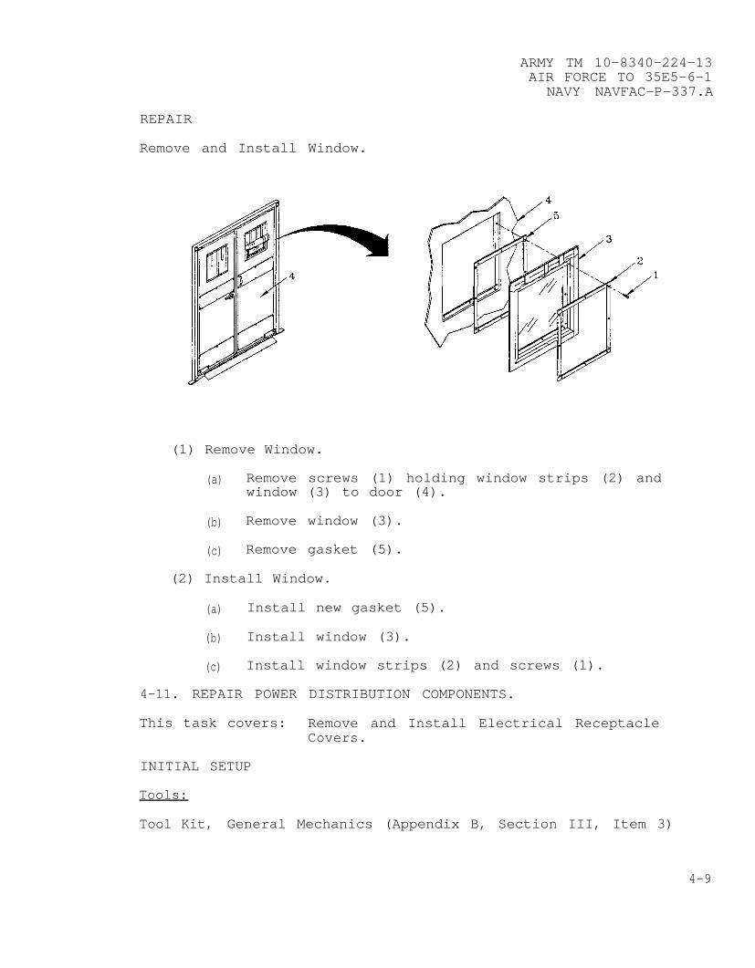
ARMY TM 10-8340-224-13AIR FORCE TO 35E5-6-1
NAVY NAVFAC-P-337.A
REPAIR
Remove and Install Window.
(1) Remove Window.
(a) Remove screws (1) holding window strips (2) andwindow (3) to door (4).
(b) Remove window (3).
(c) Remove gasket (5).
(2) Install Window.
(a) Install new gasket (5).
(b) Install window (3).
(c) Install window strips (2) and screws (1).
4-11. REPAIR POWER DISTRIBUTION COMPONENTS.
This task covers: Remove and Install Electrical ReceptacleCovers.
INITIAL SETUP
Tools:
Tool Kit, General Mechanics (Appendix B, Section III, Item 3)
4-9

ARMY TM 10-8340-224-13AIR FORCE TO 35E5-6-1NAVY NAVFAC-P-337.A
4-11. REPAIR POWER DISTRIBUTION COMPONENTS (CONT)
Materials/Parts:
Cover (TM 10-8340-224-23P, Figure 22, Item 5,6; Figure 23, Item5,6; Figure 24, Item 4,12,14; Figure 26, Item 3,5)
Screw (TM 10-8340-224-23P, Figure 22, Item 17,33; Figure 23, Item15,33)
Equipment Condition:
Electrical Power must be turned off.
Remove Receptacle Covers.
WARNING
Lethal voltage is present when thepower control system is connectedto power source. Disconnect frompower source before inspecting orrepairing any electrical component.Electrical shock or death mayresult from failure to heed thiswarning.
(1) Remove and Install Receptacle Cover.
(a) Remove cover (1) from receptacle (2).
(b) Remove screw (3) and cover chain (4) from receptacle(2).
(2) Install Receptacle
(a) Install screw(2).
(b) Install cover
Cover.
(3) and cover chain (4) on receptacle
(1) on receptacle (2).
4-10

ARMY TM 10-8340-224-13AIR FORCE TO 35E5-6-1
NAVY NAVFAC-P-337.A
Section V. Preparation for Storage or Shipment
4-12. PREPARATION FOR STORAGE. To prepare the TEMPER equipmentfor storage, clean and dry the fabric sections and othercomponents as described in paragraph 3–6. Perform operator PMCSas specified in Table 2–3.
Pack the fabric and frame assemblies into the tent cover andframe sections cover assembly. Place bags onto a wooden palletand store in a building, shed, or other dry place. Store thelight set in its storage container.
Special Instructions for Administrative Storaqe.Placement of equipment in administrative storage should be forshort periods of time when a shortage of maintenance resourcesexist. Items should be in mission readiness within 24 hours orwithin the time factors as determined by the directing authority.Appropriate maintenance records will be kept during storage.
Before placing equipment in administrative storage, currentmaintenance services and Equipment Serviceability Criteria (ESC)evaluations should be completed, shortcomings and deficienciesshould be corrected, and all Modification Work Orders (MWOs)should be applied.
Storage site selection. Inside storage is preferred for itemsselected for administrative storage. If inside storage is notavailable trucks, vans, conex or other containers may be used.
4-13. PRESERVATION. If the TEMPER components are to be storedwithout regular PMCS being performed, consult TM 38–230-2 forpreservation requirements.
4-14. PREPARATION FOR SHIPMENT. Prepare the TEMPER for shipmentby packing components into the wooden crate, using the originalpacking material, in which they were received. Strap crates ontowooden pallet.
4-11/(4-12 blank)

ARMY TM 10-8340-224-13AIR FORCE TO 35E5-6-1
NAVY NAVFAC-P-337.A
CHAPTER 5
DIRECT SUPPORT MAINTENANCE INSTRUCTIONS
Subject Section/Paragraph
Repair Parts, Special Tools; Test Measurement DiagnosticEquipment (TMDE) and Support Equipment . . . . . . . . . . . . . . . ...I
Common Tools and Equipment . . . . . . . . . . . . . . . . . . . . . . ...5-1Special Tools, TMDE, and Support Equipment. . . . . . . . . . . . . . .5–2Repair Parts . . . . . . . . . . . . . . . . . . . . . . . . . . . . . . . . . ..5–3
Troubleshooting . . . . . . . . . . . . . . . . . . . . . . . . . . . . . . . . ...IITroubleshooting Procedures . . . . . . . . . . . . . . . . . . . . . . . . ..5–4
Maintenance Procedures . . . . . . . . . . . . . . . . . . . . . . . . . . . . . . . . IIIGeneral . . . . . . . . . . . . . . . . . . . . . . . . . . . . . . . . . . . . ..5–5Machine Stitching.. . . . . . . . . . . . . . . . . . . . . . . . . . . . . . ...5-6Automatic Stitching. . . . . . . . . . . . . . . . . . . . . . . . . . . . . ..5–7Welding . . . . . . . . . . . . . . . . . . . . . . . . . . . . . . . . . . ...5-8Repair Fabric Assemblies . . . . . . . . . . . . . . . . . . . . . . . . ...5-9Repair Frame Assemblies . . . . . . . . . . . . . . . . . . . . . . . . ...5-10Repair Frame Section Components . . . . . . . . . . . . . . . . . . . . . . . . ..5–11Repair Frame and Power Control Assemblies . . . . . . . . . . . . . . . .5–12Repair Double Bump-Through Door Assembly. . . . . . . . . . . . . . . . .5–13Repair Power Control, Type III/IV . . . . . . . . . . . . . . . . . . . . . ...5-14Test and Repair Light Set, Type I . . . . . . . . . . . . . . . . . . . . ..5–15
Section I. REPAIR PARTS, SPECIAL TOOLS; TEST MEASUREMENTDIAGNOSTIC EQUIPMENT (TMDE) AND SUPPORT EQUIPMENT
5-1. COMMON TOOLS AND EQUIPMENT. For authorized common tools andequipment refer to the Modified Table of Organization andEquipment (MTOE) applicable to your unit.
5-2. SPECIAL TOOLS, TMDE, AND SUPPORT EQUIPMENT. No special toolsor equipment are required to perform direct support maintenanceon the TEMPER.
5-3. REPAIR PARTS. Repair Parts are listed and illustrated in TM10-8340-224–23P.
Section II. TROUBLESHOOTING
5-4. TROUBLESHOOTING PROCEDURES. See Tables 3-1 and 4-1 foroperator and unit troubleshooting procedures.
5-1

ARMY TM 10-8340-224-13AIR FORCE TO 35E5-6-1NAVY NAVFAC-P-337.A
Section III. MAINTENANCE PROCEDURES
5-5. GENERAL. Direct Support maintenance functions identified inSection II, Appendix B, consist of repairing or replacingcomponents that are riveted or sewn, welding new and brokenparts, and replacement of electrical components in the powercontrol and light set. Procedures for machine stitching areprovided in paragraph 5-6. Specific tentage repair procedures areprovided in FM 10-16. Procedures for removal and replacement ofrivets are discussed in paragraph TC 9-510. Refer to TC 9-510 forinformation on metal repairs. Procedures for electrical componentrepair are provided in paragraphs 5-14 and 5-15.
5-6. MACHINE STITCHING. All stitch types, except bartacking,shall conform to FED-STD 751. Type 301 and 401 stitching requires5-7 stitches per inch. Bartacking shall be 1/8 inch in width andfree of thread breaks and loose stitching.
a. Thread Breaks. Thread breaks in stitching shall beoverstitched not less than 1 inch at each break on stitch type301, and not less than 1 1/2” at each break on stitch type 401.Thread breaks in type 401 may be overstitched with stitch type301. Thread breaks noted during inspection must be repaired byoverstitching the existing stitching starting from a distance of1 inch beyond the break. The ends of repair stitching are notrequired to be backstitched.
b. Stitching Ends. The ends of type 301 stitching shall beoverstitched not less than 1 inch except where ends are turnedunder in a hem or held down by other stitching. Where 301stitchings performed automatically on stitch patterns such asbox, box with cross-stitch, “W” stitching or straight linetacking, at least three tying, overlapping, or back stitchesshall be used to secure the ends of stitching.
c. Skipped Stitches. Two or more consecutively skippedstitches occurring in type 301 stitching shall be overstitchednot less than 1 inch. Any skipped stitches in type 401 stitchingshall be overstitched not less than 1 1/2 inches. Skippedstitches in 401 stitching may be overstitched with type 301stitching. Skipped stitches noted during inspection shall berepaired as specified for thread breaks in a., above.
5-7. AUTOMATIC STITCHING. Automatic stitching machines may beused to perform any of the required stitch patterns provided therequirements of the stitch pattern, stitches per inch, size andtype of thread are met, and at least three or more overlapping,tying or backstitches secure the ends of the stitching.
5-2
ARMY TM 10–8340–224–13AIR FORCE TO 35E5-6-1
NAVY NAVFAC-P–337.A
5-8. WELDING. Major components of the TEMPER such as the framesections, power distribution stand may require welding to repairdeformations or broken welds. Refer to TM 9-237 for informationon welding theory, application, and procedures.
5-9. REPAIR FABRIC ASSEMBLIES.
This task covers: a. Repair Fabric Assemblies
INITIAL SETUP
Tools:
Sewing Machine (Appendix B, Section III, Item 5)
Materials/Parts:
Refer to TM 10-8340-224-23P, Figures 1 through 12
GENERAL
Repair the following tent fabric sections:
End SectionDoor SectionWindow SectionFlyEnd Section LinerIntermediate LinerFloorVestibulePlenumBlackout CurtainModesty CurtainPartition
Repair rips, tears, holes or separated seams, and replace, asnecessary, quick disconnect fasteners, hook and pile fasteners,buckles, labels, grommets, windows, straps, tie tapes, chapes,and reinforcements. Follow the procedures outlined in paragraph5-6 through 5-7, and FM 10–16 to perform the repairs and/or makethe items specified in TM 10-8340-224-23P, Repair Parts andSpecial Tools List, (RPSTL) from bulk material. Use the materialsspecified in TM 10–8340-224-23P, under the group corresponding tothe fabric section being repaired. Cut bulk material to sizesindicated.
5-3
ARMY TM 10-8340-224-13AIR FORCE TO 35E5-6-1NAVY NAVFAC-P-337.A
5-10. REPAIR FRAME SECTIONS.
This task covers: Replace Rivets
INITIAL SETUP
Tools:
Tool Kit, Common No 1 (Appendix B, Section III, Item 7)Riveting Tool (Appendix B, Section III, Item 6)
Materials/Parts:
Refer to TM 10-8340-224-23P, Figures 13 through 20
GENERAL
Repair the following tent frame sections:
Arch Assembly SectionalizedHeader AssemblyPurlin AssemblyEave Extender AssemblyRidge Extender AssemblyDoor Sill AssemblyVestibule Frame Assembly
Replace rivets in all frame components IAW general procedures inTC 9-510.
5-4

ARMY TM 10-8340-224-13AIR FORCE TO 35E5-6-1
NAVY NAVFAC-P–337.A
5-11. REPAIR FRAME SECTION COMPONENTS.
This task covers: Remove and Install Purlin Assembly and Door
INITIAL SETUP
Tools:
Tool Kit, Common
Materials/Parts:
Sill Assembly, End Fittings
No 1 (Appendix B, Section III, Item 3)
End Fitting (TM 10-8340-224-23P, Figure 15, Item 2; Figure 19,Item 3)
Screw, Drive, Round Head (TM 10-8340-224-23P, Figure 15, Item 5;Figure 19, Item 6)
Rivet,
REPAIR
Remove and Install Purlin Assembly and Door Sill Assembly EndFitting.
(1) Remove End Fitting
(a) Remove rivets/screws (1) holding end fitting topurlin assembly or door sill assembly
(b) Remove end fitting (2)
(2) Install End Fitting
(a) Insert end fitting (2) into purlin assembly or doorsill assembly.
(b) Install rivets/screws (1).
5-5

ARMY TM 10-8340-224-13AIR FORCE TO 35E5-6-1NAVY NAVFAC-P-337.A
5-12. REPAIR FRAME AND POWER CONTROL ASSEMBLIES.
This task covers: Repair Frame and Power Control Assemblies
INITIAL SETUP
Tools:
Tool Kit, Common No 1 (Appendix B, Section III, Item 7)
Materials/Parts:
Refer to TM 10-8340-224-23P, Figures 13 through 20 and 25
GENERAL
Repair the following tent frame sections and power controlcomponents:
Arch Assembly, Sectionalized and RigidEave Extender AssemblyRidge Extender AssemblyPower Panel Stand AssemblyVestibule Frame Assembly
Repair welds IAW the procedures outlined in TM 9-237 to performthe repairs and/or make the items specified in TM 10-8340-224-23P, Repair Parts and Special Tools List.
5-6

ARMY TM 10–8340-224-13AIR FORCE TO 35E5-6-1
NAVY NAVFAC-P-337.A
5-13. REPAIR DOUBLE BUMP THROUGH DOOR ASSEMBLY.
This task covers: a. Remove and Install Door Assembly (left orright).
b. Remove and Install Hinge
INITIAL SETUP
Tools:
Riveting Tool (Appendix B, Section III, Item 6)Tool Kit, Common No 1 (Appendix B, Section III, Item 7)
Materials/Parts:
Left Door Assembly (TM 10-8340-224-23P, Figure 21, Item 3)Right Door Assembly (TM 10-8340-224-23P, Figure 21, Item 13)Hex Head Screw Cap (TM 10-8340-224-23P, Figure 21, Item 34)Lock-Spring Washer (TM 10-8340-224-23P, Figure 21, Item 35)
Equipment Condition:
Double Bump Through Door Assembly may or may not be installed.
REPAIR
a. Remove and Install Door Assembly (left or right).
(1) Remove Door Assembly.
(a) Remove hex head screw caps (1) and lock-spring washer(2) from hinge base (3)
(b) Pull door (4) out from bottom allowing pivot (5) topull free from frame (6).
5-7
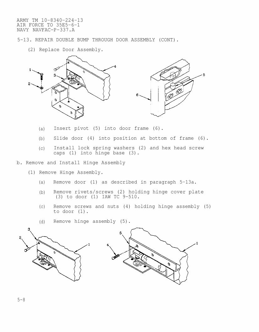
ARMY TM 10-8340-224-13AIR FORCE TO 35E5-6-1NAVY NAVFAC-P-337.A
5-13. REPAIR DOUBLE BUMP THROUGH DOOR ASSEMBLY (CONT).
(2) Replace Door Assembly.
(a) Insert pivot (5) into door frame (6).
(b) Slide door (4) into position at bottom of frame (6).
(c) Install lock spring washers (2) and hex head screwcaps (1) into hinge base (3).
b. Remove and Install Hinge Assembly
(1) Remove Hinge Assembly.
(a)
(b)
(c)
(d)
Remove door (1) as described in paragraph 5-13a.
Remove rivets/screws (2) holding hinge cover plate(3) to door (1) IAW TC 9-510.
Remove screws and nuts (4) holding hinge assembly (5)to door (1).
Remove hinge assembly (5).
5-8

ARMY TM 10-8340-224-13AIR FORCE TO 35E5-6-1
NAVY NAVFAC-P-337.A
(2) Install Hinge Assembly.
(a) Install screws and nuts (4) to mount hinge assembly(5) to door (1).
(b) Install rivets/screws (2) and hinge cover plate (3)on door (1) IAW TC 9-510 as applicable.
(c) Install door (1) as described in paragraph 5-13a.
5-14. REPAIR POWER CONTROL, TYPE III/IV AND CONVENIENCE OUTLET.
This task covers: a. Remove and install circuit breaker, toggleand push-pull.
b. Remove and install receptacle connector withgasket from Power Control/ConvenienceOutlet.
c. Remove and install mounting box receptaclefrom Power Control/Convenience Outlet.
INITIAL SETUP
Tools:
Tool Kit, Common No 1 (Appendix B, Section III, Item 7)
Materials/Parts:
Circuit breaker, toggle (TM 10-8340-224-23P, Figure 22, Item 14;Figure 23, Item 11)
Circuit breaker, push-pull (TM 10-8340-224-23P, Figure 22, Item15; Figure 23, Item 12)
Connector, receptacle with gasket (TM 10-8340-224-23P, Figure 22,Item 7,8; Figure 23, Item 7,8; Figure 24, Item 3)
Receptacle, Mounting Box (TM 10-8340-224-23P, Figure 22,Item 10,11; Figure 23, Item 10; Figure 24, Item 5)
Equipment Condition:
External Electrical power disconnected; Power controldisconnected.
5-9
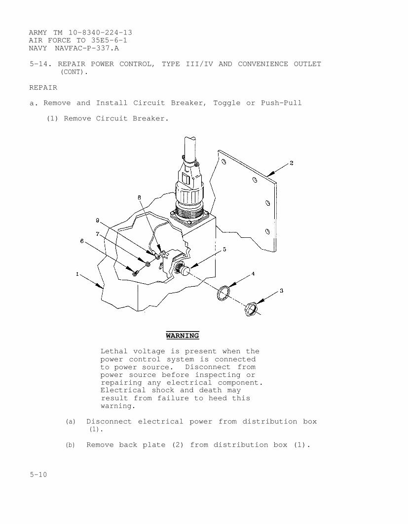
ARMY TM 10-8340-224-13AIR FORCE TO 35E5–6-1NAVY NAVFAC-P-337.A
5-14. REPAIR POWER CONTROL, TYPE III/IV AND CONVENIENCE OUTLET(CONT).
REPAIR
a. Remove and Install Circuit Breaker, Toggle or Push-Pull
(1) Remove Circuit Breaker.
WARNING
Lethal voltage is present when thepower control system is connectedto power source. Disconnect frompower source before inspecting orrepairing any electrical component.Electrical shock and death mayresult from failure to heed thiswarning.
(a) Disconnect electrical power from distribution box(1).
(b) Remove back plate (2) from distribution box (1).
5-10

ARMY TM 10-8340-224-13AIR FORCE TO 35E5-6-1
NAVY NAVFAC–P-337.A
(d) Remove screws (6) and washers (7) from circuitbreaker posts (8) and remove terminal lugs (9).
(2) Install Circuit Breaker.
(a) Install screws (6), washers (7) and terminals lugs(9) on circuit breaker posts (8).
(b) Place circuit breaker (5) in proper position.
(c) Install circuit breaker retaining nut (3) and washer(4).
(d) Install back plate (2).
b. Remove and Install Receptacle Connector with Gasket from PowerControl/Convenience Outlet
(1) Remove Receptacle Connector with Gasket.
5-11
ARMY TM 10–8340–224–13AIR FORCE TO 35E5–6–1NAVY NAVFAC–P–337.A
5–14. REPAIR POWER CONTROL, TYPE III/IV AND CONVENIENCE OUTLET(Cont).
WARNING
Lethal voltage is present when the powercontrol system is connected to powersource. Disconnect from power sourcebefore inspecting or repairing anyelectrical component. Electrical shockand death may result from failure toheed this warning.
(a) Disconnect electrical power from distribution box(1).
(b) Remove back plate (2) from distribution box (1)(Distribution box only).
(c) Remove screws (3), receptacle cover (4), gasket (5)and receptacle connector (6).
(d) Remove wires (7).
(2) Install Receptacle Connector with Gasket.
(a) Insert wires (7) into rear of receptacle connector(6).
(b) Install receptacle connector (6), gasket (5),receptacle cover (4) and screws (2).
(c) Install back plate (2) (Distribution box only).
(d) Connect electrical power.
c. Remove and Install Mounting Box Receptacle from PowerControl/Convenience Outlet.
5-12

ARMY TM 10-8340-224-13AIR FORCE TO 35E5-6-1
NAVY NAVFAC-P-337.A
(1) Remove Mounting Box Receptacle.
(a) Remove screws (1), cover (2) and mounting boxreceptacle (3) from distribution box (4) orconvenience outlet (5).
(b) Remove screws (6) separating cover (2) and mountingbox receptacle (3).
(c) Loosen set screws (7) and remove wires (8).
(2) Install Mounting Box Receptacle.
(a)
(b)
(c)
(d)
Install wires (8) and tighten set screws (7).
Assemble mounting box receptacle (3) and cover (2)with screws (6).
Install
Installscrewsoutlet
screws (1) in cover (2).
mounting box receptacle (3), cover (2) and(1) in distribution box (4) or convenience(5).
5-13
ARMY TM 10-8340-224-13AIR FORCE TO 35E5-6-1NAVY NAVFAC-P-337.A
5-15. TEST AND REPAIR LIGHT SET, TYPE I.
This task covers: a.b.c.d.e.f.g.h.i.
Test Ballast AssemblyTest SwitchTest FuseholderRemove and Install Ballast AssemblyRemove and Install Female Cable AssemblyRemove and Install Male Cable AssemblyRemove and Install SwitchRemove and Install FuseholderRemove and Install Handles, Hinges, andLatches
INITIAL SETUP
Tools:
Tool Kit, Common No 1 (Appendix B, Section III, Item 7)Multimeter (Appendix B, Section III, Item 4)Electric Soldering Iron (Appendix B, Section III, Item 8)
Materials/Parts:
Ballast Assembly (TM 10-8340-224-23P, Figure 27, Item 7)Cable Assembly, Female (TM 10-8340-224-23P, Figure 27, Item 27)Cable Assembly, Male (TM 10-8340-224-23P, Figure 27, Item 24)Fuseholder (TM 10-8340-224-23P, Figure 27, Item 10,36)Switch (TM 10-8340-224-23P, Figure 27, Item 9)Insulation Sleeving (Appendix E, Item 7)Tape, Electrical Insulation (Appendix E, Item 15)Handle (TM 10-8340-224-23P, Figure 27, Item 4)Hinge (TM 10-8340-224-23P, Figure 27, Item 5)Latch (TM 10-8340-224-23P, Figure 27, Item 3)
5-14
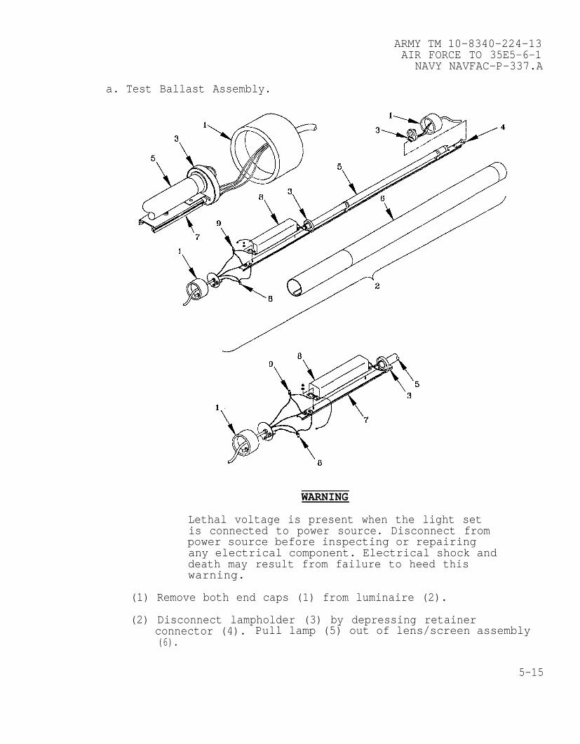
ARMY TM 10-8340-224-13AIR FORCE TO 35E5-6-1
NAVY NAVFAC-P-337.A
a. Test Ballast Assembly.
WARNING
Lethal voltage is present when the light setis connected to power source. Disconnect frompower source before inspecting or repairingany electrical component. Electrical shock anddeath may result from failure to heed thiswarning.
(1) Remove both end caps (1) from luminaire (2).
(2) Disconnect lampholder (3) by depressing retainerconnector (4). Pull lamp (5) out of lens/screen assembly(6).
5-15

ARMY TM 10-8340-224-13AIR FORCE TO 35E5-6-1NAVY NAVFAC-P-337.A
5-15. TEST AND REPAIR LIGHT SET, Type I (CONT).
(3) Slide the extrusion assembly (7) out of the lens/screenassembly (6).
(4) Check condition of wires leading from ballast (8) tolampholders (3) along extrusion assembly (7) for cut,loose, or exposed wires.
(5) Test for continuity at the power input connection (9)(black and white wire splices).
(6) Connect lampholder (3) to extrusion assembly (7).
(7) If continuity exists at the power input connection,test at lampholders (3), (with switch in ONposition).
NOTE
No continuity at the lampholders indicates afaulty ballast, or wiring.
(8) Remove and install ballast assembly in accordance withparagraph 5-15d.
b. Test Switch
5-16
ARMY TM 10-8340-224-13AIR FORCE TO 35E5-6-1
NAVY NAVFAC-P-337.A
WARNING
Lethal voltage is present when the light setis connected to power source. Disconnect frompower source before inspecting or repairingany electrical component. Electrical shock anddeath may result from failure to heed thiswarning.
(1) Complete steps a. (1), through a. (3), to partiallydisassemble luminaire.
(2) Test for continuity at the switch connector posts (withswitch in ON position).
(3) If continuity does not exist, replace switch IAWpara 5-15.g.
c. Test Fuseholder
5-17

ARMY TM 10-8340-224-13AIR FORCE TO 35E5-6-1NAVY NAVFAC-P-337.A
5-15. TEST AND REPAIR LIGHT SET, Type
WARNING
Lethal voltage is present
I (CONT).
when the light setis connected to power source. Disconnect frompower source before inspecting or repairingany electrical component. Electrical shock anddeath may result from failure to heed thiswarning.
(1) Complete steps a. (1), through a. (3), to partiallydisassemble luminaire.
(2) Test for continuity at the fuseholder connection wires(with fuse in place).
(3) If continuity does not exist, replace fuseholder IAW para5-15.h.
d. Remove and Install Ballast Assembly.
5-18
ARMY TM 10–8340–224–13AIR FORCE TO 35E5–6–1
NAVY NAVFAC–P–337.A
(1) Remove Ballast Assembly.
(a)
(b)
(c)
(d)
(e)
(f)
(g)
(h)
WARNING
Lethal voltage is presentconnected to power source.
when the light set isDisconnect from power
source before inspecting or repairing any electricalcomponent. Electrical shock and death may resultfrom failure to heed this warning.
Remove male (1) and female (2) end caps fromluminaire (3).
Disconnect lampholder (4) by depressing retainerconnector (5). Pull lamp (6) out of lens/screenassembly (7).
Slide the extrusion assembly (8) out of thelens/screen assembly (7) from male side only.
Disconnect ring terminal (9) of black wire fromswitch with flat tip screwdriver.
Disconnect white AC wire (10) by removing splice (11)and separating wires.
If leads (12,13) from ballast assembly (14) wires areserviceable, cut the wires at point of exit from theballast assembly (14). If the wires are damaged,remove from lampholders (4) and extrusion assembly(8).
Remove two 1/8” hex nuts (15) and washer (16)securing ballast assembly (14) to extrusion assembly(8).
Lift ballast assembly (14) off extrusion assembly(8).
(2) Install Ballast Assembly.
(a) place ballast assembly (14) onto extrusion assembly(8), and secure with two 1/8” hex nuts (15) andwashers (16).
5-19
ARMY TM 10-8340-224-13AIR FORCE TO 35E5-6-1NAVY NAVFAC-P-337.A
5-15. TEST
(b)
( c )
(d)
(e)
(f)
(g)
(h)
e. Remove and Install Female Cable Assembly.
1. Remove Female Cable Assembly.
AND REPAIR LIGHT SET, Type I (CONT).
NOTE
Ensure that one set of wires ofsame color from ballast assemblygoes to closest lampholder and oneset goes to far lampholder.
If wire leads (12,13) from ballast assembly (14) werefound serviceable, remove 1/4” of insulation from theends of the wires. Solder the wires on the ballastassembly (14) to wires (12,13) on the extrusionassembly (8). Apply insulation tape after the solderpoint cools.
If wire leads (12,13) from ballast assembly (14) wereremoved from the extrusion assembly (8) entirely,install wires supplied with ballast assembly (14)onto extrusion assembly (8) and lampholders (4).
Connect AC (white) wire (10) to AC input connectionand install splice (10).
Connect black wire ring terminal (9) to switch.
Ensure that extrusion assembly (8) aligns with trackin lens/screen assembly (7) and ballast assembly (14)is covered by solid portion. Slide extrusionassembly (8) into lens/screen assembly (7).
Install male end cap assembly (1) on luminaire (3).Install lamp (6).
Install lampholder (4) and female end cap (2) ontoluminaire (3).
5-20

ARMY TM 10-8340-224–13AIR FORCE TO 35E5–6–1
NAVY NAVFAC–P–337.A
(a) Remove end cap (1) on female power cord (2) fromluminaire (3).
(b) Remove lampholder (4) by depressing retainerconnector (5).
(c) Cut female power cord (2) wires from lampholder (4)and pull power cord (2) out of end cap (1).
(2) Install Female Cable Assembly.
(a)
(b)
(c)
(d)
(e)
Insert loose wire end of new female power cord (2)through end cap (1) so that approximately threeinches of the cord are inside the end cap (1).
Remove outer insulation from power cord (2) on insideof end cap (1), and approximately 1/2” fromindividual wires.
Solder power cord (2) wires to lampholder (4) wires.
Install lampholder (4).
Install end cap (1) onto luminaire (3).
5-21

ARMY TM 10-8340-224-13AIR FORCE TO 35E5–6-1NAVY NAVFAC–P–337.A
5-15. TEST AND REPAIR LIGHT SET, Type I (CONT).
f. Remove and Install Male Cable Assembly.
(1) Remove Male Cable Assembly.
(a)
(b)
(c)
(d)
(e)
(f)
(g)
Remove fuse cap (1) and fuse (2).
Remove molded male and female end caps (3,4) fromluminaire (5).
Disconnect lampholder (6) by depressing retainerconnector (7).
Pull the lens/screen (8) off the extrusion assembly(9) to expose the ballast (10).
Remove splices (11) and disconnect black (12) andwhite (13) wires of the male power cord (14).
Disconnect the male power cord ground wire (15) fromthe ground post (16).
Pull male power cord (14) out of the molded end cap(3) and bushing (17).
5-22

ARMY TM 10–8340–224–13AIR FORCE TO 35E5–6–1
NAVY NAVFAC–P–337.A
(2) Install Male Cable Assembly.
(a) Push male power cord (14) through the male molded endcap (3) and bushing (17).
(b) Connect black (12) and white (13) wires of the malepower cord (14) and re–install splices (11).
(c) Connect the male power cord ground wire (15) to theground post (16).
(d) Install molded end cap (3) of male power cord (14)over luminaire (5).
(e) Install fuse cap (1) and fuse (2).
(f) Install lampholder (6), and end cap (4) of femalepower cord (18) over luminaire (5).
g. Remove and Install Switch.
(1) Remove Switch.
5-23
ARMY TM 10–8340-224-13AIR FORCE TO 35E5–6–1NAVY NAVFAC–P–337.A
5-15. TEST AND REPAIR LIGHT SET, Type I (CONT).
(a) Remove fuse cap and fuse.
(b) Remove molded male (1) and female (2) end caps fromluminaire (3).
(c) Disconnect lampholder (4) by pressing retainer (5).
(d) Pull lens/screen assembly (6) off the extrusionassembly (7) to expose the ballast (8).
(e) Separate bracket (9) from male end cap (1).
(f) Remove ring terminals (10) from rear of switch (11).
(g) Unscrew switch seal (12) and remove switch (11) andpaper insulation (13) from the rear of the bracket(9).
(2) Install Switch.
(a) Insert new switch (11)into cutout in bracket
(b) Screw switch seal (12)
(c) Connect ring terminals
through paper(9).
onto threaded
insulator (13)
toggle sleeve.
(10) to switch (11).
(d) Install bracket (9) into male end cap (1).
(e) Slide extrusion assembly (7) into lens/screenassembly (6).
(f) Install lampholders (4).
(g) Install male (1) and female (2) end caps overluminaire (3).
h. Remove and Install Fuse Cap and Fuseholder.
(1) Remove Fuseholder.
(a) Remove molded male (1) and female (2) end caps fromluminaire (3).
(b) Disconnect lampholder (4) by pressing retainer (5).
(c) Pull lens/screen assembly (6) off the extrusionassembly (7) to expose the ballast (8).
5-24
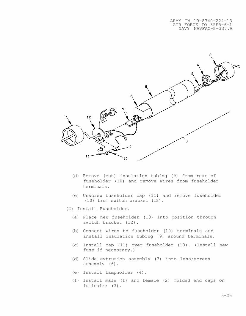
ARMY TM 10–8340–224–13AIR FORCE TO 35E5-6–1
NAVY NAVFAC–P–337.A
(d) Remove (cut) insulation tubing (9) from rear offuseholder (10) and remove wires from fuseholderterminals.
(e) Unscrew fuseholder cap (11) and remove fuseholder(10) from switch bracket (12).
(2) Install Fuseholder.
(a) Place new fuseholder (10) into position throughswitch bracket (12).
(b) Connect wires to fuseholder (10) terminals andinstall insulation tubing (9) around terminals.
(c) Install cap (11) over fuseholder (10). (Install newfuse if necessary.)
(d) Slide extrusion assembly (7) into lens/screenassembly (6).
(e) Install lampholder (4).
(f) Install male (1) and female (2) molded end caps onluminaire (3).
5-25

ARMY TM 10–8340–224-13AIR FORCE TO 35E5–6–1NAVY NAVFAC–P–337.A
5-15. TEST AND REPAIR LIGHT SET, Type I (CONT).
i. Remove and Install Handles, Hinges and Latches.
(1) Remove Handles, Hinges, and Latches.
Remove a handle, hinge or latch from the storagecontainer by removing the rivets as described in TC9-510.
(2) Install Handles, Hinges, and Latches.
Align new handle, hinge or latch with holes in case andinstall rivets as described in TC 9–510.
5-26
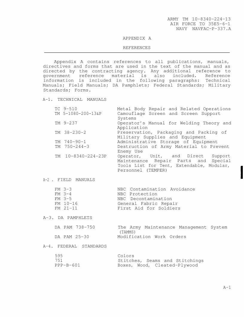
ARMY TM 10-8340–224-13AIR FORCE TO 35E5–6-1
NAVY NAVFAC-P-337.A
APPENDIX A
REFERENCES
Appendix A contains references to all publications, manuals,directives and forms that are used in the text of the manual and asdirected by the contracting agency. Any additional reference togovernment reference material is also included. Referenceinformation is included in the following paragraphs: TechnicalManuals; Field Manuals; DA Pamphlets; Federal Standards; MilitaryStandards; Forms.
A-1. TECHNICAL MANUALS
TC 9-510TM 5-1080–200-13&P
TM 9–237
TM 38-230–2
TM 740-90-1TM 750-244-3
TM 10-8340-224–23P
A-2 . FIELD MANUALS
FM 3-3FM 3–4FM 3-5FM 10-16FM 21-11
A-3. DA PAMPHLETS
DA PAM 738–750
DA PAM 25-30
A–4. FEDERAL STANDARDS
595751PPP-B-601
Metal Body Repair and Related OperationsCamouflage Screen and Screen SupportSystemsOperator’s Manual for Welding Theory andApplicationPreservation, Packaging and Packing ofMilitary Supplies and EquipmentAdministrative Storage of EquipmentDestruction of Army Material to PreventEnemy UseOperator, Unit, and Direct SupportMaintenance Repair Parts and SpecialTools List for Tent, Extendable, Modular,Personnel (TEMPER)
NBC Contamination AvoidanceNBC ProtectionNBC DecontaminationGeneral Fabric RepairFirst Aid for Soldiers
The Army Maintenance Management System(TAMMS)Modification Work Orders
ColorsStitches, Seams and StitchingsBoxes, Wood, Cleated-Plywood
A-1
ARMY TM 10-8340-224-13AIR FORCE TO 35E5-6-1NAVY NAVFAC-P-337.A
A-5 MILITARY STANDARDS
147704731
A-6. FORMS
DD Form 6DA Form 2028-2
DA Form 2404
DA Form 2408-16DA Form 2410
SF 361SF 362
SF 368
Palletizing Unit LoadsTreatment and Painting of MaterialQuality of Wood Members for Containers andPallets
Packaging Improvement ReportRecommended Changes to EquipmentTechnical PublicationsEquipment Inspection and MaintenanceWorksheetAircraft Component Historical RecordComponent Removal and Repair/OverhaulRecordDiscrepancy in Shipment ReportReport of Packaging and HandlingDeficienciesQuality Deficiency Report
A-2

ARMY TM 10-8340-224-13AIR FORCE TO 35E5–6-1
NAVY NAVFAC-P-337.A
APPENDIX B
MAINTENANCE ALLOCATION CHART
Section I. Introduction
B-1. GENERAL.
a. This section provides a general explanation of allmaintenance and repair functions authorized at variousmaintenance categories.
b. The Maintenance Allocation Chart (MAC) in section IIdesignates overall authority and responsibility for theperformance of maintenance functions on the identified end itemor component. The application of the maintenance functions to theend item or component will be consistent with the capacities andcapabilities of the designated maintenance categories.
c. Section III lists the tools and test equipment (bothspecial tools and common tool sets) required for each maintenancefunction as referenced from section II.
d. Section IV contains supplemental instructions andexplanatory notes for a particular maintenance function.
B-2. MAINTENANCE FUNCTIONS. Maintenance functions will be limitedto and defined as follows:
a. Inspect. To determine the serviceability of an item bycomparing its physical, mechanical and/or electricalcharacteristics with established standards through examination.
b. Test. To verify serviceability and to detect incipientfailure by measuring the mechanical or electrical characteristicsof an item and comparing those characteristics with prescribedstandards.
c. Service. Operations required periodically to keep an itemin proper operational condition, i.e., to clean (decontaminate),to preserve, to drain, to paint, or to replenish fuel,lubricants, hydraulic fluids, or compressed air supplies.
d. Adjust. To maintain, within prescribed limits, by bringinginto proper or exact position, or by setting the operatingcharacteristics to the specified parameters.
e. Align. To adjust specified variable elements of an item tobring about optimum or desired performance.
B-1

ARMY TM 10-8340-224-13AIR FORCE TO 35E5-6-1NAVY NAVFAC-P-337.A
B-2 MAINTENANCE FUNCTIONS (CONT)
f. Calibrate. To determine and cause corrections to be madeor to be adjusted on instruments or test measuring and diagnosticequipments used in precision measurement. Consists of comparisonsof two instruments, one of which is a certified standard of knownaccuracy, to detect and adjust any discrepancy in the accuracy ofthe instrument being compared.
g. Remove/Install . The act of emplacing, seating, or fixinginto position an item, part, module (component or assembly) in amanner to allow the proper functioning of the equipment orsystem.
h. Replace. The act of substituting a serviceable like typepart, subassembly, or module (component or assembly) for anunserviceable counterpart.
i. Repair. The application of maintenance services (inspect,test, service, adjust, aline, calibrate, replace) or othermaintenance actions (welding, grinding, riveting, straightening,facing, remachining, or resurfacing) to restore serviceability toan item by correcting specific damage, fault, malfunction, orfailure in a part, subassembly, module (component or assembly),end item, or system.
j. Overhaul. The maintenance effort (service/action)necessary to restore an item to a completelyserviceable/operational condition as prescribed by maintenancestandards (i.e., DMWR) in appropriate technical publications.Overhaul is normally the highest degree of maintenance performedby the Army. Overhaul does not normally return an item to likenew condition.
k. Rebuild. Consists of those services/actions necessary forthe restoration of unserviceable equipment to a like newcondition in accordance with original manufacturing standards.Rebuild is the highest degree of material maintenance applied toArmy equipment. The rebuild operation includes the act ofreturning to zero those age measurements (hours, miles, etc.)considered in classifying Army equipment/components.
B-3. COLUMN ENTRIES
a. Column 1 - Group Number. Column 1 lists group numbers, thepurpose of which is to identify components, assemblies,subassemblies, and modules with the next higher assembly.
b. Column 2 - Component/Assembly. Column 2 contains the nounnames of components, assemblies, subassemblies, and modules forwhich maintenance is authorized.
B-2
ARMY TM 10-8340-224-13AIR FORCE TO 35E5-6-1
NAVY NAVFAC-P-337.A
c. Column 3 - Maintenance Functions. Column 3 lists thefunctions to be performed on the item listed in column 2. Whenitems are listed without maintenance functions, it is solely forthe purpose of having the group number in the MAC and RPSTLcoincide.
d. Column 4 - Maintenance Cateqory. Column 4 specifies, bythe listing of “work time” figures in the appropriatesubcolumn(s), the lowest level of maintenance authorized toperform the function listed in column 3. This figure representsthe active time required to perform that maintenance function atthe indicated category maintenance. If the number or complexityof the tasks within the listed maintenance function vary atdifferent maintenance categories, appropriate “work time” figureswill be shown for each category. The number of task-hoursspecified by the “work time” figure represents the average timerequired to restore an item (assembly, subassembly, component,module, end item or system) to a serviceable condition undertypical field operating conditions. This time includespreparation time, troubleshooting time, and qualityassurance/quality control time in addition to the time requiredto perform the specific tasks identified for the maintenancefunctions authorized in the maintenance allocation chart.Subcolumns of column 4 are as follows:
C Operator/Crew
O Unit
F Direct Support
H General Support
D Depot
e. Column 5 - Tools and Equipment. Column 5 specifies bycode, those common tool sets (not individual tools) and special-tools, test, and support equipment required to perform thedesignated function.
f. Column 6 - Remarks. When applicable, this column containsa letter code, in alphabetical order, which is keyed to theremarks contained in Section IV.
B-4 . TOOL AND TEST EQUIPMENT REQUIREMENTS (Sect. III)
a. Tool or Test Equipment Reference Code. The numbers in thiscolumn coincide with the numbers used in the tools and equipmentcolumn of the MAC. The numbers indicate the applicable tool ortest equipment for the maintenance functions.
B-3
ARMY TM 10-8340-224-13AIR FORCE TO 35E5-6-1NAVY NAVFAC-P-337.A
B-4. TOOL AND TEST EQUIPMENT REQUIREMENTS (Sect. III) (CONT)
b. Maintenance Caterory. The codes in this column indicatethe maintenance category allocated the tool or test equipment.
c. Nomenclature. This column lists the noun name andnomenclature of the tools and test equipment required to performthe maintenance functions.
d. National Stock Number. This column lists the National/Natostock number of the specific tool or test equipment.
e. Tool Number. This column lists the manufacturer’s partnumber of the tool followed by the Federalmanufacturers (5-digit) in parentheses.
B-5. REMARKS. (Sect. IV)
a. Reference Code. This code refers toin section II, column 6.
Supply Code for
the appropriate item
b. Remarks. This column provides the required explanatoryinformation necessary to clarify items appearing in section II.
B-4

ARMY TM 10-8340-224-13AIR FORCE TO 35E5-6-1
NAVY NAVFAC-P-357.A
(1)GROUP
NUMBER
00
01
0101
0102
0103
0104
0105
0106
0107
0108
0109
0110
0111
Section II. MAINTENANCE ALLOCATION CHART
(2)coMPoNENT/
ASSEMBLY
Tent, Extendable, Modular
Tent Sections (Fabric)
End Section
Door Section
Window Section
Fly
End Section Liner
lhterrnediate Section her
Floor
Vestibule
Plenom
Modesty Curtain
Partition
(3)MAINT
FUNCTION
InspectServiceReplaceRepair
ReplaeeRepair
ReplaceRepair
ReplaceRepair
ReplaceRepair
ReplaceRepair
ReplaceRepair
ReplaceRepair
ReplaceRepair
ReplaceRepair
ReplaceRepair
ReplaceRepair
c
.5s
(4)MAINTENANCE
CATEGORY—o
—
.5
.5
.1
.5
.1.5
.1
.5
.1
.5
.1
.5
.1
.5
.1
.5
.1
.5
.1
.5
.1
.5
.1
.5
—F
—
1.0
.5
.5
.5
.5
.5
.5
.5
.5
.5
.5
.5
D
(5)TOOLS &
TESTEQUIPT
2
1,5
1,5
1,5
1,5
1,5
1,5
1,5
1,5
1,5
I ,5
1,5
1,5
(6)RIZMARKS
A
A
A
A
A
A
A
A
A
A
A
A
B-5

ARMY TM 1 0 - 8 3 4 0 - 2 2 4 - 1 3AIR FORCE TO 35E5-6-1NAVY NAVFAC-P-337.A
Section II. MAINTENANCE ALLOCATION CHART
(1) (2) (3) (4) (5)GROUP
(6)coMPoNmT/ MAINT MAINTENANCE TOOLS &
NUMBERREMARKs
ASSEMBLY FUNCTION CATEGORY TESTEQLJIPT
c o F H D
02 Frame Sections Inspect .5Service .5Replace .5Repair ..5 .5 3,6,7
0201 Arch Assembly Replace .1Repair .2 .5 3,6,7
0202 Header Assembly Replace .1Repair .2 .5 3,6,7
0203 Porlitt Assembly Replace .1Repair .5 .5 3,6,7
0204 Eave Extender Assembly Replace .1Repair .2 .5 3,6,7
0205 Ridge Extender Assembly Replace .1Repair .2 .5 3,6,7
0206 Door Sill Assembly Replace .1Repair .5 .5 3,6,7
02a7 Vestibule Frsme Assembly Replace .1Repair .2 .5 3,6,7
0208 Fmme Sections Cover Assembly Replace .1Repair .2 .5 1,5 A
03 Bump Through Dam Inspect .2SewiceReplace .3Repair 1.0 1.0 3,6,7
04 Power Control Inspect .5ServiceReplace .2 !Repair .3 2.0 3,7
0401 Power Control Type 111/120 V Replace .2Repair .3 2.0 3,7
0402 Power Control TW IVf208 V Replace .2Repair .3 2.0 3,7
0403 Convenience outlet Type III Replace .2Repair .3 Lo 3,7
B-6
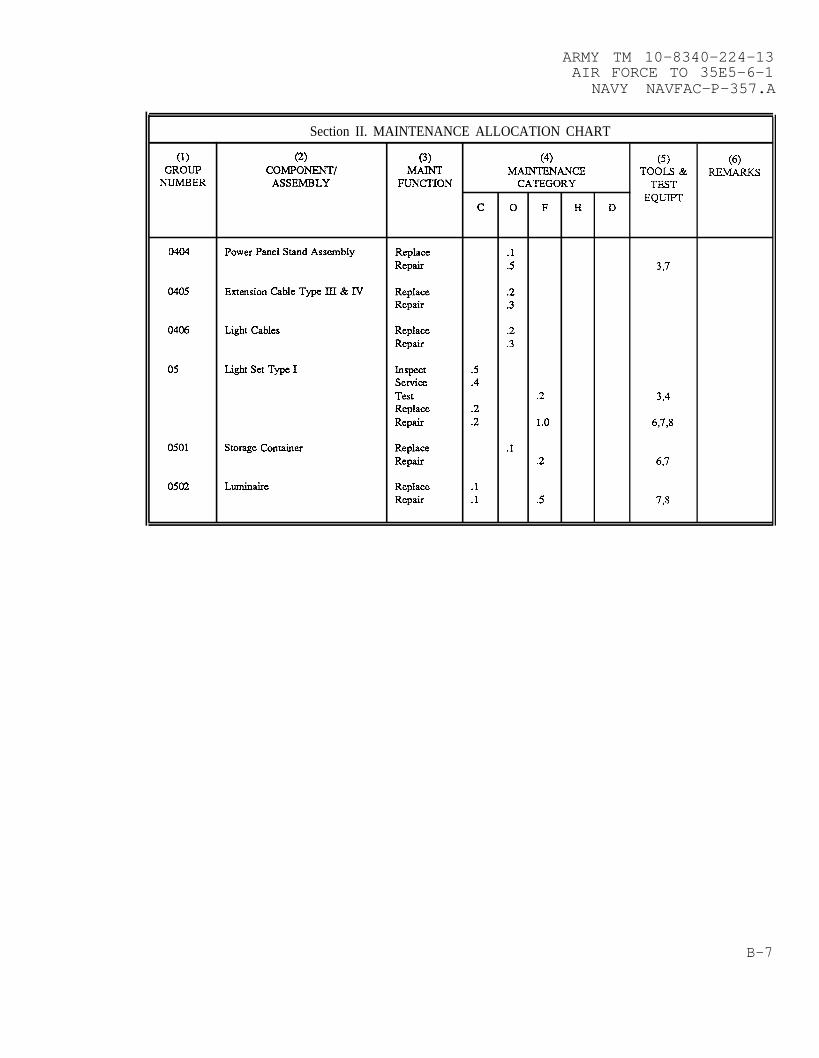
ARMY TM 10–8340-224-13AIR FORCE TO 35E5-6-1
NAVY NAVFAC-P-357.A
Section II. MAINTENANCE ALLOCATION CHART
(1) (2) (3) (4) (5) (6)GROUP coMPoNENT/ MAINT MAINTENANCE TOOLS & RE.MARKS
NUMBER ASSEMBLY FUNCTION CATEGORY TESTEQUIPT
c o F H D
0404 Power Panel Stand Assembly Replace .1Repair .5 3,7
0405 Extension Cable Type KU& IV Replace .2Repair .3
0406 Light Cables Replace .2Repair .3
05 Light Set Type I Inspect .5Servim .4Test .2 3,4Replace .2Repair .2 1.0 6,7,8
0501 Storage Container Replace .1Repair .2 6,7
0502 L-aim Replace .1Repair .1 .5 7,s
B-7
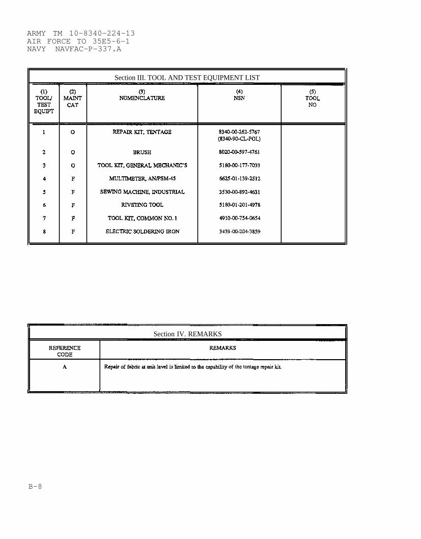
ARMY TM 10-8340-224-13AIR FORCE TO 35E5-6-1NAVY NAVFAC-P-337.A
Section III. TOOL AND TEST EQUIPMENT LIST
(1) (2) (3) (4) (5)TOOL/ MAINT NOMENCLATURE NSN TOOLTEST CAT NO
EQUIPT
—.~
1 0 REPAIRIUT,’TENTAGE 8340-00-262-5767(8340-90-CL-POL)
2 0 BRUSH 8020-00-597-4761
3 0 TOOL KIT, GENERAL MECHANIC’S 5180-00-177-7033
4 F MULTIMETE~ AIWSM-45 662S-01-139-2512
5 F SEWING MACHINE, INDUSTRIAL 3530-00-892-4631
6 F RIVETING TOOL 5180-01-201-4978
7 F TOOL IUT, COMMON NO, 1 4910-00-754-0654
8 F ELECTRIC SOLDERING IRON 3439-00-204-3859
Section IV. REMARKS
REFERENCE REMARKSCODE
A Repair Of fabric at unit level is limited to the capability of the tentage repair kk
B-8

ARMY TM 10-8340-224-13AIR FORCE TO 35E5-6-1
NAVY NAVFAC-P-337.A
APPENDIX C
COMPONENTS OF END ITEM AND BASIC ISSUE ITEM LISTS
SECTION I. INTRODUCTION
C-1. SCOPE. This appendix lists end items and basic issue items forthe Tent, Extendable, Modular, Personnel (TEMPER) to help youinventory items required for safe and efficient operation.
C-2. GENERAL. The Components of End Items and Basic IssueLists are divided into the following sections:
a. Section II. Components of End Item List. This listing
Items
is forinformational purposes only, and does not authorize replacements.The Components of End Item list contains items that must be withthe system whenever it is issued or transferred between propertyaccounts. However, these items are removed and separately packagedfor transportation or shipment. The end items are illustrated tohelp identify them.
b. Section III. Basic Issue Item List. This listing is theminimum number of items needed to operate and perform emergencyrepairs on the TEMPER. Although Basic Issue Items are shipped andpackaged separately, they must be with the TEMPER during operationand whenever it is transferred between property accounts. The hard-to identify items are illustrated. This manual is your authority torequest/requisition replacement Basic Issue Items, based onTOE/MTOE authorization of the end item.
C-3. EXPLANATION OF COLUMNS. The following provides an explanationof columns found in the Components of End Item and Basic Issue ItemTable Listing:
a. Column (1) - Illustration Number (Illus Number) Indicatesthe number of the illustration in which the item is shown.
b. Column (2) - National Stock Number. Indicates the Nationalstock number assigned to the item. It will be used forrequisitioning purposes.
c. Column (3) - Description. Indicates the Federal item nameand, if required, a minimum description to identify and locate theitem. The last line for each item indicates the Federal Supply Codefor Manufacturer (CAGEC) in parentheses followed by the partnumber. If the item you need is not the same for different modelsof the equipment, a Usable On Code will appear on the right side ofthe description column on the same line as the part number. Thesecodes are identified below:
C-1

ARMY TM 10-8340-224-13AIR FORCE TO 35E5-6-1NAVY NAVFAC-P-337.A
C-3. EXPLANATION OF COLUMNS (CONT)
CODE
FDVFDWFDXFDYFDZFEAFEBFECFEDFEEFEFFEGFEHFEJFEKFEL
FEMFENFEPFEQFERFESFETFEUFEVFEWFEXFEYFEZFFAFFBFFC
USED ON
Type I, GreenType II, GreenType III, GreenType IV, GreenType V, GreenType VI, GreenType VII, GreenType VIII, GreenType IX, GreenType X, GreenType XI, GreenType XII, GreenType XIII, GreenType XIV, GreenType XV, GreenType XVI, Green
Type I, TanType II, TanType III, TanType IV, TanType V, TanType VI, TanType VII, TanType VIII, TanType IX, TanType X, TanType XI, TanType XII, TanType XIII, TanType XIV, TanType XV, TanType XVI, Tan
d. Column (4) - Unit of Measure (U/M). Indicates the measureused in performing the actual operational/maintenance function. Atwo letter abbreviation (e.g., EA, in, PR) is used as the measure.
e. Column (5) - Quantity required (Qty rqr.) Indicates how manyof an item are authorized to be used with/on the equipment.
C-2
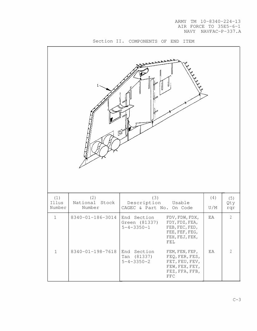
ARMY TM 10-8340-224-13AIR FORCE TO 35E5-6-1
NAVY NAVFAC-P-337.A
Section II. COMPONENTS OF END ITEM
(1)IllusNumber
1
1
(2)National Stock
Number
8340-01-186-3014
8340-01-198-7618
(3)Description Usable
CAGEC & Part No. On Code
End Section FDV,FDW,FDX,Green (81337) FDY,FDZ,FEA,5-4-3350-1 FEB,FEC,FED,
FEE,FEF,FEG,FEH,FEJ,FEK,FEL
End Section FEM,FEN,FEP,Tan (81337) FEQ,FER,FES,5-4-3350-2 FET,FEU,FEV,
FEW,FEX,FEY,FEZ,FFA,FFB,FFC
(4)
U/M
EA
EA
(5)Qtyrqr
2
2
C-3

ARMY TM 10-8340-224-13AIR FORCE TO 35E5-6-1NAVY NAVFAC-P-337.A
Section II. COMPONENTS OF END ITEM (CONT)
(1) (2) (3) (4) (5)Illus National Stock Description Usable QtyNumber Number CAGEC & Part No. On Code U/M rqr
2 8340-01-186-3020 Door Section FDV EA 3(Temperate) FDW,FDZ,FEA, EA 1Green (81337) FEF5-4-3362-1
2 8340-01-213-6004 Door Section FEP EA 3(Temperate) FEU,FEV,FEW EA 2Tan (81337) FEN,FER,FES, EA 15-4-3362-2 FEX
3 8340-01-186-3015 Door Section FEK EA 3(Desert/Tropical) FEH, FEL EA 2Green (81337) FEB, FEJ EA 15-4-3351-1
3 8340-01-213-6003 Door Section FEM EA 4(Desert/Tropical) FFB EA 3Tan (81337) FEZ, FFC EA 25-4-3351-2 FET,FEY,FFA EA 1
C-4

ARMY TM 10-8340-224-13AIR FORCE TO 35E5-6-1
NAVY NAVFAC-P-337.A
Section II. COMPONENTS OF END ITEM (CONT)
(1) (2) (3)Description
(4) (5)Illus National Stock Usable QtyNumber Number CAGEC & Part No. On Code U/M rqr
4 8340-01-186-3021 Window Section FEC EA 10(Temperate) FED EA 8Green (81337) FDW EA 75-4-3363-1 FDX,FEE EA 6
FDV EA 5FDY EA 4
FEF,FEK EA 3FEG,FEL EA 2
FDZ,FEA,FEB EA 1
4 8340-01-198-7619 Window Section FEU EA 10(Temperate) FEV EA 8Tan (81337) FEN EA 75-4-3363-2 FEP,FEW EA 6
FEM EA 5FEQ EA 4
FEX,FFB EA 3FEY,FFC EA 2
FER,FES,FET EA 1
C-5
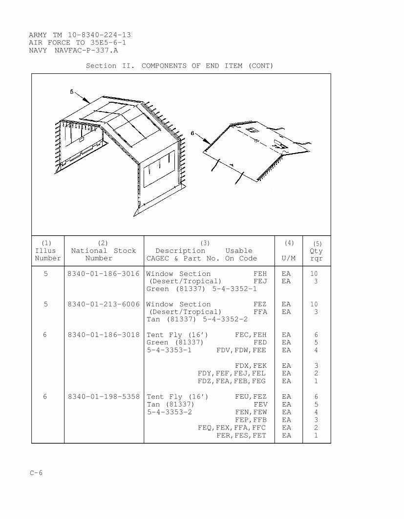
ARMY TM 10-8340-224-13AIR FORCE TO 35E5-6-1NAVY NAVFAC-P-337.A
Section II. COMPONENTS OF END ITEM (CONT)
(1) (2) (3) (4) (5)Illus National Stock Description Usable QtyNumber Number CAGEC & Part No. On Code U/M rqr
5 8340–01-186-3016 Window Section FEH EA 10(Desert/Tropical) FEJ EA 3Green (81337) 5-4-3352-1
5 8340-01-213-6006 Window Section FEZ EA 10(Desert/Tropical) FFA EA 3Tan (81337) 5-4-3352-2
6 8340-01-186-3018 Tent Fly (16’) FEC,FEH EA 6Green (81337) FED EA 55-4-3353-1 FDV,FDW,FEE EA 4
FDX,FEK EA 3FDY,FEF,FEJ,FEL EA 2FDZ,FEA,FEB,FEG EA 1
6 8340-01-198-5358 Tent Fly (16’) FEU,FEZ EA 6Tan (81337) FEV EA 55-4-3353-2 FEN,FEW EA 4
FEP,FFB EA 3FEQ,FEX,FFA,FFC EA 2
FER,FES,FET EA 1
C-6

ARMY TM 10-8340-224-13AIR FORCE TO 35E5-6-1
NAVY NAVFAC-P-337.A
Section II. COMPONENTS OF END ITEM (CONT)
(1) (2) (3) (4) (5)Illus National Stock Description Usable QtyNumber Number CAGEC & Part No. On Code U/M rqr
7 8340-01-186-3017 Tent Fly (8’) EA VGreen (81337)5-4-8486-1(USAF Only)
7 8340-01-213-9565 Tent Fly (8’) EA VTan (81337)5-4-8486-2(USAF Only)
8 8340-01-186-3022 End Section FDV,FDW,FDX, EA 2Liner, Natural FDY,FDZ,FEA,(Temperate) FEC,FED,FEE,(81337) FEF,FEG,FEM,5-4-3364 FEN,FEP,FEQ,
FER,FES,FEU,FEV,FEW,FEX,FEY
FEB,FET EA 1
C-7

ARMY TM 10-8340-224-13AIR FORCE TO 35E5-6-1NAVY NAVFAC-P-337.A
Section II. COMPONENTS OF END ITEM (CONT)
(1) (2) (3) (4) (5)Illus National Stock Description Usable QtyNumber Number CAGEC & Part No. On Code U/M rqr
9 8340-01-213-9566 End Section FEH,FEJ, EA 2Liner, Natural FEK,FEL,(Desert/Tropical) FEZ,FFA,5-4-3365 FFB,FFC
10 8340-01-186-3023 Intermediate FEC,FEU EA 10Liner, Natural FED,FEV EA 8(Temperate) FDV,FDW,FEE, EA 6(81337) FEM,FEN,FEW5-4-3366 FDX,FEP EA 4
FEK,FFB EA 3FDY,FEF,FEL, EA 2FEQ,FEX,FFC
C-8

ARMY TM 10-8340-224-13AIR FORCE TO 35E5-6-1
NAVY NAVFAC-P-337.A
Section II. COMPONENTS OF END ITEM (CONT)
(1) (2) (3) (4) (5)Illus National Stock Description Usable QtyNumber Number CAGEC & Part No. On Code U/M rqr
11 8340-01-211-9636 Intermediate FEH,FEZ EA 10Liner, Natural FEJ,FFA EA 2(Desert/Tropical) FEK,FFB EA 1(81337)5-4-3367
12 8340-01-186-3024 Tent Floor (8’) FEC,FEH,FEU, EA 12Single Ply, FEZGreen (81337) FED,FEV EA 105-4-3368-1 FDV,FDW,FEE EA 8
FEM,FEN,FEWFDY,FEF,FEJ EA 6FDZ,FEA,FEG EA 2FER,FES,FEY
12 8340-01-198-7622 Tent Floor (8’) EA VSingle Ply, Gray (81337)5-4-3368-2(USAF Only)
C-9

ARMY TM 10-8340-224-13AIR FORCE TO 35E5-6-1NAVY NAVFAC-P-337.A
Section II. COMPONENTS OF END ITEM (CONT)
(1) (2) (3)Description
(4) (5)Illus National Stock Usable QtyNumber Number CAGEC & Part No. On Code U/M rqr
13 8340-01-186-3025 Tent Floor (8’) FED,FEV EA 10(Insulated) FDV,FDW,FEE, EA 8Green (81337) FEM,FEN,FEW5-4-3369 FEF,FEJ,FEX, EA 4
FFAFDZ,FEA,FEG, EA 2FER,FES,FEY
14 Tent Floor (24’) EA V(Single Ply) Green(81337) 5-4-3984-1(USAF Only)
14 Tent Floor (24’) EA V(Single Ply) Gray(81337) 5-4-3984-2(USAF Only)
C-10

ARMY TM 10-8340-224-13AIR FORCE TO 35E5-6-1
NAVY NAVFAC-P-337.A
Section II. COMPONENTS OF END ITEM (CONT)
(1)IllusNumber
15
15
(2)National Stock
Number
8340-01-254-5758
(3)Description Usable
CAGEC & Part No. On Code
Tent Floor (40’)(Single Ply) Green(81337) 5-4-3985-1(USAF Only)
Tent Floor (40’)(Single Ply) Gray(81337) 5-4-3985-2(USAF Only)
(4)
U/M
EA
EA
(5)Qtyrqr
V
V
C-11
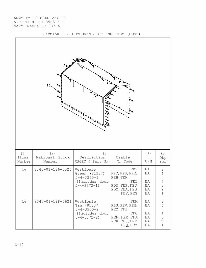
ARMY TM 10-8340-224-13AIR FORCE TO 35E5-6-1NAVY NAVFAC-P-337.A
Section II. COMPONENTS OF END ITEM (CONT)
(1) (2) (3) (4) (5)Illus National Stock Description Usable QtyNumber Number CAGEC & Part No. On Code U/M rqr
16 8340-01-186-3026 Vestibule FDV EA 8Green (81337) FEC,FED,FEE, EA 65-4-3370-1 FEH,FEK(Includes door FEL EA 45-4-3372-1) FDW,FEF,FEJ EA 3
FDZ,FEA,FEB EA 2FDY,FEG EA 1
16 8340-01-198-7621 Vestibule FEM EA 8Tan (81337) FEU,FEV,FEW, EA 65-4-3370-2 FEZ,FFB(Includes door FFC EA 45-4-3372-2) FEN,FEX,FFA EA 3
FER,FES,FET EA 2FEQ,FEY EA 1
C-12

ARMY TM 10-8340-224-13AIR FORCE TO 35E5-6-1
NAVY NAVFAC-P-337.A
Section II. COMPONENTS OF END ITEM (CONT)
(1) (2) (3)Description
(4) (5)Illus National Stock Usable QtyNumber Number CAGEC & Part No. On Code U/M rqr
17 Vestibule Door FDV EA 8Green (81337) FEC,FED,FEE, EA 65-4-3371-1 FEH,FEK
FEL EA 4FDW,FEF,FEJ EA 3FDZ,FEA,FEB EA 2
FDY,FEG EA 1
17 Vestibule Door FEM EA 8Tan (81337) FEU,FEV,FEW, EA 65-4-3371-2 FEZ,FFB
FFC EA 4FEN,FEX,FFA EA 3FER,FES,FET EA 2
FEQ,FEY EA 1
C-13
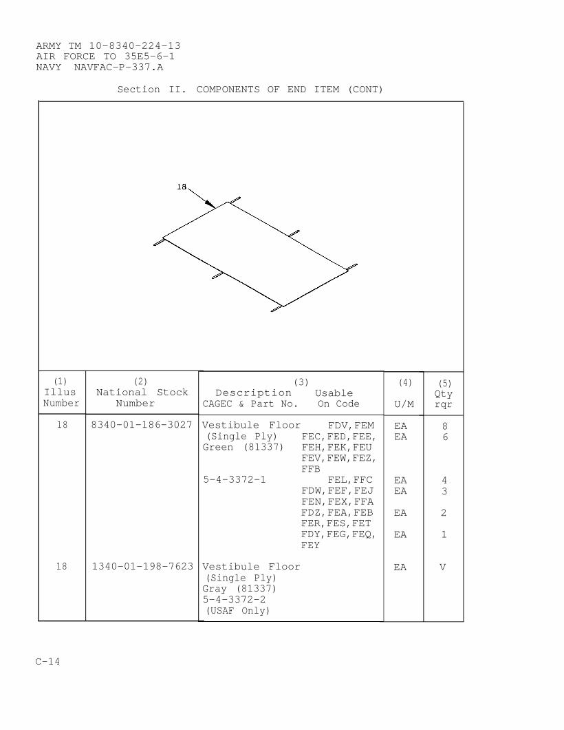
ARMY TM 10-8340-224-13AIR FORCE TO 35E5-6-1NAVY NAVFAC-P-337.A
Section II. COMPONENTS OF END ITEM (CONT)
(1)IllusNumber
18
18
(2)National Stock
Number
8340-01-186-3027
1340-01-198-7623
(3)Description Usable
CAGEC & Part No. On Code
Vestibule Floor FDV,FEM(Single Ply)Green (81337)
5-4-3372-1
FEC,FED,FEE,FEH,FEK,FEUFEV,FEW,FEZ,FFB
FEL,FFCFDW,FEF,FEJFEN,FEX,FFAFDZ,FEA,FEBFER,FES,FETFDY,FEG,FEQ,FEY
Vestibule Floor(Single Ply)Gray (81337)5-4-3372-2(USAF Only)
(4)
U/M
EAEA
EAEA
EA
EA
EA
(5)Qtyrqr
86
43
2
1
V
C-14

ARMY TM 10-8340-224-13AIR FORCE TO 35E5-6-1
NAVY NAVFAC-P-337.A
Section II. COMPONENTS OF END ITEM (CONT)
(1) (2) (3) (4) (5)Illus National Stock Description Usable QtyNumber Number CAGEC & Part No. On Code U/M rqr
19 8340-01-186-3028 Vestibule Floor FDV,FEM EA 8(Insulated) FEC,FED,FEE, EA 6Green (81337) FEH,FEU,FEV,5-4-3373 FEW,FEZ
FDW,FEF,FEJ, EA 3FEN,FEX,FFAFDZ,FEA,FEB, EA 2FER,FES,FET
FEG,FEY EA 1
C-15

ARMY TM 10-8340-224-13AIR FORCE TO 35E5-6-1NAVY NAVFAC-P-337.A
Section II. COMPONENTS OF END ITEM (CONT)
(1)IllusNumber
20
20
(2)National Stock
Number
8340-01-186-3019
8340-01-198-7620
(3)Description Usable
CAGEC & Part No. On Code
Tent Cover FEC,FEHGreen (81337) FDV,FDW5-4-3359-1 FED
FEEFDX,FDZ,FEA,FEKFDY,FEG,FEL
FEB
Tent Cover FEU,FEZTan (81337) FEM,FEN5-4-3359-2 FEV
FEWFEP,FES,FFBFEQ,FEY,FFC
FET,
(4)
U/M
EAEAEAEAEA
EAEA
EAEAEAEAEAEAEA
(5)Qtyrqr
12111083
21
1211108321
C-16
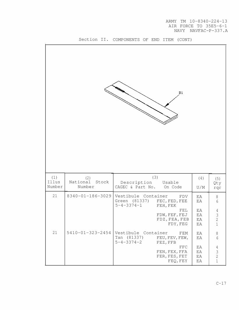
ARMY TM 10-8340-224-13AIR FORCE TO 35E5-6-1
NAVY NAVFAC-P-337.A
Section II. COMPONENTS OF END ITEM (CONT)
(1)IllusNumber
21
21
(2)National Stock
Number
8340-01-186-3029
5410-01-323-2454
(3)Description Usable
CAGEC & Part No. On Code
Vestibule Container FDVGreen (81337) FEC,FED,FEE5-4-3374-1 FEH,FEK
FELFDW,FEF,FEJFDZ,FEA,FEB
FDY,FEG
Vestibule Container FEMTan (81337) FEU,FEV,FEW,5-4-3374-2 FEZ,FFB
FFCFEN,FEX,FFAFER,FES,FET
FEQ,FEY
(4)
U/M
EAEA
EAEAEAEA
EAEA
EAEAEAEA
(5)Qtyrqr
86
4321
86
4321
C-17
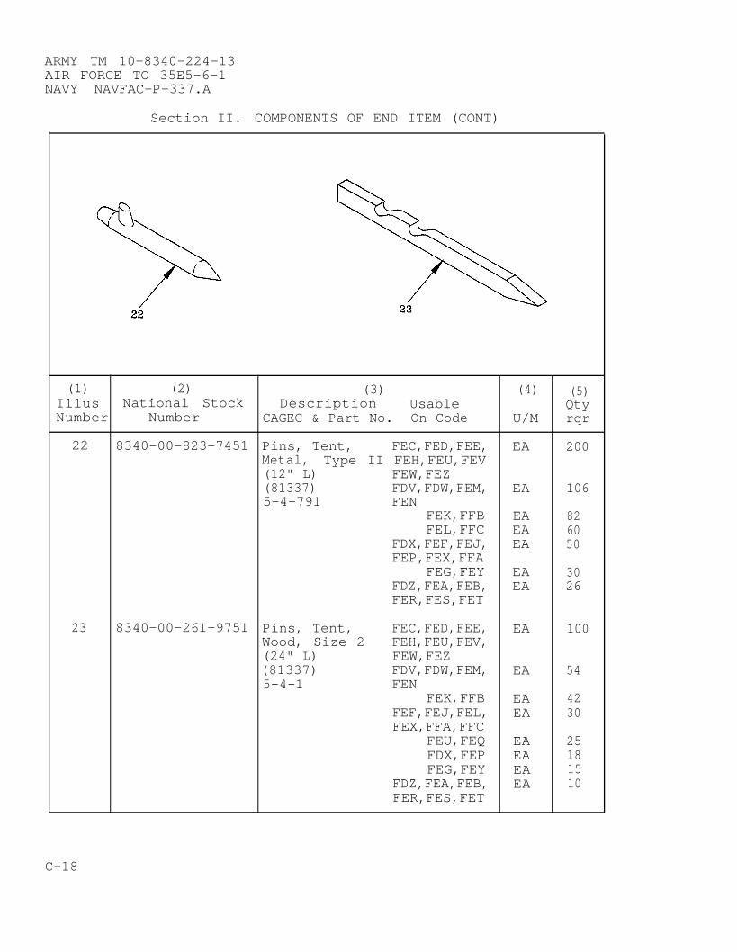
ARMY TM 10-8340-224-13AIR FORCE TO 35E5-6-1NAVY NAVFAC-P-337.A
Section II. COMPONENTS OF END ITEM (CONT)
(1) (2) (3)Description
(4) (5)Illus National Stock Usable QtyNumber Number CAGEC & Part No. On Code U/M rqr
22 8340-00-823-7451 Pins, Tent, FEC,FED,FEE, EA 200Metal, Type II FEH,FEU,FEV(12" L) FEW,FEZ(81337) FDV,FDW,FEM, EA 1065-4-791 FEN
FEK,FFB EA 82FEL,FFC EA 60
FDX,FEF,FEJ, EA 50FEP,FEX,FFA
FEG,FEY EA 30FDZ,FEA,FEB, EA 26FER,FES,FET
23 8340-00-261-9751 Pins, Tent, FEC,FED,FEE, EA 100Wood, Size 2 FEH,FEU,FEV,(24" L) FEW,FEZ(81337) FDV,FDW,FEM, EA 545-4-1 FEN
FEK,FFB EA 42FEF,FEJ,FEL, EA 30FEX,FFA,FFC
FEU,FEQ EA 25FDX,FEP EA 18FEG,FEY EA 15
FDZ,FEA,FEB, EA 10FER,FES,FET
C-18
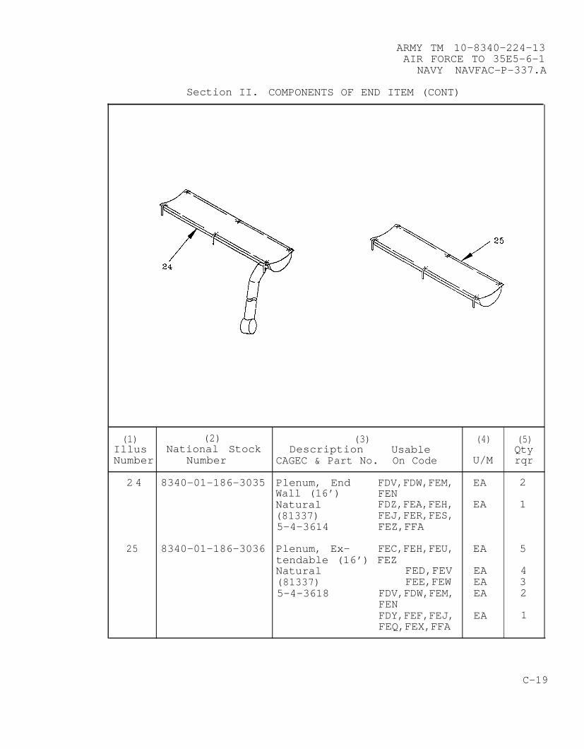
ARMY TM 10-8340-224-13AIR FORCE TO 35E5-6-1
NAVY NAVFAC-P-337.A
Section II. COMPONENTS OF END ITEM (CONT)
(1) (2) (3) (4) (5)Illus National Stock Description Usable QtyNumber Number CAGEC & Part No. On Code U/M rqr
2 4 8340-01-186-3035 Plenum, End FDV,FDW,FEM, EA 2Wall (16’) FENNatural FDZ,FEA,FEH, EA 1(81337) FEJ,FER,FES,5-4-3614 FEZ,FFA
25 8340-01-186-3036 Plenum, Ex- FEC,FEH,FEU, EA 5tendable (16’) FEZNatural FED,FEV EA 4(81337) FEE,FEW EA 35-4-3618 FDV,FDW,FEM, EA 2
FENFDY,FEF,FEJ, EA 1FEQ,FEX,FFA
C-19
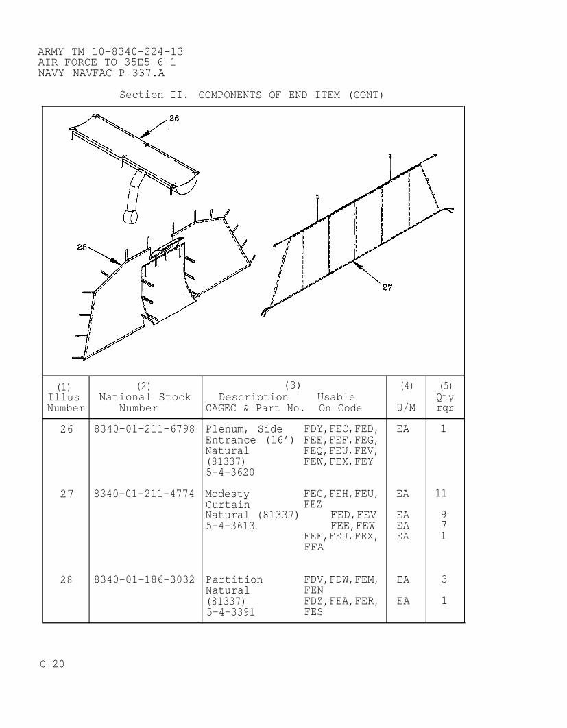
ARMY TM 10-8340-224-13AIR FORCE TO 35E5-6-1NAVY NAVFAC-P-337.A
Section II. COMPONENTS OF END ITEM (CONT)
(1) (2) (3)Description
(4) (5)Illus National Stock Usable QtyNumber Number CAGEC & Part No. On Code U/M rqr
26 8340-01-211-6798 Plenum, Side FDY,FEC,FED, EA 1Entrance (16’) FEE,FEF,FEG,Natural FEQ,FEU,FEV,(81337) FEW,FEX,FEY5-4-3620
27 8340-01-211-4774 Modesty FEC,FEH,FEU, EA 11Curtain FEZNatural (81337) FED,FEV EA 95-4-3613 FEE,FEW EA 7
FEF,FEJ,FEX, EA 1FFA
28 8340-01-186-3032 Partition FDV,FDW,FEM, EA 3Natural FEN(81337) FDZ,FEA,FER, EA 15-4-3391 FES
C-20

ARMY TM 10-8340-224-13AIR FORCE TO 35E5-6-1
NAVY NAVFAC-P-337.A
Section II. COMPONENTS OF END ITEM (CONT)
(1) (2) (3) (4) (5)Illus National Stock Description Usable QtyNumber Number CAGEC & Part No. On Code U/M rqr
29 8340–01-186-3030 Tent Pin FEC,FED,FEH EA 8Container FDV,FDY,FEE, EA 4Green (81337) FEJ,FEK5-4-8487-1 FDX,FEL EA 2
FDZ,FEA,FEB, EA 1FEG
29 Tent Pin FEU,FEV,FEZ EA 8Container FEM,FEN,FEQ, EA 4Tan (81337) FEP,FFC EA 35-4-8487-2 FER,FES,FET, EA 1
FEY
C-21

ARMY TM 10-8340-224-13AIR FORCE TO 35E5-6-1NAVY NAVFAC-P-337.A
Section II. COMPONENTS OF END ITEM (CONT)
(1)IllusNumber
30
31
(2)National Stock
Number
8340-01-240-5854
8340-01-186-3004
(3)Description Usable
CAGEC & Part No. On Code
Arch AssemblySectionalizedGreen (81337)5-4-4006
HeaderAssemblyGreen (81337)5-4-3325
FEC,FEH,FEU,FEZ
FED,FEVFDV,FDW,FEE,FEM,FEN,FEWFDX,FEK,FEP,FFBFDY,FEF,FEJ,FEL,FEQ,FEX,FFA,FFCFDZ,FEA,FEB,FEG,FER,FES,FET,FEY
FEC,FEH,FEU,FEZ
FED,FEVFDV,FDW,FEE,FEM,FEN,FEWFDX,FEK,FEP,FFBFDY,FEF,FEJ,FEL,FEQ,FEX,FFA,FFCFDZ,FEA,FEB,FEG,FER,FES,FET,FEY
(4)
U/M
EA
EAEA
EA
EA
EA
EA
EAEA
EA
EA
EA
(5)Qtyrqr
13
119
7
5
3
13
119
7
5
3
C-22
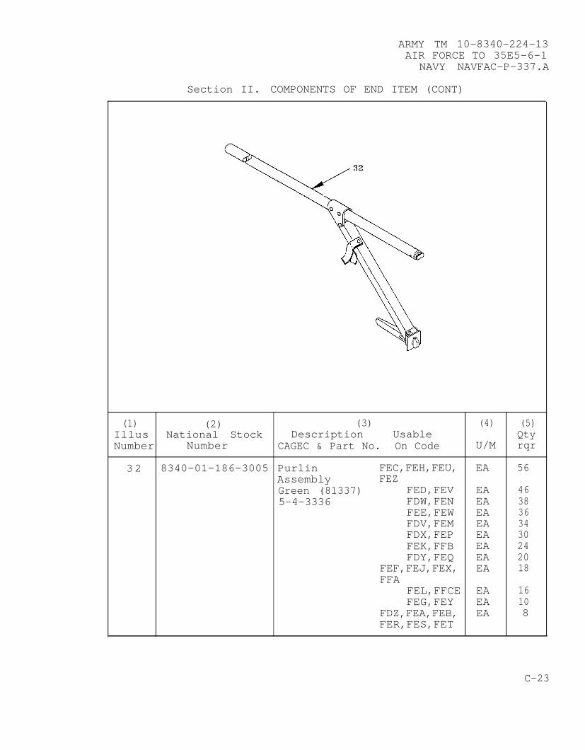
ARMY TM 10-8340-224-13AIR FORCE TO 35E5-6-1
NAVY NAVFAC-P-337.A
Section II. COMPONENTS OF END ITEM (CONT)
(1) (2) (3) (4) (5)Illus National Stock Description Usable QtyNumber Number CAGEC & Part No. On Code U/M rqr
32 8340-01-186-3005 Purlin FEC,FEH,FEU, EA 56Assembly FEZGreen (81337) FED,FEV EA 465-4-3336 FDW,FEN EA 38
FEE,FEW EA 36FDV,FEM EA 34FDX,FEP EA 30FEK,FFB EA 24FDY,FEQ EA 20
FEF,FEJ,FEX, EA 18FFA
FEL,FFCE EA 16FEG,FEY EA 10
FDZ,FEA,FEB, EA 8FER,FES,FET
C-23

ARMY TM 10-8340-224-13AIR FORCE TO 35E5-6-1NAVY NAVFAC-P-337.A
Section II. COMPONENTS OF END ITEM (CONT)
(1) (2) (3) (4) (5)Illus National Stock Description Usable QtyNumber Number CAGEC & Part No. On Code U/M rqr
33 8340-01-186-3009 Eave Extender FEC,FEH,FEU, EA 26Assembly FEZGreen (81337) FED,FEV EA 225-4-3341 FDV,FDW,FEE, EA 18
FEM,FEN,FEWFDX,FEK,FEP, EA 14FFBFDY,FEF,FEJ, EA 10FEL,FEQ,FEX,FFA,FFCFDZ,FEA,FEB, EA 6FEG,FER,FES,FET,FEY
34 8340-01-186-3008 Ridge Extender FEC,FEH,FEU, EA 13Assembly FEZGreen (81337) FED,FEV EA 115-4-3340 FDV,FDW,FEE, EA 9
FEM,FEN,FEWFDX,FEK,FEP, EA 7FFBFDY,FEF,FEJ, EA 5FEL,FEQ,FEX,FFA,FFCFDZ,FEA,FEB, EA 3FEG,FER,FES,FET,FEY
C-24
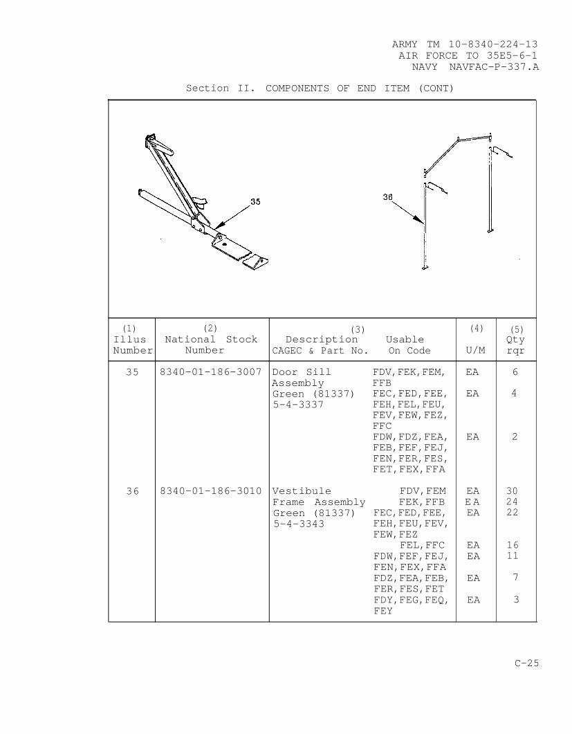
ARMY TM 10-8340-224-13AIR FORCE TO 35E5-6-1
NAVY NAVFAC-P-337.A
Section II. COMPONENTS OF END ITEM (CONT)
(1) (2) (3) (4) (5)Illus National Stock Description Usable QtyNumber Number CAGEC & Part No. On Code U/M rqr
35 8340-01-186-3007 Door Sill FDV,FEK,FEM, EA 6Assembly FFBGreen (81337) FEC,FED,FEE, EA 45-4-3337 FEH,FEL,FEU,
FEV,FEW,FEZ,FFCFDW,FDZ,FEA, EA 2FEB,FEF,FEJ,FEN,FER,FES,FET,FEX,FFA
36 8340-01-186-3010 Vestibule FDV,FEM EA 30Frame Assembly FEK,FFB EA 24Green (81337) FEC,FED,FEE, EA 225-4-3343 FEH,FEU,FEV,
FEW,FEZFEL,FFC EA 16
FDW,FEF,FEJ, EA 11FEN,FEX,FFAFDZ,FEA,FEB, EA 7FER,FES,FETFDY,FEG,FEQ, EA 3FEY
C-25

ARMY TM 10-8340-224-13AIR FORCE TO 35E5-6-1NAVY NAVFAC-P-337.A
Section II. COMPONENTS OF END ITEM (CONT)
(1) (2) (3) (4) (5)Illus National Stock Description Usable QtyNumber Number CAGEC & Part No. On Code U/M rqr
37 8340-01-186-3013 Frame Sections FEC,FEH EA 12Cover Assembly FED EA 10Green (81337) FDV,FDW,FEE EA 85-4-3347-1 FDX,FEK EA 6
FDY,FEF,FEJ, EA 4FELFDZ,FEA,FEB, EA 2FEG
37 8340-01-213-9557 Frame Sections FEU,FEZ EA 12Cover Assembly FEV EA 10Tan (81337) FEM,FEN,FEW EA 85-4-3347-2 FEP,FFB EA 6
FEQ,FEX,FFA, EA 4
FFCFER,FES,FET, EA 2FEY
C-26

ARMY TM 10-8340-224-13AIR FORCE TO 35E5-6-1
NAVY NAVFAC-P-337.A
Section II. COMPONENTS OF END ITEM (CONT)
(1)IllusNumber
38
38
(2)National Stock
Number
8340-01-263-2546
8340-01-211-6788
(3)Description Usable
CAGEC & Part No. On Code
Double Bump- FEC,FED,FEE,Through Doors FEF,FEH,FEJGreen (81337) FEG5-4-4081-1
Double Bump- FEU,FEV,FEW,Through Doors FEX,FEZ,FFATan (81337) FEY5-4-4081-2
(4)
U/M
EA
EA
EA
EA
(5)Qtyrqr
2
1
2
1
C-27
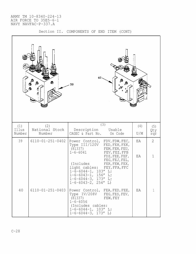
ARMY TM 10-8340-224-13AIR FORCE TO 35E5-6-1NAVY NAVFAC-P-337.A
Section II. COMPONENTS OF END ITEM (CONT)
(1) (2) (3)
Description(4) (5)
Illus National Stock Usable QtyNumber Number CAGEC & Part No. On Code U/M rqr
39 6110-01-251-0402 Power Control, FDV,FDW,FEC, EA 2Type III/120V FED,FEH,FEK,(81337) FEM,FEN,FEU,1-6-6041 FEV,FEZ,FFB
FDZ,FEE,FEF, EA 1FEG,FEJ,FEL,
(Includes FER,FEW,FEX,light cables: FEY,FFA,FFC1-6-6044-1, 103” L;1-6-6043-1, 156” L;1-6-6044-3, 173” L;1-6-6043-2, 254” L)
40 6110-01-251-0403 Power Control, FEA,FED,FEE, EA 1Type IV/208V FEG,FES,FEV,(81337) FEW,FEY1-6-6056(Includes cables:1-6-6044-1, 103” L;1-6-6044-3, 173” L)
C-28
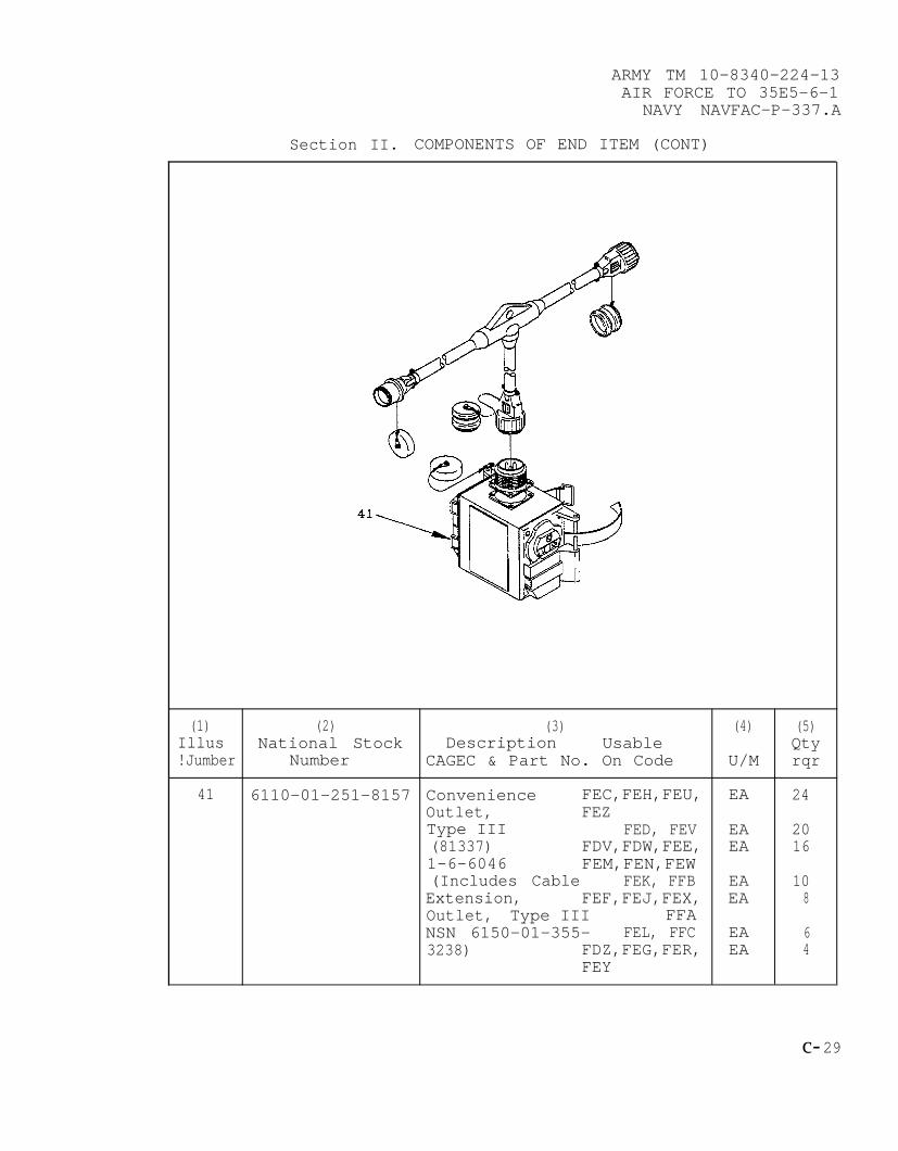
ARMY TM 10-8340-224-13AIR FORCE TO 35E5-6-1
NAVY NAVFAC-P-337.A
Section II. COMPONENTS OF END ITEM (CONT)
(1) (2) (3) (4) (5)Illus National Stock Description Usable Qty!Jumber Number CAGEC & Part No. On Code U/M rqr
41 6110-01–251-8157 Convenience FEC,FEH,FEU, EA 24Outlet, FEZType III FED, FEV EA 20(81337) FDV,FDW,FEE, EA 161-6-6046 FEM,FEN,FEW(Includes Cable FEK, FFB EA 10Extension, FEF,FEJ,FEX, EA 8Outlet, Type III FFANSN 6150-01-355- FEL, FFC EA 63238) FDZ,FEG,FER, EA 4
FEY
c- 29
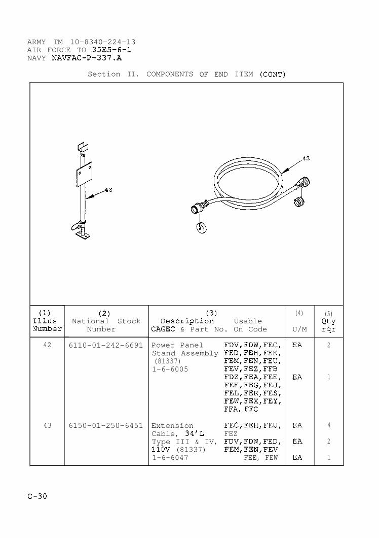
ARMY TM 10-8340-224-13AIR FORCE TO 35E5-6-1NAVY NAVFAC-P-337.A
Section II. COMPONENTS OF END ITEM (CONT)
(1)IllusNumber
42
43
42
(2)National Stock
Number
6110-01-242-6691
6150-01-250-6451
Descrlptl~;),,
UsableCAGEC & Part No. On Code
Power Panel FDV,FDW,FEC,Stand Assembly FED,FEH,FEK,(81337) FEM,FEN,FEU,1-6-6005 FEV,FEZ,FFB
FDZ,FEA,FEE,FEF,FEG,FEJ,FEL,FER,FES,FEW,FEX,FEY,FFA, FFC
Extension FEC,FEH,FEU,Cable, 34’L FEZType III & IV, FDV,FDW,FED,11OV (81337) FEM,FEN,FEV1-6-6047 FEE, FEW
(4)
U/M
EA
EA
EA
EA
EA
(5)Qtyrqr
2
1
4
2
1
4
.
C-30

ARMY TM 10-8340-224-13AIR FORCE TO 35E5-6-1
NAVY NAVFAC-P-337.A
Section II. COMPONENTS OF END ITEM (CONT)
(1) (2) (3) (4) (5)Illus National Stock Description Usable QtyNumber Number CAGEC & Part No. On Code U/M rqr
44 Light Cables EA V(81337)1-6-6048(USAF Only)
45 6230-01-242-2016 Light Set, FEC,FEH,FEU, EA 6Portable, FEZFlourescent, FED, FEV EA 5Type I FDV,FDW,FEE, EA 4(81337) FEM,FEN,FEW5-4-6824 FEK, FFB EA 3
FEF,FEJ,FEL, EA 2FEX,FFA,FFCFDZ,FEA,FEG, EA 1FER,FES,FEY
C-31

ARMY TM 10-8340-224-13AIR FORCE TO 35E5-6-1NAVY NAVFAC-P-337.A
Section III. BASIC ISSUE ITEMS
(1)IllusNumber
(2)National Stock
Number
(3)Description Usable
CAGEC & Part No. On Code
Technical ManualOperator, Unit andDirect SupportMaintenance ManualTM 10-8340-224-13
(4)
U/M
EA
(5)Qtyrqr
1
C-32
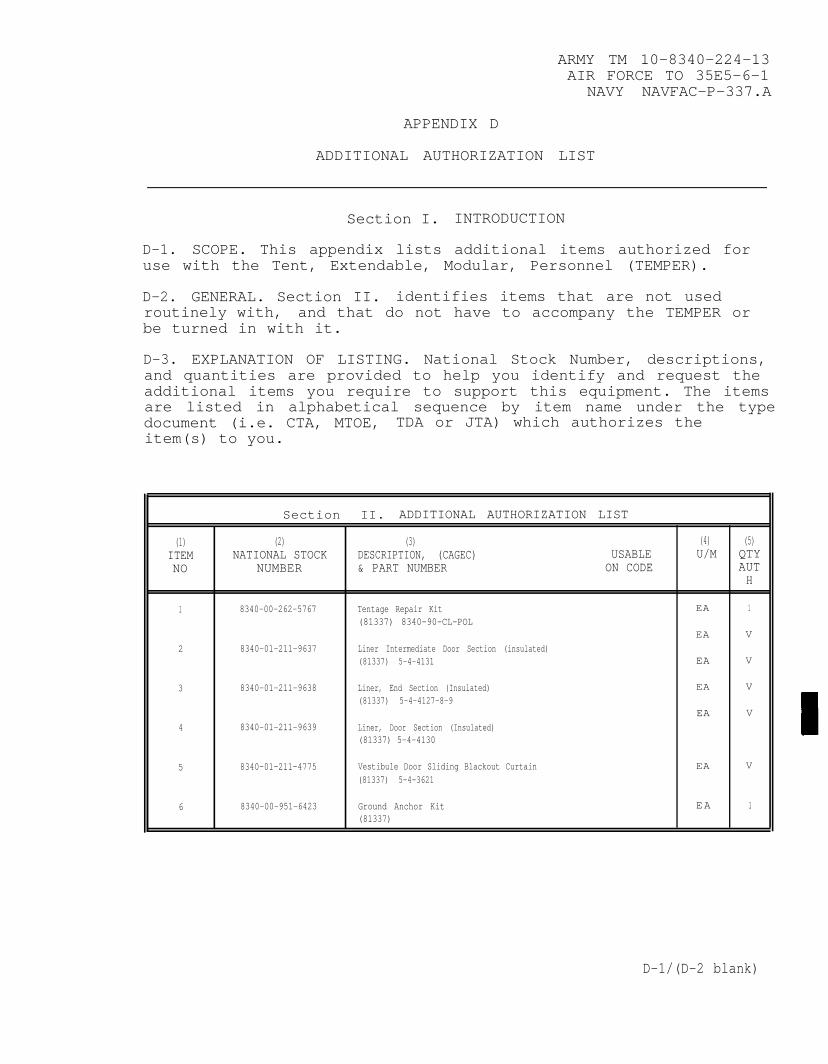
ARMY TM 10-8340-224-13AIR FORCE TO 35E5-6-1
NAVY NAVFAC-P-337.A
APPENDIX D
ADDITIONAL AUTHORIZATION LIST
Section I. INTRODUCTION
D-1. SCOPE. This appendix lists additional items authorized foruse with the Tent, Extendable, Modular, Personnel (TEMPER).
D-2. GENERAL. Section II. identifies items that are not usedroutinely with, and that do not have to accompany the TEMPER orbe turned in with it.
D-3. EXPLANATION OF LISTING. National Stock Number, descriptions,and quantities are provided to help you identify and request theadditional items you require to support this equipment. The itemsare listed in alphabetical sequence by item name under the typedocument (i.e. CTA, MTOE, TDA or JTA) which authorizes theitem(s) to you.
Section II. ADDITIONAL AUTHORIZATION LIST
(1) (2) (3) (4) (5)ITEM NATIONAL STOCK DESCRIPTION, (CAGEC) USABLE U/M QTYNO NUMBER & PART NUMBER ON CODE AUT
H
1 8340-00-262-5767 Tentage Repair Kit EA 1(81337) 8340-90-CL-POL
EA V
2 8340-01-211-9637 Liner Intermediate Door Section (insulated)(81337) 5-4-4131 EA V
3 8340-01-211-9638 Liner, End Section (Insulated) EA V
(81337) 5-4-4127-8-9EA V
4 8340-01-211-9639 Liner, Door Section (Insulated)(81337) 5-4-4130
5 8340-01-211-4775 Vestibule Door Sliding Blackout Curtain EA V
(81337) 5-4-3621
6 8340-00-951-6423 Ground Anchor Kit EA 1(81337)
D-1/(D-2 blank)

ARMY TM 10–8340-224-13AIR FORCE TO 35E5-6-1
NAVY NAVFAC-P-337.A
APPENDIX E
EXPENDABLE/DURABLE SUPPLIES AND MATERIALS LIST
Section I. INTRODUCTION
E-1. SCOPE. This appendix lists expendable supplies and materialsyou will need to operate and maintain the Tent, Extendable,Modular, Personnel (TEMPER). The listing is for informationalpurposes only and is not authority to requisition the listed items.These items are authorized to you by CTA 50-970, Expendable Items(Except Medical, Class V, Repair Parts, and Heraldic Items), or CTA8-100, Army Medical Department Expendable/Durable Items.
E-2. EXPLANATION OE COLUMNS.
a. Column (1) - Item number. This number is assigned to theentry in the listing and is referenced in the narrativeinstructions to identify the material (e.g., “Use cleaningcompound, item 5, App.D”).
b. Column (2) – Level. This column identifies the lowest levelof maintenance that requires the listed item.
C Operator/CrewO Unit MaintenanceF Direct Support MaintenanceH General Support MaintenanceD Maintenance
c. Column (3) - National Stock Number. This is the Nationalstock number assigned to the item; use it to request or requisitionthe item.
d. Column (4) - Description. Indicates the Federal item nameand, if required, a description to identify the item. The last linefor each item indicates the Federal Supply code for manufacturer(FSCM) in parentheses followed by the part number.
e. Column (5) – Unit of Measure (U/M) . Indicates the measureused in performing the actual maintenance function. This measure isexpressed by a two-character alphabetical abbreviation (e.g., ea,in, pr). If the unit of measure differs from the unit of issue,requisition the lowest unit of issue that will satisfy yourrequirements.
E-1

ARMY TM 10-8340-224-13AIR FORCE TO 35E5-6-1NAVY NAVFAC-P-337.A
Section II.
EXPENDABLE/DURABLE SUPPLIES AND MATERIALS LIST
(1) (2) (3) (4) (5)NATIONAL
ITEM STOCKNUMBER LEVEL NUMBER DESCRIPTION U/M
1
2
3
4
5
6
7
8
9
10
11
12
13
14
15
E-2
c
O
O
O
O
O
F
O
C
O
O
C
F
O
F
7920-00-240-7174
8020-00-597-4761
6810-00-782-2686
4240-01-204-2827
5970-00-431-8599
8030-01-350-4984
9150-00-999-7548
4240-01-315-18644240-01-315-18634240-01-311-9013
7930-00-965-4868
3439-00-223-2538
5440-00-227-1592
5970-00-644-3167
Brush, Scrub, w/o Handle Ea
Brush, Varnish Ea
Denatured Alcohol Gal
Filter, Cartridge Ea(55799) 464023
Gloves, Latex-Nitrile Pr(55799) 695456 Sz 8-8 1/2(55799) 695457 SZ 9-9 1/2(55799) 695458 Sz 10-10 1/2
Goggles, Chemical Splash Ea(55799) 695877
Insulation, Sleeving Ft
K-Kote Seam Sealer Gal(0R6N1) 83-234C
Lubricant, Stick Form Ea
Rake, Snow Ea(62840) 89-416
Respirator, Air Filtering Ea(55799) 479529 Sz Small(55799) 479528 Sz Medium(55799) 479530 Sz Large
Soap, Toilet, Cake, Hand Box
Solder, 50/10/50 Lead
Step Ladder, 4 foot, EaWooden, with Bucket Shelf
Tape, Electrical Insula- Eation, 3/4 inch width

ARMY TM 10-8340-224-13AIR FORCE TO 35E5-6-1
NAVY NAVFAC-P-337.A
EXPENDABLE/DURABLE SUPPLIES AND MATERIALS LIST (CONT)
(1) (2) (3) (4) (5)NATIONAL
ITEM STOCKNUMBER LEVEL NUMBER DESCRIPTION U/M
16 O 5210-00-221-1882 Tape, Measure 100 foot Ea
17 O 7920-00-205-1711 Wiping Rags Bale
E-3
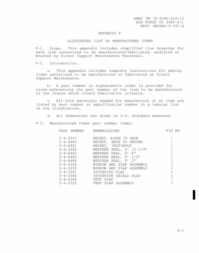
ARMY TM 10-8340-224-13AIR FORCE TO 35E5-6-1
NAVY NAVFAC-P–337.A
APPENDIX F
ILLUSTRATED LIST OF MANUFACTURED ITEMS
F-1. Scope. This appendix includes simplified line drawings foreach item authorized to be manufactured/fabricated, modified ormounted by Direct Support Maintenance Personnel.
F-2. Introduction.
a. This appendix includes complete instructions for makingitems authorized to be manufactured or fabricated at DirectSupport Maintenance.
b. A part number in alphanumeric order is provided forcross-referencing the part number of the item to be manufacturedto the figure which covers fabrication criteria.
c. All bulk materials needed for manufacture of an item arelisted by part number or specification number in a tabular liston the illustration.
d. All dimensions are given in U.S. Standard measures.
F–3. Manufactured items part number index.
PART NUMBER NOMENCLATURE FIG NO
5-4-33575-4-84805-4-84815-4-33605-4-84825-4-84835-4-84845-4-33565-4-33785-4-33815-4-33865-4-33885-4-3355
BECKET, RIDGE TO EAVEBECKET, EAVE TO GROUNDBECKET, VESTIBULEWEATHER SEAL, 6’ 11–1/4”WEATHER SEAL, 8’ 8“WEATHER SEAL, 9’ 1/2”WEATHER SEAL, 9’ 2“WINDOW AND FLAP ASSEMBLYWINDOW AND FLAP ASSEMBLYSTOVEPIPE FLAPSTOVEPIPE SHIELD FLAPVENT FLAPVENT FLAP ASSEMBLY
1112222345678
F-1
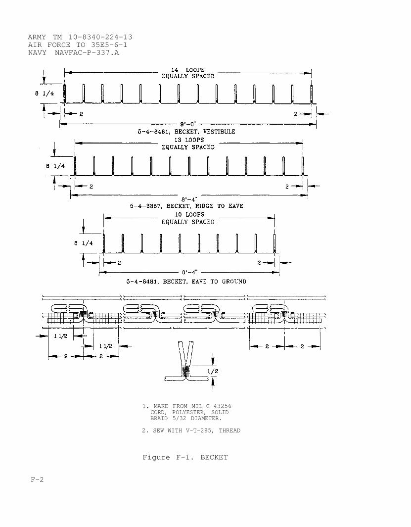
ARMY TM 10-8340-224-13AIR FORCE TO 35E5-6-1NAVY NAVFAC-P-337.A
1. MAKE FROM MIL-C-43256CORD, POLYESTER, SOLIDBRAID 5/32 DIAMETER.
2. SEW WITH V-T-285, THREAD
Figure F-1. BECKET
F-2
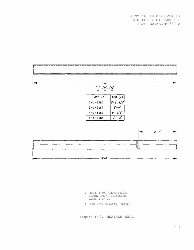
ARMY TM 10-8340-224-13AIR FORCE TO 35E5-6-1
NAVY NAVFAC-P-337.A
1. MAKE FROM MIL-C-44103,CLOTH, DUCK, POLYESTER,CLASS 1 OR 2.
2. SEW WITH V-T-285, THREAD.
Figure F-2. WEATHER SEAL
F-3

ARMY TM 10-8340-224-13AIR FORCE TO 35E5-6-1NAVY NAVFAC-P-337.A
1.
2.
3.
MAKE FROM MIL-C-44103,CLOTH, DUCK, POLYESTER,CLASS 1 OR 2, MIL-F-21840,FASTENER, HOOK AND PILE,MIL-T-43566, TAPE, TEXTILE.
SEW WITH V-T-285, THREAD.
INSTALL MIL-G-16491, GROMMETIAW FM 10-16.
Figure F-3. WINDOW AND FLAP ASSEMBLY
F-4
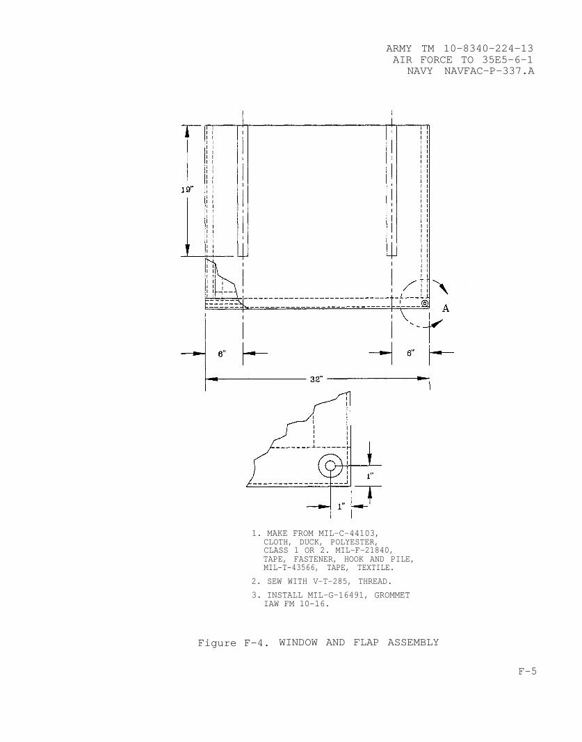
ARMY TM 10-8340-224-13AIR FORCE TO 35E5-6-1
NAVY NAVFAC-P-337.A
1. MAKE FROM MIL–C-44103,CLOTH, DUCK, POLYESTER,CLASS 1 OR 2. MIL-F-21840,TAPE, FASTENER, HOOK AND PILE,MIL-T-43566, TAPE, TEXTILE.
2. SEW WITH V-T-285, THREAD.
3. INSTALL MIL-G-16491, GROMMETIAW FM 10-16.
Figure F-4. WINDOW AND FLAP ASSEMBLY
F-5

ARMY TM 10-8340-224-13AIR FORCE TO 35E5-6-1NAVY NAVFAC-P-337.A
1. MAKE FROM MIL-C-44103,CLOTH, DUCK, POLYESTER,CLASS 1 OR 2, MIL-F-21840,TAPE, FASTENER, HOOK AND PILE,MIL-T-43566, TAPE, TEXTILE.
2. SEW WITH V-T-285, THREAD.
Figure F-5. STOVEPIPE FLAP
F-6

ARMY TM 10-8340-224-13AIR FORCE TO 35E5-6-1
NAVY NAVFAC-P-337.A
1. MAKE FROM MIL–C–44103,CLOTH, DUCK, POLYESTER,CLASS 1 OR 2, MIL–F–21840,TAPE, FASTENER, HOOK AND PILE,MIL-T–43566, TAPE, TEXTILE.
2. SEW WITH V–T-285, THREAD.
Figure F-6. STOVEPIPE SHIELD FLAP
F-7

ARMY TM 10-8340-224-13AIR FORCE TO 35E5-6–1NAVY NAVFAC-P-337.A
1. MAKE FROM MIL–C–44103,CLOTH, DUCK, POLYESTER,CLASS 1 OR 2, MIL–F–21840,TAPE, FASTENER, HOOK AND PILE,MIL-T–43566, TAPE, TEXTILE.
2. SEW WITH V–T–285, THREAD.
Figure F-7. VENT FLAP
F-8
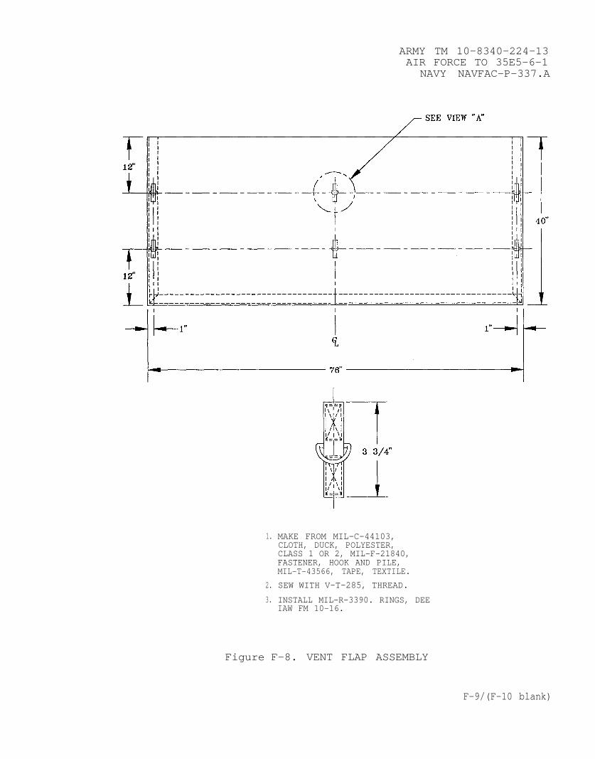
ARMY TM 10-8340-224-13AIR FORCE TO 35E5-6-1
NAVY NAVFAC–P–337.A
1.
2.
3.
MAKE FROM MIL–C–44103,CLOTH, DUCK, POLYESTER,CLASS 1 OR 2, MIL-F–21840,FASTENER, HOOK AND PILE,MIL–T–43566, TAPE, TEXTILE.
SEW WITH V–T–285, THREAD.
INSTALL MIL-R–3390. RINGS, DEEIAW FM 10–16.
Figure F–8. VENT FLAP ASSEMBLY
F-9/(F-10 blank)
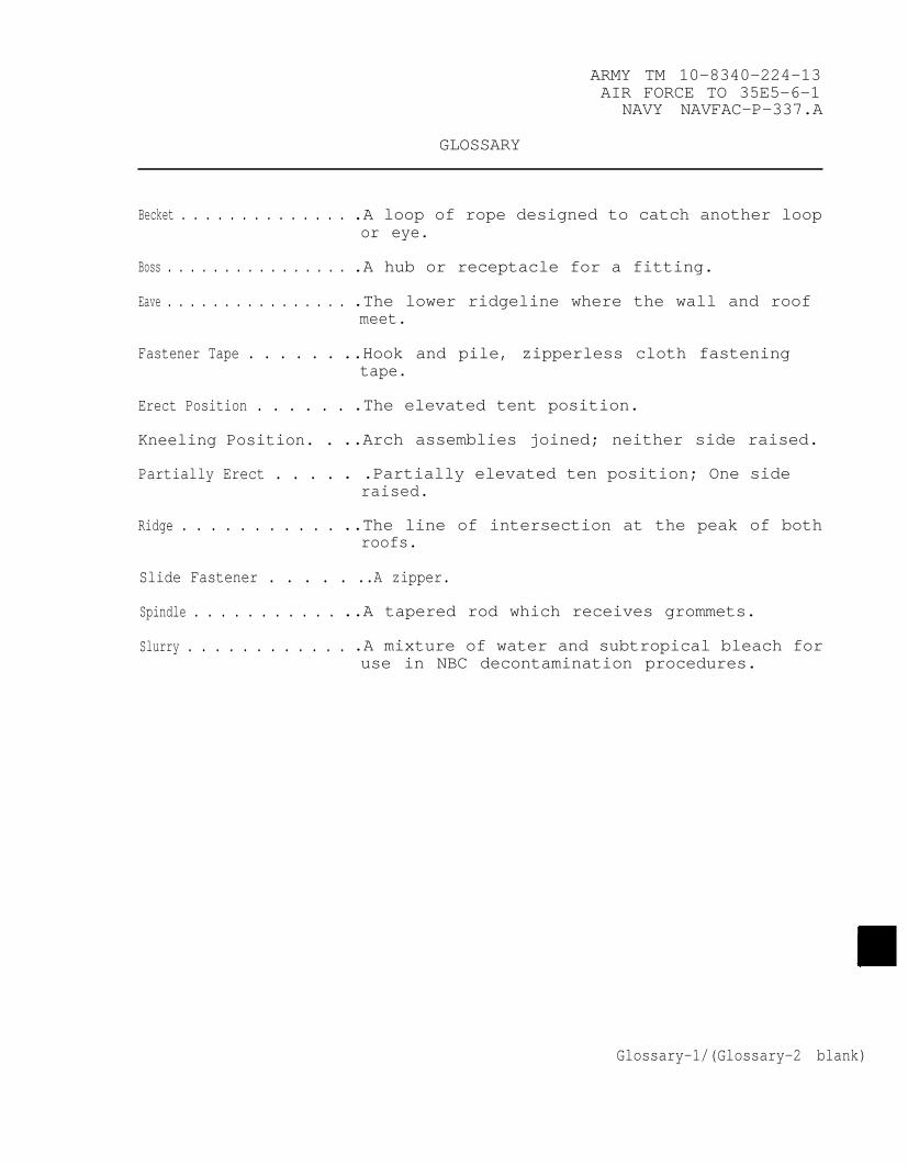
ARMY TM 10-8340-224-13AIR FORCE TO 35E5-6-1
NAVY NAVFAC-P–337.A
GLOSSARY
Becket . . . . . . . . . . . . . . .A loop of rope designed to catch another loopor eye.
Boss . . . . . . . . . . . . . . . . .A hub or receptacle for a fitting.
Eave . . . . . . . . . . . . . . . . .The lower ridgeline where the wall and roofmeet.
Fastener Tape . . . . . . ..Hook and pile, zipperless cloth fasteningtape.
Erect Position . . . . . . .The elevated tent position.
Kneeling Position. . ..Arch assemblies joined; neither side raised.
Partially Erect . . . . . .Partially elevated ten position; One sideraised.
Ridge . . . . . . . . . . . ..The line of intersection at the peak of bothroofs.
Slide Fastener . . . . . ..A zipper.
Spindle . . . . . . . . . . . ..A tapered rod which receives grommets.
Slurry . . . . . . . . . . . . .A mixture of water and subtropical bleach foruse in NBC decontamination procedures.
Glossary-1/(Glossary-2 blank)
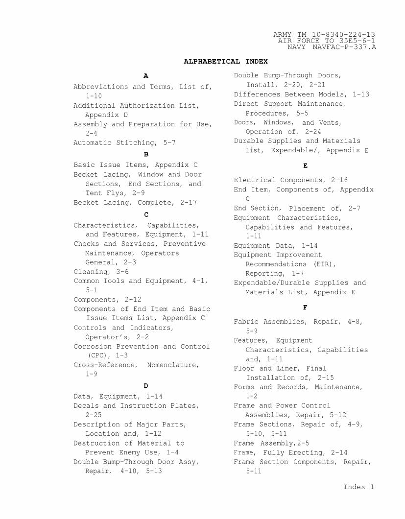
ARMY TM 10-8340–224–13AIR FORCE TO 35E5–6–1
NAVY NAVFAC–P–337.A
ALPHABETICAL INDEX
A
Abbreviations and Terms, List of,1–10
Additional Authorization List,Appendix D
Assembly and Preparation for Use,2-4
Automatic Stitching, 5–7
B
Basic Issue Items, Appendix CBecket Lacing, Window and Door
Sections, End Sections, andTent Flys, 2–9
Becket Lacing, Complete, 2–17
C
Characteristics, Capabilities,and Features, Equipment, 1—11
Checks and Services, PreventiveMaintenance, OperatorsGeneral, 2–3
Cleaning, 3–6Common Tools and Equipment, 4–1,
5–1Components, 2–12Components of End Item and Basic
Issue Items List, Appendix CControls and Indicators,
Operator’s, 2–2Corrosion Prevention and Control
(CPC), 1-3Cross–Reference, Nomenclature,
1–9
D
Data, Equipment, 1–14Decals and Instruction Plates,
2–25Description of Major Parts,
Location and, 1-12Destruction of Material to
Prevent Enemy Use, 1–4Double Bump–Through Door Assy,
Repair, 4-10, 5-13
Double Bump–Through Doors,Install, 2-20, 2-21
Differences Between Models, 1–13Direct Support Maintenance,
Procedures, 5–5Doors, Windows, and Vents,
Operation of, 2–24Durable Supplies and Materials
List, Expendable/, Appendix
E
Electrical Components, 2–16
E
End Item, Components of, AppendixC
End Section, Placement of, 2-7Equipment Characteristics,
Capabilities and Features,1-11
Equipment Data, 1–14Equipment Improvement
Recommendations (EIR),Reporting, 1–7
Expendable/Durable Supplies andMaterials List, Appendix E
F
Fabric Assemblies, Repair, 4–8,5–9
Features, EquipmentCharacteristics, Capabilitiesand, 1–11
Floor and Liner, FinalInstallation of, 2-15
Forms and Records, Maintenance,1–2
Frame and Power ControlAssemblies, Repair, 5–12
Frame Sections, Repair of, 4–9,5–l0, 5–11
Frame Assembly,2-5Frame, Fully Erecting, 2–14Frame Section Components, Repair,
5-11
Index 1
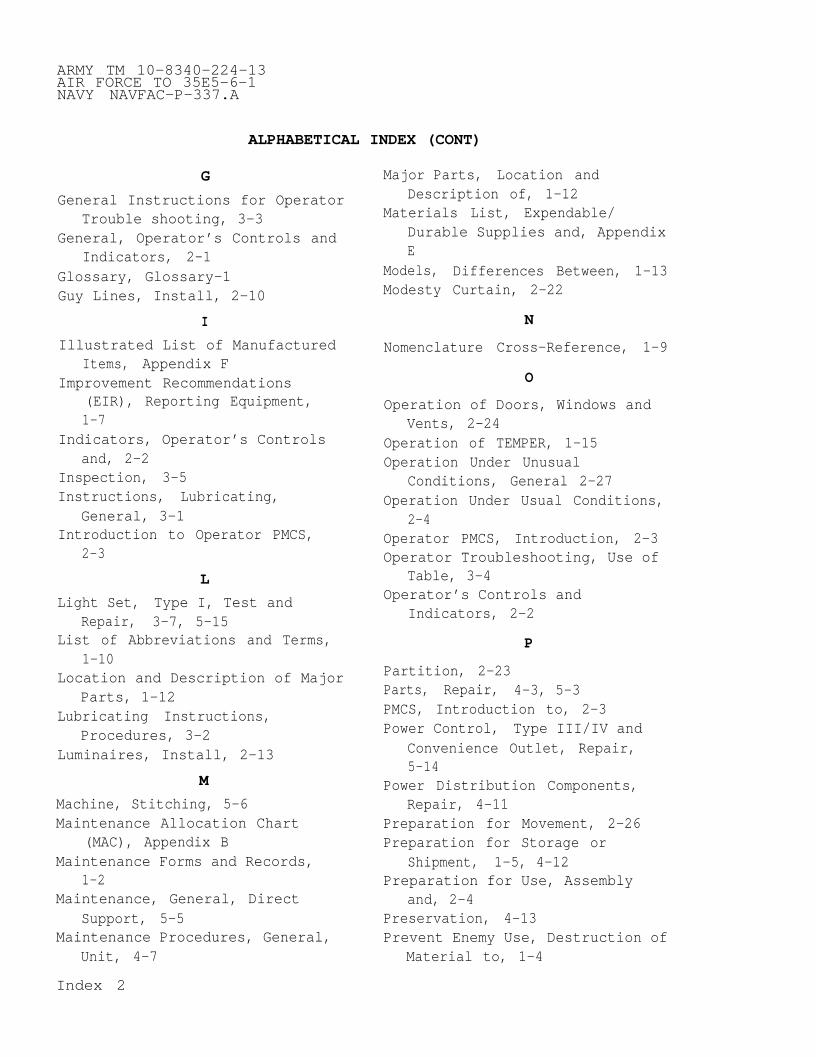
ARMY TM 10–8340–224–13AIR FORCE TO 35E5–6–1NAVY NAVFAC-P–337.A
ALPHABETICAL INDEX (CONT)
G
General Instructions for OperatorTrouble shooting, 3–3
General, Operator’s Controls andIndicators, 2-1
Glossary, Glossary-1Guy Lines, Install, 2-10
I
Illustrated List of ManufacturedItems, Appendix F
Improvement Recommendations(EIR), Reporting Equipment,1–7
Indicators, Operator’s Controlsand, 2-2
Inspection, 3–5Instructions, Lubricating,
General, 3-1Introduction to Operator PMCS,
2-3
L
Light Set, Type I, Test andRepair, 3-7, 5-15
List of Abbreviations and Terms,1-10
Location and Description of MajorParts, 1-12
Lubricating Instructions,Procedures, 3-2
Luminaires, Install, 2-13
M
Machine, Stitching, 5–6Maintenance Allocation Chart
(MAC), Appendix BMaintenance Forms and Records,
1–2Maintenance, General, Direct
Support, 5-5Maintenance Procedures, General,
Unit, 4–7
Major Parts, Location andDescription of, 1–12
Materials List, Expendable/Durable Supplies and, AppendixE
Models, Differences Between, 1–13Modesty Curtain, 2–22
N
Nomenclature Cross–Reference, 1–9
O
Operation of Doors, Windows andVents, 2-24
Operation of TEMPER, 1-15Operation Under Unusual
Conditions, General 2–27Operation Under Usual Conditions,
2-4Operator PMCS, Introduction, 2-3Operator Troubleshooting, Use of
Table, 3-4Operator’s Controls and
Indicators, 2-2
P
Partition, 2-23Parts, Repair, 4-3, 5-3PMCS, Introduction to, 2–3Power Control, Type III/IV and
Convenience Outlet, Repair,5–14
Power Distribution Components,Repair, 4-11
Preparation for Movement, 2–26Preparation for Storage or
Shipment, 1-5, 4-12Preparation for Use, Assembly
and, 2-4Preservation, 4–13Prevent Enemy Use, Destruction of
Material to, 1–4
Index 2

ARMY TM 10–8340–224-13AIR FORCE TO 35E5–6–1
NAVY NAVFAC–P–337.A
ALPHABETICAL INDEX (CONT)
P
Procedures, OperatorTroubleshooting, GeneralInstructions, 3–3
Q
Quality Assurance, 1–6
R
Raising the Frame to PartiallyErect Position, 2-11
Records, Maintenance, Forms and,1–2
References, Appendix ARepair Double Bump–Through Door
Assembly, 4-10, 5-13Repair Fabric Assemblies, 4–8,
5–9Repair Frame and Power Control
Assemblies, 5–12Repair Frame Sections, 4–9, 5–10Repair Light Set, Type I, 3–7,
5–15Repair Parts, 4–3, 5–3Repair Power Control Type III/IV,
5–1 4Repair Power Distribution
Components, 4–11Reporting Equipment Improvement
Recommendations (EIR), 1–7
S
Scope, 1–1Service Upon Receipt, of
Material, 4–5Shipment, Preparation for, 1–5,
4–14Site and Shelter Requirements,
4–4Special Tools, TMDE, and Support
Equipment, 4–2, 5–2Stakes and Guy Lines, 2–18
Stitching, Automatic, 5–7Stitching, Machine, 5–6Storage, Preparation for, 1–5,
4–12Supplies and Materials List,
Expendable/Durable, Appendix E
T
Tent Flys, Placement of, 2–8Terms, List of Abbreviations and,
1-10Test and Repair Light Set, Type
I, 5–15Tools and Equipment, Common, 4–1,
5–1Tool and Test Equipment List,
Appendix BTroubleshooting Procedures,
Operator, GeneralInstructions, 3-3
Troubleshooting Procedures, Unit,General Instructions, 4–6
Troubleshooting Procedures,Direct Support, 5–4
U
Unit Maintenance Procedures,General, 4-7
Unit Troubleshooting, General,4–6
Unusual Conditions, OperationUnder, General, 2–27
V
Vents, Operation of, 2–24Vestibule Assembly, 2–19
W
Warranty Information, 1–8Welding, 5-8Window and Door Sections, Initial
Placement of, 2-6Windows, Operation of, 2–24
Index 3/(Index 4 blank)


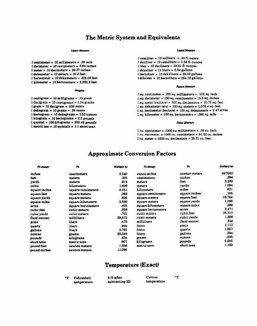

PIN: 071122-002