aroend ndt conference, mamaia, june 2013 mt & ut testing
TRANSCRIPT
AROEND NDT Conference, Mamaia, June 2013
MT & UT Testing Systems (Railways & Welded Pipes)
DIN EN ISO 9001:2008
MT+UT-Systems AROEND WD May2013.do
Magnetic Particle and Ultrasonic Testing Systems for the Railway Industry and for Welded Pipes
Authors:
Dr. (USA) Wolfram A. Karl Deutsch, Dipl.-Ing. Frank Bartholomai, Dipl.-Ing. Michael Joswig
KARL DEUTSCH Pruef- und Messgeraetebau GmbH + Co KG, Wuppertal, Germany
Tel: (+49-202) 7192-0, Fax: (+49-292) 714-932, [email protected], www.karldeutsch.de
Abstract
This article presents several testing systems for the railway and steel industry. Magnetic particle and ultrasonic testing systems are presented.
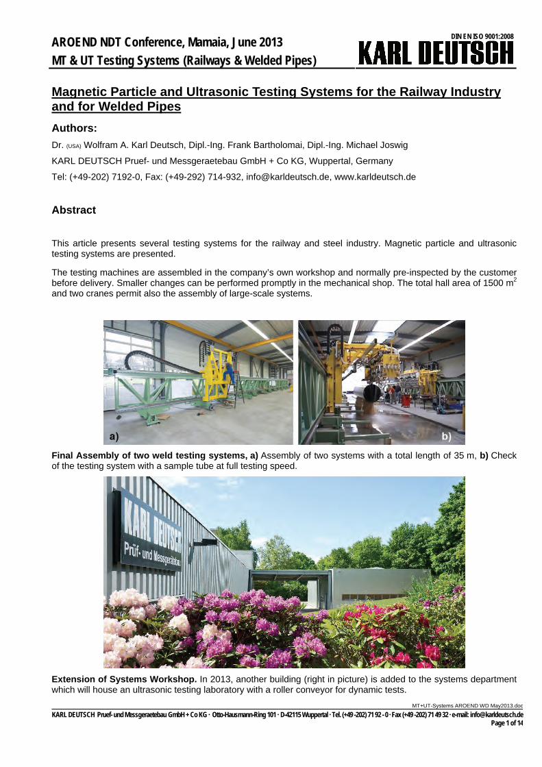
The testing machines are assembled in the company’s own workshop and normally pre-inspected by the customer before delivery. Smaller changes can be performed promptly in the mechanical shop. The total hall area of 1500 m2 and two cranes permit also the assembly of large-scale systems.
Final Assembly of two weld testing systems, a) Assembly of two systems with a total length of 35 m, b) Check of the testing system with a sample tube at full testing speed.
Extension of Systems Workshop. In 2013, another building (right in picture) is added to the systems department which will house an ultrasonic testing laboratory with a roller conveyor for dynamic tests.
c
KARL DEUTSCH Pruef- und Messgeraetebau GmbH + Co KG Otto-Hausmann-Ring 101 D-42115 Wuppertal Tel. (+49 -202) 71 92 - 0 Fax (+49 -202) 71 49 32 e-mail: [email protected] Page 1 of 14
AROEND NDT Conference, Mamaia, June 2013
MT & UT Testing Systems (Railways & Welded Pipes)
DIN EN ISO 9001:2008
MT+UT-Systems AROEND WD May2013.do
Magnetic Particle Testing of Railway Wheels, Axles and Wheelsets
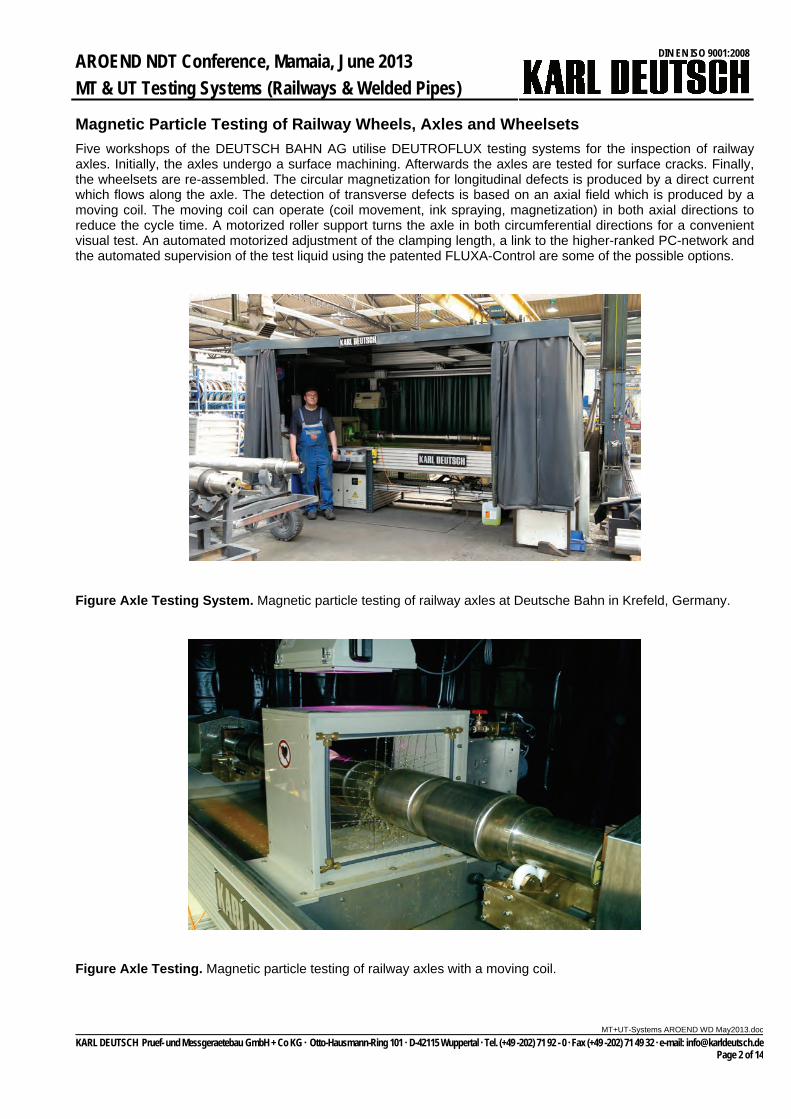
Five workshops of the DEUTSCH BAHN AG utilise DEUTROFLUX testing systems for the inspection of railway axles. Initially, the axles undergo a surface machining. Afterwards the axles are tested for surface cracks. Finally, the wheelsets are re-assembled. The circular magnetization for longitudinal defects is produced by a direct current which flows along the axle. The detection of transverse defects is based on an axial field which is produced by a moving coil. The moving coil can operate (coil movement, ink spraying, magnetization) in both axial directions to reduce the cycle time. A motorized roller support turns the axle in both circumferential directions for a convenient visual test. An automated motorized adjustment of the clamping length, a link to the higher-ranked PC-network and the automated supervision of the test liquid using the patented FLUXA-Control are some of the possible options.
Figure Axle Testing System. Magnetic particle testing of railway axles at Deutsche Bahn in Krefeld, Germany.
Figure Axle Testing. Magnetic particle testing of railway axles with a moving coil.
c
KARL DEUTSCH Pruef- und Messgeraetebau GmbH + Co KG Otto-Hausmann-Ring 101 D-42115 Wuppertal Tel. (+49 -202) 71 92 - 0 Fax (+49 -202) 71 49 32 e-mail: [email protected] Page 2 of 14

AROEND NDT Conference, Mamaia, June 2013
MT & UT Testing Systems (Railways & Welded Pipes)
DIN EN ISO 9001:2008
MT+UT-Systems AROEND WD May2013.do
Figure Visual Test. Motorized roller unit for convenient viewing of the axle under UV-light. The UV-lamp can easily be moved into the correct axial position.
Figure Loading and Unloading. The roof of the test cabin can be pneumatically opened and closed. The UV-lamp is then moved backwards into the safety position.
c
KARL DEUTSCH Pruef- und Messgeraetebau GmbH + Co KG Otto-Hausmann-Ring 101 D-42115 Wuppertal Tel. (+49 -202) 71 92 - 0 Fax (+49 -202) 71 49 32 e-mail: [email protected] Page 3 of 14
AROEND NDT Conference, Mamaia, June 2013
MT & UT Testing Systems (Railways & Welded Pipes)
DIN EN ISO 9001:2008
MT+UT-Systems AROEND WD May2013.do
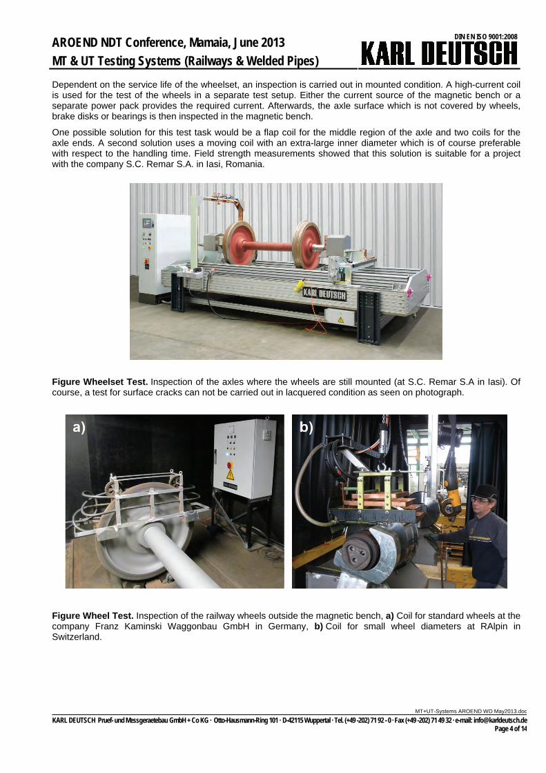
Dependent on the service life of the wheelset, an inspection is carried out in mounted condition. A high-current coil is used for the test of the wheels in a separate test setup. Either the current source of the magnetic bench or a separate power pack provides the required current. Afterwards, the axle surface which is not covered by wheels, brake disks or bearings is then inspected in the magnetic bench.
One possible solution for this test task would be a flap coil for the middle region of the axle and two coils for the axle ends. A second solution uses a moving coil with an extra-large inner diameter which is of course preferable with respect to the handling time. Field strength measurements showed that this solution is suitable for a project with the company S.C. Remar S.A. in Iasi, Romania.
Figure Wheelset Test. Inspection of the axles where the wheels are still mounted (at S.C. Remar S.A in Iasi). Of course, a test for surface cracks can not be carried out in lacquered condition as seen on photograph.
Figure Wheel Test. Inspection of the railway wheels outside the magnetic bench, a) Coil for standard wheels at the company Franz Kaminski Waggonbau GmbH in Germany, b) Coil for small wheel diameters at RAlpin in Switzerland.
c
KARL DEUTSCH Pruef- und Messgeraetebau GmbH + Co KG Otto-Hausmann-Ring 101 D-42115 Wuppertal Tel. (+49 -202) 71 92 - 0 Fax (+49 -202) 71 49 32 e-mail: [email protected] Page 4 of 14
AROEND NDT Conference, Mamaia, June 2013
MT & UT Testing Systems (Railways & Welded Pipes)
DIN EN ISO 9001:2008
MT+UT-Systems AROEND WD May2013.do
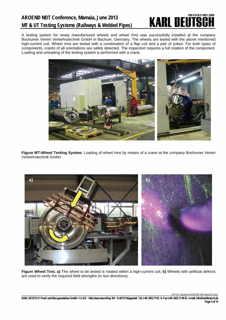
A testing system for newly manufactured wheels and wheel rims was successfully installed at the company Bochumer Verein Verkehrstechnik GmbH in Bochum, Germany. The wheels are tested with the above mentioned high-current coil. Wheel rims are tested with a combination of a flap coil and a pair of yokes. For both types of components, cracks of all orientations are safely detected. The inspection requires a full rotation of the component. Loading and unloading of the testing system is performed with a crane.
Figure MT-Wheel Testing System. Loading of wheel rims by means of a crane at the company Bochumer Verein Verkehrstechnik GmbH.
Figure Wheel Test. a) The wheel to be tested is rotated within a high-current coil, b) Wheels with artificial defects are used to verify the required field strengths (in two directions).
c
KARL DEUTSCH Pruef- und Messgeraetebau GmbH + Co KG Otto-Hausmann-Ring 101 D-42115 Wuppertal Tel. (+49 -202) 71 92 - 0 Fax (+49 -202) 71 49 32 e-mail: [email protected] Page 5 of 14

AROEND NDT Conference, Mamaia, June 2013
MT & UT Testing Systems (Railways & Welded Pipes)
DIN EN ISO 9001:2008
MT+UT-Systems AROEND WD May2013.do
Immersion Tank Testing System for High-Speed Train Bearings
A highly sensitive testing system was designed for our customer Rulmenti in Romania. Founded in 1953, Rulmenti produces up to 30 million bearings per year with a staff of currently 3,100 employees. Bearings subjected to high stress have to be tested, for instance, in compliance with DIN EN 12080 (bearings for railway applications). The most restrictive test class 1 of this specification enforces a defect size of 0.5 mm FBH (a flat bottom hole acts as a calibration reflector for the ultrasound). For high-speed trains, 100% of the bearings must be tested with test class 1 being mandatory.
This test must be carried in straight-beam mode and requires a high test sensitivity, a small shot index and a very precise test mechanic. In addition, the distance of the reflector with respect to the back wall is also only 0.5 mm. Therefore, a fine adjustment of the monitor gate is required. The defect detection is either carried out by evaluating the defect echo directly or by an indirect method where a reduction of the back wall echo is monitored. For this indirect method, the reduction is small (typical 1.5 - 3.0 dB for a 0.5 mm FBH). Thus a precise threshold setting and stable echo heights are preconditions.
The test system is designed for ring diameters of 100 mm to 500 mm, ring heights of 80 mm to 120 mm and wall thicknesses of 5 mm to 25 mm. The internal and external bearing rings have internal and external surfaces being parallel to each other. The rings rotate during the test. The maximum rotational speed of the testing mechanic is 1 m/s. The shot index is synchronized with the ring rotation by means of a measuring wheel and can be adjusted to values between 0.1 and 2.5 mm. The echo dynamic (depending on the ultrasonic probe and the defect size to be detected) determines the value for the shot index. Typically, a shot index of 0.5 mm is chosen which leads to a rotational speed of 860 mm/s.
Figure Bearing Ring Test. a) Total view of testing system, b) Inspection of external bearing ring during rotation.
Special line-focussed probes for internal bearing rings (type STS10 PB6-12 L75) and point-focussed probes for external bearing rings (type STS6 PB4-20 P60) allow for a testing track width of 0.5 mm and thus determine the distance of the testing helix (with respect to the height axis of the testing system). The track width (lead of the helix) may be adjusted between 0.1 and 2.5 mm. The echo dynamic in axial direction permits a tracking width of typically 0.5 mm. In order to increase the test cycle time, up to four identical probes are used. This results in test times between 15 and 75 seconds (for smallest and largest ring, respectively). The times for loading, ring positioning and discharging needs to be added. Special attention was given to a convenient adjustment for the probes, so straight-beam sound penetration into the ring material is ensured. This was achieved by a sophisticated design of the probe holders and the probe housings.
Figure Probe Holder and Test Result. a) Inspection of internal bearing ring with up to four probes, b) A-scan with indication from a 1 mm flat bottom hole (marked with a red box) which is located 1 mm in front of the back wall.
c
KARL DEUTSCH Pruef- und Messgeraetebau GmbH + Co KG Otto-Hausmann-Ring 101 D-42115 Wuppertal Tel. (+49 -202) 71 92 - 0 Fax (+49 -202) 71 49 32 e-mail: [email protected] Page 6 of 14

AROEND NDT Conference, Mamaia, June 2013
MT & UT Testing Systems (Railways & Welded Pipes)
DIN EN ISO 9001:2008
MT+UT-Systems AROEND WD May2013.do
Ultrasonic testing of ERW pipes with or without phased arrays
The production of ERW pipes includes several steps of NDT in order to obtain early information about the welding process as a feedback for the production line and secondly, the final inspection of the finished pipe. If the wall thickness gets too large for eddy current testing and if stringent specifications of the oil and gas industries must be fulfilled, ultrasonic testing is the method of choice.
Up to four ultrasonic systems are encountered during the production process. As a first step, often the strip is tested either with fixed or oscillating probes. In recent projects, a full coverage of the strip was realized with linear test tracks and a large number of fixed probes. Directly after welding, a first online weld test is carried out. This is to check the quality of the welding process as well as the internal scarfing. It usually requires 4 probes: 2 from each side for internal and external longitudinal defects. Sometimes, an oscillating deburring check is added to verify the proper scarfing of the internal burr by using additional wall thickness measurement. After annealing, mechanical treatment and hydro-test, the final weld inspection is carried out (offline weld testing). A testing portal with moveable carriage is commonly used. The testing portal shows the advantage that the weld is inspected without pipe movement, thus avoiding vibrations which could degrade the test results. The pipe ends can be tested in the same testing system or in a separate setup.
Figure Final Pipe Weld Test. Offline weld testing portal (type ECHOGRAPH-SNHFT).
As an alternative to a strip tester, the full-body inspection can be performed in the pipe stage. Either the offline weld testing portal is extended with additional full-body probes or a separate pipe body testing system is used. The number of probes can be varied in accordance with the required coverage and throughput. Typical values for the coverage are 25%, 50% and (mostly in recent projects) even 100%.
Figure Pipe Body Test. a) Either before welding with strip testing system (type ECHOGRAPH-BAPS), or b) after welding with rotational pipe testing portal (type ECHOGRAPH-RPTR).
c
KARL DEUTSCH Pruef- und Messgeraetebau GmbH + Co KG Otto-Hausmann-Ring 101 D-42115 Wuppertal Tel. (+49 -202) 71 92 - 0 Fax (+49 -202) 71 49 32 e-mail: [email protected] Page 7 of 14

AROEND NDT Conference, Mamaia, June 2013
MT & UT Testing Systems (Railways & Welded Pipes)
DIN EN ISO 9001:2008
MT+UT-Systems AROEND WD May2013.do
Conventional Online Weld Testing of ERW Pipes
During the test, the weld seam is in 12 o’clock position. For an automated weld inspection, the use of probe pairs is typical. The probe pairs are centred with respect to the weld. Each probe is used in pulse-echo-mode for flaw detection from both sides of the weld seam. In addition, the through-transmission signal (v-path) of a probe pair is used for a continuous coupling and function check. Two probe pairs are usually employed: One pair for internal defects and one pair for external defects.
In addition, the inner pipe surface of the tube can be inspected for proper removal of the burr. Ultrasound is the only possible method and is then also used for measurement of the wall thickness in the weld area. An oscillating probe movement with straight beam incidence is carried out. Challenges for this test task are the high temperature of the weld area which could cause coupling problems and the sometimes improper roundness of the pipe which can cause measurement errors for the wall thickness, due to an imperfect probe position with respect to the test angle.
Figure Conventional Online Weld Test. Weld testing with five ultrasonic probes.
Water jet coupling is applied, which means that the water path between probe and tube surface is in the order of several centimetres. This method of ultrasonic coupling results in little wear for the probes and the probe guiding devices. Also, the angle adjustment is carried out within the probe carrier – in contrast to water gap coupling where the testing angle is fixed within the ultrasonic probe. Any required testing angle can be chosen and steplessly adjusted. Even for an uneven pipe surface, stable coupling conditions are achieved because the water path can vary more than with gap coupling. Finally, this method is robust at elevated temperatures as the water flow protects the probes from damage.
The mechanical set-up for an online testing system consists of a stable machine frame, a horizontal boom and the probe holders. The boom which can be adjusted in height according to the pipe diameter is attached to the frame by a vertical drive. All probe holders can be moved between the testing position (online), and the calibration position (offline) by means of a horizontal drive. The calibration station consists of a table which is motorized. The table carries a test tube with artificial defects. This enables a dynamic check of the testing sensitivity. The coupling water is fed back into the coupling water circulation system.
c
KARL DEUTSCH Pruef- und Messgeraetebau GmbH + Co KG Otto-Hausmann-Ring 101 D-42115 Wuppertal Tel. (+49 -202) 71 92 - 0 Fax (+49 -202) 71 49 32 e-mail: [email protected] Page 8 of 14

AROEND NDT Conference, Mamaia, June 2013
MT & UT Testing Systems (Railways & Welded Pipes)
DIN EN ISO 9001:2008
MT+UT-Systems AROEND WD May2013.do
Figure Test Mechanics (Online Test). Stationary machine frame with probe holders in the calibration position.
During the test, the probes must be guided symmetrically to the weld seam to ensure reliable defect detection. This is done by means of an automated seam tracking system. The weld seam does not have a mechanical crown and cannot be used for a proper probe positioning. Therefore, a painted line, the so-called “pilot line”, is applied (typically at 3 o’clock circumferential position) onto the pipe during welding having a constant distance to the weld seam (at 12 o’clock). A CCD colour camera picks up the paint line. A software package processes the result and the Siemens PLC drives the probes into the correct position. The camera is equipped with a strobe LED illumination for excellent performance in poor lighting conditions. The achievable accuracy is about ±2 mm.
Figure Seam tracking. Unit is mounted on entry side of testing system (camera in circle).
The advantages of a conventional ultrasonic testing system using water jet coupling are: Small number of testing channels, relatively inexpensive test electronic Small number of relatively inexpensive probes Long life time of the probes due to the cooling and cleaning effect even close to the hot weld seam Reliable coupling due to small probe surface and small respective water jet diameter Any testing angle can be chosen without changing probe or mechanical parts No change of mechanical parts for entire pipe geometry range (diameter, wall thickness), i.e. no curved shoes
etc.
c
KARL DEUTSCH Pruef- und Messgeraetebau GmbH + Co KG Otto-Hausmann-Ring 101 D-42115 Wuppertal Tel. (+49 -202) 71 92 - 0 Fax (+49 -202) 71 49 32 e-mail: [email protected] Page 9 of 14
AROEND NDT Conference, Mamaia, June 2013
MT & UT Testing Systems (Railways & Welded Pipes)
DIN EN ISO 9001:2008
MT+UT-Systems AROEND WD May2013.do
Phased Array Online Weld Testing of ERW Pipes
The test specifications for ERW pipes describe which artificial defects must be detected such as notches (internal, external, mostly longitudinal) or through drilled holes (TDH’s). The defect size (notch length and depth or hole diameter) is stated in accordance with the requirements. The specifications do not regulate the use of conventional or phased array UT. Some additional features can be achieved by using PAUT which are now described.
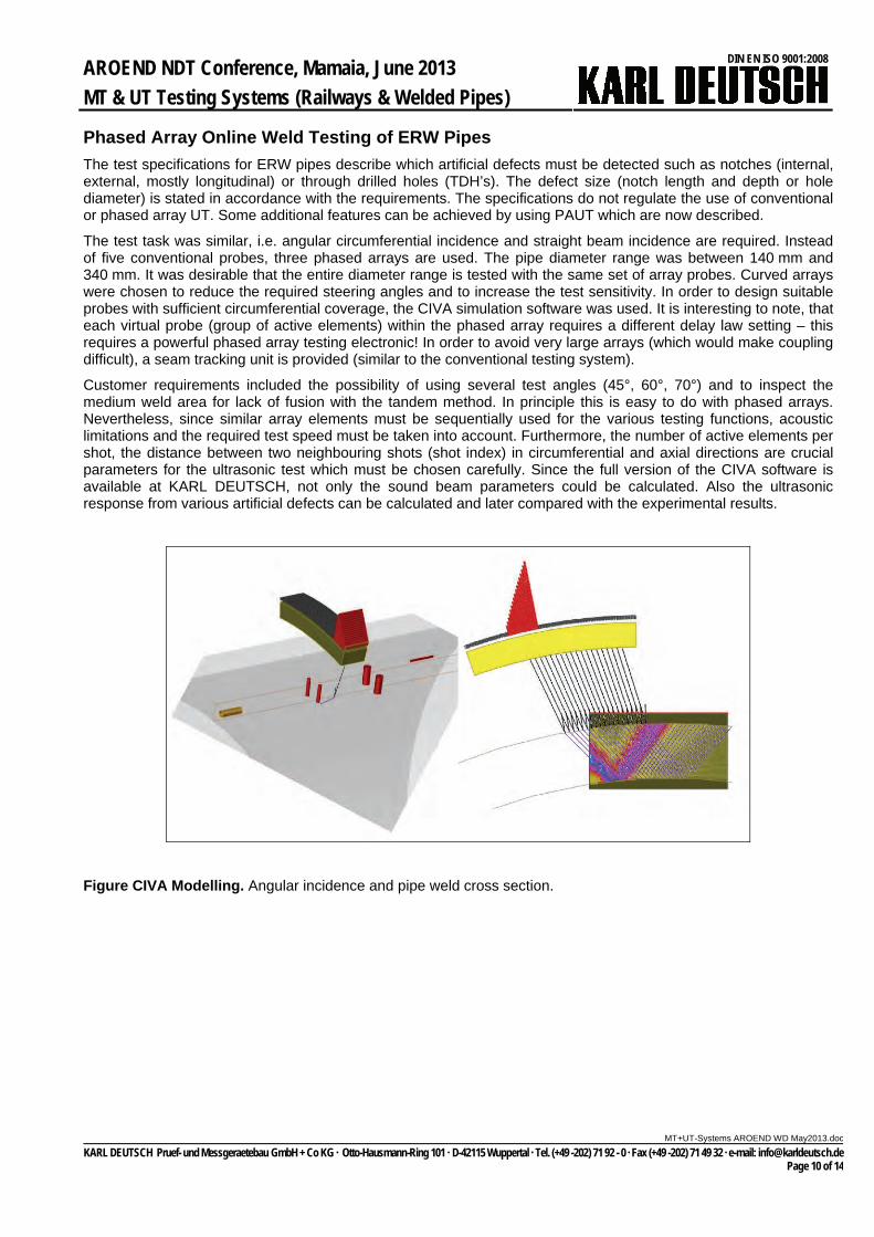
The test task was similar, i.e. angular circumferential incidence and straight beam incidence are required. Instead of five conventional probes, three phased arrays are used. The pipe diameter range was between 140 mm and 340 mm. It was desirable that the entire diameter range is tested with the same set of array probes. Curved arrays were chosen to reduce the required steering angles and to increase the test sensitivity. In order to design suitable probes with sufficient circumferential coverage, the CIVA simulation software was used. It is interesting to note, that each virtual probe (group of active elements) within the phased array requires a different delay law setting – this requires a powerful phased array testing electronic! In order to avoid very large arrays (which would make coupling difficult), a seam tracking unit is provided (similar to the conventional testing system).
Customer requirements included the possibility of using several test angles (45°, 60°, 70°) and to inspect the medium weld area for lack of fusion with the tandem method. In principle this is easy to do with phased arrays. Nevertheless, since similar array elements must be sequentially used for the various testing functions, acoustic limitations and the required test speed must be taken into account. Furthermore, the number of active elements per shot, the distance between two neighbouring shots (shot index) in circumferential and axial directions are crucial parameters for the ultrasonic test which must be chosen carefully. Since the full version of the CIVA software is available at KARL DEUTSCH, not only the sound beam parameters could be calculated. Also the ultrasonic response from various artificial defects can be calculated and later compared with the experimental results.
Figure CIVA Modelling. Angular incidence and pipe weld cross section.
c
KARL DEUTSCH Pruef- und Messgeraetebau GmbH + Co KG Otto-Hausmann-Ring 101 D-42115 Wuppertal Tel. (+49 -202) 71 92 - 0 Fax (+49 -202) 71 49 32 e-mail: [email protected] Page 10 of 14
AROEND NDT Conference, Mamaia, June 2013
MT & UT Testing Systems (Railways & Welded Pipes)
DIN EN ISO 9001:2008
MT+UT-Systems AROEND WD May2013.do
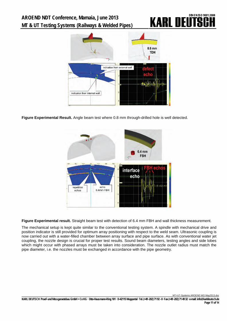
Figure Experimental Result. Angle beam test where 0.8 mm through-drilled hole is well detected.
Figure Experimental result. Straight beam test with detection of 6.4 mm FBH and wall thickness measurement.
The mechanical setup is kept quite similar to the conventional testing system. A spindle with mechanical drive and position indicator is still provided for optimum array positioning with respect to the weld seam. Ultrasonic coupling is now carried out with a water-filled chamber between array surface and pipe surface. As with conventional water jet coupling, the nozzle design is crucial for proper test results. Sound beam diameters, testing angles and side lobes which might occur with phased arrays must be taken into consideration. The nozzle outlet radius must match the pipe diameter, i.e. the nozzles must be exchanged in accordance with the pipe geometry.
c
KARL DEUTSCH Pruef- und Messgeraetebau GmbH + Co KG Otto-Hausmann-Ring 101 D-42115 Wuppertal Tel. (+49 -202) 71 92 - 0 Fax (+49 -202) 71 49 32 e-mail: [email protected] Page 11 of 14
AROEND NDT Conference, Mamaia, June 2013
MT & UT Testing Systems (Railways & Welded Pipes)
DIN EN ISO 9001:2008
MT+UT-Systems AROEND WD May2013.do
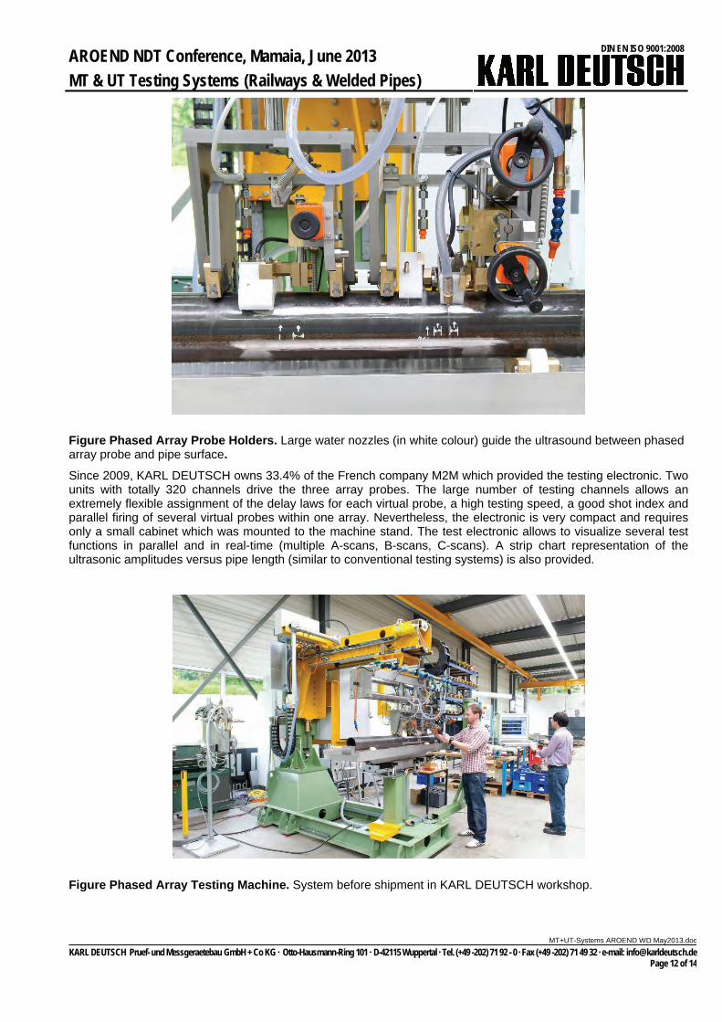
Figure Phased Array Probe Holders. Large water nozzles (in white colour) guide the ultrasound between phased array probe and pipe surface.
Since 2009, KARL DEUTSCH owns 33.4% of the French company M2M which provided the testing electronic. Two units with totally 320 channels drive the three array probes. The large number of testing channels allows an extremely flexible assignment of the delay laws for each virtual probe, a high testing speed, a good shot index and parallel firing of several virtual probes within one array. Nevertheless, the electronic is very compact and requires only a small cabinet which was mounted to the machine stand. The test electronic allows to visualize several test functions in parallel and in real-time (multiple A-scans, B-scans, C-scans). A strip chart representation of the ultrasonic amplitudes versus pipe length (similar to conventional testing systems) is also provided.
Figure Phased Array Testing Machine. System before shipment in KARL DEUTSCH workshop.
c
KARL DEUTSCH Pruef- und Messgeraetebau GmbH + Co KG Otto-Hausmann-Ring 101 D-42115 Wuppertal Tel. (+49 -202) 71 92 - 0 Fax (+49 -202) 71 49 32 e-mail: [email protected] Page 12 of 14
AROEND NDT Conference, Mamaia, June 2013
MT & UT Testing Systems (Railways & Welded Pipes)
DIN EN ISO 9001:2008
MT+UT-Systems AROEND WD May2013.do
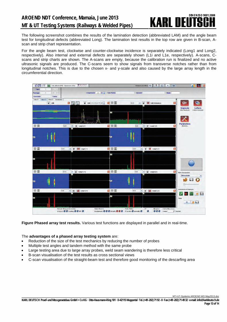
The following screenshot combines the results of the lamination detection (abbreviated LAM) and the angle beam test for longitudinal defects (abbreviated Long). The lamination test results in the top row are given in B-scan, A-scan and strip chart representation.
For the angle beam test, clockwise and counter-clockwise incidence is separately indicated (Long1 and Long2, respectively). Also internal and external defects are separately shown (L1i and L1e, respectively). A-scans, C-scans and strip charts are shown. The A-scans are empty, because the calibration run is finalized and no active ultrasonic signals are produced. The C-scans seem to show signals from transverse notches rather than from longitudinal notches. This is due to the chosen x- and y-scale and also caused by the large array length in the circumferential direction.
Figure Phased array test results. Various test functions are displayed in parallel and in real-time.
The advantages of a phased array testing system are: Reduction of the size of the test mechanics by reducing the number of probes Multiple test angles and tandem method with the same probe Large testing area due to large array probes, weld seam wandering is therefore less critical B-scan visualisation of the test results as cross sectional views C-scan visualisation of the straight-beam test and therefore good monitoring of the descarfing area
c
KARL DEUTSCH Pruef- und Messgeraetebau GmbH + Co KG Otto-Hausmann-Ring 101 D-42115 Wuppertal Tel. (+49 -202) 71 92 - 0 Fax (+49 -202) 71 49 32 e-mail: [email protected] Page 13 of 14

AROEND NDT Conference, Mamaia, June 2013
MT & UT Testing Systems (Railways & Welded Pipes)
DIN EN ISO 9001:2008
MT+UT-Systems AROEND WD May2013.do
References
In 2012, the second edition of the classic text book on Magnetic Particle Testing could be presented (in German language):
Figure MT-Book. New book about magnetic particle testing (in German language).
[1] V. Deutsch, W. Morgner, M. Vogt: Magnetic Particle Testing – Basic Concepts and Practical Solutions (Magnetpulver-Rissprüfung – Grundlagen und Praxis), Castell Publishing House Wuppertal, Germany, 256 Seiten, 2012.
[2] V. Deutsch, W. Morgner, M. Vogt: Magnetic Particle Testing – Basic Concepts and Practical Solutions (Magnetpulver-Rissprüfung – Grundlagen und Praxis), DVS Publishing House Germany, 125 Seiten, 1995, Romanian translation available.
[3] V. Deutsch, M. Vogt, M. Platte, V. Schuster, W. Deutsch: Magnetic Particle Testing, Volume 3 from the series NDT Compact and Clear, Castell Publishing House, Wuppertal Germany, 55 pages, 2002.
[4] W. Deutsch, F. Bartholomai, D. Herkenrath: DEUTROFLUX MEMORY Parameter Storage for complex magnetic particle testing machines (in German language), German NDT Conference, Muenster Germany, May 2009.
[5] Deutsch, Volker, Michael Platte and Manfred Vogt: “Ultrasonic Testing – Principles and Industrial Applications (in German language)”, 372 pages, Springer Publishing House, 1997, Romanian translation available.
[6] Deutsch, Volker, Michael Platte, Manfred Vogt, Wolfram Deutsch and Volker Schuster: “Ultrasonic Testing – Compact & Understandable”, 77 pages, Castell Publishing House Wuppertal, 2002.
[7] Deutsch, Wolfram: “Automated Ultrasonic Inspection – Examples from the Steel Mill”, WCNDT World Conference for Nondestructive Testing, Rome Italy, 2000.
[8] Deutsch, Wolfram: “Automated Ultrasonic Pipe Weld Inspection”, WCNDT World Conference for Nondestructive Testing, Shanghai China, 2008.
[9] Deutsch, Wolfram, Michael Joswig, Klaus Maxam, Stefan Nitsche, Michel Vahe, Alexandre Noël, Patrick Pichard and Sylvain Deutsch, “Phased Array Ultrasonic Testing of Heavy-Wall Seamless Tubes by Means of a Testing Portal”, WCNDT World Conference for Nondestructive Testing, Moscow Russia, 2010.
[10] Deutsch, Wolfram, Martin Gessinger and Michael Joswig: “ECHOGRAPH Ultrasonic Testing of Helical Submerged Arc-Welded (HSAW) Pipes”, WCNDT World Conference for Nondestructive Testing, Durban South Africa, 2012.
[11] Deutsch, Wolfram A. Karl; Razeng, Mathias; Roye, Werner; Maxam, Klaus; Schulte, Peter: Phased Array UT or Conventional UT: A reference analysis based on industrial installations for welded tubes, ASNT Conference, Florida, 2012.
c
KARL DEUTSCH Pruef- und Messgeraetebau GmbH + Co KG Otto-Hausmann-Ring 101 D-42115 Wuppertal Tel. (+49 -202) 71 92 - 0 Fax (+49 -202) 71 49 32 e-mail: [email protected] Page 14 of 14