arr-m series product manual - unipower llc · arr-m series product manual . pm990.7800.00, rev. 4 ....
TRANSCRIPT

ARR-M Series Product Manual
PM990.7800.00, Rev. 4
Revision History
UNIPOWER, LLC 65 Industrial Park Rd Dunlap, TN 37327 Phone: +1-954-346-2442 Toll Free: 1-800-440-3504 Web site – www.unipowerco.com
Rev PCO# Checked/Approved & Date
4 45404 W.Deakins 7/10/19

~i~
BATTERY CHARGER USER’S MANUAL
~ii~
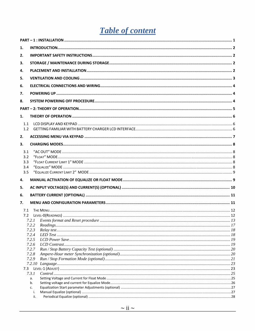
Table of content PART – 1 : INSTALLATION ..................................................................................................................................................... 1
1. INTRODUCTION........................................................................................................................................................... 2
2. IMPORTANT SAFETY INSTRUCTIONS ............................................................................................................................ 2
3. STORAGE / MAINTENANCE DURING STORAGE ............................................................................................................. 2
4. PLACEMENT AND INSTALLATION ................................................................................................................................. 2
5. VENTILATION AND COOLING ....................................................................................................................................... 3
6. ELECTRICAL CONNECTIONS AND WIRING ..................................................................................................................... 4
7. POWERING UP ............................................................................................................................................................ 4
8. SYSTEM POWERING OFF PROCEDURE .......................................................................................................................... 4
PART – 2: THEORY OF OPERATION ........................................................................................................................................ 5
1. THEORY OF OPERATION .............................................................................................................................................. 6
1.1 LCD DISPLAY AND KEYPAD ................................................................................................................................................... 6 1.2 GETTING FAMILIAR WITH BATTERY CHARGER LCD INTERFACE ............................................................................................ 6
2. ACCESSING MENU VIA KEYPAD ................................................................................................................................... 7
3. CHARGING MODES ...................................................................................................................................................... 8
3.1 “AC OUT” MODE .................................................................................................................................................................. 8 3.2 “FLOAT” MODE ...................................................................................................................................................................... 8 3.3 “FLOAT CURRENT LIMIT 1” MODE ............................................................................................................................................. 8 3.4 “EQUALIZE” MODE ................................................................................................................................................................. 8 3.5 “EQUALIZE CURRENT LIMIT 2” MODE ........................................................................................................................................ 9
4. MANUAL ACTIVATION OF EQUALIZE OR FLOAT MODE ................................................................................................. 9
5. AC INPUT VOLTAGE(S) AND CURRENT(S) (OPTIONAL) ................................................................................................ 10
6. BATTERY CURRENT (OPTIONAL) ................................................................................................................................ 11
7. MENU AND CONFIGURATION PARAMETERS .............................................................................................................. 11
7.1 THE MENU ............................................................................................................................................................................ 12 7.2 LEVEL‐0(READINGS) ............................................................................................................................................................... 12
7.2.1 Events format and Reset procedure ............................................................................................................................ 13 7.2.2 Readings ...................................................................................................................................................................... 17 7.2.3 Relay test ..................................................................................................................................................................... 18 7.2.4 LED Test ..................................................................................................................................................................... 18 7.2.5 LCD Power Save ......................................................................................................................................................... 19 7.2.6 LCD Contrast .............................................................................................................................................................. 19 7.2.7 Run / Stop Battery Capacity Test (optional) ............................................................................................................... 20 7.2.8 Ampere-Hour meter Synchronization (optional) ......................................................................................................... 20 7.2.9 Run / Stop Formation Mode (optional) ....................................................................................................................... 21 7.2.10 Language ..................................................................................................................................................................... 23
7.3 LEVEL‐1 (ADJUST) .................................................................................................................................................................. 23 7.3.1 Control ........................................................................................................................................................................ 25 a. Setting Voltage and Current for Float Mode ................................................................................................................................... 25 b. Setting voltage and current for Equalize Mode ............................................................................................................................... 26 c. Equalization Start parameter Adjustments (optional) .................................................................................................................... 27 i. Manual Equalize (optional) ............................................................................................................................................................. 27 ii. Periodical Equalize (optional) ...................................................................................................................................................... 28

~iii~
iii. Low Voltage Equalize (optional) .................................................................................................................................................. 29 iv. Low Capacity Equalize (optional) ................................................................................................................................................. 30 v. Charger Equalize Start (optional) ................................................................................................................................................. 31 vi. AC Fail Equalize (optional) ........................................................................................................................................................... 32 vii. Refresh Equalize (optional) .......................................................................................................................................................... 33 viii. Remote Equalize (optional) ......................................................................................................................................................... 34 ix. Current Limit Equalize (optional) ................................................................................................................................................. 35
d. Equalize Termination (optional) ...................................................................................................................................................... 36 i. Stopping Equalize after a preset delay: Security Time .................................................................................................................... 36 ii. Voltage Post-Charge Mode (optional) ......................................................................................................................................... 37 iii. Current Post-Charge Mode (optional) .......................................................................................................................................... 38 iv. Temperature Post-Charge Mode (optional) ................................................................................................................................. 39 v. Capacity Post-Charge Mode (optional) ........................................................................................................................................ 40
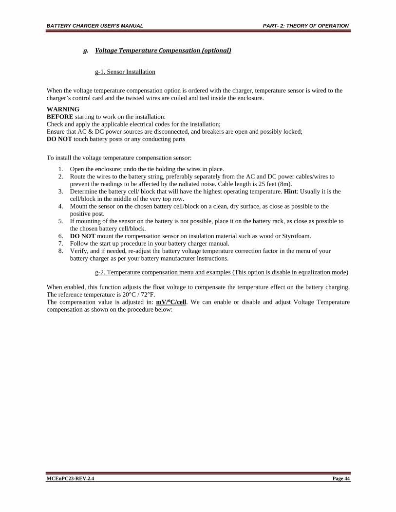
e. Formation Mode parameter adjustments (optional) ...................................................................................................................... 41 f. Load Sharing (optional) ................................................................................................................................................................... 42 g. Voltage Temperature Compensation (optional) ............................................................................................................................. 44
g-1. Sensor Installation ........................................................................................................................................................................... 44 g-2. Temperature compensation menu and examples (This option is disable in equalization mode) ..................................................... 44
7.3.2 Alarms ......................................................................................................................................................................... 47 a. Reset Alarms: Audible and Alarm Messages ................................................................................................................................... 48 b. Alarm adjustments and configuration ............................................................................................................................................. 49
i. Battery High Voltage Alarm ........................................................................................................................................................... 50 ii. Battery Low Voltage Alarm......................................................................................................................................................... 51 iii. Positive Ground Fault Alarm ....................................................................................................................................................... 52 iv. Negative Ground Fault Alarm ..................................................................................................................................................... 53 v. AC Fail Alarm ............................................................................................................................................................................. 54 vi. Rectifier Fail Alarm ..................................................................................................................................................................... 55 vii. Rectifier High Voltage Alarm * ................................................................................................................................................... 56 viii. High Voltage Shutdown Alarm * ............................................................................................................................................. 57 ix. Rectifier Low Voltage Alarm * ................................................................................................................................................... 58 x. End of Discharge Alarm (2nd Low Volt Level)* .......................................................................................................................... 59 xi. Charger High Temperature Alarm * ............................................................................................................................................ 60 xii. Charger Low Temperature Alarm * ............................................................................................................................................. 61 xiii. Battery High Temperature Alarm ** ........................................................................................................................................ 62 xiv. Battery Low Temperature Alarm ** ........................................................................................................................................ 63 xv. AC High Voltage Alarm ** ......................................................................................................................................................... 64 xvi. AC Low Voltage Alarm ** ...................................................................................................................................................... 65 xvii. High Ripple Alarm * ................................................................................................................................................................ 66 xviii. Rectifier Low Current Alarm * ................................................................................................................................................ 67 xix. Rectifier High Current Alarm * ................................................................................................................................................ 68 xx. Battery Low Current Alarm ** .................................................................................................................................................... 69 xxi. Battery High Current Alarm ** ................................................................................................................................................ 70 xxii. Battery High Capacity Alarm ** .............................................................................................................................................. 71 xxiii. Battery Low Capacity Alarm **............................................................................................................................................... 72 xxiv. Equalize Alarm * ...................................................................................................................................................................... 73 xxv. PCOM Alarm ** ...................................................................................................................................................................... 73 xxvi. PM Alarm ** ............................................................................................................................................................................ 74 xxvii. Frequency Alarm * ................................................................................................................................................................... 74 xxviii. Unbalanced Battery Alarm ** ................................................................................................................................................. 75 xxix. Temperature Probe Alarm ** ................................................................................................................................................... 76 xxx. Battery Discharge Alarm ** ..................................................................................................................................................... 77 xxxi. Common Relay and Audible Alarm configuration ** .............................................................................................................. 78
7.3.3 System Clock ** .......................................................................................................................................................... 79
8. CURRENT TEMPERATURE COMPENSATION « OUTPUT CURRENT DERATING » (OPTIONAL) ......................................... 81
9. REMOTE SENSING ..................................................................................................................................................... 81
10. TROUBLESHOOTING .................................................................................................................................................. 82
11. REGULAR PREVENTIVE MAINTENANCE ...................................................................................................................... 85

~iv~
FIGURE LIST ....................................................................................................................................................................... 86
ACRONYM LIST .................................................................................................................................................................. 88
LCD MESSAGES LIST ........................................................................................................................................................... 90
APPENDIXES ...................................................................................................................................................................... 92

MCEnPC23-REV.2.4 Page 1
PART – 1 : INSTALLATION
INSTALLATION

BATTERY CHARGER USER’S MANUAL PART-1:INSTALLATION
MCEnPC23-REV.2.4 Page 2
1. INTRODUCTION
This user manual contains important technical instructions to be followed by qualified personnel responsible for the installation, start-up, maintenance operations and knowledgeable on batteries and safety requirements/precautions involved. We recommend this manual to be read attentively to ensure safe and reliable operation of this equipment. Should you require any assistance, please call our service department.
2. IMPORTANT SAFETY INSTRUCTIONS Keep these instructions in a safe place: this manual contains important safety and operating instructions AC and DC currents are present in this system even with indicators and breakers are in “OFF” position. Before performing any maintenance on this system, make sure that the battery and the AC power are disconnected.
Only experienced and qualified personnel must perform maintenance. Electrostatic sensitive components are used in this equipment. Proper ESD (electrostatic discharge) procedures must be
followed to prevent any severe damage to electronic components. Working in the vicinity of Lead Acid or Nickel Cadmium batteries is dangerous: batteries generate explosive gases
during normal operation. Therefore, never smoke or allow an open spark or flame in the vicinity of the battery or engine.
To reduce risk of battery explosion, follow these instructions and those on the battery. Never charge a frozen battery. Do not expose charger/rectifier to rain or snow unless it has the appropriate NEMA/IP rating. Do not install or operate chargers if they have been dropped or damaged. Refer to your local/national electrical code for installation
3. STORAGE / MAINTENANCE DURING STORAGE If the charger/rectifier has to be stored before commissioning, it should be stored in a dry place, in the ambient temperature within –40oF to 185oF (-40oC to 85oC), not exposed to direct sunlight, on the same pallet, protected against moisture, dust, dirt and damage. Do not use the charger/rectifier as a stocking shelf. Remember that storing the charger/rectifier for a long period (5 years or more) can deteriorate performance of the filter capacitors and can cause also contact oxidation for relays, breakers, contactors… Filter capacitors shall be replaced after storing the charger/rectifier 5 years or more. Please contact the manufacturer for capacitor specifications and installation.
Warning
For batteries and other accessories (UPS…), please refer to the specific manufacturer indications for battery periodical recharge and powering up procedure after storage.
4. PLACEMENT AND INSTALLATION FOR INSTALLATION, PLEASE REFER TO NATIONAL AND/OR LOCAL ELECTRICAL CODES. Chargers/rectifiers are very heavy. To prevent personal injury or equipment damage, use appropriate lifting devices and execute extreme care while handling the equipment. The following instructions are very important to satisfactory operation. Changing the settings voids the warranty.

BATTERY CHARGER USER’S MANUAL PART-1:INSTALLATION
MCEnPC23-REV.2.4 Page 3
Warning Battery application and maintenance: Your battery is a crucial back up for your critical application. Special care and appropriate safety and maintenance procedures must be implemented. Please refer to the battery manufacturer instructions and the applicable battery installation, maintenance, testing and replacement standards for stationary application in order to optimize the life of the battery as well as to determine when the battery should be replaced. VRLA case (Lead Acid battery incorrectly called "maintenance free"): As this battery is sealed not allowing visual inspection or water addition, dry out and thermal runaway inside the battery can happen resulting to an unpredictable failure occurrence. Great care in installation, maintenance, testing and replacement is required to insure availability of backup power. The manufacturer instruction, your local standards and the following standards can be your guide to help to apply proper procedures: (other standards may apply). IEEE484: IEEE Recommended Practice for Installation Design and Installation of Vented Lead-Acid Batteries for Stationary Applications. IEEE450: IEEE Recommended Practice for Maintenance, Testing, and Replacement of Vented Lead-Acid Batteries for Stationary applications. IEEE1188: IEEE Recommended Practice for Maintenance, Testing, and Replacement of Valve-Regulated Lead-Acid (VRLA) Batteries for Stationary Applications. IEEE1106: IEEE Recommended Practice for Installation, Maintenance, Testing and Replacement of Vented Nickel-Cadmium Batteries for Stationary Applications.
5. VENTILATION AND COOLING
The rectifier/charger is rated to better perform within 18F (–10C) and 122F (+50C) temperature range. To calculate the required air displacement (exchange) volume, please use the following equation:
kr
T
TkH
TT
eBTUV
0125.0
V = air flow: [cubic meter/hour] BTU: Total dissipated heat Tr: Maximum allowed room temperature [K] {i.e. 50C = 323K] Tk= Temperature of input cooling air To= 273 K H = Altitude [km]
WARNING! Avoid placing the system in direct sunlight The adequate ventilation and safe access require that the following clearances are respected:
3 in. (10 cm) on the sides and top; 3 feet (1 meter) in front of the unit; DO NOT INSTALL OVER COMBUSTIBLE SURFACES;
Should seismic conditions require a more secure installation the unit can be bolted to the floor. Four (4) holes are provided for this purpose.

BATTERY CHARGER USER’S MANUAL PART-1:INSTALLATION
MCEnPC23-REV.2.4 Page 4
6. ELECTRICAL CONNECTIONS AND WIRING Before connecting the battery charger ensure that:
The battery is disconnected (if applicable) The circuit breakers are OFF The relays, fuses and circuit boards are installed The unit is wired in accordance with the instructions (refer to the wiring connections and electrical diagram)
The appropriate cable sizes are very important. The nameplate provides the essential information regarding the input and output voltages and currents. Use a branch feeder (circuit breaker or fused disconnect switch), sized to the maximum input current. Refer to your Local or National Electrical Code for LOCKOUT, WIRE GAUGE and GROUNDING instructions. The ampacity of the power cables must be sized to the maximal correspondent current. Correct voltage and polarity are of critical importance. Check all connections for tightness and polarity. Connect battery (if applicable to the output terminals observing its polarity.
7. POWERING UP
After the installation of all wires is completed and has been double checked, the unit may be powered up as follow:
Before connecting a load to a charger, compare the critical characteristics of the load against those of the charger (i.e. measure ripple, line-neutral voltage, positive-neutral voltage).
Keep a log of the values entered for VFLOAT and VEQUALIZE values entered, alarm messages, alarm and SCR blinking LEDs, etc.
All input and output breakers must be in ”OFF” position Apply power to the equipment from a source Turn on AC breaker (if supplied) (”ON” position) Wait 30 seconds Turn on DC breaker (if supplied) (”ON” position) Green LED must light up Wait 5 seconds until the LCD display will show the system’s output voltage and status The system soft starts by rising the output current and the voltage
If an adjustment or calibration of the unit is necessary, refer to the field programming section for more information.
8. SYSTEM POWERING OFF PROCEDURE
Open the DC breaker (if supplied) (OFF position); Open the source panel’s AC breaker (if supplied) (OFF position); Open the AC breaker feeding the powering the battery charger from external distribution panel; If work inside a unit has to be performed, wait 5 minutes to let the filter capacitors to discharge or use
bleeding resistors of the correct rating to discharge the capacitors; After following all previous steps, the battery charger can be considered de-energized.

MCEnPC23-REV.2.4 Page 5
PART – 2: THEORY OF OPERATION
THEORY OF OPERATION

BATTERY CHARGER USER’S MANUAL PART- 2: THEORY OF OPERATION
MCEnPC23-REV.2.4 Page 6
1. THEORY OF OPERATION
The battery charger provides a fully regulated and Isolated DC output from the main AC input. The LCD show
continuously the battery charger status: DC Voltage, DC current, alarms ….
1.1 LCDDISPLAYANDKEYPAD
F1 F2 F3 F4
CONTROL, ALARM & COMMUNICATION
136.2V 10.5A
Equalize
A B C D
OR
ON ACALARM(S)
Each key corresponds to above function as described on the following figures
Figure 1 : Battery charger home screen.
The LCD display and keypad provide very flexible and user friendly interface. The standard display is a high visibility backlit two-line LCD display. Four (4) long life membrane switches are used as the keypad buttons.
1.2 GETTINGFAMILIARWITHBATTERYCHARGERLCDINTERFACE
All adjustable values and readings are displayed on the first line. Ex.: alarm activation status, voltage and current readings… On the second line, soft keys are used: each keyboard button’s function is displayed. The assignment of a button to a function can change as needed by different menus or at different levels of access. The Red LED will blink when any alarm occurs. A corresponding alarm message will also be displayed on the second line. If more than one message is to be displayed then the messages will scroll sequentially. All settings can be saved individually. The lit green LED indicates that the AC is on. The LCD back lighting will turn off after 5 min of inactivity, if the power save function is selected. It will turn back on whenever a button is pressed or any alarm occurs. The accuracy of all readings is 0.5% +/- 1digit.

BATTERY CHARGER USER’S MANUAL PART- 2: THEORY OF OPERATION
MCEnPC23-REV.2.4 Page 7
2. ACCESSING MENU VIA KEYPAD All gray buttons in all figures inside this manual mean that this button is pressed and activated. When more than one button is gray, this means that we have a choice to press any button on keypad.
WARNING! All values indicated in the following figures are given as examples. These values don’t apply necessarily to your system. For more information about the real values and options set for your application, please refer to the test report at the end of this manual.
On power-up the following readings appears on the screen:
F1 F2 F3 F4
136.2V
Equalize
10.5A
A B C D
Figure 2 : Home screen example after turning ON the battery charger.
From that point, if you press any button once from F1 to F4 (or A to D with other keypad), you reach the menu screen:
Eq FltMode
Ok Next Pr Exit
Figure 3 : LCD Display after pressing any button.
From this menu, buttons F2 and F3 (B and C with other keypad) allow us to navigate all other menus and sub-menus, adjustments and enable or disable functions. A detailed description of all menus and sub-menus will be provided in the following paragraph. Important!
All adjustments of your battery charger are made in our service department. Some sub-menus are password protected. Only authorized personal will be able to access these sub-menus.

BATTERY CHARGER USER’S MANUAL PART- 2: THEORY OF OPERATION
MCEnPC23-REV.2.4 Page 8
3. CHARGING MODES
3.1 “ACOUT”MODE
In the case of a power outage, if the AC breaker is open or if the control board fuse has blown, an AC fail alarm will be generated, warning you that one of the cases has occurred. In this mode, the rectifier waits for the AC input to be reconnected to the charger or the control board. Note: In this mode, the load will be powered by the battery only.
0.0V 0.0AOUT AC
Figure 4 : AC OUT Mode Display.
3.2 “Float”MODE The Float mode is the default charging mode. It can be run via:
Keypad (manually); Preset delay (periodically); External signal (optional); ModBus RS232 / RS485, or ModBus TCP/IP communication (optional); DNP3 RS232 / RS485 communication (optional);
The image below shows the LCD display when the charger is in “Float” mode.
Float132.6V 14.5A
Figure 5 : Float Mode Display.
3.3 “FloatCurrentLimit1”MODE The maximum Float current is preset at the factory. The image below shows the LCD display when the charger is in “Float Current Limit” mode.
Limit1Current 130.5V 20.0A
Figure 6 : Float Current Limit Mode Display.
3.4 “Equalize”MODE Some batteries need to be periodically Equalized. Basically, Equalization refers to a controlled charging at a higher voltage than Float level. Equalize Mode can be run:
Via Keypad (manually);

BATTERY CHARGER USER’S MANUAL PART- 2: THEORY OF OPERATION
MCEnPC23-REV.2.4 Page 9
Via a preset delay (periodically); Via external signal (optional); Via ModBus RS232 / RS485, or ModBus TCP/IP communication (optional); Via DNP3 RS232 / RS485 communication (optional); If DC Output voltage is within a preset value (Low Volt Equalize: optional); If battery capacity is within a preset value (optional); After an AC Failure during a preset delay (optional); If the battery charger is within a current limit during a preset delay (optional);
The image below shows the LCD display when the charger is in “Equalize” mode.
Equalize136.2V 9.5A
Figure 7 : Equalize Mode Display.
3.5 “EqualizeCurrentLimit2”MODE
The maximum Equalize current is preset at the factory. The image below shows the LCD display when the charger is in “Equalize Current Limit” mode.
Limit2Current 128.5V 20.1A
Figure 8 : Equalize Current Limit Mode Display.
4. MANUAL ACTIVATION OF EQUALIZE OR FLOAT MODE When ordered, the charger can be configured for the manual “Equalize” mode. Please refer to your order and the battery manufacturer to confirm the Equalize requirement. If “Equalize” function does not appear on the LCD, then this automatic function has been disabled at the factory. Contact the agent or the manufacturer for more information. Switching the charger from “Float” to “Equalize” mode can be done manually through the menu. Other equalizing options are also included below. The equalizing time is adjustable between 1 hour and 8191 hours.

BATTERY CHARGER USER’S MANUAL PART- 2: THEORY OF OPERATION
MCEnPC23-REV.2.4 Page 10
120.5V 10.2AEqualize
MODE EqFltOk Next ExitPr
Float ExitEq
FloatFloat ExitEq
EqualizeFloat ExitEq
Figure 9 : Enabling Manually Float or Equalize Mode.
5. AC INPUT VOLTAGE(S) AND CURRENT(S) (OPTIONAL)
If this option is ordered, the AC Input Voltage and Current are displayed on the LCD.
VAC1136.4V 20.0A
120.5V
IAC1
136.4V 20.0A 80.3A
Figure 10 : AC Input Voltage and Current Readings.
In case of 3 phase units, the phase voltage and current readings will be scrolling on the LCD as follow: VAC1, VAC2, VAC3, IAC1, IAC2 and IAC3.

BATTERY CHARGER USER’S MANUAL PART- 2: THEORY OF OPERATION
MCEnPC23-REV.2.4 Page 11
6. BATTERY CURRENT (OPTIONAL) The current flowing IN or OUT of the battery will be displayed on LCD if this option is enabled. Negative (-) sign will be displayed in case of battery discharging.
IBatt 136.2V 20.1A
23.3A
IBatt 136.1V 20.0A
80.4A -
Figure 11 : Battery Current Display.
7. MENU AND CONFIGURATION PARAMETERS The battery charger is controlled by a 32-bit Microcontroller installed on the control board. All parameters are saved into a EEPROM. The settings are configured into two categories:
1. Charger active parameters such as the alarm settings, O/P voltage and current, etc. 2. Charger active configuration: Temperature compensation, load sharing (if ordered). The calibration settings
are reserved for factory use only. The battery charger allows users to adjust and visualize the following parameters:
DC Output voltage and current; Equalize operation mode; Float operation mode; Charger current limit mode; Battery voltage remote sensing; Alarm adjustments; Temperature compensation; Load sharing; 250 events monitoring (date and time stamp are optional); Reset alarms and relays; Measures :
AC Frequency. Rectifier voltage. Voltage between positive output and chassis. Voltage between negative output and chassis. Remaining time for Equalize. Elapsed time for Equalize. Charger temperature. Battery temperature (optional). Battery Voltage discharge test (optional). Battery current discharge test (optional). Battery discharge time (optional).
Relay test. LCD contrast adjustment.

BATTERY CHARGER USER’S MANUAL PART- 2: THEORY OF OPERATION
MCEnPC23-REV.2.4 Page 12
Battery Test (optional). Formation test (optional). Language selection. DNP3 and Modbus Communication (optional).
Battery charger parameter adjustment and visualization. Pre-programmable 4 messages, to be displayed on LCD (Refer to ModBus manual).
Four external command via a four normally open contact (optional):
Display of the four pre-programmable messages (Refer to ModBus manual). Switching to Equalize mode. Switching to Float mode. Reset relays. Run or Stop the battery charger.
7.1 TheMenu The menu is divided into three levels: Level-0 for Readings, Level-1 for Adjustments and Level-2 for Advanced Settings. LEVEL-0 (Readings): This level is directly accessible by the user with no password need. In this level, the user can perform basic operation of the charger such as:
Run or stop any other operating function as Battery Test; Read different data such as the Battery Temperature (optional); Read different events: AC frequency or others;
LEVEL-1 (Adjustments): This level is protected by a password and reserved for charging parameters adjustments such as float voltage, current, alarms, etc. A user can disable / enable this password in Level 2. LEVEL-2 (Advanced settings): This level is reserved for the Factory calibration purpose and protected by a password. This level is to adjust, calibrate, enable or disable different charger functions.
7.2 Level‐0(Readings) The following figure shows all steps to access Level-0:

BATTERY CHARGER USER’S MANUAL PART- 2: THEORY OF OPERATION
MCEnPC23-REV.2.4 Page 13
136.4V 50.1A
Alarms?Reset Ok Next Pr Exit
Ok Next Pr Exit
Ok Next Pr Exit
EqFltMode
Readings? Level0
Charger OutputHome ScreenEqualize
This message will appearonly if an alarm is active
This menu will display only ifEqualize mode is Enabled
Press F1(or A) to access Level0
Next Press
Next Press
A B C D
F1 F2 F3 F4
Figure 12 : Procedure to access Level-0.
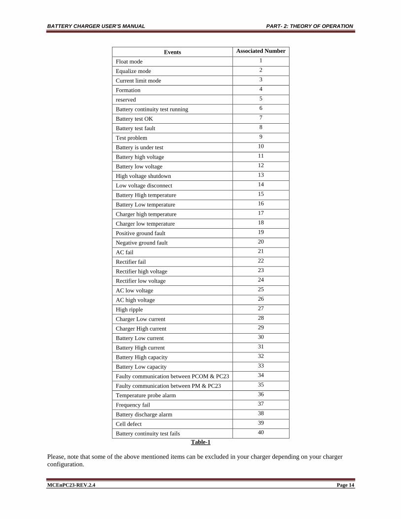
7.2.1 Events format and Reset procedure The latest 250 events are saved in the memory. Please refer to Table-1 for the event index. Please note that if dated events are required, then a special circuit with a backup battery has to be ordered at the time of placing your purchase order. Table-1 provide a list of events with associated number
BATTERY CHARGER USER’S MANUAL PART- 2: THEORY OF OPERATION
MCEnPC23-REV.2.4 Page 14
Events Associated Number
Float mode 1
Equalize mode 2
Current limit mode 3
Formation 4
reserved 5
Battery continuity test running 6
Battery test OK 7
Battery test fault 8
Test problem 9
Battery is under test 10
Battery high voltage 11
Battery low voltage 12
High voltage shutdown 13
Low voltage disconnect 14
Battery High temperature 15
Battery Low temperature 16
Charger high temperature 17
Charger low temperature 18
Positive ground fault 19
Negative ground fault 20
AC fail 21
Rectifier fail 22
Rectifier high voltage 23
Rectifier low voltage 24
AC low voltage 25
AC high voltage 26
High ripple 27
Charger Low current 28
Charger High current 29
Battery Low current 30
Battery High current 31
Battery High capacity 32
Battery Low capacity 33
Faulty communication between PCOM & PC23 34
Faulty communication between PM & PC23 35
Temperature probe alarm 36
Frequency fail 37
Battery discharge alarm 38
Cell defect 39
Battery continuity test fails 40 Table-1
Please, note that some of the above mentioned items can be excluded in your charger depending on your charger configuration.
BATTERY CHARGER USER’S MANUAL PART- 2: THEORY OF OPERATION
MCEnPC23-REV.2.4 Page 15
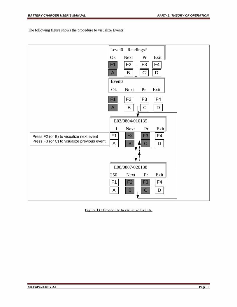
The following figure shows the procedure to visualize Events:
F1 F2 F3 F4
F1 F3 F4
F1 F2 F3 F4
Events
ExitPr Next Ok
Readings? Level0
F1 F2 F3 F4
10135E03/0804/0
20138E08/0807/0
F2Press F2 (or B) to visualize next eventPress F3 (or C) to visualize previous event
ExitPr Next Ok
A B C D
ExitPr Next 1
ExitPr Next 250
A B C D
A B C D
A B C D
Figure 13 : Procedure to visualize Events.

BATTERY CHARGER USER’S MANUAL PART- 2: THEORY OF OPERATION
MCEnPC23-REV.2.4 Page 16
Event Format: Event format is described as follow:
Event tenth The
E07/ 08
Year
Month
DayHour
Minute
07 02 01 38
10 Next Pr Exit
Figure 14 : Event Format description.
Reset Events : The following figure shows the procedure to Reset Events:
:getyou Next till Press
Readings? Level0
EventsReset
Yes No
Ok EventsReset secondes 2
duringDisplay
EventsReset
ExitPr Next Ok
ExitPr Next Ok
Figure 15 : Procedure to Reset Events.
BATTERY CHARGER USER’S MANUAL PART- 2: THEORY OF OPERATION
MCEnPC23-REV.2.4 Page 17
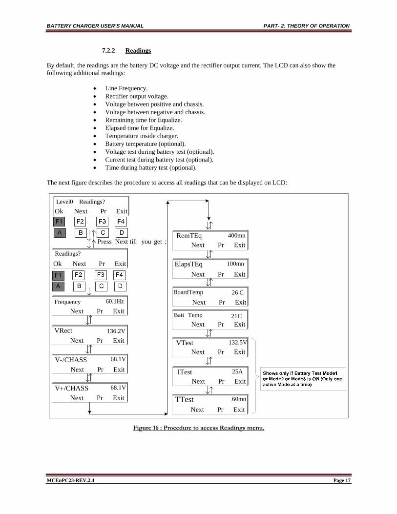
7.2.2 Readings By default, the readings are the battery DC voltage and the rectifier output current. The LCD can also show the following additional readings:
Line Frequency. Rectifier output voltage. Voltage between positive and chassis. Voltage between negative and chassis. Remaining time for Equalize. Elapsed time for Equalize. Temperature inside charger. Battery temperature (optional). Voltage test during battery test (optional). Current test during battery test (optional). Time during battery test (optional).
The next figure describes the procedure to access all readings that can be displayed on LCD:
Readings? Level0
Readings?
Frequency 60.1Hz
VRect 136.2V
/CHASS-V 68.1V
/CHASSV 68.1V
RemTEq 400mn
ElapsTEq 100mn
C 26
VTest 132.5V
ITest 25A
TTest 60mn
ExitPr Next Ok
:getyou Next till Press
BoardTemp
TempBatt C 21
ExitPr Next Ok
ExitPr Next
ExitPr Next
ExitPr Next
ExitPr Next
ExitPr Next
ExitPr Next
ExitPr Next
ExitPr Next
ExitPr Next
ExitPr Next
ExitPr Next
Figure 16 : Procedure to access Readings menu.

BATTERY CHARGER USER’S MANUAL PART- 2: THEORY OF OPERATION
MCEnPC23-REV.2.4 Page 18
Acronyms : Refer to acronym list used for the battery charger at the end of this manual.
7.2.3 Relay test During relay test, all relays will be energized (or de-energized if you select the fail safe operation option) for 5 seconds; after which the relays will return to their initial status.
Test?Relay
Readings? Level0
RunTest Relay
:getyou Next till Press
secondes 2duringDisplay
ExitPr Next Ok
ExitPr Next Ok
Figure 17 : Procedure to run Relay Test.
7.2.4 LED Test During LED test, all LEDs will be lit for 5 seconds; after which the LEDs will return to their initial status.
Test? LED
Readings? Level0
RunTest LED
:getyou Next till Press
secondes 2duringDisplay
ExitPr Next Ok
ExitPr Next Ok
Figure 18 : Procedure to run LED Test.
BATTERY CHARGER USER’S MANUAL PART- 2: THEORY OF OPERATION
MCEnPC23-REV.2.4 Page 19
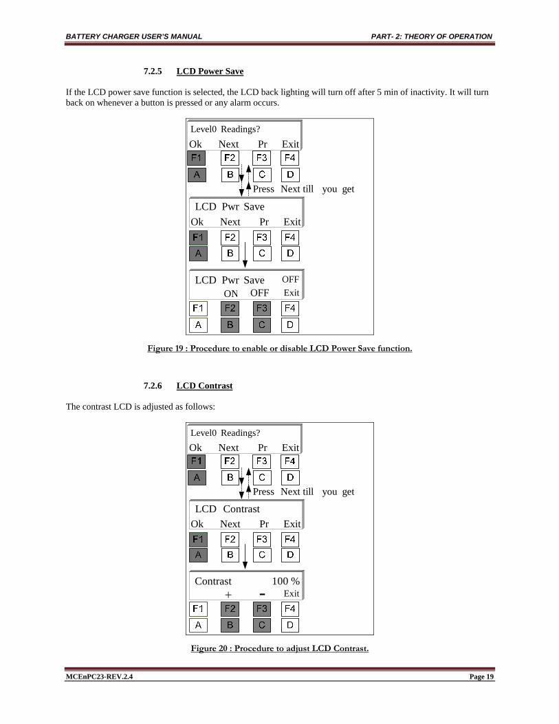
7.2.5 LCD Power Save If the LCD power save function is selected, the LCD back lighting will turn off after 5 min of inactivity. It will turn back on whenever a button is pressed or any alarm occurs.
SavePwr LCD
Readings? Level0
ON OFF ExitOFF
getyou Next till Press
ExitPr Next Ok
ExitPr Next Ok
SavePwr LCD
Figure 19 : Procedure to enable or disable LCD Power Save function.
7.2.6 LCD Contrast The contrast LCD is adjusted as follows:
Contrast LCD
Readings? Level0
- Exit
getyou Next till Press
ExitPr Next Ok
ExitPr Next Ok
% 100 Contrast
Figure 20 : Procedure to adjust LCD Contrast.

BATTERY CHARGER USER’S MANUAL PART- 2: THEORY OF OPERATION
MCEnPC23-REV.2.4 Page 20
7.2.7 Run / Stop Battery Capacity Test (optional) The image below shows how to run or stop manually the battery-capacity-test.
Test?Battery
RunTest Battery StopTest Batt
Readings? Level0
:getyou Next till Press
Available!Not
ExitPr Next Ok
Test?Battery Run Stop
ExitPr Next Ok
Figure 21 : Procedure to Run or Stop Battery Capacity Test.
7.2.8 Ampere-Hour meter Synchronization (optional) The image below shows how to synchronize the ampere-hour meter. Adjustment is needed only under certain conditions:
1. When the battery voltage is between 0.98% and 1.02% of Vcharge value; 2. When The current flowing in the battery (charging current) is less than Icharge for a time exceeding
Tcharge”; For more details see Appendix “Ampere-Hour meter (included when this option is purchased).

BATTERY CHARGER USER’S MANUAL PART- 2: THEORY OF OPERATION
MCEnPC23-REV.2.4 Page 21
Yes No
Synchro AHOk Pr
sure?you Are
Ok Synchro
Readings? Level0
Ok Next Pr Exit
Next Exit
:getyou Next till Press
Figure 22 : Procedure to synchronize Ampere-Hour meter.
7.2.9 Run / Stop Formation Mode (optional)
The formation mode is to be exclusively used to prime a battery as per its manufacturer instructions. In this mode, the charger forms the battery at the preset voltage and during the preset time, after which the charger will go back into the float mode. The image below shows how to run or stop formation mode.

BATTERY CHARGER USER’S MANUAL PART- 2: THEORY OF OPERATION
MCEnPC23-REV.2.4 Page 22
Run Stop
StartFormation
Formation
Available!Not StopFormation
FormationOk Pr
Readings? Level0
Ok Next Pr Exit
Next Exit
:getyou Next till Press
Figure 23 : Procedure to Run or Stop Formation Mode.
Once Formation mode started, the LCD will show one of messages below, depending on Battery formation status
Formation140.2V 1.5A
Limit3Current 137.6V 3.0A
OR
Figure 24 : Battery Formation mode display.
BATTERY CHARGER USER’S MANUAL PART- 2: THEORY OF OPERATION
MCEnPC23-REV.2.4 Page 23
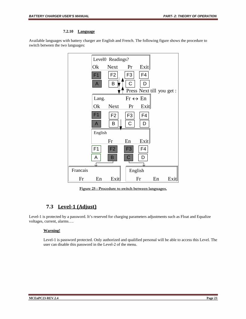
7.2.10 Language Available languages with battery charger are English and French. The following figure shows the procedure to switch between the two languages:
F1
F1 F2 F3 F4
Lang.
F2 F3 F4
Francais English
EnFr
English
F1
Readings? Level0
F2 F3 F4
:getyou Next till Press
ExitPr Next Ok
A B C D
A B C D
ExitPr Next Ok
ExitEn Fr
A B C D
ExitEn Fr ExitEn Fr
Figure 25 : Procedure to switch between languages.
7.3 Level‐1(Adjust) Level-1 is protected by a password. It’s reserved for charging parameters adjustments such as Float and Equalize voltages, current, alarms….
Warning! Level-1 is password protected. Only authorized and qualified personal will be able to access this Level. The user can disable this password in the Level-2 of the menu.

BATTERY CHARGER USER’S MANUAL PART- 2: THEORY OF OPERATION
MCEnPC23-REV.2.4 Page 24
136.2V 50.0A
F1
Alarms?Reset
EqFlt Mode
Readings?Level0
F2 F3 F4
Adjust?Level1
ExitPasswordEnter
A B C D
Figure 26 : Procedure to access Level - 1.
If a parameter is modified, the LCD will display the following screen to confirm changes. If the modification is not saved or canceled, the battery charger will keep the old value.
Save?Yes No
Figure 27 : Display after modifying a parameter.
BATTERY CHARGER USER’S MANUAL PART- 2: THEORY OF OPERATION
MCEnPC23-REV.2.4 Page 25
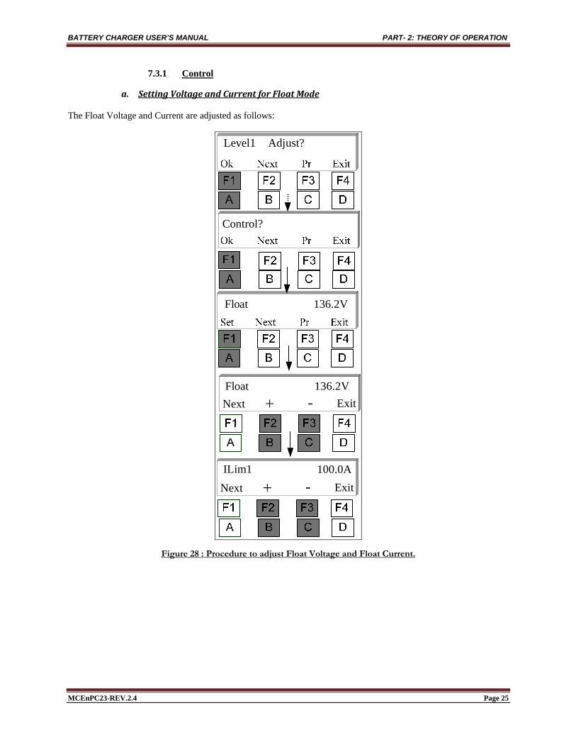
7.3.1 Control
a. SettingVoltageandCurrentforFloatMode The Float Voltage and Current are adjusted as follows:
Control?
Adjust? Level1
136.2V Float
Next Exit -
ILim1Next Exit -
100.0A
136.2V Float
Figure 28 : Procedure to adjust Float Voltage and Float Current.

BATTERY CHARGER USER’S MANUAL PART- 2: THEORY OF OPERATION
MCEnPC23-REV.2.4 Page 26
b. SettingvoltageandcurrentforEqualizeMode
EqSet ExitNext Pr
EqNext Exit -
EqNext ExitON OFF
ON
138.2V ON
138.2V ON
ILim2Next Exit -
100.0A
Control?
Adjust? Level1
Ok Next Pr Exit
Ok Next Pr Exit
:getyou Next till Press
Figure 29 : Procedure to adjust Equalize Voltage and Equalize Current.
BATTERY CHARGER USER’S MANUAL PART- 2: THEORY OF OPERATION
MCEnPC23-REV.2.4 Page 27
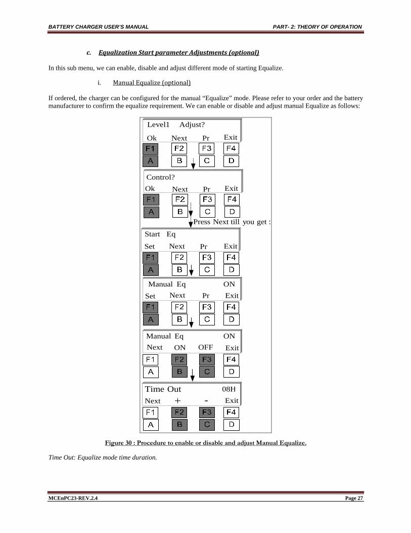
c. EqualizationStartparameterAdjustments(optional) In this sub menu, we can enable, disable and adjust different mode of starting Equalize.
i. ManualEqualize(optional) If ordered, the charger can be configured for the manual “Equalize” mode. Please refer to your order and the battery manufacturer to confirm the equalize requirement. We can enable or disable and adjust manual Equalize as follows:
Control?Ok Next Pr Exit
Adjust? Level1
Ok Next Pr Exit
EqStart
Set ExitNext Pr
ON Eq ManualSet ExitNext Pr
Next ExitON OFF
Out TimeNext Exit -
08H
:getyou Next till Press
ON Eq Manual
Figure 30 : Procedure to enable or disable and adjust Manual Equalize.
Time Out: Equalize mode time duration.

BATTERY CHARGER USER’S MANUAL PART- 2: THEORY OF OPERATION
MCEnPC23-REV.2.4 Page 28
ii. PeriodicalEqualize(optional) If Periodical Equalize is enabled then the charger will go into “Equalize” mode every preset period. The period is adjustable between 1 day and 8191 days. The duration is adjustable between 1 and 8191 hours. We can enable or disable and adjust periodical Equalize as follows:
Control?Ok Next Pr Exit
Adjust? Level1
Ok Next Pr Exit
EqStart
Set ExitNext Pr
ON Eq PeriodicSet ExitNext Pr
Next ExitON OFF
Out TimeNext Exit -
08H
:getyou Next till Press
ON Eq Periodic
:getyou Next till Press
Delay
Next Exit -D 31
Figure 31 : Procedure to enable or disable and adjust Periodical Equalize.
Delay : (31D = 31 Days) After this Delay, the battery charger will return automatically to Equalize mode for a duration “Time Out ”of 8H.

BATTERY CHARGER USER’S MANUAL PART- 2: THEORY OF OPERATION
MCEnPC23-REV.2.4 Page 29
iii. LowVoltageEqualize(optional) If the Low Voltage Equalize is enabled, then the charger will go into “Equalize” mode whenever the DC output voltage drops under a preset voltage. The duration is adjustable between 1 and 8191 hours. We can enable or disable and adjust low volt Equalize as follows:
Control?Ok Next Pr Exit
Adjust? Level1
Ok Next Pr Exit
EqStart
Set ExitNext Pr
ON 120.0V LVEqSet ExitNext Pr
Next Exit
ON OFF
Out Time
Next Exit
08H
:getyou Next till Press
:getyou Next till Press
Next Exit -
-ON 120.0V LVEq
ON LVEq
Figure 32 : Procedure to enable or disable and adjust Low Volt Equalize.

BATTERY CHARGER USER’S MANUAL PART- 2: THEORY OF OPERATION
MCEnPC23-REV.2.4 Page 30
iv. LowCapacityEqualize(optional) If the Low Capacity Equalize is enabled, then the charger will go into “Equalize” mode whenever the capacity battery decreases under a preset capacity. The duration is adjustable between 1 and 8191 hours. We can enable or disable and adjust low capacity Equalize as follows:
Control?Ok Next Pr Exit
Adjust? Level1
Ok Next Pr Exit
EqStart
Set ExitNext Pr
ON % 50 LCapEqSet ExitNext Pr
Next Exit
ON OFF
Out Time
Next Exit
08H
:getyou Next till Press
:getyou Next till Press
Next Exit -
-ON % 50 LCapEq
ON % 50 LCapEq
Figure 33 : Procedure to enable or disable and adjust Low Capacity Equalize.

BATTERY CHARGER USER’S MANUAL PART- 2: THEORY OF OPERATION
MCEnPC23-REV.2.4 Page 31
v. ChargerEqualizeStart(optional) If the charger Equalize Start is enabled, then the charger will go into “Equalize” mode when it starts (first time power up). The duration is adjustable between 1 and 8191 hours. We can enable or disable and adjust charger Equalize Start as follows:
Control?Ok Next Pr Exit
Adjust? Level1
Ok Next Pr Exit
EqStart
Set ExitNext Pr
ON Start EqSet ExitNext Pr
ON OFF
Out Time
Next Exit
08H
:getyou Next till Press
:getyou Next till Press
Next Exit -
ON Start Eq
Figure 34 : Procedure to enable or disable and adjust Charger Equalize Start.
BATTERY CHARGER USER’S MANUAL PART- 2: THEORY OF OPERATION
MCEnPC23-REV.2.4 Page 32
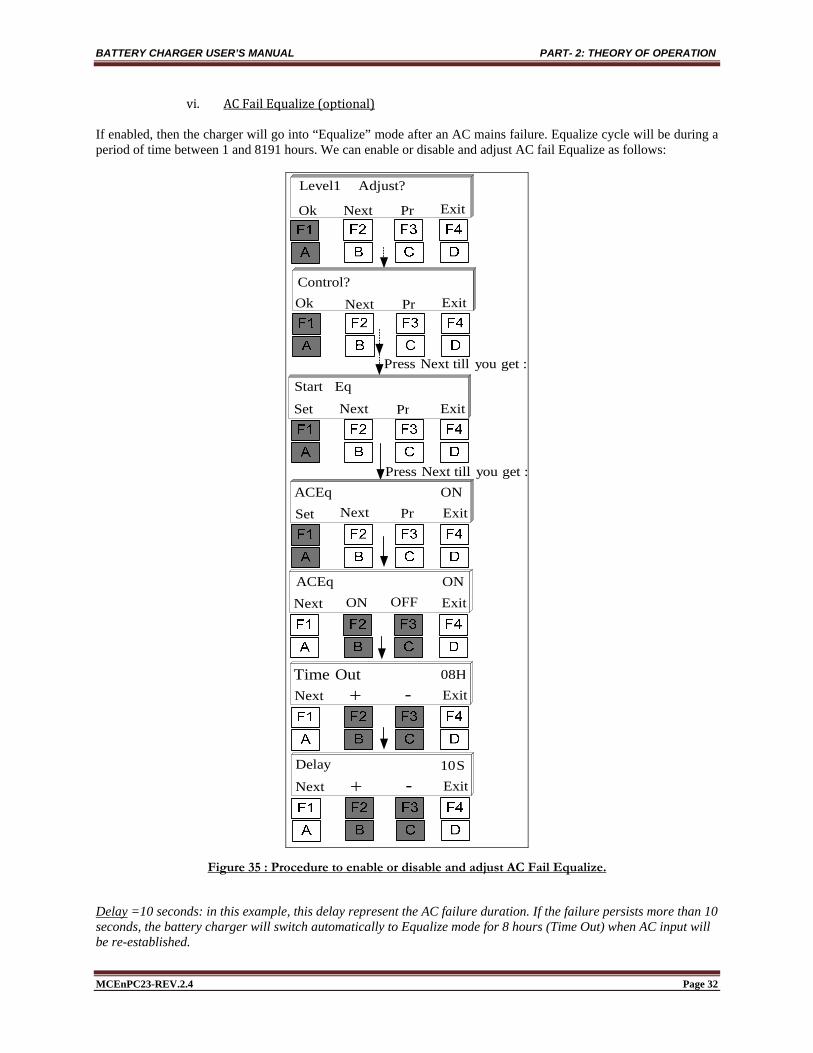
vi. ACFailEqualize(optional) If enabled, then the charger will go into “Equalize” mode after an AC mains failure. Equalize cycle will be during a period of time between 1 and 8191 hours. We can enable or disable and adjust AC fail Equalize as follows:
Control?Ok Next Pr Exit
Adjust? Level1
Ok Next Pr Exit
EqStart
Set ExitNext Pr
ON ACEqSet ExitNext Pr
ON OFF
Out Time
Next Exit
08H
:getyou Next till Press
:getyou Next till Press
Next Exit -
ON ACEq
Delay S 10Next Exit -
Figure 35 : Procedure to enable or disable and adjust AC Fail Equalize.
Delay =10 seconds: in this example, this delay represent the AC failure duration. If the failure persists more than 10 seconds, the battery charger will switch automatically to Equalize mode for 8 hours (Time Out) when AC input will be re-established.

BATTERY CHARGER USER’S MANUAL PART- 2: THEORY OF OPERATION
MCEnPC23-REV.2.4 Page 33
vii. RefreshEqualize(optional) If Refresh Equalize is enabled, then the charger will go into “Equalize” mode for a preset time between 1 and 8191minutes every period between 1 and 8191 hours. Example: The charger will equalize the battery during 5min every 24 hours.
Control?Ok Next Pr Exit
Adjust? Level1
Ok Next Pr Exit
EqStart
Set ExitNext Pr
ON EqRefresh Set ExitNext Pr
ON OFF
Out Time
Next Exit
10mn
:getyou Next till Press
:getyou Next till Press
Next Exit -
Delay H24Next Exit -
ON EqRefresh
Figure 36 : Procedure to enable or disable and adjust Refresh Equalize.

BATTERY CHARGER USER’S MANUAL PART- 2: THEORY OF OPERATION
MCEnPC23-REV.2.4 Page 34
viii. RemoteEqualize(optional) If Remote Equalize is enabled, the charger will go into “Equalize” mode during a preset time between 1 and 8191 hours, if command is initiated by users via web page, or whenever an external normally open contact closes momentarily or permanently. For more details, refer to Appendix-5. We can enable or disable remote Equalize via the external normally open contact as shown on the procedure below:
Figure 37 : External signal to Start Equalize remotely.
Control?Ok Next Pr Exit
Adjust? Level1
Ok Next Pr Exit
EqStart
Set ExitNext Pr
ON Eq RemoteSet ExitNext Pr
ON OFF
Out Time
Next Exit
08H
:getyou Next till Press
:getyou Next till Press
Next Exit -
ON Eq Remote
Figure 38 : Procedure to enable or disable and adjust Remote Equalize.

BATTERY CHARGER USER’S MANUAL PART- 2: THEORY OF OPERATION
MCEnPC23-REV.2.4 Page 35
ix. CurrentLimitEqualize(optional) If Current Limit Equalize is enabled, the charger will go into “Equalize” mode during a preset time between 1 and 8191 hours, whenever the rectifier goes into the current limit for a period of time between 1 and 8191 seconds. We can enable or disable current limit Equalize as shown on the procedure below:
Control?Ok Next Pr Exit
Adjust? Level1
Ok Next Pr Exit
EqStart
Set ExitNext Pr
ON ILimEqSet ExitNext Pr
ON OFF
Out Time
Next Exit
08H
:getyou Next till Press
:getyou Next till Press
Next Exit -
ON ILimEq
Delay S 10Next Exit -
Figure 39 : Procedure to enable or disable and adjust Current Limit Equalize.

BATTERY CHARGER USER’S MANUAL PART- 2: THEORY OF OPERATION
MCEnPC23-REV.2.4 Page 36
d. EqualizeTermination(optional) We can stop Equalize mode manually as described on Part-2 / Paragraph-4. However, Equalize mode can be stopped also automatically as described on the following paragraph.
i. Stopping Equalize after a preset delay: Security Time To ensure a security while the battery charger is operating in Equalize mode and in order to protect batteries, a preprogrammed time security can be set. The Equalize mode will stop automatically after this preset time security. Whatever is the Equalize starting option, it will end after this security delay.
Control?Ok Next Pr Exit
Adjust? Level1
Ok Next Pr Exit
Eq Stop
Set ExitNext Pr
H 08 EqTSecuritSet ExitNext Pr
:getyou Next till Press
Exit -H 08 EqTSecurit
Figure 40 : Procedure to set security delay to stop Equalize mode.

BATTERY CHARGER USER’S MANUAL PART- 2: THEORY OF OPERATION
MCEnPC23-REV.2.4 Page 37
ii. Voltage Post-Charge Mode (optional) When the Voltage Post-Charge mode is selected, the charger will revert back from Equalize into the Float mode when the load voltage reaches the Equalize one during a preset time between 1 and 8191 minutes. We can enable or disable Voltage Post-Charge as shown on the procedure below:
Control?Ok Next Pr Exit
Adjust? Level1
Ok Next Pr Exit
Eq Stop
Set ExitNext Pr
ON VPostChgSet ExitNext Pr
ON OFFNext Exit
:getyou Next till Press
:getyou Next till Press
Delay mn 30Next Exit -
ON VPostChg
Figure 41 : Procedure to set Voltage Post-Charge parameters to Stop Equalize mode.
BATTERY CHARGER USER’S MANUAL PART- 2: THEORY OF OPERATION
MCEnPC23-REV.2.4 Page 38
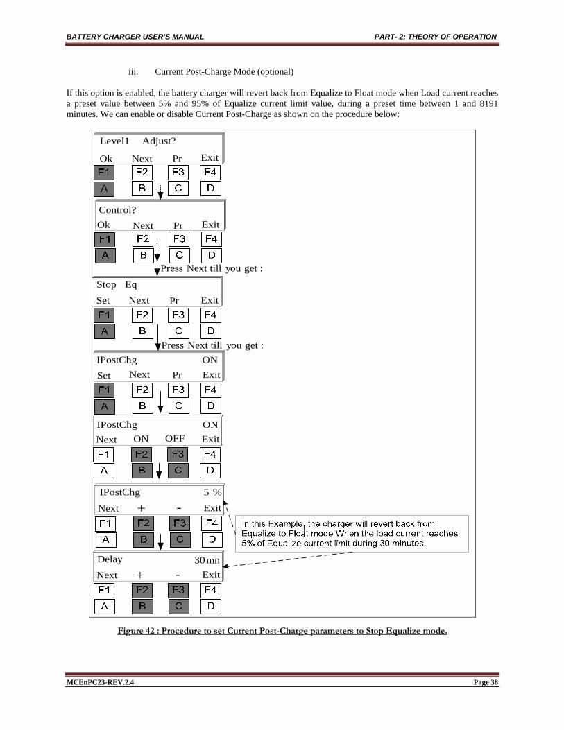
iii. Current Post-Charge Mode (optional) If this option is enabled, the battery charger will revert back from Equalize to Float mode when Load current reaches a preset value between 5% and 95% of Equalize current limit value, during a preset time between 1 and 8191 minutes. We can enable or disable Current Post-Charge as shown on the procedure below:
Control?Ok Next Pr Exit
Adjust? Level1
Ok Next Pr Exit
Eq Stop
Set ExitNext Pr
ON IPostChgSet ExitNext Pr
ON OFFNext Exit
:getyou Next till Press
:getyou Next till Press
Delay mn 30Next Exit -
ON IPostChg
Next Exit -% 5 IPostChg
Figure 42 : Procedure to set Current Post-Charge parameters to Stop Equalize mode.

BATTERY CHARGER USER’S MANUAL PART- 2: THEORY OF OPERATION
MCEnPC23-REV.2.4 Page 39
iv. Temperature Post-Charge Mode (optional) When the Temperature Post-Charge is selected, the charger will revert back from Equalize into the Float mode when the battery temperature reaches its preset value, during a preset time between 1 and 8191 minutes. We can enable or disable Temperature Post-Charge as shown on the procedure below:
Control?Ok Next Pr Exit
Adjust? Level1
Ok Next Pr Exit
Eq Stop
Set ExitNext Pr
ON TPostChgSet ExitNext Pr
ON OFFNext Exit
:getyou Next till Press
:getyou Next till Press
Delay mn 30Next Exit -
ON TPostChg
Next Exit -C 60 TPostChg
Figure 43 : Procedure to set Temperature Post-Charge parameters to Stop Equalize mode.

BATTERY CHARGER USER’S MANUAL PART- 2: THEORY OF OPERATION
MCEnPC23-REV.2.4 Page 40
v. Capacity Post-Charge Mode (optional) When the Capacity Post-Charge is selected, the charger will revert back from Equalize into the Float mode when the battery Capacity reaches its preset value, during a preset time between 1 and 8191 minutes. We can enable or disable Capacity Post-Charge as shown on the procedure below:
Control?Ok Next Pr Exit
Adjust? Level1
Ok Next Pr Exit
Eq Stop
Set ExitNext Pr
ON CapPostChgSet ExitNext Pr
ON OFFNext Exit
:getyou Next till Press
:getyou Next till Press
Delay mn 30Next Exit -
ON CapPostChg
Next Exit -95% CapPostChg
Figure 44 : Procedure to set Capacity Post-Charge parameters to Stop Equalize mode.

BATTERY CHARGER USER’S MANUAL PART- 2: THEORY OF OPERATION
MCEnPC23-REV.2.4 Page 41
e. FormationModeparameteradjustments(optional) We can enable or disable and adjust Formation Mode parameters as follows:
Control?Ok Next Pr Exit
Adjust? Level1
Ok Next Pr Exit
ON 140.3V VFormSet ExitNext Pr
ON OFFNext Exit
:getyou Next till Press
Next Exit -
Next Exit -
Next Exit -ON 140.3V VForm
ON VForm
1.1A IForm
00 Relay
Next Exit -08H Time
NFS FSNext Exit
FS Logic
Figure 45 : Procedure to adjust Formation Mode parameters.
BATTERY CHARGER USER’S MANUAL PART- 2: THEORY OF OPERATION
MCEnPC23-REV.2.4 Page 42
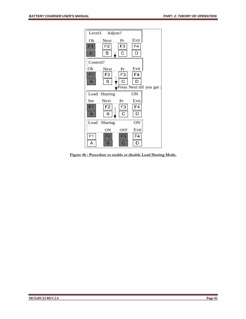
f. LoadSharing(optional) Two or more chargers may be used in parallel to share the same load and recharge the same battery. This parallel configuration is meant to improve site reliability and ease the routine service during shutdowns and preventive maintenance. So should one charger fail or being disconnected, the other charger will take over. Ideally, chargers and connected charging circuits, including cabling, must be symmetrical in order to keep the same voltage drop. The chargers are usually sized to supply the load while recharging the battery when only one charger is available. Consult with the design engineer for the sizing rational. In order to compensate for the different component, wiring and sensing characteristics, forced load sharing is introduced to force 2 identical chargers to share the load as equal as possible. The dynamic “negative slope load sharing” is designed to force 2 chargers to share the common load without having any common control circuit, thus preventing “Single Point Failure”: NO COMMON CONTROL WIRING IS REQUIRED AND NO MASTER (PRIMARY) CHARGER SET UP IS REQUIRED. Instructions and requirements:
Insure that redundant chargers are fed by equivalent AC input voltages; Proper AC and DC protection coordination must be done by others, especially for the chargers contribution
in case of input or output short circuit event. Load sharing between 2 similar chargers with similar control boards and software version and filter circuit,
is approximately 10% when chargers are operated between 10% and their current limit. In order to compensate for the non-symmetrical cabling which may induce non-symmetrical voltage drops,
chargers Float and Equalize voltages must be site fine-tuned to read the same current (50% of total load current) whenever it is possible. Ideally, the chargers must be running at more than 10% to 20% of their nominal output current. Example: 100mV to 200mV fine-tune on a 125VDC system would be sufficient.
Equal load sharing on more than 2 chargers is not tested. Power cables for chargers, load and battery interconnections are provided by others.
If temperature compensation option applies to both battery chargers with load sharing option, observe all safety precautions and follow sensor installation instructions as described in (Page 43, § g). Sensors shall be placed together in one spot to avoid temperature gradient. Cable length for both sensors shall be equal. We can enable or disable Load Sharing option as shown on the procedure below:
BATTERY CHARGER USER’S MANUAL PART- 2: THEORY OF OPERATION
MCEnPC23-REV.2.4 Page 43
Control?Ok Next Pr Exit
Adjust? Level1
Ok Next Pr Exit
ON Sharing Load
Set ExitNext Pr
:getyou Next till Press
ExitON OFF
ON Sharing Load
Figure 46 : Procedure to enable or disable Load Sharing Mode.
BATTERY CHARGER USER’S MANUAL PART- 2: THEORY OF OPERATION
MCEnPC23-REV.2.4 Page 44
g. VoltageTemperatureCompensation(optional)
g-1. Sensor Installation
When the voltage temperature compensation option is ordered with the charger, temperature sensor is wired to the charger’s control card and the twisted wires are coiled and tied inside the enclosure.
WARNING BEFORE starting to work on the installation: Check and apply the applicable electrical codes for the installation; Ensure that AC & DC power sources are disconnected, and breakers are open and possibly locked; DO NOT touch battery posts or any conducting parts
To install the voltage temperature compensation sensor:
1. Open the enclosure; undo the tie holding the wires in place. 2. Route the wires to the battery string, preferably separately from the AC and DC power cables/wires to
prevent the readings to be affected by the radiated noise. Cable length is 25 feet (8m). 3. Determine the battery cell/ block that will have the highest operating temperature. Hint: Usually it is the
cell/block in the middle of the very top row. 4. Mount the sensor on the chosen battery cell/block on a clean, dry surface, as close as possible to the
positive post. 5. If mounting of the sensor on the battery is not possible, place it on the battery rack, as close as possible to
the chosen battery cell/block. 6. DO NOT mount the compensation sensor on insulation material such as wood or Styrofoam. 7. Follow the start up procedure in your battery charger manual. 8. Verify, and if needed, re-adjust the battery voltage temperature correction factor in the menu of your
battery charger as per your battery manufacturer instructions.
g-2. Temperature compensation menu and examples (This option is disable in equalization mode) When enabled, this function adjusts the float voltage to compensate the temperature effect on the battery charging. The reference temperature is 20°C / 72°F. The compensation value is adjusted in: mV/ºC/cell. We can enable or disable and adjust Voltage Temperature compensation as shown on the procedure below:

BATTERY CHARGER USER’S MANUAL PART- 2: THEORY OF OPERATION
MCEnPC23-REV.2.4 Page 45
Control?Ok Next Pr Exit
Adjust? Level1
Ok Next Pr Exit
:getyou Next till Press
ExitON OFF
ON TCompVolt
Next
ON TCompVolt
Set ExitNext Pr
Exit -5.0mV TCompVolt
Next
Exit -Next
Exit -Next
Figure 47 : Procedure to enable or disable and adjust Temperature Compensation parameters.
Example-1:
Reference Temperature = 20 ºC Nominal voltage per/cell=2.27V Compensation Value : 5mV/ºC/cell Battery Temperature = 30 ºC DC Output Voltage = 132V
Compensation at DC Output: VC 9074.2132100027.2
53020 0
DC Output After Compensation = V093.1299074.2132

BATTERY CHARGER USER’S MANUAL PART- 2: THEORY OF OPERATION
MCEnPC23-REV.2.4 Page 46
Example-2:
Reference Temperature = 20 ºC Nominal voltage per/cell=2.27V Compensation Value : 5mV/ºC/cell Battery Temperature = 10 ºC DC Output Voltage = 132V
Compensation at DC Output: VC 907.2132100027.2
51020 0
DC Output After Compensation = V907.134907.2132

BATTERY CHARGER USER’S MANUAL PART- 2: THEORY OF OPERATION
MCEnPC23-REV.2.4 Page 47
7.3.2 Alarms The battery charger offers the possibility to detect and display many alarms, which can be assigned to a specific relay (up to 24 relay). The list below shows all alarms that can be set and adjusted separately:
Battery High Voltage; Battery Low Voltage; Positive Ground Fault; Negative Ground Fault; AC Fail; Rectifier Fail; Rectifier High Voltage *; High Voltage Shutdown *; Rectifier Low Voltage *; End of Discharge *; Internal high Temperature *; Internal Low Temperature *; External High Temperature & Shutdown **; External Low Temperature **; AC High Voltage **; AC Low Voltage **; High Ripple *; Rectifier Low Current *; Rectifier High Current *; Battery Low Current **; Battery High Current **; Battery High Capacity **; Battery Low Capacity **; Equalize Alarm *; PCOM Communication Alarm **; PM Communication Alarm **; Frequency Fail *; Unbalanced Battery or Cell Defect **; Temperature Probe Alarm **; Battery Discharge Alarm **; Common and Audible Alarm **;
There can be up to 24 optional relays associated with different alarms. Each alarm has the following parameters to be set:
Alarm Enabled/Disabled Threshold Enter value Time delay 1-8191 sec. Relay 1 to 24 Alarm Display Latched or unlatched Relay operation Latched or unlatched Failsafe operation ON or OFF (fail-safe (FS) is when relay coils are de-energized when
associated alarms occur) Common Alarm ON or OFF (When common relay for all alarms is ordered)
Should any alarm occur, a message will be displayed and the Red LED will blink. * : Included, enabled upon customer request only. Can also be field activated ** : Optional

BATTERY CHARGER USER’S MANUAL PART- 2: THEORY OF OPERATION
MCEnPC23-REV.2.4 Page 48
a. ResetAlarms:AudibleandAlarmMessages Audible alarm and all alarm messages displayed on LCD can be reset as shown on figure below:
136.2V
Equalize10.0A
Yes No
Buzzer?Reset Ok Next Pr Exit
Buzzer?Reset
Yes No
Alarms?Reset
OkBuzzer Reset
Alarms?Reset Ok Next Pr Exit
Buzzer?Reset Ok Next Pr Exit
Ok AlarmsReset
Alarms?Reset Ok Next Pr Exit
Figure 48 : Reset Audible and Message Alarms Procedure.

BATTERY CHARGER USER’S MANUAL PART- 2: THEORY OF OPERATION
MCEnPC23-REV.2.4 Page 49
b. Alarmadjustmentsandconfiguration With a few exceptions, most alarms in the battery charger have the same setup method. This paragraph will cover the common configuration for all available alarms. In order to simplify alarm configuration figures, this section will be represented by a rectangular box indicating: Common Alarm configuration. The following figure shows in details all steps to follow for alarm adjustments and settings:
Next ExitON OFFOFF Relay Latch
Next Exit -98% Hysteresis
Next Exit -00Relay
Next Exit -S 30Time
Next ExitNFS FSFS Logic
Next ExitON OFFON MesgLatch
Next ExitON OFFON ay EnblCOMRel
Figure 49 : Common Alarm Configuration.

BATTERY CHARGER USER’S MANUAL PART- 2: THEORY OF OPERATION
MCEnPC23-REV.2.4 Page 50
i. Battery High Voltage Alarm Battery High Voltage alarm is activated if the battery voltage exceeds a preset value during a preset time. The following figure shows in details all steps to follow to adjust Battery High Voltage Alarm, while next figures will be simplified.
VoltHigh Batt 10.5A 143.1V
Next ExitON OFFOFF Relay Latch
Next Exit -
Next Exit -00Relay
Next Exit -S 30Time
Next ExitNFS FSFS Logic
Next ExitON OFFON MesgLatch
Next ExitON OFFON ay EnblCOMRel
Alarms?Ok Next Pr Exit
Adjust? Level1
Ok Next Pr Exit
ON 140.3V HVAL1Set ExitNext Pr
ON OFFNext Exit
:getyou Next till Press
Next Exit -ON 140.3V HVAL1
ON HVAL1
98% Hysteresis
Figure 50 : Battery High Volt Alarm adjustments procedure.
BATTERY CHARGER USER’S MANUAL PART- 2: THEORY OF OPERATION
MCEnPC23-REV.2.4 Page 51
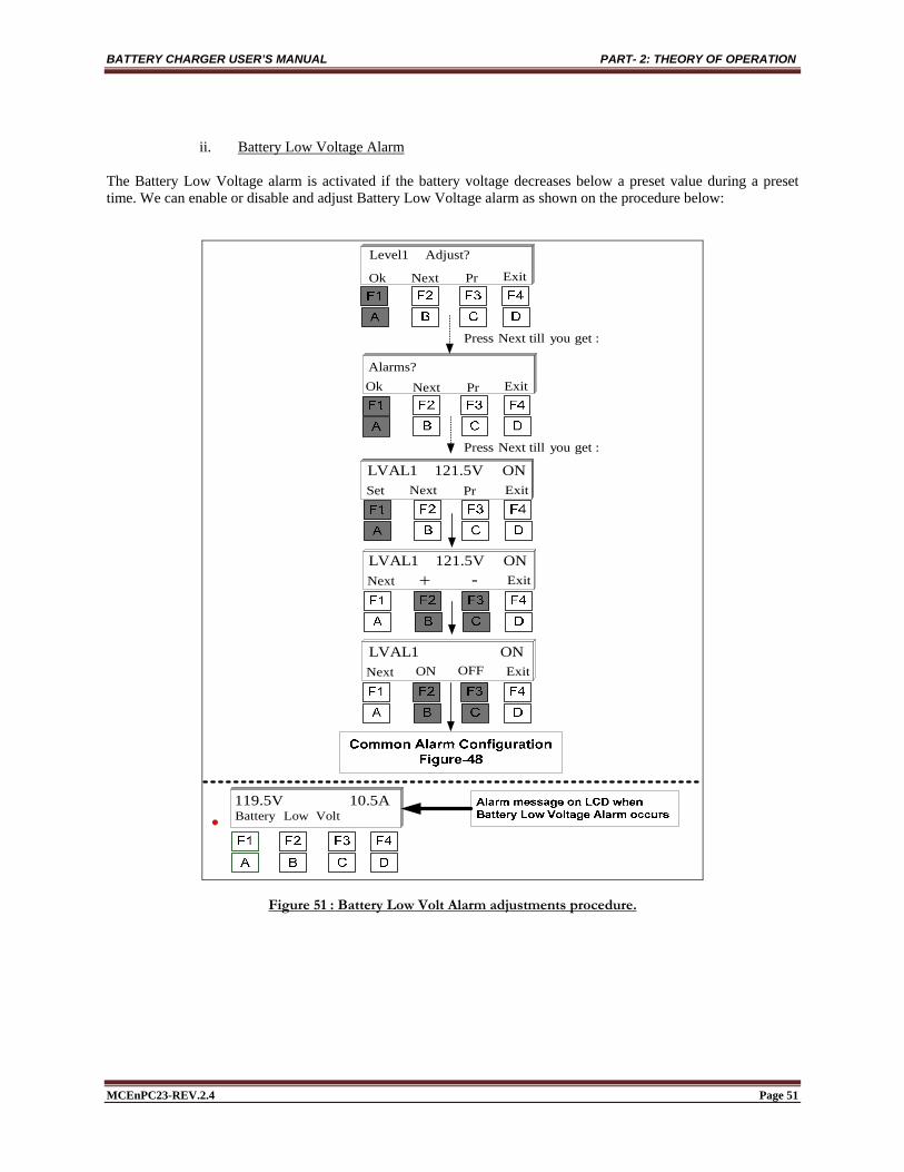
ii. Battery Low Voltage Alarm The Battery Low Voltage alarm is activated if the battery voltage decreases below a preset value during a preset time. We can enable or disable and adjust Battery Low Voltage alarm as shown on the procedure below:
Alarms?Ok Next Pr Exit
Adjust? Level1
Ok Next Pr Exit
ON 121.5V LVAL1Set ExitNext Pr
ON OFFNext Exit
:getyou Next till Press
Next Exit -ON 121.5V LVAL1
ON LVAL1
Volt LowBattery 10.5A 119.5V
:getyou Next till Press
Figure 51 : Battery Low Volt Alarm adjustments procedure.

BATTERY CHARGER USER’S MANUAL PART- 2: THEORY OF OPERATION
MCEnPC23-REV.2.4 Page 52
iii. Positive Ground Fault Alarm If resistance between positive to chassis decreases below a preset value during a preset time, this alarm will be activated. Leakage resistance is given by the following formula:
LeakLeak I
R2
1
Example: mAI Leak 5 , VRleak /100
We can enable or disable and adjust Positive Ground Fault alarm as shown on the procedure below:
Alarms?Ok Next Pr Exit
Adjust? Level1
Ok Next Pr Exit
ON5.0mA GNDFSet ExitNext Pr
ON OFFNext Exit
:getyou Next till Press
Next Exit -
ON GNDF
Fault Ground10.5A 136.2V
:getyou Next till Press
ON5.0mA GNDF
Figure 52 : Positive Ground Fault Alarm adjustments procedure.

BATTERY CHARGER USER’S MANUAL PART- 2: THEORY OF OPERATION
MCEnPC23-REV.2.4 Page 53
iv. Negative Ground Fault Alarm If resistance between negative to chassis decreases below a preset value during a preset time, this alarm will be activated. Leakage resistance is given by the following formula:
LeakLeak I
R2
1
Example: mAI Leak 5 , VRleak /100
We can enable or disable and adjust Negative Ground Fault alarm as shown on the procedure below:
Alarms?Ok Next Pr Exit
Adjust? Level1
Ok Next Pr Exit
ON5.0mA GNDFSet ExitNext Pr
ON OFFNext Exit
:getyou Next till Press
Next Exit -
ON GNDF
Fault Ground10.5A 136.2V
:getyou Next till Press
ON5.0mA GNDF
Figure 53 : Negative Ground Fault Alarm adjustments procedure.

BATTERY CHARGER USER’S MANUAL PART- 2: THEORY OF OPERATION
MCEnPC23-REV.2.4 Page 54
v. AC Fail Alarm AC Fail alarm is activated if main AC Input fails for longer than 100ms during the preset time. We can enable or disable and adjust AC Fail alarm as shown on the procedure below:
Alarms?Ok Next Pr Exit
Adjust? Level1
Ok Next Pr Exit
ON Fail ACSet ExitNext Pr
ON OFFNext Exit
:getyou Next till Press
ON Fail AC
Fail AC10.5A 130.3V
:getyou Next till Press
Figure 54 : AC Fail Alarm adjustments procedure.
BATTERY CHARGER USER’S MANUAL PART- 2: THEORY OF OPERATION
MCEnPC23-REV.2.4 Page 55
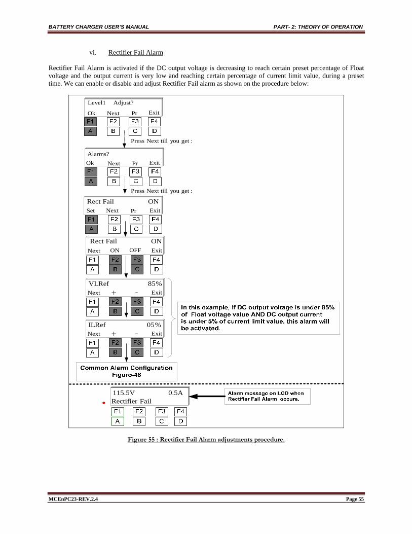
vi. Rectifier Fail Alarm Rectifier Fail Alarm is activated if the DC output voltage is decreasing to reach certain preset percentage of Float voltage and the output current is very low and reaching certain percentage of current limit value, during a preset time. We can enable or disable and adjust Rectifier Fail alarm as shown on the procedure below:
Alarms?Ok Next Pr Exit
Adjust? Level1
Ok Next Pr Exit
ON FailRect Set ExitNext Pr
ON OFFNext Exit
:getyou Next till Press
Next Exit -
0.5A 115.5V
:getyou Next till Press
% 85 VLRef
ON FailRect
Next Exit -% 05 ILRef
FailRectifier
Figure 55 : Rectifier Fail Alarm adjustments procedure.

BATTERY CHARGER USER’S MANUAL PART- 2: THEORY OF OPERATION
MCEnPC23-REV.2.4 Page 56
vii. Rectifier High Voltage Alarm * Rectifier High Voltage alarm is activated if the charger output voltage exceeds a preset value during a preset time. We can enable or disable and adjust Rectifier High Voltage Alarm as shown on the procedure below:
Alarms?Ok Next Pr Exit
Adjust? Level1
Ok Next Pr Exit
ON 142.3V HVAL2Set ExitNext Pr
ON OFFNext Exit
:getyou Next till Press
Next Exit -
VoltHigh Rect 10.5A 143.0V
:getyou Next till Press
ON 142.3V HVAL2
ON HVAL2
Figure 56 : Rectifier High Voltage Alarm adjustments procedure.
* : Included, enabled upon customer request only. Can also be field activated ** : Optional

BATTERY CHARGER USER’S MANUAL PART- 2: THEORY OF OPERATION
MCEnPC23-REV.2.4 Page 57
viii. High Voltage Shutdown Alarm * High Voltage Shutdown alarm is activated if the rectifier voltage exceeds a preset value during a preset time. This alarm turns the Rectifier OFF. We can enable or disable and adjust High Voltage Shutdown Alarm as shown on the procedure below:
Alarms?Ok Next Pr Exit
Adjust? Level1
Ok Next Pr Exit
ON 145.2V HVSHSet ExitNext Pr
ON OFFNext Exit
:getyou Next till Press
Next Exit -
Shutdown HV10.5A 146.0V
:getyou Next till Press
ON 145.2V HVSH
ON HVSH
Figure 57 : High Voltage Shutdown Alarm adjustments procedure.
* : Included, enabled upon customer request only. Can also be field activated ** : Optional
BATTERY CHARGER USER’S MANUAL PART- 2: THEORY OF OPERATION
MCEnPC23-REV.2.4 Page 58
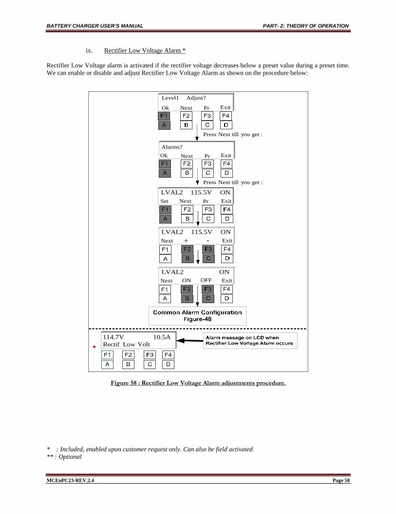
ix. Rectifier Low Voltage Alarm * Rectifier Low Voltage alarm is activated if the rectifier voltage decreases below a preset value during a preset time. We can enable or disable and adjust Rectifier Low Voltage Alarm as shown on the procedure below:
Alarms?Ok Next Pr Exit
Adjust? Level1
Ok Next Pr Exit
ON 115.5V LVAL2Set ExitNext Pr
ON OFFNext Exit
:getyou Next till Press
Next Exit -ON 115.5V LVAL2
ON LVAL2
Volt Low Rectif10.5A 114.7V
:getyou Next till Press
Figure 58 : Rectifier Low Voltage Alarm adjustments procedure.
* : Included, enabled upon customer request only. Can also be field activated ** : Optional

BATTERY CHARGER USER’S MANUAL PART- 2: THEORY OF OPERATION
MCEnPC23-REV.2.4 Page 59
x. End of Discharge Alarm (2nd Low Volt Level)* End of Discharge Alarm is activated if the battery voltage decreases below a preset value during a preset time. It can be used as a critical alarm to prevent excessive battery discharge. We can enable or disable and adjust Low Voltage Disconnect Alarm as shown on the procedure below:
Alarms?Ok Next Pr Exit
Adjust? Level1
Ok Next Pr Exit
ON 115.5V EnDisSet ExitNext Pr
ON OFFNext Exit
:getyou Next till Press
Next Exit -
ON EnDis
Discharge of End10.5A 114.7V
:getyou Next till Press
ON 115.5V EnDis
Figure 59 : End of Discharge Alarm adjustments procedure.
* : Included, enabled upon customer request only. Can also be field activated ** : Optional

BATTERY CHARGER USER’S MANUAL PART- 2: THEORY OF OPERATION
MCEnPC23-REV.2.4 Page 60
xi. Charger High Temperature Alarm * Charger High Temperature alarm is activated when the inside temperature exceeds a preset value during a preset time. We can enable or disable and adjust Charger High Temperature Alarm as shown on the procedure below:
Alarms?Ok Next Pr Exit
Adjust? Level1
Ok Next Pr Exit
ON C 70 HIntTSet ExitNext Pr
ON OFFNext Exit
:getyou Next till Press
Next Exit -
ON HIntT
HighTempCharger 10.5A 136.2V
:getyou Next till Press
ON C 70 HIntT
Figure 60 : Charger High Temperature Alarm adjustments procedure.
* : Included, enabled upon customer request only. Can also be field activated ** : Optional

BATTERY CHARGER USER’S MANUAL PART- 2: THEORY OF OPERATION
MCEnPC23-REV.2.4 Page 61
xii. Charger Low Temperature Alarm * Charger Low Temperature alarm is activated when the inside temperature decreases below a preset value during a preset time. We can enable or disable and adjust Charger Low Temperature Alarm as shown on the procedure below:
Alarms?Ok Next Pr Exit
Adjust? Level1
Ok Next Pr Exit
ON C 10 LIntTSet ExitNext Pr
ON OFFNext Exit
:getyou Next till Press
Next Exit -
ON LIntT
Temp LowCharger 10.5A 136.2V
:getyou Next till Press
ON C 10 LIntT
Figure 61 : Charger Low Temperature Alarm adjustments procedure.
* : Included, enabled upon customer request only. Can also be field activated ** : Optional

BATTERY CHARGER USER’S MANUAL PART- 2: THEORY OF OPERATION
MCEnPC23-REV.2.4 Page 62
xiii. Battery High Temperature Alarm ** Battery High Temperature alarm is activated if the battery temperature exceeds the preset value during a preset time. We can also force the battery charger to be shut down automatically if the battery temperature reaches the High temperature preset value, by turning ON Shut Down parameter. If Shut Down parameter is turned OFF, the battery high temperature will be generated and the battery charger will still provide DC output. We can enable or disable and adjust Battery High Temperature alarm as shown on the procedure below:
Alarms?Ok Next Pr Exit
Adjust? Level1
Ok Next Pr Exit
ON C 55 HExtTSet ExitNext Pr
ON OFFNext Exit
:getyou Next till Press
Next Exit -
ON HExtT
HighTempBattery 10.5A 136.2V
:getyou Next till Press
ON C 55 HExtT
:getyou Next till Press
ON OFFNext ExitOFF Down Shut
Figure 62 : Battery High Temperature Alarm adjustments procedure.
* : Included, enabled upon customer request only. Can also be field activated ** : Optional

BATTERY CHARGER USER’S MANUAL PART- 2: THEORY OF OPERATION
MCEnPC23-REV.2.4 Page 63
xiv. Battery Low Temperature Alarm ** Battery Low Temperature alarm is activated if the battery temperature decreases below the preset value during a preset time. We can enable or disable and adjust this alarm as shown on the procedure below:
Alarms?Ok Next Pr Exit
Adjust? Level1
Ok Next Pr Exit
ON C 05 LExtTSet ExitNext Pr
ON OFFNext Exit
:getyou Next till Press
Next Exit -
ON LExtT
Temp LowBattery 10.5A 136.2V
:getyou Next till Press
ON C 05 LExtT
Figure 63 : Battery Low Temperature Alarm adjustments procedure.
* : Included, enabled upon customer request only. Can also be field activated ** : Optional

BATTERY CHARGER USER’S MANUAL PART- 2: THEORY OF OPERATION
MCEnPC23-REV.2.4 Page 64
xv. AC High Voltage Alarm ** AC High Voltage alarm is activated if the AC voltage exceeds the preset value during a preset time. We can enable or disable and adjust this alarm as shown on the procedure below:
Alarms?Ok Next Pr Exit
Adjust? Level1
Ok Next Pr Exit
ON 265.2V ACHVSet ExitNext Pr
ON OFFNext Exit
:getyou Next till Press
Next Exit -
ON ACHV
VoltageHigh AC10.5A 136.2V
:getyou Next till Press
ON 265.2V ACHV
Figure 64 : AC High Voltage Alarm adjustments procedure.
* : Included, enabled upon customer request only. Can also be field activated ** : Optional
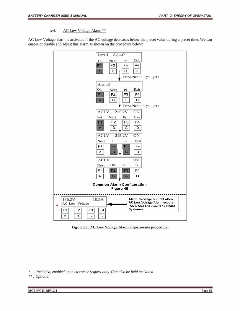
BATTERY CHARGER USER’S MANUAL PART- 2: THEORY OF OPERATION
MCEnPC23-REV.2.4 Page 65
xvi. AC Low Voltage Alarm ** AC Low Voltage alarm is activated if the AC voltage decreases below the preset value during a preset time. We can enable or disable and adjust this alarm as shown on the procedure below:
Alarms?Ok Next Pr Exit
Adjust? Level1
Ok Next Pr Exit
ON 215.2V ACLVSet ExitNext Pr
ON OFFNext Exit
:getyou Next till Press
Next Exit -
ON ACLV
Voltage Low AC10.5A 136.2V
:getyou Next till Press
ON 215.2V ACLV
Figure 65 : AC Low Voltage Alarm adjustments procedure.
* : Included, enabled upon customer request only. Can also be field activated ** : Optional

BATTERY CHARGER USER’S MANUAL PART- 2: THEORY OF OPERATION
MCEnPC23-REV.2.4 Page 66
xvii. High Ripple Alarm * High Ripple alarm is activated if the DC voltage ripple exceeds the preset value during a preset time. It can be set between 1% and 15% of nominal DC voltage. We can enable or disable and adjust this alarm as shown on the procedure below:
Alarms?Ok Next Pr Exit
Adjust? Level1
Ok Next Pr Exit
ON % 02 RippleSet ExitNext Pr
ON OFFNext Exit
:getyou Next till Press
Next Exit -
ON Ripple
RippleHigh 10.5A 136.2V
:getyou Next till Press
ON % 02 Ripple
Figure 66 : High Ripple Alarm adjustments procedure.
* : Included, enabled upon customer request only. Can also be field activated ** : Optional

BATTERY CHARGER USER’S MANUAL PART- 2: THEORY OF OPERATION
MCEnPC23-REV.2.4 Page 67
xviii. Rectifier Low Current Alarm * Rectifier Low Current alarm is activated if rectifier output current decreases below the preset value during a preset time. We can enable or disable and adjust this alarm as shown on the procedure below:
Alarms?Ok Next Pr Exit
Adjust? Level1
Ok Next Pr Exit
ONA 2.0 ILowSet ExitNext Pr
ON OFFNext Exit
:getyou Next till Press
Next Exit -
ON ILow
Current LowRect 1.5A 136.2V
:getyou Next till Press
ONA 2.0 ILow
Figure 67 : Rectifier Low Current Alarm adjustments procedure.
* : Included, enabled upon customer request only. Can also be field activated ** : Optional

BATTERY CHARGER USER’S MANUAL PART- 2: THEORY OF OPERATION
MCEnPC23-REV.2.4 Page 68
xix. Rectifier High Current Alarm * Rectifier High Current alarm is activated if rectifier output current exceeds the preset value during a preset time. We can enable or disable and adjust this alarm as shown on the procedure below:
Alarms?Ok Next Pr Exit
Adjust? Level1
Ok Next Pr Exit
ONA 65.0IHigh
Set ExitNext Pr
ON OFFNext Exit
:getyou Next till Press
Next Exit -
ON IHigh
tHighCurrenRect 67.3A 136.2V
:getyou Next till Press
ONA 65.0IHigh
Figure 68 : Rectifier High Current Alarm adjustments procedure.
* : Included, enabled upon customer request only. Can also be field activated ** : Optional

BATTERY CHARGER USER’S MANUAL PART- 2: THEORY OF OPERATION
MCEnPC23-REV.2.4 Page 69
xx. Battery Low Current Alarm ** Battery Low Current alarm is activated if the current provided from battery to load decreases below the preset value during a preset time. We can enable or disable and adjust this alarm as shown on the procedure below:
Alarms?Ok Next Pr Exit
Adjust? Level1
Ok Next Pr Exit
ONA 10.0ILBat Set ExitNext Pr
ON OFFNext Exit
:getyou Next till Press
Next Exit -
ON ILBat
Current LowBatt 10.0A 136.2V
:getyou Next till Press
ONA 10.0ILBat
Figure 69 : Battery Low Current Alarm adjustments procedure.
* : Included, enabled upon customer request only. Can also be field activated ** : Optional

BATTERY CHARGER USER’S MANUAL PART- 2: THEORY OF OPERATION
MCEnPC23-REV.2.4 Page 70
xxi. Battery High Current Alarm ** Battery High Current alarm is activated if the current provided from battery to load exceeds the preset value during a preset time. We can enable or disable and adjust this alarm as shown on the procedure below:
Alarms?Ok Next Pr Exit
Adjust? Level1
Ok Next Pr Exit
ONA 75.0IHBat Set ExitNext Pr
ON OFFNext Exit
:getyou Next till Press
Next Exit -
ON IHBat
tHighCurrenBatt 10.0A 136.2V
:getyou Next till Press
ONA 75.0IHBat
Figure 70 : Battery High Current Alarm adjustments procedure.
* : Included, enabled upon customer request only. Can also be field activated ** : Optional

BATTERY CHARGER USER’S MANUAL PART- 2: THEORY OF OPERATION
MCEnPC23-REV.2.4 Page 71
xxii. Battery High Capacity Alarm ** Battery High Capacity alarm is activated if the battery capacity exceeds a preset value during a preset time. We can enable or disable and adjust this alarm as shown on the procedure below:
Alarms?Ok Next Pr Exit
Adjust? Level1
Ok Next Pr Exit
ON % 120 HCapSet ExitNext Pr
ON OFFNext Exit
:getyou Next till Press
Next Exit -
ON HCapacity
CapacityHigh 10.0A 136.2V
:getyou Next till Press
ON % 120 HCap
Figure 71 : Battery High Capacity Alarm adjustments procedure.
* : Included, enabled upon customer request only. Can also be field activated ** : Optional
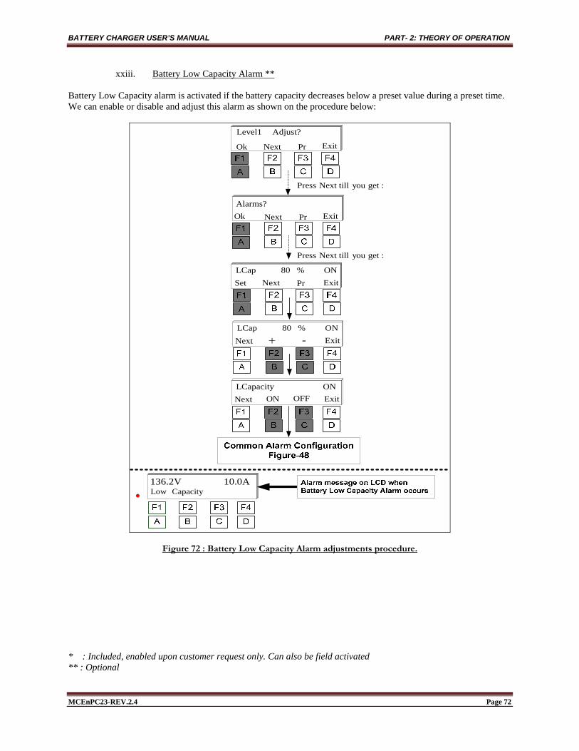
BATTERY CHARGER USER’S MANUAL PART- 2: THEORY OF OPERATION
MCEnPC23-REV.2.4 Page 72
xxiii. Battery Low Capacity Alarm ** Battery Low Capacity alarm is activated if the battery capacity decreases below a preset value during a preset time. We can enable or disable and adjust this alarm as shown on the procedure below:
Alarms?Ok Next Pr Exit
Adjust? Level1
Ok Next Pr Exit
ON % 80 LCapSet ExitNext Pr
ON OFFNext Exit
:getyou Next till Press
Next Exit -
ON LCapacity
Capacity Low10.0A 136.2V
:getyou Next till Press
ON % 80 LCap
Figure 72 : Battery Low Capacity Alarm adjustments procedure.
* : Included, enabled upon customer request only. Can also be field activated ** : Optional
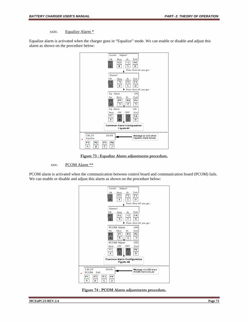
BATTERY CHARGER USER’S MANUAL PART- 2: THEORY OF OPERATION
MCEnPC23-REV.2.4 Page 73
xxiv. Equalize Alarm * Equalize alarm is activated when the charger goes in “Equalize” mode. We can enable or disable and adjust this alarm as shown on the procedure below:
Alarms?Ok Next Pr Exit
Adjust? Level1
Ok Next Pr Exit
ON Alarm EqSet ExitNext Pr
ON OFFNext Exit
:getyou Next till Press
ON Alarm Eq
Equalize10.0A 136.2V
:getyou Next till Press
Figure 73 : Equalize Alarm adjustments procedure.
xxv. PCOM Alarm ** PCOM alarm is activated when the communication between control board and communication board (PCOM) fails. We can enable or disable and adjust this alarm as shown on the procedure below:
Alarms?Ok Next Pr Exit
Adjust? Level1
Ok Next Pr Exit
ON Alarm PCOMSet ExitNext Pr
ON OFFNext Exit
:getyou Next till Press
Fail PCOM10.0A 136.2V
:getyou Next till Press
ON Alarm PCOM
Figure 74 : PCOM Alarm adjustments procedure.

BATTERY CHARGER USER’S MANUAL PART- 2: THEORY OF OPERATION
MCEnPC23-REV.2.4 Page 74
xxvi. PM Alarm ** PM alarm is activated when the communication between control board and measuring board (PM) fails. We can enable or disable and adjust this alarm as shown on the procedure below:
Alarms?Ok Next Pr Exit
Adjust? Level1
Ok Next Pr Exit
ON Alarm PMSet ExitNext Pr
ON OFFNext Exit
:getyou Next till Press
Fail PM10.0A 136.2V
:getyou Next till Press
ON Alarm PM
Figure 75 : PM Alarm adjustments procedure.
xxvii. Frequency Alarm * If the frequency is out of the range, then this alarm is activated. This alarm is available when PM board (AC measurement) is ordered. We can enable or disable and adjust this alarm as shown on the procedure below:
Alarms?Ok Next Pr Exit
Adjust? Level1
Ok Next Pr Exit
ON AlFrequency Set ExitNext Pr
ON OFFNext Exit
:getyou Next till Press
FailFrequency 10.0A 136.2V
:getyou Next till Press
ON AlFrequency
ON Down Shut Next ExitON OFF
Figure 76 : Frequency Alarm adjustments procedure.
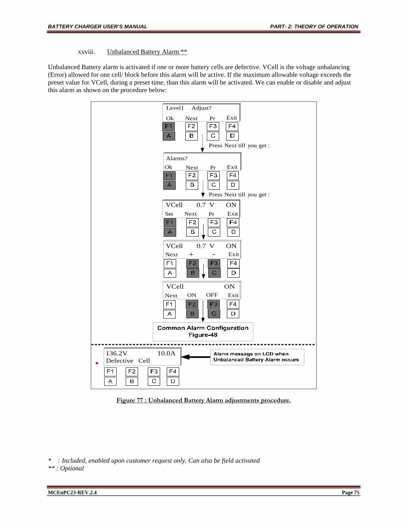
BATTERY CHARGER USER’S MANUAL PART- 2: THEORY OF OPERATION
MCEnPC23-REV.2.4 Page 75
xxviii. Unbalanced Battery Alarm ** Unbalanced Battery alarm is activated if one or more battery cells are defective. VCell is the voltage unbalancing (Error) allowed for one cell/ block before this alarm will be active. If the maximum allowable voltage exceeds the preset value for VCell, during a preset time, than this alarm will be activated. We can enable or disable and adjust this alarm as shown on the procedure below:
Alarms?Ok Next Pr Exit
Adjust? Level1
Ok Next Pr Exit
ON V 0.7 VCellSet ExitNext Pr
ON OFFNext Exit
:getyou Next till Press
Next Exit -
ON VCell
Cell Defective10.0A 136.2V
:getyou Next till Press
ON V 0.7 VCell
Figure 77 : Unbalanced Battery Alarm adjustments procedure.
* : Included, enabled upon customer request only. Can also be field activated ** : Optional

BATTERY CHARGER USER’S MANUAL PART- 2: THEORY OF OPERATION
MCEnPC23-REV.2.4 Page 76
xxix. Temperature Probe Alarm ** This alarm is activated if a short circuit occurs in the temperature probe, provided (optional) with the battery charger. If the circuit inside the probe is open, the temperature considered by the system will be 20ºC. We can enable or disable and adjust this alarm as shown on the procedure below:
Alarms?Ok Next Pr Exit
Adjust? Level1
Ok Next Pr Exit
ON Al ProbeSet ExitNext Pr
ON OFFNext Exit
:getyou Next till Press
Probe Defective10.0A 136.2V
:getyou Next till Press
ON Al Probe
Figure 78 : Procedure to Enable or disable Probe Alarm.
* : Included, enabled upon customer request only. Can also be field activated ** : Optional

BATTERY CHARGER USER’S MANUAL PART- 2: THEORY OF OPERATION
MCEnPC23-REV.2.4 Page 77
xxx. Battery Discharge Alarm ** This alarm is activated when the battery start to provide current to the load. In this case, the value of battery current shown on LCD display (if enabled) will be negative. We can enable or disable and adjust this alarm as shown on the procedure below:
Alarms?Ok Next Pr Exit
Adjust? Level1
Ok Next Pr Exit
OFF DischargBat
Set ExitNext Pr
ON OFFNext Exit
:getyou Next till Press
gDischarginBatt 10.0A 136.2V
:getyou Next till Press
OFF DischargBat
-Next Exit1.0A- ThIBat
Figure 79 : Battery Discharge Alarm adjustments procedure.
* : Included, enabled upon customer request only. Can also be field activated ** : Optional

BATTERY CHARGER USER’S MANUAL PART- 2: THEORY OF OPERATION
MCEnPC23-REV.2.4 Page 78
xxxi. Common Relay and Audible Alarm configuration ** Common Relay (if applicable) will be activated when any alarm, that is configured to enable the common relay occur. We can set common relay parameters as shown on the procedure below:
Alarms?Ok Next Pr Exit
Adjust? Level1
Ok Next Pr Exit
06 Relay COM
Set ExitNext Pr
ON OFFNext Exit
:getyou Next till Press
Next Exit -
OFFLatch Al COM
:getyou Next till Press
06 Relay COM
Next ExitFS Logic
NFS FS
Figure 80 : Common Relay Configuration
Audible Alarm (if applicable) will be active when any alarm occurs. We can enable or disable audible alarm as shown on the procedure below: * : Included, enabled upon customer request only. Can also be field activated ** : Optional

BATTERY CHARGER USER’S MANUAL PART- 2: THEORY OF OPERATION
MCEnPC23-REV.2.4 Page 79
Alarms?Ok Next Pr Exit
Adjust? Level1
Ok Next Pr Exit
OFF Buzzer Set ExitNext Pr
ON OFF Exit
:getyou Next till Press
:getyou Next till Press
OFF Buzzer
Figure 81 : Procedure to enable or disable Audible Alarm
7.3.3 System Clock ** The latest 250 events are saved in the memory. If dated events are required, then a special circuit with a backup battery has to be requested at the time of placing your order. We can access system clock settings as shown on the procedure below: * : Included, enabled upon customer request only. Can also be field activated ** : Optional

BATTERY CHARGER USER’S MANUAL PART- 2: THEORY OF OPERATION
MCEnPC23-REV.2.4 Page 80
Alarms?Ok Next Pr Exit
Adjust? Level1
Ok Next Pr Exit
SettingClock
Ok ExitNext Pr
:getyou Next till Press
Next Exit -
:getyou Next till Press
mn 00 Minute
Next Exit -H 05 Hour
Next Exit -D 23 Day
Next Exit - 10 Month
Next Exit -09 Year
Next Ext HEX CODE MODBUS
BCD HEX
Figure 82 : Procedure to adjust System Clock

BATTERY CHARGER USER’S MANUAL PART- 2: THEORY OF OPERATION
MCEnPC23-REV.2.4 Page 81
8. CURRENT TEMPERATURE COMPENSATION « OUTPUT CURRENT DERATING » (OPTIONAL)
Current temperature compensation function can be enabled or disabled in Level 2. When enabled, in order to protect all power components, the rectifier output current will be de-rated by a preset % (ex. 1%/°C/A) if the inside temperature exceeds a preset value (ex. 40°C).
Example-1: Current Limit = 150A Preset Temperature = 40 ºC Compensation percentage = 1%//ºC/A Actual internal Temperature = 60 ºC
New Current Limit value =
A120100
1504060150
Compensation current in case of loss an AC Phase (optional):
This compensation is also enabled or disabled in Level-2. When enabled, in order to protect all power components, the rectifier output current will be de-rated by a preset % (ex. 34%) in case of loss of a phase.
Exemple-2: Current Limit = 150A Compensation percentage = 34% If one phase is lost, the new current limit value will be set automatically at:
New Current Limit value = A99100
15034150
9. REMOTE SENSING Remote sensing function regulates the DC output voltage at the battery terminals instead of battery charger DC output terminals. It compensate for voltage drop in the DC wiring between the battery charger and the battery. The LCD display shows constantly the actual voltage at the battery terminals. For remote sensing wiring, follow instructions on electrical schematic.
DANGER! There are LIVE TERMINALS and components inside the battery charger even after turning OFF AC and DC breakers.

BATTERY CHARGER USER’S MANUAL PART- 2: THEORY OF OPERATION
MCEnPC23-REV.2.4 Page 82
10. TROUBLESHOOTING Should any problem occur with your charger/rectifier, please, read the following.
Warning! Insure that qualified electricians perform all electrical work or properly trained persons, under direct supervision of a qualified electrician, service this equipment. The battery and AC supply must be disconnected before replacing any component. After disconnecting AC supply and batteries, wait 10 minutes to allow internal capacity to be completely discharged. Observe all safety precautions!

BATTERY CHARGER USER’S MANUAL PART- 2: THEORY OF OPERATION
MCEnPC23-REV.2.4 Page 83
Fault Possible root cause Recommendation
No DC Output
1. Open AC Breaker; 2. AC Input failure; 3. DC fuse blown; 4. Open blocking diode; 5. Open or loose connection;
6. Control board failure; 7. SCR module failure; 8. High Volt Shutdown alarm;
- Verify that AC breaker is closed ("ON"). Check for AC voltage on both sides of the breaker;
- Verify that the AC supply is of correct voltage and frequency; - Verify the DC output fuse; - Check blocking diode (if provided); - Check all wiring from Input to Output for open or loose connections (Refer to
schematic); - Replace control board; - Verify SCR modules and replace if needed; - In case of High Voltage Shutdown Alarm: Turn OFF the AC and DC breakers
for 5 minutes then restart;
DC fuse blows or DC breaker trips
1. Freewheeling diode failure; 2. Control board failure; 3. SCR module failure; 4. Battery connections reversed; 5. DC filter failure;
- Check the freewheeling diode for short circuit; - Replace control board; - Verify SCR modules and replace if needed; - Verify polarity of battery connections; - Check for shorted DC filter Capacitor;
AC breaker trips 1. Short circuit; 2. SCR, Diode or control board
failure;
- Check for shorts from Input to Output connections (Refer to schematic); - Replace defective component;
Low voltage alarm
- Charger overload; - AC Input failure; - Float, equalize and/or low
voltage alarm adjustments affected;
- Check if the charger is in the current limit mode. Check the load for problems; - Verify that the AC supply is of correct voltage and frequency; - Refer to the adjustment procedures to reset;
High ripple voltage
1. AC line is too high;
2. Defective filter capacitor;
3. SCR, Diode or control board failure;
- Read Input voltage and rectify the problem. Verify that the AC supply is of correct voltage and frequency;
- Disconnect the capacitor(s) to observe any change in the output voltage ripple. Replace capacitor(s) if needed;
- Replace defective component;

BATTERY CHARGER USER’S MANUAL PART- 2: THEORY OF OPERATION
MCEnPC23-REV.2.4 Page 84
If the problem persists, contact our service department.
Fault Possible root cause Recommendation
High Output Current
1. Float and (or) Equalize Current limits improperly set;
2. Shunt signal problem; 3. Affected calibration;
- Refer to the adjustment procedures to reset;
- Check shunt signal connection to control board (Refer to schematic); - Check with an external ammeter and compare reading with current value on the
display;
Low Output Current
1. Float and (or) Equalize Current limits improperly set;
2. Affected calibration;
3. Loose connection;
- Refer to the adjustment procedures to reset; - Check with an external ammeter and compare reading with current value on the
display; - Check power wiring for loose connection (Refer to schematic);
Abnormal noise
1. SCR firing circuit problem;
2. Unbalanced current at the AC Input / Output of power transformer;
3. SCR module failure; 4. Control board failure;
- Check if all LEDs on control board are ON: One LED blinking, 2 solid for 1Phase system and 6 solid for 3Phase system;
- Check if current is balanced at the Input and the Output of Power Transformer - Verify SCR modules and replace if needed; - Replace control board;
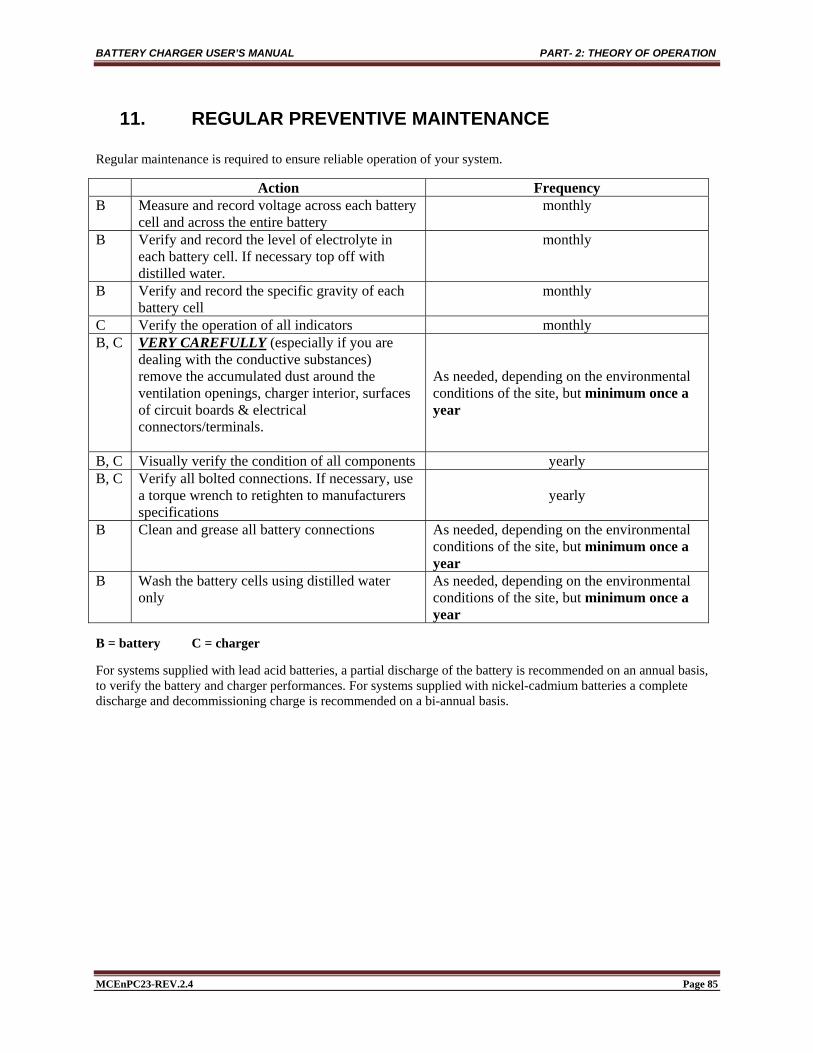
BATTERY CHARGER USER’S MANUAL PART- 2: THEORY OF OPERATION
MCEnPC23-REV.2.4 Page 85
11. REGULAR PREVENTIVE MAINTENANCE
Regular maintenance is required to ensure reliable operation of your system.
Action Frequency B Measure and record voltage across each battery
cell and across the entire battery monthly
B Verify and record the level of electrolyte in each battery cell. If necessary top off with distilled water.
monthly
B Verify and record the specific gravity of each battery cell
monthly
C Verify the operation of all indicators monthly B, C VERY CAREFULLY (especially if you are
dealing with the conductive substances) remove the accumulated dust around the ventilation openings, charger interior, surfaces of circuit boards & electrical connectors/terminals.
As needed, depending on the environmental conditions of the site, but minimum once a year
B, C Visually verify the condition of all components yearly B, C Verify all bolted connections. If necessary, use
a torque wrench to retighten to manufacturers specifications
yearly
B Clean and grease all battery connections As needed, depending on the environmental conditions of the site, but minimum once a year
B Wash the battery cells using distilled water only
As needed, depending on the environmental conditions of the site, but minimum once a year
B = battery C = charger
For systems supplied with lead acid batteries, a partial discharge of the battery is recommended on an annual basis, to verify the battery and charger performances. For systems supplied with nickel-cadmium batteries a complete discharge and decommissioning charge is recommended on a bi-annual basis.
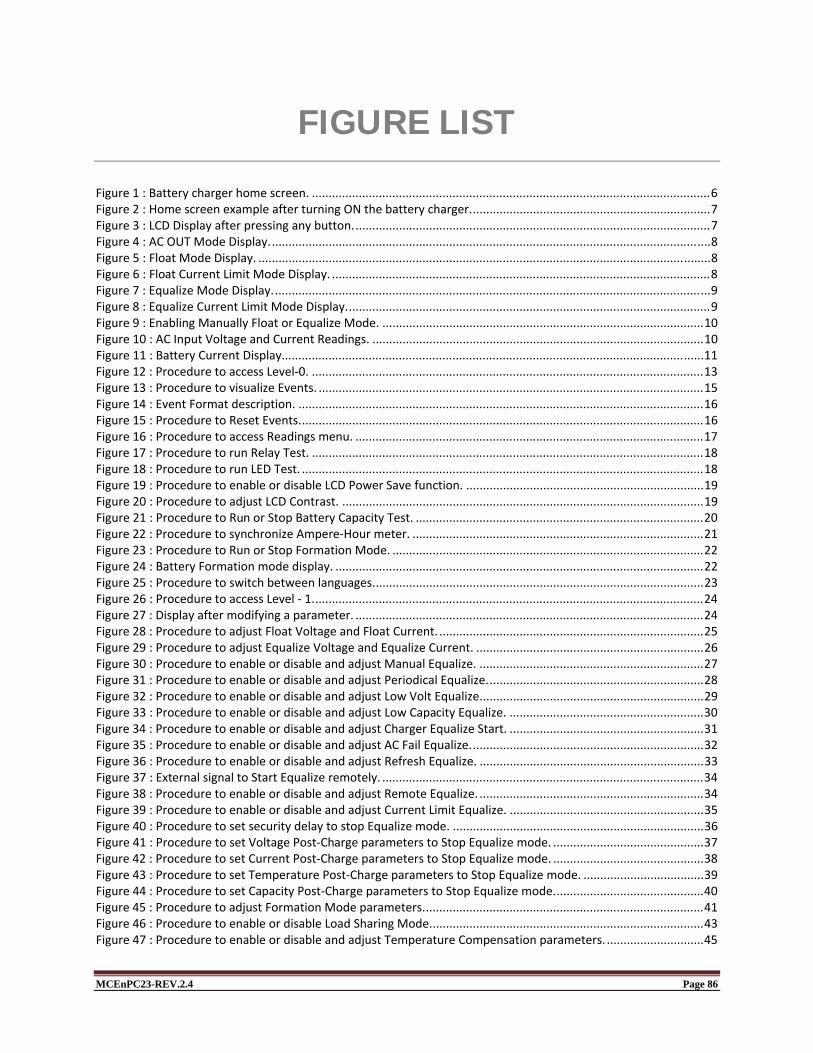
MCEnPC23-REV.2.4 Page 86
FIGURE LIST Figure 1 : Battery charger home screen. ....................................................................................................................... 6 Figure 2 : Home screen example after turning ON the battery charger. ....................................................................... 7 Figure 3 : LCD Display after pressing any button. .......................................................................................................... 7 Figure 4 : AC OUT Mode Display. ................................................................................................................................... 8 Figure 5 : Float Mode Display. ....................................................................................................................................... 8 Figure 6 : Float Current Limit Mode Display. ................................................................................................................. 8 Figure 7 : Equalize Mode Display. .................................................................................................................................. 9 Figure 8 : Equalize Current Limit Mode Display. ............................................................................................................ 9 Figure 9 : Enabling Manually Float or Equalize Mode. ................................................................................................ 10 Figure 10 : AC Input Voltage and Current Readings. ................................................................................................... 10 Figure 11 : Battery Current Display.............................................................................................................................. 11 Figure 12 : Procedure to access Level‐0. ..................................................................................................................... 13 Figure 13 : Procedure to visualize Events. ................................................................................................................... 15 Figure 14 : Event Format description. ......................................................................................................................... 16 Figure 15 : Procedure to Reset Events. ........................................................................................................................ 16 Figure 16 : Procedure to access Readings menu. ........................................................................................................ 17 Figure 17 : Procedure to run Relay Test. ..................................................................................................................... 18 Figure 18 : Procedure to run LED Test. ........................................................................................................................ 18 Figure 19 : Procedure to enable or disable LCD Power Save function. ....................................................................... 19 Figure 20 : Procedure to adjust LCD Contrast. ............................................................................................................ 19 Figure 21 : Procedure to Run or Stop Battery Capacity Test. ...................................................................................... 20 Figure 22 : Procedure to synchronize Ampere‐Hour meter. ....................................................................................... 21 Figure 23 : Procedure to Run or Stop Formation Mode. ............................................................................................. 22 Figure 24 : Battery Formation mode display. .............................................................................................................. 22 Figure 25 : Procedure to switch between languages. .................................................................................................. 23 Figure 26 : Procedure to access Level ‐ 1. .................................................................................................................... 24 Figure 27 : Display after modifying a parameter. ........................................................................................................ 24 Figure 28 : Procedure to adjust Float Voltage and Float Current. ............................................................................... 25 Figure 29 : Procedure to adjust Equalize Voltage and Equalize Current. .................................................................... 26 Figure 30 : Procedure to enable or disable and adjust Manual Equalize. ................................................................... 27 Figure 31 : Procedure to enable or disable and adjust Periodical Equalize. ................................................................ 28 Figure 32 : Procedure to enable or disable and adjust Low Volt Equalize. .................................................................. 29 Figure 33 : Procedure to enable or disable and adjust Low Capacity Equalize. .......................................................... 30 Figure 34 : Procedure to enable or disable and adjust Charger Equalize Start. .......................................................... 31 Figure 35 : Procedure to enable or disable and adjust AC Fail Equalize. ..................................................................... 32 Figure 36 : Procedure to enable or disable and adjust Refresh Equalize. ................................................................... 33 Figure 37 : External signal to Start Equalize remotely. ................................................................................................ 34 Figure 38 : Procedure to enable or disable and adjust Remote Equalize. ................................................................... 34 Figure 39 : Procedure to enable or disable and adjust Current Limit Equalize. .......................................................... 35 Figure 40 : Procedure to set security delay to stop Equalize mode. ........................................................................... 36 Figure 41 : Procedure to set Voltage Post‐Charge parameters to Stop Equalize mode. ............................................. 37 Figure 42 : Procedure to set Current Post‐Charge parameters to Stop Equalize mode. ............................................. 38 Figure 43 : Procedure to set Temperature Post‐Charge parameters to Stop Equalize mode. .................................... 39 Figure 44 : Procedure to set Capacity Post‐Charge parameters to Stop Equalize mode. ............................................ 40 Figure 45 : Procedure to adjust Formation Mode parameters. ................................................................................... 41 Figure 46 : Procedure to enable or disable Load Sharing Mode. ................................................................................. 43 Figure 47 : Procedure to enable or disable and adjust Temperature Compensation parameters. ............................. 45

MCEnPC23-REV.2.4 Page 87
Figure 48 : Reset Audible and Message Alarms Procedure. ........................................................................................ 48 Figure 49 : Common Alarm Configuration. .................................................................................................................. 49 Figure 50 : Battery High Volt Alarm adjustments procedure. ..................................................................................... 50 Figure 51 : Battery Low Volt Alarm adjustments procedure. ...................................................................................... 51 Figure 52 : Positive Ground Fault Alarm adjustments procedure. .............................................................................. 52 Figure 53 : Negative Ground Fault Alarm adjustments procedure. ............................................................................. 53 Figure 54 : AC Fail Alarm adjustments procedure. ...................................................................................................... 54 Figure 55 : Rectifier Fail Alarm adjustments procedure. ............................................................................................. 55 Figure 56 : Rectifier High Voltage Alarm adjustments procedure. .............................................................................. 56 Figure 57 : High Voltage Shutdown Alarm adjustments procedure. ........................................................................... 57 Figure 58 : Rectifier Low Voltage Alarm adjustments procedure. ............................................................................... 58 Figure 59 : End of Discharge Alarm adjustments procedure. ...................................................................................... 59 Figure 60 : Charger High Temperature Alarm adjustments procedure. ...................................................................... 60 Figure 61 : Charger Low Temperature Alarm adjustments procedure. ....................................................................... 61 Figure 62 : Battery High Temperature Alarm adjustments procedure. ....................................................................... 62 Figure 63 : Battery Low Temperature Alarm adjustments procedure. ........................................................................ 63 Figure 64 : AC High Voltage Alarm adjustments procedure. ....................................................................................... 64 Figure 65 : AC Low Voltage Alarm adjustments procedure. ........................................................................................ 65 Figure 66 : High Ripple Alarm adjustments procedure. ............................................................................................... 66 Figure 67 : Rectifier Low Current Alarm adjustments procedure. ............................................................................... 67 Figure 68 : Rectifier High Current Alarm adjustments procedure. .............................................................................. 68 Figure 69 : Battery Low Current Alarm adjustments procedure. ................................................................................ 69 Figure 70 : Battery High Current Alarm adjustments procedure. ................................................................................ 70 Figure 71 : Battery High Capacity Alarm adjustments procedure. .............................................................................. 71 Figure 72 : Battery Low Capacity Alarm adjustments procedure. ............................................................................... 72 Figure 73 : Equalize Alarm adjustments procedure. .................................................................................................... 73 Figure 74 : PCOM Alarm adjustments procedure. ....................................................................................................... 73 Figure 75 : PM Alarm adjustments procedure. ............................................................................................................ 74 Figure 76 : Frequency Alarm adjustments procedure. ................................................................................................ 74 Figure 77 : Unbalanced Battery Alarm adjustments procedure. ................................................................................. 75 Figure 78 : Procedure to Enable or disable Probe Alarm. ............................................................................................ 76 Figure 79 : Battery Discharge Alarm adjustments procedure. .................................................................................... 77 Figure 80 : Common Relay Configuration .................................................................................................................... 78 Figure 81 : Procedure to enable or disable Audible Alarm .......................................................................................... 79 Figure 82 : Procedure to adjust System Clock ............................................................................................................. 80
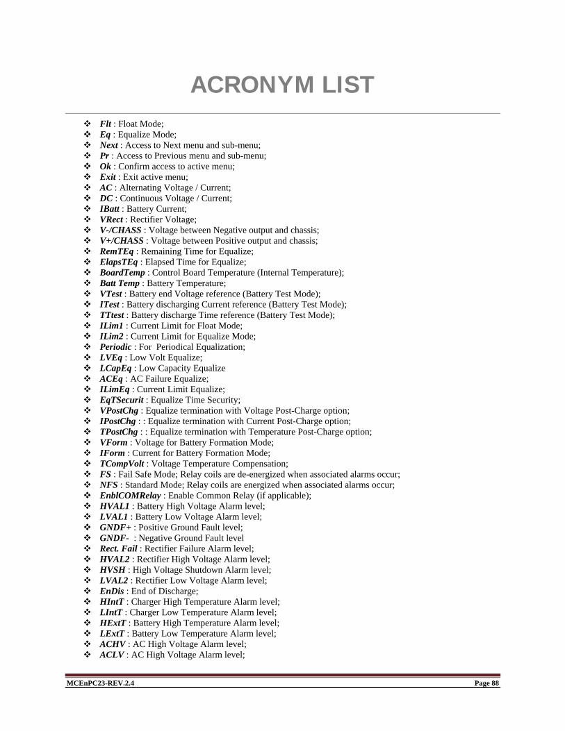
MCEnPC23-REV.2.4 Page 88
ACRONYM LIST Flt : Float Mode; Eq : Equalize Mode; Next : Access to Next menu and sub-menu; Pr : Access to Previous menu and sub-menu; Ok : Confirm access to active menu; Exit : Exit active menu; AC : Alternating Voltage / Current; DC : Continuous Voltage / Current; IBatt : Battery Current; VRect : Rectifier Voltage; V-/CHASS : Voltage between Negative output and chassis; V+/CHASS : Voltage between Positive output and chassis; RemTEq : Remaining Time for Equalize; ElapsTEq : Elapsed Time for Equalize; BoardTemp : Control Board Temperature (Internal Temperature); Batt Temp : Battery Temperature; VTest : Battery end Voltage reference (Battery Test Mode); ITest : Battery discharging Current reference (Battery Test Mode); TTtest : Battery discharge Time reference (Battery Test Mode); ILim1 : Current Limit for Float Mode; ILim2 : Current Limit for Equalize Mode; Periodic : For Periodical Equalization; LVEq : Low Volt Equalize; LCapEq : Low Capacity Equalize ACEq : AC Failure Equalize; ILimEq : Current Limit Equalize; EqTSecurit : Equalize Time Security; VPostChg : Equalize termination with Voltage Post-Charge option; IPostChg : : Equalize termination with Current Post-Charge option; TPostChg : : Equalize termination with Temperature Post-Charge option; VForm : Voltage for Battery Formation Mode; IForm : Current for Battery Formation Mode; TCompVolt : Voltage Temperature Compensation; FS : Fail Safe Mode; Relay coils are de-energized when associated alarms occur; NFS : Standard Mode; Relay coils are energized when associated alarms occur; EnblCOMRelay : Enable Common Relay (if applicable); HVAL1 : Battery High Voltage Alarm level; LVAL1 : Battery Low Voltage Alarm level; GNDF+ : Positive Ground Fault level; GNDF- : Negative Ground Fault level Rect. Fail : Rectifier Failure Alarm level; HVAL2 : Rectifier High Voltage Alarm level; HVSH : High Voltage Shutdown Alarm level; LVAL2 : Rectifier Low Voltage Alarm level; EnDis : End of Discharge; HIntT : Charger High Temperature Alarm level; LIntT : Charger Low Temperature Alarm level; HExtT : Battery High Temperature Alarm level; LExtT : Battery Low Temperature Alarm level; ACHV : AC High Voltage Alarm level; ACLV : AC High Voltage Alarm level;
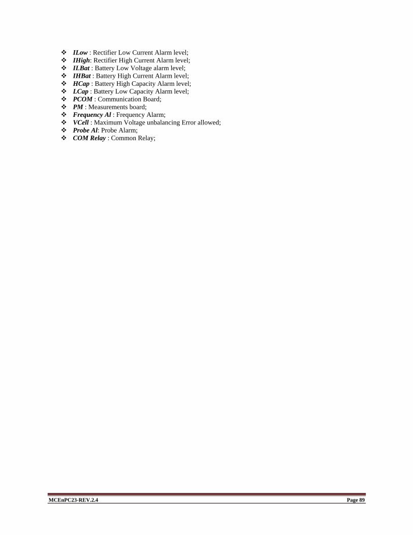
MCEnPC23-REV.2.4 Page 89
ILow : Rectifier Low Current Alarm level; IHigh: Rectifier High Current Alarm level; ILBat : Battery Low Voltage alarm level; IHBat : Battery High Current Alarm level; HCap : Battery High Capacity Alarm level; LCap : Battery Low Capacity Alarm level; PCOM : Communication Board; PM : Measurements board; Frequency Al : Frequency Alarm; VCell : Maximum Voltage unbalancing Error allowed; Probe Al: Probe Alarm; COM Relay : Common Relay;
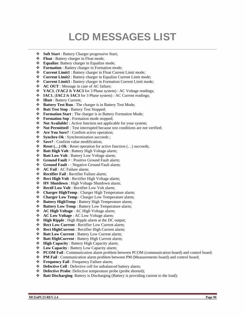
MCEnPC23-REV.2.4 Page 90
LCD MESSAGES LIST Soft Start : Battery Charger progressive Start; Float : Battery charger in Float mode; Equalize: Battery charger in Equalize mode; Formation : Battery charger in Formation mode; Current Limit1 : Battery charger in Float Current Limit mode; Current Limit2 : Battery charger in Equalize Current Limit mode; Current Limit3 : Battery charger in Formation Current Limit mode; AC OUT : Message in case of AC failure; VAC1, (VAC2 & VAC3 for 3 Phase system) : AC Voltage readings; IAC1, (IAC2 & IAC3 for 3 Phase system) : AC Current readings; IBatt : Battery Current; Battery Test Run : The charger is in Battery Test Mode; Batt Test Stop : Battery Test Stopped; Formation Start : The charger is in Battery Formation Mode; Formation Sop : Formation mode stopped; Not Available! : Active function not applicable for your system; Not Permitted! : Test interrupted because test conditions are not verified; Are You Sure? : Confirm active operation; Synchro Ok : Synchronization succeeds ; Save? : Confirm value modification; Reset (…) Ok : Reset operation for active function (…) succeeds; Batt High Volt : Battery High Voltage alarm; Batt Low Volt : Battery Low Voltage alarm; Ground Fault + : Positive Ground Fault alarm; Ground Fault - : Negative Ground Fault alarm; AC Fail : AC Failure alarm; Rectifier Fail : Rectifier Failure alarm; Rect High Volt : Rectifier High Voltage alarm; HV Shutdown : High Voltage Shutdown alarm; Rectif Low Volt : Rectifier Low Volt alarm; Charger HighTemp : Charger High Temperature alarm; Charger Low Temp : Charger Low Temperature alarm; Battery HighTemp : Battery High Temperature alarm; Battery Low Temp : Battery Low Temperature alarm; AC High Voltage : AC High Voltage alarm; AC Low Voltage : AC Low Voltage alarm; High Ripple : High Ripple alarm at the DC output; Rect Low Current : Rectifier Low Current alarm; Rect HighCurrent : Rectifier High Current alarm; Batt Low Current : Battery Low Current alarm; Batt HighCurrent : Battery High Current alarm; High Capacity : Battery High Capacity alarm; Low Capacity : Battery Low Capacity alarm; PCOM Fail : Communication alarm problem between PCOM (communication board) and control board; PM Fail : Communication alarm problem between PM (Measurements board) and control board; Frequency Fail : Frequency Failure alarm; Defective Cell : Defective cell for unbalanced battery alarm; Defective Probe: Defective temperature probe (probe shorted); Batt Discharging: Battery is Discharging (Battery is providing current to the load);

ELECTRICAL / ELECTRONIC PRODUCTS WARRANTY
The Manufacturer Warrants to the original user that its rectifying equipment, load banks, DC-DC converters, chargers and UPS systems are free from defects in factory workmanship and materials, such warranty being conditional upon the product having been installed, commissioned, operated and maintained by qualified personnel and according to manufacturer instructions. Our liability is limited to repairing or replacing without charge at its factory any product or component which at user's expense has been returned to our plant or authorized service center within 1 year from date of commissioning or 18 months from shipment, whichever occurs first. The manufacturer repair or replacement of any defective product shall constitute fulfillment of his obligations. This warranty applies to manufacturer products which are shown by the purchaser to have been originally defective and shall not apply to products which must be repaired or replaced due to normal wear, misuse, negligence, wreckage, accident, any Act Of God or to products which have been repaired or altered outside of seller's factory or one of its authorized service centers unless authorized solely by the manufacturer. The manufacturer shall not be liable for loss, damage, or expense, consequential or otherwise from the use of its products or from any other cause. This warranty supersedes and is given in place of all other warranties expressed or implied or conditions whether statutory or otherwise as to quality and fitness for any purpose for which the products are supplied. No person, agent or dealer is authorized to give any warranty on behalf of manufacturer or to assume for seller any other liability in connection with any of its products unless made in writing and signed by an officer of the manufacturer.
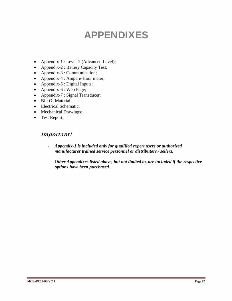
MCEnPC23-REV.2.4 Page 92
APPENDIXES
Appendix-1 : Level-2 (Advanced Level); Appendix-2 : Battery Capacity Test; Appendix-3 : Communication; Appendix-4 : Ampere-Hour meter; Appendix-5 : Digital Inputs; Appendix-6 : Web Page; Appendix-7 : Signal Transducer; Bill Of Material; Electrical Schematic; Mechanical Drawings; Test Report;
Important!
- Appendix-1 is included only for qualified expert users or authorized manufacturer trained service personnel or distributors / sellers.
- Other Appendixes listed above, but not limited to, are included if the respective options have been purchased.

Page 1 of 39 Rev. 13
Communication User Manual Appendix 3
27/01/2015
Page 2 of 39 Rev. 13
Table of contents 1. CONFIGURATION .......................................................................................................................................................... 3
1.1 COMMUNICATION PROTOCOL ............................................................................................................................... 3 1.2 RS-232 CONNECTION .............................................................................................................................................. 4 1.3 RS-485 CONNECTION .............................................................................................................................................. 4 1.4 ETHERNET TCP/IP CONNECTION .......................................................................................................................... 6
1.4.1 Network precautions: before you start ................................................................................................................. 6 1.4.2 Using PCOM board with a local host system ...................................................................................................... 6 1.4.3 Connecting the PCOM board .............................................................................................................................. 6 1.4.4 Connecting to a Network ..................................................................................................................................... 6 1.4.5 Connecting Directly to a Host System ................................................................................................................. 7 1.4.6 Configuring the PCOM board .............................................................................................................................. 9 1.4.6.2 Display IP address .......................................................................................................................................... 10
2. MODBUS RTU............................................................................................................................................................... 11
2.1 RAM MEMORY MAP ................................................................................................................................................ 11 2.2 CHARGER COMMON PARAMETERS SET UP ...................................................................................................... 14
2.2.1 General .............................................................................................................................................................. 14 2.2.2 Voltage or current settings................................................................................................................................. 14
2.3 OPERATION MODE MODIFICATION ..................................................................................................................... 14 2.3.2 Formation mode ................................................................................................................................................ 14 2.3.3 Battery test ........................................................................................................................................................ 15 2.3.4 Alarm reset ........................................................................................................................................................ 15 2.3.5 Messages .......................................................................................................................................................... 15
2.4 OTHER SETTINGS .................................................................................................................................................. 16
3. DNP V3.00 ..................................................................................................................................................................... 16
3.1 INTRODUCTION ...................................................................................................................................................... 16 3.2 DEVICE PROFILE .................................................................................................................................................... 16 3.3 IMPLEMENTATION TABLE ..................................................................................................................................... 18 3.4 POINT LIST .............................................................................................................................................................. 19 3.5 CHARGER COMMON PARAMETERS SET UP ...................................................................................................... 31
4. COMMON NOTES FOR MODBUS AND DNP3 ........................................................................................................... 32
5. THE 40-20MA OUTPUT ................................................................................................................................................ 39

Page 3 of 39 Rev. 13
1. CONFIGURATION The Primax PCOM Communication Card operates in the following modes:
a. Slave Modbus RS-232/485 b. Slave Modbus TCP/IP
c. Slave DNP3 (available only in the R232/485). The RS-232/485 operates with 8 bits, 1 start and 1 stop bit. The speed of the transmission is configured on the PCOM board, and selected by switch SW2 (see table 2). The available speeds are 1200, 2400, 4800, 9600 (default), 19200, 38400 and 56000 baud. The address of the PCOM card is on board configurable by switch SW3 (see table 3, and table 8). The default address is “1“for Modbus and “10” for DNP3. The protocol of communication Modbus RS232/485, Modbus TCP/IP or DNP3 is selected by switch SW1 (see table 1).
1 1 1
GS TD(B) TD(A) RD(B) RD(A)
1
address Slave
SW3
CONFIGTCP/IP
SW1 SW2
RATE BAUD ETHERNETRS485
SW7
5RS232/RS48 J14
DB9
CAN1CAN2
J2J4
J15J8
1.1 COMMUNICATION PROTOCOL
The switch SW1 allows for choosing a communication protocol: Modbus RTU, Modbus TCP/IP or DNP3.
Position of SW1 Chosen protocol on
1
MODBUS RS232/485
on
1
MODBUS TCP/IP
on
1
DNP3 RS232/485
Table 1: Communication protocol

Page 4 of 39 Rev. 13
1.2 RS-232 CONNECTION The RS-232 standard allows only a single point-to-point connection. The cable needed for the RS-232 communication is a standard one with DB9 male and female connectors. The DB9 male is connected at the PCOM side and the DB9 female is connected at the customer DTE. The cable can be 15.2m (50 ft) long maximum. To connect to the RS232 via (DB9), the switch SW7 must be set to (off/off/off) as shown below.
232RS
7SW
DTE 232RS
PCOM
TXD
RXD TXD
RXD
)(GSgroundSignal
RTS
CTS
RTS
CTS
1ground 2groundconnectioncableRSFigure 232:2
PCOM_TXD
PCOM_RXD
Ground 2J14
DB9 Female connector
594837261
1.3 RS-485 CONNECTION
To connect to the RS485 port, the switch SW7, must be set to (on/on/on) as shown below
on
1
485RS
7SW
Figure 3, provides the wiring connection to the RS485.
GS )(BTD )(ATD )(BRD )(ARD
12345
485RS
15JHEADER 5: GS 4: TD (B) 3: TD (A) 2: RD (B) 1: RD (A)
Figure3: Connector RS485

Page 5 of 39 Rev. 13
Position of SW2 Communication speed ( baud)
300
on
1
1200
2400
9600
19200
38400
56000
Table 2 speed of communication according to the position of the switch
Position of SW3 Slave address 0
1
on
1
2
3
. .
. . on
1
256
Table3: address of communication according to the position of the SW3 switch

Page 6 of 39 Rev. 13
1.4 ETHERNET TCP/IP CONNECTION
1.4.1 Network precautions: before you start
The Primax PCOM board, provided in your kit is designed to connect to a network over Ethernet. As with any system, however, some precautions are in order before you connect. Whenever new hardware or software is added to a network, it is always advisable to create a separate test network that is isolated from your LAN. This allows testing the new system in a controlled environment and minimizes the possibilities of network interference from the new equipment. The major sources of potential interference include:
Addressing. Each device on the network must have a unique address. If Dynamic Host Configuration Protocol (DHCP) is in use, The Primax PCOM board will automatically acquire a valid IP address. If DHCP is not used, or a fixed address is required, adding the board to the network without assigning an address may create network conflicts.
Traffic levels. While the on-board Ethernet controller will filter out unwanted messages, a highly loaded network with many broadcast messages may place a sizable burden on the PCOM board.
Data Security. Although it is unlikely that the addition of a single device will compromise the integrity or privacy of sensitive information, it is always a good idea to perform extensive testing with new equipment before adding it to a secure network.
Experimentation. Even as a simple microcontroller-based device, the PCOM is capable of generating a high volume of network traffic which may severely disrupt normal network operations.
1.4.2 Using PCOM board with a local host system
The PCOM can communicate directly with a properly configured desktop system, known here as a local host system. In this configuration, the host system can communicate and configure the board through its network connection; it can also configure the board through the serial port. When configured this way, the setup is referred to as a test system. The PCOM can also communicate to a network and a local host system separately. In this setup, the board participates on the network through its Ethernet connection. At the same time, it is connected to the local host system through the serial port, from which it can be directly configured. To function as a local host, the system must meet the following basic requirements:
Any computer system capable of network communication. Standard Ethernet card or integrated adapter, capable of supporting 100 Mbps operation, with RJ45 connector. One available standard serial port with a matching COM port available through the operating system. Any operating system with TCP/IP Stack software. Any terminal emulation package, such as HyperTerminal for Microsoft® Windows® operating system (optional
for configuring the PCOM board’s IP Address).
1.4.3 Connecting the PCOM board
There are two basic network configurations for the PCOM board: direct connection to a network and connection to a local host system through a crossover cable. If DHCP is not enabled on the network, the board will need to be configured before a direct network connection can be used. If you are connecting the PCOM board to a DHCP-enabled network, follow the steps in Section “Connecting to a Network”. If you are using the board for the first time on a network using fixed IP addresses, follow the steps in Section “Connecting directly to a Host System”. Once the IP address is configured the first time, you will be able to connect the board directly to the network as described in Section “Connecting to a Network” without using a local host. If you are connecting the board to a local host in a test system configuration, you will also follow the steps in Section connecting directly to a Host System. If DHCP is enabled on the local host, the board will configure itself. Otherwise, you will need to configure both the host and board IP addresses according to the directions in Section “Configuring the PCOM Board”.
1.4.4 Connecting to a Network
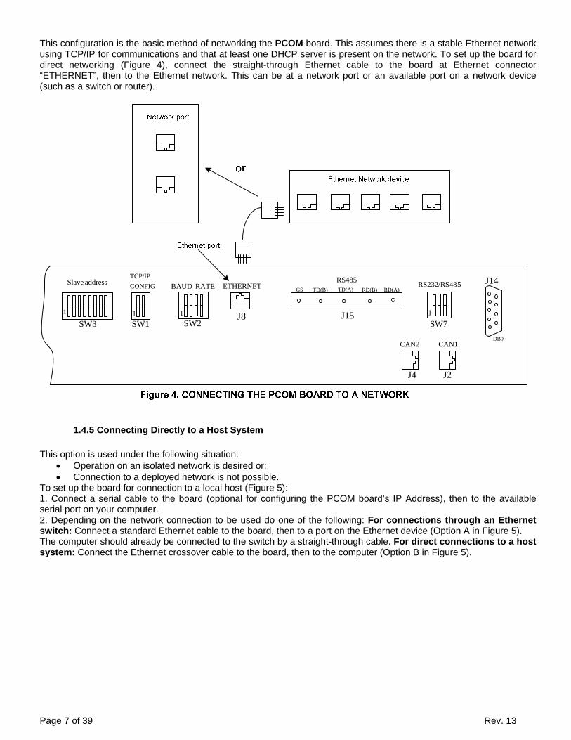
Page 7 of 39 Rev. 13
This configuration is the basic method of networking the PCOM board. This assumes there is a stable Ethernet network using TCP/IP for communications and that at least one DHCP server is present on the network. To set up the board for direct networking (Figure 4), connect the straight-through Ethernet cable to the board at Ethernet connector “ETHERNET”, then to the Ethernet network. This can be at a network port or an available port on a network device (such as a switch or router).
1 1 1
GS TD(B) TD(A) RD(B) RD(A)
1
address Slave
SW3
CONFIGTCP/IP
SW1 SW2
RATE BAUD ETHERNETRS485
SW7
5RS232/RS48
DB9CAN1CAN2
J15J8
J4 J2
J14
1.4.5 Connecting Directly to a Host System
This option is used under the following situation:
Operation on an isolated network is desired or; Connection to a deployed network is not possible.
To set up the board for connection to a local host (Figure 5): 1. Connect a serial cable to the board (optional for configuring the PCOM board’s IP Address), then to the available serial port on your computer. 2. Depending on the network connection to be used do one of the following: For connections through an Ethernet switch: Connect a standard Ethernet cable to the board, then to a port on the Ethernet device (Option A in Figure 5). The computer should already be connected to the switch by a straight-through cable. For direct connections to a host system: Connect the Ethernet crossover cable to the board, then to the computer (Option B in Figure 5).

Page 8 of 39 Rev. 13
Figure 5. CONNECTING THE PCOM BOARD TO A NETWORK
1 1 1
GS TD(B) TD(A) RD(B) RD(A)
1
address Slave
SW3
CONFIGTCP/IP
SW1 SW2
RATE BAUD ETHERNETRS485
SW7
5RS232/RS48
DB9CAN1CAN2
J15J8
J14
J4 J2
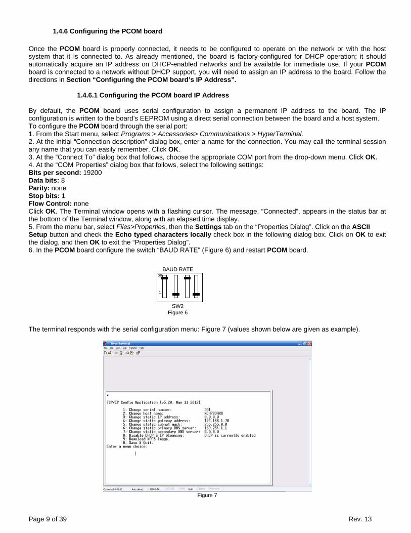
Page 9 of 39 Rev. 13
1.4.6 Configuring the PCOM board
Once the PCOM board is properly connected, it needs to be configured to operate on the network or with the host system that it is connected to. As already mentioned, the board is factory-configured for DHCP operation; it should automatically acquire an IP address on DHCP-enabled networks and be available for immediate use. If your PCOM board is connected to a network without DHCP support, you will need to assign an IP address to the board. Follow the directions in Section “Configuring the PCOM board’s IP Address”.
1.4.6.1 Configuring the PCOM board IP Address By default, the PCOM board uses serial configuration to assign a permanent IP address to the board. The IP configuration is written to the board’s EEPROM using a direct serial connection between the board and a host system. To configure the PCOM board through the serial port: 1. From the Start menu, select Programs > Accessories> Communications > HyperTerminal. 2. At the initial “Connection description” dialog box, enter a name for the connection. You may call the terminal session any name that you can easily remember. Click OK. 3. At the “Connect To” dialog box that follows, choose the appropriate COM port from the drop-down menu. Click OK. 4. At the “COM Properties” dialog box that follows, select the following settings: Bits per second: 19200 Data bits: 8 Parity: none Stop bits: 1 Flow Control: none Click OK. The Terminal window opens with a flashing cursor. The message, “Connected”, appears in the status bar at the bottom of the Terminal window, along with an elapsed time display. 5. From the menu bar, select Files>Properties, then the Settings tab on the “Properties Dialog”. Click on the ASCII Setup button and check the Echo typed characters locally check box in the following dialog box. Click on OK to exit the dialog, and then OK to exit the “Properties Dialog”. 6. In the PCOM board configure the switch “BAUD RATE” (Figure 6) and restart PCOM board.
on
1
BAUD RATE
SW2Figure 6
The terminal responds with the serial configuration menu: Figure 7 (values shown below are given as example).
Figure 7

Page 10 of 39 Rev. 13
7. Select option “3” at the prompt, enter the board’s new IP address based on the configuration you are using: If the board is connected to the local host system through a crossover cable: Use your host system’s IP address, incremented by one, in the final position. For example, if the host system’s IP address is “169.225.150.10” enters “169.225.150.11”. If the board is connected to a fixed address network: Use the IP address assigned by your system administrator. Press <ENTER>. 8. Select option “8” to disable DHCP. This menu will configure the board to use the manually assigned IP address. If DHCP is disabled, text for option “8” will change to: “8: Enable DHCP & IP Gleaning: DHCP is Currently disabled” To re-enable DHCP, select option “8”. 9. Select option “0” to save changes and quit.
10. In the PCOM board reconfigure the switch “BAUD RATE” as shown on (Figure 8), and restart PCOM board.
on
1
BAUD RATE
SW2Figure 8
11. Close the terminal session. For your convenience, you may save the terminal session when prompted. You are now ready to communicate with the board.
1.4.6.2 Display IP address
The IP address assigned by the server to PCOM card is displayed on the LCD display charger (Figure 9). Display example:
30V.150 .1 168 . 192 #
10A

Page 11 of 39 Rev. 13
2. MODBUS RTU
2.1 RAM MEMORY MAP
The following map shows the structure RAM of the PCOM card. (R) mean «readable » and (W) mean « writable ». The function available is: Holding register (03), input register (04), write register (06), and preset multiple register (16).
Variable
Unit
Address
(hex)
Address (dec)
Byte
State
Note
Output voltage V 01 1 2 R note(1) Output current A 02 2 2 R note(1) Battery current A 03 3 2 R note(2) AC volt phase 1 V 04 4 2 R note(1) AC volt phase 2 V 05 5 2 R note(1) AC volt phase 3 V 06 6 2 R note(1) AC current phase 1 A 07 7 2 R note(1) AC current phase 2 A 08 8 2 R note(1) AC current phase 3 A 09 9 2 R note(1) Battery temperature °C 0AH 10 1 R note(3) Control board & inside temperature °C 0AL 10 1 R note(3) AC frequency Hz 0B 11 2 R note(1) Nominal output voltage V 0C 12 2 R note(1) Nominal output current (Shunt1) A 0D 13 2 R note(1) Float voltage V 0E 14 2 R/W note(1) Equalize voltage V 0F 15 2 R/W note(1) Float Current limit A 10 16 2 R/W note(1) Equalize Current limit A 11 17 2 R/W note(1) Formation voltage V 12 18 2 R/W note(1) Formation current A 13 19 2 R/W note(1) Formation relay 14H 20 1 R/W note(3) Formation remaining time H 14L 20 1 R/W note(3) Formation time H 15H 21 1 R/W note(3) Charger state 15L 21 1 R note(8) Charger configuration 16 22 2 R/W note(7) Equalize mode start 17 23 2 R/W note(9) Equalize remaining time out mn 18 24 2 R note(4) Equalize elapsed time out mn 19 25 2 R note(4) Manual equalize time out H 1AH 26 1 R/W note(3) Periodical equalize time H 1AL 26 1 R/W note(3) Periodical equalize period (delay) H 1BH 27 1 R/W note(3) DC Low volts equalize time out H 1BL 27 1 R/W note(3) DC Low volts equalize level V 1C 28 2 R/W note(1) AC fail equalize time out H 1DH 29 1 R/W note(3) AC fail equalize delay S 1DL 29 1 R/W note(3) Refresh equalize time out mn 1EH 30 1 R/W note(3) Refresh equalize period (delay) H 1EL 30 1 R/W note(3) Remote equalize time out H 1F H 31 1 R/W note(3) Current limit equalize time out H 1FL 31 1 R/W note(3) Current limit equalize delay S 20H 32 1 R/W note(3) Equalize termination (On/Off) 20L 32 1 R/W note(10)Post Charge Voltage delay mn 21 33 2 R/W note(4)
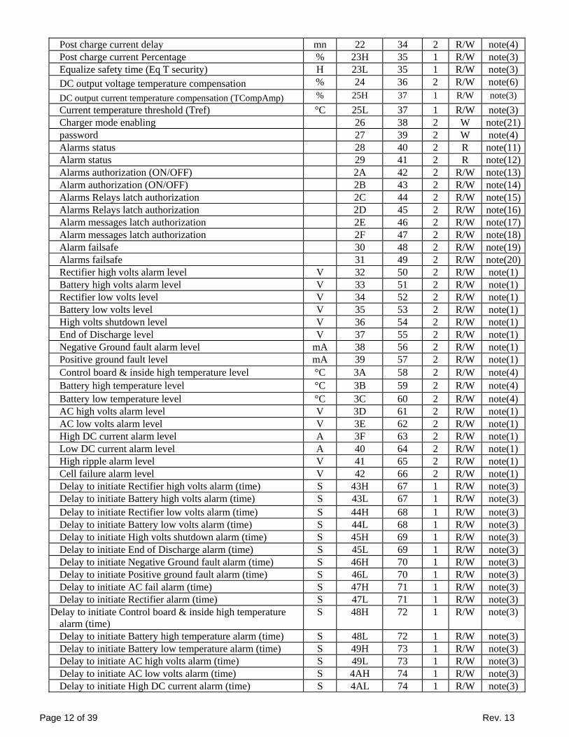
Page 12 of 39 Rev. 13
Post charge current delay mn 22 34 2 R/W note(4) Post charge current Percentage % 23H 35 1 R/W note(3) Equalize safety time (Eq T security) H 23L 35 1 R/W note(3) DC output voltage temperature compensation % 24 36 2 R/W note(6) DC output current temperature compensation (TCompAmp) % 25H 37 1 R/W note(3) Current temperature threshold (Tref) °C 25L 37 1 R/W note(3) Charger mode enabling 26 38 2 W note(21)password 27 39 2 W note(4) Alarms status 28 40 2 R note(11)Alarm status 29 41 2 R note(12)Alarms authorization (ON/OFF) 2A 42 2 R/W note(13)Alarm authorization (ON/OFF) 2B 43 2 R/W note(14)Alarms Relays latch authorization 2C 44 2 R/W note(15)Alarms Relays latch authorization 2D 45 2 R/W note(16)Alarm messages latch authorization 2E 46 2 R/W note(17)Alarm messages latch authorization 2F 47 2 R/W note(18)Alarm failsafe 30 48 2 R/W note(19)Alarms failsafe 31 49 2 R/W note(20)Rectifier high volts alarm level V 32 50 2 R/W note(1) Battery high volts alarm level V 33 51 2 R/W note(1) Rectifier low volts level V 34 52 2 R/W note(1) Battery low volts level V 35 53 2 R/W note(1) High volts shutdown level V 36 54 2 R/W note(1) End of Discharge level V 37 55 2 R/W note(1) Negative Ground fault alarm level mA 38 56 2 R/W note(1) Positive ground fault level mA 39 57 2 R/W note(1) Control board & inside high temperature level °C 3A 58 2 R/W note(4) Battery high temperature level °C 3B 59 2 R/W note(4) Battery low temperature level °C 3C 60 2 R/W note(4) AC high volts alarm level V 3D 61 2 R/W note(1) AC low volts alarm level V 3E 62 2 R/W note(1) High DC current alarm level A 3F 63 2 R/W note(1) Low DC current alarm level A 40 64 2 R/W note(1) High ripple alarm level V 41 65 2 R/W note(1) Cell failure alarm level V 42 66 2 R/W note(1) Delay to initiate Rectifier high volts alarm (time) S 43H 67 1 R/W note(3) Delay to initiate Battery high volts alarm (time) S 43L 67 1 R/W note(3) Delay to initiate Rectifier low volts alarm (time) S 44H 68 1 R/W note(3) Delay to initiate Battery low volts alarm (time) S 44L 68 1 R/W note(3) Delay to initiate High volts shutdown alarm (time) S 45H 69 1 R/W note(3) Delay to initiate End of Discharge alarm (time) S 45L 69 1 R/W note(3) Delay to initiate Negative Ground fault alarm (time) S 46H 70 1 R/W note(3) Delay to initiate Positive ground fault alarm (time) S 46L 70 1 R/W note(3) Delay to initiate AC fail alarm (time) S 47H 71 1 R/W note(3) Delay to initiate Rectifier alarm (time) S 47L 71 1 R/W note(3)
Delay to initiate Control board & inside high temperature alarm (time)
S 48H 72 1 R/W note(3)
Delay to initiate Battery high temperature alarm (time) S 48L 72 1 R/W note(3) Delay to initiate Battery low temperature alarm (time) S 49H 73 1 R/W note(3) Delay to initiate AC high volts alarm (time) S 49L 73 1 R/W note(3) Delay to initiate AC low volts alarm (time) S 4AH 74 1 R/W note(3) Delay to initiate High DC current alarm (time) S 4AL 74 1 R/W note(3)
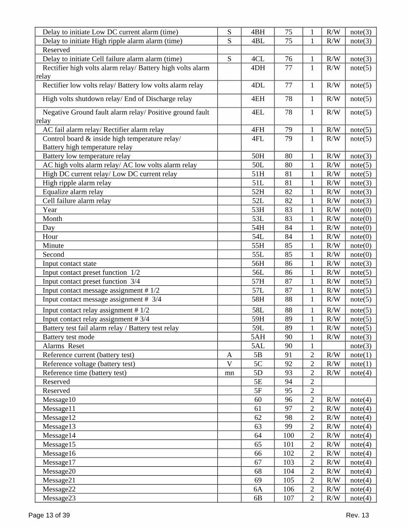
Page 13 of 39 Rev. 13
Delay to initiate Low DC current alarm (time) S 4BH 75 1 R/W note(3) Delay to initiate High ripple alarm alarm (time) S 4BL 75 1 R/W note(3) Reserved Delay to initiate Cell failure alarm alarm (time) S 4CL 76 1 R/W note(3) Rectifier high volts alarm relay/ Battery high volts alarm
relay 4DH 77 1 R/W note(5)
Rectifier low volts relay/ Battery low volts alarm relay 4DL 77 1 R/W note(5)
High volts shutdown relay/ End of Discharge relay 4EH 78 1 R/W note(5)
Negative Ground fault alarm relay/ Positive ground fault relay
4EL 78 1 R/W note(5)
AC fail alarm relay/ Rectifier alarm relay 4FH 79 1 R/W note(5) Control board & inside high temperature relay/ Battery high temperature relay
4FL 79 1 R/W note(5)
Battery low temperature relay 50H 80 1 R/W note(3) AC high volts alarm relay/ AC low volts alarm relay 50L 80 1 R/W note(5) High DC current relay/ Low DC current relay 51H 81 1 R/W note(5) High ripple alarm relay 51L 81 1 R/W note(3) Equalize alarm relay 52H 82 1 R/W note(3) Cell failure alarm relay 52L 82 1 R/W note(3) Year 53H 83 1 R/W note(0) Month 53L 83 1 R/W note(0) Day 54H 84 1 R/W note(0) Hour 54L 84 1 R/W note(0) Minute 55H 85 1 R/W note(0) Second 55L 85 1 R/W note(0) Input contact state 56H 86 1 R/W note(3) Input contact preset function 1/2 56L 86 1 R/W note(5) Input contact preset function 3/4 57H 87 1 R/W note(5) Input contact message assignment # 1/2 57L 87 1 R/W note(5) Input contact message assignment # 3/4 58H 88 1 R/W note(5) Input contact relay assignment # 1/2 58L 88 1 R/W note(5) Input contact relay assignment # 3/4 59H 89 1 R/W note(5) Battery test fail alarm relay / Battery test relay 59L 89 1 R/W note(5) Battery test mode 5AH 90 1 R/W note(3) Alarms Reset 5AL 90 1 note(3) Reference current (battery test) A 5B 91 2 R/W note(1) Reference voltage (battery test) V 5C 92 2 R/W note(1) Reference time (battery test) mn 5D 93 2 R/W note(4) Reserved 5E 94 2 Reserved 5F 95 2 Message10 60 96 2 R/W note(4) Message11 61 97 2 R/W note(4) Message12 62 98 2 R/W note(4) Message13 63 99 2 R/W note(4) Message14 64 100 2 R/W note(4) Message15 65 101 2 R/W note(4) Message16 66 102 2 R/W note(4) Message17 67 103 2 R/W note(4) Message20 68 104 2 R/W note(4) Message21 69 105 2 R/W note(4) Message22 6A 106 2 R/W note(4) Message23 6B 107 2 R/W note(4)

Page 14 of 39 Rev. 13
Message24 6C 108 2 R/W note(4) Message25 6D 109 2 R/W note(4) Message26 6E 110 2 R/W note(4) Message27 6F 111 2 R/W note(4) Message30 70 112 2 R/W note(4) Message31 71 113 2 R/W note(4) Message32 72 114 2 R/W note(4) Message33 73 115 2 R/W note(4) Message34 74 116 2 R/W note(4) Message35 75 117 2 R/W note(4) Message36 76 118 2 R/W note(4) Message37 77 119 2 R/W note(4) Message40 78 120 2 R/W note(4) Message41 79 121 2 R/W note(4) Message42 7A 122 2 R/W note(4) Message43 7B 123 2 R/W note(4) Message44 7C 124 2 R/W note(4) Message45 7D 125 2 R/W note(4) Message46 7E 126 2 R/W note(4) Message47 7F 127 2 R/W note(4)
Table 4: RAM map
2.2 CHARGER COMMON PARAMETERS SET UP
2.2.1 General
Writing into the RAM leads to modify the charger operating parameters. In this paragraph, we present the most common charger settings. For more information, please contact the factory. RAM registers are coded in 16 bits. In order to write into the Ram: send the password to the address (27 hex; call technical support for password). When the password is accepted, each register with state (W) can be modified. WARNING: Only qualified and trained personnel can access this mapping. Parameters modification with wrong information may lead to major defects and failures if wrong data is used.
2.2.2 Voltage or current settings
In order to modify the float voltage, write the required value in register (0E hex) (Refer to Note 1, for the byte format to send). For equalize voltage, the address (0F hex) is to be used. In order to modify the float limit current, write the required value in register (10 hex). For equalize limit current, the address (11 hex) is to be used.
2.3 OPERATION MODE MODIFICATION
To switch from float, to equalize, send (0001 in binary) to bit 3, 2, 1 and 0 respectively into the register (26 hex), (Refer to Note 21). To switch from equalize, to float, send (00010 in binary) to bit 3, 2, 1 and 0 respectively into the register (26 hex), (Refer to Note 21).
2.3.2 Formation mode
To start a formation mode send (0100 in binary) to bit 3, 2, 1 and 0 respectively into the register (26 hex), (Refer to Note 21).
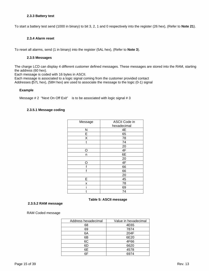
Page 15 of 39 Rev. 13
2.3.3 Battery test
To start a battery test send (1000 in binary) to bit 3, 2, 1 and 0 respectively into the register (26 hex), (Refer to Note 21).
2.3.4 Alarm reset
To reset all alarms, send (1 in binary) into the register (5AL hex), (Refer to Note 3).
2.3.5 Messages
The charge LCD can display 4 different customer defined messages. These messages are stored into the RAM, starting the address (60 hex). Each message is coded with 16 bytes in ASCII. Each message is associated to a logic signal coming from the customer provided contact Addresses (57L hex), (58H hex) are used to associate the message to the logic (0-1) signal
Example Message # 2 "Next On Off Exit” is to be associated with logic signal # 3
2.3.5.1 Message coding
Message ASCII Code in hexadecimal
N 4E E 65 X 78 t 74 20
O 4F n 6E 20
O 4F f 66 f 66 20
E 45 x 78 i 69 t 74
Table 5: ASCII message
2.3.5.2 RAM message
RAM Coded message
Address hexadecimal Value in hexadecimal 68 4E65 69 7874 6A 204F 6B 6E20 6C 4F66 6D 6620 6E 4578 6F 6974
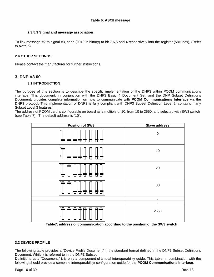
Page 16 of 39 Rev. 13
Table 6: ASCII message
2.3.5.3 Signal and message association
To link message #2 to signal #3, send (0010 in binary) to bit 7,6,5 and 4 respectively into the register (58H hex), (Refer to Note 5).
2.4 OTHER SETTINGS
Please contact the manufacturer for further instructions.
3. DNP V3.00
3.1 INTRODUCTION The purpose of this section is to describe the specific implementation of the DNP3 within PCOM communications interface. This document, in conjunction with the DNP3 Basic 4 Document Set, and the DNP Subset Definitions Document, provides complete information on how to communicate with PCOM Communications Interface via the DNP3 protocol. This implementation of DNP3 is fully compliant with DNP3 Subset Definition Level 2, contains many Subset Level 3 features. The address of PCOM card is configurable on board as a multiple of 10, from 10 to 2550, and selected with SW3 switch (see Table 7). The default address is “10“.
Position of SW3 Slave address
0
on
1
10
20
30
. .
. . on
1
2560
Table7: address of communication according to the position of the SW3 switch
3.2 DEVICE PROFILE The following table provides a “Device Profile Document” in the standard format defined in the DNP3 Subset Definitions Document. While it is referred to in the DNP3 Subset Definitions as a “Document,” it is only a component of a total interoperability guide. This table, in combination with the following should provide a complete interoperability/ configuration guide for the PCOM Communications Interface:

Page 17 of 39 Rev. 13
DNP V3.00 DEVICE PROFILE DOCUMENT Vendor Name: Primax Technologies Inc. 133 Guthrie, Dorval (Quebec) Canada H9P2P1 Highest DNP Level Supported: For Requests: Level 2 For Responses: Level 2
Device Function:
Master Slave
Notable objects, functions, and/or qualifiers supported in addition to the Highest DNP Levels Supported (the complete list is described in the attached table): Maximum Data Link Frame Size (octets): Transmitted: 292 Received: 292
Maximum Application Fragment Size (octets): Transmitted: 249 Received: 249
Maximum Data Link Re-tries:
None Fixed at 3 Configurable range 0 to 255
Maximum Application Layer Re-tries:
None Configurable
Requires Data Link Layer Confirmation:
Never Always Sometimes Configurable
Requires Application Layer Confirmation:
Never Always When reporting Event Data When sending multi-fragment responses Sometimes Configurable
Timeouts while waiting for: Data Link Confirm: None Fixed at____ Variable Configurable Complete Appl. Fragment: None Fixed at____ Variable Configurable Application Confirm: None Fixed at____ Variable Configurable Complete Appl. Response: None Fixed at____ Variable Configurable Sends/Executes Control Operations: WRITE Binary Outputs Never Always Sometimes Configurable SELECT/OPERATE: Never Always Sometimes Configurable DIRECT OPERATE: Never Always Sometimes Configurable DIRECT OPERATE – NO ACK Never Always Sometimes Configurable Cont>1 Never Always Sometimes Configurable Pulse On Never Always Sometimes Configurable Pulse Off Never Always Sometimes Configurable Latch On Never Always Sometimes Configurable Latch Off Never Always Sometimes Configurable Queue Never Always Sometimes ConfigurableClear Queue Never Always Sometimes Configurable
Sends Unsolicited Responses: Never Configurable, See hardware
configuration section Only certain objects Sometimes (attach explanation) ENABLE/DISABLE UNSOLICITED
Sends Static Data in Unsolicited Responses: Never When Device Restarts When Status Flags Change No other options are permitted.
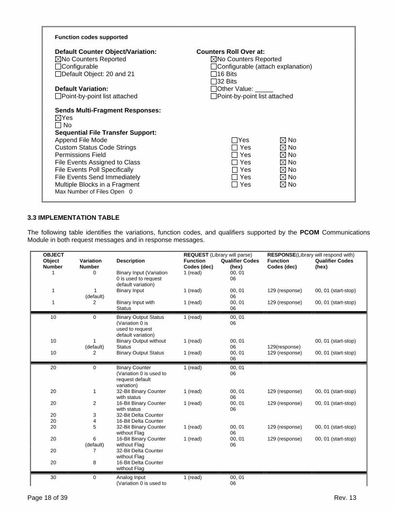
Page 18 of 39 Rev. 13
Function codes supported Default Counter Object/Variation:
No Counters Reported Configurable Default Object: 20 and 21
Default Variation:
Point-by-point list attached
Counters Roll Over at: No Counters Reported Configurable (attach explanation) 16 Bits 32 Bits Other Value: _____ Point-by-point list attached
Sends Multi-Fragment Responses: Yes No
Sequential File Transfer Support: Append File Mode Yes No Custom Status Code Strings Yes No Permissions Field Yes No File Events Assigned to Class Yes No File Events Poll Specifically Yes No File Events Send Immediately Yes No Multiple Blocks in a Fragment Yes No Max Number of Files Open 0
3.3 IMPLEMENTATION TABLE The following table identifies the variations, function codes, and qualifiers supported by the PCOM Communications Module in both request messages and in response messages.
OBJECT REQUEST (Library will parse) RESPONSE(Library will respond with) Object Number
Variation Number
Description Function Codes (dec)
Qualifier Codes (hex)
Function Codes (dec)
Qualifier Codes (hex)
1 0 Binary Input (Variation 0 is used to request default variation)
1 (read) 00, 01 06
1 1 (default)
Binary Input 1 (read) 00, 01 06
129 (response) 00, 01 (start-stop)
1 2 Binary Input with Status
1 (read) 00, 01 06
129 (response) 00, 01 (start-stop)
10 0 Binary Output Status (Variation 0 is used to request default variation)
1 (read) 00, 01 06
10 1 (default)
Binary Output without Status
1 (read) 00, 01 06
129(response)
00, 01 (start-stop)
10 2 Binary Output Status 1 (read) 00, 01 06
129 (response) 00, 01 (start-stop)
20 0 Binary Counter (Variation 0 is used to request default variation)
1 (read) 00, 01 06
20 1 32-Bit Binary Counter with status
1 (read) 00, 01 06
129 (response) 00, 01 (start-stop)
20 2 16-Bit Binary Counter with status
1 (read) 00, 01 06
129 (response) 00, 01 (start-stop)
20 3 32-Bit Delta Counter 20 4 16-Bit Delta Counter 20 5 32-Bit Binary Counter
without Flag 1 (read) 00, 01
06 129 (response) 00, 01 (start-stop)
20 6 (default)
16-Bit Binary Counter without Flag
1 (read) 00, 01 06
129 (response) 00, 01 (start-stop)
20 7 32-Bit Delta Counter without Flag
20 8 16-Bit Delta Counter without Flag
30 0 Analog Input (Variation 0 is used to
1 (read) 00, 01 06
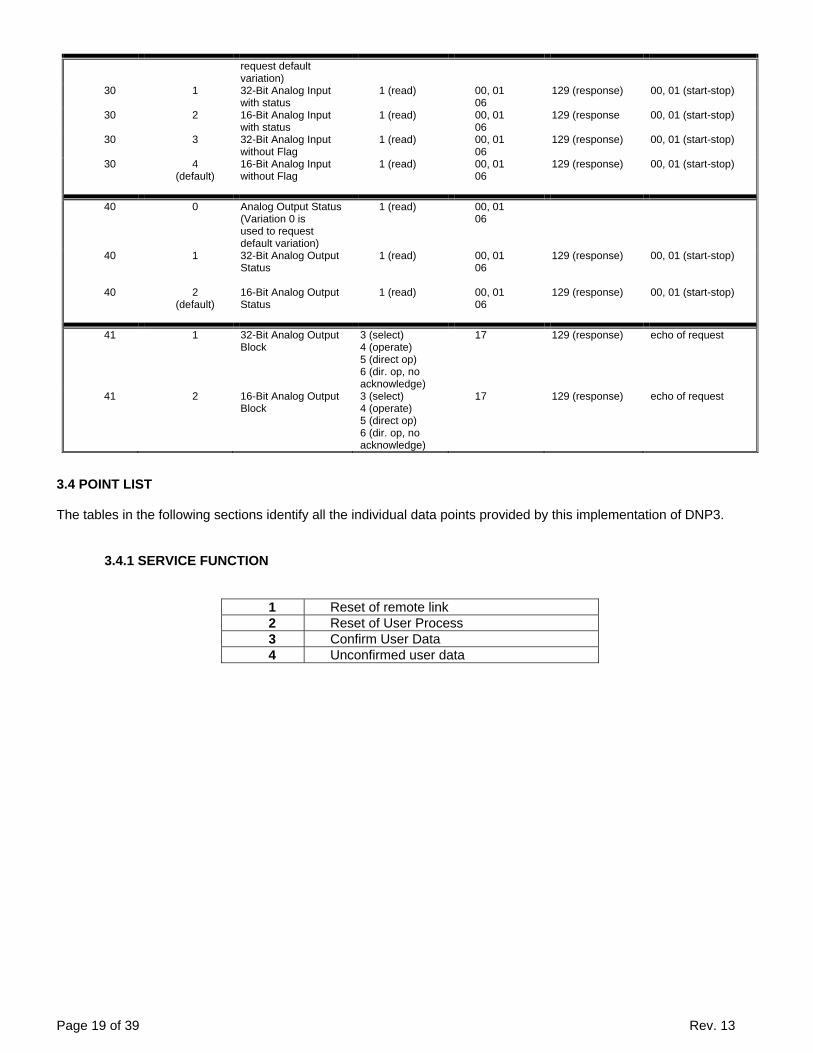
Page 19 of 39 Rev. 13
request default variation)
30 1 32-Bit Analog Input with status
1 (read)22 00, 01 06
129 (response) 00, 01 (start-stop)
30 2
16-Bit Analog Input with status
1 (read) 00, 01 06
129 (response 00, 01 (start-stop)
30 3 32-Bit Analog Input without Flag
1 (read) 00, 01 06
129 (response) 00, 01 (start-stop)
30 4 (default)
16-Bit Analog Input without Flag
1 (read) 22 (assign
class)
00, 01 06
129 (response) 00, 01 (start-stop)
40 0 Analog Output Status (Variation 0 is used to request default variation)
1 (read) 22 (assign
class)
00, 01 06
40 1 32-Bit Analog Output Status
1 (read) 22 (assign
class)
00, 01 06
129 (response) 00, 01 (start-stop)
40 2 (default)
16-Bit Analog Output Status
1 (read) 22 (assign
class)
00, 01 06
129 (response) 00, 01 (start-stop)
41 1 32-Bit Analog Output Block
3 (select) 4 (operate) 5 (direct op) 6 (dir. op, no acknowledge)
17 129 (response) echo of request
41 2 16-Bit Analog Output Block
3 (select) 4 (operate) 5 (direct op) 6 (dir. op, no acknowledge)
17 129 (response) echo of request
3.4 POINT LIST
The tables in the following sections identify all the individual data points provided by this implementation of DNP3.
3.4.1 SERVICE FUNCTION
1 Reset of remote link 2 Reset of User Process 3 Confirm User Data 4 Unconfirmed user data

Page 20 of 39 Rev. 13
Object 01 variation 0 (Binary input all variation) Default: Object 01 variation 01 (Binary input)
Request (slave must parse)
Response (master must parse)
Codes function
Codes Qual (hex) Codes function
Codes Qual (hex)
1 read 00,01,06 129-read 00,01
Point
Signification Status
0 1 0 Unused 1 High volt battery alarm Non active Active 2 High volt rectifier alarm Non active Active 3 High volt shut down alarm Non active Active 4 Low volt battery alarm Non active Active 5 Low volt rectifier alarm Non active Active 6 End of Discharge alarm Non active Active 7 Ground fault negative alarm Non active Active 8 Ground fault positive alarm Non active Active 9 Rectifier fail alarm Non active Active 10 high Control board & inside high temperature alarm Non active Active 11 Low control board & inside high temperature alarm Non active Active 12 Battery high temperature alarm Non active Active 13 Battery low temperature alarm Non active Active 14 AC high volts alarm Non active Active 15 AC low volts alarm Non active Active 16 Unused 17 Cell failure alarm Non active Active 18 AC fail alarm Non active Active 19 High ripple alarm Non active Active 20 High DC current rectifier alarm Non active Active 21 Low DC current rectifier alarm Non active Active 22 Equalize alarm Non active Active 23 Frequency fault alarm Non active Active 24 Battery test failure alarm Non active Active 25 High DC current battery alarm Non active Active 26 Low DC current battery alarm Non active Active 27 High capacity battery alarm Non active Active 28 Low capacity battery alarm Non active Active 29 Probe Alarm Non active Active 30 Unused 31 Common alarm Non active Active 32 Unused Non active Active 33 Mode float Non active Active 34 Mode equalize Non active Active 35 Mode current limit Non active Active 36 Mode test battery Non active Active 37 Mode formation voltage Non active Active 38 Mode formation current Non active Active 39 Switch1 Non active Active 40 Switch2 Non active Active 41 Switch3 Non active Active 42 Switch4 Non active Active
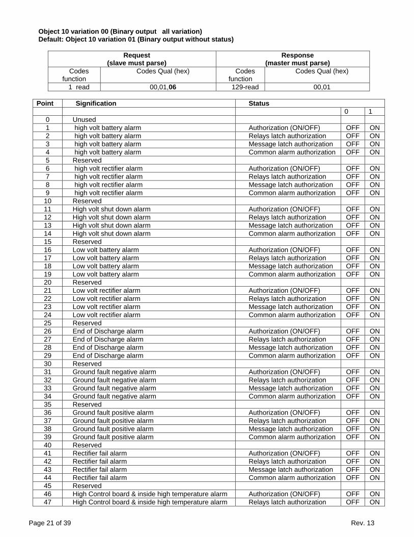
Page 21 of 39 Rev. 13
Object 10 variation 00 (Binary output all variation) Default: Object 10 variation 01 (Binary output without status)
Request (slave must parse)
Response (master must parse)
Codes function
Codes Qual (hex) Codes function
Codes Qual (hex)
1 read 00,01,06 129-read 00,01
Point Signification Status 0 1 0 Unused 1 high volt battery alarm Authorization (ON/OFF) OFF ON 2 high volt battery alarm Relays latch authorization OFF ON 3 high volt battery alarm Message latch authorization OFF ON 4 high volt battery alarm Common alarm authorization OFF ON 5 Reserved 6 high volt rectifier alarm Authorization (ON/OFF) OFF ON 7 high volt rectifier alarm Relays latch authorization OFF ON 8 high volt rectifier alarm Message latch authorization OFF ON 9 high volt rectifier alarm Common alarm authorization OFF ON 10 Reserved 11 High volt shut down alarm Authorization (ON/OFF) OFF ON 12 High volt shut down alarm Relays latch authorization OFF ON 13 High volt shut down alarm Message latch authorization OFF ON 14 High volt shut down alarm Common alarm authorization OFF ON 15 Reserved 16 Low volt battery alarm Authorization (ON/OFF) OFF ON 17 Low volt battery alarm Relays latch authorization OFF ON 18 Low volt battery alarm Message latch authorization OFF ON 19 Low volt battery alarm Common alarm authorization OFF ON 20 Reserved 21 Low volt rectifier alarm Authorization (ON/OFF) OFF ON 22 Low volt rectifier alarm Relays latch authorization OFF ON 23 Low volt rectifier alarm Message latch authorization OFF ON 24 Low volt rectifier alarm Common alarm authorization OFF ON 25 Reserved 26 End of Discharge alarm Authorization (ON/OFF) OFF ON 27 End of Discharge alarm Relays latch authorization OFF ON 28 End of Discharge alarm Message latch authorization OFF ON 29 End of Discharge alarm Common alarm authorization OFF ON 30 Reserved 31 Ground fault negative alarm Authorization (ON/OFF) OFF ON 32 Ground fault negative alarm Relays latch authorization OFF ON 33 Ground fault negative alarm Message latch authorization OFF ON 34 Ground fault negative alarm Common alarm authorization OFF ON 35 Reserved 36 Ground fault positive alarm Authorization (ON/OFF) OFF ON 37 Ground fault positive alarm Relays latch authorization OFF ON 38 Ground fault positive alarm Message latch authorization OFF ON 39 Ground fault positive alarm Common alarm authorization OFF ON 40 Reserved 41 Rectifier fail alarm Authorization (ON/OFF) OFF ON 42 Rectifier fail alarm Relays latch authorization OFF ON 43 Rectifier fail alarm Message latch authorization OFF ON 44 Rectifier fail alarm Common alarm authorization OFF ON 45 Reserved 46 High Control board & inside high temperature alarm Authorization (ON/OFF) OFF ON 47 High Control board & inside high temperature alarm Relays latch authorization OFF ON

Page 22 of 39 Rev. 13
48 High Control board & inside high temperature alarm Message latch authorization OFF ON 49 High Control board & inside high temperature alarm Common alarm authorization OFF ON 50 Reserved 51 Low control board & inside high temperature alarm Authorization (ON/OFF) OFF ON 52 Low control board & inside high temperature alarm Relays latch authorization OFF ON 53 Low control board & inside high temperature alarm Message latch authorization OFF ON 54 Low control board & inside high temperature alarm Common alarm authorization OFF ON 55 Reserved 56 High battery temperature alarm Authorization (ON/OFF) OFF ON 57 High battery temperature alarm Relays latch authorization OFF ON 58 High battery temperature alarm Message latch authorization OFF ON 59 High battery temperature alarm Common alarm authorization OFF ON 60 High battery temperature alarm Shut Down authorization OFF ON 61 Low battery temperature alarm Authorization (ON/OFF) OFF ON 62 Low battery temperature alarm Relays latch authorization OFF ON 63 Low battery temperature alarm Message latch authorization OFF ON 64 Low battery temperature alarm Common alarm authorization OFF ON 65 Reserved 66 AC high volts alarm Authorization (ON/OFF) OFF ON 67 AC high volts alarm Relays latch authorization OFF ON 68 AC high volts alarm Message latch authorization OFF ON 69 AC high volts alarm Common alarm authorization OFF ON 70 Reserved 71 AC low volts alarm Authorization (ON/OFF) OFF ON 72 AC low volts alarm Relays latch authorization OFF ON 73 AC low volts alarm Message latch authorization OFF ON 74 AC low volts alarm Common alarm authorization OFF ON 75 Reserved 76 Cell failure alarm Authorization (ON/OFF) OFF ON 77 Cell failure alarm Relays latch authorization OFF ON 78 Cell failure alarm Message latch authorization OFF ON 79 Cell failure alarm Common alarm authorization OFF ON 80 Reserved 81 AC fail alarm Authorization (ON/OFF) OFF ON 82 AC fail alarm Relays latch authorization OFF ON 83 AC fail alarm Message latch authorization OFF ON 84 AC fail alarm Common alarm authorization OFF ON 85 Reserved 86 High ripple alarm Authorization (ON/OFF) OFF ON 87 High ripple alarm Relays latch authorization OFF ON 88 High ripple alarm Message latch authorization OFF ON 89 High ripple alarm Common alarm authorization OFF ON 90 Reserved 91 High DC current rectifier alarm Authorization (ON/OFF) OFF ON 92 High DC current rectifier alarm Relays latch authorization OFF ON 93 High DC current rectifier alarm Message latch authorization OFF ON 94 High DC current rectifier alarm Common alarm authorization OFF ON 95 Reserved 96 Low DC current rectifier alarm Authorization (ON/OFF) OFF ON 97 Low DC current rectifier alarm Relays latch authorization OFF ON 98 Low DC current rectifier alarm Message latch authorization OFF ON 99 Low DC current rectifier alarm Common alarm authorization OFF ON 100 Reserved 101 Equalize alarm Authorization (ON/OFF) OFF ON 102 Equalize alarm Relays latch authorization OFF ON 103 Equalize alarm Message latch authorization OFF ON 104 Equalize alarm Common alarm authorization OFF ON 105 Reserved 106 Frequency fault alarm Authorization (ON/OFF) OFF ON
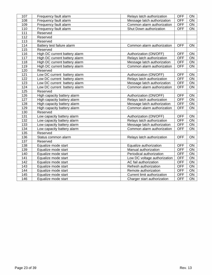
Page 23 of 39 Rev. 13
107 Frequency fault alarm Relays latch authorization OFF ON 108 Frequency fault alarm Message latch authorization OFF ON 109 Frequency fault alarm Common alarm authorization OFF ON 110 Frequency fault alarm Shut Down authorization OFF ON 111 Reserved 112 Reserved 113 Reserved 114 Battery test failure alarm Common alarm authorization OFF ON 115 Reserved 116 High DC current battery alarm Authorization (ON/OFF) OFF ON 117 High DC current battery alarm Relays latch authorization OFF ON 118 High DC current battery alarm Message latch authorization OFF ON 119 High DC current battery alarm Common alarm authorization OFF ON 120 Reserved 121 Low DC current battery alarm Authorization (ON/OFF) OFF ON 122 Low DC current battery alarm Relays latch authorization OFF ON 123 Low DC current battery alarm Message latch authorization OFF ON 124 Low DC current battery alarm Common alarm authorization OFF ON 125 Reserved 126 High capacity battery alarm Authorization (ON/OFF) OFF ON 127 High capacity battery alarm Relays latch authorization OFF ON 128 High capacity battery alarm Message latch authorization OFF ON 129 High capacity battery alarm Common alarm authorization OFF ON 130 Reserved 131 Low capacity battery alarm Authorization (ON/OFF) OFF ON 132 Low capacity battery alarm Relays latch authorization OFF ON 133 Low capacity battery alarm Message latch authorization OFF ON 134 Low capacity battery alarm Common alarm authorization OFF ON 135 Reserved 136 Status common alarm Relays latch authorization OFF ON 137 Reserved 138 Equalize mode start Equalize authorization OFF ON 139 Equalize mode start Manual authorization OFF ON 140 Equalize mode start Periodical authorization OFF ON 141 Equalize mode start Low DC voltage authorization OFF ON 142 Equalize mode start AC fail authorization OFF ON 143 Equalize mode start Refresh authorization OFF ON 144 Equalize mode start Remote authorization OFF ON 145 Equalize mode start Current limit authorization OFF ON 146 Equalize mode start Charger start authorization OFF ON

Page 24 of 39 Rev. 13
Object 30 variation 00 (Analog input all variation) Default: Object 30 variation 04 (16-Bit analog input without status)
Request (slave must parse)
Response (master must parse)
Codes function
Codes Qual (hex) Codes function
Codes Qual (hex)
1 read 00,01,06 129-read 00,01
Point
Signification Unit Note
0 Unused 1 Rectifier voltage Volt note(1) 2 Rectifier current Ampere note(1) 3 Battery current Ampere note(2) 4 AC volt phase 1 Volt note(1) 5 AC volt phase 2 Volt note(1) 6 AC volt phase 3 Volt note(1) 7 AC current phase 1 Ampere note(1) 8 AC current phase 2 Ampere note(1) 9 AC current phase 3 Ampere note(1) 10 Battery temperature °C note(22) 11 Control board & inside temperature °C note(22) 12 AC frequency Hertz note(1)
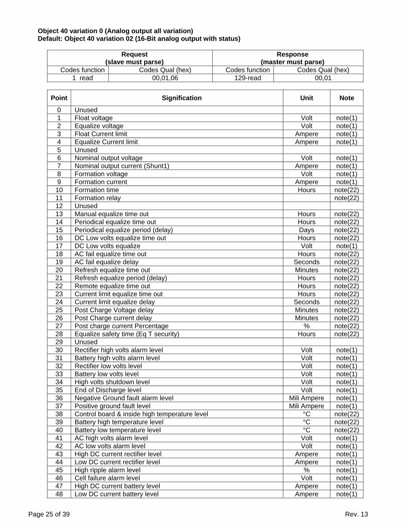
Page 25 of 39 Rev. 13
Object 40 variation 0 (Analog output all variation) Default: Object 40 variation 02 (16-Bit analog output with status)
Request (slave must parse)
Response (master must parse)
Codes function Codes Qual (hex) Codes function Codes Qual (hex) 1 read 00,01,06 129-read 00,01
Point Signification Unit Note
0 Unused 1 Float voltage Volt note(1) 2 Equalize voltage Volt note(1) 3 Float Current limit Ampere note(1) 4 Equalize Current limit Ampere note(1) 5 Unused 6 Nominal output voltage Volt note(1) 7 Nominal output current (Shunt1) Ampere note(1) 8 Formation voltage Volt note(1) 9 Formation current Ampere note(1) 10 Formation time Hours note(22) 11 Formation relay note(22) 12 Unused 13 Manual equalize time out Hours note(22) 14 Periodical equalize time out Hours note(22) 15 Periodical equalize period (delay) Days note(22) 16 DC Low volts equalize time out Hours note(22) 17 DC Low volts equalize Volt note(1) 18 AC fail equalize time out Hours note(22) 19 AC fail equalize delay Seconds note(22) 20 Refresh equalize time out Minutes note(22) 21 Refresh equalize period (delay) Hours note(22) 22 Remote equalize time out Hours note(22) 23 Current limit equalize time out Hours note(22) 24 Current limit equalize delay Seconds note(22) 25 Post Charge Voltage delay Minutes note(22) 26 Post Charge current delay Minutes note(22) 27 Post charge current Percentage % note(22) 28 Equalize safety time (Eq T security) Hours note(22) 29 Unused 30 Rectifier high volts alarm level Volt note(1) 31 Battery high volts alarm level Volt note(1) 32 Rectifier low volts level Volt note(1) 33 Battery low volts level Volt note(1) 34 High volts shutdown level Volt note(1) 35 End of Discharge level Volt note(1) 36 Negative Ground fault alarm level Mili Ampere note(1) 37 Positive ground fault level Mili Ampere note(1) 38 Control board & inside high temperature level °C note(22) 39 Battery high temperature level °C note(22) 40 Battery low temperature level °C note(22) 41 AC high volts alarm level Volt note(1) 42 AC low volts alarm level Volt note(1) 43 High DC current rectifier level Ampere note(1) 44 Low DC current rectifier level Ampere note(1) 45 High ripple alarm level % note(1) 46 Cell failure alarm level Volt note(1) 47 High DC current battery level Ampere note(1) 48 Low DC current battery level Ampere note(1)

Page 26 of 39 Rev. 13
49 Delay to initiate Rectifier high volts alarm (time) Seconds note(22) 50 Delay to initiate Battery high volts alarm (time) Seconds note(22) 51 Delay to initiate Rectifier low volts alarm (time) Seconds note(22) 52 Delay to initiate Battery low volts alarm (time) Seconds note(22) 53 Delay to initiate High volts shutdown alarm (time) Seconds note(22) 54 Delay to initiate End of Discharge alarm (time) Seconds note(22) 55 Delay to initiate Negative Ground fault alarm (time) Seconds note(22) 56 Delay to initiate Positive ground fault alarm (time) Seconds note(22) 57 Delay to initiate AC fail alarm (time) Seconds note(22) 58 Delay to initiate Rectifier alarm (time) Seconds note(22) 59 Delay to initiate Control board & inside high temperature alarm (time) Seconds note(22) 60 Delay to initiate Battery high temperature alarm (time) Seconds note(22) 61 Delay to initiate Battery low temperature alarm (time) Seconds note(22) 62 Delay to initiate AC high volts alarm (time) Seconds note(22) 63 Delay to initiate AC low volts alarm (time) Seconds note(22) 64 Delay to initiate High DC current alarm (time) Seconds note(22) 65 Delay to initiate Low DC current alarm (time) Seconds note(22) 66 Delay to initiate High ripple alarm (time) Seconds note(22) 67 Unused 68 Delay to initiate High DC current battery alarm (time) Seconds note(22) 69 Delay to initiate Low DC current battery alarm (time) Seconds note(22) 70 Delay to initiate Cell failure alarm alarm (time) Seconds note(22) 71 Rectifier high volts alarm relay note(22) 72 Battery high volts alarm relay note(22) 73 Rectifier low volts relay note(22) 74 Battery low volts alarm relay note(22) 75 High volts shutdown relay note(22) 76 End of Discharge relay note(22) 77 Negative Ground fault alarm relay note(22) 78 Positive ground fault relay note(22) 79 AC fail alarm relay note(22) 80 Rectifier alarm relay note(22) 81 Control board & inside high temperature relay note(22) 82 Battery high temperature relay note(22) 83 Battery low temperature relay note(22) 84 AC high volts alarm relay note(22) 85 AC low volts alarm relay note(22) 86 High DC current relay note(22) 87 Low DC current relay note(22) 88 High ripple alarm relay note(22) 89 Equalize alarm relay note(22) 90 Cell failure alarm relay note(22) 91 High DC current battery relay note(22) 92 Low DC current battery relay note(22) 93 Unused 94 DC output voltage temperature compensation mV note(1) 95 DC output current temperature compensation(TCompAmp) % note(22) 96 Temperature threshold (Tref) °C note(22) 97 Unused 98 Battery test mode note(22) 99 Battery test fail alarm relay note(22)
100 Battery test relay note(22) 101 Reference current (battery test) Ampere note(1) 102 Reference voltage (battery test) Volt note(1) 103 Reference time (battery test) Minutes note(22)

Page 27 of 39 Rev. 13
Object 20 variation 00 (Binary counter all variation) Default: Object 20 variation 06 (16-Bit binary counter without status)
Request (slave must parse)
Response (master must parse)
Codes function
Codes Qual (hex) Codes function
Codes Qual (hex)
1 read 00,01,06 129-read 00,01
Point Unit Note
0 Unused 1 Equalize remaining time minutes note(22) 2 Equalize elapsed time minutes note(22) 3 Formation remaining time hours note(22)
Object 41 variation 01 (32-Bit analog OUTPUT BLOCK) Object 41 variation 02 (16-Bit analog OUTPUT BLOCK) Select (function 3) Operate (function 4) Direct operation (function 5) Direct operation no acknowledge (function 6)
Request
(slave must parse) Response
(master must parse) Codes function Codes Qual (hexa) Codes
function Codes Qual (hexa)
5 Direct operate
17 129-read echo of request
Point Address (hex)
Variable Unit Byte Note
1 0E Float voltage V 2 note(1) 2 0F Equalize voltage V 2 note(1) 3 10 Float Current limit A 2 note(1) 4 11 Equalize Current limit A 2 note(1) 5 12 Formation voltage V 2 note(1) 6 13 Formation current A 2 note(1) 7 14H Formation relay 1 note(3) 8 15H Formation time H 1 note(3) 9 16 Charger configuration 2 Refer to
paragraph (3.5.3)10 17 Equalize mode start 2 note(9) 11 1AH Manual equalize time H 1 note(3) 12 1AL Periodical equalize time H 1 note(3) 13 1BH Periodical equalize period (delay) D 1 note(3) 14 1BL DC Low volts equalize time out H 1 note(3) 15 1C DC Low volts equalize level V 2 note(1) 16 Reserved 17 1DH AC fail equalize time out H 1 note(3) 18 1DL AC fail equalize delay S 1 note(3) 19 1EH Refresh equalize time out mn 1 note(3) 20 1EL Refresh equalize period (delay) H 1 note(3)
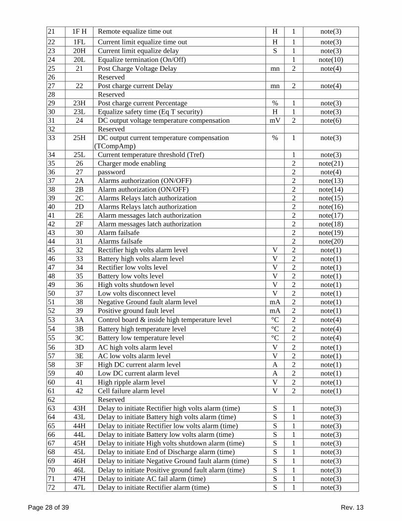
Page 28 of 39 Rev. 13
21 1F H Remote equalize time out H 1 note(3) 22 1FL Current limit equalize time out H 1 note(3) 23 20H Current limit equalize delay S 1 note(3) 24 20L Equalize termination (On/Off) 1 note(10) 25 21 Post Charge Voltage Delay mn 2 note(4) 26 Reserved 27 22 Post charge current Delay mn 2 note(4) 28 Reserved 29 23H Post charge current Percentage % 1 note(3) 30 23L Equalize safety time (Eq T security) H 1 note(3) 31 24 DC output voltage temperature compensation mV 2 note(6) 32 Reserved 33 25H DC output current temperature compensation
(TCompAmp) % 1 note(3)
34 25L Current temperature threshold (Tref) 1 note(3) 35 26 Charger mode enabling 2 note(21) 36 27 password 2 note(4) 37 2A Alarms authorization (ON/OFF) 2 note(13) 38 2B Alarm authorization (ON/OFF) 2 note(14) 39 2C Alarms Relays latch authorization 2 note(15) 40 2D Alarms Relays latch authorization 2 note(16) 41 2E Alarm messages latch authorization 2 note(17) 42 2F Alarm messages latch authorization 2 note(18) 43 30 Alarm failsafe 2 note(19) 44 31 Alarms failsafe 2 note(20) 45 32 Rectifier high volts alarm level V 2 note(1) 46 33 Battery high volts alarm level V 2 note(1) 47 34 Rectifier low volts level V 2 note(1) 48 35 Battery low volts level V 2 note(1) 49 36 High volts shutdown level V 2 note(1) 50 37 Low volts disconnect level V 2 note(1) 51 38 Negative Ground fault alarm level mA 2 note(1) 52 39 Positive ground fault level mA 2 note(1) 53 3A Control board & inside high temperature level °C 2 note(4) 54 3B Battery high temperature level °C 2 note(4) 55 3C Battery low temperature level °C 2 note(4) 56 3D AC high volts alarm level V 2 note(1) 57 3E AC low volts alarm level V 2 note(1) 58 3F High DC current alarm level A 2 note(1) 59 40 Low DC current alarm level A 2 note(1) 60 41 High ripple alarm level V 2 note(1) 61 42 Cell failure alarm level V 2 note(1) 62 Reserved 63 43H Delay to initiate Rectifier high volts alarm (time) S 1 note(3) 64 43L Delay to initiate Battery high volts alarm (time) S 1 note(3) 65 44H Delay to initiate Rectifier low volts alarm (time) S 1 note(3) 66 44L Delay to initiate Battery low volts alarm (time) S 1 note(3) 67 45H Delay to initiate High volts shutdown alarm (time) S 1 note(3) 68 45L Delay to initiate End of Discharge alarm (time) S 1 note(3) 69 46H Delay to initiate Negative Ground fault alarm (time) S 1 note(3) 70 46L Delay to initiate Positive ground fault alarm (time) S 1 note(3) 71 47H Delay to initiate AC fail alarm (time) S 1 note(3) 72 47L Delay to initiate Rectifier alarm (time) S 1 note(3)

Page 29 of 39 Rev. 13
73 48H Delay to initiate Control board & inside high temperature alarm (time)
S 1 note(3)
74 48L Delay to initiate Battery high temperature alarm (time) S 1 note(3) 75 49H Delay to initiate Battery low temperature alarm (time) S 1 note(3) 76 49L Delay to initiate AC high volts alarm (time) S 1 note(3) 77 4AH Delay to initiate AC low volts alarm (time) S 1 note(3) 78 4AL Delay to initiate High DC current alarm (time) S 1 note(3) 79 4BH Delay to initiate Low DC current alarm (time) S 1 note(3) 80 4BL Delay to initiate High ripple alarm (time) S 1 note(3) 81 Reserved 82 4CL Delay to initiate Cell failure alarm (time) S 1 note(3) 83 4DH Rectifier high volts alarm relay/ Battery high volts alarm
relay 1 note(5)
84 4DL Rectifier low volts relay/ Battery low volts alarm relay 1 note(5)
85 4EH High volts shutdown relay/ End of Discharge relay 1 note(5)
86 4EL Negative Ground fault alarm relay/ Positive ground fault relay
1 note(5)
87 4FH AC fail alarm relay/ Rectifier alarm relay 1 note(5) 88 4FL Control board & inside high temperature relay/
Battery high temperature relay 1 note(5)
89 50H Battery low temperature relay 1 note(3) 90 50L AC high volts alarm relay/ AC low volts alarm relay 1 note(5) 91 51H High DC current relay/ Low DC current relay 1 note(5) 92 51L High ripple alarm relay 1 note(3) 93 52H Equalize alarm relay 1 note(3) 94 52L Cell failure alarm relay 1 note(3) 95 53H Year 1 note(0) 96 53L Month 1 note(0) 97 54H Day 1 note(0) 98 54L Hour 1 note(0) 99 55H Minute 1 note(0) 100 Reserved 101 Reserved 102 56L Input contact preset function 1/2 1 note(5) 103 57H Input contact preset function 3/4 1 note(5) 104 57L Input contact message assignment # 1/2 1 note(5) 105 58H Input contact message assignment # 3/4 1 note(5) 106 58L Input contact relay assignment # 1/2 1 note(5) 107 59H Input contact relay assignment # 3/4 1 note(5) 108 59L Battery test fail alarm relay / Battery test relay 1 note(5) 109 5AH Battery test mode 1 note(3) 110 5AL Alarms Reset 1 Refer to
paragraph (3.5.4)111 5B Reference current (battery test) A 2 note(1) 112 5C Reference voltage (battery test) V 2 note(1) 113 5D Reference time (battery test) mn 2 note(4) 114 60 Message10 2 note(4) 115 61 Message11 2 note(4) 116 62 Message12 2 note(4) 117 63 Message13 2 note(4) 118 64 Message14 2 note(4) 119 65 Message15 2 note(4) 120 66 Message16 2 note(4)

Page 30 of 39 Rev. 13
121 67 Message17 2 note(4) 122 68 Message20 2 note(4) 123 69 Message21 2 note(4) 124 6A Message22 2 note(4) 125 6B Message23 2 note(4) 126 6C Message24 2 note(4) 127 6D Message25 2 note(4) 128 6E Message26 2 note(4) 129 6F Message27 2 note(4) 130 70 Message30 2 note(4) 131 71 Message31 2 note(4) 132 72 Message32 2 note(4) 133 73 Message33 2 note(4) 134 74 Message34 2 note(4) 135 75 Message35 2 note(4) 136 76 Message36 2 note(4) 137 77 Message37 2 note(4) 138 78 Message40 2 note(4) 139 79 Message41 2 note(4) 140 7A Message42 2 note(4) 141 7B Message43 2 note(4) 142 7C Message44 2 note(4) 143 7D Message45 2 note(4) 144 7E Message46 2 note(4) 145 7F Message47 2 note(4)

Page 31 of 39 Rev. 13
3.5 CHARGER COMMON PARAMETERS SET UP
3.5.1 GENERAL Select (function 3), Operate (function 4), Direct operation (function 5), Direct operation no acknowledge, with Object 41 variation 01 or 02, allows to modify the charger operating parameters. In this paragraph, we present the most common charger settings. For more information, please contact the factory. All points are coded in 16 bits. Only qualified and trained personnel can access this mapping. Parameters modification with wrong information may lead to major defects and failures if wrong data is used.
3.5.2 VOLTAGE OR CURRENT SETTINGS In order to modify the float voltage, write the required value in point 1 (Refer to Note1, for the byte format to send). For equalize voltage, the point 2 is to be used. In order to modify the float current limit, write the required value in point 3 (Refer to Note1, for the byte format to send). For equalize current limit, the point 4 is to be used.
3.5.3 CHARGER CONFIGURATION Please do not modify this register without consulting the factory. To modify the charger configuration, write the required value in point 5, the byte format to send is the following:
MSB LSB
15 14 13 12 11 10 9 8 7 6 5 4 3 2 1 0
0: ON/OFF display 1: Load sharing 2: Temperature compensation 3: AC current display 4: AC voltage display 5: LCD sleep mode 6: Language 7: Battery current display 8 Formation 9: Battery test 10: x 11: x 12: x 13: x 14: x 15: x
3.5.4 ALARM RESET To reset all alarms, send (01 in binary) into the point 90L.

Page 32 of 39 Rev. 13
4. COMMON NOTES FOR MODBUS AND DNP3 Note 0 Variable is coded in 1 byte. As requested by the user, the decoding is in hexadecimal or BCD code. Note 1 Variable is coded in 2 bytes including the decimal part
Example: O/P voltage = 651.3V corresponds to 6513 in decimal. In hexadecimal the corresponding value will be 1971 hex; (19 MSB, 71 LSB) (MSB : most significant byte, LSB : least significant byte)
Note 2 Variable is coded in 2 bytes. It can be positive or negative the most significant bit is associated to the sign
Example 1:
Battery current =135.2A In decimal, the value will be coded: 1352 In binary the value will be: 0000 0101 0100 1000 In hexadecimal the value will be: 0548 hex; (05 MSB, 48 LSB)
Example 2:
Battery current =-135.2A In decimal, the value will be coded: 34120 In binary the value will be: 1000 0101 0100 1000 In hexadecimal the value will be: 8548 hex; (85 MSB, 48 LSB)
Note 3 Variables are coded in one byte.
Note 4 Variables are coded in 2 bytes.
Note 5 Variables are coded in one byte split in two 1/2 bytes
Example: If value is (45 hex), the 2 variables are in the format X/Y, X=4, and Y=5. Note 6 The variable is coded into 2 bytes with the consideration of the decimal part Example: 0.123 will be coded 123 in decimal, and 7B in hexadecimal.
Note 7 Charger configuration: Address: (16 hex)
15 14 13 12 11 10 9 8 7 6 5 4 3 2 1 0
0: ON/OFF display 1: Load sharing
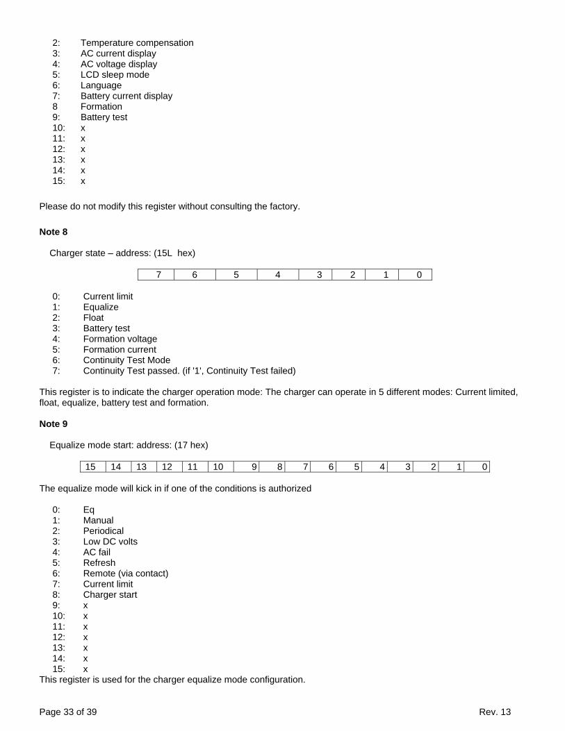
Page 33 of 39 Rev. 13
2: Temperature compensation 3: AC current display 4: AC voltage display 5: LCD sleep mode 6: Language 7: Battery current display 8 Formation 9: Battery test 10: x 11: x 12: x 13: x 14: x 15: x
Please do not modify this register without consulting the factory.
Note 8 Charger state – address: (15L hex)
7 6 5 4 3 2 1 0
0: Current limit 1: Equalize 2: Float 3: Battery test 4: Formation voltage 5: Formation current 6: Continuity Test Mode 7: Continuity Test passed. (if '1', Continuity Test failed)
This register is to indicate the charger operation mode: The charger can operate in 5 different modes: Current limited, float, equalize, battery test and formation.
Note 9 Equalize mode start: address: (17 hex)
15 14 13 12 11 10 9 8 7 6 5 4 3 2 1 0
The equalize mode will kick in if one of the conditions is authorized
0: Eq 1: Manual 2: Periodical 3: Low DC volts 4: AC fail 5: Refresh 6: Remote (via contact) 7: Current limit 8: Charger start 9: x 10: x 11: x 12: x 13: x 14: x 15: x
This register is used for the charger equalize mode configuration.

Page 34 of 39 Rev. 13
Note 10 Equalize termination– address: (20L hex)
7 6 5 4 3 2 1 0
0: x 1: post equalize 1 2: post equalize 2 3: x 4: x 5: x 6: x 7: x
Note 11
Alarm state- address: (28 hex)
15 14 13 12 11 10 9 8 7 6 5 4 3 2 1 0
0: Battery high volts 1: Rectifier high volts 2: High volts shutdown 3: Battery low volts 4: Rectifier low volts 5: Low volts disconnect 6: Negative ground fault 7: Positive ground fault 8: Rectifier fail 9: Internal high temperature 10: Internal low temperature 11: Battery high temperature 12: Battery low temperature 13: AC high volt 14: AC low volt 15: x
This register indicates the charger alarm status: The alarm is active when the bit =1 Note 12
Alarm state- address: (29 hex)
15 14 13 12 11 10 9 8 7 6 5 4 3 2 1 0
0: Battery cell failure 1: AC fail 2: High ripple 3: High DC current 4: Low DC current 5: Equalize alarm 6: Mains frequency failure 7: Battery test failure 8: High current battery 9: Low current battery 10: High capacity 11: Low capacity
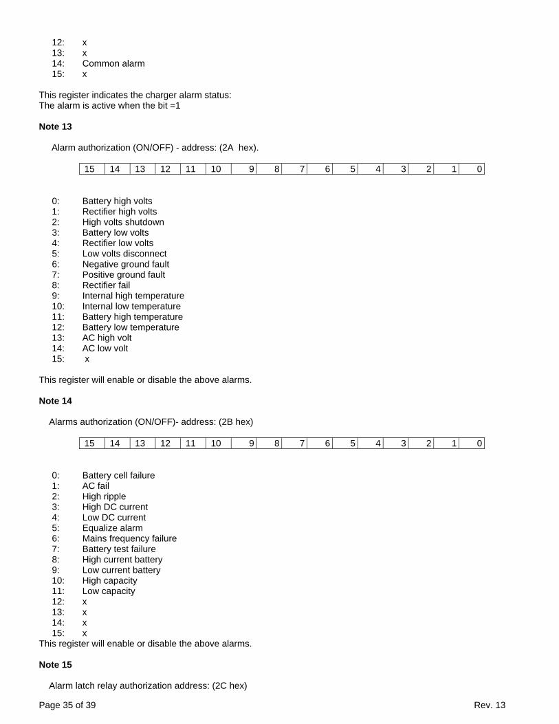
Page 35 of 39 Rev. 13
12: x 13: x 14: Common alarm 15: x
This register indicates the charger alarm status: The alarm is active when the bit =1 Note 13
Alarm authorization (ON/OFF) - address: (2A hex).
15 14 13 12 11 10 9 8 7 6 5 4 3 2 1 0
0: Battery high volts 1: Rectifier high volts 2: High volts shutdown 3: Battery low volts 4: Rectifier low volts 5: Low volts disconnect 6: Negative ground fault 7: Positive ground fault 8: Rectifier fail 9: Internal high temperature 10: Internal low temperature 11: Battery high temperature 12: Battery low temperature 13: AC high volt 14: AC low volt 15: x
This register will enable or disable the above alarms. Note 14
Alarms authorization (ON/OFF)- address: (2B hex)
15 14 13 12 11 10 9 8 7 6 5 4 3 2 1 0
0: Battery cell failure 1: AC fail 2: High ripple 3: High DC current 4: Low DC current 5: Equalize alarm 6: Mains frequency failure 7: Battery test failure 8: High current battery 9: Low current battery 10: High capacity 11: Low capacity 12: x 13: x 14: x 15: x
This register will enable or disable the above alarms. Note 15
Alarm latch relay authorization address: (2C hex)

Page 36 of 39 Rev. 13
15 14 13 12 11 10 9 8 7 6 5 4 3 2 1 0
0: Battery high volts 1: Rectifier high volts 2: High volts shutdown 3: Battery low volts 4: Rectifier low volts 5: Low volts disconnect 6: Negative ground fault 7: Positive ground fault 8: Rectifier fail 9: Internal high temperature 10: Internal low temperature 11: Battery high temperature 12: Battery low temperature 13: AC high volt 14: AC low volt 15: x
This register is used to enable or disable any of the above alarms. Note 16
Alarm latch relay authorization address: (2D hex)
15 14 13 12 11 10 9 8 7 6 5 4 3 2 1 0
0: Battery cell failure 1: AC fail 2: High ripple 3: High DC current 4: Low DC current 5: Equalize alarm 6: Mains frequency failure 7: Battery test failure 8: High current battery 9: Low current battery 10: High capacity 11: Low capacity 12: x 13: x 14: Common alarm 15: x
This register is used to enable and disable the above alarm relay latching.
Note 17
Alarm latch message authorization address: (2E hex)
15 14 13 12 11 10 9 8 7 6 5 4 3 2 1 0
0: Battery high volts 1: Rectifier high volts 2: High volts shutdown 3: Battery low volts

Page 37 of 39 Rev. 13
4: Rectifier low volts 5: Low volts disconnect 6: Negative ground fault 7: Positive ground fault 8: Rectifier fail 9: Internal high temperature 10: Internal low temperature 11: Battery high temperature 12: Battery low temperature 13: AC high volt 14: AC low volt 15: x
This register is used to enable and disable the above alarm message latching.
Note 18
Alarm latch message authorization address: (2F hex)
15 14 13 12 11 10 9 8 7 6 5 4 3 2 1 0
0: Battery cell failure 1: AC fail 2: High ripple 3: High DC current 4: Low DC current 5: Equalize alarm 6: Mains frequency failure 7: Battery test failure 8: High current battery 9: Low current battery 10: High capacity 11: Low capacity 12: x 13: x 14: Common alarm 15: x
This register is used to enable and disable the above alarm message latching.
Note 19
Fail-safe or non-fail safe alarm relays operation address: (30 hex)
15 14 13 12 11 10 9 8 7 6 5 4 3 2 1 0
0: Battery high volts 1: Rectifier high volts 2: High volts shutdown 3: Battery low volts 4: Rectifier low volts 5: Low volts disconnect 6: Negative ground fault 7: Positive ground fault 8: Rectifier fail 9: Internal high temperature 10: Internal low temperature 11: Battery high temperature 12: Battery low temperature 13: AC high volt
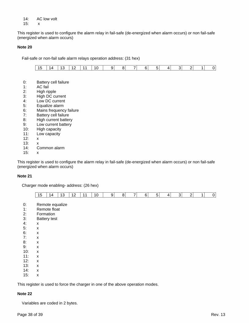
Page 38 of 39 Rev. 13
14: AC low volt 15: x
This register is used to configure the alarm relay in fail-safe (de-energized when alarm occurs) or non fail-safe (energized when alarm occurs)
Note 20
Fail-safe or non-fail safe alarm relays operation address: (31 hex)
15 14 13 12 11 10 9 8 7 6 5 4 3 2 1 0
0: Battery cell failure 1: AC fail 2: High ripple 3: High DC current 4: Low DC current 5: Equalize alarm 6: Mains frequency failure 7: Battery cell failure 8: High current battery 9: Low current battery 10: High capacity 11: Low capacity 12: x 13: x 14: Common alarm 15: x
This register is used to configure the alarm relay in fail-safe (de-energized when alarm occurs) or non fail-safe (energized when alarm occurs) Note 21
Charger mode enabling- address: (26 hex)
15 14 13 12 11 10 9 8 7 6 5 4 3 2 1 0
0: Remote equalize 1: Remote float 2: Formation 3: Battery test 4: x 5: x 6: x 7: x 8: x 9: x 10: x 11: x 12: x 13: x 14: x 15: x
This register is used to force the charger in one of the above operation modes.
Note 22 Variables are coded in 2 bytes.
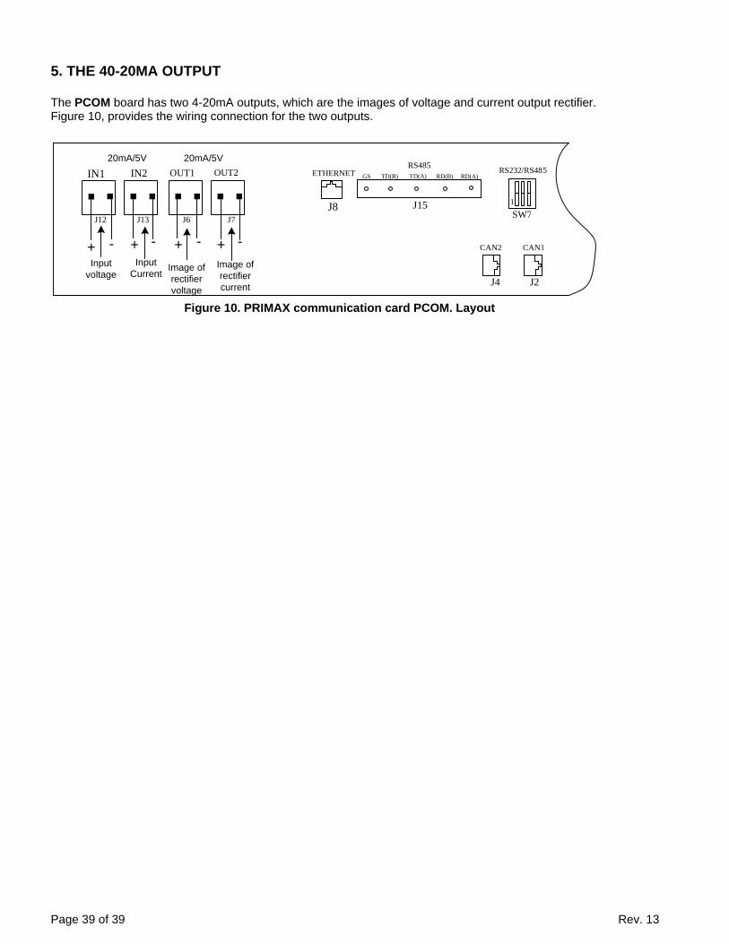
Page 39 of 39 Rev. 13
5. THE 40-20MA OUTPUT The PCOM board has two 4-20mA outputs, which are the images of voltage and current output rectifier. Figure 10, provides the wiring connection for the two outputs.
Figure 10. PRIMAX communication card PCOM. Layout
OUT2OUT1IN2IN120mA/5V20mA/5V
+ - + -
Image of rectifier current
Image of rectifier voltage
+ -Input
voltage
+ -Input
Current
J12 J13 J6 J7
GS TD(B) TD(A) RD(B) RD(A)
1
ETHERNETRS485
SW7
5RS232/RS48
CAN1CAN2
J15J8
J4 J2