art theatre new millswordpress.arttheatre.co.uk/wp-content/uploads/2015/10/new-mills... · art...
TRANSCRIPT
Issue No 2 – 10/2014-‐ph
ART THEATRE NEW MILLS
TECHNICAL INFORMATION
For more Information / technical advice contact
Paul Holt, Technical Director Telephone: 07713214540
Email: [email protected]
Art Theatre Technical Information Pack Sound and Lighting Only
Subject to review and Change at any time without prior notice

Issue No 2 – 10/2014-‐ph
2
TECHNICAL INFORMATION OVERVIEW TECHNICAL DETAILS 3 SOUND
FOH AUDIO 4
MONITORS 4
EQUIPMENT 4
MICROPHONES 5 PROJECTION AND AUDIO VISUAL 6 COMMUNICATION SYSTEMS 7 INFRASTURCTURE 8
LIGHTING
DIMMERS 9
CONTROL 9
RIGGING POSITIONS 9 CONVENTIONAL FIXTURES 10
MOVING FIXTURES 10
FOLLOW SPOTS 10
MISCELLANEOUS 10
APPENDIX PLANS AND LAYOUTS 11

Issue No 2 – 10/2014-‐ph
3
Technical Details Technical Staff The Art Theatre is a wholly self-financing Amateur Theatre with Facilities of a Semi Professional venue. Staffed by in house technicians that are top-quality, professional, stagehands. Crew is hired on a per show basis to suit the specific needs of the production. Seating Capacity TOTAL CAPACITY: 511 Stalls: 286 Stalls Box Left: 5 – Currently not used for Audience Stalls Box Right: 5 – Currently not used for Audience Stalls Wheelchair positions 3 Circle: 210 Circle Box Left: 5 Circle Box Right: 5 Load-In and Storage • Loading area is through the main scene dock entrance of the theatre on Wood Street. • Loading takes place at street level, on a flat and even road, however there is a pavement to negotiate • There is a drop of approx 500mm from the scene dock door to stage level, ramping can be provided. • Loading area can accommodate pieces not in excess of 10' x 4'. • There are no lifts • Stage Loading Doors are located off-stage left and are NOT DIRECTLY accessible by truck. • They are 10’h x 4’w and are 2’ off the ground.

Issue No 2 – 10/2014-‐ph
4
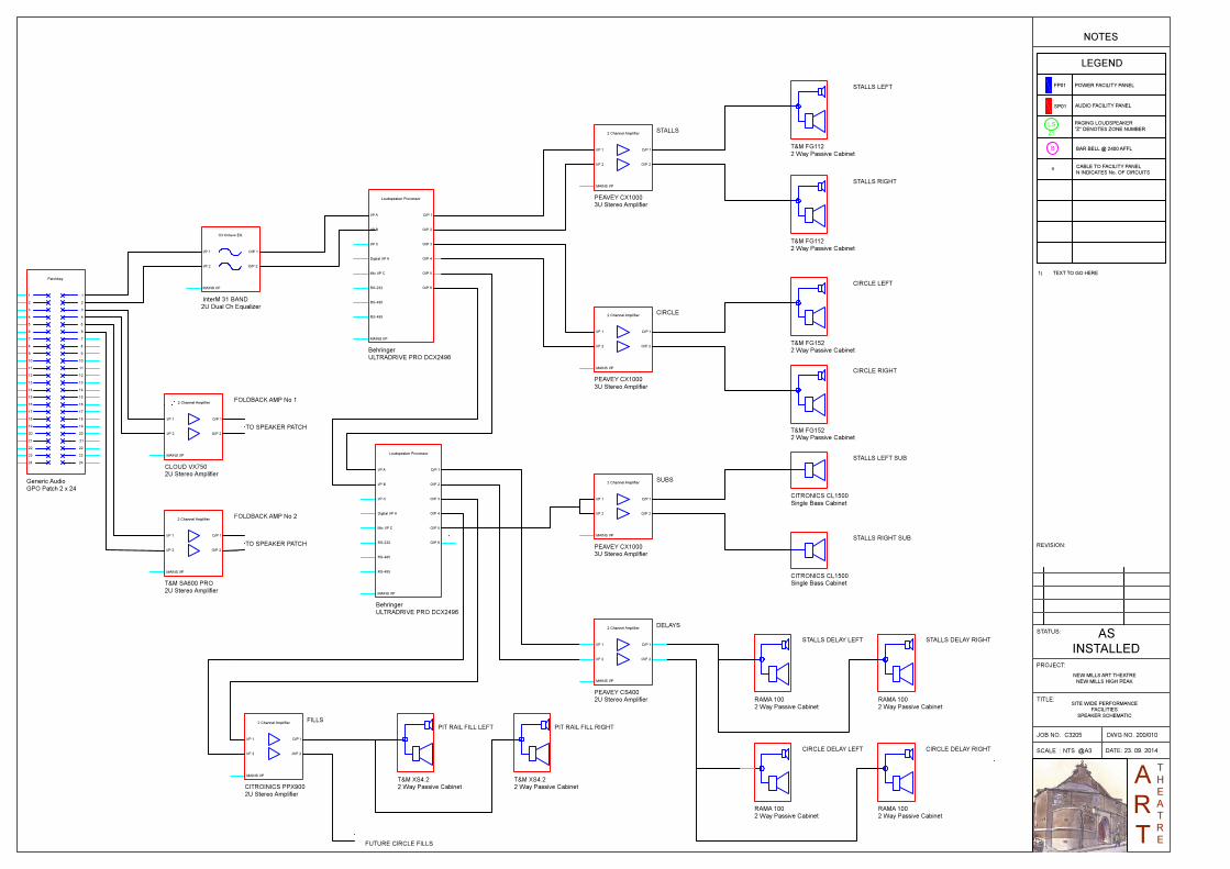
Sound FOH Mix Position: FOH Left. Under the circle balcony with an overhang of 9.5mtr. Open control position and enclosed in booth. Speakers: Stalls 2 - T&M Systems FG112 250WMain front Left and Right 2 – T&M Systems XS4.2 80-watt front fills 2 - Bose 101A Under Balcony Delays 2 – Citronics CL115 500-Watt Subwoofer 2 - Wharfdale Force 9 Subwoofer Circle 2- T&M Systems FG115 250W Main front Left and Right on circle boxes 2 - Bose 101A Rear Circle Delays Control & Processing – Lighting Control Room: Main System 5 – Peavey CX1000S 2 Channel Power amplifiers 1 - Peavey CS 400X 2 Channel Power amplifier 1 - Citronics PPX900 2 channel Power Amplifier 2 - Behringer DCX2496 Loudspeaker Processors 1 - InterM Dual 31 Band Graphic Equaliser Monitors 1 - Cloud VX 750 2 Channel Power amplifier (Monitors) Monitor Speakers: 4 – Wharfedale Force 9 250 Watt Passive Speakers Control Position: 1 – Soundcraft K3 48/8/2 Channel Console 3 - Soundcraft CPS275 Power Supplies – Two Use, one spare 1 - Allen & Heath GL3 24/4/2 Channel Console, can be setup for Monitor Mix if required 1 - Behringer X32 Digital Mixer and 1 x S16 Digital Stage Box is Available as a sub hire Outboard, Playback & Recording: 1 - Tascam CD-CD200 CD/MP3 Playback 1 – American Audio UCD 100 CD/ USB Player 1 – Tascam MD350 Minidisk Player and Recordcer 2 – Behringer MDX4600 Compressor / Gates 2 – Behringer GEQ 1502 Dual15 band Graphic Equiliser 1 – Behringer DEQ2496 Digital Sound Processor c/w Sensing Mic 1 – Yamaha SPX 900 Digital Effect Unit 1 – Lexicom MX 200 Dual Effect Engine 1 - Behinger Multiway Patch bay for Effect rack and Desk connections
Issue No 2 – 10/2014-‐ph
5
MICROPHONES Wired 3 - Crown PCC160 2 - Audio Technica ATPro 2 – Audio Technica AT Pro 47 Mic’s 4 - Audio Technica AT 4041 Short Riffle Mic’s 6 – Generic Handheld Instrument Microphones 2 – Studio Condenser Overhead Mic’s 2 – Generic retro 50’s Style Ribbon Mic’s 1 - Shure SM58 w/switch Wireless Microphone System: 4 – Trantec S4.16 Radio Microphones Lapel With Antenna Distribution Additional Equipment that can be sub hired 8 No MI Pro channel 38 Professional Lapel Microphones complete MISCELLANEOUS 10 – Black Boom Microphone Stands 12 - Music Stands w/lights 4 Passive DI Boxes

Issue No 2 – 10/2014-‐ph
6
Projection and Audio Visual Projection EQUIPMENT
1 - Sanyo XP46L mounted on the front of the circle handrail 2 - Sanyo XT11 Projectors mounted on front of circle handrail 1 - Electrically operated 3.5 Mtr 4:3 screen mounted in front of the main House rag CONTROL / INPUT 1 – Kramer 4 x 4 Matrix switch in main Rack in Lighting control Room 5 – Input points a) Lighting Control b) Sound Control c) Stage managers corner (ASL) d) House PC Lighting Control room Rack e) Orchestra Pit Right Facility Panel The Projection system is still in the process of upgrading so these details are subject to change without notice. The theatre also possesses a larger format electrically operated screen that may be installed at request.
Audio Visual The theatre is currently in the process of updating the existing Black and White Visual Systems to colour, which will be completed for March 2015. The existing systems allows vision of the stage from the following locations a) Box office b) Rear of Bar c) Lighting Control d) Foyer e) Bar Foyer f) Stage managers desk g) ASM Position Currently there are no visual monitors in the dressing rooms, props or Wardrobe but this is subject to the current upgrading of the existing system The installed Video patch system can provide Video relay to any of the positions with Video, Connection via the switcher AV racks in the Lighting Control room to allow for full flexibility The camera feed from the stage is a Standard definition Colour Low Light Camera. The theatre also posses a Day and Night Camera that can be install if so requested There are also Two 24” Screen Mounted on the front of the balcony for Relay of any required Visual to the stage for Actor Comfort. Again all these can be interconnected to display a variety of images from several different sources as required
Issue No 2 – 10/2014-‐ph
7
Communication Systems Theatre paging The theatre has a comprehensive paging system with plug in points at various locations to allow access to the four zone paging matrix. All dressing room speakers have individual volume controls with Bar foyer and Technical areas each have their own area volume controls. Show relay feed is supplied to each of the areas and is overridden by priority paging into an individual or all zone page from any of the connected microphones. There is also a matrix output feed into the paging system to enhance the Show relay aspect of the performance The main paging plug in points are as follows Stage Manager Desk – Permanent Location Lighting Control – Permanent Location Sound Control Box office 1st floor Bar The four paging Zones are as follows Zone 1 All backstage dressing rooms, wardrobe and Props Zone 2 All Technical Areas Zone 3 Ground Floor Foyer and Toilets Zone 4 1st floor Bar Technical Comms The theatre is provided with technical communications system connection points at all strategic locations in the theatre; all facility panels have two circuits of technical comms channel A & B are presented on facility panels The theatre has the following system accessories 7 No single channel Beltpack 1 no Dual Channel Beltpack 8 No Single Muff headsets 1 High output Xenon Flasher All the above can be plugged into any location on either channel A or B with the master dual comms beltpack located in the lighting control position The Main Power supply system is located in the Sound control Position with access for Aux input from the Mixing desk from one of the matrix Outputs Hard of hearing System (AFILS) The theatre has in induction loop system installed to the circle only at present and this provides a clean show relay feed of the show for the hard of hearing. This system will be extended to the stalls by the end of 2015 season There are signs in the theatre advising users to listen to the show via their own hearing aids on the “T” setting on the hearing aids.

Issue No 2 – 10/2014-‐ph
8
Infrastructure Generally all areas of the theatre have connectivity panels all wired back to either the AV racks in the Lighting control room or the Sound control position at the rear of the auditorium where they are terminated on industry standard XLR connectors or Multiway patch bays Panels All panels are fully labelled and all details for cable tieline ways and routing can be found on the attached schedule and line drawings appended to this package (if not included please email a request to [email protected]) In general the connection count is as follows Audio Tieline count from stage (8 Panels) 62 Sends – 24 Returns Video Tie Line count from Stage (8 Panels) 18 Speaker tie Line count from Stage (8 Panels) 14 Network Tie line count form stage (8 Panels) 16
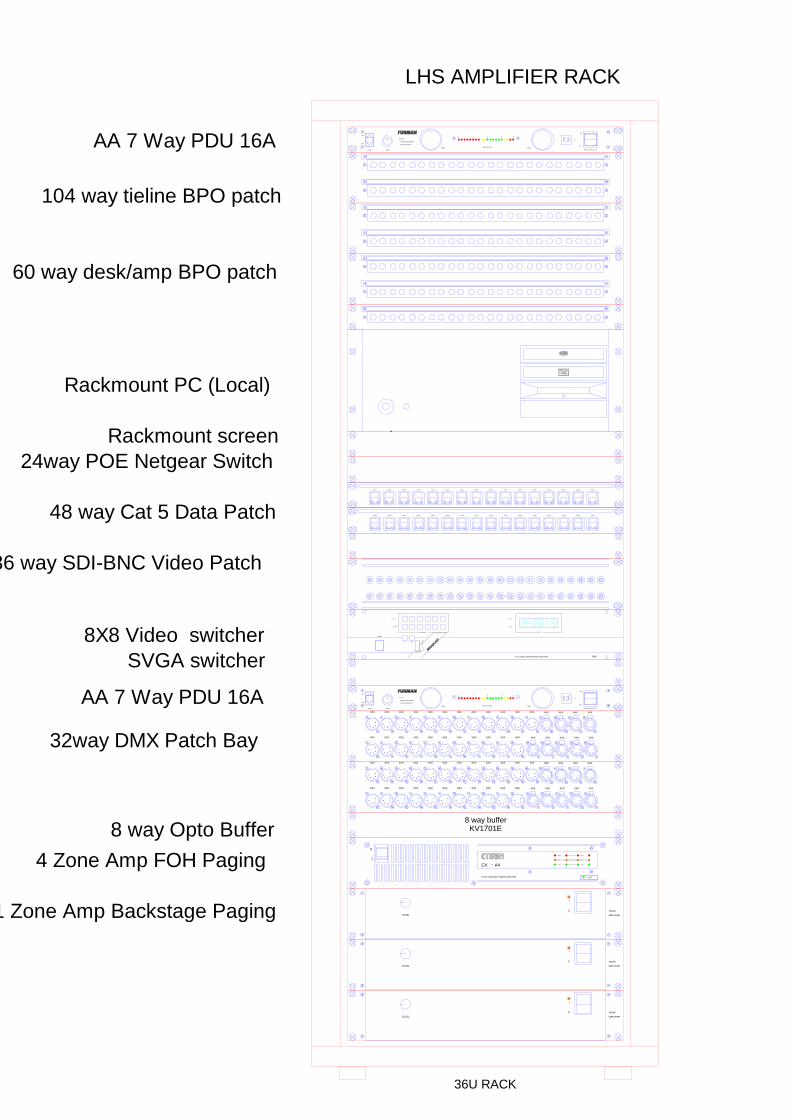
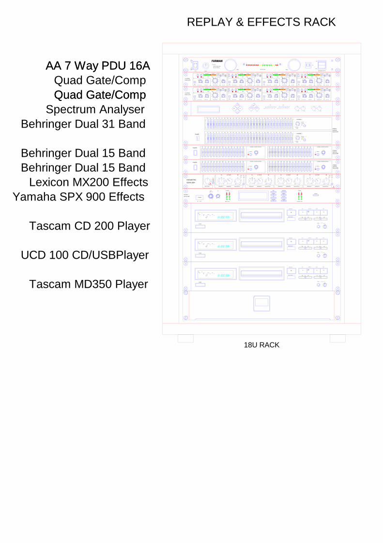
Equipment Racks Please see the attached equipment rack layouts for the main systems racks and these are located in the following positions Lighting Control Room AV Rack No 1 AV Rack No 2 Sound Control Room AV Rack No 3 Replay and Effects Rack Desk Patchbay Rack

Issue No 2 – 10/2014-‐ph
9
Lighting System DIMMERS Front of House - Lighting Control, Room 8 – Zero 88 Dual 15A Betapack Series 1 0 – 10V analogue control 1 – ShowTec 72 way DMX to 0 – 10V Demux 1 – 54 way 15A Cord Patch to Front of House Positions Stage Area - High Level Perch Above ASL 12 – Zero 88 Dual 15A Betapack Series 1 0 – 10V Analogue control 1 – ShowTec 72 way DMX to 0 – 10V Demux 1 – 98 way 15A Cord Patch to Internally wired Bars and Low Level outlets CONTROL 1 – Strand Palette 750 Channels c/w Dual Monitors 1 - Strand Pocket Palette Remote on PDA 1 - Jands Event Plus 48 Console c/w Monitor – Backup desk 1 – ETC Congo Desk is available as a Sub Hire c/w Monitor and Wireless ELC remote RIGGING POSITIONS STAGE No. 1 Bar 16 Channels No 1 - 16 Winched with SWL of 175Kg U.D.L. No. 2 Bar 16 Channels No 17 - 32 Winched with SWL of 175Kg U.D.L. No. 3 Bar 16 Channels No 33 - 48 Winched with SWL of 175Kg U.D.L. No. 4 Bar 12 Channels No 49 - 60 Fixed with SWL of 175Kg U.D.L. Side Booms rear of proscenium Stage Left 5 Channels No 61 - 65 Stage Right 5 Channels No 66 - 70 Stage Low Level Points DSL 5 Channels No 71 - 75 PIT 6 Channels No 76 - 81 DSR 5 Channels No 82 - 86 USL 6 Channels No 87 - 92 USR 6 Channels No 93 - 98 FROUNT OF HOUSE MAIN FOH BAR 10 Channels No 1 - 10 AR Circle Box 6 Channels No 13 - 18 AL Circle Box 6 Channels No 19 - 24 AR Stalls box 6 Channels No 25 - 30 Roof Void* 12 Channels No 31 – 42 AL Stalls Box 6 Channels No 43 - 48 AR Stalls 3 Channels No 49 - 51 AL Stalls 3 Channels No 52 - 54 *There is currently no bar position for this advance truss position, although a truss is available

Issue No 2 – 10/2014-‐ph
10
Fixtures CONVENTIONAL FIXTURES 4 - Strand Cadenza 2KW 12/25 degree Profiles 2 - Strand Alto 2.5Kw 8/14 degree Profiles 4 - Strand Cantata 18/32 degree Profiles 10 - Strand Cantata 26/44 degree Profiles 2 - Strand Cantata fresnels 12 - Strand Harmony 15/28 degree Profiles 5 - Strand Harmony 24/44 degree Profiles 5 - Strand Harmony Fresnels 1.2Kw 2 - Strand Harmony Pebble Convex 2 - Strand Pattern 803 Fresnels 2 - Strand Leko Profiles 30 Degree 4 - Strand Preludes Fresnels 10 - Strand Iris One 1.25Kw Cyc Lights 4 - Strand Orion 1.25Kw Ground Row Lights 2 - Strand Coad four 500Watt Cyc Batten 15 - CCT Starlet Fresnels 1.2Kw 24 - Generic Par64 Parcans various Beam Angles LED FIXTURES 4 – LEDJ Colour Storm Tri battens 2 – LED Tri Par Cans 24 x 3 Watt MOVING FIXTURES 4 – Showtec Explorer 575 MISCELLANIOUS FIXTURES 2 - QTX Jumbo DMX Controlled Strobes FOLLOW SPOTS 2 – Pani Short Throw 1200w Spots complete with colour changers MISCELLANEOUS Various - Barn Doors 2 - QTX Smoke Machines c/w Remote Control 1 - QTX Atmospheric Hazer c/w Remote Control
Issue No 2 – 10/2014-‐ph
11
Appendix PLANS, LAYOUTS & CAD
Plans of the current rigging positions are available on request and we hope to have a WYSIWYG template available in the near future as it is currently under construction. A Capture layout is also in the process of development
APPENDIX A RACK LAYOUT DRAWINGS
APPENDIX B AUDIO SCHEMATICS
APPENDIX C FACILITY PANEL SCHEDULE
APPENDIX D LIGHTING SCHEMATICS
APPENDIX E RIGGING PLANS
APPENDIX F MISCELLANIOUS

Issue No 2 – 10/2014-‐ph
12
APPENDIX A
Rack Layout Drawings
XXX XXX XXX XXX XXXXXX XXX XXX XXXXXX XXX XXX XXX XXX XXXXXX
XXX XXX XXX XXX XXXXXX XXX XXX XXX XXX XXX XXX XXX XXX XXXXXX
36U RACK
XXXXX XXXXXXXXXX XXXXX XXXXX XXXXXXXXXX XXXXX XXXXX XXXXXXXXXX XXXXX XXXXX XXXXXXXXXX XXXXX
XXXXX XXXXXXXXXX XXXXX XXXXX XXXXXXXXXX XXXXX XXXXX XXXXXXXXXX XXXXX XXXXX XXXXXXXXXX XXXXX
104 way tieline BPO patch
36 way SDI-BNC Video Patch
LINE VOLTAGE
DIMMER
PULL PULL
A
M
P
OFF
ON
OFF
SWITCHED OUTLETS
ON
OFF
LIGHTS
POWER CONDITIONER
AND LIGHT MODULE
PL PLUS E
10
FOUR CHANNEL POWER AMPLIFIER
CX - A41234
POWER
SIGNAL
PEAK
PROTECT
SIGNAL
PEAK
PROTECT
0
LINE VOLTAGE
DIMMER
PULL PULL
A
M
P
OFF
ON
OFF
SWITCHED OUTLETS
ON
OFF
LIGHTS
POWER CONDITIONER
AND LIGHT MODULE
PL PLUS E
10
KRAMER
SELECTOR
1 2 3 4 5 6
OUTPUT
INPUT
ALL OFF
OUTPUT
INPUT
STATUS
2066
POWER
6 X 6 VIDEO AUDIO MATRIX SWITCHER
8 way bufferKV1701E
32way DMX Patch Bay
48 way Cat 5 Data Patch
1 Zone Amp Backstage Paging
4 Zone Amp FOH Paging
8 way Opto Buffer
SVGA switcher
60 way desk/amp BPO patch
AA 7 Way PDU 16A
AA 7 Way PDU 16A
LHS AMPLIFIER RACK
I
O
LEVEL AMPLIFIER
MONO
I
O
LEVEL AMPLIFIER
MONO
I
O
LEVEL AMPLIFIER
MONO
XXX XXX XXX XXX XXXXXX XXX XXX XXXXXX XXX XXX XXX XXX XXXXXX
XXX XXX XXX XXX XXXXXX XXX XXX XXX XXX XXX XXX XXX XXX XXXXXX
Digital Audio
8X8 Video switcher
24way POE Netgear Switch
Rackmount PC (Local)
Rackmount screen

36U RACK
R
A
CLIP
-2
-5
-10
-20
-30
-40
MUTE
CLIP
-2
-5
-10
-20
-30
-40
MUTE
CLIP
-2
-5
-10
-20
-30
-40
MUTE
CB
CLIP
-40
MUTE
LIMIT
-2
-5
-10
-20
CLIP
-40
MUTE
LIMIT
-2
-5
-10
-20
CLIP
-40
MUTE
LIMIT
-2
-5
-10
-20
CLIP
-40
MUTE
LIMIT
-2
-5
-10
-20
CLIP
-40
MUTE
LIMIT
-2
-5
-10
-20
CLIP
-40
MUTE
LIMIT
-2
-5
-10
-20
1 2 3 4 5 6
R
ARCHITECTURAL
ACOUSTICS
DUAL CHANNEL
INDUSTRIAL POWER AMPLIFIER
TMSPS
ACTIVE
POWER
TMSPS
ACTIVE
POWER
MADE IN U.S.A.
POWER
OFF ON
TM
TM
R
ARCHITECTURAL
ACOUSTICS
DUAL CHANNEL
INDUSTRIAL POWER AMPLIFIER
TMSPS
ACTIVE
POWER
TMSPS
ACTIVE
POWER
MADE IN U.S.A.
POWER
OFF ON
TM
R
ARCHITECTURAL
ACOUSTICS
DUAL CHANNEL
INDUSTRIAL POWER AMPLIFIER
TMSPS
ACTIVE
POWER
TMSPS
ACTIVE
POWER
MADE IN U.S.A.
POWER
OFF ON
TM
R
ARCHITECTURAL
ACOUSTICS
DUAL CHANNEL
INDUSTRIAL POWER AMPLIFIER
TMSPS
ACTIVE
POWER
TMSPS
ACTIVE
POWER
MADE IN U.S.A.
POWER
OFF ON
TM
R
ARCHITECTURAL
ACOUSTICS
DUAL CHANNEL
INDUSTRIAL POWER AMPLIFIER
TMSPS
ACTIVE
POWER
TMSPS
ACTIVE
POWER
MADE IN U.S.A.
POWER
OFF ON
CX 1000 - Subs Ch 6
CX 400 - Delays Mono
CX 1000 - Cluster
CX 1000 - Circle Main ch 3/4
CX 1000 - Stalls Main ch 1/2
Speaker Patch bay
Loudspeaker Managment
Professional Power Amplifier
V T X 750PROTECT SIGNAL PEAK
PROTECT SIGNAL PEAK
POWER BRIDGE
LEVEL
LEVEL
0 10
0 10
A
B
I
O
LEVEL CH1 LEVEL CH2
LINE VOLTAGE
DIMMER
PULL PULL
A
M
P
OFF
ON
OFF
SWITCHED OUTLETS
ON
OFF
LIGHTS
POWER CONDITIONER
AND LIGHT MODULE
PL PLUS E
10
LINE VOLTAGE
DIMMER
PULL PULL
A
M
P
OFF
ON
OFF
SWITCHED OUTLETS
ON
OFF
LIGHTS
POWER CONDITIONER
AND LIGHT MODULE
PL PLUS E
10
16 In 32 Out
2K
2K
EQ-9231
20 25 32 40
-12
+12
-12
0
20 25 32 40
+12
0
50 63 80 100 125 160 200 250
50 63 80 100 125 160 200 250
800500315 400 630 1.25K1K 1.6K
800500315 400 630 1.25K1K 1.6K
GRAPHIC EQUALIZER
OFF
LO-CUT
OFF
OFF
OFF
LO-CUT
12.5K
12.5K
3.15K2.5K 4K 5K 6.3K 8K 10K
3.15K2.5K 4K 5K 6.3K 8K 10K
16K 20K LEVEL
-12
+12
-12
-12
0
16K 20K
+12
LEVEL
-12
ON
RIGHT0
ON
EQ
PEAK
ON
+12
0
+12
0 LEFT
ON
EQ
PEAK
POWER
OFF
ON Inter M Main EQ
Cloud Amp 2 x 750 W
Spare space for amp 2U
T & M SA600 Amp
AA 7 Way PDU 16A
AA 7 Way PDU 16A
RHS PATCHBAY RACK
R
A
CLIP
-2
-5
-10
-20
-30
-40
MUTE
CLIP
-2
-5
-10
-20
-30
-40
MUTE
CLIP
-2
-5
-10
-20
-30
-40
MUTE
CB
CLIP
-40
MUTE
LIMIT
-2
-5
-10
-20
CLIP
-40
MUTE
LIMIT
-2
-5
-10
-20
CLIP
-40
MUTE
LIMIT
-2
-5
-10
-20
CLIP
-40
MUTE
LIMIT
-2
-5
-10
-20
CLIP
-40
MUTE
LIMIT
-2
-5
-10
-20
CLIP
-40
MUTE
LIMIT
-2
-5
-10
-20
1 2 3 4 5 6
LINE VOLTAGE
DIMMER
PULL PULL
A
M
P
OFF
ON
OFF
SWITCHED OUTLETS
ON
OFF
LIGHTS
POWER CONDITIONER
AND LIGHT MODULE
PL PLUS E
10
25 40 63 100 160 250 400 630 1k 1.6k 2.5k 4k 6.3k 10k 16k
6421
0
12
4
6
0
12
12
8
8
5
52
2
LEVEL
CHANNEL 1 MASTER CONTROL
BYPASS
0 10
8
64
2 GRAPHIC
EQUALIZER
POWERCHANNEL 2 MASTER CONTROL
STEREO
25 40 63 100 160 250 400 630 1k 1.6k 2.5k 4k 6.3k 10k 16k
6421
0
12
4
6
0
12
12
8
8
5
52
2
LEVEL
BYPASS
0 10
8
64
2
POWER
PARAMETRIC
EQUALIZER
INPUT LEVEL
0
1
2
3
45
6
7
8
9
10
IN
OUT
OVERLOAD
EQ
FREQUENCY BANDWIDTH EQUALIZATION
20
30
50
100
180
215
250
375
400 1/3
1/2
1
2
3
4
-20
-18
-9
-3
Flat
+3
+6
+9
12
+18
+20
Hz OCTAVE dBPEAK
SHELF
FREQUENCY BANDWIDTH EQUALIZATION
20
30
50
100
180
215
250
375
400 1/3
1/2
1
2
3
4
-20
-18
-9
-3
Flat
+3
+6
+9
12
+18
+20
Hz OCTAVE dB
FREQUENCY BANDWIDTH EQUALIZATION
20
30
50
100
180
215
250
375
400 1/3
1/2
1
2
3
4
-20
-18
-9
-3
Flat
+3
+6
+9
12
+18
+20
Hz OCTAVE dB
FREQUENCY BANDWIDTH EQUALIZATION
20
30
50
100
180
215
250
375
400 1/3
1/2
1
2
3
4
-20
-18
-9
-3
Flat
+3
+6
+9
12
+18
+20
Hz OCTAVE dBPEAK
SHELF
POWER
TRACK INDEX RANDOM INTRO
STEPTOTAL
EACH
REMAIN
WW SEC
OPEN/CLOSE PLAY AUTO CUE STOP
REMOTE SENSORSKIP SEARCH
PHONES
PAUSE
H M S
POWER100
100
INPUT
ON OFF
MIX CONTINUEEDIT
PRESET PRESET
^ ^
CURSOR CURSOR
< >
ADD DELETE
CHANNEL
INPUT LEVEL
L R
0
-15
-10
-5
inf
CHL CHR
CHANNEL
L R
0
-15
-10
-5
inf
OUTPUT LEVEL
BYPASS
STEREO
EFFECTOR
POWER
TRACK INDEX RANDOM INTRO
STEPTOTAL
EACH
REMAIN
WW SEC
OPEN/CLOSE PLAY AUTO CUE STOP
REMOTE SENSORSKIP SEARCH
PHONES
PAUSE
H M S
4 CHANNEL
NOISE GATE
1
I N EXT
KEYLISTEN
1k 25
10
15
500200
100 20k
56
8
100.5
1
3
KEY FILTER Hz WIDTH OCT
15- 20 10 5 3 1 0 1 2 4 6 8
KEY LEVEL VU+PEAK
Hz
-50
5
10
15
OUT-50
-30
-20
THRESHOLD dBv
GATE OPEN
ATTACK RANGE
FAST
AUTO
20dB
70dB
RELEASE
1 mS
10
50
4 S
100300
1 S
2 S
LINK LINKI N EXT
KEYLISTEN
1k 25
10
15
500200
100 20k
56
8
100.5
1
3
KEY FILTER Hz WIDTH OCT
15- 20 10 5 3 1 0 1 2 4 6 8
KEY LEVEL VU+PEAK
Hz
-50
5
10
15
OUT-50
-30
-20
THRESHOLD dBv
GATE OPEN
ATTACK RANGE
FAST
AUTO
20dB
70dB
RELEASE
1 mS
10
50
4 S
100300
1 S
2 S
I N EXT
KEYLISTEN
1k 25
10
15
500200
100 20k
56
8
100.5
1
3
KEY FILTER Hz WIDTH OCT
15- 20 10 5 3 1 0 1 2 4 6 8
KEY LEVEL VU+PEAK
Hz
-50
5
10
15
OUT-50
-30
-20
THRESHOLD dBv
GATE OPEN
ATTACK RANGE
FAST
AUTO
20dB
70dB
RELEASE
1 mS
10
50
4 S
100300
1 S
2 S
I N EXT
KEYLISTEN
1k 25
10
15
500200
100 20k
56
8
100.5
1
3
KEY FILTER Hz WIDTH OCT
15- 20 10 5 3 1 0 1 2 4 6 8
KEY LEVEL VU+PEAK
Hz
-50
5
10
15
OUT-50
-30
-20
THRESHOLD dBv
GATE OPEN
ATTACK RANGE
FAST
AUTO
20dB
70dB
RELEASE
1 mS
10
50
4 S
100300
1 S
2 S
2 3 4
25 40 63 100 160 250 400 630 1k 1.6k 2.5k 4k 6.3k 10k 16k
6421
0
12
4
6
0
12
12
8
8
5
52
2
LEVEL
CHANNEL 1 MASTER CONTROL
BYPASS
0 10
8
64
2 GRAPHIC
EQUALIZER
POWERCHANNEL 2 MASTER CONTROL
STEREO
25 40 63 100 160 250 400 630 1k 1.6k 2.5k 4k 6.3k 10k 16k
6421
0
12
4
6
0
12
12
8
8
5
52
2
LEVEL
BYPASS
0 10
8
64
2
POWER
+
12
8
5
20
2
5
812-
+
12
8
520
2
5812-
25 31.5 40 50 63 80 100 125 160 200 250 315 400 500 630 800 1k 1.25k 1.6k 2k 2.5k 3.15k 4k 5k 6.3k 8k 10k 12.5k 16k 20k
CHANNEL
LEVEL
CHANNEL
BYPASS
0
2
4
10
8
6
CHANNEL 1
EQUALIZER
GRAPHIC
STEREO
+
12
8
5
20
2
5
812-
+
12
8520
2
5812-
25 31.5 40 50 63 80 100 125 160 200 250 315 400 500 630 800 1k 1.25k 1.6k 2k 2.5k 3.15k 4k 5k 6.3k 8k 10k 12.5k 16k 20k
CHANNEL
LEVEL
BYPASS
0
2
4
10
8
62
2
CHANNEL 2
CHANNEL
1
1
POWER
TRACK INDEX RANDOM INTRO
STEPTOTAL
EACH
REMAIN
WW SEC
OPEN/CLOSE PLAY AUTO CUE STOP
REMOTE SENSORSKIP SEARCH
PHONES
PAUSE
H M S
18U RACK
-36 -24 -12 -3 -1 0 +4 +8 -36 -24 -12 -3 -1 0 +4 +8Enter Esc
Volume
Rec Cue On Off
Send Caller
AA 7 Way PDU 16AAA 7 Way PDU 16AQuad Gate/CompQuad Gate/CompQuad Gate/Comp
Spectrum AnalyserBehringer Dual 31 Band
Behringer Dual 15 BandBehringer Dual 15 Band
Lexicon MX200 EffectsYamaha SPX 900 Effects
Tascam CD 200 Player
Tascam MD350 Player
UCD 100 CD/USBPlayer
REPLAY & EFFECTS RACK

XXX XXX XXX XXX XXXXXX XXX XXX XXXXXX XXX XXX XXX XXX XXXXXX
XXX XXX XXX XXX XXXXXX XXX XXX XXX XXX XXX XXX XXX XXX XXXXXX
6U RACK
10H.SET
VOL
0
SIDE
TONE
PTT
ON
OFF
A
B
A+B
CALL
A B
MIC
LINE
100
5
AUX
LEVEL
A
B
A+B
BA
DCV
POWER5
MASTER STATION
POWER
REMOTE
AC POWER
POWER
REMOTE
AC POWER
POWER
REMOTE
AC POWER
0 10
GROUP
ST4
0 10
ST3
0 10
ST2
0 10
ST1
0 10
6
0 10
5
0 10
4
0 10
3
0 10
2
0 10
L RC
1
0 10
GR
ST
AUX
CUE
ASSIGN
0 10
STEREO
POWER
ON
OFF
L RCL RC L RC L RC L RC MONITOR
AUX
CUE
PHONES
SUM
0 10 0 10
0 10
GR
ST
AUX
CUE
ASSIGN
GR
ST
AUX
CUE
ASSIGN
GR
ST
AUX
CUE
ASSIGN
GR
ST
AUX
CUE
ASSIGN
GR
ST
AUX
CUE
ASSIGN
GR
ST
AUX
CUE
ASSIGN
GR
ST
AUX
CUE
ASSIGN
GR
ST
AUX
CUE
ASSIGN
GR
ST
AUX
CUE
ASSIGN
25 40 63 100 160 250 400 630 1k 1.6k 2.5k 4k 6.3k 10k 16k
6421
0
12
4
6
0
12
12
8
8
5
52
2
LEVEL
CHANNEL 1 MASTER CONTROL
BYPASS
0 10
8
64
2 GRAPHIC
EQUALIZER
POWERCHANNEL 2 MASTER CONTROL
STEREO
25 40 63 100 160 250 400 630 1k 1.6k 2.5k 4k 6.3k 10k 16k
6421
0
12
4
6
0
12
12
8
8
5
52
2
LEVEL
BYPASS
0 10
8
64
2
1 2
COMP
ON
OFF
OP 3 6 10 15 20
+20-20
THRESHOLD
(dB)
RATIO
1:1 30:1
POWER
COMPRESSOR
COMP
ON
OFF
OP 3 6 10 15 20
+20-20
THRESHOLD
(dB)
RATIO
1:1 30:1
COMPRESSOR
dB
SIGNAL
1
dB
SIGNAL
2
dB
SIGNAL
dB
SIGNAL
dB
SIGNAL
dB
SIGNAL
dB
SIGNAL
dB
SIGNAL
dB
SIGNAL
dB
SIGNAL
3 4 5 6 7 8 9 10Left Right Power
LINE VOLTAGE
DIMMER
PULL PULL
A
M
P
OFF
ON
OFF
SWITCHED OUTLETS
ON
OFF
LIGHTS
POWER CONDITIONER
AND LIGHT MODULE
PL PLUS E
10
16U RACK
AA 7 Way PDU 16A
Dual Comms PSU
Facility Panel FP12Paging Mic Mixer
Rane Dual CompressorDaul 15 Band Graphic
Paging Matrix Quest
Soundcraft PSU No 1
Soundcraft PSU No 2
Soundcraft PSU No 3
MIXING DESK PATCHBAYS
SOUND CONTROL RACK

Issue No 2 – 10/2014-‐ph
17
APPENDIX B
AV Schematic Drawings


Issue No 2 – 10/2014-‐ph
22
APPENDIX C
Facility Panels

Facility Panel schedule
Project New Mills Art Theatre
Date May 2014 Issue 275 Ohm 50 Ohm 50 Ohm
Analogue Analogue Show SDI Video Cat 5 Speaker 6 Pin 6 Pin Radio Radio Paging Comms Comms DMX Out DMX in Tech Cue Lite Computer SVGA SVGAPanel Ref. Location Designation Send Return Relay Tie Line Point Outlet LV Con LV Con Aerials Aerials Mic In A B Ring Point Mini input outputConnection 3 Pin F 3 Pin M Inputs BNC RJ45 NL4 Output Input Output Input RJ45 3 Pin M 3 Pin M 5 Pin F 5 Pin M 13A 4 Pin F Jack 15 HD 15 HD
FP 01 Orchestra Pit Left 12 4 4 2 4 1 1 1 1 1 FP 02 Orchestra Pit Right 8 4 2 2 2 1 1 1 1 1 1FP 03 Downstage Left 8 4 2 2 2 1 1 1 1 1 1 FP 04 Down Stage Right 8 4 2 2 2 1 1 1 1 1 1 1FP 05 ASL Perch ( Dimmer area) Dimmer control 6 2 3 1 1 3 1 1FP 06 Upstage left 8 4 2 2 2 1 1 1 1 1FP 07 Upstage Right 8 4 2 2 2 1 1 1 1 1FP 08 SM Manager 4 2 1 1 1 1 1 1FP 09 ASL Front Box 2 1 1 1 2 1 1 1 1 1FP 10 ASR Front Box 2 1 1 1 2 1 1 1 1 1FP 11 Lighting Box Lighting Control 4 2 4 4 2 6 1 1 1 3 1 1Local AV Rack 1Desk Mix Position Sound Control 24 12FP 12 Sound Control 6 4 4 2 1 1 1 2 1 1 1FP 13 Box Office 2 2 1 1FP13/1 Foyer Screen 1FP 14 Bar Area 2 2 1 1FP14/1 Bar Screen 1FP 15 Followspot Bay 1 1 2 1 1 2FP16 Roof Void 2 1 3 2FP16/1 ASL Front Box Top 1FP16/2 ASR Front Box Top 1FP16/3 ASL Circle Box Top 1FP16/4 ASR Circle Box Top 1FP17 Projector Location Projector 2 2 2 1 1 1 2 1 2FP18 Lighting Box Dimmer control 2 3 1FP19 ASL Circle Box Top 1 FP20 ASR Circle Box Top 1 FP21 Circle Front Bar 1
AV Rack Total Count 102 38 2 37 36 28 6 6 2 5 15 14 23 11 2 13 1 5 4
Patch Bay Count 140
Facilities

Issue No 2 – 10/2014-‐ph
24
APPENDIX D
Lighting Drawings


Issue No 2 – 10/2014-‐ph
27
APPENDIX E
Rigging Plans

Issue No 2 – 10/2014-‐ph
28
Issue No 2 – 10/2014-‐ph
29
APPENDIX F
Miscellaneous