artcam pro 8.0 reference manual - cnctar.hobbycnc.hu · artcam pro 8.0 reference manual overview...
TRANSCRIPT
ArtCAM Pro 8.0
Reference Manual
By Delcam plc
Issue: 8.003 Released: 20/07/05

DisclaimerDelcam plc has no control over the use made of the software described inthis manual and cannot accept responsibility for any loss or damagehowsoever caused as a result of using the software. Users are advised thatall the results from the software should be checked by a competentperson, in accordance with good quality control procedures.Information contained in this manual is subject to change without noticeand does not represent a commitment by Delcam plc. The softwaredescribed in this manual is furnished under licence agreement and may beused or copied in accordance with the terms of such licence. No part ofthis manual may be reproduced or transmitted in any form or by anymeans, electronic or mechanical, including photocopying and recording,for any purpose without the express permission of Delcam plc.
Copyright © 2005 Delcam plc. All rights reserved.Delcam plcTalbot WaySmall Heath Business ParkBirmingham B10 0HJEnglandTel: (UK) 0121-766-5544
(Int) +44 (0) 121-766-5544
ArtCAM Pro 8.0 Reference Manual Contents • i
Contents
Overview 1ArtCAM Pro Overview....................................................................1Information about ArtCAM Pro.......................................................1Comparing Bitmaps, Vectors and Reliefs........................................3
What is a Vector?...................................................................3What is a Bitmap?..................................................................4What is a Relief?....................................................................5
ArtCAM Pro Layout 7ArtCAM Pro Layout ........................................................................7Using the Design Windows ...........................................................11
Adjusting the Window View ...............................................11Opening a New 2D View Window......................................12Labelling a 2D View Window.............................................13Deleting a 2D View Window ..............................................13
2D View Manipulation ..................................................................15 3D View.........................................................................15 Zoom In Tool .................................................................15 Zoom Out Tool ..............................................................15 Zoom Previous...............................................................16 Window Fit ....................................................................16 Zoom Object(s) ..............................................................16 Zoom 1:1........................................................................16 Vectors On/Off ..............................................................16 Bitmap On/Off ...............................................................16 Greyscale View..............................................................17 Undo...............................................................................17 Redo ...............................................................................17 Link All Colours ............................................................17 Unlink All Colours ........................................................17 Link/Unlink Colours......................................................17
ii • Contents ArtCAM Pro 8.0 Reference Manual
Merge Colours ...............................................................18 2D Bitmap Contrast Tool ....................................18
Scrolling the 2D View .........................................................192D View Options............................................................................19
Using Rulers ........................................................................20Using the Snap Grid.............................................................20Using Guidelines..................................................................22Snapping to Objects .............................................................25
3D View Manipulation...................................................................26 2D View .........................................................................26 Twiddle Tool..................................................................26 Pan View........................................................................27 Zoom ..............................................................................27 Zoom Out .......................................................................28 Previous View................................................................28 Scale To Fit ....................................................................28 Isometric View...............................................................28 View Along X................................................................28 View Along Y................................................................28 View Along Z ................................................................29
Select Relief Detail.........................................29 Draw Zero Plane ............................................................29 Draw X Y.......................................................................29 Origin .............................................................................30 Objects To Draw............................................................30 Colour Shade..................................................................31
3D View Options............................................................................31Using the Top Toolbar ...................................................................33Updating ArtCAM Pro...................................................................33Installing Your ArtCAM Licence ..................................................37Managing ArtCAM Pro's Preferences ...........................................37
Working with Models 45Getting Started ...............................................................................45
Creating a Model .................................................................45Creating a Model from an Image.........................................47Opening an Existing Model .................................................48Viewing Model Information ................................................50Closing a Model...................................................................50
ArtCAM Pro 8.0 Reference Manual Contents • iii
Shutting Down ArtCAM Pro...............................................51Managing a Model .........................................................................52
Creating a New Model.........................................................53Creating a New Model Using Pixels ...................................54Opening a Model .................................................................54Saving a Model ....................................................................55Saving the 3D View as an Image.........................................56Printing a Model ..................................................................57Importing Images.................................................................61Editing the Model Dimensions ............................................62Editing Asymmetrical Dimensions in a Model ...................63Setting the Position of a Model ...........................................65Clearing a Model .................................................................67Deskewing a Model .............................................................67Creating a Greyscale Image from a Relief ..........................67Adding a Border to a Model ................................................69Using a Spot Filter on a Bitmap Image ...............................70Adjusting Light and Material Settings ................................71Using the Selection Rectangle.............................................78Cropping a Model ................................................................79Using the ArtCAM Pro Notepad .........................................80Importing Vector Artwork...................................................81Exporting Vector Artwork...................................................87Importing a 3D Model File..................................................87Importing a 3D Model File for Unwrapping .......................92Importing CopyCAD Relief Data........................................95Multiplate Engraving Tool ..................................................96Correcting an Action .........................................................104Mirroring a Model .............................................................105Rotating a Model ...............................................................105Printing a Model ................................................................106
Working with Layers ...................................................................110Creating a New Layer........................................................110Naming a Layer .................................................................111Assigning a Colour to a Layer...........................................111Manipulating Layers..........................................................112
Using the Font Editor...................................................................116Using the Face Wizard.................................................................122
Working with Bitmaps 129Drawing using Bitmaps................................................................129
Bitmap Drawing Tools ......................................................129
iv • Contents ArtCAM Pro 8.0 Reference Manual
Creating a Model from a Bitmap .................................................130Importing a Bitmap into a Model.................................................130Setting a Bitmap's Size and Origin ..............................................130Working with Colours..................................................................130
Selecting the Primary and Secondary Colours ..................131Reducing Colours ..............................................................132Colour Merging..................................................................133Colour Linking...................................................................134Edge Marking ....................................................................135Colour Thinning.................................................................135Colour Thickening .............................................................136Adding Colours..................................................................137Saving a Custom Colour Palette ........................................139Loading a Custom Colour Palette......................................139
Editing a Bitmap Image ...............................................................140Using the Paint Brush ........................................................140Using the Draw Tool..........................................................143Using the Bitmap Line Tool ..............................................144Using the Erase Tool..........................................................144Flood Filling ......................................................................145Copying and Pasting Bitmap Areas...................................146
Converting a Bitmap into Vectors ...............................................147Creating a Shape from a Bitmap ..................................................149
Working with Vectors 151Overview ......................................................................................151Drawing with Polylines................................................................152
Creating a Polyline.............................................................152Completing Polyline Creation ...........................................154Closing a Polyline to Create a Polygon .............................155Amending a Polyline .........................................................155
Creating Simple Shapes ...............................................................156Creating a Rectangle..........................................................156Creating a Circle ................................................................159Creating an Ellipse.............................................................161Creating a Polygon.............................................................164Creating a Star ...................................................................166Creating an Arc ..................................................................169
Editing Vector Objects.................................................................171Selecting Vectors ...............................................................172Moving Vectors .................................................................174Editing Vector Spans .........................................................175
ArtCAM Pro 8.0 Reference Manual Contents • v
Editing Vector Nodes ........................................................182Deleting Vector Objects ....................................................191Copying and Pasting Vector Objects.................................192Offsetting Vector Objects ..................................................197Splining Vector Objects.....................................................199Filleting Vector Objects.....................................................203Trimming Vector Objects ..................................................207Wrapping Vectors to a Relief ............................................209Locking and Unlocking Vector Objects ............................211Fitting Arcs to Vector Objects...........................................211Nesting Vector Objects......................................................212Distorting Vector Objects ..................................................218Pasting Vectors Along a Curve .........................................223Converting Vector Objects ................................................224Creating a Vector Border...................................................225Using the Vector Doctor....................................................226
Working with Vector Text ...........................................................229Creating Vector Text .........................................................230Selecting Vector Text ........................................................231Editing Vector Text ...........................................................231Formatting Vector Text .....................................................233Wrapping Text Round a Curve..........................................238
Measuring Vector Objects ...........................................................243Transforming Vector Objects ......................................................244
Using Transform Vectors Mode........................................244Using the Transform Vector(s) Page.................................246
Manipulating Vector Objects.......................................................254Mirroring Vectors ..............................................................254Aligning Vectors................................................................257Centring Vectors................................................................258Merging Vectors ................................................................259Joining Vectors ..................................................................262Closing Vectors .................................................................265Clipping Vectors................................................................266Slicing Vectors...................................................................268
Grouping Vector Objects .............................................................270Viewing the Properties of a Vector Object ..................................272Reversing a Vector Object's Direction.........................................274
Ungrouped Vectors............................................................274Grouped Vectors................................................................275
Creating Bitmaps from Vectors ...................................................275Flood Filling Vector Objects .............................................276
Importing Vector Artwork ...........................................................276
vi • Contents ArtCAM Pro 8.0 Reference Manual
Exporting Vector Artwork ...........................................................276Creating a Shape from a Vector ...................................................277Creating a Feature from a Vector.................................................277
Creating a Raised Feature ..................................................277Creating a Recessed Feature ..............................................280Creating a Centreline Engraved Feature............................281Returning a Feature to a Vector.........................................282
Working with Reliefs 285Overview ......................................................................................285Using the Shape Editor.................................................................286
Creating a Shape from a Bitmap........................................286Creating a Shape from a Closed Vector ............................290
Creating a Shape Using Vectors ..................................................294Creating a Swept Profile Shape .........................................295Creating a Two Rail Sweep ...............................................310Creating a Weave Shape ....................................................316Creating ISO-FORM Letters .............................................320
Creating a Dome ..........................................................................323Creating a Feature ........................................................................324Calculating a Relief......................................................................325
Replacing the Relief...........................................................326Adding to the Relief...........................................................326Subtracting from the Relief ...............................................328Merging with the Relief.....................................................330
Transforming and Manipulating Reliefs ......................................333Using 3D Clipart ................................................................333Copying and Pasting a Relief ............................................344Pasting a Relief along a Vector .........................................349Inverting a Relief ...............................................................351Smoothing a Relief ............................................................352Scaling the Relief Height...................................................354Scaling to Volume .............................................................356Mirroring a Relief ..............................................................357Mirror Merging a Relief ....................................................358Offsetting a Relief..............................................................359Resetting a Relief...............................................................360Resetting the Relief Height................................................360
Managing and Editing Reliefs......................................................361Saving a Relief...................................................................362Loading a Relief.................................................................363Calculating the Surface Area .............................................366
ArtCAM Pro 8.0 Reference Manual Contents • vii
Displaying the Calculation Time.......................................367Adding a Draft Angle ........................................................368Creating a Triangle Mesh ..................................................368Creating a Cross-Section ...................................................370Creating an Angled Plane ..................................................371Blending 3D Shapes ..........................................................374Relief Envelope Distortion ................................................378Fading a Relief...................................................................386Creating a Ring ..................................................................390Adding Texture to a Relief ................................................390Sculpting a Relief ..............................................................397Removing Holes in the Relief Surface ..............................402Creating a Greyscale Image from a Relief ........................402Rotating a Relief or Triangle Mesh ...................................402
Machining Models 403Overview......................................................................................403
Using Toolpaths.................................................................4052D Toolpaths................................................................................405
2D Profiling .......................................................................4072D Area Clearance.............................................................417V-Bit Carving ....................................................................423Bevel Carving ....................................................................428Smart Engraving ................................................................434Machine Vectors................................................................441Inlay Wizard ......................................................................447Drill Holes .........................................................................476
3D Toolpaths................................................................................481Machine Relief...................................................................481Feature Machining .............................................................486Z Level Roughing..............................................................490Laser Machining ................................................................4953D Cut Out.........................................................................4983D Rest Machining............................................................505
Managing and Modifying Toolpaths ...........................................508Selecting Toolpaths ...........................................................509Transforming Toolpaths ....................................................510Copying Toolpaths ............................................................512Merging Toolpaths ............................................................521Creating Toolpath Panels...................................................523Editing a Profile Pass.........................................................527Setting the Machining Order .............................................537
viii • Contents ArtCAM Pro 8.0 Reference Manual
Adjusting the Machining Parameters of a Tool.................540Saving a Toolpath ..............................................................543Editing a Toolpath .............................................................545Deleting Toolpaths.............................................................546Calculating a Single Toolpath ...........................................548Calculating a Batch of Toolpaths ......................................549Using a Toolpath Summary ...............................................550Using the Tool Groups Database.......................................554Adjusting the Material Setup .............................................562Deleting the Material .........................................................564Creating a Toolpath Template ...........................................564Loading a Toolpath Template............................................565Loading Toolpath Data ......................................................566Setting the Toolpath Order ................................................567
Simulating Toolpaths ...................................................................567Viewing a Toolpath ...........................................................573Hiding a Toolpath ..............................................................575Resetting a Simulation .......................................................576Deleting a Simulation ........................................................577Saving a Simulation as a Relief .........................................577Loading a Simulation from a Relief ..................................578
Index 579
ArtCAM Pro 8.0 Reference Manual Overview • 1
Overview
ArtCAM Pro OverviewArtCAM Pro is a unique software program which allows users toeasily create impressive, high quality 3D products starting from 2Dbitmap or vector based artwork. ArtCAM Pro transforms ideas intofinished products far more quickly than is possible using conventionalmethods. Even in cases where a hand-finished look is desired,ArtCAM Pro accelerates production. Using ArtCAM Pro and amachine tool or router to machine most of the job, leaves the artisanmore time to concentrate on the original design and the fine details,which together help to differentiate products in today's competitivemarkets.
Information about ArtCAM ProYou can find information about the features in ArtCAM Pro from thefollowing sources:
1. The ArtCAM Pro Assistant (In-line Help). Click on the on each page displayed in the Assistant window
to view its In-Line Help. For further details, see "ArtCAMPro Layout" in the ArtCAM Pro Layout chapter.
2. The ArtCAM Pro On-Line Help pages. From the Mainmenu bar, click on the Help menu, followed by the Indexoption. You can find a list of shortcuts that can be used inArtCAM Pro here.
3. The Assistant's Getting Started page. Click on the icon in the Other Features area to display details of thelatest features in ArtCAM Pro.
Overview • 2 ArtCAM Pro 8.0 Reference Manual
4. The ArtCAM Pro Reference Manual (this manual).5. The ArtCAM Pro Website. From the Main menu bar, click
on the Help menu, followed by the ArtCAM Pro On TheWeb > ArtCAM Pro Home Page option.
6. The ArtCAM User Forum. From the Main menu bar, clickon the Help menu, followed by the ArtCAM Pro On TheWeb > ArtCAM Pro Forum option. You can also accessthe forum at http://forum.artcam.com.If you have not already registered as a forum member, clickon the Join option on the forum's Home Page to do so.Registered users are able to download images, exampleArtCAM models and relief files attached to posts.
7. Subscribe to the ArtCAM Pro Newsletter. From the Mainmenu bar, click on the Help menu, followed by theSubscribe to the ArtCAM Pro Newsletter option tosend an e-mail requesting subscription to the quarterlynewsletter.
8. The Frequently Asked Questions page. From the Mainmenu bar, click on the Help menu, followed by theArtCAM Pro On The Web > Frequently AskedQuestions option.
ArtCAM Pro Reference ManualThis manual provides you with instructions on how to create andmanipulate both 2D and 3D models, and then machine them.This Reference Manual is divided into the following sections:
• Overview. This section provides an overview of whatArtCAM Pro can be used for.
• ArtCAM Pro Layout. This section explains the layout ofArtCAM Pro, how to use its design windows and manage itspreferences.
• Working with Models. This section explains how tocreate and manage an ArtCAM model, as well as create andedit fonts for use within ArtCAM Pro.
• Working with Bitmaps. This section explains how tocreate and manipulate bitmap images in a model. These canthen be used to create vector objects or 3D shapes as all orpart of a relief in a model.
ArtCAM Pro 8.0 Reference Manual Overview • 3
• Working with Vectors. This section explains how tocreate and manipulate vector artwork in a model. This canthen be used to create a three-dimensional shape as all orpart of a relief, or to machine a 2D model.
• Working with Reliefs. This section explains how tocreate different types of shapes and combine them with anyexisting relief, how to transform, manipulate, edit andmanage the relief. The relief can then be used to machine a3D model.
• Machining Models. This section explains how to machinea model from the vector artwork or three-dimensional reliefthat you have created.
Comparing Bitmaps, Vectors andReliefs
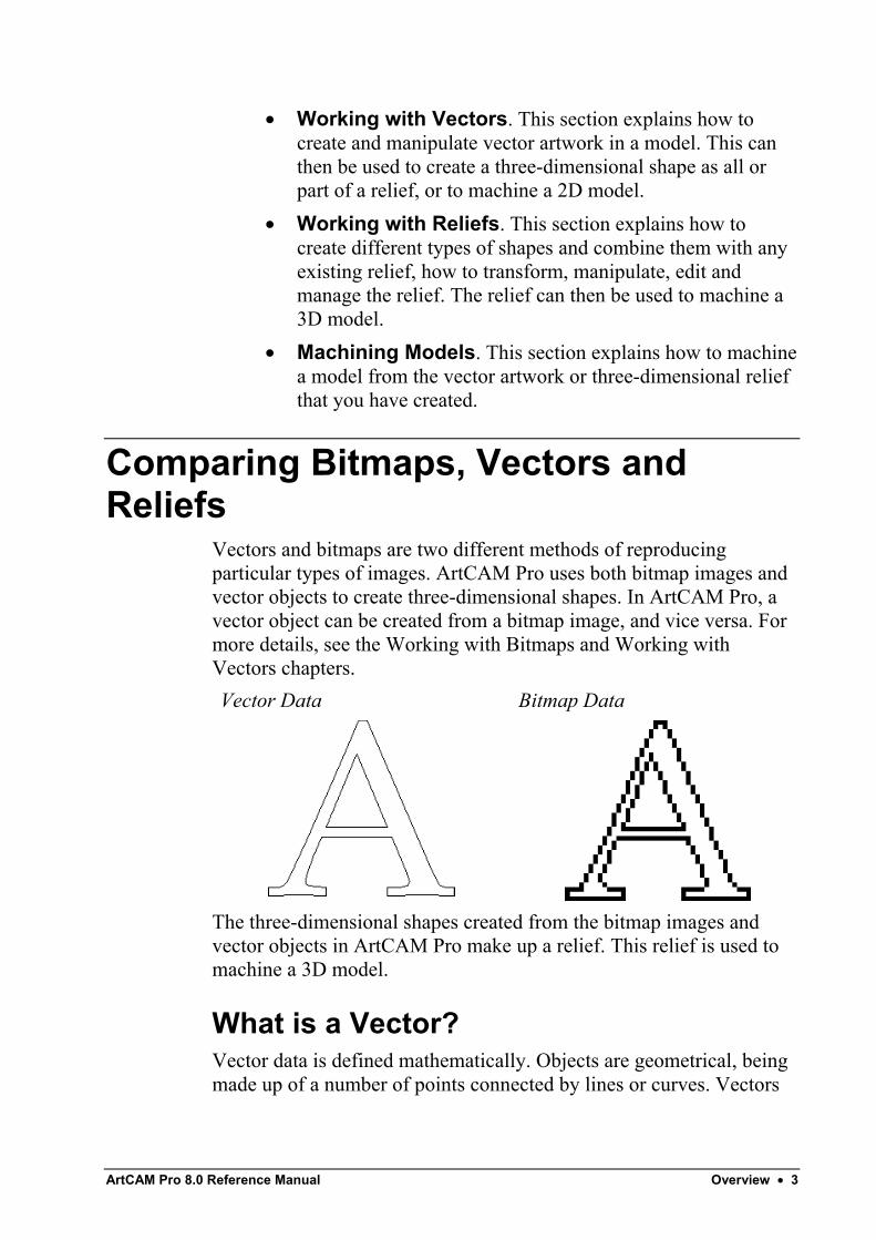
Vectors and bitmaps are two different methods of reproducingparticular types of images. ArtCAM Pro uses both bitmap images andvector objects to create three-dimensional shapes. In ArtCAM Pro, avector object can be created from a bitmap image, and vice versa. Formore details, see the Working with Bitmaps and Working withVectors chapters.Vector Data Bitmap Data
The three-dimensional shapes created from the bitmap images andvector objects in ArtCAM Pro make up a relief. This relief is used tomachine a 3D model.
What is a Vector?Vector data is defined mathematically. Objects are geometrical, beingmade up of a number of points connected by lines or curves. Vectors
Overview • 4 ArtCAM Pro 8.0 Reference Manual
are extremely flexible and can be manipulated with both ease andaccuracy.The amount of data required to display all of the attributes of a vectorobject is very small, so graphics made up of vector objects can havevery small file sizes. As the objects become more complex, the sizesincrease.Vector data is ideal for producing smooth features. A vector object notonly has greater definition than the bitmap, the geometry of the vectorobject can also be used to drive an assigned machining tool directly,which, in turn, can produce a better finish.ArtCAM Pro can read files containing vector data saved in thefollowing formats:
• Drawing Interchange files, including PowerSHAPE andAutoCAD (.dxf)
• Encapsulated PostScript format (.eps)• AutoCAD 2D Drawing files (.dwg)• Adobe Illustrator image (.ai)• Windows Metafile (.wmf)• Lotus, PC Paint or DUCT picture (.pic)
What is a Bitmap?Bitmap data is made up of a set of values specifying the colour ofindividual pixels (picture elements) that make up an image. Bitmapdata is characterised by resolution and bit depth.Resolution relates to the detail in an image and is expressed in dots perinch (.dpi) or pixels per inch (.ppi). The higher the resolution (i.e. themore dots used to describe the image), the more detail possible.Bit depth has to do with the number of colours the image can display.Bits are the building blocks of binary data. A black and white image is1 bit, meaning it can be off or on, black or white. As bit depthincreases, more colours are available.Unlike vector data, bitmap data is large. For example, a simple objectlike the letter in the previous image is 32,838 bytes as vector data inArtCAM Pro. When rasterized (changed to a bitmap), the file sizechanges to 40,078 bytes in ArtCAM Pro. For small compositions theincrease in file size may not matter greatly, but for larger compositionsthe difference in file size seriously impacts machining times.
ArtCAM Pro 8.0 Reference Manual Overview • 5
ArtCAM Pro allows three-dimensional shapes to be created from areasof bitmap colour. It can also read bitmap files generated by otherdrawing and desktop publishing packages or those scanned from paperbased artwork saved in any of the following formats:
• Windows Bitmap (.bmp)• TIFF image (.tif)• PCX image (.pcx)• CompuServe image (.gif)• JPEG image (.jpg or .jpeg)
What is a Relief?A relief is made up of one or more three-dimensional shapes created inArtCAM Pro. A three-dimensional shape becomes all or part of arelief when the relief combination method selected for the shape hasbeen calculated.Ultimately, a relief is made up of a grid of points in a similar way to abitmap image. However, instead of colour, each point is assigned aspecific height.When a new model is created in ArtCAM Pro, you are required to setits size in millimetres or inches. The model's resolution is alsospecified here. The number of points in the model determines theresolution of the relief and any associated bitmap image. For furtherinformation, see "Creating a Model" in the Working with Modelschapter.A compromise must be made between the quality of a model,including any relief within it, and the speed of the processor in yourcomputer. For most jobs, a model of 1,000,000 points is a reasonablevalue. Since a relief is made up of a number of points, even the qualityand smoothness of the three-dimensional shapes created from vectorobjects depends on the resolution of the model, although this is to alesser extent than with those shapes created from bitmap images.A relief can be saved or loaded in the .rlf format. If there is no bitmapimage of the same resolution as the relief, ArtCAM Pro creates agreyscale bitmap representation of the 3D model when it is loaded.

Overview • 6 ArtCAM Pro 8.0 Reference Manual
ArtCAM Pro 8.0 Reference Manual ArtCAM Pro Layout • 7
ArtCAM Pro Layout
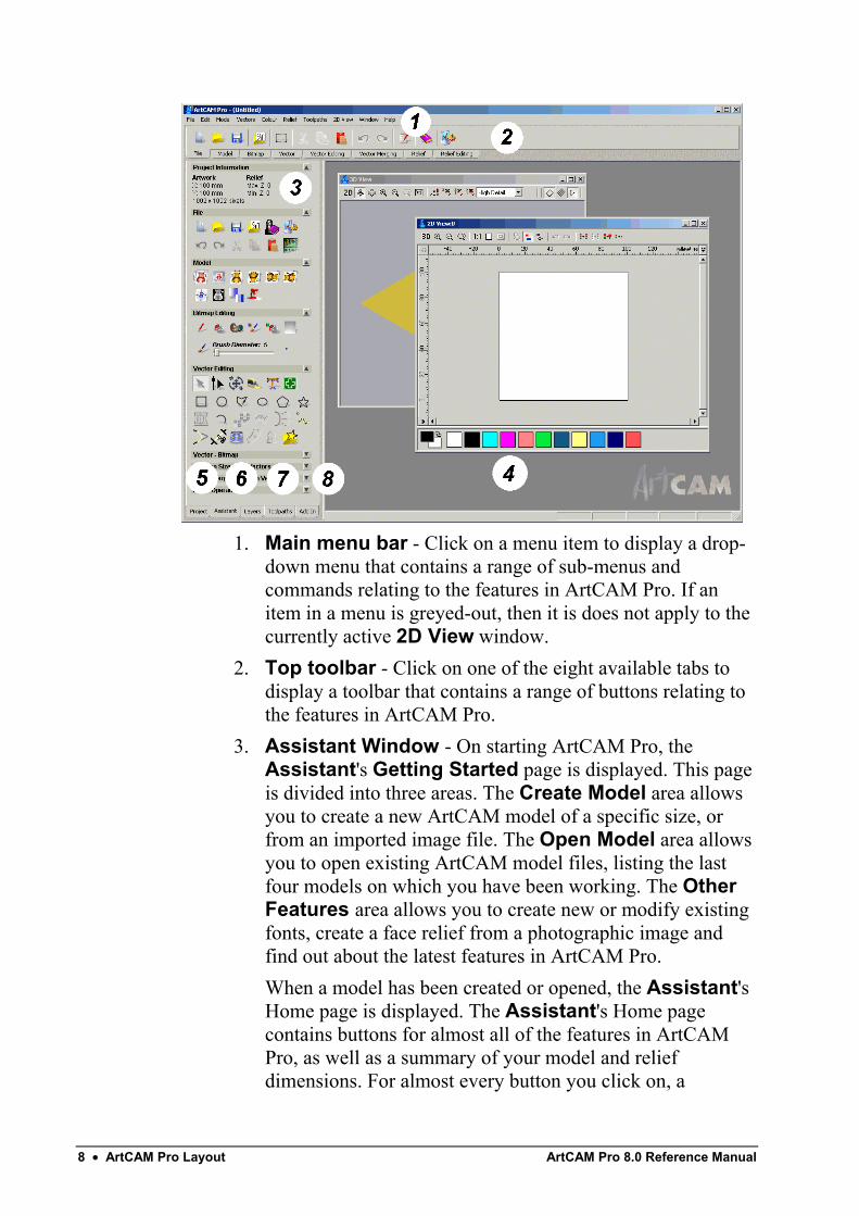
ArtCAM Pro LayoutThe ArtCAM Pro screen layout has been designed to let you workeffectively and efficiently.The hub of ArtCAM Pro is the innovative Assistant window. Whenyou have an open model, the Assistant's Home page displays acollection of tools to help you create, edit and machine a model. Thesetools appear in the form of buttons.Grouped in a logical arrangement, you can to navigate to the buttonthat you require quickly. To find out more about most of the buttons inArtCAM Pro, click on it to display a page in the Assistant windowshowing In-line Help. The In-line Help informs you of exactly where,when and how to use the button, thus reducing the learning curve.The screen layout is divided into eight regions:
8 • ArtCAM Pro Layout ArtCAM Pro 8.0 Reference Manual
1. Main menu bar - Click on a menu item to display a drop-down menu that contains a range of sub-menus andcommands relating to the features in ArtCAM Pro. If anitem in a menu is greyed-out, then it is does not apply to thecurrently active 2D View window.
2. Top toolbar - Click on one of the eight available tabs todisplay a toolbar that contains a range of buttons relating tothe features in ArtCAM Pro.
3. Assistant Window - On starting ArtCAM Pro, theAssistant's Getting Started page is displayed. This pageis divided into three areas. The Create Model area allowsyou to create a new ArtCAM model of a specific size, orfrom an imported image file. The Open Model area allowsyou to open existing ArtCAM model files, listing the lastfour models on which you have been working. The OtherFeatures area allows you to create new or modify existingfonts, create a face relief from a photographic image andfind out about the latest features in ArtCAM Pro.When a model has been created or opened, the Assistant'sHome page is displayed. The Assistant's Home pagecontains buttons for almost all of the features in ArtCAMPro, as well as a summary of your model and reliefdimensions. For almost every button you click on, a
ArtCAM Pro 8.0 Reference Manual ArtCAM Pro Layout • 9
corresponding interactive In-line Help page is displayed inits place. These buttons are divided into ten areas:
• File - You can use these buttons to manage yourmodel files, as well as the image, vector and trianglemodel files that you want to use.
• Model - You can use these buttons to manage theappearance of your model, as well as adjust how amodel appears in the 3D View window.
• Bitmap Editing - You can use these buttons todraw and paint bitmap shapes, as well as manage thecontent of the Colour Palette and the size and shapeof the brush you use.
• Vector Editing - You can use these buttons tocreate vector objects in the form of shapes or text, aswell as measure and manipulate the vector objectsthat make up the artwork in your model.
• Vector - Bitmap - You can use these buttons toconvert a vector object in your model to a bitmap, orvice versa.
• Position Size Align Vectors - You can use thesebuttons to transform, mirror, align and centre vectorobjects, as well as wrap them around a curve or nestthem within a defined area.
• Group Merge Join Trim Vectors - You can usethese buttons to group, merge, join, trim, clip andslice the vector objects you create as part of yourmodel.
• Relief Operations - You can use these buttons toload, save and calculate reliefs, create a trianglemesh or cross-section.
• Vector Based Relief Creation - You can usethese buttons to create three-dimensional shapesfrom the vector artwork in your model, and paste animported relief along a vector object.
• Relief Editing - You can use these buttons to scale,smooth, invert, offset, sculpt, reset or add texture to arelief. You can also create an angled plane or ablended shape, distort a relief or copy and paste arelief.
10 • ArtCAM Pro Layout ArtCAM Pro 8.0 Reference Manual
You can change the appearance of the Assistant's Homepage in the following way:
• Click on the arrow displayed in each of the ten areasof the Assistant's Home page to either hide ordisplay the buttons within that particular area.
You can also change the appearance of each page displayedin the Assistant window when you click on any of thebuttons on the Assistant's Home page:
• Click on to hide all In-line Help shown onthe page. You can also click on the icon in thetop-right corner of the page to hide In-line Helpshown.
• Click on to display In-line Help on thepage. You can also click on the icon in the top-right corner of the page to display the In-line Help.
• Click on the icon in the top-right corner of thepage to return to the Assistant's Home page.
You can play a video tutorial on how you can use the pagethat is currently displayed in the Assistant window if you:
• Click on the video icon when the In-line Help isshown.
4. Design Windows - This is the central area of the screen.ArtCAM Pro uses two types of view. The 2D View windowdisplays the vector and bitmap artwork in your model andpreviews of any calculated 2D toolpaths, while the 3DView window displays a three-dimensional relief and anycalculated or simulated toolpaths.
5. Project - This tab displays the Project page in theAssistant window. You can use this page to viewinformation about your model, to create, delete or edit thedesign windows and calculate reliefs. You can also edit,calculate, delete and simulate toolpaths, or create a templatefrom them.
6. Layers - This tab displays the Layers page in theAssistant window. You can use this page to organise thevector artwork in your model into layers. Each layer youcreate can be given its own name and colour. You can alsotoggle the visibility, snapping and locking for the vector
ArtCAM Pro 8.0 Reference Manual ArtCAM Pro Layout • 11
artwork on each layer. You can also use this page to controlwhich sheet of nested vectors or plates is active at any giventime.
7. Toolpaths - This tab displays the Toolpaths Home pagein the Assistant window. You can use this page to createmachining toolpaths, drill holes, add bridging and leadmoves, manage the machining order, produce a toolpathsummary, and manage the tools database.You can also use this page to simulate toolpaths, savetoolpaths, edit toolpaths, load or save a toolpath template,and edit the machining parameters relating to a tool.
8. Add In - This tab displays the Add Ins page in theAssistant window. You can use this page to control 'plug-in' tools compatible with ArtCAM Pro. The root of the AddIn tab is in the ArtCAM Pro installation folder, and 'plug-in'tools will be made available to download from the ArtCAMMaintenance Download page. For details, see "UpdatingArtCAM Pro" on page 34.
Using the Design WindowsWhen you create or open a model in ArtCAM Pro, a 2D View and a3D View design window are displayed. You use the 2D Viewwindow to create the vector and bitmap artwork you need to produce athree-dimensional relief in ArtCAM Pro. This relief is shown in the3D View window.
Adjusting the Window ViewYou can adjust the appearance of the 2D View and 3D Viewwindows in ArtCAM Pro:
1. From the Main menu bar, click on the Window menu,followed by the option for how you want the designwindows to be displayed:
• Cascade - Click on this option to display both the2D View and 3D View windows overlapping oneanother.
• Tile - Click on this option to display both the 2DView and 3D View windows beside one another.
12 • ArtCAM Pro Layout ArtCAM Pro 8.0 Reference Manual
• 2D View - Click on this option to display the 2DView window only.
Note: You can also display the 2D View window by pressing the F2key on your keyboard when the 3D View window is displayed.
• 3D View - Click on this option to display the 3DView window only.
Note: You can also display the 3D View window by pressing the F3key on your keyboard when the 2D View window is displayed.
You can also select which design window is displayed from theProject page:
1. Click on the Project tab to display the Projectpage.
2. With the Views element shown, click on the 2D View or3D View window that you want to view.
Opening a New 2D View WindowTo open a new 2D View window:
• From the Main menu bar, click on the 2D View menu, andthen on the New View option.
A 2D View window appears named as 2D View: 1 by default. Youcan change the name of the new window if you want to. For details,see "Labelling a 2D View Window" on page 13.The content within the new 2D View window is identical to that ofthe previous window.The Colour Palette beneath the new 2D View window is the same asthat which is below the previous 2D View window, although anycolour links or relief attributes used are removed.You can also open a new 2D View window from the Project page:
1. Click on the Project tab to display the Projectpage.
2. With the Views element shown, right-click on the last 2DView created to display the context menu, and then click onthe New View option.
ArtCAM Pro 8.0 Reference Manual ArtCAM Pro Layout • 13
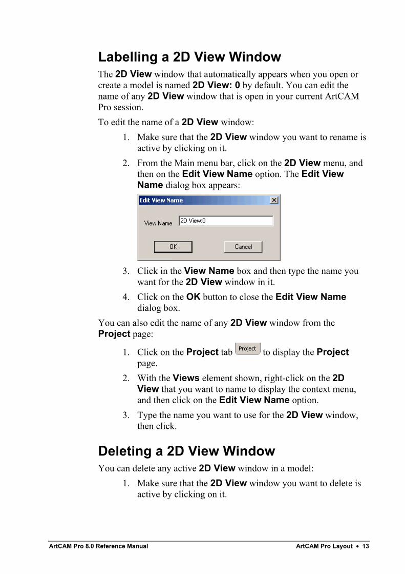
Labelling a 2D View WindowThe 2D View window that automatically appears when you open orcreate a model is named 2D View: 0 by default. You can edit thename of any 2D View window that is open in your current ArtCAMPro session.To edit the name of a 2D View window:
1. Make sure that the 2D View window you want to rename isactive by clicking on it.
2. From the Main menu bar, click on the 2D View menu, andthen on the Edit View Name option. The Edit ViewName dialog box appears:
3. Click in the View Name box and then type the name youwant for the 2D View window in it.
4. Click on the OK button to close the Edit View Namedialog box.
You can also edit the name of any 2D View window from theProject page:
1. Click on the Project tab to display the Projectpage.
2. With the Views element shown, right-click on the 2DView that you want to name to display the context menu,and then click on the Edit View Name option.
3. Type the name you want to use for the 2D View window,then click.
Deleting a 2D View WindowYou can delete any active 2D View window in a model:
1. Make sure that the 2D View window you want to delete isactive by clicking on it.
14 • ArtCAM Pro Layout ArtCAM Pro 8.0 Reference Manual
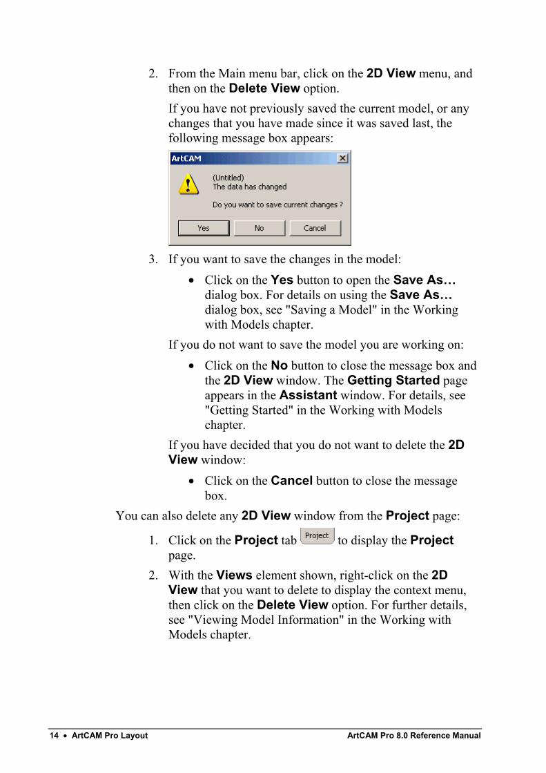
2. From the Main menu bar, click on the 2D View menu, andthen on the Delete View option.If you have not previously saved the current model, or anychanges that you have made since it was saved last, thefollowing message box appears:
3. If you want to save the changes in the model:• Click on the Yes button to open the Save As…
dialog box. For details on using the Save As…dialog box, see "Saving a Model" in the Workingwith Models chapter.
If you do not want to save the model you are working on:• Click on the No button to close the message box and
the 2D View window. The Getting Started pageappears in the Assistant window. For details, see"Getting Started" in the Working with Modelschapter.
If you have decided that you do not want to delete the 2DView window:
• Click on the Cancel button to close the messagebox.
You can also delete any 2D View window from the Project page:
1. Click on the Project tab to display the Projectpage.
2. With the Views element shown, right-click on the 2DView that you want to delete to display the context menu,then click on the Delete View option. For further details,see "Viewing Model Information" in the Working withModels chapter.
ArtCAM Pro 8.0 Reference Manual ArtCAM Pro Layout • 15
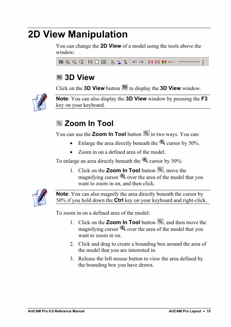
2D View ManipulationYou can change the 2D View of a model using the tools above thewindow:
3D ViewClick on the 3D View button to display the 3D View window.
Note: You can also display the 3D View window by pressing the F3key on your keyboard.
Zoom In ToolYou can use the Zoom In Tool button in two ways. You can:
• Enlarge the area directly beneath the cursor by 50%.• Zoom in on a defined area of the model.
To enlarge an area directly beneath the cursor by 50%:
1. Click on the Zoom In Tool button , move themagnifying cursor over the area of the model that youwant to zoom in on, and then click.
Note: You can also magnify the area directly beneath the cursor by50% if you hold down the Ctrl key on your keyboard and right-click.
To zoom in on a defined area of the model:
1. Click on the Zoom In Tool button , and then move themagnifying cursor over the area of the model that youwant to zoom in on.
2. Click and drag to create a bounding box around the area ofthe model that you are interested in.
3. Release the left mouse button to view the area defined bythe bounding box you have drawn.
16 • ArtCAM Pro Layout ArtCAM Pro 8.0 Reference Manual
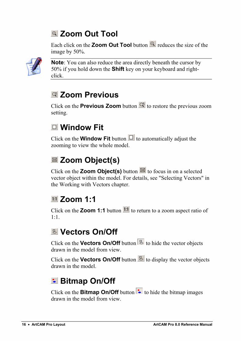
Zoom Out ToolEach click on the Zoom Out Tool button reduces the size of theimage by 50%.
Note: You can also reduce the area directly beneath the cursor by50% if you hold down the Shift key on your keyboard and right-click.
Zoom PreviousClick on the Previous Zoom button to restore the previous zoomsetting.
Window FitClick on the Window Fit button to automatically adjust thezooming to view the whole model.
Zoom Object(s)Click on the Zoom Object(s) button to focus in on a selectedvector object within the model. For details, see "Selecting Vectors" inthe Working with Vectors chapter.
Zoom 1:1Click on the Zoom 1:1 button to return to a zoom aspect ratio of1:1.
Vectors On/OffClick on the Vectors On/Off button to hide the vector objectsdrawn in the model from view.
Click on the Vectors On/Off button to display the vector objectsdrawn in the model.
Bitmap On/OffClick on the Bitmap On/Off button to hide the bitmap imagesdrawn in the model from view.
ArtCAM Pro 8.0 Reference Manual ArtCAM Pro Layout • 17
Click on the Bitmap On/Off button to display the bitmap imagesdrawn in the model.
Greyscale ViewClick on the Greyscale View button to display a greyscale viewof the existing relief.
Click on the Greyscale View button to hide the greyscale viewof the existing relief.
Note: You can set the default colours used in the Greyscale Viewusing the ArtCAM Options page. For details, see "ManagingArtCAM Pro's Preferences" on page 37.
UndoClick on the Undo button to cancel each of your consecutiveediting actions, working backwards.
RedoClick on the Redo button to repeat each of the editing actions youhave previously cancelled in succession, working forwards.
Link All ColoursClick on the Link All Colours button to simultaneously link allcolours in the current Colour Palette, other than the Secondary Colour,to the Primary Colour.
Unlink All ColoursClick on the Unlink All Colours button to unlink all colourscurrently linked together in the Colour Palette.
Link/Unlink ColoursClick on the Link/Unlink Colours button to link the SecondaryColour to the Primary Colour.You can see that the Secondary and Primary Colours are linked whenthey appear in the Colour Palette as follows:
18 • ArtCAM Pro Layout ArtCAM Pro 8.0 Reference Manual
When the Secondary Colour is linked to the Primary Colour, it isdisplayed as the Primary Colour in the bitmap image.
Click on the Link/Unlink Colours button again to unlink theSecondary Colour from the Primary Colour.
Note: You can also link or unlink the Secondary and Primary Coloursif you click on the Link/Unlink Colours icon in the ColourPalette or double right-click on the Secondary Colour itself.
Merge ColoursClick on the Merge Colours button to merge the currentSecondary Colour with the current Primary Colour.
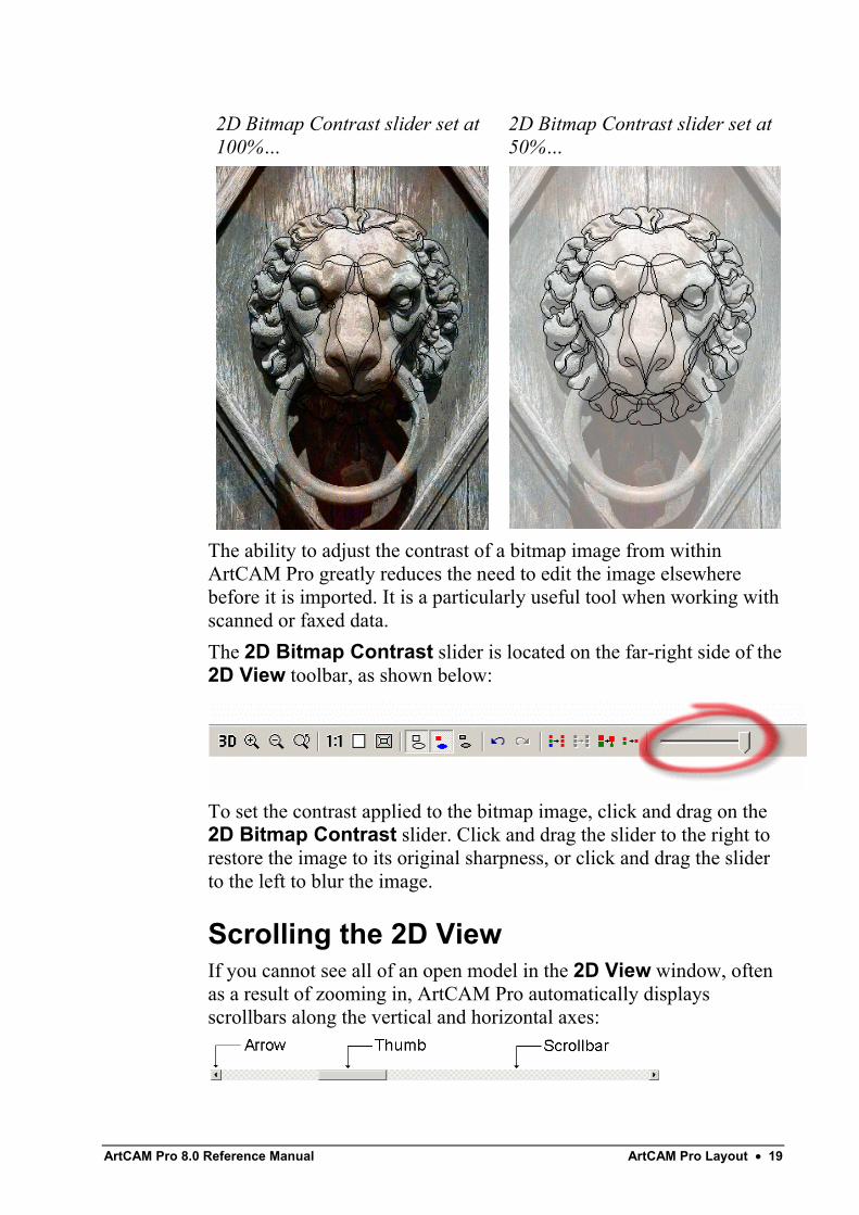
2D Bitmap Contrast ToolYou can adjust the contrast of a bitmap image shown in the 2D Viewwindow, making it far easier to draw vector outlines representingspecific areas within the bitmap image.The contrast command changes the amount of shading applied to abitmap image shown in the 2D View window. You can use it to blurthe image, to make colours appear more saturated.
ArtCAM Pro 8.0 Reference Manual ArtCAM Pro Layout • 19
2D Bitmap Contrast slider set at100%…
2D Bitmap Contrast slider set at50%…
The ability to adjust the contrast of a bitmap image from withinArtCAM Pro greatly reduces the need to edit the image elsewherebefore it is imported. It is a particularly useful tool when working withscanned or faxed data.The 2D Bitmap Contrast slider is located on the far-right side of the2D View toolbar, as shown below:
To set the contrast applied to the bitmap image, click and drag on the2D Bitmap Contrast slider. Click and drag the slider to the right torestore the image to its original sharpness, or click and drag the sliderto the left to blur the image.
Scrolling the 2D ViewIf you cannot see all of an open model in the 2D View window, oftenas a result of zooming in, ArtCAM Pro automatically displaysscrollbars along the vertical and horizontal axes:
20 • ArtCAM Pro Layout ArtCAM Pro 8.0 Reference Manual
To view a different area of the open model, you can:• Click on the arrow at either end of the scrollbar.• Drag the thumb in the scrollbar to the appropriate position.• Click directly in the scrollbar on either side of the thumb to
page back and forth.
2D View OptionsWhen drawing vector objects in ArtCAM Pro, there are threeinvaluable features available to help you create a vector objectaccording to an exact set of measurements. These are:
• Rulers. For details, see "Using Rulers" on page 20.• The Snap Grid. For details, see "Using the Snap Grid" on
page 21.• Horizontal and vertical guidelines. For details, see "Using
Guidelines" on page 23.These features help consistently align and size vector objects.
Using RulersYou can use the rulers adjacent to the X and Y-axis of the 2D Viewwindow to make measurements.The ruler along the X-axis also displays the units of measurement(millimetres or inches) selected for the model that is shown in the 2DView window. For details, see "Creating a Model" in the Workingwith Models chapter.To turn the rulers off:
1. From the Main menu bar, click on the 2D View menu,followed by the Show Rulers option to deselect it. Therulers along the X and Y-axis of the 2D View window arehidden.
To turn the rulers on:1. From the Main menu bar, click on the 2D View menu,
followed by the Show Rulers option to select it. Rulersappear adjacent to the X and Y-axis of the 2D Viewwindow.
ArtCAM Pro 8.0 Reference Manual ArtCAM Pro Layout • 21
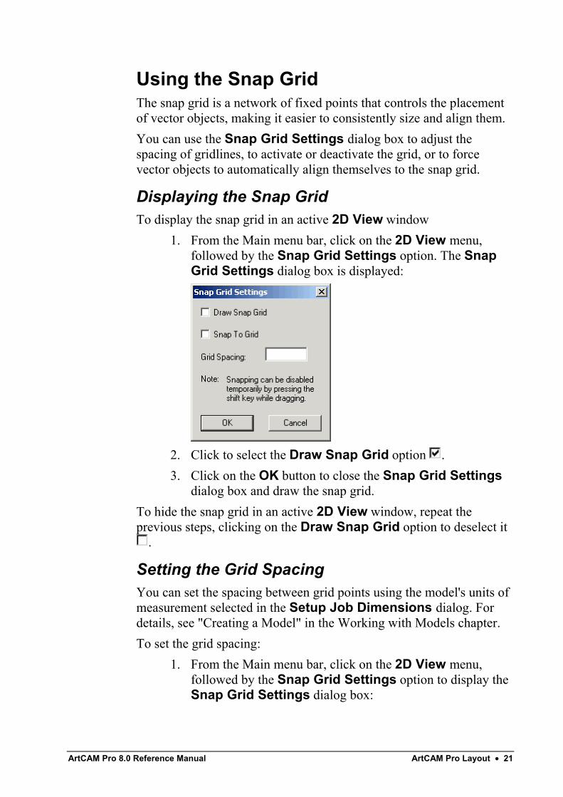
Using the Snap GridThe snap grid is a network of fixed points that controls the placementof vector objects, making it easier to consistently size and align them.You can use the Snap Grid Settings dialog box to adjust thespacing of gridlines, to activate or deactivate the grid, or to forcevector objects to automatically align themselves to the snap grid.
Displaying the Snap GridTo display the snap grid in an active 2D View window
1. From the Main menu bar, click on the 2D View menu,followed by the Snap Grid Settings option. The SnapGrid Settings dialog box is displayed:
2. Click to select the Draw Snap Grid option .3. Click on the OK button to close the Snap Grid Settings
dialog box and draw the snap grid.To hide the snap grid in an active 2D View window, repeat theprevious steps, clicking on the Draw Snap Grid option to deselect it
.
Setting the Grid SpacingYou can set the spacing between grid points using the model's units ofmeasurement selected in the Setup Job Dimensions dialog. Fordetails, see "Creating a Model" in the Working with Models chapter.To set the grid spacing:
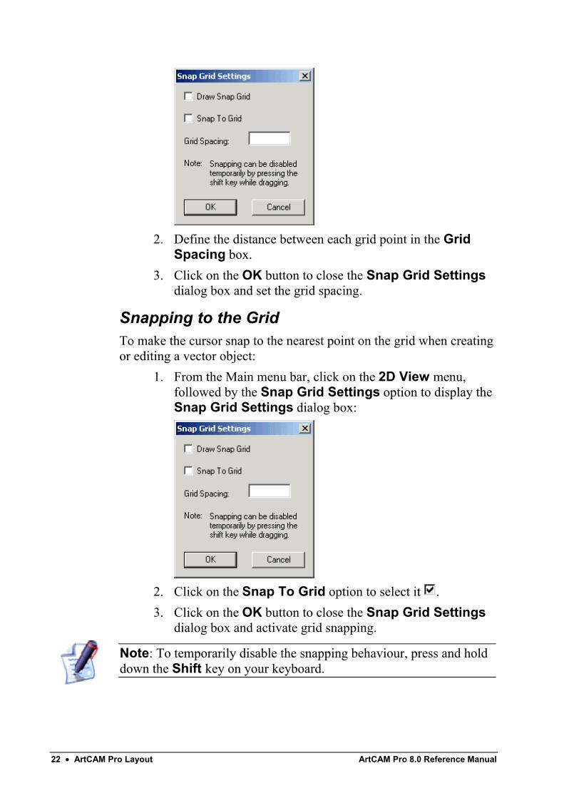
1. From the Main menu bar, click on the 2D View menu,followed by the Snap Grid Settings option to display theSnap Grid Settings dialog box:
22 • ArtCAM Pro Layout ArtCAM Pro 8.0 Reference Manual
2. Define the distance between each grid point in the GridSpacing box.
3. Click on the OK button to close the Snap Grid Settingsdialog box and set the grid spacing.
Snapping to the GridTo make the cursor snap to the nearest point on the grid when creatingor editing a vector object:
1. From the Main menu bar, click on the 2D View menu,followed by the Snap Grid Settings option to display theSnap Grid Settings dialog box:
2. Click on the Snap To Grid option to select it .3. Click on the OK button to close the Snap Grid Settings
dialog box and activate grid snapping.
Note: To temporarily disable the snapping behaviour, press and holddown the Shift key on your keyboard.
ArtCAM Pro 8.0 Reference Manual ArtCAM Pro Layout • 23
Using GuidelinesWhile a Snap Grid is made up of a network of fixed points, aguideline is a solid line parallel to either the horizontal (X) or vertical(Y) axis that can be moved to any position in the 2D View window.To create guidelines, the rulers must be checked on. For details, see"Using Rulers" on page 20.To create a horizontal guideline:
• Click and hold down the left mouse button on the top rulerto display a guideline in the 2D View window, and thendrag it into position.
To create a vertical guideline:• Click and hold down the left mouse button on the left-hand
ruler to display a guideline in the 2D View window, andthen drag it into position.
To reposition a guideline:• Move the cursor over the guideline you want to move.
When the cursor changes to a double-headed arrow ,click and drag the guideline into its new position.
Warning: You must have the both the Show Rulers and the ShowGuidelines options selected in the 2D View menu to see guidelinesin the 2D View window.
Defining a Guideline's PositionYou can define the position of a guideline using the Position Guidedialog box. This is a more accurate method than clicking and dragginga guideline into position.To display the Position Guide dialog box, move the mouse cursorover a guideline and click the right mouse button:
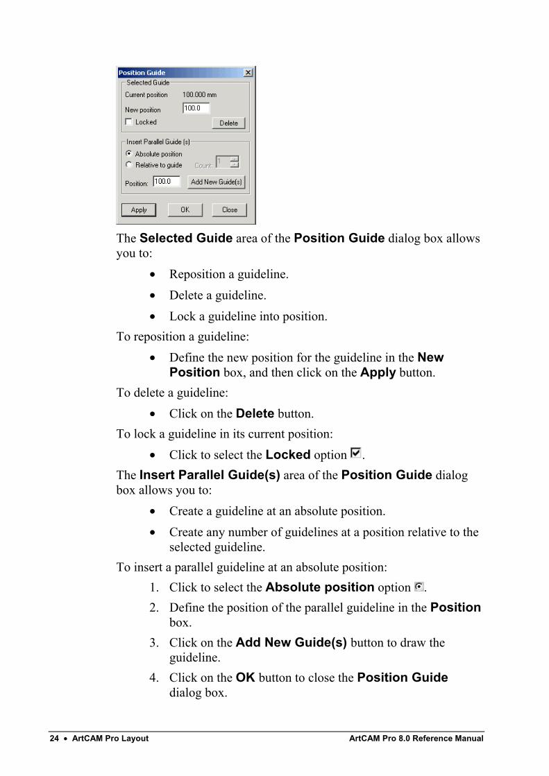
24 • ArtCAM Pro Layout ArtCAM Pro 8.0 Reference Manual
The Selected Guide area of the Position Guide dialog box allowsyou to:
• Reposition a guideline.• Delete a guideline.• Lock a guideline into position.
To reposition a guideline:• Define the new position for the guideline in the New
Position box, and then click on the Apply button.To delete a guideline:
• Click on the Delete button.To lock a guideline in its current position:
• Click to select the Locked option .The Insert Parallel Guide(s) area of the Position Guide dialogbox allows you to:
• Create a guideline at an absolute position.• Create any number of guidelines at a position relative to the
selected guideline.To insert a parallel guideline at an absolute position:
1. Click to select the Absolute position option .2. Define the position of the parallel guideline in the Position
box.3. Click on the Add New Guide(s) button to draw the
guideline.4. Click on the OK button to close the Position Guide
dialog box.
ArtCAM Pro 8.0 Reference Manual ArtCAM Pro Layout • 25
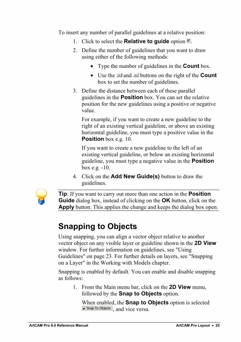
To insert any number of parallel guidelines at a relative position:1. Click to select the Relative to guide option .2. Define the number of guidelines that you want to draw
using either of the following methods:• Type the number of guidelines in the Count box.• Use the and buttons on the right of the Count
box to set the number of guidelines.3. Define the distance between each of these parallel
guidelines in the Position box. You can set the relativeposition for the new guidelines using a positive or negativevalue.For example, if you want to create a new guideline to theright of an existing vertical guideline, or above an existinghorizontal guideline, you must type a positive value in thePosition box e.g. 10.If you want to create a new guideline to the left of anexisting vertical guideline, or below an existing horizontalguideline, you must type a negative value in the Positionbox e.g. -10.
4. Click on the Add New Guide(s) button to draw theguidelines.
Tip: If you want to carry out more than one action in the PositionGuide dialog box, instead of clicking on the OK button, click on theApply button. This applies the change and keeps the dialog box open.
Snapping to ObjectsUsing snapping, you can align a vector object relative to anothervector object on any visible layer or guideline shown in the 2D Viewwindow. For further information on guidelines, see "UsingGuidelines" on page 23. For further details on layers, see "Snappingon a Layer" in the Working with Models chapter.Snapping is enabled by default. You can enable and disable snappingas follows:
1. From the Main menu bar, click on the 2D View menu,followed by the Snap to Objects option.When enabled, the Snap to Objects option is selected
, and vice versa.
26 • ArtCAM Pro Layout ArtCAM Pro 8.0 Reference Manual
Note: Make sure that the Toggle Snapping button for the layer isalso enabled . For details, see "Snapping on a Layer" in theWorking with Models chapter.
Tip: To temporarily disable snapping, press and hold down the Shiftkey on your keyboard.
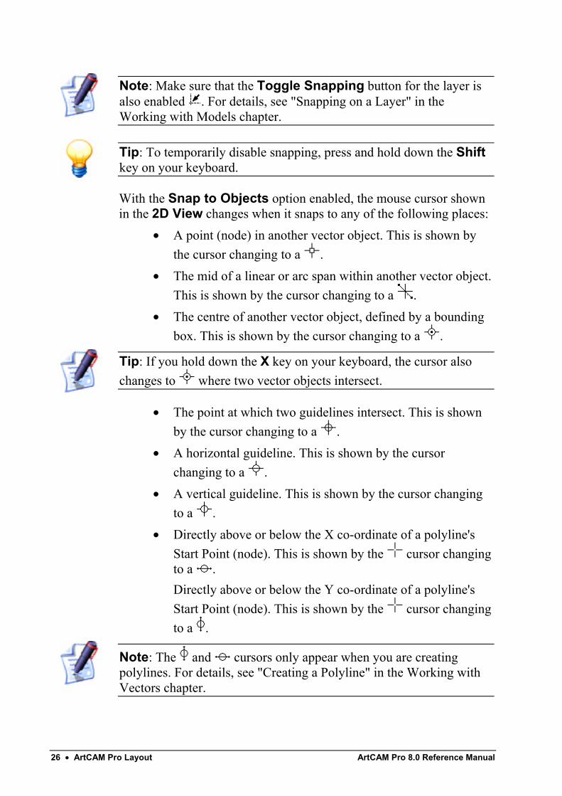
With the Snap to Objects option enabled, the mouse cursor shownin the 2D View changes when it snaps to any of the following places:
• A point (node) in another vector object. This is shown bythe cursor changing to a .
• The mid of a linear or arc span within another vector object.This is shown by the cursor changing to a .
• The centre of another vector object, defined by a boundingbox. This is shown by the cursor changing to a .
Tip: If you hold down the X key on your keyboard, the cursor alsochanges to where two vector objects intersect.
• The point at which two guidelines intersect. This is shownby the cursor changing to a .
• A horizontal guideline. This is shown by the cursorchanging to a .
• A vertical guideline. This is shown by the cursor changingto a .
• Directly above or below the X co-ordinate of a polyline'sStart Point (node). This is shown by the cursor changingto a .Directly above or below the Y co-ordinate of a polyline'sStart Point (node). This is shown by the cursor changingto a .
Note: The and cursors only appear when you are creatingpolylines. For details, see "Creating a Polyline" in the Working withVectors chapter.
ArtCAM Pro 8.0 Reference Manual ArtCAM Pro Layout • 27
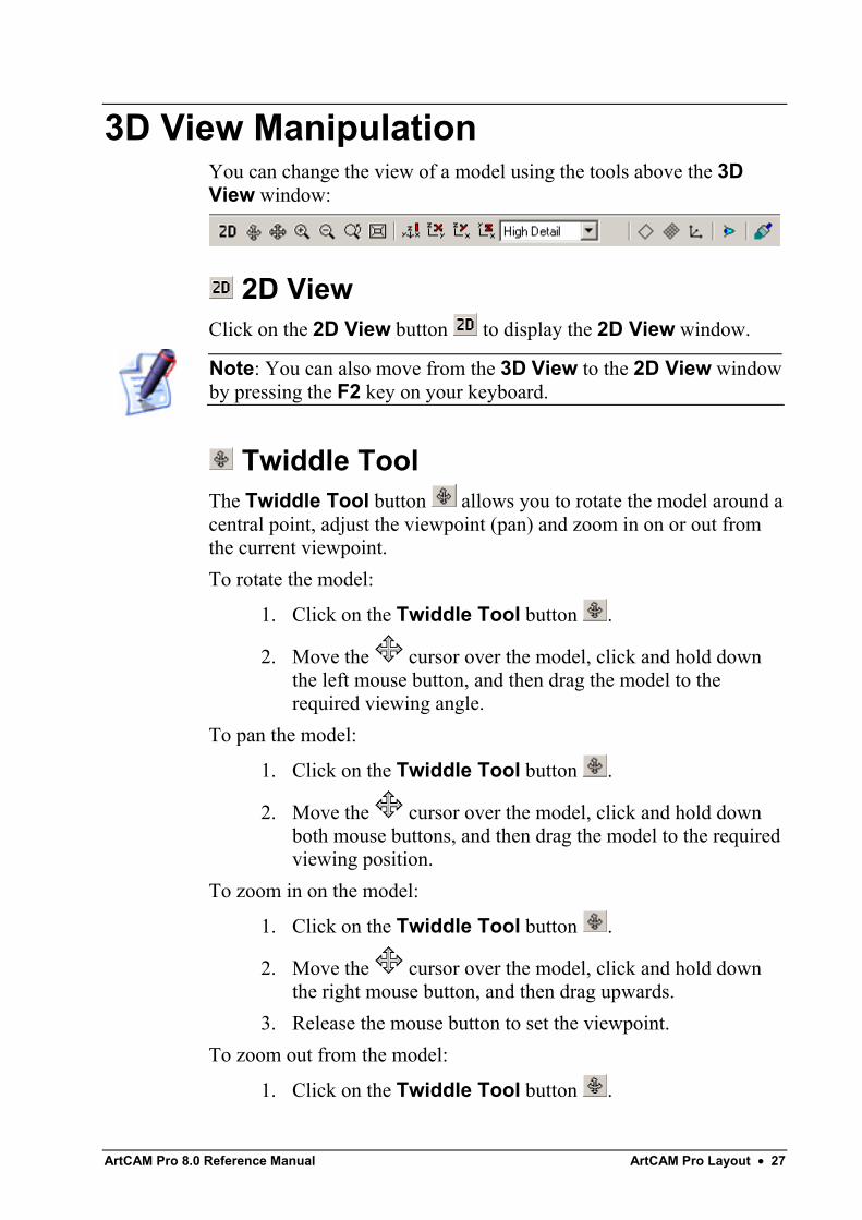
3D View ManipulationYou can change the view of a model using the tools above the 3DView window:
2D ViewClick on the 2D View button to display the 2D View window.
Note: You can also move from the 3D View to the 2D View windowby pressing the F2 key on your keyboard.
Twiddle ToolThe Twiddle Tool button allows you to rotate the model around acentral point, adjust the viewpoint (pan) and zoom in on or out fromthe current viewpoint.To rotate the model:
1. Click on the Twiddle Tool button .
2. Move the cursor over the model, click and hold downthe left mouse button, and then drag the model to therequired viewing angle.
To pan the model:
1. Click on the Twiddle Tool button .
2. Move the cursor over the model, click and hold downboth mouse buttons, and then drag the model to the requiredviewing position.
To zoom in on the model:
1. Click on the Twiddle Tool button .
2. Move the cursor over the model, click and hold downthe right mouse button, and then drag upwards.
3. Release the mouse button to set the viewpoint.To zoom out from the model:
1. Click on the Twiddle Tool button .
28 • ArtCAM Pro Layout ArtCAM Pro 8.0 Reference Manual
2. Move the cursor over the model, click and hold downthe right mouse button, and then drag downwards.
3. Release the mouse button to set the viewpoint.
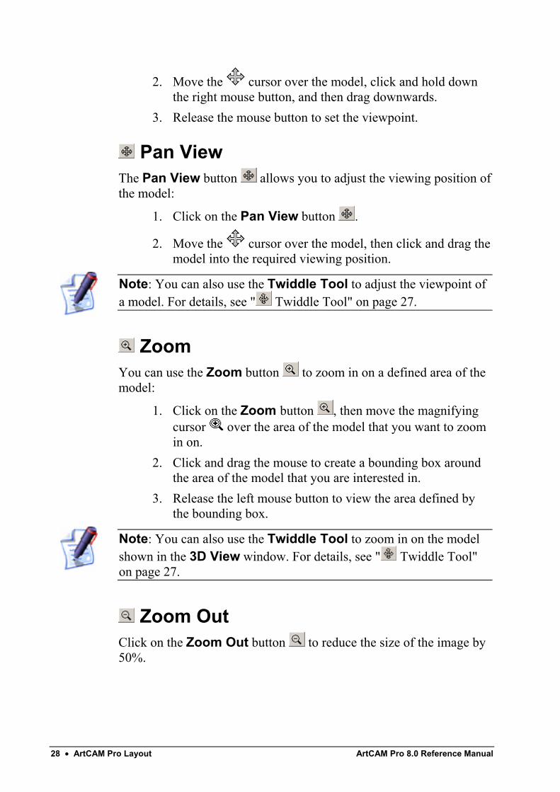
Pan ViewThe Pan View button allows you to adjust the viewing position ofthe model:
1. Click on the Pan View button .
2. Move the cursor over the model, then click and drag themodel into the required viewing position.
Note: You can also use the Twiddle Tool to adjust the viewpoint ofa model. For details, see " Twiddle Tool" on page 27.
ZoomYou can use the Zoom button to zoom in on a defined area of themodel:
1. Click on the Zoom button , then move the magnifyingcursor over the area of the model that you want to zoomin on.
2. Click and drag the mouse to create a bounding box aroundthe area of the model that you are interested in.
3. Release the left mouse button to view the area defined bythe bounding box.
Note: You can also use the Twiddle Tool to zoom in on the modelshown in the 3D View window. For details, see " Twiddle Tool"on page 27.
Zoom OutClick on the Zoom Out button to reduce the size of the image by50%.
ArtCAM Pro 8.0 Reference Manual ArtCAM Pro Layout • 29
Previous ViewClick on the Previous View button to restore the previous zoomsetting.
Scale To FitThe Scale To Fit button resizes the model so that it fits in the 3DView window.
Isometric ViewThe Isometric View button displays the model in the standardisometric view. The viewing angle is shown by the XYZrepresentation on the button.
View Along XThe View Along X button displays the model from the X-axis.
View Along YThe View Along Y button displays the model from the Y-axis.
View Along ZThe View Along Z button displays the model from the Z-axis.
Select Relief DetailClick on the Select Relief Detail list box to display the list ofoptions you can use when colour shading the relief, and then click onthe option that you want to use:
• Low Detail – Select this option to colour shade the relief ata quarter of the model's pixel resolution.
• Medium Detail – Select this option to colour shade therelief at half of the model's pixel resolution.
• High Detail – Select this option to colour shade the reliefequal to the model's pixel resolution. This option producesexcellent visual clarity, but can mean that the relief takeslonger to render.
30 • ArtCAM Pro Layout ArtCAM Pro 8.0 Reference Manual
Draw Zero PlaneClick on the Draw Zero Plane button to hide the zero level ofthe relief from view.If you want to display the zero level of the relief, click on the DrawZero Plane button again.
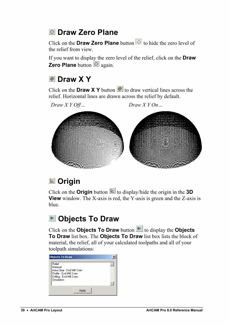
Draw X YClick on the Draw X Y button to draw vertical lines across therelief. Horizontal lines are drawn across the relief by default.Draw X Y Off… Draw X Y On…
OriginClick on the Origin button to display/hide the origin in the 3DView window. The X-axis is red, the Y-axis is green and the Z-axis isblue.
Objects To DrawClick on the Objects To Draw button to display the ObjectsTo Draw list box. The Objects To Draw list box lists the block ofmaterial, the relief, all of your calculated toolpaths and all of yourtoolpath simulations:
ArtCAM Pro 8.0 Reference Manual ArtCAM Pro Layout • 31
All items shown in the 3D View window are highlighted in blue in theObjects To Draw list box. If an item is not highlighted, it is notshown in the 3D View window.You can hide any of the objects displayed in the 3D View:
1. Click to select the object in the list box that you want tohide. The selected object is no longer highlighted in blue.
2. Click on the Apply button to show the object in the 3DView window.
3. Click on the icon in the top right corner of the ObjectsTo Draw list box to close it.
To show any of the hidden objects in the 3D View:1. Click to select the object in the list box that you want to
show. The selected object is now highlighted in blue.2. Click on the Apply button to show the object in the 3D
View window.3. Click on the in the top-right corner of the Objects To
Draw list box to close it.
Colour ShadeClick on the Colour Shade button to replace the relief ortoolpath simulation with a colour shaded view.
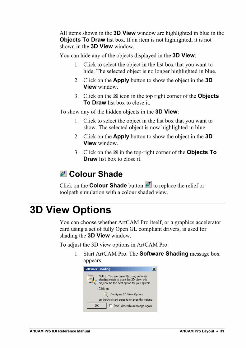
3D View OptionsYou can choose whether ArtCAM Pro itself, or a graphics acceleratorcard using a set of fully Open GL compliant drivers, is used forshading the 3D View window.To adjust the 3D view options in ArtCAM Pro:
1. Start ArtCAM Pro. The Software Shading message boxappears:
32 • ArtCAM Pro Layout ArtCAM Pro 8.0 Reference Manual
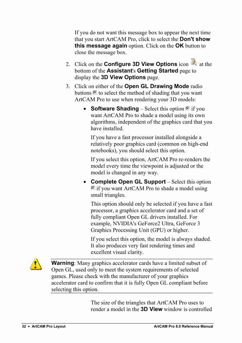
If you do not want this message box to appear the next timethat you start ArtCAM Pro, click to select the Don't showthis message again option. Click on the OK button toclose the message box.
2. Click on the Configure 3D View Options icon at thebottom of the Assistant's Getting Started page todisplay the 3D View Options page.
3. Click on either of the Open GL Drawing Mode radiobuttons to select the method of shading that you wantArtCAM Pro to use when rendering your 3D models:
• Software Shading – Select this option if youwant ArtCAM Pro to shade a model using its ownalgorithms, independent of the graphics card that youhave installed.If you have a fast processor installed alongside arelatively poor graphics card (common on high-endnotebooks), you should select this option.If you select this option, ArtCAM Pro re-renders themodel every time the viewpoint is adjusted or themodel is changed in any way.
• Complete Open GL Support – Select this option if you want ArtCAM Pro to shade a model using
small triangles.This option should only be selected if you have a fastprocessor, a graphics accelerator card and a set offully compliant Open GL drivers installed. Forexample, NVIDIA's GeForce2 Ultra, GeForce 3Graphics Processing Unit (GPU) or higher.If you select this option, the model is always shaded.It also produces very fast rendering times andexcellent visual clarity.
Warning: Many graphics accelerator cards have a limited subset ofOpen GL, used only to meet the system requirements of selectedgames. Please check with the manufacturer of your graphicsaccelerator card to confirm that it is fully Open GL compliant beforeselecting this option.
The size of the triangles that ArtCAM Pro uses torender a model in the 3D View window is controlled
ArtCAM Pro 8.0 Reference Manual ArtCAM Pro Layout • 33
by the list box in the 3D View toolbar. The higherthe detail, the smaller the triangles that are used. Fordetails, see "3D View Manipulation" on page 27.
4. Click on the Apply button to confirm your 3D Viewsettings.
5. Click on the Close button to close the 3D View Optionspage and return to the Assistant's Getting Started page.
You can also display the 3D View Options page in the followingway:
1. From the Main menu bar, click on the Window menu, andthen on the 3D View Options option.
If you attempt to change the Open GL Drawing Mode while amodel is open in ArtCAM Pro, the following message box appears:
Click on the OK button to close the message box, then shut down andrestart ArtCAM Pro for the new Open GL Drawing Mode to takeeffect. For further details, see "Shutting Down ArtCAM Pro" in theWorking with Models chapter.
Using the Top ToolbarYou can hide or view the Top toolbar which contains the File, Model,Bitmap, Vector, Vector Editing, Vector Merging, Relief andRelief Editing toolbars.Hiding the Top toolbar increases the size of the central area of thescreen, which in turn allows you to increase the size of the designwindows.If the Top toolbar is hidden, you can still access the options on theFile, Model, Bitmap, Vector, Vector Editing, Vector Merging,Relief and Relief Editing toolbars from the Main menu bar. TheTop toolbar is shown by default.To hide the Top toolbar:
• From the Main menu bar, click on the Window menu, andthen on the Show Top Toolbar option.
34 • ArtCAM Pro Layout ArtCAM Pro 8.0 Reference Manual
To view the Top toolbar:• From the Main menu bar, click on the Window menu, and
then on the Show Top Toolbar option.
Updating ArtCAM ProArtCAM Pro customers have the option to purchase maintenancealong with their software. Maintenance is a contract between you thecustomer, Delcam plc and your reseller. Having a valid maintenancecontract ensures that you always have access to the most up-to-dateversion of the software, with the most advanced functionality helpingyou stay competitive and get the most from your software investment.Delcam plc are committed to releasing a new major version ofArtCAM Pro containing new features and functionality at least once ayear. Having maintenance will ensure that you automatically receivethe new versions along with any associated documentation. You willalso be authorised to download useful 'plug-in' tools from theMaintenance Download page.Contact your local software supplier for more information aboutmaintenance.All users with maintenance can check for software updates fromwithin ArtCAM Pro:
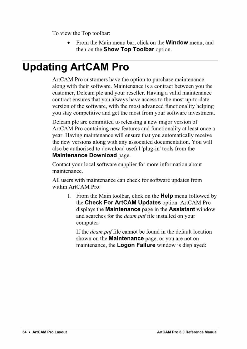
1. From the Main toolbar, click on the Help menu followed bythe Check For ArtCAM Updates option. ArtCAM Prodisplays the Maintenance page in the Assistant windowand searches for the dcam.paf file installed on yourcomputer.If the dcam.paf file cannot be found in the default locationshown on the Maintenance page, or you are not onmaintenance, the Logon Failure window is displayed:
ArtCAM Pro 8.0 Reference Manual ArtCAM Pro Layout • 35
Click on the icon in the top right corner of the window toclose it. From the Maintenance page, you can eitherinstruct ArtCAM Pro to search again for the dcam.paf file,or you can locate the file manually.To instruct ArtCAM Pro to search again:
• Click on the Search button.
Note: If ArtCAM Pro fails to display the Maintenance Downloadpage after locating the dcam.paf file, click on the Login button.
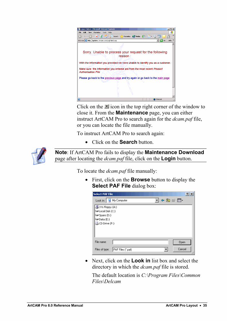
To locate the dcam.paf file manually:• First, click on the Browse button to display the
Select PAF File dialog box:
• Next, click on the Look in list box and select thedirectory in which the dcam.paf file is stored.The default location is C:\Program Files\CommonFiles\Delcam
36 • ArtCAM Pro Layout ArtCAM Pro 8.0 Reference Manual
• Once you have found the dcam.paf file, click on itsfile name. Its name appears in the File Name area.
• Finally, click on the Open button to display theMaintenance Download page.
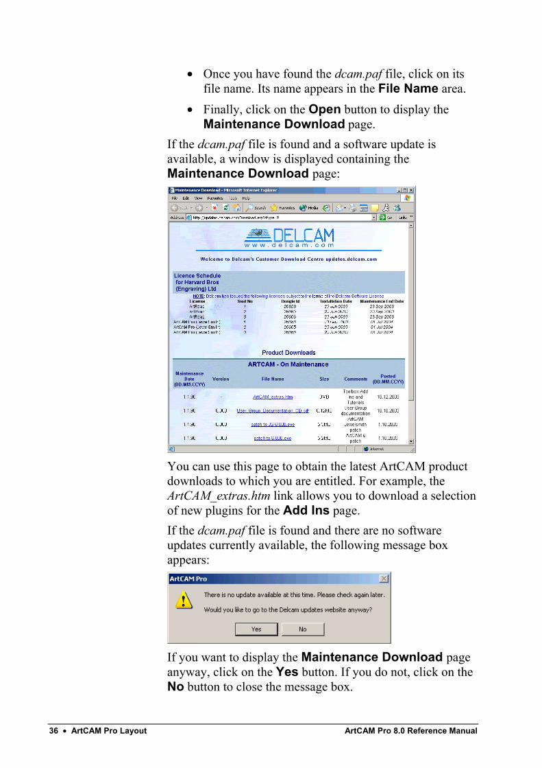
If the dcam.paf file is found and a software update isavailable, a window is displayed containing theMaintenance Download page:
You can use this page to obtain the latest ArtCAM productdownloads to which you are entitled. For example, theArtCAM_extras.htm link allows you to download a selectionof new plugins for the Add Ins page.If the dcam.paf file is found and there are no softwareupdates currently available, the following message boxappears:
If you want to display the Maintenance Download pageanyway, click on the Yes button. If you do not, click on theNo button to close the message box.
ArtCAM Pro 8.0 Reference Manual ArtCAM Pro Layout • 37
2. Click on the OK button on the Maintenance page to returnto the Assistant's Home page.
Installing Your ArtCAM LicenceIn order to use ArtCM Pro, you must ensure that you have installed availd licence. This licence can be installed as one of two different filetypes: a PAFfile (dcam.paf ) or a Delcam Licence file (dcam.dcamlic).To install your ArtCAM licence:
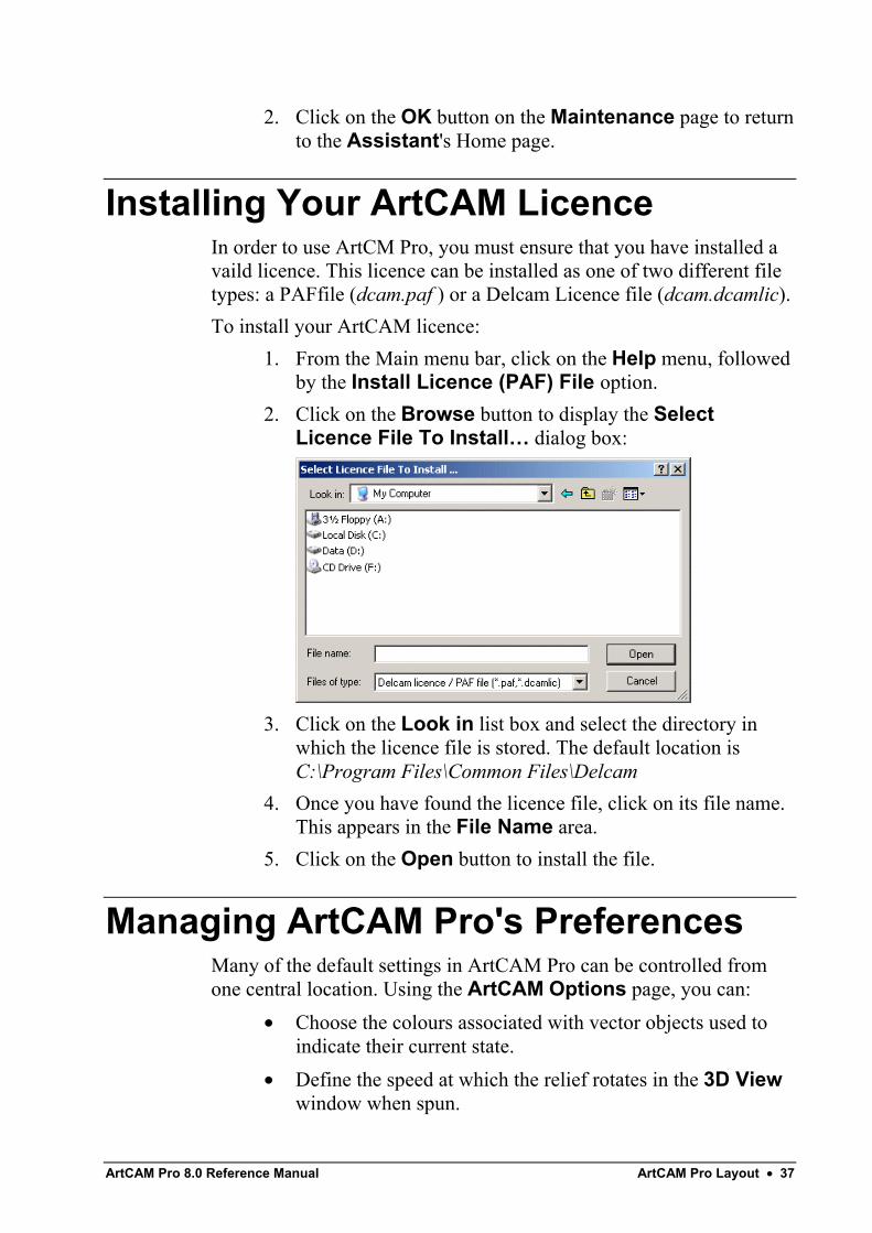
1. From the Main menu bar, click on the Help menu, followedby the Install Licence (PAF) File option.
2. Click on the Browse button to display the SelectLicence File To Install… dialog box:
3. Click on the Look in list box and select the directory inwhich the licence file is stored. The default location isC:\Program Files\Common Files\Delcam
4. Once you have found the licence file, click on its file name.This appears in the File Name area.
5. Click on the Open button to install the file.
Managing ArtCAM Pro's PreferencesMany of the default settings in ArtCAM Pro can be controlled fromone central location. Using the ArtCAM Options page, you can:
• Choose the colours associated with vector objects used toindicate their current state.
• Define the speed at which the relief rotates in the 3D Viewwindow when spun.
38 • ArtCAM Pro Layout ArtCAM Pro 8.0 Reference Manual
• Define the default settings used for machining strategieswithin 2D and 3D toolpaths.
• Instruct ArtCAM Pro to check for or ignore self-intersections in imported vector artwork.
• Control the increments used in ArtCAM Pro.• Control the size of the design windows when ArtCAM Pro
is started.• Set the size of text information shown in the 2D View
window.• Save reliefs in the same directory as the ArtCAM model file
in which they were created by default.• Choose the colours for the greyscale image of the current
relief show in the Greyscale View and how they areblended.
• Control the size of the 'scratch' file associated with theUndo and Redo buttons.
To adjust the aforementioned display settings in ArtCAM Pro:1. Click on the File tab in the Main toolbar to display
the File toolbar.
2. Click on the Options button to display the ArtCAMOptions page. The default colours and settings currentlyused in ArtCAM Pro are shown on the page.
3. In the 2D Drawing Colours area, click on the arrow todisplay its settings:
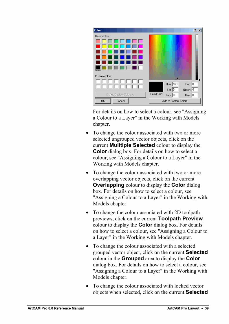
• To change the colour associated with a selectedungrouped vector object, click on the currentSelected colour to display the Color dialog box:
ArtCAM Pro 8.0 Reference Manual ArtCAM Pro Layout • 39
For details on how to select a colour, see "Assigninga Colour to a Layer" in the Working with Modelschapter.
• To change the colour associated with two or moreselected ungrouped vector objects, click on thecurrent Mulitiple Selected colour to display theColor dialog box. For details on how to select acolour, see "Assigning a Colour to a Layer" in theWorking with Models chapter.
• To change the colour associated with two or moreoverlapping vector objects, click on the currentOverlapping colour to display the Color dialogbox. For details on how to select a colour, see"Assigning a Colour to a Layer" in the Working withModels chapter.
• To change the colour associated with 2D toolpathpreviews, click on the current Toolpath Previewcolour to display the Color dialog box. For detailson how to select a colour, see "Assigning a Colour toa Layer" in the Working with Models chapter.
• To change the colour associated with a selectedgrouped vector object, click on the current Selectedcolour in the Grouped area to display the Colordialog box. For details on how to select a colour, see"Assigning a Colour to a Layer" in the Working withModels chapter.
• To change the colour associated with locked vectorobjects when selected, click on the current Selected
40 • ArtCAM Pro Layout ArtCAM Pro 8.0 Reference Manual
colour in the Locked area to display the Colordialog box. For details on how to select a colour, see"Assigning a Colour to a Layer" in the Working withModels chapter.
• To change the colour associated with locked vectorobjects when deselected, click on the currentUnselected colour in the Locked area to displaythe Color dialog box. For details on how to select acolour, see "Assigning a Colour to a Layer" in theWorking with Models chapter.
4. In the 3D View area, click on the arrow to display itssettings:
• To change the frame rate at which a relief or trianglemodel in the 3D View window rotates when spun,define the new speed in the Spin Update Rate box.For details on how to rotate a relief or trianglemodel, see "Rotating a Relief or Triangle Mesh" inthe Working with Reliefs chapter.
5. In the Machining area, click on the arrow to display itssettings:
• Climb Milling rotates the toolbit in the samedirection as the feed motion. To set climb milling asthe default cutting direction used in toolpaths, clickto select the Use Climb Milling by Default option
.• A raster machining strategy machines in passes back
and forth along a specified angle. To set the defaultangle for toolpaths that use a raster machiningstrategy, type the angle in the Default RasterAngle box.
• When using an offset machining strategy in atoolpath, machining inwards from the outside edge ofthe block of material by default, click to select theStart Offset Machining at Edge option .
• If you are machining small areas of material withvery fine detail, click to select the Use EngravingEngine for Area Clear option . Other than usingthe Engraving engine for Area Clearance toolpaths,this option adds tails to remove up-stands when the
ArtCAM Pro 8.0 Reference Manual ArtCAM Pro Layout • 41
stepover is greater than the tool radius. This option isdeselected by default.
• To show the cutting direction in all 2D toolpathpreviews shown in the 2D View window, click toselect the Cutting Direction option .
• ArtCAM Pro shows rapid and plunge moves in allsimulated toolpaths by default. To hide all rapid andplunge moves, click to deselect the Rapid &Plunge Moves option .
6. In the File Import area, click on the arrow to display itssettings:
• ArtCAM Pro identifies all self-intersections withinimported vector artwork by default. To ignore anyself-intersections, click to deselect the Check forCrossings option .
Note: You can use the Vector Doctor tool to check for self-intersections in vector artwork. For details, see "Using the VectorDoctor" in the Working with Vectors chapter.
7. In the Text Defaults area, click on the arrow to displayits settings. These settings allow you to control the defaultincrements used in the Size and Transform areas of theText Tool page and the Text Position area of the Texton a Curve page in ArtCAM Pro:
• In the Point spin increment box, define theincremental value used between each click on eitherthe or arrow whenever the points option isselected. This option is set to 3 points by default.
• In the MM spin increment box, define theincremental value used between each click on eitherthe or arrow whenever the mm option isselected. This option is set to 1 mm by default.
• In the Inches spin increment box, define theincremental value used between each click on eitherthe or arrow whenever the inches option isselected. This option is set to 0.04 inches by default.
8. In the 2D Drawing Options area, click on the arrow todisplay its settings:
42 • ArtCAM Pro Layout ArtCAM Pro 8.0 Reference Manual
• ArtCAM Pro replaces a selection of points (nodes)with a single vertical or horizontal linear span bydefault. To align a selection of points (nodes) witheither the X or Y axis whilst preserving the points,click to deselect the Align Nodes – replace witha single line option .
• To set the size of the text information shown in the2D View window, such as the numbers and lettersdisplayed when creating a Two Rail Sweep, type thepoint size of the font in the pt box. A default size of15 points is used.
9. In the Miscellaneous area, click on the arrow todisplay its settings:
• To maximise both of the design windows whenArtCAM Pro is started, click to select the MaximiseViews on Startup option .
• To save a relief file (*.rlf) in the same directory asthe ArtCAM model file (*.art) from which it wascreated, click to select the Save Reliefs in Art FileDirectory option .
10. In the Greyscale View area, click on the arrow todisplay its settings:
• To change the colour of the relief's zero plane, clickon the current Base Colour to display the Colordialog box. For details on how to select a colour, see"Assigning a Colour to a Layer" in the Working withModels chapter.
• To change the colour of the lowest points in therelief, click on the current Lowest Colour todisplay the Color dialog box. For details on how toselect a colour, see "Assigning a Colour to a Layer"in the Working with Models chapter. ArtCAM Problends the relief from this colour to the colourselected for its highest points.
• To change the colour of the highest points in therelief, click on the current Highest Colour todisplay the Color dialog box. For details on how toselect a colour, see "Assigning a Colour to a Layer"in the Working with Models chapter.
ArtCAM Pro 8.0 Reference Manual ArtCAM Pro Layout • 43
• If you do not want ArtCAM Pro to use a linear blendfor the colours selected for the lowest and highestpoints in the relief, click to deselect the Linearcolour blend option . When deselected, thisoption produces a more detailed view of the higherpoints in the relief.
11. In the Scratch File Settings area, define the amount ofspace that you want to allocate on your computer to thetemporary scratch file. The default size is 100mb.The scratch file is stored in the Temp directory associatedwith the User currently logged-in to Windows. For example,C:Documents and Settings\<user>\Local Settings\Temp.
12. Click on the Apply button to confirm your settings.If you want to restore the default settings at any time, clickon the Reset button.
13. Click on the icon to return to the Assistant's Homepage.
Note: You can also click on the icon at the top of the page toreturn to the Assistant's Home page.

44 • ArtCAM Pro Layout ArtCAM Pro 8.0 Reference Manual
ArtCAM Pro 8.0 Reference Manual Working with Models • 45
Working with Models
Getting StartedWhen you start ArtCAM Pro, the Assistant's Getting Started pageis displayed. This page is divided into three areas:
• Create Model – This allows you to define the dimensionsof a block of material or select an image file from whichyou want to produce an ArtCAM model. For details, see"Creating a Model" on page 45.
• Open Model – This allows you to open ArtCAM modelfiles that you have already created. For details, see"Creating a Model from an Image" on page 47.
• Other Features – This allows you to create your own oredit existing fonts for use within ArtCAM Pro's Text Tool,create a relief from a photographic image containing a side-profile of a person's head and neck, and display details ofthe latest features available in ArtCAM Pro. For details, see"Using the Font Editor" on page 116 and "Using the FaceWizard" on page 122.
Creating a ModelTo create a model:
1. Click on the Create New Model icon on theAssistant's Getting Started page to display the SizeFor New Model dialog box:
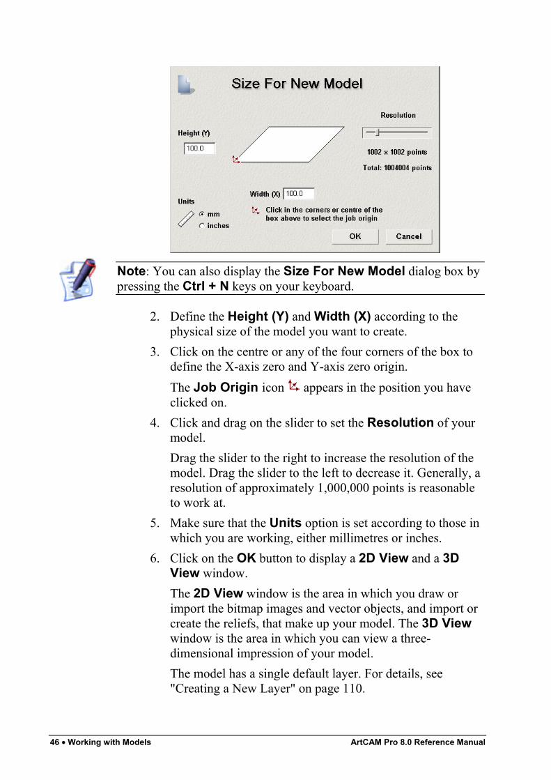
46 • Working with Models ArtCAM Pro 8.0 Reference Manual
Note: You can also display the Size For New Model dialog box bypressing the Ctrl + N keys on your keyboard.
2. Define the Height (Y) and Width (X) according to thephysical size of the model you want to create.
3. Click on the centre or any of the four corners of the box todefine the X-axis zero and Y-axis zero origin.The Job Origin icon appears in the position you haveclicked on.
4. Click and drag on the slider to set the Resolution of yourmodel.Drag the slider to the right to increase the resolution of themodel. Drag the slider to the left to decrease it. Generally, aresolution of approximately 1,000,000 points is reasonableto work at.
5. Make sure that the Units option is set according to those inwhich you are working, either millimetres or inches.
6. Click on the OK button to display a 2D View and a 3DView window.The 2D View window is the area in which you draw orimport the bitmap images and vector objects, and import orcreate the reliefs, that make up your model. The 3D Viewwindow is the area in which you can view a three-dimensional impression of your model.The model has a single default layer. For details, see"Creating a New Layer" on page 110.
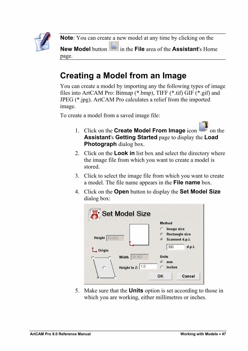
ArtCAM Pro 8.0 Reference Manual Working with Models • 47
Note: You can create a new model at any time by clicking on the
New Model button in the File area of the Assistant's Homepage.
Creating a Model from an ImageYou can create a model by importing any the following types of imagefiles into ArtCAM Pro: Bitmap (*.bmp), TIFF (*.tif) GIF (*.gif) andJPEG (*.jpg). ArtCAM Pro calculates a relief from the importedimage.To create a model from a saved image file:
1. Click on the Create Model From Image icon on theAssistant's Getting Started page to display the LoadPhotograph dialog box.
2. Click on the Look in list box and select the directory wherethe image file from which you want to create a model isstored.
3. Click to select the image file from which you want to createa model. The file name appears in the File name box.
4. Click on the Open button to display the Set Model Sizedialog box:
5. Make sure that the Units option is set according to those inwhich you are working, either millimetres or inches.
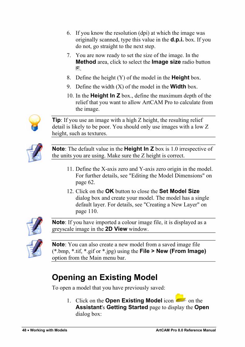
48 • Working with Models ArtCAM Pro 8.0 Reference Manual
6. If you know the resolution (dpi) at which the image wasoriginally scanned, type this value in the d.p.i. box. If youdo not, go straight to the next step.
7. You are now ready to set the size of the image. In theMethod area, click to select the Image size radio button
.8. Define the height (Y) of the model in the Height box.9. Define the width (X) of the model in the Width box.10. In the Height In Z box., define the maximum depth of the
relief that you want to allow ArtCAM Pro to calculate fromthe image.
Tip: If you use an image with a high Z height, the resulting reliefdetail is likely to be poor. You should only use images with a low Zheight, such as textures.
Note: The default value in the Height In Z box is 1.0 irrespective ofthe units you are using. Make sure the Z height is correct.
11. Define the X-axis zero and Y-axis zero origin in the model.For further details, see "Editing the Model Dimensions" onpage 62.
12. Click on the OK button to close the Set Model Sizedialog box and create your model. The model has a singledefault layer. For details, see "Creating a New Layer" onpage 110.
Note: If you have imported a colour image file, it is displayed as agreyscale image in the 2D View window.
Note: You can also create a new model from a saved image file(*.bmp, *.tif, *.gif or *.jpg) using the File > New (From Image)option from the Main menu bar.
Opening an Existing ModelTo open a model that you have previously saved:
1. Click on the Open Existing Model icon on theAssistant's Getting Started page to display the Opendialog box:
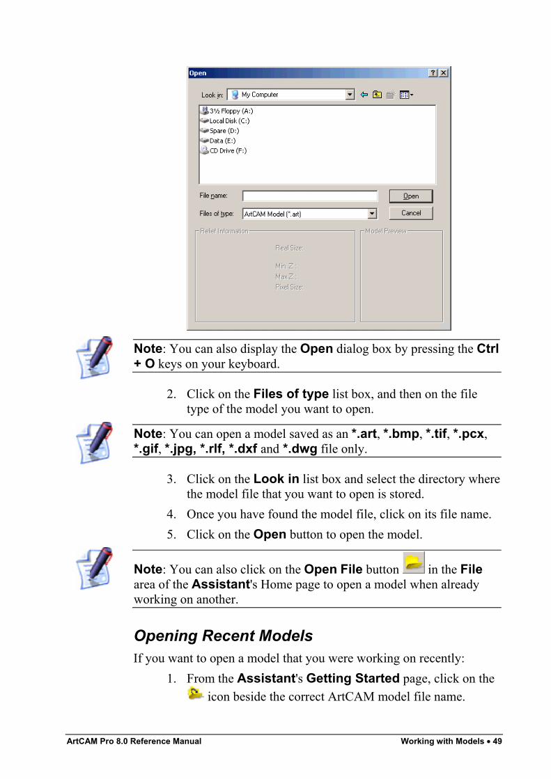
ArtCAM Pro 8.0 Reference Manual Working with Models • 49
Note: You can also display the Open dialog box by pressing the Ctrl+ O keys on your keyboard.
2. Click on the Files of type list box, and then on the filetype of the model you want to open.
Note: You can open a model saved as an *.art, *.bmp, *.tif, *.pcx,*.gif, *.jpg, *.rlf, *.dxf and *.dwg file only.
3. Click on the Look in list box and select the directory wherethe model file that you want to open is stored.
4. Once you have found the model file, click on its file name.5. Click on the Open button to open the model.
Note: You can also click on the Open File button in the Filearea of the Assistant's Home page to open a model when alreadyworking on another.
Opening Recent ModelsIf you want to open a model that you were working on recently:
1. From the Assistant's Getting Started page, click on the icon beside the correct ArtCAM model file name.
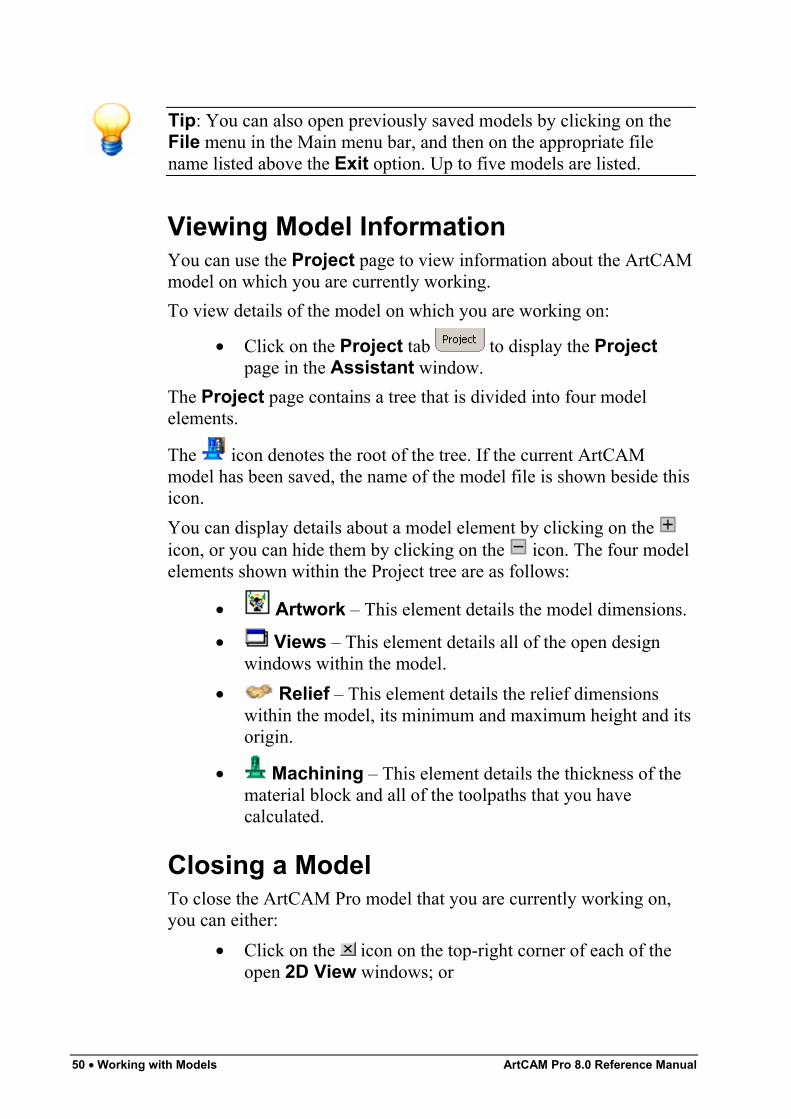
50 • Working with Models ArtCAM Pro 8.0 Reference Manual
Tip: You can also open previously saved models by clicking on theFile menu in the Main menu bar, and then on the appropriate filename listed above the Exit option. Up to five models are listed.
Viewing Model InformationYou can use the Project page to view information about the ArtCAMmodel on which you are currently working.To view details of the model on which you are working on:
• Click on the Project tab to display the Projectpage in the Assistant window.
The Project page contains a tree that is divided into four modelelements.
The icon denotes the root of the tree. If the current ArtCAMmodel has been saved, the name of the model file is shown beside thisicon.You can display details about a model element by clicking on the icon, or you can hide them by clicking on the icon. The four modelelements shown within the Project tree are as follows:
• Artwork – This element details the model dimensions.
• Views – This element details all of the open designwindows within the model.
• Relief – This element details the relief dimensionswithin the model, its minimum and maximum height and itsorigin.
• Machining – This element details the thickness of thematerial block and all of the toolpaths that you havecalculated.
Closing a ModelTo close the ArtCAM Pro model that you are currently working on,you can either:
• Click on the icon on the top-right corner of each of theopen 2D View windows; or
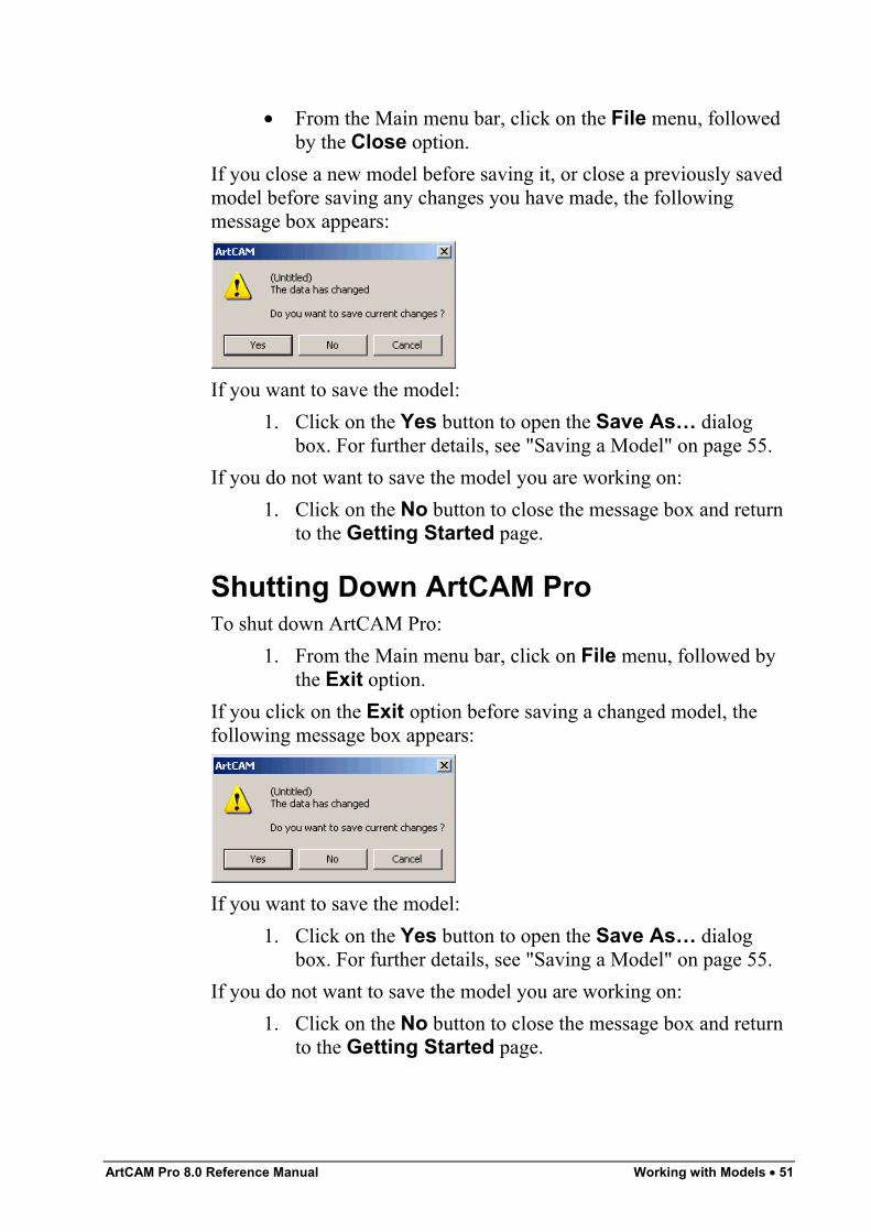
ArtCAM Pro 8.0 Reference Manual Working with Models • 51
• From the Main menu bar, click on the File menu, followedby the Close option.
If you close a new model before saving it, or close a previously savedmodel before saving any changes you have made, the followingmessage box appears:
If you want to save the model:1. Click on the Yes button to open the Save As… dialog
box. For further details, see "Saving a Model" on page 55.If you do not want to save the model you are working on:
1. Click on the No button to close the message box and returnto the Getting Started page.
Shutting Down ArtCAM ProTo shut down ArtCAM Pro:
1. From the Main menu bar, click on File menu, followed bythe Exit option.
If you click on the Exit option before saving a changed model, thefollowing message box appears:
If you want to save the model:1. Click on the Yes button to open the Save As… dialog
box. For further details, see "Saving a Model" on page 55.If you do not want to save the model you are working on:
1. Click on the No button to close the message box and returnto the Getting Started page.
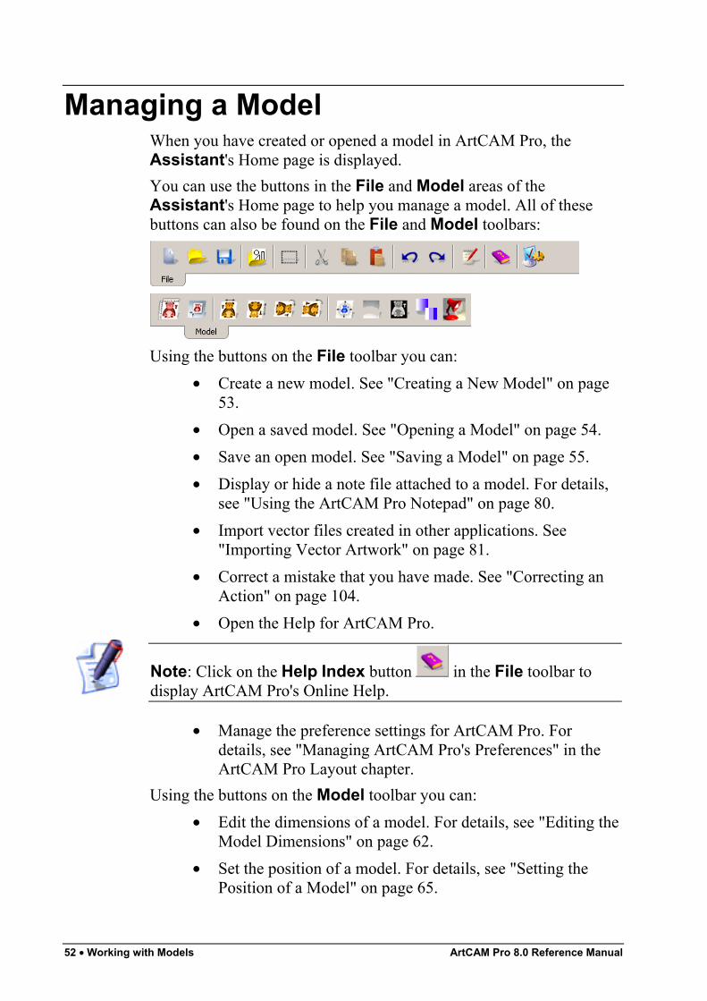
52 • Working with Models ArtCAM Pro 8.0 Reference Manual
Managing a ModelWhen you have created or opened a model in ArtCAM Pro, theAssistant's Home page is displayed.You can use the buttons in the File and Model areas of theAssistant's Home page to help you manage a model. All of thesebuttons can also be found on the File and Model toolbars:
Using the buttons on the File toolbar you can:• Create a new model. See "Creating a New Model" on page
53.• Open a saved model. See "Opening a Model" on page 54.• Save an open model. See "Saving a Model" on page 55.• Display or hide a note file attached to a model. For details,
see "Using the ArtCAM Pro Notepad" on page 80.• Import vector files created in other applications. See
"Importing Vector Artwork" on page 81.• Correct a mistake that you have made. See "Correcting an
Action" on page 104.• Open the Help for ArtCAM Pro.
Note: Click on the Help Index button in the File toolbar todisplay ArtCAM Pro's Online Help.
• Manage the preference settings for ArtCAM Pro. Fordetails, see "Managing ArtCAM Pro's Preferences" in theArtCAM Pro Layout chapter.
Using the buttons on the Model toolbar you can:• Edit the dimensions of a model. For details, see "Editing the
Model Dimensions" on page 62.• Set the position of a model. For details, see "Setting the
Position of a Model" on page 65.
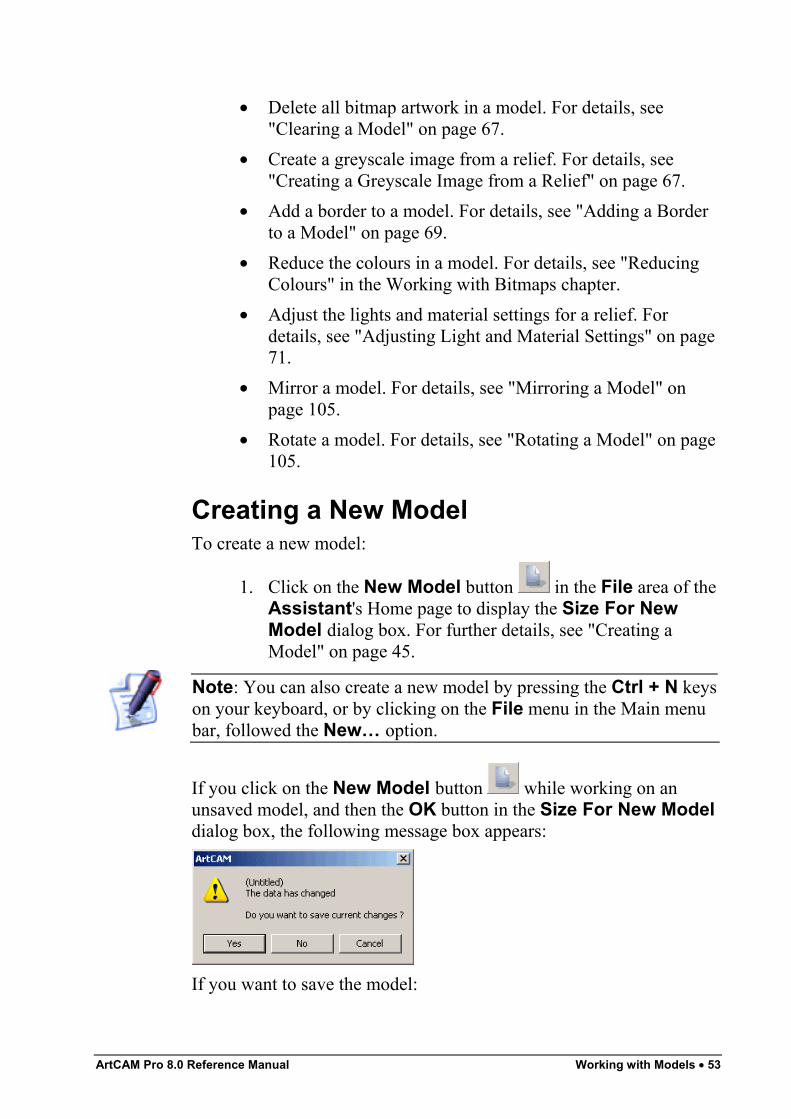
ArtCAM Pro 8.0 Reference Manual Working with Models • 53
• Delete all bitmap artwork in a model. For details, see"Clearing a Model" on page 67.
• Create a greyscale image from a relief. For details, see"Creating a Greyscale Image from a Relief" on page 67.
• Add a border to a model. For details, see "Adding a Borderto a Model" on page 69.
• Reduce the colours in a model. For details, see "ReducingColours" in the Working with Bitmaps chapter.
• Adjust the lights and material settings for a relief. Fordetails, see "Adjusting Light and Material Settings" on page71.
• Mirror a model. For details, see "Mirroring a Model" onpage 105.
• Rotate a model. For details, see "Rotating a Model" on page105.
Creating a New ModelTo create a new model:
1. Click on the New Model button in the File area of theAssistant's Home page to display the Size For NewModel dialog box. For further details, see "Creating aModel" on page 45.
Note: You can also create a new model by pressing the Ctrl + N keyson your keyboard, or by clicking on the File menu in the Main menubar, followed the New… option.
If you click on the New Model button while working on anunsaved model, and then the OK button in the Size For New Modeldialog box, the following message box appears:
If you want to save the model:
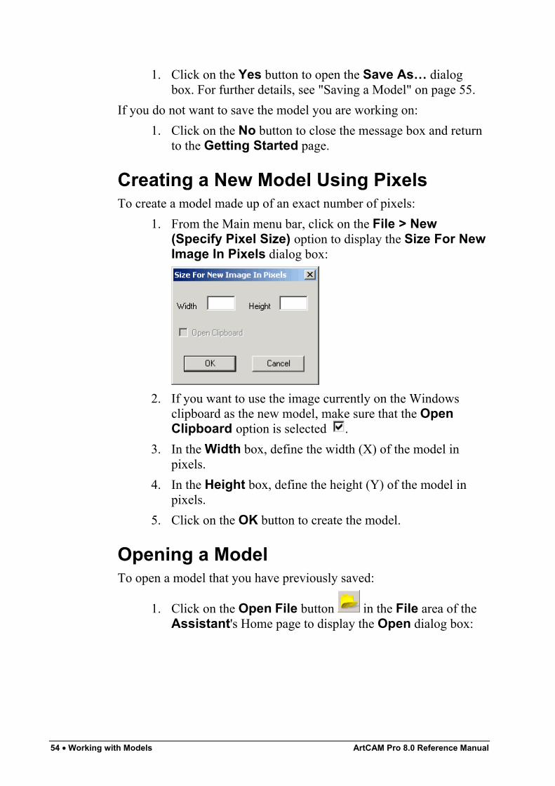
54 • Working with Models ArtCAM Pro 8.0 Reference Manual
1. Click on the Yes button to open the Save As… dialogbox. For further details, see "Saving a Model" on page 55.
If you do not want to save the model you are working on:1. Click on the No button to close the message box and return
to the Getting Started page.
Creating a New Model Using PixelsTo create a model made up of an exact number of pixels:
1. From the Main menu bar, click on the File > New(Specify Pixel Size) option to display the Size For NewImage In Pixels dialog box:
2. If you want to use the image currently on the Windowsclipboard as the new model, make sure that the OpenClipboard option is selected .
3. In the Width box, define the width (X) of the model inpixels.
4. In the Height box, define the height (Y) of the model inpixels.
5. Click on the OK button to create the model.
Opening a ModelTo open a model that you have previously saved:
1. Click on the Open File button in the File area of theAssistant's Home page to display the Open dialog box:
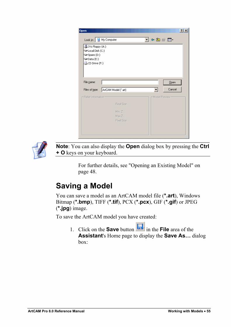
ArtCAM Pro 8.0 Reference Manual Working with Models • 55
Note: You can also display the Open dialog box by pressing the Ctrl+ O keys on your keyboard.
For further details, see "Opening an Existing Model" onpage 48.
Saving a ModelYou can save a model as an ArtCAM model file (*.art), WindowsBitmap (*.bmp), TIFF (*.tif), PCX (*.pcx), GIF (*.gif) or JPEG(*.jpg) image.To save the ArtCAM model you have created:
1. Click on the Save button in the File area of theAssistant's Home page to display the Save As… dialogbox:
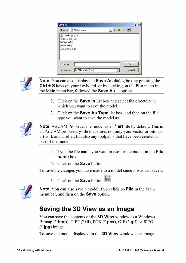
56 • Working with Models ArtCAM Pro 8.0 Reference Manual
Note: You can also display the Save As dialog box by pressing theCtrl + S keys on your keyboard, or by clicking on the File menu inthe Main menu bar, followed the Save As… option.
2. Click on the Save In list box and select the directory inwhich you want to save the model.
3. Click on the Save As Type list box, and then on the filetype you want to save the model as.
Note: ArtCAM Pro saves the model as an *.art file by default. This isan ArtCAM proprietary file that stores not only your vector or bitmapartwork and a relief, but also any toolpaths that have been created aspart of the model.
4. Type the file name you want to use for the model in the Filename box.
5. Click on the Save button.To save the changes you have made to a model since it was last saved:
1. Click on the Save button .
Note: You can also save a model if you click on File in the Mainmenu bar, and then on the Save option.
Saving the 3D View as an ImageYou can save the contents of the 3D View window as a WindowsBitmap (*.bmp), TIFF (*.tif), PCX (*.pcx), GIF (*.gif) or JPEG(*.jpg) image.To save the model displayed in the 3D View window as an image:
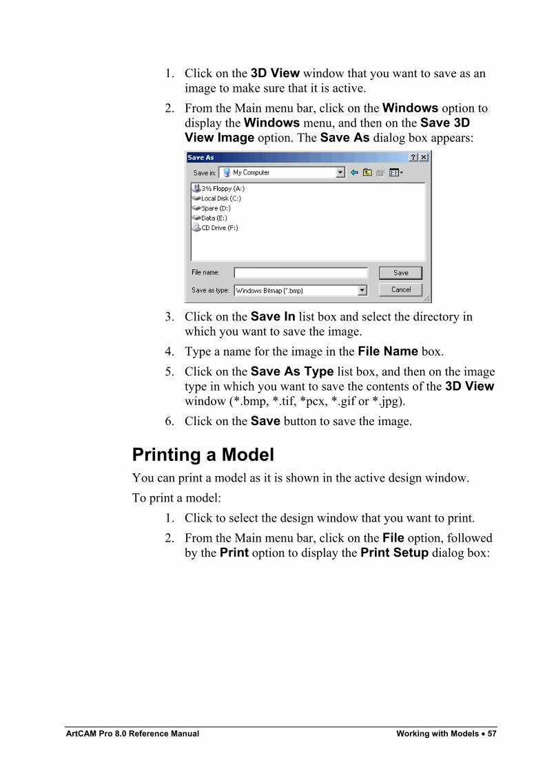
ArtCAM Pro 8.0 Reference Manual Working with Models • 57
1. Click on the 3D View window that you want to save as animage to make sure that it is active.
2. From the Main menu bar, click on the Windows option todisplay the Windows menu, and then on the Save 3DView Image option. The Save As dialog box appears:
3. Click on the Save In list box and select the directory inwhich you want to save the image.
4. Type a name for the image in the File Name box.5. Click on the Save As Type list box, and then on the image
type in which you want to save the contents of the 3D Viewwindow (*.bmp, *.tif, *pcx, *.gif or *.jpg).
6. Click on the Save button to save the image.
Printing a ModelYou can print a model as it is shown in the active design window.To print a model:
1. Click to select the design window that you want to print.2. From the Main menu bar, click on the File option, followed
by the Print option to display the Print Setup dialog box:
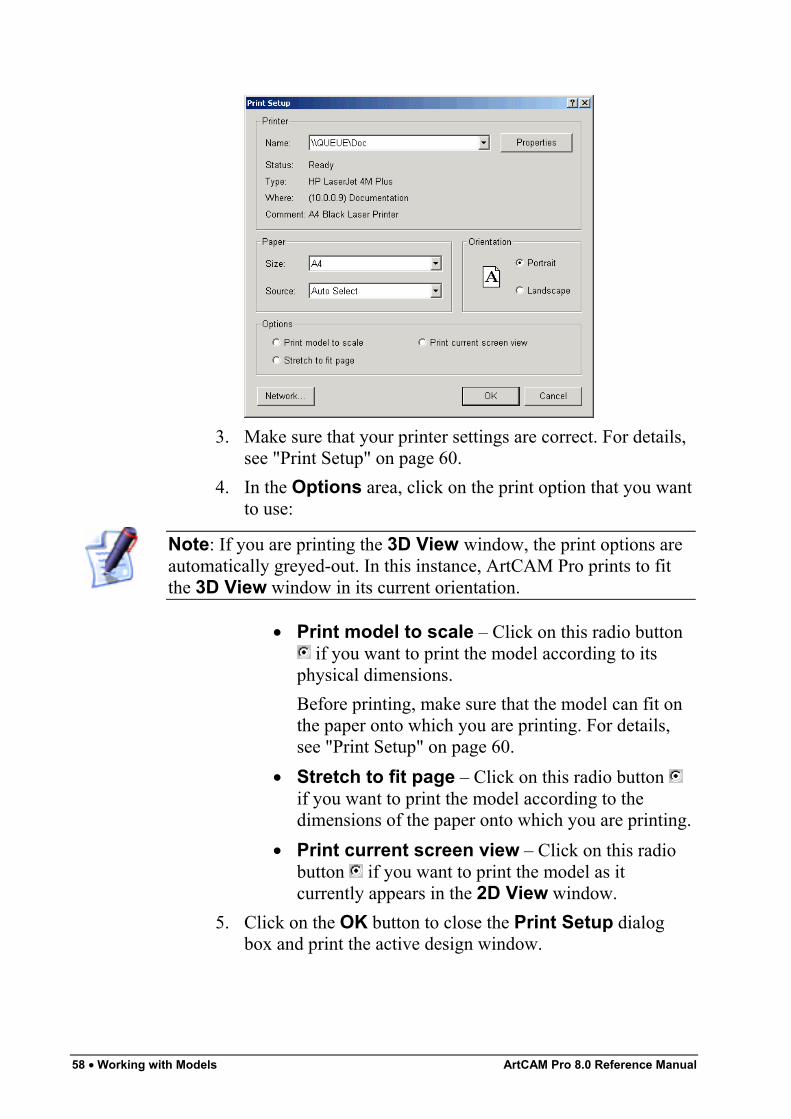
58 • Working with Models ArtCAM Pro 8.0 Reference Manual
3. Make sure that your printer settings are correct. For details,see "Print Setup" on page 60.
4. In the Options area, click on the print option that you wantto use:
Note: If you are printing the 3D View window, the print options areautomatically greyed-out. In this instance, ArtCAM Pro prints to fitthe 3D View window in its current orientation.
• Print model to scale – Click on this radio button if you want to print the model according to its
physical dimensions.Before printing, make sure that the model can fit onthe paper onto which you are printing. For details,see "Print Setup" on page 60.
• Stretch to fit page – Click on this radio button if you want to print the model according to thedimensions of the paper onto which you are printing.
• Print current screen view – Click on this radiobutton if you want to print the model as itcurrently appears in the 2D View window.
5. Click on the OK button to close the Print Setup dialogbox and print the active design window.
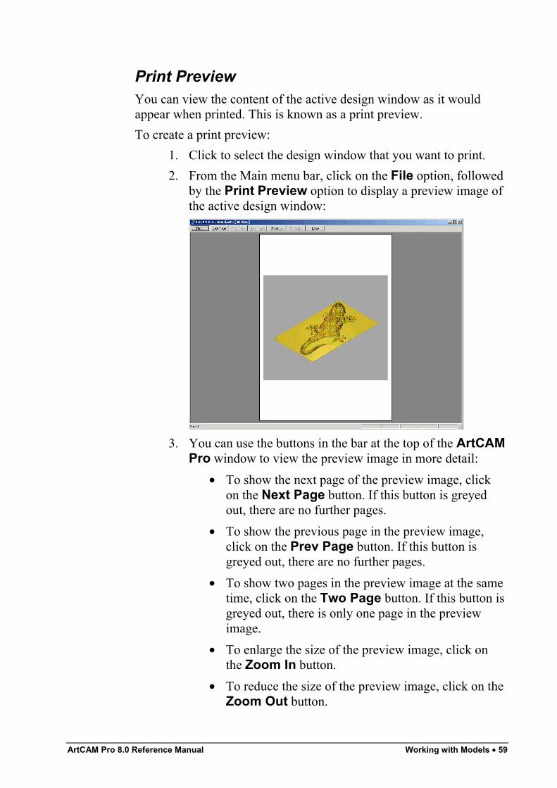
ArtCAM Pro 8.0 Reference Manual Working with Models • 59
Print PreviewYou can view the content of the active design window as it wouldappear when printed. This is known as a print preview.To create a print preview:
1. Click to select the design window that you want to print.2. From the Main menu bar, click on the File option, followed
by the Print Preview option to display a preview image ofthe active design window:
3. You can use the buttons in the bar at the top of the ArtCAMPro window to view the preview image in more detail:
• To show the next page of the preview image, clickon the Next Page button. If this button is greyedout, there are no further pages.
• To show the previous page in the preview image,click on the Prev Page button. If this button isgreyed out, there are no further pages.
• To show two pages in the preview image at the sametime, click on the Two Page button. If this button isgreyed out, there is only one page in the previewimage.
• To enlarge the size of the preview image, click onthe Zoom In button.
• To reduce the size of the preview image, click on theZoom Out button.
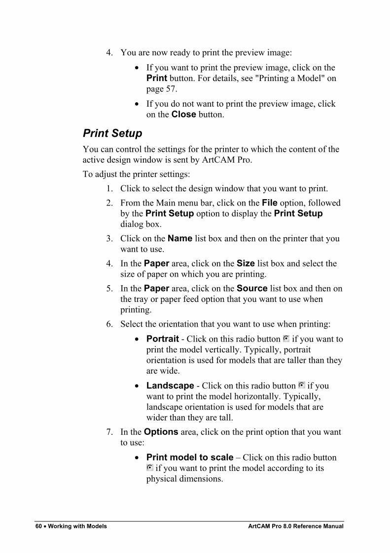
60 • Working with Models ArtCAM Pro 8.0 Reference Manual
4. You are now ready to print the preview image:• If you want to print the preview image, click on the
Print button. For details, see "Printing a Model" onpage 57.
• If you do not want to print the preview image, clickon the Close button.
Print SetupYou can control the settings for the printer to which the content of theactive design window is sent by ArtCAM Pro.To adjust the printer settings:
1. Click to select the design window that you want to print.2. From the Main menu bar, click on the File option, followed
by the Print Setup option to display the Print Setupdialog box.
3. Click on the Name list box and then on the printer that youwant to use.
4. In the Paper area, click on the Size list box and select thesize of paper on which you are printing.
5. In the Paper area, click on the Source list box and then onthe tray or paper feed option that you want to use whenprinting.
6. Select the orientation that you want to use when printing:• Portrait - Click on this radio button if you want to
print the model vertically. Typically, portraitorientation is used for models that are taller than theyare wide.
• Landscape - Click on this radio button if youwant to print the model horizontally. Typically,landscape orientation is used for models that arewider than they are tall.
7. In the Options area, click on the print option that you wantto use:
• Print model to scale – Click on this radio button if you want to print the model according to its
physical dimensions.
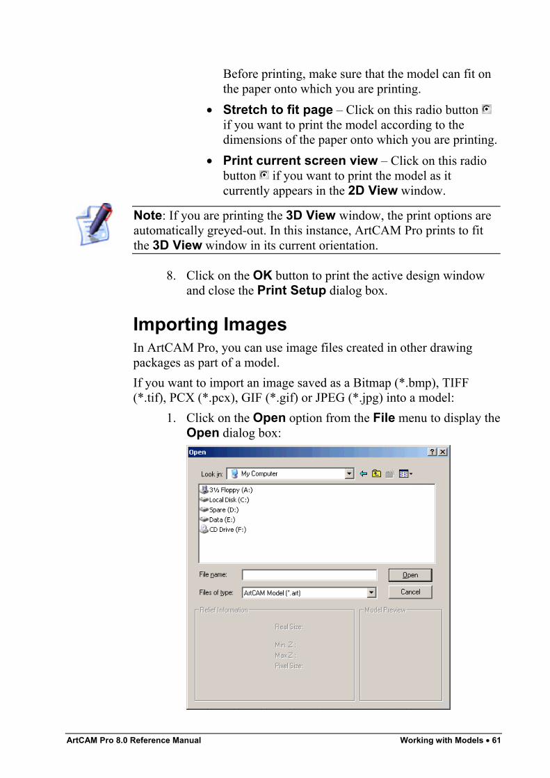
ArtCAM Pro 8.0 Reference Manual Working with Models • 61
Before printing, make sure that the model can fit onthe paper onto which you are printing.
• Stretch to fit page – Click on this radio button if you want to print the model according to thedimensions of the paper onto which you are printing.
• Print current screen view – Click on this radiobutton if you want to print the model as itcurrently appears in the 2D View window.
Note: If you are printing the 3D View window, the print options areautomatically greyed-out. In this instance, ArtCAM Pro prints to fitthe 3D View window in its current orientation.
8. Click on the OK button to print the active design windowand close the Print Setup dialog box.
Importing ImagesIn ArtCAM Pro, you can use image files created in other drawingpackages as part of a model.If you want to import an image saved as a Bitmap (*.bmp), TIFF(*.tif), PCX (*.pcx), GIF (*.gif) or JPEG (*.jpg) into a model:
1. Click on the Open option from the File menu to display theOpen dialog box:
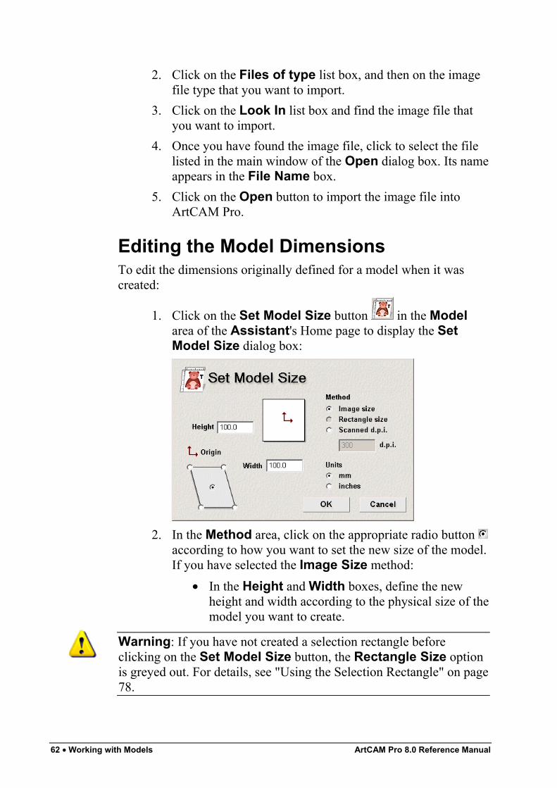
62 • Working with Models ArtCAM Pro 8.0 Reference Manual
2. Click on the Files of type list box, and then on the imagefile type that you want to import.
3. Click on the Look In list box and find the image file thatyou want to import.
4. Once you have found the image file, click to select the filelisted in the main window of the Open dialog box. Its nameappears in the File Name box.
5. Click on the Open button to import the image file intoArtCAM Pro.
Editing the Model DimensionsTo edit the dimensions originally defined for a model when it wascreated:
1. Click on the Set Model Size button in the Modelarea of the Assistant's Home page to display the SetModel Size dialog box:
2. In the Method area, click on the appropriate radio button according to how you want to set the new size of the model.If you have selected the Image Size method:
• In the Height and Width boxes, define the newheight and width according to the physical size of themodel you want to create.
Warning: If you have not created a selection rectangle beforeclicking on the Set Model Size button, the Rectangle Size optionis greyed out. For details, see "Using the Selection Rectangle" on page78.
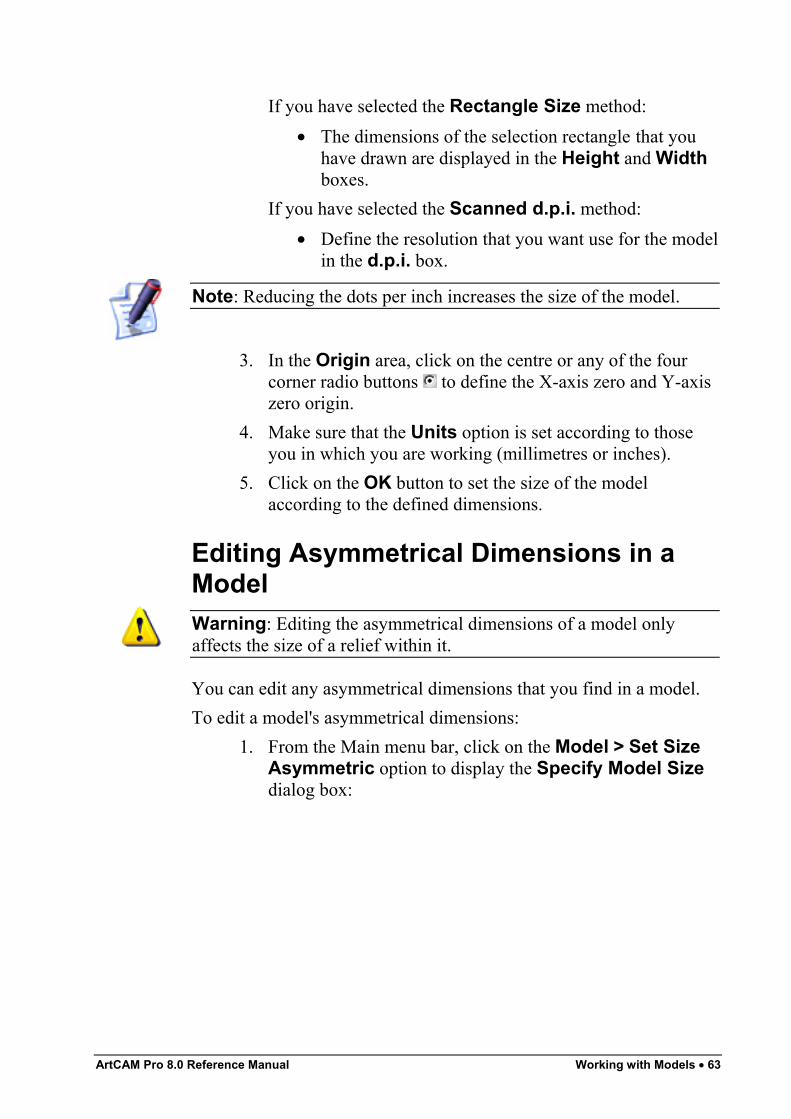
ArtCAM Pro 8.0 Reference Manual Working with Models • 63
If you have selected the Rectangle Size method:• The dimensions of the selection rectangle that you
have drawn are displayed in the Height and Widthboxes.
If you have selected the Scanned d.p.i. method:• Define the resolution that you want use for the model
in the d.p.i. box.
Note: Reducing the dots per inch increases the size of the model.
3. In the Origin area, click on the centre or any of the fourcorner radio buttons to define the X-axis zero and Y-axiszero origin.
4. Make sure that the Units option is set according to thoseyou in which you are working (millimetres or inches).
5. Click on the OK button to set the size of the modelaccording to the defined dimensions.
Editing Asymmetrical Dimensions in aModelWarning: Editing the asymmetrical dimensions of a model onlyaffects the size of a relief within it.
You can edit any asymmetrical dimensions that you find in a model.To edit a model's asymmetrical dimensions:
1. From the Main menu bar, click on the Model > Set SizeAsymmetric option to display the Specify Model Sizedialog box:
64 • Working with Models ArtCAM Pro 8.0 Reference Manual
2. Click on the Sizing Method radio button that you wantto use:
• Image dimensions – This option allows you to setthe size of a model using specific measurements.
• Rectangle dimensions – This option allows youto set the size of a model to an area defined by aSelection Rectangle. For details, see "Using theSelection Rectangle" on page 78.
• Scanned resolution – This option allows you toset the size of a model by defining the size of a pixelwithin it.
3. If you have selected the Image dimensions or theRectangle dimensions option:
• To define both the Width (X) and the Height (Y) asa specific size, make sure that both of these optionsis selected in the Dimensions area, and thentype the measurement in each of the boxes.
• To preserve the ratio between the Width (X) and theHeight (Y) of the model, make sure that only one ofthese options is selected in the Dimensions area,and then type the measurement in the adjacent box.All other boxes in the Dimensions area areautomatically greyed out when only one of theavailable options is selected .
• To define the distance between the origin and the topright corner of the model, make sure that only the
ArtCAM Pro 8.0 Reference Manual Working with Models • 65
Diagonal option is selected in the Dimensionsarea, then type the measurement in the adjacent box.
If you have selected the Scanned resolution option:• Click on of the radio buttons in the Scanned
Resolution in d.p.i. area to define the size of apixel in the model.
Note: Reducing the dots per inch increases the size of the model.
4. Make sure that the Units option is set according to those inwhich you are working (millimetres or inches).
5. Click on the Apply button to preview the new model size.The Real Height and Real Width values in theImage/Model Size area are updated according to yournew dimensions.
6. Click on the OK button to set the size of the model.
Setting the Position of a ModelYou can define the position of the X-axis zero and Y-axis zero originas one of five pre-defined locations using the Set Model Size dialogbox. For details, see "Editing the Model Dimensions" on page 62.To define the position of the X-axis zero and Y-axis zero origin assomewhere other than the five available locations in the Set ModelSize dialog box, you can use the Set Position dialog box. You canalso define the Z-axis zero origin using the Set Position dialog box.To set the position of a model:
1. Click on the Set Model Position button in theModel area of the Assistant's Home page to display theSet Position dialog box:
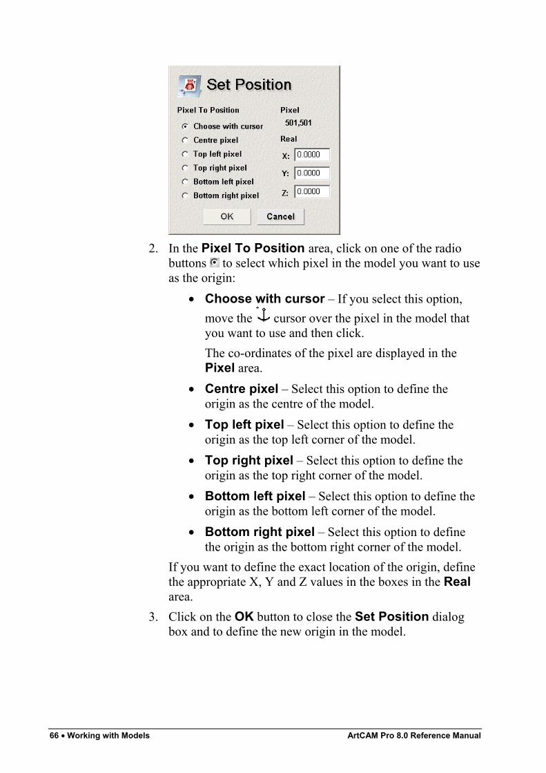
66 • Working with Models ArtCAM Pro 8.0 Reference Manual
2. In the Pixel To Position area, click on one of the radiobuttons to select which pixel in the model you want to useas the origin:
• Choose with cursor – If you select this option,move the cursor over the pixel in the model thatyou want to use and then click.The co-ordinates of the pixel are displayed in thePixel area.
• Centre pixel – Select this option to define theorigin as the centre of the model.
• Top left pixel – Select this option to define theorigin as the top left corner of the model.
• Top right pixel – Select this option to define theorigin as the top right corner of the model.
• Bottom left pixel – Select this option to define theorigin as the bottom left corner of the model.
• Bottom right pixel – Select this option to definethe origin as the bottom right corner of the model.
If you want to define the exact location of the origin, definethe appropriate X, Y and Z values in the boxes in the Realarea.
3. Click on the OK button to close the Set Position dialogbox and to define the new origin in the model.
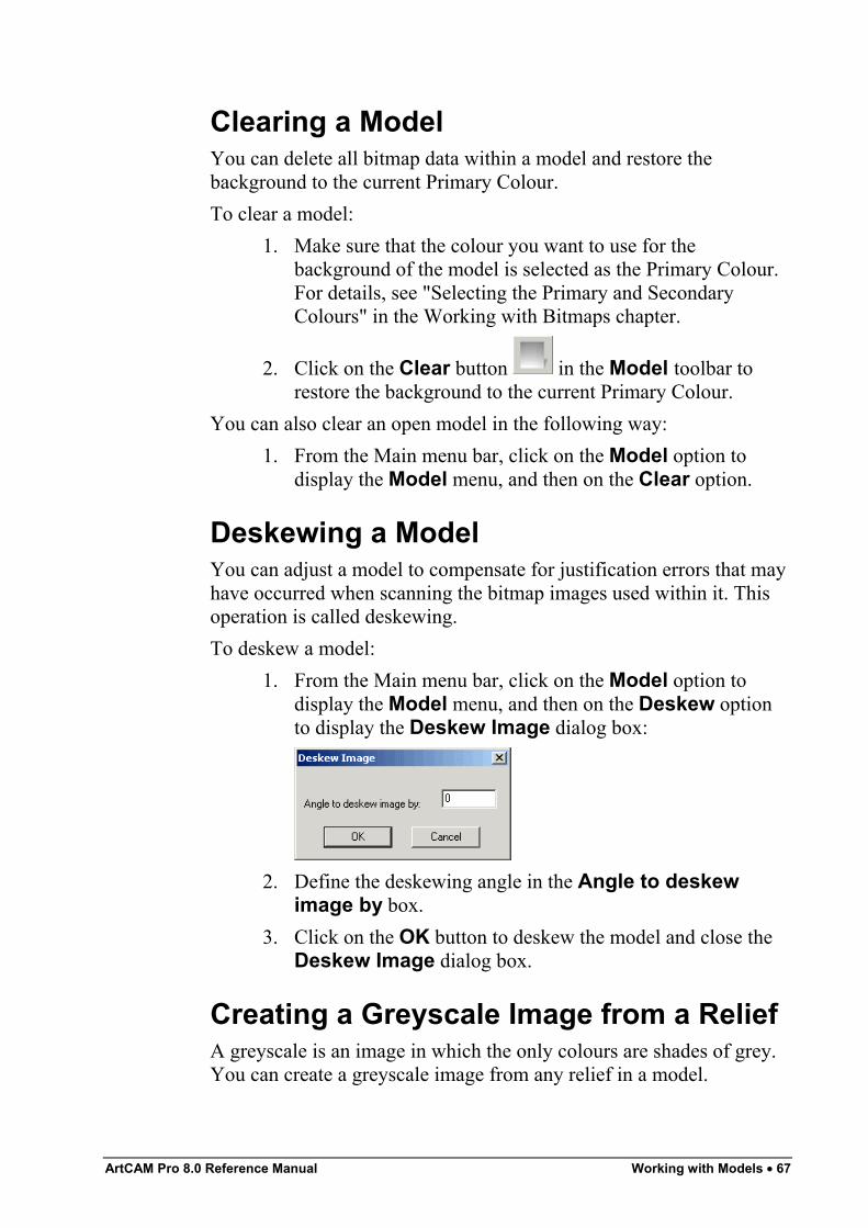
ArtCAM Pro 8.0 Reference Manual Working with Models • 67
Clearing a ModelYou can delete all bitmap data within a model and restore thebackground to the current Primary Colour.To clear a model:
1. Make sure that the colour you want to use for thebackground of the model is selected as the Primary Colour.For details, see "Selecting the Primary and SecondaryColours" in the Working with Bitmaps chapter.
2. Click on the Clear button in the Model toolbar torestore the background to the current Primary Colour.
You can also clear an open model in the following way:1. From the Main menu bar, click on the Model option to
display the Model menu, and then on the Clear option.
Deskewing a ModelYou can adjust a model to compensate for justification errors that mayhave occurred when scanning the bitmap images used within it. Thisoperation is called deskewing.To deskew a model:
1. From the Main menu bar, click on the Model option todisplay the Model menu, and then on the Deskew optionto display the Deskew Image dialog box:
2. Define the deskewing angle in the Angle to deskewimage by box.
3. Click on the OK button to deskew the model and close theDeskew Image dialog box.
Creating a Greyscale Image from a ReliefA greyscale is an image in which the only colours are shades of grey.You can create a greyscale image from any relief in a model.
68 • Working with Models ArtCAM Pro 8.0 Reference Manual
Warning: The greyscale image created from the existing reliefreplaces any bitmap images currently drawn in the 2D View window.If you do not want to lose your bitmap artwork, use the GreyscaleView button in the 2D View toolbar instead.
It is recommended that you use this option to view a swept profileshape more clearly, particularly when you want to position vector textor 3D clipart relative to it. For details, see "Creating a Swept ProfileShape" in the Working with Reliefs chapter.This option is particularly useful for identifying areas of a model towhich you want to add texture, as the entire relief is painted in a singlecolour by default. For details, see "Adding Texture to a Relief" in theWorking with Reliefs chapter.To create a greyscale image from a relief, replacing any existingbitmap artwork in the 2D View during the process:
1. Click on the Greyscale From Relief button in theModel area of the Assistant's Home page.
You can also create a greyscale image from a relief in either of thefollowing ways:
• Press the F10 key on your keyboard.• From the Main menu bar, click on the Model menu, and
then click on the Greyscale From Relief option.
Note: If you want to restore the full colour image of a relief, click onthe Edit option in the Main menu bar to display the Edit menu, andthen on the Undo Create Greyscale Image option.
You can display a greyscale view of the exisiting relief without losingany of the bitmap artwork currently shown in the 2D View window.To do so:
• Click on the Greyscale View button in the 2D Viewtoolbar.
Note: You can set the default colours used in the Greyscale Viewusing the ArtCAM Options page. For details, see "ManagingArtCAM Pro's Preferences" in the ArtCAM Pro Layout chapter.
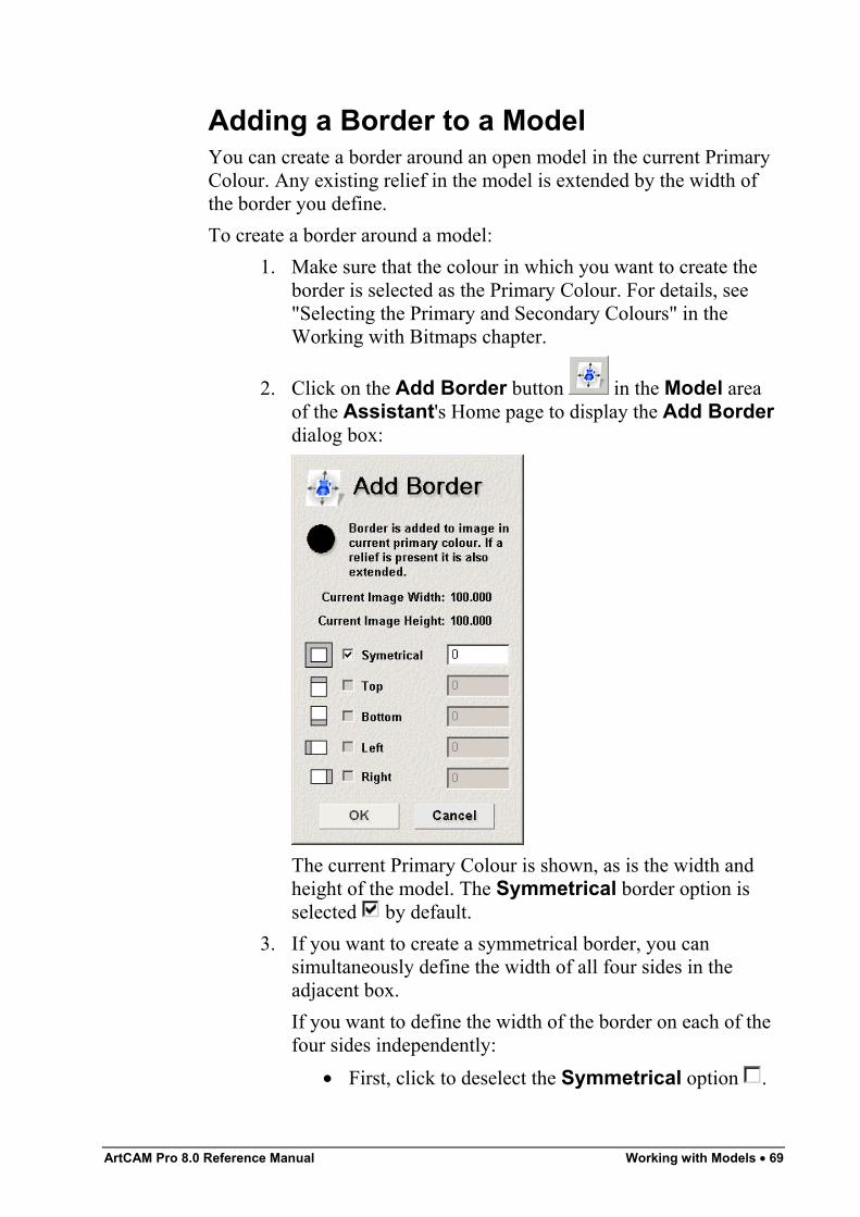
ArtCAM Pro 8.0 Reference Manual Working with Models • 69
Adding a Border to a ModelYou can create a border around an open model in the current PrimaryColour. Any existing relief in the model is extended by the width ofthe border you define.To create a border around a model:
1. Make sure that the colour in which you want to create theborder is selected as the Primary Colour. For details, see"Selecting the Primary and Secondary Colours" in theWorking with Bitmaps chapter.
2. Click on the Add Border button in the Model areaof the Assistant's Home page to display the Add Borderdialog box:
The current Primary Colour is shown, as is the width andheight of the model. The Symmetrical border option isselected by default.
3. If you want to create a symmetrical border, you cansimultaneously define the width of all four sides in theadjacent box.If you want to define the width of the border on each of thefour sides independently:
• First, click to deselect the Symmetrical option .
70 • Working with Models ArtCAM Pro 8.0 Reference Manual
• Next, click to select the option for each of thesides (Top, Bottom, Left, Right) to which youwant to add a border, and then define their widths inthe adjacent boxes.If a side option is not selected , it is greyed out.
4. Click on the OK button to close the Add Border dialogbox and create the border around the model.
Using a Spot Filter on a Bitmap ImageYou can remove any isolated pixels from within a scanned bitmapimage using a spot filter.A spot filter performs better with black and white or greyscale images.It may be necessary to apply a spot filter several times on the sameimage to remove all unwanted pixels (spots) in the bitmap image.To use a spot filter:
1. From the Main menu bar, click on the Model option todisplay the Model menu. Move over the Spot Filter optionto display the filters available.
2. Click on the Spot Filter option that you want to apply tothe bitmap image:
• Photo Image – This option is the maximum filterthat is most likely to remove unwanted spots in theimage.
Warning: The Photo Image filter may also remove areas of thebitmap image that you want to keep.
• General – This option is the medium filter.• Line Drawing – This option is the minimum filter,
which removes only a few spots in the image. Youmay have to apply this filter several times beforeremoving any unwanted spots.
The Working dialog box appears during the filteringprocess:
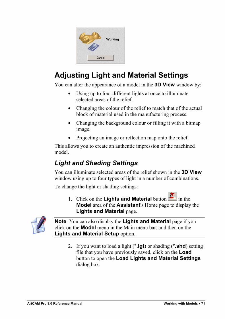
ArtCAM Pro 8.0 Reference Manual Working with Models • 71
Adjusting Light and Material SettingsYou can alter the appearance of a model in the 3D View window by:
• Using up to four different lights at once to illuminateselected areas of the relief.
• Changing the colour of the relief to match that of the actualblock of material used in the manufacturing process.
• Changing the background colour or filling it with a bitmapimage.
• Projecting an image or reflection map onto the relief.This allows you to create an authentic impression of the machinedmodel.
Light and Shading SettingsYou can illuminate selected areas of the relief shown in the 3D Viewwindow using up to four types of light in a number of combinations.To change the light or shading settings:
1. Click on the Lights and Material button in theModel area of the Assistant's Home page to display theLights and Material page.
Note: You can also display the Lights and Material page if youclick on the Model menu in the Main menu bar, and then on theLights and Material Setup option.
2. If you want to load a light (*.lgt) or shading (*.shd) settingfile that you have previously saved, click on the Loadbutton to open the Load Lights and Material Settingsdialog box:
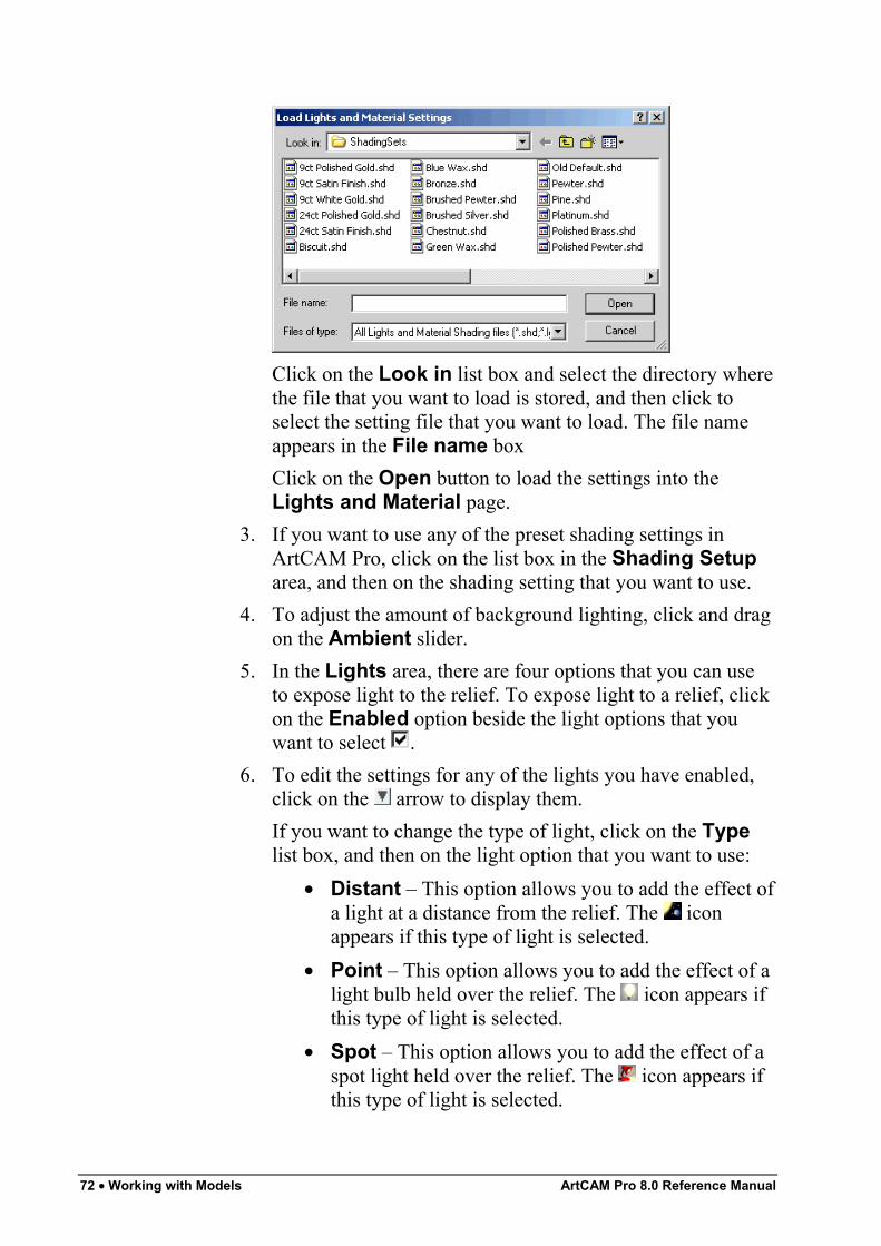
72 • Working with Models ArtCAM Pro 8.0 Reference Manual
Click on the Look in list box and select the directory wherethe file that you want to load is stored, and then click toselect the setting file that you want to load. The file nameappears in the File name boxClick on the Open button to load the settings into theLights and Material page.
3. If you want to use any of the preset shading settings inArtCAM Pro, click on the list box in the Shading Setuparea, and then on the shading setting that you want to use.
4. To adjust the amount of background lighting, click and dragon the Ambient slider.
5. In the Lights area, there are four options that you can useto expose light to the relief. To expose light to a relief, clickon the Enabled option beside the light options that youwant to select .
6. To edit the settings for any of the lights you have enabled,click on the arrow to display them.If you want to change the type of light, click on the Typelist box, and then on the light option that you want to use:
• Distant – This option allows you to add the effect ofa light at a distance from the relief. The iconappears if this type of light is selected.
• Point – This option allows you to add the effect of alight bulb held over the relief. The icon appears ifthis type of light is selected.
• Spot – This option allows you to add the effect of aspot light held over the relief. The icon appears ifthis type of light is selected.
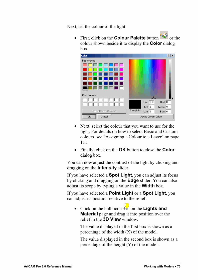
ArtCAM Pro 8.0 Reference Manual Working with Models • 73
Next, set the colour of the light:
• First, click on the Colour Palette button or thecolour shown beside it to display the Color dialogbox:
• Next, select the colour that you want to use for thelight. For details on how to select Basic and Customcolours, see "Assigning a Colour to a Layer" on page111.
• Finally, click on the OK button to close the Colordialog box.
You can now adjust the contrast of the light by clicking anddragging on the Intensity slider.If you have selected a Spot Light, you can adjust its focusby clicking and dragging on the Edge slider. You can alsoadjust its scope by typing a value in the Width box.If you have selected a Point Light or a Spot Light, youcan adjust its position relative to the relief:
• Click on the bulb icon on the Lights andMaterial page and drag it into position over therelief in the 3D View window.The value displayed in the first box is shown as apercentage of the width (X) of the model.The value displayed in the second box is shown as apercentage of the height (Y) of the model.
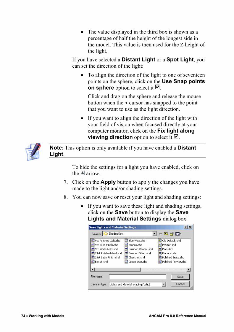
74 • Working with Models ArtCAM Pro 8.0 Reference Manual
• The value displayed in the third box is shown as apercentage of half the height of the longest side inthe model. This value is then used for the Z height ofthe light.
If you have selected a Distant Light or a Spot Light, youcan set the direction of the light:
• To align the direction of the light to one of seventeenpoints on the sphere, click on the Use Snap pointson sphere option to select it .Click and drag on the sphere and release the mousebutton when the cursor has snapped to the pointthat you want to use as the light direction.
• If you want to align the direction of the light withyour field of vision when focused directly at yourcomputer monitor, click on the Fix light alongviewing direction option to select it .
Note: This option is only available if you have enabled a DistantLight.
To hide the settings for a light you have enabled, click onthe arrow.
7. Click on the Apply button to apply the changes you havemade to the light and/or shading settings.
8. You can now save or reset your light and shading settings:• If you want to save these light and shading settings,
click on the Save button to display the SaveLights and Material Settings dialog box:
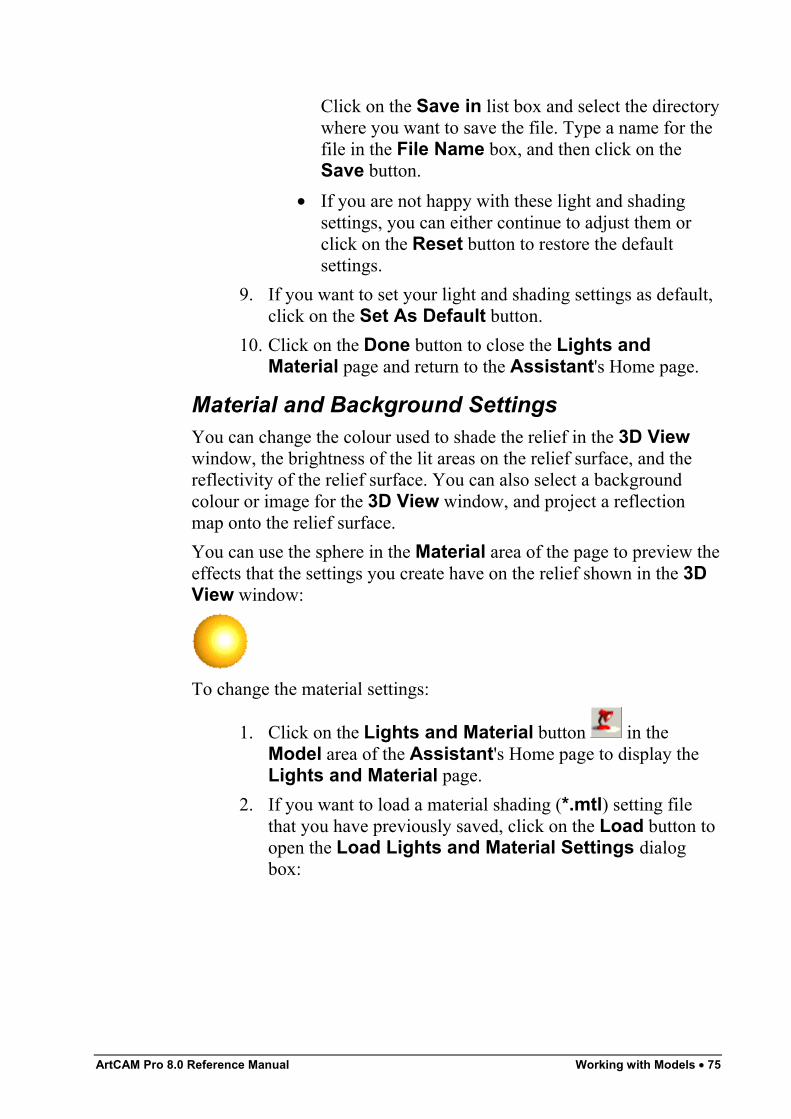
ArtCAM Pro 8.0 Reference Manual Working with Models • 75
Click on the Save in list box and select the directorywhere you want to save the file. Type a name for thefile in the File Name box, and then click on theSave button.
• If you are not happy with these light and shadingsettings, you can either continue to adjust them orclick on the Reset button to restore the defaultsettings.
9. If you want to set your light and shading settings as default,click on the Set As Default button.
10. Click on the Done button to close the Lights andMaterial page and return to the Assistant's Home page.
Material and Background SettingsYou can change the colour used to shade the relief in the 3D Viewwindow, the brightness of the lit areas on the relief surface, and thereflectivity of the relief surface. You can also select a backgroundcolour or image for the 3D View window, and project a reflectionmap onto the relief surface.You can use the sphere in the Material area of the page to preview theeffects that the settings you create have on the relief shown in the 3DView window:
To change the material settings:
1. Click on the Lights and Material button in theModel area of the Assistant's Home page to display theLights and Material page.
2. If you want to load a material shading (*.mtl) setting filethat you have previously saved, click on the Load button toopen the Load Lights and Material Settings dialogbox:
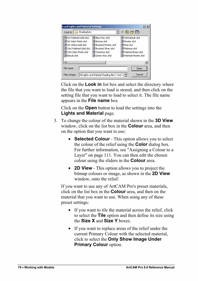
76 • Working with Models ArtCAM Pro 8.0 Reference Manual
Click on the Look in list box and select the directory wherethe file that you want to load is stored, and then click on thesetting file that you want to load to select it. The file nameappears in the File name boxClick on the Open button to load the settings into theLights and Material page.
3. To change the colour of the material shown in the 3D Viewwindow, click on the list box in the Colour area, and thenon the option that you want to use:
• Selected Colour - This option allows you to selectthe colour of the relief using the Color dialog box.For further information, see "Assigning a Colour to aLayer" on page 111. You can then edit the chosencolour using the sliders in the Colour area.
• 2D View - This option allows you to project thebitmap colours or image, as shown in the 2D Viewwindow, onto the relief.
If you want to use any of ArtCAM Pro's preset materials,click on the list box in the Colour area, and then on thematerial that you want to use. When using any of thesepreset settings:
• If you want to tile the material across the relief, clickto select the Tile option and then define its size usingthe Size X and Size Y boxes.
• If you want to replace areas of the relief under thecurrent Primary Colour with the selected material,click to select the Only Show Image UnderPrimary Colour option.
ArtCAM Pro 8.0 Reference Manual Working with Models • 77
Note: If you want to use your own material, copy the TIF image file(*.tif) representing the material to the ArtCAMPro\Rendering\Materials folder and then restart ArtCAM Pro. Yourimage will then be listed in the Colour list box when the Lights andMaterial page is next displayed.
4. To adjust the reflectivity of the material surface, click anddrag on the Shininess slider.
5. To adjust the brightness of the lit areas in the model, clickand drag on the Highlight Intensity slider.
6. If you want to project a reflection map onto the reliefsurface, click on the list box in the Reflection Map area,and then on the reflection map that you want to use.
7. You can now fill the background of the 3D View windowwith an image or a colour. To fill the background with acolour:
• In the Background area, click on the list box andthen on the Selected Colour option. This is thedefault option when the Lights and Material pageis displayed.
• Next, click on the Colour Palette button todisplay the Color dialog box.
• Select the colour that you want to use as thebackground. For details on how to select Basic andCustom colours, see "Assigning a Colour to a Layer"on page 111.
• Finally, click on the OK button to close the Colordialog box.
To fill the background with a bitmap image:• In the Background area, click on the list box and
then on the image that you want to use.
Note: If you want to use your own bitmap image as a background inthe 3D View window, copy the bitmap file (*.bmp) to the ArtCAMPro\Backgrounds folder and then restart ArtCAM Pro. Your imagewill then be listed in the Background list box when the Lights andMaterial page is next displayed.
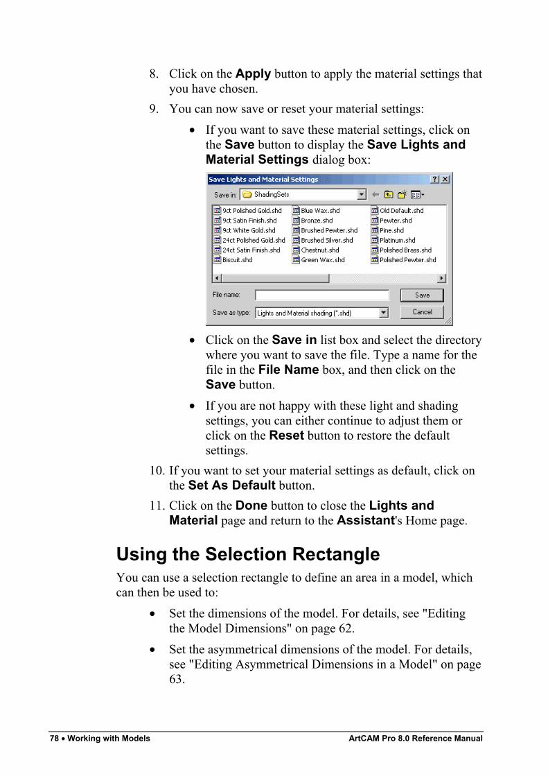
78 • Working with Models ArtCAM Pro 8.0 Reference Manual
8. Click on the Apply button to apply the material settings thatyou have chosen.
9. You can now save or reset your material settings:• If you want to save these material settings, click on
the Save button to display the Save Lights andMaterial Settings dialog box:
• Click on the Save in list box and select the directorywhere you want to save the file. Type a name for thefile in the File Name box, and then click on theSave button.
• If you are not happy with these light and shadingsettings, you can either continue to adjust them orclick on the Reset button to restore the defaultsettings.
10. If you want to set your material settings as default, click onthe Set As Default button.
11. Click on the Done button to close the Lights andMaterial page and return to the Assistant's Home page.
Using the Selection RectangleYou can use a selection rectangle to define an area in a model, whichcan then be used to:
• Set the dimensions of the model. For details, see "Editingthe Model Dimensions" on page 62.
• Set the asymmetrical dimensions of the model. For details,see "Editing Asymmetrical Dimensions in a Model" on page63.
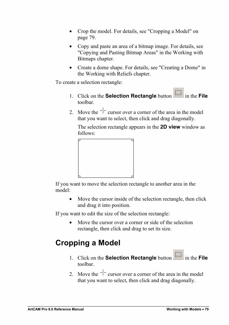
ArtCAM Pro 8.0 Reference Manual Working with Models • 79
• Crop the model. For details, see "Cropping a Model" onpage 79.
• Copy and paste an area of a bitmap image. For details, see"Copying and Pasting Bitmap Areas" in the Working withBitmaps chapter.
• Create a dome shape. For details, see "Creating a Dome" inthe Working with Reliefs chapter.
To create a selection rectangle:
1. Click on the Selection Rectangle button in the Filetoolbar.
2. Move the cursor over a corner of the area in the modelthat you want to select, then click and drag diagonally.The selection rectangle appears in the 2D view window asfollows:
If you want to move the selection rectangle to another area in themodel:
• Move the cursor inside of the selection rectangle, then clickand drag it into position.
If you want to edit the size of the selection rectangle:• Move the cursor over a corner or side of the selection
rectangle, then click and drag to set its size.
Cropping a Model
1. Click on the Selection Rectangle button in the Filetoolbar.
2. Move the cursor over a corner of the area in the modelthat you want to select, then click and drag diagonally.
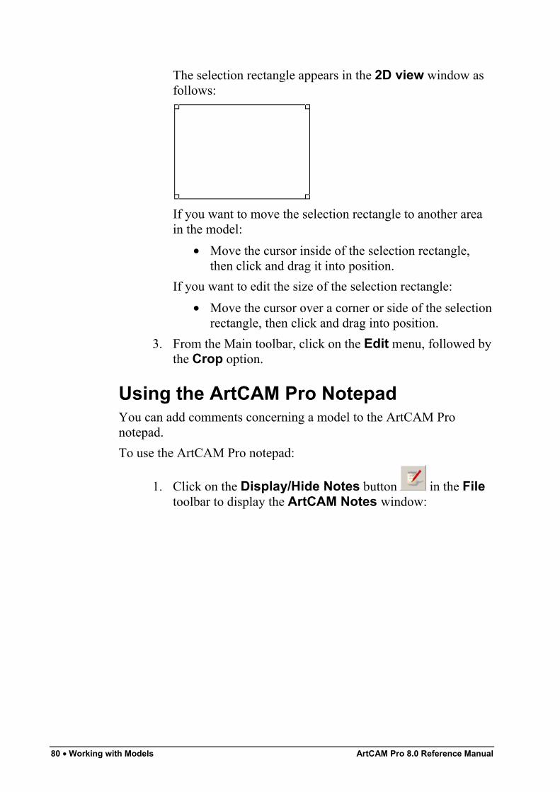
80 • Working with Models ArtCAM Pro 8.0 Reference Manual
The selection rectangle appears in the 2D view window asfollows:
If you want to move the selection rectangle to another areain the model:
• Move the cursor inside of the selection rectangle,then click and drag it into position.
If you want to edit the size of the selection rectangle:• Move the cursor over a corner or side of the selection
rectangle, then click and drag into position.3. From the Main toolbar, click on the Edit menu, followed by
the Crop option.
Using the ArtCAM Pro NotepadYou can add comments concerning a model to the ArtCAM Pronotepad.To use the ArtCAM Pro notepad:
1. Click on the Display/Hide Notes button in the Filetoolbar to display the ArtCAM Notes window:
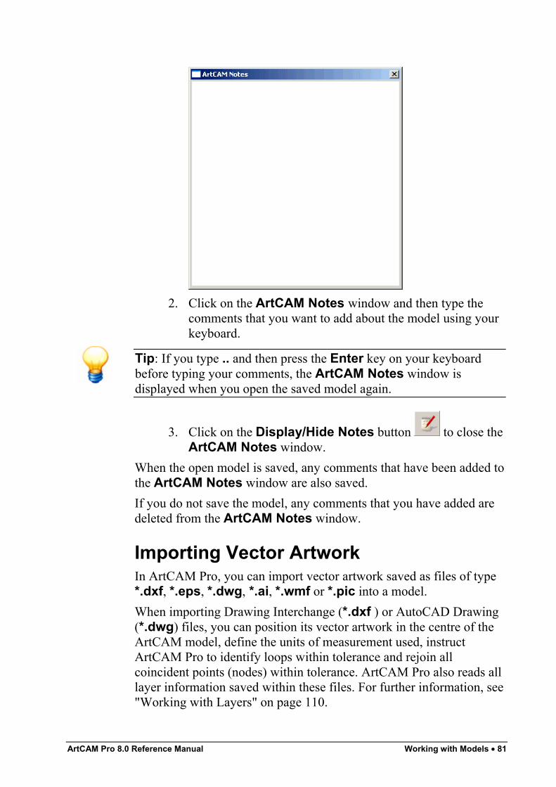
ArtCAM Pro 8.0 Reference Manual Working with Models • 81
2. Click on the ArtCAM Notes window and then type thecomments that you want to add about the model using yourkeyboard.
Tip: If you type .. and then press the Enter key on your keyboardbefore typing your comments, the ArtCAM Notes window isdisplayed when you open the saved model again.
3. Click on the Display/Hide Notes button to close theArtCAM Notes window.
When the open model is saved, any comments that have been added tothe ArtCAM Notes window are also saved.If you do not save the model, any comments that you have added aredeleted from the ArtCAM Notes window.
Importing Vector ArtworkIn ArtCAM Pro, you can import vector artwork saved as files of type*.dxf, *.eps, *.dwg, *.ai, *.wmf or *.pic into a model.When importing Drawing Interchange (*.dxf ) or AutoCAD Drawing(*.dwg) files, you can position its vector artwork in the centre of theArtCAM model, define the units of measurement used, instructArtCAM Pro to identify loops within tolerance and rejoin allcoincident points (nodes) within tolerance. ArtCAM Pro also reads alllayer information saved within these files. For further information, see"Working with Layers" on page 110.
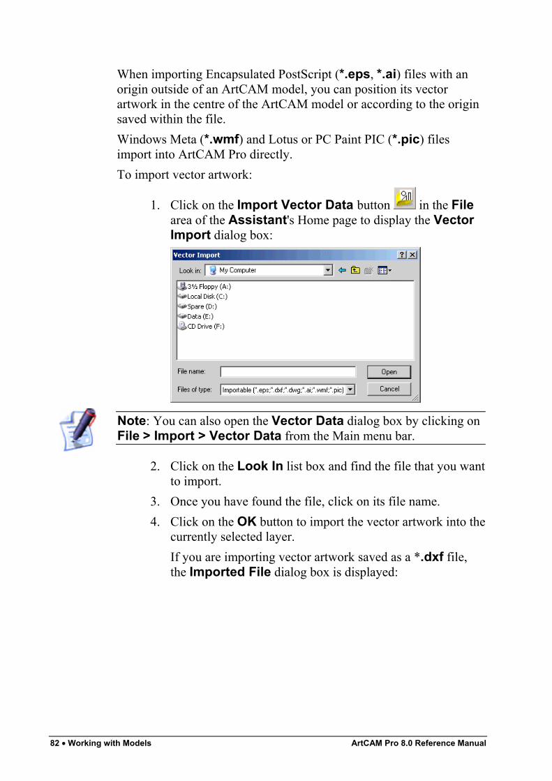
82 • Working with Models ArtCAM Pro 8.0 Reference Manual
When importing Encapsulated PostScript (*.eps, *.ai) files with anorigin outside of an ArtCAM model, you can position its vectorartwork in the centre of the ArtCAM model or according to the originsaved within the file.Windows Meta (*.wmf) and Lotus or PC Paint PIC (*.pic) filesimport into ArtCAM Pro directly.To import vector artwork:
1. Click on the Import Vector Data button in the Filearea of the Assistant's Home page to display the VectorImport dialog box:
Note: You can also open the Vector Data dialog box by clicking onFile > Import > Vector Data from the Main menu bar.
2. Click on the Look In list box and find the file that you wantto import.
3. Once you have found the file, click on its file name.4. Click on the OK button to import the vector artwork into the
currently selected layer.If you are importing vector artwork saved as a *.dxf file,the Imported File dialog box is displayed:
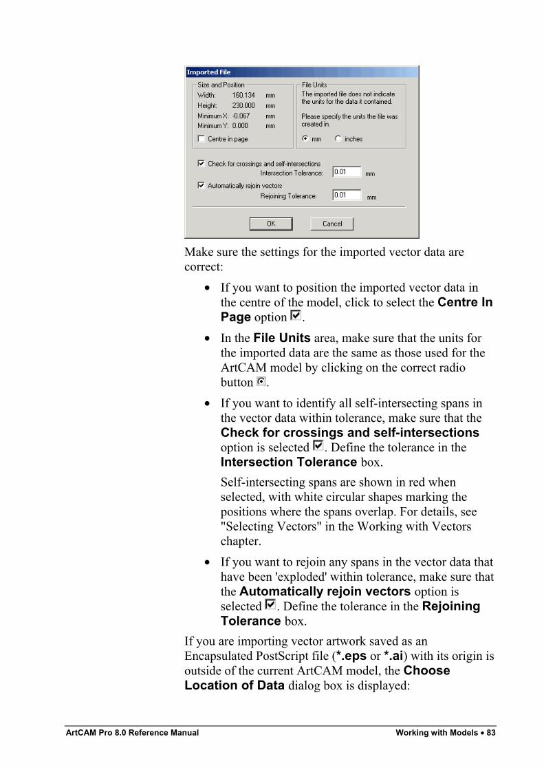
ArtCAM Pro 8.0 Reference Manual Working with Models • 83
Make sure the settings for the imported vector data arecorrect:
• If you want to position the imported vector data inthe centre of the model, click to select the Centre InPage option .
• In the File Units area, make sure that the units forthe imported data are the same as those used for theArtCAM model by clicking on the correct radiobutton .
• If you want to identify all self-intersecting spans inthe vector data within tolerance, make sure that theCheck for crossings and self-intersectionsoption is selected . Define the tolerance in theIntersection Tolerance box.Self-intersecting spans are shown in red whenselected, with white circular shapes marking thepositions where the spans overlap. For details, see"Selecting Vectors" in the Working with Vectorschapter.
• If you want to rejoin any spans in the vector data thathave been 'exploded' within tolerance, make sure thatthe Automatically rejoin vectors option isselected . Define the tolerance in the RejoiningTolerance box.
If you are importing vector artwork saved as anEncapsulated PostScript file (*.eps or *.ai) with its origin isoutside of the current ArtCAM model, the ChooseLocation of Data dialog box is displayed:
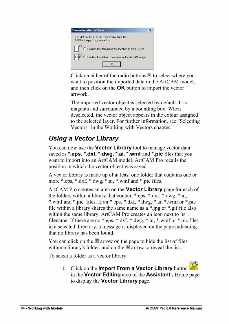
84 • Working with Models ArtCAM Pro 8.0 Reference Manual
Click on either of the radio buttons to select where youwant to position the imported data in the ArtCAM model,and then click on the OK button to import the vectorartwork.The imported vector object is selected by default. It ismagenta and surrounded by a bounding box. Whendeselected, the vector object appears in the colour assignedto the selected layer. For further information, see "SelectingVectors" in the Working with Vectors chapter.
Using a Vector LibraryYou can now use the Vector Library tool to manage vector datasaved as *.eps, *.dxf, *.dwg, *.ai, *.wmf and *.pic files that youwant to import into an ArtCAM model. ArtCAM Pro recalls theposition in which the vector object was saved.A vector library is made up of at least one folder that contains one ormore *.eps, *.dxf, *.dwg, *.ai, *.wmf and *.pic files.ArtCAM Pro creates an area on the Vector Library page for each ofthe folders within a library that contain *.eps, *.dxf, *.dwg, *.ai,*.wmf and *.pic files. If an *.eps, *.dxf, *.dwg, *.ai, *.wmf or *.picfile within a library shares the same name as a *.jpg or *.gif file alsowithin the same library, ArtCAM Pro creates an icon next to itsfilename. If there are no *.eps, *.dxf, *.dwg, *.ai, *.wmf or *.pic filesin a selected directory, a message is displayed on the page indicatingthat no library has been found.You can click on the arrow on the page to hide the list of fileswithin a library's folder, and on the arrow to reveal the list.To select a folder as a vector library:
1. Click on the Import From a Vector Library button in the Vector Editing area of the Assistant's Home pageto display the Vector Library page.
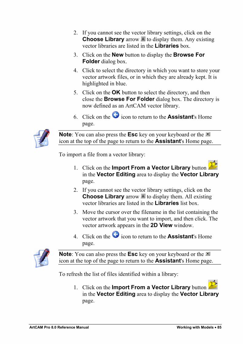
ArtCAM Pro 8.0 Reference Manual Working with Models • 85
2. If you cannot see the vector library settings, click on theChoose Library arrow to display them. Any existingvector libraries are listed in the Libraries box.
3. Click on the New button to display the Browse ForFolder dialog box.
4. Click to select the directory in which you want to store yourvector artwork files, or in which they are already kept. It ishighlighted in blue.
5. Click on the OK button to select the directory, and thenclose the Browse For Folder dialog box. The directory isnow defined as an ArtCAM vector library.
6. Click on the icon to return to the Assistant's Homepage.
Note: You can also press the Esc key on your keyboard or the icon at the top of the page to return to the Assistant's Home page.
To import a file from a vector library:
1. Click on the Import From a Vector Library button in the Vector Editing area to display the Vector Librarypage.
2. If you cannot see the vector library settings, click on theChoose Library arrow to display them. All existingvector libraries are listed in the Libraries list box.
3. Move the cursor over the filename in the list containing thevector artwork that you want to import, and then click. Thevector artwork appears in the 2D View window.
4. Click on the icon to return to the Assistant's Homepage.
Note: You can also press the Esc key on your keyboard or the icon at the top of the page to return to the Assistant's Home page.
To refresh the list of files identified within a library:
1. Click on the Import From a Vector Library button in the Vector Editing area to display the Vector Librarypage.
86 • Working with Models ArtCAM Pro 8.0 Reference Manual
2. If you cannot see the vector library settings, click on theChoose Library arrow to display them. All existingvector libraries are listed in the Libraries box.
3. Click on the Libraries list box, and then on the library forwhich you want to update the listing.
4. In the Options area, click on the Rescan button to refreshthe list of folders and files within the current library
5. Click on the icon to return to the Assistant's Homepage.
Note: You can also press the Esc key on your keyboard or the icon at the top of the page to return to the Assistant's Home page.
To remove a library:
1. Click on the Import From a Vector Library button in the Vector Editing area to display the Vector Librarypage.
2. If you cannot see the vector library settings, click on theChoose Library arrow to display them. All existingvector libraries are listed in the Libraries box.
3. Click on the Libraries list box, and then on the library youwant to remove.
4. In the Options area, click on the Remove button toremove the selected library.
5. A message box appears asking you to confirm your decisionto remove the library:
Click on the OK button to close the message box andremove the library.
6. Click on the icon to return to the Assistant's Homepage.
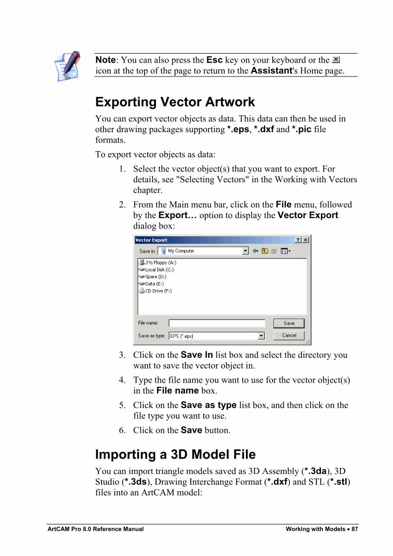
ArtCAM Pro 8.0 Reference Manual Working with Models • 87
Note: You can also press the Esc key on your keyboard or the icon at the top of the page to return to the Assistant's Home page.
Exporting Vector ArtworkYou can export vector objects as data. This data can then be used inother drawing packages supporting *.eps, *.dxf and *.pic fileformats.To export vector objects as data:
1. Select the vector object(s) that you want to export. Fordetails, see "Selecting Vectors" in the Working with Vectorschapter.
2. From the Main menu bar, click on the File menu, followedby the Export… option to display the Vector Exportdialog box:
3. Click on the Save In list box and select the directory youwant to save the vector object in.
4. Type the file name you want to use for the vector object(s)in the File name box.
5. Click on the Save as type list box, and then click on thefile type you want to use.
6. Click on the Save button.
Importing a 3D Model FileYou can import triangle models saved as 3D Assembly (*.3da), 3DStudio (*.3ds), Drawing Interchange Format (*.dxf) and STL (*.stl)files into an ArtCAM model:
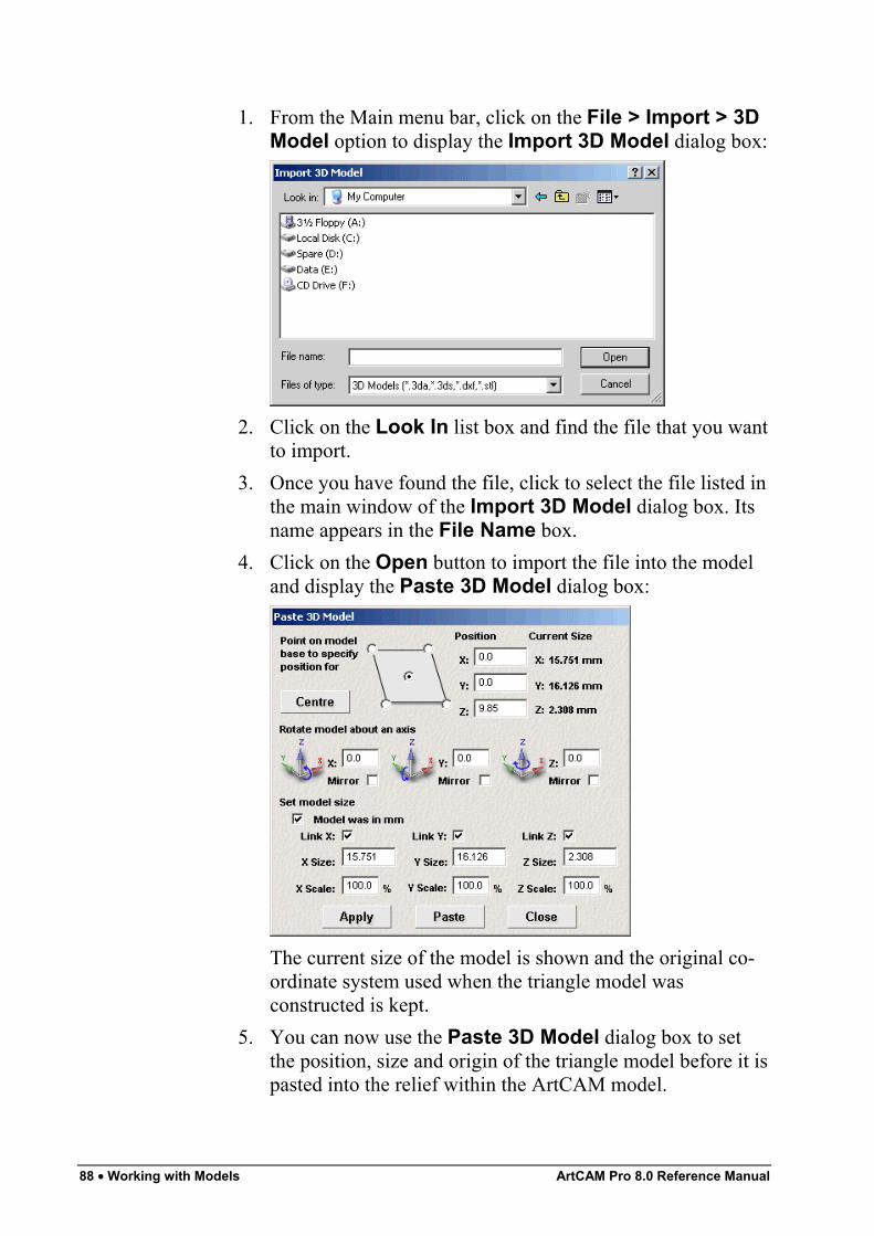
88 • Working with Models ArtCAM Pro 8.0 Reference Manual
1. From the Main menu bar, click on the File > Import > 3DModel option to display the Import 3D Model dialog box:
2. Click on the Look In list box and find the file that you wantto import.
3. Once you have found the file, click to select the file listed inthe main window of the Import 3D Model dialog box. Itsname appears in the File Name box.
4. Click on the Open button to import the file into the modeland display the Paste 3D Model dialog box:
The current size of the model is shown and the original co-ordinate system used when the triangle model wasconstructed is kept.
5. You can now use the Paste 3D Model dialog box to setthe position, size and origin of the triangle model before it ispasted into the relief within the ArtCAM model.
ArtCAM Pro 8.0 Reference Manual Working with Models • 89
Using the Paste 3D Model Dialog BoxThe Paste 3D Model dialog box allows you set the position, size andorigin of an imported three-dimensional model before it is pasted intothe relief within an ArtCAM model.To define how the triangle model is pasted into the relief:
1. Set the position of the triangle model within the ArtCAMmodel:
• To position the triangle model in the centre of theArtCAM model, click on the Centre button.
• To position the triangle model in the centre or one ofthe four corners in the ArtCAM model, click on theappropriate Point on base to specify positionfor radio button on the model diagram.
• To position the triangle model in a specific locationwithin the ArtCAM model, define the co-ordinates inthe X, Y and Z boxes.
2. To rotate the triangle model on any of the three axes:• In the Rotate model about an axis area, define
the angle of rotation in the X, Y and/or Z box.• To mirror the model in any of the three axes, make
sure that the Mirror option below the X, Y and/or Zbox is selected .
3. If you are working in inches, the Model was in inchesoption is selected by default. If the triangle modelappears too large, either click to deselect the option andscale the 3D model between inches and mm, or proceed tothe next step to resize or scale the triangle model.If you are working in millimetres, the Model was in mmoption is selected by default. If the triangle modelappears too small, either click to deselect the option andscale the triangle model between mm and inches, or proceedto the next step to resize or scale the triangle model.
4. Set the size of the triangle model:• To resize or scale the triangle model in a specific
axis, click to deselect the Link options for the axesthat you do not want to adjust . For example, if youonly want to resize the model in the X-axis, click todeselect the Link Y and Link Z options.
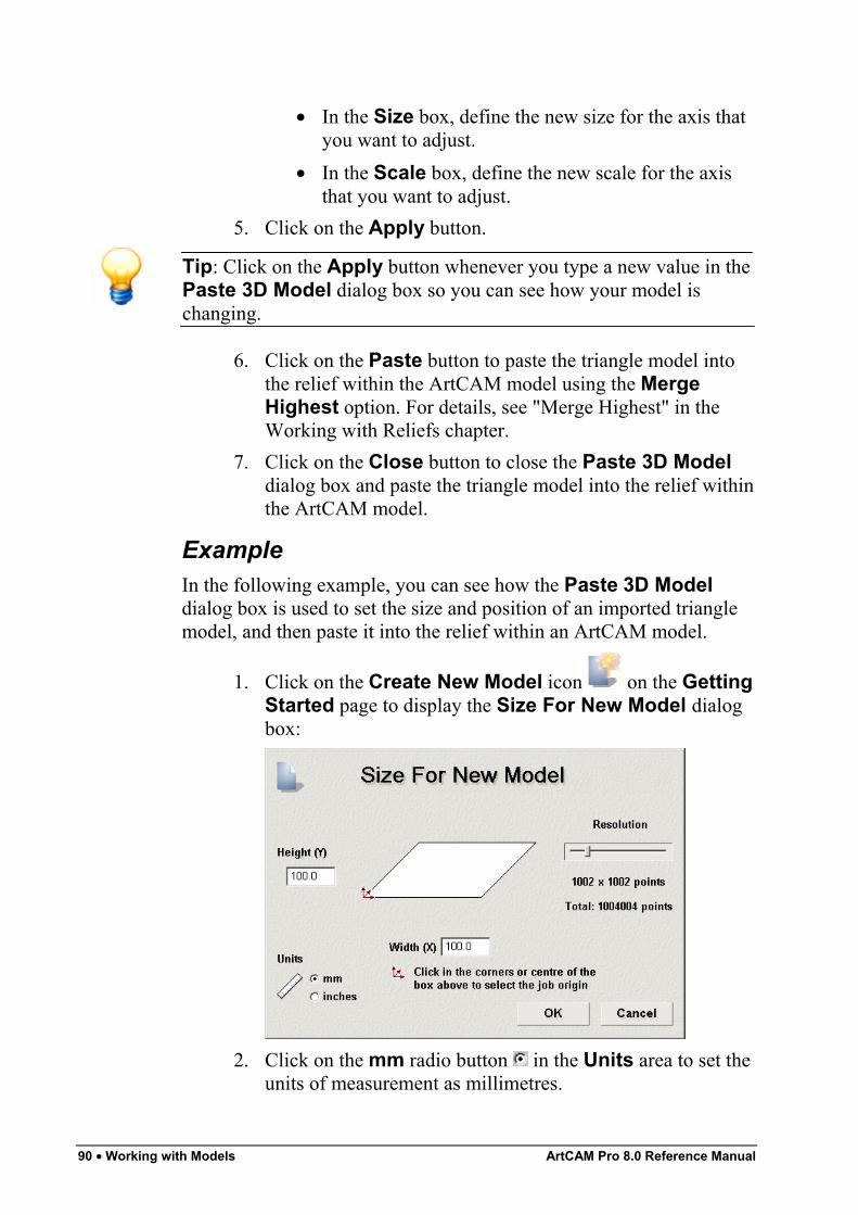
90 • Working with Models ArtCAM Pro 8.0 Reference Manual
• In the Size box, define the new size for the axis thatyou want to adjust.
• In the Scale box, define the new scale for the axisthat you want to adjust.
5. Click on the Apply button.
Tip: Click on the Apply button whenever you type a new value in thePaste 3D Model dialog box so you can see how your model ischanging.
6. Click on the Paste button to paste the triangle model intothe relief within the ArtCAM model using the MergeHighest option. For details, see "Merge Highest" in theWorking with Reliefs chapter.
7. Click on the Close button to close the Paste 3D Modeldialog box and paste the triangle model into the relief withinthe ArtCAM model.
ExampleIn the following example, you can see how the Paste 3D Modeldialog box is used to set the size and position of an imported trianglemodel, and then paste it into the relief within an ArtCAM model.
1. Click on the Create New Model icon on the GettingStarted page to display the Size For New Model dialogbox:
2. Click on the mm radio button in the Units area to set theunits of measurement as millimetres.
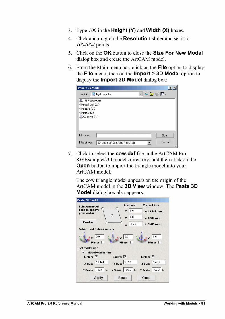
ArtCAM Pro 8.0 Reference Manual Working with Models • 91
3. Type 100 in the Height (Y) and Width (X) boxes.4. Click and drag on the Resolution slider and set it to
1004004 points.5. Click on the OK button to close the Size For New Model
dialog box and create the ArtCAM model.6. From the Main menu bar, click on the File option to display
the File menu, then on the Import > 3D Model option todisplay the Import 3D Model dialog box:
7. Click to select the cow.dxf file in the ArtCAM Pro8.0\Examples\3d models directory, and then click on theOpen button to import the triangle model into yourArtCAM model.The cow triangle model appears on the origin of theArtCAM model in the 3D View window. The Paste 3DModel dialog box also appears:
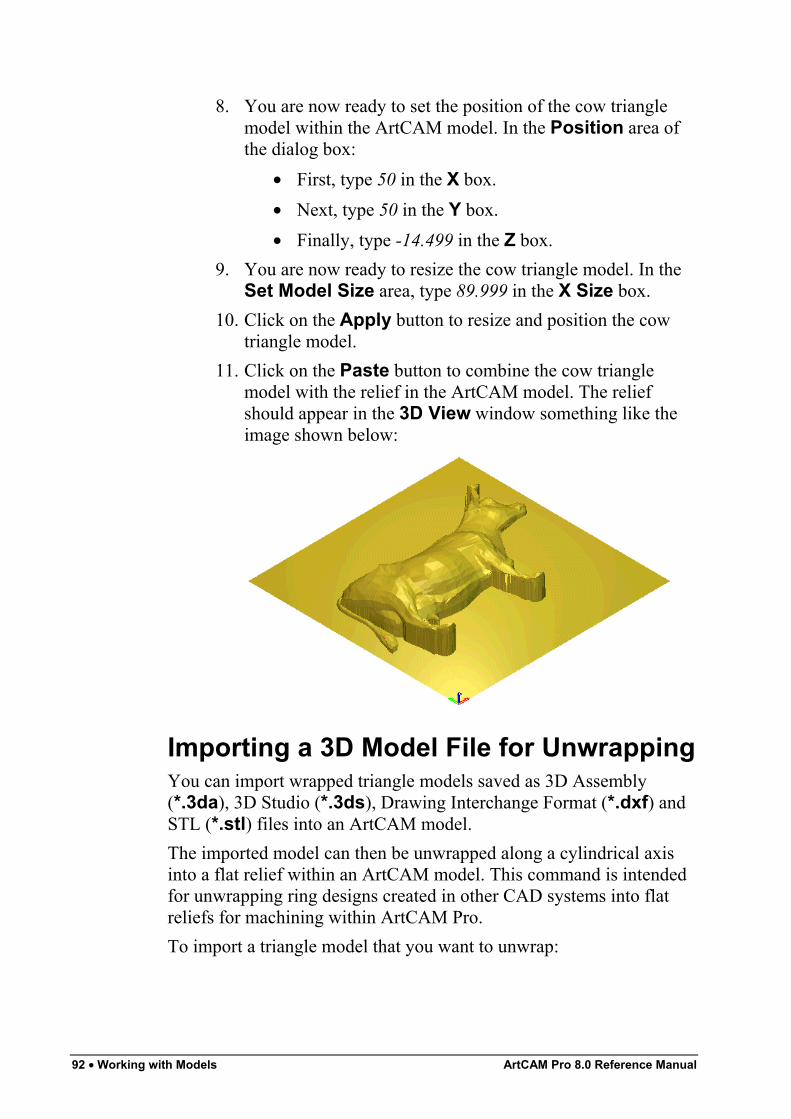
92 • Working with Models ArtCAM Pro 8.0 Reference Manual
8. You are now ready to set the position of the cow trianglemodel within the ArtCAM model. In the Position area ofthe dialog box:
• First, type 50 in the X box.• Next, type 50 in the Y box.• Finally, type -14.499 in the Z box.
9. You are now ready to resize the cow triangle model. In theSet Model Size area, type 89.999 in the X Size box.
10. Click on the Apply button to resize and position the cowtriangle model.
11. Click on the Paste button to combine the cow trianglemodel with the relief in the ArtCAM model. The reliefshould appear in the 3D View window something like theimage shown below:
Importing a 3D Model File for UnwrappingYou can import wrapped triangle models saved as 3D Assembly(*.3da), 3D Studio (*.3ds), Drawing Interchange Format (*.dxf) andSTL (*.stl) files into an ArtCAM model.The imported model can then be unwrapped along a cylindrical axisinto a flat relief within an ArtCAM model. This command is intendedfor unwrapping ring designs created in other CAD systems into flatreliefs for machining within ArtCAM Pro.To import a triangle model that you want to unwrap:
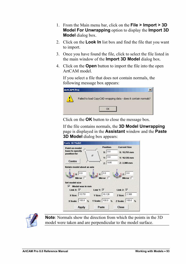
ArtCAM Pro 8.0 Reference Manual Working with Models • 93
1. From the Main menu bar, click on the File > Import > 3DModel For Unwrapping option to display the Import 3DModel dialog box.
2. Click on the Look In list box and find the file that you wantto import.
3. Once you have found the file, click to select the file listed inthe main window of the Import 3D Model dialog box.
4. Click on the Open button to import the file into the openArtCAM model.If you select a file that does not contain normals, thefollowing message box appears:
Click on the OK button to close the message box.If the file contains normals, the 3D Model Unwrappingpage is displayed in the Assistant window and the Paste3D Model dialog box appears:
Note: Normals show the direction from which the points in the 3Dmodel were taken and are perpendicular to the model surface.
94 • Working with Models ArtCAM Pro 8.0 Reference Manual
The current size of the model is shown and the original co-ordinate system used when the triangle model wasconstructed is kept.
5. You can now use the Paste 3D Model dialog box and/orthe 3D Model Unwrapping page to set the position, sizeand origin of the unwrapped model and exactly how it willbe unwrapped:
• For details on using the Paste 3D Model dialogbox, see "Using the Paste 3D Model Dialog Box" onpage 89.
• For details on using the 3D Model Unwrappingpage, see "Using the 3D Model Unwrapping page"on page 94.
Using the 3D Model Unwrapping pageThe 3D Model Unwrapping page allows you to unwrap an importedtriangle model along a cylindrical axis into a flat relief within anArtCAM model.To unwrap a triangle model along a cylindrical axis:
1. In the 3D Model Origin area, define the position of thetriangle model's origin within the ArtCAM model using thethe X, Y and Z boxes.
2. In the Rotate Model area, use the and buttonsto rotate the triangle model along any of the three axes inthe ArtCAM Pro model in 90° increments.
3. In the Unwrapping Cylinder area:• In the Diameter box, define the diameter of the
cylindrical axis along which the triangle model isunwrapped.
• Click on one of the Axes radio buttons to selectthe axis along which the centreline in the trianglemodel is aligned.
• In the Border Width box, define the width of theborder which is added above and below the trianglemodel.If you want to add a border later or using anothermethod, see "Adding a Border to a Model" on page69 for details.
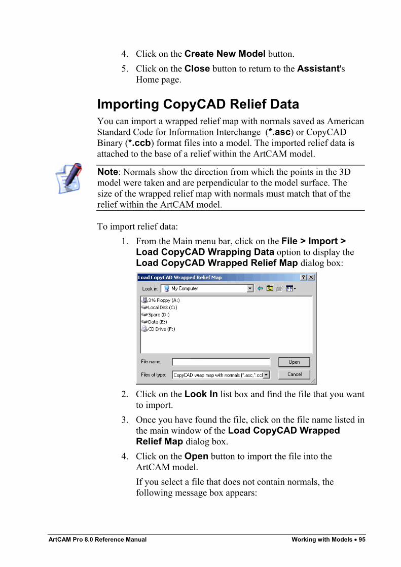
ArtCAM Pro 8.0 Reference Manual Working with Models • 95
4. Click on the Create New Model button.5. Click on the Close button to return to the Assistant's
Home page.
Importing CopyCAD Relief DataYou can import a wrapped relief map with normals saved as AmericanStandard Code for Information Interchange (*.asc) or CopyCADBinary (*.ccb) format files into a model. The imported relief data isattached to the base of a relief within the ArtCAM model.
Note: Normals show the direction from which the points in the 3Dmodel were taken and are perpendicular to the model surface. Thesize of the wrapped relief map with normals must match that of therelief within the ArtCAM model.
To import relief data:1. From the Main menu bar, click on the File > Import >
Load CopyCAD Wrapping Data option to display theLoad CopyCAD Wrapped Relief Map dialog box:
2. Click on the Look In list box and find the file that you wantto import.
3. Once you have found the file, click on the file name listed inthe main window of the Load CopyCAD WrappedRelief Map dialog box.
4. Click on the Open button to import the file into theArtCAM model.If you select a file that does not contain normals, thefollowing message box appears:
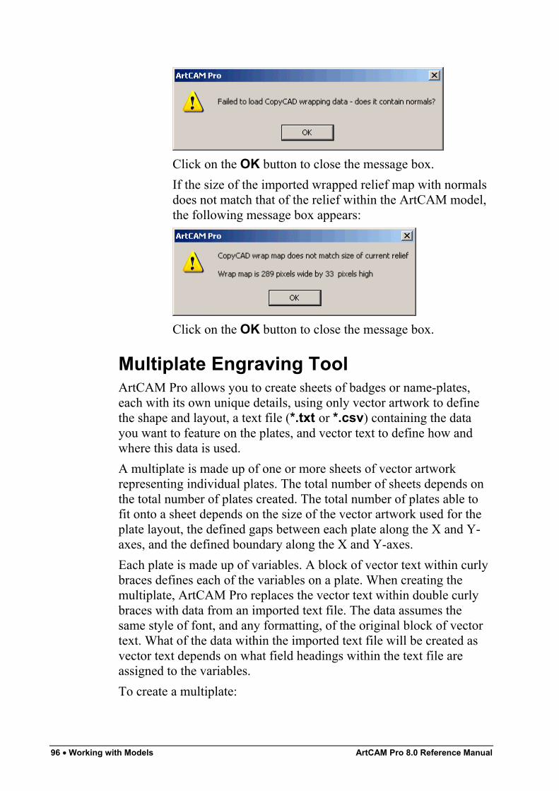
96 • Working with Models ArtCAM Pro 8.0 Reference Manual
Click on the OK button to close the message box.If the size of the imported wrapped relief map with normalsdoes not match that of the relief within the ArtCAM model,the following message box appears:
Click on the OK button to close the message box.
Multiplate Engraving ToolArtCAM Pro allows you to create sheets of badges or name-plates,each with its own unique details, using only vector artwork to definethe shape and layout, a text file (*.txt or *.csv) containing the datayou want to feature on the plates, and vector text to define how andwhere this data is used.A multiplate is made up of one or more sheets of vector artworkrepresenting individual plates. The total number of sheets depends onthe total number of plates created. The total number of plates able tofit onto a sheet depends on the size of the vector artwork used for theplate layout, the defined gaps between each plate along the X and Y-axes, and the defined boundary along the X and Y-axes.Each plate is made up of variables. A block of vector text within curlybraces defines each of the variables on a plate. When creating themultiplate, ArtCAM Pro replaces the vector text within double curlybraces with data from an imported text file. The data assumes thesame style of font, and any formatting, of the original block of vectortext. What of the data within the imported text file will be created asvector text depends on what field headings within the text file areassigned to the variables.To create a multiplate:
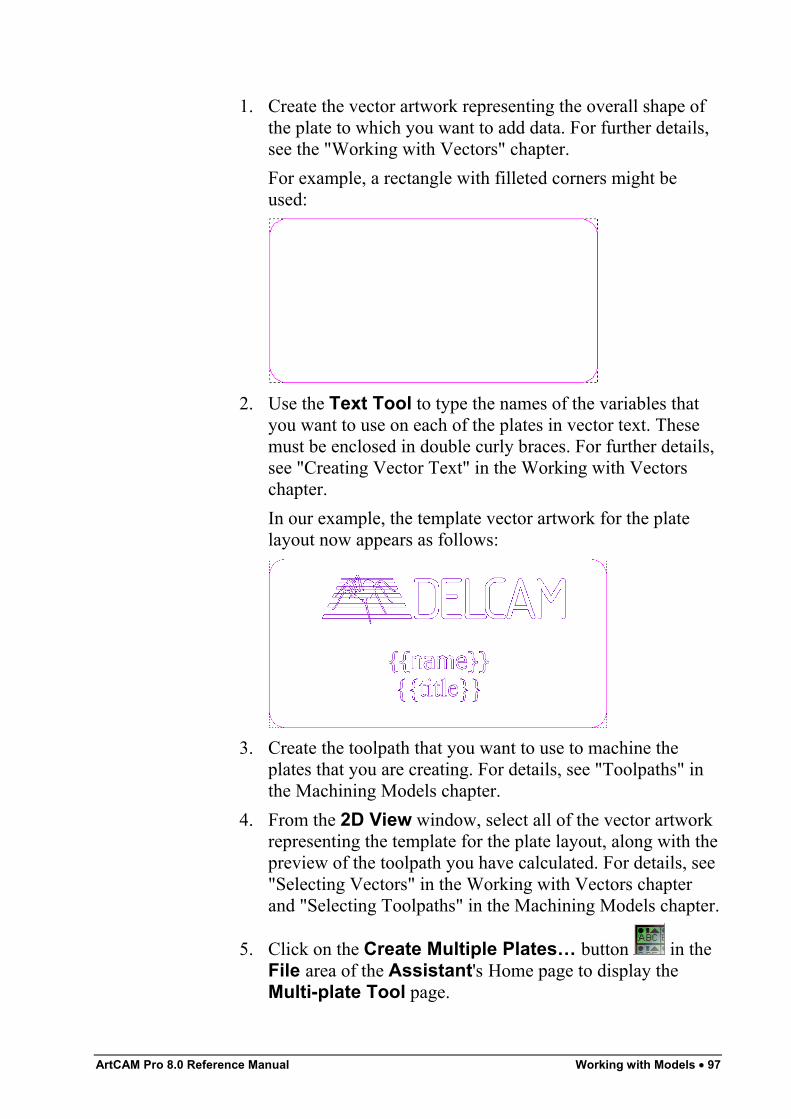
ArtCAM Pro 8.0 Reference Manual Working with Models • 97
1. Create the vector artwork representing the overall shape ofthe plate to which you want to add data. For further details,see the "Working with Vectors" chapter.For example, a rectangle with filleted corners might beused:
2. Use the Text Tool to type the names of the variables thatyou want to use on each of the plates in vector text. Thesemust be enclosed in double curly braces. For further details,see "Creating Vector Text" in the Working with Vectorschapter.In our example, the template vector artwork for the platelayout now appears as follows:
3. Create the toolpath that you want to use to machine theplates that you are creating. For details, see "Toolpaths" inthe Machining Models chapter.
4. From the 2D View window, select all of the vector artworkrepresenting the template for the plate layout, along with thepreview of the toolpath you have calculated. For details, see"Selecting Vectors" in the Working with Vectors chapterand "Selecting Toolpaths" in the Machining Models chapter.
5. Click on the Create Multiple Plates… button in theFile area of the Assistant's Home page to display theMulti-plate Tool page.
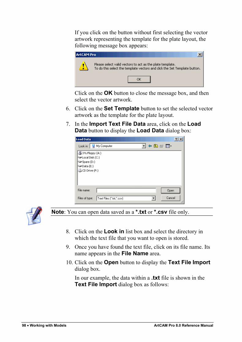
98 • Working with Models ArtCAM Pro 8.0 Reference Manual
If you click on the button without first selecting the vectorartwork representing the template for the plate layout, thefollowing message box appears:
Click on the OK button to close the message box, and thenselect the vector artwork.
6. Click on the Set Template button to set the selected vectorartwork as the template for the plate layout.
7. In the Import Text File Data area, click on the LoadData button to display the Load Data dialog box:
Note: You can open data saved as a *.txt or *.csv file only.
8. Click on the Look in list box and select the directory inwhich the text file that you want to open is stored.
9. Once you have found the text file, click on its file name. Itsname appears in the File Name area.
10. Click on the Open button to display the Text File Importdialog box.In our example, the data within a .txt file is shown in theText File Import dialog box as follows:
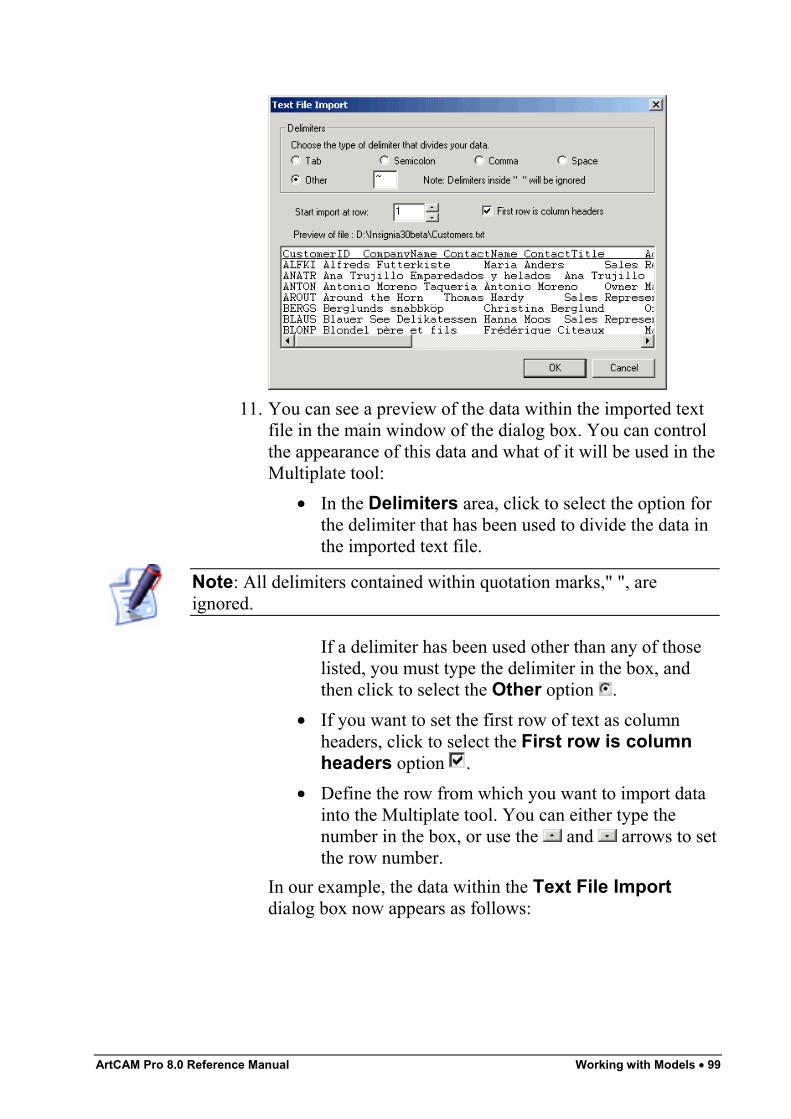
ArtCAM Pro 8.0 Reference Manual Working with Models • 99
11. You can see a preview of the data within the imported textfile in the main window of the dialog box. You can controlthe appearance of this data and what of it will be used in theMultiplate tool:
• In the Delimiters area, click to select the option forthe delimiter that has been used to divide the data inthe imported text file.
Note: All delimiters contained within quotation marks," ", areignored.
If a delimiter has been used other than any of thoselisted, you must type the delimiter in the box, andthen click to select the Other option .
• If you want to set the first row of text as columnheaders, click to select the First row is columnheaders option .
• Define the row from which you want to import datainto the Multiplate tool. You can either type thenumber in the box, or use the and arrows to setthe row number.
In our example, the data within the Text File Importdialog box now appears as follows:
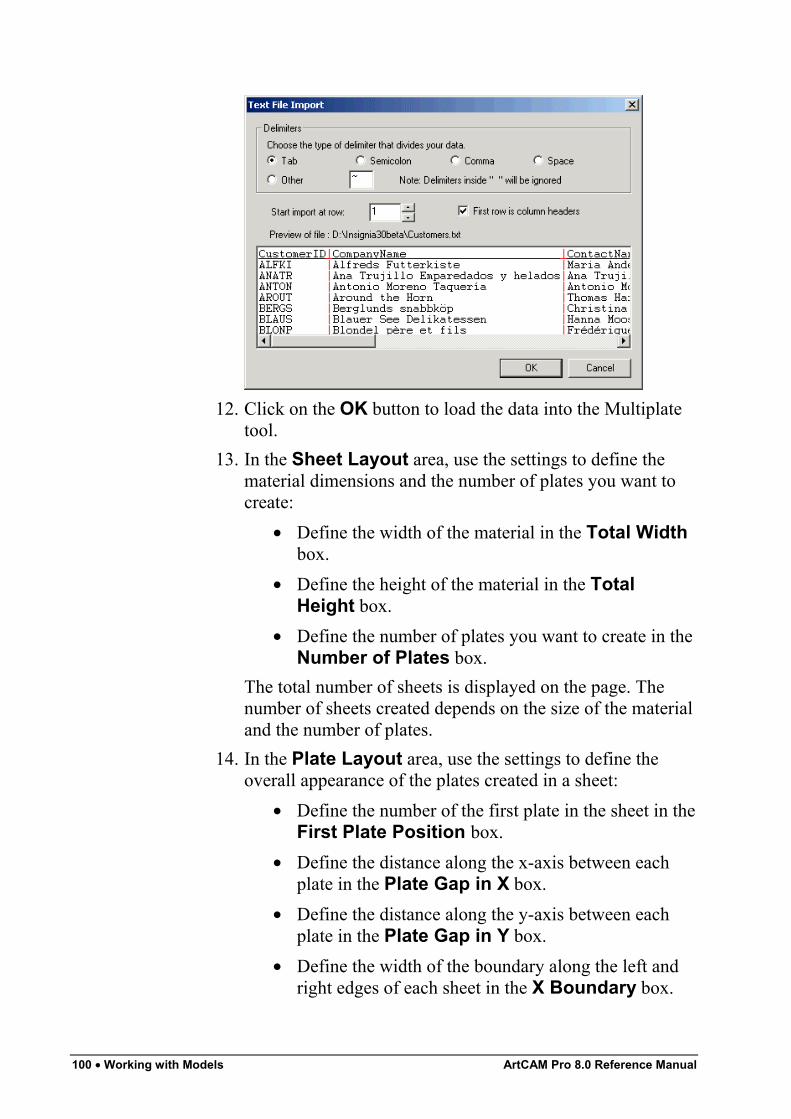
100 • Working with Models ArtCAM Pro 8.0 Reference Manual
12. Click on the OK button to load the data into the Multiplatetool.
13. In the Sheet Layout area, use the settings to define thematerial dimensions and the number of plates you want tocreate:
• Define the width of the material in the Total Widthbox.
• Define the height of the material in the TotalHeight box.
• Define the number of plates you want to create in theNumber of Plates box.
The total number of sheets is displayed on the page. Thenumber of sheets created depends on the size of the materialand the number of plates.
14. In the Plate Layout area, use the settings to define theoverall appearance of the plates created in a sheet:
• Define the number of the first plate in the sheet in theFirst Plate Position box.
• Define the distance along the x-axis between eachplate in the Plate Gap in X box.
• Define the distance along the y-axis between eachplate in the Plate Gap in Y box.
• Define the width of the boundary along the left andright edges of each sheet in the X Boundary box.
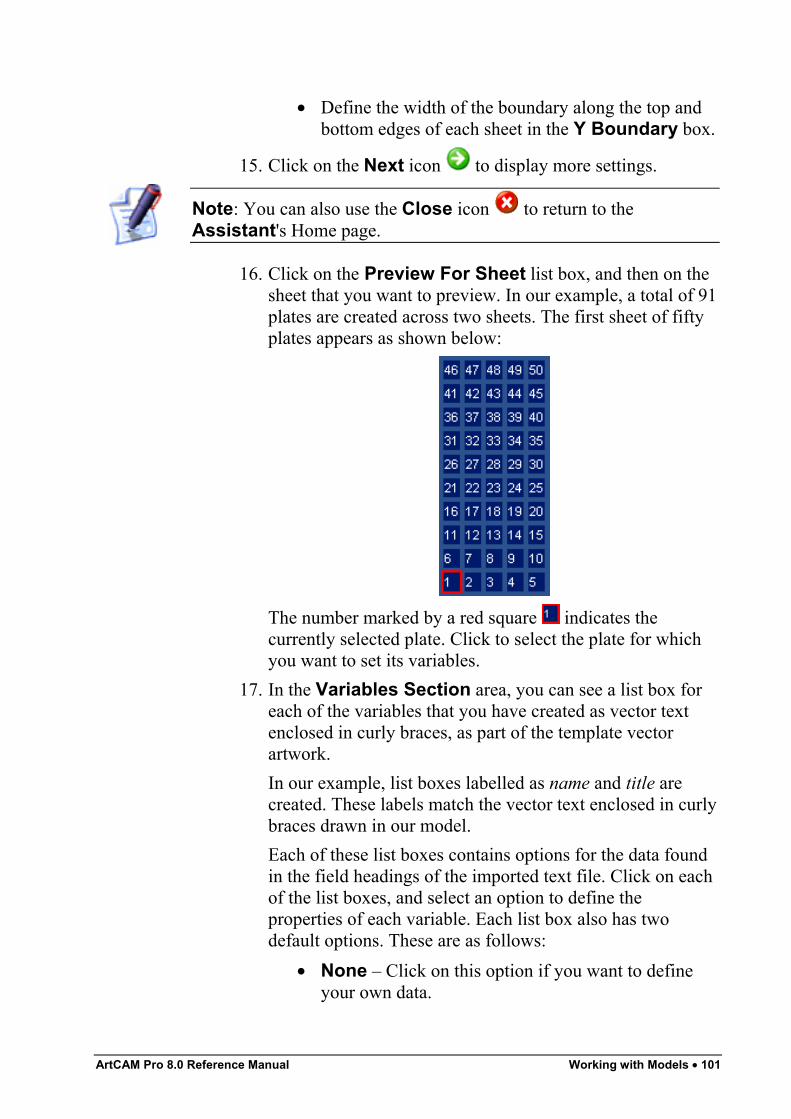
ArtCAM Pro 8.0 Reference Manual Working with Models • 101
• Define the width of the boundary along the top andbottom edges of each sheet in the Y Boundary box.
15. Click on the Next icon to display more settings.
Note: You can also use the Close icon to return to theAssistant's Home page.
16. Click on the Preview For Sheet list box, and then on thesheet that you want to preview. In our example, a total of 91plates are created across two sheets. The first sheet of fiftyplates appears as shown below:
The number marked by a red square indicates thecurrently selected plate. Click to select the plate for whichyou want to set its variables.
17. In the Variables Section area, you can see a list box foreach of the variables that you have created as vector textenclosed in curly braces, as part of the template vectorartwork.In our example, list boxes labelled as name and title arecreated. These labels match the vector text enclosed in curlybraces drawn in our model.Each of these list boxes contains options for the data foundin the field headings of the imported text file. Click on eachof the list boxes, and select an option to define theproperties of each variable. Each list box also has twodefault options. These are as follows:
• None – Click on this option if you want to defineyour own data.
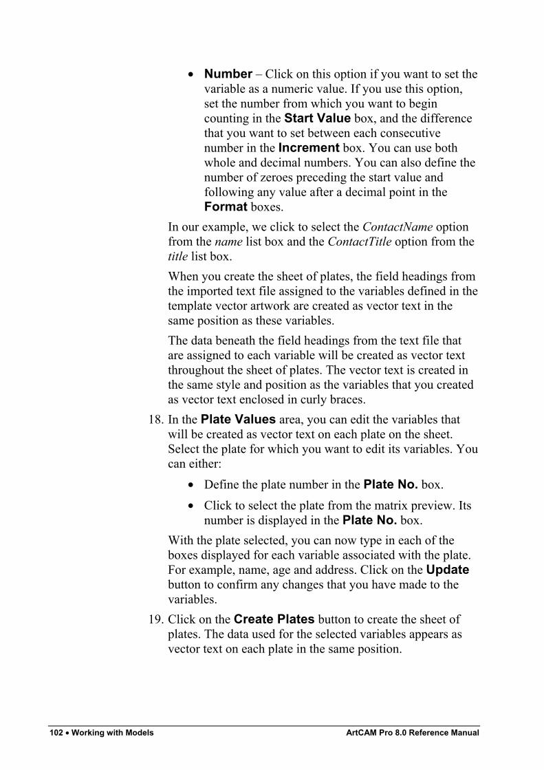
102 • Working with Models ArtCAM Pro 8.0 Reference Manual
• Number – Click on this option if you want to set thevariable as a numeric value. If you use this option,set the number from which you want to begincounting in the Start Value box, and the differencethat you want to set between each consecutivenumber in the Increment box. You can use bothwhole and decimal numbers. You can also define thenumber of zeroes preceding the start value andfollowing any value after a decimal point in theFormat boxes.
In our example, we click to select the ContactName optionfrom the name list box and the ContactTitle option from thetitle list box.When you create the sheet of plates, the field headings fromthe imported text file assigned to the variables defined in thetemplate vector artwork are created as vector text in thesame position as these variables.The data beneath the field headings from the text file thatare assigned to each variable will be created as vector textthroughout the sheet of plates. The vector text is created inthe same style and position as the variables that you createdas vector text enclosed in curly braces.
18. In the Plate Values area, you can edit the variables thatwill be created as vector text on each plate on the sheet.Select the plate for which you want to edit its variables. Youcan either:
• Define the plate number in the Plate No. box.• Click to select the plate from the matrix preview. Its
number is displayed in the Plate No. box.With the plate selected, you can now type in each of theboxes displayed for each variable associated with the plate.For example, name, age and address. Click on the Updatebutton to confirm any changes that you have made to thevariables.
19. Click on the Create Plates button to create the sheet ofplates. The data used for the selected variables appears asvector text on each plate in the same position.
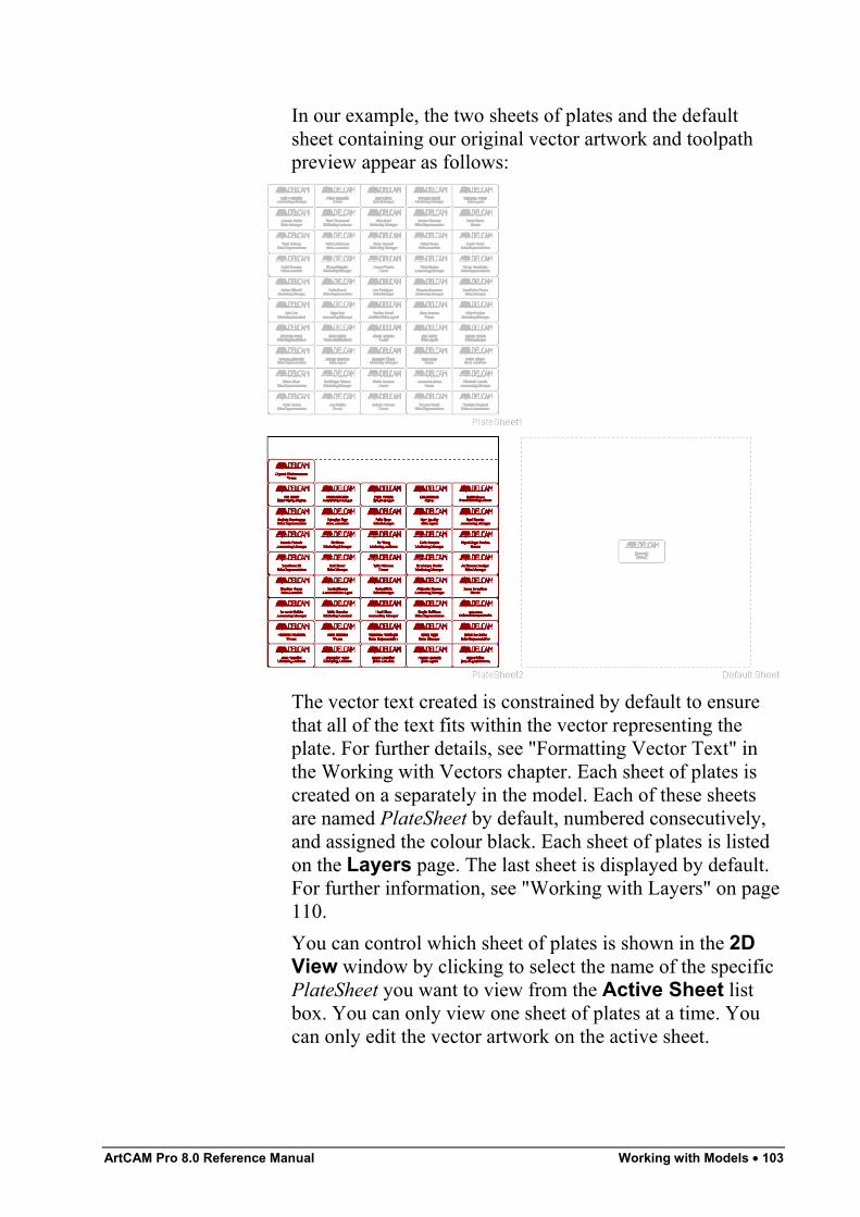
ArtCAM Pro 8.0 Reference Manual Working with Models • 103
In our example, the two sheets of plates and the defaultsheet containing our original vector artwork and toolpathpreview appear as follows:
The vector text created is constrained by default to ensurethat all of the text fits within the vector representing theplate. For further details, see "Formatting Vector Text" inthe Working with Vectors chapter. Each sheet of plates iscreated on a separately in the model. Each of these sheetsare named PlateSheet by default, numbered consecutively,and assigned the colour black. Each sheet of plates is listedon the Layers page. The last sheet is displayed by default.For further information, see "Working with Layers" on page110.You can control which sheet of plates is shown in the 2DView window by clicking to select the name of the specificPlateSheet you want to view from the Active Sheet listbox. You can only view one sheet of plates at a time. Youcan only edit the vector artwork on the active sheet.
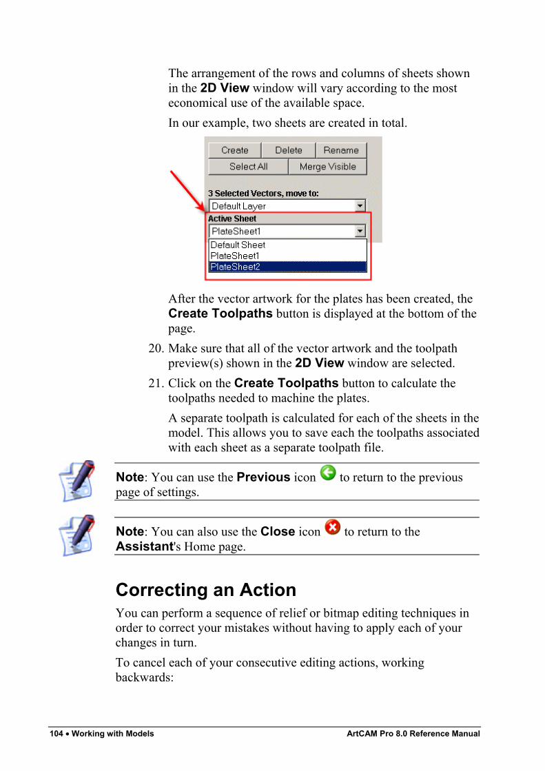
104 • Working with Models ArtCAM Pro 8.0 Reference Manual
The arrangement of the rows and columns of sheets shownin the 2D View window will vary according to the mosteconomical use of the available space.In our example, two sheets are created in total.
After the vector artwork for the plates has been created, theCreate Toolpaths button is displayed at the bottom of thepage.
20. Make sure that all of the vector artwork and the toolpathpreview(s) shown in the 2D View window are selected.
21. Click on the Create Toolpaths button to calculate thetoolpaths needed to machine the plates.A separate toolpath is calculated for each of the sheets in themodel. This allows you to save each the toolpaths associatedwith each sheet as a separate toolpath file.
Note: You can use the Previous icon to return to the previouspage of settings.
Note: You can also use the Close icon to return to theAssistant's Home page.
Correcting an ActionYou can perform a sequence of relief or bitmap editing techniques inorder to correct your mistakes without having to apply each of yourchanges in turn.To cancel each of your consecutive editing actions, workingbackwards:
ArtCAM Pro 8.0 Reference Manual Working with Models • 105
• Click on the Undo button in the File area of theAssistant's Home Page.
Note: You can also cancel an action by pressing the Ctrl + Z keys onyour keyboard.
To repeat each of the editing actions you have previously cancelled insuccession, working forwards:
• Click on the Redo button in the File area of theAssistant's Home Page.
Note: You can also redo a cancelled action by pressing the Ctrl + Ykeys on your keyboard.
Note: Alternatively, click on the Edit menu in the Main menu bar,followed by the relative option listed, for example, Undo DrawEllipse.
The number of times that you can undo or redo your actions dependson the size of the 'scratch' file associated with ArtCAM Pro, as well asthe magnitude of your editing. For example, a sequence of smallchanges to the relief or bitmap will store more undo actions than largermodifications.To set the size of the 'scratch' file associated with the Undo andRedo buttons, see "Managing ArtCAM Pro's Preferences" in theArtCAM Pro Layout chapter.
Mirroring a ModelYou can mirror an open model both vertically and horizontally.To mirror a model horizontally:
1. From the Main menu bar, click on the Model menu,followed by the Mirror > Horizontal option.
To mirror a model vertically:1. From the Main menu bar, click on the Model menu,
followed by the Mirror > Vertical option.
Rotating a ModelYou can rotate an open model both clockwise and anti-clockwise.To rotate a model clockwise:
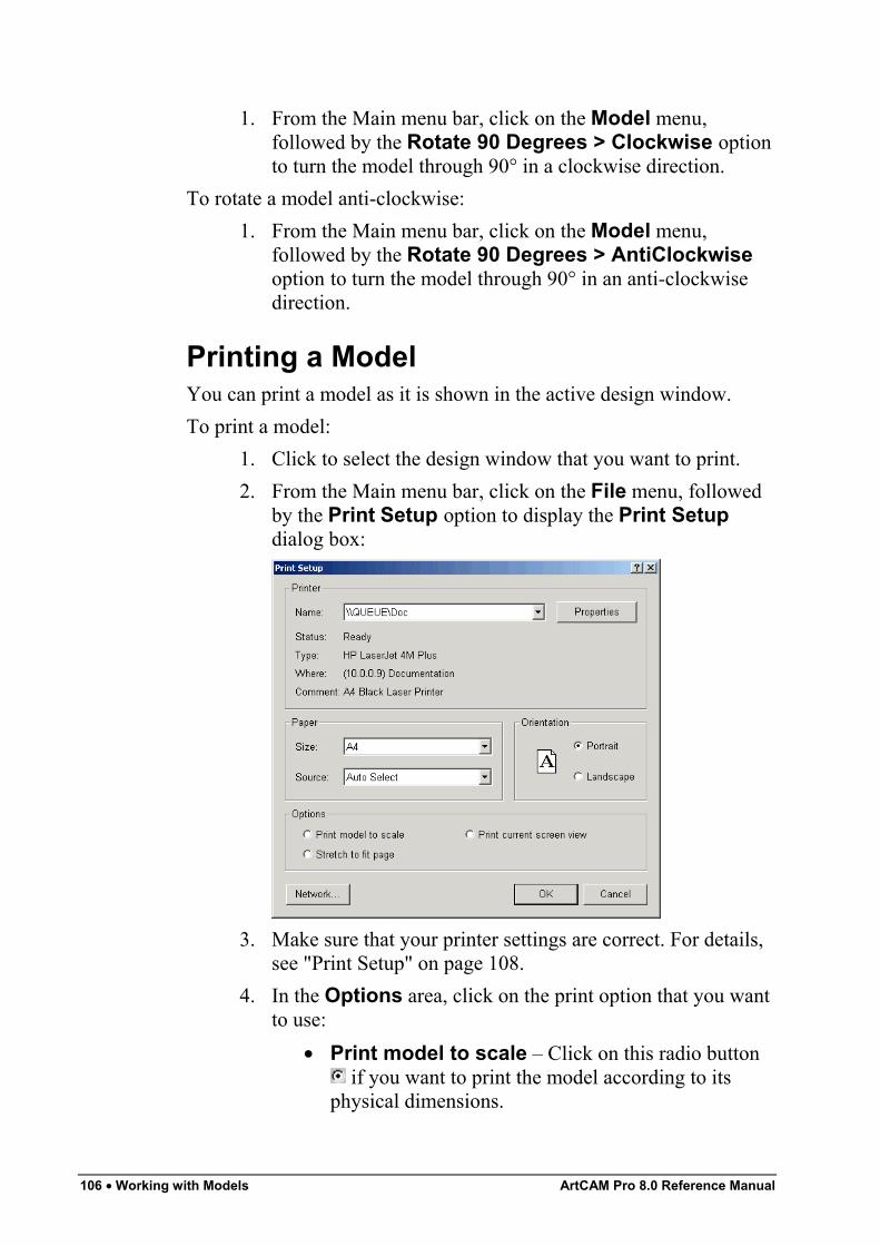
106 • Working with Models ArtCAM Pro 8.0 Reference Manual
1. From the Main menu bar, click on the Model menu,followed by the Rotate 90 Degrees > Clockwise optionto turn the model through 90° in a clockwise direction.
To rotate a model anti-clockwise:1. From the Main menu bar, click on the Model menu,
followed by the Rotate 90 Degrees > AntiClockwiseoption to turn the model through 90° in an anti-clockwisedirection.
Printing a ModelYou can print a model as it is shown in the active design window.To print a model:
1. Click to select the design window that you want to print.2. From the Main menu bar, click on the File menu, followed
by the Print Setup option to display the Print Setupdialog box:
3. Make sure that your printer settings are correct. For details,see "Print Setup" on page 108.
4. In the Options area, click on the print option that you wantto use:
• Print model to scale – Click on this radio button if you want to print the model according to its
physical dimensions.
ArtCAM Pro 8.0 Reference Manual Working with Models • 107
Before printing, make sure that the model can fitonto the paper to which it is currently being printed.For details, see "Print Setup" on page 108.
• Stretch to fit page – Click on this radio button if you want to print the model according to thedimensions of the paper onto which it is to beprinted.
• Print current screen view – Click on this radiobutton if you want to print the model as itcurrently appears in the 2D View window.
Note: If you are printing the 3D View window, the print options areautomatically greyed-out. In this instance, ArtCAM Pro prints to fitthe 3D View window in its current orientation.
5. Click on the OK button to close the Print Setup dialogbox and print the active design window.
Print PreviewYou can view the content of the active design window as it wouldappear when printed.To create a print preview:
1. Click to select the design window that you want to print.2. From the Main menu bar, click on the File option, followed
by the Print Preview option to display a preview image ofthe active design window.
3. You can use the buttons in the bar at the top of the ArtCAMPro window to view the preview image in more detail:
• To show the next page of the preview image, clickon the Next Page button. If this is greyed out, thereare no further pages.
• To show the previous page in the preview image,click on the Prev Page button. If this is greyed out,there are no further pages.
• To show two pages in the preview image at the sametime, click on the Two Page button. If this is greyedout, there is only one page in the preview image.
• To enlarge the size of the preview image, click onthe Zoom In button.
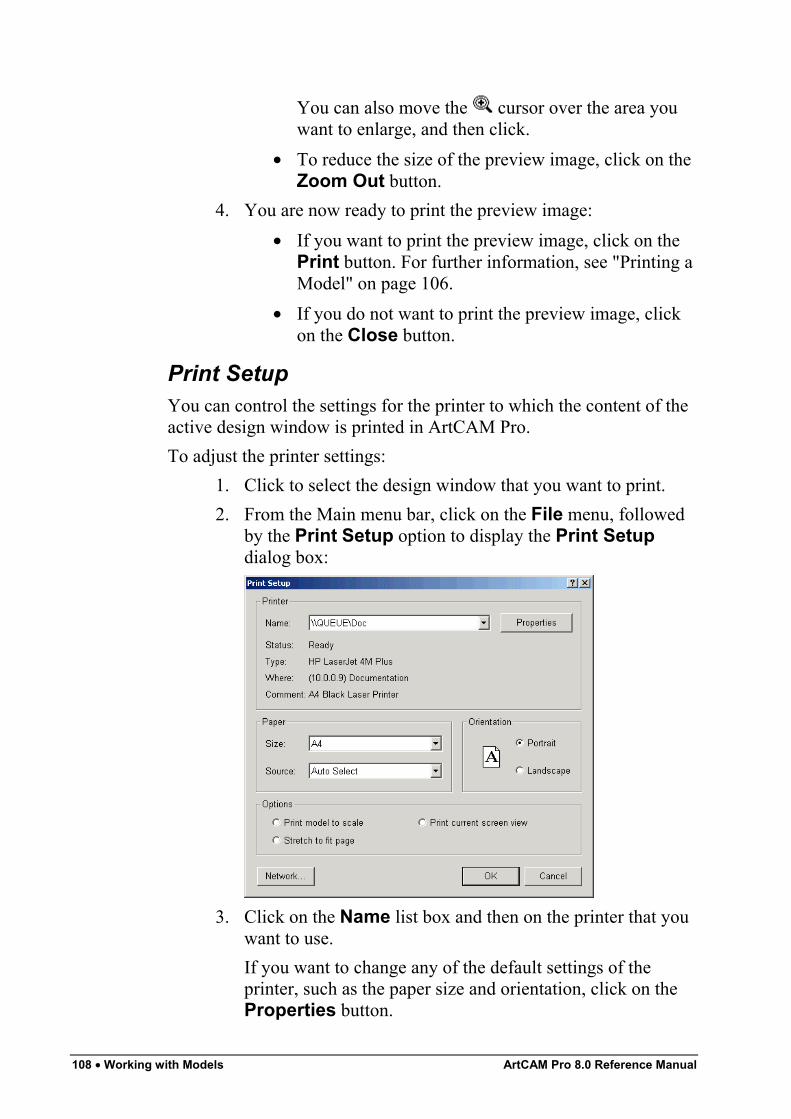
108 • Working with Models ArtCAM Pro 8.0 Reference Manual
You can also move the cursor over the area youwant to enlarge, and then click.
• To reduce the size of the preview image, click on theZoom Out button.
4. You are now ready to print the preview image:• If you want to print the preview image, click on the
Print button. For further information, see "Printing aModel" on page 106.
• If you do not want to print the preview image, clickon the Close button.
Print SetupYou can control the settings for the printer to which the content of theactive design window is printed in ArtCAM Pro.To adjust the printer settings:
1. Click to select the design window that you want to print.2. From the Main menu bar, click on the File menu, followed
by the Print Setup option to display the Print Setupdialog box:
3. Click on the Name list box and then on the printer that youwant to use.If you want to change any of the default settings of theprinter, such as the paper size and orientation, click on theProperties button.
ArtCAM Pro 8.0 Reference Manual Working with Models • 109
4. In the Paper area, click on the Size list box and select thesize of paper that you want to print to.
5. In the Paper area, click on the Source list box and then onthe tray or paper feed option that you want to use whenprinting.
6. Select the orientation that you want to use when printing:• Portrait - Click on this radio button if you want to
print the model vertically. Typically, portraitorientation is used for models that are taller than theyare wide.
• Landscape - Click on this radio button if youwant to print the model horizontally. Typically,landscape orientation is used for models that arewider than they are tall.
7. In the Options area, click on the print option that you wantto use:
• Print model to scale – Click on this radio button if you want to print the model according to its
physical dimensions.Before printing, make sure that the model can fitonto the paper to which it is currently being printed.
• Stretch to fit page – Click on this radio button if you want to print the model according to thedimensions of the paper onto which it is to beprinted.
• Print current screen view – Click on this radiobutton if you want to print the model as itcurrently appears in the 2D View window.
Note: If you are printing the 3D View window, the print options areautomatically greyed-out. In this instance, ArtCAM Pro prints to fitthe 3D View window in its current orientation.
8. Click on the OK button to print the active design windowand close the Print Setup dialog box.

110 • Working with Models ArtCAM Pro 8.0 Reference Manual
Working with LayersAll models have a single default layer. You can, however, add asmany layers as you want. This allows you to view only the vectorobjects you are interested in at any given time, clearing the 2D Viewwindow of all unnecessary detail.Layers are seen in the 2D View window only. Using the Layerspage, you can:
• Create a layer to represent each part of the model that youare creating. For details, see "Creating a New Layer" onpage 110.
• Name a layer to identify the vector objects on it. For details,see "Naming a Layer" on page 111.
• Assign a colour to a layer, which is used for all vectorobjects on it. For details, see "Assigning a Colour to aLayer" on page 111.
• Hide layers, allowing you to isolate the part of the modelthat you want to work on. For details, see "Viewing aLayer" on page 113.
• Lock the vectors on a layer into position, or unlock them.For details, see "Locking the Vectors on a Layer" on page114.
• Align vector object on a layer with another vector object onany visible layer or a guideline using snapping. For details,see "Snapping on a Layer" on page 114.
Creating a New LayerThe Default Layer for the model is listed on the Layers page, andits default colour is black. You can change this colour at any time. Fordetails, see "Assigning a Colour to a Layer" on page 111.You can create up to 990 layers in a model. For all of the layers thatyou create, the Visibility and Snapping options are selected bydefault, the Locking option is deselected and it is coloured black.For further information, see "Manipulating Layers" on page 112.To create a new layer:
1. Click on the Layers tab to display the Layers page.
ArtCAM Pro 8.0 Reference Manual Working with Models • 111
Tip: You can toggle between the Assistant page and the Layerspage using the F7 key on your keyboard.
2. Click on the Create button to add a layer to the model. It isnamed Layer by default, and is numbered sequentially.
3. Type a name for the new layer.4. Click on the button to apply the name to the layer. If you
want to change the name, click on button, then follow thesteps in "Naming a Layer" on page 111.
Naming a LayerThe name of a layer should reflect what the vector objects in it areused for in a model. You can change the name of any layer, other thanthe Default Layer, at any time. To do so:
1. Click on the Layers tab to display the Layers page.2. Click on the layer on the page that you want to rename to
select it. It is highlighted in blue.
Note: You cannot rename the Default Layer.
3. Click on the Rename button.4. Type over the current name with the name for the layer.5. Click on the button to apply the name to the layer. If you
want to change the name, click on button and repeat theprevious step.
Assigning a Colour to a LayerYou can assign a colour to a layer. Once you have done so, all of thevector objects in the layer are shown in that colour. This allows you toeasily recognise what vector objects in the 2D View window belongto a specific layer in the model.
Tip: Avoid using blue, magenta or red when assigning a colour to alayer. This is because these colours are used in the program when youselect vector objects or view toolpath previews. For details, see"Selecting Vectors" in the Working with Vectors chapter and"Selecting Toolpaths" in the Machining Models chapter.
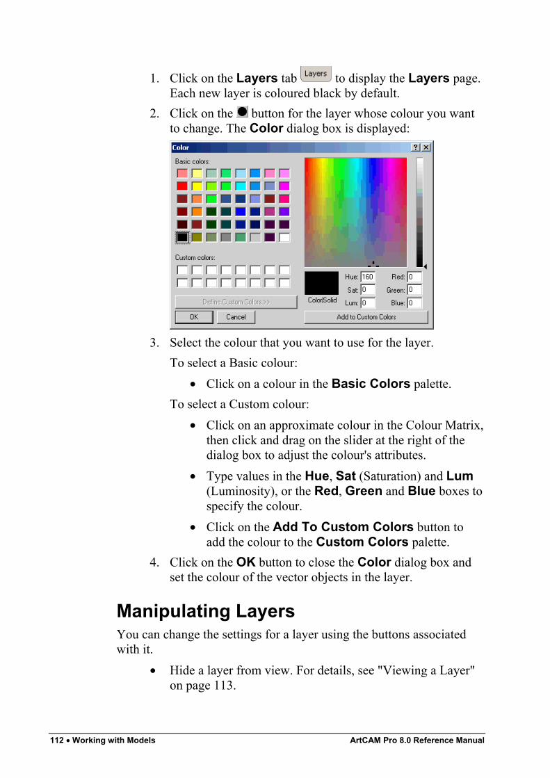
112 • Working with Models ArtCAM Pro 8.0 Reference Manual
1. Click on the Layers tab to display the Layers page.Each new layer is coloured black by default.
2. Click on the button for the layer whose colour you wantto change. The Color dialog box is displayed:
3. Select the colour that you want to use for the layer.To select a Basic colour:
• Click on a colour in the Basic Colors palette.To select a Custom colour:
• Click on an approximate colour in the Colour Matrix,then click and drag on the slider at the right of thedialog box to adjust the colour's attributes.
• Type values in the Hue, Sat (Saturation) and Lum(Luminosity), or the Red, Green and Blue boxes tospecify the colour.
• Click on the Add To Custom Colors button toadd the colour to the Custom Colors palette.
4. Click on the OK button to close the Color dialog box andset the colour of the vector objects in the layer.
Manipulating LayersYou can change the settings for a layer using the buttons associatedwith it.
• Hide a layer from view. For details, see "Viewing a Layer"on page 113.
ArtCAM Pro 8.0 Reference Manual Working with Models • 113
• Lock vector objects on a layer into position. For details, see"Locking the Vectors on a Layer" on page 114.
• Snap one vector object on a layer in relation to another. Fordetails, see "Snapping on a Layer" on page 114.
• Move vector objects from one layer to another. For details,see "Transferring Vectors Between Layers" on page 114.
• Merge one layer with another. For details, see "MergingLayers" on page 115.
Viewing a LayerYou can turn the visibility for a layer on and off. When a layer isvisible, the vector artwork drawn on the layer is shown in theparticular colour assigned to the layer.
Note: You only hide the vector objects on a layer. If you also want tohide a toolpath preview associated with a vector object, see "Hiding aToolpath" in the Machining Models chapter.
Note: You cannot merge a layer with another when its visibility isdeselected . For details, see "Merging Layers" on page 115.
Note: If you try to create a vector object on an active layer in whichthe visibility is deselected , the visibility is automatically selected
.
• Click on the Toggle Visibility button to hide thecontents of a layer.
• Click on the Toggle Visibility button to show thecontents of a layer.
• Click on the Toggle All Visibility button tosimultaneously hide the contents of all the layers that makeup the model.
• Click on the Toggle All Visibility button tosimultaneously show the contents of all the layers that makeup the model.
114 • Working with Models ArtCAM Pro 8.0 Reference Manual
Locking the Vectors on a LayerYou can lock or unlock selected vector objects on a layer, so that theycannot be moved within it. Locking, however, does not prevent youfrom transferring vector objects from one layer to another.
• Click on the Toggle Locking button to lock theselected vector objects on a layer.
• Click on the Toggle Locking button to unlock alllocked vector objects on a layer.
Snapping on a LayerUsing snapping, you can align a vector object on the active layer withanother vector object on any visible layer or a guideline. For furtherinformation on guidelines, see "Using Guidelines" in the ArtCAM ProLayout chapter.
Note: The Snap To Objects option in the 2D View menu must beselected to use the Toggle Snapping button on theLayers page. For details, see "Snapping To Objects" in the ArtCAMPro Layout chapter.
You can turn the snapping for a layer on and off.• Click on the Toggle Snapping button to select
snapping on the layer.• Click on the Toggle Snapping button to deselect
snapping on the layer.
Tip: To temporarily disable snapping, hold down the Shift key onyour keyboard.
For details on how the mouse cursor changes when it snaps,see "Snapping To Objects" in the ArtCAM Pro Layoutchapter.
Transferring Vectors Between LayersYou can transfer selected vector objects from one layer to another.
1. Click on the Layers tab to display the Layers page.2. From the 2D View window, select the vector object(s) that
you want to transfer. For details, see "Selecting Vectors" inthe Working with Vectors chapter.
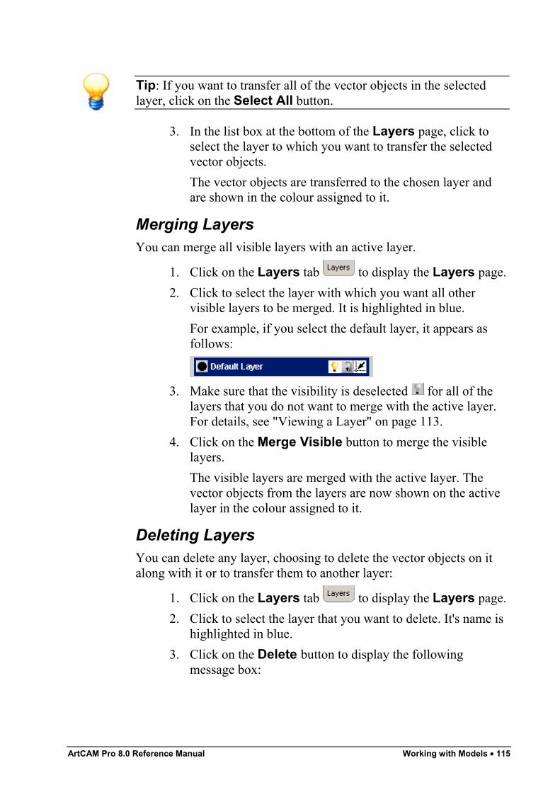
ArtCAM Pro 8.0 Reference Manual Working with Models • 115
Tip: If you want to transfer all of the vector objects in the selectedlayer, click on the Select All button.
3. In the list box at the bottom of the Layers page, click toselect the layer to which you want to transfer the selectedvector objects.The vector objects are transferred to the chosen layer andare shown in the colour assigned to it.
Merging LayersYou can merge all visible layers with an active layer.
1. Click on the Layers tab to display the Layers page.2. Click to select the layer with which you want all other
visible layers to be merged. It is highlighted in blue.For example, if you select the default layer, it appears asfollows:
3. Make sure that the visibility is deselected for all of thelayers that you do not want to merge with the active layer.For details, see "Viewing a Layer" on page 113.
4. Click on the Merge Visible button to merge the visiblelayers.The visible layers are merged with the active layer. Thevector objects from the layers are now shown on the activelayer in the colour assigned to it.
Deleting LayersYou can delete any layer, choosing to delete the vector objects on italong with it or to transfer them to another layer:
1. Click on the Layers tab to display the Layers page.2. Click to select the layer that you want to delete. It's name is
highlighted in blue.3. Click on the Delete button to display the following
message box:
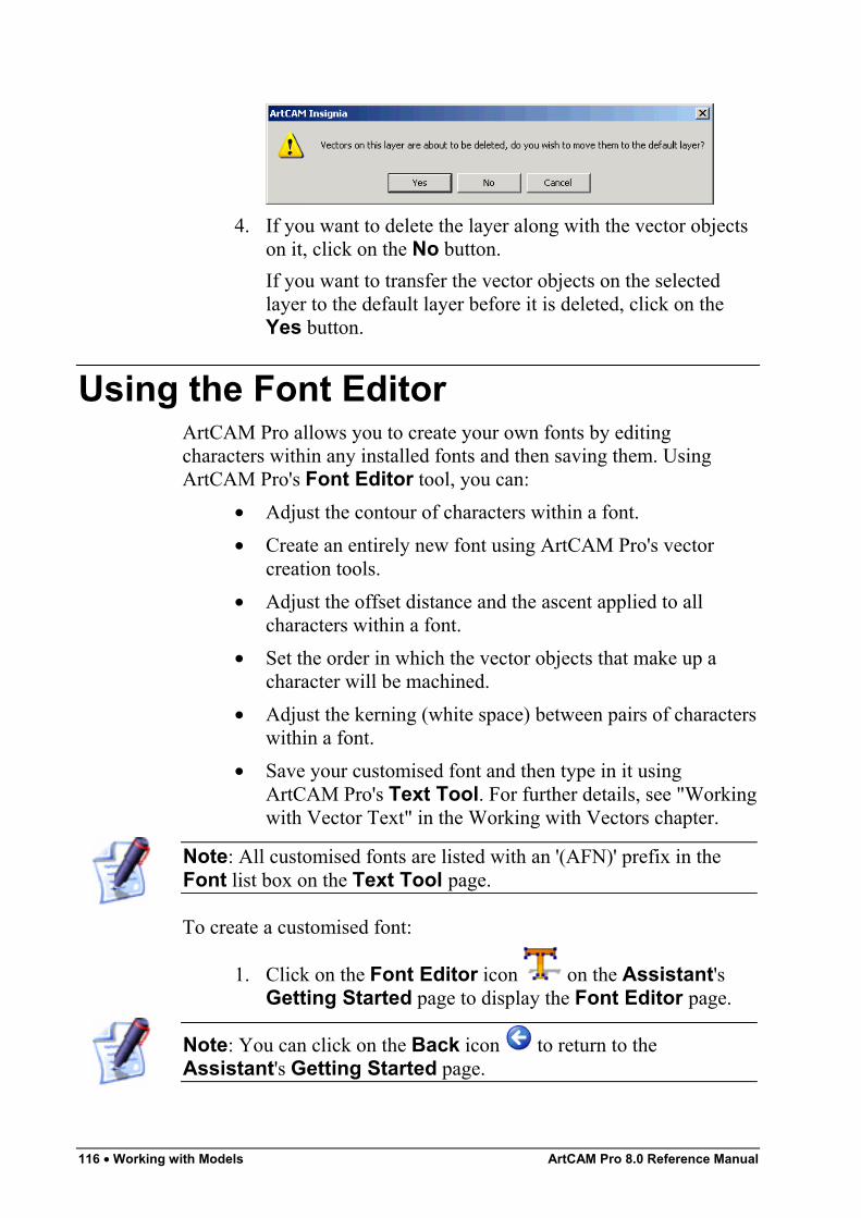
116 • Working with Models ArtCAM Pro 8.0 Reference Manual
4. If you want to delete the layer along with the vector objectson it, click on the No button.If you want to transfer the vector objects on the selectedlayer to the default layer before it is deleted, click on theYes button.
Using the Font EditorArtCAM Pro allows you to create your own fonts by editingcharacters within any installed fonts and then saving them. UsingArtCAM Pro's Font Editor tool, you can:
• Adjust the contour of characters within a font.• Create an entirely new font using ArtCAM Pro's vector
creation tools.• Adjust the offset distance and the ascent applied to all
characters within a font.• Set the order in which the vector objects that make up a
character will be machined.• Adjust the kerning (white space) between pairs of characters
within a font.• Save your customised font and then type in it using
ArtCAM Pro's Text Tool. For further details, see "Workingwith Vector Text" in the Working with Vectors chapter.
Note: All customised fonts are listed with an '(AFN)' prefix in theFont list box on the Text Tool page.
To create a customised font:
1. Click on the Font Editor icon on the Assistant'sGetting Started page to display the Font Editor page.
Note: You can click on the Back icon to return to theAssistant's Getting Started page.
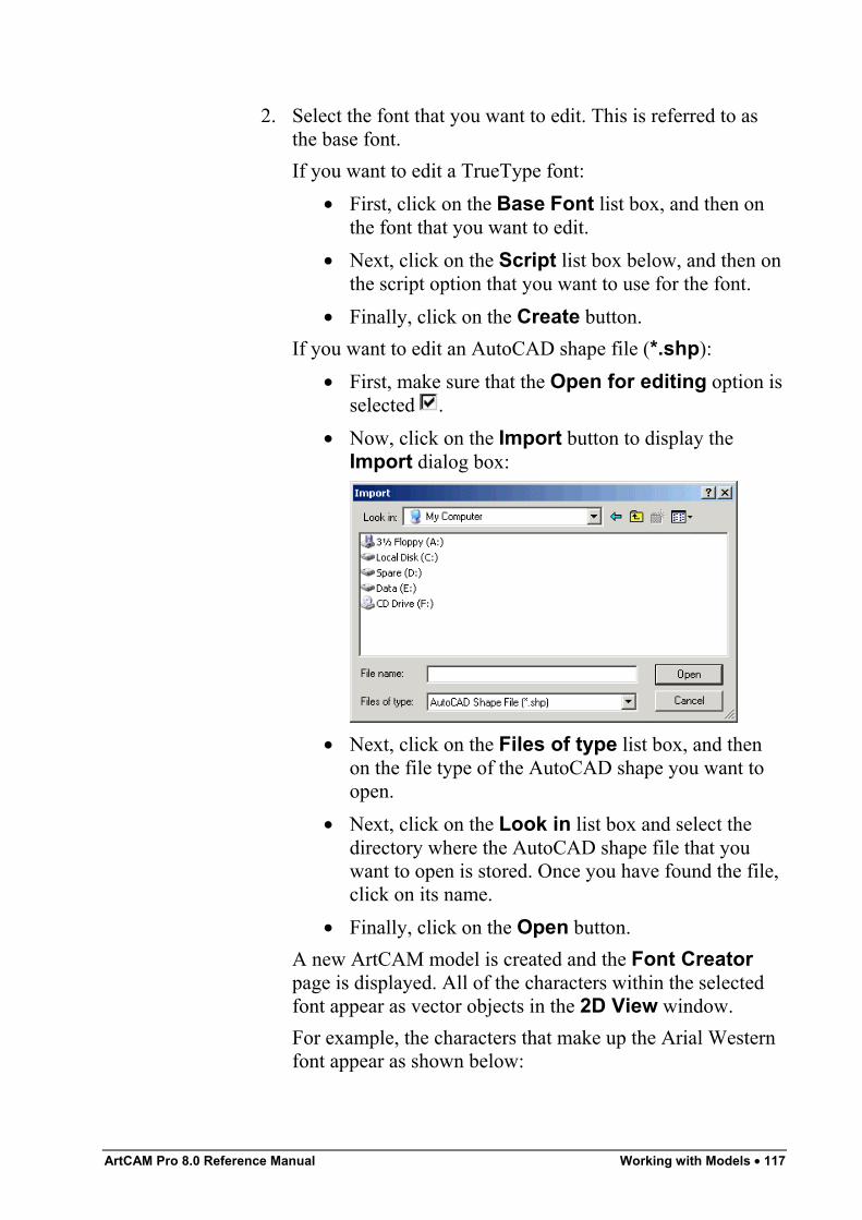
ArtCAM Pro 8.0 Reference Manual Working with Models • 117
2. Select the font that you want to edit. This is referred to asthe base font.If you want to edit a TrueType font:
• First, click on the Base Font list box, and then onthe font that you want to edit.
• Next, click on the Script list box below, and then onthe script option that you want to use for the font.
• Finally, click on the Create button.If you want to edit an AutoCAD shape file (*.shp):
• First, make sure that the Open for editing option isselected .
• Now, click on the Import button to display theImport dialog box:
• Next, click on the Files of type list box, and thenon the file type of the AutoCAD shape you want toopen.
• Next, click on the Look in list box and select thedirectory where the AutoCAD shape file that youwant to open is stored. Once you have found the file,click on its name.
• Finally, click on the Open button.A new ArtCAM model is created and the Font Creatorpage is displayed. All of the characters within the selectedfont appear as vector objects in the 2D View window.For example, the characters that make up the Arial Westernfont appear as shown below:
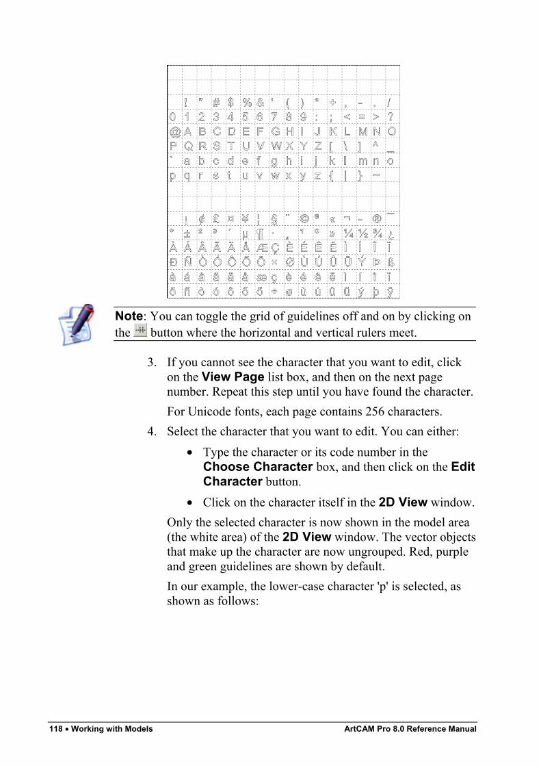
118 • Working with Models ArtCAM Pro 8.0 Reference Manual
Note: You can toggle the grid of guidelines off and on by clicking onthe button where the horizontal and vertical rulers meet.
3. If you cannot see the character that you want to edit, clickon the View Page list box, and then on the next pagenumber. Repeat this step until you have found the character.For Unicode fonts, each page contains 256 characters.
4. Select the character that you want to edit. You can either:• Type the character or its code number in the
Choose Character box, and then click on the EditCharacter button.
• Click on the character itself in the 2D View window.Only the selected character is now shown in the model area(the white area) of the 2D View window. The vector objectsthat make up the character are now ungrouped. Red, purpleand green guidelines are shown by default.In our example, the lower-case character 'p' is selected, asshown as follows:
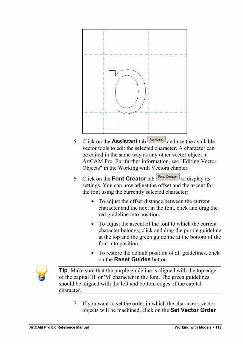
ArtCAM Pro 8.0 Reference Manual Working with Models • 119
5. Click on the Assistant tab and use the availablevector tools to edit the selected character. A character canbe edited in the same way as any other vector object inArtCAM Pro. For further information, see "Editing VectorObjects" in the Working with Vectors chapter.
6. Click on the Font Creator tab to display itssettings. You can now adjust the offset and the ascent forthe font using the currently selected character:
• To adjust the offset distance between the currentcharacter and the next in the font, click and drag thered guideline into position.
• To adjust the ascent of the font to which the currentcharacter belongs, click and drag the purple guidelineat the top and the green guideline at the bottom of thefont into position.
• To restore the default position of all guidelines, clickon the Reset Guides button.
Tip: Make sure that the purple guideline is aligned with the top edgeof the capital 'H' or 'M' character in the font. The green guidelinesshould be aligned with the left and bottom edges of the capitalcharacter.
7. If you want to set the order in which the character's vectorobjects will be machined, click on the Set Vector Order
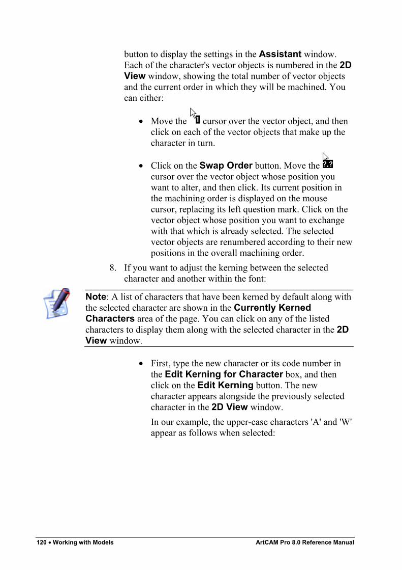
120 • Working with Models ArtCAM Pro 8.0 Reference Manual
button to display the settings in the Assistant window.Each of the character's vector objects is numbered in the 2DView window, showing the total number of vector objectsand the current order in which they will be machined. Youcan either:
• Move the cursor over the vector object, and thenclick on each of the vector objects that make up thecharacter in turn.
• Click on the Swap Order button. Move the cursor over the vector object whose position youwant to alter, and then click. Its current position inthe machining order is displayed on the mousecursor, replacing its left question mark. Click on thevector object whose position you want to exchangewith that which is already selected. The selectedvector objects are renumbered according to their newpositions in the overall machining order.
8. If you want to adjust the kerning between the selectedcharacter and another within the font:
Note: A list of characters that have been kerned by default along withthe selected character are shown in the Currently KernedCharacters area of the page. You can click on any of the listedcharacters to display them along with the selected character in the 2DView window.
• First, type the new character or its code number inthe Edit Kerning for Character box, and thenclick on the Edit Kerning button. The newcharacter appears alongside the previously selectedcharacter in the 2D View window.In our example, the upper-case characters 'A' and 'W'appear as follows when selected:
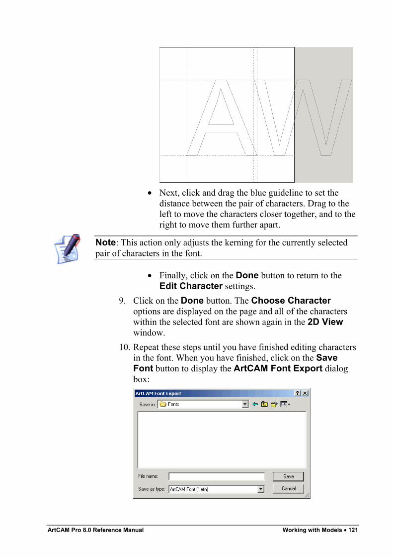
ArtCAM Pro 8.0 Reference Manual Working with Models • 121
• Next, click and drag the blue guideline to set thedistance between the pair of characters. Drag to theleft to move the characters closer together, and to theright to move them further apart.
Note: This action only adjusts the kerning for the currently selectedpair of characters in the font.
• Finally, click on the Done button to return to theEdit Character settings.
9. Click on the Done button. The Choose Characteroptions are displayed on the page and all of the characterswithin the selected font are shown again in the 2D Viewwindow.
10. Repeat these steps until you have finished editing charactersin the font. When you have finished, click on the SaveFont button to display the ArtCAM Font Export dialogbox:
122 • Working with Models ArtCAM Pro 8.0 Reference Manual
The ArtCAM Pro 8.0\Fonts folder is selected by default.11. Type a name for the font in the File Name box, and then
click on the Save button to close the ArtCAM FontExport dialog box and save the font (*.afn).
12. Click on the Quit button to return to the Assistant'sGetting Started page.
Note: If you click on the Quit button before saving the font, amessage box appears warning that the font has been modified. If youwant to save the font, click on the Yes button. If you do not, click onthe No button.
Using the Face WizardArtCAM Pro allows you to create a relief from a photographic imagecontaining a side-profile of a person's head and neck saved as aBitmap (*.bmp), TIFF (*.tif), GIF (*.gif) or JPEG (*.jpg) file. Thisprocess is almost entirely automated.To produce a detailed relief, your image should ideally be captured bya digital source using a resolution of at least 1024 x 768 pixels. Colourphotographic images can be imported, but they will appear as blackand white in ArtCAM Pro.To create a relief using the Face Wizard tool:
1. Click on the Face Wizard icon on the Assistant'sGetting Started page to display the first page of the FaceWizard.
2. Click on the Open Photo… icon to display theSelect Image File dialog box:
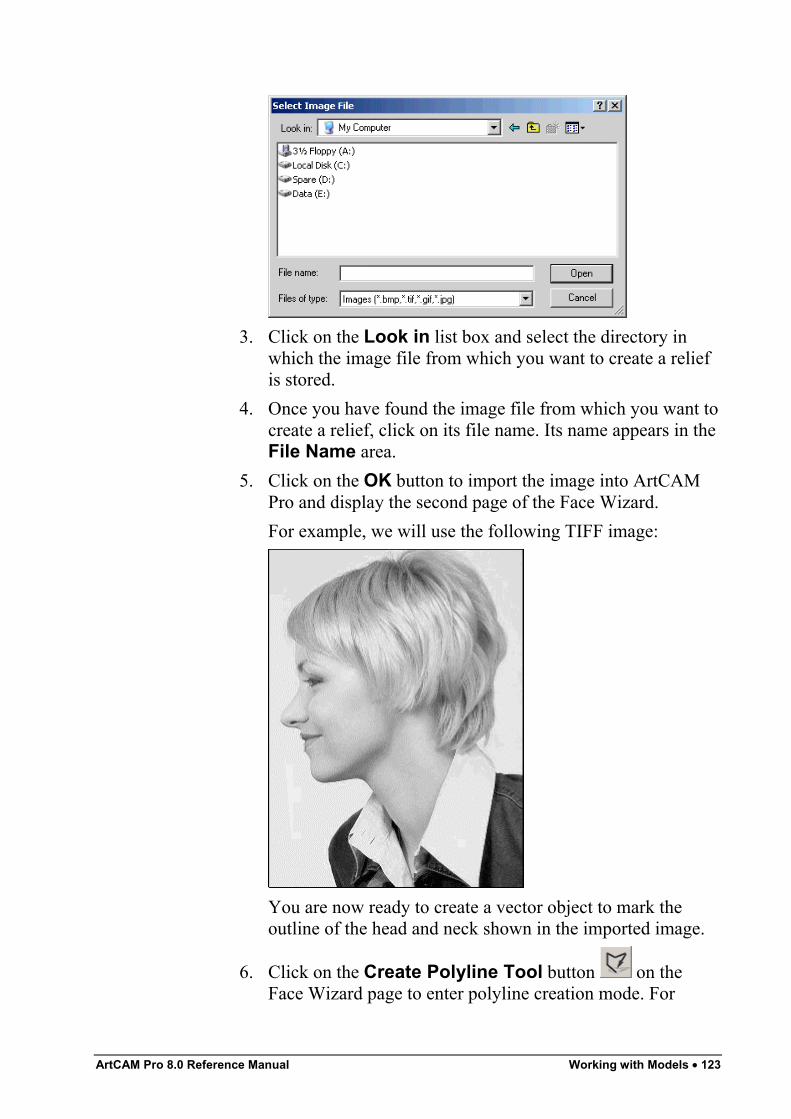
ArtCAM Pro 8.0 Reference Manual Working with Models • 123
3. Click on the Look in list box and select the directory inwhich the image file from which you want to create a reliefis stored.
4. Once you have found the image file from which you want tocreate a relief, click on its file name. Its name appears in theFile Name area.
5. Click on the OK button to import the image into ArtCAMPro and display the second page of the Face Wizard.For example, we will use the following TIFF image:
You are now ready to create a vector object to mark theoutline of the head and neck shown in the imported image.
6. Click on the Create Polyline Tool button on theFace Wizard page to enter polyline creation mode. For
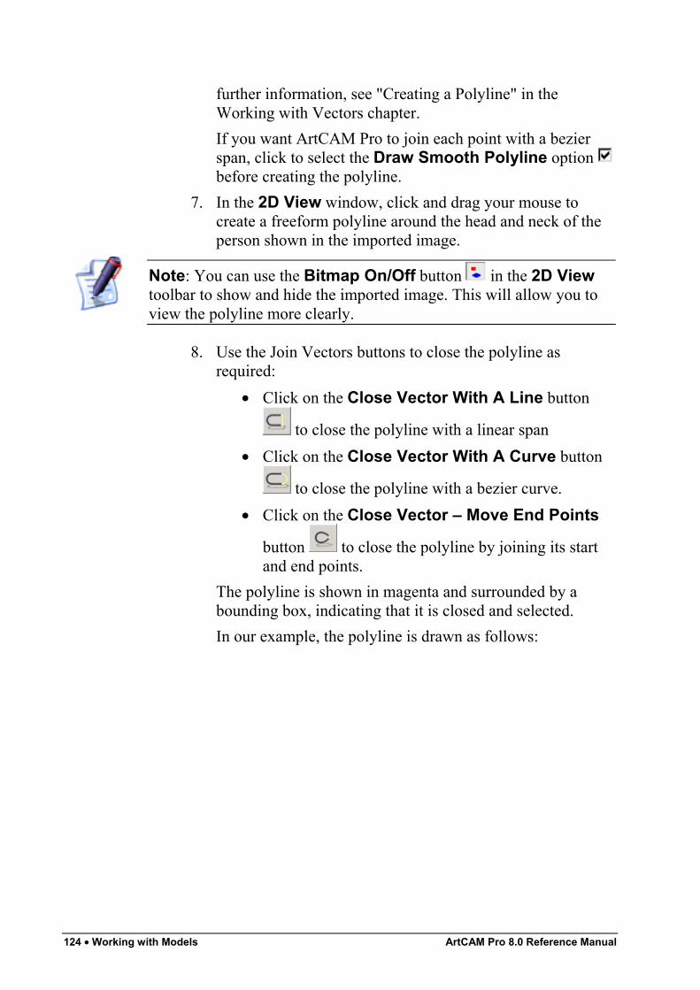
124 • Working with Models ArtCAM Pro 8.0 Reference Manual
further information, see "Creating a Polyline" in theWorking with Vectors chapter.If you want ArtCAM Pro to join each point with a bezierspan, click to select the Draw Smooth Polyline option before creating the polyline.
7. In the 2D View window, click and drag your mouse tocreate a freeform polyline around the head and neck of theperson shown in the imported image.
Note: You can use the Bitmap On/Off button in the 2D Viewtoolbar to show and hide the imported image. This will allow you toview the polyline more clearly.
8. Use the Join Vectors buttons to close the polyline asrequired:
• Click on the Close Vector With A Line button
to close the polyline with a linear span• Click on the Close Vector With A Curve button
to close the polyline with a bezier curve.• Click on the Close Vector – Move End Points
button to close the polyline by joining its startand end points.
The polyline is shown in magenta and surrounded by abounding box, indicating that it is closed and selected.In our example, the polyline is drawn as follows:
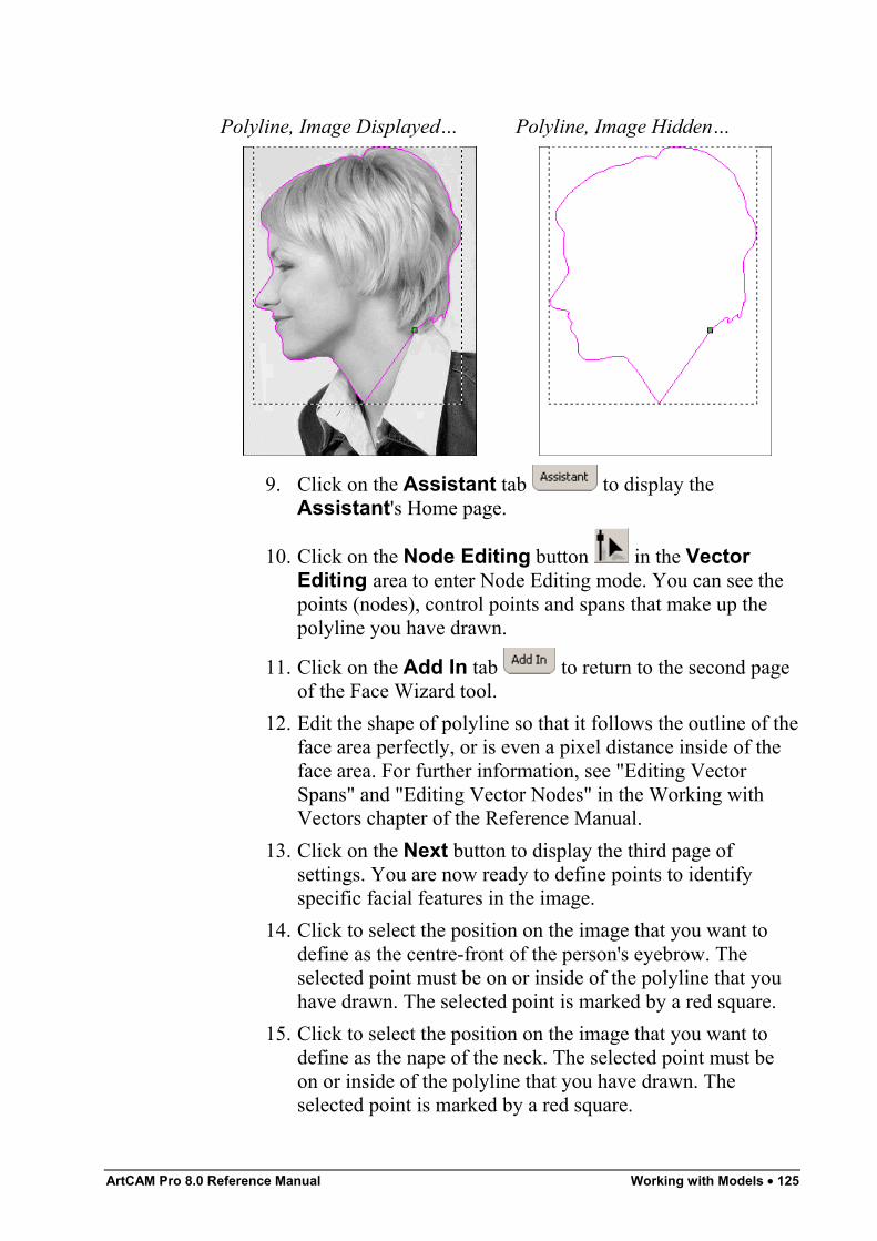
ArtCAM Pro 8.0 Reference Manual Working with Models • 125
Polyline, Image Displayed… Polyline, Image Hidden…
9. Click on the Assistant tab to display theAssistant's Home page.
10. Click on the Node Editing button in the VectorEditing area to enter Node Editing mode. You can see thepoints (nodes), control points and spans that make up thepolyline you have drawn.
11. Click on the Add In tab to return to the second pageof the Face Wizard tool.
12. Edit the shape of polyline so that it follows the outline of theface area perfectly, or is even a pixel distance inside of theface area. For further information, see "Editing VectorSpans" and "Editing Vector Nodes" in the Working withVectors chapter of the Reference Manual.
13. Click on the Next button to display the third page ofsettings. You are now ready to define points to identifyspecific facial features in the image.
14. Click to select the position on the image that you want todefine as the centre-front of the person's eyebrow. Theselected point must be on or inside of the polyline that youhave drawn. The selected point is marked by a red square.
15. Click to select the position on the image that you want todefine as the nape of the neck. The selected point must beon or inside of the polyline that you have drawn. Theselected point is marked by a red square.
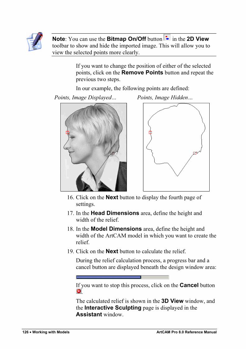
126 • Working with Models ArtCAM Pro 8.0 Reference Manual
Note: You can use the Bitmap On/Off button in the 2D Viewtoolbar to show and hide the imported image. This will allow you toview the selected points more clearly.
If you want to change the position of either of the selectedpoints, click on the Remove Points button and repeat theprevious two steps.In our example, the following points are defined:
Points, Image Displayed… Points, Image Hidden…
16. Click on the Next button to display the fourth page ofsettings.
17. In the Head Dimensions area, define the height andwidth of the relief.
18. In the Model Dimensions area, define the height andwidth of the ArtCAM model in which you want to create therelief.
19. Click on the Next button to calculate the relief.During the relief calculation process, a progress bar and acancel button are displayed beneath the design window area:
If you want to stop this process, click on the Cancel button.
The calculated relief is shown in the 3D View window, andthe Interactive Sculpting page is displayed in theAssistant window.
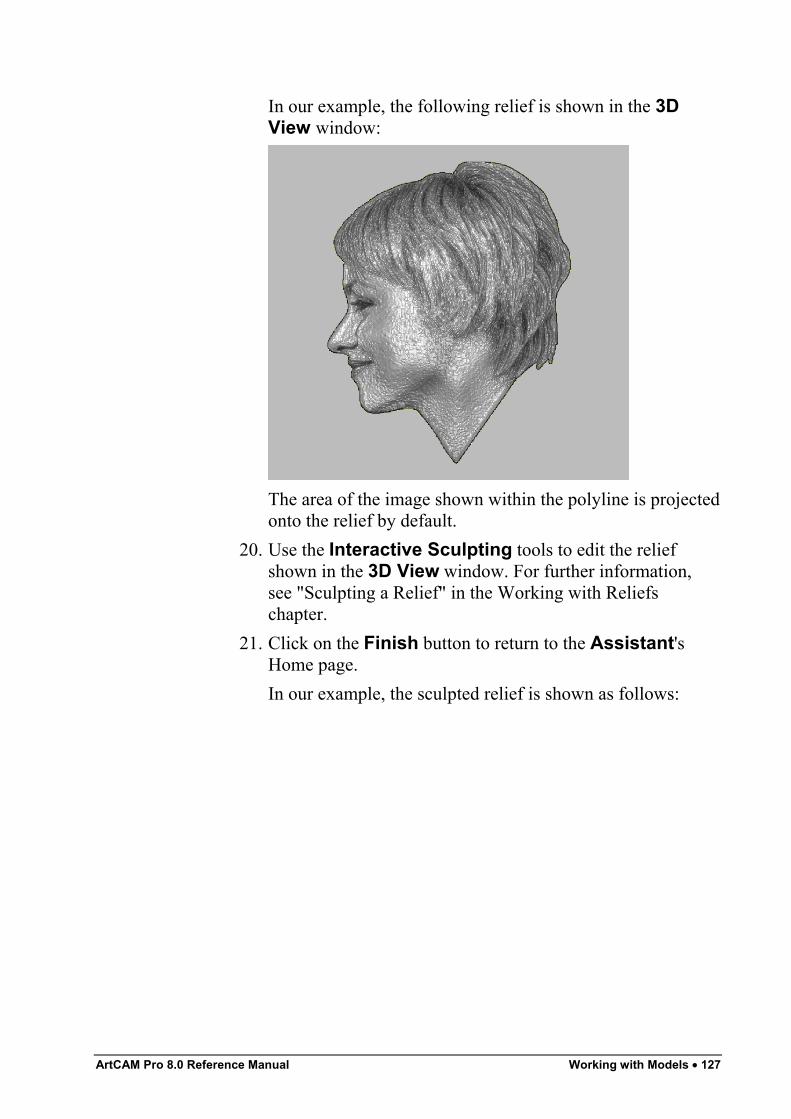
ArtCAM Pro 8.0 Reference Manual Working with Models • 127
In our example, the following relief is shown in the 3DView window:
The area of the image shown within the polyline is projectedonto the relief by default.
20. Use the Interactive Sculpting tools to edit the reliefshown in the 3D View window. For further information,see "Sculpting a Relief" in the Working with Reliefschapter.
21. Click on the Finish button to return to the Assistant'sHome page.In our example, the sculpted relief is shown as follows:
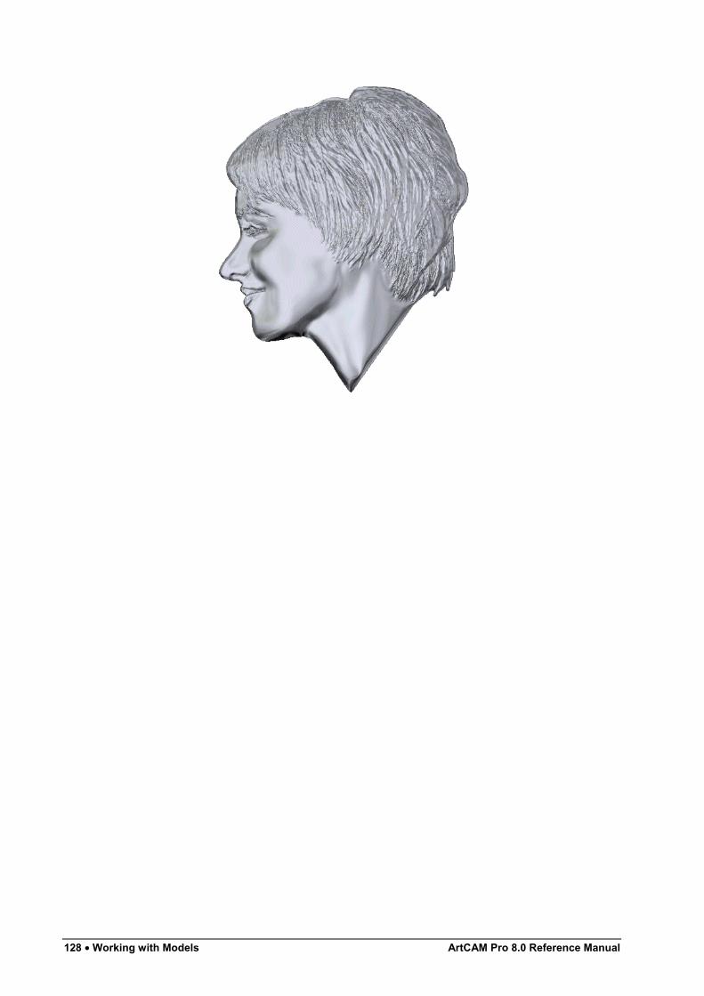
128 • Working with Models ArtCAM Pro 8.0 Reference Manual
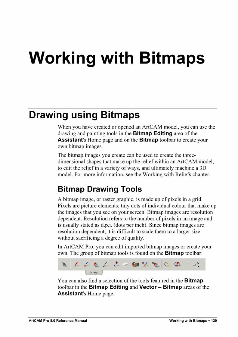
ArtCAM Pro 8.0 Reference Manual Working with Bitmaps • 129
Working with Bitmaps
Drawing using BitmapsWhen you have created or opened an ArtCAM model, you can use thedrawing and painting tools in the Bitmap Editing area of theAssistant's Home page and on the Bitmap toolbar to create yourown bitmap images.The bitmap images you create can be used to create the three-dimensional shapes that make up the relief within an ArtCAM model,to edit the relief in a variety of ways, and ultimately machine a 3Dmodel. For more information, see the Working with Reliefs chapter.
Bitmap Drawing ToolsA bitmap image, or raster graphic, is made up of pixels in a grid.Pixels are picture elements; tiny dots of individual colour that make upthe images that you see on your screen. Bitmap images are resolutiondependent. Resolution refers to the number of pixels in an image andis usually stated as d.p.i. (dots per inch). Since bitmap images areresolution dependent, it is difficult to scale them to a larger sizewithout sacrificing a degree of quality.In ArtCAM Pro, you can edit imported bitmap images or create yourown. The group of bitmap tools is found on the Bitmap toolbar:
You can also find a selection of the tools featured in the Bitmaptoolbar in the Bitmap Editing and Vector – Bitmap areas of theAssistant's Home page.
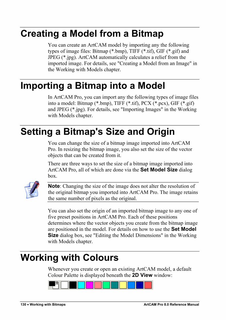
130 • Working with Bitmaps ArtCAM Pro 8.0 Reference Manual
Creating a Model from a BitmapYou can create an ArtCAM model by importing any the followingtypes of image files: Bitmap (*.bmp), TIFF (*.tif), GIF (*.gif) andJPEG (*.jpg). ArtCAM automatically calculates a relief from theimported image. For details, see "Creating a Model from an Image" inthe Working with Models chapter.
Importing a Bitmap into a ModelIn ArtCAM Pro, you can import any the following types of image filesinto a model: Bitmap (*.bmp), TIFF (*.tif), PCX (*.pcx), GIF (*.gif)and JPEG (*.jpg). For details, see "Importing Images" in the Workingwith Models chapter.
Setting a Bitmap's Size and OriginYou can change the size of a bitmap image imported into ArtCAMPro. In resizing the bitmap image, you also set the size of the vectorobjects that can be created from it.There are three ways to set the size of a bitmap image imported intoArtCAM Pro, all of which are done via the Set Model Size dialogbox.
Note: Changing the size of the image does not alter the resolution ofthe original bitmap you imported into ArtCAM Pro. The image retainsthe same number of pixels as the original.
You can also set the origin of an imported bitmap image to any one offive preset positions in ArtCAM Pro. Each of these positionsdetermines where the vector objects you create from the bitmap imageare positioned in the model. For details on how to use the Set ModelSize dialog box, see "Editing the Model Dimensions" in the Workingwith Models chapter.
Working with ColoursWhenever you create or open an existing ArtCAM model, a defaultColour Palette is displayed beneath the 2D View window:
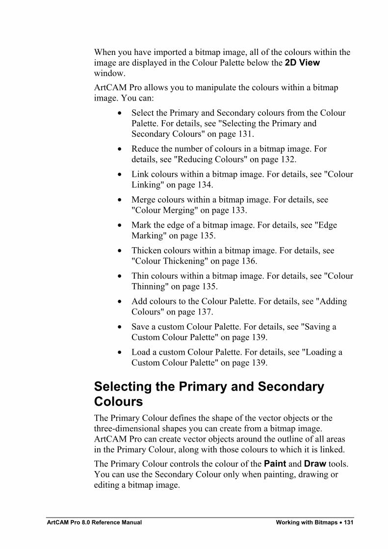
ArtCAM Pro 8.0 Reference Manual Working with Bitmaps • 131
When you have imported a bitmap image, all of the colours within theimage are displayed in the Colour Palette below the 2D Viewwindow.ArtCAM Pro allows you to manipulate the colours within a bitmapimage. You can:
• Select the Primary and Secondary colours from the ColourPalette. For details, see "Selecting the Primary andSecondary Colours" on page 131.
• Reduce the number of colours in a bitmap image. Fordetails, see "Reducing Colours" on page 132.
• Link colours within a bitmap image. For details, see "ColourLinking" on page 134.
• Merge colours within a bitmap image. For details, see"Colour Merging" on page 133.
• Mark the edge of a bitmap image. For details, see "EdgeMarking" on page 135.
• Thicken colours within a bitmap image. For details, see"Colour Thickening" on page 136.
• Thin colours within a bitmap image. For details, see "ColourThinning" on page 135.
• Add colours to the Colour Palette. For details, see "AddingColours" on page 137.
• Save a custom Colour Palette. For details, see "Saving aCustom Colour Palette" on page 139.
• Load a custom Colour Palette. For details, see "Loading aCustom Colour Palette" on page 139.
Selecting the Primary and SecondaryColoursThe Primary Colour defines the shape of the vector objects or thethree-dimensional shapes you can create from a bitmap image.ArtCAM Pro can create vector objects around the outline of all areasin the Primary Colour, along with those colours to which it is linked.The Primary Colour controls the colour of the Paint and Draw tools.You can use the Secondary Colour only when painting, drawing orediting a bitmap image.
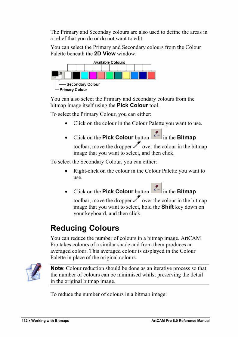
132 • Working with Bitmaps ArtCAM Pro 8.0 Reference Manual
The Primary and Seconday colours are also used to define the areas ina relief that you do or do not want to edit.You can select the Primary and Secondary colours from the ColourPalette beneath the 2D View window:
You can also select the Primary and Secondary colours from thebitmap image itself using the Pick Colour tool.To select the Primary Colour, you can either:
• Click on the colour in the Colour Palette you want to use.
• Click on the Pick Colour button in the Bitmaptoolbar, move the dropper over the colour in the bitmapimage that you want to select, and then click.
To select the Secondary Colour, you can either:• Right-click on the colour in the Colour Palette you want to
use.
• Click on the Pick Colour button in the Bitmaptoolbar, move the dropper over the colour in the bitmapimage that you want to select, hold the Shift key down onyour keyboard, and then click.
Reducing ColoursYou can reduce the number of colours in a bitmap image. ArtCAMPro takes colours of a similar shade and from them produces anaveraged colour. This averaged colour is displayed in the ColourPalette in place of the original colours.
Note: Colour reduction should be done as an iterative process so thatthe number of colours can be minimised whilst preserving the detailin the original bitmap image.
To reduce the number of colours in a bitmap image:
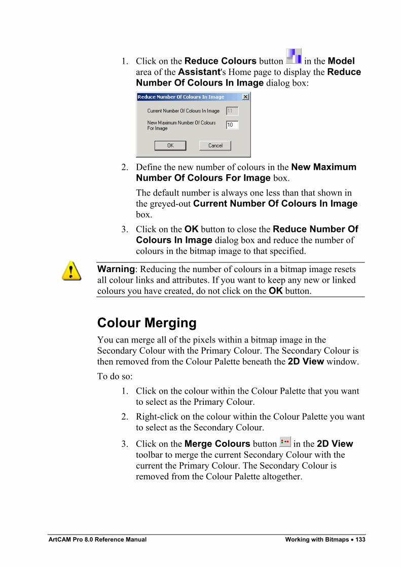
ArtCAM Pro 8.0 Reference Manual Working with Bitmaps • 133
1. Click on the Reduce Colours button in the Modelarea of the Assistant's Home page to display the ReduceNumber Of Colours In Image dialog box:
2. Define the new number of colours in the New MaximumNumber Of Colours For Image box.The default number is always one less than that shown inthe greyed-out Current Number Of Colours In Imagebox.
3. Click on the OK button to close the Reduce Number OfColours In Image dialog box and reduce the number ofcolours in the bitmap image to that specified.
Warning: Reducing the number of colours in a bitmap image resetsall colour links and attributes. If you want to keep any new or linkedcolours you have created, do not click on the OK button.
Colour MergingYou can merge all of the pixels within a bitmap image in theSecondary Colour with the Primary Colour. The Secondary Colour isthen removed from the Colour Palette beneath the 2D View window.To do so:
1. Click on the colour within the Colour Palette that you wantto select as the Primary Colour.
2. Right-click on the colour within the Colour Palette you wantto select as the Secondary Colour.
3. Click on the Merge Colours button in the 2D Viewtoolbar to merge the current Secondary Colour with thecurrent the Primary Colour. The Secondary Colour isremoved from the Colour Palette altogether.
134 • Working with Bitmaps ArtCAM Pro 8.0 Reference Manual
Colour LinkingYou can both link and unlink colours within the Colour Palettebeneath the 2D View window. When a colour in the Colour Palette islinked to the Primary Colour, it is treated as the Primary Colour for aslong as it linked to it.There are three ways you can link a colour in the Colour Palette withthe current Primary Colour:
• Click on the Link/Unlink button to link the SecondaryColour to the Primary Colour.
• Click on the Link/Unlink icon in the Colour Palette tolink the Secondary Colour to the Primary Colour.
• Double right-click on the colour in the Colour Palette thatyou want to link to the Primary Colour.
You can see that colours are linked to the Primary Colour when shownin the Colour Palette as follows:
When colours are linked to the Primary Colour, they are displayedwithin the image in the Primary Colour.
Linking All ColoursBy clicking on the Link All Colours button , you cansimultaneously link all colours currently in the Colour Palette, otherthan the Secondary Colour, to the Primary Colour.
Tip: Depending on how many colours there are you want to link, itmay be quicker to use the Link All Colours method of linking andthen use the Link/Unlink button to unlink the individual coloursthat you do not want.
Unlinking All ColoursBy clicking on the Unlink All Colours button , you can unlink allcolours currently linked in the Colour Palette.
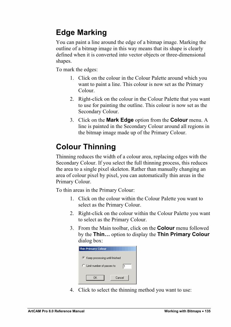
ArtCAM Pro 8.0 Reference Manual Working with Bitmaps • 135
Edge MarkingYou can paint a line around the edge of a bitmap image. Marking theoutline of a bitmap image in this way means that its shape is clearlydefined when it is converted into vector objects or three-dimensionalshapes.To mark the edges:
1. Click on the colour in the Colour Palette around which youwant to paint a line. This colour is now set as the PrimaryColour.
2. Right-click on the colour in the Colour Palette that you wantto use for painting the outline. This colour is now set as theSecondary Colour.
3. Click on the Mark Edge option from the Colour menu. Aline is painted in the Secondary Colour around all regions inthe bitmap image made up of the Primary Colour.
Colour ThinningThinning reduces the width of a colour area, replacing edges with theSecondary Colour. If you select the full thinning process, this reducesthe area to a single pixel skeleton. Rather than manually changing anarea of colour pixel by pixel, you can automatically thin areas in thePrimary Colour.To thin areas in the Primary Colour:
1. Click on the colour within the Colour Palette you want toselect as the Primary Colour.
2. Right-click on the colour within the Colour Palette you wantto select as the Primary Colour.
3. From the Main toolbar, click on the Colour menu followedby the Thin… option to display the Thin Primary Colourdialog box:
4. Click to select the thinning method you want to use:
136 • Working with Bitmaps ArtCAM Pro 8.0 Reference Manual
• Keep processing until finished - This optioncontinues to thin all regions in the Primary Colouruntil they are reduced to a width of one pixel.
• Limit number of passes to - This option sets alimit on the number of thinning passes according tothe value you type in the box. Each pass converts oneedge pixel in the Primary Colour to the SecondaryColour.
5. Click on the OK button to close the Thin Primary Colourdialog box and to thin all regions in the Primary Colour. TheWorking box is displayed while ArtCAM Pro completesthe colour thinning process:
The region of removed pixels is marked in the currentSecondary Colour. If you do not need to mark this region,ensure that the Secondary Colour is the same as thebackground colour in the bitmap image before colourthinning.
Colour ThickeningThickening increases the width of a colour area, expanding the borderswith the Secondary Colour. Rather than manually changing an area ofcolour pixel by pixel, you can automatically thicken areas in thePrimary Colour.To thicken areas in the Primary Colour:
1. Click on the colour within the Colour Palette you want toselect as the Primary Colour.
2. Right-click on the colour within the Colour Palette you wantto select as the Secondary Colour.
3. From the Main toolbar, click on the Colour menu followedby the Thicken… option to display the Thicken Colourdialog box:
ArtCAM Pro 8.0 Reference Manual Working with Bitmaps • 137
4. Define the brush diameter in the Number of Pixels box.
Warning: The brush diameter should be an odd number. Evennumbers are automatically rounded up to an odd number.
5. Click on the OK button to close the Thicken Colourdialog box and to apply a round brush of the diameter youhave already defined in the current Secondary Colour toeach pixel in the current Primary Colour.The Working box is displayed while ArtCAM Procompletes the colour thickening process:
If you want to cancel the colour thickening process at anytime, click on the Cancel button.The original pixels in the bitmap image remain in thePrimary Colour, while the thickened regions appear in theSecondary Colour. If you do not need this distinction,ensure that both the Primary and Secondary Colours areidentical before colour thickening.
Adding ColoursYou can increase the range of colours within the Colour Palettebeneath the 2D View window. You can add Basic Colours and/orcreate your own Custom Colours for you to paint in.To add to the Colour Palette:
1. Click on the Add Colour button in the BitmapEditing area of the Assistant's Home page to open theColor dialog box:
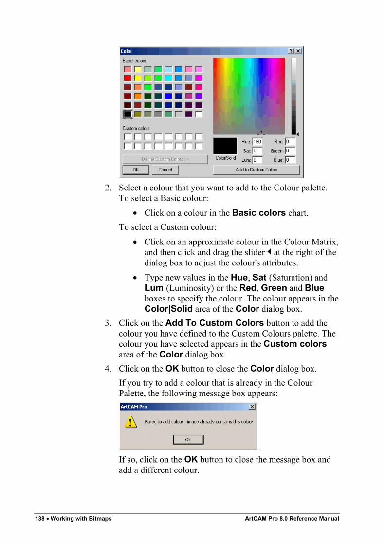
138 • Working with Bitmaps ArtCAM Pro 8.0 Reference Manual
2. Select a colour that you want to add to the Colour palette.To select a Basic colour:
• Click on a colour in the Basic colors chart.To select a Custom colour:
• Click on an approximate colour in the Colour Matrix,and then click and drag the slider at the right of thedialog box to adjust the colour's attributes.
• Type new values in the Hue, Sat (Saturation) andLum (Luminosity) or the Red, Green and Blueboxes to specify the colour. The colour appears in theColor|Solid area of the Color dialog box.
3. Click on the Add To Custom Colors button to add thecolour you have defined to the Custom Colours palette. Thecolour you have selected appears in the Custom colorsarea of the Color dialog box.
4. Click on the OK button to close the Color dialog box.If you try to add a colour that is already in the ColourPalette, the following message box appears:
If so, click on the OK button to close the message box andadd a different colour.
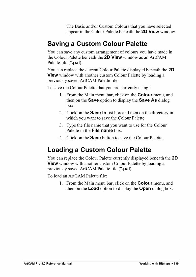
ArtCAM Pro 8.0 Reference Manual Working with Bitmaps • 139
The Basic and/or Custom Colours that you have selectedappear in the Colour Palette beneath the 2D View window.
Saving a Custom Colour PaletteYou can save any custom arrangement of colours you have made inthe Colour Palette beneath the 2D View window as an ArtCAMPalette file (*.pal).You can replace the current Colour Palette displayed beneath the 2DView window with another custom Colour Palette by loading apreviously saved ArtCAM Palette file.To save the Colour Palette that you are currently using:
1. From the Main menu bar, click on the Colour menu, andthen on the Save option to display the Save As dialogbox.
2. Click on the Save In list box and then on the directory inwhich you want to save the Colour Palette.
3. Type the file name that you want to use for the ColourPalette in the File name box.
4. Click on the Save button to save the Colour Palette.
Loading a Custom Colour PaletteYou can replace the Colour Palette currently displayed beneath the 2DView window with another custom Colour Palette by loading apreviously saved ArtCAM Palette file (*.pal).To load an ArtCAM Palette file:
1. From the Main menu bar, click on the Colour menu, andthen on the Load option to display the Open dialog box:
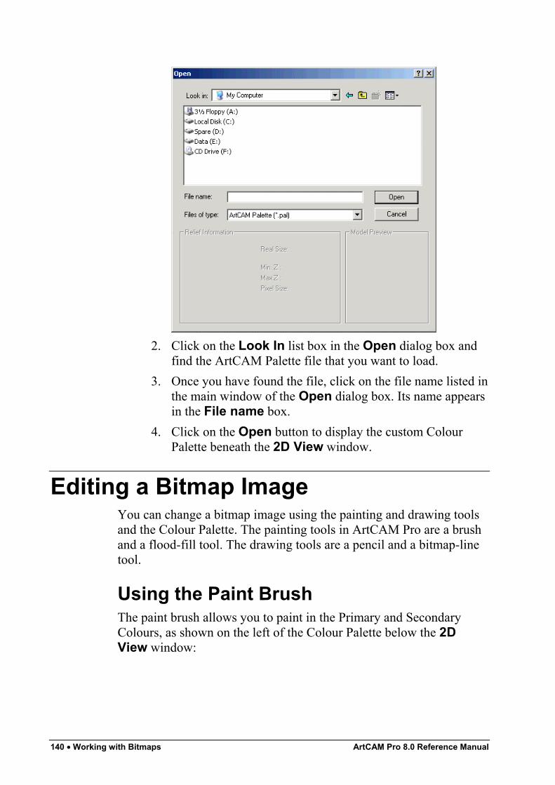
140 • Working with Bitmaps ArtCAM Pro 8.0 Reference Manual
2. Click on the Look In list box in the Open dialog box andfind the ArtCAM Palette file that you want to load.
3. Once you have found the file, click on the file name listed inthe main window of the Open dialog box. Its name appearsin the File name box.
4. Click on the Open button to display the custom ColourPalette beneath the 2D View window.
Editing a Bitmap ImageYou can change a bitmap image using the painting and drawing toolsand the Colour Palette. The painting tools in ArtCAM Pro are a brushand a flood-fill tool. The drawing tools are a pencil and a bitmap-linetool.
Using the Paint BrushThe paint brush allows you to paint in the Primary and SecondaryColours, as shown on the left of the Colour Palette below the 2DView window:
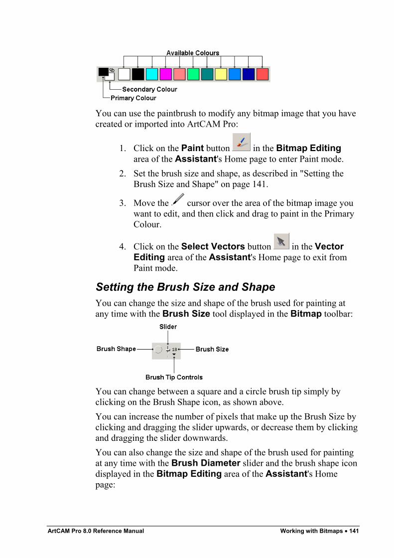
ArtCAM Pro 8.0 Reference Manual Working with Bitmaps • 141
You can use the paintbrush to modify any bitmap image that you havecreated or imported into ArtCAM Pro:
1. Click on the Paint button in the Bitmap Editingarea of the Assistant's Home page to enter Paint mode.
2. Set the brush size and shape, as described in "Setting theBrush Size and Shape" on page 141.
3. Move the cursor over the area of the bitmap image youwant to edit, and then click and drag to paint in the PrimaryColour.
4. Click on the Select Vectors button in the VectorEditing area of the Assistant's Home page to exit fromPaint mode.
Setting the Brush Size and ShapeYou can change the size and shape of the brush used for painting atany time with the Brush Size tool displayed in the Bitmap toolbar:
You can change between a square and a circle brush tip simply byclicking on the Brush Shape icon, as shown above.You can increase the number of pixels that make up the Brush Size byclicking and dragging the slider upwards, or decrease them by clickingand dragging the slider downwards.You can also change the size and shape of the brush used for paintingat any time with the Brush Diameter slider and the brush shape icondisplayed in the Bitmap Editing area of the Assistant's Homepage:
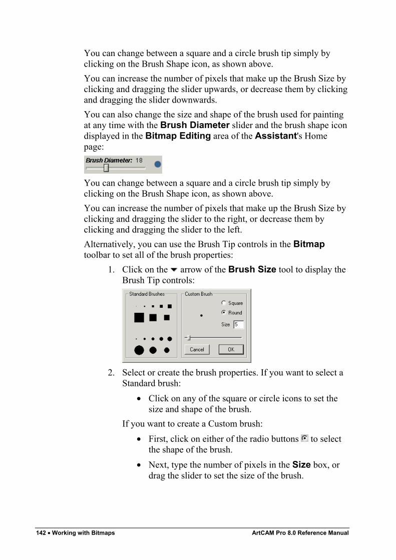
142 • Working with Bitmaps ArtCAM Pro 8.0 Reference Manual
You can change between a square and a circle brush tip simply byclicking on the Brush Shape icon, as shown above.You can increase the number of pixels that make up the Brush Size byclicking and dragging the slider upwards, or decrease them by clickingand dragging the slider downwards.You can also change the size and shape of the brush used for paintingat any time with the Brush Diameter slider and the brush shape icondisplayed in the Bitmap Editing area of the Assistant's Homepage:
You can change between a square and a circle brush tip simply byclicking on the Brush Shape icon, as shown above.You can increase the number of pixels that make up the Brush Size byclicking and dragging the slider to the right, or decrease them byclicking and dragging the slider to the left.Alternatively, you can use the Brush Tip controls in the Bitmaptoolbar to set all of the brush properties:
1. Click on the arrow of the Brush Size tool to display theBrush Tip controls:
2. Select or create the brush properties. If you want to select aStandard brush:
• Click on any of the square or circle icons to set thesize and shape of the brush.
If you want to create a Custom brush:• First, click on either of the radio buttons to select
the shape of the brush.• Next, type the number of pixels in the Size box, or
drag the slider to set the size of the brush.
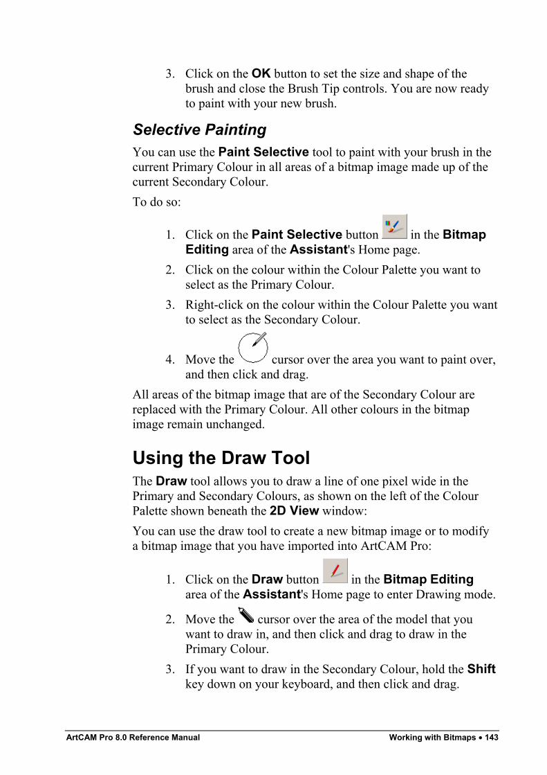
ArtCAM Pro 8.0 Reference Manual Working with Bitmaps • 143
3. Click on the OK button to set the size and shape of thebrush and close the Brush Tip controls. You are now readyto paint with your new brush.
Selective PaintingYou can use the Paint Selective tool to paint with your brush in thecurrent Primary Colour in all areas of a bitmap image made up of thecurrent Secondary Colour.To do so:
1. Click on the Paint Selective button in the BitmapEditing area of the Assistant's Home page.
2. Click on the colour within the Colour Palette you want toselect as the Primary Colour.
3. Right-click on the colour within the Colour Palette you wantto select as the Secondary Colour.
4. Move the cursor over the area you want to paint over,and then click and drag.
All areas of the bitmap image that are of the Secondary Colour arereplaced with the Primary Colour. All other colours in the bitmapimage remain unchanged.
Using the Draw ToolThe Draw tool allows you to draw a line of one pixel wide in thePrimary and Secondary Colours, as shown on the left of the ColourPalette shown beneath the 2D View window:You can use the draw tool to create a new bitmap image or to modifya bitmap image that you have imported into ArtCAM Pro:
1. Click on the Draw button in the Bitmap Editingarea of the Assistant's Home page to enter Drawing mode.
2. Move the cursor over the area of the model that youwant to draw in, and then click and drag to draw in thePrimary Colour.
3. If you want to draw in the Secondary Colour, hold the Shiftkey down on your keyboard, and then click and drag.
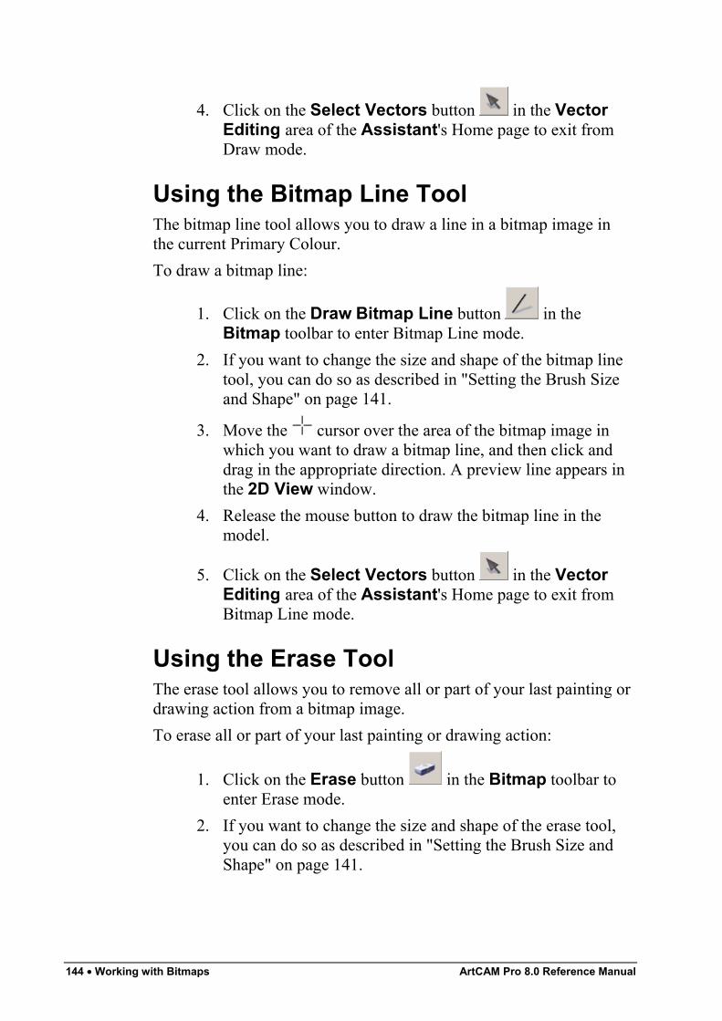
144 • Working with Bitmaps ArtCAM Pro 8.0 Reference Manual
4. Click on the Select Vectors button in the VectorEditing area of the Assistant's Home page to exit fromDraw mode.
Using the Bitmap Line ToolThe bitmap line tool allows you to draw a line in a bitmap image inthe current Primary Colour.To draw a bitmap line:
1. Click on the Draw Bitmap Line button in theBitmap toolbar to enter Bitmap Line mode.
2. If you want to change the size and shape of the bitmap linetool, you can do so as described in "Setting the Brush Sizeand Shape" on page 141.
3. Move the cursor over the area of the bitmap image inwhich you want to draw a bitmap line, and then click anddrag in the appropriate direction. A preview line appears inthe 2D View window.
4. Release the mouse button to draw the bitmap line in themodel.
5. Click on the Select Vectors button in the VectorEditing area of the Assistant's Home page to exit fromBitmap Line mode.
Using the Erase ToolThe erase tool allows you to remove all or part of your last painting ordrawing action from a bitmap image.To erase all or part of your last painting or drawing action:
1. Click on the Erase button in the Bitmap toolbar toenter Erase mode.
2. If you want to change the size and shape of the erase tool,you can do so as described in "Setting the Brush Size andShape" on page 141.
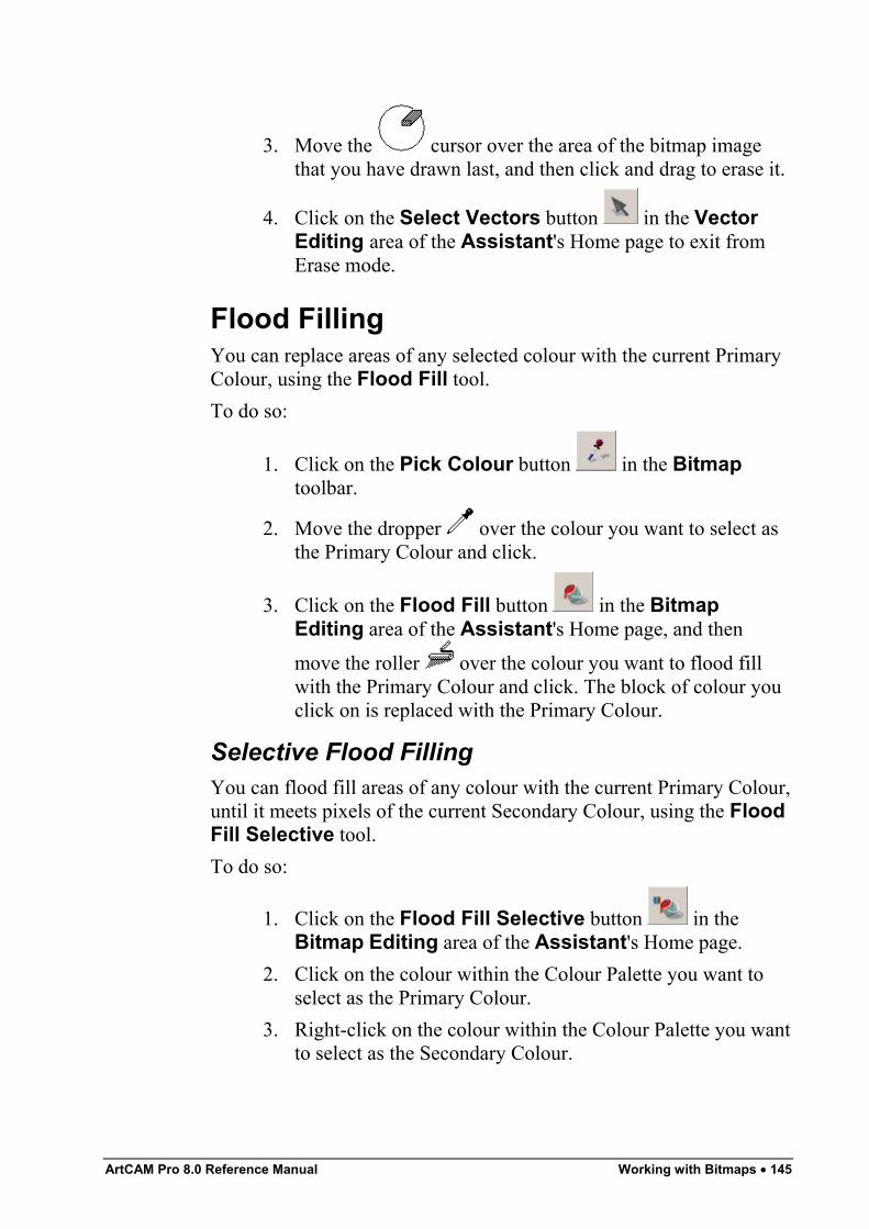
ArtCAM Pro 8.0 Reference Manual Working with Bitmaps • 145
3. Move the cursor over the area of the bitmap imagethat you have drawn last, and then click and drag to erase it.
4. Click on the Select Vectors button in the VectorEditing area of the Assistant's Home page to exit fromErase mode.
Flood FillingYou can replace areas of any selected colour with the current PrimaryColour, using the Flood Fill tool.To do so:
1. Click on the Pick Colour button in the Bitmaptoolbar.
2. Move the dropper over the colour you want to select asthe Primary Colour and click.
3. Click on the Flood Fill button in the BitmapEditing area of the Assistant's Home page, and then
move the roller over the colour you want to flood fillwith the Primary Colour and click. The block of colour youclick on is replaced with the Primary Colour.
Selective Flood FillingYou can flood fill areas of any colour with the current Primary Colour,until it meets pixels of the current Secondary Colour, using the FloodFill Selective tool.To do so:
1. Click on the Flood Fill Selective button in theBitmap Editing area of the Assistant's Home page.
2. Click on the colour within the Colour Palette you want toselect as the Primary Colour.
3. Right-click on the colour within the Colour Palette you wantto select as the Secondary Colour.
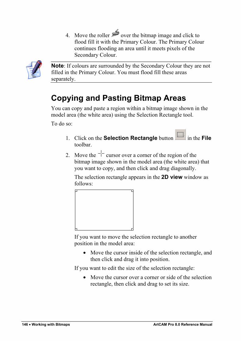
146 • Working with Bitmaps ArtCAM Pro 8.0 Reference Manual
4. Move the roller over the bitmap image and click toflood fill it with the Primary Colour. The Primary Colourcontinues flooding an area until it meets pixels of theSecondary Colour.
Note: If colours are surrounded by the Secondary Colour they are notfilled in the Primary Colour. You must flood fill these areasseparately.
Copying and Pasting Bitmap AreasYou can copy and paste a region within a bitmap image shown in themodel area (the white area) using the Selection Rectangle tool.To do so:
1. Click on the Selection Rectangle button in the Filetoolbar.
2. Move the cursor over a corner of the region of thebitmap image shown in the model area (the white area) thatyou want to copy, and then click and drag diagonally.The selection rectangle appears in the 2D view window asfollows:
If you want to move the selection rectangle to anotherposition in the model area:
• Move the cursor inside of the selection rectangle, andthen click and drag it into position.
If you want to edit the size of the selection rectangle:• Move the cursor over a corner or side of the selection
rectangle, then click and drag to set its size.
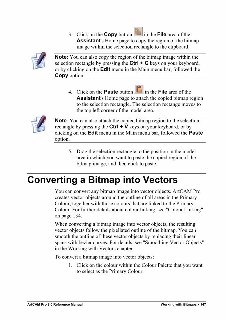
ArtCAM Pro 8.0 Reference Manual Working with Bitmaps • 147
3. Click on the Copy button in the File area of theAssistant's Home page to copy the region of the bitmapimage within the selection rectangle to the clipboard.
Note: You can also copy the region of the bitmap image within theselection rectangle by pressing the Ctrl + C keys on your keyboard,or by clicking on the Edit menu in the Main menu bar, followed theCopy option.
4. Click on the Paste button in the File area of theAssistant's Home page to attach the copied bitmap regionto the selection rectangle. The selection rectange moves tothe top left corner of the model area.
Note: You can also attach the copied bitmap region to the selectionrectangle by pressing the Ctrl + V keys on your keyboard, or byclicking on the Edit menu in the Main menu bar, followed the Pasteoption.
5. Drag the selection rectangle to the position in the modelarea in which you want to paste the copied region of thebitmap image, and then click to paste.
Converting a Bitmap into VectorsYou can convert any bitmap image into vector objects. ArtCAM Procreates vector objects around the outline of all areas in the PrimaryColour, together with those colours that are linked to the PrimaryColour. For further details about colour linking, see "Colour Linking"on page 134.When converting a bitmap image into vector objects, the resultingvector objects follow the pixellated outline of the bitmap. You cansmooth the outline of these vector objects by replacing their linearspans with bezier curves. For details, see "Smoothing Vector Objects"in the Working with Vectors chapter.To convert a bitmap image into vector objects:
1. Click on the colour within the Colour Palette that you wantto select as the Primary Colour.
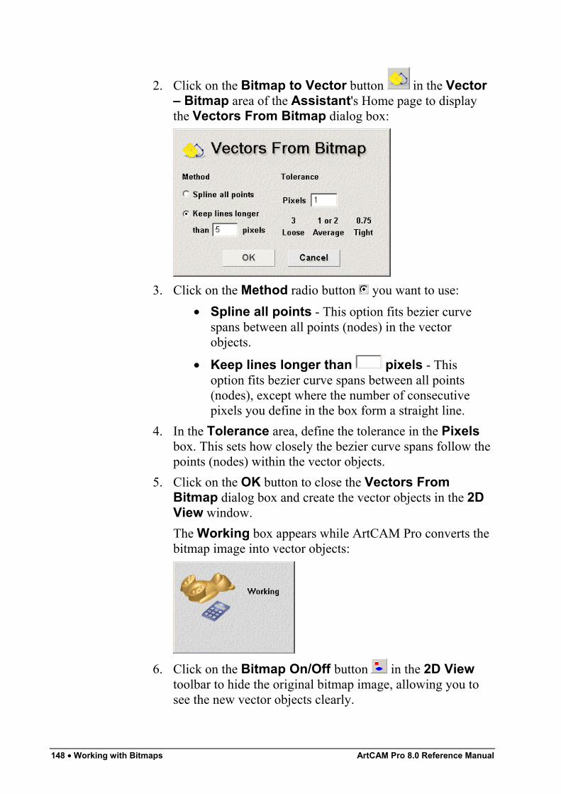
148 • Working with Bitmaps ArtCAM Pro 8.0 Reference Manual
2. Click on the Bitmap to Vector button in the Vector– Bitmap area of the Assistant's Home page to displaythe Vectors From Bitmap dialog box:
3. Click on the Method radio button you want to use:• Spline all points - This option fits bezier curve
spans between all points (nodes) in the vectorobjects.
• Keep lines longer than pixels - Thisoption fits bezier curve spans between all points(nodes), except where the number of consecutivepixels you define in the box form a straight line.
4. In the Tolerance area, define the tolerance in the Pixelsbox. This sets how closely the bezier curve spans follow thepoints (nodes) within the vector objects.
5. Click on the OK button to close the Vectors FromBitmap dialog box and create the vector objects in the 2DView window.The Working box appears while ArtCAM Pro converts thebitmap image into vector objects:
6. Click on the Bitmap On/Off button in the 2D Viewtoolbar to hide the original bitmap image, allowing you tosee the new vector objects clearly.

ArtCAM Pro 8.0 Reference Manual Working with Bitmaps • 149
Creating a Shape from a BitmapYou can generate three-dimensional shapes from any colour within abitmap image using the Shape Editor tool. For more details, see"Creating a Shape from a Bitmap" in the Working with Reliefschapter.

150 • Working with Bitmaps ArtCAM Pro 8.0 Reference Manual
ArtCAM Pro 8.0 Reference Manual Working with Vectors • 151
Working with Vectors
OverviewA vector object, or object-oriented graphic, is made up of a sequenceof commands or mathematical statements that places lines and shapesin a given two-dimensional or three-dimensional space. Vector objectsare fully scalable without loss of resolution, and file sizes areindependent of resolution.In ArtCAM Pro, you can both import vector artwork from otherapplications and convert a bitmap image into vector objects. Fordetails, see "Importing Vector Artwork" in the Working with Modelschapter and "Converting a Bitmap into Vectors" in the Working withBitmaps chapter.Once you have created or opened a model file, you can use thedrawing tools in the Vector Editing area of the Assistant's Homepage and/or the Vector toolbar to create your own vector objects thatcan then be used to:
• Machine a 2D model. For details, see "2D ToolpathStrategies" in the Machining Models chapter.Create a shape that can be used to machine a 3D model. Fordetails, see "Creating a Shape from a Closed Vector" and"Creating a Shape Using Vectors" in the Working withReliefs chapter, then "3D Toolpath Strategies" in theMachining Models chapter.
The group of vector drawing tools are found in the Vector Editingarea of the Assistant's Home page and on the Vector toolbar:
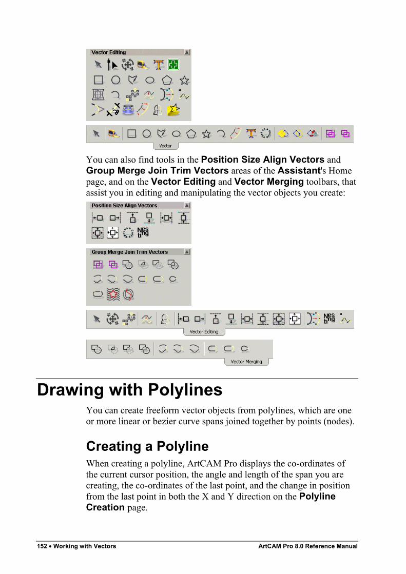
152 • Working with Vectors ArtCAM Pro 8.0 Reference Manual
You can also find tools in the Position Size Align Vectors andGroup Merge Join Trim Vectors areas of the Assistant's Homepage, and on the Vector Editing and Vector Merging toolbars, thatassist you in editing and manipulating the vector objects you create:
Drawing with PolylinesYou can create freeform vector objects from polylines, which are oneor more linear or bezier curve spans joined together by points (nodes).
Creating a PolylineWhen creating a polyline, ArtCAM Pro displays the co-ordinates ofthe current cursor position, the angle and length of the span you arecreating, the co-ordinates of the last point, and the change in positionfrom the last point in both the X and Y direction on the PolylineCreation page.
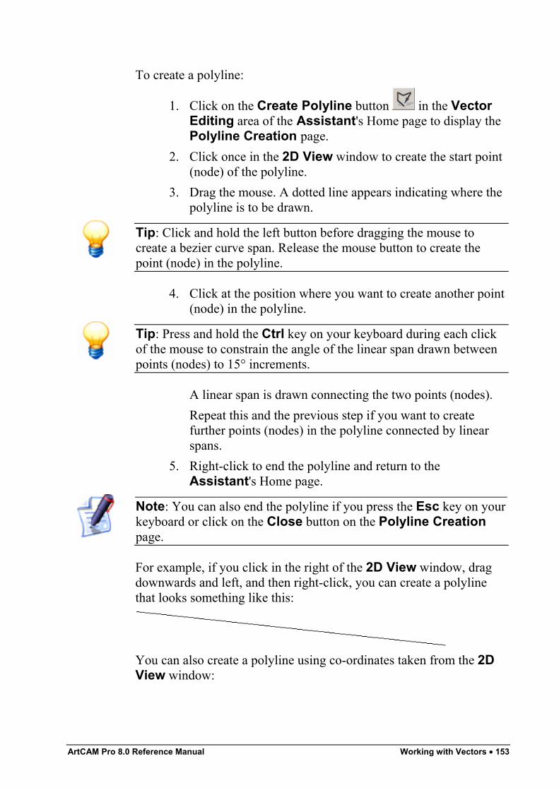
ArtCAM Pro 8.0 Reference Manual Working with Vectors • 153
To create a polyline:
1. Click on the Create Polyline button in the VectorEditing area of the Assistant's Home page to display thePolyline Creation page.
2. Click once in the 2D View window to create the start point(node) of the polyline.
3. Drag the mouse. A dotted line appears indicating where thepolyline is to be drawn.
Tip: Click and hold the left button before dragging the mouse tocreate a bezier curve span. Release the mouse button to create thepoint (node) in the polyline.
4. Click at the position where you want to create another point(node) in the polyline.
Tip: Press and hold the Ctrl key on your keyboard during each clickof the mouse to constrain the angle of the linear span drawn betweenpoints (nodes) to 15° increments.
A linear span is drawn connecting the two points (nodes).Repeat this and the previous step if you want to createfurther points (nodes) in the polyline connected by linearspans.
5. Right-click to end the polyline and return to theAssistant's Home page.
Note: You can also end the polyline if you press the Esc key on yourkeyboard or click on the Close button on the Polyline Creationpage.
For example, if you click in the right of the 2D View window, dragdownwards and left, and then right-click, you can create a polylinethat looks something like this:
You can also create a polyline using co-ordinates taken from the 2DView window:
154 • Working with Vectors ArtCAM Pro 8.0 Reference Manual
1. Click on the Create Polyline button in the VectorEditing area of the Assistant's Home page to display thePolyline Creation page.
2. Click on the position in the 2D View window where youwant to create the polyline's Start Point.
3. Define the position of the next point, using any of thefollowing methods:
Tip: Move the cursor to the position where you want to create thepoint in the polyline. The X and Y co-ordinates for the position areshown in the Cursor Position area of the page.
• Define the X and Y co-ordinates for the next point inthe X and Y boxes.
• Define the angle of the next span in the polyline inthe ° box, followed by its length in the L box.
• Define the distance from the previous point in the Xand Y axes in the dx and dy boxes.
4. If you want the polyline to be made up of bezier curve spansjoined by smoothed points, rather than linear spans joinedby points, click to select the Draw Smooth Polylinesoption . For further information, see "Editing VectorSpans" on page 175 and "Editing Vector Nodes" on page182.
5. Click on the Add button.6. Repeat these steps until you have finished creating the
polyline, and then click on the Close button to return to theAssistant's Home page.
Completing Polyline CreationTo complete the polyline you are drawing, but remain in polylinecreation mode:
• Press the Space Bar on your keyboard.To finish creating a polyline and return to the Assistant's Homepage, leaving it as an open vector object, you can use any of thefollowing methods:
• Right-click on your mouse.
ArtCAM Pro 8.0 Reference Manual Working with Vectors • 155
• Press the Esc key on your keyboard.• Press the Return key on your keyboard.• Click on the Close button on the Polyline Creation page.
By default, the polyline is black, indicating that an ungrouped, openvector object has been created. If, however, you create a polyline on alayer to which a colour has been given, the polyline adopts the layer'scolour. For further information, see "Selecting Vectors" on page 172and "Assigning a Colour to a Layer" in the Working with Modelschapter.
Closing a Polyline to Create a PolygonIf you are in Polyline Creation mode, you can finish creating apolyline and automatically join its Start Point with its last point toform a polygon if you:
• Press the Tab key on your keyboard.If you have already created a polyline, you can join its Start Point withits last point (node) to form a polygon if you:
1. Click to select the polyline that you have created. Thepolyline is magenta and surrounded by a bounding box. Fordetails, see "Selecting Vectors" on page 172.
2. Click on the Node Editing button in the VectorEditing area of the Assistant's Home page to enter NodeEditing mode. The polyline turns black, and you can see thespans and points (nodes) that make up the polyline.
3. Click and drag the start point (green) to meet the last pointin the polyline.
Amending a PolylineA polyline is made up of spans and points (nodes). Spans can be lines,arcs or bezier curves. You can change the position of the points andthe nature of the spans after the polyline is created. For example, alinear span can be changed to an arc or a bezier curve span.You change a polyline's form using both the Node Editing and VectorEditing menu options. These menus are displayed when working inNode Editing mode and right-clicking on either a span or a point. Fordetails, see "Editing Vector Spans" on page 175 and "Editing VectorNodes" on page 182.
156 • Working with Vectors ArtCAM Pro 8.0 Reference Manual
Creating Simple ShapesIn addition to the Create Polyline button , as detailed in"Creating a Polyline" on page 152, there are a further six buttons inthe Vector Editing area of the Assistant's Home page that allowyou to create specific vector object shapes.You can create:
• Rectangles or Squares. See "Creating a Rectangle" on page156.
• Circles. See "Creating a Circle" on page 159• Ellipses. See "Creating an Ellipse" on page 161.• Polygons. See "Creating a Polygon" on page 164.• Stars. See "Creating a Star" on page 166.• Arcs. See "Creating an Arc" on page 169.
Creating a RectangleYou can create either an exact or an approximate square or rectangularshaped vector object.To create an exact square or rectangle:
1. Click on the Create Rectangle button in the VectorEditing area of the Assistant's Home page to display theRectangle Creation page.
2. Click on the Square or Rectangle radio button toselect the type of shape you want to create.
3. Define the height of the shape in the Height box.4. Define the width of the shape in the Width box.5. If you want filleted (rounded) corners, define the radius you
want to apply to all four corners in the Corner Radii box.Otherwise, leave the default value of 0 in the Corner Radiibox.
6. Define the centre point of your shape. To do so, you caneither:
• Define the X and Y co-ordinates of the centre pointin the Centre Point's X and Y boxes.
ArtCAM Pro 8.0 Reference Manual Working with Vectors • 157
• Move the cursor over the 2D View window andclick on the position that you want to set as thecentre point. The X and Y co-ordinates of the pointappear in the Centre Point's X and Y boxes.
7. If you want your shape to be drawn at a specific angle to themodel block, define the angle in the Angle box:
• Type a positive angle to rotate the shape clockwise.• Type a negative angle to rotate the shape anti-
clockwise.8. Click on the Preview button to see the shape you are about
to create in the 2D View window.9. If you want to draw your shape and remain in Rectangle
Creation mode, click on the Create button. If you want todraw your shape and return to the Assistant's Home page,right-click.
To create an approximate sized square or rectangle:
1. Click on the Create Rectangle button in the VectorEditing area of the Assistant's Home page to display theRectangle Creation page.
2. Click on the Square or Rectangle radio button toselect the type of shape you want to create.
3. Move the cursor over the 2D View window, and thenclick and drag to create the size of shape you want.
4. Release the mouse button to draw a preview image of theshape you are creating in the 2D View window.
5. If you want to draw your shape and remain in RectangleCreation mode, click on the Create button. If you want todraw your shape and return to the Assistant's Home page,right-click.
Editing a Square or RectangleYou can edit the size, position, corners and/or angle of a square orrectangular shaped vector object.To begin editing a square or rectangle:
1. Select the square or rectangle you want to edit. For details,see "Selecting Vectors" on page 172.
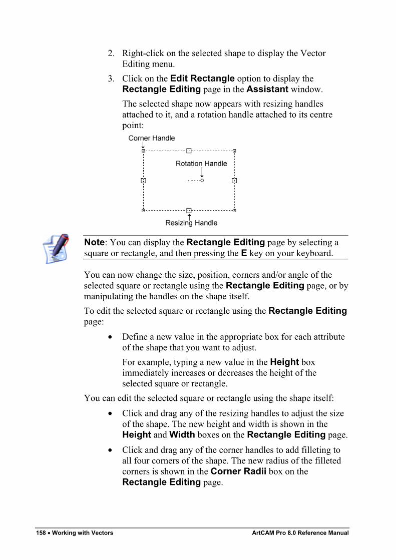
158 • Working with Vectors ArtCAM Pro 8.0 Reference Manual
2. Right-click on the selected shape to display the VectorEditing menu.
3. Click on the Edit Rectangle option to display theRectangle Editing page in the Assistant window.The selected shape now appears with resizing handlesattached to it, and a rotation handle attached to its centrepoint:
Note: You can display the Rectangle Editing page by selecting asquare or rectangle, and then pressing the E key on your keyboard.
You can now change the size, position, corners and/or angle of theselected square or rectangle using the Rectangle Editing page, or bymanipulating the handles on the shape itself.To edit the selected square or rectangle using the Rectangle Editingpage:
• Define a new value in the appropriate box for each attributeof the shape that you want to adjust.For example, typing a new value in the Height boximmediately increases or decreases the height of theselected square or rectangle.
You can edit the selected square or rectangle using the shape itself:• Click and drag any of the resizing handles to adjust the size
of the shape. The new height and width is shown in theHeight and Width boxes on the Rectangle Editing page.
• Click and drag any of the corner handles to add filleting toall four corners of the shape. The new radius of the filletedcorners is shown in the Corner Radii box on theRectangle Editing page.
ArtCAM Pro 8.0 Reference Manual Working with Vectors • 159
• Click and drag the rotation handle to adjust the angle of theshape. The new angle is shown in the Angle box on theRectangle Editing page.
• Move the cursor over the centre point of the shape. Whenit changes to the cursor, click and drag to move thewhole shape. The new centre point appears in the CentrePoint's X and Y boxes on the Rectangle Editing page.
Tip: To create an exact square, hold down the Shift key down onyour keyboard, and then drag the resizing handles on your rectangle tothe required size.
To confirm the new shape shown in the 2D View window and returnto the Assistant's Home page, right-click.
Creating a CircleYou can create a circular shaped vector object.To create a circle of a specified size:
1. Click on the Create Circles button in the VectorEditing area of the Assistant's Home page to display theCircle Creation page.
2. Define the centre point of the circle. To do so, you caneither:
• Define the X and Y co-ordinates of the centre pointin the Circle Centre's X and Y boxes.
• Move the cursor over the 2D View window andclick on the position you want to set as the centrepoint. The X and Y co-ordinates of the point areshown in the Circle Centre's X and Y boxes.
3. In the Circle Size area, define the size of the circle. Youcan:
• Click to select the Radius radio button , and thendefine the circle's radius in the box below; or
• Click to select the Diameter radio button , andthen define the circle's diameter in the box below.
4. If you want the circle to be made up of four arc spans, ratherthan four bezier curve spans, click to select the Create
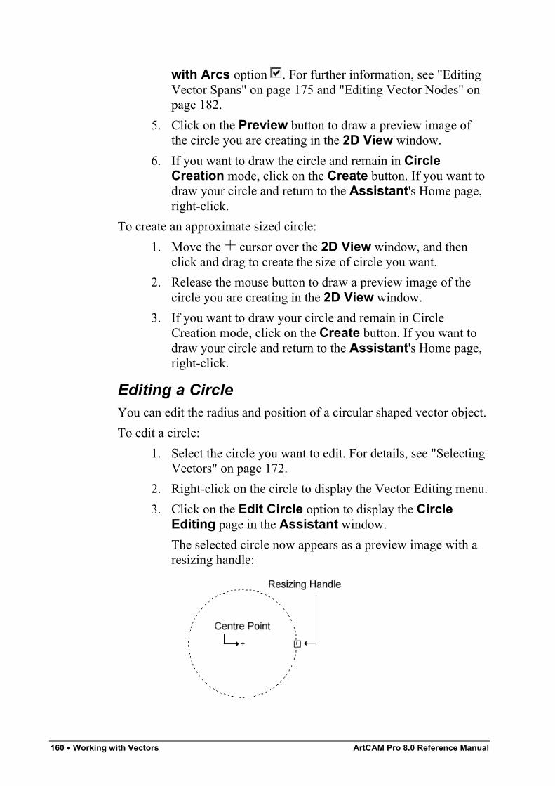
160 • Working with Vectors ArtCAM Pro 8.0 Reference Manual
with Arcs option . For further information, see "EditingVector Spans" on page 175 and "Editing Vector Nodes" onpage 182.
5. Click on the Preview button to draw a preview image ofthe circle you are creating in the 2D View window.
6. If you want to draw the circle and remain in CircleCreation mode, click on the Create button. If you want todraw your circle and return to the Assistant's Home page,right-click.
To create an approximate sized circle:1. Move the cursor over the 2D View window, and then
click and drag to create the size of circle you want.2. Release the mouse button to draw a preview image of the
circle you are creating in the 2D View window.3. If you want to draw your circle and remain in Circle
Creation mode, click on the Create button. If you want todraw your circle and return to the Assistant's Home page,right-click.
Editing a CircleYou can edit the radius and position of a circular shaped vector object.To edit a circle:
1. Select the circle you want to edit. For details, see "SelectingVectors" on page 172.
2. Right-click on the circle to display the Vector Editing menu.3. Click on the Edit Circle option to display the Circle
Editing page in the Assistant window.The selected circle now appears as a preview image with aresizing handle:
ArtCAM Pro 8.0 Reference Manual Working with Vectors • 161
You can now change the size and position of the selectedcircle using the Circle Editing page, or by manipulatingthe resizing handle and the centre point on the shape itself.
Note: You can display the Circle Editing page by selecting a circle,and then pressing the E key on your keyboard.
To edit the selected circle using the Circle Editing page:• Define a new value in the appropriate box for either of the
shape's attributes that you want to adjust.For example, typing a new value in the Radius boximmediately increases or decreases the size of the selectedcircle.
You can edit the selected circle using the shape itself:• Click and drag the resizing handle to adjust its radius. The
new radius is shown in the Radius box on the CircleEditing page.
• Move the cursor over the centre point of the circle. Whenit changes to the cursor, click and drag to move thecircle. The new centre point is shown in the Centre Point'sX and Y boxes on the page.
To confirm the new circle shown in the 2D View window and returnto the Assistant's Home page, right-click.
Creating an EllipseYou can create an elliptical shaped vector object.To create an ellipse of a specified size:
1. Click on the Create Ellipse button in the VectorEditing area of the Assistant's Home page to display theEllipse Creation page.
2. Define the centre point of your ellipse. To do so, you caneither:
• Define the X and Y co-ordinates of the centre pointin the Start Point's X and Y boxes.
• Move the cursor over the 2D View window andthen click on the point. The X and Y co-ordinates of
162 • Working with Vectors ArtCAM Pro 8.0 Reference Manual
the point are shown in the Start Point's X and Yboxes.
3. Define the height of the ellipse in the Ellipse Height box.4. Define the width of the ellipse in the Ellipse Width box.5. If you want your shape to be drawn at a specific angle to the
model block, define the angle in the Angle box:6. Click on the Preview button to see the ellipse you are
about to create in the 2D View window.7. If you want to draw your ellipse and remain in Ellipse
Creation mode, click on the Create button. If you want todraw your ellipse and return to the Assistant's Home page,right-click..
To create an approximate sized ellipse:1. Move the cursor over the 2D View window, and then
click and drag to create the size of ellipse you want.2. Release the mouse button to draw a preview image of the
ellipse you are creating in the 2D View window.3. If you want to draw your ellipse and remain in Ellipse
Creation mode, click on the Create button. If you want todraw your ellipse and return to the Assistant's Home page,right-click.
Editing an EllipseYou can edit the size, position and/or angle of an elliptical shapedvector object.To edit an ellipse:
1. Select the ellipse you want to edit. For details, see"Selecting Vectors" on page 172.
2. Right-click on the selected ellipse to display the VectorEditing menu.
3. Click on the Edit Ellipse option to display the EllipseEditing page in the Assistant window.The selected ellipse now appears as a preview image withresizing handles attached to it, and a rotation handle aboutits centre point:
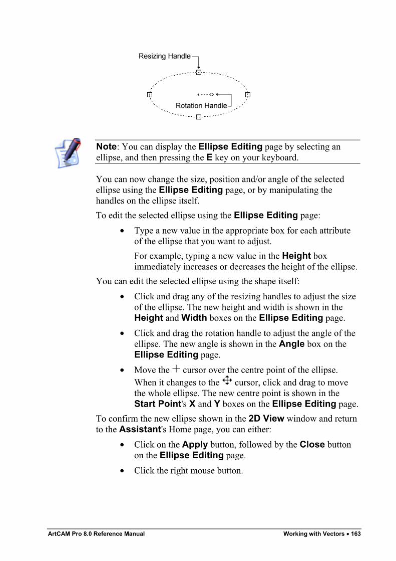
ArtCAM Pro 8.0 Reference Manual Working with Vectors • 163
Note: You can display the Ellipse Editing page by selecting anellipse, and then pressing the E key on your keyboard.
You can now change the size, position and/or angle of the selectedellipse using the Ellipse Editing page, or by manipulating thehandles on the ellipse itself.To edit the selected ellipse using the Ellipse Editing page:
• Type a new value in the appropriate box for each attributeof the ellipse that you want to adjust.For example, typing a new value in the Height boximmediately increases or decreases the height of the ellipse.
You can edit the selected ellipse using the shape itself:• Click and drag any of the resizing handles to adjust the size
of the ellipse. The new height and width is shown in theHeight and Width boxes on the Ellipse Editing page.
• Click and drag the rotation handle to adjust the angle of theellipse. The new angle is shown in the Angle box on theEllipse Editing page.
• Move the cursor over the centre point of the ellipse.When it changes to the cursor, click and drag to movethe whole ellipse. The new centre point is shown in theStart Point's X and Y boxes on the Ellipse Editing page.
To confirm the new ellipse shown in the 2D View window and returnto the Assistant's Home page, you can either:
• Click on the Apply button, followed by the Close buttonon the Ellipse Editing page.
• Click the right mouse button.
164 • Working with Vectors ArtCAM Pro 8.0 Reference Manual
Creating a PolygonYou can create a vast range of polygonal shaped vector objects.To create an exact polygon:
1. Click on the Create Polygons button in the VectorEditing area of the Assistant's Home page to display thePolygon Creation page.
2. Define the polygon's number of sides in the Settings' No.of Sides box.
Warning: A polygon must have a minimum of three sides. Typing 3in the Settings' No. of Sides box produces a triangle.
3. If you want your polygon to be drawn at a specific angle tothe model block, define the angle in the Settings' Anglebox:
• Type a positive angle in the Angle box to rotate thepolygon clockwise.
• Type a negative angle in the Angle box to rotate thepolygon anti-clockwise.
4. Define the centre point of your polygon. To do so, you caneither:
• Define the X and Y co-ordinates of the centre pointin the Polygon Centre's X and Y boxes.
• Move the cursor to the point in the model you areinterested in and then click. The X and Y co-ordinates of the point you click on appear in thePolygon Centre's X and Y boxes.
5. Define the polygon's radius in the Geometry's Radiusbox.
6. Click on the Preview button to see the polygon you areabout to create in the 2D View window.
7. If you want to draw your polygon and remain in PolygonCreation mode, click on the Create button. If you want todraw your polygon and return to the Assistant's Homepage, right-click.
To create an approximate sized polygon:
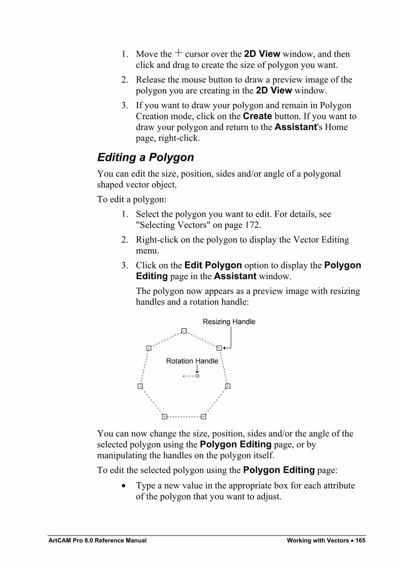
ArtCAM Pro 8.0 Reference Manual Working with Vectors • 165
1. Move the cursor over the 2D View window, and thenclick and drag to create the size of polygon you want.
2. Release the mouse button to draw a preview image of thepolygon you are creating in the 2D View window.
3. If you want to draw your polygon and remain in PolygonCreation mode, click on the Create button. If you want todraw your polygon and return to the Assistant's Homepage, right-click.
Editing a PolygonYou can edit the size, position, sides and/or angle of a polygonalshaped vector object.To edit a polygon:
1. Select the polygon you want to edit. For details, see"Selecting Vectors" on page 172.
2. Right-click on the polygon to display the Vector Editingmenu.
3. Click on the Edit Polygon option to display the PolygonEditing page in the Assistant window.The polygon now appears as a preview image with resizinghandles and a rotation handle:
You can now change the size, position, sides and/or the angle of theselected polygon using the Polygon Editing page, or bymanipulating the handles on the polygon itself.To edit the selected polygon using the Polygon Editing page:
• Type a new value in the appropriate box for each attributeof the polygon that you want to adjust.
166 • Working with Vectors ArtCAM Pro 8.0 Reference Manual
For example, typing a new value in the No. of Sides boximmediately increases or decreases the number of sides inthe selected polygon.
You can edit the selected polygon using the shape itself:• Click and drag any of the resizing handles to adjust the size
of the polygon. The new size is shown in the Geometry'sRadius box on the Polygon Editing page.
• Click and drag the rotation handle to adjust the angle of thepolygon. The new angle is shown in the Angle box on theRectangle Editing page.
• Move the cursor over the centre point of the polygon.When it changes to the cursor, click and drag to movethe whole polygon. The new centre point is shown in thePolygon Centre's X and Y boxes on the PolygonEditing page.
To confirm the new polygon shown in the 2D View window andreturn to the Assistant's Home page, you can either:
• Click on the Apply button, followed by the Close buttonon the Polygon Editing page.
• Click the right mouse button.
Creating a StarYou can create a star shaped vector object.To create an exact star:
1. Click on the Create Stars button in the VectorEditing area of the Assistant's Home page to display theStar Creation page.
2. Define the polygon's number of sides in the Settings' No.of Points box.
3. If you want your star to be drawn at a specific angle to themodel block, define the angle in the Settings' Angle box:
• Type a positive angle in the Angle box to rotate thestar clockwise.
• Type a negative angle in the Angle box to rotate thestar anti-clockwise.
ArtCAM Pro 8.0 Reference Manual Working with Vectors • 167
4. Define the centre point of your star. To do so, you caneither:
• Define the X and Y co-ordinates of the centre pointin the Star Centre's X and Y boxes.
• Move the cursor over the 2D View window andclick on the position you want to set as the centrepoint. The X and Y co-ordinates of the point areshown in the Star Centre's X and Y boxes.
5. In the Geometry's Radius of first Points box, definethe radius of the polygon, upon which the outer points(nodes) in the star lie.
6. In the Geometry's Radius of second Points box,define the radius of the polygon, upon which the innerpoints (nodes) in the star lie.
7. Click on the Preview button to see the ellipse you areabout to create in the 2D View window.
8. If you want to draw your star and remain in Star Creationmode, click on the Create button. If you want to draw yourstar and return to the Assistant's Home page, right-click.
To create an approximate sized star:1. Move the cursor over the 2D View window, and then
click and drag to create the size of polygon you want, uponwhich the outer points in the star lie.
2. Click and drag to create the size of polygon you want, uponwhich the inner points in the star lie.
3. Release the mouse button to draw a preview image of thestar you are creating in the 2D View window.
4. If you want to draw your star and remain in Star Creationmode, click on the Create button. If you want to draw yourpolygon and return to the Assistant's Home page, right-click.
Editing a StarYou can edit the size, position, sides and/or angle of a star shapedvector object.To edit a star:
1. Select the star you want to edit. For details, see "SelectingVectors" on page 172.
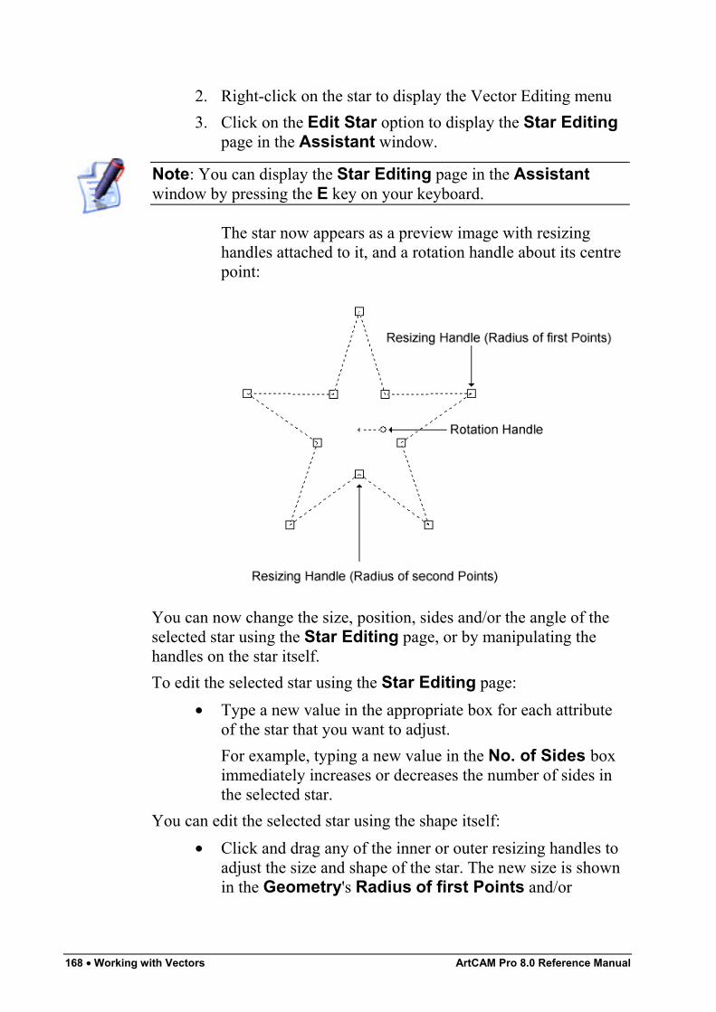
168 • Working with Vectors ArtCAM Pro 8.0 Reference Manual
2. Right-click on the star to display the Vector Editing menu3. Click on the Edit Star option to display the Star Editing
page in the Assistant window.
Note: You can display the Star Editing page in the Assistantwindow by pressing the E key on your keyboard.
The star now appears as a preview image with resizinghandles attached to it, and a rotation handle about its centrepoint:
You can now change the size, position, sides and/or the angle of theselected star using the Star Editing page, or by manipulating thehandles on the star itself.To edit the selected star using the Star Editing page:
• Type a new value in the appropriate box for each attributeof the star that you want to adjust.For example, typing a new value in the No. of Sides boximmediately increases or decreases the number of sides inthe selected star.
You can edit the selected star using the shape itself:• Click and drag any of the inner or outer resizing handles to
adjust the size and shape of the star. The new size is shownin the Geometry's Radius of first Points and/or
ArtCAM Pro 8.0 Reference Manual Working with Vectors • 169
Radius of second Points boxes on the Star Editingpage.
• Click and drag the rotation handle to adjust the angle of thestar. The new angle is shown in the Angle box on theRectangle Editing page.
• Move the cursor over the centre point of the star. When itchanges to the cursor, then click and drag to move thewhole star. The new centre point appears in the StarCentre's X and Y boxes on the Star Editing page.
To confirm the new star shown in the 2D View window and return tothe Assistant's Home page, you can either:
• Click on the Apply button, followed by the Close buttonon the Star Editing page.
• Click the right mouse button.
Creating an ArcYou can create an arc shaped vector object.To create an arc:
1. Click on the Create Arcs button in the VectorEditing area of the Assistant's Home page to display theArc Creation page.
2. Click on either of the Arc Type radio buttons to selectthe type of arc you want to create:
• Centre – Start – End – A swept arc created bydefining a centre point, a Start Point and then an endpoint.
• Start – End – Point On Arc – A fitted arc createdby defining a Start Point, an end point and then a midpoint.
• Start – End – Radius – A swept arc created bydefining a Start Point, a end point and then a radius.
3. If you have selected the Centre – Start – End option:• Move the cursor over the 2D View window and
click on the position that you want to set as the arc'scentre point. The X and Y co-ordinates of the pointare shown in the Centre Point area of the page.
170 • Working with Vectors ArtCAM Pro 8.0 Reference Manual
• Move the cursor over the 2D View window andthen click on the position that you want to set as thearc's start point. The X and Y co-ordinates of thepoint are shown in the Start Point area of the page.
• Move the cursor over the 2D View window andclick on the position that you want to set as the arc'send point. The X and Y co-ordinates of the point areshown in the End Point area of the page.
If you have selected the Start – End – Point On Arcoption:
• Move the cursor over the 2D View window andthen click on the position that you want to set as thearc's start point. The X and Y co-ordinates of thepoint are shown in the Start Point area of the page.
• Move the cursor over the 2D View window andclick on the position that you want to set as the arc'send point. The X and Y co-ordinates of the point areshown in the End Point area of the page.
• Move the cursor over the 2D View window andclick on the position that you want to set as the arc'smid point. The X and Y co-ordinates of the point areshown in the Centre Point area of the page.
If you have selected the Start – End – Radius option:• Define the direction of the arc. If you want to draw
the arc in a clockwise direction from its Start Point,make sure that the Clockwise option is selected .
• Define the radius of the arc in the Radius box.• Move the cursor over the model area and click on
the position that you want to set as the arcs StartPoint. The X and Y co-ordinates of the point aredisplayed in the Start Point area of the page.
• Move the cursor over the model area and click onthe position that you want to set as the arc's endpoint. The X and Y co-ordinates of the point aredisplayed in the End Point area of the page.
4. Rather than clicking on your mouse to set the position ofspecific points in the arc, you can also specify their exact
ArtCAM Pro 8.0 Reference Manual Working with Vectors • 171
co-ordinates. What points you can define in the arc dependson which type of arc you are actually creating:
• If you want to change the position of the centrepoint, define the co-ordinates of its new position inthe X and Y boxes in the Edit Centre Point area.
• If you want to change the position of the Start Point,define the co-ordinates of its new position in the Xand Y boxes in the Edit Start Point area.
• If you want to change the position of the end point,define the co-ordinates of its new position in the Xand Y boxes in the Edit End Point area.
• If you want to change the radius of the arc, define itsnew radius in the Radius box.
5. Click on the Preview button to see the arc you are about tocreate in the 2D View window.
6. If you want to draw your arc and remain in Arc Creationmode, click on the Create button. If you want to draw yourarc and return to the Assistant's Home page, right-click onyour mouse.
Editing Vector ObjectsYou can edit any of the standard shapes of vector object in a model inthe same way: square, rectangle, circle, ellipse, polygon and star.To edit any of these standard shapes, select the vector object, theneither:
• Press the E key on your keyboard.• Right-click to display the Vector Editing menu and then
click on the Edit option for the selected vector object e.g.Edit Ellipse.
ArtCAM Pro displays the Editing page for the selected vector objectin the Assistant e.g. Ellipse Editing. You are then able to changethe properties for the selected shape of vector object by modifying theappropriate values. For example, the Height of a rectangle.You cannot edit the following vector objects using an Editing page inthe Assistant, although they still can be edited:
• Created with the Polyline Creation tool. For details, see"Creating a Polyline" on page 152.
172 • Working with Vectors ArtCAM Pro 8.0 Reference Manual
• Created with the Arc Creation tool. For details, see"Creating an Arc" on page 169.
• Created with one of the buttons in the Vector Editing areaof the Assistant's page, and in which you have moved oredited a point (node) or span. For details, see "EditingVector Objects" on page 171.
• Imported directly into ArtCAM Pro. For details, see"Importing Vector Artwork" in the Working with Modelschapter.
• Created from a bitmap image using the Bitmap to Vectortool. For details, see "Converting a Bitmap into Vectors" inthe Working with Bitmaps chapter.
Selecting VectorsYou can select vector objects from any of the visible layers in amodel. For further information on layers, see "Viewing a Layer" in theWorking with Models chapter.To select a single vector object from a layer:
1. Click on the Select Vectors button in the VectorEditing area, and then on the vector object that you want toselect.
Note: If the Select Vectors button is shown as in the VectorEditing area, you are already in Select Vectors mode.
Note: You can also press the Esc key to enter Select Vectors mode,or right-click to display the Vector Editing menu, and then click onthe Select Vectors Mode option.
Note: You can also use the N key to toggle between the differentmodes. For example, pressing the N key once when in TransformVectors mode takes you into Node Editing mode. Pressing it twicetakes you into Select Vectors mode.
To select more than one vector object from any visible layer:
ArtCAM Pro 8.0 Reference Manual Working with Vectors • 173
1. Click on the Select Vectors button in the VectorEditing area, and then on the vector object that you want toselect.
2. Hold the Shift key down on your keyboard, and then clickon each of the vector objects you want to select.
Note: You can also click and drag around any number of vectorobjects to select them. A bounding box surrounds all selected vectorobjects.
Tip: To deselect a vector object you have selected by mistake, holdthe Shift key down on your keyboard and then click.
Vector objects are not always shown in the colour assigned to thelayer from which they have been selected:
Note: You can set the default colour for selected vector objects usingthe ArtCAM Options page. For details, see "Managing ArtCAMPro's Preferences" in the ArtCAM Pro Layout chapter.
• By default, one or more ungrouped vector objects aremagenta when selected. When deselected, they appear in thecolour assigned to the layer on which they are drawn.You can change the default colour used to indicate singleand multiple ungrouped vector objects when selected usingthe ArtCAM Options page. For details, see "ManagingArtCAM Pro's Preferences" in the ArtCAM Pro Layoutchapter.
• By default, all grouped closed vector objects are purplewhen selected, unless they are self-intersecting. Then theyare shown in red with the icon marking the position of allintersections. When deselected, all grouped closed vectorobjects appear in the colour assigned to the layer on whichthey are drawn, again unless they are self-intersecting. Thenthey are shown in red.You can change the default colour used to indicate groupedvector objects when selected using the ArtCAM Optionspage. For details, see "Managing ArtCAM Pro'sPreferences" in the ArtCAM Pro Layout chapter.

174 • Working with Vectors ArtCAM Pro 8.0 Reference Manual
• By default, any locked vector object is grey when selected.When deselected it is green, regardless of the colourassigned to the layer on which it is drawn.You can change the default colours used to indicate lockedvector objects when selected and deselected using theArtCAM Options page. For details, see "ManagingArtCAM Pro's Preferences" in the ArtCAM Pro Layoutchapter.
• A grouped open vector object is blue when deselected,regardless of the colour assigned to the layer on which it isdrawn.
• If you click and drag to around a vector object to select it,and it has one or more overlaying copies, the vector objectturns red.You can change the default colour used to indicateoverlaying vector objects using the ArtCAM Optionspage. For details, see "Managing ArtCAM Pro'sPreferences" in the ArtCAM Pro Layout chapter.
Moving VectorsYou can move part or the whole of any selected vector object toanother area of the layer, or to a different layer in a model. For furtherdetails, see "Transferring Vectors Between Layers" in the Workingwith Models chapter.
Note: You cannot move a vector object if it is locked. For details, see"Locking and Unlocking Vector Objects" on page 211 and "Lockingthe Vectors on a Layer" in the Working with Models chapter.
To move a vector object to another position in the current layer:1. Select the vector object that you want to move. For details,
see “Selecting Vectors” on page 172.2. Move the cursor over the bounding box. The cursor changes
from to .3. Click and drag the vector object into its new position, and
then release the mouse button.To transfer a vector object from one layer to another:
1. Select the vector object that you want to transfer to anotherlayer. For details, see "Selecting Vectors" on page 172.
ArtCAM Pro 8.0 Reference Manual Working with Vectors • 175
2. Right-click on the selected vector object to display theVector Editing menu, and then click on the Move ToLayer option to display the list of layers in the model.
3. Click to select the layer from those listed to which you wantto transfer the selected vector object. The selected vectorobject is transferred to the layer and is now shown in thecolour assigned to it.
Alternatively, you can transfer a vector object from one layer toanother in the following way:
1. Click on the Layers tab to display the Layers page.2. Select the vector object that you want to transfer to another
layer. For details, see "Selecting Vectors" on page 172.
Tip: If you want to transfer all of the vector objects in the currentlyselected layer, click on the Select All button.
3. In the list box at the bottom of the Layers page, click onthe layer to which you want to transfer the selected vectorobject. The selected vector object is transferred to thechosen layer and are shown in the colour assigned to it.
Editing Vector SpansSpans within a vector object can be linear, arc or a bezier curve. Youcan change the type of span using the Vector Editing options,displayed when you right-click on a selected vector object.The Vector Editing options allow you to:
• Convert a span to a line. For details, see "Converting a Spanto a Line" on page 176.
• Convert a span to a bezier curve. For details, see"Converting a Span to a Bezier Curve" on page 177.
• Convert a span to an arc. For details, see "Converting aSpan to an Arc" on page 178.
• Insert a point (node) into a span. For details, see "Inserting aPoint" on page 179.
• Remove a span. For details, see "Removing a Span" on page181.
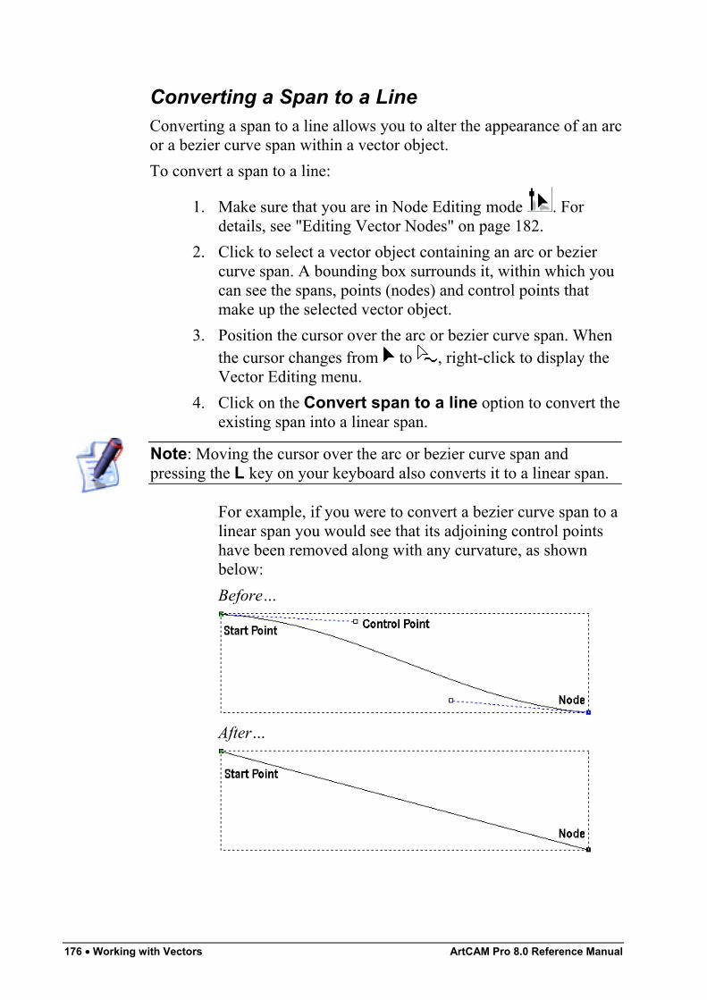
176 • Working with Vectors ArtCAM Pro 8.0 Reference Manual
Converting a Span to a LineConverting a span to a line allows you to alter the appearance of an arcor a bezier curve span within a vector object.To convert a span to a line:
1. Make sure that you are in Node Editing mode . Fordetails, see "Editing Vector Nodes" on page 182.
2. Click to select a vector object containing an arc or beziercurve span. A bounding box surrounds it, within which youcan see the spans, points (nodes) and control points thatmake up the selected vector object.
3. Position the cursor over the arc or bezier curve span. Whenthe cursor changes from to , right-click to display theVector Editing menu.
4. Click on the Convert span to a line option to convert theexisting span into a linear span.
Note: Moving the cursor over the arc or bezier curve span andpressing the L key on your keyboard also converts it to a linear span.
For example, if you were to convert a bezier curve span to alinear span you would see that its adjoining control pointshave been removed along with any curvature, as shownbelow:Before…
After…
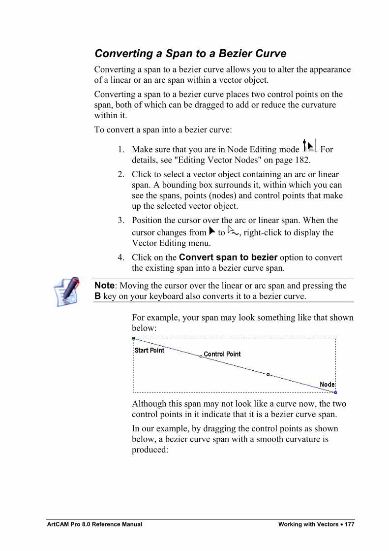
ArtCAM Pro 8.0 Reference Manual Working with Vectors • 177
Converting a Span to a Bezier CurveConverting a span to a bezier curve allows you to alter the appearanceof a linear or an arc span within a vector object.Converting a span to a bezier curve places two control points on thespan, both of which can be dragged to add or reduce the curvaturewithin it.To convert a span into a bezier curve:
1. Make sure that you are in Node Editing mode . Fordetails, see "Editing Vector Nodes" on page 182.
2. Click to select a vector object containing an arc or linearspan. A bounding box surrounds it, within which you cansee the spans, points (nodes) and control points that makeup the selected vector object.
3. Position the cursor over the arc or linear span. When thecursor changes from to , right-click to display theVector Editing menu.
4. Click on the Convert span to bezier option to convertthe existing span into a bezier curve span.
Note: Moving the cursor over the linear or arc span and pressing theB key on your keyboard also converts it to a bezier curve.
For example, your span may look something like that shownbelow:
Although this span may not look like a curve now, the twocontrol points in it indicate that it is a bezier curve span.In our example, by dragging the control points as shownbelow, a bezier curve span with a smooth curvature isproduced:
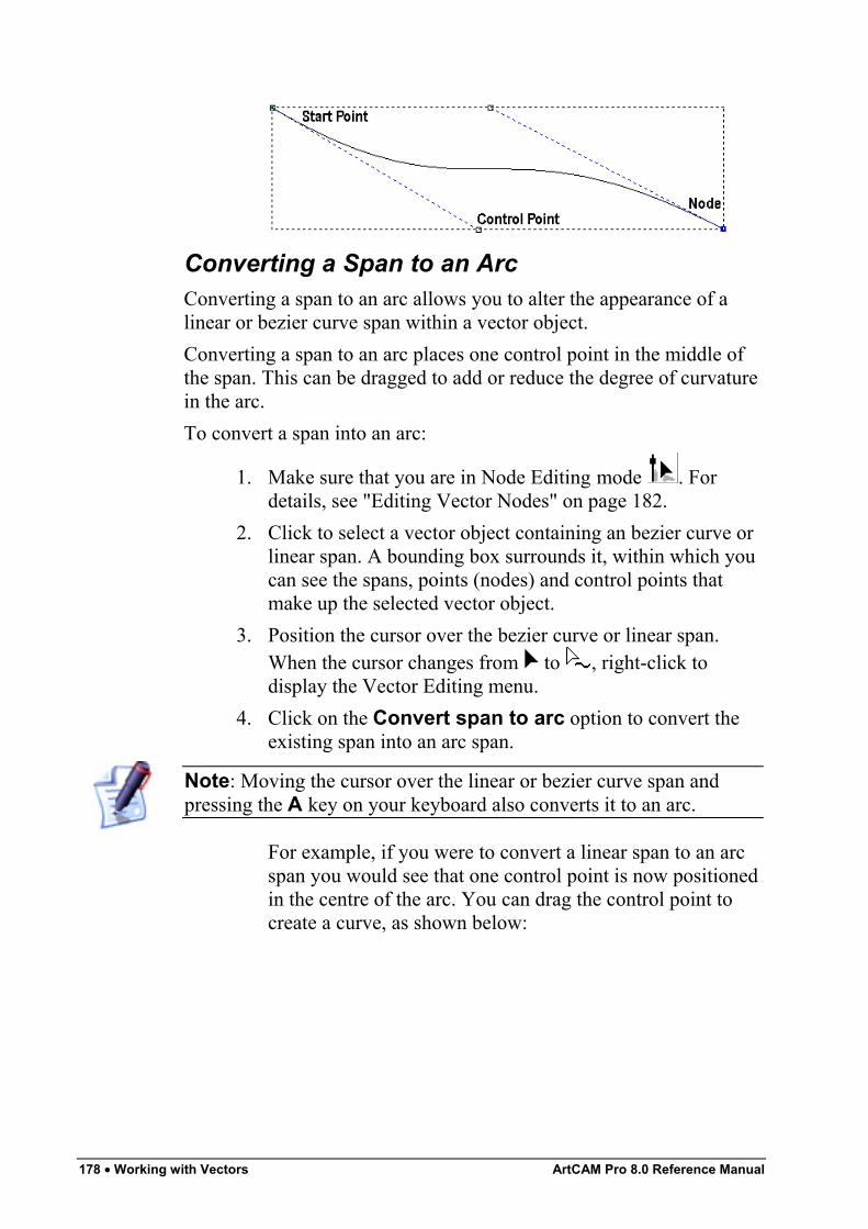
178 • Working with Vectors ArtCAM Pro 8.0 Reference Manual
Converting a Span to an ArcConverting a span to an arc allows you to alter the appearance of alinear or bezier curve span within a vector object.Converting a span to an arc places one control point in the middle ofthe span. This can be dragged to add or reduce the degree of curvaturein the arc.To convert a span into an arc:
1. Make sure that you are in Node Editing mode . Fordetails, see "Editing Vector Nodes" on page 182.
2. Click to select a vector object containing an bezier curve orlinear span. A bounding box surrounds it, within which youcan see the spans, points (nodes) and control points thatmake up the selected vector object.
3. Position the cursor over the bezier curve or linear span.When the cursor changes from to , right-click todisplay the Vector Editing menu.
4. Click on the Convert span to arc option to convert theexisting span into an arc span.
Note: Moving the cursor over the linear or bezier curve span andpressing the A key on your keyboard also converts it to an arc.
For example, if you were to convert a linear span to an arcspan you would see that one control point is now positionedin the centre of the arc. You can drag the control point tocreate a curve, as shown below:
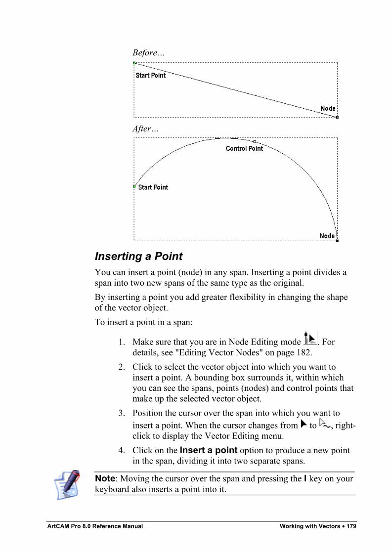
ArtCAM Pro 8.0 Reference Manual Working with Vectors • 179
Before…
After…
Inserting a PointYou can insert a point (node) in any span. Inserting a point divides aspan into two new spans of the same type as the original.By inserting a point you add greater flexibility in changing the shapeof the vector object.To insert a point in a span:
1. Make sure that you are in Node Editing mode . Fordetails, see "Editing Vector Nodes" on page 182.
2. Click to select the vector object into which you want toinsert a point. A bounding box surrounds it, within whichyou can see the spans, points (nodes) and control points thatmake up the selected vector object.
3. Position the cursor over the span into which you want toinsert a point. When the cursor changes from to , right-click to display the Vector Editing menu.
4. Click on the Insert a point option to produce a new pointin the span, dividing it into two separate spans.
Note: Moving the cursor over the span and pressing the I key on yourkeyboard also inserts a point into it.
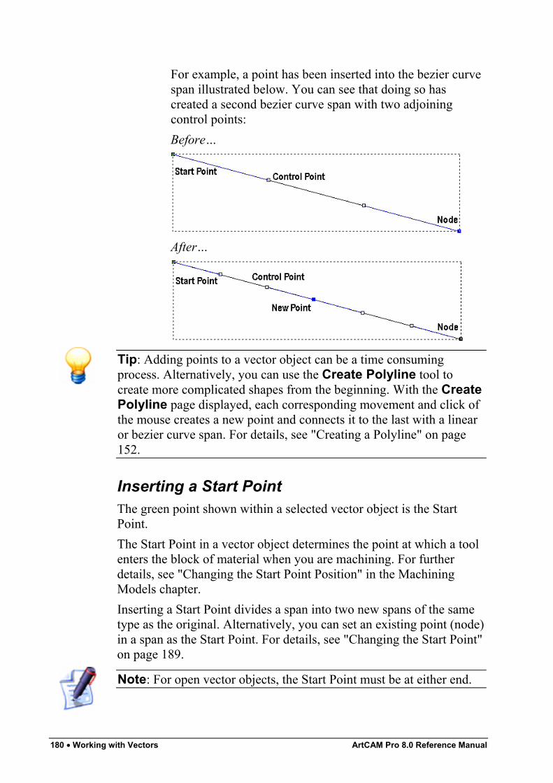
180 • Working with Vectors ArtCAM Pro 8.0 Reference Manual
For example, a point has been inserted into the bezier curvespan illustrated below. You can see that doing so hascreated a second bezier curve span with two adjoiningcontrol points:Before…
After…
Tip: Adding points to a vector object can be a time consumingprocess. Alternatively, you can use the Create Polyline tool tocreate more complicated shapes from the beginning. With the CreatePolyline page displayed, each corresponding movement and click ofthe mouse creates a new point and connects it to the last with a linearor bezier curve span. For details, see "Creating a Polyline" on page152.
Inserting a Start PointThe green point shown within a selected vector object is the StartPoint.The Start Point in a vector object determines the point at which a toolenters the block of material when you are machining. For furtherdetails, see "Changing the Start Point Position" in the MachiningModels chapter.Inserting a Start Point divides a span into two new spans of the sametype as the original. Alternatively, you can set an existing point (node)in a span as the Start Point. For details, see "Changing the Start Point"on page 189.
Note: For open vector objects, the Start Point must be at either end.
ArtCAM Pro 8.0 Reference Manual Working with Vectors • 181
To insert a Start Point in a span:
1. Make sure that you are in Node Editing mode . Fordetails, see "Editing Vector Nodes" on page 182
2. Click to select the vector object into which you want toinsert a Start Point. A bounding box surrounds it, withinwhich you can see the spans, points (nodes) and controlpoints that make up the selected vector object.
3. Position the cursor over the span into which you want toinsert a Start Point. When the cursor changes from to ,right-click to display the Vector Editing menu.
4. Click on the Insert Start Point option to produce a newStart Point in the span and divide it into two separate spans.
Note: Moving the cursor over the span and pressing the P key onyour keyboard also inserts a Start Point into it.
Removing a SpanYou can remove a linear, bezier curve or an arc span within anyselected vector object in the same way.To remove a span:
1. Make sure that you are in Node Editing mode . Fordetails, see "Editing Vector Nodes" on page 182.
2. Click to select the vector object from which you want toremove a span. A bounding box surrounds it, within whichyou can see the spans, points (nodes) and control points thatmake up the selected vector object.
3. Position the cursor over the span. When the cursor changesfrom to , right-click to display the Vector Editingmenu.
4. Click on the Remove Span option to remove the selectedspan.
Note: Moving the cursor over the span and pressing the R key onyour keyboard also removes it.
For example, a vector object with two spans appears asfollows:
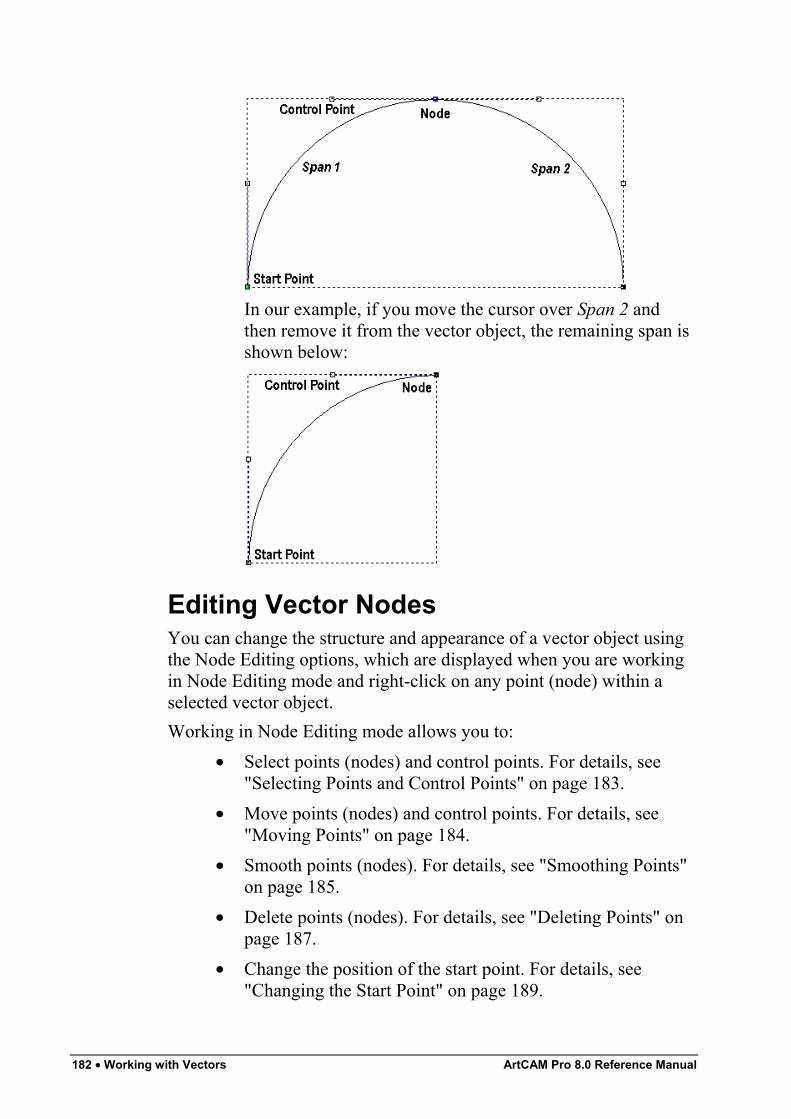
182 • Working with Vectors ArtCAM Pro 8.0 Reference Manual
In our example, if you move the cursor over Span 2 andthen remove it from the vector object, the remaining span isshown below:
Editing Vector NodesYou can change the structure and appearance of a vector object usingthe Node Editing options, which are displayed when you are workingin Node Editing mode and right-click on any point (node) within aselected vector object.Working in Node Editing mode allows you to:
• Select points (nodes) and control points. For details, see"Selecting Points and Control Points" on page 183.
• Move points (nodes) and control points. For details, see"Moving Points" on page 184.
• Smooth points (nodes). For details, see "Smoothing Points"on page 185.
• Delete points (nodes). For details, see "Deleting Points" onpage 187.
• Change the position of the start point. For details, see"Changing the Start Point" on page 189.
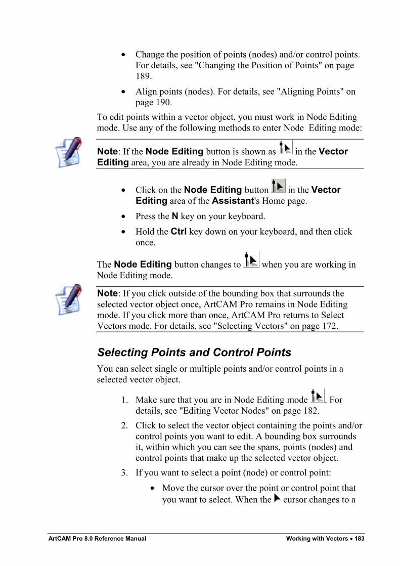
ArtCAM Pro 8.0 Reference Manual Working with Vectors • 183
• Change the position of points (nodes) and/or control points.For details, see "Changing the Position of Points" on page189.
• Align points (nodes). For details, see "Aligning Points" onpage 190.
To edit points within a vector object, you must work in Node Editingmode. Use any of the following methods to enter Node Editing mode:
Note: If the Node Editing button is shown as in the VectorEditing area, you are already in Node Editing mode.
• Click on the Node Editing button in the VectorEditing area of the Assistant's Home page.
• Press the N key on your keyboard.• Hold the Ctrl key down on your keyboard, and then click
once.
The Node Editing button changes to when you are working inNode Editing mode.
Note: If you click outside of the bounding box that surrounds theselected vector object once, ArtCAM Pro remains in Node Editingmode. If you click more than once, ArtCAM Pro returns to SelectVectors mode. For details, see "Selecting Vectors" on page 172.
Selecting Points and Control PointsYou can select single or multiple points and/or control points in aselected vector object.
1. Make sure that you are in Node Editing mode . Fordetails, see "Editing Vector Nodes" on page 182.
2. Click to select the vector object containing the points and/orcontrol points you want to edit. A bounding box surroundsit, within which you can see the spans, points (nodes) andcontrol points that make up the selected vector object.
3. If you want to select a point (node) or control point:• Move the cursor over the point or control point that
you want to select. When the cursor changes to a
184 • Working with Vectors ArtCAM Pro 8.0 Reference Manual
, click to select it. The selected point or controlpoint turns red.If you select a point that has adjoining control points,these are selected along with the point itself. All ofwhich turn red.
If you want to select more than one point (node) or controlpoint, you can use any of the following methods:
• Click and drag to form a bounding box around them.The selected points and/or control points turn red.
• Click to select a point or control point. Hold the Ctrlkey down on your keyboard, and then click onfurther points and/or control points to select them.The selected points and/or control points turn red.
• Click to select a point or control point. Hold theShift key down on your keyboard, and then click toselect a second point. ArtCAM Pro finds the shortestdistance between these two points, and then selectsall of the other points in between them. The selectedpoints and/or control points turn red.
Deselecting Points and Control PointsIf you want to deselect a point or control point:
• Move the cursor over the point or control point that youwant to deselect. When the cursor changes to a , holdthe Shift key down on your keyboard and then click on thepoint or control point to deselect it.
Moving PointsYou can move one or more points and/or control points to a newposition.To move a selection of points (nodes) and/or control points:
1. Make sure that you are in Node Editing mode . Fordetails, see "Editing Vector Nodes" on page 182.
2. Click to select the vector object containing the points youwant to move. A bounding box surrounds the selectedvector, within which you can see the spans, points (nodes)and control points that make up the selected vector object.
ArtCAM Pro 8.0 Reference Manual Working with Vectors • 185
3. Hold the Shift key down on your keyboard, and then clickto select the points and/or control points that you want tomove. For details, see "Selecting Points and Control Points"on page 183. The selected points and/or control points turnred.
4. You can now move the selected points and/or control pointsusing either of the following methods:
• Move the cursor over any of the selected point(s)and then click and drag the point into its newposition.
• Use any of the four arrow keys on your keyboard tonudge the selected point(s) into its new position.
Smoothing PointsYou can smooth any point (node) in a vector object other than theStart Point or the last point in an ungrouped, open vector object. Fordetails, see "Selecting Vectors" on page 172.In smoothing, the span on either side of a point is converted to a beziercurve span. ArtCAM Pro positions control points next to the point,allowing you to control the degree of curvature in the whole vectorobject.To smooth a single point:
1. Make sure that you are in Node Editing mode . Fordetails, see "Editing Vector Nodes" on page 182.
2. Click to select the vector object containing the point youwant to smooth. A bounding box surrounds it, within whichyou can see the spans, points (nodes) and control points thatmake up the selected vector object. All unsmoothed pointsare shown in black.
3. Move the cursor over the point that you want to smooth.When the cursor changes to a , right-click to displaythe Vector Editing menu.
4. Click to select the Smooth Point option to convert thespans on either side of the point to bezier curves. The pointturns blue.
Note: Moving the cursor over the point and pressing the S key onyour keyboard also smoothes it.
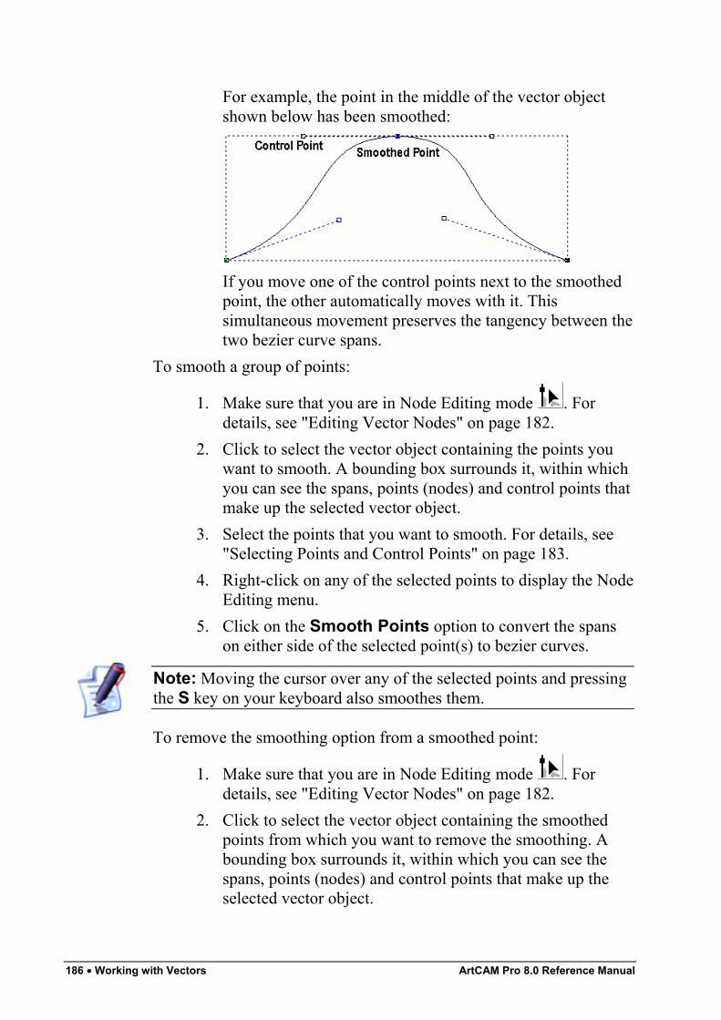
186 • Working with Vectors ArtCAM Pro 8.0 Reference Manual
For example, the point in the middle of the vector objectshown below has been smoothed:
If you move one of the control points next to the smoothedpoint, the other automatically moves with it. Thissimultaneous movement preserves the tangency between thetwo bezier curve spans.
To smooth a group of points:
1. Make sure that you are in Node Editing mode . Fordetails, see "Editing Vector Nodes" on page 182.
2. Click to select the vector object containing the points youwant to smooth. A bounding box surrounds it, within whichyou can see the spans, points (nodes) and control points thatmake up the selected vector object.
3. Select the points that you want to smooth. For details, see"Selecting Points and Control Points" on page 183.
4. Right-click on any of the selected points to display the NodeEditing menu.
5. Click on the Smooth Points option to convert the spanson either side of the selected point(s) to bezier curves.
Note: Moving the cursor over any of the selected points and pressingthe S key on your keyboard also smoothes them.
To remove the smoothing option from a smoothed point:
1. Make sure that you are in Node Editing mode . Fordetails, see "Editing Vector Nodes" on page 182.
2. Click to select the vector object containing the smoothedpoints from which you want to remove the smoothing. Abounding box surrounds it, within which you can see thespans, points (nodes) and control points that make up theselected vector object.
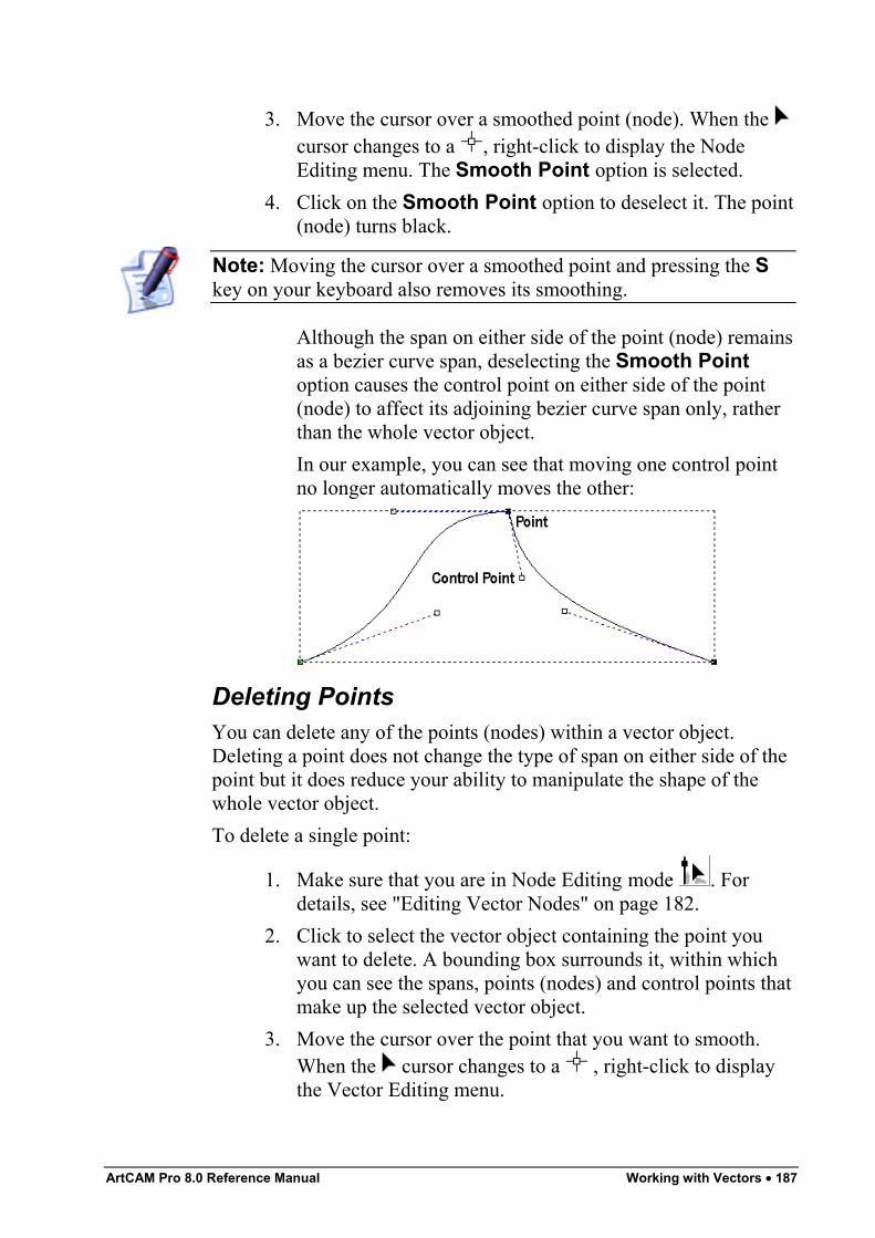
ArtCAM Pro 8.0 Reference Manual Working with Vectors • 187
3. Move the cursor over a smoothed point (node). When the cursor changes to a , right-click to display the NodeEditing menu. The Smooth Point option is selected.
4. Click on the Smooth Point option to deselect it. The point(node) turns black.
Note: Moving the cursor over a smoothed point and pressing the Skey on your keyboard also removes its smoothing.
Although the span on either side of the point (node) remainsas a bezier curve span, deselecting the Smooth Pointoption causes the control point on either side of the point(node) to affect its adjoining bezier curve span only, ratherthan the whole vector object.In our example, you can see that moving one control pointno longer automatically moves the other:
Deleting PointsYou can delete any of the points (nodes) within a vector object.Deleting a point does not change the type of span on either side of thepoint but it does reduce your ability to manipulate the shape of thewhole vector object.To delete a single point:
1. Make sure that you are in Node Editing mode . Fordetails, see "Editing Vector Nodes" on page 182.
2. Click to select the vector object containing the point youwant to delete. A bounding box surrounds it, within whichyou can see the spans, points (nodes) and control points thatmake up the selected vector object.
3. Move the cursor over the point that you want to smooth.When the cursor changes to a , right-click to displaythe Vector Editing menu.
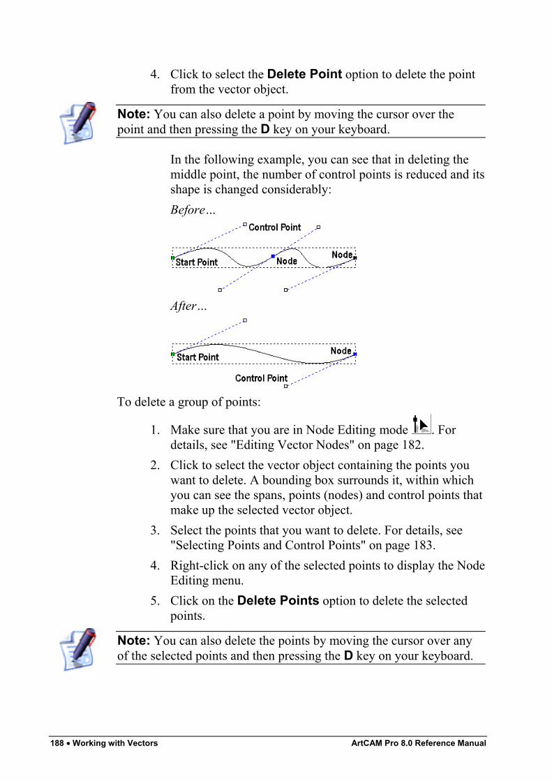
188 • Working with Vectors ArtCAM Pro 8.0 Reference Manual
4. Click to select the Delete Point option to delete the pointfrom the vector object.
Note: You can also delete a point by moving the cursor over thepoint and then pressing the D key on your keyboard.
In the following example, you can see that in deleting themiddle point, the number of control points is reduced and itsshape is changed considerably:Before…
After…
To delete a group of points:
1. Make sure that you are in Node Editing mode . Fordetails, see "Editing Vector Nodes" on page 182.
2. Click to select the vector object containing the points youwant to delete. A bounding box surrounds it, within whichyou can see the spans, points (nodes) and control points thatmake up the selected vector object.
3. Select the points that you want to delete. For details, see"Selecting Points and Control Points" on page 183.
4. Right-click on any of the selected points to display the NodeEditing menu.
5. Click on the Delete Points option to delete the selectedpoints.
Note: You can also delete the points by moving the cursor over anyof the selected points and then pressing the D key on your keyboard.
ArtCAM Pro 8.0 Reference Manual Working with Vectors • 189
Changing the Start PointThe Start Point in a vector object determines the point at which a toolenters the block of material when you are machining your model.You can change the position of the Start Point in any vector object.The green point within a selected vector object is the Start Point.To change the position of the Start Point:
1. Make sure that you are in Node Editing mode . Fordetails, see "Editing Vector Nodes" on page 182.
2. Click to select the vector object in which you want tochange the position of its Start point. A bounding boxsurrounds it, within which you can see the spans, points(nodes) and control points that make up the selected vectorobject.
3. Move the cursor over the point that you want to set as theStart Point. When the cursor changes to a , right-clickto display the Node Editing menu.
4. Click on the Start Point option to make the selected pointthe Start Point. The point changes from black to green.
Note: You can also change the position of the Start Point by movingthe cursor over the point you want to set as the new Start Point andthen pressing the P key on your keyboard.
Using a toolpath preview in the 2D View window, you can also setthe position of the Start Point in any toolpath containing a profile pass.For further details, see "Changing the Start Point Position" in theMachining Models chapter.
Changing the Position of PointsYou can change the position of any point (node) or control pointwithin a selected vector object.To change the exact position of a point or control point:
1. Make sure that you are in Node Editing mode . Fordetails, see "Editing Vector Nodes" on page 182.
2. Click to select the vector object in which you want tochange the position of a point or control point. A boundingbox surrounds it, within which you can see the spans, points
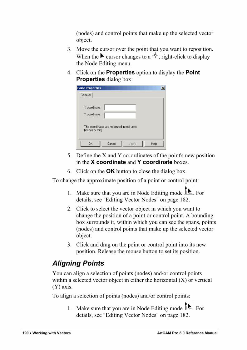
190 • Working with Vectors ArtCAM Pro 8.0 Reference Manual
(nodes) and control points that make up the selected vectorobject.
3. Move the cursor over the point that you want to reposition.When the cursor changes to a , right-click to displaythe Node Editing menu.
4. Click on the Properties option to display the PointProperties dialog box:
5. Define the X and Y co-ordinates of the point's new positionin the X coordinate and Y coordinate boxes.
6. Click on the OK button to close the dialog box.To change the approximate position of a point or control point:
1. Make sure that you are in Node Editing mode . Fordetails, see "Editing Vector Nodes" on page 182.
2. Click to select the vector object in which you want tochange the position of a point or control point. A boundingbox surrounds it, within which you can see the spans, points(nodes) and control points that make up the selected vectorobject.
3. Click and drag on the point or control point into its newposition. Release the mouse button to set its position.
Aligning PointsYou can align a selection of points (nodes) and/or control pointswithin a selected vector object in either the horizontal (X) or vertical(Y) axis.To align a selection of points (nodes) and/or control points:
1. Make sure that you are in Node Editing mode . Fordetails, see "Editing Vector Nodes" on page 182.
ArtCAM Pro 8.0 Reference Manual Working with Vectors • 191
2. Click to select the vector object containing the points youwant to align. A bounding box surrounds the selectedvector, within which you can see the spans, points (nodes)and control points that make up the selected vector object.
3. Hold the Shift key down on your keyboard, and then clickto select the points and/or control points you want to alignwith that selected last. For details, see "Selecting Points andControl Points" on page 183. The selected points and/orcontrol points turn red.
4. Right-click on any of the selected points and/or controlpoints to display the Node Editing menu.
5. Click on the Align Nodes option, followed by either the inX or the in Y option, depending on the axis with which youwant to align the points and/or control points. By default,the point selected first is aligned with the point selected last,and a single horizontal (X) or vertical (Y) linear spanreplaces the intermediate points.
Note: You can also align selected points and/or control points alongthe X-axis by pressing the X key on your keyboard, and along the Y-axis by pressing the Y key on your keyboard.
Note: If you want to preserve all of the intermediate points (nodes)when aligning them with the X or Y axis, click to deselect the AlignNodes – replace with a single line option on the ArtCAMOptions page. For details, see "Managing ArtCAM Pro'sPreferences" in the ArtCAM Pro Layout chapter.
Deleting Vector ObjectsYou can delete a selected vector object or group of vector objectsusing any of the following methods:
• First, hold the Shift key down on your keyboard and thenclick to select the vector object that you want to delete.Next, right-click on any of the selected vector objects todisplay the Vector Editing menu, and then click on theDelete option.
• Select the vector objects that you want to delete, and thenpress the Delete key on your keyboard. For details, see"Selecting Vectors" on page 172.
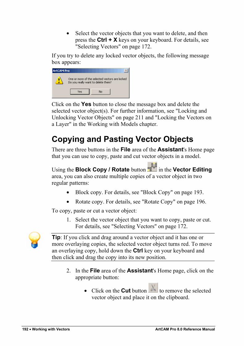
192 • Working with Vectors ArtCAM Pro 8.0 Reference Manual
• Select the vector objects that you want to delete, and thenpress the Ctrl + X keys on your keyboard. For details, see"Selecting Vectors" on page 172.
If you try to delete any locked vector objects, the following messagebox appears:
Click on the Yes button to close the message box and delete theselected vector object(s). For further information, see "Locking andUnlocking Vector Objects" on page 211 and "Locking the Vectors ona Layer" in the Working with Models chapter.
Copying and Pasting Vector ObjectsThere are three buttons in the File area of the Assistant's Home pagethat you can use to copy, paste and cut vector objects in a model.
Using the Block Copy / Rotate button in the Vector Editingarea, you can also create multiple copies of a vector object in tworegular patterns:
• Block copy. For details, see "Block Copy" on page 193.• Rotate copy. For details, see "Rotate Copy" on page 196.
To copy, paste or cut a vector object:1. Select the vector object that you want to copy, paste or cut.
For details, see "Selecting Vectors" on page 172.
Tip: If you click and drag around a vector object and it has one ormore overlaying copies, the selected vector object turns red. To movean overlaying copy, hold down the Ctrl key on your keyboard andthen click and drag the copy into its new position.
2. In the File area of the Assistant's Home page, click on theappropriate button:
• Click on the Cut button to remove the selectedvector object and place it on the clipboard.
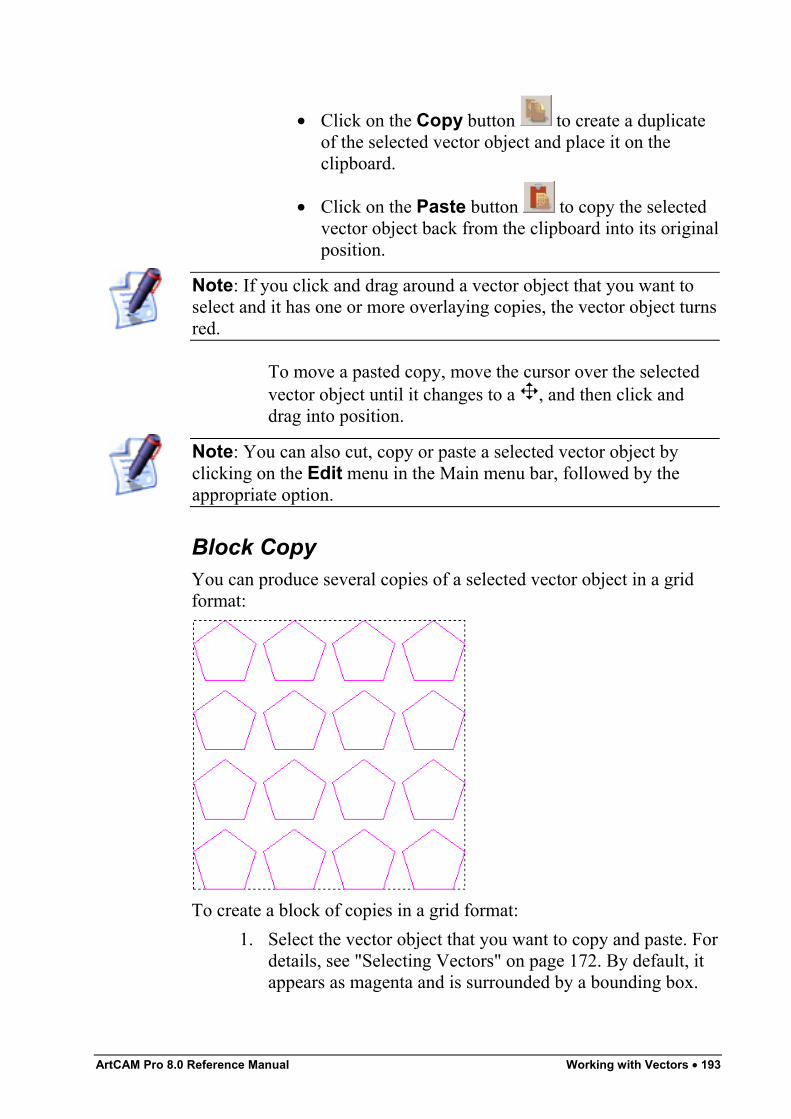
ArtCAM Pro 8.0 Reference Manual Working with Vectors • 193
• Click on the Copy button to create a duplicateof the selected vector object and place it on theclipboard.
• Click on the Paste button to copy the selectedvector object back from the clipboard into its originalposition.
Note: If you click and drag around a vector object that you want toselect and it has one or more overlaying copies, the vector object turnsred.
To move a pasted copy, move the cursor over the selectedvector object until it changes to a , and then click anddrag into position.
Note: You can also cut, copy or paste a selected vector object byclicking on the Edit menu in the Main menu bar, followed by theappropriate option.
Block CopyYou can produce several copies of a selected vector object in a gridformat:
To create a block of copies in a grid format:1. Select the vector object that you want to copy and paste. For
details, see "Selecting Vectors" on page 172. By default, itappears as magenta and is surrounded by a bounding box.
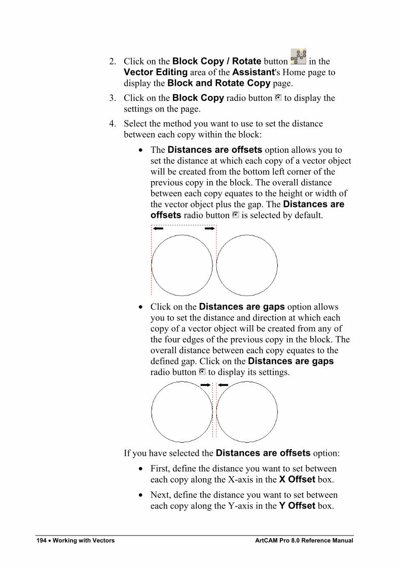
194 • Working with Vectors ArtCAM Pro 8.0 Reference Manual
2. Click on the Block Copy / Rotate button in theVector Editing area of the Assistant's Home page todisplay the Block and Rotate Copy page.
3. Click on the Block Copy radio button to display thesettings on the page.
4. Select the method you want to use to set the distancebetween each copy within the block:
• The Distances are offsets option allows you toset the distance at which each copy of a vector objectwill be created from the bottom left corner of theprevious copy in the block. The overall distancebetween each copy equates to the height or width ofthe vector object plus the gap. The Distances areoffsets radio button is selected by default.
• Click on the Distances are gaps option allowsyou to set the distance and direction at which eachcopy of a vector object will be created from any ofthe four edges of the previous copy in the block. Theoverall distance between each copy equates to thedefined gap. Click on the Distances are gapsradio button to display its settings.
If you have selected the Distances are offsets option:• First, define the distance you want to set between
each copy along the X-axis in the X Offset box.• Next, define the distance you want to set between
each copy along the Y-axis in the Y Offset box.
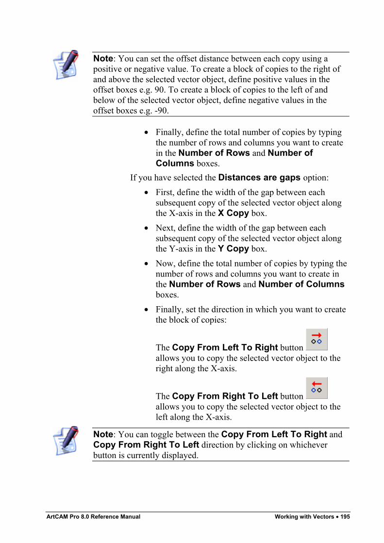
ArtCAM Pro 8.0 Reference Manual Working with Vectors • 195
Note: You can set the offset distance between each copy using apositive or negative value. To create a block of copies to the right ofand above the selected vector object, define positive values in theoffset boxes e.g. 90. To create a block of copies to the left of andbelow of the selected vector object, define negative values in theoffset boxes e.g. -90.
• Finally, define the total number of copies by typingthe number of rows and columns you want to createin the Number of Rows and Number ofColumns boxes.
If you have selected the Distances are gaps option:• First, define the width of the gap between each
subsequent copy of the selected vector object alongthe X-axis in the X Copy box.
• Next, define the width of the gap between eachsubsequent copy of the selected vector object alongthe Y-axis in the Y Copy box.
• Now, define the total number of copies by typing thenumber of rows and columns you want to create inthe Number of Rows and Number of Columnsboxes.
• Finally, set the direction in which you want to createthe block of copies:
The Copy From Left To Right button allows you to copy the selected vector object to theright along the X-axis.
The Copy From Right To Left button allows you to copy the selected vector object to theleft along the X-axis.
Note: You can toggle between the Copy From Left To Right andCopy From Right To Left direction by clicking on whicheverbutton is currently displayed.
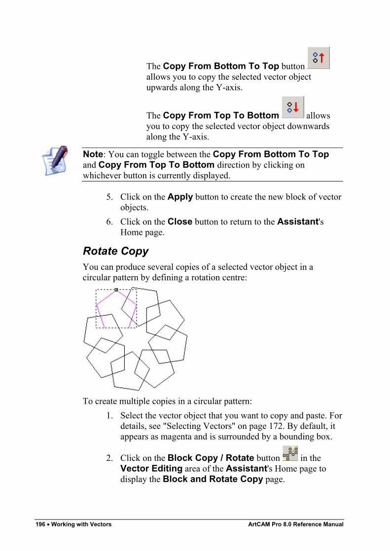
196 • Working with Vectors ArtCAM Pro 8.0 Reference Manual
The Copy From Bottom To Top button allows you to copy the selected vector objectupwards along the Y-axis.
The Copy From Top To Bottom allowsyou to copy the selected vector object downwardsalong the Y-axis.
Note: You can toggle between the Copy From Bottom To Topand Copy From Top To Bottom direction by clicking onwhichever button is currently displayed.
5. Click on the Apply button to create the new block of vectorobjects.
6. Click on the Close button to return to the Assistant'sHome page.
Rotate CopyYou can produce several copies of a selected vector object in acircular pattern by defining a rotation centre:
To create multiple copies in a circular pattern:1. Select the vector object that you want to copy and paste. For
details, see "Selecting Vectors" on page 172. By default, itappears as magenta and is surrounded by a bounding box.
2. Click on the Block Copy / Rotate button in theVector Editing area of the Assistant's Home page todisplay the Block and Rotate Copy page.
ArtCAM Pro 8.0 Reference Manual Working with Vectors • 197
3. Click on the Rotate Copy radio button to display thesettings on the page.
4. Define the point around which you want to rotate theselected vector object. You can either:
• Define the X and Y co-ordinates of the origin ofrotation in the Rotation Centre X and RotationCentre Y boxes.
• Click to select the Pick Centre with Mouseoption . Move the cursor over the point in themodel (white area) that you want to use as the originof rotation, and then click to select. Its co-ordinatesappear in the Rotation Centre X and RotationCentre Y boxes.
5. Define how each of the copies are rotated by clicking oneither of the Angle radio buttons :
• Incremental - To rotate each subsequent copy ofthe selected vector object by a specified angle.
• Total - To rotate each copy of the selected vectorobject evenly within a specified angle.
6. Define the angle of rotation in the degrees box:• Type a positive value to rotate the vector object
clockwise.• Type a negative value to rotate the vector object anti-
clockwise.7. Define the number of copies you want to create in the
Number of Objects box.8. Click on the Apply button to create the new circular pattern
of vector objects.9. Click on the Close button to return to the Assistant's
Home page.
Offsetting Vector ObjectsYou can create an offset vector from any of the vector objects alreadydrawn in your model.To create an offset vector from a vector object:
198 • Working with Vectors ArtCAM Pro 8.0 Reference Manual
1. Select the vector object from which you want to create anoffset vector. For details, see "Selecting Vectors" on page172.
2. Click on the Offset Vector(s) button in the VectorEditing area of the Assistant's Home page to display theOffset Vector(s) page.
Note: You can also display the Offset Vector(s) page from theMain menu bar by clicking on the Vectors menu, followed by theOffset… option.
3. Define the distance between the selected vector object andthe offset vector in the Offset Distance box.
4. Click to select one of the Offset Direction radio buttons to set the position of the offset vector:
• Select Outwards/Right if you want the offsetvector to be drawn outside of the selected vectorobject if it is closed, or to the right of the Start Point,looking down the selected vector object if it is open.
• Select Inwards/Left if you want the offset vector tobe drawn within the selected vector object if it isclosed, or to the left of the Start Point, looking downthe selected vector object if it is open.
• Select Both Sides (Ridge) if you want two offsetvectors to be drawn. One inside and another outsideof the selected vector object if it is closed, or oneither side of the Start Point, looking down theselected vector object if it is open.
5. Click to select one of the Offset Corners radio buttons to set the shape of the corners in the offset vector:
• Select the Radiused option if you want the cornersof the offset vector to appear as arcs with a radiusequal to the Offset Distance.
• Select the Chamfered option if you want thecorners of the offset vector to appear as chamfers.
• Select the Sharp option if you want the corners ofthe offset vector to appear as sharp points.
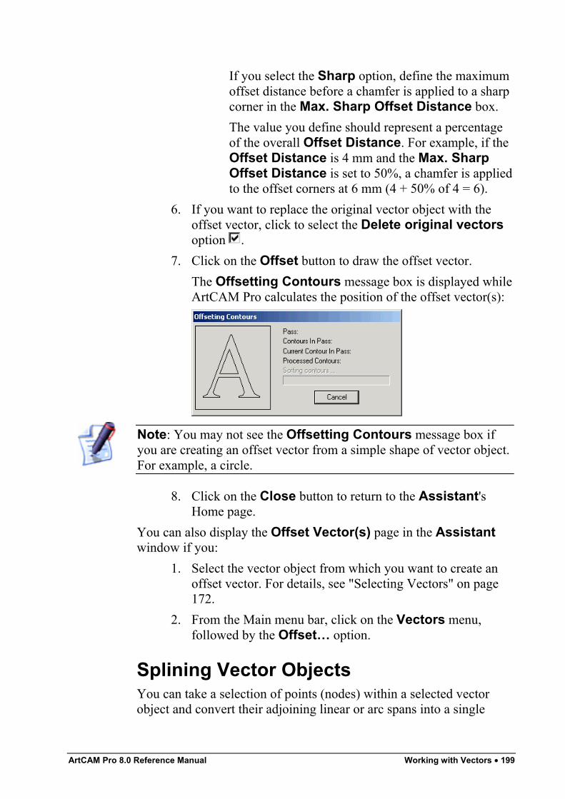
ArtCAM Pro 8.0 Reference Manual Working with Vectors • 199
If you select the Sharp option, define the maximumoffset distance before a chamfer is applied to a sharpcorner in the Max. Sharp Offset Distance box.The value you define should represent a percentageof the overall Offset Distance. For example, if theOffset Distance is 4 mm and the Max. SharpOffset Distance is set to 50%, a chamfer is appliedto the offset corners at 6 mm (4 + 50% of 4 = 6).
6. If you want to replace the original vector object with theoffset vector, click to select the Delete original vectorsoption .
7. Click on the Offset button to draw the offset vector.The Offsetting Contours message box is displayed whileArtCAM Pro calculates the position of the offset vector(s):
Note: You may not see the Offsetting Contours message box ifyou are creating an offset vector from a simple shape of vector object.For example, a circle.
8. Click on the Close button to return to the Assistant'sHome page.
You can also display the Offset Vector(s) page in the Assistantwindow if you:
1. Select the vector object from which you want to create anoffset vector. For details, see "Selecting Vectors" on page172.
2. From the Main menu bar, click on the Vectors menu,followed by the Offset… option.
Splining Vector ObjectsYou can take a selection of points (nodes) within a selected vectorobject and convert their adjoining linear or arc spans into a single
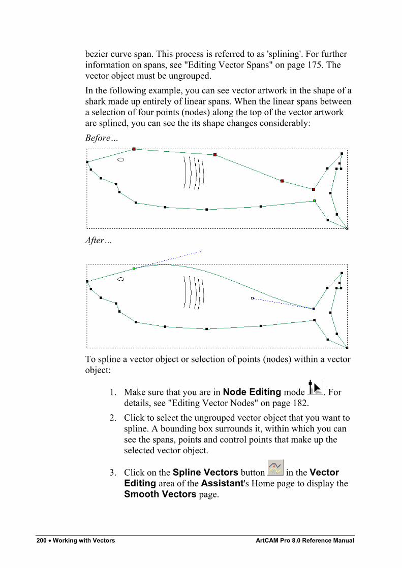
200 • Working with Vectors ArtCAM Pro 8.0 Reference Manual
bezier curve span. This process is referred to as 'splining'. For furtherinformation on spans, see "Editing Vector Spans" on page 175. Thevector object must be ungrouped.In the following example, you can see vector artwork in the shape of ashark made up entirely of linear spans. When the linear spans betweena selection of four points (nodes) along the top of the vector artworkare splined, you can see the its shape changes considerably:Before…
After…
To spline a vector object or selection of points (nodes) within a vectorobject:
1. Make sure that you are in Node Editing mode . Fordetails, see "Editing Vector Nodes" on page 182.
2. Click to select the ungrouped vector object that you want tospline. A bounding box surrounds it, within which you cansee the spans, points and control points that make up theselected vector object.
3. Click on the Spline Vectors button in the VectorEditing area of the Assistant's Home page to display theSmooth Vectors page.
ArtCAM Pro 8.0 Reference Manual Working with Vectors • 201
Note: You can also display the Spline Vectors page from the Mainmenu bar by clicking on the Vectors menu, followed by the SplineVectors… option.
4. If you only want to spline specific spans within the selectedvector object, click to select the points and/or control pointsto which these spans are attached. The selected points turnred. For details, see "Selecting Points and Control Points"on page 183.In the Selected Vectors Information area, ArtCAM Prodisplays the total number of spans and points (includingcontrol points) within the selection, and the number oflinear, arc and bezier spans that make up the total.
5. If you only want convert spans to bezier spans that arewithin a specific tolerance, define the maximum distancethe point (node) can be from the selected span in theTolerance box.
6. If you want to keep all linear spans within the currentselection equal to or greater than a specific length, click onthe Preserve Straight Spans option and then definethe length in the Keep lines longer than box.Otherwise, leave the default Ignore Straight Spansoption selected to replace all of the linear and arc spanswithin the current selection with bezier curve spans.
7. Click on the Spline button to spline all selected spansThe linear and/or arc spans joined to the selected points areconverted to bezier spans. ArtCAM Pro displays the newtotal number of spans and points (including control points)within the selection, and the new number of linear, arc andbezier spans that make up the total.
8. Click on the Close button to return to the Assistant'sHome page.
You can also display the Spline Vectors page in the following way:
1. Make sure that you are in Node Editing mode . Fordetails, see "Editing Vector Nodes" on page 182.
2. Click to select the vector object that you want to spline. Abounding box surrounds it, within which you can see the
202 • Working with Vectors ArtCAM Pro 8.0 Reference Manual
spans, points and control points that make up the selectedvector object.
3. Select the points (nodes) and/or control points to which thespans in the vector object you want to spline are attached.For details, see "Selecting Points and Control Points" onpage 183.
Note: You can also display the Spline Vectors page from the Mainmenu bar by clicking on the Vectors menu, followed by the SplineVectors… option.
4. Right-click on any of the selected points to display the NodeEditing menu, and then click on the Spline Vectors…option to display the Spline Vectors page.In the Selected Vectors Information area, ArtCAM Prodisplays the total number of spans and points (includingcontrol points) within the selection, and the number oflinear, arc and bezier spans that make up the total.
5. If you only want convert spans to bezier spans that arewithin a specific tolerance, define the maximum distancethe point (node) can be from the selected span in theTolerance box.
6. If you want to keep all linear spans within the currentselection equal to or greater than a specific length, click onthe Preserve Straight Spans option and then definethe length in the Keep lines longer than box.Otherwise, leave the default Ignore Straight Spansoption selected to replace all of the linear and arc spanswithin the current selection with bezier curve spans.
7. Click on the Spline button to spline all selected spans.The linear and/or arc spans joined to the selected points areconverted to bezier spans. ArtCAM Pro displays the newtotal number of spans and points (including control points)within the selection, and the new number of linear, arc andbezier spans that make up the total.
8. Click on the Close button to return to the Assistant'sHome page.
You can also display the Spline Vectors page in the following way:
ArtCAM Pro 8.0 Reference Manual Working with Vectors • 203
1. Make sure that you are in Node Editing mode . Fordetails, see "Editing Vector Nodes" on page 182.
2. Click to select the vector object that you want to spline. Abounding box surrounds it, within which you can see thespans, points and control points that make up the selectedvector object.
3. Select the points (nodes) and/or control points to which thespans in the vector object you want to spline are attached.For details, see "Selecting Points and Control Points" onpage 183.
4. Right-click on any of the selected points to display the NodeEditing menu, and then click on the Spline Vectors…option to display the Spline Vectors page.
Restoring the Original Shape of a Splined VectorYou can undo the splining applied to a vector object, allowing you torestore its original shape, using either of the following methods:
• From the Main menu bar, click on the Edit menu, followedby the Undo Spline Vectors option.
• Press the Ctrl + Z keys on your keyboard.
Filleting Vector ObjectsA fillet is an arc, which is made up of two points (nodes) and a controlpoint. ArtCAM Pro allows you to define and subsequently edit theradius of the fillet arc that you create.You can close an open vector object with a fillet, or by joining the twopoints at the junction. In the latter instance, ArtCAM Pro extends thespans connected to the two points.
Note: Not all open vector objects can be closed with a fillet. Forpractical results, a vector object should contain at least three points(nodes) and have sufficient space to fit the fillet arc.
You can also convert a sharp corner within a vector object into afilleted, or rounded, corner.To convert a sharp corner into a filleted corner:
1. Select the vector object in which you want to insert filletedcorners. For details, see "Selecting Vectors" on page 172.
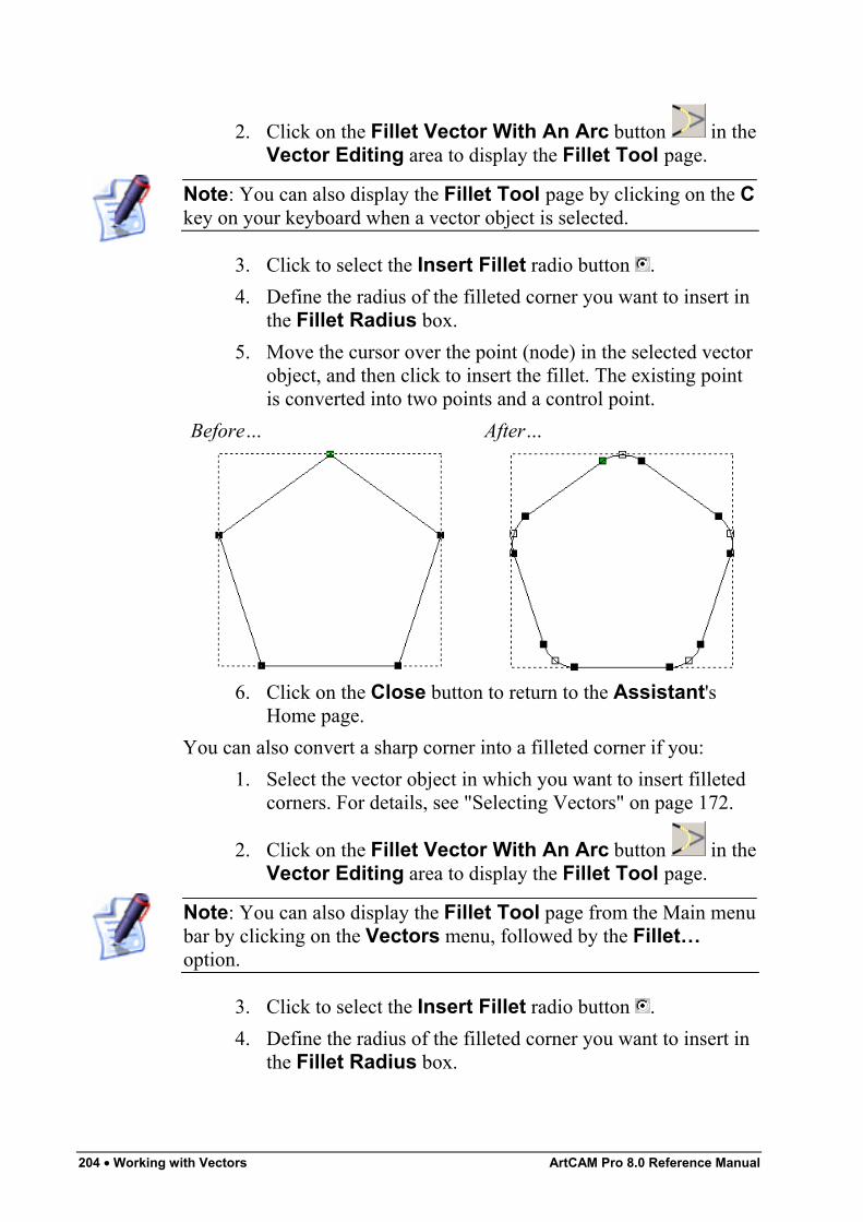
204 • Working with Vectors ArtCAM Pro 8.0 Reference Manual
2. Click on the Fillet Vector With An Arc button in theVector Editing area to display the Fillet Tool page.
Note: You can also display the Fillet Tool page by clicking on the Ckey on your keyboard when a vector object is selected.
3. Click to select the Insert Fillet radio button .4. Define the radius of the filleted corner you want to insert in
the Fillet Radius box.5. Move the cursor over the point (node) in the selected vector
object, and then click to insert the fillet. The existing pointis converted into two points and a control point.
Before… After…
6. Click on the Close button to return to the Assistant'sHome page.
You can also convert a sharp corner into a filleted corner if you:1. Select the vector object in which you want to insert filleted
corners. For details, see "Selecting Vectors" on page 172.
2. Click on the Fillet Vector With An Arc button in theVector Editing area to display the Fillet Tool page.
Note: You can also display the Fillet Tool page from the Main menubar by clicking on the Vectors menu, followed by the Fillet…option.
3. Click to select the Insert Fillet radio button .4. Define the radius of the filleted corner you want to insert in
the Fillet Radius box.
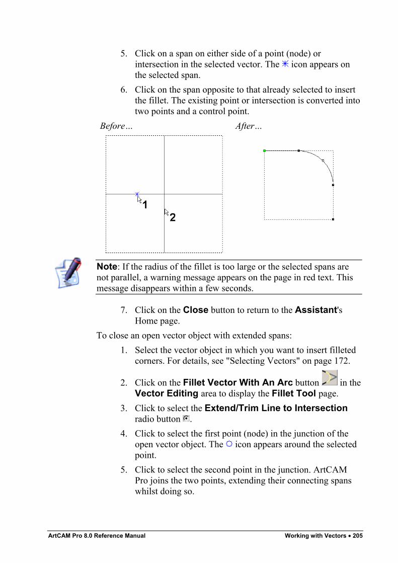
ArtCAM Pro 8.0 Reference Manual Working with Vectors • 205
5. Click on a span on either side of a point (node) orintersection in the selected vector. The icon appears onthe selected span.
6. Click on the span opposite to that already selected to insertthe fillet. The existing point or intersection is converted intotwo points and a control point.
Before… After…
Note: If the radius of the fillet is too large or the selected spans arenot parallel, a warning message appears on the page in red text. Thismessage disappears within a few seconds.
7. Click on the Close button to return to the Assistant'sHome page.
To close an open vector object with extended spans:1. Select the vector object in which you want to insert filleted
corners. For details, see "Selecting Vectors" on page 172.
2. Click on the Fillet Vector With An Arc button in theVector Editing area to display the Fillet Tool page.
3. Click to select the Extend/Trim Line to Intersectionradio button .
4. Click to select the first point (node) in the junction of theopen vector object. The icon appears around the selectedpoint.
5. Click to select the second point in the junction. ArtCAMPro joins the two points, extending their connecting spanswhilst doing so.
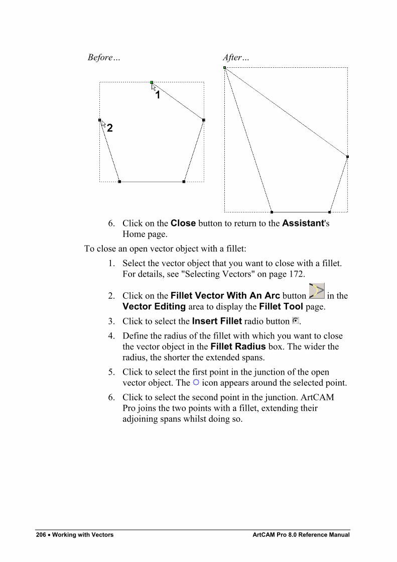
206 • Working with Vectors ArtCAM Pro 8.0 Reference Manual
Before… After…
6. Click on the Close button to return to the Assistant'sHome page.
To close an open vector object with a fillet:1. Select the vector object that you want to close with a fillet.
For details, see "Selecting Vectors" on page 172.
2. Click on the Fillet Vector With An Arc button in theVector Editing area to display the Fillet Tool page.
3. Click to select the Insert Fillet radio button .4. Define the radius of the fillet with which you want to close
the vector object in the Fillet Radius box. The wider theradius, the shorter the extended spans.
5. Click to select the first point in the junction of the openvector object. The icon appears around the selected point.
6. Click to select the second point in the junction. ArtCAMPro joins the two points with a fillet, extending theiradjoining spans whilst doing so.
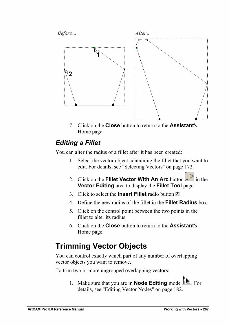
ArtCAM Pro 8.0 Reference Manual Working with Vectors • 207
Before… After…
7. Click on the Close button to return to the Assistant'sHome page.
Editing a FilletYou can alter the radius of a fillet after it has been created:
1. Select the vector object containing the fillet that you want toedit. For details, see "Selecting Vectors" on page 172.
2. Click on the Fillet Vector With An Arc button in theVector Editing area to display the Fillet Tool page.
3. Click to select the Insert Fillet radio button .4. Define the new radius of the fillet in the Fillet Radius box.5. Click on the control point between the two points in the
fillet to alter its radius.6. Click on the Close button to return to the Assistant's
Home page.
Trimming Vector ObjectsYou can control exactly which part of any number of overlappingvector objects you want to remove.To trim two or more ungrouped overlapping vectors:
1. Make sure that you are in Node Editing mode . Fordetails, see "Editing Vector Nodes" on page 182.
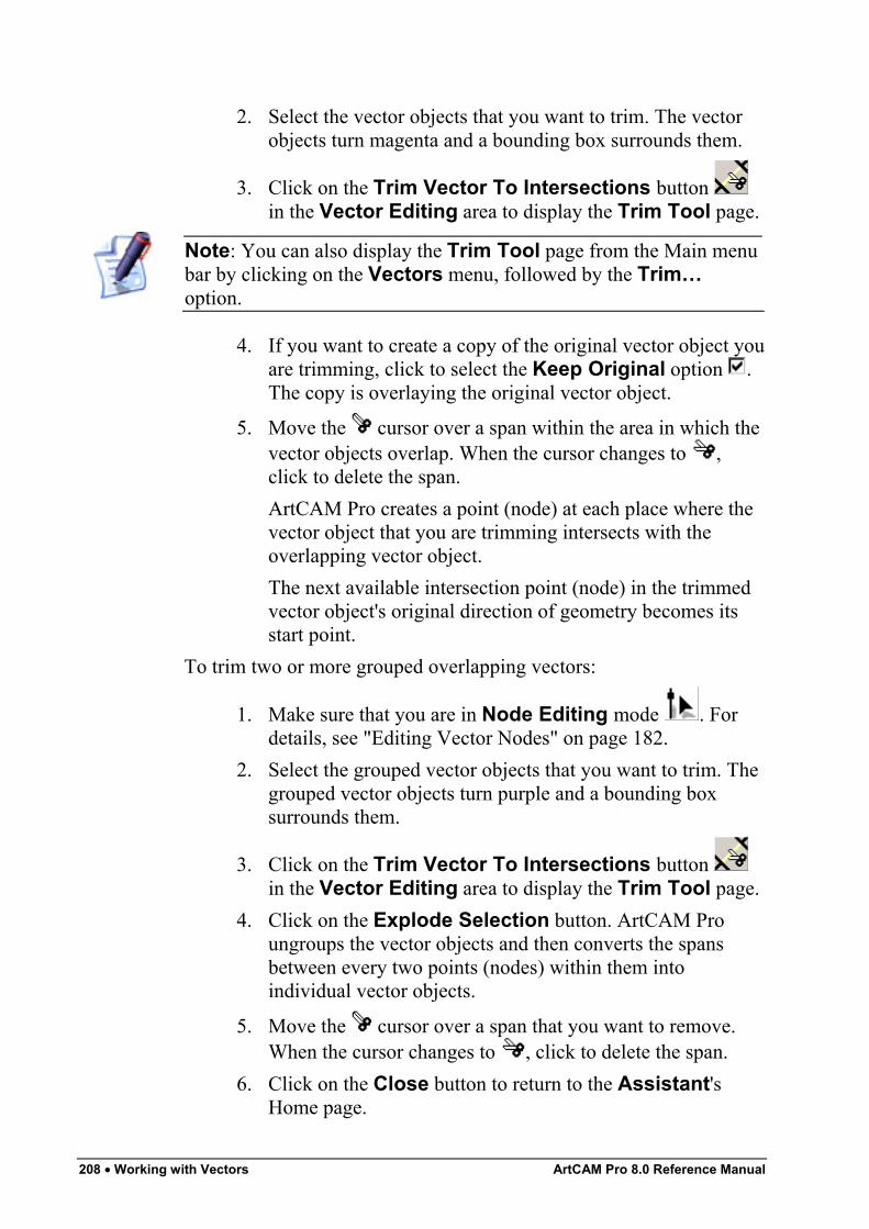
208 • Working with Vectors ArtCAM Pro 8.0 Reference Manual
2. Select the vector objects that you want to trim. The vectorobjects turn magenta and a bounding box surrounds them.
3. Click on the Trim Vector To Intersections button in the Vector Editing area to display the Trim Tool page.
Note: You can also display the Trim Tool page from the Main menubar by clicking on the Vectors menu, followed by the Trim…option.
4. If you want to create a copy of the original vector object youare trimming, click to select the Keep Original option .The copy is overlaying the original vector object.
5. Move the cursor over a span within the area in which thevector objects overlap. When the cursor changes to ,click to delete the span.ArtCAM Pro creates a point (node) at each place where thevector object that you are trimming intersects with theoverlapping vector object.The next available intersection point (node) in the trimmedvector object's original direction of geometry becomes itsstart point.
To trim two or more grouped overlapping vectors:
1. Make sure that you are in Node Editing mode . Fordetails, see "Editing Vector Nodes" on page 182.
2. Select the grouped vector objects that you want to trim. Thegrouped vector objects turn purple and a bounding boxsurrounds them.
3. Click on the Trim Vector To Intersections button in the Vector Editing area to display the Trim Tool page.
4. Click on the Explode Selection button. ArtCAM Proungroups the vector objects and then converts the spansbetween every two points (nodes) within them intoindividual vector objects.
5. Move the cursor over a span that you want to remove.When the cursor changes to , click to delete the span.
6. Click on the Close button to return to the Assistant'sHome page.
ArtCAM Pro 8.0 Reference Manual Working with Vectors • 209
Wrapping Vectors to a ReliefYou can wrap vector objects across the surface of a relief. After beingwrapped, the selected vector object is restructured in the 2D Viewwindow. You can apply a three-dimensional shape to the restructuredvector object, and then combine this with the existing relief. Thisallows you to maintain the surface area of the original vector object inthe relief.To wrap a vector object to a relief:
1. Select the vector object that you want to wrap across therelief surface. For details, see "Selecting Vectors" on page172.
2. Click on the Wrap Vectors To Relief button in theVector Editing area to display the Wrap Vectors ToRelief page.
3. In the Wrap Mode area, click to select the wrappingmethod that you want to use:
• Radial – This option allows you to wrap the clipartrelief around a spherical shape, curved around the Xand Y-axes.
• Cylindrical Wrap in X – This option allows you towrap the clipart relief around a cylindrical shape thatis curved around the X-axis.
• Cylindrical Wrap in Y – This option allows you towrap the clipart relief around a cylindrical shape thatis curved around the Y-axis.
4. In the Wrap Origin area, define the origin around whichthe selected vector object will be wrapped. You can use anyof the following methods:
• Click on any of radio buttons on the rectanglediagram. The X and Y co-ordinates of the chosenorigin appear in the X and Y boxes.
• Type the X and Y co-ordinates of the origin in the Xand Y boxes.
• Click on the Use Mouse option , followed by theStart button. Move the cursor to the position in the2D View window that you want to use as the origin,
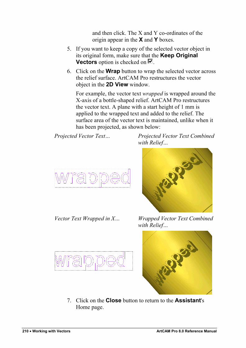
210 • Working with Vectors ArtCAM Pro 8.0 Reference Manual
and then click. The X and Y co-ordinates of theorigin appear in the X and Y boxes.
5. If you want to keep a copy of the selected vector object inits original form, make sure that the Keep OriginalVectors option is checked on .
6. Click on the Wrap button to wrap the selected vector acrossthe relief surface. ArtCAM Pro restructures the vectorobject in the 2D View window.For example, the vector text wrapped is wrapped around theX-axis of a bottle-shaped relief. ArtCAM Pro restructuresthe vector text. A plane with a start height of 1 mm isapplied to the wrapped text and added to the relief. Thesurface area of the vector text is maintained, unlike when ithas been projected, as shown below:
Projected Vector Text… Projected Vector Text Combinedwith Relief…
Vector Text Wrapped in X… Wrapped Vector Text Combinedwith Relief…
7. Click on the Close button to return to the Assistant'sHome page.
ArtCAM Pro 8.0 Reference Manual Working with Vectors • 211
Locking and Unlocking Vector ObjectsYou can prevent a vector object from being moved to a differentposition in your model by locking it.To lock a vector object in its current position:
1. Select the vector object that you want to lock into position.For details, see "Selecting Vectors" on page 172.
2. Right-click to display the Vector Editing menu, then selectthe Lock Vector(s) option. The selected vector objectturns green. When deselected it appears as grey.
If you want to move any vector object that has previously been lockedinto position:
1. Select the locked vector object that you want to move. Fordetails, see "Selecting Vectors" on page 172.
2. Right-click to display the Vector Editing menu, then selectthe Unlock Vector(s) option.
Fitting Arcs to Vector ObjectsYou can automatically replace all of a selected vector object's beziercurve spans with a series of arc spans whilst maintaining its originalshape.To do so:
1. Select the vector object whose bezier curves you want toconvert to arcs. For details, see "Selecting Vectors" on page172.
2. Click on the Arc Fit Vectors button in the VectorEditing area of the Assistant's Home page to display theFit Arcs To Vectors page.
Note: You can also display the Fit Arcs To Vectors page from theMain menu bar by clicking on the Vectors menu, followed by the FitArcs to Vectors… option.
The number of spans (linear, bezier curve and arc) pointsand control points for the vector object is displayed in theSelected Vectors Information area.
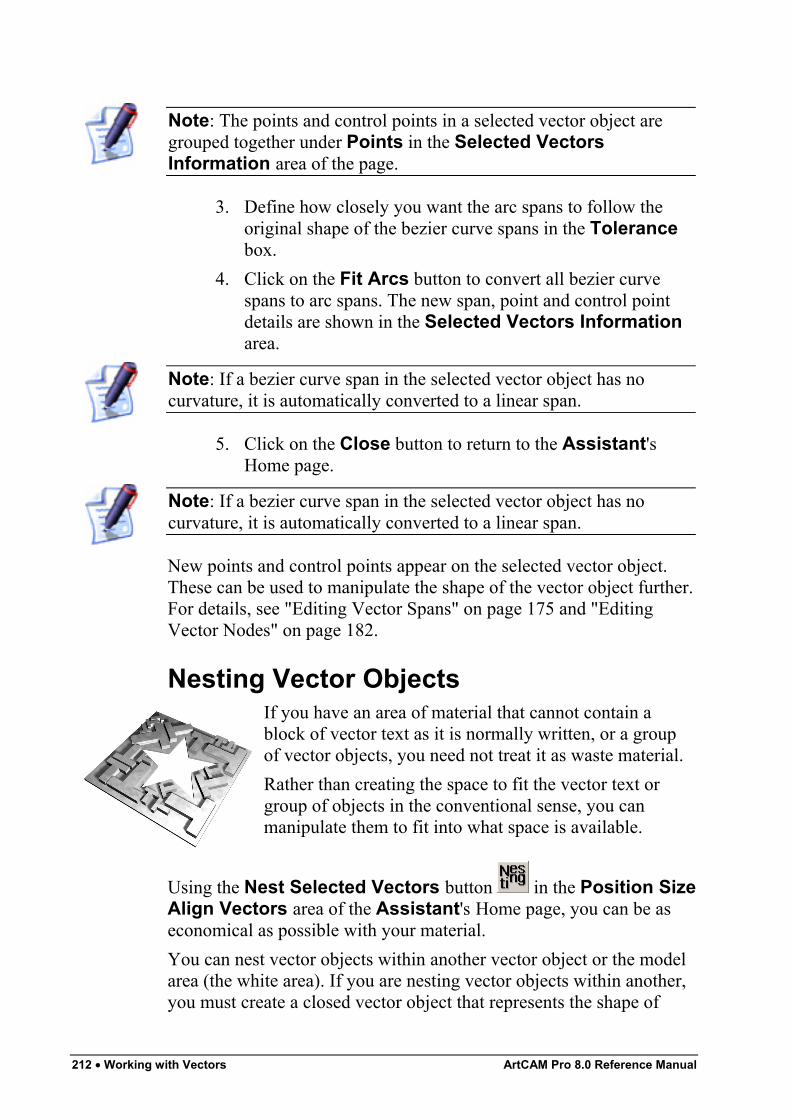
212 • Working with Vectors ArtCAM Pro 8.0 Reference Manual
Note: The points and control points in a selected vector object aregrouped together under Points in the Selected VectorsInformation area of the page.
3. Define how closely you want the arc spans to follow theoriginal shape of the bezier curve spans in the Tolerancebox.
4. Click on the Fit Arcs button to convert all bezier curvespans to arc spans. The new span, point and control pointdetails are shown in the Selected Vectors Informationarea.
Note: If a bezier curve span in the selected vector object has nocurvature, it is automatically converted to a linear span.
5. Click on the Close button to return to the Assistant'sHome page.
Note: If a bezier curve span in the selected vector object has nocurvature, it is automatically converted to a linear span.
New points and control points appear on the selected vector object.These can be used to manipulate the shape of the vector object further.For details, see "Editing Vector Spans" on page 175 and "EditingVector Nodes" on page 182.
Nesting Vector ObjectsIf you have an area of material that cannot contain ablock of vector text as it is normally written, or a groupof vector objects, you need not treat it as waste material.Rather than creating the space to fit the vector text orgroup of objects in the conventional sense, you canmanipulate them to fit into what space is available.
Using the Nest Selected Vectors button in the Position SizeAlign Vectors area of the Assistant's Home page, you can be aseconomical as possible with your material.You can nest vector objects within another vector object or the modelarea (the white area). If you are nesting vector objects within another,you must create a closed vector object that represents the shape of
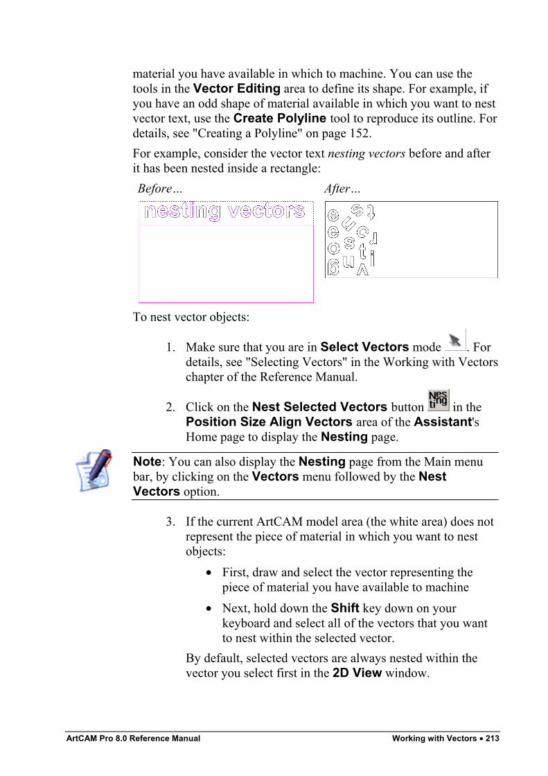
ArtCAM Pro 8.0 Reference Manual Working with Vectors • 213
material you have available in which to machine. You can use thetools in the Vector Editing area to define its shape. For example, ifyou have an odd shape of material available in which you want to nestvector text, use the Create Polyline tool to reproduce its outline. Fordetails, see "Creating a Polyline" on page 152.For example, consider the vector text nesting vectors before and afterit has been nested inside a rectangle:Before… After…
To nest vector objects:
1. Make sure that you are in Select Vectors mode . Fordetails, see "Selecting Vectors" in the Working with Vectorschapter of the Reference Manual.
2. Click on the Nest Selected Vectors button in thePosition Size Align Vectors area of the Assistant'sHome page to display the Nesting page.
Note: You can also display the Nesting page from the Main menubar, by clicking on the Vectors menu followed by the NestVectors option.
3. If the current ArtCAM model area (the white area) does notrepresent the piece of material in which you want to nestobjects:
• First, draw and select the vector representing thepiece of material you have available to machine
• Next, hold down the Shift key down on yourkeyboard and select all of the vectors that you wantto nest within the selected vector.
By default, selected vectors are always nested within thevector you select first in the 2D View window.
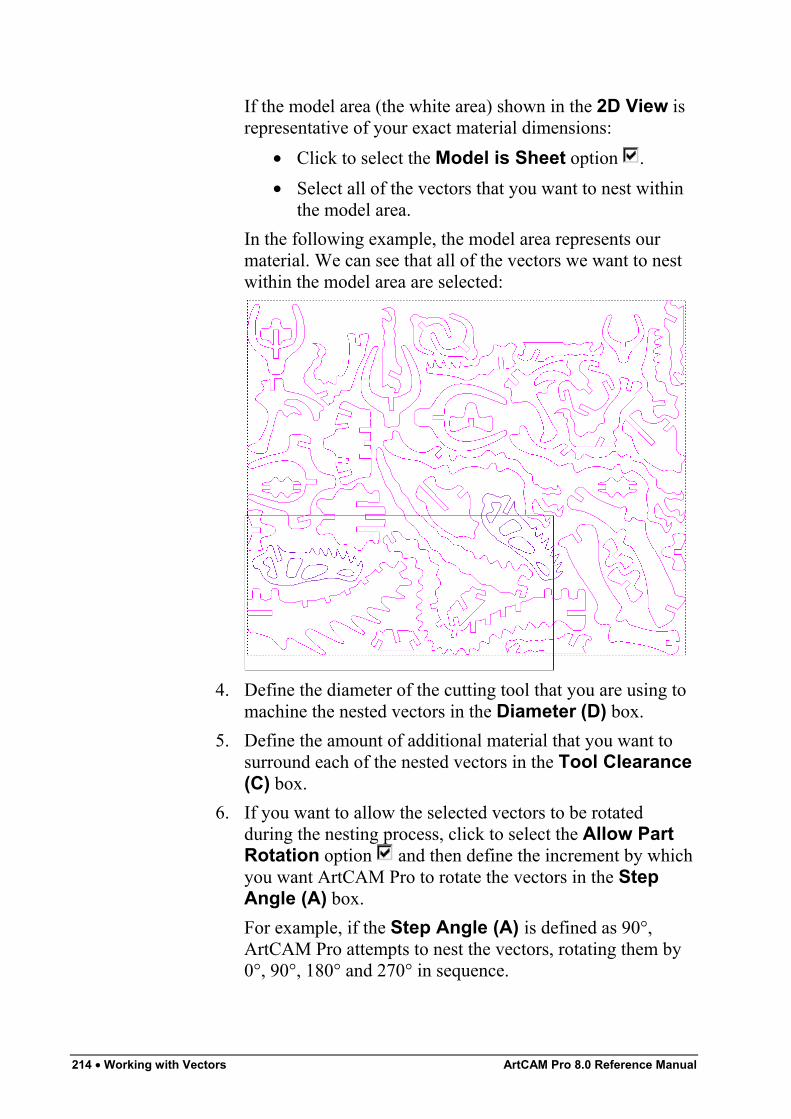
214 • Working with Vectors ArtCAM Pro 8.0 Reference Manual
If the model area (the white area) shown in the 2D View isrepresentative of your exact material dimensions:
• Click to select the Model is Sheet option .• Select all of the vectors that you want to nest within
the model area.In the following example, the model area represents ourmaterial. We can see that all of the vectors we want to nestwithin the model area are selected:
4. Define the diameter of the cutting tool that you are using tomachine the nested vectors in the Diameter (D) box.
5. Define the amount of additional material that you want tosurround each of the nested vectors in the Tool Clearance(C) box.
6. If you want to allow the selected vectors to be rotatedduring the nesting process, click to select the Allow PartRotation option and then define the increment by whichyou want ArtCAM Pro to rotate the vectors in the StepAngle (A) box.For example, if the Step Angle (A) is defined as 90°,ArtCAM Pro attempts to nest the vectors, rotating them by0°, 90°, 180° and 270° in sequence.
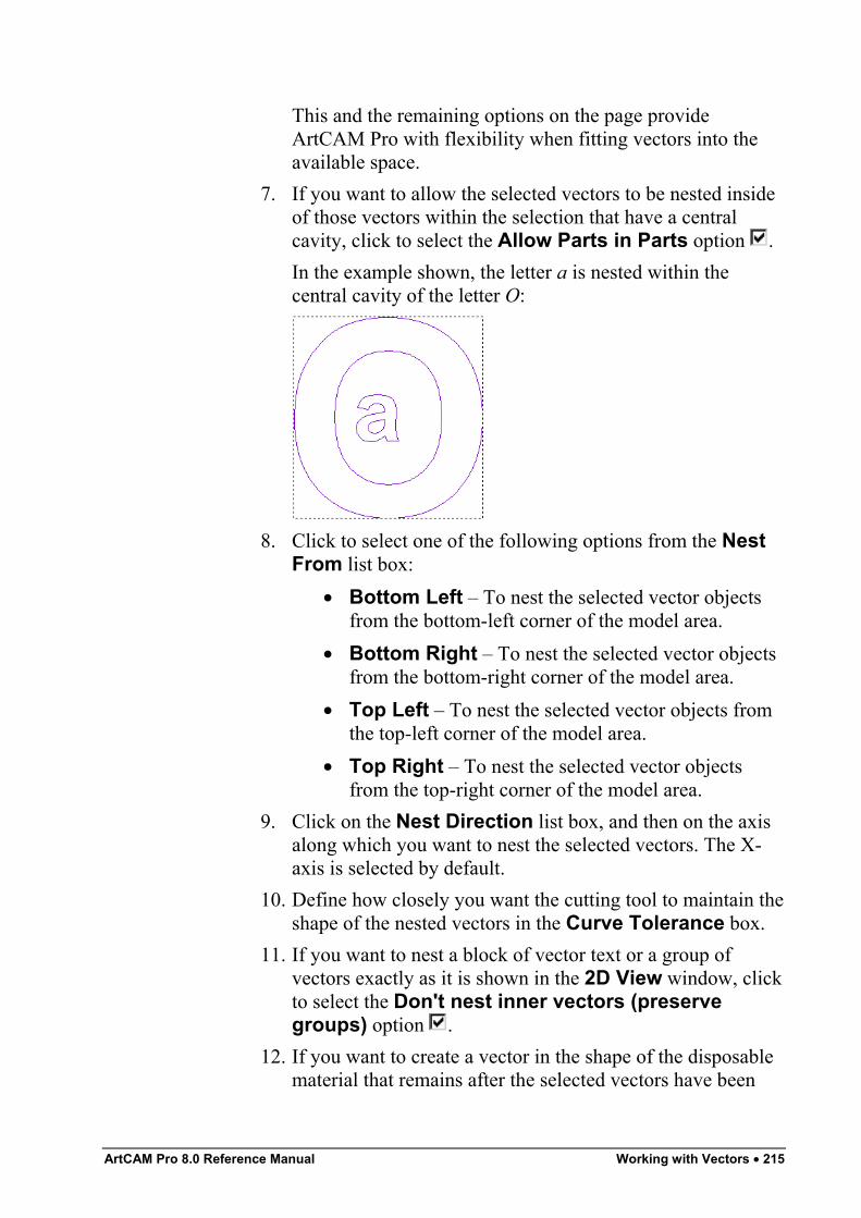
ArtCAM Pro 8.0 Reference Manual Working with Vectors • 215
This and the remaining options on the page provideArtCAM Pro with flexibility when fitting vectors into theavailable space.
7. If you want to allow the selected vectors to be nested insideof those vectors within the selection that have a centralcavity, click to select the Allow Parts in Parts option .In the example shown, the letter a is nested within thecentral cavity of the letter O:
8. Click to select one of the following options from the NestFrom list box:
• Bottom Left – To nest the selected vector objectsfrom the bottom-left corner of the model area.
• Bottom Right – To nest the selected vector objectsfrom the bottom-right corner of the model area.
• Top Left – To nest the selected vector objects fromthe top-left corner of the model area.
• Top Right – To nest the selected vector objectsfrom the top-right corner of the model area.
9. Click on the Nest Direction list box, and then on the axisalong which you want to nest the selected vectors. The X-axis is selected by default.
10. Define how closely you want the cutting tool to maintain theshape of the nested vectors in the Curve Tolerance box.
11. If you want to nest a block of vector text or a group ofvectors exactly as it is shown in the 2D View window, clickto select the Don't nest inner vectors (preservegroups) option .
12. If you want to create a vector in the shape of the disposablematerial that remains after the selected vectors have been
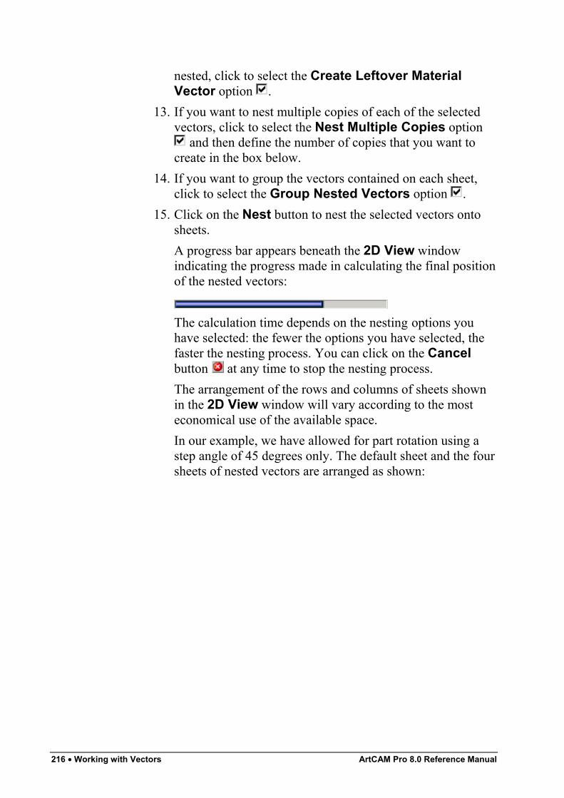
216 • Working with Vectors ArtCAM Pro 8.0 Reference Manual
nested, click to select the Create Leftover MaterialVector option .
13. If you want to nest multiple copies of each of the selectedvectors, click to select the Nest Multiple Copies option
and then define the number of copies that you want tocreate in the box below.
14. If you want to group the vectors contained on each sheet,click to select the Group Nested Vectors option .
15. Click on the Nest button to nest the selected vectors ontosheets.A progress bar appears beneath the 2D View windowindicating the progress made in calculating the final positionof the nested vectors:
The calculation time depends on the nesting options youhave selected: the fewer the options you have selected, thefaster the nesting process. You can click on the Cancelbutton at any time to stop the nesting process.The arrangement of the rows and columns of sheets shownin the 2D View window will vary according to the mosteconomical use of the available space.In our example, we have allowed for part rotation using astep angle of 45 degrees only. The default sheet and the foursheets of nested vectors are arranged as shown:
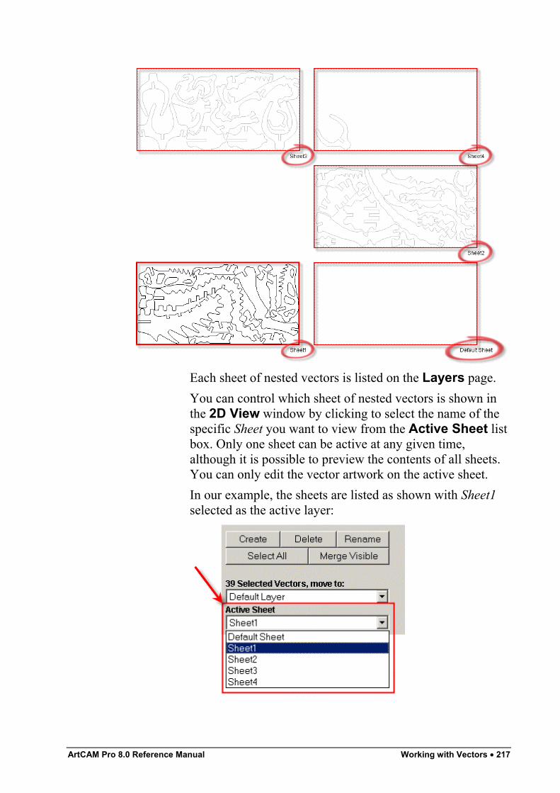
ArtCAM Pro 8.0 Reference Manual Working with Vectors • 217
Each sheet of nested vectors is listed on the Layers page.You can control which sheet of nested vectors is shown inthe 2D View window by clicking to select the name of thespecific Sheet you want to view from the Active Sheet listbox. Only one sheet can be active at any given time,although it is possible to preview the contents of all sheets.You can only edit the vector artwork on the active sheet.In our example, the sheets are listed as shown with Sheet1selected as the active layer:
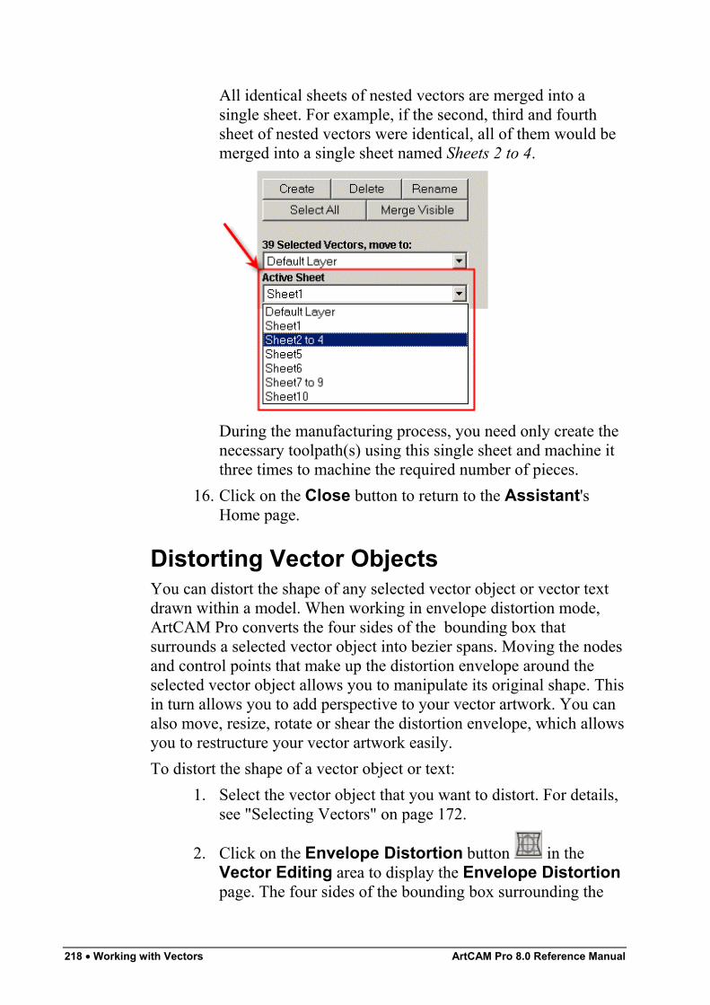
218 • Working with Vectors ArtCAM Pro 8.0 Reference Manual
All identical sheets of nested vectors are merged into asingle sheet. For example, if the second, third and fourthsheet of nested vectors were identical, all of them would bemerged into a single sheet named Sheets 2 to 4.
During the manufacturing process, you need only create thenecessary toolpath(s) using this single sheet and machine itthree times to machine the required number of pieces.
16. Click on the Close button to return to the Assistant'sHome page.
Distorting Vector ObjectsYou can distort the shape of any selected vector object or vector textdrawn within a model. When working in envelope distortion mode,ArtCAM Pro converts the four sides of the bounding box thatsurrounds a selected vector object into bezier spans. Moving the nodesand control points that make up the distortion envelope around theselected vector object allows you to manipulate its original shape. Thisin turn allows you to add perspective to your vector artwork. You canalso move, resize, rotate or shear the distortion envelope, which allowsyou to restructure your vector artwork easily.To distort the shape of a vector object or text:
1. Select the vector object that you want to distort. For details,see "Selecting Vectors" on page 172.
2. Click on the Envelope Distortion button in theVector Editing area to display the Envelope Distortionpage. The four sides of the bounding box surrounding the
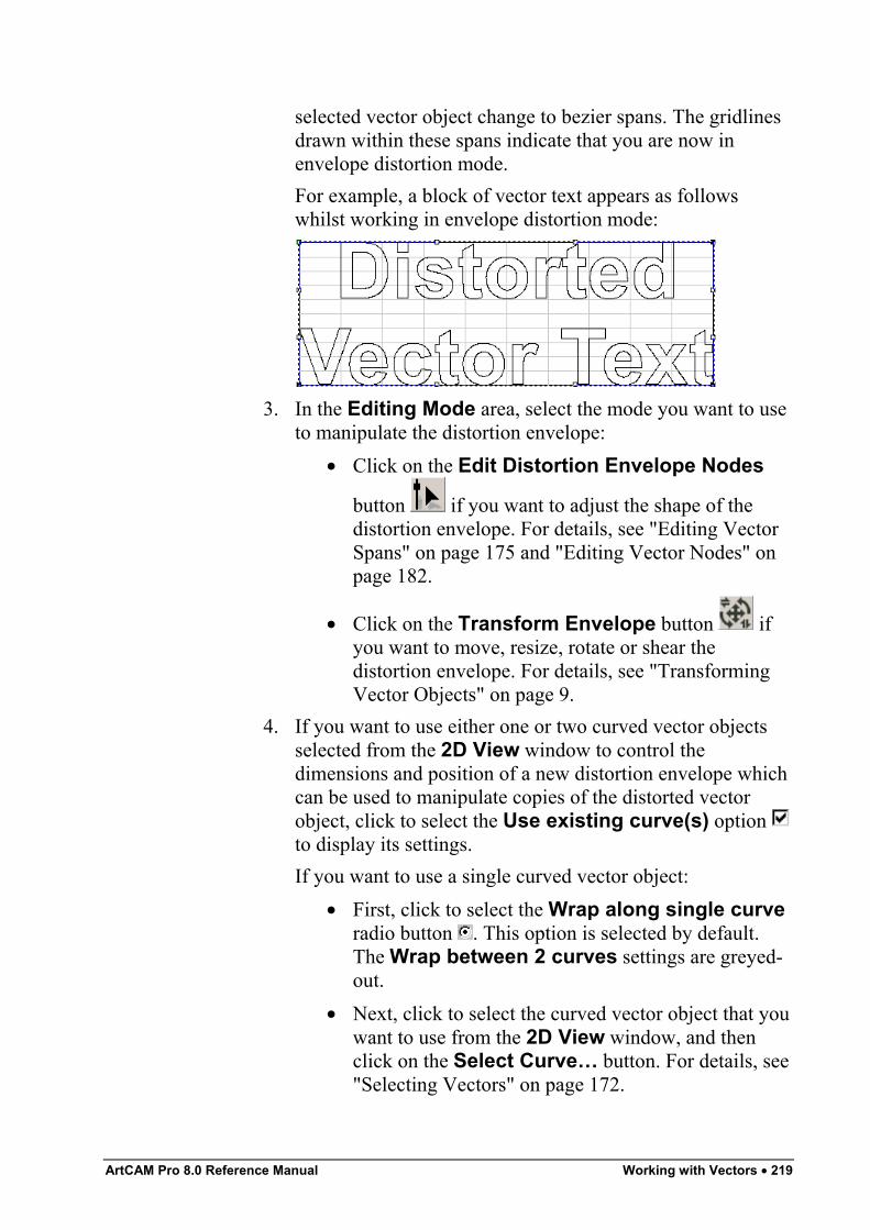
ArtCAM Pro 8.0 Reference Manual Working with Vectors • 219
selected vector object change to bezier spans. The gridlinesdrawn within these spans indicate that you are now inenvelope distortion mode.For example, a block of vector text appears as followswhilst working in envelope distortion mode:
3. In the Editing Mode area, select the mode you want to useto manipulate the distortion envelope:
• Click on the Edit Distortion Envelope Nodes
button if you want to adjust the shape of thedistortion envelope. For details, see "Editing VectorSpans" on page 175 and "Editing Vector Nodes" onpage 182.
• Click on the Transform Envelope button ifyou want to move, resize, rotate or shear thedistortion envelope. For details, see "TransformingVector Objects" on page 9.
4. If you want to use either one or two curved vector objectsselected from the 2D View window to control thedimensions and position of a new distortion envelope whichcan be used to manipulate copies of the distorted vectorobject, click to select the Use existing curve(s) option to display its settings.If you want to use a single curved vector object:
• First, click to select the Wrap along single curveradio button . This option is selected by default.The Wrap between 2 curves settings are greyed-out.
• Next, click to select the curved vector object that youwant to use from the 2D View window, and thenclick on the Select Curve… button. For details, see"Selecting Vectors" on page 172.
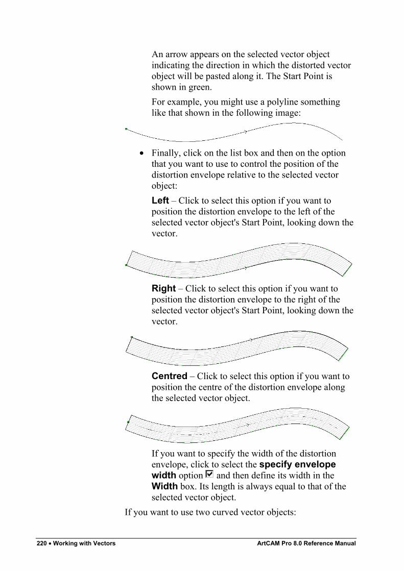
220 • Working with Vectors ArtCAM Pro 8.0 Reference Manual
An arrow appears on the selected vector objectindicating the direction in which the distorted vectorobject will be pasted along it. The Start Point isshown in green.For example, you might use a polyline somethinglike that shown in the following image:
• Finally, click on the list box and then on the optionthat you want to use to control the position of thedistortion envelope relative to the selected vectorobject:Left – Click to select this option if you want toposition the distortion envelope to the left of theselected vector object's Start Point, looking down thevector.
Right – Click to select this option if you want toposition the distortion envelope to the right of theselected vector object's Start Point, looking down thevector.
Centred – Click to select this option if you want toposition the centre of the distortion envelope alongthe selected vector object.
If you want to specify the width of the distortionenvelope, click to select the specify envelopewidth option and then define its width in theWidth box. Its length is always equal to that of theselected vector object.
If you want to use two curved vector objects:
ArtCAM Pro 8.0 Reference Manual Working with Vectors • 221
• First, click to select the Wrap between 2 curvesradio button . The Wrap along single curvesettings are greyed-out.
• Next, click to select the curved vector object shownin the 2D View that you want to use as the top edgeof the distortion envelope, and then click on theSelect Top Curve… button.An arrow appears on the selected vector objectindicating the direction in which the distorted vectorobject will be positioned along it. The Start Point isshown in green.
• Finally, click to select the curved vector objectshown in the 2D View that you want to use as thebottom edge of the distortion envelope, and thenclick on the Select Bottom Curve… button.An arrow appears on the selected vector objectindicating the direction in which the distorted vectorobject will be positioned along it. The Start Point isshown in green.
5. In the Number of Copies area, define the number ofcopies of the distorted vector object that you want to create:
• If you want to stretch the distorted vector objectalong the length of the selected vector object(s), clickto select the One - Stretch to Fit radio button .
• If you want ArtCAM Pro to calculate the optimumnumber of copies of the distorted vector object thatshould be created along the selected vector object(s),click to select the Many - Best Fit radio button .
• If you want to create a specific number of copies ofthe distorted vector object along the selected vectorobject(s), click to select the Many - Specificnumber of copies radio button and then definethe number of copies in the Copies box.
6. Click on the Apply button to position the distortionenvelope about the selected curved vector object(s). Thedistortion envelope is divided into sections equal to thenumber of copies of the distorted vector object you want tocreate.
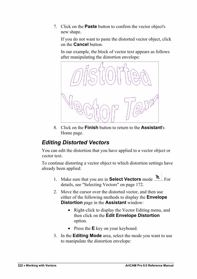
222 • Working with Vectors ArtCAM Pro 8.0 Reference Manual
7. Click on the Paste button to confirm the vector object'snew shape.If you do not want to paste the distorted vector object, clickon the Cancel button.In our example, the block of vector text appears as followsafter manipulating the distortion envelope:
8. Click on the Finish button to return to the Assistant'sHome page.
Editing Distorted VectorsYou can edit the distortion that you have applied to a vector object orvector text.To continue distorting a vector object to which distortion settings havealready been applied:
1. Make sure that you are in Select Vectors mode . Fordetails, see "Selecting Vectors" on page 172.
2. Move the cursor over the distorted vector, and then useeither of the following methods to display the EnvelopeDistortion page in the Assistant window:
• Right-click to display the Vector Editing menu, andthen click on the Edit Envelope Distortionoption.
• Press the E key on your keyboard.3. In the Editing Mode area, select the mode you want to use
to manipulate the distortion envelope:
ArtCAM Pro 8.0 Reference Manual Working with Vectors • 223
• Click on the Edit Distortion Envelope Nodes
button if you want to adjust the shape of thedistortion envelope. For details, see "Editing VectorSpans" on page 175 and "Editing Vector Nodes" onpage 182.
• Click on the Transform Envelope button ifyou want to move, resize, rotate or shear thedistortion envelope. For details, see "TransformingVector Objects" on page 9.
4. Click on the Paste button to confirm the vector object'snew shape.
5. Click on the Finish button to return to the Assistant'sHome page.
Pasting Vectors Along a CurveYou can paste copies of a selected vector object along another curvedvector object within a model.To do so:
1. Hold down the Shift key on your keyboard, and then clickon the vector object that you want to copy, followed by thecurved vector object that you want to paste copies along.For details, see "Selecting Vectors" on page 172.
2. Click on the Paste Along A Curve button in theVector Editing area of the Assistant's Home page todisplay the Paste Along A Curve page.
Note: You can also display the Paste Along A Curve page fromthe Main menu bar by clicking on the Vectors menu, followed by thePaste Vector(s) on Curve… option.
3. Select the pasting method that you want to use:• Click on the Specify Number radio button , and
then define the number of copies you want to createin the Number of Copies box.
• Click on the Specify Distance radio button ,then set the distance between each of the copies inthe Distance Between Copies box.
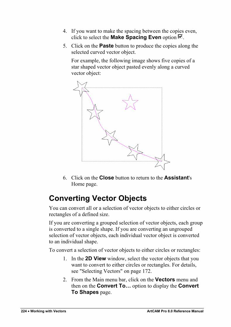
224 • Working with Vectors ArtCAM Pro 8.0 Reference Manual
4. If you want to make the spacing between the copies even,click to select the Make Spacing Even option .
5. Click on the Paste button to produce the copies along theselected curved vector object.For example, the following image shows five copies of astar shaped vector object pasted evenly along a curvedvector object:
6. Click on the Close button to return to the Assistant'sHome page.
Converting Vector ObjectsYou can convert all or a selection of vector objects to either circles orrectangles of a defined size.If you are converting a grouped selection of vector objects, each groupis converted to a single shape. If you are converting an ungroupedselection of vector objects, each individual vector object is convertedto an individual shape.To convert a selection of vector objects to either circles or rectangles:
1. In the 2D View window, select the vector objects that youwant to convert to either circles or rectangles. For details,see "Selecting Vectors" on page 172.
2. From the Main menu bar, click on the Vectors menu andthen on the Convert To… option to display the ConvertTo Shapes page.
ArtCAM Pro 8.0 Reference Manual Working with Vectors • 225
3. If you want to convert the selected vector objects to circles:• In the To Circles area, select either of the available
conversion methods:Click on the From Original radio button if youwant to convert the selected vector objects to circlesof the same size as the original shape; orClick on the Specify radio button if you want toconvert the selected vector objects to circles with adiameter equal to that which you define in theDiameter box.
• Next, click on the To Circles button to convert theselected vector objects to circles.
If you want to convert the selected vector objects torectangles:
• In the To Rectangles area, select either of theavailable conversion methods:Click on the From Original radio button toconvert the selected vector objects to rectangles ofthe same size as the original shape; orClick on the Specify radio button to convert theselected vector objects to convert the selected vectorobjects to rectangles with dimensions equal to thatwhich you define in the Height and Width boxes.
• Next, click on the To Rectangles button to convertthe selected vector objects to rectangles.
4. Click on the Close button to return to the Assistant'sHome page.
Creating a Vector BorderYou can create a rectangular vector border around a selection ofvector objects. You can define the width of the border around the Xand Y-axis.You can edit the vector border as you would any other square orrectangle created in ArtCAM Pro. For details, see "Editing a Square orRectangle" on page 157.To create a rectangular vector border around a selection of vectorobjects:
226 • Working with Vectors ArtCAM Pro 8.0 Reference Manual
1. Make sure that you are in Select Vectors mode . Fordetails, see "Selecting Vectors" on page 172.
2. In the 2D View window, select the vector objects aroundwhich you want to create a vector border.
3. From the Main menu bar, click on the Vectors menu andthen on the Create Border… option to display the CreateBorder page.
4. Define the width of the vector border in the Gap In X andGap In Y boxes.
5. Click on the Create Border button to create the vectorborder.
6. Click on the Close button to return to the Assistant'sHome page.
Using the Vector DoctorIn previous versions of ArtCAM Pro, you would have to manuallyfind and edit a range of common problems within vector artwork,often detrimental to the machining process, to correct them. You cannow avoid problems during the manufacturing process by:
• Identifying all coincident points (nodes) in the vectorobjects that make up the artwork, within a specifiedtolerance, so that they can be joined using the JoinVectors with Coincident Start or End Points tool.For details, see "Identifying Coincident Points" on page226.
• Identifying all loops in self-intersecting vector objectswithin the artwork less than a defined size, and thenremoving them. For details, see "Loop Detection andRemoval" on page 227.
Identifying Coincident PointsYou can instruct ArtCAM Pro to check for concurrent start or endpoints (nodes) in a selection of open vector objects, within a defineddistance of one another:To identify the coincident points in your vector artwork:
1. Make sure that you are in Select Vectors mode . Fordetails, see "Selecting Vectors" on page 172.
ArtCAM Pro 8.0 Reference Manual Working with Vectors • 227
2. Click and drag around the vector artwork in the 2D Viewwindow, or an area within it, to select it. All grouped vectorobjects within the selection turn purple; all ungroupedvector objects turn magenta.
3. Click on the Vector Doctor button in the VectorEditing area to display the Vector Doctor page.
Note: You can also display the Vector Doctor page from the Mainmenu bar by clicking on the Vectors menu, followed by the VectorDoctor… option.
4. In the Identify Problems area, make sure that theCoincident Points option is selected .
5. If you only want ArtCAM Pro to recognise points in theselected vector object within a specific distance of oneanother as coincident, define the distance in the Tolerancebox.
6. Click on the Identify button. ArtCAM Pro marks allcoincident points in the selected vector object with the icon.
7. Click on the Close button to return to the Assistant'sHome page.
Loop Detection and RemovalLooped self-intersections found within vector artwork intended forengraving often cause problems during the manufacturing process.You can instruct ArtCAM Pro to identify all loops within a selectionof vector objects less than a defined size, inserts a point (node) at thebottom of the loop where the vector objects self-intersect, and thentrim away the loop.For example, the 'g' character shown below includes a self-intersectingvector object with a loop. You can see the difference in its shape afterthe loop has been removed:
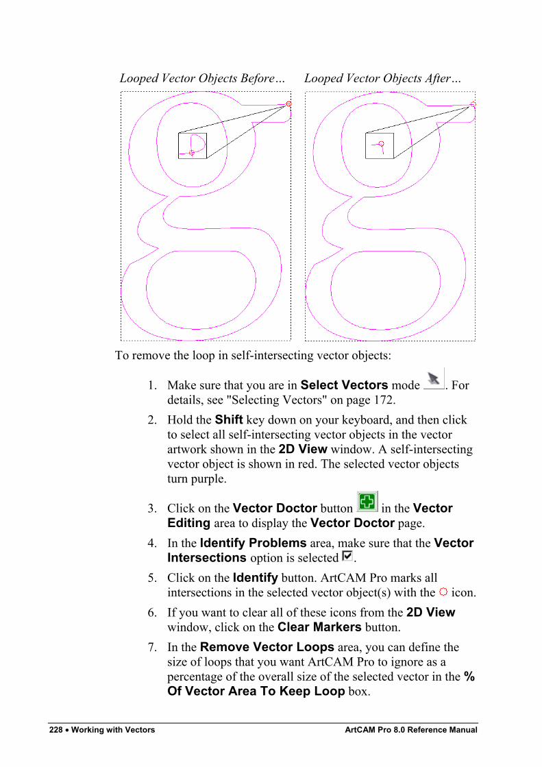
228 • Working with Vectors ArtCAM Pro 8.0 Reference Manual
Looped Vector Objects Before… Looped Vector Objects After…
To remove the loop in self-intersecting vector objects:
1. Make sure that you are in Select Vectors mode . Fordetails, see "Selecting Vectors" on page 172.
2. Hold the Shift key down on your keyboard, and then clickto select all self-intersecting vector objects in the vectorartwork shown in the 2D View window. A self-intersectingvector object is shown in red. The selected vector objectsturn purple.
3. Click on the Vector Doctor button in the VectorEditing area to display the Vector Doctor page.
4. In the Identify Problems area, make sure that the VectorIntersections option is selected .
5. Click on the Identify button. ArtCAM Pro marks allintersections in the selected vector object(s) with the icon.
6. If you want to clear all of these icons from the 2D Viewwindow, click on the Clear Markers button.
7. In the Remove Vector Loops area, you can define thesize of loops that you want ArtCAM Pro to ignore as apercentage of the overall size of the selected vector in the %Of Vector Area To Keep Loop box.

ArtCAM Pro 8.0 Reference Manual Working with Vectors • 229
For example, if your vector artwork contains a figure 8, it islikely that you will want to keep both of its loops. If theoriginal vector object has an area of 100 mm² and contains aloop of 1.5 mm², a value of 1% would mean that the loopwould be converted into an independent vector. A value of2%, however, would mean that the loop would be deleted.
8. Type the name of the layer onto which you want to createthe corrected vector object(s) in the Layer Name box. If nolayer is defined, ArtCAM Pro creates the corrected vectorobject(s) on the currently selected layer.
9. If you want to keep a copy of the looped, self-intersectingvector object(s), make sure that the Keep Originals optionis selected .
10. Click on the Remove Loops button to remove all loops inthe selected vector object(s).
11. Click on the Close button to return to the Assistant'sHome page.
Note: You can also press the Ctrl + Alt + Shift + R keys on yourkeyboard to remove all loops in the selected vector object(s).
Working with Vector TextYou can create and manipulate vector text using three tools inArtCAM Pro. These are:
• The Font Editor icon on the Assistant's GettingStarted page. For details, see "Using the Font Editor" inthe Working with Models chapter.
• The Create Vector Text button in the VectorEditing area of the Assistant's Home page. For details,see "Creating Vector Text" on page 230.
• The Wrap Text Round a Curve button in thePosition Size Align Vectors area of the Assistant'sHome page. For details, see "Wrapping Text Round aCurve" on page 238.
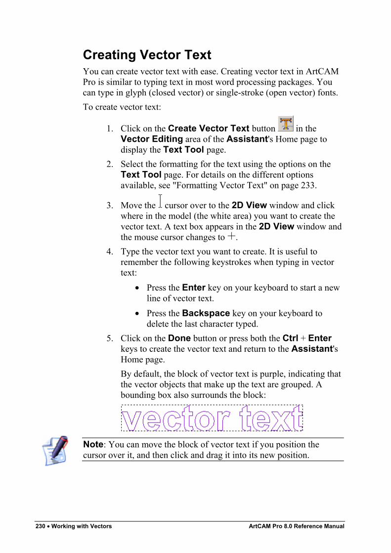
230 • Working with Vectors ArtCAM Pro 8.0 Reference Manual
Creating Vector TextYou can create vector text with ease. Creating vector text in ArtCAMPro is similar to typing text in most word processing packages. Youcan type in glyph (closed vector) or single-stroke (open vector) fonts.To create vector text:
1. Click on the Create Vector Text button in theVector Editing area of the Assistant's Home page todisplay the Text Tool page.
2. Select the formatting for the text using the options on theText Tool page. For details on the different optionsavailable, see "Formatting Vector Text" on page 233.
3. Move the cursor over to the 2D View window and clickwhere in the model (the white area) you want to create thevector text. A text box appears in the 2D View window andthe mouse cursor changes to .
4. Type the vector text you want to create. It is useful toremember the following keystrokes when typing in vectortext:
• Press the Enter key on your keyboard to start a newline of vector text.
• Press the Backspace key on your keyboard todelete the last character typed.
5. Click on the Done button or press both the Ctrl + Enterkeys to create the vector text and return to the Assistant'sHome page.By default, the block of vector text is purple, indicating thatthe vector objects that make up the text are grouped. Abounding box also surrounds the block:
Note: You can move the block of vector text if you position thecursor over it, and then click and drag it into its new position.
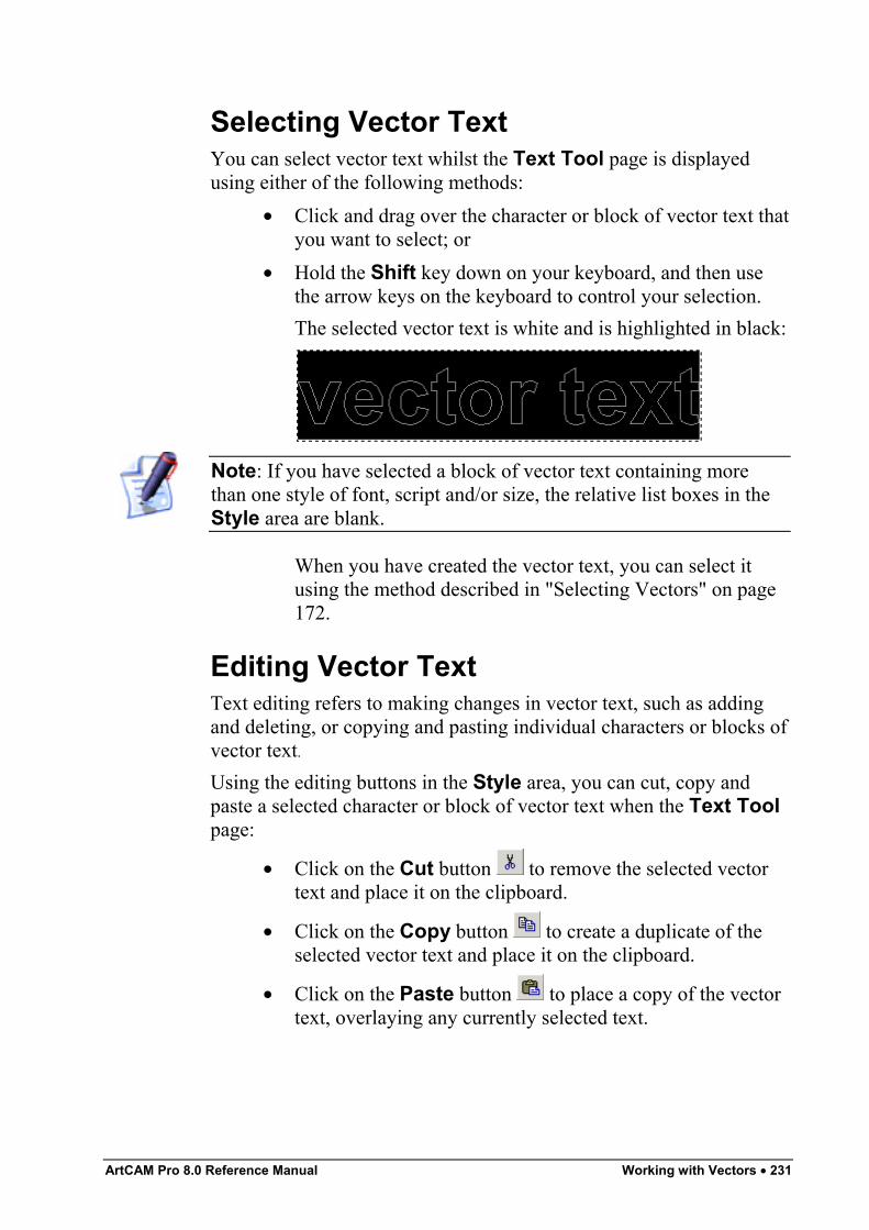
ArtCAM Pro 8.0 Reference Manual Working with Vectors • 231
Selecting Vector TextYou can select vector text whilst the Text Tool page is displayedusing either of the following methods:
• Click and drag over the character or block of vector text thatyou want to select; or
• Hold the Shift key down on your keyboard, and then usethe arrow keys on the keyboard to control your selection.The selected vector text is white and is highlighted in black:
Note: If you have selected a block of vector text containing morethan one style of font, script and/or size, the relative list boxes in theStyle area are blank.
When you have created the vector text, you can select itusing the method described in "Selecting Vectors" on page172.
Editing Vector TextText editing refers to making changes in vector text, such as addingand deleting, or copying and pasting individual characters or blocks ofvector text.Using the editing buttons in the Style area, you can cut, copy andpaste a selected character or block of vector text when the Text Toolpage:
• Click on the Cut button to remove the selected vectortext and place it on the clipboard.
• Click on the Copy button to create a duplicate of theselected vector text and place it on the clipboard.
• Click on the Paste button to place a copy of the vectortext, overlaying any currently selected text.
232 • Working with Vectors ArtCAM Pro 8.0 Reference Manual
Note: If you copy a block of vector text that contains multiple fonts,when you use the Paste button the vector text is written in thefont currently selected on the Text Tool page.
Note: A selected block of vector text that has already beentransformed, e.g. sheared, appears as a default block whilst the TextTool page is displayed. After closing the page, the transform isrestored and any changes that you have made to the text are applied.
You can use either of the following methods to edit a selectedcharacter or block of vector text after it has been created:
• Right-click on the block of vector text to display the TextEditing menu, and then click on the Edit Text Blockoption to display the Text Tool page.
• Press the E key on your keyboard to display the Text Toolpage.
You can also cut, copy and/or paste a block of vector text after it hasbeen created using the editing buttons in the File area of theAssistant's Home page. For details, see "Copying and PastingVector Objects" on page 192.You can add or delete characters when the Text Tool page isdisplayed in the Assistant window using your keyboard:
• Use the character keys on your keyboard to add charactersto the block of vector text.
• Press the Backspace key on your keyboard to delete thelast typed character.
You can delete a selected block of vector text when the Text Toolpage is not displayed in the Assistant window using either of thefollowing ways:
• Move the cursor over the block of vector text, and thenpress the Delete key on your keyboard.
• Right-click on the selected block of vector text to displaythe Vector Editing menu, and then click on the Deleteoption.
ArtCAM Pro 8.0 Reference Manual Working with Vectors • 233
Formatting Vector TextText formatting refers to setting the way vector text looks usingdifferent fonts, bold or italic type, indents and alignments.You can format a character or block of vector text both during andafter its creation using the formatting buttons and the list boxes in theStyle area of the Text Tool page.You can use the formatting buttons as follows:
• Click on the Toggle Vertical Text Flow button todisplay vector text vertically, rather than horizontally.
When the Toggle Vertical Text Flow button isselected, the Kerning options are removed from the TextTool page and the alignment buttons are adjusted.
• Click on the Bold button to make the vector text bold,or to remove the bold formatting.
• Click on the Italic button to make the vector text italic,or to remove the italic formatting.
• Click on the Align Left button to align the selectedvector text to the left of the text box with a ragged rightedge. This button affects selected vector text of more thanone line.
Note: If the Toggle Vertical Text Flow button is selected, theAlign Top button replaces the Align Left button , allowingyou to align the vector text with the top of the text box with a raggedbottom edge.
• Click on the Centred button to place the selectedvector text in the centre of the text box. This button affectsvector text of more than one line.
Note: If the Toggle Vertical Text Flow button is selected, theicon for the Centered button is rotated .
• Click on the Align Right button to align the selectedvector text to the right of the text box with a ragged leftedge. This button affects selected vector text of more thanone line.
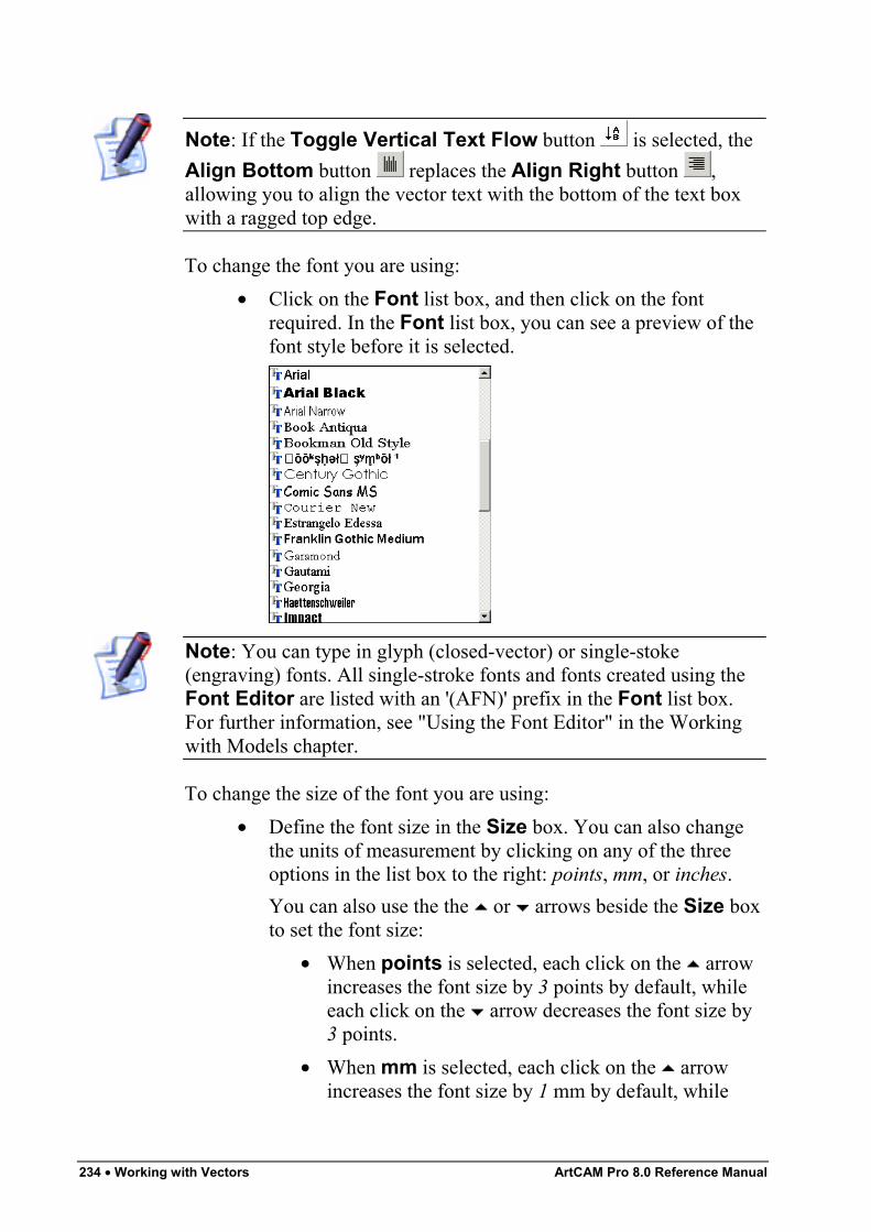
234 • Working with Vectors ArtCAM Pro 8.0 Reference Manual
Note: If the Toggle Vertical Text Flow button is selected, theAlign Bottom button replaces the Align Right button ,allowing you to align the vector text with the bottom of the text boxwith a ragged top edge.
To change the font you are using:• Click on the Font list box, and then click on the font
required. In the Font list box, you can see a preview of thefont style before it is selected.
Note: You can type in glyph (closed-vector) or single-stoke(engraving) fonts. All single-stroke fonts and fonts created using theFont Editor are listed with an '(AFN)' prefix in the Font list box.For further information, see "Using the Font Editor" in the Workingwith Models chapter.
To change the size of the font you are using:• Define the font size in the Size box. You can also change
the units of measurement by clicking on any of the threeoptions in the list box to the right: points, mm, or inches.You can also use the the or arrows beside the Size boxto set the font size:
• When points is selected, each click on the arrowincreases the font size by 3 points by default, whileeach click on the arrow decreases the font size by3 points.
• When mm is selected, each click on the arrowincreases the font size by 1 mm by default, while
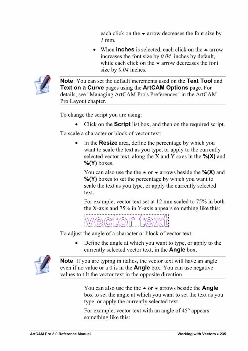
ArtCAM Pro 8.0 Reference Manual Working with Vectors • 235
each click on the arrow decreases the font size by1 mm.
• When inches is selected, each click on the arrowincreases the font size by 0.04 inches by default,while each click on the arrow decreases the fontsize by 0.04 inches.
Note: You can set the default increments used on the Text Tool andText on a Curve pages using the ArtCAM Options page. Fordetails, see "Managing ArtCAM Pro's Preferences" in the ArtCAMPro Layout chapter.
To change the script you are using:• Click on the Script list box, and then on the required script.
To scale a character or block of vector text:• In the Resize area, define the percentage by which you
want to scale the text as you type, or apply to the currentlyselected vector text, along the X and Y axes in the %(X) and%(Y) boxes.You can also use the the or arrows beside the %(X) and%(Y) boxes to set the percentage by which you want toscale the text as you type, or apply the currently selectedtext.For example, vector text set at 12 mm scaled to 75% in boththe X-axis and 75% in Y-axis appears something like this:
To adjust the angle of a character or block of vector text:• Define the angle at which you want to type, or apply to the
currently selected vector text, in the Angle box.
Note: If you are typing in italics, the vector text will have an angleeven if no value or a 0 is in the Angle box. You can use negativevalues to tilt the vector text in the opposite direction.
You can also use the the or arrows beside the Anglebox to set the angle at which you want to set the text as youtype, or apply the currently selected text.For example, vector text with an angle of 45° appearssomething like this:
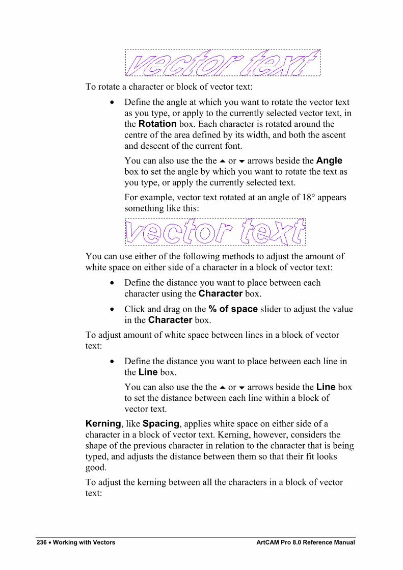
236 • Working with Vectors ArtCAM Pro 8.0 Reference Manual
To rotate a character or block of vector text:• Define the angle at which you want to rotate the vector text
as you type, or apply to the currently selected vector text, inthe Rotation box. Each character is rotated around thecentre of the area defined by its width, and both the ascentand descent of the current font.You can also use the the or arrows beside the Anglebox to set the angle by which you want to rotate the text asyou type, or apply the currently selected text.For example, vector text rotated at an angle of 18° appearssomething like this:
You can use either of the following methods to adjust the amount ofwhite space on either side of a character in a block of vector text:
• Define the distance you want to place between eachcharacter using the Character box.
• Click and drag on the % of space slider to adjust the valuein the Character box.
To adjust amount of white space between lines in a block of vectortext:
• Define the distance you want to place between each line inthe Line box.You can also use the the or arrows beside the Line boxto set the distance between each line within a block ofvector text.
Kerning, like Spacing, applies white space on either side of acharacter in a block of vector text. Kerning, however, considers theshape of the previous character in relation to the character that is beingtyped, and adjusts the distance between them so that their fit looksgood.To adjust the kerning between all the characters in a block of vectortext:
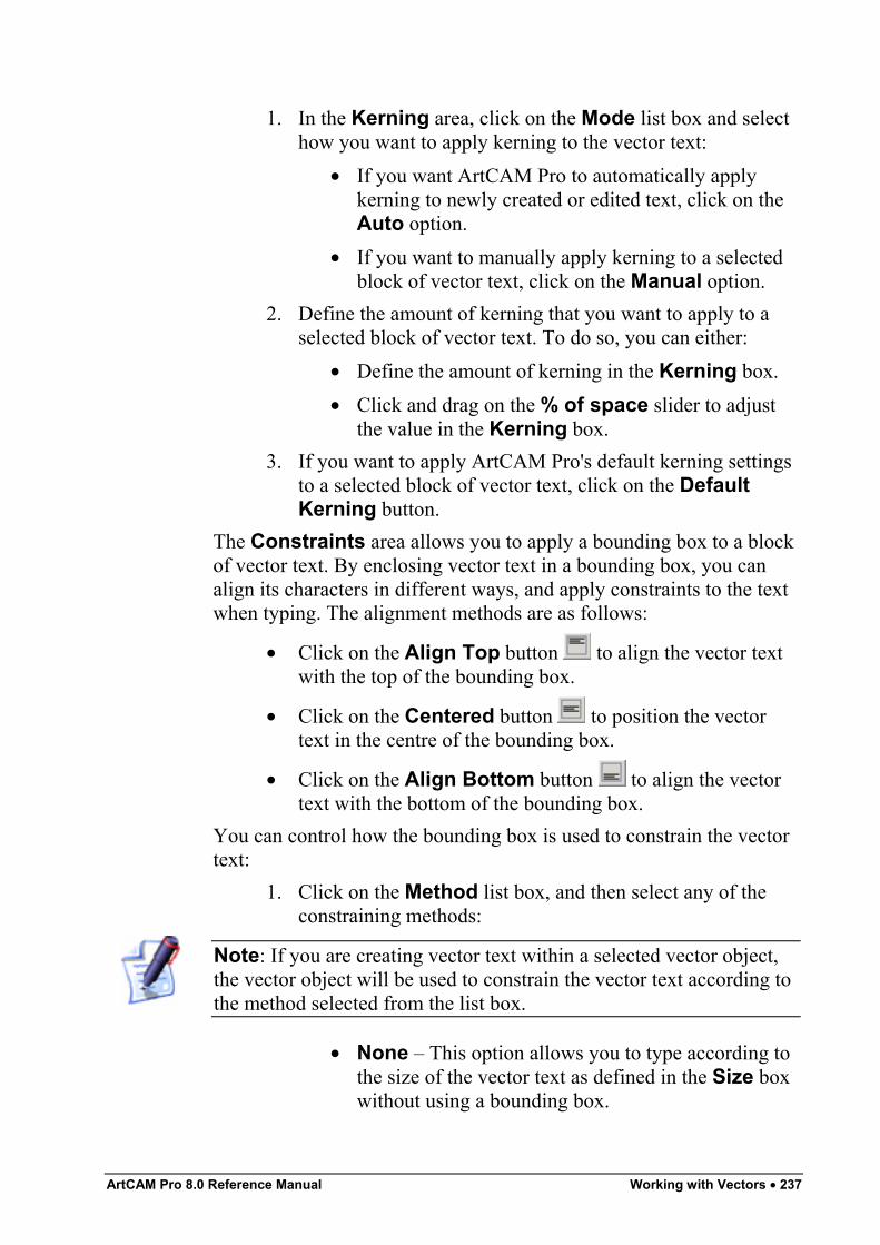
ArtCAM Pro 8.0 Reference Manual Working with Vectors • 237
1. In the Kerning area, click on the Mode list box and selecthow you want to apply kerning to the vector text:
• If you want ArtCAM Pro to automatically applykerning to newly created or edited text, click on theAuto option.
• If you want to manually apply kerning to a selectedblock of vector text, click on the Manual option.
2. Define the amount of kerning that you want to apply to aselected block of vector text. To do so, you can either:
• Define the amount of kerning in the Kerning box.• Click and drag on the % of space slider to adjust
the value in the Kerning box.3. If you want to apply ArtCAM Pro's default kerning settings
to a selected block of vector text, click on the DefaultKerning button.
The Constraints area allows you to apply a bounding box to a blockof vector text. By enclosing vector text in a bounding box, you canalign its characters in different ways, and apply constraints to the textwhen typing. The alignment methods are as follows:
• Click on the Align Top button to align the vector textwith the top of the bounding box.
• Click on the Centered button to position the vectortext in the centre of the bounding box.
• Click on the Align Bottom button to align the vectortext with the bottom of the bounding box.
You can control how the bounding box is used to constrain the vectortext:
1. Click on the Method list box, and then select any of theconstraining methods:
Note: If you are creating vector text within a selected vector object,the vector object will be used to constrain the vector text according tothe method selected from the list box.
• None – This option allows you to type according tothe size of the vector text as defined in the Size boxwithout using a bounding box.
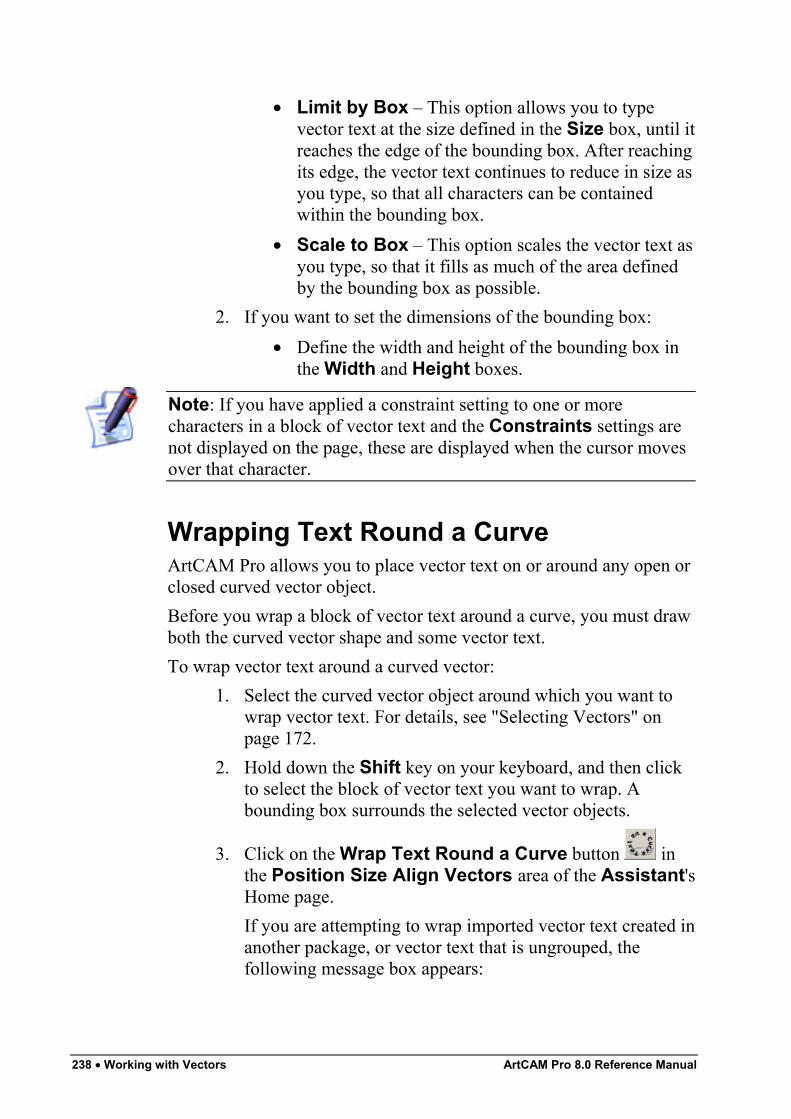
238 • Working with Vectors ArtCAM Pro 8.0 Reference Manual
• Limit by Box – This option allows you to typevector text at the size defined in the Size box, until itreaches the edge of the bounding box. After reachingits edge, the vector text continues to reduce in size asyou type, so that all characters can be containedwithin the bounding box.
• Scale to Box – This option scales the vector text asyou type, so that it fills as much of the area definedby the bounding box as possible.
2. If you want to set the dimensions of the bounding box:• Define the width and height of the bounding box in
the Width and Height boxes.
Note: If you have applied a constraint setting to one or morecharacters in a block of vector text and the Constraints settings arenot displayed on the page, these are displayed when the cursor movesover that character.
Wrapping Text Round a CurveArtCAM Pro allows you to place vector text on or around any open orclosed curved vector object.Before you wrap a block of vector text around a curve, you must drawboth the curved vector shape and some vector text.To wrap vector text around a curved vector:
1. Select the curved vector object around which you want towrap vector text. For details, see "Selecting Vectors" onpage 172.
2. Hold down the Shift key on your keyboard, and then clickto select the block of vector text you want to wrap. Abounding box surrounds the selected vector objects.
3. Click on the Wrap Text Round a Curve button inthe Position Size Align Vectors area of the Assistant'sHome page.If you are attempting to wrap imported vector text created inanother package, or vector text that is ungrouped, thefollowing message box appears:
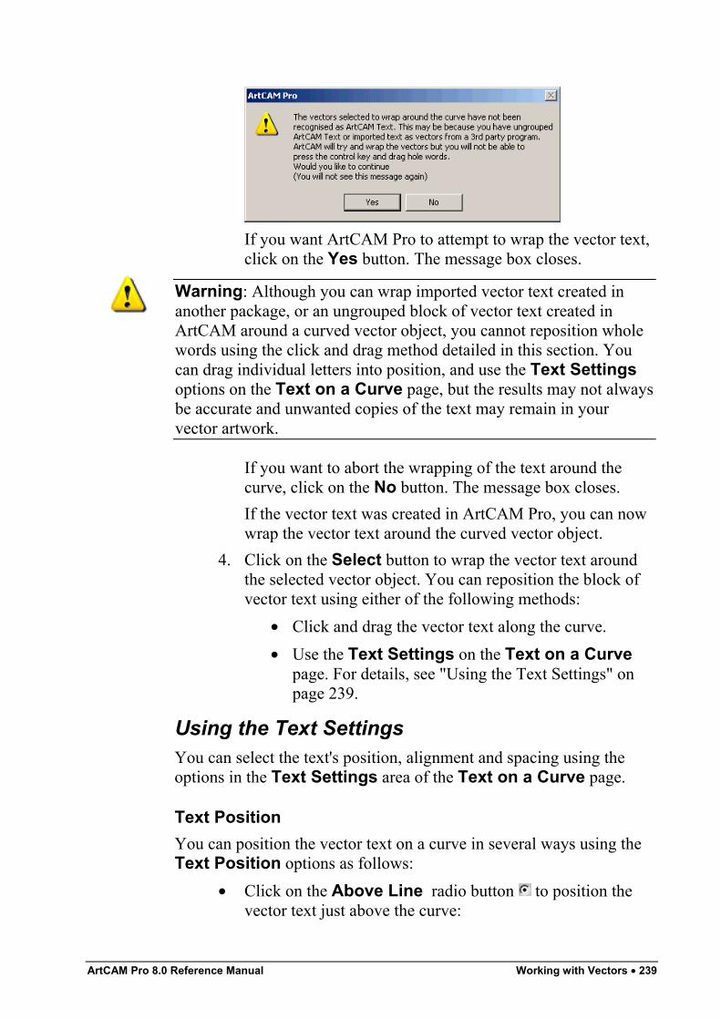
ArtCAM Pro 8.0 Reference Manual Working with Vectors • 239
If you want ArtCAM Pro to attempt to wrap the vector text,click on the Yes button. The message box closes.
Warning: Although you can wrap imported vector text created inanother package, or an ungrouped block of vector text created inArtCAM around a curved vector object, you cannot reposition wholewords using the click and drag method detailed in this section. Youcan drag individual letters into position, and use the Text Settingsoptions on the Text on a Curve page, but the results may not alwaysbe accurate and unwanted copies of the text may remain in yourvector artwork.
If you want to abort the wrapping of the text around thecurve, click on the No button. The message box closes.If the vector text was created in ArtCAM Pro, you can nowwrap the vector text around the curved vector object.
4. Click on the Select button to wrap the vector text aroundthe selected vector object. You can reposition the block ofvector text using either of the following methods:
• Click and drag the vector text along the curve.• Use the Text Settings on the Text on a Curve
page. For details, see "Using the Text Settings" onpage 239.
Using the Text SettingsYou can select the text's position, alignment and spacing using theoptions in the Text Settings area of the Text on a Curve page.
Text PositionYou can position the vector text on a curve in several ways using theText Position options as follows:
• Click on the Above Line radio button to position thevector text just above the curve:
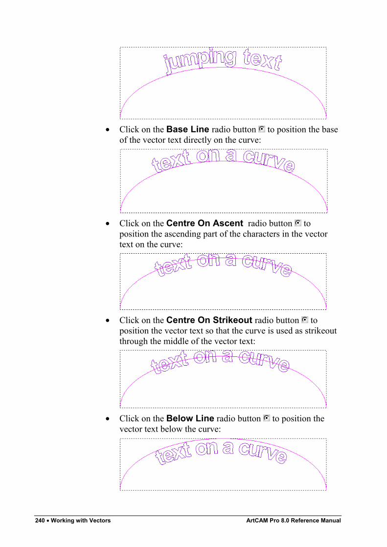
240 • Working with Vectors ArtCAM Pro 8.0 Reference Manual
• Click on the Base Line radio button to position the baseof the vector text directly on the curve:
• Click on the Centre On Ascent radio button toposition the ascending part of the characters in the vectortext on the curve:
• Click on the Centre On Strikeout radio button toposition the vector text so that the curve is used as strikeoutthrough the middle of the vector text:
• Click on the Below Line radio button to position thevector text below the curve:
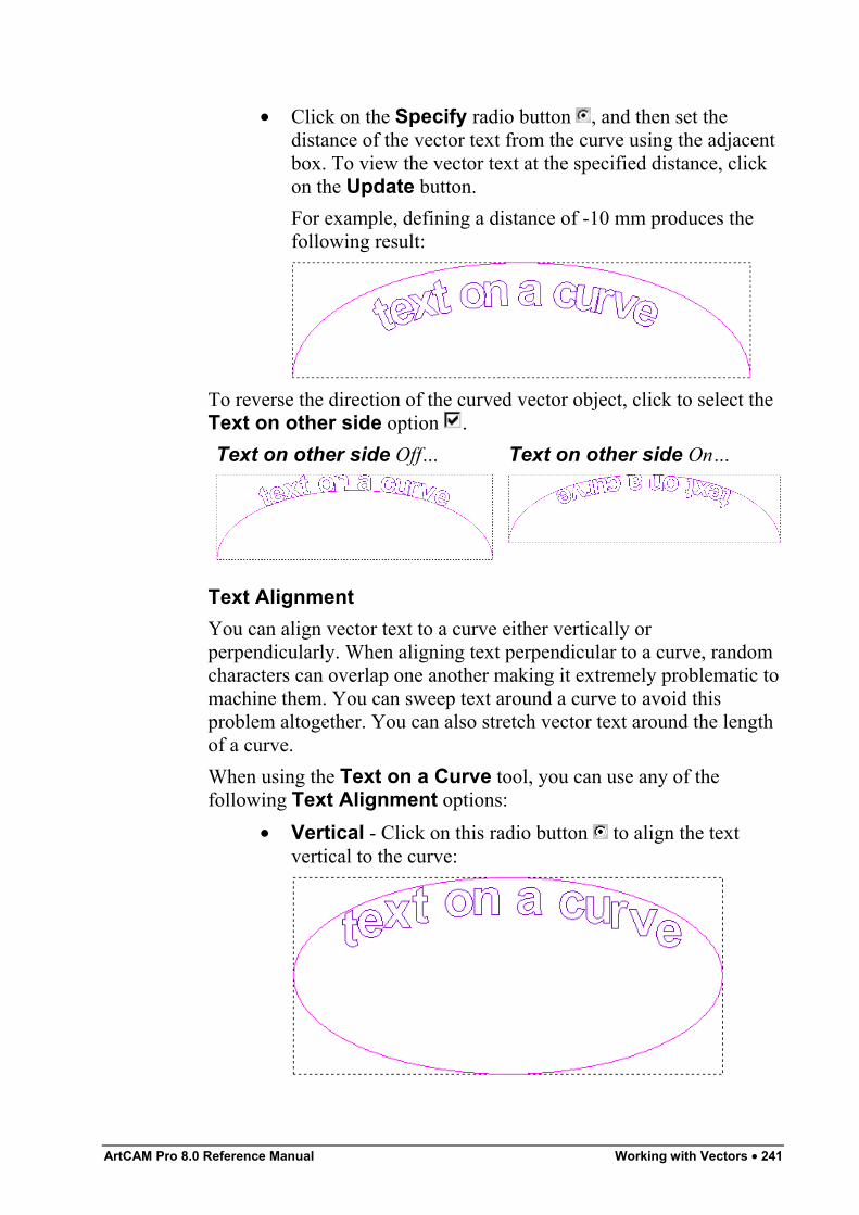
ArtCAM Pro 8.0 Reference Manual Working with Vectors • 241
• Click on the Specify radio button , and then set thedistance of the vector text from the curve using the adjacentbox. To view the vector text at the specified distance, clickon the Update button.For example, defining a distance of -10 mm produces thefollowing result:
To reverse the direction of the curved vector object, click to select theText on other side option .Text on other side Off… Text on other side On…
Text AlignmentYou can align vector text to a curve either vertically orperpendicularly. When aligning text perpendicular to a curve, randomcharacters can overlap one another making it extremely problematic tomachine them. You can sweep text around a curve to avoid thisproblem altogether. You can also stretch vector text around the lengthof a curve.When using the Text on a Curve tool, you can use any of thefollowing Text Alignment options:
• Vertical - Click on this radio button to align the textvertical to the curve:
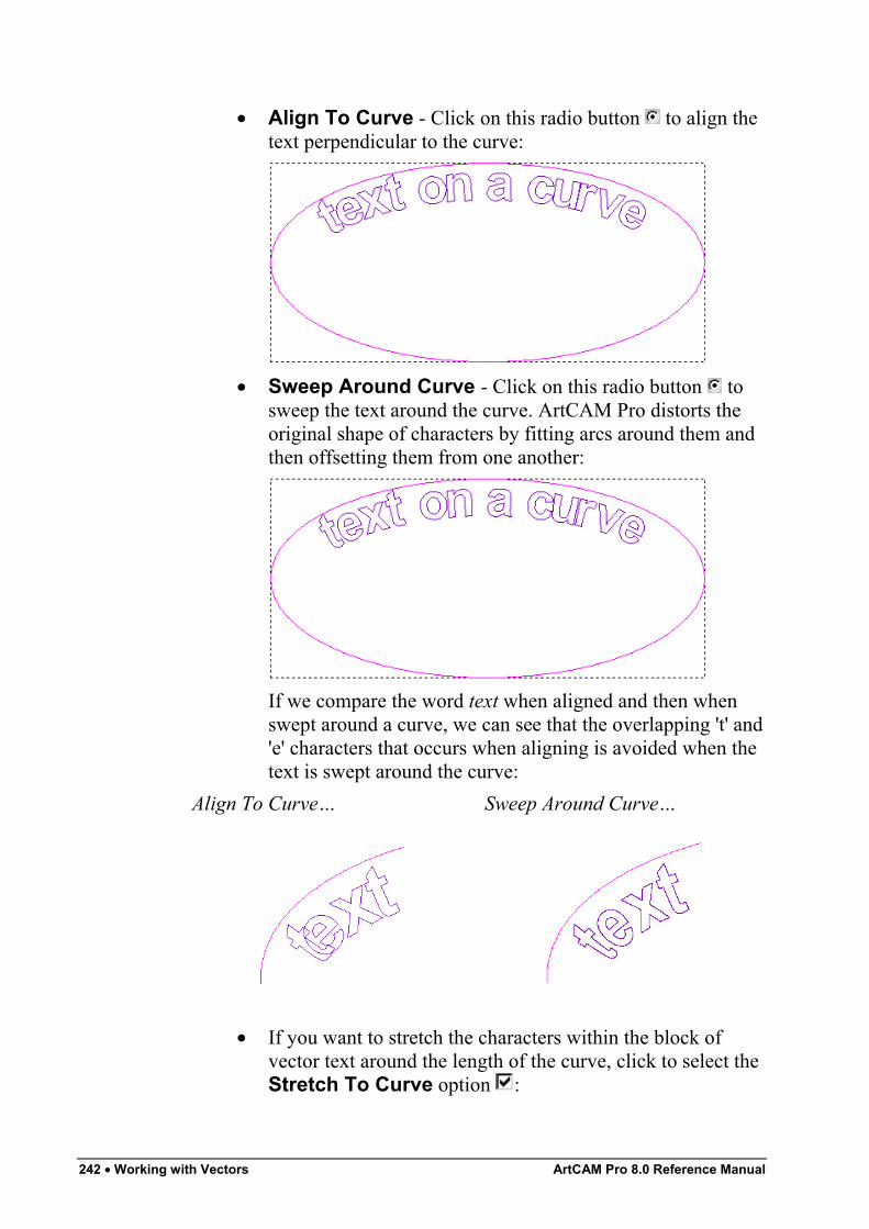
242 • Working with Vectors ArtCAM Pro 8.0 Reference Manual
• Align To Curve - Click on this radio button to align thetext perpendicular to the curve:
• Sweep Around Curve - Click on this radio button tosweep the text around the curve. ArtCAM Pro distorts theoriginal shape of characters by fitting arcs around them andthen offsetting them from one another:
If we compare the word text when aligned and then whenswept around a curve, we can see that the overlapping 't' and'e' characters that occurs when aligning is avoided when thetext is swept around the curve:
Align To Curve… Sweep Around Curve…
• If you want to stretch the characters within the block ofvector text around the length of the curve, click to select theStretch To Curve option :
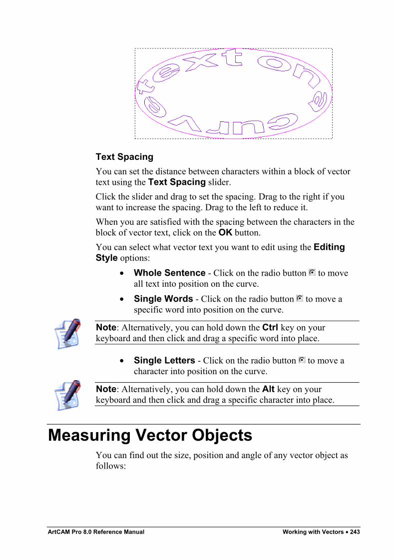
ArtCAM Pro 8.0 Reference Manual Working with Vectors • 243
Text SpacingYou can set the distance between characters within a block of vectortext using the Text Spacing slider.Click the slider and drag to set the spacing. Drag to the right if youwant to increase the spacing. Drag to the left to reduce it.When you are satisfied with the spacing between the characters in theblock of vector text, click on the OK button.You can select what vector text you want to edit using the EditingStyle options:
• Whole Sentence - Click on the radio button to moveall text into position on the curve.
• Single Words - Click on the radio button to move aspecific word into position on the curve.
Note: Alternatively, you can hold down the Ctrl key on yourkeyboard and then click and drag a specific word into place.
• Single Letters - Click on the radio button to move acharacter into position on the curve.
Note: Alternatively, you can hold down the Alt key on yourkeyboard and then click and drag a specific character into place.
Measuring Vector ObjectsYou can find out the size, position and angle of any vector object asfollows:
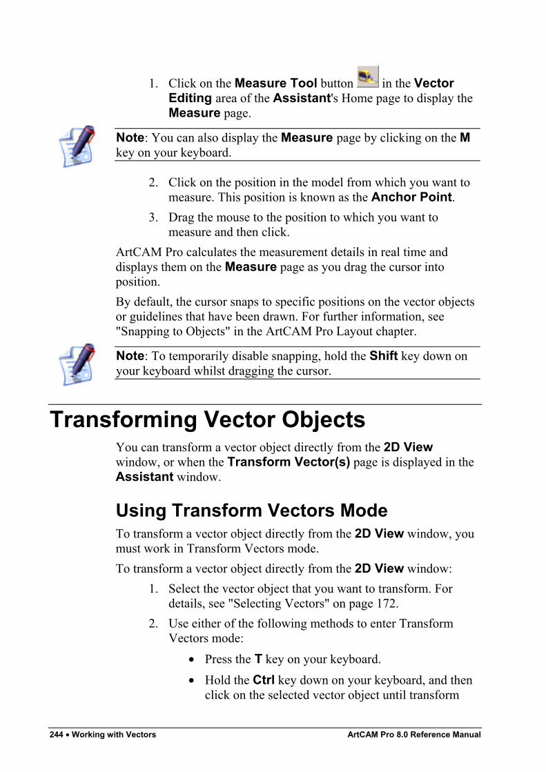
244 • Working with Vectors ArtCAM Pro 8.0 Reference Manual
1. Click on the Measure Tool button in the VectorEditing area of the Assistant's Home page to display theMeasure page.
Note: You can also display the Measure page by clicking on the Mkey on your keyboard.
2. Click on the position in the model from which you want tomeasure. This position is known as the Anchor Point.
3. Drag the mouse to the position to which you want tomeasure and then click.
ArtCAM Pro calculates the measurement details in real time anddisplays them on the Measure page as you drag the cursor intoposition.By default, the cursor snaps to specific positions on the vector objectsor guidelines that have been drawn. For further information, see"Snapping to Objects" in the ArtCAM Pro Layout chapter.
Note: To temporarily disable snapping, hold the Shift key down onyour keyboard whilst dragging the cursor.
Transforming Vector ObjectsYou can transform a vector object directly from the 2D Viewwindow, or when the Transform Vector(s) page is displayed in theAssistant window.
Using Transform Vectors ModeTo transform a vector object directly from the 2D View window, youmust work in Transform Vectors mode.To transform a vector object directly from the 2D View window:
1. Select the vector object that you want to transform. Fordetails, see "Selecting Vectors" on page 172.
2. Use either of the following methods to enter TransformVectors mode:
• Press the T key on your keyboard.• Hold the Ctrl key down on your keyboard, and then
click on the selected vector object until transform
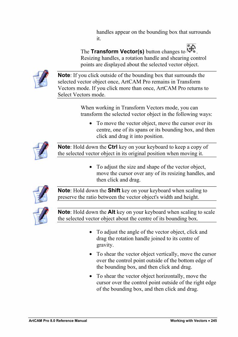
ArtCAM Pro 8.0 Reference Manual Working with Vectors • 245
handles appear on the bounding box that surroundsit.
The Transform Vector(s) button changes to .Resizing handles, a rotation handle and shearing controlpoints are displayed about the selected vector object.
Note: If you click outside of the bounding box that surrounds theselected vector object once, ArtCAM Pro remains in TransformVectors mode. If you click more than once, ArtCAM Pro returns toSelect Vectors mode.
When working in Transform Vectors mode, you cantransform the selected vector object in the following ways:
• To move the vector object, move the cursor over itscentre, one of its spans or its bounding box, and thenclick and drag it into position.
Note: Hold down the Ctrl key on your keyboard to keep a copy ofthe selected vector object in its original position when moving it.
• To adjust the size and shape of the vector object,move the cursor over any of its resizing handles, andthen click and drag.
Note: Hold down the Shift key on your keyboard when scaling topreserve the ratio between the vector object's width and height.
Note: Hold down the Alt key on your keyboard when scaling to scalethe selected vector object about the centre of its bounding box.
• To adjust the angle of the vector object, click anddrag the rotation handle joined to its centre ofgravity.
• To shear the vector object vertically, move the cursorover the control point outside of the bottom edge ofthe bounding box, and then click and drag.
• To shear the vector object horizontally, move thecursor over the control point outside of the right edgeof the bounding box, and then click and drag.
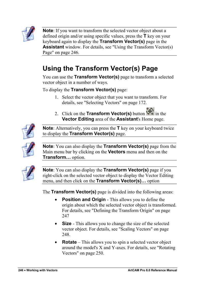
246 • Working with Vectors ArtCAM Pro 8.0 Reference Manual
Note: If you want to transform the selected vector object about adefined origin and/or using specific values, press the T key on yourkeyboard again to display the Transform Vector(s) page in theAssistant window. For details, see "Using the Transform Vector(s)Page" on page 246.
Using the Transform Vector(s) PageYou can use the Transform Vector(s) page to transform a selectedvector object in a number of ways.To display the Transform Vector(s) page:
1. Select the vector object that you want to transform. Fordetails, see "Selecting Vectors" on page 172.
2. Click on the Transform Vector(s) button in theVector Editing area of the Assistant's Home page.
Note: Alternatively, you can press the T key on your keyboard twiceto display the Transform Vector(s) page.
Note: You can also display the Transform Vector(s) page from theMain menu bar by clicking on the Vectors menu and then on theTransform… option.
Note: You can also display the Transform Vector(s) page if youright-click on the selected vector object to display the Vector Editingmenu, and then click on the Transform Vector(s)… option
The Transform Vector(s) page is divided into the following areas:• Position and Origin - This allows you to define the
origin about which the selected vector object is transformed.For details, see "Defining the Transform Origin" on page247
• Size - This allows you to change the size of the selectedvector object. For details, see "Scaling Vectors" on page248.
• Rotate – This allows you to spin a selected vector objectaround the model's X and Y-axes. For details, see "RotatingVectors" on page 250.
ArtCAM Pro 8.0 Reference Manual Working with Vectors • 247
• Move – This allows you to move a selected vector objectalong the X and Y-axis. For details, see "Moving Vectors"on page 251.
• Shear - This enables you to shear a selected vector object.For details, see "Shearing Vectors" on page 253.
Defining the Transform OriginYou can transform a selected vector object relative to a defined originusing the Position and Origin area of the Transform Vector(s)page.To define the origin by which you want to reposition, resize or rotate aselected vector object:
1. Select the vector object that you want to transform. Fordetails, see "Selecting Vectors" on page 172.
2. Click on the Transform Vector(s) button in theVector Editing area to display the Transform Vector(s)page in the Assistant window.
3. The co-ordinates in the X and Y boxes show the currentposition of the transform origin. Define the new origin aboutwhich you want to transform the selected vector object inany of the following ways:
• Click on any of the five radio buttons on therectangle diagram to set the origin to one of five pre-set positions. The co-ordinates of the selectedposition are displayed in the X and Y boxes.
• Define the X and Y co-ordinates of the position youwant to set as the origin in the X and Y boxes.
• Click to select the Transform about (x,y) option. The default X and Y boxes are greyed-out and
new X and Y boxes are displayed on the page. The icon appears in the 2D View window, marking thecurrent position of the transform origin.To set the origin you can either define its X and Yco-ordinates in the X and Y boxes or move the cursor to the position in the 2D View window thatyou want to use, and then click to select. In the latterinstance, the co-ordinates of the selected position aredisplayed in the X and Y boxes.
248 • Working with Vectors ArtCAM Pro 8.0 Reference Manual
4. Click on the Apply button to define the transform origin.You can now transform the selected vector object about thisorigin.
Scaling VectorsYou can change the size of a vector object using the Size area of theTransform Vector(s) page in the following ways:
• Using specific measurements.• Using the slider.• Using a percentage of its original size.
To change the size of a vector object using specific measurements:1. Select the vector object that you want to resize. For details,
see "Selecting Vectors" on page 172.
2. Click on the Transform Vector(s) button in theVector Editing area to display the Transform Vector(s)page.
3. Make sure that the origin by which you want to resize theselected vector object is correct. For details, see "Definingthe Transform Origin" on page 247.
4. If you want to preserve the ratio between the width andheight of the selected vector object, make sure that the LinkWidth and Height option is selected . This option isselected by default.
5. Define the width of the selected vector object using theNew Width box. If the Link Width and Height option isselected , the current value in the New Height box isadjusted. If the Link Width and Height option isdeselected , you must define its height using the NewHeight box.
Note: If you want to keep a copy of the selected vector object in itsoriginal size, click to select the Copy on Apply (Ctrl) option orhold down the Ctrl key on your keyboard when scaling.
Note: Hold down the Shift key on your keyboard when scaling topreserve the ratio between the vector object's width and height.
ArtCAM Pro 8.0 Reference Manual Working with Vectors • 249
Note: Hold down the Alt key on your keyboard when scaling to scalethe selected vector object about the centre of its bounding box.
6. Click on the Apply button to resize the selected vectorobject. The values shown in the New Width and NewHeight boxes are adjusted.
7. Click on the OK button to return to the Assistant's Homepage.
To change the size of a vector object using the slider:1. Select the vector object that you want to resize. For details,
see "Selecting Vectors" on page 172.
2. Click on the Transform Vector(s) button in theVector Editing area to display the Transform Vector(s)page.
3. Make sure that the origin by which you want to resize theselected vector object is correct. For details, see "Definingthe Transform Origin" on page 247.
4. If you want to preserve the ratio between the width andheight of the selected vector object, make sure that the LinkWidth and Height option is selected . This option isselected by default.
Note: If the Link Width and Height option is deselected , onlythe width of the selected vector object can be adjusted using theslider.
Note: If you want to keep a copy of the selected vector object in itsoriginal size, click to select the Copy on Apply (Ctrl) option orhold down the Ctrl key on your keyboard when scaling.
5. Click and drag the slider in the appropriate direction:• Drag to the right if you want to increase the size of
the selected vector object.• Drag to the left if you want to reduce the size of the
selected vector object.
Note: If you drag the slider without selecting the Link Width andHeight option , only the value in the New Width box changes.
250 • Working with Vectors ArtCAM Pro 8.0 Reference Manual
A preview image of the new size of the selected vectorobject appears in the 2D View window.
6. Click on the Apply button to resize of the selected vectorobject.
7. Click on the Close button to return to the Assistant'sHome page.
Rotating VectorsYou can rotate a vector object in two ways using the Rotate area ofthe Transform Vector(s) page:
• Using a specific angle.• Using the slider.
To rotate a vector object using a specific angle:1. Select the vector object that you want to rotate. For details,
see "Selecting Vectors" on page 172.
2. Click on the Transform Vector(s) button in theVector Editing area to display the Transform Vector(s)page.
3. Make sure that the origin by which you want to rotate theselected vector object is correct. For details, see "Definingthe Transform Origin" on page 247.
4. Define the angle by which you want to rotate the selectedvector object in the Rotate box:
• A positive value rotates the selected vector objectclockwise.
• A negative value rotates the selected vector objectanti-clockwise.
Note: If you want to keep a copy of the selected vector object in itsoriginal position, click to select the Copy on Apply (Ctrl) option or hold down the Ctrl key on your keyboard when rotating.
5. Click on the Apply button to rotate the selected vectorobject by the defined angle.
6. Click on the Close button to return to the Assistant'sHome page.
To rotate a vector object around the X and Y axes using the sliders:
ArtCAM Pro 8.0 Reference Manual Working with Vectors • 251
1. Select the vector object that you want to rotate. For details,see "Selecting Vectors" on page 172.
2. Click on the Transform Vector(s) button in theVector Editing area to display the Transform Vector(s)page.
3. Make sure that the origin by which you want to rotate theselected vector object is correct. For details, see "Definingthe Transform Origin" on page 247.
4. Click and drag the slider in the appropriate direction:• Drag to the right if you want to rotate the selected
vector object clockwise.• Drag to the left if you want to rotate the selected
vector object anti-clockwise.
Note: If you want to keep a copy of the selected vector object in itsoriginal position, click to select the Copy on Apply (Ctrl) option or hold down the Ctrl key on your keyboard when rotating.
5. Click on the Apply button to rotate the selected vectorobject by the angle shown in the Rotate box.
6. Click on the Close button to return to the Assistant'sHome page.
Moving VectorsYou can reposition a vector object in two ways using the Move areaof the Transform Vector(s) page:
• Using specific co-ordinates.• Using the sliders.
To move a vector object to a specific position:1. Select the vector object that you want to move. For details,
see "Selecting Vectors" on page 172.
2. Click on the Transform Vector(s) button in theVector Editing area to display the Transform Vector(s)page.
3. Make sure that the origin by which you want to move theselected vector object is correct. For details, see "Definingthe Transform Origin" on page 247.
252 • Working with Vectors ArtCAM Pro 8.0 Reference Manual
4. Define the co-ordinate to which you want to move theselected vector object along the X-axis in the Move X box.A positive value moves the selected vector to the right,while a negative value moves it to the left.
Note: If you want to keep a copy of the selected vector object in itsoriginal position, click to select the Copy on Apply (Ctrl) option or hold down the Ctrl key on your keyboard when moving.
5. Define the co-ordinate to which you want to move theselected vector object along the Y-axis in the Move Y box.A positive value moves the selected vector upwards, while anegative value moves it downwards.
6. Click on the Apply button to reposition the selected vectorobject.
7. Click on the Close button to return to the Assistant'sHome page.
To move a vector object along the X and Y axes using the sliders:1. Select the vector object that you want to move. For details,
see "Selecting Vectors" on page 172.
2. Click on the Transform Vector(s) button in theVector Editing area to display the Transform Vector(s)page.
3. Make sure that the origin by which you want to move theselected vector object is correct. For details, see "Definingthe Transform Origin" on page 247.
4. Click and drag the sliders in the appropriate direction:• Drag the Move X slider to the right if you want to
move the selected vector object to the right.• Drag the Move Y slider to the right if you want to
move the selected vector object upwards.• Drag the Move X slider to the left if you want to
move the selected vector object to the left.• Drag the Move Y slider to the left if you want to
move the selected vector object downwards.5. Click on the Apply button to reposition the selected vector
object.
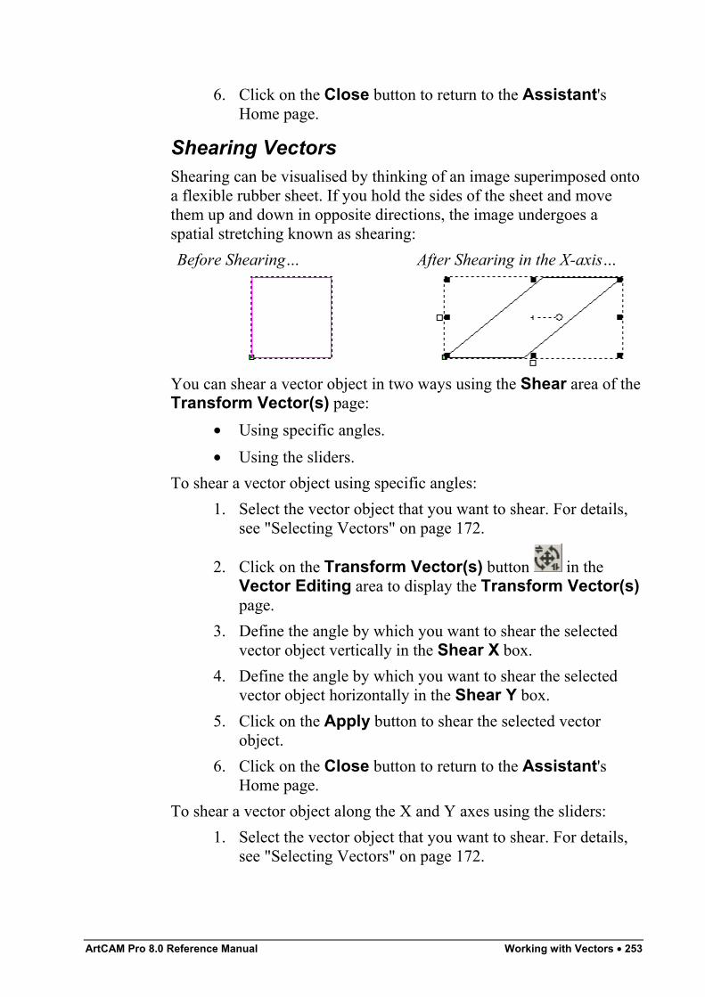
ArtCAM Pro 8.0 Reference Manual Working with Vectors • 253
6. Click on the Close button to return to the Assistant'sHome page.
Shearing VectorsShearing can be visualised by thinking of an image superimposed ontoa flexible rubber sheet. If you hold the sides of the sheet and movethem up and down in opposite directions, the image undergoes aspatial stretching known as shearing:Before Shearing… After Shearing in the X-axis…
You can shear a vector object in two ways using the Shear area of theTransform Vector(s) page:
• Using specific angles.• Using the sliders.
To shear a vector object using specific angles:1. Select the vector object that you want to shear. For details,
see "Selecting Vectors" on page 172.
2. Click on the Transform Vector(s) button in theVector Editing area to display the Transform Vector(s)page.
3. Define the angle by which you want to shear the selectedvector object vertically in the Shear X box.
4. Define the angle by which you want to shear the selectedvector object horizontally in the Shear Y box.
5. Click on the Apply button to shear the selected vectorobject.
6. Click on the Close button to return to the Assistant'sHome page.
To shear a vector object along the X and Y axes using the sliders:1. Select the vector object that you want to shear. For details,
see "Selecting Vectors" on page 172.
254 • Working with Vectors ArtCAM Pro 8.0 Reference Manual
2. Click on the Transform Vector(s) button in theVector Editing area to display the Transform Vector(s)page.
3. To shear the vector object vertically, click and drag theShear X slider.
Note: If you want to keep a copy of the selected vector object in itsoriginal shape, click to select the Copy on Apply (Ctrl) option orhold down the Ctrl key on your keyboard when shearing.
If you want to shear the vector object horizontally, click anddrag the Shear Y slider.
4. Click on the Apply button to shear the selected vectorobject.
5. Click on the Close button to return to the Assistant'sHome page.
Manipulating Vector ObjectsThere is a range of tools in both the Position Size Align Vectorsand Group Merge Join Trim Vectors areas of the Assistant'sHome page designed to assist you in manipulating vector objects.
Mirroring VectorsUsing the Mirror Vectors page, you can reverse the direction of avector object from its original position.To mirror a selection of vector objects:
1. Select the vector objects that you want to mirror. For details,see "Selecting Vectors" on page 172.
2. Click on the Mirror Vectors button in the VectorEditing area of the Assistant's Home page to display theMirror Vectors page.
3. If you want to produce mirrored copies and keep theoriginal position of the selected vector objects, click toselect the Copy the Original Vectors (Ctrl) option orhold down the Ctrl key on your keyboard when mirroring.
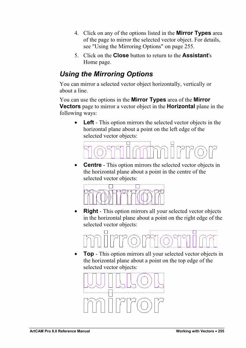
ArtCAM Pro 8.0 Reference Manual Working with Vectors • 255
4. Click on any of the options listed in the Mirror Types areaof the page to mirror the selected vector object. For details,see "Using the Mirroring Options" on page 255.
5. Click on the Close button to return to the Assistant'sHome page.
Using the Mirroring OptionsYou can mirror a selected vector object horizontally, vertically orabout a line.You can use the options in the Mirror Types area of the MirrorVectors page to mirror a vector object in the Horizontal plane in thefollowing ways:
• Left - This option mirrors the selected vector objects in thehorizontal plane about a point on the left edge of theselected vector objects:
• Centre - This option mirrors the selected vector objects inthe horizontal plane about a point in the centre of theselected vector objects:
• Right - This option mirrors all your selected vector objectsin the horizontal plane about a point on the right edge of theselected vector objects:
• Top - This option mirrors all your selected vector objects inthe horizontal plane about a point on the top edge of theselected vector objects:
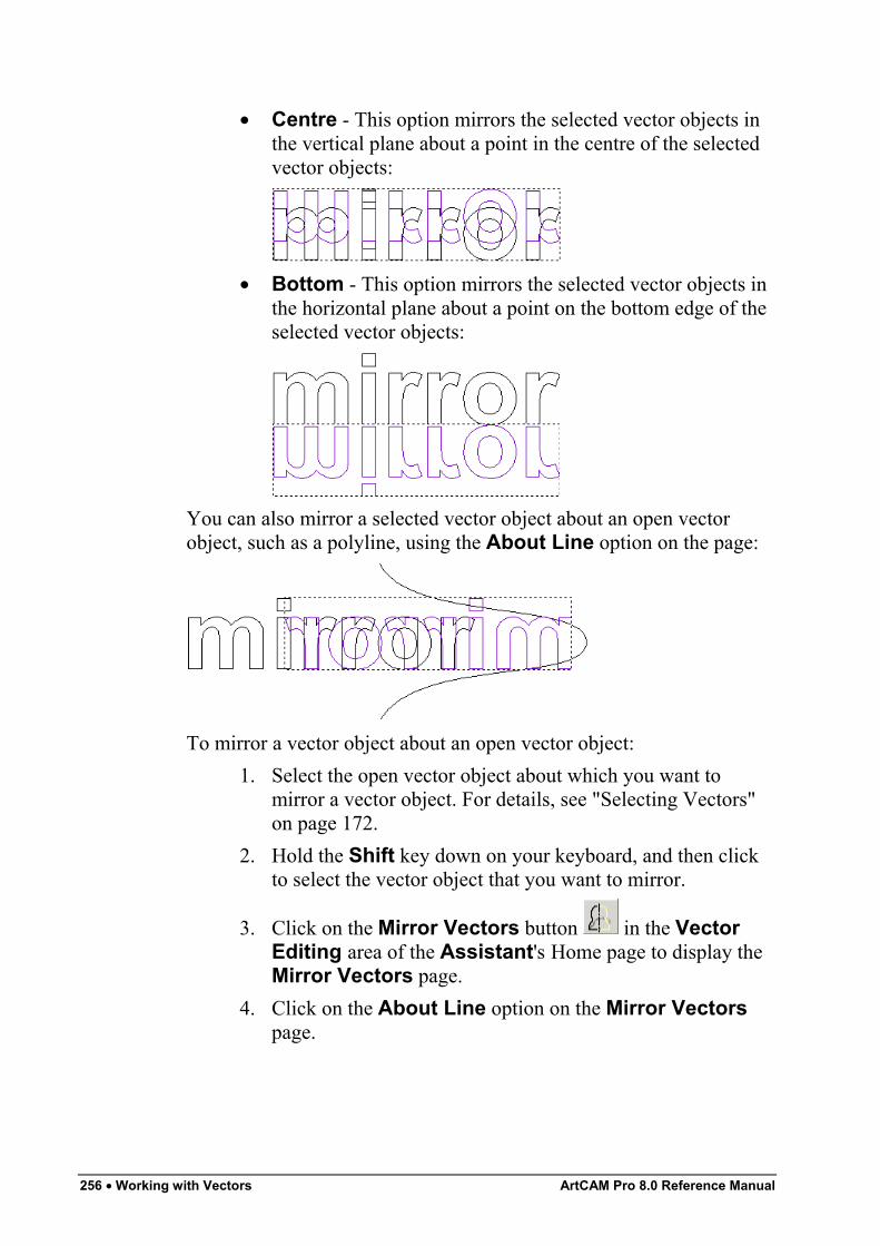
256 • Working with Vectors ArtCAM Pro 8.0 Reference Manual
• Centre - This option mirrors the selected vector objects inthe vertical plane about a point in the centre of the selectedvector objects:
• Bottom - This option mirrors the selected vector objects inthe horizontal plane about a point on the bottom edge of theselected vector objects:
You can also mirror a selected vector object about an open vectorobject, such as a polyline, using the About Line option on the page:
To mirror a vector object about an open vector object:1. Select the open vector object about which you want to
mirror a vector object. For details, see "Selecting Vectors"on page 172.
2. Hold the Shift key down on your keyboard, and then clickto select the vector object that you want to mirror.
3. Click on the Mirror Vectors button in the VectorEditing area of the Assistant's Home page to display theMirror Vectors page.
4. Click on the About Line option on the Mirror Vectorspage.
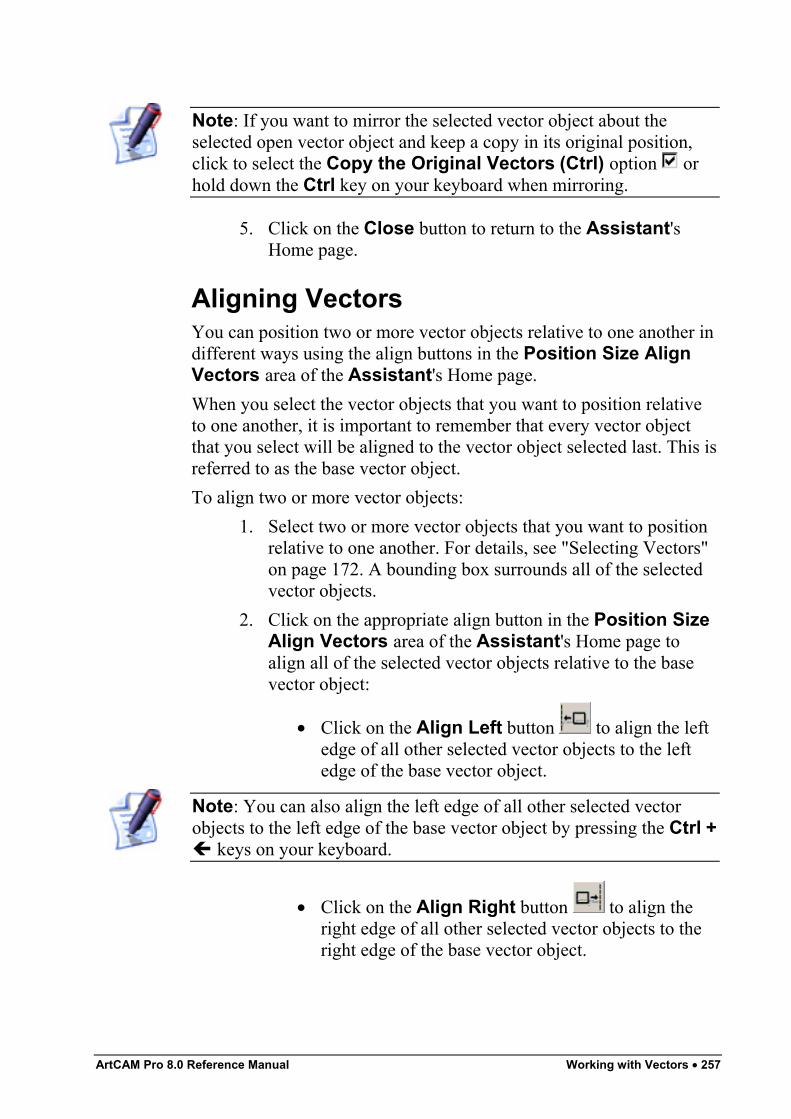
ArtCAM Pro 8.0 Reference Manual Working with Vectors • 257
Note: If you want to mirror the selected vector object about theselected open vector object and keep a copy in its original position,click to select the Copy the Original Vectors (Ctrl) option orhold down the Ctrl key on your keyboard when mirroring.
5. Click on the Close button to return to the Assistant'sHome page.
Aligning VectorsYou can position two or more vector objects relative to one another indifferent ways using the align buttons in the Position Size AlignVectors area of the Assistant's Home page.When you select the vector objects that you want to position relativeto one another, it is important to remember that every vector objectthat you select will be aligned to the vector object selected last. This isreferred to as the base vector object.To align two or more vector objects:
1. Select two or more vector objects that you want to positionrelative to one another. For details, see "Selecting Vectors"on page 172. A bounding box surrounds all of the selectedvector objects.
2. Click on the appropriate align button in the Position SizeAlign Vectors area of the Assistant's Home page toalign all of the selected vector objects relative to the basevector object:
• Click on the Align Left button to align the leftedge of all other selected vector objects to the leftedge of the base vector object.
Note: You can also align the left edge of all other selected vectorobjects to the left edge of the base vector object by pressing the Ctrl +
keys on your keyboard.
• Click on the Align Right button to align theright edge of all other selected vector objects to theright edge of the base vector object.
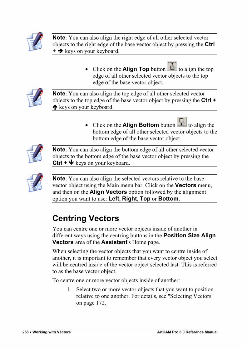
258 • Working with Vectors ArtCAM Pro 8.0 Reference Manual
Note: You can also align the right edge of all other selected vectorobjects to the right edge of the base vector object by pressing the Ctrl+ keys on your keyboard.
• Click on the Align Top button to align the topedge of all other selected vector objects to the topedge of the base vector object.
Note: You can also align the top edge of all other selected vectorobjects to the top edge of the base vector object by pressing the Ctrl +
keys on your keyboard.
• Click on the Align Bottom button to align thebottom edge of all other selected vector objects to thebottom edge of the base vector object.
Note: You can also align the bottom edge of all other selected vectorobjects to the bottom edge of the base vector object by pressing theCtrl + keys on your keyboard.
Note: You can also align the selected vectors relative to the basevector object using the Main menu bar. Click on the Vectors menu,and then on the Align Vectors option followed by the alignmentoption you want to use: Left, Right, Top or Bottom.
Centring VectorsYou can centre one or more vector objects inside of another indifferent ways using the centring buttons in the Position Size AlignVectors area of the Assistant's Home page.When selecting the vector objects that you want to centre inside ofanother, it is important to remember that every vector object you selectwill be centred inside of the vector object selected last. This is referredto as the base vector object.To centre one or more vector objects inside of another:
1. Select two or more vector objects that you want to positionrelative to one another. For details, see "Selecting Vectors"on page 172.
ArtCAM Pro 8.0 Reference Manual Working with Vectors • 259
2. Click on any of the centring buttons in the Position SizeAlign Vectors area to centre all of the selected vectorobjects inside of the base vector object:
• Click on the Centre Vertically button to alignthe centre of all other selected vector objects to thecentre in the X-axis of the base vector object.
• Click on the Centre Horizontally button toalign the centre of all other selected vector objects tothe centre in the Y-axis of the base vector object.
• Click on the Centre Vector button to align thecentre of all other selected vector objects to thecentre of the base vector object.
There is one additional centring button in the PositionSize Align Vectors area of the Assistant's Home page,although it does not, unlike the other centring buttons, affectone vector object relative to another:
• Click on the Centre In Page button to alignthe centre of the selected vector objects to the centreof the model area (the white area).
Note: You can also centre all of the selected vector objects inside ofthe base vector object using the Main menu bar, by clicking on theVectors menu, followed by the Align Vectors option and then onthe alignment option that you want to use: Horizontal Centre,Vertical Centre, Centre or Centre In Page.
Note: You can also align the centre of the selected vector objectswith the centre of the model area (the white area) by pressing the F9key on your keyboard.
Merging VectorsYou can merge two or more shapes of vector objects in order to createa new shape of vector object using the merging buttons in the GroupMerge Join Trim Vectors area of the Assistant's Home page. Thenewly merged vector object is drawn on the currently active layer.
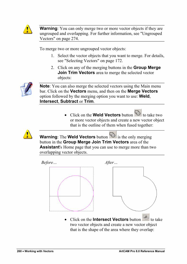
260 • Working with Vectors ArtCAM Pro 8.0 Reference Manual
Warning: You can only merge two or more vector objects if they areungrouped and overlapping. For further information, see "UngroupedVectors" on page 274.
To merge two or more ungrouped vector objects:1. Select the vector objects that you want to merge. For details,
see "Selecting Vectors" on page 172.2. Click on any of the merging buttons in the Group Merge
Join Trim Vectors area to merge the selected vectorobjects:
Note: You can also merge the selected vectors using the Main menubar. Click on the Vectors menu, and then on the Merge Vectorsoption followed by the merging option you want to use: Weld,Intersect, Subtract or Trim.
• Click on the Weld Vectors button to take twoor more vector objects and create a new vector objectthat is the outline of them when fused together:
Warning: The Weld Vectors button is the only mergingbutton in the Group Merge Join Trim Vectors area of theAssistant's Home page that you can use to merge more than twooverlapping vector objects.
Before… After…
• Click on the Intersect Vectors button to taketwo vector objects and create a new vector objectthat is the shape of the area where they overlap:
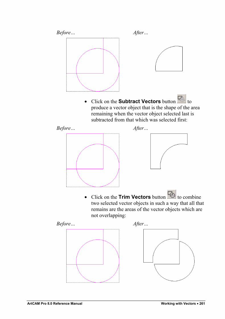
ArtCAM Pro 8.0 Reference Manual Working with Vectors • 261
Before… After…
• Click on the Subtract Vectors button toproduce a vector object that is the shape of the arearemaining when the vector object selected last issubtracted from that which was selected first:
Before… After…
• Click on the Trim Vectors button to combinetwo selected vector objects in such a way that all thatremains are the areas of the vector objects which arenot overlapping:
Before… After…
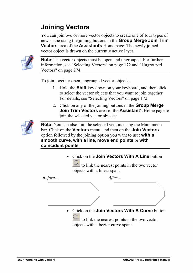
262 • Working with Vectors ArtCAM Pro 8.0 Reference Manual
Joining VectorsYou can join two or more vector objects to create one of four types ofnew shape using the joining buttons in the Group Merge Join TrimVectors area of the Assistant's Home page. The newly joinedvector object is drawn on the currently active layer.
Note: The vector objects must be open and ungrouped. For furtherinformation, see "Selecting Vectors" on page 172 and "UngroupedVectors" on page 274.
To join together open, ungrouped vector objects:1. Hold the Shift key down on your keyboard, and then click
to select the vector objects that you want to join together.For details, see "Selecting Vectors" on page 172.
2. Click on any of the joining buttons in the Group MergeJoin Trim Vectors area of the Assistant's Home page tojoin the selected vector objects:
Note: You can also join the selected vectors using the Main menubar. Click on the Vectors menu, and then on the Join Vectorsoption followed by the joining option you want to use: with asmooth curve, with a line, move end points or withcoincident points.
• Click on the Join Vectors With A Line button
to link the nearest points in the two vectorobjects with a linear span:
Before… After…
• Click on the Join Vectors With A Curve button
to link the nearest points in the two vectorobjects with a bezier curve span:
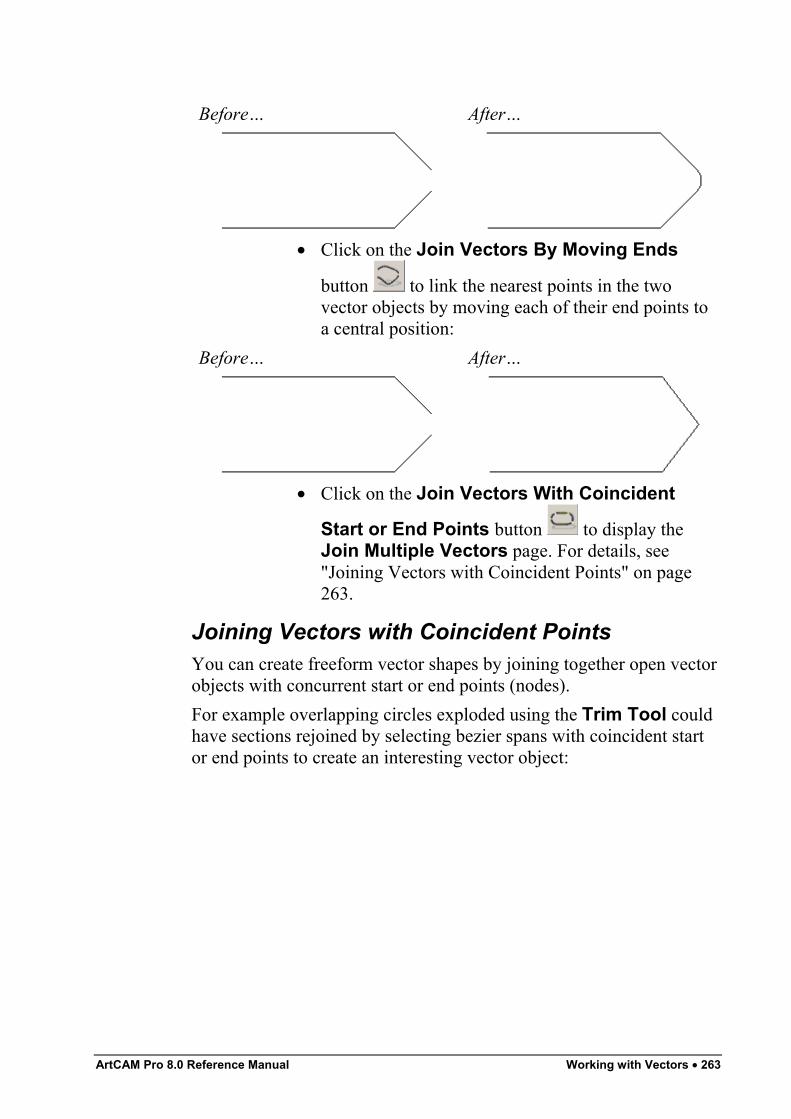
ArtCAM Pro 8.0 Reference Manual Working with Vectors • 263
Before… After…
• Click on the Join Vectors By Moving Ends
button to link the nearest points in the twovector objects by moving each of their end points toa central position:
Before… After…
• Click on the Join Vectors With Coincident
Start or End Points button to display theJoin Multiple Vectors page. For details, see"Joining Vectors with Coincident Points" on page263.
Joining Vectors with Coincident PointsYou can create freeform vector shapes by joining together open vectorobjects with concurrent start or end points (nodes).For example overlapping circles exploded using the Trim Tool couldhave sections rejoined by selecting bezier spans with coincident startor end points to create an interesting vector object:
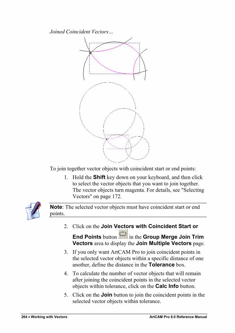
264 • Working with Vectors ArtCAM Pro 8.0 Reference Manual
Joined Coincident Vectors…
To join together vector objects with coincident start or end points:1. Hold the Shift key down on your keyboard, and then click
to select the vector objects that you want to join together.The vector objects turn magenta. For details, see "SelectingVectors" on page 172.
Note: The selected vector objects must have coincident start or endpoints.
2. Click on the Join Vectors with Coincident Start or
End Points button in the Group Merge Join TrimVectors area to display the Join Multiple Vectors page.
3. If you only want ArtCAM Pro to join coincident points inthe selected vector objects within a specific distance of oneanother, define the distance in the Tolerance box.
4. To calculate the number of vector objects that will remainafter joining the coincident points in the selected vectorobjects within tolerance, click on the Calc Info button.
5. Click on the Join button to join the coincident points in theselected vector objects within tolerance.
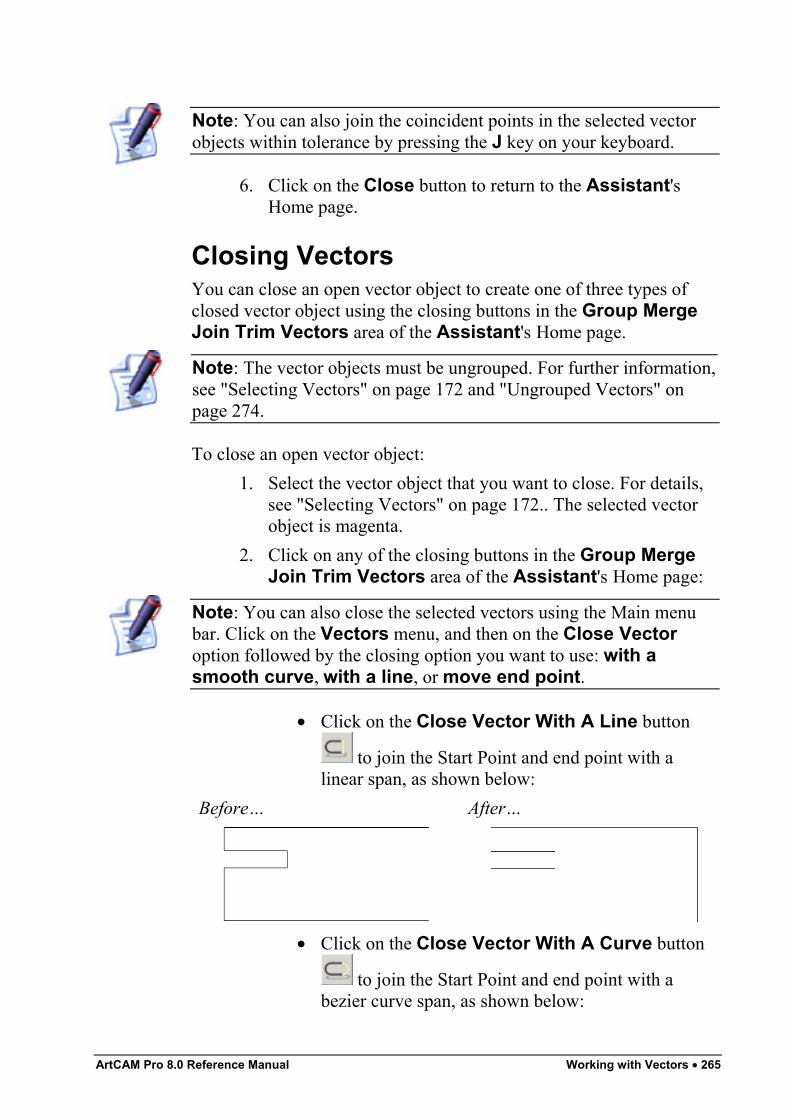
ArtCAM Pro 8.0 Reference Manual Working with Vectors • 265
Note: You can also join the coincident points in the selected vectorobjects within tolerance by pressing the J key on your keyboard.
6. Click on the Close button to return to the Assistant'sHome page.
Closing VectorsYou can close an open vector object to create one of three types ofclosed vector object using the closing buttons in the Group MergeJoin Trim Vectors area of the Assistant's Home page.
Note: The vector objects must be ungrouped. For further information,see "Selecting Vectors" on page 172 and "Ungrouped Vectors" onpage 274.
To close an open vector object:1. Select the vector object that you want to close. For details,
see "Selecting Vectors" on page 172.. The selected vectorobject is magenta.
2. Click on any of the closing buttons in the Group MergeJoin Trim Vectors area of the Assistant's Home page:
Note: You can also close the selected vectors using the Main menubar. Click on the Vectors menu, and then on the Close Vectoroption followed by the closing option you want to use: with asmooth curve, with a line, or move end point.
• Click on the Close Vector With A Line button
to join the Start Point and end point with alinear span, as shown below:
Before… After…
• Click on the Close Vector With A Curve button
to join the Start Point and end point with abezier curve span, as shown below:
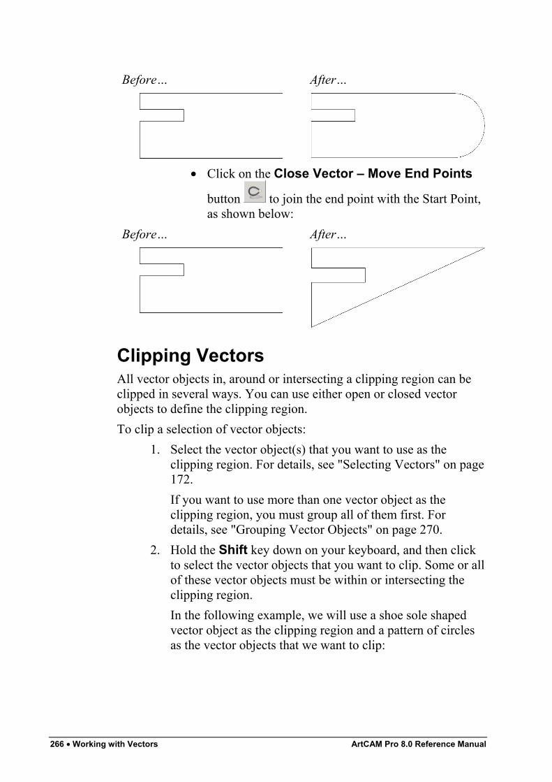
266 • Working with Vectors ArtCAM Pro 8.0 Reference Manual
Before… After…
• Click on the Close Vector – Move End Points
button to join the end point with the Start Point,as shown below:
Before… After…
Clipping VectorsAll vector objects in, around or intersecting a clipping region can beclipped in several ways. You can use either open or closed vectorobjects to define the clipping region.To clip a selection of vector objects:
1. Select the vector object(s) that you want to use as theclipping region. For details, see "Selecting Vectors" on page172.If you want to use more than one vector object as theclipping region, you must group all of them first. Fordetails, see "Grouping Vector Objects" on page 270.
2. Hold the Shift key down on your keyboard, and then clickto select the vector objects that you want to clip. Some or allof these vector objects must be within or intersecting theclipping region.In the following example, we will use a shoe sole shapedvector object as the clipping region and a pattern of circlesas the vector objects that we want to clip:
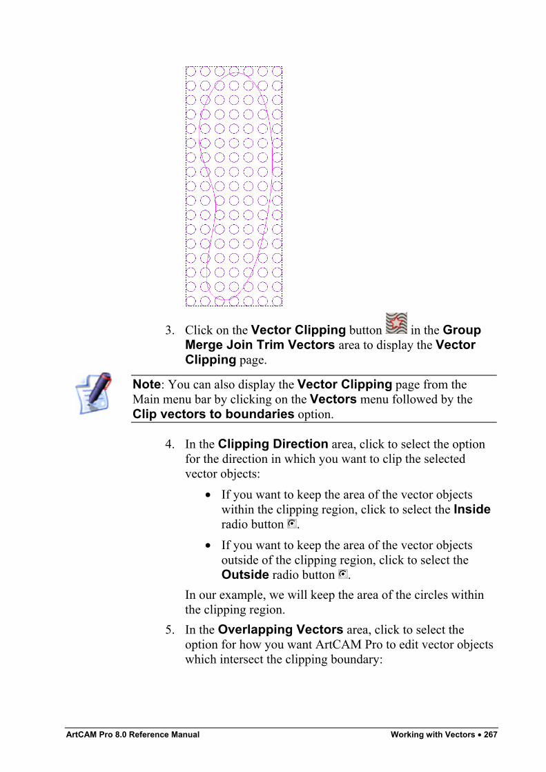
ArtCAM Pro 8.0 Reference Manual Working with Vectors • 267
3. Click on the Vector Clipping button in the GroupMerge Join Trim Vectors area to display the VectorClipping page.
Note: You can also display the Vector Clipping page from theMain menu bar by clicking on the Vectors menu followed by theClip vectors to boundaries option.
4. In the Clipping Direction area, click to select the optionfor the direction in which you want to clip the selectedvector objects:
• If you want to keep the area of the vector objectswithin the clipping region, click to select the Insideradio button .
• If you want to keep the area of the vector objectsoutside of the clipping region, click to select theOutside radio button .
In our example, we will keep the area of the circles withinthe clipping region.
5. In the Overlapping Vectors area, click to select theoption for how you want ArtCAM Pro to edit vector objectswhich intersect the clipping boundary:
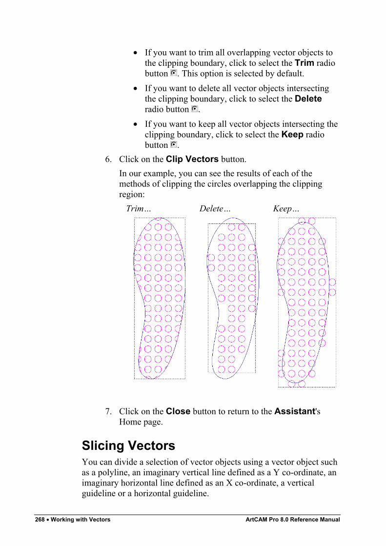
268 • Working with Vectors ArtCAM Pro 8.0 Reference Manual
• If you want to trim all overlapping vector objects tothe clipping boundary, click to select the Trim radiobutton . This option is selected by default.
• If you want to delete all vector objects intersectingthe clipping boundary, click to select the Deleteradio button .
• If you want to keep all vector objects intersecting theclipping boundary, click to select the Keep radiobutton .
6. Click on the Clip Vectors button.In our example, you can see the results of each of themethods of clipping the circles overlapping the clippingregion:
Trim… Delete… Keep…
7. Click on the Close button to return to the Assistant'sHome page.
Slicing VectorsYou can divide a selection of vector objects using a vector object suchas a polyline, an imaginary vertical line defined as a Y co-ordinate, animaginary horizontal line defined as an X co-ordinate, a verticalguideline or a horizontal guideline.
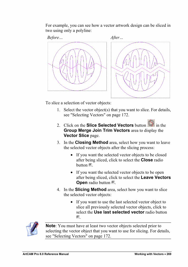
ArtCAM Pro 8.0 Reference Manual Working with Vectors • 269
For example, you can see how a vector artwork design can be sliced intwo using only a polyline:Before… After…
To slice a selection of vector objects:1. Select the vector object(s) that you want to slice. For details,
see "Selecting Vectors" on page 172.
2. Click on the Slice Selected Vectors button in theGroup Merge Join Trim Vectors area to display theVector Slice page.
3. In the Closing Method area, select how you want to leavethe selected vector objects after the slicing process:
• If you want the selected vector objects to be closedafter being sliced, click to select the Close radiobutton .
• If you want the selected vector objects to be openafter being sliced, click to select the Leave VectorsOpen radio button .
4. In the Slicing Method area, select how you want to slicethe selected vector objects:
• If you want to use the last selected vector object toslice all previously selected vector objects, click toselect the Use last selected vector radio button
.
Note: You must have at least two vector objects selected prior toselecting the vector object that you want to use for slicing. For details,see "Selecting Vectors" on page 172.
270 • Working with Vectors ArtCAM Pro 8.0 Reference Manual
• If you want to use a vertical line to slice the selectedvector objects, click to select the Use a verticalline radio button , and then define the position onthe Y-axis along which you want to slice in the LineCoordinate box.
Note: You can also use a vertical guideline to slice the vector objects.When using a guideline, its Y co-ordinate is displayed in the LineCoordinate box. For details, see "Using Guidelines" in the ArtCAMPro Layout chapter.
• If you want to use a horizontal line to slice theselected vector objects, click to select the Use ahorizontal line radio button , and then define theposition on the X-axis along which you want to slicein the Line Coordinate box.
Note: You can also use a horizontal guideline to slice the vectorobjects. When using a guideline, its X co-ordinate is displayed in theLine Coordinate box. For details, see "Using Guidelines" in theArtCAM Pro Layout chapter.
5. Click on the Slice Vectors button.6. Click on the Close button to return to the Assistant's
Home page.
Grouping Vector ObjectsGrouping combines all of the individual spans, points (nodes) andcontrol points that make up a vector object as a single entity.You can group an individual vector object or a selection of them. Thisprocess allows you to simultaneously machine or engrave each of thevector objects that you define as a group in the same way. For details,see "Selecting Vectors" on page 172.Grouping allows you to machine or engrave an open vector objectalong with an individual or group of closed vector objects when usingcertain toolpaths. These toolpaths are Engraving and Drilling. Fordetails, see "Using Toolpaths" in the Machining Models chapter.To group an open vector object:
ArtCAM Pro 8.0 Reference Manual Working with Vectors • 271
1. Select the vector object that you want to group. For details,see "Selecting Vectors" on page 172. The selected vectorobject is magenta.
2. Click on the Group button in the Group Merge JoinTrim Vectors area of the Assistant's Home page. Thevector object turns purple. When deselected, the vectorobject is blue, regardless of the colour assigned to the layeron which it is drawn.
Note: You can also group the selected vector object(s) by pressingthe Ctrl + G keys on your keyboard or by clicking on the Vectorsmenu in the Main menu bar, and then on the Group Vector(s)option.
To group a closed vector object:1. Select the vector object that you want to group. For details,
see "Selecting Vectors" on page 172.
2. Click on the Group button in the Group Merge JoinTrim Vectors area of the Assistant's Home page. Thevector object turns purple.If you group a closed vector object containing self-intersections, when deselected it turns red with the iconmarking the position of all intersections.If you select a combination of open and closed vectorobjects with the intention of grouping them, all of them turnmagenta. However, when they have been grouped anddeselected, the closed vector objects appear in the colourassigned to the layer on which they are drawn, while theopen vector objects appear in blue regardless of the colourassigned to the layer on which they are drawn.
Note: You can also right-click on the selected vector object to displaythe Vector Editing menu, and then click on the Group Vector(s)option.
You can also ungroup vector objects. To ungroup any vector object:1. Select the vector object that you want to ungroup. For
details, see "Selecting Vectors" on page 172.
272 • Working with Vectors ArtCAM Pro 8.0 Reference Manual
2. Click on the Ungroup button in the Group MergeJoin Trim Vectors area of the Assistant's Home page.The vector object is deselected. If the selected vector objectis open, the vector object turns blue, regardless of the colourassigned to the layer on which it is drawn. If the selectedvector object is closed, it appears in the colour assigned tothe layer on which it is drawn.
Note: You can also group the selected vector object(s) by pressingthe Ctrl + U keys on your keyboard or by clicking on the Vectorsmenu in the Main menu bar, and then on the Ungroup Vector(s)option.
Note: You can also right-click on the selected vector object to displaythe Vector Editing menu, and then click on the Ungroup Vector(s)option.
Viewing the Properties of a VectorObject
You can find out the number of points (nodes), linear, bezier curve orarc spans within any ungrouped vector object using the VectorProperties dialog box.To view the properties of an ungrouped vector object:
1. Select an ungrouped vector object. For details, see"Selecting Vectors" on page 172.
2. Right-click to display the Vector Editing menu, then clickon the Properties… option to display the VectorProperties dialog box.The General page of the Vector Properties dialog box isdisplayed by default:
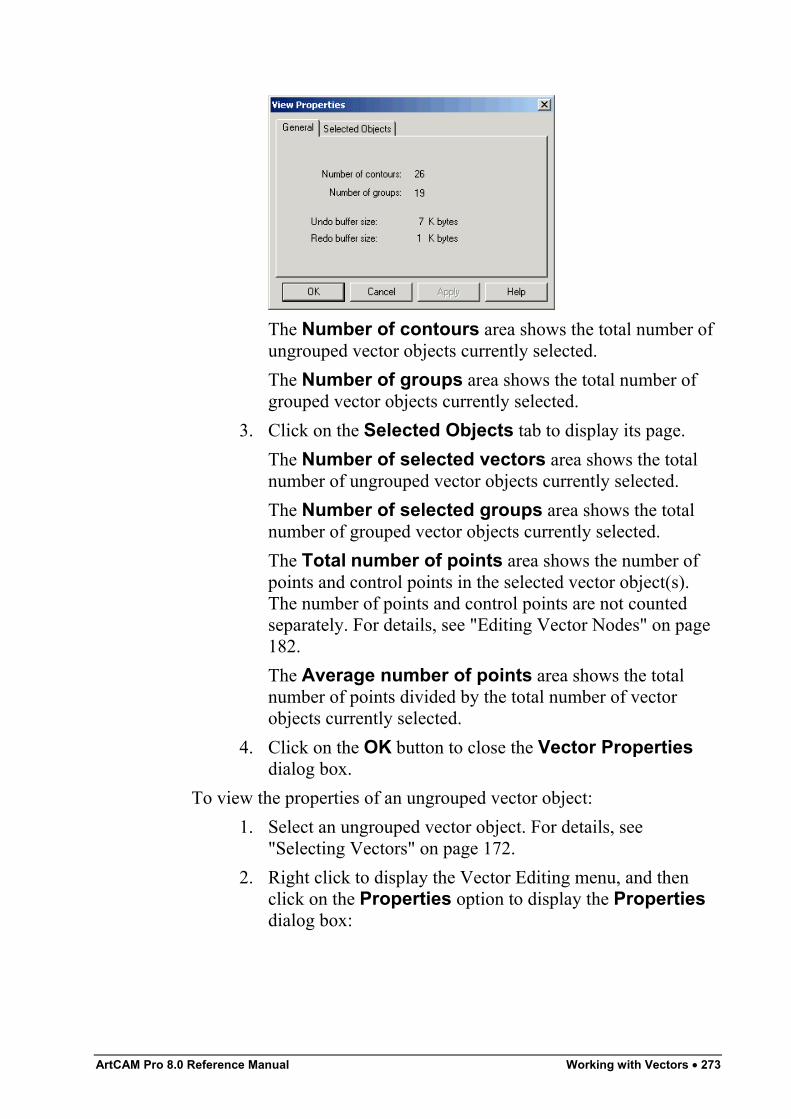
ArtCAM Pro 8.0 Reference Manual Working with Vectors • 273
The Number of contours area shows the total number ofungrouped vector objects currently selected.The Number of groups area shows the total number ofgrouped vector objects currently selected.
3. Click on the Selected Objects tab to display its page.The Number of selected vectors area shows the totalnumber of ungrouped vector objects currently selected.The Number of selected groups area shows the totalnumber of grouped vector objects currently selected.The Total number of points area shows the number ofpoints and control points in the selected vector object(s).The number of points and control points are not countedseparately. For details, see "Editing Vector Nodes" on page182.The Average number of points area shows the totalnumber of points divided by the total number of vectorobjects currently selected.
4. Click on the OK button to close the Vector Propertiesdialog box.
To view the properties of an ungrouped vector object:1. Select an ungrouped vector object. For details, see
"Selecting Vectors" on page 172.2. Right click to display the Vector Editing menu, and then
click on the Properties option to display the Propertiesdialog box:
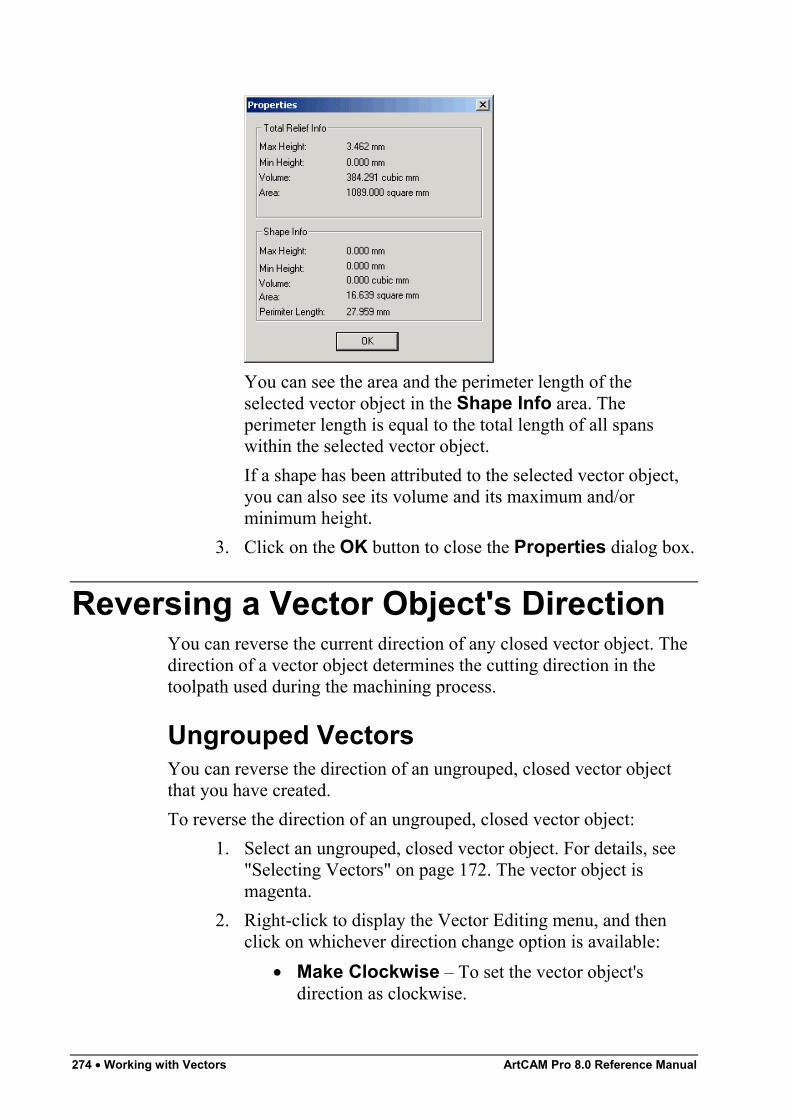
274 • Working with Vectors ArtCAM Pro 8.0 Reference Manual
You can see the area and the perimeter length of theselected vector object in the Shape Info area. Theperimeter length is equal to the total length of all spanswithin the selected vector object.If a shape has been attributed to the selected vector object,you can also see its volume and its maximum and/orminimum height.
3. Click on the OK button to close the Properties dialog box.
Reversing a Vector Object's DirectionYou can reverse the current direction of any closed vector object. Thedirection of a vector object determines the cutting direction in thetoolpath used during the machining process.
Ungrouped VectorsYou can reverse the direction of an ungrouped, closed vector objectthat you have created.To reverse the direction of an ungrouped, closed vector object:
1. Select an ungrouped, closed vector object. For details, see"Selecting Vectors" on page 172. The vector object ismagenta.
2. Right-click to display the Vector Editing menu, and thenclick on whichever direction change option is available:
• Make Clockwise – To set the vector object'sdirection as clockwise.
ArtCAM Pro 8.0 Reference Manual Working with Vectors • 275
• Make Anti-Clockwise – To set the vector object'sdirection as anti-clockwise.
Grouped VectorsYou can reverse the direction of a grouped, closed vector object thatyou have created.To reverse the direction of a grouped, closed vector object:
1. Select a grouped, closed vector object. For details, see"Selecting Vectors" on page 172. The selected vector objectis purple.
2. Right-click to display the Vector Editing menu, then clickon the Reverse Vector(s) option.
You can confirm the direction of a grouped, closed vector object byungrouping it after you click on the Reverse Vector(s) option, andthen regrouping it again. For details, see "Grouping Vector Objects"on page 270.
Creating Bitmaps from VectorsYou can create a bitmap image from any vector object. ArtCAM Procreates bitmap images in the current Primary Colour around theoutline of all selected vector objects. The new bitmap image is onepixel wide. For details, see "Selecting the Primary and SecondaryColours" in the Working with Bitmaps chapter.To convert a vector object into a bitmap image:
1. Click on the colour in the Colour Palette that you want toselect as the Primary Colour.
2. Select the vector objects that you want to create bitmapimages from. For details, see "Selecting Vectors" on page172.
3. Click on the Vector to Bitmap button in the Vector– Bitmap area of the Assistant's Home page to createbitmap images from the selected vector objects.
4. Click on the Vectors On/Off button in the 2D Viewtoolbar to hide the original vector objects, allowing you tosee the new bitmap images clearly.
276 • Working with Vectors ArtCAM Pro 8.0 Reference Manual
Flood Filling Vector ObjectsYou can colour within the outline of any vector object in the currentPrimary Colour using the Flood Fill Vectors tool. For details, see"Selecting the Primary and Secondary Colours" in the Working withBitmaps chapter.To flood fill a vector object:
1. Click on the colour in the Colour Palette that you want toselect as the Primary Colour.If you want to select a colour from a bitmap image as the
Primary Colour, click on the Pick Colour button inthe Bitmap toolbar, then move the dropper over thecolour you want to use and click.
2. Select the vector object(s) that you want to flood fill. Fordetails, see "Selecting Vectors" on page 172.
3. Click on the Flood Fill Vectors button in the Vector– Bitmap area of the Assistant's Home page to colourwithin the outline of the selected vector objects.
4. Click on the Vectors On/Off button in the 2D Viewtoolbar to hide the original vector objects, allowing you tosee the new bitmap images clearly.
Importing Vector ArtworkIn ArtCAM Pro, you can import vector artwork saved as *.dxf, *.eps,*.dwg, *.ai, *.wmf or *.pic files into an open model. For moredetails, see "Importing Vector Artwork" in the Working with Modelschapter.
Exporting Vector ArtworkIn ArtCAM Pro, you can export vector artwork as an *.eps, *.dxf or*.pic file to be used in other packages. For details, see "ExportingVector Artwork" in the Working with Models chapter.
ArtCAM Pro 8.0 Reference Manual Working with Vectors • 277
Creating a Shape from a VectorYou can generate three-dimensional shapes from vector objects usingthe Shape Editor tool. You can also create complex freeform three-dimensional shapes from vector objects. For more details, see"Creating a Shape from a Vector" and "Creating a Shape UsingVectors" in the Working with Reliefs chapter.
Creating a Feature from a VectorYou can create three different types of features from a vector object:A depth or height is attributed to the vector object from which thefeature is created. The feature is either added to or subtracted from thesurface of the existing relief in your model. The contour of theexisting relief is preserved in the feature that is combined with it.obligeA feature is machined using a Feature Machining toolpath. Forinformation on toolpaths, see "Overview" in the Machining Modelschapter. For details on creating a Feature Machining toolpath, see"Feature Machining" in the Machining Models chapter.
Creating a Raised FeatureYou can create a raised (male) feature from a selected vector object,usually vector text, which you can then machine using the FeatureMachining tool. For details, see "Feature Machining" in theMachining Models chapter.Using the Raised Feature page, you can:
• Control whether any central cavity in the vector object isremoved or not during the feature machining process.
• Control what edge of the vector object the tool meets whencutting it from the block of material.
To create a raised feature:1. Select the vector object from which you want to create a
raised feature. For details, see "Selecting Vectors" on page172.
2. Click on the Toolpaths tab to display theToolpaths Home page.
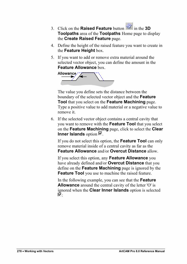
278 • Working with Vectors ArtCAM Pro 8.0 Reference Manual
3. Click on the Raised Feature button in the 3DToolpaths area of the Toolpaths Home page to displaythe Create Raised Feature page.
4. Define the height of the raised feature you want to create inthe Feature Height box.
5. If you want to add or remove extra material around theselected vector object, you can define the amount in theFeature Allowance box.
The value you define sets the distance between theboundary of the selected vector object and the FeatureTool that you select on the Feature Machining page.Type a positive value to add material or a negative value toremove it.
6. If the selected vector object contains a central cavity thatyou want to remove with the Feature Tool that you selecton the Feature Machining page, click to select the ClearInner Islands option .If you do not select this option, the Feature Tool can onlyremove material inside of a central cavity as far as theFeature Allowance and/or Overcut Distance allow.If you select this option, any Feature Allowance youhave already defined and/or Overcut Distance that youdefine on the Feature Machining page is ignored by theFeature Tool you use to machine the raised feature.In the following example, you can see that the FeatureAllowance around the central cavity of the letter 'O' isignored when the Clear Inner Islands option is selected
:
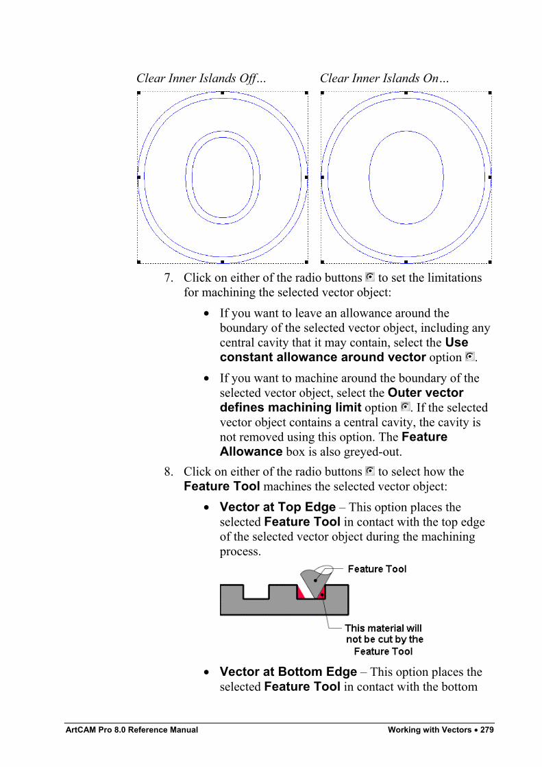
ArtCAM Pro 8.0 Reference Manual Working with Vectors • 279
Clear Inner Islands Off… Clear Inner Islands On…
7. Click on either of the radio buttons to set the limitationsfor machining the selected vector object:
• If you want to leave an allowance around theboundary of the selected vector object, including anycentral cavity that it may contain, select the Useconstant allowance around vector option .
• If you want to machine around the boundary of theselected vector object, select the Outer vectordefines machining limit option . If the selectedvector object contains a central cavity, the cavity isnot removed using this option. The FeatureAllowance box is also greyed-out.
8. Click on either of the radio buttons to select how theFeature Tool machines the selected vector object:
• Vector at Top Edge – This option places theselected Feature Tool in contact with the top edgeof the selected vector object during the machiningprocess.
• Vector at Bottom Edge – This option places theselected Feature Tool in contact with the bottom
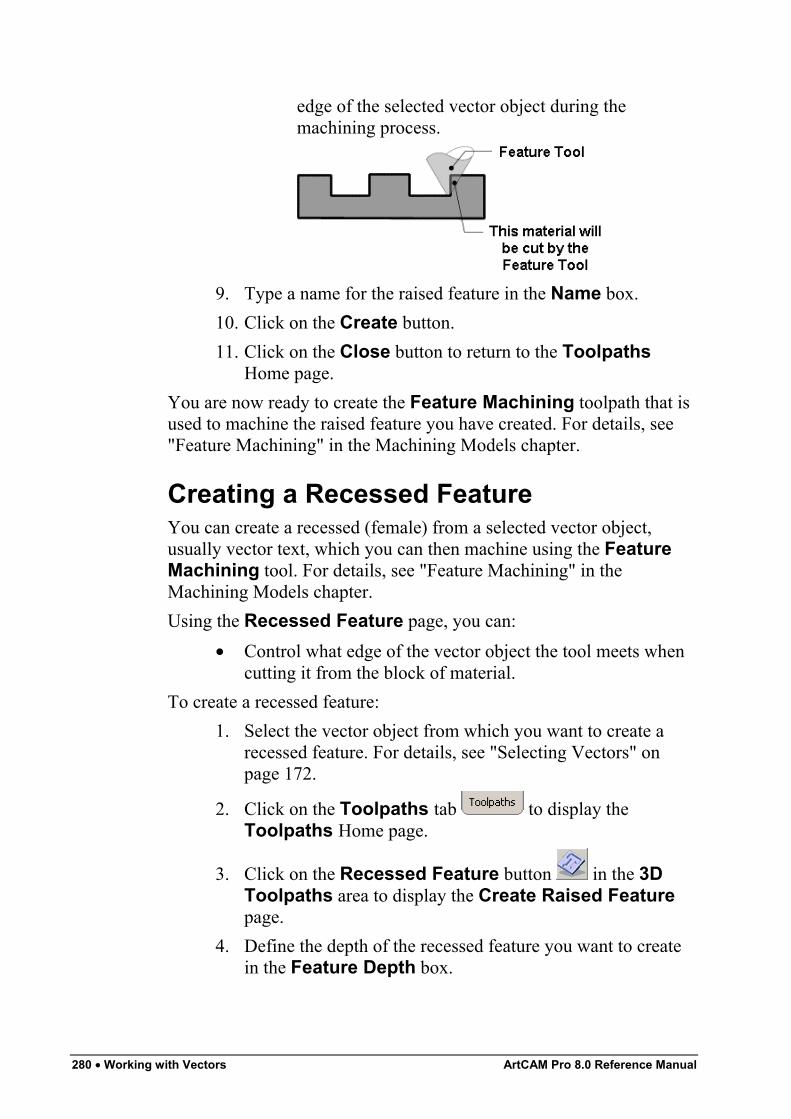
280 • Working with Vectors ArtCAM Pro 8.0 Reference Manual
edge of the selected vector object during themachining process.
9. Type a name for the raised feature in the Name box.10. Click on the Create button.11. Click on the Close button to return to the Toolpaths
Home page.You are now ready to create the Feature Machining toolpath that isused to machine the raised feature you have created. For details, see"Feature Machining" in the Machining Models chapter.
Creating a Recessed FeatureYou can create a recessed (female) from a selected vector object,usually vector text, which you can then machine using the FeatureMachining tool. For details, see "Feature Machining" in theMachining Models chapter.Using the Recessed Feature page, you can:
• Control what edge of the vector object the tool meets whencutting it from the block of material.
To create a recessed feature:1. Select the vector object from which you want to create a
recessed feature. For details, see "Selecting Vectors" onpage 172.
2. Click on the Toolpaths tab to display theToolpaths Home page.
3. Click on the Recessed Feature button in the 3DToolpaths area to display the Create Raised Featurepage.
4. Define the depth of the recessed feature you want to createin the Feature Depth box.
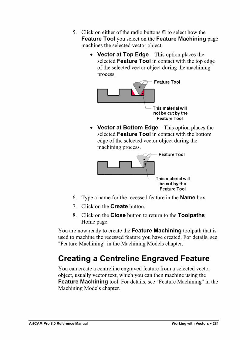
ArtCAM Pro 8.0 Reference Manual Working with Vectors • 281
5. Click on either of the radio buttons to select how theFeature Tool you select on the Feature Machining pagemachines the selected vector object:
• Vector at Top Edge – This option places theselected Feature Tool in contact with the top edgeof the selected vector object during the machiningprocess.
• Vector at Bottom Edge – This option places theselected Feature Tool in contact with the bottomedge of the selected vector object during themachining process.
6. Type a name for the recessed feature in the Name box.7. Click on the Create button.8. Click on the Close button to return to the Toolpaths
Home page.You are now ready to create the Feature Machining toolpath that isused to machine the recessed feature you have created. For details, see"Feature Machining" in the Machining Models chapter.
Creating a Centreline Engraved FeatureYou can create a centreline engraved feature from a selected vectorobject, usually vector text, which you can then machine using theFeature Machining tool. For details, see "Feature Machining" in theMachining Models chapter.
282 • Working with Vectors ArtCAM Pro 8.0 Reference Manual
The boundary of a selected vector object represents the centreline ofthe cutting tool. The engraved feature has no diameter other than thatof the tip of the cutting tool.To create a centreline engraved feature:
1. Select the vector object from which you want to create acentreline engraved feature. For details, see "SelectingVectors" on page 172.
2. Click on the Toolpaths tab to display theToolpaths Home page.
3. Click on the Centreline Engraved Feature button in the 3D Toolpaths area to display the CreateCentreline Feature page.
4. Define the depth of the centreline engraved feature youwant to create in the Feature Depth box.
5. Type a name for the centreline engraved feature in theName box.
6. Click on the Create button.7. You are now ready to create the Feature Machining
toolpath that is used to machine the centreline engravedfeature you have created. For details, see "FeatureMachining" in the Machining Models chapter.
You are now ready to create the Feature Machining toolpath that isused to machine the centreline engraved feature you have created. Fordetails, see "Feature Machining" in the Machining Models chapter.
Returning a Feature to a VectorYou can return a raised, recessed or centreline engraved feature to thevector object from which it was created.To return a raised, recessed or centreline engraved feature to itsoriginal vector object:
1. Click to select the feature in the 2D View window that youwant to return to a vector object. A bounding box surroundsit.
2. Click on the Toolpaths tab to display theToolpaths Home page.
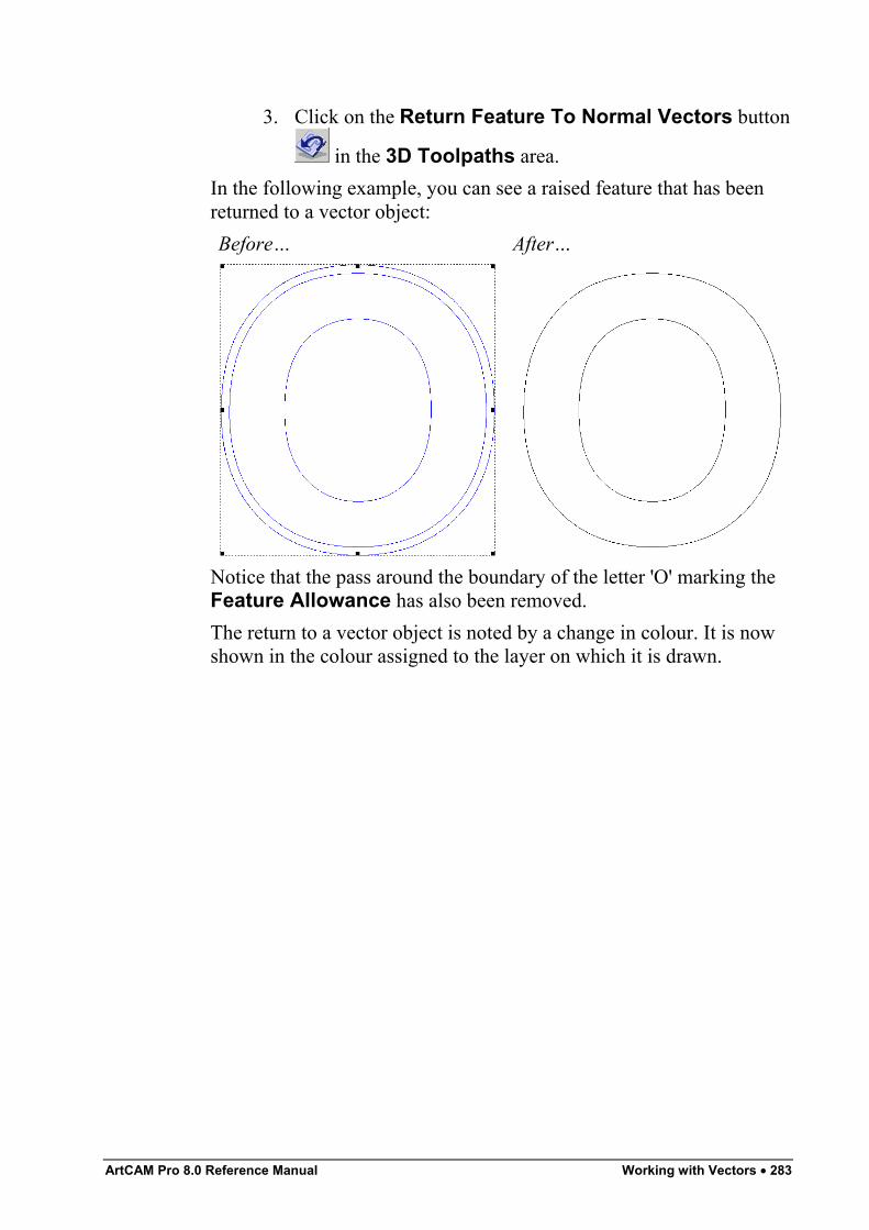
ArtCAM Pro 8.0 Reference Manual Working with Vectors • 283
3. Click on the Return Feature To Normal Vectors button
in the 3D Toolpaths area.In the following example, you can see a raised feature that has beenreturned to a vector object:Before… After…
Notice that the pass around the boundary of the letter 'O' marking theFeature Allowance has also been removed.The return to a vector object is noted by a change in colour. It is nowshown in the colour assigned to the layer on which it is drawn.

284 • Working with Vectors ArtCAM Pro 8.0 Reference Manual
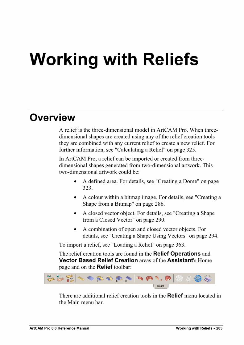
ArtCAM Pro 8.0 Reference Manual Working with Reliefs • 285
Working with Reliefs
OverviewA relief is the three-dimensional model in ArtCAM Pro. When three-dimensional shapes are created using any of the relief creation toolsthey are combined with any current relief to create a new relief. Forfurther information, see "Calculating a Relief" on page 325.In ArtCAM Pro, a relief can be imported or created from three-dimensional shapes generated from two-dimensional artwork. Thistwo-dimensional artwork could be:
• A defined area. For details, see "Creating a Dome" on page323.
• A colour within a bitmap image. For details, see "Creating aShape from a Bitmap" on page 286.
• A closed vector object. For details, see "Creating a Shapefrom a Closed Vector" on page 290.
• A combination of open and closed vector objects. Fordetails, see "Creating a Shape Using Vectors" on page 294.
To import a relief, see "Loading a Relief" on page 363.The relief creation tools are found in the Relief Operations andVector Based Relief Creation areas of the Assistant's Homepage and on the Relief toolbar:
There are additional relief creation tools in the Relief menu located inthe Main menu bar.
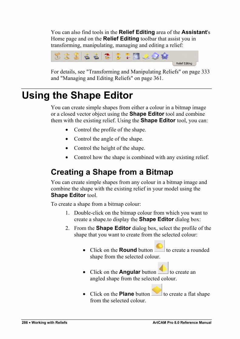
286 • Working with Reliefs ArtCAM Pro 8.0 Reference Manual
You can also find tools in the Relief Editing area of the Assistant'sHome page and on the Relief Editing toolbar that assist you intransforming, manipulating, managing and editing a relief:
For details, see "Transforming and Manipulating Reliefs" on page 333and "Managing and Editing Reliefs" on page 361.
Using the Shape EditorYou can create simple shapes from either a colour in a bitmap imageor a closed vector object using the Shape Editor tool and combinethem with the existing relief. Using the Shape Editor tool, you can:
• Control the profile of the shape.• Control the angle of the shape.• Control the height of the shape.• Control how the shape is combined with any existing relief.
Creating a Shape from a BitmapYou can create simple shapes from any colour in a bitmap image andcombine the shape with the existing relief in your model using theShape Editor tool.To create a shape from a bitmap colour:
1. Double-click on the bitmap colour from which you want tocreate a shape.to display the Shape Editor dialog box:
2. From the Shape Editor dialog box, select the profile of theshape that you want to create from the selected colour:
• Click on the Round button to create a roundedshape from the selected colour.
• Click on the Angular button to create anangled shape from the selected colour.
• Click on the Plane button to create a flat shapefrom the selected colour.
ArtCAM Pro 8.0 Reference Manual Working with Reliefs • 287
Note: You can restore the default settings in the Shape Editordialog box by clicking on the Reset button at any time.
3. If you want to create a rounded or an angled shape, youmust define an angle using any of the following methods:
• Type an angle in the Angle box. Type a positivevalue to produce a convex shape and a negativevalue to produce a concave shape. Type a value of 0to produce a plane.
• Click and drag on the slider to the left of the Anglebox. Drag the slider upward to increase the angle ofthe shape. Drag the slider downward to decrease it.The angle appears in the Angle box.
• Click on the up or down arrow on the right of theAngle box. The angle appears in the Angle box.
The default angle for a rounded or an angled shape is 45°.4. Define the height at which the shape starts in the Z direction
in the Start Height box. This creates a vertical side-wallbeneath the shape. If you are creating a flat shape, this valuecontrols the height of the plane.
5. Select the height option that you want to use:• To allow the shape to grow to the height that it
would naturally reach, click on the No Limit radiobutton .If you want to apply a scaling factor to the Z-axis ofthe shape, click to select the Scale option , andthen define the scaling factor in the Scale box, orclick and drag on the slider that is activated.
• To allow the shape to grow to a specific height andthen plateau, click on the Limit To Height radiobutton , and then define the height in the Heightbox that is activated.If the natural height of the shape exceeds that of thevalue you type in the Height box, a flat top appearson the shape.If you want to apply a scaling factor to the shape inits Z-axis, click to select the Scale option , and
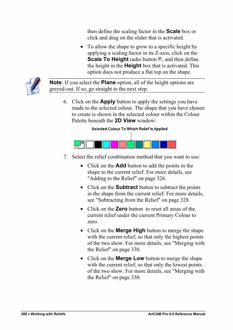
288 • Working with Reliefs ArtCAM Pro 8.0 Reference Manual
then define the scaling factor in the Scale box orclick and drag on the slider that is activated.
• To allow the shape to grow to a specific height byapplying a scaling factor in its Z-axis, click on theScale To Height radio button , and then definethe height in the Height box that is activated. Thisoption does not produce a flat top on the shape.
Note: If you select the Plane option, all of the height options aregreyed-out. If so, go straight to the next step.
6. Click on the Apply button to apply the settings you havemade to the selected colour. The shape that you have chosento create is shown in the selected colour within the ColourPalette beneath the 2D View window:
7. Select the relief combination method that you want to use:• Click on the Add button to add the points in the
shape to the current relief. For more details, see"Adding to the Relief" on page 326.
• Click on the Subtract button to subtract the pointsin the shape from the current relief. For more details,see "Subtracting from the Relief" on page 328.
• Click on the Zero button to reset all areas of thecurrent relief under the current Primary Colour tozero.
• Click on the Merge High button to merge the shapewith the current relief, so that only the highest pointsof the two show. For more details, see "Merging withthe Relief" on page 330.
• Click on the Merge Low button to merge the shapewith the current relief, so that only the lowest pointsof the two show. For more details, see "Merging withthe Relief" on page 330.
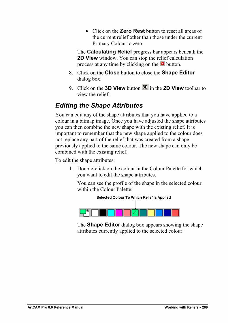
ArtCAM Pro 8.0 Reference Manual Working with Reliefs • 289
• Click on the Zero Rest button to reset all areas ofthe current relief other than those under the currentPrimary Colour to zero.
The Calculating Relief progress bar appears beneath the2D View window. You can stop the relief calculationprocess at any time by clicking on the button.
8. Click on the Close button to close the Shape Editordialog box.
9. Click on the 3D View button in the 2D View toolbar toview the relief.
Editing the Shape AttributesYou can edit any of the shape attributes that you have applied to acolour in a bitmap image. Once you have adjusted the shape attributesyou can then combine the new shape with the existing relief. It isimportant to remember that the new shape applied to the colour doesnot replace any part of the relief that was created from a shapepreviously applied to the same colour. The new shape can only becombined with the existing relief.To edit the shape attributes:
1. Double-click on the colour in the Colour Palette for whichyou want to edit the shape attributes.You can see the profile of the shape in the selected colourwithin the Colour Palette:
The Shape Editor dialog box appears showing the shapeattributes currently applied to the selected colour:
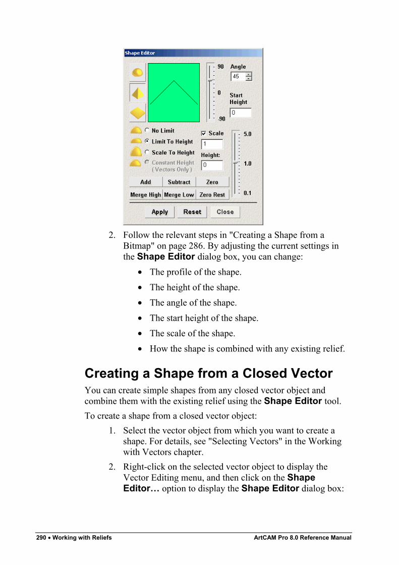
290 • Working with Reliefs ArtCAM Pro 8.0 Reference Manual
2. Follow the relevant steps in "Creating a Shape from aBitmap" on page 286. By adjusting the current settings inthe Shape Editor dialog box, you can change:
• The profile of the shape.• The height of the shape.• The angle of the shape.• The start height of the shape.• The scale of the shape.• How the shape is combined with any existing relief.
Creating a Shape from a Closed VectorYou can create simple shapes from any closed vector object andcombine them with the existing relief using the Shape Editor tool.To create a shape from a closed vector object:
1. Select the vector object from which you want to create ashape. For details, see "Selecting Vectors" in the Workingwith Vectors chapter.
2. Right-click on the selected vector object to display theVector Editing menu, and then click on the ShapeEditor… option to display the Shape Editor dialog box:
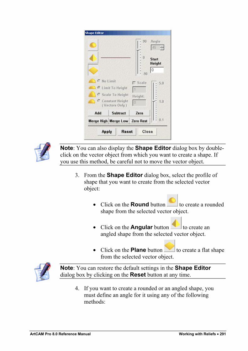
ArtCAM Pro 8.0 Reference Manual Working with Reliefs • 291
Note: You can also display the Shape Editor dialog box by double-click on the vector object from which you want to create a shape. Ifyou use this method, be careful not to move the vector object.
3. From the Shape Editor dialog box, select the profile ofshape that you want to create from the selected vectorobject:
• Click on the Round button to create a roundedshape from the selected vector object.
• Click on the Angular button to create anangled shape from the selected vector object.
• Click on the Plane button to create a flat shapefrom the selected vector object.
Note: You can restore the default settings in the Shape Editordialog box by clicking on the Reset button at any time.
4. If you want to create a rounded or an angled shape, youmust define an angle for it using any of the followingmethods:
292 • Working with Reliefs ArtCAM Pro 8.0 Reference Manual
• Type an angle in the Angle box. Type a positivevalue to produce a convex shape and a negativevalue to produce a concave shape. Type a value of 0to produce a plane.
• Click and drag on the slider to the left of the Anglebox. Drag the slider upward to increase the angle ofthe shape. Drag the slider downward to decrease it.The angle appears in the Angle box.
• Click on the up or down arrow on the right of theAngle box. The angle appears in the Angle box.
The default angle for a rounded or an angled shape is 45°.5. Define the height at which the shape starts in the Z direction
in the Start Height box. This creates a vertical side-wallbeneath the shape. If you are creating a flat shape, this valuecontrols the height of the plane.
6. Select the height option that you want to use:• To allow the shape to grow to the height that it
would naturally reach, click on the No Limit radiobutton .
• To allow the shape to grow to a specific height andthen plateau, click on the Limit To Height radiobutton , and then define the height in the Heightbox that is activated.
• To allow the shape to grow to a specific height byapplying a scaling factor in its Z-axis, click on theScale To Height radio button , and then definethe height in the Height box that is activated. Thisoption does not produce a flat top on the shape.
• To allow the shape to grow to a defined height, clickon the Constant Height (Vectors Only) radiobutton , and then define the height in the Heightbox that is activated. This creates a shape where theangle or curvature changes to maintain a constantheight, even where its width changes.
Note: If you have selected the Plane option, all of the height optionsare greyed-out. If so, go straight to the next step.
ArtCAM Pro 8.0 Reference Manual Working with Reliefs • 293
7. Click on the Apply button to apply the settings you havemade to the selected vector object.
8. Select the relief combination method that you want to use:• Click on the Add button to add the points in the
shape to the current relief. For more details, see"Adding to the Relief" on page 326.
• Click on the Subtract button to subtract the pointsin the shape from the current relief. For more details,see "Subtracting from the Relief" on page 328.
• Click on the Zero button to reset the relief withinthe area defined by the selected vector object to zero.
• Click on the Merge High button to merge the shapewith the current relief, so that only the highest pointsof the two show. For more details, see "Merging withthe Relief" on page 330.
• Click on the Merge Low button to merge the shapewith the current relief, so that only the lowest pointsof the two show. For more details, see "Merging withthe Relief" on page 330.
• Click on the Zero Rest button to reset the currentrelief outside of the area defined by the selectedvector object to zero.
The Calculating Relief progress bar appears beneath the2D View window. You can stop the relief calculationprocess at any time by clicking on the button.
9. Click on the Close button to close the Shape Editordialog box.
10. Click on the 3D View button in the 2D View toolbar toview the relief.
Editing the Shape AttributesYou can edit any of the shape attributes that you have applied to avector object. Once you have adjusted the shape attributes you canthen combine the new shape with the existing relief. It is important toremember that the new shape applied to the vector object does notreplace any part of the relief that was created from a shape previouslyapplied to the same vector object. The new shape can only becombined with the existing relief.
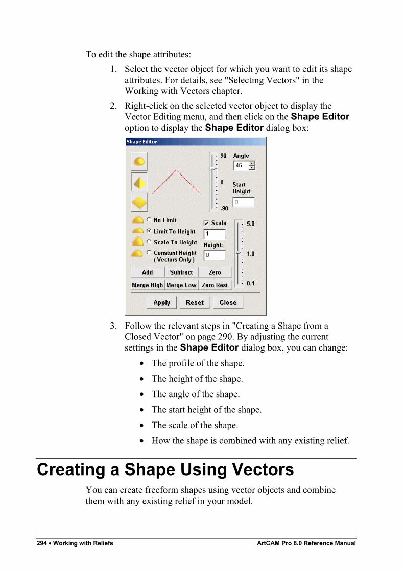
294 • Working with Reliefs ArtCAM Pro 8.0 Reference Manual
To edit the shape attributes:1. Select the vector object for which you want to edit its shape
attributes. For details, see "Selecting Vectors" in theWorking with Vectors chapter.
2. Right-click on the selected vector object to display theVector Editing menu, and then click on the Shape Editoroption to display the Shape Editor dialog box:
3. Follow the relevant steps in "Creating a Shape from aClosed Vector" on page 290. By adjusting the currentsettings in the Shape Editor dialog box, you can change:
• The profile of the shape.• The height of the shape.• The angle of the shape.• The start height of the shape.• The scale of the shape.• How the shape is combined with any existing relief.
Creating a Shape Using VectorsYou can create freeform shapes using vector objects and combinethem with any existing relief in your model.
ArtCAM Pro 8.0 Reference Manual Working with Reliefs • 295
The freeform shapes that you can create using vector objects are asfollows:
• Swept Profile. You can create three different types ofswept profile shape using the Swept Profiles Wizard orany one of the three buttons in the Vector Based ReliefCreation area of the Assistant's Home page. You canExtrude, Spin or Turn a swept profile. For details, see"Creating a Swept Profile Shape" on page 295.
• Two-Rail Sweep. You can create a two-rail swept shapeusing the Two Rail Sweep button in the Vector BasedRelief Creation area of the Assistant's Home page andat least three vector objects. For details, see "Creating aTwo Rail Sweep" on page 310.
• Weave. You can create a weave shape using the WeaveWizard button in the Vector Based Relief Creationarea of the Assistant's Home page and two or more vectorobjects. For details, see "Creating a Weave Shape" on page316.
• ISO-Form Letters. You can create ISO-Form letters usingthe ISO-Form Letter button in the Vector Based ReliefCreation area of the Assistant's Home page and at leastone vector object. For details, see "Creating ISO-FORMLetters" on page 320.
Creating a Swept Profile ShapeA swept profile shape can be created using vector objects. You cancreate a swept profile shape in three different ways:
• Extrude. For details, see "Extruding a Shape" on page 295.• Spin. For details, see "Spinning a Shape" on page 301.• Turn. For details, see "Turning a Shape" on page 307.
Extruding a ShapeYou can extrude a shape using up to four vector objects. The firstvector object defines the line along which the shape is extruded. Thisis referred to as the drive curve. The second defines the start cross-section of the shape, while the third defines the end cross-section. Thevector object used to define the end cross-section can be the same asthat used to define the start cross-section. The optional fourth vectorobject determines the height of the shape in the Z direction.
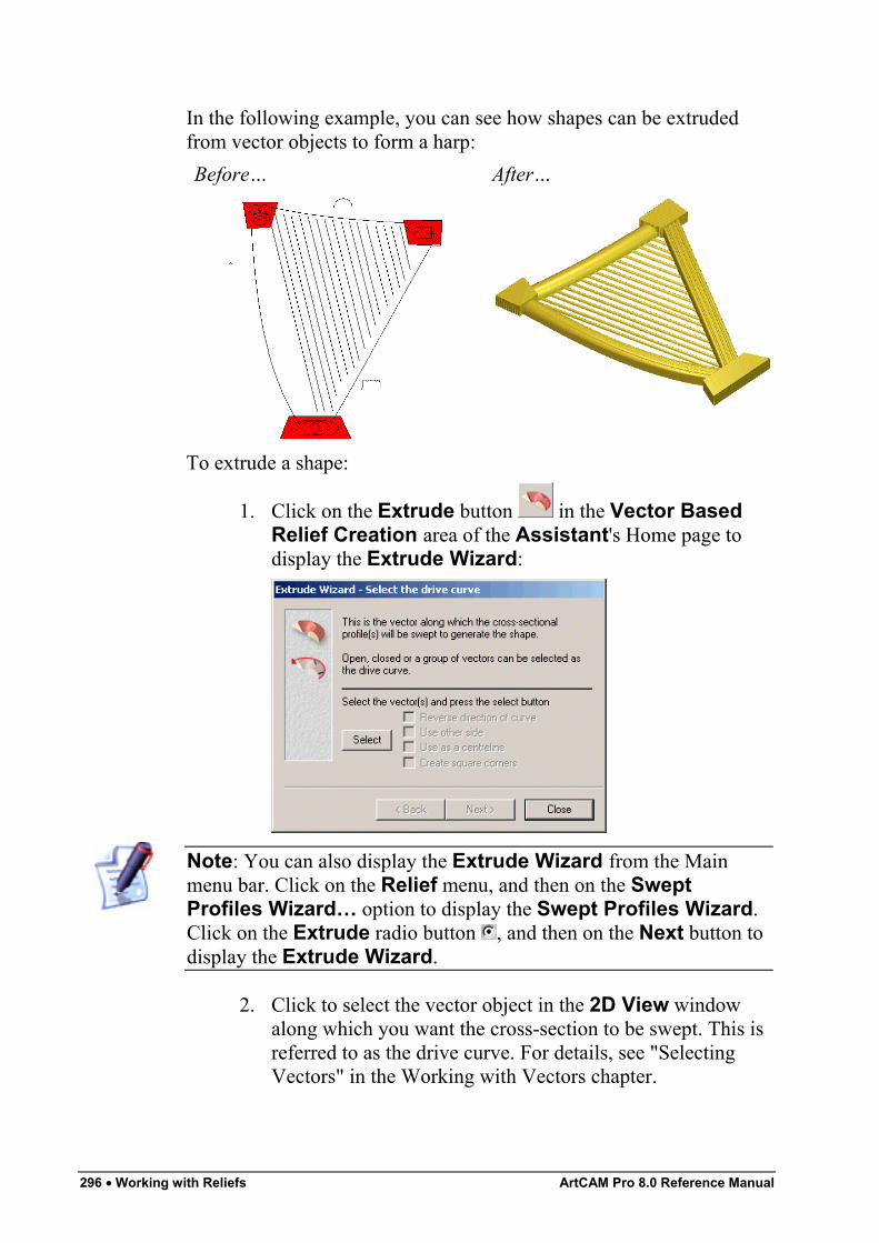
296 • Working with Reliefs ArtCAM Pro 8.0 Reference Manual
In the following example, you can see how shapes can be extrudedfrom vector objects to form a harp:Before… After…
To extrude a shape:
1. Click on the Extrude button in the Vector BasedRelief Creation area of the Assistant's Home page todisplay the Extrude Wizard:
Note: You can also display the Extrude Wizard from the Mainmenu bar. Click on the Relief menu, and then on the SweptProfiles Wizard… option to display the Swept Profiles Wizard.Click on the Extrude radio button , and then on the Next button todisplay the Extrude Wizard.
2. Click to select the vector object in the 2D View windowalong which you want the cross-section to be swept. This isreferred to as the drive curve. For details, see "SelectingVectors" in the Working with Vectors chapter.
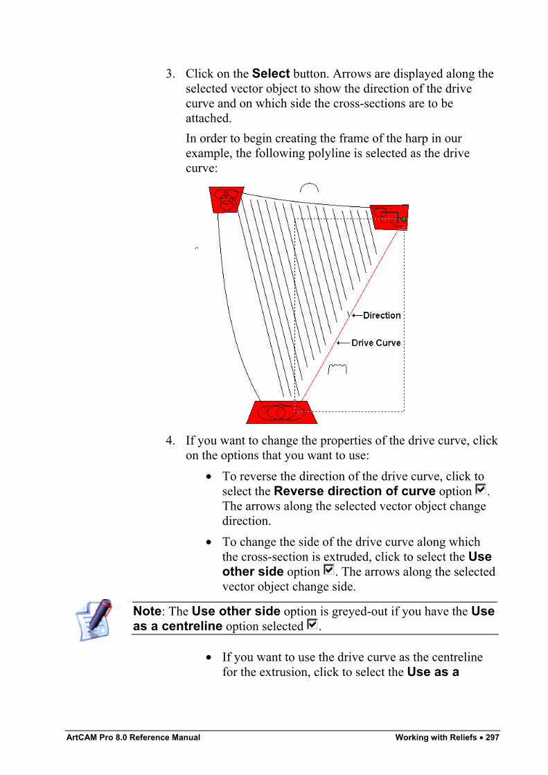
ArtCAM Pro 8.0 Reference Manual Working with Reliefs • 297
3. Click on the Select button. Arrows are displayed along theselected vector object to show the direction of the drivecurve and on which side the cross-sections are to beattached.In order to begin creating the frame of the harp in ourexample, the following polyline is selected as the drivecurve:
4. If you want to change the properties of the drive curve, clickon the options that you want to use:
• To reverse the direction of the drive curve, click toselect the Reverse direction of curve option .The arrows along the selected vector object changedirection.
• To change the side of the drive curve along whichthe cross-section is extruded, click to select the Useother side option . The arrows along the selectedvector object change side.
Note: The Use other side option is greyed-out if you have the Useas a centreline option selected .
• If you want to use the drive curve as the centrelinefor the extrusion, click to select the Use as a
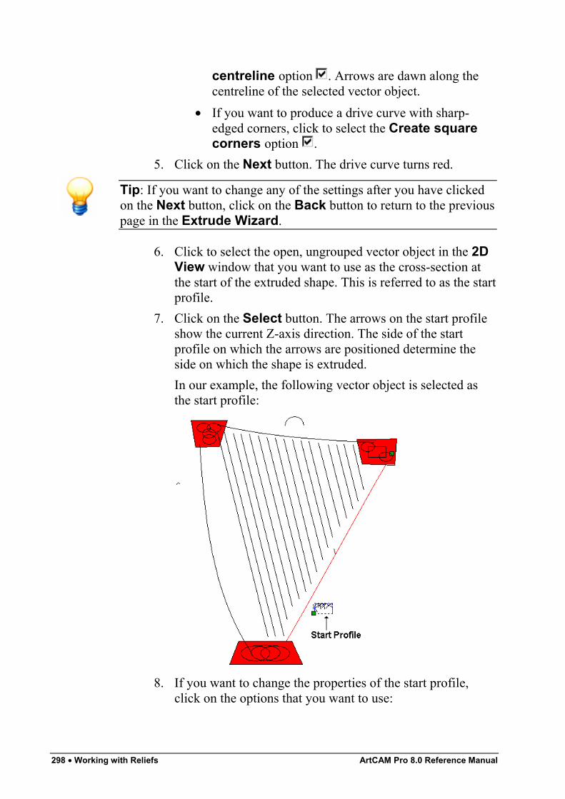
298 • Working with Reliefs ArtCAM Pro 8.0 Reference Manual
centreline option . Arrows are dawn along thecentreline of the selected vector object.
• If you want to produce a drive curve with sharp-edged corners, click to select the Create squarecorners option .
5. Click on the Next button. The drive curve turns red.
Tip: If you want to change any of the settings after you have clickedon the Next button, click on the Back button to return to the previouspage in the Extrude Wizard.
6. Click to select the open, ungrouped vector object in the 2DView window that you want to use as the cross-section atthe start of the extruded shape. This is referred to as the startprofile.
7. Click on the Select button. The arrows on the start profileshow the current Z-axis direction. The side of the startprofile on which the arrows are positioned determine theside on which the shape is extruded.In our example, the following vector object is selected asthe start profile:
8. If you want to change the properties of the start profile,click on the options that you want to use:
ArtCAM Pro 8.0 Reference Manual Working with Reliefs • 299
• To change the position of the start point (node) in theselected vector object, click to select the Moveanchor point to other end option . The startpoint (node) is green and determines which end ofthe start profile is attached to the drive curve.
• To invert the selected vector object in the Z-axisdirection, click to select the Invert curve in Zoption .
9. Click on the Next button. The start profile turns blue.10. Click to select the open, ungrouped vector object in the 2D
View window that you want to use as the profile at the endof the extruded shape:
• If you want to use the same vector object that youhad selected as the profile at the start of the extrudedshape, make sure that the End profile is the sameas the start profile option is selected , and thengo straight to the next step.In our example, the vector object used for the endprofile is the same as that which was selected as thestart profile.
Note: The Select button and the end profile options are greyed-outif the End profile is the same as the start profile option isselected .
• If you want to use another vector object in the model,make sure that the End profile is the same asthe start profile option is deselected , click onthe vector object that you want to use, and then clickon the Select button.
If you want to change the properties of the end profile,select the options that you want to use:
• To change the position of the start point (node) in theselected vector object, click to select the Moveanchor point to other end option . The startpoint (node) is green and determines which end ofthe end profile is attached to the drive curve.
• To invert the selected vector object in the Z-axisdirection, click to select the Invert curve in Zoption .
300 • Working with Reliefs ArtCAM Pro 8.0 Reference Manual
11. Click on the Next button. The end profile turns blue.12. To add a contour and scale the swept profile in the Z-axis
along its length:• First, click to select the Use a z modulation
vector option .• Next, click to select the vector object that you want
to use as the z modulation vector.• Now, click on the Select button.• To change the position of the start point (node) in the
selected vector object, click to select the Moveanchor point to other end option . The startpoint (node) is green and determines which end ofthe swept profile is attached to the drive curve.
• To invert the selected vector object in the Z-axisdirection, click to select the Invert curve in Zoption .
If you do not want to scale the swept profile in the Z-axisalong its length, go straight to the next step.
13. Click on the Next button. The z modulation vector turnsgreen.
14. Select the relief combination method that you want to use:• Click on the Add radio button to add the extruded
shape to the current relief. For more details, see"Adding to the Relief" on page 326.
• Click on the Subtract radio button to subtract theextruded shape from the current relief. For moredetails, see "Subtracting from the Relief" on page328.
• Click on the Merge Highest radio button tomerge the extruded shape with the current relief, sothat only the highest points of the two show. Fordetails, see "Merging with the Relief" on page 330.
• Click on the Merge Lowest radio button tomerge the extruded shape with the current relief, sothat only the lowest points of the two show. Fordetails, see "Merging with the Relief" on page 330.
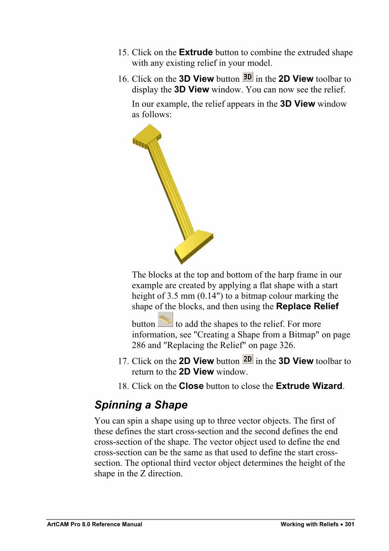
ArtCAM Pro 8.0 Reference Manual Working with Reliefs • 301
15. Click on the Extrude button to combine the extruded shapewith any existing relief in your model.
16. Click on the 3D View button in the 2D View toolbar todisplay the 3D View window. You can now see the relief.In our example, the relief appears in the 3D View windowas follows:
The blocks at the top and bottom of the harp frame in ourexample are created by applying a flat shape with a startheight of 3.5 mm (0.14") to a bitmap colour marking theshape of the blocks, and then using the Replace Relief
button to add the shapes to the relief. For moreinformation, see "Creating a Shape from a Bitmap" on page286 and "Replacing the Relief" on page 326.
17. Click on the 2D View button in the 3D View toolbar toreturn to the 2D View window.
18. Click on the Close button to close the Extrude Wizard.
Spinning a ShapeYou can spin a shape using up to three vector objects. The first ofthese defines the start cross-section and the second defines the endcross-section of the shape. The vector object used to define the endcross-section can be the same as that used to define the start cross-section. The optional third vector object determines the height of theshape in the Z direction.
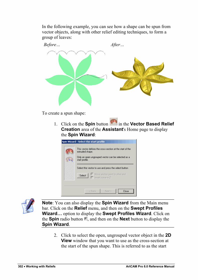
302 • Working with Reliefs ArtCAM Pro 8.0 Reference Manual
In the following example, you can see how a shape can be spun fromvector objects, along with other relief editing techniques, to form agroup of leaves:Before… After…
To create a spun shape:
1. Click on the Spin button in the Vector Based ReliefCreation area of the Assistant's Home page to displaythe Spin Wizard:
Note: You can also display the Spin Wizard from the Main menubar. Click on the Relief menu, and then on the Swept ProfilesWizard… option to display the Swept Profiles Wizard. Click onthe Spin radio button , and then on the Next button to display theSpin Wizard.
2. Click to select the open, ungrouped vector object in the 2DView window that you want to use as the cross-section atthe start of the spun shape. This is referred to as the start
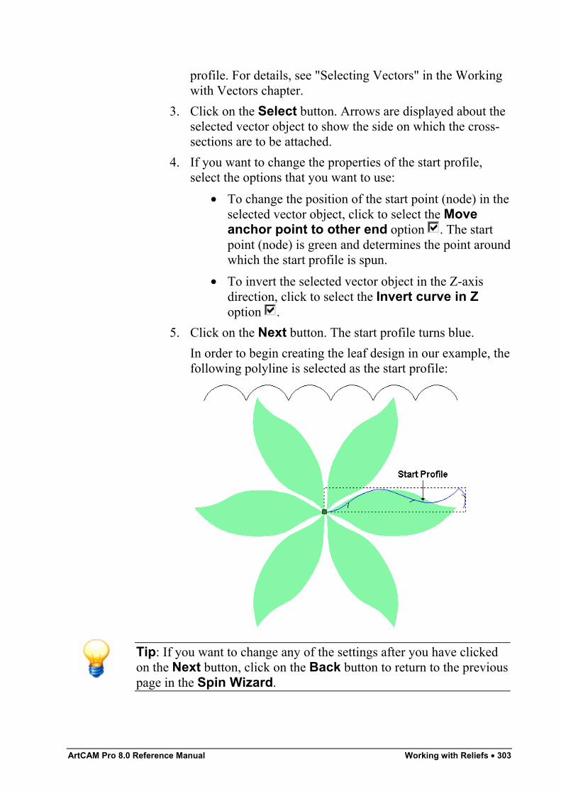
ArtCAM Pro 8.0 Reference Manual Working with Reliefs • 303
profile. For details, see "Selecting Vectors" in the Workingwith Vectors chapter.
3. Click on the Select button. Arrows are displayed about theselected vector object to show the side on which the cross-sections are to be attached.
4. If you want to change the properties of the start profile,select the options that you want to use:
• To change the position of the start point (node) in theselected vector object, click to select the Moveanchor point to other end option . The startpoint (node) is green and determines the point aroundwhich the start profile is spun.
• To invert the selected vector object in the Z-axisdirection, click to select the Invert curve in Zoption .
5. Click on the Next button. The start profile turns blue.In order to begin creating the leaf design in our example, thefollowing polyline is selected as the start profile:
Tip: If you want to change any of the settings after you have clickedon the Next button, click on the Back button to return to the previouspage in the Spin Wizard.
304 • Working with Reliefs ArtCAM Pro 8.0 Reference Manual
6. Click to select the open vector object that you want to use asthe cross-section at the end of the spun shape. This isreferred to as the end profile.
• To use the same vector object that you have alreadyused, make sure that the End profile is the sameas the start profile option is selected , and thengo straight to the next step.
In our example, the vector object used for the end profile isthe same as that which was selected as the start profile.
Note: The Select button and the end profile options are greyed-out ifthe End profile is the same as the start profile option isselected .
• To use another vector object, make sure that the Endprofile is the same as the start profile optionis deselected , click to select the vector object thatyou want to use, and then click on the Select button.
If you want to change the properties of the end profile,select the options that you want to use:
• To change the position of the start point (node) in theselected vector object, click to select the Moveanchor point to other end option . The startpoint (node) is green and determines the point aroundwhich the end profile is spun.
• To invert the selected vector object in the Z-axisdirection, click to select the Invert curve in Zoption .
7. Click on the Next button. The end profile turns blue.8. You are now ready to define how the profile is swept. If you
want to sweep the profile through 360°, starting at 0°, clickon the Next button. If you want to sweep the profilethrough a specific angle:
• First, click to deselect the Sweep through 360degrees option .
• Next, define the start angle in the Start Angle box.• Now, click on the spin direction radio button that
you want to use. Click to select Clockwise if youwant to sweep the profile in a clockwise direction
ArtCAM Pro 8.0 Reference Manual Working with Reliefs • 305
about the start point (node). Click to select Anti-Clockwise if you want to sweep the profile in ananti-clockwise direction about the start point (node).
• Next, define the finish angle in the Finish Anglebox.
• Finally, click on the Next button.In our example, the profile is swept through 360°.
9. If you want to scale the spun profile in the Z-axis along itslength:
• First, click to select the Use a z modulationvector option .
• Next, click to select the vector object that you wantto use as the z modulation vector.
• Next, click on the Select button.• To change the position of the start point (node) in the
selected vector object, click to select the Moveanchor point to other end option . The startpoint (node) is green and determines the point aroundwhich the end profile is spun.
• To invert the selected vector object in the Z-axisdirection, click to select the Invert curve in Zoption .
If you do not want to scale the spun profile in the Z-axisalong its length, go straight to the next step.In our example, the following polyline is selected as the zmodulation vector:
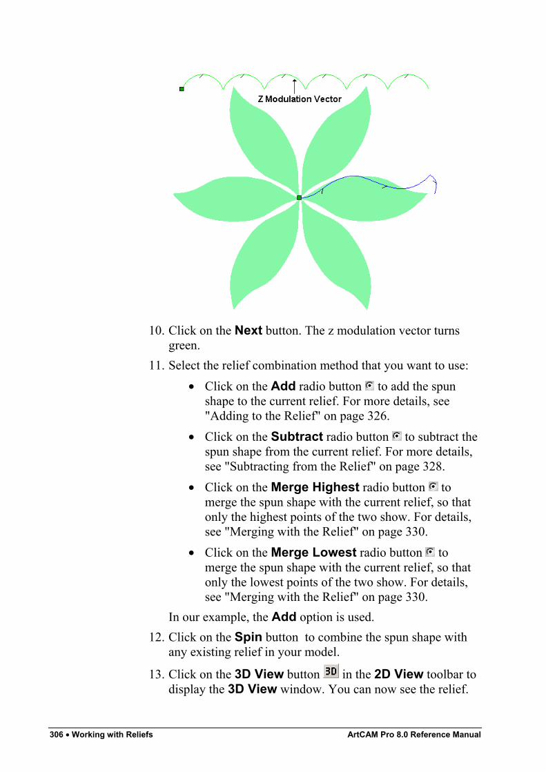
306 • Working with Reliefs ArtCAM Pro 8.0 Reference Manual
10. Click on the Next button. The z modulation vector turnsgreen.
11. Select the relief combination method that you want to use:• Click on the Add radio button to add the spun
shape to the current relief. For more details, see"Adding to the Relief" on page 326.
• Click on the Subtract radio button to subtract thespun shape from the current relief. For more details,see "Subtracting from the Relief" on page 328.
• Click on the Merge Highest radio button tomerge the spun shape with the current relief, so thatonly the highest points of the two show. For details,see "Merging with the Relief" on page 330.
• Click on the Merge Lowest radio button tomerge the spun shape with the current relief, so thatonly the lowest points of the two show. For details,see "Merging with the Relief" on page 330.
In our example, the Add option is used.12. Click on the Spin button to combine the spun shape with
any existing relief in your model.
13. Click on the 3D View button in the 2D View toolbar todisplay the 3D View window. You can now see the relief.
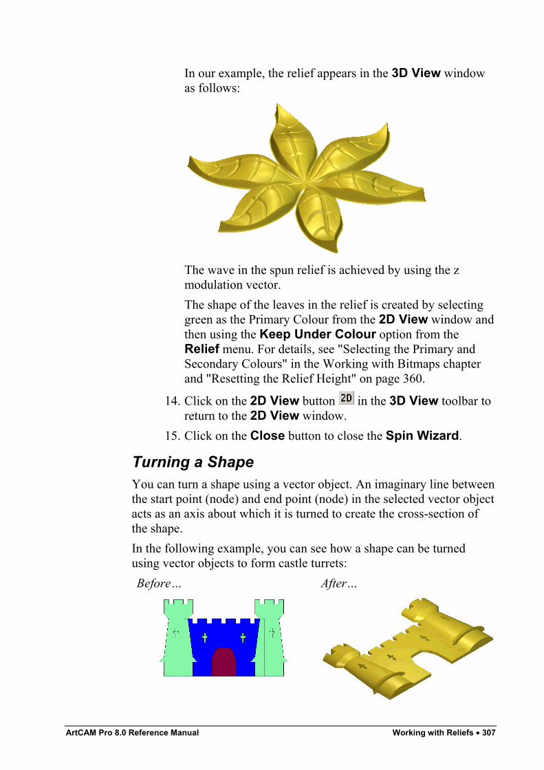
ArtCAM Pro 8.0 Reference Manual Working with Reliefs • 307
In our example, the relief appears in the 3D View windowas follows:
The wave in the spun relief is achieved by using the zmodulation vector.The shape of the leaves in the relief is created by selectinggreen as the Primary Colour from the 2D View window andthen using the Keep Under Colour option from theRelief menu. For details, see "Selecting the Primary andSecondary Colours" in the Working with Bitmaps chapterand "Resetting the Relief Height" on page 360.
14. Click on the 2D View button in the 3D View toolbar toreturn to the 2D View window.
15. Click on the Close button to close the Spin Wizard.
Turning a ShapeYou can turn a shape using a vector object. An imaginary line betweenthe start point (node) and end point (node) in the selected vector objectacts as an axis about which it is turned to create the cross-section ofthe shape.In the following example, you can see how a shape can be turnedusing vector objects to form castle turrets:Before… After…
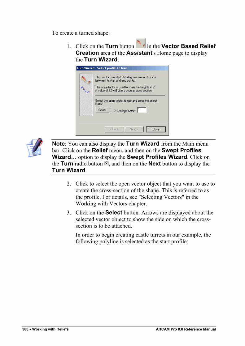
308 • Working with Reliefs ArtCAM Pro 8.0 Reference Manual
To create a turned shape:
1. Click on the Turn button in the Vector Based ReliefCreation area of the Assistant's Home page to displaythe Turn Wizard:
Note: You can also display the Turn Wizard from the Main menubar. Click on the Relief menu, and then on the Swept ProfilesWizard… option to display the Swept Profiles Wizard. Click onthe Turn radio button , and then on the Next button to display theTurn Wizard.
2. Click to select the open vector object that you want to use tocreate the cross-section of the shape. This is referred to asthe profile. For details, see "Selecting Vectors" in theWorking with Vectors chapter.
3. Click on the Select button. Arrows are displayed about theselected vector object to show the side on which the cross-section is to be attached.In order to begin creating castle turrets in our example, thefollowing polyline is selected as the start profile:
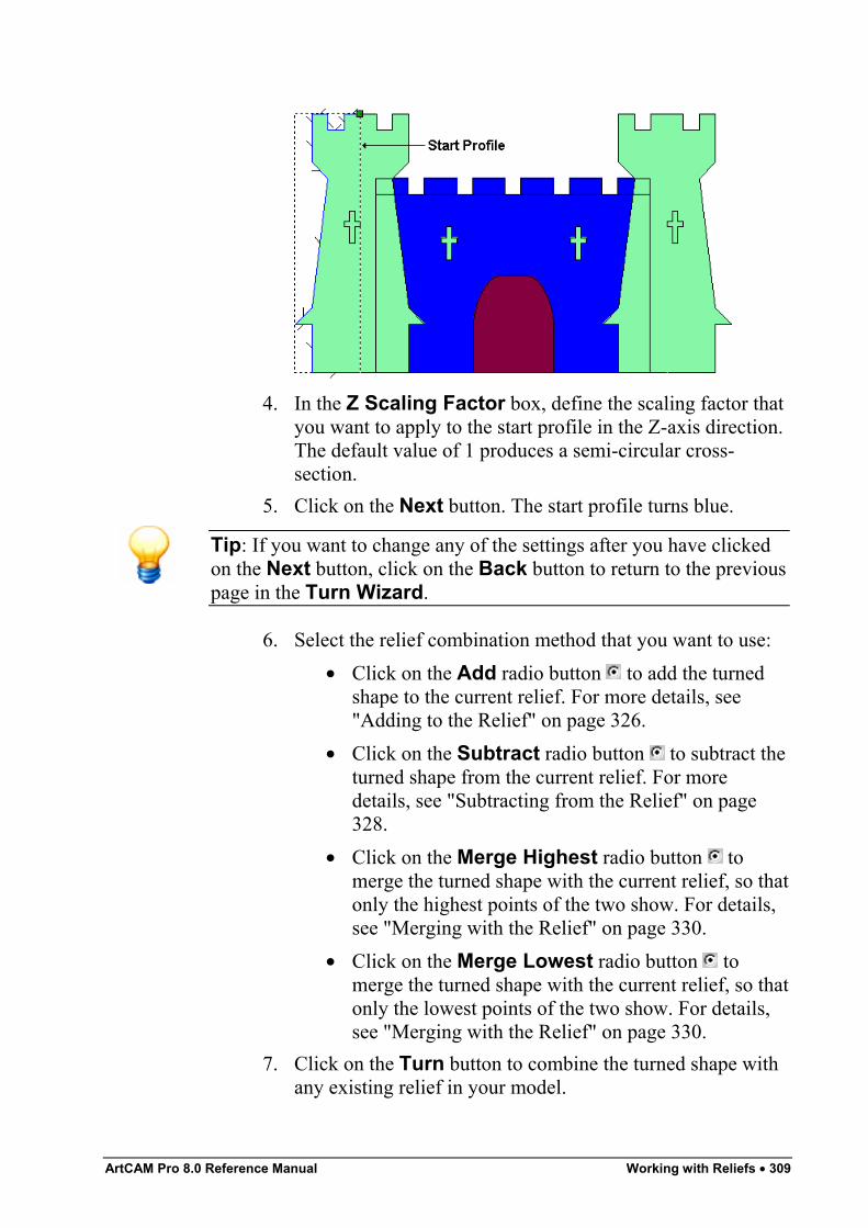
ArtCAM Pro 8.0 Reference Manual Working with Reliefs • 309
4. In the Z Scaling Factor box, define the scaling factor thatyou want to apply to the start profile in the Z-axis direction.The default value of 1 produces a semi-circular cross-section.
5. Click on the Next button. The start profile turns blue.
Tip: If you want to change any of the settings after you have clickedon the Next button, click on the Back button to return to the previouspage in the Turn Wizard.
6. Select the relief combination method that you want to use:• Click on the Add radio button to add the turned
shape to the current relief. For more details, see"Adding to the Relief" on page 326.
• Click on the Subtract radio button to subtract theturned shape from the current relief. For moredetails, see "Subtracting from the Relief" on page328.
• Click on the Merge Highest radio button tomerge the turned shape with the current relief, so thatonly the highest points of the two show. For details,see "Merging with the Relief" on page 330.
• Click on the Merge Lowest radio button tomerge the turned shape with the current relief, so thatonly the lowest points of the two show. For details,see "Merging with the Relief" on page 330.
7. Click on the Turn button to combine the turned shape withany existing relief in your model.
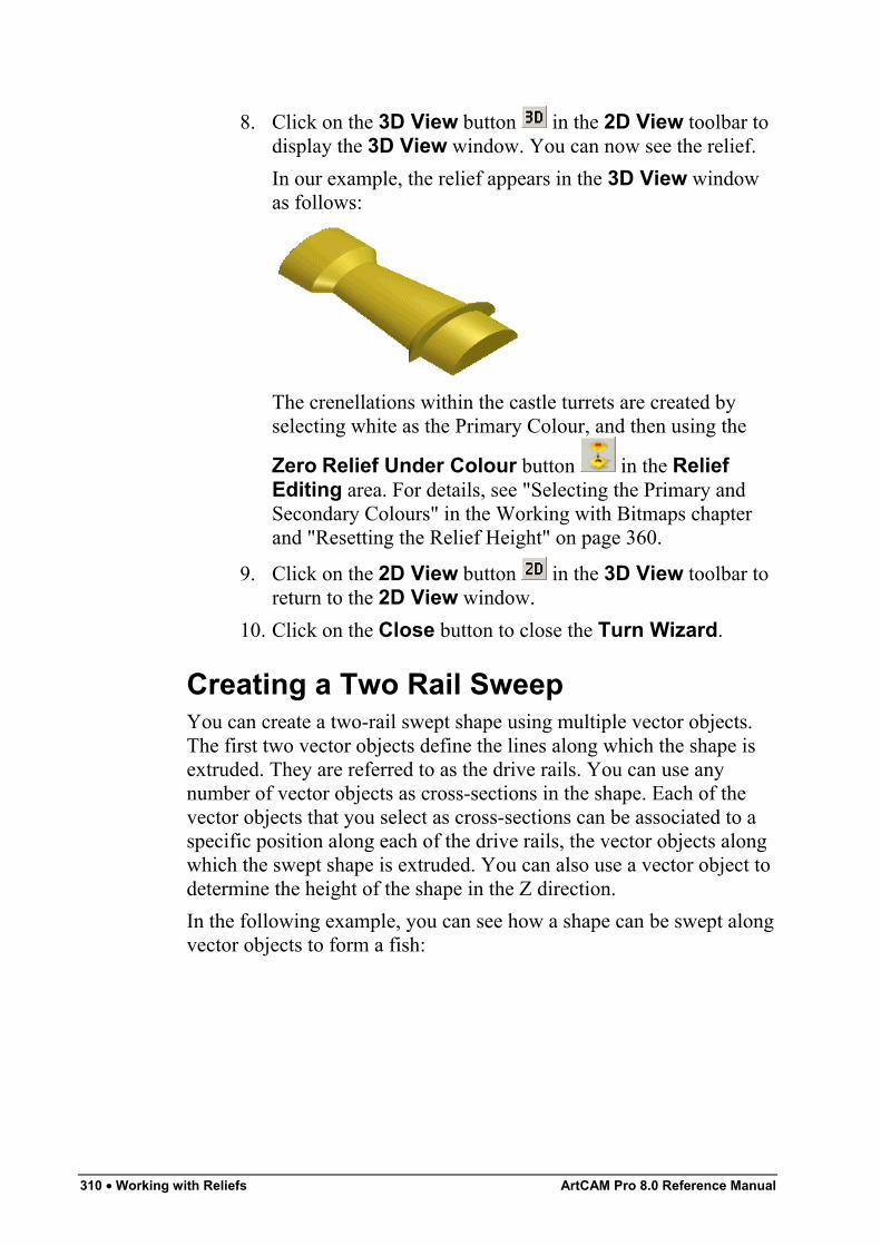
310 • Working with Reliefs ArtCAM Pro 8.0 Reference Manual
8. Click on the 3D View button in the 2D View toolbar todisplay the 3D View window. You can now see the relief.In our example, the relief appears in the 3D View windowas follows:
The crenellations within the castle turrets are created byselecting white as the Primary Colour, and then using the
Zero Relief Under Colour button in the ReliefEditing area. For details, see "Selecting the Primary andSecondary Colours" in the Working with Bitmaps chapterand "Resetting the Relief Height" on page 360.
9. Click on the 2D View button in the 3D View toolbar toreturn to the 2D View window.
10. Click on the Close button to close the Turn Wizard.
Creating a Two Rail SweepYou can create a two-rail swept shape using multiple vector objects.The first two vector objects define the lines along which the shape isextruded. They are referred to as the drive rails. You can use anynumber of vector objects as cross-sections in the shape. Each of thevector objects that you select as cross-sections can be associated to aspecific position along each of the drive rails, the vector objects alongwhich the swept shape is extruded. You can also use a vector object todetermine the height of the shape in the Z direction.In the following example, you can see how a shape can be swept alongvector objects to form a fish:
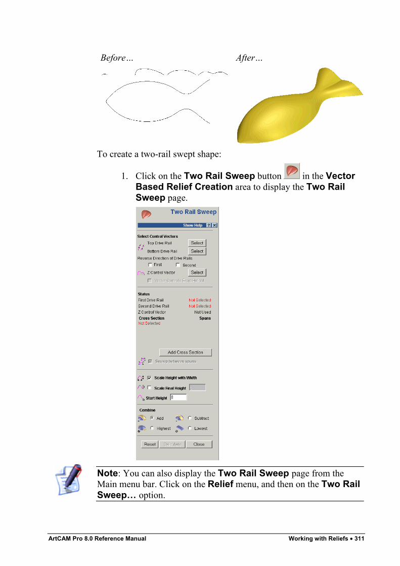
ArtCAM Pro 8.0 Reference Manual Working with Reliefs • 311
Before… After…
To create a two-rail swept shape:
1. Click on the Two Rail Sweep button in the VectorBased Relief Creation area to display the Two RailSweep page.
Note: You can also display the Two Rail Sweep page from theMain menu bar. Click on the Relief menu, and then on the Two RailSweep… option.
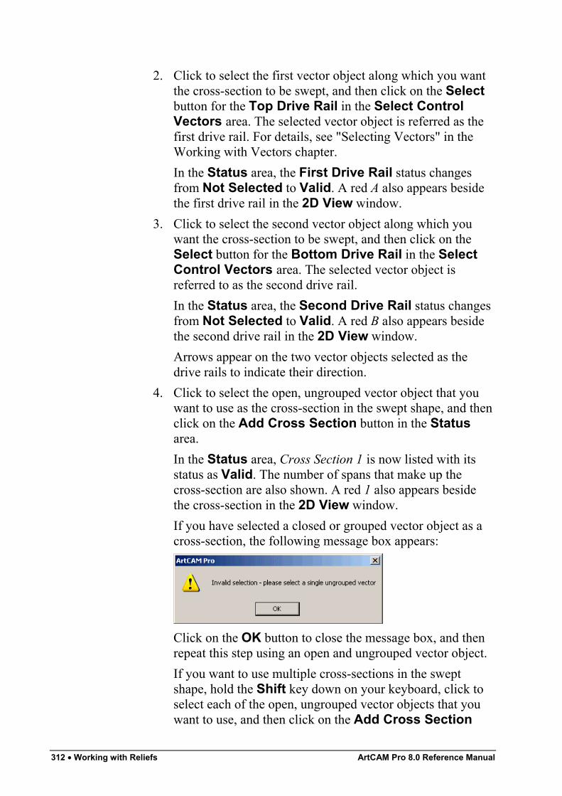
312 • Working with Reliefs ArtCAM Pro 8.0 Reference Manual
2. Click to select the first vector object along which you wantthe cross-section to be swept, and then click on the Selectbutton for the Top Drive Rail in the Select ControlVectors area. The selected vector object is referred as thefirst drive rail. For details, see "Selecting Vectors" in theWorking with Vectors chapter.In the Status area, the First Drive Rail status changesfrom Not Selected to Valid. A red A also appears besidethe first drive rail in the 2D View window.
3. Click to select the second vector object along which youwant the cross-section to be swept, and then click on theSelect button for the Bottom Drive Rail in the SelectControl Vectors area. The selected vector object isreferred to as the second drive rail.In the Status area, the Second Drive Rail status changesfrom Not Selected to Valid. A red B also appears besidethe second drive rail in the 2D View window.Arrows appear on the two vector objects selected as thedrive rails to indicate their direction.
4. Click to select the open, ungrouped vector object that youwant to use as the cross-section in the swept shape, and thenclick on the Add Cross Section button in the Statusarea.In the Status area, Cross Section 1 is now listed with itsstatus as Valid. The number of spans that make up thecross-section are also shown. A red 1 also appears besidethe cross-section in the 2D View window.If you have selected a closed or grouped vector object as across-section, the following message box appears:
Click on the OK button to close the message box, and thenrepeat this step using an open and ungrouped vector object.If you want to use multiple cross-sections in the sweptshape, hold the Shift key down on your keyboard, click toselect each of the open, ungrouped vector objects that youwant to use, and then click on the Add Cross Section
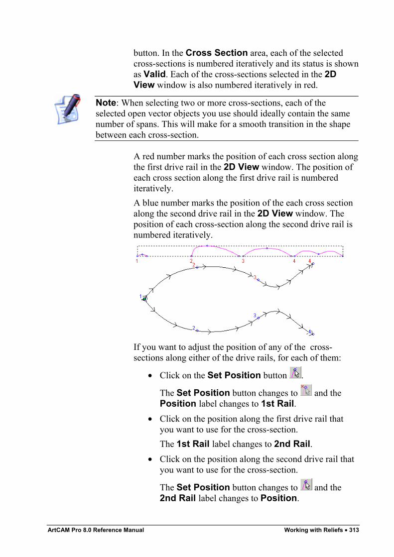
ArtCAM Pro 8.0 Reference Manual Working with Reliefs • 313
button. In the Cross Section area, each of the selectedcross-sections is numbered iteratively and its status is shownas Valid. Each of the cross-sections selected in the 2DView window is also numbered iteratively in red.
Note: When selecting two or more cross-sections, each of theselected open vector objects you use should ideally contain the samenumber of spans. This will make for a smooth transition in the shapebetween each cross-section.
A red number marks the position of each cross section alongthe first drive rail in the 2D View window. The position ofeach cross section along the first drive rail is numberediteratively.A blue number marks the position of the each cross sectionalong the second drive rail in the 2D View window. Theposition of each cross-section along the second drive rail isnumbered iteratively.
If you want to adjust the position of any of the cross-sections along either of the drive rails, for each of them:
• Click on the Set Position button .
The Set Position button changes to and thePosition label changes to 1st Rail.
• Click on the position along the first drive rail thatyou want to use for the cross-section.The 1st Rail label changes to 2nd Rail.
• Click on the position along the second drive rail thatyou want to use for the cross-section.
The Set Position button changes to and the2nd Rail label changes to Position.
314 • Working with Reliefs ArtCAM Pro 8.0 Reference Manual
By default, ArtCAM Pro creates a smooth blended shapebetween each cross-section made up of an equal number ofspans. If you would rather a linear blended shape is used,click on the Smooth Blend button . The Linear Blendbutton is displayed in its place.If you want to cancel the use of any of the selected cross-sections, click on the Delete button for each of thecross-sections that you do not want to use.If all of the vector objects selected as cross-sections containthe same number of spans, the Sweep Between Spansoption is activated and selected by default . This instructsArtCAM Pro to sweep between matching spans.If you do not want to sweep between matching spans, clickto deselect the Sweep Between Spans option .
5. Make sure that the direction of the two vector objects thatyou have selected as drive rails is the same:
• If you need to reverse the direction of the first driverail, click to select the First option in theReverse Direction of Drive Rails area.
• If you need to reverse the direction of the seconddrive rail, click to select the Second option .
6. You are now ready to decide how you want to scale theswept shape. If you want to scale the two-rail swept profilein the Z-axis along its length:
• Click to select the open vector object that you wantto use to control the Z height of the swept shape, andthen click on the Select button for the Z ControlVector in the Select Control Vectors area. Theselected vector object is referred to as the zmodulation curve.In the Status area, the Z Modulation Curve statuschanges from Not Selected to Valid. A red Z alsoappears beside the z modulation curve in the 2DView window.
• Next, click to select the Vector Controls ExactHeight option . The Scale Height with Widthand Scale Final Height options are greyed-out.
ArtCAM Pro 8.0 Reference Manual Working with Reliefs • 315
If you do not want to use a vector object to determine theheight of the swept shape, you can select an alternativescaling option:
• To scale the height of the cross-section across thetwo drive rails in proportion with its width, makesure that the Scale Height with Width option isselected .If you want the height of the cross-section across thetwo drive rails to remain constant, click to deselectthe Scale Height with Width option .
Note: Narrow sections in the swept shape appear low, while widesections appear high when the Scale Height with Width option isselected.
• To define the final height of the swept shape before itis combined with any existing relief, click to selectthe Scale Final Height option , and then definethe height of the shape in its box.
Note: If you have selected the Vector Controls Exact Heightoption, then the Scale Height with Width and Scale FinalHeight options are greyed-out.
7. If you want to add a start height to the two-rail swept shape,define the height in the Start Height box. This produces abase that is combined with the swept shape after it has beencalculated. The start height is not included in the scaledfinal height of the swept shape.
8. In the Combine area of the page, select the reliefcombination method that you want to use:
• Click on the Add radio button to add the two-railswept shape to the current relief. For more details,see "Adding to the Relief" in the Working withReliefs chapter of the Reference Manual.
• Click on the Subtract radio button to subtract thetwo-rail swept shape from the current relief. Formore details, see "Subtracting from the Relief" in theWorking with Reliefs chapter of the ReferenceManual.
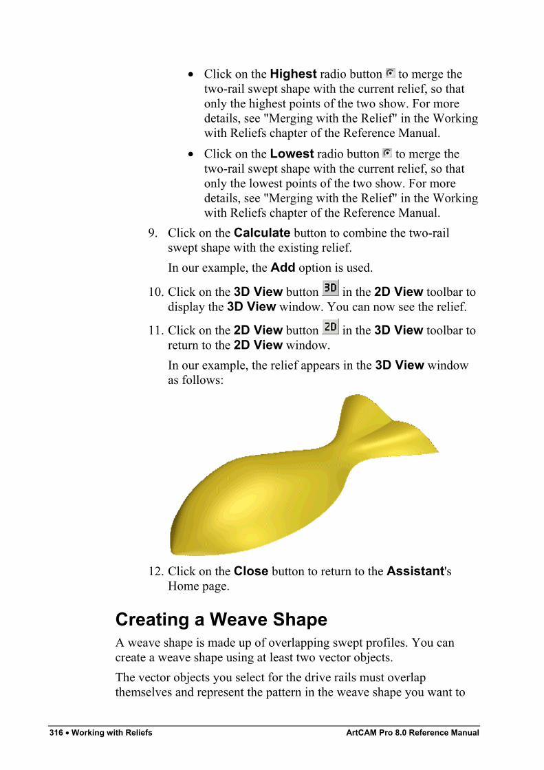
316 • Working with Reliefs ArtCAM Pro 8.0 Reference Manual
• Click on the Highest radio button to merge thetwo-rail swept shape with the current relief, so thatonly the highest points of the two show. For moredetails, see "Merging with the Relief" in the Workingwith Reliefs chapter of the Reference Manual.
• Click on the Lowest radio button to merge thetwo-rail swept shape with the current relief, so thatonly the lowest points of the two show. For moredetails, see "Merging with the Relief" in the Workingwith Reliefs chapter of the Reference Manual.
9. Click on the Calculate button to combine the two-railswept shape with the existing relief.In our example, the Add option is used.
10. Click on the 3D View button in the 2D View toolbar todisplay the 3D View window. You can now see the relief.
11. Click on the 2D View button in the 3D View toolbar toreturn to the 2D View window.In our example, the relief appears in the 3D View windowas follows:
12. Click on the Close button to return to the Assistant'sHome page.
Creating a Weave ShapeA weave shape is made up of overlapping swept profiles. You cancreate a weave shape using at least two vector objects.The vector objects you select for the drive rails must overlapthemselves and represent the pattern in the weave shape you want to
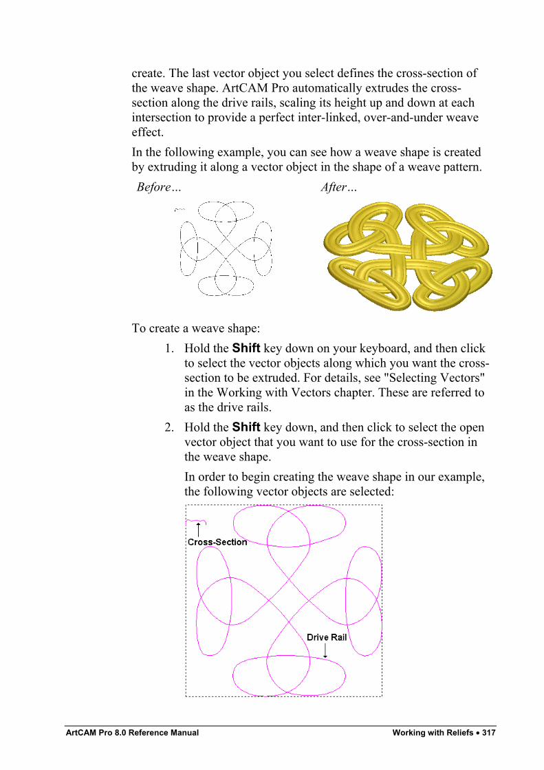
ArtCAM Pro 8.0 Reference Manual Working with Reliefs • 317
create. The last vector object you select defines the cross-section ofthe weave shape. ArtCAM Pro automatically extrudes the cross-section along the drive rails, scaling its height up and down at eachintersection to provide a perfect inter-linked, over-and-under weaveeffect.In the following example, you can see how a weave shape is createdby extruding it along a vector object in the shape of a weave pattern.Before… After…
To create a weave shape:1. Hold the Shift key down on your keyboard, and then click
to select the vector objects along which you want the cross-section to be extruded. For details, see "Selecting Vectors"in the Working with Vectors chapter. These are referred toas the drive rails.
2. Hold the Shift key down, and then click to select the openvector object that you want to use for the cross-section inthe weave shape.In order to begin creating the weave shape in our example,the following vector objects are selected:
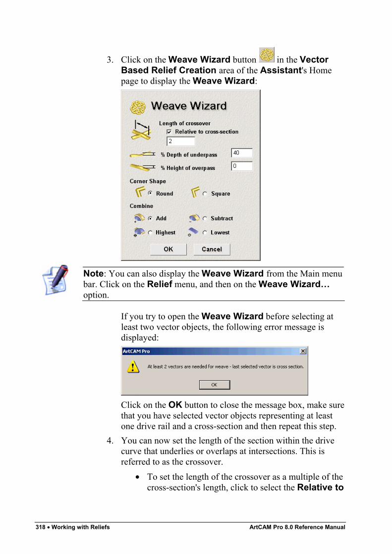
318 • Working with Reliefs ArtCAM Pro 8.0 Reference Manual
3. Click on the Weave Wizard button in the VectorBased Relief Creation area of the Assistant's Homepage to display the Weave Wizard:
Note: You can also display the Weave Wizard from the Main menubar. Click on the Relief menu, and then on the Weave Wizard…option.
If you try to open the Weave Wizard before selecting atleast two vector objects, the following error message isdisplayed:
Click on the OK button to close the message box, make surethat you have selected vector objects representing at leastone drive rail and a cross-section and then repeat this step.
4. You can now set the length of the section within the drivecurve that underlies or overlaps at intersections. This isreferred to as the crossover.
• To set the length of the crossover as a multiple of thecross-section's length, click to select the Relative to
ArtCAM Pro 8.0 Reference Manual Working with Reliefs • 319
cross-section option , and then define its lengthin the Length of crossover box.
• To set the length of the crossover as an absolutedistance, make sure that the Relative to cross-section option is deselected , and then define itslength in the Length of crossover box.
In our example, the Relative to cross-section option isselected and the length of the crossover is set to 4.
5. Define the height of the cross-section where it underlies atan intersection in the % Depth of underpass box.In our example, the % Depth of underpass is set to 40.
6. Define the height of the cross-section where it overlaps at anintersection in the % Height of overpass box.In our example, the % Height of overpass is set to 20.
7. In the Corner Shape area of the page, select the type ofcorner that you want to use in the cross-section:
• To apply rounded corners to the cross-section, clickon the Round radio button .
• To apply squared corners to the cross-section, clickon the Square radio button .
In our example, Round corners are selected8. In the Combine area of the page, select the relief
combination method that you want to use:• Click on the Add radio button to add the weave
shape to the current relief. For more details, see"Adding to the Relief" on page 326.
• Click on the Subtract radio button to subtract theweave shape from the current relief. For moredetails, see "Subtracting from the Relief" on page328.
• Click on the Highest radio button to merge theweave shape with the current relief, so that only thehighest points of the two show. For details, see"Merging with the Relief" on page 330.
• Click on the Lowest radio button to merge theweave shape with the current relief, so that only the
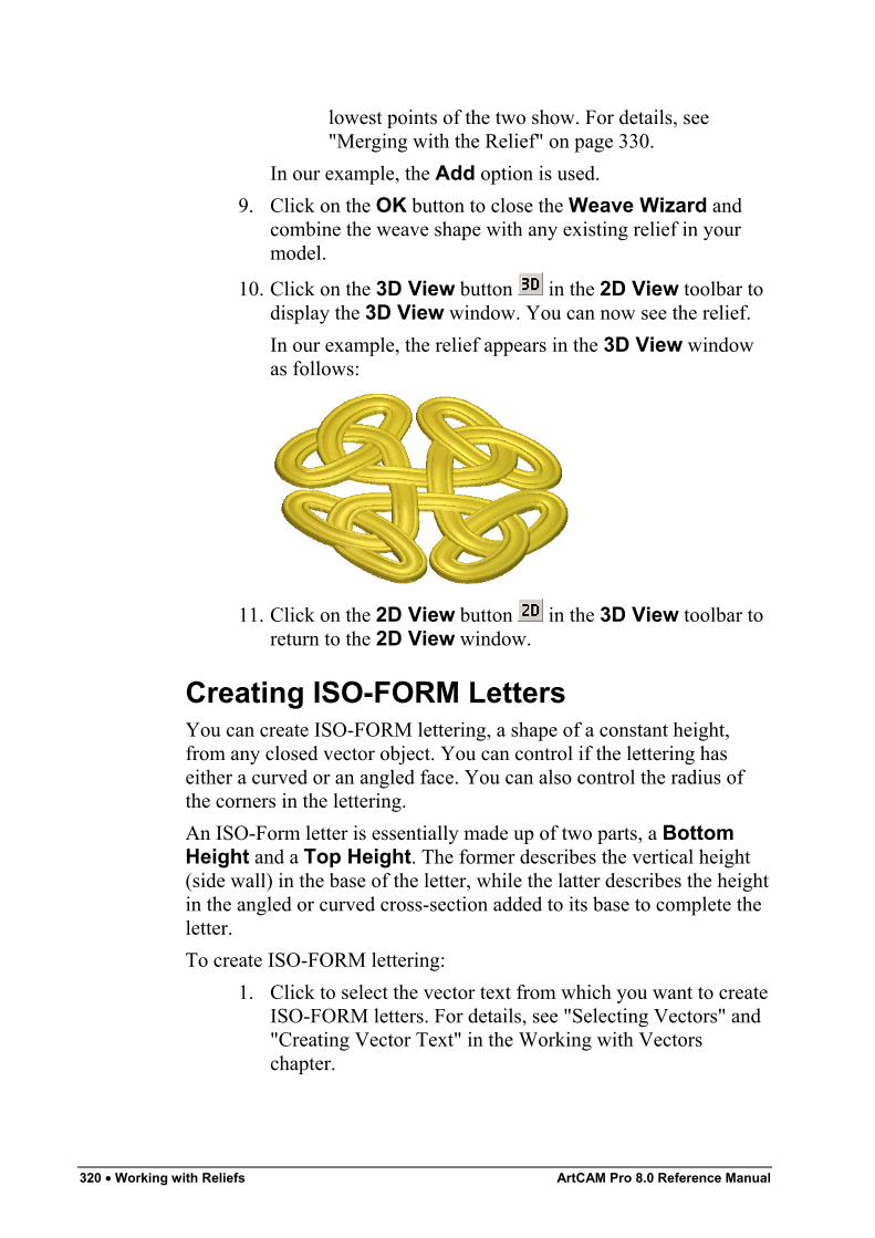
320 • Working with Reliefs ArtCAM Pro 8.0 Reference Manual
lowest points of the two show. For details, see"Merging with the Relief" on page 330.
In our example, the Add option is used.9. Click on the OK button to close the Weave Wizard and
combine the weave shape with any existing relief in yourmodel.
10. Click on the 3D View button in the 2D View toolbar todisplay the 3D View window. You can now see the relief.In our example, the relief appears in the 3D View windowas follows:
11. Click on the 2D View button in the 3D View toolbar toreturn to the 2D View window.
Creating ISO-FORM LettersYou can create ISO-FORM lettering, a shape of a constant height,from any closed vector object. You can control if the lettering haseither a curved or an angled face. You can also control the radius ofthe corners in the lettering.An ISO-Form letter is essentially made up of two parts, a BottomHeight and a Top Height. The former describes the vertical height(side wall) in the base of the letter, while the latter describes the heightin the angled or curved cross-section added to its base to complete theletter.To create ISO-FORM lettering:
1. Click to select the vector text from which you want to createISO-FORM letters. For details, see "Selecting Vectors" and"Creating Vector Text" in the Working with Vectorschapter.
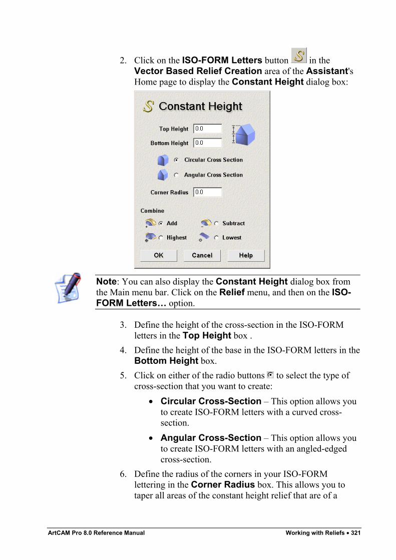
ArtCAM Pro 8.0 Reference Manual Working with Reliefs • 321
2. Click on the ISO-FORM Letters button in theVector Based Relief Creation area of the Assistant'sHome page to display the Constant Height dialog box:
Note: You can also display the Constant Height dialog box fromthe Main menu bar. Click on the Relief menu, and then on the ISO-FORM Letters… option.
3. Define the height of the cross-section in the ISO-FORMletters in the Top Height box .
4. Define the height of the base in the ISO-FORM letters in theBottom Height box.
5. Click on either of the radio buttons to select the type ofcross-section that you want to create:
• Circular Cross-Section – This option allows youto create ISO-FORM letters with a curved cross-section.
• Angular Cross-Section – This option allows youto create ISO-FORM letters with an angled-edgedcross-section.
6. Define the radius of the corners in your ISO-FORMlettering in the Corner Radius box. This allows you totaper all areas of the constant height relief that are of a
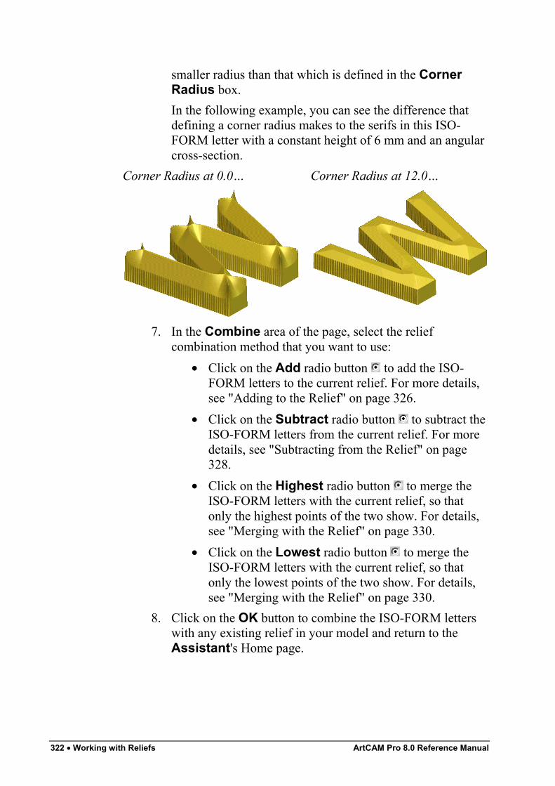
322 • Working with Reliefs ArtCAM Pro 8.0 Reference Manual
smaller radius than that which is defined in the CornerRadius box.In the following example, you can see the difference thatdefining a corner radius makes to the serifs in this ISO-FORM letter with a constant height of 6 mm and an angularcross-section.
Corner Radius at 0.0… Corner Radius at 12.0…
7. In the Combine area of the page, select the reliefcombination method that you want to use:
• Click on the Add radio button to add the ISO-FORM letters to the current relief. For more details,see "Adding to the Relief" on page 326.
• Click on the Subtract radio button to subtract theISO-FORM letters from the current relief. For moredetails, see "Subtracting from the Relief" on page328.
• Click on the Highest radio button to merge theISO-FORM letters with the current relief, so thatonly the highest points of the two show. For details,see "Merging with the Relief" on page 330.
• Click on the Lowest radio button to merge theISO-FORM letters with the current relief, so thatonly the lowest points of the two show. For details,see "Merging with the Relief" on page 330.
8. Click on the OK button to combine the ISO-FORM letterswith any existing relief in your model and return to theAssistant's Home page.
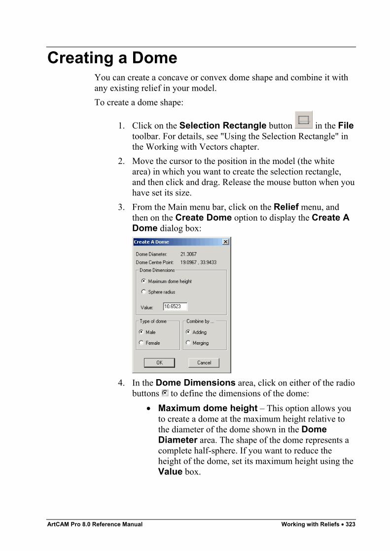
ArtCAM Pro 8.0 Reference Manual Working with Reliefs • 323
Creating a DomeYou can create a concave or convex dome shape and combine it withany existing relief in your model.To create a dome shape:
1. Click on the Selection Rectangle button in the Filetoolbar. For details, see "Using the Selection Rectangle" inthe Working with Vectors chapter.
2. Move the cursor to the position in the model (the whitearea) in which you want to create the selection rectangle,and then click and drag. Release the mouse button when youhave set its size.
3. From the Main menu bar, click on the Relief menu, andthen on the Create Dome option to display the Create ADome dialog box:
4. In the Dome Dimensions area, click on either of the radiobuttons to define the dimensions of the dome:
• Maximum dome height – This option allows youto create a dome at the maximum height relative tothe diameter of the dome shown in the DomeDiameter area. The shape of the dome represents acomplete half-sphere. If you want to reduce theheight of the dome, set its maximum height using theValue box.
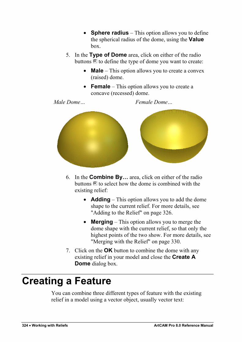
324 • Working with Reliefs ArtCAM Pro 8.0 Reference Manual
• Sphere radius – This option allows you to definethe spherical radius of the dome, using the Valuebox.
5. In the Type of Dome area, click on either of the radiobuttons to define the type of dome you want to create:
• Male – This option allows you to create a convex(raised) dome.
• Female – This option allows you to create aconcave (recessed) dome.
Male Dome… Female Dome…
6. In the Combine By… area, click on either of the radiobuttons to select how the dome is combined with theexisting relief:
• Adding – This option allows you to add the domeshape to the current relief. For more details, see"Adding to the Relief" on page 326.
• Merging – This option allows you to merge thedome shape with the current relief, so that only thehighest points of the two show. For more details, see"Merging with the Relief" on page 330.
7. Click on the OK button to combine the dome with anyexisting relief in your model and close the Create ADome dialog box.
Creating a FeatureYou can combine three different types of feature with the existingrelief in a model using a vector object, usually vector text:
ArtCAM Pro 8.0 Reference Manual Working with Reliefs • 325
• Raised Feature. For details, see "Creating a Raised Feature"in the Working with Vectors chapter.
• Recessed Feature. For details, see "Creating a RecessedFeature" in the Working with Vectors chapter.
• Centreline Engraved Feature. For details, see "Creating aCentreline Engraved Feature" in the Working with Vectorschapter.
A depth or height is attributed to the vector object from which thefeature is created. The height is added to, or the depth subtracted from,any existing relief in the model. This forms the shape of the vectorobject, usually vector text, on the relief surface. The contour of theexisting relief is preserved in the feature with which it is combined.A feature is machined using a Feature Machining toolpath. Forinformation on toolpaths, see "Overview" in the Machining Modelschapter. For details on creating a Feature Machining toolpath, see"Feature Machining" in the Machining Models chapter.
Calculating a ReliefYou can calculate a relief from the shape attributes you have assignedto a bitmap colour in the current 2D View window using one of fourdifferent combination methods:
• Replace – You can replace the current relief with a shapeto create a new relief. For details, see "Replacing the Relief"on page 326.
• Add – You can add a shape to the current relief to create anew relief. For details, see "Adding to the Relief" on page326.
• Subtract – You can subtract a shape from the current reliefto create a new relief. For details, see "Subtracting from theRelief" on page 328.
• Merge – You can merge a shape with the current relief, sothat only the highest or the lowest points of the two remainin a new relief. For details, see "Merging with the Relief" onpage 330.
These combination methods can be selected from the Main menu bar,by clicking on the Relief menu, and then the Calculate option.
326 • Working with Reliefs ArtCAM Pro 8.0 Reference Manual
Replacing the ReliefYou can replace the current relief with a shape to create a new relief.To replace the current relief with a shape:
1. Create the shape with which you want to replace the currentrelief. For details, see "Creating a Shape from a Bitmap" onpage 286.
2. Click on the Replace Relief button in the ReliefOperations area of the Assistant's Home page to replacethe current relief with the shape.
Note: You can also replace the current relief with a shape using theMain menu bar. Click on the Relief menu, followed by theCalculate > Replace option.
The Calculating Relief progress bar appears beneath the2D View window. You can cancel the relief replacementprocess at any time by clicking on the button.
3. Click on the 3D View button in the 2D View toolbar todisplay the 3D View window.
You can also replace the current relief with a shape using the Projectpage:
1. Click on the Project tab to display the Projectpage.
2. Right-click on the current 2D View listed in the Viewsarea to display the context menu. Click on the CalculateRelief option, followed by the Replace option. For furtherdetails, see “Viewing Model Information” in the Workingwith Models chapter.
Adding to the ReliefYou can add a shape to the current relief to create a new relief.To add a shape to the current relief:
1. Create the shape that you want to add to the current relief.For details, see "Creating a Shape from a Bitmap" on page286.In the following example, a blue circle is drawn in a modelusing the Paint tool:

ArtCAM Pro 8.0 Reference Manual Working with Reliefs • 327
A rounded shape is then applied to the circle using theShape Editor dialog box, as you can see by looking at theColour Palette below the 2D View window:
The calculated relief appears in the 3D View window asfollows:
The rectangular vector object is then flood-filled in red:
A plane is applied to the rectangle using the Shape Editordialog box, as you can see by looking at the Colour Palettebelow the 2D View window:
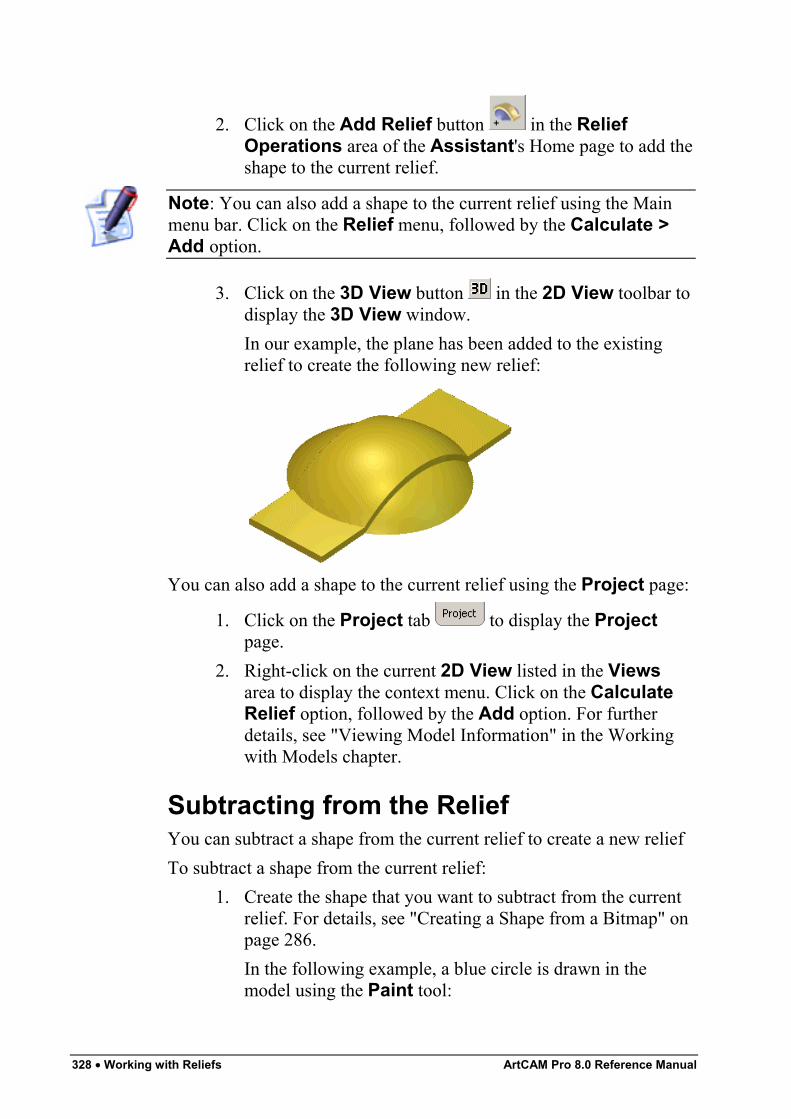
328 • Working with Reliefs ArtCAM Pro 8.0 Reference Manual
2. Click on the Add Relief button in the ReliefOperations area of the Assistant's Home page to add theshape to the current relief.
Note: You can also add a shape to the current relief using the Mainmenu bar. Click on the Relief menu, followed by the Calculate >Add option.
3. Click on the 3D View button in the 2D View toolbar todisplay the 3D View window.In our example, the plane has been added to the existingrelief to create the following new relief:
You can also add a shape to the current relief using the Project page:
1. Click on the Project tab to display the Projectpage.
2. Right-click on the current 2D View listed in the Viewsarea to display the context menu. Click on the CalculateRelief option, followed by the Add option. For furtherdetails, see "Viewing Model Information" in the Workingwith Models chapter.
Subtracting from the ReliefYou can subtract a shape from the current relief to create a new reliefTo subtract a shape from the current relief:
1. Create the shape that you want to subtract from the currentrelief. For details, see "Creating a Shape from a Bitmap" onpage 286.In the following example, a blue circle is drawn in themodel using the Paint tool:
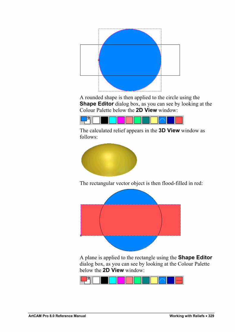
ArtCAM Pro 8.0 Reference Manual Working with Reliefs • 329
A rounded shape is then applied to the circle using theShape Editor dialog box, as you can see by looking at theColour Palette below the 2D View window:
The calculated relief appears in the 3D View window asfollows:
The rectangular vector object is then flood-filled in red:
A plane is applied to the rectangle using the Shape Editordialog box, as you can see by looking at the Colour Palettebelow the 2D View window:
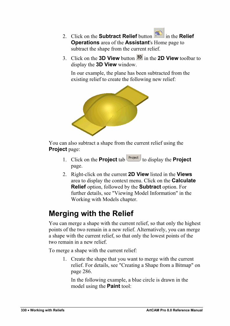
330 • Working with Reliefs ArtCAM Pro 8.0 Reference Manual
2. Click on the Subtract Relief button in the ReliefOperations area of the Assistant's Home page tosubtract the shape from the current relief.
3. Click on the 3D View button in the 2D View toolbar todisplay the 3D View window.In our example, the plane has been subtracted from theexisting relief to create the following new relief:
You can also subtract a shape from the current relief using theProject page:
1. Click on the Project tab to display the Projectpage.
2. Right-click on the current 2D View listed in the Viewsarea to display the context menu. Click on the CalculateRelief option, followed by the Subtract option. Forfurther details, see "Viewing Model Information" in theWorking with Models chapter.
Merging with the ReliefYou can merge a shape with the current relief, so that only the highestpoints of the two remain in a new relief. Alternatively, you can mergea shape with the current relief, so that only the lowest points of thetwo remain in a new relief.To merge a shape with the current relief:
1. Create the shape that you want to merge with the currentrelief. For details, see "Creating a Shape from a Bitmap" onpage 286.In the following example, a blue circle is drawn in themodel using the Paint tool:
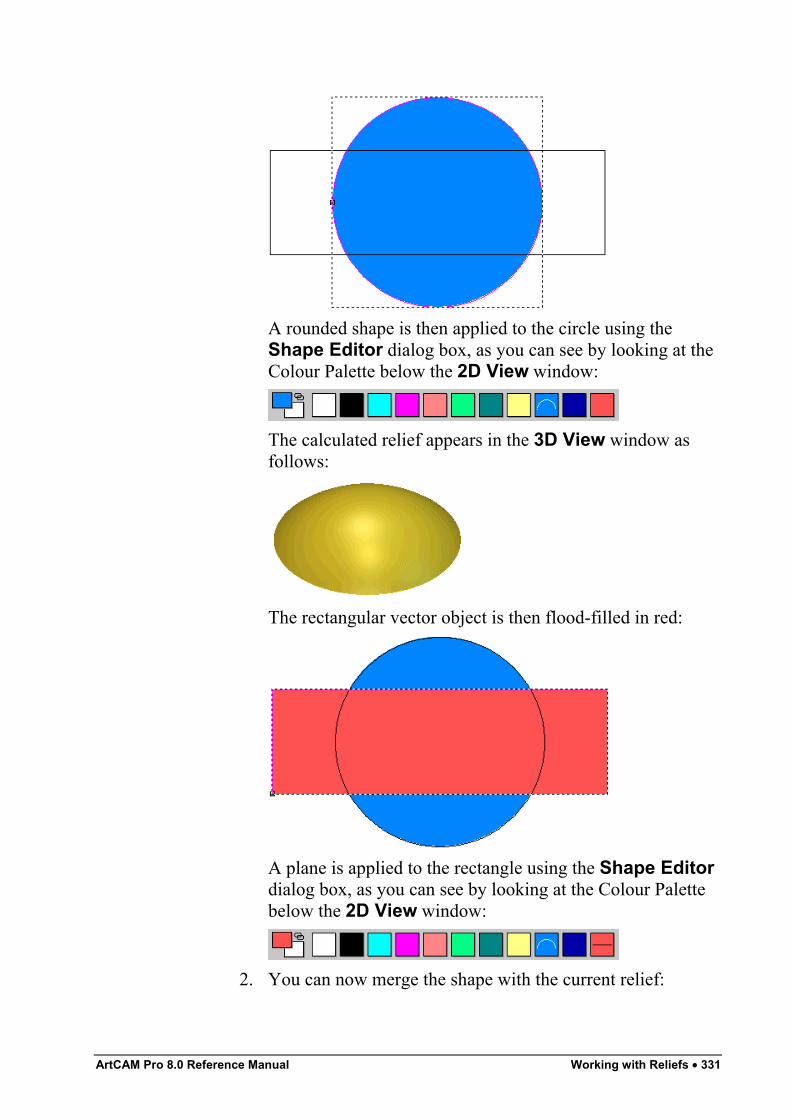
ArtCAM Pro 8.0 Reference Manual Working with Reliefs • 331
A rounded shape is then applied to the circle using theShape Editor dialog box, as you can see by looking at theColour Palette below the 2D View window:
The calculated relief appears in the 3D View window asfollows:
The rectangular vector object is then flood-filled in red:
A plane is applied to the rectangle using the Shape Editordialog box, as you can see by looking at the Colour Palettebelow the 2D View window:
2. You can now merge the shape with the current relief:
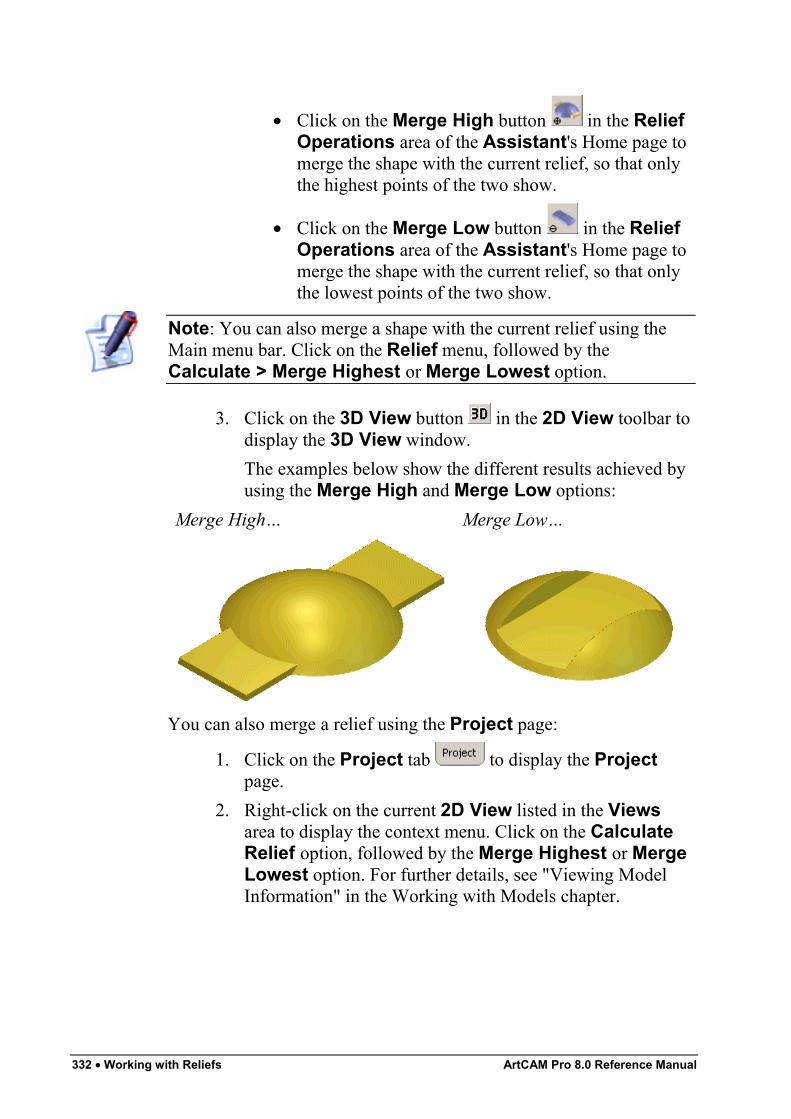
332 • Working with Reliefs ArtCAM Pro 8.0 Reference Manual
• Click on the Merge High button in the ReliefOperations area of the Assistant's Home page tomerge the shape with the current relief, so that onlythe highest points of the two show.
• Click on the Merge Low button in the ReliefOperations area of the Assistant's Home page tomerge the shape with the current relief, so that onlythe lowest points of the two show.
Note: You can also merge a shape with the current relief using theMain menu bar. Click on the Relief menu, followed by theCalculate > Merge Highest or Merge Lowest option.
3. Click on the 3D View button in the 2D View toolbar todisplay the 3D View window.The examples below show the different results achieved byusing the Merge High and Merge Low options:
Merge High… Merge Low…
You can also merge a relief using the Project page:
1. Click on the Project tab to display the Projectpage.
2. Right-click on the current 2D View listed in the Viewsarea to display the context menu. Click on the CalculateRelief option, followed by the Merge Highest or MergeLowest option. For further details, see "Viewing ModelInformation" in the Working with Models chapter.
ArtCAM Pro 8.0 Reference Manual Working with Reliefs • 333
Transforming and Manipulating ReliefsYou can use the buttons in the Relief Operations and ReliefEditing areas of the Assistant's Home page, along with the Reliefmenu options in the Main menu bar, to transform and manipulate therelief that you have created or want to import.You can transform and manipulate a relief in the following ways:
• Using 3D clipart. For details, see "Using 3D Clipart" onpage 333.
• Copying and Pasting a Relief. For details, see "Copying andPasting a Relief" on page 344.
• Pasting a relief along a vector. For details, see "Pasting aRelief along a Vector" on page 349.
• Inverting a relief. For details, see "Inverting a Relief" onpage 351.
• Smoothing a relief. For details, see "Smoothing a Relief" onpage 352.
• Scaling the relief height. For details, see "Scaling the ReliefHeight" on page 354.
• Scaling to volume. For details, see "Scaling to Volume" onpage 356.
• Mirroring a relief. For details, see "Mirroring a Relief" onpage 357.
• Mirror merging a relief. For details, see "Mirror Merging aRelief" on page 358.
• Offsetting a relief. For details, see "Offsetting a Relief" onpage 359.
• Resetting a relief. For details, see "Resetting a Relief" onpage 360.
• Resetting the relief height. For details, see "Resetting theRelief Height" on page 360.
Using 3D ClipartYou can use the 3D Clipart dialog box to resize and transform clipartrelief, and select the way in which it is combined with the currentrelief.
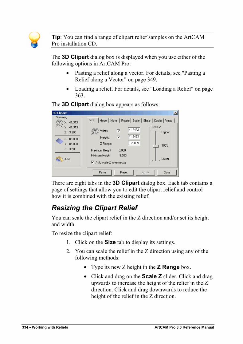
334 • Working with Reliefs ArtCAM Pro 8.0 Reference Manual
Tip: You can find a range of clipart relief samples on the ArtCAMPro installation CD.
The 3D Clipart dialog box is displayed when you use either of thefollowing options in ArtCAM Pro:
• Pasting a relief along a vector. For details, see "Pasting aRelief along a Vector" on page 349.
• Loading a relief. For details, see "Loading a Relief" on page363.
The 3D Clipart dialog box appears as follows:
There are eight tabs in the 3D Clipart dialog box. Each tab contains apage of settings that allow you to edit the clipart relief and controlhow it is combined with the existing relief.
Resizing the Clipart ReliefYou can scale the clipart relief in the Z direction and/or set its heightand width.To resize the clipart relief:
1. Click on the Size tab to display its settings.2. You can scale the relief in the Z direction using any of the
following methods:• Type its new Z height in the Z Range box.• Click and drag on the Scale Z slider. Click and drag
upwards to increase the height of the relief in the Zdirection. Click and drag downwards to reduce theheight of the relief in the Z direction.
ArtCAM Pro 8.0 Reference Manual Working with Reliefs • 335
• Click to select the Auto scale Z when resizeoption . This option scales the relief in the Zdirection whenever its width or height is changed.
3. To set the width and/or height of the clipart relief:• Type its new height and/or width in the Width
and/or Height box. If you want to scale the X and Yaxes differentially, make sure that both the Widthand Height options are selected before you type avalue in each of the boxes.
4. Click on the Apply button to adjust the clipart reliefaccording to your settings.
Combining the ReliefsYou can combine the clipart relief with the current relief in one of fourways: Add, Subtract, Merge Highest or Merge Lowest. You canalso set the position in which the clipart relief is combined with theexisting relief.To combine clipart relief with the current relief:
1. Click on the Mode tab to display its settings.2. Click on the Paste Mode radio button that you want to
use. For details, see "Calculating a Relief" on page 325.3. Define the height at which you want to combine the
imported relief with the current relief in the Start Heightbox.
4. To calculate the height you have defined from the Z zeroposition in the relief, click on the From Zero radio button
. To calculate the height that you have defined from thecurrent position in the relief, click on the From Currentradio button .
5. To paste a vector outline in the shape of the imported reliefin the 2D View window, click to select the Copy outlineoption .
6. Click on the Apply button to adjust the clipart reliefaccording to your settings.
Positioning the Clipart ReliefYou set the position of the clipart relief.To reposition the clipart relief:
336 • Working with Reliefs ArtCAM Pro 8.0 Reference Manual
1. Click on the Move tab to display its settings.2. To move the imported relief in the Y axis direction, you can
either:• Type a value in the Move Y origin by box.• Click and drag on the vertical slider.
3. To move the imported relief in the X axis direction, you caneither:
• Type a value in the Move X origin by box.• Click and drag on the horizontal slider.
4. Click on the Apply button to adjust the clipart reliefaccording to your settings.
Rotating the Clipart ReliefYou can rotate and/or mirror the clipart relief along the X or Y axisaround the centre of the clipart relief or a defined position in theArtCAM model.To rotate and/or mirror the clipart relief:
1. Click on the Rotate tab to display its settings.2. To rotate the clipart relief, you can either:
• To rotate the clipart relief about its centre, define theangle in the Rotate by angle box, or click and dragon the slider to set the angle.
• To rotate the clipart relief about a specific position inthe model, click to deselect the Rotate aboutcentre option , and then define the new origin ofrotation.
If you have deselected the Rotate about centre option,you can define the origin of rotation using either of thefollowing methods:
• Click on the Cursor button, move the cursorover the position that you want to use, and then click.
• Type the X and Y co-ordinates of the point in the Xand Y boxes.
3. You can now mirror the clipart relief along the X or Y axis:• To mirror the clipart relief along the X-axis, click on
the Horizontal button.
ArtCAM Pro 8.0 Reference Manual Working with Reliefs • 337
• To mirror the imported relief along the Y-axis, clickon the Vertical button.
4. Click on the Apply button to adjust the clipart reliefaccording to your settings.
Scaling the Clipart ReliefYou can scale the clipart relief to a percentage of its original size.To scale the clipart relief:
1. Click on the Scale tab to display its settings.2. To scale the clipart relief, you can either:
• Type a percentage of the clipart relief's current sizein the New scale % box.
• Click and drag on the slider. Click and drag to theright to increase the size of the clipart relief. Clickand drag to the left to reduce it.
3. Click on the Apply button to adjust the clipart reliefaccording to your settings.
Tip: If scaling to 1% or 200% does not produce big enough or smallenough results, click on the Apply button. This scales the relief to thenew size and resets the New Scale % to 100. You can now repeatthe scaling process to further increase or reduce its size.
Shearing the Clipart ReliefShearing can be visualised by thinking of an image superimposed ontoa flexible rubber sheet. If you hold the sides of the sheet and movethem up and down in opposite directions, the image undergoes aspatial stretching known as shearing. You can shear the clipart reliefboth horizontally and vertically.To shear the clipart relief:
1. Click on the Shear tab to display its settings.2. To shear the clipart relief horizontally, you can either:
• Type a value in the Shear in X axis box.• Click and drag on the horizontal slider.
3. To shear the clipart relief vertically, you can either:• Type a value in the Shear in Y axis box.
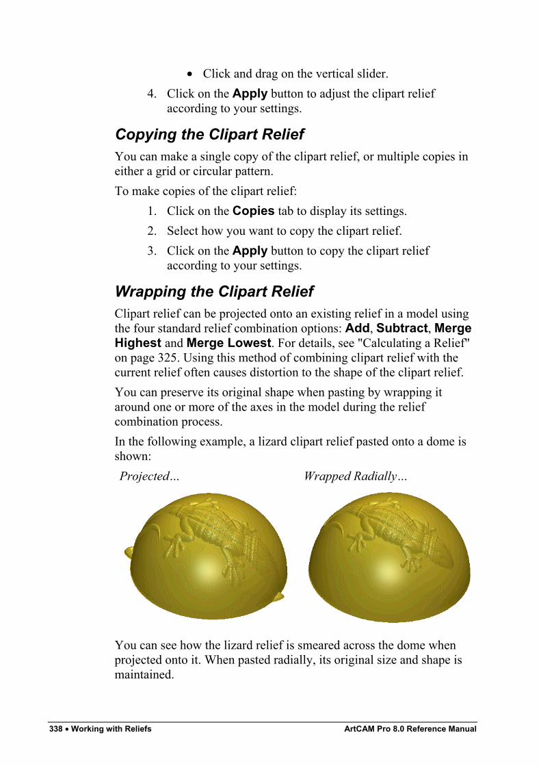
338 • Working with Reliefs ArtCAM Pro 8.0 Reference Manual
• Click and drag on the vertical slider.4. Click on the Apply button to adjust the clipart relief
according to your settings.
Copying the Clipart ReliefYou can make a single copy of the clipart relief, or multiple copies ineither a grid or circular pattern.To make copies of the clipart relief:
1. Click on the Copies tab to display its settings.2. Select how you want to copy the clipart relief.3. Click on the Apply button to copy the clipart relief
according to your settings.
Wrapping the Clipart ReliefClipart relief can be projected onto an existing relief in a model usingthe four standard relief combination options: Add, Subtract, MergeHighest and Merge Lowest. For details, see "Calculating a Relief"on page 325. Using this method of combining clipart relief with thecurrent relief often causes distortion to the shape of the clipart relief.You can preserve its original shape when pasting by wrapping itaround one or more of the axes in the model during the reliefcombination process.In the following example, a lizard clipart relief pasted onto a dome isshown:Projected… Wrapped Radially…
You can see how the lizard relief is smeared across the dome whenprojected onto it. When pasted radially, its original size and shape ismaintained.
ArtCAM Pro 8.0 Reference Manual Working with Reliefs • 339
To wrap the clipart relief:1. Click on the Wrap tab to display its options.2. In the Wrap Type area, click to select the wrapping option
that you want to use:• Project – This option allows you to paste the clipart
relief onto the relief surface.
Warning: Using the Project method of wrapping clipart relief ontoan existing relief can cause distortion to its original shape.
• Radial – This option allows you to wrap the clipartrelief around a spherical shape that is curved in boththe X and Y-axes.
• Wrap in X – This option allows you to wrap theclipart relief around a cylindrical shape that is curvedaround the X-axis.
• Wrap in Y – This option allows you to wrap theclipart relief around a cylindrical shape that is curvedaround the Y-axis.
3. In the Wrap Origin area, define the origin around whichthe relief will be wrapped. You can use any of the followingmethods:
Note: If the Project option is selected in the Wrap Type area, theWrap Origin area is greyed-out.
• Click on any of radio buttons on the rectanglediagram. The X and Y co-ordinates of the chosenorigin appear in the X and Y boxes.
• Type the X and Y co-ordinates of the origin in the Xand Y boxes.
• Click on the Use Mouse option , followed by theStart button. Move the cursor to the position in the2D View window that you want to use as the origin,and then click to select. The X and Y co-ordinates ofthe origin appear in the X and Y boxes.
4. Click on the Apply button to wrap the clipart relief aroundthe existing relief. The vector outline in the 2D Viewwindow representing the clipart relief is corrected tocompensate for the distortion.
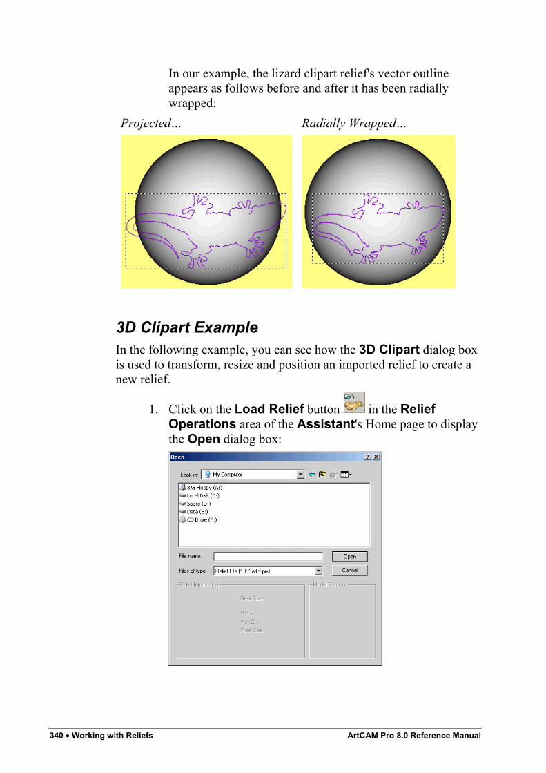
340 • Working with Reliefs ArtCAM Pro 8.0 Reference Manual
In our example, the lizard clipart relief's vector outlineappears as follows before and after it has been radiallywrapped:
Projected… Radially Wrapped…
3D Clipart ExampleIn the following example, you can see how the 3D Clipart dialog boxis used to transform, resize and position an imported relief to create anew relief.
1. Click on the Load Relief button in the ReliefOperations area of the Assistant's Home page to displaythe Open dialog box:
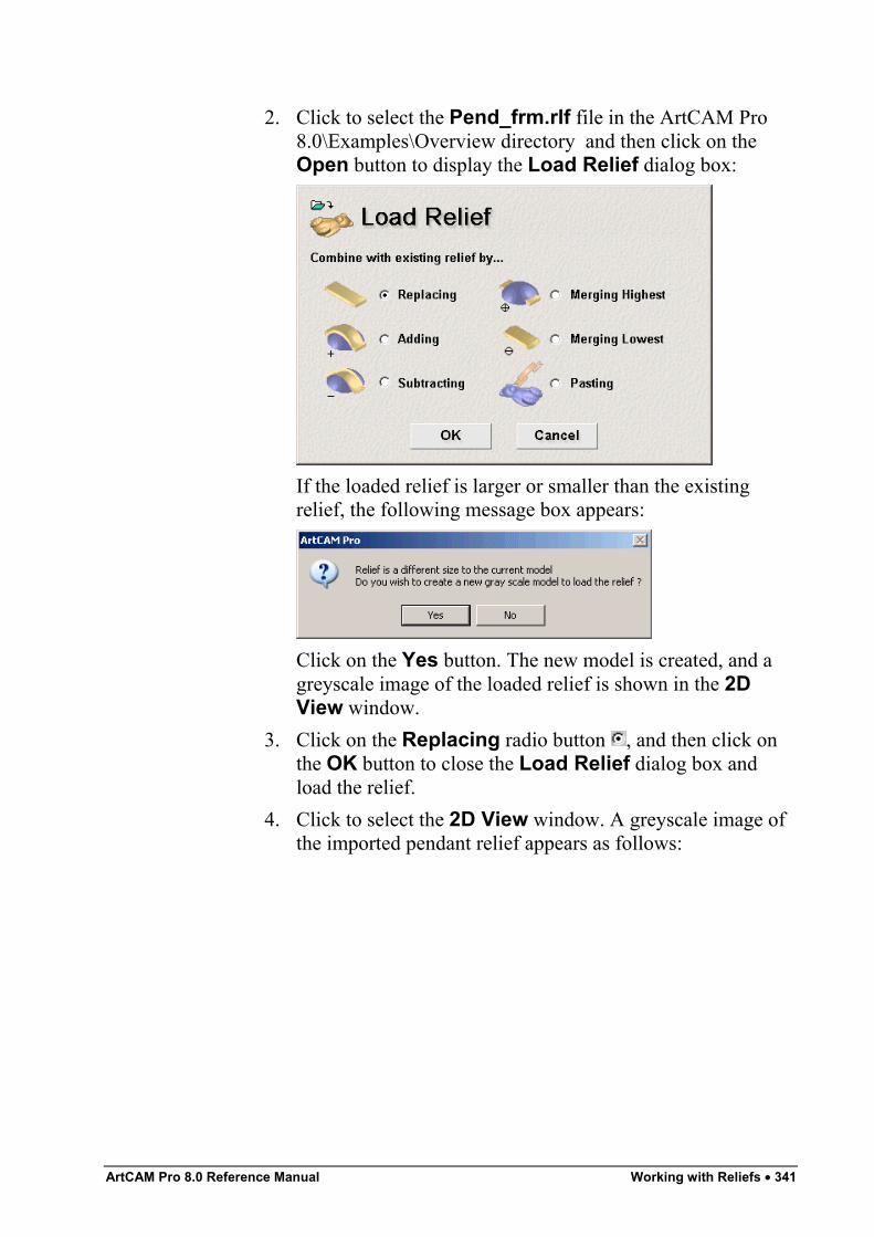
ArtCAM Pro 8.0 Reference Manual Working with Reliefs • 341
2. Click to select the Pend_frm.rlf file in the ArtCAM Pro8.0\Examples\Overview directory and then click on theOpen button to display the Load Relief dialog box:
If the loaded relief is larger or smaller than the existingrelief, the following message box appears:
Click on the Yes button. The new model is created, and agreyscale image of the loaded relief is shown in the 2DView window.
3. Click on the Replacing radio button , and then click onthe OK button to close the Load Relief dialog box andload the relief.
4. Click to select the 2D View window. A greyscale image ofthe imported pendant relief appears as follows:
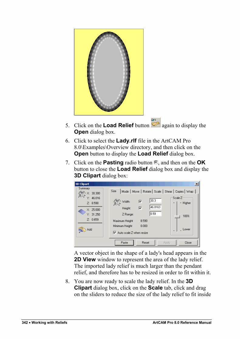
342 • Working with Reliefs ArtCAM Pro 8.0 Reference Manual
5. Click on the Load Relief button again to display theOpen dialog box.
6. Click to select the Lady.rlf file in the ArtCAM Pro8.0\Examples\Overview directory, and then click on theOpen button to display the Load Relief dialog box.
7. Click on the Pasting radio button , and then on the OKbutton to close the Load Relief dialog box and display the3D Clipart dialog box:
A vector object in the shape of a lady's head appears in the2D View window to represent the area of the lady relief.The imported lady relief is much larger than the pendantrelief, and therefore has to be resized in order to fit within it.
8. You are now ready to scale the lady relief. In the 3DClipart dialog box, click on the Scale tab, click and dragon the sliders to reduce the size of the lady relief to fit inside
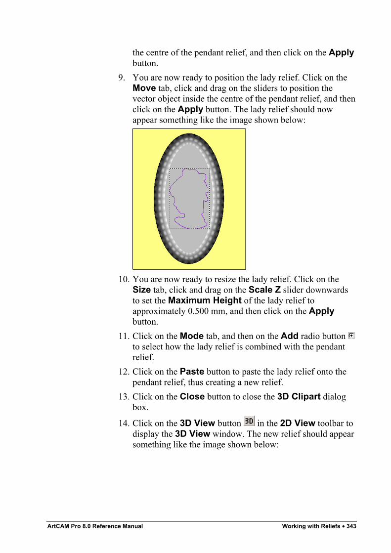
ArtCAM Pro 8.0 Reference Manual Working with Reliefs • 343
the centre of the pendant relief, and then click on the Applybutton.
9. You are now ready to position the lady relief. Click on theMove tab, click and drag on the sliders to position thevector object inside the centre of the pendant relief, and thenclick on the Apply button. The lady relief should nowappear something like the image shown below:
10. You are now ready to resize the lady relief. Click on theSize tab, click and drag on the Scale Z slider downwardsto set the Maximum Height of the lady relief toapproximately 0.500 mm, and then click on the Applybutton.
11. Click on the Mode tab, and then on the Add radio button to select how the lady relief is combined with the pendantrelief.
12. Click on the Paste button to paste the lady relief onto thependant relief, thus creating a new relief.
13. Click on the Close button to close the 3D Clipart dialogbox.
14. Click on the 3D View button in the 2D View toolbar todisplay the 3D View window. The new relief should appearsomething like the image shown below:
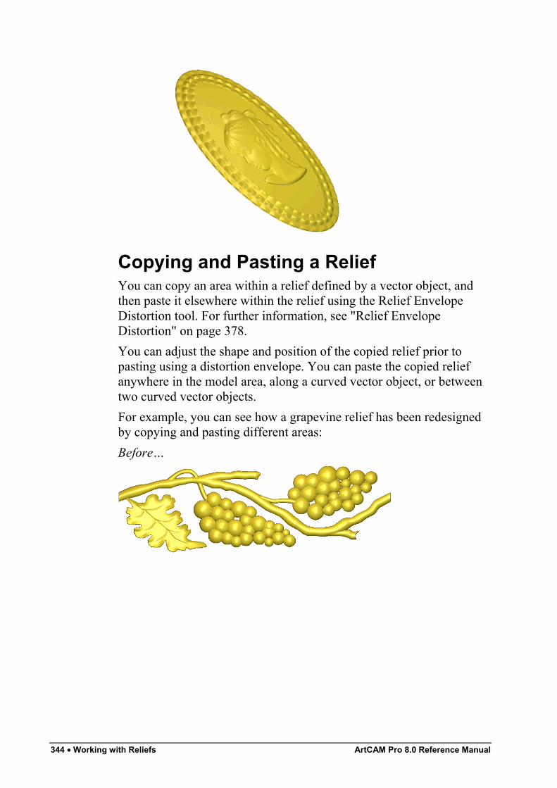
344 • Working with Reliefs ArtCAM Pro 8.0 Reference Manual
Copying and Pasting a ReliefYou can copy an area within a relief defined by a vector object, andthen paste it elsewhere within the relief using the Relief EnvelopeDistortion tool. For further information, see "Relief EnvelopeDistortion" on page 378.You can adjust the shape and position of the copied relief prior topasting using a distortion envelope. You can paste the copied reliefanywhere in the model area, along a curved vector object, or betweentwo curved vector objects.For example, you can see how a grapevine relief has been redesignedby copying and pasting different areas:Before…
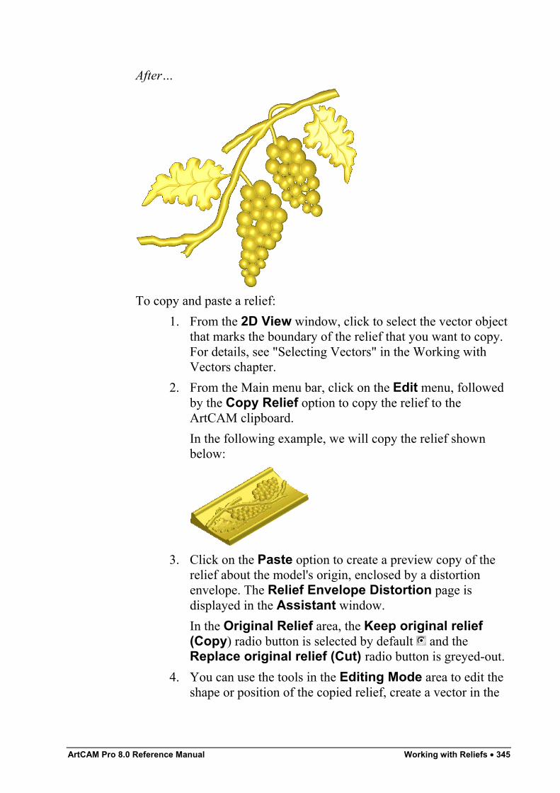
ArtCAM Pro 8.0 Reference Manual Working with Reliefs • 345
After…
To copy and paste a relief:1. From the 2D View window, click to select the vector object
that marks the boundary of the relief that you want to copy.For details, see "Selecting Vectors" in the Working withVectors chapter.
2. From the Main menu bar, click on the Edit menu, followedby the Copy Relief option to copy the relief to theArtCAM clipboard.In the following example, we will copy the relief shownbelow:
3. Click on the Paste option to create a preview copy of therelief about the model's origin, enclosed by a distortionenvelope. The Relief Envelope Distortion page isdisplayed in the Assistant window.In the Original Relief area, the Keep original relief(Copy) radio button is selected by default and theReplace original relief (Cut) radio button is greyed-out.
4. You can use the tools in the Editing Mode area to edit theshape or position of the copied relief, create a vector in the
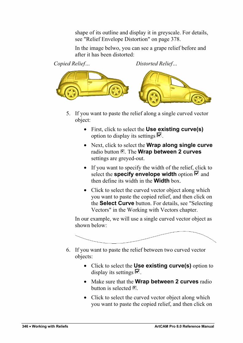
346 • Working with Reliefs ArtCAM Pro 8.0 Reference Manual
shape of its outline and display it in greyscale. For details,see "Relief Envelope Distortion" on page 378.In the image belwo, you can see a grape relief before andafter it has been distorted:
Copied Relief… Distorted Relief…
5. If you want to paste the relief along a single curved vectorobject:
• First, click to select the Use existing curve(s)option to display its settings .
• Next, click to select the Wrap along single curveradio button . The Wrap between 2 curvessettings are greyed-out.
• If you want to specify the width of the relief, click toselect the specify envelope width option andthen define its width in the Width box.
• Click to select the curved vector object along whichyou want to paste the copied relief, and then click onthe Select Curve button. For details, see "SelectingVectors" in the Working with Vectors chapter.
In our example, we will use a single curved vector object asshown below:
6. If you want to paste the relief between two curved vectorobjects:
• Click to select the Use existing curve(s) option todisplay its settings .
• Make sure that the Wrap between 2 curves radiobutton is selected .
• Click to select the curved vector object along whichyou want to paste the copied relief, and then click on
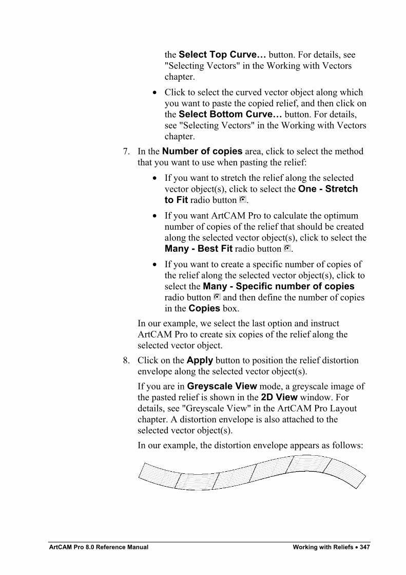
ArtCAM Pro 8.0 Reference Manual Working with Reliefs • 347
the Select Top Curve… button. For details, see"Selecting Vectors" in the Working with Vectorschapter.
• Click to select the curved vector object along whichyou want to paste the copied relief, and then click onthe Select Bottom Curve… button. For details,see "Selecting Vectors" in the Working with Vectorschapter.
7. In the Number of copies area, click to select the methodthat you want to use when pasting the relief:
• If you want to stretch the relief along the selectedvector object(s), click to select the One - Stretchto Fit radio button .
• If you want ArtCAM Pro to calculate the optimumnumber of copies of the relief that should be createdalong the selected vector object(s), click to select theMany - Best Fit radio button .
• If you want to create a specific number of copies ofthe relief along the selected vector object(s), click toselect the Many - Specific number of copiesradio button and then define the number of copiesin the Copies box.
In our example, we select the last option and instructArtCAM Pro to create six copies of the relief along theselected vector object.
8. Click on the Apply button to position the relief distortionenvelope along the selected vector object(s).If you are in Greyscale View mode, a greyscale image ofthe pasted relief is shown in the 2D View window. Fordetails, see "Greyscale View" in the ArtCAM Pro Layoutchapter. A distortion envelope is also attached to theselected vector object(s).In our example, the distortion envelope appears as follows:
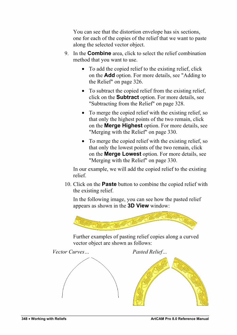
348 • Working with Reliefs ArtCAM Pro 8.0 Reference Manual
You can see that the distortion envelope has six sections,one for each of the copies of the relief that we want to pastealong the selected vector object.
9. In the Combine area, click to select the relief combinationmethod that you want to use.
• To add the copied relief to the existing relief, clickon the Add option. For more details, see "Adding tothe Relief" on page 326.
• To subtract the copied relief from the existing relief,click on the Subtract option. For more details, see"Subtracting from the Relief" on page 328.
• To merge the copied relief with the existing relief, sothat only the highest points of the two remain, clickon the Merge Highest option. For more details, see"Merging with the Relief" on page 330.
• To merge the copied relief with the existing relief, sothat only the lowest points of the two remain, clickon the Merge Lowest option. For more details, see"Merging with the Relief" on page 330.
In our example, we will add the copied relief to the existingrelief.
10. Click on the Paste button to combine the copied relief withthe existing relief.In the following image, you can see how the pasted reliefappears as shown in the 3D View window:
Further examples of pasting relief copies along a curvedvector object are shown as follows:
Vector Curves… Pasted Relief…
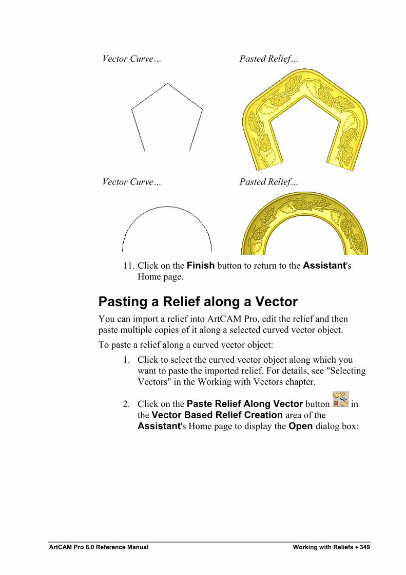
ArtCAM Pro 8.0 Reference Manual Working with Reliefs • 349
Vector Curve… Pasted Relief…
Vector Curve… Pasted Relief…
11. Click on the Finish button to return to the Assistant'sHome page.
Pasting a Relief along a VectorYou can import a relief into ArtCAM Pro, edit the relief and thenpaste multiple copies of it along a selected curved vector object.To paste a relief along a curved vector object:
1. Click to select the curved vector object along which youwant to paste the imported relief. For details, see "SelectingVectors" in the Working with Vectors chapter.
2. Click on the Paste Relief Along Vector button inthe Vector Based Relief Creation area of theAssistant's Home page to display the Open dialog box:
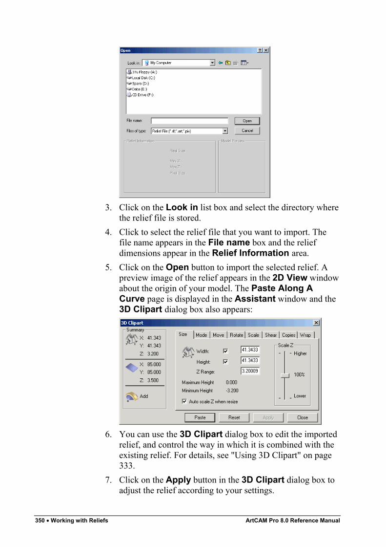
350 • Working with Reliefs ArtCAM Pro 8.0 Reference Manual
3. Click on the Look in list box and select the directory wherethe relief file is stored.
4. Click to select the relief file that you want to import. Thefile name appears in the File name box and the reliefdimensions appear in the Relief Information area.
5. Click on the Open button to import the selected relief. Apreview image of the relief appears in the 2D View windowabout the origin of your model. The Paste Along ACurve page is displayed in the Assistant window and the3D Clipart dialog box also appears:
6. You can use the 3D Clipart dialog box to edit the importedrelief, and control the way in which it is combined with theexisting relief. For details, see "Using 3D Clipart" on page333.
7. Click on the Apply button in the 3D Clipart dialog box toadjust the relief according to your settings.
ArtCAM Pro 8.0 Reference Manual Working with Reliefs • 351
8. You can now use the Settings area of the Paste Along ACurve page to adjust the size of each consecutive copy thatis pasted along the selected vector object, and the spacingbetween them:
• To set the spacing between each copy as apercentage of the relief width, type a value in theSpacing (S) box.
• To set the size of the first pasted copy as apercentage of the relief width, type a value in theStart size (B) box.
• To set the size of the last pasted copy as a percentageof the relief width, type a value in the Final size (E)box.
Note: If you type a value in the Start size (B) and Final size (E)boxes, each consecutive copy of the relief pasted along the selectedvector object is scaled proportionately.
• If you want the copies of the relief to be pastedevenly along the selected vector object(s), make surethat the Adjust to fit exactly option is selected .
9. Click on the Paste button on the Paste Along A Curvepage to paste the relief along the selected vector object.
Warning: Do not click on the Paste button in the 3D Clipart dialogbox if you want to paste the relief along the selected vector object(s).
Note: To undo this action, press the Ctrl + Z keys on your keyboard.
10. If you do not want to change the way that the copies of therelief have been pasted along the selected vector object,click on the Close button in the 3D Clipart dialog box.
11. Click on the Close button on the Paste Along A Curvepage to return to the Assistant's Home page.
Inverting a ReliefYou can invert the existing relief in two ways:
• In the Z-axis only, without any mirroring.
352 • Working with Reliefs ArtCAM Pro 8.0 Reference Manual
• In the Z-axis, and mirror left to right.Either or these options allow you turn a concave shape into a convexshape, and vice versa.To invert a relief in the Z axis only:
1. Click on the Invert Relief Z Only button in theRelief Editing area of the Assistant's Home page. Therelief is inverted in the Z-axis only.
2. Click on the 3D View button in the 2D View toolbar todisplay the 3D View window. You can view the invertedrelief.
To invert a relief in the Z-axis and mirror left to right:
1. Click on the Invert Relief – Male/Female button inthe Relief Editing area of the Assistant's Home page.The relief is inverted in the Z-axis, and it is also mirroredleft to right.
Note: You can also invert the relief in the Z-axis and mirror left toright from the Main menu bar. Click on the Relief menu, and then onthe Invert > Male/Female option.
The inverted relief is mirrored to allow you to producematching top and bottom halves when machining a model orcreate a mould from a male model.
Note: All engraved features on the relief remain as defined. They areadded to or subtracted from the relief.
2. Click on the 3D View button in the 2D View toolbar todisplay the 3D View window. You can view the invertedrelief.
Smoothing a ReliefYou can remove surface irregularities that might appear on a reliefafter it has been calculated. You can smooth the whole surface, or aspecific area of the relief.To smooth the whole relief:
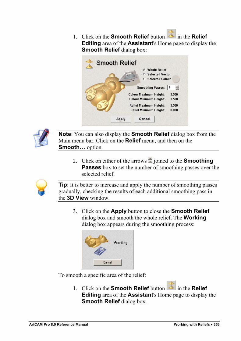
ArtCAM Pro 8.0 Reference Manual Working with Reliefs • 353
1. Click on the Smooth Relief button in the ReliefEditing area of the Assistant's Home page to display theSmooth Relief dialog box:
Note: You can also display the Smooth Relief dialog box from theMain menu bar. Click on the Relief menu, and then on theSmooth… option.
2. Click on either of the arrows joined to the SmoothingPasses box to set the number of smoothing passes over theselected relief.
Tip: It is better to increase and apply the number of smoothing passesgradually, checking the results of each additional smoothing pass inthe 3D View window.
3. Click on the Apply button to close the Smooth Reliefdialog box and smooth the whole relief. The Workingdialog box appears during the smoothing process:
To smooth a specific area of the relief:
1. Click on the Smooth Relief button in the ReliefEditing area of the Assistant's Home page to display theSmooth Relief dialog box.
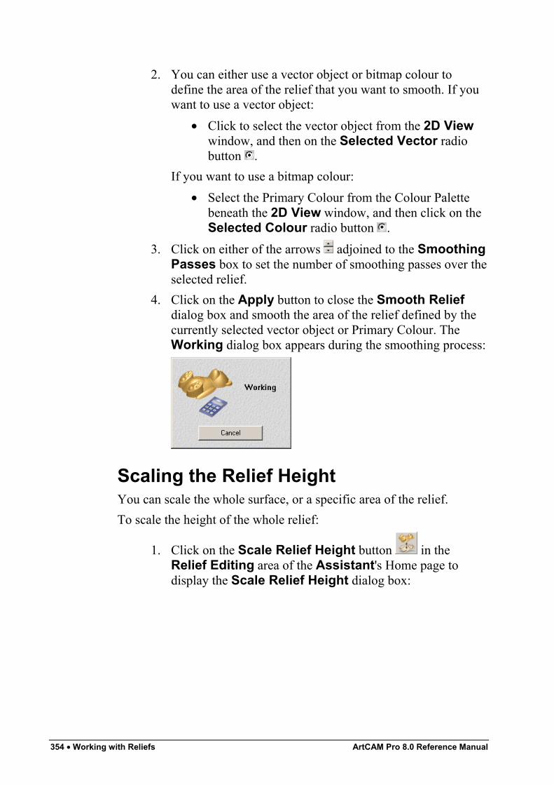
354 • Working with Reliefs ArtCAM Pro 8.0 Reference Manual
2. You can either use a vector object or bitmap colour todefine the area of the relief that you want to smooth. If youwant to use a vector object:
• Click to select the vector object from the 2D Viewwindow, and then on the Selected Vector radiobutton .
If you want to use a bitmap colour:• Select the Primary Colour from the Colour Palette
beneath the 2D View window, and then click on theSelected Colour radio button .
3. Click on either of the arrows adjoined to the SmoothingPasses box to set the number of smoothing passes over theselected relief.
4. Click on the Apply button to close the Smooth Reliefdialog box and smooth the area of the relief defined by thecurrently selected vector object or Primary Colour. TheWorking dialog box appears during the smoothing process:
Scaling the Relief HeightYou can scale the whole surface, or a specific area of the relief.To scale the height of the whole relief:
1. Click on the Scale Relief Height button in theRelief Editing area of the Assistant's Home page todisplay the Scale Relief Height dialog box:
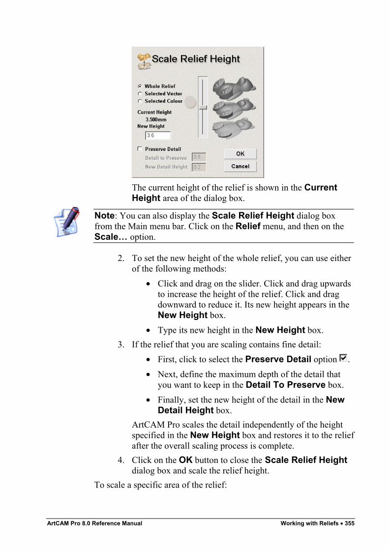
ArtCAM Pro 8.0 Reference Manual Working with Reliefs • 355
The current height of the relief is shown in the CurrentHeight area of the dialog box.
Note: You can also display the Scale Relief Height dialog boxfrom the Main menu bar. Click on the Relief menu, and then on theScale… option.
2. To set the new height of the whole relief, you can use eitherof the following methods:
• Click and drag on the slider. Click and drag upwardsto increase the height of the relief. Click and dragdownward to reduce it. Its new height appears in theNew Height box.
• Type its new height in the New Height box.3. If the relief that you are scaling contains fine detail:
• First, click to select the Preserve Detail option .• Next, define the maximum depth of the detail that
you want to keep in the Detail To Preserve box.• Finally, set the new height of the detail in the New
Detail Height box.ArtCAM Pro scales the detail independently of the heightspecified in the New Height box and restores it to the reliefafter the overall scaling process is complete.
4. Click on the OK button to close the Scale Relief Heightdialog box and scale the relief height.
To scale a specific area of the relief:
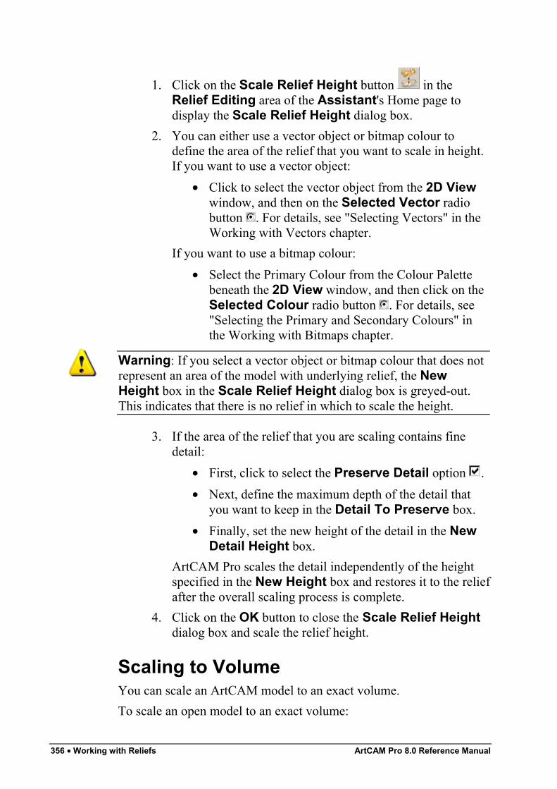
356 • Working with Reliefs ArtCAM Pro 8.0 Reference Manual
1. Click on the Scale Relief Height button in theRelief Editing area of the Assistant's Home page todisplay the Scale Relief Height dialog box.
2. You can either use a vector object or bitmap colour todefine the area of the relief that you want to scale in height.If you want to use a vector object:
• Click to select the vector object from the 2D Viewwindow, and then on the Selected Vector radiobutton . For details, see "Selecting Vectors" in theWorking with Vectors chapter.
If you want to use a bitmap colour:• Select the Primary Colour from the Colour Palette
beneath the 2D View window, and then click on theSelected Colour radio button . For details, see"Selecting the Primary and Secondary Colours" inthe Working with Bitmaps chapter.
Warning: If you select a vector object or bitmap colour that does notrepresent an area of the model with underlying relief, the NewHeight box in the Scale Relief Height dialog box is greyed-out.This indicates that there is no relief in which to scale the height.
3. If the area of the relief that you are scaling contains finedetail:
• First, click to select the Preserve Detail option .• Next, define the maximum depth of the detail that
you want to keep in the Detail To Preserve box.• Finally, set the new height of the detail in the New
Detail Height box.ArtCAM Pro scales the detail independently of the heightspecified in the New Height box and restores it to the reliefafter the overall scaling process is complete.
4. Click on the OK button to close the Scale Relief Heightdialog box and scale the relief height.
Scaling to VolumeYou can scale an ArtCAM model to an exact volume.To scale an open model to an exact volume:
ArtCAM Pro 8.0 Reference Manual Working with Reliefs • 357
1. From the Main menu bar, click on the Relief menu and thenon the Volume option to display the Scale To Volumepage in the Assistant window.The current size of your model is shown in the Model Sizearea. Its height in the Z direction is shown in the Model ZHeight area. Its volume is shown in the Current Volumearea, according to the units of measurement you are using.
2. Click on the Volume Units list box, followed by the unitsof measurement that you want to use.If you are using millimetres, you can select either of thefollowing options:
• Cubic mm – Click on this option to define thevolume in cubic millimetres.
• Cubic cm – Click on this option to define thevolume in cubic centimetres.
If you are using inches, you can select either of thefollowing options:
• Cubic Inches – Click on this option to define thevolume in cubic inches.
• Cubic Feet – Click on this option to define thevolume in cubic feet.
3. Define the new volume for the model in the Enter NewVolume box.
4. If you want to scale the model in the Z direction only, clickto select the Scale in Z Only option .
5. Click on the Apply button to scale the model.6. Click on the Finish button to return to the Assistant's
Home page.
Mirroring a ReliefYou can reverse the direction of a relief from its original position bothhorizontally and vertically.To mirror the relief horizontally:
• From the Main menu bar, click on the Relief menu, andthen on the Mirror > Mirror Horizontal option.
To mirror the relief vertically:
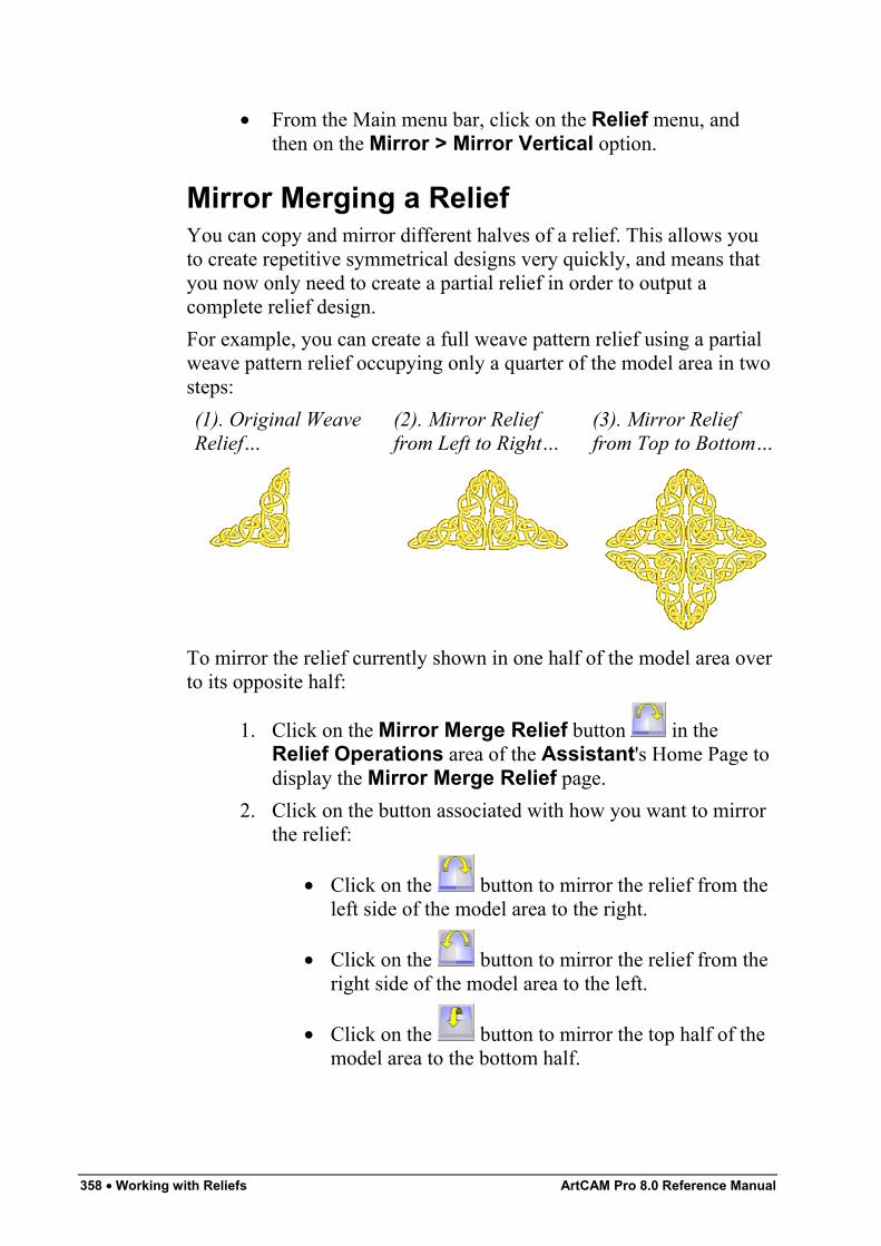
358 • Working with Reliefs ArtCAM Pro 8.0 Reference Manual
• From the Main menu bar, click on the Relief menu, andthen on the Mirror > Mirror Vertical option.
Mirror Merging a ReliefYou can copy and mirror different halves of a relief. This allows youto create repetitive symmetrical designs very quickly, and means thatyou now only need to create a partial relief in order to output acomplete relief design.For example, you can create a full weave pattern relief using a partialweave pattern relief occupying only a quarter of the model area in twosteps:(1). Original WeaveRelief…
(2). Mirror Relieffrom Left to Right…
(3). Mirror Relieffrom Top to Bottom…
To mirror the relief currently shown in one half of the model area overto its opposite half:
1. Click on the Mirror Merge Relief button in theRelief Operations area of the Assistant's Home Page todisplay the Mirror Merge Relief page.
2. Click on the button associated with how you want to mirrorthe relief:
• Click on the button to mirror the relief from theleft side of the model area to the right.
• Click on the button to mirror the relief from theright side of the model area to the left.
• Click on the button to mirror the top half of themodel area to the bottom half.
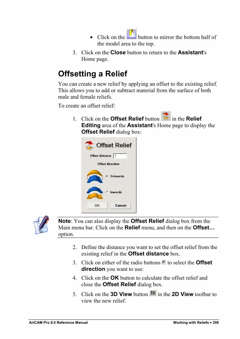
ArtCAM Pro 8.0 Reference Manual Working with Reliefs • 359
• Click on the button to mirror the bottom half ofthe model area to the top.
3. Click on the Close button to return to the Assistant'sHome page.
Offsetting a ReliefYou can create a new relief by applying an offset to the existing relief.This allows you to add or subtract material from the surface of bothmale and female reliefs.To create an offset relief:
1. Click on the Offset Relief button in the ReliefEditing area of the Assistant's Home page to display theOffset Relief dialog box:
Note: You can also display the Offset Relief dialog box from theMain menu bar. Click on the Relief menu, and then on the Offset…option.
2. Define the distance you want to set the offset relief from theexisting relief in the Offset distance box.
3. Click on either of the radio buttons to select the Offsetdirection you want to use:
4. Click on the OK button to calculate the offset relief andclose the Offset Relief dialog box.
5. Click on the 3D View button in the 2D View toolbar toview the new relief.
360 • Working with Reliefs ArtCAM Pro 8.0 Reference Manual
Resetting a ReliefYou can reset the whole relief to zero, effectively removing it.To reset the relief to zero:
1. Click on the Reset Relief button in the ReliefOperations area of the Assistant's Home page.
2. Click on the 3D View button in the 2D View toolbar todisplay the 3D View window. You can now see that therelief has been reset to zero.
3. Click on the 2D View button in the 3D View toolbar toreturn to the 2D View window.
Resetting the Relief HeightYou can reset the height of the relief under the current Primary Colourto zero, and vice versa.To reset the height of the relief to zero in all areas under the currentPrimary Colour:
1. Select the Primary Colour from the Colour Palette beneaththe 2D View window. For details, see "Selecting thePrimary and Secondary Colours" in the Working withBitmaps chapter. The Primary Colour represents the areas ofthe relief that you want to reset to zero.
2. Click on the Zero Relief Under Colour button in theRelief Editing area of the Assistant's Home page.
3. Click on the 3D View button in the 2D View toolbar todisplay the 3D View window. You can now see that allareas of the relief under the current Primary Colour havebeen reset to zero.
To reset the height of the whole relief to zero, except in those areasunder the current Primary Colour:
1. Select the Primary Colour from the Colour Palette beneaththe 2D View window. The Primary Colour represents theareas of the relief that you do not want to reset to zero.
2. Click on the Keep Under Colour button in theRelief Editing area of the Assistant's Home page.
ArtCAM Pro 8.0 Reference Manual Working with Reliefs • 361
Note: You can also reset the height of the whole relief to zero, exceptin those areas under the current Primary Colour, from the Main menubar. Click on the Relief menu, and then on the Keep Under Colouroption.
3. Click on the 3D View button in the 2D View toolbar todisplay the 3D View window. You can now see that allareas of the relief not under the current Primary Colour havebeen reset to zero.
Managing and Editing ReliefsYou can use the buttons in the Relief Operations and ReliefEditing areas of the Assistant's Home page, along with the Reliefmenu options in the Main menu bar, to manage and edit a relief thatyou have created.You can manage and edit a relief in the following ways:
• Saving a relief. For details, see "Saving a Relief" on page362.
• Loading a relief. For details, see "Loading a Relief" on page363.
• Calculating the surface area. For details, see "Calculatingthe Surface Area" on page 366.
• Displaying the calculation time. For details, see "Displayingthe Calculation Time" on page 367.
• Adding a draft angle. For details, see "Adding a DraftAngle" on page 368.
• Creating a triangle mesh. For details, see "Creating aTriangle Mesh" on page 368.
• Creating a cross-section. For details, see "Creating a Cross-Section" on page 370.
• Creating an angled plane. For details, see "Creating anAngled Plane" on page 371.
• Blending 3D shapes. For details, see "Blending 3D Shapes"on page 374.
• Relief Envelope Distortion. For details, see "ReliefEnvelope Distortion" on page 378.
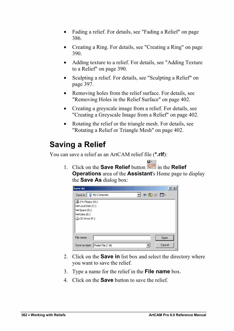
362 • Working with Reliefs ArtCAM Pro 8.0 Reference Manual
• Fading a relief. For details, see "Fading a Relief" on page386.
• Creating a Ring. For details, see "Creating a Ring" on page390.
• Adding texture to a relief. For details, see "Adding Textureto a Relief" on page 390.
• Sculpting a relief. For details, see "Sculpting a Relief" onpage 397.
• Removing holes from the relief surface. For details, see"Removing Holes in the Relief Surface" on page 402.
• Creating a greyscale image from a relief. For details, see"Creating a Greyscale Image from a Relief" on page 402.
• Rotating the relief or the triangle mesh. For details, see"Rotating a Relief or Triangle Mesh" on page 402.
Saving a ReliefYou can save a relief as an ArtCAM relief file (*.rlf):
1. Click on the Save Relief button in the ReliefOperations area of the Assistant's Home page to displaythe Save As dialog box:
2. Click on the Save in list box and select the directory whereyou want to save the relief.
3. Type a name for the relief in the File name box.4. Click on the Save button to save the relief.
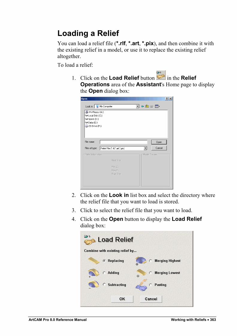
ArtCAM Pro 8.0 Reference Manual Working with Reliefs • 363
Loading a ReliefYou can load a relief file (*.rlf, *.art, *.pix), and then combine it withthe existing relief in a model, or use it to replace the existing reliefaltogether.To load a relief:
1. Click on the Load Relief button in the ReliefOperations area of the Assistant's Home page to displaythe Open dialog box:
2. Click on the Look in list box and select the directory wherethe relief file that you want to load is stored.
3. Click to select the relief file that you want to load.4. Click on the Open button to display the Load Relief
dialog box:
364 • Working with Reliefs ArtCAM Pro 8.0 Reference Manual
5. Select how you want to use the loaded relief by clicking onone of the Combine with existing relief by… radiobuttons :
Warning: If the pixel size of the relief that you want to load does notequal the pixel size of the existing relief, only the Replacing andPasting options are available in the Load Relief dialog box.
• To replace the existing relief with the relief you havechosen to load, click on the Replacing radio button
. For more details, see "Replacing the Relief" onpage 326.
• To add the relief you have chosen to load to theexisting relief, click on the Adding radio button .For more details, see "Adding to the Relief" on page326.
• To subtract the relief you have chosen to load fromthe existing relief, click on the Subtracting radiobutton . For more details, see "Subtracting from theRelief" on page 328.
• To merge the relief you want to load with theexisting relief, so that only the highest points of thetwo remain, click on the Merging Highest radiobutton . For more details, see "Merging with theRelief" on page 330.
• To merge the relief you want to load with theexisting relief, so that only the lowest points of thetwo remain, click on the Merging Lowest radiobutton . For more details, see "Merging with theRelief" on page 330.
• To paste the relief you have chosen to load onto theexisting relief, click on the Pasting radio button .For details, see "Using 3D Clipart" on page 333.
6. Click on the OK button to combine the loaded relief withthe existing relief according to the method selected in theprevious step. The new relief is shown in the 3D Viewwindow.If you have chosen the Replace option and the loadedrelief is larger or smaller than the existing relief, thefollowing message box appears:
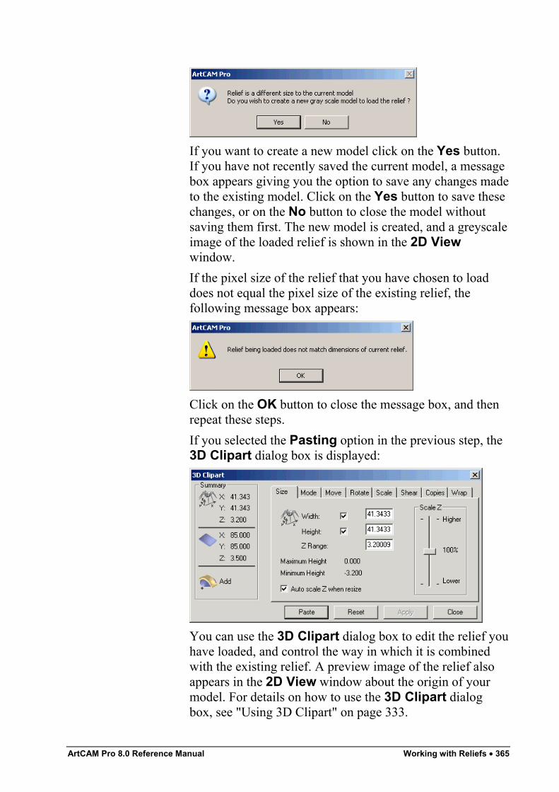
ArtCAM Pro 8.0 Reference Manual Working with Reliefs • 365
If you want to create a new model click on the Yes button.If you have not recently saved the current model, a messagebox appears giving you the option to save any changes madeto the existing model. Click on the Yes button to save thesechanges, or on the No button to close the model withoutsaving them first. The new model is created, and a greyscaleimage of the loaded relief is shown in the 2D Viewwindow.If the pixel size of the relief that you have chosen to loaddoes not equal the pixel size of the existing relief, thefollowing message box appears:
Click on the OK button to close the message box, and thenrepeat these steps.If you selected the Pasting option in the previous step, the3D Clipart dialog box is displayed:
You can use the 3D Clipart dialog box to edit the relief youhave loaded, and control the way in which it is combinedwith the existing relief. A preview image of the relief alsoappears in the 2D View window about the origin of yourmodel. For details on how to use the 3D Clipart dialogbox, see "Using 3D Clipart" on page 333.
366 • Working with Reliefs ArtCAM Pro 8.0 Reference Manual
You can also load a relief in the following way:1. From the Main menu bar, click on the Relief menu,
followed by the Load option, and then on the reliefcombination option that you want to use:
• To replace the existing relief with the relief you havechosen to load, click on the Replace option. Formore details, see "Replacing the Relief" on page 326.
• To add the relief you have chosen to load to theexisting relief, click on the Add option. For moredetails, see "Adding to the Relief" on page 326.
• To subtract the relief you have chosen to load fromthe existing relief, click on the Subtract option. Formore details, see "Subtracting from the Relief" onpage 328.
• To merge the relief you want to load with theexisting relief, so that only the highest points of thetwo remain, click on the Merge Highest option.For more details, see "Merging with the Relief" onpage 330.
• To merge the relief you want to load with theexisting relief, so that only the lowest points of thetwo remain, click on the Merge Lowest option. Formore details, see "Merging with the Relief" on page330.
• To paste the relief you have chosen to load onto theexisting relief, click on the Pasting option. Fordetails, see "Using 3D Clipart" on page 333.
• To scale the existing relief by the relief you havechosen to load, click on the Multiply option.
Note: In order for the Multiply option to produce a feasible reliefyou should load a relief with a Max Z height of between 0 and 1.
Calculating the Surface AreaTo calculate the surface area of the whole relief or the area of therelief under the current Primary Colour:
1. Make sure that the current Primary Colour represents thearea of the relief of which you want to find out the surface
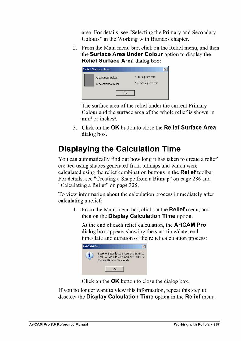
ArtCAM Pro 8.0 Reference Manual Working with Reliefs • 367
area. For details, see "Selecting the Primary and SecondaryColours" in the Working with Bitmaps chapter.
2. From the Main menu bar, click on the Relief menu, and thenthe Surface Area Under Colour option to display theRelief Surface Area dialog box:
The surface area of the relief under the current PrimaryColour and the surface area of the whole relief is shown inmm² or inches².
3. Click on the OK button to close the Relief Surface Areadialog box.
Displaying the Calculation TimeYou can automatically find out how long it has taken to create a reliefcreated using shapes generated from bitmaps and which werecalculated using the relief combination buttons in the Relief toolbar.For details, see "Creating a Shape from a Bitmap" on page 286 and"Calculating a Relief" on page 325.To view information about the calculation process immediately aftercalculating a relief:
1. From the Main menu bar, click on the Relief menu, andthen on the Display Calculation Time option.At the end of each relief calculation, the ArtCAM Prodialog box appears showing the start time/date, endtime/date and duration of the relief calculation process:
Click on the OK button to close the dialog box.If you no longer want to view this information, repeat this step todeselect the Display Calculation Time option in the Relief menu.
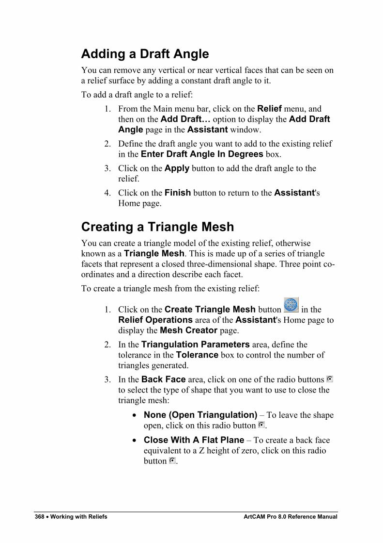
368 • Working with Reliefs ArtCAM Pro 8.0 Reference Manual
Adding a Draft AngleYou can remove any vertical or near vertical faces that can be seen ona relief surface by adding a constant draft angle to it.To add a draft angle to a relief:
1. From the Main menu bar, click on the Relief menu, andthen on the Add Draft… option to display the Add DraftAngle page in the Assistant window.
2. Define the draft angle you want to add to the existing reliefin the Enter Draft Angle In Degrees box.
3. Click on the Apply button to add the draft angle to therelief.
4. Click on the Finish button to return to the Assistant'sHome page.
Creating a Triangle MeshYou can create a triangle model of the existing relief, otherwiseknown as a Triangle Mesh. This is made up of a series of trianglefacets that represent a closed three-dimensional shape. Three point co-ordinates and a direction describe each facet.To create a triangle mesh from the existing relief:
1. Click on the Create Triangle Mesh button in theRelief Operations area of the Assistant's Home page todisplay the Mesh Creator page.
2. In the Triangulation Parameters area, define thetolerance in the Tolerance box to control the number oftriangles generated.
3. In the Back Face area, click on one of the radio buttons to select the type of shape that you want to use to close thetriangle mesh:
• None (Open Triangulation) – To leave the shapeopen, click on this radio button .
• Close With A Flat Plane – To create a back faceequivalent to a Z height of zero, click on this radiobutton .
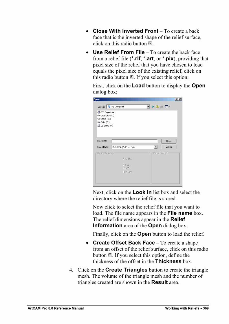
ArtCAM Pro 8.0 Reference Manual Working with Reliefs • 369
• Close With Inverted Front – To create a backface that is the inverted shape of the relief surface,click on this radio button .
• Use Relief From File – To create the back facefrom a relief file (*.rlf, *.art, or *.pix), providing thatpixel size of the relief that you have chosen to loadequals the pixel size of the existing relief, click onthis radio button . If you select this option:First, click on the Load button to display the Opendialog box:
Next, click on the Look in list box and select thedirectory where the relief file is stored.Now click to select the relief file that you want toload. The file name appears in the File name box.The relief dimensions appear in the ReliefInformation area of the Open dialog box.Finally, click on the Open button to load the relief.
• Create Offset Back Face – To create a shapefrom an offset of the relief surface, click on this radiobutton . If you select this option, define thethickness of the offset in the Thickness box.
4. Click on the Create Triangles button to create the trianglemesh. The volume of the triangle mesh and the number oftriangles created are shown in the Result area.
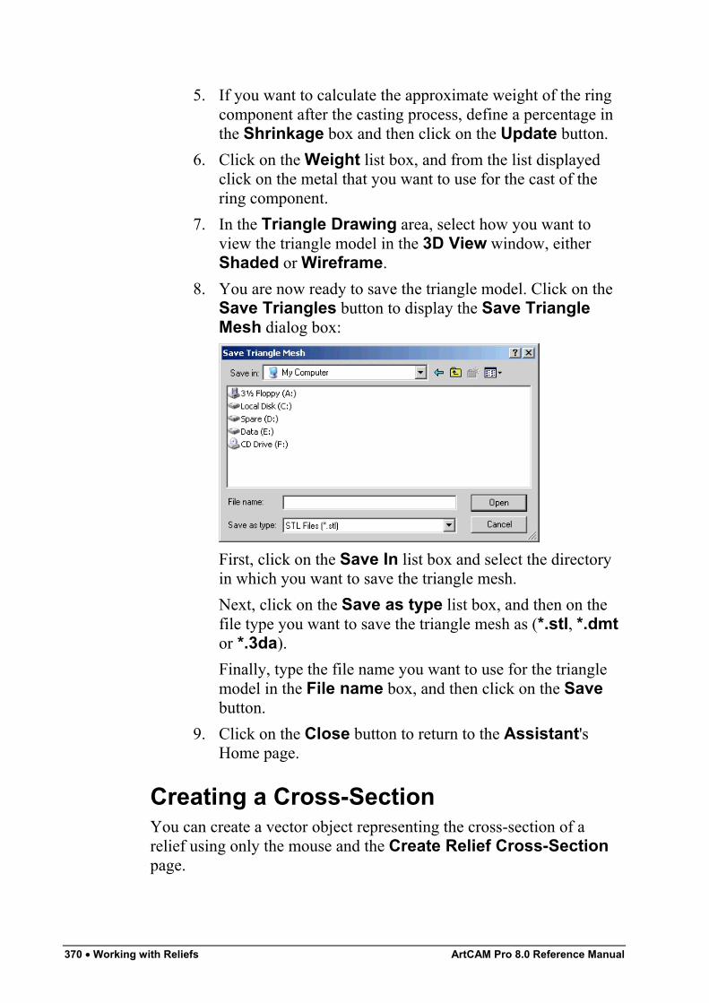
370 • Working with Reliefs ArtCAM Pro 8.0 Reference Manual
5. If you want to calculate the approximate weight of the ringcomponent after the casting process, define a percentage inthe Shrinkage box and then click on the Update button.
6. Click on the Weight list box, and from the list displayedclick on the metal that you want to use for the cast of thering component.
7. In the Triangle Drawing area, select how you want toview the triangle model in the 3D View window, eitherShaded or Wireframe.
8. You are now ready to save the triangle model. Click on theSave Triangles button to display the Save TriangleMesh dialog box:
First, click on the Save In list box and select the directoryin which you want to save the triangle mesh.Next, click on the Save as type list box, and then on thefile type you want to save the triangle mesh as (*.stl, *.dmtor *.3da).Finally, type the file name you want to use for the trianglemodel in the File name box, and then click on the Savebutton.
9. Click on the Close button to return to the Assistant'sHome page.
Creating a Cross-SectionYou can create a vector object representing the cross-section of arelief using only the mouse and the Create Relief Cross-Sectionpage.
ArtCAM Pro 8.0 Reference Manual Working with Reliefs • 371
ArtCAM Pro calculates the measurement details in real time. Thismeans that you can view the calculated values on the Relief Cross-Section page as you are dragging the cursor into position.To create a cross-section:
1. Click on the Create Cross-Section button in theRelief Operations area of the Assistant's Home page todisplay the Create Relief Cross-Section page.
2. Move the cursor over the area in the model (the white area)that in which you want to create a cross-section, and thenclick on the position that you want to define as the start.The co-ordinates of the cross-section's start position appearin the Anchor Position's X and Y area.By default, the cursor snaps to points (nodes) in a vectorobject. This is indicated by the cursor changing to a cursorwhen over the points (nodes).
Note: To disable snapping, hold the Shift key down on yourkeyboard whilst dragging the cursor into position.
3. Drag the mouse over the position in the span that you wantto define as the end of the cross-section, and then click.The distance between the start and the end of the cross-section is shown in the Distance area.The angle between the start and the end position of thecross-section is shown in the Angle area.The distance between the start and the end of the cross-section in both the X and Y axes is shown in the X and Ydistance area.
4. If you want to align the cross-section with the X-axis, clickto select the Align Cross Section Horizontally option
.5. Click on the Create button to create the cross-section.6. Click on the Close button to return to the Assistant's
Home page.
Creating an Angled PlaneYou can create an angled plane using up to three defined points in amodel.
372 • Working with Reliefs ArtCAM Pro 8.0 Reference Manual
To create an angled plane:
1. Click on the Create Angled Plane button in theRelief Editing area of the Assistant's Home page todisplay the Create Angled Plane page in the Assistantwindow.
Note: You can also display the Create Angled Plane page fromthe Main menu bar. Click on the Relief menu, and then on theCreate Angled Plane… option.
2. If you want to create an angled plane within the boundary ofa vector object, click to select the vector object. For details,see "Selecting Vectors" in the Working with Vectorschapter. If you do not select a vector object, the angledplane is created across the entire relief surface.
3. If you want to create an angled plane using three definedpoints, click to select the Set Third Point option . TheThird Point on Plane area appears on the page.The advantage of selecting a third point is that it adds a tiltor 'roll' to the sides of the angled plane.
4. You can use the mouse cursor to define the points on theplane:
• Click on the Start button in the Use Cursor toSelect Points area, move the cursor over therequired position in the 2D View window, and thenclick. The co-ordinates for this point are displayed inthe X, Y and Z boxes.The co-ordinates for this point appear in red whenyou click on the Start button, then change to blackwhen you click in the 2D View window.
Alternatively, type the co-ordinates of the point in the X, Yand Z boxes in the First Point on Plane area.
5. If you had defined the first point using the mouse cursor:• Move the cursor over the required position in the 2D
View window, and then click to define the secondpoint.The co-ordinates for this point are displayed inthe X, Y and Z boxes.
ArtCAM Pro 8.0 Reference Manual Working with Reliefs • 373
The co-ordinates for this point appear in red, thenchange to black when you click in the 2D Viewwindow.
Otherwise, type the co-ordinates of the point in the X, Y andZ boxes in the Second Point on Plane area.
6. If you had defined the first and second points using themouse cursor:
• Move the cursor over the required position in the 2DView window, and then click to define the thirdpoint. The co-ordinates for this point are displayed inthe X, Y and Z boxes.The co-ordinates for this point appear in red, thenchange to black when you click in the 2D Viewwindow.
Alternatively, type the co-ordinates of the point in the X, Yand Z boxes in the Third Point on Plane area.
7. In the Combine area, click on one of the radio buttons toselect how the angled plane is combined with the existingrelief:
• To add the angled plane to the existing relief, clickon the Add option. For more details, see "Adding tothe Relief" on page 326.
• To subtract the angled plane from the existing relief,click on the Subtract option. For more details, see"Subtracting from the Relief" on page 328.
• To merge the angled plane with the existing relief, sothat only the highest points of the two remain, clickon the Highest option. For more details, see"Merging with the Relief" on page 330.
• To merge the angled plane with the existing relief, sothat only the lowest points of the two remain, clickon the Lowest option. For more details, see"Merging with the Relief" on page 330.
8. Click on the Create button.9. Click on the Close button to return to the Assistant's
Home page.
374 • Working with Reliefs ArtCAM Pro 8.0 Reference Manual
Blending 3D ShapesYou can create new types of three-dimensional shapes called 'blended'shapes. A blended shape is a three-dimensional shape that can begenerated from vector objects or the existing relief.To create a blended shape:
1. Select the vector object to define the outline of the blendedshape. For details, see "Selecting Vectors" in the Workingwith Vectors chapter.
2. Click on the Create 3D Blend button in the ReliefEditing area of the Assistant's Home page to display theCreate 3D Blend page.
3. In the Profile area, select the profile of the blended shapeby clicking on the appropriate radio button :
• Linear – This option instructs ArtCAM Pro to createa straight-edged shape.
• Convex – This option instructs ArtCAM Pro tocreate a shape that curves outwards.
• Concave – This option instructs ArtCAM Pro tocreate a shape that curves inwards.
• Smooth – This option instructs ArtCAM Pro tocreate a shape with rounded edges.
• Selected Vector – This option allows you to use across-section to define the profile of the shape.If you have selected this option, hold the Shift keydown on your keyboard, and then click on the openvector object that you want to use as the cross-section. Both the selected vector objects turnmagenta and are surrounded by a bounding box.
4. In the Heights area, define the height of the blended shape:• To define the height at the centre of the blended
shape, type its value in the Inner box.• If you want to set the height at the centre of the
blended shape as equal to the highest point in theexisting relief, click to select the From Reliefoption .
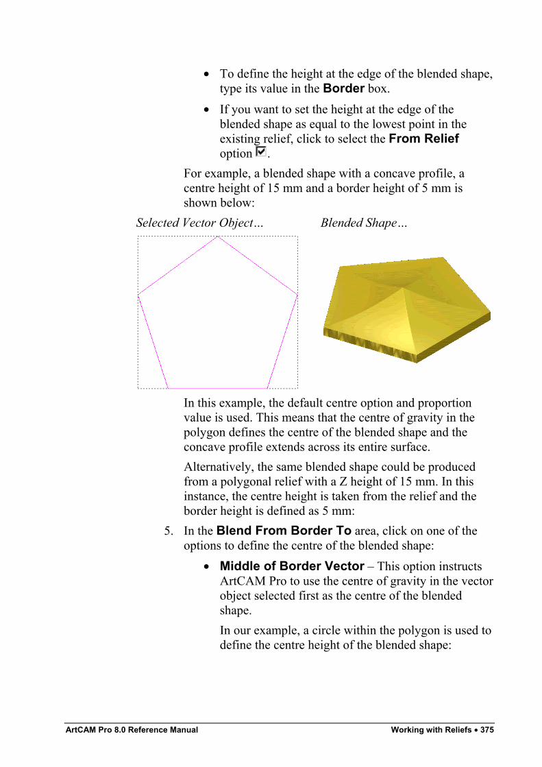
ArtCAM Pro 8.0 Reference Manual Working with Reliefs • 375
• To define the height at the edge of the blended shape,type its value in the Border box.
• If you want to set the height at the edge of theblended shape as equal to the lowest point in theexisting relief, click to select the From Reliefoption .
For example, a blended shape with a concave profile, acentre height of 15 mm and a border height of 5 mm isshown below:
Selected Vector Object… Blended Shape…
In this example, the default centre option and proportionvalue is used. This means that the centre of gravity in thepolygon defines the centre of the blended shape and theconcave profile extends across its entire surface.Alternatively, the same blended shape could be producedfrom a polygonal relief with a Z height of 15 mm. In thisinstance, the centre height is taken from the relief and theborder height is defined as 5 mm:
5. In the Blend From Border To area, click on one of theoptions to define the centre of the blended shape:
• Middle of Border Vector – This option instructsArtCAM Pro to use the centre of gravity in the vectorobject selected first as the centre of the blendedshape.In our example, a circle within the polygon is used todefine the centre height of the blended shape:
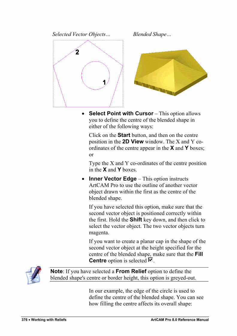
376 • Working with Reliefs ArtCAM Pro 8.0 Reference Manual
Selected Vector Objects… Blended Shape…
• Select Point with Cursor – This option allowsyou to define the centre of the blended shape ineither of the following ways:Click on the Start button, and then on the centreposition in the 2D View window. The X and Y co-ordinates of the centre appear in the X and Y boxes;orType the X and Y co-ordinates of the centre positionin the X and Y boxes.
• Inner Vector Edge – This option instructsArtCAM Pro to use the outline of another vectorobject drawn within the first as the centre of theblended shape.If you have selected this option, make sure that thesecond vector object is positioned correctly withinthe first. Hold the Shift key down, and then click toselect the vector object. The two vector objects turnmagenta.If you want to create a planar cap in the shape of thesecond vector object at the height specified for thecentre of the blended shape, make sure that the FillCentre option is selected .
Note: If you have selected a From Relief option to define theblended shape's centre or border height, this option is greyed-out.
In our example, the edge of the circle is used todefine the centre of the blended shape. You can seehow filling the centre affects its overall shape:
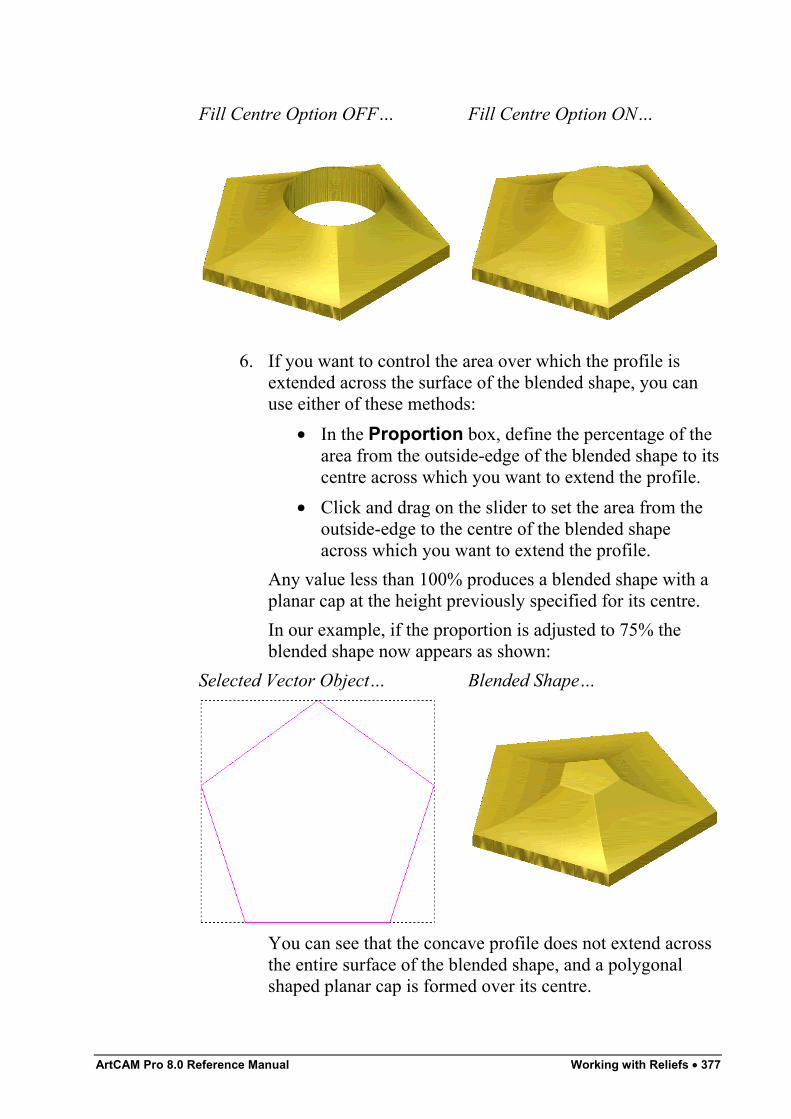
ArtCAM Pro 8.0 Reference Manual Working with Reliefs • 377
Fill Centre Option OFF… Fill Centre Option ON…
6. If you want to control the area over which the profile isextended across the surface of the blended shape, you canuse either of these methods:
• In the Proportion box, define the percentage of thearea from the outside-edge of the blended shape to itscentre across which you want to extend the profile.
• Click and drag on the slider to set the area from theoutside-edge to the centre of the blended shapeacross which you want to extend the profile.
Any value less than 100% produces a blended shape with aplanar cap at the height previously specified for its centre.In our example, if the proportion is adjusted to 75% theblended shape now appears as shown:
Selected Vector Object… Blended Shape…
You can see that the concave profile does not extend acrossthe entire surface of the blended shape, and a polygonalshaped planar cap is formed over its centre.
378 • Working with Reliefs ArtCAM Pro 8.0 Reference Manual
7. In the Combine area, select how you want to combine theblended shape with the existing relief:
Note: If you have selected a From Relief option to define theblended shape's centre or border height, go straight to the next step.
• Click on the Add radio button to add the blendedshape to the points in the existing relief. For moredetails, see "Adding to the Relief" on page 326.
• Click on the Subtract radio button to subtract theblended shape from the existing relief. For moredetails, see "Subtracting from the Relief" on page328.
• Click on the Highest radio button to merge theblended shape with the existing relief, so that onlythe highest points of the two remain. For moredetails, see "Merging with the Relief" on page 330.
• Click on the Lowest radio button to merge theblended shape with the existing relief, so that onlythe lowest points of the two remain. For more details,see "Merging with the Relief" on page 330.
8. Click on the Create Blend button to create the blendedshape. A progress bar appears beneath the 2D Viewwindow indicating the progress ArtCAM Pro is making incalculating the blended shape.
9. Click on the Close button to return to the Assistant'sHome page.
Relief Envelope DistortionYou can distort an area of a relief within the boundary of a selectedvector object drawn within a model. When working in relief envelopedistortion mode, ArtCAM Pro converts the four sides of the boundingbox that surrounds a selected vector object into bezier spans. Movingthe nodes and control points that make up the distortion envelopearound the selected vector object allows you to manipulate the originalshape of the relief, which in turn allows you to add perspective to therelief. You can also move, resize, rotate or shear the distortionenvelope, which allows you to restructure the relief easily.To distort an area of the a relief within the boundary of a selectedvector object:
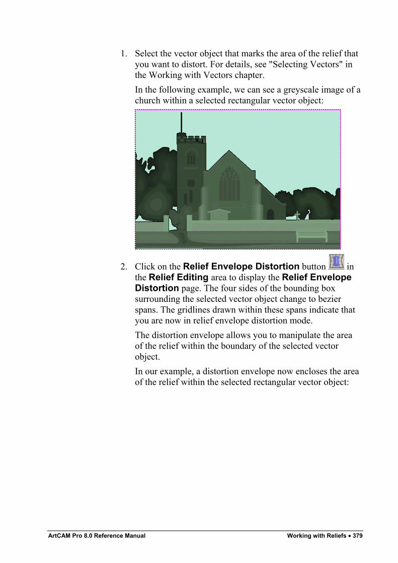
ArtCAM Pro 8.0 Reference Manual Working with Reliefs • 379
1. Select the vector object that marks the area of the relief thatyou want to distort. For details, see "Selecting Vectors" inthe Working with Vectors chapter.In the following example, we can see a greyscale image of achurch within a selected rectangular vector object:
2. Click on the Relief Envelope Distortion button inthe Relief Editing area to display the Relief EnvelopeDistortion page. The four sides of the bounding boxsurrounding the selected vector object change to bezierspans. The gridlines drawn within these spans indicate thatyou are now in relief envelope distortion mode.The distortion envelope allows you to manipulate the areaof the relief within the boundary of the selected vectorobject.In our example, a distortion envelope now encloses the areaof the relief within the selected rectangular vector object:
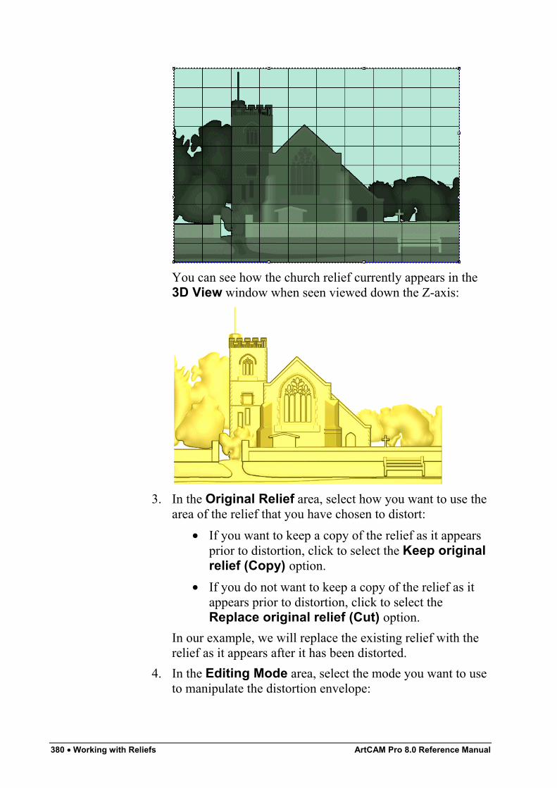
380 • Working with Reliefs ArtCAM Pro 8.0 Reference Manual
You can see how the church relief currently appears in the3D View window when seen viewed down the Z-axis:
3. In the Original Relief area, select how you want to use thearea of the relief that you have chosen to distort:
• If you want to keep a copy of the relief as it appearsprior to distortion, click to select the Keep originalrelief (Copy) option.
• If you do not want to keep a copy of the relief as itappears prior to distortion, click to select theReplace original relief (Cut) option.
In our example, we will replace the existing relief with therelief as it appears after it has been distorted.
4. In the Editing Mode area, select the mode you want to useto manipulate the distortion envelope:
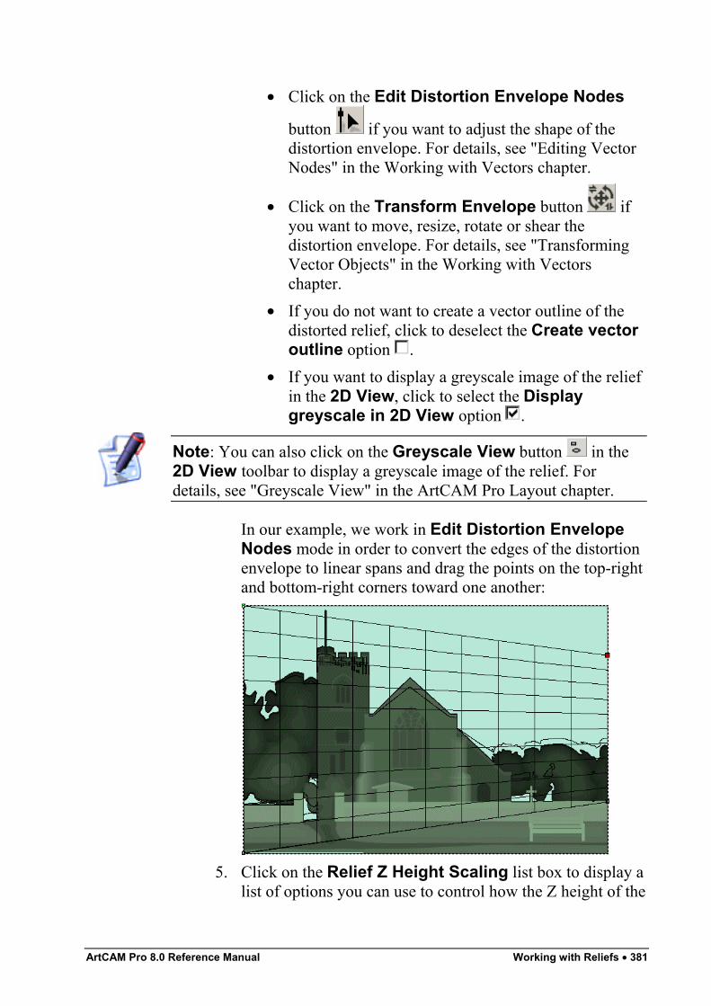
ArtCAM Pro 8.0 Reference Manual Working with Reliefs • 381
• Click on the Edit Distortion Envelope Nodes
button if you want to adjust the shape of thedistortion envelope. For details, see "Editing VectorNodes" in the Working with Vectors chapter.
• Click on the Transform Envelope button ifyou want to move, resize, rotate or shear thedistortion envelope. For details, see "TransformingVector Objects" in the Working with Vectorschapter.
• If you do not want to create a vector outline of thedistorted relief, click to deselect the Create vectoroutline option .
• If you want to display a greyscale image of the reliefin the 2D View, click to select the Displaygreyscale in 2D View option .
Note: You can also click on the Greyscale View button in the2D View toolbar to display a greyscale image of the relief. Fordetails, see "Greyscale View" in the ArtCAM Pro Layout chapter.
In our example, we work in Edit Distortion EnvelopeNodes mode in order to convert the edges of the distortionenvelope to linear spans and drag the points on the top-rightand bottom-right corners toward one another:
5. Click on the Relief Z Height Scaling list box to display alist of options you can use to control how the Z height of the
382 • Working with Reliefs ArtCAM Pro 8.0 Reference Manual
distorted relief is scaled, then click to select the option thatyou want to use:
• Average Scale – This option applies an overallscaling factor to the distorted relief based on thechange in its area.
• Linear Scale – This option calculates the Z heightof each point within the relief based on the localdistortion at that point. For example, if the area of thedistorted relief has increased at a particular pointthen the height of that point will also increase.
• Stretch & Squeeze – This option calculates the Zheight of each point within the relief based on thelocal distortion at that point. For example, if the areaof the distorted relief has decreased (squeezed) thenits Z height will be raised. If the area of the distortedrelief has increased (stretched), then its Z height willbe lowered.
• Keep Current Z – This option maintains theexisting Z height of the distorted relief.If you want to apply an additional scaling factor tothe distorted relief, define the percentage by whichyou want to scale its Z height in the Scaling Factorbox.
6. If you want to use either one or two curved vector objectsselected from the 2D View window to control thedimensions and position of a new distortion envelope whichcan be used to manipulate copies of the distorted relief,click to select the Use existing curve(s) option todisplay its settings.If you want to use a single curved vector object:
• First, click to select the Wrap along single curveradio button . The Wrap between 2 curvessettings are greyed-out.
• Next, click to select the curved vector object that youwant to use from the 2D View window, and thenclick on the Select Curve… button. For details, see"Selecting Vectors" in the Working with Vectorschapter.
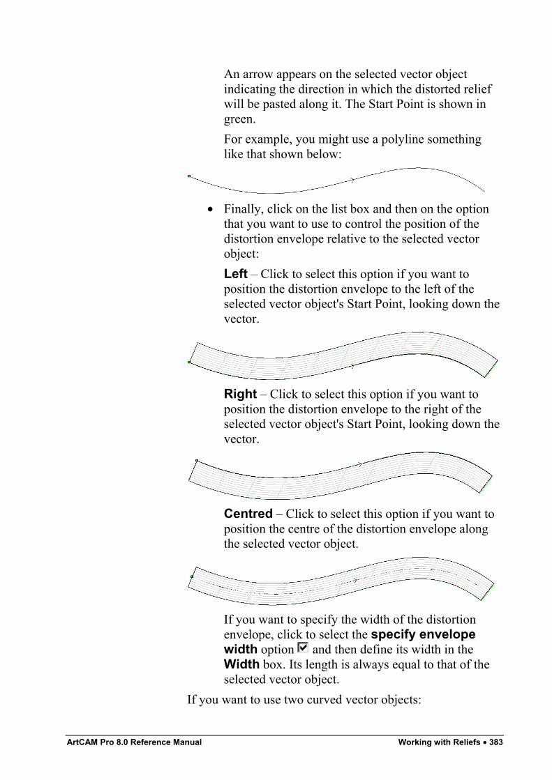
ArtCAM Pro 8.0 Reference Manual Working with Reliefs • 383
An arrow appears on the selected vector objectindicating the direction in which the distorted reliefwill be pasted along it. The Start Point is shown ingreen.For example, you might use a polyline somethinglike that shown below:
• Finally, click on the list box and then on the optionthat you want to use to control the position of thedistortion envelope relative to the selected vectorobject:Left – Click to select this option if you want toposition the distortion envelope to the left of theselected vector object's Start Point, looking down thevector.
Right – Click to select this option if you want toposition the distortion envelope to the right of theselected vector object's Start Point, looking down thevector.
Centred – Click to select this option if you want toposition the centre of the distortion envelope alongthe selected vector object.
If you want to specify the width of the distortionenvelope, click to select the specify envelopewidth option and then define its width in theWidth box. Its length is always equal to that of theselected vector object.
If you want to use two curved vector objects:
384 • Working with Reliefs ArtCAM Pro 8.0 Reference Manual
• First, click to select the Wrap between 2 curvesradio button . The Wrap along single curvesettings are greyed-out.
• Next, click to select the curved vector object shownin the 2D View that you want to use as the top edgeof the distortion envelope, and then click on theSelect Top Curve… button.An arrow appears on the selected vector objectindicating the direction in which the distorted reliefwill be positioned along it. The Start Point is shownin green.
• Finally, click to select the curved vector objectshown in the 2D View that you want to use as thebottom edge of the distortion envelope, and thenclick on the Select Bottom Curve… button.An arrow appears on the selected vector objectindicating the direction in which the distorted reliefwill be positioned along it. The Start Point is shownin green.
7. In the Number of Copies area, define the number ofcopies of the distorted relief that you want to create:
• If you want to stretch the distorted relief along thelength of the selected vector object(s), click to selectthe One - Stretch to Fit radio button .
• If you want ArtCAM Pro to calculate the optimumnumber of copies of the distorted relief that shouldbe created along the selected vector object(s), clickto select the Many - Best Fit radio button .
• If you want to create a specific number of copies ofthe distorted relief along the selected vectorobject(s), click to select the Many - Specificnumber of copies radio button and then definethe number of copies in the Copies box.
8. Click on the Apply button to position the distortionenvelope about the selected curved vector object(s). Thedistortion envelope is divided into sections equal to thenumber of copies of the distorted relief you want to create.
9. In the Combine area, click to select the relief combinationmethod that you want to use:
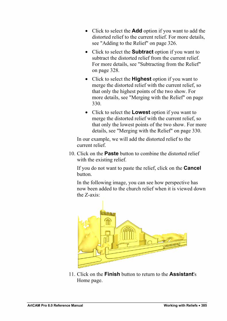
ArtCAM Pro 8.0 Reference Manual Working with Reliefs • 385
• Click to select the Add option if you want to add thedistorted relief to the current relief. For more details,see "Adding to the Relief" on page 326.
• Click to select the Subtract option if you want tosubtract the distorted relief from the current relief.For more details, see "Subtracting from the Relief"on page 328.
• Click to select the Highest option if you want tomerge the distorted relief with the current relief, sothat only the highest points of the two show. Formore details, see "Merging with the Relief" on page330.
• Click to select the Lowest option if you want tomerge the distorted relief with the current relief, sothat only the lowest points of the two show. For moredetails, see "Merging with the Relief" on page 330.
In our example, we will add the distorted relief to thecurrent relief.
10. Click on the Paste button to combine the distorted reliefwith the existing relief.If you do not want to paste the relief, click on the Cancelbutton.In the following image, you can see how perspective hasnow been added to the church relief when it is viewed downthe Z-axis:
11. Click on the Finish button to return to the Assistant'sHome page.
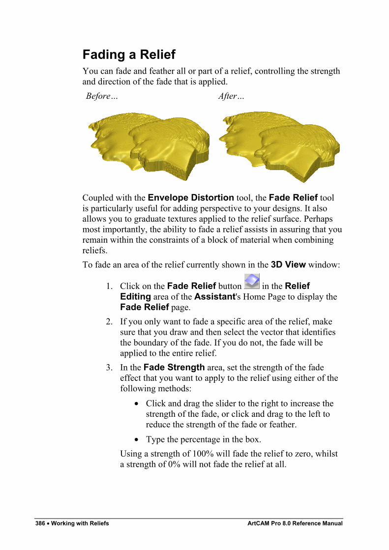
386 • Working with Reliefs ArtCAM Pro 8.0 Reference Manual
Fading a ReliefYou can fade and feather all or part of a relief, controlling the strengthand direction of the fade that is applied.Before… After…
Coupled with the Envelope Distortion tool, the Fade Relief toolis particularly useful for adding perspective to your designs. It alsoallows you to graduate textures applied to the relief surface. Perhapsmost importantly, the ability to fade a relief assists in assuring that youremain within the constraints of a block of material when combiningreliefs.To fade an area of the relief currently shown in the 3D View window:
1. Click on the Fade Relief button in the ReliefEditing area of the Assistant's Home Page to display theFade Relief page.
2. If you only want to fade a specific area of the relief, makesure that you draw and then select the vector that identifiesthe boundary of the fade. If you do not, the fade will beapplied to the entire relief.
3. In the Fade Strength area, set the strength of the fadeeffect that you want to apply to the relief using either of thefollowing methods:
• Click and drag the slider to the right to increase thestrength of the fade, or click and drag to the left toreduce the strength of the fade or feather.
• Type the percentage in the box.Using a strength of 100% will fade the relief to zero, whilsta strength of 0% will not fade the relief at all.
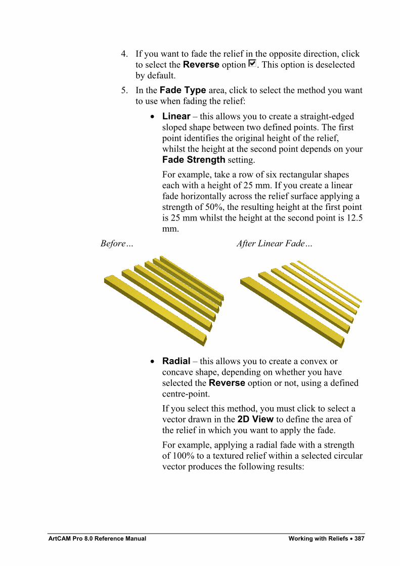
ArtCAM Pro 8.0 Reference Manual Working with Reliefs • 387
4. If you want to fade the relief in the opposite direction, clickto select the Reverse option . This option is deselectedby default.
5. In the Fade Type area, click to select the method you wantto use when fading the relief:
• Linear – this allows you to create a straight-edgedsloped shape between two defined points. The firstpoint identifies the original height of the relief,whilst the height at the second point depends on yourFade Strength setting.For example, take a row of six rectangular shapeseach with a height of 25 mm. If you create a linearfade horizontally across the relief surface applying astrength of 50%, the resulting height at the first pointis 25 mm whilst the height at the second point is 12.5mm.
Before… After Linear Fade…
• Radial – this allows you to create a convex orconcave shape, depending on whether you haveselected the Reverse option or not, using a definedcentre-point.If you select this method, you must click to select avector drawn in the 2D View to define the area ofthe relief in which you want to apply the fade.For example, applying a radial fade with a strengthof 100% to a textured relief within a selected circularvector produces the following results:
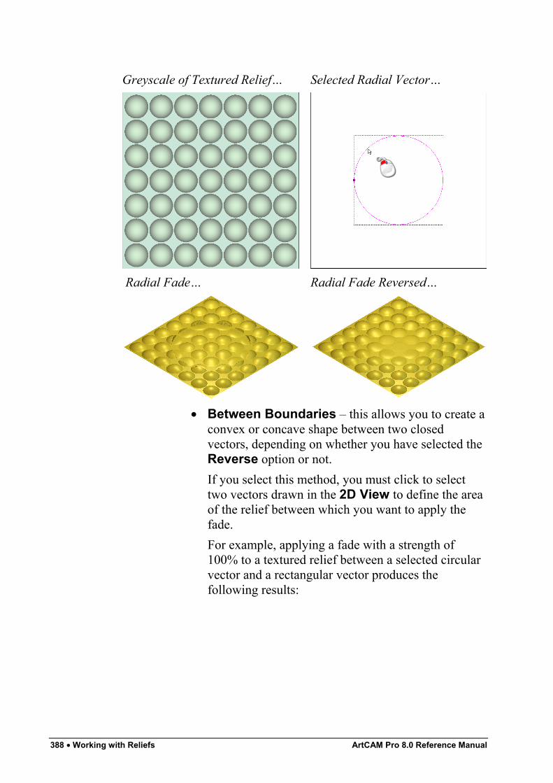
388 • Working with Reliefs ArtCAM Pro 8.0 Reference Manual
Greyscale of Textured Relief… Selected Radial Vector…
Radial Fade… Radial Fade Reversed…
• Between Boundaries – this allows you to create aconvex or concave shape between two closedvectors, depending on whether you have selected theReverse option or not.If you select this method, you must click to selecttwo vectors drawn in the 2D View to define the areaof the relief between which you want to apply thefade.For example, applying a fade with a strength of100% to a textured relief between a selected circularvector and a rectangular vector produces thefollowing results:
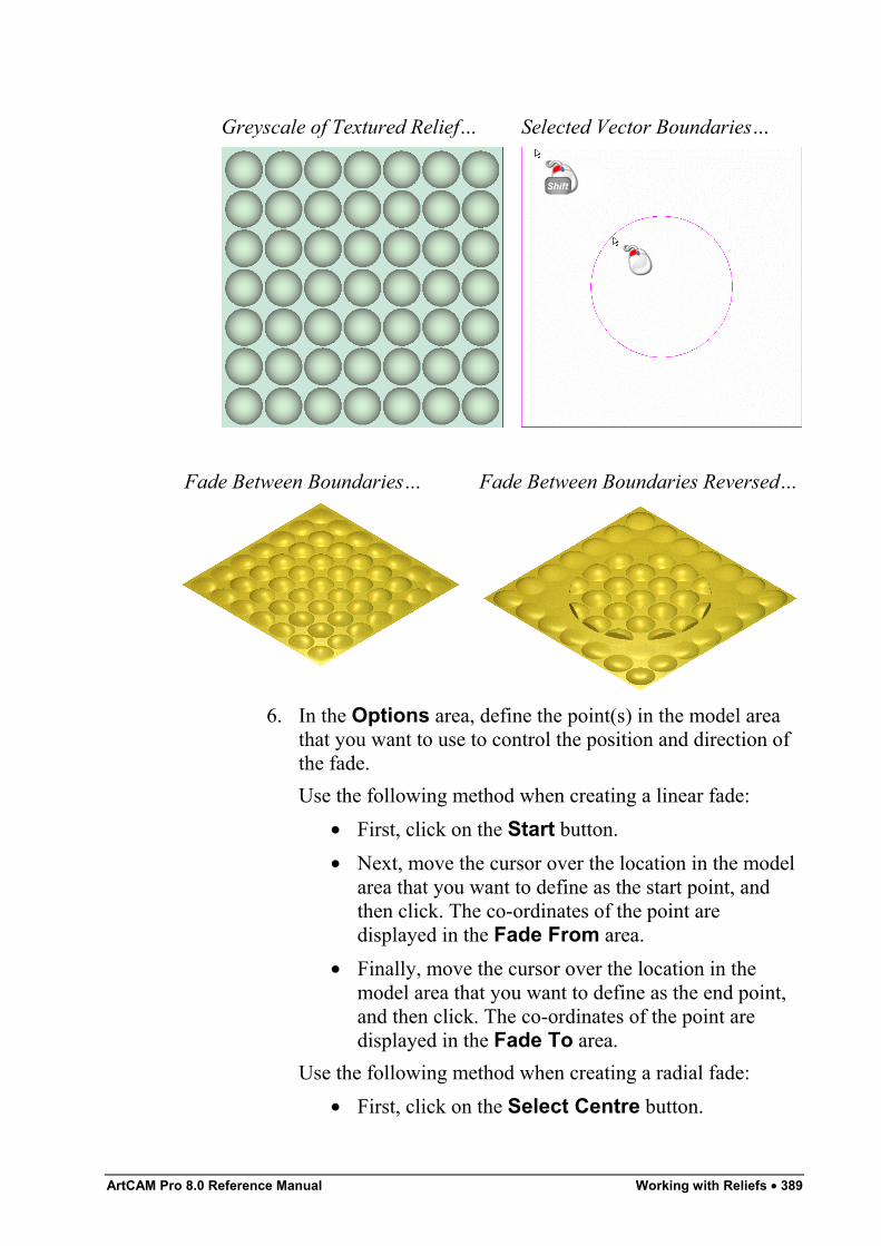
ArtCAM Pro 8.0 Reference Manual Working with Reliefs • 389
Greyscale of Textured Relief… Selected Vector Boundaries…
Fade Between Boundaries… Fade Between Boundaries Reversed…
6. In the Options area, define the point(s) in the model areathat you want to use to control the position and direction ofthe fade.Use the following method when creating a linear fade:
• First, click on the Start button.• Next, move the cursor over the location in the model
area that you want to define as the start point, andthen click. The co-ordinates of the point aredisplayed in the Fade From area.
• Finally, move the cursor over the location in themodel area that you want to define as the end point,and then click. The co-ordinates of the point aredisplayed in the Fade To area.
Use the following method when creating a radial fade:• First, click on the Select Centre button.
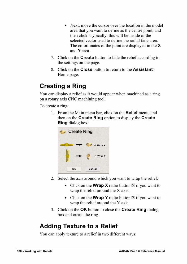
390 • Working with Reliefs ArtCAM Pro 8.0 Reference Manual
• Next, move the cursor over the location in the modelarea that you want to define as the centre point, andthen click. Typically, this will be inside of theselected vector used to define the radial fade area.The co-ordinates of the point are displayed in the Xand Y area.
7. Click on the Create button to fade the relief according tothe settings on the page.
8. Click on the Close button to return to the Assistant'sHome page.
Creating a RingYou can display a relief as it would appear when machined as a ringon a rotary axis CNC machining tool.To create a ring:
1. From the Main menu bar, click on the Relief menu, andthen on the Create Ring option to display the CreateRing dialog box:
2. Select the axis around which you want to wrap the relief:• Click on the Wrap X radio button if you want to
wrap the relief around the X-axis.• Click on the Wrap Y radio button if you want to
wrap the relief around the Y-axis.3. Click on the OK button to close the Create Ring dialog
box and create the ring.
Adding Texture to a ReliefYou can apply texture to a relief in two different ways:
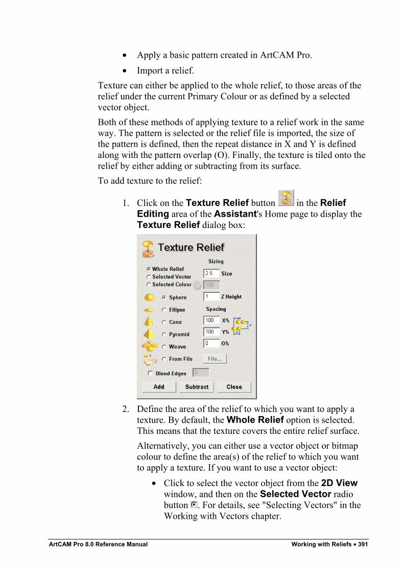
ArtCAM Pro 8.0 Reference Manual Working with Reliefs • 391
• Apply a basic pattern created in ArtCAM Pro.• Import a relief.
Texture can either be applied to the whole relief, to those areas of therelief under the current Primary Colour or as defined by a selectedvector object.Both of these methods of applying texture to a relief work in the sameway. The pattern is selected or the relief file is imported, the size ofthe pattern is defined, then the repeat distance in X and Y is definedalong with the pattern overlap (O). Finally, the texture is tiled onto therelief by either adding or subtracting from its surface.To add texture to the relief:
1. Click on the Texture Relief button in the ReliefEditing area of the Assistant's Home page to display theTexture Relief dialog box:
2. Define the area of the relief to which you want to apply atexture. By default, the Whole Relief option is selected.This means that the texture covers the entire relief surface.Alternatively, you can either use a vector object or bitmapcolour to define the area(s) of the relief to which you wantto apply a texture. If you want to use a vector object:
• Click to select the vector object from the 2D Viewwindow, and then on the Selected Vector radiobutton . For details, see "Selecting Vectors" in theWorking with Vectors chapter.
392 • Working with Reliefs ArtCAM Pro 8.0 Reference Manual
If you want to use a bitmap colour:• Select the Primary Colour from the Colour Palette
beneath the 2D View window, and then click on theSelected Colour radio button . For details, see"Selecting the Primary and Secondary Colours" inthe Working with Bitmaps chapter.
3. Click on the appropriate radio button to select the textureyou want to combine with the existing relief, and thendefine its size and height.The size of the texture determines how it is applied to therelief. If the texture's current size does not match that of thearea of the relief to which it is being applied, you can eithercompress or expand it so that it fits perfectly over the area,or allow ArtCAM Pro to automatically tile it over the area.
• If you have selected the Sphere option , define itssize and height in the Size and Z Height boxes inthe Sizing area of the Texture Relief dialog box.
• If you have selected the Ellipse option , define itssize, scaling factor and height in the Size,Horizontal % and Z Height boxes in the Sizingarea of the Texture Relief dialog box.
• If you have selected the Cone option , define itssize, scaling factor and height in the Size, TipRadius % and Z Height boxes in the Sizing areaof the Texture Relief dialog box.
• If you have selected the Pyramid option , defineits size, scaling factor and height in the Size,Truncation % and Z Height boxes in the Sizingarea of the Texture Relief dialog box.
• If you have selected the Weave option , define itssize, scaling factor and height in the Size, BarWidth % and Z Height boxes in the Sizing area ofthe Texture Relief dialog box.
• If you have selected the From Relief option ,click on the File button to display the Open dialogbox:
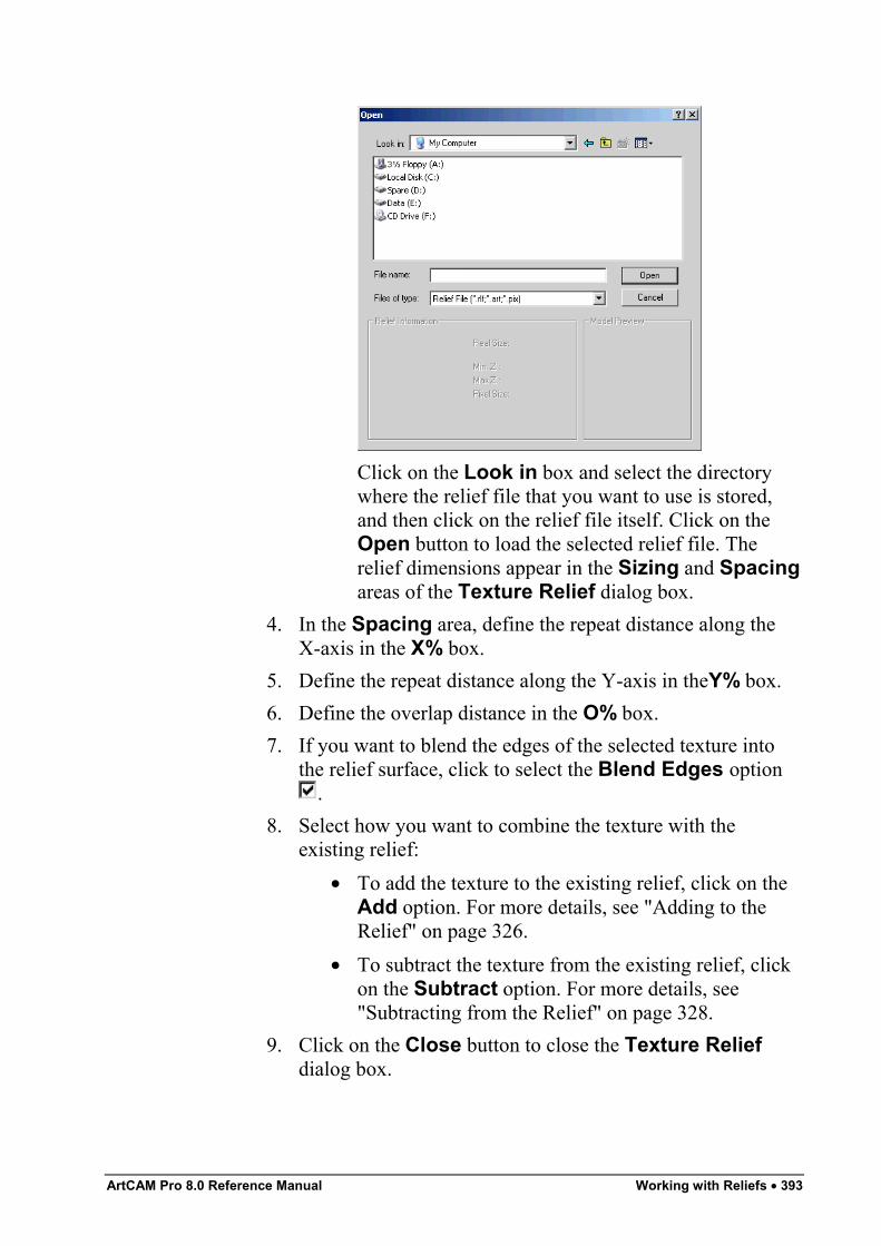
ArtCAM Pro 8.0 Reference Manual Working with Reliefs • 393
Click on the Look in box and select the directorywhere the relief file that you want to use is stored,and then click on the relief file itself. Click on theOpen button to load the selected relief file. Therelief dimensions appear in the Sizing and Spacingareas of the Texture Relief dialog box.
4. In the Spacing area, define the repeat distance along theX-axis in the X% box.
5. Define the repeat distance along the Y-axis in theY% box.6. Define the overlap distance in the O% box.7. If you want to blend the edges of the selected texture into
the relief surface, click to select the Blend Edges option.
8. Select how you want to combine the texture with theexisting relief:
• To add the texture to the existing relief, click on theAdd option. For more details, see "Adding to theRelief" on page 326.
• To subtract the texture from the existing relief, clickon the Subtract option. For more details, see"Subtracting from the Relief" on page 328.
9. Click on the Close button to close the Texture Reliefdialog box.
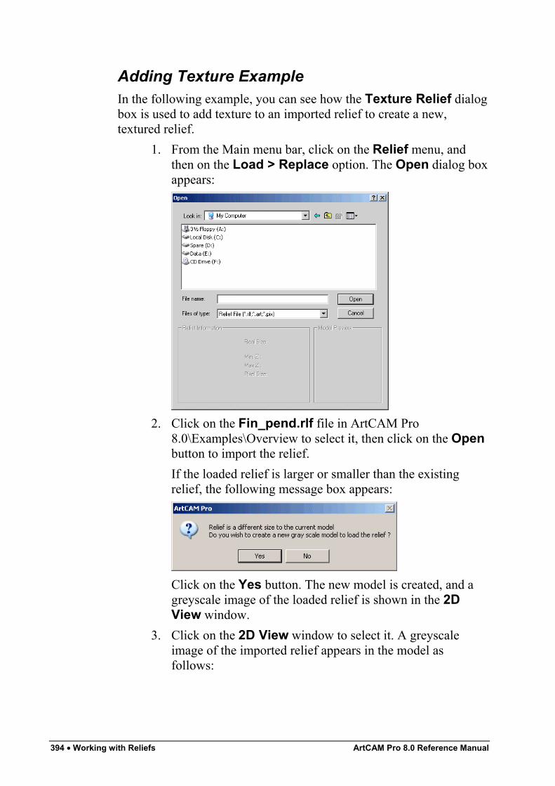
394 • Working with Reliefs ArtCAM Pro 8.0 Reference Manual
Adding Texture ExampleIn the following example, you can see how the Texture Relief dialogbox is used to add texture to an imported relief to create a new,textured relief.
1. From the Main menu bar, click on the Relief menu, andthen on the Load > Replace option. The Open dialog boxappears:
2. Click on the Fin_pend.rlf file in ArtCAM Pro8.0\Examples\Overview to select it, then click on the Openbutton to import the relief.If the loaded relief is larger or smaller than the existingrelief, the following message box appears:
Click on the Yes button. The new model is created, and agreyscale image of the loaded relief is shown in the 2DView window.
3. Click on the 2D View window to select it. A greyscaleimage of the imported relief appears in the model asfollows:
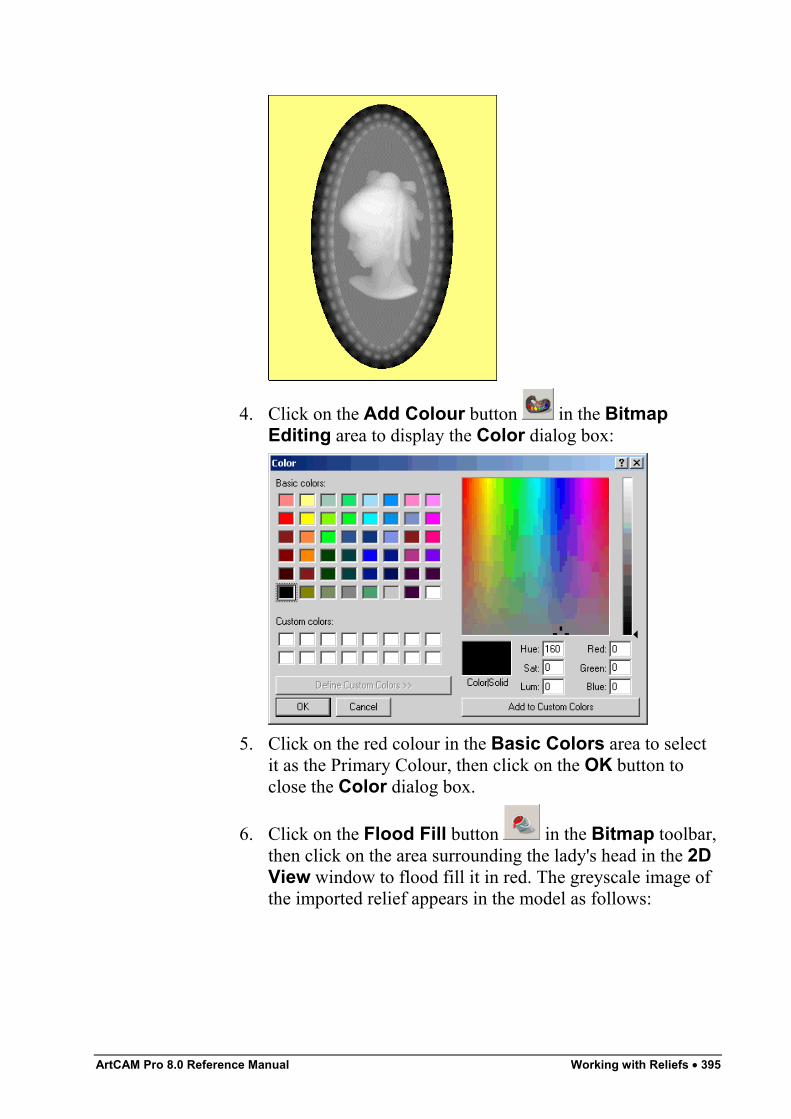
ArtCAM Pro 8.0 Reference Manual Working with Reliefs • 395
4. Click on the Add Colour button in the BitmapEditing area to display the Color dialog box:
5. Click on the red colour in the Basic Colors area to selectit as the Primary Colour, then click on the OK button toclose the Color dialog box.
6. Click on the Flood Fill button in the Bitmap toolbar,then click on the area surrounding the lady's head in the 2DView window to flood fill it in red. The greyscale image ofthe imported relief appears in the model as follows:
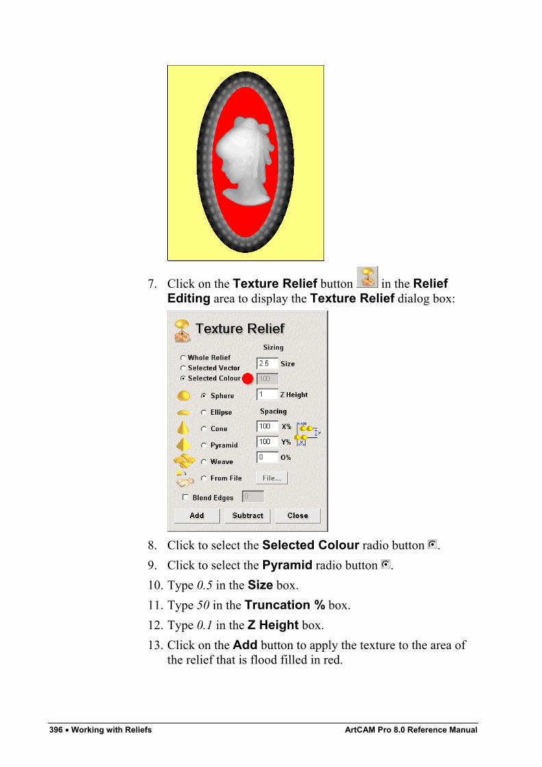
396 • Working with Reliefs ArtCAM Pro 8.0 Reference Manual
7. Click on the Texture Relief button in the ReliefEditing area to display the Texture Relief dialog box:
8. Click to select the Selected Colour radio button .9. Click to select the Pyramid radio button .10. Type 0.5 in the Size box.11. Type 50 in the Truncation % box.12. Type 0.1 in the Z Height box.13. Click on the Add button to apply the texture to the area of
the relief that is flood filled in red.
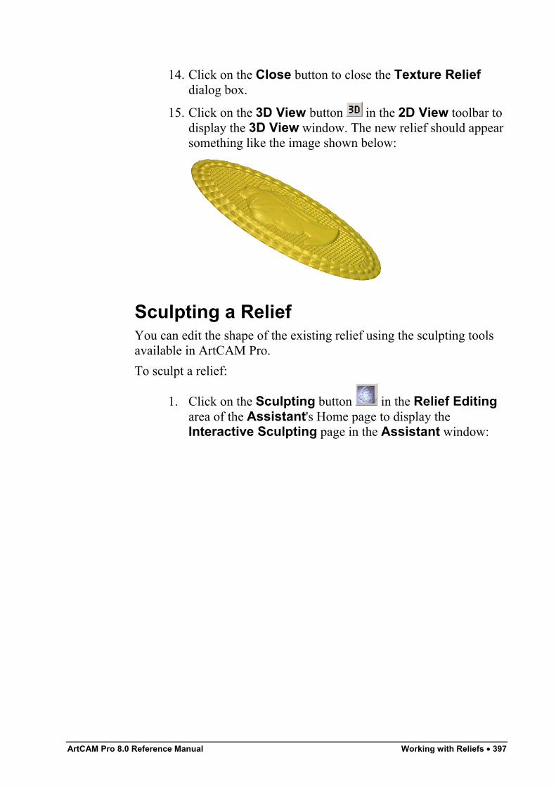
ArtCAM Pro 8.0 Reference Manual Working with Reliefs • 397
14. Click on the Close button to close the Texture Reliefdialog box.
15. Click on the 3D View button in the 2D View toolbar todisplay the 3D View window. The new relief should appearsomething like the image shown below:
Sculpting a ReliefYou can edit the shape of the existing relief using the sculpting toolsavailable in ArtCAM Pro.To sculpt a relief:
1. Click on the Sculpting button in the Relief Editingarea of the Assistant's Home page to display theInteractive Sculpting page in the Assistant window:
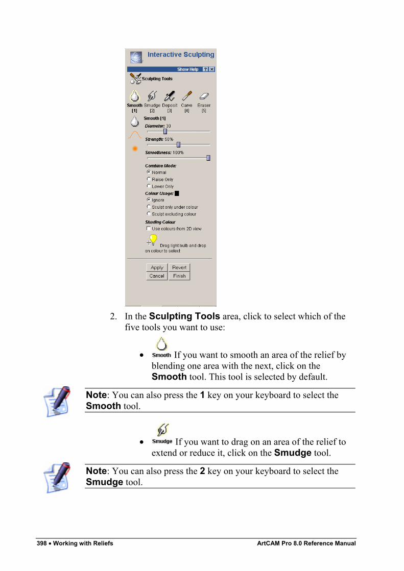
398 • Working with Reliefs ArtCAM Pro 8.0 Reference Manual
2. In the Sculpting Tools area, click to select which of thefive tools you want to use:
• If you want to smooth an area of the relief byblending one area with the next, click on theSmooth tool. This tool is selected by default.
Note: You can also press the 1 key on your keyboard to select theSmooth tool.
• If you want to drag on an area of the relief toextend or reduce it, click on the Smudge tool.
Note: You can also press the 2 key on your keyboard to select theSmudge tool.
ArtCAM Pro 8.0 Reference Manual Working with Reliefs • 399
• If you want to add material to the relief, clickon the Deposit tool.
Note: You can also press the 3 key on your keyboard to select theDeposit tool.
• If you want to remove material from the relief,click on the Carve tool.
Note: You can also press the 4 key on your keyboard to select theCarve tool.
• If you want to remove the changes that youhave made to the relief in the current sculptingsession, click on the Eraser tool.
Note: You can also press the 5 key on your keyboard to select theEraser tool.
3. To change the number of pixels that make up the width ofthe tool, click and drag on the Diameter slider.The diameter of the tool controls how much material isdeposited or removed from the area of the relief affected bythe selected sculpting tool.Click and drag to the right to increase the width of the tool.Click and drag to the left to reduce the width of the tool.The image to the left of the slider changes as you move theslider to reflect the diameter of the tool.
4. To change the height of the deposit or the depth of theremoval as a percentage of the tool width, click and drag onthe Strength slider.Click and drag to the right to increase the height of thedeposit or depth of the removal. Click and drag to the left toreduce the height of the deposit or depth of the removal. Theimage to the left of the slider changes as you move the sliderto reflect the height of the deposit or the depth of theremoval.
400 • Working with Reliefs ArtCAM Pro 8.0 Reference Manual
Tip: If your mouse has a wheel, you can roll it backwards to reducethe strength, or forwards to increase the strength of the selected tool.
5. To change the sharpness of the tool tip, click and drag onthe Smoothness slider.
6. If you want to sculpt the relief using a bitmap colourprojected onto its surface:
• First, click to select the Use colours from 2Dview option in the Shading Colour area. Thebitmap image or bitmap colours in the 2D Viewwindow are projected onto the relief shown in the 3DView window.
Warning: You might want to click to deselect the Use ColoursFrom 2D View option in the Shading Colour area whensculpting a face relief. If a photographic image is projected onto therelief during a sculpting session, your results can often be deceptive.For further details, see "Using the Face Wizard" in the Working withModels chapter.
• Next, click and drag the icon over the colour thatyou want to select. The colour is displayed in theColour Usage area
• Finally, click on the appropriate Colour Usageradio button :Ignore – Click on this option if you do not want tosculpt underneath or around the selected colour.Sculpt only under colour – Click on this optionif you only want to sculpt underneath the selectedcolour.Sculpt excluding colour – Click on this option ifyou only want to sculpt around the selected colour.
7. If you have selected the Smooth or Smudge tool, click toselect a combination method from the Relief CombineMode or Combine Mode area to use when sculpting therelief:
• To use the average smoothing result to raise andlower the region under the tool cursor , selectthe Normal option.
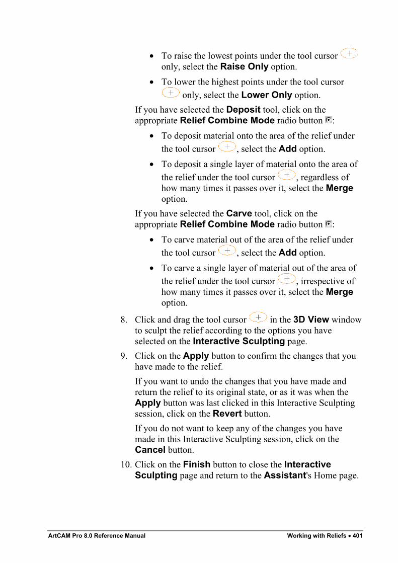
ArtCAM Pro 8.0 Reference Manual Working with Reliefs • 401
• To raise the lowest points under the tool cursor only, select the Raise Only option.
• To lower the highest points under the tool cursor only, select the Lower Only option.
If you have selected the Deposit tool, click on theappropriate Relief Combine Mode radio button :
• To deposit material onto the area of the relief underthe tool cursor , select the Add option.
• To deposit a single layer of material onto the area ofthe relief under the tool cursor , regardless ofhow many times it passes over it, select the Mergeoption.
If you have selected the Carve tool, click on theappropriate Relief Combine Mode radio button :
• To carve material out of the area of the relief underthe tool cursor , select the Add option.
• To carve a single layer of material out of the area ofthe relief under the tool cursor , irrespective ofhow many times it passes over it, select the Mergeoption.
8. Click and drag the tool cursor in the 3D View windowto sculpt the relief according to the options you haveselected on the Interactive Sculpting page.
9. Click on the Apply button to confirm the changes that youhave made to the relief.If you want to undo the changes that you have made andreturn the relief to its original state, or as it was when theApply button was last clicked in this Interactive Sculptingsession, click on the Revert button.If you do not want to keep any of the changes you havemade in this Interactive Sculpting session, click on theCancel button.
10. Click on the Finish button to close the InteractiveSculpting page and return to the Assistant's Home page.
402 • Working with Reliefs ArtCAM Pro 8.0 Reference Manual
Removing Holes in the Relief SurfaceYou can remove any small holes that can be seen on the relief surface.To remove any small holes on the relief surface:
1. From the Main menu bar, click on the Relief menu, andthen on the Remove Small Holes option.
2. Click on the 3D View button in the 2D View toolbar todisplay the 3D View window. Check the relief surface forany small holes that might still be present, and if necessaryrepeat these steps.
Creating a Greyscale Image from a ReliefA greyscale is an image in which the only colours are shades of grey.You can create a greyscale image from the existing relief. For details,see "Creating a Greyscale Image from a Relief" in the Working withModels chapter and "Greyscale View" in the ArtCAM Pro Layoutchapter.
Rotating a Relief or Triangle MeshYou can rotate the relief or triangle model shown in the 3D Viewwindow. This allows you to improve the visualisation of the relief ortriangle model, especially when a reflection map has been projectedonto its surface. For details, see "Adjusting Light and MaterialSettings" in the Working with Models chapter.To rotate a relief or triangle model:
1. Click on the 3D View button to display the 3D Viewwindow.
2. Hold the Ctrl key down on your keyboard, move the cursor over the relief or triangle model, and then push themouse in the direction in which you want to rotate.
To stop the relief or triangle model revolving, click anywhere in the3D View window.You can adjust the speed at which the relief or triangle model revolvesusing the ArtCAM Options page. For details, see "ManagingArtCAM Pro's Preferences" in the ArtCAM Pro Layout chapter.
ArtCAM Pro 8.0 Reference Manual Machining Models • 403
Machining Models
OverviewWarning: It is assumed that you already know how to operate yourmachine tool, and that you are able to select the appropriate tools andthe necessary cutting conditions for the job you are doing. If you arenot confident about any aspect of operating your machine tool,consult a member of staff or your machine tool supplier.
You use toolpaths to machine both two-dimensional and three-dimensional models. 2D toolpaths are used to machine all or part of amodel from the vector objects you have created. 3D toolpaths are usedto machine all or part of a model from the three-dimensional shapesyou have combined to make the relief.ArtCAM Pro provides a database containing a broad selection of toolsthat you can use when creating your toolpaths. You can edit themachining parameters of these tools and add new tools to the databaseif necessary.You can control the cut direction of the tools used for machining byselecting either Conventional or Climb Milling in almost all of thetoolpath strategies available in ArtCAM Pro.In Conventional Milling, the teeth of the tool meet the block ofmaterial at the bottom of the cut. The teeth of the tool slide along untilsufficient pressure builds up to break through the material surface.This sliding action, under pressure, tends to abrade the edge of thetool, which results in dulling. Also, the cutting action has a tendencyto lift the block of material, fixture and table from their positions.
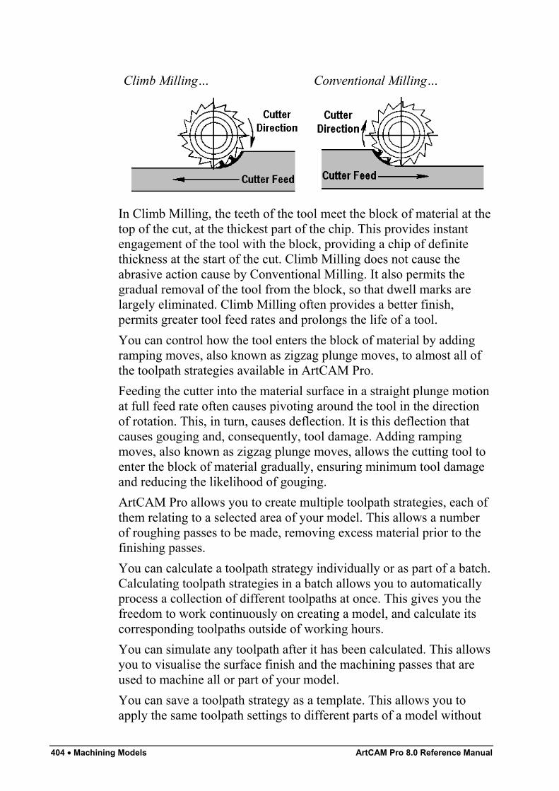
404 • Machining Models ArtCAM Pro 8.0 Reference Manual
Climb Milling… Conventional Milling…
In Climb Milling, the teeth of the tool meet the block of material at thetop of the cut, at the thickest part of the chip. This provides instantengagement of the tool with the block, providing a chip of definitethickness at the start of the cut. Climb Milling does not cause theabrasive action cause by Conventional Milling. It also permits thegradual removal of the tool from the block, so that dwell marks arelargely eliminated. Climb Milling often provides a better finish,permits greater tool feed rates and prolongs the life of a tool.You can control how the tool enters the block of material by addingramping moves, also known as zigzag plunge moves, to almost all ofthe toolpath strategies available in ArtCAM Pro.Feeding the cutter into the material surface in a straight plunge motionat full feed rate often causes pivoting around the tool in the directionof rotation. This, in turn, causes deflection. It is this deflection thatcauses gouging and, consequently, tool damage. Adding rampingmoves, also known as zigzag plunge moves, allows the cutting tool toenter the block of material gradually, ensuring minimum tool damageand reducing the likelihood of gouging.ArtCAM Pro allows you to create multiple toolpath strategies, each ofthem relating to a selected area of your model. This allows a numberof roughing passes to be made, removing excess material prior to thefinishing passes.You can calculate a toolpath strategy individually or as part of a batch.Calculating toolpath strategies in a batch allows you to automaticallyprocess a collection of different toolpaths at once. This gives you thefreedom to work continuously on creating a model, and calculate itscorresponding toolpaths outside of working hours.You can simulate any toolpath after it has been calculated. This allowsyou to visualise the surface finish and the machining passes that areused to machine all or part of your model.You can save a toolpath strategy as a template. This allows you toapply the same toolpath settings to different parts of a model without
ArtCAM Pro 8.0 Reference Manual Machining Models • 405
having to create a toolpath strategy over and over again. A templatecan be applied to a vector object or relief in a model.In order to machine the model that you have created, you must create atoolpath file from the toolpaths you have calculated. A toolpath filecontains one or more calculated toolpaths. Each toolpath is made up ofa sequence of commands which tell a CNC machine tool or laserengraving system the path it is required to follow in order to produceyour model.You can save the toolpath file in a format recognised by your machinetool or engraving system. This ensures that the commands within thetoolpath file are interpreted accurately by your system.If your CNC machine has a tool changer, you can group all of thetoolpath strategies for a series of tools into one machine-specific file.If your CNC machine does not have a tool changer, you must generateseparate toolpath files for each tool that you want to use.
Using ToolpathsArtCAM Pro provides a number of toolpath that you can use tomachine all or part of a two-dimensional or three-dimensional model.These are available using the Toolpaths Home page, which isdisplayed when you click on the Toolpaths tab .For details of the 2D toolpaths that are available in ArtCAM Pro, see"2D Toolpaths" on page 405.For details of the 3D toolpaths that are available in ArtCAM Pro, see"3D Toolpaths" on page 481.You can also find buttons on the Toolpaths Home page that assistyou in managing and modifying the toolpaths you have created. Fordetails, see "Managing and Modifying Toolpaths" on page 508.
2D ToolpathsArtCAM Pro provides a number of two-dimensional toolpaths thatyou can use to machine your model, based on the vector objectscreated within it. These include:
• 2D Profiling. This toolpath allows you to create a toolpatheither inside or outside the boundary of a vector object. Fordetails, see "2D Profiling" on page 407.
406 • Machining Models ArtCAM Pro 8.0 Reference Manual
• 2D Area Clearance. This toolpath allows you to clear anarea of material either inside or outside the boundary of avector object. You can use a range of tools with this strategyand ArtCAM Pro automatically calculates the order inwhich they should be used. For details, see "2D AreaClearance" on page 417.
• V-Bit Carving. This toolpath allows you to replicate ahand carved look for the vector object or vector text youwant to machine. For details, see "V-Bit Carving" on page423.
Warning: You cannot machine a V-Bit Carving toolpath withoutusing a 3-axis machine. For further information, consult a member ofstaff or your machine tool supplier.
• Bevel Carving. This toolpath allows you to replicate abevelled (angle-edged) look for the vector object or vectortext you want to machine. For details, see "Bevel Carving"on page 428.
Warning: You cannot machine a Bevel Carving toolpath withoutusing a 3-axis machine. For further information, consult a member ofstaff or your machine tool supplier.
• Smart Engraving. This toolpath allows you to engravearound the boundary of a vector object or group of vectortext. You can use a range of tools with this strategy andArtCAM Pro automatically calculates the order in whichthey should be used. For details, see "Smart Engraving" onpage 434.
• Drilling Holes. This toolpath allows you to create drillholes using vector objects. For details, see "Drill Holes" onpage 476.
• Machine Vectors. This toolpath allows you to machinealong the boundary of a vector object with the centre of atool. For details, see "Machine Vectors" on page 441.
• Inlay Machining. This toolpath allows you to create aselection of corresponding inlays (female) and inserts(male) from a vector object. For details, see "Inlay Wizard"on page 447.
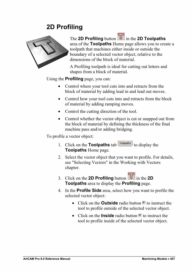
ArtCAM Pro 8.0 Reference Manual Machining Models • 407
2D ProfilingThe 2D Profiling button in the 2D Toolpathsarea of the Toolpaths Home page allows you to create atoolpath that machines either inside or outside theboundary of a selected vector object, relative to thedimensions of the block of material.A Profiling toolpath is ideal for cutting out letters andshapes from a block of material.
Using the Profiling page, you can:• Control where your tool cuts into and retracts from the
block of material by adding lead in and lead out moves.• Control how your tool cuts into and retracts from the block
of material by adding ramping moves.• Control the cutting direction of the tool.• Control whether the vector object is cut or snapped out from
the block of material by defining the thickness of the finalmachine pass and/or adding bridging.
To profile a vector object:
1. Click on the Toolpaths tab to display theToolpaths Home page.
2. Select the vector object that you want to profile. For details,see "Selecting Vectors" in the Working with Vectorschapter.
3. Click on the 2D Profiling button in the 2DToolpaths area to display the Profiling page.
4. In the Profile Side area, select how you want to profile theselected vector object:
• Click on the Outside radio button to instruct thetool to profile outside of the selected vector object.
• Click on the Inside radio button to instruct thetool to profile inside of the selected vector object.
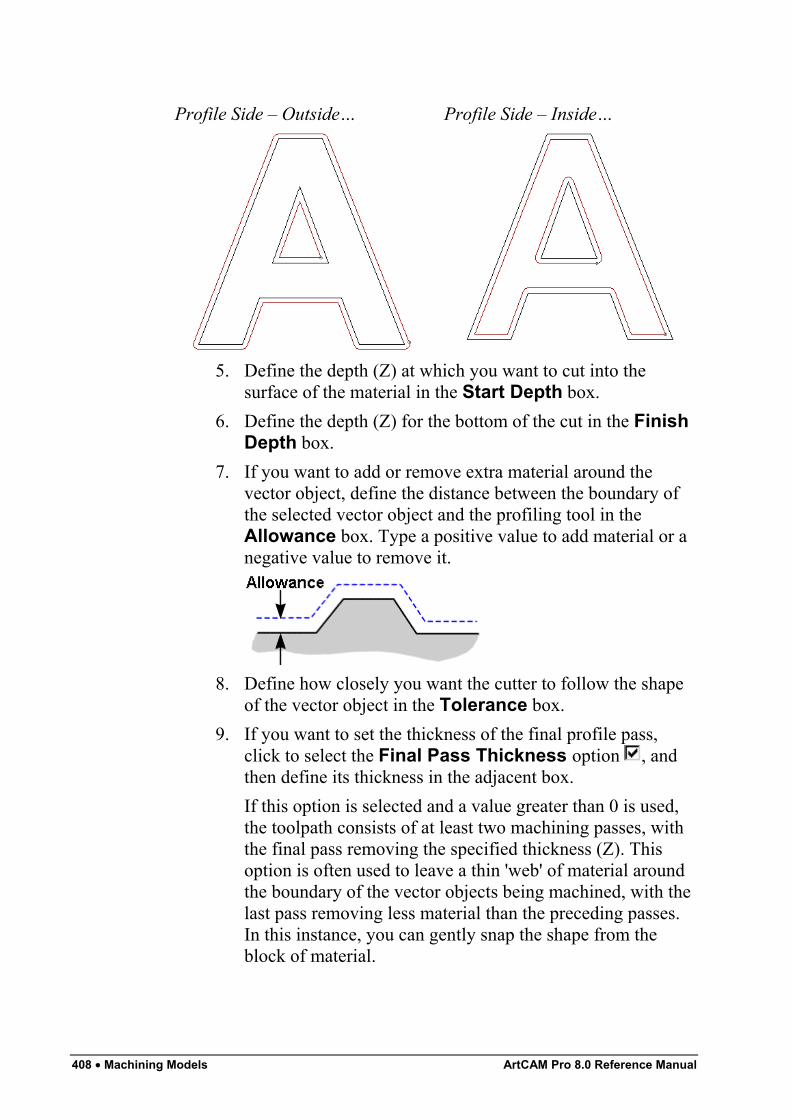
408 • Machining Models ArtCAM Pro 8.0 Reference Manual
Profile Side – Outside… Profile Side – Inside…
5. Define the depth (Z) at which you want to cut into thesurface of the material in the Start Depth box.
6. Define the depth (Z) for the bottom of the cut in the FinishDepth box.
7. If you want to add or remove extra material around thevector object, define the distance between the boundary ofthe selected vector object and the profiling tool in theAllowance box. Type a positive value to add material or anegative value to remove it.
8. Define how closely you want the cutter to follow the shapeof the vector object in the Tolerance box.
9. If you want to set the thickness of the final profile pass,click to select the Final Pass Thickness option , andthen define its thickness in the adjacent box.If this option is selected and a value greater than 0 is used,the toolpath consists of at least two machining passes, withthe final pass removing the specified thickness (Z). Thisoption is often used to leave a thin 'web' of material aroundthe boundary of the vector objects being machined, with thelast pass removing less material than the preceding passes.In this instance, you can gently snap the shape from theblock of material.
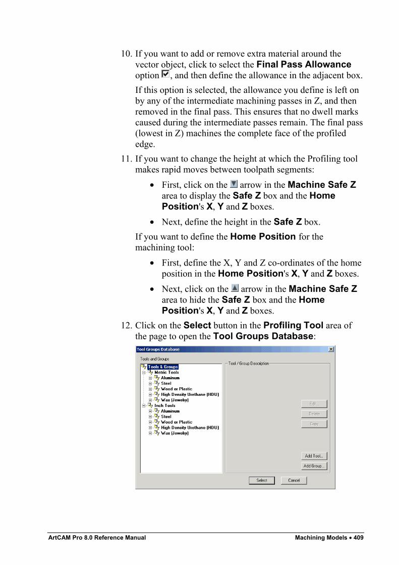
ArtCAM Pro 8.0 Reference Manual Machining Models • 409
10. If you want to add or remove extra material around thevector object, click to select the Final Pass Allowanceoption , and then define the allowance in the adjacent box.If this option is selected, the allowance you define is left onby any of the intermediate machining passes in Z, and thenremoved in the final pass. This ensures that no dwell markscaused during the intermediate passes remain. The final pass(lowest in Z) machines the complete face of the profilededge.
11. If you want to change the height at which the Profiling toolmakes rapid moves between toolpath segments:
• First, click on the arrow in the Machine Safe Zarea to display the Safe Z box and the HomePosition's X, Y and Z boxes.
• Next, define the height in the Safe Z box.If you want to define the Home Position for themachining tool:
• First, define the X, Y and Z co-ordinates of the homeposition in the Home Position's X, Y and Z boxes.
• Next, click on the arrow in the Machine Safe Zarea to hide the Safe Z box and the HomePosition's X, Y and Z boxes.
12. Click on the Select button in the Profiling Tool area ofthe page to open the Tool Groups Database:
410 • Machining Models ArtCAM Pro 8.0 Reference Manual
13. Double-click on the tool you want to use. ArtCAM Procloses the Tool Groups Database and displays theselected tool's description in the Profiling Tool area.If you want to amend the machining parameters for theselected tool, click on the arrow in the Profiling Toolarea. For further information, see "Adjusting MachiningParameters When Creating a Toolpath" on page 540.When you have finished, click on the arrow to hide themachining parameters.
14. The cutting direction defaults to Climb Mill. If you want tochange this, click on the arrow in the Cut Directionarea, then click on either of the Cut Direction radiobuttons :
• Climb Mill - Climb Milling rotates the cutter in thesame direction as the feed motion.
• Conventional – Conventional Milling rotates thecutter in the opposite direction to the feed motion.
For more details, see "Overview" on page 403.
Note: You can set the default cutting direction in ArtCAM Pro usingthe ArtCAM Options page. For details, see "Managing ArtCAMPro's Preferences" in the ArtCAM Pro Layout chapter.
15. To add lead-in and lead-out moves to the toolpath, click toselect the Add Lead In/Out Moves option . The leadmoves settings are displayed:
• If you only want to have a lead-in move, click toselect the Do not Lead Out option .
• Define the distance from the toolpath that you wantthe tool to cut into and retract from the vectorobject's boundary in the Distance (D) box.
• Define the distance from the start/end point in theprofile pass that you want the tool to machine over inthe Over Cut (O) box. This further helps to create asmooth finish.
• Select how you want the tool to move using the AddLead In/Out Moves radio buttons :
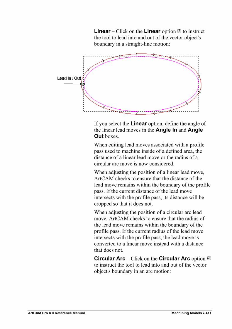
ArtCAM Pro 8.0 Reference Manual Machining Models • 411
Linear – Click on the Linear option to instructthe tool to lead into and out of the vector object'sboundary in a straight-line motion:
If you select the Linear option, define the angle ofthe linear lead moves in the Angle In and AngleOut boxes.When editing lead moves associated with a profilepass used to machine inside of a defined area, thedistance of a linear lead move or the radius of acircular arc move is now considered.When adjusting the position of a linear lead move,ArtCAM checks to ensure that the distance of thelead move remains within the boundary of the profilepass. If the current distance of the lead moveintersects with the profile pass, its distance will becropped so that it does not.When adjusting the position of a circular arc leadmove, ArtCAM checks to ensure that the radius ofthe lead move remains within the boundary of theprofile pass. If the current radius of the lead moveintersects with the profile pass, the lead move isconverted to a linear move instead with a distancethat does not.Circular Arc – Click on the Circular Arc option to instruct the tool to lead into and out of the vectorobject's boundary in an arc motion:
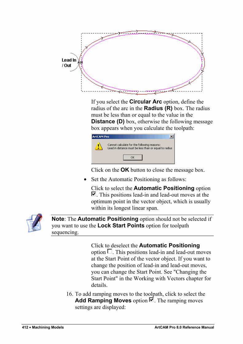
412 • Machining Models ArtCAM Pro 8.0 Reference Manual
If you select the Circular Arc option, define theradius of the arc in the Radius (R) box. The radiusmust be less than or equal to the value in theDistance (D) box, otherwise the following messagebox appears when you calculate the toolpath:
Click on the OK button to close the message box.• Set the Automatic Positioning as follows:
Click to select the Automatic Positioning option. This positions lead-in and lead-out moves at the
optimum point in the vector object, which is usuallywithin its longest linear span.
Note: The Automatic Positioning option should not be selected ifyou want to use the Lock Start Points option for toolpathsequencing.
Click to deselect the Automatic Positioningoption . This positions lead-in and lead-out movesat the Start Point of the vector object. If you want tochange the position of lead-in and lead-out moves,you can change the Start Point. See "Changing theStart Point" in the Working with Vectors chapter fordetails.
16. To add ramping moves to the toolpath, click to select theAdd Ramping Moves option . The ramping movessettings are displayed:
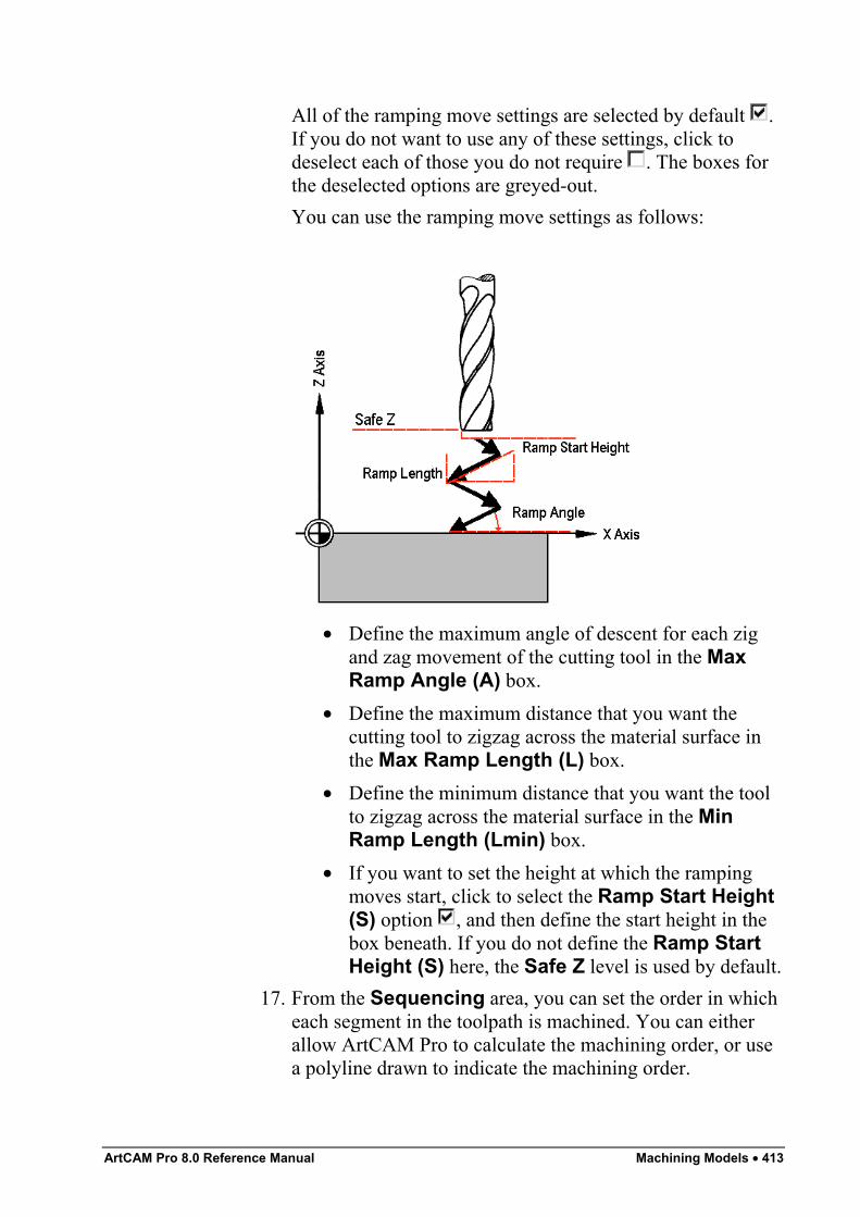
ArtCAM Pro 8.0 Reference Manual Machining Models • 413
All of the ramping move settings are selected by default .If you do not want to use any of these settings, click todeselect each of those you do not require . The boxes forthe deselected options are greyed-out.You can use the ramping move settings as follows:
• Define the maximum angle of descent for each zigand zag movement of the cutting tool in the MaxRamp Angle (A) box.
• Define the maximum distance that you want thecutting tool to zigzag across the material surface inthe Max Ramp Length (L) box.
• Define the minimum distance that you want the toolto zigzag across the material surface in the MinRamp Length (Lmin) box.
• If you want to set the height at which the rampingmoves start, click to select the Ramp Start Height(S) option , and then define the start height in thebox beneath. If you do not define the Ramp StartHeight (S) here, the Safe Z level is used by default.
17. From the Sequencing area, you can set the order in whicheach segment in the toolpath is machined. You can eitherallow ArtCAM Pro to calculate the machining order, or usea polyline drawn to indicate the machining order.
414 • Machining Models ArtCAM Pro 8.0 Reference Manual
If you want to ArtCAM Pro to calculate the order in whicheach segment in the toolpath is machined:
• First, click on the Auto radio button .• Next, click on the list box and then on the option that
you want to use for the machining order:Optimise – Click on this option to instruct ArtCAMPro to find the most efficient machining order.Use Text Order – Click on this option to instructArtCAM Pro to machine according to the order inwhich the selected vector text was created. Thecutting tool moves along the first line of text fromleft to right, until it locates a carriage return when itcontinues machining along the next line from right toleft. This process is repeated until the last characterin the last line of text is located.Left To Right – Click on this option to instructArtCAM Pro to machine from the left of the modelto the right.Right To Left – Click on this option to instructArtCAM Pro to machine from the right of the modelto the left.Bottom To Top – Click on this option to instructArtCAM Pro to machine from the bottom of themodel to its top.Top To Bottom – Click on this option to instructArtCAM Pro to machine from the top of the model tothe bottom.Spiral Out – Click on this option to instructArtCAM Pro to machine from the centre of themodel outwards in a spiral motion. This isparticularly useful if you are using clamps to securethe material on your router.Spiral In – Click on this option to instruct ArtCAMPro to machine from the outside edge of the modelinwards in a spiral motion.
If you want to manually set the order in which each segmentin the toolpath is machined:
• First, click on the Manual radio button .
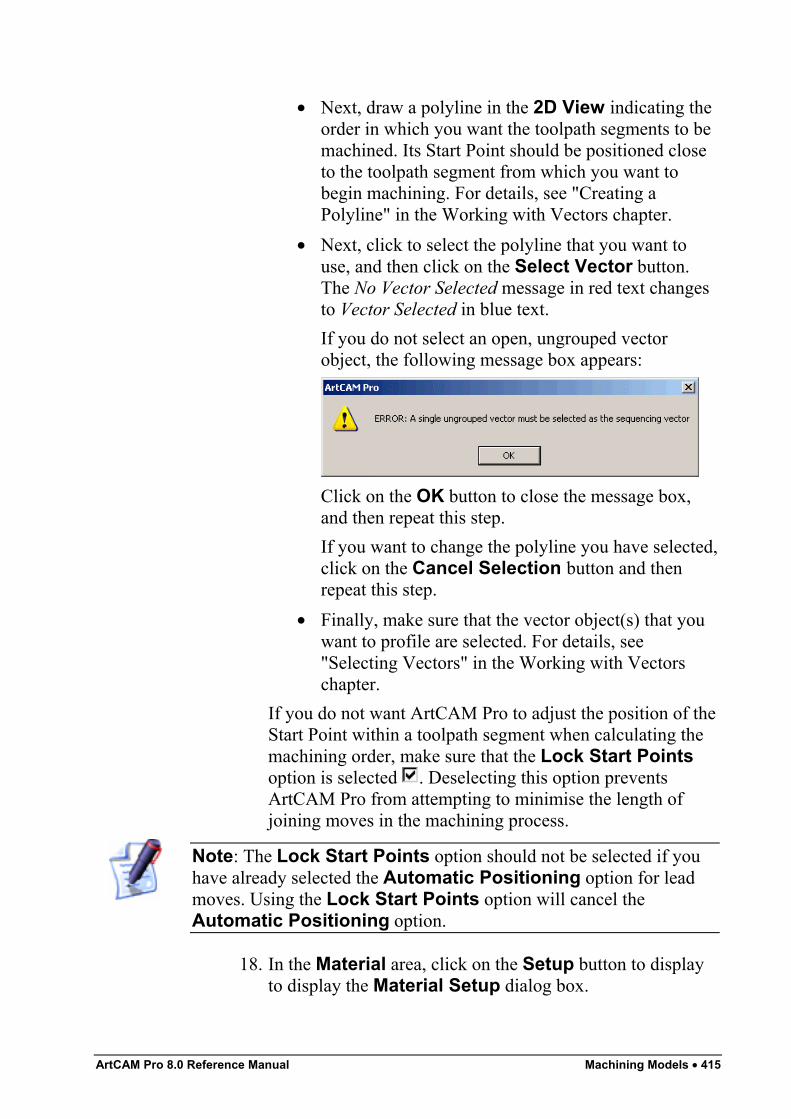
ArtCAM Pro 8.0 Reference Manual Machining Models • 415
• Next, draw a polyline in the 2D View indicating theorder in which you want the toolpath segments to bemachined. Its Start Point should be positioned closeto the toolpath segment from which you want tobegin machining. For details, see "Creating aPolyline" in the Working with Vectors chapter.
• Next, click to select the polyline that you want touse, and then click on the Select Vector button.The No Vector Selected message in red text changesto Vector Selected in blue text.If you do not select an open, ungrouped vectorobject, the following message box appears:
Click on the OK button to close the message box,and then repeat this step.If you want to change the polyline you have selected,click on the Cancel Selection button and thenrepeat this step.
• Finally, make sure that the vector object(s) that youwant to profile are selected. For details, see"Selecting Vectors" in the Working with Vectorschapter.
If you do not want ArtCAM Pro to adjust the position of theStart Point within a toolpath segment when calculating themachining order, make sure that the Lock Start Pointsoption is selected . Deselecting this option preventsArtCAM Pro from attempting to minimise the length ofjoining moves in the machining process.
Note: The Lock Start Points option should not be selected if youhave already selected the Automatic Positioning option for leadmoves. Using the Lock Start Points option will cancel theAutomatic Positioning option.
18. In the Material area, click on the Setup button to displayto display the Material Setup dialog box.
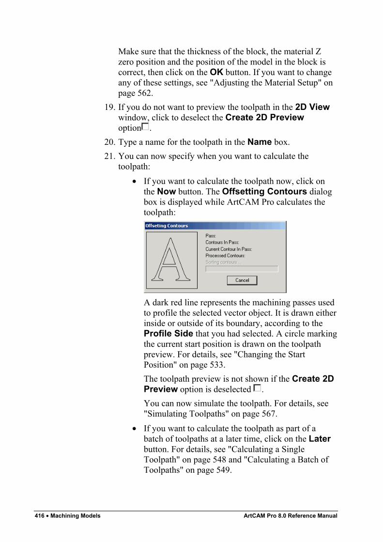
416 • Machining Models ArtCAM Pro 8.0 Reference Manual
Make sure that the thickness of the block, the material Zzero position and the position of the model in the block iscorrect, then click on the OK button. If you want to changeany of these settings, see "Adjusting the Material Setup" onpage 562.
19. If you do not want to preview the toolpath in the 2D Viewwindow, click to deselect the Create 2D Previewoption .
20. Type a name for the toolpath in the Name box.21. You can now specify when you want to calculate the
toolpath:• If you want to calculate the toolpath now, click on
the Now button. The Offsetting Contours dialogbox is displayed while ArtCAM Pro calculates thetoolpath:
A dark red line represents the machining passes usedto profile the selected vector object. It is drawn eitherinside or outside of its boundary, according to theProfile Side that you had selected. A circle markingthe current start position is drawn on the toolpathpreview. For details, see "Changing the StartPosition" on page 533.The toolpath preview is not shown if the Create 2DPreview option is deselected .You can now simulate the toolpath. For details, see"Simulating Toolpaths" on page 567.
• If you want to calculate the toolpath as part of abatch of toolpaths at a later time, click on the Laterbutton. For details, see "Calculating a SingleToolpath" on page 548 and "Calculating a Batch ofToolpaths" on page 549.
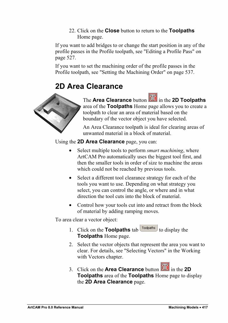
ArtCAM Pro 8.0 Reference Manual Machining Models • 417
22. Click on the Close button to return to the ToolpathsHome page.
If you want to add bridges to or change the start position in any of theprofile passes in the Profile toolpath, see "Editing a Profile Pass" onpage 527.If you want to set the machining order of the profile passes in theProfile toolpath, see "Setting the Machining Order" on page 537.
2D Area ClearanceThe Area Clearance button in the 2D Toolpathsarea of the Toolpaths Home page allows you to create atoolpath to clear an area of material based on theboundary of the vector object you have selected.An Area Clearance toolpath is ideal for clearing areas ofunwanted material in a block of material.
Using the 2D Area Clearance page, you can:• Select multiple tools to perform smart machining, where
ArtCAM Pro automatically uses the biggest tool first, andthen the smaller tools in order of size to machine the areaswhich could not be reached by previous tools.
• Select a different tool clearance strategy for each of thetools you want to use. Depending on what strategy youselect, you can control the angle, or where and in whatdirection the tool cuts into the block of material.
• Control how your tools cut into and retract from the blockof material by adding ramping moves.
To area clear a vector object:
1. Click on the Toolpaths tab to display theToolpaths Home page.
2. Select the vector objects that represent the area you want toclear. For details, see "Selecting Vectors" in the Workingwith Vectors chapter.
3. Click on the Area Clearance button in the 2DToolpaths area of the Toolpaths Home page to displaythe 2D Area Clearance page.
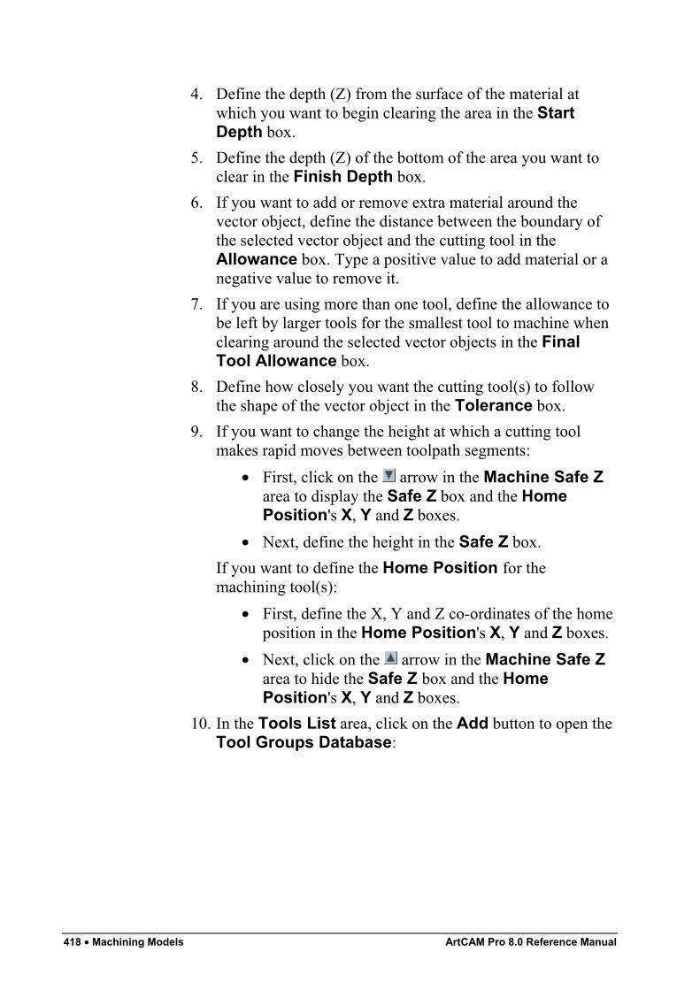
418 • Machining Models ArtCAM Pro 8.0 Reference Manual
4. Define the depth (Z) from the surface of the material atwhich you want to begin clearing the area in the StartDepth box.
5. Define the depth (Z) of the bottom of the area you want toclear in the Finish Depth box.
6. If you want to add or remove extra material around thevector object, define the distance between the boundary ofthe selected vector object and the cutting tool in theAllowance box. Type a positive value to add material or anegative value to remove it.
7. If you are using more than one tool, define the allowance tobe left by larger tools for the smallest tool to machine whenclearing around the selected vector objects in the FinalTool Allowance box.
8. Define how closely you want the cutting tool(s) to followthe shape of the vector object in the Tolerance box.
9. If you want to change the height at which a cutting toolmakes rapid moves between toolpath segments:
• First, click on the arrow in the Machine Safe Zarea to display the Safe Z box and the HomePosition's X, Y and Z boxes.
• Next, define the height in the Safe Z box.If you want to define the Home Position for themachining tool(s):
• First, define the X, Y and Z co-ordinates of the homeposition in the Home Position's X, Y and Z boxes.
• Next, click on the arrow in the Machine Safe Zarea to hide the Safe Z box and the HomePosition's X, Y and Z boxes.
10. In the Tools List area, click on the Add button to open theTool Groups Database:
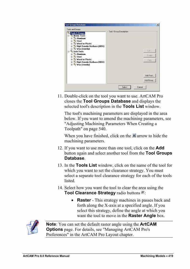
ArtCAM Pro 8.0 Reference Manual Machining Models • 419
11. Double-click on the tool you want to use. ArtCAM Procloses the Tool Groups Database and displays theselected tool's description in the Tools List window.The tool's machining parameters are displayed in the areabelow. If you want to amend the machining parameters, see"Adjusting Machining Parameters When Creating aToolpath" on page 540.When you have finished, click on the arrow to hide themachining parameters.
12. If you want to use more than one tool, click on the Addbutton again and select another tool from the Tool GroupsDatabase.
13. In the Tools List window, click on the name of the tool forwhich you want to set the clearance strategy. You mustselect a separate tool clearance strategy for each of the toolslisted.
14. Select how you want the tool to clear the area using theTool Clearance Strategy radio buttons :
• Raster - This strategy machines in passes back andforth along the X-axis at a specified angle. If youselect this strategy, define the angle at which youwant the tool to move in the Raster Angle box.
Note: You can set the default raster angle using the ArtCAMOptions page. For details, see "Managing ArtCAM Pro'sPreferences" in the ArtCAM Pro Layout chapter.
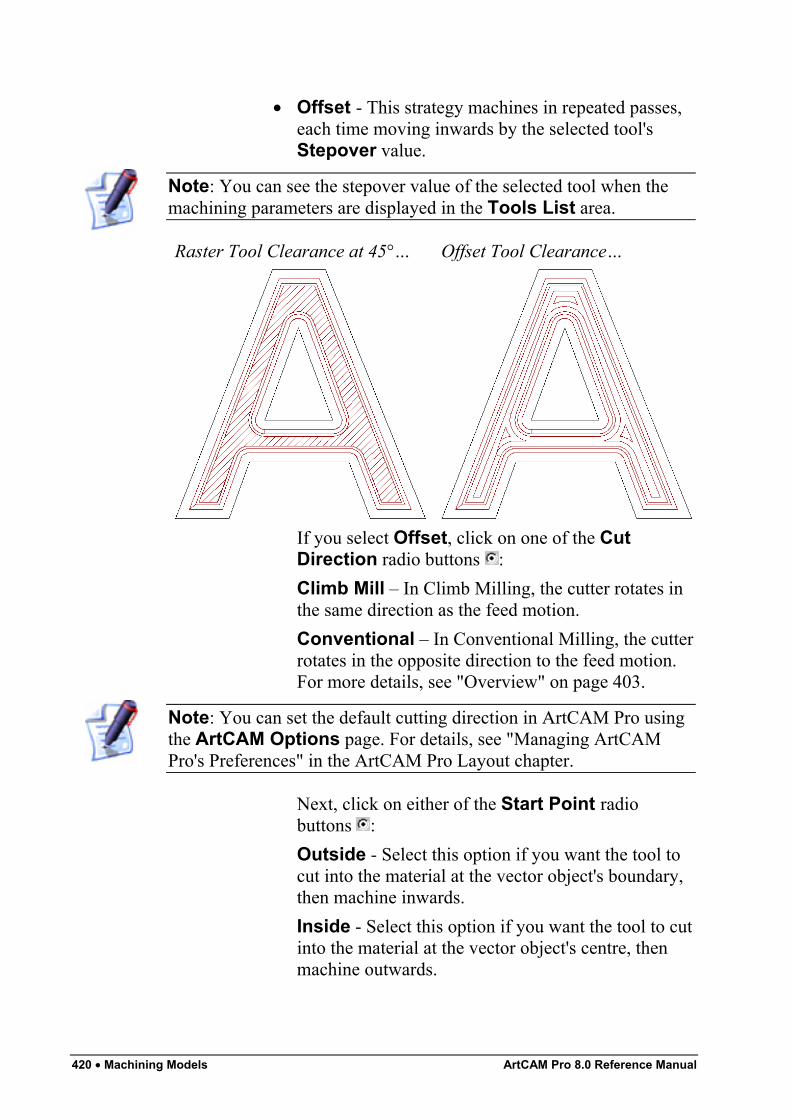
420 • Machining Models ArtCAM Pro 8.0 Reference Manual
• Offset - This strategy machines in repeated passes,each time moving inwards by the selected tool'sStepover value.
Note: You can see the stepover value of the selected tool when themachining parameters are displayed in the Tools List area.
Raster Tool Clearance at 45°… Offset Tool Clearance…
If you select Offset, click on one of the CutDirection radio buttons :Climb Mill – In Climb Milling, the cutter rotates inthe same direction as the feed motion.Conventional – In Conventional Milling, the cutterrotates in the opposite direction to the feed motion.For more details, see "Overview" on page 403.
Note: You can set the default cutting direction in ArtCAM Pro usingthe ArtCAM Options page. For details, see "Managing ArtCAMPro's Preferences" in the ArtCAM Pro Layout chapter.
Next, click on either of the Start Point radiobuttons :Outside - Select this option if you want the tool tocut into the material at the vector object's boundary,then machine inwards.Inside - Select this option if you want the tool to cutinto the material at the vector object's centre, thenmachine outwards.
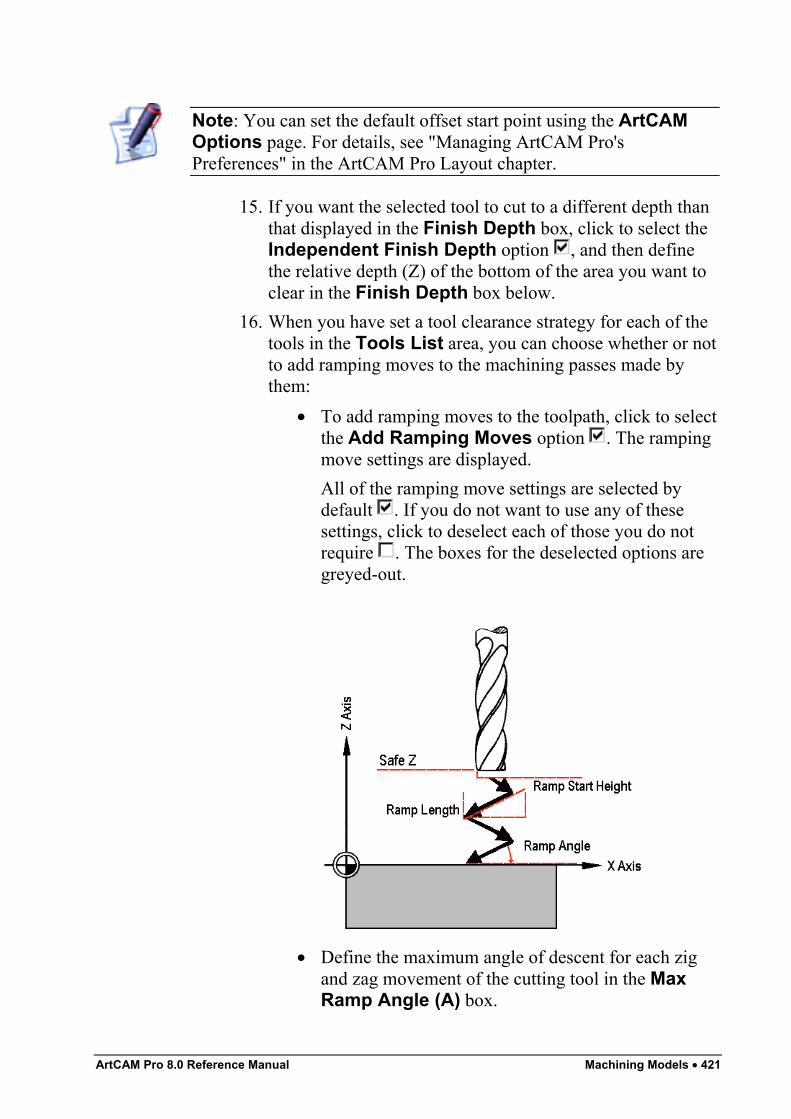
ArtCAM Pro 8.0 Reference Manual Machining Models • 421
Note: You can set the default offset start point using the ArtCAMOptions page. For details, see "Managing ArtCAM Pro'sPreferences" in the ArtCAM Pro Layout chapter.
15. If you want the selected tool to cut to a different depth thanthat displayed in the Finish Depth box, click to select theIndependent Finish Depth option , and then definethe relative depth (Z) of the bottom of the area you want toclear in the Finish Depth box below.
16. When you have set a tool clearance strategy for each of thetools in the Tools List area, you can choose whether or notto add ramping moves to the machining passes made bythem:
• To add ramping moves to the toolpath, click to selectthe Add Ramping Moves option . The rampingmove settings are displayed.All of the ramping move settings are selected bydefault . If you do not want to use any of thesesettings, click to deselect each of those you do notrequire . The boxes for the deselected options aregreyed-out.
• Define the maximum angle of descent for each zigand zag movement of the cutting tool in the MaxRamp Angle (A) box.
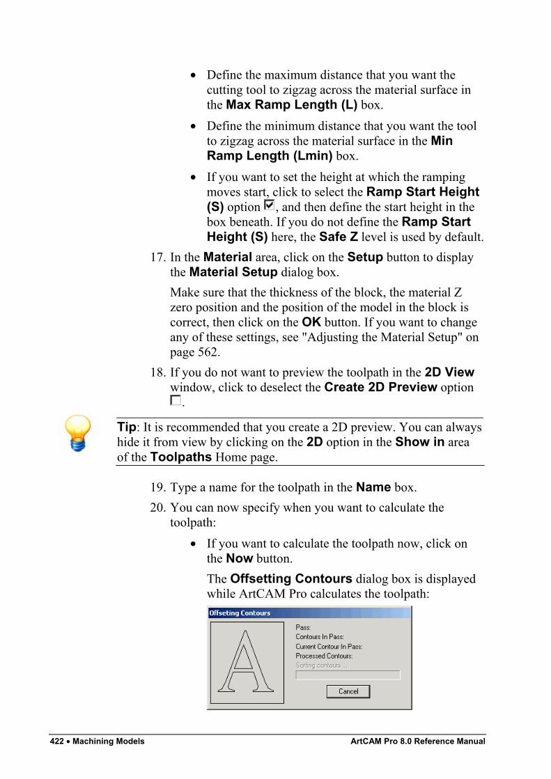
422 • Machining Models ArtCAM Pro 8.0 Reference Manual
• Define the maximum distance that you want thecutting tool to zigzag across the material surface inthe Max Ramp Length (L) box.
• Define the minimum distance that you want the toolto zigzag across the material surface in the MinRamp Length (Lmin) box.
• If you want to set the height at which the rampingmoves start, click to select the Ramp Start Height(S) option , and then define the start height in thebox beneath. If you do not define the Ramp StartHeight (S) here, the Safe Z level is used by default.
17. In the Material area, click on the Setup button to displaythe Material Setup dialog box.Make sure that the thickness of the block, the material Zzero position and the position of the model in the block iscorrect, then click on the OK button. If you want to changeany of these settings, see "Adjusting the Material Setup" onpage 562.
18. If you do not want to preview the toolpath in the 2D Viewwindow, click to deselect the Create 2D Preview option
.
Tip: It is recommended that you create a 2D preview. You can alwayshide it from view by clicking on the 2D option in the Show in areaof the Toolpaths Home page.
19. Type a name for the toolpath in the Name box.20. You can now specify when you want to calculate the
toolpath:• If you want to calculate the toolpath now, click on
the Now button.The Offsetting Contours dialog box is displayedwhile ArtCAM Pro calculates the toolpath:
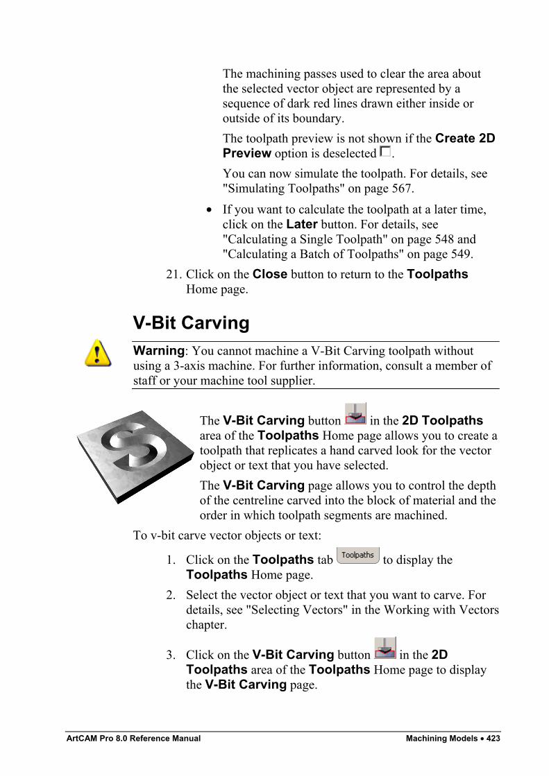
ArtCAM Pro 8.0 Reference Manual Machining Models • 423
The machining passes used to clear the area aboutthe selected vector object are represented by asequence of dark red lines drawn either inside oroutside of its boundary.The toolpath preview is not shown if the Create 2DPreview option is deselected .You can now simulate the toolpath. For details, see"Simulating Toolpaths" on page 567.
• If you want to calculate the toolpath at a later time,click on the Later button. For details, see"Calculating a Single Toolpath" on page 548 and"Calculating a Batch of Toolpaths" on page 549.
21. Click on the Close button to return to the ToolpathsHome page.
V-Bit CarvingWarning: You cannot machine a V-Bit Carving toolpath withoutusing a 3-axis machine. For further information, consult a member ofstaff or your machine tool supplier.
The V-Bit Carving button in the 2D Toolpathsarea of the Toolpaths Home page allows you to create atoolpath that replicates a hand carved look for the vectorobject or text that you have selected.The V-Bit Carving page allows you to control the depthof the centreline carved into the block of material and theorder in which toolpath segments are machined.
To v-bit carve vector objects or text:
1. Click on the Toolpaths tab to display theToolpaths Home page.
2. Select the vector object or text that you want to carve. Fordetails, see "Selecting Vectors" in the Working with Vectorschapter.
3. Click on the V-Bit Carving button in the 2DToolpaths area of the Toolpaths Home page to displaythe V-Bit Carving page.
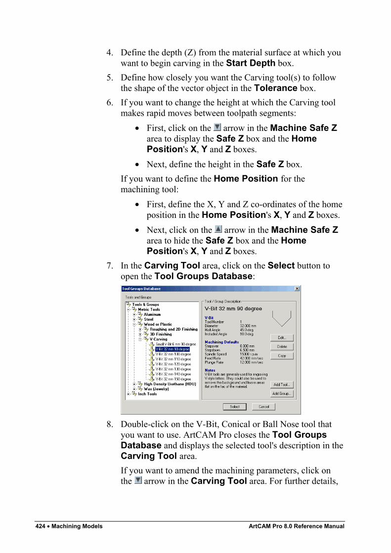
424 • Machining Models ArtCAM Pro 8.0 Reference Manual
4. Define the depth (Z) from the material surface at which youwant to begin carving in the Start Depth box.
5. Define how closely you want the Carving tool(s) to followthe shape of the vector object in the Tolerance box.
6. If you want to change the height at which the Carving toolmakes rapid moves between toolpath segments:
• First, click on the arrow in the Machine Safe Zarea to display the Safe Z box and the HomePosition's X, Y and Z boxes.
• Next, define the height in the Safe Z box.If you want to define the Home Position for themachining tool:
• First, define the X, Y and Z co-ordinates of the homeposition in the Home Position's X, Y and Z boxes.
• Next, click on the arrow in the Machine Safe Zarea to hide the Safe Z box and the HomePosition's X, Y and Z boxes.
7. In the Carving Tool area, click on the Select button toopen the Tool Groups Database:
8. Double-click on the V-Bit, Conical or Ball Nose tool thatyou want to use. ArtCAM Pro closes the Tool GroupsDatabase and displays the selected tool's description in theCarving Tool area.If you want to amend the machining parameters, click onthe arrow in the Carving Tool area. For further details,
ArtCAM Pro 8.0 Reference Manual Machining Models • 425
see "Adjusting Machining Parameters When Creating aToolpath" on page 540.When you have finished, click on the arrow to hide themachining parameters.
9. From the Sequencing area, you can set the order in whicheach segment in the toolpath is machined. You can eitherallow ArtCAM Pro to calculate the machining order, or usea polyline drawn to indicate the machining order.If you want to ArtCAM Pro to calculate the order in whicheach segment in the toolpath is machined:
• First, click on the Auto radio button .• Next, click on the list box and then on the option that
you want to use for the machining order:Optimise – Click on this option to instruct ArtCAMPro to find the most efficient machining order.Use Text Order – Click on this option to instructArtCAM Pro to machine according to the order inwhich the selected vector text was created. Thecutting tool moves along the first line of text fromleft to right, until it locates a carriage return when itcontinues machining along the next line from right toleft. This process is repeated until the last characterin the last line of text is located.Left To Right – Click on this option to instructArtCAM Pro to machine from the left of the modelto the right.Right To Left – Click on this option to instructArtCAM Pro to machine from the right of the modelto the left.Bottom To Top – Click on this option to instructArtCAM Pro to machine from the bottom of themodel to its top.Top To Bottom – Click on this option to instructArtCAM Pro to machine from the top of the model tothe bottom.Spiral Out – Click on this option to instructArtCAM Pro to machine from the centre of themodel outwards in a spiral motion. This is
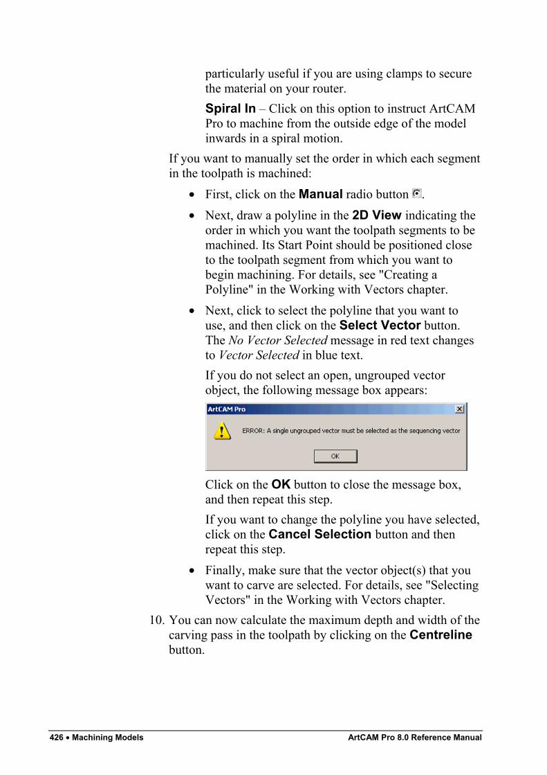
426 • Machining Models ArtCAM Pro 8.0 Reference Manual
particularly useful if you are using clamps to securethe material on your router.Spiral In – Click on this option to instruct ArtCAMPro to machine from the outside edge of the modelinwards in a spiral motion.
If you want to manually set the order in which each segmentin the toolpath is machined:
• First, click on the Manual radio button .• Next, draw a polyline in the 2D View indicating the
order in which you want the toolpath segments to bemachined. Its Start Point should be positioned closeto the toolpath segment from which you want tobegin machining. For details, see "Creating aPolyline" in the Working with Vectors chapter.
• Next, click to select the polyline that you want touse, and then click on the Select Vector button.The No Vector Selected message in red text changesto Vector Selected in blue text.If you do not select an open, ungrouped vectorobject, the following message box appears:
Click on the OK button to close the message box,and then repeat this step.If you want to change the polyline you have selected,click on the Cancel Selection button and thenrepeat this step.
• Finally, make sure that the vector object(s) that youwant to carve are selected. For details, see "SelectingVectors" in the Working with Vectors chapter.
10. You can now calculate the maximum depth and width of thecarving pass in the toolpath by clicking on the Centrelinebutton.
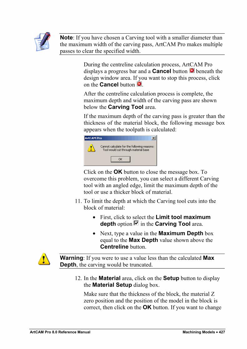
ArtCAM Pro 8.0 Reference Manual Machining Models • 427
Note: If you have chosen a Carving tool with a smaller diameter thanthe maximum width of the carving pass, ArtCAM Pro makes multiplepasses to clear the specified width.
During the centreline calculation process, ArtCAM Prodisplays a progress bar and a Cancel button beneath thedesign window area. If you want to stop this process, clickon the Cancel button .After the centreline calculation process is complete, themaximum depth and width of the carving pass are shownbelow the Carving Tool area.If the maximum depth of the carving pass is greater than thethickness of the material block, the following message boxappears when the toolpath is calculated:
Click on the OK button to close the message box. Toovercome this problem, you can select a different Carvingtool with an angled edge, limit the maximum depth of thetool or use a thicker block of material.
11. To limit the depth at which the Carving tool cuts into theblock of material:
• First, click to select the Limit tool maximumdepth option in the Carving Tool area.
• Next, type a value in the Maximum Depth boxequal to the Max Depth value shown above theCentreline button.
Warning: If you were to use a value less than the calculated MaxDepth, the carving would be truncated.
12. In the Material area, click on the Setup button to displaythe Material Setup dialog box.Make sure that the thickness of the block, the material Zzero position and the position of the model in the block iscorrect, then click on the OK button. If you want to change
428 • Machining Models ArtCAM Pro 8.0 Reference Manual
any of these settings, see "Adjusting the Material Setup" onpage 562.
13. If you do not want to preview the toolpath in the 2D Viewwindow, click to deselect the Create 2D Preview option
.
Tip: It is recommended that you create a 2D preview. You can alwayshide it from view by clicking on the 2D option in the Show in areaof the Toolpaths Home page.
14. Type a name for the toolpath in the Name box.15. You can now specify when you want to calculate the
toolpath:• If you want to calculate the toolpath now, click on
the Now button.If you have not already calculated the carving pass inthe toolpath, the selected vector object is colour-filled in cyan during the centreline calculationprocess.Dark red lines drawn inside its boundary representthe machining passes used to carve the selectedvector object.The toolpath preview is not shown if the Create 2DPreview option is deselected .You can now simulate the toolpath. For details, see"Simulating Toolpaths" on page 567.
• If you want to calculate the toolpath at a later time,click on the Later button. See "Calculating a SingleToolpath" on page 548 and "Calculating a Batch ofToolpaths" on page 549 for details.
16. Click on the Close button to return to the ToolpathsHome page.
Bevel CarvingWarning: You cannot machine a Bevel Carving toolpath withoutusing a 3-axis machine. For further information, consult a member ofstaff or your machine tool supplier.
ArtCAM Pro 8.0 Reference Manual Machining Models • 429
The Bevel Carving button in the 2D Toolpathsarea of the Toolpaths Home page allows you to create atoolpath that replicates a bevelled (angled-edge) look forthe vector text or object that you have selected.To create a bevel carving, you must use two types oftool:
• An angled-edge carving tool to create thebevelled edge.
• A profiling tool to create the vertical wallbelow the bevelled edge.
The angle of the bevelled edge is determined by the angle of thecarving tool.Using the Bevel Carving page, you can:
• Choose whether or not you want to create a vertical wall inthe bevel carving.
• Control the height of the angled edge in the bevel carving.• Control the cutting direction of the tool.
To begin bevelling your vector text or object you must:
1. Click on the Toolpaths tab to display theToolpaths Home page.
2. Select the vector object from which you want to create abevel carving. For details, see "Selecting Vectors" in theWorking with Vectors chapter.
3. Click on the Bevel Carving button in the 2DToolpaths area of the Toolpaths Home page to displaythe Bevel Carving page.
4. Define the depth (Z) from the material surface at which youwant to begin carving in the Start Depth box. This is theapex of the bevel carved object.
5. Define the height of the wall in the material block in theWall Height box. This is the vertical wall below thebevelled edge.
Note: If you do create a vertical wall, a Profiling tool must be usedwhen machining.
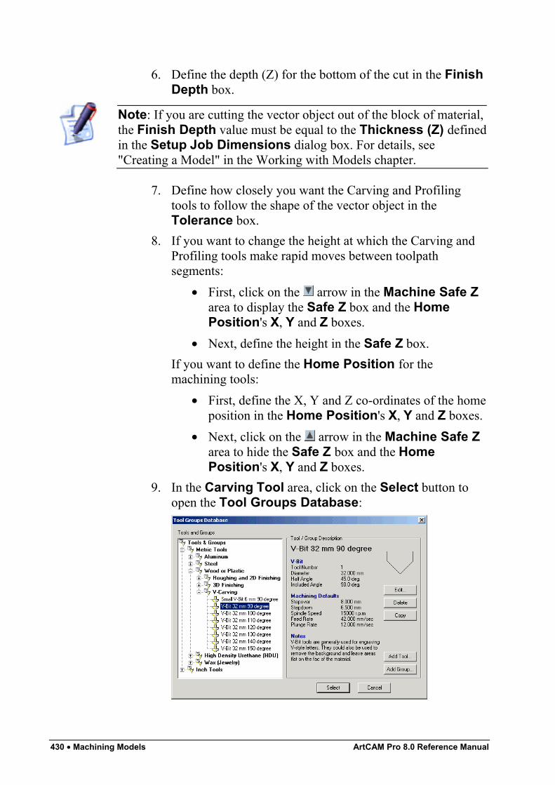
430 • Machining Models ArtCAM Pro 8.0 Reference Manual
6. Define the depth (Z) for the bottom of the cut in the FinishDepth box.
Note: If you are cutting the vector object out of the block of material,the Finish Depth value must be equal to the Thickness (Z) definedin the Setup Job Dimensions dialog box. For details, see"Creating a Model" in the Working with Models chapter.
7. Define how closely you want the Carving and Profilingtools to follow the shape of the vector object in theTolerance box.
8. If you want to change the height at which the Carving andProfiling tools make rapid moves between toolpathsegments:
• First, click on the arrow in the Machine Safe Zarea to display the Safe Z box and the HomePosition's X, Y and Z boxes.
• Next, define the height in the Safe Z box.If you want to define the Home Position for themachining tools:
• First, define the X, Y and Z co-ordinates of the homeposition in the Home Position's X, Y and Z boxes.
• Next, click on the arrow in the Machine Safe Zarea to hide the Safe Z box and the HomePosition's X, Y and Z boxes.
9. In the Carving Tool area, click on the Select button toopen the Tool Groups Database:
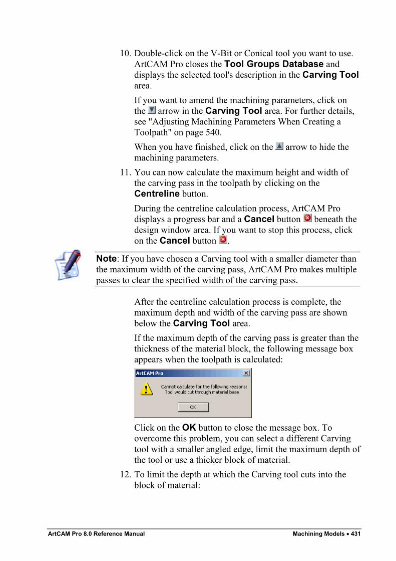
ArtCAM Pro 8.0 Reference Manual Machining Models • 431
10. Double-click on the V-Bit or Conical tool you want to use.ArtCAM Pro closes the Tool Groups Database anddisplays the selected tool's description in the Carving Toolarea.If you want to amend the machining parameters, click onthe arrow in the Carving Tool area. For further details,see "Adjusting Machining Parameters When Creating aToolpath" on page 540.When you have finished, click on the arrow to hide themachining parameters.
11. You can now calculate the maximum height and width ofthe carving pass in the toolpath by clicking on theCentreline button.During the centreline calculation process, ArtCAM Prodisplays a progress bar and a Cancel button beneath thedesign window area. If you want to stop this process, clickon the Cancel button .
Note: If you have chosen a Carving tool with a smaller diameter thanthe maximum width of the carving pass, ArtCAM Pro makes multiplepasses to clear the specified width of the carving pass.
After the centreline calculation process is complete, themaximum depth and width of the carving pass are shownbelow the Carving Tool area.If the maximum depth of the carving pass is greater than thethickness of the material block, the following message boxappears when the toolpath is calculated:
Click on the OK button to close the message box. Toovercome this problem, you can select a different Carvingtool with a smaller angled edge, limit the maximum depth ofthe tool or use a thicker block of material.
12. To limit the depth at which the Carving tool cuts into theblock of material:
432 • Machining Models ArtCAM Pro 8.0 Reference Manual
• First, click to select the Limit tool maximumdepth option in the Carving Tool area.
• Next, type a value in the Maximum Depth boxequal to the Max Depth value shown below theCarving Tool area.
Warning: If you were to use a value less than the calculated MaxDepth, the carving would be truncated.
13. Click on the Select button in the Profiling Tool area ofthe page to open the Tool Groups Database again.
14. Double-click on the tool you want to use to display itsdescription in the Profiling Tool area.If you want to amend the machining parameters, click onthe arrow in the Profiling Tool area. For further details,see "Adjusting Machining Parameters When Creating aToolpath" on page 540.When you have finished, click on the arrow to hide themachining parameters.
15. To set the cut direction of the Profiling Tool, click on the arrow in the Cut Direction area, and then click on either
of the Cut Direction radio buttons :• Climb Mill – In Climb Milling, the cutter rotates in
the same direction as the feed motion.• Conventional – In Conventional Milling, the cutter
rotates in the opposite direction to the feed motion.For more details, see "Overview" on page 403.
16. In the Material area, click on the Setup button to displaythe Material Setup dialog box.Make sure that the thickness of the block, the material Zzero position and the position of the model in the block iscorrect, then click on the OK button. If you want to changeany of these settings, see "Adjusting the Material Setup" onpage 562.
17. If you do not want to preview the toolpath in the 2D Viewwindow, click to deselect the Create 2D Preview option
.
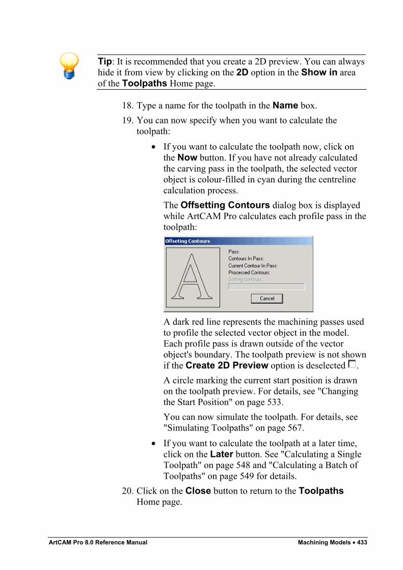
ArtCAM Pro 8.0 Reference Manual Machining Models • 433
Tip: It is recommended that you create a 2D preview. You can alwayshide it from view by clicking on the 2D option in the Show in areaof the Toolpaths Home page.
18. Type a name for the toolpath in the Name box.19. You can now specify when you want to calculate the
toolpath:• If you want to calculate the toolpath now, click on
the Now button. If you have not already calculatedthe carving pass in the toolpath, the selected vectorobject is colour-filled in cyan during the centrelinecalculation process.The Offsetting Contours dialog box is displayedwhile ArtCAM Pro calculates each profile pass in thetoolpath:
A dark red line represents the machining passes usedto profile the selected vector object in the model.Each profile pass is drawn outside of the vectorobject's boundary. The toolpath preview is not shownif the Create 2D Preview option is deselected .A circle marking the current start position is drawnon the toolpath preview. For details, see "Changingthe Start Position" on page 533.You can now simulate the toolpath. For details, see"Simulating Toolpaths" on page 567.
• If you want to calculate the toolpath at a later time,click on the Later button. See "Calculating a SingleToolpath" on page 548 and "Calculating a Batch ofToolpaths" on page 549 for details.
20. Click on the Close button to return to the ToolpathsHome page.
434 • Machining Models ArtCAM Pro 8.0 Reference Manual
If you want to add bridges to, add lead moves to, or change the startposition in any of the profile passes in the Bevelled Carving toolpath,see "Editing a Profile Pass" on page 527.If you want to set the machining order of the profile passes in theBevelled Carving toolpath, see "Setting the Machining Order" on page537.
Help with Creating a Bevelled CarvingYou can display information on how to create a Bevelled Carvingtoolpath if you click on at the top of the Bevel Carvingpage.However, if you would like further assistance with creating a BevelledCarving toolpath:
1. Click on the More Help button at the bottom of the page todisplay the Bevelled Carving Help window.
2. Click on either of the Step 1 radio buttons to display itscorresponding Step 2 in the window:
• I want to cut the bevelled carving out of thematerial – Select this option if you want to removethe bevelled carving from the block of material.
• The bevelled carving sits within a bigger job– Select this option if you do not want to remove thebevelled carving from the block of material.
3. Once you have read the information displayed, click on theClose Window button to close the Bevelled CarvingHelp window.
Smart EngravingThe Engraving button in the 2D Toolpaths areaof the Toolpaths Home page allows you to create atoolpath that engraves the vector text or object that youhave selected.
Using the Smart Engraving page, you can:• Select multiple tools to perform smart engraving, where
ArtCAM Pro automatically selects the biggest tool first, andthen the smaller tools in order of size. This provides themost efficient way of machining, as the bigger tools clear
ArtCAM Pro 8.0 Reference Manual Machining Models • 435
the material and the smaller ones can then machine smallerpockets to provide the engraved detail.
• Select a different tool clearance strategy for each of thetools you want to use. Depending on what strategy youselect, you can control the angle, or where and in whatdirection the tool cuts into the block of material.
• Control the areas that the Engraving tool sharpens andprofiles.
• Offset the Roughing tool so to leave sufficient material forthe Engraving tool to form the side of the engraved feature.
To engrave a vector object:
1. Click on the Toolpaths tab to display theToolpaths Home page.
2. Select the vector object that you want to engrave. Fordetails, see "Selecting Vectors" in the Working with Vectorschapter.
3. Click on the Engraving button in the 2D Toolpathsarea of the Toolpaths Home page to display the SmartEngraving page.
4. Define the depth (Z) from the material surface at which youwant to begin engraving in the Start Depth box.
5. Define the depth (Z) for the bottom of the cut in the FinishDepth box.
6. Define how closely you want the Roughing and Engravingtools to follow the shape of the vector object in theTolerance box.
7. To place the Engraving tool in contact with the top edge ofthe vector object during the machining process, make surethat the Vectors are on surface option is selected .If the Vectors are on surface option is deselected , theEngraving tool is placed in contact with the bottom edge ofthe vector object during the machining process. The DoCorner Sharpening option is also automatically greyedout.
8. If you are engraving one vector object inside of another, anddo not want the Engraving tool to sharpen the corners or
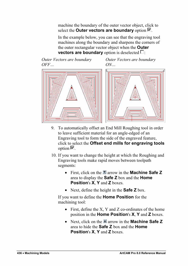
436 • Machining Models ArtCAM Pro 8.0 Reference Manual
machine the boundary of the outer vector object, click toselect the Outer vectors are boundary option .In the example below, you can see that the engraving toolmachines along the boundary and sharpens the corners ofthe outer rectangular vector object when the Outervectors are boundary option is deselected :
Outer Vectors are boundaryOFF…
Outer Vectors are boundaryON…
9. To automatically offset an End Mill Roughing tool in orderto leave sufficient material for an angle-edged of anEngraving tool to form the side of the engraved feature,click to select the Offset end mills for engraving toolsoption .
10. If you want to change the height at which the Roughing andEngraving tools make rapid moves between toolpathsegments:
• First, click on the arrow in the Machine Safe Zarea to display the Safe Z box and the HomePosition's X, Y and Z boxes.
• Next, define the height in the Safe Z box.If you want to define the Home Position for themachining tool:
• First, define the X, Y and Z co-ordinates of the homeposition in the Home Position's X, Y and Z boxes.
• Next, click on the arrow in the Machine Safe Zarea to hide the Safe Z box and the HomePosition's X, Y and Z boxes.
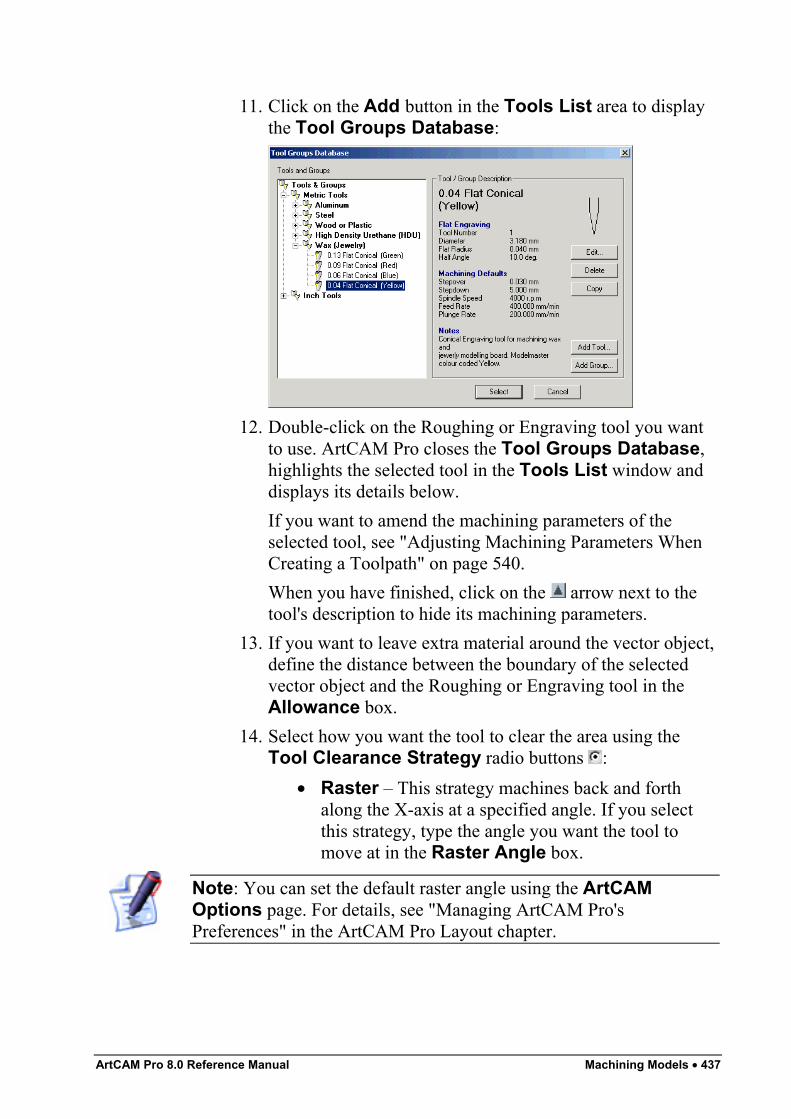
ArtCAM Pro 8.0 Reference Manual Machining Models • 437
11. Click on the Add button in the Tools List area to displaythe Tool Groups Database:
12. Double-click on the Roughing or Engraving tool you wantto use. ArtCAM Pro closes the Tool Groups Database,highlights the selected tool in the Tools List window anddisplays its details below.If you want to amend the machining parameters of theselected tool, see "Adjusting Machining Parameters WhenCreating a Toolpath" on page 540.When you have finished, click on the arrow next to thetool's description to hide its machining parameters.
13. If you want to leave extra material around the vector object,define the distance between the boundary of the selectedvector object and the Roughing or Engraving tool in theAllowance box.
14. Select how you want the tool to clear the area using theTool Clearance Strategy radio buttons :
• Raster – This strategy machines back and forthalong the X-axis at a specified angle. If you selectthis strategy, type the angle you want the tool tomove at in the Raster Angle box.
Note: You can set the default raster angle using the ArtCAMOptions page. For details, see "Managing ArtCAM Pro'sPreferences" in the ArtCAM Pro Layout chapter.
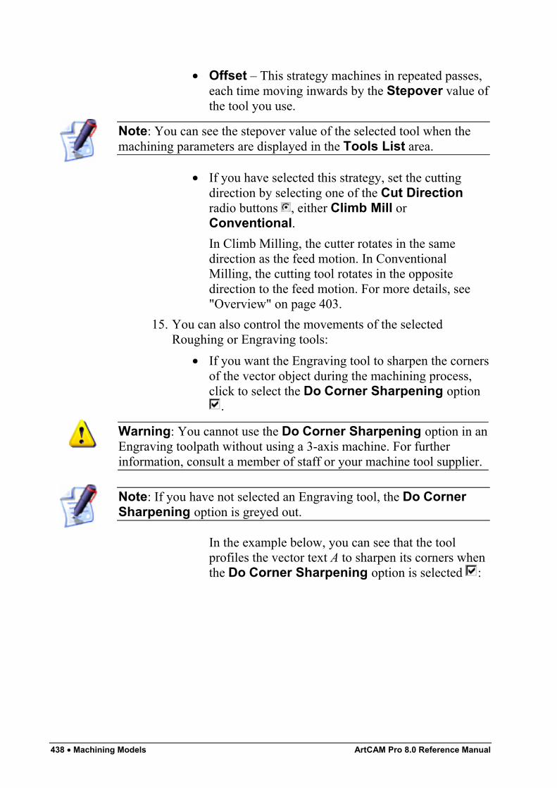
438 • Machining Models ArtCAM Pro 8.0 Reference Manual
• Offset – This strategy machines in repeated passes,each time moving inwards by the Stepover value ofthe tool you use.
Note: You can see the stepover value of the selected tool when themachining parameters are displayed in the Tools List area.
• If you have selected this strategy, set the cuttingdirection by selecting one of the Cut Directionradio buttons , either Climb Mill orConventional.In Climb Milling, the cutter rotates in the samedirection as the feed motion. In ConventionalMilling, the cutting tool rotates in the oppositedirection to the feed motion. For more details, see"Overview" on page 403.
15. You can also control the movements of the selectedRoughing or Engraving tools:
• If you want the Engraving tool to sharpen the cornersof the vector object during the machining process,click to select the Do Corner Sharpening option
.
Warning: You cannot use the Do Corner Sharpening option in anEngraving toolpath without using a 3-axis machine. For furtherinformation, consult a member of staff or your machine tool supplier.
Note: If you have not selected an Engraving tool, the Do CornerSharpening option is greyed out.
In the example below, you can see that the toolprofiles the vector text A to sharpen its corners whenthe Do Corner Sharpening option is selected :
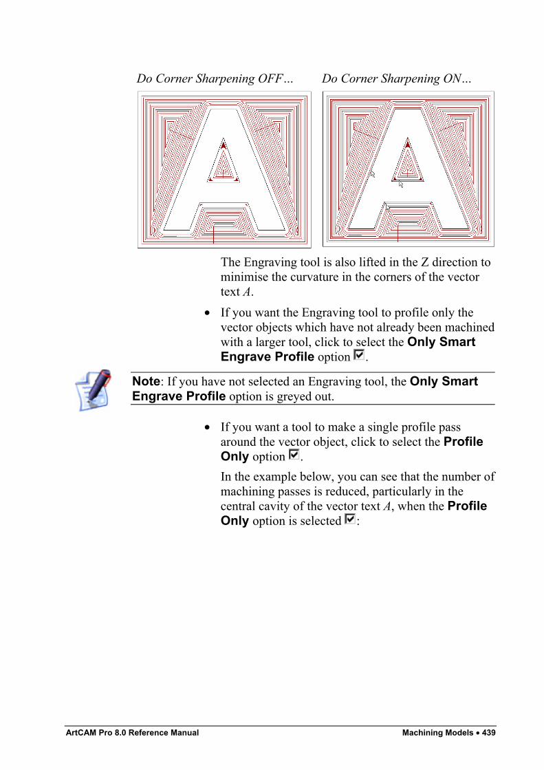
ArtCAM Pro 8.0 Reference Manual Machining Models • 439
Do Corner Sharpening OFF… Do Corner Sharpening ON…
The Engraving tool is also lifted in the Z direction tominimise the curvature in the corners of the vectortext A.
• If you want the Engraving tool to profile only thevector objects which have not already been machinedwith a larger tool, click to select the Only SmartEngrave Profile option .
Note: If you have not selected an Engraving tool, the Only SmartEngrave Profile option is greyed out.
• If you want a tool to make a single profile passaround the vector object, click to select the ProfileOnly option .In the example below, you can see that the number ofmachining passes is reduced, particularly in thecentral cavity of the vector text A, when the ProfileOnly option is selected :
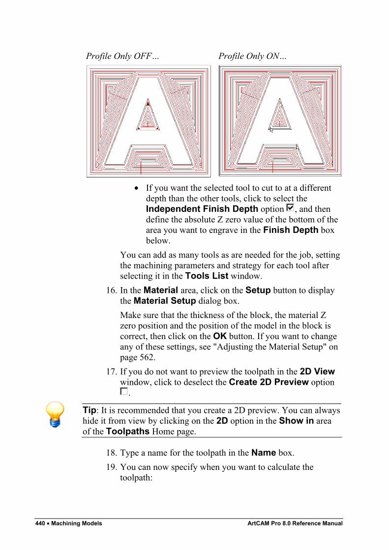
440 • Machining Models ArtCAM Pro 8.0 Reference Manual
Profile Only OFF… Profile Only ON…
• If you want the selected tool to cut to at a differentdepth than the other tools, click to select theIndependent Finish Depth option , and thendefine the absolute Z zero value of the bottom of thearea you want to engrave in the Finish Depth boxbelow.
You can add as many tools as are needed for the job, settingthe machining parameters and strategy for each tool afterselecting it in the Tools List window.
16. In the Material area, click on the Setup button to displaythe Material Setup dialog box.Make sure that the thickness of the block, the material Zzero position and the position of the model in the block iscorrect, then click on the OK button. If you want to changeany of these settings, see "Adjusting the Material Setup" onpage 562.
17. If you do not want to preview the toolpath in the 2D Viewwindow, click to deselect the Create 2D Preview option
.
Tip: It is recommended that you create a 2D preview. You can alwayshide it from view by clicking on the 2D option in the Show in areaof the Toolpaths Home page.
18. Type a name for the toolpath in the Name box.19. You can now specify when you want to calculate the
toolpath:
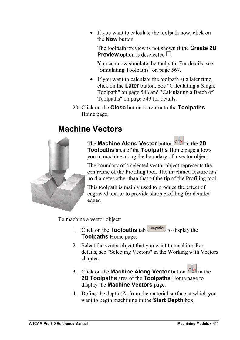
ArtCAM Pro 8.0 Reference Manual Machining Models • 441
• If you want to calculate the toolpath now, click onthe Now button.The toolpath preview is not shown if the Create 2DPreview option is deselected .You can now simulate the toolpath. For details, see"Simulating Toolpaths" on page 567.
• If you want to calculate the toolpath at a later time,click on the Later button. See "Calculating a SingleToolpath" on page 548 and "Calculating a Batch ofToolpaths" on page 549 for details.
20. Click on the Close button to return to the ToolpathsHome page.
Machine VectorsThe Machine Along Vector button in the 2DToolpaths area of the Toolpaths Home page allowsyou to machine along the boundary of a vector object.The boundary of a selected vector object represents thecentreline of the Profiling tool. The machined feature hasno diameter other than that of the tip of the Profiling tool.This toolpath is mainly used to produce the effect ofengraved text or to provide sharp profiling for detailededges.
To machine a vector object:
1. Click on the Toolpaths tab to display theToolpaths Home page.
2. Select the vector object that you want to machine. Fordetails, see "Selecting Vectors" in the Working with Vectorschapter.
3. Click on the Machine Along Vector button in the2D Toolpaths area of the Toolpaths Home page todisplay the Machine Vectors page.
4. Define the depth (Z) from the material surface at which youwant to begin machining in the Start Depth box.
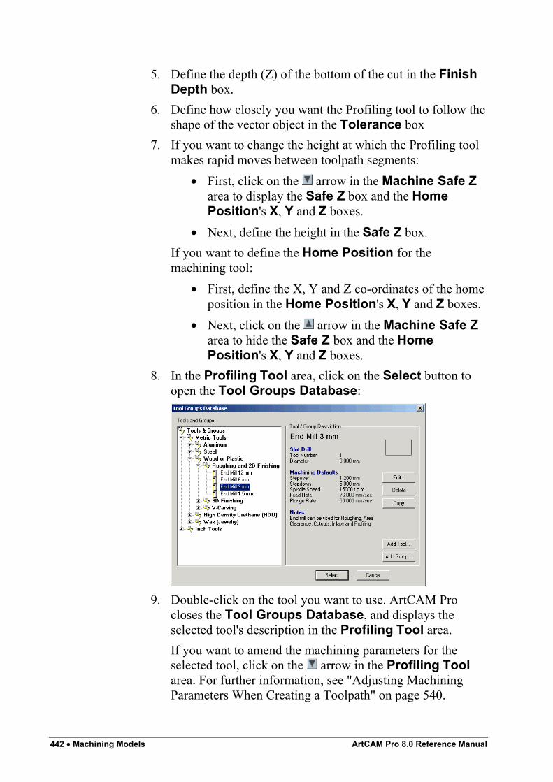
442 • Machining Models ArtCAM Pro 8.0 Reference Manual
5. Define the depth (Z) of the bottom of the cut in the FinishDepth box.
6. Define how closely you want the Profiling tool to follow theshape of the vector object in the Tolerance box
7. If you want to change the height at which the Profiling toolmakes rapid moves between toolpath segments:
• First, click on the arrow in the Machine Safe Zarea to display the Safe Z box and the HomePosition's X, Y and Z boxes.
• Next, define the height in the Safe Z box.If you want to define the Home Position for themachining tool:
• First, define the X, Y and Z co-ordinates of the homeposition in the Home Position's X, Y and Z boxes.
• Next, click on the arrow in the Machine Safe Zarea to hide the Safe Z box and the HomePosition's X, Y and Z boxes.
8. In the Profiling Tool area, click on the Select button toopen the Tool Groups Database:
9. Double-click on the tool you want to use. ArtCAM Procloses the Tool Groups Database, and displays theselected tool's description in the Profiling Tool area.If you want to amend the machining parameters for theselected tool, click on the arrow in the Profiling Toolarea. For further information, see "Adjusting MachiningParameters When Creating a Toolpath" on page 540.
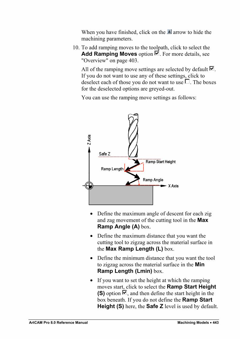
ArtCAM Pro 8.0 Reference Manual Machining Models • 443
When you have finished, click on the arrow to hide themachining parameters.
10. To add ramping moves to the toolpath, click to select theAdd Ramping Moves option . For more details, see"Overview" on page 403.All of the ramping move settings are selected by default .If you do not want to use any of these settings, click todeselect each of those you do not want to use . The boxesfor the deselected options are greyed-out.You can use the ramping move settings as follows:
• Define the maximum angle of descent for each zigand zag movement of the cutting tool in the MaxRamp Angle (A) box.
• Define the maximum distance that you want thecutting tool to zigzag across the material surface inthe Max Ramp Length (L) box.
• Define the minimum distance that you want the toolto zigzag across the material surface in the MinRamp Length (Lmin) box.
• If you want to set the height at which the rampingmoves start, click to select the Ramp Start Height(S) option , and then define the start height in thebox beneath. If you do not define the Ramp StartHeight (S) here, the Safe Z level is used by default.
444 • Machining Models ArtCAM Pro 8.0 Reference Manual
11. From the Sequencing area, you can set the order in whicheach segment in the toolpath is machined. You can eitherallow ArtCAM Pro to calculate the machining order, or usea polyline drawn to indicate the machining order.If you want to ArtCAM Pro to calculate the order in whicheach segment in the toolpath is machined:
• First, click on the Auto radio button .• Next, click on the list box and then on the option that
you want to use for the machining order:Optimise – Click on this option to instruct ArtCAMPro to find the most efficient machining order.Use Text Order – Click on this option to instructArtCAM Pro to machine according to the order inwhich the selected vector text was created. Thecutting tool moves along the first line of text fromleft to right, until it locates a carriage return when itcontinues machining along the next line from right toleft. This process is repeated until the last characterin the last line of text is located.Left To Right – Click on this option to instructArtCAM Pro to machine from the left of the modelto the right.Right To Left – Click on this option to instructArtCAM Pro to machine from the right of the modelto the left.Bottom To Top – Click on this option to instructArtCAM Pro to machine from the bottom of themodel to its top.Top To Bottom – Click on this option to instructArtCAM Pro to machine from the top of the model tothe bottom.Spiral Out – Click on this option to instructArtCAM Pro to machine from the centre of themodel outwards in a spiral motion. This isparticularly useful if you are using clamps to securethe material on your router.Spiral In – Click on this option to instruct ArtCAMPro to machine from the outside edge of the modelinwards in a spiral motion.
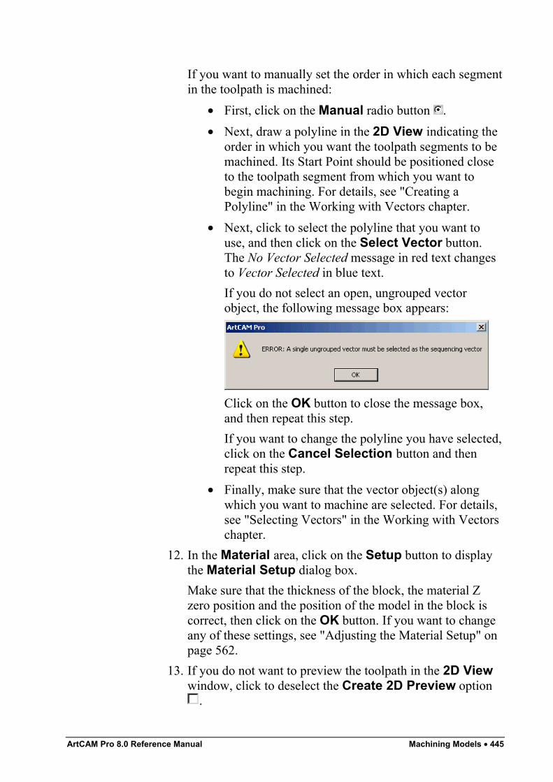
ArtCAM Pro 8.0 Reference Manual Machining Models • 445
If you want to manually set the order in which each segmentin the toolpath is machined:
• First, click on the Manual radio button .• Next, draw a polyline in the 2D View indicating the
order in which you want the toolpath segments to bemachined. Its Start Point should be positioned closeto the toolpath segment from which you want tobegin machining. For details, see "Creating aPolyline" in the Working with Vectors chapter.
• Next, click to select the polyline that you want touse, and then click on the Select Vector button.The No Vector Selected message in red text changesto Vector Selected in blue text.If you do not select an open, ungrouped vectorobject, the following message box appears:
Click on the OK button to close the message box,and then repeat this step.If you want to change the polyline you have selected,click on the Cancel Selection button and thenrepeat this step.
• Finally, make sure that the vector object(s) alongwhich you want to machine are selected. For details,see "Selecting Vectors" in the Working with Vectorschapter.
12. In the Material area, click on the Setup button to displaythe Material Setup dialog box.Make sure that the thickness of the block, the material Zzero position and the position of the model in the block iscorrect, then click on the OK button. If you want to changeany of these settings, see "Adjusting the Material Setup" onpage 562.
13. If you do not want to preview the toolpath in the 2D Viewwindow, click to deselect the Create 2D Preview option
.
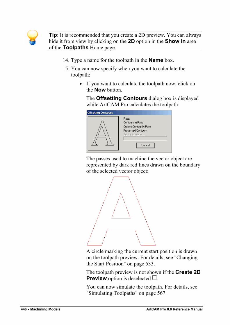
446 • Machining Models ArtCAM Pro 8.0 Reference Manual
Tip: It is recommended that you create a 2D preview. You can alwayshide it from view by clicking on the 2D option in the Show in areaof the Toolpaths Home page.
14. Type a name for the toolpath in the Name box.15. You can now specify when you want to calculate the
toolpath:• If you want to calculate the toolpath now, click on
the Now button.The Offsetting Contours dialog box is displayedwhile ArtCAM Pro calculates the toolpath:
The passes used to machine the vector object arerepresented by dark red lines drawn on the boundaryof the selected vector object:
A circle marking the current start position is drawnon the toolpath preview. For details, see "Changingthe Start Position" on page 533.The toolpath preview is not shown if the Create 2DPreview option is deselected .You can now simulate the toolpath. For details, see"Simulating Toolpaths" on page 567.
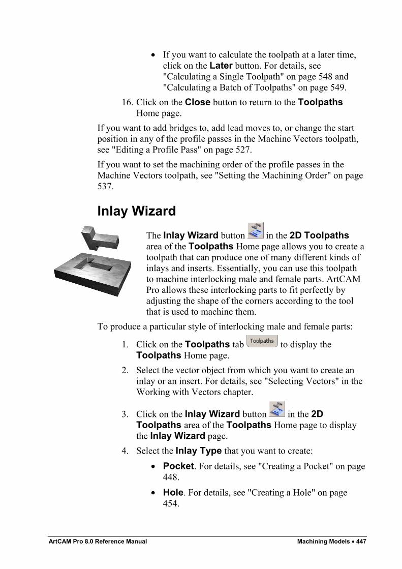
ArtCAM Pro 8.0 Reference Manual Machining Models • 447
• If you want to calculate the toolpath at a later time,click on the Later button. For details, see"Calculating a Single Toolpath" on page 548 and"Calculating a Batch of Toolpaths" on page 549.
16. Click on the Close button to return to the ToolpathsHome page.
If you want to add bridges to, add lead moves to, or change the startposition in any of the profile passes in the Machine Vectors toolpath,see "Editing a Profile Pass" on page 527.If you want to set the machining order of the profile passes in theMachine Vectors toolpath, see "Setting the Machining Order" on page537.
Inlay WizardThe Inlay Wizard button in the 2D Toolpathsarea of the Toolpaths Home page allows you to create atoolpath that can produce one of many different kinds ofinlays and inserts. Essentially, you can use this toolpathto machine interlocking male and female parts. ArtCAMPro allows these interlocking parts to fit perfectly byadjusting the shape of the corners according to the toolthat is used to machine them.
To produce a particular style of interlocking male and female parts:
1. Click on the Toolpaths tab to display theToolpaths Home page.
2. Select the vector object from which you want to create aninlay or an insert. For details, see "Selecting Vectors" in theWorking with Vectors chapter.
3. Click on the Inlay Wizard button in the 2DToolpaths area of the Toolpaths Home page to displaythe Inlay Wizard page.
4. Select the Inlay Type that you want to create:• Pocket. For details, see "Creating a Pocket" on page
448.• Hole. For details, see "Creating a Hole" on page
454.
448 • Machining Models ArtCAM Pro 8.0 Reference Manual
• Stepped Pocket. For details, see "Creating aStepped Pocket" on page 458.
• Stepped Hole. For details, see "Creating a SteppedHole" on page 465.
• Straight Insert. For details, see "Creating aStraight Insert" on page 469.
• Stepped Insert. For details, see "Creating aStepped Insert" on page 474.
Creating a PocketThis Female Inlay option displays the Female Inlay Pocket pagein the Assistant window. This allows you to create a pocket, whichis a hole in the material that has a bottom and does not go rightthrough the block. You can then create a male straight insert to fit intothe pocket.Using the Female Inlay Pocket page, you can:
• Select both Roughing and Finishing tools.• Select a tool clearance strategy for the Finishing or
Roughing tool you want to use. Depending on the strategyyou select, you can control the angle, where and in whatdirection the tool cuts into the block of material.
• Control how the Roughing and/or Finishing tools cut intoand retract from the block of material by adding rampingmoves.
To create a pocket:
1. Click on the Pocket option in the Inlay Types areaof the Inlay Wizard page. ArtCAM Pro displays theFemale Inlay Pocket page in the Assistant window.
2. Define the depth (Z) from the material surface at which youwant to create the pocket in the Start Depth box.
3. Define the depth (Z) of the bottom of the pocket in theFinish Depth box.
4. If you want to enlarge or reduce the pocket around theselected vector object, define the distance between theboundary of the selected vector object and the cuttingtool(s) in the Allowance box. Type a positive value to addmaterial or a negative value to remove it.
ArtCAM Pro 8.0 Reference Manual Machining Models • 449
Make sure that there is a sufficient allowance for thecorresponding male straight insert to fit into the pocket.
5. Define how closely you want the cutting tool(s) to followthe shape of the vector object in the Tolerance box.
6. If you want to change the height at which a cutting toolmakes rapid moves between toolpath segments:
• First, click on the arrow in the Machine Safe Zarea to display the Safe Z box and the HomePosition's X, Y and Z boxes.
• Next, define the height in the Safe Z box.If you want to define the Home Position for themachining tool:
• First, define the X, Y and Z co-ordinates of the homeposition in the Home Position's X, Y and Z boxes.
• Next, click on the arrow in the Machine Safe Zarea to hide the Safe Z box and the HomePosition's X, Y and Z boxes.
7. Click on the Select button in the Finishing Tool area ofthe page to open the Tool Groups Database:
8. Double-click on the tool you want to use. ArtCAM Procloses the Tool Groups Database and displays theselected tool's description in the Finishing Tool area.
Important: The selected Finishing Tool must be the same size asthe tool used to machine the male straight insert you want to fit intothis pocket.
If you want to amend the machining parameters for theselected tool, click on the arrow in the Finishing Toolarea. For further information, see "Adjusting MachiningParameters When Creating a Toolpath" on page 540.When you have finished, click on the arrow to hide themachining parameters.
9. Select whether you want to use a Roughing tool or not:10. If you want to enlarge or reduce the pocket around the
selected vector object, define the distance between theboundary of the selected vector object and the Finishing toolin the Allowance box. Type a positive value to addmaterial or a negative value to remove it.
450 • Machining Models ArtCAM Pro 8.0 Reference Manual
11. Select how you want the tool to clear the pocket using theStrategy radio buttons :
Important: If you are using a Roughing tool, the strategy that youselect applies to the selected tool and an Offset strategy with aClimb Mill cut direction is applied by default to the Finishing tool. Ifyou are not using a Roughing tool, the strategy that you select appliesto the Finishing tool.
• Raster - This strategy machines in passes back andforth along the X-axis at a specified angle. If youselect this strategy, define the angle you want thetool to move at in the Raster Angle box.
Note: You can set the default raster angle using the ArtCAMOptions page. For details, see "Managing ArtCAM Pro'sPreferences" in the ArtCAM Pro Layout chapter.
Next, click on one of the Profile Pass radio buttons:
None – Select this option if you do not want the toolto profile the selected vector object.First – Select this option if you want the tool toprofile the selected vector object first and then rasterclear the area.Last – Select this option if you want the tool tomove outwards to raster clear the area, then profilethe selected vector object.
• Offset - This strategy machines in repeated passes,each time moving inwards by the Stepover value ofthe tool you use.
Note: You can see the stepover value of the selected tool when themachining parameters are displayed in the Roughing Tool and/orFinishing Tool areas.
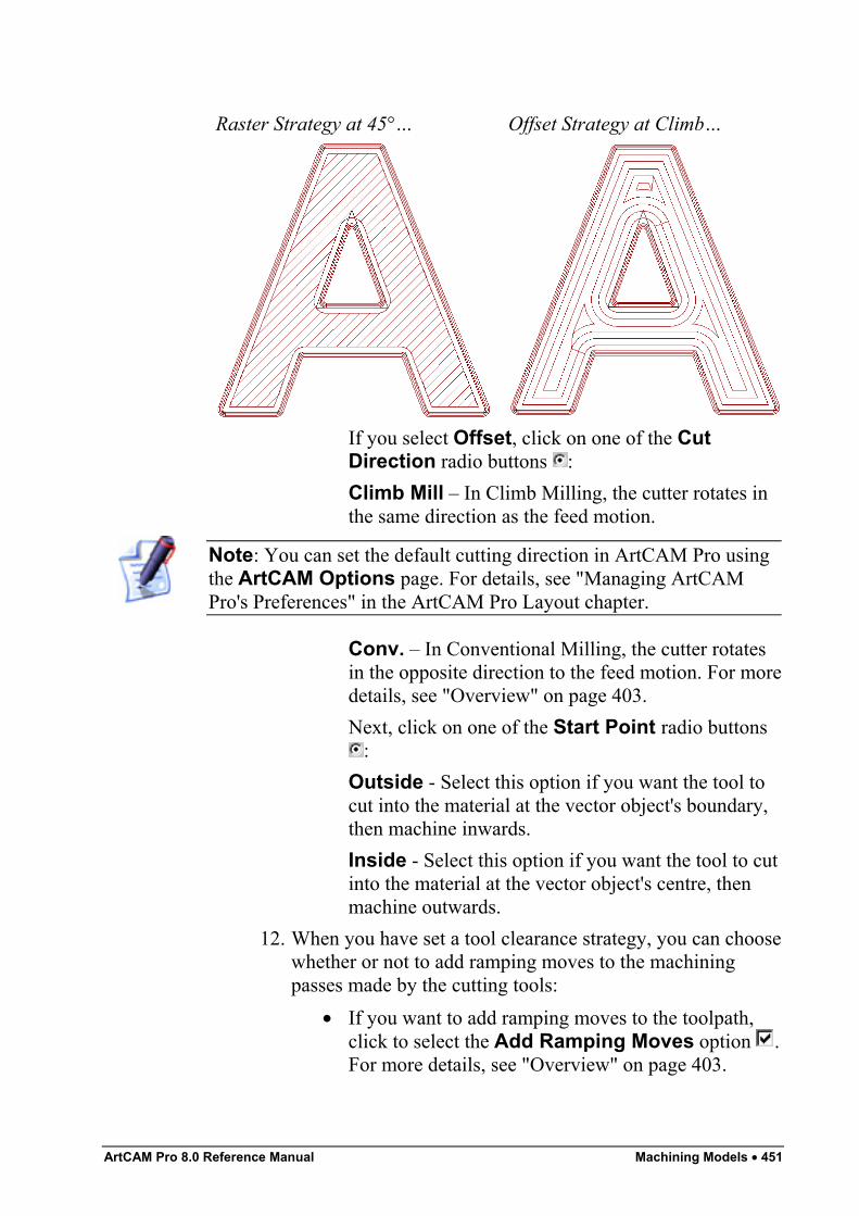
ArtCAM Pro 8.0 Reference Manual Machining Models • 451
Raster Strategy at 45°… Offset Strategy at Climb…
If you select Offset, click on one of the CutDirection radio buttons :Climb Mill – In Climb Milling, the cutter rotates inthe same direction as the feed motion.
Note: You can set the default cutting direction in ArtCAM Pro usingthe ArtCAM Options page. For details, see "Managing ArtCAMPro's Preferences" in the ArtCAM Pro Layout chapter.
Conv. – In Conventional Milling, the cutter rotatesin the opposite direction to the feed motion. For moredetails, see "Overview" on page 403.Next, click on one of the Start Point radio buttons
:Outside - Select this option if you want the tool tocut into the material at the vector object's boundary,then machine inwards.Inside - Select this option if you want the tool to cutinto the material at the vector object's centre, thenmachine outwards.
12. When you have set a tool clearance strategy, you can choosewhether or not to add ramping moves to the machiningpasses made by the cutting tools:
• If you want to add ramping moves to the toolpath,click to select the Add Ramping Moves option .For more details, see "Overview" on page 403.
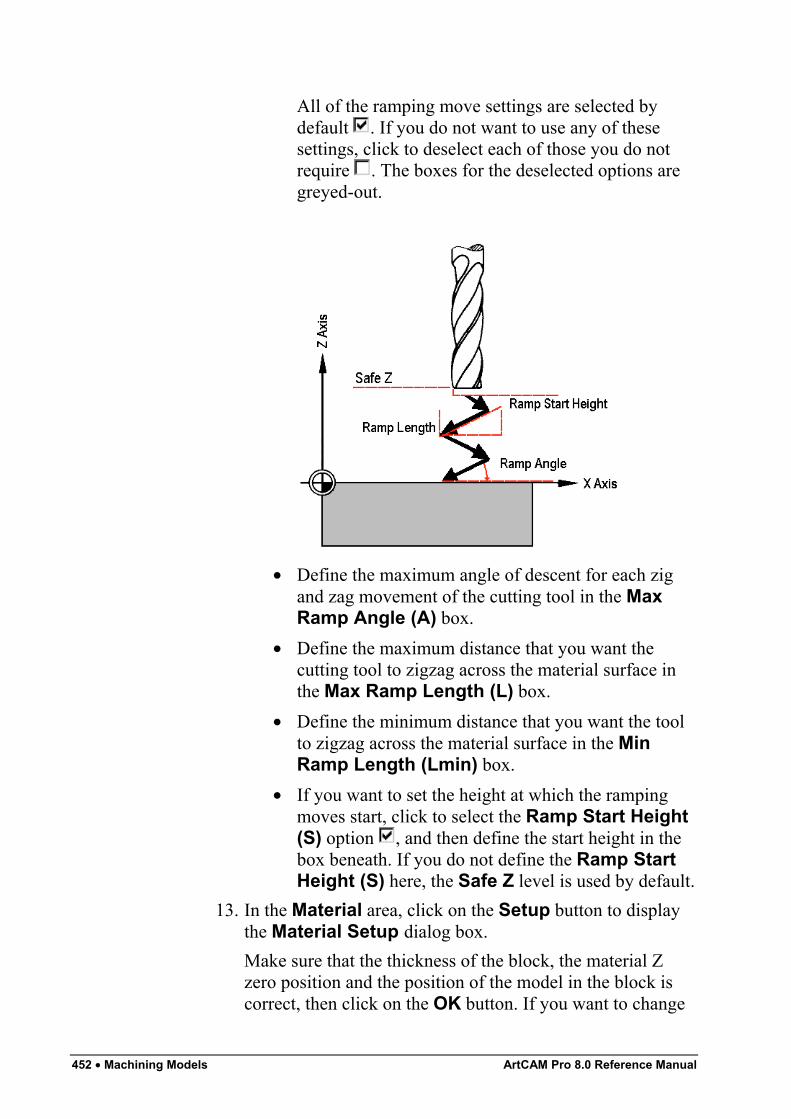
452 • Machining Models ArtCAM Pro 8.0 Reference Manual
All of the ramping move settings are selected bydefault . If you do not want to use any of thesesettings, click to deselect each of those you do notrequire . The boxes for the deselected options aregreyed-out.
• Define the maximum angle of descent for each zigand zag movement of the cutting tool in the MaxRamp Angle (A) box.
• Define the maximum distance that you want thecutting tool to zigzag across the material surface inthe Max Ramp Length (L) box.
• Define the minimum distance that you want the toolto zigzag across the material surface in the MinRamp Length (Lmin) box.
• If you want to set the height at which the rampingmoves start, click to select the Ramp Start Height(S) option , and then define the start height in thebox beneath. If you do not define the Ramp StartHeight (S) here, the Safe Z level is used by default.
13. In the Material area, click on the Setup button to displaythe Material Setup dialog box.Make sure that the thickness of the block, the material Zzero position and the position of the model in the block iscorrect, then click on the OK button. If you want to change
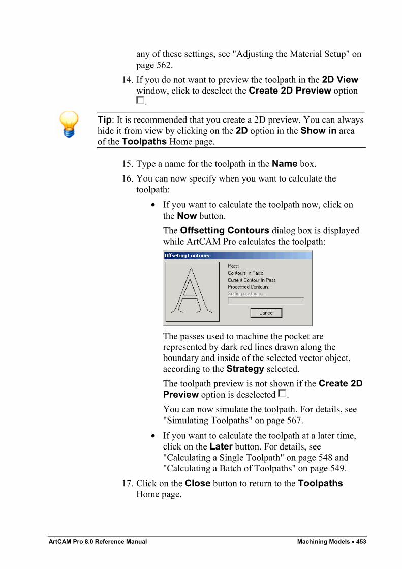
ArtCAM Pro 8.0 Reference Manual Machining Models • 453
any of these settings, see "Adjusting the Material Setup" onpage 562.
14. If you do not want to preview the toolpath in the 2D Viewwindow, click to deselect the Create 2D Preview option
.
Tip: It is recommended that you create a 2D preview. You can alwayshide it from view by clicking on the 2D option in the Show in areaof the Toolpaths Home page.
15. Type a name for the toolpath in the Name box.16. You can now specify when you want to calculate the
toolpath:• If you want to calculate the toolpath now, click on
the Now button.The Offsetting Contours dialog box is displayedwhile ArtCAM Pro calculates the toolpath:
The passes used to machine the pocket arerepresented by dark red lines drawn along theboundary and inside of the selected vector object,according to the Strategy selected.The toolpath preview is not shown if the Create 2DPreview option is deselected .You can now simulate the toolpath. For details, see"Simulating Toolpaths" on page 567.
• If you want to calculate the toolpath at a later time,click on the Later button. For details, see"Calculating a Single Toolpath" on page 548 and"Calculating a Batch of Toolpaths" on page 549.
17. Click on the Close button to return to the ToolpathsHome page.
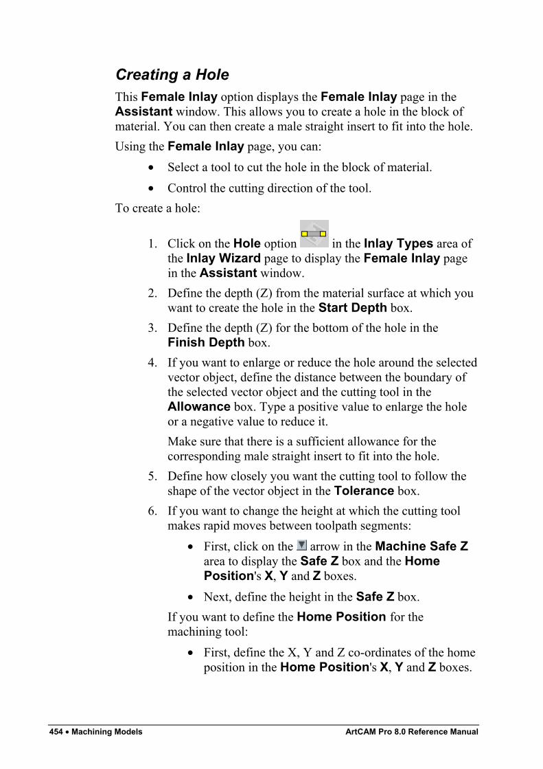
454 • Machining Models ArtCAM Pro 8.0 Reference Manual
Creating a HoleThis Female Inlay option displays the Female Inlay page in theAssistant window. This allows you to create a hole in the block ofmaterial. You can then create a male straight insert to fit into the hole.Using the Female Inlay page, you can:
• Select a tool to cut the hole in the block of material.• Control the cutting direction of the tool.
To create a hole:
1. Click on the Hole option in the Inlay Types area ofthe Inlay Wizard page to display the Female Inlay pagein the Assistant window.
2. Define the depth (Z) from the material surface at which youwant to create the hole in the Start Depth box.
3. Define the depth (Z) for the bottom of the hole in theFinish Depth box.
4. If you want to enlarge or reduce the hole around the selectedvector object, define the distance between the boundary ofthe selected vector object and the cutting tool in theAllowance box. Type a positive value to enlarge the holeor a negative value to reduce it.Make sure that there is a sufficient allowance for thecorresponding male straight insert to fit into the hole.
5. Define how closely you want the cutting tool to follow theshape of the vector object in the Tolerance box.
6. If you want to change the height at which the cutting toolmakes rapid moves between toolpath segments:
• First, click on the arrow in the Machine Safe Zarea to display the Safe Z box and the HomePosition's X, Y and Z boxes.
• Next, define the height in the Safe Z box.If you want to define the Home Position for themachining tool:
• First, define the X, Y and Z co-ordinates of the homeposition in the Home Position's X, Y and Z boxes.
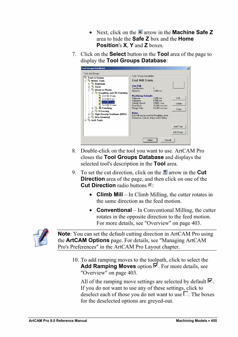
ArtCAM Pro 8.0 Reference Manual Machining Models • 455
• Next, click on the arrow in the Machine Safe Zarea to hide the Safe Z box and the HomePosition's X, Y and Z boxes.
7. Click on the Select button in the Tool area of the page todisplay the Tool Groups Database:
8. Double-click on the tool you want to use. ArtCAM Procloses the Tool Groups Database and displays theselected tool's description in the Tool area.
9. To set the cut direction, click on the arrow in the CutDirection area of the page, and then click on one of theCut Direction radio buttons :
• Climb Mill – In Climb Milling, the cutter rotates inthe same direction as the feed motion.
• Conventional – In Conventional Milling, the cutterrotates in the opposite direction to the feed motion.For more details, see "Overview" on page 403.
Note: You can set the default cutting direction in ArtCAM Pro usingthe ArtCAM Options page. For details, see "Managing ArtCAMPro's Preferences" in the ArtCAM Pro Layout chapter.
10. To add ramping moves to the toolpath, click to select theAdd Ramping Moves option . For more details, see"Overview" on page 403.All of the ramping move settings are selected by default .If you do not want to use any of these settings, click todeselect each of those you do not want to use . The boxesfor the deselected options are greyed-out.
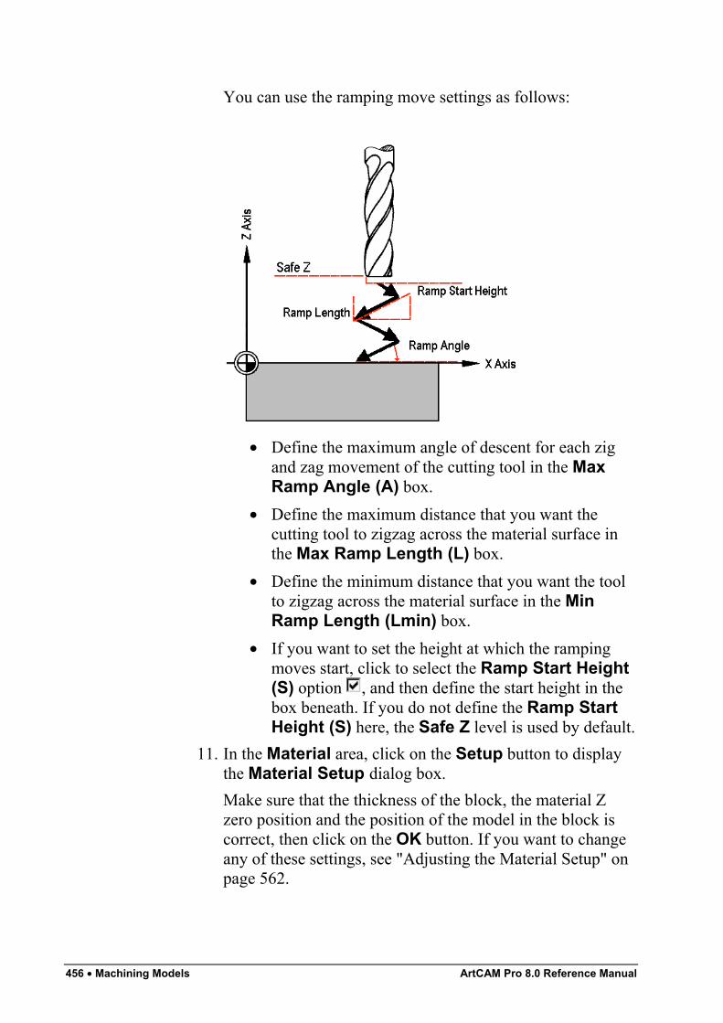
456 • Machining Models ArtCAM Pro 8.0 Reference Manual
You can use the ramping move settings as follows:
• Define the maximum angle of descent for each zigand zag movement of the cutting tool in the MaxRamp Angle (A) box.
• Define the maximum distance that you want thecutting tool to zigzag across the material surface inthe Max Ramp Length (L) box.
• Define the minimum distance that you want the toolto zigzag across the material surface in the MinRamp Length (Lmin) box.
• If you want to set the height at which the rampingmoves start, click to select the Ramp Start Height(S) option , and then define the start height in thebox beneath. If you do not define the Ramp StartHeight (S) here, the Safe Z level is used by default.
11. In the Material area, click on the Setup button to displaythe Material Setup dialog box.Make sure that the thickness of the block, the material Zzero position and the position of the model in the block iscorrect, then click on the OK button. If you want to changeany of these settings, see "Adjusting the Material Setup" onpage 562.
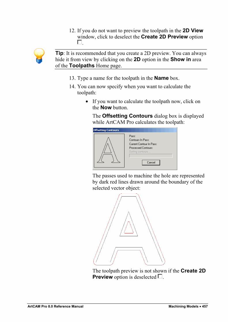
ArtCAM Pro 8.0 Reference Manual Machining Models • 457
12. If you do not want to preview the toolpath in the 2D Viewwindow, click to deselect the Create 2D Preview option
.
Tip: It is recommended that you create a 2D preview. You can alwayshide it from view by clicking on the 2D option in the Show in areaof the Toolpaths Home page.
13. Type a name for the toolpath in the Name box.14. You can now specify when you want to calculate the
toolpath:• If you want to calculate the toolpath now, click on
the Now button.The Offsetting Contours dialog box is displayedwhile ArtCAM Pro calculates the toolpath:
The passes used to machine the hole are representedby dark red lines drawn around the boundary of theselected vector object:
The toolpath preview is not shown if the Create 2DPreview option is deselected .
458 • Machining Models ArtCAM Pro 8.0 Reference Manual
You can now simulate the toolpath. For details, see"Simulating Toolpaths" on page 567.
• If you want to calculate the toolpath at a later time,click on the Later button. If you have chosen tocalculate the toolpath later, see "Calculating a SingleToolpath" on page 548 and "Calculating a Batch ofToolpaths" on page 549.
15. Click on the Close button to return to the ToolpathsHome page.
If you want to add bridges to, add lead moves to, or change the startposition in any of the profile passes in the Female Inlay toolpath, see"Editing a Profile Pass" on page 527.If you want to set the machining order of the profile passes in theFemale Inlay toolpath, see "Setting the Machining Order" on page537.
Creating a Stepped PocketThis Female Inlay option displays the Female Stepped PocketInlay page in the Assistant window. This allows you to create astepped pocket, which is a stepped hole in the material that has abottom and does not go right through the block. You can then create amale stepped insert to fit into the stepped pocket.Using the Female Stepped Pocket Inlay page, you can:
• Select both Roughing and Finishing tools.• Select a tool clearance strategy for the Finishing or
Roughing tool you want to use.Depending on the strategy you select, you can control theangle, where and in what direction the tool cuts into theblock of material.
• Control how the Roughing and/or Finishing tools cut intoand retract from the block of material by adding rampingmoves.
To create a stepped pocket:
1. Click on the Stepped Pocket option in the InlayTypes area of the Inlay Wizard page to display theFemale Stepped Pocket Inlay page in the Assistantwindow.
ArtCAM Pro 8.0 Reference Manual Machining Models • 459
2. Define the depth (Z) from the material surface at which youwant to create the stepped pocket in the Start Depth box.
3. Define the depth (Z) of the bottom of the stepped pocket inthe Finish Depth box.
4. If you want to enlarge or reduce the stepped pocket aroundthe selected vector object, define the distance between theboundary of the selected vector object and the cuttingtool(s) in the Allowance box. Type a positive value to addmaterial or a negative value to remove it.Make sure that there is a sufficient allowance for thecorresponding male stepped insert to fit into the steppedpocket.
5. Define how closely you want the cutting tool(s) to followthe shape of the vector object in the Tolerance box.
6. If you want to change the height at which the cutting toolsused make rapid moves between toolpath segments:
• First, click on the arrow in the Machine Safe Zarea to display the Safe Z box and the HomePosition's X, Y and Z boxes.
• Next, define the height in the Safe Z box.If you want to define the Home Position for themachining tools used:
• First, define the X, Y and Z co-ordinates of the homeposition in the Home Position's X, Y and Z boxes.
• Next, click on the arrow in the Machine Safe Zarea to hide the Safe Z box and the HomePosition's X, Y and Z boxes.
7. In the Shoulder Dimensions area, define the relativedepth of the shoulder from the Start Depth in the Depth(d) box.
8. Define the width of the shoulder in the Width (s) box.9. In the Finishing Tool area, click on the Select button to
open the Tool Groups Database:
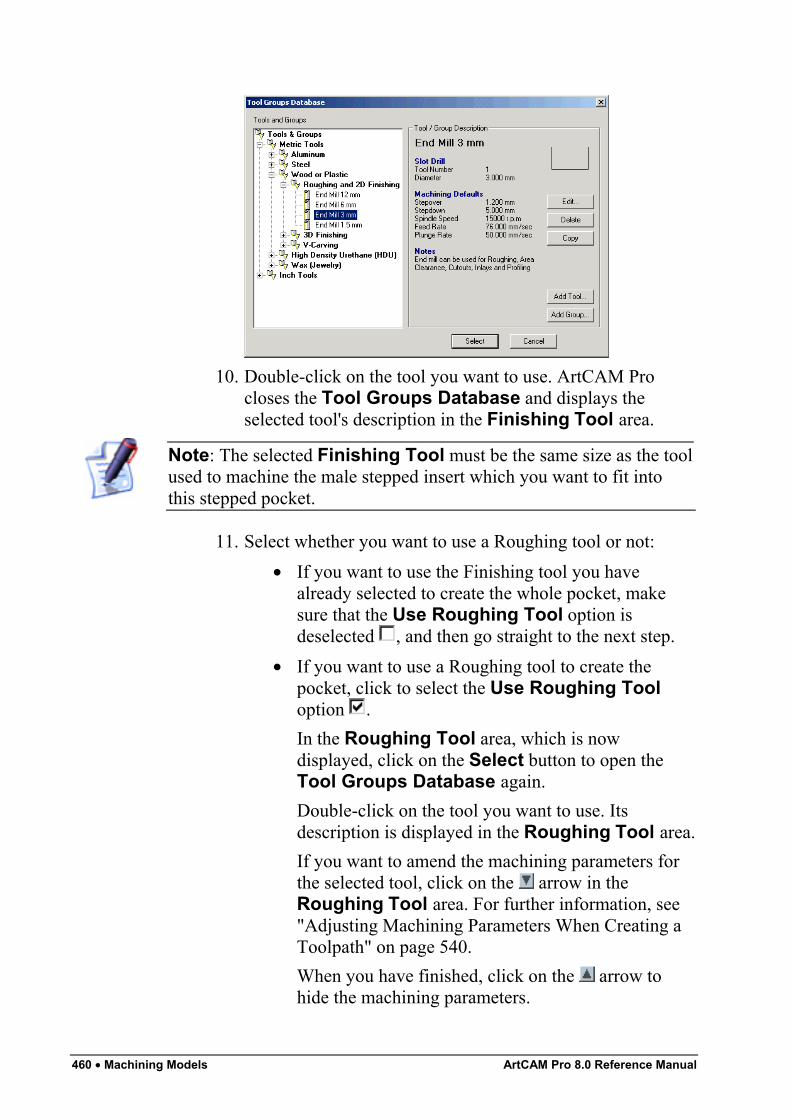
460 • Machining Models ArtCAM Pro 8.0 Reference Manual
10. Double-click on the tool you want to use. ArtCAM Procloses the Tool Groups Database and displays theselected tool's description in the Finishing Tool area.
Note: The selected Finishing Tool must be the same size as the toolused to machine the male stepped insert which you want to fit intothis stepped pocket.
11. Select whether you want to use a Roughing tool or not:• If you want to use the Finishing tool you have
already selected to create the whole pocket, makesure that the Use Roughing Tool option isdeselected , and then go straight to the next step.
• If you want to use a Roughing tool to create thepocket, click to select the Use Roughing Tooloption .In the Roughing Tool area, which is nowdisplayed, click on the Select button to open theTool Groups Database again.Double-click on the tool you want to use. Itsdescription is displayed in the Roughing Tool area.If you want to amend the machining parameters forthe selected tool, click on the arrow in theRoughing Tool area. For further information, see"Adjusting Machining Parameters When Creating aToolpath" on page 540.When you have finished, click on the arrow tohide the machining parameters.
ArtCAM Pro 8.0 Reference Manual Machining Models • 461
12. If you want the Finishing tool to enlarge or reduce thestepped pocket around the selected vector object, define thedistance between the boundary of the selected vector objectand the Finishing tool in the Allowance box. Type apositive value to enlarge the stepped pocket or a negativevalue to reduce it.
13. Select how you want the tool to clear the pocket using theStrategy radio buttons :
Important: If you are using a Roughing tool, the strategy that youselect applies to the selected tool and an Offset strategy with aClimb Mill cut direction is applied by default to the Finishing tool. Ifyou are not using a Roughing tool, the strategy that you select appliesto the Finishing tool.
• Raster - This strategy machines in passes back andforth along the X-axis at a specified angle. If youselect this strategy, first define the angle at whichyou want the tool to move in the Raster Angle box.
Note: You can set the default raster angle using the ArtCAMOptions page. For details, see "Managing ArtCAM Pro'sPreferences" in the ArtCAM Pro Layout chapter.
Next, click on one of the Profile Pass radio buttons:
None – Select this option if you do not want the toolto profile the selected vector object.First – Select this option if you want the tool toprofile the selected vector object first and then rasterclear the area.Last – Select this option if you want the tool tomove outwards to raster clear the area, then profilethe selected vector object.
• Offset - This strategy machines in repeated passes,each time moving inwards by the Stepover value ofthe tool you use.
Note: You can see the stepover value of the selected tool when themachining parameters are displayed in the Roughing Tool and/orFinishing Tool areas.
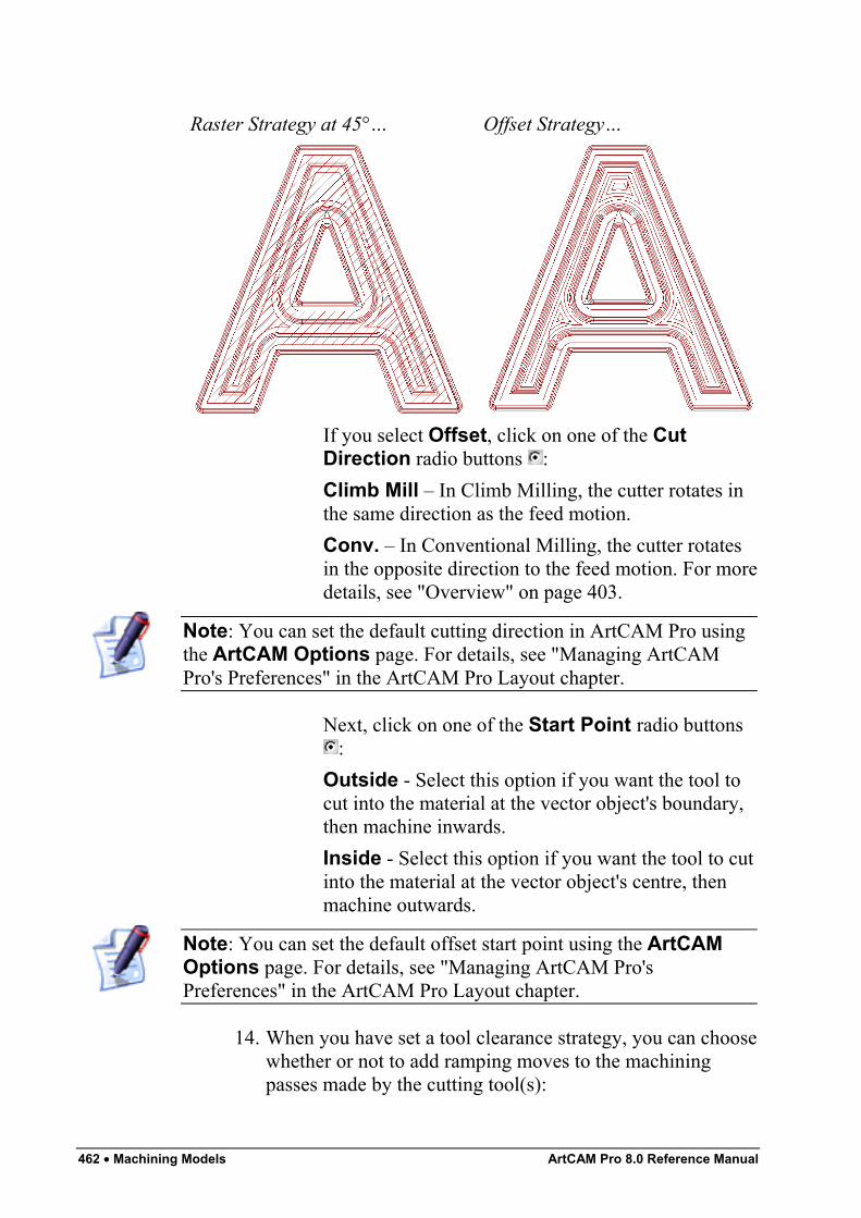
462 • Machining Models ArtCAM Pro 8.0 Reference Manual
Raster Strategy at 45°… Offset Strategy…
If you select Offset, click on one of the CutDirection radio buttons :Climb Mill – In Climb Milling, the cutter rotates inthe same direction as the feed motion.Conv. – In Conventional Milling, the cutter rotatesin the opposite direction to the feed motion. For moredetails, see "Overview" on page 403.
Note: You can set the default cutting direction in ArtCAM Pro usingthe ArtCAM Options page. For details, see "Managing ArtCAMPro's Preferences" in the ArtCAM Pro Layout chapter.
Next, click on one of the Start Point radio buttons:
Outside - Select this option if you want the tool tocut into the material at the vector object's boundary,then machine inwards.Inside - Select this option if you want the tool to cutinto the material at the vector object's centre, thenmachine outwards.
Note: You can set the default offset start point using the ArtCAMOptions page. For details, see "Managing ArtCAM Pro'sPreferences" in the ArtCAM Pro Layout chapter.
14. When you have set a tool clearance strategy, you can choosewhether or not to add ramping moves to the machiningpasses made by the cutting tool(s):
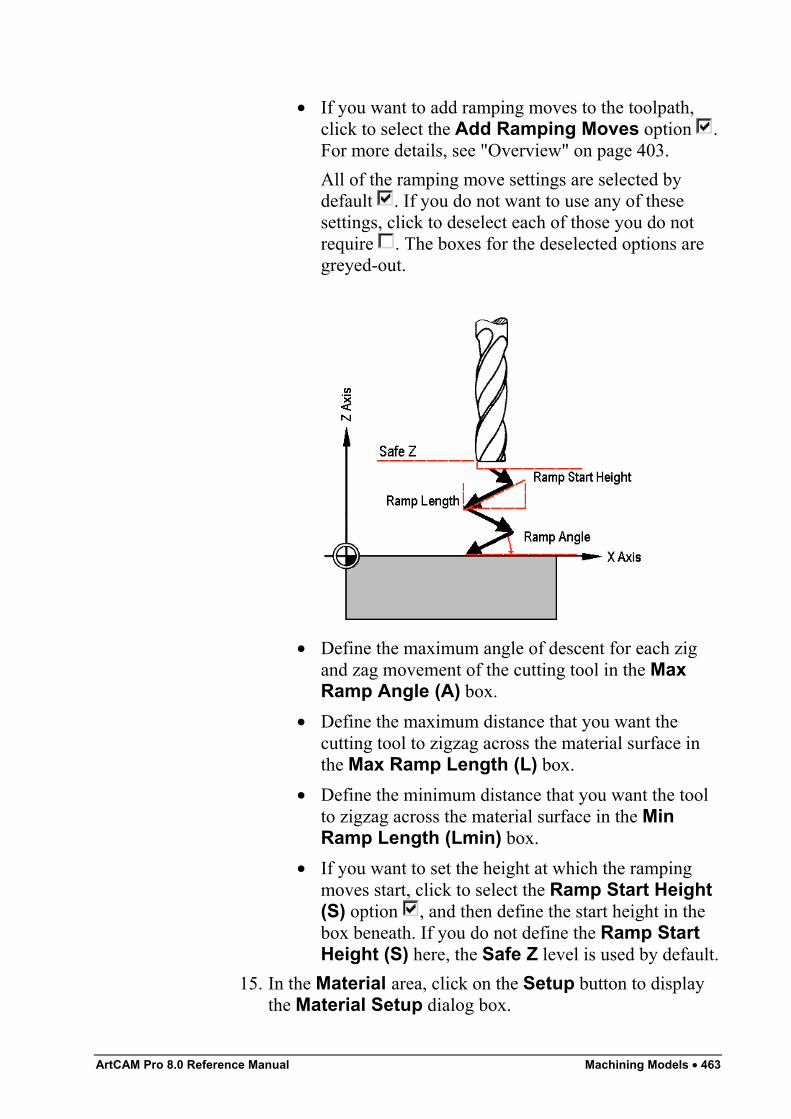
ArtCAM Pro 8.0 Reference Manual Machining Models • 463
• If you want to add ramping moves to the toolpath,click to select the Add Ramping Moves option .For more details, see "Overview" on page 403.All of the ramping move settings are selected bydefault . If you do not want to use any of thesesettings, click to deselect each of those you do notrequire . The boxes for the deselected options aregreyed-out.
• Define the maximum angle of descent for each zigand zag movement of the cutting tool in the MaxRamp Angle (A) box.
• Define the maximum distance that you want thecutting tool to zigzag across the material surface inthe Max Ramp Length (L) box.
• Define the minimum distance that you want the toolto zigzag across the material surface in the MinRamp Length (Lmin) box.
• If you want to set the height at which the rampingmoves start, click to select the Ramp Start Height(S) option , and then define the start height in thebox beneath. If you do not define the Ramp StartHeight (S) here, the Safe Z level is used by default.
15. In the Material area, click on the Setup button to displaythe Material Setup dialog box.
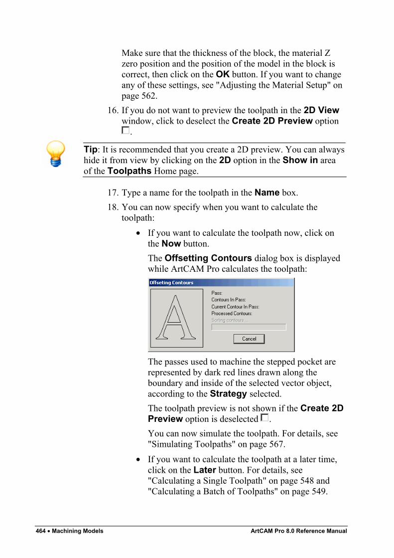
464 • Machining Models ArtCAM Pro 8.0 Reference Manual
Make sure that the thickness of the block, the material Zzero position and the position of the model in the block iscorrect, then click on the OK button. If you want to changeany of these settings, see "Adjusting the Material Setup" onpage 562.
16. If you do not want to preview the toolpath in the 2D Viewwindow, click to deselect the Create 2D Preview option
.
Tip: It is recommended that you create a 2D preview. You can alwayshide it from view by clicking on the 2D option in the Show in areaof the Toolpaths Home page.
17. Type a name for the toolpath in the Name box.18. You can now specify when you want to calculate the
toolpath:• If you want to calculate the toolpath now, click on
the Now button.The Offsetting Contours dialog box is displayedwhile ArtCAM Pro calculates the toolpath:
The passes used to machine the stepped pocket arerepresented by dark red lines drawn along theboundary and inside of the selected vector object,according to the Strategy selected.The toolpath preview is not shown if the Create 2DPreview option is deselected .You can now simulate the toolpath. For details, see"Simulating Toolpaths" on page 567.
• If you want to calculate the toolpath at a later time,click on the Later button. For details, see"Calculating a Single Toolpath" on page 548 and"Calculating a Batch of Toolpaths" on page 549.
ArtCAM Pro 8.0 Reference Manual Machining Models • 465
19. Click on the Close button to return to the ToolpathsHome page.
Creating a Stepped HoleThis Female Inlay option displays the Female Stepped HoleInlay page in the Assistant window. This allows you to create astepped hole in the block of material. You can then create a malestepped insert to fit into the stepped hole.Using the Female Stepped Hole Inlay page, you can:
• Control the depth and width of the hole's shoulder.• Select a tool to cut the hole in the block of material.• Control the cutting direction of the tool.
To create a stepped hole:
1. Click on the Stepped Hole option in the InlayTypes area of the Inlay Wizard page to display theFemale Stepped Hole Inlay page in the Assistantwindow.
2. Define the depth (Z) from the material surface at which youwant to create the stepped hole in the Start Depth box.
3. Define the depth (Z) of the bottom of the stepped hole in theFinish Depth box.
4. If you want to enlarge or reduce the stepped hole around theselected vector object, define the distance between theboundary of the selected vector object and the cutting tool inthe Allowance box. Type a positive value to enlarge thestepped hole or a negative value to reduce it.Make sure that there is a sufficient allowance for thecorresponding male stepped insert to fit into the steppedhole.
5. Define how closely you want the cutting tool to follow theshape of the vector object in the Tolerance box.
6. If you want to change the height at which the cutting toolmakes rapid moves between toolpath segments:
• First, click on the arrow in the Machine Safe Zarea to display the Safe Z box and the HomePosition's X, Y and Z boxes.
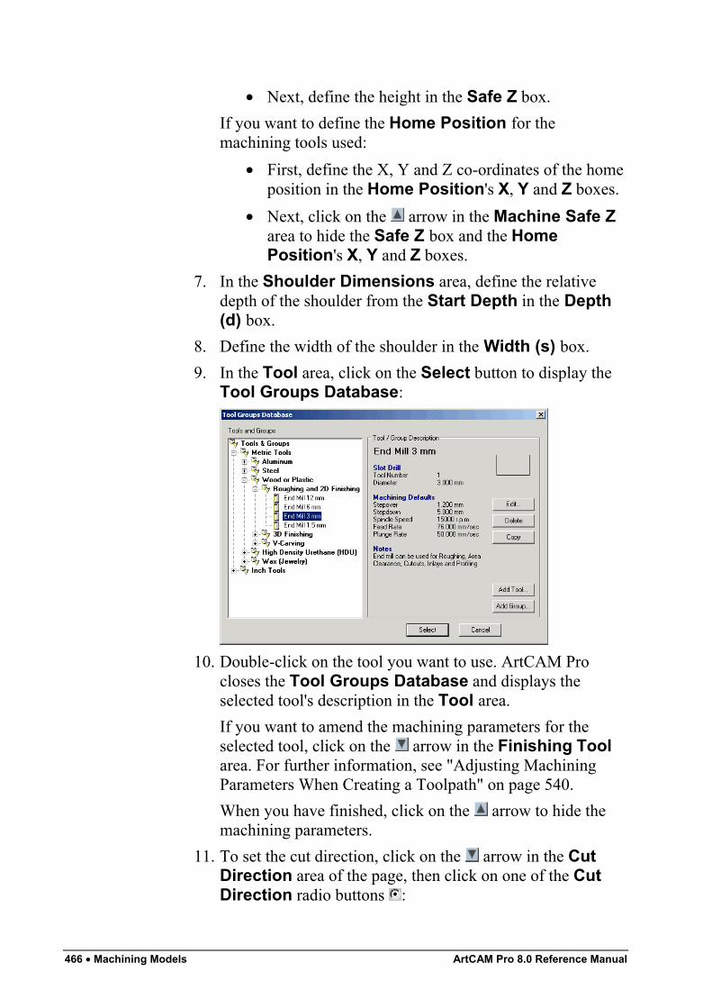
466 • Machining Models ArtCAM Pro 8.0 Reference Manual
• Next, define the height in the Safe Z box.If you want to define the Home Position for themachining tools used:
• First, define the X, Y and Z co-ordinates of the homeposition in the Home Position's X, Y and Z boxes.
• Next, click on the arrow in the Machine Safe Zarea to hide the Safe Z box and the HomePosition's X, Y and Z boxes.
7. In the Shoulder Dimensions area, define the relativedepth of the shoulder from the Start Depth in the Depth(d) box.
8. Define the width of the shoulder in the Width (s) box.9. In the Tool area, click on the Select button to display the
Tool Groups Database:
10. Double-click on the tool you want to use. ArtCAM Procloses the Tool Groups Database and displays theselected tool's description in the Tool area.If you want to amend the machining parameters for theselected tool, click on the arrow in the Finishing Toolarea. For further information, see "Adjusting MachiningParameters When Creating a Toolpath" on page 540.When you have finished, click on the arrow to hide themachining parameters.
11. To set the cut direction, click on the arrow in the CutDirection area of the page, then click on one of the CutDirection radio buttons :
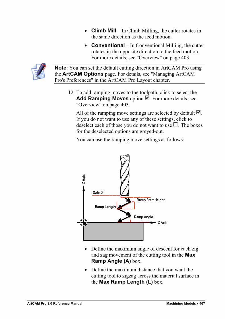
ArtCAM Pro 8.0 Reference Manual Machining Models • 467
• Climb Mill – In Climb Milling, the cutter rotates inthe same direction as the feed motion.
• Conventional – In Conventional Milling, the cutterrotates in the opposite direction to the feed motion.For more details, see "Overview" on page 403.
Note: You can set the default cutting direction in ArtCAM Pro usingthe ArtCAM Options page. For details, see "Managing ArtCAMPro's Preferences" in the ArtCAM Pro Layout chapter.
12. To add ramping moves to the toolpath, click to select theAdd Ramping Moves option . For more details, see"Overview" on page 403.All of the ramping move settings are selected by default .If you do not want to use any of these settings, click todeselect each of those you do not want to use . The boxesfor the deselected options are greyed-out.You can use the ramping move settings as follows:
• Define the maximum angle of descent for each zigand zag movement of the cutting tool in the MaxRamp Angle (A) box.
• Define the maximum distance that you want thecutting tool to zigzag across the material surface inthe Max Ramp Length (L) box.
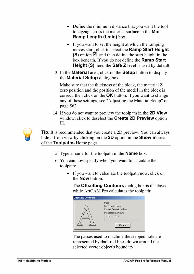
468 • Machining Models ArtCAM Pro 8.0 Reference Manual
• Define the minimum distance that you want the toolto zigzag across the material surface in the MinRamp Length (Lmin) box.
• If you want to set the height at which the rampingmoves start, click to select the Ramp Start Height(S) option , and then define the start height in thebox beneath. If you do not define the Ramp StartHeight (S) here, the Safe Z level is used by default.
13. In the Material area, click on the Setup button to displaythe Material Setup dialog box.Make sure that the thickness of the block, the material Zzero position and the position of the model in the block iscorrect, then click on the OK button. If you want to changeany of these settings, see "Adjusting the Material Setup" onpage 562.
14. If you do not want to preview the toolpath in the 2D Viewwindow, click to deselect the Create 2D Preview option
.
Tip: It is recommended that you create a 2D preview. You can alwayshide it from view by clicking on the 2D option in the Show in areaof the Toolpaths Home page.
15. Type a name for the toolpath in the Name box.16. You can now specify when you want to calculate the
toolpath:• If you want to calculate the toolpath now, click on
the Now button.The Offsetting Contours dialog box is displayedwhile ArtCAM Pro calculates the toolpath:
The passes used to machine the stepped hole arerepresented by dark red lines drawn around theselected vector object's boundary:
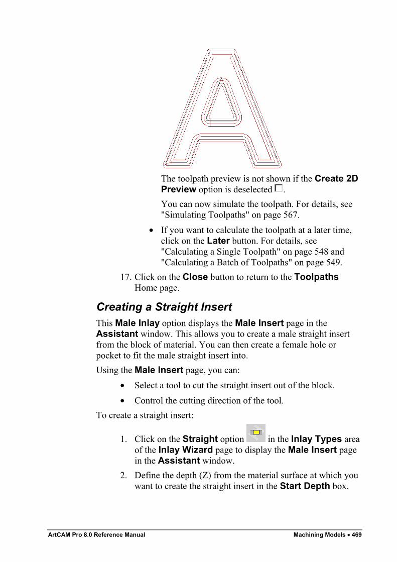
ArtCAM Pro 8.0 Reference Manual Machining Models • 469
The toolpath preview is not shown if the Create 2DPreview option is deselected .You can now simulate the toolpath. For details, see"Simulating Toolpaths" on page 567.
• If you want to calculate the toolpath at a later time,click on the Later button. For details, see"Calculating a Single Toolpath" on page 548 and"Calculating a Batch of Toolpaths" on page 549.
17. Click on the Close button to return to the ToolpathsHome page.
Creating a Straight InsertThis Male Inlay option displays the Male Insert page in theAssistant window. This allows you to create a male straight insertfrom the block of material. You can then create a female hole orpocket to fit the male straight insert into.Using the Male Insert page, you can:
• Select a tool to cut the straight insert out of the block.• Control the cutting direction of the tool.
To create a straight insert:
1. Click on the Straight option in the Inlay Types areaof the Inlay Wizard page to display the Male Insert pagein the Assistant window.
2. Define the depth (Z) from the material surface at which youwant to create the straight insert in the Start Depth box.
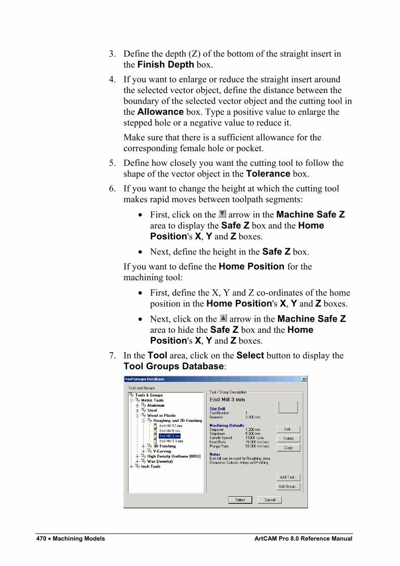
470 • Machining Models ArtCAM Pro 8.0 Reference Manual
3. Define the depth (Z) of the bottom of the straight insert inthe Finish Depth box.
4. If you want to enlarge or reduce the straight insert aroundthe selected vector object, define the distance between theboundary of the selected vector object and the cutting tool inthe Allowance box. Type a positive value to enlarge thestepped hole or a negative value to reduce it.Make sure that there is a sufficient allowance for thecorresponding female hole or pocket.
5. Define how closely you want the cutting tool to follow theshape of the vector object in the Tolerance box.
6. If you want to change the height at which the cutting toolmakes rapid moves between toolpath segments:
• First, click on the arrow in the Machine Safe Zarea to display the Safe Z box and the HomePosition's X, Y and Z boxes.
• Next, define the height in the Safe Z box.If you want to define the Home Position for themachining tool:
• First, define the X, Y and Z co-ordinates of the homeposition in the Home Position's X, Y and Z boxes.
• Next, click on the arrow in the Machine Safe Zarea to hide the Safe Z box and the HomePosition's X, Y and Z boxes.
7. In the Tool area, click on the Select button to display theTool Groups Database:
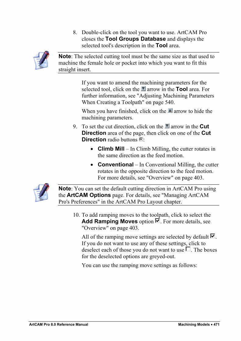
ArtCAM Pro 8.0 Reference Manual Machining Models • 471
8. Double-click on the tool you want to use. ArtCAM Procloses the Tool Groups Database and displays theselected tool's description in the Tool area.
Note: The selected cutting tool must be the same size as that used tomachine the female hole or pocket into which you want to fit thisstraight insert.
If you want to amend the machining parameters for theselected tool, click on the arrow in the Tool area. Forfurther information, see "Adjusting Machining ParametersWhen Creating a Toolpath" on page 540.When you have finished, click on the arrow to hide themachining parameters.
9. To set the cut direction, click on the arrow in the CutDirection area of the page, then click on one of the CutDirection radio buttons :
• Climb Mill – In Climb Milling, the cutter rotates inthe same direction as the feed motion.
• Conventional – In Conventional Milling, the cutterrotates in the opposite direction to the feed motion.For more details, see "Overview" on page 403.
Note: You can set the default cutting direction in ArtCAM Pro usingthe ArtCAM Options page. For details, see "Managing ArtCAMPro's Preferences" in the ArtCAM Pro Layout chapter.
10. To add ramping moves to the toolpath, click to select theAdd Ramping Moves option . For more details, see"Overview" on page 403.All of the ramping move settings are selected by default .If you do not want to use any of these settings, click todeselect each of those you do not want to use . The boxesfor the deselected options are greyed-out.You can use the ramping move settings as follows:
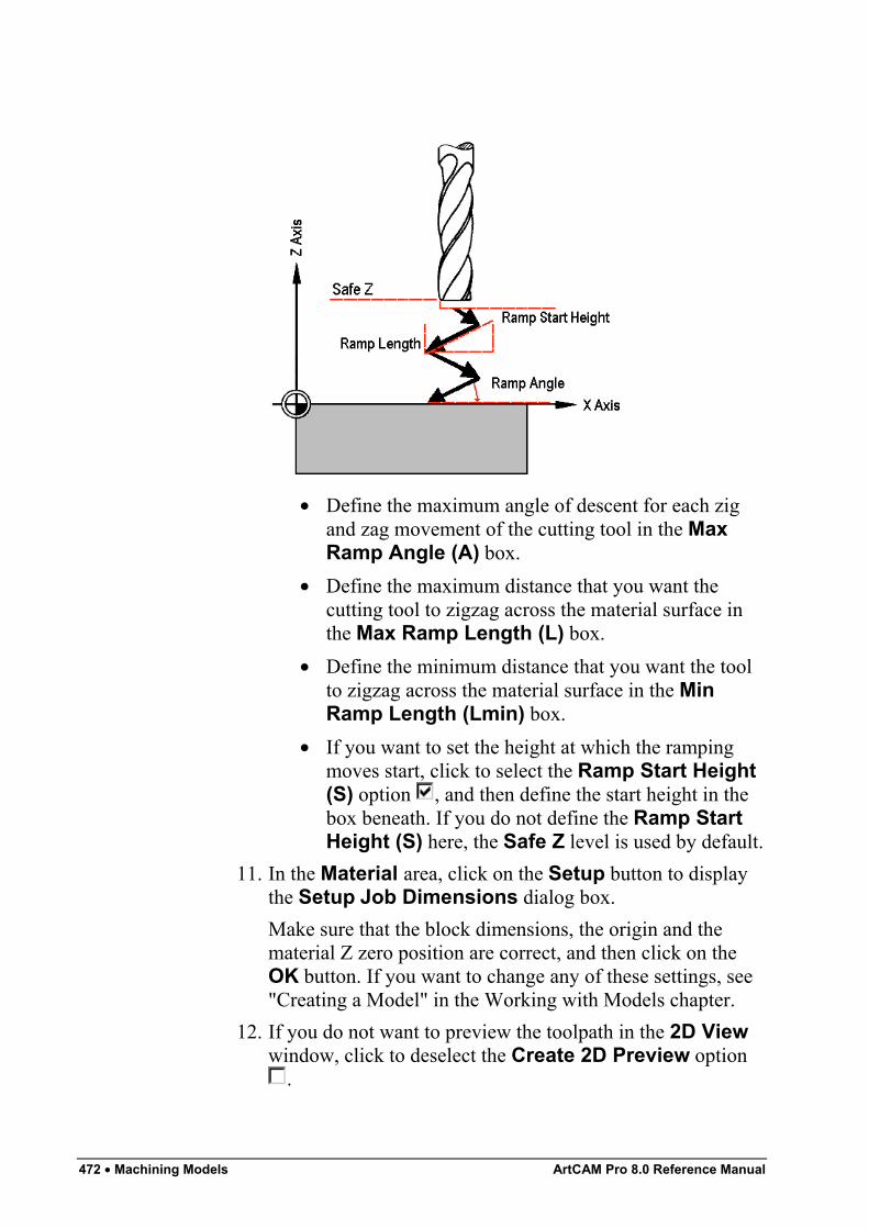
472 • Machining Models ArtCAM Pro 8.0 Reference Manual
• Define the maximum angle of descent for each zigand zag movement of the cutting tool in the MaxRamp Angle (A) box.
• Define the maximum distance that you want thecutting tool to zigzag across the material surface inthe Max Ramp Length (L) box.
• Define the minimum distance that you want the toolto zigzag across the material surface in the MinRamp Length (Lmin) box.
• If you want to set the height at which the rampingmoves start, click to select the Ramp Start Height(S) option , and then define the start height in thebox beneath. If you do not define the Ramp StartHeight (S) here, the Safe Z level is used by default.
11. In the Material area, click on the Setup button to displaythe Setup Job Dimensions dialog box.Make sure that the block dimensions, the origin and thematerial Z zero position are correct, and then click on theOK button. If you want to change any of these settings, see"Creating a Model" in the Working with Models chapter.
12. If you do not want to preview the toolpath in the 2D Viewwindow, click to deselect the Create 2D Preview option
.
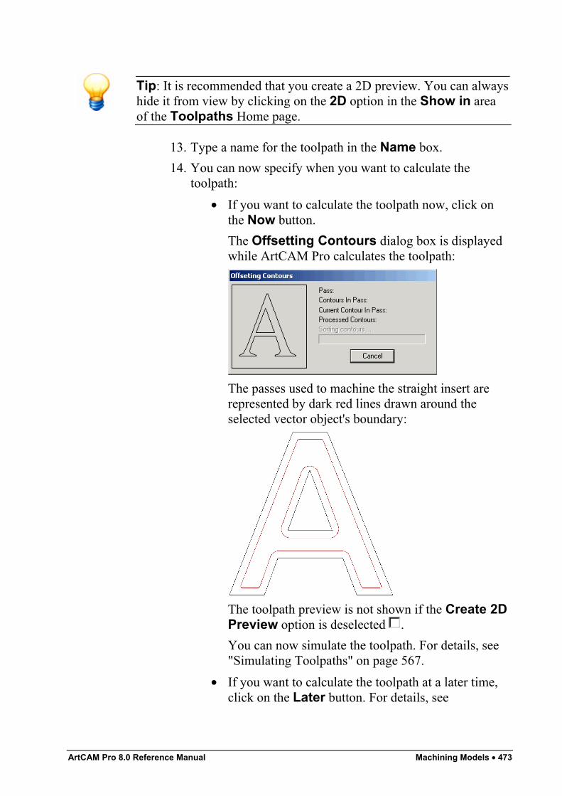
ArtCAM Pro 8.0 Reference Manual Machining Models • 473
Tip: It is recommended that you create a 2D preview. You can alwayshide it from view by clicking on the 2D option in the Show in areaof the Toolpaths Home page.
13. Type a name for the toolpath in the Name box.14. You can now specify when you want to calculate the
toolpath:• If you want to calculate the toolpath now, click on
the Now button.The Offsetting Contours dialog box is displayedwhile ArtCAM Pro calculates the toolpath:
The passes used to machine the straight insert arerepresented by dark red lines drawn around theselected vector object's boundary:
The toolpath preview is not shown if the Create 2DPreview option is deselected .You can now simulate the toolpath. For details, see"Simulating Toolpaths" on page 567.
• If you want to calculate the toolpath at a later time,click on the Later button. For details, see
474 • Machining Models ArtCAM Pro 8.0 Reference Manual
"Calculating a Single Toolpath" on page 548 and"Calculating a Batch of Toolpaths" on page 549.
15. Click on the Close button to return to the ToolpathsHome page.
If you want to add bridges to, add lead moves to, or change the startposition in any of the profile passes in the Male Insert toolpath, see"Editing a Profile Pass" on page 527.If you want to set the machining order of the profile passes in the MaleInsert toolpath, see "Setting the Machining Order" on page 537.
Creating a Stepped InsertThis Male Inlay option displays the Male Stepped Insert page inthe Assistant window. This allows you to create a male steppedinsert from the block of material. You can then create a femalestepped hole or stepped pocket to fit the male stepped insert into.Using the Male Stepped Insert page, you can:
• Select a tool to cut the stepped insert out of the block.• Control the depth and width of the insert shoulder.• Control the cutting direction of the tool.
To create a stepped insert:
1. Click on the Stepped option in the Inlay Typesarea of the Inlay Wizard page to display the MaleStepped Insert page in the Assistant window.
2. Define the depth (Z) from the material surface at which youwant to create the stepped insert in the Start Depth box.
3. Define the depth (Z) of the bottom of the stepped insert inthe Finish Depth box.
4. If you want to enlarge or reduce the stepped insert aroundthe selected vector object, define the distance between theboundary of the selected vector object and the cutting tool inthe Allowance box. Type a positive value to enlarge thestepped insert or a negative value to reduce it.
5. Define how closely you want the cutting tool to follow theshape of the vector object in the Tolerance box.
6. If you want to change the height at which the cutting toolmakes rapid moves between toolpath segments:
ArtCAM Pro 8.0 Reference Manual Machining Models • 475
7. In the Shoulder Dimensions area, define the relativedepth of the shoulder from the Start Depth in the Depth(d) box.
8. Define the width of the shoulder in the Width (s) box.9. In the Tool area, click on the Select button to display the
Tool Groups Database:10. Double-click on the tool you want to use. ArtCAM Pro
closes the Tool Groups Database and displays theselected tool's description in the Tool area.
11. To set the cut direction, click on the arrow in the CutDirection area of the Male Stepped Insert page, thenclick on one of the Cut Direction radio buttons :
• Climb Mill – In Climb Milling, the cutter rotates inthe same direction as the feed motion.
• Conventional – In Conventional Milling, the cutterrotates in the opposite direction to the feed motion.For more details, see "Overview" on page 403.
Note: You can set the default cutting direction in ArtCAM Pro usingthe ArtCAM Options page. For details, see "Managing ArtCAMPro's Preferences" in the ArtCAM Pro Layout chapter.
12. To add ramping moves to the toolpath, click to select theAdd Ramping Moves option . For more details, see"Overview" on page 403.
13. In the Material area, click on the Setup button to displaythe Material Setup dialog box.
14. If you do not want to preview the toolpath in the 2D Viewwindow, click to deselect the Create 2D Preview option
.15. Type a name for the toolpath in the Name box.16. You can now specify when you want to calculate the
toolpath:• If you want to calculate the toolpath now, click on
the Now button.The Offsetting Contours dialog box is displayedwhile ArtCAM Pro calculates the toolpath:
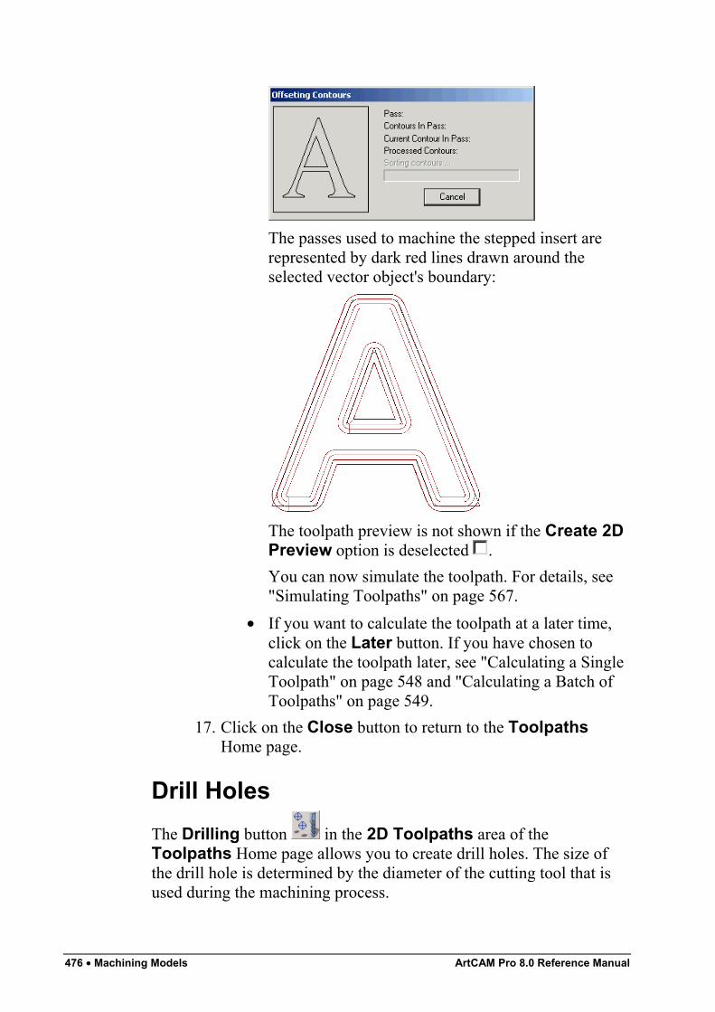
476 • Machining Models ArtCAM Pro 8.0 Reference Manual
The passes used to machine the stepped insert arerepresented by dark red lines drawn around theselected vector object's boundary:
The toolpath preview is not shown if the Create 2DPreview option is deselected .You can now simulate the toolpath. For details, see"Simulating Toolpaths" on page 567.
• If you want to calculate the toolpath at a later time,click on the Later button. If you have chosen tocalculate the toolpath later, see "Calculating a SingleToolpath" on page 548 and "Calculating a Batch ofToolpaths" on page 549.
17. Click on the Close button to return to the ToolpathsHome page.
Drill HolesThe Drilling button in the 2D Toolpaths area of theToolpaths Home page allows you to create drill holes. The size ofthe drill hole is determined by the diameter of the cutting tool that isused during the machining process.
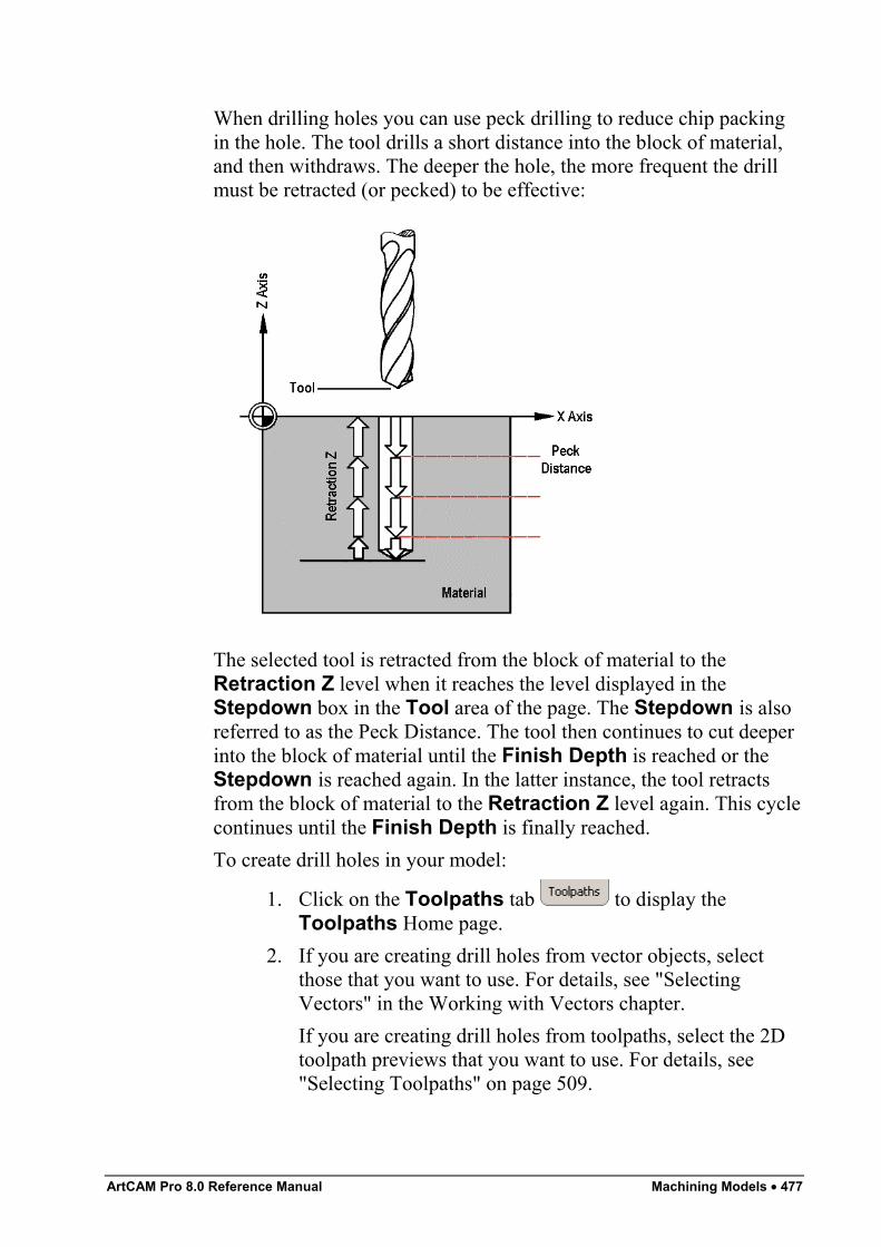
ArtCAM Pro 8.0 Reference Manual Machining Models • 477
When drilling holes you can use peck drilling to reduce chip packingin the hole. The tool drills a short distance into the block of material,and then withdraws. The deeper the hole, the more frequent the drillmust be retracted (or pecked) to be effective:
The selected tool is retracted from the block of material to theRetraction Z level when it reaches the level displayed in theStepdown box in the Tool area of the page. The Stepdown is alsoreferred to as the Peck Distance. The tool then continues to cut deeperinto the block of material until the Finish Depth is reached or theStepdown is reached again. In the latter instance, the tool retractsfrom the block of material to the Retraction Z level again. This cyclecontinues until the Finish Depth is finally reached.To create drill holes in your model:
1. Click on the Toolpaths tab to display theToolpaths Home page.
2. If you are creating drill holes from vector objects, selectthose that you want to use. For details, see "SelectingVectors" in the Working with Vectors chapter.If you are creating drill holes from toolpaths, select the 2Dtoolpath previews that you want to use. For details, see"Selecting Toolpaths" on page 509.
478 • Machining Models ArtCAM Pro 8.0 Reference Manual
3. Click on the Drilling button in the 2D Toolpathsarea of the Toolpaths Home page to display the Drillingpage.
4. Define the depth (Z) from the material surface at which youwant to create the drill holes in the Start Depth box.
5. Define the depth (Z) of the bottom of each drill hole in theFinish Depth box.
6. If you want to change the height at which the cutting toolmakes rapid moves between toolpath segments:
7. Click on the Select button in the Tool area of the page toopen the Tool Groups Database:
8. Double-click on the tool you want to use. ArtCAM Procloses the Tool Groups Database and displays theselected tool's description in the Tool area.
9. To set where the holes are drilled in your model, click onone of the Drill Centre of… radio buttons :
10. To drill the holes using the peck drilling method:11. From the Sequencing area, you can set the order in which
each segment in the toolpath is machined. You can eitherallow ArtCAM Pro to calculate the machining order, or usea polyline drawn to indicate the machining order.If you want to ArtCAM Pro to calculate the order in whicheach segment in the toolpath is machined:
• First, click on the Auto radio button .• Next, click on the list box and then on the option that
you want to use for the machining order:Optimise – Click on this option to instruct ArtCAMPro to find the most efficient machining order.Use Text Order – Click on this option to instructArtCAM Pro to machine according to the order inwhich the selected vector text was created. Thecutting tool moves along the first line of text fromleft to right, until it locates a carriage return when itcontinues machining along the next line from right toleft. This process is repeated until the last characterin the last line of text is located.
ArtCAM Pro 8.0 Reference Manual Machining Models • 479
Left To Right – Click on this option to instructArtCAM Pro to machine from the left of the modelto the right.Right To Left – Click on this option to instructArtCAM Pro to machine from the right of the modelto the left.Bottom To Top – Click on this option to instructArtCAM Pro to machine from the bottom of themodel to its top.Top To Bottom – Click on this option to instructArtCAM Pro to machine from the top of the model tothe bottom.Spiral Out – Click on this option to instructArtCAM Pro to machine from the centre of themodel outwards in a spiral motion. This isparticularly useful if you are using clamps to securethe material on your router.Spiral In – Click on this option to instruct ArtCAMPro to machine from the outside edge of the modelinwards in a spiral motion.
If you want to manually set the order in which each segmentin the toolpath is machined:
• First, click on the Manual radio button .• Next, draw a polyline in the 2D View indicating the
order in which you want the toolpath segments to bemachined. Its Start Point should be positioned closeto the toolpath segment from which you want tobegin machining. For details, see "Creating aPolyline" in the Working with Vectors chapter.
• Next, click to select the polyline that you want touse, and then click on the Select Vector button.The No Vector Selected message in red text changesto Vector Selected in blue text.If you do not select an open, ungrouped vectorobject, the following message box appears:
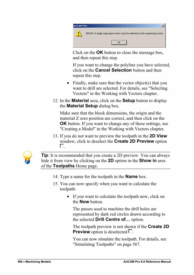
480 • Machining Models ArtCAM Pro 8.0 Reference Manual
Click on the OK button to close the message box,and then repeat this step.If you want to change the polyline you have selected,click on the Cancel Selection button and thenrepeat this step.
• Finally, make sure that the vector object(s) that youwant to drill are selected. For details, see "SelectingVectors" in the Working with Vectors chapter.
12. In the Material area, click on the Setup button to displaythe Material Setup dialog box.Make sure that the block dimensions, the origin and thematerial Z zero position are correct, and then click on theOK button. If you want to change any of these settings, see"Creating a Model" in the Working with Vectors chapter.
13. If you do not want to preview the toolpath in the 2D Viewwindow, click to deselect the Create 2D Preview option
.
Tip: It is recommended that you create a 2D preview. You can alwayshide it from view by clicking on the 2D option in the Show in areaof the Toolpaths Home page.
14. Type a name for the toolpath in the Name box.15. You can now specify when you want to calculate the
toolpath:• If you want to calculate the toolpath now, click on
the Now button.The passes used to machine the drill holes arerepresented by dark red circles drawn according tothe selected Drill Centre of… option.The toolpath preview is not shown if the Create 2DPreview option is deselected .You can now simulate the toolpath. For details, see"Simulating Toolpaths" on page 567.
ArtCAM Pro 8.0 Reference Manual Machining Models • 481
• If you want to calculate the toolpath at a later time,click on the Later button. For details, see"Calculating a Single Toolpath" on page 548 and"Calculating a Batch of Toolpaths" on page 549.
16. Click on the Close button to return to the ToolpathsHome page.
3D ToolpathsArtCAM Pro provides a number of three-dimensional toolpaths thatyou can use to machine your model, based on the vector objects and/orrelief created within it. These include:
• Machining a Relief. This strategy allows you to machineany relief that you have created in a model. For details, see"Machine Relief" on page 481.
• Feature Machining. This strategy is used to machine theRaised, Recessed and Centreline Engraved featuresyou have created from vector objects in a model. For details,see "Feature Machining" on page 486.
• Z Level Roughing. This strategy allows you to quicklyremove unwanted material from a relief. For details, see "ZLevel Roughing" on page 490.
• 3D Laser Machining. This strategy allows users of alaser-engraving machine to quickly remove layers ofunwanted material from a relief. For details, see "LaserMachining" on page 495.
• Cutting Out. This strategy allows you to create a toolpatheither inside or outside the boundary of a vector object. Fordetails, see "3D Cut Out" on page 498.
• 3D Rest Machining. Rest (as in 'rest of material')Machining allows you to find all of the areas of a relief thatcannot be machined based on one tool size, and thenmachine only these areas with another, smaller tool. Fordetails, see "3D Rest Machining" on page 505.
Machine ReliefThe Machine Relief button in the 3D Toolpaths area of theToolpaths Home page allows you to:
482 • Machining Models ArtCAM Pro 8.0 Reference Manual
• Machine the entire surface of a relief.• Machine a specific area of a relief, as defined by a selected
vector object.Using the Machine Relief page, you can:
• Select a different tool clearance strategy for each of thetools you want to use. Depending on what strategy youselect, you can control the angle, or where and in whatdirection the tool cuts into the block of material.
• Control how the tool cuts into and retracts from the block ofmaterial by adding ramping moves.
To machine the surface of a relief:
1. Click on the Toolpaths tab to display theToolpaths Home page.
2. Click on the Machine Relief button in the 3DToolpaths area to display the Machine Relief page.
3. Click on one of the Area to Machine radio buttons toselect how the relief is machined:
• Click on the Whole Model radio button if youwant to machine the entire surface of the relief.
• Click on the Selected Vector radio button if youwant to machine an area of the relief as defined by aselected vector object.If you select this option, select the vector object thatrepresents the area of the relief you want to machine.For details, see "Selecting Vectors" in the Workingwith Vectors chapter.
4. Click on the Strategy list box to display the strategiesavailable and then on the strategy you want to select. If youhave selected the Whole Model option, then you canchoose from the following strategies:
• Raster in X – This strategy machines back andforth along the X-axis at a specified angle.
• Raster in X and Y – This strategy machines in twoperpendicular directions at a specified angle. Thisstrategy improves the surface finish but can be timeconsuming.
ArtCAM Pro 8.0 Reference Manual Machining Models • 483
• Spiral – This strategy machines in a spiral motion,stopping when the tool reaches the first edge of therelief. This strategy does not always allow you tomachine the entire relief.
• Spiral in Box – This strategy machines in a spiralmotion. When the tool reaches the first edge of therelief it retracts, traverses along the edge of the reliefand then plunges to continue machining the next areaof the relief. This strategy allows you to machine theentire relief, but can be time consuming.
If you have selected the Selected Vector option, then youcan choose from the following strategies:
• Raster in X – This strategy machines back andforth along the X-axis at a specified angle.
• Offset – This strategy machines in repeated passes,each time moving inwards by the Stepover value ofthe tool you use. You can see the Stepover value ofthe selected tool when the machining parameters aredisplayed in the Tool area.
5. If you have selected a Raster strategy, type the angle atwhich you want the tool to move in the Raster Angle box.
Note: You can set the default offset start point using the ArtCAMOptions page. For details, see "Managing ArtCAM Pro'sPreferences" in the ArtCAM Pro Layout chapter.
6. To leave additional material on the relief surface to allowfor the final machining pass, type a value in the Allowancebox. The allowance sets the distance between the surface ofthe relief and the cutting tool.
7. Type a value in the Tolerance box to specify how closelyyou want the cutting tool to follow the shape of the relief.
8. If you want to change the height at which the machiningtool makes rapid moves between toolpath segments:
• First, click on the arrow in the Machine Safe Zarea to display the Safe Z box and the HomePosition's X, Y and Z boxes.
• Next, define the height in the Safe Z box.
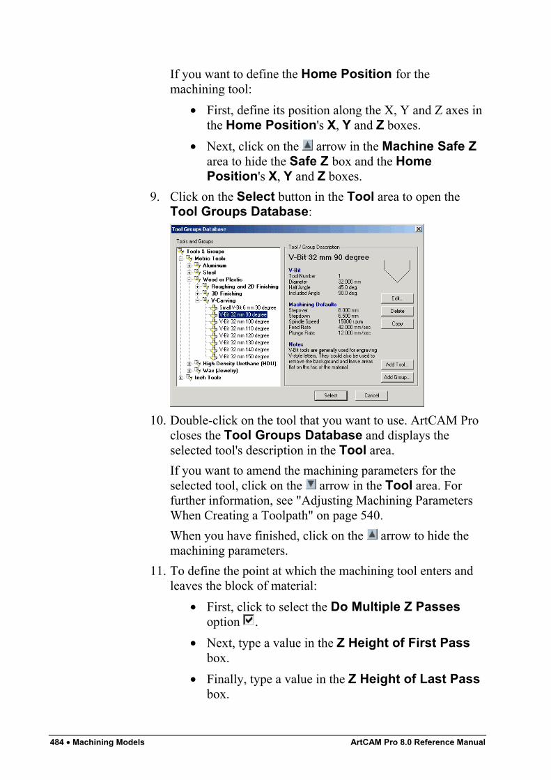
484 • Machining Models ArtCAM Pro 8.0 Reference Manual
If you want to define the Home Position for themachining tool:
• First, define its position along the X, Y and Z axes inthe Home Position's X, Y and Z boxes.
• Next, click on the arrow in the Machine Safe Zarea to hide the Safe Z box and the HomePosition's X, Y and Z boxes.
9. Click on the Select button in the Tool area to open theTool Groups Database:
10. Double-click on the tool that you want to use. ArtCAM Procloses the Tool Groups Database and displays theselected tool's description in the Tool area.If you want to amend the machining parameters for theselected tool, click on the arrow in the Tool area. Forfurther information, see "Adjusting Machining ParametersWhen Creating a Toolpath" on page 540.When you have finished, click on the arrow to hide themachining parameters.
11. To define the point at which the machining tool enters andleaves the block of material:
• First, click to select the Do Multiple Z Passesoption .
• Next, type a value in the Z Height of First Passbox.
• Finally, type a value in the Z Height of Last Passbox.
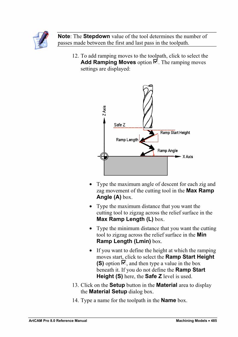
ArtCAM Pro 8.0 Reference Manual Machining Models • 485
Note: The Stepdown value of the tool determines the number ofpasses made between the first and last pass in the toolpath.
12. To add ramping moves to the toolpath, click to select theAdd Ramping Moves option . The ramping movessettings are displayed:
• Type the maximum angle of descent for each zig andzag movement of the cutting tool in the Max RampAngle (A) box.
• Type the maximum distance that you want thecutting tool to zigzag across the relief surface in theMax Ramp Length (L) box.
• Type the minimum distance that you want the cuttingtool to zigzag across the relief surface in the MinRamp Length (Lmin) box.
• If you want to define the height at which the rampingmoves start, click to select the Ramp Start Height(S) option , and then type a value in the boxbeneath it. If you do not define the Ramp StartHeight (S) here, the Safe Z level is used.
13. Click on the Setup button in the Material area to displaythe Material Setup dialog box.
14. Type a name for the toolpath in the Name box.
486 • Machining Models ArtCAM Pro 8.0 Reference Manual
15. You can now specify when you want to calculate thetoolpath:
• If you want to calculate the toolpath now, click onthe Now button.
• If you want to calculate the toolpath as part of abatch of toolpaths at a later time, click on the Laterbutton. For details, see "Creating a Single Copy" onpage 512 and "Calculating a Batch of Toolpaths" onpage 549.
16. Click on the Close button to return to the ToolpathsHome page.
Feature MachiningThe Feature Machining button in the Toolpaths Home pageallows you to machine a raised, recessed or centreline engravedfeature that you have created from a vector object with a depth orheight relative to the current relief. The contour of the existing relief ispreserved in the feature that is combined with it. For details, see"Creating a Feature from a Vector" in the Working with Vectorschapter.Using the Feature Machining page, you can:
• Select a tool clearance strategy for the machining tool youwant to use. Depending on the strategy you select, you cancontrol the angle, where and in what direction themachining tool cuts into the block of material.
To machine a feature that you have created from a vector object:
1. Click on the Toolpaths tab to display theToolpaths Home page.
2. Click on the Feature Machining button in the 3DToolpaths area to display the Feature Machining page.
3. Click on the Choose Feature list box to display the list offeatures available and then on the feature that you want tomachine.
Tip: If you move the mouse cursor over a feature in the ChooseFeature list box, a pop-up window appears detailing the attributes ofthe feature.
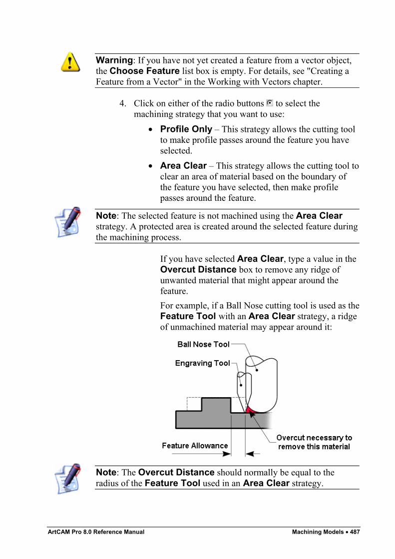
ArtCAM Pro 8.0 Reference Manual Machining Models • 487
Warning: If you have not yet created a feature from a vector object,the Choose Feature list box is empty. For details, see "Creating aFeature from a Vector" in the Working with Vectors chapter.
4. Click on either of the radio buttons to select themachining strategy that you want to use:
• Profile Only – This strategy allows the cutting toolto make profile passes around the feature you haveselected.
• Area Clear – This strategy allows the cutting tool toclear an area of material based on the boundary ofthe feature you have selected, then make profilepasses around the feature.
Note: The selected feature is not machined using the Area Clearstrategy. A protected area is created around the selected feature duringthe machining process.
If you have selected Area Clear, type a value in theOvercut Distance box to remove any ridge ofunwanted material that might appear around thefeature.For example, if a Ball Nose cutting tool is used as theFeature Tool with an Area Clear strategy, a ridgeof unmachined material may appear around it:
Note: The Overcut Distance should normally be equal to theradius of the Feature Tool used in an Area Clear strategy.
488 • Machining Models ArtCAM Pro 8.0 Reference Manual
5. If you want the cutting tool to sharpen the corners in thefeature as it is machined, click to select the CornerSharpen option .
6. To perform the machining strategy that you have selected asa series of passes in the Z direction, click to select the DoMultiple Z Passes option .
7. Click on either of the radio buttons to select how thecutting tool reaches the depth you defined when creating thefeature. For details, see "Creating a Feature" in the Workingwith Vectors chapter.
8. Click on either of the radio buttons to select the cutdirection you want to use:
• Climb – In Climb Milling, the cutter rotates in thesame direction as the feed motion.
• Conventional – In Conventional Milling, the cutterrotates in the opposite direction to the feed motion.
For more details, see "Overview" on page 403.
Note: You can set the default cutting direction using the ArtCAMOptions page. For details, see "Managing ArtCAM Pro'sPreferences" in the ArtCAM Pro Layout chapter.
9. Type a value in the Tolerance box to specify how closelyyou want the cutting tool to follow the shape of the selectedfeature.
10. If you want to change the height at which the machiningtool makes rapid moves between toolpath segments:
• First, click on the arrow in the Machine Safe Zarea to display the Safe Z box and the HomePosition's X, Y and Z boxes.
• Next, define the height in the Safe Z box.If you want to define the Home Position for themachining tool:
• First, define its position along the X, Y and Z axes inthe Home Position's X, Y and Z boxes.
• Next, click on the arrow in the Machine Safe Zarea to hide the Safe Z box and the HomePosition's X, Y and Z boxes.
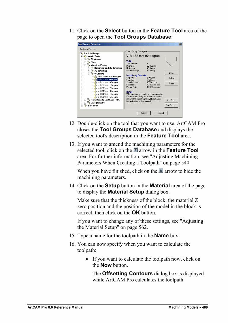
ArtCAM Pro 8.0 Reference Manual Machining Models • 489
11. Click on the Select button in the Feature Tool area of thepage to open the Tool Groups Database:
12. Double-click on the tool that you want to use. ArtCAM Procloses the Tool Groups Database and displays theselected tool's description in the Feature Tool area.
13. If you want to amend the machining parameters for theselected tool, click on the arrow in the Feature Toolarea. For further information, see "Adjusting MachiningParameters When Creating a Toolpath" on page 540.When you have finished, click on the arrow to hide themachining parameters.
14. Click on the Setup button in the Material area of the pageto display the Material Setup dialog box.Make sure that the thickness of the block, the material Zzero position and the position of the model in the block iscorrect, then click on the OK button.If you want to change any of these settings, see "Adjustingthe Material Setup" on page 562.
15. Type a name for the toolpath in the Name box.16. You can now specify when you want to calculate the
toolpath:• If you want to calculate the toolpath now, click on
the Now button.The Offsetting Contours dialog box is displayedwhile ArtCAM Pro calculates the toolpath:
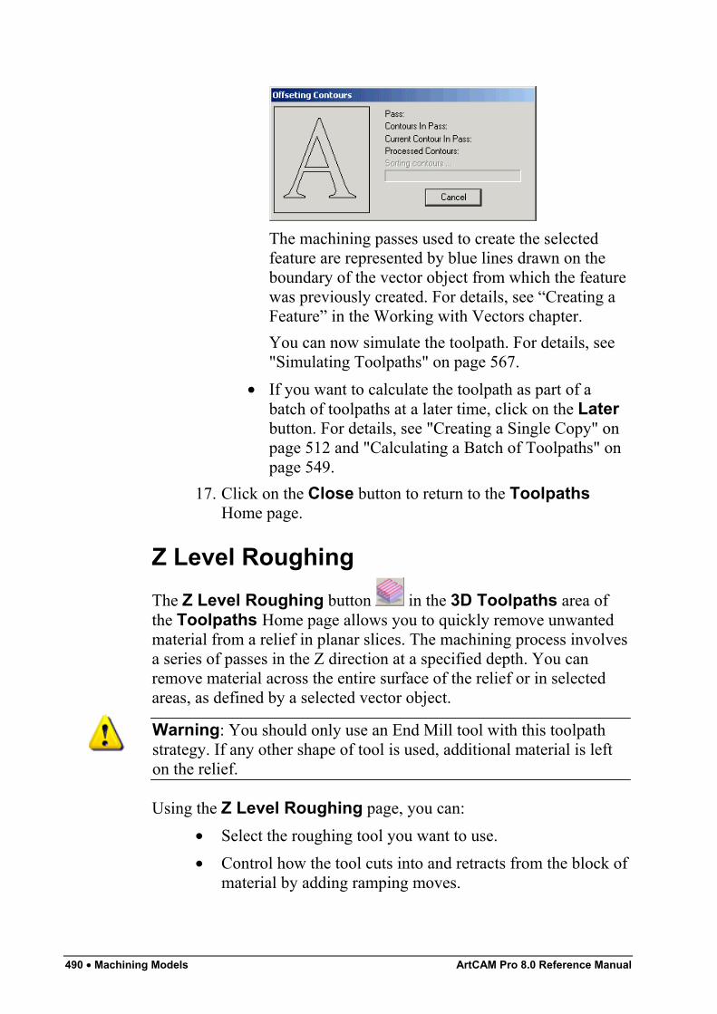
490 • Machining Models ArtCAM Pro 8.0 Reference Manual
The machining passes used to create the selectedfeature are represented by blue lines drawn on theboundary of the vector object from which the featurewas previously created. For details, see “Creating aFeature” in the Working with Vectors chapter.You can now simulate the toolpath. For details, see"Simulating Toolpaths" on page 567.
• If you want to calculate the toolpath as part of abatch of toolpaths at a later time, click on the Laterbutton. For details, see "Creating a Single Copy" onpage 512 and "Calculating a Batch of Toolpaths" onpage 549.
17. Click on the Close button to return to the ToolpathsHome page.
Z Level RoughingThe Z Level Roughing button in the 3D Toolpaths area ofthe Toolpaths Home page allows you to quickly remove unwantedmaterial from a relief in planar slices. The machining process involvesa series of passes in the Z direction at a specified depth. You canremove material across the entire surface of the relief or in selectedareas, as defined by a selected vector object.
Warning: You should only use an End Mill tool with this toolpathstrategy. If any other shape of tool is used, additional material is lefton the relief.
Using the Z Level Roughing page, you can:• Select the roughing tool you want to use.• Control how the tool cuts into and retracts from the block of
material by adding ramping moves.
ArtCAM Pro 8.0 Reference Manual Machining Models • 491
• Depending on what strategy you select, you can control theangle, or where and in what direction the roughing tool cutsinto the block of material.
To remove a cross section of a relief in the Z direction:
1. Click on the Toolpaths tab to display theToolpaths Home page.
2. Click on the Z Level Roughing button in the 3DToolpaths area to display the Z Level Roughing page.
3. Click on either of the Area to Machine radio buttons toselect how the material is removed from the relief:
• Click on the Complete Relief radio button if youwant to remove material across the entire surface ofthe relief.
• Click on the Area under selected vectors radiobutton if you want to remove material in an area ofthe relief, as defined by a selected vector object.If you select this option, select the vector object thatrepresents the area of the material that you want toremove from the relief. For details, see "SelectingVectors" in the Working with Vectors chapter.
4. Click on the Select button in the Roughing Tool area todisplay the Tool Groups Database:
5. Double-click on the tool you want to use. ArtCAM Procloses the Tool Groups Database and displays theselected tool's description in the Roughing Tool area.
6. Click on the Setup button in the Material area to displaythe Material Setup dialog box.Make sure that the thickness of the block, the material Zzero position and the position of the model in the block iscorrect, then click on the OK button.If you want to change any of these settings, see "Adjustingthe Material Setup" on page 562.
7. To add ramping moves to the toolpath, click to select theAdd Ramping Moves option . The ramping movessettings are displayed:
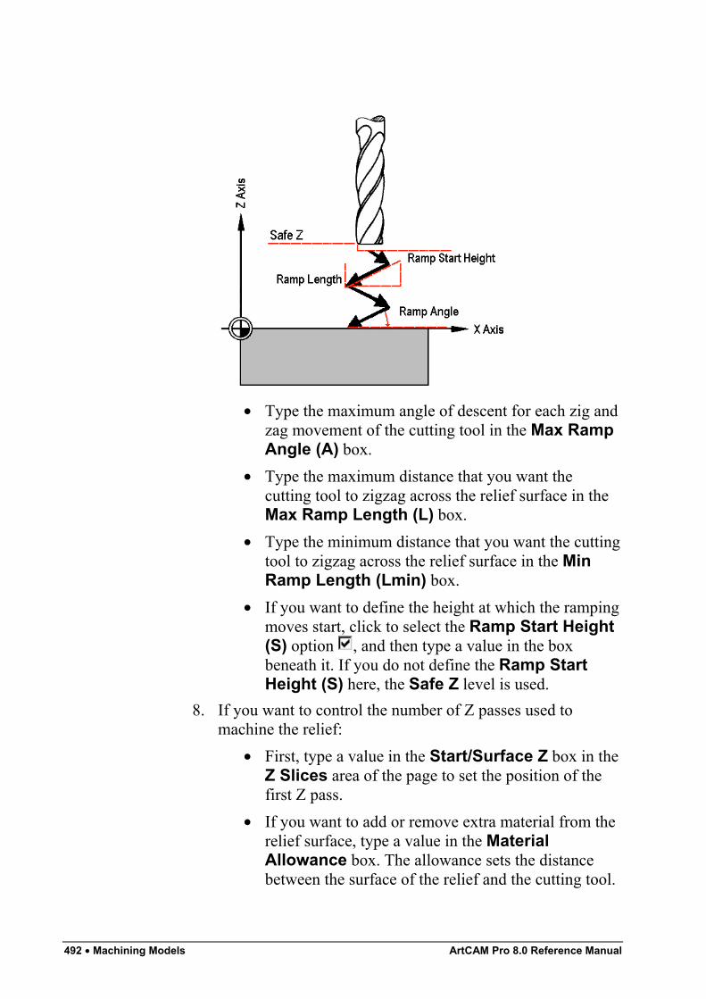
492 • Machining Models ArtCAM Pro 8.0 Reference Manual
• Type the maximum angle of descent for each zig andzag movement of the cutting tool in the Max RampAngle (A) box.
• Type the maximum distance that you want thecutting tool to zigzag across the relief surface in theMax Ramp Length (L) box.
• Type the minimum distance that you want the cuttingtool to zigzag across the relief surface in the MinRamp Length (Lmin) box.
• If you want to define the height at which the rampingmoves start, click to select the Ramp Start Height(S) option , and then type a value in the boxbeneath it. If you do not define the Ramp StartHeight (S) here, the Safe Z level is used.
8. If you want to control the number of Z passes used tomachine the relief:
• First, type a value in the Start/Surface Z box in theZ Slices area of the page to set the position of thefirst Z pass.
• If you want to add or remove extra material from therelief surface, type a value in the MaterialAllowance box. The allowance sets the distancebetween the surface of the relief and the cutting tool.
ArtCAM Pro 8.0 Reference Manual Machining Models • 493
• Next, type a value in the Last Slice Z box to set theposition of the final Z pass.
• Finally, click on the Apply button to confirm yoursettings.
9. If you want to change the height at which the cutting toolmakes rapid moves between toolpath segments:
• First, click on the arrow in the Machine Safe Zarea to display the Safe Z box and the HomePosition's X, Y and Z boxes.
• Next, define the height in the Safe Z box.If you want to define the Home Position for themachining tool:
• First, define its position along the X, Y and Z axes inthe Home Position's X, Y and Z boxes.
• Next, click on the arrow in the Machine Safe Zarea to hide the Safe Z box and the HomePosition's X, Y and Z boxes.
10. Type a value in the Tolerance box to specify how closelyyou want the cutting tool to follow the shape of the relief.
11. Click on either of the radio buttons to select themachining strategy that you want to use:
• Raster – This strategy machines back and forthalong the X-axis at a specified angle.If you select Raster, first type the angle you wantthe tool to move at in the Angle box.
Note: You can set the default raster angle using the ArtCAMOptions page. For details, see "Managing ArtCAM Pro'sPreferences" in the ArtCAM Pro Layout chapter.
Next, click on one of the Profile Pass radio buttons:
None – Select this option if you do not want the toolto profile the relief.First – Select this option if you want the tool toprofile the relief first and then raster clear the area.
494 • Machining Models ArtCAM Pro 8.0 Reference Manual
Last – Select this option if you want the tool tomove outwards to raster clear the area, then profilethe relief.
• Offset – This strategy machines in repeated passes,each time moving inwards by the Stepover value ofthe tool you use.If you have selected Offset, first click on one of theCut Direction radio buttons :Climb – In Climb Milling, the cutter rotates in thesame direction as the feed motion.Conventional – In Conventional Milling, the cutterrotates in the opposite direction to the feed motion.For more details, see "Overview" on page 403.
Note: You can set the default cutting direction in ArtCAM Pro usingthe ArtCAM Options page. For details, see "Managing ArtCAM Pro'sPreferences" in the ArtCAM Pro Layout chapter.
Next, click on one of the Start From radio buttons:
Outside – Select this option if you want the tool tocut into the material at the boundary of the reliefsurface, then machine inwards.Inside – Select this option if you want the tool to cutinto the material at the centre of the relief surface,then machine outwards.
Note: You can set the default offset start point using the ArtCAMOptions page. For details, see "Managing ArtCAM Pro'sPreferences" in the ArtCAM Pro Layout chapter.
12. Type a name for the toolpath in the Name box.13. You can now specify when you want to calculate the
toolpath:• If you want to calculate the toolpath now, click on
the Now button.You can now simulate the toolpath. For details, see"Simulating Toolpaths" on page 567.
ArtCAM Pro 8.0 Reference Manual Machining Models • 495
• If you want to calculate the toolpath as part of abatch of toolpaths at a later time, click on the Laterbutton. For details, see "Creating a Single Copy" onpage 512 and "Calculating a Batch of Toolpaths" onpage 549.
14. Click on the Close button to return to the ToolpathsHome page.
Laser MachiningThe 3D Laser Machining button in the 3D Toolpaths area ofthe Toolpaths Home page allows users of a laser-engraving machineto quickly remove layers of unwanted material from a relief. Themachining process involves a laser beam making a series of passes inthe Z direction at a specified depth.Using the Laser Machining page, you can:
• Control whether the laser machines from the base or thesurface of the relief.
• Output the toolpath in segments to allow for any refocusingof the laser that might be required between passes.
• Depending on what strategy you select, you can control theangle, or where and in what direction the laser cuts into theblock of material.
• Engrave detail into a previously machined model, using tworeliefs. This process is known as Rest (as in 'rest ofmaterial') Laser Engraving.
Important: The toolpath(s) need to be saved as an output file using asuitable post-processor such as the 2D HPGL (*.plt) before being sentto a laser engraving machine. For details, see "Saving a Toolpath" onpage 543.
To remove layers of a relief in the Z direction using a laser engravingmachine:
1. Click on the Toolpaths tab to display theToolpaths Home page.
2. Click on the 3D Laser Machining button in the 3DToolpaths area to display the Laser Machining page.
496 • Machining Models ArtCAM Pro 8.0 Reference Manual
3. Click on the Setup button in the Material area to displaythe Material Setup dialog box.Make sure that the thickness of the block, the material Zzero position and the position of the model in the block iscorrect, then click on the OK button.If you want to change any of these settings, see "Adjustingthe Material Setup" on page 562.
4. If you want to control the number of Z passes used to lasermachine the relief, you can:
• Type a value in the Start/Surface Z box to set theposition of the first Z pass.
• To enlarge or reduce the relief, type a value in theMaterial Allowance box. The allowance sets thedistance between the surface of the relief and thecutting tool. Type a positive value to enlarge therelief or a negative value to reduce it.
• Type a value in the Last Slice Z box to set theposition of the final Z pass.
• To machine from the base of the relief upwards, clickto select the Reverse Tool Slice Order option .
• Click on the Apply button to confirm your settings.5. In the Toolpath Section(s) area, click on either of the
radio buttons to select how the toolpath is calculated:• Output One Toolpath – This option allows you to
laser machine the entire relief at once.• Output In Sections – This option allows you to
laser machine the relief in segments. If you selectthis option, type a value in the Section Thicknessbox to set the depth of each toolpath segment.
6. In the Slice Type area, click on either of the radio buttons to set the type of strategy you want to use when laser
machining the relief:• Profile – This strategy machines around the
boundary of the relief surface.• Raster Clearance - This strategy machines back
and forth at a specified angle.
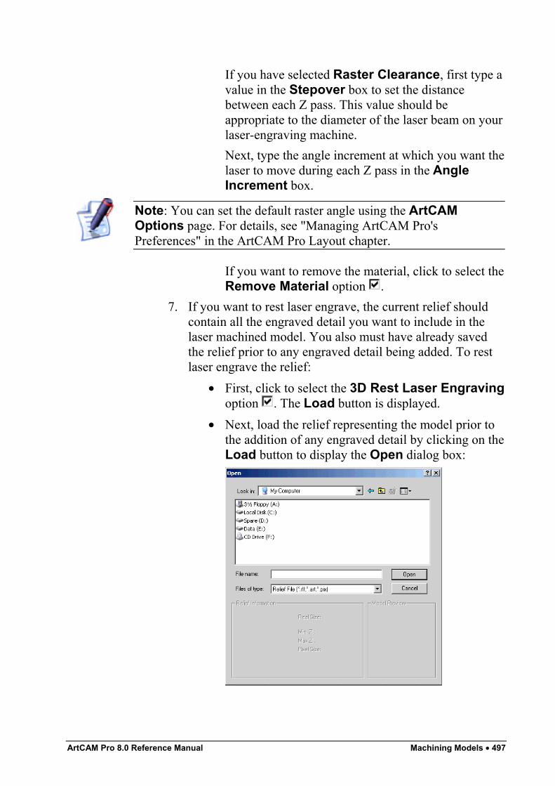
ArtCAM Pro 8.0 Reference Manual Machining Models • 497
If you have selected Raster Clearance, first type avalue in the Stepover box to set the distancebetween each Z pass. This value should beappropriate to the diameter of the laser beam on yourlaser-engraving machine.Next, type the angle increment at which you want thelaser to move during each Z pass in the AngleIncrement box.
Note: You can set the default raster angle using the ArtCAMOptions page. For details, see "Managing ArtCAM Pro'sPreferences" in the ArtCAM Pro Layout chapter.
If you want to remove the material, click to select theRemove Material option .
7. If you want to rest laser engrave, the current relief shouldcontain all the engraved detail you want to include in thelaser machined model. You also must have already savedthe relief prior to any engraved detail being added. To restlaser engrave the relief:
• First, click to select the 3D Rest Laser Engravingoption . The Load button is displayed.
• Next, load the relief representing the model prior tothe addition of any engraved detail by clicking on theLoad button to display the Open dialog box:
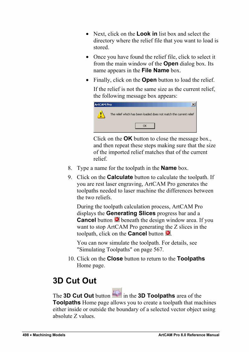
498 • Machining Models ArtCAM Pro 8.0 Reference Manual
• Next, click on the Look in list box and select thedirectory where the relief file that you want to load isstored.
• Once you have found the relief file, click to select itfrom the main window of the Open dialog box. Itsname appears in the File Name box.
• Finally, click on the Open button to load the relief.If the relief is not the same size as the current relief,the following message box appears:
Click on the OK button to close the message box.,and then repeat these steps making sure that the sizeof the imported relief matches that of the currentrelief.
8. Type a name for the toolpath in the Name box.9. Click on the Calculate button to calculate the toolpath. If
you are rest laser engraving, ArtCAM Pro generates thetoolpaths needed to laser machine the differences betweenthe two reliefs.During the toolpath calculation process, ArtCAM Prodisplays the Generating Slices progress bar and aCancel button beneath the design window area. If youwant to stop ArtCAM Pro generating the Z slices in thetoolpath, click on the Cancel button .You can now simulate the toolpath. For details, see"Simulating Toolpaths" on page 567.
10. Click on the Close button to return to the ToolpathsHome page.
3D Cut OutThe 3D Cut Out button in the 3D Toolpaths area of theToolpaths Home page allows you to create a toolpath that machineseither inside or outside the boundary of a selected vector object usingabsolute Z values.
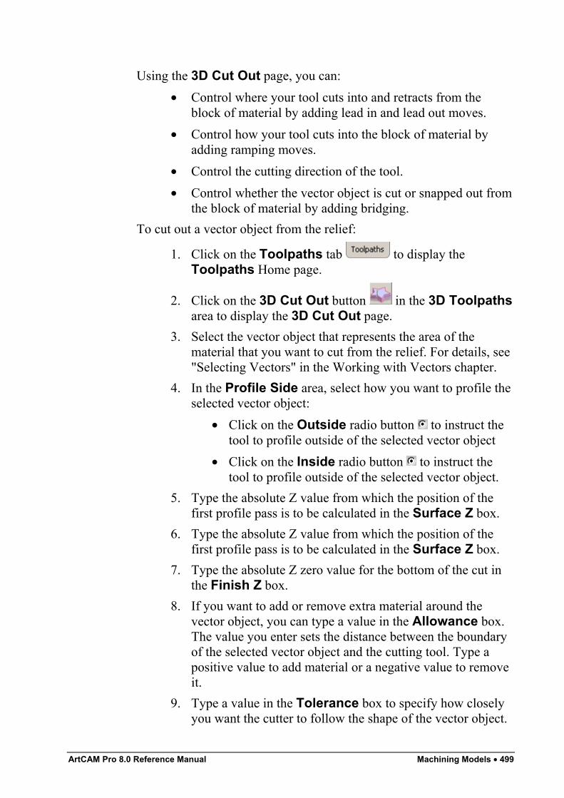
ArtCAM Pro 8.0 Reference Manual Machining Models • 499
Using the 3D Cut Out page, you can:• Control where your tool cuts into and retracts from the
block of material by adding lead in and lead out moves.• Control how your tool cuts into the block of material by
adding ramping moves.• Control the cutting direction of the tool.• Control whether the vector object is cut or snapped out from
the block of material by adding bridging.To cut out a vector object from the relief:
1. Click on the Toolpaths tab to display theToolpaths Home page.
2. Click on the 3D Cut Out button in the 3D Toolpathsarea to display the 3D Cut Out page.
3. Select the vector object that represents the area of thematerial that you want to cut from the relief. For details, see"Selecting Vectors" in the Working with Vectors chapter.
4. In the Profile Side area, select how you want to profile theselected vector object:
• Click on the Outside radio button to instruct thetool to profile outside of the selected vector object
• Click on the Inside radio button to instruct thetool to profile outside of the selected vector object.
5. Type the absolute Z value from which the position of thefirst profile pass is to be calculated in the Surface Z box.
6. Type the absolute Z value from which the position of thefirst profile pass is to be calculated in the Surface Z box.
7. Type the absolute Z zero value for the bottom of the cut inthe Finish Z box.
8. If you want to add or remove extra material around thevector object, you can type a value in the Allowance box.The value you enter sets the distance between the boundaryof the selected vector object and the cutting tool. Type apositive value to add material or a negative value to removeit.
9. Type a value in the Tolerance box to specify how closelyyou want the cutter to follow the shape of the vector object.
500 • Machining Models ArtCAM Pro 8.0 Reference Manual
10. If you want to change the height at which the cutting toolmakes rapid moves between toolpath segments:
• First, click on the arrow in the Machine Safe Zarea to display the Safe Z box and the HomePosition's X, Y and Z boxes.
• Next, define the height in the Safe Z box.If you want to define the Home Position for themachining tool:
• First, define its position along the X, Y and Z axes inthe Home Position's X, Y and Z boxes.
• Next, click on the arrow in the Machine Safe Zarea to hide the Safe Z box and the HomePosition's X, Y and Z boxes.
11. Click on the Select button in the Profiling Tool area ofthe page to open the Tool Groups Database:
12. Double-click on the tool that you want to use. ArtCAM Procloses the Tool Groups Database and displays theselected tool's description in the Profiling Tool area.
13. The cutting direction defaults to Climb Mill. If you want tochange this, click on the arrow in the Cut Directionarea of the 3D Cut Out page, then click on one of the CutDirection radio buttons :
• Climb Mill – In Climb Milling, the cutter rotates inthe same direction as the feed motion.
• Conventional – In Conventional Milling, the cutterrotates in the opposite direction to the feed motion.
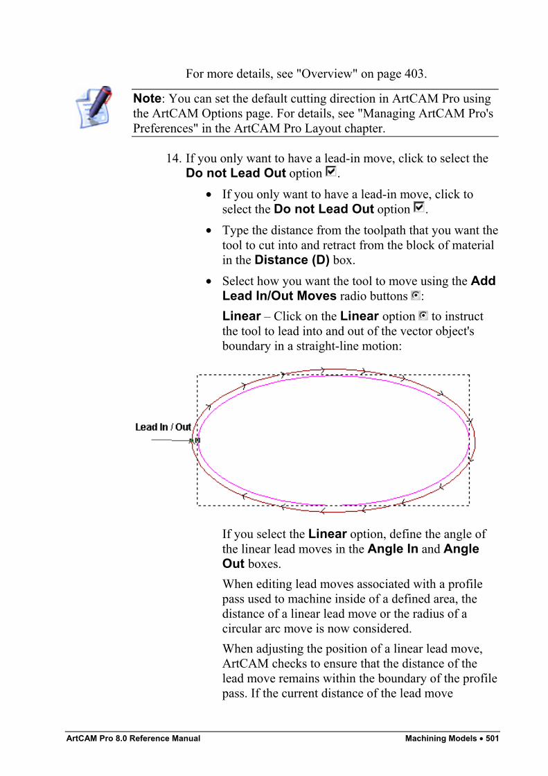
ArtCAM Pro 8.0 Reference Manual Machining Models • 501
For more details, see "Overview" on page 403.
Note: You can set the default cutting direction in ArtCAM Pro usingthe ArtCAM Options page. For details, see "Managing ArtCAM Pro'sPreferences" in the ArtCAM Pro Layout chapter.
14. If you only want to have a lead-in move, click to select theDo not Lead Out option .
• If you only want to have a lead-in move, click toselect the Do not Lead Out option .
• Type the distance from the toolpath that you want thetool to cut into and retract from the block of materialin the Distance (D) box.
• Select how you want the tool to move using the AddLead In/Out Moves radio buttons :Linear – Click on the Linear option to instructthe tool to lead into and out of the vector object'sboundary in a straight-line motion:
If you select the Linear option, define the angle ofthe linear lead moves in the Angle In and AngleOut boxes.When editing lead moves associated with a profilepass used to machine inside of a defined area, thedistance of a linear lead move or the radius of acircular arc move is now considered.When adjusting the position of a linear lead move,ArtCAM checks to ensure that the distance of thelead move remains within the boundary of the profilepass. If the current distance of the lead move
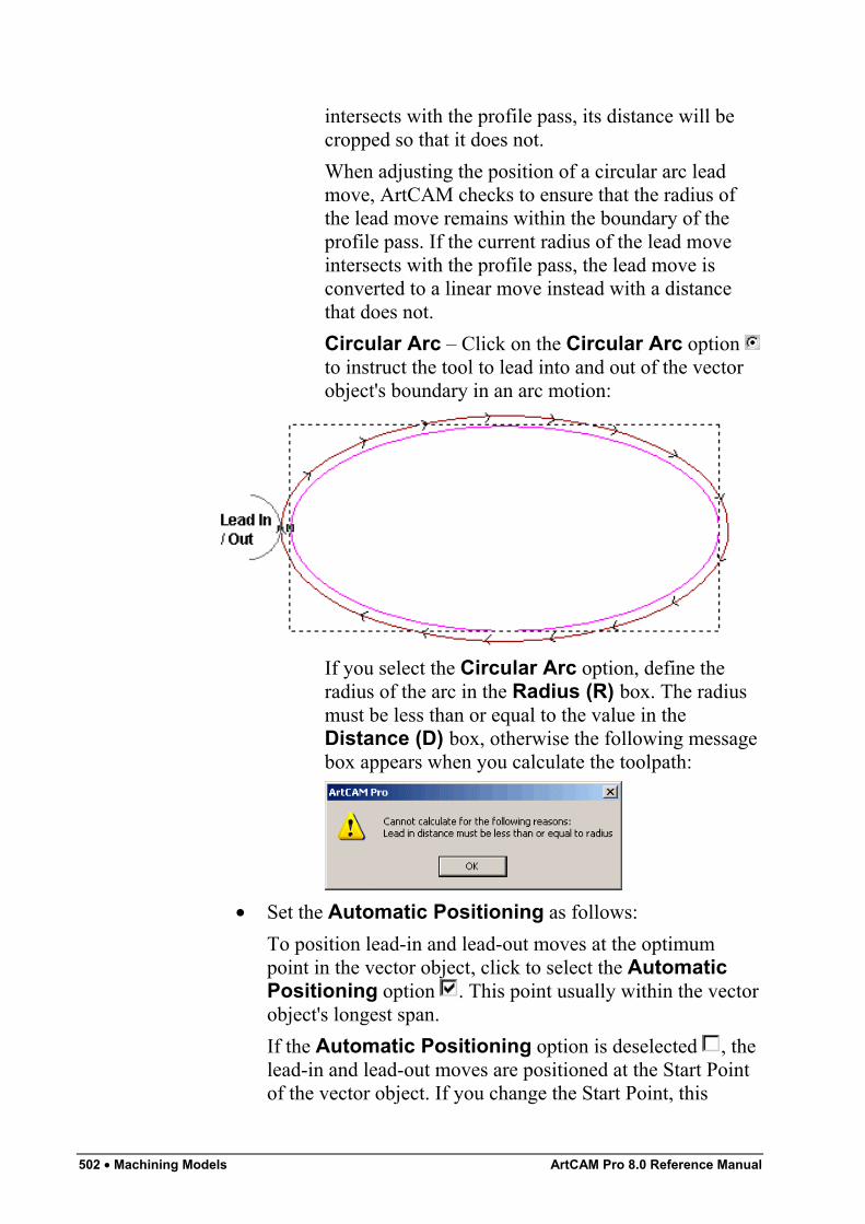
502 • Machining Models ArtCAM Pro 8.0 Reference Manual
intersects with the profile pass, its distance will becropped so that it does not.When adjusting the position of a circular arc leadmove, ArtCAM checks to ensure that the radius ofthe lead move remains within the boundary of theprofile pass. If the current radius of the lead moveintersects with the profile pass, the lead move isconverted to a linear move instead with a distancethat does not.Circular Arc – Click on the Circular Arc option to instruct the tool to lead into and out of the vectorobject's boundary in an arc motion:
If you select the Circular Arc option, define theradius of the arc in the Radius (R) box. The radiusmust be less than or equal to the value in theDistance (D) box, otherwise the following messagebox appears when you calculate the toolpath:
• Set the Automatic Positioning as follows:To position lead-in and lead-out moves at the optimumpoint in the vector object, click to select the AutomaticPositioning option . This point usually within the vectorobject's longest span.If the Automatic Positioning option is deselected , thelead-in and lead-out moves are positioned at the Start Pointof the vector object. If you change the Start Point, this
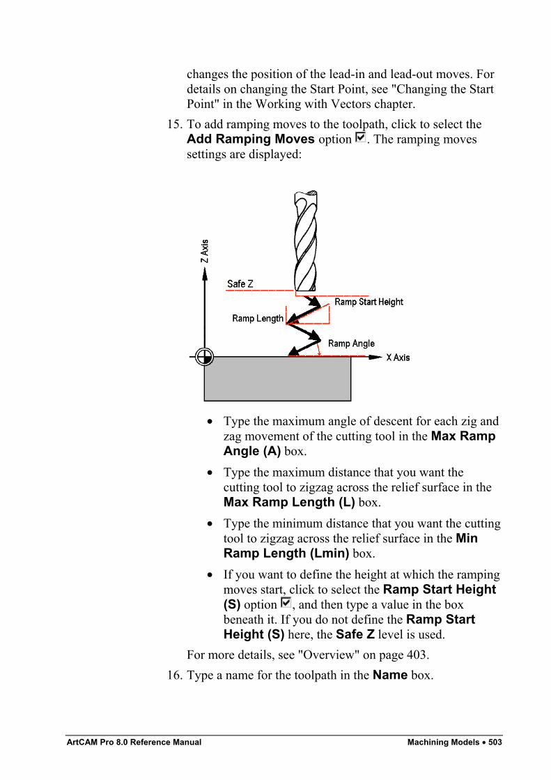
ArtCAM Pro 8.0 Reference Manual Machining Models • 503
changes the position of the lead-in and lead-out moves. Fordetails on changing the Start Point, see "Changing the StartPoint" in the Working with Vectors chapter.
15. To add ramping moves to the toolpath, click to select theAdd Ramping Moves option . The ramping movessettings are displayed:
• Type the maximum angle of descent for each zig andzag movement of the cutting tool in the Max RampAngle (A) box.
• Type the maximum distance that you want thecutting tool to zigzag across the relief surface in theMax Ramp Length (L) box.
• Type the minimum distance that you want the cuttingtool to zigzag across the relief surface in the MinRamp Length (Lmin) box.
• If you want to define the height at which the rampingmoves start, click to select the Ramp Start Height(S) option , and then type a value in the boxbeneath it. If you do not define the Ramp StartHeight (S) here, the Safe Z level is used.
For more details, see "Overview" on page 403.16. Type a name for the toolpath in the Name box.
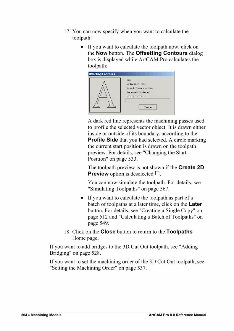
504 • Machining Models ArtCAM Pro 8.0 Reference Manual
17. You can now specify when you want to calculate thetoolpath:
• If you want to calculate the toolpath now, click onthe Now button. The Offsetting Contours dialogbox is displayed while ArtCAM Pro calculates thetoolpath:
A dark red line represents the machining passes usedto profile the selected vector object. It is drawn eitherinside or outside of its boundary, according to theProfile Side that you had selected. A circle markingthe current start position is drawn on the toolpathpreview. For details, see "Changing the StartPosition" on page 533.The toolpath preview is not shown if the Create 2DPreview option is deselected .You can now simulate the toolpath. For details, see"Simulating Toolpaths" on page 567.
• If you want to calculate the toolpath as part of abatch of toolpaths at a later time, click on the Laterbutton. For details, see "Creating a Single Copy" onpage 512 and "Calculating a Batch of Toolpaths" onpage 549.
18. Click on the Close button to return to the ToolpathsHome page.
If you want to add bridges to the 3D Cut Out toolpath, see "AddingBridging" on page 528.If you want to set the machining order of the 3D Cut Out toolpath, see"Setting the Machining Order" on page 537.
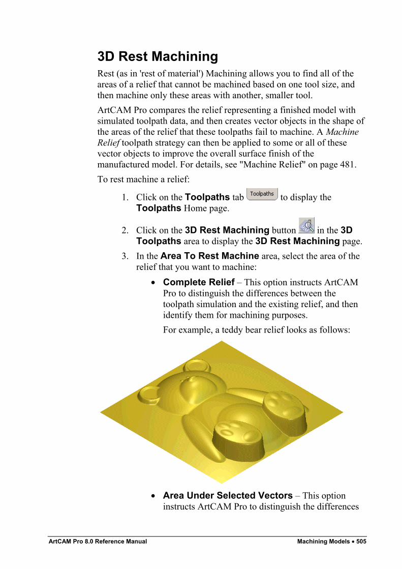
ArtCAM Pro 8.0 Reference Manual Machining Models • 505
3D Rest MachiningRest (as in 'rest of material') Machining allows you to find all of theareas of a relief that cannot be machined based on one tool size, andthen machine only these areas with another, smaller tool.ArtCAM Pro compares the relief representing a finished model withsimulated toolpath data, and then creates vector objects in the shape ofthe areas of the relief that these toolpaths fail to machine. A MachineRelief toolpath strategy can then be applied to some or all of thesevector objects to improve the overall surface finish of themanufactured model. For details, see "Machine Relief" on page 481.To rest machine a relief:
1. Click on the Toolpaths tab to display theToolpaths Home page.
2. Click on the 3D Rest Machining button in the 3DToolpaths area to display the 3D Rest Machining page.
3. In the Area To Rest Machine area, select the area of therelief that you want to machine:
• Complete Relief – This option instructs ArtCAMPro to distinguish the differences between thetoolpath simulation and the existing relief, and thenidentify them for machining purposes.For example, a teddy bear relief looks as follows:
• Area Under Selected Vectors – This optioninstructs ArtCAM Pro to distinguish the differences
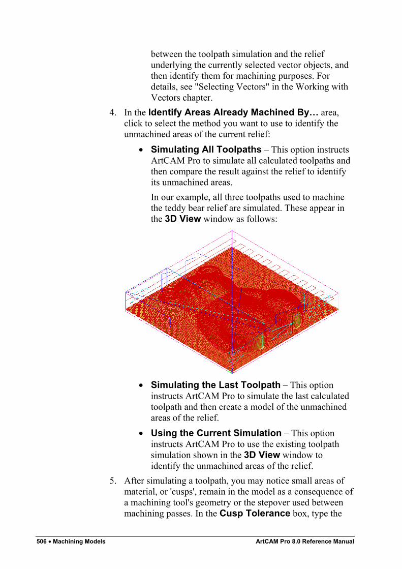
506 • Machining Models ArtCAM Pro 8.0 Reference Manual
between the toolpath simulation and the reliefunderlying the currently selected vector objects, andthen identify them for machining purposes. Fordetails, see "Selecting Vectors" in the Working withVectors chapter.
4. In the Identify Areas Already Machined By… area,click to select the method you want to use to identify theunmachined areas of the current relief:
• Simulating All Toolpaths – This option instructsArtCAM Pro to simulate all calculated toolpaths andthen compare the result against the relief to identifyits unmachined areas.In our example, all three toolpaths used to machinethe teddy bear relief are simulated. These appear inthe 3D View window as follows:
• Simulating the Last Toolpath – This optioninstructs ArtCAM Pro to simulate the last calculatedtoolpath and then create a model of the unmachinedareas of the relief.
• Using the Current Simulation – This optioninstructs ArtCAM Pro to use the existing toolpathsimulation shown in the 3D View window toidentify the unmachined areas of the relief.
5. After simulating a toolpath, you may notice small areas ofmaterial, or 'cusps', remain in the model as a consequence ofa machining tool's geometry or the stepover used betweenmachining passes. In the Cusp Tolerance box, type the
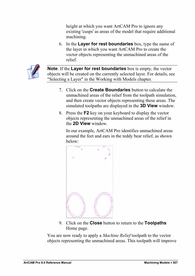
ArtCAM Pro 8.0 Reference Manual Machining Models • 507
height at which you want ArtCAM Pro to ignore anyexisting 'cusps' as areas of the model that require additionalmachining.
6. In the Layer for rest boundaries box, type the name ofthe layer in which you want ArtCAM Pro to create thevector objects representing the unmachined areas of therelief.
Note: If the Layer for rest boundaries box is empty, the vectorobjects will be created on the currently selected layer. For details, see"Selecting a Layer" in the Working with Models chapter.
7. Click on the Create Boundaries button to calculate theunmachined areas of the relief from the toolpath simulation,and then create vector objects representing these areas. Thesimulated toolpaths are displayed in the 3D View window.
8. Press the F2 key on your keyboard to display the vectorobjects representing the unmachined areas of the relief inthe 2D View window.In our example, ArtCAM Pro identifies unmachined areasaround the feet and ears in the teddy bear relief, as shownbelow:
9. Click on the Close button to return to the ToolpathsHome page.
You are now ready to apply a Machine Relief toolpath to the vectorobjects representing the unmachined areas. This toolpath will improve
508 • Machining Models ArtCAM Pro 8.0 Reference Manual
the overall surface finish of the relief during the manufacturingprocess. For details, see "Machine Relief" on page 481.
Managing and Modifying ToolpathsYou can use the Toolpaths Home page to modify and manage thetoolpath strategies that you are using.You can modify or manage a toolpath strategy in the following ways:
• Merge a selection of calculated toolpaths into a singletoolpath. For details, see "Merging Toolpaths" on page 521.
• Set the order in which the individual toolpaths selected formerging will be machined. For details, see "Creating aSingle Copy" on page 512, "Creating a Block Copy" onpage 515 and "Merging Toolpaths" on page 521.
• Transform one or more calculated toolpaths. For details, see"Transforming Toolpaths" on page 510.
• Make a single copy of one or more calculated toolpaths. Fordetails, see "Creating a Single Copy" on page 512.
• Make multiple copies of one or more calculated toolpaths ina grid format. For details, see "Creating a Block Copy" onpage 515.
• Set the machining order in all toolpaths that involve profilepasses. For details, see "Setting the Machining Order" onpage 537.
• Adjust the machining parameters of a tool both during andafter the toolpath creation. For details, see "Adjusting theMachining Parameters of a Tool" on page 540.
• Save a toolpath. For details, see "Saving a Toolpath" onpage 543.
• Edit toolpath settings. For details, see "Editing a Toolpath"on page 545.
• Delete a toolpath or toolpath group. For details, see"Deleting Toolpaths" on page 546.
• Calculate a toolpath by itself or as part of a batch. Fordetails, see "Calculating a Single Toolpath" on page 548 and"Calculating a Batch of Toolpaths" on page 549.
ArtCAM Pro 8.0 Reference Manual Machining Models • 509
• Create a Toolpath Summary and calculate the estimatedmachining time. For details, see "Using a ToolpathSummary" on page 550.
• Add to, edit or delete the tools within the Tool GroupsDatabase. "Using the Tool Groups Database" on page 554.
• Adjust the Material Setup. For details, see "Adjusting theMaterial Setup" on page 562.
• Delete the material.. For details, see "Deleting the Material"on page 564.
• Save a toolpath as a template. For details, see "Creating aToolpath Template" on page 564.
• Load a toolpath template. For details, see "Loading aToolpath Template" on page 565.
• Set the toolpath order. For details, see "Setting the ToolpathOrder" on page 567.
Selecting ToolpathsYou can manipulate calculated 2D or 3D toolpaths in the same way asyou would vector objects in ArtCAM Pro.You can transform, copy or edit profile passes within a toolpath,provided that a 2D Preview was created during the calculationprocess. Toolpath previews are shown in the 2D View window onlyand are dark red.To select a toolpath preview from the 2D View window:
1. Make sure that you are in Select Vectors mode . Fordetails, see "Selecting Vectors" in the Working with Vectorschapter.
2. Click to select the preview of the toolpath that you want touse. The selected toolpath preview turns blue and issurrounded by a bounding box.For example, the preview of a Profiling toolpath is shownbelow:
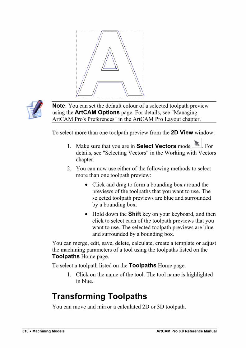
510 • Machining Models ArtCAM Pro 8.0 Reference Manual
Note: You can set the default colour of a selected toolpath previewusing the ArtCAM Options page. For details, see "ManagingArtCAM Pro's Preferences" in the ArtCAM Pro Layout chapter.
To select more than one toolpath preview from the 2D View window:
1. Make sure that you are in Select Vectors mode . Fordetails, see "Selecting Vectors" in the Working with Vectorschapter.
2. You can now use either of the following methods to selectmore than one toolpath preview:
• Click and drag to form a bounding box around thepreviews of the toolpaths that you want to use. Theselected toolpath previews are blue and surroundedby a bounding box.
• Hold down the Shift key on your keyboard, and thenclick to select each of the toolpath previews that youwant to use. The selected toolpath previews are blueand surrounded by a bounding box.
You can merge, edit, save, delete, calculate, create a template or adjustthe machining parameters of a tool using the toolpaths listed on theToolpaths Home page.To select a toolpath listed on the Toolpaths Home page:
1. Click on the name of the tool. The tool name is highlightedin blue.
Transforming ToolpathsYou can move and mirror a calculated 2D or 3D toolpath.
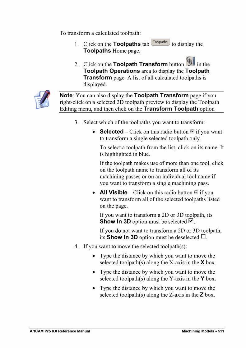
ArtCAM Pro 8.0 Reference Manual Machining Models • 511
To transform a calculated toolpath:
1. Click on the Toolpaths tab to display theToolpaths Home page.
2. Click on the Toolpath Transform button in theToolpath Operations area to display the ToolpathTransform page. A list of all calculated toolpaths isdisplayed.
Note: You can also display the Toolpath Transform page if youright-click on a selected 2D toolpath preview to display the ToolpathEditing menu, and then click on the Transform Toolpath option
3. Select which of the toolpaths you want to transform:• Selected – Click on this radio button if you want
to transform a single selected toolpath only.To select a toolpath from the list, click on its name. Itis highlighted in blue.If the toolpath makes use of more than one tool, clickon the toolpath name to transform all of itsmachining passes or on an individual tool name ifyou want to transform a single machining pass.
• All Visible – Click on this radio button if youwant to transform all of the selected toolpaths listedon the page.If you want to transform a 2D or 3D toolpath, itsShow In 3D option must be selected .If you do not want to transform a 2D or 3D toolpath,its Show In 3D option must be deselected .
4. If you want to move the selected toolpath(s):• Type the distance by which you want to move the
selected toolpath(s) along the X-axis in the X box.• Type the distance by which you want to move the
selected toolpath(s) along the Y-axis in the Y box.• Type the distance by which you want to move the
selected toolpath(s) along the Z-axis in the Z box.
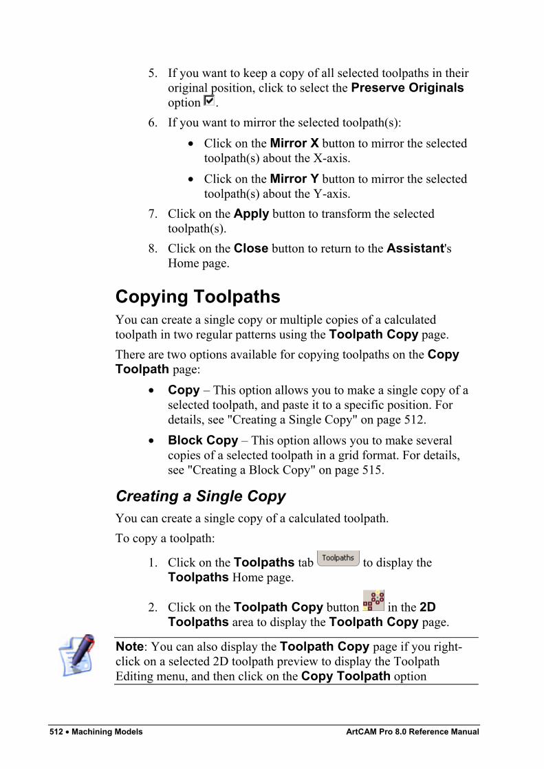
512 • Machining Models ArtCAM Pro 8.0 Reference Manual
5. If you want to keep a copy of all selected toolpaths in theiroriginal position, click to select the Preserve Originalsoption .
6. If you want to mirror the selected toolpath(s):• Click on the Mirror X button to mirror the selected
toolpath(s) about the X-axis.• Click on the Mirror Y button to mirror the selected
toolpath(s) about the Y-axis.7. Click on the Apply button to transform the selected
toolpath(s).8. Click on the Close button to return to the Assistant's
Home page.
Copying ToolpathsYou can create a single copy or multiple copies of a calculatedtoolpath in two regular patterns using the Toolpath Copy page.There are two options available for copying toolpaths on the CopyToolpath page:
• Copy – This option allows you to make a single copy of aselected toolpath, and paste it to a specific position. Fordetails, see "Creating a Single Copy" on page 512.
• Block Copy – This option allows you to make severalcopies of a selected toolpath in a grid format. For details,see "Creating a Block Copy" on page 515.
Creating a Single CopyYou can create a single copy of a calculated toolpath.To copy a toolpath:
1. Click on the Toolpaths tab to display theToolpaths Home page.
2. Click on the Toolpath Copy button in the 2DToolpaths area to display the Toolpath Copy page.
Note: You can also display the Toolpath Copy page if you right-click on a selected 2D toolpath preview to display the ToolpathEditing menu, and then click on the Copy Toolpath option
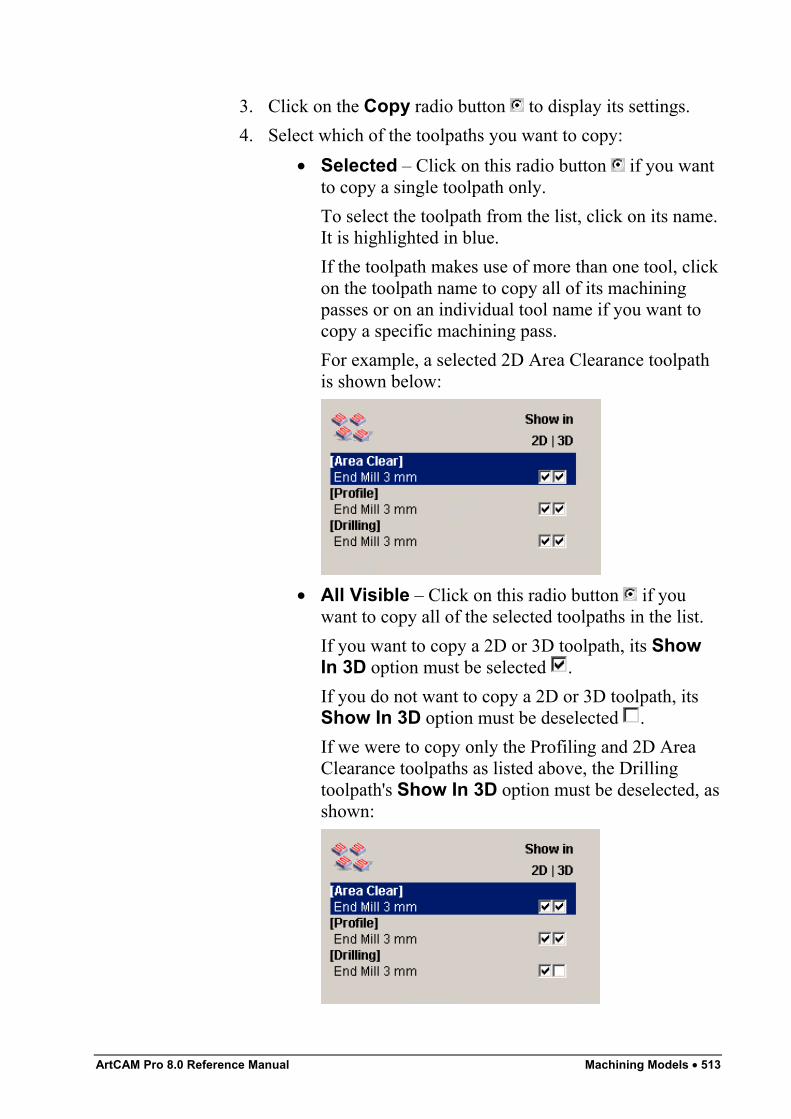
ArtCAM Pro 8.0 Reference Manual Machining Models • 513
3. Click on the Copy radio button to display its settings.4. Select which of the toolpaths you want to copy:
• Selected – Click on this radio button if you wantto copy a single toolpath only.To select the toolpath from the list, click on its name.It is highlighted in blue.If the toolpath makes use of more than one tool, clickon the toolpath name to copy all of its machiningpasses or on an individual tool name if you want tocopy a specific machining pass.For example, a selected 2D Area Clearance toolpathis shown below:
• All Visible – Click on this radio button if youwant to copy all of the selected toolpaths in the list.If you want to copy a 2D or 3D toolpath, its ShowIn 3D option must be selected .If you do not want to copy a 2D or 3D toolpath, itsShow In 3D option must be deselected .If we were to copy only the Profiling and 2D AreaClearance toolpaths as listed above, the Drillingtoolpath's Show In 3D option must be deselected, asshown:
514 • Machining Models ArtCAM Pro 8.0 Reference Manual
5. Define the distance you want to set between the selectedtoolpath and its copy along the X-axis in the X Offset box.The X and Y offsets that you define set the distance atwhich each copy of a toolpath will be created from thebottom left corner of the previous copy in the block.
Note: You can set the offset distance between each copy using apositive or negative value. To create a copy to the right of and abovethe selected toolpath, type positive values in the offset boxes e.g. 90.To create a block of copies to the left of and below of the selectedtoolpath, type negative values in the offset boxes e.g. -90.
6. Define the distance you want to set between the selectedtoolpath and its copy along the Y-axis in the Y Offset box.
7. If you have selected a 3D toolpath, define the distance youwant to set between the selected toolpath and its copy alongthe Z-axis in the Z Offset box.
Note: If you have selected a 2D toolpath, the Z Offset box is greyed-out.
8. If you want to merge the copy with its original toolpath:
• First, prioritise the toolpaths using the and arrows. Click to select the name of the toolpath in thelist that you want to prioritise, and then on theappropriate arrow to set its position in the list. Theorder in which the toolpaths are listed on the pagereflects the machining order of the toolpaths thatmake up the merged toolpath. The toolpath at the topof the list is the first to be machined, and so on.
• Next, click to select the Merge Results option .A Name box appears.
• Finally, type a name for the new toolpath in theName box.
9. Click on the Apply button to create the new toolpath.In our example, the copied toolpath appears in the 2D Viewwindow, as shown below:
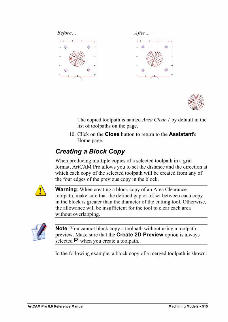
ArtCAM Pro 8.0 Reference Manual Machining Models • 515
Before… After…
The copied toolpath is named Area Clear 1 by default in thelist of toolpaths on the page.
10. Click on the Close button to return to the Assistant'sHome page.
Creating a Block CopyWhen producing multiple copies of a selected toolpath in a gridformat, ArtCAM Pro allows you to set the distance and the direction atwhich each copy of the selected toolpath will be created from any ofthe four edges of the previous copy in the block.
Warning: When creating a block copy of an Area Clearancetoolpath, make sure that the defined gap or offset between each copyin the block is greater than the diameter of the cutting tool. Otherwise,the allowance will be insufficient for the tool to clear each areawithout overlapping.
Note: You cannot block copy a toolpath without using a toolpathpreview. Make sure that the Create 2D Preview option is alwaysselected when you create a toolpath.
In the following example, a block copy of a merged toolpath is shown:
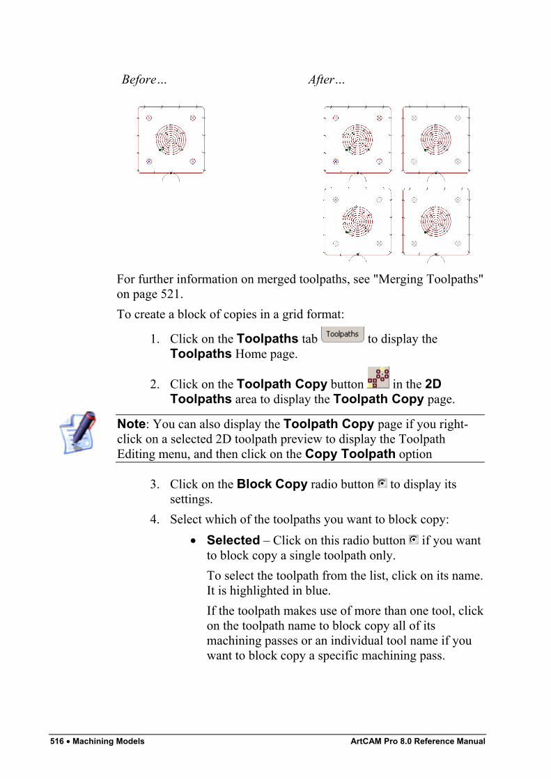
516 • Machining Models ArtCAM Pro 8.0 Reference Manual
Before… After…
For further information on merged toolpaths, see "Merging Toolpaths"on page 521.To create a block of copies in a grid format:
1. Click on the Toolpaths tab to display theToolpaths Home page.
2. Click on the Toolpath Copy button in the 2DToolpaths area to display the Toolpath Copy page.
Note: You can also display the Toolpath Copy page if you right-click on a selected 2D toolpath preview to display the ToolpathEditing menu, and then click on the Copy Toolpath option
3. Click on the Block Copy radio button to display itssettings.
4. Select which of the toolpaths you want to block copy:• Selected – Click on this radio button if you want
to block copy a single toolpath only.To select the toolpath from the list, click on its name.It is highlighted in blue.If the toolpath makes use of more than one tool, clickon the toolpath name to block copy all of itsmachining passes or an individual tool name if youwant to block copy a specific machining pass.
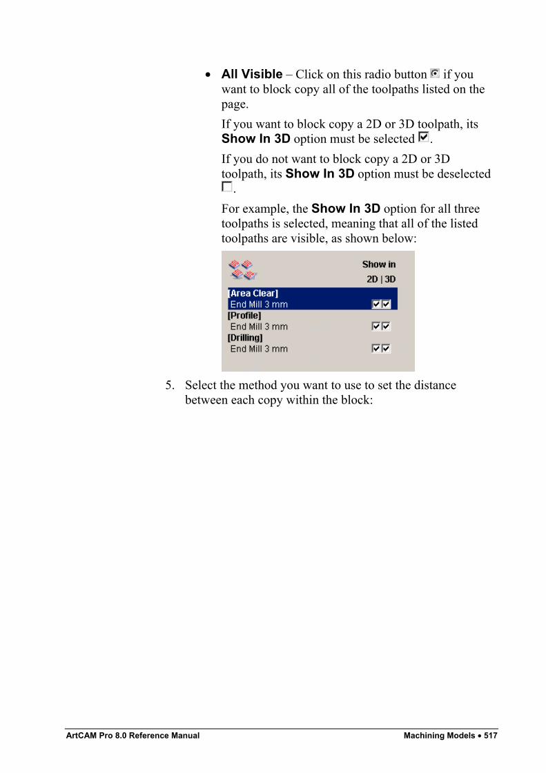
ArtCAM Pro 8.0 Reference Manual Machining Models • 517
• All Visible – Click on this radio button if youwant to block copy all of the toolpaths listed on thepage.If you want to block copy a 2D or 3D toolpath, itsShow In 3D option must be selected .If you do not want to block copy a 2D or 3Dtoolpath, its Show In 3D option must be deselected
.For example, the Show In 3D option for all threetoolpaths is selected, meaning that all of the listedtoolpaths are visible, as shown below:
5. Select the method you want to use to set the distancebetween each copy within the block:
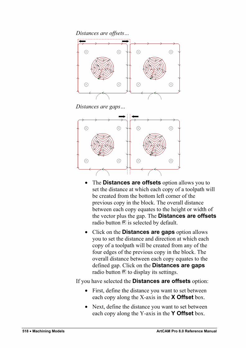
518 • Machining Models ArtCAM Pro 8.0 Reference Manual
Distances are offsets…
Distances are gaps…
• The Distances are offsets option allows you toset the distance at which each copy of a toolpath willbe created from the bottom left corner of theprevious copy in the block. The overall distancebetween each copy equates to the height or width ofthe vector plus the gap. The Distances are offsetsradio button is selected by default.
• Click on the Distances are gaps option allowsyou to set the distance and direction at which eachcopy of a toolpath will be created from any of thefour edges of the previous copy in the block. Theoverall distance between each copy equates to thedefined gap. Click on the Distances are gapsradio button to display its settings.
If you have selected the Distances are offsets option:• First, define the distance you want to set between
each copy along the X-axis in the X Offset box.• Next, define the distance you want to set between
each copy along the Y-axis in the Y Offset box.
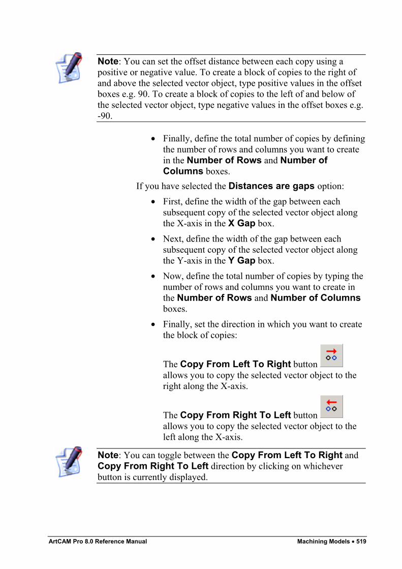
ArtCAM Pro 8.0 Reference Manual Machining Models • 519
Note: You can set the offset distance between each copy using apositive or negative value. To create a block of copies to the right ofand above the selected vector object, type positive values in the offsetboxes e.g. 90. To create a block of copies to the left of and below ofthe selected vector object, type negative values in the offset boxes e.g.-90.
• Finally, define the total number of copies by definingthe number of rows and columns you want to createin the Number of Rows and Number ofColumns boxes.
If you have selected the Distances are gaps option:• First, define the width of the gap between each
subsequent copy of the selected vector object alongthe X-axis in the X Gap box.
• Next, define the width of the gap between eachsubsequent copy of the selected vector object alongthe Y-axis in the Y Gap box.
• Now, define the total number of copies by typing thenumber of rows and columns you want to create inthe Number of Rows and Number of Columnsboxes.
• Finally, set the direction in which you want to createthe block of copies:
The Copy From Left To Right button allows you to copy the selected vector object to theright along the X-axis.
The Copy From Right To Left button allows you to copy the selected vector object to theleft along the X-axis.
Note: You can toggle between the Copy From Left To Right andCopy From Right To Left direction by clicking on whicheverbutton is currently displayed.
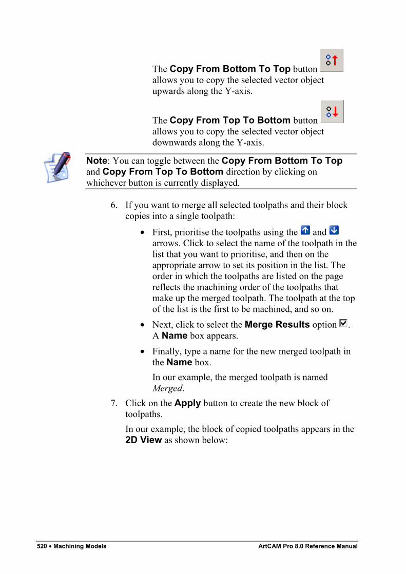
520 • Machining Models ArtCAM Pro 8.0 Reference Manual
The Copy From Bottom To Top button allows you to copy the selected vector objectupwards along the Y-axis.
The Copy From Top To Bottom button allows you to copy the selected vector objectdownwards along the Y-axis.
Note: You can toggle between the Copy From Bottom To Topand Copy From Top To Bottom direction by clicking onwhichever button is currently displayed.
6. If you want to merge all selected toolpaths and their blockcopies into a single toolpath:
• First, prioritise the toolpaths using the and arrows. Click to select the name of the toolpath in thelist that you want to prioritise, and then on theappropriate arrow to set its position in the list. Theorder in which the toolpaths are listed on the pagereflects the machining order of the toolpaths thatmake up the merged toolpath. The toolpath at the topof the list is the first to be machined, and so on.
• Next, click to select the Merge Results option .A Name box appears.
• Finally, type a name for the new merged toolpath inthe Name box.In our example, the merged toolpath is namedMerged.
7. Click on the Apply button to create the new block oftoolpaths.In our example, the block of copied toolpaths appears in the2D View as shown below:
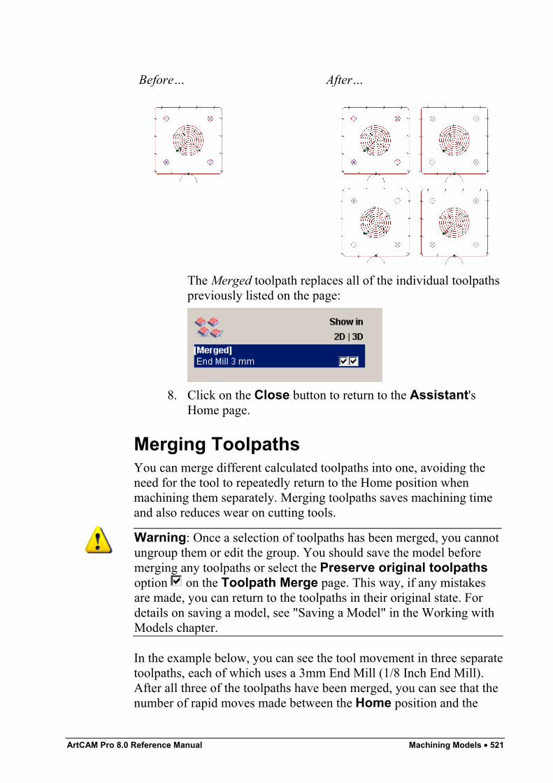
ArtCAM Pro 8.0 Reference Manual Machining Models • 521
Before… After…
The Merged toolpath replaces all of the individual toolpathspreviously listed on the page:
8. Click on the Close button to return to the Assistant'sHome page.
Merging ToolpathsYou can merge different calculated toolpaths into one, avoiding theneed for the tool to repeatedly return to the Home position whenmachining them separately. Merging toolpaths saves machining timeand also reduces wear on cutting tools.
Warning: Once a selection of toolpaths has been merged, you cannotungroup them or edit the group. You should save the model beforemerging any toolpaths or select the Preserve original toolpathsoption on the Toolpath Merge page. This way, if any mistakesare made, you can return to the toolpaths in their original state. Fordetails on saving a model, see "Saving a Model" in the Working withModels chapter.
In the example below, you can see the tool movement in three separatetoolpaths, each of which uses a 3mm End Mill (1/8 Inch End Mill).After all three of the toolpaths have been merged, you can see that thenumber of rapid moves made between the Home position and the
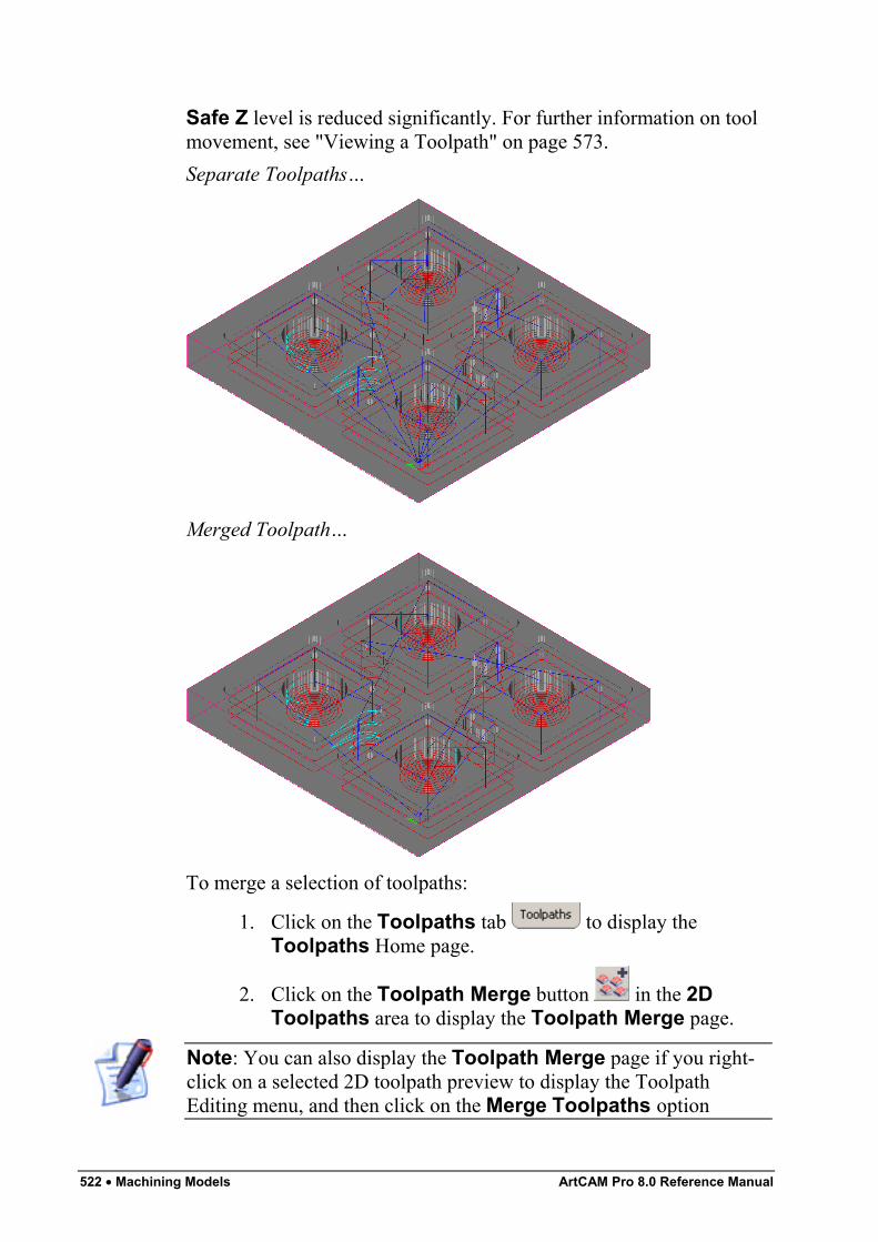
522 • Machining Models ArtCAM Pro 8.0 Reference Manual
Safe Z level is reduced significantly. For further information on toolmovement, see "Viewing a Toolpath" on page 573.Separate Toolpaths…
Merged Toolpath…
To merge a selection of toolpaths:
1. Click on the Toolpaths tab to display theToolpaths Home page.
2. Click on the Toolpath Merge button in the 2DToolpaths area to display the Toolpath Merge page.
Note: You can also display the Toolpath Merge page if you right-click on a selected 2D toolpath preview to display the ToolpathEditing menu, and then click on the Merge Toolpaths option
ArtCAM Pro 8.0 Reference Manual Machining Models • 523
3. Make sure that only the toolpaths that you want to mergeare selected:
• If you want to merge a 2D or 3D toolpath, its ShowIn 3D option must be selected .
• If you do not want to merge a 2D or 3D toolpath, itsShow In 3D option must be deselected .
4. In the Merging Order area, select the order in which youwant the merged toolpaths to be machined:
• As List - Click on this radio button if you wantthe toolpaths to be machined in the order in whichthey are listed on the page.
You can prioritise the toolpaths using the and arrows. Click to select the name of the toolpath in thelist that you want to prioritise, and then on theappropriate arrow to set its position in the list. Thetoolpath at the top of the list is the first to bemachined, and so on.
• Automatic - Click on this radio button if youwant ArtCAM Pro to calculate the order in which thetoolpaths are machined, finding the shortest routebetween them.
5. If you want to keep a copy of the toolpaths in their originalstate, click to select the Preserve original toolpathsoption .
6. Type a name for the merged toolpath in the Name box.7. Click on the Calculate button to merge the selected
toolpaths into a single toolpath.A progress bar appears beneath the 2D View windowindicating the progress made in merging the toolpaths.
8. Click on the Close button to return to the Assistant'sHome page.
Creating Toolpath PanelsYou can machine a design larger than the bed-size of you router, orlarger than the panels of material that are currently available. ArtCAMPro divides calculated toolpaths into sections so that you can machineseparate panels of material one by one and then piece them alltogether, or machine a single panel of material larger than the router's
524 • Machining Models ArtCAM Pro 8.0 Reference Manual
bed-size in sections, repositioning the panel on the router bed until allsections have been machined.
Warning: To use toolpath panelling, the job origin must be set to thebottom left corner of the model. For details, see "Creating a Model" inthe Working with Models chapter.
To create toolpath panels:
1. Click on the Toolpaths tab to display theToolpaths Home page.
2. Make sure that all of the previews of the toolpaths that youwant to divide into panels are shown in the 2D Viewwindow. Click to select the Show In 2D option next to anyhidden toolpaths to make them visible .
3. Click on the Toolpath Panelling button in theToolpath Operations area to display the ArtCAMToolpath Panelling page.
4. In the Standard Panel Size area, define the width andheight of the available panels of material, or the size of therouter-bed (whichever maybe the limiting factor in the job),using the Width and Height boxes, and then click on theUpdate Panels button.If you want to allow a toolpath to extend beyond the top andright edges of a panel of material, define the maximumovercut distance in the Overcut Distance box.Guidelines are drawn in the 2D View to represent the sizeof each panel or the router-bed itself. For details on usingguidelines, see "Using Guidelines" in the ArtCAM ProLayout chapter.
Warning: Make sure that the dimensions of your router allow you todrag the panels of material you want to use across its bed.
For example, you might only be able to acquire panels ofmaterial with a height and width of 500 mm (19.7").
5. In the Panel Numbers area, use the buttons to set theorder in which the panels are numbered:
• Click on the button to number the panelsvertically.
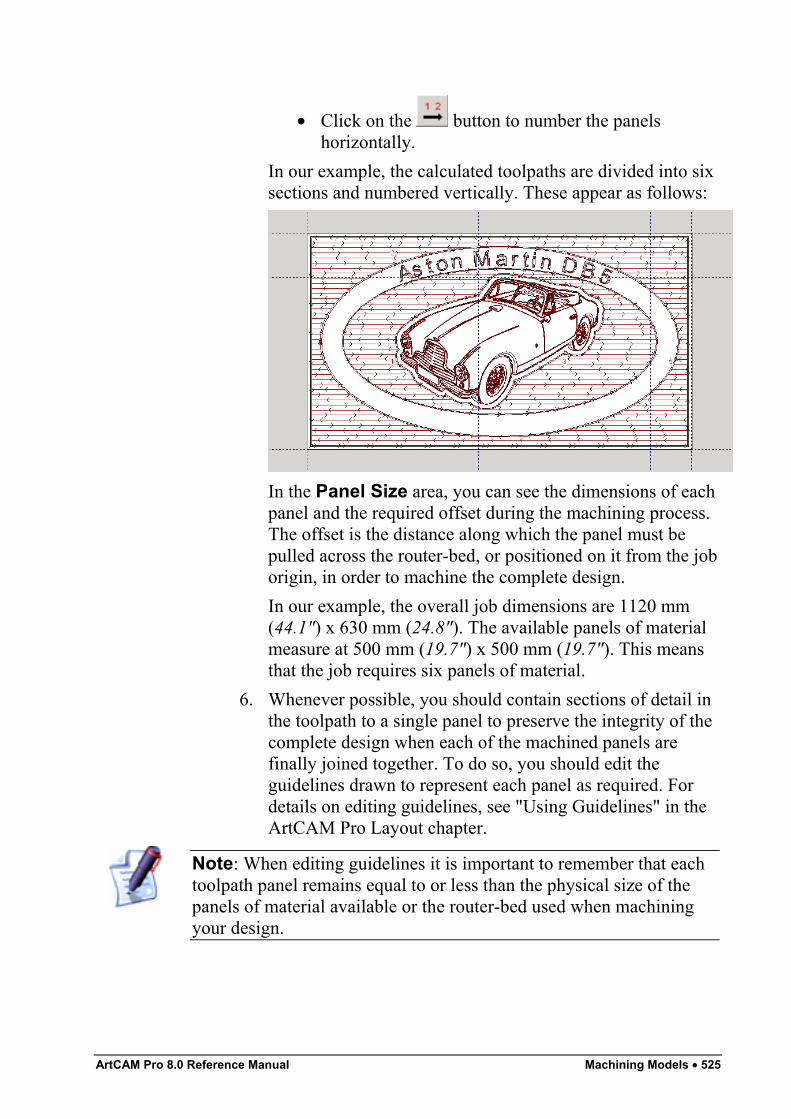
ArtCAM Pro 8.0 Reference Manual Machining Models • 525
• Click on the button to number the panelshorizontally.
In our example, the calculated toolpaths are divided into sixsections and numbered vertically. These appear as follows:
In the Panel Size area, you can see the dimensions of eachpanel and the required offset during the machining process.The offset is the distance along which the panel must bepulled across the router-bed, or positioned on it from the joborigin, in order to machine the complete design.In our example, the overall job dimensions are 1120 mm(44.1") x 630 mm (24.8"). The available panels of materialmeasure at 500 mm (19.7") x 500 mm (19.7"). This meansthat the job requires six panels of material.
6. Whenever possible, you should contain sections of detail inthe toolpath to a single panel to preserve the integrity of thecomplete design when each of the machined panels arefinally joined together. To do so, you should edit theguidelines drawn to represent each panel as required. Fordetails on editing guidelines, see "Using Guidelines" in theArtCAM Pro Layout chapter.
Note: When editing guidelines it is important to remember that eachtoolpath panel remains equal to or less than the physical size of thepanels of material available or the router-bed used when machiningyour design.
526 • Machining Models ArtCAM Pro 8.0 Reference Manual
In our example, the guidelines have been repositioned sothat the text in the design is machined across as few panelsas possible and so that each word is undivided.
7. If you want to print the data required to machine thetoolpath panels accurately:
• First, click on the Display Panel Info button todisplay the ArtCAM Toolpath Panelling window.This contains an image of the toolpaths when dividedinto panels and the data for machining the job.
• If you want to include the toolpath summary dataalong with the panel information, click to select theInclude Toolpath Summary option . Forfurther information, see "Using a ToolpathSummary" on page 550.
• Next, scroll to the bottom of the ArtCAM ToolpathPanelling window, and then click on the Printbutton. If you have more than one printer installed,the standard windows Print dialog box appears.Select the printer on which you want to print thepanel measurements, and then click on the OKbutton.
8. Click on the 3D View button in the 2D View toolbar todisplay the 3D View window.
9. In the 3D View Toolpath Drawing area, you can selectthe panel(s) that you want to view in the 3D View window:
• Click on the Display All radio button if you wantto display all panels.
• Click on the Display Selected radio button ifyou want to display only a selection of panels. Thisoption activates the Panel Number list box and theoptions beneath.In this instance, click on the Panel Number listbox, and then on the panel that you want to display.If you want to display the selected panel about thejob origin, click on the At Origin radio button . Ifyou want to display the selected panel, as it willappear in the overall job design, click on the InFinished Job radio button .
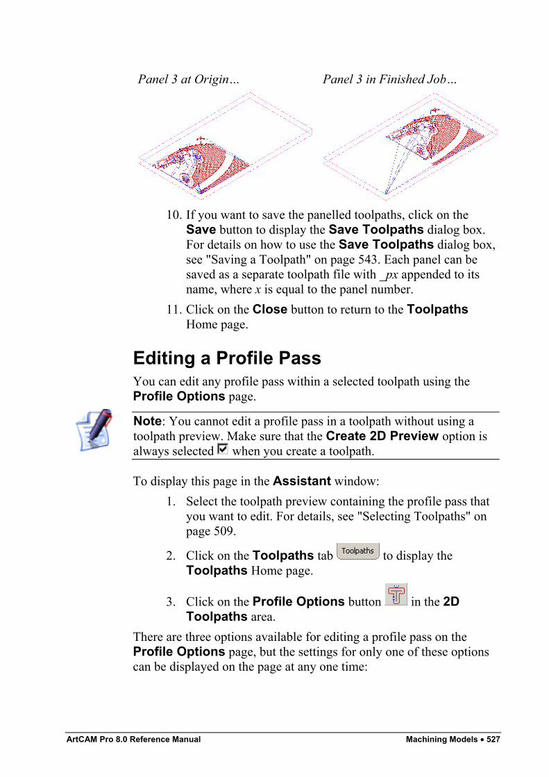
ArtCAM Pro 8.0 Reference Manual Machining Models • 527
Panel 3 at Origin… Panel 3 in Finished Job…
10. If you want to save the panelled toolpaths, click on theSave button to display the Save Toolpaths dialog box.For details on how to use the Save Toolpaths dialog box,see "Saving a Toolpath" on page 543. Each panel can besaved as a separate toolpath file with _px appended to itsname, where x is equal to the panel number.
11. Click on the Close button to return to the ToolpathsHome page.
Editing a Profile PassYou can edit any profile pass within a selected toolpath using theProfile Options page.
Note: You cannot edit a profile pass in a toolpath without using atoolpath preview. Make sure that the Create 2D Preview option isalways selected when you create a toolpath.
To display this page in the Assistant window:1. Select the toolpath preview containing the profile pass that
you want to edit. For details, see "Selecting Toolpaths" onpage 509.
2. Click on the Toolpaths tab to display theToolpaths Home page.
3. Click on the Profile Options button in the 2DToolpaths area.
There are three options available for editing a profile pass on theProfile Options page, but the settings for only one of these optionscan be displayed on the page at any one time:
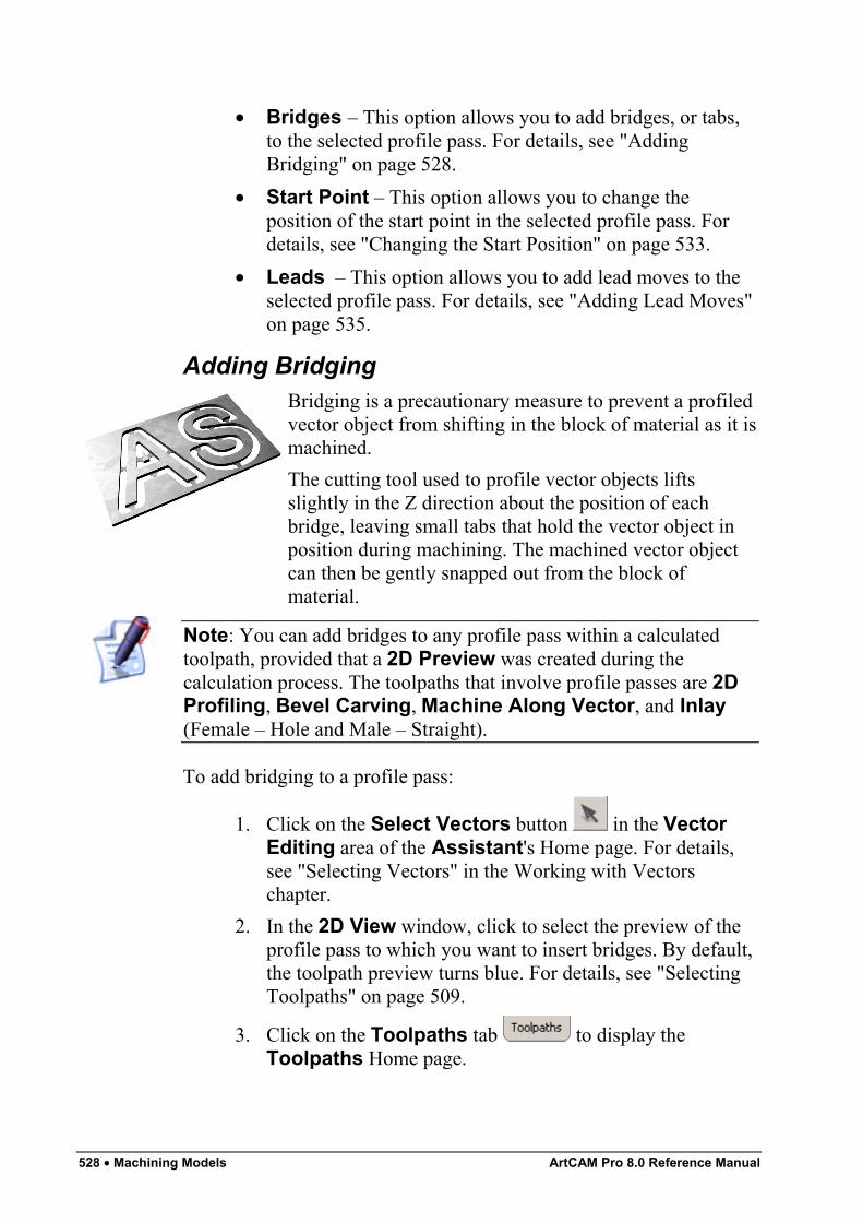
528 • Machining Models ArtCAM Pro 8.0 Reference Manual
• Bridges – This option allows you to add bridges, or tabs,to the selected profile pass. For details, see "AddingBridging" on page 528.
• Start Point – This option allows you to change theposition of the start point in the selected profile pass. Fordetails, see "Changing the Start Position" on page 533.
• Leads – This option allows you to add lead moves to theselected profile pass. For details, see "Adding Lead Moves"on page 535.
Adding BridgingBridging is a precautionary measure to prevent a profiledvector object from shifting in the block of material as it ismachined.The cutting tool used to profile vector objects liftsslightly in the Z direction about the position of eachbridge, leaving small tabs that hold the vector object inposition during machining. The machined vector objectcan then be gently snapped out from the block ofmaterial.
Note: You can add bridges to any profile pass within a calculatedtoolpath, provided that a 2D Preview was created during thecalculation process. The toolpaths that involve profile passes are 2DProfiling, Bevel Carving, Machine Along Vector, and Inlay(Female – Hole and Male – Straight).
To add bridging to a profile pass:
1. Click on the Select Vectors button in the VectorEditing area of the Assistant's Home page. For details,see "Selecting Vectors" in the Working with Vectorschapter.
2. In the 2D View window, click to select the preview of theprofile pass to which you want to insert bridges. By default,the toolpath preview turns blue. For details, see "SelectingToolpaths" on page 509.
3. Click on the Toolpaths tab to display theToolpaths Home page.
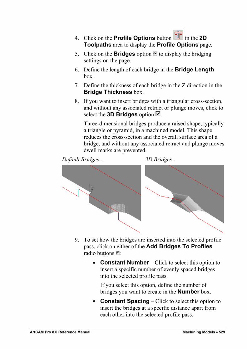
ArtCAM Pro 8.0 Reference Manual Machining Models • 529
4. Click on the Profile Options button in the 2DToolpaths area to display the Profile Options page.
5. Click on the Bridges option to display the bridgingsettings on the page.
6. Define the length of each bridge in the Bridge Lengthbox.
7. Define the thickness of each bridge in the Z direction in theBridge Thickness box.
8. If you want to insert bridges with a triangular cross-section,and without any associated retract or plunge moves, click toselect the 3D Bridges option .Three-dimensional bridges produce a raised shape, typicallya triangle or pyramid, in a machined model. This shapereduces the cross-section and the overall surface area of abridge, and without any associated retract and plunge movesdwell marks are prevented.
Default Bridges… 3D Bridges…
9. To set how the bridges are inserted into the selected profilepass, click on either of the Add Bridges To Profilesradio buttons :
• Constant Number – Click to select this option toinsert a specific number of evenly spaced bridgesinto the selected profile pass.If you select this option, define the number ofbridges you want to create in the Number box.
• Constant Spacing – Click to select this option toinsert the bridges at a specific distance apart fromeach other into the selected profile pass.
530 • Machining Models ArtCAM Pro 8.0 Reference Manual
If you select this option, first define the distancebetween bridges from the centre of each bridge, inthe Distance box.Next define the minimum number of bridges youwant to insert into the selected profile pass,irrespective of the distance you have set betweenthem, in the Min. Number box. If you want to limitthe number of bridges created, define the maximumnumber in the Max. Number box.
10. Click on the Create Bridges button to add the bridges tothe selected profile pass.
11. Click on the Close button to return to the Assistant'sHome page.
Editing BridgingYou can edit the bridging that you have added to a profile pass inseveral ways. You can:
• Insert new bridges. For details, see "Inserting a Bridge" onpage 530.
• Delete an individual or all existing bridges. For details, see"Deleting Bridges" on page 531.
• Change the length of individual or all existing bridges. Fordetails, see "Changing the Length of a Bridge" on page 532.
• Move bridges into a new position on the profile pass. Fordetails, see "Moving a Bridge" on page 533.
Inserting a BridgeYou can add an individual bridge to any place in a selected profilepass. To do so:
1. Click on the Select Vectors button in the VectorEditing area of the Assistant's Home page. For details,see "Selecting Vectors" in the Working with Vectorschapter.
2. In the 2D View window, click to select the preview of theprofile pass to which you want to insert bridges. By default,the toolpath preview turns blue. For details, see "SelectingToolpaths" on page 509.
ArtCAM Pro 8.0 Reference Manual Machining Models • 531
3. Click on the Toolpaths tab to display theToolpaths Home page.
4. Click on the Profile Options button in the 2DToolpaths area to display the Profile Options page. Thebridging settings are displayed on the page.
5. Move the cursor over the position in the profile pass whereyou want to insert the centre-point of the new bridge.
6. Press the I key on your keyboard or double-click the leftmouse button to insert the new bridge. The new bridge is thesame length and thickness as all of the other bridges in theselected profile pass.
Deleting BridgesYou can delete any or all of the bridges in a selected profile pass. Todo so:
1. Click on the Select Vectors button in the VectorEditing area of the Assistant's Home page. For details,see "Selecting Vectors" in the Working with Vectorschapter.
2. In the 2D View window, click to select the preview of theprofile pass containing the bridges that you want to delete.By default, the toolpath preview turns blue. For details, see"Selecting Toolpaths" on page 509.
3. Click on the Toolpaths tab to display theToolpaths Home page.
4. Click on the Profile Options button in the 2DToolpaths area to display the Profile Options page.
5. If you want to delete an individual bridge, move the cursorover the bridge you are removing and then use either of thefollowing methods:
• Press the D key on your keyboard. You must haveclicked at least once in the 2D View window beforeyou can do this.
• Double-click on the bridge itself.
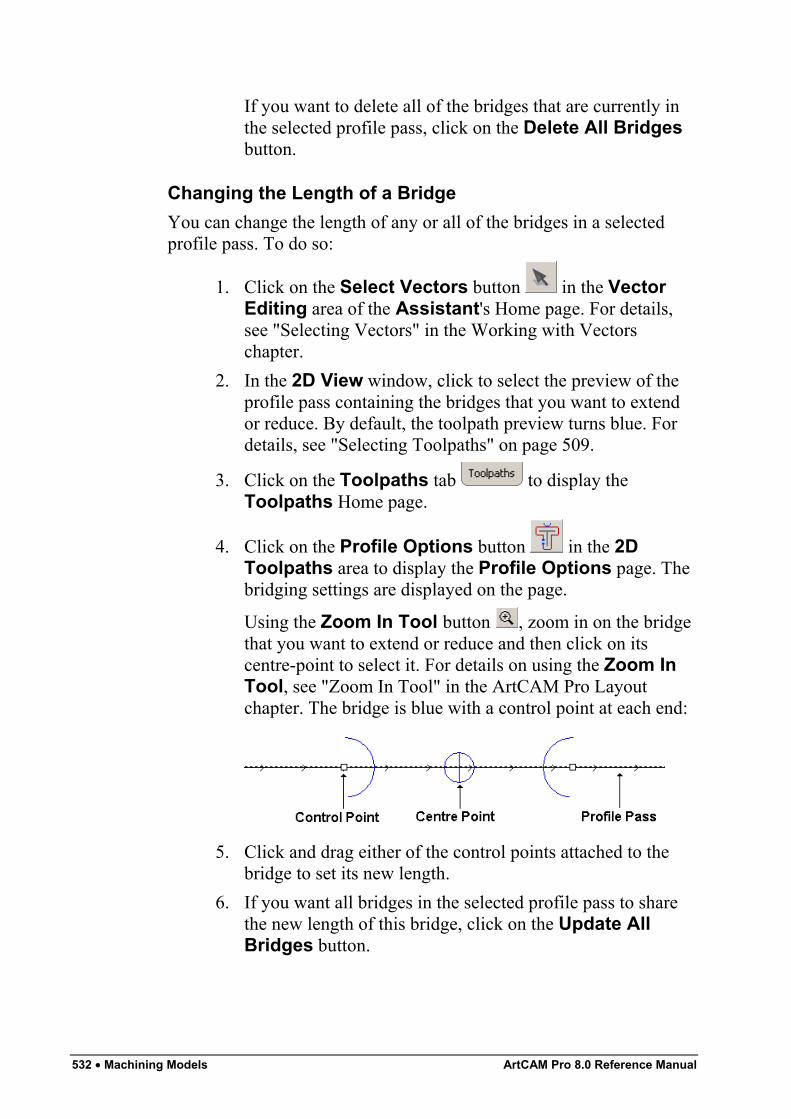
532 • Machining Models ArtCAM Pro 8.0 Reference Manual
If you want to delete all of the bridges that are currently inthe selected profile pass, click on the Delete All Bridgesbutton.
Changing the Length of a BridgeYou can change the length of any or all of the bridges in a selectedprofile pass. To do so:
1. Click on the Select Vectors button in the VectorEditing area of the Assistant's Home page. For details,see "Selecting Vectors" in the Working with Vectorschapter.
2. In the 2D View window, click to select the preview of theprofile pass containing the bridges that you want to extendor reduce. By default, the toolpath preview turns blue. Fordetails, see "Selecting Toolpaths" on page 509.
3. Click on the Toolpaths tab to display theToolpaths Home page.
4. Click on the Profile Options button in the 2DToolpaths area to display the Profile Options page. Thebridging settings are displayed on the page.
Using the Zoom In Tool button , zoom in on the bridgethat you want to extend or reduce and then click on itscentre-point to select it. For details on using the Zoom InTool, see "Zoom In Tool" in the ArtCAM Pro Layoutchapter. The bridge is blue with a control point at each end:
5. Click and drag either of the control points attached to thebridge to set its new length.
6. If you want all bridges in the selected profile pass to sharethe new length of this bridge, click on the Update AllBridges button.
ArtCAM Pro 8.0 Reference Manual Machining Models • 533
Moving a BridgeYou can change the position of an individual bridge on a selectedprofile pass. To do so:
1. Click on the Select Vectors button in the VectorEditing area of the Assistant's Home page. For details,see "Selecting Vectors" in the Working with Vectorschapter.
2. In the 2D View window, click to select the preview of theprofile pass containing the bridges that you want to move.By default, the toolpath preview turns blue. For details, see"Selecting Toolpaths" on page 509.
3. Click on the Toolpaths tab to display theToolpaths Home page.
4. Click on the Profile Options button in the 2DToolpaths area to display the Profile Options page. Thebridging settings are displayed on the page.
5. Using the Zoom In Tool button , zoom in on the bridgethat you want to move and then click on its centre-point toselect it. For details on using the Zoom In Tool, see"Zoom In Tool" in the ArtCAM Pro Layout chapter.
6. Click and drag on the centre-point to move the bridge alongthe profile pass into its new position.
Changing the Start PositionThe start position in a profile pass determines the place at which thecutting tool enters the block of material when you are machining amodel. The green point (node) surrounded by a blue circle indicatesthe current start position in the profile pass.To change the start position relative to a defined reference point:
1. Click on the Select Vectors button in the VectorEditing area of the Assistant's Home page. For details,see "Selecting Vectors" in the Working with Vectorschapter.
2. In the 2D View window, click to select the preview of theprofile pass in which you want to change the start position.
534 • Machining Models ArtCAM Pro 8.0 Reference Manual
By default, the toolpath preview turns blue. For details, see"Selecting Toolpaths" on page 509.
3. Click on the Toolpaths tab to display theToolpaths Home page.
4. Click on the Profile Options button in the 2DToolpaths area to display the Profile Options page.
5. Click on the Start Point option to display the Start Pointsettings on the page.
6. In the Reference Point area, click on one of the four radiobuttons to define the reference point by which you wantto set the position of the Start Point in the selected profilepass:
• Centre of Gravity – This option sets the referencepoint in the main mass of the vector object fromwhich the selected toolpath was created.If you select this option, four radio buttons areshown in the Position area. These indicate thepositions available for the Start Point in the selectedprofile pass relative to the reference point.You can set the Start Point above, below, left or rightof its current position, depending on the cuttingdirection of the selected profile pass.
• Centre of Bounding Box – This option sets thereference point in the centre of the selected profilepass, as defined by the bounding box that surroundsit.If you select this option, four radio buttons areshown in the Position area. These indicate thepositions available for the Start Point in the selectedprofile pass relative to the reference point.You can set the Start Point above, below, left or rightof its current position, depending on the cuttingdirection of the selected profile pass.
• Highest or Lowest X or Y Value – This optionsets the reference point as the position in the selectedprofile pass with the highest or lowest X or Y value,depending on its cutting direction.
ArtCAM Pro 8.0 Reference Manual Machining Models • 535
If you select this option, four radio buttons areshown in the Position area. These indicate thepositions available for the Start Point in the selectedprofile pass relative to the reference point.You can set the Start Point above, below, left or rightof its current position, depending on the cuttingdirection of the selected profile pass.
7. In the Position area, click on any of the radio buttons toselect the position of the Start Point in the selected profilepass. Alternatively, you can click on the Start Point in theselected profile pass and drag it into position.
8. Click on the Apply button to set the new position of theStart Point.
9. Click on the Close button to return to the Assistant'sHome page.
You can set any point (node) in a selected vector object as the StartPoint. For further information, see "Changing the Start Point" in theWorking with Vectors chapter. This defines the Start Point position ina toolpath when it is first created.
Adding Lead MovesLead moves are a precautionary measure to prevent dwell marks fromappearing on a model at the point at which the tool enters and leavesthe block of material when machining a profile pass.Instead of plunging into the block of material, machining the profilepass and then retracting from it, the tool enters and leaves the block ata specified distance from the start/end of the profile pass. This is eitherthe Start Point in the vector object from which the profile pass wascalculated, or in the centre of its longest span.
Note: You can add lead moves to any profile pass within a calculatedtoolpath, provided that a 2D Preview was created during thecalculation process. The toolpaths that involve profile passes are 2DProfiling, Bevel Carving, Machine Along Vector, and Inlay(Female – Hole and Male – Straight).
Note: You can also add lead moves to a Profiling toolpath whencreating the toolpath itself. For details, see "2D Profiling" on page407.
536 • Machining Models ArtCAM Pro 8.0 Reference Manual
To add lead moves to a profile pass:
1. Click on the Select Vectors button in the VectorEditing area of the Assistant's Home page. For details,see "Selecting Vectors" in the Working with Vectorschapter.
2. In the 2D View window, click to select the preview of theprofile pass in which you want to add lead moves. Bydefault, the toolpath preview turns blue. For details, see"Selecting Toolpaths" on page 509.
3. Click on the Toolpaths tab to display theToolpaths Home page.
4. Click on the Profile Options button in the 2DToolpaths area to display the Profile Options page.
5. Click on the Leads option to display the lead movesettings on the page.
6. If you do want to add a lead-out move to the profile pass,click to select the Do not Lead Out option .
7. Define the distance from the profile pass that you want thetool to cut into and retract from the block of material in theDistance (D) box.
8. Define the distance from the start/end point in the profilepass that you want the tool to machine over in the OverCut (O) box. This further helps to create a smooth finish.
9. Select how you want the tool to move using either of theradio buttons :
• Linear – Click on this option to instruct the tool tolead into and out of the block of material in astraight-line motion. If you select the Linear option,define the angle of the linear lead moves in theAngle In and Angle Out boxes.When editing lead moves associated with a profilepass used to machine inside of a defined area, thedistance of a linear lead move or the radius of acircular arc move is now considered.When adjusting the position of a linear lead move,ArtCAM checks to ensure that the distance of thelead move remains within the boundary of the profile
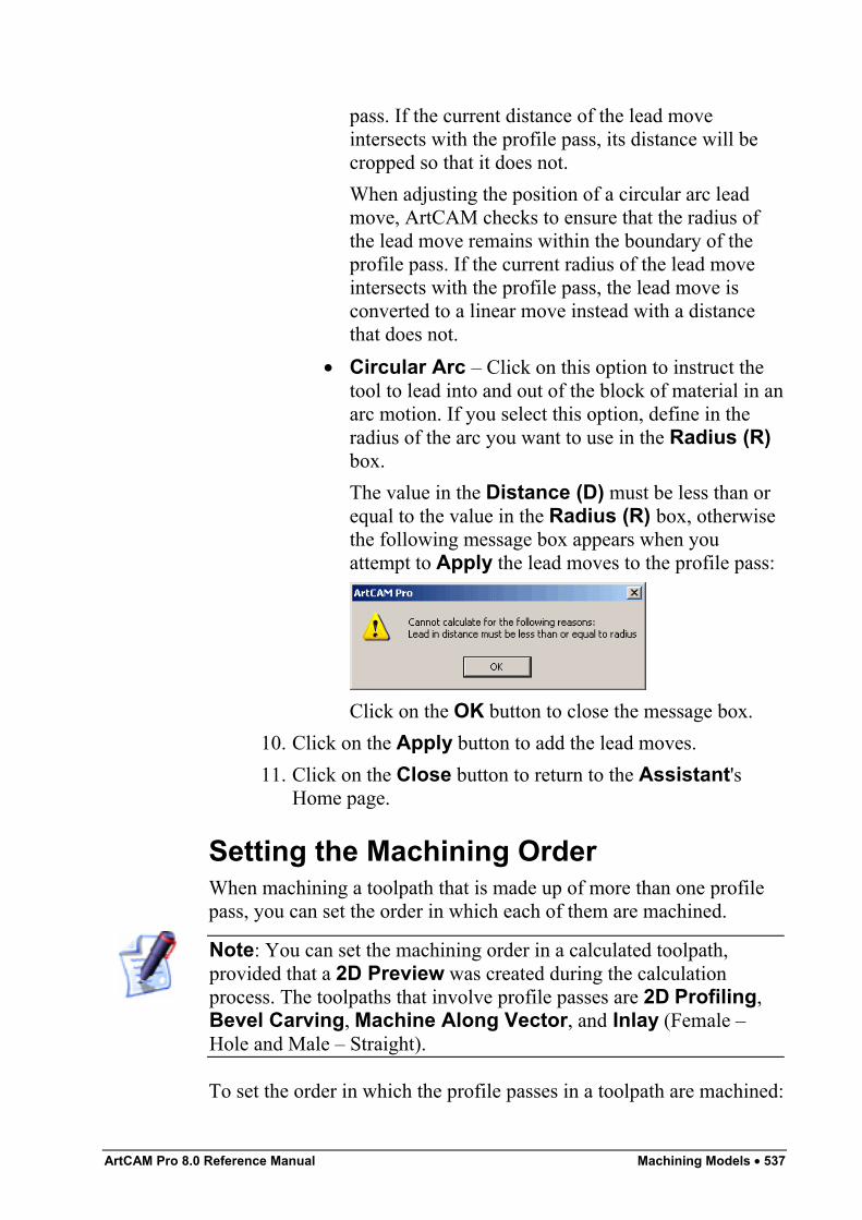
ArtCAM Pro 8.0 Reference Manual Machining Models • 537
pass. If the current distance of the lead moveintersects with the profile pass, its distance will becropped so that it does not.When adjusting the position of a circular arc leadmove, ArtCAM checks to ensure that the radius ofthe lead move remains within the boundary of theprofile pass. If the current radius of the lead moveintersects with the profile pass, the lead move isconverted to a linear move instead with a distancethat does not.
• Circular Arc – Click on this option to instruct thetool to lead into and out of the block of material in anarc motion. If you select this option, define in theradius of the arc you want to use in the Radius (R)box.The value in the Distance (D) must be less than orequal to the value in the Radius (R) box, otherwisethe following message box appears when youattempt to Apply the lead moves to the profile pass:
Click on the OK button to close the message box.10. Click on the Apply button to add the lead moves.11. Click on the Close button to return to the Assistant's
Home page.
Setting the Machining OrderWhen machining a toolpath that is made up of more than one profilepass, you can set the order in which each of them are machined.
Note: You can set the machining order in a calculated toolpath,provided that a 2D Preview was created during the calculationprocess. The toolpaths that involve profile passes are 2D Profiling,Bevel Carving, Machine Along Vector, and Inlay (Female –Hole and Male – Straight).
To set the order in which the profile passes in a toolpath are machined:
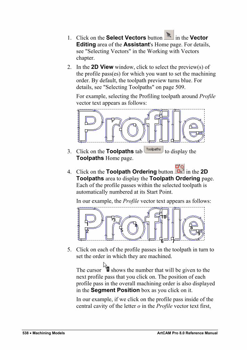
538 • Machining Models ArtCAM Pro 8.0 Reference Manual
1. Click on the Select Vectors button in the VectorEditing area of the Assistant's Home page. For details,see "Selecting Vectors" in the Working with Vectorschapter.
2. In the 2D View window, click to select the preview(s) ofthe profile pass(es) for which you want to set the machiningorder. By default, the toolpath preview turns blue. Fordetails, see "Selecting Toolpaths" on page 509.For example, selecting the Profiling toolpath around Profilevector text appears as follows:
3. Click on the Toolpaths tab to display theToolpaths Home page.
4. Click on the Toolpath Ordering button in the 2DToolpaths area to display the Toolpath Ordering page.Each of the profile passes within the selected toolpath isautomatically numbered at its Start Point.In our example, the Profile vector text appears as follows:
5. Click on each of the profile passes in the toolpath in turn toset the order in which they are machined.
The cursor shows the number that will be given to thenext profile pass that you click on. The position of eachprofile pass in the overall machining order is also displayedin the Segment Position box as you click on it.In our example, if we click on the profile pass inside of thecentral cavity of the letter o in the Profile vector text first,
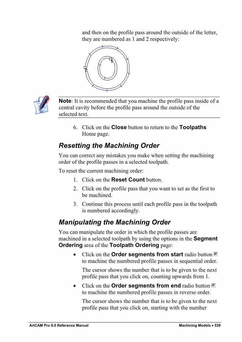
ArtCAM Pro 8.0 Reference Manual Machining Models • 539
and then on the profile pass around the outside of the letter,they are numbered as 1 and 2 respectively:
Note: It is recommended that you machine the profile pass inside of acentral cavity before the profile pass around the outside of theselected text.
6. Click on the Close button to return to the ToolpathsHome page.
Resetting the Machining OrderYou can correct any mistakes you make when setting the machiningorder of the profile passes in a selected toolpath.To reset the current machining order:
1. Click on the Reset Count button.2. Click on the profile pass that you want to set as the first to
be machined.3. Continue this process until each profile pass in the toolpath
is numbered accordingly.
Manipulating the Machining OrderYou can manipulate the order in which the profile passes aremachined in a selected toolpath by using the options in the SegmentOrdering area of the Toolpath Ordering page:
• Click on the Order segments from start radio button to machine the numbered profile passes in sequential order.The cursor shows the number that is to be given to the nextprofile pass that you click on, counting upwards from 1.
• Click on the Order segments from end radio button to machine the numbered profile passes in reverse order.The cursor shows the number that is to be given to the nextprofile pass that you click on, starting with the number
540 • Machining Models ArtCAM Pro 8.0 Reference Manual
equal to the total number of profile passes in the toolpathand counting down.
• Click on the Swap segments radio button to swap theposition in the machining order of the first profile pass youclick on with that of the second you click on.
The cursor shows two question marks . After you clickon the profile pass that you want to swap with another, itsnumber is shown on the cursor.
For example, the cursor is shown as when you click onthe first segment. After you click on the profile pass thatyou want to swap with that which is already selected, the
cursor returns to .
Adjusting the Machining Parameters of aToolYou can adjust the machining parameters for CNC machine tools inArtCAM Pro as follows:
• When creating a toolpath, in the toolpath's page. Forexample, the Profiling page. For details, see "AdjustingMachining Parameters When Creating a Toolpath" on page540.
• After creating a toolpath, using the Toolpaths Home page.For details, see "Adjusting Machining Parameters in aCreated Toolpath" on page 542.
Note: You can also change the tool's default machining parametersstored in the Tool Groups Database. This method should only beused before selecting a toolpath. For details, see "Editing a Tool" onpage 556.
Adjusting Machining Parameters When Creatinga ToolpathYou can change the machining parameters of the CNC machine toolused to machine a model, when creating a toolpath.To change the machining parameters of a CNC machine tool:
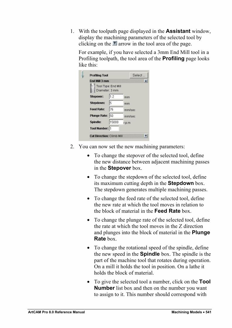
ArtCAM Pro 8.0 Reference Manual Machining Models • 541
1. With the toolpath page displayed in the Assistant window,display the machining parameters of the selected tool byclicking on the arrow in the tool area of the page.For example, if you have selected a 3mm End Mill tool in aProfiling toolpath, the tool area of the Profiling page lookslike this:
2. You can now set the new machining parameters:• To change the stepover of the selected tool, define
the new distance between adjacent machining passesin the Stepover box.
• To change the stepdown of the selected tool, defineits maximum cutting depth in the Stepdown box.The stepdown generates multiple machining passes.
• To change the feed rate of the selected tool, definethe new rate at which the tool moves in relation tothe block of material in the Feed Rate box.
• To change the plunge rate of the selected tool, definethe rate at which the tool moves in the Z directionand plunges into the block of material in the PlungeRate box.
• To change the rotational speed of the spindle, definethe new speed in the Spindle box. The spindle is thepart of the machine tool that rotates during operation.On a mill it holds the tool in position. On a lathe itholds the block of material.
• To give the selected tool a number, click on the ToolNumber list box and then on the number you wantto assign to it. This number should correspond with
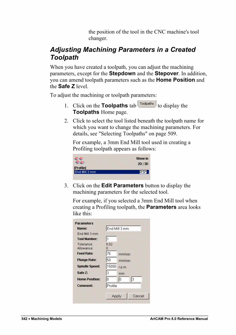
542 • Machining Models ArtCAM Pro 8.0 Reference Manual
the position of the tool in the CNC machine's toolchanger.
Adjusting Machining Parameters in a CreatedToolpathWhen you have created a toolpath, you can adjust the machiningparameters, except for the Stepdown and the Stepover. In addition,you can amend toolpath parameters such as the Home Position andthe Safe Z level.To adjust the machining or toolpath parameters:
1. Click on the Toolpaths tab to display theToolpaths Home page.
2. Click to select the tool listed beneath the toolpath name forwhich you want to change the machining parameters. Fordetails, see "Selecting Toolpaths" on page 509.For example, a 3mm End Mill tool used in creating aProfiling toolpath appears as follows:
3. Click on the Edit Parameters button to display themachining parameters for the selected tool.For example, if you selected a 3mm End Mill tool whencreating a Profiling toolpath, the Parameters area lookslike this:
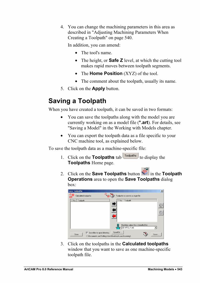
ArtCAM Pro 8.0 Reference Manual Machining Models • 543
4. You can change the machining parameters in this area asdescribed in "Adjusting Machining Parameters WhenCreating a Toolpath" on page 540.In addition, you can amend:
• The tool's name.• The height, or Safe Z level, at which the cutting tool
makes rapid moves between toolpath segments.• The Home Position (XYZ) of the tool.• The comment about the toolpath, usually its name.
5. Click on the Apply button.
Saving a ToolpathWhen you have created a toolpath, it can be saved in two formats:
• You can save the toolpaths along with the model you arecurrently working on as a model file (*.art). For details, see"Saving a Model" in the Working with Models chapter.
• You can export the toolpath data as a file specific to yourCNC machine tool, as explained below.
To save the toolpath data as a machine-specific file:
1. Click on the Toolpaths tab to display theToolpaths Home page.
2. Click on the Save Toolpaths button in the ToolpathOperations area to open the Save Toolpaths dialogbox:
3. Click on the toolpaths in the Calculated toolpathswindow that you want to save as one machine-specifictoolpath file.
544 • Machining Models ArtCAM Pro 8.0 Reference Manual
To select more than one toolpath, hold the Shift key downon your keyboard and then click on each of the toolpaths.
4. Click on the right button to transfer your selectedtoolpaths to the Toolpaths to save to a single filewindow.
5. Make sure that the toolpaths are in the correct order.
Click on the up and down buttons to set the orderin which the toolpaths will be saved. Each click, up ordown, moves the selected toolpath one position in the list.
Click on the black left button to transfer the currentlyhighlighted toolpaths back to the Calculated toolpathswindow.
Click on the red left button to transfer all toolpathsback to the Calculated toolpaths window.
6. Click on the Machine output file is formatted for listbox, and then click to select the machine format you want touse.
7. If you want to save the machine-specific toolpath file to thespool directory, make sure that the Save Files to SpoolDirectory option is selected .If you have not already selected the spool directory, click onthe Spool Dir… button to display the Browse ForFolder dialog box. Click on the folder to which you want tospool your machine-specific toolpath files, followed by theOK button to set it as the spool directory.If you do not want to save the machine-specific toolpath fileto the spool directory, make sure that the Save Files toSpool Directory option is deselected .
8. Click on the Save button.9. Type the file name for the machine-specific toolpath in the
File name box.10. Click on the Save as type list box, then click to select the
file type in which you want to save your machine-specifictoolpath.
11. Click on the Save button to close the Save As dialog box.
ArtCAM Pro 8.0 Reference Manual Machining Models • 545
12. Click on the Close button in the Save Toolpaths dialogbox.
Note: You can also save a toolpath from either the 2D View or the3D View in the same way. From the Main menu bar, click on theToolpaths menu, followed by the Save Toolpath option to displaythe Save Toolpaths dialog box. For details on using the SaveToolpaths dialog box, return to the start of this section.
Editing a ToolpathYou can change the settings in any toolpath that you have created.To edit the settings in a toolpath using the 2D View window:
1. Click on the Select Vectors button in the VectorEditing area of the Assistant's Home page. For details,see "Selecting Vectors" in the Working with Vectorschapter.
2. Select the preview of the toolpath that you want to edit. Fordetails, see "Selecting Toolpaths" on page 509.
3. Right-click to display the Toolpath menu, and then click onthe Edit Toolpath option to display the toolpath's detailsin the Assistant window.
For example, if you select a Profiling toolpath and then the EditToolpath option from the Toolpath menu, the Profiling page isdisplayed in the Assistant window.Alternatively, you can edit toolpath settings using the ToolpathsHome page:
1. Click on the Select Vectors button in the VectorEditing area of the Assistant's Home page. For details,see "Selecting Vectors" in the Working with Vectorschapter.
2. Click on the Toolpaths tab to display theToolpaths Home page.
3. Select the toolpath listed that you want to edit. For details,see "Selecting Toolpaths" on page 509.
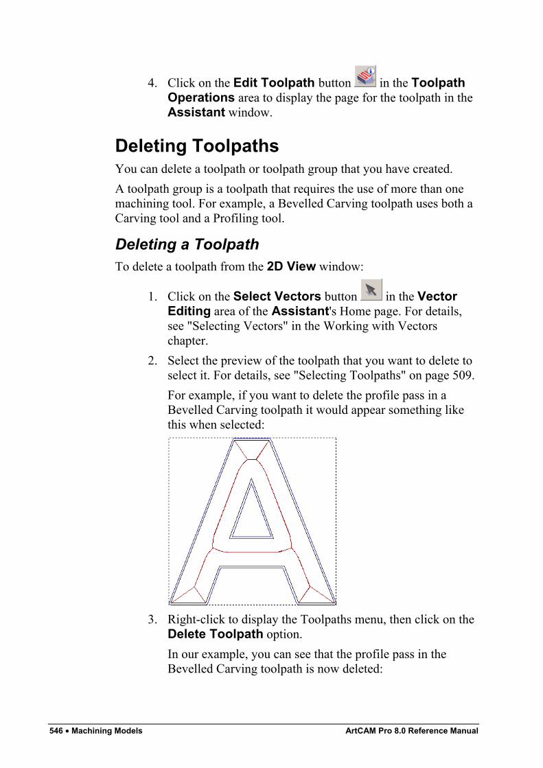
546 • Machining Models ArtCAM Pro 8.0 Reference Manual
4. Click on the Edit Toolpath button in the ToolpathOperations area to display the page for the toolpath in theAssistant window.
Deleting ToolpathsYou can delete a toolpath or toolpath group that you have created.A toolpath group is a toolpath that requires the use of more than onemachining tool. For example, a Bevelled Carving toolpath uses both aCarving tool and a Profiling tool.
Deleting a ToolpathTo delete a toolpath from the 2D View window:
1. Click on the Select Vectors button in the VectorEditing area of the Assistant's Home page. For details,see "Selecting Vectors" in the Working with Vectorschapter.
2. Select the preview of the toolpath that you want to delete toselect it. For details, see "Selecting Toolpaths" on page 509.For example, if you want to delete the profile pass in aBevelled Carving toolpath it would appear something likethis when selected:
3. Right-click to display the Toolpaths menu, then click on theDelete Toolpath option.In our example, you can see that the profile pass in theBevelled Carving toolpath is now deleted:
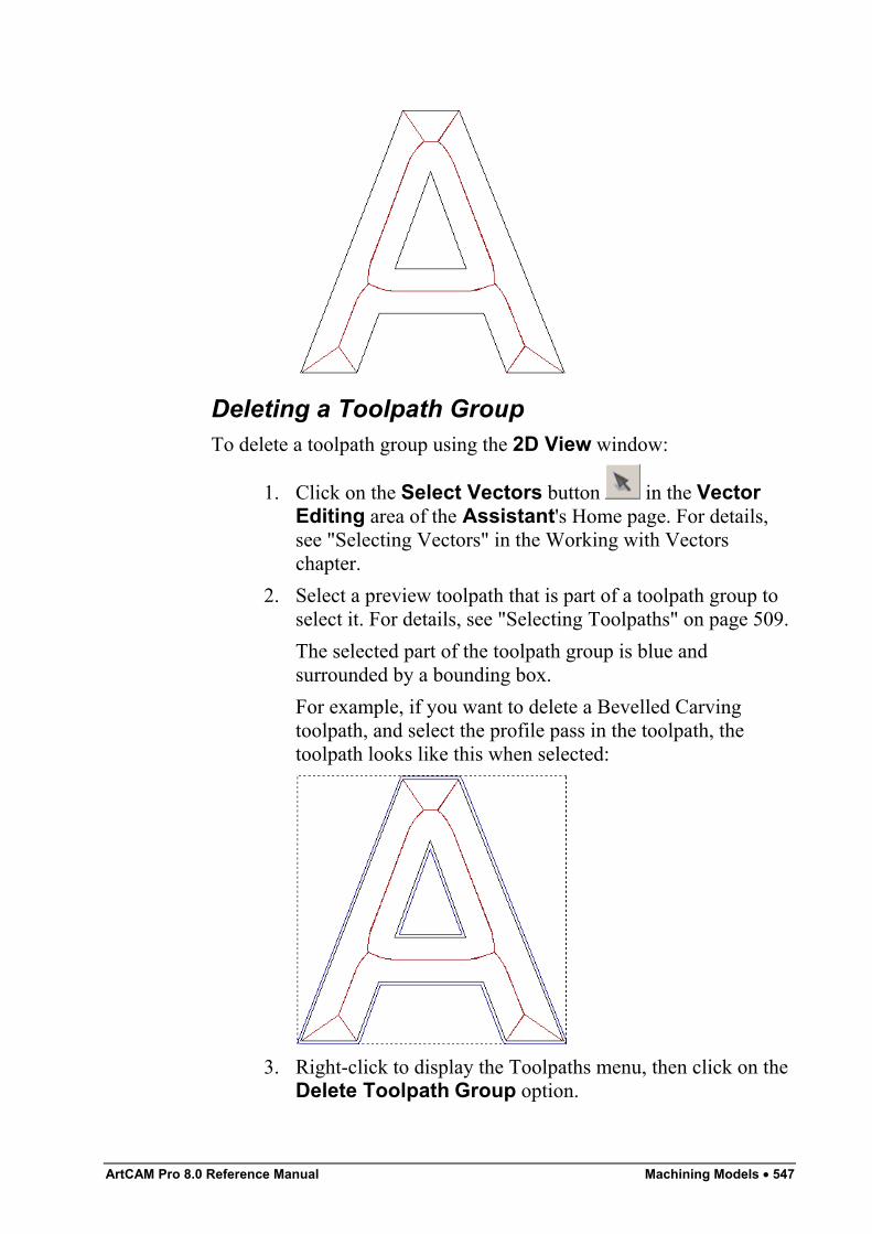
ArtCAM Pro 8.0 Reference Manual Machining Models • 547
Deleting a Toolpath GroupTo delete a toolpath group using the 2D View window:
1. Click on the Select Vectors button in the VectorEditing area of the Assistant's Home page. For details,see "Selecting Vectors" in the Working with Vectorschapter.
2. Select a preview toolpath that is part of a toolpath group toselect it. For details, see "Selecting Toolpaths" on page 509.The selected part of the toolpath group is blue andsurrounded by a bounding box.For example, if you want to delete a Bevelled Carvingtoolpath, and select the profile pass in the toolpath, thetoolpath looks like this when selected:
3. Right-click to display the Toolpaths menu, then click on theDelete Toolpath Group option.
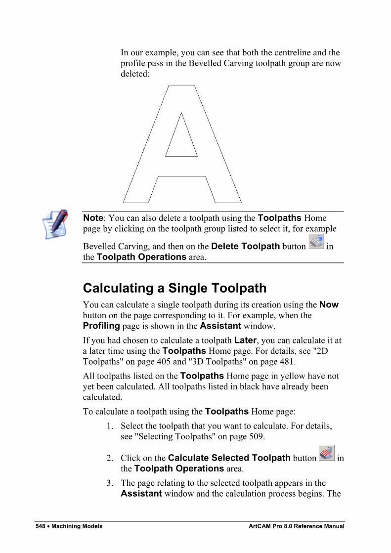
548 • Machining Models ArtCAM Pro 8.0 Reference Manual
In our example, you can see that both the centreline and theprofile pass in the Bevelled Carving toolpath group are nowdeleted:
Note: You can also delete a toolpath using the Toolpaths Homepage by clicking on the toolpath group listed to select it, for example
Bevelled Carving, and then on the Delete Toolpath button inthe Toolpath Operations area.
Calculating a Single ToolpathYou can calculate a single toolpath during its creation using the Nowbutton on the page corresponding to it. For example, when theProfiling page is shown in the Assistant window.If you had chosen to calculate a toolpath Later, you can calculate it ata later time using the Toolpaths Home page. For details, see "2DToolpaths" on page 405 and "3D Toolpaths" on page 481.All toolpaths listed on the Toolpaths Home page in yellow have notyet been calculated. All toolpaths listed in black have already beencalculated.To calculate a toolpath using the Toolpaths Home page:
1. Select the toolpath that you want to calculate. For details,see "Selecting Toolpaths" on page 509.
2. Click on the Calculate Selected Toolpath button inthe Toolpath Operations area.
3. The page relating to the selected toolpath appears in theAssistant window and the calculation process begins. The
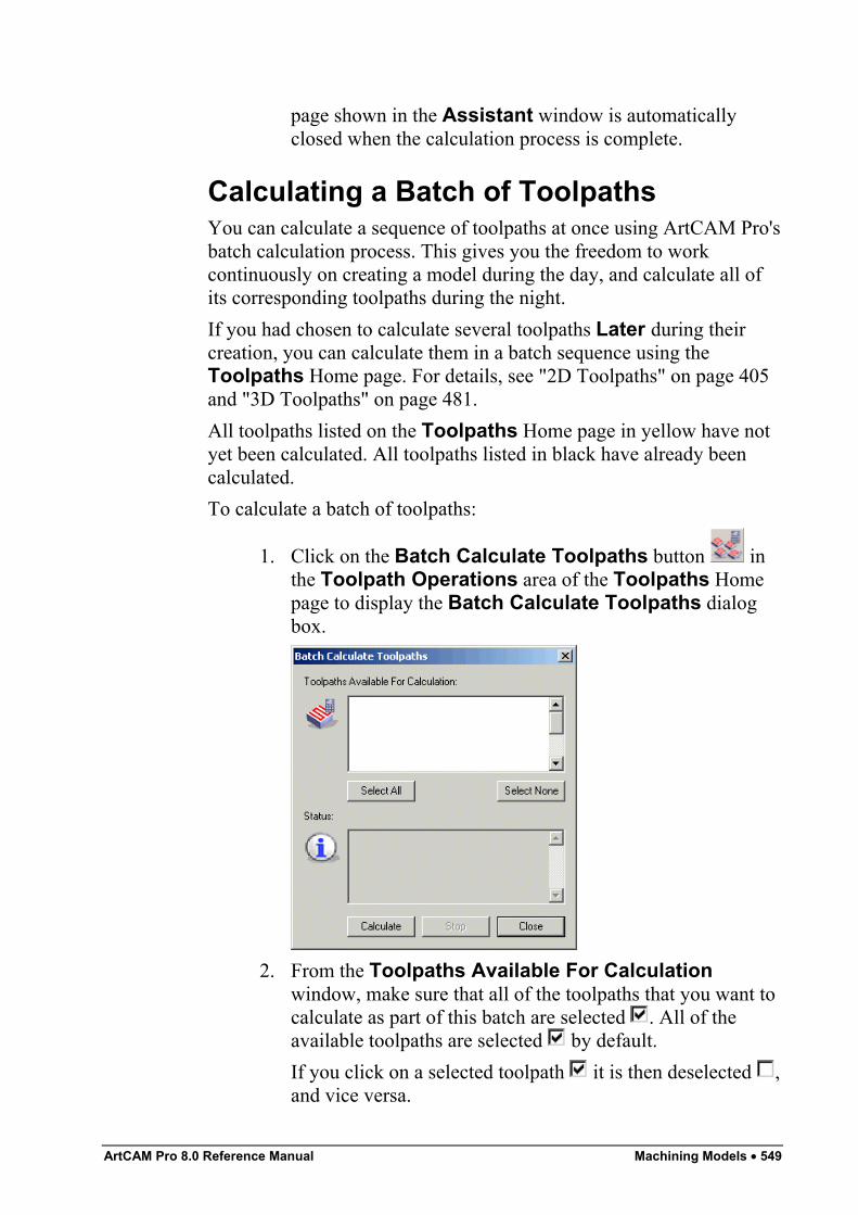
ArtCAM Pro 8.0 Reference Manual Machining Models • 549
page shown in the Assistant window is automaticallyclosed when the calculation process is complete.
Calculating a Batch of ToolpathsYou can calculate a sequence of toolpaths at once using ArtCAM Pro'sbatch calculation process. This gives you the freedom to workcontinuously on creating a model during the day, and calculate all ofits corresponding toolpaths during the night.If you had chosen to calculate several toolpaths Later during theircreation, you can calculate them in a batch sequence using theToolpaths Home page. For details, see "2D Toolpaths" on page 405and "3D Toolpaths" on page 481.All toolpaths listed on the Toolpaths Home page in yellow have notyet been calculated. All toolpaths listed in black have already beencalculated.To calculate a batch of toolpaths:
1. Click on the Batch Calculate Toolpaths button inthe Toolpath Operations area of the Toolpaths Homepage to display the Batch Calculate Toolpaths dialogbox.
2. From the Toolpaths Available For Calculationwindow, make sure that all of the toolpaths that you want tocalculate as part of this batch are selected . All of theavailable toolpaths are selected by default.If you click on a selected toolpath it is then deselected ,and vice versa.
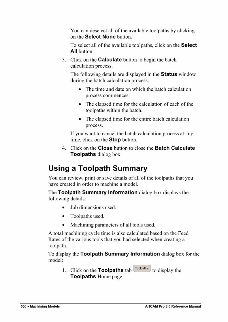
550 • Machining Models ArtCAM Pro 8.0 Reference Manual
You can deselect all of the available toolpaths by clickingon the Select None button.To select all of the available toolpaths, click on the SelectAll button.
3. Click on the Calculate button to begin the batchcalculation process.The following details are displayed in the Status windowduring the batch calculation process:
• The time and date on which the batch calculationprocess commences.
• The elapsed time for the calculation of each of thetoolpaths within the batch.
• The elapsed time for the entire batch calculationprocess.
If you want to cancel the batch calculation process at anytime, click on the Stop button.
4. Click on the Close button to close the Batch CalculateToolpaths dialog box.
Using a Toolpath SummaryYou can review, print or save details of all of the toolpaths that youhave created in order to machine a model.The Toolpath Summary Information dialog box displays thefollowing details:
• Job dimensions used.• Toolpaths used.• Machining parameters of all tools used.
A total machining cycle time is also calculated based on the FeedRates of the various tools that you had selected when creating atoolpath.To display the Toolpath Summary Information dialog box for themodel:
1. Click on the Toolpaths tab to display theToolpaths Home page.
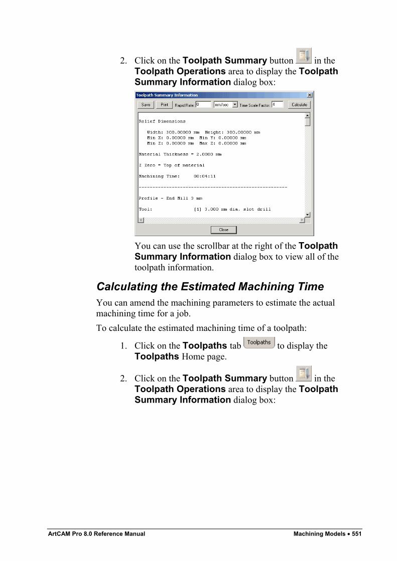
ArtCAM Pro 8.0 Reference Manual Machining Models • 551
2. Click on the Toolpath Summary button in theToolpath Operations area to display the ToolpathSummary Information dialog box:
You can use the scrollbar at the right of the ToolpathSummary Information dialog box to view all of thetoolpath information.
Calculating the Estimated Machining TimeYou can amend the machining parameters to estimate the actualmachining time for a job.To calculate the estimated machining time of a toolpath:
1. Click on the Toolpaths tab to display theToolpaths Home page.
2. Click on the Toolpath Summary button in theToolpath Operations area to display the ToolpathSummary Information dialog box:
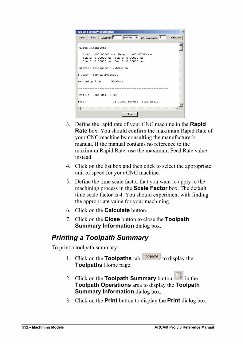
552 • Machining Models ArtCAM Pro 8.0 Reference Manual
3. Define the rapid rate of your CNC machine in the RapidRate box. You should confirm the maximum Rapid Rate ofyour CNC machine by consulting the manufacturer'smanual. If the manual contains no reference to themaximum Rapid Rate, use the maximum Feed Rate valueinstead.
4. Click on the list box and then click to select the appropriateunit of speed for your CNC machine.
5. Define the time scale factor that you want to apply to themachining process in the Scale Factor box. The defaulttime scale factor is 4. You should experiment with findingthe appropriate value for your machining.
6. Click on the Calculate button.7. Click on the Close button to close the Toolpath
Summary Information dialog box.
Printing a Toolpath SummaryTo print a toolpath summary:
1. Click on the Toolpaths tab to display theToolpaths Home page.
2. Click on the Toolpath Summary button in theToolpath Operations area to display the ToolpathSummary Information dialog box.
3. Click on the Print button to display the Print dialog box:
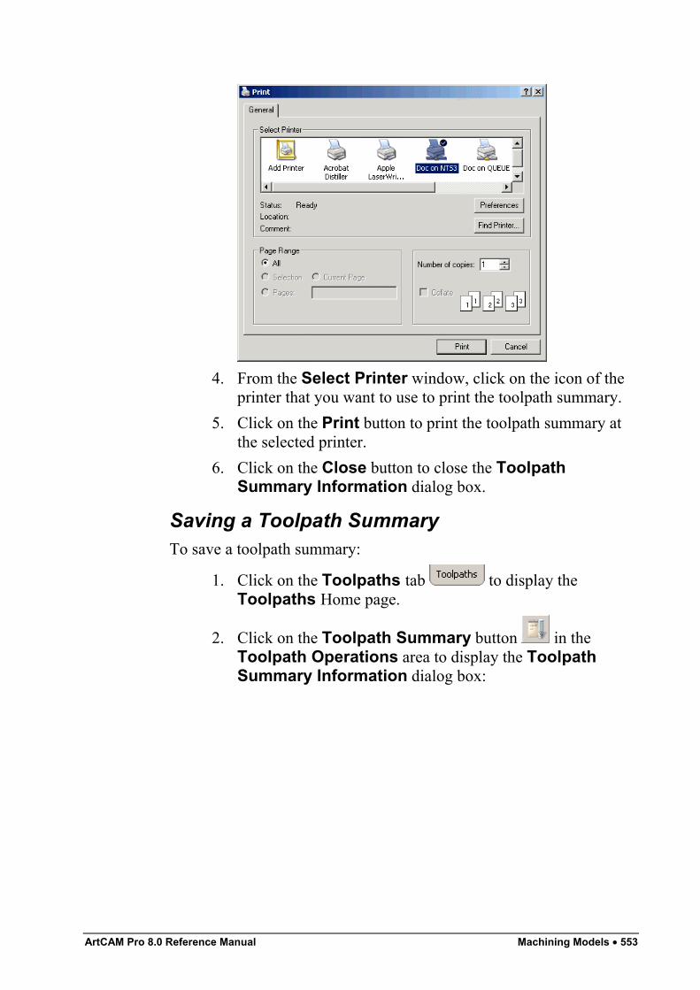
ArtCAM Pro 8.0 Reference Manual Machining Models • 553
4. From the Select Printer window, click on the icon of theprinter that you want to use to print the toolpath summary.
5. Click on the Print button to print the toolpath summary atthe selected printer.
6. Click on the Close button to close the ToolpathSummary Information dialog box.
Saving a Toolpath SummaryTo save a toolpath summary:
1. Click on the Toolpaths tab to display theToolpaths Home page.
2. Click on the Toolpath Summary button in theToolpath Operations area to display the ToolpathSummary Information dialog box:
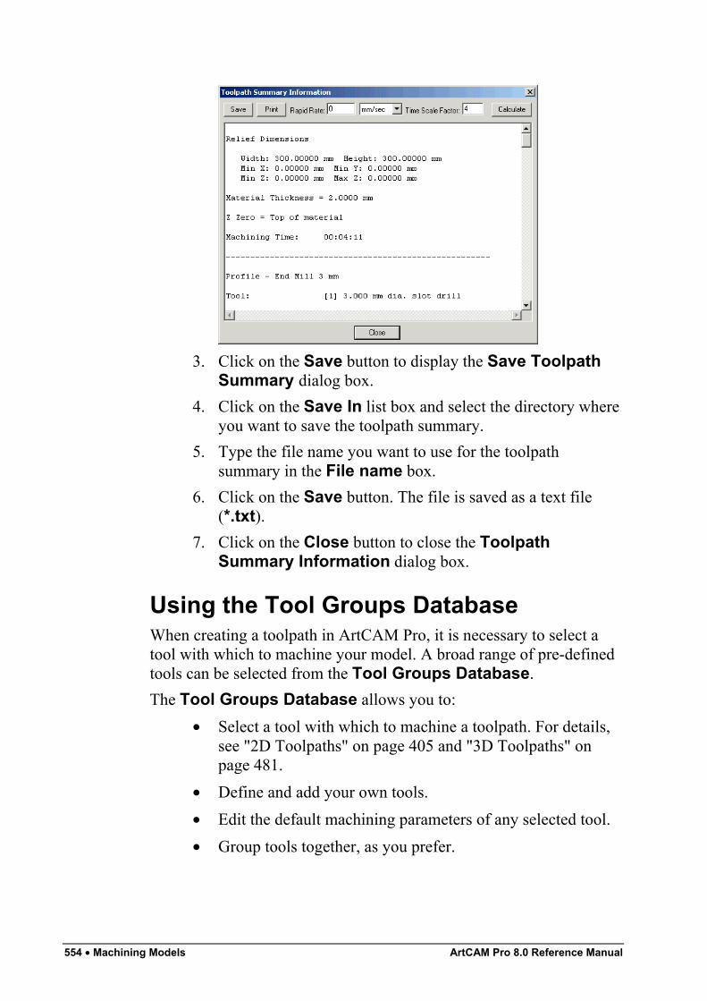
554 • Machining Models ArtCAM Pro 8.0 Reference Manual
3. Click on the Save button to display the Save ToolpathSummary dialog box.
4. Click on the Save In list box and select the directory whereyou want to save the toolpath summary.
5. Type the file name you want to use for the toolpathsummary in the File name box.
6. Click on the Save button. The file is saved as a text file(*.txt).
7. Click on the Close button to close the ToolpathSummary Information dialog box.
Using the Tool Groups DatabaseWhen creating a toolpath in ArtCAM Pro, it is necessary to select atool with which to machine your model. A broad range of pre-definedtools can be selected from the Tool Groups Database.The Tool Groups Database allows you to:
• Select a tool with which to machine a toolpath. For details,see "2D Toolpaths" on page 405 and "3D Toolpaths" onpage 481.
• Define and add your own tools.• Edit the default machining parameters of any selected tool.• Group tools together, as you prefer.
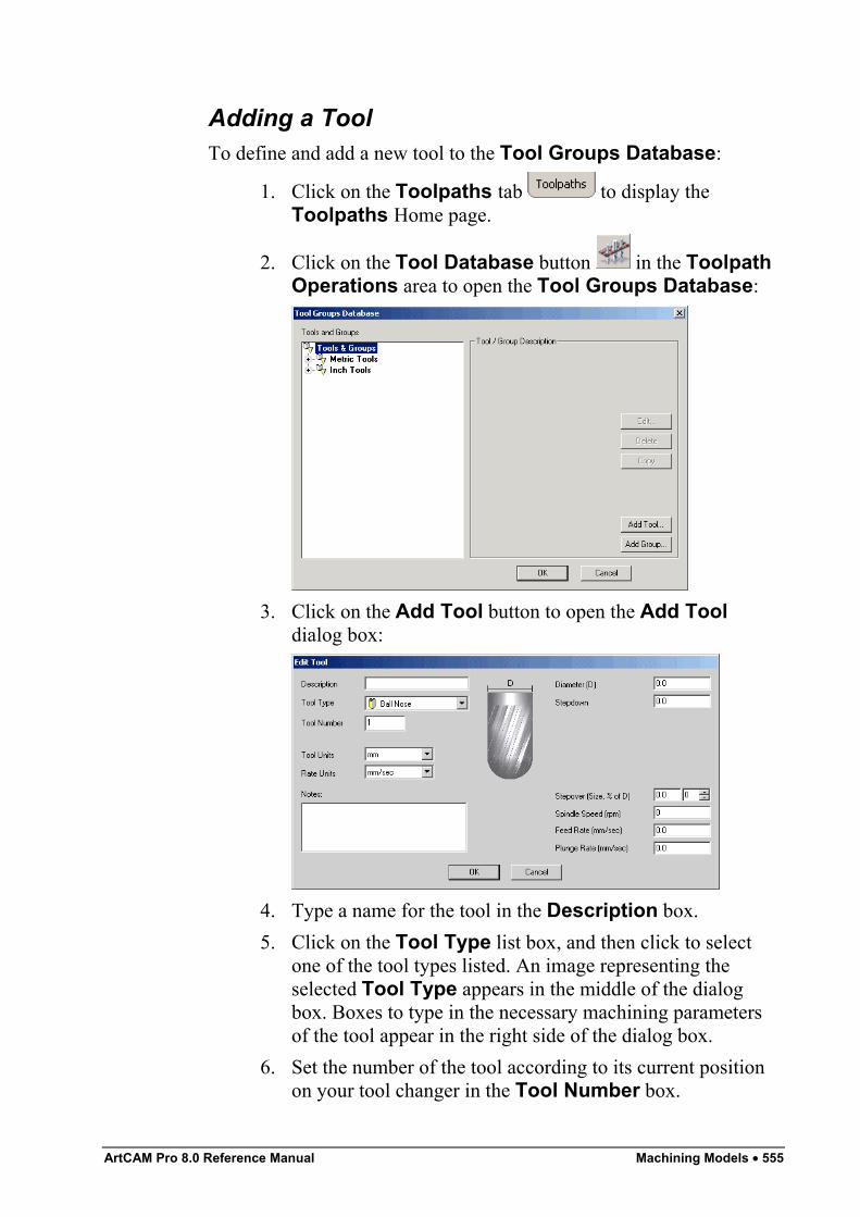
ArtCAM Pro 8.0 Reference Manual Machining Models • 555
Adding a ToolTo define and add a new tool to the Tool Groups Database:
1. Click on the Toolpaths tab to display theToolpaths Home page.
2. Click on the Tool Database button in the ToolpathOperations area to open the Tool Groups Database:
3. Click on the Add Tool button to open the Add Tooldialog box:
4. Type a name for the tool in the Description box.5. Click on the Tool Type list box, and then click to select
one of the tool types listed. An image representing theselected Tool Type appears in the middle of the dialogbox. Boxes to type in the necessary machining parametersof the tool appear in the right side of the dialog box.
6. Set the number of the tool according to its current positionon your tool changer in the Tool Number box.
556 • Machining Models ArtCAM Pro 8.0 Reference Manual
7. Click on the Tool Units list box, and then click to selectthe unit of measurement for the tool.
8. Click on the Rate Units list box, and then click to selectthe unit of speed for the tool.
9. Type any relevant information concerning the practical useof the tool you are adding to the Tool Groups Databasein the Notes box.
10. Define the machining parameters of the tool using the boxeson the right of the dialog box. For example, Diameter,Stepover and Flute Length.
11. Click on the OK button to add the tool to the Tool GroupsDatabase. The tool you have added appears in the Toolsand Groups window, and its details appear in the Tool /Group Description area of the Tool GroupsDatabase.
12. Click on the tool in the Tools and Groups window anddrag it into the appropriate group in the Tool GroupsDatabase.
Note: For details on how to set up your own group, see "Adding aTool Group" on page 559.
13. Click on the OK button to close the Tool GroupsDatabase.
Editing a ToolYou can edit the geometry and the default machining parameters ofany tool selected from the Tool Groups Database:
• Description – To change the name of the selected tool,type it in this box.
• Tool Number – To change the number of the selected toolto correspond with its position on a tool changer, define it inthis box.
• Tool Units – To change the unit of measurement for theselected tool, click on the Tool Units list box and then onthe unit of measurement you want to use.
• Rate Units – To change the unit of speed for the selectedtool, click on the Rate Units list box and then on the unitof speed you want to use.
ArtCAM Pro 8.0 Reference Manual Machining Models • 557
• Notes – If you want to make any notes about the selectedtool, type them in this box.
• Diameter – To change the diameter of the selected tool,define it in this box.
• Stepdown – If you want to change the maximum cut depthof the selected tool, define it in this box.
• Stepover – If you want to change the distance betweenadjacent machining passes made by the selected tool, defineit in this box.You can also adjust the stepover of the selected tool usingthe % of box and buttons:
• Each click on increases the stepover of theselected tool by 1% of the value shown in theDiameter box.
• Each click on decreases the stepover of theselected tool by 1% of the value shown in theDiameter box.
• Type a value in the % of box to define theStepover as a percentage of the tool Diameter.
• Spindle Speed – To change the rotational speed of thespindle, define it in this box.
• Feed Rate – To change the rate at which the tool moves inrelation to the block of material, define it in this box.
• Plunge Rate – To change the rate at which the tool movesin the Z direction and plunges into the block of material,define it in this box.
Editing the geometry of certain types of tools in the Tool GroupsDatabase requires more data than with other tools. The additionalinformation required includes:
• Included Angle – To change the angle of a V-Bit tool,define the new angle in this box.
• Half Angle – To change the angle of a Conical tool, definethe new angle in this box.
• Flat Radius – To change the radius of a flat Conical tool,define the new radius in this box.
• Tip Radius – To change the radius of a rounded Conicaltool, define the new radius in this box.
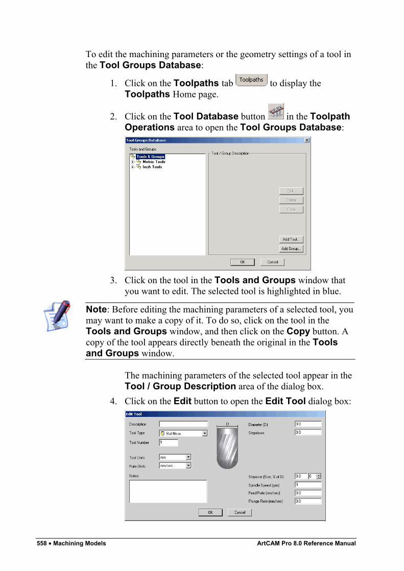
558 • Machining Models ArtCAM Pro 8.0 Reference Manual
To edit the machining parameters or the geometry settings of a tool inthe Tool Groups Database:
1. Click on the Toolpaths tab to display theToolpaths Home page.
2. Click on the Tool Database button in the ToolpathOperations area to open the Tool Groups Database:
3. Click on the tool in the Tools and Groups window thatyou want to edit. The selected tool is highlighted in blue.
Note: Before editing the machining parameters of a selected tool, youmay want to make a copy of it. To do so, click on the tool in theTools and Groups window, and then click on the Copy button. Acopy of the tool appears directly beneath the original in the Toolsand Groups window.
The machining parameters of the selected tool appear in theTool / Group Description area of the dialog box.
4. Click on the Edit button to open the Edit Tool dialog box:
ArtCAM Pro 8.0 Reference Manual Machining Models • 559
5. Define all new machining parameters and tool geometrysettings for the selected tool using the boxes in the dialogbox, or by clicking on the appropriate options in the listboxes.
6. Click on the OK button to save these new settings andparameters and to return to the Tool Groups Database.The tool you have edited appears in the Tools andGroups window, and the information that you had typed inthe Edit Tool dialog box appears in the Tool / GroupDescription area of the Tool Groups Database.
7. Click on the OK button to close the Tool GroupsDatabase.
Copying a ToolYou can copy any tool within the Tool Groups Database:
1. Click on the tool that you want to copy in the Tools andGroups window. The selected tool is highlighted in blue.
2. Click on the Copy button. A copy of the tool appearsdirectly beneath the original tool. You can move thelocation of the tool by clicking and dragging on it.
Deleting a ToolYou can delete any tool listed in the Tool Groups Database:
1. Click on the tool that you want to delete in the Tools andGroups window. The selected tool is highlighted in blue.
2. Click on the Delete button. A message box appearsrequsting you to confirm your decision to delete the tool.
3. Click on the Yes button to delete the tool.
Adding a Tool GroupWithin the Tool Groups Database, tools are organised into variousgroups for ease of reference. When you define and add a selection oftools to the Tool Groups Database, you may want to create a newgroup for them.To create a new tool group:
1. Click on the Tool Database button in the Toolpathsarea of the Assistant's Home page to open the ToolGroups Database:
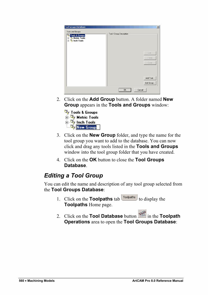
560 • Machining Models ArtCAM Pro 8.0 Reference Manual
2. Click on the Add Group button. A folder named NewGroup appears in the Tools and Groups window:
3. Click on the New Group folder, and type the name for thetool group you want to add to the database. You can nowclick and drag any tools listed in the Tools and Groupswindow into the tool group folder that you have created.
4. Click on the OK button to close the Tool GroupsDatabase.
Editing a Tool GroupYou can edit the name and description of any tool group selected fromthe Tool Groups Database:
1. Click on the Toolpaths tab to display theToolpaths Home page.
2. Click on the Tool Database button in the ToolpathOperations area to open the Tool Groups Database:
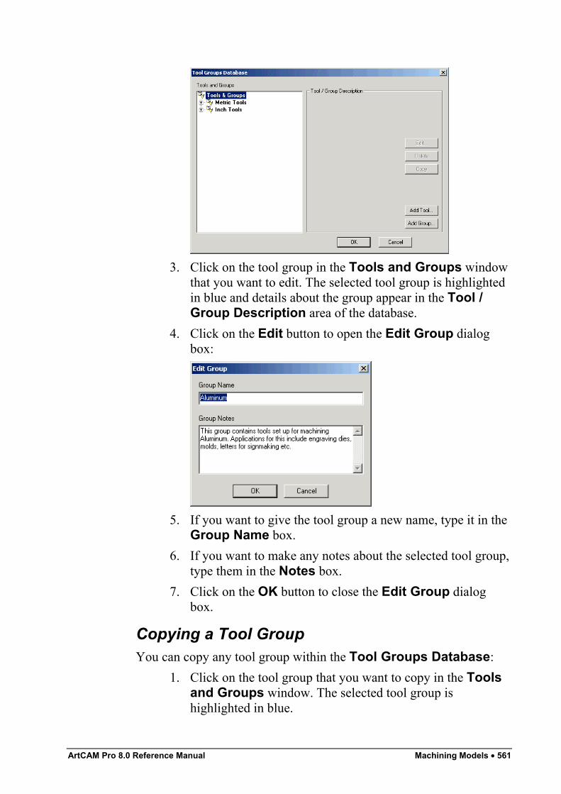
ArtCAM Pro 8.0 Reference Manual Machining Models • 561
3. Click on the tool group in the Tools and Groups windowthat you want to edit. The selected tool group is highlightedin blue and details about the group appear in the Tool /Group Description area of the database.
4. Click on the Edit button to open the Edit Group dialogbox:
5. If you want to give the tool group a new name, type it in theGroup Name box.
6. If you want to make any notes about the selected tool group,type them in the Notes box.
7. Click on the OK button to close the Edit Group dialogbox.
Copying a Tool GroupYou can copy any tool group within the Tool Groups Database:
1. Click on the tool group that you want to copy in the Toolsand Groups window. The selected tool group ishighlighted in blue.
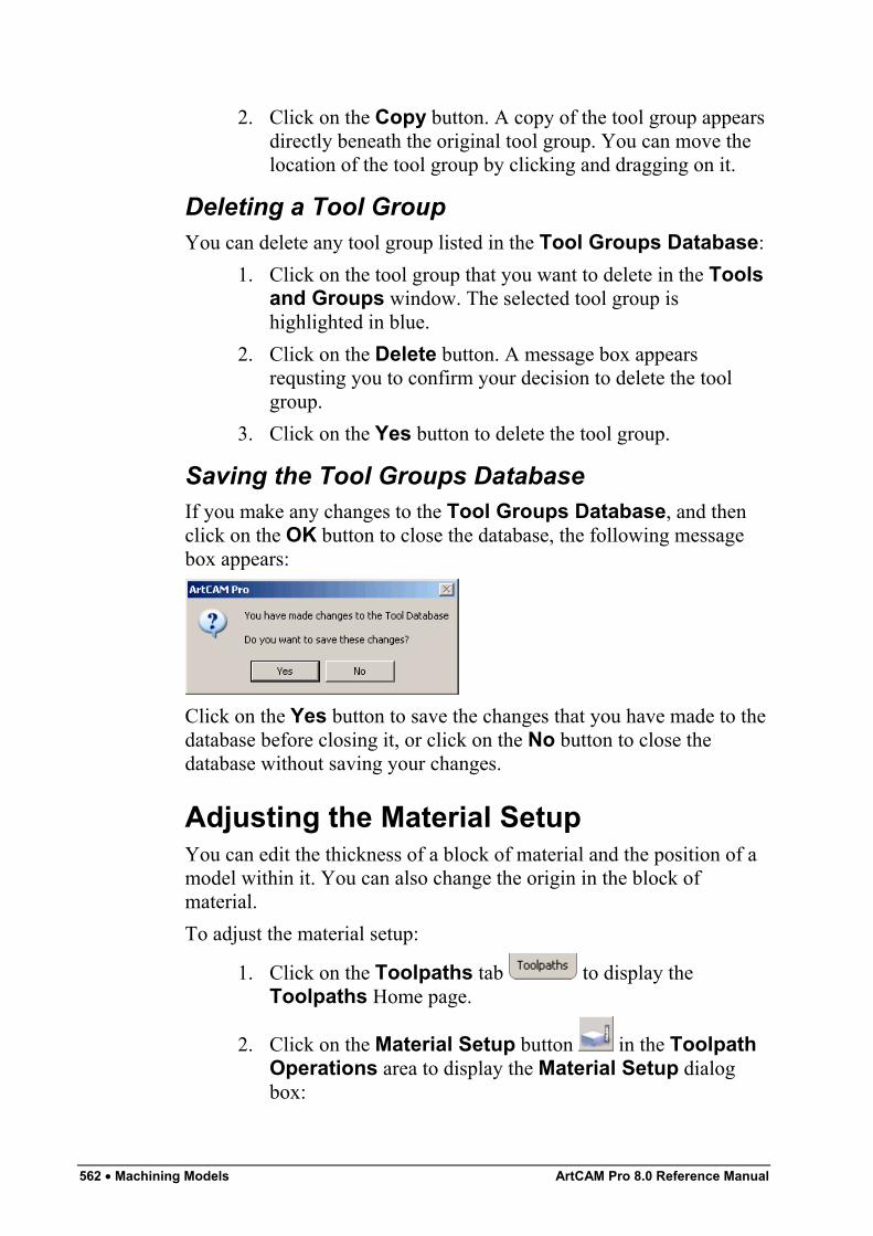
562 • Machining Models ArtCAM Pro 8.0 Reference Manual
2. Click on the Copy button. A copy of the tool group appearsdirectly beneath the original tool group. You can move thelocation of the tool group by clicking and dragging on it.
Deleting a Tool GroupYou can delete any tool group listed in the Tool Groups Database:
1. Click on the tool group that you want to delete in the Toolsand Groups window. The selected tool group ishighlighted in blue.
2. Click on the Delete button. A message box appearsrequsting you to confirm your decision to delete the toolgroup.
3. Click on the Yes button to delete the tool group.
Saving the Tool Groups DatabaseIf you make any changes to the Tool Groups Database, and thenclick on the OK button to close the database, the following messagebox appears:
Click on the Yes button to save the changes that you have made to thedatabase before closing it, or click on the No button to close thedatabase without saving your changes.
Adjusting the Material SetupYou can edit the thickness of a block of material and the position of amodel within it. You can also change the origin in the block ofmaterial.To adjust the material setup:
1. Click on the Toolpaths tab to display theToolpaths Home page.
2. Click on the Material Setup button in the ToolpathOperations area to display the Material Setup dialogbox:
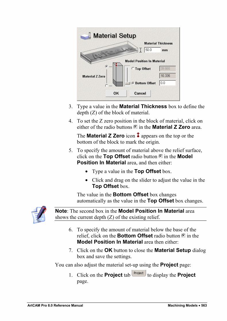
ArtCAM Pro 8.0 Reference Manual Machining Models • 563
3. Type a value in the Material Thickness box to define thedepth (Z) of the block of material.
4. To set the Z zero position in the block of material, click oneither of the radio buttons in the Material Z Zero area.The Material Z Zero icon appears on the top or thebottom of the block to mark the origin.
5. To specify the amount of material above the relief surface,click on the Top Offset radio button in the ModelPosition In Material area, and then either:
• Type a value in the Top Offset box.• Click and drag on the slider to adjust the value in the
Top Offset box.The value in the Bottom Offset box changesautomatically as the value in the Top Offset box changes.
Note: The second box in the Model Position In Material areashows the current depth (Z) of the existing relief.
6. To specify the amount of material below the base of therelief, click on the Bottom Offset radio button in theModel Position In Material area then either:
7. Click on the OK button to close the Material Setup dialogbox and save the settings.
You can also adjust the material set-up using the Project page:
1. Click on the Project tab to display the Projectpage.
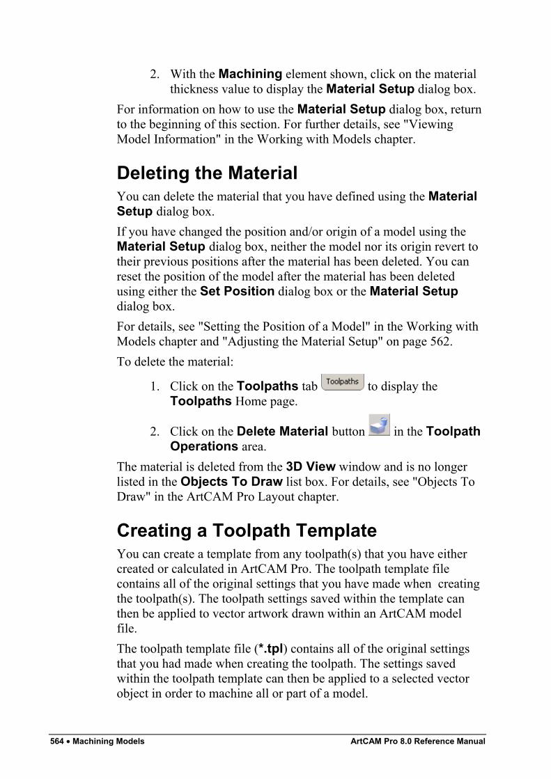
564 • Machining Models ArtCAM Pro 8.0 Reference Manual
2. With the Machining element shown, click on the materialthickness value to display the Material Setup dialog box.
For information on how to use the Material Setup dialog box, returnto the beginning of this section. For further details, see "ViewingModel Information" in the Working with Models chapter.
Deleting the MaterialYou can delete the material that you have defined using the MaterialSetup dialog box.If you have changed the position and/or origin of a model using theMaterial Setup dialog box, neither the model nor its origin revert totheir previous positions after the material has been deleted. You canreset the position of the model after the material has been deletedusing either the Set Position dialog box or the Material Setupdialog box.For details, see "Setting the Position of a Model" in the Working withModels chapter and "Adjusting the Material Setup" on page 562.To delete the material:
1. Click on the Toolpaths tab to display theToolpaths Home page.
2. Click on the Delete Material button in the ToolpathOperations area.
The material is deleted from the 3D View window and is no longerlisted in the Objects To Draw list box. For details, see "Objects ToDraw" in the ArtCAM Pro Layout chapter.
Creating a Toolpath TemplateYou can create a template from any toolpath(s) that you have eithercreated or calculated in ArtCAM Pro. The toolpath template filecontains all of the original settings that you have made when creatingthe toolpath(s). The toolpath settings saved within the template canthen be applied to vector artwork drawn within an ArtCAM modelfile.The toolpath template file (*.tpl) contains all of the original settingsthat you had made when creating the toolpath. The settings savedwithin the toolpath template can then be applied to a selected vectorobject in order to machine all or part of a model.
ArtCAM Pro 8.0 Reference Manual Machining Models • 565
To create a toolpath template:
1. Click on the Toolpaths tab to display theToolpaths Home page.
2. Make sure that only the toolpaths that you want to save as atemplate are listed on the page. These toolpaths can eitherbe created or calculated. Created toolpaths are listed in redtext, whilst calculated toolpaths are listed in black text.
3. Click on the Save Toolpath As Template button inthe Toolpath Operations area to display the SaveToolpath Template dialog box.
4. Click on the Save In list box and select the directory youwant to save the toolpath template in.
5. Type the file name you want to use for the toolpath templatein the File name box.
6. Click on the Save button.The toolpath template can now be loaded at any time to machine all orpart of a model. For details, see "Loading a Toolpath Template" onpage 565.
Loading a Toolpath TemplateWhen you load a toolpath template, the toolpath settings within thefile are automatically assigned to the vector object in the model fromwhich the original toolpath that forms the template was created.If the vector object from which the original toolpath was created hasbeen deleted, or you want to use the template with a different modelaltogether, you need to select the vector object to which you want toassign the toolpath template before the toolpath can be edited orcalculated.To load a toolpath template file (*.tpl):
1. Click on the Toolpaths tab to display theToolpaths Home page.
2. Click on the Load Toolpath Template button in theToolpath Operations area to display the LoadToolpath Template dialog box:
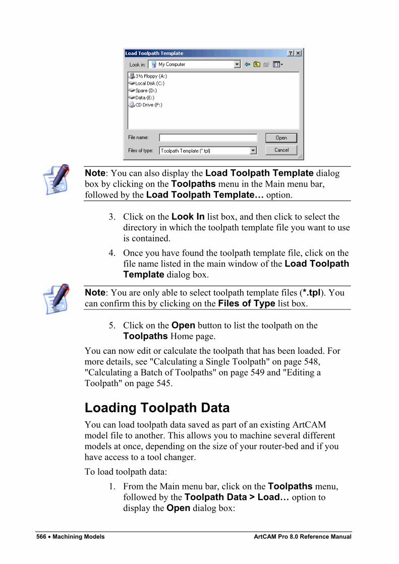
566 • Machining Models ArtCAM Pro 8.0 Reference Manual
Note: You can also display the Load Toolpath Template dialogbox by clicking on the Toolpaths menu in the Main menu bar,followed by the Load Toolpath Template… option.
3. Click on the Look In list box, and then click to select thedirectory in which the toolpath template file you want to useis contained.
4. Once you have found the toolpath template file, click on thefile name listed in the main window of the Load ToolpathTemplate dialog box.
Note: You are only able to select toolpath template files (*.tpl). Youcan confirm this by clicking on the Files of Type list box.
5. Click on the Open button to list the toolpath on theToolpaths Home page.
You can now edit or calculate the toolpath that has been loaded. Formore details, see "Calculating a Single Toolpath" on page 548,"Calculating a Batch of Toolpaths" on page 549 and "Editing aToolpath" on page 545.
Loading Toolpath DataYou can load toolpath data saved as part of an existing ArtCAMmodel file to another. This allows you to machine several differentmodels at once, depending on the size of your router-bed and if youhave access to a tool changer.To load toolpath data:
1. From the Main menu bar, click on the Toolpaths menu,followed by the Toolpath Data > Load… option todisplay the Open dialog box:
ArtCAM Pro 8.0 Reference Manual Machining Models • 567
2. Click on the Look In list box, and then click to select thedirectory in which the ArtCAM model file containing thetoolpaths that you want to use is saved.
3. Once you have found the ArtCAM model file, click on thefile name listed in the main window of the Open dialogbox.
Note: You are only able to select ArtCAM model files (*.art). Youcan confirm this by clicking on the Files of Type list box.
The name of the ArtCAM model you have selected appearsin the File Name box.
4. Click on the Open button to list all of the toolpaths savedas part of the selected ArtCAM model file on theToolpaths Home page.
You can now edit the toolpaths as required. For more details, see"Editing a Toolpath" on page 545.
Setting the Toolpath OrderEach time a new toolpath is created or calculated it is listed on theToolpaths Home page. The previous toolpath is then moved down aposition in this list of toolpaths. This can often mean that the final listof toolpaths does not reflect the order in which you want to machine ajob. In this instance, you can reset the order in which created andcalculated toolpaths are listed to reflect how you want to machine thejob.To set the order in which created and calculated toolpaths are listed:
1. Click to select the name of the toolpath that you want toprioritise. Its name is highlighted in blue.
2. Use the buttons on the page to set the position of thetoolpath in the list:
• Click on the button to move the toolpath upwards.
• Click on the button to move the toolpathdownwards.
Simulating ToolpathsYou can simulate a toolpath that has been calculated. This allows youto visualise the machining passes used to create a finished model. The
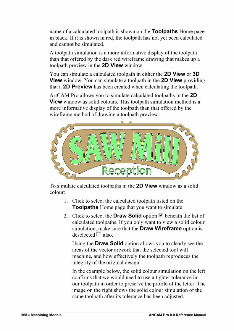
568 • Machining Models ArtCAM Pro 8.0 Reference Manual
name of a calculated toolpath is shown on the Toolpaths Home pagein black. If it is shown in red, the toolpath has not yet been calculatedand cannot be simulated.A toolpath simulation is a more informative display of the toolpaththan that offered by the dark red wireframe drawing that makes up atoolpath preview in the 2D View window.You can simulate a calculated toolpath in either the 2D View or 3DView window. You can simulate a toolpath in the 2D View providingthat a 2D Preview has been created when calculating the toolpath.ArtCAM Pro allows you to simulate calculated toolpaths in the 2DView window as solid colours. This toolpath simulation method is amore informative display of the toolpath than that offered by thewireframe method of drawing a toolpath preview.
To simulate calculated toolpaths in the 2D View window as a solidcolour:
1. Click to select the calculated toolpath listed on theToolpaths Home page that you want to simulate.
2. Click to select the Draw Solid option beneath the list ofcalculated toolpaths. If you only want to view a solid coloursimulation, make sure that the Draw Wireframe option isdeselected also.Using the Draw Solid option allows you to clearly see theareas of the vector artwork that the selected tool willmachine, and how effectively the toolpath reproduces theintegrity of the original design.In the example below, the solid colour simulation on the leftconfirms that we would need to use a tighter tolerance inour toolpath in order to preserve the profile of the letter. Theimage on the right shows the solid colour simulation of thesame toolpath after its tolerance has been adjusted.
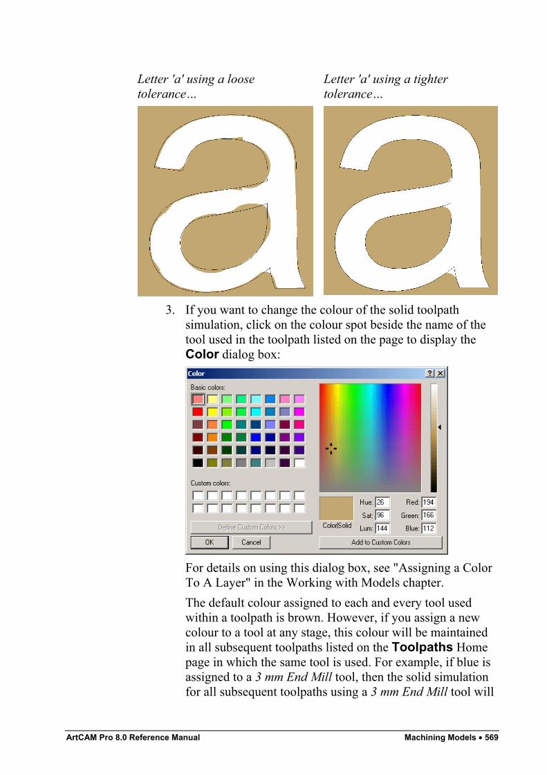
ArtCAM Pro 8.0 Reference Manual Machining Models • 569
Letter 'a' using a loosetolerance…
Letter 'a' using a tightertolerance…
3. If you want to change the colour of the solid toolpathsimulation, click on the colour spot beside the name of thetool used in the toolpath listed on the page to display theColor dialog box:
For details on using this dialog box, see "Assigning a ColorTo A Layer" in the Working with Models chapter.The default colour assigned to each and every tool usedwithin a toolpath is brown. However, if you assign a newcolour to a tool at any stage, this colour will be maintainedin all subsequent toolpaths listed on the Toolpaths Homepage in which the same tool is used. For example, if blue isassigned to a 3 mm End Mill tool, then the solid simulationfor all subsequent toolpaths using a 3 mm End Mill tool will
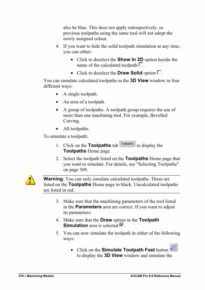
570 • Machining Models ArtCAM Pro 8.0 Reference Manual
also be blue. This does not apply retrospectively, soprevious toolpaths using the same tool will not adopt thenewly assigned colour.
4. If you want to hide the solid toolpath simulation at any time,you can either:
• Click to deselect the Show In 2D option beside thename of the calculated toolpath .
• Click to deselect the Draw Solid option .You can simulate calculated toolpaths in the 3D View window in fourdifferent ways:
• A single toolpath.• An area of a toolpath.• A group of toolpaths. A toolpath group requires the use of
more than one machining tool. For example, BevelledCarving.
• All toolpaths.To simulate a toolpath:
1. Click on the Toolpaths tab to display theToolpaths Home page.
2. Select the toolpath listed on the Toolpaths Home page thatyou want to simulate. For details, see "Selecting Toolpaths"on page 509.
Warning: You can only simulate calculated toolpaths. These arelisted on the Toolpaths Home page in black. Uncalculated toolpathsare listed in red.
3. Make sure that the machining parameters of the tool listedin the Parameters area are correct. If you want to adjustits parameters:
4. Make sure that the Draw option in the ToolpathSimulation area is selected .
5. You can now simulate the toolpath in either of the followingways:
• Click on the Simulate Toolpath Fast button to display the 3D View window and simulate the
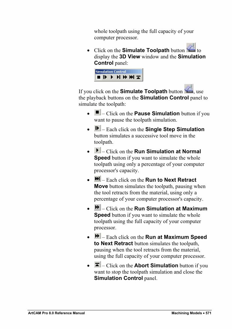
ArtCAM Pro 8.0 Reference Manual Machining Models • 571
whole toolpath using the full capacity of yourcomputer processor.
• Click on the Simulate Toolpath button todisplay the 3D View window and the SimulationControl panel:
If you click on the Simulate Toolpath button , usethe playback buttons on the Simulation Control panel tosimulate the toolpath:
• – Click on the Pause Simulation button if youwant to pause the toolpath simulation.
• – Each click on the Single Step Simulationbutton simulates a successive tool move in thetoolpath.
• – Click on the Run Simulation at NormalSpeed button if you want to simulate the wholetoolpath using only a percentage of your computerprocessor's capacity.
• – Each click on the Run to Next RetractMove button simulates the toolpath, pausing whenthe tool retracts from the material, using only apercentage of your computer processor's capacity.
• – Click on the Run Simulation at MaximumSpeed button if you want to simulate the wholetoolpath using the full capacity of your computerprocessor.
• – Each click on the Run at Maximum Speedto Next Retract button simulates the toolpath,pausing when the tool retracts from the material,using the full capacity of your computer processor.
• – Click on the Abort Simulation button if youwant to stop the toolpath simulation and close theSimulation Control panel.
572 • Machining Models ArtCAM Pro 8.0 Reference Manual
Tip: You can also simulate a toolpath by clicking on a toolpathpreview in the 2D View window, and then on the SimulateToolpath option from the menu displayed when you right-click.
Note: You can also simulate a toolpath by clicking on a toolpathpreview in the 2D View window, and then clicking on theToolpaths menu in the Main menu bar, followed by the SimulateToolpath option.
To simulate an area of a toolpath at the resolution used for the wholerelief:
1. In the 2D View, create a vector object, or move an existingvector object, so that it surrounds the area of the toolpathpreview that you want to simulate. For details, see "Drawingwith Polylines", "Creating Simple Shapes" and "MovingVectors" in the Working with Vectors chapter.
2. Make sure the vector object you want to use to define thearea of the toolpath that you are simulating is selected. Fordetails, see "Selecting Vectors" in the Working with Vectorschapter.
3. Click on the Toolpaths tab to display theToolpaths Home page.
4. In the Toolpath Simulation area, click to select theInside Vector option .
5. Click on either of the simulation buttons to simulate the areaof the toolpath defined by the selected vector object:
• Click on the Simulate Toolpath button todisplay the 3D View window and the SimulationControl control panel. You can use the playbackbuttons on the Simulation Control panel to controlhow the toolpath area is simulated.
• Click on the Simulate Toolpath Fast button to display the 3D View window and simulate thetoolpath area using the full capacity of yourcomputer processor.
To simulate a group of toolpaths:
ArtCAM Pro 8.0 Reference Manual Machining Models • 573
1. Click on the Toolpaths tab to display theToolpaths Home page.
Warning: You can only simulate calculated toolpaths. These arelisted on the Toolpaths Home page in black. Uncalculated toolpathsare listed in red.
2. Select any part of the calculated toolpath group that youwant to simulate. For details, see "Selecting Toolpaths" onpage 509.
3. From the Main menu bar, click on the Toolpaths menu,followed by the Simulate Toolpath option to display arepresentation of the calculated toolpath group and themachined vector object(s) in the 3D View window.
Tip: You can also simulate a toolpath group by selecting a toolpathpreview in the 2D View window that belongs to the group, right-clicking on the toolpath preview to display the Toolpath Editing menuand then clicking on the Simulate Toolpath Group option.
To simulate all of the toolpaths you have calculated:
1. Click on the Toolpaths tab to display theToolpaths Home page.
2. Click on the Simulate All Toolpaths button todisplay a representation of the calculated toolpaths and themachined vector object(s) in the 3D View window.
Tip: You can also simulate all toolpaths group by clicking on theToolpaths menu in the Main menu bar, and then on the SimulateAll Toolpaths option.
Viewing a ToolpathYou can view a toolpath you have created in both the 2D View and3D View windows. A toolpath is displayed as a sequence of dark redlines in the 2D View window, and a series of multi-coloured lines inthe 3D View window.The colour in which a toolpath is displayed within the 3D Viewwindow shows the movement the selected tool will make whenmachining the vector object.
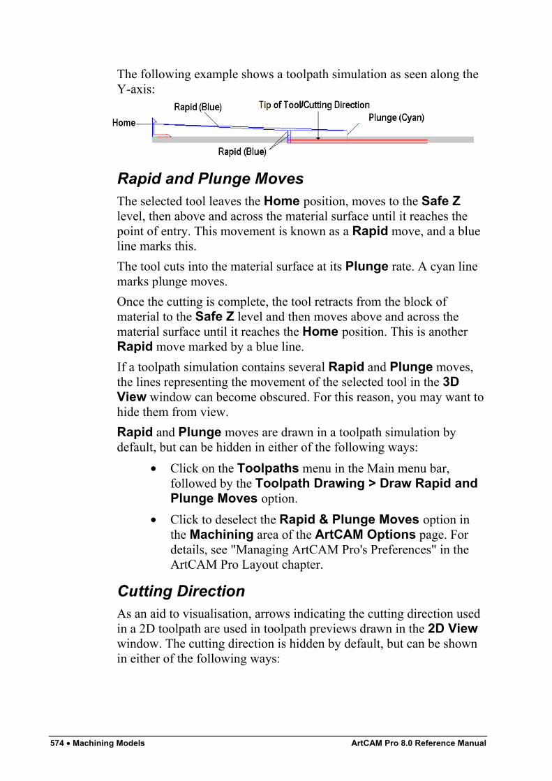
574 • Machining Models ArtCAM Pro 8.0 Reference Manual
The following example shows a toolpath simulation as seen along theY-axis:
Rapid and Plunge MovesThe selected tool leaves the Home position, moves to the Safe Zlevel, then above and across the material surface until it reaches thepoint of entry. This movement is known as a Rapid move, and a blueline marks this.The tool cuts into the material surface at its Plunge rate. A cyan linemarks plunge moves.Once the cutting is complete, the tool retracts from the block ofmaterial to the Safe Z level and then moves above and across thematerial surface until it reaches the Home position. This is anotherRapid move marked by a blue line.If a toolpath simulation contains several Rapid and Plunge moves,the lines representing the movement of the selected tool in the 3DView window can become obscured. For this reason, you may want tohide them from view.Rapid and Plunge moves are drawn in a toolpath simulation bydefault, but can be hidden in either of the following ways:
• Click on the Toolpaths menu in the Main menu bar,followed by the Toolpath Drawing > Draw Rapid andPlunge Moves option.
• Click to deselect the Rapid & Plunge Moves option inthe Machining area of the ArtCAM Options page. Fordetails, see "Managing ArtCAM Pro's Preferences" in theArtCAM Pro Layout chapter.
Cutting DirectionAs an aid to visualisation, arrows indicating the cutting direction usedin a 2D toolpath are used in toolpath previews drawn in the 2D Viewwindow. The cutting direction is hidden by default, but can be shownin either of the following ways:
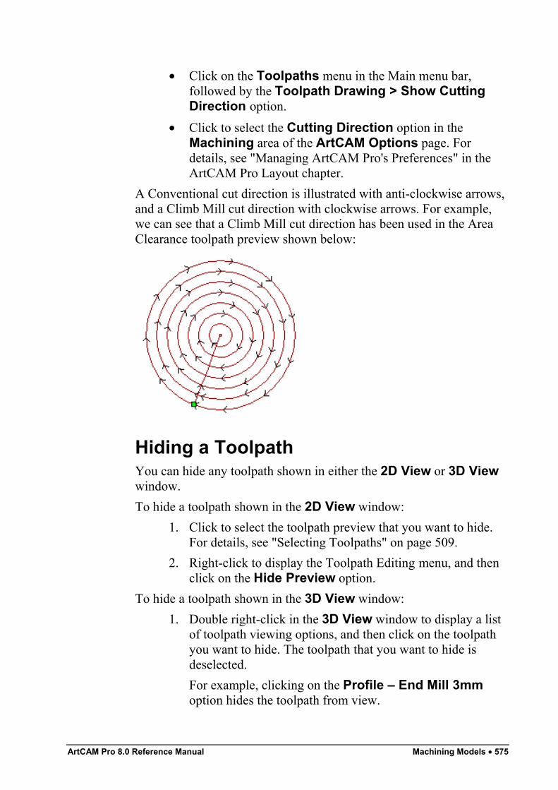
ArtCAM Pro 8.0 Reference Manual Machining Models • 575
• Click on the Toolpaths menu in the Main menu bar,followed by the Toolpath Drawing > Show CuttingDirection option.
• Click to select the Cutting Direction option in theMachining area of the ArtCAM Options page. Fordetails, see "Managing ArtCAM Pro's Preferences" in theArtCAM Pro Layout chapter.
A Conventional cut direction is illustrated with anti-clockwise arrows,and a Climb Mill cut direction with clockwise arrows. For example,we can see that a Climb Mill cut direction has been used in the AreaClearance toolpath preview shown below:
Hiding a ToolpathYou can hide any toolpath shown in either the 2D View or 3D Viewwindow.To hide a toolpath shown in the 2D View window:
1. Click to select the toolpath preview that you want to hide.For details, see "Selecting Toolpaths" on page 509.
2. Right-click to display the Toolpath Editing menu, and thenclick on the Hide Preview option.
To hide a toolpath shown in the 3D View window:1. Double right-click in the 3D View window to display a list
of toolpath viewing options, and then click on the toolpathyou want to hide. The toolpath that you want to hide isdeselected.For example, clicking on the Profile – End Mill 3mmoption hides the toolpath from view.
576 • Machining Models ArtCAM Pro 8.0 Reference Manual
Note: You can hide any of the toolpaths shown in the 3D Viewwindow using the Objects To Draw button in the 3D Viewtoolbar. For details, see "Objects To Draw" in the ArtCAM ProLayout chapter.
Restoring a Hidden ToolpathYou can restore a toolpath that has been hidden in either the 2D Viewor 3D View window.To restore a toolpath hidden in the 2D View window:
1. Click on the Toolpaths tab to display theToolpaths Home page.
2. Make sure that the 2D View window is displayed
If the 3D View button is in the toolbar above the designwindow, the 2D View is displayed. If not, click on the 2DView button .
3. Click to select the Show In 2D box next to the relevanttoolpath you want to view . The toolpath appears in the2D View window in dark red.
To restore a toolpath hidden in the 3D View window:1. Double right-click in the 3D View window to display a list
of toolpath viewing options, and then click on the toolpathyou want to view. The toolpath that you want to restore isnow selected.For example, clicking on the Profile – End Mill 3mmoption restores the toolpath to view.
Note: You can restore any of the toolpaths hidden in the 3D Viewwindow using the Objects To Draw button in the 3D Viewtoolbar. For details, see "Objects To Draw" in the ArtCAM ProLayout chapter.
Resetting a SimulationYou can reset a toolpath simulation that has been drawn in the 3DView window.To reset a toolpath simulation:
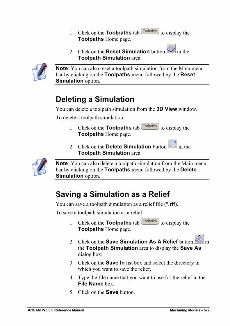
ArtCAM Pro 8.0 Reference Manual Machining Models • 577
1. Click on the Toolpaths tab to display theToolpaths Home page.
2. Click on the Reset Simulation button in theToolpath Simulation area.
Note: You can also reset a toolpath simulation from the Main menubar by clicking on the Toolpaths menu followed by the ResetSimulation option.
Deleting a SimulationYou can delete a toolpath simulation from the 3D View window.To delete a toolpath simulation:
1. Click on the Toolpaths tab to display theToolpaths Home page.
2. Click on the Delete Simulation button in theToolpath Simulation area.
Note: You can also delete a toolpath simulation from the Main menubar by clicking on the Toolpaths menu followed by the DeleteSimulation option.
Saving a Simulation as a ReliefYou can save a toolpath simulation as a relief file (*.rlf).To save a toolpath simulation as a relief:
1. Click on the Toolpaths tab to display theToolpaths Home page.
2. Click on the Save Simulation As A Relief button inthe Toolpath Simulation area to display the Save Asdialog box:
3. Click on the Save In list box and select the directory inwhich you want to save the relief.
4. Type the file name that you want to use for the relief in theFile Name box.
5. Click on the Save button.
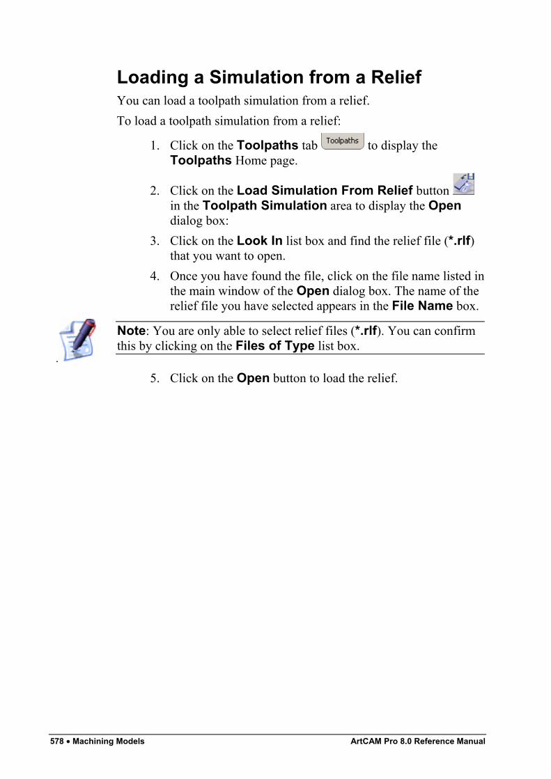
578 • Machining Models ArtCAM Pro 8.0 Reference Manual
Loading a Simulation from a ReliefYou can load a toolpath simulation from a relief.To load a toolpath simulation from a relief:
1. Click on the Toolpaths tab to display theToolpaths Home page.
2. Click on the Load Simulation From Relief button in the Toolpath Simulation area to display the Opendialog box:
3. Click on the Look In list box and find the relief file (*.rlf)that you want to open.
4. Once you have found the file, click on the file name listed inthe main window of the Open dialog box. The name of therelief file you have selected appears in the File Name box.
.
Note: You are only able to select relief files (*.rlf). You can confirmthis by clicking on the Files of Type list box.
5. Click on the Open button to load the relief.
ArtCAM Pro 8.0 Reference Manual Index • 579
Index
22D Area Clearance 4172D Toolpaths
profiling 4072D View
bitmap contrast 18deleting 13grayscale view 17guidelines 23labelling 13link all colours 17linking primary and secondary
colours 17merge colours 18opening a new 12printing 106redo 17rulers 20scrolling 19showing and hiding bitmaps 16showing and hiding vectors 16snap grid 21undo 17unlink all colours 17window fit 16zoom aspect ratio 16zoom objects 16zoom out tool 16zoom previous 16
33D Cut Out 4983D Laser Machining 4953D Rest Machining 5053D Shapes
blended shapes 374creating a dome 323creating a two rail sweep 310creating a weave 316creating an iso-form letter 320creating from a bitmap 286creating from a vector 290editing attributes applied to bitmap
289editing attributes applied to vector
293extruding 295shape editor 286, 290spinning 301turning 307
3D Toolpaths3D cut out 4983D laser machining 4953D rest machining 505
3D Viewdraw x y 30draw zero plane 30isometric view 29objects to draw 30pan view 28previous view 29printing 106saving as an image 56scale to fit 29select relief detail 29software shading 31twiddle tool 27view along x 29view along y 29view along z 29zoom 28zoom in tool 15
580 • Contents ArtCAM Pro 8.0 Reference Manual
zoom out 28
AAdd
border around vectors 225borders to a model 69bridges 528colours to the colour palette 137lead moves to a profile pass 535point to a vector 179ramping moves 404relief 326tool group to database 559
Addingdraft angle 368
Alignvector text to curve 241vectors 257
Angled Plane 371Arc
converting to a bezier curve 177converting to a line 176creating 169fitting to vectors 211inserting a point 179inserting a start point 180removing 181
ArtCAM Proassistant 7compatible bitmap data 4compatible vector data 3notepad 80options 37preferences 37screen layout 7top toolbar 33updating 34
Assistanthome page 7
BBevelled Carving 429Bezier Curve
converting to a line 176converting to an arc 178inserting a point 179inserting a start point 180removing 181
Bitmap Line Tool 144Bitmaps
adding to the colour palette 137bitmap line tool 144contrast in 2D View window 18converting into vectors 147definition 4edge marking 135erase tool 144flood filling 145linking primary and secondary
colours 17, 134overview 129selective flood filling 145selective painting 143setting the origin 130setting the size 130showing and hiding 16spot filters 70thickening colour 136thinning colour 135toolbar 129
Blended 3D shapes 374Border 225Bridges
overview 528
CCalculating
batch of toolpaths 549machining time 551single toolpath 548
Calculating reliefs
ArtCAM Pro 8.0 Reference Manual Index • 581
adding 326merging 330subtracting 328
Centreline Engraved Feature 281Centring vectors 258Circle
creating 159editing 160
Climb Milling 404Clipping Vectors 266Closing
vectors 265Colour
adding to colour palette 137edge marking 135linking primary and secondary 134thickening 136thinning 135unlinking primary and secondary
134Colour Palette
adding colours 137loading 139saving 139
Colourslink all 17merge 18unlink all 17
Conventional Milling 403Converting
bitmap into vectors 147feature to a vector 282span to a bezier curve 177span to a line 176span to an arc 178vectors to circles 224vectors to rectangles 224
Creating3D shape from bitmap 2863D shape from vector 290angled plane 371arc 169bitmaps from vectors 275
blended shapes 374border around vectors 225centreline engraved feature 281circle 159cross-section 370dome 323drill holes 476ellipse 161layers 110models from an image 47multiplate 96pocket 448polygon 164raised feature 277recessed feature 280rectangle 156ring 390star 166stepped pocket 458toolpath panels 523toolpath template 564vector text 230
Cut Direction 403
DDeleting
material 564points 187span 181toolpath simulation 577
Deskewing 67Distorting Vectors 218Dome 323Draft Angle 368Draw X Y 30Draw Zero Plane 30Drilling 476
EEdge Marking 135Editing
582 • Contents ArtCAM Pro 8.0 Reference Manual
3D shape attributes applied to bitmap289
3D shape attributes applied to vector293
asymmetrical model dimensions 63circle 160distorted vectors 222ellipse 162machining parameters 540, 542polygon 165polyline 155rectangle 157relief height 354star 167start position in a toolpath 533toolpaths 545vector nodes 182vector points 182vector spans 175vector text 231vectors 171
Ellipsecreating 161editing 162
Engraving 434Envelope Distortion 218
reliefs 378Erase Tool 144
FFace Wizard 122Feature Machining 486Fillet
inserting 203Fitting arcs to vectors 211Flood Fill 145Flood Fill Selective 145
GGrouped Vectors 275Grouping Vectors 270
Guidelinespositioning 23
HHiding
toolpaths 575
IImporting
toolpath data 566vector artwork 81
Inlay Wizardfemale inlay pocket 448female stepped pocket inlay 458overview 447
Insertingfillets 203
ISO-FORM Letters 320Isometric View 29
JJoining
vectors with coincident points 263
LLayers
creating 110overview 110
Lead moves 535Light and Material Settings
lights 71material 75
Lineconverting to a bezier curve 177converting to an arc 178inserting a point 179inserting a start point 180removing 181
Linking Colours 134Loading
ArtCAM Pro 8.0 Reference Manual Index • 583
custom colour palette 139reliefs 363toolpath simulation from relief 578
Lockingvectors 211
MMachine Vectors 441Maintenance 34Material Setup 562Merging
colours 18reliefs 330toolpaths 521
Mirrormodel 105relief 357vectors 254
Modelsadding borders 69adjusting material setup 562clearing 67creating from an image 47creating layers 110deskewing 67editing asymmetrical dimensions 63importing images 61importing unwrapped triangle
models 92importing vector artwork 81layers 110loading toolpath data 566mirroring 105printing 57, 106rotating 105saving 55setting position 65
Movingpoints 184
Multiplate Tool 96
NNesting Vectors 212Node editing 182Nodes
moving 184
OObjects To Draw 30Offset
relief 359Offset Vector 197Origin
setting position 65
PPaint Brush
selective painting 143Pan View 28Panelling 523Paste
relief along a vector 349vectors along a curve 223
Peck Drilling 477Pocket 448Point
aligning 190changing position 189changing the start point 189deleting 187editing 182inserting 179smoothing 185
Pointsidentifying coincident 226joining coincident 263moving 184
Polygoncreating 164, 165editing 165
Polylineediting 155
584 • Contents ArtCAM Pro 8.0 Reference Manual
Previous View 29Print
model 106preview 107setup 108
Profiling 407Properties of a Vector 272
RRaised Feature 277Ramping Moves 404Recessed Feature 280Rectangle
creating 156editing 157
Reliefsadding 326adding a draft angle 368calculation time 367copy and paste 344creating a cross-section 370creating a ring 390creating an angled plane 371creating blended shapes 374definition 5detail in 3D view 29envelope distortion 378face wizard 122loading 363merging 330mirroring 357offset 359pasting along a vector 349removing holes in surface 402resetting 360resetting height 360scaling 356scaling height 354sculpting tools 397smoothing 352subtracting 328wrapping clipart relief 338
wrapping vectors to 209Ring 390Rotate
model 105Rulers 20
SSaving
3D view as an image 56custom colour palette 139model 55tool groups database 562toolpath simulation 577
Scale To Fit 29Sculpting Tools 397Select Relief Details 29Selecting
toolpaths 509vector objects 172
Selective Painting 143Showing Toolpaths 576Simulating
toolpaths in 2D View 568toolpaths in 3D View 570
Simulation2d view 5683d view 570
Slicing Vectors 268Smooth
nodes 185points 185relief 352vectors 185
Spanconverting to a bezier curve 177converting to a line 176converting to an arc 178deleting 181inserting a point 179inserting start point 180
Splining Vectors 199Spot Filters 70
ArtCAM Pro 8.0 Reference Manual Index • 585
Starcreating 166editing 167
Start Pointchanging 189
Start Position 533Stepped Pocket 458Swept Profile Shape
extruding 295spinning 301turning 307
TThickening Colours 136Thinning Colour 135Tool Groups Database
adding tool groups 559saving changes 562using 554
Toolpath Ordering 537Toolpath Panelling 523Toolpath Summary
calculating machining time 551using 550
Toolpath Templatecreating 564loading 565
Toolpaths2D area clearance 417add bridges to a profile pass 528add lead moves to a profile pass 535bevelled carving 429calculating 548calculating in a batch 549changing the start position 533creating a template 564cut direction 403deleting a simulation 577drilling holes 476editing 545engraving 434hiding 575
inlay wizard 447lead moves 535loading a template 565loading toolpath data 566machine vectors 441machining order of profile passes
537machining parameters 540, 542merging 521panelling 523peck drilling 477ramping moves 404resetting a simulation 576resetting machining order 539selecting 509showing 576simulating 567tool groups database 554toolpath summary 550v-bit carving 423viewing 573
Transformvectors 246
Transform Vectors Mode 244Trim Tool 207Twiddle Tool 27Two Rail Sweep 310
UUngrouped vectors 274Unlinking Colours 134Unlocking
vectors 211
VV-Bit Carving 423Vector Doctor
coincident points 226Vector Library 84Vector Text
aligning 241
586 • Contents ArtCAM Pro 8.0 Reference Manual
creating 230editing 231formatting 233selecting 231spacing 243wrapping round a curve 238
Vectorsaligning 257aligning points 190centring 258changing the start point 189clipping 266closing 265converting into bitmaps 275converting shapes 224converting span to a bezier curve
177converting span to a line 176converting span to an arc 178copying and pasting 192creating a border 225creating a centreline engraved
feature 281creating a circle 159creating a polygon 164creating a raised feature 277creating a recessed feature 280creating a rectangle 156creating a star 166creating an arc 169creating an ellipse 161creating text 230definition 3deleting points 187deleting spans 181distorting 218editing 171, 175editing a circle 160, 162editing a polygon 165editing a rectangle 157editing a star 167editing nodes 182editing points 182
editing vector text 231filleting 203fitting arcs 211formatting vector text 233grouped 275grouping 270importing 81, 84inserting points 179inserting start point 180joining coincident points 263library 84locking 211loop detection and removal 81, 227making a multiplate 96mirroring 254nesting 212offsetting 197overview 151paste relief along 349pasting along a curve 223returning a feature to a vector 282selecting 172showing and hiding 16slicing 268smoothing points 185snapping 25splining 199, 203transform origin 247trimming 207ungrouped 274unlocking 211viewing properties 272wrapping text around a curve 238wrapping to a relief 209
View Along X 29View Along Y 29View Along Z 29Viewing a toolpath 573
WWeave Shape 316

ArtCAM Pro 8.0 Reference Manual Index • 587
ZZoom 28Zoom Out 28