articles finite element analysis of blister formation in laser
TRANSCRIPT
ARTICLES
Finite element analysis of blister formation in laser-inducedforward transfer
Nicholas T. Kattamis, Matthew S. Brown, and Craig B. Arnolda)
Department of Mechanical and Aerospace Engineering, Princeton Institute for the Science andTechnology of Materials, Princeton University, Princeton, New Jersey 08544
(Received 16 January 2011; accepted 21 June 2011)
Blister-actuated laser-induced forward transfer (BA-LIFT) is a direct-write technique, whichenables high-resolution printing of sensitive inks for electronic or biological applications. DuringBA-LIFT, a polymer laser-absorbing layer deforms into an enclosed blister and ejects ink from anadjacent donor film. In this work, we develop a finite element model to replicate and predict blisterexpansion dynamics during BA-LIFT. Model inputs consist of standard mechanical properties,strain-rate-dependent material parameters, and a parameter encapsulating the thermal and opticalproperties of the film. We present methods to determine these material parameters fromexperimental measurements. The simulated expansion dynamics are shown to be in goodagreement with experimental measurements using two different polymer layer thicknesses. Finally,the ability to model high-fluence blister rupture is demonstrated through a strain-based failureapproach.
I. INTRODUCTION
Laser-induced forward transfer (LIFT) is a high-resolutiondirect-write printing technique, which enables the depositionof a wide range of solid,1 multiphase,2,3 and organic4–6 inksinto two- or three-dimensional patterns. In conventionalLIFT, the bottom of a laser-transparent substrate is coatedwith a donor ink film and placed above a receiver sub-strate.2,3 A pulsed laser is absorbed within a confined regionof the ink film, resulting in the localized transfer of materialonto the receiver substrate.4 User-programmable patterns canbe created by translating the donor and receiver substrates.
In instances where the active material is susceptible tophotolytic damage or the ink does not strongly absorb theincident photons, a dynamic release layer (DRL) can beincorporated between the glass and the ink. For example,laser absorption within a thin metal (10–50 nm) DRL canbe used to propel transfers by providing a localized heatsource, which vaporizes the adjacent ink and/or the metalfilm itself.7–10 However, such thermally induced ejectionscan lead to pyrolytic damage in certain ink materials.11 Byutilizing DRL that undergo low-temperature vaporization,such as triazene polymer,12,13 nanoparticle films,14 orfunctional release layers,15 this thermal damage can bemitigated. However, the ink is still directly exposed to thegaseous decomposition products, which may lead tofurther contamination issues.
To enable the deposition of inkmaterials that are sensitiveto photolytic and pyrolytic damage or to contamination fromablated DRL fragments, a thick (2–10 lm) polyimide layercan be incorporated between the glass and ink.16 Uponpulsed laser irradiation, a rapidly expanding polymer blisterforms and imparts momentum to the adjacent ink layer,inducing transfer. This blister-actuated LIFT (BA-LIFT)mechanism is fundamentally different from that whichoccurs in traditional DRLs in that the outer layer of thefilm remains sealed, protecting the ink from direct heatingand contamination from the ablation species.10 In addition,the large film thickness and small thermal diffusivity of thepolymer minimize heat diffusion through the polymer/inkinterface, further reducing the chance for damage. Thesequalities enable the deposition of material systems that areespecially prone to damage during transfer, such as delicateembryonic stem cells17 and organic light-emitting mole-cules.11,17,18 At sufficiently high laser fluences (Fl), blisterrupture can occur, permitting ablated species to interactwith the ink.10 The occurrence of blister rupture is still notwell understood, nor is the dependence of polymer filmmaterial properties and the laser/material interaction on theobserved blister dynamics. Therefore, a physically accuratenumerical model of the blister dynamics during BA-LIFTwould enable a fundamental understanding of the processand provides a useful platform to conduct future parametricstudies helping to optimize the printing process.In this work, we use finite element analysis (FEA) to
model the dynamics of laser-induced blister formation ona thick polyimide film. Experiments are first carried outto measure blister size and shape as a function of laserfluence and time for a 7-lm polymer film. Based on these
a)Address all correspondence to this author.e-mail: [email protected]
DOI: 10.1557/jmr.2011.215
J. Mater. Res., 2011 �Materials Research Society 2011 1
results, strain-rate-dependent material parameters aredetermined for the polyimide, providing insight to thepolymer’smechanical behavior at high strain rates. The con-version efficiency of laser energy into pressure–volumework done by the enclosed gas is then estimated bymatching blister heights generated by the model to theexperiments. These procedures establish all free parametersrequired to model the initial stages of blister growth for anarbitrary polyimide film thickness and laser beam shape. Toverify the model accuracy and predictability, results arecompared to 3-lm-thick polyimide film experiments andare shown to coincide with the simulated blister shape andsize without the need for additional fitting parameters.Finally, the conditions for blister rupture are investigated,and the ability to capture this phenomenon in the model isdemonstrated.
II. FINITE ELEMENT MODEL
The dynamic response of blister formation is modeledby means of structural FEA in ANSYS�. In this FEA,model geometry is converted into a discrete number ofelements, each composed of four nodes (quadrilateralelement). Initial conditions and boundary conditions areapplied to relevant nodes in the form of nodal forces andnodal constraints. Both element stiffness and mass matri-ces are computed at each time step in terms of the elementslocal coordinate system, converted to global coordinates,and finally assembled into their global matrices. Finiteelement equilibrium equations relating the nodal forces tothe model stiffness, mass, damping, and kinematics arethen used to determine the time-dependent nodal displace-ments. These are derived from a momentum balance ona structural element, incorporating initial conditions andboundary conditions. Details can be found in the litera-ture.19 Finally, element strain and stress in the polymer isdetermined through strain/displacement and constitutiveequations. Velocities and accelerations are calculatedthrough time derivatives of the nodal displacements.
A. Model preprocessing
The spatial profile of the laser beamused in theBA-LIFTexperiments is a top-hat (Table I). The uniformity andradial symmetry of the beam allows for the simplificationof a three-dimensional finite element model to a two-dimensional axisymmetric analysis. Axisymmetry is chosenthrough element modification within ANSYS� and byenforcing zero displacement in the r-direction on themodel’s axis of symmetry [Fig. 1(a)]. This simplificationdrastically reduces simulation run time while still capturingthe appropriate physics.
Initially, the model geometry is composed of a uni-form 3- or 7-lm-thick film bonded to a rigid substrate[Fig. 1(a)]. Rate-independent material properties for thefilm are selected as Kapton� polyimide.20 Material
damping is modeled through a Rayleigh damping stiff-ness matrix multiplier (b). In the absence of a publishedvalue for polyimide, b is estimated using a proceduredescribed in literature.21–24 In short, this parameter isestimated by first conducting a modal analysis to deter-mine the systems dominant natural frequencies, number-ing them 1 – n. An assumption for rigid structures that thedamping ratio for each mode is linearly proportional tothe frequency of the system is then used. This enablescalculation of the damping ratio for the nth mode basedon a judicious selection of the damping ratio for the firstmode. The calculation is repeated over a larger number ofmodes (1 – 2.5n) and averaged to yield b; 2.5� 10�9 s.All relevant rate-independent material properties for poly-imide are shown in Table I. The substrate is subsequentlyselected as standard borosilicate glass (Table II) at a thick-ness of 5 lm. Based on the elastic modulus of glass relativeto polyimide, glass deformation is negligible, and thereforethe selected value is able to mimic the behavior of the actual1-mm-thick microscope slide. This further reduces modelsize and simulation run time.
To prevent acceleration of the donor assembly, thenodes on the bottom of the glass substrate are set to zerodisplacement in the r- and z-directions. The mechanicalbond between the polyimide film and glass slide [Fig. 1(a)]is simulated by initially coupling the overlapping polymerand glass nodes to constrain them to undergo identicalrigid body motion. This sets the initial condition of theinterface prior to laser interaction and subsequent polymer
TABLE I. Material parameters for polyimide film and laser parameters.
Symbol Value Units
Polyimide material parameterElastic Modulusa E 2 GPaPoisson Ratioa m 0,34 —
Densitya q 1420 kg/m3
Yield Stressa rY 70 MPaNonlinear Plasticitya r(e) FIG l(b) MPaMaterial Viscosityc c 1 � 107 s�1
Strain Rate Hardeningc m 0.4 —
Rayleigh Dampinga,b b 2.5 � 10�9 sCritical Energy Release Ratea Gc 700 J/m3
Gas Molar Massb M 30 g/molGas Constant R 8.314 J/kg-KSpecific Heat at Constant Pressureb Cp 1616 J/kg-KSpecific Heat at Constant Volumeb cv 1339 J/kg-KLaser Energy to Pressure Conversionc g Varies —
Material Thicknessd tf 3.0/7.0 lmLaser Parameter
Beam Pulse Widtha s 20 nsBeam Shaped — Top-hat —
Beam Ablation Radiusd ra 10.5 lm
aPublished Data.bEstimated Data.cFitting parameter.dMeasured Data.
N.T. Kattamis et al.: Finite element analysis of blister formation in laser-induced forward transfer
J. Mater. Res., 20112

film debonding. We determine an optimal mesh size of0.25 � 0.25 lm2 by recording equilibrium (t ; 500 ns)blister profile size and shape and finding that finer meshsizes produce identical results. All relevant simulationparameters are in Table III.
B. Laser/matter interaction
Upon pulsed laser irradiation of the donor substrate,a small volume of vapor at the glass/polymer interface iscreated, which breaks the bond at the interface. Thisbehavior is incorporated in the model by removing thepolymer/glass nodal coupling over a specified width whichis defined here as the portion of the beam that exceeds theablation threshold fluence of the material. For the top-hatbeam profile and fluences used in the experiments, theablation threshold of polyimide at our laser wavelength(k 5 355 nm) is approximately 120 mJ/cm,2,25 which isexceededwithin the first few nanoseconds of the rising edgeof the pulse. Therefore, the width of the initial vaporizedvolume is selected as the beam diameter (21 lm).
The mass of vaporized material continues to grow asthe laser interacts with the polymer layer, reducing solidlayer thickness and decreasing its resistance to mechan-ical bending and its ability to sustain membrane loads.This may change the dynamic response of the blister andfinal resting shape. However, the depth of material re-moval has not been characterized under such confinedablation configurations and may differ drastically from
standard Beer–Lambert law ablation depths. Therefore,ablation depths cannot be accurately included in thisanalysis and are set to zero.
The driving force for blister expansion is provided by thehigh-pressure pocket of gas trapped within the film. Signif-icant blister deformation occurs over the time scale of thelaser pulse (40 ns). As the gas expands and does pressure–volume (PV) work in deforming the film, thermal energyis constantly being added to the gas over the course of thelaser pulse. This heat addition is neither at constant volume
FIG. 1. (a) Axisymmetric finite element analysis (FEA) depicting a polyimide film bonded to a glass slide. The laser enters through the slide in the+z-direction, creating an enclosed volume of pressurized gas. Arrowheads denote the direction of the imposed boundary condition. (b) Stress–straincurve for Kapton� polyimide and (c) polyimide film delamination modeled as crack propagation via a fracture mechanics approach.
TABLE II. Material parameters for glass support.
Glass material parameter Symbol Value Units
Elastic modulusa E 70 GPaPoisson ratioa m 0.17 —
Densitya q 2650 kg/m3
Material thicknessb ts 5 lm
aPublished data.bMeasured data.
TABLE III. Finite element analysis simulation parameters.
Simulation parameter Symbol Model Units
Mesh size Dx 0.25 lmTime step Dt 0.10 nsMaximum iterations per time step Nmax 1000 —
Minimum iterations per time step Nmin 1 —
Ablated volumea Vo 10 lm3
aEstimated data.
N.T. Kattamis et al.: Finite element analysis of blister formation in laser-induced forward transfer
3J. Mater. Res., 2011
nor constant pressure, as the pressure and volume arechanging continuously because of the complex interactionwith the deforming solid polymer film. Therefore, to dealwith these nonuniform conditions, we break up the heataddition and volume expansion process into discrete steps.At the beginning of a time step, heat is added at constantvolume, increasing the temperature and pressure. Then,over the course of the time step, the deformation of thesolid film and the expansion of the enclosed gas aresimulated subject to this constant pressure. At the end ofthe time step, the gas pressure and temperature are adjustedassuming that this volume expansion occurred adiabati-cally. In the limit of vanishingly small time steps, thistreatment converges on the actual continuous laser heatingand expansion process.
Within one time step, the amount of laser energyconverted into thermal energy within the gas can berepresented as
DQ ¼ k
ZIðFl; tÞdt ; ð1Þ
where I is the instantaneous laser power and the integralextends over the time step. The functional form of I(Fl,t) issuch that it is Gaussian in time t and the integral of I overthe entire laser pulse equals the total laser energy. Theparameter k is the conversion efficiency of laser energy tothermal energy in the gas. In general, k is also a function oflaser fluence, which accounts for the nonlinear absorptionbecause of the formation of plasma.
At the beginning of a time step, the heat DQ is added tothe gas at constant volume, resulting in an increase oftemperature DT according to
DT ¼ DQmcv
; ð2Þ
where m is the mass of the gas and cv is its specific heat atconstant volume. Equation (2) uses the constant-specific-heat assumption of an ideal gas. The resulting change inpressure DP at the beginning of the time step is capturedthrough an ideal gas model
DP ¼ m
M
R
VDT ; ð3Þ
where R is the universal gas constant, V is the volume ofthe gas, andM its molar mass. By substituting Eq. (2) intoEq. (3), the increase in gas pressure is given by,
DP ¼ RDQMVcv
: ð4Þ
Likewise, the increase in gas pressure can be directlyrelated to the laser power by substituting Eq. (1) into Eq. (4),which is given by
DP ¼ kR
Mcv
1V
ZIðFl; tÞdt : ð5Þ
Equation (5) is valid for each time step over the entirelaser pulse length, estimated as 40 ns. All relevant Kapton�
polyimide thermal properties are given in Table I.In the analysis, heat is added to the gas at constant
volume at the beginning of each time step, increasing itspressure, and then the deformation of blister film issimulated over the time step subject to a constant internalgas pressure. At the end of the time step, the volume ofthe gas has increased to Vt from its initial value Vt�Dt. Thepressure at the start of the next time step Pt is updated fromthe pressure used during the previous time step Pt�Dt
assuming that the expansion occurred adiabatically, giving
Pt ¼ Pt�DtVt�Dt
Vt
� �cpcv
: ð6Þ
Here, cp is the specific heat of the ablated species atconstant pressure. As the time step size is decreased, thistreatment with discrete isochoric, isobaric, and adiabaticsteps converges to the actual process of continuous heataddition and expansion. The parameters cp, cv, and M areestimated by assuming that the blister gas is composed of anaverage of the primary polyimide ablation products at thenanosecond ablation temperature (850 °C)26; H2O, CO, andCO2.
25 The final expression for the updated blister gaspressure is obtained by combining Eqs. (5) and (6), giving
Pt ¼ Pt�DtVt�Dt
Vt
� �cpcvþg
1Vt
Z t
t�Dt
IðFl; tÞdt ; ð7Þ
where g5 kR/Mcv. The prefactor g is a system parameterthat incorporates the thermal and optical properties of thepolyimide to relate the incremental change in gas pressuredP to the incremental laser energy addition dEL, such thatdPdEL
¼ 1Vtg at a given volume Vt. Althoughg should vary in
time as the laser-absorption and energy-conversion path-ways evolve during the course of the laser pulse, forsimplicity, we assume a static value that is only a functionof the laser fluence. Once the laser pulse ends after 40 ns,the second term in Eq. (7) goes to zero, and we are left withthe expression for adiabatic expansion.
To begin the analysis, an initial gas volume (Vo) of finitevalue must be assumed because of the singularity present inEq. (7) if Vo50. To test the sensitivity of the model to Vo,we have obtained blister dynamics for initial volumesranging from 1 to roughly 230 lm3, which is the volumedefined by the beam area and the laser-absorption depth(;0.67 lm).17 In all cases, blister dynamics are observed tobe insensitive to the initial volume. Therefore, a minimalvalue (1 lm3), indicative of surface absorption, is selected.
N.T. Kattamis et al.: Finite element analysis of blister formation in laser-induced forward transfer
J. Mater. Res., 20114
C. Strain-rate-dependent material properties
As gas pressure increases in the blister, a mechanicalresponse in the polymer film occurs that is dependent on thepolymer’s mechanical properties. Kapton� polyimide filmmechanical properties are incorporated in the model, cap-turing the linear elastic regime aswell as the nonlinear plasticregime, which is modeled using multilinear kinematichardening.27 This accommodates uniform plastic deforma-tion once material yielding has occurred. The correspondingstress–strain diagram is seen in Fig. 1(b), and all relevantmechanical properties are in Table I. These properties aremeasured at very low strain rates (_e , 1 s�1).20 However,because of the variation in strain rates (_e) encountered duringBA-LIFT, often in excess of 107 s�1, highly erroneoussolutions may result from the use of mechanical propertiesfrom these typical “static” measurements. Therefore, toaccount for the strain-rate-dependent variation in materialflow stress in ANSYS�, the following Peirce equation28 isused,
ry ¼ ryo 1þ _eplc
� �m
: ð8Þ
This equation captures the change in the model’sresponse to a dynamically applied load and modifies thedynamics and shape of the resulting finite element blisters.Herery is the dynamic flow stress, which is larger than thestatic yield stress ryo (Table I), c is the material viscosityparameter, and m is the strain-rate-hardening parameter.The equivalent plastic strain rate ( _epl) is calculated directlywithin ANSYS�, followed by the dynamic flow stresspending knowledge ofm and c. The free parametersm andc are determined through a parameter map analysis, thedetails of which are found in the experimental section.
D. Interface delamination
The mechanical deformation of the polymer filmcreates stress at the bonded glass/polymer interface(cohesive zone). This causes the compliant polymerfilm to delaminate from the rigid glass substrate. In-terface delamination in the cohesive zone is accountedfor using a fracture mechanics approach. Here, theenergy available to propagate the crack, termed thestrain energy release rate (G), is calculated and comparedto the energy required to propagate the crack, termed thecritical strain energy release rate (GC). Delamination isallowed to proceed once G exceeds GC. A number oftechniques that can be implemented to calculate the strainenergy release rate include the finite crack extensionmethod,29 virtual crack extension method,30,31 equiva-lent domain integral method,32,33 and the virtual crackclosure technique (VCCT).34,35 The VCCT has beenwidely implemented for crack propagation at laminateinterfaces. However, two separate analyses are required
to first propagate the crack and then calculate the energyrequired to close the crack. To circumvent this tediousanalysis, the modified VCCT is chosen to calculate theenergy release rates without the need for two separateanalyses.36 It accomplishes this by assuming the energyrequired to propagate the crack from an area A to an areaA 1 dA is the same as it is to propagate it anotherincrement from A 1 dA to A 1 2dA. In its most generalform, the energy release rate is given by,
G ¼ DEDA
¼ 12Fd
1DA
; ð9Þ
where DE is the energy required to propagate the crackthrough an areaDA, F is the applied load, and d is the cracktip opening displacement. In discretized form, Eq. (9)becomes,
GI ¼ � 12DA
FZi vi�Dr � vi�Dr�ð Þ ; ð10Þ
GII ¼ � 12DA
FRi ðui�Dr � ui�Dr�Þ ; ð11Þ
where GI and GII are the opening and in-plane shearingenergy release rates, DA5 p(r2iþDr – r
2i ) is the delaminated
area created by propagating a crack from node i to theadjacent elemental node (i1 Dr), FZi and FRi are the nodalforces at the crack tip in the Z- and R-directions, ui�1 andvi�1 are the displacements of the previous node uppercrack face in the R- and Z-directions, and * denotes thelower crack face [Fig. 1(c)]. FZi and FRi are input on a 2pbasis because of the axisymmetry of the problem. Thecritical energy release rate of polyimide bonded to glass ismeasured to be between 600 and 800 J/m2.37–39 Here, wechoose an intermediate value of 700 J/m2. By examiningenergy release rates and not stress intensity values, thecontributions from mode I interlamellar tension and modeII interlamellar sliding shear can be summed together toobtain the total strain energy release rate GT. Crack propa-gation will occur when,
GT ¼ GI þ GII > GC : ð12Þ
III. RESULTS AND DISCUSSION
The first step in the FEA of blister formation is tomeasure the strain-rate-dependent material properties. Forthis purpose, experiments are carried out to measureblister size and shape for a 7-lm-thick polyimide film asdetailed in the literature.16 A 4.75 J/cm2 laser fluence isselected, producing a 75-lm-diameter blister over whichto compare with finite element blister profiles.
N.T. Kattamis et al.: Finite element analysis of blister formation in laser-induced forward transfer
5J. Mater. Res., 2011
A. Strain-rate-dependent material properties
Initial simulations using strain-rate-independent mate-rial properties (Kapton�)20 measured at low strain rates( _e ; 0.3 s�1) produce blisters that do not properly matchthe experimental profiles. This error is attributed to thedependence of the polymer’s molecular response on strainrate. In amorphous polymer deformation at low strainrates, polymer chain reorienting through rotation, align-ment, and sliding accommodate more strain at a givenstress.40,41 However, at peak strain rates encounteredduring laser-induced blister formation (107–108 s�1), theextent of chain reorienting is limited, effectively strength-ening the material by increasing the stress needed to strainthe material.42,43 These changes in mechanical propertiesaffect the shape and dynamic response of the blisters andare important to include in the FEA. This is typicallyaccomplished by fitting the two unknown material param-eters (m and c) in Eq. (8) to stress–strain curves acquired ata range of strain rates.
A variety of methods exist to obtain the necessarymechanical properties ofmaterials at a range of strain rates.44
However, the complexity of the measurements increaseswith strain rate. For example, commercially availablemechanical testing machines enable stress–strain materialmeasurements at quasi-static strain rates (_e, 10 s�1). Thesetests are simple to conduct and can capture elastic and anypermanent plastic deformation effects that occur prior tomaterial failure. For strain rates between 101–103 s�1,commercially available drop weight testing machines areused to acquire similar material measurements. Beyondthese strain rates, however, commercially available techni-ques do not exist, and more complex methods such as theSplit-Hopkinson pressure bar technique45,46 or the flyerplate shock loaded technique47 must be utilized. The majordifficulty in employing these techniques stems from theunknown temperature distribution in the polymer and itseffect on the material parameters.
We take a different approach to obtain the necessarystrain-rate-dependent material parameters of Eq. (8)(m and c) through the use of a parameter analysis. Thisprocedure enables the determination of these parameterswithout the knowledge of the temperature distributionswithin the polymer film. In this analysis, the two param-eters are independently varied, and corresponding finiteelement blister profiles are extracted. Care is taken toensure that the numerical profile heights match theexperimental profile heights by adjusting the parameterg in Eq. (7). Adjustments in g are permissible at this stagesince the physical values of g and its dependence onfluence cannot be determined until all material propertiesare known. The accuracy of fit is then determined bycalculating the average residual sum of squares (RSS)between the finite element and experimental blister pro-files as follows,
RSS ¼ 1n+n
i¼1yi � f ðxiÞð Þ2 : ð13Þ
Here, n is the number of surface nodes over which theresidual between the finite element value yi and experi-mental value f (xi) is calculated. The values of m and c thatminimize this metric are selected as the polymers rate-sensitive parameters.
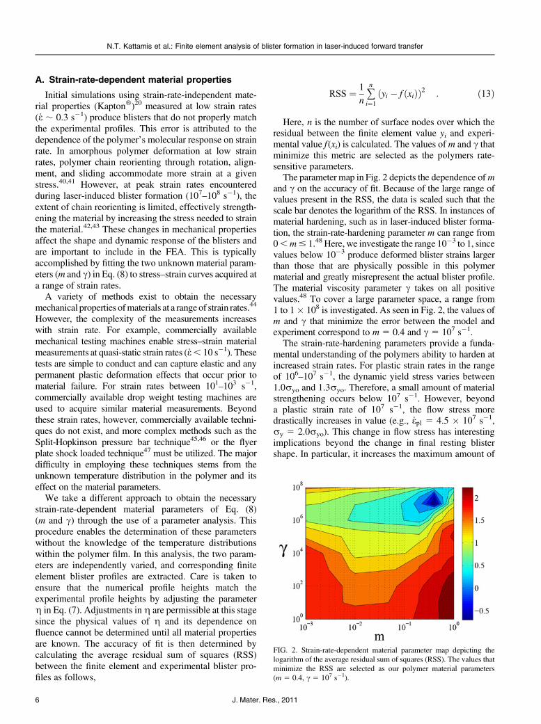
The parameter map in Fig. 2 depicts the dependence ofmand c on the accuracy of fit. Because of the large range ofvalues present in the RSS, the data is scaled such that thescale bar denotes the logarithm of the RSS. In instances ofmaterial hardening, such as in laser-induced blister forma-tion, the strain-rate-hardening parameter m can range from0,m# 1.48 Here, we investigate the range 10�3 to 1, sincevalues below 10�3 produce deformed blister strains largerthan those that are physically possible in this polymermaterial and greatly misrepresent the actual blister profile.The material viscosity parameter c takes on all positivevalues.48 To cover a large parameter space, a range from1 to 1� 108 is investigated. As seen in Fig. 2, the values ofm and c that minimize the error between the model andexperiment correspond to m 5 0.4 and c 5 107 s�1.
The strain-rate-hardening parameters provide a funda-mental understanding of the polymers ability to harden atincreased strain rates. For plastic strain rates in the rangeof 106–107 s�1, the dynamic yield stress varies between1.0ryo and 1.3ryo. Therefore, a small amount of materialstrengthening occurs below 107 s�1. However, beyonda plastic strain rate of 107 s�1, the flow stress moredrastically increases in value (e.g., _epl 5 4.5 � 107 s�1,ry 5 2.0ryo). This change in flow stress has interestingimplications beyond the change in final resting blistershape. In particular, it increases the maximum amount of
FIG. 2. Strain-rate-dependent material parameter map depicting thelogarithm of the average residual sum of squares (RSS). The values thatminimize the RSS are selected as our polymer material parameters(m 5 0.4, c 5 107 s�1).
N.T. Kattamis et al.: Finite element analysis of blister formation in laser-induced forward transfer
J. Mater. Res., 20116

stored elastic energy in the blister by increasing the yieldstress and yield strain of the polymer. This providesadditional blister overshoot beyond its equilibrium height,which contributes to the experimentally observable oscil-latory response. This dynamic behavior would be drasti-cally limited if an increase in stored elastic energy is notpresent since the modulus of resilience of polyimide isvirtually negligible at quasi-static strain rates.20
B. Conversion efficiency of laser energy topressure–volume work
To elucidate the fluence dependence of the parameterg, experiments are first carried out on a 7-lm polyimidefilm at a range of fluences (1.85–4.75 J/cm2). g values arethen selected in the FEA to ensure that numerical blisterheights match experimental blister heights at each fluence.Figure 3(a) depicts exact matches between finite elementblister heights and corresponding experimental blisters,verifying our correct selection of g. These values aredepicted in the figure.
Valuesofg versus laserfluence, as determined in Fig. 3(a),can now be plotted in Fig. 3(b). A trendline is added to guidethe eye. The fluence axis intercept (;0.8 J/cm2) correspondsto the minimum fluence needed to create an experimentally
detectable blister height and is in agreement with previouswork.16 This implies that any blister deformation that mayoccur at or below this fluence is dominated by elastic effects,which are recovered by the time an image is captured at500 ns. In addition, we observe an increase ingwith fluence.This increase is justifiable since at higher fluence, a smallerpercent of the deposited energy is consumed by latent heats.Therefore, a larger percentage of the energy is available tobe coupled into the blister gas. In addition, it is also wellestablished that during ablation confinement, an increase inthemean density of the gas occurs,49 whichmay contribute tothe increase ing and thus the amplification in laser absorptionby the gas.
A more rigorous explanation for the observed increasein g with fluence can be formulated from measurementson the ablation of polyimide. In the absence of opticalmeasurements during confined ablation, measurementsconsisting of plume transmission and reflection duringstandard ablation of polyimide must be interpreted. Re-flection measurements (k 5 248 nm) depict the levelingoff of the reflected pulse intensity beyond the ablationthreshold and up to 5 J/cm2, corresponding to a decreasein reflectivity at higher fluence.50 In addition, similar mea-surements (k 5 248 nm) at fluences between 1 and180 mJ/cm2 depict a truncation in reflected pulse widthand a similar reduction in amplitude at and beyond theablation fluence.51–53 Further measurements confirm thatthe scattering by the plume is not a predominant factor in theattenuation of the reflected radiation, pointing towardenhanced absorption by the ablated species as the probableattenuation mechanism.51 In a different approach, opticalmeasurements have been used to demonstrate a decrease intransmission through the ablation plume with increase influence.54,55 Therefore, since transmission through andreflection from the gas decreases, the absorption in thegas should increase with fluence. This suggests that theconversion efficiency of laser energy into thermal energy inthe gas should also display a similar increase.
The observed relationship in Fig. 3(b) should dependsolely on the laser/matter interaction, which includes laserwavelength, laser pulse length, and the optical, photo-chemical, and thermal properties of the material. There-fore, the conversion efficiency should be independent ofBA-LIFT process parameters. These parameters can in-clude film thickness, laser beam shape, and donor inkfluidic properties.
C. Model validation
1. g, c, and m for thinner film thickness
Determination of the fluence dependence of the pa-rameter g and strain-rate-dependent material parameters(m and c) sets the model’s remaining parameters and willenable future optimization of BA-LIFT. It is, however,necessary to ensure that the finite element model is
FIG. 3. (a) Profile comparison between experiments conducted ona 7-lm polyimide film and corresponding FEA. Values for the parameterg are selected to ensure a match in blister height at each fluence. Thesevalues are plotted against fluence in (b).
N.T. Kattamis et al.: Finite element analysis of blister formation in laser-induced forward transfer
7J. Mater. Res., 2011
validated against another set of experiments. The first stepin this process consists of ensuring that our calculation ofthe energy-conversion efficiency is accurate. This isaccomplished by either varying polymer film thicknessor laser beam shape and then by comparing modelpredictions to experimental data. Since polymer filmthickness is the more common process parameter variedto experimentally probe BA-LIFT,16 it is selected asa means for model validation.
BA-LIFT experiments are conducted to generate blisterson a 3-lm film at a range of fluences (1.37–2.86 J/cm2), andtheir profiles are compared to numerical blister profiles(3 lm) generated by extrapolating g values from thetrendline in Fig. 3(b). The numerical analysis is executedwithout any free parameters, since c, m, and g have beendetermined through the analyses outlined in previoussections (Table I). The numerical calculations are in goodagreement with the experiments (Fig. 4). As is apparent,only a slight deviation in height of a few percent existsbetween the model and experiment, confirming our calcu-lation of the conversion efficiency (g). The largest deviationin height (7%) occurs at the lowest fluence (1.37 J/cm2).This may be attributed to the uncertainty present inextrapolatingg values from the trendline [Fig. 3(b)] beyondthe experimental data set.
In addition to the model’s accurate prediction of height,the overall shapes of the numerical blister profiles are ingood agreement with the experimental blister profiles. Toquantify the accuracy in shape, the average RSS is cal-culated among profiles, yielding values between 0.49 and0.77. The logarithm of the range of these values (�0.31,�0.11) is very close to theminimumRSS depicted in Fig. 2,reaffirming our determination of strain-rate-dependentmaterial parameters (c and m). The parameter-free fit ofFig. 4 confirms that the numerical steady-state (500 ns)blister profiles match the experiments.
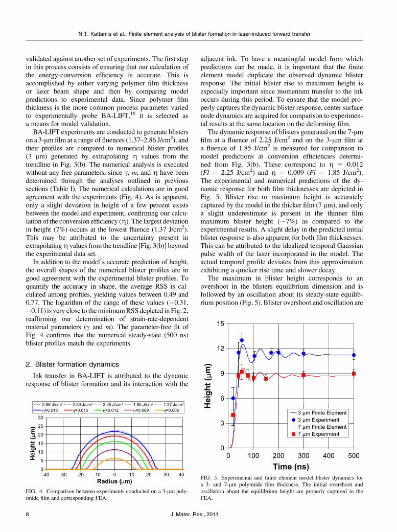
2. Blister formation dynamics
Ink transfer in BA-LIFT is attributed to the dynamicresponse of blister formation and its interaction with the
adjacent ink. To have a meaningful model from whichpredictions can be made, it is important that the finiteelement model duplicate the observed dynamic blisterresponse. The initial blister rise to maximum height isespecially important since momentum transfer to the inkoccurs during this period. To ensure that the model pro-perly captures the dynamic blister response, center surfacenode dynamics are acquired for comparison to experimen-tal results at the same location on the deforming film.
The dynamic response of blisters generated on the 7-lmfilm at a fluence of 2.25 J/cm2 and on the 3-lm film ata fluence of 1.85 J/cm2 is measured for comparison tomodel predictions at conversion efficiencies determi-ned from Fig. 3(b). These correspond to g 5 0.012(Fl 5 2.25 J/cm2) and g 5 0.009 (Fl 5 1.85 J/cm2).The experimental and numerical predictions of the dy-namic response for both film thicknesses are depicted inFig. 5. Blister rise to maximum height is accuratelycaptured by the model in the thicker film (7 lm), and onlya slight underestimate is present in the thinner filmmaximum blister height (;7%) as compared to theexperimental results. A slight delay in the predicted initialblister response is also apparent for both film thicknesses.This can be attributed to the idealized temporal Gaussianpulse width of the laser incorporated in the model. Theactual temporal profile deviates from this approximationexhibiting a quicker rise time and slower decay.
The maximum in blister height corresponds to anovershoot in the blisters equilibrium dimension and isfollowed by an oscillation about its steady-state equilib-rium position (Fig. 5). Blister overshoot and oscillation are
FIG. 4. Comparison between experiments conducted on a 3-lm poly-imide film and corresponding FEA.
FIG. 5. Experimental and finite element model blister dynamics fora 3- and 7-lm polyimide film thickness. The initial overshoot andoscillation about the equilibrium height are properly captured in theFEA.
N.T. Kattamis et al.: Finite element analysis of blister formation in laser-induced forward transfer
J. Mater. Res., 20118

possible through a combination of interface delaminationand an enhanced amount of stored elastic energy present athigh strain rates. The stretching and sliding of polymerchains remove kinetic energy from the system throughfrictional heating, producing the observable dampedblister response. Damped blister oscillations are properlycaptured by the model with a steady-state in blisterresponse reached at approximately 500 ns.
3. Conditions for blister rupture
The deposition of delicate materials such as organicmolecules and embryonic stem cells that are highlysusceptible to optical, thermal, and mechanical damagehas been demonstrated with BA-LIFT.11,17 This capabil-ity is attributed to the polymers large film thicknessrelative to the optical and thermal diffusion length andits capacity to deform to high strain without rupture,thereby maintaining a confined ablation process thateliminates the interaction of hot vapor with delicate inkmaterial. However, at sufficiently high laser fluences,blister rupture occurs, changing the mechanism for trans-fer16 and permitting hot ablated species to interact withand contaminate the ink material. Specifically, in previouswork we have demonstrated the occurrence of damage todelicate embryonic stem cells printed from rupturedblisters.17 To understand the conditions for safe transfer,it is necessary to gain a fundamental understanding of howblister rupture occurs and to be able to capture it within themodel. This will then enable meaningful BA-LIFT processparameter optimization in the finite element model prior toexperimentation.
To model blister rupture, a fundamental understandingof material failure is required. Rupture in highly ductilematerials, such as polyimide, is best modeled via strain-based failure theories.56 Because of the inherently com-plex distributions of normal and shear strains present in theblisters generated during BA-LIFT, the vonMises strain isinvestigated. It is given in its reduced form as,
ee ¼ 11þ m0
ffiffiffiffiffiffiffiffiffiffiffiffiffiffiffiffiffiffiffiffiffiffiffiffiffiffiffiffiffiffiffiffiffiffiffiffiffiffiffiffiffiffiffiffiffiffiffiffiffiffiffiffiffiffiffiffiffiffiffiffiffiffiffiffiffiffiffiffiffiffiffiffiffiffiffiffiffiffi12
ðe1 � e2Þ2 þ ðe2 � e3Þ2 þ ðe3 � e1Þ2h ir
;
ð14Þwhere ee is the equivalent von Mises strain, m9 is thematerial Poisson ratio for elastic strain and 0.5 for plasticstrain, and e1, e2, and e3 are the principle strains. Failure ispredicted to occur once the von Mises strain at regions ofthe model exceed the failure strain in uniaxial tension,56
given as 0.72 for this polymer.20
Blisters generated on a 3-lm film at fluences (2.59,3.00, 3.20 J/cm2) below and above the rupture fluence areused for model validation. These blisters are subsequentlysputter coated with 2 nm of iridium, and high-resolutionimages are captured by scanning electron microscopy
(SEM) with an in-lens detector. FEA is first carried outat g 5 0.015, corresponding to a subthreshold rupturefluence (2.59 J/cm2). Figure 6(b) shows the blister and itsassociated strain at 50 ns, while Fig. 6(d) shows the blisterat 60 ns. Blister film thickness is observed to decrease indimension in the top-center portion, indicative of a highlystrained region. This effect is better shown in the SEMcross section of Fig. 6(c), where the thickness of the centraldelaminated region is thinner than the edge region. Onemay expect that a maximum in blister strain would coincidewith the occurrence of maximum blister height and thuszero blister velocity, which occurs at 60 ns [Fig. 6(d)].However, this is not the case. Instead, a maximum in blisterstrain is observed to occur at 50 ns [Fig. 6(b)], prior tomaximum in blister height. This implies that the experi-mentally observed blister rupture at higher fluences mustoccur during the initial expansion process when the blisterstill has momentum.
Issues of blister rupture are shown in Fig. 7. Upon anincrease in laser fluence to 3.00 J/cm2, experimental blisterrupture is observed to occur [Fig. 7(a)]. The effects ofrapid propagation of a number of cracks originating fromsurface or internal microstructural defects are observed.To verify that the finite element model can predict whenthe material rupture strain in the blister is exceeded, the vonMises strain is again investigated. The analysis is conductedatg5 0.019, as determined from Fig. 3. Figure 7(c) depictsa maximum in strain occurring at 49 ns, prior to the max-imum in blister height. This figure shows a small volume,beginning at the outer surface of the blister and propagat-ing through the majority of the film thickness that has
FIG. 6. Image comparison for experiment (Fl5 2.59 J/cm2) and model(g 5 0.015). (a) Scanning electron microscopy (SEM) image of theresulting blister. (b) Maximum in predicted blister strain is observed at50 ns, and (c) the blister reaches its peak dimensions by 60 ns. Thinningof the film is observable in (b) and in (c). (d) SEM cross sectiondepicting blister thinning at the top.
N.T. Kattamis et al.: Finite element analysis of blister formation in laser-induced forward transfer
9J. Mater. Res., 2011

exceeded the failure strain (gray). An internal blisterpressure of 40.5 MPa, as calculated from Eq. (7), wouldhelp drive the fracture process through the weakened film.A continued increase in fluence to 3.20 J/cm2 producesa larger fractured blister, characterized by a fully openedtulip-like shape [Fig. 7(b)], and a correspondingly largerfinite element (g 5 0.021) volume that has exceeded thematerial failure strain [Fig. 7(d)]. The larger internalpressure at rupture, calculated as 42.6 MPa, supplies moreenergy to the fracture process, creating larger fracturesurfaces. In both cases, the release of hot pressurized gasescan contaminate and cause damage to delicate ink systemsand should be avoidedwhen sensitive inks are to be printed.
IV. CONCLUSIONS
In summary, this work presents an experimental andnumerical investigation of the initial stages of laser-inducedblister formation on a polyimide film. The polyimide filmis modeled in bonded contact with a glass substrate. Uponpulsed laser irradiation, a fraction of the incoming energy isadded to a gas enclosed at the bi-material interface. Theexpanding gas energizes the adjacent polymer film, leadingto deformation and delamination from the glass substratewith a rapidly expanding blister. Strain-rate-dependentmaterial parameters (m and c) are determined by fittingnumerical results to the experimental measurements for a7-lm-thick polyimide absorbing film layer, providinginsight into the mechanical behavior of this polymer at veryhigh strain rates. In addition, we estimate the parameterg bymatching equilibrium (500 ns) numerical blister heights to
experimental results to provide a measure of the confinedablation process. These parameters (m, c, and g), in con-junction with readily available material properties, encom-pass all quantities necessary to model the initial stages ofblister formation for an arbitrary polyimide film thicknessand laser beam shape.
To test the accuracy of our model, experiments arecarried out on a 3-lm-thick polyimide film, and thenumerical calculation exhibits proper blister size andshape using m, c, and g value measurements from theprevious 7-lm-thick film analysis. Blister dynamics aresubsequently investigated to ensure that the transfer ofmomentum from the blister to the adjacent ink is properlycaptured, and model predictions are shown to be inagreement with the experiments. In the high-laser-fluenceregime, blister rupture occurs and permits the escape ofhot ablated species and their interaction with ink material.This phenomenon is characterized by significant materialplasticity at the top portion of the blister, followed by rapidcrack propagation away from the overstrained region,producing tulip-like fracture geometry. A strain-basedfailure analysis is used to capture this phenomenon, andstrains in excess of the material failure strain are predictedfor experimental blisters that have ruptured. A maximumin strain is also shown to occur prior to a maximum inpredicted blister height, indicating that the experimentallyobserved blister rupture must occur while the blister is inmotion. This validated finite element model will enableboth BA-LIFT process parameter optimization prior toexperimentation and the design of new LIFT configura-tions that include DRLs sandwiched between the glassdonor and a highly elastic deformable polymer.
ACKNOWLEDGMENTS
This work was supported by the National ScienceFoundation (MRSEC Program) through the PrincetonCenter for Complex Materials (DMR 0819860), theNational Science Foundation (DMR-0548147), and theAir Force Office of Scientific Research (AFOSR-FA9550-08-1-0094).
REFERENCES
1. J. Bohandy, B.F. Kim, and F.J. Adrian: Metal deposition froma supported metal film using an excimer laser. J. Appl. Phys. 60,1538 (1986).
2. A. Piqué, D.B. Chrisey, R.C.Y. Auyeung, J. Fitz-Gerald, H.D. Wu,R.A. McGill, S. Lakeou, P.K. Wu, V. Nguyen, and M. Duignan:A novel laser transfer process for direct writing of electronic andsensor materials. Appl. Phys. A 69, 279 (1999).
3. A. Piqué, C.B. Arnold, H. Kim, M. Ollinger, and T.E. Sutto: Rapidprototyping of micropower sources by laser direct-write. Appl.Phys. A 79, 783 (2004).
4. C.B. Arnold, P. Serra, and A. Piqué: Laser direct-write techniquesfor printing of complex materials. MRS Bull. 32, 23 (2007).
FIG. 7. Blister rupture occurring at higher laser fluences. SEM images ofblister rupture at (a) 3.00 and (b) 3.20 J/cm2. Corresponding finite elementpredictions of blister strain at (c) 3.00 J/cm2 with g 5 0.019 and(d) 3.00 J/cm2 with g5 0.021. Increasing laser fluence results in a largervolume that is in excess of the material failure strain (gray).
N.T. Kattamis et al.: Finite element analysis of blister formation in laser-induced forward transfer
J. Mater. Res., 201110
5. D.A. Willis, and V. Grosu: Microdroplet deposition by laser-induced forward transfer. Appl. Phys. Lett. 86, 244103–1 (2005).
6. V. Schultze and M. Wagner: Blow-off of aluminium films.Appl. Phys., A Solids Surf. 53, 241 (1991).
7. M. Colina, M. Duocastella, J.M. Fernández-Pradas, P. Serra, andJ.L. Morenza: Laser-induced forward transfer of liquids: Study ofthe droplet ejection process. J. Appl. Phys. 99, 084909–1 (2006).
8. M. Colina, P. Serra, J.M. Fernández-Pradas, L. Sevilla, andJ.L. Morenza: DNA deposition through laser induced forwardtransfer. Biosens. Bioelectron. 20, 1638 (2005).
9. J.M. Fitz-Gerald, A. Piqué, D.B. Chrisey, P.D. Rack, M. Zeleznik,R.C.Y. Auyeung, and S. Lakeou: Laser direct writing of phosphorscreens for high-definition displays. Appl. Phys. Lett. 76, 1386 (2000).
10. M. Brown, N. Kattamis, and C. Arnold: Time-resolved dynamics oflaser-induced micro-jets from thin liquid films. Microfluid. Nano-fluid. 11, 199 (2011).
11. N.T. Kattamis, N.D. McDaniel, S. Bernhard, and C.B. Arnold:Laser direct write printing of sensitive and robust light emittingorganic molecules. Appl. Phys. Lett. 94, 103306–1 (2009).
12. R. Fardel, M. Nagel, F. Nüesch, T. Lippert, and A. Wokaun:Fabrication of organic light-emitting diode pixels by laser-assistedforward transfer. Appl. Phys. Lett. 91, 061103–1 (2007).
13. J. Xu, J. Liu, D. Cui, M. Gerhold, A.Y. Wang, M. Nagel, andT.K. Lippert: Laser-assisted forward transfer of multi-spectralnanocrystal quantum dot emitters. Nanotechnology 18, 025403–1(2007).
14. S.H. Ko, H. Pan, S.G. Ryu, N. Misra, C.P. Grigoropoulos, andH.K. Park: Nanomaterial enabled laser transfer for organic lightemitting material direct writing. Appl. Phys. Lett. 93, 151110–1(2008).
15. A.J. Birnbaum, K. Heungsoo, N.A. Charipar, and A. Piqué: Laserprinting of multi-layered polymer/metal heterostructures for elec-tronic and MEMS devices. Appl. Phys. A 99, 711 (2010).
16. M.S. Brown, N.T. Kattamis, and C.B. Arnold: Time-resolved studyof polyimide absorption layers for blister-actuated laser-inducedforward transfer. J. Appl. Phys. 107, 083103–1 (2010).
17. N.T. Kattamis, P.E. Purnick, R. Weiss, and C.B. Arnold: Thick filmlaser induced forward transfer for deposition of thermally andmechanically sensitive materials. Appl. Phys. Lett. 91, 171120–1(2007).
18. N.T. Kattamis, N.D. McDaniel, S. Bernhard, and C.B. Arnold:Ambient laser direct-write printing of a patterned organo-metallicelectroluminescent device. Org. Electron. 12, 7 (2011).
19. S. Moaveni: Finite Element Analysis: Theory and Application withAnsys, 3rd ed. (Prentice Hall, Upper Saddle River, NJ, 2007).
20. Dupont, Kapton Polyimide Film Product Information, p. 3.21. A. Mostofi: The incorporation of damping in lumped-parameter
modelling techniques: Proceedings of the Institution of MechanicalEngineers, Part K. J. Multi-Body Dynam. 213, 11 (1999).
22. G.B. Warburton: The Dynamic Behaviour of Structures, 2nd ed.(Pergamon Press, Oxford/New York, 1976).
23. E.L. Wilson and J. Penzien: Evaluation of orthogonal dampingmatrices. Int. J. Numer. Methods Eng. 4, 5 (1972).
24. J.F. Hall: Problems encountered from the use (or misuse) ofRayleigh damping. Earthquake Eng. Struct. Dynam. 35, 525(2006).
25. J.H. Brannon, J.R. Lankard, A.I. Baise, F. Burns, andJ. Kaufman: Excimer laser etching of polyimide. J. Appl. Phys.58, 2036 (1985).
26. S. Küper, J. Brannon, and K. Brannon: Threshold behavior inpolyimide photoablation: Single-shot rate measurements andsurface-temperature modeling. Appl. Phys., A Solids Surf. 56, 43(1993).
27. D.C. Drucker and W. Prager: Soil mechanics and plastic analysisfor limit design. Q. Appl. Math. 10, 157 (1952).
28. D. Peirce, C.F. Shih, and A. Needleman: A tangent modulusmethod for rate dependent solids. Comput. Struct. 18, 875 (1984).
29. R. Krüger, M. König, and T. Schneider: Computation of localenergy release rates along straight and curved delamination frontsof unidirectionally laminated DCB and ENF specimens, inProceedings of the 34th AIAA/ASME/ASCE/AHS/ASC SSDM Con-ference, 1332 (1993).
30. T.K. Hellen: On the method of virtual crack extensions.Int. J. Numer. Methods Eng. 9, 187 (1975).
31. D.M. Parks: The virtual crack extension method for non-linear material behavior. Comput. Meth. Appl. Mech. Eng. 12,353 (1977).
32. F.Z. Li, C.F. Shih, and A. Needleman: A comparison of methodsfor calculating energy release rates. Eng. Fract. Mech. 21, 405(1985).
33. B. Moran and C.F. Shih: Crack tip and associated domain integralsfrom momentum and energy balance. Eng. Fract. Mech. 27, 615(1987).
34. E.F. Rybicki and M.F. Kanninen: A finite element calculation ofstress intensity factors by a modified crack closure integral. Eng.Fract. Mech. 9, 931 (1977).
35. K.N. Shivakumar, P.W. Tan, and J.C. Newman Jr.: A virtual crack-closure technique for calculating stress intensity factors for crackedthree dimensional bodies. Int. J. Fract. 36, R43 (1988).
36. R. Krueger: Virtual crack closure technique: History, approach, andapplications. Appl. Mech. Rev. 57, 109 (2004).
37. L.P. Buchwalter and R.H. Lacombe: Adhesion of polyimide tofluorine-contaminated SiO2 surface. Effect of aminopropyltriethox-ysilane on the adhesion. J. Adhes. Sci. Technol. 5, 449 (1991).
38. L.P. Buchwalter, T.S. Oh, and J. Kim: Adhesion of polyimides toceramics. Effects of aminopropyltriethoxysilane and temperatureand humidity exposure on adhesion. J. Adhes. Sci. Technol. 5, 333(1991).
39. K.L. Mittal: Adhesion Measurement of Films and Coatings:Relative Adhesion Measurement for Thin Film MicroelectronicStructures. Part II, Vol. 2 (VSP, Boston, 2001), p. 26.
40. W.D. Calister:Material Science and Engineering: An Introduction,7th edition. (Wiley, New York, 2007).
41. R.W. Hertzberg: Deformation and Fracture Mechanisms of Engi-neering Materials, 4th ed. (John Wiley & Sons, Inc., New York,1996), p. 225.
42. A.S. Argon: Theory for the low-temperature plastic deformation ofglassy polymers. Philos. Mag. 28, 839 (1973).
43. M.C. Boyce, D.M. Parks, and A.S. Argon: Large inelastic de-formation of glassy polymers. part I: Rate dependent constitutivemodel. Mech. Mater. 7, 15 (1988).
44. J.E. Field, S.M. Walley, W.G. Proud, H.T. Goldrein, andC.R. Siviour: Review of experimental techniques for high ratedeformation and shock studies. Int. J. Impact Eng. 30, 725 (2004).
45. E.O.W.J. Harding and J.D. Campbell: Tensile testing of materials athigh impact rates of strain. J. Mech. Eng. Sci. 2, 88 (1960).
46. B.A. Hopkinson: A method of measuring the pressure produced inthe detonation of high explosives or by the impact of bullets. Philos.Trans. R. Soc. London, Ser. A 213, 437 (1914).
47. G.T. Gray: ASM Handbook Mechanical Testing and Evaluation:Shock Wave Testing of Ductile Materials, Vol. 8 (ASM Interna-tional, Materials Park, OH, 2000), p. 530.
48. P. Perzyna: Advances in Applied Mechanics: Fundamental Problemsin Viscoplasticity, Vol. 9 (Academic Press, NewYork, 1966), p. 243.
49. R. Fabbro, J. Fournier, P. Ballard, D. Devaux, and J. Virmont:Physical study of laser-produced plasma in confined geometry.J. Appl. Phys. 68, 775 (1990).
50. G. Paraskevopoulos, D.L. Singleton, R.S. Irwin, and R.S. Taylor:Time-resolved reflectivity as a probe of the dynamics of laserablation of organic polymers. J. Appl. Phys. 70, 1938 (1991).
N.T. Kattamis et al.: Finite element analysis of blister formation in laser-induced forward transfer
11J. Mater. Res., 2011
51. M.N. Ediger and G.H. Pettit: Time-resolved reflectivity of ArFlaser-irradiated polyimide. J. Appl. Phys. 71, 3510 (1992).
52. D.L. Singleton, G. Paraskevopoulos, and R.S. Taylor: Dynamicsof excimer laser ablation of polyimide determined by time-resolvedreflectivity. Appl. Phys., B Photophys. Laser Chem. 50, 227 (1990).
53. G.H. Pettit, M.N. Ediger, D.W. Hahn, B.E. Brinson, andR. Sauerbrey: Transmission of polyimide during pulsed ultravioletlaser irradiation. Appl. Phys., A Solids Surf. 58, 573 (1994).
54. H. Schmidt, J. Ihlemann, B. Wolff-Rottke, K. Luther, and J. Troe:Ultraviolet laser ablation of polymers: Spot size, pulse duration, andplume attenuation effects explained. J. Appl. Phys. 83, 5458 (1998).
55. G. Koren: Temporal measurements of photofragment attenuation at248 nm in the laser ablation of polyimide in air. Appl. Phys. Lett. 50,1030 (1987).
56. A.F. Bower: Applied Mechanics of Solids (CRC Press, New York,2010), p. 553.
N.T. Kattamis et al.: Finite element analysis of blister formation in laser-induced forward transfer
J. Mater. Res., 201112