artisan technology group is your source for quality … › info ›...
TRANSCRIPT

Artisan Technology Group is your source for quality new and certified-used/pre-owned equipment
• FAST SHIPPING AND DELIVERY
• TENS OF THOUSANDS OF IN-STOCK ITEMS
• EQUIPMENT DEMOS
• HUNDREDS OF MANUFACTURERS SUPPORTED
• LEASING/MONTHLY RENTALS
• ITAR CERTIFIED SECURE ASSET SOLUTIONS
SERVICE CENTER REPAIRSExperienced engineers and technicians on staff at our full-service, in-house repair center
WE BUY USED EQUIPMENTSell your excess, underutilized, and idle used equipment We also offer credit for buy-backs and trade-inswww.artisantg.com/WeBuyEquipment
REMOTE INSPECTIONRemotely inspect equipment before purchasing with our interactive website at www.instraview.com
LOOKING FOR MORE INFORMATION? Visit us on the web at www.artisantg.com for more information on price quotations, drivers, technical specifications, manuals, and documentation
Contact us: (888) 88-SOURCE | [email protected] | www.artisantg.com
SMViewInstra
SERVICE MANUAL
Multiskan RC/MS/EX
Thermo Electron Corporation, Ratastie 2, P.O.Box 100, 01621 Vantaa, FinlandTelefax +358-9-32910 409, Tel. +358-9-329 100
280 6100
Artisan Technology Group - Quality Instrumentation ... Guaranteed | (888) 88-SOURCE | www.artisantg.com
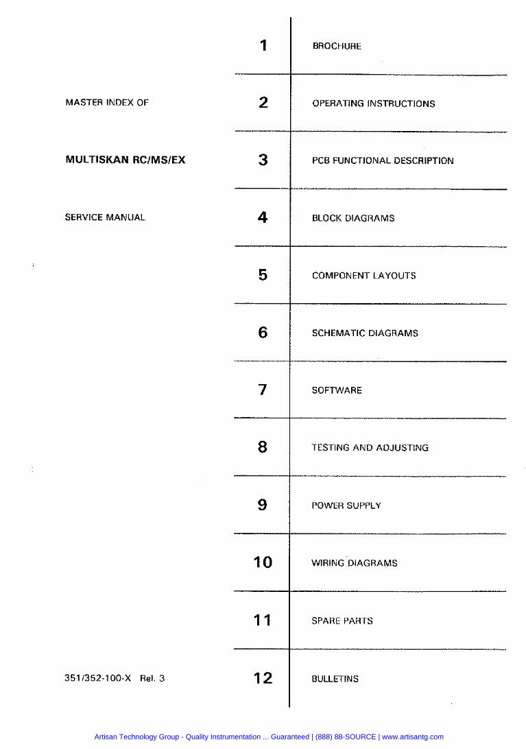
MASTER INDEX OF
MULTISKAN RCIMSIEX
SERVICE MANUAL
BROCHURE
OPERATING INSTRUCTIONS
PCB FUNCTIONAL DESCRIPTION
BLOCK DIAGRAMS
COMPONENT LAYOUTS
SCHEMATIC DIAGRAMS
SOFTWARE
TESTING AND ADJUSTING
POWER SUPPLY
WIRING DIAGRAMS
SPARE PARTS
BULLETINS
Artisan Technology Group - Quality Instrumentation ... Guaranteed | (888) 88-SOURCE | www.artisantg.com
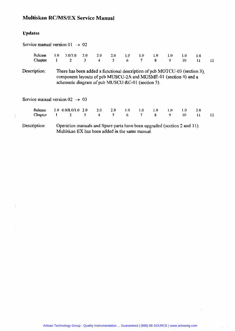
Multiskan RC/MS/EX Service Manual
Updates
Service manual version 01 -+ 02
Release 1.0 3.013.0 2.0 2.0 2.0 1.0 1.0 1.0 1.0 1.0 1.0 Chapter 1 2 3 4 5 6 7 8 9 10 I I 12
Description: There has been added a hnctional description of pcb MOTCU-03 (section 3), component layouts of pcb MUSCU-2A and MUSME-01 (section 4) and a schematic diagram of pcb MUSCU-RC-01 (section 5).
Service manual version 02 -+ 03
Release 1.06.0/8.0/1.0 2.0 2.0 2.0 1.0 1.0 1.0 1.0 1.0 2.0 Chapter 1 2 3 4 5 6 7 8 9 10 11 12
Description: Operation manuals and Spare parts have been upgraded (section 2 and 1 I). Multiskan EX has been added in the same manual.
Artisan Technology Group - Quality Instrumentation ... Guaranteed | (888) 88-SOURCE | www.artisantg.com
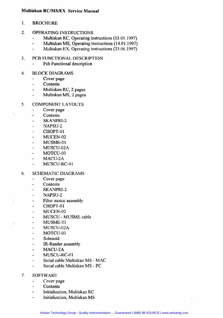
Multiskan RC/MS/EX Sewice Manual
BROCHURE
OPERATING INSTRUCTIONS - Multiskan RC, Operating instructions (03.01.1997) - Multiskan MS, Operating instructions (14.01.1997) - Multiskan EX, Operating instructions (25.06.1997)
PCB FUNCTIONAL DESCRIPTION - Pcb Functional description
BLOCK DIAGRAMS - Cover page - Contents - Multiskan RC, 2 pages - Multiskan MS, 2 pages
COMPONENT LAYOUTS - Cover page - Contents - SKANPRI-2 - NAPSU-2 - CHOPT-01 - MUCEN-02 - MUSME-01 - MUSCU-02A - MOTCU-03 - MACU-2A - MUSCU-RC-01
SCHEMATIC DIAGRAMS - Cover page - Contents - SKANPIU-2 - NAPSU-2 - Filter motor assembly - CHOPT-01 - MUCEN-02 - MUSCU - MUSME cable - MUSME-01 - MUSCU-02A - MOTCU-03 - Solenoid - IR-Reader assembly - MACU-2A - MUSCU-RC-01 - Serial cable Multiskan MS - MAC - Serial cable Multiskan MS - PC
SOFTWARE - Cover page - Contents - Initialization, Multiskan RC - Initialization, Multiskan MS
Artisan Technology Group - Quality Instrumentation ... Guaranteed | (888) 88-SOURCE | www.artisantg.com

8. TESTING AND ADJUSTING - Cover page - Contents - Lamp voltage - Comvuter Control Commands in All Modules - ~ e s t k g and Adjusting for Multiskan RC - Testing and Adjusting for Multiskan MS
9. POWERSUPPLY - Cover page - Contents - SR 924199 Parts layout, 2 pages - SR 924100 Schematic diagram
10. WIRING DIAGRAMS Cover page Contents Track cover grounding wire Power cable Filter motor cable Fan assembly LCD display Lamp cable CHOPT - Power CHOPT - MIJSCU CHOPT -motor MUSCU - MUSME Track motor grounding wire Solenoid IR-Reader assembly Hall sensor assembly Grounding wire Serial cable Multiskan MS - MAC Serial cable Multiskan MS - PC Grounding wire Grounding wire RS-232C Serial cable PC Serial cable MAC
1 1. SPARE PARTS - Multiskan RCIMSIEX Spare part list
12. BULLETINS
Artisan Technology Group - Quality Instrumentation ... Guaranteed | (888) 88-SOURCE | www.artisantg.com
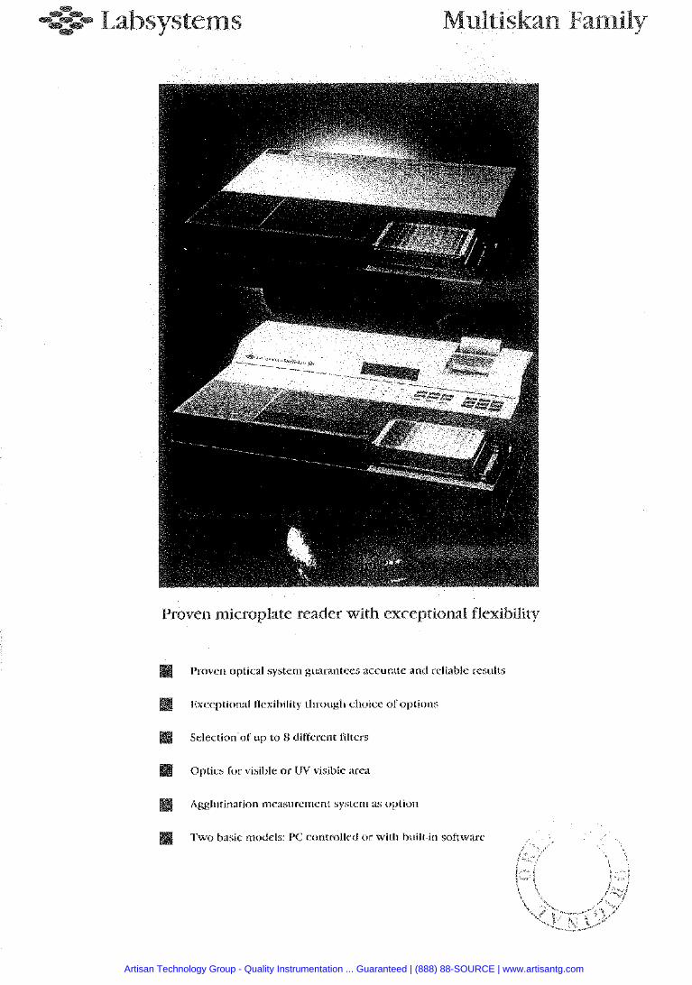
Proven microplate reader with exceptional flexibiliry
[bB Proven optic:il system guarantees accurate and rcliable results
Exception;il flcxihilily thn)iigh choice ofoptiotis
Selection of up to 8 different lilters
Optics [or visible or I1V visihlc arca
a Agglutin:ttion nieasurenient system 2s option
Two hasic models: PC contsolled or with built-in software
Artisan Technology Group - Quality Instrumentation ... Guaranteed | (888) 88-SOURCE | www.artisantg.com
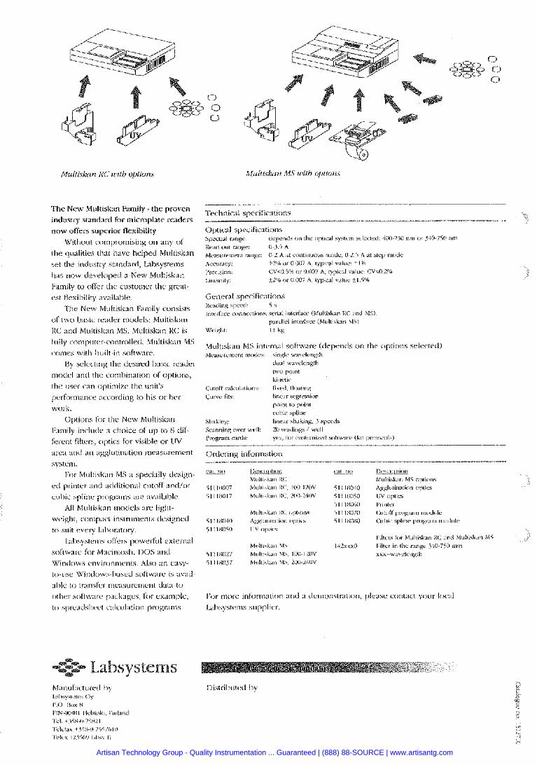
The New Multiskan Family - the provcn Technical spccifiarlions
~ ~ industry standard for microplate readers
now oifers supcrior flexibility Optical specifimtions
Wirhont wmpromising on any o f *p"""l r"nge ilcpends on the optcrl syhtcin dccrcd 100-75C nrn o r )iIlb7Vi i im
Krldk,", ranxc: 114 5 A the q w l i t i e tlxrt have helped Multiskan ~ ~ ~ ~ ~ , ~ ~ ~ ~ ~ ~ , t nnli.c: (1-2 A r r coniinimus mode. 0-2.5 A st s e n nrixic set the indusrrv stmdarcl, 1;absvstems Accoiac~: ~ 2 % or t) 007 A, cypicat V ; ~ I C ~ ~ . i l ' m
has now devclopeci a Ncw Multiskan '"""'"": CVcO5"h ooi UlW7 A, ryps:d v.$lue. CVa1.2% l.inc?rity: ti% oillo07 A, lypicrl v;iluc + I S M
Family to oftkr the customer the great-
cst flexibility :rv:iillhle.
The New Multiskan Fanlily consists
d t w r , l,asic r a d e r models: Muliisknrr
IK mil Multiskan MS. Multis1t:ln RC is
fully comp~itel--rontr<)llerl. Multiskan MS
rrmcs with 1,uilt-in software.
t3y selecting the dcsircd Ik~sic redder
rnodcl :ind the crmbinatkm o i options,
the user c:m <,ptimize the unit's
perfrx~natice according to his or her
work. Options for rlie Ncw Multisknn
I::imily include :I cl~oice oC up to K dif-
ferent filters. oplics fix visil~le or in/
area and ;in :tgglutin'ation measurcmcnt
system
For Multisk:m MS ;I specially drsign-
ed primer :~nd :iddition;~l ct~toff :ind/or
wl,ic spline progr:ims ;IK :iv;iil;ll,lc.
All Multiskm t~loilels ;ire light-
weight, ctm,p:icr instl-~imcnls ilcsigncd
to suit every i:ilwr:itory I.;hsyten~b oilers powerful cxtcrnal
soI'cw:irc for M:~cintoslr. 1)OS end
Ordering information
-1 1,e..c,iji,""'
b1~cI~i~h:m Ill: 51 1 lHliO7 M u h k . ~ I!<:, IOUI~OV 51 1 IHli17 MU/<I&.III IlC. 2lIlI-L4llV
&W --- l I e , c , # ~
hliillirk;tn MS ojilimr i l I lHiM0 Ag#l~$~irutkm optics 51 I IHOiO I IV <>pic> 51 I IHO(*i I'linirr i l l i X O 7 0 C,,li,l'i linlgrnie .arlolc 51 1 IHOHO Cc#l,ic s~,iiilc ~pnqv:un #~IMUIC
Artisan Technology Group - Quality Instrumentation ... Guaranteed | (888) 88-SOURCE | www.artisantg.com
Information in this manual i s subject to change without prior notice.
Cat. no 1506250
Artisan Technology Group - Quality Instrumentation ... Guaranteed | (888) 88-SOURCE | www.artisantg.com
LABSYSTEMS W T I
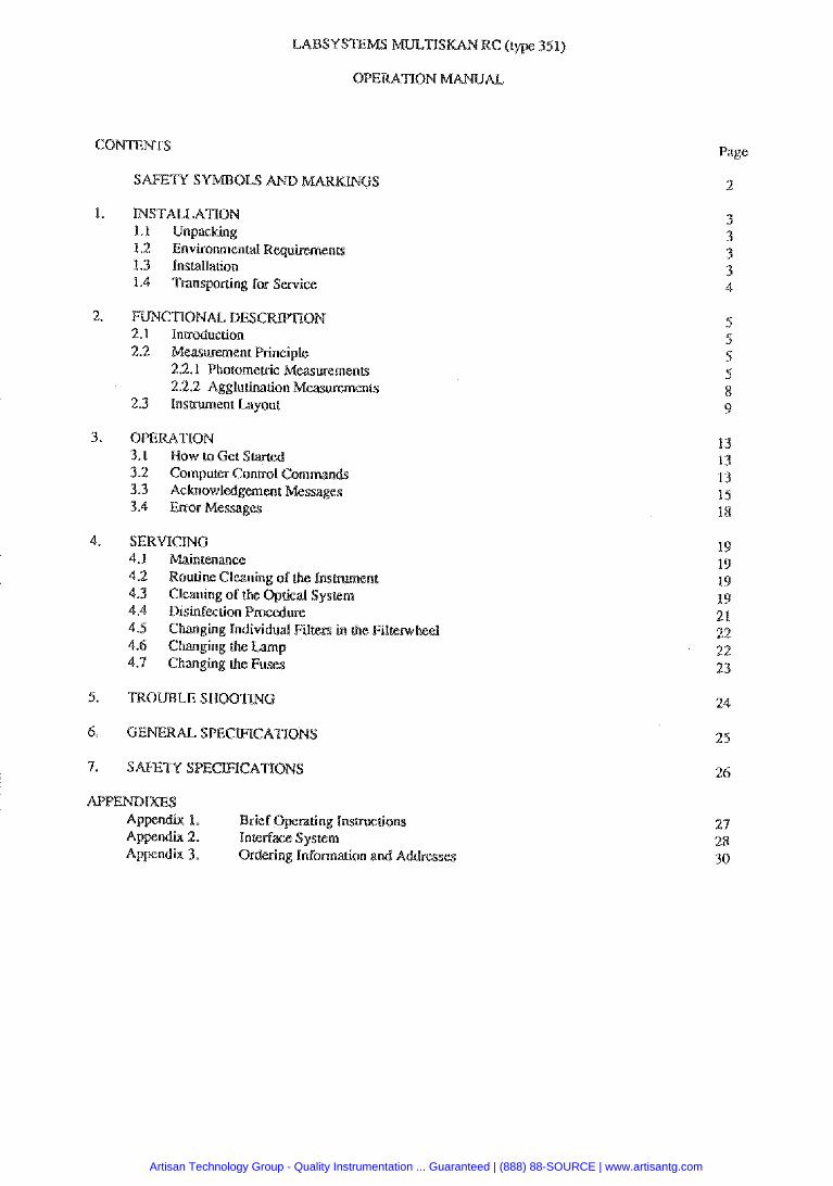
CONTENTS
SAFETY SYMBOLS GS
I. LPISTALLATION 1.1 Unpacking 1.2 EnvironmenW RequiremenLs 1.3 Installation 1.4 Transporting for Service
2. FUNCTIONAL DESCR 2.1 Inuoduction 2.2 Measurement Rinciple
2.2.1 Photometric Measwemen@ 2.2.2 Agglurination Measuremenu
2.3 Insnunlent Layout
3. OPERATION 3.1 Now to G e t s 1.2 Computer Control Commands 3.3 Achowledgemenc Messages 3.4 &or Messages
4. SERVTCLNC 4.1 Maintenance 4.2 Routine Cleaning of the Insbrument 4.3 Cleaning of the Optical Syswm 4.4 Disinfection
4.7 Changing &e
APPEND Ap 1. Appendix 2. Appendix 3. Ordering Infomarion and Addresses
Page
2
Artisan Technology Group - Quality Instrumentation ... Guaranteed | (888) 88-SOURCE | www.artisantg.com

0 Power OFF
Caution, risk of personal injmy to Lhe operator o ~ . a safety hazard for the smoundmg
Caution, risk ge to the inshumene, othgr eg~bipnrent m loss of function in a application.
Artisan Technology Group - Quality Instrumentation ... Guaranteed | (888) 88-SOURCE | www.artisantg.com
@ RC carefully and checkPor any age that may havebcen cauM during rrans part is damaged or missing. contact the local Labsystems represenlative.
Keep the original package for future mspamrion.
XC to avoid exposure to excess dust, vibrations. strong magnetic fields, disecr sunlight, draft, excessive moisture OK large ternpr;tlwe Ructuations.
Leave sufficient clearance (10 cm) at both sides of the unit for adquace air circularion.
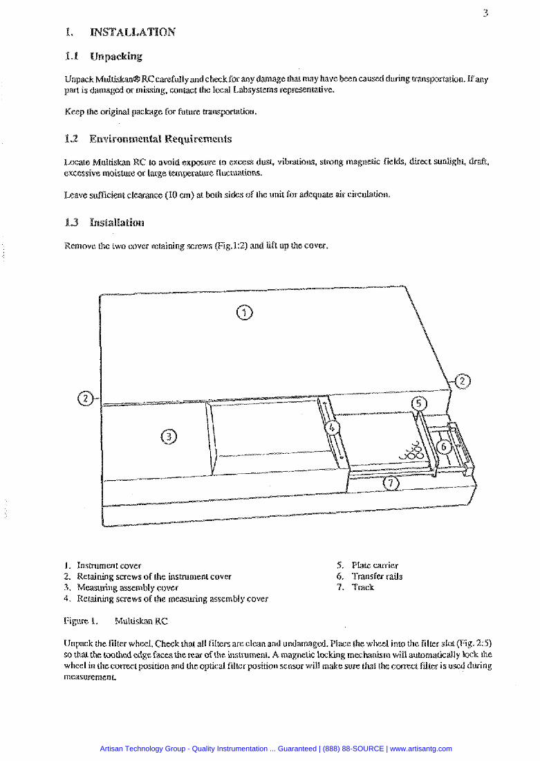
Remove the two cover relairing screws (Fig.12) and ljft up the cover.
1. lnsburnent cover 2. Retaining screws of the insmment cover 3. Measuring assembly cover 4. Reraining screws of the measwing assembly cover
5. Plale carrier 6. Transfa mils 9. Track
Figure 1. Multiskan RC
Unpack the filter wheel. Chwk thar all films are c l a n and undamaged. P l x 1 inla the f i ler slo( (Fig. 2 5 ) so that the toothed edge faces the rear of h e insvurnent. A magnetic locking m will automarically lack the wheel in thccomecc position and h e optical filter position sensor will rn measuaemenl
Artisan Technology Group - Quality Instrumentation ... Guaranteed | (888) 88-SOURCE | www.artisantg.com
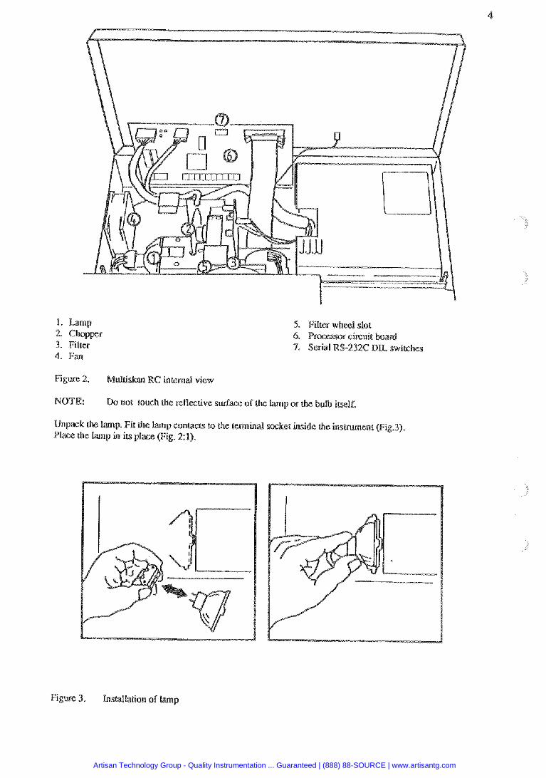
1 . Lamp 2. Chopper 3. Filter 4. Fan
5. Film whecl slot 6. ssor ckuit 7. Serial RS-232C D L switches
Figure 2. Multiskan RC internal view
NOTE: Do not toush the reflacrive surface oh the Lamp or the bulb i k l f ,
Unpack the lamp. Fit the lamp contacts to the terminal socket inside the insmment (Fiy.3). Place the lamp in its place (Fig. 21).
Figure 3. Inscallation of lamp
Artisan Technology Group - Quality Instrumentation ... Guaranteed | (888) 88-SOURCE | www.artisantg.com
Check visually has there are no loose inside the insmment.
Close rhe insmment cover md replace the reraining screws.
Multiskan RCdoes not preduce operatkg noiseaia level which wuld cause8 hazard. Nosound level measlaemenrs m needed after insrallation.
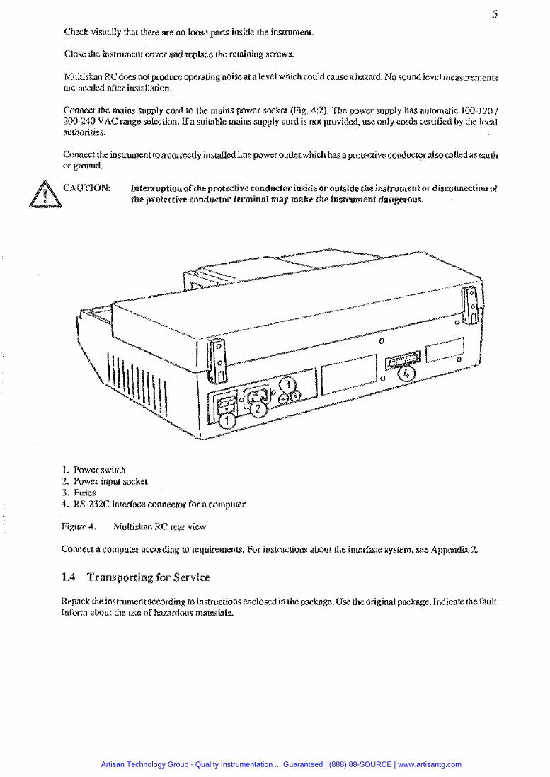
Connect the mains supply cord tv the mains power socket Fig. 42). The power supply has automatic 1WI20 / 200-240 VAC range selection. If a suitable rnains supply cord i s not provided, use only cords certified by rhe i d authorities.
Connect the insmment to acomecdy instaltcd IinepowerouUei which hasaprowtiveconductoralsocdled as earth or ground.
CAUTION: Interruption of the protec6ve eon uclor inside or oueide the i enlor disconnection of the protective conductor terminal may make the instru
1. Power switch 2. Power input socket 3. Fuses
nnectoc for a computer
Comect a cornpurer accordin uiamenu. For instructions about the inkdace sysern.
Repack the instrument according la insuuctionsenclod in Lhc package. Use the original pac ge. India& the fault. Inform about the use of
Artisan Technology Group - Quality Instrumentation ... Guaranteed | (888) 88-SOURCE | www.artisantg.com

Mulliskan RC is m eiat-channel vertical light path filar photom%terdesigned to perform bath stm and agglutination measuremenu under the conml of a computer.
The wavelength (400 - 750 nm or optional 340 - 450 nm) is seler. using maximum eight high qualiky intedercnce filters held in a filter wheel.
The readings can be processed via a serial RS-242C interface.
2.2.1 Photometric
Mult imRCuti l iza theoriginallabsystemskonceptofverlic2il phommew in which the hghtbeam passes through he whole sample.
In vertical photomeQ, the absorption of light is pmporaional to the amount of light absorbing substance in the well
Absorption is expressed by \he following equation:
whem A = absorbance, a = molar absorptivity of the substance, m = mass of absorbing substance and S = cross- sectional aaea pergendicular to the light pa&.
The advanages of (he venial tight path measurcmms. are:
(I) inaccurate pigetling of nonabsorbing liquids does not alfec.6 Lhe measu absorbance values
(2) evapmtion of nonabsorbing tiqlaids duping the cion d m not d f a r ahsohank values and
(4) acemhdegreeof inhomage ityin ~solution.forexampleasarcsultoflayering in turbidity nwaurernenrs. does not affect (he results.
Artisan Technology Group - Quality Instrumentation ... Guaranteed | (888) 88-SOURCE | www.artisantg.com
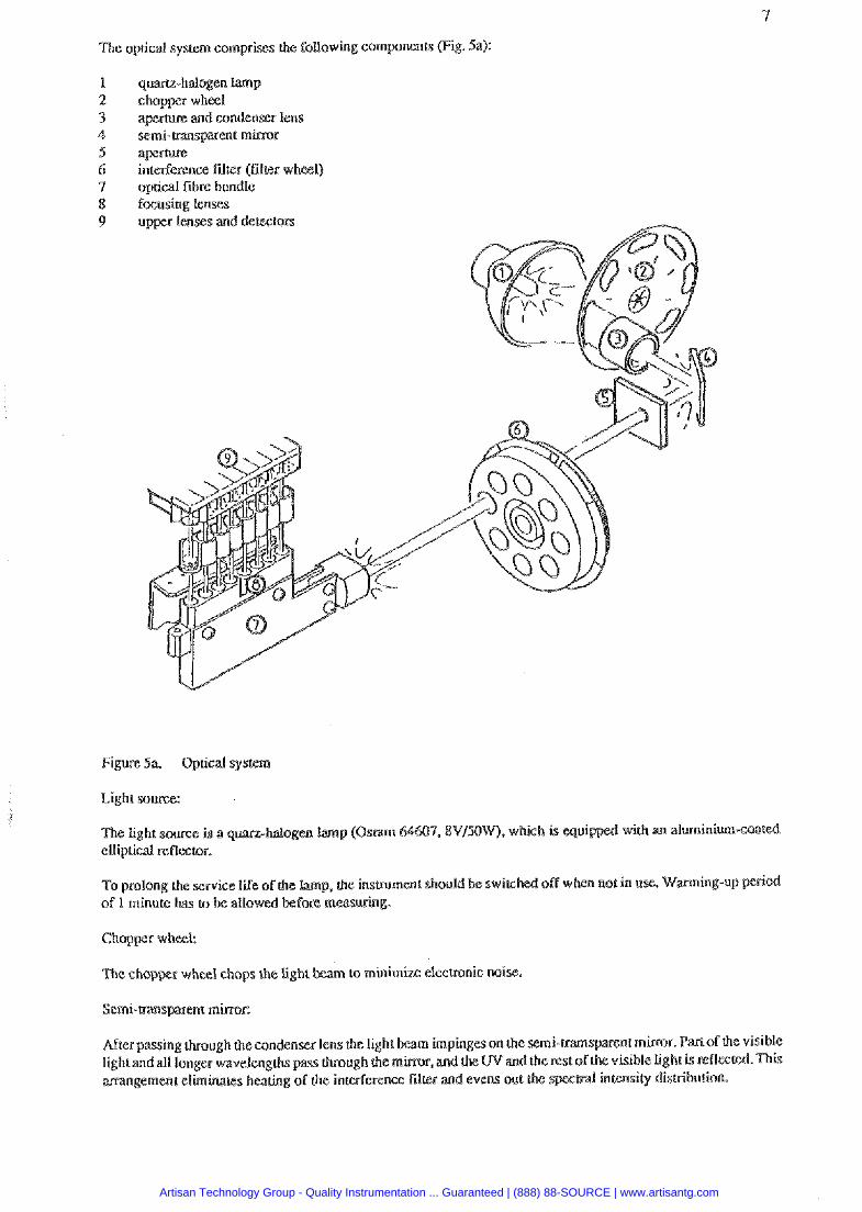
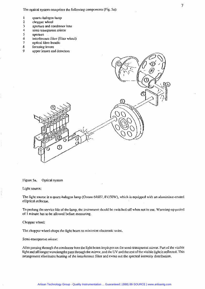
The optical system comprises h e following componenrs (Fig. 5a):
1 quartz-halogen lamp 2 chopper wheel 3 a p e m e and condenser lens 4 semi-mnsparenr mirror 5 a p e m e 6 inteplerenffi filter (filler wheel) 7 optical fibre bundle 8 focusing lenses 9 upper lenses and detectors
Figure 5a. Optical system
Light source:
To prolong the service life of the lamp, &e hsuumenl should of 1 minute has IO be allowed before measuring.
Chopper wheel:
Thc chopper wheel chops the light lo minimize elecmnic noise.
After passing through h e condenwr lens the light aenr mirror. Bartofthe visible light and aU longer wavelengths pass lhrough the visible tight kreflec arrangement eliminates hearing of the interferen tensity Bisuibucion.
Artisan Technology Group - Quality Instrumentation ... Guaranteed | (888) 88-SOURCE | www.artisantg.com
The wavelength is selec born (he maximrun of eight filters held in the filter wheel.
Fibre bundte:
ter, thelight thecommon endof the fibre bundle, whichdivides s and defles upwapds.
Focusing lenses:
After being divided the light passes through a focusing system of eight lenses.
Detectors:
The light kams pass through the bouoms of the wells though the samples via up r lenses to the Bemtom, w h ~ h measure the intensity of lighr,
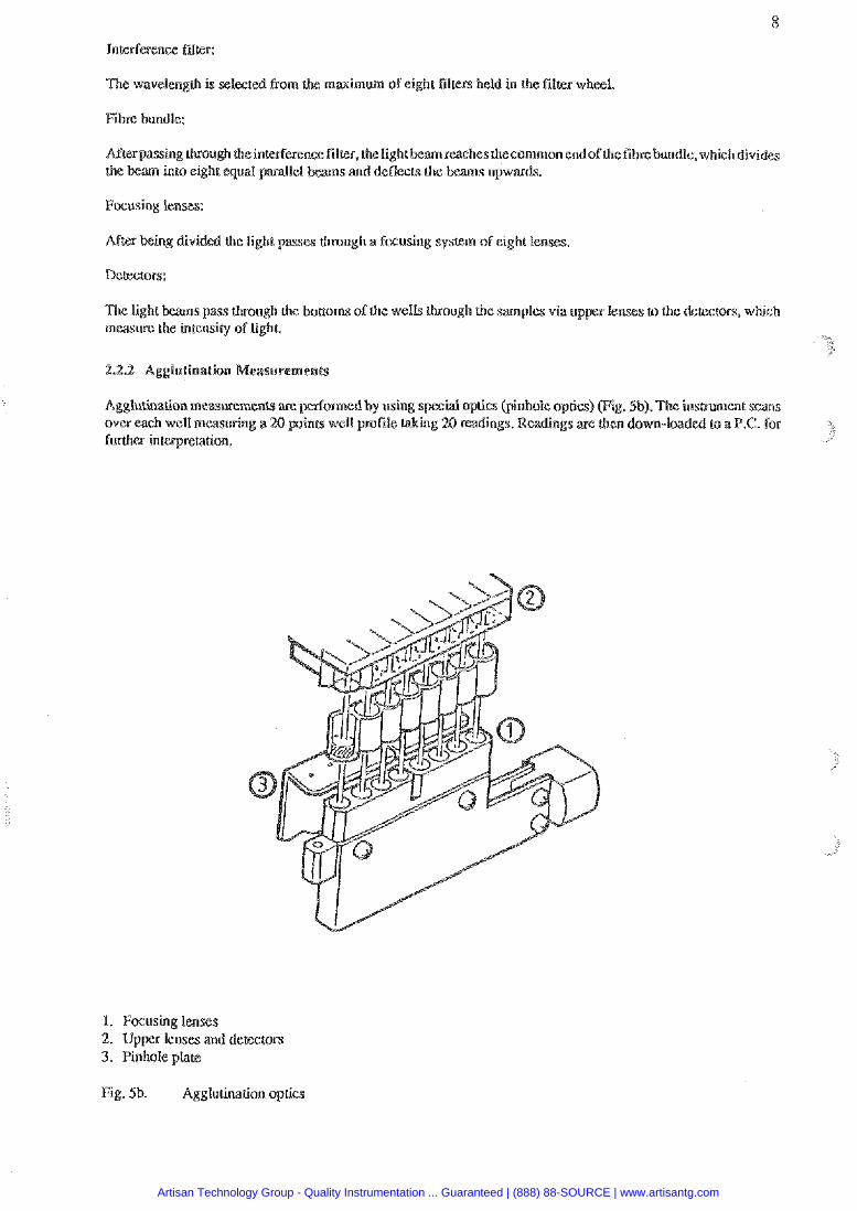
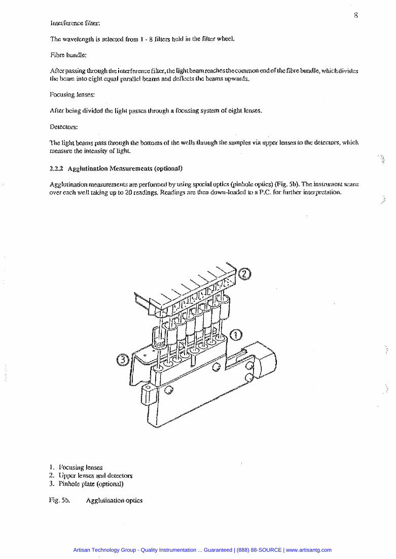
2.2.2 Agglutination
Agglulination measmemenu are rmedby using special optics (pinhole optics) (Fig. Sb). Tke insmunent scms over each well measuring a 29 p i n u well pmfile taking 20 readings. Readings are then down-loaded to a PC. for f d i e ~ interpre&tion.
I. Focusing lenses 2. Upper lenses and dececmrs 3. Pinhole plate
Fig. Sb. Agglutination optics
Artisan Technology Group - Quality Instrumentation ... Guaranteed | (888) 88-SOURCE | www.artisantg.com
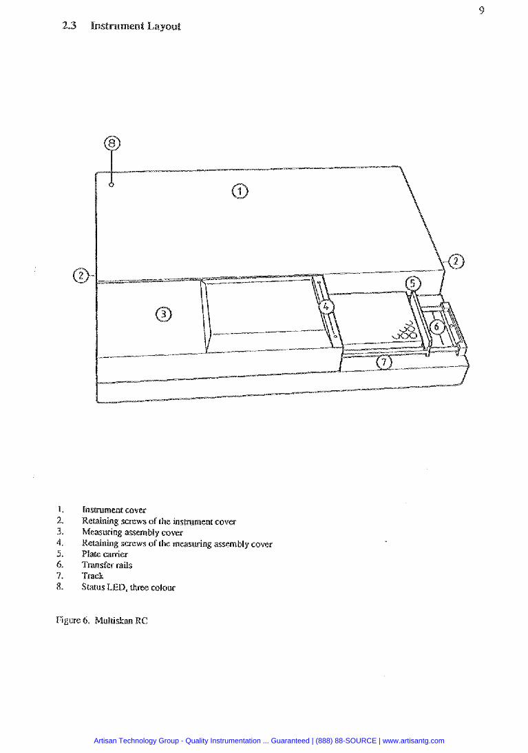
Instrumen6 cover Reraining screws of h e insmmenr cover Measuring assembly cover Retaining screws oi'thc measuring assembly cover Place carrier Transfer rails Track Status LED, thm colola
Figure 6. Multiskan RC
Artisan Technology Group - Quality Instrumentation ... Guaranteed | (888) 88-SOURCE | www.artisantg.com
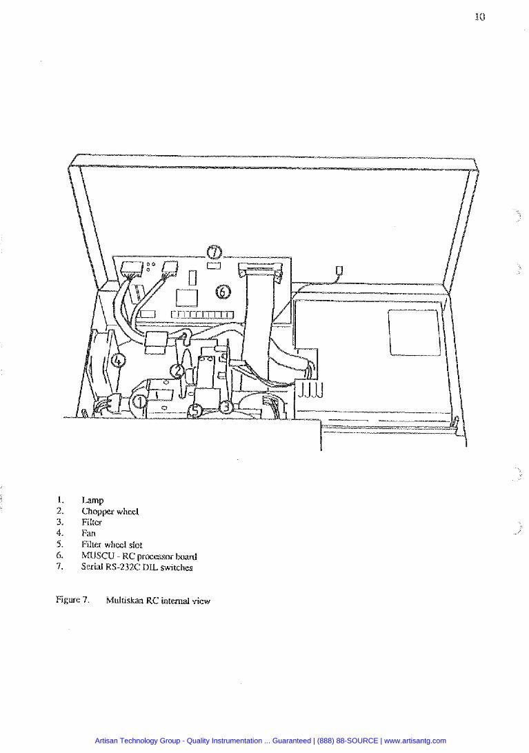
1. Lamp 2. Chopper wheel 3. Fitter 4. Fan 5. Filter wheel slot 6. MUSCU - RC processor bard 7. Scpial RS-232C D L switches
Figure 7. Multiskan RC internal view
Artisan Technology Group - Quality Instrumentation ... Guaranteed | (888) 88-SOURCE | www.artisantg.com
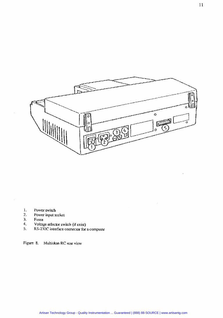
1. Power switch 2. Power input 3. Fuses 4. Volfage selector switch (if exist) 5. RS-232C inleefax cannecror for a computer
Figure 8. Multi
Artisan Technology Group - Quality Instrumentation ... Guaranteed | (888) 88-SOURCE | www.artisantg.com
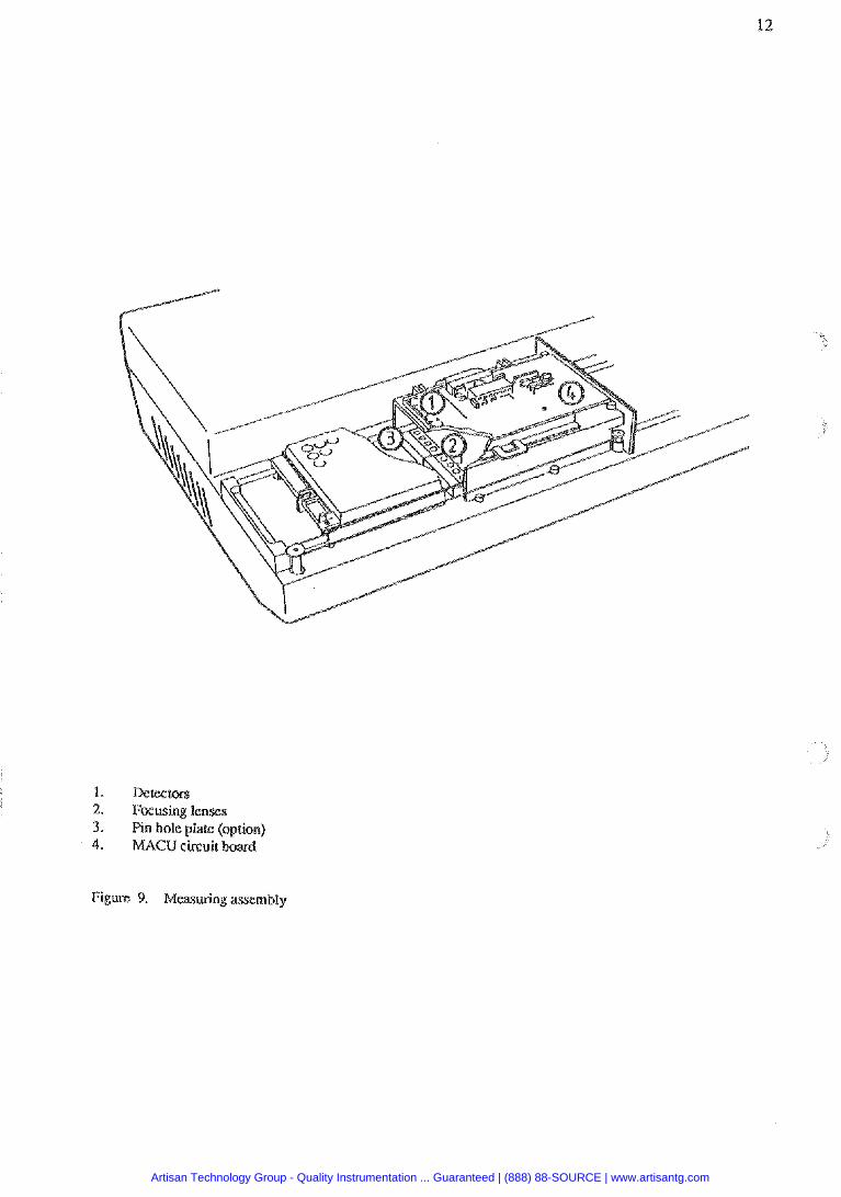
1. Detectors 2. Focusing lenses 3. Pin hole plare (option) 4. U4CU circuit board
Figure 9. Measuring assembly
Artisan Technology Group - Quality Instrumentation ... Guaranteed | (888) 88-SOURCE | www.artisantg.com
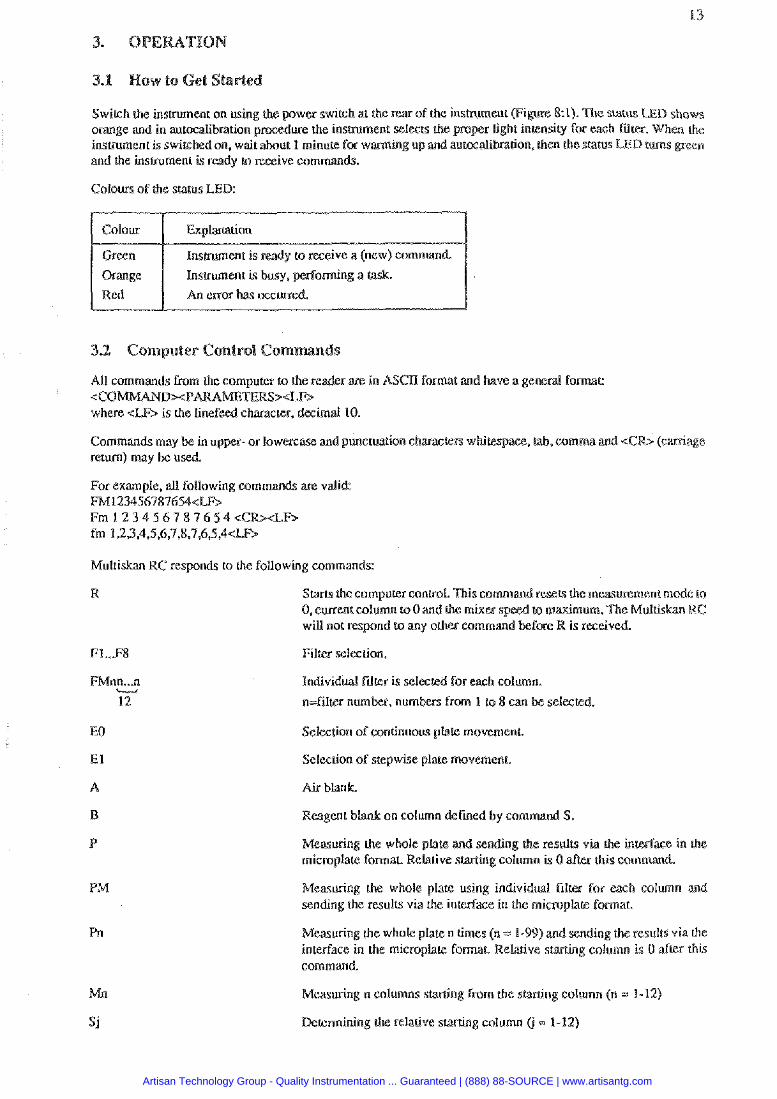
Switch the instrument on using er switch at the rear oE the instrument O: el). 9h% status LED shows orange and in autocalibration pr selects the proper light ity for each Tdter. When the insmment is switched on. wait a ing up and autocdibrarion, then she status LED turns peen and the insmment is ready to m i v e commands.
Colours of the status LED:
Cohur
Geecn Orange Red
Explmtion
Instrument is ready to receive a (new) command.
Instrument is busy, m o r n i n g a task.
An e m has mureed.
All commands Cram the computer to the reader are in ASCn format and have a general formar <CO x P A R S 9 d b where eEF> is the linefeed character, decimal 10.
Commands may be in upper- or lowercase and puncrllauon 6 am. lab. comma and < return) may be used.
For exmple, all following commands are valid: FM1234567876546B F m 1 2 3 4 5 6 7 8 7 6 5 4 e C R > d F b fm 1,2,3,4,5,6,7,8,7,6,5,4<LF>
Muluskan RC responds to the following commands:
Starrs h e computer control. n i s command resets the measurement m d e to 0, current wlumn to 0 and the mixex RC will not rcspnd to any other camman
Individual F d ~ r is selec
n=filtzr umber, numbcn from 1 to 8 can be selezbed.
EO Seleeuon of continuous ptak movemenr.
El Selection of stepwise plate movement
B on column defied by com
Measuring the whole plate and sending the results via the in microplate format Relative starting column is 0 alkr this command.
Rlcasuring the whole plate using individual filer for esch column and sending the resulrs via rhe inledace in h e microplate fomar
Measuring the whole plate n times (n = 1-44) and sending the results via the inledace in the micmpta@ form& Relarive smting column is 0 a h this command
Measuring n columns starting fmrn the s ng column (n .: 1-12)
Artisan Technology Group - Quality Instrumentation ... Guaranteed | (888) 88-SOURCE | www.artisantg.com
T
v Q
STATUS
C
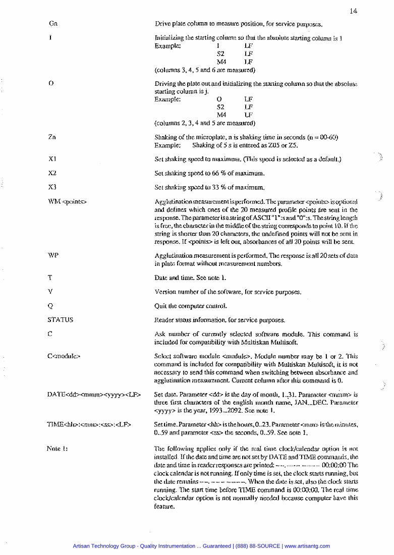
Drive plate column to measure pasition, for sewice p
Initializing the stating coluatn so that the absolute stming collamn is I Example: I WF
$2 LF M4 LF
(columns 3.4.5 m d 6 are measurgd)
X v i n g the plate out and initializing the s w i n g w l m n sa that the absolute sraning column is j, Example: 0 W
S2 M4
(columns 2 ,3 ,4 and 5 are m
Shaking of the microplate, n is shaking Lime in saonds (n s 00-60) Example: Shaking of 5 s is ente
Set shaking to maxhum. (This s
to 33 %of maximum.
Aggluhation measvrement is performed. T ~ I nse is aU 2 0 % ~ of data in plate f0Prnak without measlvement num
Dale and time. See note. I.
Version number of the sofLwm. fw service p
Quit the cornpum canual.
Read- s t a m infomrion. for service p
m rnrxiule. This command is
Mulrisafr, it is not
Set dale. Parameer eddz is the day of month. 1..31.
cyyyp is Lhe y w , 1993 ... 2092. See 1.
Set h e . Paranretesdb isrhe hoaus,0..23.Paramem<rnma ischeminures. 0..59 and parameter <sy the seconds, 0..59. See not% 1.
Artisan Technology Group - Quality Instrumentation ... Guaranteed | (888) 88-SOURCE | www.artisantg.com
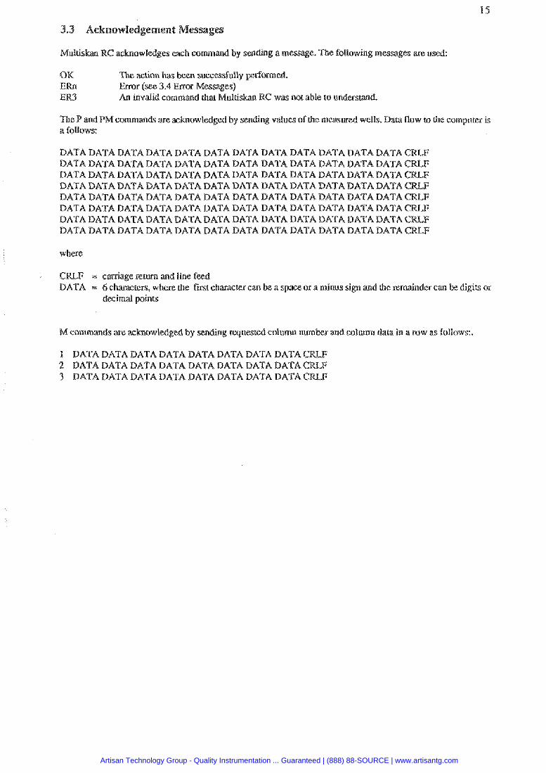
owledges each command by sending a message. The foilowing messages sut: u
OK The action has been successfully p r l omed . ERn Error (see 3.4 Enor Messages) ER3 An invalid command that Multis RC was not able to understaid.
The P and PM commands are acknowledged by sending values ofthe measwed wells. Data flow to the computer is a EoUows:
DATA DATA DATA DATA DATA DATA DATA DATA DATA DATA DATA BATA CRLF DATADATADATADATADATADATADATADATADATADATADATADATACaF DATADATADATADATADATADATADATADATADATADATADATADATA DATA DATA DATA DATA DATA DATA DATA DATA DATA DATA DATA DATA DATA DATA DATA DATA DATA DATA DATA DATA DATA DATA DATA BATA CRLF DATADATADATADATADATADATADATADATADAmDATADATADATA DATA DATA DATA DATA DATA DATA DATA DATA DATA DATA DATA DATA DATADATADATADATADATADATADATADATADATADATADATADATA
where
CRLF = carriage ~e turn and line feed DATA = 6 cham(ers, where che rust character can be a space or a minus sign and the remainder can be digics or
decimal points
M commands are acknowldged by sending rques column number and column data in a row as follows:.
1 DATA DATA DATA DATA DATA DATA DATA DATA CRW 2 DATA DATA DATA DATA DATA DATA DATA DATA 3 DATADATADATADATADATADATADATADATACRLF:
Artisan Technology Group - Quality Instrumentation ... Guaranteed | (888) 88-SOURCE | www.artisantg.com
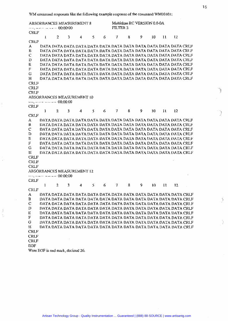
command wsponsrs like the foUowing example response of the command
8 WC ERSION 0.GCJA - - - - - - - - - mm00
1 2 3 4 5 6 4 8 9 10 11 12
DATADATADATADATADATADATADATADATADATADATADATADATACaLF B DATA DATA DATA DATA DATA DATA DATA DATA DATA DATA DATA DATA CRLF C DATA DATA DATA DATA DATA DATA DATA DATA DATA DATA DATA DATA B DATADATADATADATADATADATADATADATADATADATADATADATA E DATADATADATADATADATADATADATADATADATADATADATADATACRLF F DATADATADATADATADATADATADAA7DATADA%;QDATABATADATACKF G DATA DATA BATA DATA DATA DATA DATA DATA DATA DATA DATA DATA CRLF N DATADATADATADATADATADATADATADATADATADATADATADATA C C CRLF mABSORBAMCES MEASURE 10 - - - - - - - - - 00:00:00
I 2 3 4 5 6 7 8 9 10 11 12
A DATA DATA DATA DATA DATA DATA DATA DATA DATA DATA DATA DATA B DATADATADATADATADATADATADATADATADATADATADATADATA C DATADATADATADATADATADATADATADATADATADATADATADATA D DATA DATA DATA DATA DATA DATA DATA DATA DATA DATA DATA DATA E DATADATADATADATADATADATADATADATADATADATADATADATA F DATADATADATADATADATADATADATADATADATADATADATADATA G DATA DATA DATA DATA DATA DATA DATA DATA DATA DATA DATA DATA I3 DATADATADATADATADATADATADATADATADATADATADATADATA C K F CRLF CRLF ABSORBANCES E A S W h . I E m 12 - - - - - - - - - 00 w:00 CRLF
1 2 3 4 5 6 7 8 9 10 11 12 CRLF A DATADATADATADATADATADATADATADATADATADATADATADATA B DATA DATA DATA DATA DATA DATA DATA BATA DATA DATA DATA DATA 6 DATADATADATADATADATADATADATADATADATADATADATADATA D DATADATADATADATADATADATADATADATADATADATADATADATA E DATA DATA DATA DATA BATA DATA DATA B A A F DATADATADATADATADAATAATADATADATADATADATADATADATA G DATADATADATADATADATADATADATADATADATADATADATADATA H BATA DATA DATA DATA DATA DATA DATA DATA DATA DATA DATA DATA CRLF C W CRLF GRLF EOF Were EOF is end mark. decimal 26.
Artisan Technology Group - Quality Instrumentation ... Guaranteed | (888) 88-SOURCE | www.artisantg.com
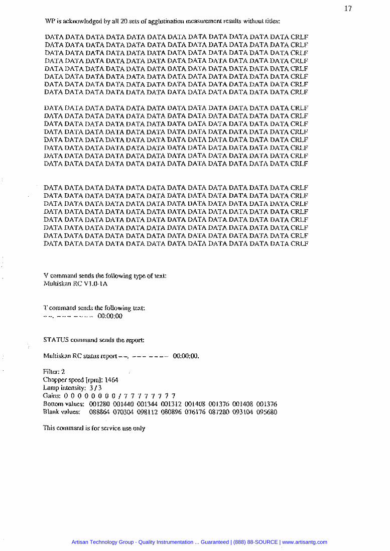
WP is acknowledged by all 20 seu of agglurination measuremen: results wilhour titles:
DATADATADATABATADATABATADATADATADATADATADATADATACEF DATA DATA DATA DATA DATA DATA DATA DATA DATA DATA DATA DATA CRLF DATA DATA DATA DATA DATA DATA DATA DATA DATA DATA DATA DATA CWLF DATADATADATADA'FADATADATADATADATADATADATADATADATACRLF DATA DATA DATA DATA DATA DATA DATA DATA DATA DATA DATA DATA DATADATADATADATADATADATADATADATADATADATADATADATAeRLF DATADATABATADATADATADATADATADATARATADATADATADATACCRLF DATADATADATADATADATADATADATADATADATADATADATADATACCRLF
DATADATADATADATADATADATADATADATADATADATADATADATACKLF DATADATADATADATADATADATADATADATADATADATADATADATACRLF DATADATADATADATADATADATADATADATADATADATADATADATACKF DATADATADATADATADAATDATADATABATADATADATADATADATACRLF DATA DATA DATA DATA DATA DATA DATA DATA DATA DATA DATA DATA CRLF DATADATADATADATADATADATADATADATABATADATADATADATACRLF DATA DATA DATA DATA DATA DATA DATA DATA DATA DATA DATA DATA CRLF DATA DATA DATA DATA DATA DATA DATA DATA DATA DATA DATA DATA CRLF
DATADATADATADATADATADATADATABATADATADATADATADATACKF DATADATADATADATADATADATADATADATADATADATADATADATA DATADATADATADATADATADATADATADATADATADATADATADATA DATADATADATADATADATADATADATADATADATAWATADATADATACRLF DATADATADATADATADATADATADATADATADATADATADATADATA DATADATADATADATADATADATADATADATADATADATADATADATA DATADATADATADATADATADATADATADATADATADATADATADATA BATADATADATADATADATADATADATADATADATADATADATADATACRLF
V command sends the fo11owing Multiskm RC VI.0-1A
STATUS command sen& (Ire %
Filter: 2 Chopper [rpml: 14 Lamp intensity: 3 / 3 G a i n s : 0 0 0 0 0 8 0 0 / 7 7 7 Bouom values: 001280 001440 00 12 GO1408 001376 W1408 001396 Blank values: 088864 070304 08112 080896 074176 087280 093104 095680
n i s command is for service use only
Artisan Technology Group - Quality Instrumentation ... Guaranteed | (888) 88-SOURCE | www.artisantg.com
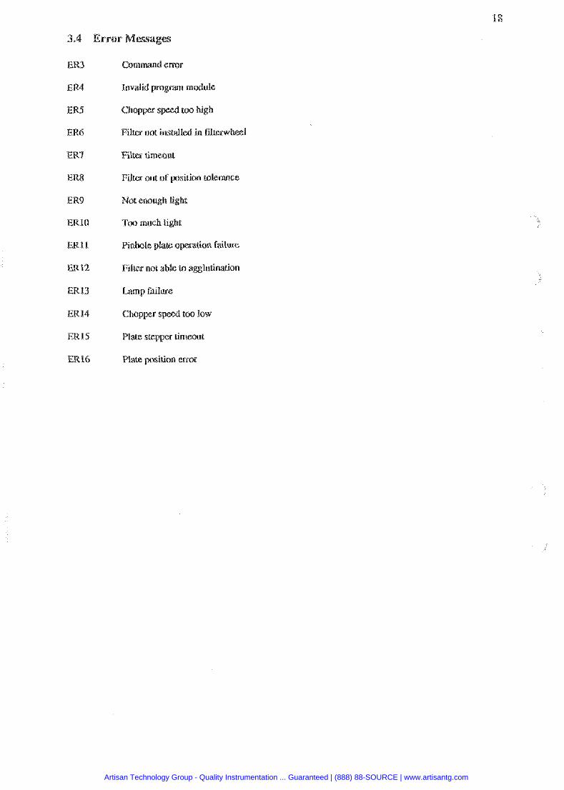
Command e m
Filter not insralled in fdtsrwheei
Fitter timeout
Filter out of psiuon tolerance
Not enough light
Too much light
Pinhole plate operation failure
Filter not able to ag$luunation
Lamp failme
Chopper too low
Plate stepper timeout
Plate position cmr
Artisan Technology Group - Quality Instrumentation ... Guaranteed | (888) 88-SOURCE | www.artisantg.com
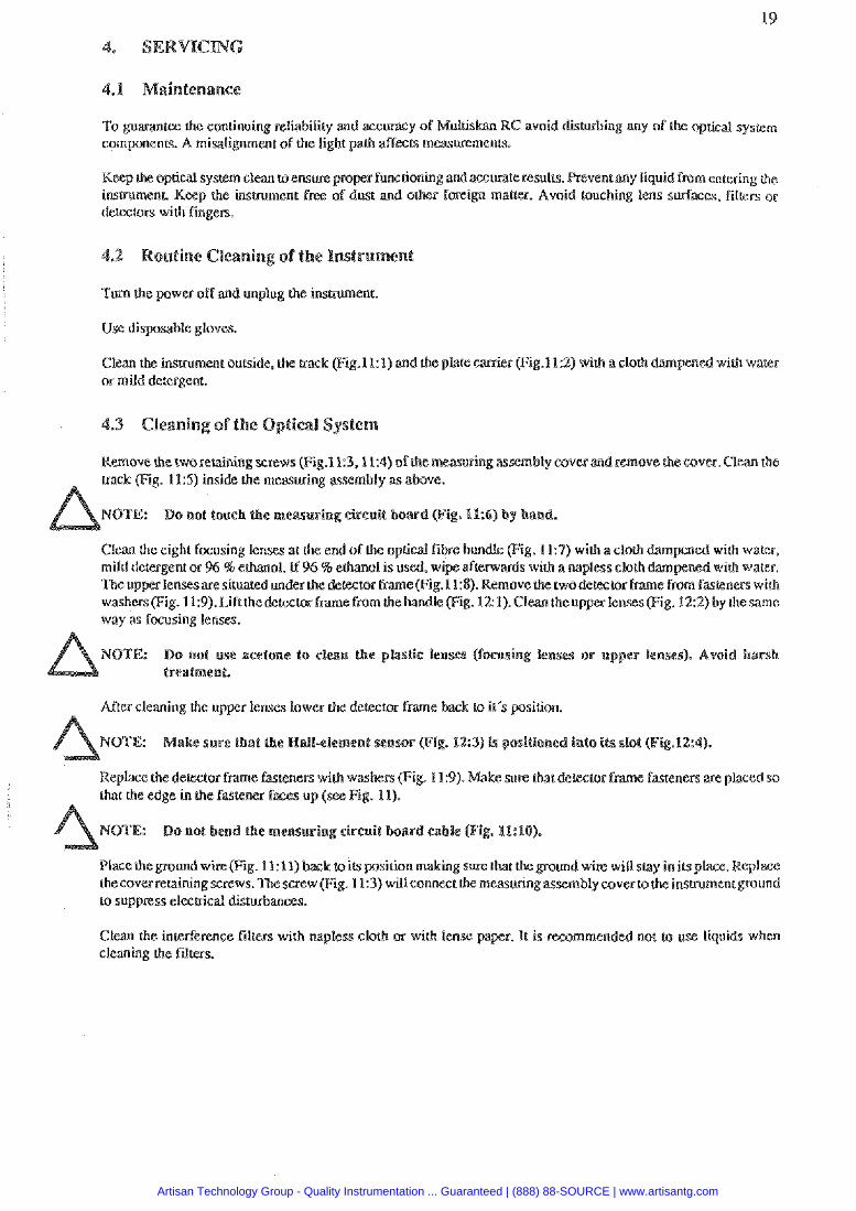
To guarantee the continuing reliability md accuracy of Multis KC avoid diswbing any of the optical sysrem component& A misalignment of the light path affecrs measmemenu.
Keep the optica1 syscem clean w ensure proper funcrioning and aauateresul!s. Revent any liquid from entering the instrumeni Keep the instrument free of dust and other foreign malter. Avoid touching tens swfaces. filters or delectoe; with fingers.
T m the pawet off and unplug the inshument.
Use disylosable gloves.
Clean the instrument ourside. the mcft (Fig.1 l:l) and the plate carrier (Fig.lk2) with a cloth or mild detergent.
Remove thecworetaining screws (Fig.l1:3.11:4) ofthem ing assembly covermd remove thecover. Clean the track (Fig. 115) inside the measwing assembly as above.
NOTE: Do not touch the msa$uring circuit
Clean the eight focusing lenses at the end of the optical f i b bundle (Fig. 119) with a cloth dmpened with water. mild detergent or % %ethanol. If 96 % ethanol is used. wi aflenuards with a napless cloth with water. The upper lensesaresituared under thedefector fme(Fig.l1:8). Remove the twodeaector frame from fasleners with washers (Fig. 11:9). Lift thedemtor fmme fmm t h e h d e (Fig. 12: 1).Clesn the up IensesfFig. 122) by thesame way as focusing lenses.
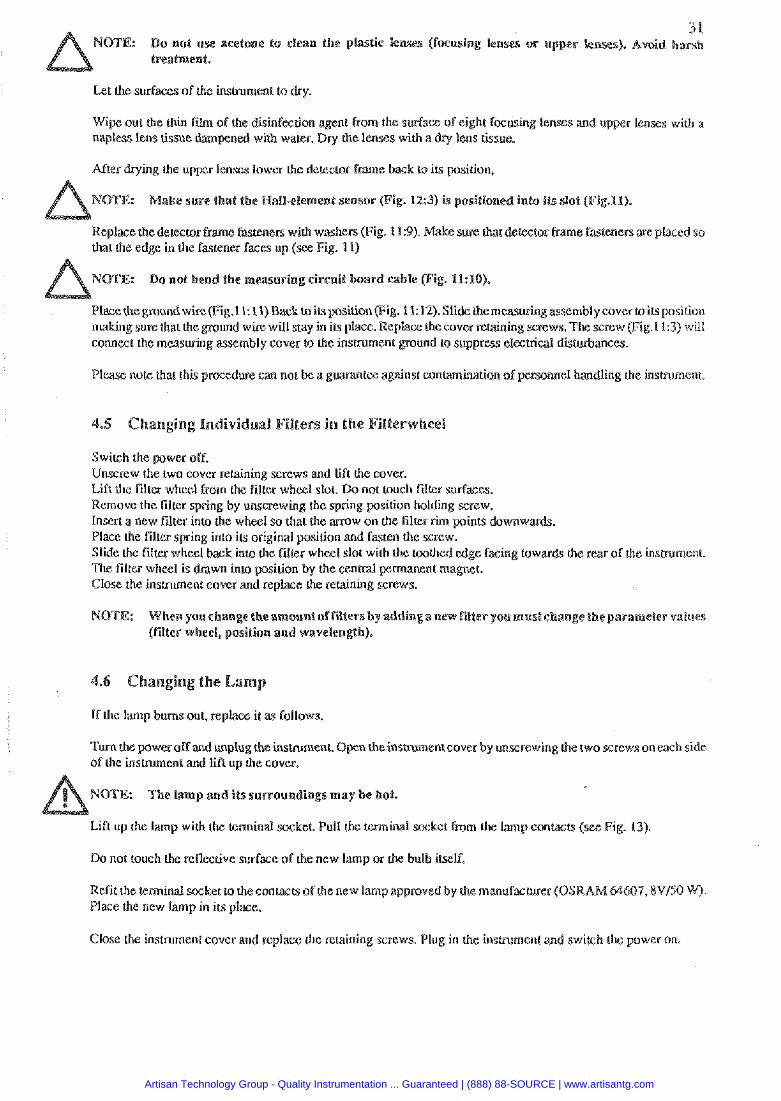
NOTE: Do not use acetone to clean the p treatment,
After cleaning the upper lenses lower ck to it's position.
NOTE: Make sure Lbat the Mall-@lsmeel nsar (Fig. 123) ir positioned into its slot (Fi
Replace the dewlor frame fasteners with washers (Fig. 1 L:9). Make sure char defector frame fasteners are placed so that the edge in the fastener farm up (
MOTE: Do no2 bend tbe me
Place the ground wise (Fig. I l:ll) back wire wiU slay inilsplace. the cover retaining screws. Thescrew pi bly coverto the instrumen to suppress elecmcal disturbancss.
Clem the interference filters with napless clolh or with lense pa P. It is r ammend& not use liquids when cleaning the filters.
Artisan Technology Group - Quality Instrumentation ... Guaranteed | (888) 88-SOURCE | www.artisantg.com
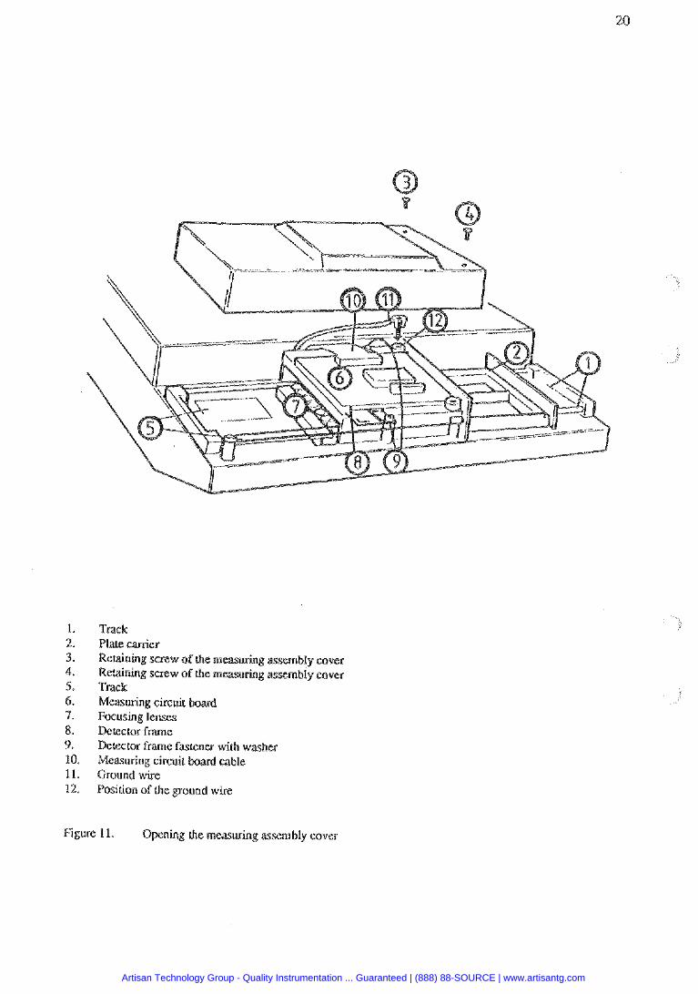
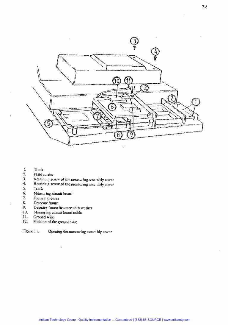
Track Plate carrier Retaining snew of the measuring Retaining screw of the m e a s h g assembly cover Track Measuring circuit Focusing lenses Dctescor f m e Dcwror frame tmener with washer Measuring circuit b a r d cable Ground wire Position of Lhe ground wire
Figure 1 1 . Opening che mawring assembly cover
Artisan Technology Group - Quality Instrumentation ... Guaranteed | (888) 88-SOURCE | www.artisantg.com
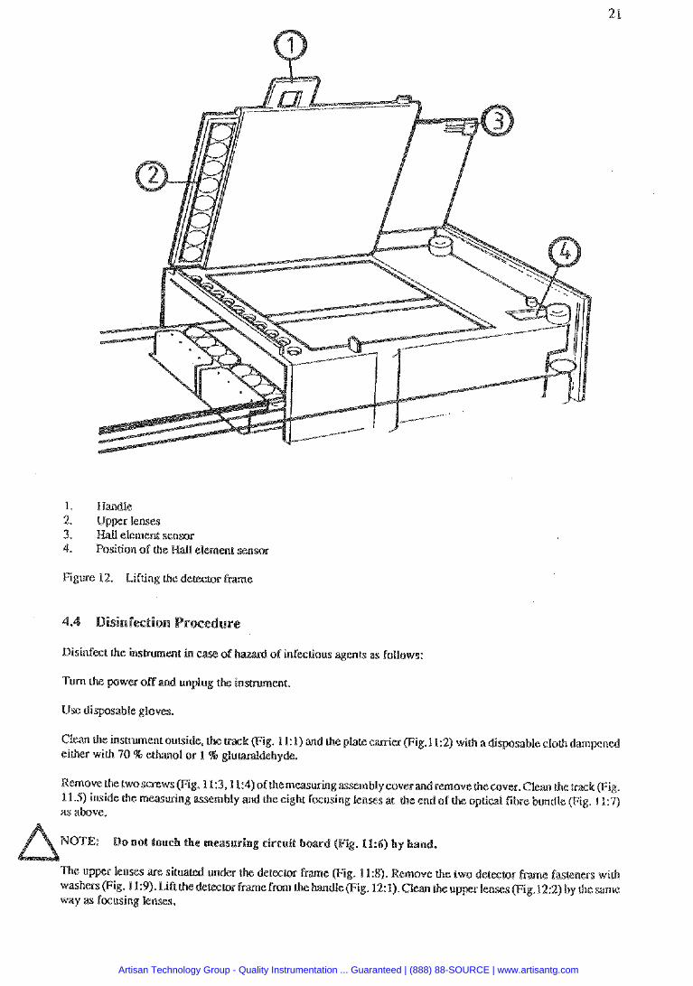
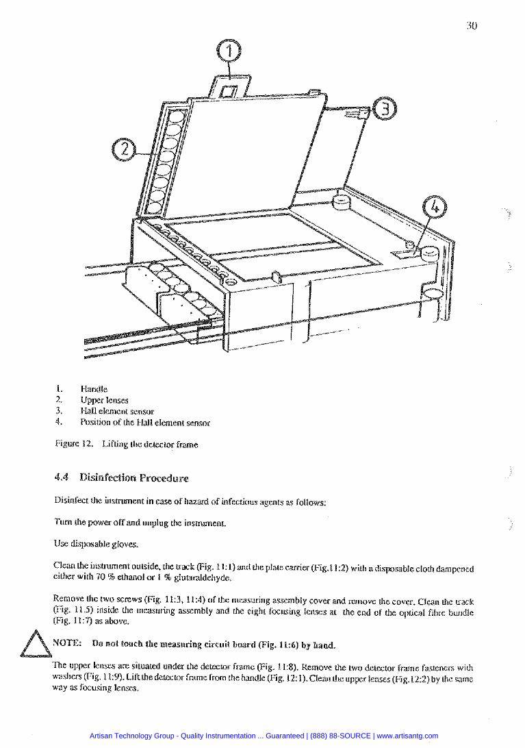
1. Handle 2. Upper lenses 3. Iiall element sensor 4. Position of the
Figure 12. Lifting the detector P m e
of infwtious agenB as follows:
Turn bhe power off and unplug
Use dispasabls gloves.
Clean the insuument outside, ck .g. 1 1: 1) and the platc &w (Fig.112) with a disposable cloth dampned either with '70 % elhanol or 1 % ohyde.
Remove the iwosmws(Fi :3,11:4)of themallring assembly coverandre 11.5) inside the measuring mbly and the eight focusing lenses at the end o as above.
NOTE: Do not touc
The upper lenses ape si emtor frame (Fig. 1 I:@. Remove a e two de lor fme raseners wilh washers (Fig. 1 1:9). Li tPMn the kandle(Fig. 12: 1). elm the up ,1212) by the same way as focusing lenses.
Artisan Technology Group - Quality Instrumentation ... Guaranteed | (888) 88-SOURCE | www.artisantg.com
NOT& Do not we acetone to clean the or upper lemes). Avoid harsh treatment.
Let the surfaces of the inshument to dry.
Wipe out the chin film of h e disinfection agent &om the surface of eight fausing lenses and up napless lens tissue dampened with water. Dry the lenses with a dry lens tissue.
After drying the u p p lenses lower the detector h e back to its position,
ake sure that the Nall-ele ent sensor Fig. 12:3) is positione into its slot (Fig.11).
Replace the delector frame fasteners with washers (Fig. 11:9). Make sure thatdewor f m e fasteners ape placedso that the edge in the fastener faces up (see Fig. 11)
NOTE: Do not bend the memuring circuit board cable (Fig. 11:10).
Place the ground [email protected] k11) Backm its position (Fig. 11:12). Slikthemmeasuring assembly cover to its position making sure that the ground wire will stay in its place. Re the cover retaining screws. The screw (Fig.l1:3) w~ll connect the measuring assembly cover to the insmmen nd to suppress eleclrid dkmbances.
Please note that this p r o d w e can nor be a guarantee against conmination of personnel handling the insmrnent.
Switch the power off. Unscrew the two cover retaining screws and lift the cover. Lift the filter wheel kom the filter wheel slot. Do not much filer sdaem. Remove the filter spring by unscrewing the spring psition holding screw. Insert a new Filter into the wheel so that the arrow on the filter Am points dovvnwapds. Place the filter spring into its original position and faten the screw. Slide the filler wheel back into the Tilter wheel slot with the too&& edge facing lowards the rear of the insmment. The filter wheel is drawn into psition by the cenlral Close the insmmenr cover and repiace the reraining screws.
If the h p bums out, replace it as Follows.
Turn tbe poweroff and unplug the insmmens. n the inscrumenteover by unscrewing (he two sccewsoneachside of the insbument a& lift up the cover.
NOTE: ThelPIm its surroundings
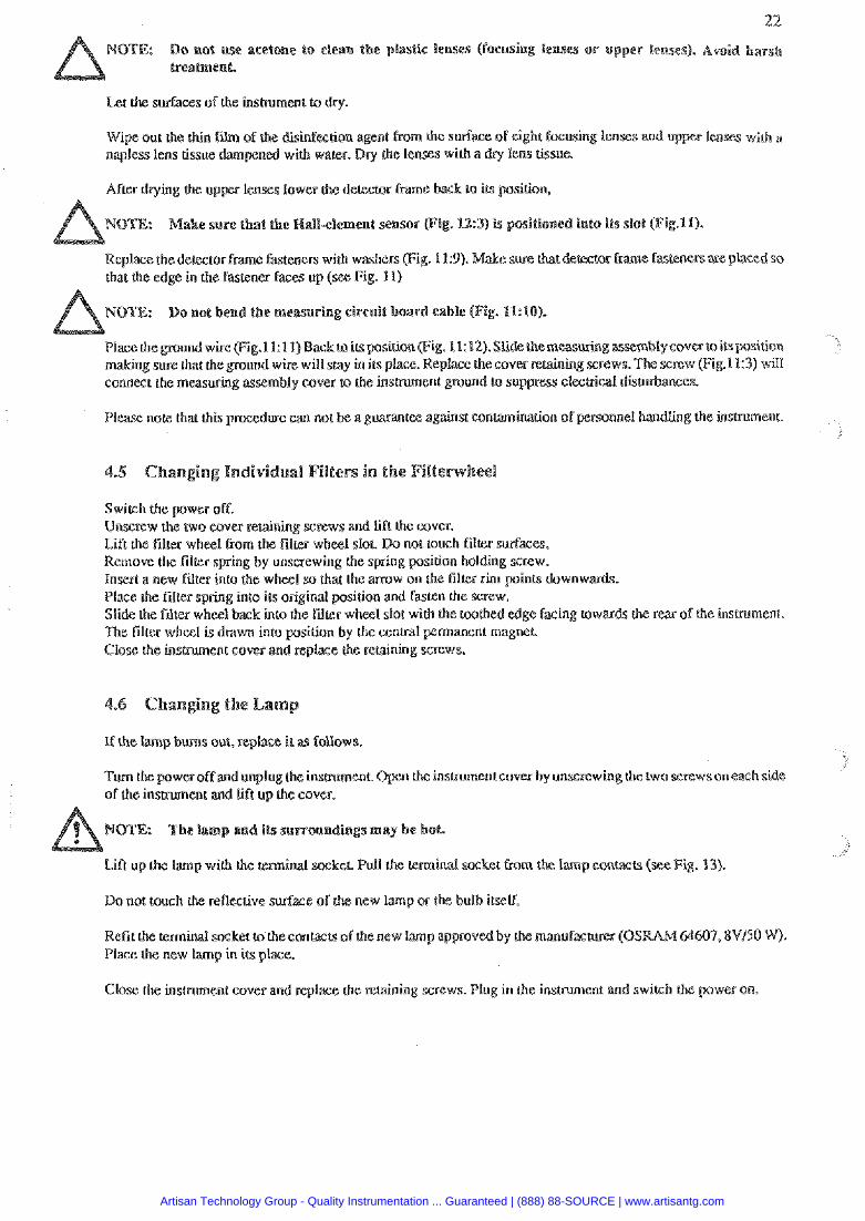
Lift up the hemp with h e e m i d mkeL Pull the terminal ~ k e t Cram lamp emfacts (see Fig. 13).
Do not touch h e reflec(ive surface of new lamp or the bulb irself.
Refit the terminal socket to theconlacts ofthe new lamp approved by the manufas~~rer (OSR Place the new lamp in its place.
Close the instrument cover and replace the retaining screws. Plug in the insmment and swirch k
Artisan Technology Group - Quality Instrumentation ... Guaranteed | (888) 88-SOURCE | www.artisantg.com
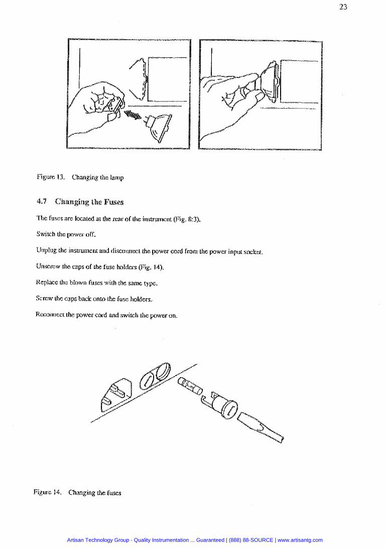
Figure 13. Changing the lamp
The fuses are imtd at the rear of the insmrnent (Fig. 83).
Switch h e power o f t
Unplug the insuument and disconnect the power cord from the power input smkec.
Unscrew the caps of the fuse holders (Fig. 14).
Replace the blown fuss with che same t
Screw the caps back onto the fuse holdees.
Reconnect h e power cord and switch the
Figure 14. Changing ik fuses
Artisan Technology Group - Quality Instrumentation ... Guaranteed | (888) 88-SOURCE | www.artisantg.com
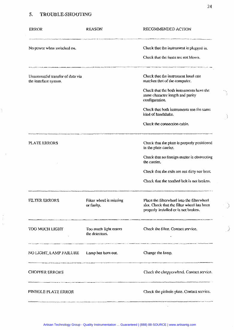
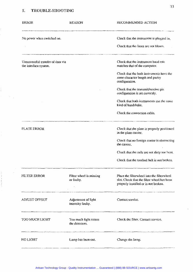
No power when switched on. Chock that the insmment is plugged in
Cheek that the fuses are not blown.
Unsuccessful rransfer of data via the interface system.
that Ihe insgument baud raLe marches that of the computer.
Check 'nsmments use the same kind o e.
Check the connection cable.
PLATE ERRORS that Ihe plate is pro in the plate &ex.
matter i s obsmcting
Film whml is missing or faulty.
Change the lamp.
CHOPPER ERRORS
PINHOLE PLATE Ihe pillhole plate.
Artisan Technology Group - Quality Instrumentation ... Guaranteed | (888) 88-SOURCE | www.artisantg.com
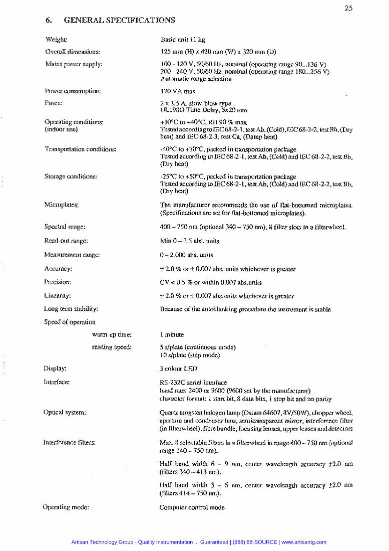
Weight:
Overall dimensions:
Mains pwer supply:
Power consumption:
Fuses:
Operating conditions: (indoor use)
Transpot4arion conditions:
Storage conditions:
Spcsml range:
Read-out range:
Measvrement range:
A c e m y :
Precision:
Linearity:
h a g lerm stability:
S p d of operation
warm up time:
reading s
Display:
Interlace:
Optical system:
Operating mode:
Basic unit 1 l kg
100 - 120 V. 50160 Hz. nominal rating m g e 90 ... 136 V) 200 - 240 V. $0/60 Mz, nominal g m g e 180 ... 256 V) Automatic range selection
2 x 3.5 A. slow-blow type UL1986 Time Delay. 5x20 mm
TestedaecordingroEC68-2-l.cestAb.(Cold),EC68-2-2, test Bb,(Dry heat) and E C 68-2-3. test Ca (Damp hat )
Tested according ro E C 68-2- I, test Ab, (Cold) and IEC 68-2-2, (sst Ub. (Dry heat)
r recommends the use of flac-battm (Specifications are set for flat-
400 - 750 nm (optional ), 8 fdtcr slots in a fdkrwhecl.
Min 0 - 3.5 abs. units
0 - 2.000 abs. units
P 2.0 % or f 0.007 abs. wifa whichever is gr
k 2.0 5% or * 0.007 abs.miu whichever is
en% is stable
5 stplate (continuou m 10 dplate (step mode)
3 colour LED
RS-232C serial inlerfaa baud nk: 2400 w 9 set by the manulacauer) chanrrer formal: 1 slsri bit. 8 data biu. I stop bit
Quartz tungsten halogen I m p (0 a p e m e md condenser lens. se
I), fibrebundle. fixusing le
x. 8 selectable filrers ffl a fil - 750 m (optional range 140 - 750 nm).
Half band width 4 - 9 nm. center wavelenglh z c (fillers 340 - 413 m).
Half band width 3 - 6 nm, center wavelengrh ace (filters 414 - 750 m).
Computer c m m l made
Artisan Technology Group - Quality Instrumentation ... Guaranteed | (888) 88-SOURCE | www.artisantg.com
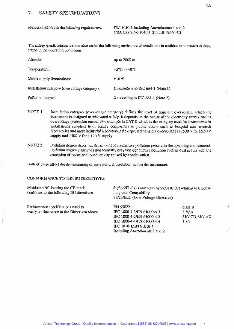
Multiskm RC fufils (he following re E C lOl0-l including and 2 CSA C22.2 No 1010. -0
ifications ate met also under the folhwing envkomental conditions in addition or in excess to those stated in the operahg conditions:
Altitude:
Mains supply fluctuations: f 1 0 %
lnslallation category (overvol6agc category): I1 ac~otding to E C
Pollurion degree: 2 according to E C
NOTE X %ns&llalion CaKegOPy (overvoltage category) defmcs level of msienc ovewolrage which the instrument i s designed lo withstand safely. It depends on the nature ofthe elechiciry supply and ib overvoltage protection meam. FOP example in CAT U which is the category used for instmmenbv, in installations supplied f m supply comparable tic mains such as hospital and re IabboracoPies and most indusaid labemcaries the ex msien t overvoltage is 2500 V for a230 V supply and lSOO V for a 120 M supply.
NOTE 2 Pollution degree describss tAe amount of conductive pollution present in the operating envkonment, Pollution degree 2 assumes that normally only non-conductive llution such as dust occurs with the exception of o c c a s i d conductivity awed by con&nsarim.
Both oC these affect the dimensioning of the elecmsal insubtion within the insmmenL
Multi- RC bearing the CE rn IEEC) relating lo Elestro- conforms (a the following EU
73/23/EEC o w Voltage Direceive)
c b B 3 Vlm 4kVCD,8kMAD I kV
Artisan Technology Group - Quality Instrumentation ... Guaranteed | (888) 88-SOURCE | www.artisantg.com
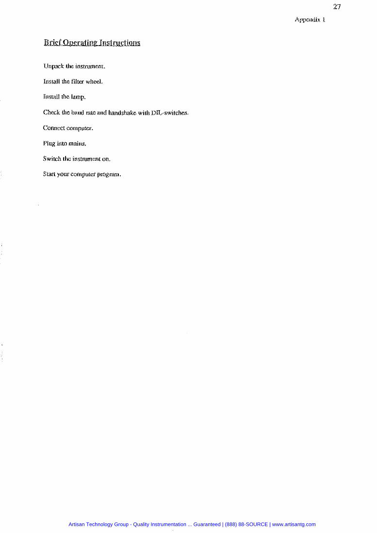
Unpack the insmmenr.
Install the filter wheel.
Install the lamp.
Check the baud rate and handshake with DIL-switches.
Connect computer.
Plug into mains.
Switch the i n s m e n t on.
Start your computer pro
Artisan Technology Group - Quality Instrumentation ... Guaranteed | (888) 88-SOURCE | www.artisantg.com
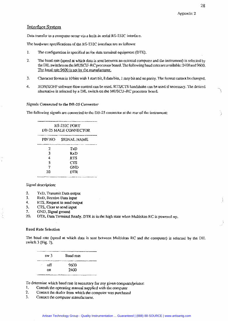
Data transfer (o a computer occur via a built-in serial WS-232C interface
ifimsions of che RS-232C interface ape as foI1ows:
1. The configmation is s ifid as for data teminal equipment @E).
2. The baudrat e n m external computer and insmmenc) is s e f ~ k d b board. The following baud nmaseavailable: 2400and 9
3. Chzwter format is 10 bits wiLh 1 5 bit, 8 data bits. 1 stop bit and no pariry. The format cannot be changed.
4. XON/XOFF software flow conbol can be us SIC% handshake alternative is selecred by a D L switch on fh CU-RC p~ocess
The following signals are connected to che DB-25 connector at the rear of rhe insmmenr
Signal descPiption:
2. TxD. Tmsmit Data w q u r
is in the high state when MuIris
tween Muttiskan R switch 3 (Fig. 9).
s w 3 Baud rare
off 9 on 2
To deternine which baud rate is n
Artisan Technology Group - Quality Instrumentation ... Guaranteed | (888) 88-SOURCE | www.artisantg.com
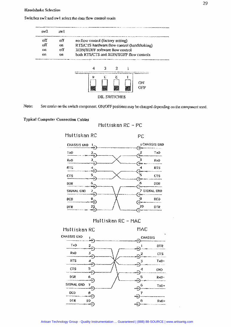
Ifandshake Seleelion
Swieches sw2 and swl select h e dam flow conhal mode
sw2 swl
off off no flow conml (faclory setting) off on RTS/@TS hadware flow control @mdshakink;) on off XON/)(OFF software flow control on on boch RTSICTS and X0NIXBf;F flow conuols
OM OFF
Note: See marks on the switch component. ONIOFF positions may be changed depending on ihe component used.
puler Connectioe Cabl
1 CHASSIS GNR
SIGNAL GNB 7
CHASSIS
DCD B
DTR 20 -3
. a
Artisan Technology Group - Quality Instrumentation ... Guaranteed | (888) 88-SOURCE | www.artisantg.com
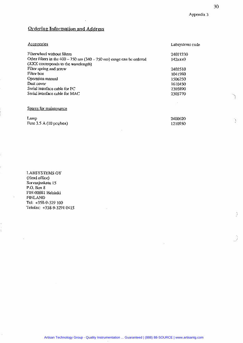
Filterwheel without fdters 0th- fitreps in the 4OO - 750 nm ( 3 4 - 750 urn) a g e can (XXX conresponds to rh% wavetengrh) Filter spring and screw
box rion manual
Bust cover intedxe cable for inlerlase cable for
Lamp Fuse 3.5 A (10 pcs/box)
Labsystems 6
Artisan Technology Group - Quality Instrumentation ... Guaranteed | (888) 88-SOURCE | www.artisantg.com

Labsystems Oy P.0. Box 8 FIN-00881 Nelsirrki. Finland Tel. 9358-9-329 1 0 Telefax 9358-9-3291 0.115
Artisan Technology Group - Quality Instrumentation ... Guaranteed | (888) 88-SOURCE | www.artisantg.com
LABSYS 14.1.1997
I a f o m a ~ o n in t h i s manual is subject to change without psior notice,
Artisan Technology Group - Quality Instrumentation ... Guaranteed | (888) 88-SOURCE | www.artisantg.com
LMSTALLAnON 1.1 Unpacking 1.2 Environmental Requiremenu 1.3 Inslallation 1.4 Tmspodcing for Service
FUNCTIONAL DES ON 2.1 Introduction 2.2 Measwement Wnciple
2.2.1 Photometric Measuremenu 2.2.2 Agglutination Measuremenu (optional)
2.3 insimmerit Layout 2.4 Keypad
Roll (printer option) 3.3 Measuring
3.3.1 Module 1: Frimar)r EIA Software 3.3.2 Module 2: Agglutination Software (optional) 3.3.3 Module 3: Cut-off Software (aptiaraal) 3.3.4 Module 4: Cubic Spline (optional)
3.4 Computer Control S
3.6 General P
APPE A p ~ n d k I. Appendix 2. Appendix 3. Ordering 1nlom;uion and Ad& Appendix 4. Exmplm How to Use M u l t i W MS
Page
Artisan Technology Group - Quality Instrumentation ... Guaranteed | (888) 88-SOURCE | www.artisantg.com
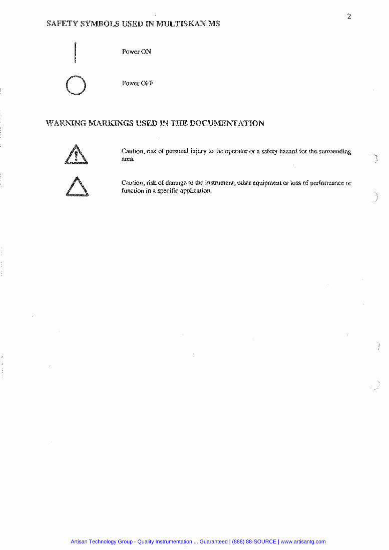
Power ON
0 Power OFF
Caution, risk of personal injury to the o for che surrounding area.
Artisan Technology Group - Quality Instrumentation ... Guaranteed | (888) 88-SOURCE | www.artisantg.com
09 MS carefully andcheck forany damage that may have missing, cantast h e local systems representarive.
Keep the original package for fume
Locate Mufriskan MS to avoid exposure to e x c w dust, vibrations. strong magnetic fields, direct sunlight, draFi, excessive moisture or large tempmlwe fluctuations.
Leave sufficient clearance (10 em) at both sides of the unit for adquate air ckulation.
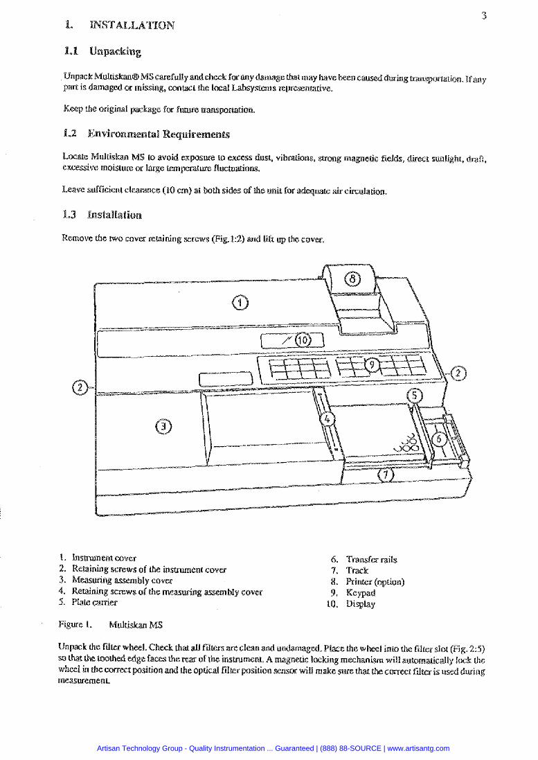
Remove the two cover retaining screws (Fig.12) and lift up (he cover.
I. Pnsmrnent cover 6. Tmsfa rails 2. Relainhg screws of the insmment cov 4. 3. Measuring assembly cover 8. r (option) 4. Retaining screws of the measuring 9. Keypad 5. Plate carrier 10. Dispiay
Figure 1. MulLi
e rrtter wheel. Check that aU fillem toothed edge faces the
wheel in the cornea position and the oprical fd measwernenL
Artisan Technology Group - Quality Instrumentation ... Guaranteed | (888) 88-SOURCE | www.artisantg.com
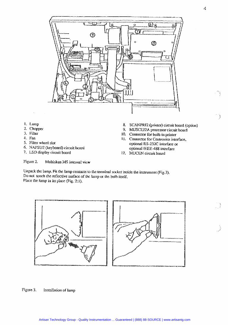
1 . Lamp 2. Chopper 3. Filter 4. Fan 5. Filter wheel slot 6. NAPSU2 (keyboard) circuit board 7. bSB disptay circuit board
8. SC brine) circuit bad (qrion) 9. MUSCUnAp
10. Connecmr for built-in prinm 11. Conneetor for Cenmics interface,
optional RS-232C inredace or
12.
Figure 2. Mutti MS incemal view
Unpack lhs lamp. Fit the lamp contacts to the temina! sacket inside !.he inslrument (Fig.3). Do not touch the reflective surface of the Lamp or the bulb itself. Place (he lamp in irs place (Fig. 21).
Figure 3. Installation of lamp
Artisan Technology Group - Quality Instrumentation ... Guaranteed | (888) 88-SOURCE | www.artisantg.com
Check visua!Jy that there are no loose inside, the inshlmenc.
Close the insmment cover and xepeplace the retainin
not pmduceoperating noiseata level which couldcause a hazard. Nosound level mzasuremenrs are needed dkr inscallation.
Comect the mains supply cord lo the rnains wer sacket (Fig. 4:2). 'lhe power supply automatic IW)-120/ 200.240 VAC range selection. If a suitable maim supply cord is not provided, use only cords certified by h e id authorities.
Cornst the insbument to a correctly installed line werouUet whish has aprotestive conduclor also called as e or ground.
CAUTION: lnlerruption oEl teetivecunductor inside or outside the inslru ay make the instru.
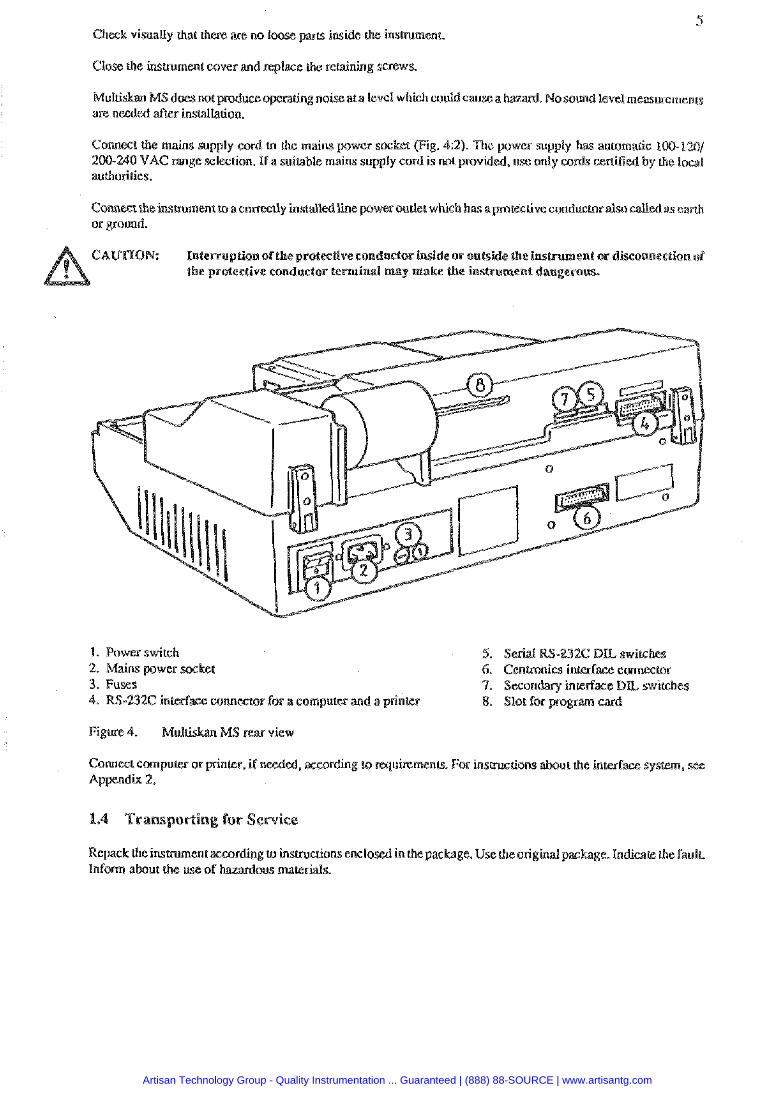
1. Power switch
m a l o r for a compucer and a printer
. according to requi~ements. For insmrcriorrs Appendix 2.
Artisan Technology Group - Quality Instrumentation ... Guaranteed | (888) 88-SOURCE | www.artisantg.com

Multiskan MS ismeight-chnelvePrica1 Lightpath filterphotome~adesigned.topeSFom and agglutination meamements.
There is a versarile builtin software available in Multihn MS. It comprises ssveml software package$ @rog~;un modules). Each package it acombination of measurement and dculation modes.
Extended memory capacity is achieved by pro
The wavelength (400 - 750 nrn or optional 340 - 450 nm) i s selected using maximum eight high qualily interference Firers held in a filter wheel.
The readings can be p ssed via a serial RS-232C inlePfaceor via a paraLlel Cenmnics printer interface. The opuonal bullt-m thermal printer provides &o a recad of the results.
2.2.1 Photometric uremen(s
Multiskan MS urilizes the original Labsysterns' concept of venical phocomeoy in which the light through the whole sample.
In venical photomehy, theabsorption of light is pmgorrional to the amount of light absorbing substance in lhe well.
Absorption is expressed by che following equation:
a A = ----- m,
S
where A = ah ty of the subsmce. m =; of absorbing subsmce and S = noss- sectional aaea
The advantages of the vertisal light path mwmement
(I) inaccurate pipeuislg of norrabsorbirrg Liquids d absorbanse values
(2) evaporation of nonabsohing tiqd& during the lion d m nok affect the m wed absorbance values and
ofinhomogertei(y in solucion,forexampleasaresullollayeringinlwbidity measuremen&. does ncx affect the results.
Artisan Technology Group - Quality Instrumentation ... Guaranteed | (888) 88-SOURCE | www.artisantg.com
The optical system comprises the following comwnenrs (Fig. 5a):
semi-ganswent minor a p e m e interference filter (filter wheel) optical fibre bundle focusing lenses upper lenses and dewtors
Light source:
The light socuce is a 607,8V/SOW, which is equi with arn aluminium-coated elliptical reflecmr,
To pmlong h e service life ofthe lamp, the instrument should be switched otfwhen not in use. Warming-up perid of 1 minute has re be atlowed tiefore measuring.
r wheel chops the light lo minimize elecuonic noise.
After passing through the condenser lens the light beam impinges on h e semi- light and all longer wavcleng&s pass through the mirror,and &c hc and the arrangement eliminates h d g of the interference filter and evens out the intensity disuibution.
Artisan Technology Group - Quality Instrumentation ... Guaranteed | (888) 88-SOURCE | www.artisantg.com
In(erference fd(er:
The wavelength is selected from I - 8 fiirers held in the fiter wheel.
Fibre bundle:
Mtcrpassing rhrough che i ecommon endof thefibw bundle, whichdivides the beam into eight equal wards.
Focusing lenses:
After being divided b e light passes rhrough a Focusing system of eight lenses.
&lectors:
s pass through the bouoms of che wells though the samples v ~ a up measure the intensity of @he
2.2.2 Agglutination ursmenbr (oglionsl)
Agglutinarion mwmemenrs are performed by using ial optics @inhole optics) (Fig. 5b). The ins over each well taking up to 20 readigs. Readings are then down-loaded to a P.C. for funhex inmrerarion.
1. Fwusing lenses l e m and detectors
3. Pinhole plate (optional)
Fig. Sb. Agglurination optics
Artisan Technology Group - Quality Instrumentation ... Guaranteed | (888) 88-SOURCE | www.artisantg.com
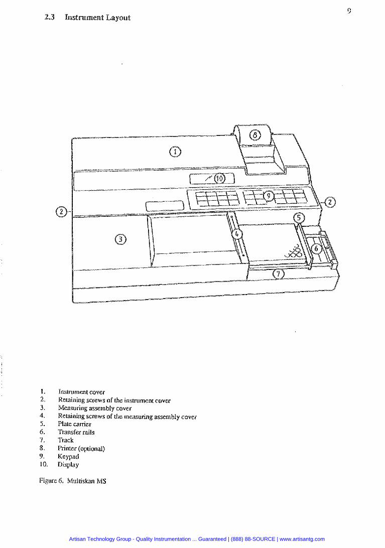
1. 2. 3. 4. 5. 6. 7. 8. 9. ao.
Instrument cover Recaining screws of Lhe insmment cover Measuring assembly cover Recaining screws of the measuring assembly cover Plate eanier Transfer rails Track Printer (optional) Keypad Display
Artisan Technology Group - Quality Instrumentation ... Guaranteed | (888) 88-SOURCE | www.artisantg.com
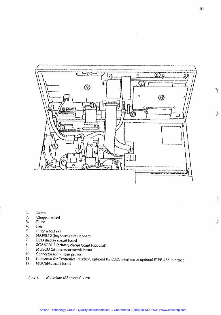
Fm Filter wheel slot MAPSU 2 (keyboard) circuit LCD display circuit
Comeelar for built-in printer C O M K ~ O ~ for Centronics interface, optional RS-232C interface or opuond E
Figure 7. Multi ,!AS i n t e d view
Artisan Technology Group - Quality Instrumentation ... Guaranteed | (888) 88-SOURCE | www.artisantg.com
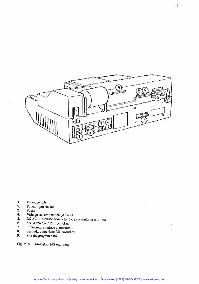
Power swirsh Power input %Let Fuses Voltage selector switch (if exist) RS-232C interface connector for a compu(er or a peinw Serial RS-232C B E switches Cenmnics interfa= conngtor Secondary inmfxace D L switches Slot for program card
Figure 8. Mullislaan MS r e a view
Artisan Technology Group - Quality Instrumentation ... Guaranteed | (888) 88-SOURCE | www.artisantg.com
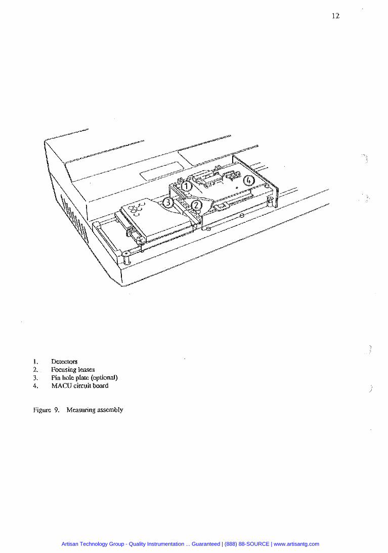
Figure 9. Measuring assembly
Artisan Technology Group - Quality Instrumentation ... Guaranteed | (888) 88-SOURCE | www.artisantg.com
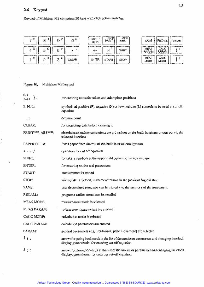
Keypad of Mui t isb MS comprises 30 keys wisk click action switches:
Figure 10. Multi
0-9 A-N 1: for entering numeric values md micmpIa&
. . CLEAR:
PR . ABSmK':
PAPER FEED:
+ - X I :
START:
STOP:
SAVE:
BECALL:
EilEAS N(ODE:
IMEAS P
CAEC MODE:
? ( :
sitive (P). mgarive 0 or low positive (&) canuols to be u equation
printed out on the barill-in nkr or sent out via the
m the roll of ihe built-in or e x m a l printer
rnicroplale is ejected, insuumenc rems tr, the previous logical s u m
all
measurement are e n r e d
S-forma& plate movement)
m o w : forgoing backw erenand changing theclwk display, pmnskais:
m w : for going lorwardr in the List of the m ecem and changing the clack display. parenthesis: enwing clrlsff equation
Artisan Technology Group - Quality Instrumentation ... Guaranteed | (888) 88-SOURCE | www.artisantg.com

wftwze cOmg&s pro modules, software pac es which are combinations 06 m and dculation modes.
The following program modules are available:
1. Primary EL4 software 2. Agglutination software (optional) 3. Cut off software (optional) 4. Cubic spline safwrwrue (optional)
Module 1: Primary EEIA
This ~F tware is a basic software to p e r l m EIA mpasuremenrs. It includes the following measlvernent modes: absorbance, dual wavelengrh, two pint . kinetic. multivawelengrh mode and computer control.
The following calculation modw can : factor. lineax stan . smandard line, limit, double limit. column suba;rction and point to
Module 2: Agglurination software (optiond)
This module enables agglutination measuremen&. A id optics @inhole optics) is en into use. 20 mdings are faken per each well. Wcsults are sent via interface for further processing.
Module 3: Cut off software (optional)
Thereare diferentcutoff calculations available in this module: double Limit, range, fixedcut off and floating cut off.
Module 4: Cubic spline (optional)
Measurement modes: available am absorbance. dual wavelengk two p i n t and kinetic. Calculation mode: available is cubic spline.
Changing bstween mcdules occurs by First pressing the S key.
More memory capacity is
Cards ;ire prograsnmed by Labsysms upon request-
Artisan Technology Group - Quality Instrumentation ... Guaranteed | (888) 88-SOURCE | www.artisantg.com
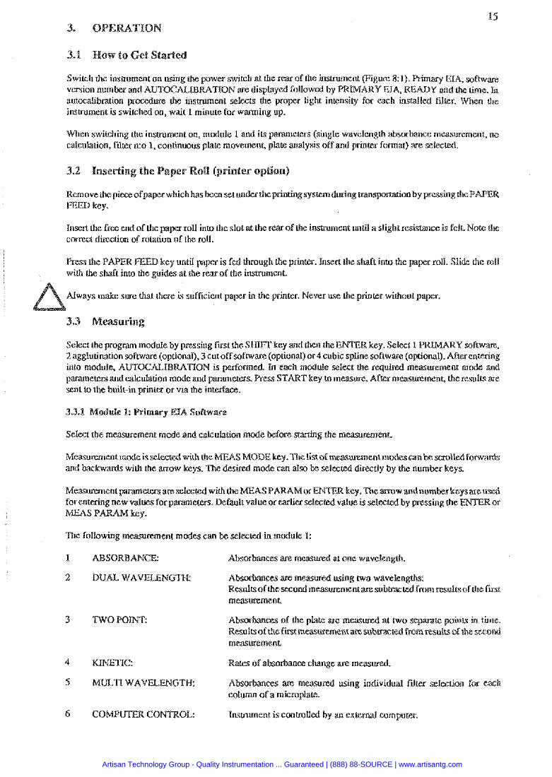
Switch the instrument on using h e pwer switch at the rem of the insmment (Figure 8:1 a q EIA, sofbware version number and A m K & I B R A n O N are display Y md the h e . h autocalibrarion procedure the insevment selects the proper Light i&nsity for each instdl instrument is switched on, wait 1 minute for warming up.
When switching the insmment on, rnodule 1 and its parameters (single waveleng* absorbance measluemen& no calculation, filler n:o 1, continuous plate movemenS plate analysis off and printer format) are selec
Remove the piece ofpaper which has cn by pressing the P FEED key.
Insen the free end of the pager roll into the slot at Phe rear ofthe insrnunenl unI3 a sli ht resistance is felt Note the correct d k t i o n of rotation of ihe roll.
Press the PAPER FEED key unLil papa is fed rhrough the printer. Insert the shaft into the paper roll. Slide ihe roll with the shaft into the guides at the rear of the ksaunent
Always make sure that there is sufficient pa r in the printer. Never use the princer without pa
3. easurin
module by pressing Pmt the S N l F F key and ihen ware (optional), 3 cut off sofwrw;ue (optional) or
into module, AUTWALI parameters and calculation sent to the built-in prinm or via the inserface.
Measurement mode is selw S MODE key .The Lisa of mausement rncdes wn and backwards with the m a w ired mode can a h be selec dirmrly by the number keys.
DUAL WAVELENGW:
mauremenl
KINETIC:
Instrument is conrralled by an extc
Artisan Technology Group - Quality Instrumentation ... Guaranteed | (888) 88-SOURCE | www.artisantg.com
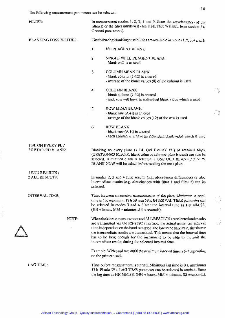
16 The following measurement papameen can be selected:
2 - blank well is entered
3 umn (1-12) 1s enter
- avemgc of the blank values (8) of the column i s us
4 COL - blank column (1-12) is e n ~ r d -each row wiU have an individual b value which is us&
5 RQW BL - blank row (A-H) is enle - average of the blank val (12) of the row is u
6
- tach column will have an individ value whisk is uscd
1 EL ON EVERY PL /
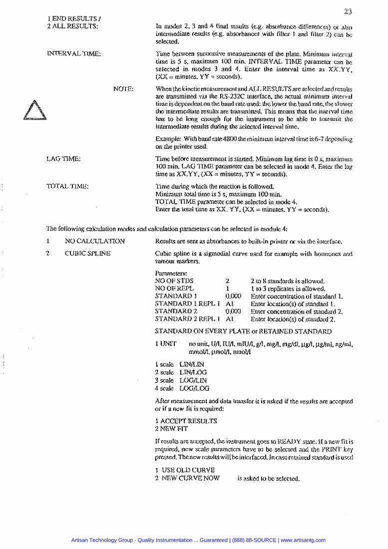
1 END RESULTS I
. 1 USE OLD B
Time huween sucses&a measuremenu of the glare. M i n i m a interval ' 17h59min59s. can
.SSP
NOTE:
Lime is depcndenton h e bau
Artisan Technology Group - Quality Instrumentation ... Guaranteed | (888) 88-SOURCE | www.artisantg.com
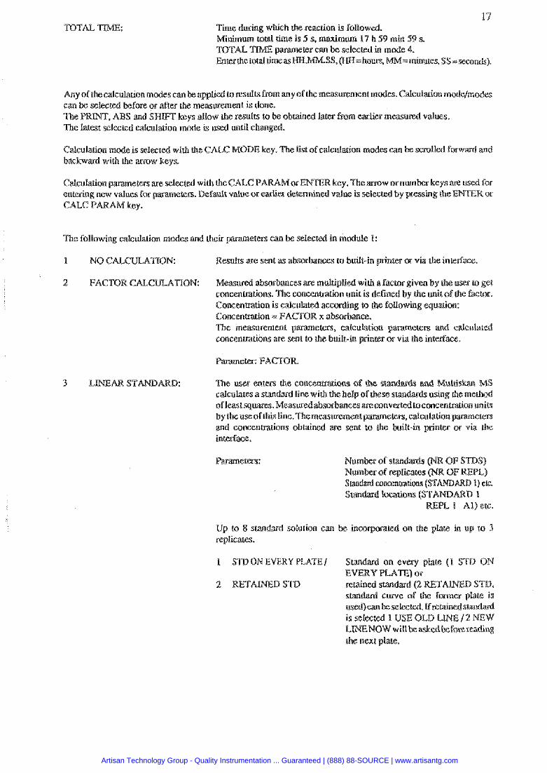
TOTAL 14
Time during which h e reaction is followed.
Any of the calculation modes m be applied loresults from any of Lhe measurement modes. Cdculation m can be selected before or after the measurement is done. The PRINT, ABS and SHIFT keys allow the results to be obtained later from earlier measured values. The latest selected calculation mode is used unu changed.
Calculation mode i s select& with h e CAM: MODE key. Ihe List ofcalcularion m scrolled forward and backward with the anow keys.
Calculation parameters are selected with theCALC P entering new values for parameters. &fault value or C U C P koy.
The following calculation modes md heir
NO CALCULAnOM:
FACTOR CAL. TION:
Results we sent as absorbances to built-in primer
Measured absorbances are multiplid with a Factor given by the uses (a get concentrations. The cmcenrp-acion unit is de by the unit oT the factor. C o n c e n ~ o n is dculated according (a th Concentntion = FACTOR x absorb-. The measurement p;aramelers, calcula cmcenuations are senk to the built-in
calculates a standard line w
Up !o 8 smdard solution can replicates.
1 STD ON EVERY PLATE I
che next plare.
Artisan Technology Group - Quality Instrumentation ... Guaranteed | (888) 88-SOURCE | www.artisantg.com
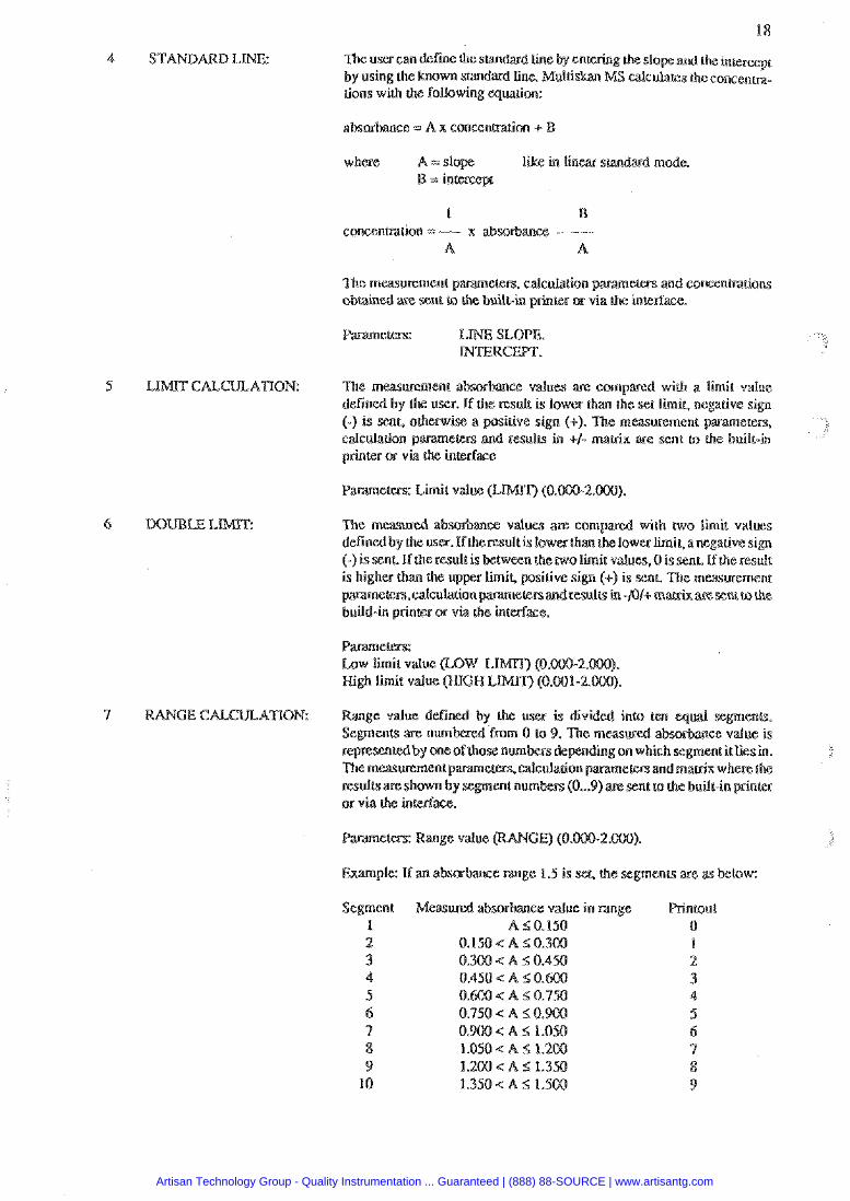
The user can defiie the smdard line by enre d the intercept by using the known stan the concenm- tions with the following equation:
absorbance =: A x concentmion + B
where like in linear srandard mode.
The measmment parame==. calcula(ion pamineern and cowenmations obtained we sent co the built-in pYinter or via the interlace.
5 LIMIT CAECULATION: with a limit value limik negative sign
). The maupement p sent to the built-in
6 UBLE LIMIT: 7he measwed absorbace values with two limit values defined by the user. If heresdais lowerth erlimir,anegalivesign f-) i e result is between the two limit values,O is sent. if the result is h the lrpp~r limiL gasitive sign (+) is sent. The measurement parameem. dculaeion p and results in -PI+ m sent to the build-in peinter or via th
Low limit value High limit value
7 RANGEC ATTON: fmm 0 lo 9. The
Enample: If an abs~banse range 1.5 is the segmenrs are as Mow:
Measured absorbance value in range A S 0.150
O.lSO<A 50.300 0.300 < A 5 0.4%
0.900 < A 5 1.0
Artisan Technology Group - Quality Instrumentation ... Guaranteed | (888) 88-SOURCE | www.artisantg.com
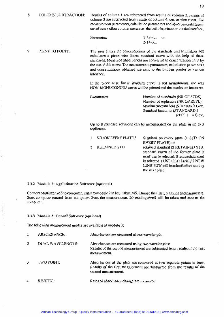
Results of column P are submcced from resuh of volumn 2, results of column 3 are s u b a r e d h r n results of column 4, etc. or vice v e s a The maurement parameters, calculation and ab~rbmcediffepen- ces ofevery other column are sent to the builtin p r i n ~ r o r via the interfarce.
Ihe ma enters the cousenhacions of the s calculates a pie% wise lin stan&&. Meilsiaed absopbmces are con
use of this curve. The measusement p and conceumtions obtained are sent to h e built-in printer or via the interface.
I f the piece wise En smdard curve is not monolonous, the text NON-MONOTONOUS curve will be grin and the lteults are incomecn.
1 STDON EVERY PIATE/ Standard on every plate (1 STCI ON
332 ule 2: Agglutination So
Connect Multiskan MS to compures. Enm MS. C h a m the filter, Star% compulgP control fmm wmpurer. 0 readings/well will computer.
The following measmment m s are avaitable in module 3:
1 ABSORBANCE:
2 DUALWAV Absorbanas are using Resulu of the sec from resulu ofthe rust mmlrremenl
4 ne:
Rcsulrs of the fmt che results of Phe
Artisan Technology Group - Quality Instrumentation ... Guaranteed | (888) 88-SOURCE | www.artisantg.com
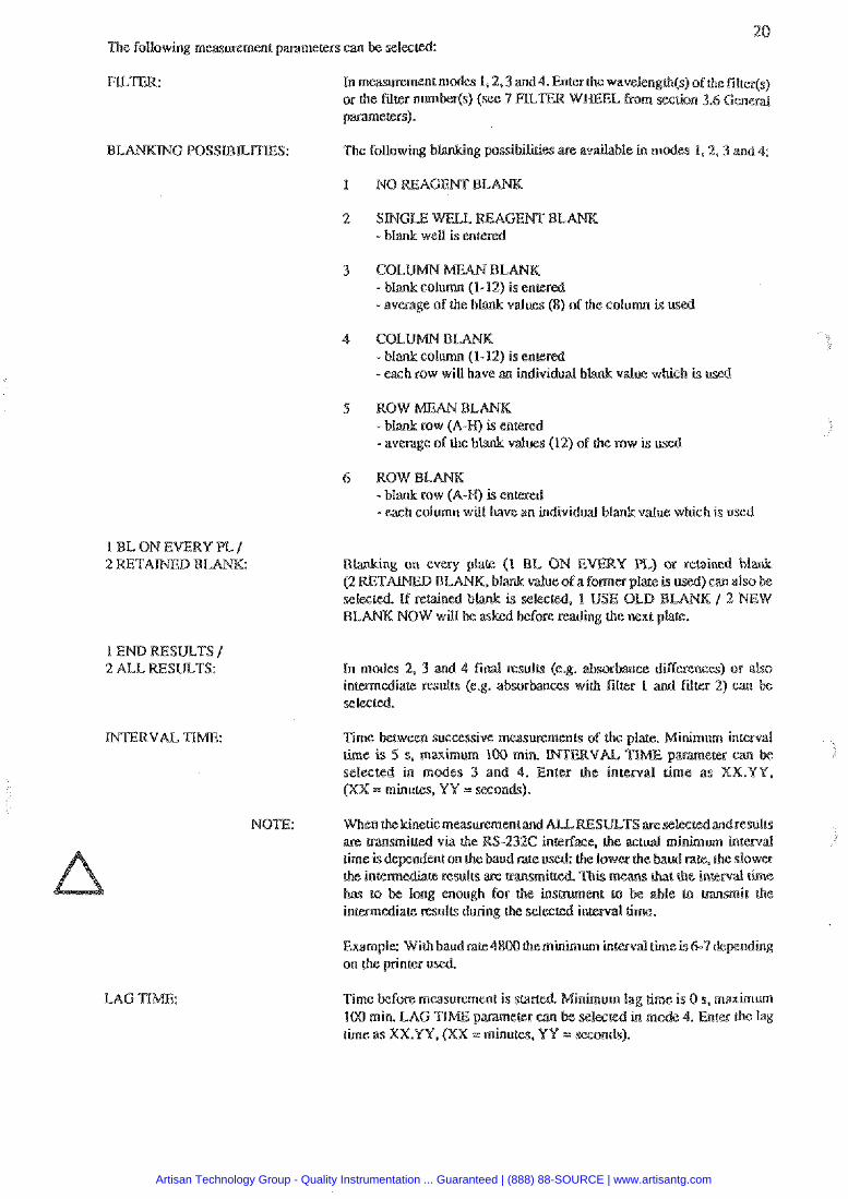
20 The following m w w e m e n t parameters can be selectd
In measwement modes 1.2.3 and4. Enter the wavelength(s) ofthe filter(s) or the filter number($ (see 7 RL E from mnion 3.6 Generd p m e r e r s ) .
BL ng possibilities ape available in rn
2 SINGLE WELL R E A G E m - blank weU is entered
3 CO AN BL - bl (1-12) - average of the blank values (8) of the column is us
I BL ON EVERY PL / 2 RETAINED BLANK.
1 END RESULTS / 2 ALL RESULTS:
-each row will have an individual b
(12) of rhe row is used
value which is used
Blanking o n every plate (1 EL O N E Y PL) or retained blank (2 RETANXI BLA selected. If retained b BLANK NOW will be a-c
Time between successive measuremen& of the piace. Minimum inremat time i s 5 s. maximum 100 min. p w e r e r a n be selected in modes 3 and 4. Enter the interval rime a s XX.YY, (XX = minutes. YY = w o n & ) .
NOT1E: When thekinetic measurement are m s m i u e d vla the R.3 h e is dcpndcnt on the baud lower the baud rate, the slower the inremediare rcsulrs are has ro be lmg enough lo i n m e d i a resulrs during
Exmple: With baudnse4800 the minimum in on b e printer d.
Time before measurement i s s 100 min. LAG T1bE p m e time as XXYY. (XX - minuteslf. YY = seconds).
Artisan Technology Group - Quality Instrumentation ... Guaranteed | (888) 88-SOURCE | www.artisantg.com
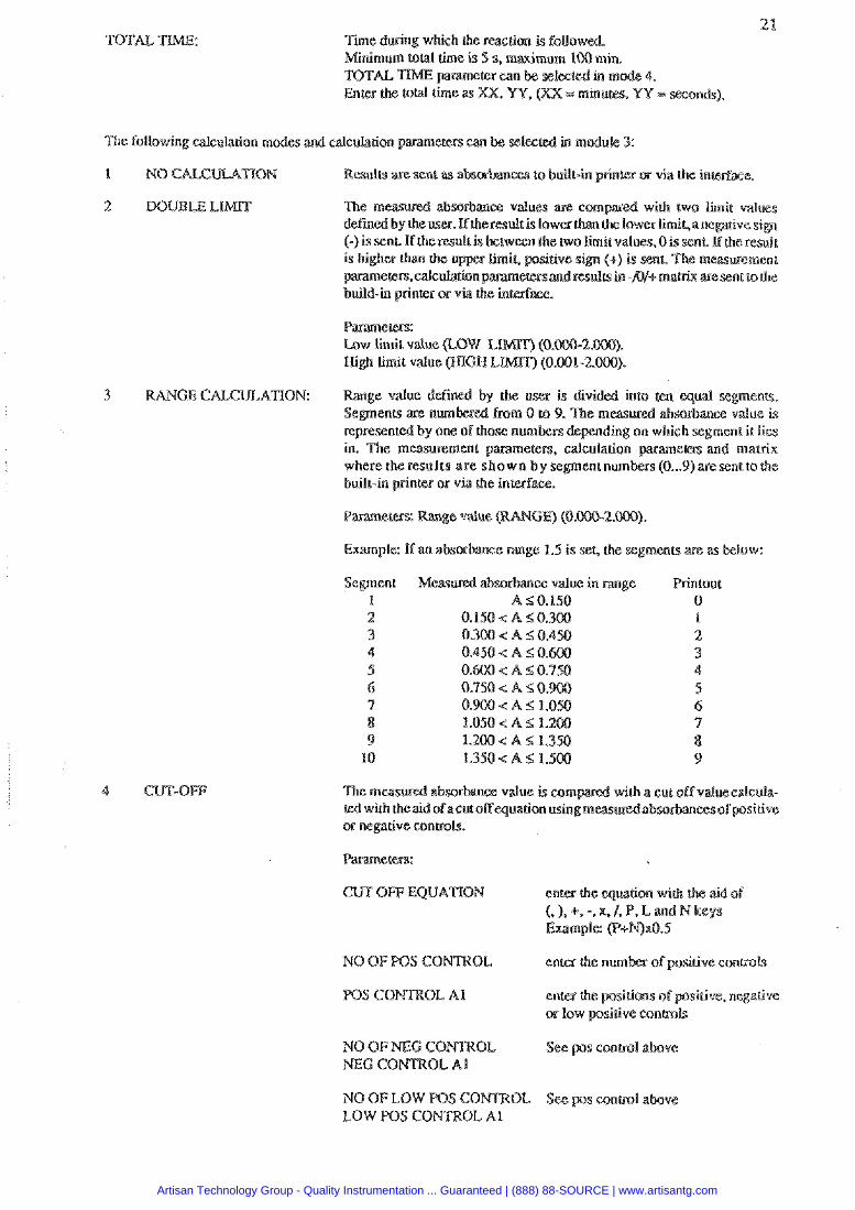
The following calculation modes and dculahon paramelers can
NO CKCUI-A%ION
DOUBLE LIMT
Results are sent as absefbances to built-in printer or via the interface.
The banm values are c with two limit values defin therwdt is lowerth er limir,a negative sign (-) is sent If the result is between the two limit values, 0 is sent. if tbe result
ded into ten equal segments. measwed abmbance d u e is
represented by one of rs depending on whi in. The measuremen
t numben (0 ... 9) are sent to the built-in printer or via the inmface.
Parameen: Range value
Example: ff an absor e m g e 1.5 is set, the segments are as below:
M a w e d absorbance value in range A S 0.150
0.1SQ < A i; 0.300 0.300 A r; 0.4
1.206 < a 5 n.350 1.350 .:A r; 1.5BB
wilh a cut oFf valuecaleula- ted wilh theaidof acutoffecqua6sn usingm absohanws orpositive or negative contmls.
S CONTROL A l
NEG CONTROL A1
Example: 0"+1\1)x0.9
LOW POS CONTROL A1
Artisan Technology Group - Quality Instrumentation ... Guaranteed | (888) 88-SOURCE | www.artisantg.com
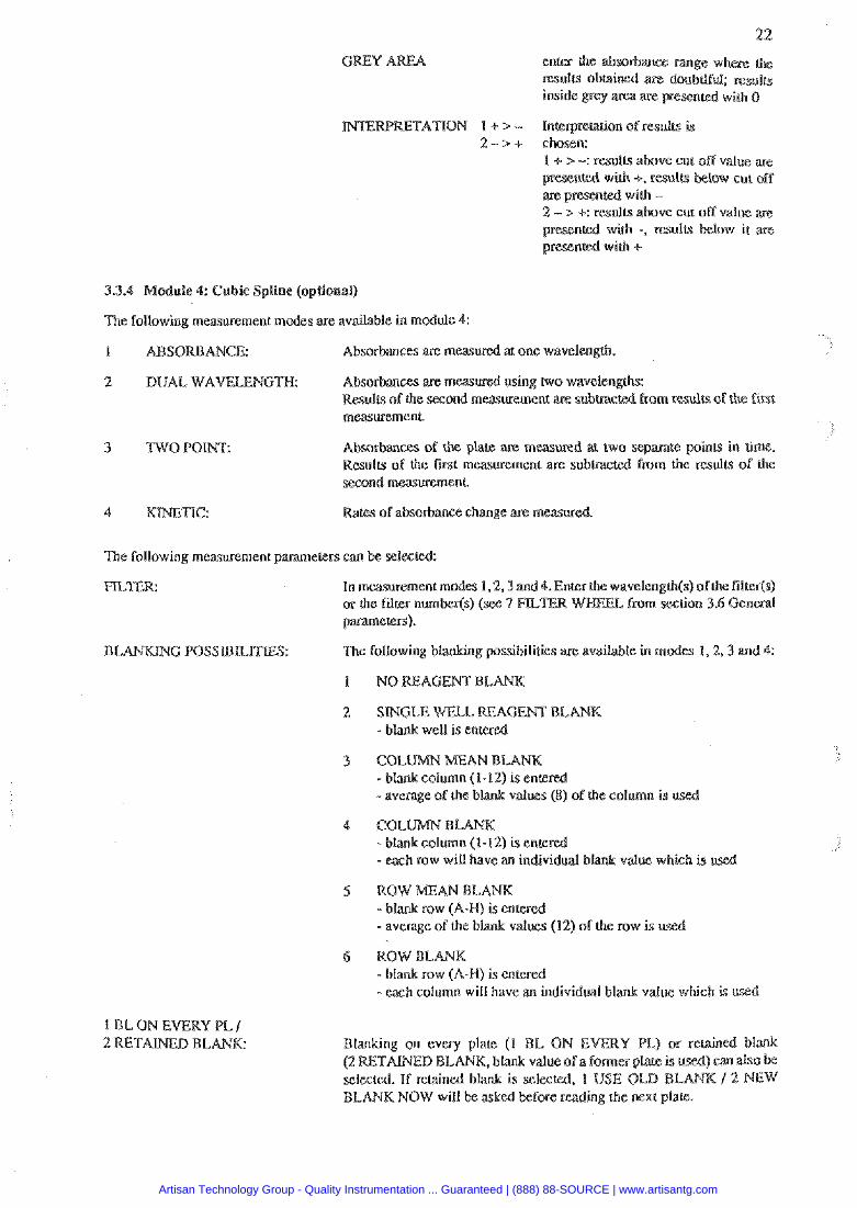
odule 4: Cub$ Spline (opllnnal)
The following measurement modes are available in modrale 4:
Interpreration of results is chosen: 1 + s -: results above cut off value are present& with +, results are presented with - 2 - > +: results above cut off value ale
with -, results below i r are
I BBSORBANCE: Absoabances are meas~xed a1 one wavelen
2 D U A L , W A V ~ N C ~ Absorbances are measured using nvo wavelengths: Results of the second measurement are subuae from results of the first measurement.
Absorbmces of the plats are meas two .%epmte points in time. Results of lhe fvst measurement are submcted from lhe resulL5 of the second measu+emeni
4 K ~ W E ~ C : Rates of absorbance change are measured
The following measurement paramerers ean bs selslul:
In measwemen1 modes 1.2.3 and4. Enter h e wavelength(s) ofthe fitter(s) or lhe fitter nwntscr(s) (see 7 FB. parameters).
BL The following b M n g possibilities are avrritable in mod- 1.2.3 and 4:
1 BL ON EVERY PL / 2 RETAWED BLANK:
2 SINGLE WELL REAGENT BL - blank weU is enrered
3 co umn (1-12) 1s en@
-average of the blank values (8) of the column is vceB
4 C O L W B
- average of the blank values (12) of the mw i s u
6 ROW %L
-each column will have an individual blank value which is u
Blanking on evepy plarc (1 BL ON E (2 RETALNED BLANK, blank val selected. If rek ind blank is sel BLANK NOW will be asked More reading the nexl plate.
Artisan Technology Group - Quality Instrumentation ... Guaranteed | (888) 88-SOURCE | www.artisantg.com
NOTE:
TOTAL TTIME:
In maties 2, 3 and 4 final results (e.g. absorbmce differences) or also iace resula (e.g. absorbanas with filter 1 and filter 2) can
I the plare. aninimum intern& parameter can be
ted in modes 3 and 4. Enter the inlerval time as X X Y Y , minum, YY =.won&).
When the kinetic mmurement md ULTS ase selected and r e s u l ~ are hansmiad via the RS-232C the actual minimum interval time is dependent on the er the baud rate, rhesfowcr
means that the interval h i m e
to be able to m s m i t the in terndate results d
Example: With baud rate48 h e minimum interval h e is 6-7 depending
Time during which the reaction is foUowd. Minimum loud time i s 5 s. maximum 100 min. TO in mode 4. En inutm, VU = wands).
The followmg calculation modes and calculation p m e c e r s can be seles
1 NO CALCTYLATlQN Resulu aae sent as abs~bances to built-in prints or via the interface.
Cubic spline. is a si curve used for example with hormones and turnour makers.
2 1 ~ 8 s is &owed.
1 En& Icc&n(s) of smdard 2.
ON EVERY PLATE
l UMT no uniL UA. WA. mlU/I, mmelll, p o l l l . nmoVl
l sale LWLW
Artisan Technology Group - Quality Instrumentation ... Guaranteed | (888) 88-SOURCE | www.artisantg.com
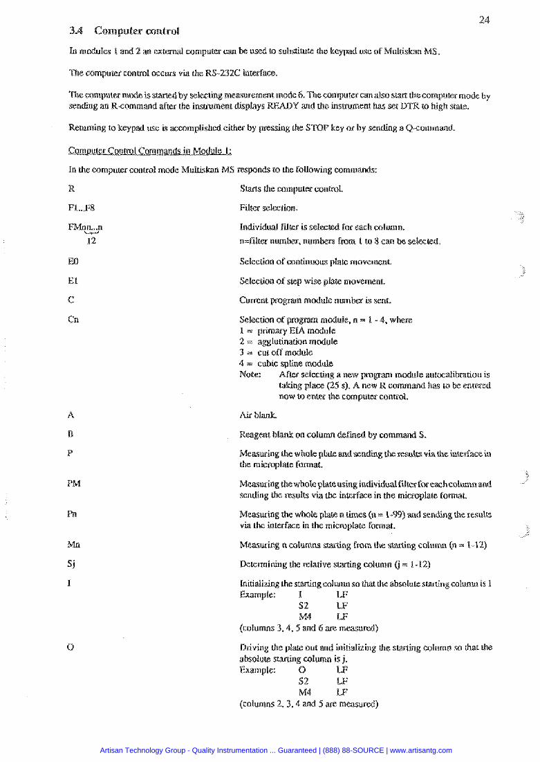
In mdules 1 and 2 an external computer can used ta substitute the keypad use of Multi S.
The computer control occws via the RS-232C interface.
The compu~e~ made is s by selwting m a w e m e ode 4. Tbe computer can &o s sending an R-command after h e insrmment displays Y and rke instrument has set D m 'R high state.
Retming to keypad use is xcomplished either by pressing the STOP key or by sending a Q-command.
nds to Lke following commands:
R S m the computer conlrol.
F1..P8 Filter selection.
FWnm.&n individd FdW i s selected for each column.
12 n=filb% number, numkm fmm I to 8 can he selecled.
EO Selection of continuous plate movemenr
Selection of step wise plate movemen(.
Selection of Bduk, n = 1 - 4. w 1 = primary 2 = agglut idon module 3 = cut off module 4 = cubic spline module Note: Mtw selecting a new pro module autociilibration is
Paking place (25 s). A new R command has PB be entered now lo en& the compuler wntml.
Air blank.
on column &fined by mm
Mearuring the whole p l akdsend ing results via che inser%am in the microplate form&
using individual filter for inledax in the mimoplac@ format
Measuring che whole p ) and sending ahe mulU via the interface in fie microplare fom&
Mwrsring n columns staRing from the starting column (n = 1-12)
Rtemining iho relative starting column (j = 1-12)
Initializing thc scarsing c o h m so that h e absolute staning column is 1 Example: I W
S2 M4 LF
(calumns 3.4.5 and 6 are measured)
Driving the pla& our and initialiring the s g eolumn so thar ihe absolure stating column is j. Example: 0 W
S2 w M4 LF
(columns 2.3,4 and 5 arc measured)
Artisan Technology Group - Quality Instrumentation ... Guaranteed | (888) 88-SOURCE | www.artisantg.com
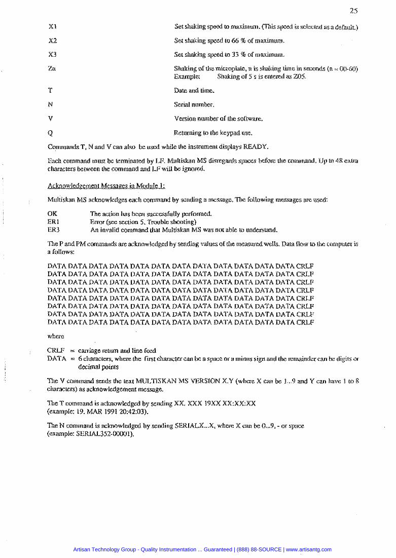
XI to maximum. Cfhk s is asa debaul~)
ng of h e microplare. n is h e in seconds (n = 00.60) Example: Shaking of S s is
Dare and rime.
N Sekal number.
V Version number of the soft
Q Returning m che keypad use.
Commands T, Nand V can also be u d while the insmment displays Y.
Each command must be terminated by LF. MS dmgards spa- before the uomrnand. U characters between the command and LF will be ignore&
Multiskan MS acknowledges each command by sending a message. 'The following messages are u
OK n suscessfully pcdomed ERl Error (see section 5. Tnuble s ER3 An invalid command thak Mu1 S w a not able ro under;
The P and PM commands are achowledg& by sending valua of h e measwed welts. Dara flow u, the cornpurer is a follows:
DATA DATA DATA DATA DATA DATA DATA DATA DATA DATA DATA DATA DATADATADATADATADATADATADATADATADATADATADATADATA DATADATADATADATADATADATADATADATADATADATADATADATA BATA DATA BATA DATA BATA DATA DATA DATA DATA DATA DATA DATA DATADATADATADATADATADATADATADATADATADATADATADATA DATADATADATADATADATADATADATADATADATADATADATADATA DATA DATA BATA DATA DATA DATA DATA DATA BATA DATA DATA DATA DATADATADATADATADATADATADATADATADATADATADATADATA
where
- - - - a vase or a minus si and the remainder can
The V com texl L.9 and Y can have 1 to 8 c k w r s )
The T command is achowldged by sending XX. XXX 19 (example: 19. 1991 U):42:03).
The N command is achowledgeoi by sending S IALX ... X, where X can (example: S E R m 3 5 2
Artisan Technology Group - Quality Instrumentation ... Guaranteed | (888) 88-SOURCE | www.artisantg.com
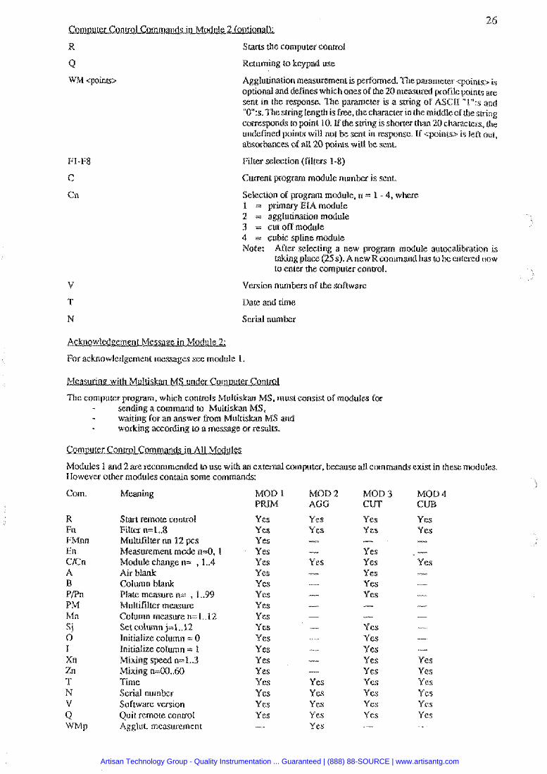
R Starcs h e computer control
Q Returning to keypad use
WM <points> Agglutination measurement is perfomed. The parameter w i n - opdolLli and defmes which ones of the 20 measwed profile points ape sent in the response. The p m e t e r is a sukng of ASCII "1":s and "0":s.Tke string length is free, t h e c h m c k r in the middleofhesbing corresponds to point 10. ff the saing is shoner than 20 characters. (he undefined points will not be sent in response. If cpoinrsl is left our, absorbances of a8 20 p i n t s wilt be sent.
Filter selection ( f i lws 1-8)
Cuwent program module number is sent.
module. n .; 1 - 4, where 1 = primary EIA module 2 .; agglutination madule 3 = cut off module 4 =: cubic spline mcxiule Note: Afkz selecting a new module autocalibration is
W g place (25 s). A ne rnand has to be entered now to enter the computer conml .
V Version n u m b r s of h e software
T Dare and time
N
For acknowledgement messages see module 1.
The cornpurer program, which controls Multis S . must consist of modules for - sending a command to Mutuskan MS. - waiting for an answer Fmm Mul - working according to a message or resulu.
Modules 1 and 2 are recommended to use with an excemal wmpurer, beeiluse aU commands exist in these modules, However other modules contain some commands:
Com. Meaning
Start mo!& control F i l w n=1..8 Mululilrer nu 12 pcs Measurement mode n 4 , I Module change n- , 1 ..4 Air blank Column blank Plate measure n= , 1 ..99 Multifilrer measme Column measure n=l..12 Setcolumn j=1..12 Initialize column = 0 Initklize column = 1 Mixing spwl n=1..3 Mixing n=00..60 Time Serial number Software version Qui t remote control Agglul. rnusuremcnt
MOD l MOD 2 MOD 3 MOD 4 PRIM ACC CUT C
Yes Yes Yes Yes Yes Yes Yes Yes Yes Yes Yes Yes Yes Yes Yes Yes Yes Yes Yes -
Yes Yes - Yes Yes Yes Yes Yes
- Y cs Yes Yes Yes Yes Yes Yes Yes Yes -
Artisan Technology Group - Quality Instrumentation ... Guaranteed | (888) 88-SOURCE | www.artisantg.com
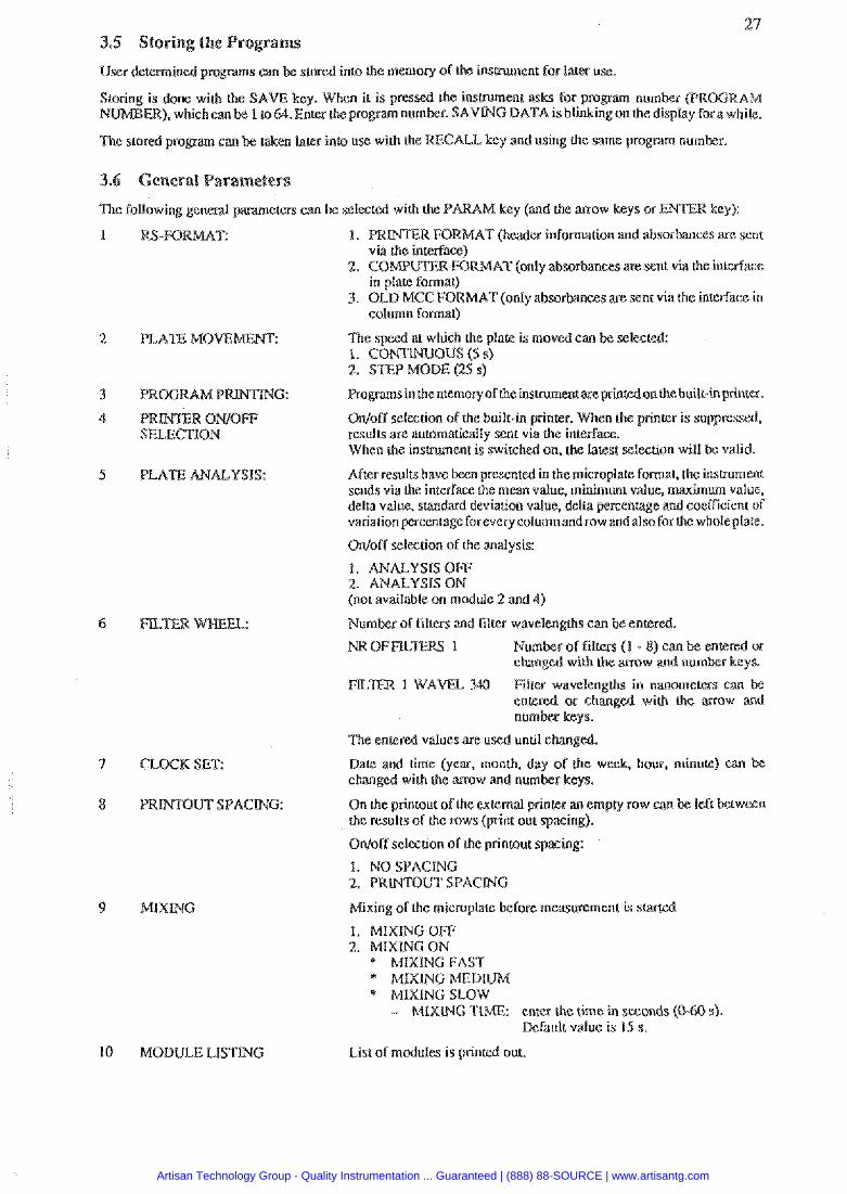
27
be stored into the memory of the insmment for law use.
y. When it is pressed the i n s w e n t asks For program numbcr (PROGR ER), which can tx I m64. Enlea the program number. SAVING DATA is blinleingon the diqlay fora while.
The stored program can be laken later into use with h e RECALL key and using the same prognm numks.
The following general parameters can be selected with the PARAM key (and UE mow keys or R key):
1. PKD4TE.R FORMAT (header inEomation and absorbances are sent via the interface)
2. COMPUTERFOR (only absorbances are sent via the interface in plate format)
3. OLD MCC FORfkIAT(onIy absorbances are sent via the interface in solumn format)
PLATE MOVE The speed at which the plate is moved can be selected: 1. c o m o u s ( 5 r;) 2. STEP MODE (25 s)
Program in the mernoryof the instnunent are princedonthe built-inprisiter.
PRJNER ONIOFI: Odoff selection of the built-in printer. When the printer is suppres SELECTION rsults are automatically sent via the interface.
When h e instrument is switched on, the larest selection will be valid.
PLATE ANALYSIS: After results have been presented in the microplate format. the insuurlent sends via the interface the mean value. minimum value. maximum value. delta value. smdard deviation value, delta prcenmge and coefficient of variationprcenraye foreverycalvmnand row andalso forthe whole plate.
9 MIXWG
Odoff scleftion of the analysis:
1. ANALYSlS OFF 2. ANALYSIS ON (nor available an module 2 and 4)
Nurnbea of filters and filter wavelengths can
Na ClF 1 bee of filters ( I - 8 or gcd wirh the m o w S.
FILER 1 WAVEL 30 Filter wavelengths in nanomem can bc entered oc changed with thc mow and
The entered values arc uscd until changed.
Date and lime (year, month, day oT the week, how, minute) can changed with the mow and number keys.
On the printout of the exccrnal printer an empty mw can Ihc results of the mws (print out spacing).
On!olf selection of the printout
1. NO SPACING 2. PRWTOUT SPAClNC
Mixing of the rnicroplsle before mmWmGnK is s
1. MIXING OFF 2. MIXING OW
* MIXING FAST * MIXING MEDIUM * MIXING SLOW
- MIXLNG TIME enter the time in seconds (0- Dcfaulr value is lS s.
10 MODULE LISTMG List o l modules is printed out.
Artisan Technology Group - Quality Instrumentation ... Guaranteed | (888) 88-SOURCE | www.artisantg.com
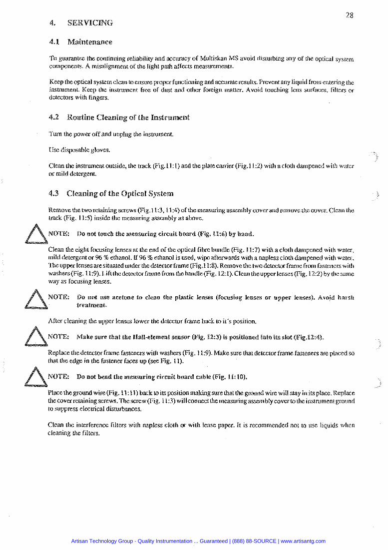
To guarantee Lhe continuing reliability and accmcy of Mul MS avoid disturbing my of the optical syscem components. A misali~ment of (he light path affects measurements.
Keep the optical system clean t ensure propee functioningmd accurateresults. Prevent my liquid from entering the instrument. Keep the insaument Free of dust and orher foreign m a w . Avoid touching lens surfaces, filrers or detectors wilh fingers.
Tum the power off and unplug (he instrument.
Use disposable gloves.
Clean the instrument outside, (he track (Fig.11: I) andl the plate carrier (Fig.I1.:2) with a cloth dampened with water or mild detergent.
Remove the two retaining screws (Fig.l1:3,11:4) of the measuring assembly coves and remove the cover. Clean the tnck (Fig. 115) inside the measuring assembly as above.
e measuring circuit board (Fig. ll:6) by band.
Clean the eight focusing lenm at the end of the optical fibre bundle (Fig. 113) with a cloth mild detergent or % % ethanol. if 96 % ethanol is used. wipe afternards with a napless cloth The upper lensesaresituatcd under thedetector frame(Fig.l1:8). Remove (he twoderector f m e from fasteners with washers(Fig. 11:9). Liftthedetector frame from h e handle (Fig. 12: 1). C l m (heuppcr lenses (Fig. 122) by the same way as focusing lenses.
acetone to clean the p nses). Avojd harsh
After cleaning the upper lenses lower derectr frame back LO it's position.
ake sure that the Nall-elewent sensor (Fig. 19:s) is positioned into its slot (Fig.lf:rJ).
Replace the delecmr fnme fasteners with washers pig. 11:9). e sure that delecmr frame fasteners are placed so lhat the edge in ihe Fastener faces up (
ndwke(Fig. 1l:ll)bask und win will stay in its place. Replace (hccover reuiningscrcws. Thescrew (Fig. 11:3) witlconnect the measuring assembly 60verto the instrument ground to suppress electrical disturbances.
Clean the inlerference filten with napless cloh w with lense paper. It is recommended nor to use liquids whcn cleaning (he Filers.
Artisan Technology Group - Quality Instrumentation ... Guaranteed | (888) 88-SOURCE | www.artisantg.com
Track Plate carrier Retaining screw of the measuring assembly cover Reraining screw of the measuring assembly cover Track Measuring cissuit board Focusing tenses Belector frame DemL8r f m e lastenex with washer Measusing circuit Ground wire Position of the gmund wire
Figure 1 I . ning the measuring ssernbly cover
Artisan Technology Group - Quality Instrumentation ... Guaranteed | (888) 88-SOURCE | www.artisantg.com
I. Handle 2. Upper lenses 3. %I1 element sensor 4. Position of the Plall element sensor
Figure 12. Lilting the degctor fnme
Disinfect the insuument in cage of hazard of infecuous agents as follows:
Turn the power off and unplu
Use disposable gloves
Clean the instnrment outside, (he raazk (Fig. 1 I: 1) and the place carrier (Fig.11:2) with a disposable cloth dampcned either wilh 70 % ethanol or 1 % glucaraldehyde.
Remove the two screws (Fig. 11:3, 11:Q) of the measuring assembly cover and remove the cover. Clean Lhe mask (Fig. 11.5) inside the meawing assembly and h e eight f~ocusing lenscs at the end of rhc optical libre bundle (Fig. I1:n as abve .
NOTE: Do not touch the measuring cirsuil board (Fig. 11:6) by ban
The upper lenscs are situated under rhe detector frame (Fig. 11:8). Remove h e two de fme fauners washers (Fig. 11:9). Lirt thedetector frame from the handle (Fig. 12: 1). Clem the up rienses~ig.12:2)by *cwmc way as focusing lenses.
Artisan Technology Group - Quality Instrumentation ... Guaranteed | (888) 88-SOURCE | www.artisantg.com
3 1 o not w asetoue Lo clean the or upper ieoses), Avoid harsh
treatment.
Let the surfaces of the ksmment to dry.
Wipe out the thin fihn of the disinfection agent from the suriace of eight focusing lenses and upper l enw with a napless lens tissue dampened with waler. DKY the lenses with a dpy lens tissue.
After drying the upper lenses lower the deteetor h e back to its position,
ake sure that the Wall-efement sensor (Fig. 123) is positione into its slot (Fig.11).
Replase the detector f m e fasreners with washers (Fig. 11:9). W e sure that detector fPame fasteners ape placed so that the edge in the fastener faces up (see Fig. 11)
NOTE: Do not bend the cable (Fig. 11:10).
PLam~e~oundwire~ig.l1:11)Backloicsposition~ig. 11:12).Slidethemeasuriny assembly cover w its position making sure that the ground wiie will stay in io; place. Replace the cover rerainin screws.Thescrew (Fig.l1:3) will connect h e measuring assembly cover to the instrument ground to suppress elecui
Please note that this pr we can not bs a guarantee against cantmination of personnel handling the instrument.
Switch the power off. Unscrew the hvo cover reraining screws and lift the mver. Lift the filter wheel ham the filter whe l slot. Do nor touch fritter surfaces. Remove the filter spring by unscrewing the spring position holding screw. lnsepl a new ftlter into the wheel so that the arrow on the filer rim points downwards. Place the fitter spring into its original pasition and fasten the mew. Slide the frtcer wheel back k w the litter wheel slot with the toothed edge facing mwa+8s the rear of the hsmment. The filter wheel is drawn into position by the cenaal perrnanenr magner Close the instrument cover and replace the remining mews.
hen youchange the a 7 adding a new fitter you ustchange the parameter values (filter wheel, position and wavelen@h).
If the lamp bums out, replace it as follows.
n the insmmentcove~ by unscrewing the two screws oneach side
NOTE: Tl~elam and its snrroundings may be hot.
Lift up the lamp with the leminal socket. Pull ihe eminal socket from !.he lamp contaco; (see Fig. 13).
Do not touch the reflective surface of ihe new lamp or
Refit the terminal sacker lotheconcaclsof the new lmlpappmved by the mmufaerurer (OSR 6.1607.8V/50 W. Place the new lamp in its place.
Close the instrument cover and replace the retaining screws. Plug in the insvument and switch the power on.
Artisan Technology Group - Quality Instrumentation ... Guaranteed | (888) 88-SOURCE | www.artisantg.com
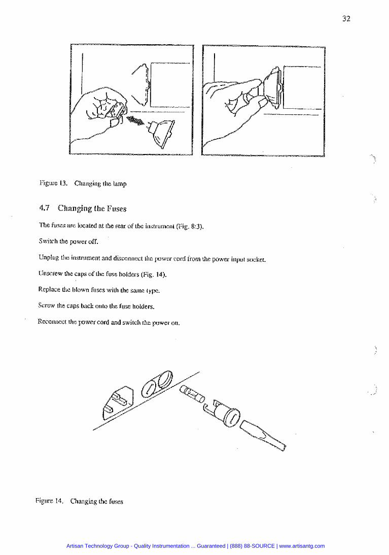
Figure 13. Changing the lamp
The fuses are located at the rear of the instrument (Fig. 83).
Switch the power off.
Unplug the insuurnent and disconnect rhe power cord from the power input swkek
Unscrew the caps of the fuse holders (Fig. 14).
Replace the blown fuses wirh the same type.
Screw the caps back onto the fuse holders.
wer cord and switch the power on.
Figure l4. Changing the fuses
Artisan Technology Group - Quality Instrumentation ... Guaranteed | (888) 88-SOURCE | www.artisantg.com
REASON
No power when switched on Check that the insmmenr is plugged in,
Check that the fuses ;ire not blown.
Unsuccessful transfer of dam via the interface system.
Check that the instrument baud rate matches chat of the computer.
Check that the both instruments have che ter length and paity
confiwtion.
ha6 the msmi&eceive pin configuration is set c o m d y .
Check that both insmrnents u s e the same kind of bndshake.
Check the connection sable.
PLATE ERROR Check that the plate is properly posirioned in the plak canier.
Check that no foreign mauer is obsrructirig the canier.
Check that b e rai ls not dkty nor bcnr
Check that the toothed belt is not broken.
Filter wheel is missing Place h e filterwhwl into the filtenvheel or faulty. slor Check chat the filter wheel has been
ADJUST OFFSET Adjust-nent OF light Conlac6 service. intensity faulty.
TOO MUCH LIGHT Too much light enters Check the filler. Contact service. the detectors.
NO LIGHT Lamp has bum out. Change the lamp.
Artisan Technology Group - Quality Instrumentation ... Guaranteed | (888) 88-SOURCE | www.artisantg.com
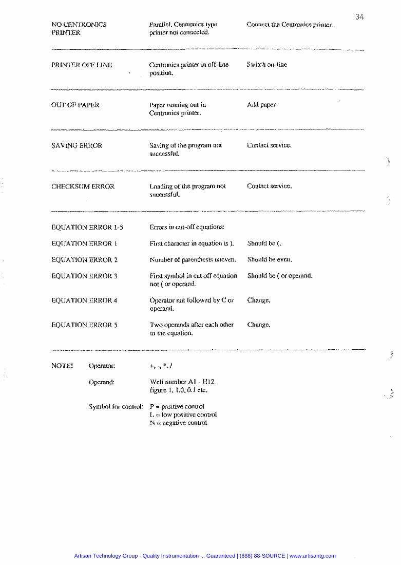
Parallel. Cenrrenics t. CorurecP the Centronics printer. printer not connected.
P R m R OFF LINE Centronics prinfzr in off-line Swirsh on-line position.
OUT 01;' PAPER Paper running out in Add paper Cenrronics printer.
S A V N ERROR Saving of the program not Contact service. successful.
CHECKSUM ERROR Loading of the pm- not Conracr service. successful.
Errors in cut-off equauons:
Fuss character h equation is ). Should bc (.
EQUATION ERROR 2 Number of parenrhesis uneven. Should be even
EQUATION EUKOR 1 First symbol in cut off equation Should bc (or opcmd. not ( or operand
EQUATION ERROR 4 Opsmtor nor followed by C or Change. opcmd.
Two opcmds after each orher Change in ihe equation.
Symbol for control: P = positive wnuol
PI = negaLive conuol
Artisan Technology Group - Quality Instrumentation ... Guaranteed | (888) 88-SOURCE | www.artisantg.com
. GENERAL CATION
Weight:
Overall dimensions:
Uains power supply:
Power Consumption:
Fuses:
Operating conditions: (indoor use)
Transporntion conditions:
Storage conditions:
Specml range:
Read-out range:
Measurement range:
Accuracy:
Precision:
Linearity:
Long Em stability:
S p e u l of operation
w m up h e : reading s
Display:
Keypad:
Interface:
Optical syslem:
Interference filters:
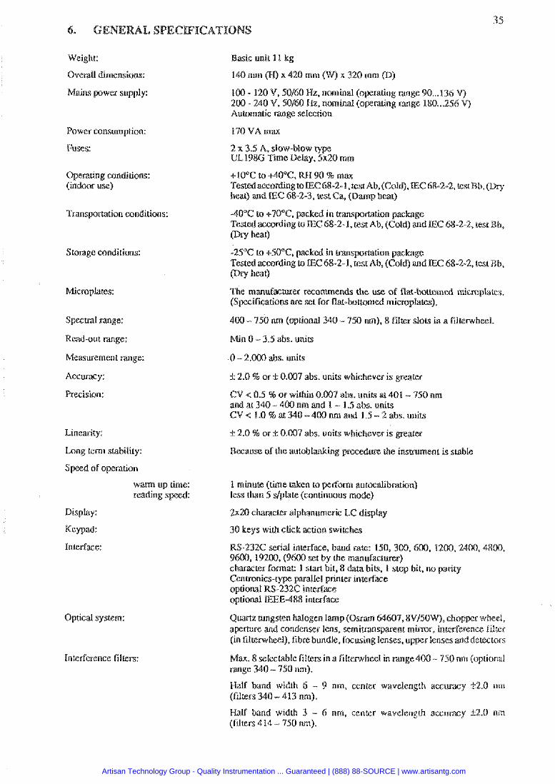
Basic unit 11 kg
140 mm (IT) x 420 mrn x 320 mrn @)
100 - 120 V, 50160 Ilz, nominal (operating range 90 ... 136 V) 200 - 240 V, 50160 Hz, nominal (oprating range 180 ...2% V) Automatic range selection
170 VA max
2 x 3.5 A, slow-blow type UL198G Time &lay, 5x20 mm
TestedaecordingtoEC68-2-1,testAb. (Cold).EC68-2-2. test Bb. (Dry hear) and E C 68-2-3, test Ca. (Damp heat)
40°C to +TOT, packed in m n ~ ~ t i o n package Tested according to LEC 68-2-1, Kcst Ab, (Cold) and @ru h a 0
-25°C to +50°C, packed in transporntion package Tested according to EC 68-2-1. test Ab, (Cold) and E C 68-2-2, rest Bb. (Dry hat)
The manul%rurer recommends h e use of flak-twtromgd microplaes. (Specificarions are set for flat-bouomed minoplates),
400 - 450 nm (optional 340 - I M sun), I) flrlter slots in a filterwheel
Min 0 - 3.5 abs. units
0 - 2 . W abs. units
ir 2.0 % or k 0.007 abs. units whichever is grealer
CV < 0.5 46 or within 0. 7 a h . units ar 401 - 950 nm and at 340 - 400 nm and 1 - 1.5 abs. units CV< 1.0%aN0-400nmand 1.5-2ahs.units
12.0 % or f 0.007 abs. unirs whichever is
1 minute ( M e taken to perform autocalibration) less than 5 dplate (continuous mode)
2x20 character alphanumeric LC display
30 keys wilh click action switches
RS-232C serial interface, baud pale: 150,300,600. 1200,2400,4800, 96M). 19200, (9MW set by the mandaclurer) character formal: 1 s m bit, 8 dam bits, I stop bit. no parity
lei printes interface optional RS-232C optional GE-488 interface
QuMz NngStefl halogen lamp ( O m 64607,8V/50W). chopper wheel, apcaure and condenser lens, semimsparenk m m r , interference filter (in filtenvhesl), fibre bundle, focusrng lenses, u r lenses and detec~ors
&?ax. 8 selectable filters in a fillemheel in m g e 400 - 750 nm (optional range 340 - 750 nrn).
Half band wid& 6 - 9 nm, center wavelcnglh accuracy 1.2.0 nm (filters 340 - 413 m).
Half band widlh 3 - 6 nm, center wavelength accuracy 92.0 nrn (filters 4 14 - 450 nm).
Artisan Technology Group - Quality Instrumentation ... Guaranteed | (888) 88-SOURCE | www.artisantg.com
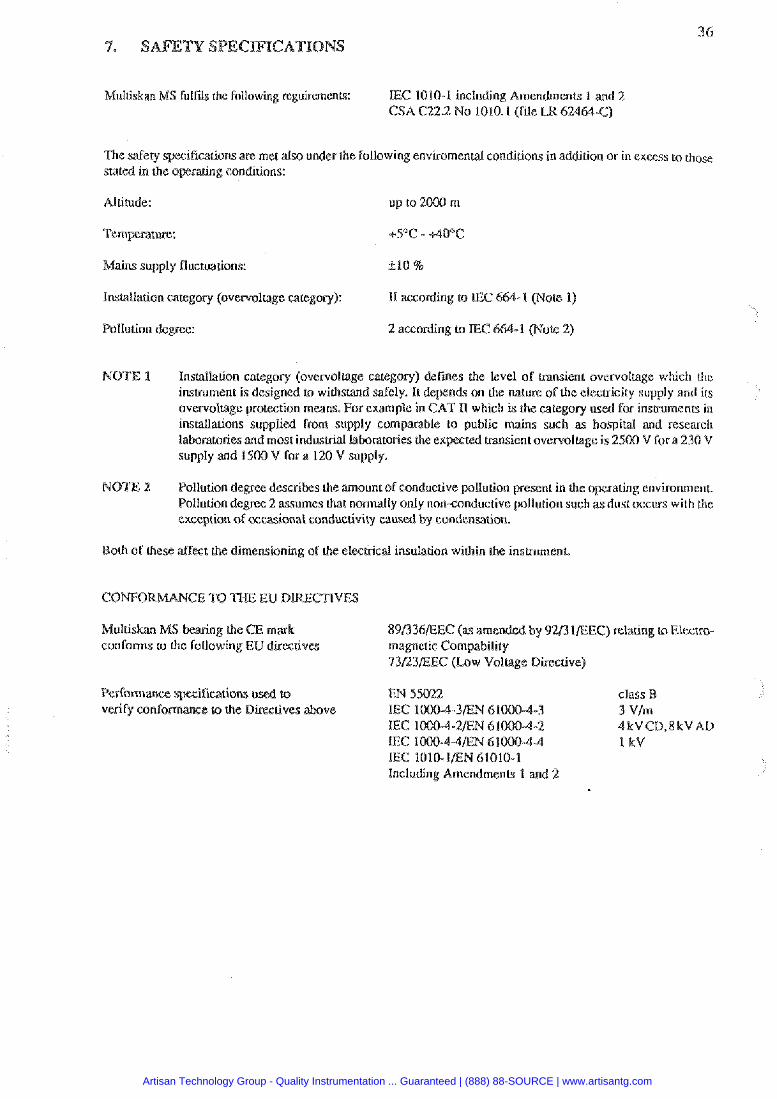
Multiskan MS fulfds the Following reguuements: IEC 1010-1 including Amendments 1 and 7. CSA C22.2 No 1010.1 (file Ui 6246Q-C)
The safety specifications are met also under the following enviromentd conditions in addition or in excess to rhose stated in the operating conditions:
Altitude: up to 2RN m
Mains supply fluctuauons: 410 %
Inslallation category (overvoltage category): I1 ascoxding KI IEC
Pollution d e w : 2 according &I TEC
NOTE 1 lnsrallation category (overvol6age category) defies the level of msient overvoltage which h e instrument is designed to withstand safely. Ir depends on the nature of the electricity supply and irs overvoltage protection means. For example in CAT I1 which is the category used for instruments in installations supplied from supply comparable In public mains such as hospital and research taboratories and most indusbial laboratoris the ex ted transient overvoltage is 2500 U for a 230 V supply and 1500 V for a 120 V supply.
NOTE 2 Pollution degrce describes h e mount of conductive pollution present in the operating environment. Pollution degree 2 assumes that normally only non-conductive pollution such as dust occurs with the exception of occasional conductivity caused by condensation.
Both of these affect the dimensioning of the electrical insulation within the insmmenr
Multiskan MS bearing the CE m 89/336EEC (as amended by E/31/EEC) relating to Elecrrcc conforms KI the following EU directives magnetic Compability
73D3EEC (Law Voltage Directive)
Pcrfomancc qxcifieations used to class B verify conformaxe to the Dkt ives above 3 V/m
4kUCD.8kVAB I kt'
IEC 1010-lEN 61010-1 including Amendments 1 and 2
Artisan Technology Group - Quality Instrumentation ... Guaranteed | (888) 88-SOURCE | www.artisantg.com
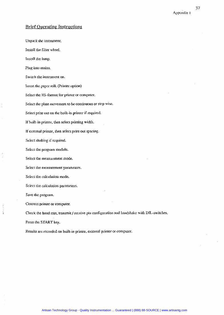
37 Appendix 1
Unpack the insmment.
Insult1 the Firer wheel.
lnswll the lamp.
Plug into mains.
Switch the instrument on.
Insert h e papa roll. (Printer option)
Select the RS-format for printex or computer.
Select the plafe movement to be continuous at. step wise.
Select print out on the built-in printer if required.
If built-in printer, then select printing widlik.
If external printer. then select print out spacing.
Select sh&hg if required.
Select the program module.
Select the measurement mode.
Selecr the nleasurement patameten.
Select the calculation mode.
Selcct the calculation para me^^:^^.
Connect ppinm or computer.
Check the baud rate. hansmit /receive pin conligutarion and handshake with DL-switches.
Results are recorded on built-in prink%, cxternal printer or computer.
Artisan Technology Group - Quality Instrumentation ... Guaranteed | (888) 88-SOURCE | www.artisantg.com
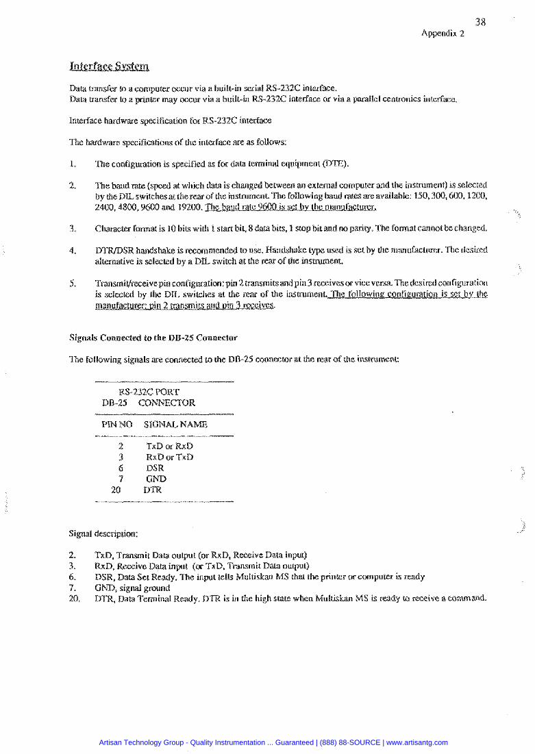
Daca transfer tn a computer occur via a built-in serial RS-232C interface. Data transfer ro a printer may occur via a built-in RS-232C interface or via a parallel wnt~onics interface.
Inmface hardware specification for RS-232C interface
The hardware specifications ofthe interface are as follows:
1. The configuration is s iIied as for data temina! equipment CDTE).
2. The baud rate ( at whisk clata is changed between an external computer and the insmment) is selected vaitakle: 150,300,600,1200,
2400,4800,9600 and 19200.
3. Chaeacter format is 10 bits wilh 1 s ta t bit, 8 data bibs, 1 stop bit and no parity. The format cannot becbnged.
4. DTR/DSR handshake is recommended to use. Handshake used is set by the mandacturer. The desired alternative i s selected by a D L switch at the rear of the instrumene
5. Transmit/~eceivepin configuration: pin 2 msmi~sandpin 3 receivesor viceversa Thedesired configuration e insmmenl
Signals Connected to the DB-25 Connector
The following signals are connected ta the DB-25 connector at ihe r w of the insrrunlcnt:
RS-232C PORT
NO SIGNAL.N
2 TxD or RxD 3 RxD ar TxD 6 DSW
Signal description:
2. TxD, Transmit Data ourput (or RxD, Receive Data input) 3. RxD. Receive Data input (or TxD. Tmsmit DaLa ourput) 6. DSR, Data Set Ready. I h e input tells Multiskan MS that prinkr or computer h ready 7. GND, signal ground 20. DTR. Data Terminal Ready. DTR i s in the high sfate when Mulris MS is ready to receive a command
Artisan Technology Group - Quality Instrumentation ... Guaranteed | (888) 88-SOURCE | www.artisantg.com
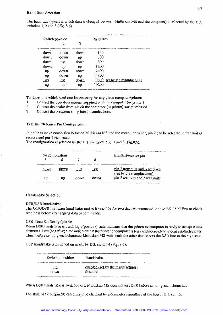
39 Baud Wale Selection
a1 which data is changed ~WWXI Muld MS and the computes) is s e l ~ t e d by rhe D L switches 1,2 and 3 (Fig. 8:6).
Switch position Baud rate I 2 3
dow" down down down
UP UP A
UP
down down
UP UP
down down Ja
UP
down UP
down up
down UP
UP
To determine which baud rate is necessary for any given computer/printer: 1 . Consult the opcra~ing manual supplied with the computer (or printer) 2. Contact the dealer From which the computer (or printer) was purchased 3. Contact the computer (or printer) m a n u f ~ t l a e r .
eceive Pin ConTigura6oo
In order to make connection between Multiskan klS and dre computer easier, pin 2 can be selected to tmnsmit or receive and pin 3 vice versa The cortfiguration is selected by the D L switches 5 . 6 . 9 and 8 (Fig.8:6).
Switch position ~ransmir/receive pin 5 6 7 8
UP UP down down
Handshake Selestian
Thc D W S R hardware hands ss~ble icr two d e v i w connected via (he RS-231C line to check readiness befort exchanging data or commands.
DSR, Data Set Ready (pin 6): When DSR handshake is used. high faositive) stale indieam chat the prinrer cr computer is ready to accept a d m character. Low (negative) state indicates that the printer or computer is busy and not rwdy to accept adatacharacter. Thus, M o r e sending each characm Multiskar, MS wai& unrbl the other device sets the DSR line to the high stare.
DSR handshake is switched on or off by D L switch 4 (Fig. 8:6)
Switeh 4 position Handshake
down disabled
When DSR handshake is switchcd off, Multiskan MS does not lest DSR before sending each character.
The state of DTR (pin20) can always be checked by a compukr regardless of h e fourth D L swirch.
Artisan Technology Group - Quality Instrumentation ... Guaranteed | (888) 88-SOURCE | www.artisantg.com
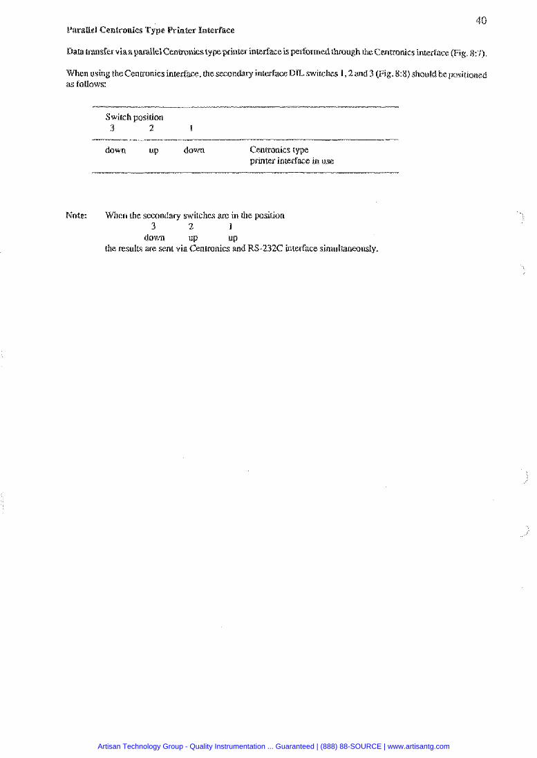
40 ParaUel Centronics Type
Baa msfa viaa parallel Centronics type printer interface is&onned h u g h the Centronics interface (Fig. &I).
When ushg theCentronics interface, he secondary interface D L switches 1,2and 3 (Fig. $3) should belxlsioioned as foUows:
Switch position 3 2 I P
down up down Centronics type printer interface in use
Note: Whcn the secondary switches are in the gasition 3 2 1
down up UP
the results are sent via Centronics and RS-232C interface simultaneously.
Artisan Technology Group - Quality Instrumentation ... Guaranteed | (888) 88-SOURCE | www.artisantg.com
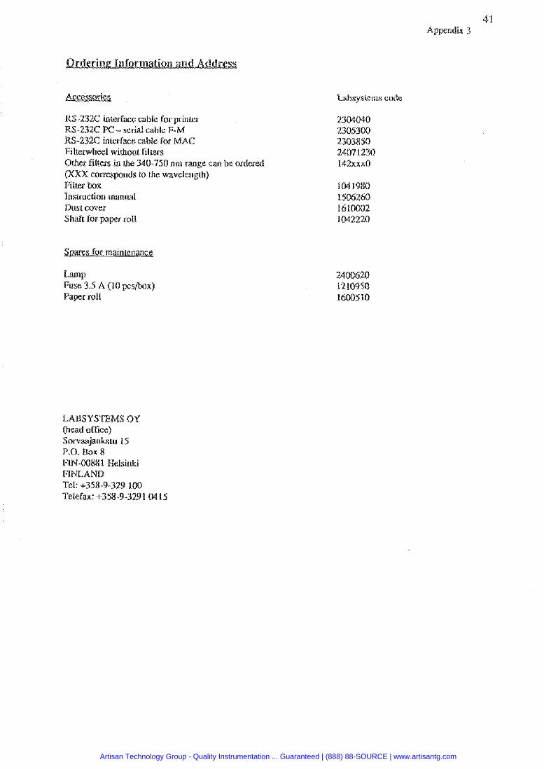
RS-232C interface cable for printer RS-232C PC- serial cable F-M RS-232C interface cable for MAC Filterwheel without filters Other filters in the 340-750 nm range can be ordeed (XXX conarponds to the wavelength) Filter box lnstrucrion manual Bust cover Shaft for paper roll
Lamp Fuse 1.5 A (10 pcs/box) Paper roll
LABSYSEMS OY (head office) Sorvaajwru I5 P.O. Box 8 FTN-00881 Helsinki F?m Tel: +358-9-329 la0 Telefax: 9358-9-32.91 MIS
Artisan Technology Group - Quality Instrumentation ... Guaranteed | (888) 88-SOURCE | www.artisantg.com
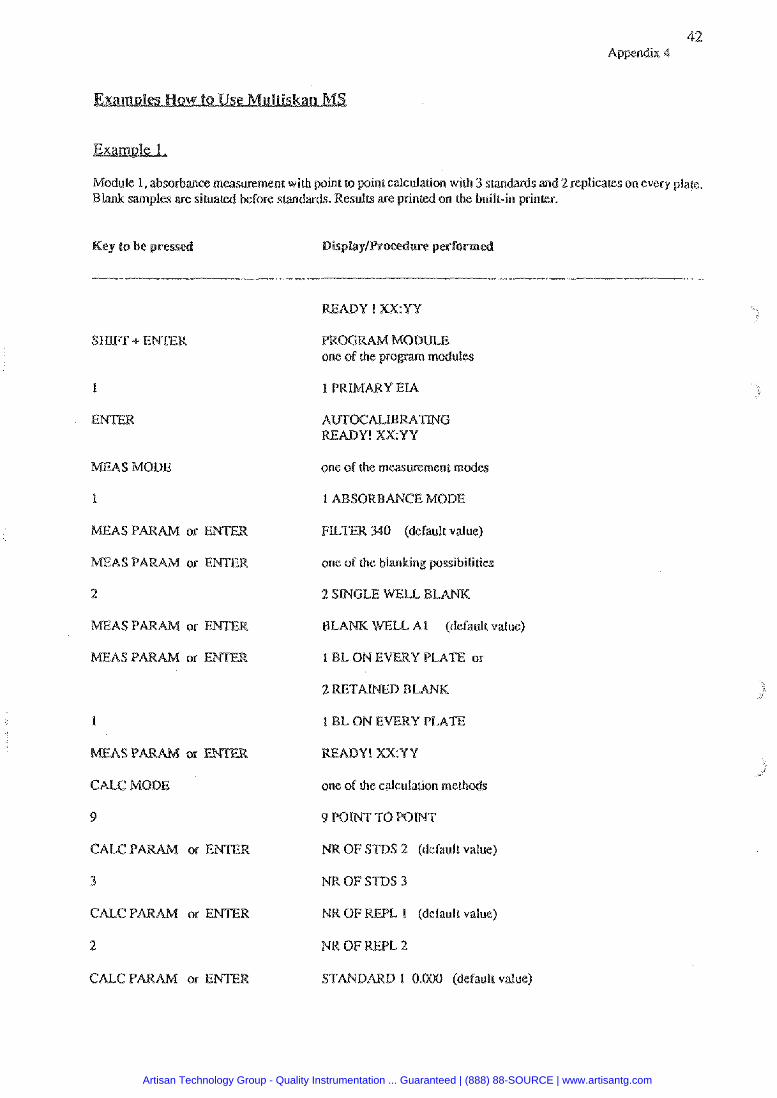
42 Appendix 4
Module 1, absorbance measvrement with point (o p i n t calculation with 3 s m W s and 2 replicates on every plak Blank samples are sirualed before smdards. Rcsulv; are printed on the built-in printer.
Key to be pressed
MEAS MODE
1
MEAS PARAM or EMTER
2
MEAS PARAM or
1
CAeC MODE
9
CALC PAWAM or E
3
CA&C PARAM or ENTER
2
READY! X X Y Y
one of the measurement modes
SORBANCE MODE
FILTER. 340 (dcfaulr value)
one of the blanking possibilities
2 S I K L E WELL BL
WF;U A1 (default vduc)
I BL ON EVERY PLATE
READY! X R Y Y
one of rhe calculation methods
9 PONT TO POINT
OF STDS 2 (default value)
NR OF STDS 3
OF W L I (defaulL value)
N R O F W L . 2
STAI'IDARD 1 0.009 (default value)
Artisan Technology Group - Quality Instrumentation ... Guaranteed | (888) 88-SOURCE | www.artisantg.com
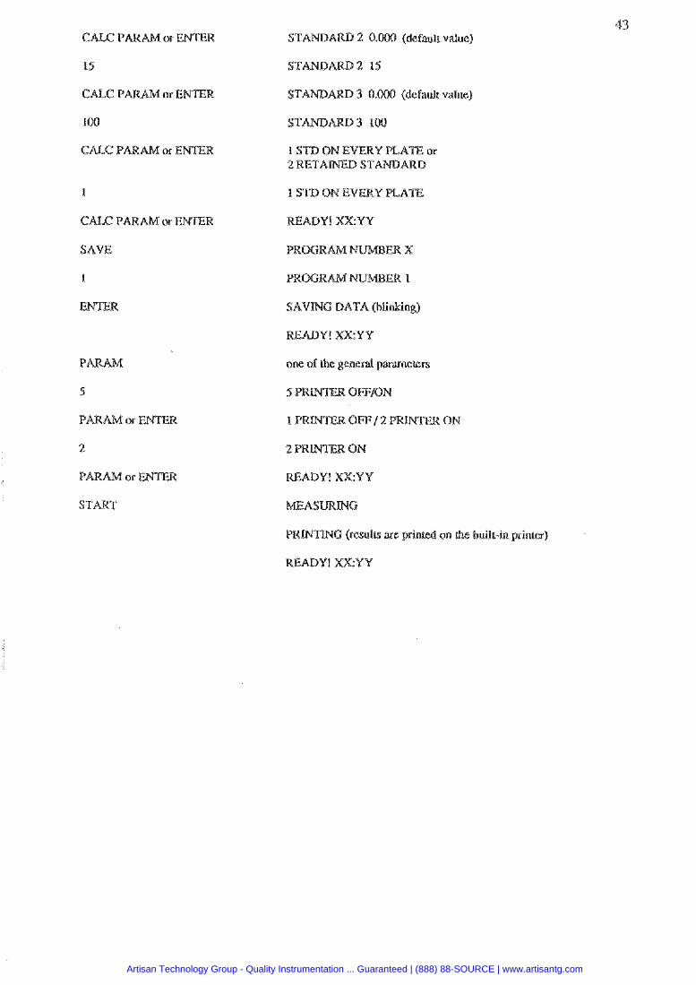
15
CALC PARAM or ENTER
100
1
CALC PARAM or ENTER
SAVE
1
ENTER
PaRAM
S
PARAIM or
2
P a R M or
START
B 2 0.W (dcfauir value)
B 3 0.000 (default value)
1 S T D ON EVEKY PLATE or D
1 STD ON EVERY PLATE
READY! XXYY
SAVWG DATA (blinking)
BEADY! XX:YY
one of the general p m c c e r s
ON
@ ( r e s u l ~ are yrin on the built-in printer)
Artisan Technology Group - Quality Instrumentation ... Guaranteed | (888) 88-SOURCE | www.artisantg.com
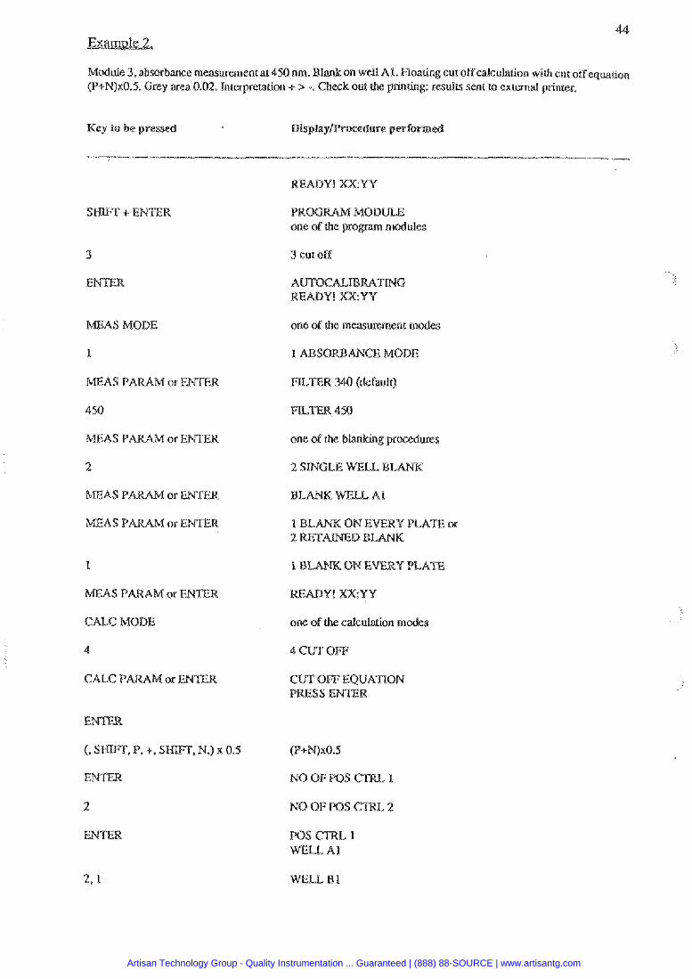
Module 3, absorbance mwurementat 450 nm. B1 on well Al. Floating cut offmlalcularion with cut offquaLion (P+wx0.5. Grey a e a 0.02. Tntevreurhion c z -.Check out h e printing: resulv; sent to external printer.
Key lo be pressed wedure performe
3
ENTER
MEAS MODE
1
MEAS PARAM or ENTER
450
r n A S PARAM or ENTER
2
MEAS PARAM or
MEAS PARAM or
1
CALC MODE
4
W
(, S m . P. +, S W , N.) x 0.5
ENTER
2
ENTER
3 cut off
one of the measul-sment modes
one of the blanking procedures
1 U ON EVERY PEA
one of the calcularion m
4 CUT OFF
CUT OFF EQUATION
Artisan Technology Group - Quality Instrumentation ... Guaranteed | (888) 88-SOURCE | www.artisantg.com
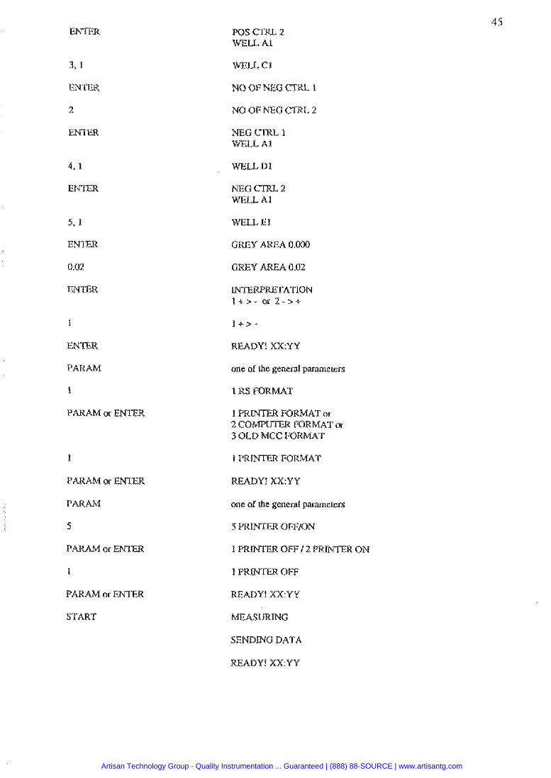
3 , 1
ENTER
2
E N m
I
ENTER
PARAM
1
PARAM or E N E R
WELL C1
MEG CTRI, 2 WELL A l
READY! XX:YY
one of the genera! paramsrers
READY! XX:YY
one of the general parameen
I PR OFF
READY! XX:YV
SENDING DATA
READY! XRYY
Artisan Technology Group - Quality Instrumentation ... Guaranteed | (888) 88-SOURCE | www.artisantg.com

Absorbance measurement at405 nm. Blanking on well A l @lank well only on the rust plate). Cubic spline crrrve tit with 2 standards and2 ~eplicaces (positions: BI, C1, B1,EI). Same standard suwe used for other plates. Unit for smdardconceneationsmg/l. 2platesare measured Swleused is [email protected]@mal princerfor resordingofrhcresulrs.
Key lo be presse oeedure performed
4
ENTER
MEAS MODE
1
ENTER
405
ENTER
2
ENTER
ENTER
2
m T E R
CALC MODE
2
ENTER
m T E R
2
0.001
ENTER
Bl
E N r n
C 1
W\Im
I
EFITER
DI
E W E R
READY! XX:YY
4 Cubic spline
READY! XX:YV
one of the measurement modes
1 ABSORBANCE MODE
FILTER 340 (default)
FU.m 405
one of the blanking p
2 SWGLE MU. BL
1 BLANK OM EVERY PLATE or 2 RETAU%D BLANK
READY! X X Y Y
one of rhe calculation m
2 CUBIC SPL
NO OF STDS 2 (default)
NO OF STDS 1 (default)
Artisan Technology Group - Quality Instrumentation ... Guaranteed | (888) 88-SOURCE | www.artisantg.com
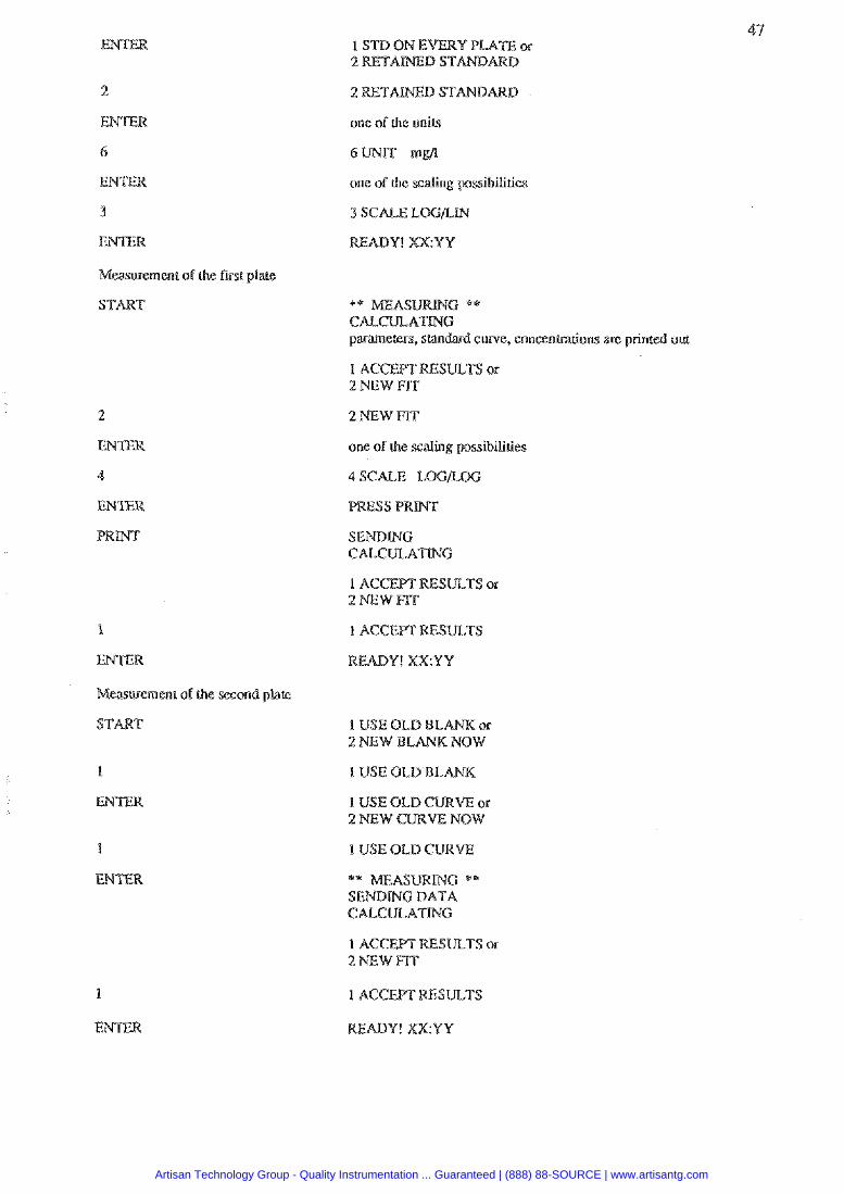
2
ENTER
6
ENTER
3
ENTER
Measvement of the ftrsi plate
1
ENTER
Measurement oh the second plate
1 STD ON EVERY PLATE or
one of the uniu
6 W nlgl
one of the scaling possibilities
READY! XX:YY
** rnAEASI/RrnG ** C ~ C ~ A S W G
curve, concentraliorts are printed out
2 NEW FIT
one of the scaling pssibilities
PRESS P R W r
SENDING CALCULAT!XG
1 A C C W RESULTS or 2 NEW FK
1 US P
1 USE OLD BLANK,
I USE OLD CURVE or 2 NEW CURVE NOW
*' EASUWING '* SENDLNG DATA CALCULATING
1 ACCEPT RESULTS or 2 NEW FIT
1 ACCEPT RESULTS
ADY! XX:YY
Artisan Technology Group - Quality Instrumentation ... Guaranteed | (888) 88-SOURCE | www.artisantg.com
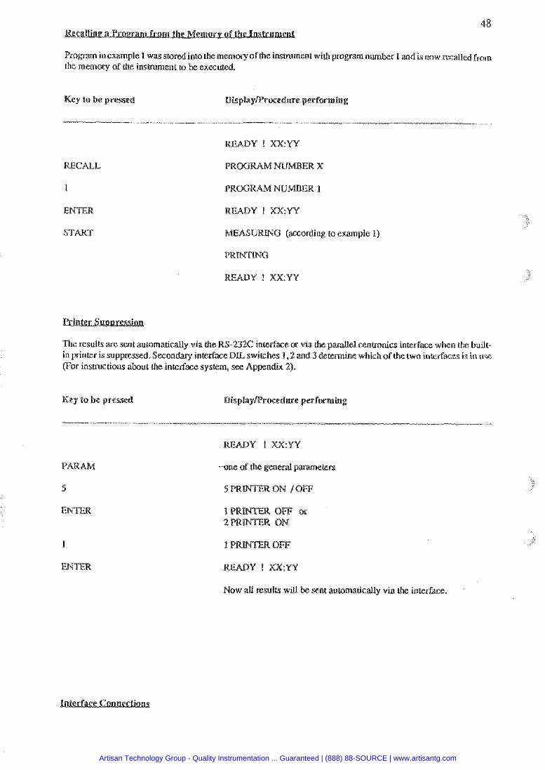
Prawn inexampte I was stnrcd into the memory of the insmment with pn, number 1 and is now rmalld from the memory of the instrument tn be e x a u l d
Key to be pressed ocedure performing
RECALL
1
ENTER
START
-
m m Y ! X X Y Y
MEASURWC (according lo example 1)
PR C
READY ! XXYY
The resulls are sent automatically via rhe RS-232C interface or via the p el mnbonics interface when rhe built- in printer i s suppressed. Secondary interface DLL switches 1 ,2 and 3 determine which of the two interfaces is in usc (For instructions about the interface system, see Appendix 2).
Key lo be presse Display ure performin
- m e of the general
Now all results will sent ansomausally via the interface.
Artisan Technology Group - Quality Instrumentation ... Guaranteed | (888) 88-SOURCE | www.artisantg.com
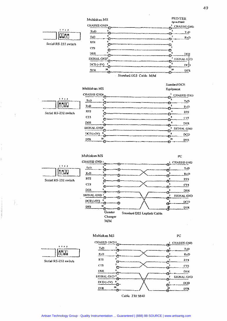
Muluskan MS
Serial RS-232 switch
Multiskan MS
Serial RS-232 switch
Multiskan MS PC
8 7 , s
Serial RS-232 swilsh
Scrial RS-232 switch
Artisan Technology Group - Quality Instrumentation ... Guaranteed | (888) 88-SOURCE | www.artisantg.com

Labsystems Oy P.O. Box 8 FW-00881 Helsinki. Finland Tel. +358-9-329 180 Tclefax +358-9-3291 0415
Artisan Technology Group - Quality Instrumentation ... Guaranteed | (888) 88-SOURCE | www.artisantg.com
Infomation in this manual is subject to change without prior notice.
Cat. no. 1507300
Artisan Technology Group - Quality Instrumentation ... Guaranteed | (888) 88-SOURCE | www.artisantg.com
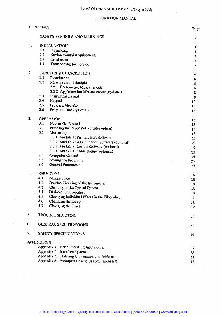
TNSTALLATXON 1.1 Unpacacking 1.2 Environmen(a1 Requirements 1.3 lnslailation 1.4 Transporting for Sewice
FIIMCnONAL DESC 2.1 Introduction 2.2 Measurement Principle
2.2.1 PhotomeLlic Measurements 2.2.2 Agglutination Measurements (optional)
2.3 Instrument Layout 2.4 Keypad
3.1 How to Get Started 3.2 Inserting the Paper Roll (printer option) 3.3 Measuring
3.3.1 Module 1: Primary EIA Software 3.3.2 Module 2: Agglutination Software (optional) 3.3.3 Module 3: Cut-off Sothvare (optional) 3.3.4 Module 4: Cubic Spline (optional)
3.4 Computer Control 3.5 Storing the Programs 3.6 General Parameters
SERVfCTMG 4.1 Maintenance 4.2 Routine Cleaning of the Instrument 4.3 Cleaning of the Optical System 4.4 Disinfection Procedure
ng Kndividual Filters in the Filtenvheel
x 1. Brief Operating Instructions x 2. Interface System x 3. Ordering lnfoma(ion and Address
Appendix 4. Examples How to Use Muttiskau EX
Page
Artisan Technology Group - Quality Instrumentation ... Guaranteed | (888) 88-SOURCE | www.artisantg.com
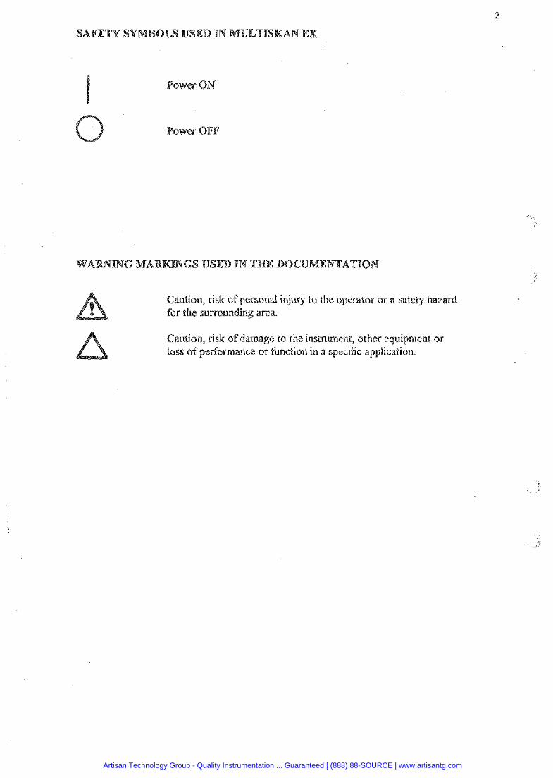
Caution, risk of personal injury to the operator or a safety hazar for the surrounding area.
Caution, risk of damage to the instrument, other equipment or loss of performance or function in a specific application.
Artisan Technology Group - Quality Instrumentation ... Guaranteed | (888) 88-SOURCE | www.artisantg.com
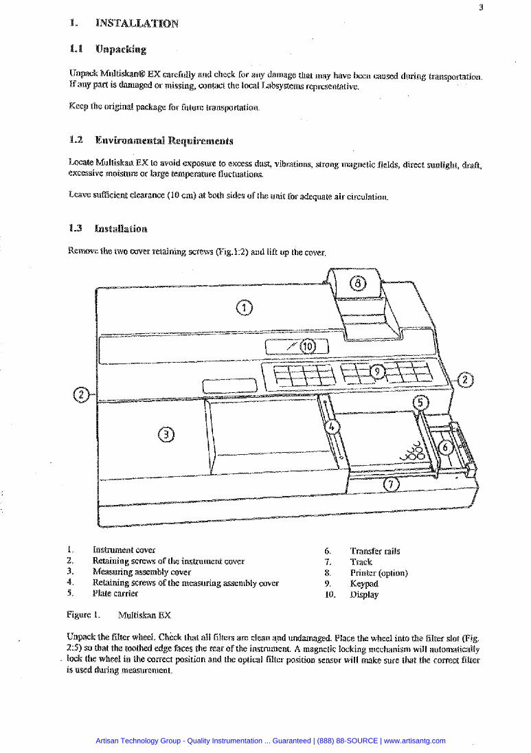
Unpack Mulliskana EX carefully and cheek for any damage that may have been caused during transporCltion maged or missing, contact the local Labsystems representative.
Keep the original package for future transpor(ation
Locate Multiskan EX to avoid expasure to excess dust, vibrations, strong magnetic fields, direct sunlight, dr ex~clssive moisture or large tern rahlre fluctuations.
Leave sumcienl clearance (10 em) at bath sides ofthe unit for adequate air circulation
Remove (he two cover retaining screws (Fig.12) and liA up the cover.
1. Ins(Purnent cover 6. Transfer rails 2. Retaining screws of the instrument cover 9. Track 3. Meamring assembly cover 8. Printer (option) 4. Retaining screws of the measuring assembly cover 9. Keypad 5. Plate carder 10. Display
Figure 1. Multiskan EX
Unpack the filter wheel. Check that all filters are clean and un aged. Place the wheel into the filter slot (Fig. 2 5 ) so that the toothed edge faces the rear of the instrument. A magnetic locking mechanism will automatically lmk the wheel in the correct position and the optical filter position sensor will make sure that the comect filler is used during measurement.
Artisan Technology Group - Quality Instrumentation ... Guaranteed | (888) 88-SOURCE | www.artisantg.com
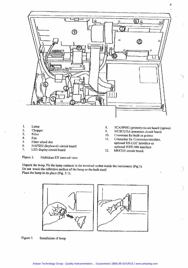
1. Lamp 2. Chopper 3. Filter 4. f i n 5. Filter wheel slot 6. NAPSU2 (keyboard) circuit bowd 7. LSD display circuit board
Figure 2. Multiskan EX internal view
8. SCAWR12 (printer) circuit board (option) 9. MUSCUIZA processor circuit board 10. Connector for built-in printer 1 I. Connector for Centronics interface,
232C interface or aplional EEE-488 interface
12. MUCEN circuit b a r d
Unpack the lamp. Fit the lamp contacts to the terminal socket inside the instrument (Fig.3). Do not touch the reflective surface of the lamp or the bulb itself. Place the lamp in its place (Fig. 2: 1).
Figure 3. installation of lamp
Artisan Technology Group - Quality Instrumentation ... Guaranteed | (888) 88-SOURCE | www.artisantg.com
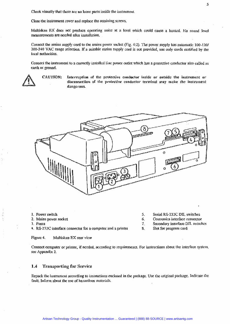
visually that there are: no loose parts inside the instrument.
Close the insmment cover and replace the retaining screws.
EX does not ce operating noise at a level whish could cause a ham ents are needed nstdlation.
Connect the mains supply co to the mains power socket (Fig. 42). The power supply has automaiic 100-1401 200-240 VAC range selection. If a suitable mains supply cord i s not provided, use only cords cerliGed by the local auehorities.
Comest the insmment to a correctly installed line power outlet which has a protective conductor also called earth or pound.
ption of the protectiw conductor inside o r outside e inslmment or isconnection of the protective conductor le
1. Power switch 5. Serial RS-232C DU switches 6. Centronics interface connector
3. Fuses nterface D L switches -232C inter(% annestor for a computer and a printer gram card
4. Mnltiskan EX rear view
Connest computer or printer, if needed, according to requirements. For instmctions about the interface system,
Repack the insmment according to instructions enclosed in the package. Use the original paskage. Indicate the fault. Infom about the use of hazardous materials.
Artisan Technology Group - Quality Instrumentation ... Guaranteed | (888) 88-SOURCE | www.artisantg.com

Multiskan EX is an eight-channet vertical light path filter photometer designed to pelrom both standard photometric. and agglutination measurements.
There is a versatile built-in software available in Multiskan EX. It comprises several software (program modules). Each package is a combination of measurement and calculation modes.
memory capacity is achieved by programmable program card
The wavelensh (400 - 750 nm or optional 340 - 450 nm) is selected using mmirnum eight high quality interference filters held in a filter wheel.
processed via a serial RS-232C interface or via a parallel Centronics The optional huilt-in thermal printer provides also a record ofthe results.
Multiskan EX utilizes the original Lahystems' concept of vertical photometry in which the light beam passes through the whole sample.
In vertical photometry, the absorption of light is proportional to the amount of light absorbing substance in the well.
Absorption is expressed by the following equation:
where A = absorbance, a = molar absorptivity of the substance, m = mass of absorbing subs tam and S = cms- ndimlar to the light path.
The advantages of lhe vertical light path measurement are:
(I) inaccurate pi ning of nonabsorbing lrquids does not affect the measured absorbance values
(2) evaporation of nonabsorbing liquids during the reaction dm5 not atfect the measured absorbance values and
(3) a cenaiain degree of inhomogeneity in the solution, for example as a result of layering in turbidity measurements, does not affect the results.
Artisan Technology Group - Quality Instrumentation ... Guaranteed | (888) 88-SOURCE | www.artisantg.com
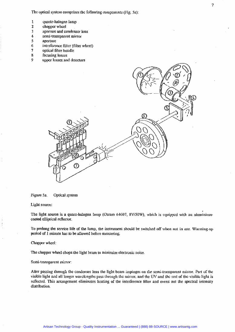
The optical system comprises the following components (Fig. Sa):
qua&-halogen lamp
a p e m e and condenser lens semi-transparent minor apemre interference filter (filter wheel) optical fibre bundle focusing lenses upper lenses and detectors
Figure 3a. Optical system
Tke light source is a quarz-halogen lamp (Osram 64607, SVISOW), wh~ch is equipped with an aluminium- coated elliplid refleeror.
the service life of the lamp, the instrument should he switched off when not in use. Warmin riod of I minute ha: to
r wheel chops the light beam to minimize electronic noise
Semi-tsmwenl mirror:
ARer passing through the condenser lens the light beam impinges on the semi-transparent mirror. Pad o f the visible light and all longer wavelengths pass through the mirror, and the UV and the rest of the visible light is reflected. This arrangement eliminates heating of the interPerence filter and evens our the s distribution.
Artisan Technology Group - Quality Instrumentation ... Guaranteed | (888) 88-SOURCE | www.artisantg.com
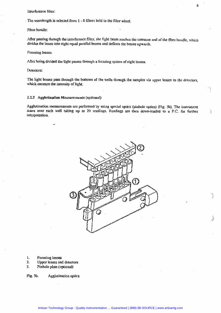
filters held in the filter wh
Artisan Technology Group - Quality Instrumentation ... Guaranteed | (888) 88-SOURCE | www.artisantg.com
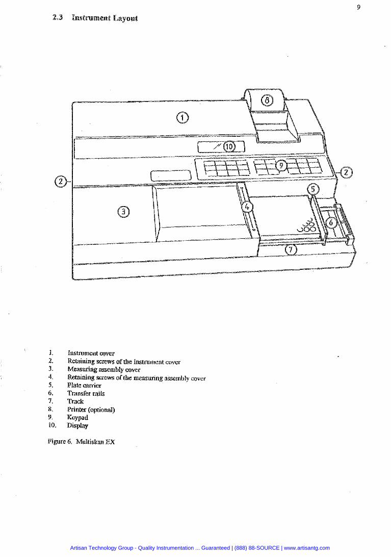
InsWment cover Relaining screws ofthe inmment cover
bly cover of the measuring assembly cover
Plate carrier Transfer rails Track Printer (optional) Keypad Display
Figure 6. Multiskan EX
Artisan Technology Group - Quality Instrumentation ... Guaranteed | (888) 88-SOURCE | www.artisantg.com
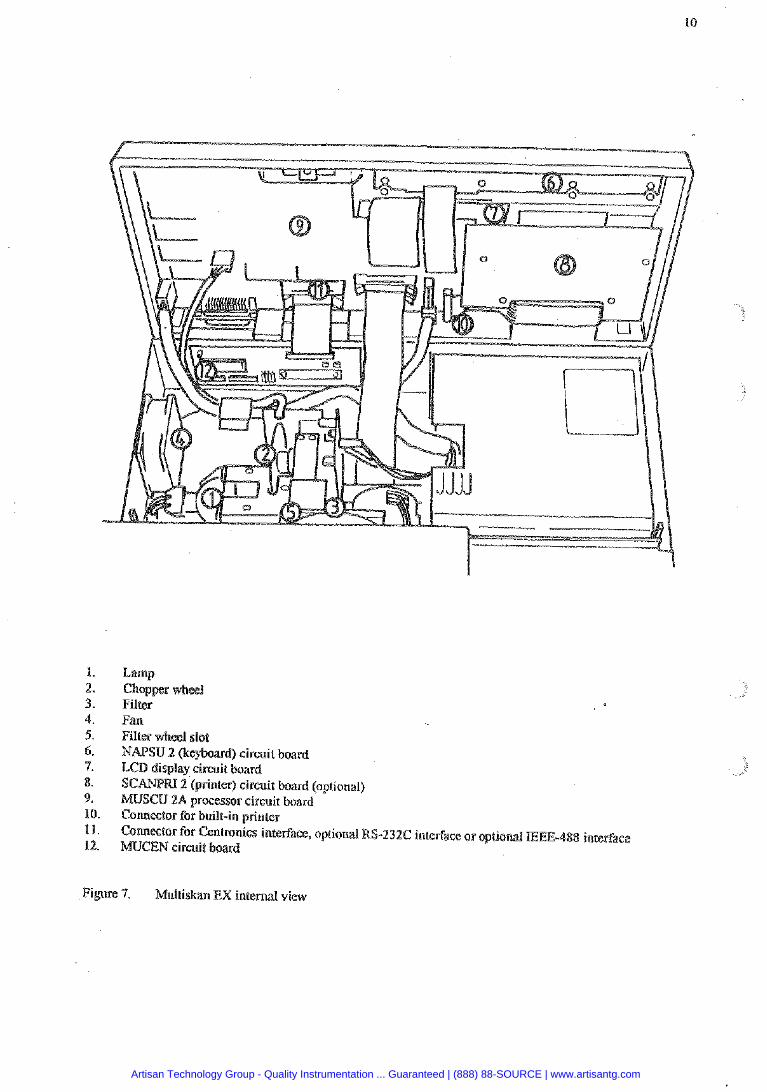
Lamp
Fan Filter wheel slot NAPSU 2 (keyboard) circuit board LCD display circuit board
2 (printer) circuit board (opiional) MUSCU %A processor circuit board Connector for built-in printer COMW~O~' for Centronics interface, optional RS-232C interface or optional EEE-488 interface MOCEN circuit board
Figure 7. Multiskan EX internal view
Artisan Technology Group - Quality Instrumentation ... Guaranteed | (888) 88-SOURCE | www.artisantg.com
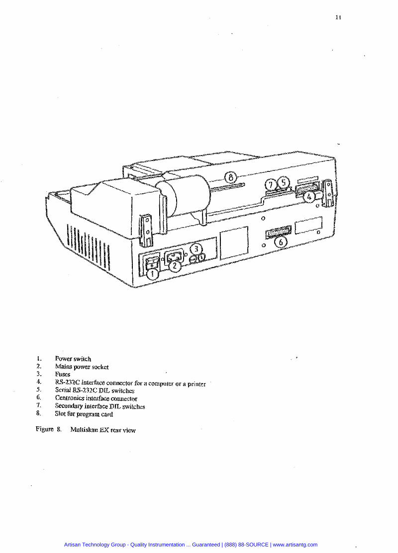
-- 4. R S - 2 3 X interfa= connector for a computer or a printer
32C DL switches interPace connector nterfaau: B E switches
8. Slot far program a r d
Figure 8. R/lultiskan EX rear view
Artisan Technology Group - Quality Instrumentation ... Guaranteed | (888) 88-SOURCE | www.artisantg.com
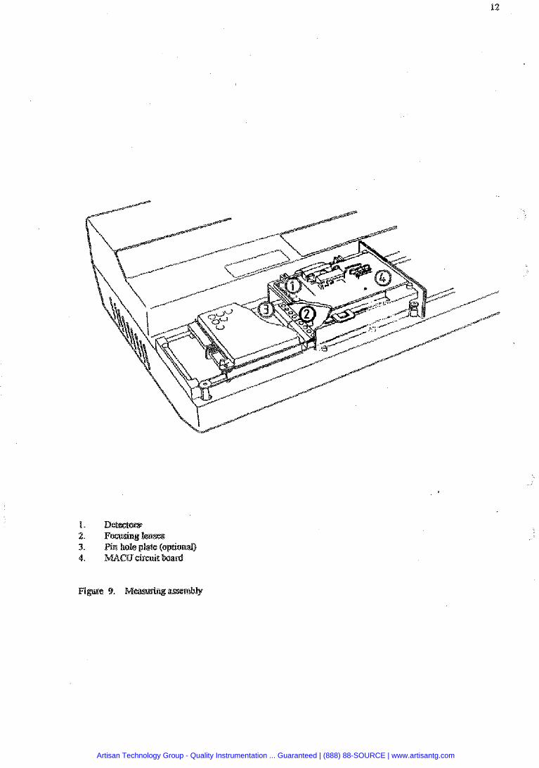
Artisan Technology Group - Quality Instrumentation ... Guaranteed | (888) 88-SOURCE | www.artisantg.com
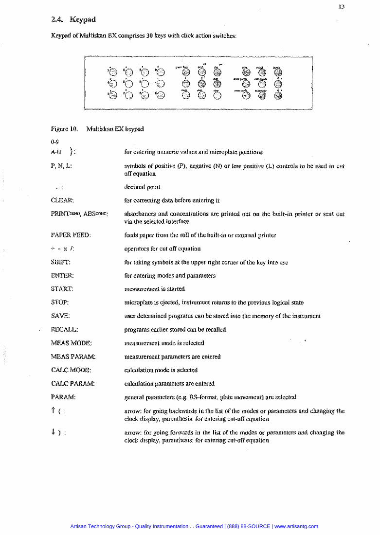
EX comprises 40 keys with click action switches:
PAPER FEED:
+ - x I:
ENTER:
STOP:
for entering numeric values and microplate positions
symbols of positive (P), negative fN) or low positive (L) controls to off equation
decimal point
for correcting data
absorbances and concentrations are printed out on the built-in printer or sent out via the selected intedBee
feeds paper from the roll of the built-in or external printer
operators for cut off equation
for taking symbols at the upper right comer of the key into use
for entering modes and parameters
masurement is 5tar(ed
microplate is ejected inwment returns to the previous logical state
user determined p r o p stored into the memory ofthe in
programs earlier stored can be recalled
measurement mode is select
m w e m e n t parameten are enter
calculation made is selected
catculalion parameters are entered
general parameters (e.g. -fowat, plate movement) are selestc
arrow: for going backwards in the lisr ofthe modes or parameters and changing the clock display, parenthesis: for entering cut-off equation
arrow: for going forwards in the list of ehe modes or parameters and changing the clock display, parenthesis: for entering cutsff equation
Artisan Technology Group - Quality Instrumentation ... Guaranteed | (888) 88-SOURCE | www.artisantg.com
Mulriskan EX software comprises program modules, software packages which are sombinationr: of measurement and calculation modes. . . The following program modules are available:
1. Primary ElA software 2. Aalutination software (optional) 3. Cut off s o h a r e (optional) 4. Cubic spline software (optional)
ule 1: Ptimary EIA
This software is a basic s o h a r e to perform EIA measurements. It includes the following measurement m absohance, dual wavelensh, two point, kinetic, muttivawelength mode and computer control.
The following calculation modes can be selected: factor, linear standard, standard line, limit, double limit, range, column subtraction and point to point calculation.
ule 2: Agglutination software (optional)
This module enables agglutination measrlrements A special optics (pmhole optics) is taken into use. 20 readings are taken reach well. Results are sent via interface for further processing.
Module 3: Cut off software (optional)
There are different cut off calculations avatlablc in this module: double limit, range, fixed cur off and floating cut off.
Module 4: Cubic spline (optional)
Measurement modss: available are absorbance, dual wavelength, two p i n t and kinetic Calculation mode: available is cubic spline.
Changing between modules occurs by first pressing the SHIFT key and then the ENTER key
More memory capacity is offered by a programmable program card which can he plugged-in to the instmment.
med by Labsystems upen request.
Artisan Technology Group - Quality Instrumentation ... Guaranteed | (888) 88-SOURCE | www.artisantg.com
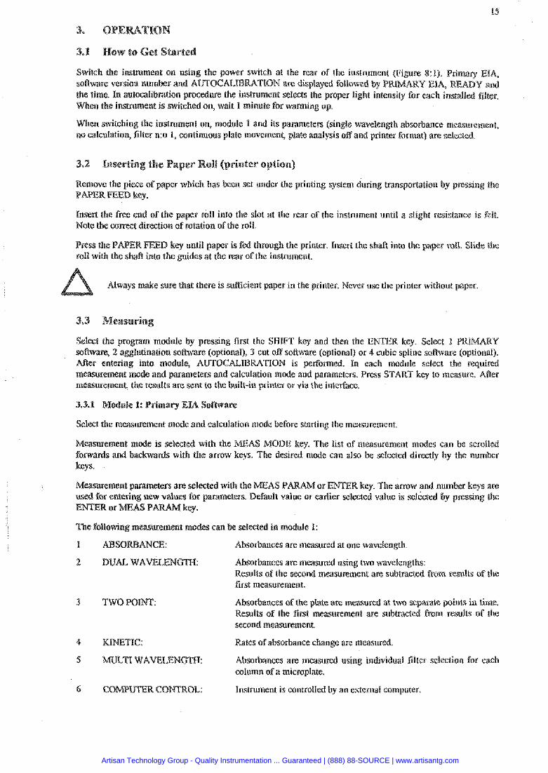
Switch the instrument on using the power switch at the rear of the instrument (F iyre 8:1). Primary ~ 1 4 s o h a r e version number and AUTOCALB ION are displayed followed by P the time. In antmalibration procedure the i ent selects the proper light inte
en the instrument is switched on, wait 1 minute for warning up.
When switching the instrument on, module 1 and its parameters (single wavelenah absorbance measurement, no calculation, filter n:o 1, continuous plate movement, plate analysis off and printer format) are selected.
Remove the piece of paper which has been set under the printing system during transpoffation by pressing the PAPER PEED key.
Insert the free end of the pa r roll into the slot at the rear of the instmment until a slight resistance is felt. Note the correct direction of rotation ofthe roll.
l%ED key until pa r is fed through the printer. Insert the sh& into the pa roll with the shaft into the guides at the rear of the instrument.
e sure that there is sufllcient paper in thc printer. Never use the printer without paper.
Select the program module by pressing first the SHIFT key and then the ENTER key. Select 1 sofiware, 2 agglutination software (optional), off software (optional) or 4 cubic spline software Mer entering into module, AUTOCALIB ION is performed. In each module select the required measurement mode and parameters and calculation mode and parameters. Press START key to measure. M e r m w r e m e n l , the results are sent to the built-in printer or via the interface.
Select the masurement mode and calculation mode before starting the measurement.
Measurement mode i s selected with the MEAS MODE key. The list of surement modes can be scro forwards and backwards with the anow keys. The desmd mode can als selected directly by the nu keys.
ected with the MEAS I! or ENTER key. The arrow and number keys are parameters. Default v rlier selected value is selected by pressin
The following meamemenr modes can be selected in module I:
Absorbances are measured at one wavelength.
2 DUAL WAELENGTN: Absotbances arc: measured using two wavelengths: Results of the second measurement are subtracted from results of the first measurement.
Absorbances of the plate are measured at two separate points in time. Results of the first measurement are subtracted from results of the second measurement.
4 TIC: Rates of absorbance change are measured
5 MULTE WAVELENGmI-I: Absorbanceo are measured using individual filter selection for each column ofa microplate.
6 COMUTER CONTROL: Instrument is controlled by an esternal computer.
Artisan Technology Group - Quality Instrumentation ... Guaranteed | (888) 88-SOURCE | www.artisantg.com
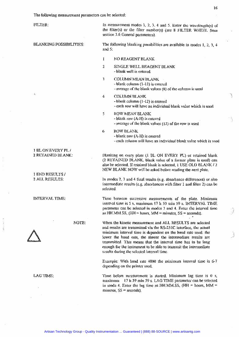
16
The following measurement parameters can be selected:
FILER:
1 BL ON EVERY PL I 2 E T A m D BLANK:
2 ALL RESmTS:
LAG TIE/LE:
In measurement modes 1, 2, 3, 4 and 5. Enter tho wavelen@h(s) of the filter(s) or the filter numberfs) (see 8 FILTER section 3.6 General parameters).
The following blanking possibilities are available in modes 1, 1, 3, 4 and 5:
2 SINGLE WELL REAGENT BLANK -blank well is entered
3 COLUMN MEAN BLANK - blank column (1-12) is entered - average of the blank values (8) of the calumn is used
4 COLUMNBLANK -blank column (1-12) IS entered - each row wrll have an individual blank value which is used
- blank row (A-PI) is entered - average of the blank values (12) ofthe row 1s used
6 ROWBLANK -blank row (A-K) is entered -each column will have an individual blank value which is used
Blanking a n every plate (1 BL ON EVERY PL) or retained blank (2 RETAINED BLANK, blank value of a former plate is used) can also be selected. ff retained blank is selected, 1 USE OLD BLA NEW BLANK NOW will be asked before rcading the nest plate.
In modes 2, 3 and 4 final results (e.g. absorbance differences) or also intermediate results (e.g. absorbances with filter 1 and filter 2) can be selected.
Time between successive measurements of the plate. Minimum interval time is 5 s, maximum 17 h 59 min 59 s. m R V L TIME parameter can be selected in modes 3 and 4. Enter the interval time as IZCI.MM.SS, (KH- hours, MM = minutes, SS = seconds).
NOTE: When the kinetic measurement and AEL SULTS are selected and results are transmitted via the RS-23 interface, the actual minimum interval time is nt on the baud rate used: the lower the baud rate, the the intemediate res transmitted. This means that the interval time has to enough for the instrument to be able to transmit the intemediate results during the selected interval time.
Esample: With baud rate 4800 the minimum interval time is 6-7 depending on the printer used.
Time before measurement is started. Mininlurn lag time is 0 s, masimum 17 h 59 min 59 s. LAG ~~ parameter can be selected in mode 4, Enter the lag lime as .SS, (I-LtI = hours, MM - minutes, SS = seconds).
Artisan Technology Group - Quality Instrumentation ... Guaranteed | (888) 88-SOURCE | www.artisantg.com
Time during which the reaction is followed. Minimum total time is 5 s, maximum 19 h 59 min 59 s. TOTAL TIME parameter can be selected in mode 4. Enter the total time as I;DI.MM.SS, OIfI = hours, =seconds).
Any of the calculation modes can be applied to results from any of the measurement modes. Calculation mcBe/mode-s can be selected before or aRcr the measurement is done.
keys allow the results to be obtained later from earlier measured values. The latest selected calculation mode is used until changed.
e is selected with the CALC MODE key. Tke list of calculation modes can he. scrolled forwar th the arrow keys.
Calculation parameters ape selected with the CAeC P or ENTER key. The arrow or number keys are used for entering new parameters. Berault value or earlier determined value is selected by pressin f ie ENTER or CALC
The following calculation modes and their parameters can be selected in module 1:
I NO CALCCR,ATION: Results are sent as absorbance$ to built-in printer or via the interface.
2 FACTOR CKCULATION: Measured absorbances are multiplied with a factor given by the user to get concentrations. The concentration unit is defined by the unit of the factor. Concentration is calsulated according to the following equation: Concentration -FACTOR x absorbance. The measurement parameters, calculation parameters and calculated concentrations are sent to the built-in printer or via the interface.
Parameter: FACTOR
The user enters the concentrations of the standards and Multiskan EX calculates a standard line with the help of these standards using the method of least squares. Measured absorbances are converted to concentration units by the use of this line. The measurement parameters, calculation parameters and concentrations obtained are sent to the built-in printer or via the interface.
Parameters: Number of standards O\iR OF STDS) Number of replicates (NR OF REPE) Standard concentrations
(STANDARD 1) etc. Standard locations
(STANDARD L REPL 1 A l ) els.
Up to 8 nandard solution can incorporated on the plat% in up lo 3 replicates.
1 STB ON EVERY PLATE / Standard on every plate (1 S T B ON EVERY PLATE) or
2 RETAINEBSTD retained standard (2 standard curve of the former plate i s used) can be selected. If re is selected 1 USE OLD 1.. L I E NOW will be asked before reading the next plate.
Artisan Technology Group - Quality Instrumentation ... Guaranteed | (888) 88-SOURCE | www.artisantg.com
The user can define the standard line by entering the slope and rke intercept by using the known standard line. Raultiskan EX calculates the concentrations with the following equation:
absorbance =; A s concentration + B where A = slope like in linear standar mode.
8 = intercept
The measurement parameters, calculation parameters an concentrations obtained are sent to the built-in printer or via the intsrface.
Parameters: LINE SLOPE RTERCEPT.
3 L M T CKCULATION: The measurement absorbance values are compared with a limit value defined by the user. If the result is lower than the set limit, negative sign (-) is sent, athenvise a positive sign (+). The masurement parameters, calculation parameters and results in +/- matrix are sent to the built-in printer or via the interface
Parameters: Limit value (LIMIT) (0.000-2.000).
The measured absorbanse values are compared with two limit values defined by the user. If the result is lower than the lower limil a negative sign (-) is sent. If the result is between the two limit values, 0 is scnt. If the result is higher than the upper limit, positive sign (+) is sent. The measurement parameters, calculation parameters and results in -lo/+ matrix are sent to the build-in printer or via rhe inreiface.
Parameters: Low limit value (LOW LIMIT) (0.000-2.000). High limit value (HIGH LIMIT) (0.001-2.000)
7 GE CBLCULATION: Range value defined by the user i s divided into ten equal segments. Segments are numbered from 0 to 9. The measured absorbance value is represented by one of tho= numbers depending on which segment it lies in. The measurement parameters, calculation parameters and matrix where the results are shown by segment num sent to the built-in printer or via the interface.
Parameters: Range value (RANGE) (0.000-2.000).
Example: If an absorbance range 1.5 is set, the segments are as below:
Segment Measured absorbance valne in range Printout I A 5 0.150 0 2 0. IS0 < A S 0.300 1 3 0.300 < A 5 0.450 2 4 0.450 < A 5 0.600 3 5 0.600 < A 5 0.750 4 6 0.750 < A r; 0.900 5 9 0.900 < A S 1.050 6 8 1.050 < A 5 1.200 7 9 1.200 < A 5 1.350 8
10 1.350 < A 5 I.500 9
Artisan Technology Group - Quality Instrumentation ... Guaranteed | (888) 88-SOURCE | www.artisantg.com

CTION: sults of column I are subtracted from rssults of column 2, resulis column 3 are subtracted from results of column 4, etc. or vice
versa. The measurement parameters, calculation parameters an absorbance dixerences of every other column are sent in the built-in printer or via the inleiface.
Parameter: 1-2 3-4... or 2-1 4-3 ...
The user enters the concentrations of the standards and Mulriskan EX calculates a piece wise linear standard curve with the help of these standards. Measured absorbances are converted to concentration units by the use of this curve. The mmiasuretnent parameters, calculation parameters and concentrations obtained are sent to the built-in printer or via the interface.
If the piece wise linear standard curve is not monotonous, the text NON-MONOTONOUS curve will be printed and the results are incorrect.
Parameters:
Up to 8 standard solutions can be incorporated on the plate in up to 3 repticates.
I STD ON EVERY PLATE / Standard on every plate (I S1D ON EVERY PLATE) or
2 RETAINED STT) retained standard (2 standard curve of th used) can be selected. If retained standard is selected 1 USE OLD L W I 2 NEW LINE NOW wit1 be asked before readin the next plate.
lutinalion Software (optional)
X to computer. Enter to module 2 in Multiskan EX. Choose the filter, blanking and puler contrd from computer. Starl the measurement. 20 readingdwell will be taken and
sent to the computer.
The following measurement modes are available in tnadule 3:
1 Absorbances are measured at one wavelength.
2 DUAL WAVELENGm: Absorbances are measured using two wavelengths: Results of the second measurement are subtracted from results of the first measurement.
3 TWOPOW: Absorbances of the plate are measured at two separate Results of the first measurement are subtracted from th second measurement.
Rates of absorbance change are measured.
Artisan Technology Group - Quality Instrumentation ... Guaranteed | (888) 88-SOURCE | www.artisantg.com
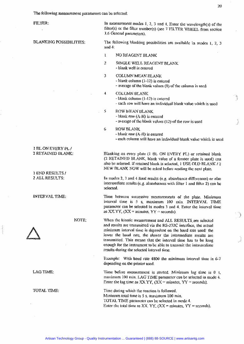
20
measurement parameters can be selected:
Yn measurement modes 1, 2, 3 and 4. Enter the wavelen@h(s) o f the filter(s) or the filter nunlber(s) (see 4 FILTER 3.6 General parameters).
MG POSSIBIEITIES: The following blanking possibilities arc available in mo and 4:
1 NO WFAGEMT BLANK
2 STNGLE WELL REAGENT BLANK - blank well is entered
3 COLldMNMEANELA - blank column (1-12) is entered - average ofthe blank values (8) of the column is used
-blank column (1-12) is entered - each row will have an lndlvldual blank value wh~ch is used
5 ROWMFANBLANK -blank row (A-li) is entered - average of the blank values (12) ofthe row is used
- each column will have an individual blank value which is use
1 BL ON EVERY PI, / 2
2 ALL RESULTS:
TOTAL
Blanking on evcry plate (1 BL ON EVERY PL) or retained blank (2 RETAINED BLANK, blank value of a former plate is used) can also be selected. Kretained blank is selected, 1 USE OLD BLA NEW BLANK NOW will be asked before reading the next plate.
In modes 2, 3 and 4 final results (e.g. absorbance differences) or also intermediate results ( e g . absorbances with filter I and filter 2) can selected.
Time between successive measurements of the plate. Mir ' ~nterval time is 5 s, maximum 100 min. INTERVAL parameter can be selected in modes 3 and 4. Enter the interval time as PO<.=, (XX = m~nutcs, W = seconds).
NOTE: When the kinetic measurement and ALL RESULTS are selected and results are transm~tted via the RS-232C interface, the ac minimum interval time is dependent on the baud rate used: the lower the baud rate, the slower the intermediate res transm~tted. This means that the interval time has to enough for the instmment to be able to transmit the intermediate results during the selected interval time.
Example: With baud rate 4800 the minimum interval time is 6-7 depending on the printer used.
Time before measurement is started. Minimum lag time is 0 s, maximum 100 min. LAG TIME parameter can be selecte Enter the lag time as = minutes, YY seconds).
Time during which the reaction is followed. Minimum total time is 5 s, maximum I00 min. TOTAL TTME parameter can be selected in mode 4. Enter the total time as
Artisan Technology Group - Quality Instrumentation ... Guaranteed | (888) 88-SOURCE | www.artisantg.com
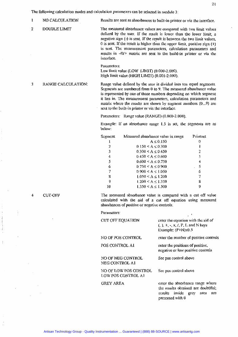
The following calculation m es and calculation parameters can selected in module 3:
1 NO CALCmATION Results are sent as absorbance$ to built-in printer or via the inte~aface.
The measured absorbance values are compared with two limit values dsfined by the user. If the result is lower than the lower firnit, a negative sign (-) is sent. If the result is between the two limit values, 0 is sent. If the nsult is higher than the upper limit, positive sign (+) is sent. The measurement parameters, calculation pawmeters an results in -1011- matrix are sent to the build-in printer or via the interface.
Parameters: Low limit value (LOW LIMIT) (0.000-2.000). High limit value @UGH LIMIT) (0.001-2.000).
3 Range value defined by the user is divided into ten equal segments Segments are numhred from 0 to 9. The measured absorbance value is represented by one of those numbers depending on which segment it lies in. The measurement parameters, calculation parameters and matrix where the results are shown by segment numbers (0 ... 9) are sent to the built-in printer or via the interface.
Parameters: Range value W N G E ) (0.000-2.000)
Example: If an absorbance range 1.5 is set, the segments are as below:
Segment 1 2 3 4 5 6 9 8 9
10
Measured absorbance value in range AS0.150
0.150 < A 5; 0.300 0.300 < A 10.450 0.450 < A r; 0.600 0.600 c: A 5 0.750 0.750 < A 2 0.900 0.900 < A E; 1.050 1.050 < A S 1.200 1.200 < A S 1.330 1.350 € A 5 1.500
Printout 0 1 2 3 4 5 6 7 8 9
The measured absorbance value is compared with a cut off value calculated with the aid o f a cut off equation using measured absorbances of positive or negative controls.
Parameters:
CUT OFF EQUATION
NO OF LOW POS CB LOW PQS CONTKOL A1
enter the equation with the aid of (, ), +. -, x, 1, P, L and N keys Example: (P+FJ)x0.5
enter the number of positive controls
enter the positions s f positive, negative or low positive controls
See pos control above
See p s control abovc
GREY AREA enter the absorbance range where the results obtained are doubllful; results inside grey area are presented with 0
Artisan Technology Group - Quality Instrumentation ... Guaranteed | (888) 88-SOURCE | www.artisantg.com
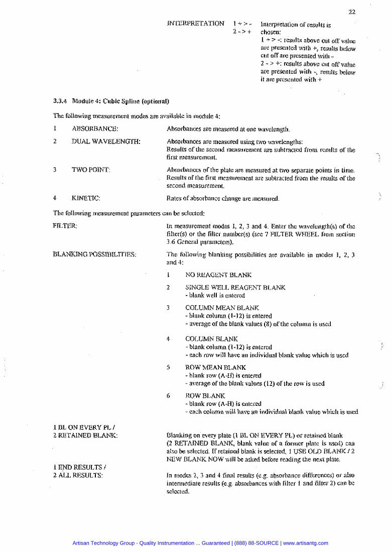
INTENMTATION 1 1. > - Interpretation oFresul& is 2 - > c chosen:
1 + > -: results above cut off value are presented with +, results below cut off are presented with - 2 - > +: results above cut offv~lne are presented with 9 results it are presented with 6
odule 4: Cubic Sgtline (optional)
The tbllowing measurement modes are available in module 4:
1 Absorbanees are measured at one wavelength
2 DUAL W A m L E N G m : Absorbanees are measured usmg two wavelengths. Results of the second measurement are subtracted from results of the first measurement.
3 TWOPBTNT: Absorbances of the plate are measured at two separate polnts ~n time Results of the first measurement are subtracted from the results ofthe second measumnent.
4 KINETIC: Rates of absorbance change are measured
The following measurement parameters can be selected:
FILER In measurement modes 1, 2, 3 and 4. Enter the wavelmgth(s) of the filter($ or the filter number(@ (see 7 FILER 3.6 General parameters).
The following blanking possibilities are available in modes 1, 2, 3 and 4:
NO REAGENT BLA
SINGLE WELL REAGENT BLANK -blank well is entered
C O L - W MEAN BLA -blank column (1-12) is entered - average of the blank values (8) of the column is used
COL BE -blank column (1-12) is entered - each row will have an individual blank value which is used
ROW MEAN BLA -blank row (A-W) is entered - average of the blank values (12) of the row is used
ROW BLANK -blank row (A-I-f) is entered - each column will have an individual bla value which is used
1 E r n 2 ALL
Blanking on every plate (I BL ON EVERY PL) or retained blank (2 RETAImD BL , blank value of a former plate i also be selected. If ed blank is selected, 1 USE OLD NEW BLANK NOW will be asked before reading the next plate.
In nrodes 2, 3 and 4 final results (e.g. absorbance differc~~ees) or also intermediate results (e.g. absorbances with filter I and filter 2) can selected.
Artisan Technology Group - Quality Instrumentation ... Guaranteed | (888) 88-SOURCE | www.artisantg.com
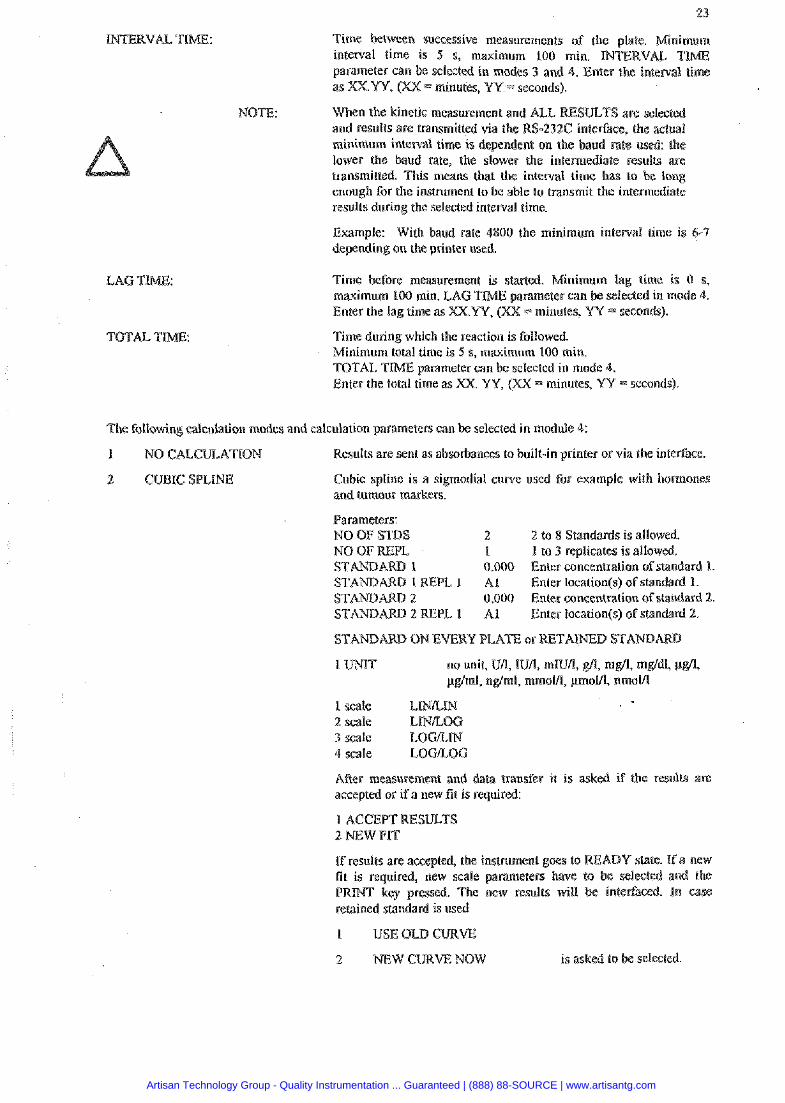
Time between successive measurements of t interval time is 5 s, maximum 100 min. parameter can be selected in modes 3 and 4. Enter the interval time as XX.YY, (XX = minutes, W = seconds).
NOTE: When the kinetic measurement and iBLL and results are transmitted via the -232C inle&ace, the actual minimum interval time is depend on the baud rate used: the lower the baud rate, the slower the intermediate results are transmitted. This means that the interval time has to enough for the instrument to be able to transmit the intermediate results during the selected interval time.
Example: With band rate 4800 the minimum interval time is 6-9 depending an the printer used.
Time before measurement is started. Minimum lag time is 0 s, maximum 100 min. rameter can be selected in mode 4. Enter the lag time a minutes, W = seconds).
Time during which the reaction is followed. Minimum total time is 5 s, maximum 100 min. TOTAL TME parameter can be selected in mode 4. Enter the total time as XX. W, (XX = minutes, W = seconds)
The following calculation modes and calculation parameters can be selected in module 4:
1 P.IQCALCaATIOM Results are sent as absorbances to built-in printer or via the interface.
2 CUBIC SPLI Cubic spline is a sigmodial cuwe used for example with hormones and tumour markers.
Parameters: NO OF S m S 2 2 to 8 Standards is allowed. NO OF WPL 1 I to 3 replicates is allowed. STANDARD 1 0.000 Enter concentration of stanciard I.
1 REPL 1 A1 Enter lacation(s) of standard 1. 0.000 Enter concentration of standard 2. A1 Enter location(s) of standard 2.
AINED S T A r n
l UNIT no unit, Ull, IU/I, mlUfl, gn, mgA, m &ml, nglml, mmalfl, ymoVI, nmoVl
1 scale L1NLM 2 scale LWiLOC 3 scale LQGiLM 4 scale EOGkOG
After measurement and data transfer it is asked if the results are accepted or if a new fit is required:
I ACCEPT WSULTS 2 NEW FIT
If results are accepted, the i n s tmen t goes to fit is required, new scale parameters have PWNT key pressed. The new results will retained standard is used
I USEOLD CURVE
2 N E W C m W N O W
Artisan Technology Group - Quality Instrumentation ... Guaranteed | (888) 88-SOURCE | www.artisantg.com
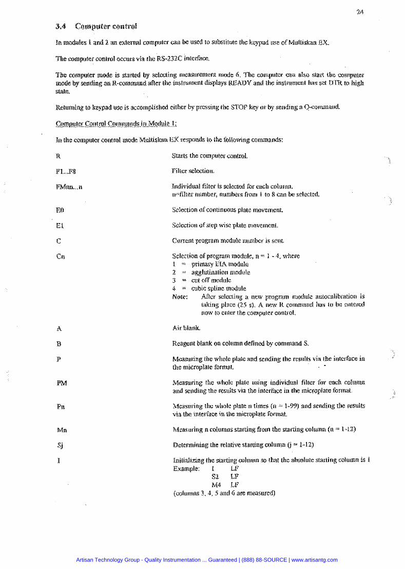
In modules I and 2 an external computer can he used to substitute the keypad use of Multiskan EX.
The computer control occurs via the RS-232C interface.
e mmputer mode is started by selecting measurement mode 6 . The computer can also s?a& the com mode by sending an R-command &ee the instrument displays RE Y and the instrument ha^: set BTR to high state.
Rehrming to keypad use is accomplished either by pnssing the STOP key nr by sending a Q-command
Comsuter Control Commands in Module 1:
In the computer control medc Multiskan EX responds to the, following commands:
R Starts the computer control.
FI ... FB Filter selection.
Individual filter is selected for each column. n=filter number, numbers from I to 8 can be selected.
EO Selection of continuous plate movement.
El Selection of step wise plate movement
C Current program module number is sent
Selection ofprogram module, n = 1 - 4, where I = primaryEIAmodu1e 2 = agglutination module 3 = cut off module 4 = cubic spline module Note: After selecting a new program module autocalibration is
taking place (25 s). A new R command has to be entered now to enter the computer control.
Air blank.
Reagent blank on column defined by command S .
Measuring the whole plate and sending the results via the interface in the microplate format.
Measuring the whale plate using individual filter for each c o l m n and sending the results via the interface in the microplate format.
Measuring the whole plate n times (n = 1-99) and sending the res-ults via the interface in the microplate Format.
Measuring n columns starting from the starting column (n = 1-12)
Determining the relative staning column (j = 1-11)
Initializing the starling column so that the absolute staning column i s I Example: I LF
S2 LF M4 LF
(columns 3.4, 5 and 6 are measured)
Artisan Technology Group - Quality Instrumentation ... Guaranteed | (888) 88-SOURCE | www.artisantg.com
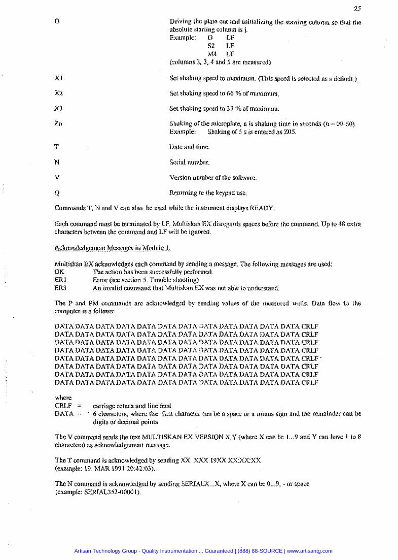
Driving the plate our and initializing the starting column so that the absolute starting column is j. Example: O CF
S2 LF M4 LF
(columns 2 , 3 , 4 and 5 are measured)
XI Set shaking speed to maximum. (This speed is selected as a default.)
X2 Set shaking speed to 66 %of maximum
X3 Set shaking speed to 33 %of maximum
Shaking of the microplate, n in shaking time in seconds (n = 0060) Example: Shaking of 5 s is entered as 205.
Date and time.
N Serial number.
V Version number of the sotlware.
Returning to the keypad use.
Commands T, Nand V can also be used while the instrument displays RE
Each command must be terminated by CF. Multiskan EX disregards spaces before the command. Up to 48 extra characters between the command and LF will be ignored.
Acknowled~ement Messges in Module I:
Multiskan EXacknowledges each command by sending a message. The following messages are used: OK The action has been successfully performed. ERI Error (see section 5. Trouble shooting) ER? An invalid command that Multiskan EX was not able lo understand.
The P and PM commands are acknowledged by sending values of the measured wells. Data flow to the computer is a follows:
DATA DATA BATA DATA DATA DATA DATA DATA DATA DATA DATA DATA CRLF DATA DATA DATA DATA DATA DATA DATA DATA DATA DATA DATA DATA CRLF DATA DATA DATA DATA DATA DATA DATA DATA BATA DATA DATA DATA CRLF DATA DATA DATA DATA BATA DATA BATA DATA DATA BATA DATA BATA CRLF DATA DATA DATA DATA DATA DATA DATA DATA DATA DATA DATA DATA CRLF - DATA DATA BATA DATA DATA DATA DATA DATA DATA DATA DATA DATA CR&F DATA BATA DATA DATA DATA DATA DATA DATA DATA DATA DATA DATA CRLF DATA DATA DATA DATA DATA DATA DATA DATA DATA DATA DATA DATA CaLF
where C = carriage return and line feed D = 6 characters, where the first character can be a space or a minus sign and the remainder c
digits or decimal points
The V command sends the test MULTISKAN EX VERSION X.V (where X can be 1...9 and Y can have % So 8 characters) as acknowledgement message.
The T command is acknowledged by sending XX. (example: 19. MAR 1991 20:42:03).
The N command is acknowledged by sending SERIALX ... X, where X can be 0...9, -or space (example: SERIAL352-00001).
Artisan Technology Group - Quality Instrumentation ... Guaranteed | (888) 88-SOURCE | www.artisantg.com
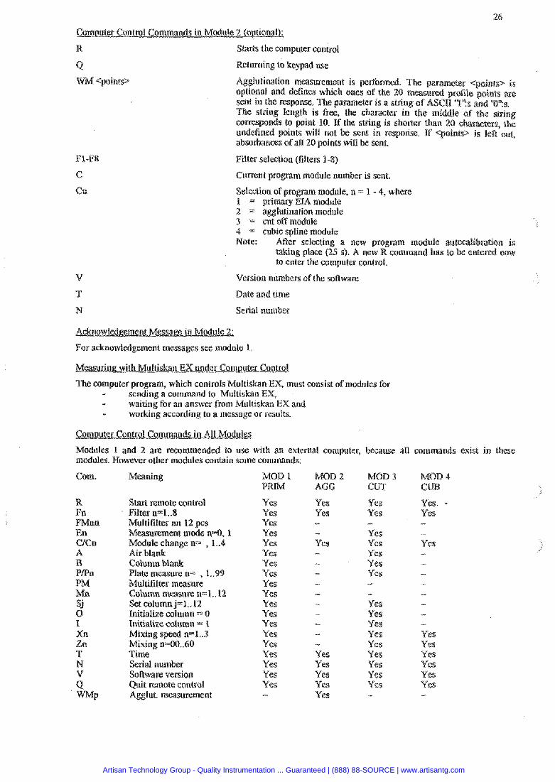
Comvuter Control Commands in Module 2 (ogtionalL
R Starts the computer control
Returning to keypad use
Agglutination measurement is perlbrmed. The pa optional and defines which ones, of the 20 measur sent in the response. The pammeter is a string of W The string lenah is free, the character in the middle corresponds to p i n t 10. If the strin is shorter than 20 charactere, the undefined p in t s will not absorbauces ofall 20 point
Filter selection (filters 1-8)
Current program module number is sent.
Selection of program module, n = 1 - 4, where i = primary EIA module 2 - agglutination module 3 = cut off module 4 = cubic spline module Note: Mer selecting a new program module autacalibmtion is
taking place (25 s). A new R command has lo to enter the computer control.
V Version numbers of the software
7' Date and time
N Serial number
Acknowledgement M-ModuIe 2:
For acknowledgement messages see module 1.
Measuring with Multiskan EX under Computer Control
The computer progam, which controls Multiskan EX, must consist of modules for - sending a command to Multiskan EX, - waiting for an answer from Multiskan EX and - working according to a message or results.
Comouter Control Commands in 411 Modules
Modules 1 and 2 are reconlmended to use with an external computer, because all commands exist in these modules. However other modules contain some commands:
Corn. Meaning
Multifilter nn 12 pcs Measurement mode n=O, 1 Mcdule change n;- , 1..4 Air blank: Column blank Plate measure n= , L.99 Multililtee measure Column measure n=I.. 12 Set columnj=1..12 Initialize column = 0 Initialize column = 1
Mixing n=00..60 Time Serial number Software version Quit remote control Agglut. measurement
MOD l MOW 2 MOD3 MOB 4 PRIM AGG CUT CUR
Yes Yes Yes Yes Yes Yes Yes Yes Yes Yes Yes Yes Yes Yes Yes Yes Yes Yes Yes -
Yes Yes - - Yes -
- - Yes Yes Yes Yes Yes
Yes Yes - Yes Yes Yes Yes Yes - - Yes Yes Yes Yes Yes Yes Yes Yes Yes
Yes. Yes - - Yes -
- - - Yes Yes Yes Yes Yes Yes -
Artisan Technology Group - Quality Instrumentation ... Guaranteed | (888) 88-SOURCE | www.artisantg.com

User determined programs can he stored into the memory of the instrument foe later use.
s done with the SAVE key. When it is pressed the instrument asks for program number (P R), which can be 1 to 64. Enter the program number. SAVING DATA is blinking on the dis
The stored program can be taken later into use with the RECALL key and using the sane progra
The following general parameters can be selected with the P key (and the arrow keys or ENTER key):
1. P R W E R F O T (header idamation and abserbances are sent via the interface)
2. COMPUTER FORMAT (only absarbances are sent via the . . interlace in plate format)
3. OLD MCC IiO AT (only absorbances are sent via the interlace in column format)
PLATE MOVEmNT: The speed at which the plate is moved can he selected: 1. CONTINUOUS (5 s) 2. STEP MODE (25 s)
Programs in the memory of the instrument are printed on the built-in printer.
P R ONIOFF Odoff selection of the built-in printer. When the printer i s snppresse SELECTION results are automatically sent via the interface.
When the instrument is switched on, the latest selection will be valid.
PLATE ANALYSIS: Aner results have been presented in the microplate format, fhe instrument sends via the interface the mean value, minimum value, maximum value, delta value, standard deviation value, delta percentage and coeficient of variation percentage for every column and row and also for the whole plate.
4 CLOCKSET:
Odoff selection of the analysis: I. ANALYSIS OFF 2. ANALYSIS ON (nut available on module 2 and 4)
Number of filters and filter wavelengths can be entered.
NROF FlLTERS 1 Number of filters (1 - 8) can be entered or changed with the arrow and number keys.
FILTER I WAVEE 340 Filter wavelengths in nanometers can entered or changed with the arrow an number keys.
The entered values are used until changed.
Date and lime (year, month, day of the week, hour, minute) can changed with the arrow and number keys.
On the printout of the external printer an empty row can between the results of the rows (print out spacing).
Odoff selection of the printout spacing: 1. NOSPACMG 2. PRINTOUT SPACING
Mixing of the microplate before measurement i s started 1. MIXING OFF 2. MIXYNGON
* MlXlNG FAST * MXMGEVIEDrn * M I r n G S E B W
- M I n N G TTNDE: enter the time in seconds (0-60 s). Default value is Li s.
10 MODULE LISTING List of modules is printed out.
Artisan Technology Group - Quality Instrumentation ... Guaranteed | (888) 88-SOURCE | www.artisantg.com
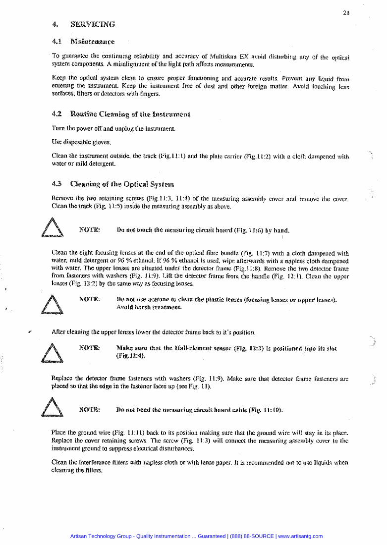
To guarantee the continuing reliab~lity and accuracy of Multiskan EX avoid disturbing any of the optical system components. .A misalignment of the light path s e c t s measurements.
Keep the optical system clean to ensure proper functioning and accurate results. Prevent any liquid from entering the instrument. Keep the instrument free of dust and other foreign matter. Avoid touching lens surPaces, filters or detectors with fingers.
Turn the power off and unplug the instrument
Use disposable gloves
Clean the instrument outside, the track (Fig.ll:l) and the plate carrier (Fig.LI:Z) with a cloth dampen water or mild detergent.
Remove the two retaining screws (Fig 11:3, 11'4) of the measuring assembly cover and remove the cover. Clean the track (Fig. 11'5) inside the measuring assembly as above.
: Do not touch the measuring circuit hoard (Fig 1 1 6 ) by
Clean the eight focusing lenses at the end of the optical fibre bundle (Fig. 117) with a cloth dampened with water, mild detergent or 96 %ethanol. If 96 %ethanol is used. wipe &crwards with a napless cloth dampened with water. The upper lenses are situated under the detector frame (Fig.l1:8). Remove the two detector frame from fasteners with washers (Fig. 11:9). Lift the detector frame from the handle (Fig. 12:1). Clean the upper lenses (Fig. 122) by the same way as focusing lenses.
t
: Do not use acctone to clean the plastic lenses (focusing lenses o r upper lenses). Avoid harsh treatment.
I ARer cleaning the upper lenses lower the detector frame back to it's position.
NOTE: ake sure that the Nail-element sensor (Fig. 12:s) is positions i&12:4).
Replace the d e t a o r frame fasteners with washers (Fig. 11:9). Make sure that detector frame fasteners are placed so that the edge in the fastener faces up (see Fig 11).
NOTE: Do not bend the measuring circuit board cable (Fig. Ik10).
Place the ground wire (Fig. I l:1 I) back to its position making sure that the ground wire will stay in its place. Replace the cover retaining screws. The screw (Fig. 113) will connea the measuring assembly cover to the insirument ground to suppress electrical disturbances.
Clean the interference filters with napless cloth or with lense paper. It is recommended not to use liquids when cleaning the filters.
Artisan Technology Group - Quality Instrumentation ... Guaranteed | (888) 88-SOURCE | www.artisantg.com
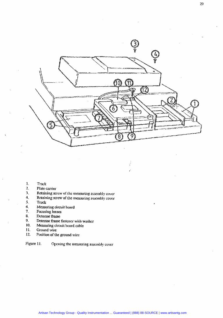
Track Plate carrier Retaining screw of the measuring assembly cover Rebining screw of the measuring assembly cover Track Measuring circuit board Fosusing lenses
fastener with washer Measuring circuit board cable Ground wire Position of the ground wire
Figure 11. Opening the measuring assembly cover
Artisan Technology Group - Quality Instrumentation ... Guaranteed | (888) 88-SOURCE | www.artisantg.com
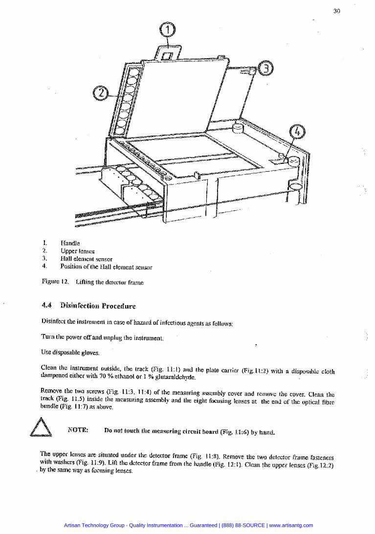
1. Handle 2. Upper lenses 1. Hall element sensor 4. Position sf the Hall element sensor
Figure 12. LiAing the detector frame
Disinfect the instrument in case of hazard of infectious agents as follows:
Turn the pwer off and unplug the instrument.
Use disposable gloves
Clean the i n s tmen t outside, the track Fig. 11:l) and the plate canier (Fig.l1:2) with a disposable cloth dampened either with 40 % ethanol or 1 % gluhraldehyde.
emove the two screws (Fig. 11:3, 11:4) of the measuring assembly cover and remove the cover. Clean the track F ig . 11.5) inside the measuring assembly and the eight focusing lenses at the end of the optical fibre bundle (Fig. 11:7) as above.
The upper lenses are situated under the detector hame (Fig. 11:X). Remove the two detector frame fastenen with washers (Fig. 11:9). LiA the detector frame from the handle (Fig. 121). Clean the upper lenses (Fig.122) by the same way as focusing lenses.
Artisan Technology Group - Quality Instrumentation ... Guaranteed | (888) 88-SOURCE | www.artisantg.com
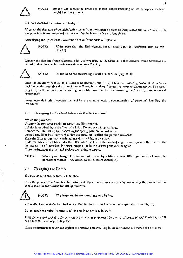
o not use acetone to clean the i~lastie lenses (focusin Avoid harsh treatment
Let the surfaces of the instrument to diy.
Wipe out the thin film of the disidection agent from the surface of eight focusing lenses and u a napless lens tissue dampened with water. Dry the tenses with a dry lens tissue.
After drying the upper lenses lower the detector frame back to its position,
NOTE: e sure that the Rall+lement sensor (Fig 12:3) is positione
Replace the detector frame fasteners with washers (Fig. 113). Make sure that detector frame fasteners are placed so that the edge in the fastener faces up (see Fig. 11)
: Do not bend the measuring circuit board cable (Fig. 11:10).
Place the ground wire (Fig.ll : l l) Back to its position (Fig. 11:12). Slide the measuring assembly cover to its sure that the ground wire will slay in its place. Replace the cover retaining screws. The screw
Qig.ll:3) will connect the measuring assembly cover to the instrument ground to suppress electricial disturbances.
Please note that this procedure can not be a guarantee against contamination of perso~rnei handling the instrument.
Switch the power off. Unscrew the two cover retaining screws and lift the cover. Lift the filter wheel from the filter wheel slot. Do not touch filter surfaces. Remove the filter spring by unscrewing the spring position holding screw. Insett a new filter into the wheel so that the arrow on the filter rim points downwards. Place the filter spring into its original position and fasten the screw. Slide the filter wheel back into the filter wheel slot with the toothed edge facing towards the rear of the instrument. The filter wheel is drawn into position by the central pemanent magnet. Close the instrument cover and replace the retaining screws.
hen you change the amount of filters by addin a new filler you must change the rametcr values (filter wheel. position and wavelen
If the lamp bums our, replace i t as follows.
Turn the power off and unplug the instrument. Open the inarument cover by unscrewing the two screws on each side of the instrument and lift up the cover.
: The lamp and its eurroundings may be hot.
Lift up the lamp with the terminal socket. Pull the terminal socket from the lamp contacts (see Fig. 13).
Do not touch the reflective surface of the new lamp or the bulb itself.
Refit the terminal socket to the contacts af the new lamp approved by the manufacturer (OS W). Place the new lamp in its place.
Close the instrument cover and replace the retaining screws. Plug in the instrument and switch the powcr on
Artisan Technology Group - Quality Instrumentation ... Guaranteed | (888) 88-SOURCE | www.artisantg.com
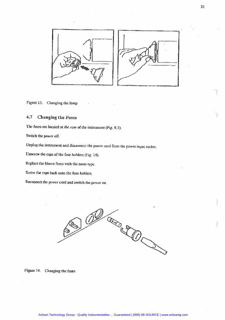
Figure 13. Changing the lamp
The f ises are located at the rear of the initmment (Fig.
Switch the power off.
Unplug the instnlment and disconnect the power cord from the power input socket.
Unscrew the caps of the fuse holders (Fig. 14).
Replace the blown fuses with the same type.
Screw the caps back onto the fuse holders.
wer cord and switch the power on.
Figure 14. Changing the fuses
Artisan Technology Group - Quality Instrumentation ... Guaranteed | (888) 88-SOURCE | www.artisantg.com
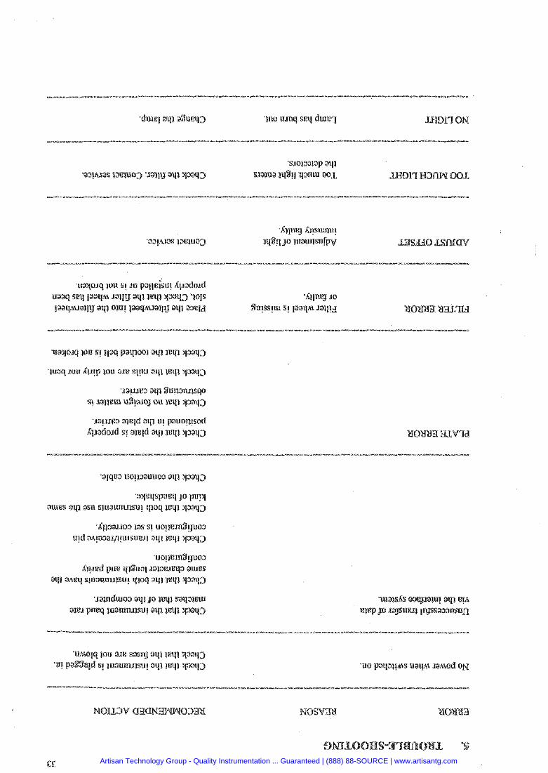
'sioisaap aqi ‘oqhlas xxnoo3 'mlg ays ysaq3 s.xa)ua 1q8g qanw BOL
Artisan Technology Group - Quality Instrumentation ... Guaranteed | (888) 88-SOURCE | www.artisantg.com
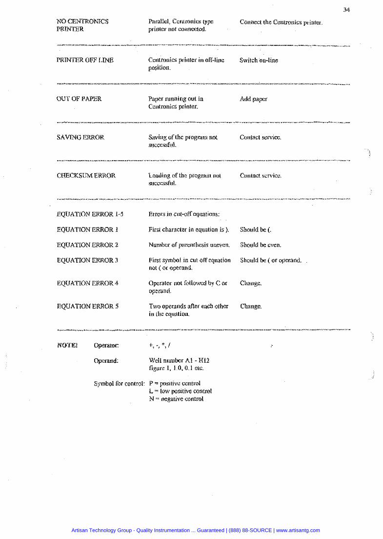
34
Parallel, Centronics Connect the Centronics printer. printer not connecte
P Centronics printer in off-line Switch on-line position.
OUT OF PAPER Paper running out in Add paper Centronics printer.
Contact sewice. successful.
"" *-----*-*------------------- - ----- --- ---- ---"-" m-----*-<--e---------------m-------------* ---- -- ----- --- ------- Loading of the program not Contact service. successful.
EQUATION ERROR 1-5 Errors in cut-off equations:
First character in equation is ). Should be (.
EQUATTON ERROR 2 Number of parenthesis uneven. Should be even
First symbol in cut off equation Should be ( or operand not ( or operand.
Operator not followed by C or Change. operand.
Two operands after each other Change. in the equation.
Operand: Well number At - W12 figure I, 1.0, 0.1 etc.
Symbol COP. contro1: P = positive conlrol L = low positive control N = negative control
Artisan Technology Group - Quality Instrumentation ... Guaranteed | (888) 88-SOURCE | www.artisantg.com
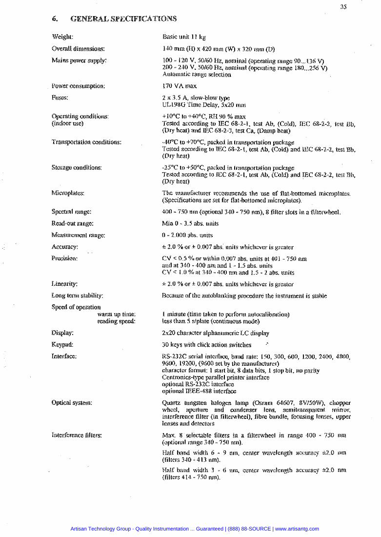
Weight:
era11 dimensions:
Power consumption:
Fuss:
Oprating conditions: (indoor use)
torage conditions:
Microplates:
Read-out range:
Measurement range:
Accuracy:
Precision:
Lineariw:
Long term stabiliv:
Display:
Intepface:
Optical system:
Interference filters:
Basic unit 11 kg
100 - 120 V, 50160 Hz, nominal ( rating range 90 ... 136 200 - 240 V, 50160 Hz, nominal rating range 180 ... 25 Automatic range selection
170 VA max
2 x 3.5 A, slow-blow type UL198G Time Delay, 5x20 mm
1, test Ab, (Cold), E C 68-22, test pry hear) and E C 68-24, test Ca, @amp heat)
40°C to +70°C, packed in t r a n s ~ m t i o n package Tested according lo IEC 68-2-1, test Ah, (Cold) and EC 68-2-2, test Ply heat)
-25°C to +50°C, packed in transportation package Tested according to IEC 68-2-1, rest Ab, (Cold) and IE Ply heat)
The manifacturer recornmends the use of flat-bttomed micro (Specifications are set for flat-bottomed rnicroplates).
400 - 750 nm (optional 340 - 950 nm), 8 filter slots in a filtemheel.
Min 0 - 3.5 abs. units
0 - 2.000 ahs. units
1: 2.0 % o r lt: 0.007 abs. units whichever is greater
CV c 0.5 %or within 0.007 abs. units at 401 - 750 nm and at 340 - 400 nm and 1 - 1.5 abs. units CV < 1.0 %at 340 - 400 om and 1.5 - 2 abs. units
n 2.0 % o r 1: 0.007 abs. units whichever is greater
Because of the autoblanking precedure the instrument is stable
1 minute (time taken to pefiom autocalibration) less than 5 dplate (continuous mode)
2x20 character alphanumeric LC display
30 keys with click action switches
RS-232C serial interface, baud rate: 150, 300, 600, 1200, 2400, 4800, 9600, 19200, (9600 set by the manufacturer) character fonnat: 1 start bit, 8 data bits, 1 stop bit, no parity
parallel printer interface optional RS-232G interface optional EEE-488 interface
Quartz angsten halogen lamp (Osram 64609, 8V/50W), cho wheel, apemre and condenser lens, semitranspamnt mi interference filter (in filtenvheel), fibre bundle, focusing lenses, u lenses and detectors
Max. 8 selectable filters in a filterwheel in range 400 - 750 urn (optional range 340 - 450 nm).
Half band width 6 - 9 nm, center wavelength accuracy k2.0 nm (filters 310 - 413 nm).
Half band width 3 - 6 nm. center wavelensh acmracy h2.0 nm (filters 414 - 350 nm).
Artisan Technology Group - Quality Instrumentation ... Guaranteed | (888) 88-SOURCE | www.artisantg.com
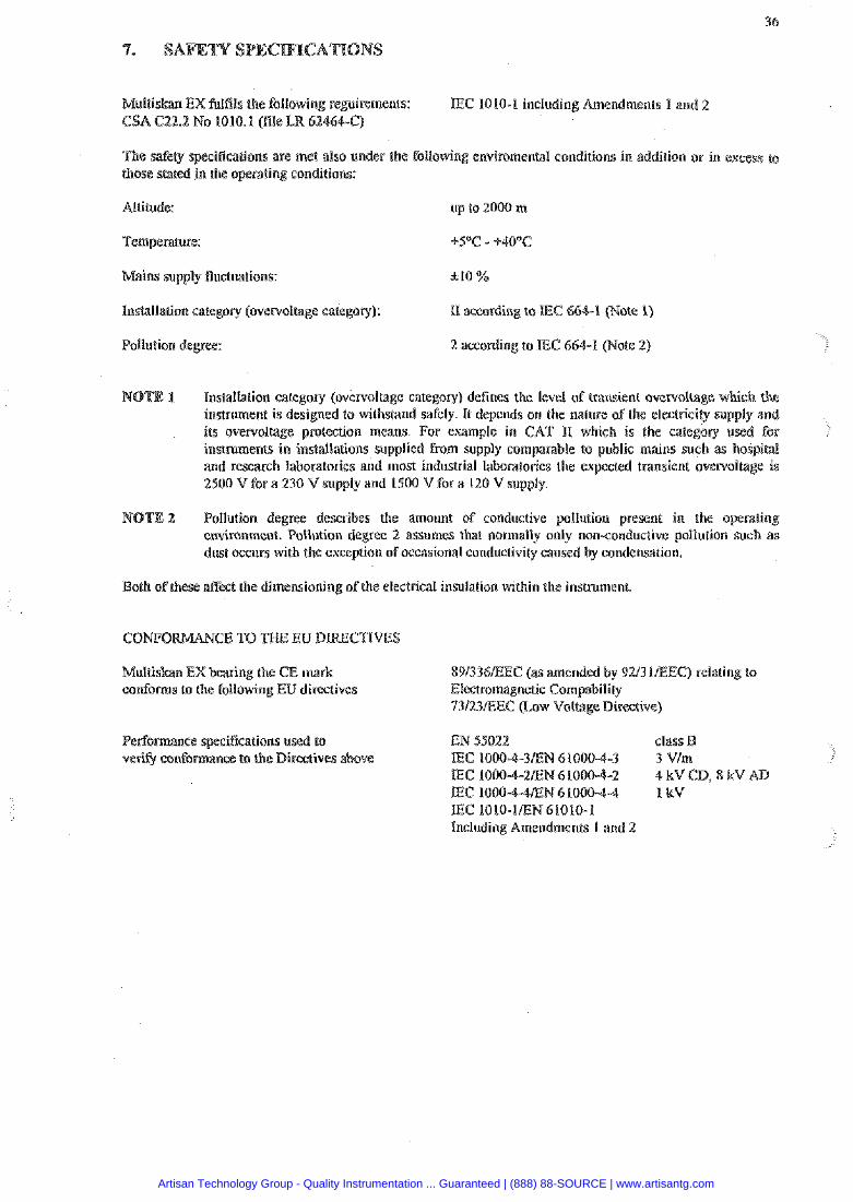
Multiskan EX fulfils the (bllowing repirements: E C 1010-1 including Amendments 1 and 2 CSA C22.2 No 1010.1 (file L
iflcations are met also under the following envitamental conditions in addition or in excess to these stated in the operating conditions:
Mains supply fluctuations: A10 %
Ins@llation eategary (overvol(age category): II amording to IEC 664-1 (Note I)
Pollution degree: 2 according to 1EC 664-1 (Note 2)
1 installatieu category (ov'ervoltage category) defines the level of transient ovewollnge wwhb the instrument is designed to withstand safely. It depends on the nature of the electricity su its overvoltage protection means. For example in CAT I1 which is the category instruments in indallations supplied Ersm supply comparable to public mains such as and research laboratories and most industrial laboratories the expected transient ove 2500 V for a 230 V supply and 1500 V for a 120 V supply.
2 Follution degree describes the amount of conductive pollution present in the operarin environment. Pollution degree 2 assumes ihat normally only non-conductive pollution such as dust occurs with the exception of occasional conductivity caused by condensation.
d the dimensioning ofthe electrical insulation within the instrument.
NCE TO THE EW DLRECTIVES
Multiskan EX bearing the CE mark 891346iEEC (as amended by 92131EEC) relating to conforms to the foliowing Ell directives Electromagnetic Campability
73/23/EEC (Low Voltage Directive)
Pe cations used to EN 45022 class I3 ve to the Bireaives above IEC 10004-3EN 61000-4-3 3 V/m
a c 1000-4-am 61000-4-2 4 k v ca 8 k v IEC 1000-4-4EN 6100044 I kV IEC 1010-lEN61010-1 Ineludmg Amendments I and 2
Artisan Technology Group - Quality Instrumentation ... Guaranteed | (888) 88-SOURCE | www.artisantg.com
Unpack the instrument.
Install the filter wheel.
Install the lamp.
Plug into mains.
Switch the instmment on.
r roll. (Printer option)
Select the RS-fomat for printer or computer.
Select the plate movement to k continuous or step wise.
Select print out on the built-in printer if required.
Ifbuilt-in printer, then select printing width.
Ifexternal printer, then select print out spacing.
Select shaking ifrequired.
Select the program module.
Select the measurement parameters.
Select the calculation mode.
Select the calculation parameters.
Save rhe program.
Connect printer or computer.
Cheek the baud rate, trmsmit I receive pin configuration and handshake with DIE-switches.
Results are recorded on built-in printer, external printer or computer.
Artisan Technology Group - Quality Instrumentation ... Guaranteed | (888) 88-SOURCE | www.artisantg.com
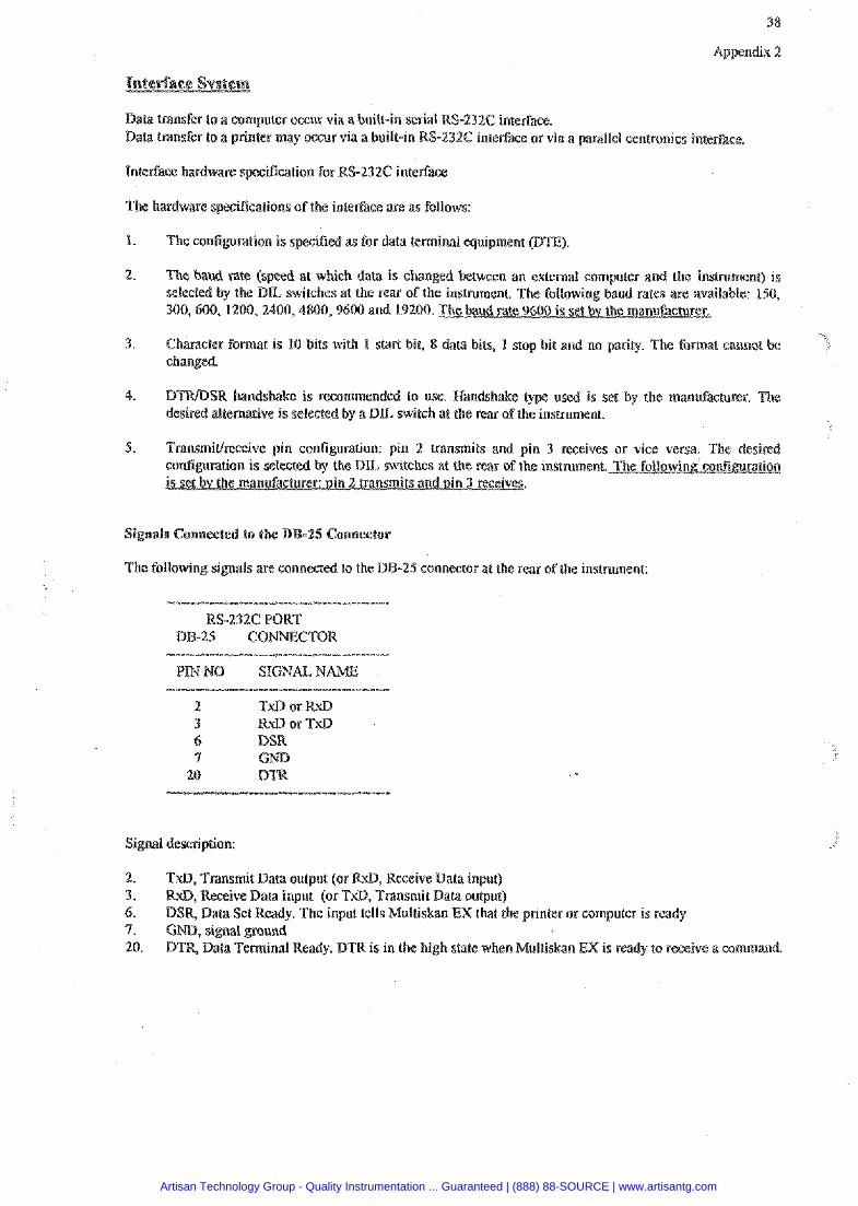
38
Data transfer to a computer occur via a built-in serial RS-232C interface. Data transfer to a printer may occur via a built-in RS-232.C inregace or via a parallel centronics interbace.
Interface hardware specification for RS-232C interface
cifications of the interface are as follows:
The configuration is specified as for data terminal equipment (DTE).
The baud rate (speed af whish data is changed between an external computer and the instrument) is selected by the D L switches at the rear of the instrument. The following baud rates are available: 150, 400,600, 1200,2400,4800,9600 and 19200. The baud rate 9600 is set bv the manufacturer.
Character format ts 10 bits with 1 start bit, 8 data bits, 1 stop bit and no parity The fomat cannot changed.
SR handshake is recommended to use. Handshake used is set by the mandacturer. The desired alternative i s selected by a DTL switch at the rear of the instmment.
TransmiUreceive pin configuration: pin 2 transmits and pin 3 receives or vise versa. The desired configuration is selected by the DIL switches at the rcar of the instrument. The fol lowing'co~t~rat ion is set bv the manufacturer: oin 2 transmits and in 3 receives.
The following signals are connected to the DB-25 connector at the rear of the instrument:
RS-232C PORT BB-25 CONMECTOR
PINNO SIGNAL N *--ee--**----*--om--*----*--*---.-- -
2 TxD or W 3 RUD or TxD 6 D 7 G
20 ---v-------m------o*-<-"--ea
2. TxD, Transmit Data output (or BuD, Receive Data input) Receive Data input (or TxD, Transmit Data output) Data Set Ready. The input tells Multiskan EX that the printer or computer is ready
Ready. BTR is in the high state when Muitiskac~ EX is ready to receive a command
Artisan Technology Group - Quality Instrumentation ... Guaranteed | (888) 88-SOURCE | www.artisantg.com
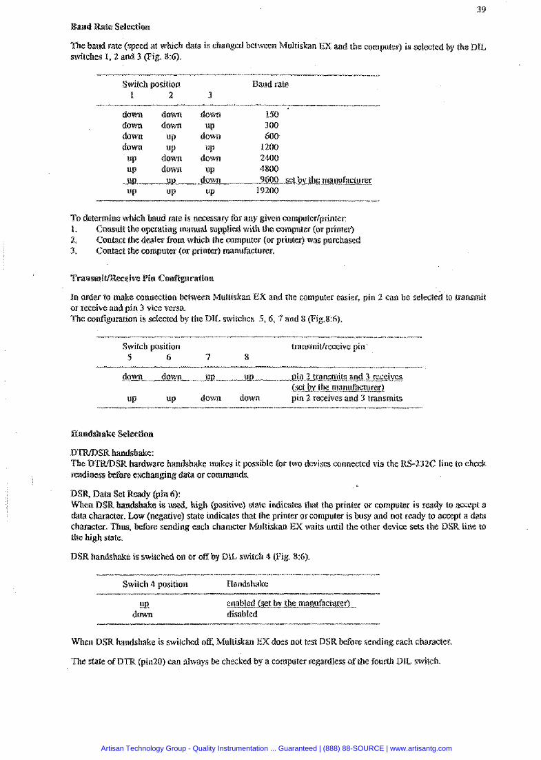
and Rate Selection
ed at which da(a is changed ultiskan EX and the computer) is selected by the D L switches I, 2 and 3 (Fig. 8:6).
Switch position aud rate 1 2 3
down down do- 150 down down up 100 dawn up down 600 down up UP 1200
up down down 2400 UP down up 4800 ui? ui? down 9600 set bv the manufacmrer UP up UP 19200
7% determine which baud rate is nesessary for m y given computer/grinter: 1. Conmlt (he operating manual suaplied with the computer (or printer) 2. Contact the dealer from which the computer (or printer) was purchased 3. Contact the computer (or printer) manufacturer.
In order to make connection between Multiskan EX and the computer easier, pin 2 can be selecte or receive and pin 3 vise versa. The conIipration is selected by the DIL switches 9,6 , 7 and 8 (Fig.86).
Switch position LlansmiWreseive pin 5 6 7 8
down down up- UB ain 2 transmits and 3 receives bet bv the manufacturer)
UP down down pin 2 receives and 3 transmits
Raodshake Selection
R b d w x e handshake makes it possible foe two devises connected via the RS-232C line to check
DSR Data Set Ready (pin 6): (positive) state indicates tnat the printer or computer is ready to acce
ive) state indicates that the printer OF computer i s busy and not ready to accept a data ding each character Multiskan EX waits until the other device sets the DSR line to
the high state.
DSR handshake is switched on or off by D E switch 4 pig. 8:6).
Switch 4 position Handshake - u
down disabled
When DSR handshake is switched off, Multiskan EX does not test DSR before sending each character.
The state of DTB (pin20) can always be checkcd by a computer regardless ofthe fourth DIL switch.
Artisan Technology Group - Quality Instrumentation ... Guaranteed | (888) 88-SOURCE | www.artisantg.com
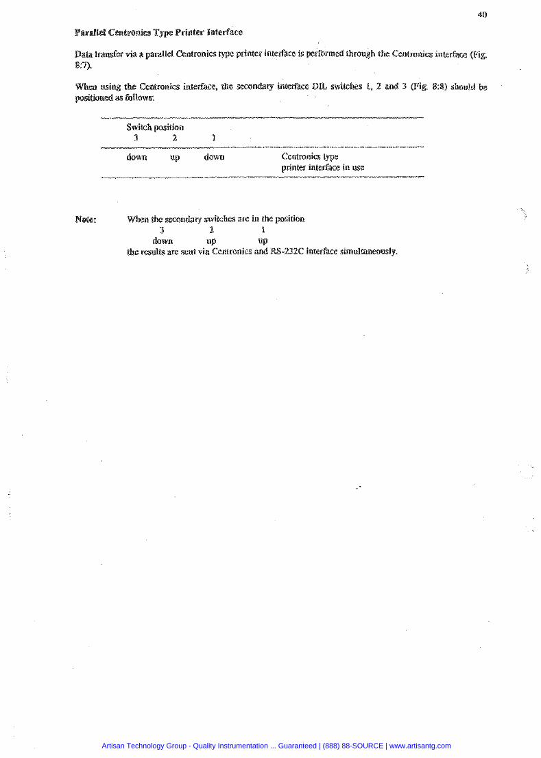
arallel Centronics Type
&r via a parailel Centronics e prirrter interEace is p e ~ o m e d through the Centronics interface @i
en using the Cenbonicr intePPace, the secon ry interface BIL switches 1, 2 and 4 (Fi 'tioned as follaws:
down up down Centronics type printer interface in use
Note: ondary switches are in the position 3 2 P
down UP UP the results are sent via Centronics and RS-234C interface simultaneously.
Artisan Technology Group - Quality Instrumentation ... Guaranteed | (888) 88-SOURCE | www.artisantg.com

Appendix 3
Accessories
RS-232C interfact: cable for printer RS-232C PC -serial cable F- RS-232C interface cable for MAC Filtenvheel without filters 0th filters in the 340-750 nm range can
spends to the wavelensh)
Dust cover
Spares for maintenance Lamp
(head ofice) Snrvaajankaru 15 P.O. Box 8 m a 0 8 8 1 Helsinki
Tel: +358-9-329 100 Telefax: 9358-9-3291 0415
Artisan Technology Group - Quality Instrumentation ... Guaranteed | (888) 88-SOURCE | www.artisantg.com
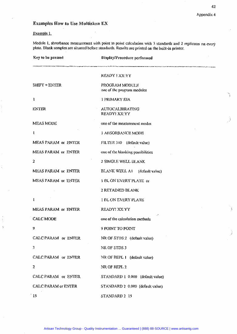
I, absorbance measure ent with point to point calculation with 4 standards and 2 replicates on e v e ~ lank samples are sihra before standards. Results are printed on the built-in printer.
AS MODE
1
or EPITEW
or ENTER
2
AS P
AS P
I
9
CALC P or ENTER
3
CALG P or ENTER
2
15
1 P Y EIA
one o f the measurement modes
FILTER 340 (default value)
one of the blanking possibilities
2 SINGLE WELL BLA
WELL A1 (default value)
I BL ON EVERY PLATE or
1 BL ON EVERY PLATE
READY! XX:W
one of the calculation meth
NB OF STDS 2 (default value)
NR OF STDS 3
PL 1 (default value)
STA 1 0.000 (default value)
STA 2 0.000 (default value)
Artisan Technology Group - Quality Instrumentation ... Guaranteed | (888) 88-SOURCE | www.artisantg.com
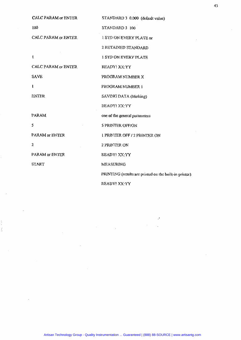
ST 3 0.000 (default value)
STANDMD 3 100
SAVING DATA Blinking)
one of the general parameters
P W N G (results are printed on the built-in printer)
Artisan Technology Group - Quality Instrumentation ... Guaranteed | (888) 88-SOURCE | www.artisantg.com
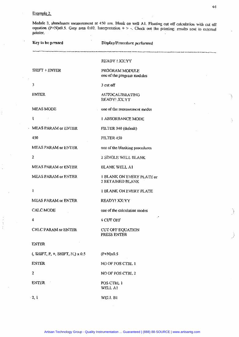
d e 3, a b s o h e e measurement at 450 urn. Blank on well AL. Floating cut off calculation wiLh cut off equation (g+W)xO.b. Grey area 0.02. lntetpretation +- > -. Check out the pEinting: results sent to external peinler.
AS MODE
I
AS P
450
MEAS P
2
MEAS P or ENTER
AS P or R
one of the program modules
3 cut of f
ING
one of the measurement modes
FLLTER 450
one of the blanking procedures
2 SINGLE WELL BLA
one of the calculation rnsdss
CUT OFF EQUATION
(Pi-Pqx0.5
WELL A1
WELL IS1
Artisan Technology Group - Quality Instrumentation ... Guaranteed | (888) 88-SOURCE | www.artisantg.com
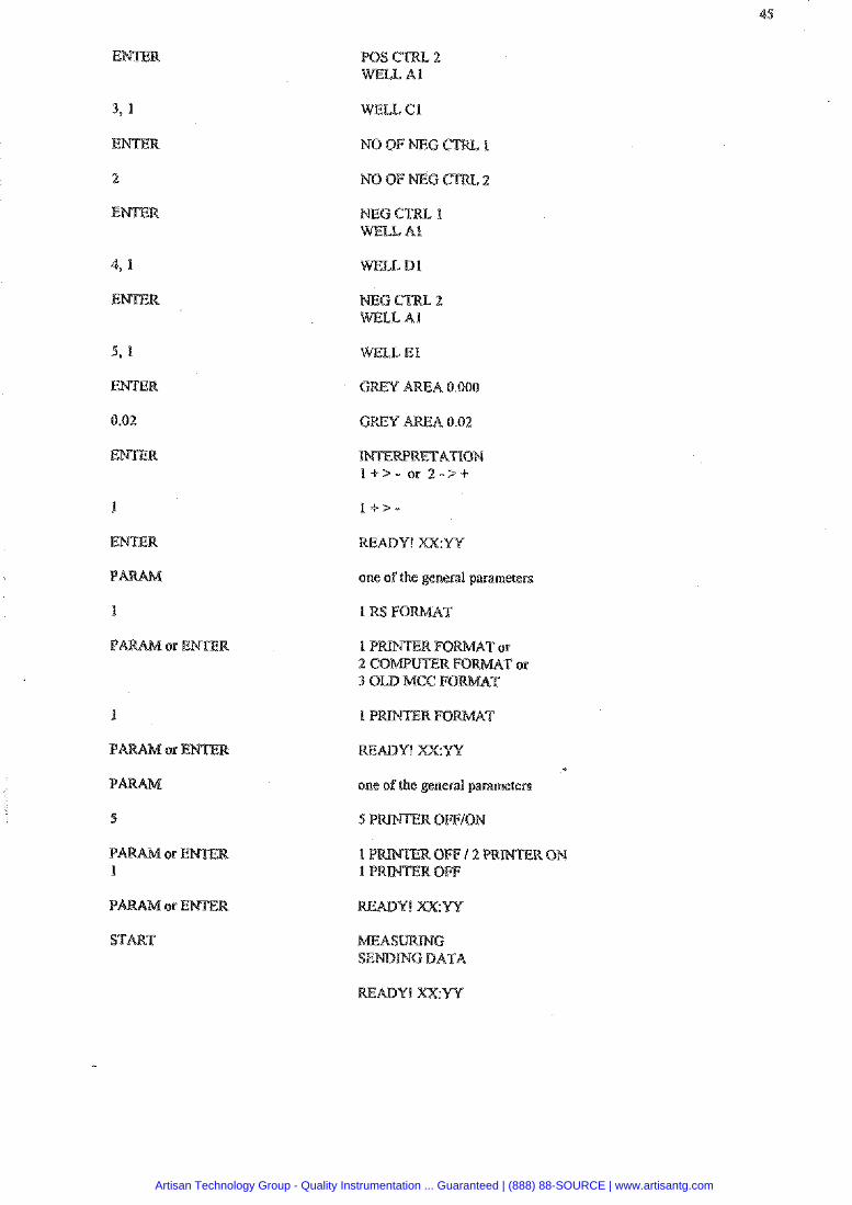
WELL G1
GREY AREA 0.000
one sf the general parameters
1 RS FOKMAT
one of the general parameters
Artisan Technology Group - Quality Instrumentation ... Guaranteed | (888) 88-SOURCE | www.artisantg.com
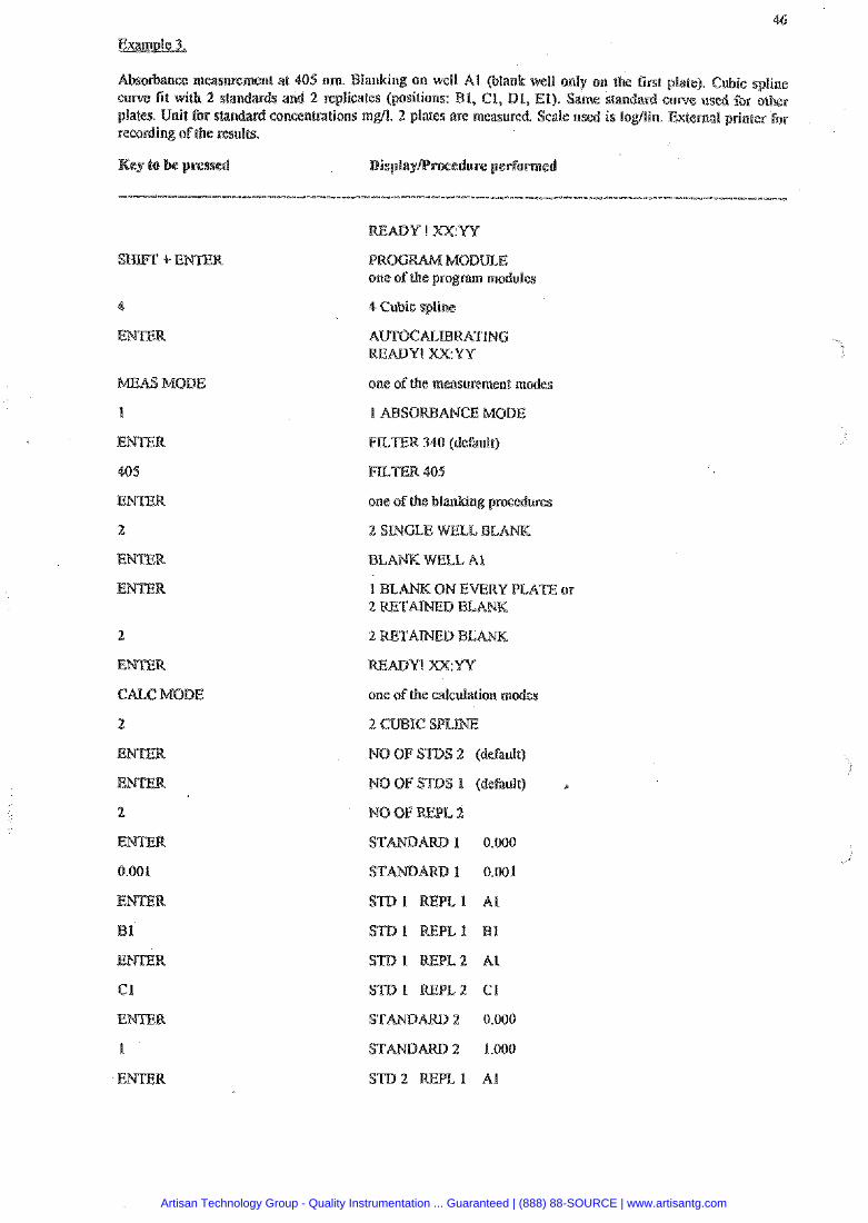
surement at 405 nm. Blanking on well A l (blank well only on the first c u m fit with 2 sbndards and 2 replicates (positions: B1, CI, DL, E1). Same standard plates. standard concentmtions mgl. 2 plates are measured. Scale used i s Iogflin. External printer for remrdi redts.
one of the program modules
4 Cubic spline
READY! XXYY
one of the measurement modes
FILTER 340 (default)
one ofthe blanking procedures
2 SINGLE WELL BEA
BLANK WELL A1
1 BLANK ON EVERY PLATE or
one of the calculation modes
NO OF STBS 1 (default) a
NO OF WPL 2
STDl REPE2 C1
STA 2 0.000
STA 2 1.000
Artisan Technology Group - Quality Instrumentation ... Guaranteed | (888) 88-SOURCE | www.artisantg.com

ment ofthe first plate
one ofthe units
one of the scaling
*" MEASURING *' CALCULATIWG parameters, standard curve, concentrations are printed out
L ACCEPT RESULTS or 2 NEW FIT
2 NEW FIT
one of the scaling pssibiiities
4 SCALE LOGLOG
PRESS PRINT
I ACCEPT ESWLTS or 2 NEW BIT
2 NEW BLANK NOW
I USE OED BL
I USE BED CUR
1 ACCEPT RESULTS on 2 NEW FIT
1 ACCEPT RESULTS
READY! xx:W
Artisan Technology Group - Quality Instrumentation ... Guaranteed | (888) 88-SOURCE | www.artisantg.com
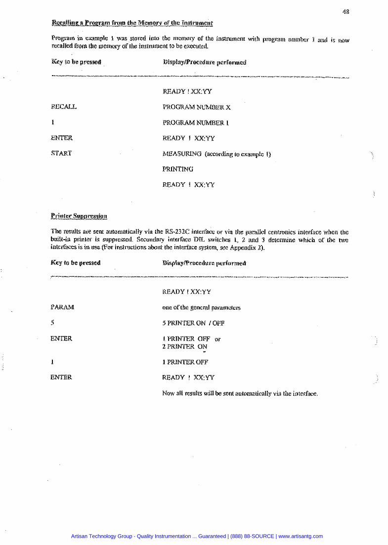
in exampIe 1 was stored into the memory of the instmment with program num m the memory of the inamment to be executed.
m e results are sent automatically via the RS-232C inte~ace or via the parallel centronics interface when the built-in printer i s suppressed. Secondary interface DIL witches 2 and 3 determine whisk of the twe inteefaces is in use (For instructions about the inteeface system, see Ap
one ofthe genenl paramete
Now all results will nc automalically via the irrterface.
Artisan Technology Group - Quality Instrumentation ... Guaranteed | (888) 88-SOURCE | www.artisantg.com
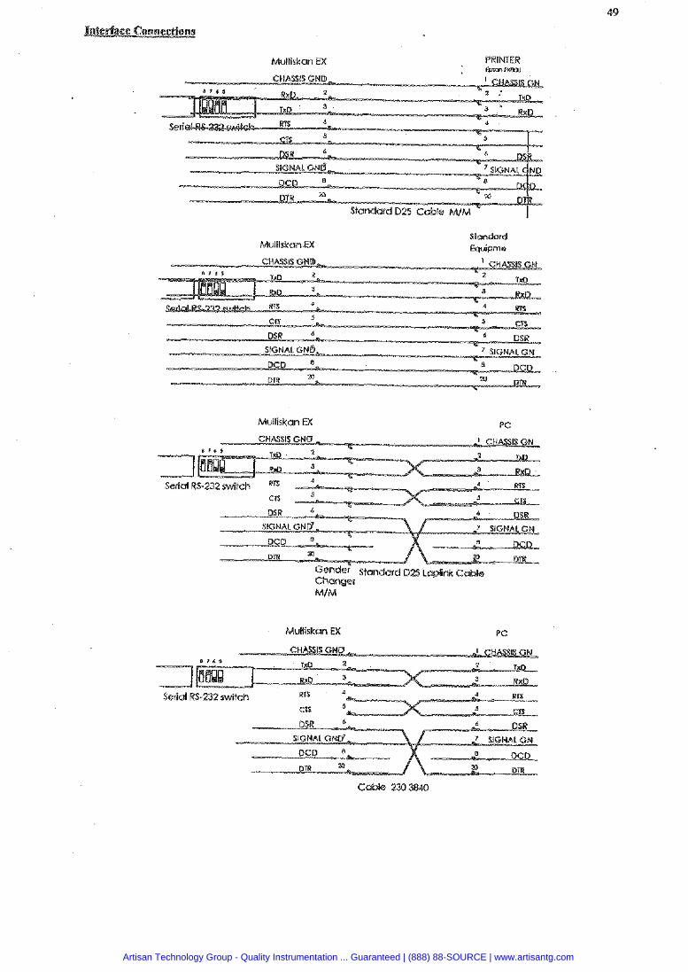
Multiskan EX PRINTER L W F Y e o o
Multiskan EX Standard Equipms
Multiskan EX PC
MIM
Mullisken EX PC
Serial RS-232 switch
Artisan Technology Group - Quality Instrumentation ... Guaranteed | (888) 88-SOURCE | www.artisantg.com

Artisan Technology Group - Quality Instrumentation ... Guaranteed | (888) 88-SOURCE | www.artisantg.com
ULTISKAN RC and MS SERVICE
Document Release ection 3511352- 100-X 2.0 3
age 1
Artisan Technology Group - Quality Instrumentation ... Guaranteed | (888) 88-SOURCE | www.artisantg.com
SERVICE
SUBJECT PAGE
Cover page .................................... ....... .............................................. Contents ...........................................................................................
I2 ............................. only in Printer option ................ -01 ............................................. .................................
............................... -2 only in M ................................. cb MACU-2A .................................... ....... ....................................... cb MUSCU-2A ............................ only in M .................................
Pcb MUSIME-01 ............................. only in n/l ................................. cb MOTCU-03 ................................................................................ cb MUSCURC-01 ........................ only in RC .................................
Document 3511352-100-X
Release 2 . 0
Section 3
Page 2
Artisan Technology Group - Quality Instrumentation ... Guaranteed | (888) 88-SOURCE | www.artisantg.com
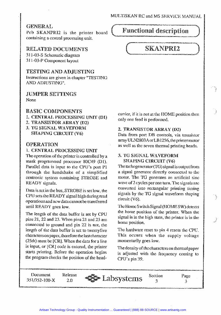
Pcb SRANPRIZ is the printer board containing a cenh-dl processing unit.
31 1-034 Schematic diagram Component layout
NG AND AD in chapter "TESTING
mask p r o g a m e d processor 80C49 (Dl). Parallel data is input to the CPU's port PI through the handshake of a simplified centronic system containing S READY signals.
Data is set in the bus, TROBE is set low, the GPU sets the READY signal high duringread operations and new datacannot be transferred until READY goes low.
The length of the data buffer is set by GPU pins 21,22 and 23. When pins 21 and 23 are connected to ground and pin 22 is not, the length of the data buffer is set to twentyfive charactersonpaper, therefore thelast character (25th) must be [CR]. When the data for a line is input, or [CR] code is entered, the printer
rinting. Before the operation begins the program checks the position of the head-
carrier, if it is not at the RQ only one feed is performed.
ntrois, via wansistor 256, the printermotor
as well as the seven thermal printing heads.
The tachogenerator (TG) signal isoutput from a signal generator directly connected to the motor. The TG generates an artificial sine wave of 2 cycles per one turn. The signals arc converted into rectanplar printing timing sigaals by the TG signal waveform shaping circuit (V6).
TheHomeSwitch Signat (HOME SW)detects the home position of the printer. signal is in the high state, the printer is in the home position.
The hardware reset to pin 4 resets the CIPU. This occurs when the supply voltage momentarily goes low.
Thedensity of thecharacters on themalpaper is adjusted with the fre uency coming to CPU9s pin 49.
Document Release Section Page e 3511352-100-x 2.0 a 3
Artisan Technology Group - Quality Instrumentation ... Guaranteed | (888) 88-SOURCE | www.artisantg.com
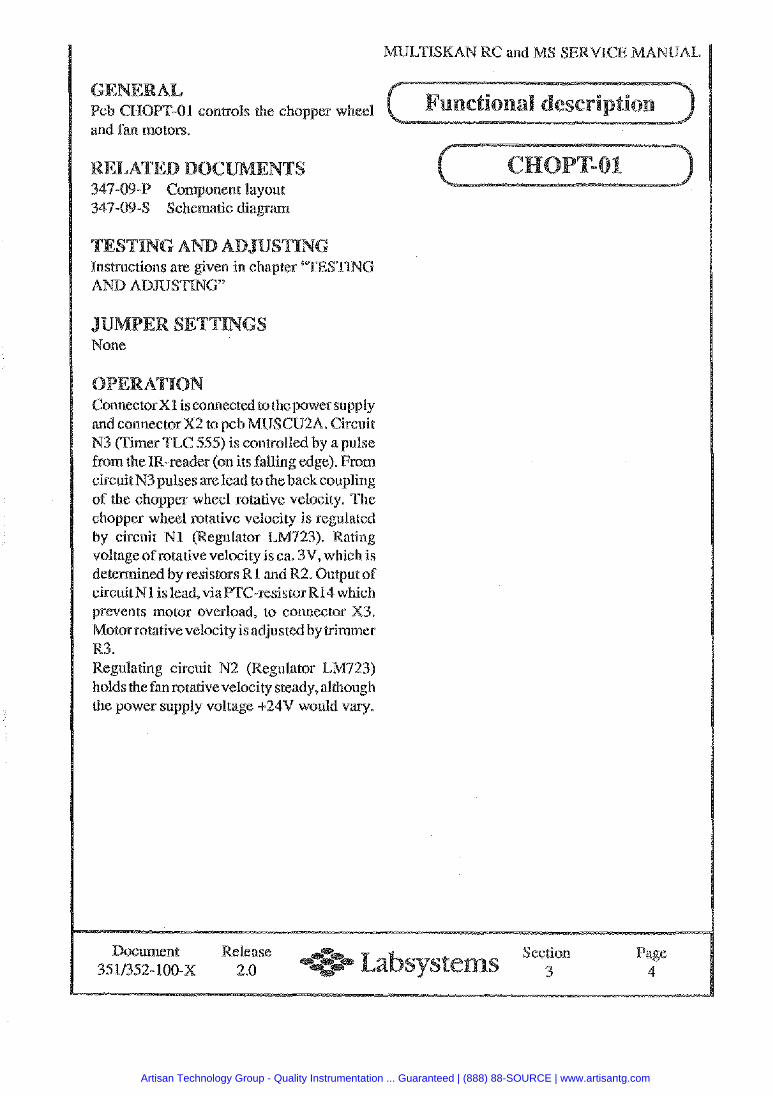
VETISMAN RC and SERVICE MANUAL
1 conh-ols the chopper wheel and fan motors.
LATED DO Component layout Schematic diagram
NG AND AD nshuctions are given in
G None
Connector Xl is connected to the power supply and connector X2 to pcb MUSCU2A. Circuit N3 (Timer TLC 555) is controlled by a pulse from thela-reader (on its falling edge). From circuit N3 pulses are lead to the back coupling of the chopper wheel rotative velocity. The chopper wheel rotative velocity is regulated by circuit N l (Regulator LM723). Rating voltage ofrotative velocity is ea. 3V, which is determined bv resistors R I and R2. Output of circuit Nl is lead, viaPTC-resistorRl4 which prevents motor overload, to connector X3. Motor~otativevclocity is adjusted by trimmer R3. Regulating circuit N2 (Regulator L1M1723) holds the fanrotativevelocity steady,although the power supply voltage +24V would vary.
Document 3511352-100-X
Release 2.0
Section 3
Page 4
Artisan Technology Group - Quality Instrumentation ... Guaranteed | (888) 88-SOURCE | www.artisantg.com
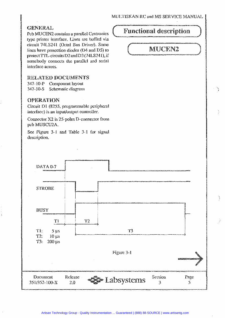
and MS
2 contains a parallel Cen@onics type printer interface. Lines axe buffed via circuit 74LS241 (Octal lines have protection diodes (D4 and D5) to nrotectT7Z-circuits D2 andD3 (74LS241Lif somebody connects the parallel and serial interface across.
Circuit Dl (8255, programmable peripheral interface) is an input/output controller.
Connector X2 is 25-poles D-connector from
See Figure 3-1 and Table 3-1 for signal description.
Figure 3-1
ANUAL
Document Release Section Page 451/352-100-X 2.0 3 5
Artisan Technology Group - Quality Instrumentation ... Guaranteed | (888) 88-SOURCE | www.artisantg.com
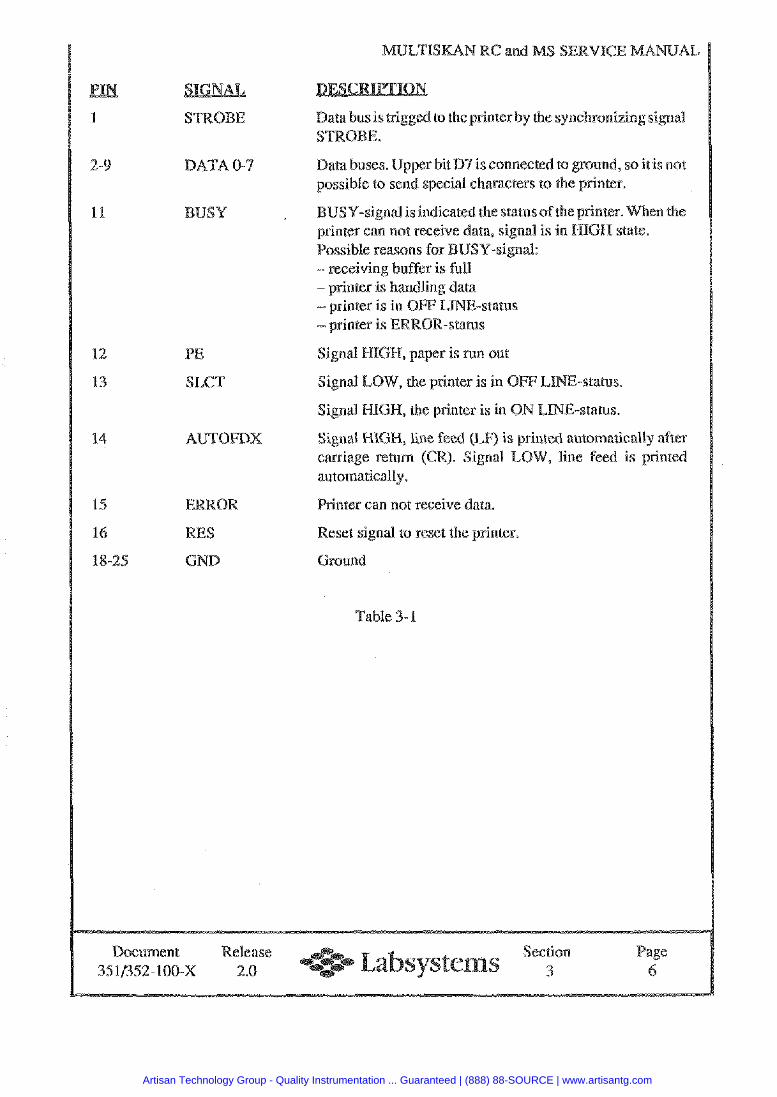
MUCI'ISKAN RC and
DATA 0-3
PE
SLCT
AUTOFDX
ERROR
S
GNB
Data busis trigged to the printerby the synchronizing signal
Data buses. Upper hit D7 is connected to ground, so it is not possible to send special characters to the printer.
USY-signal is indicated the status ofthe printer. printer can not rece ra, signal is in HIGH s Possible reasons - receiving buffe -printer is handling data
Signal HIGH, paper is nun out
Signal LOW, the printer is in OFF LINE-status.
Signal IBGH, the printer is in OM LI
Signal X-XIGFI, line feed (LF) is printed automatic'dlly after carriage return (CR). Signal LO line feed is printed automatically,
Printer can not receive data.
Reset signal to reset the printer.
round
Table 3-1
Document Release Section Page 35 11352- 100-X 2.0 3 A
Artisan Technology Group - Quality Instrumentation ... Guaranteed | (888) 88-SOURCE | www.artisantg.com
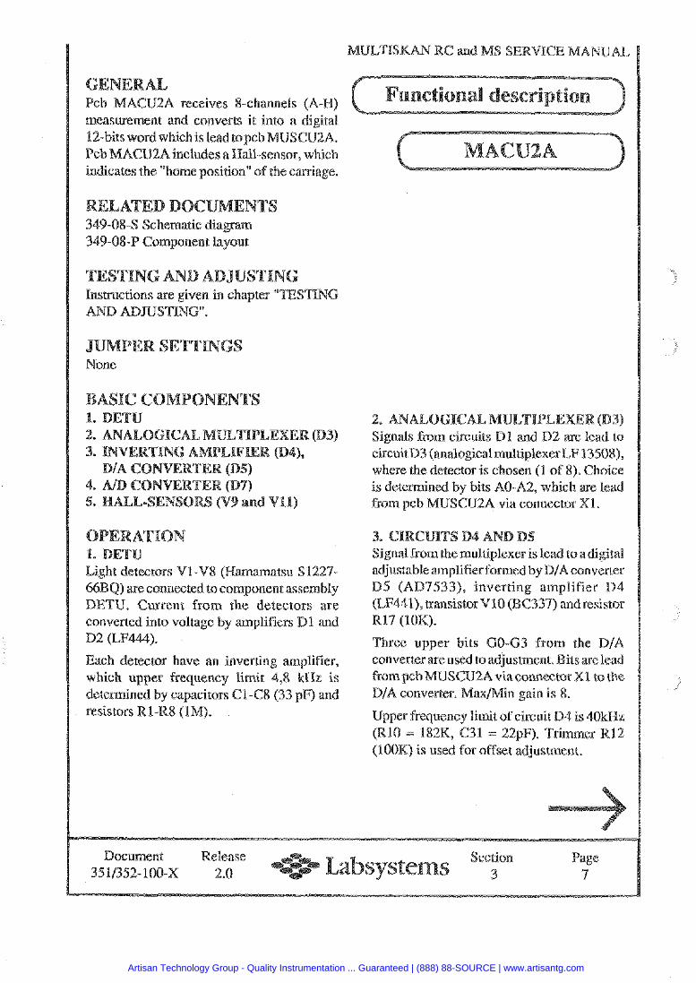
measurement and converts it into a digital 32-bits wordwhichisleadtopcb Pcb MACU2A includes a Wall-sensor, which indicates the "home position" of the carriage.
cb MACU2A receives 8-channds (A-M)
349-084 Schematic diagram 349-08-P Component layout
lnsrmctions are given in chapter "TESTING AND ADSUSTING".
None
1. DETU Light detectors V1-V8 (Hamamatsu S1227-
) are connected to component assembly DETU. Current from the detectors are converted into voltage by amplifiers Dl and D2 (LF444).
Each detector have an inverting amplifier, which upper frequency limit 4,8 kHz is determined by capacitors Cl-C8 (33 pF) and resistors R1-R8 (IM).
ANALOGICAL Signals Prom circuits D l and D% are lead to circuitD3 (analogical multiplexerLF 13508), where the detector is chosen (1 of 8). Choice is determined by bits AO-A2, which are lead from pcb MWSCU2A via connector XI.
ignal from the multiplexer is lead to adigital adjustable amplifier formed by D/A converter B5 (AD9533), inverting amplifier D4 (kF441), aansistorV10 (BG337) and resistor R17 (10K).
Three upper bits G O 4 3 from the D/A converter are used to adjustment. ~ompcbMWSCU%AviaconnectorX1 to the D/A converter. Naxmin gain is 8.
Upper frequency limit of circuit D4 is 4OkUz (RlO = 182K, G31 = 22pF). Trimmer R12 (IOOK) is used for offset adjustment.
Document Release Section Page 3511352-100-X 2.0 3 7
Artisan Technology Group - Quality Instrumentation ... Guaranteed | (888) 88-SOURCE | www.artisantg.com
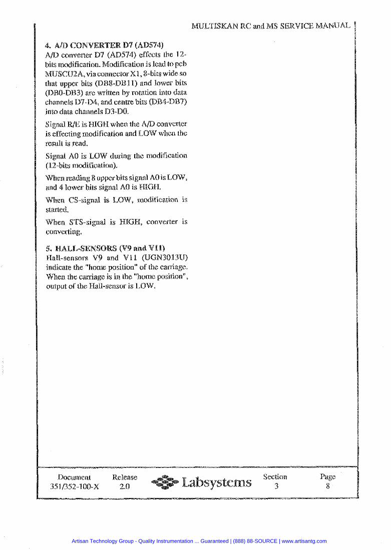
dification is lead to pcb ctorxl, &bits wide so
into data channels D3-DO.
converter when the
result is read.
Signal A0 is LOW during the modification (12-bits modification).
en reading 8 upper bits sig 4 lower bits signal A0 is
modification is starred.
hen STS-signal is HIGH, converter is converting.
Wall-sensors V9 and V11 (UGN3013U) indicate the "home position" of the carriage. When the carriage is in the "home position",
Document Release Section Page 3511352-100-x 2.0 e 3 8
Artisan Technology Group - Quality Instrumentation ... Guaranteed | (888) 88-SOURCE | www.artisantg.com
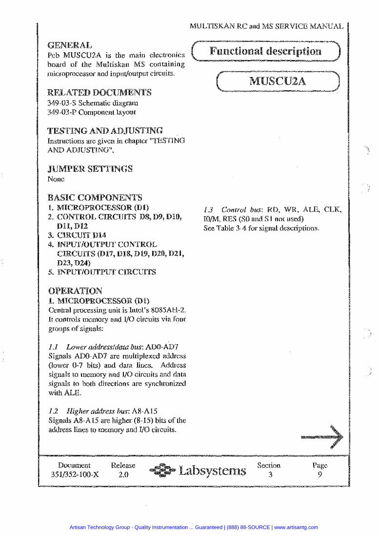
MULTISKAN RC and
2A is the main elecrronics board of the microprocessor and inpudoutput ciP.Guits.
W 349-034 Schematic diagram 349-03-P Component layout
NG AND AD Insmctions are given in chapter "TESTING AND ADJUSTING".
U G None
Central processing unit is Intel's 8085AW-2. It controls memory and 110 circuits via four groups of signals:
I .I Lower addressIdare bus: ADO-AD7 Signals ADO-ADS are multiplexed address (lower 0-7 bits) and data lines. Address signals to memory and 110 circuits and data signals to both directions are synchronized with ALE.
1.2 Higher uddress bus: A8-A15 Signals A 8 4 1 5 are higher (8-15) bits of the address lines to memory and VO circuits.
1.3 Control bus: RD, R, ALE, CEK, ES (SO and S 1 not used)
See Table 3-4 for signal descfiptions.
Document Release Section age 351/352-100-X 2.0 3 9
Artisan Technology Group - Quality Instrumentation ... Guaranteed | (888) 88-SOURCE | www.artisantg.com

MULTISKAN RC and M
) Write pulse for SRAM, EEPROM and P/O circuits.
RD (Read) Read puls EEPROM, circuits.
ALE AEEis usedto set the lower (Address bits (0-7) of address for Latch circuit D l 1 (Octal transpa- Enable) rent latch). ALE is also,
togetherwith CPU READY signal, used tocreate aclock signal oF3.042 MHz which is lead to the CLK input of the CPU.
CLK (Clock) Clocksignal forVO circuirs.
10 Select read/write operation to be either inputloutput or memory oriented, input/ output HIGH active
RE Reset output for peripheral circuits, HIGH active
SO, S1 Not used
ee Table 3-5 for signal descbiptions.
RSTS.5 hdicates that a key has been pressed, HIGH activate
RST6.5 Plate carrier home position indication, LOW active
'ming interrupt for the PU
SID Delay counter input
OD Buzzer, outputPT1GR active
ES IN eset input
XI, X2 6.144 MHz crystal input
HOED Forced to LOW state
Forced to LOW state
Table 3-2 READY Forced to HIGH state
Control bus signal description
Table 3-3 CPU external control lines
Fig. 3-1 illustrates control signal wavefoms ESET switch has been applied.
Document Release Section age e 351/352-100-X 2.0 3 10
Artisan Technology Group - Quality Instrumentation ... Guaranteed | (888) 88-SOURCE | www.artisantg.com
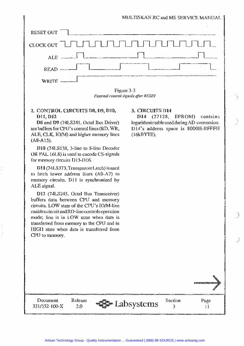
MblLTlSKAld a@ and S SERVICE MANUAL
RESET OUT
CLOCK OUT
ALE
Figure 3-3 Exter~lal control signals after RESET
(74LS241, Octal CPU's control lin
ALE, CLK, TOM) and higher memory lines (A84.15).
(74LS138, 3-fine to 8-line Decoder OR PAL 16L8) is used to encode CS-signals for memory circuits D13-Di6.
Dl1 (74LS373,Transpaent Latch) is used to latch lower address lines (AO-A7) to memory circuits. D l1 is synchronized by ALE signal.
D U (74LS245, Octal us Transceiver) buffers data between CPU and memory circuits. LOW state of the GPU's ION-line enablescircuit and RD-line controls operation mode; line is in LOW state when datd is transferred from memory to the CPU and in HIGH state when data is transfenred from CPU to memory.
logarithmic table used D14's address spa
Document Release Section Page 3511352- 100-X 2.0 3 11
Artisan Technology Group - Quality Instrumentation ... Guaranteed | (888) 88-SOURCE | www.artisantg.com
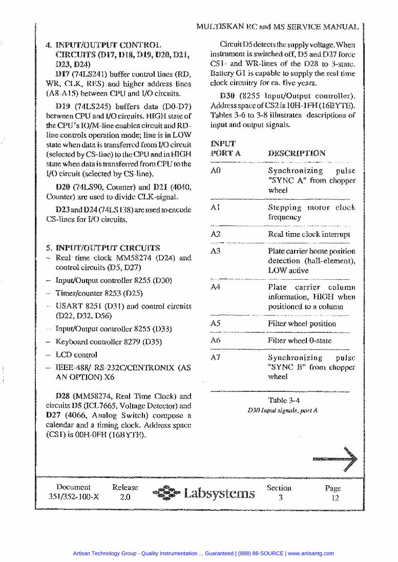
ULT'TSMAN RC and MS SERVICE
Dl7 (74LS241) buffer control lines (KD, WR, CLK, RES) and higher address lines (A%-Al5) between CPU and 110 circuits.
(74LS245) buffers between CPU and VO circuits the CPU's IOM-line enables line conwols operarion mode; line is in LOW state when data is rpansf-ed from UO (selected by CS-line) to the CPU and in state when datais transfened from GPU to the It0 circuit (selected by CS-line).
(74LS90, Counter) and (4040, Counter) are used to divide CLK-signal.
(74LS 138) areused to encode CS-lines for XI0 circuits.
- Real time clock MM58274 (D24) and control circuits (B5, D27)
- Input/Oupur controller 8255 (D30)
- Timerlcounter 8253 (D25)
T 8251 (D31) and control circuits (022, D32, D56)
- InpuUOutput controller 8255 (033)
- Keyboard controller 8279 (D35)
LCD control
- TEEE-4881 RS-232ClCENTROMX (AS AN OPTTON) X6
M58274, Real Time Clock) and (ICL7665, Voltage Detector) and
27 (4066, Analog Switch) compose a calendar and a timing clock. Address space (CS I) is OON-OFT3 (I6BYTE).
Circuit D5 detectstkc supply voltage. tched off, D5 md D27 force ines of the D28 to 3-state.
artery 61 is capable to supply the real rime clock circuitq for ca. five years.
(8255 input1Outpue co spaceofCS2is IOET-lFH(
Tables 3-6 to 3-8 illustrates descriptions of input and output signals.
A0 Synchronizing pulse "SYNC A" fmm chopper wheel
repping motor clock frequency
A2 Real time clock intenupt
A3 Plate canier home position detection (hall-element),
A4
positioned to a column
A5 Filter wheel position
A6 Filter wheel 0-state
A4 Synchronizing pulse " from chopper
wheel
Table 3-4 030 Input signals, port A
Document Release Section age 35 1135%- 100-X 2.0 3 12
Artisan Technology Group - Quality Instrumentation ... Guaranteed | (888) 88-SOURCE | www.artisantg.com
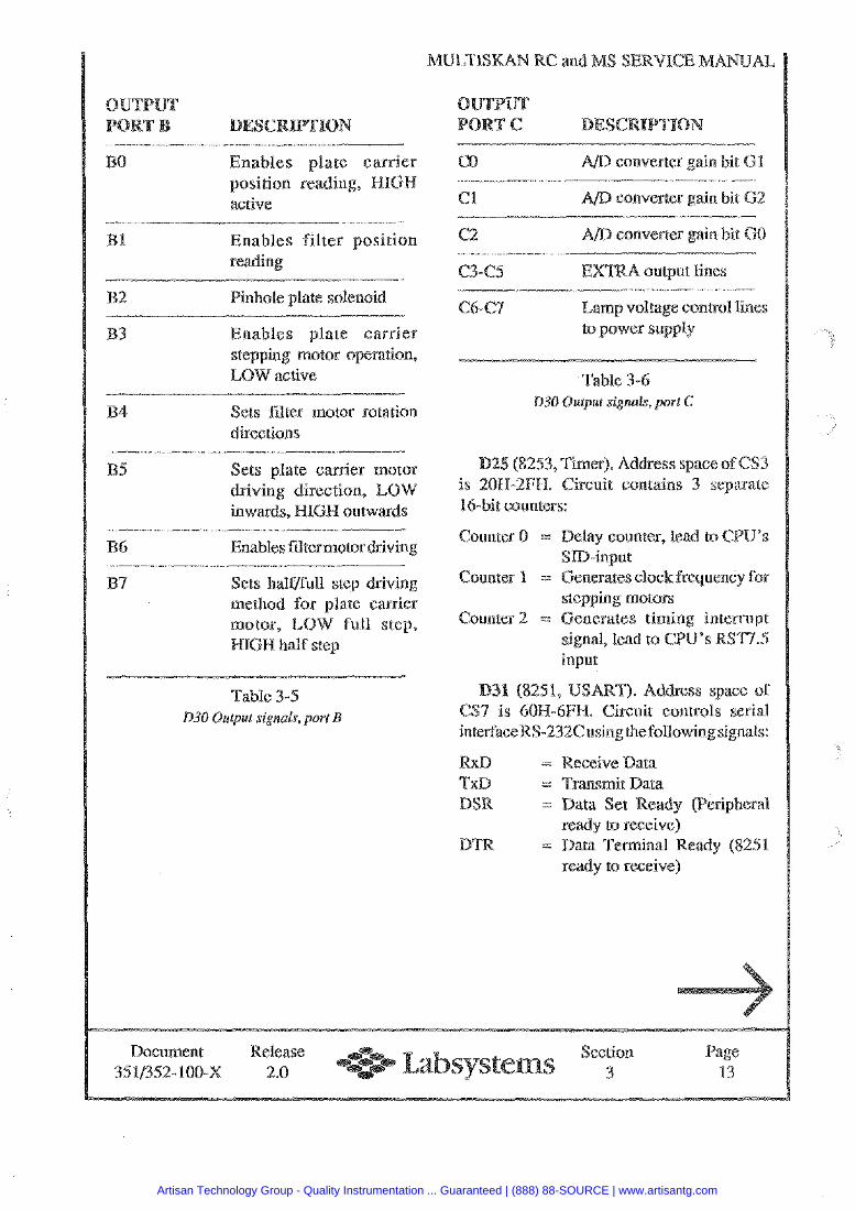
Enables plate carrier position reading, HIGH active
1 Enables filter position reading
- 2 inhote plate solenoid
3 Enables plate carrier stepping motor operation, LOW active
B4 Sets filter motor rotation directions
B5 Sets plate carrier motor driving direction, LOW inwards, HIGH outwards
R6 Enables filter motor driving
Sets halflfull step driving method for plate canler motor, LOW full step, HIGH half step
Table 3-5 030 Output signals, port B
MULTISKAN RC and
C0 converter gain bit 6 1
C1 converter gain bit G2 - C2 converter gain bit GO
C6-64 Lamp voltage control lines to power supply
Table 3-6 030 Output signals, port C
(8253,Timer). Address space of CS3 is 20B-2FB. Circuit contains 3 separate 16-bit counters:
Counter 0 =: y counter, lead to CPU's
Counter 1 = Generates clock frequency for stepping motors
Counter 2 = Generates timing interrupt signal, lead to CPU's RSTI.5 input
(8251, USART). Address space of CS7 is 60H-6FH. Circuit controls serial interfaceRS-232Cusingthefollowingsignals:
RxB = Receive Data TxD = Transmit Data DSR = Data Set Ready (Peripheral
ready to receive BTR = Data Terminal
ready to receive)
Document 3511352- 100-M
Release 2.0
Section 3
Artisan Technology Group - Quality Instrumentation ... Guaranteed | (888) 88-SOURCE | www.artisantg.com
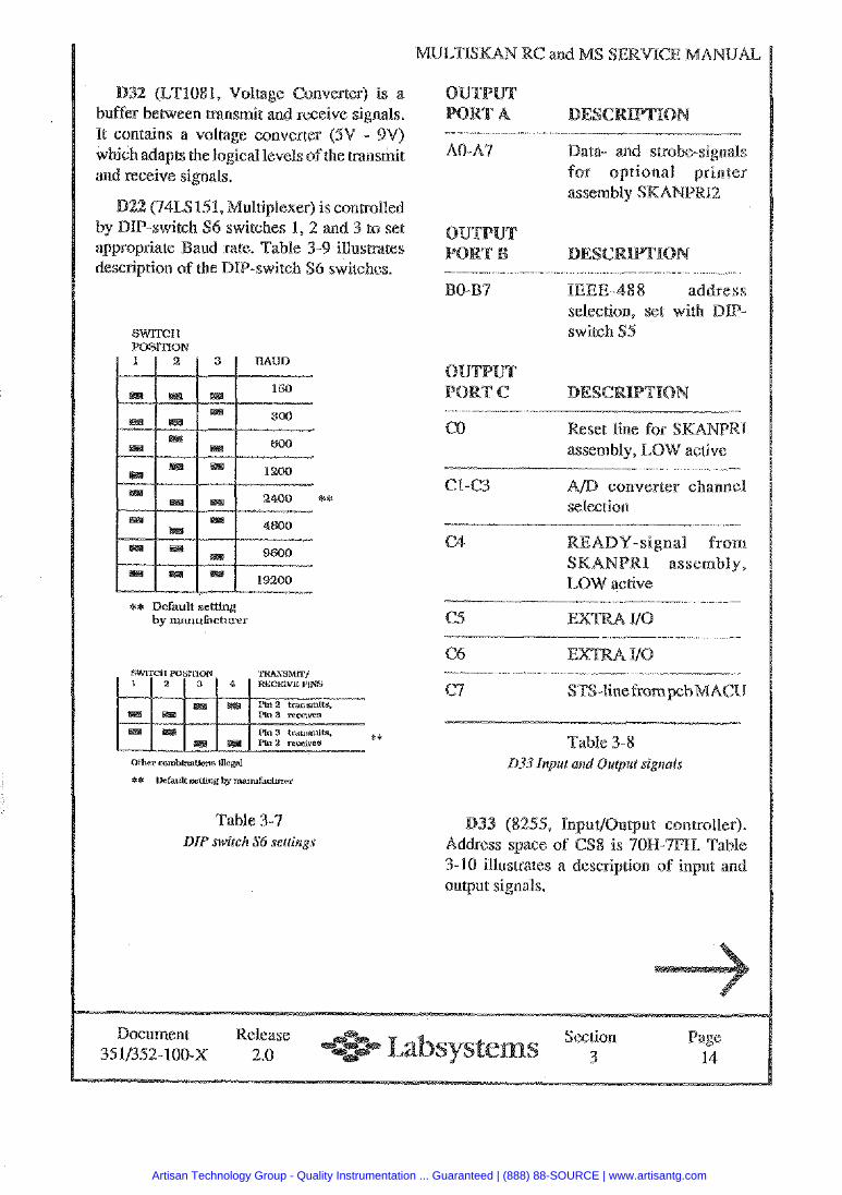
ULTISMAN RC and M
(LT108 1, Voltage buffer between transmit and receive signals. It contains a voltage converter (5V - 9V) which adapts the logical levels of the transmit and receive signals.
ultiplexer) is controlled
switch S6 switches.
* Q
** Default setthg by manufacturer
Table 3-7 DIP switch S6 settings
AO-A7 Data- and swobe-signals for optional printer
IEEE-488 address selection, set with BIP- switch $5
- C0 Reset line for
assembly, LOW active
C1-C3 A D converter channel selection
C4 READY-signal from SKANPRI assembly, LOW active
Table 3-8 833 Input and Output signels
B33 (8255, Inpur/Output controller). Address space of CS8 is 701-1-7FH. Table 3-10 illustrates a description of input and output signals.
Document Release Section a& e 3511352-100-X 2.0 1 14
Artisan Technology Group - Quality Instrumentation ... Guaranteed | (888) 88-SOURCE | www.artisantg.com
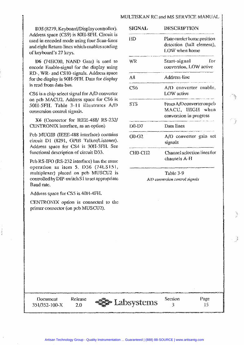
(82'79, Keyboardmisplay controller). s space (CS9) is 80H-8FI-T. Circuit is
oded mode using four Scan-lines turn-lines which enables reading
of keyboard's 27 keys.
(34RC00, NAND Gate) is used to encode Enable-signal for the display using
-, WR- and CS10- Is. Address space for the display is 90 . Data for display is read from data-bus.
6 is a chip select signal for AD con CUZ. Address space for Table 3-11 illustrates AID
conversion control signals.
(Connector for IEEE-4881 RS-2321 GENTRONX interface, as an option)
(XEEE-488 interface) contains c h u i t 131 (8291, GPTB TalkerListener). Address space for CS4 is 40H-3FH. See functional description of circuit D33.
Pcb RS-IF0 (RS-232 interface) has the same operation as item 5. D36 (74LS151, multiplexer) placed on pcb MUSCU2 is controlled by DIP-switch S 1 to set appropriate Baud rate.
Address space for CS5 is 4OH-4FFI.
CENTRONIX option is connected to the printer connector (on pcb MUSCU2).
Platecanier home position detection (hall element),
WR Start-signal for conversion, 1,
A8 Ad&ess-line - .- - -- -
CS6 AID converter enable,
TS
conversion in progress
130-D4 Data lines
60-62 converter gain set signals
CEIO-CH2 Channel selection lines for channels A-R
Table 3-9 Air) conversion control signals
Document Release ection Page 3511352- auo-x 2.0 3 15
Artisan Technology Group - Quality Instrumentation ... Guaranteed | (888) 88-SOURCE | www.artisantg.com
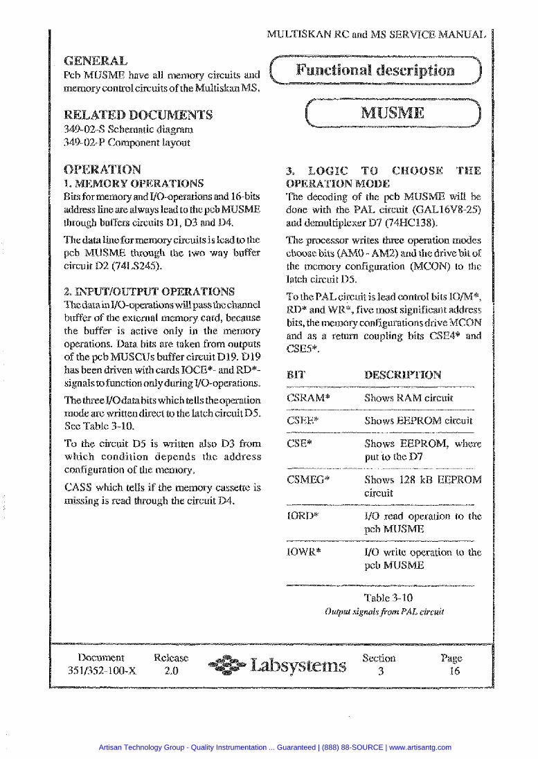
RC and MS
have all memorv circuits and memory control circuits of the Multiskan
through buffers circuits Dl, D3 and D4.
USME will be done with the PAL circuit (CAL16VX-25) and demultiplexer 0 7 (74HCl38).
The data line for memory circuits is lead to the pcb MUSME though the two way buffer circuit D2 (74LS245).
ThedatainVO-operationswillp'dss thechannel buffer of the external memory card, because the buffer is active only in the memory
s are taken from outputs s buffer circuit D19. Dl9
has been driven with cards IOCE*- and RD*- signals to functiononly during VO-operations.
ThethfeeVOdaaahits whish tells theoperation mode are written direct to the latchcircuit B5. See Table 3-10.
To the circuit 0 5 is written also D3 from which condition depends the address configuration of the memory.
CASS which tells if the memory cassette is missing i s read through the circuit D4.
The processor writes three operation modes - AM2) and the drive hit of
the memory configuration (MCON) to the latch circuit D5.
To the PAL circuit is lead control bits IOM*, RD* and WK*, five most significant address bits, the memory configurationsdrive MCON and as a return coupling bits CSE4* and CSE5*.
GSRAM*
CSEE* Shows EEPRO
CSE* Shows EEPRO put to the D7
CSMEG* Shows 128 kB EEP circuit
IORD* 110 read operation to the pch MUSME
UO write operation to the pcb lLlUSME
Table 3-10 Output signalsfrom PAL circuit
Document Release Section Page 3511352- 100-X 2.0 3 16
Artisan Technology Group - Quality Instrumentation ... Guaranteed | (888) 88-SOURCE | www.artisantg.com
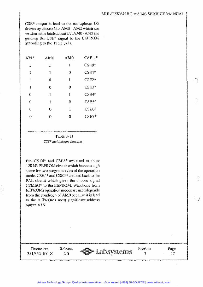
CSE* output is lead to the multiplexer Dli driven by choose bits AM0 - A written in the ircuitD7. AM0 - guiding the according to the Table 3-1 1.
.,* *
CSEO*
CSEl*
CSEZ*
CSE3*
CSE4*
CSES*
CSE6*
C S E P
Table 3- 1 1 CSE* mul~iplaxers funcrion
Bits CSE4* and CSES* are used to show 128 kB EEPROM circuit which have enough space for two program codes of the operation mode. CSE4* and CSE5* are lead back to the PAL circuit which gives the choose signal CSMEG* to the EEPROM. Wkichone from EEPROMsoperauon modes areuseddepends from the condition of AM0 because it is lead to the EEPROMs most significant address output A16.
Document Release Section age 3511352-100-X 2.0 3 113
Artisan Technology Group - Quality Instrumentation ... Guaranteed | (888) 88-SOURCE | www.artisantg.com
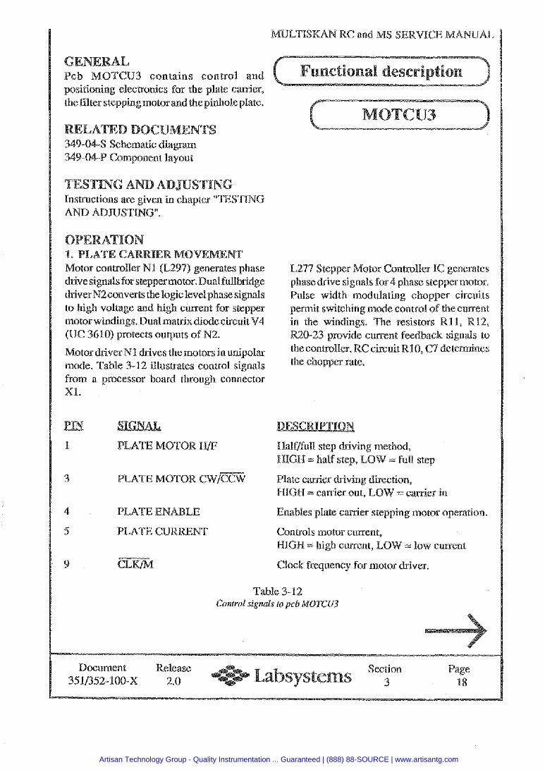
GENERAL BTCU3 contains control and
positioning electronics for the alate carrier, A - the filter stepping motorand the pinhole plate.
349-04-S Schematic diagram Component layout
NG AND AD Inseructions are given in chapter "TESTING AND ADJUSTING".
Motor controller NI (L297) generates phase drive sign& for steppermotor. Dual fullbridge dfiverN2converts the logic level phase signals to high voltage and high current for stepper motor windings. Dual matrix diode circuit V4 (UC 3610) protects outputs of N2.
Motor dbiverN1 drives the motors in unipolar mode. Table 3-12 illustrates control signals from a processor board through connector XI.
kepper Motor Controller I hase drive signals for 4 phase stepper motor. ulse width modulating chopper circuits
permit switching mode control of the current in the windings. The resistors R l l , R12, R20-23 provide current feedback signals to the controller. RC circuit R10, C4 determines the chopper rate.
1 PLATE MOTOR WF Half/full step dtiving method, =GI3 = half step, LOW = full step
3 PLATE MOTOR CW/=W late carrier driving direction, HIGH = canier out, LOW =: canier in
4 PLATE ENABLE Enables plate carrier stepping motor operation.
5 PLATE CURRENT Controls motor current, HIGH = high current, LOW - low current
9 Clock frequency for motor driver.
Table 3- 12 Control signals to pcb MOTCU3
Document Release Section Page 3511352-100-X 2.0 3 18
Artisan Technology Group - Quality Instrumentation ... Guaranteed | (888) 88-SOURCE | www.artisantg.com
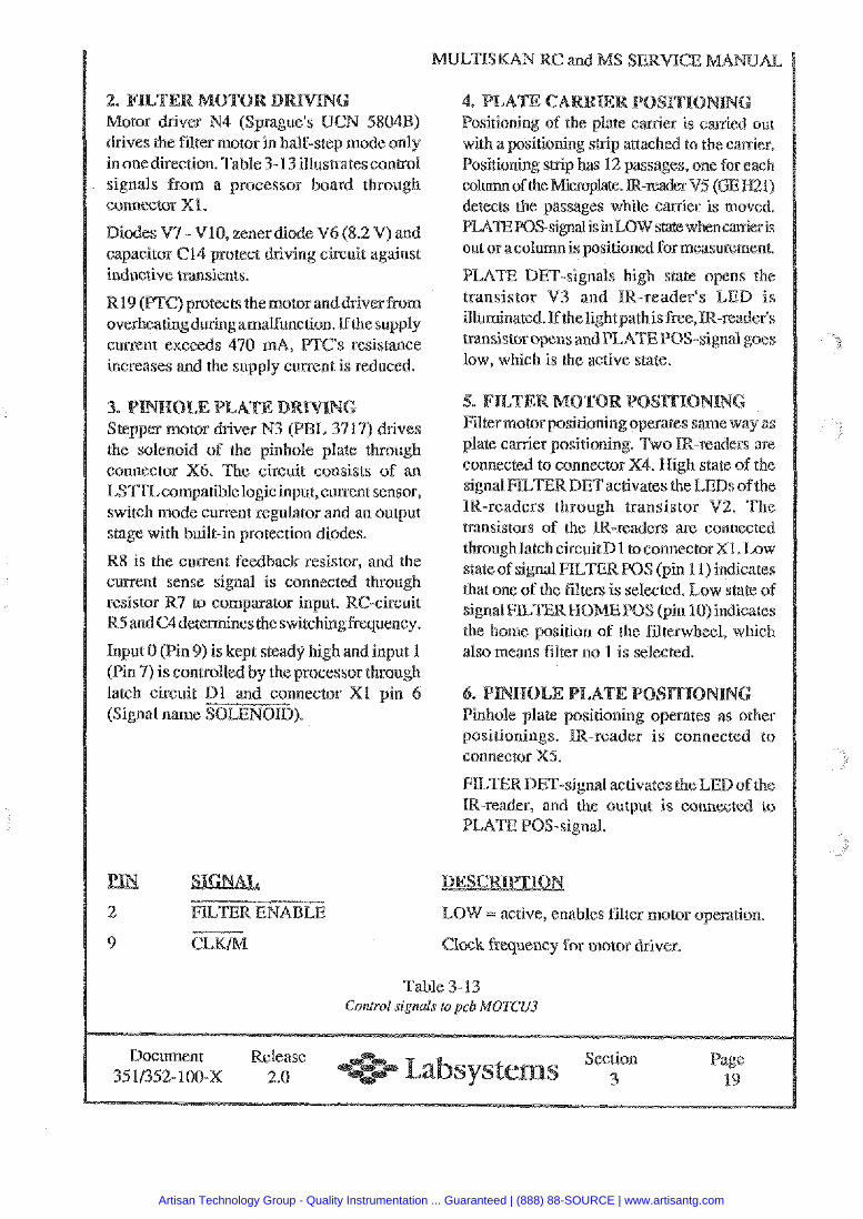
OR DRIVING (Sprague's OCN 5804
drives the filter motor in half-step mode only in one direction. Table 3- 13 illus~tescontrol signals from a processor board through connector Or 1.
Diodes V'7 - V10, zener diode V6 (8.2 V) and capacitor 614 protect driving circuit against inductive rransients.
R19 (PTC) protects themotor anddriver from overheatingduringamalfnnction. Ifthesupply current exceeds 470 mA, PTC's resistance increases and the supply current is reduced.
a. 0 Stepper motor driver N3 (PBL 3717) drives the solenoid of the pinhole plate through connector X6. The circuit consists of an LS'PIZcompatible logic input, current sensor, switch mode current regulator and an output stage with built-in protection diodes.
R8 is the current feedback resistor, and the current sense signal is connected through resistor R'7 to comparator input. R5 andC4determineslhe switching kequency.
Input 0 (Pin 9) is kept steady high and input 1 (Pin 9 ) is controlled by the processor through latch circuit D l and connector Xl pin 6 (Signal name SOLENOID).
2 FILTER ENABLE
9
MULTISKAN RC and M
with a positioning strip attached to the carrier. Positioning strip has 12 sages, one for each c o h ofthe Mimpllate.
out or acolumn is positioned for measurement.
PLATE DET-signals high state opens the transistor V3 and IR-reader's LED is illuminated. If the lightpathis free, tsansisror opens and PLATEPOS-signal goes low, which is the active state.
Filter motor positioningoperates same way as plate carrier positioning. Two IR-readers are connected to connector X4. High state of the signal FlLTEKDETactivates the LEDs of the IR-readers through transistor V%. The transistors of the iR-readers are connected throughlatch circuitD1 toconnectorX1. Low state of signal ELTERPOS (pin 11) indicates that one of the filters is selected. Law state of signal FlLTERMOMEPOS (pin 10) indicates the home position of the filterwheel, which also means filter no 1 is selected.
Pinhole plate positioning operates as other positionings. IR-reader is connected to connector X5.
FILTER DET-signal activates the LED of the IR-reader, and the output is connected to PLATE PO§-signal.
LOW = active, enables filter motor operation.
Clock frequency for motor driver.
Table 3-13 Control signals to pcb MOTCU3
Document Release ection age 35 1/352-100-X 2.0 4 19
Artisan Technology Group - Quality Instrumentation ... Guaranteed | (888) 88-SOURCE | www.artisantg.com
MULTISMAN RC and
Pcb J-Re-01 is the main electronics board of the ultiskan RC containing microprocessor.
Insmctions are given in chapter "TESTING AND ADJUSTING".
U NG None
Document Release Section Page 3511352-100-X 2.0 3 20
Artisan Technology Group - Quality Instrumentation ... Guaranteed | (888) 88-SOURCE | www.artisantg.com
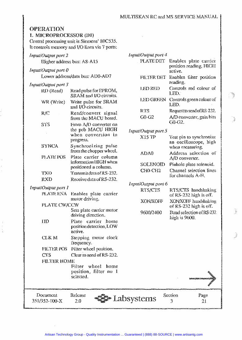
It controls m e m y and VO lines via 7 ports:
InputlOutput port 2 Higher address bus: A8-A15
InputlOuput port 0 Lower addressldata bus: ADO-ADS
JnputlOutput port 3 RD (Read) Read pulse for EPROM,
SRAM and IJO circuits. R (Write) Wire pulse for SSRA
md VO circuits. R/C ReadJconvert signal
from the MACU board. S'TS From A/D converter on
the pcb MACU HIGH when conversion in progress.
SUNCA Synchronizing pulse from the chopper wheel.
S Plate carrier column information HIGH when positioned a column.
TXD TrmsmitdataofRS-232. D Receivedata of RS-232.
InpuriOutput port 1 PLATE ENA Enables plate carrier
motor driving. PLATE CWICCW
Sets plate carrier motor driving direction.
ND Plate carrier home positiondetection, LOW active.
CLK M f tepping motor clock frequency.
S Filter wheel position. CTS Clear to send of RS-232. FILTER HONE
Filter wheel home position, filter no 1 selected.
MULTISKAN RC and MS ERVICE MANUAL
InputlOutput porr 4 PLAEDET Enables plate carrier
position reading, HIGH active.
EU,mRDET Enables filter position reading.
D Controls red colour of LED. Controls green cotous of LED.
KTS Requestto send ofRS-232. GO-62 A/D converter, gain bits
GO-G2.
InputiOuput port 5 XIS TP Test pin to synchronize
an oscilloscope, high when measuring.
ADA0 Address selectiotl of AID converter.
SOLENOID Pinhole plate solenoid. CHO-CH2 Channel selection lines
for channels AX.
InputlOu@ut porr 6 RTSJCTS RTSJCTS handshaking
of RS-232 high is off^ XONKOFF XONKOFF handshaking
of RS-232 high is off. 960012400 Baud selection of
high is 9600.
Document Release Section Page 3511352-100-~ 2.0 e 3 21
Artisan Technology Group - Quality Instrumentation ... Guaranteed | (888) 88-SOURCE | www.artisantg.com
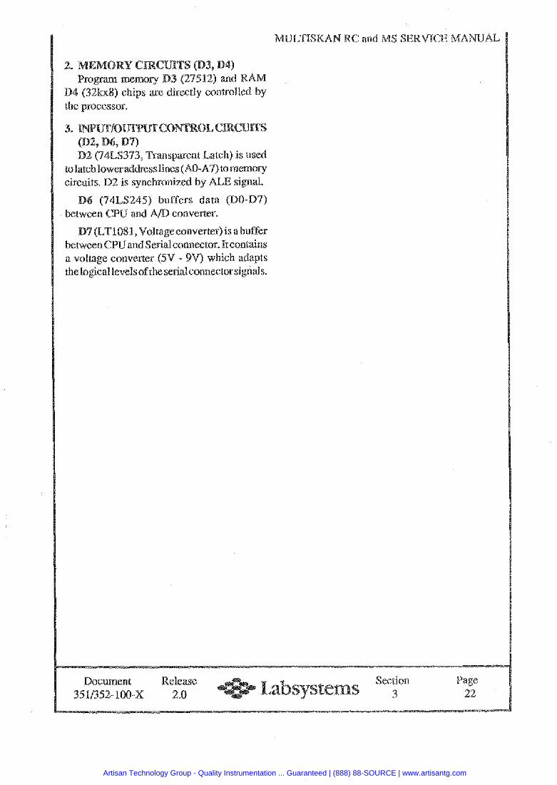
MULTISKAN RC and M
(32kxR) chips me directly controlled by
tolatch lower addresslines (AO-87) tomemov circuits. D2 is synchronized by ALE signal.
(74LS245) buffers data (DO-D7) between CPU and A D converter.
11)7 (LT1081, Voltageconvefler) is a buffer between CPW and Serial connector. It contains a voltage converter (5V - 9V) which adapts the logical levels of the serial connector signals.
Document Release ection Page 3~11352- 100-x 2.0 e 3 22
Artisan Technology Group - Quality Instrumentation ... Guaranteed | (888) 88-SOURCE | www.artisantg.com
I MUI,TISI<AN RC and MS SERVICE MANUAL
Section 4
Rlocli diagrams
Docurnent Relea\c 0.- Sectmn P'tge 35 11152-1 00-x 2 o -,=,- Labsystems 1
Artisan Technology Group - Quality Instrumentation ... Guaranteed | (888) 88-SOURCE | www.artisantg.com
MULJ1'ISKAN RC and MS SERVICE MANUAL,
I ~ o c k diagrams 1
Cover p g c 1 Contents ..................... .. ......................................................................... 2 Multiskun RC .......................................... 351-01X-01 ........................... 3 Multiskan RC .......................................... 3 1 - O X - 0 ........................... 4 Multisknn MS .......................................... 352-01X-01 ........................... 5 MUSCIJ-2A and MUSME-01 ................. 352-02X-02 ........................... 6
Uocornent Release 0-0 Section Page 3511352-100-x 2.0 - -.- - Labsystems 2
Artisan Technology Group - Quality Instrumentation ... Guaranteed | (888) 88-SOURCE | www.artisantg.com
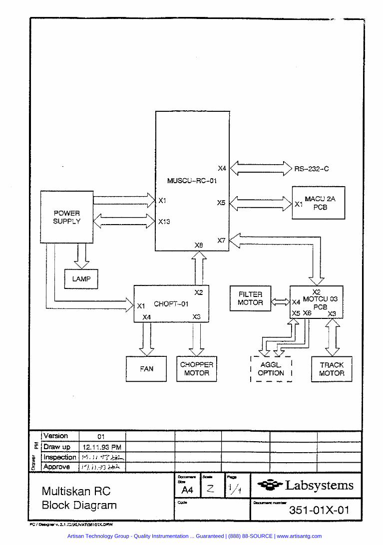
POWER SUPPLY
LAMP u I I
X2
~1 CHOPT-01
x4 x3
77 77 FAN CHOPPER
MOTOR
FILTER MOTOR MOTCU 03
I
, AGGL. I I TRACK ' OPTION I I - - _ -
I MOTOR I
Version I 01
f Draw Up 12.11.93 PM
Inspection lq. I I
Approve 1-7 I I -n bbh -so.. p.p SQ.
Multiskan RC A4 I/? Labsystems Block Diagram M -nume.
351 -01X-01
Artisan Technology Group - Quality Instrumentation ... Guaranteed | (888) 88-SOURCE | www.artisantg.com
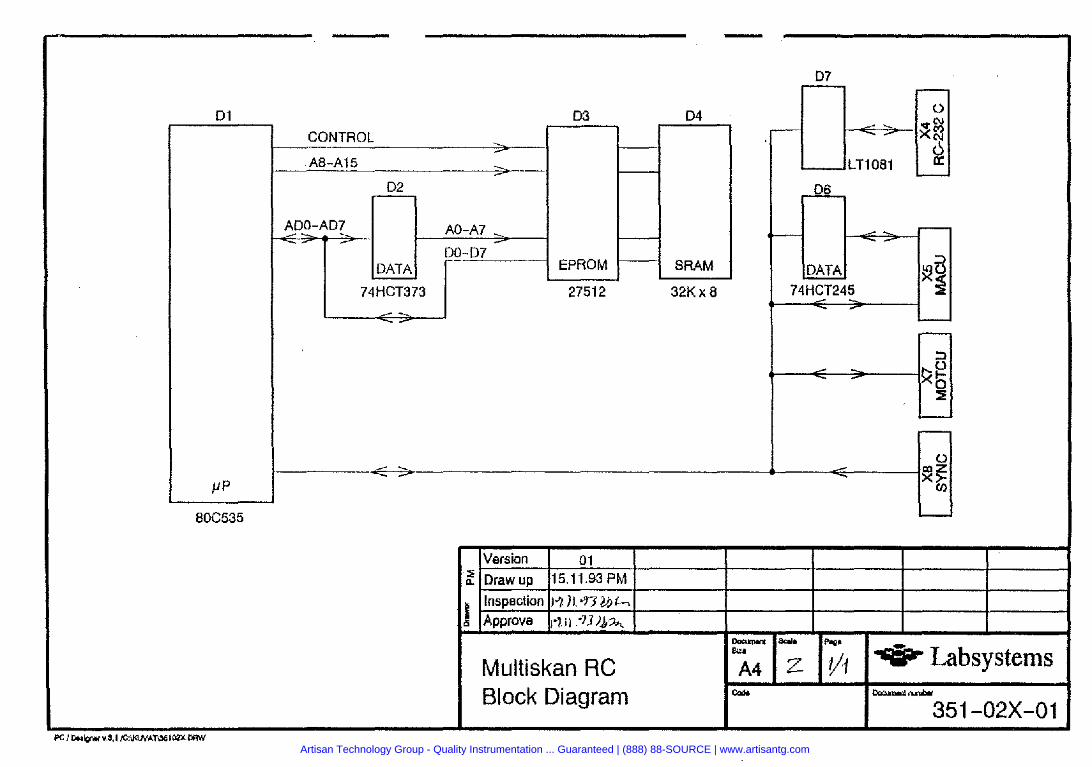
Artisan Technology Group - Quality Instrumentation ... Guaranteed | (888) 88-SOURCE | www.artisantg.com
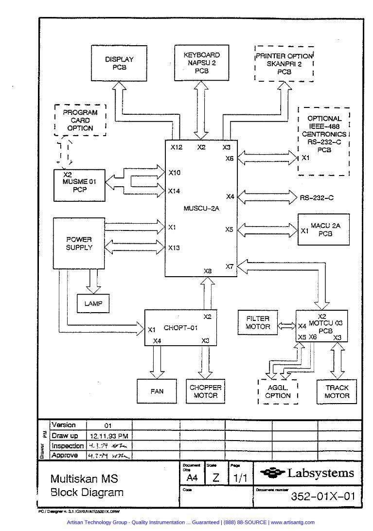
I - - - - - -
DISPLAY KEYBOARD 1~~~~~~~ OPTION^
PC8 NAPSU 2
I SKANPRl2 1
PC8 PC8 I - 1 - -
- - - - 1 PROGRAM I I - - - - - ' CARD
7
I OPTIONAL I
I OPTION I I IEEE-488 I
MUSME 01 i"...K3 POWER SUPPLY
' CENTRONICS I RS-232-C I
/" MACU 2A \1
FILTER MOTOR
I AGGL. I
I OPTION I MOTOR I - - - -
Artisan Technology Group - Quality Instrumentation ... Guaranteed | (888) 88-SOURCE | www.artisantg.com
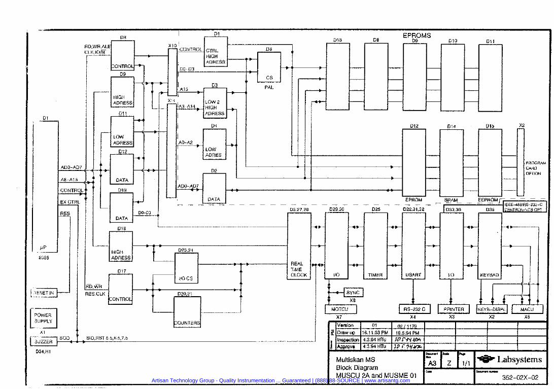
PAL
-
. 7F. - . - . . - . - . . . . - . . . . . . - - -II )3 PY
Multiskan MS 1 1 ,,, 1- ~absvstems
I rw I L , I , , . Block Diagram U -u
MUSCU 2A and MUSME 01 352-02X-02 Artisan Technology Group - Quality Instrumentation ... Guaranteed | (888) 88-SOURCE | www.artisantg.com
MULTISKAN RC and MS SERVICE MANUAL
Document Releasc Section Page 3.5~352-100-x 2.0 e 5 t
Artisan Technology Group - Quality Instrumentation ... Guaranteed | (888) 88-SOURCE | www.artisantg.com

MULTISKAN RC and MS SElWlCE MANUAL
SUBJECT DOCUMENT'
Cover page ............................................................................................. Contents .................................................................................................. SKANPRI-2 ........................................ 31 1-03-P-02 ............................... NAPSU-2 .......................................... ..347-01- P-1A .............................. CEIOPT-01 .......................................... 347-09-P-02 ............................... MUCEN-02 ......................................... 347-10-P-02 ...............................
............................... MUSME-01 ........................................ 349-02-P-02 MUSCU-02A ...................................... 349-03-P-04 ............................... MOTCU-03 ......................................... 349-04-P-02 ............................... MACLJ-2A .......................................... 349-08-P-01 ...............................
............................... MUSCU-RC-01 .................................. 351-01-P-02
1) Only in Printer option 2) Only in Multiskan MS 3) Ot~ly in Multiskan RC
Document 35 1/352- 100-X
Release 2.0
Section 5
Artisan Technology Group - Quality Instrumentation ... Guaranteed | (888) 88-SOURCE | www.artisantg.com
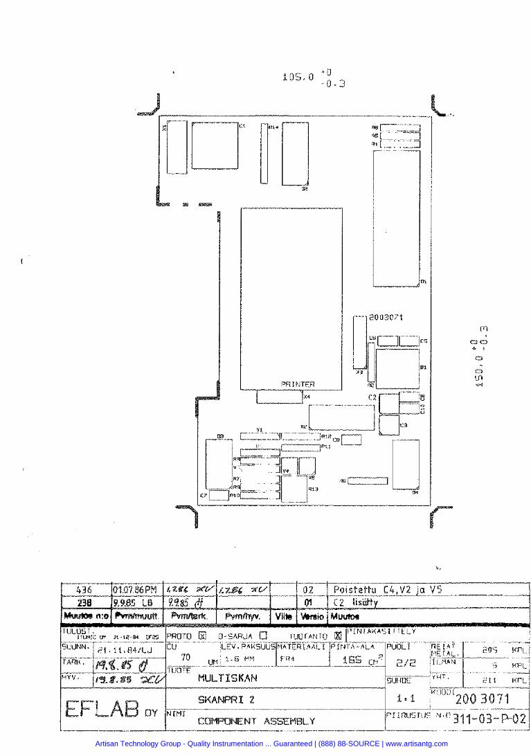
Artisan Technology Group - Quality Instrumentation ... Guaranteed | (888) 88-SOURCE | www.artisantg.com
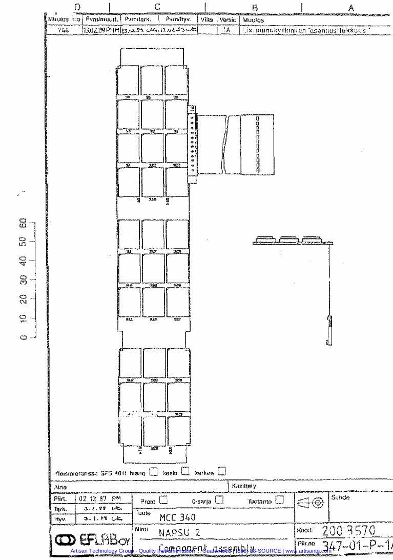
Artisan Technology Group - Quality Instrumentation ... Guaranteed | (888) 88-SOURCE | www.artisantg.com
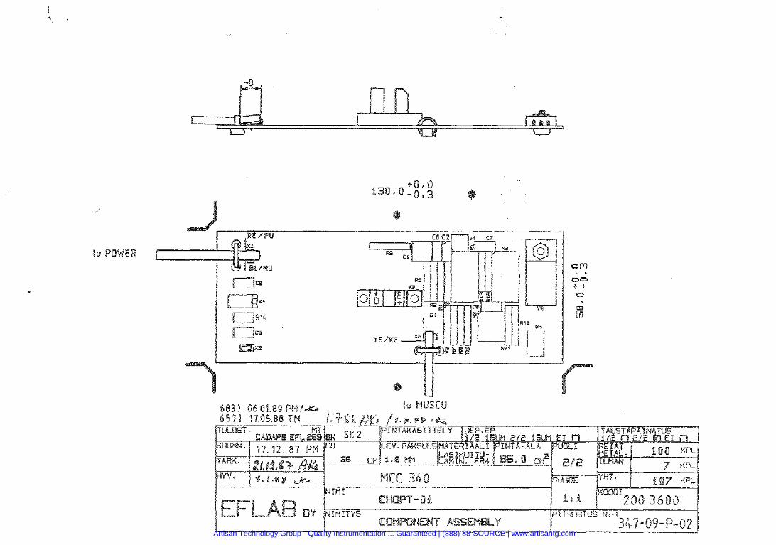
Artisan Technology Group - Quality Instrumentation ... Guaranteed | (888) 88-SOURCE | www.artisantg.com
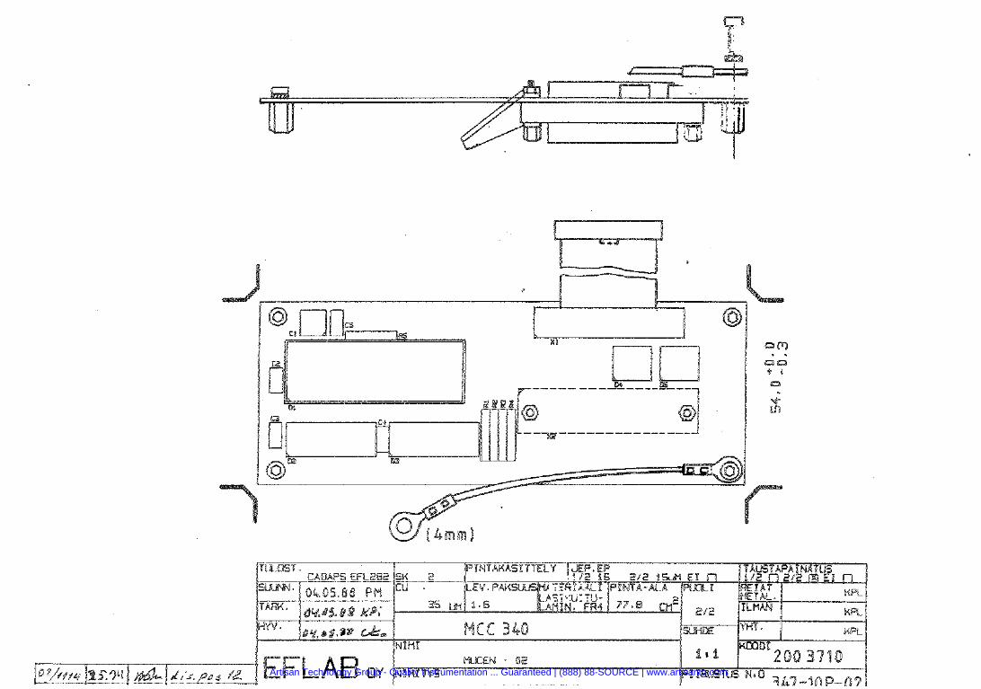
Artisan Technology Group - Quality Instrumentation ... Guaranteed | (888) 88-SOURCE | www.artisantg.com
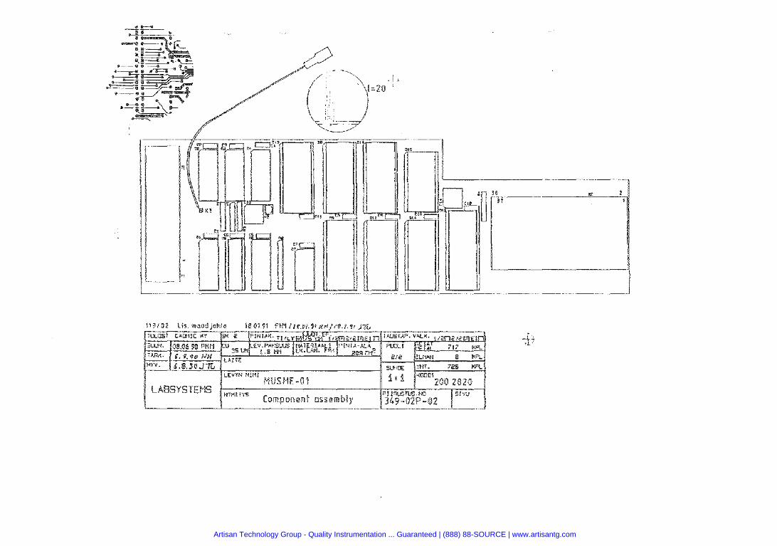
Artisan Technology Group - Quality Instrumentation ... Guaranteed | (888) 88-SOURCE | www.artisantg.com
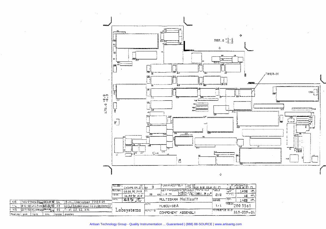
Artisan Technology Group - Quality Instrumentation ... Guaranteed | (888) 88-SOURCE | www.artisantg.com
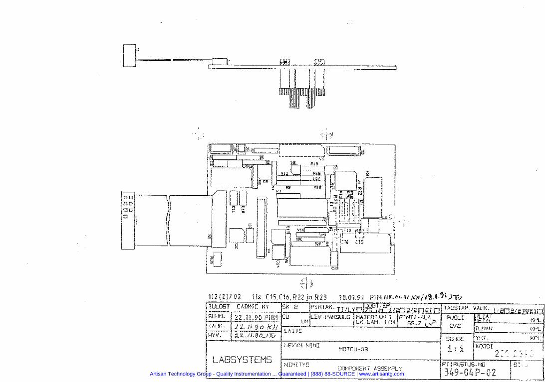
Artisan Technology Group - Quality Instrumentation ... Guaranteed | (888) 88-SOURCE | www.artisantg.com
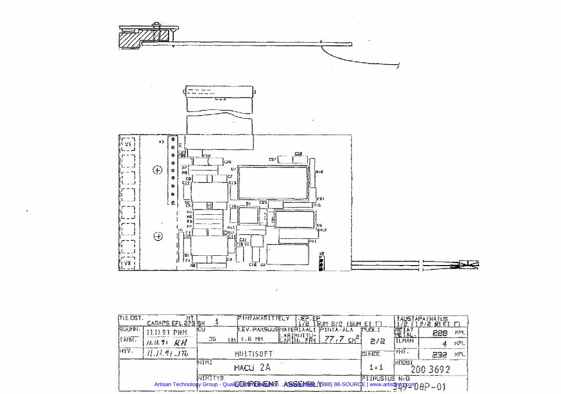
Artisan Technology Group - Quality Instrumentation ... Guaranteed | (888) 88-SOURCE | www.artisantg.com
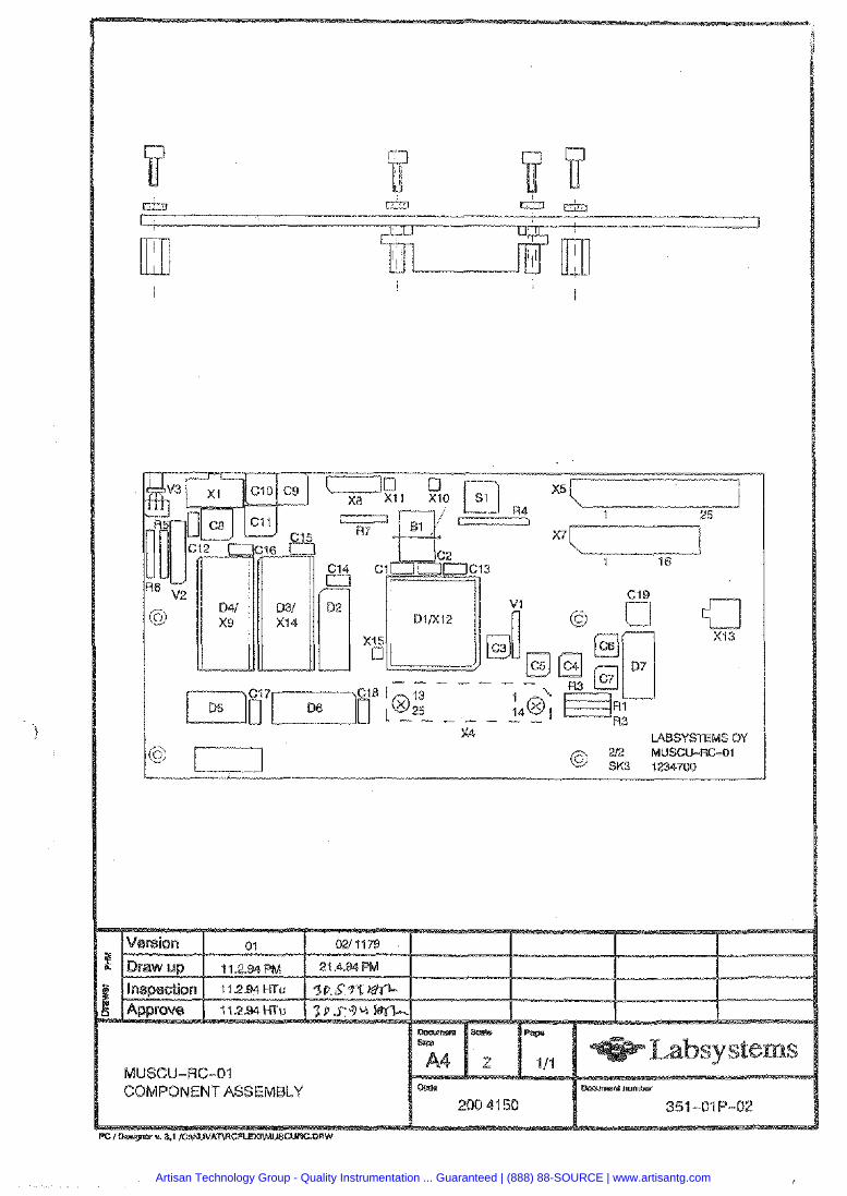
MUSCU-WC-01 COMPONENT ASSEMBLY
351 -01 P-02
Artisan Technology Group - Quality Instrumentation ... Guaranteed | (888) 88-SOURCE | www.artisantg.com
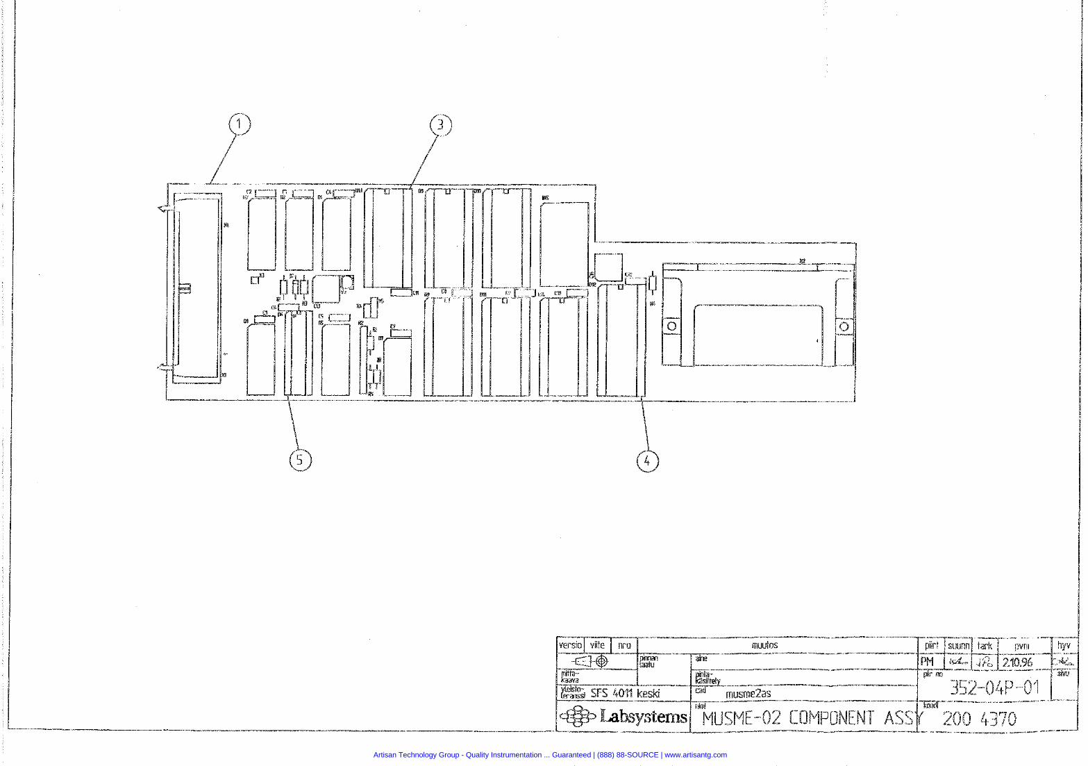
Artisan Technology Group - Quality Instrumentation ... Guaranteed | (888) 88-SOURCE | www.artisantg.com
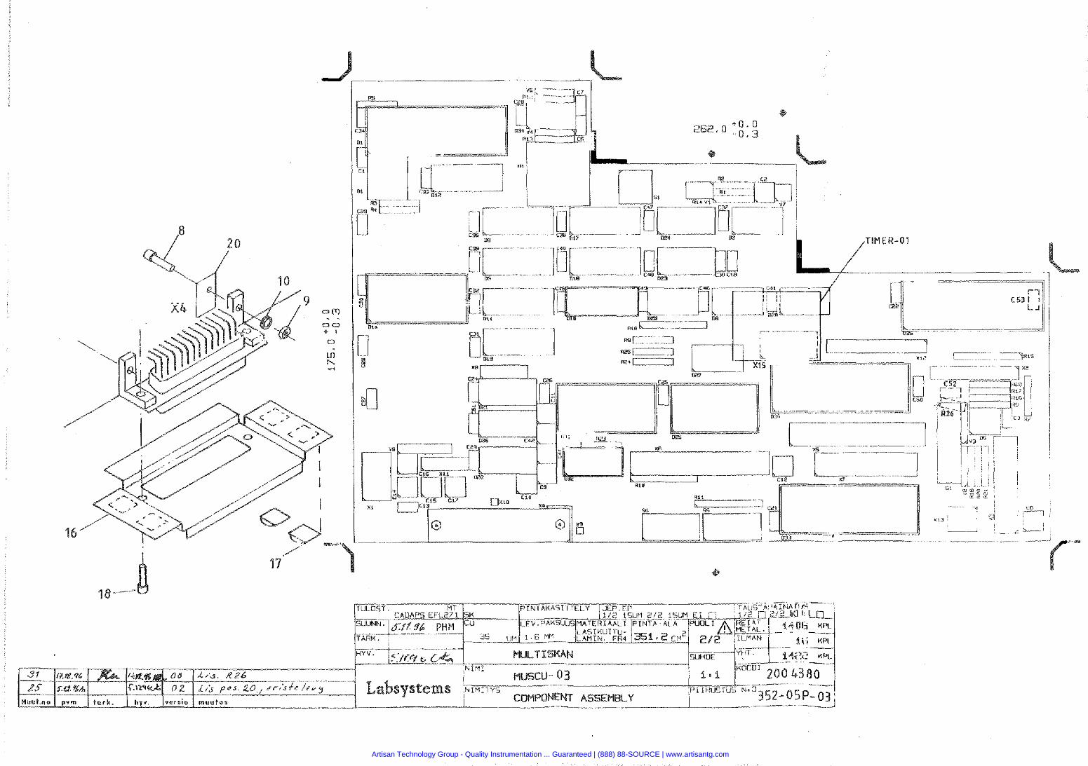
Artisan Technology Group - Quality Instrumentation ... Guaranteed | (888) 88-SOURCE | www.artisantg.com
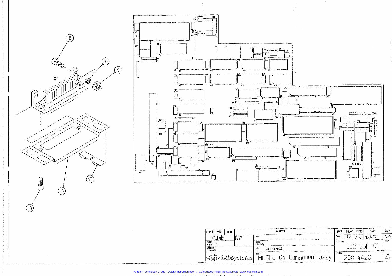
Artisan Technology Group - Quality Instrumentation ... Guaranteed | (888) 88-SOURCE | www.artisantg.com
Artisan Technology Group - Quality Instrumentation ... Guaranteed | (888) 88-SOURCE | www.artisantg.com
ion
Artisan Technology Group - Quality Instrumentation ... Guaranteed | (888) 88-SOURCE | www.artisantg.com
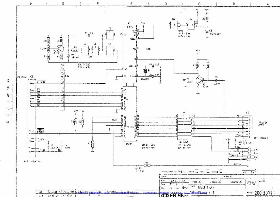
Artisan Technology Group - Quality Instrumentation ... Guaranteed | (888) 88-SOURCE | www.artisantg.com
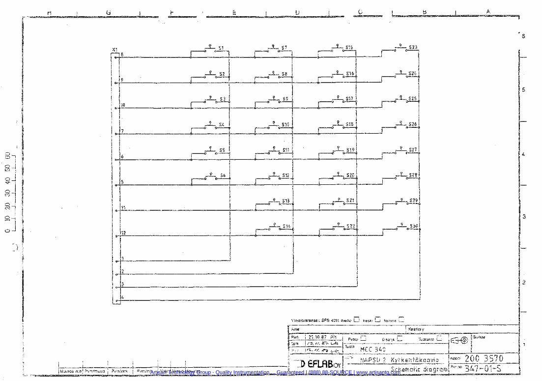
Artisan Technology Group - Quality Instrumentation ... Guaranteed | (888) 88-SOURCE | www.artisantg.com
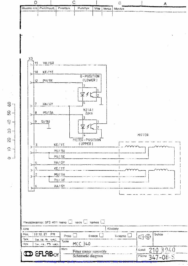
Artisan Technology Group - Quality Instrumentation ... Guaranteed | (888) 88-SOURCE | www.artisantg.com
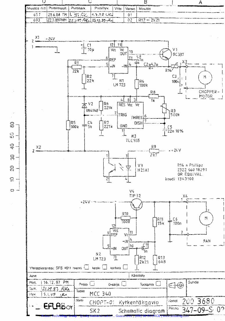
Artisan Technology Group - Quality Instrumentation ... Guaranteed | (888) 88-SOURCE | www.artisantg.com
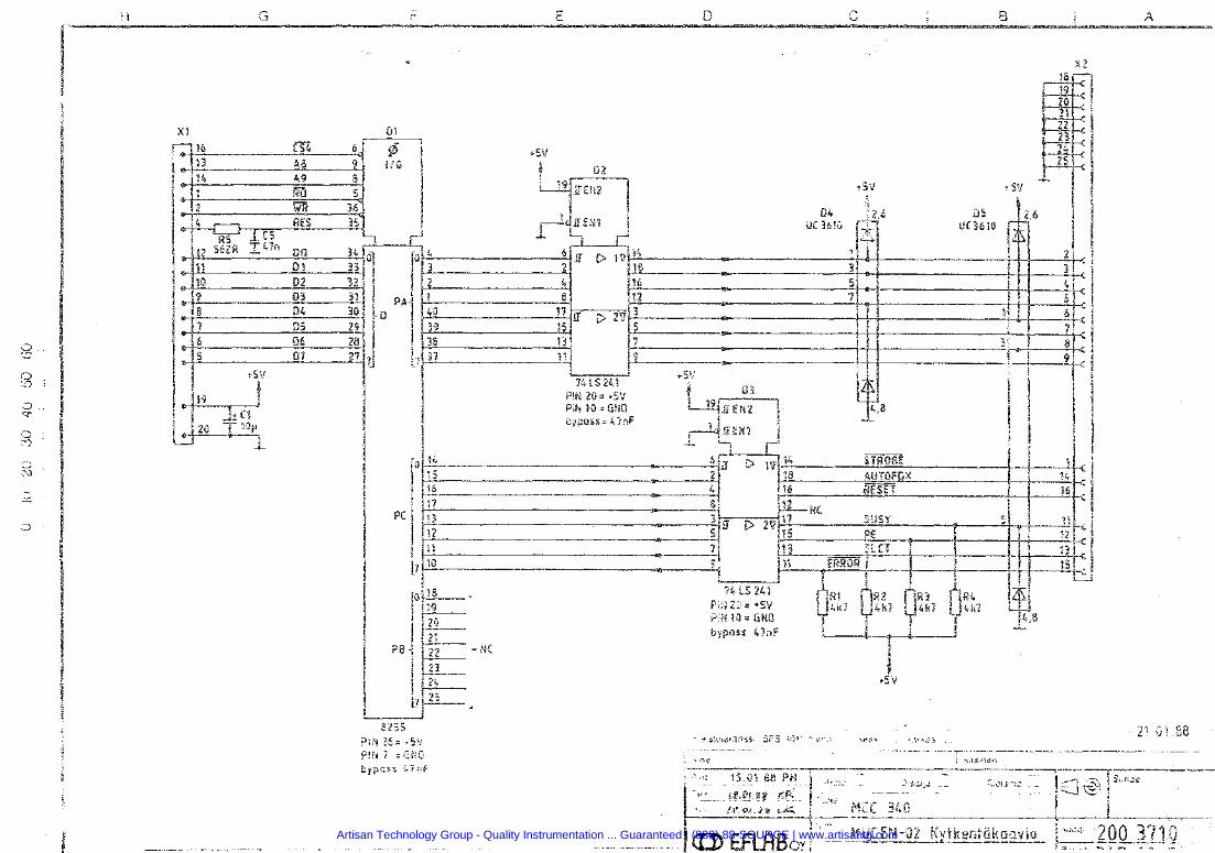
Artisan Technology Group - Quality Instrumentation ... Guaranteed | (888) 88-SOURCE | www.artisantg.com
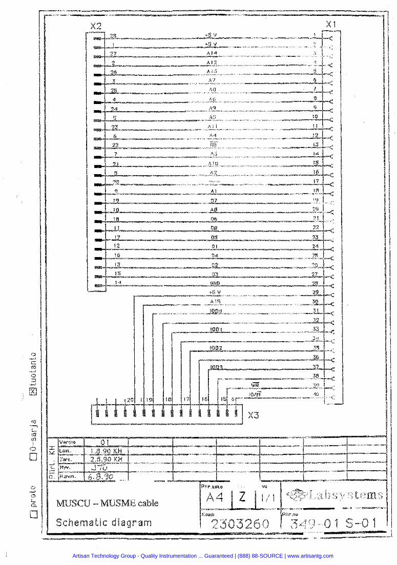
Artisan Technology Group - Quality Instrumentation ... Guaranteed | (888) 88-SOURCE | www.artisantg.com
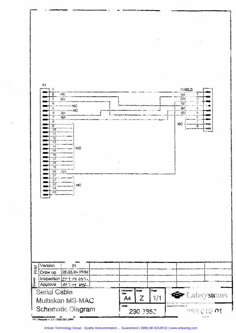
Artisan Technology Group - Quality Instrumentation ... Guaranteed | (888) 88-SOURCE | www.artisantg.com
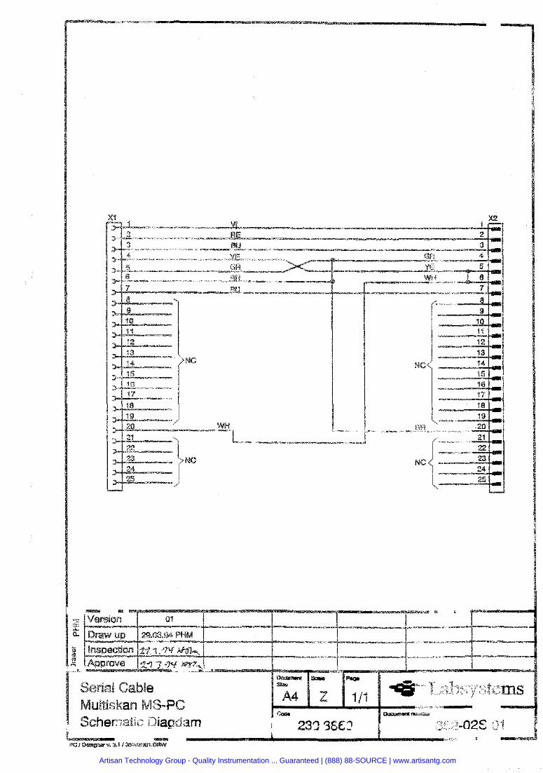
Artisan Technology Group - Quality Instrumentation ... Guaranteed | (888) 88-SOURCE | www.artisantg.com
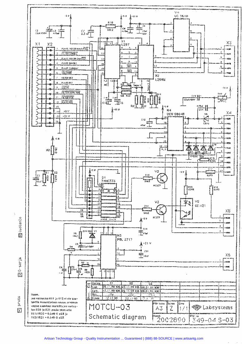
om.
Artisan Technology Group - Quality Instrumentation ... Guaranteed | (888) 88-SOURCE | www.artisantg.com
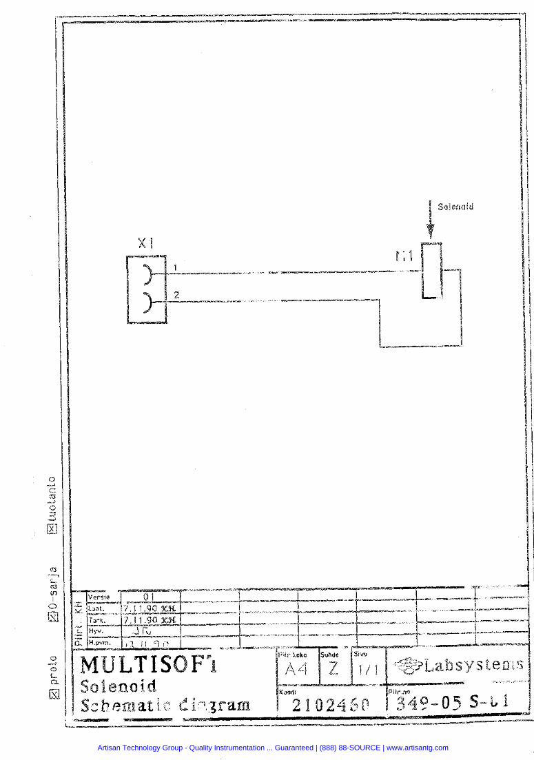
Artisan Technology Group - Quality Instrumentation ... Guaranteed | (888) 88-SOURCE | www.artisantg.com
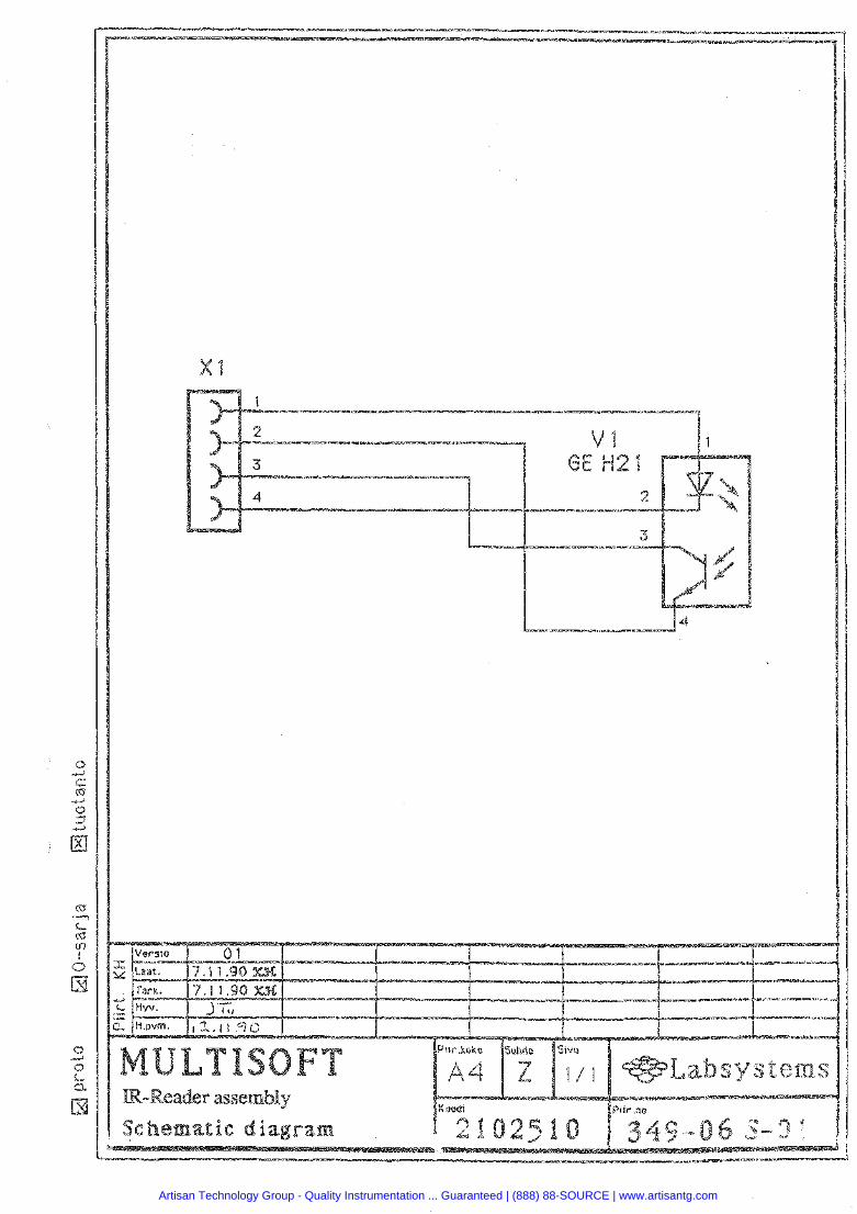
Sivu
1 / 1
Artisan Technology Group - Quality Instrumentation ... Guaranteed | (888) 88-SOURCE | www.artisantg.com
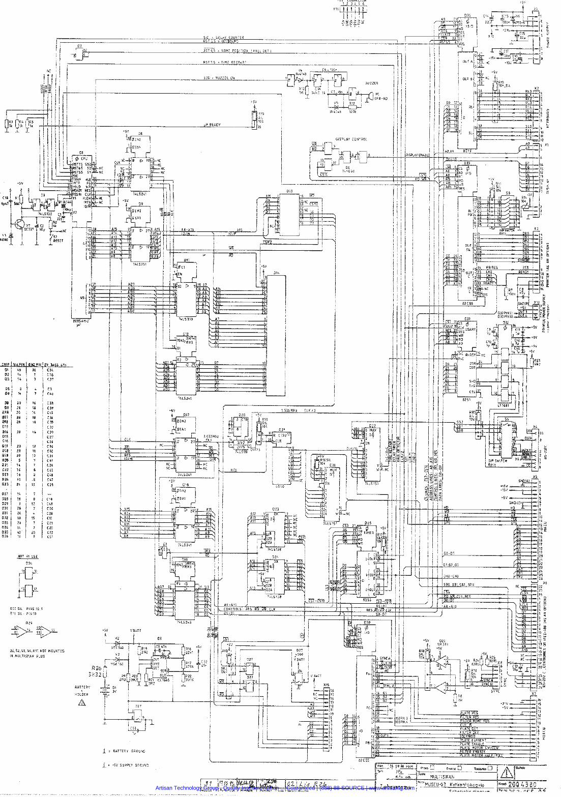
TEST CONNECTOR 1 2 3 4 5 6
X I 1
t 9 $ > 2 S * u-Cr- * - 8
- - SID 3 DELAY COUNTER R S T 5.5 n K E Y B O A R D
0 3 R% 6 MOME POSITION I WALL DL? i
u I
RST 7 5 = T I M E R E S T A R T
I B U Z Z E R
MOT IN USE
D3L
BO. 5B1.SB2, BRX
n
8 - A 1 0
Q2,52,SS,Xb,RI¶ NOT ROUMTED IN M W L T i S K A N P L U S
Artisan Technology Group - Quality Instrumentation ... Guaranteed | (888) 88-SOURCE | www.artisantg.com
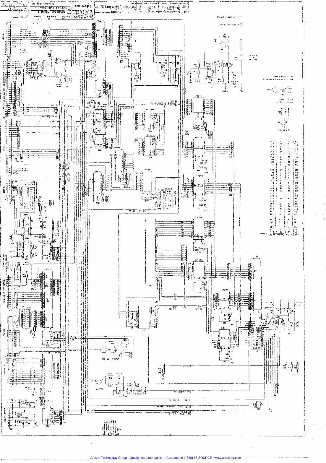
Artisan Technology Group - Quality Instrumentation ... Guaranteed | (888) 88-SOURCE | www.artisantg.com
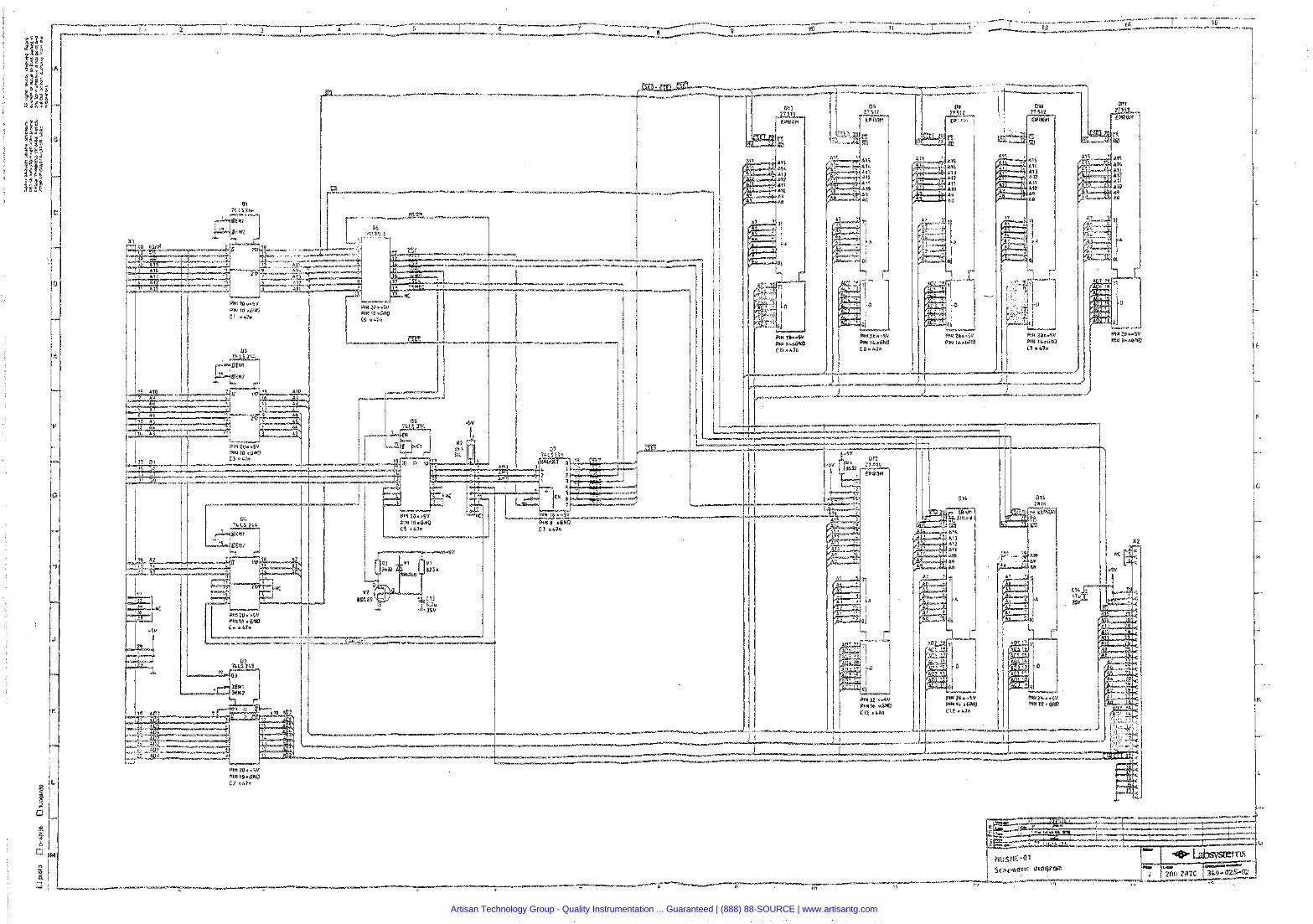
Artisan Technology Group - Quality Instrumentation ... Guaranteed | (888) 88-SOURCE | www.artisantg.com
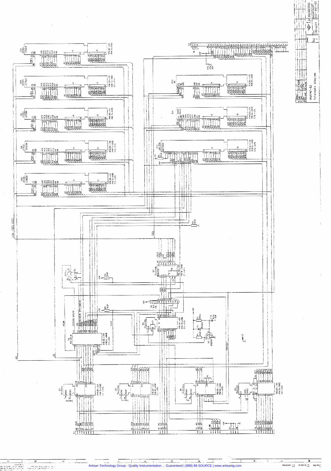
Artisan Technology Group - Quality Instrumentation ... Guaranteed | (888) 88-SOURCE | www.artisantg.com
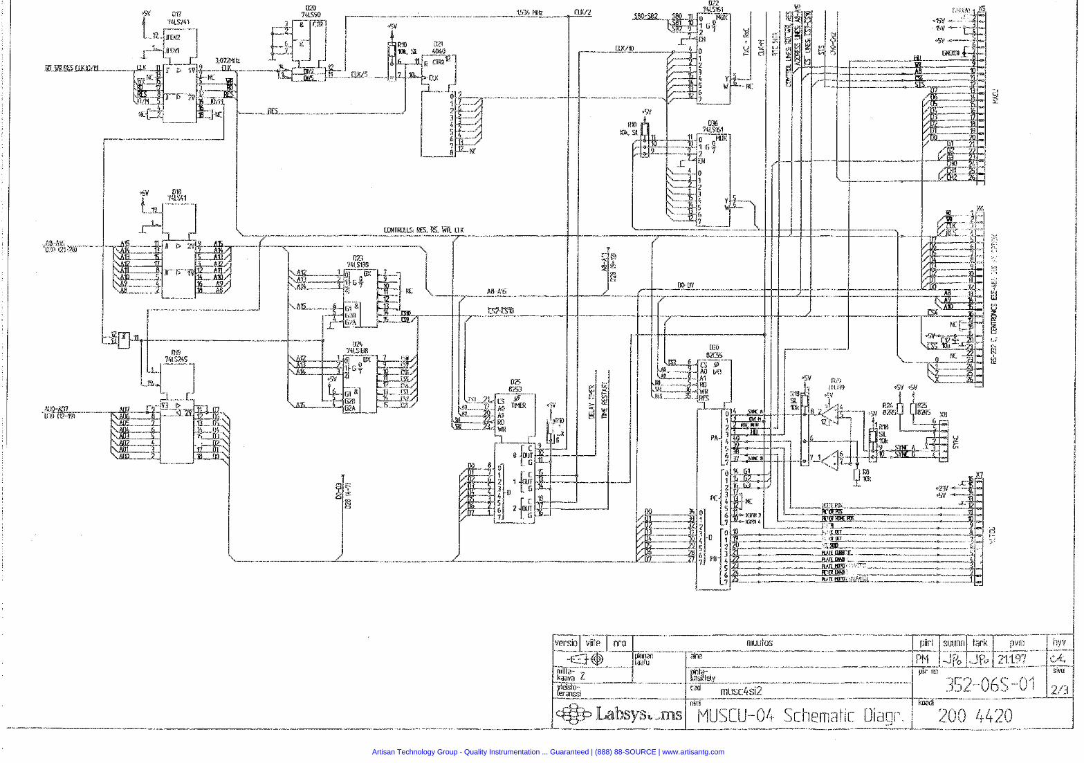
Artisan Technology Group - Quality Instrumentation ... Guaranteed | (888) 88-SOURCE | www.artisantg.com
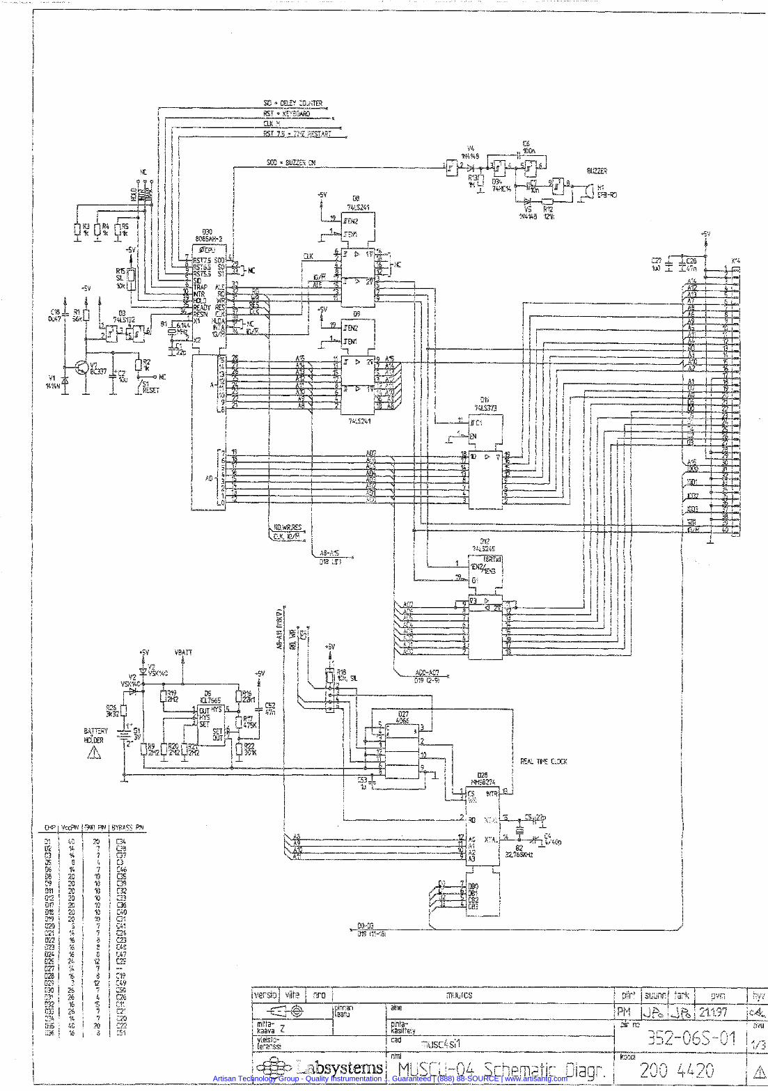
Artisan Technology Group - Quality Instrumentation ... Guaranteed | (888) 88-SOURCE | www.artisantg.com
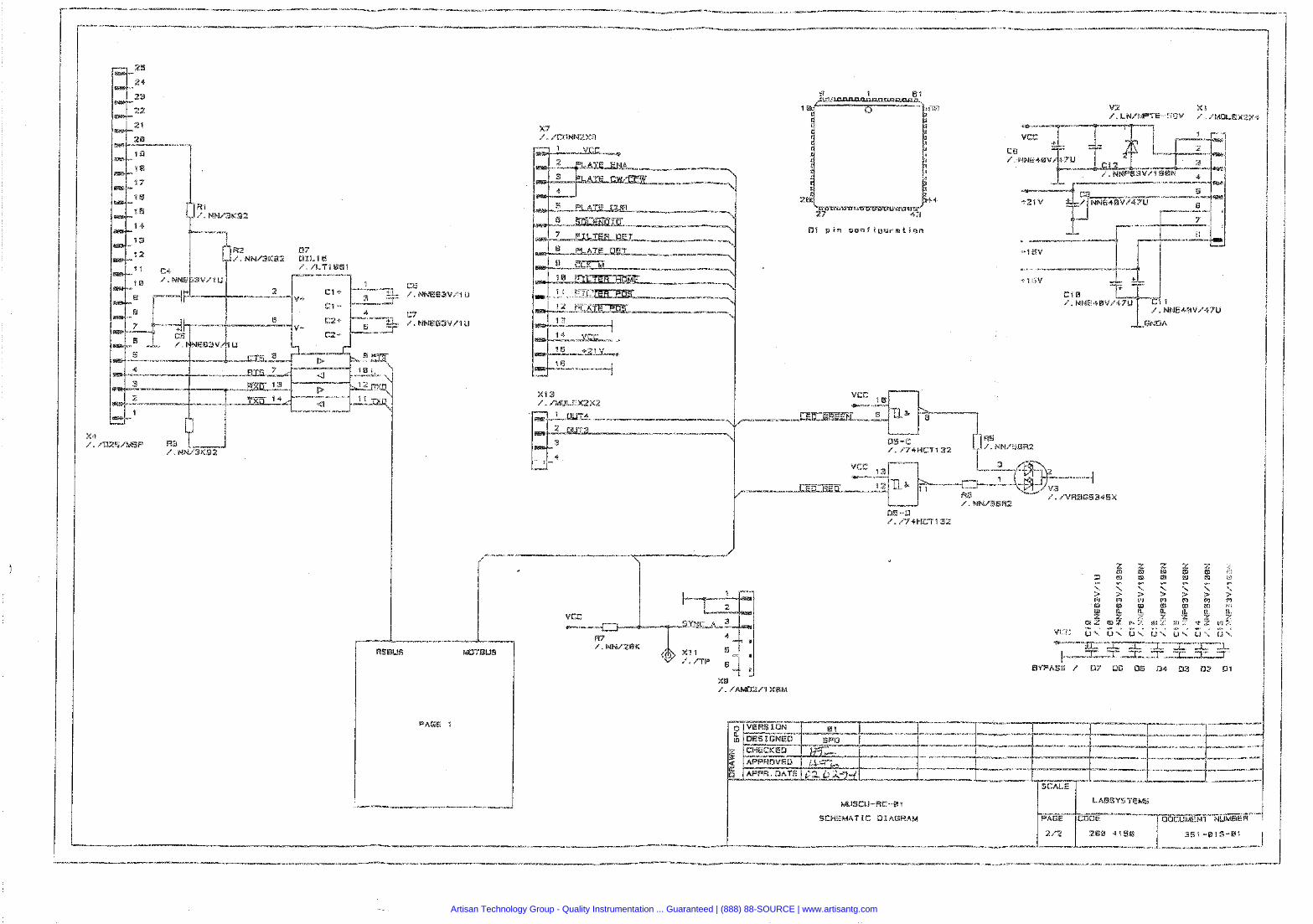
Artisan Technology Group - Quality Instrumentation ... Guaranteed | (888) 88-SOURCE | www.artisantg.com
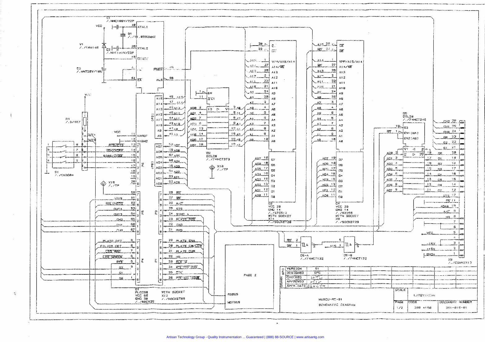
Artisan Technology Group - Quality Instrumentation ... Guaranteed | (888) 88-SOURCE | www.artisantg.com
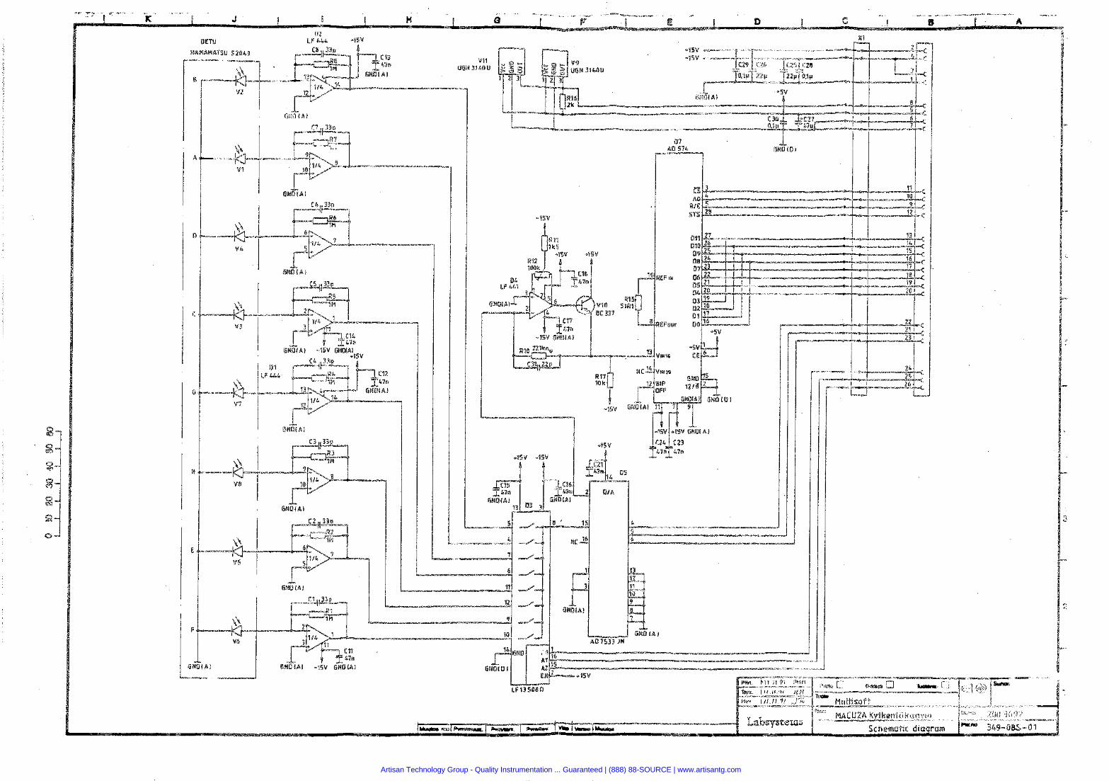
Artisan Technology Group - Quality Instrumentation ... Guaranteed | (888) 88-SOURCE | www.artisantg.com
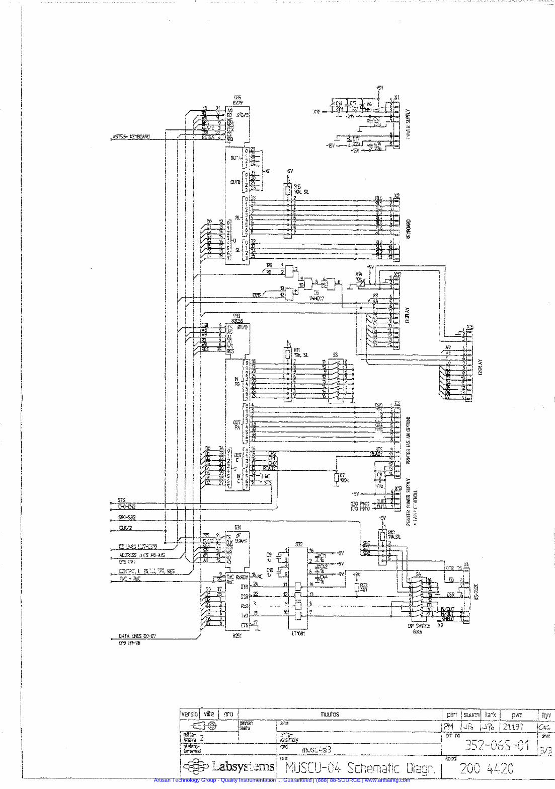
Artisan Technology Group - Quality Instrumentation ... Guaranteed | (888) 88-SOURCE | www.artisantg.com
MULTISKAN RC and MS SERVICE MANUAL
Section 7
f Software
Document Release -0- Section Page ~ ~ ~ I ~ S Z - I O O - X 1 .O -qe Labsystems I
Artisan Technology Group - Quality Instrumentation ... Guaranteed | (888) 88-SOURCE | www.artisantg.com
MULTISKAN RC and MS SERVICE MANUAL
Software
Contents
SUBJECT PAGE
Cover page .............................................................................................. 1 Contents ..................................................................................... ~ ............ 2 Initialization, Multiskan RC ................................................................... 3 Initialization. Multiskan MS ................................................................... 5
Document Release -0- Section Page I ?~1,352-100-x 1 .O --:-- Labsystems 2
Artisan Technology Group - Quality Instrumentation ... Guaranteed | (888) 88-SOURCE | www.artisantg.com
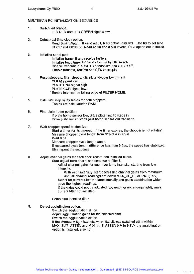
Labsystems Oy IRSD 1
MULTISKAN RC INITIALIZATION SEQUENCE
Switch led orange. LED RED and LED GREEN signals low
Detect real time clock option. Read Smartwatch. If valid result, RTC option installed. Else try to set time 01.01.1994 00:OO:OO. Read again and if still invalid, RTC option not installed.
Initialize serial port. lnitialize transmit and receive buffers. lnitialize baud timer for baud selected by DIL switch. Disable transmit if RTSICTS handshake and CTS is off Enable transmit, receive and CTS interrupts.
Reset steppers: filter stepper off, plate stepper low current. CLK M signal low. PLATE ENA signal high. PLATE CUR signal low. Enable interrupt on falling edge of FILTER HOME.
Calculate step delay tables for both steppers. Tables are calculated to RAM.
Find plate home position. If plate home sensor low, drive plate first 40 steps in. Drive plate out 20 steps past home sensor low transition.
Wait chopper speed to stabilize. Start a timer for i s timeout. If the timer expires, the chopper is not rotating. Measure chopper cycle length from SYNC A interval. Wait 0.5s Measure chopper cycle length again. If measured cycle length difference less than 5 . 5 ~ ~ ~ the speed has stabilized. Else repeat the sequence.
Adjust channel gains for each filter, record non installed filters. Start adjust from filter 1 and continue to filter 8:
Adjust channel gains for each four lamp intensity, starting from low intensity.
With each intensity, start decreasing channel gains from maximum until all channel readings are below MAX-CH-READING (9.9V).
Select for current filter the lamp intensity and gains combination which gave the highest readings. If the gains could not be adjusted (too much or not enough light), mark current filter not installed.
Select first installed filter
Detect agglutination option. Switch the agglutination slit on. Adjust agglutination gains for the selected filter. Switch the agglutination slit off. If the change in light intensity when the slit was switched off is within MAX-SLIT-ATTEN and MIN-SLIT-ATTEN (4V to 9.1V), the agglutination option is installed, else not.
Artisan Technology Group - Quality Instrumentation ... Guaranteed | (888) 88-SOURCE | www.artisantg.com

Labsystems Oy IRSD
9.1 If present, adjust gains for agglutination, record filters not suitable for agglutination. Adjust agglutination gains for each installed filter:
Starting from high lamp intensity, adjust channel gains from high to low gain until1 a lamp intensitylchannel gain combination where all channel levels are below MAX-SLIT-READING (9V) is found.
If the gains could not be adjusted to get channel readings between MIN-SLIT-READING and MAX-SLIT-READING (1V to 9V), the filter is not suitable for agglutination.
10. Select first installed filter.
11. Switch led green unless error during initialization.
Artisan Technology Group - Quality Instrumentation ... Guaranteed | (888) 88-SOURCE | www.artisantg.com
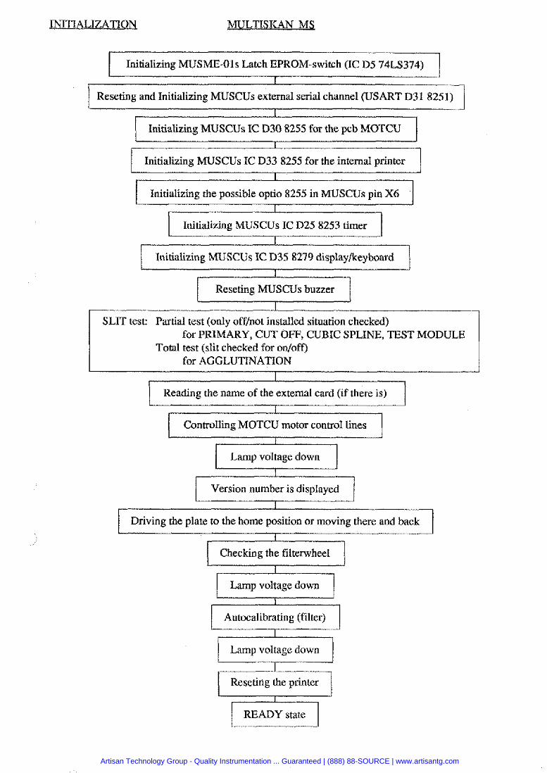
MULTISKAN M$
I Initializing MUSME-01s Latch EPROM-switch (IC D5 74LS374) 1 I Reseting and Initializing MUSCUs external serial channel (USART D31 8251) 1
I
Initializing MUSCUs IC D30 8255 for the pcb MOTCU
I Initializing MUSCUs IC D33 8255 for the internal printer I Initializing the possible optio 8255 in MUSCUs pin X6
Initializing MUSCUs IC D25 8253 timer I
Initializing MUSCUs IC D35 8279 display/keyboard
I
Reseting MUSCUs buzzer I
SLIT test: Partial test (only offhot installed situation checked) for PRIMARY, CUT OFF, CUBIC SPLINE, TEST MODULE
Total test (slit checked for onloff) for AGGLUTINATION
1 Reading the name of the external card (if there is) 1 ( Controlling MOTCU motor control lines I
I
Lamp voltage down
I
Version number is displayed I
Driving the plate to the home position or moving there and back
I
Checking the filterwheel
I
Lamp voltage down
Autocalibrating (filter) L---?-J Lamp voltage down u
1 Reseting the printer I I READY state I
Artisan Technology Group - Quality Instrumentation ... Guaranteed | (888) 88-SOURCE | www.artisantg.com
MULTISKAN RC and MS SERVICE MANUAL
Section 8
Testing and Adjusting
Document Release Section Page *=! Labsystems 3511352-100-X 1.0 --- 8 1
Artisan Technology Group - Quality Instrumentation ... Guaranteed | (888) 88-SOURCE | www.artisantg.com
MULTISKAN RC and MS SERVICE MANUAL
( Testing and Adjusting 1
f Contents I
SUBJECT PAGE
Cover page ......................................................................................... Contents ............................................................................................. Lamp Voltage .....................................................................................
.................................. Computer Control Commands in All Modules ........................................... Testing and Adjusting for Multiskan RC
..................................... Problems in Setting up the Instrument Adjustments with ADJ Commands .......................................... Error Limits .............................................................................. Error Messages .........................................................................
.......................................... Testing and Adjusting for Multiskan MS FOR SERVICE PERSONNEL ................................................ Built-in Adjusting Programs .................................................... Built-in Test Programs .............................................................
Document Release .% Section Page 3511352-loo-x 1 . 0 -<a Labsystems 8 2
Artisan Technology Group - Quality Instrumentation ... Guaranteed | (888) 88-SOURCE | www.artisantg.com
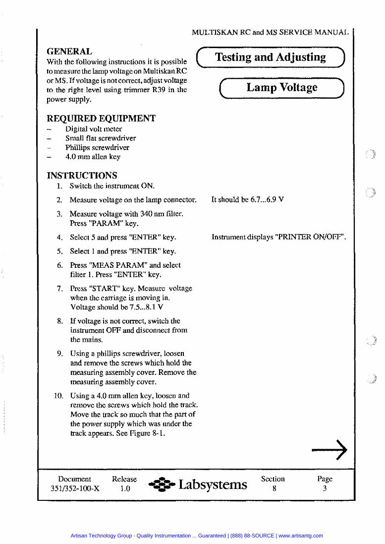
MULTISKAN RC
GENERAL With the foilowing instructions it is possible Testing and Adjusting to measure the lamp voltage on Multiskan RC or MS. If voltage is not correct, adjust voltage to the right level using trimmer R39 in the power supply.
REQUIRED EQUIPMENT - Digital volt meter - Small flat screwdriver - Phillips screwdriver - 4.0 mm allen key
INSTRUCTIONS Switch the instrument ON.
Measure voltage on the lamp connector.
Measure voltage with 340 nm filter. Press "PARAM key.
Select 5 and press "ENTER" key.
Select 1 and press "ENTER key.
Press "MEAS PARAM" and select filter 1. Press "ENTER key.
Press "START" key. Measure voltage when the caniage is moving in. Voltage should be 7.5 ... 8.1 V
If voltage is not correct, switch the instrument OFF and disconnect from the mains.
Using a phillips screwdriver, loosen and remove the screws which hold the measuring assembly cover. Remove the measuring assembly cover.
Using a 4.0 mm allen key, loosen and remove the screws which hold the track. Move the track so much that the part of the power supply which was under the track appears. See Figure 8- 1.
Lamp Voltage
It should be 6.7 ... 6.9 V
Instrument displays "PRINTER ONIOFF".
Document Release Section Page 351/352-100-x 1 .O 0%:- Labsystems 8 3
Artisan Technology Group - Quality Instrumentation ... Guaranteed | (888) 88-SOURCE | www.artisantg.com
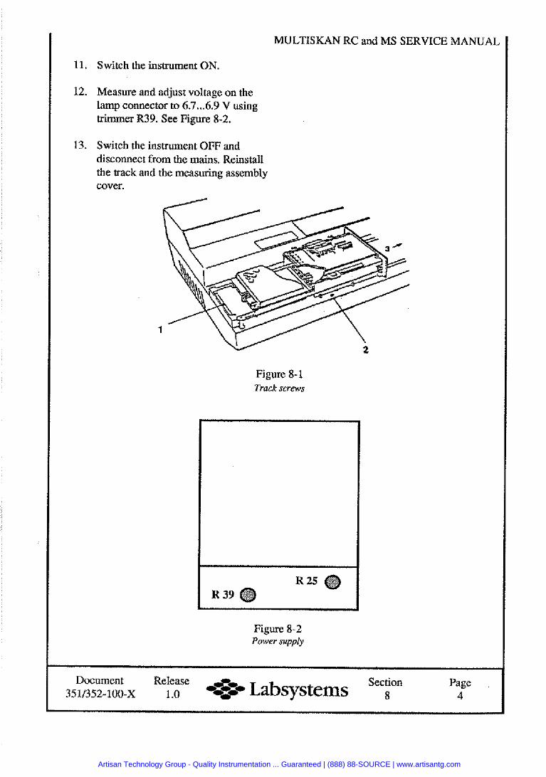
MULTISKAN RC and MS SERVICE MANUAL
11. Switch the instrument ON.
12. Measure and adjust voltage on the lamp connector to 6.7 ... 6.9 V using trimmer R39. See Figure 8-2.
13. Switch the instrument OFF and disconnect from the mains. Reinstall the track and the measuring assembly cover.
Figure 8-1 Track screws
Figure 8-2 Power supply
Document Release Section Page Labsysterns 351/352- 100-X 1 .O 8 4
Artisan Technology Group - Quality Instrumentation ... Guaranteed | (888) 88-SOURCE | www.artisantg.com
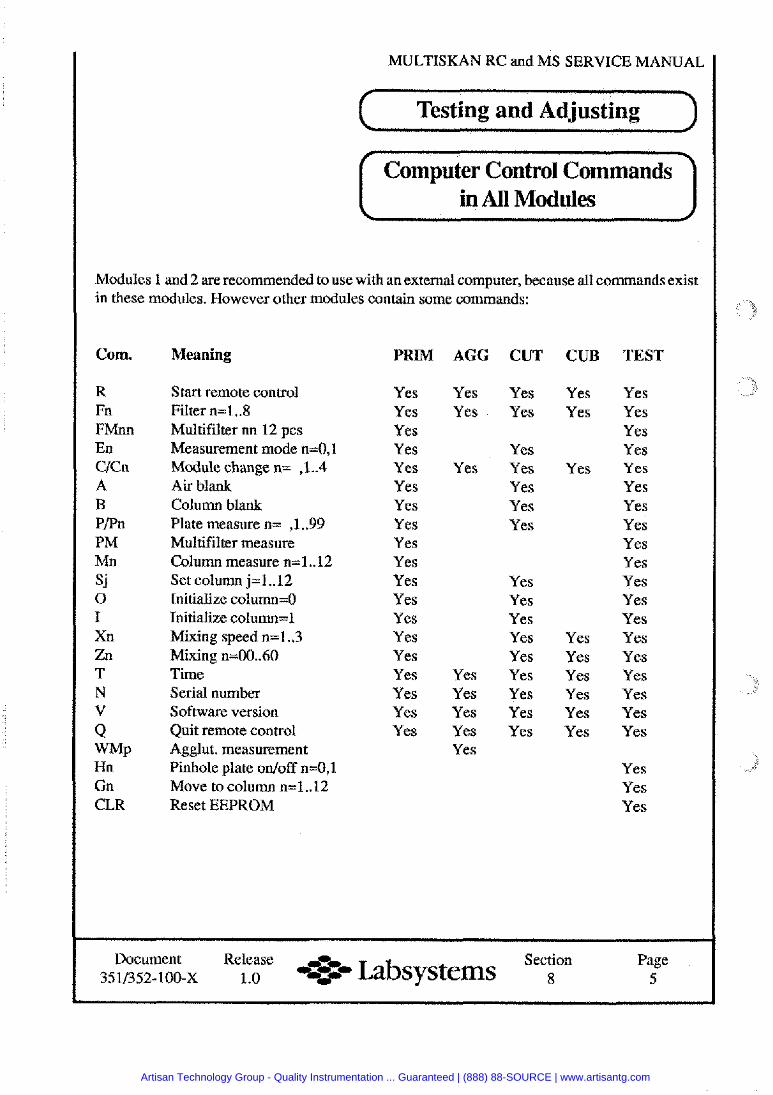
MULTISKAN RC and MS SERVICE MANUAL
Testing and Adjusting
Computer Control Commands in All Modules I
Modules 1 and 2 are recommended to use with an external computer, because all commands exist in these modules. However other modules contain some commands:
Corn.
R Fn FMnn En C/Cn A B PPn PM Mn s j 0 I Xn Zn T N V Q WMI, Hn Gn CLR
Meaning
Start remote control Filter n=1..8 Multifilter nn 12 pcs Measurement mode n=0,1 Module change n= ,1..4 Air blank Column blank Plate measure n= ,1..99 Multifilter measure Column measure n=l.. 12 Set column j=1..12 Initialize column=O Initialize column=l Mixing speed n=1..3 Mixing n=00..60 Time Serial number Software version Quit remote control Agglut. measurement Pinhole plate on/off n=0,1 Move to column n=1..12 Reset EEPROM
PRIM
Yes Yes Yes Yes Y cs Yes Yes Yes Yes Yes Yes Yes Yes Yes Yes Yes Yes Yes Yes
AGG CUT
Yes Yes Yes Yes
Yes Yes Yes
Yes Yes Yes
Yes Yes Yes Yes Yes
Yes Yes Yes Yes Yes Yes Yes Yes Yes
CUB
Yes Yes
Yes
Yes Yes Yes Yes Yes Yes
TEST
Yes Yes Yes Yes Yes Yes Yes Yes Yes Yes Yes Yes Yes Yes Yes Yes Yes Yes Yes
Yes Yes Yes
Document 3SlB.52-100-X
Release 1 .o
rtr, -OZ-- Labsystems Section 8
Page 5
Artisan Technology Group - Quality Instrumentation ... Guaranteed | (888) 88-SOURCE | www.artisantg.com
MULTISKAN RC and MS SERVICE MANUAL
( Testing and Adjusting )
Testing and Adjusting
for
Multiskan RC 351
Artisan Technology Group - Quality Instrumentation ... Guaranteed | (888) 88-SOURCE | www.artisantg.com
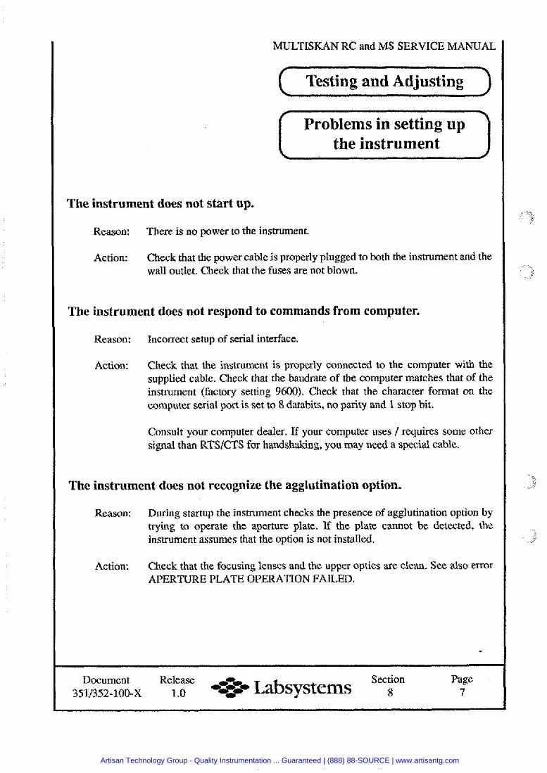
MULTISKAN RC and MS SERVICE MANUAL
( Testing and Adjusting )
( Problems in setting up 1 I the instrument I
The instrument does not start up.
Reason: There is no power to the instrument.
Action: Check that the power cable is properly plugged to both the instrument and the wall outlet. Check that the fuses are not blown.
The instrument does not respond to commands from computer.
Reason: Incorrect setup of serial interface.
Action: Check that the instrument is properly connected to the computer with the supplied cable. Check that the baudrate of the computer matches that of the instrument (factory setting 9600). Check that the character format on the computer serial port is set to 8 databits, no parity and 1 stop bit.
Consult your computer dealer. If your computer uses /requires some other signal than RTSICTS for handshaking, you may need a special cable.
The instrument does not recognize the agglutination option.
Reason: During startup the instrument checks the presence of agglutination option by trying to operate the aperture plate. If the plate cannot be detected, the instrument assumes that the option is not installed.
Action: Check that the focusing lenses and the upper optics are clean. See also error APERTURE PLATE OPERATION FAILED.
Document Release -0- Section Page 35113.52-100-x 1.0 - t # Labsystems 8 7
Artisan Technology Group - Quality Instrumentation ... Guaranteed | (888) 88-SOURCE | www.artisantg.com
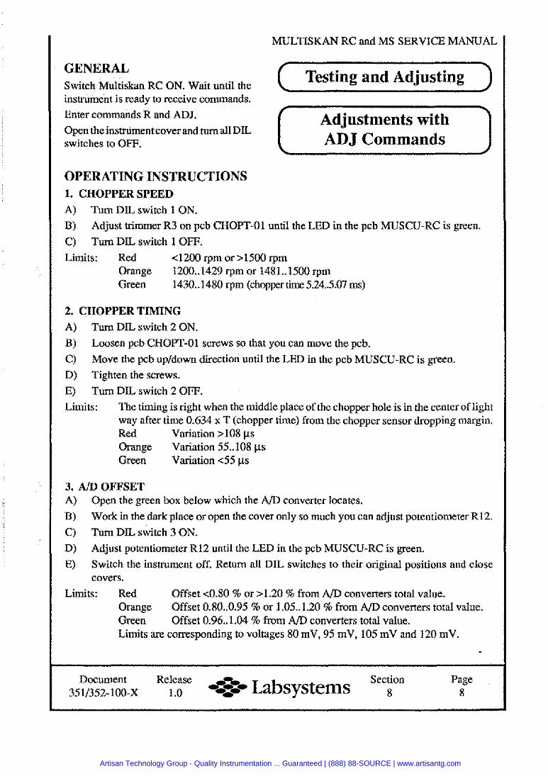
MULTISKAN RC and MS SERVICE MANUAL
GENERAL Switch Multiskan RC ON. Wait until the
Testing and Adjusting instrument is ready to receive commands. Enter commands R and ADJ. Open the instrument cover and turn all DIL switches to OFF. ADJ Commands
OPERATING INSTRUCTIONS 1. CHOPPER SPEED A) Turn DIL switch 1 ON.
B) Adjust trimmer R3 on pcb CHOPT-01 until the LED in the pcb MUSCU-RC is green.
C) Turn DIL switch 1 OFF. Limits: Red 4 2 0 0 rpm or s1500 rpm
Orange 1200..1429 rprn or 1481..1500 rpm Green 1430..1480 rpm (chopper time 5.24307 ms)
2. CHOPPER TIMING
A) Turn DIL switch 2 ON.
B) Loosen pcb CHOPT-01 screws so that you can move the pcb.
C) Move the pcb upldown direction until the LED in the pcb MUSCU-RC is green. D) Tighten the screws.
E) Turn DIL switch 2 OFF. Limits: The timing is right when the middle place of the chopper hole is in the center of light
way after time 0.634 x T (chopper time) from the chopper sensor dropping margin. Red Variation >lo8 ps Orange Variation 55.. 108 ps Green Variation <55 ps
3. AID OFFSET A) Open the green box below which the A/D converter locates.
B) Work in the dark place or open the cover only so much you can adjust potentiometer R12.
C) Turn DIL switch 3 ON.
D) Adjust potentiometer R12 until the LED in the pcb MUSCU-RC is green.
E) Switch the instrument off. Return all DIL switches to their original positions and close covers.
Limits: Red Offset <0.80 % or >1.20 % from A/D converters total value. Orange Offset 0.80..0.95 % or 1.05.1.20 % from A/D converters total value. Green Offset 0.96..1.04 % from A/D converters total value. Limits are corresponding to voltages 80 mV, 95 mV, 105 mV and 120 mV.
Document 3511352-100-X
Release 1 .o
*-a Labsystems Section 8
Page 8
Artisan Technology Group - Quality Instrumentation ... Guaranteed | (888) 88-SOURCE | www.artisantg.com
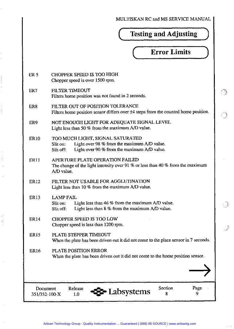
ER 5
ER7
ER8
ER9
ERlO
ERl l
ER12
ER13
ER14
ER15
ER16
MULTISKAN RC and MS SERVICE MANUAL
( Testing and Adjusting
Error Limits
CHOPPER SPEED IS TOO HIGH Chopper speed is over 1500 rpm.
FILTER TIMEOUT Filters home position was not found in 2 seconds.
FILTER OUT OF POSITION TOLERANCE Filters home position sensor differs over 1 4 steps from the counted home position.
NOT ENOUGH LIGHT FOR ADEQUATE SIGNAL LEVEL Light less than 50 % from the maximum A/D value.
TOO MUCH LIGHT, SIGNAL SATURATED Slit on: Light over 98 % from the maximum A/D value. Slit off: Light over 90 % from the maximum A/D value.
APERTURE PLATE OPERATION FAILED The change of the light intensity over 91 % or less than 40 % from the maximum A/D value.
FILTER NOT USABLE FOR AGGLUTINATION Light less than 10 % from the maximum A/D value.
LAMP FAIL Slit on: Light less than 46 % from the maximum A/D value. Slit off: Light less than 8 % from the maximum A/D value.
CHOPPER SPEED IS TOO LOW Chopper speed is less than 1200 rpm.
PLATE STEPPER TIMEOUT When the plate has been driven out it did not come to the place sensor in 7 seconds.
PLATE POSITION ERROR When the plate has been driven out it did not come to the home position sensor.
Document Release Section Page 35 1/352-100-~ 1 .O 4% Labsystems 8 9
Artisan Technology Group - Quality Instrumentation ... Guaranteed | (888) 88-SOURCE | www.artisantg.com
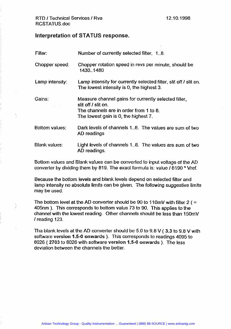
RTD I Technical Services I Rva RCSTATUS.doc
Interpretation of STATUS response.
Filter:
Chopper speed:
Lamp intensity:
Gains:
Bottom values:
Blank values:
Number of currently selected filter, 1 ..8
Chopper rotation speed in revs per minute, should be 1430..1480
Lamp intensity for currently selected filter, slit off I slit on. The lowest intensity is 0, the highest 3.
Measure channel gains for currently selected filter, slit off 1 slit on. The channels are in order from 1 to 8. The lowest gain is 0, the highest 7.
Dark levels of channels 1 ..8. The values are sum of two AD readings
Light levels of channels 1 ..8. The values are sum of two AD readings.
Bottom values and Blank values can be converted to input voltage of the AD converter by dividing them by 81 9. The exact formula is: value 181 90 * Vref.
Because the bottom levels and blank levels depend on selected filter and lamp intensity no absolute limits can be given. The following suggestive limits may be used:
The bottom level at the AD wnverter should be 90 to 11OmV with filter 2 ( = 405nm ). This corresponds to bottom value 73 to 90. This applies to the channel with the lowest reading. Other channels should be less than i50mV I reading 123.
Tha blank levels at the AD converter should be 5.0 to 9.8 V ( 3.3 to 9.8 V with software version 1.5-0 onwards ). This corresponds to readings 4095 to 8026 ( 2703 to 8026 with software version 1.5-0 onwards ). The less deviation between the channels the better.
Artisan Technology Group - Quality Instrumentation ... Guaranteed | (888) 88-SOURCE | www.artisantg.com
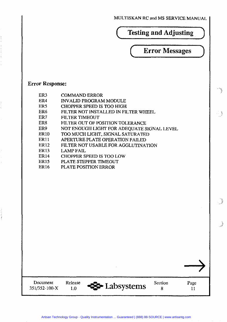
MULTISKAN RC and MS SERVICE MANUAL
( Testing and Adjusting 1 ( Error Messages 1
Error Response:
ER3 ER4 ER5 ER6 ER7 ER8 ER9 ERlO ERl 1 ER12 ER13 ER14 ER15 ER16
COMMAND ERROR INVALID PROGRAM MODULE CHOPPER SPEED IS TOO HIGH FILTER NOT INSTALLED IN FILTER WHEEL FILTER TIMEOUT FILTER OUT OF POSITION TOLERANCE NOT ENOUGH LIGHT FOR ADEQUATE SIGNAL LEVEL TOO MUCH LIGHT, SIGNAL SATURATED APERTURE PLATE OPERATION FAILED FILTER NOT USABLE FOR AGGLUTINATION LAMP FAIL CHOPPER SPEED IS TOO LOW PLATE STEPPER TIMEOUT PLATE POSITION ERROR
Document Release ,r~, Section Page 351/352- 100-x 1.0 -..;=-- Labsysterns 8 11
Artisan Technology Group - Quality Instrumentation ... Guaranteed | (888) 88-SOURCE | www.artisantg.com
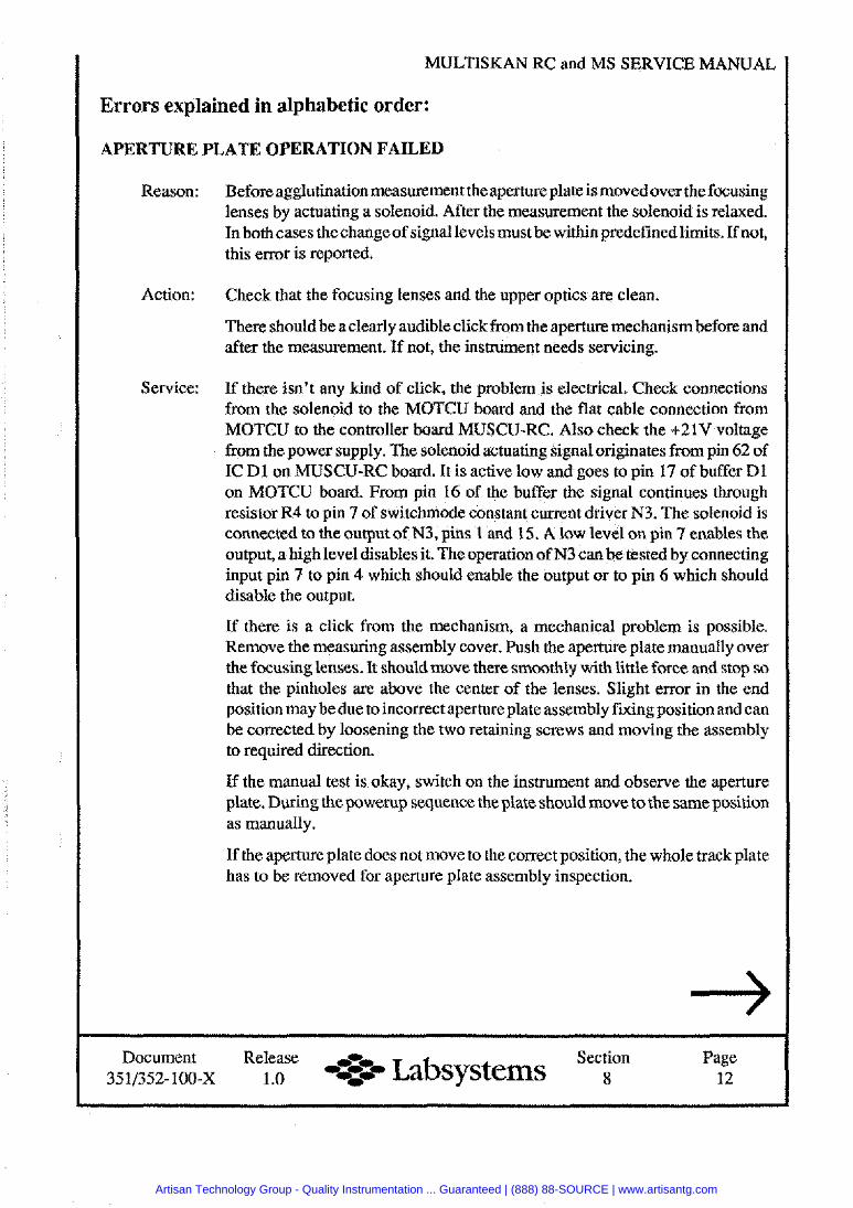
MULTISKAN RC and MS
Errors explained in alphabetic order:
APERTURE PLATE OPERATION FAILED
Reason:
Action:
Service:
Before agglutination measurement the aperture plate is movedover the focusing lenses by actuating a solenoid. After the measurement the solenoid is relaxed. In both Eases thechange of signal levels must be within predefined limits. If not, this error is reported.
Check that the focusing lenses and the upper optics are clean.
There should be a clearly audible click from the aperture mechanism before and after the measurement. If not, the instrument needs servicing.
If there isn't any kind of click, the problem is electrical. Check connections from the solenoid to the MOTCU board and the flat cable connection from MOTCU to the controller board MUSCU-RC. Also check the +21V voltage from the power supply. The solenoid actuating signal originates from pin 62 of IC D l on MUSCU-RC board. It is active low and goes to pin 17 of buffer Dl on MOTCU board. From pin 16 of the buffer the signal continues through resistor R4 to pin 7 of switchmode constant current driver N3. The solenoid is connected to the output of N3, pins 1 and 15. A low level on pin 7 enables the output, a highlevel disables it. The operation of N3 can be tested by connecting input pin 7 to pin 4 which should enable the output or to pin 6 which should disable the output.
If there is a click from the mechanism, a mechanical vroblem is vossible. Remove the measuring assembly cover. Push the aperture plate manually over the focusing lenses. It should move there smoothly with little force and stor, so that the pinholes are above the center of the lenses. Slight error in the knd . - position may be due to incorrect aperture plate assembly fixing position and can be corrected by loosening the two retaining screws and moving the assembly to required direction.
If the manual test is okay, switch on the instrument and observe the aperture plate. During the powerup sequence the plate should move to the same position as manually.
If the aperture plate does not move to the correct position, the whole track plate has to be removed for aperture plate assembly inspection.
Document Release ,, Section Page 35 11352- 100-x 1 .O --=e Labsystems 8 12
Artisan Technology Group - Quality Instrumentation ... Guaranteed | (888) 88-SOURCE | www.artisantg.com
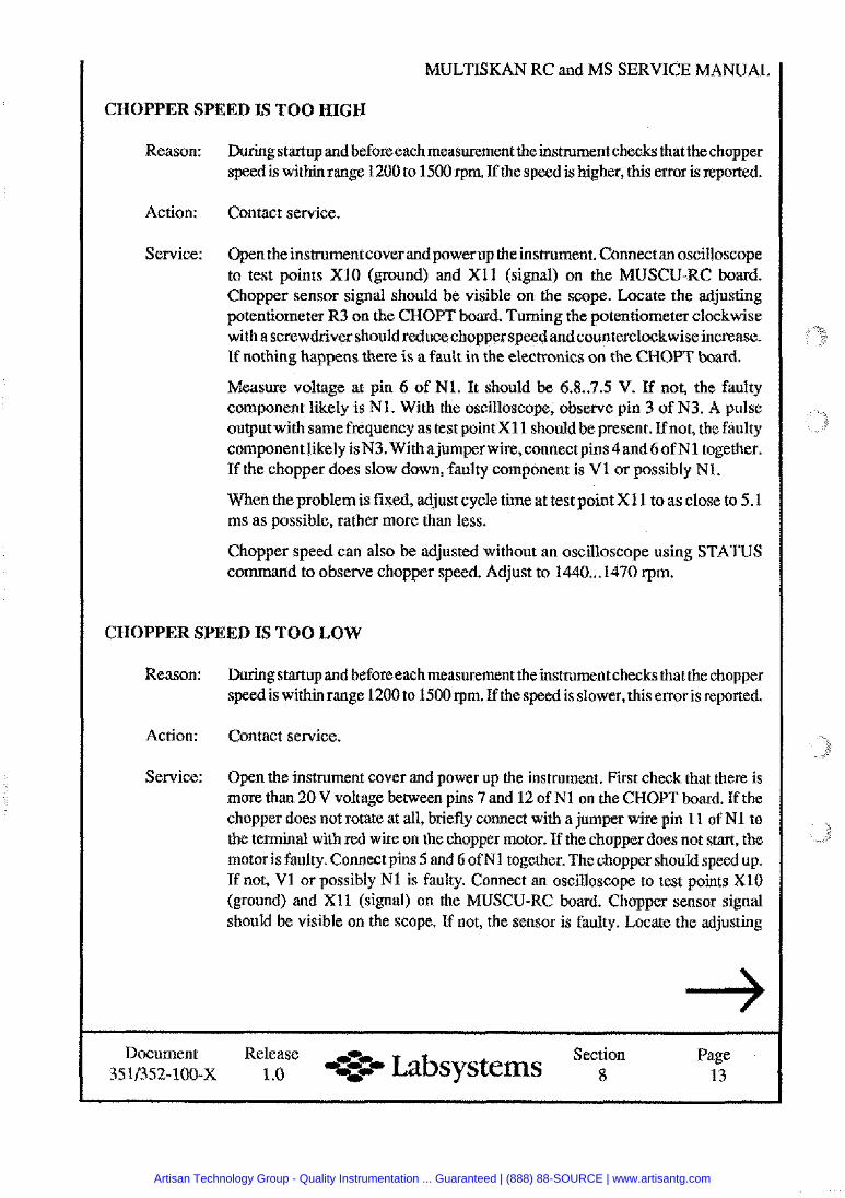
MULTISKAN RC and MS SERVICE MANUAL
CHOPPER SPEED IS TOO HIGH
Reason: During startup and before each measurement the instrument checks thatthe chopper speed is within range 1200 to 1500 rpm. If the speed is higher, this error is reported.
Action: Contact service.
Service: Open theinstrument cover andpower up the instrument. Connect an oscilloscope to test points XI0 (ground) and XI1 (signal) on the MUSCU-RC board. Chopper sensor signal should be visible on the scope. Locate the adjusting potentiometer R3 on the CHOPT board. Turning the potentiometer clockwise with a screwdriver should reducechopper speed andcounterclockwise increase. If nothing happens there is a fault in the electronics on the CHOPT board.
Measure voltage at pin 6 of N1. It should be 6.8..7.5 V. If not, the faulty component likely is N1. With the oscilloscope, observe pin 3 of N3. A pulse outputwith same frequency as test pointX11 should be present. If not, the faulty component likely isN3. With ajumper wire,connectpins 4 and6of N1 together. If the chopper does slow down, faulty component is V1 or possibly N1.
When the problemis fixed, adjust cycle time at test point XI1 to as close to 5.1 ms as possible, rather more than less.
Chopper speed can also be adjusted without an oscilloscope using STATUS command to observe chopper speed. Adjust to 1440 ... 1470 rpm.
CHOPPER SPEED IS TOO LOW
Reason: During startup and before each measurement theinstrument checks that the chopper speed is within range 1200 to 1500 rpm. If the speed is slower, this error is reported.
Action: Contact service.
Service: Open the instrument cover and power up the instrument. Fist check that there is more than 20 V voltage between pins 7 and 12 of N1 on the CHOPT board. If the chopper does not rotate at all, briefly connect with a jumper wire pin 11 of N1 to the terminal with red wire on the chopper motor. If the chopper does not start, the motor is faulty. Connect pins 5 and 6 of N1 together. The chopper should speed up. If not, V1 or possibly N1 is faulty. Connect an oscilloscope to test points XI0 (ground) and XI1 (signal) on the MUSCU-RC board. Chopper sensor signal should be visible on the scope. If not, the sensor is faulty. Locate the adjusting
Document Release ,-- Section Page 3511352-100-x 1 .O -:-- Labsystems 8 13
Artisan Technology Group - Quality Instrumentation ... Guaranteed | (888) 88-SOURCE | www.artisantg.com
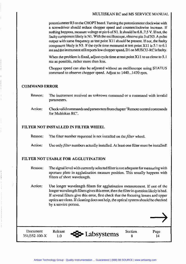
MULTISKAN RC and MS SERVICE MANUAL
potentiometer R3 on the CHOPT hoard. Turning the potentiometer clockwise with a screwdriver should reduce chopper speed and counterclockwise increase. If nothing happens, measure voltage at pin 6 of Nl. It should be 6.8..7.5 V. Ifnot, the faulty component likely is N1. With the oscilloscope, observe pin 3 of N3. A pulse output with same frequency as test point X11 should be present. If not, the faulty component likely is N3. If the cycle time measured at test point XI1 is 5.1 to 6.1 ms and theinstrument stillreports low chopper speed,Dl on MUSCU-RC is faulty.
When the problem is fixed, adjust cycle time at test point X1 1 to as close to 5.1 ms as possible, rather more than less.
Chopper speed can also be adjusted without an oscilloscope using STATUS command to observe chopper speed. Adjust to 1440 ... 1470 rpm.
COMMAND ERROR
Reason: The instrument received an unknown command or a command with invalid parameters.
Action: Checkvalidcommands and parameters fromchapter 'Remote control commands for Multiskan RC'.
FILTER NOT INSTALLED IN FILTER WHEEL
Reason: The filter number requested is not installed on thefilter wheel.
Action: Use onlyfilter numbers actually installed. At least one filter must be installed!
FILTER NOT USABLE FOR AGGLUTINATION
Reason: The signallevel with currently selected filter is not adequate for measuring with aperture plate in agglutination measure position. This usually happens with filters of short wavelength.
Action: Use longer wavelength filters for agglutination measurement. If one of the longerwavelength filters gives thisenor, then the filter inquestionlikely is bad. If several filters give this error, first check that the focusing lenses and upper optics are clean. If cleaning does not help, the optical system should be checked by a service person.
Document Release -0- Section Page 3511352-loo-x 1 .o Labsysterns 8 14
Artisan Technology Group - Quality Instrumentation ... Guaranteed | (888) 88-SOURCE | www.artisantg.com
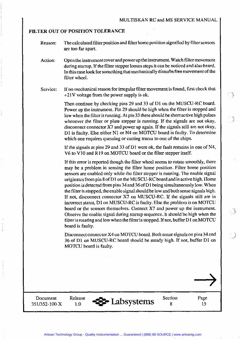
MULTISKAN
FILTER OUT OF POSITION TOLERANCE
Reason: Thecalculated filter position and fi lter home position signalled by filter sensors are too far apart.
Action: Open the instrument cover and power up the instrument. Watch filter movement d&ng startup. If the filter stepper loo&s steps it can be noticed and also heard. In this caselook for something that mechanically disturbs freemovement of the filter wheel.
Service: If no mechanical reason for irregular filter movement is found, first check that +21V voltage from the power supply is ok.
Then continue by checking pins 29 and 33 of D1 on the MUSCU-RC board. Power up the instrument. Pin 29 should be high when the filter is stopped and low when the filter is running. At pin 33 there should be short active high pulses whenever the filter or plate stepper is running. If the signals are not okay, disconnect connector X7 and power up again. If the signals still are not okay, D1 is faulty. Else either N1 or N4 on MOTCU board is faulty. To determine which one requires quessing or cutting traces to one of the chips.
If the signals at pins 29 and 33 of D1 were ok, the fault remains in one of N4, V6 to V10 and R19 on MOTCU board or the filter stepper itself.
If this error is reported though the filter wheel seems to rotate smoothly, there may be a problem in sensing the filter home position. Filter home position sensors are enabled only while the filter stepper is running. The enable signal originatesfrompin 8 of D l on theMUSCU-RC board and is active high. Home position isdetected from pins 34 and 36of D1 being simultaneously low. When the filter is stopped, theenable signal shouldbe low and both sense signals high. If not, disconnect connector X7 on MUSCU-RC. If the signals still are in incorrect states, Dl on MUSCU-RC is faulty. Else the problem is on MOTCU board or the sensors themselves. Connect X7 and power up the instrument. Observe the enable signal during startup sequence. It should be high when the filteris rotating andlow when the filter is stopped. If not, buffer Dl on MOTCU - . .
board is faulty.
Disconnect connector X4 on MOTCU board. Both sense signals on pins 34 and 36 of D l on MUSCU-RC board should be steady high. If not, buffer Dl on MOTCU board is faulty.
Document Release ,r, Section Page 351/352-100-~ 1 .O -<-- Labsystems 8 15
Artisan Technology Group - Quality Instrumentation ... Guaranteed | (888) 88-SOURCE | www.artisantg.com
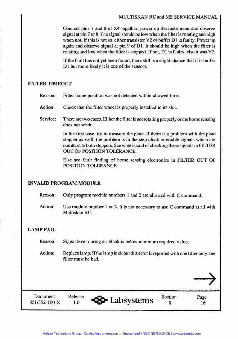
MULTISKAN RC and MS SERVICE MANUAL
Connect pins 7 and 8 of X4 together, power up the instrument and observe signal at pin 7 or 8. The signal should he low when the filter is rotating and high when not. If this is not so, either transistor V2 or buffer Dl is faulty. Power up again and observe signal at pin 9 of Dl. It should be high when the filter is rotating and low when the filter is stopped. If not, D l is faulty, else it was V2.
If the fault has not yet been found, there still is a slight chance that it is buffer D l but more likely it is one of the sensors.
FILTER TIMEOUT
Reason: Filter home position was not detected within allowed time.
Action: Check that the filter wheel is properly installed in its slot.
Service: There are twocases. Either the filter is notrotatingproperly or the home sensing does not work.
In the first case, try to measure the plate. If there is a problem with the plate stepper as well, the problem is in the step clock or enable signals which are common to both steppers. See what is said of checking these signals in FILTER OUT OF POSITION TOLERANCE.
Else see fault finding of home sensing electronics in FILTER OUT OF POSITION TOLERANCE.
INVALID PROGRAM MODULE
Reason:
Action:
LAMP FAIL
Reason:
Action:
Only program module numbers 1 and 2 are allowed with C command.
Use module number 1 or 2. It is not necessary to use C command at all with Multiskan RC.
Signal level during air blank is below minimum required value.
Replace lamp. If the lamp is ok but this error is reported with one filter only, the filter must be bad.
Document Release Section Page 4%- Labsystems 35 11352- 100-X 1 .O 8 16
Artisan Technology Group - Quality Instrumentation ... Guaranteed | (888) 88-SOURCE | www.artisantg.com
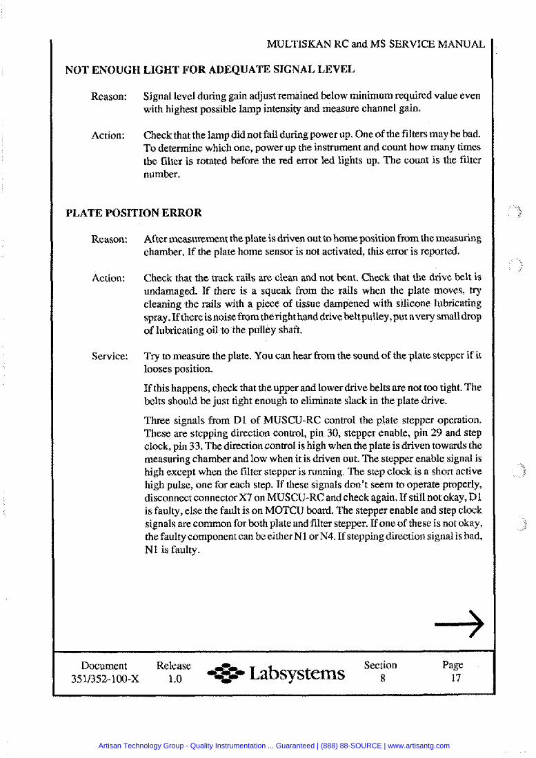
Document Release Section Page *:% Labsystems 351/352-100-X 1 .O -4- 8 17
MULTISKAN RC and MS SERVICE MANUAL
NOT ENOUGH LIGHT FOR ADEQUATE SIGNAL LEVEL
Reason: Signal level during gain adjust remained below minimum required value even with highest possible lamp intensity and measure channel gain.
Action: Check that the lamp did not fail duringpower up. One of the filters may be bad. To determine which one, power up the instrument and count how many times the filter is rotated before the red error led lights up. The count is the filter number.
PLATE POSITION ERROR
Reason: After measurement the plate is driven out to home position from the measuring chamber. If the plate home sensor is not activated, this error is reported.
Action: Check that the track rails are clean and not bent. Check that the drive belt is undamaged. If there is a squeak from the rails when the plate moves, try cleaning the rails with a piece of tissue dampened with silicone lubricating spray. If thereis noise from the right handdrive belt pulley,put avery smalldrop of lubricating oil to the pulley shaft.
Service: Tq to measure the plate. You can hear from the sound of the plate stepper if it looses position.
If this happens, check that the upper and lower drive belts are not too tight. The belts should be just tight enough to eliminate slack in the plate drive.
Three signals from D l of MUSCU-RC control the plate stepper operation. These are stepping direction control, pin 30, stepper enable, pin 29 and step clock, pin 33. The direction control is high when the plate is driven towards the measuring chamber and low when it is driven out. The stepper enable signal is high except when the filter stepper is running. The step clock is a short active high pulse, one for each step. If these signals don't seem to operate properly, disconnect connectorX7 on MUSCU-RC and check again. If still not okay, Dl is faulty, else the fault is on MOTCU board. The stepper enable and step clock signals are common for both plate and filter stepper. If one of these is not okay, the faulty component can be either N1 or N4. If stepping direction signalis bad, Nl is faulty.
Artisan Technology Group - Quality Instrumentation ... Guaranteed | (888) 88-SOURCE | www.artisantg.com
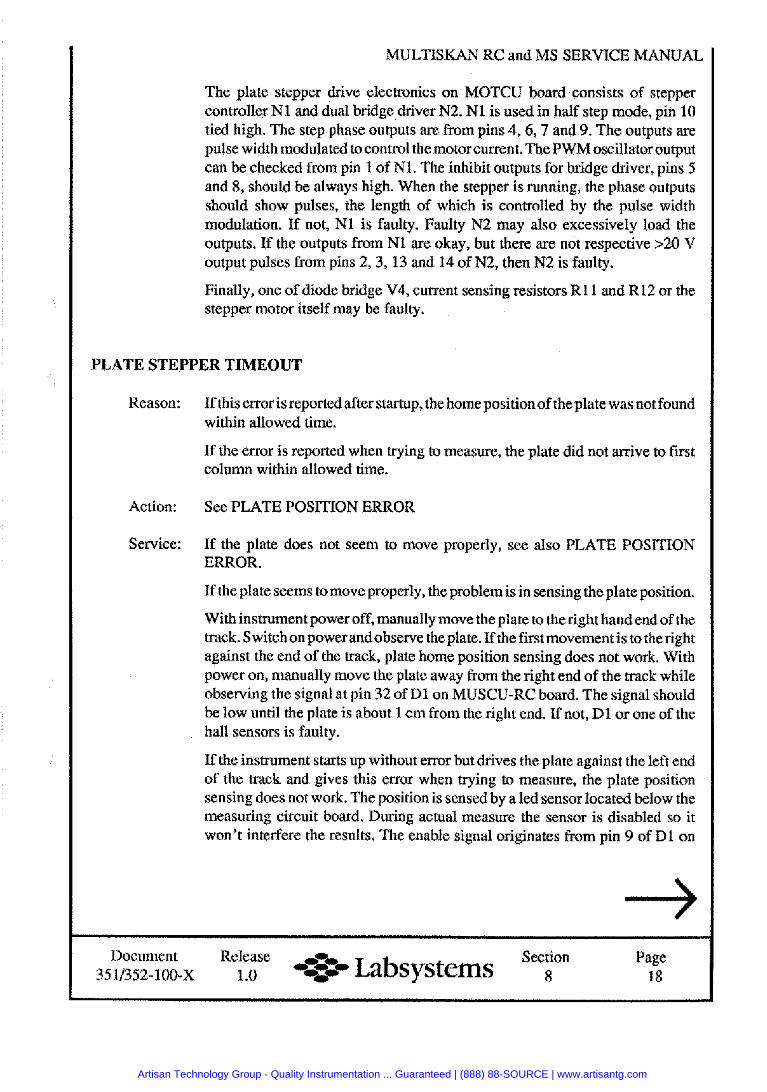
MULTISKAN RC and MS SERVICE MANUAL
The plate stepper drive electronics on MOTCU board consists of stepper controller N1 and dual bridge driver N2. N1 is used in half step mode, pin 10 tied high. The step phase outputs are from pins 4, 6,7 and 9. The outputs are pulse width modulated to control the motor current. The PWMoscillatoroutput can be checked from pin 1 of N1. The inhibit outputs for bridge driver, pins 5 and 8, should be always high. When the stepper is running, the phase outputs should show pulses, the length of which is controlled by the pulse width modulation. If not, N1 is faulty. Faulty N2 may also excessively load the outputs. If the outputs from N1 are okay, but there are not respective >20 V output pulses from pins 2,3, 13 and 14 of N2, then N2 is faulty.
Finally, one of diode bridge V4, current sensing resistors R11 and R12 or the stepper motor itself may be faulty.
PLATE STEPPER TIMEOUT
Reason:
Action:
Service:
If this error is reported after startup, the home position of the plate was not found within allowed time.
If the error is reported when trying to measure, the plate did not arrive to first column within allowed time.
See PLATE POSITION ERROR
If the plate does not seem to move pmperly, see also PLATE POSITION ERROR.
If the plate seems tomove properly, the pmblemis in sensing the plate position.
With instrument power off, manually move the plate to the right handend of the track. Switchon powerandobserve the plate. If the first movement is to theright against the end of the track, plate home position sensing does not work. With power on, manually move the plate away from the right end of the track while observing the signal at pin 32 of Dl on MUSCU-RC board. The signal should be low until the plate is about 1 cm from the right end. If not, D l or one of the hall sensors is faulty.
If the instrument starts up without error but drives the plate against the left end of the track and gives this error when trying to measure, the plate position sensing does not work. The position is sensed by a led sensor located below the measuring circuit board. During actual measure the sensor is disabled so it won't interfere the results. The enable signal originates from pin 9 of Dl on
Document Release Section Page Labsystems 351/352-100-X 1 .O *og 8 18
Artisan Technology Group - Quality Instrumentation ... Guaranteed | (888) 88-SOURCE | www.artisantg.com
MULTISKAN RC and MS SERVICE MANUAL
MUSCU-RC board and first goes to pin 14 of buffer Dl on MOTCU board. The signal is normally high with low periods when the instrument is doing measurement. When the instrument is ready, check the following points on MOTCU board: pin 14 of Dl high, pin 15 of Dl high, collector of V3 low.
If the sensor enable is ok, check the sensor output. The output from the sensor goes first to input pin 1 of buffer D 1 on MOTCU board. From buffer output pin 6 it goes topin 23 of Dl on MUSCU-RC board. The signalis low when the plate is out and should go high about 3 cm before the whole plate is inside the measuring chamber.
TOO MUCH LIGHT, SIGNAL SATURATED
Reason: Duringgain adjustment for agglutination measurement, the signal level was too high even with lowest lamp intensity and measure channel gain.
Action: Contact service.
Document Release ,% Section Page 351/352-100-x 1 .o %:-. Labsystems 8 19
Artisan Technology Group - Quality Instrumentation ... Guaranteed | (888) 88-SOURCE | www.artisantg.com
MULTISKAN RC and MS SERVICE MANUAL
( Testing and Adjusting )
Testing and Adjusting
for
Multiskan MS 352
Document Release -0- Section Page 35113.52-100-x 1 .O -*- Labsystems 8 20
Artisan Technology Group - Quality Instrumentation ... Guaranteed | (888) 88-SOURCE | www.artisantg.com
MULTISKAN RC and MS SERVICE MANUAL
( Testing and Adjusting )
( FOR SERVICE PERSONNEL 1 CONTENTS:
CHECKING THE SUPPLY VOLTAGES
MEASURING THE LAMP VOLTAGE
ADJUSTING THE DISPLAY INTENSITY
SAVING THE FILTERS
CHECKING THE SYNCWRONIZING
ADJUSTING THE CLOCK FREQUENCY
SETTING THE DATE AND TUlE
STORIHG THE SERIAL NUMBER
FOCUSING THE LAMP
CHECKING THE AJD-OFFSET
ADJUSTING THE PRINTER (option)
TEST PROGRAMS
PROGRAM STORE TEST
TEST MEASUREMENTS
REQUIRED EQUIPMENT: - Multimeter
- Oscilloscope
- Detergent plate (0.1% TWEEN 190 @/well)
- NDF-cassette
- Test connector
- Frequency counter
- Printer
- If you do not have the filters specified here, use those you have.
Document Release Section Page 35113.52- 100-x 1.0 -7 Labsystems 8 21
Artisan Technology Group - Quality Instrumentation ... Guaranteed | (888) 88-SOURCE | www.artisantg.com
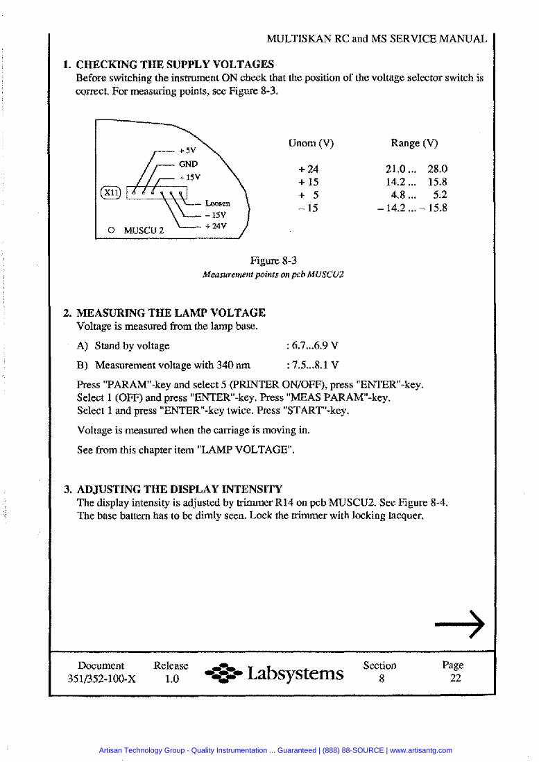
MULTISKAN RC and MS SERVICE MANUAL
1. CHECKING THE SUPPLY VOLTAGES Before switching the instrument ON check that the position of the voltage selector switch is correct. For measuring points, see Figure 8-3.
Unom (V) Range (V)
+ 24 21.0 ... 28.0 + 15 14.2 ... 15.8 + 5 4.8 ... 5.2
Loosen - 15 - 14.2 ... - 15.8 - 15v
0 MUSCU2 + 2av
Figure 8-3 Measurement points on pcb MUSCUZ
2. MEASURING THE LAMP VOLTAGE Voltage is measured from the lamp base.
A) Stand by voltage : 6.7 ... 6.9 V
B) Measurement voltage with 340 nm : 7.5...8.1 V
Press "PARAM-key and select 5 (PRINTER ONIOFF), press "ENTER-key. Select 1 (OFF) and press "ENTER-key. Press "MEAS PARAMw-key. Select 1 and press "ENTERw-key twice. Press "START-key.
Voltage is measured when the carriage is moving in.
See from this chapter item "LAMP VOLTAGE.
3. ADJUSTING THE DISPLAY INTENSITY The display intensity is adjusted by trimmer R14 on pcb MUSCU2. See Figure 8-4. The base battern has to be dimly seen. Lock the trimmer with locking lacquer.
Document Release ,r~, Section Page 1.0 -+=..- Labsystems 8 22
Artisan Technology Group - Quality Instrumentation ... Guaranteed | (888) 88-SOURCE | www.artisantg.com
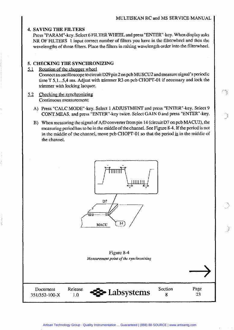
MULTISKAN RC and MS SERVICE MANUAL
4. SAVING THE FILTERS Press "PARAM-key. Select 6FILTER WHEELandpress "ENTl2R-key. Whendisplay asks NR OF FILTERS 1 input correct number of filters you have in the filterwheel and then the wavelengths of those filters. Place the filters in raising wavelength order into the filterwheel.
5. CHECKING THE SYNCHRONIZING Rotation of the chopwer wheel Connect an oscilloscope to circuit D29pin 2 onpcb MUSCU2 and measure signal's periodic time T 5,l ... 5,4 ms. Adjust with trimmer R3 on pcb CHOPT-01 if necessary and lock the trimmer with locking lacquer.
Checkine the svnchronizirlg Continuous measurement:
A) Press "CALC MODEv-key. Select 1 ADJUSTMENT and press "ENTER-key. Select 9 CONT.MEAS. and press "ENTER-key twice. Select GAIN 0 and press "ENTER-key.
B) When measuring the signal of A/D converter from pin 14 (circuit D7 on pcb MACU2), the measuring period has to be in the middle of the channel. See Figure 8-4. If the period is not in the middle of the channel, move pcb CHOPT-01 so that the period jS in the middle of the channel.
Figure 8-4 Measurement point of the synchronizing
Document Release Section Page 35 11352- loo-x 1.0 -%a Labsystems 8 23
Artisan Technology Group - Quality Instrumentation ... Guaranteed | (888) 88-SOURCE | www.artisantg.com
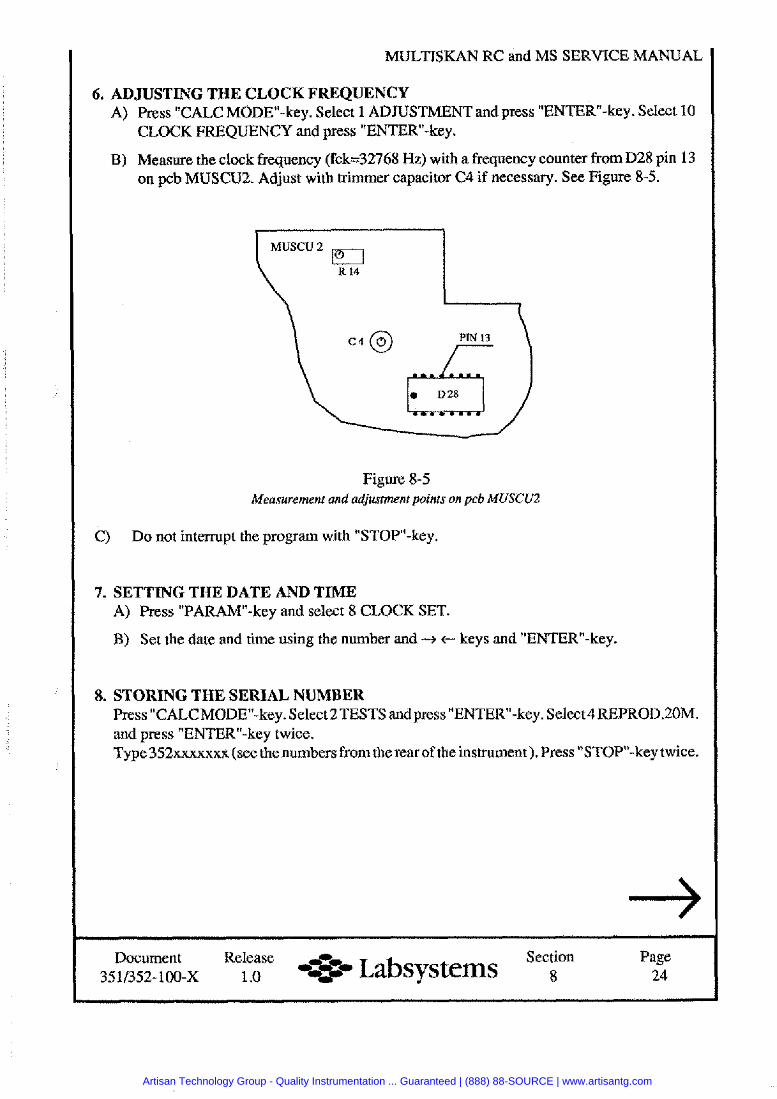
MULTISKAN RC and MS SERVICE MANUAL
6. ADJUSTING THE CLOCK FREQUENCY A) Press "CALC MODEv-key. Select 1 ADJUSTMENTandpress "ENTER-key. Select 10
CLOCK FREQUENCY and press "ENTER-key.
B) Measure the clock frequency (fck=32768 Hz) with a frequency counter from D28 pin 13 on pcb MUSCU2. Adjust with trimmer capacitor C4 if necessary. See Figure 8-5.
Figure 8-5 Measurement and adjustment points on pcb MUSCUZ
C) Do not interrupt the program with "STOP"-key.
7. SETTING THE DATE AND TIME A) Press "PARAW-key and select 8 CLOCK SET.
B) Set the date and time using the number and -+ c keys and "ENTER-key.
8. STORING THE SERIAL NUMBER Press "CALCMODEW-key. Select 2TESTS and press "ENTER-key. Select4REPROD.ZOM. and press "ENTER-key twice. Type352xxxxxxx (see thenumbers from the rear of the instrument). Press "STOPn-key twice.
Document Release Section Page 3 ~ 3 5 2 - 1 0 0 - x 1 .o * Labsystems 8 24
Artisan Technology Group - Quality Instrumentation ... Guaranteed | (888) 88-SOURCE | www.artisantg.com
MULTISKAN RC and MS SERVICE MANUAL
9. FOCUSING THE LAMP A) Check that the filter and track cover are at their places.
B) Press "CALC MODE-key. Select 1 ADJUSTMENT and press "ENTER-key. Select 3 LIGHTALLandpress "ENTER-key. Select GAINX (X=level where the readings are not yet HIGH) and press "ENTER-key.
C) Adjust the distance between the lamp and optics so that the maximum value (> 2000) is on the display.
D) Check with GAIN 0 that the smallest channel value is over 350. If the value is lower than 350, check the components of the light path (lamp, filter, fibre bundle, lenses ... )
10. CHECKING THE AID OFFSET a n ? the offsa Instrument must be warm, installed with a filter wheel and track cover.
A) Press "CALC MODE-key. Select 1 ADJUSTMENTS and press "ENTERw-key. Select 2 AID OFFSET and press "ENTER-key.
B) Select 405 and press "ENTERu-key.
C) Input "0" for "GAIN".
D) Adjust the trimmerRl2onpcb MACU2 to setthevalue on theright handsideof thedisplay to 40. After adjusting re-install the track cover and re-check the value.
Checkine the ligh- 10.2.1 Minimum light
A) Select 6 LIGHT CHANNEL and press "ENTER-key.
33) Select 405 nm and press "ENTER-key.
C) Select channels A( ... H) and press "ENTERM-key. Select GAINOandpress "ENTERv-key. Before selecting a new channel press "STOP-key and "ENTERw-key twice. The lowest channel value has to be 350. If is not, check the components of the light path.
10.2.2 Checking the detector electronics (D/AC)
A) Select "3 LIGHT ALL" and press "ENTER-key. Select filter 1 (340 nm) and press "ENTERw-key. Select GAIN 0 and press "ENTERN-key.
B) If the maximum value is over 350 on the display, carry out the following measurements, otherwise go to the point C).
- Select GAIN 1( ... 7) and press "ENTER-key. When selecting another GAIN press "STOP-key once and "ENTERw-key twice. COUNT-value has to increase 180 ... 400 COUNTSIgain step.
Document Release ,% Section Page 35 11352-100-~ 1 .O -4-- Labsystems 8 25
Artisan Technology Group - Quality Instrumentation ... Guaranteed | (888) 88-SOURCE | www.artisantg.com
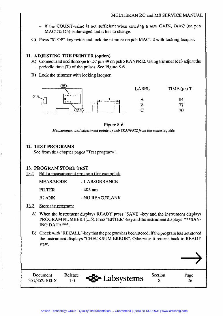
MULTISKAN RC and MS
- If the COUNT-value is not sufficient when entering a new GAIN, DIAC (on pcb MACU2: D5) is damaged and it has to change.
C) Press "STOP-key twice and lock the trimmer on pcb MACU2 with locking lacquer,
11. ADJUSTING THE PRINTER (option) A) Connect and oscilloscope to D7 pin 39 on pcb SKANPR12. Using trimmer R13 adjust the
periodic time (T) of the pulses. See Figure 8-6.
B) Lock the trimmer with locking lacquer.
LABEL TIME (ps) T
T A 84 B 77 C 70
Figure 8-6 Measurement and adjustment points on pcb SKANPRI2 from the soldering side
12. TEST PROGRAMS See from this chapter pages "Test programs".
13. PROGRAM STORE TEST Ed Edit a measurement oromam (for examolel;
MEAS .MODE - I ABSORBANCE
FTLTER - 405 nm
BLANK - NO REAG.BLANK
13,2 Store t h e w w m x
A) When the instrument displays READY press "SAVEv-key and the instrument displays PROGRAMNUMBER 1( ... 5).Press "ENTER-key andtheinstrument displays ***SAV- ING DATA***.
B) Check with "RECALL"-key that the program has been stored. If the program has not stored the instrument displays "CHECKSUM ERROR. Otherwise it retums back to READY state.
Document Release Section Page es- Labsystems 35 11352- 100-X 1 .O 8 26
Artisan Technology Group - Quality Instrumentation ... Guaranteed | (888) 88-SOURCE | www.artisantg.com
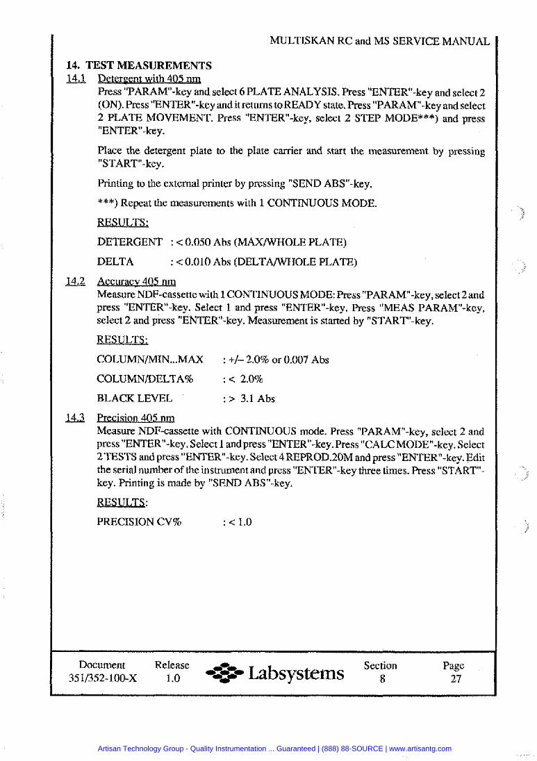
MULTISKAN RC and MS SERVICE MANUAL
14. TEST MEASUREMENTS &jJ =nt with 405 nm
Press "PARAM-key and select 6 PLATE ANALYSIS. Press "ENTERw-key and select 2 (ON). Press "ENTER-key andit returns toREADY state. Press "PARAM"-key and select 2 PLATE MOVEMENT. Press "ENTER-key, select 2 STEP MODE***) and press "ENTER-key.
Place the detergent plate to the plate carrier and start the measurement by pressing "START-key.
Printing to the external printer by pressing "SEND ABS"-key.
***) Repeat the measurements with 1 CONTINUOUS MODE.
RESULTS;
DETERGENT : < 0.050 Abs (MAXWHOLE PLATE)
DELTA : < 0.010 Abs (DELTAANWOLE PLATE)
&2 Accuracv 405 n q Measure NDF-cassette with 1 CONTINUOUS MODE: Press "PARAM-key, select 2and press "ENTER-key. Select 1 and press "ENTER-key. Press "MEAS PARAM"-key, select 2 and press "ENTER-key. Measurement is started by "START-key.
RESULTS:
COLUMNMIN ... MAX : +/- 2.0% or 0.007 Abs
COLUMNDELTA% : < 2.0%
BLACK LEVEL : > 3.1 Abs
U3 Precis . . ion 405 nrq
Measure NDF-cassette with CONTINUOUS mode. Press "PARAM-key, select 2 and press "ENTER-key. Select 1 and press "ENTER-key. Press TALCMODE"-key. Select 2TESTS and press "ENTER"-key. Select 4REPROD.20M and press "ENTERn-key. Edit the serial number of the instrument and press "ENTERw-key three times. Press "START- key. Printing is made by "SEND ABSM-key.
RESULTS:
PRECISION CV% : < 1.0
Document Release -0- Section Page 35 11352- 100-x 1.0 -+w Labsystems 8 27
Artisan Technology Group - Quality Instrumentation ... Guaranteed | (888) 88-SOURCE | www.artisantg.com
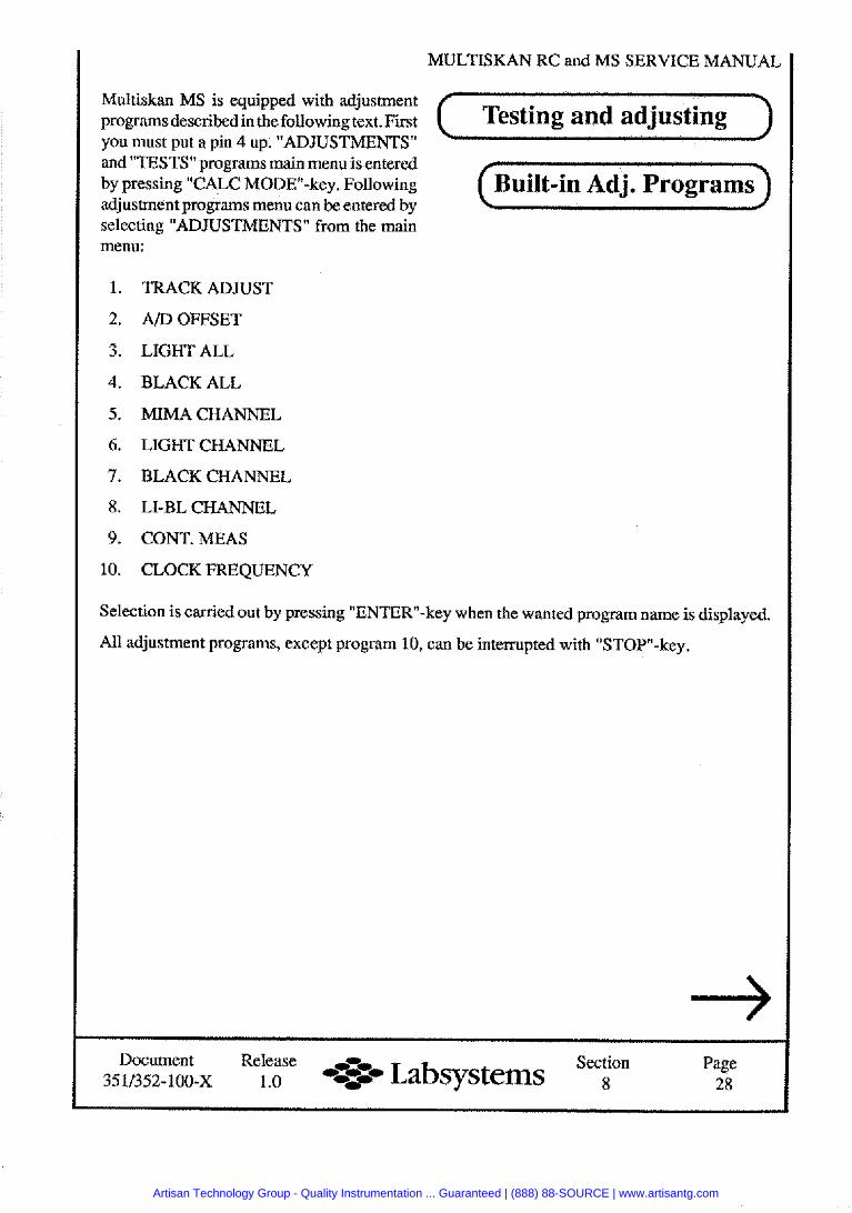
MULTISKAN RC and MS SERVICE MANUAL
Multiskan MS is equipped with adjustment programsdescribedinthefollowing text. First Testing and adjusting you must put a pin 4 up. "ADJUSTMENTS" and "TESTS" programs main menu is entered by pressing TALC MODEw-key. Following uik-in Adj. Programs adjustment programs menu can be entered by selecting "ADJUSTMENTS" from the main menu:
1. TRACK ADJUST
2. ADOFFSET
3. LIGHT ALL
4. BLACK ALL
5. MIMACHANNEL
6. LIGHT CHANNEL
7. BLACK CHANNEL
8. LI-BL CHANNEL
9. CONT. MEAS
10. CLOCK FREQUENCY
Selection is carried out by pressing "ENTER-key when the wanted program name is displayed.
All adjustment programs, except program 10, can be interrupted with "STOP-key.
Document Release Section Page d2 Labsystems 3511352-100-X 1.0 8 28
Artisan Technology Group - Quality Instrumentation ... Guaranteed | (888) 88-SOURCE | www.artisantg.com
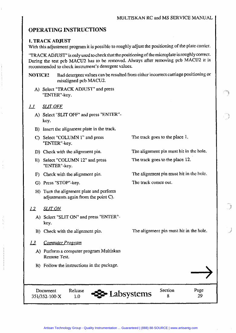
MULTISKAN RC and MS SERVICE MANUAL
OPERATING INSTRUCTIONS
1. TRACK ADJUST With this adjustment program it is possible to roughly adjust the positioning of the plate carrier.
"TRACK ADJUST isonly used tocheck that thepositioningof themicroplate isroughly correct. During the test pcb MACU2 has to be removed. Always after removing pcb MACU2 it i s recommended to check instrument's detergent values.
NOTICE! Bad detergent values can be resulted from either incorrect carriage positioning or misaligned pcb MACU2.
A) Select "TRACK ADJUST and press "ENTER-key.
L L s L m E E A) Select "SLIT OFF" and press "ENTER-
key.
B) Insert the alignment plate in the track.
C) Select "COLUMN 1" and press "ENTER1'-key.
D) Check with the alignment pin.
E) Select "COLUMN 12" and press "ENTER"-key.
F) Check with the alignment pin.
G) Press "STOP-key.
H) Turn the alignment plate and perform adjustments again from the point C).
& & i L Q M A) Select "SLIT O N and press "ENTERu-
key.
B) Check with the alignment pin.
Comuuter Program
A) Perform a computer program Multiskan Remote Test.
B) Follow the instructions in the package.
The track goes to the place 1.
The alignment pin must hit in the hole.
The track goes to the place 12.
The alignment pin must hit in the hole.
The track comes out.
The alignment pin must hit in the hole.
Document Release ,, Section Page 3 ~ ~ 2 - 1 0 0 - x 1 .O --=& Labsystems 8 29
Artisan Technology Group - Quality Instrumentation ... Guaranteed | (888) 88-SOURCE | www.artisantg.com
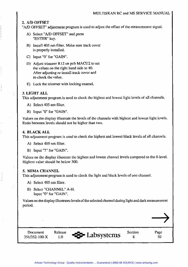
MULTISKAN RC and MS SERVICE MANUAL
2. AID OFFSET "AID OFFSET adjustment program is used to adjust the offset of the measurement signal.
A) Select "AID OFFSET and press "ENTER key.
B) Install 405 nm filter. Make sure track cover is properly installed.
C) Input " 0 for "GAIN.
D) Adjust trimmer R12 on pcb MACU2 to set the values on the right hand side to 40. After adjusting re-install track cover and re-check the value.
E) Lock the trimmer with locking enamel.
3. LIGHT ALL This adjustment program is used to check the highest and lowest light levels of all channels.
A) Select 405 nm filter.
B) Input " 0 for "GAIN.
Values on the display illustrate the levels of the channels with highest and lowest light levels. Ratio between levels should not be higher than two.
4. BLACK ALL This adjustment program is used to check the highest and lowest black levels of all channels.
A) Select 405 nm filter.
B) Input "7" for "GAIN.
Values on the display illustrate the highest and lowest channel levels compared to the 0-level. Highest value should be below 300.
5. MIMA CHANNEL This adjustment program is used to check the light and black levels of one channel.
A) Select 405 nm filter.
B) Select "CHANNEL" A-H. Input " 0 for "GAIN".
Values on the display illustrates levels of the selected channel during light and dark measurement period.
Document Release Section Labsystems Page 3511352- 100-X 1.0 30
Artisan Technology Group - Quality Instrumentation ... Guaranteed | (888) 88-SOURCE | www.artisantg.com
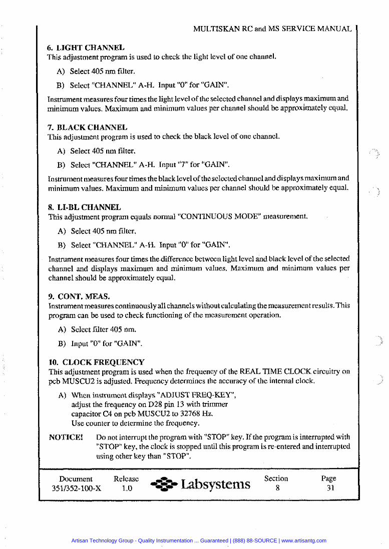
MULTISKAN RC and MS
6. LIGHT CHANNEL This adjustment program is used to check the light level of one channel.
A) Select 405 nm filter.
B) Select "CHANNEL A-H. Input " 0 for "GAIN.
Instrument measures four times the light level of the selected channel and displays maximum and minimum values. Maximum and minimum values per channel should be approximately equal.
7. BLACK CHANNEL This adjustment program is used to check the black level of one channel.
A) Select 405 nm filter.
B) Select "CHANNEL A-H. Input "7" for "GAIN.
Instrument measures four times the black level of the selectedchannel and displays maximum and minimum values. Maximum and minimum values per channel should be approximately equal.
8. LI-BL CHANNEL This adjustment program equals normal "CONTINUOUS MODE" measurement.
A) Select 405 nm filter.
B) Select "CHANNEL A-H. Input " 0 for "GAIN".
Instrument measures four times the difference between light level and black level of the selected channel and displays maximum and minimum values. Maximum and minimum values per channel should be approximately equal.
9. CONT. MEAS. Instrument measures continuously all channels without calculating the measurement results. This program can be used to check functioning of the measurement operation.
A) Select filter 405 nm.
B) Input " 0 for "GAIN".
10. CLOCK FREQUENCY This adjustment program is used when the frequency of the REAL TIME CLOCK circuitry on pcb MUSCU2 is adjusted. Frequency determines the accuracy of the internal clock.
A) When instrument displays "ADJUST FREQ-KEY", adjust the frequency on D28 pin 13 with trimmer capacitor C4 on pcb MUSCU2 to 32768 Hz. Use counter to determine the frequency.
NOTICE! Do not interrupt the program with "STOP" key. If the program is interrupted with "STOP key, the clock is stopped until this program is re-entered and intempted using other key than "STOP.
Document Release ,ri, Section Page 3511x52-100-x 1 .O -*#- Labsystems 8 3 1
Artisan Technology Group - Quality Instrumentation ... Guaranteed | (888) 88-SOURCE | www.artisantg.com
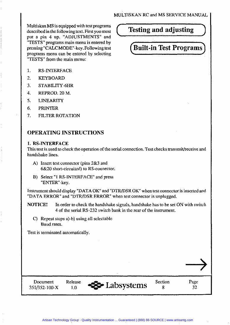
MULTISKAN RC and MS SERVICE
Multiskan MS is equipped with test programs describedin the following text. First youmust Testing and adjusting put a pin 4 up. "ADJUSTMENTS" and "TESTS" programs main menu is entered by pressing TALCMODE-key. Following test uilt-in Test Programs programs menu can be entered by selecting "TESTS" from the main menu:
1. RS-INTERFACE
2. KEYBOARD
3. STABILITY-6HR
4. REPROD. 20 M.
5. LINEARITY
6. PRINTER
7. FILTER ROTATION
OPERATING INSTRUCTIONS
1. RS-INTERFACE This test is used to check the o~eration of the serial connection. Test checks transmitheceive and handshake lines.
A) Insert test connector (pins 2&3 and 6&20 short-circuited) to RS-connector.
B) Select "1 RS-INTERFACE and press "ENTER-key.
Instrument should display "DATA O K and "DTRfDSR O K when test connector is inserted and "DATA ERROR and "DTRfDSR ERROR" when test connector is unplugged.
NOTICE! In order to check the handshake signals, handshake has to be set ON with switch 4 of the serial RS-232 switch bank in the rear of the instrument.
C) Repeat steps a)-b) using all selectable Baud rates.
Test is terminated automatically.
Document Release ,% Section Page 3511352-loo-x 1 .o --pC, Labsystems 8 32
Artisan Technology Group - Quality Instrumentation ... Guaranteed | (888) 88-SOURCE | www.artisantg.com
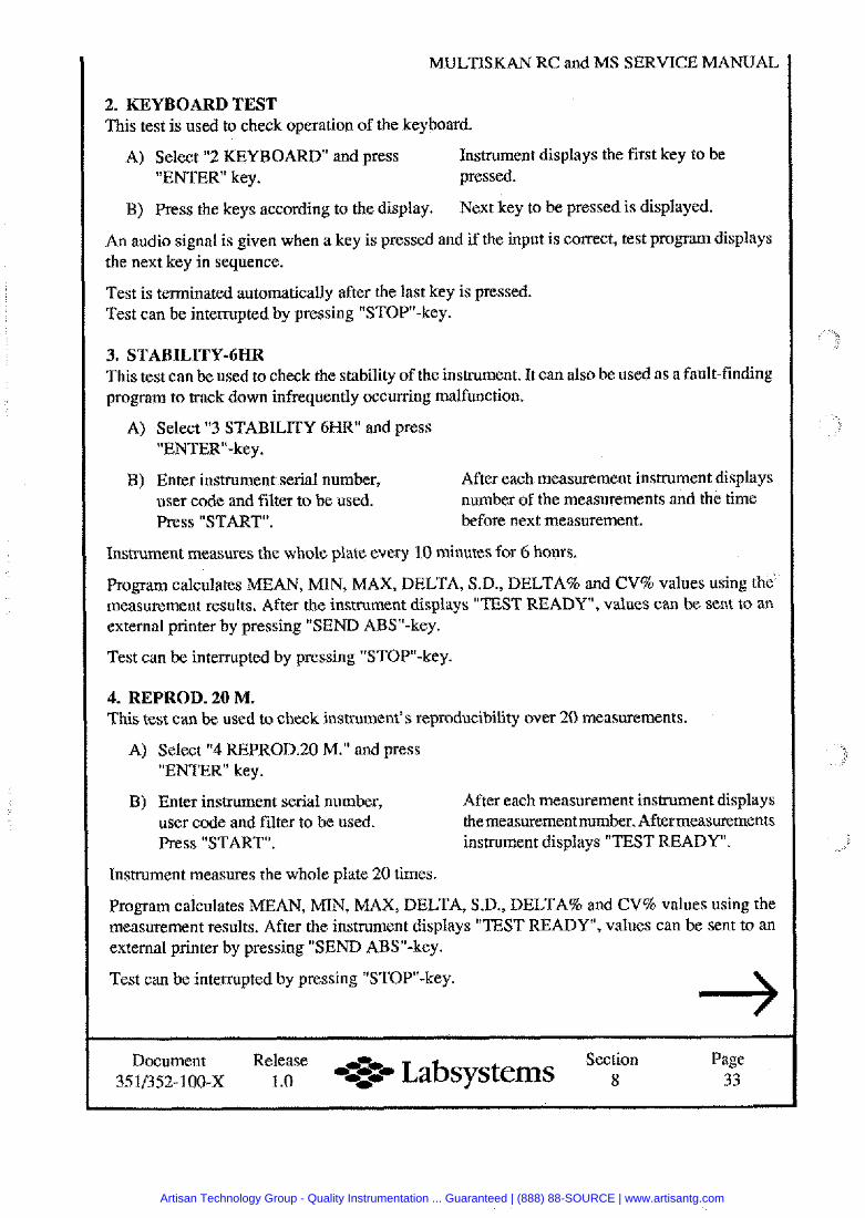
MULTISKAN RC and MS SERVICE MANUAL
2. KEYBOARD TEST This test is used to check operation of the keyboard.
A) Select "2 KEYBOARD" and press Instrument displays the first key to be "ENTER key. pressed.
B) Press the keys according to the display. Next key to be pressed is displayed.
An audio signal is given when a key is pressed and if the input is correct, test program displays the next key in sequence.
Test is terminated automatically after the last key is pressed. Test can be interrupted by pressing "STOP-key.
3. STABILITY-6HR This test can be used to check the stability of the instrument. It can also be used as a fault-finding program to track down infrequently occurring malfunction.
A) Select "3 STABILITY 6HR" and press "ENTER-key.
B) Enter instrument serial number, After each measurement instrument displays user code and filter to be used. number of the measurements and the time Press "START". before next measurement.
Instrument measures the whole plate every 10 minutes for 6 hours.
Program calculates MEAN, MIN, MAX, DELTA, S.D., DELTA% and CV% values using the measurement results. After the instrument displays "TEST READY, values can be sent to an external printer by pressing "SEND ABSW-key.
Test can be interrupted by pressing "STOP-key.
4. REPROD. 20 M. This test can be used to check instrument's reproducibility over 20 measurements.
A) Select "4 REPROD.20 M." and press "ENTER key.
B) Enter instrument serial number, After each measurement instrument displays user code and filter to be used. themeasurement number. Aftermeasurements Press "START". instrument displays "TEST READY.
Instrument measures the whole plate 20 times.
Program calculates MEAN, MIN, MAX, DELTA, S.D., DELTA% and CV% values using the measurement results. After the instrument displays "TEST READY, values can be sent to an external printer by pressing "SEND ABS"-key.
Test can be interrupted by pressing "STOP-key.
Document Release ,% Section Page 3511352-100-x 1 .O %:..- Labsystems 8 33
Artisan Technology Group - Quality Instrumentation ... Guaranteed | (888) 88-SOURCE | www.artisantg.com
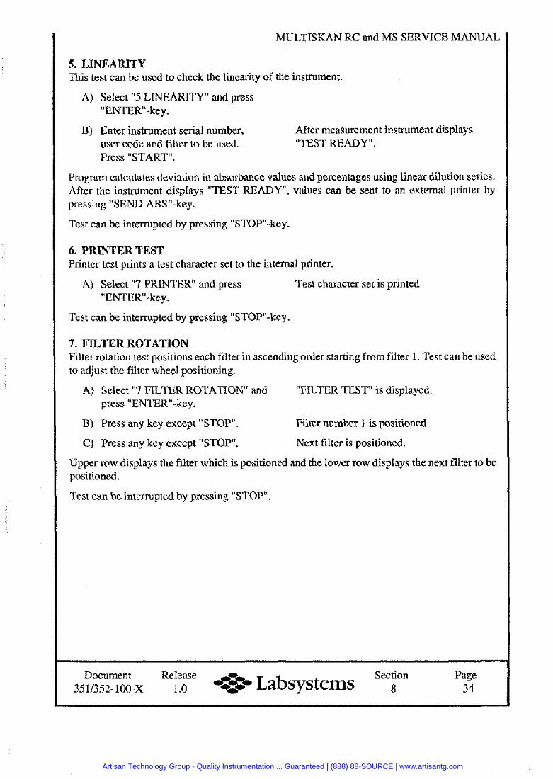
MULTISKAN RC and MS
5. LINEARITY This test can be used to check the linearity of the instrument.
A) Select "5 LINEARITY and press "ENTER-key.
B) Enter instrument serial number, After measurement instrument displays user code and filter to be used. "TEST READY ". Press "START".
Program calculates deviation in absorbance values and percentages using linear dilution series. After the instrument displays "TEST READY", values can be sent to an external printer by pressing "SEND ABSn-key.
Test can be interrupted by pressing "STOP-key.
6. PRINTER TEST Printer test prints a test character set to the internal printer.
A) Select "7 PRINTER and press Test character set is printed "ENTER-key.
Test can be interrupted by pressing "STOP-key.
7. FILTER ROTATION Filter rotation test positions each filter in ascending order starting from filter 1. Test can be used to adjust the filter wheel positioning.
A) Select "7 FILTER ROTATION' and "FILTER TEST" is displayed. press "ENTER"-key.
B) Press any key except "STOP". Filter number 1 is positioned.
C) Press any key except "STOP. Next filter is positioned.
Upper row displays the filter which is positioned and the lower row displays the next filter to be positioned.
Test can be interrupted by pressing "STOP.
Document Release --- Section Page 3.511352-100-~ 1 .O Labsystems 8 34
Artisan Technology Group - Quality Instrumentation ... Guaranteed | (888) 88-SOURCE | www.artisantg.com
Artisan Technology Group - Quality Instrumentation ... Guaranteed | (888) 88-SOURCE | www.artisantg.com
MULTISKAN RC and MS SERVICE MANUAL
Power supply
Contents
SUBJECT DOCUMENT PAGE
Cover page .............................................................................................. 1 Contents .................................................................................................. 2 SR 924100 Parts layout ............................... 4092 ................................. 3 SR 924100 Parts layout ............................... 4104 3. ............................ 4 SR 924100 Schematic diagram ................... 4 101 20 ........................... 5 -
Document Release -P i t Section 35 1/352- 100-x 1 .O --st Labsystems
Page 2
Artisan Technology Group - Quality Instrumentation ... Guaranteed | (888) 88-SOURCE | www.artisantg.com
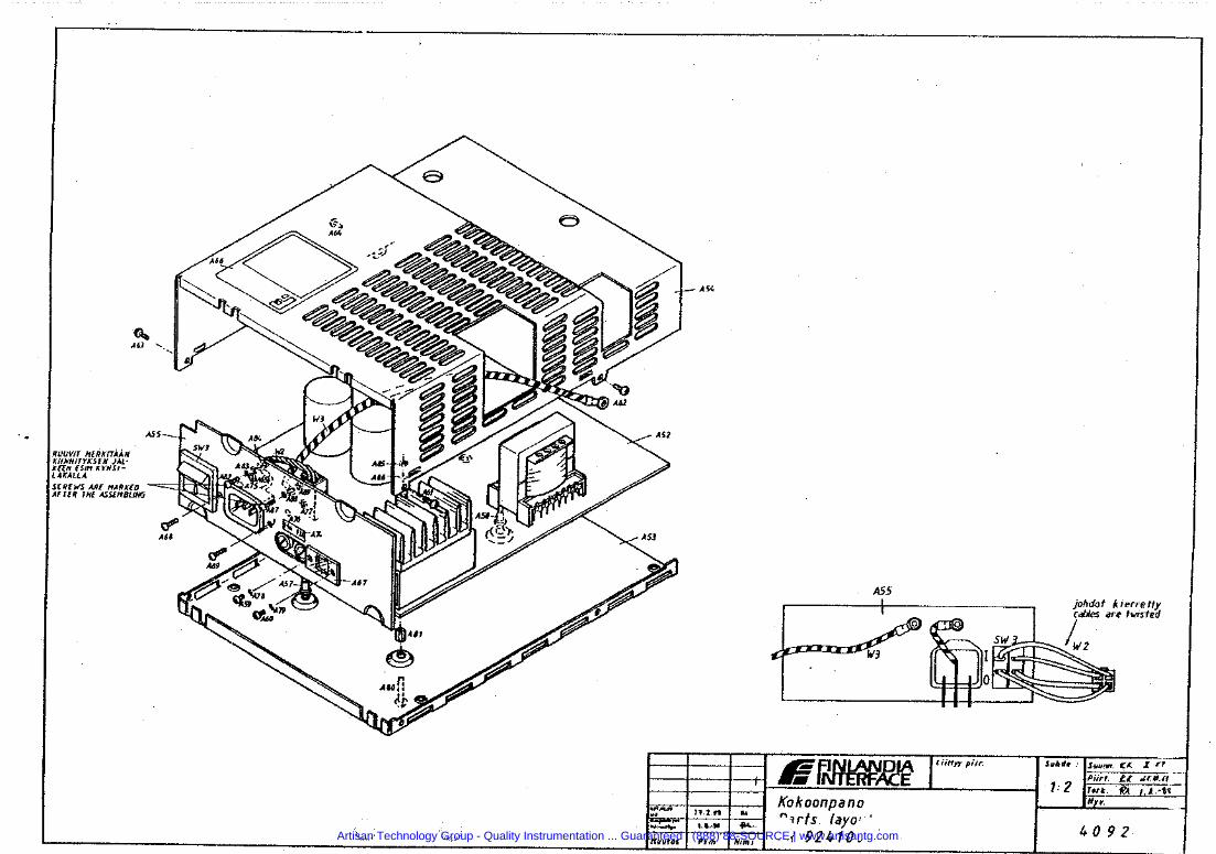
Artisan Technology Group - Quality Instrumentation ... Guaranteed | (888) 88-SOURCE | www.artisantg.com
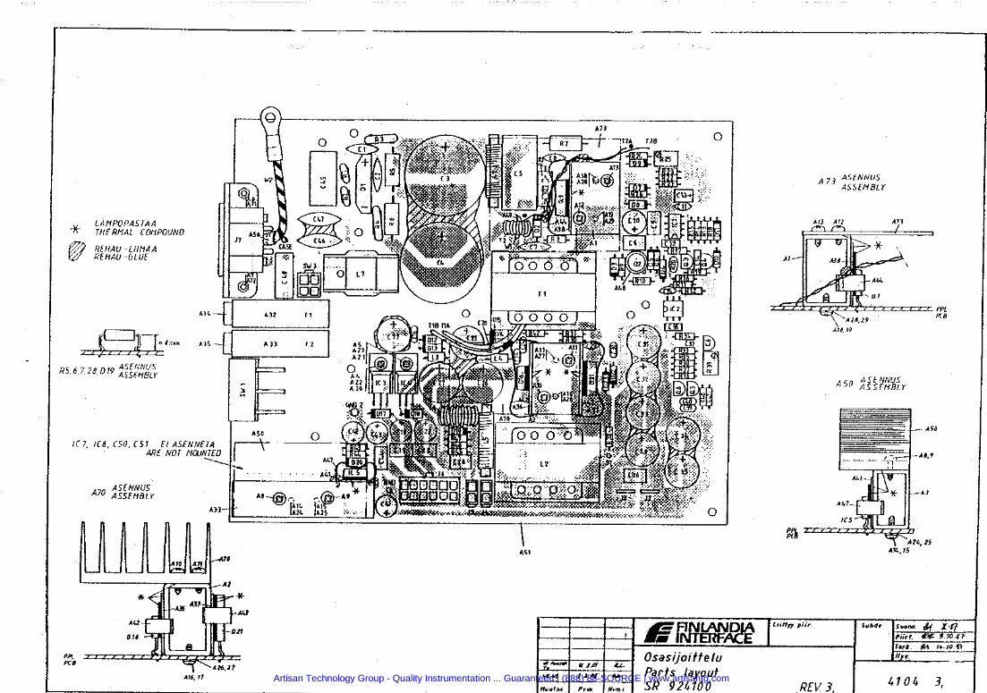
Artisan Technology Group - Quality Instrumentation ... Guaranteed | (888) 88-SOURCE | www.artisantg.com
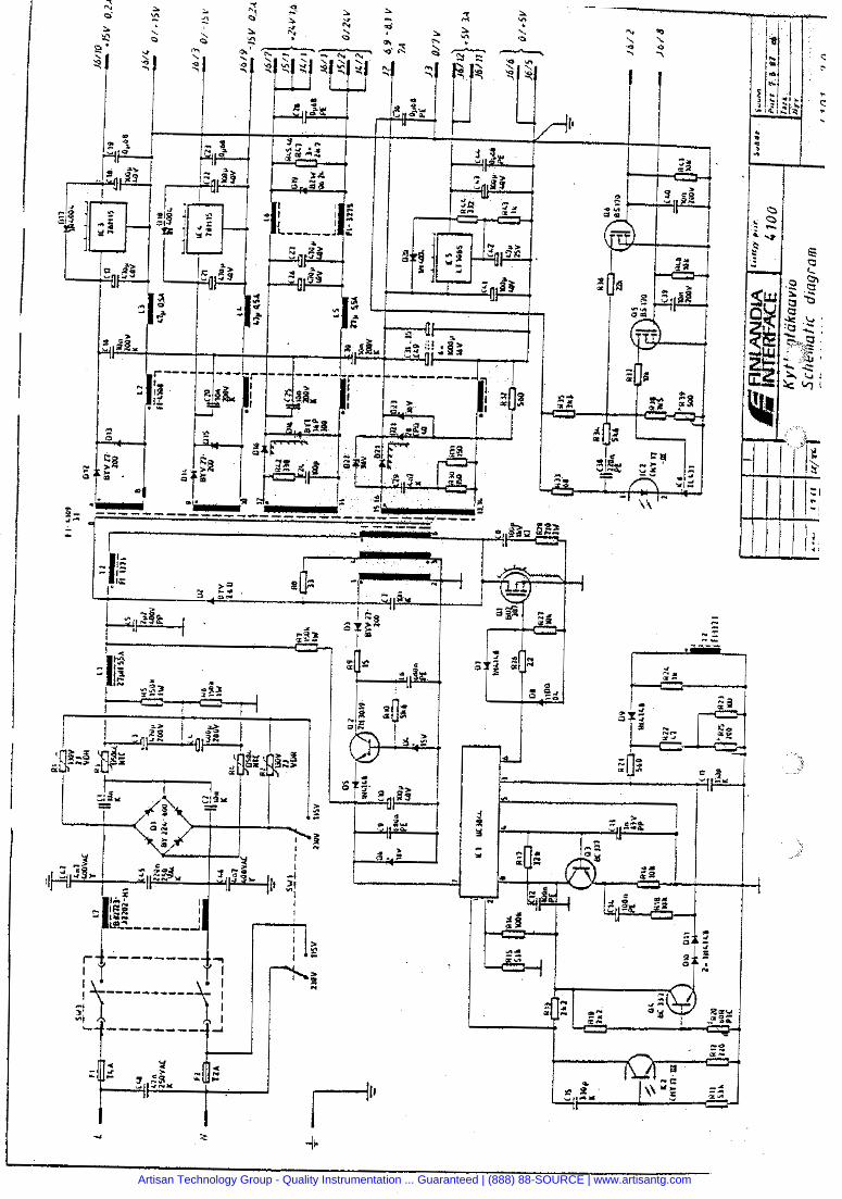
1 4- e c. -a Po'
Artisan Technology Group - Quality Instrumentation ... Guaranteed | (888) 88-SOURCE | www.artisantg.com

, 4N 3269 page 1/17
IPS 93
TECHNICAL MANUAL
Artisan Technology Group - Quality Instrumentation ... Guaranteed | (888) 88-SOURCE | www.artisantg.com
date 22.08.1996
I. TECHNICAL SPECIFICATIONS
1.1 INPUT AND GENERAL
1.2 OUTPUTS AND GENERAL
1.2.1 OUTPUT 1:5,1V
1.2.2 OUTPUT 2: 6,8-8,OV
1.2.3 OUTPUT 3: 24V
1.2.4 OUTPUTS 4 AND 5: k15V
2. WORKING PRINCIPLE
2.1 INPUT
2.2 OUTPUTS
3. CONNECTORS
4. SCHEMATIC DIAGRAM
5. LAYOUT
6. ASSEMBLY
4N 3269 page 2/17
change date - appr. . . . . . . . . . . . . . . .. . . . . . . . . . . . . ..
7. PART LISTS, ASSEMBLY AND POWER BOARD
8. TROUBLESHOOTING AND REPAIR PROCEDURES
#
Artisan Technology Group - Quality Instrumentation ... Guaranteed | (888) 88-SOURCE | www.artisantg.com
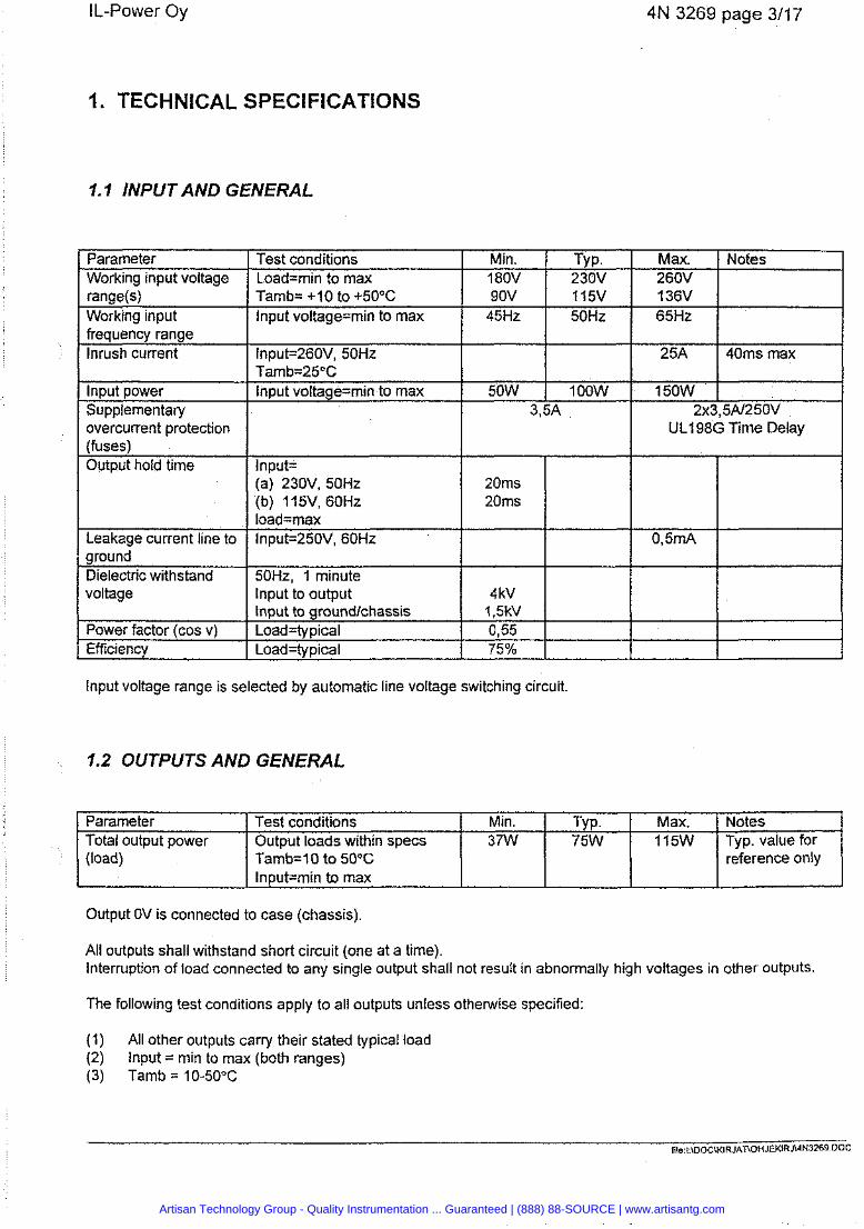
4N 3269 page 3/17
I. TECHNICAL SPECIFICATIONS
1.1 INPUT AND GENERAL
Parameter Working input voltage
Working input frequency range Inrush current
lnput power Supplementary overcurrent protection
Test conditions I Min. TYP. I Max. 1 Notes
Tamb= + I0 to +50°C Input voltage=min to max
Load=min to max 1 180V 1 230V I 260V I
lnput=260V, 50Hz Tamb=2!j°C Input voltage=min to max
lnput voltage range is selected by automatic line voltage switching circuit.
1.2 OUTPUTS AND GENERAL
90V 45Hz
(fuses) Output hold time
Leakage current line to ground Dielectric withstand voltage
Power factor (cos v) Efficiency
50W
1 15V 50Hz
Input= (a) 230V, 50Hz (b) 1 15V, 60Hz load=max lnput=250V, 60Hz
50Hz, 1 minute Input to output Input to groundlchassis Load=typical Load=typical
Output OV is connected to case (chassis).
136V 65Hz
1 OOW
Parameter Total output power (load)
I Input=min to max
All outputs shall withstand short circuit (one at a time). Interruption of load connected to any single output shall not result in abnormally high voltages in other outputs.
3,5A
20ms 20ms
4kV 1,5kV 0,55 75%
Min. 37W
Test conditions Output loads within specs Tamb=lO to 50°C
The following test conditions apply to all outputs unless otherwise specified:
2x3,5A/2 50V UL198G Time Delay
25A
150W
0,5mA
I
(1) All other outputs carry their stated typical load (2) lnput = min to max (both ranges) (3) Tamb = 10-50°C
40ms max
TYP. 75W
I
Max. 1 15W
Notes Typ. value for reference only
Artisan Technology Group - Quality Instrumentation ... Guaranteed | (888) 88-SOURCE | www.artisantg.com
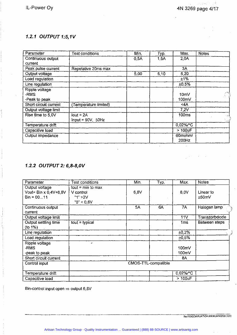
4N 3269 page 4/17
1.2. I OUTPUT l:5, I V
I current I I I
Parameter Continuous output
Test conditions Min. TY P. 0,5A 1,5A
Peak pulse current Output voltage Load reaulation
I Peak to peak 1 1 1
Repetative 20ms max 5,OO 5,lO
- Line regulation Ripple voltage -RMS
I Short circuit current I (Temperature limited) ! 1
I t
I Out~ut voltaae limit I I I
I Temperature drift I I I
is; time ~O%,OV
Capacitive load Output impedance
lout = 2A h u t = 90V. 50Hz
1.2.2 OUTPUT 2: 6,8-8,OV
Output voltage limit I 1 Output settling time 1 lout = typical -
I - . [ (to 1 %) I
Min.
6,8V
5A
Parameter Output voltage Vout= Bin x 0,4V+6,8V Bin = 00 ... 11
I Continuous output current
Test conditions lout = min to max V control
'I 1 I' >2v "0" < 0,8V
Line regulation Load regulation Ripple voltage
Max. Notes 2,OA
e
Short circuit current Control input
Tvo. I Max. I Notes I
I CMOS-TTL
I 8,OV I Linear to
11V 1 Transzorbdiode I ms I Between steps
I OOmV 8A
compatible
Bin-control input open 3 output 6,8V
Temperature drift Capacitive load
file I \OOCU<lRJAT\OHJEKIRJ\4N3269 DOC
0,02%1°C > 100uF
Artisan Technology Group - Quality Instrumentation ... Guaranteed | (888) 88-SOURCE | www.artisantg.com
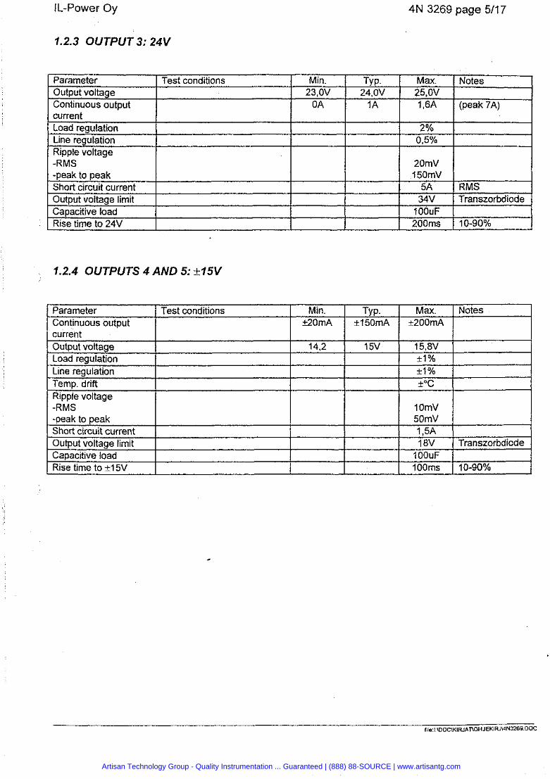
4N 3269 page 511 7
1.2.3 OUTPUT 3: 24V
1.2.4 OUTPUTS 4 AND 5: +15V
Parameter Continuous output current
C
Parameter Output voltage Continuous output current Load regulation Line regulation Ripple voltage -RMS -peak to peak Short circuit current Output voltage limit Capacitive load Rise time to 24V
Output voltage
Min. 23,OV
0 A
Test conditions
Load regulation Line regulation Temp. drift Ripple voltage -RMS -r~eak to ~ e a k
Rise time to +15V
TY P. 24,OV
1A
50mV 1,5A 18V Transzorbdiode
1 OOuF
Max. 25,OV 1,6A
2% 0,5%
20mV 15OmV
5A 34V
1 OOuF 200ms
Notes
(peak 7A)
RMS Transzorbdiode
10-90%
Artisan Technology Group - Quality Instrumentation ... Guaranteed | (888) 88-SOURCE | www.artisantg.com
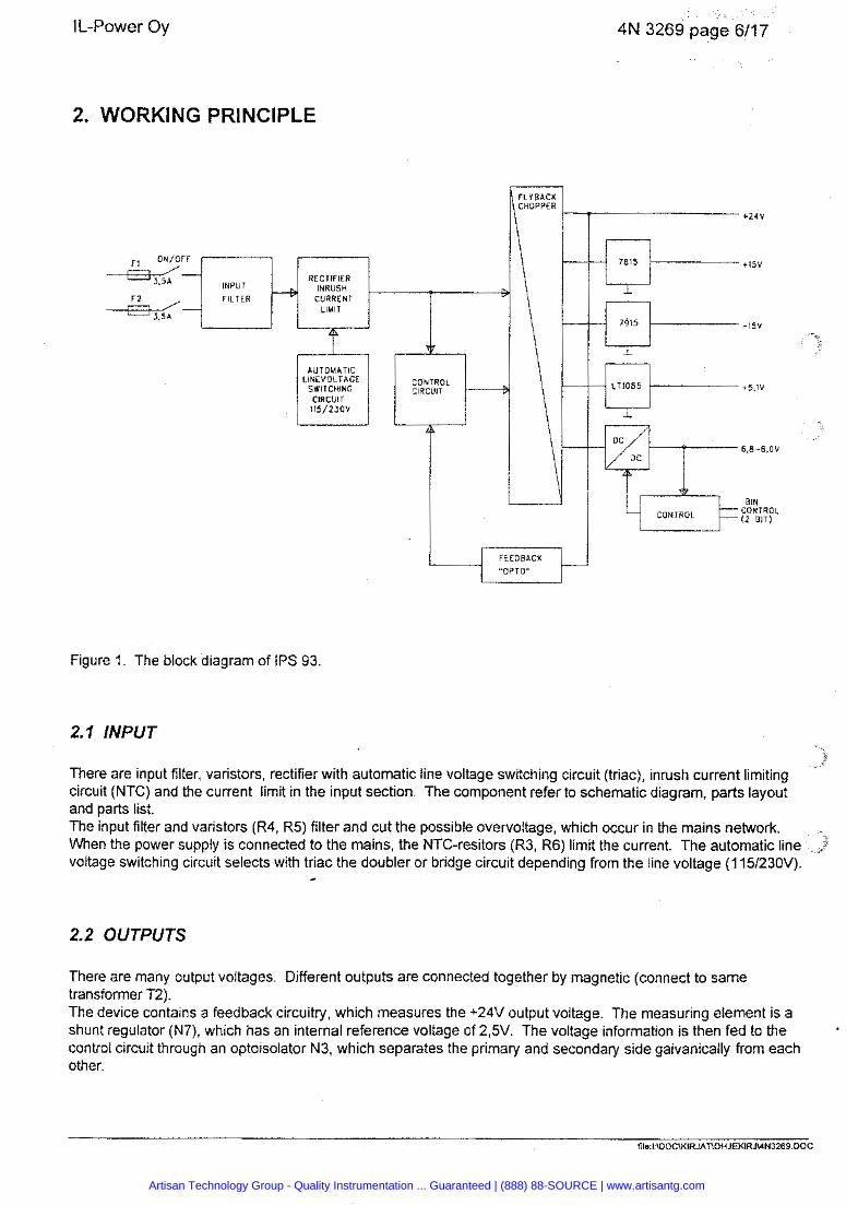
4N 3269 page 6/17
2. WORKING PRINCIPLE
RECTlF IER INRUSH
FZ CURRENT LIMIT
LINEVOLTAGE SWITCHING
CIRCUIT
"OPTO"
BIN
CONTROL CONTROL ( 2 BIT)
Figure 1. The block diagram of IPS 93.
2.7 INPUT
There are input filter, varistors, rectifier with automatic line voltage switching circuit (triac), inrush current limiting circuit (NTC) and the current limit in the input section. The component refer to schematic diagram, parts layout and parts list. The input filter and varistors (R4, R5) filter and cut the possible overvoltage, which occur in the mains network. When the power supply is connected to the mains, the NTC-resitors (R3, R6) limit the current. The automatic line voltage switching circuit selects with triac the doubler or bridge circuit depending from the line voltage (1 151230V).
4
2.2 OUTPUTS
There are many output voltages. Different outputs are connected together by magnetic (connect to same transformer T2). The device contains a feedback circuitry, which measures the +24V output voltage. The measuring element is a shunt regulator (N7), which has an internal reference voltage of 2,5V. The voltage information is then fed to the control circuit through an optoisolator N3, which separates the primary and secondary side galvanically from each other.
file I \DOC\KIRJAT\OHJEKIRJWN3269 DOC
Artisan Technology Group - Quality Instrumentation ... Guaranteed | (888) 88-SOURCE | www.artisantg.com
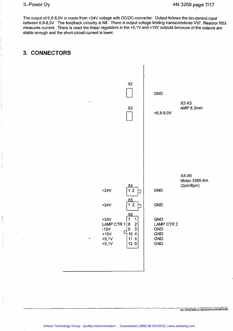
IL-Power Oy 4N 3269 page 7/17
The output of 6,8-8,OV is made from +24V voltage with DCIDC-converter. Output follows the bin-control input between 6,8-8,OV. The feedback circuitry is N8. There is output voltage limiting transzorbdiode V37. Resistor R53 measures current. There is used the linear regulators in the +5,1V and +15V outputs because of the outputs are stable enough and the short-circuit current is lower.
3. CONNECTORS
GND
X2-x3 AMP 6,3mm
+6,8-8,OV
X4-X6 Molex 5566-NA (2pint8pin)
GND
GND
GND LAMP CTR 2 GND GND GND GND
Artisan Technology Group - Quality Instrumentation ... Guaranteed | (888) 88-SOURCE | www.artisantg.com
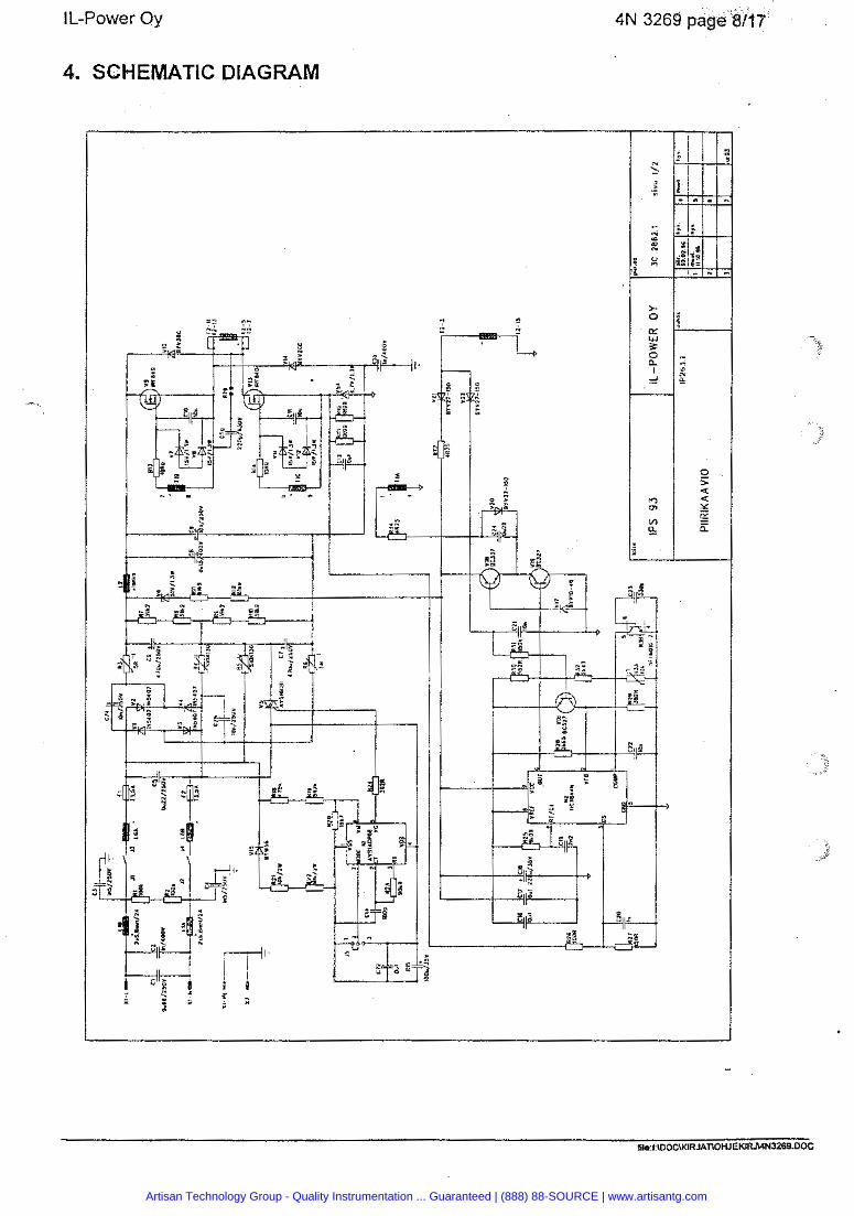
I L-Power Oy 4N 3269 page 8/17
4. SCHEMATIC DIAGRAM
Artisan Technology Group - Quality Instrumentation ... Guaranteed | (888) 88-SOURCE | www.artisantg.com
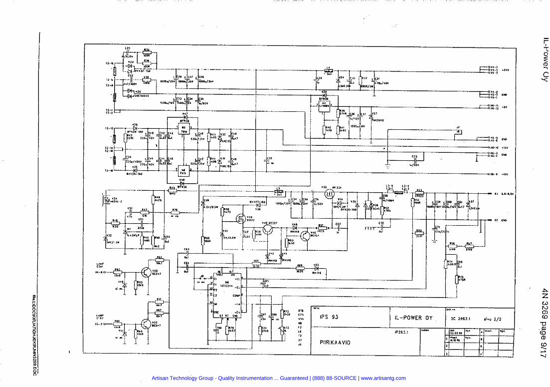
2 178 *.I. mu n.
JZ CI5 ,,, I P S 9 3 IL-POWER OY JC 2862.1 sivu 2 /2 *I
RIJ r2 '
t 6 IP2631 '*'* ,& "'. -1 *?. 11
I 7 a PllRlKAAVlO
I Sp1% m" 5
1 6
1 7
Artisan Technology Group - Quality Instrumentation ... Guaranteed | (888) 88-SOURCE | www.artisantg.com

16 AUNNUS. - LllUAfAAN. OSALLA 15 KllNNl CI JA LIEEN
ASENNUS XOROIUSPALAN. 0SA 11 KANSSA. - C2.9.1J.39.51.58.70,71.73-75.L4.5.R5l.78 ASENNUSET 2- 3mm. - R21.22.37.Vl-4.24.30.31.37 ASENNUS FIRRIIIIIHCLUEN, OSA 12 KANSSA: - R51.78
lolie
IPS 93 IL-POWER OY
piir.no
30 2863.1
Artisan Technology Group - Quality Instrumentation ... Guaranteed | (888) 88-SOURCE | www.artisantg.com
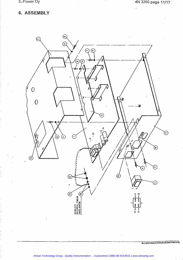
I L-Power Oy
6. ASSEMBLY
4N 3269 page 11/17
Artisan Technology Group - Quality Instrumentation ... Guaranteed | (888) 88-SOURCE | www.artisantg.com
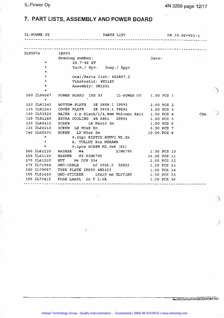
4N 3269 page 1211 7
7. PART LISTS, ASSEMBLY AND POWER BOARD
IL-POWER OY PARTS LIST 08.10.96*V21-1
IL95076 IPS93 Drawing number: Date:
* 25.7-96 KT * Tark./ Hyv. Insp./ Appr * * Osal/Parts list: 4A2857.2 * Vikatestit: 4N3180 * Assembly: 3H3201 *
100 IL90067 POWER BOARD IPS 93 IL-POWER OY 1.00 PCS 1 *
110 IL81242 BOTTOM PLATE 3E 2858.1 IPS93 1.00 PCS 2 115 IL81243 COVER PLATE 3E 2859.1 IPS93 1.00 PCS 3 120 IL52520 MAINS 2-p black/l/4,8mm Molveno A412 1.00 PCS 4 125 IL81245 EXTRA COOLING 4E 2861 IPS93 1.00 PCS 5 130 IL60415 SCREW LK M4x10 Zn 1.00 PCS 6 135 IL60210 SCREW LK M3x8 Zn 6.00 PCS 7 140 IL60205 SCREW LK M3x6 Zn 10.00 PCS 8
* 9:2kpl RISTIU.RUUV1 M2,Px * 8, TULLUT Xln MUKANA * 9 : 2pcs SCREW M2,9x8 (XI)
160 IL61220 WASHER M4 DIN6798 2.00 PCS 10 165 IL61120 WASHER M3 DIN6798 16.00 PCS 11 170 IL61200 NUT M4 DIN 934 2.00 PCS 12 175 IL75944 GND-CABLE 45 3056.2 IPS93 1.00 PCS 13 180 IL70057 TYPE PLATE IPS93 4N3152 1.00 PCS 14 185 IL53450 GND-STICKER 10x10 mm ELFVING 1.00 PCS 15 190 IL70415 FWSE LABEL 2x T 3,5A 1.00 PCS 16
. . . . . . . . . . . . . . . . . . . . . . . . . . . . . . . . . . . . . . . . . . . . . . . . . . . . . . . . . . . . . . . . . . . . . . . . . . . . . . .
CSA
file I U)OCU<IRJAT\OHJEKIRJWN~Z~~ DOC
Artisan Technology Group - Quality Instrumentation ... Guaranteed | (888) 88-SOURCE | www.artisantg.com
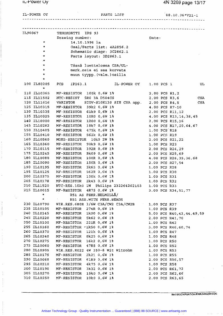
4N 3269 page 13/17
IL-POWER OY PARTS LIST 08.10.96*V21-1
TEHOKORTTI IPS 93 Drawing number:
14.10.1996 la Osal/Parts list: 4492856.2 Schematic diagr: 3C2862.1 Parts layout: 3B2863.1
Tassa luettelossa CSA/UL- merk.osia ei saa korvata muun tyypp. (valm. ) osilla
PCB IP263.1 IL-POWER OY
MF-RESISTOR lOOk 0,6W 1% NTC-RESIST SRO 3A D504CS VARISTOR SIOV-S1OK130 SIE CSA app MF-RESISTOR 39k2 0,6W 1% MF-RESISTOR 61k9 0,6W 1% MF-RESISTOR lORO 0,6W 1% MF-RESISTOR lROO 0,6W 1% MF-RESISTOR 18k7 0,6W 1% MF-RESISTOR 475k 0,6W 1% MF-RESISTOR 562k 0,6W 1% MOKS-RESISTOR lOkO 2W 5% MF-RESISTOR 90k9 0,6W 1% MF-RESISTOR 392R 0,6W 1% MF-RESISTOR 9k09 0,6W 1% MF-RESISTOR lOOR 0,6W 1% MF-RESISTOR 150R 0,6W 1% MF-RESISTOR 3k65 0,6W 1% MF-RESISTOR 562R 0,6W 1% MF-RESISTOR 150k 0,6W 1% MF-RESISTOR 2k43 0,6W 1% NTC-RES.10kO 1W Philips 232264262103 MF-RESISTOR 4R75 0,6W 1%
~ 5 1 AS FERR.HELMIL~/ R51 ASS.WITH FERR.BEADS
WIR.RES.680R 3/6W C3A/CW2 C~A/CW~B MF-RESISTOR 274R 0,6W 1% MF-RESISTOR lkOO 0,6W 1% MF-RESISTOR 5k62 0,6W 1% MF-RESISTOR 221R 0,6W 1% MF-RESISTOR *lk50 0,6W 1% MF-RESISTOR 121k 0,6W 1% MF-RESISTOR 8k25 0,6w 1% MF-RESISTOR 16k2 0,6W 1% MF-RESISTOR 47R5 0,6W 1% WIR.RES.RO22 4W 350-8 Wit Witrohm MF-RESISTOR 2k21 0,6W 1% MF-RESISTOR 61R9 0,6W 1% MF-RESISTOR 4k75 0,6W 1% MF-RESISTOR 3k32 0,6W 1% MF-RESISTOR 15k0 0,6W 1% MF-RESISTOR lOkO 0,6W 1%
Date :
1.00 PCS 1
2.00 PCS R1,2 2.00 PCS R3,6 2.00 PCS R4,5 4.00 PCS R7-10 2.00 PCS R11,12 4.00 PCS R13,14,38,45 2.00 PCS R15,16 4.00 PCS R17,20,64,67 1.00 PCS R18 1.00 PCS R19 2.00 PCS R21,22 1.00 PCS R23 2.00 PCS R24,29 2.00 PCS R25,69 4.00 PCS R26,35,36,68 2.00 PCS R27,54 1.00 PCS R28 1.00 PCS R30 1.00 PCS R31 1.00 PCS R32 1.00 PCS R33 3.00 PCS R34,51,77
CSA CSA
1.00 PCS R37 1.00 PCS R39 5.00 PCS R40,43,44,49,59 2.00 PCS R41,70 1.00 PCS R42 3.00 PCS R46,60,74 1.00 PCS R47 1.00 PCS R48 1.00 PCS R50 1.00 PCS R52 1.00 PCS R53 1.00 PCS R55 2.00 PCS R56,57 1.00 PCS R58 2.00 PCS R61,72 2.00 PCS R62,66 2.00 PCS R63,65
Artisan Technology Group - Quality Instrumentation ... Guaranteed | (888) 88-SOURCE | www.artisantg.com
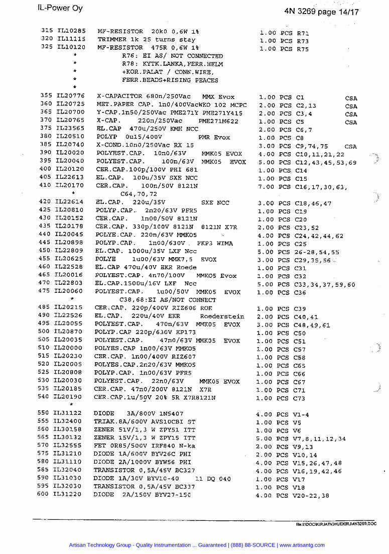
4N 3269 page 14/17
MF-RESISTOR 2OkO 0,6W 1% TRIMMER lk 25 turns stay MF-RESISTOR 475R 016W 1%
R76: EI AS/ NOT CONNECTED R78: KYTK.LANKA,FERR.HELM +KOR.PALAT / CONN.WIRE, FERR.BEADS+RISING PEACES
X-CAPACITOR 680n/250Vac MMX Evox MET.PAPER CAP. ln0/400Vac~f(0 102 MCPC Y-CAP.ln50/250Vac PME271Y PME271Y415 X-CAP . 220n/250Vac PME271M622 EL.CAP 470u/250V KMH NCC POLYP Ou15/4OOV PMR Evox X-COM).10n0/250Vac RX 15 POLYEST.CAP. 10n0/63V MMK05 EVOX POLYEST.CAP. 100n/63V MMKOS EVOX CER.CAP.lOOpJ100v PHI 681 EL.CAP. 100u/35V SXE NCC CER.CAP. 100n/50V 8121N
C64,7O, 72 EL.CAP. 220u/35V SXE NCC POLYP.CAP. 2n20/63V PFRS CER-CAP. ln00/50V 8121N CER.CAP. 330p/100V 8121N 8121N X7R POLYE.CAP. 220n/63V MMK05 POLYP.CAP. ln00/630V. FKP3 WIMA EL.CAP. 1000u/35V LXF Ncc POLYE lu00/63V MMK7,5 EVOX EL-CAP 470u/40V EKR Roede POLYEST.CAP. 4n70/100~ MMK05 ~ v o x EL.CAP.l500u/16V LXF Ncc POLYEST-CAP. lu00/50V MMK05 EVOX
C38,68:EI AS/NOT CONNECT CER.CAP. 220p/400V RIZ606 ROE EL-CAP. 220u/40V EKR Roederstein POLYEST-CAP. 470n/63V MMKOS EVOX POLYP.CAP 220p/630V KP173 POLYEST.CAP. 47n0/63V MMK05 EVOX POLYES.CAP ln00/63V MMKO5 CER.CAP. ln00/400V RIZ607 POLYES.CAP.2n20/63V MMKO5 POLYP.CAP. ln00/63V PFR5 POLYEST.CAP. 22n0/63V MMK05 EVOX CER.CAP. 47n0/200V 8121N X7R CER.CAP.lu/50V 20% 5R X7R8121N
DIODE 3A/800V IN5407 TRIAK.8A/600V AVSLOCBI ST ZENER 51V/1,3 W ZPY51 ITT ZENER 15V/1,3 W ZPY15 ITT FET 0R85/500V IRF840 N-ka DIODE 1A/600V BW26C PHI DIODE 2A/lOOOV BYW56 PHI TRANSISTOR O15A/45V BC327 DIODE 1A/30V BW10-40 11 DQ 040 TRANSISTOR 0,5A/45V BC337 DIODE 2A/150V BW27-150
1.00 PCS R71 1.00 PCS R73 1.00 PCS R75
1.00 PCS C1 CSA 2.00 PCS C2,13 CSA 2.00 PCS C3,4 CSA 1.00 PCS C5 CS A 2.00 PCS C6,7 1.00 PCS C8 3.00 PCS C9,74,75 CSA 4.00 PCS C1O111,21,22 5.00 PCS C12,43,45,53,69 1.00 PCS C14 1.00 PCS C15 7.00 PCS C16,17,30,63,
3.00 PCS C18,46,47 1.00 PCS C19 1.00 PCS C20 2.00 PCS C23,52 4.00 PCS C24,42,44,62 1.00 PCS C25 5.00 PCS 26-28,54,55 3.00 PCS C29,35,56 1.00 PCS C31 1.00 PCS C32 5.00 PCS C33,34,37,59,60 1.00 PCS C36
1.00 PCS C39 2.00 PCS C40,41 3.00 PCS C48,49,61 1.00 PCS C50 1.00 PCS C51 1.00 PCS C57 1.00 PCS C58 1.00 PCS C65 1.00 PCS C66 1.00 PCS C67 1.00 PCS C71 1.00 PCS C73
4.00 PCS V1-4 1.00 PCS v5 1.00 PCS V6 5.00 PCS V7,8,11,12,34 2.00 PCS V9,13 2.00 PCS V10,14 4.00 PCS V15,26,47,48 4.00 PCS V16,19,42,46 1.00 PCS V17 1.00 PCS V18 4.00 PCS V20-22/38
file.1 U)OCwlRJAT\OHJEKlRJWN3269 DOC
Artisan Technology Group - Quality Instrumentation ... Guaranteed | (888) 88-SOURCE | www.artisantg.com
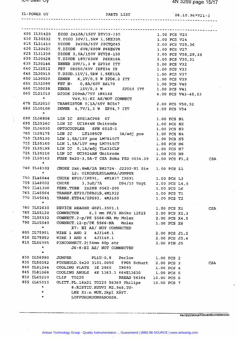
4N 3269 page 15/17
IL-POWER OY PARTS LIST 08.10.96*V21-3
605 IL31420 DIOD 2~10A/150V BW32-150 1.00 PCS V23 610 IL30532 T.DIOD 30V/1,5kW 1,5KE30A 1.00 PCS V24 615 IL31410 DIODE 2x20A/45V 20CTQ045 2.00 PCS V25,36 620 IL30421 T.DIODE 6V8/600W P6KE6V8 1.00 PCS V27 625 IL31230 DIODE 3,5A/150V BW28-150 3.00 PCS V28,29,35 630 IL30428 T.DIODE 18V/600W P6KEl8A 2.00 PCS V30,31 635 IL30146 ZENER 30V/1,3 W ZPY30 ITT 1.00 PCS V32 640 IL32512 FET OR050/60V IRFZ34 IR 1.00 PCS V33 645 IL30515 T.DIOD.llV/l,SkW 1,SKEllA 1.00 PCS V37 650 IL30020 ZENER 6,2~/0,5 W ZPD6,2 ITT 1.00 PCS V39 655 IL32090 FET N- 0,8A/60V BS170 1.00 PCS V40 660 IL30038 ZENER 15V/0,5W ZPD15 ITT 1.00 PCS V41 665 IL31010 DIODE 200m~/75V IN4148 4.00 PCS V43-45,53
* V49,51:EI AS/NOT CONNECT
675 IL32010 TRANSISTOR 0;1A/45V BC547 2.00 PCS V50,52 680 IL30108 ZENER 4,7V/1,3 W ZPY4,7 ITT 1.00 PCS V54
* 690 IL36808 LIN IC AVSlACP08 ST 1.00 PCS N1 695 IL35240 LIN IC UC3844N Unitrode 1.00 PCS N2 700 IL36030 OPTOCOUPLER SFH 601G-2 1.00 PCS N3 705 IL35175 LIN IC LT1085CP 3A/adj pos 1.00 PCS N4 710 IL35130 LIN 1,5~/15V pas LM7815CT 1.00 PCS N5 715 IL35160 LIN 1,5A/15V neg LM7915CT 1.00 PCS N6 720 IL35195 LIN IC 0,1A/adj T L ~ ~ ~ C L P 1.00 PCS N7 725 IL35210 LIN IC uC3524AN Unitrode 1-00 PCS N8 730 IL50145 FUSE 5x20-3,5A-T CSA Schu FSD 0034.39 2.00 PCS F1,2 CS A
* 740 IL48102 CHOKE 2~6,8mH/2A B82724- J2202-N1 Sie 1.00 PCS L1
* ~2 : OIKOSULKULANKA/JUMPER
750 IL46044 CHOKE EF25/IPS91, 4M1837 IPS91 1.00 PCS L3 755 IL48002 CHOKE 3,3uH/7A DS4/15 Vogt 2.00 PCS L4,5 760 IL41300 FERR.TUBE 2X28B 0562-200 1.00 PCS L6 765 IL45564 T R A N S F . E F ~ O / D P A O ~ B , ~ M ~ ~ ~ ~ 1.00 PCS T1 770 IL45641 TRANS.ETD~~/IPS~~, 4M3150 1.00 PCS T2
* 780 IL52630 DEVICE HEADER ~~~1.3501.1 1.00 PCS X1 CSA 785IL55120 CONNECTOR 6,3mrnPK/SAbiko12523 2.00PCSX2,3 790 IL55532 CONNECT.2-p/PK 5566-NA Mo Molex 2.00 PCS X4,5 795 IL55540 CONNECT.12-p/PK 5566-NA Molex 1.00 PCS X6
* X7: EI AS/ NOT CONNECTED
805 IL75951 WIRE 1 AND 2 453148.1 2.00 PCS J1,2 810 IL75952 WIRE 3 AND 4 4J3149.1 2.00 PCS J3,4 815 IL56995 PINCONNECT.2;54mm 40p str 3.00 PIN J5
* J6 - 8 : EI AS/ NOT CONNECTED *
830 IL56990 JUMPER PL1U- 0,8 Perlos 1.00 PCS 2 835 IL50352 FUSEHOLD.5x20 3101.0050 FPGS Schurt 2.00 PCS 3 840 IL81244 COOLING PLATE 3E 2860 IPS93 1.00 PCS 4 845 IL81068 COOLING ANGLE 4E 1363.1 664313630 1.00 PCS 5 850 IL65210 CLIP TO220 BREAD 56364 10.00 PCS 6 855 IL65015 GL1TT.pL.16~21 TO220 56369 Philips 10.00 PCS 7
* 8:RISTIU.RUUVI M2,9x8,TU- * LEE X1:n MUK,Zkpl a Y T . * LOPPUKOKOONPANOSSA.
Artisan Technology Group - Quality Instrumentation ... Guaranteed | (888) 88-SOURCE | www.artisantg.com
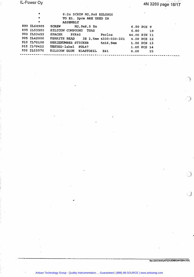
Artisan Technology Group - Quality Instrumentation ... Guaranteed | (888) 88-SOURCE | www.artisantg.com
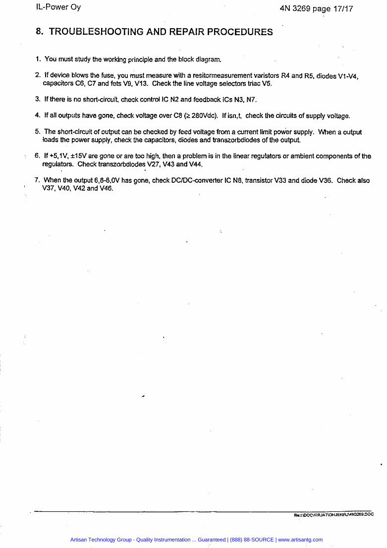
Il-Power Oy 4N 3269 page 17/17
8. TROUBLESHOOTING AND REPAIR PROCEDURES
1. You must study the working principle and the block diagram.
2. If device blows the fuse, you must measure with a resitormeasurement varistors R4 and R5, diodes V1-V4, capacitors C6, C7 and fets V9, V13. Check the line voltage selectors triac V5.
3. If there is no short-circuit, check control IC N2 and feedback ICs N3, N7
4. If all outputs have gone, check voltage over C8 (2 280Vdc). If isn,t, check the circuits of supply voltage.
5. The short-circuit of output can be checked by feed voltage from a current limit power supply. When a output loads the power supply, check the capacitors, diodes and transzorbdiodes of the output.
6. If +5,1V, f l5V are gone or are too high, then a problem is in the linear regulators or ambient components of the regulators. Check transzorbdiodes V27, V43 and V44.
7. When the output 6,8-8,OV has gone, check DClDC-converter IC N8, transistor V33 and diode V36. Check also V37, V40, V42 and V46.
Artisan Technology Group - Quality Instrumentation ... Guaranteed | (888) 88-SOURCE | www.artisantg.com
Document Release Section Page 35 11352- 100-X 1 .o 10 1
Artisan Technology Group - Quality Instrumentation ... Guaranteed | (888) 88-SOURCE | www.artisantg.com
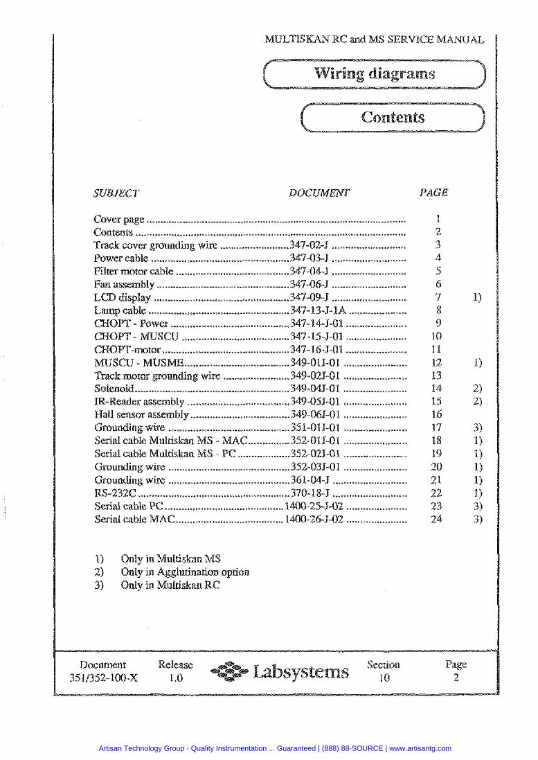
e ...................... .. ..................................................................... Contents ...............................................................................................
......................... 347-02-5 ........................... ........................ ....... ... 34'7-03-J ...................*.......
Filter motor cable ......................... .. .......... 347-04-5 ........................... Fan assembly ............................................. 347-064 ...........................
........................... ................................................. LCD display 347-09-% ................................. 347-13-J-1A .....................
- Power ....................................... 347-14-J-01 ...................... ................... ............................. U ..... 347-15-3- ...
34'7-16-5-01 ............................. ...................... ...349-01 9-01 .... .............................. ...................
wi*e ........................ 349-02J-01 ................... .... ....................... .... 349-045-01 .................... ...
IR-Reader assembly ................... .................. 348-059-01 ....................... Hall sensor assembly ...................... ... ....... 349-04J-01 .................... ...
.......... ounding wke ......................... ...451101JJ01 ... .................... rial cable Multiskm - MAC ............... 352-019-01 .......................
Serial cable Multiskan - PC ................... 352-021-01 ....................... .......... Grounding wire .......................... 352-035-01 .......................
Grounding wire ................................... .... . . 361-044 .......................... S-232C ....................... .. ......................... 370- 18-5 ...........................
Serial cable PC .......................................... 1400-25-5-02 ................... ... AC ..................................... 1400-26-1-02 ................... ...
1) Only in WIulriskan M 2) Only in Agglutinarion option 3) Only in Gvlultiskan RC
PAGE
1 2 3 4 5 6 7 8 9
10 11 12 13 14 15 1 17 18 19 20 21 22 23 24
Document Release Sscrian Page 351/352-100-X 1 . 0 10 2
Artisan Technology Group - Quality Instrumentation ... Guaranteed | (888) 88-SOURCE | www.artisantg.com
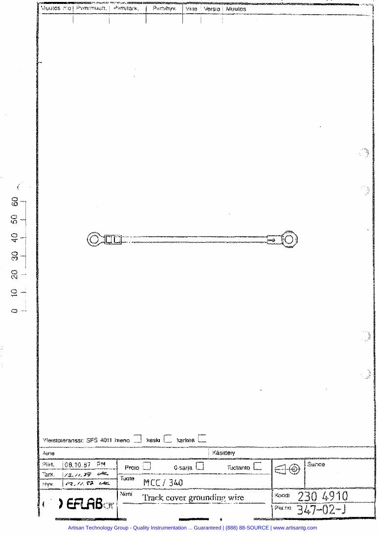
Artisan Technology Group - Quality Instrumentation ... Guaranteed | (888) 88-SOURCE | www.artisantg.com
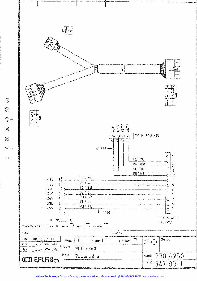
TO MUSCU XI3
u TO MUSCU X I TO P O W E R
e l l a m v
Artisan Technology Group - Quality Instrumentation ... Guaranteed | (888) 88-SOURCE | www.artisantg.com
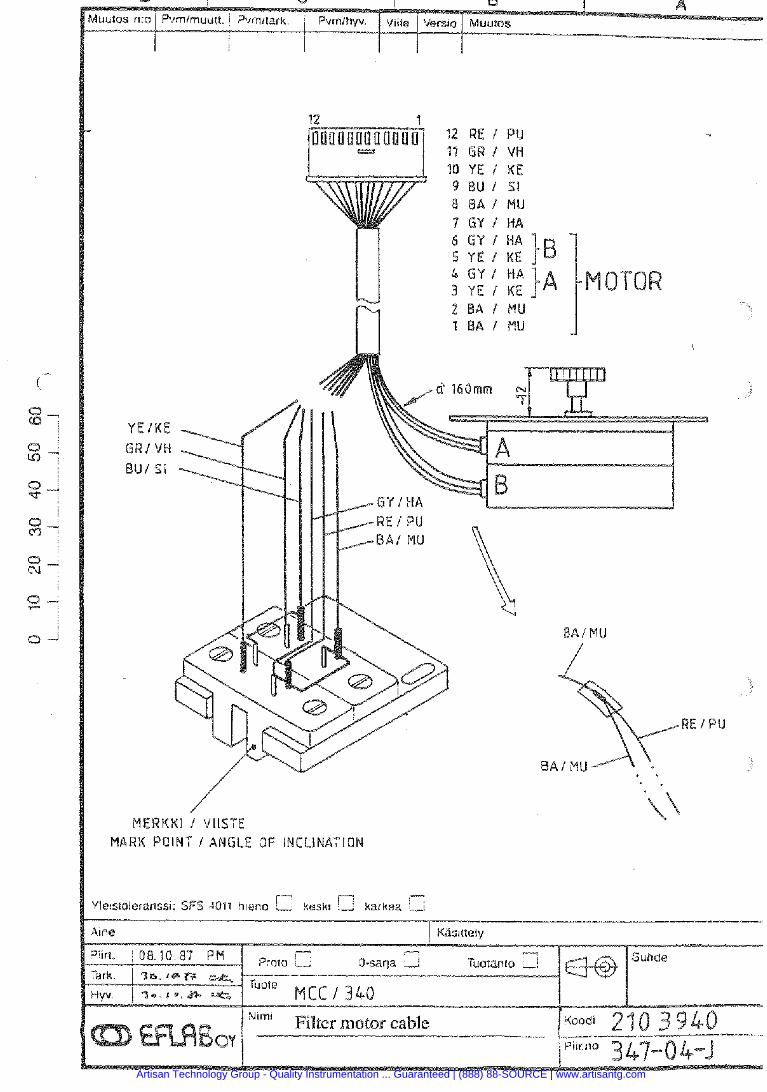
/ M E B K K I I VIISTE
M A R K POINT I ANGLE OF INCLINATION
41ne
Filter motor cable
Artisan Technology Group - Quality Instrumentation ... Guaranteed | (888) 88-SOURCE | www.artisantg.com
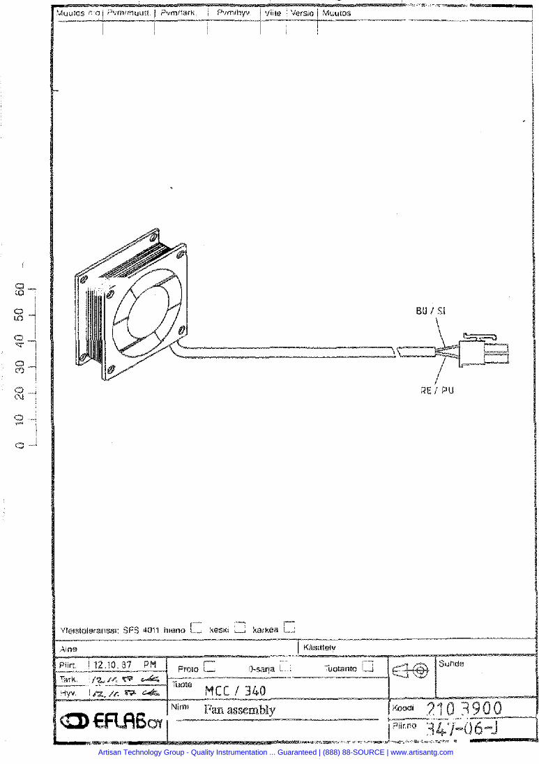
Artisan Technology Group - Quality Instrumentation ... Guaranteed | (888) 88-SOURCE | www.artisantg.com
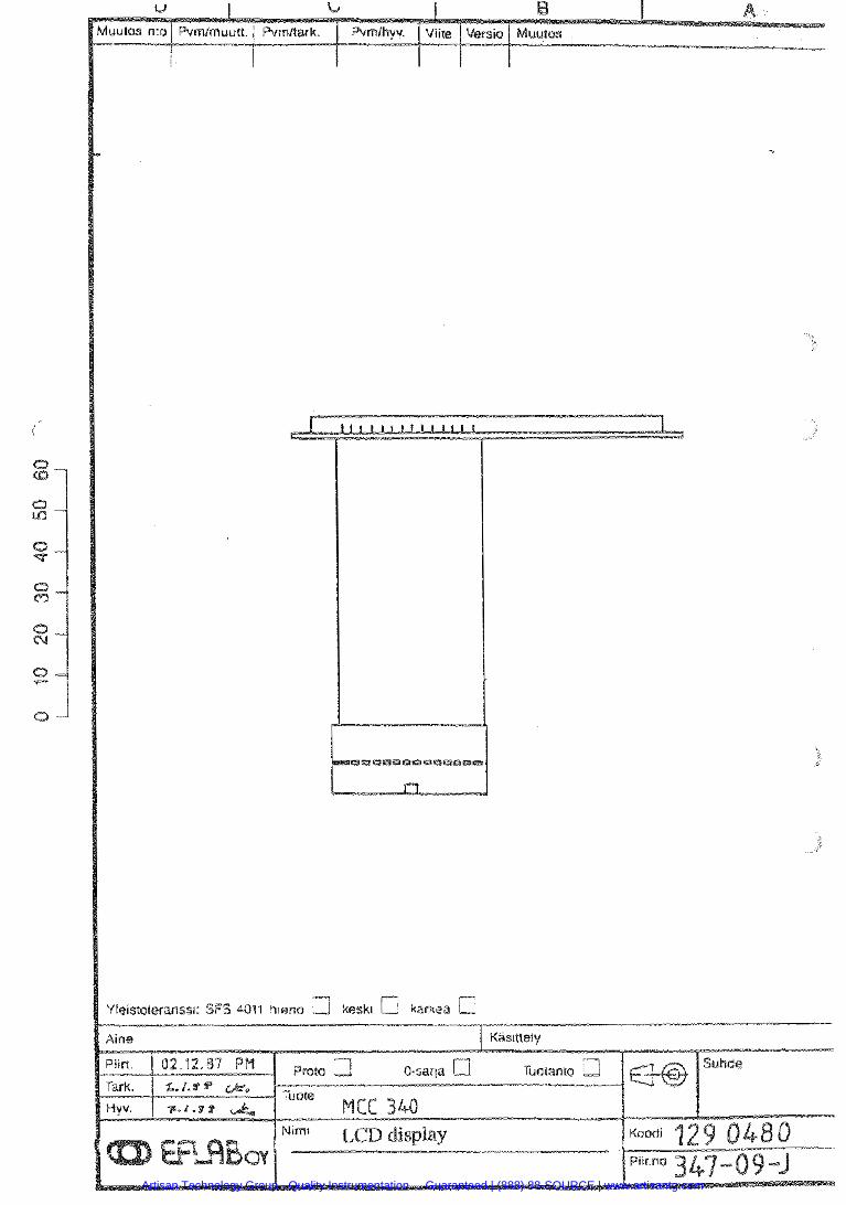
Yletstoleranssl: SFS 4011 h ~ e n o kesk! a karkra
Artisan Technology Group - Quality Instrumentation ... Guaranteed | (888) 88-SOURCE | www.artisantg.com
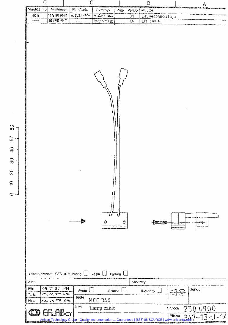
i'leistoleranss~: SFS 4011 hlena e] kesk~ a karkea a
Artisan Technology Group - Quality Instrumentation ... Guaranteed | (888) 88-SOURCE | www.artisantg.com
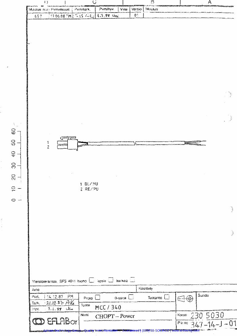
Artisan Technology Group - Quality Instrumentation ... Guaranteed | (888) 88-SOURCE | www.artisantg.com
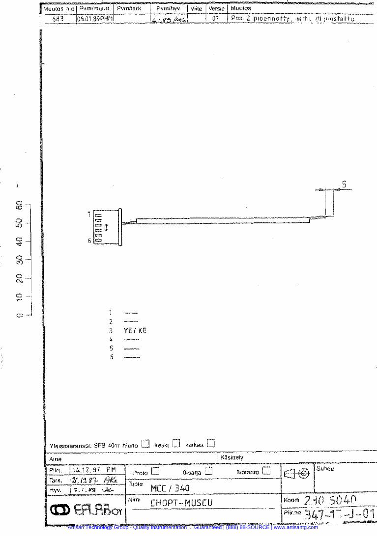
Artisan Technology Group - Quality Instrumentation ... Guaranteed | (888) 88-SOURCE | www.artisantg.com
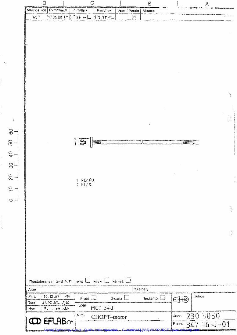
Artisan Technology Group - Quality Instrumentation ... Guaranteed | (888) 88-SOURCE | www.artisantg.com
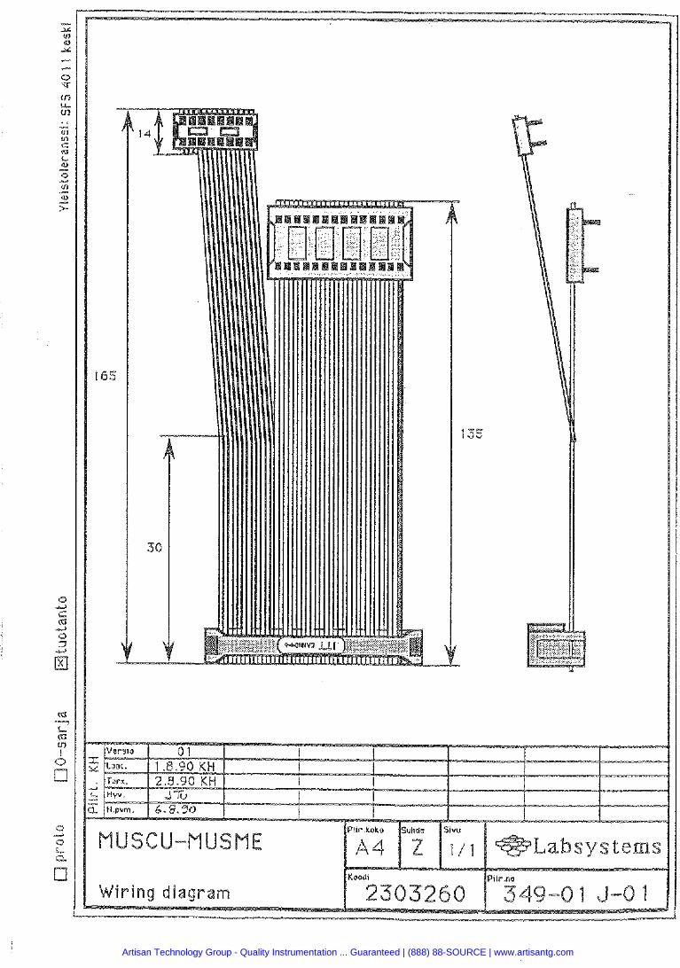
Koo Pllr
Artisan Technology Group - Quality Instrumentation ... Guaranteed | (888) 88-SOURCE | www.artisantg.com
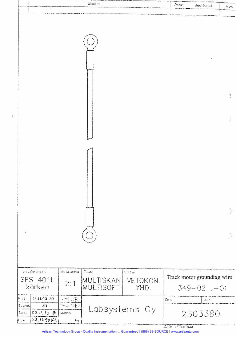
1 karkea
Artisan Technology Group - Quality Instrumentation ... Guaranteed | (888) 88-SOURCE | www.artisantg.com
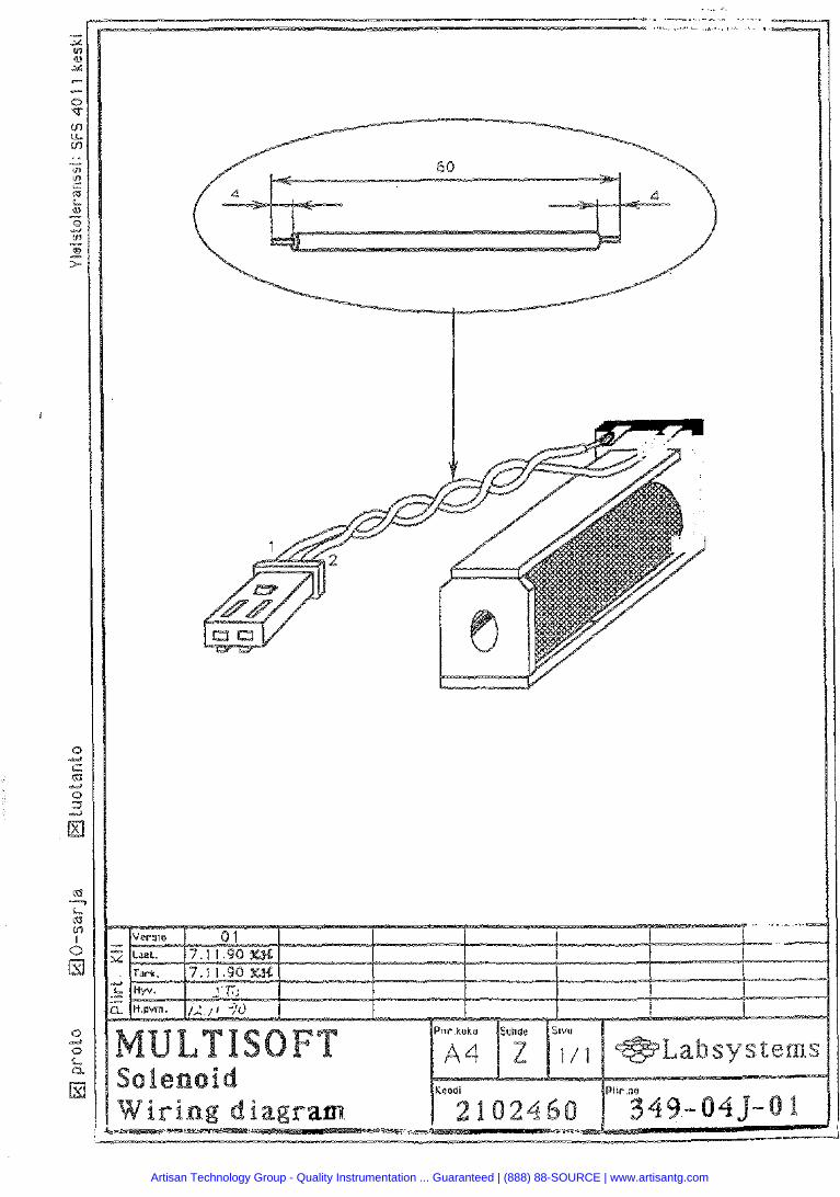
Artisan Technology Group - Quality Instrumentation ... Guaranteed | (888) 88-SOURCE | www.artisantg.com
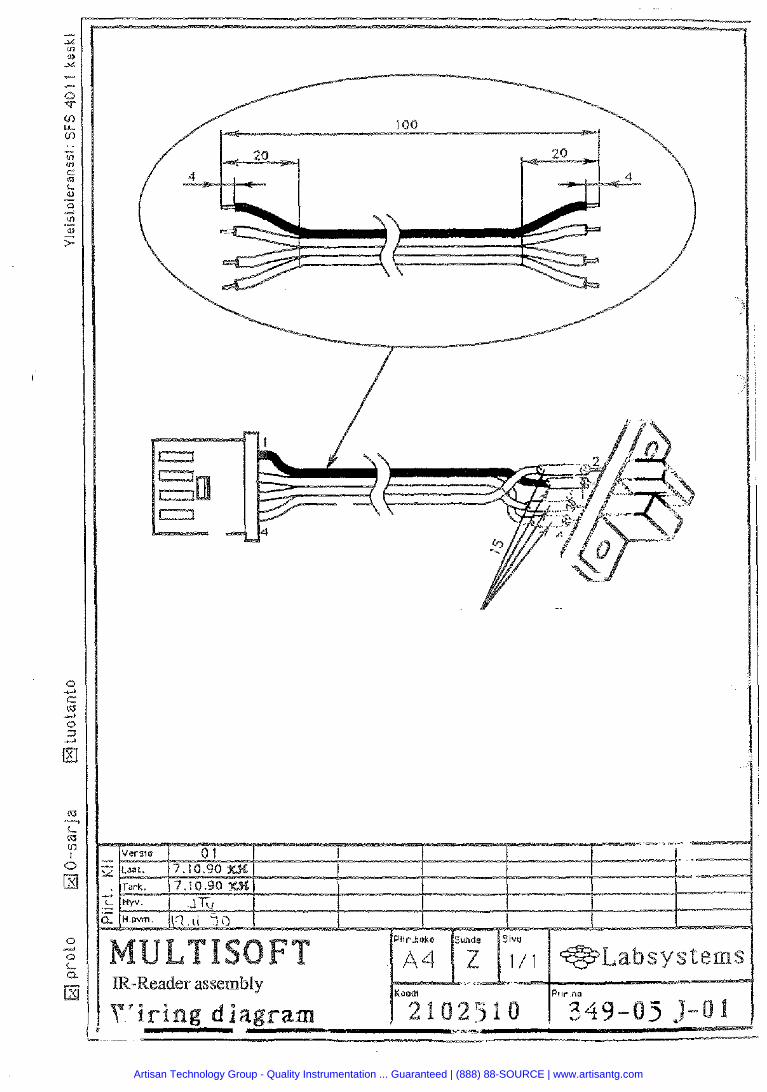
Artisan Technology Group - Quality Instrumentation ... Guaranteed | (888) 88-SOURCE | www.artisantg.com
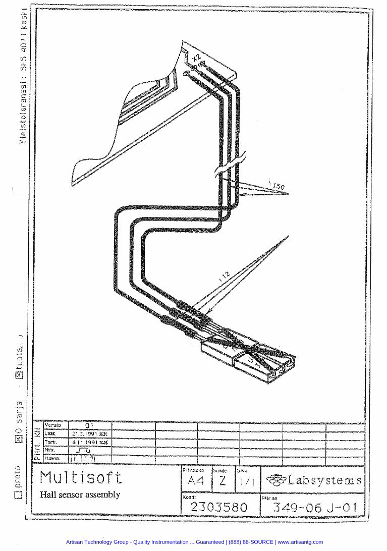
WaU sensor assembly
Artisan Technology Group - Quality Instrumentation ... Guaranteed | (888) 88-SOURCE | www.artisantg.com
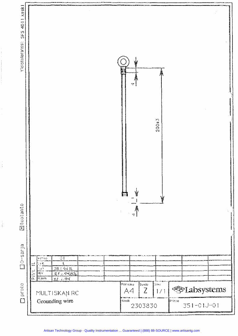
Artisan Technology Group - Quality Instrumentation ... Guaranteed | (888) 88-SOURCE | www.artisantg.com
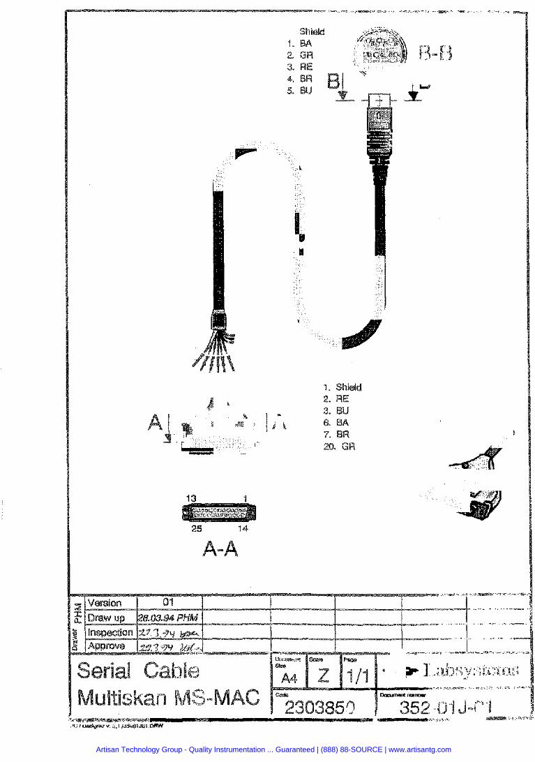
Artisan Technology Group - Quality Instrumentation ... Guaranteed | (888) 88-SOURCE | www.artisantg.com
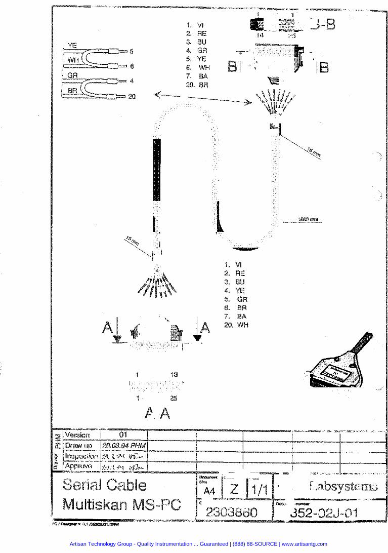
Artisan Technology Group - Quality Instrumentation ... Guaranteed | (888) 88-SOURCE | www.artisantg.com
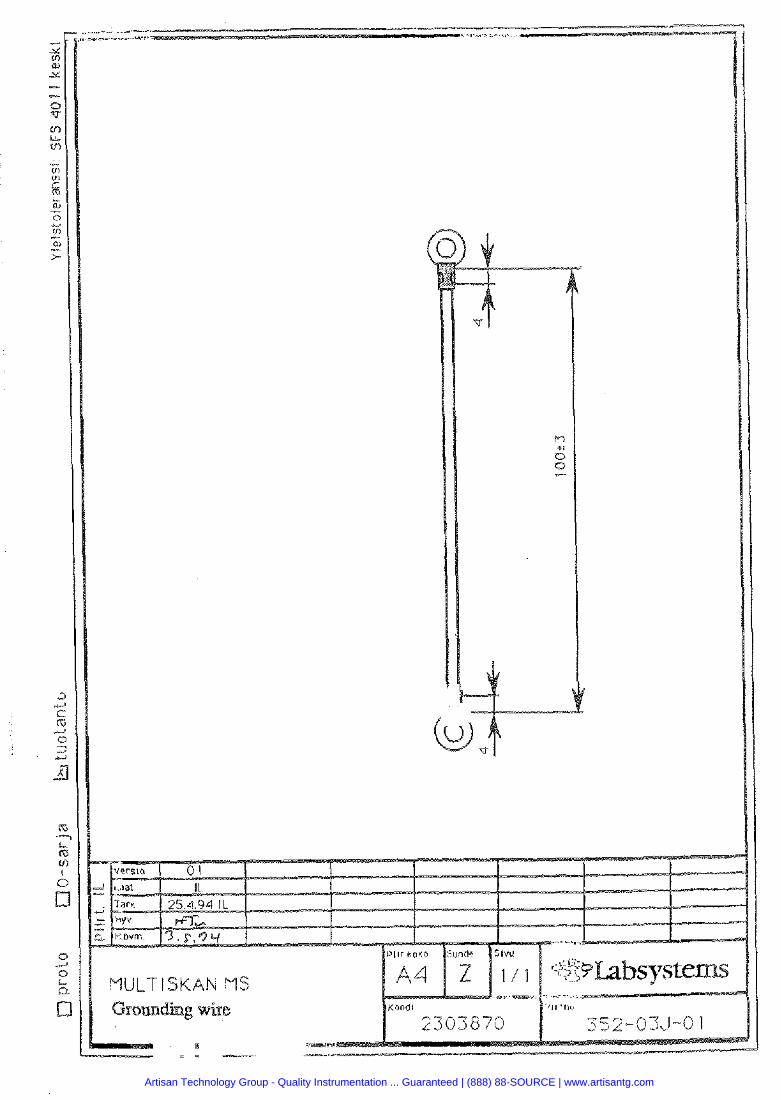
Artisan Technology Group - Quality Instrumentation ... Guaranteed | (888) 88-SOURCE | www.artisantg.com
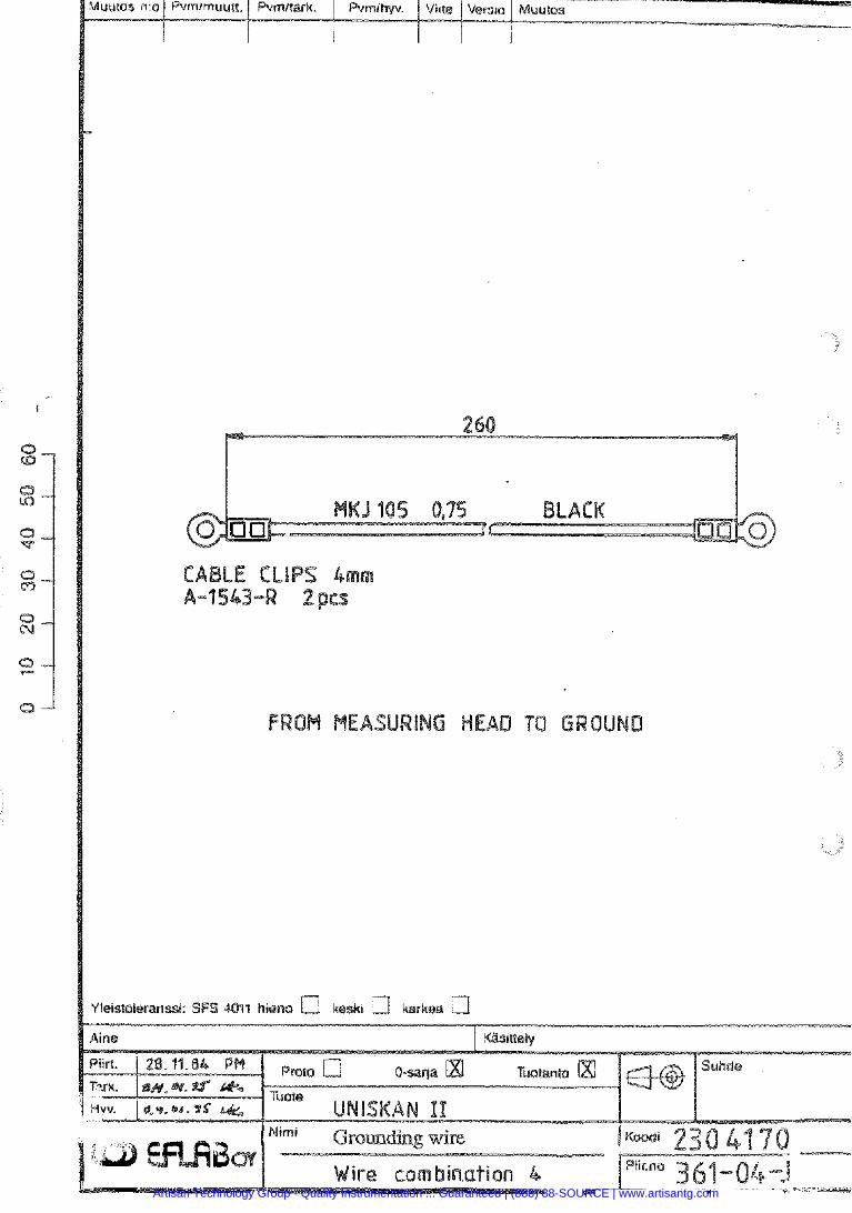
Artisan Technology Group - Quality Instrumentation ... Guaranteed | (888) 88-SOURCE | www.artisantg.com
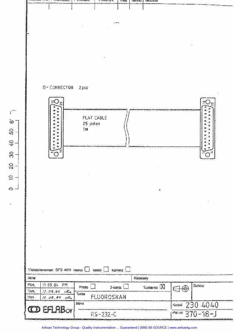
0- CONNECTOR 2pps
FLAT CABLE
'leisraleranssi: SFS 4011 hieno a kaski 61/
Artisan Technology Group - Quality Instrumentation ... Guaranteed | (888) 88-SOURCE | www.artisantg.com
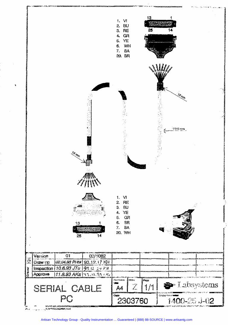
Artisan Technology Group - Quality Instrumentation ... Guaranteed | (888) 88-SOURCE | www.artisantg.com
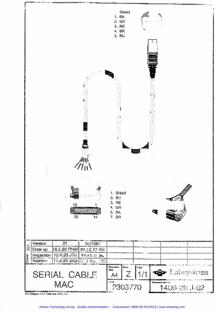
Artisan Technology Group - Quality Instrumentation ... Guaranteed | (888) 88-SOURCE | www.artisantg.com
MULTISKAN RC/MS/EX SERVICE MANUAL
Section 11
Spare parts
MULTISKAN RC/MS/E=X
Document Release Section Labsystems , , Page 3511352-100-X 2.0 1
Artisan Technology Group - Quality Instrumentation ... Guaranteed | (888) 88-SOURCE | www.artisantg.com
MULTISKAN RCIMSEX SERVICE MANUAL
( Spare parts 1
Contents
SUBJECT PAGE
Cover page Contents . . .. . . . . . . . . . . . . . . . . . . . . . . . . . . . . . . ... .... ....... ... . .. . . . . . . . . .. . . . . . . , . . . . . . . . . , , . , . . . RC main parts, figure RC main parts, text MSlEXmainparts, figure ... . . . .. .. ... ... .. . ..... . .... . ......... . .... ... .. . .. ... . ... . .. ... . MStEXmainparts, text MSfEXtop cover asse MSIEXtop cover ass Track plate assembly, figure ........................................................... Track plate assembly, text Optic assembly, figure Optic assembly, text ....................................................................... Electronic components Miscellaneous
Document 3511352-100-X
Release 2.0
~PII -3.t Labsystems Section 11
Page 2
Artisan Technology Group - Quality Instrumentation ... Guaranteed | (888) 88-SOURCE | www.artisantg.com
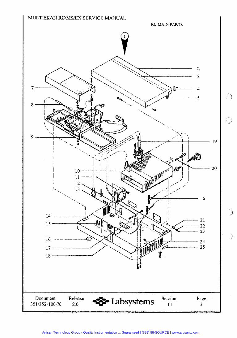
RC MAN PARTS
Document Release Section Labsysterns , , Page 3511352-100-X 2.0 =-- 3
Artisan Technology Group - Quality Instrumentation ... Guaranteed | (888) 88-SOURCE | www.artisantg.com
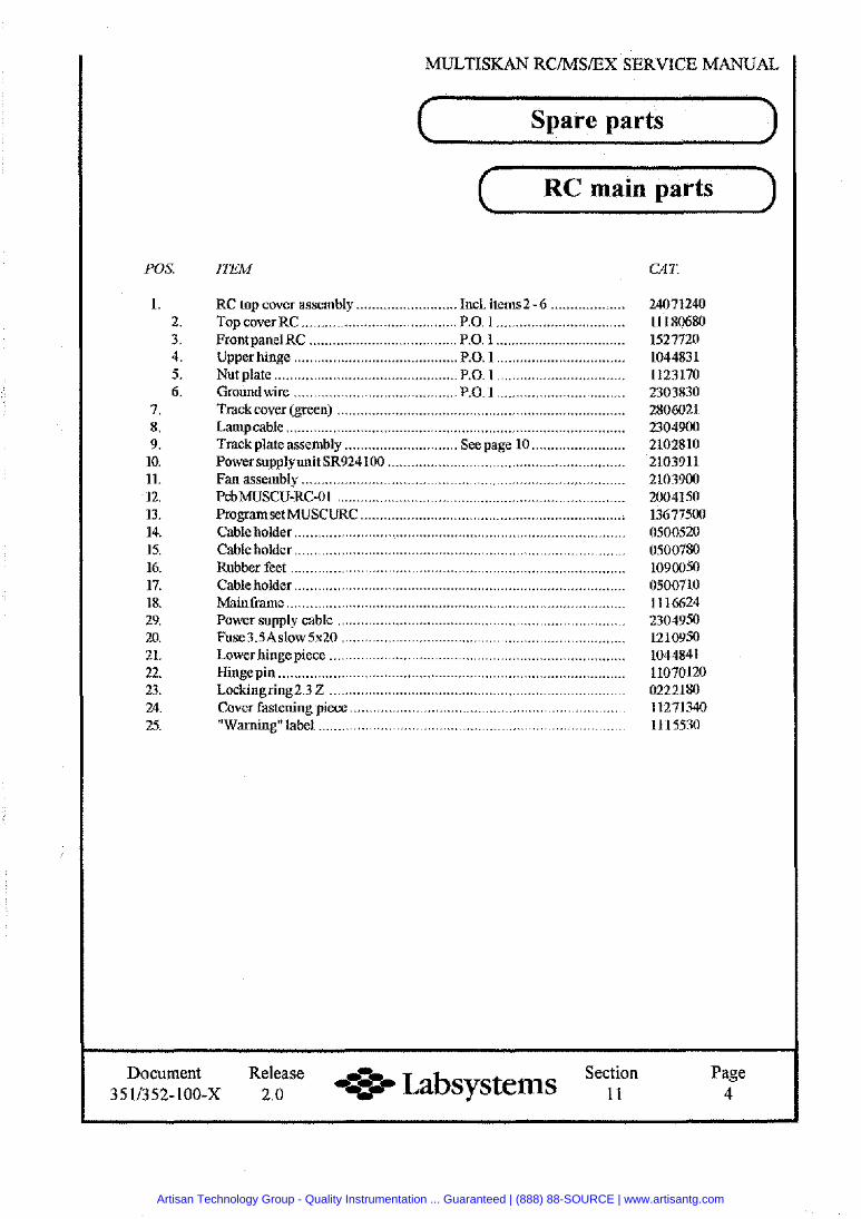
MULTISKAN RCIMSIEX SERVICE MANUAL
Spare parts
( RC main parts
POS.
1. 2. 3. 4. 5. 6.
7. 8. 9.
10. 11. 12. 13. 14. 15. 16. 17. 18. 29. 20. 21. 22. 23. 24. 25.
ITEM CAT.
RC top cover assembly .......................... Incl. items2 - 6 ................... Top cover RC ....................................... P.O. 1 .............................. FrontpanelRC ...................................... P.O. 1 .................................
.......................... .o. 1 ....
.............................. .o. 1 ...
............................... .o. 1 ........................................
Lamp cable .................................................................................... Track plate assembly ............................. See page 10 ........................ Power supply unit SR924 100 ................................................ .............
Document Release Section Labsystems , , Page 3511352-100-X 2.0 4
Artisan Technology Group - Quality Instrumentation ... Guaranteed | (888) 88-SOURCE | www.artisantg.com
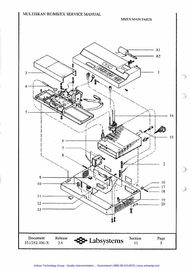
MULTISKAN RCIMSIEX SERVICE MANUAL MS/EX MAIN PARTS
Document Release Section -* Labsystems , , Page 3511352-100-X 2.0 5
Artisan Technology Group - Quality Instrumentation ... Guaranteed | (888) 88-SOURCE | www.artisantg.com
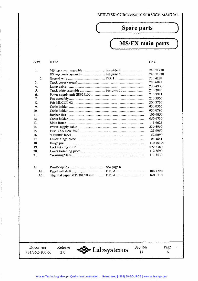
MLnTISKAN RCNSlEX SERVICE MANUAL
Spare parts
( MSIEX main parts 1
POS.
1.
2. 3. 4. 5. 6. 7. 8. 9.
10. 11. 12. 13. 14. 15. 16. 17. 18. 19. 20. 21.
A. Al . A2.
ITEM CAT
......................... MS top cover assembly ......................... See page 8 EX top cover assembly ......................... See page 8 .........................
................................ Ground wire ......................................... P.O. 1 Track cover (green) Lamp cab1
....................... ............................ Track plate assembly See page 10 ........................................................... Power supply unit SR924100
Cable bolder ............................... ... ..............................................
Fuse 3.5A slow 5x20 "Ground" label
Printer option ....................................... See page 8 .............................. ..................................... Paper roll sh& P.O. A 104 2220 ............................ ............ Thermal paper MW201158 mm P.O. A 160 0510
Document Release Section + Labsystems ,, Page 3511352-100-X 2.0 6
Artisan Technology Group - Quality Instrumentation ... Guaranteed | (888) 88-SOURCE | www.artisantg.com
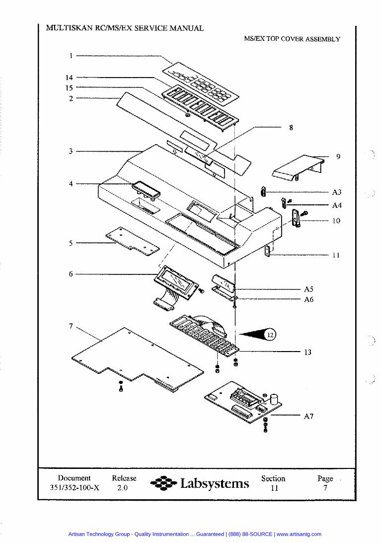
MULTISKAN RCIMSIEX SERVICE MANUAL. MSIEX TOP COVER ASSEMBLY
Document Release Section - i Labsystems ,, Page
3511352-100-X 2.0 7
Artisan Technology Group - Quality Instrumentation ... Guaranteed | (888) 88-SOURCE | www.artisantg.com
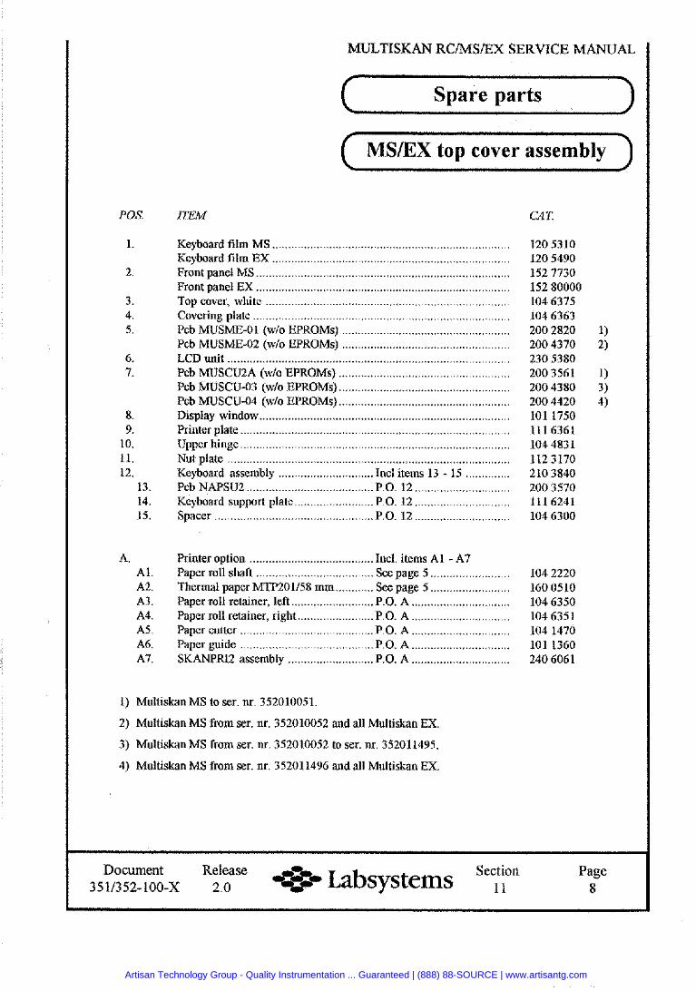
MJLTISKAN RClMSlEX SERVICE MANUAL
POS.
1.
2.
3. 4. 5.
6. 7.
8. 9.
10. 11. 12.
13. 14. 15.
A. Al. A2. A3. A4. A5. A6. A7.
( Spare parts I MSIEX top cover assembly
ITEM CAT.
Keyboard film MS Keyboard film EX Front panel MS Front panel EX ................................................................................ Top cover, white ........................ .. ................................................
Pcb MUSCU-03 (wh EPROMs)
Nut plate ......................................................................................... Keyboard assembly ..................... ..... Incl items 13 - 15 .............. Pcb NAPSU2 ........................................ P.O. 12 .............................. Keyboard support plate ......................... P.O. 12 .............................. Spacer P.O. 12 ..............................
Printer option ....................................... Ind. itcms Al - A7 Paper roll shaft ..................... ................ See page 5 ......................... 104 2220 Thermal paper MTP201158 mm ............ See page 5 ......................... 160 0510 Paper roll retainer, left .......................... P.O. A ............................. 104 6350 Paper roll retainer, right ........................ P.O. A ............................... 104 6351 Paper cutter P.O. A ............................. 104 1470 Paper guide P.O. A ............................. 101 1360 SKANPRI2 assembly ........................... P.O. A .............................. 240 6061
1) Multiskan MS to ser. nr. 352010051.
2) Multiskan MS from ser. nr. 352010052 and all Multiskan EX.
3) Multiskan MS from ser. nr. 352010052 to ser. nr. 352011495.
4) Mnltiskan MS from ser. nr. 352011496 and all Multiskan EX.
Document Release Section Labsystems ,, Page 3511352-100-X 2.0 8
Artisan Technology Group - Quality Instrumentation ... Guaranteed | (888) 88-SOURCE | www.artisantg.com
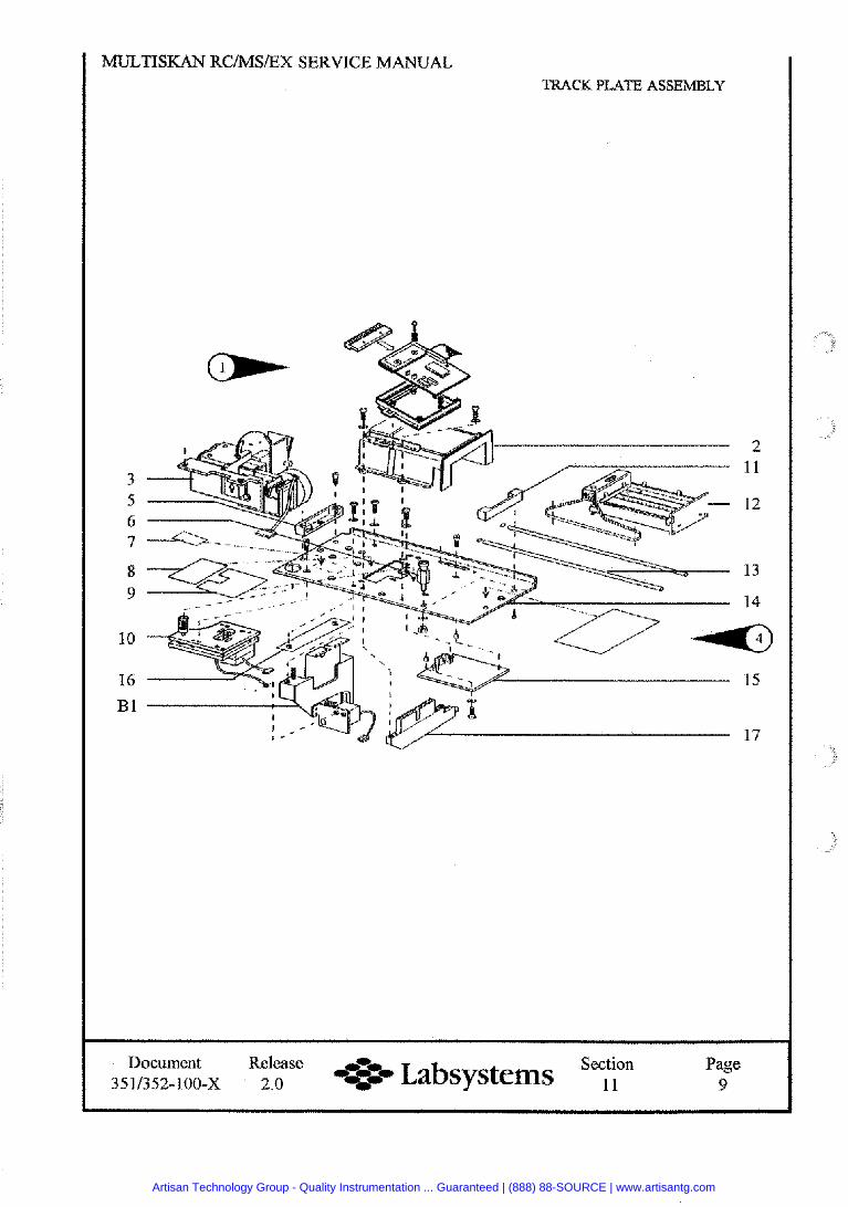
MULTISKAN RCIMSEX SERVICE MANUAL TRACK PLATE ASSEMBLY
Document Release Section 4- Labsystems , , Page 3511352-100-X 2.0 9
Artisan Technology Group - Quality Instrumentation ... Guaranteed | (888) 88-SOURCE | www.artisantg.com
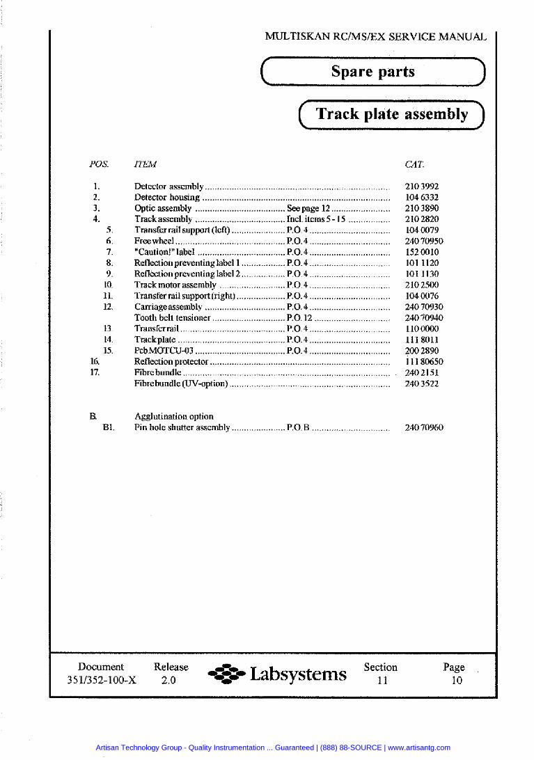
MULTISKAN RCIMSIEX SERVICE MANUAL
POS .
1 . 2 . 3 . 4 .
5 . 6 . 7 . 8 . 9 .
10 . 11 . 12 .
13 . 14 . 15 .
16 . 17 .
B . B1 .
Spare parts
( Track plate assembly )
ITEM CAT.
Detector assembly Detector housing Optic assembly ..................... ... ........ ........................ Trackassembly .................................. Incl . items 5 . 15 ................. Transfer rail support (left) ...................... P.O. 4 .................................
. 0.4 ..............................
. 0.4 ................................. Reflectionpreventinglabel 1 .................. P.O. 4 ................................. Reflection preventinglabel2 .................. P.O. 4 ................................. Track motor assembly ........................... P.O. 4 ................................. Transfer rail support (right) .................... P.O. 4 ................................. Carriageassembly ................................. P.O. 4 ................................. Tooth belt tensioner .............................. P.O. 12 ...............................
. 0.4 ...............
. 0.4 .................. .. ........
Fibre bundle ........................... ..... ............................................. Fibrebundle (UV-option) ..................................................................
Agglutination option Pin hole shutter assembly ...................... P.0.B .......
Document Release Section e* Labsystems , , Page 3511352-100-X 2.0 10
Artisan Technology Group - Quality Instrumentation ... Guaranteed | (888) 88-SOURCE | www.artisantg.com
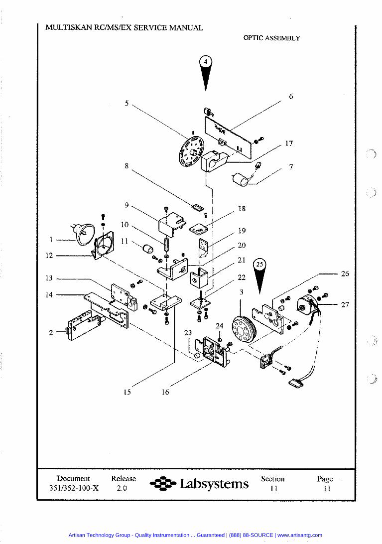
MULTISKAN RCIMSEX SERVICE MANUAL OPTIC ASSEMBLY
Document Release Section --*- Labsystems , , Page 35113.52-100-X 2.0 .a I1
Artisan Technology Group - Quality Instrumentation ... Guaranteed | (888) 88-SOURCE | www.artisantg.com
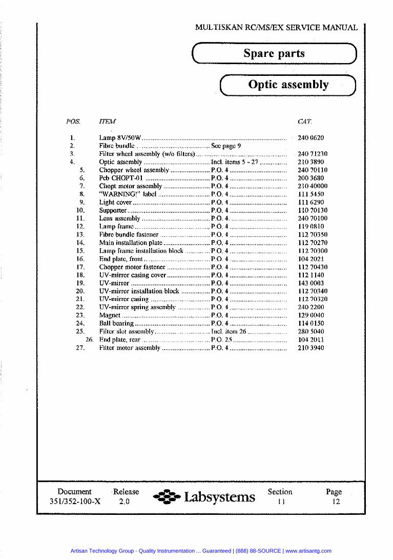
MULTISKAN RC/MS/EX SERVICE MANUAL
POS .
1 . 2 . 3 . 4 .
5 . 6 . 7 . 8 . 9 .
10 . 11 . 12 . 13 . 14 . 15 . 16 . 17 . 18 . 19 . 20 . 21 . 22 . 23 . 24 . 25 .
( Spare parts I
Optic assembly
ITEM
Chopper wheel assembly ...................... P.O. 4 ................................ Pcb CHOPT-01 .................................... P.O. 4 ................................ Chopt motor assembly ......................... P.O. 4 ............................. "WARNING!" label .......................... P.O. 4 ..............................
. 0. 4 .............................
. 0 . 4 ..............................
. 0. 4 ................................
. 0. 4 ................................
. 0 . 4 ........................ .. .... Main installation plate .......................... P.O. 4 ................................ Lamp frame installation block .............. P.O. 4 ............................. End plate, front ................................... P.O. 4 ................................ Chopper motor fastener ........................ P.O. 4 .............................. UV-mirror casing cover ...................... P.O. 4 ................................ UV-mirror ............................................ P.O. 4 ................... .. ....... UV-mirror installation block ................ P.O. 4 .................... .. ..... UV-mirror casing ....................... .......... P.0. 4 ................................ UV-mirror spring assembly .................. P.O. 4 ................................
. 0. 4 .................... .. ......
. 0 . 4 ............................. Filter slot assembly ............................... Incl. item 26 ......................
26 . End plate. rear .................................... P.O. 25 .............................. ................................ 27 . Filter motor assembly ........................... P.O. 4
CAT.
240 0620
240 71230 210 3890 240 70110 200 3680 210 40000 111 54.50 11 1 6290 110 70130 240 70100 119 0810 112 70350 112 70270 112 70300 104 2021 112 70430 112 1140 143 0003 112 70340 112 70320 240 2200 129 0040 114 0150 280 5040 104 2011 210 3940
Document Release Section e- Labsystems , , Page 3511352-100-X 2.0 12
Artisan Technology Group - Quality Instrumentation ... Guaranteed | (888) 88-SOURCE | www.artisantg.com
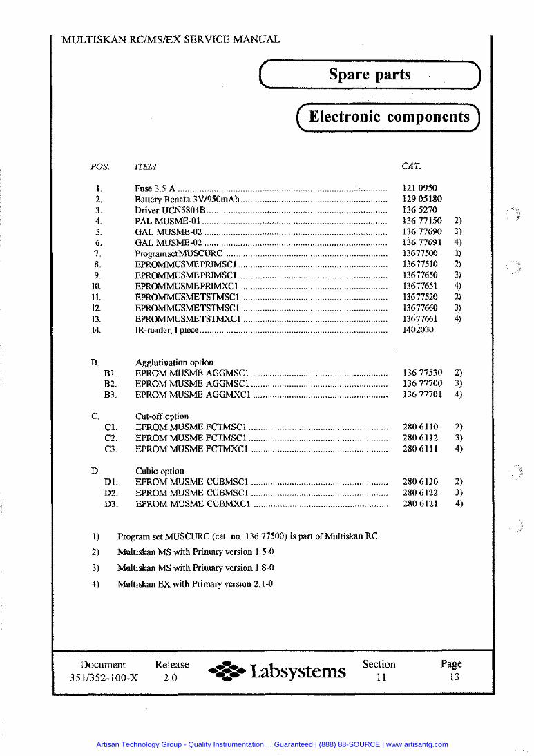
POS.
1. 2. 3. 4. 5. 6. 7. 8. 9.
10. 11. 12. 13. 14.
B. B1. 82. B3.
C. C1. C2. C3.
D. Dl. D2. D3.
Spare parts
Electronic components
ITEM CAT.
... '..... ........ ................................... . ........ Driver UCN5804 PAL MUSME-
GAL MUSME-02 ............................................................................
EPROMMLJSME EPROMMUSME EPROMMUSME EPROMMUSMETSTMXC IR-reader, I piece .. .................... ... ~ .........................
Agglutination option EPROM MUSME AGGMSCl ........................ ......... .. . . . .. . 136 77530 2) EPROM MUSME AGGMSCl .. .............. 136 77700 3) EPROM MUSME AGGMXCI .... .. ......... ............. ....... ... . . . . . . . . 136 77701 4)
Cut-off option EPROM MUSME FCTMSCl ....................................................... 280 6110 2) EPROM MUSME FCTMSCl ................. .......................... .......... 280 6112 3) EPROM MUSME FCTMXCl ......................... .... ................... 280 6 11 1 4)
Cubic option EPROM MUSME CUBMSCl ................ ,,............. 280 6120 2) EPROM MUSME CUBMSCl .... . . . . . . . . . . 280 6122 3) EPROMMUSME CUBUXCl ................................................. 280 6121 4)
1) Program set MUSCURC (cat. no. 136 77500) is part of Multiskan RC.
2) Multiskan MS with Primary version 1.5-0
3) Multiskan MS with Primary version 1.8-0
4) Multiskan EX with Primary version 2.1-0
Document Release --o Section Page 3511352-100-x 2.0 --so Labsystems , , 13
Artisan Technology Group - Quality Instrumentation ... Guaranteed | (888) 88-SOURCE | www.artisantg.com
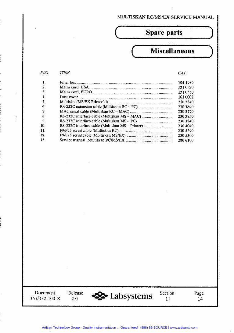
MIJLTISKAN RC/MS/EX SERVICE MANUAL
Spare parts
Miscellaneous
POS.
1. 2. 3. 4. 5. 6. 7. 8, 9.
10. 11. 12. 13.
ITEM C1T.
Filter box ......................................................................................... Mains cord, USA
. . . . . . . . . . . . . . . . . . . . . * . . . . . . . . . . . . . . . . . . . . . . . . . . . . . . . . . . . . . RS-232C extension cable (Multiskan RC -PC) ............................. .. MAC serial cable (Multiskan RC - MAC) ....................................... RS-232C interface cable (Multiskan MS -MAC) ... RS-232C interface cable (Mnltiskan MS -PC) .... RS-232C interface cable (Multiskan MS -Printer) .......................... F91F25 serial cable (Multiskan F9/F25 serial cable (Multiskan Sewice manual, Multiskan RC/MS/EX ............ ................ .. ......,,
Document Release Section -z* Labsystems , , Page 3511352-100-X 2.0 14
Artisan Technology Group - Quality Instrumentation ... Guaranteed | (888) 88-SOURCE | www.artisantg.com
Artisan Technology Group - Quality Instrumentation ... Guaranteed | (888) 88-SOURCE | www.artisantg.com
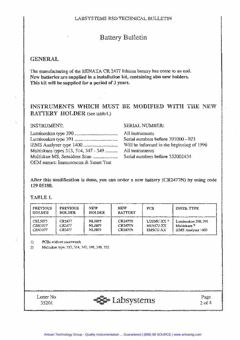
urn battery has 6
Lumin~skm type 390 ...................... .. ....... ,411 insmments Luminoskm type 391. ................................ Serial numbers fore 391000 -, 023 iEMS Analyzer type 1400 ............................ Will be in n the beginning sf 1995 Multiskms types 313, 314, 347 - 349 .......... All insmments Multiskan MS, Sensident Scan .................... Serial numbws @fore 352002434 OEM names: Immunoscan & Srnm Test
CRI-5077 CR2477 NLS077 CR2477N LUSMU-XX '1 Lumit~sskan 395,391 CRIIS077 CR2477 NU077 CR2477N MUSCU-XX Mulriskm a CRHSO77 CR2477 NL5077 CR2477N EMSCU-XU; iEMS Gndyzer 1400
1) PCBs without smartwatch
2) Mulriskan type: 311,314,347,348,349,352
Letter No 35201
Artisan Technology Group - Quality Instrumentation ... Guaranteed | (888) 88-SOURCE | www.artisantg.com
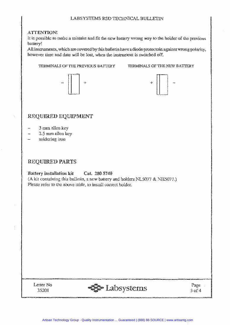
It is possible to make a mistake and f i t the new battery won way to the holder of the previous battery! All insmments, which are covered by this buktin have a&odeprotect~in against however tirne and dace will be lost, when the ins menr is switched off
- 3 nam allen key - 2.5 mm allen key - soldering iron
ttery installation kit Cat. 2 kit containing this bulletin, a new batte~y and holders 5077 & N%%S077.)
Please refer to the above table, to install correct holder,
Letter No 35201
Page 3 o f4
Artisan Technology Group - Quality Instrumentation ... Guaranteed | (888) 88-SOURCE | www.artisantg.com
SYSTEMS RSD E C CAL BLJELETIb
Switch the insmment off ;and remove the mains cord.
By using a 3mm allen key, remove the screws attaching the tap cover.
nalyzer: Disconnect all cables from EMSCU pcb and remove screws holding it. ns: Discor~nect ail cables from MUSCU pcb and remove screws holding it.
ns: Lift the EUSMU pcb from the rack.
Note the polarity before removing the Previous holder. (Plus t e d n a l is indicated in the pcb by "comer mark", the holder has i- marking). Unsolder and remove the battery holder.
Install the new holder.
Place the PCB back and install the new battery.
Switch the insrmment on and set the new rime and date.
Switch the insehument off and wait for a moment until switching en again to confirpxl that the instmment has kept the time &date - setring.
Letter No 35201
Page 4 o f 4
Artisan Technology Group - Quality Instrumentation ... Guaranteed | (888) 88-SOURCE | www.artisantg.com
August 20th, 1998
Letter no. 35501
Artisan Technology Group - Quality Instrumentation ... Guaranteed | (888) 88-SOURCE | www.artisantg.com
It has been noticed that there has occurred some problems to know which aRer sales kits belongs to which instrument.
Easiest way to find out the Eprom option kit to be used is to see the primary version The primary version is shown during the start up.
ultiskan MS with Primary version 1.5-0 28051 10 Gut-off Eprom Option kit 2806120 Cubic Spline Eprom Option kit
Multiskan MS with Primary version 1.8-0 2806112 Cut-off Eprom Option kit 2806122 Cubic Spline Eprom Option kit
Multiskan EX with Primary version 2.1-0 28061 1 1 Cut-off Eprom Option kit 2806121 Cubic Spline Eprom Option kit
Please see next page for detailed information
Artisan Technology Group - Quality Instrumentation ... Guaranteed | (888) 88-SOURCE | www.artisantg.com
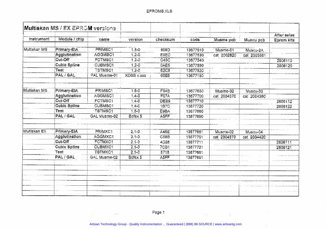
Artisan Technology Group - Quality Instrumentation ... Guaranteed | (888) 88-SOURCE | www.artisantg.com

Artisan Technology Group is your source for quality new and certified-used/pre-owned equipment
• FAST SHIPPING AND DELIVERY
• TENS OF THOUSANDS OF IN-STOCK ITEMS
• EQUIPMENT DEMOS
• HUNDREDS OF MANUFACTURERS SUPPORTED
• LEASING/MONTHLY RENTALS
• ITAR CERTIFIED SECURE ASSET SOLUTIONS
SERVICE CENTER REPAIRSExperienced engineers and technicians on staff at our full-service, in-house repair center
WE BUY USED EQUIPMENTSell your excess, underutilized, and idle used equipment We also offer credit for buy-backs and trade-inswww.artisantg.com/WeBuyEquipment
REMOTE INSPECTIONRemotely inspect equipment before purchasing with our interactive website at www.instraview.com
LOOKING FOR MORE INFORMATION? Visit us on the web at www.artisantg.com for more information on price quotations, drivers, technical specifications, manuals, and documentation
Contact us: (888) 88-SOURCE | [email protected] | www.artisantg.com
SMViewInstra