artisan technology group is your source for quality ... machine edition ge fanuc controller and i/o...
TRANSCRIPT

Artisan Technology Group is your source for quality new and certified-used/pre-owned equipment
• FAST SHIPPING AND DELIVERY
• TENS OF THOUSANDS OF IN-STOCK ITEMS
• EQUIPMENT DEMOS
• HUNDREDS OF MANUFACTURERS SUPPORTED
• LEASING/MONTHLY RENTALS
• ITAR CERTIFIED SECURE ASSET SOLUTIONS
SERVICE CENTER REPAIRSExperienced engineers and technicians on staff at our full-service, in-house repair center
WE BUY USED EQUIPMENTSell your excess, underutilized, and idle used equipment We also offer credit for buy-backs and trade-inswww.artisantg.com/WeBuyEquipment
REMOTE INSPECTIONRemotely inspect equipment before purchasing with our interactive website at www.instraview.com
LOOKING FOR MORE INFORMATION? Visit us on the web at www.artisantg.com for more information on price quotations, drivers, technical specifications, manuals, and documentation
Contact us: (888) 88-SOURCE | [email protected] | www.artisantg.com
SMViewInstra
Controller & I/OSolutionsMore choices for your applications
GE Fanuc Automation
Artisan Technology Group - Quality Instrumentation ... Guaranteed | (888) 88-SOURCE | www.artisantg.com
GE Fanuc Controller and I/O Solutions 1www.gefanuc.com
Table of Contents
GE Fanuc Controllers and I/O Overview. . . . . . . . . . . . . . . . . . . 2
Proficy™ Machine Edition . . . . . . . . . . . . . . . . . . . . . . . . . . . . . . . . . 7
PACSystems™ RX7i Controllers. . . . . . . . . . . . . . . . . . . . . . . . . . . 11
PACSystems RX3i Controllers . . . . . . . . . . . . . . . . . . . . . . . . . . . 33
Series 90™-70 PLCs . . . . . . . . . . . . . . . . . . . . . . . . . . . . . . . . . . . . . 75
Series 90-30 PLCs . . . . . . . . . . . . . . . . . . . . . . . . . . . . . . . . . . . . . . 97
VersaMax® I/O and Control . . . . . . . . . . . . . . . . . . . . . . . . . . . . 135
VersaMax Nano and Micro Controllers . . . . . . . . . . . . . . . . . 171
QuickPanel™ Control . . . . . . . . . . . . . . . . . . . . . . . . . . . . . . . . . . . 193
QuickPanel™ Control-Europe, Middle East and Africa . . . . 199
Genius® Distributed I/O . . . . . . . . . . . . . . . . . . . . . . . . . . . . . . . . 203
VersaPoint™ I/O . . . . . . . . . . . . . . . . . . . . . . . . . . . . . . . . . . . . . . . 217
VersaMax IP . . . . . . . . . . . . . . . . . . . . . . . . . . . . . . . . . . . . . . . . . . 231
QuickPanel View . . . . . . . . . . . . . . . . . . . . . . . . . . . . . . . . . . . . . . 237
QuickPanel View-Europe, Middle East and Africa. . . . . . . . 245
GE Fanuc Automation Services . . . . . . . . . . . . . . . . . . . . . . . . 251
Appendix . . . . . . . . . . . . . . . . . . . . . . . . . . . . . . . . . . . . . . . . . . . . . 257
Index . . . . . . . . . . . . . . . . . . . . . . . . . . . . . . . . . . . . . . . . . . . . . . . . . 259
©2005 GE Fanuc Automation, Inc. All Rights Reserved. 11.05 GFA-406D
Artisan Technology Group - Quality Instrumentation ... Guaranteed | (888) 88-SOURCE | www.artisantg.com
Controllers and I/O Overview
2 GE Fanuc Controller and I/O Solutions www.gefanuc.com
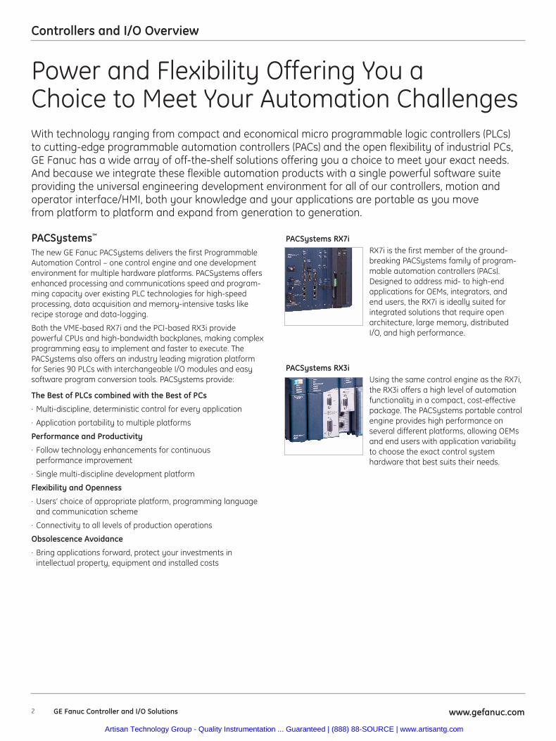
PACSystems™
The new GE Fanuc PACSystems delivers the first ProgrammableAutomation Control – one control engine and one developmentenvironment for multiple hardware platforms. PACSystems offersenhanced processing and communications speed and program-ming capacity over existing PLC technologies for high-speedprocessing, data acquisition and memory-intensive tasks likerecipe storage and data-logging.
Both the VME-based RX7i and the PCI-based RX3i providepowerful CPUs and high-bandwidth backplanes, making complexprogramming easy to implement and faster to execute. ThePACSystems also offers an industry leading migration platformfor Series 90 PLCs with interchangeable I/O modules and easysoftware program conversion tools. PACSystems provide:
The Best of PLCs combined with the Best of PCs
· Multi-discipline, deterministic control for every application
· Application portability to multiple platforms
Performance and Productivity
· Follow technology enhancements for continuousperformance improvement
· Single multi-discipline development platform
Flexibility and Openness
· Users’ choice of appropriate platform, programming languageand communication scheme
· Connectivity to all levels of production operations
Obsolescence Avoidance
· Bring applications forward, protect your investments inintellectual property, equipment and installed costs
With technology ranging from compact and economical micro programmable logic controllers (PLCs)to cutting-edge programmable automation controllers (PACs) and the open flexibility of industrial PCs,GE Fanuc has a wide array of off-the-shelf solutions offering you a choice to meet your exact needs.And because we integrate these flexible automation products with a single powerful software suiteproviding the universal engineering development environment for all of our controllers, motion andoperator interface/HMI, both your knowledge and your applications are portable as you movefrom platform to platform and expand from generation to generation.
PACSystems RX7iRX7i is the first member of the ground-breaking PACSystems family of program-mable automation controllers (PACs).Designed to address mid- to high-endapplications for OEMs, integrators, and end users, the RX7i is ideally suited for integrated solutions that require openarchitecture, large memory, distributed I/O, and high performance.
PACSystems RX3iUsing the same control engine as the RX7i,the RX3i offers a high level of automationfunctionality in a compact, cost-effectivepackage. The PACSystems portable controlengine provides high performance on several different platforms, allowing OEMsand end users with application variabilityto choose the exact control system hardware that best suits their needs.
Power and Flexibility Offering You a Choice to Meet Your Automation Challenges
Artisan Technology Group - Quality Instrumentation ... Guaranteed | (888) 88-SOURCE | www.artisantg.com
Controllers and I/O Overview
3www.gefanuc.com GE Fanuc Controller and I/O Solutions
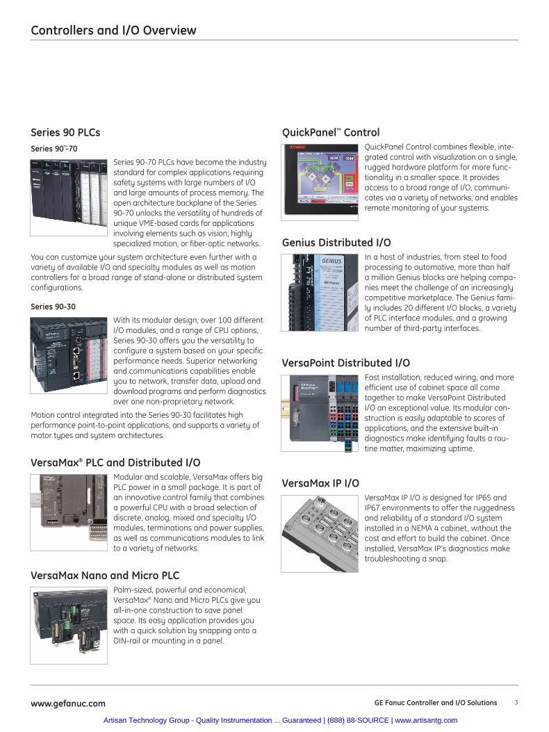
Series 90 PLCsSeries 90™-70
Series 90-70 PLCs have become the industrystandard for complex applications requiringsafety systems with large numbers of I/Oand large amounts of process memory. Theopen architecture backplane of the Series90-70 unlocks the versatility of hundreds ofunique VME-based cards for applicationsinvolving elements such as vision, highly specialized motion, or fiber-optic networks.
You can customize your system architecture even further with avariety of available I/O and specialty modules as well as motioncontrollers for a broad range of stand-alone or distributed systemconfigurations.
Series 90-30
With its modular design, over 100 differentI/O modules, and a range of CPU options,Series 90-30 offers you the versatility toconfigure a system based on your specificperformance needs. Superior networkingand communications capabilities enableyou to network, transfer data, upload anddownload programs and perform diagnosticsover one non-proprietary network.
Motion control integrated into the Series 90-30 facilitates highperformance point-to-point applications, and supports a variety ofmotor types and system architectures.
VersaMax® PLC and Distributed I/OModular and scalable, VersaMax offers bigPLC power in a small package. It is part ofan innovative control family that combinesa powerful CPU with a broad selection ofdiscrete, analog, mixed and specialty I/Omodules, terminations and power supplies,as well as communications modules to linkto a variety of networks.
VersaMax Nano and Micro PLCPalm-sized, powerful and economical,VersaMax® Nano and Micro PLCs give youall-in-one construction to save panelspace. Its easy application provides youwith a quick solution by snapping onto aDIN-rail or mounting in a panel.
QuickPanel™ ControlQuickPanel Control combines flexible, inte-grated control with visualization on a single,rugged hardware platform for more func-tionality in a smaller space. It providesaccess to a broad range of I/O, communi-cates via a variety of networks, and enablesremote monitoring of your systems.
Genius Distributed I/OIn a host of industries, from steel to foodprocessing to automotive, more than half a million Genius blocks are helping compa-nies meet the challenge of an increasinglycompetitive marketplace. The Genius fami-ly includes 20 different I/O blocks, a varietyof PLC interface modules, and a growingnumber of third-party interfaces.
VersaPoint Distributed I/O Fast installation, reduced wiring, and moreefficient use of cabinet space all cometogether to make VersaPoint DistributedI/O an exceptional value. Its modular con-struction is easily adaptable to scores ofapplications, and the extensive built-indiagnostics make identifying faults a rou-tine matter, maximizing uptime.
VersaMax IP I/OVersaMax IP I/O is designed for IP65 andIP67 environments to offer the ruggednessand reliability of a standard I/O systeminstalled in a NEMA 4 cabinet, without thecost and effort to build the cabinet. Onceinstalled, VersaMax IP’s diagnostics maketroubleshooting a snap.
Artisan Technology Group - Quality Instrumentation ... Guaranteed | (888) 88-SOURCE | www.artisantg.com
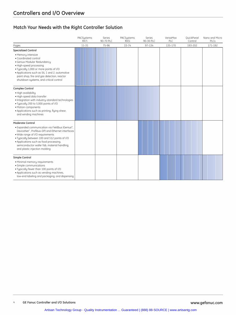
Match Your Needs with the Right Controller Solution
PACSystems Series PACSystems Series VersaMax QuickPanel Nano and MicroRX7i 90-70 PLC RX3i 90-30 PLC PLC Control PLCs
Pages 11-31 75-96 33-74 97-134 135-170 193-202 171-192
Specialized Control
• Memory intensive• Coordinated control• Genius Modular Redundancy• High-speed processing• Typically 1,000 or more points of I/O• Applications such as SIL 1 and 2, automotive
paint shop, fire and gas detection, reactor shutdown systems, and critical control
Complex Control
• High availability• High-speed data transfer• Integration with industry-standard technologies• Typically 200 to 5,000 points of I/O• Motion components• Applications such as printing, flying shear,
and winding machines
Moderate Control
• Expanded communication via Fieldbus (Genius®, DeviceNet™, Profibus-DP) and Ethernet interfaces
• Wide range of I/O requirements• Typically between 100 and 512 points of I/O• Applications such as food processing,
semiconductor wafer fab, material handling, and plastic injection molding
Simple Control
• Minimal memory requirements• Simple communications• Typically fewer than 100 points of I/O• Applications such as vending machines,
low-end labeling and packaging, and dispensing
Controllers and I/O Overview
4 GE Fanuc Controller and I/O Solutions www.gefanuc.com
Artisan Technology Group - Quality Instrumentation ... Guaranteed | (888) 88-SOURCE | www.artisantg.com
Controllers and I/O Overview
5www.gefanuc.com GE Fanuc Controller and I/O Solutions
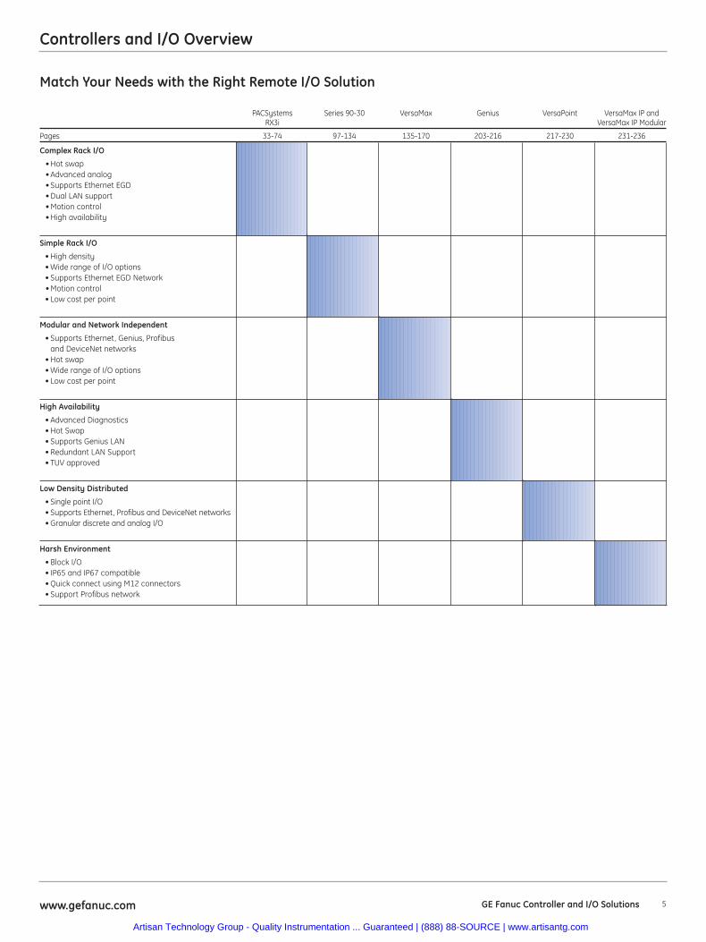
Match Your Needs with the Right Remote I/O Solution
PACSystems Series 90-30 VersaMax Genius VersaPoint VersaMax IP and RX3i VersaMax IP Modular
Pages 33-74 97-134 135-170 203-216 217-230 231-236
Complex Rack I/O
• Hot swap• Advanced analog• Supports Ethernet EGD• Dual LAN support• Motion control• High availability
Simple Rack I/O
• High density• Wide range of I/O options• Supports Ethernet EGD Network• Motion control• Low cost per point
Modular and Network Independent
• Supports Ethernet, Genius, Profibus and DeviceNet networks
• Hot swap• Wide range of I/O options• Low cost per point
High Availability
• Advanced Diagnostics• Hot Swap• Supports Genius LAN• Redundant LAN Support• TUV approved
Low Density Distributed
• Single point I/O• Supports Ethernet, Profibus and DeviceNet networks• Granular discrete and analog I/O
Harsh Environment
• Block I/O• IP65 and IP67 compatible• Quick connect using M12 connectors• Support Profibus network
Artisan Technology Group - Quality Instrumentation ... Guaranteed | (888) 88-SOURCE | www.artisantg.com

Notes
6 GE Fanuc Controller and I/O Solutions www.gefanuc.com
Artisan Technology Group - Quality Instrumentation ... Guaranteed | (888) 88-SOURCE | www.artisantg.com
Proficy Machine Edition
7www.gefanuc.com GE Fanuc Controller and I/O Solutions
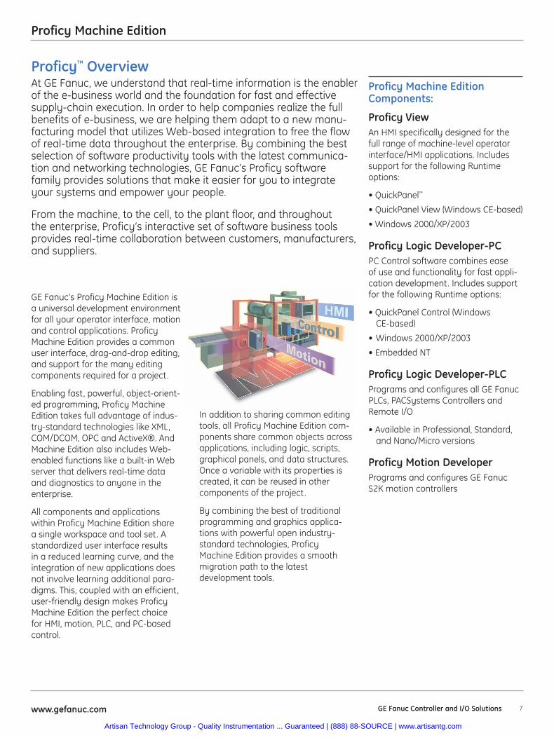
GE Fanuc’s Proficy Machine Edition isa universal development environmentfor all your operator interface, motionand control applications. ProficyMachine Edition provides a commonuser interface, drag-and-drop editing,and support for the many editingcomponents required for a project.
Enabling fast, powerful, object-orient-ed programming, Proficy MachineEdition takes full advantage of indus-try-standard technologies like XML,COM/DCOM, OPC and ActiveX®. AndMachine Edition also includes Web-enabled functions like a built-in Webserver that delivers real-time dataand diagnostics to anyone in theenterprise.
All components and applicationswithin Proficy Machine Edition sharea single workspace and tool set. Astandardized user interface resultsin a reduced learning curve, and theintegration of new applications doesnot involve learning additional para-digms. This, coupled with an efficient,user-friendly design makes ProficyMachine Edition the perfect choicefor HMI, motion, PLC, and PC-basedcontrol.
In addition to sharing common editingtools, all Proficy Machine Edition com-ponents share common objects acrossapplications, including logic, scripts,graphical panels, and data structures.Once a variable with its properties iscreated, it can be reused in othercomponents of the project.
By combining the best of traditionalprogramming and graphics applica-tions with powerful open industry-standard technologies, ProficyMachine Edition provides a smoothmigration path to the latestdevelopment tools.
Proficy Machine EditionComponents:
Proficy ViewAn HMI specifically designed for thefull range of machine-level operatorinterface/HMI applications. Includessupport for the following Runtimeoptions:
• QuickPanel™
• QuickPanel View (Windows CE-based)
• Windows 2000/XP/2003
Proficy Logic Developer-PCPC Control software combines easeof use and functionality for fast appli-cation development. Includes supportfor the following Runtime options:
• QuickPanel Control (Windows CE-based)
• Windows 2000/XP/2003
• Embedded NT
Proficy Logic Developer-PLCPrograms and configures all GE FanucPLCs, PACSystems Controllers andRemote I/O
• Available in Professional, Standard,and Nano/Micro versions
Proficy Motion DeveloperPrograms and configures GE FanucS2K motion controllers
Proficy™ OverviewAt GE Fanuc, we understand that real-time information is the enablerof the e-business world and the foundation for fast and effectivesupply-chain execution. In order to help companies realize the fullbenefits of e-business, we are helping them adapt to a new manu-facturing model that utilizes Web-based integration to free the flowof real-time data throughout the enterprise. By combining the bestselection of software productivity tools with the latest communica-tion and networking technologies, GE Fanuc’s Proficy softwarefamily provides solutions that make it easier for you to integrateyour systems and empower your people.
From the machine, to the cell, to the plant floor, and throughoutthe enterprise, Proficy‘s interactive set of software business toolsprovides real-time collaboration between customers, manufacturers,and suppliers.
Artisan Technology Group - Quality Instrumentation ... Guaranteed | (888) 88-SOURCE | www.artisantg.com
Proficy Machine Edition
8 GE Fanuc Controller and I/O Solutions www.gefanuc.com
Fully Integrated Development SystemProficy Machine Edition’s development system provides a clean, easy-to-learninterface for its components. Proficy Logic Developer-PLC automatically sharesediting and configuration tools with other components when they are installed,creating an integrated, drag-and-drop workspace that makes developing appli-cations simple. Just drag a PLC variable to an HMI animation panel to link them,or vice versa. Work on all parts of your automation system simultaneously, without switching between programs!
Toolchest Offers Object OrientedReusability and Pre-defined ToolsBuild applications rapidly with pre-configured objects from the Toolchest,a storage system for objects includingtheir associated logic or HMI elementsand data structures. Drag your ownwork to the Toolchest for easy reuse—logic, scripting, graphical objects—anything you want to save and reuse.
ConfigureProficy Logic Developer-PLC supportsthe full range of GE Fanuc PLCs,PACSystems controllers and RemoteI/O products including the Series 90™-30, Series 90-70, PACSystems™ RX3iand RX7i, VersaMax®, and VersaMaxNano/Micro PLCs, and VersaMaxRemote I/O. Configuration support isalso provided for a wide range of fieldbusses such as Ethernet Global Data(EGD), Genius®, DeviceNet™, ModBusTCP, and Profibus™.
ProgramProficy Logic Developer-PLC providesa full set of programming languagesfor you to develop your PLC applica-tions. Ladder Diagram (LD), FunctionBlock Diagram (FBD), Structured Text(ST), and C Block programming lan-guages are all supported by LogicDeveloper-PLC.
CommissionProficy Logic Developer-PLC providesa complete set of on-line developmenttools to aid in commissioning your PLCapplication. Tools such as Run ModeStore (RMS) of Logic, Online Test Mode
Proficy Logic Developer-PLC: A Superior Set of PLC Programming Tools
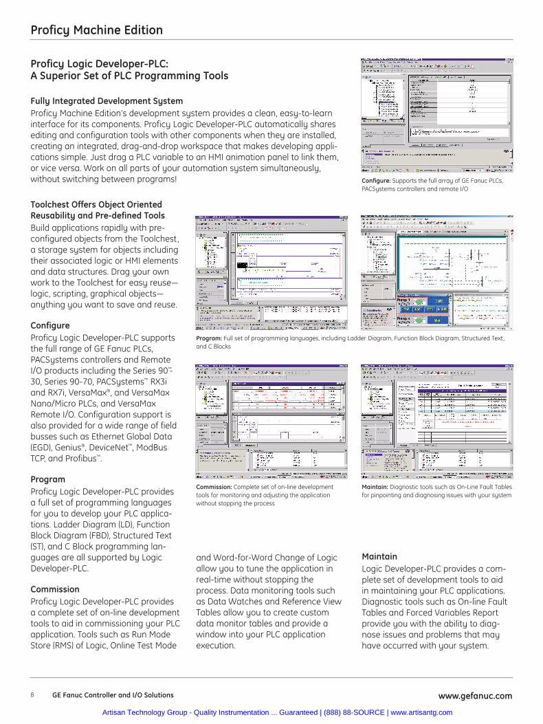
Configure: Supports the full array of GE Fanuc PLCs,PACSystems controllers and remote I/O
Program: Full set of programming languages, including Ladder Diagram, Function Block Diagram, Structured Text,and C Blocks
Commission: Complete set of on-line developmenttools for monitoring and adjusting the application without stopping the process
Maintain: Diagnostic tools such as On-Line Fault Tablesfor pinpointing and diagnosing issues with your system
and Word-for-Word Change of Logicallow you to tune the application inreal-time without stopping theprocess. Data monitoring tools suchas Data Watches and Reference ViewTables allow you to create customdata monitor tables and provide awindow into your PLC applicationexecution.
MaintainLogic Developer-PLC provides a com-plete set of development tools to aidin maintaining your PLC applications.Diagnostic tools such as On-line FaultTables and Forced Variables Reportprovide you with the ability to diag-nose issues and problems that mayhave occurred with your system.
Artisan Technology Group - Quality Instrumentation ... Guaranteed | (888) 88-SOURCE | www.artisantg.com
Proficy Machine Edition
9www.gefanuc.com GE Fanuc Controller and I/O Solutions
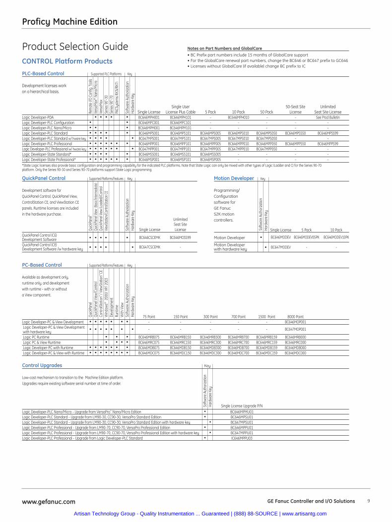
Product Selection GuideCONTROL Platform Products
PLC-Based Control Supported PLC Platforms Key
Development licenses workon a hierarchical basis.
Single User 50-Seat Site UnlimitedSingle License License Plus Cable 5 Pack 10 Pack 50 Pack License Seat Site License
Logic Developer-PDA • • • • • BC646MPH001 BC646MPH101 - BC646MPH010 - - See Prod BulletinLogic Developer-PLC Configuration • • BC646MPC001 BC646MPC101 - - - - -Logic Developer-PLC Nano/Micro • • • BC646MPM001 BC646MPM101 - - - - -Logic Developer-PLC Standard • • • • • BC646MPS001 BC646MPS101 BC646MPS005 BC646MPS010 BC646MPS050 BC646MPSS50 BC646MPSS99Logic Developer-PLC Standard w/ hware key • • • • • BC647MPS001 BC647MPS101 BC647MPS005 BC647MPS010 BC647MPS050 - -Logic Developer-PLC Professional • • • • • • • BC646MPP001 BC646MPP101 BC646MPP005 BC646MPP010 BC646MPP050 BC646MPPS50 BC646MPPS99Logic Developer-PLC Professional w/ hware key • • • • • • • BC647MPP001 BC647MPP101 BC647MPP005 BC647MPP010 BC647MPP050 - -Logic Developer-State Standard* • • • • • BC646MSS001 BC646MSS101 BC646MSS005 - - - -Logic Developer-State Professional* • • • • • • • BC646MSP001 BC646MSP101 BC646MSP005 - - - -*State Logic licenses also provide basic configuration and programming capability for the indicated PLC platforms. Note that State Logic can only be mixed with other types of Logic (Ladder and C) for the Series 90-70 platform. Only the Series 90-30 and Series 90-70 platforms support State Logic programming.
QuickPanel Control Supported Platforms/Features Key
Development software for QuickPanel Control, QuickPanel View,ControlStation CE, and ViewStation CEpanels. Runtime licenses are included in the hardware purchase.
UnlimitedSeat Site
Single License LicenseQuickPanel Control (CE) Development Software • • • • • BC646CSCEMK BC646MOSS99
QuickPanel Control (CE) Development Software /w hardware key • • • • • BC647CSCEMK -
PC-Based Control Supported Platforms/Features Key
Available as development only,runtime only, and development with runtime - with or without a View component.
75 Point 150 Point 300 Point 700 Point 1500 Point 8000 PointLogic Developer-PC & View Development • • • • • • • - - - - - BC646MOP001Logic Developer-PC & View Developmentwith hardware key
• • • • • • • - - - - - BC647MOP001
Logic PC Runtime • • • BC646MRB075 BC646MRB150 BC646MRB300 BC646MRB700 BC646MRB159 BC646MRB000Logic PC & View Runtime • • • • BC646MRC075 BC646MRC150 BC646MRC300 BC646MRC700 BC646MRC159 BC646MRC000Logic Developer-PC with Runtime • • • • • • • BC646MDB075 BC646MDB150 BC646MDB300 BC646MDB700 BC646MDB159 BC646MDB000Logic Developer-PC & View with Runtime • • • • • • • • BC646MDC075 BC646MDC150 BC646MDC300 BC646MDC700 BC646MDC159 BC646MDC000
Rem
ote
I/O C
onfig
. Too
lsVe
rsaM
ax®
Nano
/Micr
oVe
rsaM
axSe
ries 9
0™ -30
Serie
s 90™ -7
0PA
CSys
tem
s RX3
i/RX7
i
Softw
are
Auth
oriza
tion
Hard
ware
Key
Quick
Pane
l™
Quick
Pane
l View
(Basic
/Inte
rmed
iate)
Quick
Pane
l View
(Loa
ded)/
Cont
rol
ViewS
tatio
n/Co
ntro
lStat
ion C
E
Softw
are
Auth
oriza
tion
Hard
ware
Key
Quick
Pane
lQu
ickPa
nel V
iew/C
ontro
lCo
ntro
lStat
ion™
/ View
Stat
ion™
CEW
indo
ws®
2000
/ XP/
200
3De
velo
pmen
tRu
ntim
eW
ith V
iewSo
ftwar
e Au
thor
izatio
nHa
rdw
are
Key
Notes on Part Numbers and GlobalCare• BC Prefix part numbers include 15 months of GlobalCare support• For the GlobalCare renewal part numbers, change the BC646 or BC647 prefix to GC646• Licenses without GlobalCare (if available) change BC prefix to IC
Motion Developer Key
Programming/ Configurationsoftware for GE FanucS2K motion controllers.
Single License 5 Pack 10 Pack
Motion Developer • BC646MODEV BC646MODEV05PK BC646MODEV10PK
Motion Developer with hardware key • BC647MODEV - -
Softw
are
Auth
oriza
tion
Hard
ware
Key
Control Upgrades Key
Low-cost mechanism to transition to the Machine Edition platform. Upgrades require existing software serial number at time of order.
Single License Upgrade P/NLogic Developer-PLC Nano/Micro - Upgrade from VersaPro™ Nano/Micro Edition • BC646MPMU01Logic Developer-PLC Standard - Upgrade from LM90-30, CC90-30, VersaPro Standard Edition • BC646MPSU01Logic Developer-PLC Standard - Upgrade from LM90-30, CC90-30, VersaPro Standard Edition with hardware key • BC647MPSU01Logic Developer-PLC Professional - Upgrade from LM90-70, CC90-70, VersaPro Professional Edition • BC646MPPU01Logic Developer-PLC Professional - Upgrade from LM90-70, CC90-70, VersaPro Professional Edition with hardware key • BC647MPPU01Logic Developer-PLC Professional - Upgrade from Logic Developer-PLC Standard • IC646MPPU03
Softw
are
Auth
oriza
tion
Hard
ware
Key
Artisan Technology Group - Quality Instrumentation ... Guaranteed | (888) 88-SOURCE | www.artisantg.com
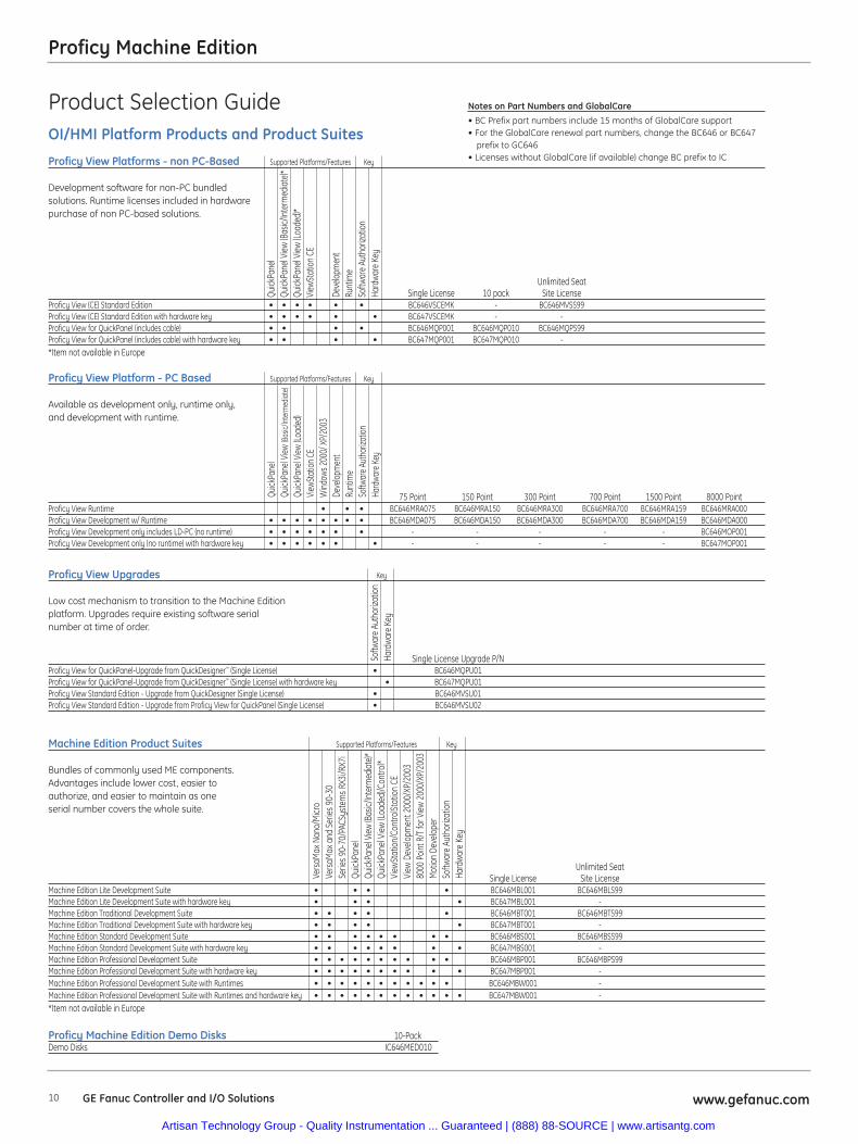
Product Selection GuideOI/HMI Platform Products and Product Suites
Quick
Pane
lQu
ickPa
nel V
iew (B
asic/
Inte
rmed
iate
)*Qu
ickPa
nel V
iew (L
oade
d)*
View
Stat
ion
CE
Deve
lopm
ent
Runt
ime
Softw
are
Auth
oriza
tion
Hard
ware
Key
Proficy View Platforms - non PC-Based Supported Platforms/Features Key
Development software for non-PC bundled solutions. Runtime licenses included in hardware purchase of non PC-based solutions.
Unlimited SeatSingle License 10 pack Site License
Proficy View (CE) Standard Edition • • • • • • BC646VSCEMK - BC646MVSS99Proficy View (CE) Standard Edition with hardware key • • • • • • BC647VSCEMK - -Proficy View for QuickPanel (includes cable) • • • • BC646MQP001 BC646MQP010 BC646MQPS99Proficy View for QuickPanel (includes cable) with hardware key • • • • BC647MQP001 BC647MQP010 -*Item not available in Europe
Proficy View Platform - PC Based Supported Platforms/Features Key
Available as development only, runtime only,and development with runtime.
75 Point 150 Point 300 Point 700 Point 1500 Point 8000 PointProficy View Runtime • • • BC646MRA075 BC646MRA150 BC646MRA300 BC646MRA700 BC646MRA159 BC646MRA000Proficy View Development w/ Runtime • • • • • • • • BC646MDA075 BC646MDA150 BC646MDA300 BC646MDA700 BC646MDA159 BC646MDA000Proficy View Development only includes LD-PC (no runtime) • • • • • • • - - - - - BC646MOP001Proficy View Development only (no runtime) with hardware key • • • • • • • - - - - - BC647MOP001
Proficy View Upgrades Key
Low cost mechanism to transition to the Machine Edition platform. Upgrades require existing software serial number at time of order.
Single License Upgrade P/NProficy View for QuickPanel-Upgrade from QuickDesigner™ (Single License) • BC646MQPU01Proficy View for QuickPanel-Upgrade from QuickDesigner™ (Single License) with hardware key • BC647MQPU01Proficy View Standard Edition - Upgrade from QuickDesigner (Single License) • BC646MVSU01Proficy View Standard Edition - Upgrade from Proficy View for QuickPanel (Single License) • BC646MVSU02
Machine Edition Product Suites Supported Platforms/Features Key
Bundles of commonly used ME components. Advantages include lower cost, easier toauthorize, and easier to maintain as one serial number covers the whole suite.
Unlimited SeatSingle License Site License
Machine Edition Lite Development Suite • • • • BC646MBL001 BC646MBLS99Machine Edition Lite Development Suite with hardware key • • • • BC647MBL001 -Machine Edition Traditional Development Suite • • • • • BC646MBT001 BC646MBTS99Machine Edition Traditional Development Suite with hardware key • • • • • BC647MBT001 -Machine Edition Standard Development Suite • • • • • • • • BC646MBS001 BC646MBSS99Machine Edition Standard Development Suite with hardware key • • • • • • • • BC647MBS001 -Machine Edition Professional Development Suite • • • • • • • • • • BC646MBP001 BC646MBPS99Machine Edition Professional Development Suite with hardware key • • • • • • • • • • BC647MBP001 -Machine Edition Professional Development Suite with Runtimes • • • • • • • • • • • BC646MBW001 -Machine Edition Professional Development Suite with Runtimes and hardware key • • • • • • • • • • • • BC647MBW001 -*Item not available in Europe
Proficy Machine Edition Demo Disks 10-PackDemo Disks IC646MED010
Vers
aMax
Nan
o/M
icro
Vers
aMax
and
Ser
ies 9
0-30
Serie
s 90-
70/P
ACSy
stem
s RX3
i/RX7
iQu
ickPa
nel
Quick
Pane
l View
(Bas
ic/In
term
edia
te)*
Quick
Pane
l View
(Loa
ded)
/Con
trol*
View
Stat
ion/
Cont
rolSt
atio
n CE
View
Dev
elopm
ent 2
000/
XP/2
003
8000
Poin
t R/T
for V
iew 2
000/
XP/2
003
Mot
ion
Deve
lope
rSo
ftwar
e Au
thor
izatio
nHa
rdw
are
Key
Quick
Pane
lQu
ickPa
nel V
iew (B
asic/
Inte
rmed
iate)
Quick
Pane
l View
(Loa
ded)
ViewS
tatio
n CE
Wind
ows 2
000/
XP/
2003
Deve
lopm
ent
Runt
ime
Softw
are A
utho
rizat
ionHa
rdwa
re K
eySo
ftwar
e Au
thor
izatio
nHa
rdwa
re K
ey
Notes on Part Numbers and GlobalCare• BC Prefix part numbers include 15 months of GlobalCare support• For the GlobalCare renewal part numbers, change the BC646 or BC647
prefix to GC646• Licenses without GlobalCare (if available) change BC prefix to IC
www.gefanuc.comGE Fanuc Controller and I/O Solutions 10
Proficy Machine Edition
Artisan Technology Group - Quality Instrumentation ... Guaranteed | (888) 88-SOURCE | www.artisantg.com
11www.gefanuc.com GE Fanuc Controller and I/O Solutions
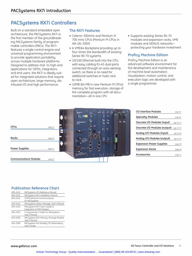
PACSystems RX7i Introduction
CPUs page 12
Racks page 13
Power Supplies page 14
I/O Interface Modules page 26
Specialty Modules page 28
Discrete I/O Modules (input) pgs 15-17
Discrete I/O Modules (output) pgs 21-23
Analog I/O Modules (input) pgs 18-20
Analog I/O Modules (output) pgs 24-25
Expansion Power Supplies page 29
Expansion Racks page 30
Accessories page 31
Publication Reference ChartGFK-2222 PACSystems CPU Reference ManualGFK-2223 PACSystems RX7i Installation ManualGFK-2224 TCP/IP Ethernet Communications
for PACSystemsGFK-2225 PACSystems Station Manager User's ManualGFK-2235 PACSystems RX7i User's Guide to
Integration of VME ModulesGFK-2259 C Programmer's Toolkit for PACSystems
User's ManualGFK-2300 PACSystems RX7i Memory Xchange Modules
User's ManualGFK-2308 PACSystems Hot Standby CPU Redundancy
User's Guide
• Supports existing Series 90-70modules and expansion racks, VMEmodules and GENIUS networks—protecting your hardware investment
Proficy Machine EditionProficy Machine Edition is anadvanced software environment forthe development and maintenanceof machine level automation.Visualization, motion control, andexecution logic are developed witha single programmer.
Built on a standard embedded openarchitecture, the PACSystems RX7i isthe first member of the groundbreak-ing PACSystems family of program-mable controllers (PACs). The RX7ifeatures a single control engine anduniversal programming environmentto provide application portabilityacross multiple hardware platforms.Designed to address mid- to high-endapplications for OEMs, integrators,and end users, the RX7i is ideally suit-ed for integrated solutions that requireopen architecture, large memory, dis-tributed I/O and high performance.
The RX7i Features• Celeron 300mHz and Pentium III
700 mHz CPUs (Pentium M CPUs in4th Qtr 2005)
• A VME64 Backplane providing up tofour times the bandwidth of existingSeries 90-70 systems
• 10/100 Ethernet built into the CPU,with easy cabling RJ-45 dual portsconnected through an auto-sensingswitch, so there is no need foradditional switches or hubs rackto rack
• 10MB (64 MB in new Pentium M CPUs)memory for fast execution, storage ofthe complete program with all docu-mentation—all in one CPU
Communications Modules page 27
PACSystems RX7i Controllers
Artisan Technology Group - Quality Instrumentation ... Guaranteed | (888) 88-SOURCE | www.artisantg.com
PACSystems RX7i
12 www.gefanuc.comGE Fanuc Controller and I/O Solutions
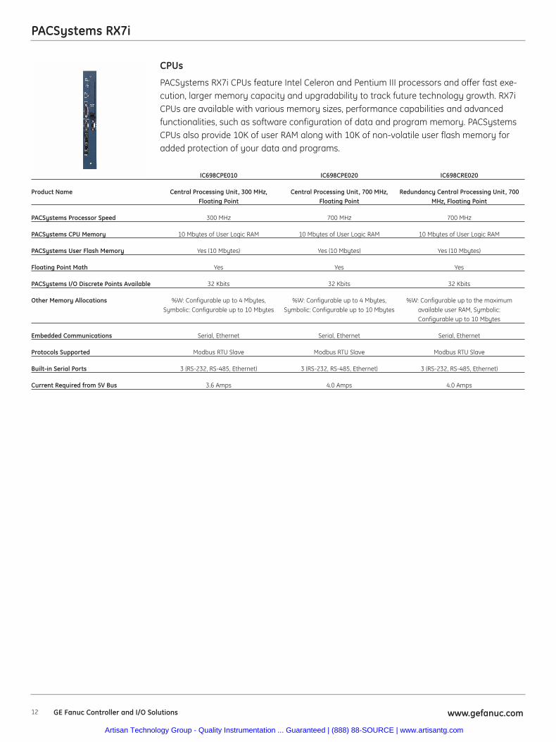
PACSystems RX7i CPUs feature Intel Celeron and Pentium III processors and offer fast exe-cution, larger memory capacity and upgradability to track future technology growth. RX7iCPUs are available with various memory sizes, performance capabilities and advancedfunctionalities, such as software configuration of data and program memory. PACSystemsCPUs also provide 10K of user RAM along with 10K of non-volatile user flash memory foradded protection of your data and programs.
CPUs
IC698CPE010 IC698CPE020 IC698CRE020
Product Name Central Processing Unit, 300 MHz, Central Processing Unit, 700 MHz, Redundancy Central Processing Unit, 700Floating Point Floating Point MHz, Floating Point
PACSystems Processor Speed 300 MHz 700 MHz 700 MHz
PACSystems CPU Memory 10 Mbytes of User Logic RAM 10 Mbytes of User Logic RAM 10 Mbytes of User Logic RAM
PACSystems User Flash Memory Yes (10 Mbytes) Yes (10 Mbytes) Yes (10 Mbytes)
Floating Point Math Yes Yes Yes
PACSystems I/O Discrete Points Available 32 Kbits 32 Kbits 32 Kbits
Other Memory Allocations %W: Configurable up to 4 Mbytes, %W: Configurable up to 4 Mbytes, %W: Configurable up to the maximumSymbolic: Configurable up to 10 Mbytes Symbolic: Configurable up to 10 Mbytes available user RAM, Symbolic:
Configurable up to 10 Mbytes
Embedded Communications Serial, Ethernet Serial, Ethernet Serial, Ethernet
Protocols Supported Modbus RTU Slave Modbus RTU Slave Modbus RTU Slave
Built-in Serial Ports 3 (RS-232, RS-485, Ethernet) 3 (RS-232, RS-485, Ethernet) 3 (RS-232, RS-485, Ethernet)
Current Required from 5V Bus 3.6 Amps 4.0 Amps 4.0 Amps
Artisan Technology Group - Quality Instrumentation ... Guaranteed | (888) 88-SOURCE | www.artisantg.com
PACSystems RX7i
13www.gefanuc.com GE Fanuc Controller and I/O Solutions
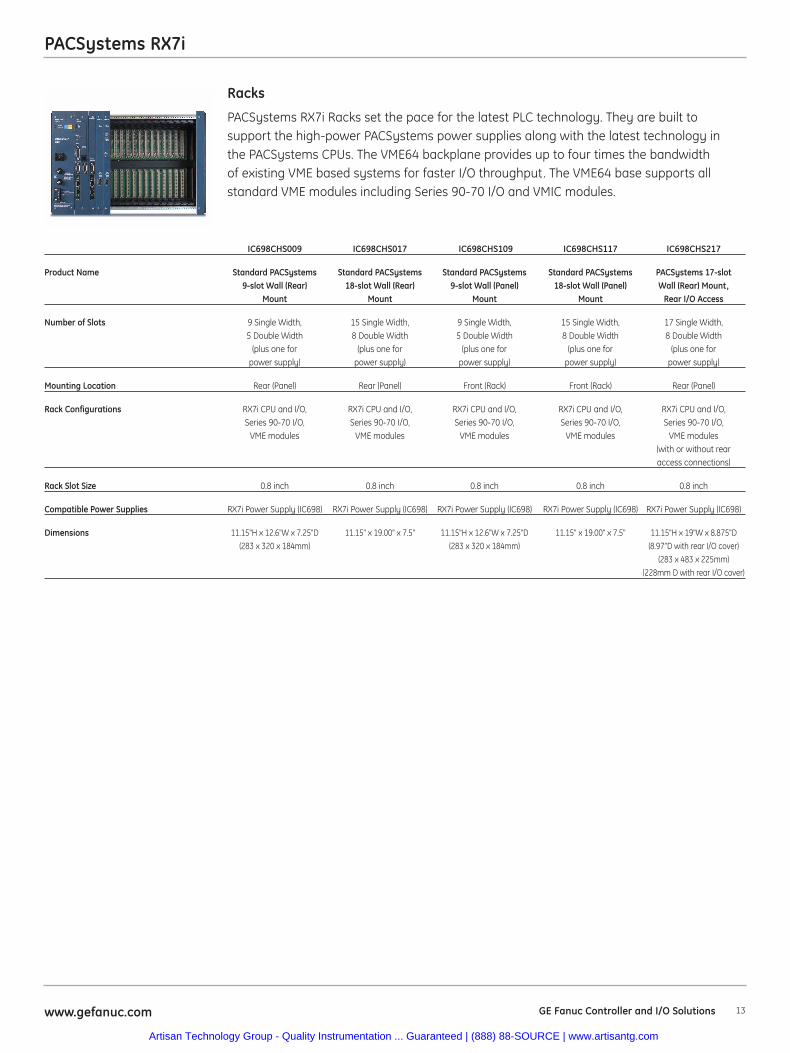
PACSystems RX7i Racks set the pace for the latest PLC technology. They are built tosupport the high-power PACSystems power supplies along with the latest technology inthe PACSystems CPUs. The VME64 backplane provides up to four times the bandwidthof existing VME based systems for faster I/O throughput. The VME64 base supports allstandard VME modules including Series 90-70 I/O and VMIC modules.
Racks
IC698CHS009 IC698CHS017 IC698CHS109 IC698CHS117 IC698CHS217
Product Name Standard PACSystems Standard PACSystems Standard PACSystems Standard PACSystems PACSystems 17-slot 9-slot Wall (Rear) 18-slot Wall (Rear) 9-slot Wall (Panel) 18-slot Wall (Panel) Wall (Rear) Mount,
Mount Mount Mount Mount Rear I/O Access
Number of Slots 9 Single Width, 15 Single Width, 9 Single Width, 15 Single Width, 17 Single Width, 5 Double Width 8 Double Width 5 Double Width 8 Double Width 8 Double Width
(plus one for (plus one for (plus one for (plus one for (plus one for power supply) power supply) power supply) power supply) power supply)
Mounting Location Rear (Panel) Rear (Panel) Front (Rack) Front (Rack) Rear (Panel)
Rack Configurations RX7i CPU and I/O, RX7i CPU and I/O, RX7i CPU and I/O, RX7i CPU and I/O, RX7i CPU and I/O, Series 90-70 I/O, Series 90-70 I/O, Series 90-70 I/O, Series 90-70 I/O, Series 90-70 I/O,
VME modules VME modules VME modules VME modules VME modules(with or without rear access connections)
Rack Slot Size 0.8 inch 0.8 inch 0.8 inch 0.8 inch 0.8 inch
Compatible Power Supplies RX7i Power Supply (IC698) RX7i Power Supply (IC698) RX7i Power Supply (IC698) RX7i Power Supply (IC698) RX7i Power Supply (IC698)
Dimensions 11.15"H x 12.6"W x 7.25"D 11.15" x 19.00" x 7.5" 11.15"H x 12.6"W x 7.25"D 11.15" x 19.00" x 7.5" 11.15"H x 19"W x 8.875"D(283 x 320 x 184mm) (283 x 320 x 184mm) (8.97”D with rear I/O cover)
(283 x 483 x 225mm) (228mm D with rear I/O cover)
Artisan Technology Group - Quality Instrumentation ... Guaranteed | (888) 88-SOURCE | www.artisantg.com
PACSystems RX7i
14 www.gefanuc.comGE Fanuc Controller and I/O Solutions
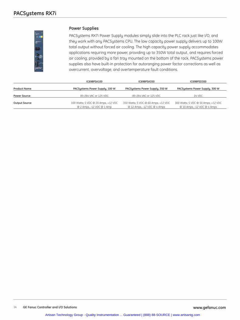
PACSystems RX7i Power Supply modules simply slide into the PLC rack just like I/O, andthey work with any PACSystems CPU. The low capacity power supply delivers up to 100Wtotal output without forced air cooling. The high capacity power supply accommodatesapplications requiring more power, providing up to 350W total output, and requires forcedair cooling, provided by a fan tray mounted on the bottom of the rack. PACSystems powersupplies also have built-in protection for autoranging power factor corrections as well asovercurrent, overvoltage, and overtemperature fault conditions.
Power Supplies
IC698PSA100 IC698PSA350 IC698PSD300
Product Name PACSystems Power Supply, 100 W PACSystems Power Supply, 350 W PACSystems Power Supply, 300 W
Power Source 85-264 VAC or 125 VDC 85-264 VAC or 125 VDC 24 VDC
Output Source 100 Watts; 5 VDC @ 20 Amps, +12 VDC 350 Watts; 5 VDC @ 60 Amps, +12 VDC 300 Watts; 5 VDC @ 50 Amps, +12 VDC@ 2 Amps, -12 VDC @ 1 Amp @ 12 Amps, -12 VDC @ 4 Amps @ 10 Amps, -12 VDC @ 4 Amps
Artisan Technology Group - Quality Instrumentation ... Guaranteed | (888) 88-SOURCE | www.artisantg.com
PACSystems RX7i
15www.gefanuc.com GE Fanuc Controller and I/O Solutions
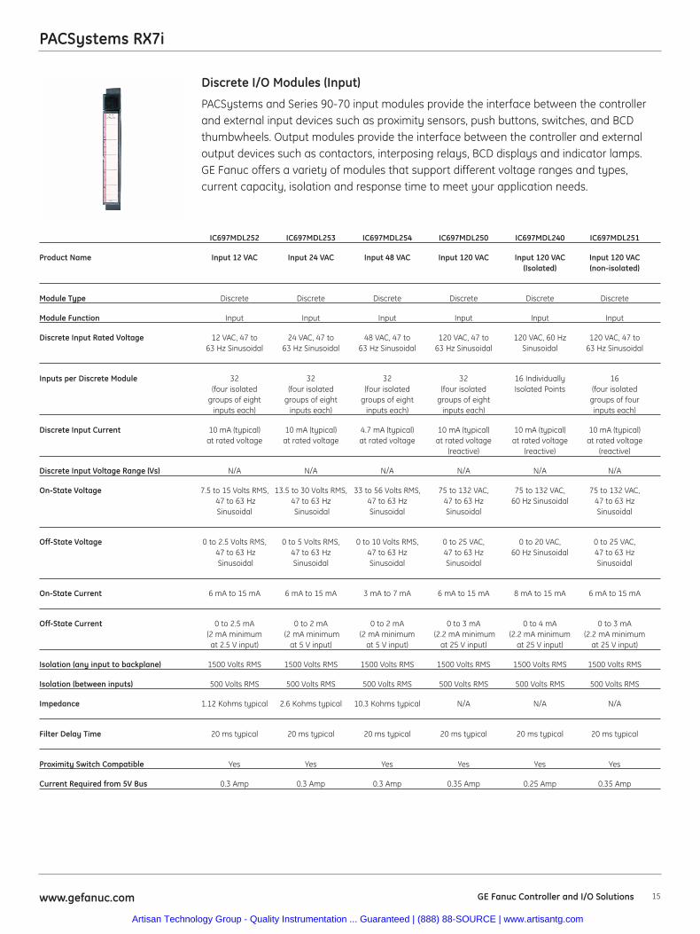
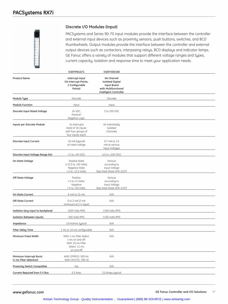
PACSystems and Series 90-70 input modules provide the interface between the controllerand external input devices such as proximity sensors, push buttons, switches, and BCDthumbwheels. Output modules provide the interface between the controller and externaloutput devices such as contactors, interposing relays, BCD displays and indicator lamps.GE Fanuc offers a variety of modules that support different voltage ranges and types,current capacity, isolation and response time to meet your application needs.
Discrete I/O Modules (Input)
IC697MDL252 IC697MDL253 IC697MDL254 IC697MDL250 IC697MDL240 IC697MDL251
Product Name Input 12 VAC Input 24 VAC Input 48 VAC Input 120 VAC Input 120 VAC Input 120 VAC(Isolated) (non-isolated)
Module Type Discrete Discrete Discrete Discrete Discrete Discrete
Module Function Input Input Input Input Input Input
Discrete Input Rated Voltage 12 VAC, 47 to 24 VAC, 47 to 48 VAC, 47 to 120 VAC, 47 to 120 VAC, 60 Hz 120 VAC, 47 to63 Hz Sinusoidal 63 Hz Sinusoidal 63 Hz Sinusoidal 63 Hz Sinusoidal Sinusoidal 63 Hz Sinusoidal
Inputs per Discrete Module 32 32 32 32 16 Individually 16 (four isolated (four isolated (four isolated (four isolated Isolated Points (four isolated
groups of eight groups of eight groups of eight groups of eight groups of four inputs each) inputs each) inputs each) inputs each) inputs each)
Discrete Input Current 10 mA (typical) 10 mA (typical) 4.7 mA (typical) 10 mA (typical) 10 mA (typical) 10 mA (typical)at rated voltage at rated voltage at rated voltage at rated voltage at rated voltage at rated voltage
(reactive) (reactive) (reactive)
Discrete Input Voltage Range (Vs) N/A N/A N/A N/A N/A N/A
On-State Voltage 7.5 to 15 Volts RMS, 13.5 to 30 Volts RMS, 33 to 56 Volts RMS, 75 to 132 VAC, 75 to 132 VAC, 75 to 132 VAC,47 to 63 Hz 47 to 63 Hz 47 to 63 Hz 47 to 63 Hz 60 Hz Sinusoidal 47 to 63 HzSinusoidal Sinusoidal Sinusoidal Sinusoidal Sinusoidal
Off-State Voltage 0 to 2.5 Volts RMS, 0 to 5 Volts RMS, 0 to 10 Volts RMS, 0 to 25 VAC, 0 to 20 VAC, 0 to 25 VAC, 47 to 63 Hz 47 to 63 Hz 47 to 63 Hz 47 to 63 Hz 60 Hz Sinusoidal 47 to 63 HzSinusoidal Sinusoidal Sinusoidal Sinusoidal Sinusoidal
On-State Current 6 mA to 15 mA 6 mA to 15 mA 3 mA to 7 mA 6 mA to 15 mA 8 mA to 15 mA 6 mA to 15 mA
Off-State Current 0 to 2.5 mA 0 to 2 mA 0 to 2 mA 0 to 3 mA 0 to 4 mA 0 to 3 mA (2 mA minimum (2 mA minimum (2 mA minimum (2.2 mA minimum (2.2 mA minimum (2.2 mA minimum at 2.5 V input) at 5 V input) at 5 V input) at 25 V input) at 25 V input) at 25 V input)
Isolation (any input to backplane) 1500 Volts RMS 1500 Volts RMS 1500 Volts RMS 1500 Volts RMS 1500 Volts RMS 1500 Volts RMS
Isolation (between inputs) 500 Volts RMS 500 Volts RMS 500 Volts RMS 500 Volts RMS 500 Volts RMS 500 Volts RMS
Impedance 1.12 Kohms typical 2.6 Kohms typical 10.3 Kohms typical N/A N/A N/A
Filter Delay Time 20 ms typical 20 ms typical 20 ms typical 20 ms typical 20 ms typical 20 ms typical
Proximity Switch Compatible Yes Yes Yes Yes Yes Yes
Current Required from 5V Bus 0.3 Amp 0.3 Amp 0.3 Amp 0.35 Amp 0.25 Amp 0.35 Amp
Artisan Technology Group - Quality Instrumentation ... Guaranteed | (888) 88-SOURCE | www.artisantg.com
PACSystems RX7i
16 www.gefanuc.comGE Fanuc Controller and I/O Solutions
PACSystems RX7i
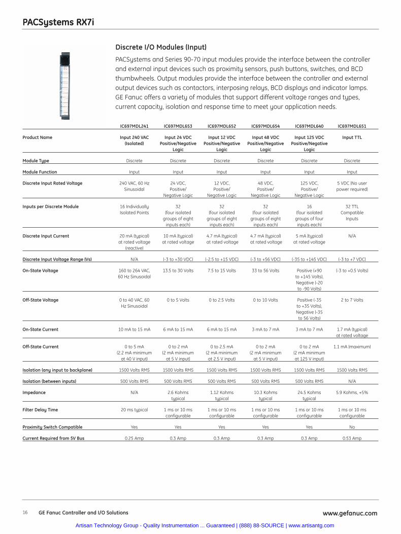
PACSystems and Series 90-70 input modules provide the interface between the controllerand external input devices such as proximity sensors, push buttons, switches, and BCDthumbwheels. Output modules provide the interface between the controller and externaloutput devices such as contactors, interposing relays, BCD displays and indicator lamps.GE Fanuc offers a variety of modules that support different voltage ranges and types,current capacity, isolation and response time to meet your application needs.
Discrete I/O Modules (Input)
IC697MDL241 IC697MDL653 IC697MDL652 IC697MDL654 IC697MDL640 IC697MDL651
Product Name Input 240 VAC Input 24 VDC Input 12 VDC Input 48 VDC Input 125 VDC Input TTL(Isolated) Positive/Negative Positive/Negative Positive/Negative Positive/Negative
Logic Logic Logic Logic
Module Type Discrete Discrete Discrete Discrete Discrete Discrete
Module Function Input Input Input Input Input Input
Discrete Input Rated Voltage 240 VAC, 60 Hz 24 VDC, 12 VDC, 48 VDC, 125 VDC, 5 VDC (No userSinusoidal Positive/ Positive/ Positive/ Positive/ power required)
Negative Logic Negative Logic Negative Logic Negative Logic
Inputs per Discrete Module 16 Individually 32 32 32 16 32 TTLIsolated Points (four isolated (four isolated (four isolated (four isolated Compatible
groups of eight groups of eight groups of eight groups of four Inputsinputs each) inputs each) inputs each) inputs each)
Discrete Input Current 20 mA (typical) 10 mA (typical) 4.7 mA (typical) 4.7 mA (typical) 5 mA (typical) N/Aat rated voltage at rated voltage at rated voltage at rated voltage at rated voltage
(reactive)
Discrete Input Voltage Range (Vs) N/A (-3 to +30 VDC) (-2.5 to +15 VDC) (-3 to +56 VDC) (-35 to +145 VDC) (-3 to +7 VDC)
On-State Voltage 160 to 264 VAC, 13.5 to 30 Volts 7.5 to 15 Volts 33 to 56 Volts Positive (+90 (-3 to +0.5 Volts)60 Hz Sinusoidal to +145 Volts),
Negative (-20to -90 Volts)
Off-State Voltage 0 to 40 VAC, 60 0 to 5 Volts 0 to 2.5 Volts 0 to 10 Volts Positive (-35 2 to 7 VoltsHz Sinusoidal to +35 Volts),
Negative (-35to 56 Volts)
On-State Current 10 mA to 15 mA 6 mA to 15 mA 6 mA to 15 mA 3 mA to 7 mA 3 mA to 7 mA 1.7 mA (typical)at rated voltage
Off-State Current 0 to 5 mA 0 to 2 mA 0 to 2.5 mA 0 to 2 mA 0 to 2 mA 1.1 mA (maximum)(2.2 mA minimum (2 mA minimum (2 mA minimum (2 mA minimum (2 mA minimum
at 40 V input) at 5 V input) at 2.5 V input) at 5 V input) at 125 V input)
Isolation (any input to backplane) 1500 Volts RMS 1500 Volts RMS 1500 Volts RMS 1500 Volts RMS 1500 Volts RMS 1500 Volts RMS
Isolation (between inputs) 500 Volts RMS 500 Volts RMS 500 Volts RMS 500 Volts RMS 500 Volts RMS N/A
Impedance N/A 2.6 Kohms 1.12 Kohms 10.3 Kohms 24.5 Kohms 5.9 Kohms, +5%typical typical typical typical
Filter Delay Time 20 ms typical 1 ms or 10 ms 1 ms or 10 ms 1 ms or 10 ms 1 ms or 10 ms 1 ms or 10 msconfigurable configurable configurable configurable configurable
Proximity Switch Compatible Yes Yes Yes Yes Yes No
Current Required from 5V Bus 0.25 Amp 0.3 Amp 0.3 Amp 0.3 Amp 0.3 Amp 0.53 Amp
Artisan Technology Group - Quality Instrumentation ... Guaranteed | (888) 88-SOURCE | www.artisantg.com
PACSystems RX7i
17www.gefanuc.com GE Fanuc Controller and I/O Solutions
PACSystems RX7i
PACSystems and Series 90-70 input modules provide the interface between the controllerand external input devices such as proximity sensors, push buttons, switches, and BCDthumbwheels. Output modules provide the interface between the controller and externaloutput devices such as contactors, interposing relays, BCD displays and indicator lamps.GE Fanuc offers a variety of modules that support different voltage ranges and types,current capacity, isolation and response time to meet your application needs.
Discrete I/O Modules (Input)
IC697MDL671 IC697VDD100
Product Name Interrupt Input 64-Channel(14 Interrupt Points, Isolated Digital
2 Configurable Input BoardPoints) with Multifunctional
Intelligent Controller
Module Type Discrete Discrete
Module Function Input Input
Discrete Input Rated Voltage 24 VDC, 5 to 250 VDCPositive/
Negative Logic
Inputs per Discrete Module 14 interrupts 64 Individually(total of 16 inputs Isolated
with four groups of Channelsfour inputs each)
Discrete Input Current 10 mA (typical) 0.7 mA to 1.0at rated voltage mA at various
Input Voltages
Discrete Input Voltage Range (Vs) (-3 to +30 VDC) (+5 to +250 VDC)
On-State Voltage Positive State Various(+13.5 to +30 Volts), according to
Negative State Input Voltage(-3 to -13.5 Volts) (See Data Sheet GFK-2107)
Off-State Voltage Positive Various(-3 to +5 Volts), according to
Negative Input Voltage(-5 to +30 Volts) (See Data Sheet GFK-2107)
On-State Current 6 mA to 15 mA N/A
Off-State Current 0 to 2 mA (2 mA N/Aminimum at 5 V input)
Isolation (any input to backplane) 1500 Volts RMS 1100 Volts RMS
Isolation (between inputs) 500 Volts RMS 1100 Volts RMS
Impedance 2.6 Kohms typical N/A
Filter Delay Time 1 ms or 10 ms configurable N/A
Minimum Pulse Width With 1 ms Filter Select: N/A1 ms on and off;With 10 ms Filter
Select: 11 ms on and off
Minimum Interrupt Burst With CPM915: 500 Hz; N/A(1 ms Filter Selection) With CPU731: 290 Hz
Proximity Switch Compatible Yes N/A
Current Required from 5 V Bus 0.3 Amp 2.0 Amps typical
Artisan Technology Group - Quality Instrumentation ... Guaranteed | (888) 88-SOURCE | www.artisantg.com
18 www.gefanuc.comGE Fanuc Controller and I/O Solutions
PACSystems RX7i
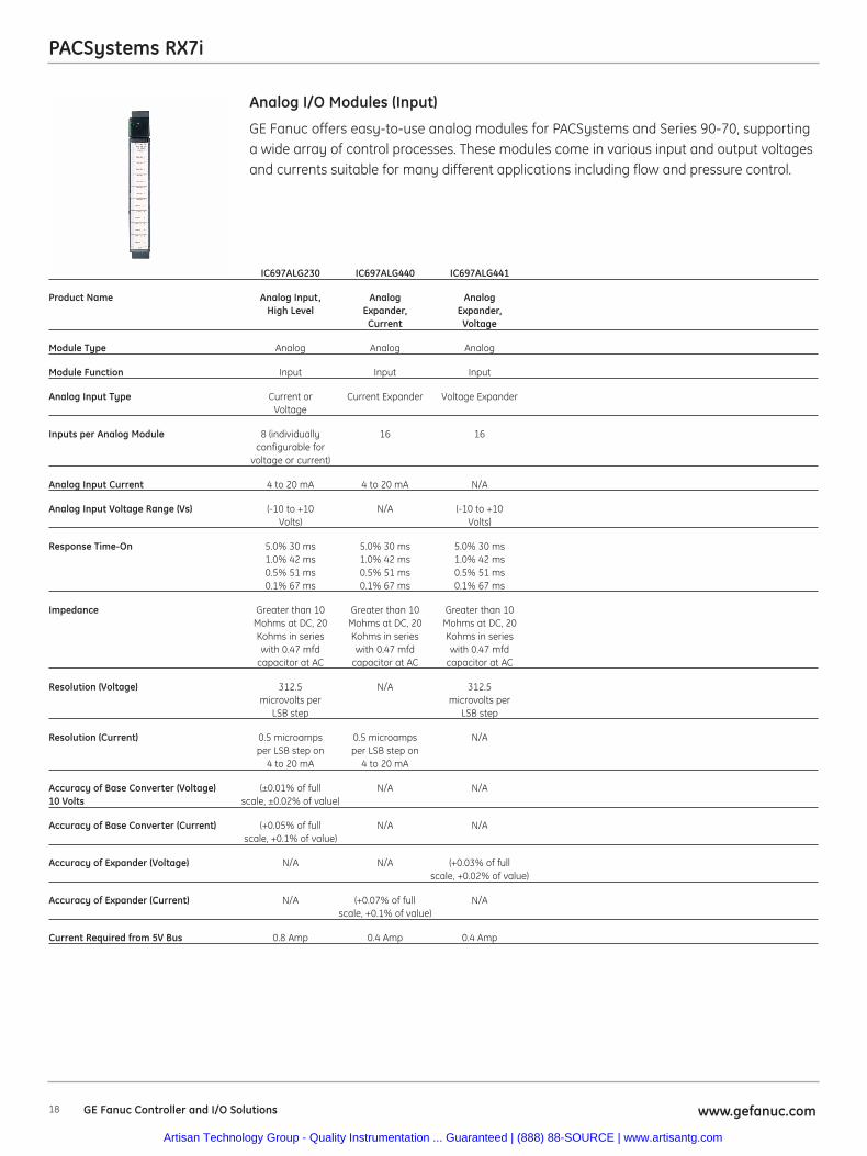
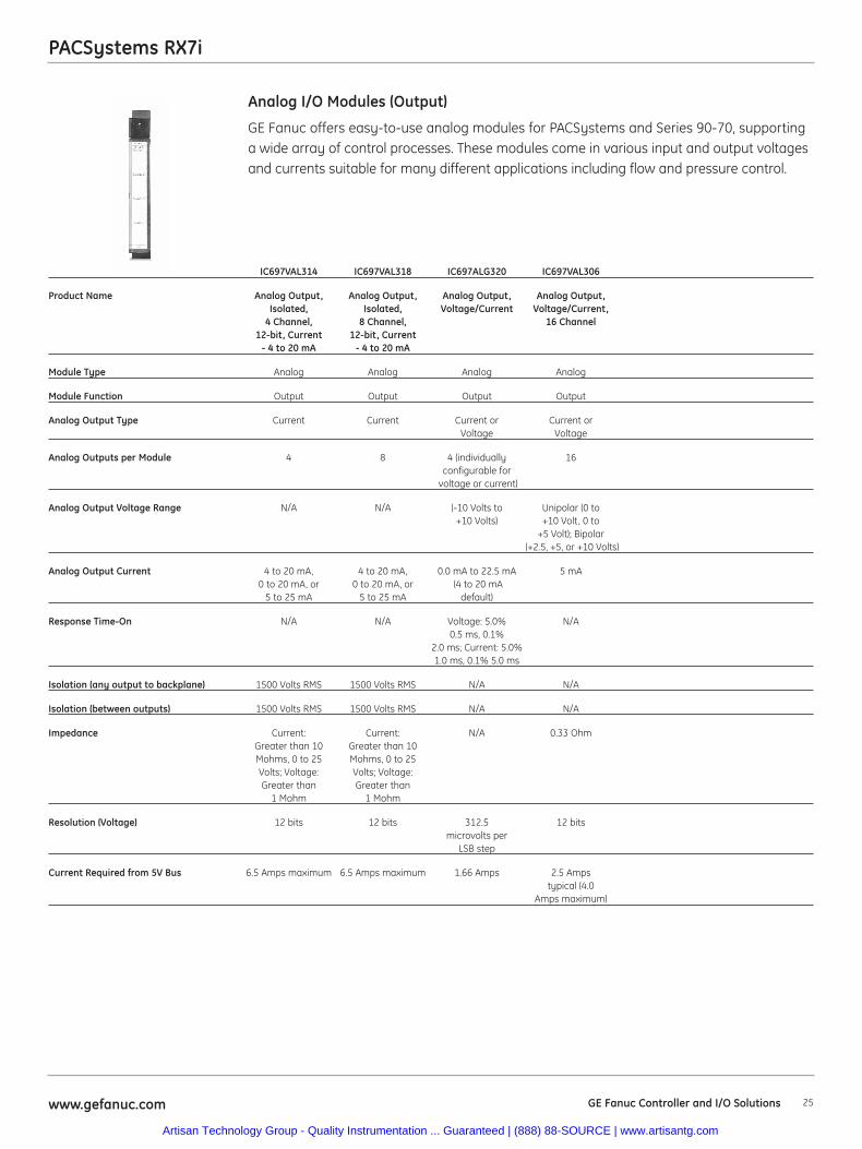
GE Fanuc offers easy-to-use analog modules for PACSystems and Series 90-70, supportinga wide array of control processes. These modules come in various input and output voltagesand currents suitable for many different applications including flow and pressure control.
Analog I/O Modules (Input)
IC697ALG230 IC697ALG440 IC697ALG441
Product Name Analog Input, Analog AnalogHigh Level Expander, Expander,
Current Voltage
Module Type Analog Analog Analog
Module Function Input Input Input
Analog Input Type Current or Current Expander Voltage ExpanderVoltage
Inputs per Analog Module 8 (individually 16 16configurable for
voltage or current)
Analog Input Current 4 to 20 mA 4 to 20 mA N/A
Analog Input Voltage Range (Vs) (-10 to +10 N/A (-10 to +10Volts) Volts)
Response Time-On 5.0% 30 ms 5.0% 30 ms 5.0% 30 ms1.0% 42 ms 1.0% 42 ms 1.0% 42 ms0.5% 51 ms 0.5% 51 ms 0.5% 51 ms0.1% 67 ms 0.1% 67 ms 0.1% 67 ms
Impedance Greater than 10 Greater than 10 Greater than 10Mohms at DC, 20 Mohms at DC, 20 Mohms at DC, 20Kohms in series Kohms in series Kohms in serieswith 0.47 mfd with 0.47 mfd with 0.47 mfd
capacitor at AC capacitor at AC capacitor at AC
Resolution (Voltage) 312.5 N/A 312.5microvolts per microvolts per
LSB step LSB step
Resolution (Current) 0.5 microamps 0.5 microamps N/Aper LSB step on per LSB step on
4 to 20 mA 4 to 20 mA
Accuracy of Base Converter (Voltage) (±0.01% of full N/A N/A10 Volts scale, ±0.02% of value)
Accuracy of Base Converter (Current) (+0.05% of full N/A N/Ascale, +0.1% of value)
Accuracy of Expander (Voltage) N/A N/A (+0.03% of fullscale, +0.02% of value)
Accuracy of Expander (Current) N/A (+0.07% of full N/Ascale, +0.1% of value)
Current Required from 5V Bus 0.8 Amp 0.4 Amp 0.4 Amp
Artisan Technology Group - Quality Instrumentation ... Guaranteed | (888) 88-SOURCE | www.artisantg.com
19www.gefanuc.com GE Fanuc Controller and I/O Solutions
PACSystems RX7i
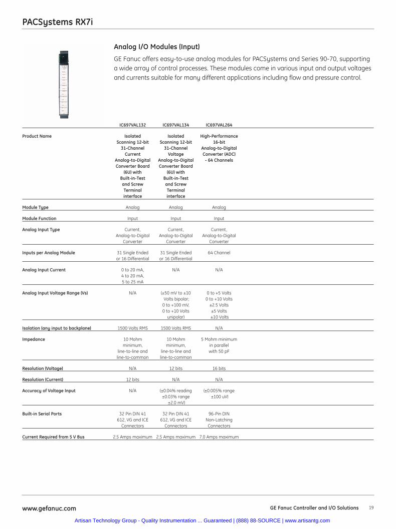
GE Fanuc offers easy-to-use analog modules for PACSystems and Series 90-70, supportinga wide array of control processes. These modules come in various input and output voltagesand currents suitable for many different applications including flow and pressure control.
Analog I/O Modules (Input)
IC697VAL132 IC697VAL134 IC697VAL264
Product Name Isolated Isolated High-PerformanceScanning 12-bit Scanning 12-bit 16-bit
31-Channel 31-Channel Analog-to-DigitalCurrent Voltage Converter (ADC)
Analog-to-Digital Analog-to-Digital - 64 ChannelsConverter Board Converter Board
(6U) with (6U) withBuilt-in-Test Built-in-Testand Screw and ScrewTerminal Terminalinterface interface
Module Type Analog Analog Analog
Module Function Input Input Input
Analog Input Type Current, Current, Current,Analog-to-Digital Analog-to-Digital Analog-to-Digital
Converter Converter Converter
Inputs per Analog Module 31 Single Ended 31 Single Ended 64 Channelor 16 Differential or 16 Differential
Analog Input Current 0 to 20 mA, N/A N/A4 to 20 mA,5 to 25 mA
Analog Input Voltage Range (Vs) N/A (±50 mV to ±10 0 to +5 VoltsVolts bipolar; 0 to +10 Volts
0 to +100 mV, ±2.5 Volts0 to +10 Volts ±5 Volts
unipolar) ±10 Volts
Isolation (any input to backplane) 1500 Volts RMS 1500 Volts RMS N/A
Impedance 10 Mohm 10 Mohm 5 Mohm minimumminimum, minimum, in parallel
line-to-line and line-to-line and with 50 pFline-to-common line-to-common
Resolution (Voltage) N/A 12 bits 16 bits
Resolution (Current) 12 bits N/A N/A
Accuracy of Voltage Input N/A (±0.04% reading (±0.005% range±0.03% range ±100 uV)
±2.0 mV)
Built-in Serial Ports 32 Pin DIN 41 32 Pin DIN 41 96-Pin DIN612, VG and ICE 612, VG and ICE Non-Latching
Connectors Connectors Connectors
Current Required from 5 V Bus 2.5 Amps maximum 2.5 Amps maximum 7.0 Amps maximum
Artisan Technology Group - Quality Instrumentation ... Guaranteed | (888) 88-SOURCE | www.artisantg.com
20 www.gefanuc.comGE Fanuc Controller and I/O Solutions
PACSystems RX7i
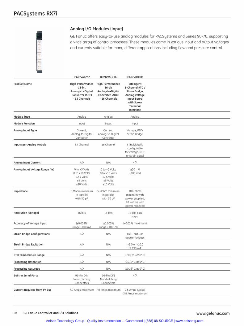
GE Fanuc offers easy-to-use analog modules for PACSystems and Series 90-70, supportinga wide array of control processes. These modules come in various input and output voltagesand currents suitable for many different applications including flow and pressure control.
Analog I/O Modules (Input)
IC697VAL232 IC697VAL216 IC697VRD008
Product Name High-Performance High-Performance Intelligent16-bit 16-bit 8-Channel RTD /
Analog-to-Digital Analog-to-Digital Strain Bridge,Converter (ADC) Converter (ADC) Analog Voltage
- 32 Channels - 16 Channels Input Boardwith ScrewTerminalInterface
Module Type Analog Analog Analog
Module Function Input Input Input
Analog Input Type Current, Current, Voltage, RTD/Analog-to-Digital Analog-to-Digital Strain Bridge
Converter Converter
Inputs per Analog Module 32 Channel 16 Channel 8 (individuallyconfigurable
for voltage, RTD,or strain gage)
Analog Input Current N/A N/A N/A
Analog Input Voltage Range (Vs) 0 to +5 Volts 0 to +5 Volts (±30 mV,0 to +10 Volts 0 to +10 Volts ±100 mV)
±2.5 Volts ±2.5 Volts±5 Volts ±5 Volts
±10 Volts ±10 Volts
Impedance 5 Mohm minimum 5 Mohm minimum 10 Mohmsin parallel in parallel minimum withwith 50 pF with 50 pF power supplied,
70 Kohms withpower removed
Resolution (Voltage) 16 bits 16 bits 12 bits plussign
Accuracy of Voltage Input (±0.005% (±0.005% (+0.03% maximum)range ±100 uV) range ±100 uV)
Strain Bridge Configurations N/A N/A Full-, half-, orquarter-bridges
Strain Bridge Excitation N/A N/A (+5.0 or +10.0at 190 mA
RTD Temperature Range N/A N/A (-200 to +850° C)
Processing Resolution N/A N/A 0.015° C at 0° C
Processing Accuracy N/A N/A (±0.25° C at 0° C)
Built-in Serial Ports 96-Pin DIN 96-Pin DIN N/ANon-Latching Non-LatchingConnectors Connectors
Current Required from 5V Bus 7.0 Amps maximum 7.0 Amps maximum 2.5 Amps typical(3.8 Amps maximum)
Artisan Technology Group - Quality Instrumentation ... Guaranteed | (888) 88-SOURCE | www.artisantg.com
21www.gefanuc.com GE Fanuc Controller and I/O Solutions
PACSystems RX7i
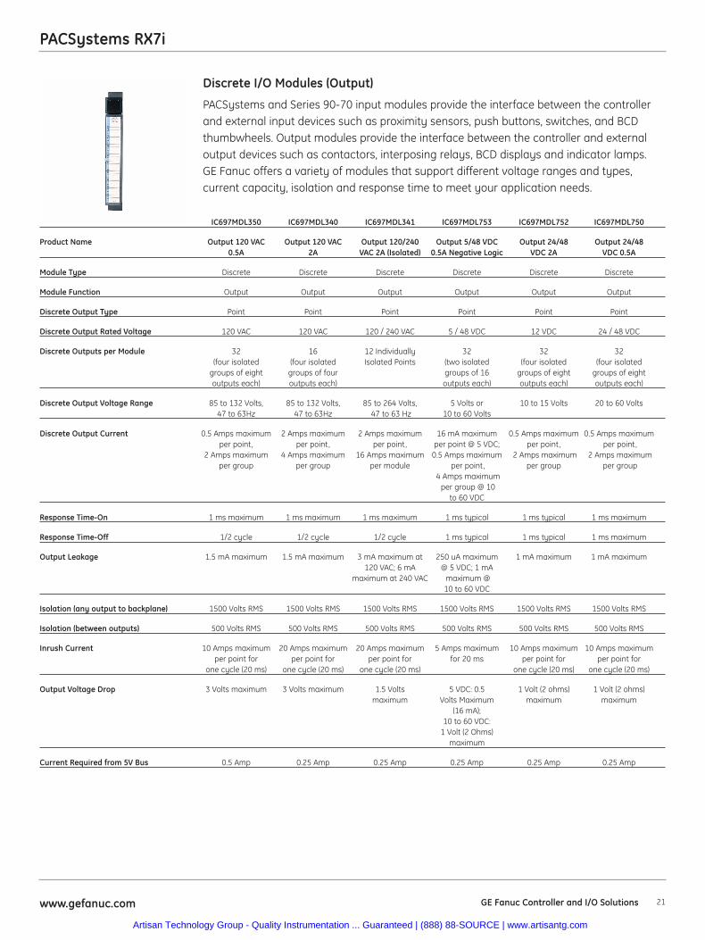
PACSystems and Series 90-70 input modules provide the interface between the controllerand external input devices such as proximity sensors, push buttons, switches, and BCDthumbwheels. Output modules provide the interface between the controller and externaloutput devices such as contactors, interposing relays, BCD displays and indicator lamps.GE Fanuc offers a variety of modules that support different voltage ranges and types,current capacity, isolation and response time to meet your application needs.
Discrete I/O Modules (Output)
IC697MDL350 IC697MDL340 IC697MDL341 IC697MDL753 IC697MDL752 IC697MDL750
Product Name Output 120 VAC Output 120 VAC Output 120/240 Output 5/48 VDC Output 24/48 Output 24/480.5A 2A VAC 2A (Isolated) 0.5A Negative Logic VDC 2A VDC 0.5A
Module Type Discrete Discrete Discrete Discrete Discrete Discrete
Module Function Output Output Output Output Output Output
Discrete Output Type Point Point Point Point Point Point
Discrete Output Rated Voltage 120 VAC 120 VAC 120 / 240 VAC 5 / 48 VDC 12 VDC 24 / 48 VDC
Discrete Outputs per Module 32 16 12 Individually 32 32 32(four isolated (four isolated Isolated Points (two isolated (four isolated (four isolated
groups of eight groups of four groups of 16 groups of eight groups of eightoutputs each) outputs each) outputs each) outputs each) outputs each)
Discrete Output Voltage Range 85 to 132 Volts, 85 to 132 Volts, 85 to 264 Volts, 5 Volts or 10 to 15 Volts 20 to 60 Volts47 to 63Hz 47 to 63Hz 47 to 63 Hz 10 to 60 Volts
Discrete Output Current 0.5 Amps maximum 2 Amps maximum 2 Amps maximum 16 mA maximum 0.5 Amps maximum 0.5 Amps maximumper point, per point, per point, per point @ 5 VDC; per point, per point,
2 Amps maximum 4 Amps maximum 16 Amps maximum 0.5 Amps maximum 2 Amps maximum 2 Amps maximumper group per group per module per point, per group per group
4 Amps maximumper group @ 10
to 60 VDC
Response Time-On 1 ms maximum 1 ms maximum 1 ms maximum 1 ms typical 1 ms typical 1 ms maximum
Response Time-Off 1/2 cycle 1/2 cycle 1/2 cycle 1 ms typical 1 ms typical 1 ms maximum
Output Leakage 1.5 mA maximum 1.5 mA maximum 3 mA maximum at 250 uA maximum 1 mA maximum 1 mA maximum120 VAC; 6 mA @ 5 VDC; 1 mA
maximum at 240 VAC maximum @ 10 to 60 VDC
Isolation (any output to backplane) 1500 Volts RMS 1500 Volts RMS 1500 Volts RMS 1500 Volts RMS 1500 Volts RMS 1500 Volts RMS
Isolation (between outputs) 500 Volts RMS 500 Volts RMS 500 Volts RMS 500 Volts RMS 500 Volts RMS 500 Volts RMS
Inrush Current 10 Amps maximum 20 Amps maximum 20 Amps maximum 5 Amps maximum 10 Amps maximum 10 Amps maximumper point for per point for per point for for 20 ms per point for per point for
one cycle (20 ms) one cycle (20 ms) one cycle (20 ms) one cycle (20 ms) one cycle (20 ms)
Output Voltage Drop 3 Volts maximum 3 Volts maximum 1.5 Volts 5 VDC: 0.5 1 Volt (2 ohms) 1 Volt (2 ohms)maximum Volts Maximum maximum maximum
(16 mA); 10 to 60 VDC:
1 Volt (2 Ohms)maximum
Current Required from 5V Bus 0.5 Amp 0.25 Amp 0.25 Amp 0.25 Amp 0.25 Amp 0.25 Amp
Artisan Technology Group - Quality Instrumentation ... Guaranteed | (888) 88-SOURCE | www.artisantg.com
22 www.gefanuc.comGE Fanuc Controller and I/O Solutions
PACSystems RX7i
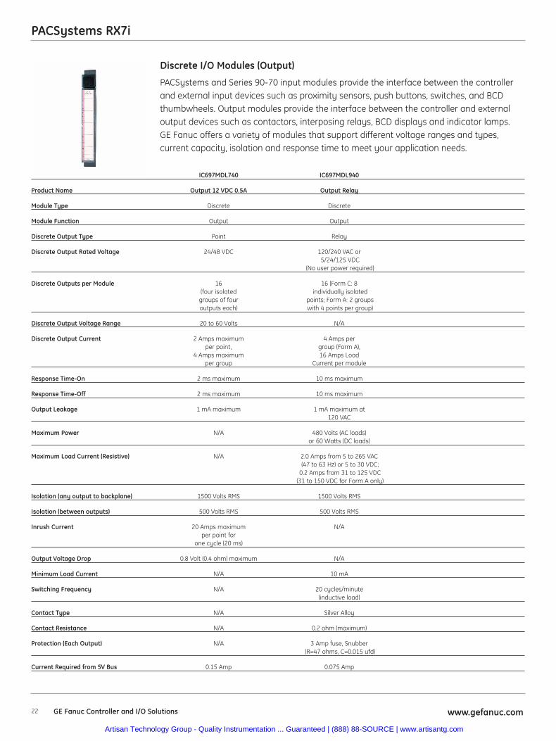
PACSystems and Series 90-70 input modules provide the interface between the controllerand external input devices such as proximity sensors, push buttons, switches, and BCDthumbwheels. Output modules provide the interface between the controller and externaloutput devices such as contactors, interposing relays, BCD displays and indicator lamps.GE Fanuc offers a variety of modules that support different voltage ranges and types,current capacity, isolation and response time to meet your application needs.
Discrete I/O Modules (Output)
IC697MDL740 IC697MDL940
Product Name Output 12 VDC 0.5A Output Relay
Module Type Discrete Discrete
Module Function Output Output
Discrete Output Type Point Relay
Discrete Output Rated Voltage 24/48 VDC 120/240 VAC or5/24/125 VDC
(No user power required)
Discrete Outputs per Module 16 16 (Form C: 8(four isolated individually isolated
groups of four points; Form A: 2 groupsoutputs each) with 4 points per group)
Discrete Output Voltage Range 20 to 60 Volts N/A
Discrete Output Current 2 Amps maximum 4 Amps perper point, group (Form A),
4 Amps maximum 16 Amps Loadper group Current per module
Response Time-On 2 ms maximum 10 ms maximum
Response Time-Off 2 ms maximum 10 ms maximum
Output Leakage 1 mA maximum 1 mA maximum at 120 VAC
Maximum Power N/A 480 Volts (AC loads) or 60 Watts (DC loads)
Maximum Load Current (Resistive) N/A 2.0 Amps from 5 to 265 VAC(47 to 63 Hz) or 5 to 30 VDC;
0.2 Amps from 31 to 125 VDC(31 to 150 VDC for Form A only)
Isolation (any output to backplane) 1500 Volts RMS 1500 Volts RMS
Isolation (between outputs) 500 Volts RMS 500 Volts RMS
Inrush Current 20 Amps maximum N/Aper point for
one cycle (20 ms)
Output Voltage Drop 0.8 Volt (0.4 ohm) maximum N/A
Minimum Load Current N/A 10 mA
Switching Frequency N/A 20 cycles/minute(inductive load)
Contact Type N/A Silver Alloy
Contact Resistance N/A 0.2 ohm (maximum)
Protection (Each Output) N/A 3 Amp fuse, Snubber(R=47 ohms, C=0.015 ufd)
Current Required from 5V Bus 0.15 Amp 0.075 Amp
Artisan Technology Group - Quality Instrumentation ... Guaranteed | (888) 88-SOURCE | www.artisantg.com
23www.gefanuc.com GE Fanuc Controller and I/O Solutions
PACSystems RX7i
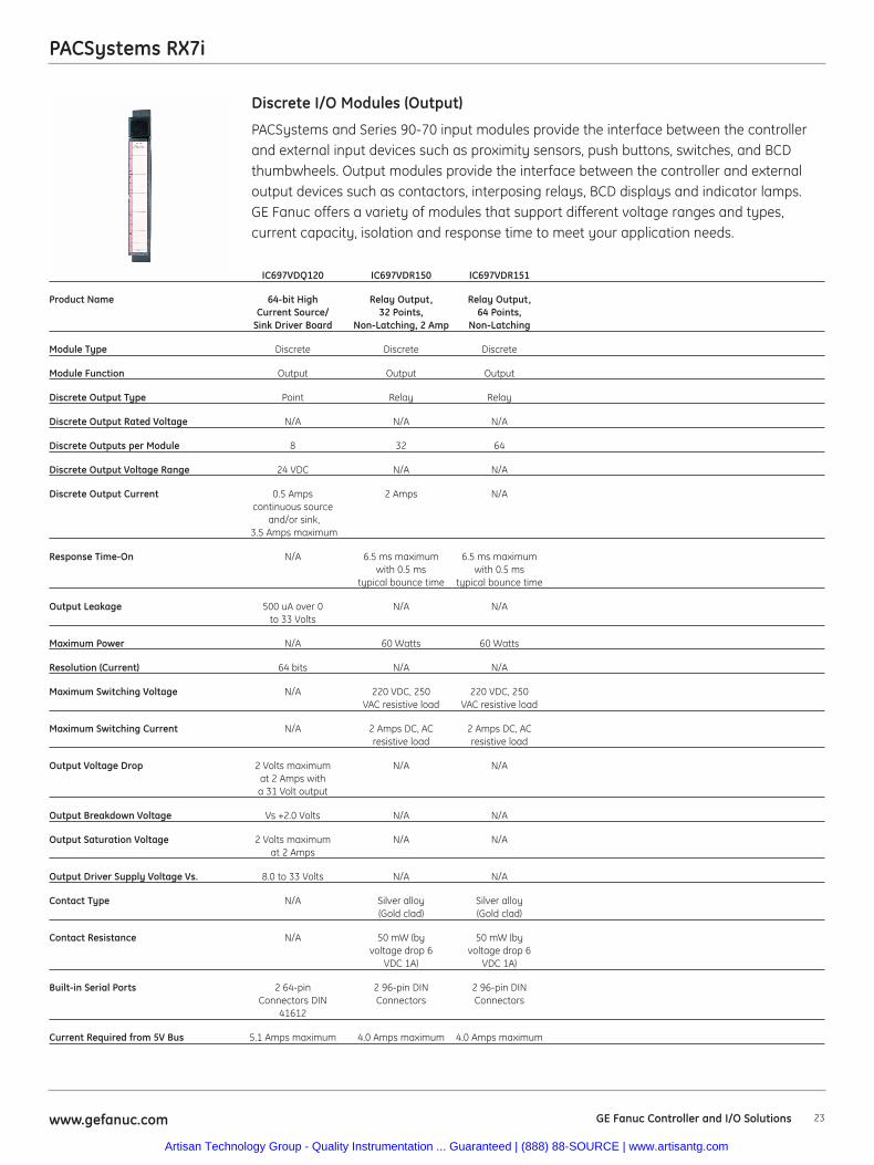
PACSystems and Series 90-70 input modules provide the interface between the controllerand external input devices such as proximity sensors, push buttons, switches, and BCDthumbwheels. Output modules provide the interface between the controller and externaloutput devices such as contactors, interposing relays, BCD displays and indicator lamps.GE Fanuc offers a variety of modules that support different voltage ranges and types,current capacity, isolation and response time to meet your application needs.
Discrete I/O Modules (Output)
IC697VDQ120 IC697VDR150 IC697VDR151
Product Name 64-bit High Relay Output, Relay Output,Current Source/ 32 Points, 64 Points,
Sink Driver Board Non-Latching, 2 Amp Non-Latching
Module Type Discrete Discrete Discrete
Module Function Output Output Output
Discrete Output Type Point Relay Relay
Discrete Output Rated Voltage N/A N/A N/A
Discrete Outputs per Module 8 32 64
Discrete Output Voltage Range 24 VDC N/A N/A
Discrete Output Current 0.5 Amps 2 Amps N/Acontinuous source
and/or sink,3.5 Amps maximum
Response Time-On N/A 6.5 ms maximum 6.5 ms maximumwith 0.5 ms with 0.5 ms
typical bounce time typical bounce time
Output Leakage 500 uA over 0 N/A N/Ato 33 Volts
Maximum Power N/A 60 Watts 60 Watts
Resolution (Current) 64 bits N/A N/A
Maximum Switching Voltage N/A 220 VDC, 250 220 VDC, 250VAC resistive load VAC resistive load
Maximum Switching Current N/A 2 Amps DC, AC 2 Amps DC, ACresistive load resistive load
Output Voltage Drop 2 Volts maximum N/A N/Aat 2 Amps witha 31 Volt output
Output Breakdown Voltage Vs +2.0 Volts N/A N/A
Output Saturation Voltage 2 Volts maximum N/A N/Aat 2 Amps
Output Driver Supply Voltage Vs. 8.0 to 33 Volts N/A N/A
Contact Type N/A Silver alloy Silver alloy (Gold clad) (Gold clad)
Contact Resistance N/A 50 mW (by 50 mW (byvoltage drop 6 voltage drop 6
VDC 1A) VDC 1A)
Built-in Serial Ports 2 64-pin 2 96-pin DIN 2 96-pin DINConnectors DIN Connectors Connectors
41612
Current Required from 5V Bus 5.1 Amps maximum 4.0 Amps maximum 4.0 Amps maximum
Artisan Technology Group - Quality Instrumentation ... Guaranteed | (888) 88-SOURCE | www.artisantg.com
24 www.gefanuc.comGE Fanuc Controller and I/O Solutions
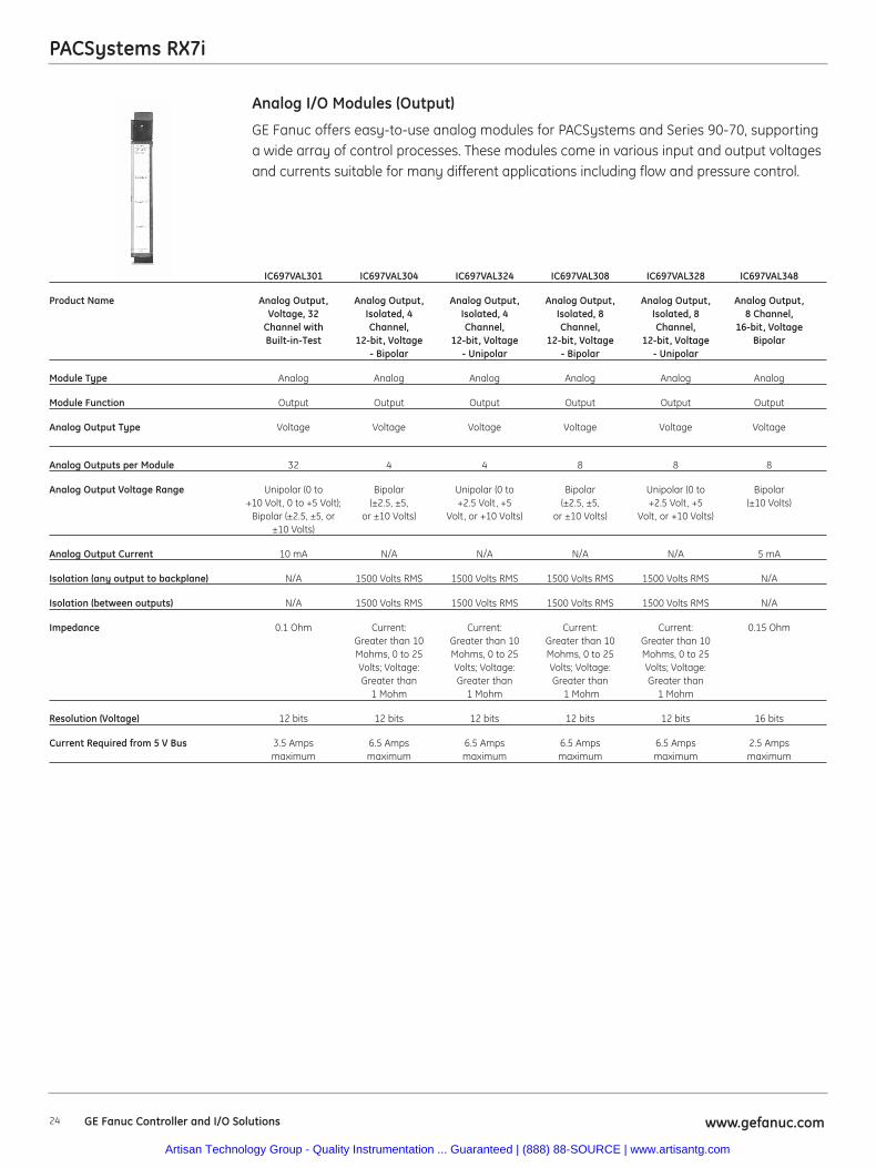
PACSystems RX7i
GE Fanuc offers easy-to-use analog modules for PACSystems and Series 90-70, supportinga wide array of control processes. These modules come in various input and output voltagesand currents suitable for many different applications including flow and pressure control.
Analog I/O Modules (Output)
IC697VAL301 IC697VAL304 IC697VAL324 IC697VAL308 IC697VAL328 IC697VAL348
Product Name Analog Output, Analog Output, Analog Output, Analog Output, Analog Output, Analog Output,Voltage, 32 Isolated, 4 Isolated, 4 Isolated, 8 Isolated, 8 8 Channel,
Channel with Channel, Channel, Channel, Channel, 16-bit, VoltageBuilt-in-Test 12-bit, Voltage 12-bit, Voltage 12-bit, Voltage 12-bit, Voltage Bipolar
- Bipolar - Unipolar - Bipolar - Unipolar
Module Type Analog Analog Analog Analog Analog Analog
Module Function Output Output Output Output Output Output
Analog Output Type Voltage Voltage Voltage Voltage Voltage Voltage
Analog Outputs per Module 32 4 4 8 8 8
Analog Output Voltage Range Unipolar (0 to Bipolar Unipolar (0 to Bipolar Unipolar (0 to Bipolar+10 Volt, 0 to +5 Volt); (±2.5, ±5, +2.5 Volt, +5 (±2.5, ±5, +2.5 Volt, +5 (±10 Volts)
Bipolar (±2.5, ±5, or or ±10 Volts) Volt, or +10 Volts) or ±10 Volts) Volt, or +10 Volts)±10 Volts)
Analog Output Current 10 mA N/A N/A N/A N/A 5 mA
Isolation (any output to backplane) N/A 1500 Volts RMS 1500 Volts RMS 1500 Volts RMS 1500 Volts RMS N/A
Isolation (between outputs) N/A 1500 Volts RMS 1500 Volts RMS 1500 Volts RMS 1500 Volts RMS N/A
Impedance 0.1 Ohm Current: Current: Current: Current: 0.15 OhmGreater than 10 Greater than 10 Greater than 10 Greater than 10Mohms, 0 to 25 Mohms, 0 to 25 Mohms, 0 to 25 Mohms, 0 to 25Volts; Voltage: Volts; Voltage: Volts; Voltage: Volts; Voltage:Greater than Greater than Greater than Greater than
1 Mohm 1 Mohm 1 Mohm 1 Mohm
Resolution (Voltage) 12 bits 12 bits 12 bits 12 bits 12 bits 16 bits
Current Required from 5 V Bus 3.5 Amps 6.5 Amps 6.5 Amps 6.5 Amps 6.5 Amps 2.5 Ampsmaximum maximum maximum maximum maximum maximum
Artisan Technology Group - Quality Instrumentation ... Guaranteed | (888) 88-SOURCE | www.artisantg.com
25www.gefanuc.com GE Fanuc Controller and I/O Solutions
PACSystems RX7i
GE Fanuc offers easy-to-use analog modules for PACSystems and Series 90-70, supportinga wide array of control processes. These modules come in various input and output voltagesand currents suitable for many different applications including flow and pressure control.
Analog I/O Modules (Output)
IC697VAL314 IC697VAL318 IC697ALG320 IC697VAL306
Product Name Analog Output, Analog Output, Analog Output, Analog Output,Isolated, Isolated, Voltage/Current Voltage/Current,
4 Channel, 8 Channel, 16 Channel12-bit, Current 12-bit, Current
- 4 to 20 mA - 4 to 20 mA
Module Type Analog Analog Analog Analog
Module Function Output Output Output Output
Analog Output Type Current Current Current or Current orVoltage Voltage
Analog Outputs per Module 4 8 4 (individually 16configurable for
voltage or current)
Analog Output Voltage Range N/A N/A (-10 Volts to Unipolar (0 to+10 Volts) +10 Volt, 0 to
+5 Volt); Bipolar(+2.5, +5, or +10 Volts)
Analog Output Current 4 to 20 mA, 4 to 20 mA, 0.0 mA to 22.5 mA 5 mA0 to 20 mA, or 0 to 20 mA, or (4 to 20 mA
5 to 25 mA 5 to 25 mA default)
Response Time-On N/A N/A Voltage: 5.0% N/A0.5 ms, 0.1%
2.0 ms; Current: 5.0%1.0 ms, 0.1% 5.0 ms
Isolation (any output to backplane) 1500 Volts RMS 1500 Volts RMS N/A N/A
Isolation (between outputs) 1500 Volts RMS 1500 Volts RMS N/A N/A
Impedance Current: Current: N/A 0.33 OhmGreater than 10 Greater than 10Mohms, 0 to 25 Mohms, 0 to 25Volts; Voltage: Volts; Voltage:Greater than Greater than
1 Mohm 1 Mohm
Resolution (Voltage) 12 bits 12 bits 312.5 12 bitsmicrovolts per
LSB step
Current Required from 5V Bus 6.5 Amps maximum 6.5 Amps maximum 1.66 Amps 2.5 Ampstypical (4.0
Amps maximum)
Artisan Technology Group - Quality Instrumentation ... Guaranteed | (888) 88-SOURCE | www.artisantg.com
26 www.gefanuc.comGE Fanuc Controller and I/O Solutions
PACSystems RX7i
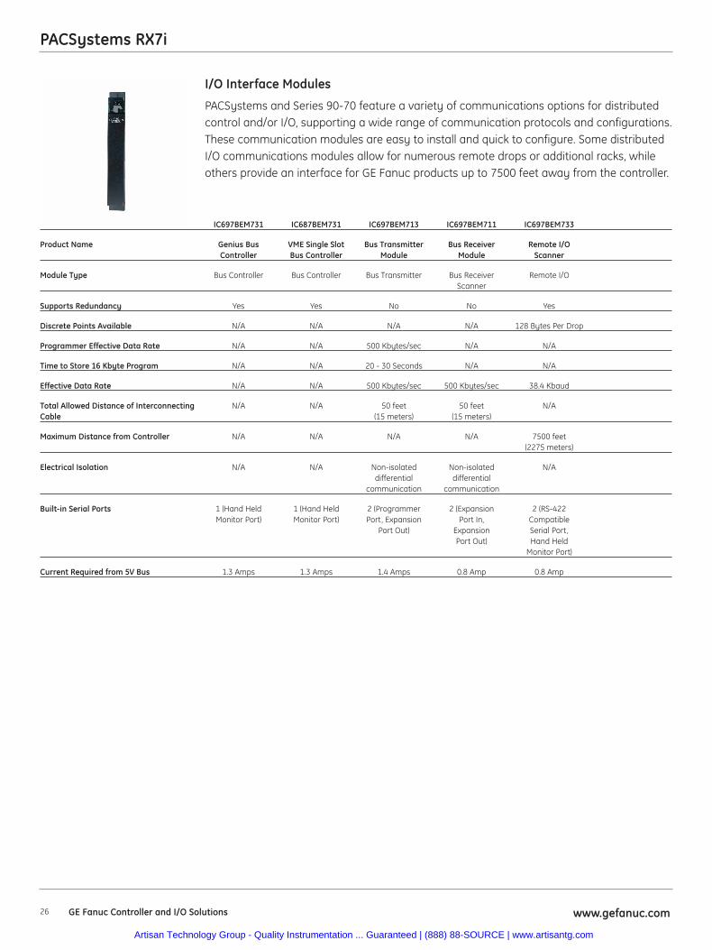
PACSystems and Series 90-70 feature a variety of communications options for distributedcontrol and/or I/O, supporting a wide range of communication protocols and configurations.These communication modules are easy to install and quick to configure. Some distributedI/O communications modules allow for numerous remote drops or additional racks, whileothers provide an interface for GE Fanuc products up to 7500 feet away from the controller.
I/O Interface Modules
IC697BEM731 IC687BEM731 IC697BEM713 IC697BEM711 IC697BEM733
Product Name Genius Bus VME Single Slot Bus Transmitter Bus Receiver Remote I/OController Bus Controller Module Module Scanner
Module Type Bus Controller Bus Controller Bus Transmitter Bus Receiver Remote I/OScanner
Supports Redundancy Yes Yes No No Yes
Discrete Points Available N/A N/A N/A N/A 128 Bytes Per Drop
Programmer Effective Data Rate N/A N/A 500 Kbytes/sec N/A N/A
Time to Store 16 Kbyte Program N/A N/A 20 - 30 Seconds N/A N/A
Effective Data Rate N/A N/A 500 Kbytes/sec 500 Kbytes/sec 38.4 Kbaud
Total Allowed Distance of Interconnecting N/A N/A 50 feet 50 feet N/ACable (15 meters) (15 meters)
Maximum Distance from Controller N/A N/A N/A N/A 7500 feet (2275 meters)
Electrical Isolation N/A N/A Non-isolated Non-isolated N/Adifferential differential
communication communication
Built-in Serial Ports 1 (Hand Held 1 (Hand Held 2 (Programmer 2 (Expansion 2 (RS-422Monitor Port) Monitor Port) Port, Expansion Port In, Compatible
Port Out) Expansion Serial Port,Port Out) Hand Held
Monitor Port)
Current Required from 5V Bus 1.3 Amps 1.3 Amps 1.4 Amps 0.8 Amp 0.8 Amp
Artisan Technology Group - Quality Instrumentation ... Guaranteed | (888) 88-SOURCE | www.artisantg.com
27www.gefanuc.com GE Fanuc Controller and I/O Solutions
PACSystems RX7i
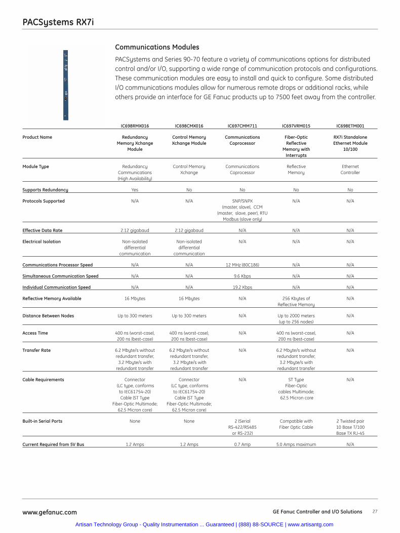
PACSystems and Series 90-70 feature a variety of communications options for distributedcontrol and/or I/O, supporting a wide range of communication protocols and configurations.These communication modules are easy to install and quick to configure. Some distributedI/O communications modules allow for numerous remote drops or additional racks, whileothers provide an interface for GE Fanuc products up to 7500 feet away from the controller.
Communications Modules
IC698RMX016 IC698CMX016 IC697CMM711 IC697VRM015 IC698ETM001
Product Name Redundancy Control Memory Communications Fiber-Optic RX7i StandaloneMemory Xchange Xchange Module Coprocessor Reflective Ethernet Module
Module Memory with 10/100Interrupts
Module Type Redundancy Control Memory Communications Reflective EthernetCommunications Xchange Coprocessor Memory Controller(High Availability)
Supports Redundancy Yes No No No No
Protocols Supported N/A N/A SNP/SNPX N/A N/A(master, slave), CCM
(master, slave, peer), RTUModbus (slave only)
Effective Data Rate 2.12 gigabaud 2.12 gigabaud N/A N/A N/A
Electrical Isolation Non-isolated Non-isolated N/A N/A N/Adifferential differential
communication communication
Communications Processor Speed N/A N/A 12 MHz (80C186) N/A N/A
Simultaneous Communication Speed N/A N/A 9.6 Kbps N/A N/A
Individual Communication Speed N/A N/A 19.2 Kbps N/A N/A
Reflective Memory Available 16 Mbytes 16 Mbytes N/A 256 Kbytes of N/AReflective Memory
Distance Between Nodes Up to 300 meters Up to 300 meters N/A Up to 2000 meters N/A(up to 256 nodes)
Access Time 400 ns (worst-case), 400 ns (worst-case), N/A 400 ns (worst-case), N/A200 ns (best-case) 200 ns (best-case) 200 ns (best-case)
Transfer Rate 6.2 Mbyte/s without 6.2 Mbyte/s without N/A 6.2 Mbyte/s without N/Aredundant transfer, redundant transfer, redundant transfer,
3.2 Mbyte/s with 3.2 Mbyte/s with 3.2 Mbyte/s withredundant transfer redundant transfer redundant transfer
Cable Requirements Connector Connector N/A ST Type N/A(LC type, conforms (LC type, conforms Fiber-Opticto IEC61754-20) to IEC61754-20) cables Multimode;Cable (ST Type Cable (ST Type 62.5 Micron core
Fiber-Optic Multimode; Fiber-Optic Multimode;62.5 Micron core) 62.5 Micron core)
Built-in Serial Ports None None 2 (Serial Compatible with 2 Twisted pairRS-422/RS485 Fiber Optic Cable 10 Base T/100
or RS-232) Base TX RJ-45
Current Required from 5V Bus 1.2 Amps 1.2 Amps 0.7 Amp 5.0 Amps maximum N/A
Artisan Technology Group - Quality Instrumentation ... Guaranteed | (888) 88-SOURCE | www.artisantg.com
28 www.gefanuc.comGE Fanuc Controller and I/O Solutions
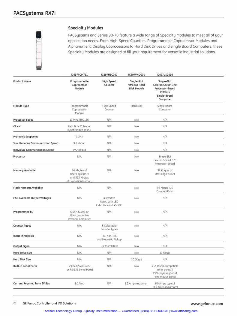
PACSystems RX7i
PACSystems and Series 90-70 feature a wide range of Specialty Modules to meet all of yourapplication needs. From High-Speed Counters, Programmable Coprocessor Modules andAlphanumeric Display Coprocessors to Hard Disk Drives and Single Board Computers, theseSpecialty Modules are designed to fill your requirement for versatile industrial solutions.
Specialty Modules
IC697PCM711 IC697HSC700 IC697VHD001 IC697VSC096
Product Name Programmable High Speed Single-Slot Single-SlotCoprocessor Counter VMEbus Hard Celeron Socket 370
Module Disk Module Processor-BasedVMEbus
Single-BoardComputer
Module Type Programmable High Speed Hard Disk Single BoardCoprocessor Counter Computer
Module
Processor Speed 12 MHz (80C186) N/A N/A N/A
Clock Real Time Calendar N/A N/A N/Asynchronized to PLC
Protocols Supported CCM2 N/A N/A N/A
Simultaneous Communication Speed 9.6 Kbaud N/A N/A N/A
Individual Communication Speed 19.2 Kbaud N/A N/A N/A
Processor N/A N/A N/A Single-SlotCeleron Socket 370
Processor-Based
Memory Available 96 Kbytes of N/A N/A 32 Kbytes ofUser Logic RAM User Logic SRAMand 512 Kbytes
of Expansion Memory
Flash Memory Available N/A N/A N/A 96 Mbyte IDECompactFlash
HSC Available Output Voltages N/A 4 (Positive N/A N/ALogic) with LED
Indicators and +5 VDC
Programmed By IC647, IC640, or N/A N/A N/AIBM-compatible
Personal Computer
Counter Types N/A 5 Selectable N/A N/ACounter Types
Input Thresholds N/A TTL, Non-TTL, N/A N/Aand Magnetic Pickup
Output Signal N/A Up To 200 KHz N/A N/A
Hard Drive Size N/A N/A N/A 12 Gbyte
Hard Disk Size N/A N/A 10 Gbyte N/A
Built-in Serial Ports 2 (RS-422/RS-485 N/A N/A 4 (2 16550-compatibleor RS-232 Serial Ports) serial ports, 2
PS/2-style keyboardand mouse ports)
Current Required from 5V Bus 1.0 Amp N/A 2.5 Amps maximum 6.0 Amps typical(8.0 Amps maximum)
Artisan Technology Group - Quality Instrumentation ... Guaranteed | (888) 88-SOURCE | www.artisantg.com
29www.gefanuc.com GE Fanuc Controller and I/O Solutions
PACSystems RX7i
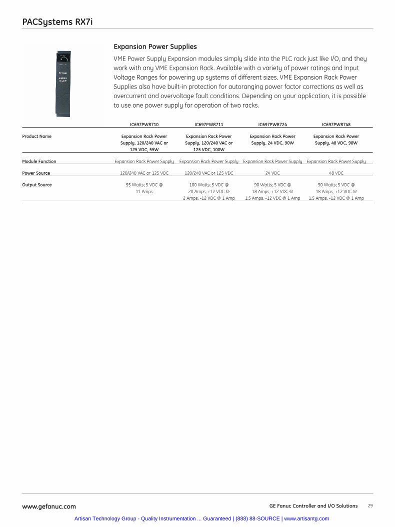
VME Power Supply Expansion modules simply slide into the PLC rack just like I/O, and theywork with any VME Expansion Rack. Available with a variety of power ratings and InputVoltage Ranges for powering up systems of different sizes, VME Expansion Rack PowerSupplies also have built-in protection for autoranging power factor corrections as well asovercurrent and overvoltage fault conditions. Depending on your application, it is possibleto use one power supply for operation of two racks.
Expansion Power Supplies
IC697PWR710 IC697PWR711 IC697PWR724 IC697PWR748
Product Name Expansion Rack Power Expansion Rack Power Expansion Rack Power Expansion Rack PowerSupply, 120/240 VAC or Supply, 120/240 VAC or Supply, 24 VDC, 90W Supply, 48 VDC, 90W
125 VDC, 55W 125 VDC, 100W
Module Function Expansion Rack Power Supply Expansion Rack Power Supply Expansion Rack Power Supply Expansion Rack Power Supply
Power Source 120/240 VAC or 125 VDC 120/240 VAC or 125 VDC 24 VDC 48 VDC
Output Source 55 Watts; 5 VDC @ 100 Watts; 5 VDC @ 90 Watts; 5 VDC @ 90 Watts; 5 VDC @ 11 Amps 20 Amps, +12 VDC @ 18 Amps, +12 VDC @ 18 Amps, +12 VDC @
2 Amps, -12 VDC @ 1 Amp 1.5 Amps, -12 VDC @ 1 Amp 1.5 Amps, -12 VDC @ 1 Amp
Artisan Technology Group - Quality Instrumentation ... Guaranteed | (888) 88-SOURCE | www.artisantg.com
30 www.gefanuc.comGE Fanuc Controller and I/O Solutions
PACSystems RX7i
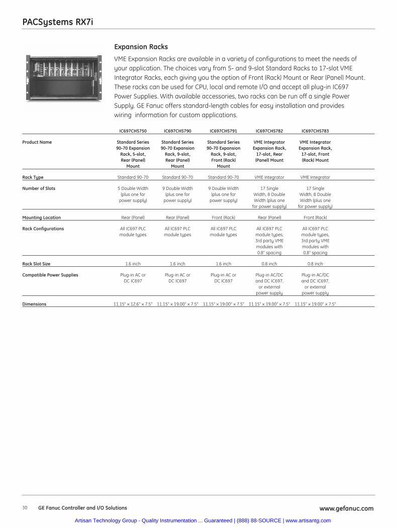
VME Expansion Racks are available in a variety of configurations to meet the needs ofyour application. The choices vary from 5- and 9-slot Standard Racks to 17-slot VMEIntegrator Racks, each giving you the option of Front (Rack) Mount or Rear (Panel) Mount.These racks can be used for CPU, local and remote I/O and accept all plug-in IC697Power Supplies. With available accessories, two racks can be run off a single Power Supply. GE Fanuc offers standard-length cables for easy installation and provides wiring information for custom applications.
Expansion Racks
IC697CHS750 IC697CHS790 IC697CHS791 IC697CHS782 IC697CHS783
Product Name Standard Series Standard Series Standard Series VME Integrator VME Integrator90-70 Expansion 90-70 Expansion 90-70 Expansion Expansion Rack, Expansion Rack,
Rack, 5-slot, Rack, 9-slot, Rack, 9-slot, 17-slot, Rear 17-slot, FrontRear (Panel) Rear (Panel) Front (Rack) (Panel) Mount (Rack) Mount
Mount Mount Mount
Rack Type Standard 90-70 Standard 90-70 Standard 90-70 VME Integrator VME Integrator
Number of Slots 5 Double Width 9 Double Width 9 Double Width 17 Single 17 Single(plus one for (plus one for (plus one for Width, 8 Double Width, 8 Double
power supply) power supply) power supply) Width (plus one Width (plus onefor power supply) for power supply)
Mounting Location Rear (Panel) Rear (Panel) Front (Rack) Rear (Panel) Front (Rack)
Rack Configurations All IC697 PLC All IC697 PLC All IC697 PLC All IC697 PLC All IC697 PLCmodule types module types module types module types, module types,
3rd party VME 3rd party VMEmodules with modules with0.8” spacing 0.8” spacing
Rack Slot Size 1.6 inch 1.6 inch 1.6 inch 0.8 inch 0.8 inch
Compatible Power Supplies Plug-in AC or Plug-in AC or Plug-in AC or Plug-in AC/DC Plug-in AC/DCDC IC697 DC IC697 DC IC697 and DC IC697, and DC IC697,
or external or externalpower supply power supply
Dimensions 11.15” x 12.6” x 7.5” 11.15” x 19.00” x 7.5” 11.15” x 19.00” x 7.5” 11.15” x 19.00” x 7.5” 11.15” x 19.00” x 7.5”
Artisan Technology Group - Quality Instrumentation ... Guaranteed | (888) 88-SOURCE | www.artisantg.com
PACSystems RX7i
31www.gefanuc.com GE Fanuc Controller and I/O Solutions
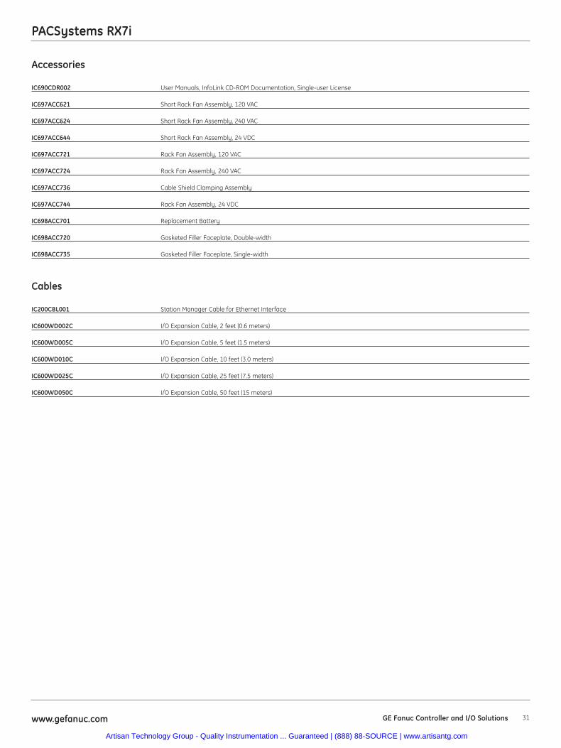
Accessories
IC690CDR002 User Manuals, InfoLink CD-ROM Documentation, Single-user License
IC697ACC621 Short Rack Fan Assembly, 120 VAC
IC697ACC624 Short Rack Fan Assembly, 240 VAC
IC697ACC644 Short Rack Fan Assembly, 24 VDC
IC697ACC721 Rack Fan Assembly, 120 VAC
IC697ACC724 Rack Fan Assembly, 240 VAC
IC697ACC736 Cable Shield Clamping Assembly
IC697ACC744 Rack Fan Assembly, 24 VDC
IC698ACC701 Replacement Battery
IC698ACC720 Gasketed Filler Faceplate, Double-width
IC698ACC735 Gasketed Filler Faceplate, Single-width
Cables
IC200CBL001 Station Manager Cable for Ethernet Interface
IC600WD002C I/O Expansion Cable, 2 feet (0.6 meters)
IC600WD005C I/O Expansion Cable, 5 feet (1.5 meters)
IC600WD010C I/O Expansion Cable, 10 feet (3.0 meters)
IC600WD025C I/O Expansion Cable, 25 feet (7.5 meters)
IC600WD050C I/O Expansion Cable, 50 feet (15 meters)
Artisan Technology Group - Quality Instrumentation ... Guaranteed | (888) 88-SOURCE | www.artisantg.com

32 www.gefanuc.comGE Fanuc Controller and I/O Solutions
Notes
Artisan Technology Group - Quality Instrumentation ... Guaranteed | (888) 88-SOURCE | www.artisantg.com
33www.gefanuc.com GE Fanuc Controller and I/O Solutions
PACSystems RX3i Introduction
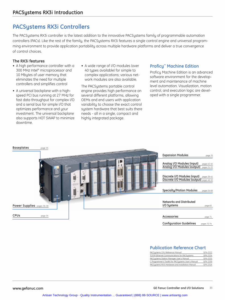
CPUs page 34
Baseplates page 35
Power Supplies pages 36-38
Networks and Distributed I/O Systems page 63
Accessories page 71
Configuration Guidelines pages 72-74
Publication Reference ChartPACSystems CPU Reference Manual GFK-2222
TCP/IP Ethernet Communications for PACSystems GFK-2224
PACSystems Station Manager User's Manual GFK-2225
C Programmer's Toolkit for PACSystems User's Manual GFK-2259
PACSystems RX3i Hardware and Installation Manual GFK-2314
• A wide range of I/O modules (over40 types available) for simple tocomplex applications; various net-work modules are also available.
The PACSystems portable controlengine provides high performance onseveral different platforms, allowingOEMs and end users with applicationvariability to choose the exact controlsystem hardware that best suits thereneeds - all in a single, compact andhighly integrated package.
PACSystems RX3i ControllersThe PACSystems RX3i controller is the latest addition to the innovative PACSystems family of programmable automationcontrollers (PACs). Like the rest of the family, the PACSystems RX3i features a single control engine and universal program-ming environment to provide application portability across multiple hardware platforms and deliver a true convergenceof control choices.
The RX3i features• A high performance controller with a
300 MHz Intel® microprocessor and10 Mbytes of user memory thateliminates the need for multiplecontrollers and simplifies control
• A universal backplane with a high-speed PCI bus running at 27 MHz forfast data throughput for complex I/Oand a serial bus for simple I/O thatoptimizes performance and yourinvestment. The universal backplanealso supports HOT SWAP to minimizedowntime.
Discrete I/O Modules (input) pages 39-41
Discrete I/O Modules (output) pages 46-50
Specialty/Motion Modules pages 54-69
Analog I/O Modules (input) pages 42-45
Analog I/O Modules (output) pages 51-53
Expansion Modules page 70
Proficy™ Machine EditionProficy Machine Edition is an advancedsoftware environment for the develop-ment and maintenance of machinelevel automation. Visualization, motioncontrol, and execution logic are devel-oped with a single programmer.
Artisan Technology Group - Quality Instrumentation ... Guaranteed | (888) 88-SOURCE | www.artisantg.com
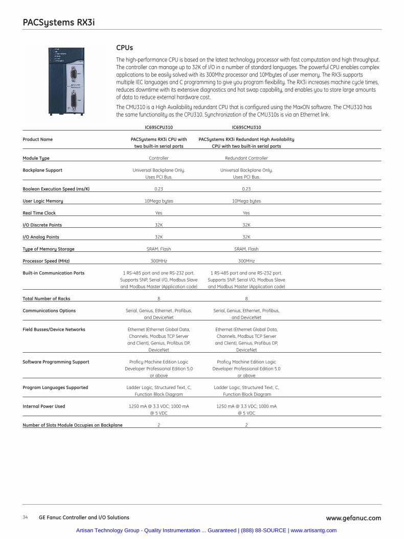
34 www.gefanuc.comGE Fanuc Controller and I/O Solutions
PACSystems RX3i
The high-performance CPU is based on the latest technology processor with fast computation and high throughput.The controller can manage up to 32K of I/O in a number of standard languages. The powerful CPU enables complexapplications to be easily solved with its 300Mhz processor and 10Mbytes of user memory. The RX3i supportsmultiple IEC languages and C programming to give you program flexibility. The RX3i increases machine cycle times,reduces downtime with its extensive diagnostics and hot swap capability, and enables you to store large amountsof data to reduce external hardware cost.
The CMU310 is a High Availability redundant CPU that is configured using the MaxON software. The CMU310 hasthe same functionality as the CPU310. Synchronization of the CMU310s is via an Ethernet link.
CPUs
IC695CPU310 IC695CMU310
Product Name PACSystems RX3i CPU with PACSystems RX3i Redundant High Availability two built-in serial ports CPU with two built-in serial ports
Module Type Controller Redundant Controller
Backplane Support Universal Backplane Only. Universal Backplane Only. Uses PCI Bus. Uses PCI Bus.
Boolean Execution Speed (ms/K) 0.23 0.23
User Logic Memory 10Mega bytes 10Mega bytes
Real Time Clock Yes Yes
I/O Discrete Points 32K 32K
I/O Analog Points 32K 32K
Type of Memory Storage SRAM, Flash SRAM, Flash
Processor Speed (MHz) 300MHz 300MHz
Built-in Communication Ports 1 RS-485 port and one RS-232 port. 1 RS-485 port and one RS-232 port.Supports SNP, Serial I/O, Modbus Slave Supports SNP, Serial I/O, Modbus Slaveand Modbus Master (Application code) and Modbus Master (Application code)
Total Number of Racks 8 8
Communications Options Serial, Genius, Ethernet, Profibus, Serial, Genius, Ethernet, Profibus,and DeviceNet and DeviceNet
Field Busses/Device Networks Ethernet (Ethernet Global Data, Ethernet (Ethernet Global Data, Channels, Modbus TCP Server Channels, Modbus TCP Server
and Client), Genius, Profibus DP, and Client), Genius, Profibus DP, DeviceNet DeviceNet
Software Programming Support Proficy Machine Edition Logic Proficy Machine Edition LogicDeveloper Professional Edition 5.0 Developer Professional Edition 5.0
or above or above
Program Languages Supported Ladder Logic, Structured Text, C, Ladder Logic, Structured Text, C,Function Block Diagram Function Block Diagram
Internal Power Used 1250 mA @ 3.3 VDC; 1000 mA 1250 mA @ 3.3 VDC; 1000 mA @ 5 VDC @ 5 VDC
Number of Slots Module Occupies on Backplane 2 2
Artisan Technology Group - Quality Instrumentation ... Guaranteed | (888) 88-SOURCE | www.artisantg.com
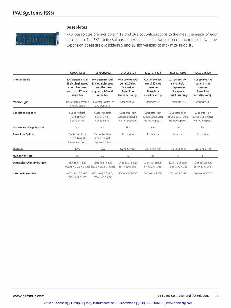
35www.gefanuc.com GE Fanuc Controller and I/O Solutions
PACSystems RX3i
RX3i baseplates are available in 12 and 16 slot configurations to the meet the needs of yourapplication. The RX3i Universal baseplates support hot swap capability to reduce downtime.Expansion bases are available in 5 and 10 slot versions to maximize flexibility.
Baseplates
IC695CHS016 IC695CHS012 IC694CHS392 IC693CHS393 IC694CHS398 IC693CHS399
Product Name PACSystems RX3i PACSystems RX3i PACSystems RX3i PACSystems RX3i PACSystems RX3i PACSystems RX3i16 slot high speed 12 slot high speed serial 10-slot serial 10-slot serial 5-slot serial 5-slot
controller base controller base Expansion Remote Expansion Remotesupports PCI and supports PCI and Baseplate Baseplate Baseplate Baseplate
serial bus serial bus (serial bus only) (serial bus only) (serial bus only) (serial bus only)
Module Type Universal Controller Universal Controller Standard I/O Standard I/O Standard I/O Standard I/Oand I/O Base and I/O Base
Backplane Support Supports both Supports both Supports High Supports High Supports High Supports High PCI and High PCI and High Speed Serial Only. Speed Serial Only. Speed Serial Only. Speed Serial Only.Speed Serial. Speed Serial. No PCI support. No PCI support. No PCI support. No PCI support.
Module Hot Swap Support Yes Yes No No No No
Baseplate Option Controller Base Controller Base Expansion Expansion Expansion Expansionand Ethernet and Ethernet
Expansion Base Expansion Base
Distance N/A N/A Up to 50 feet Up to 700 feet Up to 50 feet Up to 700 feet
Number of Slots 16 12 10 10 5 5
Dimension (WxHxD) in. (mm) 23.7 x 5.57 x 5.80 18.01 x 5.57 x 5.80 17.44 x 5.12 x 5.59 17.44 x 5.12 x 5.59 10.43 x 5.12 x 5.59 10.43 x 5.12 x 5.59(601.98 x 141.5 x 147.32) (457.5 x 141.5 x 147.32) (443 x 130 x 142) (443 x 130 x 142) (245 x 130 x 142) (245 x 130 x 142)
Internal Power Used 600 mA @ 3.3 VDC; 600 mA @ 3.3 VDC; 150 mA @ 5 VDC 460 mA @ 5 VDC 170 mA @ 5 VDC 480 mA @ 5 VDC240 mA @ 5 VDC 240 mA @ 5 VDC
Artisan Technology Group - Quality Instrumentation ... Guaranteed | (888) 88-SOURCE | www.artisantg.com
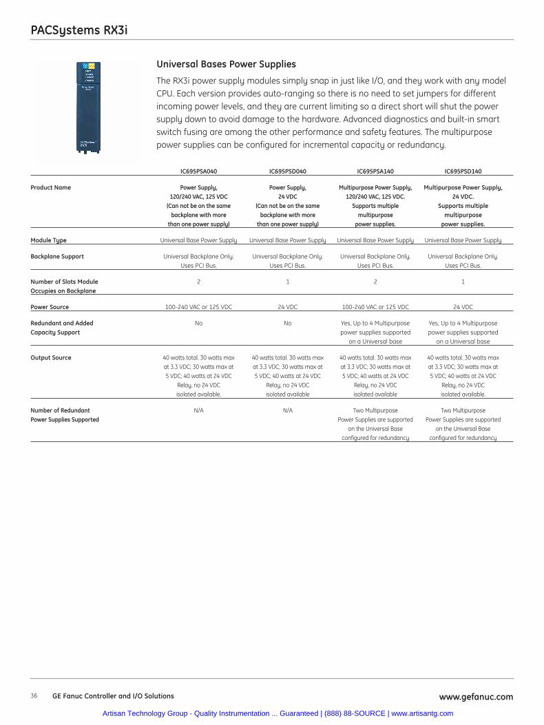
36 www.gefanuc.comGE Fanuc Controller and I/O Solutions
PACSystems RX3i
The RX3i power supply modules simply snap in just like I/O, and they work with any modelCPU. Each version provides auto-ranging so there is no need to set jumpers for differentincoming power levels, and they are current limiting so a direct short will shut the powersupply down to avoid damage to the hardware. Advanced diagnostics and built-in smartswitch fusing are among the other performance and safety features. The multipurposepower supplies can be configured for incremental capacity or redundancy.
Universal Bases Power Supplies
IC695PSA040 IC695PSD040 IC695PSA140 IC695PSD140
Product Name Power Supply, Power Supply, Multipurpose Power Supply, Multipurpose Power Supply, 120/240 VAC, 125 VDC 24 VDC 120/240 VAC, 125 VDC. 24 VDC.
(Can not be on the same (Can not be on the same Supports multiple Supports multiplebackplane with more backplane with more multipurpose multipurpose
than one power supply) than one power supply) power supplies. power supplies.
Module Type Universal Base Power Supply Universal Base Power Supply Universal Base Power Supply Universal Base Power Supply
Backplane Support Universal Backplane Only. Universal Backplane Only. Universal Backplane Only. Universal Backplane Only. Uses PCI Bus. Uses PCI Bus. Uses PCI Bus. Uses PCI Bus.
Number of Slots Module 2 1 2 1Occupies on Backplane
Power Source 100-240 VAC or 125 VDC 24 VDC 100-240 VAC or 125 VDC 24 VDC
Redundant and Added No No Yes, Up to 4 Multipurpose Yes, Up to 4 MultipurposeCapacity Support power supplies supported power supplies supported
on a Universal base on a Universal base
Output Source 40 watts total. 30 watts max 40 watts total. 30 watts max 40 watts total. 30 watts max 40 watts total. 30 watts maxat 3.3 VDC; 30 watts max at at 3.3 VDC; 30 watts max at at 3.3 VDC; 30 watts max at at 3.3 VDC; 30 watts max at5 VDC; 40 watts at 24 VDC 5 VDC; 40 watts at 24 VDC 5 VDC; 40 watts at 24 VDC 5 VDC; 40 watts at 24 VDC
Relay, no 24 VDC Relay, no 24 VDC Relay, no 24 VDC Relay, no 24 VDC isolated available. isolated available isolated available isolated available.
Number of Redundant N/A N/A Two Multipurpose Two Multipurpose Power Supplies Supported Power Supplies are supported Power Supplies are supported
on the Universal Base on the Universal Baseconfigured for redundancy configured for redundancy
Artisan Technology Group - Quality Instrumentation ... Guaranteed | (888) 88-SOURCE | www.artisantg.com
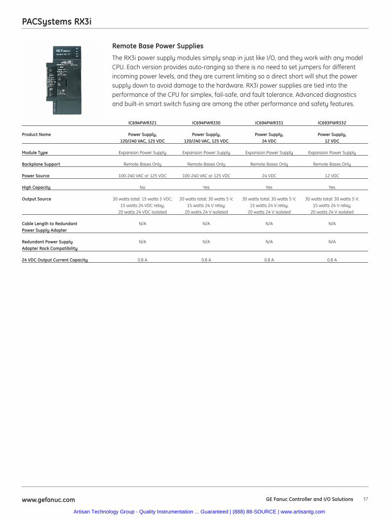
37www.gefanuc.com GE Fanuc Controller and I/O Solutions
PACSystems RX3i
The RX3i power supply modules simply snap in just like I/O, and they work with any modelCPU. Each version provides auto-ranging so there is no need to set jumpers for differentincoming power levels, and they are current limiting so a direct short will shut the powersupply down to avoid damage to the hardware. RX3i power supplies are tied into theperformance of the CPU for simplex, fail-safe, and fault tolerance. Advanced diagnosticsand built-in smart switch fusing are among the other performance and safety features.
Remote Base Power Supplies
IC694PWR321 IC694PWR330 IC694PWR331 IC693PWR332
Product Name Power Supply, Power Supply, Power Supply, Power Supply, 120/240 VAC, 125 VDC 120/240 VAC, 125 VDC 24 VDC 12 VDC
Module Type Expansion Power Supply Expansion Power Supply Expansion Power Supply Expansion Power Supply
Backplane Support Remote Bases Only Remote Bases Only Remote Bases Only Remote Bases Only
Power Source 100-240 VAC or 125 VDC 100-240 VAC or 125 VDC 24 VDC 12 VDC
High Capacity No Yes Yes Yes
Output Source 30 watts total; 15 watts 5 VDC; 30 watts total; 30 watts 5 V; 30 watts total; 30 watts 5 V; 30 watts total; 30 watts 5 V; 15 watts 24 VDC relay; 15 watts 24 V relay; 15 watts 24 V relay; 15 watts 24 V relay;
20 watts 24 VDC isolated 20 watts 24 V isolated 20 watts 24 V isolated 20 watts 24 V isolated
Cable Length to Redundant N/A N/A N/A N/APower Supply Adapter
Redundant Power Supply N/A N/A N/A N/AAdapter Rack Compatibility
24 VDC Output Current Capacity 0.8 A 0.8 A 0.8 A 0.8 A
Artisan Technology Group - Quality Instrumentation ... Guaranteed | (888) 88-SOURCE | www.artisantg.com
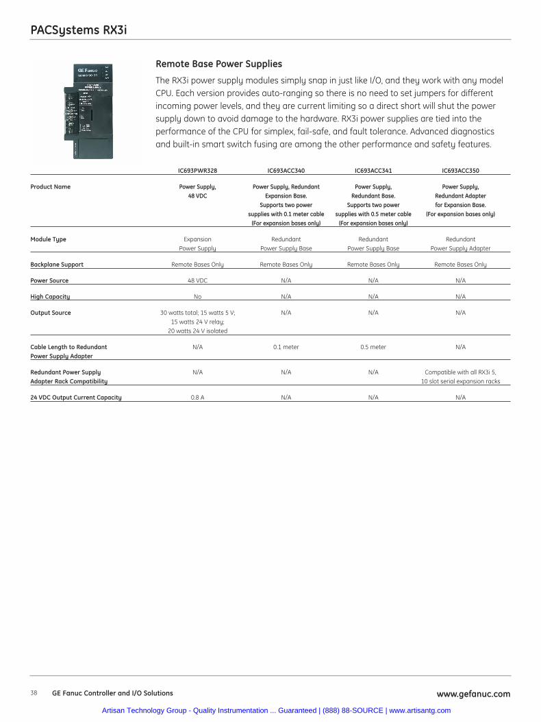
PACSystems RX3i
38 www.gefanuc.comGE Fanuc Controller and I/O Solutions
The RX3i power supply modules simply snap in just like I/O, and they work with any modelCPU. Each version provides auto-ranging so there is no need to set jumpers for differentincoming power levels, and they are current limiting so a direct short will shut the powersupply down to avoid damage to the hardware. RX3i power supplies are tied into theperformance of the CPU for simplex, fail-safe, and fault tolerance. Advanced diagnosticsand built-in smart switch fusing are among the other performance and safety features.
Remote Base Power Supplies
IC693PWR328 IC693ACC340 IC693ACC341 IC693ACC350
Product Name Power Supply, Power Supply, Redundant Power Supply, Power Supply, 48 VDC Expansion Base. Redundant Base. Redundant Adapter
Supports two power Supports two power for Expansion Base.supplies with 0.1 meter cable supplies with 0.5 meter cable (For expansion bases only)
(For expansion bases only) (For expansion bases only)
Module Type Expansion Redundant Redundant Redundant Power Supply Power Supply Base Power Supply Base Power Supply Adapter
Backplane Support Remote Bases Only Remote Bases Only Remote Bases Only Remote Bases Only
Power Source 48 VDC N/A N/A N/A
High Capacity No N/A N/A N/A
Output Source 30 watts total; 15 watts 5 V; N/A N/A N/A15 watts 24 V relay;
20 watts 24 V isolated
Cable Length to Redundant N/A 0.1 meter 0.5 meter N/APower Supply Adapter
Redundant Power Supply N/A N/A N/A Compatible with all RX3i 5,Adapter Rack Compatibility 10 slot serial expansion racks
24 VDC Output Current Capacity 0.8 A N/A N/A N/A
Artisan Technology Group - Quality Instrumentation ... Guaranteed | (888) 88-SOURCE | www.artisantg.com
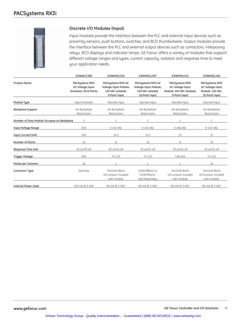
39www.gefanuc.com
PACSystems RX3i
Input modules provide the interface between the PLC and external input devices such asproximity sensors, push buttons, switches, and BCD thumbwheels. Output modules providethe interface between the PLC and external output devices such as contactors, interposingrelays, BCD displays and indicator lamps. GE Fanuc offers a variety of modules that supportdifferent voltage ranges and types, current capacity, isolation and response time to meetyour application needs.
Discrete I/O Modules (Input)
IC694ACC300 IC694MDL230 IC694MDL250* IC694MDL231 IC694MDL240
Product Name PACSystems RX3i PACSystems RX3i AC PACSystems RX3i AC PACSystems RX3i PACSystems RX3i DC Voltage Input Voltage Input Module, Voltage Input Module, AC Voltage Input AC Voltage Input
Simulator, 8/16 Points 120 VAC Isolated, 120 VAC Isolated, Module, 240 VAC Isolated, Module, 120 VAC, 8 Point Input 16 Point Input 8 Point Input 16 Point Input
Module Type Input Simulator Discrete Input Discrete Input Discrete Input Discrete Input
Backplane Support No Backplane No Backplane No Backplane No Backplane No Backplane Restrictions Restrictions Restrictions Restrictions Restrictions
Number of Slots Module Occupies on Backplane 1 1 1 1 1
Input Voltage Range N/A 0-132 VAC 0-132 VAC 0-264 VAC 0-132 VAC
Input Current (mA) N/A 14.5 14.5 15 12
Number of Points 16 8 16 8 16
Response Time (ms) 20 on/30 off 30 on/45 off 30 on/45 off 30 on/45 off 30 on/45 off
Trigger Voltage N/A 74-132 74-132 148-264 74-132
Points per Common 16 1 1 1 16
Connector Type Switches Terminal Block IC694TBBx32 or Terminal Block Terminal Block(20 screws), included IC694TBSx32. (20 screws), included (20 screws), included
with module. Sold Separately. with module. with module.
Internal Power Used 120 mA @ 5 VDC 60 mA @ 5 VDC 60 mA @ 5 VDC 60 mA @ 5 VDC 90 mA @ 5 VDC
GE Fanuc Controller and I/O Solutions
Artisan Technology Group - Quality Instrumentation ... Guaranteed | (888) 88-SOURCE | www.artisantg.com
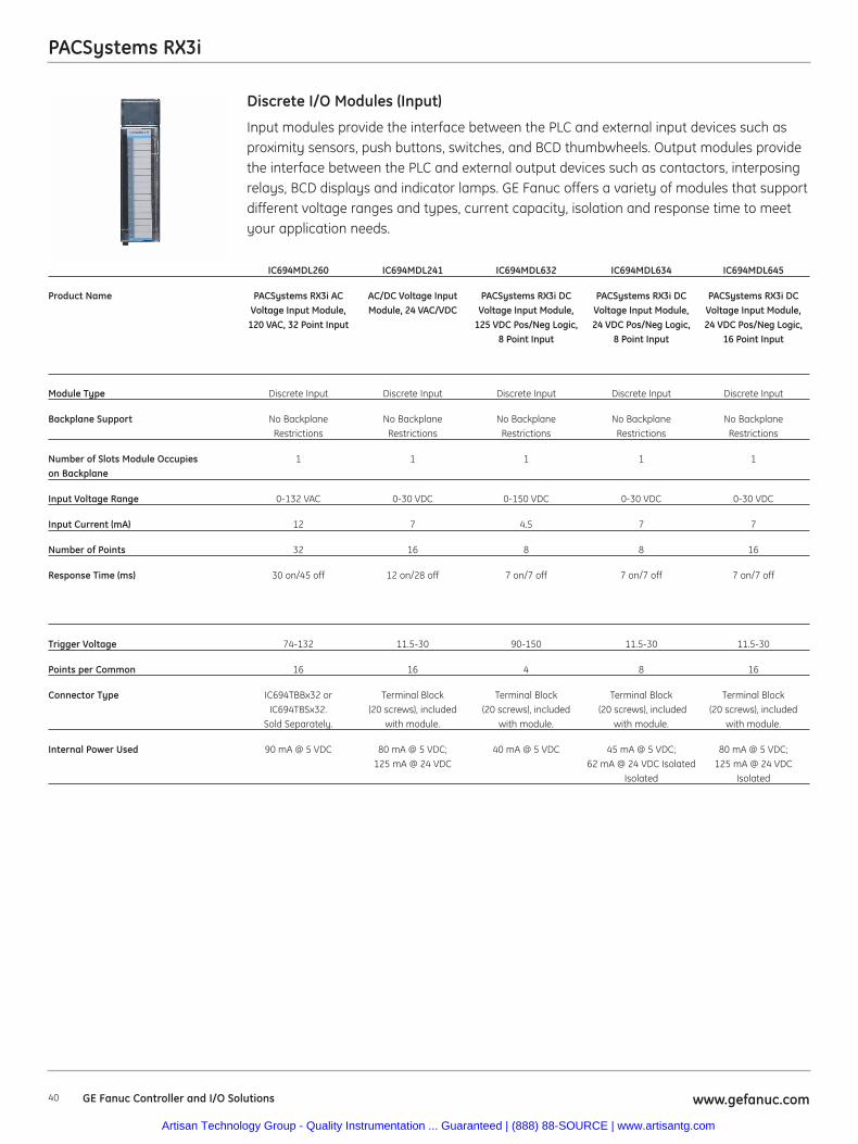
40 www.gefanuc.comGE Fanuc Controller and I/O Solutions
PACSystems RX3i
Input modules provide the interface between the PLC and external input devices such asproximity sensors, push buttons, switches, and BCD thumbwheels. Output modules providethe interface between the PLC and external output devices such as contactors, interposingrelays, BCD displays and indicator lamps. GE Fanuc offers a variety of modules that supportdifferent voltage ranges and types, current capacity, isolation and response time to meetyour application needs.
Discrete I/O Modules (Input)
IC694MDL260 IC694MDL241 IC694MDL632 IC694MDL634 IC694MDL645
Product Name PACSystems RX3i AC AC/DC Voltage Input PACSystems RX3i DC PACSystems RX3i DC PACSystems RX3i DC Voltage Input Module, Module, 24 VAC/VDC Voltage Input Module, Voltage Input Module, Voltage Input Module,
120 VAC, 32 Point Input 125 VDC Pos/Neg Logic, 24 VDC Pos/Neg Logic, 24 VDC Pos/Neg Logic,8 Point Input 8 Point Input 16 Point Input
Module Type Discrete Input Discrete Input Discrete Input Discrete Input Discrete Input
Backplane Support No Backplane No Backplane No Backplane No Backplane No BackplaneRestrictions Restrictions Restrictions Restrictions Restrictions
Number of Slots Module Occupies 1 1 1 1 1on Backplane
Input Voltage Range 0-132 VAC 0-30 VDC 0-150 VDC 0-30 VDC 0-30 VDC
Input Current (mA) 12 7 4.5 7 7
Number of Points 32 16 8 8 16
Response Time (ms) 30 on/45 off 12 on/28 off 7 on/7 off 7 on/7 off 7 on/7 off
Trigger Voltage 74-132 11.5-30 90-150 11.5-30 11.5-30
Points per Common 16 16 4 8 16
Connector Type IC694TBBx32 or Terminal Block Terminal Block Terminal Block Terminal BlockIC694TBSx32. (20 screws), included (20 screws), included (20 screws), included (20 screws), included
Sold Separately. with module. with module. with module. with module.
Internal Power Used 90 mA @ 5 VDC 80 mA @ 5 VDC; 40 mA @ 5 VDC 45 mA @ 5 VDC; 80 mA @ 5 VDC;125 mA @ 24 VDC 62 mA @ 24 VDC Isolated 125 mA @ 24 VDC
Isolated Isolated
Artisan Technology Group - Quality Instrumentation ... Guaranteed | (888) 88-SOURCE | www.artisantg.com
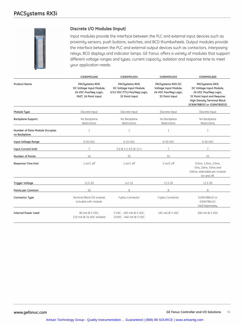
PACSystems RX3i
41www.gefanuc.com GE Fanuc Controller and I/O Solutions
Input modules provide the interface between the PLC and external input devices such asproximity sensors, push buttons, switches, and BCD thumbwheels. Output modules providethe interface between the PLC and external output devices such as contactors, interposingrelays, BCD displays and indicator lamps. GE Fanuc offers a variety of modules that supportdifferent voltage ranges and types, current capacity, isolation and response time to meetyour application needs.
Discrete I/O Modules (Input)
IC694MDL646 IC694MDL654 IC694MDL655 IC694MDL660
Product Name PACSystems RX3i PACSystems RX3i PACSystems RX3i DC PACSystems RX3i DC Voltage Input Module, DC Voltage Input Module, Voltage Input Module, DC Voltage Input Module,
24 VDC Pos/Neg Logic, 5/12 VDC (TTL) Pos/Neg Logic, 24 VDC Pos/Neg Logic, 24 VDC Pos/Neg Logic,FAST, 16 Point Input 32 Point Input 32 Point Input 32 Point Input and Requires
High Density Terminal Block (IC694TBB032 or IC694TBS032)
Module Type Discrete Input Discrete Input Discrete Input Discrete Input
Backplane Support No Backplane No Backplane No Backplane No Backplane Restrictions Restrictions Restrictions Restrictions
Number of Slots Module Occupies 1 1 1 1on Backplane
Input Voltage Range 0-30 VDC 0-15 VDC 0-30 VDC 0-30 VDC
Input Current (mA) 7 3.0 @ 5 V, 8.5 @ 12 V 7 7
Number of Points 16 32 32 32
Response Time (ms) 1 on/1 off 1 on/1 off 2 on/2 off 0.5ms, 1.0ms, 2.0ms, 5ms, 10ms, 50ms and
100ms, selectable per module. On and off.
Trigger Voltage 11.5-30 4.2-15 11.5-30 11.5-30
Points per Common 16 8 8 8
Connector Type Terminal Block (20 screws), Fujitsu Connector Fujitsu Connector IC694TBBx32 or included with module. IC694TBSx32.
Sold Separately.
Internal Power Used 80 mA @ 5 VDC; 5 VDC - 195 mA @ 5 VDC; 195 mA @ 5 VDC 300 mA @ 5 VDC125 mA @ 24 VDC Isolated 12VDC - 440 mA @ 5 VDC
Artisan Technology Group - Quality Instrumentation ... Guaranteed | (888) 88-SOURCE | www.artisantg.com
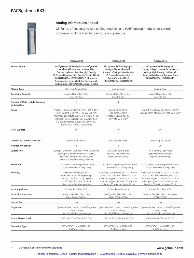
42 www.gefanuc.comGE Fanuc Controller and I/O Solutions
PACSystems RX3i
GE Fanuc offers easy-to-use analog modules and HART analog modules for controlprocesses such as flow, temperature and pressure.
Analog I/O Modules (Input)
IC695ALG600 IC695ALG608 IC695ALG616
Product Name PACSystems RX3i Analog Input. Configurable PACSystems RX3i Analog Input. PACSystems RX3i Analog Input. per channel for Current, Voltage, RTD, Configurable per channel for Configurable per channel for Current or
Thermocouple and Resistive. High Density Current or Voltage. High Density Voltage. High Density (16 Channel) (8 Channel) Requires High Density Terminal Block (8 Channel) Requires High Requires High Density Terminal Block
(IC694TBB032 or IC694TBS032). Cold Junction Density Terminal Block (IC694TBB032 or IC694TBS032). Compensation are available for Thermocouple (IC694TBB032 or IC694TBS032).configurations (IC695ACC600 contains 2 CJCs)
Module Type Universal Analog Input Analog Input Analog Input
Backplane Support Universal Backplane Only. Universal Backplane Only. Universal Backplane Only. Uses PCI Bus. Uses PCI Bus. Uses PCI Bus.
Number of Slots Module Occupies 1 1 1on Backplane
Range Voltage: +50mV, +150 mV, 0–5 V, 1–5 V, 0–10 V, Current: 0 to 20mA, Current: 0 to 20mA, 4 to 20mA, ±20mA; +10V; Current: 0–20 mA, 4–20 mA, +20 mA; 4 to 20mA, ±20mA; Voltage: ±10V, 0 to 10V, ±5V, 0 to 5V, 1 to 5V
Thermocouple Inputs: B, C, E, J, K, N, R, S, T; RTD Voltage: ±10V, 0 to 10V, Inputs: PT 385 / 3916, N 618 / 672, NiFe 518, ±5V, 0 to 5V, 1 to 5VCU 426: Resistance Inputs: 0 to 250 / 500 /
1000 / 2000 / 3000 / 4000 Ohms
HART Support N/A N/A N/A
Channel-to-Channel Isolation Two Groups of Four One Group of Eight One Group of Sixteen
Number of Channels 8 8 16
Update Rate 10ms per Channel; 4 Channels = 40ms (1KHz filter) All 8 Channels at 5 msec All 16 Channels at 9 msec 127ms per Channel* 4 Channels = 508ms @ 500Hz. Performance is @ 500Hz. Performance is
(8Hz filter) Channels that are disabled dependent on filtering. dependent on filtering.are not scanned, shortening scan time.
Resolution 11 to 16 bits, depending on configured 12 to 18 bits, depending on configured 12 to 18 bits, depending on configured range and A/D filter frequency range and A/D filter frequency range and A/D filter frequency
Accuracy Calibrated Accuracy at 25°C. Calibrated Accuracy @ 13°C – 33°C with Calibrated Accuracy @ 13°C – 33°C with Better than 0.1% of range (except 8 Hz, 12 Hz and 16 Hz filter; 0 to 10 V, 8 Hz, 12 Hz and 16 Hz filter; 0 to 10V,
10 ohm CU RTD) Accuracy depends ±10 V input types: 10 mV0 to 5V, 1 to 5 V, ±10V input types: 10 mV0 to 5V, 1 to 5V, on A/D filter, data format, input ±5 V input types: 5 mV0 to 20 mA, 4 to ±5V input types: 5 mV0 to 20 mA, 4 to
noise, and ambient temperature. 20 mA, ±20 mA input types: 20 uA 20 mA, ±20 mA input types: 20 uA
Input Impedance Current 249 ohms ±1% Current 249 ohms ±1% Current 249 ohms ±1%
Input Filter Response Configurable: 8Hz, 12Hz, 16Hz, Configurable: 8Hz, 12Hz, 16Hz, Configurable: 8Hz, 12Hz, 16Hz, 40Hz, 40Hz, 200Hz, 1000Hz 40Hz, 200Hz, 500Hz 200Hz, 500Hz
Notch Filter Yes Yes Yes
Diagnostics Open wire, short circuit, positive/negative Open wire, short circuit, positive/negative Open wire, short circuit, positive/negativerate of change, rate of change, rate of change,
High, High-High, Low, Low-Low High, High-High, Low, Low-Low High, High-High, Low, Low-Low
Internal Power Used 400 mA @ 5 V; 350 mA @ 3.3 V 450 mA @ 5 V; 600 mA @ 3.3 V 450 mA @ 5V; 600 mA @ 3.3V
Connector Type IC694TBBx32 or IC694TBSx32. IC694TBBx32 or IC694TBSx32. IC694TBBx32 or IC694TBSx32. Sold Separately. Sold Separately. Sold Separately.
Artisan Technology Group - Quality Instrumentation ... Guaranteed | (888) 88-SOURCE | www.artisantg.com
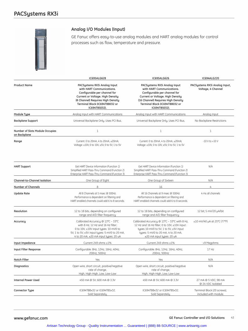
43www.gefanuc.com GE Fanuc Controller and I/O Solutions
PACSystems RX3i
GE Fanuc offers easy-to-use analog modules and HART analog modules for controlprocesses such as flow, temperature and pressure.
Analog I/O Modules (Input)
IC695ALG628 IC695ALG626 IC694ALG220
Product Name PACSystems RX3i Analog Input PACSystems RX3i Analog Input PACSystems RX3i Analog Input, with HART Communications. with HART Communications. Voltage, 4 ChannelConfigurable per channel for Configurable per channel for
Current or Voltage. High Density Current or Voltage. High Density(8 Channel) Requires High Density (16 Channel) Requires High Density
Terminal Block (IC694TBB032 or Terminal Block (IC694TBB032 orIC694TBS032). IC694TBS032).
Module Type Analog Input with HART Communications Analog Input with HART Communications Analog Input
Backplane Support Universal Backplane Only. Uses PCI Bus. Universal Backplane Only. Uses PCI Bus. No Backplane Restrictions
Number of Slots Module Occupies 1 1 1on Backplane
Range Current: 0 to 20mA, 4 to 20mA, ±20mA; Current: 0 to 20mA, 4 to 20mA, ±20mA; -10 V to +10 VVoltage: ±10V, 0 to 10V, ±5V, 0 to 5V, 1 to 5V Voltage: ±10V, 0 to 10V, ±5V, 0 to 5V, 1 to 5V
HART Support Get HART Device Information (Function 1) Get HART Device Information (Function 1) N/ASimplified HART Pass-Thru Command (Function 2) Simplified HART Pass-Thru Command (Function 2)Enterprise HART Pass-Thru Command (Function 3) Enterprise HART Pass-Thru Command (Function 3)
Channel-to-Channel Isolation One Group of Eight One Group of Sixteen N/A
Number of Channels 8 16 4
Update Rate All 8 Channels at 5 msec @ 500Hz. All 16 Channels at 9 msec @ 500Hz. 4 ms all channelsPerformance is dependent on filtering and Performance is dependent on filtering and
HART enabled channels could add 6 to 8 seconds. HART enabled channels could add 6 to 8 seconds.
Resolution 12 to 18 bits, depending on configured 12 to 18 bits, depending on configured 12 bit; 5 mV/20 μA/bitrange and A/D filter frequency range and A/D filter frequency
Accuracy Calibrated Accuracy @ 13°C – 33°C Calibrated Accuracy @ 13°C – 33°C with 8 Hz, ±10 mV/40 μA at 25°C (77°F)with 8 Hz, 12 Hz and 16 Hz filter; 12 Hz and 16 Hz filter; 0 to 10V, ±10V input :
0 to 10V, ±10V input types: 10 mV0 to types 10 mV0 to 5V, 1 to 5V, ±5V input 5V, 1 to 5V, ±5V input types: 5 mV0 to 20 mA, types: 5 mV0 to 20 mA, 4 to 20 mA,
4 to 20 mA, ±20 mA input types: 20 uA ±20 mA input types: 20 uA
Input Impedance Current 249 ohms ±1% Current 249 ohms ±1% >9 Megohms
Input Filter Response Configurable: 8Hz, 12Hz, 16Hz, 40Hz, Configurable: 8Hz, 12Hz, 16Hz, 40Hz, 17 Hz200Hz, 500Hz 200Hz, 500Hz
Notch Filter Yes Yes N/A
Diagnostics Open wire, short circuit, positive/negative Open wire, short circuit, positive/negative N/Arate of change, rate of change,
High, High-High, Low, Low-Low High, High-High, Low, Low-Low
Internal Power Used 450 mA @ 5V; 600 mA @ 3.3V 450 mA @ 5V; 600 mA @ 3.3V 27 mA @ 5 VDC; 98 mA @ 24 VDC Isolated
Connector Type IC694TBBx32 or IC694TBSx32. IC694TBBx32 or IC694TBSx32. Terminal Block (20 screws), Sold Separately. Sold Separately. included with module.
Artisan Technology Group - Quality Instrumentation ... Guaranteed | (888) 88-SOURCE | www.artisantg.com
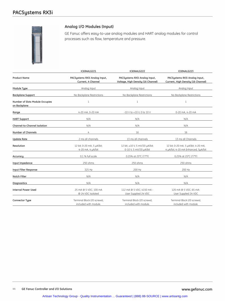
PACSystems RX3i
44 www.gefanuc.comGE Fanuc Controller and I/O Solutions
GE Fanuc offers easy-to-use analog modules and HART analog modules for controlprocesses such as flow, temperature and pressure.
Analog I/O Modules (Input)
IC694ALG221 IC694ALG222 IC694ALG223
Product Name PACSystems RX3i Analog Input, PACSystems RX3i Analog Input, PACSystems RX3i Analog Input, Current, 4 Channel Voltage, High Density (16 Channel) Current, High Density (16 Channel)
Module Type Analog Input Analog Input Analog Input
Backplane Support No Backplane Restrictions No Backplane Restrictions No Backplane Restrictions
Number of Slots Module Occupies 1 1 1on Backplane
Range 4-20 mA, 0-20 mA -10 V to +10 V, 0 to 10 V 0-20 mA, 4-20 mA
HART Support N/A N/A N/A
Channel-to-Channel Isolation N/A N/A N/A
Number of Channels 4 16 16
Update Rate 2 ms all channels 13 ms all channels 13 ms all Channels
Resolution 12 bit; 0-20 mA, 5 μA/bit; 12 bit; ±10 V, 5 mV/20 μA/bit; 12 bit; 0-20 mA, 5 μA/bit; 4-20 mA, 4-20 mA, 4 μA/bit 0-10 V, 5 mV/20 μA/bit 4 μA/bit; 4-20 mA Enhanced, 5μA/bit
Accuracy 0.1 % full scale 0.25% at 25°C (77°F) 0.25% at 25°C (77°F)
Input Impedance 250 ohms 250 ohms 250 ohms
Input Filter Response 325 Hz 200 Hz 200 Hz
Notch Filter N/A N/A N/A
Diagnositics N/A N/A N/A
Internal Power Used 25 mA @ 5 VDC; 100 mA 112 mA @ 5 VDC; 4150 mA - 120 mA @ 5 VDC; 65 mA-@ 24 VDC Isolated User Supplied 24 VDC User Supplied 24 VDC
Connector Type Terminal Block (20 screws), Terminal Block (20 screws), Terminal Block (20 screws), included with module. included with module. included with module.
Artisan Technology Group - Quality Instrumentation ... Guaranteed | (888) 88-SOURCE | www.artisantg.com
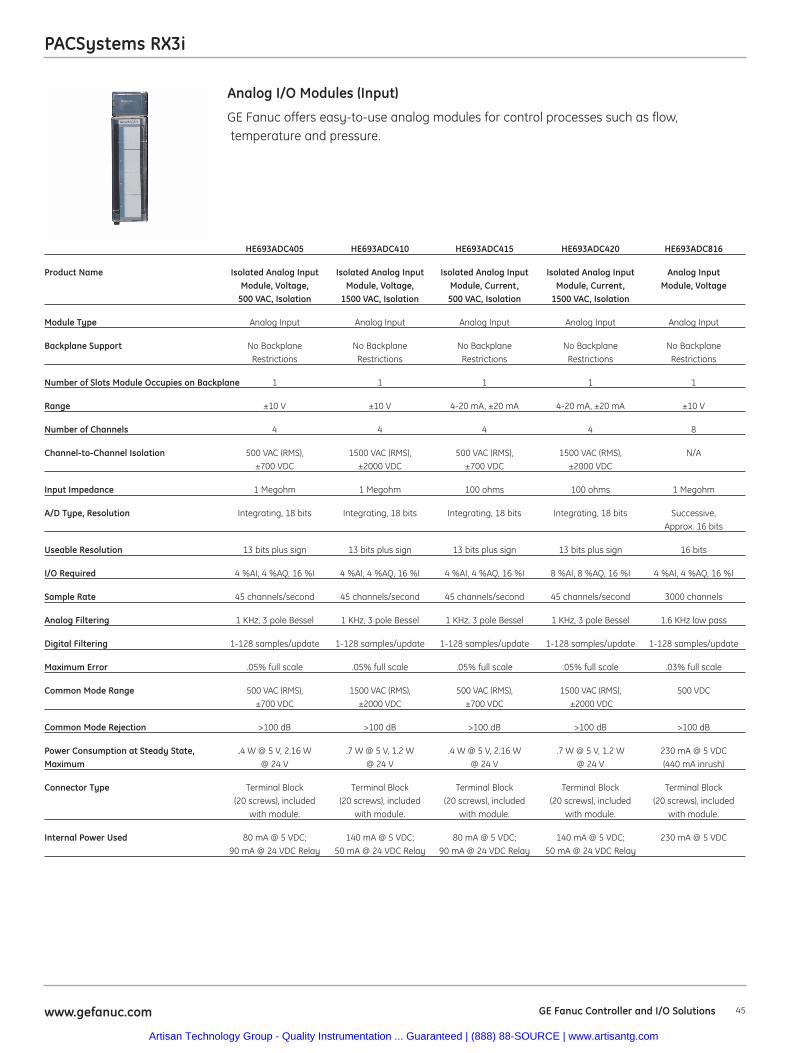
PACSystems RX3i
45www.gefanuc.com GE Fanuc Controller and I/O Solutions
GE Fanuc offers easy-to-use analog modules for control processes such as flow,temperature and pressure.
Analog I/O Modules (Input)
HE693ADC405 HE693ADC410 HE693ADC415 HE693ADC420 HE693ADC816
Product Name Isolated Analog Input Isolated Analog Input Isolated Analog Input Isolated Analog Input Analog InputModule, Voltage, Module, Voltage, Module, Current, Module, Current, Module, Voltage
500 VAC, Isolation 1500 VAC, Isolation 500 VAC, Isolation 1500 VAC, Isolation
Module Type Analog Input Analog Input Analog Input Analog Input Analog Input
Backplane Support No Backplane No Backplane No Backplane No Backplane No Backplane Restrictions Restrictions Restrictions Restrictions Restrictions
Number of Slots Module Occupies on Backplane 1 1 1 1 1
Range ±10 V ±10 V 4-20 mA, ±20 mA 4-20 mA, ±20 mA ±10 V
Number of Channels 4 4 4 4 8
Channel-to-Channel Isolation 500 VAC (RMS), 1500 VAC (RMS), 500 VAC (RMS), 1500 VAC (RMS), N/A±700 VDC ±2000 VDC ±700 VDC ±2000 VDC
Input Impedance 1 Megohm 1 Megohm 100 ohms 100 ohms 1 Megohm
A/D Type, Resolution Integrating, 18 bits Integrating, 18 bits Integrating, 18 bits Integrating, 18 bits Successive, Approx. 16 bits
Useable Resolution 13 bits plus sign 13 bits plus sign 13 bits plus sign 13 bits plus sign 16 bits
I/O Required 4 %AI, 4 %AQ, 16 %I 4 %AI, 4 %AQ, 16 %I 4 %AI, 4 %AQ, 16 %I 8 %AI, 8 %AQ, 16 %I 4 %AI, 4 %AQ, 16 %I
Sample Rate 45 channels/second 45 channels/second 45 channels/second 45 channels/second 3000 channels
Analog Filtering 1 KHz, 3 pole Bessel 1 KHz, 3 pole Bessel 1 KHz, 3 pole Bessel 1 KHz, 3 pole Bessel 1.6 KHz low pass
Digital Filtering 1-128 samples/update 1-128 samples/update 1-128 samples/update 1-128 samples/update 1-128 samples/update
Maximum Error .05% full scale .05% full scale .05% full scale .05% full scale .03% full scale
Common Mode Range 500 VAC (RMS), 1500 VAC (RMS), 500 VAC (RMS), 1500 VAC (RMS), 500 VDC±700 VDC ±2000 VDC ±700 VDC ±2000 VDC
Common Mode Rejection >100 dB >100 dB >100 dB >100 dB >100 dB
Power Consumption at Steady State, .4 W @ 5 V, 2.16 W .7 W @ 5 V, 1.2 W .4 W @ 5 V, 2.16 W .7 W @ 5 V, 1.2 W 230 mA @ 5 VDCMaximum @ 24 V @ 24 V @ 24 V @ 24 V (440 mA inrush)
Connector Type Terminal Block Terminal Block Terminal Block Terminal Block Terminal Block(20 screws), included (20 screws), included (20 screws), included (20 screws), included (20 screws), included
with module. with module. with module. with module. with module.
Internal Power Used 80 mA @ 5 VDC; 140 mA @ 5 VDC; 80 mA @ 5 VDC; 140 mA @ 5 VDC; 230 mA @ 5 VDC90 mA @ 24 VDC Relay 50 mA @ 24 VDC Relay 90 mA @ 24 VDC Relay 50 mA @ 24 VDC Relay
Artisan Technology Group - Quality Instrumentation ... Guaranteed | (888) 88-SOURCE | www.artisantg.com
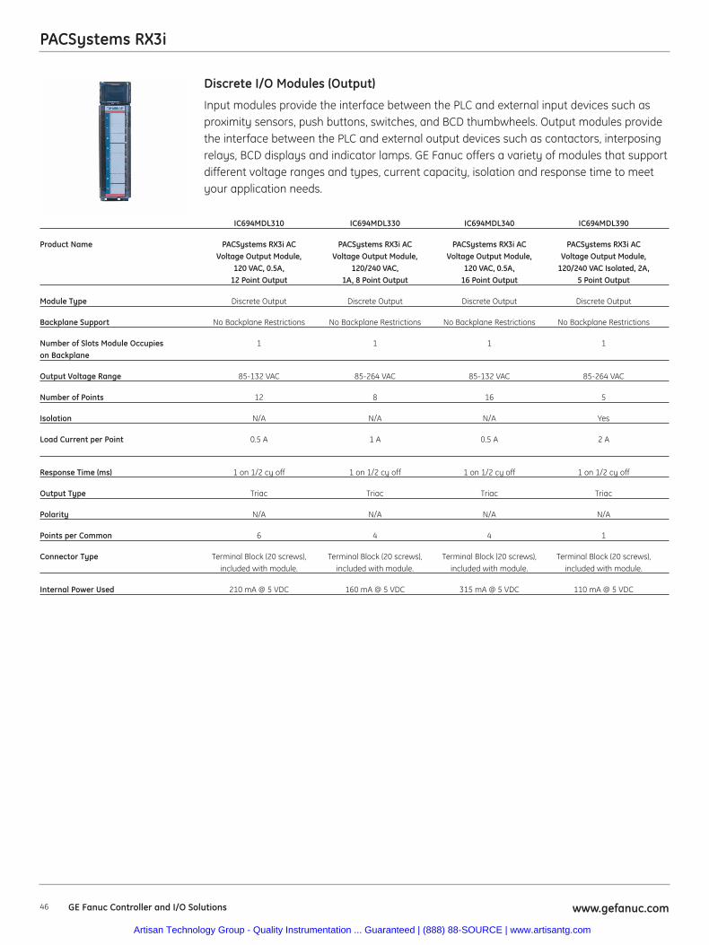
46 www.gefanuc.comGE Fanuc Controller and I/O Solutions
PACSystems RX3i
Input modules provide the interface between the PLC and external input devices such asproximity sensors, push buttons, switches, and BCD thumbwheels. Output modules providethe interface between the PLC and external output devices such as contactors, interposingrelays, BCD displays and indicator lamps. GE Fanuc offers a variety of modules that supportdifferent voltage ranges and types, current capacity, isolation and response time to meetyour application needs.
Discrete I/O Modules (Output)
IC694MDL310 IC694MDL330 IC694MDL340 IC694MDL390
Product Name PACSystems RX3i AC PACSystems RX3i AC PACSystems RX3i AC PACSystems RX3i AC Voltage Output Module, Voltage Output Module, Voltage Output Module, Voltage Output Module,
120 VAC, 0.5A, 120/240 VAC, 120 VAC, 0.5A, 120/240 VAC Isolated, 2A, 12 Point Output 1A, 8 Point Output 16 Point Output 5 Point Output
Module Type Discrete Output Discrete Output Discrete Output Discrete Output
Backplane Support No Backplane Restrictions No Backplane Restrictions No Backplane Restrictions No Backplane Restrictions
Number of Slots Module Occupies 1 1 1 1on Backplane
Output Voltage Range 85-132 VAC 85-264 VAC 85-132 VAC 85-264 VAC
Number of Points 12 8 16 5
Isolation N/A N/A N/A Yes
Load Current per Point 0.5 A 1 A 0.5 A 2 A
Response Time (ms) 1 on 1/2 cy off 1 on 1/2 cy off 1 on 1/2 cy off 1 on 1/2 cy off
Output Type Triac Triac Triac Triac
Polarity N/A N/A N/A N/A
Points per Common 6 4 4 1
Connector Type Terminal Block (20 screws), Terminal Block (20 screws), Terminal Block (20 screws), Terminal Block (20 screws),included with module. included with module. included with module. included with module.
Internal Power Used 210 mA @ 5 VDC 160 mA @ 5 VDC 315 mA @ 5 VDC 110 mA @ 5 VDC
Artisan Technology Group - Quality Instrumentation ... Guaranteed | (888) 88-SOURCE | www.artisantg.com
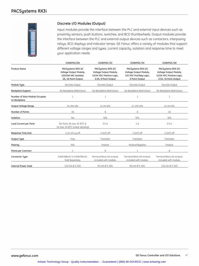
47www.gefanuc.com GE Fanuc Controller and I/O Solutions
PACSystems RX3i
Input modules provide the interface between the PLC and external input devices such asproximity sensors, push buttons, switches, and BCD thumbwheels. Output modules providethe interface between the PLC and external output devices such as contactors, interposingrelays, BCD displays and indicator lamps. GE Fanuc offers a variety of modules that supportdifferent voltage ranges and types, current capacity, isolation and response time to meetyour application needs.
Discrete I/O Modules (Output)
IC694MDL350 IC694MDL732 IC694MDL734 IC694MDL740
Product Name PACSystems RX3i AC PACSystems RX3i DC PACSystems RX3i DC PACSystems RX3i DCVoltage Output Module, Voltage Output Module, Voltage Output Module, Voltage Output Module,120/240 VAC Isolated, 12/24 VDC Positive Logic, 125 VDC Pos/Neg Logic, 12/24 VDC Positive Logic,
2A, 16 Point Output 0.5A, 8 Point Output 6 Point Output 0.5A, 16 Point Output
Module Type Discrete Output Discrete Output Discrete Output Discrete Output
Backplane Support No Backplane Restrictions No Backplane Restrictions No Backplane Restrictions No Backplane Restrictions
Number of Slots Module Occupies 1 1 1 1on Backplane
Output Voltage Range 74-264 VAC 12-24 VDC 11-150 VDC 12-24 VDC
Number of Points 16 8 6 16
Isolation Yes N/A N/A N/A
Load Current per Point Per Point 2A max. @ 30°C & 0.5 A 1 A 0.5 A1A max. @ 60°C (Linear derating)
Response Time (ms) 1 on 1/2 cy off 2 on/2 off 7 on/5 off 2 on/2 off
Output Type Triac Transistor Transistor Transistor
Polarity N/A Positive Positive/Negative Positive
Points per Common 1 8 1 8
Connector Type IC694TBBx32 or IC694TBSx32. Terminal Block (20 screws), Terminal Block (20 screws), Terminal Block (20 screws),Sold Separately. included with module. included with module. included with module.
Internal Power Used 110 mA @ 5 VDC 50 mA @ 5 VDC 90 mA @ 5 VDC 110 mA @ 5 VDC
Artisan Technology Group - Quality Instrumentation ... Guaranteed | (888) 88-SOURCE | www.artisantg.com
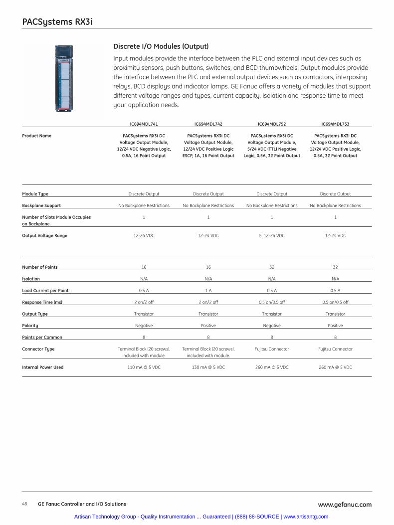
48 www.gefanuc.comGE Fanuc Controller and I/O Solutions
PACSystems RX3i
Input modules provide the interface between the PLC and external input devices such asproximity sensors, push buttons, switches, and BCD thumbwheels. Output modules providethe interface between the PLC and external output devices such as contactors, interposingrelays, BCD displays and indicator lamps. GE Fanuc offers a variety of modules that supportdifferent voltage ranges and types, current capacity, isolation and response time to meetyour application needs.
Discrete I/O Modules (Output)
IC694MDL741 IC694MDL742 IC694MDL752 IC694MDL753
Product Name PACSystems RX3i DC PACSystems RX3i DC PACSystems RX3i DC PACSystems RX3i DCVoltage Output Module, Voltage Output Module, Voltage Output Module, Voltage Output Module,
12/24 VDC Negative Logic, 12/24 VDC Positive Logic 5/24 VDC (TTL) Negative 12/24 VDC Positive Logic,0.5A, 16 Point Output ESCP, 1A, 16 Point Output Logic, 0.5A, 32 Point Output 0.5A, 32 Point Output
Module Type Discrete Output Discrete Output Discrete Output Discrete Output
Backplane Support No Backplane Restrictions No Backplane Restrictions No Backplane Restrictions No Backplane Restrictions
Number of Slots Module Occupies 1 1 1 1on Backplane
Output Voltage Range 12-24 VDC 12-24 VDC 5, 12-24 VDC 12-24 VDC
Number of Points 16 16 32 32
Isolation N/A N/A N/A N/A
Load Current per Point 0.5 A 1 A 0.5 A 0.5 A
Response Time (ms) 2 on/2 off 2 on/2 off 0.5 on/0.5 off 0.5 on/0.5 off
Output Type Transistor Transistor Transistor Transistor
Polarity Negative Positive Negative Positive
Points per Common 8 8 8 8
Connector Type Terminal Block (20 screws), Terminal Block (20 screws), Fujitsu Connector Fujitsu Connectorincluded with module. included with module.
Internal Power Used 110 mA @ 5 VDC 130 mA @ 5 VDC 260 mA @ 5 VDC 260 mA @ 5 VDC
Artisan Technology Group - Quality Instrumentation ... Guaranteed | (888) 88-SOURCE | www.artisantg.com
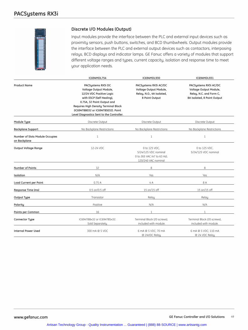
49www.gefanuc.com GE Fanuc Controller and I/O Solutions
PACSystems RX3i
Input modules provide the interface between the PLC and external input devices such asproximity sensors, push buttons, switches, and BCD thumbwheels. Output modules providethe interface between the PLC and external output devices such as contactors, interposingrelays, BCD displays and indicator lamps. GE Fanuc offers a variety of modules that supportdifferent voltage ranges and types, current capacity, isolation and response time to meetyour application needs.
Discrete I/O Modules (Output)
IC694MDL754 IC694MDL930 IC694MDL931
Product Name PACSystems RX3i DC PACSystems RX3i AC/DC PACSystems RX3i AC/DC Voltage Output Module, Voltage Output Module, Voltage Output Module,12/24 VDC Positive Logic Relay, N.O., 4A Isolated, Relay, N.C. and Form C,with ESCP (Self Healing), 8 Point Output 8A Isolated, 8 Point Output
0.75A, 32 Point Output and Requires High Density Terminal Block(IC694TBB032 or IC694TBS032). Point
Level Diagnostics Sent to the Controller.
Module Type Discrete Output Discrete Output Discrete Output
Backplane Support No Backplane Restrictions No Backplane Restrictions No Backplane Restrictions
Number of Slots Module Occupies 1 1 1on Backplane
Output Voltage Range 12-24 VDC 0 to 125 VDC, 0 to 125 VDC, 5/24/125 VDC nominal 5/24/125 VDC nominal
0 to 265 VAC (47 to 63 Hz), 120/240 VAC nominal
Number of Points 32 8 8
Isolation N/A Yes Yes
Load Current per Point 0.75 A 4 A 8 A
Response Time (ms) 0.5 on/0.5 off 15 on/15 off 15 on/15 off
Output Type Transistor Relay Relay
Polarity Positive N/A N/A
Points per Common 16 1 1
Connector Type IC694TBBx32 or IC694TBSx32. Terminal Block (20 screws), Terminal Block (20 screws),Sold Separately. included with module. included with module.
Internal Power Used 300 mA @ 5 VDC 6 mA @ 5 VDC; 70 mA 6 mA @ 5 VDC; 110 mA @ 24VDC Relay @ 24 VDC Relay
Artisan Technology Group - Quality Instrumentation ... Guaranteed | (888) 88-SOURCE | www.artisantg.com
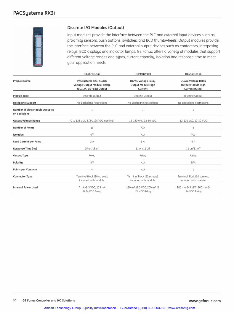
PACSystems RX3i
50 www.gefanuc.comGE Fanuc Controller and I/O Solutions
Input modules provide the interface between the PLC and external input devices such asproximity sensors, push buttons, switches, and BCD thumbwheels. Output modules providethe interface between the PLC and external output devices such as contactors, interposingrelays, BCD displays and indicator lamps. GE Fanuc offers a variety of modules that supportdifferent voltage ranges and types, current capacity, isolation and response time to meetyour application needs.
Discrete I/O Modules (Output)
IC694MDL940 HE693RLY100 HE693RLY110
Product Name PACSystems RX3i AC/DC DC/AC Voltage Relay DC/AC Voltage RelayVoltage Output Module, Relay, Output Module High Output Module High
N.O., 2A, 16 Point Output Current Current (fused)
Module Type Discrete Output Discrete Output Discrete Output
Backplane Support No Backplane Restrictions No Backplane Restrictions No Backplane Restrictions
Number of Slots Module Occupies 1 1 1on Backplane
Output Voltage Range 0 to 125 VDC, 5/24/125 VDC nominal 12-120 VAC, 12-30 VDC 12-120 VAC, 12-30 VDC
Number of Points 16 N/A 8
Isolation N/A N/A Yes
Load Current per Point 2 A 8 A 8 A
Response Time (ms) 15 on/15 off 11 on/11 off 11 on/11 off
Output Type Relay Relay Relay
Polarity N/A N/A N/A
Points per Common 4 N/A 1
Connector Type Terminal Block (20 screws), Terminal Block (20 screws), Terminal Block (20 screws), included with module. included with module. included with module.
Internal Power Used 7 mA @ 5 VDC; 135 mA 180 mA @ 5 VDC; 200 mA @ 180 mA @ 5 VDC; 200 mA @@ 24 VDC Relay 24 VDC Relay 24 VDC Relay
Artisan Technology Group - Quality Instrumentation ... Guaranteed | (888) 88-SOURCE | www.artisantg.com
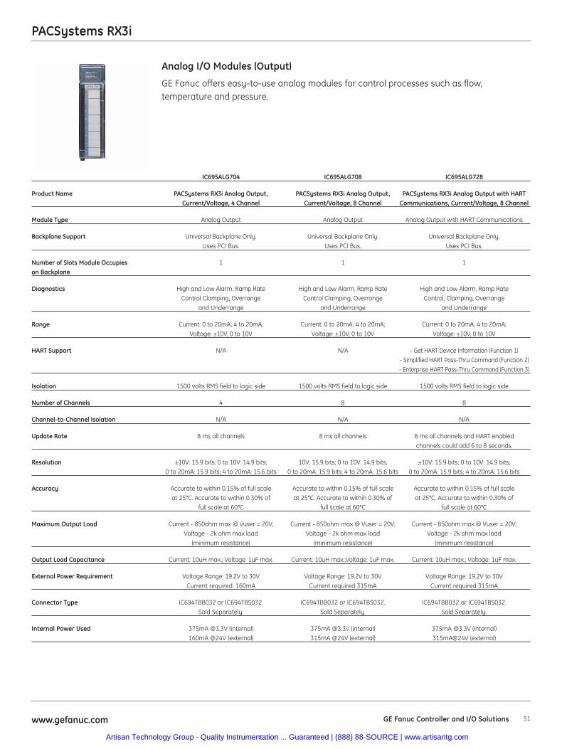
51www.gefanuc.com
PACSystems RX3i
GE Fanuc offers easy-to-use analog modules for control processes such as flow,temperature and pressure.
Analog I/O Modules (Output)
IC695ALG704 IC695ALG708 IC695ALG728
Product Name PACSystems RX3i Analog Output, PACSystems RX3i Analog Output, PACSystems RX3i Analog Output with HART Current/Voltage, 4 Channel Current/Voltage, 8 Channel Communications, Current/Voltage, 8 Channel
Module Type Analog Output Analog Output Analog Output with HART Communications
Backplane Support Universal Backplane Only. Universal Backplane Only. Universal Backplane Only.Uses PCI Bus. Uses PCI Bus. Uses PCI Bus.
Number of Slots Module Occupies 1 1 1on Backplane
Diagnostics High and Low Alarm, Ramp Rate High and Low Alarm, Ramp Rate High and Low Alarm, Ramp Rate Control Clamping, Overrange Control Clamping, Overrange Control, Clamping, Overrange
and Underrange and Underrange and Underrange
Range Current: 0 to 20mA, 4 to 20mA; Current: 0 to 20mA, 4 to 20mA; Current: 0 to 20mA, 4 to 20mA;Voltage: ±10V, 0 to 10V Voltage: ±10V, 0 to 10V Voltage: ±10V, 0 to 10V
HART Support N/A N/A - Get HART Device Information (Function 1)- Simplified HART Pass-Thru Command (Function 2)- Enterprise HART Pass-Thru Command (Function 3)
Isolation 1500 volts RMS field to logic side 1500 volts RMS field to logic side 1500 volts RMS field to logic side
Number of Channels 4 8 8
Channel-to-Channel Isolation N/A N/A N/A
Update Rate 8 ms all channels 8 ms all channels 8 ms all channels and HART enabled channels could add 6 to 8 seconds.
Resolution ±10V: 15.9 bits; 0 to 10V: 14.9 bits; 10V: 15.9 bits; 0 to 10V: 14.9 bits; ±10V: 15.9 bits; 0 to 10V: 14.9 bits; 0 to 20mA: 15.9 bits; 4 to 20mA: 15.6 bits 0 to 20mA: 15.9 bits; 4 to 20mA: 15.6 bits 0 to 20mA: 15.9 bits; 4 to 20mA: 15.6 bits
Accuracy Accurate to within 0.15% of full scale Accurate to within 0.15% of full scale Accurate to within 0.15% of full scale at 25°C. Accurate to within 0.30% of at 25°C. Accurate to within 0.30% of at 25°C. Accurate to within 0.30% of
full scale at 60°C full scale at 60°C full scale at 60°C
Maximum Output Load Current - 850ohm max @ Vuser = 20V; Current - 850ohm max @ Vuser = 20V; Current - 850ohm max @ Vuser = 20V; Voltage - 2k ohm max load Voltage - 2k ohm max load Voltage - 2k ohm max load
(minimum resistance) (minimum resistance) (minimum resistance)
Output Load Capacitance Current: 10uH max.; Voltage: 1uF max. Current: 10uH max.;Voltage: 1uF max. Current: 10uH max.; Voltage: 1uF max.
External Power Requirement Voltage Range: 19.2V to 30V Voltage Range: 19.2V to 30V Voltage Range: 19.2V to 30VCurrent required: 160mA Current required 315mA Current required 315mA
Connector Type IC694TBB032 or IC694TBS032. IC694TBB032 or IC694TBS032. IC694TBB032 or IC694TBS032.Sold Separately. Sold Separately. Sold Separately.
Internal Power Used 375mA @3.3V (internal) 375mA @3.3V (internal) 375mA @3.3V (internal) 160mA @24V (external) 315mA @24V (external) 315mA@24V (external)
GE Fanuc Controller and I/O Solutions
Artisan Technology Group - Quality Instrumentation ... Guaranteed | (888) 88-SOURCE | www.artisantg.com
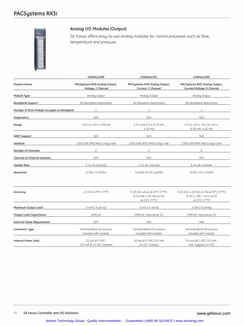
52 www.gefanuc.comGE Fanuc Controller and I/O Solutions
PACSystems RX3i
GE Fanuc offers easy-to-use analog modules for control processes such as flow,temperature and pressure.
Analog I/O Modules (Output)
IC694ALG390 IC694ALG391 IC694ALG392
Product Name PACSystems RX3i Analog Output, PACSystems RX3i Analog Output, PACSystems RX3i Analog Output, Voltage, 2 Channel Current, 2 Channel Current/Voltage, 8 Channel
Module Type Analog Output Analog Output Analog Output
Backplane Support No Backplane Restrictions No Backplane Restrictions No Backplane Restrictions
Number of Slots Module Occupies on Backplane 1 1 1
Diagnostics N/A N/A N/A
Range -10 V to +10 V, 4-20 mA 1-5 V and 0-5 V, 0-20 mA, 0 V to +10 V, -10 V to +10 V, 4-20 mA 0-20 mA, 4-20 mA
HART Support N/A N/A N/A
Isolation 1500 volts RMS field to logic side 1500 volts RMS field to logic side 1500 volts RMS field to logic side
Number of Channels 2 2 8
Channel-to-Channel Isolation N/A N/A N/A
Update Rate 5 ms all channels 5 ms all channels 8 ms all channels
Resolution 12 bit; 2.5 mV/bit 12 bit;0-20 mA, 5μA/bit 16 bit; 0.312 mV/bit
Accuracy ±5 mV at 25ºC (77ºF) 0-20 mA, ±8 μA at 25ºC (77ºF); 0-20 mA, 4-20 mA ±0.1% at 25ºC (77ºF);0-20 mA, 4-20 mA ±0.1% 0-10 V, -10F + 10 V ±0.25
at 25ºC (77ºF) at 25ºC (77ºF)
Maximum Output Load 5 mA (2 K ohms) 5 mA (2 K ohms) 5 mA (2 K ohms)
Output Load Capacitance 2000 pF 2000 pF, Inductance 1H 2000 pF, Inductance 1H
External Power Requirement N/A N/A N/A
Connector Type Terminal Block (20 screws), Terminal Block (20 screws), Terminal Block (20 screws), included with module. included with module. included with module.
Internal Power Used 32 mA @ 5 VDC; 30 mA @ 5 VDC; 215 mA 110 mA @ 5 VDC; 315 mA -120 mA @ 24 VDC Isolated 24 VDC Isolated User Supplied 24 VDC
Artisan Technology Group - Quality Instrumentation ... Guaranteed | (888) 88-SOURCE | www.artisantg.com
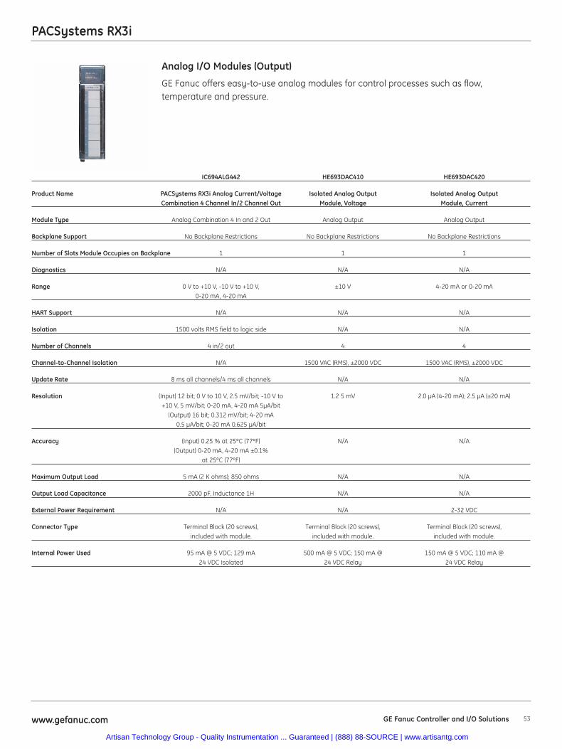
PACSystems RX3i
53www.gefanuc.com GE Fanuc Controller and I/O Solutions
GE Fanuc offers easy-to-use analog modules for control processes such as flow,temperature and pressure.
Analog I/O Modules (Output)
IC694ALG442 HE693DAC410 HE693DAC420
Product Name PACSystems RX3i Analog Current/Voltage Isolated Analog Output Isolated Analog Output Combination 4 Channel In/2 Channel Out Module, Voltage Module, Current
Module Type Analog Combination 4 In and 2 Out Analog Output Analog Output
Backplane Support No Backplane Restrictions No Backplane Restrictions No Backplane Restrictions
Number of Slots Module Occupies on Backplane 1 1 1
Diagnostics N/A N/A N/A
Range 0 V to +10 V, -10 V to +10 V, ±10 V 4-20 mA or 0-20 mA0-20 mA, 4-20 mA
HART Support N/A N/A N/A
Isolation 1500 volts RMS field to logic side N/A N/A
Number of Channels 4 in/2 out 4 4
Channel-to-Channel Isolation N/A 1500 VAC (RMS), ±2000 VDC 1500 VAC (RMS), ±2000 VDC
Update Rate 8 ms all channels/4 ms all channels N/A N/A
Resolution (Input) 12 bit; 0 V to 10 V, 2.5 mV/bit; -10 V to 1.2 5 mV 2.0 μA (4-20 mA); 2.5 μA (±20 mA)+10 V, 5 mV/bit; 0-20 mA, 4-20 mA 5μA/bit
(Output) 16 bit; 0.312 mV/bit; 4-20 mA0.5 μA/bit; 0-20 mA 0.625 μA/bit
Accuracy (Input) 0.25 % at 25ºC (77ºF) N/A N/A(Output) 0-20 mA, 4-20 mA ±0.1%
at 25ºC (77ºF)
Maximum Output Load 5 mA (2 K ohms); 850 ohms N/A N/A
Output Load Capacitance 2000 pF, Inductance 1H N/A N/A
External Power Requirement N/A N/A 2-32 VDC
Connector Type Terminal Block (20 screws), Terminal Block (20 screws), Terminal Block (20 screws),included with module. included with module. included with module.
Internal Power Used 95 mA @ 5 VDC; 129 mA 500 mA @ 5 VDC; 150 mA @ 150 mA @ 5 VDC; 110 mA @24 VDC Isolated 24 VDC Relay 24 VDC Relay
Artisan Technology Group - Quality Instrumentation ... Guaranteed | (888) 88-SOURCE | www.artisantg.com
54 www.gefanuc.comGE Fanuc Controller and I/O Solutions
PACSystems RX3i
The Millivolt Input Modules allow Millivolt level signals, such as bridged strain gages(load cells) to be directly connected to the PLC without external signal processing(transducers, transmitters, etc.) All analog and digital processing of the signal is
performed on the module.
Millivolt I/O Modules
IC695ALG600 Millivolt HE693ADC409
Product Name PACSystems RX3i Analog Input. Configurable Analog I/O Module, Millivolt Inputper channel for Current, Voltage, RTD, Thermocoupleand Resistive. High Density (8 Channel) Requires High
Density Terminal Block (IC694TBB032 or IC694TBS032). Cold Junction Compensation are available for Thermocouple
configurations (IC695ACC600 contains 2 CJCs)
Module Type Millivolt Input Millivolt Input
Backplane Support Universal Backplane Only. Uses PCI Bus. No Backplane Restrictions
Number of Slots Module Occupies 1 1on Backplane
Range Voltage: +50mV, +150 mV, 0–5 V, 1–5 V, 0–10 V, +10V ±25 mV, ±50 mV and ±100mV
Diagnostics Open wire, Short Circuit, Positive/Negative Rate N/Aof Change, High, High-High, Low, Low-Low
Channel-to-Channel Isolation Two Groups of Four N/A
Number of Channels 8 4
Notch Filter Yes N/A
Resolution 11 to 16 bits, depending on configured range and A/D filter frequency 3 μV, 6μV, 9μV (respectively)
Accuracy Calibrated Accuracy at 25°C. Better than 0.1% of range. ±0.5%Accuracy depends on A/D filter, data format, input noise,
and ambient temperature.
Input Impedance >1M ohm >20 Mohms
I/O Required N/A 4% AI
A/D Conversion Type Sigma Delta Integrating
A/D Conversion Time (Assumes 2 ADC’s running in parallel, no CJC or lead 35 Channels/secondresistance) 10ms per Channel* 4 Channels = 40ms (1KHz filter)127ms per Channel* 4 Channels = 508ms (8Hz filter) Channels
that are disabled are not scanned, shortening scan time.
Strain Gages Supported Yes Bridged (load cells)
Maximum Normal Voltage Input N/A 100 mV
Maximum Voltage Input ±14.5 VDC continuous ±35 V
Connector Type IC694TBBx32 or IC694TBSx32. Sold Separately. Terminal Block (20 screws), included with module.
Internal Power Used 400 mA @ 5 V; 350 mA @ 3.3 V 100 mA @ 5 VDC
Artisan Technology Group - Quality Instrumentation ... Guaranteed | (888) 88-SOURCE | www.artisantg.com
PACSystems RX3i
The RTD Input Modules provide RTD inputs that allow the direct connection of 2 and 3-wire RTD temperature sensors without using external signal processing (transducers,transmitters, etc.). All analog and digital processing of the RTD signal is performed onthe module.
RTD I/O Modules
IC695ALG600 RTD HE693RTD600 HE693RTD601
Product Name PACSystems RX3i Analog Input. Configurable RTD Input Module, RTD Input Module, per channel for Current, Voltage, RTD, Low Resolution High Resolution
Thermocouple and Resistive. High Density(8 Channel) Requires High Density Terminal
Block (IC694TBB032 or IC694TBS032). Cold Junction Compensation are available for Thermocouple configurations (IC695ACC600 contains 2 CJCs)
Module Type RTD Input RTD Input RTD Input
Backplane Support Universal Backplane Only. Uses PCI Bus. No Backplane Restrictions No Backplane Restrictions
Number of Slots Module Occupies 1 1 1on Backplane
Number of Channels 8 6 6
RTD Types Supported 2 and 3 wire PT 385 / 3916, 3-wire, Pt-100E, Pt-100C, Pt-100Z, 3-wire, Pt-100E, Pt-100C, Pt-100Z, N 618 / 672, NiFe 518, CU 426 Pt-1000, Cu-10, Cu-50, PT-100, Pt-1000, Cu-10, Cu-50, PT-100,
Cu-53, Cu-100, Ni-120, TD5R, Cu-53, Cu-100, Ni-120, TD5R,TD5R, Pt-90 (MIL-7990) TD5R, Pt-90 (MIL-7990)
Diagnostics Open wire, short circuit, positive/negative N/A N/Arate of change, High, High-High,
Low, Low-Low
Channel-to-Channel Isolation Two Groups of Four N/A N/A
Notch Filter Yes N/A N/A
Resolution 11 to 16 bits, depending on configured range 0.5ºC or 0.5ºF 0.125ºC , 0.1ºC, or 0.1ºFand A/D filter frequency
Accuracy Calibrated Accuracy at 25°C. ±0.5ºC, typical ±0.5ºC, typicalBetter than 0.1% of range. Accuracy depends on A/D filter, data format,
input noise, and ambient temperature.
Input Impedance >1M ohm >1000 Megohms >1000 Megohms
I/O Required N/A 6 %AI 6 %AI
Fault Protection N/A Zener Diode Clamp Zener Diode Clamp
Update Time N/A 50 Channels/second 50 Channels/second
A/D Conversion Type Sigma Delta 18 bit, integrating 18 bit, integrating
Connector Type IC694TBBx32 or IC694TBSx32. Terminal Block (20 screws), Terminal Block (20 screws), Sold Separately. included with module. included with module.
Internal Power Used 400 mA @ 5 V; 350 mA @ 3.3 V 70 mA @ 5 VDC 70 mA @ 5 VDC
55www.gefanuc.com GE Fanuc Controller and I/O Solutions
Artisan Technology Group - Quality Instrumentation ... Guaranteed | (888) 88-SOURCE | www.artisantg.com
PACSystems RX3i
56 www.gefanuc.comGE Fanuc Controller and I/O Solutions
The RTD Input Modules provide RTD inputs that allow the direct connection of 2 and 3-wire RTD temperature sensors without using external signal processing (transducers,transmitters, etc.). All analog and digital processing of the RTD signal is performed onthe module.
HE693RTD660 HE693RTD665 HE693RTD666
Product Name RTD Input Module, Isolated RTD Input Module, Isolated RTD Input Module, Isolated
Module Type RTD Input RTD Input RTD Input
Backplane Support No Backplane Restrictions No Backplane Restrictions No Backplane Restrictions
Number of Slots Module Occupies 1 1 1on Backplane
Number of Channels 6 6 6
RTD Types Supported 3 wire, Pt-100E, Pt-100C, Ni-120, 3 wire, Pt-100E, Pt-100C, Ni-120, 3 wire, Pt-100E, Pt-100C, Ni-120,Cu-10, Pt-1000,TD5R Si Cu-10, Pt-1000,TD5R Si Cu-10, Pt-1000,TD5R Si
Diagnostics N/A N/A N/A
Channel-to-Channel Isolation 5 VAC 5 VAC 5 VAC
Notch Filter None 50 Hz 60 Hz
Resolution 0.05ºC, 0.05ºF, 0.1ºC, 0.1ºF, 0.05ºC, 0.05ºF, 0.1ºC, 0.1ºF, 0.05ºC, 0.05ºF, 0.1ºC, 0.1ºF, 0.5ºC or 0.5ºF 0.5ºC or 0.5ºF 0.5ºC or 0.5ºF
Accuracy ±0.3ºC ±0.3ºC ±0.3ºC
Input Impedance >1000 Megohms >1000 Megohms >1000 Megohms
I/O Required 6% AI, 6% AQ, 16% I 6% AI, 6% AQ, 16 %I 6% AI, 6% AQ, 16% I
Fault Protection Suppression Diode Suppression Diode Suppression Diode
Update Time 50 Channels/second 50 Channels/second 50 Channels/second
A/D Conversion Type 18 bit, integrating 18 bit, integrating 18 bit, integrating
Connector Type Terminal Block (20 screws), Terminal Block (20 screws), Terminal Block (20 screws), included with module. included with module. included with module.
Internal Power Used 200 mA @ 5 VDC 200 mA @ 5 VDC 200 mA @ 5 VDC
RTD I/O Modules
Artisan Technology Group - Quality Instrumentation ... Guaranteed | (888) 88-SOURCE | www.artisantg.com
57www.gefanuc.com
PACSystems RX3i
The Millivolt Input Modules allow Millivolt level signals, such as bridged strain gages (load cells) to be directly connected to the PLC without external signal processing (transducers, transmitters, etc.) All analog and digital processing of the signal isperformed on the module.
Strain Gage I/O Modules
IC695ALG600 Strain Gage HE693STG883 HE693STG884
Product Name PACSystems RX3i Analog Input. Configurable Analog I/O Module, Strain Gage Analog I/O Module, Strain Gageper channel for Current, Voltage, RTD,
Thermocouple and Resistive. High Density (8 Channel) Requires High Density Terminal Block
(IC694TBB032 or IC694TBS032). Cold Junction Compensation are available for Thermocouple configurations (IC695ACC600 contains 2 CJCs)
Module Type Strain Gage Input Strain Gage Input Strain Gage Input
Backplane Support Universal Backplane Only. Uses PCI Bus. No Backplane Restrictions No Backplane Restrictions
Number of Slots Module Occupies 1 1 1on Backplane
Diagnostics Open wire, short circuit, positive/negative N/A N/Arate of change, High, High-High,
Low, Low-Low
Channel-to-Channel Isolation Two Groups of Four N/A N/A
Number of Channels 8 8 8
Resolution 11 to 16 bits, depending on configured 0.6 μV, 0.8 μV, 0.9 μV (respectively) 0.8 μV, 1.6 μV, 3.2 μV (respectively)range and A/D filter frequency
Accuracy Calibrated Accuracy at 25°C. Better than 0.1% of ±0.3% ±0.3%range. Accuracy depends on A/D filter, data
format, input noise, and ambient temperature.
Input Impedance >1M ohm >1000 Mohms >1000 Mohms
I/O Required N/A 8% AI, 16% I, 8% AQ, 16% Q 8% AI, 16% I, 8% AQ, 16% Q
A/D Conversion Type Sigma Delta Integrating Integrating
A/D Conversion Time (Assumes 2 ADC’s running in parallel, 35 Channels/second 35 Channels/secondno CJC or lead resistance) 10ms per Channel*
4 Channels = 40ms (1KHz filter) 127ms per Channel* 4 Channels = 508ms (8Hz filter) Channels that are disabled are not scanned, shortening scan time.
Strain Gages Supported Yes Bridged (load cells) Bridged (load cells)
Maximum Normal Voltage Input N/A 100 mV 100 mV
Maximum Voltage Input ±14.5 VDC continuous ±35 V ±35 V
Connector Type IC694TBBx32 or IC694TBSx32. Terminal Block (20 screws), Terminal Block (20 screws), Sold Separately. included with module. included with module.
Internal Power Used 400 mA @ 5 V; 350 mA @ 3.3 V 60 mA @ 5 VDC; 30 mA @ 24 VDC Relay 60 mA @ 5 VDC; 30 mA @ 24 VDC Relay
GE Fanuc Controller and I/O Solutions
Artisan Technology Group - Quality Instrumentation ... Guaranteed | (888) 88-SOURCE | www.artisantg.com
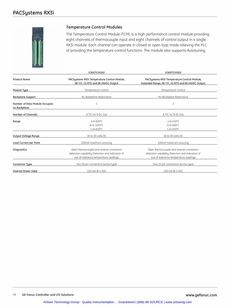
58 www.gefanuc.comGE Fanuc Controller and I/O Solutions
PACSystems RX3i
The Temperature Control Module (TCM), is a high performance control module providingeight channels of thermocouple input and eight channels of control output in a singleRX3i module. Each channel can operate in closed or open loop mode relieving the PLCof providing the temperature control functions. The module also supports Autotuning.
Temperature Control Modules
IC693TCM302 IC693TCM303
Product Name PACSystems RX3i Temperature Control Module, PACSystems RX3i Temperature Control Module, (8) T/C, (1) RTD and (8) 24VDC Output Extended Range, (8) T/C, (1) RTD and (8) 24VDC Output
Module Type Temperature Control Temperature Control
Backplane Support No Backplane Restrictions No Backplane Restrictions
Number of Slots Module Occupies 1 1on Backplane
Number of Channels 8 T/C In/ 8 DC Out 8 T/C In/ 8 DC Out
Range J=0-600°C J=0-450°CK=0-1050°C K=0-600°CL=0-600°C L=0-450°C
Output Voltage Range 18 to 30 volts DC 18 to 30 volts DC
Load Current per Point 100mA maximum sourcing 100mA maximum sourcing
Diagnostics Open thermocouple and reverse connection Open thermocouple and reverse connectiondetection capability Detection and indication of detection capability Detection and indication of
out-of-tolerance temperature readings out-of-tolerance temperature readings
Connector Type Two 20 pin connectors (screw type) Two 20 pin connectors (screw type)
Internal Power Used 150 mA @ 5 VDC 150 mA @ 5 VDC
Artisan Technology Group - Quality Instrumentation ... Guaranteed | (888) 88-SOURCE | www.artisantg.com

PACSystems RX3i
59www.gefanuc.com GE Fanuc Controller and I/O Solutions
The Thermocouple Input Modules allow thermocouple temperature sensors to be directlyconnected to the PLC with external signal processing (transducers, transmitters, etc.).The module performs all analog and digital processing of the thermocouple signal. Theenhanced thermocouple input modules add isolation or high-resolution. On these modules,each channel can be configured for a specific type of sensor wire. An autodetect externalAD592 cold junction compensation feature is also available.
Thermocouple I/O Modules
IC695ALG600 Thermocouple HE693THM166 HE693THM409 HE693THM449
Product Name PACSystems RX3i Analog Input. Analog I/O Analog I/O Analog I/O Configurable per channel for Thermocouple Thermocouple Thermocouple
Current, Voltage, RTD, Input Module Input Module Input ModuleThermocouple and Resistive.
High Density (8 Channel) Requires High Density Terminal Block
(IC694TBB032 or IC694TBS032). Cold Junction Compensation are
available for Thermocouple configurations (IC695ACC600 contains 2 CJCs)
Module Type Thermocouple Input Thermocouple Input Thermocouple Input Thermocouple Input
Backplane Support Universal Backplane Only. No Backplane Restrictions No Backplane Restrictions No Backplane RestrictionsUses PCI Bus.
Number of Slots Module Occupies 1 1 1 1on Backplane
Range B, C, E, J, K, N, R, S, T J, K, N, T, E, R, S, B, C, X J, K, N, T, E, R, S, J, K, N, T, E, R, S,
Diagnostics Open wire, Short Circuit, Yes No YesPositive/Negative Rate of Change,
High, High-High, Low, Low-Low
Number of Channels 8 16 4 4
Channel-to-Channel Isolation Two Groups of Four N/A N/A N/A
Notch Filter Yes N/A N/A N/A
Resolution 11 to 16 bits, depending on configured 0.5°C or 0.5°F 0.5°C or 0.5°F 0.5°C or 0.5°Frange and A/D filter frequency
Accuracy Calibrated Accuracy at 25°C. ±0.5°C, ±0.5°C, ±0.5°C, Better than 0.1% of range. Accuracy typical (J,K,N,T) typical (J,K,N,T) typical (J,K,N,T)depends on A/D filter, data format,
input noise, and ambient temperature.
I/O Required N/A 16 %AI, 16 %I 4 %AI 4 %AI, 16 %I
A/D Conversion Type Sigma Delta Integrating Integrating Integrating
A/D Conversion Time (Assumes 2 ADC’s running in parallel, 40 Channels/second 40 Channels/second 40 Channels/secondno CJC or lead resistance) 10ms per
Channel* 4 Channels = 40ms (1KHz filter) 127ms per Channel* 4 Channels = 508ms
(8Hz filter) Channels that are disabled are not scanned, shortening scan time.
Output Voltage Range N/A N/A N/A N/A
Load Current per Point N/A N/A N/A N/A
RTD Types Supported 2 and 3 wire PT 385 / 3916, N 618 / N/A N/A N/A672, NiFe 518, CU 426
Connector Type IC694TBBx32 or IC694TBSx32. Terminal Block (20 screws), Terminal Block (20 screws), Terminal Block (20 screws), Sold Separately. included with module. included with module. included with module.
Internal Power Used 400 mA @ 5V; 350 mA @ 3.3V 80 mA @ 5 VDC; 30 mA @ 80 mA @ 5 VDC; 60 mA @ 80 mA @ 5 VDC; 60 mA @24 VDC Relay 24 VDC Relay 24 VDC Relay
Artisan Technology Group - Quality Instrumentation ... Guaranteed | (888) 88-SOURCE | www.artisantg.com
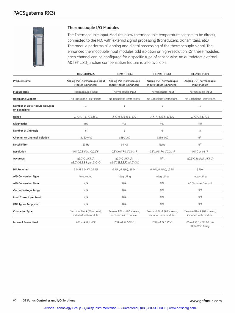
60 www.gefanuc.comGE Fanuc Controller and I/O Solutions
PACSystems RX3i
The Thermocouple Input Modules allow thermocouple temperature sensors to be directlyconnected to the PLC with external signal processing (transducers, transmitters, etc.).The module performs all analog and digital processing of the thermocouple signal. Theenhanced thermocouple input modules add isolation or high-resolution. On these modules,each channel can be configured for a specific type of sensor wire. An autodetect externalAD592 cold junction compensation feature is also available.
Thermocouple I/O Modules
HE693THM665 HE693THM666 HE693THM668 HE693THM809
Product Name Analog I/O Thermocouple Input Analog I/O Thermocouple Analog I/O Thermocouple Analog I/O Thermocouple Module (Enhanced) Input Module (Enhanced) Input Module (Enhanced) Input Module
Module Type Thermocouple Input Thermocouple Input Thermocouple Input Thermocouple Input
Backplane Support No Backplane Restrictions No Backplane Restrictions No Backplane Restrictions No Backplane Restrictions
Number of Slots Module Occupies 1 1 1 1on Backplane
Range J, K, N, T, E, R, S, B, C J, K, N, T, E, R, S, B, C J, K, N, T, E, R, S, B, C J, K, N, T, E, R, S
Diagnostics Yes Yes Yes No
Number of Channels 6 6 6 8
Channel-to-Channel Isolation ±250 VAC ±250 VAC ±250 VAC N/A
Notch Filter 50 Hz 60 Hz None N/A
Resolution 0.5°C,0.5°F,0.1°C,0.1°F 0.5°C,0.5°F,0.1°C,0.1°F 0.5°C,0.5°F,0.1°C,0.1°F 0.5°C or 0.5°F
Accuracy ±1.0°C (J,K,N,T); ±1.0°C (J,K,N,T); N/A ±0.5°C, typical (J,K,N,T)±2.0°C (S,E,B,R); ±4.0°C (C) ±2.0°C (S,E,B,R); ±4.0°C (C)
I/O Required 6 %AI, 6 %AQ, 16 %I 6 %AI, 6 %AQ, 16 %I 6 %AI, 6 %AQ, 16 %I 8 %AI
A/D Conversion Type Integrating Integrating Integrating Integrating
A/D Conversion Time N/A N/A N/A 40 Channels/second
Output Voltage Range N/A N/A N/A N/A
Load Current per Point N/A N/A N/A N/A
RTD Types Supported N/A N/A N/A N/A
Connector Type Terminal Block (20 screws), Terminal Block (20 screws), Terminal Block (20 screws), Terminal Block (20 screws), included with module. included with module. included with module. included with module.
Internal Power Used 200 mA @ 5 VDC 200 mA @ 5 VDC 200 mA @ 5 VDC 80 mA @ 5 VDC; 60 mA @ 24 VDC Relay
Artisan Technology Group - Quality Instrumentation ... Guaranteed | (888) 88-SOURCE | www.artisantg.com
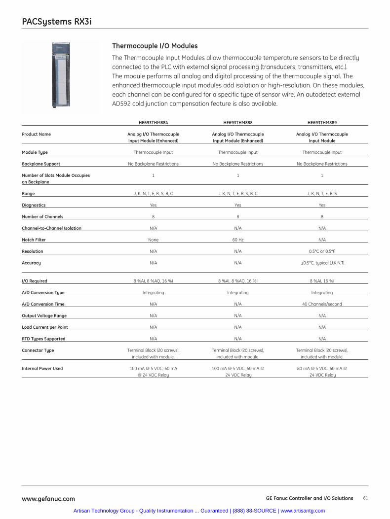
PACSystems RX3i
61www.gefanuc.com GE Fanuc Controller and I/O Solutions
Thermocouple I/O Modules
The Thermocouple Input Modules allow thermocouple temperature sensors to be directlyconnected to the PLC with external signal processing (transducers, transmitters, etc.).The module performs all analog and digital processing of the thermocouple signal. Theenhanced thermocouple input modules add isolation or high-resolution. On these modules,each channel can be configured for a specific type of sensor wire. An autodetect externalAD592 cold junction compensation feature is also available.
HE693THM884 HE693THM888 HE693THM889
Product Name Analog I/O Thermocouple Analog I/O Thermocouple Analog I/O Thermocouple Input Module (Enhanced) Input Module (Enhanced) Input Module
Module Type Thermocouple Input Thermocouple Input Thermocouple Input
Backplane Support No Backplane Restrictions No Backplane Restrictions No Backplane Restrictions
Number of Slots Module Occupies 1 1 1on Backplane
Range J, K, N, T, E, R, S, B, C J, K, N, T, E, R, S, B, C J, K, N, T, E, R, S
Diagnostics Yes Yes Yes
Number of Channels 8 8 8
Channel-to-Channel Isolation N/A N/A N/A
Notch Filter None 60 Hz N/A
Resolution N/A N/A 0.5°C or 0.5°F
Accuracy N/A N/A ±0.5°C, typical (J,K,N,T)
I/O Required 8 %AI, 8 %AQ, 16 %I 8 %AI, 8 %AQ, 16 %I 8 %AI, 16 %I
A/D Conversion Type Integrating Integrating Integrating
A/D Conversion Time N/A N/A 40 Channels/second
Output Voltage Range N/A N/A N/A
Load Current per Point N/A N/A N/A
RTD Types Supported N/A N/A N/A
Connector Type Terminal Block (20 screws), Terminal Block (20 screws), Terminal Block (20 screws), included with module. included with module. included with module.
Internal Power Used 100 mA @ 5 VDC; 60 mA 100 mA @ 5 VDC; 60 mA @ 80 mA @ 5 VDC; 60 mA @@ 24 VDC Relay 24 VDC Relay 24 VDC Relay
Artisan Technology Group - Quality Instrumentation ... Guaranteed | (888) 88-SOURCE | www.artisantg.com
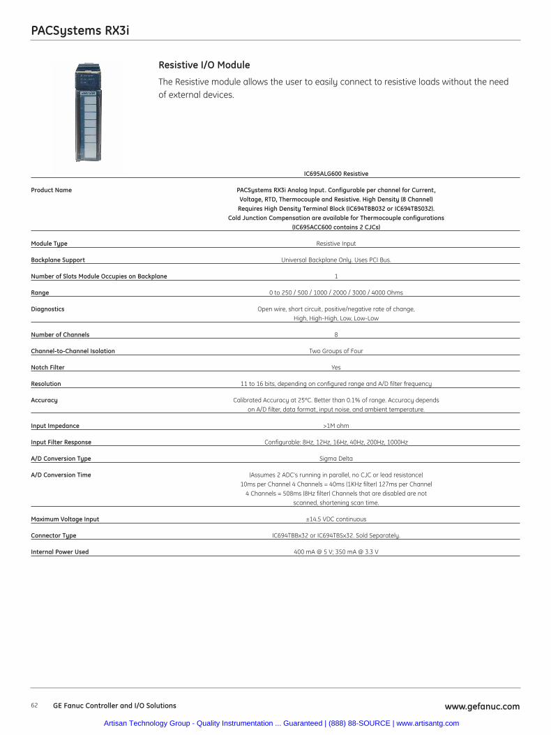
PACSystems RX3i
62 www.gefanuc.comGE Fanuc Controller and I/O Solutions
The Resistive module allows the user to easily connect to resistive loads without the needof external devices.
Resistive I/O Module
IC695ALG600 Resistive
Product Name PACSystems RX3i Analog Input. Configurable per channel for Current,Voltage, RTD, Thermocouple and Resistive. High Density (8 Channel)
Requires High Density Terminal Block (IC694TBB032 or IC694TBS032).Cold Junction Compensation are available for Thermocouple configurations
(IC695ACC600 contains 2 CJCs)
Module Type Resistive Input
Backplane Support Universal Backplane Only. Uses PCI Bus.
Number of Slots Module Occupies on Backplane 1
Range 0 to 250 / 500 / 1000 / 2000 / 3000 / 4000 Ohms
Diagnostics Open wire, short circuit, positive/negative rate of change,High, High-High, Low, Low-Low
Number of Channels 8
Channel-to-Channel Isolation Two Groups of Four
Notch Filter Yes
Resolution 11 to 16 bits, depending on configured range and A/D filter frequency
Accuracy Calibrated Accuracy at 25ºC. Better than 0.1% of range. Accuracy depends on A/D filter, data format, input noise, and ambient temperature.
Input Impedance >1M ohm
Input Filter Response Configurable: 8Hz, 12Hz, 16Hz, 40Hz, 200Hz, 1000Hz
A/D Conversion Type Sigma Delta
A/D Conversion Time (Assumes 2 ADC’s running in parallel, no CJC or lead resistance) 10ms per Channel 4 Channels = 40ms (1KHz filter) 127ms per Channel
4 Channels = 508ms (8Hz filter) Channels that are disabled are not scanned, shortening scan time.
Maximum Voltage Input ±14.5 VDC continuous
Connector Type IC694TBBx32 or IC694TBSx32. Sold Separately.
Internal Power Used 400 mA @ 5 V; 350 mA @ 3.3 V
Artisan Technology Group - Quality Instrumentation ... Guaranteed | (888) 88-SOURCE | www.artisantg.com
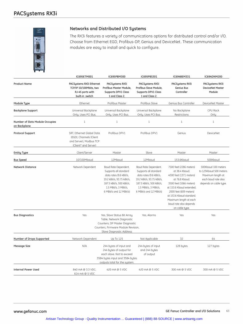
63www.gefanuc.com
PACSystems RX3i
The RX3i features a variety of communications options for distributed control and/or I/O.Choose from Ethernet EGD, Profibus-DP, Genius and DeviceNet. These communicationmodules are easy to install and quick to configure.
Networks and Distributed I/O Systems
IC695ETM001 IC695PBM300 IC695PBS301 IC694BEM331 IC694DNM200
Product Name PACSystems RX3i Ethernet PACSystems RX3i PACSystems RX3i PACSystems RX3i PACSystems RX3iTCP/IP 10/100Mbits, two Profibus Master Module, Profibus Slave Module, Genius Bus DeviceNet Master
RJ-45 ports with Supports DPV1 Class Supports DPV1 Class Controller Modulebuilt-in switch 1 and Class 2. 1 and Class 2.
Module Type Ethernet Profibus Master Profibus Slave Genius Bus Controller DeviceNet Master
Backplane Support Universal Backplane Universal Backplane Universal Backplane No Backplane CPU RackOnly. Uses PCI Bus. Only. Uses PCI Bus. Only. Uses PCI Bus. Restrictions Only
Number of Slots Module Occupies 1 1 1 1 1on Backplane
Protocol Support SRT, Ethernet Global Data Profibus DPV1 Profibus DPV1 Genius DeviceNet (EGD), Channels (Client
and Server), Modbus TCP (Client* and Server)
Entity Type Client/Server Master Slave Master Master
Bus Speed 10/100Mbaud 12Mbaud 12Mbaud 153.6Kbaud 500Kbaud
Network Distance Network Dependent Baud Rate Dependent. Baud Rate Dependent. 7500 feet (2286 meters) 500Kbaud 100 meters Supports all standard Supports all standard at 38.4 Kbaud; to 125Kbaud 500 meters.data rates (9.6 kBit/s, data rates (9.6 kBit/s, 4500 feet (1371 meters) Maximum length at
19.2 kBit/s, 93.75 kBit/s, 19.2 kBit/s, 93.75 kBit/s, at 76.8 Kbaud; each baud rate also187.5 kBit/s, 500 kBit/s, 187.5 kBit/s, 500 kBit/s, 3500 feet (1066 meters) depends on cable type.
1.5 MBit/s, 3 MBit/s, 1.5 MBit/s, 3 MBit/s, at 153.6 Kbaud extended;6 MBit/s and 12 MBit/s) 6 MBit/s and 12 MBit/s) 2000 feet (609 meters)
at 153.6 Kbaud standard.Maximum length at eachbaud rate also depends
on cable type.
Bus Diagnostics Yes Yes, Slave Status Bit Array Yes, Alarms Yes YesTable, Network Diagnostic
Counters, DP Master Diagnostic Counters, Firmware Module Revision,
Slave Diagnostic Address
Number of Drops Supported Network Dependent Up To 125 Not Applicable 32 64
Message Size N/A 244 bytes of input and 244 bytes of input 128 bytes 127 bytes244 bytes of output for and 244 bytes
each slave. Not to exceed of output 3584 bytes input and 3584 bytes
outputs total for the system.
Internal Power Used 840 mA @ 3.3 VDC; 420 mA @ 5 VDC 420 mA @ 5 VDC 300 mA @ 5 VDC 300 mA @ 5 VDC614 mA @ 5 VDC
GE Fanuc Controller and I/O Solutions
Artisan Technology Group - Quality Instrumentation ... Guaranteed | (888) 88-SOURCE | www.artisantg.com
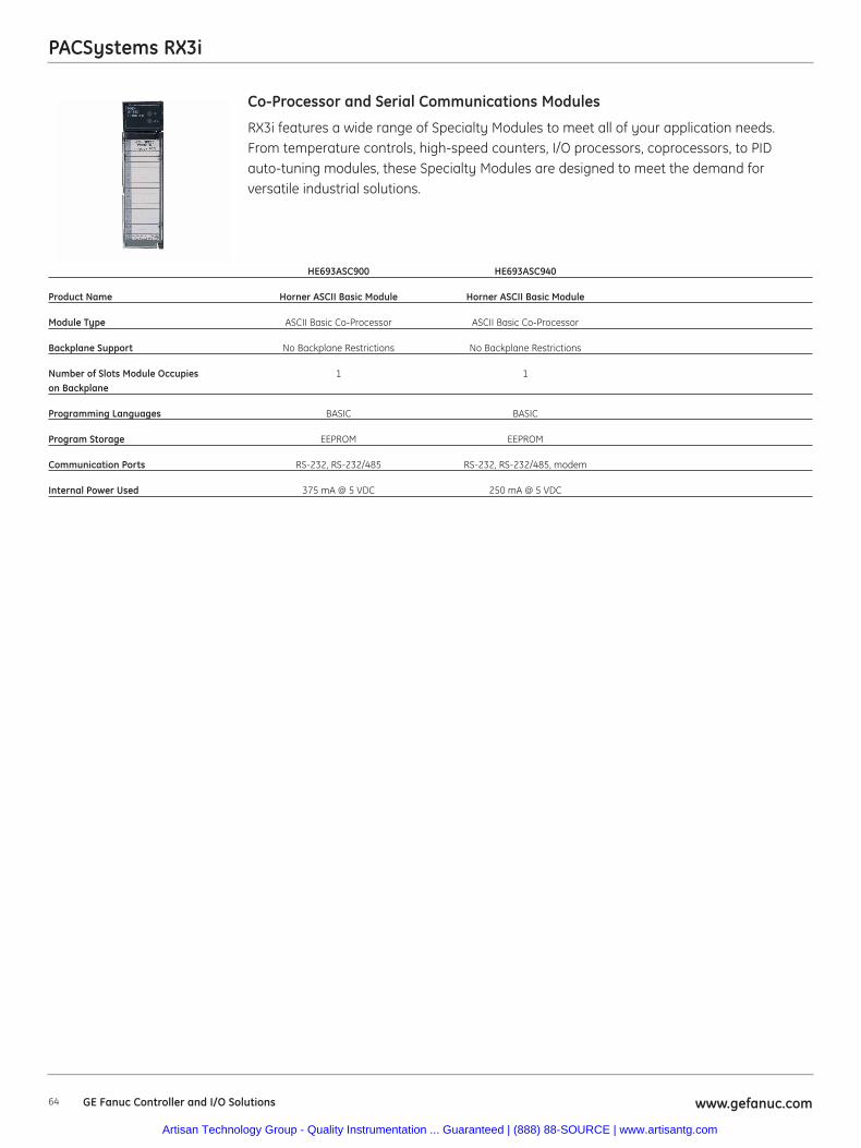
64 www.gefanuc.comGE Fanuc Controller and I/O Solutions
PACSystems RX3i
RX3i features a wide range of Specialty Modules to meet all of your application needs. From temperature controls, high-speed counters, I/O processors, coprocessors, to PID auto-tuning modules, these Specialty Modules are designed to meet the demand for versatile industrial solutions.
Co-Processor and Serial Communications Modules
HE693ASC900 HE693ASC940
Product Name Horner ASCII Basic Module Horner ASCII Basic Module
Module Type ASCII Basic Co-Processor ASCII Basic Co-Processor
Backplane Support No Backplane Restrictions No Backplane Restrictions
Number of Slots Module Occupies 1 1on Backplane
Programming Languages BASIC BASIC
Program Storage EEPROM EEPROM
Communication Ports RS-232, RS-232/485 RS-232, RS-232/485, modem
Internal Power Used 375 mA @ 5 VDC 250 mA @ 5 VDC
Artisan Technology Group - Quality Instrumentation ... Guaranteed | (888) 88-SOURCE | www.artisantg.com
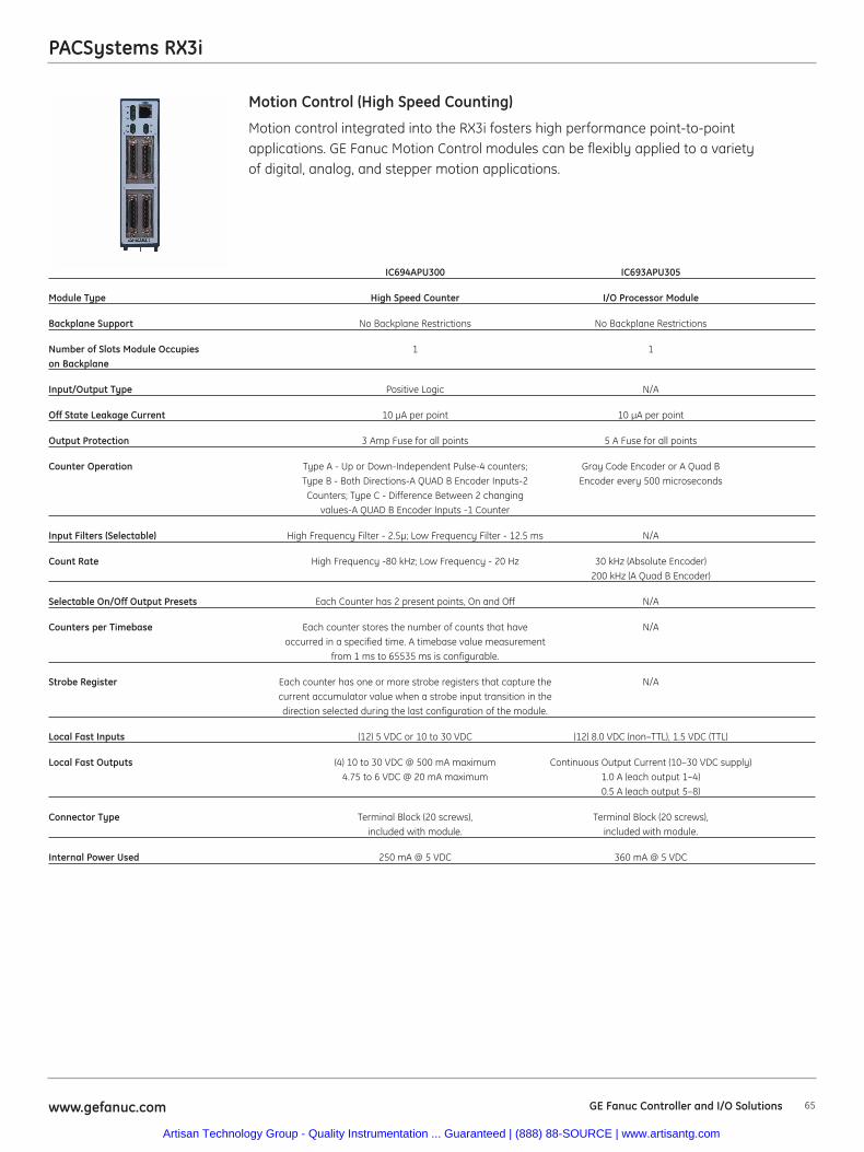
PACSystems RX3i
Motion control integrated into the RX3i fosters high performance point-to-pointapplications. GE Fanuc Motion Control modules can be flexibly applied to a varietyof digital, analog, and stepper motion applications.
Motion Control (High Speed Counting)
IC694APU300 IC693APU305
Module Type High Speed Counter I/O Processor Module
Backplane Support No Backplane Restrictions No Backplane Restrictions
Number of Slots Module Occupies 1 1on Backplane
Input/Output Type Positive Logic N/A
Off State Leakage Current 10 μA per point 10 μA per point
Output Protection 3 Amp Fuse for all points 5 A Fuse for all points
Counter Operation Type A - Up or Down-Independent Pulse-4 counters; Gray Code Encoder or A Quad B Type B - Both Directions-A QUAD B Encoder Inputs-2 Encoder every 500 microsecondsCounters; Type C - Difference Between 2 changing
values-A QUAD B Encoder Inputs -1 Counter
Input Filters (Selectable) High Frequency Filter - 2.5μ; Low Frequency Filter - 12.5 ms N/A
Count Rate High Frequency -80 kHz; Low Frequency - 20 Hz 30 kHz (Absolute Encoder)200 kHz (A Quad B Encoder)
Selectable On/Off Output Presets Each Counter has 2 present points, On and Off N/A
Counters per Timebase Each counter stores the number of counts that have N/Aoccurred in a specified time. A timebase value measurement
from 1 ms to 65535 ms is configurable.
Strobe Register Each counter has one or more strobe registers that capture the N/Acurrent accumulator value when a strobe input transition in the direction selected during the last configuration of the module.
Local Fast Inputs (12) 5 VDC or 10 to 30 VDC (12) 8.0 VDC (non–TTL), 1.5 VDC (TTL)
Local Fast Outputs (4) 10 to 30 VDC @ 500 mA maximum Continuous Output Current (10–30 VDC supply) 4.75 to 6 VDC @ 20 mA maximum 1.0 A (each output 1–4)
0.5 A (each output 5–8)
Connector Type Terminal Block (20 screws), Terminal Block (20 screws), included with module. included with module.
Internal Power Used 250 mA @ 5 VDC 360 mA @ 5 VDC
65www.gefanuc.com GE Fanuc Controller and I/O Solutions
Artisan Technology Group - Quality Instrumentation ... Guaranteed | (888) 88-SOURCE | www.artisantg.com
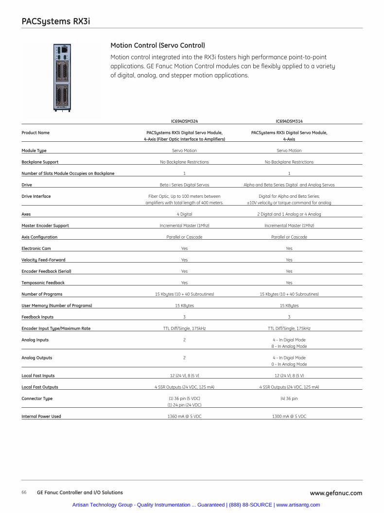
PACSystems RX3i
66 www.gefanuc.comGE Fanuc Controller and I/O Solutions
Motion control integrated into the RX3i fosters high performance point-to-pointapplications. GE Fanuc Motion Control modules can be flexibly applied to a varietyof digital, analog, and stepper motion applications.
Motion Control (Servo Control)
IC694DSM324 IC694DSM314
Product Name PACSystems RX3i Digital Servo Module, PACSystems RX3i Digital Servo Module, 4-Axis (Fiber Optic Interface to Amplifiers) 4-Axis
Module Type Servo Motion Servo Motion
Backplane Support No Backplane Restrictions No Backplane Restrictions
Number of Slots Module Occupies on Backplane 1 1
Drive Beta i Series Digital Servos Alpha and Beta Series Digital and Analog Servos
Drive Interface Fiber Optic, Up to 100 meters between Digital for Alpha and Beta Series; amplifiers with total length of 400 meters. ±10V velocity or torque command for analog
Axes 4 Digital 2 Digital and 1 Analog or 4 Analog
Master Encoder Support Incremental Master (1Mhz) Incremental Master (1Mhz)
Axis Configuration Parallel or Cascade Parallel or Cascade
Electronic Cam Yes Yes
Velocity Feed-Forward Yes Yes
Encoder Feedback (Serial) Yes Yes
Temposonic Feedback Yes Yes
Number of Programs 15 Kbytes (10 + 40 Subroutines) 15 Kbytes (10 + 40 Subroutines)
User Memory (Number of Programs) 15 KBytes 15 KBytes
Feedback Inputs 3 3
Encoder Input Type/Maximum Rate TTL Diff/Single, 175kHz TTL Diff/Single, 175kHz
Analog Inputs 2 4 - In Digial Mode8 - In Analog Mode
Analog Outputs 2 4 - In Digial Mode0 - In Analog Mode
Local Fast Inputs 12 (24 V), 8 (5 V) 12 (24 V), 8 (5 V)
Local Fast Outputs 4 SSR Outputs (24 VDC, 125 mA) 4 SSR Outputs (24 VDC, 125 mA)
Connector Type (1) 36 pin (5 VDC) (4) 36 pin(1) 24 pin (24 VDC)
Internal Power Used 1360 mA @ 5 VDC 1300 mA @ 5 VDC
Artisan Technology Group - Quality Instrumentation ... Guaranteed | (888) 88-SOURCE | www.artisantg.com
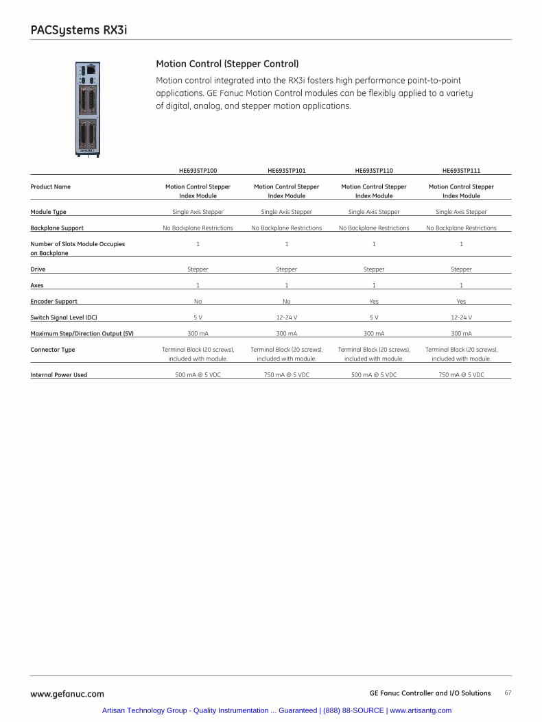
67www.gefanuc.com GE Fanuc Controller and I/O Solutions
PACSystems RX3i
Motion control integrated into the RX3i fosters high performance point-to-pointapplications. GE Fanuc Motion Control modules can be flexibly applied to a varietyof digital, analog, and stepper motion applications.
Motion Control (Stepper Control)
HE693STP100 HE693STP101 HE693STP110 HE693STP111
Product Name Motion Control Stepper Motion Control Stepper Motion Control Stepper Motion Control Stepper Index Module Index Module Index Module Index Module
Module Type Single Axis Stepper Single Axis Stepper Single Axis Stepper Single Axis Stepper
Backplane Support No Backplane Restrictions No Backplane Restrictions No Backplane Restrictions No Backplane Restrictions
Number of Slots Module Occupies 1 1 1 1on Backplane
Drive Stepper Stepper Stepper Stepper
Axes 1 1 1 1
Encoder Support No No Yes Yes
Switch Signal Level (DC) 5 V 12-24 V 5 V 12-24 V
Maximum Step/Direction Output (5V) 300 mA 300 mA 300 mA 300 mA
Connector Type Terminal Block (20 screws), Terminal Block (20 screws), Terminal Block (20 screws), Terminal Block (20 screws), included with module. included with module. included with module. included with module.
Internal Power Used 500 mA @ 5 VDC 750 mA @ 5 VDC 500 mA @ 5 VDC 750 mA @ 5 VDC
Artisan Technology Group - Quality Instrumentation ... Guaranteed | (888) 88-SOURCE | www.artisantg.com
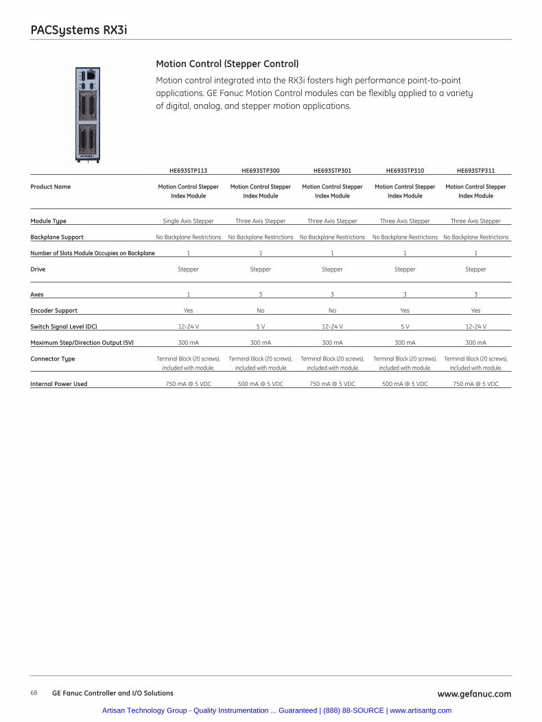
PACSystems RX3i
68 www.gefanuc.comGE Fanuc Controller and I/O Solutions
Motion control integrated into the RX3i fosters high performance point-to-pointapplications. GE Fanuc Motion Control modules can be flexibly applied to a varietyof digital, analog, and stepper motion applications.
Motion Control (Stepper Control)
HE693STP113 HE693STP300 HE693STP301 HE693STP310 HE693STP311
Product Name Motion Control Stepper Motion Control Stepper Motion Control Stepper Motion Control Stepper Motion Control Stepper Index Module Index Module Index Module Index Module Index Module
Module Type Single Axis Stepper Three Axis Stepper Three Axis Stepper Three Axis Stepper Three Axis Stepper
Backplane Support No Backplane Restrictions No Backplane Restrictions No Backplane Restrictions No Backplane Restrictions No Backplane Restrictions
Number of Slots Module Occupies on Backplane 1 1 1 1 1
Drive Stepper Stepper Stepper Stepper Stepper
Axes 1 3 3 3 3
Encoder Support Yes No No Yes Yes
Switch Signal Level (DC) 12-24 V 5 V 12-24 V 5 V 12-24 V
Maximum Step/Direction Output (5V) 300 mA 300 mA 300 mA 300 mA 300 mA
Connector Type Terminal Block (20 screws), Terminal Block (20 screws), Terminal Block (20 screws), Terminal Block (20 screws), Terminal Block (20 screws), included with module. included with module. included with module. included with module. included with module.
Internal Power Used 750 mA @ 5 VDC 500 mA @ 5 VDC 750 mA @ 5 VDC 500 mA @ 5 VDC 750 mA @ 5 VDC
Artisan Technology Group - Quality Instrumentation ... Guaranteed | (888) 88-SOURCE | www.artisantg.com
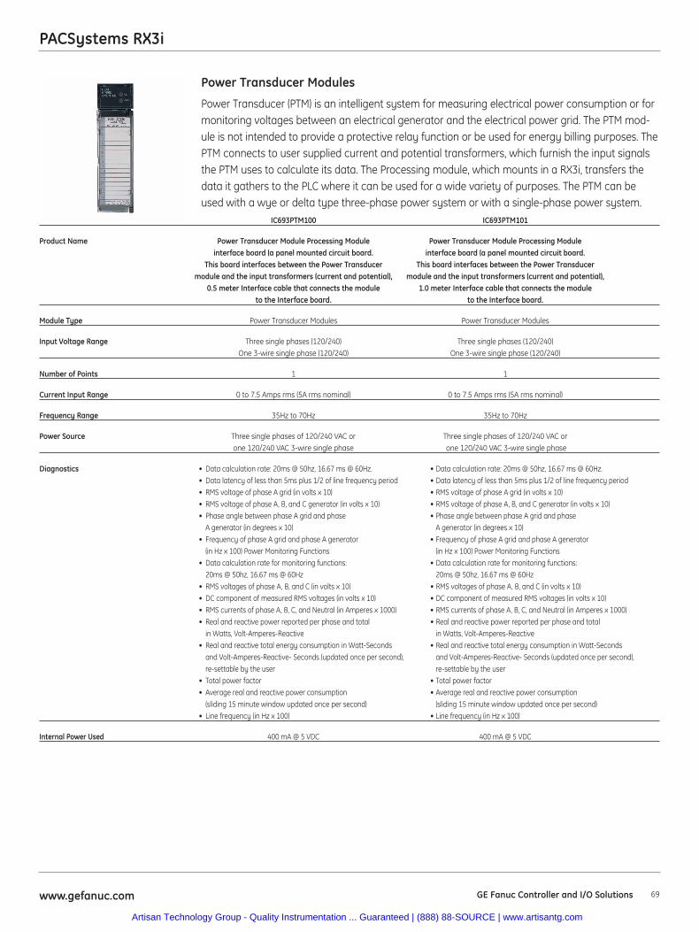
Power Transducer (PTM) is an intelligent system for measuring electrical power consumption or formonitoring voltages between an electrical generator and the electrical power grid. The PTM mod-ule is not intended to provide a protective relay function or be used for energy billing purposes. ThePTM connects to user supplied current and potential transformers, which furnish the input signalsthe PTM uses to calculate its data. The Processing module, which mounts in a RX3i, transfers thedata it gathers to the PLC where it can be used for a wide variety of purposes. The PTM can beused with a wye or delta type three-phase power system or with a single-phase power system.
Power Transducer Modules
IC693PTM100 IC693PTM101
Product Name Power Transducer Module Processing Module Power Transducer Module Processing Moduleinterface board (a panel mounted circuit board. interface board (a panel mounted circuit board.
This board interfaces between the Power Transducer This board interfaces between the Power Transducermodule and the input transformers (current and potential), module and the input transformers (current and potential),
0.5 meter Interface cable that connects the module 1.0 meter Interface cable that connects the moduleto the Interface board. to the Interface board.
Module Type Power Transducer Modules Power Transducer Modules
Input Voltage Range Three single phases (120/240) Three single phases (120/240)One 3-wire single phase (120/240) One 3-wire single phase (120/240)
Number of Points 1 1
Current Input Range 0 to 7.5 Amps rms (5A rms nominal) 0 to 7.5 Amps rms (5A rms nominal)
Frequency Range 35Hz to 70Hz 35Hz to 70Hz
Power Source Three single phases of 120/240 VAC or Three single phases of 120/240 VAC orone 120/240 VAC 3-wire single phase one 120/240 VAC 3-wire single phase
Diagnostics • Data calculation rate: 20ms @ 50hz, 16.67 ms @ 60Hz. • Data calculation rate: 20ms @ 50hz, 16.67 ms @ 60Hz.• Data latency of less than 5ms plus 1/2 of line frequency period • Data latency of less than 5ms plus 1/2 of line frequency period• RMS voltage of phase A grid (in volts x 10) • RMS voltage of phase A grid (in volts x 10)• RMS voltage of phase A, B, and C generator (in volts x 10) • RMS voltage of phase A, B, and C generator (in volts x 10)• Phase angle between phase A grid and phase • Phase angle between phase A grid and phase
A generator (in degrees x 10) A generator (in degrees x 10)• Frequency of phase A grid and phase A generator • Frequency of phase A grid and phase A generator
(in Hz x 100) Power Monitoring Functions (in Hz x 100) Power Monitoring Functions• Data calculation rate for monitoring functions: • Data calculation rate for monitoring functions:
20ms @ 50hz, 16.67 ms @ 60Hz 20ms @ 50hz, 16.67 ms @ 60Hz• RMS voltages of phase A, B, and C (in volts x 10) • RMS voltages of phase A, B, and C (in volts x 10)• DC component of measured RMS voltages (in volts x 10) • DC component of measured RMS voltages (in volts x 10)• RMS currents of phase A, B, C, and Neutral (in Amperes x 1000) • RMS currents of phase A, B, C, and Neutral (in Amperes x 1000)• Real and reactive power reported per phase and total • Real and reactive power reported per phase and total
in Watts, Volt-Amperes-Reactive in Watts, Volt-Amperes-Reactive• Real and reactive total energy consumption in Watt-Seconds • Real and reactive total energy consumption in Watt-Seconds
and Volt-Amperes-Reactive- Seconds (updated once per second), and Volt-Amperes-Reactive- Seconds (updated once per second), re-settable by the user re-settable by the user
• Total power factor • Total power factor• Average real and reactive power consumption • Average real and reactive power consumption
(sliding 15 minute window updated once per second) (sliding 15 minute window updated once per second)• Line frequency (in Hz x 100) • Line frequency (in Hz x 100)
Internal Power Used 400 mA @ 5 VDC 400 mA @ 5 VDC
PACSystems RX3i
69www.gefanuc.com GE Fanuc Controller and I/O Solutions
Artisan Technology Group - Quality Instrumentation ... Guaranteed | (888) 88-SOURCE | www.artisantg.com
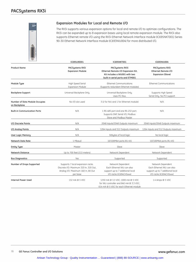
70 www.gefanuc.comGE Fanuc Controller and I/O Solutions
PACSystems RX3i
The RX3i supports various expansion options for local and remote I/O to optimize configurations. TheRX3i can be expanded up to 8 expansion bases using local remote expansion module. The RX3i alsosupports Ethernet remote I/O using the RX3i Ethernet Network Interface module (IC695NKT001) Series90-30 Ethernet Network Interface module (IC693NIU004) for more distributed I/O.
Expansion Modules for Local and Remote I/O
IC695LRE001 IC695NKT001 IC693NIU004
Product Name PACSystems RX3i PACSystems RX3i PACSystems RX3i Expansion Module Ethernet Remote I/O Expansion Kit. Ethernet Remote I/O
Kit includes a NIU001 with two Expansion (Slave)built-in serial ports and ETM001
Module Type High Speed Serial Ethernet Communications Ethernet CommunicationsExpansion Module (Supports redundant Ethernet modules)
Backplane Support Universal Backplane Only Universal Backplane Only. Supports High SpeedUses PCI Bus. Serial Only. No PCI support
Number of Slots Module Occupies No I/O slot used 3 (2 for NIU and 1 for Ethernet module) N/Aon Backplane
Built-in Communication Ports N/A 1 RS-485 port and one RS-232 port. N/ASupports SNP, Serial I/O, Modbus
Slave and Modbus Master
I/O Discrete Points N/A 2048 Inputs/2048 Outputs maximum 2048 Inputs/2048 Outputs maximum
I/O Analog Points N/A 1264 Inputs and 512 Outputs maximum 1264 Inputs and 512 Outputs maximum
User Logic Memory N/A 5Kbytes of local logic No local logic
Network Data Rate 1 Mbaud 10/100Mbit ports (RJ-45) 10/100Mbit ports (RJ-45)
Entity Type Master Slave Slave
Network Distance Up to 700 feet (213 meters) Network Dependent Network Dependent
Bus Diagnostics Yes Supported Supported
Number of Drops Supported Supports 7 local expansion racks. Network Dependent Network DependentDiscrete I/O: Maximum 320 In, 320 Out, Each Ethernet NIU can also Each Ethernet NIU can also
Analog I/O: Maximum 160 In, 80 Out support up to 7 additional local support up to 7 additional localper base I/O racks (IC694CHSxxx) I/O racks (IC694CHSxxx)
Internal Power Used 132 mA @ 5 VDC 1250 mA @ 3.3 VDC; 1000 mA @ 5 VDC 1.4 Amps @ 5 VDCfor NIU controller and 840 mA @ 3.3 VDC;
614 mA @ 5 VDC for each Ethernet module
Artisan Technology Group - Quality Instrumentation ... Guaranteed | (888) 88-SOURCE | www.artisantg.com
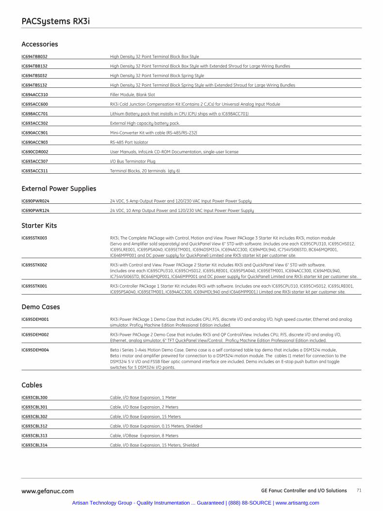
PACSystems RX3i
Accessories
IC694TBB032 High Density 32 Point Terminal Block Box Style
IC694TBB132 High Density 32 Point Terminal Block Box Style with Extended Shroud for Large Wiring Bundles
IC694TBS032 High Density 32 Point Terminal Block Spring Style
IC694TBS132 High Density 32 Point Terminal Block Spring Style with Extended Shroud for Large Wiring Bundles
IC694ACC310 Filler Module, Blank Slot
IC695ACC600 RX3i Cold Junction Compensation Kit (Contains 2 CJCs) for Universal Analog Input Module
IC698ACC701 Lithium Battery pack that installs in CPU (CPU ships with a IC698ACC701)
IC693ACC302 External High capacity battery pack.
IC690ACC901 Mini-Converter Kit with cable (RS-485/RS-232)
IC690ACC903 RS-485 Port Isolator
IC690CDR002 User Manuals, InfoLink CD-ROM Documentation, single-user license
IC693ACC307 I/O Bus Terminator Plug
IC693ACC311 Terminal Blocks, 20 terminals (qty 6)
External Power Supplies
IC690PWR024 24 VDC, 5 Amp Output Power and 120/230 VAC Input Power Power Supply
IC690PWR124 24 VDC, 10 Amp Output Power and 120/230 VAC Input Power Power Supply
Starter Kits
IC695STK003 RX3i, The Complete PACkage with Control, Motion and View. Power PACkage 3 Starter Kit includes RX3i, motion module (Servo and Amplifier sold separately) and QuickPanel View 6" STD with software. (includes one each IC695CPU310, IC695CHS012,IC695LRE001, IC695PSA040, IC695ETM001, IC694DSM314, IC694ACC300, IC694MDL940, IC754VSI06STD, BC646MQP001,IC646MPP001 and DC power supply for QuickPanel) Limited one RX3i starter kit per customer site.
IC695STK002 RX3i with Control and View. Power PACkage 2 Starter Kit includes RX3i and QuickPanel View 6" STD with software. (includes one each IC695CPU310, IC695CHS012, IC695LRE001, IC695PSA040, IC695ETM001, IC694ACC300, IC694MDL940,IC754VSI06STD, BC646MQP001, IC646MPP001 and DC power supply for QuickPanel) Limited one RX3i starter kit per customer site.
IC695STK001 RX3i Controller PACkage 1 Starter Kit includes RX3i with software. (includes one each IC695CPU310, IC695CHS012, IC695LRE001, IC695PSA040, IC695ETM001, IC694ACC300, IC694MDL940 and IC646MPP001.) Limited one RX3i starter kit per customer site.
Demo Cases
IC695DEM001 RX3i Power PACkage 1 Demo Case that includes CPU, P/S, discrete I/O and analog I/O, high speed counter, Ethernet and analogsimulator. Proficy Machine Edition Professional Edition included.
IC695DEM002 RX3i Power PACkage 2 Demo Case that includes RX3i and QP Control/View. Includes CPU, P/S, discrete I/O and analog I/O, Ethernet, analog simulator, 6" TFT QuickPanel View/Control. Proficy Machine Edition Professional Edition included.
IC695DEM004 Beta i Series 1-Axis Motion Demo Case. Demo case is a self contained table top demo that includes a DSM324i module, Beta i motor and amplifier prewired for connection to a DSM324i motion module. The cables (1 meter) for connection to the DSM324i 5 V I/O and FSSB fiber optic command interface are included. Demo includes an E-stop push button and toggle switches for 5 DSM324i I/O points.
Cables
IC693CBL300 Cable, I/O Base Expansion, 1 Meter
IC693CBL301 Cable, I/O Base Expansion, 2 Meters
IC693CBL302 Cable, I/O Base Expansion, 15 Meters
IC693CBL312 Cable, I/O Base Expansion, 0.15 Meters, Shielded
IC693CBL313 Cable, I/OBase Expansion, 8 Meters
IC693CBL314 Cable, I/O Base Expansion, 15 Meters, Shielded
71www.gefanuc.com GE Fanuc Controller and I/O Solutions
Artisan Technology Group - Quality Instrumentation ... Guaranteed | (888) 88-SOURCE | www.artisantg.com
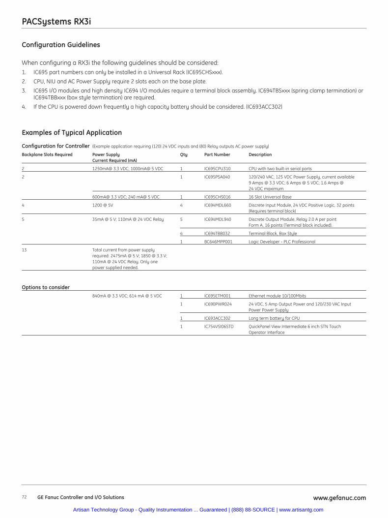
PACSystems RX3i
72 www.gefanuc.comGE Fanuc Controller and I/O Solutions
Configuration Guidelines
When configuring a RX3i the following guidelines should be considered:1. IC695 part numbers can only be installed in a Universal Rack (IC695CHSxxx).
2. CPU, NIU and AC Power Supply require 2 slots each on the base plate.
3. IC695 I/O modules and high density IC694 I/O modules require a terminal block assembly. IC694TBSxxx (spring clamp termination) orIC694TBBxxx (box style termination) are required.
4. If the CPU is powered down frequently a high capacity battery should be considered. (IC693ACC302)
Examples of Typical Application
Configuration for Controller (Example application requiring (120) 24 VDC inputs and (80) Relay outputs AC power supply)
Backplane Slots Required Power Supply Qty Part Number DescriptionCurrent Required (mA)
2 1250mA@ 3.3 VDC; 1000mA@ 5 VDC 1 IC695CPU310 CPU with two built-in serial ports
2 1 IC695PSA040 120/240 VAC, 125 VDC Power Supply, current available 9 Amps @ 3.3 VDC; 6 Amps @ 5 VDC; 1.6 Amps @ 24 VDC maximum
600mA@ 3.3 VDC; 240 mA@ 5 VDC 1 IC695CHS016 16 Slot Universal Base
4 1200 @ 5V 4 IC694MDL660 Discrete Input Module, 24 VDC Positive Logic, 32 points (Requires terminal block)
5 35mA @ 5 V; 110mA @ 24 VDC Relay 5 IC694MDL940 Discrete Output Module, Relay 2.0 A per pointForm A, 16 points (Terminal block included).
4 IC694TBB032 Terminal Block, Box Style
1 BC646MPP001 Logic Developer - PLC Professional
13 Total current from power supply required: 2475mA @ 5 V; 1850 @ 3.3 V; 110mA @ 24 VDC Relay. Only one power supplied needed.
Options to consider840mA @ 3.3 VDC; 614 mA @ 5 VDC 1 IC695ETM001 Ethernet module 10/100Mbits
1 IC690PWR024 24 VDC, 5 Amp Output Power and 120/230 VAC Input Power Power Supply
1 IC693ACC302 Long term battery for CPU
1 IC754VSI06STD QuickPanel View Intermediate 6 inch STN Touch Operator Interface
Artisan Technology Group - Quality Instrumentation ... Guaranteed | (888) 88-SOURCE | www.artisantg.com
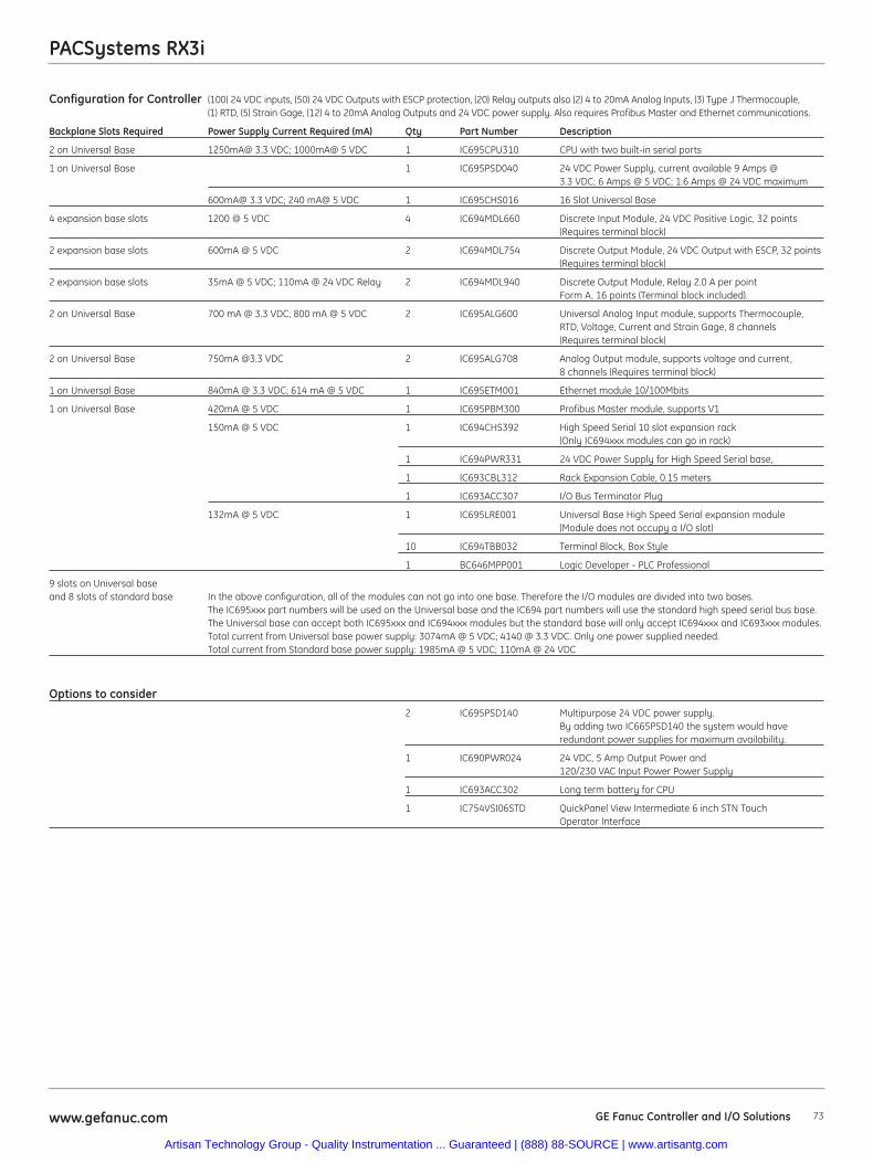
Configuration for Controller (100) 24 VDC inputs, (50) 24 VDC Outputs with ESCP protection, (20) Relay outputs also (2) 4 to 20mA Analog Inputs, (3) Type J Thermocouple, (1) RTD, (5) Strain Gage, (12) 4 to 20mA Analog Outputs and 24 VDC power supply. Also requires Profibus Master and Ethernet communications.
Backplane Slots Required Power Supply Current Required (mA) Qty Part Number Description
2 on Universal Base 1250mA@ 3.3 VDC; 1000mA@ 5 VDC 1 IC695CPU310 CPU with two built-in serial ports
1 on Universal Base 1 IC695PSD040 24 VDC Power Supply, current available 9 Amps @ 3.3 VDC; 6 Amps @ 5 VDC; 1.6 Amps @ 24 VDC maximum
600mA@ 3.3 VDC; 240 mA@ 5 VDC 1 IC695CHS016 16 Slot Universal Base
4 expansion base slots 1200 @ 5 VDC 4 IC694MDL660 Discrete Input Module, 24 VDC Positive Logic, 32 points (Requires terminal block)
2 expansion base slots 600mA @ 5 VDC 2 IC694MDL754 Discrete Output Module, 24 VDC Output with ESCP, 32 points (Requires terminal block)
2 expansion base slots 35mA @ 5 VDC; 110mA @ 24 VDC Relay 2 IC694MDL940 Discrete Output Module, Relay 2.0 A per point Form A, 16 points (Terminal block included).
2 on Universal Base 700 mA @ 3.3 VDC; 800 mA @ 5 VDC 2 IC695ALG600 Universal Analog Input module, supports Thermocouple, RTD, Voltage, Current and Strain Gage, 8 channels (Requires terminal block)
2 on Universal Base 750mA @3.3 VDC 2 IC695ALG708 Analog Output module, supports voltage and current, 8 channels (Requires terminal block)
1 on Universal Base 840mA @ 3.3 VDC; 614 mA @ 5 VDC 1 IC695ETM001 Ethernet module 10/100Mbits
1 on Universal Base 420mA @ 5 VDC 1 IC695PBM300 Profibus Master module, supports V1
150mA @ 5 VDC 1 IC694CHS392 High Speed Serial 10 slot expansion rack(Only IC694xxx modules can go in rack)
1 IC694PWR331 24 VDC Power Supply for High Speed Serial base,
1 IC693CBL312 Rack Expansion Cable, 0.15 meters
1 IC693ACC307 I/O Bus Terminator Plug
132mA @ 5 VDC 1 IC695LRE001 Universal Base High Speed Serial expansion module (Module does not occupy a I/O slot)
10 IC694TBB032 Terminal Block, Box Style
1 BC646MPP001 Logic Developer - PLC Professional
9 slots on Universal base and 8 slots of standard base In the above configuration, all of the modules can not go into one base. Therefore the I/O modules are divided into two bases.
The IC695xxx part numbers will be used on the Universal base and the IC694 part numbers will use the standard high speed serial bus base. The Universal base can accept both IC695xxx and IC694xxx modules but the standard base will only accept IC694xxx and IC693xxx modules.Total current from Universal base power supply: 3074mA @ 5 VDC; 4140 @ 3.3 VDC. Only one power supplied needed.Total current from Standard base power supply: 1985mA @ 5 VDC; 110mA @ 24 VDC
Options to consider2 IC695PSD140 Multipurpose 24 VDC power supply.
By adding two IC665PSD140 the system would have redundant power supplies for maximum availability.
1 IC690PWR024 24 VDC, 5 Amp Output Power and 120/230 VAC Input Power Power Supply
1 IC693ACC302 Long term battery for CPU
1 IC754VSI06STD QuickPanel View Intermediate 6 inch STN Touch Operator Interface
PACSystems RX3i
73www.gefanuc.com GE Fanuc Controller and I/O Solutions
Artisan Technology Group - Quality Instrumentation ... Guaranteed | (888) 88-SOURCE | www.artisantg.com
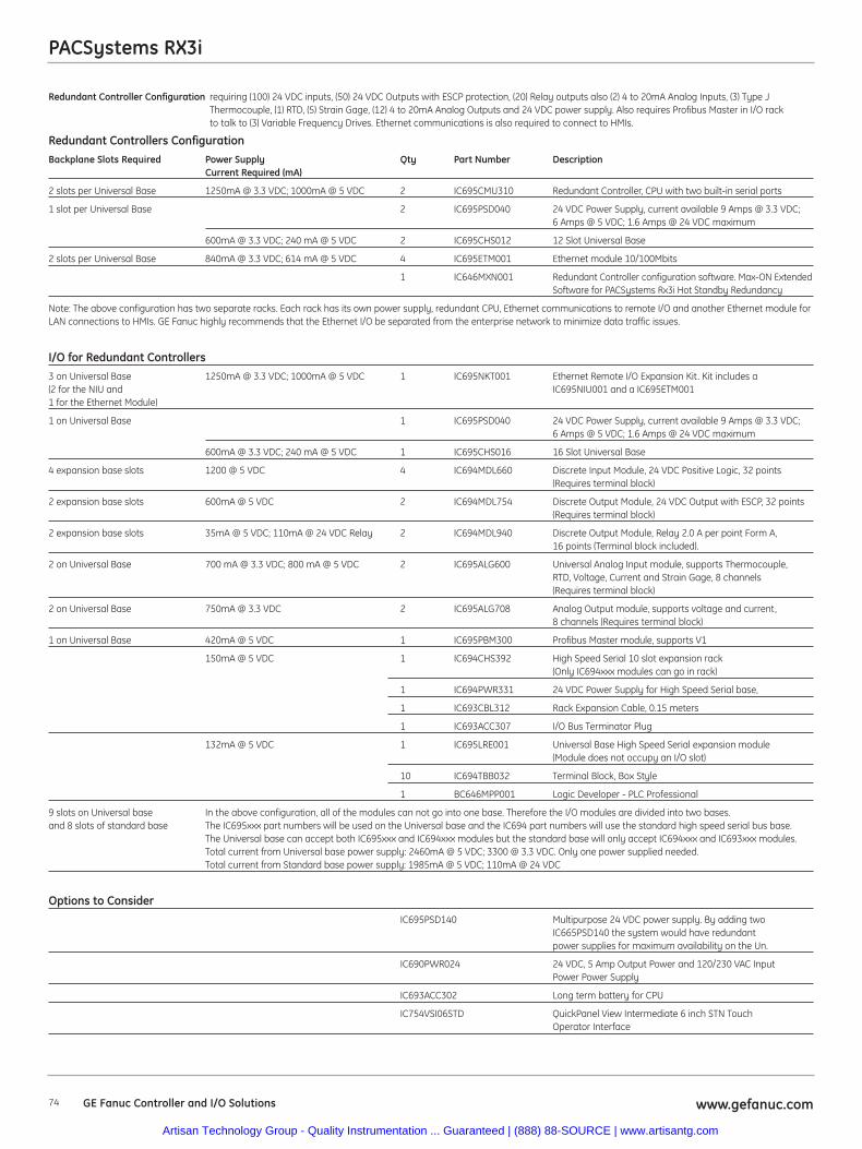
PACSystems RX3i
74 www.gefanuc.comGE Fanuc Controller and I/O Solutions
Redundant Controller Configuration requiring (100) 24 VDC inputs, (50) 24 VDC Outputs with ESCP protection, (20) Relay outputs also (2) 4 to 20mA Analog Inputs, (3) Type JThermocouple, (1) RTD, (5) Strain Gage, (12) 4 to 20mA Analog Outputs and 24 VDC power supply. Also requires Profibus Master in I/O rackto talk to (3) Variable Frequency Drives. Ethernet communications is also required to connect to HMIs.
Redundant Controllers ConfigurationBackplane Slots Required Power Supply Qty Part Number Description
Current Required (mA)
2 slots per Universal Base 1250mA @ 3.3 VDC; 1000mA @ 5 VDC 2 IC695CMU310 Redundant Controller, CPU with two built-in serial ports
1 slot per Universal Base 2 IC695PSD040 24 VDC Power Supply, current available 9 Amps @ 3.3 VDC; 6 Amps @ 5 VDC; 1.6 Amps @ 24 VDC maximum
600mA @ 3.3 VDC; 240 mA @ 5 VDC 2 IC695CHS012 12 Slot Universal Base
2 slots per Universal Base 840mA @ 3.3 VDC; 614 mA @ 5 VDC 4 IC695ETM001 Ethernet module 10/100Mbits
1 IC646MXN001 Redundant Controller configuration software. Max-ON Extended Software for PACSystems Rx3i Hot Standby Redundancy
Note: The above configuration has two separate racks. Each rack has its own power supply, redundant CPU, Ethernet communications to remote I/O and another Ethernet module forLAN connections to HMIs. GE Fanuc highly recommends that the Ethernet I/O be separated from the enterprise network to minimize data traffic issues.
I/O for Redundant Controllers3 on Universal Base 1250mA @ 3.3 VDC; 1000mA @ 5 VDC 1 IC695NKT001 Ethernet Remote I/O Expansion Kit. Kit includes a (2 for the NIU and IC695NIU001 and a IC695ETM0011 for the Ethernet Module)
1 on Universal Base 1 IC695PSD040 24 VDC Power Supply, current available 9 Amps @ 3.3 VDC; 6 Amps @ 5 VDC; 1.6 Amps @ 24 VDC maximum
600mA @ 3.3 VDC; 240 mA @ 5 VDC 1 IC695CHS016 16 Slot Universal Base
4 expansion base slots 1200 @ 5 VDC 4 IC694MDL660 Discrete Input Module, 24 VDC Positive Logic, 32 points (Requires terminal block)
2 expansion base slots 600mA @ 5 VDC 2 IC694MDL754 Discrete Output Module, 24 VDC Output with ESCP, 32 points (Requires terminal block)
2 expansion base slots 35mA @ 5 VDC; 110mA @ 24 VDC Relay 2 IC694MDL940 Discrete Output Module, Relay 2.0 A per point Form A, 16 points (Terminal block included).
2 on Universal Base 700 mA @ 3.3 VDC; 800 mA @ 5 VDC 2 IC695ALG600 Universal Analog Input module, supports Thermocouple, RTD, Voltage, Current and Strain Gage, 8 channels (Requires terminal block)
2 on Universal Base 750mA @ 3.3 VDC 2 IC695ALG708 Analog Output module, supports voltage and current, 8 channels (Requires terminal block)
1 on Universal Base 420mA @ 5 VDC 1 IC695PBM300 Profibus Master module, supports V1
150mA @ 5 VDC 1 IC694CHS392 High Speed Serial 10 slot expansion rack (Only IC694xxx modules can go in rack)
1 IC694PWR331 24 VDC Power Supply for High Speed Serial base,
1 IC693CBL312 Rack Expansion Cable, 0.15 meters
1 IC693ACC307 I/O Bus Terminator Plug
132mA @ 5 VDC 1 IC695LRE001 Universal Base High Speed Serial expansion module (Module does not occupy an I/O slot)
10 IC694TBB032 Terminal Block, Box Style
1 BC646MPP001 Logic Developer - PLC Professional
9 slots on Universal base In the above configuration, all of the modules can not go into one base. Therefore the I/O modules are divided into two bases. and 8 slots of standard base The IC695xxx part numbers will be used on the Universal base and the IC694 part numbers will use the standard high speed serial bus base.
The Universal base can accept both IC695xxx and IC694xxx modules but the standard base will only accept IC694xxx and IC693xxx modules.Total current from Universal base power supply: 2460mA @ 5 VDC; 3300 @ 3.3 VDC. Only one power supplied needed.Total current from Standard base power supply: 1985mA @ 5 VDC; 110mA @ 24 VDC
Options to ConsiderIC695PSD140 Multipurpose 24 VDC power supply. By adding two
IC665PSD140 the system would have redundant power supplies for maximum availability on the Un.
IC690PWR024 24 VDC, 5 Amp Output Power and 120/230 VAC Input Power Power Supply
IC693ACC302 Long term battery for CPU
IC754VSI06STD QuickPanel View Intermediate 6 inch STN Touch Operator Interface
Artisan Technology Group - Quality Instrumentation ... Guaranteed | (888) 88-SOURCE | www.artisantg.com
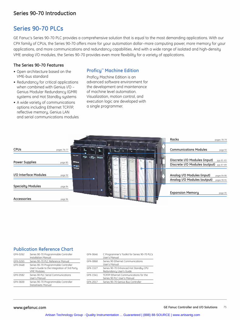
75www.gefanuc.com GE Fanuc Controller and I/O Solutions
Series 90-70 Introduction
Proficy™ Machine EditionProficy Machine Edition is anadvanced software environment forthe development and maintenanceof machine level automation.Visualization, motion control, andexecution logic are developed witha single programmer.
Series 90-70 PLCsGE Fanuc’s Series 90-70 PLC provides a comprehensive solution that is equal to the most demanding applications. With ourCPX family of CPUs, the Series 90-70 offers more for your automation dollar–more computing power, more memory for yourapplications, and more communications and redundancy capabilities. And with a wide range of isolated and high-densityVME analog I/O modules, the Series 90-70 provides even more flexibility for a variety of applications.
The Series 90-70 Features• Open architecture based on the
VME-bus standard• Redundancy for critical applications
when combined with Genius I/O –Genius Modular Redundancy (GMR)systems and Hot Standby systems
• A wide variety of communicationsoptions including Ethernet TCP/IP,reflective memory, Genius LANand serial communications modules
Publication Reference ChartGFK-0262 Series 90-70 Programmable Controller
Installation ManualGFK-0265 Series 90-70 PLC Reference ManualGFK-0448 Series 90-70 Programmable Controller
User's Guide to the Integration of 3rd PartyVME Modules
GFK-0582 Series 90 PLC Serial Communications User's Manual
GFK-0600 Series 90-70 Programmable ControllerDatasheets Manual
GFK-0646 C Programmer's Toolkit for Series 90-70 PLCsUser's Manual
GFK-0868 Series 90 Ethernet Communications User's Manual
GFK-1527 Series 90-70 Enhanced Hot Standby CPURedundancy User's Guide
GFK-1541 TCP/IP Ethernet Communications for theSeries 90 PLC User's Manual
GFK-2017 Series 90-70 Genius Bus Controller
CPUs pages 76-77
Power Supplies page 80
I/O Interface Modules page 92
Expansion Memory page 95
Communications Modules page 93
Analog I/O Modules (input) pages 84-86
Analog I/O Modules (output) pages 90-91
Specialty Modules page 94
Accessories page 96
Racks pages 78-79
Discrete I/O Modules (input) pgs 81-83
Discrete I/O Modules (output) pgs 87-89
Artisan Technology Group - Quality Instrumentation ... Guaranteed | (888) 88-SOURCE | www.artisantg.com
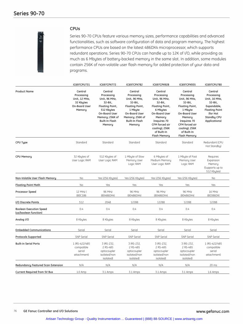
76 www.gefanuc.comGE Fanuc Controller and I/O Solutions
Series 90-70
Series 90-70 CPUs feature various memory sizes, performance capabilities and advancedfunctionalities, such as software configuration of data and program memory. The highestperformance CPUs are based on the latest 486DX4 microprocessor, which supportsredundant operations. Series 90-70 CPUs can handle up to 12K of I/O, while providing asmuch as 6 Mbytes of battery-backed memory in the same slot. In addition, some modulescontain 256K of non-volatile user flash memory for added protection of your data andprograms.
CPUs
IC697CPU731 IC697CPX772 IC697CPX782 IC697CPX928 IC697CPX935 IC697CPU780
Product Name Central Central Central Central Central CentralProcessing Processing Processing Processing Processing Processing
Unit, 12 MHz, Unit, 96 MHz, Unit, 96 MHz, Unit, 96 MHz, Unit, 96 MHz, Unit, 16 MHz,32 Kbytes 32-Bit, 32-Bit, 32-Bit, 32-Bit, 32-Bit,
On-Board User Floating Point, Floating Point, Floating Point, Floating Point, Expandable,Memory 512 Kbytes 1 Mbyte 6 Mbytes 1 Mbyte Floating Point
On-Board User On-Board User On-Board User On-Board User (for HotMemory; 256K of Memory; 256K of Memory Memory Standby CPU
Built-In Flash Built-In Flash (requires 70 (requires 70 Applications)Memory Memory CFM forced air CFM forced air
cooling); 256K cooling); 256Kof Built-In of Built-In
Flash Memory Flash Memory
CPU Type Standard Standard Standard Standard Standard Redundant (CPUHot Standby)
CPU Memory 32 Kbytes of 512 Kbytes of 1 Mbyte of Slow 6 Mbytes of 1 Mbyte of Fast RequiresUser Logic RAM User Logic RAM Memory User Medium Memory Memory User Expansion
Logic RAM User Logic RAM Logic RAM Memory(Supports up to
512 Kbytes)
Non-Volatile User Flash Memory No Yes (256 Kbytes) Yes (256 Kbytes) Yes (256 Kbytes) Yes (256 Kbytes) No
Floating Point Math No Yes Yes Yes Yes Yes
Processor Speed 12 MHz ) 96 MHz 96 MHz 96 MHz 96 MHz 16 MHz (80C186 (80486DX4) (80486DX4) (80486DX4) (80486DX4) (80386DX)
I/O Discrete Points 512 2048 12288 12288 12288 12288
Boolean Execution Speed 0.4 0.4 0.4 0.4 0.4 0.4(us/boolean function)
Analog I/O 8 Kbytes 8 Kbytes 8 Kbytes 8 Kbytes 8 Kbytes 8 Kbytes
Embedded Communications Serial Serial Serial Serial Serial Serial
Protocols Supported SNP Serial SNP Serial SNP Serial SNP Serial SNP Serial SNP Serial
Built-in Serial Ports 1 (RS-422/485 3 (RS-232, 3 (RS-232, 3 (RS-232, 3 (RS-232, 1 (RS-422/485compatible 2 RS-485 2 RS-485 2 RS-485 2 RS-485 compatible
serial optocoupler optocoupler optocoupler optocoupler serialattachment) isolated/non isolated/non isolated/non isolated/non attachment)
isolated) isolated) isolated) isolated)
Redundancy Featured Scan Extension N/A N/A N/A N/A N/A 20 ms
Current Required from 5V Bus 1.0 Amp 3.1 Amps 3.1 Amps 3.1 Amps 3.1 Amps 1.6 Amps
Artisan Technology Group - Quality Instrumentation ... Guaranteed | (888) 88-SOURCE | www.artisantg.com
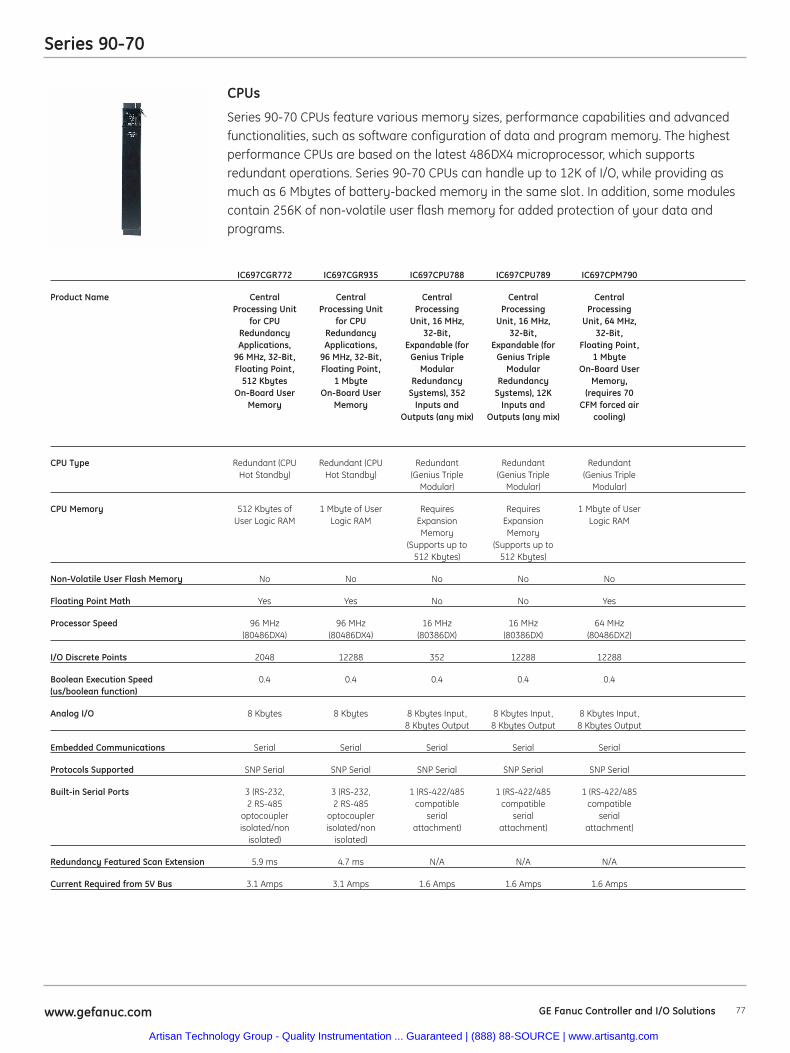
77www.gefanuc.com GE Fanuc Controller and I/O Solutions
Series 90-70
Series 90-70 CPUs feature various memory sizes, performance capabilities and advancedfunctionalities, such as software configuration of data and program memory. The highestperformance CPUs are based on the latest 486DX4 microprocessor, which supportsredundant operations. Series 90-70 CPUs can handle up to 12K of I/O, while providing asmuch as 6 Mbytes of battery-backed memory in the same slot. In addition, some modulescontain 256K of non-volatile user flash memory for added protection of your data andprograms.
CPUs
IC697CGR772 IC697CGR935 IC697CPU788 IC697CPU789 IC697CPM790
Product Name Central Central Central Central CentralProcessing Unit Processing Unit Processing Processing Processing
for CPU for CPU Unit, 16 MHz, Unit, 16 MHz, Unit, 64 MHz,Redundancy Redundancy 32-Bit, 32-Bit, 32-Bit,Applications, Applications, Expandable (for Expandable (for Floating Point,
96 MHz, 32-Bit, 96 MHz, 32-Bit, Genius Triple Genius Triple 1 MbyteFloating Point, Floating Point, Modular Modular On-Board User
512 Kbytes 1 Mbyte Redundancy Redundancy Memory,On-Board User On-Board User Systems), 352 Systems), 12K (requires 70
Memory Memory Inputs and Inputs and CFM forced airOutputs (any mix) Outputs (any mix) cooling)
CPU Type Redundant (CPU Redundant (CPU Redundant Redundant RedundantHot Standby) Hot Standby) (Genius Triple (Genius Triple (Genius Triple
Modular) Modular) Modular)
CPU Memory 512 Kbytes of 1 Mbyte of User Requires Requires 1 Mbyte of UserUser Logic RAM Logic RAM Expansion Expansion Logic RAM
Memory Memory(Supports up to (Supports up to
512 Kbytes) 512 Kbytes)
Non-Volatile User Flash Memory No No No No No
Floating Point Math Yes Yes No No Yes
Processor Speed 96 MHz 96 MHz 16 MHz 16 MHz 64 MHz(80486DX4) (80486DX4) (80386DX) (80386DX) (80486DX2)
I/O Discrete Points 2048 12288 352 12288 12288
Boolean Execution Speed 0.4 0.4 0.4 0.4 0.4(us/boolean function)
Analog I/O 8 Kbytes 8 Kbytes 8 Kbytes Input, 8 Kbytes Input, 8 Kbytes Input,8 Kbytes Output 8 Kbytes Output 8 Kbytes Output
Embedded Communications Serial Serial Serial Serial Serial
Protocols Supported SNP Serial SNP Serial SNP Serial SNP Serial SNP Serial
Built-in Serial Ports 3 (RS-232, 3 (RS-232, 1 (RS-422/485 1 (RS-422/485 1 (RS-422/4852 RS-485 2 RS-485 compatible compatible compatible
optocoupler optocoupler serial serial serialisolated/non isolated/non attachment) attachment) attachment)
isolated) isolated)
Redundancy Featured Scan Extension 5.9 ms 4.7 ms N/A N/A N/A
Current Required from 5V Bus 3.1 Amps 3.1 Amps 1.6 Amps 1.6 Amps 1.6 Amps
Artisan Technology Group - Quality Instrumentation ... Guaranteed | (888) 88-SOURCE | www.artisantg.com
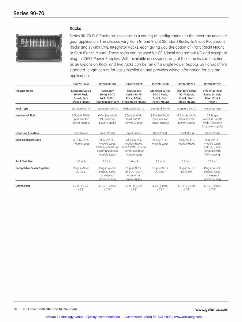
78 www.gefanuc.comGE Fanuc Controller and I/O Solutions
Series 90-70
Series 90-70 PLC Racks are available in a variety of configurations to the meet the needs ofyour application. The choices vary from 5- and 9-slot Standard Racks, to 9-slot RedundantRacks and 17-slot VME Integrator Racks, each giving you the option of Front (Rack) Mountor Rear (Panel) Mount. These racks can be used for CPU, local and remote I/O and accept allplug-in IC697 Power Supplies. With available accessories, any of these racks can functionas an Expansion Rack, and two racks can be run off a single Power Supply. GE Fanuc offersstandard-length cables for easy installation and provides wiring information for customapplications.
Racks
IC697CHS750 IC697CHS770 IC697CHS771 IC697CHS790 IC697CHS791 IC697CHS782
Product Name Standard Series Redundant Redundant Standard Series Standard Series VME Integrator90-70 Rack, Series 90-70 Series 90-70 90-70 Rack, 90-70 Rack, Rack, 17-slot,5-slot, Rear Rack, 9-Slot, Rack, 9-Slot, 9-slot, Rear 9-slot, Front Rear (Panel)
(Panel) Mount Rear (Panel) Mount Front (Rack) Mount (Panel) Mount (Rack) Mount Mount
Rack Type Standard 90-70 Redundant 90-70 Redundant 90-70 Standard 90-70 Standard 90-70 VME Integrator
Number of Slots 5 Double Width 6 Double Width 6 Double Width 9 Double Width 9 Double Width 17 Single(plus one for (plus one for (plus one for (plus one for (plus one for Width, 8 Double
power supply) power supply) power supply) power supply) power supply) Width (plus onefor power supply)
Mounting Location Rear (Panel) Rear (Panel) Front (Rack) Rear (Panel) Front (Rack) Rear (Panel)
Rack Configurations All IC697 PLC All IC697 PLC All IC697 PLC All IC697 PLC All IC697 PLC All IC697 PLCmodule types module types, module types, module types module types module types,
IC687 (VME) I/O and IC687 (VME) I/O and 3rd party VMECommunications Communications modules with
module types module types 0.8” spacing
Rack Slot Size 1.6 inch 1.6 inch 1.6 inch 1.6 inch 1.6 inch 0.8 inch
Compatible Power Supplies Plug-in AC or Plug-in AC/DC Plug-in AC/DC Plug-in AC or Plug-in AC or Plug-in AC/DCDC IC697 and DC IC697, and DC IC697, DC IC697 DC IC697 and DC IC697,
or external or external or externalpower supply power supply power supply
Dimensions 11.15” x 12.6” 11.15” x 19.00” 11.15” x 19.00” 11.15” x 19.00” 11.15” x 19.00” 11.15” x 19.00”x 7.5” x 7.5” x 7.5” x 7.5” x 7.5” x 7.5”
Artisan Technology Group - Quality Instrumentation ... Guaranteed | (888) 88-SOURCE | www.artisantg.com
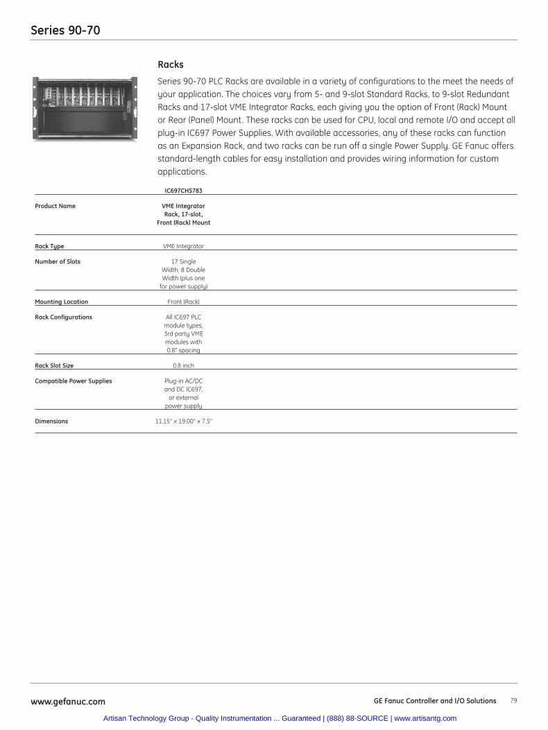
79www.gefanuc.com GE Fanuc Controller and I/O Solutions
Series 90-70
Series 90-70 PLC Racks are available in a variety of configurations to the meet the needs ofyour application. The choices vary from 5- and 9-slot Standard Racks, to 9-slot RedundantRacks and 17-slot VME Integrator Racks, each giving you the option of Front (Rack) Mountor Rear (Panel) Mount. These racks can be used for CPU, local and remote I/O and accept allplug-in IC697 Power Supplies. With available accessories, any of these racks can functionas an Expansion Rack, and two racks can be run off a single Power Supply. GE Fanuc offersstandard-length cables for easy installation and provides wiring information for customapplications.
Racks
IC697CHS783
Product Name VME IntegratorRack, 17-slot,
Front (Rack) Mount
Rack Type VME Integrator
Number of Slots 17 SingleWidth, 8 DoubleWidth (plus one
for power supply)
Mounting Location Front (Rack)
Rack Configurations All IC697 PLCmodule types,3rd party VMEmodules with0.8” spacing
Rack Slot Size 0.8 inch
Compatible Power Supplies Plug-in AC/DCand DC IC697,
or externalpower supply
Dimensions 11.15” x 19.00” x 7.5”
Artisan Technology Group - Quality Instrumentation ... Guaranteed | (888) 88-SOURCE | www.artisantg.com
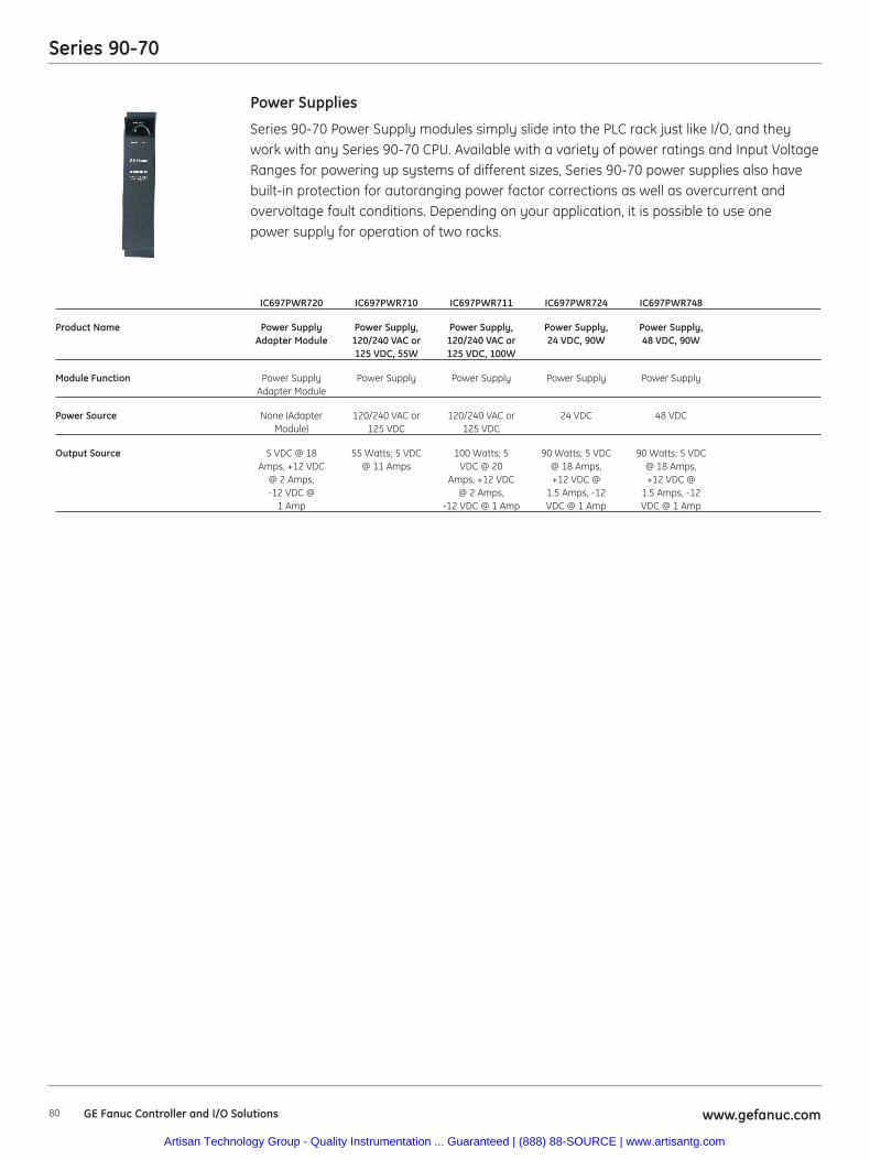
80 www.gefanuc.comGE Fanuc Controller and I/O Solutions
Series 90-70
Series 90-70 Power Supply modules simply slide into the PLC rack just like I/O, and theywork with any Series 90-70 CPU. Available with a variety of power ratings and Input VoltageRanges for powering up systems of different sizes, Series 90-70 power supplies also havebuilt-in protection for autoranging power factor corrections as well as overcurrent andovervoltage fault conditions. Depending on your application, it is possible to use onepower supply for operation of two racks.
Power Supplies
IC697PWR720 IC697PWR710 IC697PWR711 IC697PWR724 IC697PWR748
Product Name Power Supply Power Supply, Power Supply, Power Supply, Power Supply,Adapter Module 120/240 VAC or 120/240 VAC or 24 VDC, 90W 48 VDC, 90W
125 VDC, 55W 125 VDC, 100W
Module Function Power Supply Power Supply Power Supply Power Supply Power SupplyAdapter Module
Power Source None (Adapter 120/240 VAC or 120/240 VAC or 24 VDC 48 VDCModule) 125 VDC 125 VDC
Output Source 5 VDC @ 18 55 Watts; 5 VDC 100 Watts; 5 90 Watts; 5 VDC 90 Watts; 5 VDCAmps, +12 VDC @ 11 Amps VDC @ 20 @ 18 Amps, @ 18 Amps,
@ 2 Amps, Amps, +12 VDC +12 VDC @ +12 VDC @-12 VDC @ @ 2 Amps, 1.5 Amps, -12 1.5 Amps, -12
1 Amp -12 VDC @ 1 Amp VDC @ 1 Amp VDC @ 1 Amp
Artisan Technology Group - Quality Instrumentation ... Guaranteed | (888) 88-SOURCE | www.artisantg.com
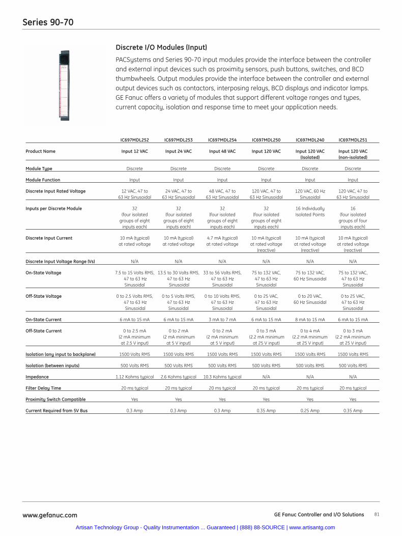
81www.gefanuc.com
Series 90-70
PACSystems and Series 90-70 input modules provide the interface between the controllerand external input devices such as proximity sensors, push buttons, switches, and BCDthumbwheels. Output modules provide the interface between the controller and externaloutput devices such as contactors, interposing relays, BCD displays and indicator lamps.GE Fanuc offers a variety of modules that support different voltage ranges and types,current capacity, isolation and response time to meet your application needs.
Discrete I/O Modules (Input)
IC697MDL252 IC697MDL253 IC697MDL254 IC697MDL250 IC697MDL240 IC697MDL251
Product Name Input 12 VAC Input 24 VAC Input 48 VAC Input 120 VAC Input 120 VAC Input 120 VAC(Isolated) (non-isolated)
Module Type Discrete Discrete Discrete Discrete Discrete Discrete
Module Function Input Input Input Input Input Input
Discrete Input Rated Voltage 12 VAC, 47 to 24 VAC, 47 to 48 VAC, 47 to 120 VAC, 47 to 120 VAC, 60 Hz 120 VAC, 47 to63 Hz Sinusoidal 63 Hz Sinusoidal 63 Hz Sinusoidal 63 Hz Sinusoidal Sinusoidal 63 Hz Sinusoidal
Inputs per Discrete Module 32 32 32 32 16 Individually 16 (four isolated (four isolated (four isolated (four isolated Isolated Points (four isolated
groups of eight groups of eight groups of eight groups of eight groups of four inputs each) inputs each) inputs each) inputs each) inputs each)
Discrete Input Current 10 mA (typical) 10 mA (typical) 4.7 mA (typical) 10 mA (typical) 10 mA (typical) 10 mA (typical)at rated voltage at rated voltage at rated voltage at rated voltage at rated voltage at rated voltage
(reactive) (reactive) (reactive)
Discrete Input Voltage Range (Vs) N/A N/A N/A N/A N/A N/A
On-State Voltage 7.5 to 15 Volts RMS, 13.5 to 30 Volts RMS, 33 to 56 Volts RMS, 75 to 132 VAC, 75 to 132 VAC, 75 to 132 VAC,47 to 63 Hz 47 to 63 Hz 47 to 63 Hz 47 to 63 Hz 60 Hz Sinusoidal 47 to 63 HzSinusoidal Sinusoidal Sinusoidal Sinusoidal Sinusoidal
Off-State Voltage 0 to 2.5 Volts RMS, 0 to 5 Volts RMS, 0 to 10 Volts RMS, 0 to 25 VAC, 0 to 20 VAC, 0 to 25 VAC, 47 to 63 Hz 47 to 63 Hz 47 to 63 Hz 47 to 63 Hz 60 Hz Sinusoidal 47 to 63 HzSinusoidal Sinusoidal Sinusoidal Sinusoidal Sinusoidal
On-State Current 6 mA to 15 mA 6 mA to 15 mA 3 mA to 7 mA 6 mA to 15 mA 8 mA to 15 mA 6 mA to 15 mA
Off-State Current 0 to 2.5 mA 0 to 2 mA 0 to 2 mA 0 to 3 mA 0 to 4 mA 0 to 3 mA (2 mA minimum (2 mA minimum (2 mA minimum (2.2 mA minimum (2.2 mA minimum (2.2 mA minimum at 2.5 V input) at 5 V input) at 5 V input) at 25 V input) at 25 V input) at 25 V input)
Isolation (any input to backplane) 1500 Volts RMS 1500 Volts RMS 1500 Volts RMS 1500 Volts RMS 1500 Volts RMS 1500 Volts RMS
Isolation (between inputs) 500 Volts RMS 500 Volts RMS 500 Volts RMS 500 Volts RMS 500 Volts RMS 500 Volts RMS
Impedance 1.12 Kohms typical 2.6 Kohms typical 10.3 Kohms typical N/A N/A N/A
Filter Delay Time 20 ms typical 20 ms typical 20 ms typical 20 ms typical 20 ms typical 20 ms typical
Proximity Switch Compatible Yes Yes Yes Yes Yes Yes
Current Required from 5V Bus 0.3 Amp 0.3 Amp 0.3 Amp 0.35 Amp 0.25 Amp 0.35 Amp
GE Fanuc Controller and I/O Solutions
Artisan Technology Group - Quality Instrumentation ... Guaranteed | (888) 88-SOURCE | www.artisantg.com
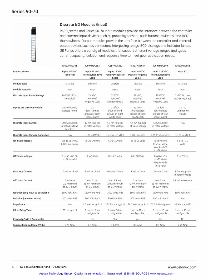
82 www.gefanuc.comGE Fanuc Controller and I/O Solutions
Series 90-70
PACSystems and Series 90-70 input modules provide the interface between the controllerand external input devices such as proximity sensors, push buttons, switches, and BCDthumbwheels. Output modules provide the interface between the controller and externaloutput devices such as contactors, interposing relays, BCD displays and indicator lamps.GE Fanuc offers a variety of modules that support different voltage ranges and types,current capacity, isolation and response time to meet your application needs.
Discrete I/O Modules (Input)
IC697MDL241 IC697MDL653 IC697MDL652 IC697MDL654 IC697MDL640 IC697MDL651
Product Name Input 240 VAC Input 24 VDC Input 12 VDC Input 48 VDC Input 125 VDC Input TTL(Isolated) Positive/Negative Positive/Negative Positive/Negative Positive/Negative
Logic Logic Logic Logic
Module Type Discrete Discrete Discrete Discrete Discrete Discrete
Module Function Input Input Input Input Input Input
Discrete Input Rated Voltage 240 VAC, 60 Hz 24 VDC, 12 VDC, 48 VDC, 125 VDC, 5 VDC (No userSinusoidal Positive/ Positive/ Positive/ Positive/ power required)
Negative Logic Negative Logic Negative Logic Negative Logic
Inputs per Discrete Module 16 Individually 32 32 (four 32 (four 16 (four 32 TTLIsolated Points (four isolated (four isolated (four isolated (four isolated Compatible
groups of eight groups of eight groups of eight groups of four Inputsinputs each) inputs each) inputs each) inputs each)
Discrete Input Current 20 mA (typical) 10 mA (typical) 4.7 mA (typical) 4.7 mA (typical) 5 mA (typical) N/Aat rated voltage at rated voltage at rated voltage at rated voltage at rated voltage
(reactive)
Discrete Input Voltage Range (Vs) N/A (-3 to +30 VDC) (-2.5 to +15 VDC) (-3 to +56 VDC) (-35 to +145 VDC) (-3 to +7 VDC)
On-State Voltage 160 to 264 VAC, 13.5 to 30 Volts 7.5 to 15 Volts 33 to 56 Volts Positive (+90 (-3 to +0.560 Hz Sinusoidal to +145 Volts), Volts)
Negative (-20to -90 Volts)
Off-State Voltage 0 to 40 VAC, 60 0 to 5 Volts 0 to 2.5 Volts 0 to 10 Volts Positive (-35 2 to 7 VoltsHz Sinusoidal to +35 Volts),
Negative (-35to 56 Volts)
On-State Current 10 mA to 15 mA 6 mA to 15 mA 6 mA to 15 mA 3 mA to 7 mA 3 mA to 7 mA 1.7 mA (typical)at rated voltage
Off-State Current 0 to 5 mA 0 to 2 mA 0 to 2.5 mA 0 to 2 mA 0 to 2 mA 1.1 mA (maximum)(2.2 minimum (2 mA minimum (2 mA minimum (2 mA minimum (2 mA minimum at 40 V input) at 5 V input) at 2.5 V input) at 5 V input) at 125 V input)
Isolation (any input to backplane) 1500 Volts RMS 1500 Volts RMS 1500 Volts RMS 1500 Volts RMS 1500 Volts RMS 1500 Volts RMS
Isolation (between inputs) 500 Volts RMS 500 Volts RMS 500 Volts RMS 500 Volts RMS 500 Volts RMS N/A
Impedance N/A 2.6 Kohms typical 1.12 Kohms typical 10.3 Kohms typical 24.5 Kohms typical 5.9 Kohms, +5%
Filter Delay Time 20 ms typical 1 ms or 10 ms 1 ms or 10 ms 1 ms or 10 ms 1 ms or 10 ms 1 ms or 10 msconfigurable configurable configurable configurable configurable
Proximity Switch Compatible Yes Yes Yes Yes Yes No
Current Required from 5V Bus 0.25 Amp 0.3 Amp 0.3 Amp 0.3 Amp 0.3 Amp 0.53 Amp
Artisan Technology Group - Quality Instrumentation ... Guaranteed | (888) 88-SOURCE | www.artisantg.com
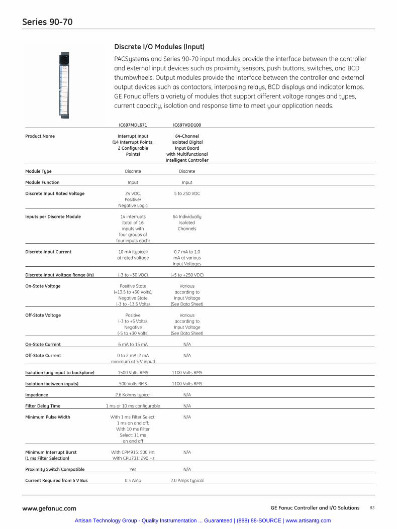
83www.gefanuc.com GE Fanuc Controller and I/O Solutions
Series 90-70
PACSystems and Series 90-70 input modules provide the interface between the controllerand external input devices such as proximity sensors, push buttons, switches, and BCDthumbwheels. Output modules provide the interface between the controller and externaloutput devices such as contactors, interposing relays, BCD displays and indicator lamps.GE Fanuc offers a variety of modules that support different voltage ranges and types,current capacity, isolation and response time to meet your application needs.
Discrete I/O Modules (Input)
IC697MDL671 IC697VDD100
Product Name Interrupt Input 64-Channel(14 Interrupt Points, Isolated Digital
2 Configurable Input BoardPoints) with Multifunctional
Intelligent Controller
Module Type Discrete Discrete
Module Function Input Input
Discrete Input Rated Voltage 24 VDC, 5 to 250 VDCPositive/
Negative Logic
Inputs per Discrete Module 14 interrupts 64 Individually(total of 16 Isolatedinputs with Channels
four groups offour inputs each)
Discrete Input Current 10 mA (typical) 0.7 mA to 1.0at rated voltage mA at various
Input Voltages
Discrete Input Voltage Range (Vs) (-3 to +30 VDC) (+5 to +250 VDC)
On-State Voltage Positive State Various(+13.5 to +30 Volts), according to
Negative State Input Voltage(-3 to -13.5 Volts) (See Data Sheet)
Off-State Voltage Positive Various(-3 to +5 Volts), according to
Negative Input Voltage(-5 to +30 Volts) (See Data Sheet)
On-State Current 6 mA to 15 mA N/A
Off-State Current 0 to 2 mA (2 mA N/Aminimum at 5 V input)
Isolation (any input to backplane) 1500 Volts RMS 1100 Volts RMS
Isolation (between inputs) 500 Volts RMS 1100 Volts RMS
Impedance 2.6 Kohms typical N/A
Filter Delay Time 1 ms or 10 ms configurable N/A
Minimum Pulse Width With 1 ms Filter Select: N/A1 ms on and off;With 10 ms Filter
Select: 11 mson and off
Minimum Interrupt Burst With CPM915: 500 Hz; N/A(1 ms Filter Selection) With CPU731: 290 Hz
Proximity Switch Compatible Yes N/A
Current Required from 5 V Bus 0.3 Amp 2.0 Amps typical
Artisan Technology Group - Quality Instrumentation ... Guaranteed | (888) 88-SOURCE | www.artisantg.com
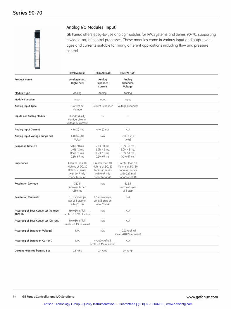
84 www.gefanuc.comGE Fanuc Controller and I/O Solutions
Series 90-70
GE Fanuc offers easy-to-use analog modules for PACSystems and Series 90-70, supportinga wide array of control processes. These modules come in various input and output volt-ages and currents suitable for many different applications including flow and pressurecontrol.
Analog I/O Modules (Input)
IC697ALG230 IC697ALG440 IC697ALG441
Product Name Analog Input, Analog AnalogHigh Level Expander, Expander,
Current Voltage
Module Type Analog Analog Analog
Module Function Input Input Input
Analog Input Type Current or Current Expander Voltage ExpanderVoltage
Inputs per Analog Module 8 (individually 16 16configurable for
voltage or current)
Analog Input Current 4 to 20 mA 4 to 20 mA N/A
Analog Input Voltage Range (Vs) (-10 to +10 N/A (-10 to +10Volts) Volts)
Response Time-On 5.0% 30 ms, 5.0% 30 ms, 5.0% 30 ms,1.0% 42 ms, 1.0% 42 ms, 1.0% 42 ms,0.5% 51 ms, 0.5% 51 ms, 0.5% 51 ms,0.1% 67 ms 0.1% 67 ms 0.1% 67 ms
Impedance Greater than 10 Greater than 10 Greater than 10Mohms at DC, 20 Mohms at DC, 20 Mohms at DC, 20Kohms in series Kohms in series Kohms in serieswith 0.47 mfd with 0.47 mfd with 0.47 mfd
capacitor at AC capacitor at AC capacitor at AC
Resolution (Voltage) 312.5 N/A 312.5microvolts per microvolts per
LSB step LSB step
Resolution (Current) 0.5 microamps 0.5 microamps N/Aper LSB step on per LSB step on
4 to 20 mA 4 to 20 mA
Accuracy of Base Converter (Voltage) (±0.01% of full N/A N/A10 Volts scale, ±0.02% of value)
Accuracy of Base Converter (Current) (+0.05% of full N/A N/Ascale, +0.1% of value)
Accuracy of Expander (Voltage) N/A N/A (+0.03% of fullscale, +0.02% of value)
Accuracy of Expander (Current) N/A (+0.07% of full N/Ascale, +0.1% of value)
Current Required from 5V Bus 0.8 Amp 0.4 Amp 0.4 Amp
Artisan Technology Group - Quality Instrumentation ... Guaranteed | (888) 88-SOURCE | www.artisantg.com
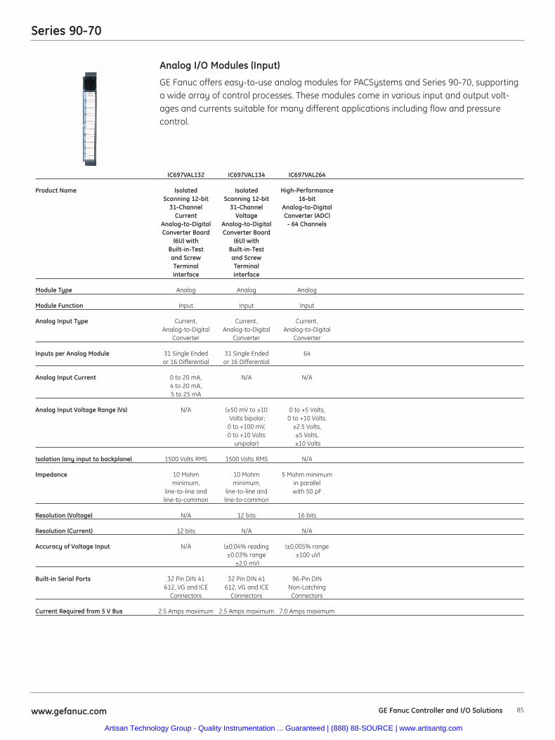
85www.gefanuc.com GE Fanuc Controller and I/O Solutions
Series 90-70
GE Fanuc offers easy-to-use analog modules for PACSystems and Series 90-70, supportinga wide array of control processes. These modules come in various input and output volt-ages and currents suitable for many different applications including flow and pressurecontrol.
Analog I/O Modules (Input)
IC697VAL132 IC697VAL134 IC697VAL264
Product Name Isolated Isolated High-PerformanceScanning 12-bit Scanning 12-bit 16-bit
31-Channel 31-Channel Analog-to-DigitalCurrent Voltage Converter (ADC)
Analog-to-Digital Analog-to-Digital - 64 ChannelsConverter Board Converter Board
(6U) with (6U) withBuilt-in-Test Built-in-Testand Screw and ScrewTerminal Terminalinterface interface
Module Type Analog Analog Analog
Module Function Input Input Input
Analog Input Type Current, Current, Current,Analog-to-Digital Analog-to-Digital Analog-to-Digital
Converter Converter Converter
Inputs per Analog Module 31 Single Ended 31 Single Ended 64or 16 Differential or 16 Differential
Analog Input Current 0 to 20 mA, N/A N/A4 to 20 mA,5 to 25 mA
Analog Input Voltage Range (Vs) N/A (±50 mV to ±10 0 to +5 Volts,Volts bipolar; 0 to +10 Volts,
0 to +100 mV, ±2.5 Volts,0 to +10 Volts ±5 Volts,
unipolar) ±10 Volts
Isolation (any input to backplane) 1500 Volts RMS 1500 Volts RMS N/A
Impedance 10 Mohm 10 Mohm 5 Mohm minimumminimum, minimum, in parallel
line-to-line and line-to-line and with 50 pFline-to-common line-to-common
Resolution (Voltage) N/A 12 bits 16 bits
Resolution (Current) 12 bits N/A N/A
Accuracy of Voltage Input N/A (±0.04% reading (±0.005% range±0.03% range ±100 uV)
±2.0 mV)
Built-in Serial Ports 32 Pin DIN 41 32 Pin DIN 41 96-Pin DIN612, VG and ICE 612, VG and ICE Non-Latching
Connectors Connectors Connectors
Current Required from 5 V Bus 2.5 Amps maximum 2.5 Amps maximum 7.0 Amps maximum
Artisan Technology Group - Quality Instrumentation ... Guaranteed | (888) 88-SOURCE | www.artisantg.com
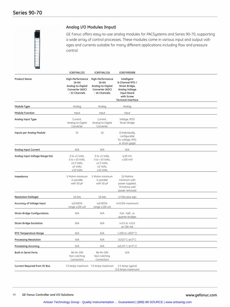
86 www.gefanuc.com
Series 90-70
GE Fanuc offers easy-to-use analog modules for PACSystems and Series 90-70, supportinga wide array of control processes. These modules come in various input and output volt-ages and currents suitable for many different applications including flow and pressurecontrol.
Analog I/O Modules (Input)
IC697VAL232 IC697VAL216 IC697VRD008
Product Name High-Performance High-Performance Intelligent16-bit 16-bit 8-Channel RTD /
Analog-to-Digital Analog-to-Digital Strain Bridge,Converter (ADC) Converter (ADC) Analog Voltage
- 32 Channels - 16 Channels Input Boardwith Screw
Terminal Interface
Module Type Analog Analog Analog
Module Function Input Input Input
Analog Input Type Current, Current, Voltage, RTD/Analog-to-Digital Analog-to-Digital Strain Bridge
Converter Converter
Inputs per Analog Module 32 16 8 (individuallyconfigurable
for voltage, RTD,or strain gage)
Analog Input Current N/A N/A N/A
Analog Input Voltage Range (Vs) 0 to +5 Volts, 0 to +5 Volts, (±30 mV,0 to +10 Volts, 0 to +10 Volts, ±100 mV)
±2.5 Volts, ±2.5 Volts,±5 Volts, ±5 Volts,±10 Volts ±10 Volts
Impedance 5 Mohm minimum 5 Mohm minimum 10 Mohmsin parallel in parallel minimum withwith 50 pF with 50 pF power supplied,
70 Kohms withpower removed
Resolution (Voltage) 16 bits 16 bits 12 bits plus sign
Accuracy of Voltage Input (±0.005% (±0.005% (+0.03% maximum)range ±100 uV) range ±100 uV)
Strain Bridge Configurations N/A N/A Full-, half-, orquarter-bridges
Strain Bridge Excitation N/A N/A (+5.0 or +10.0at 190 mA
RTD Temperature Range N/A N/A (-200 to +850° C)
Processing Resolution N/A N/A 0.015° C at 0° C
Processing Accuracy N/A N/A (±0.25° C at 0° C)
Built-in Serial Ports 96-Pin DIN 96-Pin DIN N/ANon-Latching Non-LatchingConnectors Connectors
Current Required from 5V Bus 7.0 Amps maximum 7.0 Amps maximum 2.5 Amps typical(3.8 Amps maximum)
GE Fanuc Controller and I/O Solutions
Artisan Technology Group - Quality Instrumentation ... Guaranteed | (888) 88-SOURCE | www.artisantg.com
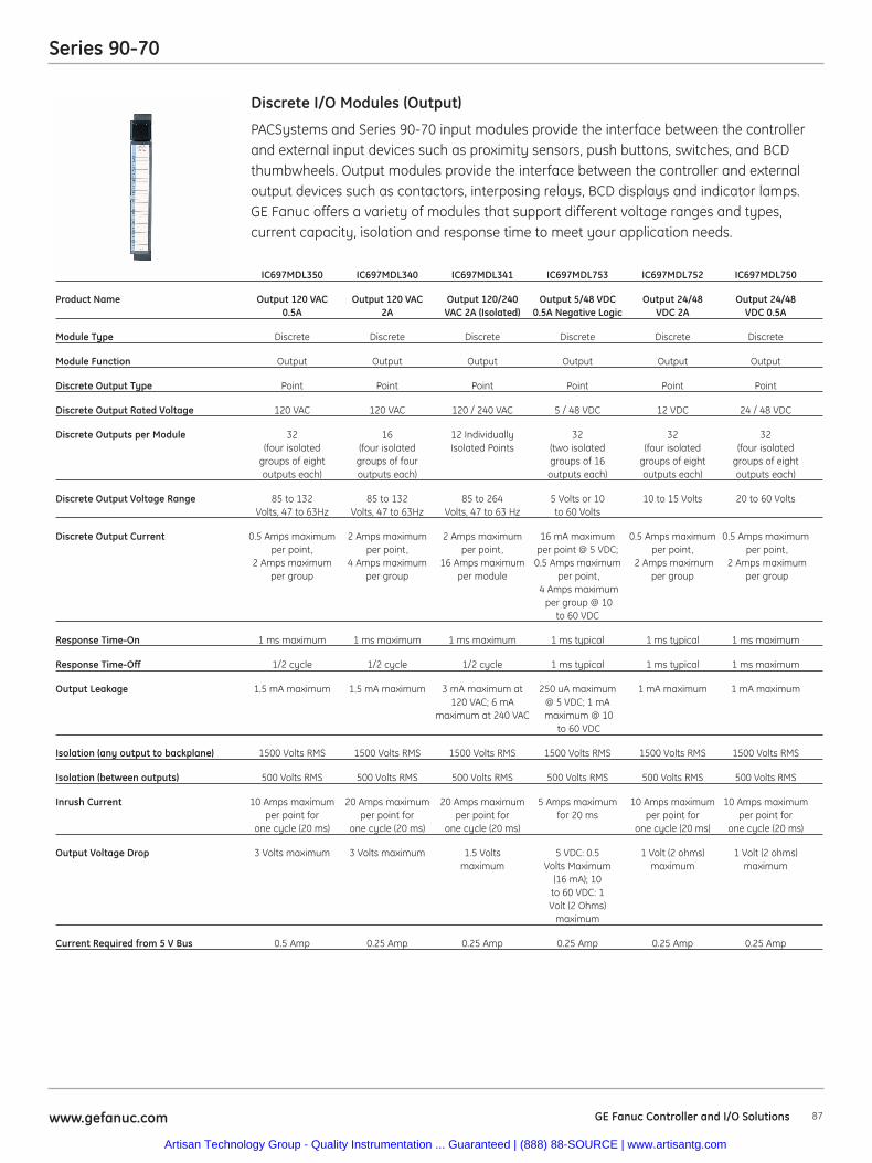
87www.gefanuc.com GE Fanuc Controller and I/O Solutions
Series 90-70
PACSystems and Series 90-70 input modules provide the interface between the controllerand external input devices such as proximity sensors, push buttons, switches, and BCDthumbwheels. Output modules provide the interface between the controller and externaloutput devices such as contactors, interposing relays, BCD displays and indicator lamps.GE Fanuc offers a variety of modules that support different voltage ranges and types,current capacity, isolation and response time to meet your application needs.
Discrete I/O Modules (Output)
IC697MDL350 IC697MDL340 IC697MDL341 IC697MDL753 IC697MDL752 IC697MDL750
Product Name Output 120 VAC Output 120 VAC Output 120/240 Output 5/48 VDC Output 24/48 Output 24/480.5A 2A VAC 2A (Isolated) 0.5A Negative Logic VDC 2A VDC 0.5A
Module Type Discrete Discrete Discrete Discrete Discrete Discrete
Module Function Output Output Output Output Output Output
Discrete Output Type Point Point Point Point Point Point
Discrete Output Rated Voltage 120 VAC 120 VAC 120 / 240 VAC 5 / 48 VDC 12 VDC 24 / 48 VDC
Discrete Outputs per Module 32 16 12 Individually 32 32 32(four isolated (four isolated Isolated Points (two isolated (four isolated (four isolated
groups of eight groups of four groups of 16 groups of eight groups of eightoutputs each) outputs each) outputs each) outputs each) outputs each)
Discrete Output Voltage Range 85 to 132 85 to 132 85 to 264 5 Volts or 10 10 to 15 Volts 20 to 60 VoltsVolts, 47 to 63Hz Volts, 47 to 63Hz Volts, 47 to 63 Hz to 60 Volts
Discrete Output Current 0.5 Amps maximum 2 Amps maximum 2 Amps maximum 16 mA maximum 0.5 Amps maximum 0.5 Amps maximumper point, per point, per point, per point @ 5 VDC; per point, per point,
2 Amps maximum 4 Amps maximum 16 Amps maximum 0.5 Amps maximum 2 Amps maximum 2 Amps maximumper group per group per module per point, per group per group
4 Amps maximumper group @ 10
to 60 VDC
Response Time-On 1 ms maximum 1 ms maximum 1 ms maximum 1 ms typical 1 ms typical 1 ms maximum
Response Time-Off 1/2 cycle 1/2 cycle 1/2 cycle 1 ms typical 1 ms typical 1 ms maximum
Output Leakage 1.5 mA maximum 1.5 mA maximum 3 mA maximum at 250 uA maximum 1 mA maximum 1 mA maximum120 VAC; 6 mA @ 5 VDC; 1 mA
maximum at 240 VAC maximum @ 10to 60 VDC
Isolation (any output to backplane) 1500 Volts RMS 1500 Volts RMS 1500 Volts RMS 1500 Volts RMS 1500 Volts RMS 1500 Volts RMS
Isolation (between outputs) 500 Volts RMS 500 Volts RMS 500 Volts RMS 500 Volts RMS 500 Volts RMS 500 Volts RMS
Inrush Current 10 Amps maximum 20 Amps maximum 20 Amps maximum 5 Amps maximum 10 Amps maximum 10 Amps maximumper point for per point for per point for for 20 ms per point for per point for
one cycle (20 ms) one cycle (20 ms) one cycle (20 ms) one cycle (20 ms) one cycle (20 ms)
Output Voltage Drop 3 Volts maximum 3 Volts maximum 1.5 Volts 5 VDC: 0.5 1 Volt (2 ohms) 1 Volt (2 ohms)maximum Volts Maximum maximum maximum
(16 mA); 10to 60 VDC: 1Volt (2 Ohms)
maximum
Current Required from 5 V Bus 0.5 Amp 0.25 Amp 0.25 Amp 0.25 Amp 0.25 Amp 0.25 Amp
Artisan Technology Group - Quality Instrumentation ... Guaranteed | (888) 88-SOURCE | www.artisantg.com
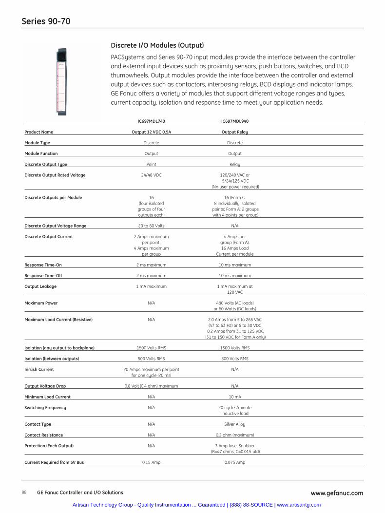
88 www.gefanuc.com
Series 90-70
PACSystems and Series 90-70 input modules provide the interface between the controllerand external input devices such as proximity sensors, push buttons, switches, and BCDthumbwheels. Output modules provide the interface between the controller and externaloutput devices such as contactors, interposing relays, BCD displays and indicator lamps.GE Fanuc offers a variety of modules that support different voltage ranges and types,current capacity, isolation and response time to meet your application needs.
Discrete I/O Modules (Output)
IC697MDL740 IC697MDL940
Product Name Output 12 VDC 0.5A Output Relay
Module Type Discrete Discrete
Module Function Output Output
Discrete Output Type Point Relay
Discrete Output Rated Voltage 24/48 VDC 120/240 VAC or5/24/125 VDC
(No user power required)
Discrete Outputs per Module 16 16 (Form C: (four isolated 8 individually isolated
groups of four points; Form A: 2 groupsoutputs each) with 4 points per group)
Discrete Output Voltage Range 20 to 60 Volts N/A
Discrete Output Current 2 Amps maximum 4 Amps perper point, group (Form A),
4 Amps maximum 16 Amps Loadper group Current per module
Response Time-On 2 ms maximum 10 ms maximum
Response Time-Off 2 ms maximum 10 ms maximum
Output Leakage 1 mA maximum 1 mA maximum at 120 VAC
Maximum Power N/A 480 Volts (AC loads) or 60 Watts (DC loads)
Maximum Load Current (Resistive) N/A 2.0 Amps from 5 to 265 VAC(47 to 63 Hz) or 5 to 30 VDC;
0.2 Amps from 31 to 125 VDC(31 to 150 VDC for Form A only)
Isolation (any output to backplane) 1500 Volts RMS 1500 Volts RMS
Isolation (between outputs) 500 Volts RMS 500 Volts RMS
Inrush Current 20 Amps maximum per point N/Afor one cycle (20 ms)
Output Voltage Drop 0.8 Volt (0.4 ohm) maximum N/A
Minimum Load Current N/A 10 mA
Switching Frequency N/A 20 cycles/minute(inductive load)
Contact Type N/A Silver Alloy
Contact Resistance N/A 0.2 ohm (maximum)
Protection (Each Output) N/A 3 Amp fuse, Snubber(R=47 ohms, C=0.015 ufd)
Current Required from 5V Bus 0.15 Amp 0.075 Amp
GE Fanuc Controller and I/O Solutions
Artisan Technology Group - Quality Instrumentation ... Guaranteed | (888) 88-SOURCE | www.artisantg.com
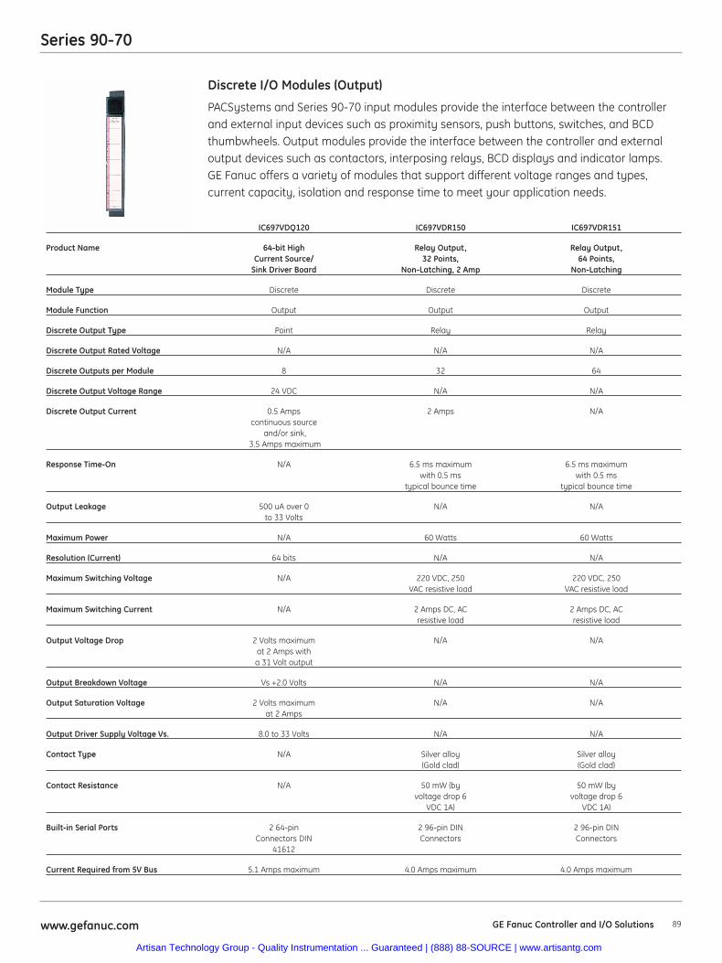
89www.gefanuc.com GE Fanuc Controller and I/O Solutions
Series 90-70
PACSystems and Series 90-70 input modules provide the interface between the controllerand external input devices such as proximity sensors, push buttons, switches, and BCDthumbwheels. Output modules provide the interface between the controller and externaloutput devices such as contactors, interposing relays, BCD displays and indicator lamps.GE Fanuc offers a variety of modules that support different voltage ranges and types, current capacity, isolation and response time to meet your application needs.
Discrete I/O Modules (Output)
IC697VDQ120 IC697VDR150 IC697VDR151
Product Name 64-bit High Relay Output, Relay Output,Current Source/ 32 Points, 64 Points,
Sink Driver Board Non-Latching, 2 Amp Non-Latching
Module Type Discrete Discrete Discrete
Module Function Output Output Output
Discrete Output Type Point Relay Relay
Discrete Output Rated Voltage N/A N/A N/A
Discrete Outputs per Module 8 32 64
Discrete Output Voltage Range 24 VDC N/A N/A
Discrete Output Current 0.5 Amps 2 Amps N/Acontinuous source
and/or sink,3.5 Amps maximum
Response Time-On N/A 6.5 ms maximum 6.5 ms maximumwith 0.5 ms with 0.5 ms
typical bounce time typical bounce time
Output Leakage 500 uA over 0 N/A N/Ato 33 Volts
Maximum Power N/A 60 Watts 60 Watts
Resolution (Current) 64 bits N/A N/A
Maximum Switching Voltage N/A 220 VDC, 250 220 VDC, 250VAC resistive load VAC resistive load
Maximum Switching Current N/A 2 Amps DC, AC 2 Amps DC, ACresistive load resistive load
Output Voltage Drop 2 Volts maximum N/A N/Aat 2 Amps witha 31 Volt output
Output Breakdown Voltage Vs +2.0 Volts N/A N/A
Output Saturation Voltage 2 Volts maximum N/A N/Aat 2 Amps
Output Driver Supply Voltage Vs. 8.0 to 33 Volts N/A N/A
Contact Type N/A Silver alloy Silver alloy (Gold clad) (Gold clad)
Contact Resistance N/A 50 mW (by 50 mW (byvoltage drop 6 voltage drop 6
VDC 1A) VDC 1A)
Built-in Serial Ports 2 64-pin 2 96-pin DIN 2 96-pin DINConnectors DIN Connectors Connectors
41612
Current Required from 5V Bus 5.1 Amps maximum 4.0 Amps maximum 4.0 Amps maximum
Artisan Technology Group - Quality Instrumentation ... Guaranteed | (888) 88-SOURCE | www.artisantg.com
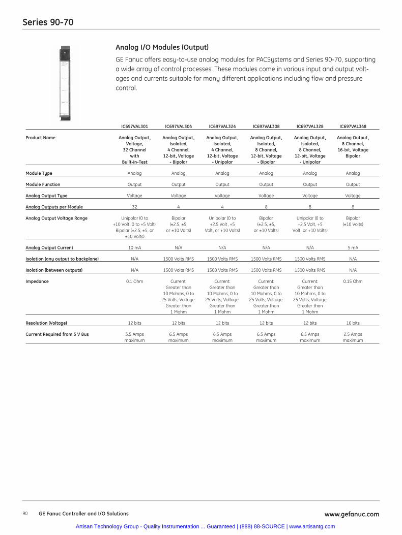
90 www.gefanuc.comGE Fanuc Controller and I/O Solutions
Series 90-70
GE Fanuc offers easy-to-use analog modules for PACSystems and Series 90-70, supportinga wide array of control processes. These modules come in various input and output volt-ages and currents suitable for many different applications including flow and pressurecontrol.
Analog I/O Modules (Output)
IC697VAL301 IC697VAL304 IC697VAL324 IC697VAL308 IC697VAL328 IC697VAL348
Product Name Analog Output, Analog Output, Analog Output, Analog Output, Analog Output, Analog Output,Voltage, Isolated, Isolated, Isolated, Isolated, 8 Channel,
32 Channel 4 Channel, 4 Channel, 8 Channel, 8 Channel, 16-bit, Voltagewith 12-bit, Voltage 12-bit, Voltage 12-bit, Voltage 12-bit, Voltage Bipolar
Built-in-Test - Bipolar - Unipolar - Bipolar - Unipolar
Module Type Analog Analog Analog Analog Analog Analog
Module Function Output Output Output Output Output Output
Analog Output Type Voltage Voltage Voltage Voltage Voltage Voltage
Analog Outputs per Module 32 4 4 8 8 8
Analog Output Voltage Range Unipolar (0 to Bipolar Unipolar (0 to Bipolar Unipolar (0 to Bipolar+10 Volt, 0 to +5 Volt); (±2.5, ±5, +2.5 Volt, +5 (±2.5, ±5, +2.5 Volt, +5 (±10 Volts)
Bipolar (±2.5, ±5, or or ±10 Volts) Volt, or +10 Volts) or ±10 Volts) Volt, or +10 Volts)±10 Volts)
Analog Output Current 10 mA N/A N/A N/A N/A 5 mA
Isolation (any output to backplane) N/A 1500 Volts RMS 1500 Volts RMS 1500 Volts RMS 1500 Volts RMS N/A
Isolation (between outputs) N/A 1500 Volts RMS 1500 Volts RMS 1500 Volts RMS 1500 Volts RMS N/A
Impedance 0.1 Ohm Current: Current: Current: Current: 0.15 OhmGreater than Greater than Greater than Greater than
10 Mohms, 0 to 10 Mohms, 0 to 10 Mohms, 0 to 10 Mohms, 0 to 25 Volts; Voltage: 25 Volts; Voltage: 25 Volts; Voltage: 25 Volts; Voltage:
Greater than Greater than Greater than Greater than 1 Mohm 1 Mohm 1 Mohm 1 Mohm
Resolution (Voltage) 12 bits 12 bits 12 bits 12 bits 12 bits 16 bits
Current Required from 5 V Bus 3.5 Amps 6.5 Amps 6.5 Amps 6.5 Amps 6.5 Amps 2.5 Amps maximum maximum maximum maximum maximum maximum
Artisan Technology Group - Quality Instrumentation ... Guaranteed | (888) 88-SOURCE | www.artisantg.com
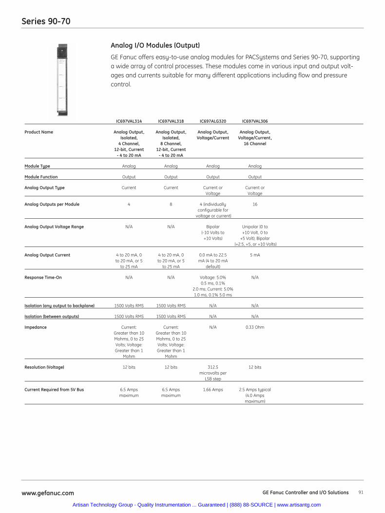
91www.gefanuc.com GE Fanuc Controller and I/O Solutions
Series 90-70
GE Fanuc offers easy-to-use analog modules for PACSystems and Series 90-70, supportinga wide array of control processes. These modules come in various input and output volt-ages and currents suitable for many different applications including flow and pressurecontrol.
Analog I/O Modules (Output)
IC697VAL314 IC697VAL318 IC697ALG320 IC697VAL306
Product Name Analog Output, Analog Output, Analog Output, Analog Output,Isolated, Isolated, Voltage/Current Voltage/Current,
4 Channel, 8 Channel, 16 Channel12-bit, Current 12-bit, Current
- 4 to 20 mA - 4 to 20 mA
Module Type Analog Analog Analog Analog
Module Function Output Output Output Output
Analog Output Type Current Current Current or Current orVoltage Voltage
Analog Outputs per Module 4 8 4 (individually 16configurable for
voltage or current)
Analog Output Voltage Range N/A N/A Bipolar Unipolar (0 to(-10 Volts to +10 Volt, 0 to
+10 Volts) +5 Volt); Bipolar(+2.5, +5, or +10 Volts)
Analog Output Current 4 to 20 mA, 0 4 to 20 mA, 0 0.0 mA to 22.5 5 mAto 20 mA, or 5 to 20 mA, or 5 mA (4 to 20 mA
to 25 mA to 25 mA default)
Response Time-On N/A N/A Voltage: 5.0% N/A0.5 ms, 0.1%
2.0 ms; Current: 5.0%1.0 ms, 0.1% 5.0 ms
Isolation (any output to backplane) 1500 Volts RMS 1500 Volts RMS N/A N/A
Isolation (between outputs) 1500 Volts RMS 1500 Volts RMS N/A N/A
Impedance Current: Current: N/A 0.33 OhmGreater than 10 Greater than 10Mohms, 0 to 25 Mohms, 0 to 25Volts; Voltage: Volts; Voltage:Greater than 1 Greater than 1
Mohm Mohm
Resolution (Voltage) 12 bits 12 bits 312.5 12 bitsmicrovolts per
LSB step
Current Required from 5V Bus 6.5 Amps 6.5 Amps 1.66 Amps 2.5 Amps typical maximum maximum (4.0 Amps
maximum)
Artisan Technology Group - Quality Instrumentation ... Guaranteed | (888) 88-SOURCE | www.artisantg.com
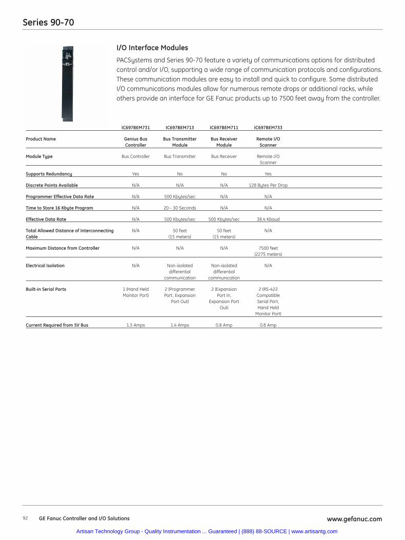
92 www.gefanuc.comGE Fanuc Controller and I/O Solutions
Series 90-70
PACSystems and Series 90-70 feature a variety of communications options for distributedcontrol and/or I/O, supporting a wide range of communication protocols and configurations.These communication modules are easy to install and quick to configure. Some distributedI/O communications modules allow for numerous remote drops or additional racks, whileothers provide an interface for GE Fanuc products up to 7500 feet away from the controller.
I/O Interface Modules
IC697BEM731 IC697BEM713 IC697BEM711 IC697BEM733
Product Name Genius Bus Bus Transmitter Bus Receiver Remote I/OController Module Module Scanner
Module Type Bus Controller Bus Transmitter Bus Receiver Remote I/OScanner
Supports Redundancy Yes No No Yes
Discrete Points Available N/A N/A N/A 128 Bytes Per Drop
Programmer Effective Data Rate N/A 500 Kbytes/sec N/A N/A
Time to Store 16 Kbyte Program N/A 20 - 30 Seconds N/A N/A
Effective Data Rate N/A 500 Kbytes/sec 500 Kbytes/sec 38.4 Kbaud
Total Allowed Distance of Interconnecting N/A 50 feet 50 feet N/ACable (15 meters) (15 meters)
Maximum Distance from Controller N/A N/A N/A 7500 feet (2275 meters)
Electrical Isolation N/A Non-isolated Non-isolated N/Adifferential differential
communication communication
Built-in Serial Ports 1 (Hand Held 2 (Programmer 2 (Expansion 2 (RS-422Monitor Port) Port, Expansion Port In, Compatible
Port Out) Expansion Port Serial Port,Out) Hand Held
Monitor Port)
Current Required from 5V Bus 1.3 Amps 1.4 Amps 0.8 Amp 0.8 Amp
Artisan Technology Group - Quality Instrumentation ... Guaranteed | (888) 88-SOURCE | www.artisantg.com
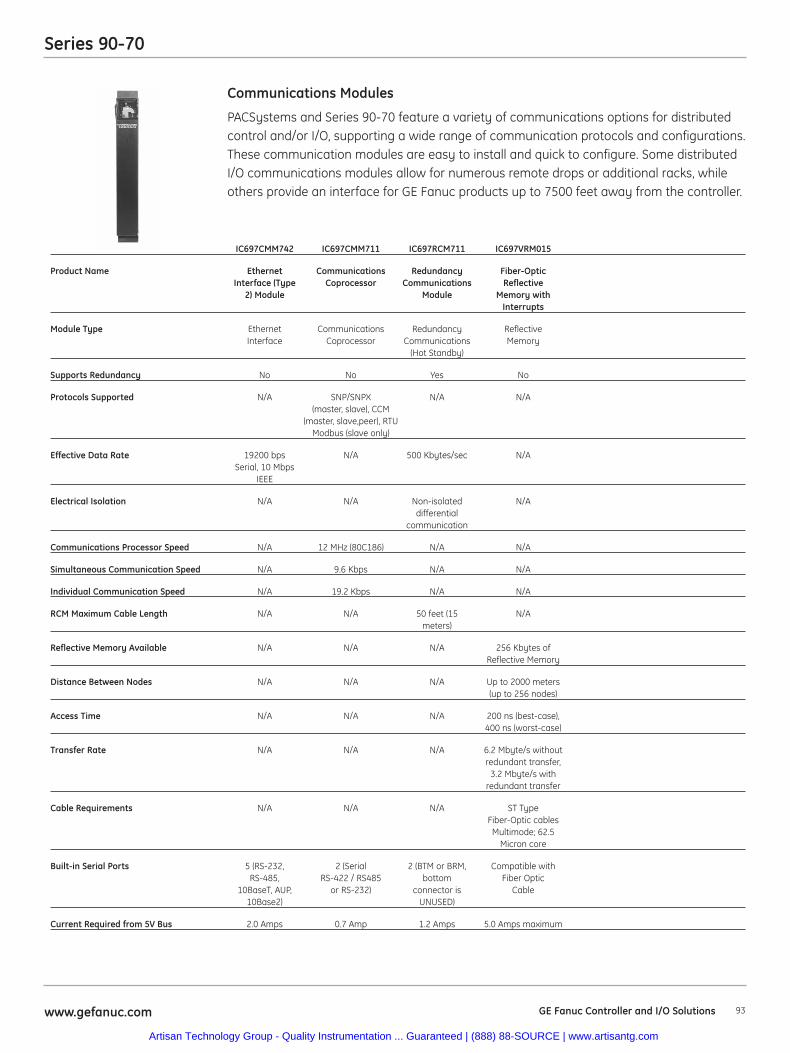
93www.gefanuc.com GE Fanuc Controller and I/O Solutions
Series 90-70
PACSystems and Series 90-70 feature a variety of communications options for distributedcontrol and/or I/O, supporting a wide range of communication protocols and configurations.These communication modules are easy to install and quick to configure. Some distributedI/O communications modules allow for numerous remote drops or additional racks, whileothers provide an interface for GE Fanuc products up to 7500 feet away from the controller.
Communications Modules
IC697CMM742 IC697CMM711 IC697RCM711 IC697VRM015
Product Name Ethernet Communications Redundancy Fiber-OpticInterface (Type Coprocessor Communications Reflective
2) Module Module Memory withInterrupts
Module Type Ethernet Communications Redundancy ReflectiveInterface Coprocessor Communications Memory
(Hot Standby)
Supports Redundancy No No Yes No
Protocols Supported N/A SNP/SNPX N/A N/A(master, slave), CCM
(master, slave,peer), RTUModbus (slave only)
Effective Data Rate 19200 bps N/A 500 Kbytes/sec N/ASerial, 10 Mbps
IEEE
Electrical Isolation N/A N/A Non-isolated N/Adifferential
communication
Communications Processor Speed N/A 12 MHz (80C186) N/A N/A
Simultaneous Communication Speed N/A 9.6 Kbps N/A N/A
Individual Communication Speed N/A 19.2 Kbps N/A N/A
RCM Maximum Cable Length N/A N/A 50 feet (15 N/Ameters)
Reflective Memory Available N/A N/A N/A 256 Kbytes ofReflective Memory
Distance Between Nodes N/A N/A N/A Up to 2000 meters (up to 256 nodes)
Access Time N/A N/A N/A 200 ns (best-case),400 ns (worst-case)
Transfer Rate N/A N/A N/A 6.2 Mbyte/s withoutredundant transfer,
3.2 Mbyte/s withredundant transfer
Cable Requirements N/A N/A N/A ST TypeFiber-Optic cables
Multimode; 62.5Micron core
Built-in Serial Ports 5 (RS-232, 2 (Serial 2 (BTM or BRM, Compatible withRS-485, RS-422 / RS485 bottom Fiber Optic
10BaseT, AUP, or RS-232) connector is Cable10Base2) UNUSED)
Current Required from 5V Bus 2.0 Amps 0.7 Amp 1.2 Amps 5.0 Amps maximum
Artisan Technology Group - Quality Instrumentation ... Guaranteed | (888) 88-SOURCE | www.artisantg.com
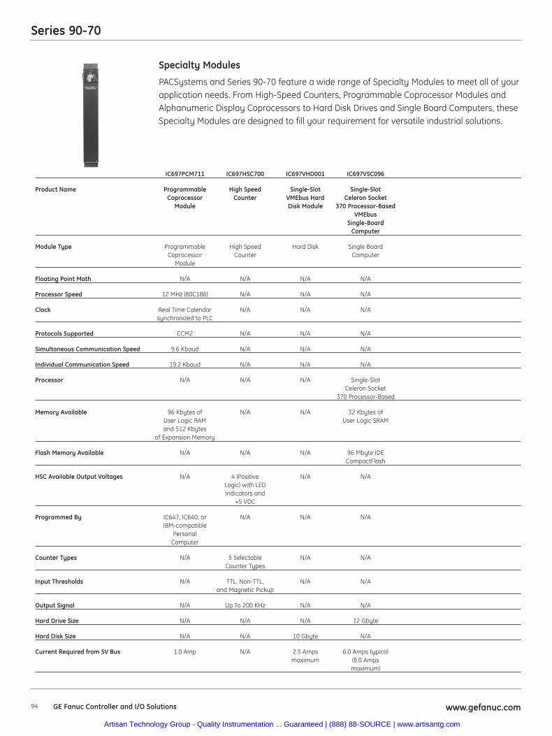
94 www.gefanuc.comGE Fanuc Controller and I/O Solutions
Series 90-70
PACSystems and Series 90-70 feature a wide range of Specialty Modules to meet all of yourapplication needs. From High-Speed Counters, Programmable Coprocessor Modules andAlphanumeric Display Coprocessors to Hard Disk Drives and Single Board Computers, theseSpecialty Modules are designed to fill your requirement for versatile industrial solutions.
Specialty Modules
IC697PCM711 IC697HSC700 IC697VHD001 IC697VSC096
Product Name Programmable High Speed Single-Slot Single-SlotCoprocessor Counter VMEbus Hard Celeron Socket
Module Disk Module 370 Processor-BasedVMEbus
Single-BoardComputer
Module Type Programmable High Speed Hard Disk Single BoardCoprocessor Counter Computer
Module
Floating Point Math N/A N/A N/A N/A
Processor Speed 12 MHz (80C186) N/A N/A N/A
Clock Real Time Calendar N/A N/A N/Asynchronized to PLC
Protocols Supported CCM2 N/A N/A N/A
Simultaneous Communication Speed 9.6 Kbaud N/A N/A N/A
Individual Communication Speed 19.2 Kbaud N/A N/A N/A
Processor N/A N/A N/A Single-SlotCeleron Socket
370 Processor-Based
Memory Available 96 Kbytes of N/A N/A 32 Kbytes ofUser Logic RAM User Logic SRAMand 512 Kbytes
of Expansion Memory
Flash Memory Available N/A N/A N/A 96 Mbyte IDECompactFlash
HSC Available Output Voltages N/A 4 (Positive N/A N/ALogic) with LEDIndicators and
+5 VDC
Programmed By IC647, IC640, or N/A N/A N/AIBM-compatible
PersonalComputer
Counter Types N/A 5 Selectable N/A N/ACounter Types
Input Thresholds N/A TTL, Non-TTL, N/A N/Aand Magnetic Pickup
Output Signal N/A Up To 200 KHz N/A N/A
Hard Drive Size N/A N/A N/A 12 Gbyte
Hard Disk Size N/A N/A 10 Gbyte N/A
Current Required from 5V Bus 1.0 Amp N/A 2.5 Amps 6.0 Amps typical maximum (8.0 Amps
maximum)
Artisan Technology Group - Quality Instrumentation ... Guaranteed | (888) 88-SOURCE | www.artisantg.com
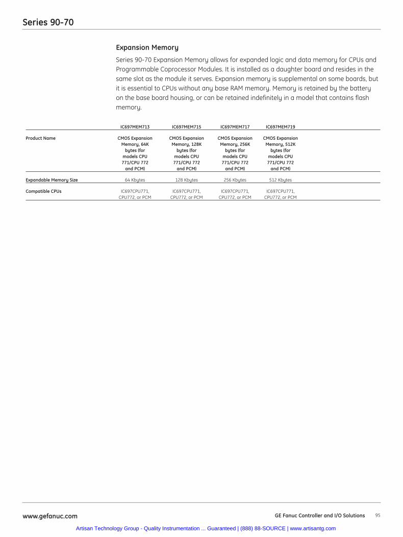
95www.gefanuc.com GE Fanuc Controller and I/O Solutions
Series 90-70
Series 90-70 Expansion Memory allows for expanded logic and data memory for CPUs andProgrammable Coprocessor Modules. It is installed as a daughter board and resides in thesame slot as the module it serves. Expansion memory is supplemental on some boards, butit is essential to CPUs without any base RAM memory. Memory is retained by the batteryon the base board housing, or can be retained indefinitely in a model that contains flashmemory.
Expansion Memory
IC697MEM713 IC697MEM715 IC697MEM717 IC697MEM719
Product Name CMOS Expansion CMOS Expansion CMOS Expansion CMOS ExpansionMemory, 64K Memory, 128K Memory, 256K Memory, 512K
bytes (for bytes (for bytes (for bytes (formodels CPU models CPU models CPU models CPU771/CPU 772 771/CPU 772 771/CPU 772 771/CPU 772
and PCM) and PCM) and PCM) and PCM)
Expandable Memory Size 64 Kbytes 128 Kbytes 256 Kbytes 512 Kbytes
Compatible CPUs IC697CPU771, IC697CPU771, IC697CPU771, IC697CPU771,CPU772, or PCM CPU772, or PCM CPU772, or PCM CPU772, or PCM
Artisan Technology Group - Quality Instrumentation ... Guaranteed | (888) 88-SOURCE | www.artisantg.com
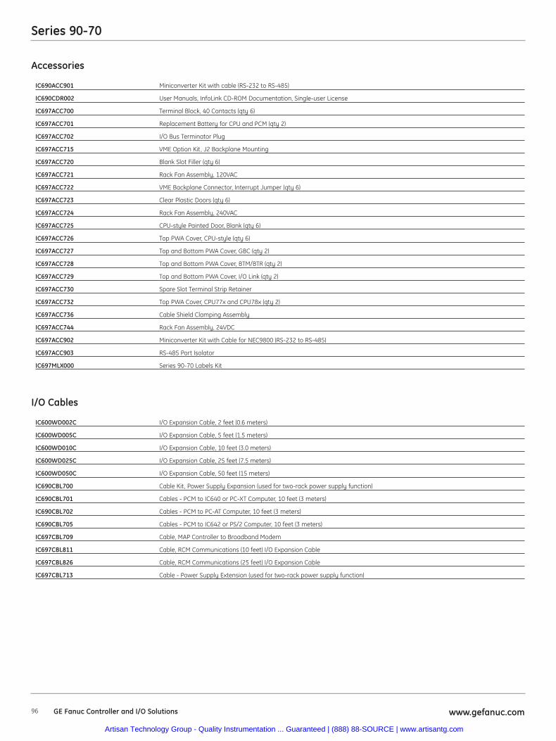
www.gefanuc.com96 GE Fanuc Controller and I/O Solutions
Accessories
IC690ACC901 Miniconverter Kit with cable (RS-232 to RS-485)
IC690CDR002 User Manuals, InfoLink CD-ROM Documentation, Single-user License
IC697ACC700 Terminal Block, 40 Contacts (qty 6)
IC697ACC701 Replacement Battery for CPU and PCM (qty 2)
IC697ACC702 I/O Bus Terminator Plug
IC697ACC715 VME Option Kit, J2 Backplane Mounting
IC697ACC720 Blank Slot Filler (qty 6)
IC697ACC721 Rack Fan Assembly, 120VAC
IC697ACC722 VME Backplane Connector, Interrupt Jumper (qty 6)
IC697ACC723 Clear Plastic Doors (qty 6)
IC697ACC724 Rack Fan Assembly, 240VAC
IC697ACC725 CPU-style Painted Door, Blank (qty 6)
IC697ACC726 Top PWA Cover, CPU-style (qty 6)
IC697ACC727 Top and Bottom PWA Cover, GBC (qty 2)
IC697ACC728 Top and Bottom PWA Cover, BTM/BTR (qty 2)
IC697ACC729 Top and Bottom PWA Cover, I/O Link (qty 2)
IC697ACC730 Spare Slot Terminal Strip Retainer
IC697ACC732 Top PWA Cover, CPU77x and CPU78x (qty 2)
IC697ACC736 Cable Shield Clamping Assembly
IC697ACC744 Rack Fan Assembly, 24VDC
IC697ACC902 Miniconverter Kit with Cable for NEC9800 (RS-232 to RS-485)
IC697ACC903 RS-485 Port Isolator
IC697MLX000 Series 90-70 Labels Kit
I/O Cables
IC600WD002C I/O Expansion Cable, 2 feet (0.6 meters)
IC600WD005C I/O Expansion Cable, 5 feet (1.5 meters)
IC600WD010C I/O Expansion Cable, 10 feet (3.0 meters)
IC600WD025C I/O Expansion Cable, 25 feet (7.5 meters)
IC600WD050C I/O Expansion Cable, 50 feet (15 meters)
IC690CBL700 Cable Kit, Power Supply Expansion (used for two-rack power supply function)
IC690CBL701 Cables - PCM to IC640 or PC-XT Computer, 10 feet (3 meters)
IC690CBL702 Cables - PCM to PC-AT Computer, 10 feet (3 meters)
IC690CBL705 Cables - PCM to IC642 or PS/2 Computer, 10 feet (3 meters)
IC697CBL709 Cable, MAP Controller to Broadband Modem
IC697CBL811 Cable, RCM Communications (10 feet) I/O Expansion Cable
IC697CBL826 Cable, RCM Communications (25 feet) I/O Expansion Cable
IC697CBL713 Cable - Power Supply Extension (used for two-rack power supply function)
Series 90-70
Artisan Technology Group - Quality Instrumentation ... Guaranteed | (888) 88-SOURCE | www.artisantg.com
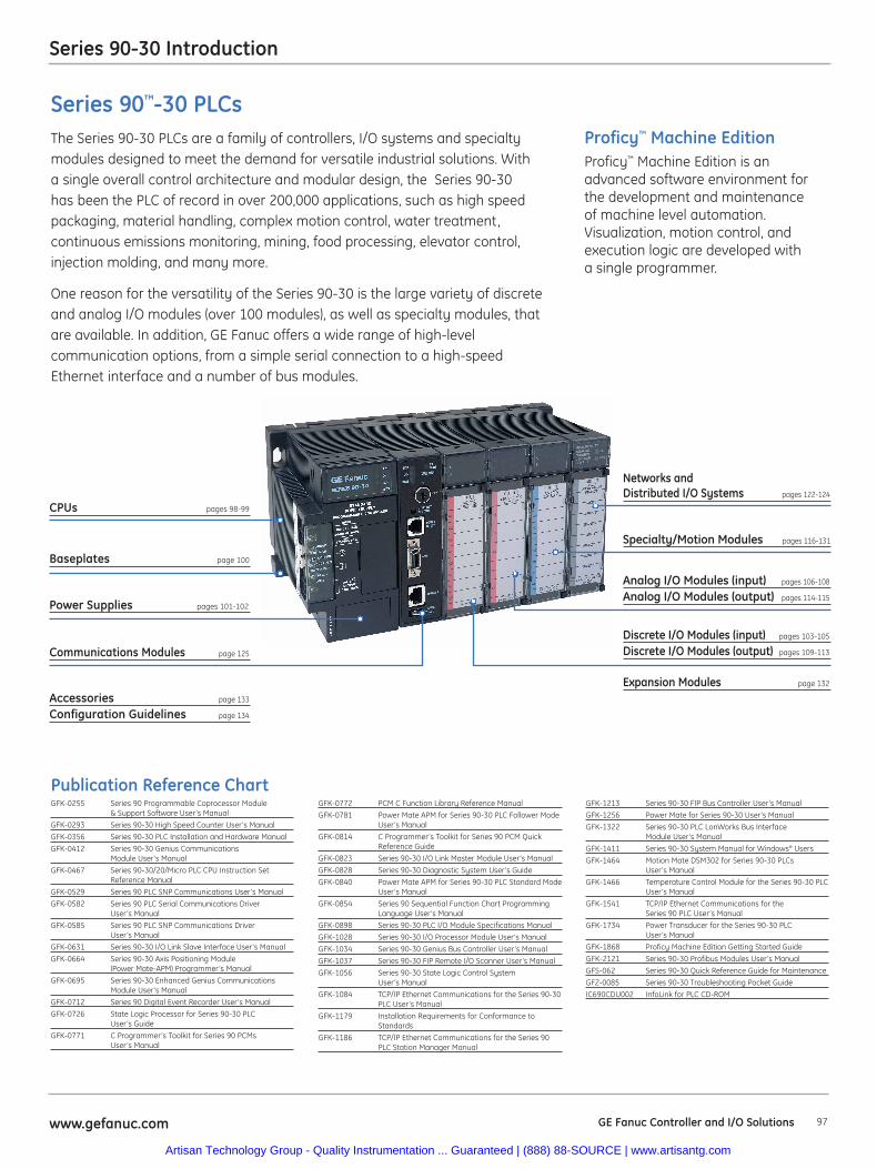
97www.gefanuc.com GE Fanuc Controller and I/O Solutions
Series 90-30 Introduction
GFK-0772 PCM C Function Library Reference Manual
GFK-0781 Power Mate APM for Series 90-30 PLC Follower Mode User’s Manual
GFK-0814 C Programmer’s Toolkit for Series 90 PCM Quick Reference Guide
GFK-0823 Series 90-30 I/O Link Master Module User’s Manual
GFK-0828 Series 90-30 Diagnostic System User’s Guide
GFK-0840 Power Mate APM for Series 90-30 PLC Standard Mode User’s Manual
GFK-0854 Series 90 Sequential Function Chart Programming Language User’s Manual
GFK-0898 Series 90-30 PLC I/O Module Specifications Manual
GFK-1028 Series 90-30 I/O Processor Module User’s Manual
GFK-1034 Series 90-30 Genius Bus Controller User’s Manual
GFK-1037 Series 90-30 FIP Remote I/O Scanner User’s Manual
GFK-1056 Series 90-30 State Logic Control System User’s Manual
GFK-1084 TCP/IP Ethernet Communications for the Series 90-30 PLC User’s Manual
GFK-1179 Installation Requirements for Conformance toStandards
GFK-1186 TCP/IP Ethernet Communications for the Series 90PLC Station Manager Manual
GFK-1213 Series 90-30 FIP Bus Controller User’s Manual
GFK-1256 Power Mate for Series 90-30 User’s Manual
GFK-1322 Series 90-30 PLC LonWorks Bus Interface Module User’s Manual
GFK-1411 Series 90-30 System Manual for Windows® Users
GFK-1464 Motion Mate DSM302 for Series 90-30 PLCs User’s Manual
GFK-1466 Temperature Control Module for the Series 90-30 PLC User’s Manual
GFK-1541 TCP/IP Ethernet Communications for the Series 90 PLC User’s Manual
GFK-1734 Power Transducer for the Series 90-30 PLC User’s Manual
GFK-1868 Proficy Machine Edition Getting Started Guide
GFK-2121 Series 90-30 Profibus Modules User’s Manual
GFS-062 Series 90-30 Quick Reference Guide for Maintenance
GFZ-0085 Series 90-30 Troubleshooting Pocket Guide
IC690CDU002 InfoLink for PLC CD-ROM
CPUs pages 98-99
Baseplates page 100
Power Supplies pages 101-102
Discrete I/O Modules (input) pages 103-105
Discrete I/O Modules (output) pages 109-113
Expansion Modules page 132
Analog I/O Modules (input) pages 106-108
Analog I/O Modules (output) pages 114-115
Networks and Distributed I/O Systems pages 122-124
Specialty/Motion Modules pages 116-131
Publication Reference ChartGFK-0255 Series 90 Programmable Coprocessor Module
& Support Software User’s Manual
GFK-0293 Series 90-30 High Speed Counter User’s Manual
GFK-0356 Series 90-30 PLC Installation and Hardware Manual
GFK-0412 Series 90-30 Genius Communications Module User’s Manual
GFK-0467 Series 90-30/20/Micro PLC CPU Instruction Set Reference Manual
GFK-0529 Series 90 PLC SNP Communications User’s Manual
GFK-0582 Series 90 PLC Serial Communications Driver User’s Manual
GFK-0585 Series 90 PLC SNP Communications Driver User’s Manual
GFK-0631 Series 90-30 I/O Link Slave Interface User’s Manual
GFK-0664 Series 90-30 Axis Positioning Module (Power Mate-APM) Programmer’s Manual
GFK-0695 Series 90-30 Enhanced Genius CommunicationsModule User’s Manual
GFK-0712 Series 90 Digital Event Recorder User’s Manual
GFK-0726 State Logic Processor for Series 90-30 PLC User’s Guide
GFK-0771 C Programmer’s Toolkit for Series 90 PCMs User’s Manual
Proficy™ Machine EditionProficy™ Machine Edition is anadvanced software environment forthe development and maintenanceof machine level automation.Visualization, motion control, andexecution logic are developed witha single programmer.
Series 90™-30 PLCsThe Series 90-30 PLCs are a family of controllers, I/O systems and specialtymodules designed to meet the demand for versatile industrial solutions. Witha single overall control architecture and modular design, the Series 90-30has been the PLC of record in over 200,000 applications, such as high speedpackaging, material handling, complex motion control, water treatment,continuous emissions monitoring, mining, food processing, elevator control, injection molding, and many more.
One reason for the versatility of the Series 90-30 is the large variety of discreteand analog I/O modules (over 100 modules), as well as specialty modules, thatare available. In addition, GE Fanuc offers a wide range of high-levelcommunication options, from a simple serial connection to a high-speedEthernet interface and a number of bus modules.
Communications Modules page 125
Accessories page 133
Configuration Guidelines page 134
Artisan Technology Group - Quality Instrumentation ... Guaranteed | (888) 88-SOURCE | www.artisantg.com
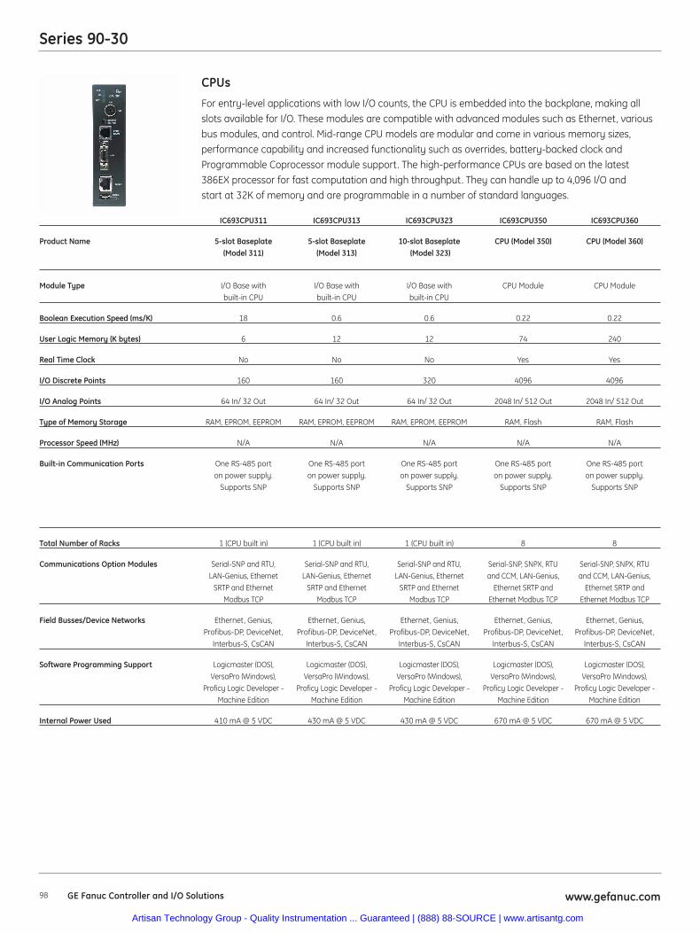
Series 90-30
98 www.gefanuc.com
For entry-level applications with low I/O counts, the CPU is embedded into the backplane, making all
slots available for I/O. These modules are compatible with advanced modules such as Ethernet, various
bus modules, and control. Mid-range CPU models are modular and come in various memory sizes,
performance capability and increased functionality such as overrides, battery-backed clock and
Programmable Coprocessor module support. The high-performance CPUs are based on the latest
386EX processor for fast computation and high throughput. They can handle up to 4,096 I/O and
start at 32K of memory and are programmable in a number of standard languages.
CPUs
IC693CPU311 IC693CPU313 IC693CPU323 IC693CPU350 IC693CPU360
Product Name 5-slot Baseplate 5-slot Baseplate 10-slot Baseplate CPU (Model 350) CPU (Model 360)(Model 311) (Model 313) (Model 323)
Module Type I/O Base with I/O Base with I/O Base with CPU Module CPU Modulebuilt-in CPU built-in CPU built-in CPU
Boolean Execution Speed (ms/K) 18 0.6 0.6 0.22 0.22
User Logic Memory (K bytes) 6 12 12 74 240
Real Time Clock No No No Yes Yes
I/O Discrete Points 160 160 320 4096 4096
I/O Analog Points 64 In/ 32 Out 64 In/ 32 Out 64 In/ 32 Out 2048 In/ 512 Out 2048 In/ 512 Out
Type of Memory Storage RAM, EPROM, EEPROM RAM, EPROM, EEPROM RAM, EPROM, EEPROM RAM, Flash RAM, Flash
Processor Speed (MHz) N/A N/A N/A N/A N/A
Built-in Communication Ports One RS-485 port One RS-485 port One RS-485 port One RS-485 port One RS-485 port on power supply. on power supply. on power supply. on power supply. on power supply.
Supports SNP Supports SNP Supports SNP Supports SNP Supports SNP
Total Number of Racks 1 (CPU built in) 1 (CPU built in) 1 (CPU built in) 8 8
Communications Option Modules Serial-SNP and RTU, Serial-SNP and RTU, Serial-SNP and RTU, Serial-SNP, SNPX, RTU Serial-SNP, SNPX, RTULAN-Genius, Ethernet LAN-Genius, Ethernet LAN-Genius, Ethernet and CCM, LAN-Genius, and CCM, LAN-Genius,
SRTP and Ethernet SRTP and Ethernet SRTP and Ethernet Ethernet SRTP and Ethernet SRTP and Modbus TCP Modbus TCP Modbus TCP Ethernet Modbus TCP Ethernet Modbus TCP
Field Busses/Device Networks Ethernet, Genius, Ethernet, Genius, Ethernet, Genius, Ethernet, Genius, Ethernet, Genius,Profibus-DP, DeviceNet, Profibus-DP, DeviceNet, Profibus-DP, DeviceNet, Profibus-DP, DeviceNet, Profibus-DP, DeviceNet,
Interbus-S, CsCAN Interbus-S, CsCAN Interbus-S, CsCAN Interbus-S, CsCAN Interbus-S, CsCAN
Software Programming Support Logicmaster (DOS), Logicmaster (DOS), Logicmaster (DOS), Logicmaster (DOS), Logicmaster (DOS),VersaPro (Windows), VersaPro (Windows), VersaPro (Windows), VersaPro (Windows), VersaPro (Windows),
Proficy Logic Developer - Proficy Logic Developer - Proficy Logic Developer - Proficy Logic Developer - Proficy Logic Developer -Machine Edition Machine Edition Machine Edition Machine Edition Machine Edition
Internal Power Used 410 mA @ 5 VDC 430 mA @ 5 VDC 430 mA @ 5 VDC 670 mA @ 5 VDC 670 mA @ 5 VDC
GE Fanuc Controller and I/O Solutions
Artisan Technology Group - Quality Instrumentation ... Guaranteed | (888) 88-SOURCE | www.artisantg.com
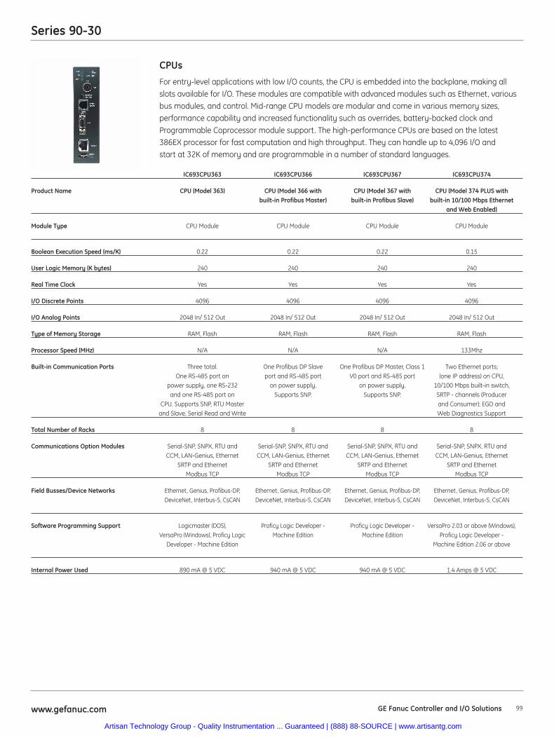
Series 90-30
99www.gefanuc.com
For entry-level applications with low I/O counts, the CPU is embedded into the backplane, making all
slots available for I/O. These modules are compatible with advanced modules such as Ethernet, various
bus modules, and control. Mid-range CPU models are modular and come in various memory sizes,
performance capability and increased functionality such as overrides, battery-backed clock and
Programmable Coprocessor module support. The high-performance CPUs are based on the latest
386EX processor for fast computation and high throughput. They can handle up to 4,096 I/O and
start at 32K of memory and are programmable in a number of standard languages.
CPUs
IC693CPU363 IC693CPU366 IC693CPU367 IC693CPU374
Product Name CPU (Model 363) CPU (Model 366 with CPU (Model 367 with CPU (Model 374 PLUS with built-in Profibus Master) built-in Profibus Slave) built-in 10/100 Mbps Ethernet
and Web Enabled)
Module Type CPU Module CPU Module CPU Module CPU Module
Boolean Execution Speed (ms/K) 0.22 0.22 0.22 0.15
User Logic Memory (K bytes) 240 240 240 240
Real Time Clock Yes Yes Yes Yes
I/O Discrete Points 4096 4096 4096 4096
I/O Analog Points 2048 In/ 512 Out 2048 In/ 512 Out 2048 In/ 512 Out 2048 In/ 512 Out
Type of Memory Storage RAM, Flash RAM, Flash RAM, Flash RAM, Flash
Processor Speed (MHz) N/A N/A N/A 133Mhz
Built-in Communication Ports Three total. One Profibus DP Slave One Profibus DP Master, Class 1 Two Ethernet ports;One RS-485 port on port and RS-485 port V0 port and RS-485 port (one IP address) on CPU,
power supply, one RS-232 on power supply. on power supply. 10/100 Mbps built-in switch,and one RS-485 port on Supports SNP. Supports SNP. SRTP - channels (Producer
CPU. Supports SNP, RTU Master and Consumer); EGD andand Slave, Serial Read and Write Web Diagnostics Support
Total Number of Racks 8 8 8 8
Communications Option Modules Serial-SNP, SNPX, RTU and Serial-SNP, SNPX, RTU and Serial-SNP, SNPX, RTU and Serial-SNP, SNPX, RTU andCCM, LAN-Genius, Ethernet CCM, LAN-Genius, Ethernet CCM, LAN-Genius, Ethernet CCM, LAN-Genius, Ethernet
SRTP and Ethernet SRTP and Ethernet SRTP and Ethernet SRTP and Ethernet Modbus TCP Modbus TCP Modbus TCP Modbus TCP
Field Busses/Device Networks Ethernet, Genius, Profibus-DP, Ethernet, Genius, Profibus-DP, Ethernet, Genius, Profibus-DP, Ethernet, Genius, Profibus-DP, DeviceNet, Interbus-S, CsCAN DeviceNet, Interbus-S, CsCAN DeviceNet, Interbus-S, CsCAN DeviceNet, Interbus-S, CsCAN
Software Programming Support Logicmaster (DOS), Proficy Logic Developer - Proficy Logic Developer - VersaPro 2.03 or above (Windows), VersaPro (Windows), Proficy Logic Machine Edition Machine Edition Proficy Logic Developer -
Developer - Machine Edition Machine Edition 2.06 or above
Internal Power Used 890 mA @ 5 VDC 940 mA @ 5 VDC 940 mA @ 5 VDC 1.4 Amps @ 5 VDC
GE Fanuc Controller and I/O Solutions
Artisan Technology Group - Quality Instrumentation ... Guaranteed | (888) 88-SOURCE | www.artisantg.com
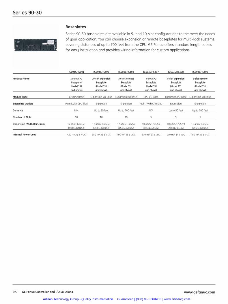
Series 90-30
100 www.gefanuc.com
Series 90-30 baseplates are available in 5- and 10-slot configurations to the meet the needsof your application. You can choose expansion or remote baseplates for multi-rack systems,covering distances of up to 700 feet from the CPU. GE Fanuc offers standard length cablesfor easy installation and provides wiring information for custom applications.
Baseplates
IC693CHS391 IC693CHS392 IC693CHS393 IC693CHS397 IC693CHS398 IC693CHS399
Product Name 10-slot CPU 10-slot Expansion 10-slot Remote 5-slot CPU 5-slot Expansion 5-slot RemoteBaseplate Baseplate Baseplate Baseplate Baseplate Baseplate (Model 331 (Model 331 (Model 331 (Model 331 (Model 331 (Model 331and above) and above) and above) and above) and above) and above)
Module Type CPU I/O Base Expansion I/O Base Expansion I/O Base CPU I/O Base Expansion I/O Base Expansion I/O Base
Baseplate Option Main (With CPU Slot) Expansion Expansion Main (With CPU Slot) Expansion Expansion
Distance N/A Up to 50 feet Up to 700 feet N/A Up to 50 feet Up to 700 feet
Number of Slots 10 10 10 5 5 5
Dimension (WxHxD) in. (mm) 17.44x5.12x5.59 17.44x5.12x5.59 17.44x5.12x5.59 10.43x5.12x5.59 10.43x5.12x5.59 10.43x5.12x5.59 (443x130x142) (443x130x142) (443x130x142) (245x130x142) (245x130x142) (245x130x142)
Internal Power Used 420 mA @ 5 VDC 150 mA @ 5 VDC 460 mA @ 5 VDC 270 mA @ 5 VDC 170 mA @ 5 VDC 480 mA @ 5 VDC
GE Fanuc Controller and I/O Solutions
Artisan Technology Group - Quality Instrumentation ... Guaranteed | (888) 88-SOURCE | www.artisantg.com
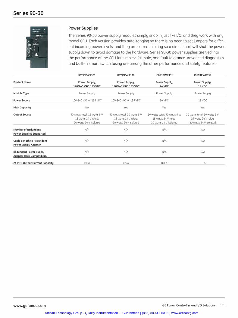
Series 90-30
101www.gefanuc.com
The Series 90-30 power supply modules simply snap in just like I/O, and they work with anymodel CPU. Each version provides auto-ranging so there is no need to set jumpers for differ-ent incoming power levels, and they are current limiting so a direct short will shut the powersupply down to avoid damage to the hardware. Series 90-30 power supplies are tied intothe performance of the CPU for simplex, fail-safe, and fault tolerance. Advanced diagnosticsand built-in smart switch fusing are among the other performance and safety features.
Power Supplies
IC693PWR321 IC693PWR330 IC693PWR331 IC693PWR332
Product Name Power Supply, Power Supply, Power Supply, Power Supply, 120/240 VAC, 125 VDC 120/240 VAC, 125 VDC 24 VDC 12 VDC
Module Type Power Supply Power Supply Power Supply Power Supply
Power Source 100-240 VAC or 125 VDC 100-240 VAC or 125 VDC 24 VDC 12 VDC
High Capacity No Yes Yes Yes
Output Source 30 watts total; 15 watts 5 V; 30 watts total; 30 watts 5 V; 30 watts total; 30 watts 5 V; 30 watts total; 30 watts 5 V;15 watts 24 V relay; 15 watts 24 V relay; 15 watts 24 V relay; 15 watts 24 V relay;
20 watts 24 V isolated 20 watts 24 V isolated 20 watts 24 V isolated 20 watts 24 V isolated
Number of Redundant N/A N/A N/A N/APower Supplies Supported
Cable Length to Redundant N/A N/A N/A N/APower Supply Adapter
Redundant Power Supply N/A N/A N/A N/AAdapter Rack Compatibility
24 VDC Output Current Capacity 0.8 A 0.8 A 0.8 A 0.8 A
GE Fanuc Controller and I/O Solutions
Artisan Technology Group - Quality Instrumentation ... Guaranteed | (888) 88-SOURCE | www.artisantg.com
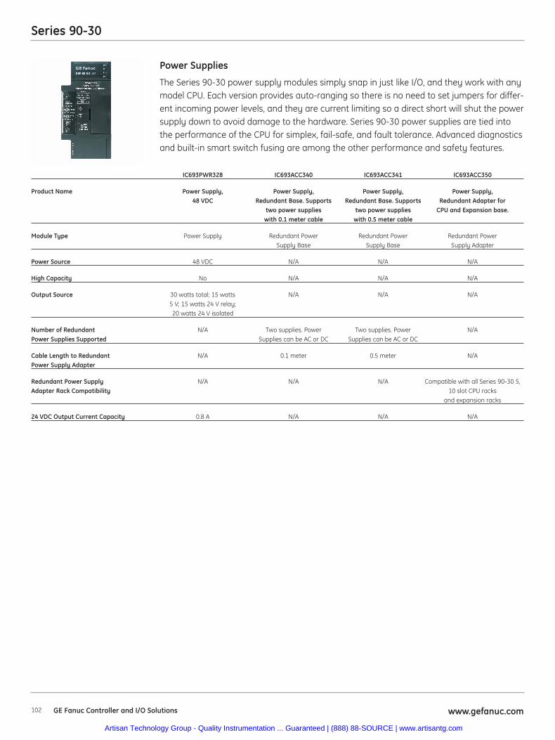
Series 90-30
102 www.gefanuc.com
The Series 90-30 power supply modules simply snap in just like I/O, and they work with anymodel CPU. Each version provides auto-ranging so there is no need to set jumpers for differ-ent incoming power levels, and they are current limiting so a direct short will shut the powersupply down to avoid damage to the hardware. Series 90-30 power supplies are tied intothe performance of the CPU for simplex, fail-safe, and fault tolerance. Advanced diagnosticsand built-in smart switch fusing are among the other performance and safety features.
Power Supplies
IC693PWR328 IC693ACC340 IC693ACC341 IC693ACC350
Product Name Power Supply, Power Supply, Power Supply, Power Supply, 48 VDC Redundant Base. Supports Redundant Base. Supports Redundant Adapter for
two power supplies two power supplies CPU and Expansion base.with 0.1 meter cable with 0.5 meter cable
Module Type Power Supply Redundant Power Redundant Power Redundant Power Supply Base Supply Base Supply Adapter
Power Source 48 VDC N/A N/A N/A
High Capacity No N/A N/A N/A
Output Source 30 watts total; 15 watts N/A N/A N/A5 V; 15 watts 24 V relay; 20 watts 24 V isolated
Number of Redundant N/A Two supplies. Power Two supplies. Power N/APower Supplies Supported Supplies can be AC or DC Supplies can be AC or DC
Cable Length to Redundant N/A 0.1 meter 0.5 meter N/APower Supply Adapter
Redundant Power Supply N/A N/A N/A Compatible with all Series 90-30 5, Adapter Rack Compatibility 10 slot CPU racks
and expansion racks
24 VDC Output Current Capacity 0.8 A N/A N/A N/A
GE Fanuc Controller and I/O Solutions
Artisan Technology Group - Quality Instrumentation ... Guaranteed | (888) 88-SOURCE | www.artisantg.com
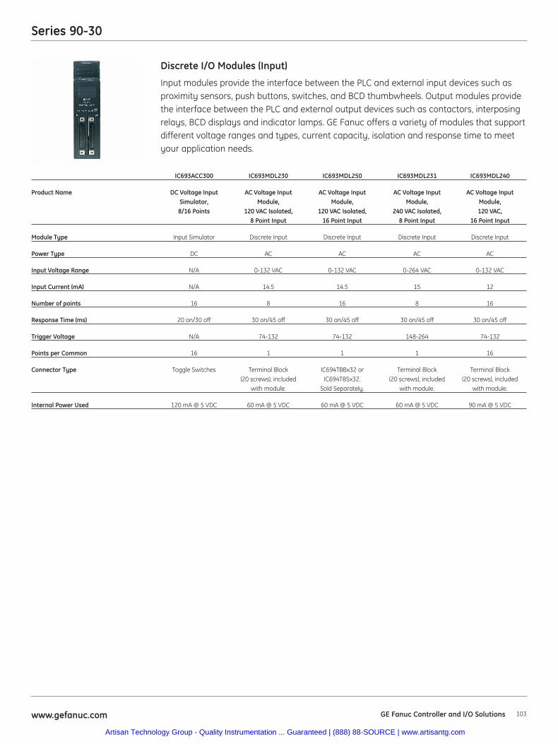
Series 90-30
103www.gefanuc.com
Input modules provide the interface between the PLC and external input devices such asproximity sensors, push buttons, switches, and BCD thumbwheels. Output modules providethe interface between the PLC and external output devices such as contactors, interposingrelays, BCD displays and indicator lamps. GE Fanuc offers a variety of modules that supportdifferent voltage ranges and types, current capacity, isolation and response time to meetyour application needs.
Discrete I/O Modules (Input)
IC693ACC300 IC693MDL230 IC693MDL250 IC693MDL231 IC693MDL240
Product Name DC Voltage Input AC Voltage Input AC Voltage Input AC Voltage Input AC Voltage Input Simulator, Module, Module, Module, Module, 8/16 Points 120 VAC Isolated, 120 VAC Isolated, 240 VAC Isolated, 120 VAC,
8 Point Input 16 Point Input 8 Point Input 16 Point Input
Module Type Input Simulator Discrete Input Discrete Input Discrete Input Discrete Input
Power Type DC AC AC AC AC
Input Voltage Range N/A 0-132 VAC 0-132 VAC 0-264 VAC 0-132 VAC
Input Current (mA) N/A 14.5 14.5 15 12
Number of points 16 8 16 8 16
Response Time (ms) 20 on/30 off 30 on/45 off 30 on/45 off 30 on/45 off 30 on/45 off
Trigger Voltage N/A 74-132 74-132 148-264 74-132
Points per Common 16 1 1 1 16
Connector Type Toggle Switches Terminal Block IC694TBBx32 or Terminal Block Terminal Block(20 screws), included IC694TBSx32. (20 screws), included (20 screws), included
with module. Sold Separately. with module. with module.
Internal Power Used 120 mA @ 5 VDC 60 mA @ 5 VDC 60 mA @ 5 VDC 60 mA @ 5 VDC 90 mA @ 5 VDC
GE Fanuc Controller and I/O Solutions
Artisan Technology Group - Quality Instrumentation ... Guaranteed | (888) 88-SOURCE | www.artisantg.com
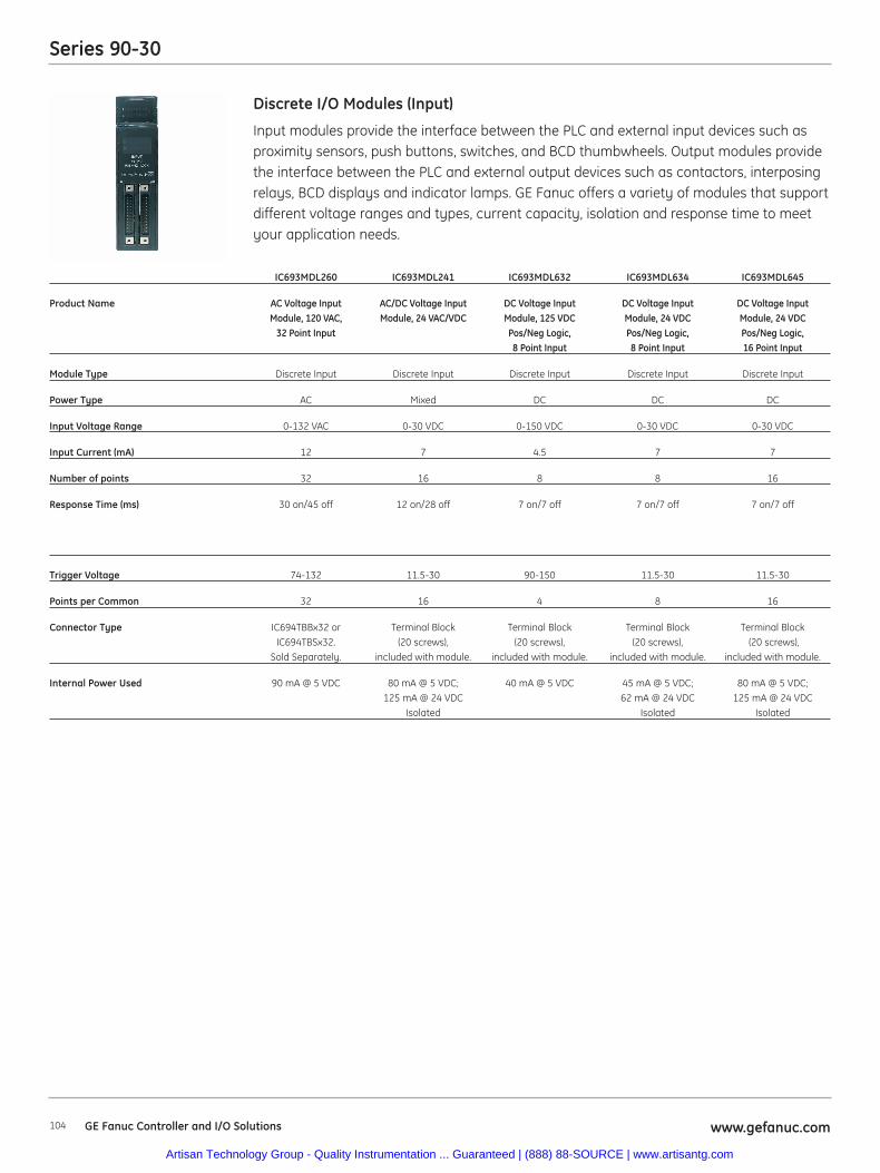
Series 90-30
104 www.gefanuc.com
Input modules provide the interface between the PLC and external input devices such asproximity sensors, push buttons, switches, and BCD thumbwheels. Output modules providethe interface between the PLC and external output devices such as contactors, interposingrelays, BCD displays and indicator lamps. GE Fanuc offers a variety of modules that supportdifferent voltage ranges and types, current capacity, isolation and response time to meetyour application needs.
Discrete I/O Modules (Input)
IC693MDL260 IC693MDL241 IC693MDL632 IC693MDL634 IC693MDL645
Product Name AC Voltage Input AC/DC Voltage Input DC Voltage Input DC Voltage Input DC Voltage Input Module, 120 VAC, Module, 24 VAC/VDC Module, 125 VDC Module, 24 VDC Module, 24 VDC
32 Point Input Pos/Neg Logic, Pos/Neg Logic, Pos/Neg Logic,8 Point Input 8 Point Input 16 Point Input
Module Type Discrete Input Discrete Input Discrete Input Discrete Input Discrete Input
Power Type AC Mixed DC DC DC
Input Voltage Range 0-132 VAC 0-30 VDC 0-150 VDC 0-30 VDC 0-30 VDC
Input Current (mA) 12 7 4.5 7 7
Number of points 32 16 8 8 16
Response Time (ms) 30 on/45 off 12 on/28 off 7 on/7 off 7 on/7 off 7 on/7 off
Trigger Voltage 74-132 11.5-30 90-150 11.5-30 11.5-30
Points per Common 32 16 4 8 16
Connector Type IC694TBBx32 or Terminal Block Terminal Block Terminal Block Terminal BlockIC694TBSx32. (20 screws), (20 screws), (20 screws), (20 screws),
Sold Separately. included with module. included with module. included with module. included with module.
Internal Power Used 90 mA @ 5 VDC 80 mA @ 5 VDC; 40 mA @ 5 VDC 45 mA @ 5 VDC; 80 mA @ 5 VDC; 125 mA @ 24 VDC 62 mA @ 24 VDC 125 mA @ 24 VDC
Isolated Isolated Isolated
GE Fanuc Controller and I/O Solutions
Artisan Technology Group - Quality Instrumentation ... Guaranteed | (888) 88-SOURCE | www.artisantg.com
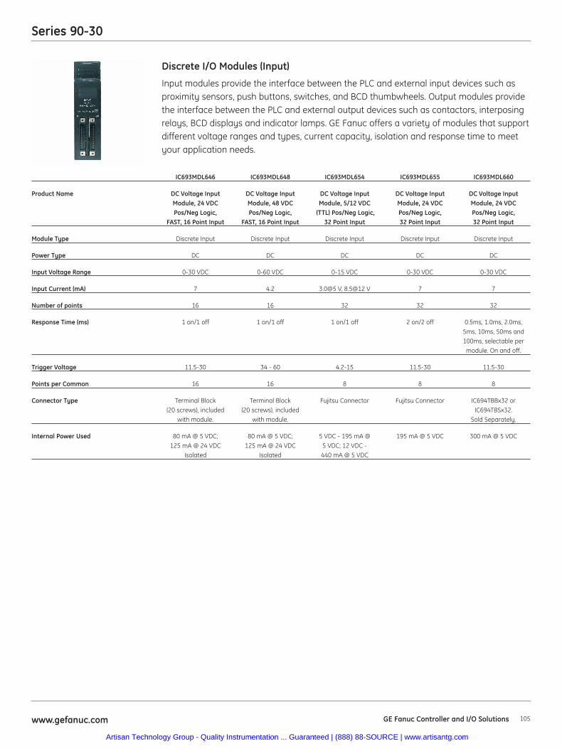
Series 90-30
105www.gefanuc.com
Input modules provide the interface between the PLC and external input devices such asproximity sensors, push buttons, switches, and BCD thumbwheels. Output modules providethe interface between the PLC and external output devices such as contactors, interposingrelays, BCD displays and indicator lamps. GE Fanuc offers a variety of modules that supportdifferent voltage ranges and types, current capacity, isolation and response time to meetyour application needs.
Discrete I/O Modules (Input)
IC693MDL646 IC693MDL648 IC693MDL654 IC693MDL655 IC693MDL660
Product Name DC Voltage Input DC Voltage Input DC Voltage Input DC Voltage Input DC Voltage Input Module, 24 VDC Module, 48 VDC Module, 5/12 VDC Module, 24 VDC Module, 24 VDCPos/Neg Logic, Pos/Neg Logic, (TTL) Pos/Neg Logic, Pos/Neg Logic, Pos/Neg Logic,
FAST, 16 Point Input FAST, 16 Point Input 32 Point Input 32 Point Input 32 Point Input
Module Type Discrete Input Discrete Input Discrete Input Discrete Input Discrete Input
Power Type DC DC DC DC DC
Input Voltage Range 0-30 VDC 0-60 VDC 0-15 VDC 0-30 VDC 0-30 VDC
Input Current (mA) 7 4.2 3.0@5 V, 8.5@12 V 7 7
Number of points 16 16 32 32 32
Response Time (ms) 1 on/1 off 1 on/1 off 1 on/1 off 2 on/2 off 0.5ms, 1.0ms, 2.0ms, 5ms, 10ms, 50ms and 100ms, selectable per
module. On and off.
Trigger Voltage 11.5-30 34 - 60 4.2-15 11.5-30 11.5-30
Points per Common 16 16 8 8 8
Connector Type Terminal Block Terminal Block Fujitsu Connector Fujitsu Connector IC694TBBx32 or(20 screws), included (20 screws), included IC694TBSx32.
with module. with module. Sold Separately.
Internal Power Used 80 mA @ 5 VDC; 80 mA @ 5 VDC; 5 VDC - 195 mA @ 195 mA @ 5 VDC 300 mA @ 5 VDC125 mA @ 24 VDC 125 mA @ 24 VDC 5 VDC; 12 VDC -
Isolated Isolated 440 mA @ 5 VDC
GE Fanuc Controller and I/O Solutions
Artisan Technology Group - Quality Instrumentation ... Guaranteed | (888) 88-SOURCE | www.artisantg.com
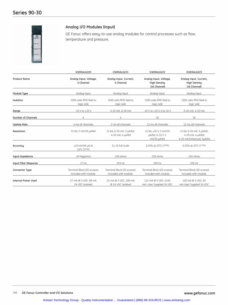
Series 90-30
106 www.gefanuc.com
GE Fanuc offers easy-to-use analog modules for control processes such as flow,temperature and pressure.
Analog I/O Modules (Input)
IC693ALG220 IC693ALG221 IC693ALG222 IC693ALG223
Product Name Analog Input, Voltage, Analog Input, Current, Analog Input, Voltage, Analog Input, Current, 4 Channel 4 Channel High Density High Density
(16 Channel) (16 Channel)
Module Type Analog Input Analog Input Analog Input Analog Input
Isolation 1500 volts RMS field to 1500 volts RMS field to 1500 volts RMS field to 1500 volts RMS field tologic side logic side logic side logic side
Range -10 V to +10 V 4-20 mA, 0-20 mA -10 V to +10 V, 0 to 10 V 0-20 mA, 4-20 mA
Number of Channels 4 4 16 16
Update Rate 4 ms all channels 2 ms all channels 13 ms all channels 13 ms all channels
Resolution 12 bit; 5 mV/20 μA/bit 12 bit; 0-20 mA, 5 μA/bit; 12 bit; ±10 V, 5 mV/20 12 bit; 0-20 mA, 5 μA/bit;4-20 mA, 4 μA/bit μA/bit; 0-10 V, 5 4-20 mA, 4 μA/bit;
mV/20 μA/bit 4-20 mA Enhanced, 5μA/bit
Accuracy ±10 mV/40 μA at 0.1 % full scale 0.25% at 25°C (77°F) 0.25% at 25°C (77°F)25°C (77°F)
Input Impedance >9 Megohms 250 ohms 250 ohms 250 ohms
Input Filter Response 17 Hz 325 Hz 200 Hz 200 Hz
Connector Type Terminal Block (20 screws), Terminal Block (20 screws), Terminal Block (20 screws), Terminal Block (20 screws), included with module. included with module. included with module. included with module.
Internal Power Used 27 mA @ 5 VDC; 98 mA 25 mA @ 5 VDC; 100 mA 112 mA @ 5 VDC; 4150 120 mA @ 5 VDC; 6524 VDC Isolated @ 24 VDC Isolated mA -User Supplied 24 VDC mA-User Supplied 24 VDC
GE Fanuc Controller and I/O Solutions
Artisan Technology Group - Quality Instrumentation ... Guaranteed | (888) 88-SOURCE | www.artisantg.com

Series 90-30
107www.gefanuc.com
GE Fanuc offers easy-to-use analog modules for control processes such as flow,temperature and pressure.
Analog I/O Modules (Input)
HE693ADC405 HE693ADC410 HE693ADC415 HE693ADC420
Product Name Isolated Analog Input Isolated Analog Input Isolated Analog Input Isolated Analog InputModule, Voltage, 500 VAC, Module, Voltage, 1500 VAC, Module, Current, 500 VAC, Module, Current, 1500 VAC,
Isolation Isolation Isolation Isolation
Module Type Analog Input Analog Input Analog Input Analog Input
Range ±10 V ±10 V 4-20 mA, ±20 mA 4-20 mA, ±20 mA
Number of Channels 4 4 4 4
Channel-to-Channel Isolation 500 VAC (RMS), ±700 VDC 1500 VAC (RMS), ±2000 VDC 500 VAC (RMS), ±700 VDC 1500 VAC (RMS), ±2000 VDC
Input Impedance 1 Megohm 1 Megohm 100 ohms 100 ohms
A/D Type, Resolution Integrating, 18 bits Integrating, 18 bits Integrating, 18 bits Integrating, 18 bits
Useable Resolution 13 bits plus sign 13 bits plus sign 13 bits plus sign 13 bits plus sign
I/O Required 4 %AI, 4 %AQ, 16 %I 4 %AI, 4 %AQ, 16 %I 4 %AI, 4 %AQ, 16 %I 8 %AI, 8 %AQ, 16 %I
Sample Rate 45 channels/second 45 channels/second 45 channels/second 45 channels/second
Analog Filtering 1 KHz, 3 pole Bessel 1 KHz, 3 pole Bessel 1 KHz, 3 pole Bessel 1 KHz, 3 pole Bessel
Digital Filtering 1-128 samples/update 1-128 samples/update 1-128 samples/update 1-128 samples/update
Maximum Error .05% full scale .05% full scale .05% full scale .05% full scale
Common Mode Range 500 VAC (RMS), ±700 VDC 1500 VAC (RMS), ±2000 VDC 500 VAC (RMS), ±700 VDC 1500 VAC (RMS), ±2000 VDC
Common Mode Rejection >100 dB >100 dB >100 dB >100 dB
Power Consumption at Steady State, 0.4 W @ 5 V, 0.7 W @ 5 V, 0.4 W @ 5 V, 0.7 W @ 5 V, Maximum 2.16 W @ 24 V 1.2 W @ 24 V 2.16 W @ 24 V 1.2 W @ 24 V
Connector Type Terminal Block (20 screws), Terminal Block (20 screws), Terminal Block (20 screws), Terminal Block (20 screws),included with module. included with module. included with module. included with module.
Internal Power Used 80 mA @ 5 VDC; 140 mA @ 5 VDC ; 80 mA @ 5 VDC; 140 mA @ 5 VDC; 90 mA @ 24 VDC Relay 50 mA @ 24 VDC Relay 90 mA @ 24 VDC Relay 50 mA @ 24 VDC Relay
GE Fanuc Controller and I/O Solutions
Artisan Technology Group - Quality Instrumentation ... Guaranteed | (888) 88-SOURCE | www.artisantg.com
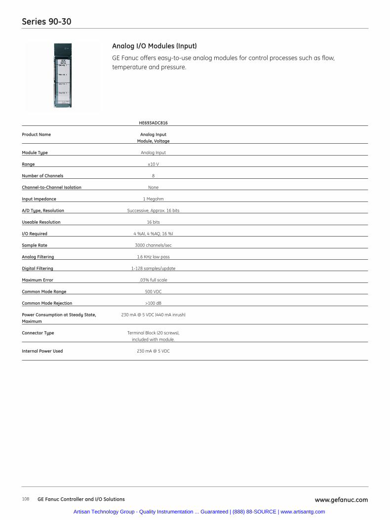
Series 90-30
108 www.gefanuc.com
GE Fanuc offers easy-to-use analog modules for control processes such as flow,temperature and pressure.
Analog I/O Modules (Input)
HE693ADC816
Product Name Analog InputModule, Voltage
Module Type Analog Input
Range ±10 V
Number of Channels 8
Channel-to-Channel Isolation None
Input Impedance 1 Megohm
A/D Type, Resolution Successive, Approx. 16 bits
Useable Resolution 16 bits
I/O Required 4 %AI, 4 %AQ, 16 %I
Sample Rate 3000 channels/sec
Analog Filtering 1.6 KHz low pass
Digital Filtering 1-128 samples/update
Maximum Error .03% full scale
Common Mode Range 500 VDC
Common Mode Rejection >100 dB
Power Consumption at Steady State, 230 mA @ 5 VDC (440 mA inrush)Maximum
Connector Type Terminal Block (20 screws), included with module.
Internal Power Used 230 mA @ 5 VDC
GE Fanuc Controller and I/O Solutions
Artisan Technology Group - Quality Instrumentation ... Guaranteed | (888) 88-SOURCE | www.artisantg.com
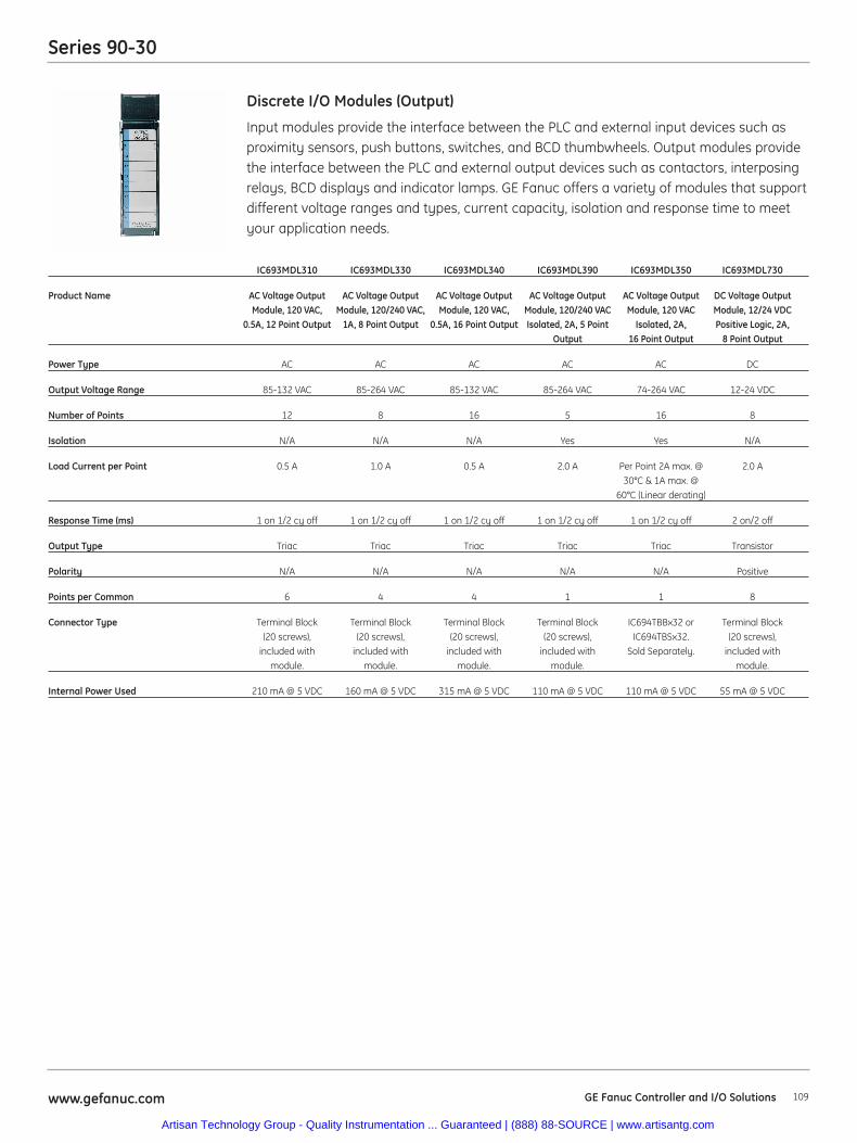
Series 90-30
109www.gefanuc.com
Input modules provide the interface between the PLC and external input devices such asproximity sensors, push buttons, switches, and BCD thumbwheels. Output modules providethe interface between the PLC and external output devices such as contactors, interposingrelays, BCD displays and indicator lamps. GE Fanuc offers a variety of modules that supportdifferent voltage ranges and types, current capacity, isolation and response time to meetyour application needs.
Discrete I/O Modules (Output)
IC693MDL310 IC693MDL330 IC693MDL340 IC693MDL390 IC693MDL350 IC693MDL730
Product Name AC Voltage Output AC Voltage Output AC Voltage Output AC Voltage Output AC Voltage Output DC Voltage OutputModule, 120 VAC, Module, 120/240 VAC, Module, 120 VAC, Module, 120/240 VAC Module, 120 VAC Module, 12/24 VDC
0.5A, 12 Point Output 1A, 8 Point Output 0.5A, 16 Point Output Isolated, 2A, 5 Point Isolated, 2A, Positive Logic, 2A,Output 16 Point Output 8 Point Output
Power Type AC AC AC AC AC DC
Output Voltage Range 85-132 VAC 85-264 VAC 85-132 VAC 85-264 VAC 74-264 VAC 12-24 VDC
Number of Points 12 8 16 5 16 8
Isolation N/A N/A N/A Yes Yes N/A
Load Current per Point 0.5 A 1.0 A 0.5 A 2.0 A Per Point 2A max. @ 2.0 A30°C & 1A max. @
60°C (Linear derating)
Response Time (ms) 1 on 1/2 cy off 1 on 1/2 cy off 1 on 1/2 cy off 1 on 1/2 cy off 1 on 1/2 cy off 2 on/2 off
Output Type Triac Triac Triac Triac Triac Transistor
Polarity N/A N/A N/A N/A N/A Positive
Points per Common 6 4 4 1 1 8
Connector Type Terminal Block Terminal Block Terminal Block Terminal Block IC694TBBx32 or Terminal Block(20 screws), (20 screws), (20 screws), (20 screws), IC694TBSx32. (20 screws),
included with included with included with included with Sold Separately. included withmodule. module. module. module. module.
Internal Power Used 210 mA @ 5 VDC 160 mA @ 5 VDC 315 mA @ 5 VDC 110 mA @ 5 VDC 110 mA @ 5 VDC 55 mA @ 5 VDC
GE Fanuc Controller and I/O Solutions
Artisan Technology Group - Quality Instrumentation ... Guaranteed | (888) 88-SOURCE | www.artisantg.com
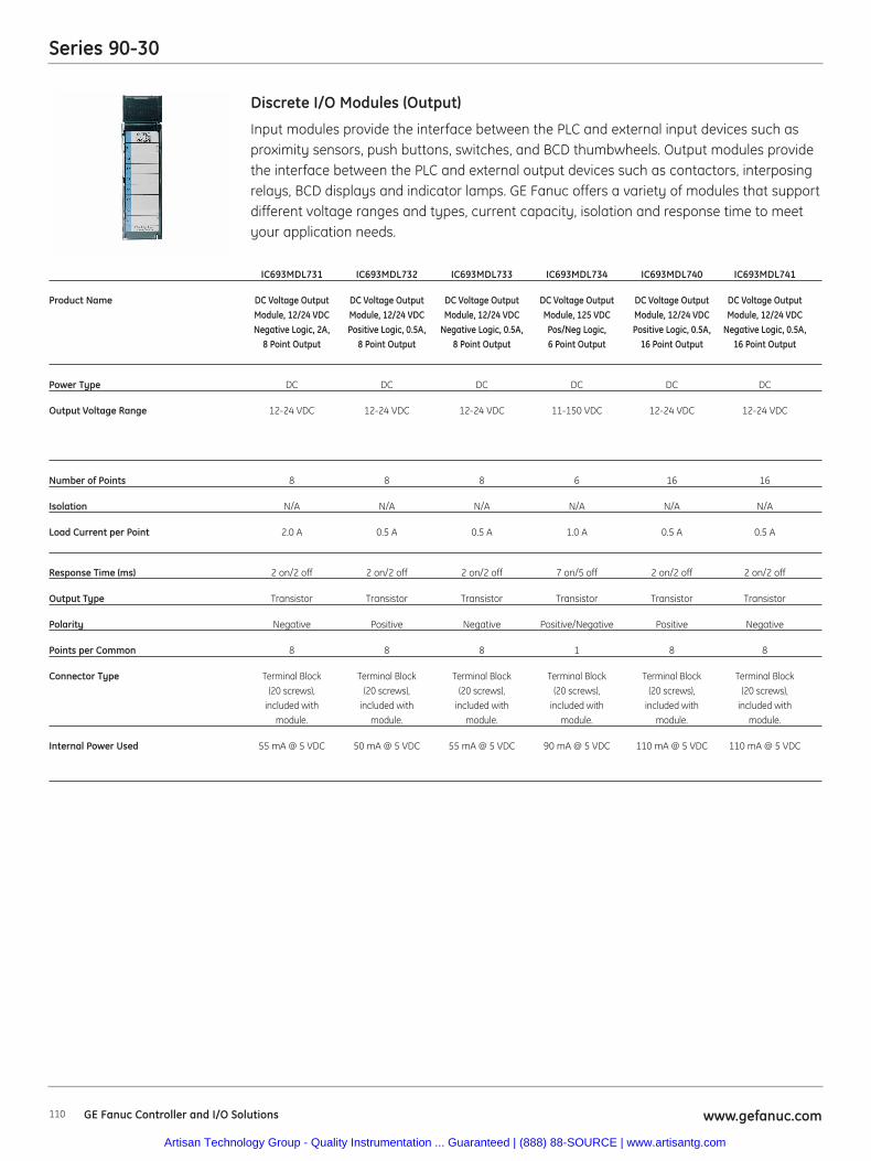
Series 90-30
110 www.gefanuc.com
Input modules provide the interface between the PLC and external input devices such asproximity sensors, push buttons, switches, and BCD thumbwheels. Output modules providethe interface between the PLC and external output devices such as contactors, interposingrelays, BCD displays and indicator lamps. GE Fanuc offers a variety of modules that supportdifferent voltage ranges and types, current capacity, isolation and response time to meetyour application needs.
Discrete I/O Modules (Output)
IC693MDL731 IC693MDL732 IC693MDL733 IC693MDL734 IC693MDL740 IC693MDL741
Product Name DC Voltage Output DC Voltage Output DC Voltage Output DC Voltage Output DC Voltage Output DC Voltage OutputModule, 12/24 VDC Module, 12/24 VDC Module, 12/24 VDC Module, 125 VDC Module, 12/24 VDC Module, 12/24 VDCNegative Logic, 2A, Positive Logic, 0.5A, Negative Logic, 0.5A, Pos/Neg Logic, Positive Logic, 0.5A, Negative Logic, 0.5A,
8 Point Output 8 Point Output 8 Point Output 6 Point Output 16 Point Output 16 Point Output
Power Type DC DC DC DC DC DC
Output Voltage Range 12-24 VDC 12-24 VDC 12-24 VDC 11-150 VDC 12-24 VDC 12-24 VDC
Number of Points 8 8 8 6 16 16
Isolation N/A N/A N/A N/A N/A N/A
Load Current per Point 2.0 A 0.5 A 0.5 A 1.0 A 0.5 A 0.5 A
Response Time (ms) 2 on/2 off 2 on/2 off 2 on/2 off 7 on/5 off 2 on/2 off 2 on/2 off
Output Type Transistor Transistor Transistor Transistor Transistor Transistor
Polarity Negative Positive Negative Positive/Negative Positive Negative
Points per Common 8 8 8 1 8 8
Connector Type Terminal Block Terminal Block Terminal Block Terminal Block Terminal Block Terminal Block(20 screws), (20 screws), (20 screws), (20 screws), (20 screws), (20 screws),
included with included with included with included with included with included withmodule. module. module. module. module. module.
Internal Power Used 55 mA @ 5 VDC 50 mA @ 5 VDC 55 mA @ 5 VDC 90 mA @ 5 VDC 110 mA @ 5 VDC 110 mA @ 5 VDC
GE Fanuc Controller and I/O Solutions
Artisan Technology Group - Quality Instrumentation ... Guaranteed | (888) 88-SOURCE | www.artisantg.com
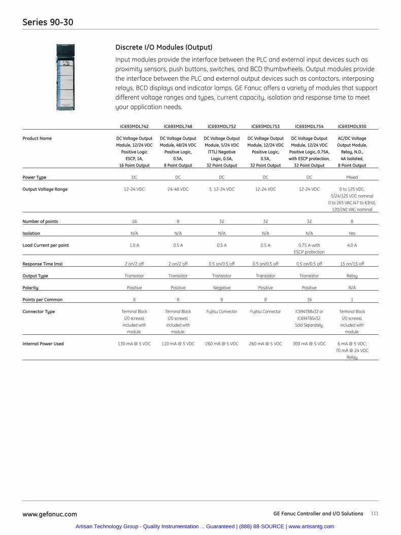
Series 90-30
111www.gefanuc.com
Input modules provide the interface between the PLC and external input devices such asproximity sensors, push buttons, switches, and BCD thumbwheels. Output modules providethe interface between the PLC and external output devices such as contactors, interposingrelays, BCD displays and indicator lamps. GE Fanuc offers a variety of modules that supportdifferent voltage ranges and types, current capacity, isolation and response time to meetyour application needs.
Discrete I/O Modules (Output)
IC693MDL742 IC693MDL748 IC693MDL752 IC693MDL753 IC693MDL754 IC693MDL930
Product Name DC Voltage Output DC Voltage Output DC Voltage Output DC Voltage Output DC Voltage Output AC/DC VoltageModule, 12/24 VDC Module, 48/24 VDC Module, 5/24 VDC Module, 12/24 VDC Module, 12/24 VDC Output Module,
Positive Logic Positive Logic, (TTL) Negative Positive Logic, Positive Logic, 0.75A, Relay, N.O.,ESCP, 1A, 0.5A, Logic, 0.5A, 0.5A, with ESCP protection, 4A Isolated,
16 Point Output 8 Point Output 32 Point Output 32 Point Output 32 Point Output 8 Point Output
Power Type DC DC DC DC DC Mixed
Output Voltage Range 12-24 VDC 24-48 VDC 5, 12-24 VDC 12-24 VDC 12-24 VDC 0 to 125 VDC, 5/24/125 VDC nominal
0 to 265 VAC (47 to 63Hz), 120/240 VAC nominal
Number of points 16 8 32 32 32 8
Isolation N/A N/A N/A N/A N/A Yes
Load Current per point 1.0 A 0.5 A 0.5 A 0.5 A 0.75 A with 4.0 AESCP protection
Response Time (ms) 2 on/2 off 2 on/2 off 0.5 on/0.5 off 0.5 on/0.5 off 0.5 on/0.5 off 15 on/15 off
Output Type Transistor Transistor Transistor Transistor Transistor Relay
Polarity Positive Positive Negative Positive Positive N/A
Points per Common 8 8 8 8 16 1
Connector Type Terminal Block Terminal Block Fujitsu Connector Fujitsu Connector IC694TBBx32 or Terminal Block(20 screws), (20 screws), IC694TBSx32. (20 screws),
included with included with Sold Separately. included with module. module. module.
Internal Power Used 130 mA @ 5 VDC 110 mA @ 5 VDC 260 mA @ 5 VDC 260 mA @ 5 VDC 300 mA @ 5 VDC 6 mA @ 5 VDC; 70 mA @ 24 VDC
Relay
GE Fanuc Controller and I/O Solutions
Artisan Technology Group - Quality Instrumentation ... Guaranteed | (888) 88-SOURCE | www.artisantg.com
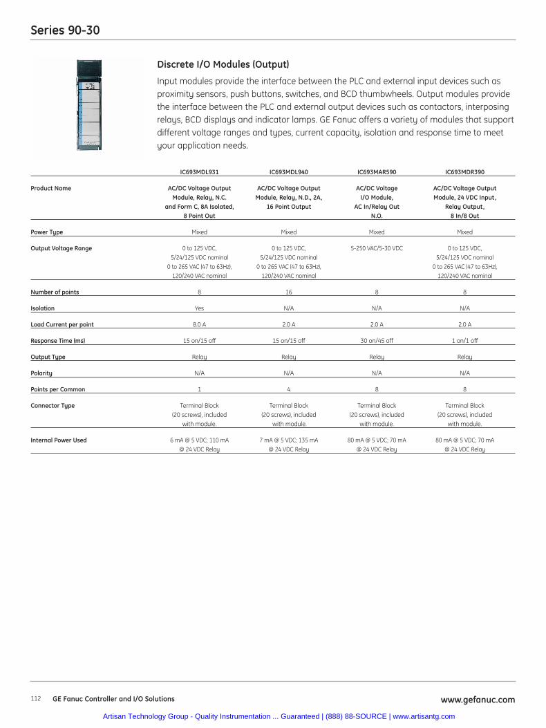
Series 90-30
112 www.gefanuc.com
Input modules provide the interface between the PLC and external input devices such asproximity sensors, push buttons, switches, and BCD thumbwheels. Output modules providethe interface between the PLC and external output devices such as contactors, interposingrelays, BCD displays and indicator lamps. GE Fanuc offers a variety of modules that supportdifferent voltage ranges and types, current capacity, isolation and response time to meetyour application needs.
Discrete I/O Modules (Output)
IC693MDL931 IC693MDL940 IC693MAR590 IC693MDR390
Product Name AC/DC Voltage Output AC/DC Voltage Output AC/DC Voltage AC/DC Voltage Output Module, Relay, N.C. Module, Relay, N.D., 2A, I/O Module, Module, 24 VDC Input,
and Form C, 8A Isolated, 16 Point Output AC In/Relay Out Relay Output, 8 Point Out N.O. 8 In/8 Out
Power Type Mixed Mixed Mixed Mixed
Output Voltage Range 0 to 125 VDC, 0 to 125 VDC, 5-250 VAC/5-30 VDC 0 to 125 VDC, 5/24/125 VDC nominal 5/24/125 VDC nominal 5/24/125 VDC nominal
0 to 265 VAC (47 to 63Hz), 0 to 265 VAC (47 to 63Hz), 0 to 265 VAC (47 to 63Hz),120/240 VAC nominal 120/240 VAC nominal 120/240 VAC nominal
Number of points 8 16 8 8
Isolation Yes N/A N/A N/A
Load Current per point 8.0 A 2.0 A 2.0 A 2.0 A
Response Time (ms) 15 on/15 off 15 on/15 off 30 on/45 off 1 on/1 off
Output Type Relay Relay Relay Relay
Polarity N/A N/A N/A N/A
Points per Common 1 4 8 8
Connector Type Terminal Block Terminal Block Terminal Block Terminal Block(20 screws), included (20 screws), included (20 screws), included (20 screws), included
with module. with module. with module. with module.
Internal Power Used 6 mA @ 5 VDC; 110 mA 7 mA @ 5 VDC; 135 mA 80 mA @ 5 VDC; 70 mA 80 mA @ 5 VDC; 70 mA@ 24 VDC Relay @ 24 VDC Relay @ 24 VDC Relay @ 24 VDC Relay
GE Fanuc Controller and I/O Solutions
Artisan Technology Group - Quality Instrumentation ... Guaranteed | (888) 88-SOURCE | www.artisantg.com
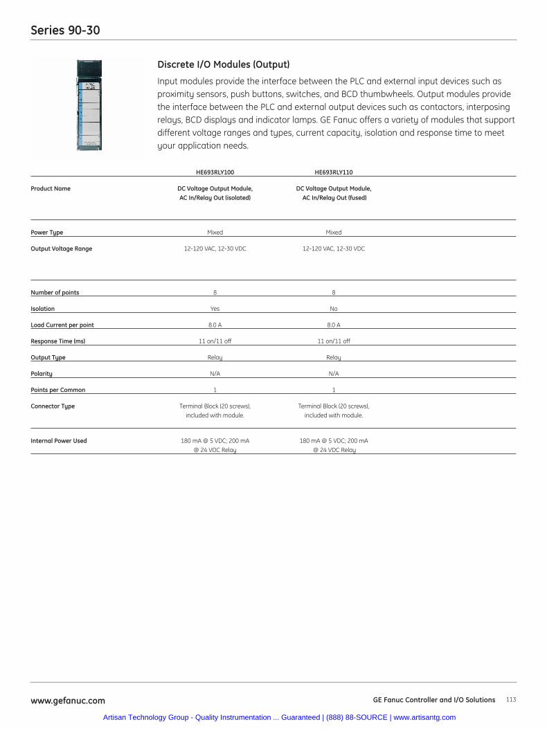
Series 90-30
113www.gefanuc.com
Input modules provide the interface between the PLC and external input devices such asproximity sensors, push buttons, switches, and BCD thumbwheels. Output modules providethe interface between the PLC and external output devices such as contactors, interposingrelays, BCD displays and indicator lamps. GE Fanuc offers a variety of modules that supportdifferent voltage ranges and types, current capacity, isolation and response time to meetyour application needs.
Discrete I/O Modules (Output)
HE693RLY100 HE693RLY110
Product Name DC Voltage Output Module, DC Voltage Output Module,AC In/Relay Out (isolated) AC In/Relay Out (fused)
Power Type Mixed Mixed
Output Voltage Range 12-120 VAC, 12-30 VDC 12-120 VAC, 12-30 VDC
Number of points 8 8
Isolation Yes No
Load Current per point 8.0 A 8.0 A
Response Time (ms) 11 on/11 off 11 on/11 off
Output Type Relay Relay
Polarity N/A N/A
Points per Common 1 1
Connector Type Terminal Block (20 screws), Terminal Block (20 screws), included with module. included with module.
Internal Power Used 180 mA @ 5 VDC; 200 mA 180 mA @ 5 VDC; 200 mA@ 24 VDC Relay @ 24 VDC Relay
GE Fanuc Controller and I/O Solutions
Artisan Technology Group - Quality Instrumentation ... Guaranteed | (888) 88-SOURCE | www.artisantg.com
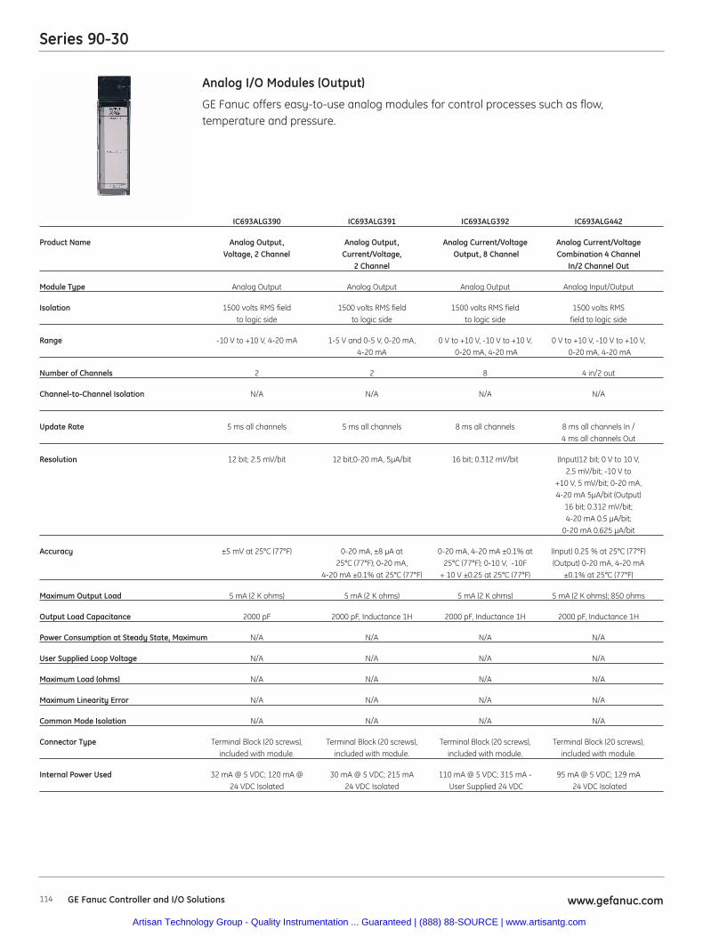
Series 90-30
114 www.gefanuc.comGE Fanuc Controller and I/O Solutions
GE Fanuc offers easy-to-use analog modules for control processes such as flow, temperature and pressure.
Analog I/O Modules (Output)
IC693ALG390 IC693ALG391 IC693ALG392 IC693ALG442
Product Name Analog Output, Analog Output, Analog Current/Voltage Analog Current/Voltage Voltage, 2 Channel Current/Voltage, Output, 8 Channel Combination 4 Channel
2 Channel In/2 Channel Out
Module Type Analog Output Analog Output Analog Output Analog Input/Output
Isolation 1500 volts RMS field 1500 volts RMS field 1500 volts RMS field 1500 volts RMSto logic side to logic side to logic side field to logic side
Range -10 V to +10 V, 4-20 mA 1-5 V and 0-5 V, 0-20 mA, 0 V to +10 V, -10 V to +10 V, 0 V to +10 V, -10 V to +10 V,4-20 mA 0-20 mA, 4-20 mA 0-20 mA, 4-20 mA
Number of Channels 2 2 8 4 in/2 out
Channel-to-Channel Isolation N/A N/A N/A N/A
Update Rate 5 ms all channels 5 ms all channels 8 ms all channels 8 ms all channels In /4 ms all channels Out
Resolution 12 bit; 2.5 mV/bit 12 bit;0-20 mA, 5μA/bit 16 bit; 0.312 mV/bit (Input)12 bit; 0 V to 10 V, 2.5 mV/bit; -10 V to
+10 V, 5 mV/bit; 0-20 mA,4-20 mA 5μA/bit (Output)
16 bit; 0.312 mV/bit; 4-20 mA 0.5 μA/bit;
0-20 mA 0.625 μA/bit
Accuracy ±5 mV at 25°C (77°F) 0-20 mA, ±8 μA at 0-20 mA, 4-20 mA ±0.1% at (Input) 0.25 % at 25°C (77°F) 25°C (77°F); 0-20 mA, 25°C (77°F); 0-10 V, -10F (Output) 0-20 mA, 4-20 mA
4-20 mA ±0.1% at 25°C (77°F) + 10 V ±0.25 at 25°C (77°F) ±0.1% at 25°C (77°F)
Maximum Output Load 5 mA (2 K ohms) 5 mA (2 K ohms) 5 mA (2 K ohms) 5 mA (2 K ohms); 850 ohms
Output Load Capacitance 2000 pF 2000 pF, Inductance 1H 2000 pF, Inductance 1H 2000 pF, Inductance 1H
Power Consumption at Steady State, Maximum N/A N/A N/A N/A
User Supplied Loop Voltage N/A N/A N/A N/A
Maximum Load (ohms) N/A N/A N/A N/A
Maximum Linearity Error N/A N/A N/A N/A
Common Mode Isolation N/A N/A N/A N/A
Connector Type Terminal Block (20 screws), Terminal Block (20 screws), Terminal Block (20 screws), Terminal Block (20 screws), included with module. included with module. included with module. included with module.
Internal Power Used 32 mA @ 5 VDC; 120 mA @ 30 mA @ 5 VDC; 215 mA 110 mA @ 5 VDC; 315 mA - 95 mA @ 5 VDC; 129 mA24 VDC Isolated 24 VDC Isolated User Supplied 24 VDC 24 VDC Isolated
Artisan Technology Group - Quality Instrumentation ... Guaranteed | (888) 88-SOURCE | www.artisantg.com
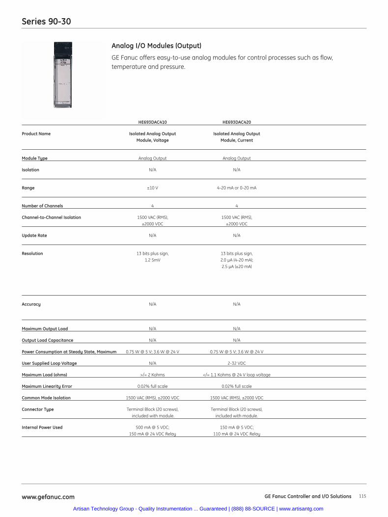
Series 90-30
115www.gefanuc.com
GE Fanuc offers easy-to-use analog modules for control processes such as flow, temperature and pressure.
Analog I/O Modules (Output)
HE693DAC410 HE693DAC420
Product Name Isolated Analog Output Isolated Analog OutputModule, Voltage Module, Current
Module Type Analog Output Analog Output
Isolation N/A N/A
Range ±10 V 4-20 mA or 0-20 mA
Number of Channels 4 4
Channel-to-Channel Isolation 1500 VAC (RMS), 1500 VAC (RMS), ±2000 VDC ±2000 VDC
Update Rate N/A N/A
Resolution 13 bits plus sign, 13 bits plus sign,1.2 5mV 2.0 μA (4-20 mA);
2.5 μA (±20 mA)
Accuracy N/A N/A
Maximum Output Load N/A N/A
Output Load Capacitance N/A N/A
Power Consumption at Steady State, Maximum 0.75 W @ 5 V; 3.6 W @ 24 V 0.75 W @ 5 V; 3.6 W @ 24 V
User Supplied Loop Voltage N/A 2-32 VDC
Maximum Load (ohms) >/= 2 Kohms </= 1.1 Kohms @ 24 V loop voltage
Maximum Linearity Error 0.02% full scale 0.02% full scale
Common Mode Isolation 1500 VAC (RMS), ±2000 VDC 1500 VAC (RMS), ±2000 VDC
Connector Type Terminal Block (20 screws), Terminal Block (20 screws), included with module. included with module.
Internal Power Used 500 mA @ 5 VDC; 150 mA @ 5 VDC; 150 mA @ 24 VDC Relay 110 mA @ 24 VDC Relay
GE Fanuc Controller and I/O Solutions
Artisan Technology Group - Quality Instrumentation ... Guaranteed | (888) 88-SOURCE | www.artisantg.com
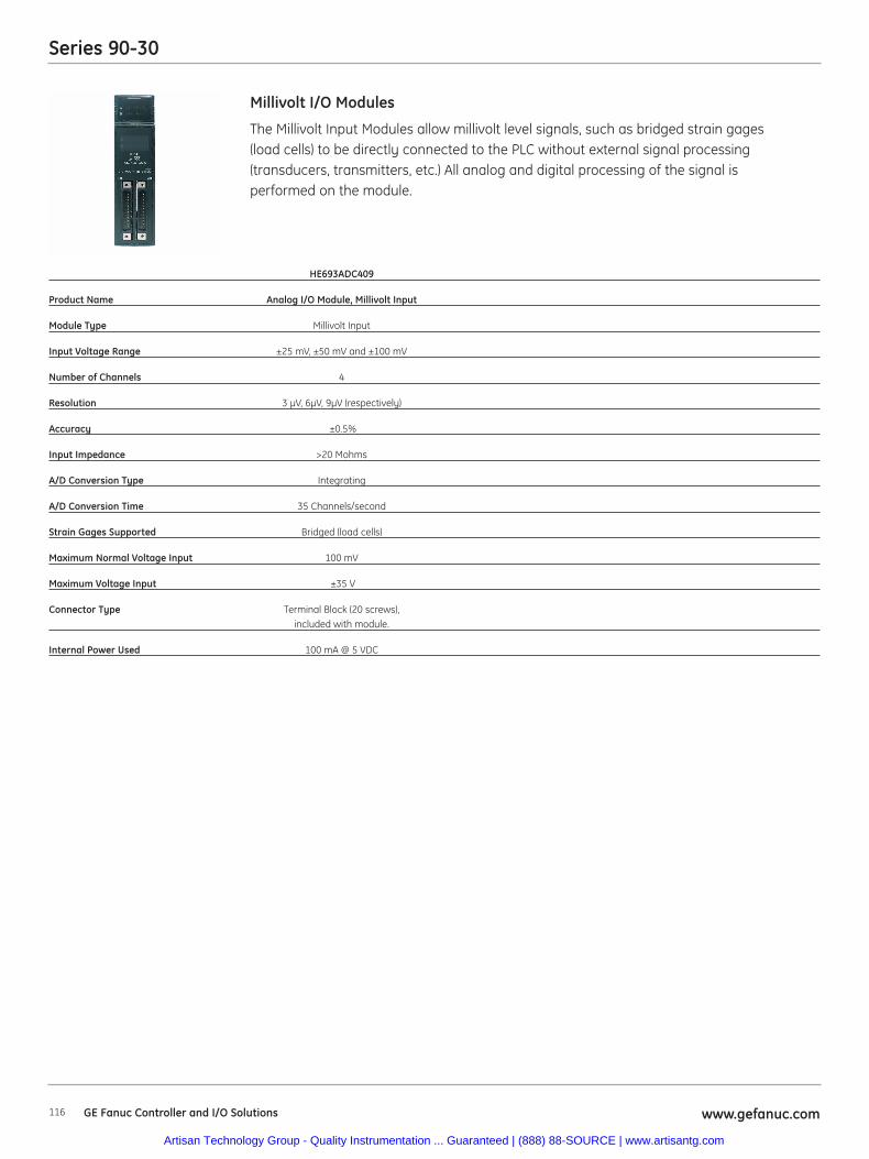
Series 90-30
116 www.gefanuc.comGE Fanuc Controller and I/O Solutions
The Millivolt Input Modules allow millivolt level signals, such as bridged strain gages (load cells) to be directly connected to the PLC without external signal processing(transducers, transmitters, etc.) All analog and digital processing of the signal isperformed on the module.
Millivolt I/O Modules
HE693ADC409
Product Name Analog I/O Module, Millivolt Input
Module Type Millivolt Input
Input Voltage Range ±25 mV, ±50 mV and ±100 mV
Number of Channels 4
Resolution 3 μV, 6μV, 9μV (respectively)
Accuracy ±0.5%
Input Impedance >20 Mohms
A/D Conversion Type Integrating
A/D Conversion Time 35 Channels/second
Strain Gages Supported Bridged (load cells)
Maximum Normal Voltage Input 100 mV
Maximum Voltage Input ±35 V
Connector Type Terminal Block (20 screws), included with module.
Internal Power Used 100 mA @ 5 VDC
Artisan Technology Group - Quality Instrumentation ... Guaranteed | (888) 88-SOURCE | www.artisantg.com
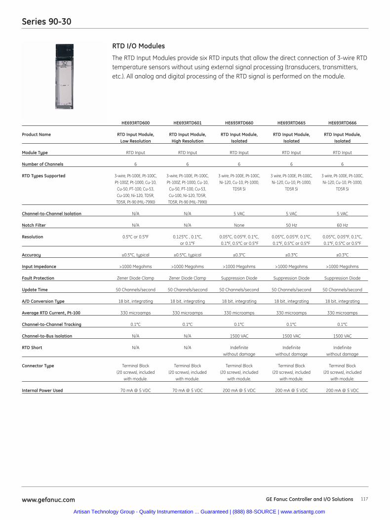
Series 90-30
117www.gefanuc.com
The RTD Input Modules provide six RTD inputs that allow the direct connection of 3-wire RTDtemperature sensors without using external signal processing (transducers, transmitters,etc.). All analog and digital processing of the RTD signal is performed on the module.
RTD I/O Modules
HE693RTD600 HE693RTD601 HE693RTD660 HE693RTD665 HE693RTD666
Product Name RTD Input Module, RTD Input Module, RTD Input Module, RTD Input Module, RTD Input Module, Low Resolution High Resolution Isolated Isolated Isolated
Module Type RTD Input RTD Input RTD Input RTD Input RTD Input
Number of Channels 6 6 6 6 6
RTD Types Supported 3-wire, Pt-100E, Pt-100C, 3-wire, Pt-100E, Pt-100C, 3 wire, Pt-100E, Pt-100C, 3 wire, Pt-100E, Pt-100C, 3 wire, Pt-100E, Pt-100C,Pt-100Z, Pt-1000, Cu-10, Pt-100Z, Pt-1000, Cu-10, Ni-120, Cu-10, Pt-1000, Ni-120, Cu-10, Pt-1000, Ni-120, Cu-10, Pt-1000,
Cu-50, PT-100, Cu-53, Cu-50, PT-100, Cu-53, TD5R Si TD5R Si TD5R Si Cu-100, Ni-120, TD5R, Cu-100, Ni-120, TD5R, TD5R, Pt-90 (MIL-7990) TD5R, Pt-90 (MIL-7990)
Channel-to-Channel Isolation N/A N/A 5 VAC 5 VAC 5 VAC
Notch Filter N/A N/A None 50 Hz 60 Hz
Resolution 0.5°C or 0.5°F 0.125°C , 0.1°C, 0.05°C, 0.05°F, 0.1°C, 0.05°C, 0.05°F, 0.1°C, 0.05°C, 0.05°F, 0.1°C,or 0.1°F 0.1°F, 0.5°C or 0.5°F 0.1°F, 0.5°C or 0.5°F 0.1°F, 0.5°C or 0.5°F
Accuracy ±0.5°C, typical ±0.5°C, typical ±0.3°C ±0.3°C ±0.3°C
Input Impedance >1000 Megohms >1000 Megohms >1000 Megohms >1000 Megohms >1000 Megohms
Fault Protection Zener Diode Clamp Zener Diode Clamp Suppression Diode Suppression Diode Suppression Diode
Update Time 50 Channels/second 50 Channels/second 50 Channels/second 50 Channels/second 50 Channels/second
A/D Conversion Type 18 bit, integrating 18 bit, integrating 18 bit, integrating 18 bit, integrating 18 bit, integrating
Average RTD Current, Pt-100 330 microamps 330 microamps 330 microamps 330 microamps 330 microamps
Channel-to-Channel Tracking 0.1°C 0.1°C 0.1°C 0.1°C 0.1°C
Channel-to-Bus Isolation N/A N/A 1500 VAC 1500 VAC 1500 VAC
RTD Short N/A N/A Indefinite Indefinite Indefinite without damage without damage without damage
Connector Type Terminal Block Terminal Block Terminal Block Terminal Block Terminal Block (20 screws), included (20 screws), included (20 screws), included (20 screws), included (20 screws), included
with module. with module. with module. with module. with module.
Internal Power Used 70 mA @ 5 VDC 70 mA @ 5 VDC 200 mA @ 5 VDC 200 mA @ 5 VDC 200 mA @ 5 VDC
GE Fanuc Controller and I/O Solutions
Artisan Technology Group - Quality Instrumentation ... Guaranteed | (888) 88-SOURCE | www.artisantg.com
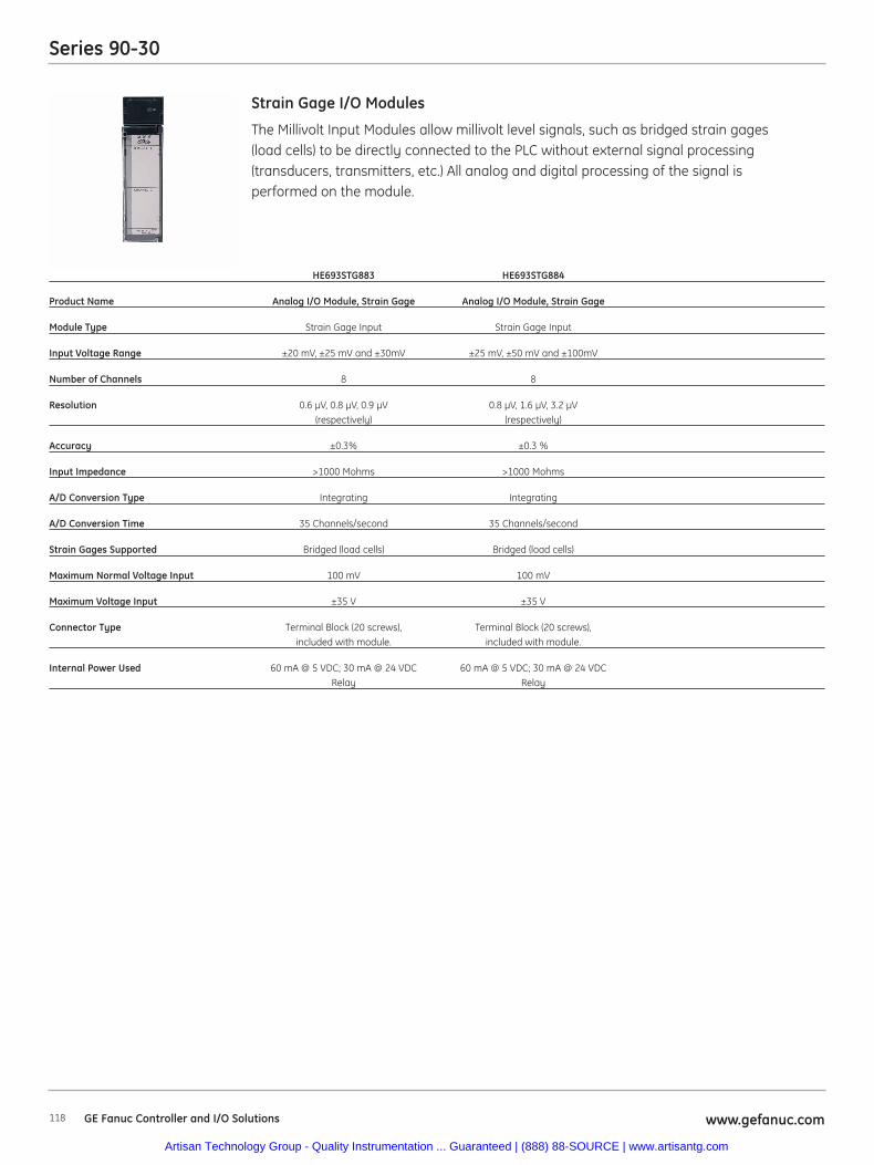
Series 90-30
118 www.gefanuc.comGE Fanuc Controller and I/O Solutions
The Millivolt Input Modules allow millivolt level signals, such as bridged strain gages(load cells) to be directly connected to the PLC without external signal processing(transducers, transmitters, etc.) All analog and digital processing of the signal isperformed on the module.
Strain Gage I/O Modules
HE693STG883 HE693STG884
Product Name Analog I/O Module, Strain Gage Analog I/O Module, Strain Gage
Module Type Strain Gage Input Strain Gage Input
Input Voltage Range ±20 mV, ±25 mV and ±30mV ±25 mV, ±50 mV and ±100mV
Number of Channels 8 8
Resolution 0.6 μV, 0.8 μV, 0.9 μV 0.8 μV, 1.6 μV, 3.2 μV(respectively) (respectively)
Accuracy ±0.3% ±0.3 %
Input Impedance >1000 Mohms >1000 Mohms
A/D Conversion Type Integrating Integrating
A/D Conversion Time 35 Channels/second 35 Channels/second
Strain Gages Supported Bridged (load cells) Bridged (load cells)
Maximum Normal Voltage Input 100 mV 100 mV
Maximum Voltage Input ±35 V ±35 V
Connector Type Terminal Block (20 screws), Terminal Block (20 screws),included with module. included with module.
Internal Power Used 60 mA @ 5 VDC; 30 mA @ 24 VDC 60 mA @ 5 VDC; 30 mA @ 24 VDCRelay Relay
Artisan Technology Group - Quality Instrumentation ... Guaranteed | (888) 88-SOURCE | www.artisantg.com
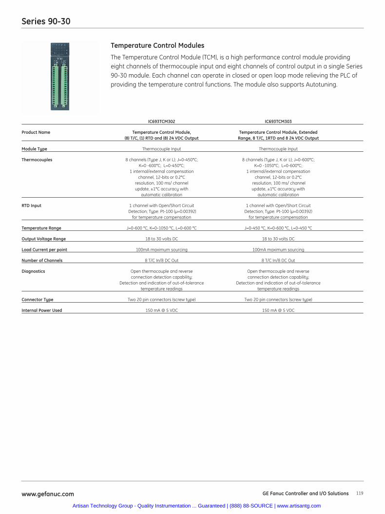
Series 90-30
119www.gefanuc.com
The Temperature Control Module (TCM), is a high performance control module providingeight channels of thermocouple input and eight channels of control output in a single Series90-30 module. Each channel can operate in closed or open loop mode relieving the PLC ofproviding the temperature control functions. The module also supports Autotuning.
Temperature Control Modules
IC693TCM302 IC693TCM303
Product Name Temperature Control Module, Temperature Control Module, Extended(8) T/C, (1) RTD and (8) 24 VDC Output Range, 8 T/C, 1RTD and 8 24 VDC Output
Module Type Thermocouple Input Thermocouple Input
Thermocouples 8 channels (Type J, K or L); J=0-450°C; 8 channels (Type J, K or L); J=0-600°C;K=0 -600°C; L=0-450°C; K=0 -1050°C; L=0-600°C;
1 internal/external compensation 1 internal/external compensation channel, 12-bits or 0.2°C channel, 12-bits or 0.2°C
resolution, 100 ms/ channel resolution, 100 ms/ channel update, ±1°C accuracy with update, ±1°C accuracy with
automatic calibration automatic calibration
RTD Input 1 channel with Open/Short Circuit 1 channel with Open/Short Circuit Detection; Type: Pt-100 (μ=0.00392) Detection; Type: Pt-100 (μ=0.00392)
for temperature compensation for temperature compensation
Temperature Range J=0-600 °C, K=0-1050 °C, L=0-600 °C J=0-450 °C, K=0-600 °C, L=0-450 °C
Output Voltage Range 18 to 30 volts DC 18 to 30 volts DC
Load Current per point 100mA maximum sourcing 100mA maximum sourcing
Number of Channels 8 T/C In/8 DC Out 8 T/C In/8 DC Out
Diagnostics Open thermocouple and reverse Open thermocouple and reverse connection detection capability; connection detection capability;
Detection and indication of out-of-tolerance Detection and indication of out-of-tolerance temperature readings temperature readings
Connector Type Two 20 pin connectors (screw type) Two 20 pin connectors (screw type)
Internal Power Used 150 mA @ 5 VDC 150 mA @ 5 VDC
GE Fanuc Controller and I/O Solutions
Artisan Technology Group - Quality Instrumentation ... Guaranteed | (888) 88-SOURCE | www.artisantg.com
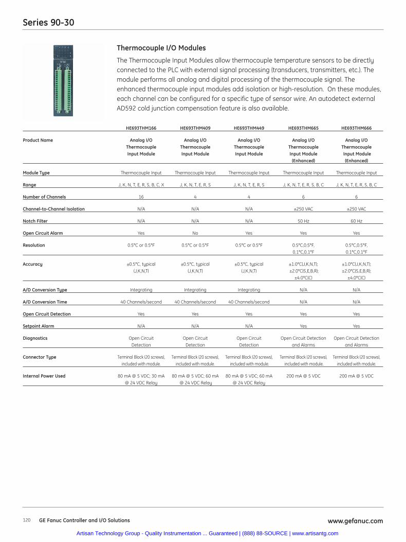
Series 90-30
120 www.gefanuc.comGE Fanuc Controller and I/O Solutions
HE693THM166 HE693THM409 HE693THM449 HE693THM665 HE693THM666
Product Name Analog I/O Analog I/O Analog I/O Analog I/O Analog I/O Thermocouple Thermocouple Thermocouple Thermocouple ThermocoupleInput Module Input Module Input Module Input Module Input Module
(Enhanced) (Enhanced)
Module Type Thermocouple Input Thermocouple Input Thermocouple Input Thermocouple Input Thermocouple Input
Range J, K, N, T, E, R, S, B, C, X J, K, N, T, E, R, S J, K, N, T, E, R, S J, K, N, T, E, R, S, B, C J, K, N, T, E, R, S, B, C
Number of Channels 16 4 4 6 6
Channel-to-Channel Isolation N/A N/A N/A ±250 VAC ±250 VAC
Notch Filter N/A N/A N/A 50 Hz 60 Hz
Open Circuit Alarm Yes No Yes Yes Yes
Resolution 0.5°C or 0.5°F 0.5°C or 0.5°F 0.5°C or 0.5°F 0.5°C,0.5°F, 0.5°C,0.5°F,0.1°C,0.1°F 0.1°C,0.1°F
Accuracy ±0.5°C, typical ±0.5°C, typical ±0.5°C, typical ±1.0°C(J,K,N,T); ±1.0°C(J,K,N,T);(J,K,N,T) (J,K,N,T) (J,K,N,T) ±2.0°C(S,E,B,R); ±2.0°C(S,E,B,R);
±4.0°C(C) ±4.0°C(C)
A/D Conversion Type Integrating Integrating Integrating N/A N/A
A/D Conversion Time 40 Channels/second 40 Channels/second 40 Channels/second N/A N/A
Open Circuit Detection Yes Yes Yes Yes Yes
Setpoint Alarm N/A N/A N/A Yes Yes
Diagnostics Open Circuit Open Circuit Open Circuit Open Circuit Detection Open Circuit DetectionDetection Detection Detection and Alarms and Alarms
Connector Type Terminal Block (20 screws), Terminal Block (20 screws), Terminal Block (20 screws), Terminal Block (20 screws), Terminal Block (20 screws), included with module. included with module. included with module. included with module. included with module.
Internal Power Used 80 mA @ 5 VDC; 30 mA 80 mA @ 5 VDC; 60 mA 80 mA @ 5 VDC; 60 mA 200 mA @ 5 VDC 200 mA @ 5 VDC@ 24 VDC Relay @ 24 VDC Relay @ 24 VDC Relay
The Thermocouple Input Modules allow thermocouple temperature sensors to be directlyconnected to the PLC with external signal processing (transducers, transmitters, etc.). Themodule performs all analog and digital processing of the thermocouple signal. Theenhanced thermocouple input modules add isolation or high-resolution. On these modules,each channel can be configured for a specific type of sensor wire. An autodetect externalAD592 cold junction compensation feature is also available.
Thermocouple I/O Modules
Artisan Technology Group - Quality Instrumentation ... Guaranteed | (888) 88-SOURCE | www.artisantg.com
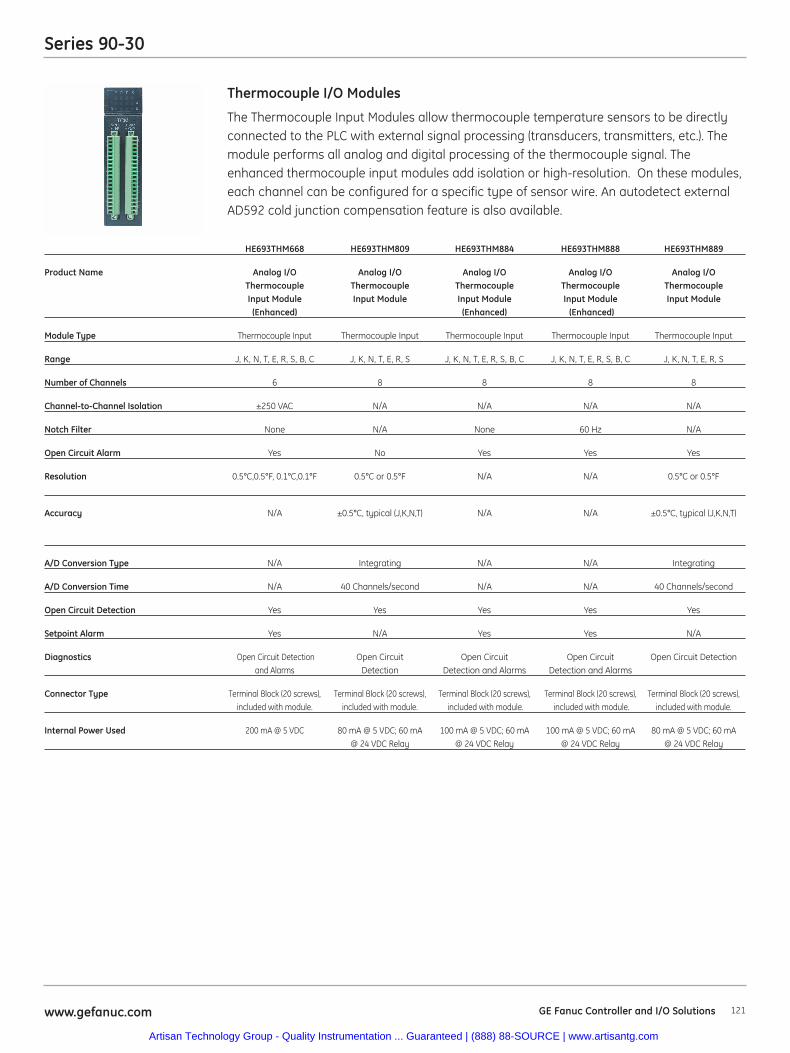
Series 90-30
121www.gefanuc.com
The Thermocouple Input Modules allow thermocouple temperature sensors to be directlyconnected to the PLC with external signal processing (transducers, transmitters, etc.). Themodule performs all analog and digital processing of the thermocouple signal. Theenhanced thermocouple input modules add isolation or high-resolution. On these modules,each channel can be configured for a specific type of sensor wire. An autodetect externalAD592 cold junction compensation feature is also available.
Thermocouple I/O Modules
HE693THM668 HE693THM809 HE693THM884 HE693THM888 HE693THM889
Product Name Analog I/O Analog I/O Analog I/O Analog I/O Analog I/OThermocouple Thermocouple Thermocouple Thermocouple Thermocouple Input Module Input Module Input Module Input Module Input Module
(Enhanced) (Enhanced) (Enhanced)
Module Type Thermocouple Input Thermocouple Input Thermocouple Input Thermocouple Input Thermocouple Input
Range J, K, N, T, E, R, S, B, C J, K, N, T, E, R, S J, K, N, T, E, R, S, B, C J, K, N, T, E, R, S, B, C J, K, N, T, E, R, S
Number of Channels 6 8 8 8 8
Channel-to-Channel Isolation ±250 VAC N/A N/A N/A N/A
Notch Filter None N/A None 60 Hz N/A
Open Circuit Alarm Yes No Yes Yes Yes
Resolution 0.5°C,0.5°F, 0.1°C,0.1°F 0.5°C or 0.5°F N/A N/A 0.5°C or 0.5°F
Accuracy N/A ±0.5°C, typical (J,K,N,T) N/A N/A ±0.5°C, typical (J,K,N,T)
A/D Conversion Type N/A Integrating N/A N/A Integrating
A/D Conversion Time N/A 40 Channels/second N/A N/A 40 Channels/second
Open Circuit Detection Yes Yes Yes Yes Yes
Setpoint Alarm Yes N/A Yes Yes N/A
Diagnostics Open Circuit Detection Open Circuit Open Circuit Open Circuit Open Circuit Detectionand Alarms Detection Detection and Alarms Detection and Alarms
Connector Type Terminal Block (20 screws), Terminal Block (20 screws), Terminal Block (20 screws), Terminal Block (20 screws), Terminal Block (20 screws), included with module. included with module. included with module. included with module. included with module.
Internal Power Used 200 mA @ 5 VDC 80 mA @ 5 VDC; 60 mA 100 mA @ 5 VDC; 60 mA 100 mA @ 5 VDC; 60 mA 80 mA @ 5 VDC; 60 mA@ 24 VDC Relay @ 24 VDC Relay @ 24 VDC Relay @ 24 VDC Relay
GE Fanuc Controller and I/O Solutions
Artisan Technology Group - Quality Instrumentation ... Guaranteed | (888) 88-SOURCE | www.artisantg.com
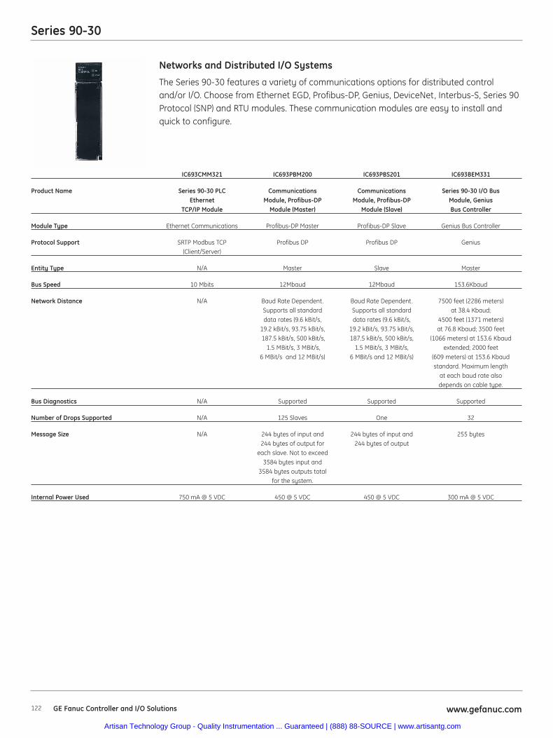
Series 90-30
122 www.gefanuc.comGE Fanuc Controller and I/O Solutions
The Series 90-30 features a variety of communications options for distributed controland/or I/O. Choose from Ethernet EGD, Profibus-DP, Genius, DeviceNet, Interbus-S, Series 90Protocol (SNP) and RTU modules. These communication modules are easy to install andquick to configure.
Networks and Distributed I/O Systems
IC693CMM321 IC693PBM200 IC693PBS201 IC693BEM331
Product Name Series 90-30 PLC Communications Communications Series 90-30 I/O Bus Ethernet Module, Profibus-DP Module, Profibus-DP Module, Genius
TCP/IP Module Module (Master) Module (Slave) Bus Controller
Module Type Ethernet Communications Profibus-DP Master Profibus-DP Slave Genius Bus Controller
Protocol Support SRTP Modbus TCP Profibus DP Profibus DP Genius(Client/Server)
Entity Type N/A Master Slave Master
Bus Speed 10 Mbits 12Mbaud 12Mbaud 153.6Kbaud
Network Distance N/A Baud Rate Dependent. Baud Rate Dependent. 7500 feet (2286 meters) Supports all standard Supports all standard at 38.4 Kbaud;data rates (9.6 kBit/s, data rates (9.6 kBit/s, 4500 feet (1371 meters)
19.2 kBit/s, 93.75 kBit/s, 19.2 kBit/s, 93.75 kBit/s, at 76.8 Kbaud; 3500 feet 187.5 kBit/s, 500 kBit/s, 187.5 kBit/s, 500 kBit/s, (1066 meters) at 153.6 Kbaud
1.5 MBit/s, 3 MBit/s, 1.5 MBit/s, 3 MBit/s, extended; 2000 feet 6 MBit/s and 12 MBit/s) 6 MBit/s and 12 MBit/s) (609 meters) at 153.6 Kbaud
standard. Maximum length at each baud rate also depends on cable type.
Bus Diagnostics N/A Supported Supported Supported
Number of Drops Supported N/A 125 Slaves One 32
Message Size N/A 244 bytes of input and 244 bytes of input and 255 bytes244 bytes of output for 244 bytes of output
each slave. Not to exceed 3584 bytes input and
3584 bytes outputs total for the system.
Internal Power Used 750 mA @ 5 VDC 450 @ 5 VDC 450 @ 5 VDC 300 mA @ 5 VDC
Artisan Technology Group - Quality Instrumentation ... Guaranteed | (888) 88-SOURCE | www.artisantg.com
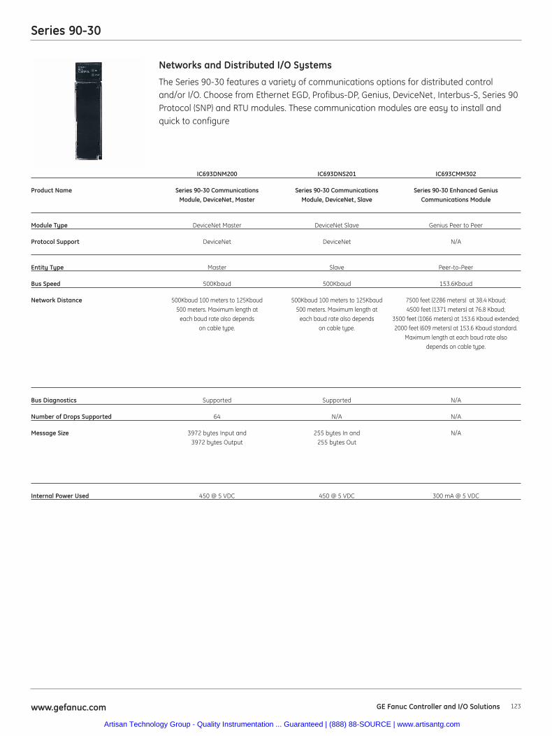
The Series 90-30 features a variety of communications options for distributed controland/or I/O. Choose from Ethernet EGD, Profibus-DP, Genius, DeviceNet, Interbus-S, Series 90Protocol (SNP) and RTU modules. These communication modules are easy to install andquick to configure
Networks and Distributed I/O Systems
Series 90-30
123www.gefanuc.com GE Fanuc Controller and I/O Solutions
IC693DNM200 IC693DNS201 IC693CMM302
Product Name Series 90-30 Communications Series 90-30 Communications Series 90-30 Enhanced Genius Module, DeviceNet, Master Module, DeviceNet, Slave Communications Module
Module Type DeviceNet Master DeviceNet Slave Genius Peer to Peer
Protocol Support DeviceNet DeviceNet N/A
Entity Type Master Slave Peer-to-Peer
Bus Speed 500Kbaud 500Kbaud 153.6Kbaud
Network Distance 500Kbaud 100 meters to 125Kbaud 500Kbaud 100 meters to 125Kbaud 7500 feet (2286 meters) at 38.4 Kbaud; 500 meters. Maximum length at 500 meters. Maximum length at 4500 feet (1371 meters) at 76.8 Kbaud;
each baud rate also depends each baud rate also depends 3500 feet (1066 meters) at 153.6 Kbaud extended;on cable type. on cable type. 2000 feet (609 meters) at 153.6 Kbaud standard.
Maximum length at each baud rate alsodepends on cable type.
Bus Diagnostics Supported Supported N/A
Number of Drops Supported 64 N/A N/A
Message Size 3972 bytes Input and 255 bytes In and N/A3972 bytes Output 255 bytes Out
Internal Power Used 450 @ 5 VDC 450 @ 5 VDC 300 mA @ 5 VDC
Artisan Technology Group - Quality Instrumentation ... Guaranteed | (888) 88-SOURCE | www.artisantg.com

Series 90-30
124 www.gefanuc.comGE Fanuc Controller and I/O Solutions
The Series 90-30 features a variety of communications options for distributed controland/or I/O. Choose from Ethernet EGD, Profibus-DP, Genius, DeviceNet, Interbus-S, Series 90Protocol (SNP) and RTU modules. These communication modules are easy to install andquick to configure
Networks and Distributed I/O Systems
IC693BEM320 IC693BEM321 HE693IBS100 HE693IBS313 HE693IBS323
Product Name Series 90-30 Series 90-30 I/O Bus Module, I/O Bus Module, I/O Bus Module,Communication, Communication, Interbus-S Slave Interbus-S Slave Interbus-S SlaveI/O Link Interface I/O Link Interface Module from 5 Slot Rack from 10 Slot Rack from
Module (Slave) Module (Master) Horner Electric Horner Electric Horner Electric
Module Type I/O Link I/O Link Interbus-S Slave Module Interbus-S Slave Base Interbus-S Slave Base
Protocol Support N/A N/A Interbus S Interbus S Interbus S
Entity Type Slave Master Slave Slave Slave
Bus Speed 1.5 mHz 1.5 mHz N/A N/A N/A
Network Distance 10 meters (33 feet) 10 meters (33 feet) 500 Kbits @ 500 Kbits @ 500 Kbits @RS-485; 200 meters RS-485; 200 meters 400 meters 400 meters 400 meters
(660 feet) (660 feet) Fiber optic bus Fiber optic bus
Bus Diagnostics N/A N/A Supported Supported Supported
Number of Drops Supported N/A N/A 256 Drops 256 Drops 256 Drops
Message Size N/A N/A N/A N/A N/A
Internal Power Used 205 mA @ 5 VDC 415 mA @ 5 VDC N/A N/A N/A
Artisan Technology Group - Quality Instrumentation ... Guaranteed | (888) 88-SOURCE | www.artisantg.com
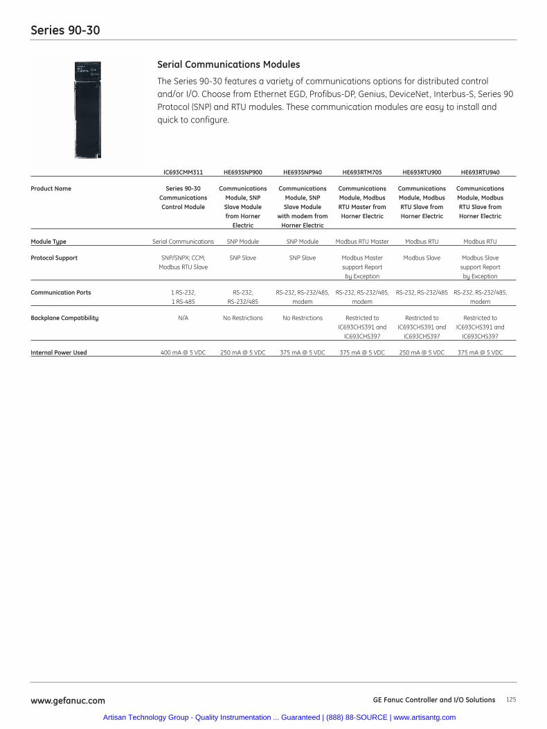
The Series 90-30 features a variety of communications options for distributed controland/or I/O. Choose from Ethernet EGD, Profibus-DP, Genius, DeviceNet, Interbus-S, Series 90Protocol (SNP) and RTU modules. These communication modules are easy to install andquick to configure.
Serial Communications Modules
IC693CMM311 HE693SNP900 HE693SNP940 HE693RTM705 HE693RTU900 HE693RTU940
Product Name Series 90-30 Communications Communications Communications Communications CommunicationsCommunications Module, SNP Module, SNP Module, Modbus Module, Modbus Module, ModbusControl Module Slave Module Slave Module RTU Master from RTU Slave from RTU Slave from
from Horner with modem from Horner Electric Horner Electric Horner ElectricElectric Horner Electric
Module Type Serial Communications SNP Module SNP Module Modbus RTU Master Modbus RTU Modbus RTU
Protocol Support SNP/SNPX; CCM; SNP Slave SNP Slave Modbus Master Modbus Slave Modbus Slave Modbus RTU Slave support Report support Report
by Exception by Exception
Communication Ports 1 RS-232, RS-232, RS-232, RS-232/485, RS-232, RS-232/485, RS-232, RS-232/485 RS-232, RS-232/485,1 RS-485 RS-232/485 modem modem modem
Backplane Compatibility N/A No Restrictions No Restrictions Restricted to Restricted to Restricted toIC693CHS391 and IC693CHS391 and IC693CHS391 and
IC693CHS397 IC693CHS397 IC693CHS397
Internal Power Used 400 mA @ 5 VDC 250 mA @ 5 VDC 375 mA @ 5 VDC 375 mA @ 5 VDC 250 mA @ 5 VDC 375 mA @ 5 VDC
Series 90-30
125www.gefanuc.com GE Fanuc Controller and I/O Solutions
Artisan Technology Group - Quality Instrumentation ... Guaranteed | (888) 88-SOURCE | www.artisantg.com
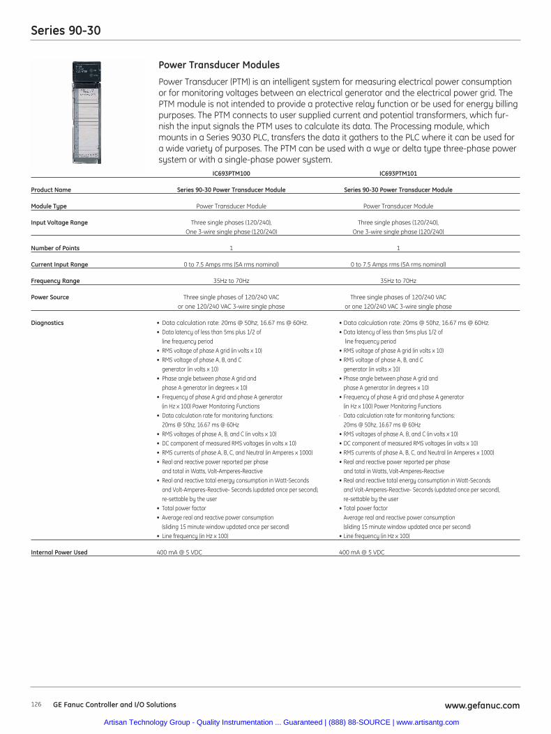
Series 90-30
126 www.gefanuc.comGE Fanuc Controller and I/O Solutions
Power Transducer (PTM) is an intelligent system for measuring electrical power consumptionor for monitoring voltages between an electrical generator and the electrical power grid. ThePTM module is not intended to provide a protective relay function or be used for energy billingpurposes. The PTM connects to user supplied current and potential transformers, which fur-nish the input signals the PTM uses to calculate its data. The Processing module, whichmounts in a Series 9030 PLC, transfers the data it gathers to the PLC where it can be used fora wide variety of purposes. The PTM can be used with a wye or delta type three-phase powersystem or with a single-phase power system.
Power Transducer Modules
IC693PTM100 IC693PTM101
Product Name Series 90-30 Power Transducer Module Series 90-30 Power Transducer Module
Module Type Power Transducer Module Power Transducer Module
Input Voltage Range Three single phases (120/240), Three single phases (120/240), One 3-wire single phase (120/240) One 3-wire single phase (120/240)
Number of Points 1 1
Current Input Range 0 to 7.5 Amps rms (5A rms nominal) 0 to 7.5 Amps rms (5A rms nominal)
Frequency Range 35Hz to 70Hz 35Hz to 70Hz
Power Source Three single phases of 120/240 VAC Three single phases of 120/240 VAC or one 120/240 VAC 3-wire single phase or one 120/240 VAC 3-wire single phase
Diagnostics • Data calculation rate: 20ms @ 50hz, 16.67 ms @ 60Hz. • Data calculation rate: 20ms @ 50hz, 16.67 ms @ 60Hz.• Data latency of less than 5ms plus 1/2 of • Data latency of less than 5ms plus 1/2 of
line frequency period line frequency period• RMS voltage of phase A grid (in volts x 10) • RMS voltage of phase A grid (in volts x 10)• RMS voltage of phase A, B, and C • RMS voltage of phase A, B, and C
generator (in volts x 10) generator (in volts x 10)• Phase angle between phase A grid and • Phase angle between phase A grid and
phase A generator (in degrees x 10) phase A generator (in degrees x 10)• Frequency of phase A grid and phase A generator • Frequency of phase A grid and phase A generator
(in Hz x 100) Power Monitoring Functions (in Hz x 100) Power Monitoring Functions• Data calculation rate for monitoring functions: · Data calculation rate for monitoring functions:
20ms @ 50hz, 16.67 ms @ 60Hz 20ms @ 50hz, 16.67 ms @ 60Hz• RMS voltages of phase A, B, and C (in volts x 10) • RMS voltages of phase A, B, and C (in volts x 10)• DC component of measured RMS voltages (in volts x 10) • DC component of measured RMS voltages (in volts x 10)• RMS currents of phase A, B, C, and Neutral (in Amperes x 1000) • RMS currents of phase A, B, C, and Neutral (in Amperes x 1000)• Real and reactive power reported per phase • Real and reactive power reported per phase
and total in Watts, Volt-Amperes-Reactive and total in Watts, Volt-Amperes-Reactive• Real and reactive total energy consumption in Watt-Seconds • Real and reactive total energy consumption in Watt-Seconds
and Volt-Amperes-Reactive- Seconds (updated once per second), and Volt-Amperes-Reactive- Seconds (updated once per second), re-settable by the user re-settable by the user
• Total power factor • Total power factor• Average real and reactive power consumption Average real and reactive power consumption
(sliding 15 minute window updated once per second) (sliding 15 minute window updated once per second)• Line frequency (in Hz x 100) • Line frequency (in Hz x 100)
Internal Power Used 400 mA @ 5 VDC 400 mA @ 5 VDC
Artisan Technology Group - Quality Instrumentation ... Guaranteed | (888) 88-SOURCE | www.artisantg.com
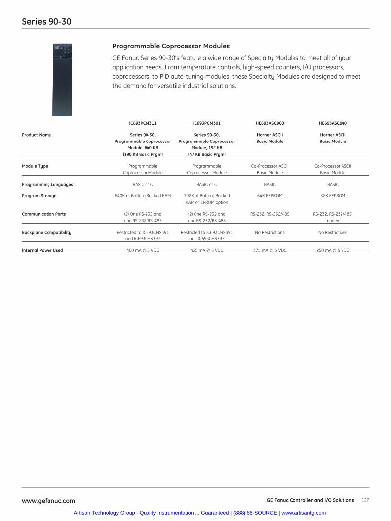
Series 90-30
127www.gefanuc.com
GE Fanuc Series 90-30's feature a wide range of Specialty Modules to meet all of yourapplication needs. From temperature controls, high-speed counters, I/O processors,coprocessors, to PID auto-tuning modules, these Specialty Modules are designed to meetthe demand for versatile industrial solutions.
Programmable Coprocessor Modules
IC693PCM311 IC693PCM301 HE693ASC900 HE693ASC940
Product Name Series 90-30, Series 90-30, Horner ASCII Horner ASCII Programmable Coprocessor Programmable Coprocessor Basic Module Basic Module
Module, 640 KB Module, 192 KB(190 KB Basic Prgm) (47 KB Basic Prgm)
Module Type Programmable Programmable Co-Processor ASCII Co-Processor ASCII Coprocessor Module Coprocessor Module Basic Module Basic Module
Programming Languages BASIC or C BASIC or C BASIC BASIC
Program Storage 640K of Battery Backed RAM 192K of Battery Backed 64K EEPROM 32K EEPROMRAM or EPROM option
Communication Ports (2) One RS-232 and (2) One RS-232 and RS-232, RS-232/485 RS-232, RS-232/485, one RS-232/RS-485 one RS-232/RS-485 modem
Backplane Compatibility Restricted to IC693CHS391 Restricted to IC693CHS391 No Restrictions No Restrictionsand IC693CHS397 and IC693CHS397
Internal Power Used 400 mA @ 5 VDC 425 mA @ 5 VDC 375 mA @ 5 VDC 250 mA @ 5 VDC
GE Fanuc Controller and I/O Solutions
Artisan Technology Group - Quality Instrumentation ... Guaranteed | (888) 88-SOURCE | www.artisantg.com
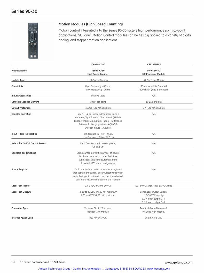
Series 90-30
128 www.gefanuc.comGE Fanuc Controller and I/O Solutions
Motion control integrated into the Series 90-30 fosters high performance point-to-pointapplications. GE Fanuc Motion Control modules can be flexibly applied to a variety of digital,analog, and stepper motion applications.
Motion Modules (High Speed Counting)
IC693APU300 IC693APU305
Product Name Series 90-30 Series 90-30 High Speed Counter I/O Processor Module
Module Type High Speed Counter I/O Processor Module
Count Rate High Frequency - 80 kHz; 30 khz (Absolute Encoder)Low Frequency - 20 Hz 200 khz (A Quad B Encoder)
Input/Output Type Positive Logic N/A
Off State Leakage Current 10 μA per point 10 μA per point
Output Protection 3 Amp Fuse for all points 5 A Fuse for all points
Counter Operation Type A - Up or Down-Independent Pulse-4 N/Acounters; Type B - Both Directions-A QUAD B
Encoder Inputs-2 Counters; Type C - DifferenceBetween 2 changing values-A QUAD B
Encoder Inputs -1 Counter
Input Filters (Selectable) High Frequency Filter - 2.5 μS; N/ALow Frequency Filter - 12.5 ms
Selectable On/Off Output Presets Each Counter has 2 present points, N/AOn and Off
Counters per Timebase Each counter stores the number of counts N/Athat have occurred in a specified time. A timebase value measurement from
1 ms to 65535 ms is configurable.
Strobe Register Each counter has one or more strobe registers N/Athat capture the current accumulator value when a strobe input transition in the direction selected
during the last configuration of the module.
Local Fast Inputs (12) 5 VDC or 10 to 30 VDC (12) 8.0 VDC (non–TTL), 1.5 VDC (TTL)
Local Fast Outputs (4) 10 to 30 VDC @ 500 mA maximum Continuous Output Current 4.75 to 6 VDC @ 20 mA maximum (10–30 VDC supply)
1.0 A (each output 1–4)0.5 A (each output 5–8)
Connector Type Terminal Block (20 screws), Terminal Block (20 screws), included with module. included with module.
Internal Power Used 250 mA @ 5 VDC 360 mA @ 5 VDC
Artisan Technology Group - Quality Instrumentation ... Guaranteed | (888) 88-SOURCE | www.artisantg.com
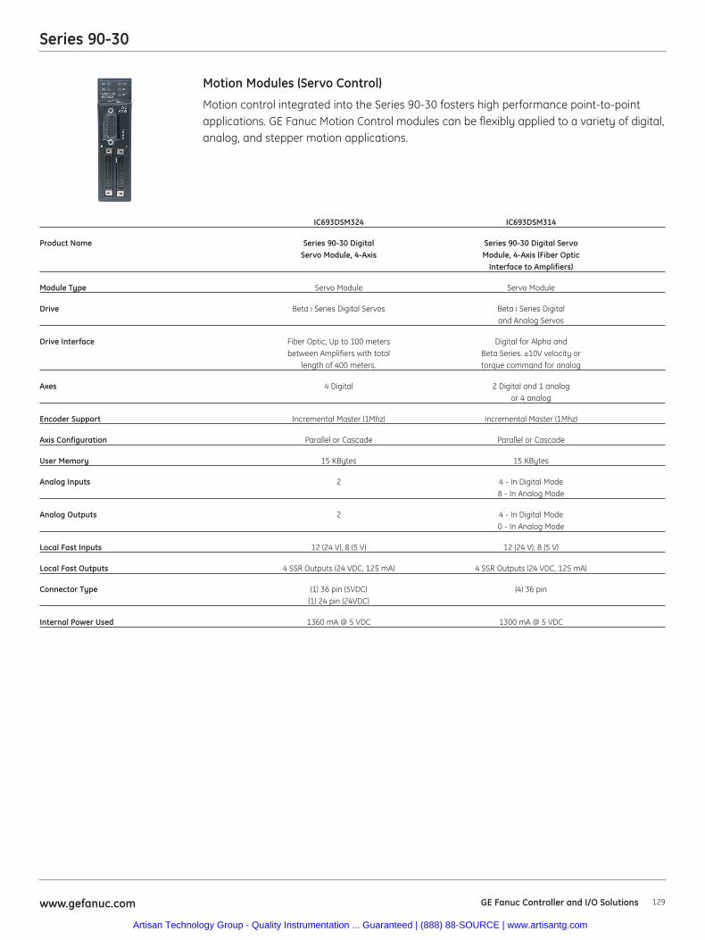
Series 90-30
129www.gefanuc.com
Motion control integrated into the Series 90-30 fosters high performance point-to-pointapplications. GE Fanuc Motion Control modules can be flexibly applied to a variety of digital,analog, and stepper motion applications.
Motion Modules (Servo Control)
IC693DSM324 IC693DSM314
Product Name Series 90-30 Digital Series 90-30 Digital Servo Servo Module, 4-Axis Module, 4-Axis (Fiber Optic
Interface to Amplifiers)
Module Type Servo Module Servo Module
Drive Beta i Series Digital Servos Beta i Series Digital and Analog Servos
Drive Interface Fiber Optic, Up to 100 meters Digital for Alpha and between Amplifiers with total Beta Series. ±10V velocity or
length of 400 meters. torque command for analog
Axes 4 Digital 2 Digital and 1 analog or 4 analog
Encoder Support Incremental Master (1Mhz) Incremental Master (1Mhz)
Axis Configuration Parallel or Cascade Parallel or Cascade
User Memory 15 KBytes 15 KBytes
Analog Inputs 2 4 - In Digital Mode8 - In Analog Mode
Analog Outputs 2 4 - In Digital Mode0 - In Analog Mode
Local Fast Inputs 12 (24 V), 8 (5 V) 12 (24 V), 8 (5 V)
Local Fast Outputs 4 SSR Outputs (24 VDC, 125 mA) 4 SSR Outputs (24 VDC, 125 mA)
Connector Type (1) 36 pin (5VDC) (4) 36 pin(1) 24 pin (24VDC)
Internal Power Used 1360 mA @ 5 VDC 1300 mA @ 5 VDC
GE Fanuc Controller and I/O Solutions
Artisan Technology Group - Quality Instrumentation ... Guaranteed | (888) 88-SOURCE | www.artisantg.com
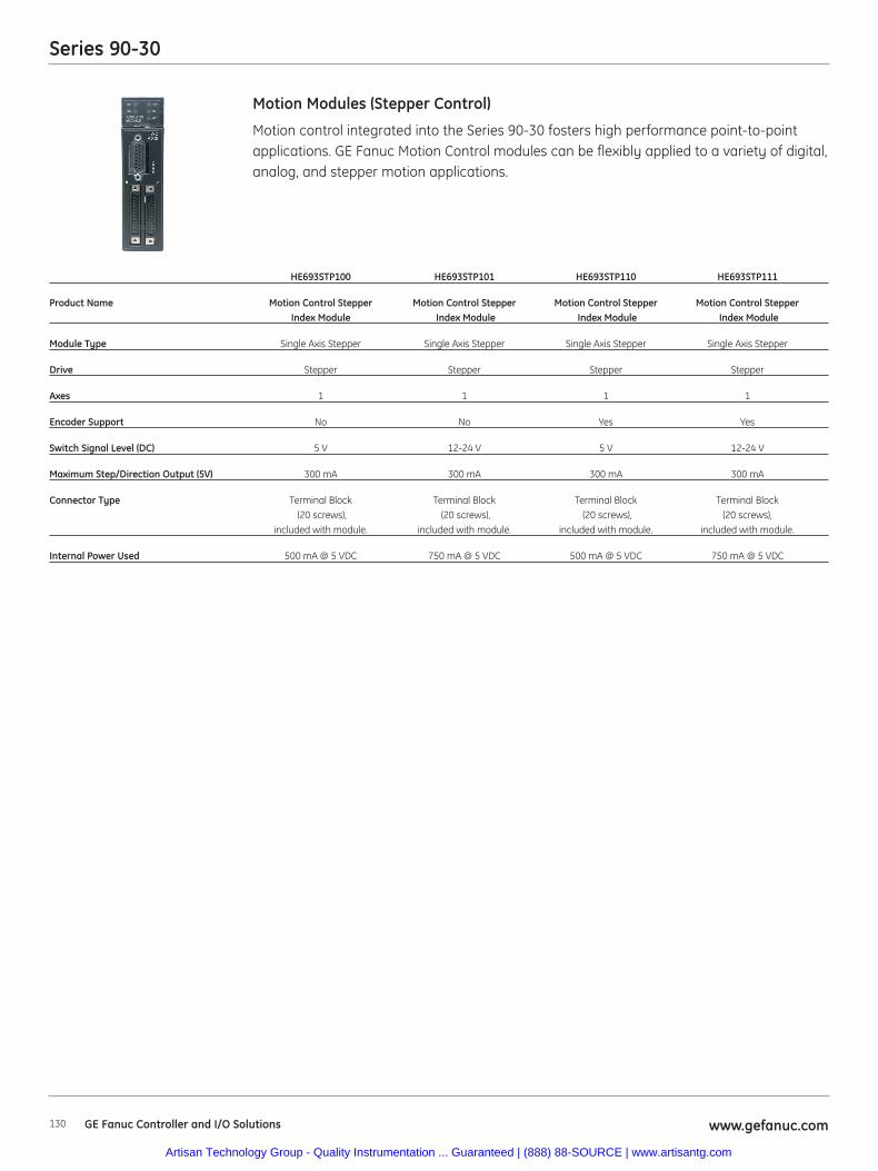
Series 90-30
130 www.gefanuc.comGE Fanuc Controller and I/O Solutions
Motion control integrated into the Series 90-30 fosters high performance point-to-pointapplications. GE Fanuc Motion Control modules can be flexibly applied to a variety of digital,analog, and stepper motion applications.
Motion Modules (Stepper Control)
HE693STP100 HE693STP101 HE693STP110 HE693STP111
Product Name Motion Control Stepper Motion Control Stepper Motion Control Stepper Motion Control StepperIndex Module Index Module Index Module Index Module
Module Type Single Axis Stepper Single Axis Stepper Single Axis Stepper Single Axis Stepper
Drive Stepper Stepper Stepper Stepper
Axes 1 1 1 1
Encoder Support No No Yes Yes
Switch Signal Level (DC) 5 V 12-24 V 5 V 12-24 V
Maximum Step/Direction Output (5V) 300 mA 300 mA 300 mA 300 mA
Connector Type Terminal Block Terminal Block Terminal Block Terminal Block (20 screws), (20 screws), (20 screws), (20 screws),
included with module. included with module. included with module. included with module.
Internal Power Used 500 mA @ 5 VDC 750 mA @ 5 VDC 500 mA @ 5 VDC 750 mA @ 5 VDC
Artisan Technology Group - Quality Instrumentation ... Guaranteed | (888) 88-SOURCE | www.artisantg.com
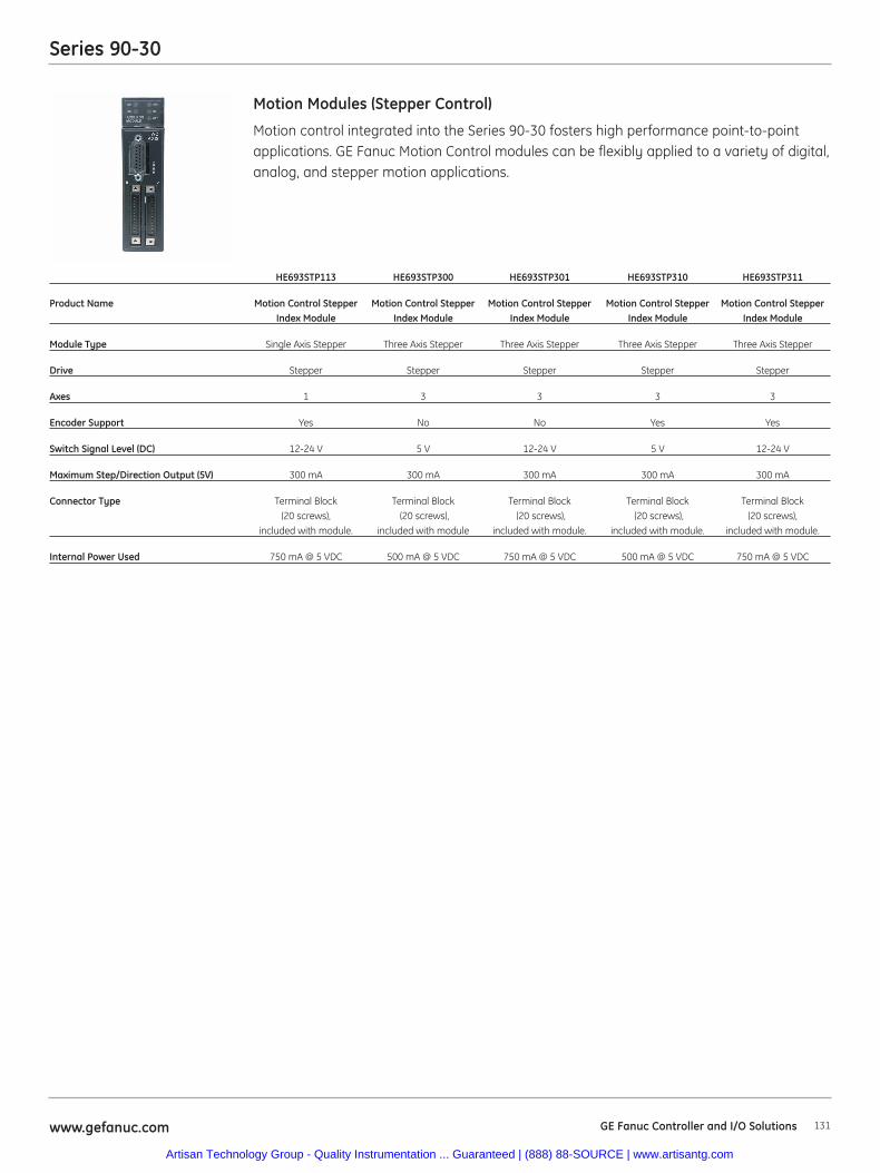
Series 90-30
131www.gefanuc.com
Motion control integrated into the Series 90-30 fosters high performance point-to-pointapplications. GE Fanuc Motion Control modules can be flexibly applied to a variety of digital,analog, and stepper motion applications.
Motion Modules (Stepper Control)
HE693STP113 HE693STP300 HE693STP301 HE693STP310 HE693STP311
Product Name Motion Control Stepper Motion Control Stepper Motion Control Stepper Motion Control Stepper Motion Control Stepper Index Module Index Module Index Module Index Module Index Module
Module Type Single Axis Stepper Three Axis Stepper Three Axis Stepper Three Axis Stepper Three Axis Stepper
Drive Stepper Stepper Stepper Stepper Stepper
Axes 1 3 3 3 3
Encoder Support Yes No No Yes Yes
Switch Signal Level (DC) 12-24 V 5 V 12-24 V 5 V 12-24 V
Maximum Step/Direction Output (5V) 300 mA 300 mA 300 mA 300 mA 300 mA
Connector Type Terminal Block Terminal Block Terminal Block Terminal Block Terminal Block(20 screws), (20 screws), (20 screws), (20 screws), (20 screws),
included with module. included with module included with module. included with module. included with module.
Internal Power Used 750 mA @ 5 VDC 500 mA @ 5 VDC 750 mA @ 5 VDC 500 mA @ 5 VDC 750 mA @ 5 VDC
GE Fanuc Controller and I/O Solutions
Artisan Technology Group - Quality Instrumentation ... Guaranteed | (888) 88-SOURCE | www.artisantg.com
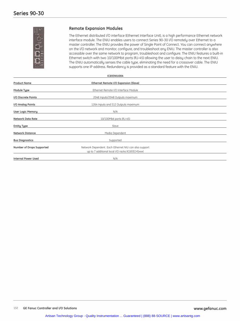
Series 90-30
132 www.gefanuc.comGE Fanuc Controller and I/O Solutions
The Ethernet distributed I/O interface (Ethernet Interface Unit), is a high performance Ethernet networkinterface module. The ENIU enables users to connect Series 90-30 I/O remotely over Ethernet to amaster controller. The ENIU provides the power of Single Point of Connect. You can connect anywhereon the I/O network and monitor, configure, and troubleshoot any ENIU. The master controller is alsoaccessible over the same network to program, troubleshoot and configure. The ENIU features a built-inEthernet switch with two 10/100Mbit ports (RJ-45) allowing the user to daisy chain to the next ENIU.The ENIU automatically senses the cable type, eliminating the need for a crossover cable. The ENIUsupports one IP address. Redundancy is provided as a standard feature with the ENIU.
Remote Expansion Modules
IC693NIU004
Product Name Ethernet Remote I/O Expansion (Slave)
Module Type Ethernet Remote I/O Interface Module
I/O Discrete Points 2048 Inputs/2048 Outputs maximum
I/O Analog Points 1264 Inputs and 512 Outputs maximum
User Logic Memory N/A
Network Data Rate 10/100Mbit ports (RJ-45)
Entity Type Slave
Network Distance Media Dependent
Bus Diagnostics Supported
Number of Drops Supported Network Dependent. Each Ethernet NIU can also supportup to 7 additional local I/O racks (IC693CHSxxx)
Internal Power Used N/A
Artisan Technology Group - Quality Instrumentation ... Guaranteed | (888) 88-SOURCE | www.artisantg.com
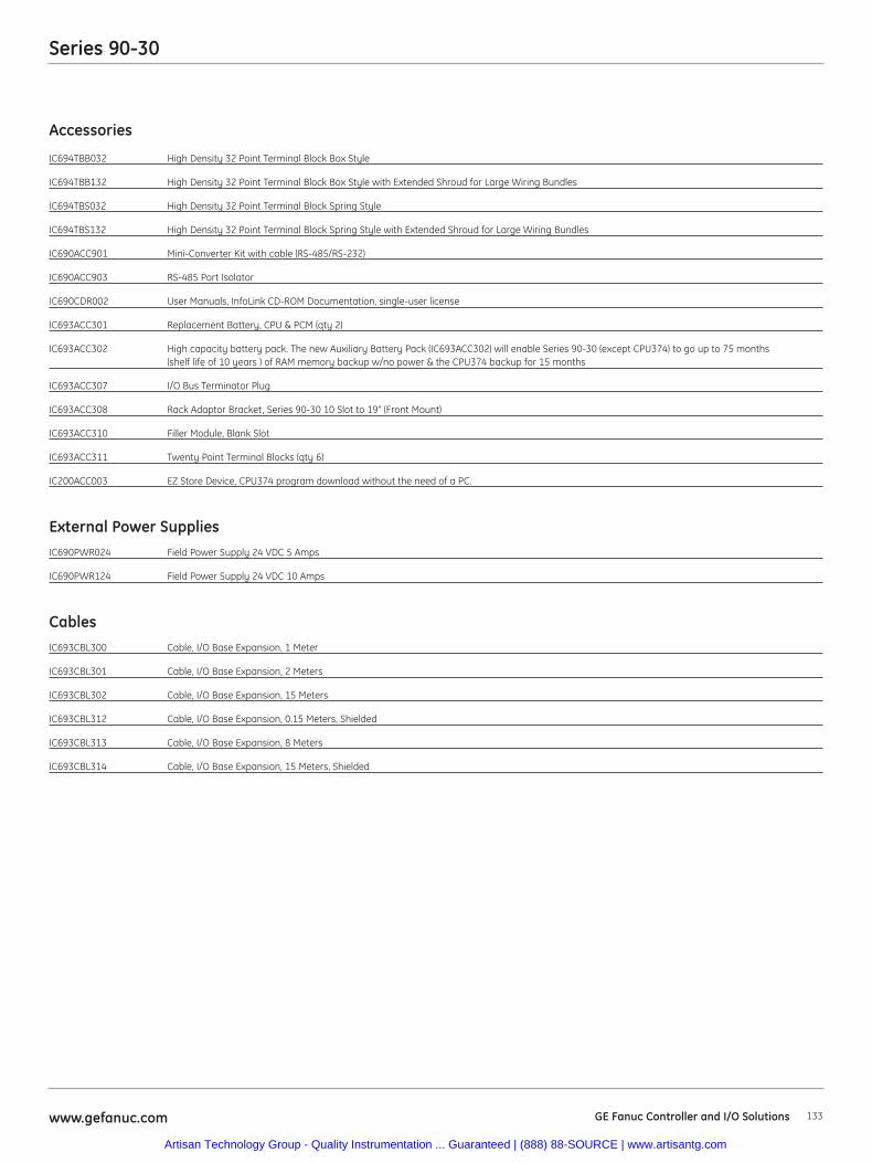
Series 90-30
133www.gefanuc.com
Accessories
IC694TBB032 High Density 32 Point Terminal Block Box Style
IC694TBB132 High Density 32 Point Terminal Block Box Style with Extended Shroud for Large Wiring Bundles
IC694TBS032 High Density 32 Point Terminal Block Spring Style
IC694TBS132 High Density 32 Point Terminal Block Spring Style with Extended Shroud for Large Wiring Bundles
IC690ACC901 Mini-Converter Kit with cable (RS-485/RS-232)
IC690ACC903 RS-485 Port Isolator
IC690CDR002 User Manuals, InfoLink CD-ROM Documentation, single-user license
IC693ACC301 Replacement Battery, CPU & PCM (qty 2)
IC693ACC302 High capacity battery pack. The new Auxiliary Battery Pack (IC693ACC302) will enable Series 90-30 (except CPU374) to go up to 75 months (shelf life of 10 years ) of RAM memory backup w/no power & the CPU374 backup for 15 months
IC693ACC307 I/O Bus Terminator Plug
IC693ACC308 Rack Adaptor Bracket, Series 90-30 10 Slot to 19" (Front Mount)
IC693ACC310 Filler Module, Blank Slot
IC693ACC311 Twenty Point Terminal Blocks (qty 6)
IC200ACC003 EZ Store Device, CPU374 program download without the need of a PC.
External Power SuppliesIC690PWR024 Field Power Supply 24 VDC 5 Amps
IC690PWR124 Field Power Supply 24 VDC 10 Amps
CablesIC693CBL300 Cable, I/O Base Expansion, 1 Meter
IC693CBL301 Cable, I/O Base Expansion, 2 Meters
IC693CBL302 Cable, I/O Base Expansion, 15 Meters
IC693CBL312 Cable, I/O Base Expansion, 0.15 Meters, Shielded
IC693CBL313 Cable, I/O Base Expansion, 8 Meters
IC693CBL314 Cable, I/O Base Expansion, 15 Meters, Shielded
GE Fanuc Controller and I/O Solutions
Artisan Technology Group - Quality Instrumentation ... Guaranteed | (888) 88-SOURCE | www.artisantg.com
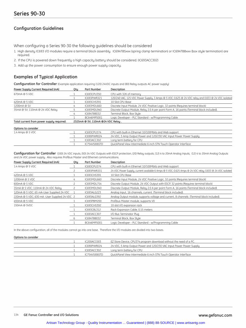
Series 90-30
134 www.gefanuc.comGE Fanuc Controller and I/O Solutions
Configuration Guidelines
When configuring a Series 90-30 the following guidelines should be considered1. High density IC693 I/O modules require a terminal block assembly. IC694TBSxxx (spring clamp termination) or IC694TBBxxx (box style termination) are
required.
2. If the CPU is powered down frequently a high capacity battery should be considered. (IC693ACC302)
3. Add up the power consumption to ensure enough power supply capacity.
Examples of Typical ApplicationConfiguration for Controller (Example application requiring (120) 24VDC inputs and (80) Relay outputs AC power supply)
Power Supply Current Required (mA) Qty Part Number Description
670mA @ 5 VDC 1 IC693CPU350 CPU with 32K of memory1 IC693PWR321 120/240 VAC, 125 VDC Power Supply, 3 Amps @ 5 VDC; 0.625 @ 24 VDC relay and 0.833 @ 24 VDC isolated
420mA @ 5 VDC 1 IC693CHS391 10 Slot CPU Base1200mA @ 5V 4 IC693MDL660 Discrete Input Module, 24 VDC Positive Logic, 32 points (Requires terminal block)35mA @ 5V; 110mA @ 24 VDC Relay 5 IC693MDL940 Discrete Output Module, Relay 2.0 A per point Form A, 16 points (Terminal block included).
4 IC694TBB032 Terminal Block, Box Style1 BC646MPS001 Logic Developer - PLC Standard - w/Programming Cable
Total current from power supply required: 2325mA @ 5V; 110mA @24 VDC Relay .
Options to consider1.4 Amps @ 5 VDC 1 IC693CPU374 CPU with built-in Ethernet 10/100Mbits and Web support
1 IC690PWR024 24 VDC, 5 Amp Output Power and 120/230 VAC Input Power Power Supply1 IC693ACC302 Long term battery for CPU1 IC754VSI06STD QuickPanel View Intermediate 6 inch STN Touch Operator Interface
Configuration for Controller (100) 24 VDC inputs, (50) 24 VDC Outputs with ESCP protection, (20) Relay outputs, (12) 4 to 20mA Analog Inputs, (12) 4 to 20mA Analog Outputsand 24 VDC power supply. Also requires Profibus Master and Ethernet communications.
Power Supply Current Required (mA) Qty Part Number Description1.4 Amps @ 5 VDC 1 IC693CPU374 CPU with built-in Ethernet 10/100Mbits and Web support
2 IC693PWR331 24 VDC Power Supply, current available 6 Amps @ 5 VDC; 0.625 Amps @ 24 VDC relay; 0.833 @ 24 VDC isolated
420mA @ 5 VDC 1 IC693CHS391 10 Slot CPU Base
1200mA @ 5 VDC 4 IC693MDL660 Discrete Input Module, 24 VDC Positive Logic, 32 points (Requires terminal block)
600mA @ 5 VDC 2 IC693MDL754 Discrete Output Module, 24 VDC Output with ESCP, 32 points (Requires terminal block)
35mA @ 5 VDC; 110mA @ 24 VDC Relay 2 IC693MDL940 Discrete Output Module, Relay 2.0 A per point Form A, 16 points (Terminal block included).
120mA @ 5 VDC; 65 mA-User Supplied 24 VDC 1 IC693ALG223 Analog Input, 16 channels, current. (Terminal block included).
220mA @ 5 VDC; 630 mA -User Supplied 24 VDC 2 IC693ALG392 Analog Output module, supports voltage and current, 8 channels (Terminal block included).
450mA @ 5 VDC 1 IC693PBM200 Profibus Master module, supports V0
150mA @ 5VDC 1 IC693CHS392 10 slot I/O expansion rack
1 IC693CBL312 Rack Expansion Cable, 0.15 meters
1 IC693ACC307 I/O Bus Terminator Plug
6 IC694TBB032 Terminal Block, Box Style
1 BC646MPS001 Logic Developer - PLC Standard - w/Programming Cable
In the above configuration, all of the modules cannot go into one base. Therefore the I/O modules are divided into two bases.
Options to consider1 IC200ACC003 EZ Store Device, CPU374 program download without the need of a PC.
1 IC690PWR024 24 VDC, 5 Amp Output Power and 120/230 VAC Input Power Power Supply
1 IC693ACC302 Long term battery for CPU
1 IC754VSI06STD QuickPanel View Intermediate 6 inch STN Touch Operator Interface
Artisan Technology Group - Quality Instrumentation ... Guaranteed | (888) 88-SOURCE | www.artisantg.com
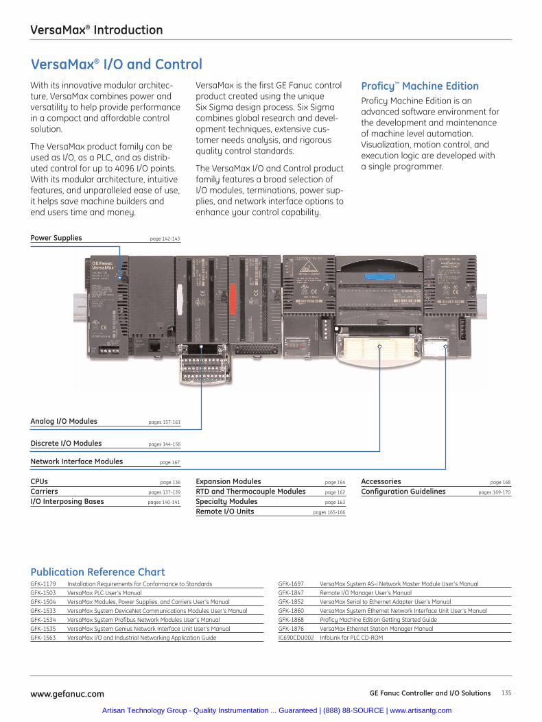
135www.gefanuc.com GE Fanuc Controller and I/O Solutions
VersaMax® Introduction
Power Supplies page 142-143
CPUs page 136
Carriers pages 137-139
I/O Interposing Bases pages 140-141
Expansion Modules page 164
RTD and Thermocouple Modules page 162
Specialty Modules page 163
Remote I/O Units pages 165-166
Accessories page 168
Configuration Guidelines pages 169-170
Discrete I/O Modules pages 144-156
Network Interface Modules page 167
Publication Reference ChartGFK-1179 Installation Requirements for Conformance to StandardsGFK-1503 VersaMax PLC User’s ManualGFK-1504 VersaMax Modules, Power Supplies, and Carriers User’s ManualGFK-1533 VersaMax System DeviceNet Communications Modules User’s ManualGFK-1534 VersaMax System Profibus Network Modules User’s ManualGFK-1535 VersaMax System Genius Network Interface Unit User’s ManualGFK-1563 VersaMax I/O and Industrial Networking Application Guide
GFK-1697 VersaMax System AS-i Network Master Module User’s ManualGFK-1847 Remote I/O Manager User’s ManualGFK-1852 VersaMax Serial to Ethernet Adapter User’s ManualGFK-1860 VersaMax System Ethernet Network Interface Unit User’s ManualGFK-1868 Proficy Machine Edition Getting Started GuideGFK-1876 VersaMax Ethernet Station Manager ManualIC690CDU002 InfoLink for PLC CD-ROM
Proficy™ Machine EditionProficy Machine Edition is anadvanced software environment forthe development and maintenanceof machine level automation.Visualization, motion control, andexecution logic are developed witha single programmer.
With its innovative modular architec-ture, VersaMax combines power andversatility to help provide performancein a compact and affordable controlsolution.
The VersaMax product family can beused as I/O, as a PLC, and as distrib-uted control for up to 4096 I/O points.With its modular architecture, intuitivefeatures, and unparalleled ease of use,it helps save machine builders andend users time and money.
VersaMax is the first GE Fanuc controlproduct created using the uniqueSix Sigma design process. Six Sigmacombines global research and devel-opment techniques, extensive cus-tomer needs analysis, and rigorousquality control standards.
The VersaMax I/O and Control productfamily features a broad selection ofI/O modules, terminations, power sup-plies, and network interface options toenhance your control capability.
Analog I/O Modules pages 157-161
VersaMax® I/O and Control
Artisan Technology Group - Quality Instrumentation ... Guaranteed | (888) 88-SOURCE | www.artisantg.com
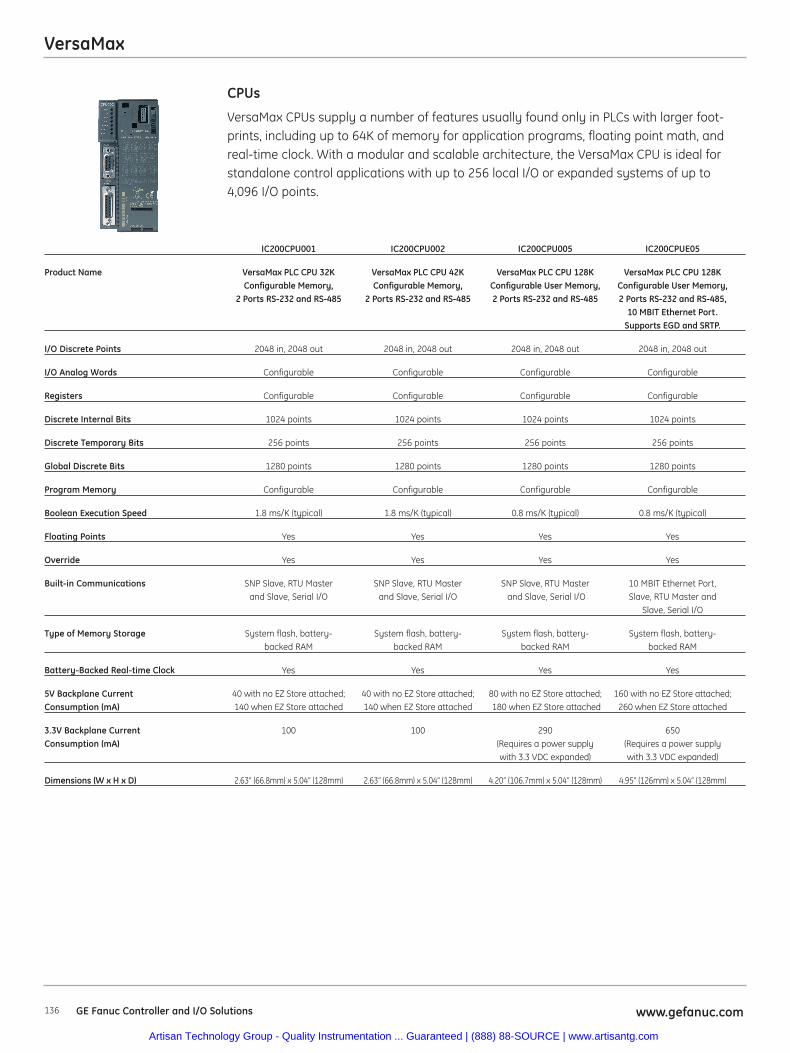
VersaMax
136 www.gefanuc.comGE Fanuc Controller and I/O Solutions
VersaMax CPUs supply a number of features usually found only in PLCs with larger foot-prints, including up to 64K of memory for application programs, floating point math, andreal-time clock. With a modular and scalable architecture, the VersaMax CPU is ideal forstandalone control applications with up to 256 local I/O or expanded systems of up to 4,096 I/O points.
CPUs
IC200CPU001 IC200CPU002 IC200CPU005 IC200CPUE05
Product Name VersaMax PLC CPU 32K VersaMax PLC CPU 42K VersaMax PLC CPU 128K VersaMax PLC CPU 128KConfigurable Memory, Configurable Memory, Configurable User Memory, Configurable User Memory,
2 Ports RS-232 and RS-485 2 Ports RS-232 and RS-485 2 Ports RS-232 and RS-485 2 Ports RS-232 and RS-485,10 MBIT Ethernet Port.
Supports EGD and SRTP.
I/O Discrete Points 2048 in, 2048 out 2048 in, 2048 out 2048 in, 2048 out 2048 in, 2048 out
I/O Analog Words Configurable Configurable Configurable Configurable
Registers Configurable Configurable Configurable Configurable
Discrete Internal Bits 1024 points 1024 points 1024 points 1024 points
Discrete Temporary Bits 256 points 256 points 256 points 256 points
Global Discrete Bits 1280 points 1280 points 1280 points 1280 points
Program Memory Configurable Configurable Configurable Configurable
Boolean Execution Speed 1.8 ms/K (typical) 1.8 ms/K (typical) 0.8 ms/K (typical) 0.8 ms/K (typical)
Floating Points Yes Yes Yes Yes
Override Yes Yes Yes Yes
Built-in Communications SNP Slave, RTU Master SNP Slave, RTU Master SNP Slave, RTU Master 10 MBIT Ethernet Port,and Slave, Serial I/O and Slave, Serial I/O and Slave, Serial I/O Slave, RTU Master and
Slave, Serial I/O
Type of Memory Storage System flash, battery- System flash, battery- System flash, battery- System flash, battery-backed RAM backed RAM backed RAM backed RAM
Battery-Backed Real-time Clock Yes Yes Yes Yes
5V Backplane Current 40 with no EZ Store attached; 40 with no EZ Store attached; 80 with no EZ Store attached; 160 with no EZ Store attached; Consumption (mA) 140 when EZ Store attached 140 when EZ Store attached 180 when EZ Store attached 260 when EZ Store attached
3.3V Backplane Current 100 100 290 650Consumption (mA) (Requires a power supply (Requires a power supply
with 3.3 VDC expanded) with 3.3 VDC expanded)
Dimensions (W x H x D) 2.63” (66.8mm) x 5.04” (128mm) 2.63” (66.8mm) x 5.04” (128mm) 4.20” (106.7mm) x 5.04” (128mm) 4.95” (126mm) x 5.04” (128mm)
Artisan Technology Group - Quality Instrumentation ... Guaranteed | (888) 88-SOURCE | www.artisantg.com
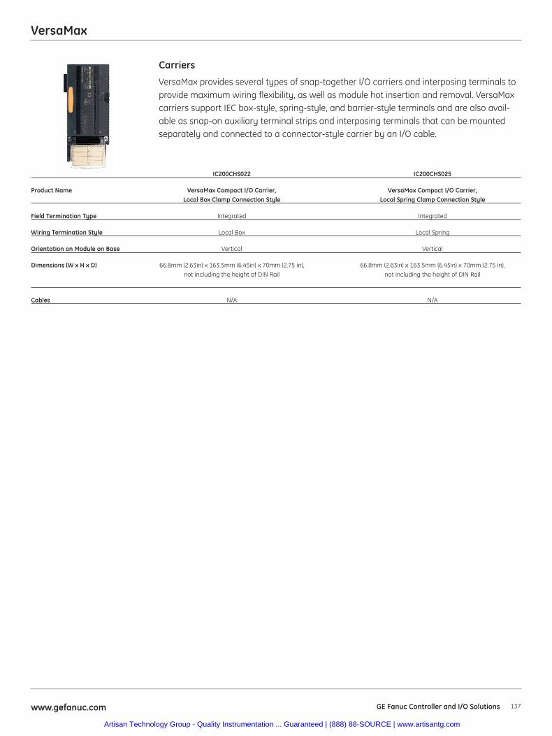
137www.gefanuc.com GE Fanuc Controller and I/O Solutions
VersaMax
VersaMax provides several types of snap-together I/O carriers and interposing terminals toprovide maximum wiring flexibility, as well as module hot insertion and removal. VersaMaxcarriers support IEC box-style, spring-style, and barrier-style terminals and are also avail-able as snap-on auxiliary terminal strips and interposing terminals that can be mountedseparately and connected to a connector-style carrier by an I/O cable.
Carriers
IC200CHS022 IC200CHS025
Product Name VersaMax Compact I/O Carrier, VersaMax Compact I/O Carrier, Local Box Clamp Connection Style Local Spring Clamp Connection Style
Field Termination Type Integrated Integrated
Wiring Termination Style Local Box Local Spring
Orientation on Module on Base Vertical Vertical
Dimensions (W x H x D) 66.8mm (2.63in) x 163.5mm (6.45in) x 70mm (2.75 in), 66.8mm (2.63in) x 163.5mm (6.45in) x 70mm (2.75 in), not including the height of DIN Rail not including the height of DIN Rail
Cables N/A N/A
Artisan Technology Group - Quality Instrumentation ... Guaranteed | (888) 88-SOURCE | www.artisantg.com
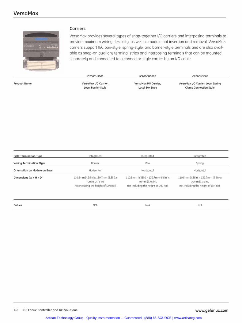
138 www.gefanuc.comGE Fanuc Controller and I/O Solutions
VersaMax
VersaMax provides several types of snap-together I/O carriers and interposing terminals toprovide maximum wiring flexibility, as well as module hot insertion and removal. VersaMaxcarriers support IEC box-style, spring-style, and barrier-style terminals and are also avail-able as snap-on auxiliary terminal strips and interposing terminals that can be mountedseparately and connected to a connector-style carrier by an I/O cable.
Carriers
IC200CHS001 IC200CHS002 IC200CHS005
Product Name VersaMax I/O Carrier, VersaMax I/O Carrier, VersaMax I/O Carrier, Local SpringLocal Barrier Style Local Box Style Clamp Connection Style
Field Termination Type Integrated Integrated Integrated
Wiring Termination Style Barrier Box Spring
Orientation on Module on Base Horizontal Horizontal Horizontal
Dimensions (W x H x D) 110.5mm (4.35in) x 139.7mm (5.5in) x 110.5mm (4.35in) x 139.7mm (5.5in) x 110.5mm (4.35in) x 139.7mm (5.5in) x70mm (2.75 in), 70mm (2.75 in), 70mm (2.75 in),
not including the height of DIN Rail not including the height of DIN Rail not including the height of DIN Rail
Cables N/A N/A N/A
Artisan Technology Group - Quality Instrumentation ... Guaranteed | (888) 88-SOURCE | www.artisantg.com
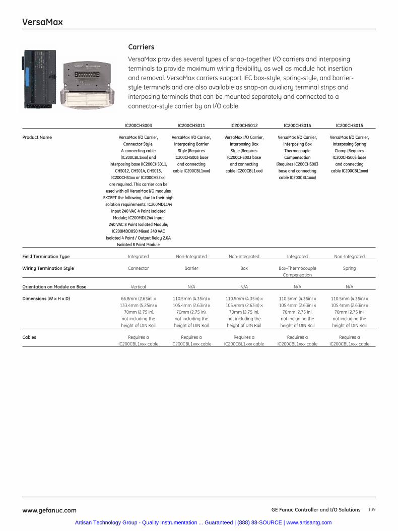
VersaMax
139www.gefanuc.com GE Fanuc Controller and I/O Solutions
IC200CHS003 IC200CHS011 IC200CHS012 IC200CHS014 IC200CHS015
Product Name VersaMax I/O Carrier, VersaMax I/O Carrier, VersaMax I/O Carrier, VersaMax I/O Carrier, VersaMax I/O Carrier,Connector Style. Interposing Barrier Interposing Box Interposing Box Interposing Spring
A connecting cable Style (Requires Style (Requires Thermocouple Clamp (Requires (IC200CBL1xxx) and IC200CHS003 base IC200CHS003 base Compensation IC200CHS003 base
interposing base (IC200CHS011, and connecting and connecting (Requires IC200CHS003 and connectingCHS012, CHS014, CHS015, cable IC200CBL1xxx) cable IC200CBL1xxx) base and connecting cable IC200CBL1xxx)
IC200CHS1xx or IC200CHS2xx) cable IC200CBL1xxx)are required. This carrier can be
used with all VersaMax I/O modules EXCEPT the following, due to their high isolation requirements: IC200MDL144
Input 240 VAC 4 Point Isolated Module; IC200MDL244 Input
240 VAC 8 Point Isolated Module; IC200MDD850 Mixed 240 VAC
Isolated 4 Point / Output Relay 2.0AIsolated 8 Point Module
Field Termination Type Integrated Non-Integrated Non-Integrated Integrated Non-Integrated
Wiring Termination Style Connector Barrier Box Box-Thermocouple SpringCompensation
Orientation on Module on Base Vertical N/A N/A N/A N/A
Dimensions (W x H x D) 66.8mm (2.63in) x 110.5mm (4.35in) x 110.5mm (4.35in) x 110.5mm (4.35in) x 110.5mm (4.35in) x133.4mm (5.25in) x 105.4mm (2.63in) x 105.4mm (2.63in) x 105.4mm (2.63in) x 105.4mm (2.63in) x
70mm (2.75 in), 70mm (2.75 in), 70mm (2.75 in), 70mm (2.75 in), 70mm (2.75 in),not including the not including the not including the not including the not including theheight of DIN Rail height of DIN Rail height of DIN Rail height of DIN Rail height of DIN Rail
Cables Requires a Requires a Requires a Requires a Requires a IC200CBL1xxx cable IC200CBL1xxx cable IC200CBL1xxx cable IC200CBL1xxx cable IC200CBL1xxx cable
VersaMax provides several types of snap-together I/O carriers and interposingterminals to provide maximum wiring flexibility, as well as module hot insertionand removal. VersaMax carriers support IEC box-style, spring-style, and barrier-style terminals and are also available as snap-on auxiliary terminal strips andinterposing terminals that can be mounted separately and connected to aconnector-style carrier by an I/O cable.
Carriers
Artisan Technology Group - Quality Instrumentation ... Guaranteed | (888) 88-SOURCE | www.artisantg.com
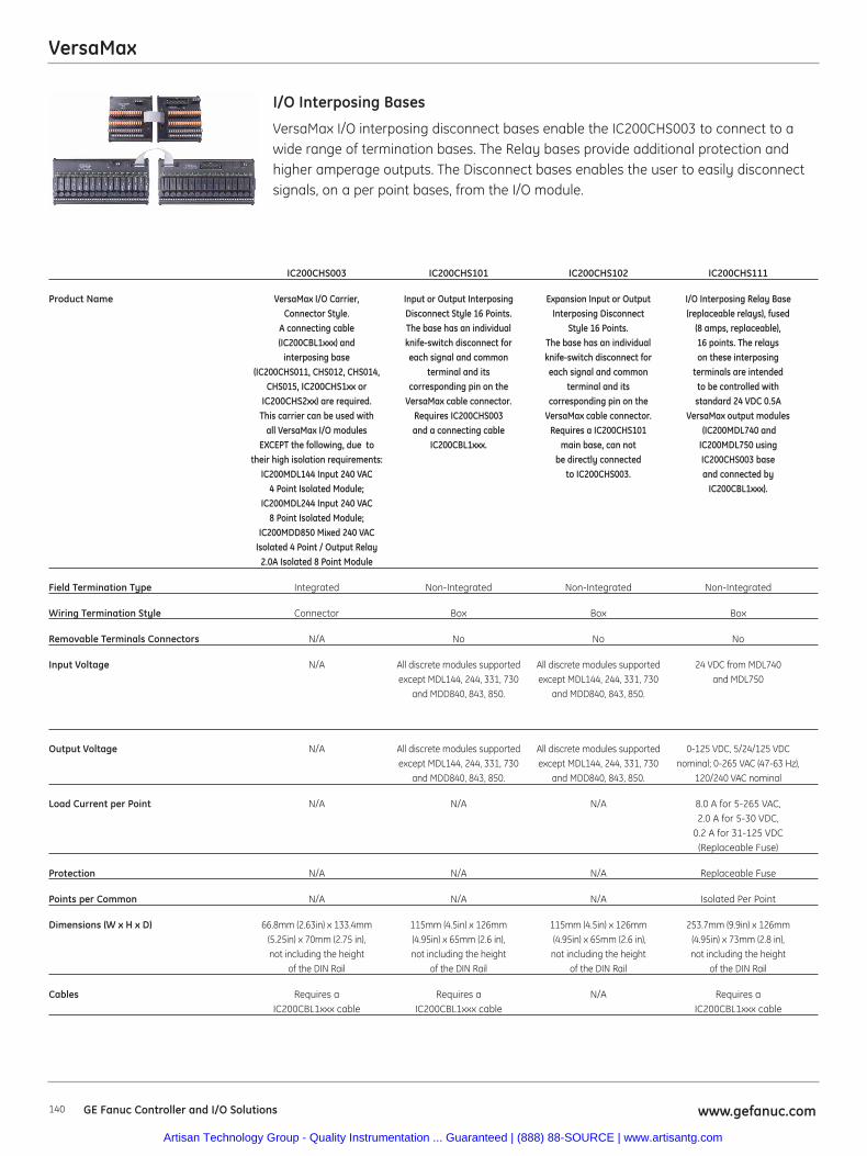
VersaMax
140 www.gefanuc.comGE Fanuc Controller and I/O Solutions
IC200CHS003 IC200CHS101 IC200CHS102 IC200CHS111
Product Name VersaMax I/O Carrier, Input or Output Interposing Expansion Input or Output I/O Interposing Relay BaseConnector Style. Disconnect Style 16 Points. Interposing Disconnect (replaceable relays), fused
A connecting cable The base has an individual Style 16 Points. (8 amps, replaceable),(IC200CBL1xxx) and knife-switch disconnect for The base has an individual 16 points. The relays
interposing base each signal and common knife-switch disconnect for on these interposing(IC200CHS011, CHS012, CHS014, terminal and its each signal and common terminals are intended
CHS015, IC200CHS1xx or corresponding pin on the terminal and its to be controlled withIC200CHS2xx) are required. VersaMax cable connector. corresponding pin on the standard 24 VDC 0.5A
This carrier can be used with Requires IC200CHS003 VersaMax cable connector. VersaMax output modulesall VersaMax I/O modules and a connecting cable Requires a IC200CHS101 (IC200MDL740 and
EXCEPT the following, due to IC200CBL1xxx. main base, can not IC200MDL750 usingtheir high isolation requirements: be directly connected IC200CHS003 base
IC200MDL144 Input 240 VAC to IC200CHS003. and connected by 4 Point Isolated Module; IC200CBL1xxx).
IC200MDL244 Input 240 VAC 8 Point Isolated Module;
IC200MDD850 Mixed 240 VACIsolated 4 Point / Output Relay
2.0A Isolated 8 Point Module
Field Termination Type Integrated Non-Integrated Non-Integrated Non-Integrated
Wiring Termination Style Connector Box Box Box
Removable Terminals Connectors N/A No No No
Input Voltage N/A All discrete modules supported All discrete modules supported 24 VDC from MDL740except MDL144, 244, 331, 730 except MDL144, 244, 331, 730 and MDL750
and MDD840, 843, 850. and MDD840, 843, 850.
Output Voltage N/A All discrete modules supported All discrete modules supported 0-125 VDC, 5/24/125 VDCexcept MDL144, 244, 331, 730 except MDL144, 244, 331, 730 nominal; 0-265 VAC (47-63 Hz),
and MDD840, 843, 850. and MDD840, 843, 850. 120/240 VAC nominal
Load Current per Point N/A N/A N/A 8.0 A for 5-265 VAC, 2.0 A for 5-30 VDC,
0.2 A for 31-125 VDC (Replaceable Fuse)
Protection N/A N/A N/A Replaceable Fuse
Points per Common N/A N/A N/A Isolated Per Point
Dimensions (W x H x D) 66.8mm (2.63in) x 133.4mm 115mm (4.5in) x 126mm 115mm (4.5in) x 126mm 253.7mm (9.9in) x 126mm(5.25in) x 70mm (2.75 in), (4.95in) x 65mm (2.6 in), (4.95in) x 65mm (2.6 in), (4.95in) x 73mm (2.8 in),not including the height not including the height not including the height not including the height
of the DIN Rail of the DIN Rail of the DIN Rail of the DIN Rail
Cables Requires a Requires a N/A Requires a IC200CBL1xxx cable IC200CBL1xxx cable IC200CBL1xxx cable
VersaMax I/O interposing disconnect bases enable the IC200CHS003 to connect to awide range of termination bases. The Relay bases provide additional protection andhigher amperage outputs. The Disconnect bases enables the user to easily disconnectsignals, on a per point bases, from the I/O module.
I/O Interposing Bases
Artisan Technology Group - Quality Instrumentation ... Guaranteed | (888) 88-SOURCE | www.artisantg.com
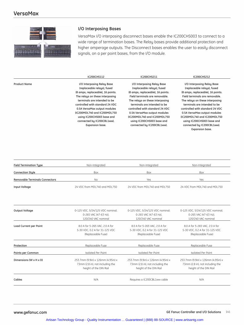
VersaMax
141www.gefanuc.com GE Fanuc Controller and I/O Solutions
VersaMax I/O interposing disconnect bases enable the IC200CHS003 to connect to awide range of termination bases. The Relay bases provide additional protection andhigher amperage outputs. The Disconnect bases enables the user to easily disconnectsignals, on a per point bases, from the I/O module.
I/O Interposing Bases
IC200CHS112 IC200CHS211 IC200CHS212
Product Name I/O Interposing Relay Base I/O Interposing Relay Base I/O Interposing Relay Base(replaceable relays), fused (replaceable relays), fused (replaceable relays), fused
(8 amps, replaceable), 16 points. (8 amps, replaceable), 16 points. (8 amps, replaceable), 16 points.The relays on these interposing Field terminals are removable. Field terminals are removable.
terminals are intended to be The relays on these interposing The relays on these interposingcontrolled with standard 24 VDC terminals are intended to be terminals are intended to be0.5A VersaMax output modules controlled with standard 24 VDC controlled with standard 24 VDC
(IC200MDL740 and IC200MDL750 0.5A VersaMax output modules 0.5A VersaMax output modulesusing IC200CHS003 base and (IC200MDL740 and IC200MDL750 (IC200MDL740 and IC200MDL750 connected by IC200CBL1xxx). using IC200CHS003 base and using IC200CHS003 base and
Expansion base. connected by IC200CBL1xxx). connected by IC200CBL1xxx). Expansion base.
Field Termination Type Non-Integrated Non-Integrated Non-Integrated
Connection Style Box Box Box
Removable Terminals Connectors No Yes Yes
Input Voltage 24 VDC from MDL740 and MDL750 24 VDC from MDL740 and MDL750 24 VDC from MDL740 and MDL750
Output Voltage 0-125 VDC, 5/24/125 VDC nominal; 0-125 VDC, 5/24/125 VDC nominal; 0-125 VDC, 5/24/125 VDC nominal;0-265 VAC (47-63 Hz), 0-265 VAC (47-63 Hz), 0-265 VAC (47-63 Hz),120/240 VAC nominal 120/240 VAC nominal 120/240 VAC nominal
Load Current per Point 8.0 A for 5-265 VAC, 2.0 A for 8.0 A for 5-265 VAC, 2.0 A for 8.0 A for 5-265 VAC, 2.0 A for 5-30 VDC, 0.2 A for 31-125 VDC 5-30 VDC, 0.2 A for 31-125 VDC 5-30 VDC, 0.2 A for 31-125 VDC
(Replaceable Fuse) (Replaceable Fuse) (Replaceable Fuse)
Protection Replaceable Fuse Replaceable Fuse Replaceable Fuse
Points per Common Isolated Per Point Isolated Per Point Isolated Per Point
Dimensions (W x H x D) 253.7mm (9.9in) x 126mm (4.95in) x 253.7mm (9.9in) x 126mm (4.95in) x 253.7mm (9.9in) x 126mm (4.95in) x73mm (2.8 in), not including the 73mm (2.8 in), not including the 73mm (2.8 in), not including the
height of the DIN Rail height of the DIN Rail height of the DIN Rail
Cables N/A Requires a IC200CBL1xxx cable N/A
Artisan Technology Group - Quality Instrumentation ... Guaranteed | (888) 88-SOURCE | www.artisantg.com
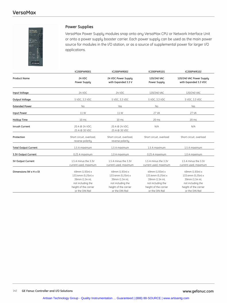
VersaMax
142 www.gefanuc.comGE Fanuc Controller and I/O Solutions
VersaMax Power Supply modules snap onto any VersaMax CPU or Network Interface Unitor onto a power supply booster carrier. Each power supply can be used as the main powersource for modules in the I/O station, or as a source of supplemental power for larger I/Oapplications.
Power Supplies
IC200PWR001 IC200PWR002 IC200PWR101 IC200PWR102
Product Name 24 VDC 24 VDC Power Supply 120/240 VAC 120/240 VAC Power Supply Power Supply with Expanded 3.3 V Power Supply with Expanded 3.3 VDC
Input Voltage 24 VDC 24 VDC 120/240 VAC 120/240 VAC
Output Voltage 5 VDC, 3.3 VDC 5 VDC, 3.3 VDC 5 VDC, 3.3 VDC 5 VDC, 3.3 VDC
Extended Power No Yes No Yes
Input Power 11 W 11 W 27 VA 27 VA
Holdup Time 10 ms 10 ms 20 ms 20 ms
Inrush Current 20 A @ 24 VDC; 20 A @ 24 VDC; N/A N/A25 A @ 30 VDC 25 A @ 30 VDC
Protection Short circuit, overload, Short circuit, overload, Short circuit, overload Short circuit, overloadreverse polarity reverse polarity
Total Output Current 1.5 A maximum 1.5 A maximum 1.5 A maximum 1.5 A maximum
3.3V Output Current 0.25 A maximum 1.0 A maximum 0.25 A maximum 1.0 A maximum
5V Output Current 1.5 A minus the 3.3V 1.5 A minus the 3.3V 1.5 A minus the 3.3V 1.5 A minus the 3.3Vcurrent used, maximum current used, maximum current used, maximum current used, maximum
Dimensions (W x H x D) 49mm (1.93in) x 49mm (1.93in) x 49mm (1.93in) x 49mm (1.93in) x133.4mm (5.25in) x 133.4mm (5.25in) x 133.4mm (5.25in) x 133.4mm (5.25in) x
39mm (1.54 in), 39mm (1.54 in), 39mm (1.54 in), 39mm (1.54 in),not including the not including the not including the not including the
height of the carrier height of the carrier height of the carrier height of the carrieror the DIN Rail or the DIN Rail or the DIN Rail or the DIN Rail
Artisan Technology Group - Quality Instrumentation ... Guaranteed | (888) 88-SOURCE | www.artisantg.com
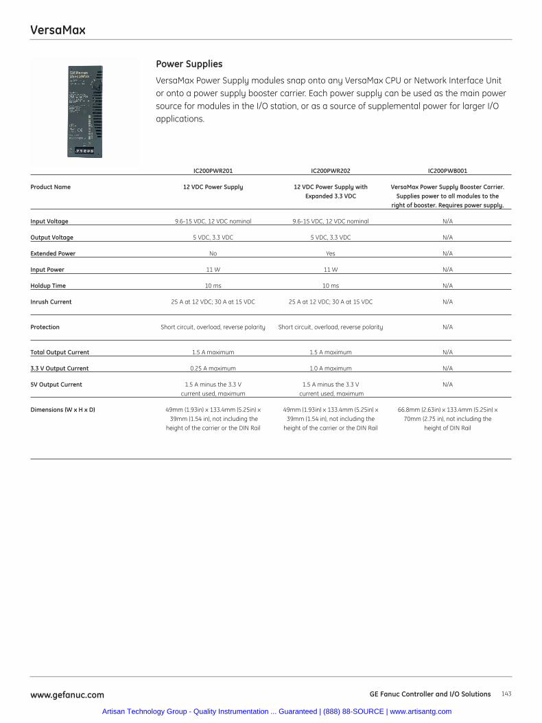
VersaMax
143www.gefanuc.com GE Fanuc Controller and I/O Solutions
VersaMax Power Supply modules snap onto any VersaMax CPU or Network Interface Unitor onto a power supply booster carrier. Each power supply can be used as the main powersource for modules in the I/O station, or as a source of supplemental power for larger I/Oapplications.
Power Supplies
IC200PWR201 IC200PWR202 IC200PWB001
Product Name 12 VDC Power Supply 12 VDC Power Supply with VersaMax Power Supply Booster Carrier.Expanded 3.3 VDC Supplies power to all modules to the
right of booster. Requires power supply.
Input Voltage 9.6-15 VDC, 12 VDC nominal 9.6-15 VDC, 12 VDC nominal N/A
Output Voltage 5 VDC, 3.3 VDC 5 VDC, 3.3 VDC N/A
Extended Power No Yes N/A
Input Power 11 W 11 W N/A
Holdup Time 10 ms 10 ms N/A
Inrush Current 25 A at 12 VDC; 30 A at 15 VDC 25 A at 12 VDC; 30 A at 15 VDC N/A
Protection Short circuit, overload, reverse polarity Short circuit, overload, reverse polarity N/A
Total Output Current 1.5 A maximum 1.5 A maximum N/A
3.3 V Output Current 0.25 A maximum 1.0 A maximum N/A
5V Output Current 1.5 A minus the 3.3 V 1.5 A minus the 3.3 V N/Acurrent used, maximum current used, maximum
Dimensions (W x H x D) 49mm (1.93in) x 133.4mm (5.25in) x 49mm (1.93in) x 133.4mm (5.25in) x 66.8mm (2.63in) x 133.4mm (5.25in) x39mm (1.54 in), not including the 39mm (1.54 in), not including the 70mm (2.75 in), not including the
height of the carrier or the DIN Rail height of the carrier or the DIN Rail height of DIN Rail
Artisan Technology Group - Quality Instrumentation ... Guaranteed | (888) 88-SOURCE | www.artisantg.com
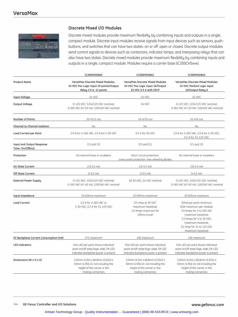
VersaMax
144 www.gefanuc.comGE Fanuc Controller and I/O Solutions
Discrete mixed modules provide maximum flexibility by combining inputs and outputs in a single,compact module. Discrete input modules receive signals from input devices such as sensors, push-buttons, and switches that can have two states: on or off, open or closed. Discrete output modulessend control signals to devices such as contactors, indicator lamps, and interposing relays that canalso have two states. Discrete mixed modules provide maximum flexibility by combining inputs andoutputs in a single, compact module. Modules require a carrier base (IC200CHSxxx).
Discrete Mixed I/O Modules
IC200MDD840 IC200MDD842 IC200MDD843
Product Name VersaMax Discrete Mixed Modules, VersaMax Discrete Mixed Modules VersaMax Discrete Mixed Modules24 VDC Pos Logic Input 20 points/Output 24 VDC Pos Logic Input 16/Output 24 VDC Positive Logic Input
Relay 2.0 A, 12 points 24 VDC 0.5 A with ESCP 10/Output Relay 6
Input Voltage 24 VDC 24 VDC 24 VDC
Output Voltage 0-125 VDC, 5/24/125 VDC nominal; 24 VDC 0-125 VDC, 5/24/125 VDC nominal;0-265 VAC (47-63 Hz), 120/240 VAC nominal 0-265 VAC (47-63 Hz), 120/240 VAC nominal
Number of Points 20 in/12 out 16 in/16 out 10 in/6 out
Channel to Channel Isolation No No No
Load Current per Point 2.0 A for 5-265 VAC, 2.0 A for 5-30 VDC 0.5 A for 30 VDC 2.0 A for 5-265 VAC, 2.0 A for 5-30 VDC, 0.2 A for 31-125 VDC
Input and Output Response 0.5 and 10 0.5 and 0.5 0.5 and 10Time- On/Off(ms)
Protection No internal fuses or snubbers Short circuit protection, No internal fuses or snubbersovercurrent protection, free-wheeling diodes
On State Current 2.0-5.5 mA 2.0-5.5 mA 2.0-5.5 mA
Off State Current 0-0.5 mA 0-0.5 mA 0-0.5 mA
External Power Supply 0-125 VDC, 5/24/125 VDC nominal; 18-30 VDC, 24 VDC nominal 0-125 VDC, 5/24/125 VDC nominal,0-265 VAC (47-63 Hz), 120/240 VAC nominal 0-265 VAC (47-63 Hz), 120/240 VAC nominal
Input Impedance 10 kOhms maximum 10 kOhms maximum 10 kOhms maximum
Load Current 2.0 A for 5-265 VAC or 0.5 Amp at 30 VDC 10mA per point minimum, 5-30 VDC, 0.2 A for 31-125 VDC maximum (resistive); 8.0A maximum per module;
2.0 Amps maximum for 2.0 Amps for 5 to 265 VAC100ms inrush maximum (resistive);
2.0 Amps for 5 to 30 VDCmaximum (resistive);
0.2 Amp for 31 to 125 VDCmaximum (resistive)
5V Backplane Current Consumption (mA) 375 maximum 100 maximum 190 maximum
LED Indicators One LED per point shows individual One LED per point shows individual One LED per point shows individualpoint on/off state (logic side); OK LED point on/off state (logic side); OK LED point on/off state (logic side); OK LED indicates backplane power is present indicates backplane power is present indicates backplane power is present
Dimensions (W x H x D) 110mm (4.3in) x 66.8mm (2.63in) x 110mm (4.3in) x 66.8mm (2.63in) x 110mm (4.3in) x 66.8mm (2.63in) x50mm (1.956 in), not including the 50mm (1.956 in), not including the 50mm (1.956 in), not including the
height of the carrier or the height of the carrier or the height of the carrier or themating connectors mating connectors mating connectors
Artisan Technology Group - Quality Instrumentation ... Guaranteed | (888) 88-SOURCE | www.artisantg.com
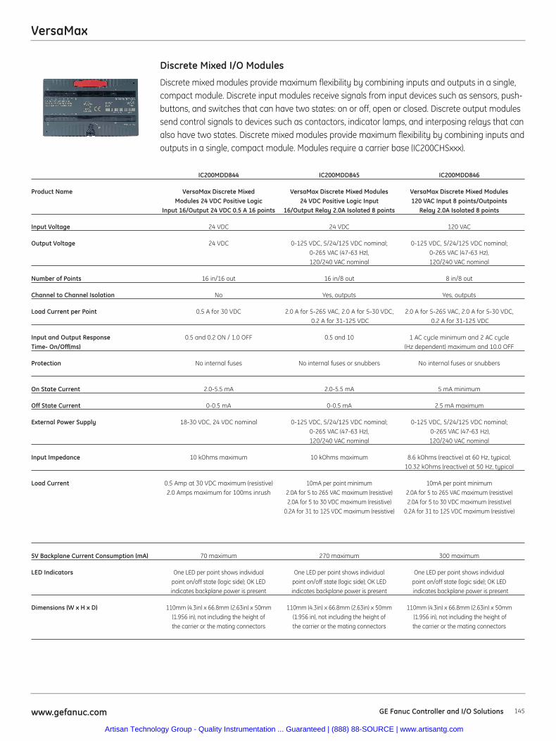
VersaMax
145www.gefanuc.com GE Fanuc Controller and I/O Solutions
Discrete mixed modules provide maximum flexibility by combining inputs and outputs in a single,compact module. Discrete input modules receive signals from input devices such as sensors, push-buttons, and switches that can have two states: on or off, open or closed. Discrete output modulessend control signals to devices such as contactors, indicator lamps, and interposing relays that canalso have two states. Discrete mixed modules provide maximum flexibility by combining inputs andoutputs in a single, compact module. Modules require a carrier base (IC200CHSxxx).
Discrete Mixed I/O Modules
IC200MDD844 IC200MDD845 IC200MDD846
Product Name VersaMax Discrete Mixed VersaMax Discrete Mixed Modules VersaMax Discrete Mixed ModulesModules 24 VDC Positive Logic 24 VDC Positive Logic Input 120 VAC Input 8 points/Outpoints
Input 16/Output 24 VDC 0.5 A 16 points 16/Output Relay 2.0A Isolated 8 points Relay 2.0A Isolated 8 points
Input Voltage 24 VDC 24 VDC 120 VAC
Output Voltage 24 VDC 0-125 VDC, 5/24/125 VDC nominal; 0-125 VDC, 5/24/125 VDC nominal; 0-265 VAC (47-63 Hz), 0-265 VAC (47-63 Hz), 120/240 VAC nominal 120/240 VAC nominal
Number of Points 16 in/16 out 16 in/8 out 8 in/8 out
Channel to Channel Isolation No Yes, outputs Yes, outputs
Load Current per Point 0.5 A for 30 VDC 2.0 A for 5-265 VAC, 2.0 A for 5-30 VDC, 2.0 A for 5-265 VAC, 2.0 A for 5-30 VDC,0.2 A for 31-125 VDC 0.2 A for 31-125 VDC
Input and Output Response 0.5 and 0.2 ON / 1.0 OFF 0.5 and 10 1 AC cycle minimum and 2 AC cycle Time- On/Off(ms) (Hz dependent) maximum and 10.0 OFF
Protection No internal fuses No internal fuses or snubbers No internal fuses or snubbers
On State Current 2.0-5.5 mA 2.0-5.5 mA 5 mA minimum
Off State Current 0-0.5 mA 0-0.5 mA 2.5 mA maximum
External Power Supply 18-30 VDC, 24 VDC nominal 0-125 VDC, 5/24/125 VDC nominal; 0-125 VDC, 5/24/125 VDC nominal;0-265 VAC (47-63 Hz), 0-265 VAC (47-63 Hz), 120/240 VAC nominal 120/240 VAC nominal
Input Impedance 10 kOhms maximum 10 kOhms maximum 8.6 kOhms (reactive) at 60 Hz, typical; 10.32 kOhms (reactive) at 50 Hz, typical
Load Current 0.5 Amp at 30 VDC maximum (resistive) 10mA per point minimum 10mA per point minimum2.0 Amps maximum for 100ms inrush 2.0A for 5 to 265 VAC maximum (resistive) 2.0A for 5 to 265 VAC maximum (resistive)
2.0A for 5 to 30 VDC maximum (resistive) 2.0A for 5 to 30 VDC maximum (resistive)0.2A for 31 to 125 VDC maximum (resistive) 0.2A for 31 to 125 VDC maximum (resistive)
5V Backplane Current Consumption (mA) 70 maximum 270 maximum 300 maximum
LED Indicators One LED per point shows individual One LED per point shows individual One LED per point shows individual point on/off state (logic side); OK LED point on/off state (logic side); OK LED point on/off state (logic side); OK LEDindicates backplane power is present indicates backplane power is present indicates backplane power is present
Dimensions (W x H x D) 110mm (4.3in) x 66.8mm (2.63in) x 50mm 110mm (4.3in) x 66.8mm (2.63in) x 50mm 110mm (4.3in) x 66.8mm (2.63in) x 50mm(1.956 in), not including the height of (1.956 in), not including the height of (1.956 in), not including the height of the carrier or the mating connectors the carrier or the mating connectors the carrier or the mating connectors
Artisan Technology Group - Quality Instrumentation ... Guaranteed | (888) 88-SOURCE | www.artisantg.com
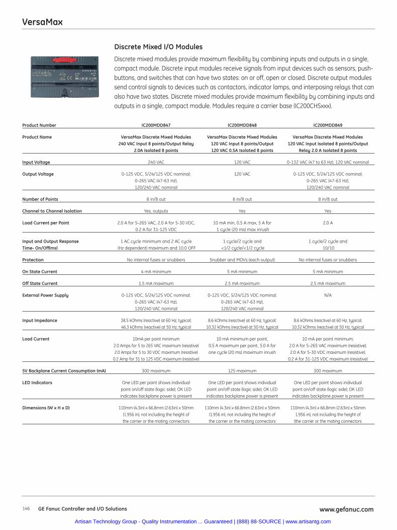
VersaMax
146 www.gefanuc.comGE Fanuc Controller and I/O Solutions
Discrete mixed modules provide maximum flexibility by combining inputs and outputs in a single,compact module. Discrete input modules receive signals from input devices such as sensors, push-buttons, and switches that can have two states: on or off, open or closed. Discrete output modulessend control signals to devices such as contactors, indicator lamps, and interposing relays that canalso have two states. Discrete mixed modules provide maximum flexibility by combining inputs andoutputs in a single, compact module. Modules require a carrier base (IC200CHSxxx).
Discrete Mixed I/O Modules
Product Number IC200MDD847 IC200MDD848 IC200MDD849
Product Name VersaMax Discrete Mixed Modules VersaMax Discrete Mixed Modules VersaMax Discrete Mixed Modules240 VAC Input 8 points/Output Relay 120 VAC Input 8 points/Output 120 VAC Input Isolated 8 points/Output
2.0A Isolated 8 points 120 VAC 0.5A Isolated 8 points Relay 2.0 A Isolated 8 points
Input Voltage 240 VAC 120 VAC 0-132 VAC (47 to 63 Hz), 120 VAC nominal
Output Voltage 0-125 VDC, 5/24/125 VDC nominal; 120 VAC 0-125 VDC, 5/24/125 VDC nominal; 0-265 VAC (47-63 Hz), 0-265 VAC (47-63 Hz), 120/240 VAC nominal 120/240 VAC nominal
Number of Points 8 in/8 out 8 in/8 out 8 in/8 out
Channel to Channel Isolation Yes, outputs Yes Yes
Load Current per Point 2.0 A for 5-265 VAC, 2.0 A for 5-30 VDC, 10 mA min, 0.5 A max, 5 A for 2.0 A0.2 A for 31-125 VDC 1 cycle (20 ms) max inrush
Input and Output Response 1 AC cycle minimum and 2 AC cycle 1 cycle/2 cycle and 1 cycle/2 cycle andTime- On/Off(ms) (Hz dependent) maximum and 10.0 OFF <1/2 cycle/<1/2 cycle 10/10
Protection No internal fuses or snubbers Snubber and MOVs (each output) No internal fuses or snubbers
On State Current 4 mA minimum 5 mA minimum 5 mA minimum
Off State Current 1.5 mA maximum 2.5 mA maximum 2.5 mA maximum
External Power Supply 0-125 VDC, 5/24/125 VDC nominal; 0-125 VDC, 5/24/125 VDC nominal; N/A0-265 VAC (47-63 Hz), 0-265 VAC (47-63 Hz),120/240 VAC nominal 120/240 VAC nominal
Input Impedance 38.5 kOhms (reactive) at 60 Hz, typical; 8.6 kOhms (reactive) at 60 Hz, typical; 8.6 kOhms (reactive) at 60 Hz, typical;46.3 kOhms (reactive) at 50 Hz, typical 10.32 kOhms (reactive) at 50 Hz, typical 10.32 kOhms (reactive) at 50 Hz, typical
Load Current 10mA per point minimum 10 mA minimum per point, 10 mA per point minimum;2.0 Amps for 5 to 265 VAC maximum (resistive) 0.5 A maximum per point, 5.0 A for 2.0 A for 5-265 VAC maximum (resistive);2.0 Amps for 5 to 30 VDC maximum (resistive) one cycle (20 ms) maximum inrush 2.0 A for 5-30 VDC maximum (resistive);
0.2 Amp for 31 to 125 VDC maximum (resistive) 0.2 A for 31-125 VDC maximum (resistive)
5V Backplane Current Consumption (mA) 300 maximum 125 maximum 300 maximum
LED Indicators One LED per point shows individual One LED per point shows individual One LED per point shows individualpoint on/off state (logic side); OK LED point on/off state (logic side); OK LED point on/off state (logic side); OK LEDindicates backplane power is present indicates backplane power is present indicates backplane power is present
Dimensions (W x H x D) 110mm (4.3in) x 66.8mm (2.63in) x 50mm 110mm (4.3in) x 66.8mm (2.63in) x 50mm 110mm (4.3in) x 66.8mm (2.63in) x 50mm(1.956 in), not including the height of (1.956 in), not including the height of 1.956 in), not including the height of the carrier or the mating connectors the carrier or the mating connectors (the carrier or the mating connectors
Artisan Technology Group - Quality Instrumentation ... Guaranteed | (888) 88-SOURCE | www.artisantg.com
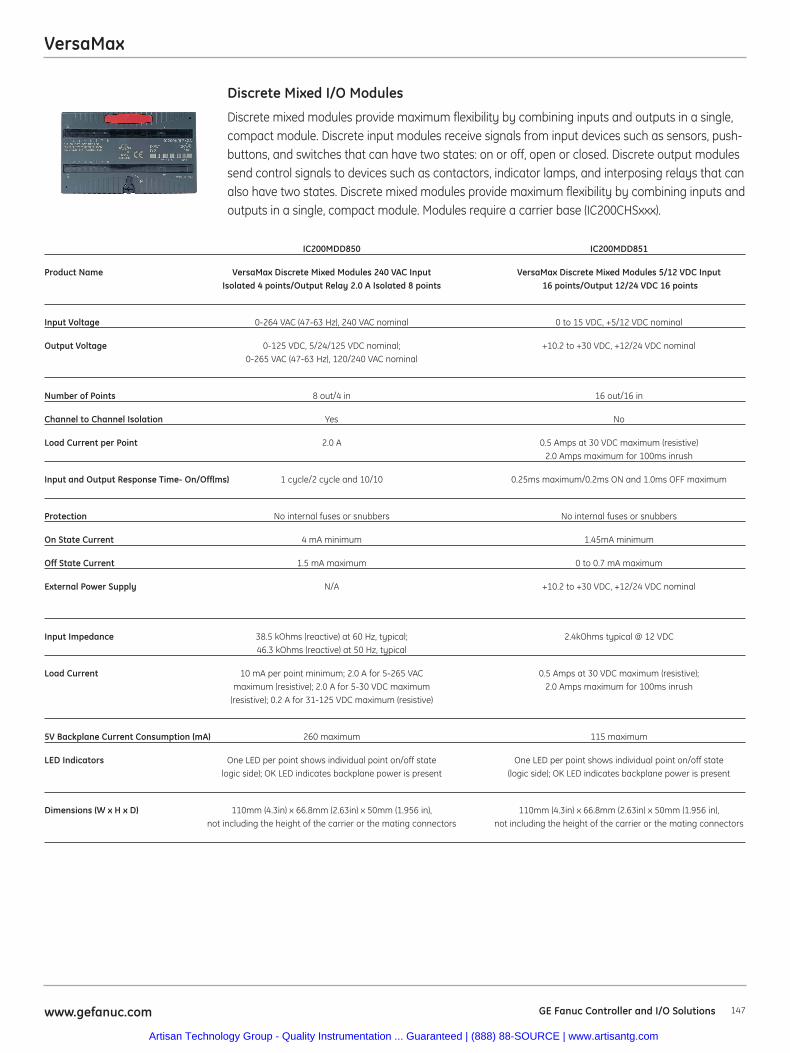
VersaMax
147www.gefanuc.com GE Fanuc Controller and I/O Solutions
Discrete mixed modules provide maximum flexibility by combining inputs and outputs in a single,compact module. Discrete input modules receive signals from input devices such as sensors, push-buttons, and switches that can have two states: on or off, open or closed. Discrete output modulessend control signals to devices such as contactors, indicator lamps, and interposing relays that canalso have two states. Discrete mixed modules provide maximum flexibility by combining inputs andoutputs in a single, compact module. Modules require a carrier base (IC200CHSxxx).
Discrete Mixed I/O Modules
IC200MDD850 IC200MDD851
Product Name VersaMax Discrete Mixed Modules 240 VAC Input VersaMax Discrete Mixed Modules 5/12 VDC InputIsolated 4 points/Output Relay 2.0 A Isolated 8 points 16 points/Output 12/24 VDC 16 points
Input Voltage 0-264 VAC (47-63 Hz), 240 VAC nominal 0 to 15 VDC, +5/12 VDC nominal
Output Voltage 0-125 VDC, 5/24/125 VDC nominal; +10.2 to +30 VDC, +12/24 VDC nominal0-265 VAC (47-63 Hz), 120/240 VAC nominal
Number of Points 8 out/4 in 16 out/16 in
Channel to Channel Isolation Yes No
Load Current per Point 2.0 A 0.5 Amps at 30 VDC maximum (resistive) 2.0 Amps maximum for 100ms inrush
Input and Output Response Time- On/Off(ms) 1 cycle/2 cycle and 10/10 0.25ms maximum/0.2ms ON and 1.0ms OFF maximum
Protection No internal fuses or snubbers No internal fuses or snubbers
On State Current 4 mA minimum 1.45mA minimum
Off State Current 1.5 mA maximum 0 to 0.7 mA maximum
External Power Supply N/A +10.2 to +30 VDC, +12/24 VDC nominal
Input Impedance 38.5 kOhms (reactive) at 60 Hz, typical; 2.4kOhms typical @ 12 VDC46.3 kOhms (reactive) at 50 Hz, typical
Load Current 10 mA per point minimum; 2.0 A for 5-265 VAC 0.5 Amps at 30 VDC maximum (resistive); maximum (resistive); 2.0 A for 5-30 VDC maximum 2.0 Amps maximum for 100ms inrush
(resistive); 0.2 A for 31-125 VDC maximum (resistive)
5V Backplane Current Consumption (mA) 260 maximum 115 maximum
LED Indicators One LED per point shows individual point on/off state One LED per point shows individual point on/off statelogic side); OK LED indicates backplane power is present (logic side); OK LED indicates backplane power is present
Dimensions (W x H x D) 110mm (4.3in) x 66.8mm (2.63in) x 50mm (1.956 in), 110mm (4.3in) x 66.8mm (2.63in) x 50mm (1.956 in), not including the height of the carrier or the mating connectors not including the height of the carrier or the mating connectors
Artisan Technology Group - Quality Instrumentation ... Guaranteed | (888) 88-SOURCE | www.artisantg.com

VersaMax
148 www.gefanuc.comGE Fanuc Controller and I/O Solutions
Discrete input modules receive signals from input devices such as sensors, pushbuttons, andswitches that can have two states: on or off, open or closed. Modules require a carrier base(IC200CHSxxx).
Discrete Input Modules
IC200MDL140 IC200MDL141 IC200MDL143
Product Name VersaMax Discrete Input Module VersaMax Discrete Input Module VersaMax Discrete Input Module120 VAC, 8 points 240 VAC, 8 points 120 VAC Isolated, 8 points
Number of Points 8 8 8
Channel to Channel Isolation No No Yes
Input and Output Response Time- On/Off (ms) 1 cycle/2 cycles 1 cycle/2 cycles 1 cycle/2 cycles
Points per Common 1 group of 8 1 group of 8 8 groups of 1
On State Current 5 mA minimum 7 mA minimum 5 mA minimum
Off State Current 2.5 mA maximum 1.5 mA maximum 2.5 mA maximum
Input Impedance 8.6 kOhms (reactive) at 60 Hz, typical; 38.5 kOhms (reactive) at 60 Hz, typical; 8.6 kOhms (reactive) at 60 Hz, typical; 10.32 kOhms (reactive) at 50 Hz, typical 46.3 kOhms (reactive) at 50 Hz, typical 10.32 kOhms (reactive) at 50 Hz, typical
5V Backplane Current Consumption (mA) 55 maximum 55 maximum 50 maximum
LED Indicators One LED per point shows individual One LED per point shows individual One LED per point shows individualpoint ON/OFF status. OK LED indicates point ON/OFF status. OK LED indicates point ON/OFF status. OK LED indicates
backplane power is present backplane power is present backplane power is present
Dimensions (W x H x D) 110mm (4.3in) x 66.8mm (2.63in) x 110mm (4.3in) x 66.8mm (2.63in) x 110mm (4.3in) x 66.8mm (2.63in) x50mm (1.956 in), not including the height of 50mm (1.956 in), not including the height of 50mm (1.956 in), not including the height of
the carrier or the mating connectors the carrier or the mating connectors the carrier or the mating connectors
Artisan Technology Group - Quality Instrumentation ... Guaranteed | (888) 88-SOURCE | www.artisantg.com
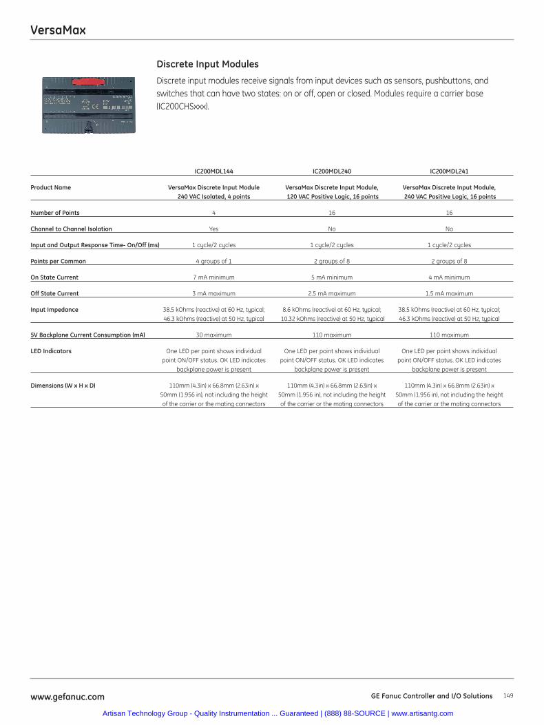
VersaMax
149www.gefanuc.com GE Fanuc Controller and I/O Solutions
Discrete input modules receive signals from input devices such as sensors, pushbuttons, andswitches that can have two states: on or off, open or closed. Modules require a carrier base(IC200CHSxxx).
Discrete Input Modules
IC200MDL144 IC200MDL240 IC200MDL241
Product Name VersaMax Discrete Input Module VersaMax Discrete Input Module, VersaMax Discrete Input Module,240 VAC Isolated, 4 points 120 VAC Positive Logic, 16 points 240 VAC Positive Logic, 16 points
Number of Points 4 16 16
Channel to Channel Isolation Yes No No
Input and Output Response Time- On/Off (ms) 1 cycle/2 cycles 1 cycle/2 cycles 1 cycle/2 cycles
Points per Common 4 groups of 1 2 groups of 8 2 groups of 8
On State Current 7 mA minimum 5 mA minimum 4 mA minimum
Off State Current 3 mA maximum 2.5 mA maximum 1.5 mA maximum
Input Impedance 38.5 kOhms (reactive) at 60 Hz, typical; 8.6 kOhms (reactive) at 60 Hz, typical; 38.5 kOhms (reactive) at 60 Hz, typical; 46.3 kOhms (reactive) at 50 Hz, typical 10.32 kOhms (reactive) at 50 Hz, typical 46.3 kOhms (reactive) at 50 Hz, typical
5V Backplane Current Consumption (mA) 30 maximum 110 maximum 110 maximum
LED Indicators One LED per point shows individual One LED per point shows individual One LED per point shows individualpoint ON/OFF status. OK LED indicates point ON/OFF status. OK LED indicates point ON/OFF status. OK LED indicates
backplane power is present backplane power is present backplane power is present
Dimensions (W x H x D) 110mm (4.3in) x 66.8mm (2.63in) x 110mm (4.3in) x 66.8mm (2.63in) x 110mm (4.3in) x 66.8mm (2.63in) x50mm (1.956 in), not including the height 50mm (1.956 in), not including the height 50mm (1.956 in), not including the heightof the carrier or the mating connectors of the carrier or the mating connectors of the carrier or the mating connectors
Artisan Technology Group - Quality Instrumentation ... Guaranteed | (888) 88-SOURCE | www.artisantg.com

VersaMax
150 www.gefanuc.comGE Fanuc Controller and I/O Solutions
Discrete input modules receive signals from input devices such as sensors, pushbuttons, andswitches that can have two states: on or off, open or closed. Modules require a carrier base(IC200CHSxxx).
Discrete Input Modules
IC200MDL243 IC200MDL244 IC200MDL631
Product Name VersaMax Discrete Input Module, VersaMax Discrete Input Module, VersaMax Discrete Input Module 125 VDC,120 VAC Isolated, 16 points 240 VAC Isolated, 8 points Pos/Neg Logic, Isolated, 8 points
Number of Points 16 8 8 isolated inputs
Channel to Channel Isolation Yes Yes Yes
Input and Output Response Time- On/Off (ms) 1 cycle/2 cycles 1 cycle/2 cycles 0.5 maximum
Points per Common 16 groups of 1 8 groups of 1 8 groups of 1
On State Current 5 mA minimum 7 mA minimum 1.0 mA minimum
Off State Current 2.5 mA maximum 3 mA maximum 0 to 0.1 mA maximum
Input Impedance 8.6 kOhms (reactive) at 60 Hz, typical; 38.5 kOhms (reactive) at 60 Hz, typical; 74 K Ohm typical at 125 VDC10.32 kOhms (reactive) at 50 Hz, typical 46.3 kOhms (reactive) at 50 Hz, typical
5V Backplane Current Consumption (mA) 100 maximum 60 maximum 40 maximum
LED Indicators One LED per point shows individual One LED per point shows individual One LED per point shows individualpoint ON/OFF status. OK LED indicates point ON/OFF status. OK LED indicates point ON/OFF status. OK LED indicates
backplane power is present backplane power is present backplane power is present
Dimensions (W x H x D) 110mm (4.3in) x 66.8mm (2.63in) x 110mm (4.3in) x 66.8mm (2.63in) x 110mm (4.3in) x 66.8mm (2.63in) x50mm (1.956 in), not including the height 50mm (1.956 in), not including the height 50mm (1.956 in), not including the heightof the carrier or the mating connectors of the carrier or the mating connectors of the carrier or the mating connectors
Artisan Technology Group - Quality Instrumentation ... Guaranteed | (888) 88-SOURCE | www.artisantg.com

VersaMax
151www.gefanuc.com GE Fanuc Controller and I/O Solutions
Discrete input modules receive signals from input devices such as sensors, pushbuttons, andswitches that can have two states: on or off, open or closed. Modules require a carrier base(IC200CHSxxx).
Discrete Input Modules
IC200MDL632 IC200MDL635 IC200MDL636
Product Name VersaMax Discrete Input Module 125 VDC, VersaMax Discrete Input Module 48 VDC, VersaMax Discrete Input Module 48 VDC, Pos/Neg Logic, Isolated, 16 points Pos/Neg Logic (2 Groups of 8), 16 points Pos/Neg Logic (4 Groups of 8), 32 points
Number of Points 16 isolated inputs 16 inputs (2 groups of 8) 32 (4 groups of 8)
Channel to Channel Isolation Yes No No
Input and Output Response Time- On/Off (ms) 0.5 maximum 0.5 maximum 0.5 maximum
Points per Common 16 groups of 1 2 groups of 8 4 groups of 8
On State Current 1.0 mA minimum 1.0 mA minimum 1.0 mA minimum
Off State Current 0 to 0.1 mA maximum 0 to 0.4 mA maximum 0 to 0.4 mA maximum
Input Impedance 74 K Ohm typical at 125 VDC 28 K Ohm typical 28 K Ohm typical
5V Backplane Current Consumption (mA) 80 maximum 70 maximum 140 maximum
LED Indicators One LED per point shows individual One LED per point shows individual One LED per point shows individual point ON/OFF status. OK LED indicates point ON/OFF status. OK LED indicates point ON/OFF status. OK LED indicates
backplane power is present backplane power is present backplane power is present
Dimensions (W x H x D) 110mm (4.3in) x 66.8mm (2.63in) x 110mm (4.3in) x 66.8mm (2.63in) x 110mm (4.3in) x 66.8mm (2.63in) x50mm (1.956 in), not including the height 50mm (1.956 in), not including the height 50mm (1.956 in), not including the heightof the carrier or the mating connectors of the carrier or the mating connectors of the carrier or the mating connectors
Artisan Technology Group - Quality Instrumentation ... Guaranteed | (888) 88-SOURCE | www.artisantg.com
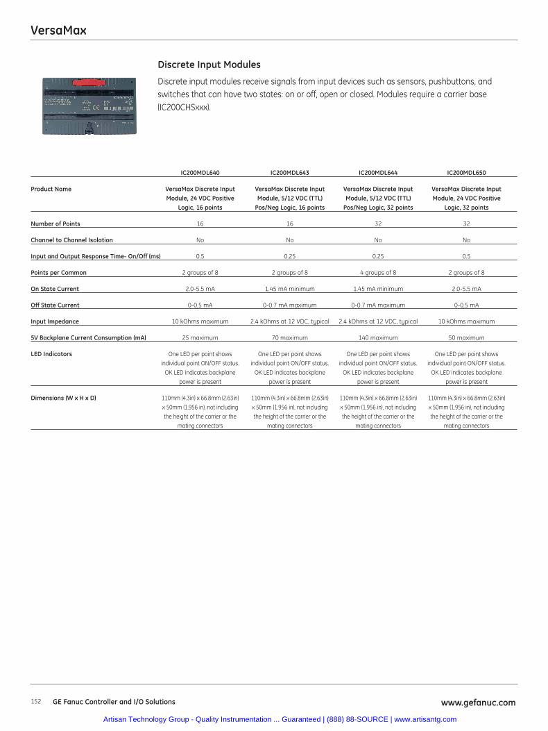
VersaMax
152 www.gefanuc.comGE Fanuc Controller and I/O Solutions
Discrete input modules receive signals from input devices such as sensors, pushbuttons, andswitches that can have two states: on or off, open or closed. Modules require a carrier base(IC200CHSxxx).
Discrete Input Modules
IC200MDL640 IC200MDL643 IC200MDL644 IC200MDL650
Product Name VersaMax Discrete Input VersaMax Discrete Input VersaMax Discrete Input VersaMax Discrete InputModule, 24 VDC Positive Module, 5/12 VDC (TTL) Module, 5/12 VDC (TTL) Module, 24 VDC Positive
Logic, 16 points Pos/Neg Logic, 16 points Pos/Neg Logic, 32 points Logic, 32 points
Number of Points 16 16 32 32
Channel to Channel Isolation No No No No
Input and Output Response Time- On/Off (ms) 0.5 0.25 0.25 0.5
Points per Common 2 groups of 8 2 groups of 8 4 groups of 8 2 groups of 8
On State Current 2.0-5.5 mA 1.45 mA minimum 1.45 mA minimum 2.0-5.5 mA
Off State Current 0-0.5 mA 0-0.7 mA maximum 0-0.7 mA maximum 0-0.5 mA
Input Impedance 10 kOhms maximum 2.4 kOhms at 12 VDC, typical 2.4 kOhms at 12 VDC, typical 10 kOhms maximum
5V Backplane Current Consumption (mA) 25 maximum 70 maximum 140 maximum 50 maximum
LED Indicators One LED per point shows One LED per point shows One LED per point shows One LED per point showsindividual point ON/OFF status. individual point ON/OFF status. individual point ON/OFF status. individual point ON/OFF status.
OK LED indicates backplane OK LED indicates backplane OK LED indicates backplane OK LED indicates backplanepower is present power is present power is present power is present
Dimensions (W x H x D) 110mm (4.3in) x 66.8mm (2.63in) 110mm (4.3in) x 66.8mm (2.63in) 110mm (4.3in) x 66.8mm (2.63in) 110mm (4.3in) x 66.8mm (2.63in) x 50mm (1.956 in), not including x 50mm (1.956 in), not including x 50mm (1.956 in), not including x 50mm (1.956 in), not includingthe height of the carrier or the the height of the carrier or the the height of the carrier or the the height of the carrier or the
mating connectors mating connectors mating connectors mating connectors
Artisan Technology Group - Quality Instrumentation ... Guaranteed | (888) 88-SOURCE | www.artisantg.com

VersaMax
153www.gefanuc.com GE Fanuc Controller and I/O Solutions
Discrete output modules send control signals to devices such as contactors, indicator lamps, andinterposing relays that can also have two states. Modules require a carrier base (IC200CHSxxx).
Discrete Output Modules
IC200MDL329 IC200MDL330 IC200MDL331
Product Name VersaMax Discrete Output Module, VersaMax Discrete Output Module, VersaMax Discrete Output Module,120 VAC, 0.5A per point Isolated, 120 VAC 0.5A per point Isolated, 120 VAC 2.0A per point Isolated,
8 points 16 points 8 points
Output Voltage 85-132 VAC (47-63 Hz), 120 VAC nominal 85-132 VAC (47-63 Hz), 120 VAC nominal 85-132 VAC (47-63 Hz), 120 VAC nominal
Number of Points 8 16 8
Channel to Channel Isolation Yes Yes Yes
Load Current per Point 0.5 A per point 0.5 A per point 2.0 A per point
Input and Output Response Time- On/Off (ms) <1/2 cycle/<1/2 cycle <1/2 cycle/<1/2 cycle <1/2 cycle/<1/2 cycle
Protection Snubber and MOVs (each output) Snubber and MOVs (each output) Snubber and MOVs (each output)
Points per Common 8 groups of 1 Isolated points Isolated points
External Power Supply 85-132 VAC (47-63 Hz), 120 VAC nominal 85-132 VAC (47-63 Hz), 120 VAC nominal 85-132 VAC (47-63 Hz), 120 VAC nominal
Load Current 10 mA minimum per point, 10 mA minimum per point, 10 mA minimum per point,0.5 A maximum per point, 0.5 A maximum per point, 2.0 A maximum per point,5.0 A for one cycle (20 ms) 5.0 A for one cycle (20 ms) 20 A for one cycle (20 ms)
maximum inrush maximum inrush maximum inrush
5V Backplane Current Consumption (mA) 70 maximum 140 maximum 85 maximum
LED Indicators One LED per point shows individual One LED per point shows individual One LED per point shows individualpoint ON/OFF status (logic side). point ON/OFF status (logic side). point ON/OFF status (logic side).
OK LED indicates backplane power OK LED indicates backplane power OK LED indicates backplane poweris present is present is present
Dimensions (W x H x D) 110mm (4.3in) x 66.8mm (2.63in) x 110mm (4.3in) x 66.8mm (2.63in) x 110mm (4.3in) x 66.8mm (2.63in) x 50mm (1.956 in), not including the 50mm (1.956 in), not including the 50mm (1.956 in), not including the
height of the carrier or the height of the carrier or the height of the carrier or themating connectors mating connectors mating connectors
Artisan Technology Group - Quality Instrumentation ... Guaranteed | (888) 88-SOURCE | www.artisantg.com
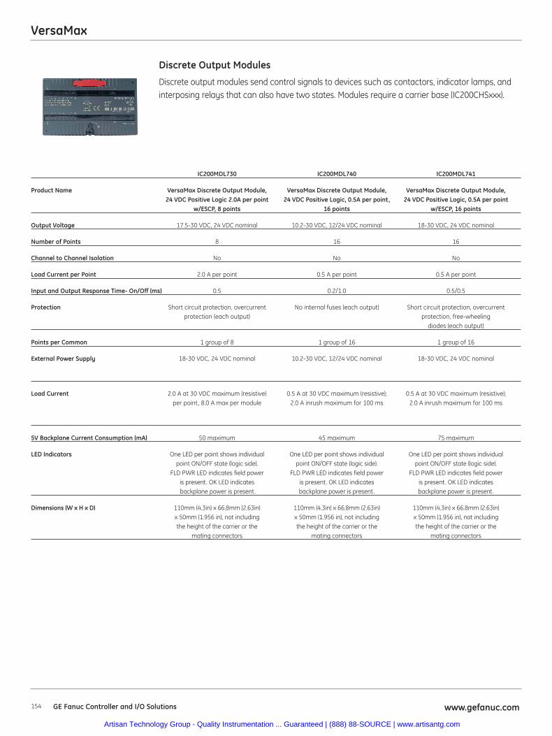
VersaMax
154 www.gefanuc.comGE Fanuc Controller and I/O Solutions
Discrete output modules send control signals to devices such as contactors, indicator lamps, andinterposing relays that can also have two states. Modules require a carrier base (IC200CHSxxx).
Discrete Output Modules
IC200MDL730 IC200MDL740 IC200MDL741
Product Name VersaMax Discrete Output Module, VersaMax Discrete Output Module, VersaMax Discrete Output Module,24 VDC Positive Logic 2.0A per point 24 VDC Positive Logic, 0.5A per point, 24 VDC Positive Logic, 0.5A per point
w/ESCP, 8 points 16 points w/ESCP, 16 points
Output Voltage 17.5-30 VDC, 24 VDC nominal 10.2-30 VDC, 12/24 VDC nominal 18-30 VDC, 24 VDC nominal
Number of Points 8 16 16
Channel to Channel Isolation No No No
Load Current per Point 2.0 A per point 0.5 A per point 0.5 A per point
Input and Output Response Time- On/Off (ms) 0.5 0.2/1.0 0.5/0.5
Protection Short circuit protection, overcurrent No internal fuses (each output) Short circuit protection, overcurrentprotection (each output) protection, free-wheeling
diodes (each output)
Points per Common 1 group of 8 1 group of 16 1 group of 16
External Power Supply 18-30 VDC, 24 VDC nominal 10.2-30 VDC, 12/24 VDC nominal 18-30 VDC, 24 VDC nominal
Load Current 2.0 A at 30 VDC maximum (resistive) 0.5 A at 30 VDC maximum (resistive); 0.5 A at 30 VDC maximum (resistive); per point, 8.0 A max per module 2.0 A inrush maximum for 100 ms 2.0 A inrush maximum for 100 ms
5V Backplane Current Consumption (mA) 50 maximum 45 maximum 75 maximum
LED Indicators One LED per point shows individual One LED per point shows individual One LED per point shows individual point ON/OFF state (logic side). point ON/OFF state (logic side). point ON/OFF state (logic side).
FLD PWR LED indicates field power FLD PWR LED indicates field power FLD PWR LED indicates field power is present. OK LED indicates is present. OK LED indicates is present. OK LED indicatesbackplane power is present. backplane power is present. backplane power is present.
Dimensions (W x H x D) 110mm (4.3in) x 66.8mm (2.63in) 110mm (4.3in) x 66.8mm (2.63in) 110mm (4.3in) x 66.8mm (2.63in) x 50mm (1.956 in), not including x 50mm (1.956 in), not including x 50mm (1.956 in), not includingthe height of the carrier or the the height of the carrier or the the height of the carrier or the
mating connectors mating connectors mating connectors
Artisan Technology Group - Quality Instrumentation ... Guaranteed | (888) 88-SOURCE | www.artisantg.com
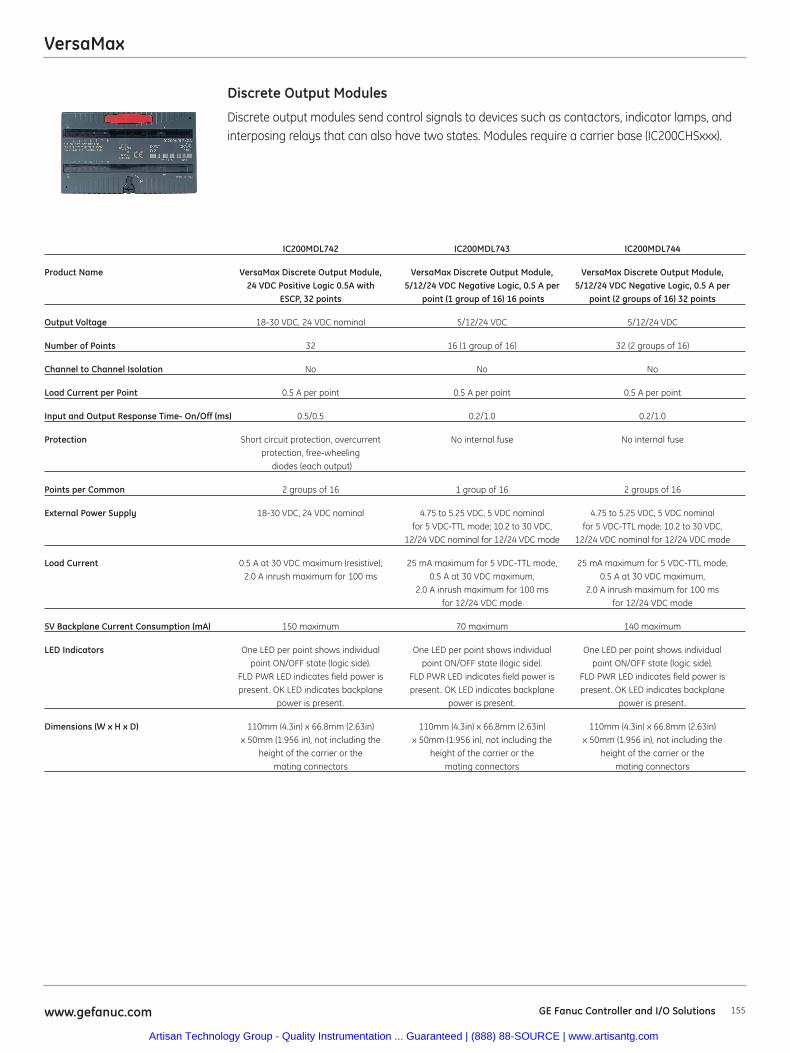
VersaMax
155www.gefanuc.com GE Fanuc Controller and I/O Solutions
Discrete output modules send control signals to devices such as contactors, indicator lamps, andinterposing relays that can also have two states. Modules require a carrier base (IC200CHSxxx).
Discrete Output Modules
IC200MDL742 IC200MDL743 IC200MDL744
Product Name VersaMax Discrete Output Module, VersaMax Discrete Output Module, VersaMax Discrete Output Module,24 VDC Positive Logic 0.5A with 5/12/24 VDC Negative Logic, 0.5 A per 5/12/24 VDC Negative Logic, 0.5 A per
ESCP, 32 points point (1 group of 16) 16 points point (2 groups of 16) 32 points
Output Voltage 18-30 VDC, 24 VDC nominal 5/12/24 VDC 5/12/24 VDC
Number of Points 32 16 (1 group of 16) 32 (2 groups of 16)
Channel to Channel Isolation No No No
Load Current per Point 0.5 A per point 0.5 A per point 0.5 A per point
Input and Output Response Time- On/Off (ms) 0.5/0.5 0.2/1.0 0.2/1.0
Protection Short circuit protection, overcurrent No internal fuse No internal fuseprotection, free-wheeling
diodes (each output)
Points per Common 2 groups of 16 1 group of 16 2 groups of 16
External Power Supply 18-30 VDC, 24 VDC nominal 4.75 to 5.25 VDC, 5 VDC nominal 4.75 to 5.25 VDC, 5 VDC nominalfor 5 VDC-TTL mode; 10.2 to 30 VDC, for 5 VDC-TTL mode; 10.2 to 30 VDC,
12/24 VDC nominal for 12/24 VDC mode 12/24 VDC nominal for 12/24 VDC mode
Load Current 0.5 A at 30 VDC maximum (resistive); 25 mA maximum for 5 VDC-TTL mode, 25 mA maximum for 5 VDC-TTL mode,2.0 A inrush maximum for 100 ms 0.5 A at 30 VDC maximum, 0.5 A at 30 VDC maximum,
2.0 A inrush maximum for 100 ms 2.0 A inrush maximum for 100 msfor 12/24 VDC mode for 12/24 VDC mode
5V Backplane Current Consumption (mA) 150 maximum 70 maximum 140 maximum
LED Indicators One LED per point shows individual One LED per point shows individual One LED per point shows individualpoint ON/OFF state (logic side). point ON/OFF state (logic side). point ON/OFF state (logic side).
FLD PWR LED indicates field power is FLD PWR LED indicates field power is FLD PWR LED indicates field power ispresent. OK LED indicates backplane present. OK LED indicates backplane present. OK LED indicates backplane
power is present. power is present. power is present.
Dimensions (W x H x D) 110mm (4.3in) x 66.8mm (2.63in) 110mm (4.3in) x 66.8mm (2.63in) 110mm (4.3in) x 66.8mm (2.63in) x 50mm (1.956 in), not including the x 50mm (1.956 in), not including the x 50mm (1.956 in), not including the
height of the carrier or the height of the carrier or the height of the carrier or themating connectors mating connectors mating connectors
Artisan Technology Group - Quality Instrumentation ... Guaranteed | (888) 88-SOURCE | www.artisantg.com
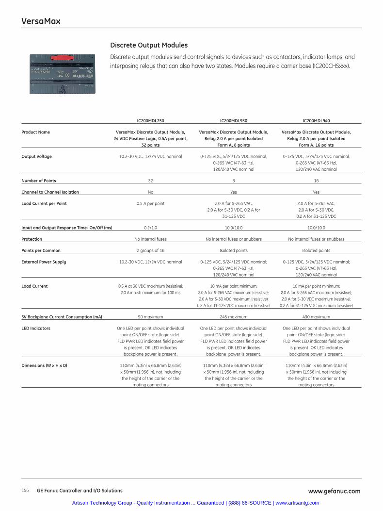
VersaMax
156 www.gefanuc.comGE Fanuc Controller and I/O Solutions
Discrete output modules send control signals to devices such as contactors, indicator lamps, andinterposing relays that can also have two states. Modules require a carrier base (IC200CHSxxx).
Discrete Output Modules
IC200MDL750 IC200MDL930 IC200MDL940
Product Name VersaMax Discrete Output Module, VersaMax Discrete Output Module, VersaMax Discrete Output Module, 24 VDC Positive Logic, 0.5A per point, Relay 2.0 A per point Isolated Relay 2.0 A per point Isolated
32 points Form A, 8 points Form A, 16 points
Output Voltage 10.2-30 VDC, 12/24 VDC nominal 0-125 VDC, 5/24/125 VDC nominal; 0-125 VDC, 5/24/125 VDC nominal; 0-265 VAC (47-63 Hz), 0-265 VAC (47-63 Hz), 120/240 VAC nominal 120/240 VAC nominal
Number of Points 32 8 16
Channel to Channel Isolation No Yes Yes
Load Current per Point 0.5 A per point 2.0 A for 5-265 VAC, 2.0 A for 5-265 VAC, 2.0 A for 5-30 VDC, 0.2 A for 2.0 A for 5-30 VDC,
31-125 VDC 0.2 A for 31-125 VDC
Input and Output Response Time- On/Off (ms) 0.2/1.0 10.0/10.0 10.0/10.0
Protection No internal fuses No internal fuses or snubbers No internal fuses or snubbers
Points per Common 2 groups of 16 Isolated points Isolated points
External Power Supply 10.2-30 VDC, 12/24 VDC nominal 0-125 VDC, 5/24/125 VDC nominal; 0-125 VDC, 5/24/125 VDC nominal; 0-265 VAC (47-63 Hz), 0-265 VAC (47-63 Hz), 120/240 VAC nominal 120/240 VAC nominal
Load Current 0.5 A at 30 VDC maximum (resistive); 10 mA per point minimum; 10 mA per point minimum; 2.0 A inrush maximum for 100 ms 2.0 A for 5-265 VAC maximum (resistive); 2.0 A for 5-265 VAC maximum (resistive);
2.0 A for 5-30 VDC maximum (resistive); 2.0 A for 5-30 VDC maximum (resistive);0.2 A for 31-125 VDC maximum (resistive) 0.2 A for 31-125 VDC maximum (resistive)
5V Backplane Current Consumption (mA) 90 maximum 245 maximum 490 maximum
LED Indicators One LED per point shows individual One LED per point shows individual One LED per point shows individualpoint ON/OFF state (logic side). point ON/OFF state (logic side). point ON/OFF state (logic side).
FLD PWR LED indicates field power FLD PWR LED indicates field power FLD PWR LED indicates field poweris present. OK LED indicates is present. OK LED indicates is present. OK LED indicates backplane power is present. backplane power is present. backplane power is present.
Dimensions (W x H x D) 110mm (4.3in) x 66.8mm (2.63in) 110mm (4.3in) x 66.8mm (2.63in) 110mm (4.3in) x 66.8mm (2.63in) x 50mm (1.956 in), not including x 50mm (1.956 in), not including x 50mm (1.956 in), not includingthe height of the carrier or the the height of the carrier or the the height of the carrier or the
mating connectors mating connectors mating connectors
Artisan Technology Group - Quality Instrumentation ... Guaranteed | (888) 88-SOURCE | www.artisantg.com
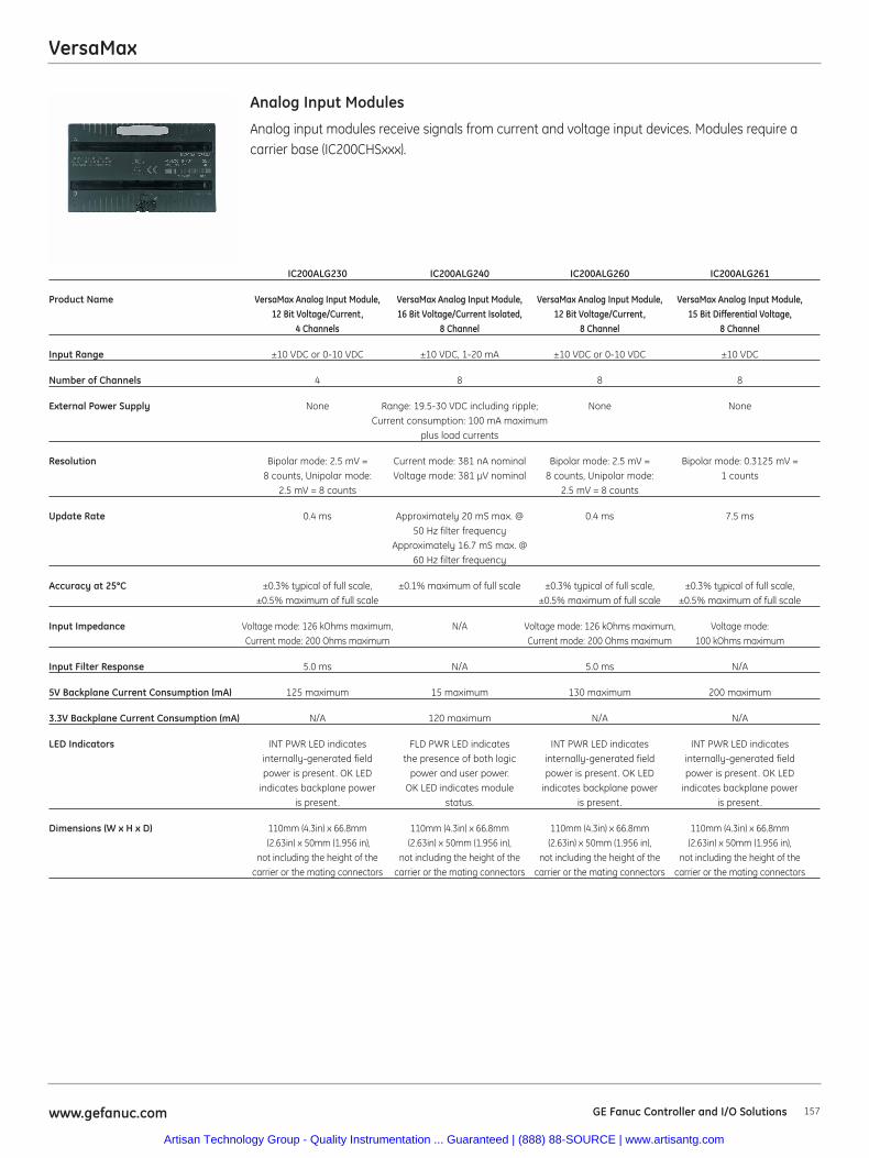
VersaMax
157www.gefanuc.com GE Fanuc Controller and I/O Solutions
Analog input modules receive signals from current and voltage input devices. Modules require acarrier base (IC200CHSxxx).
Analog Input Modules
IC200ALG230 IC200ALG240 IC200ALG260 IC200ALG261
Product Name VersaMax Analog Input Module, VersaMax Analog Input Module, VersaMax Analog Input Module, VersaMax Analog Input Module,12 Bit Voltage/Current, 16 Bit Voltage/Current Isolated, 12 Bit Voltage/Current, 15 Bit Differential Voltage,
4 Channels 8 Channel 8 Channel 8 Channel
Input Range ±10 VDC or 0-10 VDC ±10 VDC, 1-20 mA ±10 VDC or 0-10 VDC ±10 VDC
Number of Channels 4 8 8 8
External Power Supply None Range: 19.5-30 VDC including ripple; None NoneCurrent consumption: 100 mA maximum
plus load currents
Resolution Bipolar mode: 2.5 mV = Current mode: 381 nA nominal Bipolar mode: 2.5 mV = Bipolar mode: 0.3125 mV = 8 counts, Unipolar mode: Voltage mode: 381 μV nominal 8 counts, Unipolar mode: 1 counts
2.5 mV = 8 counts 2.5 mV = 8 counts
Update Rate 0.4 ms Approximately 20 mS max. @ 0.4 ms 7.5 ms50 Hz filter frequency
Approximately 16.7 mS max. @60 Hz filter frequency
Accuracy at 25°C ±0.3% typical of full scale, ±0.1% maximum of full scale ±0.3% typical of full scale, ±0.3% typical of full scale,±0.5% maximum of full scale ±0.5% maximum of full scale ±0.5% maximum of full scale
Input Impedance Voltage mode: 126 kOhms maximum, N/A Voltage mode: 126 kOhms maximum, Voltage mode: Current mode: 200 Ohms maximum Current mode: 200 Ohms maximum 100 kOhms maximum
Input Filter Response 5.0 ms N/A 5.0 ms N/A
5V Backplane Current Consumption (mA) 125 maximum 15 maximum 130 maximum 200 maximum
3.3V Backplane Current Consumption (mA) N/A 120 maximum N/A N/A
LED Indicators INT PWR LED indicates FLD PWR LED indicates INT PWR LED indicates INT PWR LED indicatesinternally-generated field the presence of both logic internally-generated field internally-generated fieldpower is present. OK LED power and user power. power is present. OK LED power is present. OK LED
indicates backplane power OK LED indicates module indicates backplane power indicates backplane poweris present. status. is present. is present.
Dimensions (W x H x D) 110mm (4.3in) x 66.8mm 110mm (4.3in) x 66.8mm 110mm (4.3in) x 66.8mm 110mm (4.3in) x 66.8mm(2.63in) x 50mm (1.956 in), (2.63in) x 50mm (1.956 in), (2.63in) x 50mm (1.956 in), (2.63in) x 50mm (1.956 in),
not including the height of the not including the height of the not including the height of the not including the height of thecarrier or the mating connectors carrier or the mating connectors carrier or the mating connectors carrier or the mating connectors
Artisan Technology Group - Quality Instrumentation ... Guaranteed | (888) 88-SOURCE | www.artisantg.com
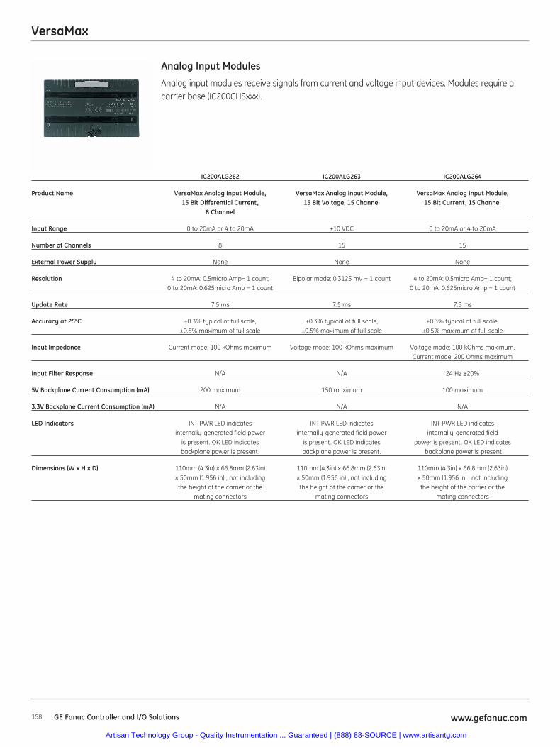
VersaMax
158 www.gefanuc.comGE Fanuc Controller and I/O Solutions
Analog input modules receive signals from current and voltage input devices. Modules require acarrier base (IC200CHSxxx).
Analog Input Modules
IC200ALG262 IC200ALG263 IC200ALG264
Product Name VersaMax Analog Input Module, VersaMax Analog Input Module, VersaMax Analog Input Module,15 Bit Differential Current, 15 Bit Voltage, 15 Channel 15 Bit Current, 15 Channel
8 Channel
Input Range 0 to 20mA or 4 to 20mA ±10 VDC 0 to 20mA or 4 to 20mA
Number of Channels 8 15 15
External Power Supply None None None
Resolution 4 to 20mA: 0.5micro Amp= 1 count; Bipolar mode: 0.3125 mV = 1 count 4 to 20mA: 0.5micro Amp= 1 count; 0 to 20mA: 0.625micro Amp = 1 count 0 to 20mA: 0.625micro Amp = 1 count
Update Rate 7.5 ms 7.5 ms 7.5 ms
Accuracy at 25°C ±0.3% typical of full scale, ±0.3% typical of full scale, ±0.3% typical of full scale, ±0.5% maximum of full scale ±0.5% maximum of full scale ±0.5% maximum of full scale
Input Impedance Current mode: 100 kOhms maximum Voltage mode: 100 kOhms maximum Voltage mode: 100 kOhms maximum, Current mode: 200 Ohms maximum
Input Filter Response N/A N/A 24 Hz ±20%
5V Backplane Current Consumption (mA) 200 maximum 150 maximum 100 maximum
3.3V Backplane Current Consumption (mA) N/A N/A N/A
LED Indicators INT PWR LED indicates INT PWR LED indicates INT PWR LED indicates internally-generated field power internally-generated field power internally-generated field
is present. OK LED indicates is present. OK LED indicates power is present. OK LED indicatesbackplane power is present. backplane power is present. backplane power is present.
Dimensions (W x H x D) 110mm (4.3in) x 66.8mm (2.63in) 110mm (4.3in) x 66.8mm (2.63in) 110mm (4.3in) x 66.8mm (2.63in)x 50mm (1.956 in) , not including x 50mm (1.956 in) , not including x 50mm (1.956 in) , not includingthe height of the carrier or the the height of the carrier or the the height of the carrier or the
mating connectors mating connectors mating connectors
Artisan Technology Group - Quality Instrumentation ... Guaranteed | (888) 88-SOURCE | www.artisantg.com

VersaMax
159www.gefanuc.com GE Fanuc Controller and I/O Solutions
Analog output modules provide voltage or current signals to analog output devices. Modulesrequire a carrier base (IC200CHSxxx).
Analog Output Modules
IC200ALG320 IC200ALG321 IC200ALG322
Product Name VersaMax Analog Output Module, VersaMax Analog Output Module, VersaMax Analog Output Module,12 Bit Current, 4 Channel 12 Bit 0-10V Voltage, 4 Channel 12 Bit ±10V Voltage, 4 Channel
Output Range 4-20 mA 0-10 VDC ±10 VDC
Number of Channels 4 4 4
External Power Supply Range: 18-30 VDC including ripple; Range: 18-30 VDC including ripple; Range: 18-30 VDC including ripple;Current consumption: 160 mA Current consumption: Current consumption:
maximum including load current 125 mA maximum 125 mA maximum
Resolution 4 uA = 8 counts 2.5 mV = 8 counts 5 mV = 16 counts
Update Rate 0.3 ms maximum 0.3 ms maximum 0.3 ms maximum
Accuracy at 25°C ±0.3% typical of full scale, ±0.3% typical of full scale, ±0.3% typical of full scale,±0.5% maximum of full scale ±0.5% maximum of full scale ±0.5% maximum of full scale
5V Backplane Current Consumption (mA) 50 maximum 50 maximum 50 maximum
3.3V Backplane Current Consumption (mA) N/A N/A N/A
LED Indicators FLD PWR LED indicates field power FLD PWR LED indicates field power FLD PWR LED indicates field poweris present. OK LED indicates is present. OK LED indicates is present. OK LED indicates backplane power is present. backplane power is present. backplane power is present.
Dimensions (W x H x D) 110mm (4.3in) x 66.8mm (2.63in) 110mm (4.3in) x 66.8mm (2.63in) 110mm (4.3in) x 66.8mm (2.63in)x 50mm (1.956 in), not including x 50mm (1.956 in), not including x 50mm (1.956 in), not including
the height of the carrier or the height of the carrier or the height of the carrier orthe mating connectors the mating connectors the mating connectors
Artisan Technology Group - Quality Instrumentation ... Guaranteed | (888) 88-SOURCE | www.artisantg.com
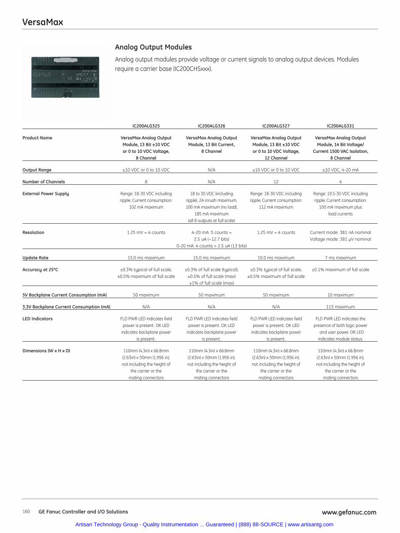
VersaMax
160 www.gefanuc.comGE Fanuc Controller and I/O Solutions
Analog output modules provide voltage or current signals to analog output devices. Modulesrequire a carrier base (IC200CHSxxx).
Analog Output Modules
IC200ALG325 IC200ALG326 IC200ALG327 IC200ALG331
Product Name VersaMax Analog Output VersaMax Analog Output VersaMax Analog Output VersaMax Analog OutputModule, 13 Bit ±10 VDC Module, 13 Bit Current, Module, 13 Bit ±10 VDC Module, 14 Bit Voltage/or 0 to 10 VDC Voltage, 8 Channel or 0 to 10 VDC Voltage, Current 1500 VAC Isolation,
8 Channel 12 Channel 8 Channel
Output Range ±10 VDC or 0 to 10 VDC N/A ±10 VDC or 0 to 10 VDC ±10 VDC, 4-20 mA
Number of Channels 8 N/A 12 4
External Power Supply Range: 18-30 VDC including 18 to 30 VDC (including Range: 18-30 VDC including Range: 19.5-30 VDC includingripple; Current consumption: ripple), 2A inrush maximum, ripple; Current consumption: ripple; Current consumption:
102 mA maximum 100 mA maximum (no load), 112 mA maximum 100 mA maximum plus185 mA maximum load currents
(all 8 outputs at full scale)
Resolution 1.25 mV = 4 counts 4-20 mA: 5 counts = 1.25 mV = 4 counts Current mode: 381 nA nominal2.5 uA (~12.7 bits) Voltage mode: 381 μV nominal
0-20 mA: 4 counts = 2.5 uA (13 bits)
Update Rate 15.0 ms maximum 15.0 ms maximum 10.0 ms maximum 7 ms maximum
Accuracy at 25°C ±0.3% typical of full scale, ±0.3% of full scale (typical), ±0.3% typical of full scale, ±0.1% maximum of full scale±0.5% maximum of full scale ±0.5% of full scale (max) ±0.5% maximum of full scale
±1% of full scale (max)
5V Backplane Current Consumption (mA) 50 maximum 50 maximum 50 maximum 10 maximum
3.3V Backplane Current Consumption (mA) N/A N/A N/A 115 maximum
LED Indicators FLD PWR LED indicates field FLD PWR LED indicates field FLD PWR LED indicates field FLD PWR LED indicates the power is present. OK LED power is present. OK LED power is present. OK LED presence of both logic power
indicates backplane power indicates backplane power indicates backplane power and user power. OK LEDis present. is present. is present. indicates module status.
Dimensions (W x H x D) 110mm (4.3in) x 66.8mm 110mm (4.3in) x 66.8mm 110mm (4.3in) x 66.8mm 110mm (4.3in) x 66.8mm(2.63in) x 50mm (1.956 in), (2.63in) x 50mm (1.956 in), (2.63in) x 50mm (1.956 in), (2.63in) x 50mm (1.956 in),not including the height of not including the height of not including the height of not including the height of
the carrier or the the carrier or the the carrier or the the carrier or the mating connectors mating connectors mating connectors mating connectors
Artisan Technology Group - Quality Instrumentation ... Guaranteed | (888) 88-SOURCE | www.artisantg.com
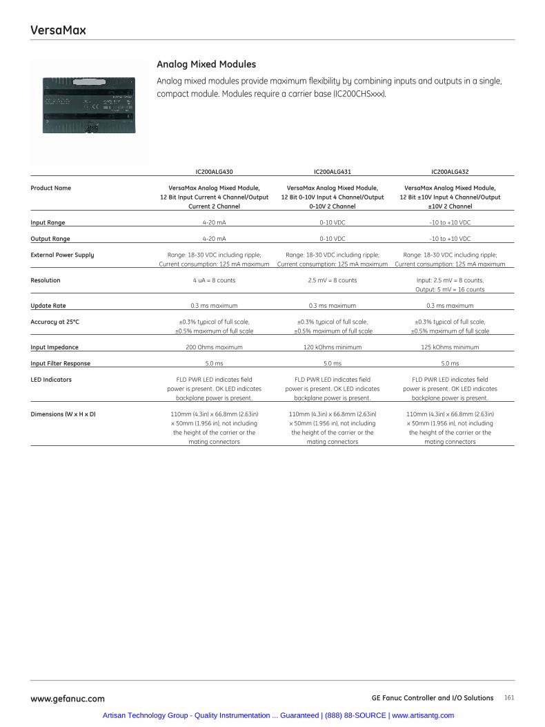
VersaMax
161www.gefanuc.com GE Fanuc Controller and I/O Solutions
Analog mixed modules provide maximum flexibility by combining inputs and outputs in a single,compact module. Modules require a carrier base (IC200CHSxxx).
Analog Mixed Modules
IC200ALG430 IC200ALG431 IC200ALG432
Product Name VersaMax Analog Mixed Module, VersaMax Analog Mixed Module, VersaMax Analog Mixed Module, 12 Bit Input Current 4 Channel/Output 12 Bit 0-10V Input 4 Channel/Output 12 Bit ±10V Input 4 Channel/Output
Current 2 Channel 0-10V 2 Channel ±10V 2 Channel
Input Range 4-20 mA 0-10 VDC -10 to +10 VDC
Output Range 4-20 mA 0-10 VDC -10 to +10 VDC
External Power Supply Range: 18-30 VDC including ripple; Range: 18-30 VDC including ripple; Range: 18-30 VDC including ripple; Current consumption: 125 mA maximum Current consumption: 125 mA maximum Current consumption: 125 mA maximum
Resolution 4 uA = 8 counts 2.5 mV = 8 counts Input: 2.5 mV = 8 counts, Output: 5 mV = 16 counts
Update Rate 0.3 ms maximum 0.3 ms maximum 0.3 ms maximum
Accuracy at 25°C ±0.3% typical of full scale, ±0.3% typical of full scale, ±0.3% typical of full scale, ±0.5% maximum of full scale ±0.5% maximum of full scale ±0.5% maximum of full scale
Input Impedance 200 Ohms maximum 120 kOhms minimum 125 kOhms minimum
Input Filter Response 5.0 ms 5.0 ms 5.0 ms
LED Indicators FLD PWR LED indicates field FLD PWR LED indicates field FLD PWR LED indicates fieldpower is present. OK LED indicates power is present. OK LED indicates power is present. OK LED indicates
backplane power is present. backplane power is present. backplane power is present.
Dimensions (W x H x D) 110mm (4.3in) x 66.8mm (2.63in) 110mm (4.3in) x 66.8mm (2.63in) 110mm (4.3in) x 66.8mm (2.63in) x 50mm (1.956 in), not including x 50mm (1.956 in), not including x 50mm (1.956 in), not includingthe height of the carrier or the the height of the carrier or the the height of the carrier or the
mating connectors mating connectors mating connectors
Artisan Technology Group - Quality Instrumentation ... Guaranteed | (888) 88-SOURCE | www.artisantg.com
VersaMax
162 www.gefanuc.comGE Fanuc Controller and I/O Solutions
Specialty modules are available for RTD and Thermocouple inputs. Modules require a carrier base(IC200CHSxxx).).
RTD and Thermocouple Modules
IC200ALG620 IC200ALG630
Product Name VersaMax Analog Input Module, VersaMax Analog Input Module, 16 Bit RTD, 4 Channel 16 Bit Thermocouple, 7 Channel
Input Range RTD types: 25, 100, and 1000 ohm platinum Thermocouple types: J, K, T, S, R, none 10, 50, and 100 ohm copper (used for mV inputs)
100 and 120 ohm nickel604 ohms nickel/iron
Number of Channels 4 7
Resolution 15 bits plus sign 15 bits plus sign
Update Rate 60 Hz: approximately 210 milliseconds per channel 60 Hz: approximately 60 milliseconds per channel50 Hz: approximately 230 milliseconds per channel 50 Hz: approximately 70 milliseconds per channel
Accuracy at 25°C on voltage measurement: ±0.15% on resistance measurement on voltage measurement: ±0.2% on temperature measurement: ±0.15% on RTD on temperature measurement:±0.15%
(temperature) measurement
5 V Backplane Current Consumption (mA) 125 maximum 125 maximum
3.3 V Backplane Current Consumption (mA) 125 maximum 125 maximum
LED Indicators OK LED: green indicates backplane OK LED: green indicates backplanepower is present. Amber indicates module fault. power is present. Amber indicates module fault.
Dimensions (W x H x D) 110mm (4.3in) x 66.8mm (2.63in) x 50mm (1.956 in), 110mm (4.3in) x 66.8mm (2.63in) x 50mm (1.956 in),not including the height of the carrier or the not including the height of the carrier or the
mating connectors mating connectors
Artisan Technology Group - Quality Instrumentation ... Guaranteed | (888) 88-SOURCE | www.artisantg.com
VersaMax
163www.gefanuc.com GE Fanuc Controller and I/O Solutions
Discrete mixed modules provide maximum flexibility by combining inputs and outputs in asingle, compact module. Discrete input modules receive signals from input devices such assensors, pushbuttons, and switches that can have two states: on or off, open or closed.Discrete output modules send control signals to devices such as contactors, indicatorlamps, and interposing relays that can also have two states. Discrete mixed modules pro-vide maximum flexibility by combining inputs and outputs in a single, compact module.Modules require a carrier base (IC200CHSxxx).
Specialty Modules
IC200MDD841
Product Name VersaMax Discrete Mixed Modules 24VDC Pos Logic Input 20/Output 12/HSC, PWM or Pulse Train
Input Voltage 24 VDC
Output Voltage 24 VDC
Number of Points 20 in/12 out/4 configurable
Channel to Channel Isolation No
Inrush Current 2.0 A maximum for 100 ms
Input and Output Response Time- On/Off (ms) 7 and 0.5
Protection No internal fuses
On State Current 3.0-8.0 mA
Off State Current 0-0.5 mA
External Power Supply 24 VDC nominal, 18-30 VDC
Input Impedance 9.6 kOhms maximum
Load Current 0.5 A maximum
5V Backplane Current Consumption (mA) 30
LED Indicators One LED per point shows individual point on/off state (logic side); OK LED indicates backplane power is present
Dimensions (W x H x D) 110mm (4.3in) x 66.8mm (2.63in) x 50mm (1.956 in), not including the height of the carrier or the mating connectors
Artisan Technology Group - Quality Instrumentation ... Guaranteed | (888) 88-SOURCE | www.artisantg.com
VersaMax
164 www.gefanuc.comGE Fanuc Controller and I/O Solutions
Expansion Modules can be used to extend a VersaMax PLC or I/O station to include up toseven additional groups of up to eight modules each, providing the architectural flexibilityto accommodate larger applications.
Expansion Modules
IC200ERM001 IC200ERM002 IC200ETM001
Product Name Expansion Receiver Module, Isolated Expansion Receiver Module, Non-Isolated Bus Transmitter Expansion Module
Expansion Type Receiver Receiver Transmitter
Distance Up to 2460 feet Up to 50 feet N/A
5 V Backplane Current Consumption (mA) 430 70 44
3.3 V Backplane Current Consumption (mA) 20 20 N/A
LED Indicators PWR LED indicates 5 VDC power PWR LED indicates 5 VDC power PWR LED indicates 5 VDC powerstatus; EXP RX LED indicates status status; EXP RX LED indicates status; EXP TX LED indicates
of the expansion bus; SCAN indicates expansion bus communications expansion bus communicationwhether CPU/NIU is scanning I/O in status; SCAN indicates whether status
expansion racks CPU/NIU is scanning I/O inexpansion racks
Dimensions (W x H x D) 2.63 (66.8mm) x 5.04 (128mm) 2.63 (66.8mm) x 5.04 (128mm) 37mm (1.45in) x 5.04 (128mm)not including the height not including the height
of power supply of power supply
Artisan Technology Group - Quality Instrumentation ... Guaranteed | (888) 88-SOURCE | www.artisantg.com
VersaMax
165www.gefanuc.com GE Fanuc Controller and I/O Solutions
A Remote I/O Unit connects VersaMax I/O modules to a host PLC or computer via a varietyof networks, which makes it easy to include VersaMax I/O in Genius, Profibus-DP, DeviceNet,or Ethernet installations. Together, the Remote I/O Unit and its modules form an I/O stationcapable of providing up to 256 points of I/O.
Remote I/O Units
IC200DBI001 IC200EBI001
Product Name Remote I/O DeviceNet Network Interface Unit (Slave) Remote I/O Ethernet Network Interface Unit
Protocol Supported DeviceNet Slave EGD and Modbus TCP Server
Distance 500Kbps 100m bus length and branches totaling < 39m 100 Meters max drop length 10/100Mbaud250Kbps 250m bus length and branches totaling < 78m
125Kbps 500m bus length and branches totaling < 156m
I/O Discrete Points Includes both discrete and analog. 1024 bytes maximum both discrete and analog.Up to 128 bytes of inputs + 2-byte status word %I: 2048 points
Up to 128 bytes of outputs + 2-byte control word. %Q: 2048 points
I/O Analog Words Includes both discrete and analog. 1024 bytes maximum both discrete and analog.Up to 128 bytes of inputs + 2-byte status word %AI: 128 channels
Up to 128 bytes of outputs + 2-byte control word. %AQ: 128 channels
I/O Data Up to 128 bytes of inputs + 2-byte status word 256 Bytes of input, output, Analog input and Analog outputUp to 128 bytes of outputs + 2-byte control word.
Network Topology Linear bus (trunkline/dropline); power and signal Network dependenton the same network cable
Transmission Media Shielded, dual twisted pair cable, terminated at both ends Ethernet twisted pair
Connector 5-pin open pluggable connector RJ-45
User Diagnostic Data 2 bytes of status/control 4
Number of Modules 8 per NIU/station 8 per NIU/station
Redundancy N/A No
5V Backplane Current Consumption (mA) 160 175
3.3V Backplane Current Consumption (mA) 10 425
Dimensions (W x H x D) 133.4mm (5.25in) x 85.9mm (3.38in) 133.4mm (5.25in) x 85.9mm (3.38in) not including the height of power supply not including the height of power supply
Artisan Technology Group - Quality Instrumentation ... Guaranteed | (888) 88-SOURCE | www.artisantg.com
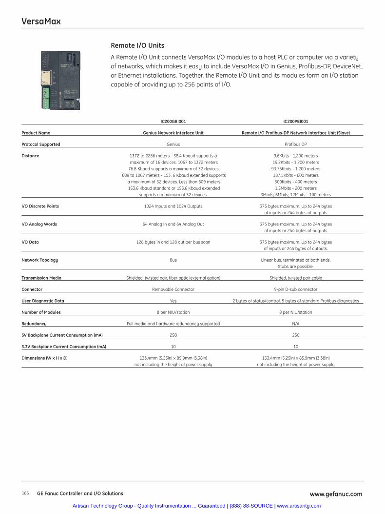
VersaMax
166 www.gefanuc.comGE Fanuc Controller and I/O Solutions
A Remote I/O Unit connects VersaMax I/O modules to a host PLC or computer via a varietyof networks, which makes it easy to include VersaMax I/O in Genius, Profibus-DP, DeviceNet,or Ethernet installations. Together, the Remote I/O Unit and its modules form an I/O stationcapable of providing up to 256 points of I/O.
Remote I/O Units
IC200GBI001 IC200PBI001
Product Name Genius Network Interface Unit Remote I/O Profibus-DP Network Interface Unit (Slave)
Protocol Supported Genius Profibus DP
Distance 1372 to 2286 meters - 38.4 Kbaud supports a 9.6Kbits - 1,200 metersmaximum of 16 devices. 1067 to 1372 meters 19.2Kbits - 1,200 meters
76.8 Kbaud supports a maximum of 32 devices. 93.75Kbits - 1,200 meters609 to 1067 meters - 153. 6 Kbaud extended supports 187.5Kbits - 600 meters
a maximum of 32 devices. Less than 609 meters 500Kbits - 400 meters153.6 Kbaud standard or 153.6 Kbaud extended 1.5Mbits - 200 meters
supports a maximum of 32 devices. 3Mbits; 6Mbits; 12Mbits - 100 meters
I/O Discrete Points 1024 Inputs and 1024 Outputs 375 bytes maximum. Up to 244 bytesof inputs or 244 bytes of outputs
I/O Analog Words 64 Analog In and 64 Analog Out 375 bytes maximum. Up to 244 bytesof inputs or 244 bytes of outputs
I/O Data 128 bytes in and 128 out per bus scan 375 bytes maximum. Up to 244 bytes of inputs or 244 bytes of outputs.
Network Topology Bus Linear bus, terminated at both ends. Stubs are possible.
Transmission Media Shielded, twisted pair, fiber optic (external option) Shielded, twisted pair cable
Connector Removable Connector 9-pin D-sub connector
User Diagnostic Data Yes 2 bytes of status/control, 5 bytes of standard Profibus diagnostics
Number of Modules 8 per NIU/station 8 per NIU/station
Redundancy Full media and hardware redundancy supported N/A
5V Backplane Current Consumption (mA) 250 250
3.3V Backplane Current Consumption (mA) 10 10
Dimensions (W x H x D) 133.4mm (5.25in) x 85.9mm (3.38in) 133.4mm (5.25in) x 85.9mm (3.38in) not including the height of power supply not including the height of power supply
Artisan Technology Group - Quality Instrumentation ... Guaranteed | (888) 88-SOURCE | www.artisantg.com
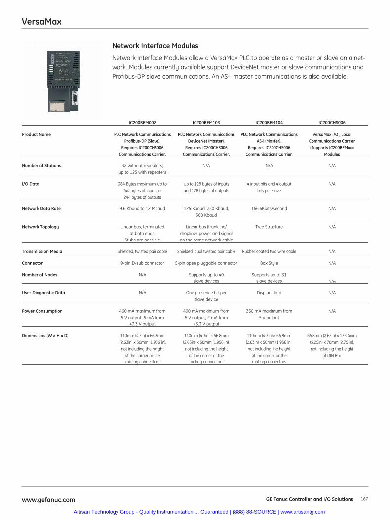
VersaMax
167www.gefanuc.com GE Fanuc Controller and I/O Solutions
IC200BEM002 IC200BEM103 IC200BEM104 IC200CHS006
Product Name PLC Network Communications PLC Network Communications PLC Network Communications VersaMax I/O , Local Profibus-DP (Slave). DeviceNet (Master). AS-i (Master). Communications Carrier
Requires IC200CHS006 Requires IC200CHS006 Requires IC200CHS006 (Supports IC200BEMxxxCommunications Carrier. Communications Carrier. Communications Carrier. Modules
Number of Stations 32 without repeaters; N/A N/A N/Aup to 125 with repeaters
I/O Data 384 Bytes maximum; up to Up to 128 bytes of inputs 4 input bits and 4 output N/A244 bytes of inputs or and 128 bytes of outputs bits per slave244 bytes of outputs
Network Data Rate 9.6 Kbaud to 12 Mbaud 125 Kbaud, 250 Kbaud, 166.6Kbits/second N/A500 Kbaud
Network Topology Linear bus, terminated Linear bus (trunkline/ Tree Structure N/Aat both ends. dropline); power and signal
Stubs are possible on the same network cable
Transmission Media Shielded, twisted pair cable Shielded, dual twisted pair cable Rubber coated two wire cable N/A
Connector 9-pin D-sub connector 5-pin open pluggable connector Box Style N/A
Number of Nodes N/A Supports up to 40 Supports up to 31 slave devices slave devices N/A
User Diagnostic Data N/A One presence bit per Display data N/Aslave device
Power Consumption 460 mA maximum from 490 mA maximum from 350 mA maximum from N/A5 V output, 5 mA from 5 V output, 2 mA from 5 V output
+3.3 V output +3.3 V output
Dimensions (W x H x D) 110mm (4.3in) x 66.8mm 110mm (4.3in) x 66.8mm 110mm (4.3in) x 66.8mm 66.8mm (2.63in) x 133.4mm (2.63in) x 50mm (1.956 in), (2.63in) x 50mm (1.956 in), (2.63in) x 50mm (1.956 in), (5.25in) x 70mm (2.75 in),not including the height not including the height not including the height not including the height
of the carrier or the of the carrier or the of the carrier or the of DIN Railmating connectors mating connectors mating connectors
Network Interface Modules allow a VersaMax PLC to operate as a master or slave on a net-work. Modules currently available support DeviceNet master or slave communications andProfibus-DP slave communications. An AS-i master communications is also available.
Network Interface Modules
Artisan Technology Group - Quality Instrumentation ... Guaranteed | (888) 88-SOURCE | www.artisantg.com
168 www.gefanuc.comGE Fanuc Controller and I/O Solutions
Accessories
IC200ACC001 Replacement Battery for VersaMax CPUs
IC200ACC003 EZ Program Store, CPU RS-485 Port Update Device
IC200ACC201 Expansion Terminator QTY 1
IC200ACC202 Expansion Terminator QTY 2
IC690ACC905 Encapsulated Thermistor Kit QTY 2
IC200ACC301 I/O Filler Module
IC200ACC302 I/O Input Simulator
IC200ACC303 I/O Shorting Bar QTY 2
IC200ACC304 I/O Cable Connector Kit QTY 2
IC200ACC313 DIN rail clips (Qty 2) to secure modules on DIN rail
IC200TBM001 I/O Auxiliary Terminal Strip, 18 Internally Bussed, Barrier Style
IC200TBM002 I/O Auxiliary Terminal Strip, 18 Internally Bussed, Box Style
IC200TBM005 I/O Auxiliary Terminal Strip, 18 Internally Bussed, Spring Clamp Style
Cables for Connector Type Carrier
IC200CBL105 Cable, I/O Non-Shielded, 2 Connectors. 0.5M used with IC200CHS003 and IC200CHS011, 012, 015.
IC200CBL110 Cable, I/O Non-Shielded, 2 Connectors, 1.0M used with IC200CHS003 and IC200CHS011, 012, 015.
IC200CBL120 Cable, I/O Non-Shielded, 2 Connectors, 2.0M used with IC200CHS003 and IC200CHS011, 012, 015.
IC200CBL230 Cable, I/O Non-Shielded, 1 Connector, 3.0M used with IC200CHS003 and IC200CHS011, 012, 015.
Cables to Connect Rack to Rack Expansion
IC200CBL600 Rack Expansion Cable, Shielded, Single Ended, 1M to One Expansion Receiver Module (IC200ERM00x)
IC200CBL601 Rack Expansion Cable, Shielded, 2 Connectors, 1M. Supports Multidrop to Multiple Expansion Receiver Modules (IC200ERM00x)
IC200CBL602 Rack Expansion Cable, Shielded, 2 Connectors, 2M. Supports Multidrop to Multiple Expansion Receiver Modules (IC200ERM00x)
IC200ACC304 I/O Cable Connector Kit, QTY 2
Starter Kits
IC200PKG001 PLC Starter Kit CPU001 Contains CPU001, PWR101, MDD845, CHS002, ACC302, CBL001, GFK-1503, GFK-1504, 641VPS300 (Infolink included), coffee mug, and plastic carry case. Does not include 24 VDC power supply for inputs.
IC200PKG010 PLC Starter Kit CPUE05 Contains CPUE05, PWR101, MDD845, CHS002, ACC302, CBL001, GFK-1503, GFK-1504, Machine Edition (Infolink included), coffee mug, and plastic carry case. Does not include 24 VDC power supply for inputs.
IC200PKG101 I/O Starter Kit GENIUS Contains GBI001, PWR101, MDD845, CHS002, ACC302, CBL001, GFK-1535, GFK-1504, 690CDR002 (Infolink), coffee mug, and plastic carry case. Does not include 24 VDC power supply for inputs.
IC200PKG102 I/O Starter Kit Profibus-DP Contains PBI001, PWR101, MDD845, CHS002, ACC302, CBL001, GFK-1534, GFK-1504, 690CDR002 (Infolink), coffee mug, and plastic carry case. Does not include 24 VDC power supply for inputs.
IC200PKG103 I/O Starter Kit DeviceNet Contains DBI001, PWR101, MDD845, CHS002, ACC302, CBL001, GFK-1533, GFK-1504, 690CDR002 (Infolink), coffee mug, and plastic carry case. Does not include 24 VDC power supply for inputs.
IC200PKG104 I/O Starter Kit Ethernet Contains EBI001, PWR101, MDD845, CHS002, ACC302, CBL001, GFK-1534, GFK-1504, Machine Edition(Infolink), coffee mug, and plastic carry case. Does not include 24 VDC power supply for inputs.
VersaMax
Artisan Technology Group - Quality Instrumentation ... Guaranteed | (888) 88-SOURCE | www.artisantg.com
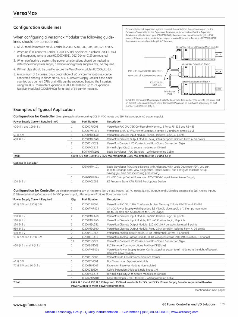
169www.gefanuc.com GE Fanuc Controller and I/O Solutions
Configuration Guidelines
When configuring a VersaMax Modular the following guide-lines should be considered:1. All I/O modules require an I/O Carrier (IC200CHS001, 002, 003, 005, 022 or 025).
2. When an I/O Connector Carrier (IC200CHS003) is selected, a cable (IC200CBL6xx)and interposing remote base (IC200CHS011, 012, 014 or 015) are required.
3. When configuring a system, the power consumptions should be tracked todetermine what power supply and how many power supplies may be required.
4. DIN rail clips should be used to secure the VersaMax modules (IC200ACC313).
5. A maximum of 8 carriers, any combination of I/O or communications, can beconnected directly to either an NIU or CPU. (Power Supply Booster base is notcounted as a carrier). CPUs and NIUs can be expanded beyond the 8 carriersusing the Bus Transmitter Expansion (IC200ETM001) and up to 7 ExpansionReceiver Modules (IC200ERM00x) for a total of 64 carrier modules.
Examples of Typical ApplicationConfiguration for Controller (Example application requiring (30) 24 VDC inputs and (10) Relay outputs AC power supply)
Power Supply Current Required (mA) Qty Part Number Description
40@ 5 V and 100@ 3 V 1 IC200CPU001 VersaMax PLC CPU 32K Configurable Memory, 2 Ports RS-232 and RS-485
1 IC200PWR101 VersaMax 120/240 VAC Power Supply (1.5 amps 5 V and 0.25 amps 3.3 V)
50 @ 5 V 1 IC200MDL650 VersaMax Discrete Input Module, 24 VDC Positive Logic, 32 points
490 @ 5 V 1 IC200MDL940 VersaMax Discrete Output Module, Relay 2.0 A per point Isolated Form A, 16 points
2 IC200CHS022 VersaMax Compact I/O Carrier, Local Box Clamp Connection Style
1 IC200ACC313 DIN rail clips (Qty 2) to secure modules on DIN rail
1 BC646MPS101 Logic Developer - PLC Standard - w/Programming Cable
Total: 580 @ 5 V and 100 @ 3 V (820 mA remaining). 1500 mA available for 5 V and 3.3 V.
Options to consider1 IC646MPH101 Logic Developer PDA Single License with Adapters. With Logic Developer PDA, you can
monitor/change data, view diagnostics, force ON/OFF, and configure machine setup — saving you time and increasing productivity.
1 IC690PWR024 24 VDC, 5 Amp Output Power and 120/230 VAC Input Power Power Supply
100 @ 5 V 1 IC200ACC003 EZ Program Store, CPU RS485 Port Update Device
Configuration for Controller (Application requiring 20K of Registers, (60) 24 VDC inputs, (15) AC Inputs, (12) AC Outputs and (20) Relay outputs also (16) Analog Inputs, (12) Isolated Analog Outputs and 24 VDC power supply. Also requires Profibus Slave connection)
Power Supply Current Required Qty Part Number Description
80 @ 5 V and 650 @ 3 V 1 IC200CPU005 VersaMax PLC CPU 128K Configurable User Memory, 2 Ports RS-232 and RS-485
3 IC200PWR002 24 VDC Power Supply with Expanded 3.3 V (Logic side supply of 1.5 amps maximum. Up to 1.0 amp can be allocated for 3.3 V usage.)
100 @ 5 V 2 IC200MDL650 VersaMax Discrete Input Module, 24 VDC Positive Logic, 32 points
110 @ 5 V 1 IC200MDL240 VersaMax Discrete Input Module, 120 VAC Positive Logic, 16 points
170 @ 5 V 2 IC200MDL331 VersaMax Discrete Output Module, 120 VAC 2.0 A per point Isolated, 8 points
980 @ 5 V 2 IC200MDL940 VersaMax Discrete Output Module, Relay 2.0 A per point Isolated Form A, 16 points
400 @ 5 V 2 IC200ALG262 VersaMax Analog Input Module, 15 Bit Differential Current, 8 Channel
10 @ 5 V and 115 @ 3 V 2 IC200ALG331 VersaMax Analog Output Module, 14 Bit Voltage/Current 1500 VAC Isolation, 8 Channel
11 IC200CHS022 VersaMax Compact I/O Carrier, Local Box Clamp Connection Style
460 @ 5 V and 5 @ 3 V 1 IC200BEM002 PLC Network Communications Profibus-DP (Slave)
1 IC200PWB001 VersaMax Power Supply Booster Carrier. Supplies power to all modules to the right of booster. Requires power supply.
1 IC200CHS006 VersaMax I/O, Local Communications Carrier
44 @ 5 V 1 IC200ETM001 Bus Transmitter Expansion Module
70 @ 5 V and 20 @ 3 V 1 IC200ERM002 Expansion Receiver Module, Non-Isolated
1 IC200CBL600 Cable Expansion Shielded Single Ended 1M
1 IC200ACC313 DIN rail clips (Qty 2) to secure modules on DIN rail
1 BC646MPS101 Logic Developer - PLC Standard - w/Programming Cable
Total: 2424 @ 5 V and 790 @ 3 V Required. 4500 mA available for 5 V and 3.3 V. Power Supply Booster required with extra Power Supply to meet power requirements.
(continued on next page)
VersaMax
For a multiple-rack expansion system, connect the cable from the expansion port on theExpansion Transmitter to the Expansion Receivers as shown below. If all the ExpansionReceivers are the Isolated type (IC200ERM001), the maximum overall cable length is 750meters. If the expansion bus includes any non-isolated Expansion Receivers (IC200ERM002),the maximum overall cable length is 15 meters.
Install the Terminator Plug (supplied with the Expansion Transmitter module) into the lower porton the last Expansion Receiver. Spare Terminator Plugs can be purchased separately as partnumber IC200ACC201 (Qty 2).
VersaMax PLC or I/O Station Main Rack (0)
VersaMax Expansion Rack 1
VersaMax Expansion Rack 7
15M with any IC200ERM002 ERMs
750M with all IC200ERM001 ERMs
IC200CBL601,602, 615
TerminatorPlug
Artisan Technology Group - Quality Instrumentation ... Guaranteed | (888) 88-SOURCE | www.artisantg.com
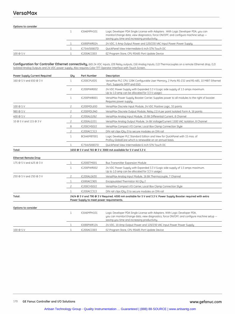
VersaMax
Options to consider
1 IC646MPH101 Logic Developer PDA Single License with Adapters . With Logic Developer PDA, you canmonitor/change data, view diagnostics, force ON/OFF, and configure machine setup — saving you time and increasing productivity.
1 IC690PWR024 24 VDC, 5 Amp Output Power and 120/230 VAC Input Power Power Supply
1 IC754VSI06STD QuickPanel View Intermediate 6 inch STN Touch DC
100 @ 5 V 1 IC200ACC003 EZ Program Store, CPU RS485 Port Update Device
Configuration for Controller Ethernet connectivity, (60) 24 VDC inputs, (20) Relay outputs, (16) Analog Inputs, (12) Thermocouples on a remote Ethernet drop, (12)Isolated Analog Outputs and 24 VDC power supply. Also requires Color TFT Operator Interface with Touch Screen.
Power Supply Current Required Qty Part Number Description
160 @ 5 V and 650 @ 3 V 1 IC200CPUE05 VersaMax PLC CPU 128K Configurable User Memory, 2 Ports RS-232 and RS-485, 10 MBIT EthernetPort. Supports SRTP and EGD.
2 IC200PWR002 24 VDC Power Supply with Expanded 3.3 V (Logic side supply of 1.5 amps maximum. Up to 1.0 amp can be allocated for 3.3 V usage.)
1 IC200PWB001 VersaMax Power Supply Booster Carrier. Supplies power to all modules to the right of booster. Requires power supply.
100 @ 5 V 2 IC200MDL650 VersaMax Discrete Input Module, 24 VDC Positive Logic, 32 points
980 @ 5 V 2 IC200MDL940 VersaMax Discrete Output Module, Relay 2.0 A per point Isolated Form A, 16 points
400 @ 5 V 2 IC200ALG262 VersaMax Analog Input Module, 15 Bit Differential Current, 8 Channel
10 @ 5 V and 115 @ 3 V 2 IC200ALG331 VersaMax Analog Output Module, 14 Bit Voltage/Current 1500 VAC Isolation, 8 Channel
8 IC200CHS022 VersaMax Compact I/O Carrier, Local Box Clamp Connection Style
2 IC200ACC313 DIN rail clips (Qty 2) to secure modules on DIN rail
1 BC646MBT001 Logic Developer PLC Standard Edition and View for QuickPanel with 15 mos. of Proficy GlobalCare which is renewable on an annual basis.
1 IC754VSI06STD QuickPanel View Intermediate 6 inch STN Touch DC
Total: 1650 @ 5 V and 765 @ 3 V. 3000 mA available for 5 V and 3.3 V.
Ethernet Remote Drop
175 @ 5 V and 425 @ 3 V 1 IC200ETM001 Bus Transmitter Expansion Module
1 IC200PWR002 24 VDC Power Supply with Expanded 3.3 V (Logic side supply of 1.5 amps maximum. Up to 1.0 amp can be allocated for 3.3 V usage.)
250 @ 5 V and 250 @ 3 V 2 IC200ALG630 VersaMax Analog Input Module, 16 Bit Thermocouple, 7 Channel
1 IC690ACC905 Encapsulated Thermistor Kit Qty 2
2 IC200CHS022 VersaMax Compact I/O Carrier, Local Box Clamp Connection Style
1 IC200ACC313 DIN rail clips (Qty 2) to secure modules on DIN rail
Total: 2424 @ 5 V and 790 @ 3 V Required. 4500 mA available for 5 V and 3.3 V. Power Supply Booster required with extra Power Supply to meet power requirements.
Options to consider
1 IC646MPH101 Logic Developer PDA Single License with Adapters. With Logic Developer PDA, you can monitor/change data, view diagnostics, force ON/OFF, and configure machine setup — saving you time and increasing productivity.
1 IC690PWR124 24 VDC, 10 Amp Output Power and 120/230 VAC Input Power Power Supply
100 @ 5 V 1 IC200ACC003 EZ Program Store, CPU RS485 Port Update Device
www.gefanuc.com170 GE Fanuc Controller and I/O Solutions
Artisan Technology Group - Quality Instrumentation ... Guaranteed | (888) 88-SOURCE | www.artisantg.com
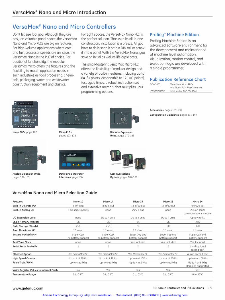
171www.gefanuc.com GE Fanuc Controller and I/O Solutions
VersaMax Nano and Micro Selection Guide
Features Nano 10 Micro 14 Micro 23 Micro 28 Micro 64
Built-in Discrete I/O 6 in/ 4out 8 in/ 6 out 13 in/10 out 16 in/12 out 40 in/24 out
Built-in Analog I/O 1 on some models none 2 in/ 1 out none 2 in on serial communications module
I/O Expansion Units none Up to 4 units Up to 4 units Up to 4 units Up to 4 units
Logic Memory (Words) 2K 9K 9K 9K 24K
Data Storage (Words) 256 256 2K 2K 32K
Scan Time (msec/K) 1.3 msec 1.1 msec 1.1 msec 1.1 msec 1.1 msec
Battery Backed RAM Super Cap, Super Cap, Super Cap and Super Cap and Super Cap andno battery support no battery support battery support battery support battery support
Real Time Clock none none Yes, Included Yes, Included Yes, Included
Serial Ports Available 1 2 2 2 1 and optional second port
Ethernet Option Yes, VersaMax SE Yes, VersaMax SE Yes, VersaMax SE Yes, VersaMax SE Yes on second port
High Speed Counter Up to 4 at 10Khz Up to 4 at 10Khz Up to 4 at 10Khz Up to 4 at 10Khz Up to 4 at 100Khz
Pulse Train/PWM Up to 4 at 5Khz Up to 4 at 5Khz Up to 4 at 5Khz Up to 4 at 5Khz Up to 4 at 65Khz(Ramping Supported)
Write Register Values to Internal Flash No Yes Yes Yes Yes
Temperature Range 0 to 55ºC 0 to 55ºC 0 to 55ºC 0 to 55ºC 0 to 55ºC
VersaMax® Nano and Micro Introduction
Publication Reference ChartGFK-1645 VersaMax Micro PLCs
and Nano PLCs User’s ManualIC690CDU002 InfoLink for PLC CD-ROM
Don’t let size fool you. Although they areeasy on valuable panel space, the VersaMaxNano and Micro PLCs are big on features.For high-volume applications where costand fast processor speeds are an issue, theVersaMax Nano is the PLC of choice. Foradditional functionality, the modularVersaMax Micro offers the features and theflexibility to match application needs insuch industries as food processing, chemi-cals, packaging, water and wastewater,construction equipment and plastics.
For tight spaces, the VersaMax Nano PLC isthe perfect solution. Thanks to its all-in-oneconstruction, installation is a breeze. All youhave to do is snap it onto a DIN rail or screwit into a panel. With the VersaMax Nano, yousave on initial as well as life cycle costs.
The small-footprint VersaMax Micro PLCoffers the flexibility of modular design anda variety of built-in features, including up to64 I/O points (expandable to 170 I/O points),fast cycle times, a robust instruction setand extensive memory that multiplies yourprogramming options.
VersaMax® Nano and Micro ControllersProficy™ Machine EditionProficy Machine Edition is anadvanced software environment forthe development and maintenanceof machine level automation.Visualization, motion control, andexecution logic are developed witha single programmer.
Nano PLCs, page 172
Accessories, pages 189-190
Configuration Guidelines, pages 191-192
Micro PLCs, pages 173-178
Discrete ExpansionUnits, pages 179-183
Analog Expansion Units,pages 184-185
DataPanels OperatorInterfaces, page 186
CommunicationsOptions, pages 187-188
Artisan Technology Group - Quality Instrumentation ... Guaranteed | (888) 88-SOURCE | www.artisantg.com
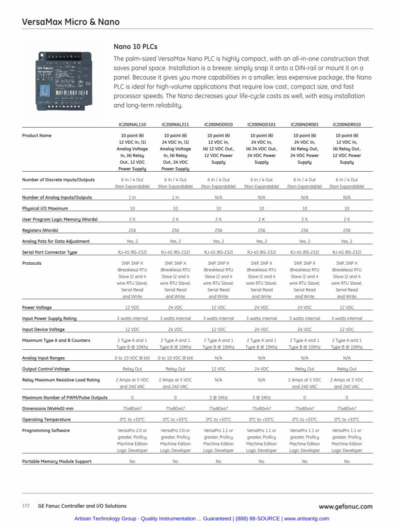
172 www.gefanuc.comGE Fanuc Controller and I/O Solutions
VersaMax Micro & Nano
The palm-sized VersaMax Nano PLC is highly compact, with an all-in-one construction thatsaves panel space. Installation is a breeze: simply snap it onto a DIN-rail or mount it on apanel. Because it gives you more capabilities in a smaller, less expensive package, the NanoPLC is ideal for high-volume applications that require low cost, compact size, and fastprocessor speeds. The Nano decreases your life-cycle costs as well, with easy installationand long-term reliability.
Nano 10 PLCs
IC200NAL110 IC200NAL211 IC200NDD010 IC200NDD101 IC200NDR001 IC200NDR010
Product Name 10 point (6) 10 point (6) 10 point (6) 10 point (6) 10 point (6) 10 point (6)12 VDC In, (1) 24 VDC In, (1) 12 VDC In, 24 VDC In, 24 VDC In, 12 VDC In,
Analog Voltage Analog Voltage (4) 12 VDC Out, (4) 24 VDC Out, (4) Relay Out, (4) Relay Out,In, (4) Relay In, (4) Relay 12 VDC Power 24 VDC Power 24 VDC Power 12 VDC PowerOut, 12 VDC Out, 24 VDC Supply Supply Supply Supply
Power Supply Power Supply
Number of Discrete Inputs/Outputs 6 In / 4 Out 6 In / 4 Out 6 In / 4 Out 6 In / 4 Out 6 In / 4 Out 6 In / 4 Out(Non Expandable) (Non Expandable) (Non Expandable) (Non Expandable) (Non Expandable) (Non Expandable)
Number of Analog Inputs/Outputs 1 In 1 In N/A N/A N/A N/A
Physical I/O Maximum 10 10 10 10 10 10
User Program Logic Memory (Words) 2 K 2 K 2 K 2 K 2 K 2 K
Registers (Words) 256 256 256 256 256 256
Analog Pots for Data Adjustment Yes, 2 Yes, 2 Yes, 2 Yes, 2 Yes, 2 Yes, 2
Serial Port Connector Type RJ-45 (RS-232) RJ-45 (RS-232) RJ-45 (RS-232) RJ-45 (RS-232) RJ-45 (RS-232) RJ-45 (RS-232)
Protocols SNP, SNP X SNP, SNP X SNP, SNP X SNP, SNP X SNP, SNP X SNP, SNP X(Breakless) RTU (Breakless) RTU (Breakless) RTU (Breakless) RTU (Breakless) RTU (Breakless) RTUSlave (2 and 4 Slave (2 and 4 Slave (2 and 4 Slave (2 and 4 Slave (2 and 4 Slave (2 and 4
wire RTU Slave). wire RTU Slave). wire RTU Slave). wire RTU Slave). wire RTU Slave). wire RTU Slave).Serial Read Serial Read Serial Read Serial Read Serial Read Serial Readand Write and Write and Write and Write and Write and Write
Power Voltage 12 VDC 24 VDC 12 VDC 24 VDC 24 VDC 12 VDC
Input Power Supply Rating 3 watts internal 3 watts internal 3 watts internal 3 watts internal 3 watts internal 3 watts internal
Input Device Voltage 12 VDC 24 VDC 12 VDC 24 VDC 24 VDC 12 VDC
Maximum Type A and B Counters 2 Type A and 1 2 Type A and 1 2 Type A and 1 2 Type A and 1 2 Type A and 1 2 Type A and 1Type B @ 10Khz Type B @ 10Khz Type B @ 10Khz Type B @ 10Khz Type B @ 10Khz Type B @ 10Khz
Analog Input Ranges 0 to 10 VDC (8 bit) 0 to 10 VDC (8 bit) N/A N/A N/A N/A
Output Control Voltage Relay Out Relay Out 12 VDC 24 VDC Relay Out Relay Out
Relay Maximum Resistive Load Rating 2 Amps at 5 VDC 2 Amps at 5 VDC N/A N/A 2 Amps at 5 VDC 2 Amps at 5 VDCand 240 VAC and 240 VAC and 240 VAC and 240 VAC
Maximum Number of PWM/Pulse Outputs 0 0 3 @ 5Khz 3 @ 5Khz 0 0
Dimensions (WxHxD) mm 75x80x47 75x80x47 75x80x47 75x80x47 75x80x47 75x80x47
Operating Temperature 0°C to +55°C 0°C to +55°C 0°C to +55°C 0°C to +55°C 0°C to +55°C 0°C to +55°C
Programming Software VersaPro 2.0 or VersaPro 2.0 or VersaPro 1.1 or VersaPro 1.1 or VersaPro 1.1 or VersaPro 1.1 orgreater, Proficy greater, Proficy greater, Proficy greater, Proficy greater, Proficy greater, Proficy Machine Edition Machine Edition Machine Edition Machine Edition Machine Edition Machine EditionLogic Developer Logic Developer Logic Developer Logic Developer Logic Developer Logic Developer
Portable Memory Module Support No No No No No No
Artisan Technology Group - Quality Instrumentation ... Guaranteed | (888) 88-SOURCE | www.artisantg.com
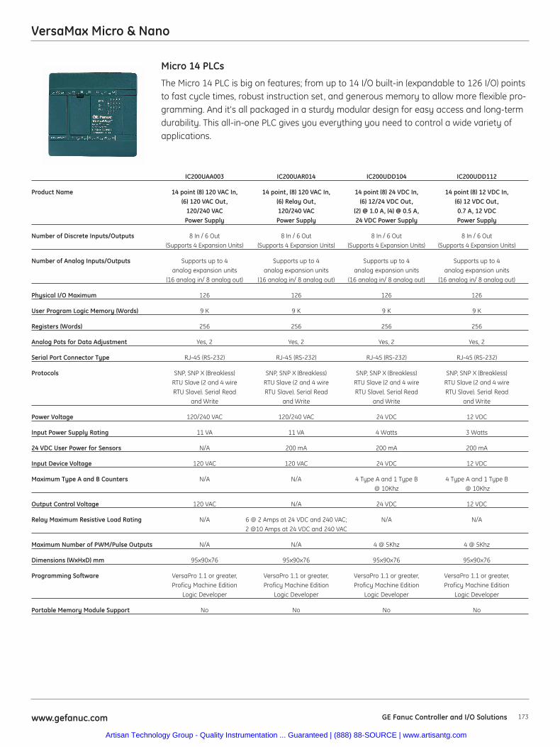
173www.gefanuc.com GE Fanuc Controller and I/O Solutions
VersaMax Micro & Nano
The Micro 14 PLC is big on features; from up to 14 I/O built-in (expandable to 126 I/O) pointsto fast cycle times, robust instruction set, and generous memory to allow more flexible pro-gramming. And it's all packaged in a sturdy modular design for easy access and long-termdurability. This all-in-one PLC gives you everything you need to control a wide variety ofapplications.
Micro 14 PLCs
IC200UAA003 IC200UAR014 IC200UDD104 IC200UDD112
Product Name 14 point (8) 120 VAC In, 14 point, (8) 120 VAC In, 14 point (8) 24 VDC In, 14 point (8) 12 VDC In,(6) 120 VAC Out, (6) Relay Out, (6) 12/24 VDC Out, (6) 12 VDC Out,
120/240 VAC 120/240 VAC (2) @ 1.0 A, (4) @ 0.5 A, 0.7 A, 12 VDC Power Supply Power Supply 24 VDC Power Supply Power Supply
Number of Discrete Inputs/Outputs 8 In / 6 Out 8 In / 6 Out 8 In / 6 Out 8 In / 6 Out (Supports 4 Expansion Units) (Supports 4 Expansion Units) (Supports 4 Expansion Units) (Supports 4 Expansion Units)
Number of Analog Inputs/Outputs Supports up to 4 Supports up to 4 Supports up to 4 Supports up to 4analog expansion units analog expansion units analog expansion units analog expansion units
(16 analog in/ 8 analog out) (16 analog in/ 8 analog out) (16 analog in/ 8 analog out) (16 analog in/ 8 analog out)
Physical I/O Maximum 126 126 126 126
User Program Logic Memory (Words) 9 K 9 K 9 K 9 K
Registers (Words) 256 256 256 256
Analog Pots for Data Adjustment Yes, 2 Yes, 2 Yes, 2 Yes, 2
Serial Port Connector Type RJ-45 (RS-232) RJ-45 (RS-232) RJ-45 (RS-232) RJ-45 (RS-232)
Protocols SNP, SNP X (Breakless) SNP, SNP X (Breakless) SNP, SNP X (Breakless) SNP, SNP X (Breakless)RTU Slave (2 and 4 wire RTU Slave (2 and 4 wire RTU Slave (2 and 4 wire RTU Slave (2 and 4 wireRTU Slave). Serial Read RTU Slave). Serial Read RTU Slave). Serial Read RTU Slave). Serial Read
and Write and Write and Write and Write
Power Voltage 120/240 VAC 120/240 VAC 24 VDC 12 VDC
Input Power Supply Rating 11 VA 11 VA 4 Watts 3 Watts
24 VDC User Power for Sensors N/A 200 mA 200 mA 200 mA
Input Device Voltage 120 VAC 120 VAC 24 VDC 12 VDC
Maximum Type A and B Counters N/A N/A 4 Type A and 1 Type B 4 Type A and 1 Type B@ 10Khz @ 10Khz
Output Control Voltage 120 VAC N/A 24 VDC 12 VDC
Relay Maximum Resistive Load Rating N/A 6 @ 2 Amps at 24 VDC and 240 VAC; N/A N/A2 @10 Amps at 24 VDC and 240 VAC
Maximum Number of PWM/Pulse Outputs N/A N/A 4 @ 5Khz 4 @ 5Khz
Dimensions (WxHxD) mm 95x90x76 95x90x76 95x90x76 95x90x76
Programming Software VersaPro 1.1 or greater, VersaPro 1.1 or greater, VersaPro 1.1 or greater, VersaPro 1.1 or greater,Proficy Machine Edition Proficy Machine Edition Proficy Machine Edition Proficy Machine Edition
Logic Developer Logic Developer Logic Developer Logic Developer
Portable Memory Module Support No No No No
Artisan Technology Group - Quality Instrumentation ... Guaranteed | (888) 88-SOURCE | www.artisantg.com
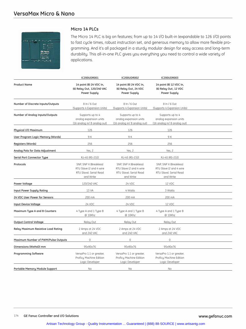
174 www.gefanuc.comGE Fanuc Controller and I/O Solutions
VersaMax Micro & Nano
The Micro 14 PLC is big on features; from up to 14 I/O built-in (expandable to 126 I/O) pointsto fast cycle times, robust instruction set, and generous memory to allow more flexible pro-gramming. And it's all packaged in a sturdy modular design for easy access and long-termdurability. This all-in-one PLC gives you everything you need to control a wide variety ofapplications.
Micro 14 PLCs
IC200UDR001 IC200UDR002 IC200UDR003
Product Name 14 point (8) 24 VDC In, 14 point (8) 24 VDC In, 14 point (8) 12 VDC In,(6) Relay Out, 120/240 VAC (6) Relay Out, 24 VDC (6) Relay Out, 12 VDC
Power Supply Power Supply Power Supply
Number of Discrete Inputs/Outputs 8 In / 6 Out 8 In / 6 Out 8 In / 6 Out(Supports 4 Expansion Units) (Supports 4 Expansion Units) (Supports 4 Expansion Units)
Number of Analog Inputs/Outputs Supports up to 4 Supports up to 4 Supports up to 4analog expansion units analog expansion units analog expansion units
(16 analog in/ 8 analog out) (16 analog in/ 8 analog out) (16 analog in/ 8 analog out)
Physical I/O Maximum 126 126 126
User Program Logic Memory (Words) 9 K 9 K 9 K
Registers (Words) 256 256 256
Analog Pots for Data Adjustment Yes, 2 Yes, 2 Yes, 2
Serial Port Connector Type RJ-45 (RS-232) RJ-45 (RS-232) RJ-45 (RS-232)
Protocols SNP, SNP X (Breakless) SNP, SNP X (Breakless) SNP, SNP X (Breakless)RTU Slave (2 and 4 wire RTU Slave (2 and 4 wire RTU Slave (2 and 4 wire RTU Slave). Serial Read RTU Slave). Serial Read RTU Slave). Serial Read
and Write and Write and Write
Power Voltage 120/240 VAC 24 VDC 12 VDC
Input Power Supply Rating 13 VA 4 Watts 3 Watts
24 VDC User Power for Sensors 200 mA 200 mA 200 mA
Input Device Voltage 24 VDC 24 VDC 12 VDC
Maximum Type A and B Counters 4 Type A and 1 Type B 4 Type A and 1 Type B 4 Type A and 1 Type B @ 10Khz @ 10Khz @ 10Khz
Output Control Voltage Relay Out Relay Out Relay Out
Relay Maximum Resistive Load Rating 2 Amps at 24 VDC 2 Amps at 24 VDC 2 Amps at 24 VDC and 240 VAC and 240 VAC and 240 VAC
Maximum Number of PWM/Pulse Outputs 0 0 0
Dimensions (WxHxD) mm 95x90x76 95x90x76 95x90x76
Programming Software VersaPro 1.1 or greater, VersaPro 1.1 or greater, VersaPro 1.1 or greater, Proficy Machine Edition Proficy Machine Edition Proficy Machine Edition
Logic Developer Logic Developer Logic Developer
Portable Memory Module Support No No No
Artisan Technology Group - Quality Instrumentation ... Guaranteed | (888) 88-SOURCE | www.artisantg.com

175www.gefanuc.com GE Fanuc Controller and I/O Solutions
VersaMax Micro & Nano
The Micro 23 PLC is big on features with 23 discrete I/O and two analog inputs and oneanalog output built-in (expandable to 135 I/O) points. The Micro 23 executes fast cycletimes, robust instruction set, and generous memory to allow more flexible programming.And it's all packaged in a sturdy modular design for easy access and long-term durability.
Micro 23 PLCs
IC200UAL004 IC200UAL005 IC200UAL006
Product Name 23 point; (13) 12 VDC In, (10) Relay Out, 23 point; (13) 24 VDC In, (9) Relay Out, 23 point; (13) 24 VDC In, (9) Relay Out, (1) (2) Analog In and (1) Analog Out, (1) 24 VDC Out, (2) Analog In and (1) 24 VDC Out, (2) Analog In and (1) Analog
12 VDC Power Supply. Analog Out, 24 VDC Power Supply. Out, 120/240 VAC Power Supply.
Number of Discrete Inputs/Outputs 13 In / 10 Out 13 In / 10 Out 13 In / 10 Out (Supports 4 Expansion Units) (Supports 4 Expansion Units) (Supports 4 Expansion Units)
Number of Analog Inputs/Outputs 2 analog in / 1 analog out built-in and 2 analog in / 1 analog out built-in and 2 analog in / 1 analog out built-in andsupports up to 4 analog expansion supports up to 4 analog expansion supports up to 4 analog expansionunits (16 analog in/ 8 analog out) units (16 analog in/ 8 analog out) units (16 analog in/ 8 analog out)
Physical I/O Maximum 135 135 135
User Program Logic Memory (Words) 9 K 9 K 9 K
Registers (Words) 2 K 2 K 2 K
Analog Pots for Data Adjustment Yes, 2 Yes, 2 Yes, 2
Serial Port Connector Type RJ-45 (RS-232) port 1 and RJ-45 (RS-232) port 1 and RJ-45 (RS-232) port 1 andDB-15 (RS-485 on port 2) DB-15 (RS-485 on port 2) DB-15 (RS-485 on port 2)
Protocols Port 1, SNP, SNP X (Breakless); Port 2, Port 1, SNP, SNP X (Breakless); Port 2, Port 1, SNP, SNP X (Breakless); Port 2, SNP, SNP X (Breakless), RTU Master SNP, SNP X (Breakless), RTU Master SNP, SNP X (Breakless), RTU Masterand Slave (2 and 4 wire RTU Slave), and Slave (2 and 4 wire RTU Slave), and Slave (2 and 4 wire RTU Slave),SNP Master, Serial Read and Write SNP Master, Serial Read and Write SNP Master, Serial Read and Write
Power Voltage 12 VDC 24 VDC 120/240 VAC
Input Power Supply Rating 8 Watts 8 Watts 34 VA
24 VDC User Power for Sensors 200 mA 200 mA 200 mA
Input Device Voltage 12 VDC 24 VDC 24 VDC
Maximum Type A and B Counters 4 Type A and 1 Type B @ 10Khz 4 Type A and 1 Type B @ 10Khz 4 Type A and 1 Type B @ 10Khz
Analog Input Ranges 0 to 10 VDC (10.24V max.) 0 to 20 mA 0 to 10 VDC (10.24V max.) 0 to 20 mA 0 to 10 VDC (10.24V max.) 0 to 20 mA (20.5 mA max.) 4 to 20 mA (20.5 mA max.) 4 to 20 mA (20.5 mA max.) 4 to 20 mA
(20.5 mA max.); 12 bit Resolution (20.5 mA max.); 12 bit Resolution (20.5 mA max.); 12 bit Resolution
Output Control Voltage Relay Out Relay Out Relay Out
Relay Maximum Resistive Load Rating 2 Amps at 24 VDC and 240 VAC 2 Amps at 24 VDC and 240 VAC 2 Amps at 24 VDC and 240 VAC
Maximum Number of PWM/Pulse Outputs N/A 1 @ 5Khz 1 @ 5Khz
Analog Output Ranges 0 to 10 VDC (10.24V max.) 0 to 20 mA 0 to 10 VDC (10.24V max.) 0 to 20 mA 0 to 10 VDC (10.24V max.) 0 to 20 mA (20.5 mA max.) 4 to 20 mA (20.5 mA max.) 4 to 20 mA (20.5 mA max.) 4 to 20 mA
(20.5 mA max.); 12 bit Resolution (20.5 mA max.); 12 bit Resolution (20.5 mA max.); 12 bit Resolution
Dimensions (WxHxD) mm 150x90x76 150x90x76 150x90x76
Programming Software VersaPro 1.1 or greater, Proficy VersaPro 1.1 or greater, Proficy VersaPro 1.1 or greater, ProficyMachine Edition Logic Developer Machine Edition Logic Developer Machine Edition Logic Developer
Portable Memory Module Support No No No
Artisan Technology Group - Quality Instrumentation ... Guaranteed | (888) 88-SOURCE | www.artisantg.com
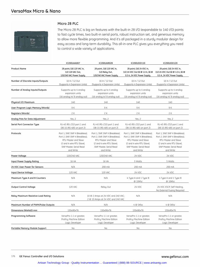
176 www.gefanuc.comGE Fanuc Controller and I/O Solutions
VersaMax Micro & Nano
The Micro 28 PLC is big on features with the built-in 28 I/O (expandable to 140 I/O) pointsto fast cycle times, two built-in serial ports, robust instruction set, and generous memoryto allow more flexible programming. And it's all packaged in a sturdy modular design foreasy access and long-term durability. This all-in-one PLC gives you everything you needto control a wide variety of applications.
Micro 28 PLC
IC200UAA007 IC200UAR028 IC200UDD110 IC200UDD120
Product Name 28 point; (16) 120 VAC In, 28 point, (16) 120 VAC In, 28 point; (16) 24 VDC In, 28 point; (16) 24 VDC In,(12) 120 VAC Out, (12) Relay Out, (12) 24 VDC Out (6) @ 1.0 A, (6) @ (12) 24 VDC Out (6) @ 1.0 A, (6) @
120/240 VAC Power Supply. 120/240 VAC Power Supply. 0.5 A, 24 VDC Power Supply. 0.5 A, 24 VDC Power Supply.
Number of Discrete Inputs/Outputs 16 In / 12 Out 16 In / 12 Out 16 In / 12 Out 16 In / 12 Out(Supports 4 Expansion Units) (Supports 4 Expansion Units) (Supports 4 Expansion Units) (Supports 4 Expansion Units)
Number of Analog Inputs/Outputs Supports up to 4 analog Supports up to 4 analog Supports up to 4 analog Supports up to 4 analogexpansion units expansion units expansion units expansion units
(16 analog in/ 8 analog out) (16 analog in/ 8 analog out) (16 analog in/ 8 analog out) (16 analog in/ 8 analog out)
Physical I/O Maximum 140 140 140 140
User Program Logic Memory (Words) 9 K 9 K 9 K 9 K
Registers (Words) 2 K 2 K 2 K 2 K
Analog Pots for Data Adjustment Yes, 2 Yes, 2 Yes, 2 Yes, 2
Serial Port Connector Type RJ-45 (RS-232) port 1 and RJ-45 (RS-232) port 1 and RJ-45 (RS-232) port 1 and RJ-45 (RS-232) port 1 andDB-15 (RS-485 on port 2) DB-15 (RS-485 on port 2) DB-15 (RS-485 on port 2) DB-15 (RS-485 on port 2)
Protocols Port 1, SNP, SNP X (Breakless); Port 1, SNP, SNP X (Breakless); Port 1, SNP, SNP X (Breakless); Port 1, SNP, SNP X (Breakless);Port 2, SNP, SNP X (Breakless), Port 2, SNP, SNP X (Breakless), Port 2, SNP, SNP X (Breakless), Port 2, SNP, SNP X (Breakless),
RTU Master and Slave RTU Master and Slave RTU Master and Slave RTU Master and Slave(2 and 4 wire RTU Slave), (2 and 4 wire RTU Slave), (2 and 4 wire RTU Slave), (2 and 4 wire RTU Slave),SNP Master, Serial Read SNP Master, Serial Read SNP Master, Serial Read SNP Master, Serial Read
and Write and Write and Write and Write
Power Voltage 120/240 VAC 120/240 VAC 24 VDC 24 VDC
Input Power Supply Rating 16 VA 16 VA 5 Watts 5 Watts
24 VDC User Power for Sensors N/A 200 mA 200 mA 200 mA
Input Device Voltage 120 VAC 120 VAC 24 VDC 24 VDC
Maximum Type A and B Counters N/A N/A 4 Type A and 1 Type B 4 Type A and 1 Type B @ 10Khz @ 10Khz
Output Control Voltage 120 VAC Relay Out 24 VDC 24 VDC ESCP, Self Healing, No External Fusing Required
Relay Maximum Resistive Load Rating N/A 10 @ 2 Amps at 24 VDC and 240 VAC; N/A N/A2 @ 10 Amps at 24 VDC and 240 VAC
Maximum Number of PWM/Pulse Outputs N/A N/A 4 @ 5Khz 4 @ 5Khz
Dimensions (WxHxD) mm 150x90x76 150x90x76 150x90x76 150x90x76
Programming Software VersaPro 1.1 or greater, VersaPro 1.1 or greater, VersaPro 1.1 or greater, VersaPro 1.1 or greater,Proficy Machine Edition Proficy Machine Edition Proficy Machine Edition Proficy Machine Edition
Logic Developer Logic Developer Logic Developer Logic Developer
Portable Memory Module Support No No No No
Artisan Technology Group - Quality Instrumentation ... Guaranteed | (888) 88-SOURCE | www.artisantg.com
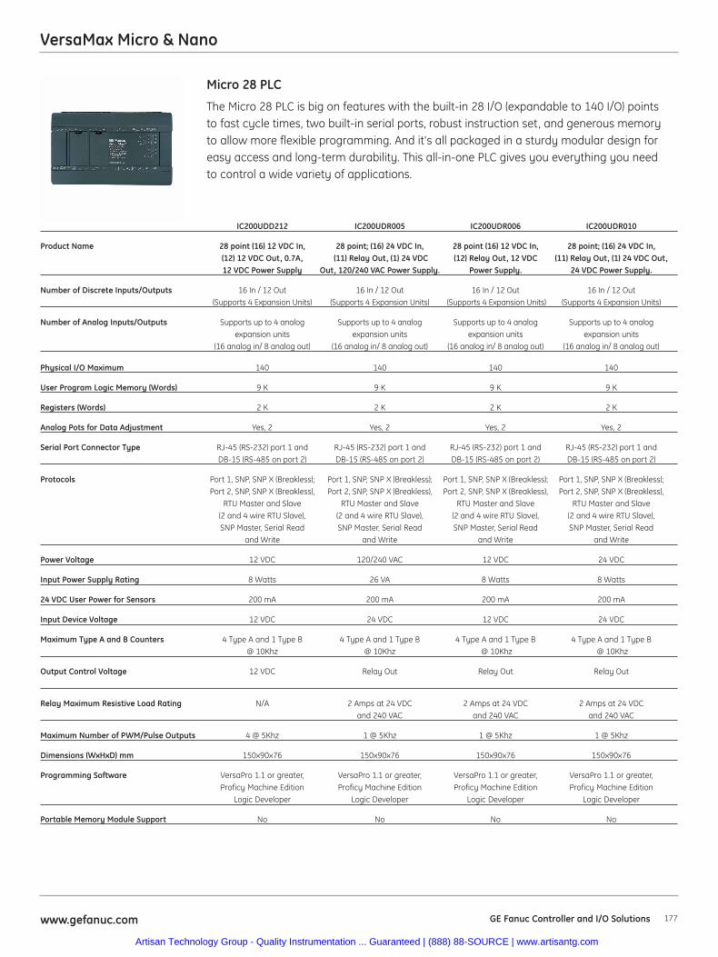
VersaMax Micro & Nano
177www.gefanuc.com GE Fanuc Controller and I/O Solutions
The Micro 28 PLC is big on features with the built-in 28 I/O (expandable to 140 I/O) pointsto fast cycle times, two built-in serial ports, robust instruction set, and generous memoryto allow more flexible programming. And it's all packaged in a sturdy modular design foreasy access and long-term durability. This all-in-one PLC gives you everything you needto control a wide variety of applications.
Micro 28 PLC
IC200UDD212 IC200UDR005 IC200UDR006 IC200UDR010
Product Name 28 point (16) 12 VDC In, 28 point; (16) 24 VDC In, 28 point (16) 12 VDC In, 28 point; (16) 24 VDC In,(12) 12 VDC Out, 0.7A, (11) Relay Out, (1) 24 VDC (12) Relay Out, 12 VDC (11) Relay Out, (1) 24 VDC Out,12 VDC Power Supply Out, 120/240 VAC Power Supply. Power Supply. 24 VDC Power Supply.
Number of Discrete Inputs/Outputs 16 In / 12 Out 16 In / 12 Out 16 In / 12 Out 16 In / 12 Out(Supports 4 Expansion Units) (Supports 4 Expansion Units) (Supports 4 Expansion Units) (Supports 4 Expansion Units)
Number of Analog Inputs/Outputs Supports up to 4 analog Supports up to 4 analog Supports up to 4 analog Supports up to 4 analogexpansion units expansion units expansion units expansion units
(16 analog in/ 8 analog out) (16 analog in/ 8 analog out) (16 analog in/ 8 analog out) (16 analog in/ 8 analog out)
Physical I/O Maximum 140 140 140 140
User Program Logic Memory (Words) 9 K 9 K 9 K 9 K
Registers (Words) 2 K 2 K 2 K 2 K
Analog Pots for Data Adjustment Yes, 2 Yes, 2 Yes, 2 Yes, 2
Serial Port Connector Type RJ-45 (RS-232) port 1 and RJ-45 (RS-232) port 1 and RJ-45 (RS-232) port 1 and RJ-45 (RS-232) port 1 andDB-15 (RS-485 on port 2) DB-15 (RS-485 on port 2) DB-15 (RS-485 on port 2) DB-15 (RS-485 on port 2)
Protocols Port 1, SNP, SNP X (Breakless); Port 1, SNP, SNP X (Breakless); Port 1, SNP, SNP X (Breakless); Port 1, SNP, SNP X (Breakless);Port 2, SNP, SNP X (Breakless), Port 2, SNP, SNP X (Breakless), Port 2, SNP, SNP X (Breakless), Port 2, SNP, SNP X (Breakless),
RTU Master and Slave RTU Master and Slave RTU Master and Slave RTU Master and Slave (2 and 4 wire RTU Slave), (2 and 4 wire RTU Slave), (2 and 4 wire RTU Slave), (2 and 4 wire RTU Slave),SNP Master, Serial Read SNP Master, Serial Read SNP Master, Serial Read SNP Master, Serial Read
and Write and Write and Write and Write
Power Voltage 12 VDC 120/240 VAC 12 VDC 24 VDC
Input Power Supply Rating 8 Watts 26 VA 8 Watts 8 Watts
24 VDC User Power for Sensors 200 mA 200 mA 200 mA 200 mA
Input Device Voltage 12 VDC 24 VDC 12 VDC 24 VDC
Maximum Type A and B Counters 4 Type A and 1 Type B 4 Type A and 1 Type B 4 Type A and 1 Type B 4 Type A and 1 Type B@ 10Khz @ 10Khz @ 10Khz @ 10Khz
Output Control Voltage 12 VDC Relay Out Relay Out Relay Out
Relay Maximum Resistive Load Rating N/A 2 Amps at 24 VDC 2 Amps at 24 VDC 2 Amps at 24 VDC and 240 VAC and 240 VAC and 240 VAC
Maximum Number of PWM/Pulse Outputs 4 @ 5Khz 1 @ 5Khz 1 @ 5Khz 1 @ 5Khz
Dimensions (WxHxD) mm 150x90x76 150x90x76 150x90x76 150x90x76
Programming Software VersaPro 1.1 or greater, VersaPro 1.1 or greater, VersaPro 1.1 or greater, VersaPro 1.1 or greater, Proficy Machine Edition Proficy Machine Edition Proficy Machine Edition Proficy Machine Edition
Logic Developer Logic Developer Logic Developer Logic Developer
Portable Memory Module Support No No No No
Artisan Technology Group - Quality Instrumentation ... Guaranteed | (888) 88-SOURCE | www.artisantg.com
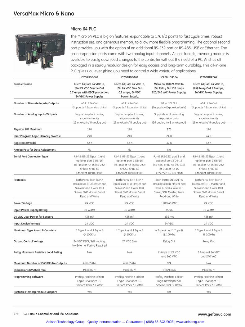
VersaMax Micro & Nano
178 www.gefanuc.comGE Fanuc Controller and I/O Solutions
The Micro 64 PLC is big on features, expandable to 176 I/O points to fast cycle times, robustinstruction set, and generous memory to allow more flexible programming. The optional secondport provides you with the option of an additional RS-232 port or RS-485, USB or Ethernet. Theserial expansion ports come with two analog input channels. A user-friendly memory module isavailable to easily download changes to the controller without the need of a PC. And it's allpackaged in a sturdy modular design for easy access and long-term durability. This all-in-onePLC gives you everything you need to control a wide variety of applications.
Micro 64 PLC
IC200UDD064 IC200UDD164 IC200UDR164 IC200UDR064
Product Name Micro 64; (40) 24 VDC In, Micro 64; (40) 24 VDC In, Micro 64; (40) 24 VDC In, Micro 64; (40) 24 VDC In,(24) 24 VDC Source Out (24) 24 VDC Sink Out (24) Relay Out 2.0 amps, (24) Relay Out 2.0 amps,
0.7 amps with ESCP protection, 0.7 amps, 24 VDC 120/240 VAC Power Supply. 24 VDC Power Supply.24 VDC Power Supply. Power Supply.
Number of Discrete Inputs/Outputs 40 In / 24 Out 40 In / 24 Out 40 In / 24 Out 40 In / 24 Out (Supports 4 Expansion Units) (Supports 4 Expansion Units) (Supports 4 Expansion Units) (Supports 4 Expansion Units)
Number of Analog Inputs/Outputs Supports up to 4 analog Supports up to 4 analog Supports up to 4 analog Supports up to 4 analogexpansion units expansion units expansion units expansion units
(16 analog in/ 8 analog out) (16 analog in/ 8 analog out) (16 analog in/ 8 analog out) (16 analog in/ 8 analog out)
Physical I/O Maximum 176 176 176 176
User Program Logic Memory (Words) 24K 24K 24 K 24 K
Registers (Words) 32 K 32 K 32 K 32 K
Analog Pots for Data Adjustment No No No No
Serial Port Connector Type RJ-45 (RS-232) port 1 and RJ-45 (RS-232) port 1 and RJ-45 (RS-232) port 1 and RJ-45 (RS-232) port 1 andoptional port 2 DB-15 optional port 2 DB-15 optional port 2 DB-15 optional port 2 DB-15
(RS-485) or RJ-45 (RS-232) (RS-485) or RJ-45 (RS-232) (RS-485) or RJ-45 (RS-232) (RS-485) or RJ-45 (RS-232) or USB or RJ-45 or USB or RJ-45 or USB or RJ-45 or USB or RJ-45
(Ethernet 10/100 Mbit) (Ethernet 10/100 Mbit) (Ethernet 10/100 Mbit) (Ethernet 10/100 Mbit)
Protocols Both Ports: SNP, SNP X Both Ports: SNP, SNP X Both Ports: SNP, SNP X Both Ports: SNP, SNP X(Breakless), RTU Master and (Breakless), RTU Master and (Breakless),RTU Master and (Breakless),RTU Master and
Slave (2 and 4 wire RTU Slave (2 and 4 wire RTU Slave (2 and 4 wire RTU Slave (2 and 4 wire RTUSlave), SNP Master, Serial Slave), SNP Master, Serial Slave), SNP Master, Serial Slave), SNP Master, Serial
Read and Write Read and Write Read and Write Read and Write
Power Voltage 24 VDC 24 VDC 120/240 VAC 24 VDC
Input Power Supply Rating 10 Watts 10 Watts 35 VA 10 Watts
24 VDC User Power for Sensors 435 mA 435 mA 435 mA 435 mA
Input Device Voltage 24 VDC 24 VDC 24 VDC 24 VDC
Maximum Type A and B Counters 4 Type A and 1 Type B 4 Type A and 1 Type B 4 Type A and 1 Type B 4 Type A and 1 Type B@ 100Khz @ 100Khz @ 100Khz @ 100Khz
Output Control Voltage 24 VDC ESCP, Self Healing, 24 VDC Sink Relay Out Relay OutNo External Fusing Required
Relay Maximum Resistive Load Rating N/A N/A 2 Amps at 24 VDC 2 Amps at 24 VDC and 240 VAC and 240 VAC
Maximum Number of PWM/Pulse Outputs 4 @ 65Khz 4 @ 65Khz N/A N/A
Dimensions (WxHxD) mm 190x90x76 190x90x76 190x90x76 190x90x76
Programming Software Proficy Machine Edition Proficy Machine Edition Proficy Machine Edition Proficy Machine EditionLogic Developer 5.0, Logic Developer 5.0, Logic Developer 5.0, Logic Developer 5.0,
Service Pack 3, Hotfix Service Pack 3, Hotfix Service Pack 3, Hotfix Service Pack 3, Hotfix
Portable Memory Module Support Yes Yes Yes Yes
Artisan Technology Group - Quality Instrumentation ... Guaranteed | (888) 88-SOURCE | www.artisantg.com
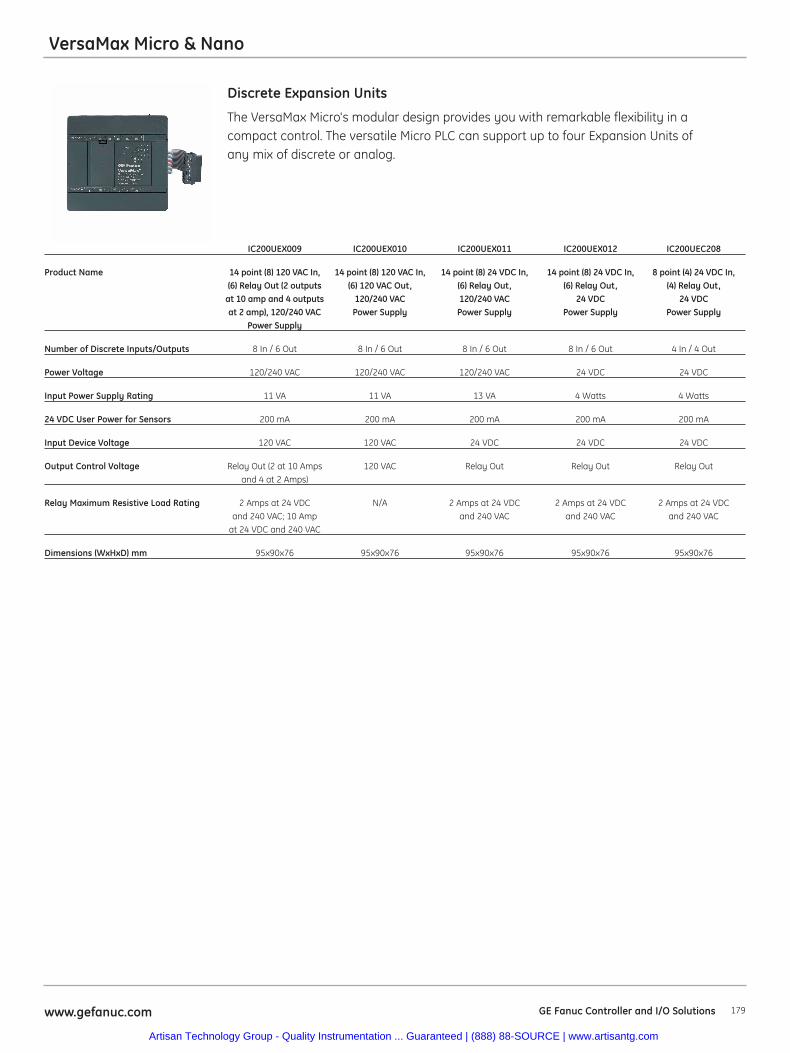
179www.gefanuc.com GE Fanuc Controller and I/O Solutions
VersaMax Micro & Nano
The VersaMax Micro's modular design provides you with remarkable flexibility in a compact control. The versatile Micro PLC can support up to four Expansion Units ofany mix of discrete or analog.
Discrete Expansion Units
IC200UEX009 IC200UEX010 IC200UEX011 IC200UEX012 IC200UEC208
Product Name 14 point (8) 120 VAC In, 14 point (8) 120 VAC In, 14 point (8) 24 VDC In, 14 point (8) 24 VDC In, 8 point (4) 24 VDC In,(6) Relay Out (2 outputs (6) 120 VAC Out, (6) Relay Out, (6) Relay Out, (4) Relay Out,
at 10 amp and 4 outputs 120/240 VAC 120/240 VAC 24 VDC 24 VDC at 2 amp), 120/240 VAC Power Supply Power Supply Power Supply Power Supply
Power Supply
Number of Discrete Inputs/Outputs 8 In / 6 Out 8 In / 6 Out 8 In / 6 Out 8 In / 6 Out 4 In / 4 Out
Power Voltage 120/240 VAC 120/240 VAC 120/240 VAC 24 VDC 24 VDC
Input Power Supply Rating 11 VA 11 VA 13 VA 4 Watts 4 Watts
24 VDC User Power for Sensors 200 mA 200 mA 200 mA 200 mA 200 mA
Input Device Voltage 120 VAC 120 VAC 24 VDC 24 VDC 24 VDC
Output Control Voltage Relay Out (2 at 10 Amps 120 VAC Relay Out Relay Out Relay Outand 4 at 2 Amps)
Relay Maximum Resistive Load Rating 2 Amps at 24 VDC N/A 2 Amps at 24 VDC 2 Amps at 24 VDC 2 Amps at 24 VDCand 240 VAC; 10 Amp and 240 VAC and 240 VAC and 240 VAC
at 24 VDC and 240 VAC
Dimensions (WxHxD) mm 95x90x76 95x90x76 95x90x76 95x90x76 95x90x76
Artisan Technology Group - Quality Instrumentation ... Guaranteed | (888) 88-SOURCE | www.artisantg.com
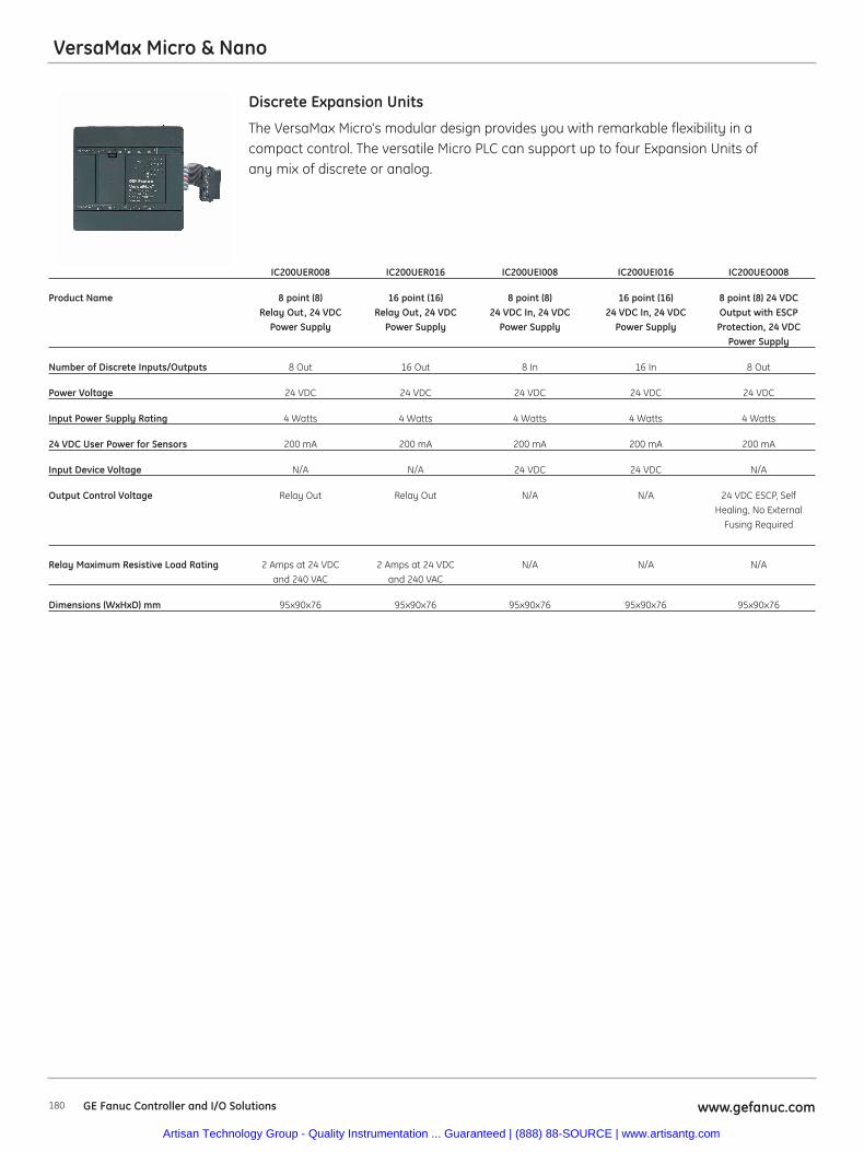
180 www.gefanuc.comGE Fanuc Controller and I/O Solutions
VersaMax Micro & Nano
The VersaMax Micro's modular design provides you with remarkable flexibility in a compact control. The versatile Micro PLC can support up to four Expansion Units ofany mix of discrete or analog.
Discrete Expansion Units
IC200UER008 IC200UER016 IC200UEI008 IC200UEI016 IC200UEO008
Product Name 8 point (8) 16 point (16) 8 point (8) 16 point (16) 8 point (8) 24 VDC Relay Out, 24 VDC Relay Out, 24 VDC 24 VDC In, 24 VDC 24 VDC In, 24 VDC Output with ESCP
Power Supply Power Supply Power Supply Power Supply Protection, 24 VDCPower Supply
Number of Discrete Inputs/Outputs 8 Out 16 Out 8 In 16 In 8 Out
Power Voltage 24 VDC 24 VDC 24 VDC 24 VDC 24 VDC
Input Power Supply Rating 4 Watts 4 Watts 4 Watts 4 Watts 4 Watts
24 VDC User Power for Sensors 200 mA 200 mA 200 mA 200 mA 200 mA
Input Device Voltage N/A N/A 24 VDC 24 VDC N/A
Output Control Voltage Relay Out Relay Out N/A N/A 24 VDC ESCP, Self Healing, No External
Fusing Required
Relay Maximum Resistive Load Rating 2 Amps at 24 VDC 2 Amps at 24 VDC N/A N/A N/Aand 240 VAC and 240 VAC
Dimensions (WxHxD) mm 95x90x76 95x90x76 95x90x76 95x90x76 95x90x76
Artisan Technology Group - Quality Instrumentation ... Guaranteed | (888) 88-SOURCE | www.artisantg.com
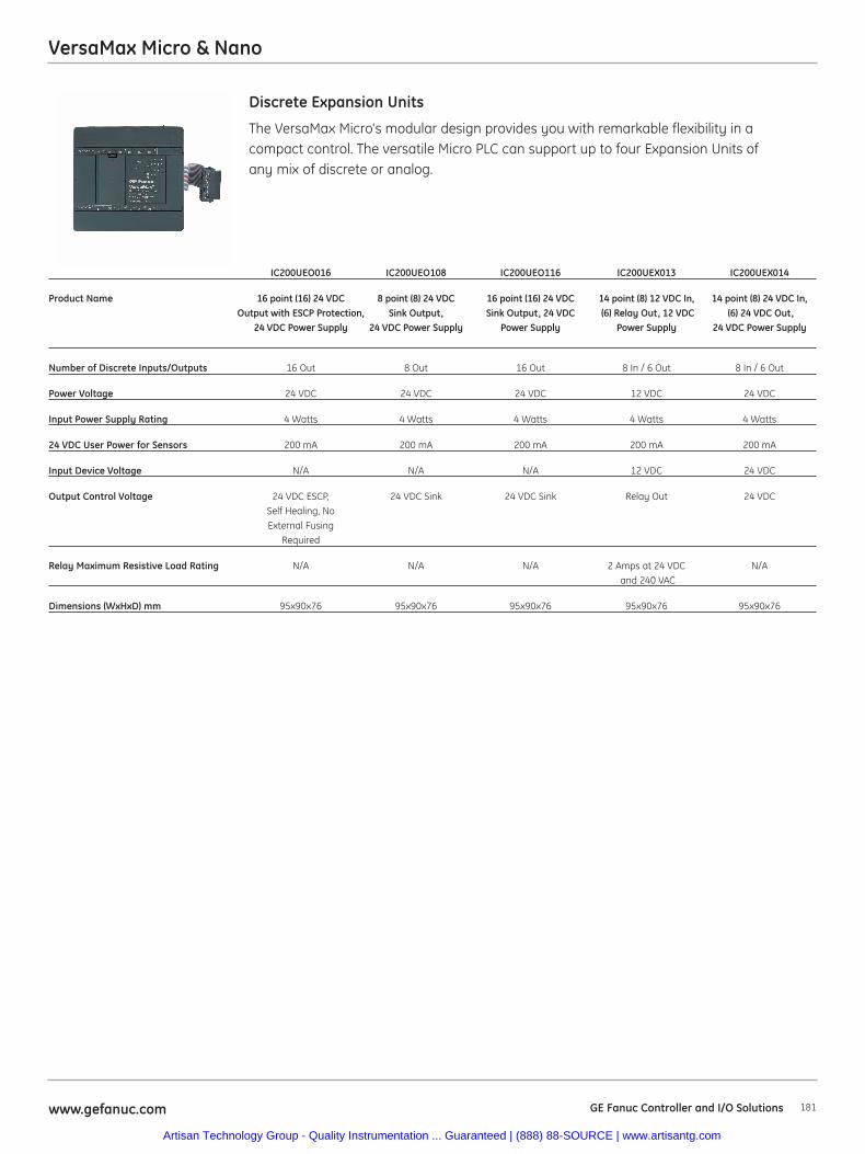
VersaMax Micro & Nano
181www.gefanuc.com GE Fanuc Controller and I/O Solutions
The VersaMax Micro's modular design provides you with remarkable flexibility in a compact control. The versatile Micro PLC can support up to four Expansion Units ofany mix of discrete or analog.
Discrete Expansion Units
IC200UEO016 IC200UEO108 IC200UEO116 IC200UEX013 IC200UEX014
Product Name 16 point (16) 24 VDC 8 point (8) 24 VDC 16 point (16) 24 VDC 14 point (8) 12 VDC In, 14 point (8) 24 VDC In,Output with ESCP Protection, Sink Output, Sink Output, 24 VDC (6) Relay Out, 12 VDC (6) 24 VDC Out,
24 VDC Power Supply 24 VDC Power Supply Power Supply Power Supply 24 VDC Power Supply
Number of Discrete Inputs/Outputs 16 Out 8 Out 16 Out 8 In / 6 Out 8 In / 6 Out
Power Voltage 24 VDC 24 VDC 24 VDC 12 VDC 24 VDC
Input Power Supply Rating 4 Watts 4 Watts 4 Watts 4 Watts 4 Watts
24 VDC User Power for Sensors 200 mA 200 mA 200 mA 200 mA 200 mA
Input Device Voltage N/A N/A N/A 12 VDC 24 VDC
Output Control Voltage 24 VDC ESCP, 24 VDC Sink 24 VDC Sink Relay Out 24 VDCSelf Healing, No External Fusing
Required
Relay Maximum Resistive Load Rating N/A N/A N/A 2 Amps at 24 VDC N/Aand 240 VAC
Dimensions (WxHxD) mm 95x90x76 95x90x76 95x90x76 95x90x76 95x90x76
Artisan Technology Group - Quality Instrumentation ... Guaranteed | (888) 88-SOURCE | www.artisantg.com
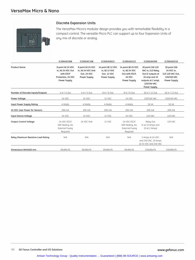
VersaMax Micro & Nano
182 www.gefanuc.comGE Fanuc Controller and I/O Solutions
The VersaMax Micro's modular design provides you with remarkable flexibility in a compact control. The versatile Micro PLC can support up to four Expansion Units ofany mix of discrete or analog.
Discrete Expansion Units
IC200UEC008 IC200UEC108 IC200UEX015 IC200UEX122 IC200UEX209 IC200UEX210
Product Name 8 point (4) 24 VDC 8 point (4) 24 VDC 14 point (8) 12 VDC 14 point (8) 24 VDC 28 point (16) 120 28 point (16) In, (4) 24 VDC Out In, (4) 24 VDC Sink In, (6) 12 VDC In, (6) 24 VDC VAC In, (12) Relay 24 VDC In,
with ESCP Out, 24 VDC Out, 12 VDC Out with ESCP, Out (2 outputs at (12) 120 VAC Out,Protection, 24 VDC Power Supply Power Supply 24 VDC 10 amp and 10 120/240 VAC
Power Supply Power Supply outputs at 2 amp), Power Supply120/240 VACPower Supply
Number of Discrete Inputs/Outputs 4 In / 4 Out 4 In / 4 Out 8 In / 6 Out 8 In / 6 Out 16 In / 12 Out 16 In / 12 Out
Power Voltage 24 VDC 24 VDC 12 VDC 24 VDC 120/240 VAC 120/240 VAC
Input Power Supply Rating 4 Watts 4 Watts 4 Watts 4 Watts 16 VA 16 VA
24 VDC User Power for Sensors 200 mA 200 mA 200 mA 200 mA 200 mA 200 mA
Input Device Voltage 24 VDC 24 VDC 12 VDC 24 VDC 120 VAC 120 VAC
Output Control Voltage 24 VDC ESCP, 24 VDC Sink 12 VDC 24 VDC ESCP, Relay Out 120 VACSelf Healing, No Self Healing, No (2 at 10 Amps andExternal Fusing External Fusing 10 at 2 Amps)
Required Required
Relay Maximum Resistive Load Rating N/A N/A N/A N/A 2 Amps at 24 VDC N/Aand 240 VAC; 10 Amps at 24 VDC and 240 VAC
Dimensions (WxHxD) mm 95x90x76 95x90x76 95x90x76 95x90x76 150x90x76 150x90x76
Artisan Technology Group - Quality Instrumentation ... Guaranteed | (888) 88-SOURCE | www.artisantg.com
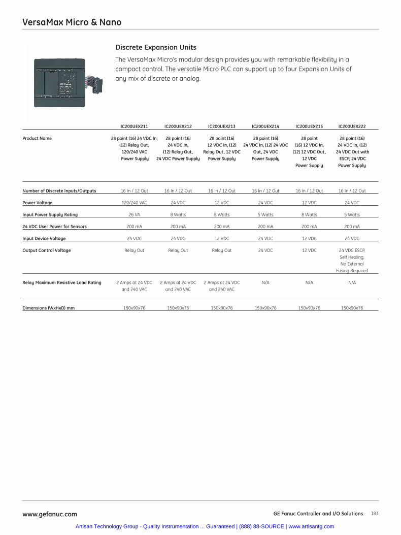
VersaMax Micro & Nano
183www.gefanuc.com GE Fanuc Controller and I/O Solutions
The VersaMax Micro's modular design provides you with remarkable flexibility in a compact control. The versatile Micro PLC can support up to four Expansion Units ofany mix of discrete or analog.
Discrete Expansion Units
IC200UEX211 IC200UEX212 IC200UEX213 IC200UEX214 IC200UEX215 IC200UEX222
Product Name 28 point (16) 24 VDC In, 28 point (16) 28 point (16) 28 point (16) 28 point 28 point (16) (12) Relay Out, 24 VDC In, 12 VDC In, (12) 24 VDC In, (12) 24 VDC (16) 12 VDC In, 24 VDC In, (12)120/240 VAC (12) Relay Out, Relay Out, 12 VDC Out, 24 VDC (12) 12 VDC Out, 24 VDC Out withPower Supply 24 VDC Power Supply Power Supply Power Supply 12 VDC ESCP, 24 VDC
Power Supply Power Supply
Number of Discrete Inputs/Outputs 16 In / 12 Out 16 In / 12 Out 16 In / 12 Out 16 In / 12 Out 16 In / 12 Out 16 In / 12 Out
Power Voltage 120/240 VAC 24 VDC 12 VDC 24 VDC 12 VDC 24 VDC
Input Power Supply Rating 26 VA 8 Watts 8 Watts 5 Watts 8 Watts 5 Watts
24 VDC User Power for Sensors 200 mA 200 mA 200 mA 200 mA 200 mA 200 mA
Input Device Voltage 24 VDC 24 VDC 12 VDC 24 VDC 12 VDC 24 VDC
Output Control Voltage Relay Out Relay Out Relay Out 24 VDC 12 VDC 24 VDC ESCP, Self Healing, No External
Fusing Required
Relay Maximum Resistive Load Rating 2 Amps at 24 VDC 2 Amps at 24 VDC 2 Amps at 24 VDC N/A N/A N/Aand 240 VAC and 240 VAC and 240 VAC
Dimensions (WxHxD) mm 150x90x76 150x90x76 150x90x76 150x90x76 150x90x76 150x90x76
Artisan Technology Group - Quality Instrumentation ... Guaranteed | (888) 88-SOURCE | www.artisantg.com
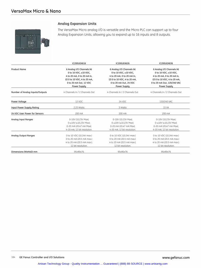
184 www.gefanuc.comGE Fanuc Controller and I/O Solutions
VersaMax Micro & Nano
The VersaMax Micro analog I/O is versatile and the Micro PLC can support up to four Analog Expansion Units, allowing you to expand up to 16 inputs and 8 outputs.
Analog Expansion Units
IC200UEX616 IC200UEX626 IC200UEX636
Product Name 6 Analog I/O Channels (4) 6 Analog I/O Channels (4) 6 Analog I/O Channels (4)0 to 10 VDC, ±10 VDC, 0 to 10 VDC, ±10 VDC, 0 to 10 VDC, ±10 VDC,
4 to 20 mA, 0 to 20 mA In, 4 to 20 mA, 0 to 20 mA In, 4 to 20 mA, 0 to 20 mA In,(2) 0 to 10 VDC, 4 to 20 mA, (2) 0 to 10 VDC, 4 to 20 mA, (2) 0 to 10 VDC, 4 to 20 mA,
0 to 20 mA Out, 12 VDC 0 to 20 mA Out, 24 VDC 0 to 20 mA Out, 120/240 VAC Power Supply Power Supply Power Supply
Number of Analog Inputs/Outputs 4 Channels In / 2 Channels Out 4 Channels In / 2 Channels Out 4 Channels In / 2 Channels Out
Power Voltage 12 VDC 24 VDC 120/240 VAC
Input Power Supply Rating 2.25 Watts 3 Watts 15 VA
24 VDC User Power for Sensors 200 mA 200 mA 200 mA
Analog Input Ranges 0-10V (10.23V Max); 0-10V (10.23V Max); 0-10V (10.23V Max);0-±10V (±10.23V Max); 0-±10V (±10.23V Max); 0-±10V (±10.23V Max);
0-20 mA (20.47 mA Max); 0-20 mA (20.47 mA Max); 0-20 mA (20.47 mA Max); 4-20 mA; 12 bit resolution. 4-20 mA; 12 bit resolution. 4-20 mA; 12 bit resolution.
Analog Output Ranges 0 to 10 VDC (10.24V max.) 0 to 10 VDC (10.24V max.) 0 to 10 VDC (10.24V max.) 0 to 20 mA (20.5 mA max.) 0 to 20 mA (20.5 mA max.) 0 to 20 mA (20.5 mA max.) 4 to 20 mA (20.5 mA max.); 4 to 20 mA (20.5 mA max.); 4 to 20 mA (20.5 mA max.);
12 bit resolution. 12 bit resolution. 12 bit resolution.
Dimensions (WxHxD) mm 95x90x76 95x90x76 95x90x76
Artisan Technology Group - Quality Instrumentation ... Guaranteed | (888) 88-SOURCE | www.artisantg.com
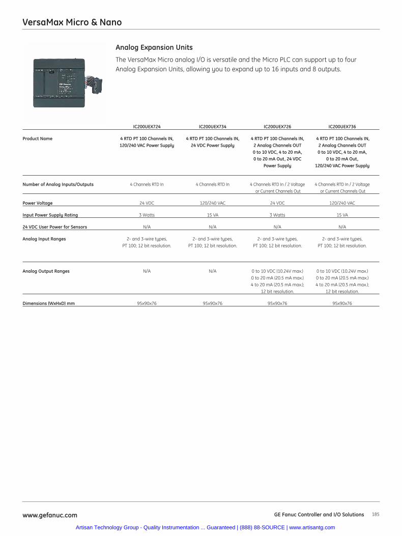
185www.gefanuc.com GE Fanuc Controller and I/O Solutions
VersaMax Micro & Nano
The VersaMax Micro analog I/O is versatile and the Micro PLC can support up to four Analog Expansion Units, allowing you to expand up to 16 inputs and 8 outputs.
Analog Expansion Units
IC200UEX724 IC200UEX734 IC200UEX726 IC200UEX736
Product Name 4 RTD PT 100 Channels IN, 4 RTD PT 100 Channels IN, 4 RTD PT 100 Channels IN, 4 RTD PT 100 Channels IN,120/240 VAC Power Supply 24 VDC Power Supply 2 Analog Channels OUT 2 Analog Channels OUT
0 to 10 VDC, 4 to 20 mA, 0 to 10 VDC, 4 to 20 mA,0 to 20 mA Out, 24 VDC 0 to 20 mA Out,
Power Supply 120/240 VAC Power Supply
Number of Analog Inputs/Outputs 4 Channels RTD In 4 Channels RTD In 4 Channels RTD In / 2 Voltage 4 Channels RTD In / 2 Voltageor Current Channels Out or Current Channels Out
Power Voltage 24 VDC 120/240 VAC 24 VDC 120/240 VAC
Input Power Supply Rating 3 Watts 15 VA 3 Watts 15 VA
24 VDC User Power for Sensors N/A N/A N/A N/A
Analog Input Ranges 2- and 3-wire types, 2- and 3-wire types, 2- and 3-wire types, 2- and 3-wire types,PT 100; 12 bit resolution. PT 100; 12 bit resolution. PT 100; 12 bit resolution. PT 100; 12 bit resolution.
Analog Output Ranges N/A N/A 0 to 10 VDC (10.24V max.) 0 to 10 VDC (10.24V max.) 0 to 20 mA (20.5 mA max.) 0 to 20 mA (20.5 mA max.) 4 to 20 mA (20.5 mA max.); 4 to 20 mA (20.5 mA max.);
12 bit resolution. 12 bit resolution.
Dimensions (WxHxD) mm 95x90x76 95x90x76 95x90x76 95x90x76
Artisan Technology Group - Quality Instrumentation ... Guaranteed | (888) 88-SOURCE | www.artisantg.com
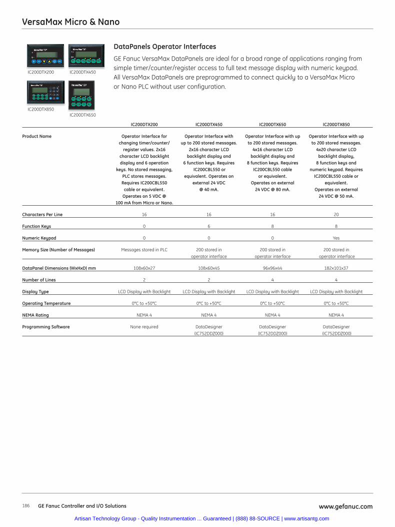
186 www.gefanuc.comGE Fanuc Controller and I/O Solutions
VersaMax Micro & Nano
GE Fanuc VersaMax DataPanels are ideal for a broad range of applications ranging fromsimple timer/counter/register access to full text message display with numeric keypad.All VersaMax DataPanels are preprogrammed to connect quickly to a VersaMax Microor Nano PLC without user configuration.
DataPanels Operator Interfaces
IC200DTX200 IC200DTX450 IC200DTX650 IC200DTX850
Product Name Operator Interface for Operator Interface with Operator Interface with up Operator Interface with upchanging timer/counter/ up to 200 stored messages. to 200 stored messages. to 200 stored messages.
register values. 2x16 2x16 character LCD 4x16 character LCD 4x20 character LCDcharacter LCD backlight backlight display and backlight display and backlight display,display and 6 operation 6 function keys. Requires 8 function keys. Requires 8 function keys and
keys. No stored messaging, IC200CBL550 or IC200CBL550 cable numeric keypad. RequiresPLC stores messages. equivalent. Operates on or equivalent. IC200CBL550 cable or Requires IC200CBL550 external 24 VDC Operates on external equivalent.
cable or equivalent. @ 40 mA. 24 VDC @ 80 mA. Operates on external Operates on 5 VDC @ 24 VDC @ 50 mA.
100 mA from Micro or Nano.
Characters Per Line 16 16 16 20
Function Keys 0 6 8 8
Numeric Keypad 0 0 0 Yes
Memory Size (Number of Messages) Messages stored in PLC 200 stored in 200 stored in 200 stored inoperator interface operator interface operator interface
DataPanel Dimensions (WxHxD) mm 108x60x27 108x60x45 96x96x44 182x101x37
Number of Lines 2 2 4 4
Display Type LCD Display with Backlight LCD Display with Backlight LCD Display with Backlight LCD Display with Backlight
Operating Temperature 0°C to +50°C 0°C to +50°C 0°C to +50°C 0°C to +50°C
NEMA Rating NEMA 4 NEMA 4 NEMA 4 NEMA 4
Programming Software None required DataDesigner DataDesigner DataDesigner(IC752DDZ000) (IC752DDZ000) (IC752DDZ000)
IC200DTX200 IC200DTX450
IC200DTX850IC200DTX650
Artisan Technology Group - Quality Instrumentation ... Guaranteed | (888) 88-SOURCE | www.artisantg.com
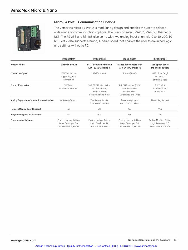
187www.gefanuc.com GE Fanuc Controller and I/O Solutions
VersaMax Micro & Nano
The VersaMax Micro 64 Port 2 is modular by design and enables the user to select awide range of communications options. The user can select RS-232, RS-485, Ethernet orUSB. The RS-232 and RS-485 also come with two analog input channels (0 to 10 VDC, 10bit). Port 2 also supports Memory Module Board that enables the user to download logicand settings without a PC.
Micro 64 Port 2 Communication Options
IC200UEM001 IC200USB001 IC200USB002 IC200UUB001
Product Name Ethernet module RS-232 option board with RS-485 option board with USB option board(2) 0 -10 VDC analog in (2) 0 -10 VDC analog in (no analog option)
Connection Type 10/100Mbits port RS-232 (RJ-45) RS-485 (RJ-45) USB (Slave Only) supporting RJ45 version 2.0,
connection Straight B type
Protocol Supported SRTP and SNP, SNP Master, SNP X, SNP, SNP Master, SNP X, SNP, SNP X, Modbus TCP (server) Modbus Master, Modbus Master, Modbus Slave,
Modbus Slave, Modbus Slave, Serial ReadSerial Read and Write Serial Read and Write
Analog Support on Communications Module No Analog Support Two Analog Inputs. Two Analog Inputs. No Analog Support0 to 10 VDC (10 bits) 0 to 10 VDC (10 bits)
Memory Module Board Support Yes Yes Yes Yes
Programming and PDA Support No Yes Yes Yes
Programming Software Proficy Machine Edition Proficy Machine Edition Proficy Machine Edition Proficy Machine EditionLogic Developer 5.0, Logic Developer 5.0, Logic Developer 5.0, Logic Developer 5.0,
Service Pack 3, Hotfix Service Pack 3, Hotfix Service Pack 3, Hotfix Service Pack 3, Hotfix
Artisan Technology Group - Quality Instrumentation ... Guaranteed | (888) 88-SOURCE | www.artisantg.com
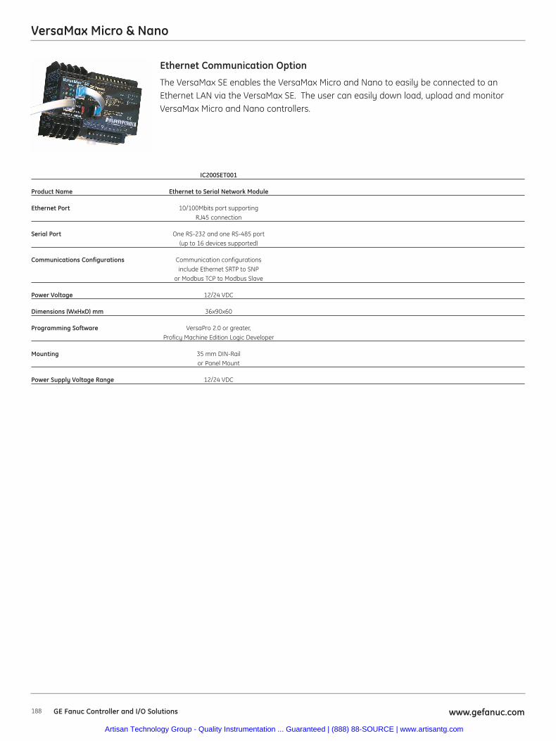
VersaMax Micro & Nano
188 www.gefanuc.comGE Fanuc Controller and I/O Solutions
The VersaMax SE enables the VersaMax Micro and Nano to easily be connected to anEthernet LAN via the VersaMax SE. The user can easily down load, upload and monitorVersaMax Micro and Nano controllers.
Ethernet Communication Option
IC200SET001
Product Name Ethernet to Serial Network Module
Ethernet Port 10/100Mbits port supporting RJ45 connection
Serial Port One RS-232 and one RS-485 port (up to 16 devices supported)
Communications Configurations Communication configurations include Ethernet SRTP to SNP
or Modbus TCP to Modbus Slave
Power Voltage 12/24 VDC
Dimensions (WxHxD) mm 36x90x60
Programming Software VersaPro 2.0 or greater, Proficy Machine Edition Logic Developer
Mounting 35 mm DIN-Rail or Panel Mount
Power Supply Voltage Range 12/24 VDC
Artisan Technology Group - Quality Instrumentation ... Guaranteed | (888) 88-SOURCE | www.artisantg.com
189www.gefanuc.com GE Fanuc Controller and I/O Solutions
VersaMax Micro & Nano
AccessoriesIC200ACC402 Spare Removable Terminal Strips, 10 per pack. (Micro 14, Micro 23 and Micro 28 and all expansion units)
IC200ACC403 Battery for Micro 23 and Micro 28 for data retention (5.2 months minimum @ 70°C and 32.4 months minimum @ 20°C)
IC200ACC404 Spare parts kit. Two terminal strips and four plastic doors and four covers for Micro 14, Micro 23 and Micro 28.
IC200ACC414 Long Term Battery for Micro 23, Micro 28 and Micro 64 (19 months minimum @ 70°C and 121 months minimum @ 20°C)
IC200ACC415 RS-232 to RS-485 Converter requires IC200CBL500 or equivalent.
IC200ACC450 Simulator for VersaMax Nano 10. (6 Inputs)
IC200ACC451 Simulator for VersaMax Micro 14, Micro 23 and Micro 28. (8 Inputs)
IC200UMB001 Flash Memory Board for program download and compatible with Micro 64 (128Kbytes)
External Power SuppliesIC690PWR024 24 VDC, 5 Amp Output Power and 120/230 VAC Input Power Power Supply
IC690PWR124 24 VDC, 10 Amp Output Power and 120/230 VAC Input Power Power Supply
Stepper Controller, Motors and Cables (More Information in Motion Solutions Catalog GFA-483)
IC800PCUB00300 Stepping Motor Power Amplifier, 12-48 VDC, 4 Amp
IC800PCUBDINMTG PowerCube DIN Rail Mounting Adaptor.
MTR-1216-N-D-E-0 Stepping Motor Nema23, Series Wdg. Holding Torque 61 oz-in/0.43 Nano meters
MTR-1220-N-D-E-0 Stepping Motor Nema23, Series Wdg. Holding Torque 116 oz-in/0.82 Nano meters
MTR-1221-N-D-E-0 Stepping Motor Nema23, Series Wdg. Holding Torque 124 oz-in/0.87 Nano meters
MTR-1231-N-D-E-0 Stepping Motor Nema23, Series Wdg. Holding Torque 236 oz-in/1.68 Nano meters
MTR-1235-N-D-E-0 Stepping Motor Nema23, Series Wdg. Holding Torque 185 oz-in/1.31 Nano meters
MTR-1331-J-N-D-E-0 Stepping Motor Nema34, Series Wdg. Holding Torque 327 oz-in/2.31 Nano meters
MTR-1N31-I-N-D-S-0 Stepping Motor Nema34, Series Wdg. Holding Torque 605 oz-in/4.27 Nano meters
CBL-12-MP-10 Power Cable, MTR-1216, 1221, or 1231 Stepping Motor, 10 Ft.
CBL-12-MP-20 Power Cable, MTR-1216, 1221, or 1231 Stepping Motor, 20 Ft.
CBL-12-MP-30 Power Cable, MTR-1216, 1221, or 1231 Stepping Motor, 30 Ft.
CBL-13-MP-10 Power Cable, MTR-1220, MTR-1235, MTR-13xx, MTR-14xx & MTR-1Nxx Series Stepping Motors, 10 Ft.
CBL-13-MP-20 Power Cable, MTR-1220, MTR-1235, MTR-13xx, MTR-14xx & MTR-1Nxx Series Stepping Motors, 20 Ft.
CBL-13-MP-30 Power Cable, MTR-1220, MTR-1235, MTR-13xx, MTR-14xx & MTR-1Nxx Series Stepping Motors, 30 Ft.
IC800PCUBC02S030 PowerCube Flying Lead I/O Interface Cable, 200 Steps/Rev & Power Save Enabled, 3 Meters
IC800PCUBC02S050 PowerCube Flying Lead Interface I/O Cable, 200 Steps/Rev & Power Save Enabled, 5 Meters
IC800PCUBC04S030 PowerCube Flying Lead Interface I/O Cable, 400 Steps/Rev & Power Save Enabled, 3 Meters
IC800PCUBC04S050 PowerCube Flying Lead Interface I/O Cable, 400 Steps/Rev & Power Save Enabled, 5 Meters
IC800PCUBC10S030 PowerCube Flying Lead Interface I/O Cable, 1000 Steps/Rev & Power Save Enabled, 3 Meters
IC800PCUBC10S050 PowerCube Flying Lead Interface I/O Cable, 1000 Steps/Rev & Power Save Enabled, 5 Meters
Programming and Trouble Shooting ToolsIC646MPM101 Proficy Logic Developer - PLC Nano/Micro, Programming Cable (No Upgrades included)
BC646MPM101 Proficy Logic Developer - PLC Nano/Micro, Programming Cable included and Proficy GlobalCare Complete (Upgrades included for 15 months of upgrades)
IC646MPH101 Logic Developer PDA Single License with Adapters . With Logic Developer PDA, you can monitor/change data, view diagnostics, force ON/OFF, and configure machine setup — saving you time and increasing productivity.
IC752DDZ000 VersaMax DP Operator Interface DataDesigner editor
Artisan Technology Group - Quality Instrumentation ... Guaranteed | (888) 88-SOURCE | www.artisantg.com
VersaMax Micro & Nano
190 www.gefanuc.comGE Fanuc Controller and I/O Solutions
Cables(0.1 meter cable, IC200CBL501, is included in every expansion base package)
IC200CBL500 Programming cable (RJ-45 to DB-9 pin) RS-232. 3 Meters.
IC200CBL501 I/O Expansion cable, 0.1 meter long (Qty 5)
IC200CBL505 I/O Expansion cable, 0.5 meter long
IC200CBL510 I/O Expansion cable, 1 meter long
Starter KitsIC200TBX010 Tool box, Nano 10 and software. Includes (IC200NDR001) 24 VDC In/Relay Out, 24 VDC powered (requires an external 24 VDC Supply)
with software, manuals and cables (IC646MPH101)
IC200TBX110 Tool box, Nano 10, operator interface and software. Includes (IC200NDR001) 24 VDC In/Relay Out, 24 VDC powered (requires an external 24 VDC Supply), VersaMax DataPanel DP45 with programming software and cables, (IC640VPS00, IC752DDZ000, IC200CBL555)
IC200TBX210 Tool box, Nano 10, Ethernet interface and software. Includes (IC200NDR001) 24 VDC In/Relay Out, 24 VDC powered (requires an external 24 VDC Supply), VersaMax SE (IC200SET001) with all software, cables (IC646MPH101) and manuals.
IC200TBX014 Tool box, Micro 14 and software. Includes (IC200UDR001) 24 VDC In/Relay Out, AC Power Supply with software, manuals and cables (IC646MPH101)
IC200TBX114 Tool box, Micro 14, operator interface and software. Includes (IC200UDR001) 24 VDC In/Relay Out, AC Power Supply, VersaMax DataPanel DP45 with programming software and cables, (IC640VPS00, IC752DDZ000, IC200CBL555)
IC200TBX214 Tool box, Micro 14, Ethernet interface and software. Includes (IC200UDR001) 24 VDC In/Relay Out, requires 120 VAC power, VersaMax SE (IC200SET001) with all software, cables (IC646MPH101) and manuals.
IC200TBX023 Tool box, Micro 23 and software. Includes (IC200UAL006) DC In/Relay Out, 2 analog In, 1 analog out, AC Power Supply with software, manuals and cables (IC646MPH101)
IC200TBX123 Tool box, Micro 23, operator interface and software. Includes (IC200UAL006) 24 VDC In/Relay Out, 2 Analog In/1 Analog out, AC P/S, VersaMax DataPanel DP45 with programming software and cables, (IC640VPS00, IC752DDZ000, IC200CBL555)
IC200TBX223 Tool box, Micro 23, Ethernet interface and software. Includes (IC200UAL006) 24 VDC In/Relay Out, requires 120 VAC Power, VersaMax SE (IC200SET001) with all software, cables (IC646MPH101) and manuals.
IC200TBX028 Tool box, Micro 28 and software. Includes (IC200UDR005) 24 VDC In/Relay Out, AC Power Supply with software, manuals and cables (IC646MPH101)
IC200TBX128 Tool box, Micro 28, operator interface and software. Includes (IC200UDR005) 24 VDC In/Relay Out, AC P/S, VersaMax DataPanel DP45 with programming software and cables, (IC640VPS00, IC752DDZ000, IC200CBL555)
IC200TBX228 Tool box, Micro 28, Ethernet interface and software. Includes (IC200UDR005) 24 VDC In/Relay Out, requires 120 VAC Power, VersaMax SE (IC200SET001) with all software, cables (IC646MPH101) and manuals.
IC200TBX064 Tool box, Micro 64 and software. Includes (IC200UDD064) 24 VDC In/24 VDC Out, DC Power Supply, (IC200USB001) RS-232 option board with (2) 0 -10 VDC analog in with Proficy software, manuals and cables (IC646MPM101)
IC200TBX164 Tool box, Micro 64 and software. Includes (IC200UDR164) 24 VDC In/Relay Out, AC Power Supply, (IC200USB001) RS-232 option board with (2) 0 -10 VDC analog in with Proficy software, manuals and cables (IC646MPM101)
IC200TBX264 Tool box, Micro 64, operator interface and software. Includes (IC200UDD064) 24 VDC In/24 VDC Out, DC Power Supply, (IC200USB001) RS-232 option board with (2) 0 -10 VDC analog in with VersaMax DataPanel DP45 with Proficy programming software and cables, (IC646MPM101, IC752DDZ000, IC200CBL555)
IC200TBX364 Tool box, Micro 64, operator interface and software. Includes (IC200UDR164) 24 VDC In/Relay Out, AC Power Supply, (IC200USB001) RS-232 option board with (2) 0 -10 VDC analog in with VersaMax DataPanel DP45 with Proficy Logic Developer programming software and cables, (IC646MPM101, IC752DDZ000, IC200CBL555)
IC200TBX464 Tool box, Micro 64, stepper motor, PowerCube amplifier and software. Includes (IC200UDD064) 24 VDC In/24 VDC Out, DC Power Supply, (IC200USB001) RS-232 option board with (2) 0 -10 VDC analog in, stepping motor amplifier (IC800PCUB00300), stepping motor (MTR-1216-N-D-E-0), stepper cable (CBL-12-MP-10), PowerCube Flying Lead interface cable (IC800PCUBC02S030) with Proficy software, manuals and cables (IC646MPM101)
IC200TBX564 Tool box, Micro 64, QuickPanel color touch screen and software. Includes (IC200UDR164) 24 VDC In/Relay Out, AC Power Supply, (IC200UEM001) Ethernet option board, QuickPanel Display (IC754VSI06STD) with Proficy software, manuals and cables (BC646MBL001)
Artisan Technology Group - Quality Instrumentation ... Guaranteed | (888) 88-SOURCE | www.artisantg.com
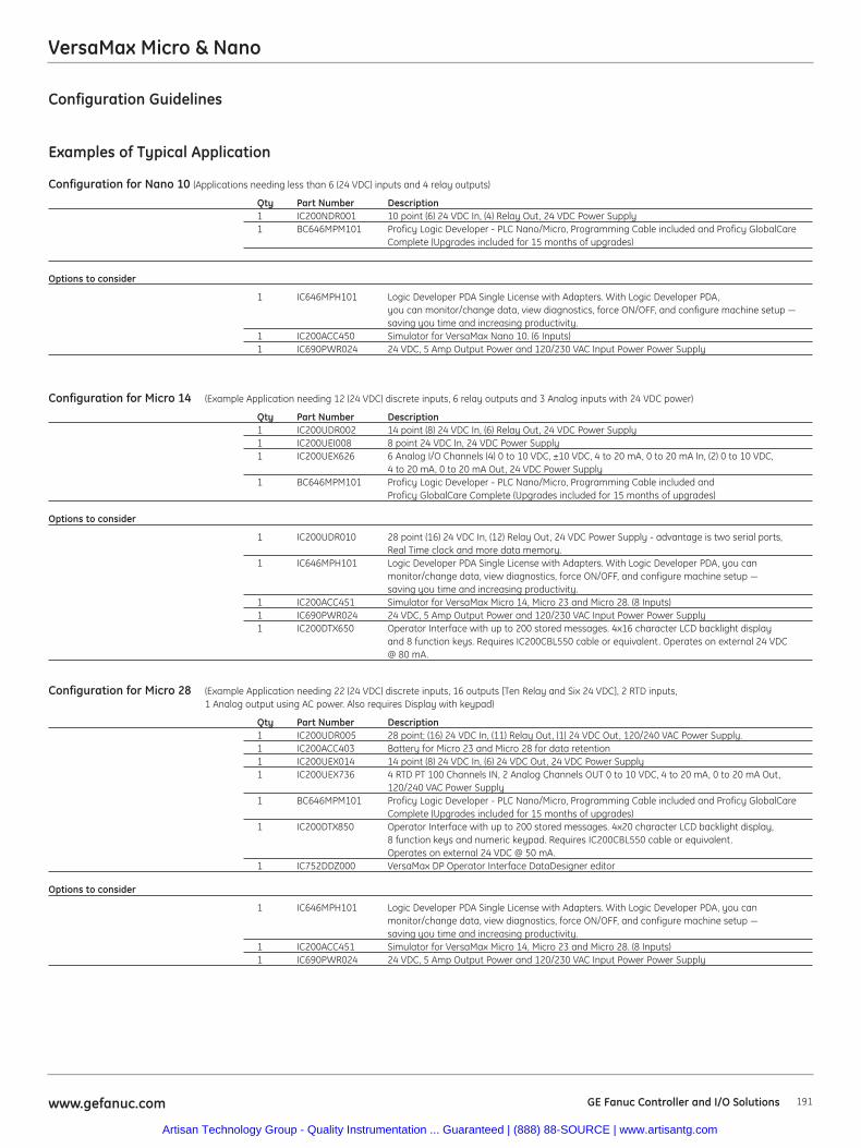
VersaMax Micro & Nano
191www.gefanuc.com GE Fanuc Controller and I/O Solutions
Configuration Guidelines
Examples of Typical Application
Configuration for Nano 10 (Applications needing less than 6 (24 VDC) inputs and 4 relay outputs)
Qty Part Number Description1 IC200NDR001 10 point (6) 24 VDC In, (4) Relay Out, 24 VDC Power Supply1 BC646MPM101 Proficy Logic Developer - PLC Nano/Micro, Programming Cable included and Proficy GlobalCare
Complete (Upgrades included for 15 months of upgrades)
Options to consider
1 IC646MPH101 Logic Developer PDA Single License with Adapters. With Logic Developer PDA, you can monitor/change data, view diagnostics, force ON/OFF, and configure machine setup — saving you time and increasing productivity.
1 IC200ACC450 Simulator for VersaMax Nano 10. (6 Inputs)1 IC690PWR024 24 VDC, 5 Amp Output Power and 120/230 VAC Input Power Power Supply
Configuration for Micro 14 (Example Application needing 12 (24 VDC) discrete inputs, 6 relay outputs and 3 Analog inputs with 24 VDC power)
Qty Part Number Description1 IC200UDR002 14 point (8) 24 VDC In, (6) Relay Out, 24 VDC Power Supply1 IC200UEI008 8 point 24 VDC In, 24 VDC Power Supply1 IC200UEX626 6 Analog I/O Channels (4) 0 to 10 VDC, ±10 VDC, 4 to 20 mA, 0 to 20 mA In, (2) 0 to 10 VDC,
4 to 20 mA, 0 to 20 mA Out, 24 VDC Power Supply1 BC646MPM101 Proficy Logic Developer - PLC Nano/Micro, Programming Cable included and
Proficy GlobalCare Complete (Upgrades included for 15 months of upgrades)
Options to consider
1 IC200UDR010 28 point (16) 24 VDC In, (12) Relay Out, 24 VDC Power Supply - advantage is two serial ports,Real Time clock and more data memory.
1 IC646MPH101 Logic Developer PDA Single License with Adapters. With Logic Developer PDA, you can monitor/change data, view diagnostics, force ON/OFF, and configure machine setup — saving you time and increasing productivity.
1 IC200ACC451 Simulator for VersaMax Micro 14, Micro 23 and Micro 28. (8 Inputs)1 IC690PWR024 24 VDC, 5 Amp Output Power and 120/230 VAC Input Power Power Supply1 IC200DTX650 Operator Interface with up to 200 stored messages. 4x16 character LCD backlight display
and 8 function keys. Requires IC200CBL550 cable or equivalent. Operates on external 24 VDC @ 80 mA.
Configuration for Micro 28 (Example Application needing 22 (24 VDC) discrete inputs, 16 outputs [Ten Relay and Six 24 VDC], 2 RTD inputs, 1 Analog output using AC power. Also requires Display with keypad)
Qty Part Number Description1 IC200UDR005 28 point; (16) 24 VDC In, (11) Relay Out, (1) 24 VDC Out, 120/240 VAC Power Supply. 1 IC200ACC403 Battery for Micro 23 and Micro 28 for data retention1 IC200UEX014 14 point (8) 24 VDC In, (6) 24 VDC Out, 24 VDC Power Supply1 IC200UEX736 4 RTD PT 100 Channels IN, 2 Analog Channels OUT 0 to 10 VDC, 4 to 20 mA, 0 to 20 mA Out,
120/240 VAC Power Supply1 BC646MPM101 Proficy Logic Developer - PLC Nano/Micro, Programming Cable included and Proficy GlobalCare
Complete (Upgrades included for 15 months of upgrades)1 IC200DTX850 Operator Interface with up to 200 stored messages. 4x20 character LCD backlight display,
8 function keys and numeric keypad. Requires IC200CBL550 cable or equivalent. Operates on external 24 VDC @ 50 mA.
1 IC752DDZ000 VersaMax DP Operator Interface DataDesigner editor
Options to consider
1 IC646MPH101 Logic Developer PDA Single License with Adapters. With Logic Developer PDA, you canmonitor/change data, view diagnostics, force ON/OFF, and configure machine setup — saving you time and increasing productivity.
1 IC200ACC451 Simulator for VersaMax Micro 14, Micro 23 and Micro 28. (8 Inputs)1 IC690PWR024 24 VDC, 5 Amp Output Power and 120/230 VAC Input Power Power Supply
Artisan Technology Group - Quality Instrumentation ... Guaranteed | (888) 88-SOURCE | www.artisantg.com
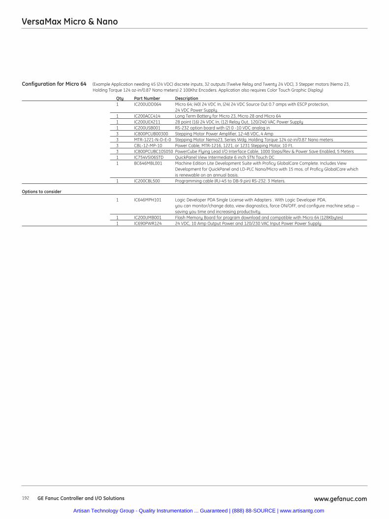
Configuration for Micro 64 (Example Application needing 45 (24 VDC) discrete inputs, 32 outputs (Twelve Relay and Twenty 24 VDC), 3 Stepper motors (Nema 23, Holding Torque 124 oz-in/0.87 Nano meters) 2 100Khz Encoders. Application also requires Color Touch Graphic Display)
Qty Part Number Description1 IC200UDD064 Micro 64; (40) 24 VDC In, (24) 24 VDC Source Out 0.7 amps with ESCP protection,
24 VDC Power Supply. 1 IC200ACC414 Long Term Battery for Micro 23, Micro 28 and Micro 641 IC200UEX211 28 point (16) 24 VDC In, (12) Relay Out, 120/240 VAC Power Supply1 IC200USB001 RS-232 option board with (2) 0 -10 VDC analog in3 IC800PCUB00300 Stepping Motor Power Amplifier, 12-48 VDC, 4 Amp3 MTR-1221-N-D-E-0 Stepping Motor Nema23, Series Wdg. Holding Torque 124 oz-in/0.87 Nano meters3 CBL-12-MP-10 Power Cable, MTR-1216, 1221, or 1231 Stepping Motor, 10 Ft.3 IC800PCUBC10S050 PowerCube Flying Lead I/O Interface Cable, 1000 Steps/Rev & Power Save Enabled, 5 Meters1 IC754VSI06STD QuickPanel View Intermediate 6 inch STN Touch DC1 BC646MBL001 Machine Edition Lite Development Suite with Proficy GlobalCare Complete. Includes View
Development for QuickPanel and LD-PLC Nano/Micro with 15 mos. of Proficy GlobalCare which is renewable on an annual basis.
1 IC200CBL500 Programming cable (RJ-45 to DB-9 pin) RS-232. 3 Meters.
Options to consider
1 IC646MPH101 Logic Developer PDA Single License with Adapters . With Logic Developer PDA, you can monitor/change data, view diagnostics, force ON/OFF, and configure machine setup — saving you time and increasing productivity.
1 IC200UMB001 Flash Memory Board for program download and compatible with Micro 64 (128Kbytes)1 IC690PWR124 24 VDC, 10 Amp Output Power and 120/230 VAC Input Power Power Supply
www.gefanuc.com192
VersaMax Micro & Nano
GE Fanuc Controller and I/O Solutions
Artisan Technology Group - Quality Instrumentation ... Guaranteed | (888) 88-SOURCE | www.artisantg.com
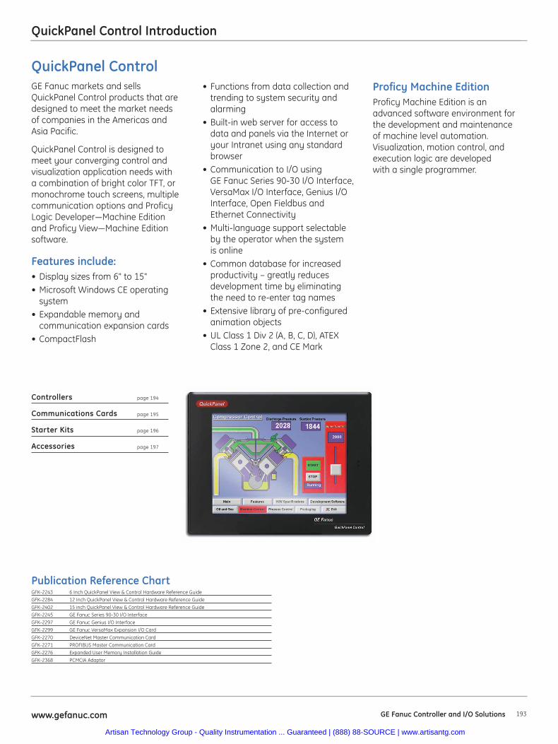
193www.gefanuc.com GE Fanuc Controller and I/O Solutions
QuickPanel Control Introduction
Proficy Machine EditionProficy Machine Edition is anadvanced software environment forthe development and maintenanceof machine level automation.Visualization, motion control, andexecution logic are developedwith a single programmer.
QuickPanel ControlGE Fanuc markets and sellsQuickPanel Control products that aredesigned to meet the market needs of companies in the Americas andAsia Pacific.
QuickPanel Control is designed tomeet your converging control andvisualization application needs witha combination of bright color TFT, ormonochrome touch screens, multiplecommunication options and ProficyLogic Developer—Machine Editionand Proficy View—Machine Editionsoftware.
Features include:• Display sizes from 6" to 15"• Microsoft Windows CE operating
system• Expandable memory and
communication expansion cards• CompactFlash
• Functions from data collection andtrending to system security andalarming
• Built-in web server for access todata and panels via the Internet oryour Intranet using any standardbrowser
• Communication to I/O usingGE Fanuc Series 90-30 I/O Interface,VersaMax I/O Interface, Genius I/OInterface, Open Fieldbus andEthernet Connectivity
• Multi-language support selectableby the operator when the systemis online
• Common database for increasedproductivity – greatly reducesdevelopment time by eliminatingthe need to re-enter tag names
• Extensive library of pre-configuredanimation objects
• UL Class 1 Div 2 (A, B, C, D), ATEXClass 1 Zone 2, and CE Mark
Controllers page 194
Communications Cards page 195
Starter Kits page 196
Accessories page 197
Publication Reference ChartGFK-2243 6 Inch QuickPanel View & Control Hardware Reference Guide
GFK-2284 12 Inch QuickPanel View & Control Hardware Reference Guide
GFK-2402 15 inch QuickPanel View & Control Hardware Reference Guide
GFK-2245 GE Fanuc Series 90-30 I/O Interface
GFK-2297 GE Fanuc Genius I/O Interface
GFK-2299 GE Fanuc VersaMax Expansion I/O Card
GFK-2270 DeviceNet Master Communication Card
GFK-2271 PROFIBUS Master Communication Card
GFK-2276 Expanded User Memory Installation Guide
GFK-2368 PCMCIA Adaptor
Artisan Technology Group - Quality Instrumentation ... Guaranteed | (888) 88-SOURCE | www.artisantg.com
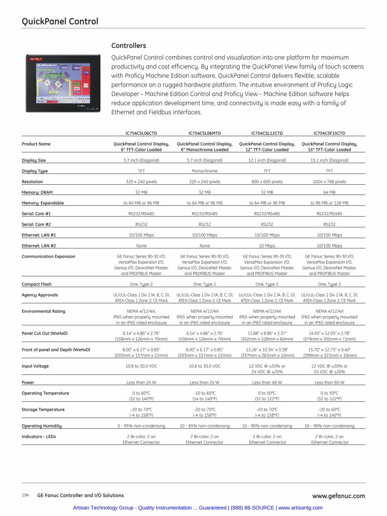
194 www.gefanuc.comGE Fanuc Controller and I/O Solutions
QuickPanel Control
QuickPanel Control combines control and visualization into one platform for maximumproductivity and cost efficiency. By integrating the QuickPanel View family of touch screenswith Proficy Machine Edition software, QuickPanel Control delivers flexible, scalableperformance on a rugged hardware platform. The intuitive environment of Proficy LogicDeveloper - Machine Edition Control and Proficy View - Machine Edition software helpsreduce application development time, and connectivity is made easy with a family ofEthernet and Fieldbus interfaces.
Controllers
IC754CSL06CTD IC754CSL06MTD IC754CSL12CTD IC754CSF15CTD
Product Name QuickPanel Control Display, QuickPanel Control Display, QuickPanel Control Display, QuickPanel Control Display,6" TFT-Color Loaded 6" Monochrome Loaded 12" TFT-Color Loaded 15" TFT-Color Loaded
Display Size 5.7 inch (Diagonal) 5.7 inch (Diagonal) 12.1 inch (Diagonal) 15.1 inch (Diagonal)
Display Type TFT Monochrome TFT TFT
Resolution 320 x 240 pixels 320 x 240 pixels 800 x 600 pixels 1024 x 768 pixels
Memory: DRAM 32 MB 32 MB 32 MB 64 MB
Memory: Expandable to 64 MB or 96 MB to 64 MB or 96 MB to 64 MB or 96 MB to 96 MB or 128 MB
Serial: Com #1 RS232/RS485 RS232/RS485 RS232/RS485 RS232/RS485
Serial: Com #2 RS232 RS232 RS232 RS232
Ethernet: LAN #1 10/100 Mbps 10/100 Mbps 10/100 Mbps 10/100 Mbps
Ethernet: LAN #2 None None 10 Mbps 10/100 Mbps
Communication Expansion GE Fanuc Series 90-30 I/O, GE Fanuc Series 90-30 I/O, GE Fanuc Series 90-30 I/O, GE Fanuc Series 90-30 I/O,VersaMax Expansion I/O, VersaMax Expansion I/O, VersaMax Expansion I/O, VersaMax Expansion I/O,
Genius I/O, DeviceNet Master, Genius I/O, DeviceNet Master, Genius I/O, DeviceNet Master, Genius I/O, DeviceNet Master,and PROFIBUS Master and PROFIBUS Master and PROFIBUS Master and PROFIBUS Master
Compact Flash One, Type 2 One, Type 2 One, Type 2 One, Type 2
Agency Approvals UL/cUL-Class 1 Div 2 (A, B, C, D); UL/cUL-Class 1 Div 2 (A, B, C, D); UL/cUL-Class 1 Div 2 (A, B, C, D); UL/cUL-Class 1 Div 2 (A, B, C, D);ATEX-Class 1 Zone 2; CE Mark ATEX-Class 1 Zone 2; CE Mark ATEX-Class 1 Zone 2; CE Mark ATEX-Class 1 Zone 2; CE Mark
Environmental Rating NEMA 4/12/4X, NEMA 4/12/4X NEMA 4/12/4X NEMA 4/12/4XIP65 when properly mounted IP65 when properly mounted IP65 when properly mounted IP65 when properly mounted
in an IP65 rated enclosure in an IP65 rated enclosure in an IP65 rated enclosure in an IP65 rated enclosure
Panel Cut Out (WxHxD) 6.14" x 4.86" x 2.76" 6.14" x 4.86" x 2.76" 11.88" x 8.96" x 2.37" 14.93" x 12.03" x 2.78"(158mm x 126mm x 70mm) (158mm x 126mm x 70mm) (302mm x 228mm x 60mm) (379mm x 305mm x 71mm)
Front of panel and Depth (WxHxD) 8.00" x 6.17" x 0.85" 8.00" x 6.17" x 0.85" 13.26" x 10.34" x 0.38" 15.70" x 12.73" x 0.40"(203mm x 157mm x 22mm) (203mm x 157mm x 22mm) (337mm x 263mm x 10mm) (399mm x 323mm x 10mm)
Input Voltage 10.8 to 30.0 VDC 10.8 to 30.0 VDC 12 VDC @ ±20% or 12 VDC @ ±20% or 24 VDC @ ±20% 24 VDC @ ±20%
Power Less than 24 W Less than 24 W Less than 48 W Less than 60 W
Operating Temperature 0 to 60°C -10 to 60°C 0 to 50°C 0 to 50°C(32 to 140°F) (14 to 140°F) (32 to 122°F) (32 to 122°F)
Storage Temperature -20 to 70°C -20 to 70°C -20 to 70°C -20 to 60°C (-4 to 158°F) (-4 to 158°F) (-4 to 158°F) (-4 to 140°F)
Operating Humidity 5 - 95% non-condensing 10 - 85% non-condensing 10 - 90% non-condensing 10 - 90% non-condensing
Indicators - LEDs 2 Bi-color, 2 on 2 Bi-color, 2 on 2 Bi-color, 2 on 2 Bi-color, 2 onEthernet Connector Ethernet Connector Ethernet Connector Ethernet Connector
Artisan Technology Group - Quality Instrumentation ... Guaranteed | (888) 88-SOURCE | www.artisantg.com
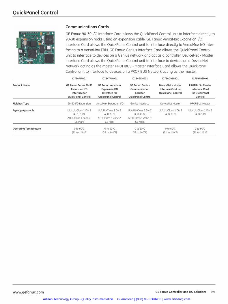
195www.gefanuc.com GE Fanuc Controller and I/O Solutions
QuickPanel Control
GE Fanuc 90-30 I/O Interface Card allows the QuickPanel Control unit to interface directly to90-30 expansion racks using an expansion cable. GE Fanuc VersaMax Expansion I/OInterface Card allows the QuickPanel Control unit to interface directly to VersaMax I/O inter-facing to a VersaMax ERM. GE Fanuc Genius Interface Card allows the QuickPanel Controlunit to interface to devices on a Genius network and act as a controller. DeviceNet - MasterInterface Card allows the QuickPanel Control unit to interface to devices on a DeviceNetNetwork acting as the master. PROFIBUS - Master Interface Card allows the QuickPanelControl unit to interface to devices on a PROFIBUS Network acting as the master.
Communications Cards
IC754PIF001 IC754TAN001 IC754GEN001 IC754DVNM01 IC754PBSM01
Product Name GE Fanuc Series 90-30 GE Fanuc VersaMax GE Fanuc Genius DeviceNet - Master PROFIBUS - MasterExpansion I/O Expansion I/O Communication Interface Card for Interface CardInterface for Interface for Card for QuickPanel Control for QuickPanel
QuickPanel Control QuickPanel Control QuickPanel Control Control
Fieldbus Type 90-30 I/O Expansion VersaMax Expansion I/O Genius Interface DeviceNet Master PROFIBUS Master
Agency Approvals UL/cUL-Class 1 Div 2 UL/cUL-Class 1 Div 2 UL/cUL-Class 1 Div 2 UL/cUL-Class 1 Div 2 UL/cUL-Class 1 Div 2(A, B, C, D); (A, B, C, D); (A, B, C, D); (A, B, C, D) (A, B C, D)
ATEX-Class 1 Zone 2; ATEX-Class 1 Zone 2; ATEX-Class 1 Zone 2;CE Mark CE Mark CE Mark
Operating Temperature 0 to 60°C 0 to 60°C 0 to 60°C 0 to 60°C 0 to 60°C(32 to 140°F) (32 to 140°F) (32 to 140°F) (32 to 140°F) (32 to 140°F)
Artisan Technology Group - Quality Instrumentation ... Guaranteed | (888) 88-SOURCE | www.artisantg.com
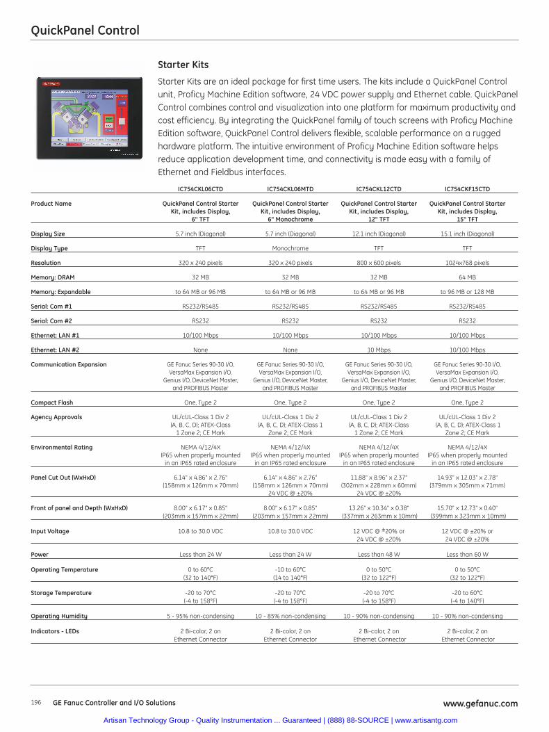
196 www.gefanuc.comGE Fanuc Controller and I/O Solutions
QuickPanel Control
Starter Kits are an ideal package for first time users. The kits include a QuickPanel Controlunit, Proficy Machine Edition software, 24 VDC power supply and Ethernet cable. QuickPanelControl combines control and visualization into one platform for maximum productivity andcost efficiency. By integrating the QuickPanel family of touch screens with Proficy MachineEdition software, QuickPanel Control delivers flexible, scalable performance on a ruggedhardware platform. The intuitive environment of Proficy Machine Edition software helpsreduce application development time, and connectivity is made easy with a family ofEthernet and Fieldbus interfaces.
Starter Kits
IC754CKL06CTD IC754CKL06MTD IC754CKL12CTD IC754CKF15CTD
Product Name QuickPanel Control Starter QuickPanel Control Starter QuickPanel Control Starter QuickPanel Control Starter Kit, includes Display, Kit, includes Display, Kit, includes Display, Kit, includes Display,
6" TFT 6" Monochrome 12" TFT 15" TFT
Display Size 5.7 inch (Diagonal) 5.7 inch (Diagonal) 12.1 inch (Diagonal) 15.1 inch (Diagonal)
Display Type TFT Monochrome TFT TFT
Resolution 320 x 240 pixels 320 x 240 pixels 800 x 600 pixels 1024x768 pixels
Memory: DRAM 32 MB 32 MB 32 MB 64 MB
Memory: Expandable to 64 MB or 96 MB to 64 MB or 96 MB to 64 MB or 96 MB to 96 MB or 128 MB
Serial: Com #1 RS232/RS485 RS232/RS485 RS232/RS485 RS232/RS485
Serial: Com #2 RS232 RS232 RS232 RS232
Ethernet: LAN #1 10/100 Mbps 10/100 Mbps 10/100 Mbps 10/100 Mbps
Ethernet: LAN #2 None None 10 Mbps 10/100 Mbps
Communication Expansion GE Fanuc Series 90-30 I/O, GE Fanuc Series 90-30 I/O, GE Fanuc Series 90-30 I/O, GE Fanuc Series 90-30 I/O,VersaMax Expansion I/O, VersaMax Expansion I/O, VersaMax Expansion I/O, VersaMax Expansion I/O,
Genius I/O, DeviceNet Master, Genius I/O, DeviceNet Master, Genius I/O, DeviceNet Master, Genius I/O, DeviceNet Master,and PROFIBUS Master and PROFIBUS Master and PROFIBUS Master and PROFIBUS Master
Compact Flash One, Type 2 One, Type 2 One, Type 2 One, Type 2
Agency Approvals UL/cUL-Class 1 Div 2 UL/cUL-Class 1 Div 2 UL/cUL-Class 1 Div 2 UL/cUL-Class 1 Div 2(A, B, C, D); ATEX-Class (A, B, C, D); ATEX-Class 1 (A, B, C, D); ATEX-Class (A, B, C, D); ATEX-Class 1
1 Zone 2; CE Mark Zone 2; CE Mark 1 Zone 2; CE Mark Zone 2; CE Mark
Environmental Rating NEMA 4/12/4X NEMA 4/12/4X NEMA 4/12/4X NEMA 4/12/4XIP65 when properly mounted IP65 when properly mounted IP65 when properly mounted IP65 when properly mounted
in an IP65 rated enclosure in an IP65 rated enclosure in an IP65 rated enclosure in an IP65 rated enclosure
Panel Cut Out (WxHxD) 6.14" x 4.86" x 2.76" 6.14" x 4.86" x 2.76" 11.88" x 8.96" x 2.37" 14.93" x 12.03" x 2.78"(158mm x 126mm x 70mm) (158mm x 126mm x 70mm) (302mm x 228mm x 60mm) (379mm x 305mm x 71mm)
24 VDC @ ±20% 24 VDC @ ±20%
Front of panel and Depth (WxHxD) 8.00" x 6.17" x 0.85" 8.00" x 6.17" x 0.85" 13.26" x 10.34" x 0.38" 15.70" x 12.73" x 0.40"(203mm x 157mm x 22mm) (203mm x 157mm x 22mm) (337mm x 263mm x 10mm) (399mm x 323mm x 10mm)
Input Voltage 10.8 to 30.0 VDC 10.8 to 30.0 VDC 12 VDC @ ±20% or 12 VDC @ ±20% or 24 VDC @ ±20% 24 VDC @ ±20%
Power Less than 24 W Less than 24 W Less than 48 W Less than 60 W
Operating Temperature 0 to 60°C -10 to 60°C 0 to 50°C 0 to 50°C(32 to 140°F) (14 to 140°F) (32 to 122°F) (32 to 122°F)
Storage Temperature -20 to 70°C -20 to 70°C -20 to 70°C -20 to 60°C (-4 to 158°F) (-4 to 158°F) (-4 to 158°F) (-4 to 140°F)
Operating Humidity 5 - 95% non-condensing 10 - 85% non-condensing 10 - 90% non-condensing 10 - 90% non-condensing
Indicators - LEDs 2 Bi-color, 2 on 2 Bi-color, 2 on 2 Bi-color, 2 on 2 Bi-color, 2 onEthernet Connector Ethernet Connector Ethernet Connector Ethernet Connector
Artisan Technology Group - Quality Instrumentation ... Guaranteed | (888) 88-SOURCE | www.artisantg.com
197www.gefanuc.com GE Fanuc Controller and I/O Solutions
AccessoriesIC754PCMCIA001 PCMCIA Adaptor for QuickPanel Control
IC754ACC32MEM Expansion Memory 32 MBytes
IC754ACC64MEM Expansion Memory 64 MBytes
IC754ACC06GAS Gasket for 6 Inch QuickPanel Control
IC754ACC12GAS Gasket for 12 Inch QuickPanel Control
IC754ACC15GAS Gasket for 15 Inch QuickPanel Control
IC754ACC06MNT Mounting Clips & Power Connector for 6 Inch QuickPanel Control
IC754ACC12MNT Mounting Clips & Power Connector for 12 Inch QuickPanel Control
IC754ACC15MNT Mounting Clips & Power Connector for 15 Inch QuickPanel Control
IC754ACC06BEZ01 Stainless Steel Bezel for 6 Inch Mono & TFT-Color QuickPanel Control
IC754ACC12BEZ01 Stainless Steel Bezel for 12 Inch TFT-Color QuickPanel Control
IC754ACC12ADP Adaptor Kit for 12 Inch QuickPanel Control into CEIIx Cutout
QuickPanel Control
Artisan Technology Group - Quality Instrumentation ... Guaranteed | (888) 88-SOURCE | www.artisantg.com

198 www.gefanuc.comGE Fanuc Controller and I/O Solutions
Notes
Artisan Technology Group - Quality Instrumentation ... Guaranteed | (888) 88-SOURCE | www.artisantg.com
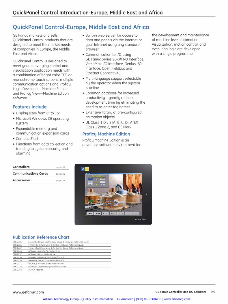
199www.gefanuc.com GE Fanuc Controller and I/O Solutions
QuickPanel Control Introduction-Europe, Middle East and Africa
the development and maintenance of machine level automation.Visualization, motion control, andexecution logic are developed with a single programmer.
GE Fanuc markets and sellsQuickPanel Control products that aredesigned to meet the market needs of companies in Europe, the MiddleEast and Africa.
QuickPanel Control is designed tomeet your converging control andvisualization application needs witha combination of bright color TFT, ormonochrome touch screens, multiplecommunication options and ProficyLogic Developer—Machine Editionand Proficy View—Machine Editionsoftware.
Features include:• Display sizes from 6" to 15"• Microsoft Windows CE operating
system• Expandable memory and
communication expansion cards• CompactFlash• Functions from data collection and
trending to system security andalarming
• Built-in web server for access todata and panels via the Internet oryour Intranet using any standardbrowser
• Communication to I/O usingGE Fanuc Series 90-30 I/O Interface,VersaMax I/O Interface, Genius I/OInterface, Open Fieldbus andEthernet Connectivity
• Multi-language support selectableby the operator when the systemis online
• Common database for increasedproductivity – greatly reducesdevelopment time by eliminating theneed to re-enter tag names
• Extensive library of pre-configuredanimation objects
• UL Class 1 Div 2 (A, B, C, D), ATEXClass 1 Zone 2, and CE Mark
Proficy Machine EditionProficy Machine Edition is anadvanced software environment for
Controllers page 200
Communications Cards page 201
Accessories page 202
Publication Reference ChartGFK-2305 6 Inch QuickPanel Control (Euro-Loaded) Hardware Reference Guide
GFK-2284 12 Inch QuickPanel View & Control Hardware Reference Guide
GFK-2402 15 inch QuickPanel View & Control Hardware Reference Guide
GFK-2245 GE Fanuc Series 90-30 I/O Interface
GFK-2297 GE Fanuc Genius I/O Interface
GFK-2299 GE Fanuc VersaMax Expansion I/O Card
GFK-2270 DeviceNet Master Communication Card
GFK-2271 PROFIBUS Master Communication Card
GFK-2276 Expanded User Memory Installation Guide
GFK-2368 PCMCIA Adaptor
QuickPanel Control-Europe, Middle East and Africa
Artisan Technology Group - Quality Instrumentation ... Guaranteed | (888) 88-SOURCE | www.artisantg.com
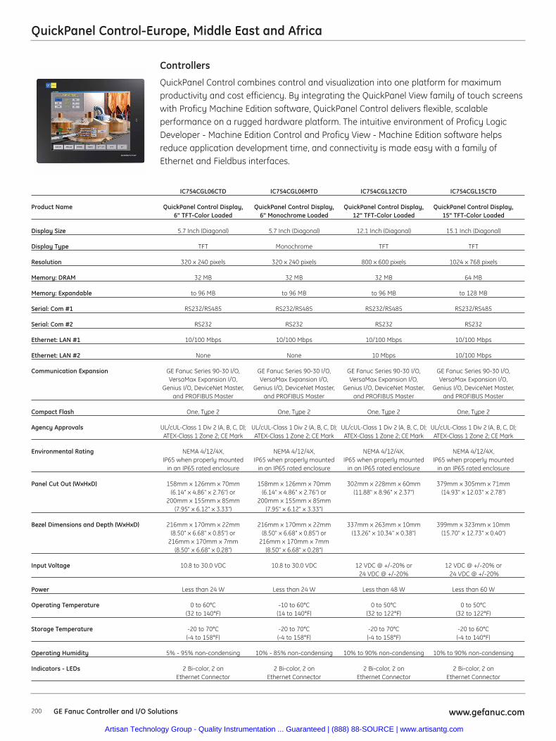
200 www.gefanuc.comGE Fanuc Controller and I/O Solutions
QuickPanel Control-Europe, Middle East and Africa
QuickPanel Control combines control and visualization into one platform for maximumproductivity and cost efficiency. By integrating the QuickPanel View family of touch screenswith Proficy Machine Edition software, QuickPanel Control delivers flexible, scalableperformance on a rugged hardware platform. The intuitive environment of Proficy LogicDeveloper - Machine Edition Control and Proficy View - Machine Edition software helpsreduce application development time, and connectivity is made easy with a family ofEthernet and Fieldbus interfaces.
Controllers
IC754CGL06CTD IC754CGL06MTD IC754CGL12CTD IC754CGL15CTD
Product Name QuickPanel Control Display, QuickPanel Control Display, QuickPanel Control Display, QuickPanel Control Display, 6" TFT-Color Loaded 6" Monochrome Loaded 12" TFT-Color Loaded 15" TFT-Color Loaded
Display Size 5.7 Inch (Diagonal) 5.7 Inch (Diagonal) 12.1 Inch (Diagonal) 15.1 Inch (Diagonal)
Display Type TFT Monochrome TFT TFT
Resolution 320 x 240 pixels 320 x 240 pixels 800 x 600 pixels 1024 x 768 pixels
Memory: DRAM 32 MB 32 MB 32 MB 64 MB
Memory: Expandable to 96 MB to 96 MB to 96 MB to 128 MB
Serial: Com #1 RS232/RS485 RS232/RS485 RS232/RS485 RS232/RS485
Serial: Com #2 RS232 RS232 RS232 RS232
Ethernet: LAN #1 10/100 Mbps 10/100 Mbps 10/100 Mbps 10/100 Mbps
Ethernet: LAN #2 None None 10 Mbps 10/100 Mbps
Communication Expansion GE Fanuc Series 90-30 I/O, GE Fanuc Series 90-30 I/O, GE Fanuc Series 90-30 I/O, GE Fanuc Series 90-30 I/O, VersaMax Expansion I/O, VersaMax Expansion I/O, VersaMax Expansion I/O, VersaMax Expansion I/O,
Genius I/O, DeviceNet Master, Genius I/O, DeviceNet Master, Genius I/O, DeviceNet Master, Genius I/O, DeviceNet Master, and PROFIBUS Master and PROFIBUS Master and PROFIBUS Master and PROFIBUS Master
Compact Flash One, Type 2 One, Type 2 One, Type 2 One, Type 2
Agency Approvals UL/cUL-Class 1 Div 2 (A, B, C, D); UL/cUL-Class 1 Div 2 (A, B, C, D); UL/cUL-Class 1 Div 2 (A, B, C, D); UL/cUL-Class 1 Div 2 (A, B, C, D); ATEX-Class 1 Zone 2; CE Mark ATEX-Class 1 Zone 2; CE Mark ATEX-Class 1 Zone 2; CE Mark ATEX-Class 1 Zone 2; CE Mark
Environmental Rating NEMA 4/12/4X, NEMA 4/12/4X, NEMA 4/12/4X, NEMA 4/12/4X, IP65 when properly mounted IP65 when properly mounted IP65 when properly mounted IP65 when properly mounted
in an IP65 rated enclosure in an IP65 rated enclosure in an IP65 rated enclosure in an IP65 rated enclosure
Panel Cut Out (WxHxD) 158mm x 126mm x 70mm 158mm x 126mm x 70mm 302mm x 228mm x 60mm 379mm x 305mm x 71mm (6.14" x 4.86" x 2.76") or (6.14" x 4.86" x 2.76") or (11.88" x 8.96" x 2.37") (14.93" x 12.03" x 2.78")
200mm x 155mm x 85mm 200mm x 155mm x 85mm (7.95" x 6.12" x 3.33") (7.95" x 6.12" x 3.33")
Bezel Dimensions and Depth (WxHxD) 216mm x 170mm x 22mm 216mm x 170mm x 22mm 337mm x 263mm x 10mm 399mm x 323mm x 10mm (8.50" x 6.68" x 0.85") or (8.50" x 6.68" x 0.85") or (13.26" x 10.34" x 0.38") (15.70" x 12.73" x 0.40")
216mm x 170mm x 7mm 216mm x 170mm x 7mm (8.50" x 6.68" x 0.28") (8.50" x 6.68" x 0.28")
Input Voltage 10.8 to 30.0 VDC 10.8 to 30.0 VDC 12 VDC @ +/-20% or 12 VDC @ +/-20% or24 VDC @ +/-20% 24 VDC @ +/-20%
Power Less than 24 W Less than 24 W Less than 48 W Less than 60 W
Operating Temperature 0 to 60°C -10 to 60°C 0 to 50°C 0 to 50°C(32 to 140°F) (14 to 140°F) (32 to 122°F) (32 to 122°F)
Storage Temperature -20 to 70°C -20 to 70°C -20 to 70°C -20 to 60°C (-4 to 158°F) (-4 to 158°F) (-4 to 158°F) (-4 to 140°F)
Operating Humidity 5% - 95% non-condensing 10% - 85% non-condensing 10% to 90% non-condensing 10% to 90% non-condensing
Indicators - LEDs 2 Bi-color, 2 on 2 Bi-color, 2 on 2 Bi-color, 2 on 2 Bi-color, 2 on Ethernet Connector Ethernet Connector Ethernet Connector Ethernet Connector
Artisan Technology Group - Quality Instrumentation ... Guaranteed | (888) 88-SOURCE | www.artisantg.com
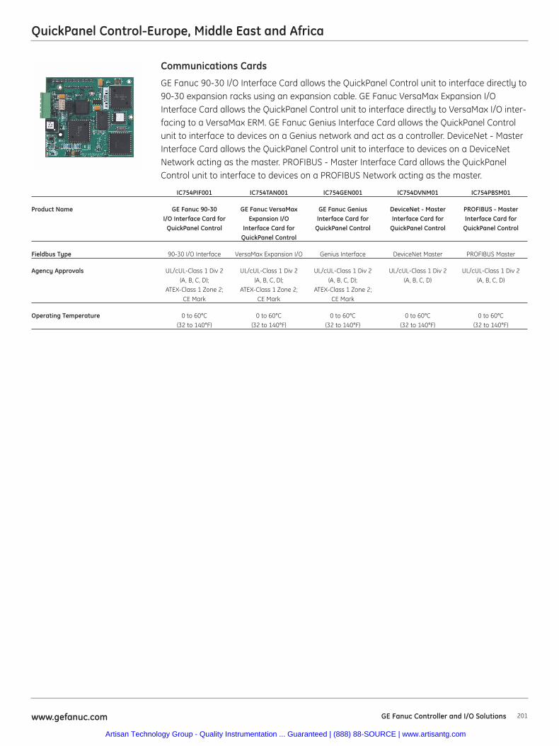
201www.gefanuc.com GE Fanuc Controller and I/O Solutions
QuickPanel Control-Europe, Middle East and Africa
GE Fanuc 90-30 I/O Interface Card allows the QuickPanel Control unit to interface directly to90-30 expansion racks using an expansion cable. GE Fanuc VersaMax Expansion I/OInterface Card allows the QuickPanel Control unit to interface directly to VersaMax I/O inter-facing to a VersaMax ERM. GE Fanuc Genius Interface Card allows the QuickPanel Controlunit to interface to devices on a Genius network and act as a controller. DeviceNet - MasterInterface Card allows the QuickPanel Control unit to interface to devices on a DeviceNetNetwork acting as the master. PROFIBUS - Master Interface Card allows the QuickPanelControl unit to interface to devices on a PROFIBUS Network acting as the master.
Communications Cards
IC754PIF001 IC754TAN001 IC754GEN001 IC754DVNM01 IC754PBSM01
Product Name GE Fanuc 90-30 GE Fanuc VersaMax GE Fanuc Genius DeviceNet - Master PROFIBUS - Master I/O Interface Card for Expansion I/O Interface Card for Interface Card for Interface Card for
QuickPanel Control Interface Card for QuickPanel Control QuickPanel Control QuickPanel ControlQuickPanel Control
Fieldbus Type 90-30 I/O Interface VersaMax Expansion I/O Genius Interface DeviceNet Master PROFIBUS Master
Agency Approvals UL/cUL-Class 1 Div 2 UL/cUL-Class 1 Div 2 UL/cUL-Class 1 Div 2 UL/cUL-Class 1 Div 2 UL/cUL-Class 1 Div 2(A, B, C, D); (A, B, C, D); (A, B, C, D); (A, B, C, D) (A, B, C, D)
ATEX-Class 1 Zone 2; ATEX-Class 1 Zone 2; ATEX-Class 1 Zone 2; CE Mark CE Mark CE Mark
Operating Temperature 0 to 60°C 0 to 60°C 0 to 60°C 0 to 60°C 0 to 60°C(32 to 140°F) (32 to 140°F) (32 to 140°F) (32 to 140°F) (32 to 140°F)
Artisan Technology Group - Quality Instrumentation ... Guaranteed | (888) 88-SOURCE | www.artisantg.com
QuickPanel Control-Europe, Middle East and Africa
AccessoriesIC754PCMCIA001 PCMCIA Adaptor for QuickPanel Control
IC754ACC32MEM Expansion Memory 32 MBytes
IC754ACC64MEM Expansion Memory 64 MBytes
IC754ACC06GASE Gasket for 6 Inch QuickPanel Control
IC754ACC12GAS Gasket for 12 Inch QuickPanel Control
IC754ACC15GAS Gasket for 15 Inch QuickPanel Control
IC754ACC06MNTE Mounting Clips & Power Connector for 6 Inch QuickPanel Control
IC754ACC12MNT Mounting Clips & Power Connector for 12 Inch QuickPanel Control
IC754ACC15MNT Mounting Clips & Power Connector for 15 Inch QuickPanel Control
IC754ACC06BEZ01 Stainless Steel Bezel for 6 Inch Mono & TFT-Color QuickPanel Control
IC754ACC12BEZ01 Stainless Steel Bezel for 12 Inch TFT-Color QuickPanel Control
IC754ACC12ADP Adaptor Kit for 12 Inch QuickPanel Control into CEIIx Cutout
GE Fanuc Controller and I/O Solutions www.gefanuc.com202
Artisan Technology Group - Quality Instrumentation ... Guaranteed | (888) 88-SOURCE | www.artisantg.com
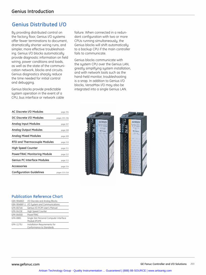
203www.gefanuc.com GE Fanuc Controller and I/O Solutions
Genius Introduction
AC Discrete I/O Modules page 204
DC Discrete I/O Modules pages 205-206
Analog Input Modules page 207
Analog Output Modules page 208
Analog Mixed Modules page 209
RTD and Thermocouple Modules page 210
High Speed Counter page 211
PowerTRAC Monitoring Module page 212
Genius PC Interface Modules page 213
Accessories page 214
Configuration Guidelines pages 215-216
Publication Reference ChartGEK-90486D I/O Discrete and Analog BlocksGEK-90486F-1 I/O System and CommunicationsGFK-0074A Genius I/O PCIM User's ManualGFK-0415E High Speed CounterGFK-0450D PowerTRACGFK-0881 Single Slot Personal Computer Interface
Module (PCIM)GFK-1179J Installation Requirements for
Conformance to Standards
By providing distributed control onthe factory floor, Genius I/O systemsoffer fewer terminations to document,dramatically shorter wiring runs, andsimpler, more effective troubleshoot-ing. Genius I/O blocks automaticallyprovide diagnostic information on fieldwiring, power conditions and loads,as well as the state of the communi-cation network, blocks and circuits.Genius diagnostics sharply reducethe time needed for initial controland debugging.
Genius blocks provide predictablesystem operation in the event of aCPU, bus interface or network cable
failure. When connected in a redun-dant configuration with two or moreCPUs running simultaneously, theGenius blocks will shift automaticallyto a backup CPU if the main controllerfails to communicate.
Genius blocks communicate withthe system CPU over the Genius LAN,greatly simplifying system installation,and with network tools such as thehand-held monitor, troubleshootingis a snap. In addition to Genius I/Oblocks, VersaMax I/O may also beintegrated into a single Genius LAN.
Genius Distributed I/O
Artisan Technology Group - Quality Instrumentation ... Guaranteed | (888) 88-SOURCE | www.artisantg.com
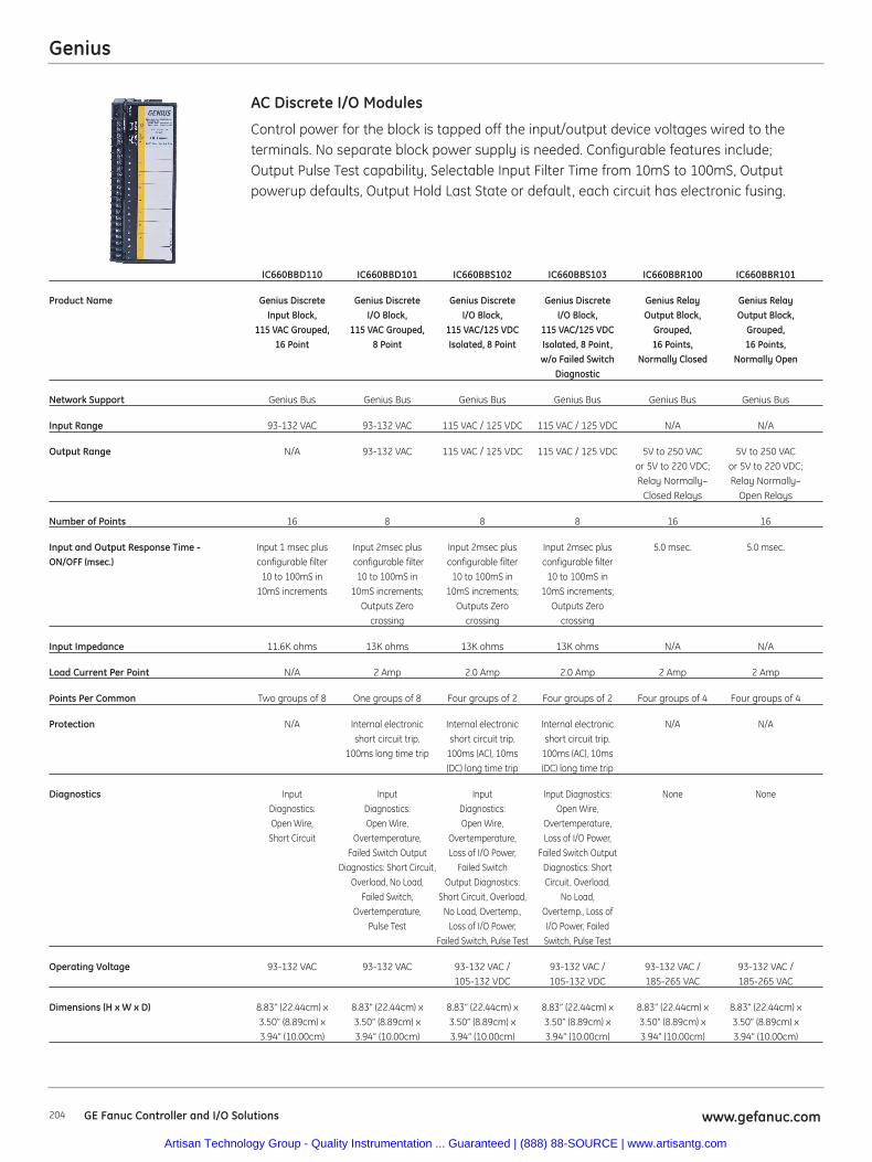
Genius
204 www.gefanuc.comGE Fanuc Controller and I/O Solutions
Control power for the block is tapped off the input/output device voltages wired to the terminals. No separate block power supply is needed. Configurable features include; Output Pulse Test capability, Selectable Input Filter Time from 10mS to 100mS, Outputpowerup defaults, Output Hold Last State or default, each circuit has electronic fusing.
AC Discrete I/O Modules
IC660BBD110 IC660BBD101 IC660BBS102 IC660BBS103 IC660BBR100 IC660BBR101
Product Name Genius Discrete Genius Discrete Genius Discrete Genius Discrete Genius Relay Genius Relay Input Block, I/O Block, I/O Block, I/O Block, Output Block, Output Block,
115 VAC Grouped, 115 VAC Grouped, 115 VAC/125 VDC 115 VAC/125 VDC Grouped, Grouped, 16 Point 8 Point Isolated, 8 Point Isolated, 8 Point, 16 Points, 16 Points,
w/o Failed Switch Normally Closed Normally OpenDiagnostic
Network Support Genius Bus Genius Bus Genius Bus Genius Bus Genius Bus Genius Bus
Input Range 93-132 VAC 93-132 VAC 115 VAC / 125 VDC 115 VAC / 125 VDC N/A N/A
Output Range N/A 93-132 VAC 115 VAC / 125 VDC 115 VAC / 125 VDC 5V to 250 VAC 5V to 250 VACor 5V to 220 VDC; or 5V to 220 VDC; Relay Normally– Relay Normally–
Closed Relays Open Relays
Number of Points 16 8 8 8 16 16
Input and Output Response Time - Input 1 msec plus Input 2msec plus Input 2msec plus Input 2msec plus 5.0 msec. 5.0 msec.ON/OFF (msec.) configurable filter configurable filter configurable filter configurable filter
10 to 100mS in 10 to 100mS in 10 to 100mS in 10 to 100mS in 10mS increments 10mS increments; 10mS increments; 10mS increments;
Outputs Zero Outputs Zero Outputs Zero crossing crossing crossing
Input Impedance 11.6K ohms 13K ohms 13K ohms 13K ohms N/A N/A
Load Current Per Point N/A 2 Amp 2.0 Amp 2.0 Amp 2 Amp 2 Amp
Points Per Common Two groups of 8 One groups of 8 Four groups of 2 Four groups of 2 Four groups of 4 Four groups of 4
Protection N/A Internal electronic Internal electronic Internal electronic N/A N/Ashort circuit trip. short circuit trip. short circuit trip.
100ms long time trip 100ms (AC), 10ms 100ms (AC), 10ms (DC) long time trip (DC) long time trip
Diagnostics Input Input Input Input Diagnostics: None NoneDiagnostics: Diagnostics: Diagnostics: Open Wire, Open Wire, Open Wire, Open Wire, Overtemperature,
Short Circuit Overtemperature, Overtemperature, Loss of I/O Power, Failed Switch Output Loss of I/O Power, Failed Switch Output
Diagnostics: Short Circuit, Failed Switch Diagnostics: Short Overload, No Load, Output Diagnostics: Circuit, Overload,
Failed Switch, Short Circuit, Overload, No Load,Overtemperature, No Load, Overtemp., Overtemp., Loss of
Pulse Test Loss of I/O Power, I/O Power, Failed Failed Switch, Pulse Test Switch, Pulse Test
Operating Voltage 93-132 VAC 93-132 VAC 93-132 VAC / 93-132 VAC / 93-132 VAC / 93-132 VAC / 105-132 VDC 105-132 VDC 185-265 VAC 185-265 VAC
Dimensions (H x W x D) 8.83” (22.44cm) x 8.83” (22.44cm) x 8.83” (22.44cm) x 8.83” (22.44cm) x 8.83” (22.44cm) x 8.83” (22.44cm) x3.50” (8.89cm) x 3.50” (8.89cm) x 3.50” (8.89cm) x 3.50” (8.89cm) x 3.50” (8.89cm) x 3.50” (8.89cm) x3.94” (10.00cm) 3.94” (10.00cm) 3.94” (10.00cm) 3.94” (10.00cm) 3.94” (10.00cm) 3.94” (10.00cm)
Artisan Technology Group - Quality Instrumentation ... Guaranteed | (888) 88-SOURCE | www.artisantg.com
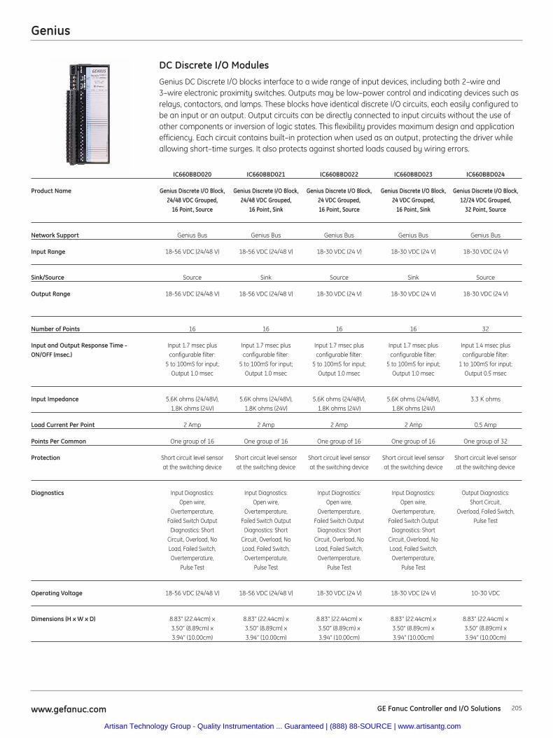
Genius
205www.gefanuc.com GE Fanuc Controller and I/O Solutions
Genius DC Discrete I/O blocks interface to a wide range of input devices, including both 2–wire and3–wire electronic proximity switches. Outputs may be low–power control and indicating devices such asrelays, contactors, and lamps. These blocks have identical discrete I/O circuits, each easily configured tobe an input or an output. Output circuits can be directly connected to input circuits without the use ofother components or inversion of logic states. This flexibility provides maximum design and applicationefficiency. Each circuit contains built–in protection when used as an output, protecting the driver whileallowing short–time surges. It also protects against shorted loads caused by wiring errors.
DC Discrete I/O Modules
IC660BBD020 IC660BBD021 IC660BBD022 IC660BBD023 IC660BBD024
Product Name Genius Discrete I/O Block, Genius Discrete I/O Block, Genius Discrete I/O Block, Genius Discrete I/O Block, Genius Discrete I/O Block,24/48 VDC Grouped, 24/48 VDC Grouped, 24 VDC Grouped, 24 VDC Grouped, 12/24 VDC Grouped,
16 Point, Source 16 Point, Sink 16 Point, Source 16 Point, Sink 32 Point, Source
Network Support Genius Bus Genius Bus Genius Bus Genius Bus Genius Bus
Input Range 18-56 VDC (24/48 V) 18-56 VDC (24/48 V) 18-30 VDC (24 V) 18-30 VDC (24 V) 18-30 VDC (24 V)
Sink/Source Source Sink Source Sink Source
Output Range 18-56 VDC (24/48 V) 18-56 VDC (24/48 V) 18-30 VDC (24 V) 18-30 VDC (24 V) 18-30 VDC (24 V)
Number of Points 16 16 16 16 32
Input and Output Response Time - Input 1.7 msec plus Input 1.7 msec plus Input 1.7 msec plus Input 1.7 msec plus Input 1.4 msec plusON/OFF (msec.) configurable filter: configurable filter: configurable filter: configurable filter: configurable filter:
5 to 100mS for input; 5 to 100mS for input; 5 to 100mS for input; 5 to 100mS for input; 1 to 100mS for input; Output 1.0 msec Output 1.0 msec Output 1.0 msec Output 1.0 msec Output 0.5 msec
Input Impedance 5.6K ohms (24/48V), 5.6K ohms (24/48V), 5.6K ohms (24/48V), 5.6K ohms (24/48V), 3.3 K ohms1.8K ohms (24V) 1.8K ohms (24V) 1.8K ohms (24V) 1.8K ohms (24V)
Load Current Per Point 2 Amp 2 Amp 2 Amp 2 Amp 0.5 Amp
Points Per Common One group of 16 One group of 16 One group of 16 One group of 16 One group of 32
Protection Short circuit level sensor Short circuit level sensor Short circuit level sensor Short circuit level sensor Short circuit level sensor at the switching device at the switching device at the switching device at the switching device at the switching device
Diagnostics Input Diagnostics: Input Diagnostics: Input Diagnostics: Input Diagnostics: Output Diagnostics: Open wire, Open wire, Open wire, Open wire, Short Circuit,
Overtemperature, Overtemperature, Overtemperature, Overtemperature, Overload, Failed Switch,Failed Switch Output Failed Switch Output Failed Switch Output Failed Switch Output Pulse Test
Diagnostics: Short Diagnostics: Short Diagnostics: Short Diagnostics: Short Circuit, Overload, No Circuit, Overload, No Circuit, Overload, No Circuit, Overload, NoLoad, Failed Switch, Load, Failed Switch, Load, Failed Switch, Load, Failed Switch, Overtemperature, Overtemperature, Overtemperature, Overtemperature,
Pulse Test Pulse Test Pulse Test Pulse Test
Operating Voltage 18-56 VDC (24/48 V) 18-56 VDC (24/48 V) 18-30 VDC (24 V) 18-30 VDC (24 V) 10-30 VDC
Dimensions (H x W x D) 8.83” (22.44cm) x 8.83” (22.44cm) x 8.83” (22.44cm) x 8.83” (22.44cm) x 8.83” (22.44cm) x3.50” (8.89cm) x 3.50” (8.89cm) x 3.50” (8.89cm) x 3.50” (8.89cm) x 3.50” (8.89cm) x3.94” (10.00cm) 3.94” (10.00cm) 3.94” (10.00cm) 3.94” (10.00cm) 3.94” (10.00cm)
Artisan Technology Group - Quality Instrumentation ... Guaranteed | (888) 88-SOURCE | www.artisantg.com
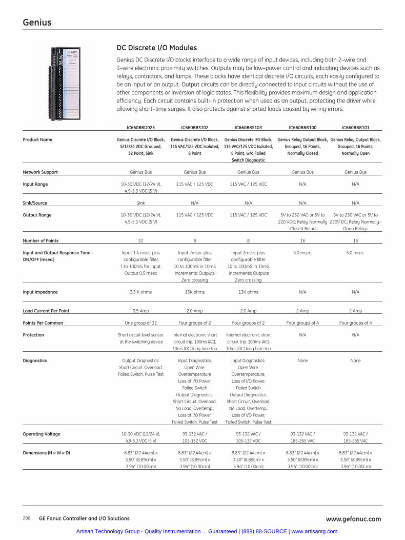
Genius
206 www.gefanuc.comGE Fanuc Controller and I/O Solutions
Genius DC Discrete I/O blocks interface to a wide range of input devices, including both 2–wire and3–wire electronic proximity switches. Outputs may be low–power control and indicating devices such asrelays, contactors, and lamps. These blocks have identical discrete I/O circuits, each easily configured tobe an input or an output. Output circuits can be directly connected to input circuits without the use ofother components or inversion of logic states. This flexibility provides maximum design and applicationefficiency. Each circuit contains built–in protection when used as an output, protecting the driver whileallowing short–time surges. It also protects against shorted loads caused by wiring errors.
DC Discrete I/O Modules
IC660BBD025 IC660BBS102 IC660BBS103 IC660BBR100 IC660BBR101
Product Name Genius Discrete I/O Block, Genius Discrete I/O Block, Genius Discrete I/O Block, Genius Relay Output Block, Genius Relay Output Block, 5/12/24 VDC Grouped, 115 VAC/125 VDC Isolated, 115 VAC/125 VDC Isolated, Grouped, 16 Points, Grouped, 16 Points,
32 Point, Sink 8 Point 8 Point, w/o Failed Normally Closed Normally Open Switch Diagnostic
Network Support Genius Bus Genius Bus Genius Bus Genius Bus Genius Bus
Input Range 10-30 VDC (12/24 V), 115 VAC / 125 VDC 115 VAC / 125 VDC N/A N/A4.9-5.3 VDC (5 V)
Sink/Source Sink N/A N/A N/A N/A
Output Range 10-30 VDC (12/24 V), 115 VAC / 125 VDC 115 VAC / 125 VDC 5V to 250 VAC or 5V to 5V to 250 VAC or 5V to4.9-5.3 VDC (5 V) 220 VDC; Relay Normally 220V DC; Relay Normally–
–Closed Relays Open Relays
Number of Points 32 8 8 16 16
Input and Output Response Time - Input 1.4 msec plus Input 2msec plus Input 2msec plus 5.0 msec. 5.0 msec.ON/OFF (msec.) configurable filter: configurable filter configurable filter
1 to 100mS for input; 10 to 100mS in 10mS 10 to 100mS in 10mSOutput 0.5 msec increments; Outputs increments; Outputs
Zero crossing Zero crossing
Input Impedance 3.3 K ohms 13K ohms 13K ohms N/A N/A
Load Current Per Point 0.5 Amp 2.0 Amp 2.0 Amp 2 Amp 2 Amp
Points Per Common One group of 32 Four groups of 2 Four groups of 2 Four groups of 4 Four groups of 4
Protection Short circuit level sensor Internal electronic short Internal electronic short N/A N/Aat the switching device circuit trip. 100ms (AC), circuit trip. 100ms (AC),
10ms (DC) long time trip 10ms (DC) long time trip
Diagnostics Output Diagnostics: Input Diagnostics: Input Diagnostics: None NoneShort Circuit, Overload, Open Wire, Open Wire, Failed Switch, Pulse Test Overtemperature Overtemperature,
Loss of I/O Power, Loss of I/O Power, Failed Switch Failed Switch
Output Diagnostics: Output Diagnostics: Short Circuit, Overload, Short Circuit, Overload,
No Load, Overtemp., No Load, Overtemp., Loss of I/O Power, Loss of I/O Power,
Failed Switch, Pulse Test Failed Switch, Pulse Test
Operating Voltage 10-30 VDC (12/24 V), 93-132 VAC / 93-132 VAC / 93-132 VAC / 93-132 VAC / 4.9-5.3 VDC (5 V) 105-132 VDC 105-132 VDC 185-265 VAC 185-265 VAC
Dimensions (H x W x D) 8.83” (22.44cm) x 8.83” (22.44cm) x 8.83” (22.44cm) x 8.83” (22.44cm) x 8.83” (22.44cm) x 3.50” (8.89cm) x 3.50” (8.89cm) x 3.50” (8.89cm) x 3.50” (8.89cm) x 3.50” (8.89cm) x3.94” (10.00cm) 3.94” (10.00cm) 3.94” (10.00cm) 3.94” (10.00cm) 3.94” (10.00cm)
Artisan Technology Group - Quality Instrumentation ... Guaranteed | (888) 88-SOURCE | www.artisantg.com
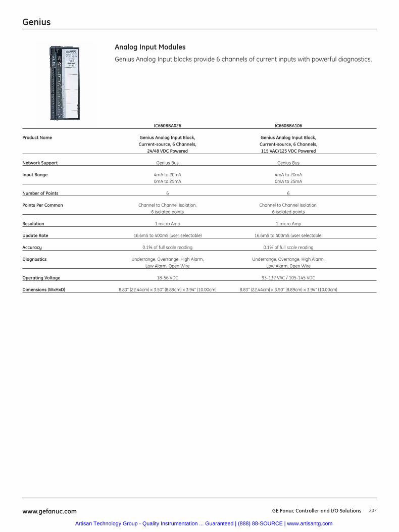
Genius
207www.gefanuc.com GE Fanuc Controller and I/O Solutions
Genius Analog Input blocks provide 6 channels of current inputs with powerful diagnostics.
Analog Input Modules
IC660BBA026 IC660BBA106
Product Name Genius Analog Input Block, Genius Analog Input Block, Current-source, 6 Channels, Current-source, 6 Channels,
24/48 VDC Powered 115 VAC/125 VDC Powered
Network Support Genius Bus Genius Bus
Input Range 4mA to 20mA 4mA to 20mA0mA to 25mA 0mA to 25mA
Number of Points 6 6
Points Per Common Channel to Channel Isolation. Channel to Channel Isolation. 6 isolated points 6 isolated points
Resolution 1 micro Amp 1 micro Amp
Update Rate 16.6mS to 400mS (user selectable) 16.6mS to 400mS (user selectable)
Accuracy 0.1% of full scale reading 0.1% of full scale reading
Diagnostics Underrange, Overrange, High Alarm, Underrange, Overrange, High Alarm, Low Alarm, Open Wire Low Alarm, Open Wire
Operating Voltage 18-56 VDC 93-132 VAC / 105-145 VDC
Dimensions (WxHxD) 8.83” (22.44cm) x 3.50” (8.89cm) x 3.94” (10.00cm) 8.83” (22.44cm) x 3.50” (8.89cm) x 3.94” (10.00cm)
Artisan Technology Group - Quality Instrumentation ... Guaranteed | (888) 88-SOURCE | www.artisantg.com
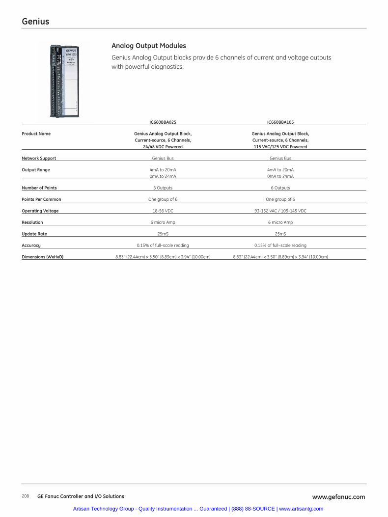
Genius
208 www.gefanuc.comGE Fanuc Controller and I/O Solutions
Genius Analog Output blocks provide 6 channels of current and voltage outputswith powerful diagnostics.
Analog Output Modules
IC660BBA025 IC660BBA105
Product Name Genius Analog Output Block, Genius Analog Output Block, Current-source, 6 Channels, Current-source, 6 Channels,
24/48 VDC Powered 115 VAC/125 VDC Powered
Network Support Genius Bus Genius Bus
Output Range 4mA to 20mA 4mA to 20mA0mA to 24mA 0mA to 24mA
Number of Points 6 Outputs 6 Outputs
Points Per Common One group of 6 One group of 6
Operating Voltage 18-56 VDC 93-132 VAC / 105-145 VDC
Resolution 6 micro Amp 6 micro Amp
Update Rate 25mS 25mS
Accuracy 0.15% of full–scale reading 0.15% of full–scale reading
Dimensions (WxHxD) 8.83” (22.44cm) x 3.50” (8.89cm) x 3.94” (10.00cm) 8.83” (22.44cm) x 3.50” (8.89cm) x 3.94” (10.00cm)
Artisan Technology Group - Quality Instrumentation ... Guaranteed | (888) 88-SOURCE | www.artisantg.com

Genius
209www.gefanuc.com GE Fanuc Controller and I/O Solutions
Genius Analog Mixed blocks provide 4 channels of inputs and 2 channels of outputs.The channels can be configured for current or voltage with powerful diagnostics.
Analog Mixed Modules
IC660BBA020 IC660BBA100 IC660BBA024 IC660BBA104
Product Name Genius Analog I/O Block, Genius Analog I/O Block, Genius Analog I/O Block, Genius Analog I/O Block, Voltage/Current, 4 Inputs/ Voltage/Current, 4 Inputs/ Current-source, 4 Inputs/ Current-source, 4 Inputs/
2 Outputs, 24/48 VDC Powered 2 Outputs, 115 VAC Powered 2 Outputs, 24/48 VDC Powered 2 Outputs, 115 VAC/125 VDC Powered
Network Support Genius Bus Genius Bus Genius Bus Genius Bus
Number of Points 4 In/ 2 Out 4 In/ 2 Out 4 In/ 2 Out 4 In/ 2 Out
Points Per Common One group of 4 Inputs and One group of 4 Inputs and One group of 4 Inputs and One group of 4 Inputs and one group of 2 Outputs one group of 2 Outputs one group of 2 Outputs one group of 2 Outputs
Input Range 0–10 VDC, 10 VDC, 5 VDC, 0–10 VDC, 10 VDC, 5 VDC, 4mA to 20mA 4mA to 20mA0–5 VDC, 4–20 mA (or 1–5 VDC) 0–5 VDC, 4–20 mA (or 1–5 VDC)
Output Range 0–10 VDC, 10 VDC, 5 VDC, 0–10 VDC, 10 VDC, 5 VDC, 4mA to 20mA 4mA to 20mA0–5 VDC, 4–20 mA (or 1–5 VDC) 0–5 VDC, 4–20 mA (or 1–5 VDC)
Operating Voltage 18-56 VDC 98-132 VAC 18-56 VDC 93-132 VAC / 105-145 VDC
Resolution 12 bit + sign 12 bit + sign Input: 1 micro Amp Output: 6mAOutput: 6 micro Amp
Update Rate Once every 4mS Once every 4mS Input: 16.6mS to 400mS Input: 16.6mS to 400mS(user selectable) Output: (user selectable) Output:
6mS to 8mS typical 6mS to 8mS typical
Accuracy Typical: 0.2% of full scale; Typical: 0.2% of full scale; Input: 0.1% of full scale Input: 0.1% of full scale Maximum: 0.5% of full scale: Maximum: 0.5% of full scale: reading reading
within 50mV on the 10 volt range, within 50mV on the 10 volt range, Output: 0.15% of full Output: 0.15% of full 25mV on the 5 volt range, and 25mV on the 5 volt range, and scale reading scale reading
100mA on the 4 to 20 mA range. 100mA on the 4 to 20 mA range.
Input Filter Response none, 8, 16, 32, 64, 128, none, 8, 16, 32, 64, 128, 16.6mS to 400mS 16.6mS to 400mS 256, 512, 1024mS 256, 512, 1024mS (user selectable) (user selectable)
Diagnostics Input: Underrange, Overrange, Input: Underrange, Overrange, Input: Underrange, Overrange, Input: Underrange, Overrange,High Alarm, Low Alarm, High Alarm, Low Alarm, High Alarm, Low Alarm, High Alarm, Low Alarm,
Open Wire Open Wire Open Wire Open Wire, Output: Underrange, Output: Underrange, Output: Underrange, Output: Underrange,
Overrange Overrange Overrange, Feedback error Overrange, Feedback error
Dimensions (WxHxD) 8.83” (22.44cm) x 3.50” 8.83” (22.44cm) x 3.50” 8.83” (22.44cm) x 3.50” 8.83” (22.44cm) x 3.50”(8.89cm) x 3.94” (10.00cm) (8.89cm) x 3.94” (10.00cm) (8.89cm) x 3.94” (10.00cm) (8.89cm) x 3.94” (10.00cm)
Artisan Technology Group - Quality Instrumentation ... Guaranteed | (888) 88-SOURCE | www.artisantg.com
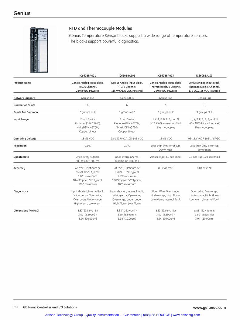
Genius
210 www.gefanuc.comGE Fanuc Controller and I/O Solutions
Genius Temperature Sensor blocks support a wide range of temperature sensors. The blocks support powerful diagnostics.
RTD and Thermocouple Modules
IC660BBA021 IC660BBA101 IC660BBA023 IC660BBA103
Product Name Genius Analog Input Block, Genius Analog Input Block, Genius Analog Input Block, Genius Analog Input Block,RTD, 6 Channel, RTD, 6 Channel, Thermocouple, 6 Channel, Thermocouple, 6 Channel,
24/48 VDC Powered 115 VAC/125 VDC Powered 24/48 VDC Powered 115 VAC/125 VDC Powered
Network Support Genius Bus Genius Bus Genius Bus Genius Bus
Number of Points 6 6 6 6
Points Per Common 3 groups of 2 3 groups of 2 3 groups of 2 3 groups of 2
Input Range 2 and 3 wire 2 and 3 wire J, K, T, E, B, R, S, and N J, K, T, E, B, R, S, and NPlatinum (DIN 43760), Platinum (DIN 43760), (#14 AWG Nicrosil vs. Nisil) (#14 AWG Nicrosil vs. Nisil)
Nickel (DIN 43760), Nickel (DIN 43760), thermocouples thermocouples.Copper, Linear Copper, Linear
Operating Voltage 18-56 VDC 93-132 VAC / 105-145 VDC 18-56 VDC 93-132 VAC / 105-145 VDC
Resolution 0.1°C 0.1°C Less than 0mV error typ, Less than 0mV error typ, 20mV max. 20mV max.
Update Rate Once every 400 ms, Once every 400 ms, 2.0 sec (typ), 3.0 sec (max) 2.0 sec (typ), 3.0 sec (max)800 ms, or 1600 ms 800 ms, or 1600 ms
Accuracy At 25°C - Platinum or At 25°C - Platinum or 8 Hz at 25°C 8 Hz at 25°CNickel: 0.5°C typical, Nickel: 0.5°C typical,
1.0°C maximum 1.0°C maximum10W Copper: 5°C typical, 10W Copper: 5°C typical,
10°C maximum 10°C maximum
Diagnostics Input shorted, Internal fault, Input shorted, Internal fault, Open Wire, Overrange, Open Wire, Overrange, Wiring error, Open wire, Wiring error, Open wire, Underrange, High Alarm, Underrange, High Alarm, Overrange, Underrange, Overrange, Underrange, Low Alarm, Internal Fault Low Alarm, Internal FaultHigh Alarm, Low Alarm High Alarm, Low Alarm
Dimensions (WxHxD) 8.83” (22.44cm) x 8.83” (22.44cm) x 8.83” (22.44cm) x 8.83” (22.44cm) x3.50” (8.89cm) x 3.50” (8.89cm) x 3.50” (8.89cm) x 3.50” (8.89cm) x 3.94” (10.00cm) 3.94” (10.00cm) 3.94” (10.00cm) 3.94” (10.00cm)
Artisan Technology Group - Quality Instrumentation ... Guaranteed | (888) 88-SOURCE | www.artisantg.com
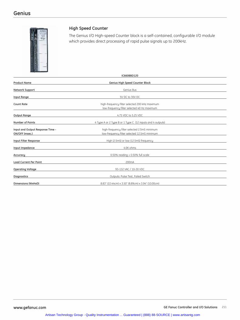
Genius
211www.gefanuc.com GE Fanuc Controller and I/O Solutions
The Genius I/O High-speed Counter block is a self-contained, configurable I/O modulewhich provides direct processing of rapid pulse signals up to 200kHz.
High Speed Counter
IC660BBD120
Product Name Genius High Speed Counter Block
Network Support Genius Bus
Input Range 5V DC to 30V DC
Count Rate high-frequency filter selected 200 kHz maximum low-frequency filter selected 40 Hz maximum
Output Range 4.75 VDC to 5.25 VDC
Number of Points 4 Type A or 2 Type B or 1 Type C (12 inputs and 4 outputs)
Input and Output Response Time - high-frequency filter selected 2.5mS minimum ON/OFF (msec.) low-frequency filter selected 12.5mS minimum
Input Filter Response High (2.5mS) or low (12.5mS) frequency
Input Impedance 4.0K ohms
Accuracy 0.50% reading + 0.50% full scale
Load Current Per Point 200mA
Operating Voltage 93-132 VAC / 10-30 VDC
Diagnostics Outputs: Pulse Test, Failed Switch
Dimensions (WxHxD) 8.83” (22.44cm) x 3.50” (8.89cm) x 3.94” (10.00cm)
Artisan Technology Group - Quality Instrumentation ... Guaranteed | (888) 88-SOURCE | www.artisantg.com
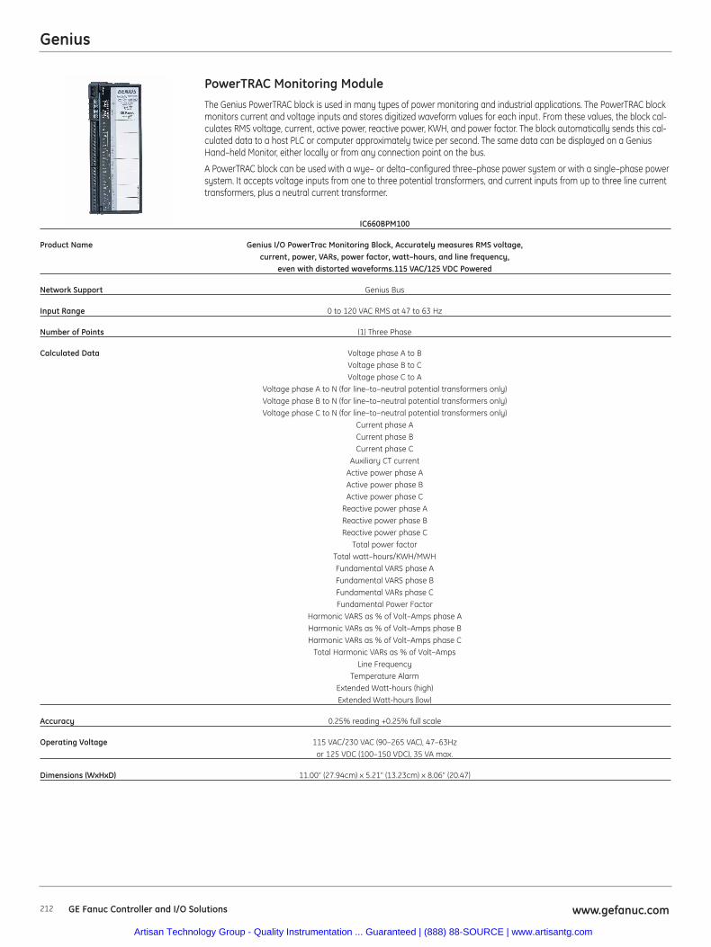
Genius
212 www.gefanuc.comGE Fanuc Controller and I/O Solutions
The Genius PowerTRAC block is used in many types of power monitoring and industrial applications. The PowerTRAC blockmonitors current and voltage inputs and stores digitized waveform values for each input. From these values, the block cal-culates RMS voltage, current, active power, reactive power, KWH, and power factor. The block automatically sends this cal-culated data to a host PLC or computer approximately twice per second. The same data can be displayed on a GeniusHand–held Monitor, either locally or from any connection point on the bus.
A PowerTRAC block can be used with a wye– or delta–configured three–phase power system or with a single–phase powersystem. It accepts voltage inputs from one to three potential transformers, and current inputs from up to three line currenttransformers, plus a neutral current transformer.
PowerTRAC Monitoring Module
IC660BPM100
Product Name Genius I/O PowerTrac Monitoring Block, Accurately measures RMS voltage, current, power, VARs, power factor, watt–hours, and line frequency,
even with distorted waveforms.115 VAC/125 VDC Powered
Network Support Genius Bus
Input Range 0 to 120 VAC RMS at 47 to 63 Hz
Number of Points (1) Three Phase
Calculated Data Voltage phase A to BVoltage phase B to CVoltage phase C to A
Voltage phase A to N (for line–to–neutral potential transformers only)Voltage phase B to N (for line–to–neutral potential transformers only)Voltage phase C to N (for line–to–neutral potential transformers only)
Current phase ACurrent phase BCurrent phase C
Auxiliary CT currentActive power phase AActive power phase BActive power phase C
Reactive power phase AReactive power phase BReactive power phase C
Total power factorTotal watt–hours/KWH/MWHFundamental VARS phase AFundamental VARS phase BFundamental VARs phase CFundamental Power Factor
Harmonic VARS as % of Volt–Amps phase AHarmonic VARs as % of Volt–Amps phase BHarmonic VARs as % of Volt–Amps phase C
Total Harmonic VARs as % of Volt–AmpsLine Frequency
Temperature AlarmExtended Watt-hours (high)Extended Watt-hours (low)
Accuracy 0.25% reading +0.25% full scale
Operating Voltage 115 VAC/230 VAC (90–265 VAC), 47–63Hzor 125 VDC (100–150 VDC), 35 VA max.
Dimensions (WxHxD) 11.00” (27.94cm) x 5.21" (13.23cm) x 8.06” (20.47)
Artisan Technology Group - Quality Instrumentation ... Guaranteed | (888) 88-SOURCE | www.artisantg.com
Genius
213www.gefanuc.com GE Fanuc Controller and I/O Solutions
The Genius PC Interface Modules (PCIM) provide a low cost ‘tap’ on the GENIUS I/O bus,allowing a host system to control remote I/O utilizing the extensive diagnostics, high reliabil-ity and noise immunity of the GENIUS l/O System.
Genius PC Interface Modules
IC660ELB931 IC660ELB921 IC660ELB922
Product Name Genius Dual-channel PCI PCIM Genius Single-channel ISA PCIM Genius Dual-channel ISA PCIM
Network Support Genius Bus Genius Bus Genius Bus
I/O Data Transfer 128 bytes per device 128 bytes per device 128 bytes per device (32 total devices supported) (32 total devices supported) (32 total devices supported)
Distance 7500 feet (2286 meters) at 38.4 Kbaud; 7500 feet (2286 meters) at 38.4 Kbaud; 7500 feet (2286 meters) at 38.4 Kbaud; 4500 feet (1371 meters) at 76.8 Kbaud; 4500 feet (1371 meters) at 76.8 Kbaud; 4500 feet (1371 meters) at 76.8 Kbaud;
3500 feet (1066 meters) at 3500 feet (1066 meters) at 3500 feet (1066 meters) at 153.6 Kbaud extended; 153.6 Kbaud extended; 153.6 Kbaud extended;
2000 feet (609 meters) at 2000 feet (609 meters) at 2000 feet (609 meters) at 153.6 Kbaud standard. 153.6 Kbaud standard. 153.6 Kbaud standard.
Maximum length at each baud rate Maximum length at each baud rate Maximum length at each baud rate also depends on cable type. also depends on cable type. also depends on cable type.
PC Power Requirement 5 VDC, 600mA 5 VDC, 400mA 5 VDC, 400mA
Mechanical PCI Slot, dimensions of board are Single Slot AT full Length Single Slot AT full Length6.875” x 4.2” (Standard PCI short Card).
Backplane Requirements The PCI Genius (PCGEN) card is compatible Motherboard - 4 bytes Motherboard - 4 byteswith PC Compatible computers having a PCI Each channel - 16Kbytes shared Each channel - 16Kbytes shared slot which is compliant with the Peripheral RAM Memory RAM MemoryComponent Interconnect Bus Specification Configurable Interrupts Configurable Interrupts
v2.2, and also works with PCI v2.1
Artisan Technology Group - Quality Instrumentation ... Guaranteed | (888) 88-SOURCE | www.artisantg.com
214 www.gefanuc.comGE Fanuc Controller and I/O Solutions
Accessories and Cables
IC660BSM021 Genius Bus Switching Module, 24/48 VDC
IC660BSM120 Genius Bus Switching Module, 115 VAC/125 VDC
IC660BLC001 Genius bus Cable w/Connectors Alpha 9823 15 In (Qty 3)
IC660BLC003 Genius bus Cable w/Connectors Alpha 9823 3 Ft
IC660BLM506 Bus Terminator 150 Ohm (Qty 4)
IC660BLM508 Bus Terminator 75 Ohm (Qty 4)
IC660BLM507 Genius Block Puller
Hand Held Monitor
IC660HHM501 Hand-Held Monitor can be used to configure and trouble shoot Genius blocks. Kit includes Cable and Battery Charger
IC660BCM501 Hand-Held Monitor Battery Charger
IC660BPM500 Hand-Held Monitor Battery Pack
Genius
Artisan Technology Group - Quality Instrumentation ... Guaranteed | (888) 88-SOURCE | www.artisantg.com
215www.gefanuc.com GE Fanuc Controller and I/O Solutions
Configuration Guidelines
When configuring a Genius network the following guidelines should be considered1. Genius LAN is limited to 32 devices. Remember that the Genius Bus Controller reserves one address and if a Hand-Held configurator
is used, it also reserves an address.
2. If the application requires redundant networks, a Bus Switching Module is required (IC660BSMxxx).
3. Termination is required at the end of each network (IC660BLM50x)
4. For long distances, beyond 4,500 feet, the number of devices is limited to 16.
Cable SelectionCable # Outer Terminating Resistor* Number of Dielectric Ambient Maximum Length Cable Run, & Make Diameter -10% to +20% Conductors/ Voltage Temp feet/meters at baudrate
1/2 Watt AWG Rating Rating 153.6s 153.6e 76.8 38.4*
(A)9823 .350 in 150 ohms 2/#22 30V 60°C 2000ft 3500ft 4500ft 7500ft(B)9182 8.89mm 606m 1061m 1364m 2283m(C)4596(M)M39240
(B)89182 .322in 150 ohms 2/#22 150V 200°C 2000ft 3500ft 4500ft 7500ft8.18mm 606m 1061m 1364m 2283m
(B)9841 .270in *120 ohms 2/#24 30V 80°C 1000ft 1500ft 2500ft 3500ft(M)M3993 6.86mm 303m 455m 758m 1061m
(A)9818C .330in 100 ohms 2/#20 300V 80°C 1500ft 2500ft 3500ft 6000ft(B)9207 8.38mm 455m 758m 1061m 1818m(M)M4270
(A)9109 .282in 100 ohms 2/#20 150V 200°C 1500ft 2500ft 3500ft 6000ft(B)89207 7.16mm 455m 758m 1061m 1818m(C)4798(M)M44270
(A)9818D .330in 100 ohms 2/#20 1500ft 2500ft 3500ft 6000ft(B)9815 8.38mm 455m 758m 1061m 1818m
(A)9818 .315in 100 ohms 4 (two pair) 150V 60°C 1200ft 1700ft 3000ft 4500ft(B)9855 8.00mm #22 364m 516m 909m 1364m(M)M4230
(A)9110 .274in 100 ohms 4 (two pair) 150V 200°C 1200ft 1700ft 3000ft 4500ft(B)89696 6.96mm #22 364m 516m 909m 1364m(B)89855(M)M64230
(A)9814C .243 75 ohms 2/#20 150V 60°C 800ft 1500ft 2500ft 3500ft(B)9463 6.17mm 242m 455m 758m 1061m(M)M4154
(A)5902C .244in 75 ohms 4 (two pair) 300V 80°C 200ft 500ft 1200ft 2500ft(B)9302 6.20mm #22 60m 152m 333m 758m(M)M17002
Notes: A=Alpha, B=Belden, C=Consolidated, M=Manhattan, *=Limited to 16 taps at 38.4 Kbaud
Genius
Artisan Technology Group - Quality Instrumentation ... Guaranteed | (888) 88-SOURCE | www.artisantg.com
Examples of Typical Application
Configuration for Controller (Example application requiring (120) 24 VDC inputs and (80) Relay outputs AC power supply) for local control. System also has five remotecabinets, with each cabinet requiring (64) 24 VDC Inputs, (21) 24 VDC 0.5 Amp, Source Outputs and (2) current inputs and (2) current outputs (24 VDC power source). Maximumdistance from control cabinet to the last remote cabinet is 3,500 feet.
Control CabinetBackplane Slots Required Power Supply Qty Part Number Description
Current Required (mA)
2 1250mA @ 3.3 VDC; 1000mA @ 5 VDC 1 IC695CPU310 CPU with two built-in serial ports
2 1 IC695PSA040 120/240 VAC, 125 VDC Power Supply, current available 9 Amps @ 3.3 VDC; 6 Amps @ 5 VDC; 1.6 Amps @ 24 VDC maximum
600mA @ 3.3 VDC; 240 mA @ 5 VDC 1 IC695CHS016 16 Slot Universal Base
4 1200mA @ 5V 4 IC694MDL660 Discrete Input Module, 24 VDC Positive Logic, 32 points (Requires terminal block)
5 35mA @ 5V; 110mA @ 24 VDC Relay 5 IC694MDL940 Discrete Output Module, Relay 2.0 A per point Form A, 16 points (Terminal block included).
4 IC694TBB032 Terminal Block, Box Style
1 300 mA @ 5 VDC 1 IC694BEM331 Genius Bus Controller (GBC), supports up to 32 devices on a Genius Bus to control remote I/O, Global Data and Datagrams
1 BC646MPP001 Logic Developer - PLC Professional
14 Total current from power supply required: 2775mA @ 5V; 1850 @ 3.3V; 110mA @ 24 VDC Relay. Only one power supplied needed.
Remote Cabinets (Qty 5)15 IC660BBD024 Block 12/24 VDC Source I/O 32 Circuits
5 IC660BBA020 Block 24/48 VDC Analog 4 Inputs / 2 Outputs
1 IC660BLM506 Bus Terminator 150 Ohm (Qty 4)
Options to consider1 IC660HHM501 Hand-Held Monitor can be used to configure and troubleshoot
Genius blocks. Kit includes Cable and Battery Charger
5 IC660BLM507 Genius Block Puller
840mA @ 3.3 VDC; 614 mA @ 5 VDC 1 IC695ETM001 RX3i Ethernet module 10/100 Mbits 2 RJ45 connections one IP address occupies one slot on system base
6 IC690PWR024 24 VDC, 5 Amp Output Power and 120/230 VAC Input Power Power Supply
1 IC693ACC302 RX3i Long term battery for CPU
1 IC754VSI06STD QuickPanel View Intermediate 6 inch STN Touch Operator Interface
Genius
GE Fanuc Controller and I/O Solutions www.gefanuc.com216
Artisan Technology Group - Quality Instrumentation ... Guaranteed | (888) 88-SOURCE | www.artisantg.com
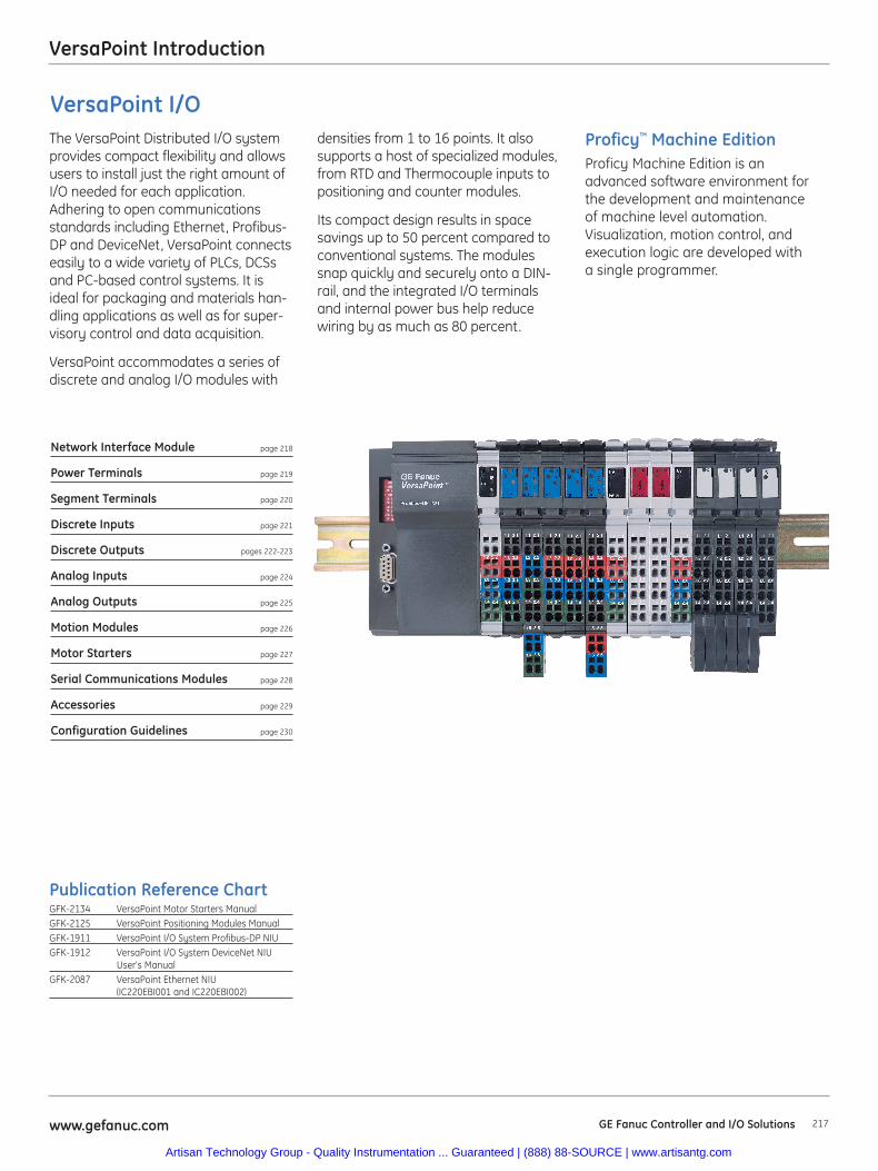
217www.gefanuc.com GE Fanuc Controller and I/O Solutions
VersaPoint Introduction
Network Interface Module page 218
Power Terminals page 219
Segment Terminals page 220
Discrete Inputs page 221
Discrete Outputs pages 222-223
Analog Inputs page 224
Analog Outputs page 225
Motion Modules page 226
Motor Starters page 227
Serial Communications Modules page 228
Accessories page 229
Configuration Guidelines page 230
Publication Reference ChartGFK-2134 VersaPoint Motor Starters ManualGFK-2125 VersaPoint Positioning Modules ManualGFK-1911 VersaPoint I/O System Profibus-DP NIUGFK-1912 VersaPoint I/O System DeviceNet NIU
User's ManualGFK-2087 VersaPoint Ethernet NIU
(IC220EBI001 and IC220EBI002)
Proficy™ Machine EditionProficy Machine Edition is anadvanced software environment forthe development and maintenanceof machine level automation.Visualization, motion control, andexecution logic are developed witha single programmer.
The VersaPoint Distributed I/O systemprovides compact flexibility and allowsusers to install just the right amount ofI/O needed for each application.Adhering to open communicationsstandards including Ethernet, Profibus-DP and DeviceNet, VersaPoint connectseasily to a wide variety of PLCs, DCSsand PC-based control systems. It isideal for packaging and materials han-dling applications as well as for super-visory control and data acquisition.
VersaPoint accommodates a series ofdiscrete and analog I/O modules with
densities from 1 to 16 points. It alsosupports a host of specialized modules,from RTD and Thermocouple inputs topositioning and counter modules.
Its compact design results in spacesavings up to 50 percent compared toconventional systems. The modulessnap quickly and securely onto a DIN-rail, and the integrated I/O terminalsand internal power bus help reducewiring by as much as 80 percent.
VersaPoint I/O
Artisan Technology Group - Quality Instrumentation ... Guaranteed | (888) 88-SOURCE | www.artisantg.com
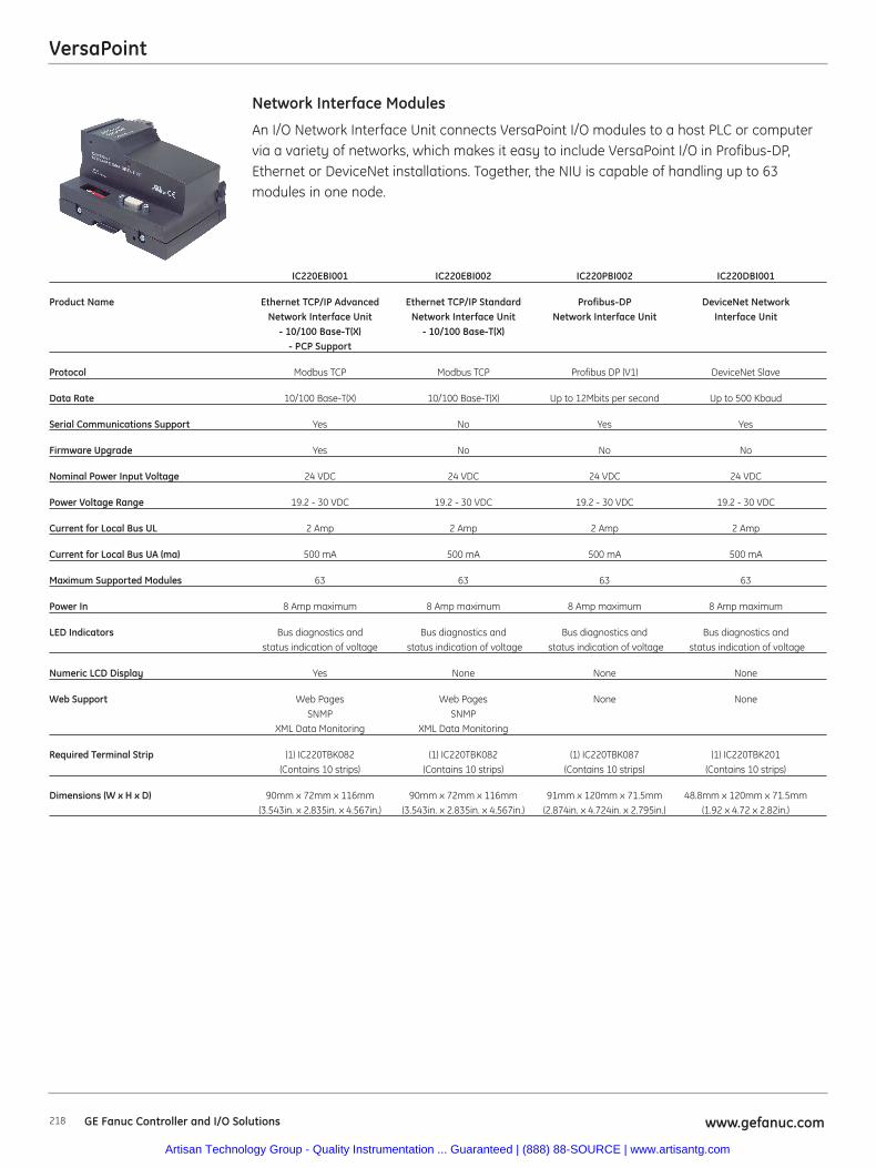
VersaPoint
218 www.gefanuc.comGE Fanuc Controller and I/O Solutions
An I/O Network Interface Unit connects VersaPoint I/O modules to a host PLC or computervia a variety of networks, which makes it easy to include VersaPoint I/O in Profibus-DP,Ethernet or DeviceNet installations. Together, the NIU is capable of handling up to 63modules in one node.
Network Interface Modules
IC220EBI001 IC220EBI002 IC220PBI002 IC220DBI001
Product Name Ethernet TCP/IP Advanced Ethernet TCP/IP Standard Profibus-DP DeviceNet NetworkNetwork Interface Unit Network Interface Unit Network Interface Unit Interface Unit
- 10/100 Base-T(X) - 10/100 Base-T(X)- PCP Support
Protocol Modbus TCP Modbus TCP Profibus DP (V1) DeviceNet Slave
Data Rate 10/100 Base-T(X) 10/100 Base-T(X) Up to 12Mbits per second Up to 500 Kbaud
Serial Communications Support Yes No Yes Yes
Firmware Upgrade Yes No No No
Nominal Power Input Voltage 24 VDC 24 VDC 24 VDC 24 VDC
Power Voltage Range 19.2 - 30 VDC 19.2 - 30 VDC 19.2 - 30 VDC 19.2 - 30 VDC
Current for Local Bus UL 2 Amp 2 Amp 2 Amp 2 Amp
Current for Local Bus UA (ma) 500 mA 500 mA 500 mA 500 mA
Maximum Supported Modules 63 63 63 63
Power In 8 Amp maximum 8 Amp maximum 8 Amp maximum 8 Amp maximum
LED Indicators Bus diagnostics and Bus diagnostics and Bus diagnostics and Bus diagnostics andstatus indication of voltage status indication of voltage status indication of voltage status indication of voltage
Numeric LCD Display Yes None None None
Web Support Web Pages Web Pages None NoneSNMP SNMP
XML Data Monitoring XML Data Monitoring
Required Terminal Strip (1) IC220TBK082 (1) IC220TBK082 (1) IC220TBK087 (1) IC220TBK201 (Contains 10 strips) (Contains 10 strips) (Contains 10 strips) (Contains 10 strips)
Dimensions (W x H x D) 90mm x 72mm x 116mm 90mm x 72mm x 116mm 91mm x 120mm x 71.5mm 48.8mm x 120mm x 71.5mm(3.543in. x 2.835in. x 4.567in.) (3.543in. x 2.835in. x 4.567in.) (2.874in. x 4.724in. x 2.795in.) (1.92 x 4.72 x 2.82in.)
Artisan Technology Group - Quality Instrumentation ... Guaranteed | (888) 88-SOURCE | www.artisantg.com
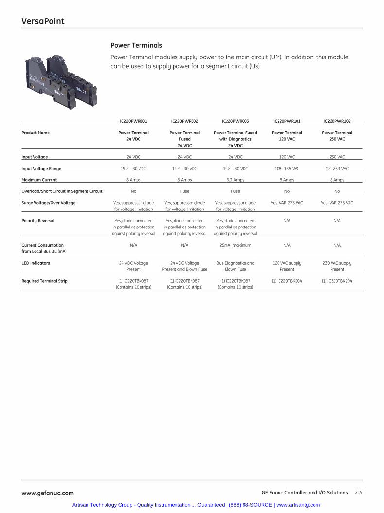
VersaPoint
219www.gefanuc.com GE Fanuc Controller and I/O Solutions
Power Terminal modules supply power to the main circuit (UM). In addition, this modulecan be used to supply power for a segment circuit (Us).
Power Terminals
IC220PWR001 IC220PWR002 IC220PWR003 IC220PWR101 IC220PWR102
Product Name Power Terminal Power Terminal Power Terminal Fused Power Terminal Power Terminal 24 VDC Fused with Diagnostics 120 VAC 230 VAC
24 VDC 24 VDC
Input Voltage 24 VDC 24 VDC 24 VDC 120 VAC 230 VAC
Input Voltage Range 19.2 - 30 VDC 19.2 - 30 VDC 19.2 - 30 VDC 108 -135 VAC 12 -253 VAC
Maximum Current 8 Amps 8 Amps 6.3 Amps 8 Amps 8 Amps
Overload/Short Circuit in Segment Circuit No Fuse Fuse No No
Surge Voltage/Over Voltage Yes, suppressor diode Yes, suppressor diode Yes, suppressor diode Yes, VAR 275 VAC Yes, VAR 275 VACfor voltage limitation for voltage limitation for voltage limitation
Polarity Reversal Yes, diode connected Yes, diode connected Yes, diode connected N/A N/Ain parallel as protection in parallel as protection in parallel as protectionagainst polarity reversal against polarity reversal against polarity reversal
Current Consumption N/A N/A 25mA, maximum N/A N/Afrom Local Bus UL (mA)
LED Indicators 24 VDC Voltage 24 VDC Voltage Bus Diagnostics and 120 VAC supply 230 VAC supply Present Present and Blown Fuse Blown Fuse Present Present
Required Terminal Strip (1) IC220TBK087 (1) IC220TBK087 (1) IC220TBK087 (1) IC220TBK204 (1) IC220TBK204(Contains 10 strips) (Contains 10 strips) (Contains 10 strips)
Artisan Technology Group - Quality Instrumentation ... Guaranteed | (888) 88-SOURCE | www.artisantg.com
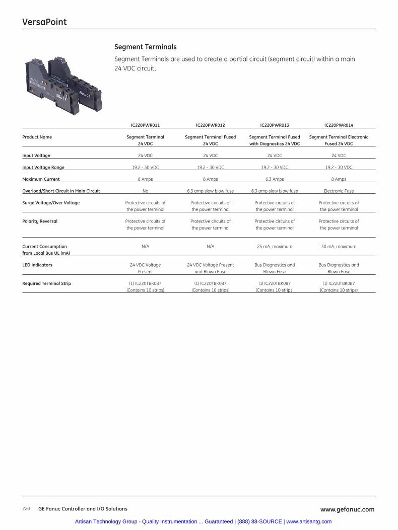
VersaPoint
220 www.gefanuc.comGE Fanuc Controller and I/O Solutions
Segment Terminals
IC220PWR011 IC220PWR012 IC220PWR013 IC220PWR014
Product Name Segment Terminal Segment Terminal Fused Segment Terminal Fused Segment Terminal Electronic 24 VDC 24 VDC with Diagnostics 24 VDC Fused 24 VDC
Input Voltage 24 VDC 24 VDC 24 VDC 24 VDC
Input Voltage Range 19.2 - 30 VDC 19.2 - 30 VDC 19.2 - 30 VDC 19.2 - 30 VDC
Maximum Current 8 Amps 8 Amps 6.3 Amps 8 Amps
Overload/Short Circuit in Main Circuit No 6.3 amp slow blow fuse 6.3 amp slow blow fuse Electronic Fuse
Surge Voltage/Over Voltage Protective circuits of Protective circuits of Protective circuits of Protective circuits of the power terminal the power terminal the power terminal the power terminal
Polarity Reversal Protective circuits of Protective circuits of Protective circuits of Protective circuits of the power terminal the power terminal the power terminal the power terminal
Current Consumption N/A N/A 25 mA, maximum 30 mA, maximumfrom Local Bus UL (mA)
LED Indicators 24 VDC Voltage 24 VDC Voltage Present Bus Diagnostics and Bus Diagnostics and Present and Blown Fuse Blown Fuse Blown Fuse
Required Terminal Strip (1) IC220TBK087 (1) IC220TBK087 (1) IC220TBK087 (1) IC220TBK087 (Contains 10 strips) (Contains 10 strips) (Contains 10 strips) (Contains 10 strips)
Segment Terminals are used to create a partial circuit (segment circuit) within a main 24 VDC circuit.
Artisan Technology Group - Quality Instrumentation ... Guaranteed | (888) 88-SOURCE | www.artisantg.com
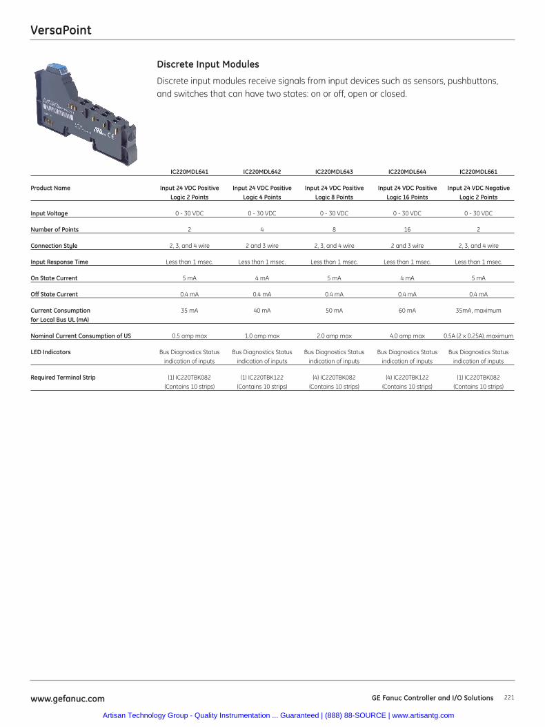
VersaPoint
221www.gefanuc.com GE Fanuc Controller and I/O Solutions
Discrete input modules receive signals from input devices such as sensors, pushbuttons,and switches that can have two states: on or off, open or closed.
Discrete Input Modules
IC220MDL641 IC220MDL642 IC220MDL643 IC220MDL644 IC220MDL661
Product Name Input 24 VDC Positive Input 24 VDC Positive Input 24 VDC Positive Input 24 VDC Positive Input 24 VDC NegativeLogic 2 Points Logic 4 Points Logic 8 Points Logic 16 Points Logic 2 Points
Input Voltage 0 - 30 VDC 0 - 30 VDC 0 - 30 VDC 0 - 30 VDC 0 - 30 VDC
Number of Points 2 4 8 16 2
Connection Style 2, 3, and 4 wire 2 and 3 wire 2, 3, and 4 wire 2 and 3 wire 2, 3, and 4 wire
Input Response Time Less than 1 msec. Less than 1 msec. Less than 1 msec. Less than 1 msec. Less than 1 msec.
On State Current 5 mA 4 mA 5 mA 4 mA 5 mA
Off State Current 0.4 mA 0.4 mA 0.4 mA 0.4 mA 0.4 mA
Current Consumption 35 mA 40 mA 50 mA 60 mA 35mA, maximumfor Local Bus UL (mA)
Nominal Current Consumption of US 0.5 amp max 1.0 amp max 2.0 amp max 4.0 amp max 0.5A (2 x 0.25A), maximum
LED Indicators Bus Diagnostics Status Bus Diagnostics Status Bus Diagnostics Status Bus Diagnostics Status Bus Diagnostics Statusindication of inputs indication of inputs indication of inputs indication of inputs indication of inputs
Required Terminal Strip (1) IC220TBK082 (1) IC220TBK122 (4) IC220TBK082 (4) IC220TBK122 (1) IC220TBK082(Contains 10 strips) (Contains 10 strips) (Contains 10 strips) (Contains 10 strips) (Contains 10 strips)
Artisan Technology Group - Quality Instrumentation ... Guaranteed | (888) 88-SOURCE | www.artisantg.com
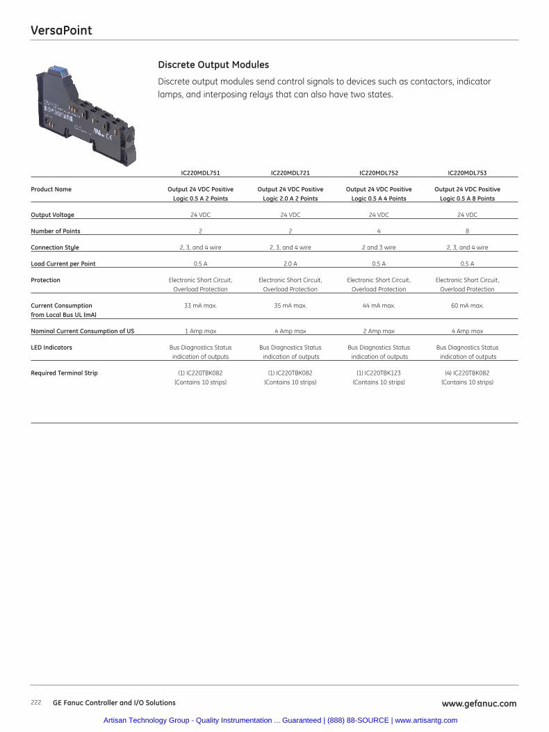
VersaPoint
222 www.gefanuc.comGE Fanuc Controller and I/O Solutions
Discrete output modules send control signals to devices such as contactors, indicatorlamps, and interposing relays that can also have two states.
Discrete Output Modules
IC220MDL751 IC220MDL721 IC220MDL752 IC220MDL753
Product Name Output 24 VDC Positive Output 24 VDC Positive Output 24 VDC Positive Output 24 VDC Positive Logic 0.5 A 2 Points Logic 2.0 A 2 Points Logic 0.5 A 4 Points Logic 0.5 A 8 Points
Output Voltage 24 VDC 24 VDC 24 VDC 24 VDC
Number of Points 2 2 4 8
Connection Style 2, 3, and 4 wire 2, 3, and 4 wire 2 and 3 wire 2, 3, and 4 wire
Load Current per Point 0.5 A 2.0 A 0.5 A 0.5 A
Protection Electronic Short Circuit, Electronic Short Circuit, Electronic Short Circuit, Electronic Short Circuit, Overload Protection Overload Protection Overload Protection Overload Protection
Current Consumption 33 mA max. 35 mA max. 44 mA max. 60 mA max.from Local Bus UL (mA)
Nominal Current Consumption of US 1 Amp max 4 Amp max 2 Amp max 4 Amp max
LED Indicators Bus Diagnostics Status Bus Diagnostics Status Bus Diagnostics Status Bus Diagnostics Statusindication of outputs indication of outputs indication of outputs indication of outputs
Required Terminal Strip (1) IC220TBK082 (1) IC220TBK082 (1) IC220TBK123 (4) IC220TBK082 (Contains 10 strips) (Contains 10 strips) (Contains 10 strips) (Contains 10 strips)
Artisan Technology Group - Quality Instrumentation ... Guaranteed | (888) 88-SOURCE | www.artisantg.com
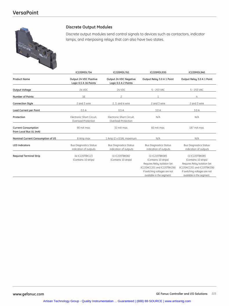
VersaPoint
223www.gefanuc.com GE Fanuc Controller and I/O Solutions
Discrete output modules send control signals to devices such as contactors, indicatorlamps, and interposing relays that can also have two states.
Discrete Output Modules
IC220MDL754 IC220MDL761 IC220MDL930 IC220MDL940
Product Name Output 24 VDC Positive Output 24 VDC Negative Output Relay 3.0 A 1 Point Output Relay 3.0 A 1 PointLogic 0.5 A 16 Points Logic 0.5 A 2 Points
Output Voltage 24 VDC 24 VDC 5 - 253 VAC 5 - 253 VAC
Number of Points 16 2 1 4
Connection Style 2 and 3 wire 2, 3, and 4 wire 2 and 3 wire 2 and 3 wire
Load Current per Point 0.5 A 0.5 A 3.0 A 3.0 A
Protection Electronic Short Circuit, Electronic Short Circuit, N/A N/AOverload Protection Overload Protection
Current Consumption 90 mA max. 32 mA max. 60 mA max. 187 mA max.from Local Bus UL (mA)
Nominal Current Consumption of US 8 Amp max 1 Amp (2 x 0.5A), maximum N/A N/A
LED Indicators Bus Diagnostics Status Bus Diagnostics Status Bus Diagnostics Status Bus Diagnostics Statusindication of outputs indication of outputs indication of outputs indication of outputs
Required Terminal Strip (4) IC220TBK123 (1) IC220TBK082 (1) IC220TBK085 (1) IC220TBK085 (Contains 10 strips) (Contains 10 strips) (Contains 10 strips) (Contains 10 strips)
Requires Relay Isolation Set Requires Relay Isolation Set(IC220ACC201 and IC220TBK206) (IC220ACC201 and IC220TBK206)
if switching voltages are not if switching voltages are notavailable in the segment. available in the segment.
Artisan Technology Group - Quality Instrumentation ... Guaranteed | (888) 88-SOURCE | www.artisantg.com
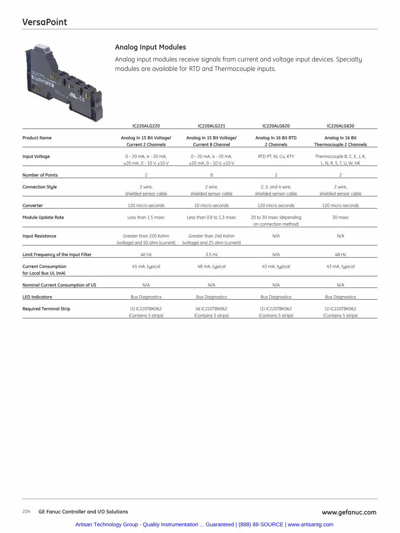
VersaPoint
224 www.gefanuc.comGE Fanuc Controller and I/O Solutions
Analog input modules receive signals from current and voltage input devices. Specialtymodules are available for RTD and Thermocouple inputs.
Analog Input Modules
IC220ALG220 IC220ALG221 IC220ALG620 IC220ALG630
Product Name Analog In 15 Bit Voltage/ Analog In 15 Bit Voltage/ Analog In 16 Bit RTD Analog In 16 Bit Current 2 Channels Current 8 Channel 2 Channels Thermocouple 2 Channels
Input Voltage 0 - 20 mA, 4 - 20 mA, 0 - 20 mA, 4 - 20 mA, RTD PT, Ni, Cu, KTY Thermocouple B, C, E, J, K, ±20 mA, 0 - 10 V, ±10 V ±20 mA, 0 - 10 V, ±10 V L, N, R, S, T, U, W, HK
Number of Points 2 8 2 2
Connection Style 2 wire, 2 wire, 2, 3, and 4 wire, 2 wire, shielded sensor cable shielded sensor cable shielded sensor cable shielded sensor cable
Converter 120 micro seconds 10 micro seconds 120 micro seconds 120 micro seconds
Module Update Rate Less than 1.5 msec Less than 0.8 to 1.3 msec 20 to 30 msec (depending 30 msecon connection method)
Input Resistance Greater than 220 Kohm Greater than 240 Kohm N/A N/A(voltage) and 50 ohm (current) (voltage) and 25 ohm (current)
Limit Frequency of the Input Filter 40 Hz 3.5 Hz N/A 48 Hz
Current Consumption 45 mA, typical 48 mA, typical 43 mA, typical 43 mA, typicalfor Local Bus UL (mA)
Nominal Current Consumption of US N/A N/A N/A N/A
LED Indicators Bus Diagnostics Bus Diagnostics Bus Diagnostics Bus Diagnostics
Required Terminal Strip (1) IC220TBK062 (4) IC220TBK062 (1) IC220TBK062 (1) IC220TBK062 (Contains 5 strips) (Contains 5 strips) (Contains 5 strips) (Contains 5 strips)
Artisan Technology Group - Quality Instrumentation ... Guaranteed | (888) 88-SOURCE | www.artisantg.com
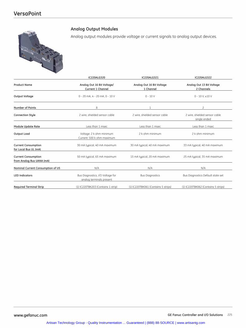
VersaPoint
225www.gefanuc.com GE Fanuc Controller and I/O Solutions
Analog output modules provide voltage or current signals to analog output devices.
Analog Output Modules
IC220ALG320 IC220ALG321 IC220ALG322
Product Name Analog Out 16 Bit Voltage/ Analog Out 16 Bit Voltage Analog Out 13 Bit Voltage Current 1 Channel 1 Channel 2 Channels
Output Voltage 0 - 20 mA, 4 - 20 mA, 0 - 10 V 0 - 10 V 0 - 10 V, ±10 V
Number of Points 8 1 2
Connection Style 2 wire, shielded sensor cable 2 wire, shielded sensor cable 2 wire, shielded sensor cablesingle ended
Module Update Rate Less than 1 msec Less than 1 msec Less than 1 msec
Output Load Voltage: 2 k ohm minimum 2 k ohm minimum 2 k ohm minimumCurrent: 500 k ohm maximum
Current Consumption 30 mA typical, 40 mA maximum 30 mA typical, 40 mA maximum 33 mA typical, 40 mA maximumfor Local Bus UL (mA)
Current Consumption 50 mA typical, 65 mA maximum 15 mA typical, 20 mA maximum 25 mA typical, 35 mA maximumfrom Analog Bus UANA (mA)
Nominal Current Consumption of US N/A N/A N/A
LED Indicators Bus Diagnostics, I/O Voltage for Bus Diagnostics Bus Diagnostics Default state setanalog terminals present
Required Terminal Strip (1) IC220TBK203 (Contains 1 strip) (1) IC220TBK061 (Contains 5 strips) (1) IC220TBK062 (Contains 5 strips)
Artisan Technology Group - Quality Instrumentation ... Guaranteed | (888) 88-SOURCE | www.artisantg.com
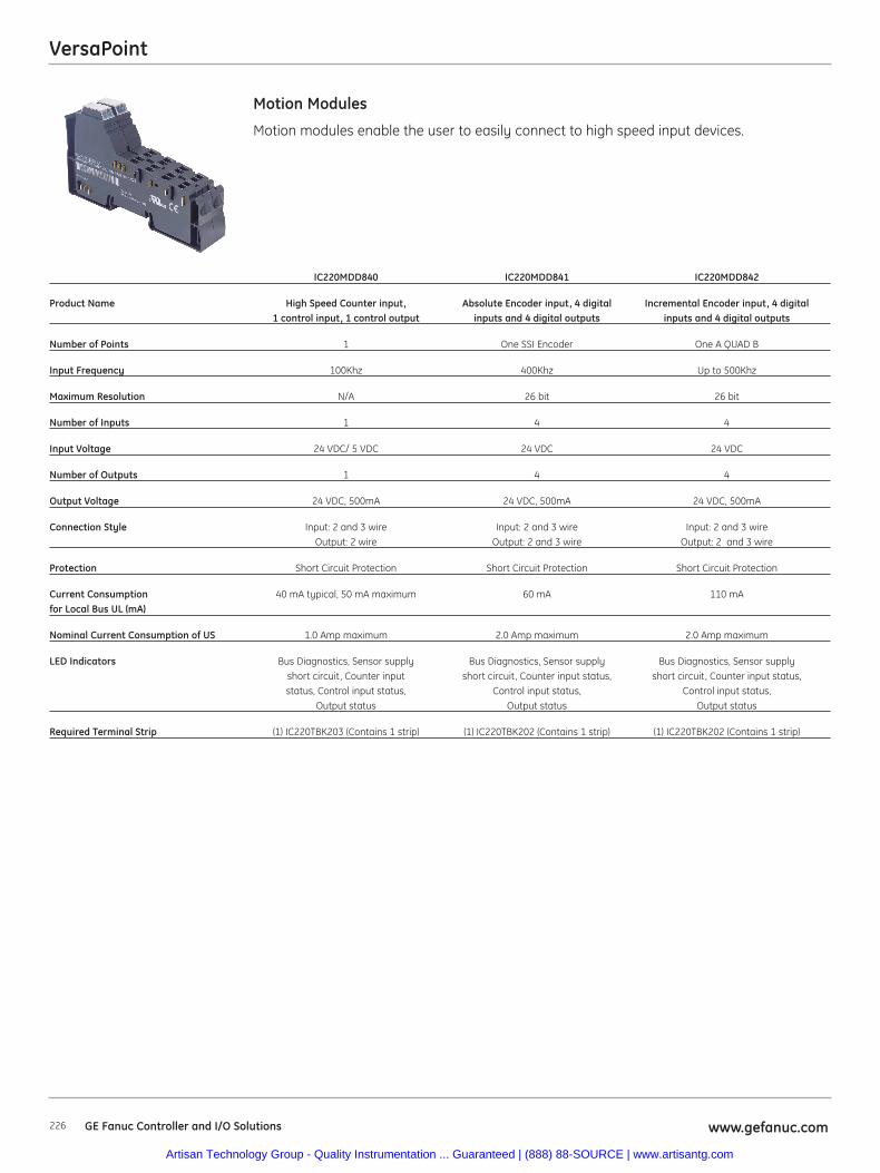
VersaPoint
226 www.gefanuc.comGE Fanuc Controller and I/O Solutions
Motion modules enable the user to easily connect to high speed input devices.
Motion Modules
IC220MDD840 IC220MDD841 IC220MDD842
Product Name High Speed Counter input, Absolute Encoder input, 4 digital Incremental Encoder input, 4 digital 1 control input, 1 control output inputs and 4 digital outputs inputs and 4 digital outputs
Number of Points 1 One SSI Encoder One A QUAD B
Input Frequency 100Khz 400Khz Up to 500Khz
Maximum Resolution N/A 26 bit 26 bit
Number of Inputs 1 4 4
Input Voltage 24 VDC/ 5 VDC 24 VDC 24 VDC
Number of Outputs 1 4 4
Output Voltage 24 VDC, 500mA 24 VDC, 500mA 24 VDC, 500mA
Connection Style Input: 2 and 3 wire Input: 2 and 3 wire Input: 2 and 3 wireOutput: 2 wire Output: 2 and 3 wire Output: 2 and 3 wire
Protection Short Circuit Protection Short Circuit Protection Short Circuit Protection
Current Consumption 40 mA typical, 50 mA maximum 60 mA 110 mAfor Local Bus UL (mA)
Nominal Current Consumption of US 1.0 Amp maximum 2.0 Amp maximum 2.0 Amp maximum
LED Indicators Bus Diagnostics, Sensor supply Bus Diagnostics, Sensor supply Bus Diagnostics, Sensor supplyshort circuit, Counter input short circuit, Counter input status, short circuit, Counter input status,status, Control input status, Control input status, Control input status,
Output status Output status Output status
Required Terminal Strip (1) IC220TBK203 (Contains 1 strip) (1) IC220TBK202 (Contains 1 strip) (1) IC220TBK202 (Contains 1 strip)
Artisan Technology Group - Quality Instrumentation ... Guaranteed | (888) 88-SOURCE | www.artisantg.com
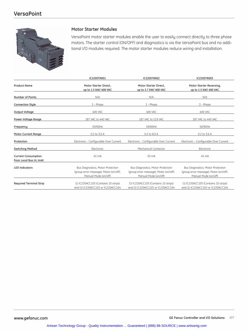
VersaPoint
227www.gefanuc.com GE Fanuc Controller and I/O Solutions
VersaPoint motor starter modules enable the user to easily connect directly to three phasemotors. The starter control (ON/OFF) and diagnostics is via the VersaPoint bus and no addi-tional I/O modules required. The motor starter modules reduce wiring and installation.
Motor Starter Modules
IC220STR001 IC220STR002 IC220STR003
Product Name Motor Starter Direct, Motor Starter Direct, Motor Starter Reversing, up to 1.5 kW/ 400 VAC up to 3.7 kW/ 400 VAC up to 1.5 kW/ 400 VAC
Number of Points N/A N/A N/A
Connection Style 3 - Phase 3 - Phase 3 - Phase
Output Voltage 400 VAC 400 VAC 400 VAC
Power Voltage Range 187 VAC to 440 VAC 187 VAC to 519 VAC 187 VAC to 440 VAC
Frequency 50/60Hz 50/60Hz 50/60Hz
Motor Current Range 0.2 to 3.6 A 0.2 to 8.0 A 0.2 to 3.6 A
Protection Electronic - Configurable Over Current Electronic - Configurable Over Current Electronic - Configurable Over Current
Switching Method Electronic Mechanical Contactor Electronic
Current Consumption 45 mA 50 mA 45 mAfrom Local Bus UL (mA)
LED Indicators Bus Diagnostics, Motor Protection Bus Diagnostics, Motor Protection Bus Diagnostics, Motor Protection (group error message), Motor (on/off), (group error message), Motor (on/off), (group error message), Motor (on/off),
Manual Mode (on/off) Manual Mode (on/off) Manual Mode (on/off)
Required Terminal Strip (1) IC220ACC105 (Contains 10 strips) (1) IC220ACC105 (Contains 10 strips) (1) IC220ACC105 (Contains 10 strips) and (1) IC220ACC103 or IC220ACC104 and (1) IC220ACC103 or IC220ACC104 and (1) IC220ACC103 or IC220ACC104
Artisan Technology Group - Quality Instrumentation ... Guaranteed | (888) 88-SOURCE | www.artisantg.com
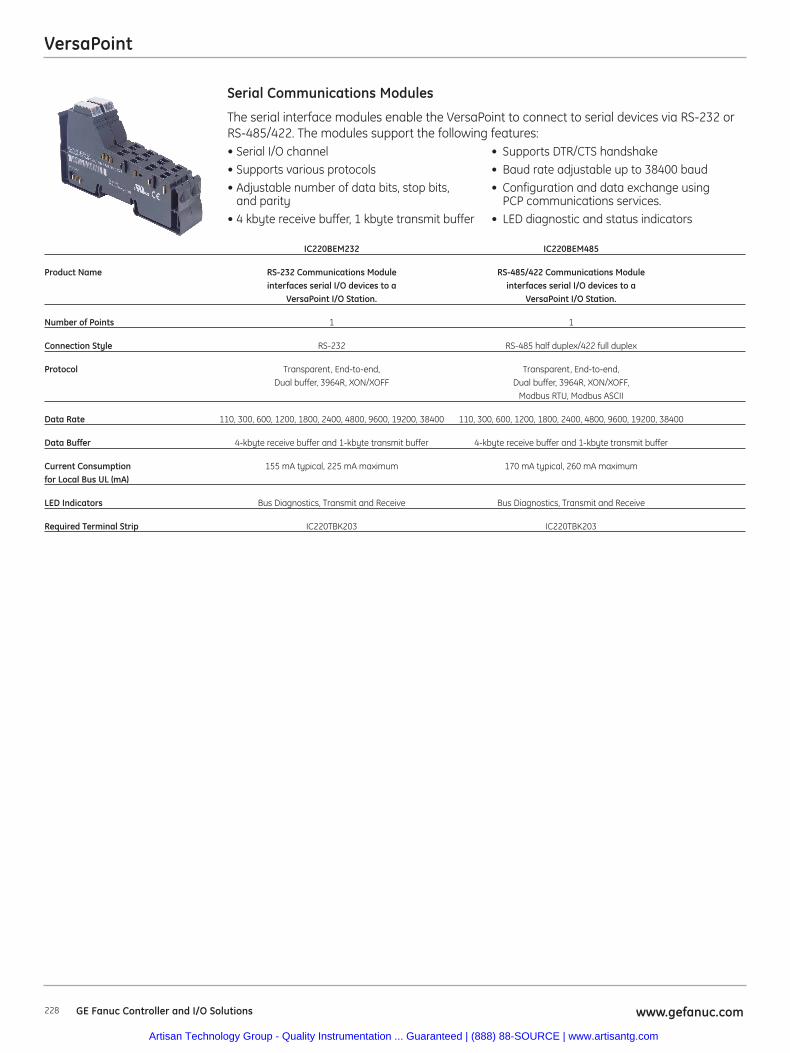
VersaPoint
228 www.gefanuc.comGE Fanuc Controller and I/O Solutions
The serial interface modules enable the VersaPoint to connect to serial devices via RS-232 orRS-485/422. The modules support the following features:• Serial I/O channel • Supports DTR/CTS handshake• Supports various protocols • Baud rate adjustable up to 38400 baud• Adjustable number of data bits, stop bits, • Configuration and data exchange using
and parity PCP communications services.• 4 kbyte receive buffer, 1 kbyte transmit buffer • LED diagnostic and status indicators
Serial Communications Modules
IC220BEM232 IC220BEM485
Product Name RS-232 Communications Module RS-485/422 Communications Moduleinterfaces serial I/O devices to a interfaces serial I/O devices to a
VersaPoint I/O Station. VersaPoint I/O Station.
Number of Points 1 1
Connection Style RS-232 RS-485 half duplex/422 full duplex
Protocol Transparent, End-to-end, Transparent, End-to-end, Dual buffer, 3964R, XON/XOFF Dual buffer, 3964R, XON/XOFF,
Modbus RTU, Modbus ASCII
Data Rate 110, 300, 600, 1200, 1800, 2400, 4800, 9600, 19200, 38400 110, 300, 600, 1200, 1800, 2400, 4800, 9600, 19200, 38400
Data Buffer 4-kbyte receive buffer and 1-kbyte transmit buffer 4-kbyte receive buffer and 1-kbyte transmit buffer
Current Consumption 155 mA typical, 225 mA maximum 170 mA typical, 260 mA maximumfor Local Bus UL (mA)
LED Indicators Bus Diagnostics, Transmit and Receive Bus Diagnostics, Transmit and Receive
Required Terminal Strip IC220TBK203 IC220TBK203
Artisan Technology Group - Quality Instrumentation ... Guaranteed | (888) 88-SOURCE | www.artisantg.com
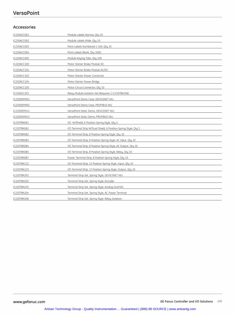
229www.gefanuc.com GE Fanuc Controller and I/O Solutions
VersaPoint
Accessories
IC220ACC001 Module Labels Narrow, Qty 10
IC220ACC002 Module Labels Wide, Qty 10
IC220ACC003 Point Labels Numbered 1-100, Qty 10
IC220ACC004 Point Labels Blank, Qty 1000
IC220ACC005 Module Keying Tabs, Qty 100
IC220ACC100 Motor Starter Brake Module DC
IC220ACC101 Motor Starter Brake Module AC/DC
IC220ACC103 Motor Starter Power Connector
IC220ACC104 Motor Starter Power Bridge
IC220ACC105 Motor Circuit Connector, Qty 10
IC220ACC201 Relay Module Isolation Set (Requires 1 IC220TBK206)
IC220DEM001 VersaPoint Demo Case, DEVICENET NIU
IC220DEM002 VersaPoint Demo Case, PROFIBUS NIU
IC220DEM011 VersaPoint Static Demo, DEVICENET NIU
IC220DEM012 VersaPoint Static Demo, PROFIBUS NIU
IC220TBK061 I/O W/Shield, 6 Position Spring Style, Qty 5
IC220TBK062 I/O Terminal Strip W/Dual Shield, 6 Position Spring Style, Qty 5
IC220TBK082 I/O Terminal Strip, 8 Position Spring Style, Qty 10
IC220TBK083 I/O Terminal Strip, 8 Position Spring Style, AC Input, Qty 10
IC220TBK084 I/O Terminal Strip, 8 Position Spring Style, AC Output, Qty 10
IC220TBK085 I/O Terminal Strip, 8 Position Spring Style, Relay, Qty 10
IC220TBK087 Power Terminal Strip, 8 Position Spring Style, Qty 10
IC220TBK122 I/O Terminal Strip, 12 Position Spring Style, Input, Qty 10
IC220TBK123 I/O Terminal Strip, 12 Position Spring Style, Output, Qty 10
IC220TBK201 Terminal Strip Set, Spring Style, DEVICENET NIU
IC220TBK202 Terminal Strip Set, Spring Style, Encoder
IC220TBK203 Terminal Strip Set, Spring Style, Analog Out/HSC
IC220TBK204 Terminal Strip Set, Spring Style, AC Power Terminal
IC220TBK206 Terminal Strip Set, Spring Style, Relay Isolation
Artisan Technology Group - Quality Instrumentation ... Guaranteed | (888) 88-SOURCE | www.artisantg.com
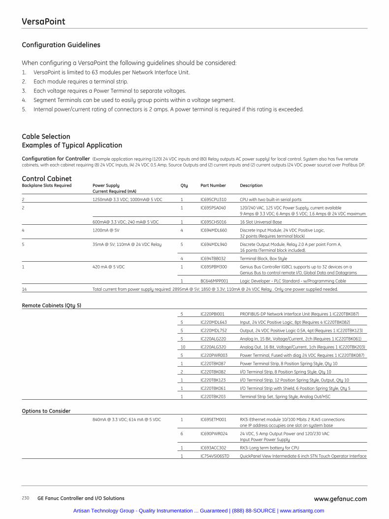
VersaPoint
Configuration Guidelines
When configuring a VersaPoint the following guidelines should be considered:1. VersaPoint is limited to 63 modules per Network Interface Unit.
2. Each module requires a terminal strip.
3. Each voltage requires a Power Terminal to separate voltages.
4. Segment Terminals can be used to easily group points within a voltage segment.
5. Internal power/current rating of connectors is 2 amps. A power terminal is required if this rating is exceeded.
Cable SelectionExamples of Typical Application
Configuration for Controller (Example application requiring (120) 24 VDC inputs and (80) Relay outputs AC power supply) for local control. System also has five remotecabinets, with each cabinet requiring (8) 24 VDC Inputs, (4) 24 VDC 0.5 Amp, Source Outputs and (2) current inputs and (2) current outputs (24 VDC power source) over Profibus DP.
Control CabinetBackplane Slots Required Power Supply Qty Part Number Description
Current Required (mA)
2 1250mA@ 3.3 VDC; 1000mA@ 5 VDC 1 IC695CPU310 CPU with two built-in serial ports
2 1 IC695PSA040 120/240 VAC, 125 VDC Power Supply, current available 9 Amps @ 3.3 VDC; 6 Amps @ 5 VDC; 1.6 Amps @ 24 VDC maximum
600mA@ 3.3 VDC; 240 mA@ 5 VDC 1 IC695CHS016 16 Slot Universal Base
4 1200mA @ 5V 4 IC694MDL660 Discrete Input Module, 24 VDC Positive Logic, 32 points (Requires terminal block)
5 35mA @ 5V; 110mA @ 24 VDC Relay 5 IC694MDL940 Discrete Output Module, Relay 2.0 A per point Form A, 16 points (Terminal block included).
4 IC694TBB032 Terminal Block, Box Style
1 420 mA @ 5 VDC 1 IC695PBM300 Genius Bus Controller (GBC), supports up to 32 devices on a Genius Bus to control remote I/O, Global Data and Datagrams
1 BC646MPP001 Logic Developer - PLC Standard - w/Programming Cable
14 Total current from power supply required: 2895mA @ 5V; 1850 @ 3.3V; 110mA @ 24 VDC Relay . Only one power supplied needed.
Remote Cabinets (Qty 5)5 IC220PBI001 PROFIBUS-DP Network Interface Unit (Requires 1 IC220TBK087)
5 IC220MDL643 Input, 24 VDC Positive Logic, 8pt (Requires 4 IC220TBK082)
5 IC220MDL752 Output, 24 VDC Positive Logic 0.5A, 4pt (Requires 1 IC220TBK123)
5 IC220ALG220 Analog In, 15 Bit, Voltage/Current, 2ch (Requires 1 IC220TBK061)
10 IC220ALG320 Analog Out, 16 Bit, Voltage/Current, 1ch (Requires 1 IC220TBK203)
5 IC220PWR003 Power Terminal, Fused with diag 24 VDC Requires 1 IC220TBK087)
1 IC220TBK087 Power Terminal Strip, 8 Position Spring Style, Qty 10
2 IC220TBK082 I/O Terminal Strip, 8 Position Spring Style, Qty 10
1 IC220TBK123 I/O Terminal Strip, 12 Position Spring Style, Output, Qty 10
1 IC220TBK061 I/O Terminal Strip with Shield, 6 Position Spring Style, Qty 5
1 IC220TBK203 Terminal Strip Set, Spring Style, Analog Out/HSC
Options to Consider840mA @ 3.3 VDC; 614 mA @ 5 VDC 1 IC695ETM001 RX3i Ethernet module 10/100 Mbits 2 RJ45 connections
one IP address occupies one slot on system base
6 IC690PWR024 24 VDC, 5 Amp Output Power and 120/230 VAC Input Power Power Supply
1 IC693ACC302 RX3i Long term battery for CPU
1 IC754VSI06STD QuickPanel View Intermediate 6 inch STN Touch Operator Interface
GE Fanuc Controller and I/O Solutions www.gefanuc.com230
Artisan Technology Group - Quality Instrumentation ... Guaranteed | (888) 88-SOURCE | www.artisantg.com
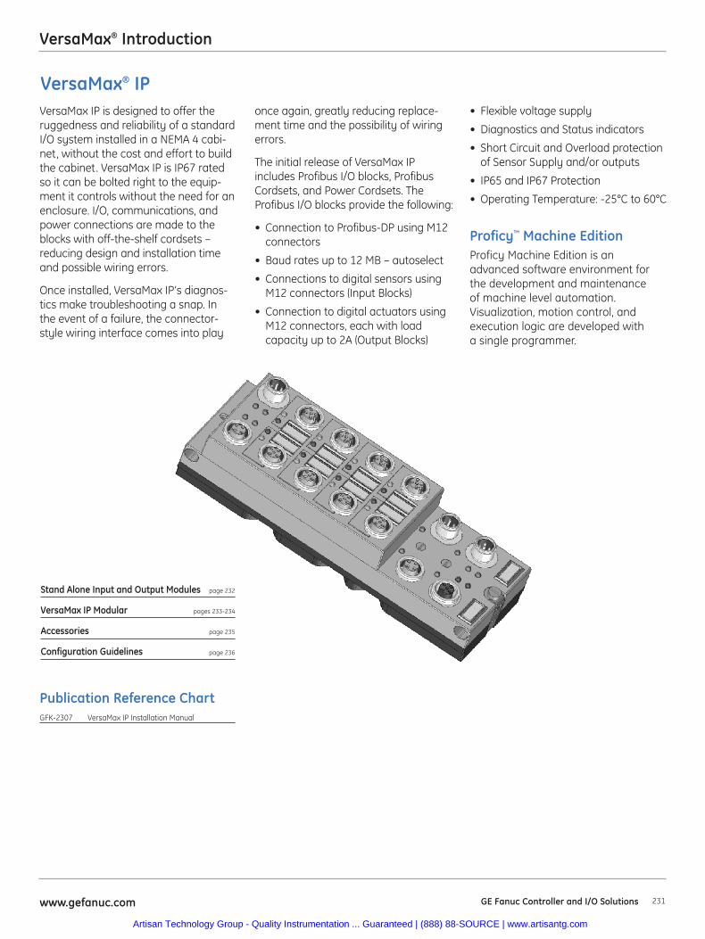
231www.gefanuc.com GE Fanuc Controller and I/O Solutions
VersaMax® Introduction
Publication Reference ChartGFK-2307 VersaMax IP Installation Manual
Proficy™ Machine EditionProficy Machine Edition is anadvanced software environment forthe development and maintenanceof machine level automation.Visualization, motion control, andexecution logic are developed witha single programmer.
VersaMax IP is designed to offer theruggedness and reliability of a standardI/O system installed in a NEMA 4 cabi-net, without the cost and effort to buildthe cabinet. VersaMax IP is IP67 ratedso it can be bolted right to the equip-ment it controls without the need for anenclosure. I/O, communications, andpower connections are made to theblocks with off-the-shelf cordsets –reducing design and installation timeand possible wiring errors.
Once installed, VersaMax IP’s diagnos-tics make troubleshooting a snap. Inthe event of a failure, the connector-style wiring interface comes into play
once again, greatly reducing replace-ment time and the possibility of wiringerrors.
The initial release of VersaMax IPincludes Profibus I/O blocks, ProfibusCordsets, and Power Cordsets. TheProfibus I/O blocks provide the following:
• Connection to Profibus-DP using M12connectors
• Baud rates up to 12 MB – autoselect
• Connections to digital sensors usingM12 connectors (Input Blocks)
• Connection to digital actuators usingM12 connectors, each with loadcapacity up to 2A (Output Blocks)
VersaMax® IP
Stand Alone Input and Output Modules page 232
VersaMax IP Modular pages 233-234
Accessories page 235
Configuration Guidelines page 236
• Flexible voltage supply
• Diagnostics and Status indicators
• Short Circuit and Overload protectionof Sensor Supply and/or outputs
• IP65 and IP67 Protection
• Operating Temperature: -25°C to 60°C
Artisan Technology Group - Quality Instrumentation ... Guaranteed | (888) 88-SOURCE | www.artisantg.com
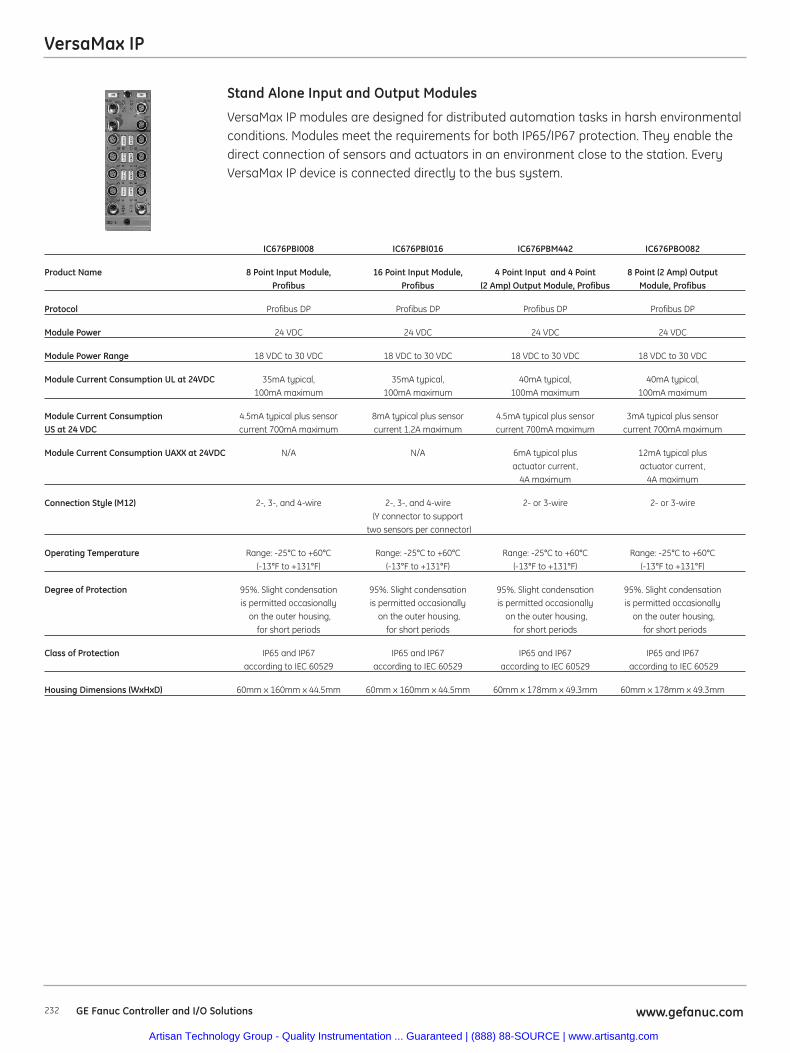
VersaMax IP
232 www.gefanuc.comGE Fanuc Controller and I/O Solutions
VersaMax IP modules are designed for distributed automation tasks in harsh environmentalconditions. Modules meet the requirements for both IP65/IP67 protection. They enable thedirect connection of sensors and actuators in an environment close to the station. EveryVersaMax IP device is connected directly to the bus system.
Stand Alone Input and Output Modules
IC676PBI008 IC676PBI016 IC676PBM442 IC676PBO082
Product Name 8 Point Input Module, 16 Point Input Module, 4 Point Input and 4 Point 8 Point (2 Amp) Output Profibus Profibus (2 Amp) Output Module, Profibus Module, Profibus
Protocol Profibus DP Profibus DP Profibus DP Profibus DP
Module Power 24 VDC 24 VDC 24 VDC 24 VDC
Module Power Range 18 VDC to 30 VDC 18 VDC to 30 VDC 18 VDC to 30 VDC 18 VDC to 30 VDC
Module Current Consumption UL at 24VDC 35mA typical, 35mA typical, 40mA typical, 40mA typical, 100mA maximum 100mA maximum 100mA maximum 100mA maximum
Module Current Consumption 4.5mA typical plus sensor 8mA typical plus sensor 4.5mA typical plus sensor 3mA typical plus sensor US at 24 VDC current 700mA maximum current 1.2A maximum current 700mA maximum current 700mA maximum
Module Current Consumption UAXX at 24VDC N/A N/A 6mA typical plus 12mA typical plusactuator current, actuator current,
4A maximum 4A maximum
Connection Style (M12) 2-, 3-, and 4-wire 2-, 3-, and 4-wire 2- or 3-wire 2- or 3-wire(Y connector to support
two sensors per connector)
Operating Temperature Range: -25°C to +60°C Range: -25°C to +60°C Range: -25°C to +60°C Range: -25°C to +60°C(-13°F to +131°F) (-13°F to +131°F) (-13°F to +131°F) (-13°F to +131°F)
Degree of Protection 95%. Slight condensation 95%. Slight condensation 95%. Slight condensation 95%. Slight condensation is permitted occasionally is permitted occasionally is permitted occasionally is permitted occasionally
on the outer housing, on the outer housing, on the outer housing, on the outer housing,for short periods for short periods for short periods for short periods
Class of Protection IP65 and IP67 IP65 and IP67 IP65 and IP67 IP65 and IP67according to IEC 60529 according to IEC 60529 according to IEC 60529 according to IEC 60529
Housing Dimensions (WxHxD) 60mm x 160mm x 44.5mm 60mm x 160mm x 44.5mm 60mm x 178mm x 49.3mm 60mm x 178mm x 49.3mm
Artisan Technology Group - Quality Instrumentation ... Guaranteed | (888) 88-SOURCE | www.artisantg.com
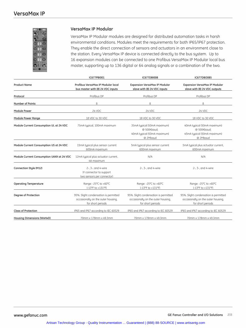
VersaMax IP
233www.gefanuc.com GE Fanuc Controller and I/O Solutions
VersaMax IP Modular modules are designed for distributed automation tasks in harshenvironmental conditions. Modules meet the requirements for both IP65/IP67 protection.They enable the direct connection of sensors and actuators in an environment close tothe station. Every VersaMax IP device is connected directly to the bus system. Up to16 expansion modules can be connected to one Profibus VersaMax IP Modular local busmaster, supporting up to 136 digital or 64 analog signals or a combination of the two.
VersaMax IP Modular
IC677PBI001 IC677DBI008 IC677DBO085
Product Name Profibus VersaMax IP Modular local Expansion VersaMax IP Modular Expansion VersaMax IP Modular bus master with (8) 24 VDC inputs slave with (8) 24 VDC inputs slave with (8) 24 VDC outputs
Protocol Profibus DP Profibus DP Profibus DP
Number of Points 8 8 8
Module Power 24 VDC 24 VDC 24 VDC
Module Power Range 18 VDC to 30 VDC 18 VDC to 30 VDC 18 VDC to 30 VDC
Module Current Consumption UL at 24 VDC 75mA typical, 100mA maximum 35mA typical (50mA maximum) 40mA typical (50mA maximum) @ 500Kbaud; @ 500Kbaud;
40mA typical (50mA maximum) 45mA typical (50mA maximum) @ 2Mbaud @ 2Mbaud
Module Current Consumption US at 24 VDC 15mA typical plus sensor current 5mA typical plus sensor current 5mA typical plus actuator current, 600mA maximum 600mA maximum 600mA maximum
Module Current Consumption UAXX at 24 VDC 12mA typical plus actuator current, N/A N/A4A maximum
Connection Style (M12) 2-, 3-, and 4-wire 2-, 3-, and 4-wire 2-, 3-, and 4-wire (Y connector to support
two sensors per connector)
Operating Temperature Range: -25°C to +60°C Range: -25°C to +60°C Range: -25°C to +60°C(-13°F to +131°F) (-13°F to +131°F) (-13°F to +131°F)
Degree of Protection 95%. Slight condensation is permitted 95%. Slight condensation is permitted 95%. Slight condensation is permitted occasionally on the outer housing, occasionally on the outer housing, occasionally on the outer housing,
for short periods for short periods for short periods
Class of Protection IP65 and IP67 according to IEC 60529 IP65 and IP67 according to IEC 60529 IP65 and IP67 according to IEC 60529
Housing Dimensions (WxHxD) 70mm x 178mm x 49.3mm 70mm x 178mm x 49.3mm 70mm x 178mm x 49.3mm
Artisan Technology Group - Quality Instrumentation ... Guaranteed | (888) 88-SOURCE | www.artisantg.com
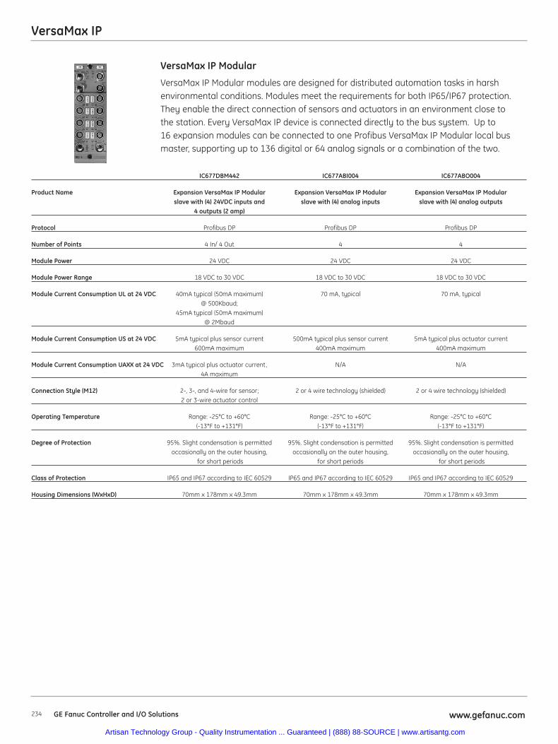
VersaMax IP
234 www.gefanuc.comGE Fanuc Controller and I/O Solutions
VersaMax IP Modular modules are designed for distributed automation tasks in harshenvironmental conditions. Modules meet the requirements for both IP65/IP67 protection.They enable the direct connection of sensors and actuators in an environment close tothe station. Every VersaMax IP device is connected directly to the bus system. Up to16 expansion modules can be connected to one Profibus VersaMax IP Modular local bus master, supporting up to 136 digital or 64 analog signals or a combination of the two.
VersaMax IP Modular
IC677DBM442 IC677ABI004 IC677ABO004
Product Name Expansion VersaMax IP Modular Expansion VersaMax IP Modular Expansion VersaMax IP Modular slave with (4) 24VDC inputs and slave with (4) analog inputs slave with (4) analog outputs
4 outputs (2 amp)
Protocol Profibus DP Profibus DP Profibus DP
Number of Points 4 In/ 4 Out 4 4
Module Power 24 VDC 24 VDC 24 VDC
Module Power Range 18 VDC to 30 VDC 18 VDC to 30 VDC 18 VDC to 30 VDC
Module Current Consumption UL at 24 VDC 40mA typical (50mA maximum) 70 mA, typical 70 mA, typical@ 500Kbaud;
45mA typical (50mA maximum) @ 2Mbaud
Module Current Consumption US at 24 VDC 5mA typical plus sensor current 500mA typical plus sensor current 5mA typical plus actuator current 600mA maximum 400mA maximum 400mA maximum
Module Current Consumption UAXX at 24 VDC 3mA typical plus actuator current, N/A N/A4A maximum
Connection Style (M12) 2-, 3-, and 4-wire for sensor; 2 or 4 wire technology (shielded) 2 or 4 wire technology (shielded)2 or 3-wire actuator control
Operating Temperature Range: -25°C to +60°C Range: -25°C to +60°C Range: -25°C to +60°C(-13°F to +131°F) (-13°F to +131°F) (-13°F to +131°F)
Degree of Protection 95%. Slight condensation is permitted 95%. Slight condensation is permitted 95%. Slight condensation is permittedoccasionally on the outer housing, occasionally on the outer housing, occasionally on the outer housing,
for short periods for short periods for short periods
Class of Protection IP65 and IP67 according to IEC 60529 IP65 and IP67 according to IEC 60529 IP65 and IP67 according to IEC 60529
Housing Dimensions (WxHxD) 70mm x 178mm x 49.3mm 70mm x 178mm x 49.3mm 70mm x 178mm x 49.3mm
Artisan Technology Group - Quality Instrumentation ... Guaranteed | (888) 88-SOURCE | www.artisantg.com
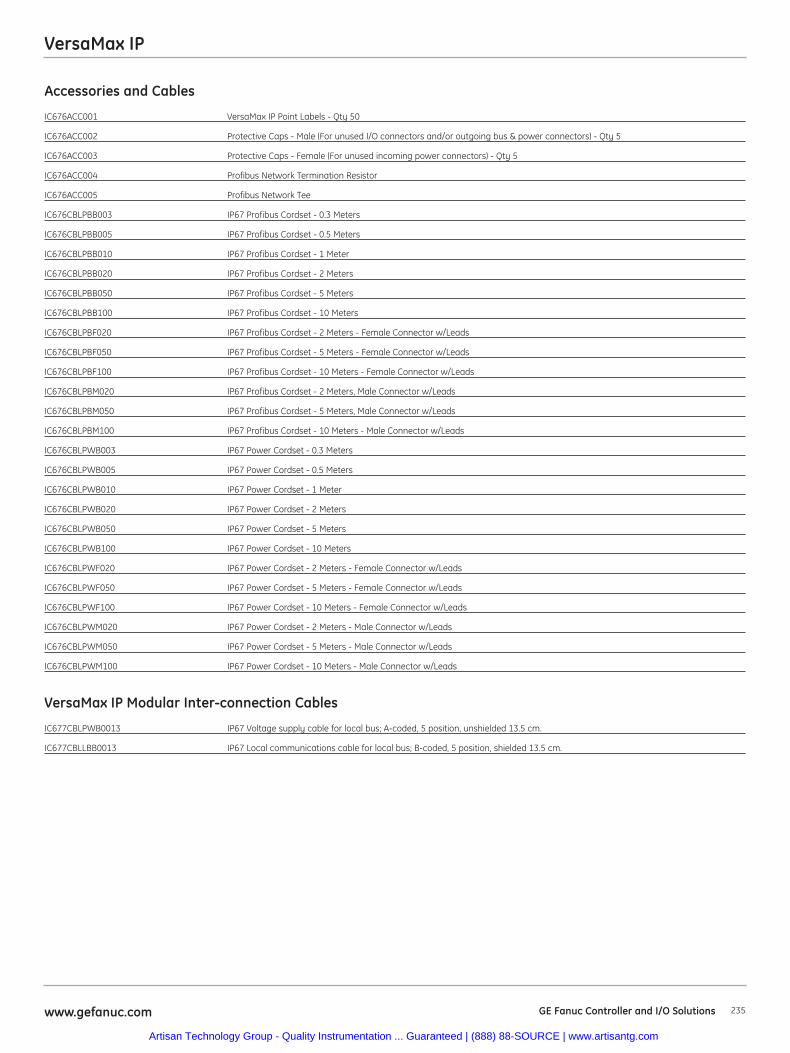
VersaMax IP
235www.gefanuc.com GE Fanuc Controller and I/O Solutions
Accessories and Cables
IC676ACC001 VersaMax IP Point Labels - Qty 50
IC676ACC002 Protective Caps - Male (For unused I/O connectors and/or outgoing bus & power connectors) - Qty 5
IC676ACC003 Protective Caps - Female (For unused incoming power connectors) - Qty 5
IC676ACC004 Profibus Network Termination Resistor
IC676ACC005 Profibus Network Tee
IC676CBLPBB003 IP67 Profibus Cordset - 0.3 Meters
IC676CBLPBB005 IP67 Profibus Cordset - 0.5 Meters
IC676CBLPBB010 IP67 Profibus Cordset - 1 Meter
IC676CBLPBB020 IP67 Profibus Cordset - 2 Meters
IC676CBLPBB050 IP67 Profibus Cordset - 5 Meters
IC676CBLPBB100 IP67 Profibus Cordset - 10 Meters
IC676CBLPBF020 IP67 Profibus Cordset - 2 Meters - Female Connector w/Leads
IC676CBLPBF050 IP67 Profibus Cordset - 5 Meters - Female Connector w/Leads
IC676CBLPBF100 IP67 Profibus Cordset - 10 Meters - Female Connector w/Leads
IC676CBLPBM020 IP67 Profibus Cordset - 2 Meters, Male Connector w/Leads
IC676CBLPBM050 IP67 Profibus Cordset - 5 Meters, Male Connector w/Leads
IC676CBLPBM100 IP67 Profibus Cordset - 10 Meters - Male Connector w/Leads
IC676CBLPWB003 IP67 Power Cordset - 0.3 Meters
IC676CBLPWB005 IP67 Power Cordset - 0.5 Meters
IC676CBLPWB010 IP67 Power Cordset - 1 Meter
IC676CBLPWB020 IP67 Power Cordset - 2 Meters
IC676CBLPWB050 IP67 Power Cordset - 5 Meters
IC676CBLPWB100 IP67 Power Cordset - 10 Meters
IC676CBLPWF020 IP67 Power Cordset - 2 Meters - Female Connector w/Leads
IC676CBLPWF050 IP67 Power Cordset - 5 Meters - Female Connector w/Leads
IC676CBLPWF100 IP67 Power Cordset - 10 Meters - Female Connector w/Leads
IC676CBLPWM020 IP67 Power Cordset - 2 Meters - Male Connector w/Leads
IC676CBLPWM050 IP67 Power Cordset - 5 Meters - Male Connector w/Leads
IC676CBLPWM100 IP67 Power Cordset - 10 Meters - Male Connector w/Leads
VersaMax IP Modular Inter-connection Cables
IC677CBLPWB0013 IP67 Voltage supply cable for local bus; A-coded, 5 position, unshielded 13.5 cm.
IC677CBLLBB0013 IP67 Local communications cable for local bus; B-coded, 5 position, shielded 13.5 cm.
Artisan Technology Group - Quality Instrumentation ... Guaranteed | (888) 88-SOURCE | www.artisantg.com
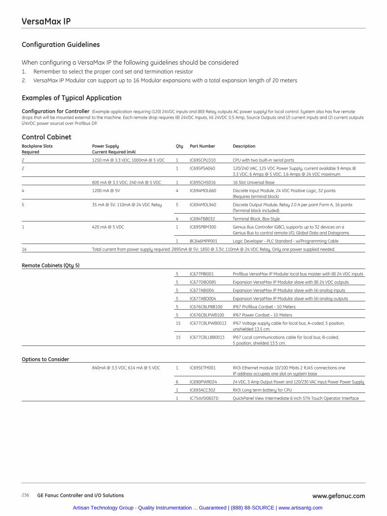
VersaMax IP
Configuration Guidelines
When configuring a VersaMax IP the following guidelines should be considered1. Remember to select the proper cord set and termination resistor
2. VersaMax IP Modular can support up to 16 Modular expansions with a total expansion length of 20 meters
Examples of Typical Application
Configuration for Controller (Example application requiring (120) 24VDC inputs and (80) Relay outputs AC power supply) for local control. System also has five remotedrops that will be mounted external to the machine. Each remote drop requires (8) 24VDC Inputs, (4) 24VDC 0.5 Amp, Source Outputs and (2) current inputs and (2) current outputs(24VDC power source) over Profibus DP.
Control CabinetBackplane Slots Power Supply Qty Part Number DescriptionRequired Current Required (mA)
2 1250 mA @ 3.3 VDC; 1000mA @ 5 VDC 1 IC695CPU310 CPU with two built-in serial ports
2 1 IC695PSA040 120/240 VAC, 125 VDC Power Supply, current available 9 Amps @ 3.3 VDC; 6 Amps @ 5 VDC; 1.6 Amps @ 24 VDC maximum
600 mA @ 3.3 VDC; 240 mA @ 5 VDC 1 IC695CHS016 16 Slot Universal Base
4 1200 mA @ 5V 4 IC694MDL660 Discrete Input Module, 24 VDC Positive Logic, 32 points (Requires terminal block)
5 35 mA @ 5V; 110mA @ 24 VDC Relay 5 IC694MDL940 Discrete Output Module, Relay 2.0 A per point Form A, 16 points (Terminal block included).
4 IC694TBB032 Terminal Block, Box Style
1 420 mA @ 5 VDC 1 IC695PBM300 Genius Bus Controller (GBC), supports up to 32 devices on a Genius Bus to control remote I/O, Global Data and Datagrams
1 BC646MPP001 Logic Developer - PLC Standard - w/Programming Cable
14 Total current from power supply required: 2895mA @ 5V; 1850 @ 3.3V; 110mA @ 24 VDC Relay. Only one power supplied needed.
Remote Cabinets (Qty 5)5 IC677PBI001 Profibus VersaMax IP Modular local bus master with (8) 24 VDC inputs
5 IC677DBO085 Expansion VersaMax IP Modular slave with (8) 24 VDC outputs
5 IC677ABI004 Expansion VersaMax IP Modular slave with (4) analog inputs
5 IC677ABO004 Expansion VersaMax IP Modular slave with (4) analog outputs
5 IC676CBLPBB100 IP67 Profibus Cordset - 10 Meters
5 IC676CBLPWB100 IP67 Power Cordset - 10 Meters
15 IC677CBLPWB0013 IP67 Voltage supply cable for local bus; A-coded, 5 position, unshielded 13.5 cm.
15 IC677CBLLBB0013 IP67 Local communications cable for local bus; B-coded, 5 position, shielded 13.5 cm.
Options to Consider840mA @ 3.3 VDC; 614 mA @ 5 VDC 1 IC695ETM001 RX3i Ethernet module 10/100 Mbits 2 RJ45 connections one
IP address occupies one slot on system base
6 IC690PWR024 24 VDC, 5 Amp Output Power and 120/230 VAC Input Power Power Supply
1 IC693ACC302 RX3i Long term battery for CPU
1 IC754VSI06STD QuickPanel View Intermediate 6 inch STN Touch Operator Interface
GE Fanuc Controller and I/O Solutions www.gefanuc.com236
Artisan Technology Group - Quality Instrumentation ... Guaranteed | (888) 88-SOURCE | www.artisantg.com
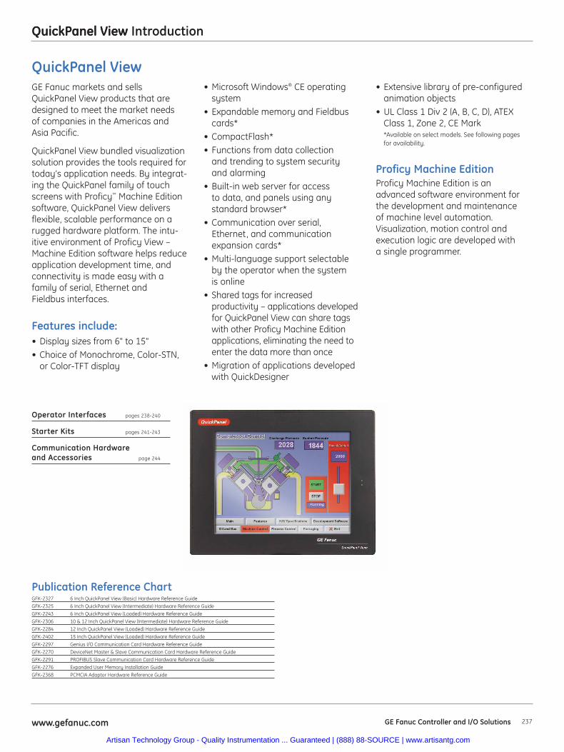
QuickPanel View
237www.gefanuc.com GE Fanuc Controller and I/O Solutions
QuickPanel View Introduction
• Extensive library of pre-configuredanimation objects
• UL Class 1 Div 2 (A, B, C, D), ATEXClass 1, Zone 2, CE Mark*Available on select models. See following pagesfor availability.
Proficy Machine EditionProficy Machine Edition is anadvanced software environment forthe development and maintenanceof machine level automation.Visualization, motion control andexecution logic are developed witha single programmer.
QuickPanel ViewGE Fanuc markets and sellsQuickPanel View products that aredesigned to meet the market needs of companies in the Americas and Asia Pacific.
QuickPanel View bundled visualizationsolution provides the tools required fortoday’s application needs. By integrat-ing the QuickPanel family of touchscreens with Proficy™ Machine Editionsoftware, QuickPanel View deliversflexible, scalable performance on arugged hardware platform. The intu-itive environment of Proficy View –Machine Edition software helps reduceapplication development time, andconnectivity is made easy with afamily of serial, Ethernet and Fieldbus interfaces.
Features include:• Display sizes from 6" to 15"• Choice of Monochrome, Color-STN,
or Color-TFT display
• Microsoft Windows® CE operatingsystem
• Expandable memory and Fieldbuscards*
• CompactFlash*• Functions from data collection
and trending to system security and alarming
• Built-in web server for access to data, and panels using any standard browser*
• Communication over serial, Ethernet, and communicationexpansion cards*
• Multi-language support selectableby the operator when the system is online
• Shared tags for increased productivity – applications developedfor QuickPanel View can share tagswith other Proficy Machine Editionapplications, eliminating the need toenter the data more than once
• Migration of applications developedwith QuickDesigner
Operator Interfaces pages 238-240
Starter Kits pages 241-243
Communication Hardware and Accessories page 244
Publication Reference ChartGFK-2327 6 Inch QuickPanel View (Basic) Hardware Reference Guide
GFK-2325 6 Inch QuickPanel View (Intermediate) Hardware Reference Guide
GFK-2243 6 Inch QuickPanel View (Loaded) Hardware Reference Guide
GFK-2306 10 & 12 Inch QuickPanel View (Intermediate) Hardware Reference Guide
GFK-2284 12 Inch QuickPanel View (Loaded) Hardware Reference Guide
GFK-2402 15 Inch QuickPanel View (Loaded) Hardware Reference Guide
GFK-2297 Genius I/O Communication Card Hardware Reference Guide
GFK-2270 DeviceNet Master & Slave Communication Card Hardware Reference Guide
GFK-2291 PROFIBUS Slave Communication Card Hardware Reference Guide
GFK-2276 Expanded User Memory Installation Guide
GFK-2368 PCMCIA Adaptor Hardware Reference Guide
Artisan Technology Group - Quality Instrumentation ... Guaranteed | (888) 88-SOURCE | www.artisantg.com
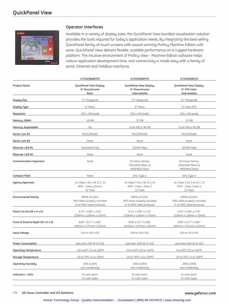
QuickPanel View
238 GE Fanuc Controller and I/O Solutions www.gefanuc.com
Available in a variety of display sizes, the QuickPanel View bundled visualization solutionprovides the tools required for today's application needs. By integrating the best-sellingQuickPanel family of touch screens with award-winning Proficy Machine Edition soft-ware, QuickPanel View delivers flexible, scalable performance on a rugged hardwareplatform. The intuitive environment of Proficy View - Machine Edition software helpsreduce application development time, and connectivity is made easy with a family ofserial, Ethernet and Fieldbus interfaces.
Operator Interfaces
IC754VSB06MTD IC754VSI06MTD IC754VSI06STD
Product Name QuickPanel View Display, QuickPanel View Display, QuickPanel View Display, 6" Monochrome 6" Monochrome 6" STN-Color
Basic Intermediate Intermediate
Display Size 5.7" (Diagonal) 5.7" (Diagonal) 5.7" (Diagonal)
Display Type 6" Mono 6" Mono 6" Color-STN
Resolution 320 x 240 pixels 320 x 240 pixels 320 x 240 pixels
Memory: DRAM 16 MB 32 MB 32 MB
Memory: Expandable No To 64 MB or 96 MB To 64 MB or 96 MB
Serial: Com #1 RS232/RS485 RS232/RS485 RS232/RS485
Serial: Com #2 None None None
Ethernet: LAN #1 Download Only 10/100 Mbps 10/100 Mbps
Ethernet: LAN #2 None None None
Communication Expansion None GE Fanuc Genius, GE Fanuc Genius,DeviceNet Slave, & DeviceNet Slave, &
PROFIBUS Slave PROFIBUS Slave
Compact Flash None One, Type 2 One, Type 2
Agency Approvals UL-Class 1 Div 2 (A, B, C, D) UL-Class 1 Div 2 (A, B, C, D) UL-Class 1 Div 2 (A, B, C, D)ATEX - Class 1 Zone 2 ATEX - Class 1 Zone 2 ATEX - Class 1 Zone 2
CE Mark CE Mark CE Mark
Environmental Rating NEMA 4/12/4X, NEMA 4/12/4X, NEMA 4/12/4X, IP65 when properly mounted IP65 when properly mounted IP65 when properly mounted
in an IP65 rated enclosure in an IP65 rated enclosure in an IP65 rated enclosure
Panel Cut-Out (W x H x D) 6.14" x 4.86" x 2.03" 6.14" x 4.86" x 2.76" 6.14" x 4.86" x 2.76"(158mm x 126mm x 52mm) (158mm x 126mm x 70mm) (158mm x 126mm x 70mm)
Front of Panel & Depth (W x H x D) 8.00" x 6.17" x 0.85" 8.00" x 6.17" x 0.85" 8.00" x 6.17" x 0.85"(203mm x 157mm x 22mm) (203mm x 157mm x 22mm) (203mm x 157mm x 22mm)
Input Voltage 10.8 to 30.0 VDC 10.8 to 30.0 VDC 10.8 to 30.0 VDC
Power Consumption Less than 24W @ 24 VDC Less than 24W @ 24 VDC Less than 24W @ 24 VDC
Operating Temperature -10 to 60°C (14 to 140°F) -10 to 60°C (14 to 140°F) 0 to 60°C (32 to 140°F)
Storage Temperature -20 to 70°C (-4 to 158°F) -20 to 70°C (-4 to 158°F) -20 to 70°C (-4 to 158°F)
Operating Humidity 10% to 85% 10% to 85% 10% to 90% non-condensing non-condensing non-condensing
Indicators - LEDs bi-color (pwr), bi-color (pwr), bi-color (pwr), tri-color (user) tri-color (user) tri-color (user)
Artisan Technology Group - Quality Instrumentation ... Guaranteed | (888) 88-SOURCE | www.artisantg.com
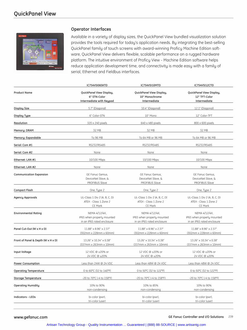
QuickPanel View
239www.gefanuc.com GE Fanuc Controller and I/O Solutions
Available in a variety of display sizes, the QuickPanel View bundled visualization solutionprovides the tools required for today's application needs. By integrating the best-sellingQuickPanel family of touch screens with award-winning Proficy Machine Edition soft-ware, QuickPanel View delivers flexible, scalable performance on a rugged hardwareplatform. The intuitive environment of Proficy View - Machine Edition software helpsreduce application development time, and connectivity is made easy with a family ofserial, Ethernet and Fieldbus interfaces.
Operator Interfaces
IC754VSI06SKTD IC754VSI10MTD IC754VSI12CTD
Product Name QuickPanel View Display, QuickPanel View Display, QuickPanel View Display,6" STN-Color 10" Monochrome 12" TFT-Color
Intermediate with Keypad Intermediate Intermediate
Display Size 5.7" (Diagonal) 10.4" (Diagonal) 12.1" (Diagonal)
Display Type 6" Color-STN 10" Mono 12" Color-TFT
Resolution 320 x 240 pixels 640 x 480 pixels 800 x 600 pixels
Memory: DRAM 32 MB 32 MB 32 MB
Memory: Expandable To 96 MB To 64 MB or 96 MB To 64 MB or 96 MB
Serial: Com #1 RS232/RS485 RS232/RS485 RS232/RS485
Serial: Com #2 None None None
Ethernet: LAN #1 10/100 Mbps 10/100 Mbps 10/100 Mbps
Ethernet: LAN #2 None None None
Communication Expansion GE Fanuc Genius, GE Fanuc Genius, GE Fanuc Genius, DeviceNet Slave, & DeviceNet Slave, & DeviceNet Slave, &
PROFIBUS Slave PROFIBUS Slave PROFIBUS Slave
Compact Flash One, Type 2 One, Type 2 One, Type 2
Agency Approvals UL-Class 1 Div 2 (A, B, C, D) UL-Class 1 Div 2 (A, B, C, D) UL-Class 1 Div 2 (A, B, C, D)ATEX - Class 1 Zone 2 ATEX - Class 1 Zone 2 ATEX - Class 1 Zone 2
CE Mark CE Mark CE Mark
Environmental Rating NEMA 4/12/4X, NEMA 4/12/4X, NEMA 4/12/4X, IP65 when properly mounted IP65 when properly mounted IP65 when properly mounted
in an IP65 rated enclosure in an IP65 rated enclosure in an IP65 rated enclosure
Panel Cut-Out (W x H x D) 11.88" x 8.96" x 2.37" 11.88" x 8.96" x 2.37" 11.88" x 8.96" x 2.37"(302mm x 228mm x 60mm) (302mm x 228mm x 60mm) (302mm x 228mm x 60mm)
Front of Panel & Depth (W x H x D) 13.26" x 10.34" x 0.38" 13.26" x 10.34" x 0.38" 13.26" x 10.34" x 0.38" (337mm x 263mm x 10mm) (337mm x 263mm x 10mm) (337mm x 263mm x 10mm)
Input Voltage 12 VDC @ ±20% or 12 VDC @ ±20% or 12 VDC @ ±20% or 24 VDC @ ±20% 24 VDC @ ±20% 24 VDC @ ±20%
Power Consumption Less than 24W @ 24 VDC Less than 48W @ 24 VDC Less than 48W @ 24 VDC
Operating Temperature 0 to 60°C (32 to 140°F) 0 to 50°C (32 to 122°F) 0 to 50°C (32 to 122°F)
Storage Temperature -20 to 70°C (-4 to 158°F) -20 to 70°C (-4 to 158°F) -20 to 70°C (-4 to 158°F)
Operating Humidity 10% to 90% 10% to 85% 10% to 90% non-condensing non-condensing non-condensing
Indicators - LEDs bi-color (pwr), bi-color (pwr), bi-color (pwr), tri-color (user) tri-color (user) tri-color (user)
Artisan Technology Group - Quality Instrumentation ... Guaranteed | (888) 88-SOURCE | www.artisantg.com
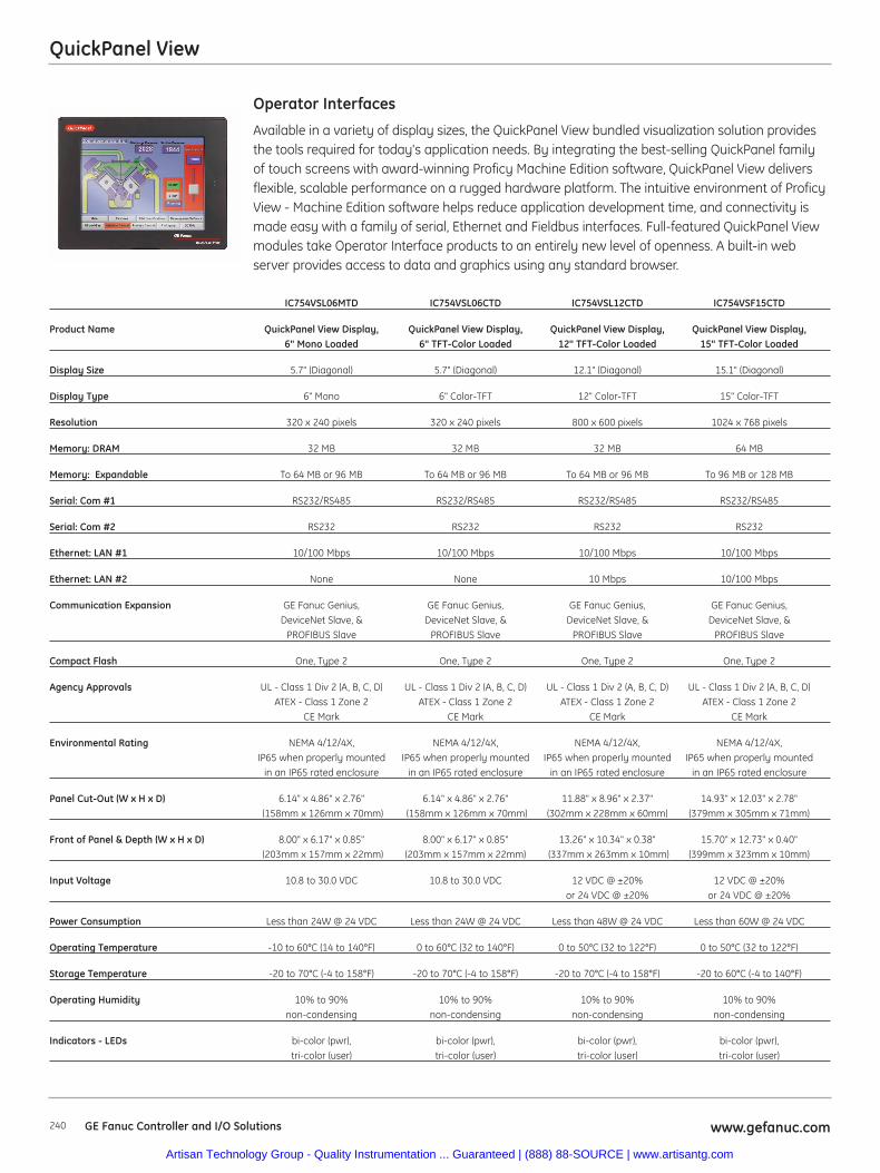
QuickPanel View
240 GE Fanuc Controller and I/O Solutions www.gefanuc.com
Available in a variety of display sizes, the QuickPanel View bundled visualization solution providesthe tools required for today's application needs. By integrating the best-selling QuickPanel familyof touch screens with award-winning Proficy Machine Edition software, QuickPanel View deliversflexible, scalable performance on a rugged hardware platform. The intuitive environment of ProficyView - Machine Edition software helps reduce application development time, and connectivity ismade easy with a family of serial, Ethernet and Fieldbus interfaces. Full-featured QuickPanel Viewmodules take Operator Interface products to an entirely new level of openness. A built-in webserver provides access to data and graphics using any standard browser.
Operator Interfaces
IC754VSL06MTD IC754VSL06CTD IC754VSL12CTD IC754VSF15CTD
Product Name QuickPanel View Display, QuickPanel View Display, QuickPanel View Display, QuickPanel View Display,6" Mono Loaded 6" TFT-Color Loaded 12" TFT-Color Loaded 15" TFT-Color Loaded
Display Size 5.7" (Diagonal) 5.7" (Diagonal) 12.1" (Diagonal) 15.1" (Diagonal)
Display Type 6" Mono 6" Color-TFT 12" Color-TFT 15" Color-TFT
Resolution 320 x 240 pixels 320 x 240 pixels 800 x 600 pixels 1024 x 768 pixels
Memory: DRAM 32 MB 32 MB 32 MB 64 MB
Memory: Expandable To 64 MB or 96 MB To 64 MB or 96 MB To 64 MB or 96 MB To 96 MB or 128 MB
Serial: Com #1 RS232/RS485 RS232/RS485 RS232/RS485 RS232/RS485
Serial: Com #2 RS232 RS232 RS232 RS232
Ethernet: LAN #1 10/100 Mbps 10/100 Mbps 10/100 Mbps 10/100 Mbps
Ethernet: LAN #2 None None 10 Mbps 10/100 Mbps
Communication Expansion GE Fanuc Genius, GE Fanuc Genius, GE Fanuc Genius, GE Fanuc Genius,DeviceNet Slave, & DeviceNet Slave, & DeviceNet Slave, & DeviceNet Slave, &
PROFIBUS Slave PROFIBUS Slave PROFIBUS Slave PROFIBUS Slave
Compact Flash One, Type 2 One, Type 2 One, Type 2 One, Type 2
Agency Approvals UL - Class 1 Div 2 (A, B, C, D) UL - Class 1 Div 2 (A, B, C, D) UL - Class 1 Div 2 (A, B, C, D) UL - Class 1 Div 2 (A, B, C, D)ATEX - Class 1 Zone 2 ATEX - Class 1 Zone 2 ATEX - Class 1 Zone 2 ATEX - Class 1 Zone 2
CE Mark CE Mark CE Mark CE Mark
Environmental Rating NEMA 4/12/4X, NEMA 4/12/4X, NEMA 4/12/4X, NEMA 4/12/4X, IP65 when properly mounted IP65 when properly mounted IP65 when properly mounted IP65 when properly mounted
in an IP65 rated enclosure in an IP65 rated enclosure in an IP65 rated enclosure in an IP65 rated enclosure
Panel Cut-Out (W x H x D) 6.14" x 4.86" x 2.76" 6.14" x 4.86" x 2.76" 11.88" x 8.96" x 2.37" 14.93" x 12.03" x 2.78" (158mm x 126mm x 70mm) (158mm x 126mm x 70mm) (302mm x 228mm x 60mm) (379mm x 305mm x 71mm)
Front of Panel & Depth (W x H x D) 8.00" x 6.17" x 0.85" 8.00" x 6.17" x 0.85" 13.26" x 10.34" x 0.38" 15.70" x 12.73" x 0.40" (203mm x 157mm x 22mm) (203mm x 157mm x 22mm) (337mm x 263mm x 10mm) (399mm x 323mm x 10mm)
Input Voltage 10.8 to 30.0 VDC 10.8 to 30.0 VDC 12 VDC @ ±20% 12 VDC @ ±20% or 24 VDC @ ±20% or 24 VDC @ ±20%
Power Consumption Less than 24W @ 24 VDC Less than 24W @ 24 VDC Less than 48W @ 24 VDC Less than 60W @ 24 VDC
Operating Temperature -10 to 60°C (14 to 140°F) 0 to 60°C (32 to 140°F) 0 to 50°C (32 to 122°F) 0 to 50°C (32 to 122°F)
Storage Temperature -20 to 70°C (-4 to 158°F) -20 to 70°C (-4 to 158°F) -20 to 70°C (-4 to 158°F) -20 to 60°C (-4 to 140°F)
Operating Humidity 10% to 90% 10% to 90% 10% to 90% 10% to 90%non-condensing non-condensing non-condensing non-condensing
Indicators - LEDs bi-color (pwr), bi-color (pwr), bi-color (pwr), bi-color (pwr), tri-color (user) tri-color (user) tri-color (user) tri-color (user)
Artisan Technology Group - Quality Instrumentation ... Guaranteed | (888) 88-SOURCE | www.artisantg.com
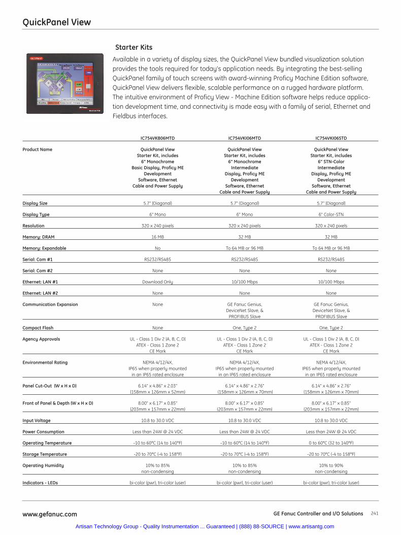
QuickPanel View
241www.gefanuc.com GE Fanuc Controller and I/O Solutions
Available in a variety of display sizes, the QuickPanel View bundled visualization solutionprovides the tools required for today's application needs. By integrating the best-sellingQuickPanel family of touch screens with award-winning Proficy Machine Edition software,QuickPanel View delivers flexible, scalable performance on a rugged hardware platform.The intuitive environment of Proficy View - Machine Edition software helps reduce applica-tion development time, and connectivity is made easy with a family of serial, Ethernet andFieldbus interfaces.
Starter Kits
IC754VKB06MTD IC754VKI06MTD IC754VKI06STD
Product Name QuickPanel View QuickPanel View QuickPanel ViewStarter Kit, includes Starter Kit, includes Starter Kit, includes
6" Monochrome 6" Monochrome 6" STN-ColorBasic Display, Proficy ME Intermediate Intermediate
Development Display, Proficy ME Display, Proficy MESoftware, Ethernet Development Development
Cable and Power Supply Software, Ethernet Software, EthernetCable and Power Supply Cable and Power Supply
Display Size 5.7" (Diagonal) 5.7" (Diagonal) 5.7" (Diagonal)
Display Type 6" Mono 6" Mono 6" Color-STN
Resolution 320 x 240 pixels 320 x 240 pixels 320 x 240 pixels
Memory: DRAM 16 MB 32 MB 32 MB
Memory: Expandable No To 64 MB or 96 MB To 64 MB or 96 MB
Serial: Com #1 RS232/RS485 RS232/RS485 RS232/RS485
Serial: Com #2 None None None
Ethernet: LAN #1 Download Only 10/100 Mbps 10/100 Mbps
Ethernet: LAN #2 None None None
Communication Expansion None GE Fanuc Genius, GE Fanuc Genius,DeviceNet Slave, & DeviceNet Slave, &
PROFIBUS Slave PROFIBUS Slave
Compact Flash None One, Type 2 One, Type 2
Agency Approvals UL - Class 1 Div 2 (A, B, C, D) UL - Class 1 Div 2 (A, B, C, D) UL - Class 1 Div 2 (A, B, C, D)ATEX - Class 1 Zone 2 ATEX - Class 1 Zone 2 ATEX - Class 1 Zone 2
CE Mark CE Mark CE Mark
Environmental Rating NEMA 4/12/4X, NEMA 4/12/4X, NEMA 4/12/4X,IP65 when properly mounted IP65 when properly mounted IP65 when properly mounted
in an IP65 rated enclosure in an IP65 rated enclosure in an IP65 rated enclosure
Panel Cut-Out (W x H x D) 6.14" x 4.86" x 2.03" 6.14" x 4.86" x 2.76" 6.14" x 4.86" x 2.76" (158mm x 126mm x 52mm) (158mm x 126mm x 70mm) (158mm x 126mm x 70mm)
Front of Panel & Depth (W x H x D) 8.00" x 6.17" x 0.85" 8.00" x 6.17" x 0.85" 8.00" x 6.17" x 0.85" (203mm x 157mm x 22mm) (203mm x 157mm x 22mm) (203mm x 157mm x 22mm)
Input Voltage 10.8 to 30.0 VDC 10.8 to 30.0 VDC 10.8 to 30.0 VDC
Power Consumption Less than 24W @ 24 VDC Less than 24W @ 24 VDC Less than 24W @ 24 VDC
Operating Temperature -10 to 60°C (14 to 140°F) -10 to 60°C (14 to 140°F) 0 to 60°C (32 to 140°F)
Storage Temperature -20 to 70°C (-4 to 158°F) -20 to 70°C (-4 to 158°F) -20 to 70°C (-4 to 158°F)
Operating Humidity 10% to 85% 10% to 85% 10% to 90%non-condensing non-condensing non-condensing
Indicators - LEDs bi-color (pwr), tri-color (user) bi-color (pwr), tri-color (user) bi-color (pwr), tri-color (user)
Artisan Technology Group - Quality Instrumentation ... Guaranteed | (888) 88-SOURCE | www.artisantg.com
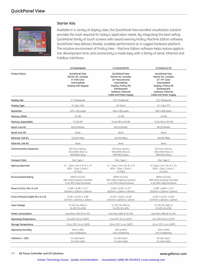
QuickPanel View
242 GE Fanuc Controller and I/O Solutions www.gefanuc.com
Available in a variety of display sizes, the QuickPanel View bundled visualization solutionprovides the tools required for today's application needs. By integrating the best-sellingQuickPanel family of touch screens with award-winning Proficy Machine Edition software,QuickPanel View delivers flexible, scalable performance on a rugged hardware platform.The intuitive environment of Proficy View - Machine Edition software helps reduce applica-tion development time, and connectivity is made easy with a family of serial, Ethernet andFieldbus interfaces.
Starter Kits
IC754VKI06SKD IC754VKI10MTD IC754VKI12CTD
Product Name QuickPanel View QuickPanel View QuickPanel ViewStarter Kit, includes Starter Kit, includes Starter Kit, includes
6" STN-Color 10" Monochrome 12" TFT-Color Intermediate Intermediate Intermediate
Display with Keypad Display, Proficy ME Display, Proficy ME Development Development
Software, Ethernet Software, EthernetCable and Power Supply Cable and Power Supply
Display Size 5.7" (Diagonal) 10.4" (Diagonal) 12.1" (Diagonal)
Display Type 6" Color-STN 10" Mono 12" Color-TFT
Resolution 320 x 240 pixels 640 x 480 pixels 800 x 600 pixels
Memory: DRAM 32 MB 32 MB 32 MB
Memory: Expandable To 96 MB To 64 MB or 96 MB To 64 MB or 96 MB
Serial: Com #1 RS232/RS485 RS232/RS485 RS232/RS485
Serial: Com #2 None None None
Ethernet: LAN #1 10/100 Mbps 10/100 Mbps 10/100 Mbps
Ethernet: LAN #2 None None None
Communication Expansion GE Fanuc Genius, GE Fanuc Genius, GE Fanuc Genius, DeviceNet Slave, & DeviceNet Slave, & DeviceNet Slave, &
PROFIBUS Slave PROFIBUS Slave PROFIBUS Slave
Compact Flash One, Type 2 One, Type 2 One, Type 2
Agency Approvals UL - Class 1 Div 2 (A, B, C, D) UL - Class 1 Div 2 (A, B, C, D) UL-Class 1 Div 2 (A, B, C, D), ATEX - Class 1 Zone 2 ATEX - Class 1 Zone 2 ATEX - Class 1 Zone 2,
CE Mark CE Mark CE Mark
Environmental Rating NEMA 4/12/4X, NEMA 4/12/4X, NEMA 4/12/4X,IP65 when properly mounted IP65 when properly mounted IP65 when properly mounted
in an IP65 rated enclosure in an IP65 rated enclosure in an IP65 rated enclosure
Panel Cut-Out (W x H x D) 11.88" x 8.96" x 2.37" 11.88" x 8.96" x 2.37" 11.88" x 8.96" x 2.37" (302mm x 228mm x 60mm) (302mm x 228mm x 60mm) (302mm x 228mm x 60mm)
Front of Panel & Depth (W x H x D) 13.26" x 10.34" x 0.38" 13.26" x 10.34" x 0.38" 13.26" x 10.34" x 0.38" (337mm x 263mm x 10mm) (337mm x 263mm x 10mm) (337mm x 263mm x 10mm)
Input Voltage 12 VDC @ ±20% or 12 VDC @ ±20% or 12 VDC @ ±20% or 24 VDC @ ±20% 24 VDC @ ±20% 24 VDC @ ±20%
Power Consumption Less than 24W @ 24 VDC Less than 48W @ 24 VDC Less than 48W @ 24 VDC
Operating Temperature 0 to 60°C (32 to 140°F) 0 to 50°C (32 to 122°F) 0 to 50°C (32 to 122°F)
Storage Temperature -20 to 70°C (-4 to 158°F) -20 to 70°C (-4 to 158°F) -20 to 70°C (-4 to 158°F)
Operating Humidity 10% to 90% 10% to 85% 10% to 90% non-condensing non-condensing non-condensing
Indicators - LEDs bi-color (pwr), bi-color (pwr), bi-color (pwr), tri-color (user) tri-color (user) tri-color (user)
Artisan Technology Group - Quality Instrumentation ... Guaranteed | (888) 88-SOURCE | www.artisantg.com
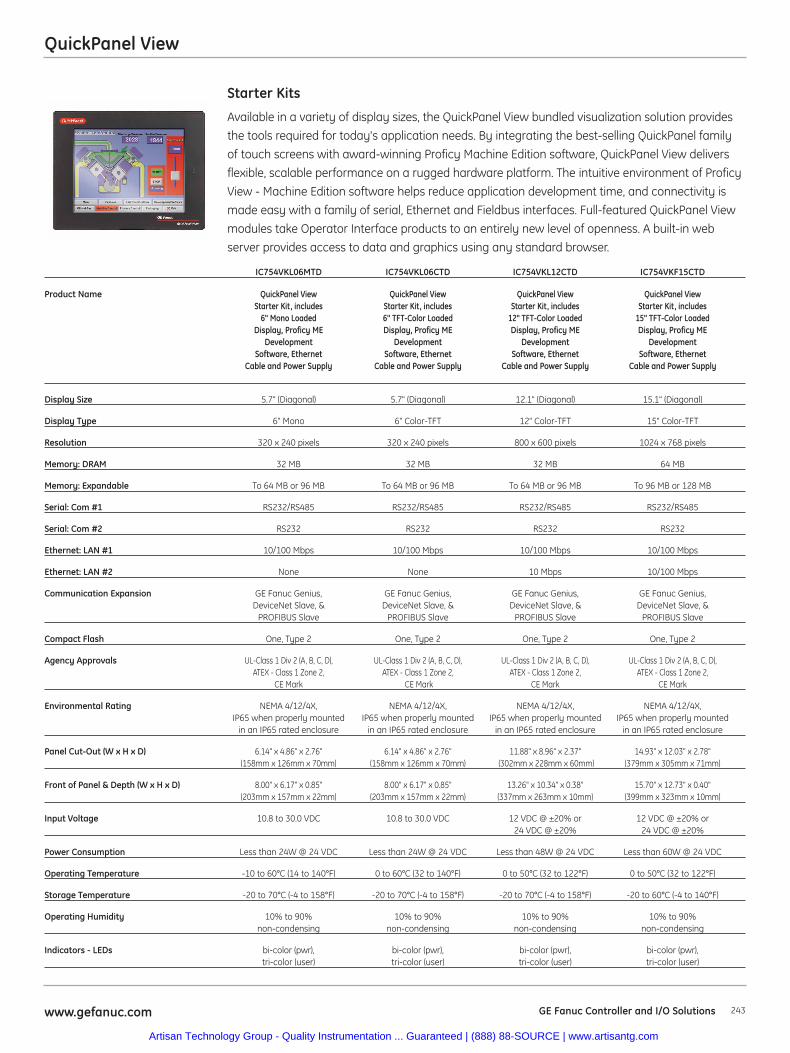
QuickPanel View
243www.gefanuc.com GE Fanuc Controller and I/O Solutions
Available in a variety of display sizes, the QuickPanel View bundled visualization solution provides
the tools required for today's application needs. By integrating the best-selling QuickPanel family
of touch screens with award-winning Proficy Machine Edition software, QuickPanel View delivers
flexible, scalable performance on a rugged hardware platform. The intuitive environment of Proficy
View - Machine Edition software helps reduce application development time, and connectivity is
made easy with a family of serial, Ethernet and Fieldbus interfaces. Full-featured QuickPanel View
modules take Operator Interface products to an entirely new level of openness. A built-in web
server provides access to data and graphics using any standard browser.
Starter Kits
IC754VKL06MTD IC754VKL06CTD IC754VKL12CTD IC754VKF15CTD
Product Name QuickPanel View QuickPanel View QuickPanel View QuickPanel View Starter Kit, includes Starter Kit, includes Starter Kit, includes Starter Kit, includes
6" Mono Loaded 6" TFT-Color Loaded 12" TFT-Color Loaded 15" TFT-Color LoadedDisplay, Proficy ME Display, Proficy ME Display, Proficy ME Display, Proficy ME
Development Development Development DevelopmentSoftware, Ethernet Software, Ethernet Software, Ethernet Software, Ethernet
Cable and Power Supply Cable and Power Supply Cable and Power Supply Cable and Power Supply
Display Size 5.7" (Diagonal) 5.7" (Diagonal) 12.1" (Diagonal) 15.1" (Diagonal)
Display Type 6" Mono 6" Color-TFT 12" Color-TFT 15" Color-TFT
Resolution 320 x 240 pixels 320 x 240 pixels 800 x 600 pixels 1024 x 768 pixels
Memory: DRAM 32 MB 32 MB 32 MB 64 MB
Memory: Expandable To 64 MB or 96 MB To 64 MB or 96 MB To 64 MB or 96 MB To 96 MB or 128 MB
Serial: Com #1 RS232/RS485 RS232/RS485 RS232/RS485 RS232/RS485
Serial: Com #2 RS232 RS232 RS232 RS232
Ethernet: LAN #1 10/100 Mbps 10/100 Mbps 10/100 Mbps 10/100 Mbps
Ethernet: LAN #2 None None 10 Mbps 10/100 Mbps
Communication Expansion GE Fanuc Genius, GE Fanuc Genius, GE Fanuc Genius, GE Fanuc Genius, DeviceNet Slave, & DeviceNet Slave, & DeviceNet Slave, & DeviceNet Slave, &
PROFIBUS Slave PROFIBUS Slave PROFIBUS Slave PROFIBUS Slave
Compact Flash One, Type 2 One, Type 2 One, Type 2 One, Type 2
Agency Approvals UL-Class 1 Div 2 (A, B, C, D), UL-Class 1 Div 2 (A, B, C, D), UL-Class 1 Div 2 (A, B, C, D), UL-Class 1 Div 2 (A, B, C, D), ATEX - Class 1 Zone 2, ATEX - Class 1 Zone 2, ATEX - Class 1 Zone 2, ATEX - Class 1 Zone 2,
CE Mark CE Mark CE Mark CE Mark
Environmental Rating NEMA 4/12/4X, NEMA 4/12/4X, NEMA 4/12/4X, NEMA 4/12/4X, IP65 when properly mounted IP65 when properly mounted IP65 when properly mounted IP65 when properly mounted
in an IP65 rated enclosure in an IP65 rated enclosure in an IP65 rated enclosure in an IP65 rated enclosure
Panel Cut-Out (W x H x D) 6.14" x 4.86" x 2.76" 6.14" x 4.86" x 2.76" 11.88" x 8.96" x 2.37" 14.93" x 12.03" x 2.78" (158mm x 126mm x 70mm) (158mm x 126mm x 70mm) (302mm x 228mm x 60mm) (379mm x 305mm x 71mm)
Front of Panel & Depth (W x H x D) 8.00" x 6.17" x 0.85" 8.00" x 6.17" x 0.85" 13.26" x 10.34" x 0.38" 15.70" x 12.73" x 0.40" (203mm x 157mm x 22mm) (203mm x 157mm x 22mm) (337mm x 263mm x 10mm) (399mm x 323mm x 10mm)
Input Voltage 10.8 to 30.0 VDC 10.8 to 30.0 VDC 12 VDC @ ±20% or 12 VDC @ ±20% or24 VDC @ ±20% 24 VDC @ ±20%
Power Consumption Less than 24W @ 24 VDC Less than 24W @ 24 VDC Less than 48W @ 24 VDC Less than 60W @ 24 VDC
Operating Temperature -10 to 60°C (14 to 140°F) 0 to 60°C (32 to 140°F) 0 to 50°C (32 to 122°F) 0 to 50°C (32 to 122°F)
Storage Temperature -20 to 70°C (-4 to 158°F) -20 to 70°C (-4 to 158°F) -20 to 70°C (-4 to 158°F) -20 to 60°C (-4 to 140°F)
Operating Humidity 10% to 90% 10% to 90% 10% to 90% 10% to 90% non-condensing non-condensing non-condensing non-condensing
Indicators - LEDs bi-color (pwr), bi-color (pwr), bi-color (pwr), bi-color (pwr), tri-color (user) tri-color (user) tri-color (user) tri-color (user)
Artisan Technology Group - Quality Instrumentation ... Guaranteed | (888) 88-SOURCE | www.artisantg.com
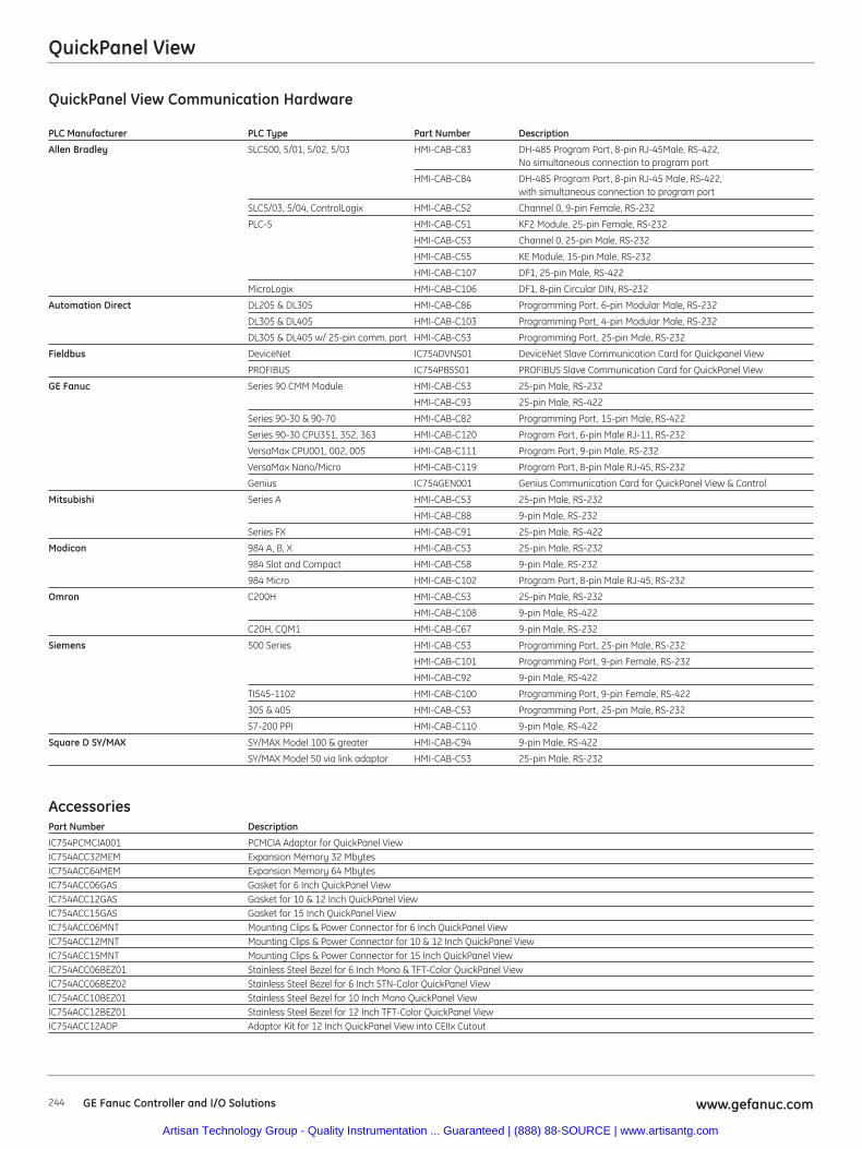
QuickPanel View Communication Hardware
PLC Manufacturer PLC Type Part Number Description
Allen Bradley SLC500, 5/01, 5/02, 5/03 HMI-CAB-C83 DH-485 Program Port, 8-pin RJ-45Male, RS-422, No simultaneous connection to program port
HMI-CAB-C84 DH-485 Program Port, 8-pin RJ-45 Male, RS-422, with simultaneous connection to program port
SLC5/03, 5/04, ControlLogix HMI-CAB-C52 Channel 0, 9-pin Female, RS-232
PLC-5 HMI-CAB-C51 KF2 Module, 25-pin Female, RS-232
HMI-CAB-C53 Channel 0, 25-pin Male, RS-232
HMI-CAB-C55 KE Module, 15-pin Male, RS-232
HMI-CAB-C107 DF1, 25-pin Male, RS-422
MicroLogix HMI-CAB-C106 DF1, 8-pin Circular DIN, RS-232
Automation Direct DL205 & DL305 HMI-CAB-C86 Programming Port, 6-pin Modular Male, RS-232
DL305 & DL405 HMI-CAB-C103 Programming Port, 4-pin Modular Male, RS-232
DL305 & DL405 w/ 25-pin comm. port HMI-CAB-C53 Programming Port, 25-pin Male, RS-232
Fieldbus DeviceNet IC754DVNS01 DeviceNet Slave Communication Card for Quickpanel View
PROFIBUS IC754PBSS01 PROFIBUS Slave Communication Card for QuickPanel View
GE Fanuc Series 90 CMM Module HMI-CAB-C53 25-pin Male, RS-232
HMI-CAB-C93 25-pin Male, RS-422
Series 90-30 & 90-70 HMI-CAB-C82 Programming Port, 15-pin Male, RS-422
Series 90-30 CPU351, 352, 363 HMI-CAB-C120 Program Port, 6-pin Male RJ-11, RS-232
VersaMax CPU001, 002, 005 HMI-CAB-C111 Program Port, 9-pin Male, RS-232
VersaMax Nano/Micro HMI-CAB-C119 Program Port, 8-pin Male RJ-45, RS-232
Genius IC754GEN001 Genius Communication Card for QuickPanel View & Control
Mitsubishi Series A HMI-CAB-C53 25-pin Male, RS-232
HMI-CAB-C88 9-pin Male, RS-232
Series FX HMI-CAB-C91 25-pin Male, RS-422
Modicon 984 A, B, X HMI-CAB-C53 25-pin Male, RS-232
984 Slot and Compact HMI-CAB-C58 9-pin Male, RS-232
984 Micro HMI-CAB-C102 Program Port, 8-pin Male RJ-45, RS-232
Omron C200H HMI-CAB-C53 25-pin Male, RS-232
HMI-CAB-C108 9-pin Male, RS-422
C20H, CQM1 HMI-CAB-C67 9-pin Male, RS-232
Siemens 500 Series HMI-CAB-C53 Programming Port, 25-pin Male, RS-232
HMI-CAB-C101 Programming Port, 9-pin Female, RS-232
HMI-CAB-C92 9-pin Male, RS-422
TI545-1102 HMI-CAB-C100 Programming Port, 9-pin Female, RS-422
305 & 405 HMI-CAB-C53 Programming Port, 25-pin Male, RS-232
S7-200 PPI HMI-CAB-C110 9-pin Male, RS-422
Square D SY/MAX SY/MAX Model 100 & greater HMI-CAB-C94 9-pin Male, RS-422
SY/MAX Model 50 via link adaptor HMI-CAB-C53 25-pin Male, RS-232
AccessoriesPart Number Description
IC754PCMCIA001 PCMCIA Adaptor for QuickPanel ViewIC754ACC32MEM Expansion Memory 32 MbytesIC754ACC64MEM Expansion Memory 64 MbytesIC754ACC06GAS Gasket for 6 Inch QuickPanel ViewIC754ACC12GAS Gasket for 10 & 12 Inch QuickPanel ViewIC754ACC15GAS Gasket for 15 Inch QuickPanel ViewIC754ACC06MNT Mounting Clips & Power Connector for 6 Inch QuickPanel ViewIC754ACC12MNT Mounting Clips & Power Connector for 10 & 12 Inch QuickPanel ViewIC754ACC15MNT Mounting Clips & Power Connector for 15 Inch QuickPanel ViewIC754ACC06BEZ01 Stainless Steel Bezel for 6 Inch Mono & TFT-Color QuickPanel ViewIC754ACC06BEZ02 Stainless Steel Bezel for 6 Inch STN-Color QuickPanel ViewIC754ACC10BEZ01 Stainless Steel Bezel for 10 Inch Mono QuickPanel ViewIC754ACC12BEZ01 Stainless Steel Bezel for 12 Inch TFT-Color QuickPanel ViewIC754ACC12ADP Adaptor Kit for 12 Inch QuickPanel View into CEIIx Cutout
www.gefanuc.comGE Fanuc Controller and I/O Solutions 244
QuickPanel View
Artisan Technology Group - Quality Instrumentation ... Guaranteed | (888) 88-SOURCE | www.artisantg.com
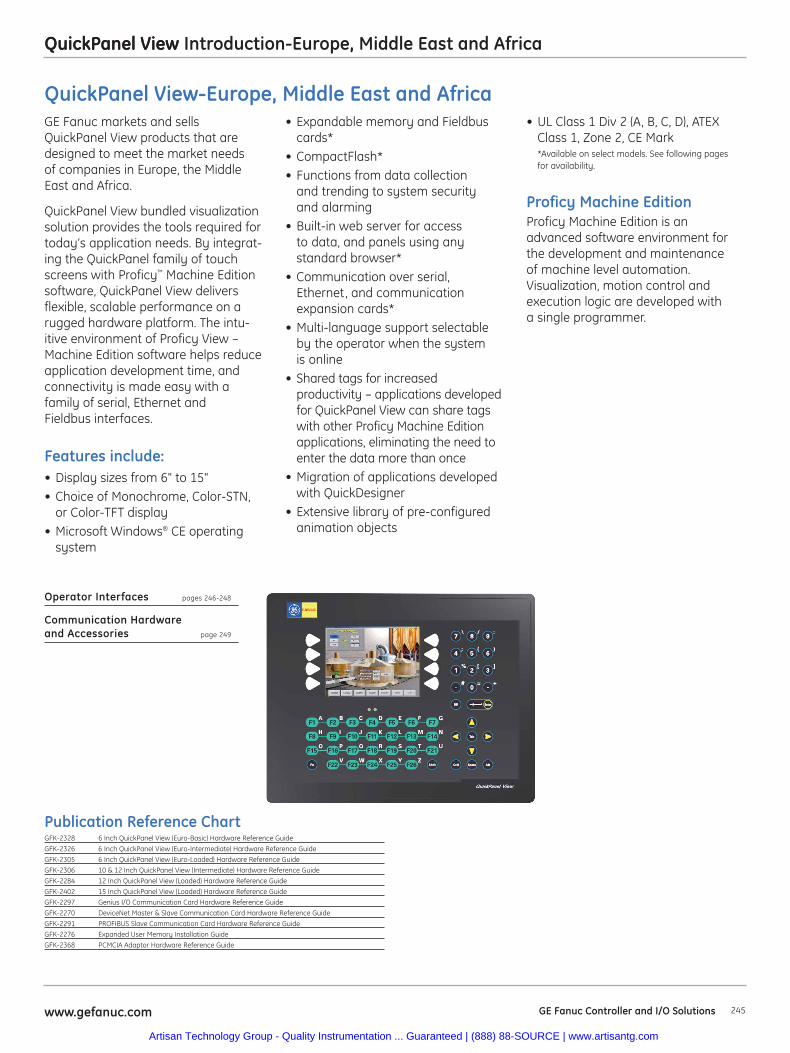
QuickPanel View
245www.gefanuc.com GE Fanuc Controller and I/O Solutions
QuickPanel View Introduction-Europe, Middle East and Africa
• UL Class 1 Div 2 (A, B, C, D), ATEXClass 1, Zone 2, CE Mark*Available on select models. See following pagesfor availability.
Proficy Machine EditionProficy Machine Edition is anadvanced software environment forthe development and maintenanceof machine level automation.Visualization, motion control andexecution logic are developed witha single programmer.
GE Fanuc markets and sellsQuickPanel View products that aredesigned to meet the market needs of companies in Europe, the MiddleEast and Africa.
QuickPanel View bundled visualizationsolution provides the tools required fortoday’s application needs. By integrat-ing the QuickPanel family of touchscreens with Proficy™ Machine Editionsoftware, QuickPanel View deliversflexible, scalable performance on arugged hardware platform. The intu-itive environment of Proficy View –Machine Edition software helps reduceapplication development time, andconnectivity is made easy with afamily of serial, Ethernet and Fieldbus interfaces.
Features include:• Display sizes from 6" to 15"• Choice of Monochrome, Color-STN,
or Color-TFT display• Microsoft Windows® CE operating
system
• Expandable memory and Fieldbuscards*
• CompactFlash*• Functions from data collection
and trending to system security and alarming
• Built-in web server for access to data, and panels using any standard browser*
• Communication over serial, Ethernet, and communicationexpansion cards*
• Multi-language support selectableby the operator when the system is online
• Shared tags for increased productivity – applications developedfor QuickPanel View can share tagswith other Proficy Machine Editionapplications, eliminating the need toenter the data more than once
• Migration of applications developedwith QuickDesigner
• Extensive library of pre-configuredanimation objects
Operator Interfaces pages 246-248
Communication Hardware and Accessories page 249
Publication Reference ChartGFK-2328 6 Inch QuickPanel View (Euro-Basic) Hardware Reference Guide
GFK-2326 6 Inch QuickPanel View (Euro-Intermediate) Hardware Reference Guide
GFK-2305 6 Inch QuickPanel View (Euro-Loaded) Hardware Reference Guide
GFK-2306 10 & 12 Inch QuickPanel View (Intermediate) Hardware Reference Guide
GFK-2284 12 Inch QuickPanel View (Loaded) Hardware Reference Guide
GFK-2402 15 Inch QuickPanel View (Loaded) Hardware Reference Guide
GFK-2297 Genius I/O Communication Card Hardware Reference Guide
GFK-2270 DeviceNet Master & Slave Communication Card Hardware Reference Guide
GFK-2291 PROFIBUS Slave Communication Card Hardware Reference Guide
GFK-2276 Expanded User Memory Installation Guide
GFK-2368 PCMCIA Adaptor Hardware Reference Guide
QuickPanel View-Europe, Middle East and Africa
Artisan Technology Group - Quality Instrumentation ... Guaranteed | (888) 88-SOURCE | www.artisantg.com
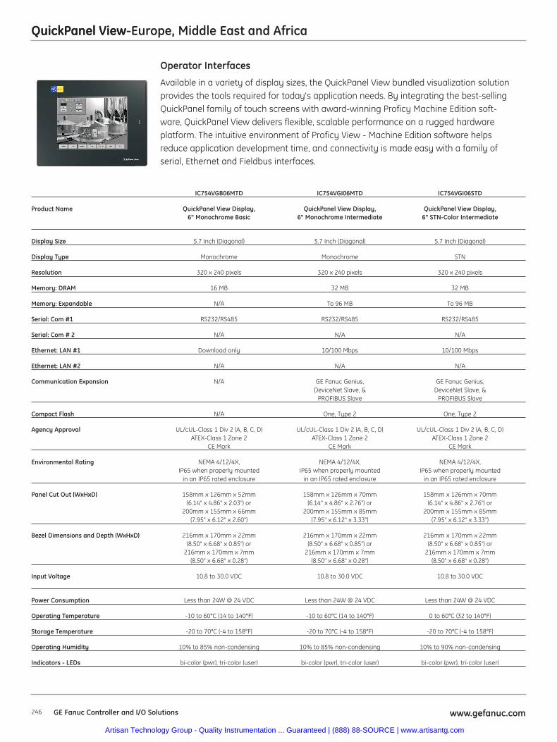
QuickPanel View
246 GE Fanuc Controller and I/O Solutions www.gefanuc.com
QuickPanel View-Europe, Middle East and Africa
Available in a variety of display sizes, the QuickPanel View bundled visualization solutionprovides the tools required for today's application needs. By integrating the best-sellingQuickPanel family of touch screens with award-winning Proficy Machine Edition soft-ware, QuickPanel View delivers flexible, scalable performance on a rugged hardwareplatform. The intuitive environment of Proficy View - Machine Edition software helpsreduce application development time, and connectivity is made easy with a family ofserial, Ethernet and Fieldbus interfaces.
Operator Interfaces
IC754VGB06MTD IC754VGI06MTD IC754VGI06STD
Product Name QuickPanel View Display, QuickPanel View Display, QuickPanel View Display, 6" Monochrome Basic 6" Monochrome Intermediate 6" STN-Color Intermediate
Display Size 5.7 Inch (Diagonal) 5.7 Inch (Diagonal) 5.7 Inch (Diagonal)
Display Type Monochrome Monochrome STN
Resolution 320 x 240 pixels 320 x 240 pixels 320 x 240 pixels
Memory: DRAM 16 MB 32 MB 32 MB
Memory: Expandable N/A To 96 MB To 96 MB
Serial: Com #1 RS232/RS485 RS232/RS485 RS232/RS485
Serial: Com # 2 N/A N/A N/A
Ethernet: LAN #1 Download only 10/100 Mbps 10/100 Mbps
Ethernet: LAN #2 N/A N/A N/A
Communication Expansion N/A GE Fanuc Genius, GE Fanuc Genius, DeviceNet Slave, & DeviceNet Slave, &
PROFIBUS Slave PROFIBUS Slave
Compact Flash N/A One, Type 2 One, Type 2
Agency Approval UL/cUL-Class 1 Div 2 (A, B, C, D) UL/cUL-Class 1 Div 2 (A, B, C, D) UL/cUL-Class 1 Div 2 (A, B, C, D)ATEX-Class 1 Zone 2 ATEX-Class 1 Zone 2 ATEX-Class 1 Zone 2
CE Mark CE Mark CE Mark
Environmental Rating NEMA 4/12/4X, NEMA 4/12/4X, NEMA 4/12/4X, IP65 when properly mounted IP65 when properly mounted IP65 when properly mounted
in an IP65 rated enclosure in an IP65 rated enclosure in an IP65 rated enclosure
Panel Cut Out (WxHxD) 158mm x 126mm x 52mm 158mm x 126mm x 70mm 158mm x 126mm x 70mm (6.14" x 4.86" x 2.03") or (6.14" x 4.86" x 2.76") or (6.14" x 4.86" x 2.76") or
200mm x 155mm x 66mm 200mm x 155mm x 85mm 200mm x 155mm x 85mm (7.95" x 6.12" x 2.60") (7.95" x 6.12" x 3.33") (7.95" x 6.12" x 3.33")
Bezel Dimensions and Depth (WxHxD) 216mm x 170mm x 22mm 216mm x 170mm x 22mm 216mm x 170mm x 22mm(8.50" x 6.68" x 0.85") or (8.50" x 6.68" x 0.85") or (8.50" x 6.68" x 0.85") or
216mm x 170mm x 7mm 216mm x 170mm x 7mm 216mm x 170mm x 7mm (8.50" x 6.68" x 0.28") (8.50" x 6.68" x 0.28") (8.50" x 6.68" x 0.28")
Input Voltage 10.8 to 30.0 VDC 10.8 to 30.0 VDC 10.8 to 30.0 VDC
Power Consumption Less than 24W @ 24 VDC Less than 24W @ 24 VDC Less than 24W @ 24 VDC
Operating Temperature -10 to 60°C (14 to 140°F) -10 to 60°C (14 to 140°F) 0 to 60°C (32 to 140°F)
Storage Temperature -20 to 70°C (-4 to 158°F) -20 to 70°C (-4 to 158°F) -20 to 70°C (-4 to 158°F)
Operating Humidity 10% to 85% non-condensing 10% to 85% non-condensing 10% to 90% non-condensing
Indicators - LEDs bi-color (pwr), tri-color (user) bi-color (pwr), tri-color (user) bi-color (pwr), tri-color (user)
Artisan Technology Group - Quality Instrumentation ... Guaranteed | (888) 88-SOURCE | www.artisantg.com
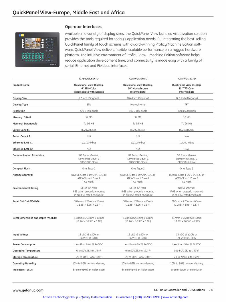
QuickPanel View
247www.gefanuc.com GE Fanuc Controller and I/O Solutions
QuickPanel View-Europe, Middle East and Africa
Available in a variety of display sizes, the QuickPanel View bundled visualization solutionprovides the tools required for today's application needs. By integrating the best-sellingQuickPanel family of touch screens with award-winning Proficy Machine Edition soft-ware, QuickPanel View delivers flexible, scalable performance on a rugged hardwareplatform. The intuitive environment of Proficy View - Machine Edition software helpsreduce application development time, and connectivity is made easy with a family ofserial, Ethernet and Fieldbus interfaces.
Operator Interfaces
IC754VGI06SKTD IC754VGI10MTD IC754VGI12CTD
Product Name QuickPanel View Display, QuickPanel View Display, QuickPanel View Display, 6" STN-Color 10" Monochrome 12" TFT-Color
Intermediate with Keypad Intermediate Intermediate
Display Size 5.7 Inch (Diagonal) 10.4 Inch (Diagonal) 12.1 Inch (Diagonal)
Display Type STN Monochrome TFT
Resolution 320 x 240 pixels 640 x 480 pixels 800 x 600 pixels
Memory: DRAM 32 MB 32 MB 32 MB
Memory: Expandable To 96 MB To 96 MB To 96 MB
Serial: Com #1 RS232/RS485 RS232/RS485 RS232/RS485
Serial: Com # 2 N/A N/A N/A
Ethernet: LAN #1 10/100 Mbps 10/100 Mbps 10/100 Mbps
Ethernet: LAN #2 N/A N/A N/A
Communication Expansion GE Fanuc Genius, GE Fanuc Genius, GE Fanuc Genius, DeviceNet Slave, & DeviceNet Slave, & DeviceNet Slave, &
PROFIBUS Slave PROFIBUS Slave PROFIBUS Slave
Compact Flash One, Type 2 One, Type 2 One, Type 2
Agency Approval UL/cUL-Class 1 Div 2 (A, B, C, D) UL/cUL-Class 1 Div 2 (A, B, C, D) UL/cUL-Class 1 Div 2 (A, B, C, D)ATEX-Class 1 Zone 2 ATEX-Class 1 Zone 2 ATEX-Class 1 Zone 2
CE Mark CE Mark CE Mark
Environmental Rating NEMA 4/12/4X, NEMA 4/12/4X, NEMA 4/12/4X, IP65 when properly mounted IP65 when properly mounted IP65 when properly mounted
in an IP65 rated enclosure in an IP65 rated enclosure in an IP65 rated enclosure
Panel Cut Out (WxHxD) 302mm x 228mm x 60mm 302mm x 228mm x 60mm 302mm x 228mm x 60mm (11.88" x 8.96" x 2.37") (11.88" x 8.96" x 2.37") (11.88" x 8.96" x 2.37")
Bezel Dimensions and Depth (WxHxD) 337mm x 263mm x 10mm 337mm x 263mm x 10mm 337mm x 263mm x 10mm (13.26" x 10.34" x 0.38") (13.26" x 10.34" x 0.38") (13.26" x 10.34" x 0.38")
Input Voltage 12 VDC @ ±20% or 12 VDC @ ±20% or 12 VDC @ ±20% or 24 VDC @ ±20% 24 VDC @ ±20% 24 VDC @ ±20%
Power Consumption Less than 24W @ 24 VDC Less than 48W @ 24 VDC Less than 48W @ 24 VDC
Operating Temperature 0 to 60°C (32 to 140°F) 0 to 50°C (32 to 122°F) 0 to 50°C (32 to 122°F)
Storage Temperature -20 to 70°C (-4 to 158°F) -20 to 70°C (-4 to 158°F) -20 to 70°C (-4 to 158°F)
Operating Humidity 10% to 90% non-condensing 10% to 85% non-condensing 10% to 90% non-condensing
Indicators - LEDs bi-color (pwr), tri-color (user) bi-color (pwr), tri-color (user) bi-color (pwr), tri-color (user)
Artisan Technology Group - Quality Instrumentation ... Guaranteed | (888) 88-SOURCE | www.artisantg.com
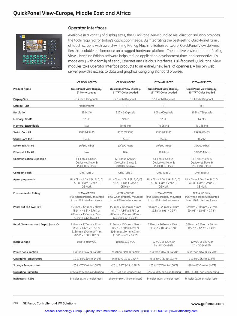
QuickPanel View
248 GE Fanuc Controller and I/O Solutions www.gefanuc.com
QuickPanel View-Europe, Middle East and Africa
Available in a variety of display sizes, the QuickPanel View bundled visualization solution providesthe tools required for today's application needs. By integrating the best-selling QuickPanel familyof touch screens with award-winning Proficy Machine Edition software, QuickPanel View deliversflexible, scalable performance on a rugged hardware platform. The intuitive environment of ProficyView - Machine Edition software helps reduce application development time, and connectivity ismade easy with a family of serial, Ethernet and Fieldbus interfaces. Full-featured QuickPanel Viewmodules take Operator Interface products to an entirely new level of openness. A built-in webserver provides access to data and graphics using any standard browser.
Operator Interfaces
IC754VGL06MTD IC754VGL06CTD IC754VGL12CTD IC754VGF15CTD
Product Name QuickPanel View Display, QuickPanel View Display, QuickPanel View Display, QuickPanel View Display, 6" Mono Loaded 6" TFT-Color Loaded 12" TFT-Color Loaded 15" TFT-Color Loaded
Display Size 5.7 Inch (Diagonal) 5.7 Inch (Diagonal) 12.1 Inch (Diagonal) 15.1 Inch (Diagonal)
Display Type Monochrome TFT TFT TFT
Resolution 320x240 320 x 240 pixels 800 x 600 pixels 1024 x 768 pixels
Memory: DRAM 32 MB 32 MB 32 MB 64 MB
Memory: Expandable N/A To 96 MB To 96 MB To 128 MB
Serial: Com #1 RS232/RS485 RS232/RS485 RS232/RS485 RS232/RS485
Serial: Com # 2 RS232 RS232 RS232 RS232
Ethernet: LAN #1 10/100 Mbps 10/100 Mbps 10/100 Mbps 10/100 Mbps
Ethernet: LAN #2 N/A N/A 10 Mbps 10/100 Mbps
Communication Expansion GE Fanuc Genius, GE Fanuc Genius, GE Fanuc Genius, GE Fanuc Genius,DeviceNet Slave, & DeviceNet Slave, & DeviceNet Slave, & DeviceNet Slave, &
PROFIBUS Slave PROFIBUS Slave PROFIBUS Slave PROFIBUS Slave
Compact Flash One, Type 2 One, Type 2 One, Type 2 One, Type 2
Agency Approvals UL - Class 1 Div 2 (A, B, C, D) UL - Class 1 Div 2 (A, B, C, D) UL - Class 1 Div 2 (A, B, C, D) UL - Class 1 Div 2 (A, B, C, D)ATEX - Class 1 Zone 2 ATEX - Class 1 Zone 2 ATEX - Class 1 Zone 2 ATEX - Class 1 Zone 2
CE Mark CE Mark CE Mark CE Mark
Environmental Rating NEMA 4/12/4X, NEMA 4/12/4X, NEMA 4/12/4X, NEMA 4/12/4X, IP65 when properly mounted IP65 when properly mounted IP65 when properly mounted IP65 when properly mounted
in an IP65 rated enclosure in an IP65 rated enclosure in an IP65 rated enclosure in an IP65 rated enclosure
Panel Cut Out (WxHxD) 158mm x 126mm x 70mm 158mm x 126mm x 70mm 302mm x 228mm x 60mm 379mm x 305mm x 71mm (6.14" x 4.86" x 2.76") or (6.14" x 4.86" x 2.76") or (11.88" x 8.96" x 2.37") (14.93" x 12.03" x 2.78")
200mm x 155mm x 85mm 200mm x 155mm x 85mm (7.95" x 6.12" x 3.33") (7.95" x 6.12" x 3.33")
Bezel Dimensions and Depth (WxHxD) 216mm x 170mm x 22mm 216mm x 170mm x 22mm 337mm x 263mm x 10mm 399mm x 323mm x 10mm (8.50" x 6.68" x 0.85") or (8.50" x 6.68" x 0.85") or (13.26" x 10.34" x 0.38") (15.70" x 12.73" x 0.40")
216mm x 170mm x 7mm 216mm x 170mm x 7mm (8.50" x 6.68" x 0.28") (8.50" x 6.68" x 0.28")
Input Voltage 10.8 to 30.0 VDC 10.8 to 30.0 VDC 12 VDC @ ±20% or 12 VDC @ ±20% or 24 VDC @ ±20% 24 VDC @ ±20%
Power Consumption Less than 24W @ 24 VDC Less than 24W @ 24 VDC Less than 48W @ 24 VDC Less than 60W @ 24 VDC
Operating Temperature -10 to 60°C (14 to 140°F) 0 to 60°C (32 to 140°F) 0 to 50°C (32 to 122°F) 0 to 50°C (32 to 122°F)
Storage Temperature -20 to 70°C (-4 to 158°F) -20 to 70°C (-4 to 158°F) -20 to 70°C (-4 to 158°F) -20 to 60°C (-4 to 140°F)
Operating Humidity 10% to 85% non-condensing 5% - 95% non-condensing 10% to 90% non-condensing 10% to 90% non-condensing
Indicators - LEDs bi-color (pwr), tri-color (user) bi-color (pwr), tri-color (user) bi-color (pwr), tri-color (user) bi-color (pwr), tri-color (user)
Artisan Technology Group - Quality Instrumentation ... Guaranteed | (888) 88-SOURCE | www.artisantg.com
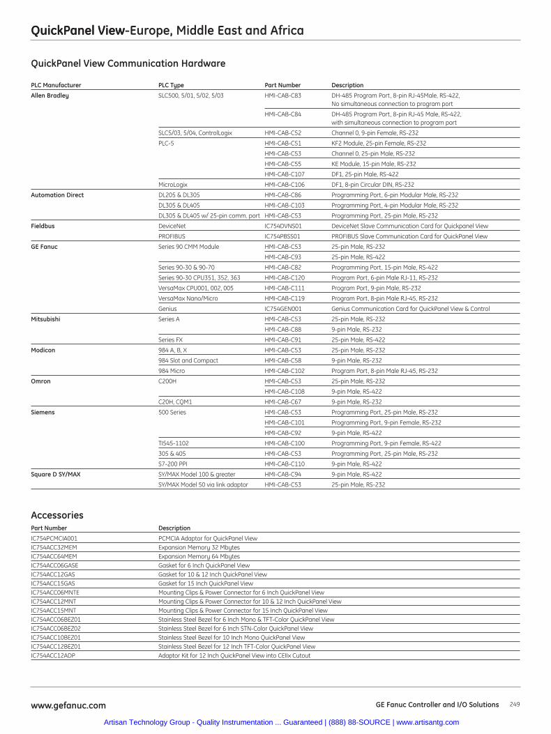
QuickPanel View
249www.gefanuc.com GE Fanuc Controller and I/O Solutions
QuickPanel View-Europe, Middle East and Africa
QuickPanel View Communication Hardware
PLC Manufacturer PLC Type Part Number Description
Allen Bradley SLC500, 5/01, 5/02, 5/03 HMI-CAB-C83 DH-485 Program Port, 8-pin RJ-45Male, RS-422, No simultaneous connection to program port
HMI-CAB-C84 DH-485 Program Port, 8-pin RJ-45 Male, RS-422, with simultaneous connection to program port
SLC5/03, 5/04, ControlLogix HMI-CAB-C52 Channel 0, 9-pin Female, RS-232
PLC-5 HMI-CAB-C51 KF2 Module, 25-pin Female, RS-232
HMI-CAB-C53 Channel 0, 25-pin Male, RS-232
HMI-CAB-C55 KE Module, 15-pin Male, RS-232
HMI-CAB-C107 DF1, 25-pin Male, RS-422
MicroLogix HMI-CAB-C106 DF1, 8-pin Circular DIN, RS-232
Automation Direct DL205 & DL305 HMI-CAB-C86 Programming Port, 6-pin Modular Male, RS-232
DL305 & DL405 HMI-CAB-C103 Programming Port, 4-pin Modular Male, RS-232
DL305 & DL405 w/ 25-pin comm. port HMI-CAB-C53 Programming Port, 25-pin Male, RS-232
Fieldbus DeviceNet IC754DVNS01 DeviceNet Slave Communication Card for Quickpanel View
PROFIBUS IC754PBSS01 PROFIBUS Slave Communication Card for QuickPanel View
GE Fanuc Series 90 CMM Module HMI-CAB-C53 25-pin Male, RS-232
HMI-CAB-C93 25-pin Male, RS-422
Series 90-30 & 90-70 HMI-CAB-C82 Programming Port, 15-pin Male, RS-422
Series 90-30 CPU351, 352, 363 HMI-CAB-C120 Program Port, 6-pin Male RJ-11, RS-232
VersaMax CPU001, 002, 005 HMI-CAB-C111 Program Port, 9-pin Male, RS-232
VersaMax Nano/Micro HMI-CAB-C119 Program Port, 8-pin Male RJ-45, RS-232
Genius IC754GEN001 Genius Communication Card for QuickPanel View & Control
Mitsubishi Series A HMI-CAB-C53 25-pin Male, RS-232
HMI-CAB-C88 9-pin Male, RS-232
Series FX HMI-CAB-C91 25-pin Male, RS-422
Modicon 984 A, B, X HMI-CAB-C53 25-pin Male, RS-232
984 Slot and Compact HMI-CAB-C58 9-pin Male, RS-232
984 Micro HMI-CAB-C102 Program Port, 8-pin Male RJ-45, RS-232
Omron C200H HMI-CAB-C53 25-pin Male, RS-232
HMI-CAB-C108 9-pin Male, RS-422
C20H, CQM1 HMI-CAB-C67 9-pin Male, RS-232
Siemens 500 Series HMI-CAB-C53 Programming Port, 25-pin Male, RS-232
HMI-CAB-C101 Programming Port, 9-pin Female, RS-232
HMI-CAB-C92 9-pin Male, RS-422
TI545-1102 HMI-CAB-C100 Programming Port, 9-pin Female, RS-422
305 & 405 HMI-CAB-C53 Programming Port, 25-pin Male, RS-232
S7-200 PPI HMI-CAB-C110 9-pin Male, RS-422
Square D SY/MAX SY/MAX Model 100 & greater HMI-CAB-C94 9-pin Male, RS-422
SY/MAX Model 50 via link adaptor HMI-CAB-C53 25-pin Male, RS-232
AccessoriesPart Number Description
IC754PCMCIA001 PCMCIA Adaptor for QuickPanel ViewIC754ACC32MEM Expansion Memory 32 MbytesIC754ACC64MEM Expansion Memory 64 MbytesIC754ACC06GASE Gasket for 6 Inch QuickPanel ViewIC754ACC12GAS Gasket for 10 & 12 Inch QuickPanel ViewIC754ACC15GAS Gasket for 15 Inch QuickPanel ViewIC754ACC06MNTE Mounting Clips & Power Connector for 6 Inch QuickPanel ViewIC754ACC12MNT Mounting Clips & Power Connector for 10 & 12 Inch QuickPanel ViewIC754ACC15MNT Mounting Clips & Power Connector for 15 Inch QuickPanel ViewIC754ACC06BEZ01 Stainless Steel Bezel for 6 Inch Mono & TFT-Color QuickPanel ViewIC754ACC06BEZ02 Stainless Steel Bezel for 6 Inch STN-Color QuickPanel ViewIC754ACC10BEZ01 Stainless Steel Bezel for 10 Inch Mono QuickPanel ViewIC754ACC12BEZ01 Stainless Steel Bezel for 12 Inch TFT-Color QuickPanel ViewIC754ACC12ADP Adaptor Kit for 12 Inch QuickPanel View into CEIIx Cutout
Artisan Technology Group - Quality Instrumentation ... Guaranteed | (888) 88-SOURCE | www.artisantg.com

250 GE Fanuc Controller and I/O Solutions www.gefanuc.com
Notes
Artisan Technology Group - Quality Instrumentation ... Guaranteed | (888) 88-SOURCE | www.artisantg.com

GE Fanuc Automation Services
251www.gefanuc.com GE Fanuc Controller and I/O Solutions
To succeed, businesses today must be able to rely on morethan just a product solution. From superior technical support,to proper implementation of your technology and trainingwhere and when you need it most, the services you receiveare every bit as important as the products you put into yourfacility. GE Fanuc offers a complete array of support servicesto help you attain the highest value possible from your tech-nology investments.
Technical Support and MaintenanceComprehensive offerings to support the full range of yourhardware and software. Our unique support solutions providethe tools, resources and experience you need to be successful.
Project and Engineering ServicesAdvanced engineering solutions that combine proven projectapplication skills, industry expertise and extensive productknowledge with best-in-class partner resources.
Training ServicesA flexible family of services that provides hands-on training inthe location, format and style that suits you best.
Field ServicesA fast, reliable on-site engineering support system designedto get your business up and running as quickly and efficientlyas possible.
Spare Parts / Warranty / Factory RepairRepair and replacement part offerings designed to protectyour hardware investment.
Basic SupportIn order to ensure your hardware investment is fully pro-tected, GE Fanuc provides you with basic support for yourPLC, I/O and Motion products, as well as the programmingsoftware sold with these products. Basic support includescallback telephone support consultation, online case man-agement and access to the GlobalCare support site.Customers can search and download hardware productmanuals, articles, Frequently Asked Questions (FAQs), datasheets (functional specs), CAD drawings, service packs,firmware and IPI's from the support site, and can participatein an active online forum. Additional services in support ofyour complete product hardware and software investmentare available by enrolling in the GlobalCare CompleteSupport program.
Optimizing Your Investment Through GlobalCare Support Services, we continue to provideour customers with a comprehensive support offering thathelps you realize the highest possible value from our prod-ucts. And we stand behind our commitment 24 hours a dayto support your enterprise.
Just as a GE Fanuc Automation solution can optimize yourbusiness, a GlobalCare Support contract can optimize yourinvestment in our software. Contact us today to learn whatwe can do for you.
Note: An Extended Hardware Warranty is available uponrequest. Contact your GE Fanuc Sales Representative formore information.
GE Fanuc Automation Services Overview
Artisan Technology Group - Quality Instrumentation ... Guaranteed | (888) 88-SOURCE | www.artisantg.com

GE Fanuc Automation Services
252 www.gefanuc.comGE Fanuc Controller and I/O Solutions
Proficy™ GlobalCare Complete Support Optimizing Your Investment Proficy GlobalCare Complete Support is the best and mostcomprehensive way to optimize your investment in aGE Fanuc Automation software solution. With GlobalCareComplete, you can be sure that your software is always upto date, and that you have access to the tools, applicationsand support to be successful.
A Network of Support Professionals Whether it comes directly from GE Fanuc or from our globalnetwork of Certified Support Professionals around the world,you’ll receive the same high levels of service throughout asupport scenario from first-level response to advancedtroubleshooting. Our support team meets our strict criteriafor product knowledge and experience. And all of our sup-port features are focused on providing you with the tools,resources and assistance to be successful.
24 x 7 Emergency Support Around the clock emergency support is available for criticalcases, through a comprehensive infrastructure of phoneand web-based support. To maximize effectiveness, oursupport professionals are organized into specialized productteams to ensure a high level of expertise in your particularcase area.
Product Maintenance GlobalCare Complete Product Maintenance ensures thatyou continue to have access to the latest product improve-ments, enhancements, tools and features that can optimizeyour investment in our software. In addition, you can go toglobalcare.gefanuc.com to download the latest Hot Fixesand Service Packs for products and drivers.
Online Knowledge Center Our Online Knowledge Center is accessible world-wide, with24-hour access to a broad range of information and datasources – including top support links, articles and whitepapers, sample codes, user forums, developer downloads,driver fact sheets and more. The Downloads section of theSupport Site provides a comprehensive storage facility forproven tools and resources that can cut development time.And a secure online forum allows you to see and benefitfrom how customers around the globe are using our prod-ucts in real-world environments.
Online Case Management We offer a sophisticated online case management systemthat allows you to monitor, update and even escalate yourcase 24 hours a day. When you log a case online, our inter-face guides you through the process and prompts you toprovide our support professionals with relevant informationabout your case and system. From there, the most qualifiedprofessional is automatically assigned to your case andhas a working knowledge of your situation. Cases loggedoutside of North America are delivered directly to localrepresentatives for immediate support.
Knowledge Base CD We publish the Knowledge Base CD three times a year asan additional resource for GlobalCare customers. It containsan entire library of valuable articles, white papers, remotediagnostic tools and other global and regional materials tohelp solve your issue when you are not connected to theInternet.
Electronic Newsletter – At Your Service GlobalCare Complete customers receive our electronicnewsletter, which is filled with important updates and helpful tips about using our products and services toyour greatest advantage.
Artisan Technology Group - Quality Instrumentation ... Guaranteed | (888) 88-SOURCE | www.artisantg.com

GE Fanuc Automation Services
253www.gefanuc.com GE Fanuc Controller and I/O Solutions
GE Fanuc performance-based training combines practical lec-tures with hands-on lab exercises to ensure that you get thevalue-added skills you need. From product courses to customclasses to application specific training, we can help you get themost from your automation products by providing expert train-ing for your work force. Courses range from comprehensiveintroductory level offerings to in-depth advanced level offerings.Let GE Fanuc Training Services be your one-stop shop for tech-nical training!
Technical training helps your employees set up, configureand troubleshoot more efficiently, decreasing downtime andincreasing throughput. It also helps your employees stay cur-rent with new technology as well as find new ways to applyyour technology, helping make your organization more pro-ductive. Industry studies have shown that technical trainingcan lower production costs because of the subsequentincreases in employee efficiency and reductions in downtime.Employee skill development and enhancement are invaluablecompany assets, the benefits of which can be realized in avery short time.
Open Enrollment TrainingGE Fanuc has an international network of regional trainingcenters offering world-class technical training for mainte-nance, operations, and engineering personnel. OpenEnrollment Training allows students to interact and networkwith fellow product users. GE Fanuc ensures that class sizesenhance student/instructor ratios. All classes are taught byGE Fanuc factory-certified instructors using GE Fanucauthorized training materials.
GE Fanuc continually exceeds customer satisfaction ratingsin both course content and in instructor experience, profes-sionalism and knowledge.
Course descriptions and schedule information are available atwww.gefanuc.com/ttc.
On-Site TrainingIn today's fast moving, cost conscious world, on-site trainingis an extremely effective tool to reduce your travel expensesand ensure your key personnel remain accessible in the eventof a plant emergency. Depending on the class and your loca-tion, on-site training can be quite cost effective when you takeinto consideration how much you'll save on T&L expenses—even for as few as four students. Add to this the benefits ofmaintaining rapid access to your key teams (not to mentionthe ability to customize and focus the training in order toshorten the learning experience) and it's easy to see how on-site training can be a powerful option.
Online TrainingThe GE Fanuc Online Institute offers visually engaging, inter-active courses to meet customer-training needs in today’schallenging business climate. With the same content asinstructor-led courses and available online with 24 x 7 access,the Online Institute has all the training with none of the travelexpense. Each course is geared toward performance objec-tives and provides users with both guided and independentpractice of concepts as well as interactive assessments withimmediate feedback. You can now meet your time and costbudgets as well as your technical training requirements. Visitthe Online Institute today athttp://onlineinstitute.gefanuc.com.
Needs AssessmentWe will perform a training needs assessment for your organi-zation to help us design customized courses and curriculumsto support the specific skill requirements of your operation.
SimulatorsTrain your personnel, test components and debug programswithout taking systems out of production. Our classroomsimulators are available to meet your training, developmentand maintenance requirements. We also develop customsimulators that match the equipment configuration inyour operation to maximize your benefits.
For all your technical training needsAmericas: 1-800-GE FANUC or (434) 978-5100Asia Pacific: 86-21-3222-4555Europe, Middle East and Africa: +800 1 GE FANUCEurope, Middle East and Africa (CNC): (352) 727979-1Email: [email protected]/ttcwww.gefanuc.com/ttc
Training Services
Artisan Technology Group - Quality Instrumentation ... Guaranteed | (888) 88-SOURCE | www.artisantg.com

GE Fanuc Automation Services
254 www.gefanuc.comGE Fanuc Controller and I/O Solutions
Hardware/Software Services When and WhereYou Need ThemWhen your equipment is down, so is your business. Andwhether your facility is impacted for a few hours or a fewweeks is largely dependent upon the quality and respon-siveness of your support provider. At GE Fanuc, we under-stand your need for fast, reliable service for your hardwareand software investments. And we’ve responded to thatneed with GE Fanuc Service on Demand – a service offeringdesigned to get you back up and running as quickly andefficiently as possible.
Superior ResponsivenessWhen your plant is down, time is money – literally. Withover 50 support locations spread throughout the world,our expert engineers can typically be at your facility within12 hours to begin handling your case. And whether we areworking independently or in tandem with your in-housemaintenance staff, one call to 1-800-GE FANUC (Americas) 86-21-3222-4555 (Asia Pacific) +800 1 GE FANUC (Europe, Middle East and Africa) puts you on the short road to being back online.
One call gives you access to:
• Our extensive base of GE Fanuc field engineers
• Primary and backup personnel
• Factory Authorized Service Providers
• 24 x 7 On-Site Emergency Support
Hardware and Software ExpertiseOur engineers are experts in the design, specification and implementation of your GE Fanuc machines, software andcontrol products. That specialized expertise enables us to troubleshoot your situation quickly, dependably, and accurately.
In addition to our expertise in GE Fanuc’s products andprotocols, our worldwide network offers a range of pre andpost deployment engineering services to provide the rightsolution to your business, regardless of what products youdecide to implement.
GE Fanuc Service on Demand is available for a wide range ofproducts, including:
• Automation & Production Software
• Controllers & I/O
• Servo Drives & Motors
• Motion Control
• Visualization (OI) & PC Solutions
Additional ServicesWhether you require 24 x 7 on-site emergency services or along-term maintenance contract, GE Fanuc can provide youwith the training, service and support you need to maximizeyour automation technology investment. Our on-site trainingenables your personnel to become experts in problem-solv-ing and general automation. In addition, our service agree-ments are available on an hourly or yearly basis, providingthe help you need for the life of your operation.
GE Fanuc offers a comprehensive array of services to fullysupport your investment in our products, including:
• Technical Support & Maintenance (Including ProficyGlobalCare)
• On-Site Emergency Services
• Legacy & Competitor System Conversions
• Startup Assistance
• Troubleshooting & Diagnostics
• Inspections & Reviews
• Training Services
• Spare Parts/Warranty/Repair
DispatchingFor more information about our services, capabilities, ratesand products handled by our Service on Demand team, or to schedule an appointment with one of our engineers,please call: 1-800-GE FANUC (Americas) 86-21-3222-4555 (Asia Pacific) +800 1 GE FANUC (Europe, Middle East and Africa)
GE Fanuc Service on Demand
Artisan Technology Group - Quality Instrumentation ... Guaranteed | (888) 88-SOURCE | www.artisantg.com
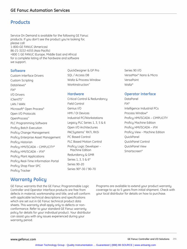
GE Fanuc Automation Services
255www.gefanuc.com GE Fanuc Controller and I/O Solutions
SoftwareCustom Interface Drivers
Custom Scripting
DataViews®
FIX®
I/O Drivers
iClientTS™
LAN / WAN
Microsoft® Open Process®
Open I/O Protocols
OpenProcess™
PLC Programming Software
Proficy Batch Execution
Proficy Change Management
Proficy Enterprise Asset Management
Proficy Historian
Proficy HMI/SCADA – CIMPLICITY®
Proficy HMI/SCADA – iFIX®
Proficy Plant Applications
Proficy Real-Time Information Portal
Proficy Shop Floor SPC
Proficy Tracker
QuickDesigner & GP Pro
SQL / Access DB
Waltz & Process Window
WorkInstruction™
HardwareCritical Control & Redundancy
Field Control
Genius I/O
HMI / OI Devices
Industrial PC/Workstations
Legacy PLC Series 1, 3, 5 & 6
Open I/O Architectures
PACSystems™ RX7i, RX3i
PC Based Control
PLC Based Motion Control
Proficy Logic Developer - Machine Edition
Redundancy & GMR
Series 1, 3, 5 & 6®
Series 90-20
Series 90®-30 / 90-70
Series 90 I/O
VersaMax® Nano & Micro
VersaPoint
Waltz®
Operator InterfaceDataPanel
FIX®
Intelligence Industrial PCs
Process Window®
Proficy HMI/SCADA – CIMPLICITY
Proficy Machine Edition
Proficy HMI/SCADA – iFIX
Proficy View - Machine Edition
QuickPanel
QuickPanel Control
QuickPanel View
Smartscreen®
Service On Demand is available for the following GE Fanucproducts. If you don’t see the product you’re looking for,please call: 1-800-GE FANUC (Americas) 86-21-3222-4555 (Asia Pacific)+800 1 GE FANUC (Europe, Middle East and Africa) for a complete listing of the hardware and software we support.
Warranty PolicyGE Fanuc warrants that the GE Fanuc Programmable LogicController and Operator Interface products are free fromdefects in material, workmanship and title, and will conformwith applicable technical descriptions and specificationswhich are set out in GE Fanuc technical product datasheets. This warranty shall apply only to defects or non-conformance. Refer to your standard GE Fanuc warrantypolicy for details for your individual product. Your distributorcan assist you with any issues experienced during yourwarranty period.
Products
Programs are available to extend your product warrantycoverage to up to 5 years from initial shipment. Check withyour local distributor for details on how to purchase.
Artisan Technology Group - Quality Instrumentation ... Guaranteed | (888) 88-SOURCE | www.artisantg.com

256 www.gefanuc.comGE Fanuc Controller and I/O Solutions
Notes
Artisan Technology Group - Quality Instrumentation ... Guaranteed | (888) 88-SOURCE | www.artisantg.com
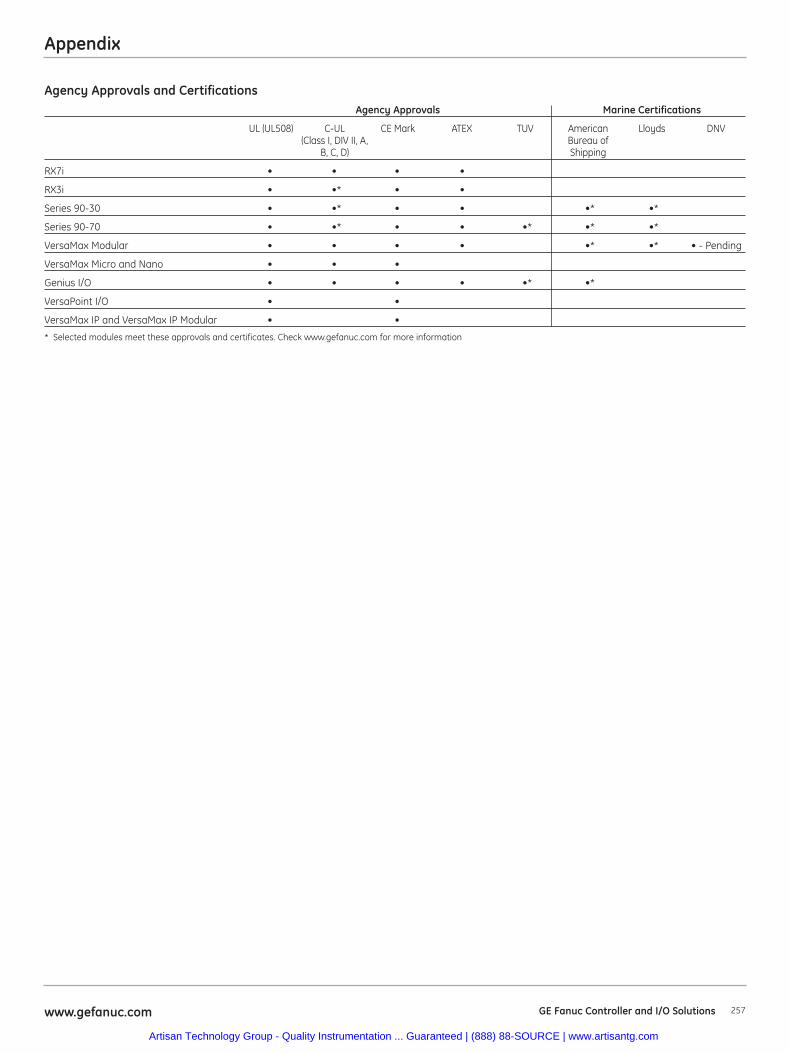
Appendix
257www.gefanuc.com GE Fanuc Controller and I/O Solutions
Agency Approvals and CertificationsAgency Approvals Marine Certifications
UL (UL508) C-UL CE Mark ATEX TUV American Lloyds DNV(Class I, DIV II, A, Bureau of
B, C, D) Shipping
RX7i • • • •
RX3i • •* • •
Series 90-30 • •* • • •* •*
Series 90-70 • •* • • •* •* •*
VersaMax Modular • • • • •* •* • - Pending
VersaMax Micro and Nano • • •
Genius I/O • • • • •* •*
VersaPoint I/O • •
VersaMax IP and VersaMax IP Modular • •
* Selected modules meet these approvals and certificates. Check www.gefanuc.com for more information
Artisan Technology Group - Quality Instrumentation ... Guaranteed | (888) 88-SOURCE | www.artisantg.com

258 www.gefanuc.comGE Fanuc Controller and I/O Solutions
Notes
Artisan Technology Group - Quality Instrumentation ... Guaranteed | (888) 88-SOURCE | www.artisantg.com
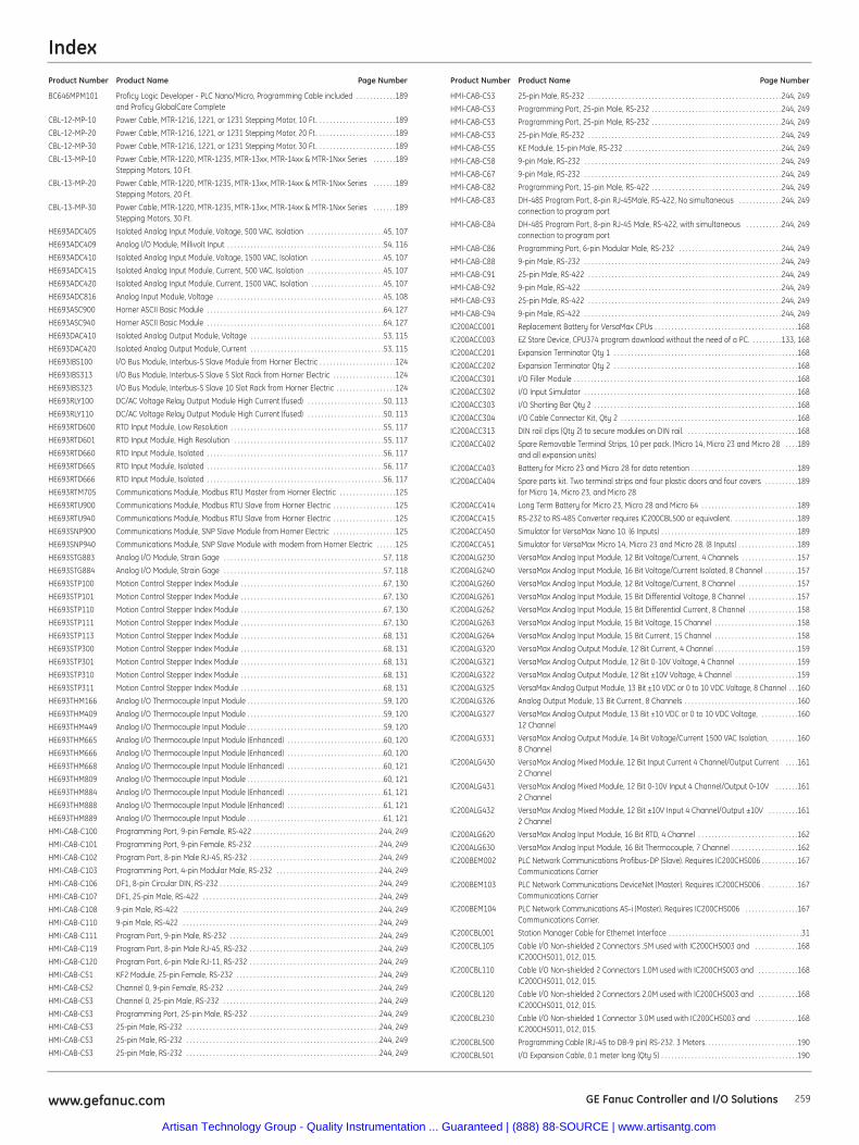
Index
259www.gefanuc.com GE Fanuc Controller and I/O Solutions
Product Number Product Name Page Number Product Number Product Name Page Number
BC646MPM101 Proficy Logic Developer - PLC Nano/Micro, Programming Cable included . . . . . . . . . . . .189and Proficy GlobalCare Complete
CBL-12-MP-10 Power Cable, MTR-1216, 1221, or 1231 Stepping Motor, 10 Ft. . . . . . . . . . . . . . . . . . . . . . . .189
CBL-12-MP-20 Power Cable, MTR-1216, 1221, or 1231 Stepping Motor, 20 Ft. . . . . . . . . . . . . . . . . . . . . . . .189
CBL-12-MP-30 Power Cable, MTR-1216, 1221, or 1231 Stepping Motor, 30 Ft. . . . . . . . . . . . . . . . . . . . . . . .189
CBL-13-MP-10 Power Cable, MTR-1220, MTR-1235, MTR-13xx, MTR-14xx & MTR-1Nxx Series . . . . . . .189Stepping Motors, 10 Ft.
CBL-13-MP-20 Power Cable, MTR-1220, MTR-1235, MTR-13xx, MTR-14xx & MTR-1Nxx Series . . . . . . .189Stepping Motors, 20 Ft.
CBL-13-MP-30 Power Cable, MTR-1220, MTR-1235, MTR-13xx, MTR-14xx & MTR-1Nxx Series . . . . . . .189Stepping Motors, 30 Ft.
HE693ADC405 Isolated Analog Input Module, Voltage, 500 VAC, Isolation . . . . . . . . . . . . . . . . . . . . . . .45, 107
HE693ADC409 Analog I/O Module, Millivolt Input . . . . . . . . . . . . . . . . . . . . . . . . . . . . . . . . . . . . . . . . . . . . . . .54, 116
HE693ADC410 Isolated Analog Input Module, Voltage, 1500 VAC, Isolation . . . . . . . . . . . . . . . . . . . . . .45, 107
HE693ADC415 Isolated Analog Input Module, Current, 500 VAC, Isolation . . . . . . . . . . . . . . . . . . . . . . .45, 107
HE693ADC420 Isolated Analog Input Module, Current, 1500 VAC, Isolation . . . . . . . . . . . . . . . . . . . . . .45, 107
HE693ADC816 Analog Input Module, Voltage . . . . . . . . . . . . . . . . . . . . . . . . . . . . . . . . . . . . . . . . . . . . . . . . . .45, 108
HE693ASC900 Horner ASCII Basic Module . . . . . . . . . . . . . . . . . . . . . . . . . . . . . . . . . . . . . . . . . . . . . . . . . . . . .64, 127
HE693ASC940 Horner ASCII Basic Module . . . . . . . . . . . . . . . . . . . . . . . . . . . . . . . . . . . . . . . . . . . . . . . . . . . . .64, 127
HE693DAC410 Isolated Analog Output Module, Voltage . . . . . . . . . . . . . . . . . . . . . . . . . . . . . . . . . . . . . . . .53, 115
HE693DAC420 Isolated Analog Output Module, Current . . . . . . . . . . . . . . . . . . . . . . . . . . . . . . . . . . . . . . . .53, 115
HE693IBS100 I/O Bus Module, Interbus-S Slave Module from Horner Electric . . . . . . . . . . . . . . . . . . . . . . .124
HE693IBS313 I/O Bus Module, Interbus-S Slave 5 Slot Rack from Horner Electric . . . . . . . . . . . . . . . . . . .124
HE693IBS323 I/O Bus Module, Interbus-S Slave 10 Slot Rack from Horner Electric . . . . . . . . . . . . . . . . . .124
HE693RLY100 DC/AC Voltage Relay Output Module High Current (fused) . . . . . . . . . . . . . . . . . . . . . . .50, 113
HE693RLY110 DC/AC Voltage Relay Output Module High Current (fused) . . . . . . . . . . . . . . . . . . . . . . .50, 113
HE693RTD600 RTD Input Module, Low Resolution . . . . . . . . . . . . . . . . . . . . . . . . . . . . . . . . . . . . . . . . . . . . . .55, 117
HE693RTD601 RTD Input Module, High Resolution . . . . . . . . . . . . . . . . . . . . . . . . . . . . . . . . . . . . . . . . . . . . .55, 117
HE693RTD660 RTD Input Module, Isolated . . . . . . . . . . . . . . . . . . . . . . . . . . . . . . . . . . . . . . . . . . . . . . . . . . . . .56, 117
HE693RTD665 RTD Input Module, Isolated . . . . . . . . . . . . . . . . . . . . . . . . . . . . . . . . . . . . . . . . . . . . . . . . . . . . .56, 117
HE693RTD666 RTD Input Module, Isolated . . . . . . . . . . . . . . . . . . . . . . . . . . . . . . . . . . . . . . . . . . . . . . . . . . . . .56, 117
HE693RTM705 Communications Module, Modbus RTU Master from Horner Electric . . . . . . . . . . . . . . . . .125
HE693RTU900 Communications Module, Modbus RTU Slave from Horner Electric . . . . . . . . . . . . . . . . . . .125
HE693RTU940 Communications Module, Modbus RTU Slave from Horner Electric . . . . . . . . . . . . . . . . . . .125
HE693SNP900 Communications Module, SNP Slave Module from Horner Electric . . . . . . . . . . . . . . . . . . .125
HE693SNP940 Communications Module, SNP Slave Module with modem from Horner Electric . . . . . .125
HE693STG883 Analog I/O Module, Strain Gage . . . . . . . . . . . . . . . . . . . . . . . . . . . . . . . . . . . . . . . . . . . . . . . .57, 118
HE693STG884 Analog I/O Module, Strain Gage . . . . . . . . . . . . . . . . . . . . . . . . . . . . . . . . . . . . . . . . . . . . . . . .57, 118
HE693STP100 Motion Control Stepper Index Module . . . . . . . . . . . . . . . . . . . . . . . . . . . . . . . . . . . . . . . . . . .67, 130
HE693STP101 Motion Control Stepper Index Module . . . . . . . . . . . . . . . . . . . . . . . . . . . . . . . . . . . . . . . . . . .67, 130
HE693STP110 Motion Control Stepper Index Module . . . . . . . . . . . . . . . . . . . . . . . . . . . . . . . . . . . . . . . . . . .67, 130
HE693STP111 Motion Control Stepper Index Module . . . . . . . . . . . . . . . . . . . . . . . . . . . . . . . . . . . . . . . . . . .67, 130
HE693STP113 Motion Control Stepper Index Module . . . . . . . . . . . . . . . . . . . . . . . . . . . . . . . . . . . . . . . . . . .68, 131
HE693STP300 Motion Control Stepper Index Module . . . . . . . . . . . . . . . . . . . . . . . . . . . . . . . . . . . . . . . . . . .68, 131
HE693STP301 Motion Control Stepper Index Module . . . . . . . . . . . . . . . . . . . . . . . . . . . . . . . . . . . . . . . . . . .68, 131
HE693STP310 Motion Control Stepper Index Module . . . . . . . . . . . . . . . . . . . . . . . . . . . . . . . . . . . . . . . . . . .68, 131
HE693STP311 Motion Control Stepper Index Module . . . . . . . . . . . . . . . . . . . . . . . . . . . . . . . . . . . . . . . . . . .68, 131
HE693THM166 Analog I/O Thermocouple Input Module . . . . . . . . . . . . . . . . . . . . . . . . . . . . . . . . . . . . . . . . .59, 120
HE693THM409 Analog I/O Thermocouple Input Module . . . . . . . . . . . . . . . . . . . . . . . . . . . . . . . . . . . . . . . . .59, 120
HE693THM449 Analog I/O Thermocouple Input Module . . . . . . . . . . . . . . . . . . . . . . . . . . . . . . . . . . . . . . . . .59, 120
HE693THM665 Analog I/O Thermocouple Input Module (Enhanced) . . . . . . . . . . . . . . . . . . . . . . . . . . . . .60, 120
HE693THM666 Analog I/O Thermocouple Input Module (Enhanced) . . . . . . . . . . . . . . . . . . . . . . . . . . . . .60, 120
HE693THM668 Analog I/O Thermocouple Input Module (Enhanced) . . . . . . . . . . . . . . . . . . . . . . . . . . . . .60, 121
HE693THM809 Analog I/O Thermocouple Input Module . . . . . . . . . . . . . . . . . . . . . . . . . . . . . . . . . . . . . . . . .60, 121
HE693THM884 Analog I/O Thermocouple Input Module (Enhanced) . . . . . . . . . . . . . . . . . . . . . . . . . . . . .61, 121
HE693THM888 Analog I/O Thermocouple Input Module (Enhanced) . . . . . . . . . . . . . . . . . . . . . . . . . . . . .61, 121
HE693THM889 Analog I/O Thermocouple Input Module . . . . . . . . . . . . . . . . . . . . . . . . . . . . . . . . . . . . . . . . .61, 121
HMI-CAB-C100 Programming Port, 9-pin Female, RS-422 . . . . . . . . . . . . . . . . . . . . . . . . . . . . . . . . . . . . . .244, 249
HMI-CAB-C101 Programming Port, 9-pin Female, RS-232 . . . . . . . . . . . . . . . . . . . . . . . . . . . . . . . . . . . . . .244, 249
HMI-CAB-C102 Program Port, 8-pin Male RJ-45, RS-232 . . . . . . . . . . . . . . . . . . . . . . . . . . . . . . . . . . . . . . .244, 249
HMI-CAB-C103 Programming Port, 4-pin Modular Male, RS-232 . . . . . . . . . . . . . . . . . . . . . . . . . . . . . . .244, 249
HMI-CAB-C106 DF1, 8-pin Circular DIN, RS-232 . . . . . . . . . . . . . . . . . . . . . . . . . . . . . . . . . . . . . . . . . . . . . . . .244, 249
HMI-CAB-C107 DF1, 25-pin Male, RS-422 . . . . . . . . . . . . . . . . . . . . . . . . . . . . . . . . . . . . . . . . . . . . . . . . . . . . .244, 249
HMI-CAB-C108 9-pin Male, RS-422 . . . . . . . . . . . . . . . . . . . . . . . . . . . . . . . . . . . . . . . . . . . . . . . . . . . . . . . . . . .244, 249
HMI-CAB-C110 9-pin Male, RS-422 . . . . . . . . . . . . . . . . . . . . . . . . . . . . . . . . . . . . . . . . . . . . . . . . . . . . . . . . . . .244, 249
HMI-CAB-C111 Program Port, 9-pin Male, RS-232 . . . . . . . . . . . . . . . . . . . . . . . . . . . . . . . . . . . . . . . . . . . . .244, 249
HMI-CAB-C119 Program Port, 8-pin Male RJ-45, RS-232 . . . . . . . . . . . . . . . . . . . . . . . . . . . . . . . . . . . . . . .244, 249
HMI-CAB-C120 Program Port, 6-pin Male RJ-11, RS-232 . . . . . . . . . . . . . . . . . . . . . . . . . . . . . . . . . . . . . . .244, 249
HMI-CAB-C51 KF2 Module, 25-pin Female, RS-232 . . . . . . . . . . . . . . . . . . . . . . . . . . . . . . . . . . . . . . . . . . .244, 249
HMI-CAB-C52 Channel 0, 9-pin Female, RS-232 . . . . . . . . . . . . . . . . . . . . . . . . . . . . . . . . . . . . . . . . . . . . . .244, 249
HMI-CAB-C53 Channel 0, 25-pin Male, RS-232 . . . . . . . . . . . . . . . . . . . . . . . . . . . . . . . . . . . . . . . . . . . . . . .244, 249
HMI-CAB-C53 Programming Port, 25-pin Male, RS-232 . . . . . . . . . . . . . . . . . . . . . . . . . . . . . . . . . . . . . . .244, 249
HMI-CAB-C53 25-pin Male, RS-232 . . . . . . . . . . . . . . . . . . . . . . . . . . . . . . . . . . . . . . . . . . . . . . . . . . . . . . . . . .244, 249
HMI-CAB-C53 25-pin Male, RS-232 . . . . . . . . . . . . . . . . . . . . . . . . . . . . . . . . . . . . . . . . . . . . . . . . . . . . . . . . . .244, 249
HMI-CAB-C53 25-pin Male, RS-232 . . . . . . . . . . . . . . . . . . . . . . . . . . . . . . . . . . . . . . . . . . . . . . . . . . . . . . . . . .244, 249
HMI-CAB-C53 25-pin Male, RS-232 . . . . . . . . . . . . . . . . . . . . . . . . . . . . . . . . . . . . . . . . . . . . . . . . . . . . . . . . . .244, 249
HMI-CAB-C53 Programming Port, 25-pin Male, RS-232 . . . . . . . . . . . . . . . . . . . . . . . . . . . . . . . . . . . . . . .244, 249
HMI-CAB-C53 Programming Port, 25-pin Male, RS-232 . . . . . . . . . . . . . . . . . . . . . . . . . . . . . . . . . . . . . . .244, 249
HMI-CAB-C53 25-pin Male, RS-232 . . . . . . . . . . . . . . . . . . . . . . . . . . . . . . . . . . . . . . . . . . . . . . . . . . . . . . . . . .244, 249
HMI-CAB-C55 KE Module, 15-pin Male, RS-232 . . . . . . . . . . . . . . . . . . . . . . . . . . . . . . . . . . . . . . . . . . . . . . .244, 249
HMI-CAB-C58 9-pin Male, RS-232 . . . . . . . . . . . . . . . . . . . . . . . . . . . . . . . . . . . . . . . . . . . . . . . . . . . . . . . . . . .244, 249
HMI-CAB-C67 9-pin Male, RS-232 . . . . . . . . . . . . . . . . . . . . . . . . . . . . . . . . . . . . . . . . . . . . . . . . . . . . . . . . . . .244, 249
HMI-CAB-C82 Programming Port, 15-pin Male, RS-422 . . . . . . . . . . . . . . . . . . . . . . . . . . . . . . . . . . . . . . .244, 249
HMI-CAB-C83 DH-485 Program Port, 8-pin RJ-45Male, RS-422, No simultaneous . . . . . . . . . . . . .244, 249connection to program port
HMI-CAB-C84 DH-485 Program Port, 8-pin RJ-45 Male, RS-422, with simultaneous . . . . . . . . . . .244, 249connection to program port
HMI-CAB-C86 Programming Port, 6-pin Modular Male, RS-232 . . . . . . . . . . . . . . . . . . . . . . . . . . . . . . .244, 249
HMI-CAB-C88 9-pin Male, RS-232 . . . . . . . . . . . . . . . . . . . . . . . . . . . . . . . . . . . . . . . . . . . . . . . . . . . . . . . . . . .244, 249
HMI-CAB-C91 25-pin Male, RS-422 . . . . . . . . . . . . . . . . . . . . . . . . . . . . . . . . . . . . . . . . . . . . . . . . . . . . . . . . . .244, 249
HMI-CAB-C92 9-pin Male, RS-422 . . . . . . . . . . . . . . . . . . . . . . . . . . . . . . . . . . . . . . . . . . . . . . . . . . . . . . . . . . .244, 249
HMI-CAB-C93 25-pin Male, RS-422 . . . . . . . . . . . . . . . . . . . . . . . . . . . . . . . . . . . . . . . . . . . . . . . . . . . . . . . . . .244, 249
HMI-CAB-C94 9-pin Male, RS-422 . . . . . . . . . . . . . . . . . . . . . . . . . . . . . . . . . . . . . . . . . . . . . . . . . . . . . . . . . . .244, 249
IC200ACC001 Replacement Battery for VersaMax CPUs . . . . . . . . . . . . . . . . . . . . . . . . . . . . . . . . . . . . . . . . . . .168
IC200ACC003 EZ Store Device, CPU374 program download without the need of a PC. . . . . . . . . .133, 168
IC200ACC201 Expansion Terminator Qty 1 . . . . . . . . . . . . . . . . . . . . . . . . . . . . . . . . . . . . . . . . . . . . . . . . . . . . . . .168
IC200ACC202 Expansion Terminator Qty 2 . . . . . . . . . . . . . . . . . . . . . . . . . . . . . . . . . . . . . . . . . . . . . . . . . . . . . . .168
IC200ACC301 I/O Filler Module . . . . . . . . . . . . . . . . . . . . . . . . . . . . . . . . . . . . . . . . . . . . . . . . . . . . . . . . . . . . . . . . . . .168
IC200ACC302 I/O Input Simulator . . . . . . . . . . . . . . . . . . . . . . . . . . . . . . . . . . . . . . . . . . . . . . . . . . . . . . . . . . . . . . . .168
IC200ACC303 I/O Shorting Bar Qty 2 . . . . . . . . . . . . . . . . . . . . . . . . . . . . . . . . . . . . . . . . . . . . . . . . . . . . . . . . . . . . .168
IC200ACC304 I/O Cable Connector Kit, Qty 2 . . . . . . . . . . . . . . . . . . . . . . . . . . . . . . . . . . . . . . . . . . . . . . . . . . . . .168
IC200ACC313 DIN rail clips (Qty 2) to secure modules on DIN rail. . . . . . . . . . . . . . . . . . . . . . . . . . . . . . . . . .168
IC200ACC402 Spare Removable Terminal Strips, 10 per pack. (Micro 14, Micro 23 and Micro 28 . . . .189and all expansion units)
IC200ACC403 Battery for Micro 23 and Micro 28 for data retention . . . . . . . . . . . . . . . . . . . . . . . . . . . . . . . .189
IC200ACC404 Spare parts kit. Two terminal strips and four plastic doors and four covers . . . . . . . . . .189for Micro 14, Micro 23, and Micro 28
IC200ACC414 Long Term Battery for Micro 23, Micro 28 and Micro 64 . . . . . . . . . . . . . . . . . . . . . . . . . . . . .189
IC200ACC415 RS-232 to RS-485 Converter requires IC200CBL500 or equivalent. . . . . . . . . . . . . . . . . . . .189
IC200ACC450 Simulator for VersaMax Nano 10. (6 Inputs) . . . . . . . . . . . . . . . . . . . . . . . . . . . . . . . . . . . . . . . . .189
IC200ACC451 Simulator for VersaMax Micro 14, Micro 23 and Micro 28. (8 Inputs) . . . . . . . . . . . . . . . . . .189
IC200ALG230 VersaMax Analog Input Module, 12 Bit Voltage/Current, 4 Channels . . . . . . . . . . . . . . . . .157
IC200ALG240 VersaMax Analog Input Module, 16 Bit Voltage/Current Isolated, 8 Channel . . . . . . . . . .157
IC200ALG260 VersaMax Analog Input Module, 12 Bit Voltage/Current, 8 Channel . . . . . . . . . . . . . . . . . .157
IC200ALG261 VersaMax Analog Input Module, 15 Bit Differential Voltage, 8 Channel . . . . . . . . . . . . . . .157
IC200ALG262 VersaMax Analog Input Module, 15 Bit Differential Current, 8 Channel . . . . . . . . . . . . . . .158
IC200ALG263 VersaMax Analog Input Module, 15 Bit Voltage, 15 Channel . . . . . . . . . . . . . . . . . . . . . . . . .158
IC200ALG264 VersaMax Analog Input Module, 15 Bit Current, 15 Channel . . . . . . . . . . . . . . . . . . . . . . . . .158
IC200ALG320 VersaMax Analog Output Module, 12 Bit Current, 4 Channel . . . . . . . . . . . . . . . . . . . . . . . . .159
IC200ALG321 VersaMax Analog Output Module, 12 Bit 0-10V Voltage, 4 Channel . . . . . . . . . . . . . . . . . .159
IC200ALG322 VersaMax Analog Output Module, 12 Bit ±10V Voltage, 4 Channel . . . . . . . . . . . . . . . . . . .159
IC200ALG325 VersaMax Analog Output Module, 13 Bit ±10 VDC or 0 to 10 VDC Voltage, 8 Channel . . .160
IC200ALG326 Analog Output Module, 13 Bit Current, 8 Channels . . . . . . . . . . . . . . . . . . . . . . . . . . . . . . . . . .160
IC200ALG327 VersaMax Analog Output Module, 13 Bit ±10 VDC or 0 to 10 VDC Voltage, . . . . . . . . . . .16012 Channel
IC200ALG331 VersaMax Analog Output Module, 14 Bit Voltage/Current 1500 VAC Isolation, . . . . . . . .1608 Channel
IC200ALG430 VersaMax Analog Mixed Module, 12 Bit Input Current 4 Channel/Output Current . . . .1612 Channel
IC200ALG431 VersaMax Analog Mixed Module, 12 Bit 0-10V Input 4 Channel/Output 0-10V . . . . . . .1612 Channel
IC200ALG432 VersaMax Analog Mixed Module, 12 Bit ±10V Input 4 Channel/Output ±10V . . . . . . . . .1612 Channel
IC200ALG620 VersaMax Analog Input Module, 16 Bit RTD, 4 Channel . . . . . . . . . . . . . . . . . . . . . . . . . . . . . .162
IC200ALG630 VersaMax Analog Input Module, 16 Bit Thermocouple, 7 Channel . . . . . . . . . . . . . . . . . . . .162
IC200BEM002 PLC Network Communications Profibus-DP (Slave). Requires IC200CHS006 . . . . . . . . . . .167Communications Carrier
IC200BEM103 PLC Network Communications DeviceNet (Master). Requires IC200CHS006 . . . . . . . . . .167Communications Carrier
IC200BEM104 PLC Network Communications AS-i (Master). Requires IC200CHS006 . . . . . . . . . . . . . . . .167Communications Carrier.
IC200CBL001 Station Manager Cable for Ethernet Interface . . . . . . . . . . . . . . . . . . . . . . . . . . . . . . . . . . . . . . . .31
IC200CBL105 Cable I/O Non-shielded 2 Connectors .5M used with IC200CHS003 and . . . . . . . . . . . . .168IC200CHS011, 012, 015.
IC200CBL110 Cable I/O Non-shielded 2 Connectors 1.0M used with IC200CHS003 and . . . . . . . . . . . .168IC200CHS011, 012, 015.
IC200CBL120 Cable I/O Non-shielded 2 Connectors 2.0M used with IC200CHS003 and . . . . . . . . . . . .168IC200CHS011, 012, 015.
IC200CBL230 Cable I/O Non-shielded 1 Connector 3.0M used with IC200CHS003 and . . . . . . . . . . . . .168IC200CHS011, 012, 015.
IC200CBL500 Programming Cable (RJ-45 to DB-9 pin) RS-232. 3 Meters. . . . . . . . . . . . . . . . . . . . . . . . . . . .190
IC200CBL501 I/O Expansion Cable, 0.1 meter long (Qty 5) . . . . . . . . . . . . . . . . . . . . . . . . . . . . . . . . . . . . . . . . .190
Artisan Technology Group - Quality Instrumentation ... Guaranteed | (888) 88-SOURCE | www.artisantg.com
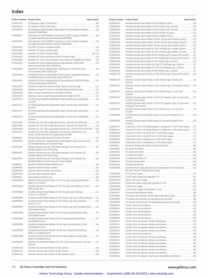
Index
260 www.gefanuc.comGE Fanuc Controller and I/O Solutions
IC200CBL505 I/O Expansion Cable, 0.5 meter long . . . . . . . . . . . . . . . . . . . . . . . . . . . . . . . . . . . . . . . . . . . . . . . .190
IC200CBL510 I/O Expansion Cable, 1 meter long . . . . . . . . . . . . . . . . . . . . . . . . . . . . . . . . . . . . . . . . . . . . . . . . .190
IC200CBL600 Rack Expansion Cable Shielded Single-Ended 1M to One Expansion Receiver . . . . . . . .168Modules (IC200ERM00x)
IC200CBL601 Rack Expansion Cable Shielded 2 Connectors (1 meter). Supports multidrop . . . . . . . . .168to multiple Expansion Receiver Modules (IC200ERM00x)
IC200CBL602 Rack Expansion Cable Shielded 2 Connectors (2 meter). Supports multidrop . . . . . . . . .168to multiple Expansion Receiver Modules (IC200ERM00x)
IC200CHS001 VersaMax I/O Carrier, Local Barrier Style . . . . . . . . . . . . . . . . . . . . . . . . . . . . . . . . . . . . . . . . . . . .138
IC200CHS002 VersaMax I/O Carrier, Local Box Style . . . . . . . . . . . . . . . . . . . . . . . . . . . . . . . . . . . . . . . . . . . . . . .138
IC200CHS003 VersaMax I/O Carrier, Connector Style. . . . . . . . . . . . . . . . . . . . . . . . . . . . . . . . . . . . . . . . . .139, 140
IC200CHS005 VersaMax I/O Carrier, Local Spring Clamp Connection Style . . . . . . . . . . . . . . . . . . . . . . . . .138
IC200CHS006 VersaMax I/O , Local Communications Carrier (Supports IC200BEMxxx Modules) . . . . .167
IC200CHS011 VersaMax I/O Carrier, Interposing Barrier Style (Requires IC200CHS003 . . . . . . . . . . . . . .139base and connecting cable IC200CBL1xx)
IC200CHS012 VersaMax I/O Carrier, Interposing Box Style (Requires IC200CHS003 base . . . . . . . . . . .139and connecting cable IC200CBL1xx)
IC200CHS014 VersaMax I/O Carrier, Interposing Box Thermocouple Compensation (Requires . . . . . .139IC200CHS003 base and connecting cable IC200CBL1xx)
IC200CHS015 VersaMax I/O Carrier, Interposing Spring Clamp (Requires IC200CHS003 base . . . . . . .139and connecting cable IC200CBL1xx)
IC200CHS022 VersaMax Compact I/O Carrier, Local Box Clamp Connection Style . . . . . . . . . . . . . . . . . .137
IC200CHS025 VersaMax Compact I/O Carrier, Local Spring Clamp Connection Style . . . . . . . . . . . . . . . .137
IC200CHS101 Input or Output Interposing Disconnect Style 16 Points. . . . . . . . . . . . . . . . . . . . . . . . . . . . . .140
IC200CHS102 Expansion Input or Output Interposing Disconnect Style 16 Points. . . . . . . . . . . . . . . . . . .140
IC200CHS111 I/O Interposing Relay Base (replaceable relays), fused (8 amps, replaceable), . . . . . . . .14016 points.
IC200CHS112 I/O Interposing Relay Base (replaceable relays), fused (8 amps, replaceable), . . . . . . . .14116 points.
IC200CHS211 I/O Interposing Relay Base (replaceable relays), fused (8 amps, replaceable), . . . . . . . . .14116 points.
IC200CHS212 I/O Interposing Relay Base (replaceable relays), fused (8 amps, replaceable), . . . . . . . .14116 points.
IC200CPU001 VersaMax PLC CPU 32K Configurable Memory, 2 Ports RS-232 and RS-485 . . . . . . . . . .136
IC200CPU002 VersaMax PLC CPU 42K Configurable Memory, 2 Ports RS-232 and RS-485 . . . . . . . . . .136
IC200CPU005 VersaMax PLC CPU 128K Configurable User Memory, 2 Ports RS-232 and RS-485 . . . .136
IC200CPUE05 VersaMax PLC CPU 128K Configurable User Memory, 2 Ports RS-232 and . . . . . . . . . . . .136RS-485, 10 MBIT Ethernet Port. Supports EGD and SRTP
IC200DBI001 Remote I/O DeviceNet Network Interface Unit (Slave) . . . . . . . . . . . . . . . . . . . . . . . . . . . . . . .165
IC200DTX200 Operator Interface for changing timer/counter/register values. 2x16 character . . . . .186LCD backlight display and 6 operation keys.
IC200DTX450 Operator Interface with up to 200 stored messages. 2x16 character LCD . . . . . . . . . . .186backlight display and 6 function keys.
IC200DTX650 Operator Interface with up to 200 stored messages. 4x16 character LCD . . . . . . . . . . .186backlight display and 8 function keys.
IC200DTX850 Operator Interface with up to 200 stored messages. 4x20 character LCD . . . . . . . . . . .186backlight display, 8 function keys and numeric keypad.
IC200EBI001 Remote I/O Ethernet Network Interface Unit . . . . . . . . . . . . . . . . . . . . . . . . . . . . . . . . . . . . . . . .165
IC200ERM001 Expansion Receiver Module, Isolated . . . . . . . . . . . . . . . . . . . . . . . . . . . . . . . . . . . . . . . . . . . . . . .164
IC200ERM002 Expansion Receiver Module, Non-Isolated . . . . . . . . . . . . . . . . . . . . . . . . . . . . . . . . . . . . . . . . . .164
IC200ETM001 Bus Transmitter Expansion Module . . . . . . . . . . . . . . . . . . . . . . . . . . . . . . . . . . . . . . . . . . . . . . . . .164
IC200GBI001 Genius Network Interface Unit . . . . . . . . . . . . . . . . . . . . . . . . . . . . . . . . . . . . . . . . . . . . . . . . . . . . .166
IC200MDD840 VersaMax Discrete Mixed Modules, 24 VDC Pos Logic Input 20 points/Output . . . . . . . .144Relay 2.0 A, 12 points
IC200MDD841 VersaMax Discrete Mixed Modules 24 VDC Pos Logic Input 20/Output 12/HSC, . . . . . .163PWM or Pulse Train
IC200MDD842 VersaMax Discrete Mixed Modules 24 VDC Pos Logic Input 16/Output . . . . . . . . . . . . . . .14424 VDC 0.5 A with ESCP
IC200MDD843 VersaMax Discrete Mixed Modules 24 VDC Positive Logic Input 10/Output Relay 6 . . .144
IC200MDD844 VersaMax Discrete Mixed Modules 24 VDC Positive Logic Input 16/Output . . . . . . . . . . .14524 VDC 0.5 A 16
IC200MDD845 VersaMax Discrete Mixed Modules 24 VDC Positive Logic Input 16/Output Relay . . . . .1452.0A Isolated 8 points
IC200MDD846 VersaMax Discrete Mixed Modules 120 VAC Input 8 points/Outpoints Relay . . . . . . . . .1452.0A Isolated 8 points
IC200MDD847 VersaMax Discrete Mixed Modules 240 VAC Input 8 points/Output Relay . . . . . . . . . . . .1462.0A Isolated 8 points
IC200MDD848 VersaMax Discrete Mixed Modules 120 VAC Input 8 points/Output 120 VAC . . . . . . . . .1460.5A Isolated 8 points
IC200MDD849 VersaMax Discrete Mixed Modules 120 VAC Input Isolated 8 points/Output . . . . . . . . . .146Relay 2.0 A Isolated 8 points
IC200MDD850 VersaMax Discrete Mixed Modules 240 VAC Input Isolated 4 points/Output . . . . . . . . . .147Relay 2.0 A Isolated 8 points
IC200MDD851 VersaMax Discrete Mixed Modules 5/12 VDC Input 16 points/Output 12/24 VDC . . . . .14716 points
IC200MDL140 VersaMax Discrete Input Module 120 VAC, 8 points . . . . . . . . . . . . . . . . . . . . . . . . . . . . . . . . .148
IC200MDL141 VersaMax Discrete Input Module 240 VAC, 8 points . . . . . . . . . . . . . . . . . . . . . . . . . . . . . . . . .148
IC200MDL143 VersaMax Discrete Input Module 120 VAC Isolated, 8 points . . . . . . . . . . . . . . . . . . . . . . . . .148
IC200MDL144 VersaMax Discrete Input Module 240 VAC Isolated, 4 points . . . . . . . . . . . . . . . . . . . . . . . . .149
IC200MDL240 VersaMax Discrete Input Module, 120 VAC Positive Logic, 16 points . . . . . . . . . . . . . . . . . .149
IC200MDL241 VersaMax Discrete Input Module, 240 VAC Positive Logic, 16 points . . . . . . . . . . . . . . . . . .149
IC200MDL243 VersaMax Discrete Input Module, 120 VAC Isolated, 16 points . . . . . . . . . . . . . . . . . . . . . . .150
IC200MDL244 VersaMax Discrete Input Module, 240 VAC Isolated, 8 points . . . . . . . . . . . . . . . . . . . . . . . . .150
IC200MDL329 VersaMax Discrete Output Module, 120 VAC, 0.5A per point Isolated, 8 points . . . . . . . .153
IC200MDL330 VersaMax Discrete Output Module, 120 VAC 0.5A per point Isolated, 16 points . . . . . . .153
IC200MDL331 VersaMax Discrete Output Module, 120 VAC 2.0A per point Isolated, 8 points . . . . . . . . .153
IC200MDL631 VersaMax Discrete Input Module 125 VDC, Pos/Neg Logic, Isolated, 8 points . . . . . . . . .150
IC200MDL632 VersaMax Discrete Input Module 125 VDC, Pos/Neg Logic, Isolated, 16 points . . . . . . . .151
IC200MDL635 VersaMax Discrete Input Module 48 VDC, Pos/Neg Logic (2 Groups of 8), 16 points . . . . .151
IC200MDL636 VersaMax Discrete Input Module 48 VDC, Pos/Neg Logic (4 Groups of 8), 32 points . . . . .151
IC200MDL640 VersaMax Discrete Input Module, 24 VDC Positive Logic, 16 points . . . . . . . . . . . . . . . . . . .152
IC200MDL643 VersaMax Discrete Input Module, 5/12 VDC (TTL) Pos/Neg Logic, 16 points . . . . . . . . . . .152
IC200MDL644 VersaMax Discrete Input Module, 5/12 VDC (TTL) Pos/Neg Logic, 32 points . . . . . . . . . . .152
IC200MDL650 VersaMax Discrete Input Module, 24 VDC Positive Logic, 32 points . . . . . . . . . . . . . . . . . . .152
IC200MDL730 VersaMax Discrete Output Module, 24 VDC Positive Logic 2.0A per point w/ESCP, . . . .1548 points
IC200MDL740 VersaMax Discrete Output Module, 24 VDC Positive Logic, 0.5A per point, . . . . . . . . . . .15416 points
IC200MDL741 VersaMax Discrete Output Module, 24 VDC Positive Logic, 0.5A per point w/ESCP, . . . .15416 points
IC200MDL742 VersaMax Discrete Output Module, 24 VDC Positive Logic 0.5A with ESCP, . . . . . . . . . . .15532 points
IC200MDL743 VersaMax Discrete Output Module, 5/12/24 VDC Negative Logic, 0.5 A per point . . . . .155(1 group of 16) 16 points
IC200MDL744 VersaMax Discrete Output Module, 5/12/24 VDC Negative Logic, 0.5 A per point . . . . .155(2 groups of 16) 32 points
IC200MDL750 VersaMax Discrete Output Module, 24 VDC Positive Logic, 0.5 A per point, . . . . . . . . . . .15632 points
IC200MDL930 VersaMax Discrete Output Module, Relay 2.0 A per point Isolated Form A, . . . . . . . . . . .1568 points
IC200MDL940 VersaMax Discrete Output Module, Relay 2.0 A per point Isolated Form A, . . . . . . . . . . .15616 points
IC200NAL110 10 point (6) 12 VDC In, (1) Analog Voltage In, (4) Relay Out, 12 VDC Power Supply . . . .172
IC200NAL211 10 point (6) 24 VDC In, (1) Analog Voltage In, (4) Relay Out, 24 VDC Power Supply . . . .172
IC200NDD010 10 point (6) 12 VDC In, (4) 12 VDC Out, 12 VDC Power Supply . . . . . . . . . . . . . . . . . . . . . . . .172
IC200NDD101 10 point (6) 24 VDC In, (4) 24 VDC Out, 24 VDC Power Supply . . . . . . . . . . . . . . . . . . . . . . . .172
IC200NDR001 10 point (6) 24 VDC In, (4) Relay Out, 24 VDC Power Supply . . . . . . . . . . . . . . . . . . . . . . . . . .172
IC200NDR010 10 point (6) 12 VDC In, (4) Relay Out, 12 VDC Power Supply . . . . . . . . . . . . . . . . . . . . . . . . . .172
IC200PBI001 Remote I/O Profibus-DP Network Interface Unit (Slave) . . . . . . . . . . . . . . . . . . . . . . . . . . . . . .166
IC200PKG001 PLC Starter Kit CPU001 . . . . . . . . . . . . . . . . . . . . . . . . . . . . . . . . . . . . . . . . . . . . . . . . . . . . . . . . . . . .168
IC200PKG010 PLC Starter Kit CPUE05 . . . . . . . . . . . . . . . . . . . . . . . . . . . . . . . . . . . . . . . . . . . . . . . . . . . . . . . . . . . .168
IC200PKG101 I/O Starter Kit GENIUS . . . . . . . . . . . . . . . . . . . . . . . . . . . . . . . . . . . . . . . . . . . . . . . . . . . . . . . . . . . . .168
IC200PKG102 I/O Starter Kit Profibus-DP . . . . . . . . . . . . . . . . . . . . . . . . . . . . . . . . . . . . . . . . . . . . . . . . . . . . . . . . .168
IC200PKG103 I/O Starter Kit DeviceNet . . . . . . . . . . . . . . . . . . . . . . . . . . . . . . . . . . . . . . . . . . . . . . . . . . . . . . . . . . .168
IC200PKG104 I/O Starter Kit Ethernet . . . . . . . . . . . . . . . . . . . . . . . . . . . . . . . . . . . . . . . . . . . . . . . . . . . . . . . . . . . .168
IC200PWB001 VersaMax Power Supply Booster Carrier. Supplies power to all modules to . . . . . . . . . .143the right of booster. Requires power supply.
IC200PWR001 24 VDC Power Supply . . . . . . . . . . . . . . . . . . . . . . . . . . . . . . . . . . . . . . . . . . . . . . . . . . . . . . . . . . . . .142
IC200PWR002 24 VDC Power Supply with Expanded 3.3 V . . . . . . . . . . . . . . . . . . . . . . . . . . . . . . . . . . . . . . . . .142
IC200PWR101 120/240 VAC Power Supply . . . . . . . . . . . . . . . . . . . . . . . . . . . . . . . . . . . . . . . . . . . . . . . . . . . . . . . .142
IC200PWR102 120/240 VAC Power Supply with Expanded 3.3 VDC . . . . . . . . . . . . . . . . . . . . . . . . . . . . . . . . .142
IC200PWR201 12 VDC Power Supply . . . . . . . . . . . . . . . . . . . . . . . . . . . . . . . . . . . . . . . . . . . . . . . . . . . . . . . . . . . . .143
IC200PWR202 12 VDC Power Supply with Expanded 3.3 VDC . . . . . . . . . . . . . . . . . . . . . . . . . . . . . . . . . . . . . .143
IC200SET001 Ethernet to Serial Network Module . . . . . . . . . . . . . . . . . . . . . . . . . . . . . . . . . . . . . . . . . . . . . . . . .188
IC200TBM001 I/O Auxiliary Terminal Strip, 18 Internally Bussed, Barrier Style . . . . . . . . . . . . . . . . . . . . . .168
IC200TBM002 I/O Auxiliary Terminal Strip, 18 Internally Bussed, Box Style . . . . . . . . . . . . . . . . . . . . . . . . .168
IC200TBM005 I/O Auxiliary Terminal Strip, 18 Internally Bussed, Spring Clamp Style . . . . . . . . . . . . . . . .168
IC200TBX010 Tool box, Nano 10 and software. . . . . . . . . . . . . . . . . . . . . . . . . . . . . . . . . . . . . . . . . . . . . . . . . . . .190
IC200TBX014 Tool box, Micro 14 and software. . . . . . . . . . . . . . . . . . . . . . . . . . . . . . . . . . . . . . . . . . . . . . . . . . . .190
IC200TBX023 Tool box, Micro 23 and software. . . . . . . . . . . . . . . . . . . . . . . . . . . . . . . . . . . . . . . . . . . . . . . . . . . .190
IC200TBX028 Tool box, Micro 28 and software. . . . . . . . . . . . . . . . . . . . . . . . . . . . . . . . . . . . . . . . . . . . . . . . . . . .190
IC200TBX064 Tool box, Micro 64 and software. . . . . . . . . . . . . . . . . . . . . . . . . . . . . . . . . . . . . . . . . . . . . . . . . . . .190
IC200TBX110 Tool box, Nano 10, operator interface and software. . . . . . . . . . . . . . . . . . . . . . . . . . . . . . . . .190
IC200TBX114 Tool box, Micro 14, operator interface and software. . . . . . . . . . . . . . . . . . . . . . . . . . . . . . . . .190
IC200TBX123 Tool box, Micro 23, operator interface and software. . . . . . . . . . . . . . . . . . . . . . . . . . . . . . . . .190
IC200TBX128 Tool box, Micro 28, operator interface and software. . . . . . . . . . . . . . . . . . . . . . . . . . . . . . . . .190
IC200TBX164 Tool box, Micro 64 and software. . . . . . . . . . . . . . . . . . . . . . . . . . . . . . . . . . . . . . . . . . . . . . . . . . . .190
IC200TBX210 Tool box, Nano 10, Ethernet interface and software. . . . . . . . . . . . . . . . . . . . . . . . . . . . . . . . .190
IC200TBX214 Tool box, Micro 14, Ethernet interface and software. . . . . . . . . . . . . . . . . . . . . . . . . . . . . . . . .190
IC200TBX223 Tool box, Micro 23, Ethernet interface and software. . . . . . . . . . . . . . . . . . . . . . . . . . . . . . . . .190
IC200TBX228 Tool box, Micro 28, Ethernet interface and software. . . . . . . . . . . . . . . . . . . . . . . . . . . . . . . . .190
IC200TBX264 Tool box, Micro 64, operator interface and software. . . . . . . . . . . . . . . . . . . . . . . . . . . . . . . . .190
IC200TBX364 Tool box, Micro 64, operator interface and software. . . . . . . . . . . . . . . . . . . . . . . . . . . . . . . . .190
IC200TBX464 Tool box, Micro 64, stepper motor, PowerCube amplifier and software. . . . . . . . . . . . . . . .190
Product Number Product Name Page Number Product Number Product Name Page Number
Artisan Technology Group - Quality Instrumentation ... Guaranteed | (888) 88-SOURCE | www.artisantg.com
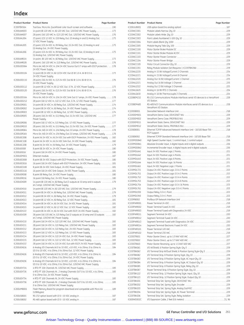
Index
261www.gefanuc.com GE Fanuc Controller and I/O Solutions
IC200TBX564 Tool box, Micro 64, QuickPanel color touch screen and software. . . . . . . . . . . . . . . . . . . . .190
IC200UAA003 14 point (8) 120 VAC In, (6) 120 VAC Out, 120/240 VAC Power Supply . . . . . . . . . . . . . . . . .173
IC200UAA007 28 point; (16) 120 VAC In, (12) 120 VAC Out, 120/240 VAC Power Supply. . . . . . . . . . . . . .176
IC200UAL004 23 point; (13) 12 VDC In, (10) Relay Out, (2) Analog In and (1) Analog Out, . . . . . . . . . . . .17512 VDC Power Supply.
IC200UAL005 23 point; (13) 24 VDC In, (9) Relay Out, (1) 24 VDC Out, (2) Analog In and . . . . . . . . . . . . .175(1) Analog Out, 24 VDC Power Supply.
IC200UAL006 23 point; (13) 24 VDC In, (9) Relay Out, (1) 24 VDC Out, (2) Analog In and . . . . . . . . . . . . .175(1) Analog Out, 120/240 VAC Power Supply.
IC200UAR014 14 point, (8) 120 VAC In, (6) Relay Out, 120/240 VAC Power Supply . . . . . . . . . . . . . . . . . . .173
IC200UAR028 28 point, (16) 120 VAC In, (12) Relay Out, 120/240 VAC Power Supply. . . . . . . . . . . . . . . . .176
IC200UDD064 Micro 64; (40) 24 VDC In, (24) 24 VDC Source Out 0.7 amps with ESCP protection, . . . .17824 VDC Power Supply.
IC200UDD104 14 point (8) 24 VDC In, (6) 12/24 VDC Out (2) @ 1.0 A, (4) @ 0.5 A, . . . . . . . . . . . . . . . . . . . .17324 VDC Power Supply
IC200UDD110 28 point; (16) 24 VDC In, (12) 24 VDC Out (6) @ 1.0 A, (6) @ 0.5 A, . . . . . . . . . . . . . . . . . . . .17624 VDC Power Supply.
IC200UDD112 14 point (8) 12 VDC In, (6) 12 VDC Out, 0.7A, 12 VDC Power Supply . . . . . . . . . . . . . . . . . . .173
IC200UDD120 28 point; (16) 24 VDC In, (12) 24 VDC Out (6) @ 1.0 A, (6) @ 0.5 A, . . . . . . . . . . . . . . . . . . . .17624 VDC Power Supply.
IC200UDD164 Micro 64; (40) 24 VDC In, (24) 24 VDC Sink Out 0.7 amps, 24 VDC Power Supply. . . . . . .178
IC200UDD212 28 point (16) 12 VDC In, (12) 12 VDC Out, 0.7A, 12 VDC Power Supply . . . . . . . . . . . . . . . .177
IC200UDR001 14 point (8) 24 VDC In, (6) Relay Out, 120/240 VAC Power Supply . . . . . . . . . . . . . . . . . . . .174
IC200UDR002 14 point (8) 24 VDC In, (6) Relay Out, 24 VDC Power Supply . . . . . . . . . . . . . . . . . . . . . . . . . .174
IC200UDR003 14 point (8) 12 VDC In, (6) Relay Out, 12 VDC Power Supply . . . . . . . . . . . . . . . . . . . . . . . . . .174
IC200UDR005 28 point; (16) 24 VDC In, (11) Relay Out, (1) 24 VDC Out, 120/240 VAC . . . . . . . . . . . . . . .177Power Supply.
IC200UDR006 28 point (16) 12 VDC In, (12) Relay Out, 12 VDC Power Supply. . . . . . . . . . . . . . . . . . . . . . . .177
IC200UDR010 28 point; (16) 24 VDC In, (11) Relay Out, (1) 24 VDC Out, 24 VDC Power Supply. . . . . . . .177
IC200UDR064 Micro 64; (40) 24 VDC In, (24) Relay Out 2.0 amps, 24 VDC Power Supply. . . . . . . . . . . . .178
IC200UDR164 Micro 64; (40) 24 VDC In, (24) Relay Out 2.0 amps, 120/240 VAC Power Supply. . . . . . . .178
IC200UEC008 8 point (4) 24 VDC In, (4) 24 VDC Out with ESCP Protection, 24 VDC Power Supply . . . .182
IC200UEC108 8 point (4) 24 VDC In, (4) 24 VDC Sink Out, 24 VDC Power Supply . . . . . . . . . . . . . . . . . . . . .182
IC200UEC208 8 point (4) 24 VDC In, (4) Relay Out, 24 VDC Power Supply . . . . . . . . . . . . . . . . . . . . . . . . . . .179
IC200UEI008 8 point (8) 24 VDC In, 24 VDC Power Supply . . . . . . . . . . . . . . . . . . . . . . . . . . . . . . . . . . . . . . . . .180
IC200UEI016 16 point (16) 24 VDC In, 24 VDC Power Supply . . . . . . . . . . . . . . . . . . . . . . . . . . . . . . . . . . . . . .180
IC200UEM001 Ethernet module. . . . . . . . . . . . . . . . . . . . . . . . . . . . . . . . . . . . . . . . . . . . . . . . . . . . . . . . . . . . . . . . . . .187
IC200UEO008 8 point (8) 24 VDC Output with ESCP Protection, 24 VDC Power Supply . . . . . . . . . . . . . . .180
IC200UEO016 16 point (16) 24 VDC Output with ESCP Protection, 24 VDC Power Supply . . . . . . . . . . . .181
IC200UEO108 8 point (8) 24 VDC Sink Output, 24 VDC Power Supply . . . . . . . . . . . . . . . . . . . . . . . . . . . . . . .181
IC200UEO116 16 point (16) 24 VDC Sink Output, 24 VDC Power Supply . . . . . . . . . . . . . . . . . . . . . . . . . . . .181
IC200UER008 8 point (8) Relay Out, 24 VDC Power Supply . . . . . . . . . . . . . . . . . . . . . . . . . . . . . . . . . . . . . . . .180
IC200UER016 16 point (16) Relay Out, 24 VDC Power Supply . . . . . . . . . . . . . . . . . . . . . . . . . . . . . . . . . . . . . .180
IC200UEX009 14 point (8) 120 VAC In, (6) Relay Out (2 outputs at 10 amp and 4 outputs . . . . . . . . . . .179at 2 amp), 120/240 VAC Power Supply
IC200UEX010 14 point (8) 120 VAC In, (6) 120 VAC Out, 120/240 VAC Power Supply . . . . . . . . . . . . . . . . .179
IC200UEX011 14 point (8) 24 VDC In, (6) Relay Out, 120/240 VAC Power Supply . . . . . . . . . . . . . . . . . . . .179
IC200UEX012 14 point (8) 24 VDC In, (6) Relay Out, 24 VDC Power Supply . . . . . . . . . . . . . . . . . . . . . . . . . .179
IC200UEX013 14 point (8) 12 VDC In, (6) Relay Out, 12 VDC Power Supply . . . . . . . . . . . . . . . . . . . . . . . . . .181
IC200UEX014 14 point (8) 24 VDC In, (6) 24 VDC Out, 24 VDC Power Supply . . . . . . . . . . . . . . . . . . . . . . . .181
IC200UEX015 14 point (8) 12 VDC In, (6) 12 VDC Out, 12 VDC Power Supply . . . . . . . . . . . . . . . . . . . . . . . .182
IC200UEX122 14 point (8) 24 VDC In, (6) 24 VDC Out with ESCP, 24 VDC Power Supply . . . . . . . . . . . . . .182
IC200UEX209 28 point (16) 120 VAC In, (12) Relay Out (2 outputs at 10 amp and 10 outputs . . . . . . .182at 2 amp), 120/240 VAC Power Supply
IC200UEX210 28 point (16) 24 VDC In, (12) 120 VAC Out, 120/240 VAC Power Supply . . . . . . . . . . . . . . .182
IC200UEX211 28 point (16) 24 VDC In, (12) Relay Out, 120/240 VAC Power Supply . . . . . . . . . . . . . . . . . .183
IC200UEX212 28 point (16) 24 VDC In, (12) Relay Out, 24 VDC Power Supply . . . . . . . . . . . . . . . . . . . . . . .183
IC200UEX213 28 point (16) 12 VDC In, (12) Relay Out, 12 VDC Power Supply . . . . . . . . . . . . . . . . . . . . . . .183
IC200UEX214 28 point (16) 24 VDC In, (12) 24 VDC Out, 24 VDC Power Supply . . . . . . . . . . . . . . . . . . . . .183
IC200UEX215 28 point (16) 12 VDC In, (12) 12 VDC Out, 12 VDC Power Supply . . . . . . . . . . . . . . . . . . . . .183
IC200UEX222 28 point (16) 24 VDC In, (12) 24 VDC Out with ESCP, 24 VDC Power Supply . . . . . . . . . . . .183
IC200UEX616 6 Analog I/O Channels (4) 0 to 10 VDC, ±10 VDC, 4 to 20ma, 0 to 20ma In, . . . . . . . . . . .184(2) 0 to 10 VDC, 4 to 20ma, 0 to 20ma Out, 12 VDC Power Supply
IC200UEX626 6 Analog I/O Channels (4) 0 to 10 VDC, ±10 VDC, 4 to 20ma, 0 to 20ma In, . . . . . . . . . . .184(2) 0 to 10 VDC, 4 to 20ma, 0 to 20ma Out, 24 VDC Power Supply
IC200UEX636 6 Analog I/O Channels (4) 0 to 10 VDC, ±10 VDC, 4 to 20ma, 0 to 20ma In, . . . . . . . . . . .184(2) 0 to 10 VDC, 4 to 20ma, 0 to 20ma Out, 120/240 VAC Power Supply
IC200UEX724 4 RTD PT 100 Channels IN, 120/240 VAC Power Supply . . . . . . . . . . . . . . . . . . . . . . . . . . . . . .185
IC200UEX726 4 RTD PT 100 Channels IN , 2 Analog Channels OUT 0 to 10 VDC, 4 to 20ma, . . . . . . . .1850 to 20ma Out, 24 VDC Power Supply
IC200UEX734 4 RTD PT 100 Channels IN, 24 VDC Power Supply . . . . . . . . . . . . . . . . . . . . . . . . . . . . . . . . . . .185
IC200UEX736 4 RTD PT 100 Channels IN , 2 Analog Channels OUT 0 to 10 VDC, 4 to 20ma, . . . . . . . .1850 to 20ma Out, 120/240 VAC Power Supply
IC200UMB001 Flash Memory Board for program download and compatible with Micro 64 . . . . . . . . .189(128Kbytes)
IC200USB001 RS-232 option board with (2) 0 -10 VDC analog in . . . . . . . . . . . . . . . . . . . . . . . . . . . . . . . . . . .187
IC200USB002 RS-485 option board with (2) 0 -10 VDC analog in . . . . . . . . . . . . . . . . . . . . . . . . . . . . . . . . . . .187
IC200UUB001 USB option board (no analog option) . . . . . . . . . . . . . . . . . . . . . . . . . . . . . . . . . . . . . . . . . . . . . . .187
IC220ACC001 Module Labels Narrow, Qty 10 . . . . . . . . . . . . . . . . . . . . . . . . . . . . . . . . . . . . . . . . . . . . . . . . . . . . .229
IC220ACC002 Module Labels Wide, Qty 10 . . . . . . . . . . . . . . . . . . . . . . . . . . . . . . . . . . . . . . . . . . . . . . . . . . . . . . .229
IC220ACC003 Point Labels Numbered 1-100 Qty 10 . . . . . . . . . . . . . . . . . . . . . . . . . . . . . . . . . . . . . . . . . . . . . .229
IC220ACC004 Point Labels Blank Qty 1000 . . . . . . . . . . . . . . . . . . . . . . . . . . . . . . . . . . . . . . . . . . . . . . . . . . . . . . .229
IC220ACC005 Module Keying Tabs Qty 100 . . . . . . . . . . . . . . . . . . . . . . . . . . . . . . . . . . . . . . . . . . . . . . . . . . . . . .229
IC220ACC100 Motor Starter Brake Module DC . . . . . . . . . . . . . . . . . . . . . . . . . . . . . . . . . . . . . . . . . . . . . . . . . . . .229
IC220ACC101 Motor Starter Brake Module AC/DC . . . . . . . . . . . . . . . . . . . . . . . . . . . . . . . . . . . . . . . . . . . . . . . . .229
IC220ACC103 Motor Starter Power Connector . . . . . . . . . . . . . . . . . . . . . . . . . . . . . . . . . . . . . . . . . . . . . . . . . . . .229
IC220ACC104 Motor Starter Power Bridge . . . . . . . . . . . . . . . . . . . . . . . . . . . . . . . . . . . . . . . . . . . . . . . . . . . . . . . .229
IC220ACC105 Motor Circuit Connector-Qty 10 . . . . . . . . . . . . . . . . . . . . . . . . . . . . . . . . . . . . . . . . . . . . . . . . . . . .229
IC220ACC201 Relay Module Isolation Set (Requires 1 IC220TBK206) . . . . . . . . . . . . . . . . . . . . . . . . . . . . . . .229
IC220ALG220 Analog In 15 Bit Voltage/Current 2 Channels . . . . . . . . . . . . . . . . . . . . . . . . . . . . . . . . . . . . . . .224
IC220ALG221 Analog In 15 Bit Voltage/Current 8 Channel . . . . . . . . . . . . . . . . . . . . . . . . . . . . . . . . . . . . . . . .224
IC220ALG320 Analog Out 16 Bit Voltage/Current 1 Channel . . . . . . . . . . . . . . . . . . . . . . . . . . . . . . . . . . . . . . .225
IC220ALG321 Analog Out 16 Bit Voltage 1 Channel . . . . . . . . . . . . . . . . . . . . . . . . . . . . . . . . . . . . . . . . . . . . . . .225
IC220ALG322 Analog Out 13 Bit Voltage 2 Channels . . . . . . . . . . . . . . . . . . . . . . . . . . . . . . . . . . . . . . . . . . . . . .225
IC220ALG620 Analog In 16 Bit RTD 2 Channels . . . . . . . . . . . . . . . . . . . . . . . . . . . . . . . . . . . . . . . . . . . . . . . . . . .224
IC220ALG630 Analog In 16 Bit Thermocouple 2 Channels . . . . . . . . . . . . . . . . . . . . . . . . . . . . . . . . . . . . . . . . .224
IC220BEM232 RS-232 Communications Module interfaces serial I/O devices to a VersaPoint . . . . . . .228I/O Station.
IC220BEM485 RS-485/422 Communications Module interfaces serial I/O devices to a . . . . . . . . . . . . .228VersaPoint I/O Station.
IC220DBI001 DeviceNet Network Interface Unit . . . . . . . . . . . . . . . . . . . . . . . . . . . . . . . . . . . . . . . . . . . . . . . . . .218
IC220DEM001 VersaPoint Demo Case, DEVICENET NIU . . . . . . . . . . . . . . . . . . . . . . . . . . . . . . . . . . . . . . . . . . . .229
IC220DEM002 VersaPoint Demo Case, PROFIBUS NIU . . . . . . . . . . . . . . . . . . . . . . . . . . . . . . . . . . . . . . . . . . . . .229
IC220DEM011 VersaPoint Static Demo, DEVICENET NIU . . . . . . . . . . . . . . . . . . . . . . . . . . . . . . . . . . . . . . . . . . .229
IC220DEM012 VersaPoint Static Demo, PROFIBUS NIU . . . . . . . . . . . . . . . . . . . . . . . . . . . . . . . . . . . . . . . . . . . . .229
IC220EBI001 Ethernet TCP/IP Advanced Network Interface Unit - 10/100 Base-T(X) - . . . . . . . . . . . . . .218PCP Support
IC220EBI002 Ethernet TCP/IP Standard Network Interface Unit - 10/100 Base-T(X) . . . . . . . . . . . . . . . .218
IC220MDD840 High Speed Counter input, 1 control input, 1 control output . . . . . . . . . . . . . . . . . . . . . . . . .226
IC220MDD841 Absolute Encoder input, 4 digital inputs and 4 digital outputs . . . . . . . . . . . . . . . . . . . . . . .226
IC220MDD842 Incremental Encoder input, 4 digital inputs and 4 digital outputs . . . . . . . . . . . . . . . . . . . .226
IC220MDL641 Input 24 VDC Positive Logic 2 Points . . . . . . . . . . . . . . . . . . . . . . . . . . . . . . . . . . . . . . . . . . . . . . . .221
IC220MDL642 Input 24 VDC Positive Logic 4 Points . . . . . . . . . . . . . . . . . . . . . . . . . . . . . . . . . . . . . . . . . . . . . . . .221
IC220MDL643 Input 24 VDC Positive Logic 8 Points . . . . . . . . . . . . . . . . . . . . . . . . . . . . . . . . . . . . . . . . . . . . . . . .221
IC220MDL644 Input 24 VDC Positive Logic 16 Points . . . . . . . . . . . . . . . . . . . . . . . . . . . . . . . . . . . . . . . . . . . . . .221
IC220MDL661 Input 24 VDC Negative Logic 2 Points . . . . . . . . . . . . . . . . . . . . . . . . . . . . . . . . . . . . . . . . . . . . . .221
IC220MDL721 Output 24 VDC Positive Logic 2.0 A 2 Points . . . . . . . . . . . . . . . . . . . . . . . . . . . . . . . . . . . . . . . .222
IC220MDL751 Output 24 VDC Positive Logic 0.5 A 2 Points . . . . . . . . . . . . . . . . . . . . . . . . . . . . . . . . . . . . . . . .222
IC220MDL752 Output 24 VDC Positive Logic 0.5 A 4 Points . . . . . . . . . . . . . . . . . . . . . . . . . . . . . . . . . . . . . . . .222
IC220MDL753 Output 24 VDC Positive Logic 0.5 A 8 Points . . . . . . . . . . . . . . . . . . . . . . . . . . . . . . . . . . . . . . . .222
IC220MDL754 Output 24 VDC Positive Logic 0.5 A 16 Points . . . . . . . . . . . . . . . . . . . . . . . . . . . . . . . . . . . . . . .223
IC220MDL761 Output 24 VDC Negative Logic 0.5 A 2 Points . . . . . . . . . . . . . . . . . . . . . . . . . . . . . . . . . . . . . . .223
IC220MDL930 Output Relay 3.0 A 1 Point . . . . . . . . . . . . . . . . . . . . . . . . . . . . . . . . . . . . . . . . . . . . . . . . . . . . . . . . .223
IC220MDL940 Output Relay 3.0 A 1 Point . . . . . . . . . . . . . . . . . . . . . . . . . . . . . . . . . . . . . . . . . . . . . . . . . . . . . . . . .223
IC220PBI002 Profibus-DP Network Interface Unit . . . . . . . . . . . . . . . . . . . . . . . . . . . . . . . . . . . . . . . . . . . . . . . .218
IC220PWR001 Power Terminal 24 VDC . . . . . . . . . . . . . . . . . . . . . . . . . . . . . . . . . . . . . . . . . . . . . . . . . . . . . . . . . . . .219
IC220PWR002 Power Terminal Fused 24 VDC . . . . . . . . . . . . . . . . . . . . . . . . . . . . . . . . . . . . . . . . . . . . . . . . . . . . .219
IC220PWR003 Power Terminal Fused with Diagnostics 24 VDC . . . . . . . . . . . . . . . . . . . . . . . . . . . . . . . . . . . .219
IC220PWR011 Segment Terminal 24 VDC . . . . . . . . . . . . . . . . . . . . . . . . . . . . . . . . . . . . . . . . . . . . . . . . . . . . . . . . .220
IC220PWR012 Segment Terminal Fused 24 VDC . . . . . . . . . . . . . . . . . . . . . . . . . . . . . . . . . . . . . . . . . . . . . . . . . . .220
IC220PWR013 Segment Terminal Fused with Diagnostics 24 VDC . . . . . . . . . . . . . . . . . . . . . . . . . . . . . . . . . .220
IC220PWR014 Segment Terminal Electronic Fused 24 VDC . . . . . . . . . . . . . . . . . . . . . . . . . . . . . . . . . . . . . . . .220
IC220PWR101 Power Terminal 120 VAC . . . . . . . . . . . . . . . . . . . . . . . . . . . . . . . . . . . . . . . . . . . . . . . . . . . . . . . . . . .219
IC220PWR102 Power Terminal 230 VAC . . . . . . . . . . . . . . . . . . . . . . . . . . . . . . . . . . . . . . . . . . . . . . . . . . . . . . . . . . .219
IC220STR001 Motor Starter Direct, up to 1.5 kW/ 400 VAC . . . . . . . . . . . . . . . . . . . . . . . . . . . . . . . . . . . . . . . .227
IC220STR002 Motor Starter Direct, up to 3.7 kW/ 400 VAC . . . . . . . . . . . . . . . . . . . . . . . . . . . . . . . . . . . . . . . .227
IC220STR003 Motor Starter Reversing, up to 1.5 kW/ 400 VAC . . . . . . . . . . . . . . . . . . . . . . . . . . . . . . . . . . . .227
IC220TBK061 I/O W/Shield, 6 Position Spring Style, Qty 5 . . . . . . . . . . . . . . . . . . . . . . . . . . . . . . . . . . . . . . . . .229
IC220TBK062 I/O Terminal Strip W/Dual Shield, 6 Position Spring Style-Qty 5 . . . . . . . . . . . . . . . . . . . . . .229
IC220TBK082 I/O Terminal Strip, 8 Position Spring Style, Qty 10 . . . . . . . . . . . . . . . . . . . . . . . . . . . . . . . . . . .229
IC220TBK083 I/O Terminal Strip, 8 Position Spring Style, AC Input-Qty 10 . . . . . . . . . . . . . . . . . . . . . . . . . .229
IC220TBK084 I/O Terminal Strip, 8 Position Spring Style, AC Output-Qty 10 . . . . . . . . . . . . . . . . . . . . . . . .229
IC220TBK085 I/O Terminal Strip, 8 Position Spring Style, Relay Qty 10 . . . . . . . . . . . . . . . . . . . . . . . . . . . . .229
IC220TBK087 Power Terminal Strip, 8 Position Spring Style, Qty 10 . . . . . . . . . . . . . . . . . . . . . . . . . . . . . . . .229
IC220TBK122 I/O Terminal Strip, 12 Position Spring Style, Input, Qty 10 . . . . . . . . . . . . . . . . . . . . . . . . . . . .229
IC220TBK123 I/O Terminal Strip, 12 Position Spring Style, Output Qty 10 . . . . . . . . . . . . . . . . . . . . . . . . . . .229
IC220TBK201 Terminal Strip Set, Spring Style, DEVICENET NIU . . . . . . . . . . . . . . . . . . . . . . . . . . . . . . . . . . . .229
IC220TBK202 Terminal Strip Set, Spring Style, Encoder . . . . . . . . . . . . . . . . . . . . . . . . . . . . . . . . . . . . . . . . . . .229
IC220TBK203 Terminal Strip Set, Spring Style, Analog Out/HSC . . . . . . . . . . . . . . . . . . . . . . . . . . . . . . . . . . . .229
IC220TBK204 Terminal Strip Set, Spring Style, AC Power Terminal . . . . . . . . . . . . . . . . . . . . . . . . . . . . . . . . .229
IC220TBK206 Terminal Strip Set, Spring Style, Relay Isolation . . . . . . . . . . . . . . . . . . . . . . . . . . . . . . . . . . . . .229
IC600WD002C I/O Expansion Cable, 2 feet (0.6 meters) . . . . . . . . . . . . . . . . . . . . . . . . . . . . . . . . . . . . . . . . . .31, 96
Product Number Product Name Page Number Product Number Product Name Page Number
Artisan Technology Group - Quality Instrumentation ... Guaranteed | (888) 88-SOURCE | www.artisantg.com
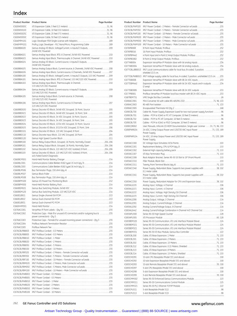
Index
262 www.gefanuc.comGE Fanuc Controller and I/O Solutions
IC600WD005C I/O Expansion Cable, 5 feet (1.5 meters) . . . . . . . . . . . . . . . . . . . . . . . . . . . . . . . . . . . . . . . . . .31, 96
IC600WD010C I/O Expansion Cable, 10 feet (3.0 meters) . . . . . . . . . . . . . . . . . . . . . . . . . . . . . . . . . . . . . . . . .31, 96
IC600WD025C I/O Expansion Cable, 25 feet (7.5 meters) . . . . . . . . . . . . . . . . . . . . . . . . . . . . . . . . . . . . . . . . .31, 96
IC600WD050C I/O Expansion Cable, 50 feet (15 meters) . . . . . . . . . . . . . . . . . . . . . . . . . . . . . . . . . . . . . . . . .31, 96
IC646MPH101 Logic Developer PDA Single License with Adapters . . . . . . . . . . . . . . . . . . . . . . . . . . . . . . . . . .189
IC646MPM101 Proficy Logic Developer - PLC Nano/Micro, Programming Cable . . . . . . . . . . . . . . . . . . . . .189
IC660BBA020 Genius Analog I/O Block, Voltage/Current, 4 Inputs/2 Outputs, . . . . . . . . . . . . . . . . . . . . . .20924/48 VDC Powered
IC660BBA021 Genius Analog Input Block, RTD, 6 Channel, 24/48 VDC Powered . . . . . . . . . . . . . . . . . . . .210
IC660BBA023 Genius Analog Input Block, Thermocouple, 6 Channel, 24/48 VDC Powered . . . . . . . . . .210
IC660BBA024 Genius Analog I/O Block, Current-source, 4 Inputs/2 Outputs, . . . . . . . . . . . . . . . . . . . . . . .20924/48 VDC Powered
IC660BBA025 Genius Analog Output Block, Current-source, 6 Channels, 24/48 VDC Powered . . . . . . .208
IC660BBA026 Genius Analog Input Block, Current-source, 6 Channels, 24/48 VDC Powered . . . . . . . .207
IC660BBA100 Genius Analog I/O Block, Voltage/Current, 4 Inputs/2 Outputs, 115 VAC Powered . . . .209
IC660BBA101 Genius Analog Input Block, RTD, 6 Channel, 115 VAC/125 VDC Powered . . . . . . . . . . . . . .210
IC660BBA103 Genius Analog Input Block, Thermocouple, 6 Channel, . . . . . . . . . . . . . . . . . . . . . . . . . . . . . .210115 VAC/125 VDC Powered
IC660BBA104 Genius Analog I/O Block, Current-source, 4 Inputs/2 Outputs, . . . . . . . . . . . . . . . . . . . . . . .209115 VAC/125 VDC Powered
IC660BBA105 Genius Analog Output Block, Current-source, 6 Channels, . . . . . . . . . . . . . . . . . . . . . . . . . .208115 VAC/125 VDC Powered
IC660BBA106 Genius Analog Input Block, Current-source, 6 Channels, . . . . . . . . . . . . . . . . . . . . . . . . . . . .207115 VAC/125 VDC Powered
IC660BBD020 Genius Discrete I/O Block, 24/48 VDC Grouped, 16 Point, Source . . . . . . . . . . . . . . . . . . . .205
IC660BBD021 Genius Discrete I/O Block, 24/48 VDC Grouped, 16 Point, Sink . . . . . . . . . . . . . . . . . . . . . . .205
IC660BBD022 Genius Discrete I/O Block, 24 VDC Grouped, 16 Point, Source . . . . . . . . . . . . . . . . . . . . . . . .205
IC660BBD023 Genius Discrete I/O Block, 24 VDC Grouped, 16 Point, Sink . . . . . . . . . . . . . . . . . . . . . . . . . .205
IC660BBD024 Genius Discrete I/O Block, 12/24 VDC Grouped, 32 Point, Source . . . . . . . . . . . . . . . . . . . .205
IC660BBD025 Genius Discrete I/O Block, 5/12/24 VDC Grouped, 32 Point, Sink . . . . . . . . . . . . . . . . . . . . .206
IC660BBD101 Genius Discrete I/O Block, 115 VAC Grouped, 8 Point . . . . . . . . . . . . . . . . . . . . . . . . . . . . . . . .204
IC660BBD110 Genius Discrete Input Block, 115 VAC Grouped, 16 Point . . . . . . . . . . . . . . . . . . . . . . . . . . . .204
IC660BBD120 Genius High Speed Counter Block . . . . . . . . . . . . . . . . . . . . . . . . . . . . . . . . . . . . . . . . . . . . . . . . . .211
IC660BBR100 Genius Relay Output Block, Grouped, 16 Points, Normally Closed . . . . . . . . . . . . . . .204, 206
IC660BBR101 Genius Relay Output Block, Grouped, 16 Points, Normally Open . . . . . . . . . . . . . . . .204, 206
IC660BBS102 Genius Discrete I/O Block, 115 VAC/125 VDC Isolated, 8 Point . . . . . . . . . . . . . . . . . . .204, 206
IC660BBS103 Genius Discrete I/O Block, 115 VAC/125 VDC Isolated, 8 Point, . . . . . . . . . . . . . . . . .204, 206w/o Failed Switch Diagnostic
IC660BCM501 Hand-Held Monitor Battery Charger . . . . . . . . . . . . . . . . . . . . . . . . . . . . . . . . . . . . . . . . . . . . . . . .214
IC660BLC001 Communications Cable (Belden 9182 type) 15 inch (qty 3) . . . . . . . . . . . . . . . . . . . . . . . . . . .214
IC660BLC003 Communications Cable (Belden 9182 type) 36 inch (qty 1) . . . . . . . . . . . . . . . . . . . . . . . . . . .214
IC660BLM506 Bus Terminator Plugs, 150 ohm (qty 4) . . . . . . . . . . . . . . . . . . . . . . . . . . . . . . . . . . . . . . . . . . . . .214
IC660BLM507 Genius Block Puller . . . . . . . . . . . . . . . . . . . . . . . . . . . . . . . . . . . . . . . . . . . . . . . . . . . . . . . . . . . . . . . .214
IC660BLM508 Bus Terminator Plugs, 150 ohm (qty 4) . . . . . . . . . . . . . . . . . . . . . . . . . . . . . . . . . . . . . . . . . . . . .214
IC660BPM100 Genius I/O PowerTrac Monitoring Block . . . . . . . . . . . . . . . . . . . . . . . . . . . . . . . . . . . . . . . . . . . .212
IC660BPM500 Hand-Held Monitor Battery Pack . . . . . . . . . . . . . . . . . . . . . . . . . . . . . . . . . . . . . . . . . . . . . . . . . . .214
IC660BSM021 Genius Bus Switching Module, 24/48 VDC . . . . . . . . . . . . . . . . . . . . . . . . . . . . . . . . . . . . . . . . . .214
IC660BSM120 Genius Bus Switching Module, 115 VAC/125 VDC . . . . . . . . . . . . . . . . . . . . . . . . . . . . . . . . . . .214
IC660ELB921 Genius Single-channel ISA PCIM . . . . . . . . . . . . . . . . . . . . . . . . . . . . . . . . . . . . . . . . . . . . . . . . . . . .213
IC660ELB922 Genius Dual-channel ISA PCIM . . . . . . . . . . . . . . . . . . . . . . . . . . . . . . . . . . . . . . . . . . . . . . . . . . . . .213
IC660ELB931 Genius Dual-channel PCI PCIM . . . . . . . . . . . . . . . . . . . . . . . . . . . . . . . . . . . . . . . . . . . . . . . . . . . . .213
IC660HHM501 Hand-Held Monitor . . . . . . . . . . . . . . . . . . . . . . . . . . . . . . . . . . . . . . . . . . . . . . . . . . . . . . . . . . . . . . . .214
IC676ACC001 VersaMax IP Point Labels - Qty 50 . . . . . . . . . . . . . . . . . . . . . . . . . . . . . . . . . . . . . . . . . . . . . . . . . .235
IC676ACC002 Protective Caps - Male (For unused I/O connectors and/or outgoing bus & . . . . . . . . . .235power connectors) - Qty 5
IC676ACC003 Protective Caps - Female (For unused incoming power connectors) - Qty 5 . . . . . . . . . .235
IC676ACC004 Profibus Network Termination Resistor . . . . . . . . . . . . . . . . . . . . . . . . . . . . . . . . . . . . . . . . . . . . .235
IC676ACC005 Profibus Network Tee . . . . . . . . . . . . . . . . . . . . . . . . . . . . . . . . . . . . . . . . . . . . . . . . . . . . . . . . . . . . . .235
IC676CBLPBB003 IP67 Profibus Cordset - 0.3 Meters . . . . . . . . . . . . . . . . . . . . . . . . . . . . . . . . . . . . . . . . . . . . . . . . .235
IC676CBLPBB005 IP67 Profibus Cordset - 0.5 Meters . . . . . . . . . . . . . . . . . . . . . . . . . . . . . . . . . . . . . . . . . . . . . . . . .235
IC676CBLPBB010 IP67 Profibus Cordset - 1 Meter . . . . . . . . . . . . . . . . . . . . . . . . . . . . . . . . . . . . . . . . . . . . . . . . . . . .235
IC676CBLPBB020 IP67 Profibus Cordset - 2 Meters . . . . . . . . . . . . . . . . . . . . . . . . . . . . . . . . . . . . . . . . . . . . . . . . . . .235
IC676CBLPBB050 IP67 Profibus Cordset - 5 Meters . . . . . . . . . . . . . . . . . . . . . . . . . . . . . . . . . . . . . . . . . . . . . . . . . . .235
IC676CBLPBB100 IP67 Profibus Cordset - 10 Meters . . . . . . . . . . . . . . . . . . . . . . . . . . . . . . . . . . . . . . . . . . . . . . . . . .235
IC676CBLPBF020 IP67 Profibus Cordset - 2 Meters - Female Connector w/Leads . . . . . . . . . . . . . . . . . . . . . .235
IC676CBLPBF050 IP67 Profibus Cordset - 5 Meters - Female Connector w/Leads . . . . . . . . . . . . . . . . . . . . . .235
IC676CBLPBF100 IP67 Profibus Cordset - 10 Meters - Female Connector w/Leads . . . . . . . . . . . . . . . . . . . . .235
IC676CBLPBM020 IP67 Profibus Cordset - 2 Meters, Male Connector w/Leads . . . . . . . . . . . . . . . . . . . . . . . . . .235
IC676CBLPBM050 IP67 Profibus Cordset - 5 Meters, Male Connector w/Leads . . . . . . . . . . . . . . . . . . . . . . . . . .235
IC676CBLPBM100 IP67 Profibus Cordset - 10 Meters - Male Connector w/Leads . . . . . . . . . . . . . . . . . . . . . . .235
IC676CBLPWB003 IP67 Power Cordset - 0.3 Meters . . . . . . . . . . . . . . . . . . . . . . . . . . . . . . . . . . . . . . . . . . . . . . . . . . .235
IC676CBLPWB005 IP67 Power Cordset - 0.5 Meters . . . . . . . . . . . . . . . . . . . . . . . . . . . . . . . . . . . . . . . . . . . . . . . . . . .235
IC676CBLPWB010 IP67 Power Cordset - 1 Meter . . . . . . . . . . . . . . . . . . . . . . . . . . . . . . . . . . . . . . . . . . . . . . . . . . . . . .235
IC676CBLPWB020 IP67 Power Cordset - 2 Meters . . . . . . . . . . . . . . . . . . . . . . . . . . . . . . . . . . . . . . . . . . . . . . . . . . . . .235
IC676CBLPWB050 IP67 Power Cordset - 5 Meters . . . . . . . . . . . . . . . . . . . . . . . . . . . . . . . . . . . . . . . . . . . . . . . . . . . . .235
IC676CBLPWB100 IP67 Power Cordset - 10 Meters . . . . . . . . . . . . . . . . . . . . . . . . . . . . . . . . . . . . . . . . . . . . . . . . . . . .235
IC676CBLPWF020 IP67 Power Cordset - 2 Meters - Female Connector w/Leads . . . . . . . . . . . . . . . . . . . . . . . .235
IC676CBLPWF050 IP67 Power Cordset - 5 Meters - Female Connector w/Leads . . . . . . . . . . . . . . . . . . . . . . . .235
IC676CBLPWF100 IP67 Power Cordset - 10 Meters - Female Connector w/Leads . . . . . . . . . . . . . . . . . . . . . . .235
IC676CBLPWM020 IP67 Power Cordset - 2 Meters - Male Connector w/Leads . . . . . . . . . . . . . . . . . . . . . . . . . . .235
IC676CBLPWM050 IP67 Power Cordset - 5 Meters - Male Connector w/Leads . . . . . . . . . . . . . . . . . . . . . . . . . . .235
IC676CBLPWM100 IP67 Power Cordset - 10 Meters - Male Connector w/Leads . . . . . . . . . . . . . . . . . . . . . . . . .235
IC676PBI008 8 Point Input Module, Profibus . . . . . . . . . . . . . . . . . . . . . . . . . . . . . . . . . . . . . . . . . . . . . . . . . . . . .232
IC676PBI016 16 Point Input Module, Profibus . . . . . . . . . . . . . . . . . . . . . . . . . . . . . . . . . . . . . . . . . . . . . . . . . . . .232
IC676PBM442 4 Point Input and 4 Point (2 Amp) Output Module, Profibus . . . . . . . . . . . . . . . . . . . . . . . . . .232
IC676PBO082 8 Point (2 Amp) Output Module, Profibus . . . . . . . . . . . . . . . . . . . . . . . . . . . . . . . . . . . . . . . . . . . .232
IC677ABI004 Expansion VersaMax IP Modular slave with (4) analog inputs . . . . . . . . . . . . . . . . . . . . . . . .234
IC677ABO004 Expansion VersaMax IP Modular slave with (4) analog outputs . . . . . . . . . . . . . . . . . . . . . . .234
IC677CBLLBB0013 IP67 Local communications cable for local bus; B-coded, 5 position, . . . . . . . . . . . . . . . .235shielded 13.5 cm.
IC677CBLPWB0013 IP67 Voltage supply cable for local bus; A-coded, 5 position, unshielded 13.5 cm. . . . .235
IC677DBI008 Expansion VersaMax IP Modular slave with (8) 24 VDC inputs . . . . . . . . . . . . . . . . . . . . . . . .233
IC677DBM442 Expansion VersaMax IP Modular slave with (4) 24 VDC inputs and 4 outputs . . . . . . . . .234(2 amp)
IC677DBO085 Expansion VersaMax IP Modular slave with (8) 24 VDC outputs . . . . . . . . . . . . . . . . . . . . . .233
IC677PBI001 Profibus VersaMax IP Modular local bus master with (8) 24 VDC inputs . . . . . . . . . . . . . .233
IC687BEM731 VME Single Slot Bus Controller . . . . . . . . . . . . . . . . . . . . . . . . . . . . . . . . . . . . . . . . . . . . . . . . . . . . . . .26
IC690ACC901 Mini-Converter Kit with cable (RS-485/RS-232) . . . . . . . . . . . . . . . . . . . . . . . . . . . . . . .71, 96, 133
IC690ACC903 RS-485 Port Isolator . . . . . . . . . . . . . . . . . . . . . . . . . . . . . . . . . . . . . . . . . . . . . . . . . . . . . . . . . . . .71, 133
IC690ACC905 Encapsulated Thermistor Kit Qty 2 . . . . . . . . . . . . . . . . . . . . . . . . . . . . . . . . . . . . . . . . . . . . . . . . .168
IC690CBL700 Cable Kit, Power Supply Expansion (used for two-rack power supply function) . . . . . . . .96
IC690CBL701 Cables - PCM to IC640 or PC-XT Computer, 10 feet (3 meters) . . . . . . . . . . . . . . . . . . . . . . . . .96
IC690CBL702 Cables - PCM to PC-AT Computer, 10 feet (3 meters) . . . . . . . . . . . . . . . . . . . . . . . . . . . . . . . . . .96
IC690CBL705 Cables - PCM to IC642 or PS/2 Computer, 10 feet (3 meters) . . . . . . . . . . . . . . . . . . . . . . . . . .96
IC690CDR002 User Manuals, InfoLink CD-ROM Documentation, Single-user License . . . . .31, 71, 96, 133
IC690PWR024 24 VDC, 5 Amp Output Power and 120/230 VAC Input Power . . . . . . . . . . . . . . .71, 133, 189Power Supply
IC690PWR124 24 VDC, 10 Amp Output Power and 120/230 VAC Input Power . . . . . . . . . . . . . .71, 133, 189Power Supply
IC693ACC300 DC Voltage Input Simulator, 8/16 Points . . . . . . . . . . . . . . . . . . . . . . . . . . . . . . . . . . . . . . . . . . . .103
IC693ACC301 Replacement Battery, CPU & PCM (qty 2) . . . . . . . . . . . . . . . . . . . . . . . . . . . . . . . . . . . . . . . . . . .133
IC693ACC302 External High capacity battery pack. . . . . . . . . . . . . . . . . . . . . . . . . . . . . . . . . . . . . . . . . . . .71, 133
IC693ACC307 I/O Bus Terminator Plug . . . . . . . . . . . . . . . . . . . . . . . . . . . . . . . . . . . . . . . . . . . . . . . . . . . . . . . .71, 133
IC693ACC308 Rack Adaptor Bracket, Series 90-30 10 Slot to 19" (Front Mount) . . . . . . . . . . . . . . . . . . . . .133
IC693ACC310 Filler Module, Blank Slot . . . . . . . . . . . . . . . . . . . . . . . . . . . . . . . . . . . . . . . . . . . . . . . . . . . . . . . . . . . .133
IC693ACC311 Twenty Point Terminal Blocks (qty 6) . . . . . . . . . . . . . . . . . . . . . . . . . . . . . . . . . . . . . . . . . . . .71, 133
IC693ACC340 Power Supply, Redundant Base. Supports two power supplies with . . . . . . . . . . . . . .38, 1020.1 meter cable
IC693ACC341 Power Supply, Redundant Base. Supports two power supplies with . . . . . . . . . . . . . .38, 1020.5 meter cable
IC693ACC350 Power Supply, Redundant Adapter for CPU and Expansion base. . . . . . . . . . . . . . . . . .38, 102
IC693ALG220 Analog Input, Voltage, 4 Channel . . . . . . . . . . . . . . . . . . . . . . . . . . . . . . . . . . . . . . . . . . . . . . . . . .106
IC693ALG221 Analog Input, Current, 4 Channel . . . . . . . . . . . . . . . . . . . . . . . . . . . . . . . . . . . . . . . . . . . . . . . . . .106
IC693ALG222 Analog Input, Voltage, High Density (16 Channel) . . . . . . . . . . . . . . . . . . . . . . . . . . . . . . . . . . .106
IC693ALG223 Analog Input, Current, High Density (16 Channel) . . . . . . . . . . . . . . . . . . . . . . . . . . . . . . . . . . .106
IC693ALG390 Analog Output, Voltage, 2 Channel . . . . . . . . . . . . . . . . . . . . . . . . . . . . . . . . . . . . . . . . . . . . . . . . .114
IC693ALG391 Analog Output, Current/Voltage, 2 Channel . . . . . . . . . . . . . . . . . . . . . . . . . . . . . . . . . . . . . . . . .114
IC693ALG392 Analog Current/Voltage Output, 8 Channel . . . . . . . . . . . . . . . . . . . . . . . . . . . . . . . . . . . . . . . . .114
IC693ALG442 Analog Current/Voltage Combination 4 Channel In/2 Channel Out . . . . . . . . . . . . . . . . . . .114
IC693APU300 Series 90-30 High Speed Counter . . . . . . . . . . . . . . . . . . . . . . . . . . . . . . . . . . . . . . . . . . . . . . . . . .128
IC693APU305 I/O Processor Module . . . . . . . . . . . . . . . . . . . . . . . . . . . . . . . . . . . . . . . . . . . . . . . . . . . . . . . . . .65, 128
IC693BEM320 Series 90-30 Communication, I/O Link Interface Module (Slave) . . . . . . . . . . . . . . . . . . . . . .124
IC693BEM321 Series 90-30 Communication, I/O Link Interface Module (Master) . . . . . . . . . . . . . . . . . . . .124
IC693BEM321 Series 90-30 Communication, I/O Link Interface Module (Master) . . . . . . . . . . . . . . . . . . . .124
IC693BEM331 Series 90-30 I/O Bus Module, Genius Bus Controller . . . . . . . . . . . . . . . . . . . . . . . . . . . . . . . . .122
IC693CBL300 Cable, I/O Base Expansion, 1 Meter . . . . . . . . . . . . . . . . . . . . . . . . . . . . . . . . . . . . . . . . . . . . .71, 133
IC693CBL301 Cable, I/O Base Expansion, 2 Meters . . . . . . . . . . . . . . . . . . . . . . . . . . . . . . . . . . . . . . . . . . . .71, 133
IC693CBL302 Cable, I/O Base Expansion, 15 Meters . . . . . . . . . . . . . . . . . . . . . . . . . . . . . . . . . . . . . . . . . . .71, 133
IC693CBL312 Cable, I/O Base Expansion, 0.15 Meters, Shielded . . . . . . . . . . . . . . . . . . . . . . . . . . . . . . . .71, 133
IC693CBL313 Cable, I/O Base Expansion, 8 Meters . . . . . . . . . . . . . . . . . . . . . . . . . . . . . . . . . . . . . . . . . . . .71, 133
IC693CBL314 Cable, I/O Base Expansion, 15 Meters, Shielded . . . . . . . . . . . . . . . . . . . . . . . . . . . . . . . . .71, 133
IC693CHS391 10-slot CPU Baseplate (Model 331 and above) . . . . . . . . . . . . . . . . . . . . . . . . . . . . . . . . . . . . . .100
IC693CHS392 10-slot Expansion Baseplate (Model 331 and above) . . . . . . . . . . . . . . . . . . . . . . . . . . . . . . . .100
IC693CHS393 10-slot Remote Baseplate (Model 331 and above) . . . . . . . . . . . . . . . . . . . . . . . . . . . . . . .35, 100
IC693CHS397 5-slot CPU Baseplate (Model 331 and above) . . . . . . . . . . . . . . . . . . . . . . . . . . . . . . . . . . . . . . .100
IC693CHS398 5-slot Expansion Baseplate (Model 331 and above) . . . . . . . . . . . . . . . . . . . . . . . . . . . . . . . . .100
IC693CHS399 5-slot Remote Baseplate (Model 331 and above) . . . . . . . . . . . . . . . . . . . . . . . . . . . . . . . .35, 100
IC693CMM302 Series 90-30 Enhanced Genius Communications Module . . . . . . . . . . . . . . . . . . . . . . . . . . . .123
IC693CMM311 Series 90-30 Communications Control Module . . . . . . . . . . . . . . . . . . . . . . . . . . . . . . . . . . . . . .125
IC693CMM321 Series 90-30 PLC Ethernet TCP/IP Module . . . . . . . . . . . . . . . . . . . . . . . . . . . . . . . . . . . . . . . . . . .122
IC693CPU311 5-slot Baseplate (Model 311) . . . . . . . . . . . . . . . . . . . . . . . . . . . . . . . . . . . . . . . . . . . . . . . . . . . . . . . .98
IC693CPU313 5-slot Baseplate (Model 313) . . . . . . . . . . . . . . . . . . . . . . . . . . . . . . . . . . . . . . . . . . . . . . . . . . . . . . . .98
Product Number Product Name Page Number Product Number Product Name Page Number
Artisan Technology Group - Quality Instrumentation ... Guaranteed | (888) 88-SOURCE | www.artisantg.com
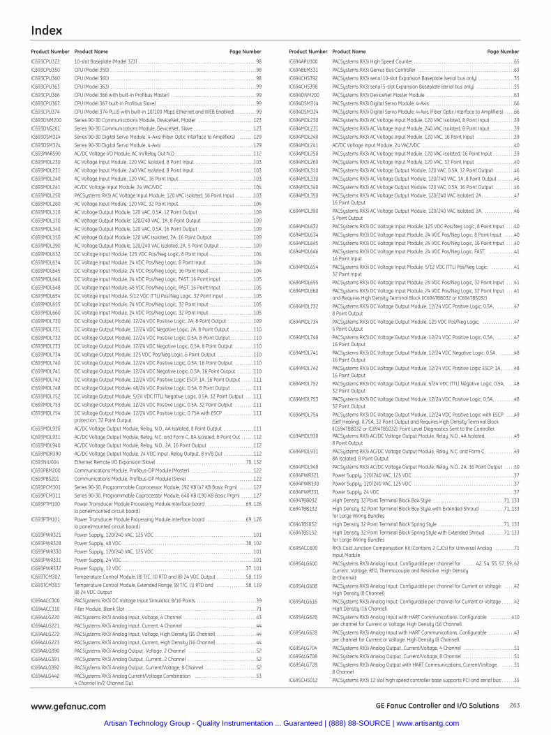
Index
263www.gefanuc.com GE Fanuc Controller and I/O Solutions
IC693CPU323 10-slot Baseplate (Model 323) . . . . . . . . . . . . . . . . . . . . . . . . . . . . . . . . . . . . . . . . . . . . . . . . . . . . . . .98
IC693CPU350 CPU (Model 350) . . . . . . . . . . . . . . . . . . . . . . . . . . . . . . . . . . . . . . . . . . . . . . . . . . . . . . . . . . . . . . . . . . . .98
IC693CPU360 CPU (Model 360) . . . . . . . . . . . . . . . . . . . . . . . . . . . . . . . . . . . . . . . . . . . . . . . . . . . . . . . . . . . . . . . . . . . .98
IC693CPU363 CPU (Model 363) . . . . . . . . . . . . . . . . . . . . . . . . . . . . . . . . . . . . . . . . . . . . . . . . . . . . . . . . . . . . . . . . . . . .99
IC693CPU366 CPU (Model 366 with built-in Profibus Master) . . . . . . . . . . . . . . . . . . . . . . . . . . . . . . . . . . . . . . . .99
IC693CPU367 CPU (Model 367 built-in Profibus Slave) . . . . . . . . . . . . . . . . . . . . . . . . . . . . . . . . . . . . . . . . . . . . . .99
IC693CPU374 CPU (Model 374 PLUS with built-in 10/100 Mbps Ethernet and WEB Enabled) . . . . . . . . . .99
IC693DNM200 Series 90-30 Communications Module, DeviceNet, Master . . . . . . . . . . . . . . . . . . . . . . . . . .123
IC693DNS201 Series 90-30 Communications Module, DeviceNet, Slave . . . . . . . . . . . . . . . . . . . . . . . . . . . .123
IC693DSM314 Series 90-30 Digital Servo Module, 4-Axis (Fiber Optic Interface to Amplifiers) . . . . . . . .129
IC693DSM324 Series 90-30 Digital Servo Module, 4-Axis . . . . . . . . . . . . . . . . . . . . . . . . . . . . . . . . . . . . . . . . . . .129
IC693MAR590 AC/DC Voltage I/O Module, AC In/Relay Out N.O. . . . . . . . . . . . . . . . . . . . . . . . . . . . . . . . . . . . .112
IC693MDL230 AC Voltage Input Module, 120 VAC Isolated, 8 Point Input . . . . . . . . . . . . . . . . . . . . . . . . . . .103
IC693MDL231 AC Voltage Input Module, 240 VAC Isolated, 8 Point Input . . . . . . . . . . . . . . . . . . . . . . . . . . .103
IC693MDL240 AC Voltage Input Module, 120 VAC, 16 Point Input . . . . . . . . . . . . . . . . . . . . . . . . . . . . . . . . . . .103
IC693MDL241 AC/DC Voltage Input Module, 24 VAC/VDC . . . . . . . . . . . . . . . . . . . . . . . . . . . . . . . . . . . . . . . . . .104
IC693MDL250 PACSystems RX3i AC Voltage Input Module, 120 VAC Isolated, 16 Point Input . . . . . . . . .103
IC693MDL260 AC Voltage Input Module, 120 VAC, 32 Point Input . . . . . . . . . . . . . . . . . . . . . . . . . . . . . . . . . . .104
IC693MDL310 AC Voltage Output Module, 120 VAC, 0.5A, 12 Point Output . . . . . . . . . . . . . . . . . . . . . . . . . .109
IC693MDL330 AC Voltage Output Module, 120/240 VAC, 1A, 8 Point Output . . . . . . . . . . . . . . . . . . . . . . . .109
IC693MDL340 AC Voltage Output Module, 120 VAC, 0.5A, 16 Point Output . . . . . . . . . . . . . . . . . . . . . . . . . .109
IC693MDL350 AC Voltage Output Module, 120 VAC Isolated, 2A, 16 Point Output . . . . . . . . . . . . . . . . . . .109
IC693MDL390 AC Voltage Output Module, 120/240 VAC Isolated, 2A, 5 Point Output . . . . . . . . . . . . . . . .109
IC693MDL632 DC Voltage Input Module, 125 VDC Pos/Neg Logic, 8 Point Input . . . . . . . . . . . . . . . . . . . . .104
IC693MDL634 DC Voltage Input Module, 24 VDC Pos/Neg Logic, 8 Point Input . . . . . . . . . . . . . . . . . . . . . .104
IC693MDL645 DC Voltage Input Module, 24 VDC Pos/Neg Logic, 16 Point Input . . . . . . . . . . . . . . . . . . . . .104
IC693MDL646 DC Voltage Input Module, 24 VDC Pos/Neg Logic, FAST, 16 Point Input . . . . . . . . . . . . . . .105
IC693MDL648 DC Voltage Input Module, 48 VDC Pos/Neg Logic, FAST, 16 Point Input . . . . . . . . . . . . . . .105
IC693MDL654 DC Voltage Input Module, 5/12 VDC (TTL) Pos/Neg Logic, 32 Point Input . . . . . . . . . . . . . .105
IC693MDL655 DC Voltage Input Module, 24 VDC Pos/Neg Logic, 32 Point Input . . . . . . . . . . . . . . . . . . . . .105
IC693MDL660 DC Voltage Input Module, 24 VDC Pos/Neg Logic, 32 Point Input . . . . . . . . . . . . . . . . . . . . .105
IC693MDL730 DC Voltage Output Module, 12/24 VDC Positive Logic, 2A, 8 Point Output . . . . . . . . . . . .109
IC693MDL731 DC Voltage Output Module, 12/24 VDC Negative Logic, 2A, 8 Point Output . . . . . . . . . . .110
IC693MDL732 DC Voltage Output Module, 12/24 VDC Positive Logic, 0.5A, 8 Point Output . . . . . . . . . . .110
IC693MDL733 DC Voltage Output Module, 12/24 VDC Negative Logic, 0.5A, 8 Point Output . . . . . . . . .110
IC693MDL734 DC Voltage Output Module, 125 VDC Pos/Neg Logic, 6 Point Output . . . . . . . . . . . . . . . . .110
IC693MDL740 DC Voltage Output Module, 12/24 VDC Positive Logic, 0.5A, 16 Point Output . . . . . . . . .110
IC693MDL741 DC Voltage Output Module, 12/24 VDC Negative Logic, 0.5A, 16 Point Output . . . . . . . .110
IC693MDL742 DC Voltage Output Module, 12/24 VDC Positive Logic ESCP, 1A, 16 Point Output . . . . . .111
IC693MDL748 DC Voltage Output Module, 48/24 VDC Positive Logic, 0.5A, 8 Point Output . . . . . . . . . . .111
IC693MDL752 DC Voltage Output Module, 5/24 VDC (TTL) Negative Logic, 0.5A, 32 Point Output . . . .111
IC693MDL753 DC Voltage Output Module, 12/24 VDC Positive Logic, 0.5A, 32 Point Output . . . . . . . . .111
IC693MDL754 DC Voltage Output Module, 12/24 VDC Positive Logic, 0.75A with ESCP . . . . . . . . . . . . . .111protection, 32 Point Output
IC693MDL930 AC/DC Voltage Output Module, Relay, N.O., 4A Isolated, 8 Point Output . . . . . . . . . . . . . .111
IC693MDL931 AC/DC Voltage Output Module, Relay, N.C. and Form C, 8A Isolated, 8 Point Out . . . . . .112
IC693MDL940 AC/DC Voltage Output Module, Relay, N.D., 2A, 16 Point Output . . . . . . . . . . . . . . . . . . . . .112
IC693MDR390 AC/DC Voltage Output Module, 24 VDC Input, Relay Output, 8 In/8 Out . . . . . . . . . . . . . .112
IC693NIU004 Ethernet Remote I/O Expansion (Slave) . . . . . . . . . . . . . . . . . . . . . . . . . . . . . . . . . . . . . . . . . .70, 132
IC693PBM200 Communications Module, Profibus-DP Module (Master) . . . . . . . . . . . . . . . . . . . . . . . . . . . . .122
IC693PBS201 Communications Module, Profibus-DP Module (Slave) . . . . . . . . . . . . . . . . . . . . . . . . . . . . . . .122
IC693PCM301 Series 90-30, Programmable Coprocessor Module, 192 KB (47 KB Basic Prgm) . . . . . . .127
IC693PCM311 Series 90-30, Programmable Coprocessor Module, 640 KB (190 KB Basic Prgm) . . . . . .127
IC693PTM100 Power Transducer Module Processing Module interface board . . . . . . . . . . . . . . . . . .69, 126(a panelmounted circuit board.)
IC693PTM101 Power Transducer Module Processing Module interface board . . . . . . . . . . . . . . . . . .69, 126(a panelmounted circuit board.)
IC693PWR321 Power Supply, 120/240 VAC, 125 VDC . . . . . . . . . . . . . . . . . . . . . . . . . . . . . . . . . . . . . . . . . . . . . .101
IC693PWR328 Power Supply, 48 VDC . . . . . . . . . . . . . . . . . . . . . . . . . . . . . . . . . . . . . . . . . . . . . . . . . . . . . . . . .38, 102
IC693PWR330 Power Supply, 120/240 VAC, 125 VDC . . . . . . . . . . . . . . . . . . . . . . . . . . . . . . . . . . . . . . . . . . . . . .101
IC693PWR331 Power Supply, 24 VDC . . . . . . . . . . . . . . . . . . . . . . . . . . . . . . . . . . . . . . . . . . . . . . . . . . . . . . . . . . . . .101
IC693PWR332 Power Supply, 12 VDC . . . . . . . . . . . . . . . . . . . . . . . . . . . . . . . . . . . . . . . . . . . . . . . . . . . . . . . . .37, 101
IC693TCM302 Temperature Control Module, (8) T/C, (1) RTD and (8) 24 VDC Output . . . . . . . . . . . . . .58, 119
IC693TCM303 Temperature Control Module, Extended Range, (8) T/C, (1) RTD and . . . . . . . . . . . . . .58, 119(8) 24 VDC Output
IC694ACC300 PACSystems RX3i DC Voltage Input Simulator, 8/16 Points . . . . . . . . . . . . . . . . . . . . . . . . . . . .39
IC694ACC310 Filler Module, Blank Slot . . . . . . . . . . . . . . . . . . . . . . . . . . . . . . . . . . . . . . . . . . . . . . . . . . . . . . . . . . . . .71
IC694ALG220 PACSystems RX3i Analog Input, Voltage, 4 Channel . . . . . . . . . . . . . . . . . . . . . . . . . . . . . . . . . .43
IC694ALG221 PACSystems RX3i Analog Input, Current, 4 Channel . . . . . . . . . . . . . . . . . . . . . . . . . . . . . . . . . .44
IC694ALG222 PACSystems RX3i Analog Input, Voltage, High Density (16 Channel) . . . . . . . . . . . . . . . . . . .44
IC694ALG223 PACSystems RX3i Analog Input, Current, High Density (16 Channel) . . . . . . . . . . . . . . . . . . .44
IC694ALG390 PACSystems RX3i Analog Output, Voltage, 2 Channel . . . . . . . . . . . . . . . . . . . . . . . . . . . . . . . .52
IC694ALG391 PACSystems RX3i Analog Output, Current, 2 Channel . . . . . . . . . . . . . . . . . . . . . . . . . . . . . . . .52
IC694ALG392 PACSystems RX3i Analog Output, Current/Voltage, 8 Channel . . . . . . . . . . . . . . . . . . . . . . . .52
IC694ALG442 PACSystems RX3i Analog Current/Voltage Combination . . . . . . . . . . . . . . . . . . . . . . . . . . . . .534 Channel In/2 Channel Out
IC694APU300 PACSystems RX3i High Speed Counter . . . . . . . . . . . . . . . . . . . . . . . . . . . . . . . . . . . . . . . . . . . . . . .65
IC694BEM331 PACSystems RX3i Genius Bus Controller . . . . . . . . . . . . . . . . . . . . . . . . . . . . . . . . . . . . . . . . . . . . .63
IC694CHS392 PACSystems RX3i serial 10-slot Expansion Baseplate (serial bus only) . . . . . . . . . . . . . . . . .35
IC694CHS398 PACSystems RX3i serial 5-slot Expansion Baseplate (serial bus only) . . . . . . . . . . . . . . . . . .35
IC694DNM200 PACSystems RX3i DeviceNet Master Module . . . . . . . . . . . . . . . . . . . . . . . . . . . . . . . . . . . . . . . . .63
IC694DSM314 PACSystems RX3i Digital Servo Module, 4-Axis . . . . . . . . . . . . . . . . . . . . . . . . . . . . . . . . . . . . . . .66
IC694DSM324 PACSystems RX3i Digital Servo Module, 4-Axis (Fiber Optic Interface to Amplifiers) . . . . .66
IC694MDL230 PACSystems RX3i AC Voltage Input Module, 120 VAC Isolated, 8 Point Input . . . . . . . . . . .39
IC694MDL231 PACSystems RX3i AC Voltage Input Module, 240 VAC Isolated, 8 Point Input . . . . . . . . . . .39
IC694MDL240 PACSystems RX3i AC Voltage Input Module, 120 VAC, 16 Point Input . . . . . . . . . . . . . . . . . .39
IC694MDL241 AC/DC Voltage Input Module, 24 VAC/VDC . . . . . . . . . . . . . . . . . . . . . . . . . . . . . . . . . . . . . . . . . . .40
IC694MDL250 PACSystems RX3i AC Voltage Input Module, 120 VAC Isolated, 16 Point Input . . . . . . . . . .39
IC694MDL260 PACSystems RX3i AC Voltage Input Module, 120 VAC, 32 Point Input . . . . . . . . . . . . . . . . . .40
IC694MDL310 PACSystems RX3i AC Voltage Output Module, 120 VAC, 0.5A, 12 Point Output . . . . . . . . .46
IC694MDL330 PACSystems RX3i AC Voltage Output Module, 120/240 VAC, 1A, 8 Point Output . . . . . . . .46
IC694MDL340 PACSystems RX3i AC Voltage Output Module, 120 VAC, 0.5A, 16 Point Output . . . . . . . . .46
IC694MDL350 PACSystems RX3i AC Voltage Output Module, 120/240 VAC Isolated, 2A, . . . . . . . . . . . . . .4716 Point Output
IC694MDL390 PACSystems RX3i AC Voltage Output Module, 120/240 VAC Isolated, 2A, . . . . . . . . . . . . . .465 Point Output
IC694MDL632 PACSystems RX3i DC Voltage Input Module, 125 VDC Pos/Neg Logic, 8 Point Input . . . .40
IC694MDL634 PACSystems RX3i DC Voltage Input Module, 24 VDC Pos/Neg Logic, 8 Point Input . . . . .40
IC694MDL645 PACSystems RX3i DC Voltage Input Module, 24 VDC Pos/Neg Logic, 16 Point Input . . . .40
IC694MDL646 PACSystems RX3i DC Voltage Input Module, 24 VDC Pos/Neg Logic, FAST, . . . . . . . . . . . .4116 Point Input
IC694MDL654 PACSystems RX3i DC Voltage Input Module, 5/12 VDC (TTL) Pos/Neg Logic, . . . . . . . . . . .4132 Point Input
IC694MDL655 PACSystems RX3i DC Voltage Input Module, 24 VDC Pos/Neg Logic, 32 Point Input . . . .41
IC694MDL660 PACSystems RX3i DC Voltage Input Module, 24 VDC Pos/Neg Logic, 32 Point Input . . . .41and Requires High Density Terminal Block (IC694TBB032 or IC694TBS032)
IC694MDL732 PACSystems RX3i DC Voltage Output Module, 12/24 VDC Positive Logic, 0.5A, . . . . . . . .478 Point Output
IC694MDL734 PACSystems RX3i DC Voltage Output Module, 125 VDC Pos/Neg Logic, . . . . . . . . . . . . . . .476 Point Output
IC694MDL740 PACSystems RX3i DC Voltage Output Module, 12/24 VDC Positive Logic, 0.5A, . . . . . . . .4716 Point Output
IC694MDL741 PACSystems RX3i DC Voltage Output Module, 12/24 VDC Negative Logic, 0.5A, . . . . . . .4816 Point Output
IC694MDL742 PACSystems RX3i DC Voltage Output Module, 12/24 VDC Positive Logic ESCP, 1A, . . . . .4816 Point Output
IC694MDL752 PACSystems RX3i DC Voltage Output Module, 5/24 VDC (TTL) Negative Logic, 0.5A, . . .4832 Point Output
IC694MDL753 PACSystems RX3i DC Voltage Output Module, 12/24 VDC Positive Logic, 0.5A, . . . . . . . .4832 Point Output
IC694MDL754 PACSystems RX3i DC Voltage Output Module, 12/24 VDC Positive Logic with ESCP . . . .49(Self Healing), 0.75A, 32 Point Output and Requires High Density Terminal Block (IC694TBB032 or IC694TBS032). Point Level Diagnostics Sent to the Controller.
IC694MDL930 PACSystems RX3i AC/DC Voltage Output Module, Relay, N.O., 4A Isolated, . . . . . . . . . . . . .498 Point Output
IC694MDL931 PACSystems RX3i AC/DC Voltage Output Module, Relay, N.C. and Form C, . . . . . . . . . . . .498A Isolated, 8 Point Output
IC694MDL940 PACSystems RX3i AC/DC Voltage Output Module, Relay, N.O., 2A, 16 Point Output . . . . .50
IC694PWR321 Power Supply, 120/240 VAC, 125 VDC . . . . . . . . . . . . . . . . . . . . . . . . . . . . . . . . . . . . . . . . . . . . . . .37
IC694PWR330 Power Supply, 120/240 VAC, 125 VDC . . . . . . . . . . . . . . . . . . . . . . . . . . . . . . . . . . . . . . . . . . . . . . .37
IC694PWR331 Power Supply, 24 VDC . . . . . . . . . . . . . . . . . . . . . . . . . . . . . . . . . . . . . . . . . . . . . . . . . . . . . . . . . . . . . .37
IC694TBB032 High Density 32 Point Terminal Block Box Style . . . . . . . . . . . . . . . . . . . . . . . . . . . . . . . . .71, 133
IC694TBB132 High Density 32 Point Terminal Block Box Style with Extended Shroud . . . . . . . . . . .71, 133for Large Wiring Bundles
IC694TBS032 High Density 32 Point Terminal Block Spring Style . . . . . . . . . . . . . . . . . . . . . . . . . . . . . . .71, 133
IC694TBS132 High Density 32 Point Terminal Block Spring Style with Extended Shroud . . . . . . . .71, 133for Large Wiring Bundles
IC695ACC600 RX3i Cold Junction Compensation Kit (Contains 2 CJCs) for Universal Analog . . . . . . . . .71Input Module
IC695ALG600 PACSystems RX3i Analog Input. Configurable per channel for . . . . . .42, 54, 55, 57, 59, 62Current, Voltage, RTD, Thermocouple and Resistive. High Density (8 Channel).
IC695ALG608 PACSystems RX3i Analog Input. Configurable per channel for Current or Voltage. . . . . .42High Density (8 Channel).
IC695ALG616 PACSystems RX3i Analog Input. Configurable per channel for Current or Voltage . . . . . .42High Density (16 Channel).
IC695ALG626 PACSystems RX3i Analog Input with HART Communications. Configurable . . . . . . . . . .410per channel for Current or Voltage. High Density (16 Channel).
IC695ALG628 PACSystems RX3i Analog Input with HART Communications. Configurable . . . . . . . . . . . .43per channel for Current or Voltage. High Density (8 Channel).
IC695ALG704 PACSystems RX3i Analog Output, Current/Voltage, 4 Channel . . . . . . . . . . . . . . . . . . . . . . . .51
IC695ALG708 PACSystems RX3i Analog Output, Current/Voltage, 8 Channel . . . . . . . . . . . . . . . . . . . . . . . .51
IC695ALG728 PACSystems RX3i Analog Output with HART Communications, Current/Voltage, . . . . . .518 Channel
IC695CHS012 PACSystems RX3i 12 slot high speed controller base supports PCI and serial bus . . . . . .35
Product Number Product Name Page Number Product Number Product Name Page Number
Artisan Technology Group - Quality Instrumentation ... Guaranteed | (888) 88-SOURCE | www.artisantg.com
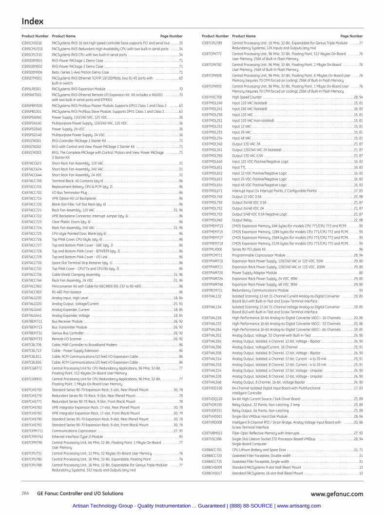
Index
264 www.gefanuc.comGE Fanuc Controller and I/O Solutions
IC695CHS016 PACSystems RX3i 16 slot high speed controller base supports PCI and serial bus . . . . . .35
IC695CMU310 PACSystems RX3i Redundant High Availability CPU with two built-in serial ports . . . . . .34
IC695CPU310 PACSystems RX3i CPU with two built-in serial ports . . . . . . . . . . . . . . . . . . . . . . . . . . . . . . . . . .34
IC695DEM001 RX3i Power PACkage 1 Demo Case . . . . . . . . . . . . . . . . . . . . . . . . . . . . . . . . . . . . . . . . . . . . . . . . . .71
IC695DEM002 RX3i Power PACkage 2 Demo Case . . . . . . . . . . . . . . . . . . . . . . . . . . . . . . . . . . . . . . . . . . . . . . . . . .71
IC695DEM004 Beta i Series 1-Axis Motion Demo Case . . . . . . . . . . . . . . . . . . . . . . . . . . . . . . . . . . . . . . . . . . . . . .71
IC695ETM001 PACSystems RX3i Ethernet TCP/IP 10/100Mbits, two RJ-45 ports with . . . . . . . . . . . . . . . .63built-in switch
IC695LRE001 PACSystems RX3i Expansion Module . . . . . . . . . . . . . . . . . . . . . . . . . . . . . . . . . . . . . . . . . . . . . . . .70
IC695NKT001 PACSystems RX3i Ethernet Remote I/O Expansion Kit. Kit includes a NIU001 . . . . . . . . . .70with two built-in serial ports and ETM001
IC695PBM300 PACSystems RX3i Profibus Master Module, Supports DPV1 Class 1 and Class 2. . . . . . . .63
IC695PBS301 PACSystems RX3i Profibus Slave Module, Supports DPV1 Class 1 and Class 2. . . . . . . . . .63
IC695PSA040 Power Supply, 120/240 VAC, 125 VDC . . . . . . . . . . . . . . . . . . . . . . . . . . . . . . . . . . . . . . . . . . . . . . .36
IC695PSA140 Multipurpose Power Supply, 120/240 VAC, 125 VDC. . . . . . . . . . . . . . . . . . . . . . . . . . . . . . . . . .36
IC695PSD040 Power Supply, 24 VDC . . . . . . . . . . . . . . . . . . . . . . . . . . . . . . . . . . . . . . . . . . . . . . . . . . . . . . . . . . . . . .36
IC695PSD140 Multipurpose Power Supply, 24 VDC. . . . . . . . . . . . . . . . . . . . . . . . . . . . . . . . . . . . . . . . . . . . . . . . .36
IC695STK001 RX3i Controller PACkage 1 Starter Kit . . . . . . . . . . . . . . . . . . . . . . . . . . . . . . . . . . . . . . . . . . . . . . . .71
IC695STK002 RX3i with Control and View. Power PACkage 2 Starter Kit . . . . . . . . . . . . . . . . . . . . . . . . . . . . .71
IC695STK003 RX3i, The Complete PACkage with Control, Motion and View. Power PACkage . . . . . . . . .713 Starter Kit
IC697ACC621 Short Rack Fan Assembly, 120 VAC . . . . . . . . . . . . . . . . . . . . . . . . . . . . . . . . . . . . . . . . . . . . . . . . . .31
IC697ACC624 Short Rack Fan Assembly, 240 VAC . . . . . . . . . . . . . . . . . . . . . . . . . . . . . . . . . . . . . . . . . . . . . . . . . .31
IC697ACC644 Short Rack Fan Assembly, 24 VDC . . . . . . . . . . . . . . . . . . . . . . . . . . . . . . . . . . . . . . . . . . . . . . . . . . .31
IC697ACC700 Terminal Block, 40 Contacts (qty 6) . . . . . . . . . . . . . . . . . . . . . . . . . . . . . . . . . . . . . . . . . . . . . . . . . .96
IC697ACC701 Replacement Battery, CPU & PCM (qty. 2) . . . . . . . . . . . . . . . . . . . . . . . . . . . . . . . . . . . . . . . . . . . .96
IC697ACC702 I/O Bus Terminator Plug . . . . . . . . . . . . . . . . . . . . . . . . . . . . . . . . . . . . . . . . . . . . . . . . . . . . . . . . . . . . .96
IC697ACC715 VME Option Kit (J2 Backplane) . . . . . . . . . . . . . . . . . . . . . . . . . . . . . . . . . . . . . . . . . . . . . . . . . . . . . . .96
IC697ACC720 Blank Slot Filler, Full Slot Rack (qty. 6) . . . . . . . . . . . . . . . . . . . . . . . . . . . . . . . . . . . . . . . . . . . . . . . .96
IC697ACC721 Rack Fan Assembly, 120 VAC . . . . . . . . . . . . . . . . . . . . . . . . . . . . . . . . . . . . . . . . . . . . . . . . . . . .31, 96
IC697ACC722 VME Backplane Connector, Interrupt Jumper (qty. 6) . . . . . . . . . . . . . . . . . . . . . . . . . . . . . . . . .96
IC697ACC723 Clear Plastic Doors (qty. 6) . . . . . . . . . . . . . . . . . . . . . . . . . . . . . . . . . . . . . . . . . . . . . . . . . . . . . . . . . .96
IC697ACC724 Rack Fan Assembly, 240 VAC . . . . . . . . . . . . . . . . . . . . . . . . . . . . . . . . . . . . . . . . . . . . . . . . . . . .31, 96
IC697ACC725 CPU-style Painted Door, Blank (qty 6) . . . . . . . . . . . . . . . . . . . . . . . . . . . . . . . . . . . . . . . . . . . . . . . .96
IC697ACC726 Top PWA Cover, CPU-Style, (qty. 6) . . . . . . . . . . . . . . . . . . . . . . . . . . . . . . . . . . . . . . . . . . . . . . . . . . .96
IC697ACC727 Top and Bottom PWA Cover - GBC (qty. 2) . . . . . . . . . . . . . . . . . . . . . . . . . . . . . . . . . . . . . . . . . . .96
IC697ACC728 Top and Bottom PWA Cover - BTM/BTR (qty. 2) . . . . . . . . . . . . . . . . . . . . . . . . . . . . . . . . . . . . . . .96
IC697ACC729 Top and Bottom PWA Cover - I/O Link . . . . . . . . . . . . . . . . . . . . . . . . . . . . . . . . . . . . . . . . . . . . . . .96
IC697ACC730 Spare Slot Terminal Strip Retainer (qty. 1) . . . . . . . . . . . . . . . . . . . . . . . . . . . . . . . . . . . . . . . . . . . .96
IC697ACC732 Top PWA Cover - CPU77x and CPU78x (qty. 2) . . . . . . . . . . . . . . . . . . . . . . . . . . . . . . . . . . . . . . .96
IC697ACC736 Cable Shield Clamping Assembly . . . . . . . . . . . . . . . . . . . . . . . . . . . . . . . . . . . . . . . . . . . . . . . .31, 96
IC697ACC744 Rack Fan Assembly, 24 VDC . . . . . . . . . . . . . . . . . . . . . . . . . . . . . . . . . . . . . . . . . . . . . . . . . . . . .31, 96
IC697ACC902 Miniconverter Kit with Cable for NEC9800 (RS-232 to RS-485) . . . . . . . . . . . . . . . . . . . . . . . . .96
IC697ACC903 RS-485 Port Isolator . . . . . . . . . . . . . . . . . . . . . . . . . . . . . . . . . . . . . . . . . . . . . . . . . . . . . . . . . . . . . . . .96
IC697ALG230 Analog Input, High Level . . . . . . . . . . . . . . . . . . . . . . . . . . . . . . . . . . . . . . . . . . . . . . . . . . . . . . . .18, 84
IC697ALG320 Analog Output, Voltage/Current . . . . . . . . . . . . . . . . . . . . . . . . . . . . . . . . . . . . . . . . . . . . . . . . .25, 91
IC697ALG440 Analog Expander, Current . . . . . . . . . . . . . . . . . . . . . . . . . . . . . . . . . . . . . . . . . . . . . . . . . . . . . . .18, 84
IC697ALG441 Analog Expander, Voltage . . . . . . . . . . . . . . . . . . . . . . . . . . . . . . . . . . . . . . . . . . . . . . . . . . . . . . .18, 84
IC697BEM711 Bus Receiver Module . . . . . . . . . . . . . . . . . . . . . . . . . . . . . . . . . . . . . . . . . . . . . . . . . . . . . . . . . . . .26, 92
IC697BEM713 Bus Transmitter Module . . . . . . . . . . . . . . . . . . . . . . . . . . . . . . . . . . . . . . . . . . . . . . . . . . . . . . . . .26, 92
IC697BEM731 Genius Bus Controller . . . . . . . . . . . . . . . . . . . . . . . . . . . . . . . . . . . . . . . . . . . . . . . . . . . . . . . . . . .26, 92
IC697BEM733 Remote I/O Scanner . . . . . . . . . . . . . . . . . . . . . . . . . . . . . . . . . . . . . . . . . . . . . . . . . . . . . . . . . . . . .26, 92
IC697CBL709 Cable, MAP Controller to Broadband Modem . . . . . . . . . . . . . . . . . . . . . . . . . . . . . . . . . . . . . . . . .96
IC697CBL713 Cable - Power Supply Extension . . . . . . . . . . . . . . . . . . . . . . . . . . . . . . . . . . . . . . . . . . . . . . . . . . . . .96
IC697CBL811 Cable, RCM Communications (10 feet) I/O Expansion Cable . . . . . . . . . . . . . . . . . . . . . . . . . . .96
IC697CBL826 Cable, RCM Communications (25 feet) I/O Expansion Cable . . . . . . . . . . . . . . . . . . . . . . . . . . .96
IC697CGR772 Central Processing Unit for CPU Redundancy Applications, 96 MHz, 32-Bit, . . . . . . . . . . .77Floating Point, 512 Kbytes On-Board User Memory
IC697CGR935 Central Processing Unit for CPU Redundancy Applications, 96 MHz, 32-Bit, . . . . . . . . . . .77Floating Point, 1 Mbyte On-Board User Memory
IC697CHS750 Standard Series 90-70 Expansion Rack, 5-slot, Rear (Panel) Mount . . . . . . . . . . . . . . . .30, 78
IC697CHS770 Redundant Series 90-70 Rack, 9-Slot, Rear (Panel) Mount . . . . . . . . . . . . . . . . . . . . . . . . . . . . .78
IC697CHS771 Redundant Series 90-70 Rack, 9-Slot, Front (Rack) Mount . . . . . . . . . . . . . . . . . . . . . . . . . . . . .78
IC697CHS782 VME Integrator Expansion Rack, 17-slot, Rear (Panel) Mount . . . . . . . . . . . . . . . . . . . . . .30, 78
IC697CHS783 VME Integrator Expansion Rack, 17-slot, Front (Rack) Mount . . . . . . . . . . . . . . . . . . . . . .30, 79
IC697CHS790 Standard Series 90-70 Expansion Rack, 9-slot, Rear (Panel) Mount . . . . . . . . . . . . . . . .30, 78
IC697CHS791 Standard Series 90-70 Expansion Rack, 9-slot, Front (Rack) Mount . . . . . . . . . . . . . . . .30, 78
IC697CMM711 Communications Coprocessor . . . . . . . . . . . . . . . . . . . . . . . . . . . . . . . . . . . . . . . . . . . . . . . . . . .27, 93
IC697CMM742 Ethernet Interface (Type 2) Module . . . . . . . . . . . . . . . . . . . . . . . . . . . . . . . . . . . . . . . . . . . . . . . . . .93
IC697CPM790 Central Processing Unit, 64 MHz, 32-Bit, Floating Point, 1 Mbyte On-Board . . . . . . . . . . .77User Memory
IC697CPU731 Central Processing Unit, 12 MHz, 32 Kbytes On-Board User Memory . . . . . . . . . . . . . . . . . .76
IC697CPU780 Central Processing Unit, 16 MHz, 32-Bit, Expandable, Floating Point . . . . . . . . . . . . . . . . . .76
IC697CPU788 Central Processing Unit, 16 MHz, 32-Bit, Expandable (for Genius Triple Modular . . . . . .77Redundancy Systems), 352 Inputs and Outputs (any mix)
IC697CPU789 Central Processing Unit, 16 MHz, 32-Bit, Expandable (for Genius Triple Modular . . . . . .77Redundancy Systems), 12K Inputs and Outputs (any mix)
IC697CPX772 Central Processing Unit, 96 MHz, 32-Bit, Floating Point, 512 Kbytes On-Board . . . . . . . .76User Memory; 256K of Built-In Flash Memory
IC697CPX782 Central Processing Unit, 96 MHz, 32-Bit, Floating Point, 1 Mbyte On-Board . . . . . . . . . . .76User Memory; 256K of Built-In Flash Memory
IC697CPX928 Central Processing Unit, 96 MHz, 32-Bit, Floating Point, 6 Mbytes On-Board User . . . . .76Memory (requires 70 CFM forced air cooling); 256K of Built-In Flash Memory
IC697CPX935 Central Processing Unit, 96 MHz, 32-Bit, Floating Point, 1 Mbyte On-Board User . . . . . .76Memory (requires 70 CFM forced air cooling); 256K of Built-In Flash Memory
IC697HSC700 High Speed Counter . . . . . . . . . . . . . . . . . . . . . . . . . . . . . . . . . . . . . . . . . . . . . . . . . . . . . . . . . . . . .28, 94
IC697MDL240 Input 120 VAC (Isolated) . . . . . . . . . . . . . . . . . . . . . . . . . . . . . . . . . . . . . . . . . . . . . . . . . . . . . . . . .15, 81
IC697MDL241 Input 240 VAC (Isolated) . . . . . . . . . . . . . . . . . . . . . . . . . . . . . . . . . . . . . . . . . . . . . . . . . . . . . . . . .16, 82
IC697MDL250 Input 120 VAC . . . . . . . . . . . . . . . . . . . . . . . . . . . . . . . . . . . . . . . . . . . . . . . . . . . . . . . . . . . . . . . . . . .15, 81
IC697MDL251 Input 120 VAC (non-isolated) . . . . . . . . . . . . . . . . . . . . . . . . . . . . . . . . . . . . . . . . . . . . . . . . . . . . .15, 81
IC697MDL252 Input 12 VAC . . . . . . . . . . . . . . . . . . . . . . . . . . . . . . . . . . . . . . . . . . . . . . . . . . . . . . . . . . . . . . . . . . . .15, 81
IC697MDL253 Input 24 VAC . . . . . . . . . . . . . . . . . . . . . . . . . . . . . . . . . . . . . . . . . . . . . . . . . . . . . . . . . . . . . . . . . . . .15, 81
IC697MDL254 Input 48 VAC . . . . . . . . . . . . . . . . . . . . . . . . . . . . . . . . . . . . . . . . . . . . . . . . . . . . . . . . . . . . . . . . . . . .15, 81
IC697MDL340 Output 120 VAC 2A . . . . . . . . . . . . . . . . . . . . . . . . . . . . . . . . . . . . . . . . . . . . . . . . . . . . . . . . . . . . . .21, 87
IC697MDL341 Output 120/240 VAC 2A (Isolated) . . . . . . . . . . . . . . . . . . . . . . . . . . . . . . . . . . . . . . . . . . . . . . . .21, 87
IC697MDL350 Output 120 VAC 0.5A . . . . . . . . . . . . . . . . . . . . . . . . . . . . . . . . . . . . . . . . . . . . . . . . . . . . . . . . . . . .21, 87
IC697MDL640 Input 125 VDC Positive/Negative Logic . . . . . . . . . . . . . . . . . . . . . . . . . . . . . . . . . . . . . . . . . . .16, 82
IC697MDL651 Input TTL . . . . . . . . . . . . . . . . . . . . . . . . . . . . . . . . . . . . . . . . . . . . . . . . . . . . . . . . . . . . . . . . . . . . . . .16, 82
IC697MDL652 Input 12 VDC Positive/Negative Logic . . . . . . . . . . . . . . . . . . . . . . . . . . . . . . . . . . . . . . . . . . . .16, 82
IC697MDL653 Input 24 VDC Positive/Negative Logic . . . . . . . . . . . . . . . . . . . . . . . . . . . . . . . . . . . . . . . . . . . .16, 82
IC697MDL654 Input 48 VDC Positive/Negative Logic . . . . . . . . . . . . . . . . . . . . . . . . . . . . . . . . . . . . . . . . . . . .16, 82
IC697MDL671 Interrupt Input (14 Interrupt Points, 2 Configurable Points) . . . . . . . . . . . . . . . . . . . . . . . .17, 83
IC697MDL740 Output 12 VDC 0.5A . . . . . . . . . . . . . . . . . . . . . . . . . . . . . . . . . . . . . . . . . . . . . . . . . . . . . . . . . . . . .22, 88
IC697MDL750 Output 24/48 VDC 0.5A . . . . . . . . . . . . . . . . . . . . . . . . . . . . . . . . . . . . . . . . . . . . . . . . . . . . . . . . . .21, 87
IC697MDL752 Output 24/48 VDC 2A . . . . . . . . . . . . . . . . . . . . . . . . . . . . . . . . . . . . . . . . . . . . . . . . . . . . . . . . . . .21, 87
IC697MDL753 Output 5/48 VDC 0.5A Negative Logic . . . . . . . . . . . . . . . . . . . . . . . . . . . . . . . . . . . . . . . . . . . .21, 87
IC697MDL940 Output Relay . . . . . . . . . . . . . . . . . . . . . . . . . . . . . . . . . . . . . . . . . . . . . . . . . . . . . . . . . . . . . . . . . . . .22, 88
IC697MEM713 CMOS Expansion Memory, 64K bytes (for models CPU 771/CPU 772 and PCM) . . . . . . . .95
IC697MEM715 CMOS Expansion Memory, 128K bytes (for models CPU 771/CPU 772 and PCM) . . . . . . .95
IC697MEM717 CMOS Expansion Memory, 256K bytes (for models CPU 771/CPU 772 and PCM) . . . . . . .95
IC697MEM719 CMOS Expansion Memory, 512K bytes (for models CPU 771/CPU 772 and PCM) . . . . . . .95
IC697MLX000 Series 90-70 Labels Kit . . . . . . . . . . . . . . . . . . . . . . . . . . . . . . . . . . . . . . . . . . . . . . . . . . . . . . . . . . . . . .96
IC697PCM711 Programmable Coprocessor Module . . . . . . . . . . . . . . . . . . . . . . . . . . . . . . . . . . . . . . . . . . . . .28, 94
IC697PWR710 Expansion Rack Power Supply, 120/240 VAC or 125 VDC, 55W . . . . . . . . . . . . . . . . . . . .29, 80
IC697PWR711 Expansion Rack Power Supply, 120/240 VAC or 125 VDC, 100W . . . . . . . . . . . . . . . . . . .29, 80
IC697PWR720 Power Supply Adapter Module . . . . . . . . . . . . . . . . . . . . . . . . . . . . . . . . . . . . . . . . . . . . . . . . . . . . . .80
IC697PWR724 Expansion Rack Power Supply, 24 VDC, 90W . . . . . . . . . . . . . . . . . . . . . . . . . . . . . . . . . . . . .29, 80
IC697PWR748 Expansion Rack Power Supply, 48 VDC, 90W . . . . . . . . . . . . . . . . . . . . . . . . . . . . . . . . . . . . .29, 80
IC697RCM711 Redundancy Communications Module . . . . . . . . . . . . . . . . . . . . . . . . . . . . . . . . . . . . . . . . . . . . . .93
IC697VAL132 Isolated Scanning 12-bit 31-Channel Current Analog-to-Digital Converter . . . . . . . .19, 85Board (6U) with Built-in-Test and Screw Terminal interface
IC697VAL134 Isolated Scanning 12-bit 31-Channel Voltage Analog-to-Digital Converter . . . . . . . .19, 85Board (6U) with Built-in-Test and Screw Terminal interface
IC697VAL216 High-Performance 16-bit Analog-to-Digital Converter (ADC) - 16 Channels . . . . . . . .20, 86
IC697VAL232 High-Performance 16-bit Analog-to-Digital Converter (ADC) - 32 Channels . . . . . . . .20, 86
IC697VAL264 High-Performance 16-bit Analog-to-Digital Converter (ADC) - 64 Channels . . . . . . . .19, 85
IC697VAL301 Analog Output, Voltage, 32 Channel with Built-in-Test . . . . . . . . . . . . . . . . . . . . . . . . . . . .24, 90
IC697VAL304 Analog Output, Isolated, 4 Channel, 12-bit, Voltage - Bipolar . . . . . . . . . . . . . . . . . . . . . .24, 90
IC697VAL306 Analog Output, Voltage/Current, 16 Channel . . . . . . . . . . . . . . . . . . . . . . . . . . . . . . . . . . . . .25, 91
IC697VAL308 Analog Output, Isolated, 8 Channel, 12-bit, Voltage - Bipolar . . . . . . . . . . . . . . . . . . . . . .24, 90
IC697VAL314 Analog Output, Isolated, 4 Channel, 12-bit, Current - 4 to 20 mA . . . . . . . . . . . . . . . . . .25, 91
IC697VAL318 Analog Output, Isolated, 8 Channel, 12-bit, Current - 4 to 20 mA . . . . . . . . . . . . . . . . . .25, 91
IC697VAL324 Analog Output, Isolated, 4 Channel, 12-bit, Voltage - Unipolar . . . . . . . . . . . . . . . . . . . .24, 90
IC697VAL328 Analog Output, Isolated, 8 Channel, 12-bit, Voltage - Unipolar . . . . . . . . . . . . . . . . . . . .24, 90
IC697VAL348 Analog Output, 8 Channel, 16-bit, Voltage Bipolar . . . . . . . . . . . . . . . . . . . . . . . . . . . . . . . .24, 90
IC697VDD100 64-Channel Isolated Digital Input Board with Multifunctional . . . . . . . . . . . . . . . . . . . . .17, 83Intelligent Controller
IC697VDQ120 64-bit High Current Source / Sink Driver Board . . . . . . . . . . . . . . . . . . . . . . . . . . . . . . . . . . .23, 89
IC697VDR150 Relay Output, 32 Points, Non-Latching, 2 Amp . . . . . . . . . . . . . . . . . . . . . . . . . . . . . . . . . . .23, 89
IC697VDR151 Relay Output, 64 Points, Non-Latching . . . . . . . . . . . . . . . . . . . . . . . . . . . . . . . . . . . . . . . . . . .23, 89
IC697VHD001 Single-Slot VMEbus Hard Disk Module . . . . . . . . . . . . . . . . . . . . . . . . . . . . . . . . . . . . . . . . . . . .28, 94
IC697VRD008 Intelligent 8-Channel RTD / Strain Bridge, Analog Voltage Input Board with . . . . . . .20, 86Screw Terminal Interface
IC697VRM015 Fiber-Optic Reflective Memory with Interrupts . . . . . . . . . . . . . . . . . . . . . . . . . . . . . . . . . . . .27, 93
IC697VSC096 Single-Slot Celeron Socket 370 Processor-Based VMEbus . . . . . . . . . . . . . . . . . . . . . . . .28, 94Single-Board Computer
IC698ACC701 CPU Lithium Battery and Spare Door . . . . . . . . . . . . . . . . . . . . . . . . . . . . . . . . . . . . . . . . . . . . .31, 71
IC698ACC720 Gasketed Filler Faceplate, Double-width . . . . . . . . . . . . . . . . . . . . . . . . . . . . . . . . . . . . . . . . . . . . .31
IC698ACC735 Gasketed Filler Faceplate, Single-width . . . . . . . . . . . . . . . . . . . . . . . . . . . . . . . . . . . . . . . . . . . . . .31
IC698CHS009 Standard PACSystems 9-slot Wall (Rear) Mount . . . . . . . . . . . . . . . . . . . . . . . . . . . . . . . . . . . . . .13
IC698CHS017 Standard PACSystems 18-slot Wall (Rear) Mount . . . . . . . . . . . . . . . . . . . . . . . . . . . . . . . . . . . . .13
Product Number Product Name Page Number Product Number Product Name Page Number
Artisan Technology Group - Quality Instrumentation ... Guaranteed | (888) 88-SOURCE | www.artisantg.com
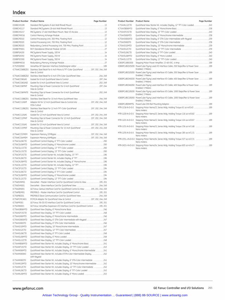
Index
265www.gefanuc.com GE Fanuc Controller and I/O Solutions
IC698CHS109 Standard PACSystems 9-slot Wall (Panel) Mount . . . . . . . . . . . . . . . . . . . . . . . . . . . . . . . . . . . . .13
IC698CHS117 Standard PACSystems 18-slot Wall (Panel) Mount . . . . . . . . . . . . . . . . . . . . . . . . . . . . . . . . . . . .13
IC698CHS217 PACSystems 17-slot Wall (Rear) Mount, Rear I/O Access . . . . . . . . . . . . . . . . . . . . . . . . . . . . . .13
IC698CMX016 Control Memory Xchange Module . . . . . . . . . . . . . . . . . . . . . . . . . . . . . . . . . . . . . . . . . . . . . . . . . . .27
IC698CPE010 Central Processing Unit, 300 MHz, Floating Point . . . . . . . . . . . . . . . . . . . . . . . . . . . . . . . . . . . . .12
IC698CPE020 Central Processing Unit, 700 MHz, Floating Point . . . . . . . . . . . . . . . . . . . . . . . . . . . . . . . . . . . . .12
IC698CRE020 Redundancy Central Processing Unit, 700 MHz, Floating Point . . . . . . . . . . . . . . . . . . . . . . . .12
IC698ETM001 RX7i Standalone Ethernet Module 10/100 . . . . . . . . . . . . . . . . . . . . . . . . . . . . . . . . . . . . . . . . . . . .27
IC698PSA100 PACSystems Power Supply, 100 W . . . . . . . . . . . . . . . . . . . . . . . . . . . . . . . . . . . . . . . . . . . . . . . . . .14
IC698PSA350 PACSystems Power Supply, 350 W . . . . . . . . . . . . . . . . . . . . . . . . . . . . . . . . . . . . . . . . . . . . . . . . . .14
IC698PSD300 PACSystems Power Supply, 300 W . . . . . . . . . . . . . . . . . . . . . . . . . . . . . . . . . . . . . . . . . . . . . . . . . .14
IC698RMX016 Redundancy Memory Xchange Module . . . . . . . . . . . . . . . . . . . . . . . . . . . . . . . . . . . . . . . . . . . . . .27
IC752DDZ000 VersaMax DP Operator Interface DataDesigner editor . . . . . . . . . . . . . . . . . . . . . . . . . . . . . . .189
IC754ACC06BEZ01 Stainless Steel Bezel for 6 Inch Mono & TFT-Color QuickPanel . . . . . . . .197, 202, 244, 249View & Control
IC754ACC06BEZ02 Stainless Steel Bezel for 6 Inch STN-Color QuickPanel View . . . . . . . . . . . . . . . . . . . . .244, 249
IC754ACC06GAS Gasket for 6 Inch QuickPanel View & Control . . . . . . . . . . . . . . . . . . . . . . . . . . . . . . . . . . .197, 244
IC754ACC06GASE Gasket for 6 Inch QuickPanel View & Control . . . . . . . . . . . . . . . . . . . . . . . . . . . . . . . . . . .202, 249
IC754ACC06MNT Mounting Clips & Power Connector for 6 Inch QuickPanel . . . . . . . . . . . . . . . . . . . . . .197, 244View & Control
IC754ACC06MNTE Mounting Clips & Power Connector for 6 Inch QuickPanel . . . . . . . . . . . . . . . . . . . . . .202, 249View & Control
IC754ACC10BEZ01 Stainless Steel Bezel for 10 Inch Mono QuickPanel View . . . . . . . . . . . . . . . . . . . . . . . .244, 249
IC754ACC12ADP Adaptor Kit for 12 Inch QuickPanel View & Control into . . . . . . . . . . . . . . .197, 202, 244, 249CEIIx Cutout
IC754ACC12BEZ01 Stainless Steel Bezel for 12 Inch TFT-Color QuickPanel . . . . . . . . . . . . . . .197, 202, 244, 249View & Control
IC754ACC12GAS Gasket for 12 Inch QuickPanel View & Control . . . . . . . . . . . . . . . . . . . . . . . .197, 202, 244, 249
IC754ACC12MNT Mounting Clips & Power Connector for 12 Inch QuickPanel . . . . . . . . . . .197, 202, 244, 249View & Control
IC754ACC15GAS Gasket for 15 Inch QuickPanel View & Control . . . . . . . . . . . . . . . . . . . . . . . .197, 202, 244, 249
IC754ACC15MNT Mounting Clips & Power Connector for 15 Inch QuickPanel . . . . . . . . . . .197, 202, 244, 249View & Control
IC754ACC32MEM Expansion Memory 32MBytes . . . . . . . . . . . . . . . . . . . . . . . . . . . . . . . . . . . . . . .197, 202, 244, 249
IC754ACC64MEM Expansion Memory 64MBytes . . . . . . . . . . . . . . . . . . . . . . . . . . . . . . . . . . . . . . .197, 202, 244, 249
IC754CGL06CTD QuickPanel Control Display, 6" TFT-Color Loaded . . . . . . . . . . . . . . . . . . . . . . . . . . . . . . . . . . .200
IC754CGL06MTD QuickPanel Control Display, 6" Monochrome Loaded . . . . . . . . . . . . . . . . . . . . . . . . . . . . . . . .200
IC754CGL12CTD QuickPanel Control Display, 12" TFT-Color Loaded . . . . . . . . . . . . . . . . . . . . . . . . . . . . . . . . . .200
IC754CGL15CTD QuickPanel Control Display, 15" TFT-Color Loaded . . . . . . . . . . . . . . . . . . . . . . . . . . . . . . . . . .200
IC754CKF15CTD QuickPanel Control Starter Kit, includes Display, 15" TFT . . . . . . . . . . . . . . . . . . . . . . . . . . . .196
IC754CKL06CTD QuickPanel Control Starter Kit, includes Display, 6" TFT . . . . . . . . . . . . . . . . . . . . . . . . . . . . .196
IC754CKL06MTD QuickPanel Control Starter Kit, includes Display, 6" Monochrome . . . . . . . . . . . . . . . . . . . .196
IC754CKL12CTD QuickPanel Control Starter Kit, includes Display, 12" TFT . . . . . . . . . . . . . . . . . . . . . . . . . . . .196
IC754CSF15CTD QuickPanel Control Display, 15" TFT-Color Loaded . . . . . . . . . . . . . . . . . . . . . . . . . . . . . . . . . .194
IC754CSL06CTD QuickPanel Control Display, 6" TFT-Color Loaded . . . . . . . . . . . . . . . . . . . . . . . . . . . . . . . . . . .194
IC754CSL06MTD QuickPanel Control Display, 6" Monochrome Loaded . . . . . . . . . . . . . . . . . . . . . . . . . . . . . . . .194
IC754CSL12CTD QuickPanel Control Display, 12" TFT-Color Loaded . . . . . . . . . . . . . . . . . . . . . . . . . . . . . . . . . .194
IC754DVNM01 DeviceNet - Master Interface Card for QuickPanel Control & View . . . . . . . . . . . . . . .195, 201
IC754DVNS01 DeviceNet - Slave Interface Card for QuickPanel View . . . . . . . . . . . . . . . . . . . . . . . . . .244, 249
IC754GEN001 GE Fanuc Genius Interface Card for QuickPanel Control & View . . . . . . .195, 201, 244, 249
IC754PBSM01 PROFIBUS - Master Interface Card for QuickPanel Control . . . . . . . . . . . . . . . . . . . . . .195, 201
IC754PBSS01 PROFIBUS Slave Communication Card for QuickPanel View . . . . . . . . . . . . . . . . . . . . .244, 249
IC754PCMCIA01 PCMCIA Adaptor for QuickPanel View & Control . . . . . . . . . . . . . . . . . . . . . .197, 202, 244, 249
IC754PIF001 GE Fanuc 90-30 I/O Interface Card for QuickPanel Control . . . . . . . . . . . . . . . . . . . . . .195, 201
IC754TAN001 GE Fanuc VersaMax Expansion I/O Interface Card for QuickPanel Control . . . . . . .195, 201
IC754VGB06MTD QuickPanel View Display, 6" Monochrome Basic . . . . . . . . . . . . . . . . . . . . . . . . . . . . . . . . . . . .246
IC754VGF15CTD QuickPanel View Display, 15" TFT-Color Loaded . . . . . . . . . . . . . . . . . . . . . . . . . . . . . . . . . . . . .248
IC754VGI06MTD QuickPanel View Display, 6" Monochrome Intermediate . . . . . . . . . . . . . . . . . . . . . . . . . . . . .246
IC754VGI06SKTD QuickPanel View Display, 6" STN-Color Intermediate with Keypad . . . . . . . . . . . . . . . . . . .247
IC754VGI06STD QuickPanel View Display, 6" STN-Color Intermediate . . . . . . . . . . . . . . . . . . . . . . . . . . . . . . . .246
IC754VGI10MTD QuickPanel View Display, 10" Monochrome Intermediate . . . . . . . . . . . . . . . . . . . . . . . . . . . .247
IC754VGI12CTD QuickPanel View Display, 12" TFT-Color Intermediate . . . . . . . . . . . . . . . . . . . . . . . . . . . . . . .247
IC754VGL06CTD QuickPanel View Display, 6" TFT-Color Loaded . . . . . . . . . . . . . . . . . . . . . . . . . . . . . . . . . . . . . .248
IC754VGL06MTD QuickPanel View Display, 6" Mono Loaded . . . . . . . . . . . . . . . . . . . . . . . . . . . . . . . . . . . . . . . . . .248
IC754VGL12CTD QuickPanel View Display, 12" TFT-Color Loaded . . . . . . . . . . . . . . . . . . . . . . . . . . . . . . . . . . . . .248
IC754VKB06MTD QuickPanel View Starter Kit, includes Display, 6" Monochrome Basic . . . . . . . . . . . . . . . .241
IC754VKF15CTD QuickPanel View Starter Kit, includes Display, 15" TFT-Color Loaded . . . . . . . . . . . . . . . . .243
IC754VKI06MTD QuickPanel View Starter Kit, includes Display, 6" Monochrome Intermediate . . . . . . . . .241
IC754VKI06SKD QuickPanel View Starter Kit, includes 6"STN-Color Intermediate Display . . . . . . . . . . . . .242with Keypad
IC754VKI06STD QuickPanel View Starter Kit, includes Display, 6" STN-Color Intermediate . . . . . . . . . . . .241
IC754VKI10MTD QuickPanel View Starter Kit, includes Display, 10" Monochrome Intermediate . . . . . . . .242
IC754VKI12CTD QuickPanel View Starter Kit, includes Display, 12" TFT-Color Intermediate . . . . . . . . . . .242
IC754VKL06CTD QuickPanel View Starter Kit, includes Display, 6" TFT-Color Loaded . . . . . . . . . . . . . . . . . .243
IC754VKL06MTD QuickPanel View Starter Kit, includes Display, 6" Mono Loaded . . . . . . . . . . . . . . . . . . . . . .243
IC754VKL12CTD QuickPanel View Starter Kit, includes Display, 12" TFT-Color Loaded . . . . . . . . . . . . . . . . .243
IC754VSB06MTD QuickPanel View Display, 6" Monochrome Basic . . . . . . . . . . . . . . . . . . . . . . . . . . . . . . . . . . . .238
IC754VSF15CTD QuickPanel View Display, 15" TFT-Color Loaded . . . . . . . . . . . . . . . . . . . . . . . . . . . . . . . . . . . . .240
IC754VSI06MTD QuickPanel View Display, 6" Monochrome Intermediate . . . . . . . . . . . . . . . . . . . . . . . . . . . . .238
IC754VSI06SKTD QuickPanel View Display, 6" STN-Color Intermediate with Keypad . . . . . . . . . . . . . . . . . . .239
IC754VSI06STD QuickPanel View Display, 6" STN-Color Intermediate . . . . . . . . . . . . . . . . . . . . . . . . . . . . . . . .238
IC754VSI10MTD QuickPanel View Display, 10" Monochrome Intermediate . . . . . . . . . . . . . . . . . . . . . . . . . . . .239
IC754VSI12CTD QuickPanel View Display, 12" TFT-Color Intermediate . . . . . . . . . . . . . . . . . . . . . . . . . . . . . . .239
IC754VSL06CTD QuickPanel View Display, 6" TFT-Color Loaded . . . . . . . . . . . . . . . . . . . . . . . . . . . . . . . . . . . . . .240
IC754VSL06MTD QuickPanel View Display, 6" Mono Loaded . . . . . . . . . . . . . . . . . . . . . . . . . . . . . . . . . . . . . . . . . .240
IC754VSL12CTD QuickPanel View Display, 12" TFT-Color Loaded . . . . . . . . . . . . . . . . . . . . . . . . . . . . . . . . . . . . .240
IC800PCUB00300 Stepping Motor Power Amplifier, 12-48 VDC, 4 Amp . . . . . . . . . . . . . . . . . . . . . . . . . . . . . . . . .189
IC800PCUBC02S030 PowerCube Flying Lead I/O Interface Cable, 200 Steps/Rev & Power Save . . . . . . . . . . .189Enabled, 3 Meters
IC800PCUBC02S050 PowerCube Flying Lead Interface I/O Cable, 200 Steps/Rev & Power Save . . . . . . . . . . .189Enabled, 5 Meters
IC800PCUBC04S030 PowerCube Flying Lead Interface I/O Cable, 400 Steps/Rev & Power Save . . . . . . . . . . .189Enabled, 3 Meters
IC800PCUBC04S050 PowerCube Flying Lead Interface I/O Cable, 400 Steps/Rev & Power Save . . . . . . . . . . .189Enabled, 5 Meters
IC800PCUBC10S030 PowerCube Flying Lead Interface I/O Cable, 1000 Steps/Rev & Power Save . . . . . . . . .189Enabled, 3 Meters
IC800PCUBC10S050 PowerCube Flying Lead Interface I/O Cable, 1000 Steps/Rev & Power Save . . . . . . . . .189Enabled, 5 Meters
IC800PCUBDINMTG PowerCube DIN Rail Mounting Adaptor. . . . . . . . . . . . . . . . . . . . . . . . . . . . . . . . . . . . . . . . . . . . . .189
MTR-1216-N-D-E-0 Stepping Motor Nema23, Series Wdg. Holding Torque 61 oz-in/0.43 . . . . . . . . . . . . . . . . .189Nano meters
MTR-1220-N-D-E-0 Stepping Motor Nema23, Series Wdg. Holding Torque 116 oz-in/0.82 . . . . . . . . . . . . . . .189Nano meters
MTR-1221-N-D-E-0 Stepping Motor Nema23, Series Wdg. Holding Torque 124 oz-in/0.87 . . . . . . . . . . . . . . .189Nano meters
MTR-1231-N-D-E-0 Stepping Motor Nema23, Series Wdg. Holding Torque 236 oz-in/1.68 . . . . . . . . . . . . . . .189Nano meters
MTR-1235-N-D-E-0 Stepping Motor Nema23, Series Wdg. Holding Torque 185 oz-in/1.31 . . . . . . . . . . . . . . .189Nano meters
MTR-1331-J-N-D-E-0 Stepping Motor Nema34, Series Wdg. Holding Torque 327 oz-in/2.31 . . . . . . . . . . . . . . .189Nano meters
MTR-1N31-I-N-D-S-0 Stepping Motor Nema34, Series Wdg. Holding Torque 605 oz-in/4.27 . . . . . . . . . . . . . . .189Nano meters
Product Number Product Name Page Number Product Number Product Name Page Number
Artisan Technology Group - Quality Instrumentation ... Guaranteed | (888) 88-SOURCE | www.artisantg.com

266 www.gefanuc.comGE Fanuc Controller and I/O Solutions
Notes
Artisan Technology Group - Quality Instrumentation ... Guaranteed | (888) 88-SOURCE | www.artisantg.com

GFA-406
Global reach with local presence
We reach out to our customers through a worldwide network
of manufacturing, sales, distribution, service and support.
Charlottesville, VirginiaGlobal and Americas Headquarters
LuxembourgEuropean Headquarters
ShanghaiAsia Pacific Headquarters
GE Fanuc delivers a total solution.GE Fanuc Automation, a joint venture between GE and FANUC LTD
of Japan, delivers automation hardware and software designed
to help users reduce costs, increase efficiency and enhance
profitability. With solutions and services catering to virtually
every industrial segment, GE Fanuc Automation provides a diverse
array of capabilities and products, including controllers, embedded
systems, advanced software, motion control, CNCs, operator
interfaces, industrial computers, and lasers. Headquartered in
Charlottesville, VA, GE Fanuc Automation is a part of GE Industrial
and combines the diverse global strengths of the GE family with
the local presence customers need to design, develop and
maintain their automation investments.
©2005 GE Fanuc Automation. All Rights Reserved.
GE Fanuc Automation Information Centers
Americas:1 800 GE FANUC or 434 978 5100
Asia Pacific: 86 21 3222 4555
Europe, Middle East and Africa:800 1 GE FANUC or 800 1 4332682 or 1 780 401 7717
Europe, Middle East and Africa (CNC):352 727979 1
Additional Resources
For more information, please visit the GE Fanuc web site at:
www.gefanuc.com
Artisan Technology Group - Quality Instrumentation ... Guaranteed | (888) 88-SOURCE | www.artisantg.com

Artisan Technology Group is your source for quality new and certified-used/pre-owned equipment
• FAST SHIPPING AND DELIVERY
• TENS OF THOUSANDS OF IN-STOCK ITEMS
• EQUIPMENT DEMOS
• HUNDREDS OF MANUFACTURERS SUPPORTED
• LEASING/MONTHLY RENTALS
• ITAR CERTIFIED SECURE ASSET SOLUTIONS
SERVICE CENTER REPAIRSExperienced engineers and technicians on staff at our full-service, in-house repair center
WE BUY USED EQUIPMENTSell your excess, underutilized, and idle used equipment We also offer credit for buy-backs and trade-inswww.artisantg.com/WeBuyEquipment
REMOTE INSPECTIONRemotely inspect equipment before purchasing with our interactive website at www.instraview.com
LOOKING FOR MORE INFORMATION? Visit us on the web at www.artisantg.com for more information on price quotations, drivers, technical specifications, manuals, and documentation
Contact us: (888) 88-SOURCE | [email protected] | www.artisantg.com
SMViewInstra