arumugam, ak. , armour, smd., lee, bs., tariq, mf., & nix ... · arumugam et al.: consumer...
TRANSCRIPT

Arumugam AK Armour SMD Lee BS Tariq MF amp Nix AR (2001)Consumer electronics application and coverage constraints using Bluetoothand proposed Bluetooth evolution technologies IEEE Transactions onConsumer Electronics 47(3) 283 - 293 [Issue 3]httpsdoiorg10110930964111
Peer reviewed version
Link to published version (if available)10110930964111
Link to publication record in Explore Bristol ResearchPDF-document
University of Bristol - Explore Bristol ResearchGeneral rights
This document is made available in accordance with publisher policies Please cite only the publishedversion using the reference above Full terms of use are availablehttpwwwbristolacukpureaboutebr-terms
Arumugam et al Using Bluetooth and Proposed Bluetooth Evolution Technologies
Consumer Electronics Application and Coverage Constraints
Applications
283
Required Bit Rates
ABSTRACT
Cordless Telephones using DECT
Cordless Videophone using MPEG4
Cordless TV
This paper considers issues such as residential coverage and achievable bit rate using the Bluetooth Personal Area Network (PAN) standard Link budget analysis is performed b-y combining detailed link level physical layer simulations with site specific power predictions from a state-of-the-art indoor propagation model Assuming a ImW transmit unit coverage plots are generated at 24 GHz for an example single and multi-storey residential environment The investigation considers Bluetooth data medium (OM) and data high (DH) packet types Results for the transmission of symmetric asynchronous data link (ACL) packets are used to discuss the bit rate capabilities of various time-bounded and non-time bounded Bluetooth enabled consumer electronic devices To meet the bit rate needs of future consumer electronic devices QPSK 16- QAM and 64-QAM are proposed as possible enhancements to the current GFSK mode Using physical layer simulations the coverage and data rate pelformance of these new modes are analysed and compared with those of standard Bluetooth The use of linear receive architectures and coherent modulation although adding signifcantly to the unit cost is shown to signifcantly improve radio sensitivity Results indicate that high bit rate QAM operation is now possible over an extended coverage area
96kbs - 552kbs [41
96kbs - 64kbs [5]
4 - 9 Mbs [6]
CONSUMER ELECTRONICS APPLICATION AND COVERAGE CONSTRAINTS USING BLUETOOTH AND PROPOSED BLUETOOTH EVOLUTION TECHNOLOGIES
A K Arumugam S M D Armour B S Lee M F Tariq and A R Nix University of Bristol Centre for Communications Research Merchant Venturers Building
Woodland Road Bristol BS8-1 UB UK
Cordless Data Modems
Personal Digital Assistants (PDAs)
INTRODUCTION In recent years the radio communications industry has moved rapidly towards the development of a universal radio interface for ubiquitous radio connectivity In the area of Personal Area Networks (PAN) this has led to the development of the Bluetooth radio standard PAN devices can be classified into one of three major categories - mobile stationary or consumer electronic [ l ] Bluetooth represents a technology specification that aims to provide robust short range radio communication with low terminal cost complexity and power consumption Although this technology is targeted towards electronic devices within the home or office it also covers consumer electronic devices such as portable computers Personal Digital Assistants (PDAs) cordless telephones videophones televisions and Video Cassette Recorders (VCR) The Bluetooth radio interface operates in the unlicensed 245GHz Industrial Scientific and Medical (ISM) band
96khs - 56kbs 171 96kbs - I28khs [7]
Manuscript received June 25 2001
Frequency hopping is used with terminals cycling through 79 lMHz hop channels at 1600 hopsls [2] The current technology is capable of transmitting data andlor voice at raw half-duplex rates of up to 1MbIs without the use of cables between portable and fixed electronic devices Asymmetric and symmetric systems provide maximum half-duplex user data rates of 725kbls and 433kbls respectively Gaussian Frequency Shift Keying (GFSK) modulation is used with a bandwidth-bit Qeriod (BT) product of 05 [3] One of the drawbacks with current Bluetooth technology is its restricted bit rate Although it is highly desirable for low bit rate applications such as data modems cordless telephones and low bit rate videophones it is unable to transport high bit rate VCR TV quality d~igital video Table 1 lists typical bit rate requirements for commonly used consumer electronics devices
I Cordless VCR I Upto2Mbs [6] I
0098 306300 $1000 2001 IEEE
284 IEEE Transactions on Consumer Electronics Vol 47 No 3 AUGUST 2001
Packet Type Number of User Symmetric h t a Payload Bits hlaximuni Rate
per time slot (kbs)
Transmitter ~ -
Formation of Add Access Transmit
Filter Packets Add Code and Add CRC
Payload Packet + and Tail Encoder (Data Medium or Header Header Bits + +
Data High)
the packet header is repeated 3 times thus producing 54 encoded bits The packet header is then decodcd at the receiver using the maximal polling method Thc second
I U
addition Channel
I I
Channel Receiver
DM 1
Compute Packet Error Rate (PER) Check Raw Binary
f Data Throughput and Bit Error User Days for Decoder Deinterleaver Demodulator Receive Compute the
Rate (BER) Errors Filter
136 1088
Figure] Block diagram of the Bluetooth transmitter and receiver simulated in Matlab
DM3
BLUETOOTH BASEBAND STRUCTURE Figure 1 shows the baseband block diagram of the simulated Bluetooth system Only symmetric asynchronous data link (ACL) packets are investigated in this study
1 Packet Structure
Table 2 lists the 6 symmetric ACL packet types investigated in this simulation The figures correspond to a maximum data rate of 1Mbs using GFSK modulation as specified in the current Bluetooth standard These values increase by 2 4 and 6 times when QPSK 16-QAM and 64-QAM modulation schemes are employed respectively
323 2581
Although each packet has a duration of 625ps the duty cycle of a standard DMl packet is just 366ps The remaining time is used for frequency hopping The access code is derived from the masterrsquos identity [89] Apart from the DM1 and DH1 packets all others contain a 16- bit payload header The 16-bit cyclic redundancy check (CRC) is calculated only for the payload header and payload The CRC is derived from the Upper Address Part (UAP) of the 48-bit device address assigned to each Bluetooth unit by the manufacturer
2 Coding Scheme
Two Forward Error Correction (FEC) schemes are employed in Bluetooth The first is a 13-rate repetition
DH3 488 3904
DH5
I DM5 I 358 I 2867 1
542 4339
Table 2 DM and DH packets for ACL link
The ACL packets have the general structure shown in Figure 2 Each packet occupies a time slot of625ps When multiple time slot transmission is used the total number of payload bits is either 3 or 5 times the value listed in Table 2 depending on whether DMDH 3 or 5 is used
coding scheme is a 23-rate shortened (15lO) Hamming binary block code that is applied to the payload header payload and CRC as well as the tail bits The tail bits are appended at the end of the CRC to ensure that the sum of bits in the payload header payload and CRC is a multiple of 10 Decoding at the receiver is performed using the single error correcting decoding algorithm using a predefined parity check matrix [lo] This decoding algorithm corrects all single errors and detects all double errors within each block of 15 bits With the exception of the packet header the DH packets are not encoded
3 Interleaver
After the encoding process block interleaving is applied to the entire packet This step is implemented-to further protect the transmitted data from error bursts due to large delay spreads which in turn cause inter-symbol- -
Access Packet Payload Payload I User CRC and interference (ISI) when the operating range increases from Code Header Header Data Tail bits 10m to 100m
(72 bits) (54 bits) (U16 (0 - 2745 bits) ( 1 6 and 0-
4 Modulation bits) 10 bits)
Figure 2 Structure of ACL Packets The investigation in this paper considers four modulation schemes The GFSK scheme is implemented based on the
Arumugam et al Consumer Electronics Application and Coverage Constraints Using Bluetooth and Proposed Bluetooth Evolution Technologies 285
current Bluetooth standard At the receiver non-linear differential phase detection is applied This form of detection does not require knowledge of the amplitude or the absolute phase of the transmitted signal Although radio performance is poor the simplicity of the resulting design enables low cost implementation
The remaining three modes utilise QPSK 16-QAM and 64-QAM modulation with coherent detection This type of detection requires a far more complex and expensive radio design - requiring automatic gain and phase control in addition to linear up and down conversion and power amplification The advantage of such schemes is their greater bandwidth efficiency and (relative to discriminator detection) improved radio sensitivity [ 1 11 Given that 16-QAM and 64-QAM require fully coherent detection the performance of differentially detected QPSK has not been simulated If differential detection is desired (to reduce cost) then operation using BPSK QPSK and 8- PSK modes is recommended although not studied further in this paper
5 Filtering and Radio Channel
In the GFSK system the mapped signal is passed through a 24-tap Gaussian filter with a BT product of 05 where B represents the 3dB bandwidth of the filter and T the symbol period A modulation index h of 028 is used [l 11
EWNo lor Symmetric Transmission 6n Bluetooth using GFSK Mdulation
I z I
I I I I I 1 8
1 2 I 1 - - - - I - I I I -y
5 I O 15 20 25 30 35 40 45 50 EbiNo In decibels
Figures 3(a) and 3(b) PER
0 5 10 15 20 25 30 35 40 45 50 EWNo in decibels
Figures 3(c) and 3(d) PER
The impulse response of the Gaussian filter is given as
exp(-t2 2s2T2 j (1) I
h(t j=- G S T
where s is given by ~=Jln(2)27tL3T The convolution between the Gaussian filter and the rectangular pulse is given by the expression
g(t) = h(f) rect(r T ) (2) where rect(t IT ) = 1 T for It1 = T 2 and zero otherwise The transmitted signal S~ can be represented by the following relationship
where A represents the amplitude o f the transmitted signal and (t j the integrated phase given by
amp ( I ) = Ae~pJm(~) (3)
t n ( t ) = ~ h x I g ( - n T ) d z + (4)
- m
where I is mapped to 1 according to the binary data and 4 is the initial phase of the camer In the case of QPSK 16-QAM and 64-QAM the mapped signal is passed through a root-raised cosine (RRC) filter with a roll-of factor a of 035
For the QAM schemes the amplitude and phase of the transmit symbols can be calculated by the following two
PER ~ j EWNo lor Symmetric Transmission m BIwlooth using QPSK Modulation
I - - I - - I- - I-
O 5 10 15 20 25 30 35 40 45 M EbiNo in decibels
versus EbNo for GFSK and QPSK Modulations
- - - - - - I
I
z z i ~ I _
_ ~
0 5 10 15 20 25 30 35 40 45 50 EWNo ~n decibels
vs EbNo for 16QAM and 64QAM Modulations
IEEE Transactions on Consumer Electronics Vol 47 No 3 AUGUST 2001 286
equations
where Ich and Qcl are the RRC filtered baseband I and Q samples The Bluetooth radio system makes use of frequency hopping where each Bluetooth packet is sent over a different quasi-static uncorrelated Rayleigh fading channel For multi-slot transmissions the entire 3 or 5 slot transmission is sent on the same hop frequency A Rayleigh fading channel is used to represent the worst possible multipath scenario Assuming the channel amplitude and phase is represented by A and amp respectively the signal arriving at the receiver can be represented by the following equation
SR(f) = ampAm exp( I [( t )+c 1) + An expl J (7)
where A and are the amplitude and phase of the additive noise term
For the GFSK system the RRC filter is also applied at the receiver The signal is then passed through a phase detector and differentiator in order to recover the Gaussian filtered waveform In order to improve the signal to noise ratio an integrate and dump filter is used prior to the decision device
6 Packet Error Rate (PER) and Data Throughput (DT) Calculation
Once the packet is received and coherently detected a CRC is performed on the payload header and payload Although the current Bluetooth standard specifies the CRC as a measure of determining if a retransmission is required automatic repeat request (ARQ) itself is not employed in the simulation Instead the user data PER is calculated by comparing the transmitted and received data
The data throughput (DT) is calculated using the following relationship
DT = ( I - PER)XM x D R (8)
whereM represents the number of bitshymbol (1 for GFSK 2 for QPSK 4 for 16-QAM and 6 for 64-QAM) and DR is the maximum data rate (listed in Table 2) for the corresponding packet
SOFTWARE SIMULATION
Figures 3(a)-(d)show the packet error rate (PER) versus the ratio of energy per bit to noise power spectral density (EbNo) for the six different ACL packets in Bluetooth using the four different modulation schemes These results are used to obtain the data throughput curves for each packet type (see Figures 4(a) - (d))
10 Data Thrwghput using GFSK Modulation Dala lhmylhpu Graphs kx OPSK Modulslian
~ L A
~ -
Figures 4(a) and(b) Data throughput plotsfor GFSK and QPSK modulations
los Dala Throughput k 1WAM Modulation ~ Data ThrarJhputuring W A M Mcd~latlon
I - I I _
I
I ~ ~ ~ ~
EMtb bn decibels
Figures 4(c) and (d) Data throughput plots for 16QAM and 64QAM modulations
Arumugam et al ampsing Bluetooth and Proposed Bluetooth Evolution Technologies
Consumer Electronics Application and Coverage Constraints
Modulation NI N k (dRni) (dBinj (hihhymh) Scheme
287
q e a k
(dB)
IV PROPAGATION MODEL A state-of-the-art indoor space-time propagation model [12] based on ray launching [13-151 is used to predict the complex temporal and spatial characteristics of the radio channel This model is used to provide information on the received signal power in an indoor single and multi-storey building The results are generated for a maximum of 6 orders of reflection and transmission combined with a single order of diffraction Short dipole antennas are used at the basestation and terminal located approximately 08m above the floor (typical desk height) The maximum transmit and receive gain of the antennas is 1 SdBi [16] A peak transmit power of OdBm (1mW) is assumed
Figures 5(a) and 5(b) respectively show a typical point-to- point indoor prediction within a single and multi-storey environment The test area is constructed predominantly from brick and has a concrete floor The dimension of the test area is 16x1 lm2 with 3m high ceilings The relative permittivity and conductivity of the material are 3 and 0005 Sm respectively [ 161
Figures 6(a) and 6(b) show coverage plots of the received signal power on the ground and first floors respectively The noise power spectral density generated at the receiver is given by the following equation [17]
N o = 10loglo kT + 10log10( BW )+ NF (9)
the noise figure of the RF amplifier which is taken to be 20dB for the GFSK system [l] For the QAM schemes a N F of lOdB is assumed (this superior value resulting from the more expensive radio front-end) The operating bandwidth BW is IMHz Thus N = -94dBm for the GFSK system and -104dBm for the QAM schemes The received Eb N o is calculated for every point in the test area (with a grid spacing of 02m) The E b N is calculated using the following expression
( Eb No )dB = PR -No + 10 log(( I -a ) k )-(peak mea^)^^ (1 0)
where pR is the received power N is the noise power spectral density a is the roll off factor of the RRC filter and k is the number of bitdsymbol Since the transmit power is assumed to be 1mW peak the peak-to-mean ratio(peakmean) of the QAM schemes is subtracted from the expression Table 3 lists key parameters for each of the four modulation schemes investigated
16-QAM -10 -104
56 64-QAM -10 -104
where k = 1 3 8 ~ (mWHzK) represents Boltzmanns constant and T = 300K is the temperature in Kelvin N F is
Table 3 Key Modulation Parameters
Figures 5(a) and (b) Received signal strength in a single and double storey indoor environment
Figures 6(a) and (b) Coverage plots for the received signal strength (in dBm) for the ground and first floors
288
Data link overthe Indoor emnmment using GFSK I
kbs
IEEE Transactions on Consumer Electronics Vol 47 No 3 AUGUST 2001
Bluetooth packet cwerage over the indooi en~ilonment using GFSK
I I 1 1 D H 5
Distance m metres
2
4
E 6
E = 8
F 10 0 M3
12
14
16 DMl 2 4 6 8 1 0
Distance m metres
Figure 7(a) and (6) GroundJoor data throughput and packet coverage for GFSK modulation
Osla link overthe Indoor emironmen1 using QPSK kWs
I n 2
6 700
p K 600 E
z 10 400
5 5 930
12 300
14 am 16
2 4 6 8 1 0
Bluetooth packet cwerage over the indoor ermiionment using QPSK
I
B 10
DM5 2 4 6 8 1 0
0stance I me1es Distance in metres
Figure 7(c) and (d) Groundjloor data throughput and packet coverage for QPSK modulation
Diolance in metres
B l ~ e t m t h packet coverage OMrlhe indoor enwmnment using IKQAM
I
Distance in metres
Figure 7(e) and U) Groundfloor data throughput and packet coverage for 16-QAM modulation
Distance I metres Distance ~n metres
Figure 7(g) and (h) Ground floor data throughput and packet coverage for 64-QAM modulation
Arumugam et al Using Bluetooth and Proposed Bluetooth Evolution Technologies
Consumer Electronics Application and Coverage Constraints
Data lhnk overthe mdoorenvironment using GFSK kbfs i n
Bluetooth packet carerage werthe indoor environment using GFSK
I 400
310
300 DH3
250
m
150
1oD
50
0
DhC
DM1 2 4 6 8 1 0 2 4 6 8 1 0
Distance m metres Distance in metres
Figure 8(a) and (b) First floor data throughput and packet coverage for GFSK modulation
Data link oyer the indoor ewiionmeni using QPSK rbfs I i n
2 1 I t im 4 7w
p 6 600
2 5 8 5w
F 10 400
12 300
14
16 2 4 6 8 1 0
Distance ~n metres
Bluetooth packet coverage owrthe indoor environment using QPSK I I r w
21 I I I
Distance in melies
Figure 8(c) and (d) First floor data throughput and packet coverage for QPSK modulation
Data link overthe indoor environment w m g 16OAM Bluetooth liacket c o v e r a ~ e (nerlhe indoor environment urlnq ISRAM
Distance in metres Distance 10 metres
Figure 8(e) and (f) Firstfloor data throughput and packet coverage f o r 16-QAM modulation
Data link wer the indoor emrronment u m o 6PQAM kwr Bluetooth oacket c w e r a ~ e overthe Indoor fnnronment m a 640W
Distance I metres
289
Figure 8(g) and (h) Firstfloor data throughput and packet coverage for 64-QAM modulation
290 lEEE Transactions on Consumer Electronics Vol 47 No 3 AUGUST 2001
Packet T~~~
V RESULTS AND DISCUSSION The results presented in Figures 6(a) and (b) assume a ground floor Bluetooth transmitter placed in the point marked TX in the plots An important observation from Figures 6(a) and (b) is that the maximum received signal strength on the first floor of the building is nearly 16 dB lower than that on the ground floor Consequently the maximum data link achievable on the first floor is expected to be less than that on the ground floor Figures 7(a)-(h) show the data link and the packet type coverage plots using GFSK QPSK 16-QAM and 64-QAM modulation formats for the ground floor of the test area concerned The data link plots are obtained by finding the maximum data throughput achievable based on the received EbNo value (calculated from the signal to noise ratio as discussed in section IV) Figures 4(a)-(d) are used as the reference EbNo plots Similar plots were generated for the first floor of the test area and are shown in Figures 8(a)-(h) Coverage analysis is summarised in the following section
The PER versus EbNo plots shown in Figures 3(a)-(d) show that the EbNo required to achieve a PER of 1 increases as higher-level modulation schemes are employed This is expected since as higher-level modes are used symbols are more susceptible to noise (since the Euclidean distance is reduced for a given average energy per bit) thus resulting in higher PER Table 4 lists the EbNo required to achieve a PER of 1
Data throughput (kbs) EblPlo dBt G S K QlSK 16-QAM 64-QAM
1 GFSK I 32 I 36 I 33 I 37 I 39 I 40 1
20 I 190 I 800
QPSK 1 24 1 26 I 25 I 28 I 26 I 30 16-OAM 1 26 1 33 1 27 I 34 1 29 I 37
1400 350
1 64-OAM 1 36 I 40 I 36 I 41 I 38 1 43 1 I I I I I I I J
Table 4 EbNo required fo r I PER
Table 5 lists the maximum data throughput of the DM1 and DH5 packet types at EbNo values of 20dB and 35dB (see Figures 4(a)-(d)) The data throughput is significantly increased as higher-level modulation schemes are employed This suggests that the proposal for using QAM schemes is an attractive option for increasing the data throughput
20 I 90 I 217 I 400 I 390 35 I 108 I 217 I 435 I 652
1 DMl I I I I I I I I
Table 5 Data throughput f o r DMI and DH5 packets
It can be observed from Figures 7 and 8 that the data throughput is much higher for the QAM schemes compared to that achievable by the currently specified GFSK scheme However the distance from the transmitter at which maximum data throughput can be achieved decreases as higher-level modulation schemes are employed In the presence of interference the performance of higher-level modulation schemes would degrade rapidly In a practical system a combination of power control and link adaption would be required
The coverage p1otsshown in Figures 7 and 8 assume no clutter in the indoor environment This accounts for the impressive coverage using a I mW transmitter Figures 9(a) and (b) show the data throughput plots for the GFSK system on the ground floor and first floor respectively assuming an additional clutter loss of 10dB It can be seen that the data throughput now degrades (comparing Figures 9(a) and (b) with Figures 7(a) and 8(a)) due to the presence of such clutter For the GFSK QPSK and 16-QAM modulation schemes the packet type coverage plots in Figures 7 and 8 show that the DM5 and DH5 type packets are predominantly responsible for providing the maximum data throughput within the indoor environment on both the ground and first floors However the DM1 packet is used for the 64-QAM mode since the maximum data throughput achievable with this mode is comparatively low due to the transmit power level used
Data link overlhe indoor enmnment using GFSK kblr
I i n 2
350 4
2 6 m
200
150
e E 8
F 10
12 100
14
16 2 4 6 6 1 0
Distance metres
Figure 9(a) GFSK Ground Floor Throughput (clutter)
Data link overthe indoor ermronmenl us ng GFSK kws
i n 400 1 t-L
Dlslance I metres
Figure 9(b) GFSK First Floor Throughput (clutter)
Arumugam et al Using Bluetooth and Proposed Bluetooth Evolution Technologies
Consumer Electronics Application and Coverage Constraints
VI CONCLUSION AND FUTURE WORK From the results obtained it is possible to determine the feasibility of the proposed higher-level modulation schemes Figures 10(a) and (b) show the percentage of ground and first floor locations in the right hand side of the building that achieve a given data throughput The indoor environment is modelled as two homes situated back to back The percentage coverage is only calculated within the home where the transmitter is located In our investigation this corresponds to the right-hand side of the building (see Figures 6(a) and (b)) Power levels in the left-hand building are considered as unwanted interference
The feasibility of 64-QAM is questionable based on Figures 10(a) and (b) which suggests a strong need for power control (to increase the maximum transmit power) Although a linear receiver architecture is more costly the advantages of achieving data rates in excess of 2Mbs is attractive for Bluetooth enabled cordless TV and VCR applications
From Figures 7 and 8 it can be concluded that the 64- QAM modulation scheme is certainly not favourable although video data rates are achievable over a very small coverage area QPSK and 16-QAM are certainly more attractive schemes although the former does not achieve data rates high enough for high quality cordless VCR applications The QPSK mode has the advantage that it can be differentially detected thus reducing the potential cost of the receiver when compared to higher level QAM schemes Given that QAM introduces considerable complexity it appears that much higher bit rates would be more readily achieved by increasing the operating bandwidth beyond the current IMHz To achieve useable VCRTV video rates with QPSK modulation the bandwidth would need to be increased by a factor of 5-1 0 This appears to offer a good trade-off between bandwidth efficiency power requirements and achievable data rate From the above it can be concluded that PSK schemes are more likely candidates for a low cost high data rate Bluetooth extension
From Figures 10(a) and (b) it can be seen that the introduction of clutter has a significant impact on the overall coverage At 80 coverage on the ground floor the achievable data rate is 400 kbs with clutter and 433 kbs without clutter However on the first floor at 80 coverage the achievable data rates are 100 kbs and 360 kbs respectively with and without clutter
Table 6 summarises the possible applications for each of the modulation schemes investigated here The proposed evolution technologies enable consumer electronics devices using Bluetooth to be more applicable to time bounded applications
29 1
Percentaue cowraue on the ground floor
1 - _I - -t
I
0 200 400 600 800 1000 1200 1400 1600 Data rate (kWs)
Figure IO(a) Data Coverage (Ground Floor)
Percentage c o w a g e on the first floor
0 200 400 600 800 1000 1200 1400 1600 Data rate (kWs)
Figure 10(b) Data Coverage (First Floor)
The need for more accurate propagation data has been identified particularly the modelling and measurement of in-building clutter In this analysis the impact of clutter was evaluated using a bulk loss of 10dB Given the use of ray tracing the results obtained are unique to the particular environment considered The results depend very heavily on the geometry of the indoor environment as well as the thickness of the walls and ceilings and the materials used to construct the building
The ISM band is prone to interference from other Bluetooth enabled devices as well as Wireless Local Area Network (WLAN) products such as those based on the IEEE 8021 1 standard Although there are regulations to avoid interference in many radio communications systems no such regulations govern the 245GHz ISM band Possible solutions exploiting spatio-temporal geometry are now being analysed to minimise the interference that exists within a Bluetooth operating environment
292 IEEE Transactions on Consumer Electronics Vol 47 No 3 AUGUST 2001
Time-bounded Non-time bounded Low data rate non-time
moderately good digital browsing cordless
modems and PDAs
Table 6 Consumer electronics application using the present and proposed Bluetooth evolution technologies
ACKNOWLEDGEMENTS AK Arumugam and BS Lee wishes to thank the Overseas Research Scholarship (ORs) UK for the financial support provided in funding this work In addition AK Arumugam also wishes thank the Institution of Electrical Engineers (IEE) UK for the financial support provided by the Robinson Research Fellowship fund
REFERENCES 1 The complete guide to Bluetooth from TOSHIBA 2 The Bluetooth Standard Version 1 Ob
(httpNwWw bluetoothcom) 3 JCHaartsen ldquoBLUETOOTHTM A new radio
interface providing ubiquitous connectivityrdquo Proceedings of VTC 2000 Tokyo Japan 2000
4 D Clancy ldquoThe Great Debate - DECT versus PHSrdquo Mobile Communications International Dec 1997
5 Mohammed Ghanbari ldquoVideo coding an introduction to standard codesrdquo
6 ISOIEC International Standard 138 182 Generics Coding of Moving Pictures and Associated Audio Information Video 1995
7 JC Haartsen Ericsson Radio Systems BV ldquoThe Bluetooth Radio Systemrdquo IEEE Personal Communications Feb2000
8 R Schneiderman (Contributing Editor) ldquoBluetoothrsquos slow dawnrdquo IEEE Spectrum Nov 2000
9 JCHaartsen ldquoBLUETOOTH - The universal radio interface for ad hoc wireless connectivityrdquo Ericsson Review No3 1998
IO AJ Viterbi and JK Omura ldquoPrinciples of Digital Communications and Codingrdquo by McGraw Hill Book Company 0 1979
IIMFTariq P Czerepinski A Nix DBull and NCanagarajah ldquoRobust and Scalable Matching Pursuits Video Transmission Using the Bluetooth Air Interface Standardrdquo IEEE Transactions on Consumer Electronics Vol 46 No 3 August 2000
12 BSLee ARNix JPMcCeehan ldquoIndoor Space-Time Propagation Modelling Using A Ray Launching Techniquerdquo IEE International Conference on Antenna and Propagation Manchester April 2001
13Tarng JH Chang WR and Hsu BJ IEEE Transactions on Vehicular Technology Vol 46 No 2
14 Kouyoumjian RG and Pathak PH IEEE Proceedings Vo162 No 11 pp 1448-1461 1974
15 Kanatas AG Kountouris ID Kostaras GB and Constantinou P IEEE Transactions on Vehicular Technology V0146 No1 pp 185-193 Feb 1997
16GEAthanasiadou and A Nix ldquoA Novel 3-D Indoor Ray-Tracing Propagation Model The Path Generator and Evaluation of Narrow-Band and Wide-Band Predictionsrdquo IEEE Transactions on Vehicular Technology Vol 49 No 4 July 2000
17 Seiichi Sampei ldquoApplications of Digital Wireless Technologies to Global Wireless Communicationsrdquo 0 1997 by Prentice Hall PT
pp 519-527 1997
Arumugam et al Using Bluetooth and Proposed Bluetooth Evolution Technologies
Consumer Electronics Application and Coverage Constraints 293
BIOGRAPHIES member of IEEE
Arun Kumar Arumugam was born in Malaysia in 1977 He obtained a BEng in Electronic and Communications Engineering in 1999 from the University of Bristol He is currently studying for a PhD at the University of Bristol He was awarded
the Robinson Research Fellowship by the Institution of Electrical Engineers (IEE) UK in November 2000 His research interests are in enhancements of the Bluetooth technology and interference suppression techniques exploiting space-time block codes and antenna diversity for Bluetooth enabled devices
Simon Armour received his BEng degree from the University of Bath (UK) in 1996 He has subsequently undertaken study for a PhD at the University of Bristol (UK) on the subject of Combined OFDM- Equalisation Strategies Following a period of post-doctoral research in the
area of advanced Wireless LAN technologies he was appointed to the position of Lecturer in Software Radio in 2001 His research interests include Software Radio Wireless LANsPANs Wireless Home Networks and Multicarrier Modulation He is a member of the IEE and IEEE
Beng-Sin Lee was born in Singapore in 1971 He received a BEng in Electronic Engineering in 1998 from the University of Bristol He is currently studying for a PhD in Electronic Engineering at the University of Bristol His main research interests are in the area of radio propagation namely site specific
wireless channel modelling in indoor and outdoor environments
M Fahim Tariq obtained a BSc in Electrical and Electronic Engineering in 1994 from the Eastern Mediterranean University in Turkey He joined the Centre for Communications Research University of Bristol UK in 1995 where he
received PhD in the area of Channel Adaptive Modem Design in Jan 2001 Dr Tariq is currently a Research Associate working in the digital communications group His research interests include advanced modulation and coding techniques adaptive equalisation channel modelling and capacity evaluation techniques He is a
Andrew Nix received BEng and PhD degrees from the University of Bristol (UK) in 1989 and 1993 respectively He joined the lecturing staff at the University of Bristol in 1992 and was promoted to Professor of Wireless Communication Systems in 2001 His main research interests include radiowave propagation modelling
cellular optimisation and advanced digital modulationreception techniques At present he leads the propagation modelling and wireless Local Area Network groups in the Centre for Communications Research (CCR) He has published in excess of 160 Journal and Conference papers in addition to contributions to three related textbooks In the area of propagation modelling his group has developed state of the art deterministic propagation models for indoor microcellular and macrocellular scenarios He is an active member of ETSI BRAN (Broadband Radio Access Networks) and a member of the IEEE

Arumugam et al Using Bluetooth and Proposed Bluetooth Evolution Technologies
Consumer Electronics Application and Coverage Constraints
Applications
283
Required Bit Rates
ABSTRACT
Cordless Telephones using DECT
Cordless Videophone using MPEG4
Cordless TV
This paper considers issues such as residential coverage and achievable bit rate using the Bluetooth Personal Area Network (PAN) standard Link budget analysis is performed b-y combining detailed link level physical layer simulations with site specific power predictions from a state-of-the-art indoor propagation model Assuming a ImW transmit unit coverage plots are generated at 24 GHz for an example single and multi-storey residential environment The investigation considers Bluetooth data medium (OM) and data high (DH) packet types Results for the transmission of symmetric asynchronous data link (ACL) packets are used to discuss the bit rate capabilities of various time-bounded and non-time bounded Bluetooth enabled consumer electronic devices To meet the bit rate needs of future consumer electronic devices QPSK 16- QAM and 64-QAM are proposed as possible enhancements to the current GFSK mode Using physical layer simulations the coverage and data rate pelformance of these new modes are analysed and compared with those of standard Bluetooth The use of linear receive architectures and coherent modulation although adding signifcantly to the unit cost is shown to signifcantly improve radio sensitivity Results indicate that high bit rate QAM operation is now possible over an extended coverage area
96kbs - 552kbs [41
96kbs - 64kbs [5]
4 - 9 Mbs [6]
CONSUMER ELECTRONICS APPLICATION AND COVERAGE CONSTRAINTS USING BLUETOOTH AND PROPOSED BLUETOOTH EVOLUTION TECHNOLOGIES
A K Arumugam S M D Armour B S Lee M F Tariq and A R Nix University of Bristol Centre for Communications Research Merchant Venturers Building
Woodland Road Bristol BS8-1 UB UK
Cordless Data Modems
Personal Digital Assistants (PDAs)
INTRODUCTION In recent years the radio communications industry has moved rapidly towards the development of a universal radio interface for ubiquitous radio connectivity In the area of Personal Area Networks (PAN) this has led to the development of the Bluetooth radio standard PAN devices can be classified into one of three major categories - mobile stationary or consumer electronic [ l ] Bluetooth represents a technology specification that aims to provide robust short range radio communication with low terminal cost complexity and power consumption Although this technology is targeted towards electronic devices within the home or office it also covers consumer electronic devices such as portable computers Personal Digital Assistants (PDAs) cordless telephones videophones televisions and Video Cassette Recorders (VCR) The Bluetooth radio interface operates in the unlicensed 245GHz Industrial Scientific and Medical (ISM) band
96khs - 56kbs 171 96kbs - I28khs [7]
Manuscript received June 25 2001
Frequency hopping is used with terminals cycling through 79 lMHz hop channels at 1600 hopsls [2] The current technology is capable of transmitting data andlor voice at raw half-duplex rates of up to 1MbIs without the use of cables between portable and fixed electronic devices Asymmetric and symmetric systems provide maximum half-duplex user data rates of 725kbls and 433kbls respectively Gaussian Frequency Shift Keying (GFSK) modulation is used with a bandwidth-bit Qeriod (BT) product of 05 [3] One of the drawbacks with current Bluetooth technology is its restricted bit rate Although it is highly desirable for low bit rate applications such as data modems cordless telephones and low bit rate videophones it is unable to transport high bit rate VCR TV quality d~igital video Table 1 lists typical bit rate requirements for commonly used consumer electronics devices
I Cordless VCR I Upto2Mbs [6] I
0098 306300 $1000 2001 IEEE
284 IEEE Transactions on Consumer Electronics Vol 47 No 3 AUGUST 2001
Packet Type Number of User Symmetric h t a Payload Bits hlaximuni Rate
per time slot (kbs)
Transmitter ~ -
Formation of Add Access Transmit
Filter Packets Add Code and Add CRC
Payload Packet + and Tail Encoder (Data Medium or Header Header Bits + +
Data High)
the packet header is repeated 3 times thus producing 54 encoded bits The packet header is then decodcd at the receiver using the maximal polling method Thc second
I U
addition Channel
I I
Channel Receiver
DM 1
Compute Packet Error Rate (PER) Check Raw Binary
f Data Throughput and Bit Error User Days for Decoder Deinterleaver Demodulator Receive Compute the
Rate (BER) Errors Filter
136 1088
Figure] Block diagram of the Bluetooth transmitter and receiver simulated in Matlab
DM3
BLUETOOTH BASEBAND STRUCTURE Figure 1 shows the baseband block diagram of the simulated Bluetooth system Only symmetric asynchronous data link (ACL) packets are investigated in this study
1 Packet Structure
Table 2 lists the 6 symmetric ACL packet types investigated in this simulation The figures correspond to a maximum data rate of 1Mbs using GFSK modulation as specified in the current Bluetooth standard These values increase by 2 4 and 6 times when QPSK 16-QAM and 64-QAM modulation schemes are employed respectively
323 2581
Although each packet has a duration of 625ps the duty cycle of a standard DMl packet is just 366ps The remaining time is used for frequency hopping The access code is derived from the masterrsquos identity [89] Apart from the DM1 and DH1 packets all others contain a 16- bit payload header The 16-bit cyclic redundancy check (CRC) is calculated only for the payload header and payload The CRC is derived from the Upper Address Part (UAP) of the 48-bit device address assigned to each Bluetooth unit by the manufacturer
2 Coding Scheme
Two Forward Error Correction (FEC) schemes are employed in Bluetooth The first is a 13-rate repetition
DH3 488 3904
DH5
I DM5 I 358 I 2867 1
542 4339
Table 2 DM and DH packets for ACL link
The ACL packets have the general structure shown in Figure 2 Each packet occupies a time slot of625ps When multiple time slot transmission is used the total number of payload bits is either 3 or 5 times the value listed in Table 2 depending on whether DMDH 3 or 5 is used
coding scheme is a 23-rate shortened (15lO) Hamming binary block code that is applied to the payload header payload and CRC as well as the tail bits The tail bits are appended at the end of the CRC to ensure that the sum of bits in the payload header payload and CRC is a multiple of 10 Decoding at the receiver is performed using the single error correcting decoding algorithm using a predefined parity check matrix [lo] This decoding algorithm corrects all single errors and detects all double errors within each block of 15 bits With the exception of the packet header the DH packets are not encoded
3 Interleaver
After the encoding process block interleaving is applied to the entire packet This step is implemented-to further protect the transmitted data from error bursts due to large delay spreads which in turn cause inter-symbol- -
Access Packet Payload Payload I User CRC and interference (ISI) when the operating range increases from Code Header Header Data Tail bits 10m to 100m
(72 bits) (54 bits) (U16 (0 - 2745 bits) ( 1 6 and 0-
4 Modulation bits) 10 bits)
Figure 2 Structure of ACL Packets The investigation in this paper considers four modulation schemes The GFSK scheme is implemented based on the
Arumugam et al Consumer Electronics Application and Coverage Constraints Using Bluetooth and Proposed Bluetooth Evolution Technologies 285
current Bluetooth standard At the receiver non-linear differential phase detection is applied This form of detection does not require knowledge of the amplitude or the absolute phase of the transmitted signal Although radio performance is poor the simplicity of the resulting design enables low cost implementation
The remaining three modes utilise QPSK 16-QAM and 64-QAM modulation with coherent detection This type of detection requires a far more complex and expensive radio design - requiring automatic gain and phase control in addition to linear up and down conversion and power amplification The advantage of such schemes is their greater bandwidth efficiency and (relative to discriminator detection) improved radio sensitivity [ 1 11 Given that 16-QAM and 64-QAM require fully coherent detection the performance of differentially detected QPSK has not been simulated If differential detection is desired (to reduce cost) then operation using BPSK QPSK and 8- PSK modes is recommended although not studied further in this paper
5 Filtering and Radio Channel
In the GFSK system the mapped signal is passed through a 24-tap Gaussian filter with a BT product of 05 where B represents the 3dB bandwidth of the filter and T the symbol period A modulation index h of 028 is used [l 11
EWNo lor Symmetric Transmission 6n Bluetooth using GFSK Mdulation
I z I
I I I I I 1 8
1 2 I 1 - - - - I - I I I -y
5 I O 15 20 25 30 35 40 45 50 EbiNo In decibels
Figures 3(a) and 3(b) PER
0 5 10 15 20 25 30 35 40 45 50 EWNo in decibels
Figures 3(c) and 3(d) PER
The impulse response of the Gaussian filter is given as
exp(-t2 2s2T2 j (1) I
h(t j=- G S T
where s is given by ~=Jln(2)27tL3T The convolution between the Gaussian filter and the rectangular pulse is given by the expression
g(t) = h(f) rect(r T ) (2) where rect(t IT ) = 1 T for It1 = T 2 and zero otherwise The transmitted signal S~ can be represented by the following relationship
where A represents the amplitude o f the transmitted signal and (t j the integrated phase given by
amp ( I ) = Ae~pJm(~) (3)
t n ( t ) = ~ h x I g ( - n T ) d z + (4)
- m
where I is mapped to 1 according to the binary data and 4 is the initial phase of the camer In the case of QPSK 16-QAM and 64-QAM the mapped signal is passed through a root-raised cosine (RRC) filter with a roll-of factor a of 035
For the QAM schemes the amplitude and phase of the transmit symbols can be calculated by the following two
PER ~ j EWNo lor Symmetric Transmission m BIwlooth using QPSK Modulation
I - - I - - I- - I-
O 5 10 15 20 25 30 35 40 45 M EbiNo in decibels
versus EbNo for GFSK and QPSK Modulations
- - - - - - I
I
z z i ~ I _
_ ~
0 5 10 15 20 25 30 35 40 45 50 EWNo ~n decibels
vs EbNo for 16QAM and 64QAM Modulations
IEEE Transactions on Consumer Electronics Vol 47 No 3 AUGUST 2001 286
equations
where Ich and Qcl are the RRC filtered baseband I and Q samples The Bluetooth radio system makes use of frequency hopping where each Bluetooth packet is sent over a different quasi-static uncorrelated Rayleigh fading channel For multi-slot transmissions the entire 3 or 5 slot transmission is sent on the same hop frequency A Rayleigh fading channel is used to represent the worst possible multipath scenario Assuming the channel amplitude and phase is represented by A and amp respectively the signal arriving at the receiver can be represented by the following equation
SR(f) = ampAm exp( I [( t )+c 1) + An expl J (7)
where A and are the amplitude and phase of the additive noise term
For the GFSK system the RRC filter is also applied at the receiver The signal is then passed through a phase detector and differentiator in order to recover the Gaussian filtered waveform In order to improve the signal to noise ratio an integrate and dump filter is used prior to the decision device
6 Packet Error Rate (PER) and Data Throughput (DT) Calculation
Once the packet is received and coherently detected a CRC is performed on the payload header and payload Although the current Bluetooth standard specifies the CRC as a measure of determining if a retransmission is required automatic repeat request (ARQ) itself is not employed in the simulation Instead the user data PER is calculated by comparing the transmitted and received data
The data throughput (DT) is calculated using the following relationship
DT = ( I - PER)XM x D R (8)
whereM represents the number of bitshymbol (1 for GFSK 2 for QPSK 4 for 16-QAM and 6 for 64-QAM) and DR is the maximum data rate (listed in Table 2) for the corresponding packet
SOFTWARE SIMULATION
Figures 3(a)-(d)show the packet error rate (PER) versus the ratio of energy per bit to noise power spectral density (EbNo) for the six different ACL packets in Bluetooth using the four different modulation schemes These results are used to obtain the data throughput curves for each packet type (see Figures 4(a) - (d))
10 Data Thrwghput using GFSK Modulation Dala lhmylhpu Graphs kx OPSK Modulslian
~ L A
~ -
Figures 4(a) and(b) Data throughput plotsfor GFSK and QPSK modulations
los Dala Throughput k 1WAM Modulation ~ Data ThrarJhputuring W A M Mcd~latlon
I - I I _
I
I ~ ~ ~ ~
EMtb bn decibels
Figures 4(c) and (d) Data throughput plots for 16QAM and 64QAM modulations
Arumugam et al ampsing Bluetooth and Proposed Bluetooth Evolution Technologies
Consumer Electronics Application and Coverage Constraints
Modulation NI N k (dRni) (dBinj (hihhymh) Scheme
287
q e a k
(dB)
IV PROPAGATION MODEL A state-of-the-art indoor space-time propagation model [12] based on ray launching [13-151 is used to predict the complex temporal and spatial characteristics of the radio channel This model is used to provide information on the received signal power in an indoor single and multi-storey building The results are generated for a maximum of 6 orders of reflection and transmission combined with a single order of diffraction Short dipole antennas are used at the basestation and terminal located approximately 08m above the floor (typical desk height) The maximum transmit and receive gain of the antennas is 1 SdBi [16] A peak transmit power of OdBm (1mW) is assumed
Figures 5(a) and 5(b) respectively show a typical point-to- point indoor prediction within a single and multi-storey environment The test area is constructed predominantly from brick and has a concrete floor The dimension of the test area is 16x1 lm2 with 3m high ceilings The relative permittivity and conductivity of the material are 3 and 0005 Sm respectively [ 161
Figures 6(a) and 6(b) show coverage plots of the received signal power on the ground and first floors respectively The noise power spectral density generated at the receiver is given by the following equation [17]
N o = 10loglo kT + 10log10( BW )+ NF (9)
the noise figure of the RF amplifier which is taken to be 20dB for the GFSK system [l] For the QAM schemes a N F of lOdB is assumed (this superior value resulting from the more expensive radio front-end) The operating bandwidth BW is IMHz Thus N = -94dBm for the GFSK system and -104dBm for the QAM schemes The received Eb N o is calculated for every point in the test area (with a grid spacing of 02m) The E b N is calculated using the following expression
( Eb No )dB = PR -No + 10 log(( I -a ) k )-(peak mea^)^^ (1 0)
where pR is the received power N is the noise power spectral density a is the roll off factor of the RRC filter and k is the number of bitdsymbol Since the transmit power is assumed to be 1mW peak the peak-to-mean ratio(peakmean) of the QAM schemes is subtracted from the expression Table 3 lists key parameters for each of the four modulation schemes investigated
16-QAM -10 -104
56 64-QAM -10 -104
where k = 1 3 8 ~ (mWHzK) represents Boltzmanns constant and T = 300K is the temperature in Kelvin N F is
Table 3 Key Modulation Parameters
Figures 5(a) and (b) Received signal strength in a single and double storey indoor environment
Figures 6(a) and (b) Coverage plots for the received signal strength (in dBm) for the ground and first floors
288
Data link overthe Indoor emnmment using GFSK I
kbs
IEEE Transactions on Consumer Electronics Vol 47 No 3 AUGUST 2001
Bluetooth packet cwerage over the indooi en~ilonment using GFSK
I I 1 1 D H 5
Distance m metres
2
4
E 6
E = 8
F 10 0 M3
12
14
16 DMl 2 4 6 8 1 0
Distance m metres
Figure 7(a) and (6) GroundJoor data throughput and packet coverage for GFSK modulation
Osla link overthe Indoor emironmen1 using QPSK kWs
I n 2
6 700
p K 600 E
z 10 400
5 5 930
12 300
14 am 16
2 4 6 8 1 0
Bluetooth packet cwerage over the indoor ermiionment using QPSK
I
B 10
DM5 2 4 6 8 1 0
0stance I me1es Distance in metres
Figure 7(c) and (d) Groundjloor data throughput and packet coverage for QPSK modulation
Diolance in metres
B l ~ e t m t h packet coverage OMrlhe indoor enwmnment using IKQAM
I
Distance in metres
Figure 7(e) and U) Groundfloor data throughput and packet coverage for 16-QAM modulation
Distance I metres Distance ~n metres
Figure 7(g) and (h) Ground floor data throughput and packet coverage for 64-QAM modulation
Arumugam et al Using Bluetooth and Proposed Bluetooth Evolution Technologies
Consumer Electronics Application and Coverage Constraints
Data lhnk overthe mdoorenvironment using GFSK kbfs i n
Bluetooth packet carerage werthe indoor environment using GFSK
I 400
310
300 DH3
250
m
150
1oD
50
0
DhC
DM1 2 4 6 8 1 0 2 4 6 8 1 0
Distance m metres Distance in metres
Figure 8(a) and (b) First floor data throughput and packet coverage for GFSK modulation
Data link oyer the indoor ewiionmeni using QPSK rbfs I i n
2 1 I t im 4 7w
p 6 600
2 5 8 5w
F 10 400
12 300
14
16 2 4 6 8 1 0
Distance ~n metres
Bluetooth packet coverage owrthe indoor environment using QPSK I I r w
21 I I I
Distance in melies
Figure 8(c) and (d) First floor data throughput and packet coverage for QPSK modulation
Data link overthe indoor environment w m g 16OAM Bluetooth liacket c o v e r a ~ e (nerlhe indoor environment urlnq ISRAM
Distance in metres Distance 10 metres
Figure 8(e) and (f) Firstfloor data throughput and packet coverage f o r 16-QAM modulation
Data link wer the indoor emrronment u m o 6PQAM kwr Bluetooth oacket c w e r a ~ e overthe Indoor fnnronment m a 640W
Distance I metres
289
Figure 8(g) and (h) Firstfloor data throughput and packet coverage for 64-QAM modulation
290 lEEE Transactions on Consumer Electronics Vol 47 No 3 AUGUST 2001
Packet T~~~
V RESULTS AND DISCUSSION The results presented in Figures 6(a) and (b) assume a ground floor Bluetooth transmitter placed in the point marked TX in the plots An important observation from Figures 6(a) and (b) is that the maximum received signal strength on the first floor of the building is nearly 16 dB lower than that on the ground floor Consequently the maximum data link achievable on the first floor is expected to be less than that on the ground floor Figures 7(a)-(h) show the data link and the packet type coverage plots using GFSK QPSK 16-QAM and 64-QAM modulation formats for the ground floor of the test area concerned The data link plots are obtained by finding the maximum data throughput achievable based on the received EbNo value (calculated from the signal to noise ratio as discussed in section IV) Figures 4(a)-(d) are used as the reference EbNo plots Similar plots were generated for the first floor of the test area and are shown in Figures 8(a)-(h) Coverage analysis is summarised in the following section
The PER versus EbNo plots shown in Figures 3(a)-(d) show that the EbNo required to achieve a PER of 1 increases as higher-level modulation schemes are employed This is expected since as higher-level modes are used symbols are more susceptible to noise (since the Euclidean distance is reduced for a given average energy per bit) thus resulting in higher PER Table 4 lists the EbNo required to achieve a PER of 1
Data throughput (kbs) EblPlo dBt G S K QlSK 16-QAM 64-QAM
1 GFSK I 32 I 36 I 33 I 37 I 39 I 40 1
20 I 190 I 800
QPSK 1 24 1 26 I 25 I 28 I 26 I 30 16-OAM 1 26 1 33 1 27 I 34 1 29 I 37
1400 350
1 64-OAM 1 36 I 40 I 36 I 41 I 38 1 43 1 I I I I I I I J
Table 4 EbNo required fo r I PER
Table 5 lists the maximum data throughput of the DM1 and DH5 packet types at EbNo values of 20dB and 35dB (see Figures 4(a)-(d)) The data throughput is significantly increased as higher-level modulation schemes are employed This suggests that the proposal for using QAM schemes is an attractive option for increasing the data throughput
20 I 90 I 217 I 400 I 390 35 I 108 I 217 I 435 I 652
1 DMl I I I I I I I I
Table 5 Data throughput f o r DMI and DH5 packets
It can be observed from Figures 7 and 8 that the data throughput is much higher for the QAM schemes compared to that achievable by the currently specified GFSK scheme However the distance from the transmitter at which maximum data throughput can be achieved decreases as higher-level modulation schemes are employed In the presence of interference the performance of higher-level modulation schemes would degrade rapidly In a practical system a combination of power control and link adaption would be required
The coverage p1otsshown in Figures 7 and 8 assume no clutter in the indoor environment This accounts for the impressive coverage using a I mW transmitter Figures 9(a) and (b) show the data throughput plots for the GFSK system on the ground floor and first floor respectively assuming an additional clutter loss of 10dB It can be seen that the data throughput now degrades (comparing Figures 9(a) and (b) with Figures 7(a) and 8(a)) due to the presence of such clutter For the GFSK QPSK and 16-QAM modulation schemes the packet type coverage plots in Figures 7 and 8 show that the DM5 and DH5 type packets are predominantly responsible for providing the maximum data throughput within the indoor environment on both the ground and first floors However the DM1 packet is used for the 64-QAM mode since the maximum data throughput achievable with this mode is comparatively low due to the transmit power level used
Data link overlhe indoor enmnment using GFSK kblr
I i n 2
350 4
2 6 m
200
150
e E 8
F 10
12 100
14
16 2 4 6 6 1 0
Distance metres
Figure 9(a) GFSK Ground Floor Throughput (clutter)
Data link overthe indoor ermronmenl us ng GFSK kws
i n 400 1 t-L
Dlslance I metres
Figure 9(b) GFSK First Floor Throughput (clutter)
Arumugam et al Using Bluetooth and Proposed Bluetooth Evolution Technologies
Consumer Electronics Application and Coverage Constraints
VI CONCLUSION AND FUTURE WORK From the results obtained it is possible to determine the feasibility of the proposed higher-level modulation schemes Figures 10(a) and (b) show the percentage of ground and first floor locations in the right hand side of the building that achieve a given data throughput The indoor environment is modelled as two homes situated back to back The percentage coverage is only calculated within the home where the transmitter is located In our investigation this corresponds to the right-hand side of the building (see Figures 6(a) and (b)) Power levels in the left-hand building are considered as unwanted interference
The feasibility of 64-QAM is questionable based on Figures 10(a) and (b) which suggests a strong need for power control (to increase the maximum transmit power) Although a linear receiver architecture is more costly the advantages of achieving data rates in excess of 2Mbs is attractive for Bluetooth enabled cordless TV and VCR applications
From Figures 7 and 8 it can be concluded that the 64- QAM modulation scheme is certainly not favourable although video data rates are achievable over a very small coverage area QPSK and 16-QAM are certainly more attractive schemes although the former does not achieve data rates high enough for high quality cordless VCR applications The QPSK mode has the advantage that it can be differentially detected thus reducing the potential cost of the receiver when compared to higher level QAM schemes Given that QAM introduces considerable complexity it appears that much higher bit rates would be more readily achieved by increasing the operating bandwidth beyond the current IMHz To achieve useable VCRTV video rates with QPSK modulation the bandwidth would need to be increased by a factor of 5-1 0 This appears to offer a good trade-off between bandwidth efficiency power requirements and achievable data rate From the above it can be concluded that PSK schemes are more likely candidates for a low cost high data rate Bluetooth extension
From Figures 10(a) and (b) it can be seen that the introduction of clutter has a significant impact on the overall coverage At 80 coverage on the ground floor the achievable data rate is 400 kbs with clutter and 433 kbs without clutter However on the first floor at 80 coverage the achievable data rates are 100 kbs and 360 kbs respectively with and without clutter
Table 6 summarises the possible applications for each of the modulation schemes investigated here The proposed evolution technologies enable consumer electronics devices using Bluetooth to be more applicable to time bounded applications
29 1
Percentaue cowraue on the ground floor
1 - _I - -t
I
0 200 400 600 800 1000 1200 1400 1600 Data rate (kWs)
Figure IO(a) Data Coverage (Ground Floor)
Percentage c o w a g e on the first floor
0 200 400 600 800 1000 1200 1400 1600 Data rate (kWs)
Figure 10(b) Data Coverage (First Floor)
The need for more accurate propagation data has been identified particularly the modelling and measurement of in-building clutter In this analysis the impact of clutter was evaluated using a bulk loss of 10dB Given the use of ray tracing the results obtained are unique to the particular environment considered The results depend very heavily on the geometry of the indoor environment as well as the thickness of the walls and ceilings and the materials used to construct the building
The ISM band is prone to interference from other Bluetooth enabled devices as well as Wireless Local Area Network (WLAN) products such as those based on the IEEE 8021 1 standard Although there are regulations to avoid interference in many radio communications systems no such regulations govern the 245GHz ISM band Possible solutions exploiting spatio-temporal geometry are now being analysed to minimise the interference that exists within a Bluetooth operating environment
292 IEEE Transactions on Consumer Electronics Vol 47 No 3 AUGUST 2001
Time-bounded Non-time bounded Low data rate non-time
moderately good digital browsing cordless
modems and PDAs
Table 6 Consumer electronics application using the present and proposed Bluetooth evolution technologies
ACKNOWLEDGEMENTS AK Arumugam and BS Lee wishes to thank the Overseas Research Scholarship (ORs) UK for the financial support provided in funding this work In addition AK Arumugam also wishes thank the Institution of Electrical Engineers (IEE) UK for the financial support provided by the Robinson Research Fellowship fund
REFERENCES 1 The complete guide to Bluetooth from TOSHIBA 2 The Bluetooth Standard Version 1 Ob
(httpNwWw bluetoothcom) 3 JCHaartsen ldquoBLUETOOTHTM A new radio
interface providing ubiquitous connectivityrdquo Proceedings of VTC 2000 Tokyo Japan 2000
4 D Clancy ldquoThe Great Debate - DECT versus PHSrdquo Mobile Communications International Dec 1997
5 Mohammed Ghanbari ldquoVideo coding an introduction to standard codesrdquo
6 ISOIEC International Standard 138 182 Generics Coding of Moving Pictures and Associated Audio Information Video 1995
7 JC Haartsen Ericsson Radio Systems BV ldquoThe Bluetooth Radio Systemrdquo IEEE Personal Communications Feb2000
8 R Schneiderman (Contributing Editor) ldquoBluetoothrsquos slow dawnrdquo IEEE Spectrum Nov 2000
9 JCHaartsen ldquoBLUETOOTH - The universal radio interface for ad hoc wireless connectivityrdquo Ericsson Review No3 1998
IO AJ Viterbi and JK Omura ldquoPrinciples of Digital Communications and Codingrdquo by McGraw Hill Book Company 0 1979
IIMFTariq P Czerepinski A Nix DBull and NCanagarajah ldquoRobust and Scalable Matching Pursuits Video Transmission Using the Bluetooth Air Interface Standardrdquo IEEE Transactions on Consumer Electronics Vol 46 No 3 August 2000
12 BSLee ARNix JPMcCeehan ldquoIndoor Space-Time Propagation Modelling Using A Ray Launching Techniquerdquo IEE International Conference on Antenna and Propagation Manchester April 2001
13Tarng JH Chang WR and Hsu BJ IEEE Transactions on Vehicular Technology Vol 46 No 2
14 Kouyoumjian RG and Pathak PH IEEE Proceedings Vo162 No 11 pp 1448-1461 1974
15 Kanatas AG Kountouris ID Kostaras GB and Constantinou P IEEE Transactions on Vehicular Technology V0146 No1 pp 185-193 Feb 1997
16GEAthanasiadou and A Nix ldquoA Novel 3-D Indoor Ray-Tracing Propagation Model The Path Generator and Evaluation of Narrow-Band and Wide-Band Predictionsrdquo IEEE Transactions on Vehicular Technology Vol 49 No 4 July 2000
17 Seiichi Sampei ldquoApplications of Digital Wireless Technologies to Global Wireless Communicationsrdquo 0 1997 by Prentice Hall PT
pp 519-527 1997
Arumugam et al Using Bluetooth and Proposed Bluetooth Evolution Technologies
Consumer Electronics Application and Coverage Constraints 293
BIOGRAPHIES member of IEEE
Arun Kumar Arumugam was born in Malaysia in 1977 He obtained a BEng in Electronic and Communications Engineering in 1999 from the University of Bristol He is currently studying for a PhD at the University of Bristol He was awarded
the Robinson Research Fellowship by the Institution of Electrical Engineers (IEE) UK in November 2000 His research interests are in enhancements of the Bluetooth technology and interference suppression techniques exploiting space-time block codes and antenna diversity for Bluetooth enabled devices
Simon Armour received his BEng degree from the University of Bath (UK) in 1996 He has subsequently undertaken study for a PhD at the University of Bristol (UK) on the subject of Combined OFDM- Equalisation Strategies Following a period of post-doctoral research in the
area of advanced Wireless LAN technologies he was appointed to the position of Lecturer in Software Radio in 2001 His research interests include Software Radio Wireless LANsPANs Wireless Home Networks and Multicarrier Modulation He is a member of the IEE and IEEE
Beng-Sin Lee was born in Singapore in 1971 He received a BEng in Electronic Engineering in 1998 from the University of Bristol He is currently studying for a PhD in Electronic Engineering at the University of Bristol His main research interests are in the area of radio propagation namely site specific
wireless channel modelling in indoor and outdoor environments
M Fahim Tariq obtained a BSc in Electrical and Electronic Engineering in 1994 from the Eastern Mediterranean University in Turkey He joined the Centre for Communications Research University of Bristol UK in 1995 where he
received PhD in the area of Channel Adaptive Modem Design in Jan 2001 Dr Tariq is currently a Research Associate working in the digital communications group His research interests include advanced modulation and coding techniques adaptive equalisation channel modelling and capacity evaluation techniques He is a
Andrew Nix received BEng and PhD degrees from the University of Bristol (UK) in 1989 and 1993 respectively He joined the lecturing staff at the University of Bristol in 1992 and was promoted to Professor of Wireless Communication Systems in 2001 His main research interests include radiowave propagation modelling
cellular optimisation and advanced digital modulationreception techniques At present he leads the propagation modelling and wireless Local Area Network groups in the Centre for Communications Research (CCR) He has published in excess of 160 Journal and Conference papers in addition to contributions to three related textbooks In the area of propagation modelling his group has developed state of the art deterministic propagation models for indoor microcellular and macrocellular scenarios He is an active member of ETSI BRAN (Broadband Radio Access Networks) and a member of the IEEE

Arumugam et al Using Bluetooth and Proposed Bluetooth Evolution Technologies
Consumer Electronics Application and Coverage Constraints
Data lhnk overthe mdoorenvironment using GFSK kbfs i n
Bluetooth packet carerage werthe indoor environment using GFSK
I 400
310
300 DH3
250
m
150
1oD
50
0
DhC
DM1 2 4 6 8 1 0 2 4 6 8 1 0
Distance m metres Distance in metres
Figure 8(a) and (b) First floor data throughput and packet coverage for GFSK modulation
Data link oyer the indoor ewiionmeni using QPSK rbfs I i n
2 1 I t im 4 7w
p 6 600
2 5 8 5w
F 10 400
12 300
14
16 2 4 6 8 1 0
Distance ~n metres
Bluetooth packet coverage owrthe indoor environment using QPSK I I r w
21 I I I
Distance in melies
Figure 8(c) and (d) First floor data throughput and packet coverage for QPSK modulation
Data link overthe indoor environment w m g 16OAM Bluetooth liacket c o v e r a ~ e (nerlhe indoor environment urlnq ISRAM
Distance in metres Distance 10 metres
Figure 8(e) and (f) Firstfloor data throughput and packet coverage f o r 16-QAM modulation
Data link wer the indoor emrronment u m o 6PQAM kwr Bluetooth oacket c w e r a ~ e overthe Indoor fnnronment m a 640W
Distance I metres
289
Figure 8(g) and (h) Firstfloor data throughput and packet coverage for 64-QAM modulation
290 lEEE Transactions on Consumer Electronics Vol 47 No 3 AUGUST 2001
Packet T~~~
V RESULTS AND DISCUSSION The results presented in Figures 6(a) and (b) assume a ground floor Bluetooth transmitter placed in the point marked TX in the plots An important observation from Figures 6(a) and (b) is that the maximum received signal strength on the first floor of the building is nearly 16 dB lower than that on the ground floor Consequently the maximum data link achievable on the first floor is expected to be less than that on the ground floor Figures 7(a)-(h) show the data link and the packet type coverage plots using GFSK QPSK 16-QAM and 64-QAM modulation formats for the ground floor of the test area concerned The data link plots are obtained by finding the maximum data throughput achievable based on the received EbNo value (calculated from the signal to noise ratio as discussed in section IV) Figures 4(a)-(d) are used as the reference EbNo plots Similar plots were generated for the first floor of the test area and are shown in Figures 8(a)-(h) Coverage analysis is summarised in the following section
The PER versus EbNo plots shown in Figures 3(a)-(d) show that the EbNo required to achieve a PER of 1 increases as higher-level modulation schemes are employed This is expected since as higher-level modes are used symbols are more susceptible to noise (since the Euclidean distance is reduced for a given average energy per bit) thus resulting in higher PER Table 4 lists the EbNo required to achieve a PER of 1
Data throughput (kbs) EblPlo dBt G S K QlSK 16-QAM 64-QAM
1 GFSK I 32 I 36 I 33 I 37 I 39 I 40 1
20 I 190 I 800
QPSK 1 24 1 26 I 25 I 28 I 26 I 30 16-OAM 1 26 1 33 1 27 I 34 1 29 I 37
1400 350
1 64-OAM 1 36 I 40 I 36 I 41 I 38 1 43 1 I I I I I I I J
Table 4 EbNo required fo r I PER
Table 5 lists the maximum data throughput of the DM1 and DH5 packet types at EbNo values of 20dB and 35dB (see Figures 4(a)-(d)) The data throughput is significantly increased as higher-level modulation schemes are employed This suggests that the proposal for using QAM schemes is an attractive option for increasing the data throughput
20 I 90 I 217 I 400 I 390 35 I 108 I 217 I 435 I 652
1 DMl I I I I I I I I
Table 5 Data throughput f o r DMI and DH5 packets
It can be observed from Figures 7 and 8 that the data throughput is much higher for the QAM schemes compared to that achievable by the currently specified GFSK scheme However the distance from the transmitter at which maximum data throughput can be achieved decreases as higher-level modulation schemes are employed In the presence of interference the performance of higher-level modulation schemes would degrade rapidly In a practical system a combination of power control and link adaption would be required
The coverage p1otsshown in Figures 7 and 8 assume no clutter in the indoor environment This accounts for the impressive coverage using a I mW transmitter Figures 9(a) and (b) show the data throughput plots for the GFSK system on the ground floor and first floor respectively assuming an additional clutter loss of 10dB It can be seen that the data throughput now degrades (comparing Figures 9(a) and (b) with Figures 7(a) and 8(a)) due to the presence of such clutter For the GFSK QPSK and 16-QAM modulation schemes the packet type coverage plots in Figures 7 and 8 show that the DM5 and DH5 type packets are predominantly responsible for providing the maximum data throughput within the indoor environment on both the ground and first floors However the DM1 packet is used for the 64-QAM mode since the maximum data throughput achievable with this mode is comparatively low due to the transmit power level used
Data link overlhe indoor enmnment using GFSK kblr
I i n 2
350 4
2 6 m
200
150
e E 8
F 10
12 100
14
16 2 4 6 6 1 0
Distance metres
Figure 9(a) GFSK Ground Floor Throughput (clutter)
Data link overthe indoor ermronmenl us ng GFSK kws
i n 400 1 t-L
Dlslance I metres
Figure 9(b) GFSK First Floor Throughput (clutter)
Arumugam et al Using Bluetooth and Proposed Bluetooth Evolution Technologies
Consumer Electronics Application and Coverage Constraints
VI CONCLUSION AND FUTURE WORK From the results obtained it is possible to determine the feasibility of the proposed higher-level modulation schemes Figures 10(a) and (b) show the percentage of ground and first floor locations in the right hand side of the building that achieve a given data throughput The indoor environment is modelled as two homes situated back to back The percentage coverage is only calculated within the home where the transmitter is located In our investigation this corresponds to the right-hand side of the building (see Figures 6(a) and (b)) Power levels in the left-hand building are considered as unwanted interference
The feasibility of 64-QAM is questionable based on Figures 10(a) and (b) which suggests a strong need for power control (to increase the maximum transmit power) Although a linear receiver architecture is more costly the advantages of achieving data rates in excess of 2Mbs is attractive for Bluetooth enabled cordless TV and VCR applications
From Figures 7 and 8 it can be concluded that the 64- QAM modulation scheme is certainly not favourable although video data rates are achievable over a very small coverage area QPSK and 16-QAM are certainly more attractive schemes although the former does not achieve data rates high enough for high quality cordless VCR applications The QPSK mode has the advantage that it can be differentially detected thus reducing the potential cost of the receiver when compared to higher level QAM schemes Given that QAM introduces considerable complexity it appears that much higher bit rates would be more readily achieved by increasing the operating bandwidth beyond the current IMHz To achieve useable VCRTV video rates with QPSK modulation the bandwidth would need to be increased by a factor of 5-1 0 This appears to offer a good trade-off between bandwidth efficiency power requirements and achievable data rate From the above it can be concluded that PSK schemes are more likely candidates for a low cost high data rate Bluetooth extension
From Figures 10(a) and (b) it can be seen that the introduction of clutter has a significant impact on the overall coverage At 80 coverage on the ground floor the achievable data rate is 400 kbs with clutter and 433 kbs without clutter However on the first floor at 80 coverage the achievable data rates are 100 kbs and 360 kbs respectively with and without clutter
Table 6 summarises the possible applications for each of the modulation schemes investigated here The proposed evolution technologies enable consumer electronics devices using Bluetooth to be more applicable to time bounded applications
29 1
Percentaue cowraue on the ground floor
1 - _I - -t
I
0 200 400 600 800 1000 1200 1400 1600 Data rate (kWs)
Figure IO(a) Data Coverage (Ground Floor)
Percentage c o w a g e on the first floor
0 200 400 600 800 1000 1200 1400 1600 Data rate (kWs)
Figure 10(b) Data Coverage (First Floor)
The need for more accurate propagation data has been identified particularly the modelling and measurement of in-building clutter In this analysis the impact of clutter was evaluated using a bulk loss of 10dB Given the use of ray tracing the results obtained are unique to the particular environment considered The results depend very heavily on the geometry of the indoor environment as well as the thickness of the walls and ceilings and the materials used to construct the building
The ISM band is prone to interference from other Bluetooth enabled devices as well as Wireless Local Area Network (WLAN) products such as those based on the IEEE 8021 1 standard Although there are regulations to avoid interference in many radio communications systems no such regulations govern the 245GHz ISM band Possible solutions exploiting spatio-temporal geometry are now being analysed to minimise the interference that exists within a Bluetooth operating environment
292 IEEE Transactions on Consumer Electronics Vol 47 No 3 AUGUST 2001
Time-bounded Non-time bounded Low data rate non-time
moderately good digital browsing cordless
modems and PDAs
Table 6 Consumer electronics application using the present and proposed Bluetooth evolution technologies
ACKNOWLEDGEMENTS AK Arumugam and BS Lee wishes to thank the Overseas Research Scholarship (ORs) UK for the financial support provided in funding this work In addition AK Arumugam also wishes thank the Institution of Electrical Engineers (IEE) UK for the financial support provided by the Robinson Research Fellowship fund
REFERENCES 1 The complete guide to Bluetooth from TOSHIBA 2 The Bluetooth Standard Version 1 Ob
(httpNwWw bluetoothcom) 3 JCHaartsen ldquoBLUETOOTHTM A new radio
interface providing ubiquitous connectivityrdquo Proceedings of VTC 2000 Tokyo Japan 2000
4 D Clancy ldquoThe Great Debate - DECT versus PHSrdquo Mobile Communications International Dec 1997
5 Mohammed Ghanbari ldquoVideo coding an introduction to standard codesrdquo
6 ISOIEC International Standard 138 182 Generics Coding of Moving Pictures and Associated Audio Information Video 1995
7 JC Haartsen Ericsson Radio Systems BV ldquoThe Bluetooth Radio Systemrdquo IEEE Personal Communications Feb2000
8 R Schneiderman (Contributing Editor) ldquoBluetoothrsquos slow dawnrdquo IEEE Spectrum Nov 2000
9 JCHaartsen ldquoBLUETOOTH - The universal radio interface for ad hoc wireless connectivityrdquo Ericsson Review No3 1998
IO AJ Viterbi and JK Omura ldquoPrinciples of Digital Communications and Codingrdquo by McGraw Hill Book Company 0 1979
IIMFTariq P Czerepinski A Nix DBull and NCanagarajah ldquoRobust and Scalable Matching Pursuits Video Transmission Using the Bluetooth Air Interface Standardrdquo IEEE Transactions on Consumer Electronics Vol 46 No 3 August 2000
12 BSLee ARNix JPMcCeehan ldquoIndoor Space-Time Propagation Modelling Using A Ray Launching Techniquerdquo IEE International Conference on Antenna and Propagation Manchester April 2001
13Tarng JH Chang WR and Hsu BJ IEEE Transactions on Vehicular Technology Vol 46 No 2
14 Kouyoumjian RG and Pathak PH IEEE Proceedings Vo162 No 11 pp 1448-1461 1974
15 Kanatas AG Kountouris ID Kostaras GB and Constantinou P IEEE Transactions on Vehicular Technology V0146 No1 pp 185-193 Feb 1997
16GEAthanasiadou and A Nix ldquoA Novel 3-D Indoor Ray-Tracing Propagation Model The Path Generator and Evaluation of Narrow-Band and Wide-Band Predictionsrdquo IEEE Transactions on Vehicular Technology Vol 49 No 4 July 2000
17 Seiichi Sampei ldquoApplications of Digital Wireless Technologies to Global Wireless Communicationsrdquo 0 1997 by Prentice Hall PT
pp 519-527 1997
Arumugam et al Using Bluetooth and Proposed Bluetooth Evolution Technologies
Consumer Electronics Application and Coverage Constraints 293
BIOGRAPHIES member of IEEE
Arun Kumar Arumugam was born in Malaysia in 1977 He obtained a BEng in Electronic and Communications Engineering in 1999 from the University of Bristol He is currently studying for a PhD at the University of Bristol He was awarded
the Robinson Research Fellowship by the Institution of Electrical Engineers (IEE) UK in November 2000 His research interests are in enhancements of the Bluetooth technology and interference suppression techniques exploiting space-time block codes and antenna diversity for Bluetooth enabled devices
Simon Armour received his BEng degree from the University of Bath (UK) in 1996 He has subsequently undertaken study for a PhD at the University of Bristol (UK) on the subject of Combined OFDM- Equalisation Strategies Following a period of post-doctoral research in the
area of advanced Wireless LAN technologies he was appointed to the position of Lecturer in Software Radio in 2001 His research interests include Software Radio Wireless LANsPANs Wireless Home Networks and Multicarrier Modulation He is a member of the IEE and IEEE
Beng-Sin Lee was born in Singapore in 1971 He received a BEng in Electronic Engineering in 1998 from the University of Bristol He is currently studying for a PhD in Electronic Engineering at the University of Bristol His main research interests are in the area of radio propagation namely site specific
wireless channel modelling in indoor and outdoor environments
M Fahim Tariq obtained a BSc in Electrical and Electronic Engineering in 1994 from the Eastern Mediterranean University in Turkey He joined the Centre for Communications Research University of Bristol UK in 1995 where he
received PhD in the area of Channel Adaptive Modem Design in Jan 2001 Dr Tariq is currently a Research Associate working in the digital communications group His research interests include advanced modulation and coding techniques adaptive equalisation channel modelling and capacity evaluation techniques He is a
Andrew Nix received BEng and PhD degrees from the University of Bristol (UK) in 1989 and 1993 respectively He joined the lecturing staff at the University of Bristol in 1992 and was promoted to Professor of Wireless Communication Systems in 2001 His main research interests include radiowave propagation modelling
cellular optimisation and advanced digital modulationreception techniques At present he leads the propagation modelling and wireless Local Area Network groups in the Centre for Communications Research (CCR) He has published in excess of 160 Journal and Conference papers in addition to contributions to three related textbooks In the area of propagation modelling his group has developed state of the art deterministic propagation models for indoor microcellular and macrocellular scenarios He is an active member of ETSI BRAN (Broadband Radio Access Networks) and a member of the IEEE
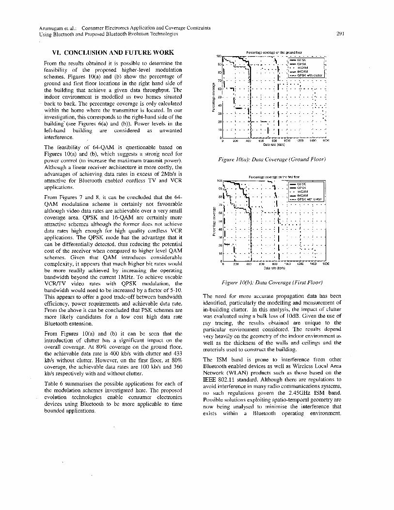
Arumugam et al Using Bluetooth and Proposed Bluetooth Evolution Technologies
Consumer Electronics Application and Coverage Constraints
VI CONCLUSION AND FUTURE WORK From the results obtained it is possible to determine the feasibility of the proposed higher-level modulation schemes Figures 10(a) and (b) show the percentage of ground and first floor locations in the right hand side of the building that achieve a given data throughput The indoor environment is modelled as two homes situated back to back The percentage coverage is only calculated within the home where the transmitter is located In our investigation this corresponds to the right-hand side of the building (see Figures 6(a) and (b)) Power levels in the left-hand building are considered as unwanted interference
The feasibility of 64-QAM is questionable based on Figures 10(a) and (b) which suggests a strong need for power control (to increase the maximum transmit power) Although a linear receiver architecture is more costly the advantages of achieving data rates in excess of 2Mbs is attractive for Bluetooth enabled cordless TV and VCR applications
From Figures 7 and 8 it can be concluded that the 64- QAM modulation scheme is certainly not favourable although video data rates are achievable over a very small coverage area QPSK and 16-QAM are certainly more attractive schemes although the former does not achieve data rates high enough for high quality cordless VCR applications The QPSK mode has the advantage that it can be differentially detected thus reducing the potential cost of the receiver when compared to higher level QAM schemes Given that QAM introduces considerable complexity it appears that much higher bit rates would be more readily achieved by increasing the operating bandwidth beyond the current IMHz To achieve useable VCRTV video rates with QPSK modulation the bandwidth would need to be increased by a factor of 5-1 0 This appears to offer a good trade-off between bandwidth efficiency power requirements and achievable data rate From the above it can be concluded that PSK schemes are more likely candidates for a low cost high data rate Bluetooth extension
From Figures 10(a) and (b) it can be seen that the introduction of clutter has a significant impact on the overall coverage At 80 coverage on the ground floor the achievable data rate is 400 kbs with clutter and 433 kbs without clutter However on the first floor at 80 coverage the achievable data rates are 100 kbs and 360 kbs respectively with and without clutter
Table 6 summarises the possible applications for each of the modulation schemes investigated here The proposed evolution technologies enable consumer electronics devices using Bluetooth to be more applicable to time bounded applications
29 1
Percentaue cowraue on the ground floor
1 - _I - -t
I
0 200 400 600 800 1000 1200 1400 1600 Data rate (kWs)
Figure IO(a) Data Coverage (Ground Floor)
Percentage c o w a g e on the first floor
0 200 400 600 800 1000 1200 1400 1600 Data rate (kWs)
Figure 10(b) Data Coverage (First Floor)
The need for more accurate propagation data has been identified particularly the modelling and measurement of in-building clutter In this analysis the impact of clutter was evaluated using a bulk loss of 10dB Given the use of ray tracing the results obtained are unique to the particular environment considered The results depend very heavily on the geometry of the indoor environment as well as the thickness of the walls and ceilings and the materials used to construct the building
The ISM band is prone to interference from other Bluetooth enabled devices as well as Wireless Local Area Network (WLAN) products such as those based on the IEEE 8021 1 standard Although there are regulations to avoid interference in many radio communications systems no such regulations govern the 245GHz ISM band Possible solutions exploiting spatio-temporal geometry are now being analysed to minimise the interference that exists within a Bluetooth operating environment
292 IEEE Transactions on Consumer Electronics Vol 47 No 3 AUGUST 2001
Time-bounded Non-time bounded Low data rate non-time
moderately good digital browsing cordless
modems and PDAs
Table 6 Consumer electronics application using the present and proposed Bluetooth evolution technologies
ACKNOWLEDGEMENTS AK Arumugam and BS Lee wishes to thank the Overseas Research Scholarship (ORs) UK for the financial support provided in funding this work In addition AK Arumugam also wishes thank the Institution of Electrical Engineers (IEE) UK for the financial support provided by the Robinson Research Fellowship fund
REFERENCES 1 The complete guide to Bluetooth from TOSHIBA 2 The Bluetooth Standard Version 1 Ob
(httpNwWw bluetoothcom) 3 JCHaartsen ldquoBLUETOOTHTM A new radio
interface providing ubiquitous connectivityrdquo Proceedings of VTC 2000 Tokyo Japan 2000
4 D Clancy ldquoThe Great Debate - DECT versus PHSrdquo Mobile Communications International Dec 1997
5 Mohammed Ghanbari ldquoVideo coding an introduction to standard codesrdquo
6 ISOIEC International Standard 138 182 Generics Coding of Moving Pictures and Associated Audio Information Video 1995
7 JC Haartsen Ericsson Radio Systems BV ldquoThe Bluetooth Radio Systemrdquo IEEE Personal Communications Feb2000
8 R Schneiderman (Contributing Editor) ldquoBluetoothrsquos slow dawnrdquo IEEE Spectrum Nov 2000
9 JCHaartsen ldquoBLUETOOTH - The universal radio interface for ad hoc wireless connectivityrdquo Ericsson Review No3 1998
IO AJ Viterbi and JK Omura ldquoPrinciples of Digital Communications and Codingrdquo by McGraw Hill Book Company 0 1979
IIMFTariq P Czerepinski A Nix DBull and NCanagarajah ldquoRobust and Scalable Matching Pursuits Video Transmission Using the Bluetooth Air Interface Standardrdquo IEEE Transactions on Consumer Electronics Vol 46 No 3 August 2000
12 BSLee ARNix JPMcCeehan ldquoIndoor Space-Time Propagation Modelling Using A Ray Launching Techniquerdquo IEE International Conference on Antenna and Propagation Manchester April 2001
13Tarng JH Chang WR and Hsu BJ IEEE Transactions on Vehicular Technology Vol 46 No 2
14 Kouyoumjian RG and Pathak PH IEEE Proceedings Vo162 No 11 pp 1448-1461 1974
15 Kanatas AG Kountouris ID Kostaras GB and Constantinou P IEEE Transactions on Vehicular Technology V0146 No1 pp 185-193 Feb 1997
16GEAthanasiadou and A Nix ldquoA Novel 3-D Indoor Ray-Tracing Propagation Model The Path Generator and Evaluation of Narrow-Band and Wide-Band Predictionsrdquo IEEE Transactions on Vehicular Technology Vol 49 No 4 July 2000
17 Seiichi Sampei ldquoApplications of Digital Wireless Technologies to Global Wireless Communicationsrdquo 0 1997 by Prentice Hall PT
pp 519-527 1997
Arumugam et al Using Bluetooth and Proposed Bluetooth Evolution Technologies
Consumer Electronics Application and Coverage Constraints 293
BIOGRAPHIES member of IEEE
Arun Kumar Arumugam was born in Malaysia in 1977 He obtained a BEng in Electronic and Communications Engineering in 1999 from the University of Bristol He is currently studying for a PhD at the University of Bristol He was awarded
the Robinson Research Fellowship by the Institution of Electrical Engineers (IEE) UK in November 2000 His research interests are in enhancements of the Bluetooth technology and interference suppression techniques exploiting space-time block codes and antenna diversity for Bluetooth enabled devices
Simon Armour received his BEng degree from the University of Bath (UK) in 1996 He has subsequently undertaken study for a PhD at the University of Bristol (UK) on the subject of Combined OFDM- Equalisation Strategies Following a period of post-doctoral research in the
area of advanced Wireless LAN technologies he was appointed to the position of Lecturer in Software Radio in 2001 His research interests include Software Radio Wireless LANsPANs Wireless Home Networks and Multicarrier Modulation He is a member of the IEE and IEEE
Beng-Sin Lee was born in Singapore in 1971 He received a BEng in Electronic Engineering in 1998 from the University of Bristol He is currently studying for a PhD in Electronic Engineering at the University of Bristol His main research interests are in the area of radio propagation namely site specific
wireless channel modelling in indoor and outdoor environments
M Fahim Tariq obtained a BSc in Electrical and Electronic Engineering in 1994 from the Eastern Mediterranean University in Turkey He joined the Centre for Communications Research University of Bristol UK in 1995 where he
received PhD in the area of Channel Adaptive Modem Design in Jan 2001 Dr Tariq is currently a Research Associate working in the digital communications group His research interests include advanced modulation and coding techniques adaptive equalisation channel modelling and capacity evaluation techniques He is a
Andrew Nix received BEng and PhD degrees from the University of Bristol (UK) in 1989 and 1993 respectively He joined the lecturing staff at the University of Bristol in 1992 and was promoted to Professor of Wireless Communication Systems in 2001 His main research interests include radiowave propagation modelling
cellular optimisation and advanced digital modulationreception techniques At present he leads the propagation modelling and wireless Local Area Network groups in the Centre for Communications Research (CCR) He has published in excess of 160 Journal and Conference papers in addition to contributions to three related textbooks In the area of propagation modelling his group has developed state of the art deterministic propagation models for indoor microcellular and macrocellular scenarios He is an active member of ETSI BRAN (Broadband Radio Access Networks) and a member of the IEEE