aryal s1 inverter 10 aryal s1 inverter 12 aryal s1 … s1... · 2018-01-29 · 2 avvertenze 1....
TRANSCRIPT

ARYAL S1 INVERTER 10ARYAL S1 INVERTER 12ARYAL S1 INVERTER 18ARYAL S1 INVERTER 24

2
AVVERTENZE
1. L’apparecchio può essere utilizzato da bambini di età non inferiore a 8 anni e da persone con ridotte
e alla comprensione dei pericoli ad esso inerenti.
WARNINGS
1. The appliance may be used by children over 8 years of age and by persons with reduced physical, sensorial or mental capacities, or without the required experience or knowledge, provided they are supervised or have been instructed in the safe use of the appliance and understand the hazards involved. 2. Children must not play with the equipment.3. Children must not be allowed to clean the appliance or perform user maintenance without proper supervision.4. If the power cable is damaged, it must be replaced by the manufacturer or by its technical support
6. To prevent the risk of an electric shock it is mandatory to switch off the main switch before performing the electrical connections or any maintenance operation to the appliances.
I
GB

3
AVERTISSEMENTS
appareils.
WARNHINWEISE
1. Kindern ab 8 Jahren sowie Personen mit körperlichen, sensoriellen oder mentalen Beeinträchtigungen beziehungsweise Personen ohne entsprechende Erfahrung oder Kenntnisse darf die Benutzung des Geräts erlaubt werden unter der Bedingung, dass die Kinder sowie die genannten Personen beaufsichtigt beziehungsweise in die für die Verwendung des Geräts geltenden Sicherheitsvorkehrungen eingewiesenen wurden und die mit dem Gerät verbundenen Gefahren verstanden haben.2. Kinder dürfen nicht mit dem Gerät spielen.
Kindern durchgeführt werden.4. Wenn das Stromkabel beschädigt ist, muss dieses zur Vermeidung jeglicher Gefahren vom Hersteller
Personal ersetzt werden, um jeglicher Gefahr vorzubeugen.5. Installation, erste Inbetriebnahme und die anschließenden Wartungsphasen, ausgenommen Reinigung oder Waschen, sind ausschließlich durch befugtes Fachpersonal auszuführen.6. Zur Vorbeugung jeglicher Stromschlaggefahr ist unbedingt der Hauptschalter abzustellen, bevor irgendwelche elektrischen Anschlüsse hergestellt oder Wartungsarbeiten an den Geräten durchgeführt werden.7. Während der Installation sind die in den Abbildungen angegebenen Mindestabstände einzuhalten.8. Befolgen Sie während des elektrischen Anschlusses des Geräts die Anweisungen in Abb.
F
D

4
ADVERTENCIAS
E
ADVERTÊNCIAS
1. O aparelho só pode ser utilizado por crianças de idade superior aos 8 anos e por pessoas com capacidades físicas, sensoriais ou mentais reduzidas, ou que não possuam a experiência ou os conhecimentos necessários, desde que sob vigilância ou depois de terem recebido as instruções relativas à utilização do aparelho em segurança e terem compreendido os perigos inerentes à mesma.2. As crianças não devem brincar com o aparelho.3. A limpeza e a manutenção destinada a ser efetuada pelo utilizador não deve ser efetuada por crianças sem vigilância.4. Se o cabo de alimentação está estragado, deve ser substituído pelo fabricante ou pelo seu
evitar qualquer tipo de risco.5. A instalação, o primeiro acionamento e as outras fases de manutenção, exceto a limpeza ou a
6. Para evitar qualquer risco de choque elétrico é indispensável desligar o interruptor geral antes de efetuar ligações elétricas ou qualquer outro trabalho de manutenção nos aparelhos.
P

5
WAARSCHUWINGENNL
GR

GB F D
6
IGENERALITA’
1.1 INFORMAZIONI GENERALI
1.2 SIMBOLOGIA
sicurezza 1.3 USO PREVISTO
1.4 ZONE DI RISCHIO 1.5 LISTA DEGLI
ACCESSORI FORNITI
INSTALLAZIONE
2.1 MODALITÀ D’INSTALLAZIONE
2.2 SCELTA DELLA POSIZIONE DELL’UNITÀ INTERNA
2.3 MONTAGGIO DELL’UNITÀ INTERNA
2.3.2 Staffa
tubi2.3.4 Tubo di connessione2.3.5 Installazione unità interna2.4 MONTAGGIO
DELL’UNITÁ ESTERNA2.4.1 Scelta della posizione
dell’unità esterna
2.4.3 Apparecchi a pompa di calore
allacciamenti delle linee
2.4.7 Vuoto impianto
2.4.8 Riempimento impianto
2.4.9 Allacciamento della linea di scarico condensa
2.4.10 Allacciamenti elettrici
all’unità esterna 2.4.12 Alimentazione elettrica
USO E MANUTENZIONE (parte utente)
3.1 USO DEL TELECOMANDO
3.1.1 Inserimento delle batterie 3.1.2 Sostituzione delle batterie3.1.3 Posizione del telecomando
3.2 COMPONENTI DEL SISTEMA
10
20 2020
22
2224
2626
28
30
32
32
3434
363840
40
44
46
4648
5456
56
60
6264
6668
70
727274
76
GENERALITES
1.1 INFORMATIONS GÉNÉRALES
1.2 SYMBOLOGIE1.2.1
1.3 UTILISATION PRÉVUE
1.4 ZONES À RISQUE1.5 LISTE DES
ACCESSOIRES FOURNIS
INSTALLATION
2.1 MODE D’INSTALLATION
2.2 CHOIX DE LA POSITION DE L’UNITE INTERIEURE
2.3 MONTAGE DE L’UNITE INTERIEURE
2.3.2 Etrier
2.3.4 Tube de raccordement
2.4 MONTAGE DE L’UNITE EXTERIEURE
2.4.3 Appareils à pompe à chaleur
branchements des
l’installation
l’installation2.4.9 Branchement de la
condensat
2.4.11 Raccordement du câble à
l’utilisateur
MODE D’EMPLOI ET ENTRETIEN (partie utilisateur)
3.1 MODE D’EMPLOI DE LA TELECOMMANDE
3.1.1 Mise en place des piles3.1.2 Remplacement des piles3.1.3 Position de la
3.2 COMPOSANTS DU SYSTEME
ALLGEMEINES
1.1 ALLGEMEINE HINWEISE
1.2 BILDSYMBOLE1.2.1 Bildsymbole1.2.2 Bildsymbole zur Sicherheit
1.3 BEST IMMUNGS-GEMÄSSE VERWENDUNG
1.4 GEFAHRENBEREICHE1.5 LISTE DER GELIEFERTEN
ZUBEHÖRS 1.5.1 Lagerung1.5.2 Erhalt und Auspacken des
Gerätes
INSTALLATION
2.1 HINWEISE ZUR INSTALLATION
2.2 POSITIONIERUNG DER INNENEINHEIT
2.3 MONTAGE DER INNENEINHEIT
2.3.1 Montage der Befestigungs-platte
2.3.2 Haltebügel 2.3.3 Bohrung für das
Durchführen der Rohre2.3.4 Anschlussschlauch 2.3.5 Installation der Inneneinheit2.4 MONTAGE DER
AUSSENEINHEIT2.4.1 Positionierung der
Außeneinheit2.4.2 Hinweise zur Montage
2.4.3 Geräte mit Wärmepumpe
2.4.4 Montage der Außeneinheit2.4.5 Verlegung und Anschluss
der Kühlleitungen
2.4.6 Überprüfungen2.4.7 Vakuumerzeugung in der
Anlage2.4.8 Füllung der Anlage
2.4.9 Anschluss der Kondenswas-serableitung
2.4.10 Elektrische Anschlüsse2.4.11 Anschluss des Kabels an
die Außeneinheit 2.4.12 Stromversorgung2.4.13 Übergabe der Anlage
BEDIENUNG UND WARTUNG (Benutzer)
3.1 BENUTZUNG DER FERNBEDIENUNG
3.1.1 Einlegen der Batterien3.1.2 Austausch der Batterien3.1.3 Position der
Fernbedienung3.2 SYSTEMKOMPONENTEN
GENERAL INFORMATION
1.1 GENERAL INFORMATION
1.2 SYMBOLS1.2.1 Editorial pictograms1.2.2 Safety pictograms
1.3 PROPER USE
1.4 HAZARDOUS ZONES1.5 LIST OF ACCESSORIES
SUPPLIED 1.5.1 Storage1.5.2 Receipt and unpacking
INSTALLATION
2.1 INSTRUCTIONS FOR INSTALLATION
2.2 SELECTION OF POSITION OF THE INSIDE UNIT
2.3 INSTALLATION OF THE INSIDE UNIT
2.3.1 Installation of fastening plate
2.3.2 Brace2.3.3 Drilling pipe passage holes
2.3.4 Connective pipe 2.3.5 Indoor unit installation2.4 INSTALLATION OF
OUTSIDE UNIT2.4.1 Selection of position for
outside unit2.4.2 Instructions for installation
2.4.3 Air-conditioner with heat pump
2.4.4 Installation of outside unit2.4.5 Installation and connection
of cooling lines
2.4.6 Tests and inspection2.4.7 System vacuum
2.4.8 Filling the system
2.4.9 Connection of condensation discharge line
2.4.10 Electric connections2.4.11 Connect the cable to the
outdoor unit 2.4.12 Power supply2.4.13 Delivery of the system
USE AND MAINTENANCE (for the user)
3.1 USE OF THE REMOTE CONTROL
3.1.1 Insertion of batteries3.1.2 Replacement of batteries3.1.3 Location of the remote
controller3.2 COMPONENTS OF THE
SYSTEM

E GR
7
P NL
11
2121
21
23
2325
2727
29
31
33
33
3535
3739
41
41
45
47
47
49
5557
5761
6365
6769
71
737375
77
GENERALIDADES
1.1 INFORMACIONES GENERALES
1.2 SIMBOLOGÍA
1.3 USO PREVISTO
1.4 ZONAS DE RIESGO1.5 LISTA DE ACCESORIOS
SUMINISTRADOS
1.5.1 Almacenamiento
INSTALACIÓN
2.1 MODALIDAD DE LA INSTALACIÓN
2.2 ELECCIÓN DE LA POSICIÓN DE LA UNIDAD INTERNA
2.3 MONTAJE DE LA UNIDAD INTERNA
2.3.2 Estribo
el paso de los tubos
2.3.5 Instalación unidad interior
2.4 MONTAJE DE LA UNIDAD EXTERNA
2.4.1 Elección de la posición de
calor
instalación2.4.8 Llenado de la instalación
condensación
USO Y MANTENIMIENTO (parte usuario)
3.1 USO DEL MANDO A DISTANCIA
3.1.1 Inserción de las pilas 3.1.2 Substitución de las pilas3.1.3 Posición del control remoto
3.2 COMPONENTES DEL SISTEMA
GENERALIDADES
1.1 INFORMAÇÕES GERAIS
1.2 SIMBOLOGIA1.2.1 Pictogramas redaccionais
1.2.2 Pictogramas relativos à segurança
1.3 USO PREVISTO
1.4 ZONAS A RISCO1.5 LISTA DOS ACESSÓRIOS
FORNECIDOS
1.5.1 Armazenagem1.5.2 Recebimento e
desembalagem
INSTALAÇÃO
2.1 MODALIDADE DE INSTALAÇÃO
2.2 ESCOLHA DA POSIÇÃO DA UNIDADE INTERNA
2.3 MONTAGEM DA UNIDADE INTERNA
2.3.1 Montagem da placa de
2.3.2 Braçadeira 2.3.3 Execução do furo para a
passagem dos tubos2.3.4 Tubo di conexão 2.3.5 Instalação da unidade
interna2.4 MONTAGEM DA
UNIDADE EXTERNA2.4.1 Escolha da posição da
unidade externa2.4.2 Advertências de
montagem2.4.3 Aparelhos com bomba de
calor 2.4.4 Montagem da unidade
externa2.4.5 Execução, assentamento
e ligação das linhas de refrigeração
2.4.7 Sistema de vácuo
2.4.8 Enchimento da máquina2.4.9 Ligação da linha de
descarga da condensação
2.4.10 Ligações eléctricas2.4.11 Conexão do cabo à
unidade externa 2.4.12 Alimentação eléctrica2.4.13 Entrega do aparelho
USO E MANUTENÇÃO (parte do utilizador)
3.1 USO DO TELECOMANDO
3.1.1 Introdução das pilhas3.1.2 Substituição das pilhas3.1.3 Posição do telecomando
3.2 COMPONENTES DO SISTEMA
ALGEMEEN
1.1 ALGEMENE INFORMATIE
1.2 SYMBOLEN1.2.1 Redactionele
1.3 BEOOGD GEBRUIK
1.4 RISICOZONES1.5 LIJST VAN DE
GELEVERDE ACCESSOIRES
INSTALLATIE
2.1 INSTALLATIEWIJZEN
2.2 KEUZE VAN DE POSITIE VAN DE BINNENUNIT
2.3 MONTAGE VAN DE BINNENUNIT
2.3.5 Installatie binnenunit
2.4 MONTAGE VAN DE BUITENUNIT
de buitenunit
2.4.3 Apparaten met
2.4.6 Testen en controles2.4.7 Vacuüm installatie
met de buitenunit
USO E MANUTENÇÃO (parte do utilizador)
3.1 USO DO TELECOMANDO
3.1.1 Introdução das pilhas3.1.2 Substituição das pilhas3.1.3 Posição do telecomando
3.2 COMPONENTES DO SISTEMA

GB F D
8
I3.3 INDICATORI DI
FUNZIONE SUL DISPLAY DELL’UNITA’ INTERNA
3.4 DESCRIZIONE DEL TELECOMANDO
3.4.1 Indicatori sul telecomando
3.4.2 Descrizione dei pulsanti 3.5 PROGRAMMAZIONE3.5.1 Funzionamento automatico3.5.2 Funzionamento in
Raffreddamento/Riscaldamento/Solo
3.6 REGOLAZIONE DELLA DIREZIONE DELL’ARIA
(alto - basso)3.7 DEUMIDIFICAZIONE3.8 FUNZIONAMENTO CON
TIMER
di accensione dal telecomando
telecomando3.8.3 Timer combinato3.8.4 Timer ON => Timer OFF3.9 FUNZIONAMENTO
MANUALE3.10 MANUTENZIONE
E PULIZIA DEL CLIMATIZZATORE
3.10.1 Pulizia dell’unità interna e del telecomando
3.11 MANUTENZIONE3.12 CONSIGLI PER IL
RISPARMIO ENERGETICO3.13 ASPETTI FUNZIONALI
DA NON INTERPRETARE COME INCONVENIENTI
4.1 SCHEMA ELETTRICO DELL’UNITÀ INTERNA MODELLO 9 E 12
4.2 SCHEMA ELETTRICO DELL’UNITÀ ESTERNA MODELLO 9 E 12
4.3 SCHEMA ELETTRICO DELL’UNITÀ INTERNA MODELLO 18 E 24
4.4 SCHEMA ELETTRICO DELL’UNITÀ ESTERNA MODELLO 18
CARATTERISTICHE TECNICHESUGGERIMENTI PER L’ELIMINAZIONE GUASTI
78
80
80
82909092
94
94
98100
102
102
104106108
110
110
112114116
116
122
122
124
124
126130
3.3 INDICATEURS DE FONCTION SUR L’AFFICHEUR DE L’UNITE INTERNE
3.4 DESCRIPTION DE LA TELECOMMANDE
3.4.2 Description des boutons 3.5 PROGRAMMATION3.5.1 3.5.2 Fonctionnement en
mode Refroidissement/
seule 3.6 REGLAGE DE LA
DIRECTION DE L’AIR
bas)3.7 DESHUMIDIFICATION 3.8 FONCTIONNEMENT
AVEC TEMPORISATEUR
telecommande
telecommande 3.8.3 Temporisateur combine3.8.4 Timer ON => Timer OFF 3.9 FONCTIONNEMENT
MANUEL 3.10 ENTRETIEN ET
NETTOYAGE DU CLIMATISEUR
3.10.1
3.11 ENTRETIEN3.12 CONSEILS POUR
L’ECONOMIE D’ENERGIE3.13 ASPECTS
FONCTIONNELS A NE PAS INTERPRETER COMME INCONVENIENTS
4.1 SCHEMA ELECTRIQUE DE L’UNITE INTERNE MODELE 9 ET 12
4.2 SCHEMA ELECTRIQUE DE L’UNITE EXTERNE MODELE 9 ET 12
4.3 SCHEMA ELECTRIQUE DE L’UNITE INTERNE MODELE 18 ET 24
4.4 SCHEMA ELECTRIQUE DE L’UNITE EXTERNE MODELE 18
CARACTERISTIQUES SUGGESTIONS POUR L’ELIMINATION DES PANNES
3.3 FUNKTIONSANZEIGEN AUF DEM DISPLAY DER INNENEINHEIT
3.4 BESCHREIBUNG DER FERNBEDIENUNG
3.4.1 Anzeigen auf der Fernbedienung
3.4.2 Beschreibung der Taster 3.5 PROGRAMMIERUNG3.5.1 Automatikbetrieb 3.5.2 Betrieb im Modus Kühlung/
Heizung/Nur Belüftung
3.6 REGELUNGDER LUFTSTRÖMUNGSRICHTUNG
3.6.1 Regelung der vertikalen Luftströmungsrichtung (oben - unten)
3.7 ENTFEUCHTEN 3.8 BETRIEB MIT TIMER
3.8.1 Setup timer für einschaltung
3.8.2 Setup timer für ausschaltung von fernbedienung
3.8.3 Kombinierter timer3.8.4 Timer ON => Timer OFF 3.9 HANDBETRIEB
3.10 WARTUNG UND REINIGUNG DES KLIMAGERÄTES
3.10.1 Reinigung der Inneneinheit und der Fernbedienung
3.11 WARTUNG3.12 TIPPS ZUM
ENERGIESPAREN3.13 FUNKTIONALE
ASPEKTE, DIE NICHT ALS STÖRUNGEN ZU VERSTEHEN SIND
4.1 ELEKTRISCHER SCHALTPLAN DER INNENEINHEIT MODELL
9 UND 124.2 ELEKTRISCHER
SCHALTPLAN DER AUSSENEINHEIT MODELL 9 UND 12
4.3 ELEKTRISCHER SCHALTPLAN DER INNENEINHEIT MODELL 18 UND 24
4.4 ELEKTRISCHER SCHALTPLAN DER AUSSENEINHEIT MODELL 18
TECHNISCHE MERKMALEHINWEISE ZU FEHLERBEHEBUNG
3.3 FUNCTION INDICATORS ON INDOOR UNIT DISPLAY PANEL
3.4 ESCRIPTION OF REMOTE CONTROL
3.4.1 Indicators on remote controller
3.4.2 Description of buttons 3.5 PROGRAMMING3.5.1 Automatic operation 3.5.2 Cooling/Heating/Fan only
operation
3.6 ADJUSTING AIR FLOW DIRECTION
3.6.1 Adjusting the Vertical Air Flow Direction (up - down)
3.7 DRYING OPERATION 3.8 TIMER OPERATION
3.8.1 Setting switch-on timer from remote control
3.8.2 Setting switch-off timer from remote control
3.8.3 Combined timer3.8.4 Timer ON => Timer OFF 3.9 MANUAL OPERATION
3.10 MAINTENANCE AND CLEANING OF THE AIR-CONDITIONER
3.10.1 Cleaning the indoor unit and remote controller
3.11 MAINTENANCE3.12 RECOMMENDATIONS
FOR ENERGY SAVINGS3.13 FUNCTIONAL ASPECTS
NOT TO BE MISTAKEN FOR ANOMALIES
4.1 9 AND 12 MODEL INTERNAL UNIT WIRING DIAGRAM
4.2 9 AND 12 MODEL EXTERNAL UNIT WIRING DIAGRAM
4.3 18 AND 24 MODEL INTERNAL UNIT WIRING DIAGRAM
4.4 18 MODEL EXTERNAL UNIT WIRING DIAGRAM
TECHNICAL FEATURESTROUBLESHOOTING TIPS

E GR
9
P NL79
81
81
83
9191
93
95
95
99101
103
103
105107109
111
111
113
115117
117
123
123
125
125
127131
3.3 INDICADORES DE FUNCIÓN EN EL DISPLAY DE LA UNIDAD INTERIOR
3.4 DESCRIPCIÓN DEL MANDO A DISTANCIA
3.4.1 Indicadores en el control remoto
3.4.2 Descripción de los botones
3.5 PROGRAMACIÓN3.5.1 Funcionamiento
automático 3.5.2 Funcionamiento en modo
3.6 REGULACIÓN DE LA DIRECCIÓN DEL AIRE
3.7 DESHUMIDIFICACIÓN 3.8 FUNCIONAMIENTO CON
TEMPORIZADOR
encendido mediante el control remoto
control remoto
3.8.3 Temporizador combinado3.8.4 Timer ON => Timer OFF 3.9 FUNCIONAMIENTO
MANUAL 3.10 MANTENIMIENTO
Y LIMPIEZA DEL CLIMATIZADOR
3.10.1 Limpieza de la unidad
3.11 MANTENIMIENTO3.12 CONSEJOS PARA EL
AHORRO DE ENERGÍA
3.13 ESTOS ASPECTOS FUNCIONALES NO DEBEN SER INTERPRETADOS COMO INCONVENIENTES
4.1 ESQUEMA ELÉCTRICO DE LA UNIDAD INTERIOR MODELO
9 Y 124.2 ESQUEMA ELÉCTRICO
DE LA UNIDAD EXTERIOR MODELO
9 Y 124.3 ESQUEMA ELÉCTRICO
DE LA UNIDAD INTERIOR MODELO 18 Y 24
4.4 ESQUEMA ELÉCTRICO DE LA UNIDAD EXTERIOR MODELO 18
CARACTERÍSTICAS TÉCNICASSUGERENCIAS PARA LA REPARACIÓN DE AVERÍAS
3.3 INDICADORES DE FUNÇÃO NO VISOR DA UNIDADE INTERNA
3.4 DESCRIÇÃO DO TELECOMANDO
3.4.1 Indicadores no telecomando
3.4.2 Descrição dos botões
3.5 PROGRAMAÇÃO3.5.1 Funcionamento automático 3.5.2 Funcionamento em
modalidade Arrefecimento/Aquecimento/Só ventilação
3.6 REGULAÇÃO DA DIRECÇÃO DO AR
3.6.1 Regulação da direcção vertical do ar (alto - baixo)
3.7 DESUMIDIFICAÇÃO 3.8 FUNCIONAMENTO COM
TEMPORIZADOR 3.8.1 Programação do
temporizador de ligação no telecomando
3.8.2 Programação do temporizador de desligação no telecomando
3.8.3 Temporizador combinado3.8.4 Timer ON => Timer OFF 3.9 FUNCIONAMENTO
MANUAL3.10 MANUTENÇÃO
E LIMPEZA DO CLIMATIZADOR
3.10.1 Limpeza da unidade interna e do telecomando
3.11 MANUTENÇÃO3.13 CONSELHOS PARA
POUPAR ENERGIA
3.13 ASPECTOS DE FUNCIONAMENTO A NÃO CONSIDERAR COMO PROBLEMAS
4.1 ESQUEMA ELÉCTRICO DA UNIDADE INTERNA MODELO 9 O 12
4.2 ESQUEMA ELÉCTRICO DA UNIDADE EXTERNA MODELO 9 O 12
4.3 ESQUEMA ELÉCTRICO DA UNIDADE INTERNA MODELO 18 O 24
4.4 ESQUEMA ELÉCTRICO DA UNIDADE EXTERNA MODELO 18
CARACTERÍSTICAS TÉCNICASCONSELHOS PARA A RESOLUÇÃO DE AVARIAS
3.3 FUNCTIE-INDICATORS OP HET DISPLAY VAN DE BINNENUNIT
3.4 BESCHRIJVING VAN DE AFSTANDSBEDIENING
3.4.1 Indicators op de
knoppen 3.5 PROGRAMMERING
3.6 INSTELLING VAN DE RICHTING VAN DE LUCHTSTROOM
3.7 ONTVOCHTIGING 3.8 WERKING MET TIMER
3.8.3 Gecombineerde timer3.8.4 Timer ON => Timer OFF3.9 MANUELE WERKING
3.10 ONDERHOUD EN REINIGING VAN DE KLIMAATREGELAAR
3.11 ONDERHOUD3.12 WENKEN VOOR DE
ENERGIEBESPARING
3.13 FUNCTIONELE ASPECTEN DIE NIET ALS ONGEMAKKEN BESCHOUWD MOETEN WORDEN
4.1 ELEKTRISCH SCHEMA VAN DE BINNENUNIT MODEL 9 EN 12
4.2 ELEKTRISCH SCHEMA VAN DE BUITENUNIT MODEL 9 EN 12
4.3 ELEKTRISCH SCHEMA VAN DE BINNENUNIT MODEL 18 EN 24
4.4 ELEKTRISCH SCHEMA VAN DE BUITENUNIT MODEL 18
TECHNISCHE KENMERKENWENKEN VOOR HET VERHELPEN VAN DEFECTEN

GB F D
10
I1GENERALITA’
INFORMAZIONI GENERALI
trasmissione a terzi senza esplicita autorizzazione della ditta OLIMPIA SPLENDID.Le macchine possono subire
L e g g e r e a t t e n t a m e n t e i l p r e s e n t e m a n u a l e p r i m a di procedere con qualsiasi operaz ione ( insta l laz ione, manutenzione, uso) ed attenersi scrupolosamente a quanto descritto nei singoli capitoli.
LA DITTA COSTRUTTRICE NON SI ASSUME RESPONSABILITÀ PER DANNI A PERSONE O COSE DERIVANTI DALLA MANCATA OSSERVANZA DELLE NORME CONTENUTE NEL PRESENTE LIBRETTO.
La ditta costruttrice si riserva
in qualsiasi momento ai propri modell i , fermo restando le
descritte nel presente manuale.
L’installazione e la manutenzione
climatizzazione come la presente potrebbero risultare pericolose in quanto all’interno di questi
refrigerante sotto pressione e componenti elettrici sotto tensione.Pertanto l’installazione, il primo avviamento e le successive fasi di manutenzione devono essere eseguite esclusivamente da personale autorizzato e
GENERAL INFORMATION
GENERAL INFORMATION
This document is restricted in use to the terms of the law and may not be copied or transferred to third parties without the express authorization of the manufacturer, OLIMPIA SPLENDID.Our machines are subject to change and some parts may appear different from the ones shown here, without this affecting the text of the manual in any way.
Read this manual carefully before performing any operation (installation, maintenance, use) and follow the instructions contained in each chapter.
THE MANUFACTURER IS NOT RESPONSIBLE FOR DAMAGES TO PERSONS OR PROPERTY CAUSED BY FAILURE TO FOLLOW THE INSTRUCTIONS IN THIS MANUAL.
The manufacturer reserves the right to make any changes it deems advisable to its models, although the essential features described in this manual remain the same.
The installation and maintenance of air-conditioners like this one may be hazardous as they contain a cooling gas under pressure as well as powered parts.Therefore, the installation, first startup and subsequent maintenance should be carried out exclusively by authorized,
GENERALITES
INFORMATIONS GÉNÉRALES
ou de transmission à tiers sans
OLIMPIA SPLENDID.
dans ce manuel.
Lire attentivement le présent manuel avant de procéder à toute opération (installation, entretien, utilisation) et suivre scrupuleusement ce qui est
LE FABRICANT DECLINE TOUTE RESPONSABILITE EN CAS DE DOMMAGES AUX PERSONNES OU AUX BIENS DERIVANT DU NON-RESPECT DES NORMES CONTENUES DANS LE PRESENT LIVRET.
Le fabricant se réserve le droit d’apporter à tout moment des
t o u t e n c o n s e r v a n t l e s caractéristiques essentielles décrites dans le présent manuel.
L’installation et l ’entretien d ’ a p p a r e i l s p o u r l a cl imatisat ion comme celui qui est décrit dans ce manuel pourraient être dangereux étant donné qu’il se trouve à l’intérieur de ces appareils un gaz
que des composants électriques sous tension.Par conséquent l’installation, la
d o i v e n t ê t r e e f f e c t u é e s exclusivement par un personnel
ALLGEMEINES
ALLGEMEINE HINWEISE
Laut Gesetz ist dies ein vertrauliches Dokument, daher gilt das Verbot der Vervielfältigung oder Übermittlung an Dritte ohne ausdrückliche Genehmigung der Firma OLIMPIA SPLENDID.An den Geräten können technische Neue rungen vo rgenommen werden, d.h. Einzelteile können u.U. anders aussehen als auf den Abbildungen, was jedoch die Gültigkeit der Anweisungen in diesem Benutzerhandbuch in keiner Weise beeinträchtigt.
Bevor Sie mit einer Tätigkeit b e g i n n e n ( I n s t a l l a t i o n , Instandhaltung, Gebrauch), lesen Sie aufmerksam das vorliegende Benutzerhandbuch und halten Sie sich strengstens an die in den einzelnen Kapiteln dargelegten Anweisungen.
D I E H E R S T E L L E R F I R M A Ü B E R N I M M T K E I N E R L E I VERANTWORTUNG FÜR SCHÄDEN AN PERSONEN ODER SACHEN, DIE DURCH NICHTBEACHTUNG D E R I M V O R L I E G E N D E N B E N U T Z E R H A N D B U C H E N T H A L T E N E N SICHERHEITSVORSCHRIFTEN ENTSTEHEN.
Die Herstel ler f i rma behält s i c h d a s R e c h t v o r , a n i h r e n M o d e l l e n j e d e r z e i t Veränderungen vorzunehmen, wobei die wesentlichen im vorliegenden Benutzerhandbuch b e s c h r i e b e n e n Geräteeigenschaften unverändert bleiben.
D i e I n s t a l l a t i o n u n d Instandhaltung von Klimaanlagen wie der hier beschriebenen können gefährlich sein, da sich im Inneren der Anlagen ein unter Druck stehendes
elektrische Bauteile enthalten, die unter Spannung stehen. Daher dürfen die Installation, die erste Inbetriebsetzung u n d d i e n a c h f o l g e n d e n I n s t a n d h a l t u n g s a r b e i t e n ausschließlich von autorisiertem und qualifiziertem Personal durchgeführt werden.
1.1

E GR
11
P NL 1GENERALIDADES
INFORMACIONES GENERALES
con prohibición de reproducción o transmisión a terceros sin la
OLIMPIA SPLENDID.
detal les dist intos respecto a
manual.
Leer atentamente el presente manua l an tes de rea l i zar cualquier tipo de operación (instalación, mantenimiento, uso) y abstenerse escrupulosamente a todo lo que se encuentra descripto en cada uno de los capítulos.
LA EMPRESA CONSTRUCTORA N O A S U M E N I N G U N A RESPONSABILIDAD POR DAÑOS EN PERSONAS O COSAS QUE DERIVEN DE LA FALTA DE OBSERVACIÓN DE LAS NORMAS CONTENIDAS EN EL PRESENTE MANUAL.
La empresa constructora se
modificaciones en cualquier momento en los propios modelos, manteniendo, sin embargo, las características esenciales descriptas en el presente manual.
La instalación y el mantenimiento de equipos para la climatización como el presente, podrían resultar peligrosos ya que en el interior
presentes un gas refrigerante bajo presión y componentes eléctricos bajo tensión.Por lo tanto la instalación, la
y las sucesivas fases de mantenimiento tienen que ser realizadas exclusivamente por
GENERALIDADES
INFORMAÇÕES GERAIS
Documento reservado nos termos da Lei que proíbe a reprodução ou a transmissão a terceiros sem explícita autorização da firma OLIMPIA SPLENDID.As máquinas poderão sofrer ac tua l izações e apresentar pormenores diferentes daqueles ilustrados, mas que não prejudicam o conteúdo dos textos presentes neste manual.
Ler atentamente o presente manual antes de efectuar qualquer operação (instalação, manutenção, uso) e respeitar escrupulosamente quanto descrito nos vários capítulos.
A FIRMA CONSTRUTORA NÃO SE ASSUME A RESPONSABILIDADE POR DANOS A PESSOAS OU A COISAS PROVOCADOS PELA INOBSERVÂNCIA DAS NORMAS CONTIDAS NO PRESENTE LIVRETE.
direito de efectuar alterações aos próprios modelos em qualquer momento, mantendo inalteradas as características essenciais descritas no presente manual.
A instalação e a manutenção de aparelhos para a climatização, como o presente, poderá resultar perigosa porque no interior destes aparelhos existe um gás refrigerante sob pressão e componentes elétricos sob tensão.Portanto a instalação, o primeiro funcionamento e as seguintes fases de manutenção devem ser executadas exclusivamente por
1.1
ALGEMEEN
ALGEMENE INFORMATIE
OLIMPIA SPLENDID.De machines
D E F A B R I K A N T S T E L T ZICH OP GENERLEI WIJZE A A N S P R A K E L I J K V O O R PERSOONLIJK LETSEL OF M AT E R I Ë L E S C H A D E D I E HET GEVOLG IS VAN DE VERONACHTZAMING VAN DE VOORSCHRIFTEN DIE IN DEZE HANDLEIDING STAAN.
v a n d e a p p a r a t u u r v o o r
starten en de daarop volgende
uitsluitend door geautoriseerd en
uitgevoerd.

GB F D
12
I1Fa i l i ng to comp ly w i th the instructions contained in this manual, and using the unit with temperatures exceeding the permissible temperature range will invalidate the warranty.
and general external cleaning can be done by the user as these operations are not difficult or dangerous.
During installation and maintenance, respect the precautions indicated in the manual, and on the labels applied inside the units, as well as all the precautions suggested by good sense and by the safety regulations in effect in your country.
A l w a y s w e a r g l o v e s a n d p r o t e c t i v e g o g g l e s w h e n performing any operations on the refrigerating side of the units.
Air conditioners MUST NOT be installed in places containing
gasses, or in very humid e n v i r o n m e n t s ( l a u n d r i e s , greenhouses, etc.), or in places where there are machines that generate very great heat.
In case of replacement of parts, use only original OLIMPIA SPLENDID parts.
IMPORTANT!To p r e v e n t a n y r i s k o f electrocution, always disconnect the main circuit breaker before making electric connections or performing any maintenance on the units.
dehors des instructions fournies par
sens commun et par les Normes
de l’installation.
I l faut toujours mettre des
de protection pour effectuer les interventions sur le côté réfrigérant des appareils.
Les climatiseurs NE DOIVENT PAS être installés dans des
inflammables, gaz explosifs,
(buanderies, serres, etc.), ou
une importante source de
En cas de remplacement d e c o m p o s a n t s , u t i l i s e r
SPLENDID.
IMPORTANT!Afin de prévenir tout risque d ’ é l e c t r o c u t i o n , i l e s t i n d i s p e n s a b l e d e c o u p e r le courant au dis joncteur principal avant d’effectuer des
toute opération d’entretien sur les appareils.
Installationen die nicht entsprechend den im vorliegenden Handbuch enthaltenen Anweisungen sowie der Einsatz unter Nichtbeachtung d e r v o r g e s c h r i e b e n e n Temperaturgrenzen, geben keinerlei Anspruch auf Garantie.
Die gewöhnliche Instandhaltung der Filter und die allgemeine äußerliche Reinigung können auch durch den Benutzer durchgeführt werden, da sie keine schwierigen oder gefährlichen Tätigkeiten erfordern.
W ä h r e n d d e r M o n t a g e u n d b e i s ä m t l i c h e n I n s t a n d h a l t u n g s t ä t i g k e i t e n müssen die Vorsichtsmaßnahmen eingehalten werden, die in diesem Benutzerhandbuch und auf den Schildern im Innern der Geräte angeführt sind; außerdem müssen sämtliche Vorsichtsmaßnahmen ergriffen werden, die der gesunde Menschenverstand gebietet und die durch die am Installationsort geltenden Sicherheitsbestimmungen vorgeschrieben sind.
B e i E i n g r i f f e n a n d e r Kühlseite der Geräte sind stets Schutzhandschuhe und Schutzbrille zu tragen.
Die Klimaanlagen DÜRFEN NICHT in Räumen installiert werden, in
denen hohe Feuchtigkeit herrscht (Wäschereien, Gewächshäuser usw.) oder in Räumen, in denen
viel Wärme freisetzen.
Bei der Auswechslung von Einzelteilen bitte ausschließlich original OLIMPIA SPLENDID-Ersatzteile verwenden.
WICHTIG!Um dem Risiko eines Stromschlags vorzubeugen, muss unbedingt der Hauptschalter ausgeschaltet werden, bevor elektr ische Anschlüsse hergestellt oder Instandhaltungsarbeiten an den Geräten vorgenommen werden.
manuale e l’utilizzo al di fuori dei limiti di temperatura prescritti fanno
d’installazione.
E’ necessario indossare sempre
pereseguire interventi sul lato
I climatizzatori NON DEVONO essere installati in ambienti con presenza di gas infiammabili, gas esplosivi , in ambienti molto umidi (lavanderie, serre, ecc.), o in locali dove sono
generano una forte fonte di calore.
I n c a s o d i s o s t i t u z i o n e d i c o m p o n e n t i u t i l i z z a r e e s c l u s i v a m e n t e r i c a m b i originali OLIMPIA SPLENDID.
IMPORTANTE!
staccare l’interruttore generale prima di effettuare collegamenti elettrici ed ogni operazione di

E GR
13
P NL 1
de temperatura prescritos decae
El ordinario mantenimiento de los
pueden ser realizadas
Es necesario llevar puestos guantes y gafas de protección para realizar intervenciones en la parte refrigerante de los equipos.
Los climatizadores NO DEBEN ser instalados en ambientes con presencia de gas inflamables, gas explosivos, en ambientes
invernaderos, etc.), o en locales donde se encuentren otras maquinarias que generen una fuerte fuente de calor.
E n c a s o d e s u b s t i t u c i ó n d e c o m p o n e n t e s u t i l i z a r exclusivamente repuestos originales OLIMPIA SPLENDID.
IMPORTANTE!Para prevenir el r iesgo de fulguración es indispensable desconectar el interruptor general antes de efectuar conexiones eléctricas y llevar a cabo las operaciones de mantenimiento en los equipos.
Instalações realizadas não de aco rdo com as i nd i cações incluídas neste manual e utilização do aparelho fora dos limites de temperatura indicados provocam a anulação da garantia.
a limpeza geral externa podem ser executadas mesmo pelo utilizador, porque não comportam operações difíceis ou perigosas.
Durante a montagem, e em cada operação de manutenção, é necessário respeitar as precauções citadas no presente manual, e nas etiquetas que se encontram no interior dos aparelhos, assim como adoptar todas as precauções sugeridas pelo bom-senso comum e pelas Normativas de Segurança em vigor no local de instalação.
É necessário usar luvas e óculos de proteção para efectuar qualquer tipo de intervenção no lado refrigerante dos aparelhos.
Os climatizadores NÃO DEVEM ser instalados em ambientes com
gases explosivos, em ambientes muito húmidos (lavandarias, estufas, etc.), ou em locais onde existam outras máquinas que geram uma forte fonte de calor.
Em caso de subst i tu ição d e c o m p o n e n t e s u t i l i z a r exc lus ivamente peças de substituição originais OLIMPIA SPLENDID.
IMPORTANTE!Para prevenir os riscos de fulguração é indispensável desligar o interruptor geral antes de efetuar l igações eléctricas e qualquer operação de manutenção nos aparelhos.
temperatuurl imieten doen de
de stickers binnenin de apparaten
installatie.
H e t i s n o d i g o m a l t i j d
MOGEN NIET
In geval van vervanging van de componenten mogen uitsluitend originele reserveonderdelen van
BELANGRIJK!
aansluit ingen tot stand te brengen en bij iedere vorm van

GB F D
14
I1The following instructions must be made known to all personnel involved in the machine’s tran-sport and installation.
Lightning, neighboring car and mobile telephone may cause mal-function. Now unplug your unit for several seconds, then restart your air conditioner.In rainy day please cut off power supply to avoid damage caused by lightning.If the unit is left unused for long time or nobody ie in the conditioned room, please turn off the main power supply to avoid accident.Please turn off the main power sup-ply to avoid accident before cleaning or maintaining the unit.Do not use cleaning agent, liquefa-cient or corrosive cleanser to clean the unit or spray water or other liquid at unit, all these may damage plastic components, even cause electric shock.Do not wet indoor unit and remote controller. Otherwise, it may cause
If any abnormal symptom (such as exceptional noise, odor, smog, abnormal temperature rise or elec-tric leakage etc.) occur, turn off the power supply immediately. Please contact local dealer.
Do not let the air conditioner run for a long time when the humidity is very high and a door or a win-dows is left open.Moisture may condense and wet or damage furniture.
Do not plug or unplug the power supply plug during operation.
Do not touch (operation) the product with wet hands.
Do not place a heater or other appliance near the power cable.
Communiquer ces instructions à tout le personnel concerné par le transport et l’installation de la
le climatiseur en marche.
des accidents.
entraîner des courts-circuits ou des incendies.
local.
Ne pas laisser le climatiseur en fonction pendant de longues périodes en présence d’une
fenêtres ouvertes.
meubles.
fonctionnement.
fonction) le produit avec les mains mouillées.
d’autres appareils à proximité du cordon d’alimentation
Das für den Transport und für die Maschineninstallation zuständige Personal ist von diesen Anweisungen in Kenntnis zu setzen.
und Mob i l te le fone können
Sekunden ab und starten Sie
Zeit unbenutzt bleibt oder niemand
zu trennen.
den Hauptschalter aus.
könnte es zu Kurzschlüssen oder
die Fenster geöffnet sind.
k o n d e n s i e r e n u n d
Betriebs.
Händen.
Positionieren Sie die Heizung
Rendere note a tutto il personale interessato al trasporto ed
le presenti istruzioni.
i telefoni cellulari possono causare
Se l’unità rimane inutilizzata per
manutenzione sull’unità.
elettriche.
corto-circuiti o incendi.
l’alimentazione elettrica. Contattare
Non lasciare il condizionatore in
L’umidità potrebbe condensarsi e
Non collegare o scollegare la spina di alimentazione durante il funzionamento.
elettriche
Non toccare (se in funzione) il prodotto con le mani bagnate.
elettriche.
Non posizionare il riscaldatore
cavo di alimentazione
elettriche.

E GR
15
P NL 1Poner las presentes instrucciones en conocimiento de todo el personal afectado por el transporte y la instalación de la máquina.
Los rayos, los automóviles cercanos y los teléfonos móviles pueden causar disfunciones. Desconecte la unidad durante algunos segundos y, a continuación, reencienda el acondicionador.En los días de lluvia se recomienda desconectar la al imentación eléctrica para evitar eventuales daños provocados por los rayos.Si la unidad permanece inutilizada por un período prolongado, o si nadie ocupa la habitación climatizada, se recomienda desconectar la alimentación eléctrica para evitar accidentes.Para evitar accidentes, apague el interruptor general entes de limpiar o realizar operaciones de mantenimiento en la unidad.No utilice detergentes líquidos o corrosivos para limpiar la unidad; no atomice agua u otros líquidos en la unidad, ya que podrían dañar los componentes de plástico o provocar descargas eléctricas.No moje la unidad interior ni el
cortocircuitos o incendios.Si observa algo extraño (como, por ejemplo, ruido inusual, mal olor, humo, aumento anómalo de la temperatura, dispersiones eléctr icas, etc.) , desconecte inmediatamente la alimentación e léc t r i ca . Con tac te con e l revendedor local.
No deje el acondicionador en funcionamiento por períodos prolongados si la humedad es elevada y hay puertas o ventanas abiertas.La humedad podría condensarse y mojar o dañar los muebles.
No conecte ni desconecte la clavija de alimentación durante el funcionamiento.Riesgo de incendio o descargas eléctricas.
No toque el aparato con las manos mojadas cuando está en funcionamiento.Riesgo de incendio o descargas eléctricas.
No coloque el calentador u otros aparatos cerca del cable de alimentación.Riesgo de incendio o descargas eléctricas.
Comunique estas instruções a todo o pessoal que se ocupar do transporte e da instalação da máquina.
Os relâmpagos, os automóveis nas proximidades e os telemóveis podem provocar maus funcionamentos. Desligar o aparelho por alguns segundos, depois ligar novamente o aparelho de ar condicionado.Nos dias de chuva é aconselhável desligar a alimentação eléctrica para evi tar possíveis danos provocados por relâmpagos.Se o apare lho es t iver sem ser uti l izado por um período prolongado, ou se ninguém usar a divisão climatizada, para evitar acidentes, é aconselhável desligar a alimentação eléctrica.Para evitar acidentes, desligar o interruptor geral antes de limpar ou efectuar trabalhos de manutenção no aparelho.Não utilizar detergentes líquidos ou corrosivos para limpar o aparelho, não borrifar água nem outros líquidos no aparelho pois poderão estragar-se os componentes de plástica ou, inclusivamente, provocar choques eléctricos.Não molhar a unidade interna nem
curto-circuitos ou incêndios.Se notar alguma coisa estranha (tal como ruído excepcional, maus cheiros, fumo, aumento anormal da temperatura ou dispersões eléctricas, etc.) desligar imediatamente a alimentação eléctrica. Contactar o revendedor local.
Não deixar o aparelho de ar condicionado a funcionar por períodos prolongados se a humidade for elevada e estiverem portas ou janelas abertas.A humidade poderá condensar-se e molhar ou estragar a mobília.
de alimentação durante o funcionamento.Existe o perigo de incêndio ou de choques eléctricos.
Não tocar (se estiver a funcionar) o aparelho com as mãos molhadas.Existe o perigo de incêndio ou de choques eléctricos.
Não colocar o aquecedor ou outras aparelhagens junto ao cabo de alimentaçãoExiste o perigo de incêndio ou de choques eléctricos.
instructies.
aantal seconden af en start de
unit omdat de plastic onderdelen
of zelfs elektrische schokken
Maak de binnenunit en de
ontstaan.
en deuren of ramen open zijn.
Risico op brand of elektrische schokken.
Risico op brand of elektrische schokken.
Risico op brand of elektrische schokken.

GB F D
16
I1Do not allow water to run into electric parts.
product, or electric shock.
Do not open the inlet grill of the product during operation.There is risk of physical injury, electric shock, or product failure.
Do not block the inlet or outlet
It may cause product failure.
Do not insert hands or other object through air inlet or outlet while the product is operated.There are sharp and moving parts that could cause personal injury.
Do not drink the water drained from the product.It is not sanitary could cause serious health issues.
Ventilate room before operating air conditioner if there is a gas leakage from another appliance.
Do not disassemble or modify unit.
Ventilate the room well when used together with a stove, etc.
Do not use for special purposes.
Do not vent R-410A into atmosphere: R-410A is a fluorinated greenhouse gas, covered by Kyoto Protocol, with a Global Warming Potential (GWP) = 2088
Veiller à ce qu’il n’entre pas d’eau dans les parties électriques
Ne pas ouvrir la grille d’entrée pendant le fonctionnement.
Ne pas bloquer l’entrée ou la sortie
Ne pas introduire les doigts ou d’autres objets dans l’entrée ou dans la sortie de l’air pendant que l’appareil est en fonction.
Ne pas boire l’eau qui sort de l’appareil.
le climatiseur en cas de fuites de gaz d’autres appareils.
Ne pas démonter, ni apporter de
est utilisé en même temps qu’un poêle etc.
Ne pas utiliser l’appareil pour des usages autres que celui pour lequel il a été conçu.
Ne pas émettre de R-410A dans
le Protocole de Kyoto, avec un
(GWP) égal à 2088
Achten Sie darauf, dass kein Wasser in elektrische Teile gelangt.Dies könn te zu B ränden , P r o d u k t s c h ä d e n o d e r Stromschlägen führen.
Öffnen Sie den Eingangsrost nicht während des Betriebs.Es besteht die Gefahr von Verletzungen, Stromschlägen oder Produktschäden
Blockieren Sie nicht den Einlass oder Auslass des Luftstroms.Das Produkt könnte beschädigt werden.
Führen Sie nicht die Hände oder Gegenstände in den Lufteinlass oder -auslass, während das Gerät in Betrieb ist.Scharfe Teile in Bewegung können Verletzungen herbeiführen.
Trinken Sie das aus dem Gerät tretende Wasser nicht.Dies ist unhygienisch und kann zu schweren Gesundheitsschäden führen.
Lüften Sie beim Austreten von Gas aus anderen Geräten den Raum, bevor Sie die Klimaanlage betätigen.
Nehmen Sie das Klimagerät nicht auseinander und nehmen Sie keine Änderungen daran vor.
Lüften Sie den Raum gut, wenn Sie das Gerät zusammen mit einem Ofen usw. benutzen.
Setzen Sie das Klimagerät nicht für andere als für die vorgesehenen Verwendungszwecke ein.
R-410A nicht in die Atmosphäre auslassen: R-410A ist ein im Kyoto-Protokoll verzeichnetes Fluorgasmit mit einem globalem Treibhauspotential (GWP) = 2088
al prodotto o scosse elettriche.
Non aprire la griglia di ingresso durante il funzionamento.
il prodotto.
Non bloccare l’ingresso o l’uscita
Non inserire dita o altri oggetti nell ’ ingresso o nell’uscita
in funzione.
dei seri problemi per la salute.
Arieggiare l’ambiente prima di azionare il condizionatore d’aria se vi sono perdite di gas da altre
Non smontare, né apportare
Arieggiare bene l’ambiente se utilizzato insieme ad una stufa, ecc.
stata concepita.
N o n i m m e t t e r e R - 4 1 0 A
nel Protocollo di Kyoto, con un Potenziale di Riscaldamento Globale (GWP)= 2088

E GR
17
P NL 1contacto con las partes eléctricas.
No abra la rejilla de entrada durante el funcionamiento.
No bloquee la entrada ni la salida del aire.
No introduzca los dedos u otros objetos en la entrada o en la salida del aire cuando el aparato está en funcionamiento.
No beba el agua que sale del aparato.
serios problemas de salud.
aparatos, ventile el ambiente antes de encender el acondicionador de aire.
No desmonte n i rea l i ce
Si el aparato se utiliza junto a una estufa, etc., ventile bien el ambiente.
No use el aparato para fines diferentes del previsto.
el R-410A es un gas invernadero
de Kyoto, con un Potencial de Calentamiento Global (GWP) = 2088
Prestar atenção para que não entre água nas partes eléctricasPoderia provocar incêndios, avarias no aparelho ou choques eléctricos.
Não abrir a grelha de entrada durante o funcionamento.Existe o perigo de ferimentos, choques eléctricos ou de estragar o aparelho.
Não obstruir a entrada ou a saída
Não introduzir os dedos nem outros objectos na entrada ou na saída do ar enquanto o aparelho está a funcionar.Existem partes afiadas e em movimento que poderão provocar ferimentos.
Não beber a água que sai do aparelho.Não é higiénico e poderia provocar problemas graves de saúde.
Arejar o ambiente antes de accionar o aparelho de ar condicionado se houver fugas de gás de outros aparelhos.
Não desmontar nem efectuar
Arejar bem o ambiente se esse for utilizado juntamente com um aquecedor, etc.
Não utilizar o aparelho para usos diferentes daquele para o qual foi concebido.
Não libertar o R-410A para a atmosfera: o R-410A é um gás de
no Protocolo de Kyoto, com um Potencial de Aquecimento Global (GWP) = 2088
product of elektrische schokken
Dit zou het product kunnen
Ventileer de ruimte alvorens de airconditioner te activeren indien
Het apparaat niet demonteren
brengen.
Ventileer de ruimte goed indien
Geen R-410A in de atmosfeer

GB F D
18
I1DISPOSAL
This symbol on the product or its packaging indicates that the appliance cannot be treated as normal domestic trash, but must be handed in at a collection point for recycling electric and electronic appliances.Your contribution to the correct disposal of this product protects the environment and the health of your fellow men. Health and the environment are endangered by incorrect disposal.Further information about the recycling of this product can be obtained from your local town hall, your refuse collection service, or in the store at which you bought the product.This regulation is valid only in EU member states.
ELIMINATION
à un centre de collecte pour le
P o u r t o u t e s i n f o r m a t i o n s
ENTSORGUNG
Dieses Symbol auf dem Produkt oder seiner Verpackung weist darauf hin, dass dieses Produkt nicht als normaler Haushaltsabfall zu behandeln ist, sondern an einem Sammelpunkt für das Recycling von elektrischen und elektronischen Geräten abgegeben werden muss.Durch Ihren Beitrag zum korrekten Entsorgen dieses Produktes schützen Sie die Umwelt und die Gesundheit Ihrer Mitmenschen. Umwelt und Gesundheit werden durch falsches Entsorgen gefährdet.Weitere Informationen über das Recycl ing d ieses Produktes erhalten Sie von Ihrem Rathaus, Ihrer Müllabfuhr oder dem Geschäft, in dem Sie das Produkt gekauft haben.Diese Vorschrift ist nur gültig für Mitgliedstaaten der EU.
SMALTIMENTO
Il simbolo sul prodotto o sulla confezione indica che il prodotto
di apparecchiature elettriche ed elettroniche.
prodotto.
il prodotto.
dell’UE.

E GR
19
P NL 1DESGUACE
no puede ser tratado como residuo
para el reciclado de aparatos
Con su contr ibución para el
Otras informaciones sobre el reciclado de este producto las
para los estados miembros de la UE.
ELIMINAÇÃO
Este símbolo que se encontra no produto ou na respectiva embalagem, indica que o produto não pode ser tratado como resíduo doméstico normal, devendo ser entregue num centro de recolha e de reciclagem para aparelhos eléctricos e electrónicos.Graças ao seu contributo para a eliminação correcta deste produto, protege o ambiente e a saúde pública. A eliminação incorrecta de resíduos prejudica o ambiente e a saúde.Para obter mais informações sobre a reciclagem deste produto, dirija-se à Câmara Municipal, aos serviços de recolha de resíduos ou à loja onde adquiriu o produto.Este regulamento só é válido para os Estados-membros da UE.
VUILVERWERKING
apparatuur.
product.

GB F D
20
I11.2
1.2.1
1.2.2
SYMBOLS
The pictograms in the next chapter provide the necessary information for correct, safe use of the machine in a rapid, unmistakable way.
Editorial pictograms
Service- Refers to situations in which
you should inform the SERVICE department in the company:
CUSTOMER TECHNICAL SERVICE.
Index- Pa rag raphs ma rked w i t h
th i s symbo l con ta in ve ry important in format ion and recommendations, particularly as regards safety.
Failure to comply with them mayresult in:- danger of injury to the operators- loss of the warranty- re fusa l o f l iab i l i ty by the
manufacturer.
Raised hand- Refers to actions that absolutely
must not be performed.
Safety pictograms
Danger of high voltage- Signals to the personnel that the
operation described could cause electrocution if not performed according to the safety rules.
Generic danger- Signals to the personnel that the
operation described could cause physical injury if not performed according to the safety rules.
Danger due to heat- Signals to the personnel that the
operation described could cause burns if not performed according to the safety rules.
SYMBOLOGIE
de la machine dans des conditions de
Pictogrammes rédactionnels
Service
informer le SERVICE interne de la
SERVICE APRES-VENTE CLIENTS.
Index
informations et des prescriptions
fabricant.
Main levée
absolument pas accomplir.
Pictogrammes concernant la sécurité
Tension électrique dangereuse
Danger général
Danger de température élevée
BILDSYMBOLE
Die im folgenden Kapitel aufgeführten Bildsymbole liefern schnell und eindeutig Informationen zum korrekten und sicheren Gebrauch des Gerätes.
Bildsymbole
Kundendienst- Kennzeichnet Si tuat ionen,
i n d e n e n d e r i n t e r n e KUNDENDIENST der Firma z u b e n a c h r i c h t i g e n i s t : KUNDENDIENST
Inhaltsverzeichnis- Die Paragrafen, denen dieses
Symbol vorausgeht, enthalten sehr wichtige Informationen und Vorschriften, insbesondere bezüglich der Sicherheit.
D ie N ich tbeach tung d iese r Informationen und Vorschriften kann dazu führen, dass:- die Unversehrtheit des Personals
an den Geräten gefährdet ist- die vertragliche Garantie verfällt- d i e H e r s t e l l e r f i r m a j e d e
Verantwortung ablehnt.
Erhobene Hand- Kennzeichnet Handlungen, die absolut verboten sind.
Bildsymbole zur Sicherheit
Gefährliche elektrische Spannung- Zeigt dem betreffenden Personal
an, dass bei der beschriebenen Tätigkeit die Gefahr eines elektrischen Schlags besteht, wenn diese nicht unter Beachtung der Sicherheitsvorschriften durchgeführt wird.
Allgemeine Gefahr- Z e i g t d e m b e t r e f f e n d e n
Personal an, dass bei der b e s c h r i e b e n e n T ä t i g k e i t Verletzungsgefahr besteht, wenn diese nicht unter Beachtung der Sicherheitsvorschriften durchgeführt wird.
Gefahr durch starke Hitze- Zeigt dem betreffenden Personal
an, dass bei der beschriebenen Tätigkeit Verbrennungsgefahr d u r c h B e r ü h r u n g h e i ß e r Gerätetei le besteht, wenn diese nicht unter Beachtung der Sicherheitsvorschriften durchgeführt wird.
SIMBOLOGIA
capitolo consentono di fornire
informazioni necessarie alla corretta utilizzazione della macchina in condizioni di sicurezza.
Pittogrammi redazionali
Service
S E R V I Z I O A S S I S T E N Z A TECNICA CLIENTI.
Indice
operatori
- declinazione di responsabilità da parte della ditta costruttrice.
Mano alzata
Pittogrammi relativi alla sicurezza
Tensione elettrica pericolosa
che l ’operazione descr i t ta
shock elettrico.
Pericolo generico- che l ’operazione descr i t ta
Pericolo di forte calore
il rischio di subire bruciature per contatto con componenti con

E GR
21
P NL 11.2
1.2.1
1.2.2
SIMBOLOGÍA
informaciones necesarias para la
Pictogramas informativos
Servicio- Indica situaciones en las cuales
se debe informar al SERVICE
S E R V I C I O ASISTENCIA TÉCNICA A CLIENTES.
Índice- los párrafos precedidos por
operadores
- d e c l i n a c i ó n d e l a s responsabilidades de la empresa constructora.
Mano levantada
hacer en absoluto.
Pictogramas relativos a la seguridad
Tensión eléctrica peligrosa- Señala al personal interesado
Peligro genérico- Señala al personal interesado
Peligro de fuerte calor- Señala al personal interesado
contacto con componentes a
SIMBOLOGIA
Os pictogramas ilustrados no presente capítu lo fornecem rapidamente e de modo unívoco as informações necessárias para a correcta utilização da máquina em condições de segurança.
Pictogramas redaccionais
Service- Ilustra situações nas quais se
deverá informar o SERVICE empresarial interno:
SERVIÇO DE ASSISTÊNCIA TÉCNICA AOS CLIENTES.
Índice- Os parágrafos precedidos por
este símbolo contêm informações e prescrições muito importantes, em particular no que diz respeito à segurança.
A sua inobservância poderá comportar:- perigo para a incolumidade dos
operadores- perda da garantia contratual- declinação da responsabilidade
Mão levantada- Assinala as acções que não se
devem absolutamente efectuar.
Pictogramas relativos à segurança
Tensão elétrica perigosa- Avisa o pessoal interessado que
a operação descrita apresenta, se não for efectuada respeitando as normativas de segurança, o risco de sofrer um choque eléctrico.
Perigo genérico- Avisa o pessoal interessado que
a operação descrita apresenta, se não for efectuada respeitando as normativas de segurança, o risco de sofrer danos físicos.
Perigo de forte calor- Avisa o pessoal interessado que
a operação descrita apresenta, se não for efectuada respeitando as normativas de segurança, o risco de sofrer queimaduras por contacto com componentes a elevada temperatura.
SYMBOLEN
Redactionele pictogrammen
Service
T E C H N I S C H E A S S I S T E N T I E D I E N S T KLANTEN.
door de fabrikant.
- Duidt op acties die absoluut niet
Pictogrammen over de
risico bestaat een elektrische
Algemeen gevaar
op te lopen.

GB F D
22
I1.3
1.4
1USO PREVISTO
calda o fredda (a scelta) con il solo
temperatura nell’ambiente.U n u s o i m p r o p r i o d e l l e apparecchiature (esterna ed interna)
responsabilità.
ZONE DI RISCHIO
I climatizzatori NON DEVONO essere installati in ambienti con presenza di gas infiammabili, gas esplosivi, in ambienti molto umidi (lavanderie, serre, ecc.), o in locali dove sono presenti altri
forte fonte di calore, in prossimità di una fonte di acqua salata o acqua sulfurea.NON usare gas, benzine o altri liquidi infiammabili vicino al climatizzatore.
ventilatore per l’immissione all’interno del locale di aria fresca esterna, ricambiare aria aprendo
utilizzato da bambini di età non inferiore a 8 anni e da persone con ridotte capacità
o prive di esperienza o della n e c e s s a r i a c o n o s c e n z a ,
abbiano ricevuto istruzioni r e l a t i v e a l l ’ u s o s i c u r o
comprensione dei pericoli ad esso inerenti.
- I bambini non devono giocare
- La pulizia e la manutenzione destinata ad essere effettuata dall ’uti l izzatore non deve essere effettuata da bambini senza sorveglianza.
- Installare sempre un interruttore automatico e prevedere un circuito di al imentazione dedicato.
Rendere note a tutto il personale interessato al t rasporto ed all’installazione della macchina le presenti istruzioni.
PROPER USE
The air-conditioner should be used for the exclusive purpose of producing hot or cool air (on demand) for the sole purpose of obtaining a comfortable temperature in the room.Improper use of the machine (outside and inside units) causing damage to persons, property or animals relieve OLIMPIA SPLENDID of any liability.
HAZARDOUS ZONES
The air-conditioner MUST NOT be installed in environments
gas are present, in very humid e n v i r o n m e n t s ( l a u n d r i e s , hothouses, etc.), in places where other machinery which generate strong sources of heat are present or in the vicinity of a source of salty or sulphurous water.DO NOT use gas, benzene or
air-conditioner.The air-conditioner does not have a fan for the intake, inside the establishment, of external fresh air. Change air by opening doors and windows.
- The appliance may be used by children over 8 years of age and by persons with reduced physical, sensorial or mental capacities, or without the r e q u i r e d e x p e r i e n c e o r knowledge, provided they are supervised or have been instructed in the safe use of the appliance and understand the hazards involved.
- Children must not play with the equipment.
- Children must not be allowed to clean the appliance or perform user maintenance without proper supervision.
- Do not allow water to run into electric parts.
- Always install circuit breaker and a dedicated power circuit.
Make sure that all personnel involved in the transportation and installation of the machine are familiar with the following instructions.
UTILISATION PRÉVUE
ZONES À RISQUE
Les climatiseurs NE DOIVENT PAS être installés en présence
à proximité d’une source d’eau salée ou d’eau sulfureuse.NE PAS UTILISER de gaz, d’essence ou autres liquides
ventilateur pour l’amenée dans
pour aérer, ouvrir portes et fenêtres.
- L’appareil peut être utilisé par des enfants d’au moins 8 ans et par des personnes ayant
sensoriel les ou mentales réduites, ou dépourvues de l ’ e x p é r i e n c e o u d e s connaissances nécessaires, à condition que ce soit sous surveillance ou qu’elles aient reçu des instructions relatives à l’utilisation sûre de l’appareil et
qui y ont liés.
- Les enfants ne doivent pas jouer avec l’appareil.
- Le nettoyage et la maintenance destinés à être effectués par l’utilisateur ne doivent pas être effectués par des enfants sans surveillance.
- Vei l ler à ce qu’ i l n’entre pas d’eau dans les parties électriques
- I n s t a l l e r t o u j o u r s u n interrupteur automatique et prévoir un circuit d’alimentation dédié.
instructions à toutes les personnes
l’installation de la machine
BESTIMMUNGS-GEMÄSSE VERWENDUNG
Das Klimagerät darf ausschließlich zur Erzeugung von Warm- oder Kaltluft (nach Wahl) verwendet werden, damit in den Räumlichkeiten eine angenehme Temperatur geschaffen wird.Jeder Gebrauch des Klimagerätes (Außen- und Inneneinheit), der über die beschriebene Verwendung hinausgeht, gilt als nicht zulässig und enthebt die Fa. OLIMPIA SPLENDID von jeder Verantwortung.
GEFAHRENBEREICHE
Das Einheiten des Klimagerätes DÜRFEN AUF KEINEN FALL in Räumen, in denen Flaschen mit
Gasen aufbewahrt werden, in sehr feuchten Räumen (Wäschereien, Gewächshäusern, usw.), in Räumen, in denen Maschinen aufgestellt sind, die eine hohe Wärmequelle erzeugen, oder in der Nähe von Salzwasser- oder Schwefelwasserquellen installiert werden.In der Nähe des Klimagerätes dürfen weder Gas, Benzin noch andere entflammbare Flüssigkeiten verwendet werden.Das Klimagerät ist mit keinem Gebläse für die Zufuhr von F r i s c h l u f t a u s g e s t a t t e t . Demzufolge sind zur Lüftung des Raums Türen und Fenster zu öffnen.
- Kindern ab 8 Jahren sowie Personen mit körperlichen, s e n s o r i e l l e n o d e r mentalen Beeinträchtigungen beziehungsweise Personen ohne entsprechende Erfahrung oder Kenntnisse darf die Benutzung des Geräts erlaubt werden unter der Bedingung, dass die Kinder sowie die g e n a n n t e n P e r s o n e n beaufsichtigt beziehungsweise in die für die Verwendung d e s G e r ä t s g e l t e n d e n Sicherhei tsvorkehrungen eingewiesenen wurden und die mit dem Gerät verbundenen Gefahren verstanden haben.
- Kinder dürfen nicht mit dem Gerät spielen.
- Die dem Benutzer obliegenden
d ü r f e n n i c h t v o n unbeaufsichtigten Kindern durchgeführt werden.
- Achten Sie darauf, dass kein Wasser in elektrische Teile gelangt.
- Installieren Sie stets einen Automatikschutzschalter und sehen Sie einen gesonderten Stromkreis vor.
Das mit der Beförderung und der Installation des Gerätes beauftragte Pe rsona l muss m i t d i esen Anweisungen vertraut gemacht werden.

E GR
23
P NL 11.3
1.4
USO PREVISTO
El climatizador tienen que ser utilizado exclusivamente para producir aire caliente o frío (a elección) con el único objetivo de hacer que la temperatura en el ambiente sea confortable.Un uso impropio de los equipamientos (externo e interno) con eventuales daños causados en personas, cosas o animales libran a la empresa OLIMPIA SPLENDID de toda responsabilidad.
ZONAS DE RIESGO
Los climatizadores NO DEBEN ser instalados en lugares con
gases explosivos, en ambientes muy húmedos (lavanderías, invernaderos, etc.) o en locales donde se encuentren presentes otras máquinas que generan un fuerte calor, a proximidad de una fuente de agua salada o de agua sulfúrea. NO utilizar gas, gasolina u otros líquidos inflamables cerca del climatizador. El climatizador no tiene ventilador para la introducción de aire fresco exterior; para ventilar, abrir puertas y ventanas.
- El aparato puede ser utilizado por niños mayores de 8 años y por personas con capacidades físicas, sensoriales o mentales reducidas, o carentes de la experiencia y conocimiento necesarios, siempre que lo hagan bajo vigilancia o después de haber recibido instrucciones sobre el uso seguro del aparato y sobre los peligros inherentes al mismo.
- Los niños no deben jugar con el aparato.
- Las operaciones de limpieza y mantenimiento a cargo del usuario no deben ser realizadas por niños sin vigilancia.
en contacto con las partes eléctricas.
- Instale siempre un interruptor automático y utilice un circuito de alimentación exclusivo.
Dar a conocer a todo el personal encargado del transporte y de la instalación de la máquina las presentes instrucciones.
USO PREVISTO
O climatizador deve ser utilizado exclusivamente para produzir ar quente ou frio (à escolha) com o único objectivo de tornar confortável a temperatura do ambiente.Um uso impróprio dos aparelhos (externo e interno) com eventuais danos causados a pessoas, co isas ou an imais l iv ram a OLIMPIA SPLENDID de toda a responsabilidade.
ZONAS A RISCO
Os climatizadores NÃO DEVEM ser instalados em ambientes com
gases explosivos, em ambientes muito húmidos (lavandarias, estufas, etc.), ou em locais onde existam outras máquinas que gerem um forte fonte de calor, ou próximo de uma fonte de água salgada ou de água sulfúrica.NÃO utilizar gás, gasolina ou outros líquidos inflamáveis próximo do climatizador.O climatizador não tem um ventilador para a introdução de ar fresco, proveniente do exterior, no interior do local. Abrir portas e janelas para arejar.
- O aparelho só pode ser utilizado por crianças de idade superior aos 8 anos e por pessoas com capacidades físicas, sensoriais ou mentais reduzidas, ou que não possuam a experiência ou os conhecimentos necessários, desde que sob vigilância ou depois de terem recebido as instruções relativas à utilização do aparelho em segurança e terem compreendido os perigos inerentes à mesma.
- As crianças não devem brincar com o aparelho.
- A limpeza e a manutenção destinada a ser efetuada pelo utilizador não deve ser efetuada por crianças sem vigilância.
- Prestar atenção para que não entre água nas partes eléctricas.
- Instalar sempre um interruptor automático e prever um circuito de alimentação individual.
Informar as pessoas encarregadas pelo transporte e pela instalação da máquina sobre as presentes instruções.
BEOOGD GEBRUIK
te maken.
RISICOZONES
MOGEN NIET
benzine of andere ontvlambare
de ruimte te voeren. Zorg voor ventilatie door deuren en ramen te openen.
jonger dan 8 jaar en door personen met verminderde
zonder ervaring of de benodigde
apparaat spelen.
dringt.- I n s t a l l e e r a l t i j d e e n
en zorg voor een speciaal voedingscircuit.
instructies.

GB F D
24
I11.5 LIST OF ACCESSORIES
SUPPLIED
Items packed with the unit
1 - Installation Plate (q.ty 1)2 - rawplug (q.ty 5)3 - Self-tapping Screw A ST3.9X25
(q.ty 5)4 - Seal (q.ty 1)5 - Drain Joint (q.ty 1)6 - Remote controller (q.ty 1)
Note: Except the above parts provided, the other parts needed dur ing instal lat ion you must purchase.
LISTE DES ACCESSOIRES FOURNIS
Contenu de l’emballage
2 - Tasseau (5)3 - Vis autotaraudeuse A ST3.9X25 (5)4 - Joint (1)
ci-dessus sont comprises dans
LISTA DEGLI ACCESSORI FORNITI
Contenuto della confezione
Le parti sopra indicate
LISTE DER GELIEFERTEN ZUBEHÖRS
Packungsinhalt
1 - Installationsplatte (Menge 1)2 - Dübel (Menge 5)3 - Selbstschneidende Schraube A
ST3.9X25 (Menge 5)4 - Dichtung (Menge 1)5 - E n t w ä s s e r u n g s -
Kupplungsstück (Menge 1)6 - Fernbedienung (Menge 1)
Hinweise: Die oben genannten Teile werden geliefert, die sonstigen für die Installation erforderlichen Teile müssen zugekauft werden.

E GR
25
P NL 1LISTA DOS ACESSÓRIOS FORNECIDOS
Conteúdo da embalagem
1 - Placa de instalação (1 un.)2 - Gancho (5 un.)3 - Parafuso auto-roscante A
ST3.9X25 (5 un.)4 - Junta (1 un.)5 - Junta de drenagem (1 un.)6 - Telecomando (1 un.)
Notas: As partes acima indicadas estão incluídas no fornecimento, os outros artigos necessários para a instalação deverão ser adquiridos.
LIJST VAN DE GELEVERDE ACCESSOIRES
1 - Installatieplaat (aantal 1)
3 - Ze l f t appende sch roe f A ST3.9X25 (aantal 5)
LISTA DE ACCESORIOS SUMINISTRADOS
Contenido del envase
1 - Placa de instalación (1)2 - Gancho (5)3 - Torni l lo autorroscante A
ST3.9X25 (5)4 - Junta (1)
6 - Control remoto (1)
Las partes indicadas están incluidas en el suministro; las demás piezas necesarias para la
1.5

GB F D
26
I1Immagazzinamento
N O N C A P O V O L G E R E L’IMBALLO.
Ricevimento e disimballo
esperto.
- controllare che tutti i componenti non abbiano subito danni durante il trasporto; nel caso notificare
a mezzo raccomandata r.r. presentando documentazione
- Fare at tenzione durante i l d is imbal lo e l ’ instal lazione dell’apparecchiatura.
strut tura ed al le alet te del
SPLENDID. N e s s u n a i n f o r m a z i o n e
concernente danni subiti potrà essere presa in esame dopo 3
competente il foro di BRESCIA.
per tutta la durata del periodo di
al centro di assistenza in caso di riparazione. Smaltire i componenti
1.5.1
1.5.2
Storage
Store the cartons in a closed environment protected against atmospheric agents and raised off
TO NOT TURN THE CARTON UPSIDE DOWN.
Receipt and unpacking
The packing is made of suitable material and is done by expert personnel.The units are delivered complete and in perfect condition, however we suggest that you perform the following controls of the quality of the shipping service:
- on receipt of the cartons check them for any damage and, if any is found, accept the goods with reservat ion, and keep photographic evidence of any damage found.
- unpack and check the contents against the packing list.
- make sure none of the parts have been damaged during shipment; in case of damage you must report it to the shipping company within 3 days of receipt, by registered letter with return receipt, presenting photographic documentation.
- Be caution when unpacking and installing the product.
Sharp edges could cause injury, be especially careful of the
condenser and evaporator.
Copy of notice should also be sent by fax to OLIMPIA SPLENDID.
No notice of damage will be accepted after 3 days from delivery.
For any controversies, the court of BRESCIA has jurisdiction.
Important note:Keep the packing at least through the warranty period, in case you need to ship the air-conditioner to the service centre for repair.Dispose of the packing materials in compliance with the rules in effect for waste disposal.
Stocker les caisses dans un local
N E PA S R E N V E R S E R L’EMBALLAGE.
Réception et déballage
- Fai re at tent ion pendant le
l’appareil.
ailettes du condensateur et de
même information à OLIMPIA SPLENDID.
Aucune information concernant
Pour la mise au rebut des
Lagerung
Die verpackten Kl imageräte sind in einem geschlossenen und gegen Witterungseinflüsse geschützten Raum auf Paletten oder entsprechenden Untersätzen aufzubewahren.DIE KARTONS DÜRFEN NICHT AUF DEN KOPF GESTELLT WERDEN.
Erhalt und Auspacken des Gerätes
Das Klimagerät wird werkseitig fachmännisch verpackt . Die Verpackung se tz t s i ch aus zweckentsprechendem Material zusammen.Die Einheiten werden komplett und in einwandfreiem Zustand geliefert. Dennoch ist bei Erhalt des Klimagerätes zu überprüfen, ob:
- die Verpackung beschädigt ist. Ist dies der Fall, ist das Klimagerät dennoch in Empfang zu nehmen und au f dem Lieferschein ein entsprechender Vermerk anzubringen. Es sind
und eventuel len sichtbaren Schäden zu machen, die als Beweismaterial dienen;
- die Anzahl der angelieferten Komponenten mit der Anzahl der auf der Verpackung angeführten Komponenten übereinstimmt;- die Komponenten während des Transports beschädigt wurden. Ist dies der Fall, ist der Schaden innerhalb von 3 Tagen ab Erhalt der Ware per Einschreiben mit Rückantwort dem Spediteur zu melden. Als Beweismaterial sind
- Handeln Sie vorsichtig beim Auspacken und bei der Installation des Geräts.
Scharfe Teile können Verletzungen herbeiführen. Achten Sie auf die Kanten der Struktur und auf die Rippen des Kondensators und des Verdampfers.
Eine Kopie dieser Unterlagen ist ebenfal ls der Fa. OLIMPIA SPLENDID zuzufaxen. D e r A n s p r u c h a u f Schadensersatz verfällt nach Ablauf der zuvor genannten Frist von 3 Tagen. Für eventuelle Streitigkeiten ist d a s G e r i c h t B R E S C I A (Italien) zuständig.
Wichtiger Hinweis:Die Verpackung is t fü r d ie ganze Dauer der Garantiezeit a u f z u b e w a h r e n . I m F a l l e von Reparaturen ist sie für die Rücksendung des Gerätes an die Kundendienststelle zu verwenden. D i e V e r p a c k u n g i s t l a u t G e s e t z e s v o r s c h r i f t e n umweltfreundlich zu entsorgen.

E GR
27
P NL 1Almacenamiento
o pallets.NO VOLCAR EL EMBALAJE.
Recepción y desembalaje
el control de la calidad de los
aparentes.
presencia de cada uno de los
- Preste atención durante el
aparato.
especial atención a las aristas
OLIMPIA SPLENDID.
a daños causados podrá ser tomada en consideración si es
tribunal competente será el de BRESCIA.
Nota importante
centro de asistencia en caso de reparaciones.Eliminar los componentes del
los residuos.
Armazenagem
Armazenar as embalagens num ambiente fechado e protegido contra os agentes atmosféricos, iso lando-as do chão com a utilização de travessas ou paletes.NÃO VIRAR EMBALAGEM AO CONTRÁRIO
Recebimento e desembalagem
A embalagem é constituída por um material adequado e é efectuada por pessoal especializado.As unidades são ent regues completas e em perfeitas condições, todavia para controlar a qualidade dos serviços de transporte seguir as seguintes advertências:
- ao receber as embalagens verificar se estas apresentam danos, em caso positivo retirar a mercadoria com muito cuidado
danos aparentes.
- desemba la r ve r i f i cando a presença dos vários componentes confrontando com a lista da embalagem
- c o n t r o l a r q u e t o d o s o s componentes não tenham sofrido danos durante o transporte; em caso contrário, notificar ao expedidor, dentro de 3 dias do recebimento da mercadoria os eventuais danos, por meio de carta registada com aviso de recepção e apresentado a
- Prestar atenção durante o desembalamento e a instalação do aparelho.
ferimentos, prestar especial atenção às arestas da estrutura e às palhetas do condensador e do evaporador.
Enviar também uma cópia da informação, via fax, à OLIMPIA SPLENDID.
Não será tomada em exame nenhuma informação relativa aos danos sofridos, se esta não respeitar o prazo de 3 dias após o recebimento da mercadoria.
Eventuais controvérsias serão de competência do foro de BRESCIA.
Nota importante:Conservar a embalagem pelo menos durante o período de garantia, para eventuais expedições ao centro de assistência, em caso de reparação.Eliminar os componentes da embalagem segundo as normativas vigentes sobre a eliminação de resíduos.
BRESCIA
1.5.1
1.5.2
Opslag
of pallets.KEER DE VERPAKKING NIET OM.
De scherpe delen kunnen letsel
naar OLIMPIA SPLENDID.
rechtspreken.
a s s i s t e n t i e c e n t r u m i n d i e n

GB F D
28
I2
2.1
INSTALLAZIONE
MODALITÀ D’INSTALLAZIONE
Per ottenere una buona riuscita dell’installazione e prestazioni di
presente manuale. La mancata
che può causare mal funzionamento
o cose.
elettrico sia a norma, rispetti i
e sia costituito di una buona messa a terra.
Non installare, rimuovere, o
soli (cliente)
Per l’installazione contattare sempre il rivenditore o un centro assistenza autorizzato.
installazione non si rovini nel tempo.
al prodotto e ferimenti alle persone.
Installare in un punto robusto e
il peso.
un luogo dove ci possono essere
INSTALLATION
INSTRUCTIONS FOR INSTALLATION
To obtain the best results and optimum performance, follow the instructions for correct installation provided in this manual. Failure to follow the instructions and apply the rules indicated may cause malfunction of the appliance and relieves the manufacturer, OLIMPIA SPLENDID of any form of guarantee and liability for damages to persons, animals or property.
The electrical system must comply with the regulations and rating data in the technical sheet, with good grounding.
Do not install, remove, or reinstall the unit by yourself (customer).
explosion, or injury.
For installation, always contact the dealer or an Authorized service center.
explosion, or injury.
Be sure the installation area does not deteriorate with age.If the base collapses, the air conditioner could fall with it, causing property damage, product failure, and personal injury.
Install the unit securely in a place which can bear the weight of the unit.
Do not install the unit in a place where
INSTALLATION
MODE D’INSTALLATION
prestations de fonctionnement
respect de l‘application des normes
OLIMPIA SPLENDID de toute
S’assurer que l’installation électr ique correspond aux normes, respecte les données
et qu’elle dispose d’une mise à la terre adéquate.
Le client ne doit pas installer, enlever ou réinstaller l’appareil par lui-même.
blessure.
Pour l’installation, contacter toujours le revendeur ou un centre d’assistance agréé.
blessure.
S ’ a s s u r e r q u e l a z o n e d’installation ne s’abîme pas avec le temps.
des meubles et de l’appareil et blesser des personnes.
Installer dans un point robuste et solide, en mesure de supporter le poids.
Ne pas installer l’appareil dans
INSTALLATION
H I N W E I S E Z U R INSTALLATION
Zur Gewährleistung einer korrekten Installation und einer einwandfreien Funktionsweise des Klimagerätes sind die in dieser Betriebsanleitung e n t h a l t e n e n A n w e i s u n g e n strikt zu befolgen. Für eventuelle Personen- oder Sachschäden, die auf ein Nichtbeachten derselben zurückzuführen sind, kann die Fa. OLIMPIA SPLENDID auf keinen Fa l l zur Verantwor tung gez ogen werden. Zudem erlischt der Garantieanspruch.
D i e e l e k t r i s c h e A n l a g e muss geerdet sein und den einschlägigen Richtlinien sowie den im Technischen Datenblatt angeführten Daten entsprechen.
Das Gerät darf nicht selbst (Kunde) installiert, entfernt oder neu installiert werden.Es bes teh t d ie Gefahr von Stromschlägen, Explosionen und Verletzungen.
Nehmen Sie für die korrekte Installation stets Kontakt mit dem Händler oder einem autorisierten Kundendienstzentrum auf.Es bes teh t d ie Gefahr von Stromschlägen, Explosionen und Verletzungen.
Stellen Sie sicher, dass der Installationsbereich langfristig unbeschädigt bleibt.Sollte der Sockel nachgeben, könnte das Klimagerät stürzen und Verletzungen von Personen s o w i e S c h ä d e n a n Einrichtungsgegenständen und Produktmängel herbeiführen.
Insta l l ie ren S ie an e inem belastbaren und standfesten Ort, der zur Aufnahme des Gewichts geeignet ist.
Installieren Sie das Gerät nicht an
Gas austreten kann.

E GR
29
P NL 2
2.1
INSTALACIÓN
MODALIDAD DE LA INSTALACIÓN
Para obtener un buen resultado
atentamente con lo indicado en el presente manual. La falta de apl icación de las normas
l ibran a la empresa OLIMPIA SPLENDID de toda forma de
o cosas.
Es importante que la instalación eléctrica cumpla con las normas, respete los datos indicados en la
por una buena toma de tierra.
No instale, quite ni reinstale el aparato por su cuenta (cliente).
Para la instalación, contacte siempre con el revendedor o con un centro de asistencia autorizado.
Ver i f ique que e l á rea de instalación no se deteriore en el transcurso del tiempo.
o heridas a personas.
Instale el aparato en un punto
el peso.
No instale el aparato en un lugar
INSTALAÇÃO
MODALIDADE DE INSTALAÇÃO
Para obter uma boa instalação e óptimas prestações funcionais, seguir atentamente quanto indicado no presente manual. A não aplicação das normas indicadas, que pode causar o mau funcionamento
OLIMPIA SPLENDID a qualquer forma de garantia e a eventuais danos causados a pessoas, animais ou coisas.
É importante que as instalações eléctricas sejam à norma, que respeitem os dados indicados na
boa ligação à terra.
Não instalar, retirar ou reinstalar o aparelho sozinho (cliente)Existe o perigo de incêndio ou de choques eléctricos, explosão ou ferimentos.
Para a instalação, contactar sempre o Revendedor ou um Centro de Assistência autorizado.Existe o perigo de incêndio ou de choques eléctricos, explosão ou ferimentos.
não se deteriorará com o tempo.Se a base cair, também o aparelho de ar condicionado poderá cair, provocando danos na mobília, avarias no produto e ferimentos nas pessoas.
Instalar num ponto robusto e sólido que tenha capacidade para suportar o peso.
Não instalar o aparelho num local onde possam existir fugas de
INSTALLATIE
INSTALLATIEWIJZEN
installatie in overeenstemming is met de normen en dat de
zijn. Bovendien dient een goede
Risico op brand of elektrische
Neem voor de installatie altijd
een bevoegd assistentiecentrum.Risico op brand of elektrische
Controleer of de installatiezone in
Installeer de apparatuur op een stevige en solide plaats die in
dragen.
Installeer de apparatuur niet in

GB F D
30
I2SCELTA DELLA POSIZIONE DELL’UNITÀ INTERNA
La posizione di instal lazione
- Non esporre l’unità interna a fonti
- Assicurarsi che lo spazio a destra e a sinistra dell’apparecchiatura sia superiore a 12 cm.
installata a muro ad un’altezza di 2.3 metri o più dal suolo.
installata lasciando uno spazio minimo di 15 cm dal soffitto
e adatta a sostenerne il peso.
attorno all ’unità uno spazio
operazioni di manutenzione.
ostacoli per la libera circolazione dell’aria sia dal lato aspirazione
nessun ostacolo ad una distanza inferiore i 2 m. Ciò potrebbe causare turbolenze ta l i da inibire il corretto funzionamento dell’apparecchio.
SELECTION OF POSITION OF THE INSIDE UNIT
The position for installation of the inside unit, to obtain the best performance and prevent breakdowns or hazards, must have the following requisites:- Do not expose the indoor unit to
heat or steam.- Ensure that the space on the left
and right of the unit is more than 12 cm.
- The indoor unit should be installed on the wall at a height of 2.3
- The indoor unit should be installed allowing a minimum clearance of
- The wall on which the inside unit is installed must be sturdy and able to withstand its weight.
- It must be possible to leave room around the unit for any maintenance operations that may be necessary.
- There should be no obstacles to the free circulation of air on the intake side and, especially, on the air outlet side; on this side, in particular, there should be no obstacles closer than 2 m. This could cause turbulence that would interfere with correct operation of the unit.
2.2 CHOIX DE LA POSITION DE L’UNITE INTERIEURE
Pour obtenir le meilleur rendement
pannes ou les si tuat ions de
à des sources de chaleur ou de
en laissant un espace minimum de 15 cm par rapport au plafond
apte à en supporter le poids.
d’entretien.
pour la libre circulation de l’air
sortie de l’air; pour ce dernier cas
m. Cela pourrait causer des
empêcher le fonctionnement correct de l’appareil.
P O S I T I O N I E R U N G D E R INNENEINHEIT
Z u r G e w ä h r l e i s t u n g e i n e r einwandfreien Funktionsweise u n d z u r Vo r b e u g u n g v o n Betriebsstörungen und Gefahren ist bei der Wahl der Stelle, an der die Inneneinheit installiert werden soll, auf Folgendes zu achten:- Setzen Sie die Inneneinheit keinen
Wärme- oder Dampfquellen aus.- Stellen Sie sicher, dass rechts und
links vom Gerät mehr als 12 cm Abstand eingehalten werden.
- Die Inneneinheit ist an der Wand auf einer Höhe von mindestens 2.3 Metern über dem Boden zu installieren.
- Die Inneneinhei t is t so zu installieren, dass mindestens 15 cm Abstand von der Decke eingehalten werden (Abb. 1).
- Die Wand, an der die Inneneinheit befestigt wird, muss dem Gewicht derselben standhalten.
- Die Einheit ist so anzubringen, d a s s a n d i e s e r j e d e r z e i t und problemlos eventuel le Wartungseingriffe vorgenommen werden können.
- A n d e r L u f t a n s a u g - u n d Luftauslassseite dürfen sich in einem Abstand von mind. 2 m keine Hindernisse befinden, da dies zu Turbulenzen führen könnte, die die einwandfreie Funktionsweise des Gerätes beeinträchtigen könnten.
1 15 cm
12 cm 12 cm

E GR
31
P NL 2ELECCIÓN DE LA POSICIÓN DE LA UNIDAD INTERNA
La posición de instalación de la
rendimiento de funcionamiento
aparato sea superior a 12 cm.- La unidad interior debe ser
instalada en la pared a una altura
- La unidad interior debe ser
el peso.
alrededor de la unidad un espacio
operaciones de mantenimiento.
para la libre circulación del aire
aire; en este caso en particular no
a una distancia inferior de 2 m.
ESCOLHA DA POSIÇÃO DA UNIDADE INTERNA
A posição de instalação da unidade interna, para obter o melhor rendimento de funcionamento e evitar avarias ou condições de perigo, deve possuir os seguintes requisitos:- Não expor a unidade interna a
fontes de calor ou vapor.- Certificar-se que o espaço à
direita e à esquerda do aparelho seja superior a 12 cm.
- A unidade interna deverá ser instalada na parede a uma altura de 2,3 metros, ou mais, do chão.
- A unidade interna deverá ser instalada deixando um espaço
unidade interna deve ser robusta e adequada para suportar o seu peso.
- Deve-se deixar um espaço livre à volta da unidade, necessário para eventuais operações de manutenção.
- Não devem existir obstáculos à livre circulação do ar, quer do lado da entrada do ar quer do lado da saída do ar; neste caso, em particular, não deve exist ir nenhum obstáculo a uma distância inferior a 2 m. A presença de um obstáculo poderá causar turbulências e prejudicar o correcto funcionamento do aparelho.
2.2KEUZE VAN DE POSITIE VAN DE BINNENUNIT
rendement te behalen en defecten
- Stel de binnenunit niet bloot aan
- Controleer of de ruimte rechts en
dan 12 cm.- De binnenunit moet op de muur
(afb. 1).
- Er dient rond de unit ruimte
onderhoud.
apparaat belemmert.

GB F D
32
I2parete esterna in modo da poter
tale che il flusso dell’aria sia
- Non sia direttamente sopra ad un apparecchio elettrodomestico
3).- Non siano presenti ostacoli per il
MONTAGGIO DELL’UNITÀ INTERNA
Montaggio della piastra di
descritto nel cap. 2.2 si procede al
tenendo conto delle dimensioni
- Posizionare correttamente la piastra mediante una bolla di
5 mm sulla parete. Inserire i fermi
- Fissare la piastra di installazione
A.
- If possible, it should be installed on an external wall so as to convey the condensation drain outside.
- It should not be installed in a
strike the people underneath
- It should not be directly over another appliance (television set, radio, refrigerator, etc.), or over a
- There should be no obstacles for reception of signals emitted by the
INSTALLATION OF THE INSIDE UNIT
Installation of fastening plate
After ascertaining the conditions described in par. 2.2, proceed to install the fastening plate, taking into consideration the dimensions
- Position the plate accurately with
- If the wall is made of brick, concrete or the like, drill eight 5 mm diameter holes in the wall. Insert Clip anchor for appropriate mounting screws.
- Fit the installation plate on the wall
de la condensation au dehors.- L’installation ne doit pas être dans
- Elle ne doit pas être directement a u d e s s u s d ’ u n a p p a r e i l
M O N TA G E D E L’ U N I T E INTERIEURE
Montage de la plaque de
en tenant compte des dimensions
A.
- Nach Möglichkeit sollte eine Außenwand vorhanden sein, damit das Kondenswasser ins Freie abgeleitet werden kann.
- Bei der Installation der Einheit ist darauf zu achten, dass der Luftstrom nicht direkt auf sich darunter befindliche Personen gerichtet ist (Abb. 2).
- Die Einheit darf nicht über einem Elektrogerät (TV, Radio, Kühlschrank, usw.) oder über einer Wärmequelle installiert werden (Abb. 3).
- Es ist darauf zu achten, dass das von der Fernbedienung gesendete Signal auf keine Hindernisse trifft (Abb. 4).
M O N T A G E D E R INNENEINHEIT
Montage der Befestigungs-platte
Nachdem überprüft wurde, ob die in Kap. 2.2 beschriebenen Bedingungen gegeben s ind, ist die Befestigungsplatte unter Berücksichtigung der in Abb. 6 angegebenen Maße zu befestigen.
- Die Platte unter Zuhilfenahme einer Wasserwaage nivellieren
- Bei Wänden aus Mauerziegeln, Beton o. Ä. führen Sie acht 5-mm-Bohrungen an der Wand aus.
S e t z e n S i e d i e Befestigungselemente für die vorgesehenen Montageschrauben ein.
- B e f e s t i g e n S i e d i e Insta l la t ionsplat te mi t fünf Schrauben vom Typ A.
2 3
2.3
2.3.1

E GR
33
P NL 2- Possivelmente deverá ser uma
parede externa de modo a poder passar para o exterior a drenagem da condensação.
- Deve estar posicionado de modo
dirigido directamente para as pessoas que se encontram por
- Que não se encontre directamente sobre um aparelho doméstico
3).- Não existam obstáculos que
interfiram no recebimento dos sinais emitidos pelo telecomando
MONTAGEM DA UNIDADE INTERNA
Após te r ver i f i cado quanto descrito no ponto 2.2 se inicia a
em consideração as dimensões
- Posicionar correctamente a placa com o auxílio de uma bolha de
- Se a parede for de tijolo, cimento ou outros materiais semelhantes, efectuar oito furos de 5 mm na parede. Introduzir a buchas para os respectivos parafusos de montagem.
- Fixar a placa de instalação na parede com cinco parafusos do tipo A.
- No se encuentre directamente por
la recepción de las señales emitidas por el mando a distancia
MONTAJE DE LA UNIDAD INTERNA
Montaje de la placa de sujeción
contenido de lo descrito en el párr.
las dimensiones indicadas en la
- Posicionar correctamente la placa
en la pared. Introduzca las trabas
pared con cinco tornillos tipo A.
rechtstreeks op de zich eronder
(afb. 4).
M O N T A G E V A N D E BINNENUNIT
M o n t a g e v a n d e bevestigingsplaat
(afb. 5).
�����������
��
���
� ���������
��
������������
��
������
��
� �
�����
����������
������������
��������
���������
����
2.3
2.3.1
4 5

GB F D
34
I
65
65
Exécution du trou pour le passage des tuyaux
Si les conduites de branchement
- Faire le trou au centre de la position
Si les conduites de branchement
Haltebügel (Abb. 6)
A - Ausgang Inneneinheit B - Installationsplatte C - Bohrung Kühlschlauch links ø
65D - Bohrung Kühlschlauch rechts
ø 65
Bohrung für das Durchführen der Rohre
Werden die Verbindungsleitungen zur rechten Rückseite der Inneneinheit geführt, ist in der Wand eine Bohrung für das Durchführen der Rohre einzuarbeiten.- In der Mitte der Stelle, an der die Einheit
montiert wird, mit einer Bohrerspitze (8-10 mm) eine Bohrung mit einer Neigung von 5% (zur ungehinderten Ableitung des Kondenswassers) durchführen. Danach das vorgebohrte Loch mit einer geführten Breitkopf-Bohrerspitze (65mm) aufbohren.
- Die Ableitung für das Kondenswasser und das Kühlmittel sowie die Kabel für den elektrischen Anschluss in die Bohrung einführen.
Werden die Verbindungsleitungen zur linken Rückseite der Inneneinheit geführt, ist in der Wand, und zwar auf der Höhe der Kühlrohre, eine Bohrung (ø 65 mm) einzuarbeiten (Abb. 6).
6
2
A - uscita unità interna B - piastra di installazione
Esecuzione foro passaggio tubi
Nel caso in cu i le l inee d i
posteriore destra dell’unità interna
tubi.
posizione il foro con una punta di
condensa). Procedere poi alla
- Inserire nel foro la l inea di
elettrico.
sinistra dell’unità interna si rende
corrispondenza dei tubi dell’impianto
2.3.2
2.3.3
A - indoor unit outlineB - installation plateC - left rear side refrigerant pipe
hole ø 65D - right rear side refrigerant pipe
hole ø 65
Drilling pipe passage holes
If the service lines for connection come from the right rear side of the inside unit it will be necessary to drill a hole in the wall for passage of the pipes.- Drill the hole at the centre of the
site of installation using an 8-10 mm bit and tilting it downward towards the outside by 5% (to
Finish the hole with a 65 mm auger.
- Insert the drain line and the cooling fluid line in the hole, as well as the cable for electric connection.
If the service lines for connection come from the left rear side of the inside unit it will be necessary to drill a hole ø 65 in the wall for the cooling
L R
H
ø ø
9 -1012

E GR
35
P NL
A - saída unidade interna B - placa de instalação C - furo do tubo de refrigerante
esquerdo ø 65D - furo do tubo de refrigerante
direito ø 65
Execução do furo para a passagem dos tubos
Caso as linhas de ligação cheguem pela parte posterior direita da unidade interna será necessário efectuar um furo na parede para a passagem dos tubos.- Efectuar o furo na posição central
com uma broca de 8-10 mm e uma inclinação para o exterior de 5% (para permitir que o líquido de
uma broca a tazza guidata de 65 mm.
- Introduzir no furo a linha de d r e n a g e m , a s l i n h a s d o refrigerante e os cabos para a ligação eléctrica.
Caso as linhas de ligação cheguem pela parte posterior esquerda da unidade interna será necessário efectuar um furo de ø 65 na parede
A - salida unidad interior B - placa de instalación
Ejecución del agujero para el paso de los tubos
interna es necesario realizar en la pared
- Efectuar en el centro de la posición un
de 65 mm.
unidad interna es necesario realizar en la
Beugel (afb. 6)
B - installatieplaat
doorgang van de leidingen
muur te boren (afb. 6).
22.3.2
2.3.3
ø ø
6
1824

GB F D
36
I
7a
E
D
F
C
A
G
B H I
43
1 For the left-hand and right-hand piping, remove the pipe cover from the side panel.
Explain to clients that the pipe cover must be kept as it may be used when relocate the air conditioner to any other place.
2 For the rear-right-hand and rear-left-hand piping, install the piping as shown. Bend the connective pipe to be laid at 43mm height or less from the wall.
3 Fix the end of the connective pipe. (Refer to Tightening Connection in REFRIGERANT PIPING CONNECTION).
A - pipe holderB - pipe cover (left)C - left pipingD - left back pipingE - right back pipingF - right pipingG - pipe cover (right)H - indoor unit outlineI - connective pipeL - upper hookM - lower hookN - cushioning material
22.3.4
1
climatiseur dans une autre position.
2
3 d e r a c c o r d e m e n t . ( Vo i r
RACCORDEMENT DU TUBE REFRIGERANT).
A - porte-tube
F - tube droiteG - protection tube (droite)
I - tube de raccordement
1
pannello laterale.
essere riutilizzata se si colloca il condizionatore in un’altra posizione.
2 Per le tubazioni posteriore destra
tubo di connessione che sarà
3 Fissare l’estremità del tubo di
Connessione in CONNESSIONE TUBO REFRIGERANTE).
A - porta-tuboB - protezione tubo (sinistra)C - tubazione sinistraD - tubazione sinistra posterioreE - tubazione destra posterioreF - tubazione destraG - protezione tubo (destra)H - uscita unità internaI - tubo di connessione
N - materiale di imbottitura
Anschlussschlauch (Abb. 7a)
1 E n t f e r n e n S i e f ü r d i e Schlauchleitungen links und rechts die Abdeckung der Schläuche von der Seitenblende.
Bitte weisen Sie Ihre Kunden darauf hin, dass die Abdeckung der Schläuche aufzubewahren ist, da sie bei der Aufstellung der Klimaanlage an einem anderen Ort wiederverwendet werden könnte.
2 I n s t a l l i e r e n S i e f ü r d i e Schlauchleitungen hinten rechts und hinten links die Schläuche wie gezeigt. Biegen Sie den Anschlussschlauch, der auf einer Höhe von 43 mm oder darunter von der Wand ausgestreckt wird.
3 Befestigen Sie das andere Ende des Anschlussschlauchs ( S i e h e B e f e s t i g t e r Anschluss in ANSCHLUSS KÜHLSCHLAUCH).
A - SchlauchhalterB - Schutz für Schlauch (links) C - Schlauchleitung linksD - Schlauchleitung links hintenE - Schlauchleitung rechts hintenF - Schlauchleitung rechtsG - Schutz für Schlauch (rechts)H - Ausgang InneneinheitI - AnschlussschlauchL - Oberer HakenM - Unterer HakenN - Futtermaterial

E GR
37
P NL 22.3.4
1 Para os tubos esquerdo e direito, retirar a tampa dos tubos do painel lateral.
Explicar aos clientes que se deve conservar a tampa dos tubos porque poderá ser reutilizada se o aparelho de ar condicionado for instalado noutra posição.
2 Para as tubagens traseira direita e traseira esquerda, instalar os tubos como ilustrado. Dobrar o tubo de conexão que será estendido a uma altura de 43 mm, ou inferior, da parede.
3 Fixar a extremidade do tubo de conexão. (Consultar o aperto da conexão em CONEXÃO DO TUBO DE REFRIGERANTE).
A - suporte do tuboB - protecção do tubo (esquerda)C - tubagem esquerdaD - tubagem esquerda traseiraE - tubagem direita traseiraF - tubagem direitaG - protecção do tubo (direita)H - saída unidade internaI - tubo de conexãoL - gancho superiorM - gancho inferiorN - material de isolamento
Verbindingsleiding (afb. 7a)
1
2 en l inksachter moeten de
3
KOELLEIDING).
M - onderhaak
1
los tubos del panel lateral.
cobertura de los tubos debe
ser necesaria si se coloca el acondicionador en otro sitio.
2
instale los tubos tal como se
desde la pared.
3
REFRIGERANTE).
A - portatubo
G - protección tubo (derecha)H - salida unidad interior
N - material acolchado

GB F D
38
I
7b)
1 Pass the piping through the hole in the wall.
2 Put the upper claw at the back of the indoor unit on the upper hook of the installation plate, move the indoor unit from side to side to see that it is securely hooked.
3 Piping can easily be made by lifting the indoor unit with a cushioning material between the indoor unit and the wall. Get it out
4 Push the lower part of the indoor unit up on the wall, Then move the indoor unit from side to side, up and down to check if it is hooked securely.
22.3.5
7b)
1
2
3 Le raccordement des tubes
une fois les raccordements
4
Installazione unità interna
1 nella parete.
2 Mettere la staffa superiore della parte posteriore dell’unità
l’unità interna lateralmente per
modo sicuro.
3 La conness ione de i t ub i può facilmente essere fatta
materiale di imbottitura tra l’unità
4 dell’unità interna sulla parete.
modo sicuro.
Installation der Inneneinheit (Abb. 7b)
1 Führen Sie die Schläuche durch die Öffnung in der Wand
2. Fügen Sie den oberen Bügel des hinteren Teils der Inneneinheit auf den oberen Haken der Installationsplatte. Bewegen Sie die Inneneinheit seitlich um sicherzustellen, dass diese auf sichere Art eingehängt ist.
3 Der Anschluss der Schläuche kann einfach erfolgen, indem die Inneneinheit mit Futtermaterial zwischen Inneneinheit und Wand angehoben wird. Entfernen Sie diese nach Herstellung der Anschlüsse.
4 Schieben Sie den unteren Teil der Inneneinheit an die Wand Bewegen Sie die Inneneinheit s e i t l i c h u n d v e r t i k a l u m sicherzustellen, dass diese auf sichere Art eingehängt ist.
7b
L
MN

E GR
39
P NL 22.3.5Instalação da unidade interna
1 Passar os tubos através do furo na parede.
2 Encaixar a chapa superior da parte traseira da unidade interna no gancho superior da placa de instalação. Deslocar a unidade in terna la tera lmente para
3 A conexão dos tubos poderá ser efectuada facilmente alçando a unidade interna com material de isolamento entre a unidade interna e a parede. Retirá-la depois de terminadas as ligações.
4 Empurrar a parte inferior da unidade interna para a parede. Deslocar depois a unidade interna lateralmente e verticalmente para
Installatie binnenunit (afb. 7b)
1 de muur.
2
3
tussen de binnenunit en de
4
Instalación unidad interior
1.
2. la parte posterior de la unidad
la placa de instalación. Desplace la unidad interior lateralmente
correctamente.
3. puede real izar fác i lmente
colocando un material acolchado
4. unidad interior contra la pared. Desplace la unidad interior en
correctamente.

GB F D
40
IINSTALLATION OF OUTSIDE UNIT
Selection of position for outside unit
The position for installation of the outside unit, to obtain the best performance and prevent breakdowns or hazards, must have the following requisites:
- It should be protected from direct
- It should be protected from atmospheric agents (rain, snow) and from direct gusts of strong
- It should also be protected from
(gutter drains or watering cans)
- It should stand on a solid surface able to withstand its weight
- The outside unit must be installed
perfectly level (check with a bubble level).
If it has to be installed on a wall, use the special kit with WALL MOUNT BRACKETS.Follow the instructions included in the kit for correct installation.
M O N T A G E D E R AUSSENEINHEIT P o s i t i o n i e r u n g d e r Außeneinheit
Z u r G e w ä h r l e i s t u n g e i n e r einwandfreien Funktionsweise und z u r V o r b e u g u n g v o n Betriebsstörungen und Gefahren ist bei der Wahl der Stelle, an der die Außeneinheit installiert werden soll, auf Folgendes zu achten:
- D i e E i n h e i t i s t g e g e n Sonneneinstrahlung geschützt zu montieren (Abb. 8).
- D i e E i n h e i t i s t g e g e n Witterungseinflüsse (Regen, Schnee) und gegen starke Windböen geschützt zu montieren (Abb. 9).
- Die Einheit ist gegen Tropfwasser (aus Blumenvasen, Regenrinnen) geschützt zu montieren (Abb. 10).
- Die Tragplatte muss dem Gewicht der Außeneinheit standhalten (Abb. 11).
- D i e A u ß e n e i n h e i t m u s s einwandfrei n ivel l ier t sein; zu r Übe rp rü fung i s t e i ne Wasserwaage zu verwenden.
Soll die Außeneinheit an einer Wand installiert werden, sind die hierfür vorgesehenen MONTAGEBÜGEL zu verwenden. Für deren Montage sind die in der Packung beiliegenden Anweisungen strikt zu befolgen.
2.4
2MONTAGGIO DELL’UNITÁ ESTERNA
S c e l t a d e l l a p o s i z i o n e dell’unità esterna
La posizione di instal lazione
posizionata perfettamente in piano
Nel caso l’unità esterna debba
necessario utilizzare il kit STAFFA DI MONTAGGIO A PARETE .
del kit.
M O N TA G E D E L’ U N I T E EXTERIEURE
extérieure
Pour obtenir le meilleur rendement
kit PATTE DE MONTAGE MURAL.
scrupuleusement les instructions
2.4.1
8 9
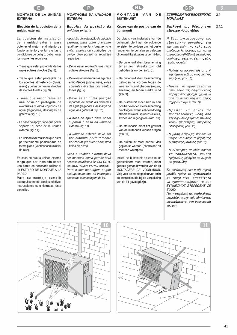
E GR
41
P NLMONTAJE DE LA UNIDAD EXTERNA
Elección de la posición de la unidad externa
La pos ic ión de ins ta lac ión
soportar el peso de la unidad
perfectamente posicionada de
de aire).
una pared es necesario utilizar el kit ESTRIBO DE MONTAJE A LA PARED.
con el kit.
2.42
MONTAGEM DA UNIDADE EXTERNA
Escolha da posição da unidade externa
A posição de instalação da unidade externa, para obter o melhor rendimento de funcionamento e evitar avarias ou condições de perigo, deve possuir os seguintes requisitos:
- Deve estar reparada dos raios
- Deve estar reparada dos agentes atmosféricos (chuva, neve) e das correntes directas dos ventos
- Deve es tar numa pos ição reparada de eventuais derrames de água (regadores, descarga de
- A base de apoio deve poder suportar o peso da unidade
- A unidade externa deve ser pos ic ionada per fe i tamente horizontal (verificar com uma bolha de nível).
Caso a unidade externa deva ser montada numa parede será necessário utilizar o kit SUPORTE DE MONTAGEM PARA PAREDE.Para a sua montagem seguir escrupulosamente as instruções anexadas à embalagem do kit.
2.4.1
1110
M O N T A G E V A N D E BUITENUNIT
Keuze van de positie van de buitenunit
rendement te behalen en defecten
(afb. 9).
- De buitenunit moet zich in een
(afb. 11).
Indien de buitenunit op een muur
MONTAGEBEUGEL VOOR MUUR.

GB F D
42
I- The unit should not be installed
d o w n w i n d o f c h i m n e y s discharging burnt gas or subject to emissions of fumes, oily or corrosive gasses.
- It should be possible to discharge the condensation produced.
- Ensure that the clearance around the back of the unit is more than 30 cm and left side is more than 30 cm. The front of the unit should have more than 70 cm of clearance and the connection side (right side) should have more than
- Take the air conditioner weight into account and select a place where noise and vibration will not be an issue.
- Select a place so that the warm air and noise from the air conditioner do not disturb neighbors.
- Die Einheit darf nicht unterhalb von Rauchgasableitungen montiert und keinen Emissionen von Dampf, öligem oder korrosivem Gas ausgesetzt werden.
- Es muss die Möglichkeit bestehen, eine Kondenswasserableitung zu installieren.
- Stellen Sie sicher, dass der Platz im hinteren Teil des Geräts mehr als 30 cm und auf der linken Seite mehr als 30 cm beträgt. Die Stirnseite des Geräts sollte mehr als 70 cm und die Seite der Anschlüsse (rechte Seite) mehr als 60 cm Platz haben (Abb. 12).
- Berücksichtigen Sie das Gewicht der Klimaanlage und wählen Sie einen Ort, an dem Geräusch und Vibrationen kein Problem darstellen.
- Wählen Sie einen Ort, an dem die Warmluft und der Lärm durch die Klimaanlage keine Störung der Nachbarn bedeuten.
2
della condensa emessa.
- Assicurarsi che lo spazio nella parte posteriore dell’apparecchiatura sia superiore a 30 cm e sul lato sinistro sia superiore a 30 cm. La parte frontale dell’apparecchiatura
spazio ed il lato delle connessioni
- C o n s i d e r a r e i l p e s o d e l
non rappresentino un problema.
condizionatore non siano di
corrosifs.
doit être possible.
- Prendre en compte le poids du climatiseur et choisir un emplacement où le bruit et les
- Choisir un emplacement où l’air
climatiseur ne causent pas de
12
60 cm
30 cm
70 cm
30 cm
60 cm

E GR
43
P NL
n i s o m e t i d o a e m i s i o n e s
emitida.
parte posterior del aparato sea
cm. La parte frontal del aparato debe tener más de 70 cm de
debe tener más de 60 cm de
- C o n s i d e r e e l p e s o d e l
no causen molestias.
el acondicionador no molesten a
2- A unidade não deve estar situada
a sotavento de chaminés de descarga de gases combustíveis, nem deve ser submetida a emissões de vapor, gases oleosos ou corrosivos.
- Deve ser possível descarregar a condensação emitida.
- Cert i f icar-se que o espaço na parte traseira do aparelho seja superior a 30cm e no lado esquerdo seja superior a 30cm. A parte frontal do aparelho deverá ter mais de 70 cm de espaço e o lado das conexões (lado direito) deverá ter mais de 60 cm de
- Considerar o peso da unidade externa e escolher um local onde o ruído e as vibrações não sejam um problema.
- Escolher um local onde o ar quente e o ruído provocado pela unidade externa não incomodem os vizinhos.
- Controleer of de ruimte aan de
zou meer dan 70 cm ruimte
dan 60 cm (afb. 12).

GB F D
44
I2Avvertenze di montaggio
Zone con probabile accumulo di neve.Posizionare l’unità esterna su un piano rialzato (muretto) con altezza
- se l’apparecchio di calore
infiltrarsi all’interno dell’unità e
elettrici.- se l’apparecchio
calore
dell’aria e rende difficoltoso il
Posizionamento dell’unità su un piano calpestabile (terrazzo, terreno, tetto, ecc.) in zone di
Nel caso realizzare un piano rialzato
dall’accumulo di sporcizia.
Su basamento metallico rigido (staffe, supporti in profilati metallici, ecc.).
macchina (a richiesta).
Instructions for installation
Z o n e s w i t h p r o b a b l e accumulation of snow.Position the outside unit on a raised structure (wall) higher than the foreseeable maximum level of
- if the air-conditioner is not equipped with a heat pump, when the snow melts the water could leak into the unit and damage the electric parts.
- i f t h e a i r - c o n d i t i o n e r i s equipped with a heat pump, the accumulation of snow could prevent the necessary circulation of air and interfere with drainage of the condensation.
(terrace, ground, roof, etc.) in
The surface on which it stands must have good drainage of water and it should be possible to prevent any accumulation of dirt (dry leaves,
If necessary, provide a dais of 10-15 cm and fasten the unit with stud bolts. This is not necessary when the unit is installed on a balcony, as
adequate drainage of any water and protection against the accumulation of dirt.
On a rigid metal base (brackets, section bars, etc.) .In this case the unit should always be fastened to the base on which it stands by means of antivibration
and capacity adequate for the weight of the machine (optional).The base should also be of suitable rigidity to prevent amplification of any vibrations due to normal operation.
Précautions pour le montage
Zones avec probable accumulation de neige.
- si l’appareil n’est pas à pompe
- si l’appareil est à pompe de
empêche la circulation normale de
Positionnement de l’unité sur un lieu de passage (terrasse, terrain,
(pattes, supports en profilés métalliques, etc.).
par des tampons en caoutchouc
l’appareil (sur demande).
au fonctionnement normal.
2.4.2
13 14
Hinweise zur Montage
Bereiche, in denen sich Schnee ansammeln kann.Die Außeneinhe i t au f e iner Erhöhung (Mauer) positionieren, deren Höhe je nach voraussehbarer Schneemenge zu bestimmen ist (Abb. 13), da:- wenn das Gerät nicht mit einer
Wärmepumpe ausgestattet ist, beim Schmelzen des Schnees Wasser in die Einheit eindringen könnte und die elektrischen Komponenten beschädigt werden könnten.
- wenn das Gerät mit einer Wärmepumpe ausgestattet ist, der sich ansammelnde Schnee die Luftzirkulierung behindern und die Ableitung deKondenswassers erschweren könnte.
Positionierung der Einheit auf einer begehbaren Fläche in schwer zugänglichen Bereichen (Balkon, Gelände, Dach usw.)Die Tragplatte muss so konzipiert sein, dass eine einwandfreie Ableitung des Wassers ermöglicht und eine Ansammlung von Schmutz (z.B. trockene Blätter, Abb. 14) unter der Einheit verhindert wird.Eventuell ist eine erhöhte Mauer (10-15 cm) zu errichten, auf der die Einheit mit Steinschrauben zu befes t igen is t . Wi rd d ie Einheit auf Balkons installiert, müssen keine entsprechenden V o r k e h r u n g s m a ß n a h m e n getroffen werden, da bereits eine ausreichende Neigung für die Ableitung des Wassers und ein ausreichender Schutz gegen eine Ansammlung von Schmutz gewährleistet sind.
Montage der Einheit auf einem metallischen Gestell (Bügel,
In diesem Fall muss die Einheit stets mit (auf Wunsch lieferbaren) schwingungsdämpfenden, für die Größe und das Gewicht des Gerätes ausgelegten Gummipuffern an der Aufstellfläche befestigt werden (Abb. 15).Das Gestell muss ebenfalls eine
damit eine Übertragung von Schwingungen verhindert und eine einwandfreie Funktionsweise gewährleistet wird.

E GR
45
P NL2.4.2
2Advertencias de montaje
Zonas con probable acumulación de nieve.Posicionar la unidad externa sobre un plano realzado (muro bajo) con una altura superior a la cantidad máxima de caída de nieve que se
- si el equipo no es con bomba de calor, mientras que se derrite la
el interior de la unidad y provocar daños en los componentes eléctricos.
- si el equipo es con bomba de calor, la acumulación de la nieve impide la regular circulación del aire
condensación.
Posicionamiento de la unidad en un plano sobre el que se puede marchar (terraza, terreno, techo, etc.) en zonas de difícil acceso.La base de apoyo tiene que tener características de buen drenaje de las aguas y evitar la posible acumulación, por debajo de la unidad, de suciedad (por ej. hojas
En caso de que sea necesario, realizar un plano realzado de 10-15
tornillos opresores de cimentación. No se requiere ninguna intervención en caso de posicionamiento en balcones, ya que los mismos ya
acumulación de suciedad.
En basamento metálico rígido (estribos, soportes en perfiles metálicos, etc.).En este caso la unidad siempre tiene que estar vinculada a la base de apoyo mediante pies de goma antivibración (fig. 15) de dimensiones y capacidad adecuadas al peso de la máquina (bajo petición ).La base, además, tiene que tener una rigidez apropiada para evitar
durante el regular funcionamiento.
Advertências de montagem
Zonas com provável acumulação de neve.
- se o aparelho não tem bomba de calor
- se o aparelho tem bomba de calor
Posicionamento da unidade sobre um plano que se pode pisar (terraço, terreno, tecto, etc.) em
unidade com parafusos prisioneiros
no caso de posicionamento da
Sobre base metálica rígida (suportes, estrutura de perfis metálicos, etc.).
15) de dimensões e capacidade
encomenda).
do aparelho.
15
montage
- indien het apparaat geen het
terechtkomt en de elektrische
- indien het apparaat
problematisch maken.
Positionering van de unit op
14).
O p o n b u i g z a m e m e t a l e n basis (beugels, steunen van

GB F D
46
IAir-conditioner with heat
Fit the seal into the drain elbow, then insert the drain joint into the base pan hole of outdoor unit, rotate 90 to securely assemble them. Connecting the drain joint with an extension drain hose (Locally purchased), in case of the water draining off the outdoor unit during the heating mode.
A - sealB - drain jointC - base pan hole of outdoor unit
Installation of outside unit
After locating the ideal position for installing the unit (as described in chap. 2.4.1 and 2.4.2) proceed as follows:- Position the unit on the base, if
necessary using the antivibration
1 air inlet 2 air outlet- Screw any fastening nuts without
tightening them fully.- Check the level of the unit with a
bubble level and shim if neces-sary.
- Tighten the fastening nuts, if any.
* 9 - 10 - 12 K models** 18 K models*** 24 K models
Geräte mit Wärmepumpe (Abb. 16)
Befestigen Sie die Dichtung im En twässe rungsw inke l s tück , setzen Sie anschließend die Entwässerungskupplung in die Öffnung der Sockelplatte und drehen Sie um 90°, um die Teile korrekt zusammenzubauen. Verbinden Sie die Entwässerungskupplung mit einer (vor Ort gekauften) Entwässerungsrohr-Verlängerung, falls während des Betriebs im Heizungs-Modus Wasser aus der Außeneinheit treten sollte.
A - DichtungB - WasserablaufkupplungC - Öffnung des Sockelbehälters
der Außeneinheit
Montage der Außeneinheit
Nach der Positionierung der Einheit an der vorgesehenen Stelle (siehe Abschnitt 2.4.1 und 2.4.2) ist wie folgt vorzugehen:- Die Einheit auf dem Gestell
positionieren und, falls erforderlich, die schwingungsdämpfenden Gummipuffer anbringen (Abb. 17).
1 Lufteinlass 2 Luftauslass- Eventuelle Befestigungsmuttern
(nicht zu fest) anziehen.- Die Einheit unter Zuhilfenahme
e i n e r W a s s e r w a a g e nivellieren. Eventuell können Unterlegscheiben verwendet werden.
- Eventuelle Befestigungsmuttern fest anziehen.
* 9 - 10 - 12 K Modelle** 18 K Modelle*** 24 K Modelle
2
per assemblarli in modo corretto.
esterna durante il funzionamento in modalità riscaldamento.
C - foro del piatto della base dell’unità esterna
Montaggio unità esterna
i d e a l e p e r i l p i a z z a m e n t o dell’unità (come descritto nei par. 2.4.1 e 2.4.2) procedere come
- Posizionare l’unità sul basamento
1 2 uscita aria
* modello 9 - 10 - 12 K** modello 18 K*** modello 24 K
Montage unité extérieure
des tampons en caoutchouc
1 2 sortie air
16
2.4.4
2.4.3

E GR
47
P NLEquipos con bomba de calor
durante el funcionamiento en modo
Montaje de la unidad externa
posición ideal para la ubicación de la unidad (como descrito en los
- Posicionar la unidad en el
1 entrada de aire 2 salida de aire
espesore.
* modelos 9 - 10 - 12 K** modelos 18 K*** modelos 24 K
9 - 10 - 12 K
24
2Aparelhos com bomba de
Fixar a junta no cotovelo de drenagem, depois introduzir a junta de drenagem no furo do prato da base, rodar de 90° para as montar correctamente. Ligar a junta de drenagem com uma extensão de tubo de drenagem (adquirida no comércio), no caso em que haja uma saída de água pela unidade externa durante o funcionamento em modalidade aquecimento.
A - juntaB - junta de drenagemC - furo do prato da base da
unidade externa
Montagem da unidade externa
Após ter individuado a posição ideal para o posicionamento da unidade (como descrito nos cap. 2.4.4 e 2.4.2) proceder do seguinte modo:- Posicionar a unidade sobre a base
de apoio, e se necessário, sobre as borrachinhas anti-vibrantes
1 entrada de ar 2 saída de ar- E n r o s c a r , s e m a p e r t a r
completamente, as eventuais
- Verificar o nível da unidade com uma bo lha de n íve l , e se necessário, utilizar uma espessura.
- Apertar def in i t ivamente as
* modelos 9 - 10 - 12 K** modelos 18 K*** modelos 24 K
2.4.4
(afb. 16)
om de onderdelen op correcte
Montage buitenunit
17). 1 luchtinlaat 2 luchtuitlaat
* 9 - 10 - 12 K modellen** 18 K modellen*** 24 K modellen
17487*514**540***
298*
340*
*35
0*** 1
1
2
2.4.3

GB F D
48
IInstallation and connection of cooling lines
IMPORTANT: Do not make the connections using normal hydraulic pipes that could contain residues of
damage the parts inside the unit and interfere with proper operation.
Use only special copper pipes for cooling, that are supplied clean and sealed at the ends.
After cutting the proper lengths, seal the ends immediately on the roll and cut piece.Pipes for re f r igera t ion wi th preinsulation can also be used.
Use only pipes with diameters that correspond to the measurements indicated in the table in par. TECHNICAL FEATURES.
- Plan the route of the pipeline so as to reduce the length and number of bends as much as possible for best performance of the system.
Caution: Capacity is base on standard length and maximum allowance length is base of reliability. Oil trap should be
A - max. max. elevationB - max. lengthùE - standard lengthF - additional refrigerantM - modelP - pipe size b1 - gas b2 - liquid
Verlegung und Anschluss der Kühlleitungen
WICHTIG: Für den Anschluss dürfen keine normalen Wasserrohre verwendet werden, da in diesen Späneres te , Schmutz ode r Wasser vorhanden sein können, d i e d i e K o m p o n e n t e n d e r Einheiten beschädigen und deren einwandfreie Funktionsweise
F ü r d i e K ü h l u n g s i n d ausschließlich Kupferrohre zu verwenden, die vollkommen sauber und an den Enden versiegelt geliefert werden.
Nach dem Zuschnitt sind die Enden der Rolle und des zugeschnittenen Rohrs sofort zu versiegeln. Für die Kühlung können auch bereits isolierte Kupferrohre verwendet werden.
Es dürfen ausschließlich Rohre mit den in der Tabelle in Abschnitt T E C H N I S C H E M E R K M A L E aufgeführ ten Durchmessern verwendet werden.
- Die Rohre sind so zu verlegen, dass ihre Länge auf ein Minimum reduziert wird. Die Krümmer der Rohre müssen so konzipiert se in , dass e ine op t ima le Funkt ionsweise der Anlage gewährleistet wird.
Achtung: Der Kondensator
basiert auf der Standardlänge und auf der maximal zulässigen Länge. Es sind Ölsammler für 5 - 7 Meter zu installieren (Abb. 18).
A - max. AnhebenB - max. LängeE - StandardlängeF - ZusatzkühlmittelM - Modelle P - Schlauchabmessung b1 - Gas b2 - Flüssigkeit
2E x é c u t i o n , p o s e e t
IMPORTANTles branchements en utilisant des
Util iser exclusivement des tuyaux en cuivre spécifiques pour réfrigération qui sont fournis nettoyés et fermés à leurs extrémités.
extrémités du rouleau et du bout coupé.
CARACTÉRISTIQUES TECHNIQUES.
l’installation.
La puissance se fonde
A - B - EF - M - P - dimensions du tube b1 - b2 -
2.4.5 E s e c u z i o n e , p o s a e d allacciamenti delle linee frigorifere
IMPORTANTE
tubazioni idrauliche che al loro interno potrebbero contenere
i componen t i de l l e un i tà e
delle apparecchiature.
Usare esclusivamente tubazioni in
sigillati alle estremità.
Dopo aver eseguito i tagli sigillare immediatamente le estremità del rotolo e dello spezzone tagliato.E’ possibile utilizzare tubi in rame
con diametri che rispecchiano le dimensioni descritte nella tabella del par. CARATTERISTICHE TECNICHE.
tubazioni in modo da ridurre il più
dei tubi per ottenere il massimo rendimento dell’impianto.
La resa si basa sulla
A - B - E - F -M - modello P - dimensioni tubo b1 - b2 -
18
A
B
B
A
indoor unit, Inneneinheit, unidade interna,
outdoor unit, Außeneinheit, unidade externa,
oil trap, Ölsammler, re-cipientes de recolha de óleo,

E GR
49
P NL
18
Ejecución, tendido y conexión
IMPORTANTE
correcto funcionamiento de los
Usar exclusivamente tuberías de cobre específicas para r e f r i g e r a c i ó n q u e s o n suministradas limpias y cerradas en sus extremidades.
cortes cerrar inmediatamente las extremidades del rollo y del tubo cortado.Es posible utilizar tubos de cobre
dimensiones descritas en la tabla del párr. CARACTERÍSTICAS TÉCNICAS.
- Localizar el recorrido de las
la instalación.
El rendimiento se basa
Se deben instalar recipientes colectores de aceite para 5-7
A- B- E- F- M - modelos P - Dimensiones del tubo b1 - b2 -
2Execução, assentamento e ligação das linhas de refrigeração
IMPORTANTE : Não u t i l i za r tubagens hidráulicas normais para efectuar as ligações, porque o seu interior pode conter resíduos metálicos, sujidade ou água, que
das unidades e prejudicar o correcto funcionamento dos aparelhos.
Usar exclusivamente tubagens de cobre específ icos para refrigeração que são fornecidos l i m p o s e s e l a d o s n a s extremidades.
Após ter cortado os tubos selar imediatamente as extremidades do rolo e do tubo cortado.É possível utilizar tubos de cobre para a refrigeração pré-isolados.
Util izar exclusivamente tubos com diâmetros que respeitem as dimensões descritas na tabela do par. CARACTERÍSTICAS TÉCNICAS.
- Calcular o percurso das tubagens de modo a reduzir o mais possível o comprimento e as curvas dos tubos para obter o rendimento máximo do aparelho.
Atenção: O rendimento baseia-se no comprimento standard e no comprimento máximo consentido. Devem ser instalados recipientes de recolha do óleo para 5 a 7
A- comprimento máximoB- levantamento máximoE- comprimento padrãoF- refrigerante suplementarM - modelosP - Dimensões do tubo b1 - gás b2 - líquido
2.4.5Uitvoering, plaatsing en
B E L A N G R I J K
zouden kunnen zetten.
leidingen die speciaal voor de
Nadat de leidingen afgesneden zijn, dienen de uiteinden van de
TECHNISCHE KENMERKEN.
het rendement is
A - B - EF - M - modellenP - b1 - b2 -
MP
b1 b2
Am
Bm
Em
F
9-10 K
12 K
18 K
24 K

GB F D
50
I2
19
- Fasten a cable raceway to the wall (possibly with internal partitioning) of suitable size for the pipes and electric wires to pass through.
- Cut the sections of pipe leaving an extra 3-4 cm on the ends.
IMPORTANT: use a wheel pipe
19) clamping it in short lengths so as not to crush the pipe.
N E V E R U S E A N O R M A L HANDSAW,scraps could fall inside the pipe and enter the circuitry of the system, damaging the parts
- Remove possible burrs with the special tool.
IMPORTANT: immediately after cutting and deburring the pipes, seal the ends with insulating tape.If you do not use preinsulated pipes, they must be insulated as follows:- material: polyurethane foam with
closed cells- :
0,45 W/ (Kxm2) or 0.39 kcal/(hxCxm2)
- minimum thickness: 6 mm (for liquid pipes)
- minimum thickness: 9 mm (for gas pipes)
Do not place both pipes in the same sheath , as th is would jeopardize the proper o p e r a t i o n o f t h e s y s t e m
- An der Wand ist ein entsprechend d imension ier ter Kabelkanal ( m ö g l i c h s t m i t i n t e r n e m Trennelement) zu montieren, in dem zu einem späteren Zeitpunkt auch die Rohrleitungen und die Stromkabel verlegt werden können.
- Beim Zuschneiden der Rohrstücke ca. 3-4 cm auf die Rohrlänge zugeben.
WICHTIG: Die Rohre dürfen a u s s c h l i e ß l i c h m i t e i n e m R o h r s c h n e i d e r ( A b b . 1 9 ) zugeschnitten werden. Der Schnitt ist langsam auszuführen, damit das Rohr nicht gequetscht wird.
AUF KEINEN FALL DARF EINE NORMALE SÄGE VERWENDET WERDEN, da die Späne sowohl in das Rohr als auch in den Kreislauf der Anlage eindringen und die Komponenten ernsthaft beschädigen könnten (Abb. 20A).
- Das Rohr eventuell entgraten.
WICHTIG: Nach dem Zuschnitt u n d d e r E n t g r a t u n g d e s Rohrs sind dessen Enden mit Isolierband zu versiegeln. Kommen keine vor isol ier ten Rohrleitungen zur Anwendung, sind diese mit einem Isolierstoff zu ummanteln, der die folgenden Merkmale aufweisen muss: - Material : PUR-Schaum mit
geschlossenen Zellen- Max. Wärmedurchgangszahl:
0,45 W/(Kxm2) oder 0.39 kcal/ (hxCxm2)
- M i n d e s t s t ä r k e : 6 m m
- Mindeststärke: 9 mm (Gasleitungen)
Auf keinen Fall dürfen beide Rohrle i tungen in dieselbe U m m a n t e l u n g e i n g e f ü h r t werden, da die einwandfreie Funktionsweise der Anlage beeinträchtigt werden könnte (Abb. 20B).
exclusivement à l’aide d’un
resserrant par petits intervalles pour ne pas écraser le tuyau.
NE JAMAIS UTILISER UNE SCIE NORMALE,les copeaux pourraient entrer dans le tuyau et par la suite entrer en circulation dans l’installation, endommageant sérieusement les
extrémités du tuyau avec du ruban isolant.
- matériau
- coefficient de transmission maxi
- épaisseur minimum
- épaisseur minimum
Ne pas introduire les deux tuyaux dans la même gaine, cela compromet le fonctionnement
- Fissare al muro una canalina
separatore interno) di opportune dimensioni in cui far passare
abbondando di circa 3-4 cm sulla
tagl io esclusivamente con un tagliatubi a rotella (fig. 19) stringendo a piccoli intervalli per
NON UTIL IZZARE MAI UN NORMALE SEGHETTO, i trucioli potrebbero entrare nel tubo e successivamente in circolo nell’impianto danneggiando seriamente i componenti (fig. 20A).
l’apposito utensile.
taglio e sbavatura sigillare le estremità del tubo con nastro isolante.Nel caso non si utilizzino tubazioni
- materialecelle chiuse
-
- spessore minimo
- spessore minimo
Non inser i re ent rambe le tubaz ioni ne l la medesima guaina, si compromette il perfetto funzionamento dell’impianto

E GR
51
P NL 2
20
B
A
(posiblemente con separador interno) de oportunas dimensiones en las cuales hacer pasar a
el corte exclusivamente con una cortatubos de rueda (fig. 19) apretando por pequeños intervalos para no aplastar el tubo.
N O U T I L I Z A R N U N C A U N SERRUCHO NORMAL,las virutas podrían entrar en el tubo y sucesivamente podrían circular por la instalación d a ñ a n d o s e r i a m e n t e l o s
herramienta apropiada.
el corte y quitadas las rebabas cerrar las extremidades del tubo con cinta aislante.
- materialpoliuretano de celdas cerradas
-
- espesor mínimo
- espesor mínimo
No colocar ambas tuberías en la misma vaina, se compromete el perfecto funcionamiento de la
- Fixar à parede um canalete para a passagem dos cabos (possivelmente com separador interno) de dimensões adequadas para depois fazer passar as tubagens e os cabos eléctricos.
- Cortar, em comprimento, as partes de tubo em excesso de cerca de 3-4 cm.
IMPORTANTE: efectuar o corte exclusivamente com um corta-tubos com moleta (fig. 19) apertando a pequenos intervalos para não esmagar o tubo.
NUNCA UTILIZAR UM SERROTE NORMAL,as limalhas poderão entrar no tubo e sucessivamente em circulação no aparelho danif icando seriamente os
- Remover eventuais rebarbas com uma ferramenta apropriada.
IMPORTANTE: após ter efectuado o corte e a eliminação da rebarba selar as extremidades do tubo
Caso se utilizem tubagens pré-isoladas, introduzir os tubos no isolante que deverá ter as seguintes características:- material: poliuretano expandido
com células fechadas- coeficiente de transmissão
max:0,45 W/ (Kxm2) ou seja 0.39 kcal/(hxCxm2)
- espessura mínima: 6mm (para as linhas do líquido)
- espessura mínima: 9 mm (para as linhas do gás)
Não in t roduz i r ambas as tubagens na mesma manga isolante, compromete-se o correcto funcionamento do
met tussenpozen op de leiding
GEBRUIK NOOIT EEN GEWOON ZAAGJE , omdat de spaanders in de
en in de installatie in circulatie
snijden en afbramen moeten de uiteinden van de leiding verzegeld
-
-
-
-
dezelfde mantel aangezien de
20B).

GB F D
52
I- Bind any joints in the sheath
securely with insulating tape.
- Flare the pipe ends using the special tool. Take care not to
21B).
- Lubricate the connecting thread with oil for coolant (DO NOT USE ANY OTHER TYPE OF LUBRICANT)
- Screw the pipe nut manually on the connecting thread
- Tighten using a wrench to hold the threaded part of the connector, so as to avoid twisting the pipe, and a dynamometric wrench on the nut (fig. 22) calibrated with the following values depending on the size of the pipe:
2- Unire accuratamente con nastro
- Lubrificare il filetto dell’attacco (NON
UTILIZZARE NESSUN ALTRO TIPO DI LUBRIFICANTE)
- Avvi tare def in i t ivamente
dell ’attacco, per evitarne
22) tarata con i seguenti valori
- Lubrif ier le f i let du raccord
(N’UTILISER AUCUN AUTRE TYPE DE LUBRIFIANT)
- Serrer à fond en utilisant
maintenir bloquée la partie
des déformations, et une clé dynamométrique sur l’écrou (fig. 22) réglée aux valeurs suivantes selon les dimensions
- Eventuelle Verbindungsstellen der Ummantelung sind sorgfältig mit Klebeband zu umkleben.
- Vor dem Begrenzungsanschlag ist die Befestigungsmutter auf das Rohr zu schieben (Abb. 21A).
- Der Begrenzungsanschlag an den Enden der Rohre ist mit Sorgfalt durchzuführen. Die Rohre dürfen hierbei in keiner Weise beschädigt werden (Abb. 21B).
- Das Gewinde des Anschlussstücks mit Kühlöl schmieren. ES DARF KEIN ANDERES SCHMIERMITTEL VERWENDET WERDEN.
- Die Mutter des Rohrs von Hand auf das Gewinde des Anschlussstücks anschrauben.
- D a n a c h d i e M u t t e r f e s t anziehen. Zu verwenden sind hierfür ein Maulschlüssel , durch den das Gewinde des Anschlussstücks zur Vermeidung von Deformationen zu blockieren ist , und ein an der Mutter anzulegender dynamometrischer Schlüssel (Abb. 22), der zuvor je nach Rohrdurchmesser auf folgende Werte geeicht wurde:
Outer Tightening Additional tightening diam. torque (N.cm) torque (N.cm) ø 6,35 1500 1600 (153 kgf.cm) (163 kgf.cm) ø 9,52 2500 2600 (255 kgf.cm) (265 kgf.cm)
ø 12,7 3500 3600 (357 kgf.cm) (367 kgf.cm)
ø 16 4500 4700 (459 kgf.cm) (479 kgf.cm)
Außendurchmesser Anzsugsmoment Zusatz- (N.cm) Anzugsmoment (N.cm) ø 6,35 1500 1600 (153 kgf.cm) (163 kgf.cm) ø 9,52 2500 2600 (255 kgf.cm) (265 kgf.cm)
ø 12,7 3500 3600 (357 kgf.cm) (367 kgf.cm)
ø 16 4500 4700 (459 kgf.cm) (479 kgf.cm)
21A
B

E GR
53
P NL 2- Unir cuidadosamente com fita
adesiva as junções das mangas isoladoras.
- Antes de lixar as extremidades do
- Lixar as extremidades do tubo, u t i l izando uma fer ramenta apropriada, de modo impecável, sem roturas, fendas ou lascas
óleo para refrigerante (NÃO UTILIZAR NENHUM OUTRO TIPO DE LUBRIFICANTE)
- Apertar manualmente a porca do tubo na rosca da junção
- A p e r t a r d e f i n i t i v a m e n t e
parte roscada da junção, para evitar a sua deformação, e uma chave dinamométrica, na
os seguintes valores segundo as dimensões dos tubos:
- Unir cuidadosamente con cinta
(NO UTILIZAR NINGÚN OTRO TIPO DE LUBRIFICANTE)
- Atornillar manualmente la tuerca del tubo sobre la rosca del empalme
- Atornil lar definitivamente utilizando una llave fija para
del empalme, para evitar deformaciones y una llave
22) regulada con los siguientes valores sobre la base de las dimensiones de los tubos
plakband.
(GEBRUIK GEEN ENKEL ANDER TYPE SMEERMIDDEL)
van de aansluiting in positie
de moer (afb. 22), die op de
grond van de afmetingen van
Diâm. Força de Força de aperto externo aperto (N.cm) adicional (N.cm)
ø 6,35 1500 1600 (153 kgf.cm) (163 kgf.cm) ø 9,52 2500 2600 (255 kgf.cm) (265 kgf.cm)
ø 12,7 3500 3600 (357 kgf.cm) (367 kgf.cm)
ø 16 4500 4700 (459 kgf.cm) (479 kgf.cm)
ø 6,35 1500 1600 (153 kgf.cm) (163 kgf.cm) ø 9,52 2500 2600 (255 kgf.cm) (265 kgf.cm)
ø 12,7 3500 3600 (357 kgf.cm) (367 kgf.cm)
ø 16 4500 4700 (459 kgf.cm) (479 kgf.cm)
(N.cm) (N.cm)
22

GB F D
54
ITests and inspection
After making all pipe connections, check the seal of the system: - Unscrew the closing cap on the
service coupling of the gas line
- Connect a tank of anhydrous nitrogen to the coupling with a
reducer.- Open the tap on the tank and
pressure reducer and bring the pressure in the circuit to 3 bar; close the tank.
- If after about 3 minutes the pressure does not drop, the circuit is in good working order and the pressure can be raised to 15 bar by reopening the tank.
- Check again after 3 minutes that the pressure remains stable at 15 bar.
- For safety reasons apply a solution of soapy water to the connectors and check for the formation of bubbles revealing leakage of gas.
- In case of a pressure drop, if the test with soapy water gives a negative result, pump R410A into
leak detector. Since the circuit has no welds, the
only place leaks can occur is on the joints, in which case, tighten the nuts thoroughly or make new
again. Repeat the seal test.
Überprüfungen
Nachdem die Rohre angeschlossen wurden, ist die Anlage auf ihre Dichtigkeit zu überprüfen: - Den Verschlussstopfen des
Anschlussstückes der Gasleitung ausschrauben (Abb. 23 - A).
- A n d a s A n s c h l u s s s t ü c k ( m i t t e l s e i n e s m i t e i n e m
Druckminderer versehenen S c h l a u c h s ) e i n e F l a s c h e anhydr i schen S t i cks to f fes anschließen.
- Den Hahn der Flasche und den Druckminderer aufdrehen und den Druck im Kreislauf auf 3 Bar einstellen. Den Hahn der Flasche wieder zudrehen.
- Ist der Druck nach ca. 3 Minuten nicht gesunken, funktioniert der Kreislauf einwandfrei und der Druck kann durch Aufdrehen des Hahns auf der Flasche auf 15 Bar erhöht werden.
- Nach weiteren 3 Minuten ist zu überprüfen, ob sich der Druckwert
- S i c h e r h e i t s h a l b e r e i n e S e i f e n l ö s u n g a n d e n Anschlussstücken anbringen und überprüfen, ob sich Luftblasen (Ausströmen von Gas) bilden.
- Sinkt der Druck, auch dann R410A in den Kreislauf geben, wenn sich keine Luftblasen bilden, und mit einem Leckortungsgerät die Leckage suchen.
D a d e r K r e i s l a u f k e i n e S c h w e i ß s t e l l e n a u f w e i s t , könnten die Leckagen nur an den Verbindungsstellen der Rohrlei tungen auftreten. In diesem Fall sind die Muttern fester zu spannen oder die Anschlüsse m i t d e n e n t s p r e c h e n d e n B e g r e n z u n g s a n s c h l ä g e n vorzunehmen.
D ie D ich t igke i t sp rü fungen wiederholen.
2
bombola d’azoto anidro con tubo
riduttore di pressione.- Aprire il rubinetto della bombola ed
il riduttore di pressione portando a 3 bar la pressione del circuito; chiudere la bombola.
- Se dopo circa tre minuti la
la pressione può essere portata a 15 bar riaprendo la bombola.
- Controllare dopo altri tre minuti
di 15 bar.
attacchi una soluzione saponata
- In caso di calo di pressione e la ricerca con soluzione saponata
immettere nel circuito R410A
presentare solo nei punti di
- Brancher au raccord une bouteille
la pression du circuit; fermer la bouteille.
circuit est dans des conditions
bouteille.
- En cas de baisse de pression et
introduire dans le circuit du R410A
23
2.4.6
A

E GR
55
P NL
los tubos es necesario hacer una
- Desenroscar el tapón de cierre de
- Conectar a la unión una bombona
bar la presión del circuito; cerrar la bombona.
el circuito está en condiciones
en los empalmes una solución
No teniendo el circuito puntos de
presentar sólo en los puntos de
a hacer los empalmes con las
pruebas de hermeticidad.
2.4.62
Terminadas as ligações dos tubos
estanqueidade do sistema de climatização.- Desapertar a tampa da junção de
ref. A).
- Ligar à junção uma botija de azoto
pressão.- Abrir a válvula da botija e o redutor
de pressão colocando a 3 bar a pressão do circuito; fechar a botija.
- Se após cerca de três minutos a pressão não diminui, o circuito está em perfeitas condições, e a pressão poderá ser colocada a 15 bar reabrindo a botija.
- Controlar após outros três minutos se a pressão se mantém a 15 bar.
- Para maior segurança aplicar nas junções uma solução de sabão e
bolhas, que indicam a perda de gás.
- Se no caso de queda de pressão a procura com a solução de sabão nas junções dê êxito negativo, introduzir no circuito o R410A e individuar a fuga com um detector de fugas.
Sendo o circuito isente de pontos de soldadura, as fugas se deverão apresentar só nos pontos de junção das tubagens, neste caso apertar as porcas com mais força, ou então refazer as junções e depois lixá-las.
Repetir a prova de estanqueidade.
Testen en controles
los (afb. 23 ref. A).
op 3 bar. Sluit de tank.- Indien de druk na drie minuten
- Indien de druk daalt en het
de moeren met meer kracht

GB F D
56
ISystem vacuum
After testing the seal, the system has to be placed under a vacuum to remove any impurities in it (air, nitrogen, moisture).- use a vacuum pump with a
capacity of 40 l/min (0,66 l/s) and connect it, by means of a hose
service coupling of the gas line.- lower the pressure in the circuit
to the absolute value of 50 Pa for about 2 hours; if after that period the setting of 50 Pa is not reached, it means there is a high level of moisture in the circuit or that there is a leak.
Keep the vacuum pump in operation for another 3 hours.
After that time, if the value has still not been reached, it will be
- After placing the system under a vacuum and c leaning i t , disconnect the pump coupling while it is still on.
- Close the gas line service coupling
Filling the system
Open the closing cap so as to be able to access he tap of the intake line and that of the liquid supply
Vakuumerzeugung in der Anlage
Nachdem die Dichtigkeit der Anlage überprüft wurde, ist in dieser zur Entfernung von Unreinheiten (Luft, Stickstoff und Feuchtigkeit) ein Vakuum zu erzeugen.- Hierfür ist eine Vakuumpumpe
mit einer Förderleistung von 40 l/min. (0,66 l/sec.) zu verwenden, die mittels eines mit einem
Schlauchs an das Anschlussstück der Gasleitung anzuschließen ist.
- Den Druck im Kreislauf ca. 2 Stunden lang bis auf einen absoluten Druck von 50 Pa senken. Hat der Druck nach Ablauf dieser Zeit nicht den eingestellten Wert (50 Pa) erreicht, bedeutet dies, dass im Kreislauf eine hohe Feuchtigkeit vorhanden oder eine Leckage aufgetreten ist. Die Va k u u m p u m p e w e i t e r e 3 Stunden laufen lassen. Wurde der eingestellte Wert auch nach Ablauf dieser Zeit nicht erreicht, ist
- Nach der erfolgten Erzeugung des Vakuums und der Reinigung der Anlage ist das Anschlussstück der Pumpe zu lösen, falls diese noch in Betrieb ist.
- D i e G a s l e i t u n g m i t d e m e n t s p r e c h e n d e n S t o p f e n verschließen (Abb. 24 - A).
Füllung der Anlage
Die Abdeckplatte öffnen und den Hahn der Ansaugleitung und der Flüssigkeitsleitung aufdrehen, wodurch das Gerät mit Kühlmittel gefüllt wird.
2Vuoto impianto
dell’impianto per una sua pulizia dalle impurità in esso contenute
- abbassare la pressione all’inter-no
di 50 Pa per circa 2 ore; se dopo
perdita. Mantenere in funzione per
ulteriore 3 ore la pompa per il
necessario la ricerca della perdita.- Terminate le operazioni di messa
staccare il raccor-do della pompa
funzione.
rif. A).
Riempimento impianto
Aprire il cappellotto di chiusura
nell’apparecchio.
Mise sous vide de l’installation
Maintenir encore en fonction
si l’on n’a pas encore atteint
ci est encore en fonction.
Remplissage de l’installation
de la conduite d’aspiration et sur
24
A
2.4.7
2.4.8

E GR
57
P NLPuesta en vac ío de la instalación
a cabo la operación de puesta
la l impieza de las impurezas
- disminuir la presión en el interior del circuito hasta alcanzar un
Mantener en marcha durante otras 3 horas la bomba para la
desconectar la unión de la bomba cuando la misma se encuentra
ref. A).
Llenado de la instalación
en la instalación.
2Sistema de vácuo
Terminadas todas as provas e as verificações de estanqueidade, é necessário colocar o circuito sob vácuo para poder limpar as impurezas presentes (ar, azoto, e humidade).- utilizar uma bomba de vácuo com
um fluxo de 40 l/min (0,66 l/s)
de serviço da linha gás.- baixar a pressão no interior do
circuito até ao valor absoluto de 50 Pa por cerca de 2 horas; se após esse período de tempo não se conseguir levar a pressão ao valor estabelecido (50 Pa),
no circuito ou que há uma perda. Manter a bomba de vácuo em
funcionamento por mais 3 horas.
ainda não atingiu esse valor, será necessário detectar a perda.
- Terminadas as operações de vácuo e de limpeza do circuito, destacar a junção da bomba mas com esta em funcionamento.
de serviço da linha do gás com a
Enchimento da máquina
Abrir o tampão para poder agir na válvula da linha de aspiração e naquela do líquido que, uma vez abertas permitem o enchimento do aparelho com refrigerante.
2.4.7
2.4.8
Vacuüm installatie
een lek is.
eens 3 uur.
te zoeken.
Vullen van de installatie
kranen te openen kan het apparaat

GB F D
58
I2
25
1
2
3
- Cercare nella documentazione
incollarla in prossimità del punto di carica e/o ripristino.
- Anno ta re ch ia ramen te la
utilizzando inchiostro indelebile.
- Staccare l’etichetta trasparente rimasta nella parte superiore del
sul punto di carica.
n e l l ’ a t m o s f e r a d u r a n t e
smaltimento.
riparata il più presto possibile.
f l u o r u r a t o n e l p r e s e n t e
spostamento a mano del prodotto
applicabili.
ATTENTION:- Together with the documentation
of the outside unit there is an adhesive sheet containing 2 labels. Remove the lower label
- Clearly note the amount of coolant loaded on the coolant label using indelible ink. - In the box marked 1, write the
quantity of gas established in the technical data (kg).
- In box 2, write any amount added by the installer (kg). In box 3 write the total of the two previous values (kg).
- Remove the transparent label that is left on the upper part of the adhesive sheet and stick it on
- Do not let the fluorinated gas escape.
gas is never released into the atmosphere during installation, maintenance and disposal.
- Should a gas leak occur, it must
soon as possible.
carry out maintenance of this product.
- Any use of fluorinated gas in this product, for example during the movement by hand of the product or the recharging of the gas, must be in accordance
- Chercher dans la documentation
de la feuille autocollante et la
- L’assistance de ce produit
ACHTUNG:- E r m i t t e l n S i e i n d e r
Dokumentation der Außeneinheit ein Blatt mit 2 Haftetiketten. Lösen Sie die untere Etikette (Abb. 25) und kleben diese in die Nähe des Lade- und/oder Nachfüllpunkts.
- Vermerken Sie die Menge des eingefüllten Kühlmittels mit unlöschbarer Tinte deutlich lesbar auf der Kühlmitteletikette. - Tr a g e n S i e i m m i t 1
gekennzeichneten Feld die in den technischen Daten festgelegte Gasmenge (kg) ein.
- Im Feld 2 vermerken Sie d ie eventuel l durch den Installateur dazugegebene Menge (kg) . Tragen Sie im Feld 3 die Summe der 2 v o r s t e h e n d e n We r t e ein (kg).
- Lösen Sie die im oberen Teil des Blatts verbliebene durchsichtige Et iket te und k leben diese oberhalb der zur vor aufgeklebten Etikette an den Ladepunkt.
- Vermeiden Sie das Austreten des enthaltenen Fluorgases. - Stel len Sie sicher, dass
das Fluorgas während der Installation, Assistenz oder Entsorgung zu keinem Zeitpunkt in die Atmosphäre gelangt.
- Sollte das Austreten des en tha l tenen F luorgases festgestellt werden, muss die Undichtigkeit schnellstmöglich ermittelt und behoben werden.
- Der Kundendienst an diesem
Kundendienstpersonal erfolgen. - Jegl iche Verwendung von
Fluorgas in diesem Produkt, z . B . b e i d e r m a n u e l l e n V e r s e t z u n g o d e r d e m Nachladen des Gases muss in Übereinstimmung stehen mit den Vo rgaben de r No rm zu bestimmten Treibhausgasen sowie gegebenenfa l ls mi t den zuständigen ört l ichen Vorschriften.

E GR
59
P NL 2
restablecimiento - Anote claramente la cantidad
utilizando tinta indeleble.
3 anote la suma de los dos
transparente de la parte superior
contenido en el circuito.
la atmósfera durante las
asistencia o eliminación.
- La asistencia de este producto ha sido encomendada a personal
presente en este producto
desplazamiento manual del
aplicables.
ATENÇÃO:- Procurar na documentação
da unidade externa uma folha adesiva com 2 et iquetas.
25) e colá-la junto da tomada de enchimento ou de recarga.
- E s c r e v e r c o m c l a r e z a a quantidade de refr igerante c a r r e g a d o n o r ó t u l o d o refrigerante util izando tinta indelével.
1, escrever a quantidade de gás estabelecida nos dados técnicos (kg).
- No quadro 2, escrever a carga adicional (se for o caso) introduzida pelo instalador (kg). No quadro 3, escrever a soma dos 2 valores anteriores (kg).
- Destacar a etiqueta transparente restante na parte superior da folha adesiva e colá-la acima da colada antes na tomada de enchimento.
- Evitar a fuga do gás fluorado contido. - Cer t i f i car-se que o gás
para a atmosfera durante a instalação, a assistência técnica ou a eliminação.
- Caso se verifique uma fuga de gás fluorado contido, a fuga deve ser encontrada e reparada o mais depressa possível.
- A assistência técnica deste p r o d u t o é c o n c e d i d a exclusivamente a pessoal
- Qualquer uti l ização do gás fluorado neste aparelho, por exemplo durante o deslocamento à mão do apare lho ou a recarga do gás, deve estar em conformidade com a normativa acerca de determinados gases fluorados com efeito estufa e com eventuais normativas locais
buitenunit een stickerblad met 2 etiketten. Maak het onderste etiket (afb. 25) en plak het in de
- In het kader dat met 1
- Maak het transparante etiket
assistentiepersoneel.

GB F D
60
IConnection of condensation discharge line
Connect the condensation drain pipe on the inside unit to a drain pipe of appropriate length and fasten with a hose clamp.Run the pipe inside the raceway parallel to the other system pipes and fastening it to them with hose clamps, not too tight so as not to damage the insulation on the pipes or kink the drain pipe.The condensation liquid should drain directly into a rainwater runoff gutter if possible.
If the drain pipe discharges directly into the sewer system, it should be bent so as to create a
return of odour into the house.
The trap bend should never be less than 1.5 m below the bottom
If the drainage is discharged into
never be closed, so as to prevent any counterpressure that would interfere with discharge, and the pipe should never reach the level
IMPORTANT: check that the condensat ion l iquid f lows properly out of the pipe by pouring about 1/2 litre of water very slowly into the collection
Anschluss der Kondenswas-serableitung
An die Kondenswasserableitung der Inneneinheit ist ein entsprechend langes Ablaufrohr anzuschließen, das mit einer Schelle zu befestigen i s t . D i e s e s R o h r m u s s i m Kabelkanal parallel zu den Rohren der Anlage verlegt und an diesen mit Schellen befestigt werden, wobei darauf zu achten ist, dass diese nicht zu fest angezogen werden, damit die Isolierung der Rohre nicht beschädigt und das Ablaufrohr nicht gequetscht wird. Das Kondenswasser sollte nach Möglichkeit direkt in eine Traufrinne abgeleitet werden.
Wird das Kondenswasser in die Kanalisation abgeleitet, ist mit dem Rohr selbst - zur Vermeidung eines Eindringens von üblen Gerüchen in den Raum - ein Krümmer zur Bildung eines Siphons zu erstellen (Abb. 26).
Der Krümmer des Siphons darf sich niemals weniger als 1,5 m unterhalb der unteren Kante des
Wird das Kondenswasser in einen Behälter abgeleitet (Abb. 27), darf dieser zur Vermeidung von Gegendrücken nie abgedeckt werden. Das Rohr selbst darf nie das Niveau des sich im Behälter ansammelnden Wassers erreichen.
W I C H T I G : D u r c h d a s e n t s p r e c h e n d e R o h r i s t d i e e i n w a n d f r e i e Kondenswasserableitung zu überprüfen. Hierfür ist ca. ein 1/2 Liter Wasser sehr langsam in die Auffangschale der Inneneinheit zu gießen (Abb. 28).
2Allacciamento della linea di scarico condensa
condensa dell’unità interna un
fascetta.Farlo scorrere all’interno della canalina parallelamente ai tubi
dei tubi e di strozzare il tubo di
bianche.
Se il tubo di drenaggio viene imboccato in un sistema fognario,
stesso una curva per creare un
la diffusione di cattivi odori nell’ambiente.
La curva di sifone non deve mai essere ad un livello inferiore ad 1,5 m dal f i lo inferiore
Se il drenaggio viene scaricato
per evitare contropressioni tali da compromettere l’operazione, ed il tubo stesso non deve mai raggiungere il livello del liquido in deposito.
condensa attraverso il relativo tubo versando, molto lentamente,
d’évacuation du condensat
Si le tuyau de drainage est relié à un tout-à-l’égout, il faut réaliser avec ce même tuyau un coude
jamais être à un niveau inférieur à 1,5 m du bord inférieur de
Si le drainage est évacué dans
jamais être fermé, pour éviter des contre-pressions telles qui pourraient compromettre l’opération, et le tuyau même ne doit jamais arriver au niveau du liquide en dépôt.
écoulement du l iquide de condensation à travers le tuyau
dans le bac de récolte de l’unité
26
2.4.9
���
�
�
�

E GR
61
P NLConexión de la línea de descarga de la condensación
condensación de la unidad interna
abrazadera. Hacerlo deslizar en el interior de la canaleta paralelamente
de condensación directamente a
Si el tubo de drenaje se dirige a un sistema de cloacas, es
una curva para crear un sifón
de malos olores en el ambiente.
La curva de sifón nunca tiene que encontrarse a un nivel que sea inferior a 1,5 m del borde inferior
Si el drenaje es descargado
nunca tiene que estar cerrado, para evitar contrapresiones tales que comprometan la operación,
alcanzar el nivel del líquido en el depósito.
correcto flujo del líquido de condensación a través del tubo
lentamente, aproximadamente
de recolección de la unidad
2Ligação da linha de descarga da condensação
Ligar ao tubo de descarga da condensação da unidade interna um tubo de drenagem com um
com uma braçadeira.I n t r o d u z i - l o n o c a n a l e t e paralelamente aos outros tubos,
sem apertar demasiado para não danificar o isolamento dos mesmos e não estrangular o tubo de drenagem.
o l í qu i do de condensação directamente numa goteira de descarga das águas brancas.
Se o tubo de drenagem for introduzido directamente no e s g o t o , s e r á n e c e s s á r i o realizar, com o próprio tubo, uma curva para criar um sifão (fig. 26), de modo a evitar a difusão de cheiros desagradáveis no ambiente.
A curva do sifão não se deve encontrar a menos de 1,5 m da
Se o tubo de drenagem descarrega directamente para um recipiente ( f ig . 27) , este não deverá s e r f e c h a d o , p a r a e v i t a r contrapressões que possam comprometer a operação e o tubo não deverá tocar o nível do líquido depositado no recipiente.
IMPORTANTE: verificar se o líquido de condensação deflui correctamente através do tubo vertendo, muito lentamente, cerca de 1/2 litro de água no recipiente de recolha da unidade
27
2.4.9
28
Aansluiting van de lijn van de condensafvoer
kabelklem.
kabelklemmen zonder de klemmen
Indien de dra inagele id ing
o m e e n s i f o n t e c r e ë r e n (afb. 26) zodat geen onaangename g e u r e n i n d e o m g e v i n g
lager zijn dan 1,5 meter onder
(afb. 26).
de correcte afvoer van de condensvloeistof door de
te gieten (afb. 28).

GB F D
62
IElectric connections
The wir ing between the two units should have the following characteristics:- 5 poles- cable cross section 1.5 mm
(models 9 - 12) for every phase + ground
- cable cross section 2.5 mm (models 18 - 24) for every phase + ground
- Indoor/Outdoor connection cable should be H07RN-F type.
1. Remove the panel and Screw, then remove the window cover.
2. Connect cables according to their marks to terminals.
3. Wrap those cables not connected with terminals with insulation tapes, so that they will not touch any electrical components.
A - panelB - window coverC - terminal block of indoor unitD - to outdoor unitE - cord clamp
Elektrische Anschlüsse
Das elektrische Verbindungskabel zwischen den beiden Einheiten muss folgende Merkmale aufweisen:- 5 Pole- Kabelquerschnitt 1.5 mm (Modelle
9 - 12) für alle Phasen + Erde- Kabelquerschnitt 2.5 mm (Modelle
18 - 24) für alle Phasen + Erde
- Das Anschlusskabel zwischen der inneren und äußeren Einheit ist vom Typ H07RN-F.
1. Entfernen Sie Blende und Schraube und nehmen Sie den Schutz ab.
2. Verbinden Sie die Anschlusskabel mit den Klemmen. Beachten Sie dabei die Kennzeichnung.
3. Umwicke ln S ie d ie n i ch t angeschlossenen Kabel mit Iso l ierband, sodass keine elektr ischen Komponenten berührt werden.
A - BlendeB - Abdeckung der elektrischen
Schalttafel - Schutz E - Klemmleiste der InneneinheitD - an die AußeneinheitE - Kabelschelle
2Allacciamenti elettrici
- 5 poli
- interna ed esterna sarà del tipo H07RN-F.
1.
2. f a c e n d o a t t e n z i o n e a i
3.
modo che non tocchino nessun componente elettrico.
A - pannello
protezione C - morsettiera dell’unità internaD - all’unità esterna
- 5 pôles- section câble 1.5 mm (modelle
terre- section câble 2.5 mm (modelle
terre
- Le câble de raccordement entre
1.
2.
3.
touchent aucun composant
A - panneau
protection
E - serre-câble
2.4.10
29
A
B
C
D
E
W 1(L) 2(N)

E GR
63
P NLConexiones eléctricas
- 5 polos- Sección del cable 1.5 mm
(modelos 9 - 12) para todas las
- Sección del cable 2.5 mm (modelos 18 - 24) para todas las
-
ser tipo H07RN-F.
1. la protección.
2. Conecte los cables a los terminales prestando atención a las marcas.
3. conectados a los terminales con
A - panel
protección
interior
2Ligações eléctricas
O cabo de ligação eléctrico entre as duas unidades deve ter as seguintes características- 5 pólos- secção do cabo 1,5 mm (modelos
9 - 12) para todas as fases + terra- secção do cabo 1,5 mm (modelos
18 - 24) para todas as fases + terra
- O cabo de conexão entre as unidades interna e externa será do tipo H07RN-F.
1. Retirar o painel e o parafuso, depois retirar a protecção.
2. Ligar os cabos nos terminais prestando atenção à numeração.
3. Envolver os cabos não ligados
de modo que não toquem em nenhum componente eléctrico.
A - painelB - tampa do quadro eléctrico -
protecçãoC - placa de junções da unidade
internaD - à unidade externaE - braçadeira
2.4.10
- 5 polen
- binnenunit en de buitenunit moet
1.
2. Sluit de kabels aan op de terminals en let op de merktekens.
3. Wikkel isolatietape rond de kabels die niet op de terminals
component raken.
A - paneelB - deksel elektrisch paneel -
D - naar buitenunitE - kabelklem

GB F D
64
IConnect the cable to the
1. Remove the electric parts cover from the outdoor unit.
2. Connect the connective cables to the terminals as identified with their respective matched numbers on the terminal block of indoor and outdoor units.
3. To prevent the ingress of water, from a loop of the connective cable as i l lustrated in the installation diagram of indoor and outdoor units.
4 . I n s u l a t e u n u s e d c o r d s (conductors) with PVC-tape.Process them so they do not touch any electrical or metal parts.
5. If required and provided, install the anti-interference filter as
A - coverB - screwC - external unit terminal stripD - connecting cable to internal unit
2
A
B
C
E
W 1(L) 2(N) S L N
D
30
1.
2.
d’identification sur le bornier
3.
4.
ne touchent pas des parties
5. Monter le filtre antiparasites
A - protection
C o n n e s s i o n e d e l c a v o
1. elettrico dell’unità esterna.
2.
delle unità interna ed esterna.
3.
unità interna ed esterna.
4. (conduttori) con nastro in PVC. Fare in modo che non tocchino parti elettriche o metalliche.
5.
A - protezione
C - morsettiera unità esterna
interna
Anschluss des Kabels an die Außeneinheit (Abb.30)
1. Entfernen Sie den Schutz der elektrischen Schalttafel der Außeneinheit.
2. Verbinden Sie die Anschlusskabel mit den Klemmen. Beachten Sie dabei die Nummerierung auf der Klemmleiste der Außen- und der Inneneinheit.
3. Bilden Sie gegen das Eindringen von Wasser eine Schlaufe mit dem Anschlusskabel, wie im Installationsschaubild der Innen- und Außeneinheit gezeigt.
4. I s o l i e r e n S i e d i e n i c h t verwendeten Kabel (Leiter) mit PVC-Band. Arbeiten Sie so, dass keine elektrischen Komponenten oder Metallteile berührt werden.
5. Falls vorgesehen und mitgeliefert den Entstörfi lter wie in der Abbildung gezeigt installieren.
A - SchutzB - SchraubeC - Klemmen AußeneinheitD - Anschlusskabel zur Inneneinheit
2.4.11

E GR
65
P NL 2Conexão do cabo à unidade
1. Retirar a protecção do quadro eléctrico da unidade externa.
2. Ligar os cabos nos bornes segu indo os números de
das unidades, interna e externa.
3. Para evitar a entrada de água, formar uma curva com o cabo de conexão, como ilustrado no diagrama de instalação das unidades, interna e externa.
4. Isolar os cabos não utilizados
Fazer com que não toquem nas partes eléctricas ou metálicas.
5. Se previsto e fornecido com o equipamento, instalar o filtro
A - protecçãoB - parafusoC - placa de junções da unidade
externaD - cabo de ligação à unidade
interna
5.
D -
de buitenunit (afb. 30)
1.
2. Sluit de kabels aan op de klemmen door de identificatienummers
binnenunit en de buitenunit te
3.
de binnenunit en de buitenunit toont.
4.
of metalen delen raken.
5.
B - schroefC - klemmenstrook buitenunit
binnenunit
Conexión del cable a la unidad
1. Quite la protección del cuadro
2. Conecte los cables a los
numeración presente en la
3.
4. (conductores) con cinta de PVC.
metálicas.
5.
molestias como se ilustra en la
A - protecciónB - tornilloC - tablero de bornes de la unidad
unidad interior
2.4.11

GB F D
66
IPower supply
Prior to connecting the conditioner, ensure that:
- The voltage and frequency power
the data plate of the device.- The power line is equipped with
an effective earth connection and is correctly sized for maximum power consumption of the air conditioner.
Refer to the table below for choosing the minimum cross-section of the power cord.
WARNING:The mains of the device must
polar disconnecting device in compliance with national installation regulations. It is necessary, however, to check that the power supply is earthed and equipped with suitable protection against overloads and/or short-circuits (delay fuse as indicated in the table on PAGE 61 or other devices with equivalent functions are recommended).
Stromversorgung
Vor dem Anschluss der Klimaanlage s ind fo lgende Bed ingungen sicherzustellen:
- D i e S p a n n u n g s - u n d F r e q u e n z w e r t e d e r S t r o m v e r s o r g u n g s t e h e n in Übereinstimmung mit den Angaben auf dem Typenschild des Gerätes.
- Die Versorgungsleitung ist mit einem wirksamen Erdschluss ausgestattet und korrekt für die maximale Stromaufnahme des Klimagerätes bemessen.
Für die Wahl des Mindestquerschnitts des Stromkabels ist Bezug auf die untenstehende Tabelle zu nehmen.
HINWEIS:Am Stromnetz des Gerätes ist eine geeignete allpolige T r e n n v o r r i c h t u n g i n Übereinst immung mit den nationalen Installationsregeln vorzusehen. In jedem Fall ist es notwendig sicherzustellen, dass die elektrische Stromversorgung mit einer wirksamen Erdung u n d a n g e m e s s e n e n S c h u t z v o r r i c h t u n g e n gegen Überlasten und/oder Kurzschlüsse ausgestattet ist
Schmelzsicherung vom Typ 61 AT oder andere Vorrichtung mit gleichwertigen Funktionen).
2Alimentazione elettrica
dell’apparecchio.- La linea di alimentazione sia
a terra e sia correttamente dimensionata per il massimo assorbimento del climatizzatore.
Per la scelta della sezione minima
riferimento alla tabella sottostante.
Sulla rete di alimentazione
previsto un adeguato dispositivo di disconnessione onnipolare in conformità alle regole di insta l laz ione naz iona l i . È
sia provvista di un’efficace messa a terra e di adeguate
l’utilizzo di un fusibile ritardato
tabella a pag. 61 o altri dispositivi con funzioni equivalenti)
Alimentation électrique
efficace et est correctement
reportera au tableau ci-dessous.
Il faut prévoir sur le réseau d’alimentation de l’appareil un dispositif de déconnexion omnipolaire approprié conforme à la réglementation d’installation nationale. Il est nécessaire néanmoins de s’assurer que l’alimentation électrique est dotée d’une mise à la terre efficace et de protections appropriées
courts-circuits (nous conseillons l’utilisation d’un fusible retardé ayant les caractérist iques indiquées dans le tableau de la page 61 ou d’autres dispositifs r e m p l i s s a n t l e s m ê m e s fonctions).
2.4.12
External Unit model Minimum cross-section of cable Recommended fuse
Modell Außeneinheit Mindestkabelquerschnitt Empfohlene Schmelzsicherung
Modelo Unidade Externa Secção mínima do cabo Fusível aconselhado

E GR
67
P NLAlimentación eléctrica
frecuencia de al imentación respeten lo especificado en la placa del aparato;
absorción del climatizador.
La red de alimentación del aparato debe estar dotada de un adecuado dispositivo de desconexión omnipolar, en conformidad con las normas nacionales de instalación. De todos modos, es necesario verificar que la alimentación eléctrica esté dotada de una eficaz toma de t ierra y de adecuadas protecciones contra sobrecargas y cortocircuitos (se recomienda utilizar un fusible retardado con las características indicadas en la tabla de la Pág. 61 u otros dispositivos con funciones análogas)
2Alimentação eléctrica
Antes de ligar o climatizador,
- Os valores da tensão e da frequência de al imentação respeitam as especificações i n d i c a d a s n a c h a p a d e
- A linha de alimentação está equipada com uma ligação à
dimensionada para o consumo máximo do climatizador.
Consultar a tabela abaixo para a escolha da secção mínima do cabo de alimentação.
ADVERTÊNCIA:Deve estar previsto na rede de alimentação do aparelho um dispositivo adequado de interrupção omnipolar em conformidade com as regras de instalação em vigor no respectivo país. Todavia é necessário veri f icar se a al imentação eléctrica está equipada com uma
protecções adequadas contra sobrecargas e/ou curto-circuitos (aconselha-se a utilização de um fusível retardado com as características indicadas na tabela da pág. 61 ou outros disposi t ivos com funções equivalentes)
2.4.12
het toestel.
onderstaande tabel.
voorzien zijn. Men moet in ieder geval controleren, dat de stroomtoevoer voorzien is van een doeltreffende aarding en van
aangegeven in de tabel op pag. 61 of andere apparaten met
aangeraden).

GB F D
68
IWARNING:Connection to the mains must be performed by the installer (excluding the moveable devices,
compliance with current regulations.
- Connect the terminals of the power cord (not supplied) to the terminal board positioned inside the electrical connections compartment of the external unit
F - Terminal boardE - Power supply cable
Delivery of the system
After making all tests and inspections of proper operation of the system, the installer should explain its basic operating features to the buyer, how to switch it on and off, and normal use of the remote control, as well as practical recommendations for suitable maintenance and cleaning.
HINWEIS:D e r A n s c h l u s s a n d a s V e r s o r g u n g s n e t z h a t i n Ü b e r e i n s t i m m u n g m i t d e n geltenden nationalen Vorschriften durch den Installateur zu erfolgen (ausgenommen bewegliche Geräte, für die keine feste Installation durch
ist).
- Sch l ießen S ie d ie Enden des (n ich t mi tge l ie fe r ten) Stromkabels an die Klemmleiste im elektrischen Betriebsschachte der Außeneinheit (Abb. 31) ein.
F - KlemmleisteE - Stromkabel
Übergabe der Anlage
Nachdem das Klimagerät installiert und seine Funktionsweise überprüft wurde, hat der Installateur dem Benutzer Funktionen und Bedienung des Gerätes (Ein- und Ausschalten, Anwendung der Fernbedienung) zu erklären sowie nützliche Hinweise in Bezug auf dessen ordentliche Wartung und Reinigung zu geben.
2L’a l lacc iamento a l la re te d i
effettuato a cura dell’installatore
installazione fissa da parte di
di alimentazione (non fornito a corredo) alla morsettiera posta nel
F - MorsettieraE
Consegna dell’impianto
controlli sul corretto funzionamento
le caratteristiche funzionali di
la corretta manutenzione ordinaria e pulizia.
- Brancher les bornes du câble d’alimentation (non fourni) au
F - BornierE - Câble d’alimentation
Livraison de l’installation à l’utilisateur
l’installateur est tenu d’illustrer
d’arrêt de l’installation et l’utilisation
pour un bon entretien de routine et
2.4.13
31
F
E
W 1(L)

E GR
69
P NL
debe ser realizada por el instalador
en conformidad con las normas
- Conecte los terminales del cable de alimentación (no suministrado)
en el compartimiento de las
F - Tablero de bornesE - Cable de alimentación
Entrega de la instalación
el correcto funcionamiento de la
normal utilización del mando a
2ADVERTÊNCIA:A ligação à rede de alimentação é da responsabilidade do instalador (excepto nos aparelhos portáteis, para os quais não é necessária uma instalação fixa efectuada por um pessoal qualificado) em conformidade com as normas em vigor.
- Ligue os terminais do cabo de alimentação (não fornecido com o aparelho) na placa de junções situada no alojamento das ligações eléctricas da unidade
F - Placa de junçõesE - Cabo de alimentação
Entrega do aparelho
Após te rm inadas todas as
funcionamento do sistema de climatização, o instalador deverá ilustrar ao cliente as características funcionais de base, as instruções para acender e desligar o aparelho e a utilização do telecomando, assim como os conselhos práticos para uma correcta manutenção ordinária e limpeza do aparelho.
2.4.13
m o e t d o o r d e i n s t a l l a t e u r
F - KlemmenbordE
Levering van de installatie
Nadat a l le contro les inzake
installateur de koper de functionele
alsmede de eerste praktische

GB F D
70
IUSE AND
MAINTENANCE (for the user)
USE OF THE REMOTE CONTROL
The remote control supplied with the air-conditioner is the instrument that enables you to use the appliance in
It should be handled with care and in particular:- Keep it dry (do not clean it with
water or leave it outdoors in bad weather)
- Avoid dropping or bumping it- Keep it out of direct sunlight
IMPORTANTThe remote control operates by means of an infrared beam. During use, there must not be any obstacle between the remote control and the air-conditioner.If other appliances in the room have remote controls (TV, stereo, etc...), there may be interference.
also interfere with transmissions between remote control and air-conditioner.Remove the batteries in case of prolonged disuse of the remote control
3
32
USO E MANUTENZIONE
(parte utente)
USO DEL TELECOMANDO
Il telecomando fornito a corredo del
V i p e r m e t t e d i u t i l i z z a r e l’apparecchiatura nel modo più
intemperie)
ATTENZIONEIl telecomando funziona con la
l’uso non interporre ostacoli fra il telecomando e il condizionatore.Nel caso in cui nell’ambiente
possono interferire nelle trasmissioni tra telecomando e condizionatore.Estrarre le batterie di alimentazione
telecomando.
3.1
MODE D’EMPLOI ET ENTRETIEN
(partie utilisateur)
MODE D’EMPLOI DE LA TELECOMMANDE
C’est un instrument à manipuler
ATTENTION
de son utilisation ne pas interposer
et le climatiseur.
dans les communications entre la
Retirer les piles d’alimentation en
BEDIENUNG UND WARTUNG (Benutzer)
BENUTZUNG DER FERNBEDIENUNG
Mit der mi t dem Kl imagerät mitgelieferten Fernbedienung können Sie das Gerät bequem bedienen (Abb. 32).
Gehen Sie bitte sehr sorgfältig mi t der Fernbedienung um, insbesondere: - sollte sie nicht nass gemacht
werden (nicht mit Wasser reinigen oder in den Regen legen)
- darf sie nicht fallen gelassen werden oder heft ige Stöße erleiden
- d a r f s i e n i c h t d i r e k t e r Sonneneinstrahlung ausgesetzt werden.
ACHTUNGDie Fernbedienung arbeitet mit Infrarot-Technologie. Während des Gebrauchs dürfen zwischen der Fernbedienung und dem Klimagerät keine Hindernisse vorhanden sein.W e r d e n i n d e r N ä h e d e s Klimagerätes auch andere Geräte mit Fernbedienung benutzt (TV, Stereoanlagen usw.), kann es zu Interferenzen kommen. E lek t ron i sche Lampen und Leuchtstofflampen können die Übertragung von der Fernbedienung zum Klimagerät stören.Wird die Fernbedienung längere Zeit nicht benutzt, sind die Batterien herauszunehmen.

E GR
71
P NL
3.1
3USO Y
MANTENIMIENTO (parte usuario)
USO DEL MANDO A DISTANCIA
intemperie)
ATENCIÓN El mando a distancia funciona con
el uso no interponer obstáculos
acondicionador.
utilizados otros aparatos dotados
interferencias.
la transmisión entre el mando a
el mando a distancia no es utilizado
USO E MANUTENÇÃO (parte do utilizador)
USO DO TELECOMANDO
O t e l e c o m a n d o f o r n e c i d o juntamente com o climatizador é um instrumento que vos permite de utilizar o aparelho de maneira mais
É um instrumento que deve ser manuseado com cuidado e especialmente:- Evite molhá-lo (não deve ser
limpo com água ou deixado às intempéries)
- Evite que caia no chão ou que sofra choques violentos
- Evite a exposição directa aos raios solares
ATENÇÃOO telecomando funciona com a tecnologia a infra-vermelhos. Durante o uso não co locar obstáculos entre o telecomando e o climatizador.C a s o s e u t i l i z e m o u t r o s aparelhos com telecomando (TV, aparelhagem, etc...) no mesmo ambiente, poderão verificar-se interferências.As lâmpadas electrónicas e aquelas
transmissões entre o telecomando e o climatizador.Extrair as pilhas de alimentação, caso não se use o telecomando por longos períodos de tempo.
GEBRUIK EN ONDERHOUD
GEBRUIK VAN DE AFSTANDSBEDIENING
in staat stelt het apparaat op een
- Maak het niet nat (niet met
LET OP
Indien andere apparaten met een
Elektronische of f luorescente

GB F D
72
IInsertion of batteries
The remote control is not supplied with batteries.
which has a snap-off cover.
Check the polarity indicated on the bottom of the compartment .
1) Insert the batteries.2) Replace the cover on the compartment.
Replacement of batteries
The batteries should be replaced when the display on the remote control does not appear sharply or when the remote control does not change the settings.
Always use new batteries and replace both at the same time.
Type of batteries: dry alkaline 1.5 V
The remote controller uses two dry batteries (AAA.LR03/LR03X2)(1) Slide the cover of the battery
compartment off according to the arrow direction, then replace the old batteries with new ones
(2) Insert the new batteries making sure that the(+) and (-) of battery are installed correctly.
(3) Reattach the cover by sliding it back into position. After replacing batteries, set the remote controller clock.
ATTENTIONWhen replacing batteries, replace both and dispose of the dead bat ter ies in the appropr iate collection centres and as required by law.
Inserimento delle batterie
le batterie di alimentazione.
sportellino a scatto.
Rispettare scrupolosamente le polarità indicate sul fondo del vano.
1) Inserire le batterie.2) Richiudere lo sportellino a scatto.
Sostituzione delle batterie
non cambia più le impostazioni del climatizzatore.
sostituirle entrambe.
secco da 1.5 V
Il telecomando utilizza due batterie a secco (AAA.LR03/LR03X2)(1) Far scorrere lo sportell ino
dello scomparto delle batterie
ed il (-) siano nella posizione corretta.
sportellino facendolo scorrere nella sua posizione. Dopo la
telecomando.
ATTENZIONE
Mise en place des piles
Respecter scrupuleusement les signes de polarité indiqués au fond du compartiment .
1) Introduire les piles.
Remplacement des piles
du climatiseur.
et les remplacer en même temps.
de 1.5 V
La télécommande utilise deux piles à sec (AAA.LR03/LR03X2)(1) Faire coulisser le cache du
logement des piles en suivant le sens de la f lèche, puis remplacer les vieilles batteries
33).(2) Introduire les batteries neuves
en veillant à ce que le (+) et le (-) soient dans la position correcte.
(3) Introduire de nouveau le cache et le faire coulisser dans sa position. Après le remplacement des piles, régler l’horloge de la télécommande.
ATTENTION
Einlegen der Batterien
Die Fernbedienung wird ohne Batterien geliefert.
D i e B a t t e r i e n s i n d i n d a s untere Batteriefach einzulegen, nachdem der einrastbare Deckel abgenommen wurde.D i e a u f d e m B o d e n d e s Batteriefachs angezeigte Polarität ist strikt einzuhalten.
1) Die Batterien einlegen.2) Den Deckel wieder einsetzen.
Austausch der Batterien
S o b a l d d a s D i s p l a y d e r Fernbedienung nicht mehr klar zu sehen ist oder es nicht mehr möglich ist, damit die Einstellungen des Klimageräts zu ändern, sollten die Batterien ausgetauscht werden.
Es sind immer neue Batterien zu verwenden, und beide Batterien sind gleichzeitig auszutauschen.
B a t t e r i e t y p : a l k a l i s c h e Trockenbatterien (1,5 V).
Die Fernbedienung verwendet zwei Trockenbatterien (AAA.LR03/LR03X2)(1) Lassen Sie die Klappe des
Batteriefaches in Pfeilrichtung laufen und ersetzen Sie die alten Batterien durch neue (Abb. 33).
(2) Setzen Sie neuen Batterien ein und achten Sie darauf, dass sich (+) und (-) in der richtigen
(3) Setzen die Klappe wieder ein und lassen Sie diese in ihre Position gleiten. Stellen Sie nach Auswechselung der Batterien die Uhr der Fernbedienung ein.
ACHTUNGWenn die Batterien leer sind, müssen sie jeweils paarweise a u s g e t a u s c h t u n d d e n vorgesehenen Sammelbehältern zugeführt oder gemäß den örtlichen Vorschriften entsorgt werden.
3.1.1
3
3.1.2
33

E GR
73
P NLInserción de las pilas
El control remoto se suministra sin
tapa con el mecanismo de resorte. Respetar escrupulosamente las polaridades indicadas en el fondo del espacio.
1) Colocar las pilas.
mecanismo de resorte.
Substitución de las pilas
seco de 1.5 V
secas (AAA.LR03/LR03X2)
control remoto.
ATENCIÓN
centros de recolección o como está
Respeitar escrupulosamente as polaridades indicadas no fundo do vão.
1) Introduzir as pilhas.
substituir ambas.
seco de 1.5 V
O telecomando utiliza duas pilhas a seco (AAA.LR03/LR03X2)(1) Deslizar a tampa do alojamento
das pilhas seguindo a direcção da seta, depois substituir as
33).(2) Introduzir as pilhas novas
prestando atenção que o (+) e o (-) estejam na posição correcta.
(3) Introduzir novamente a tampa des l izando-a para a sua posição. Depois da substituição das pilhas, regular o relógio do telecomando.
ATENÇÃO
3.1.2
3.1.13
Plaatsing van de batterijen
Neem de positie van de polen
aangeduid op de bodem van
Vervanging van de batterijen
1.5 V
LR03/LR03X2)
(-).
en schuif het in positie. Nadat
LET OP

GB F D
74
I1 When replacing batteries, do
not use old batteries or different type batteries. Otherwise it may cause the remote controller to malfunction.
2 If you do not use the remote controller for a few weeks or more, remove the batteries. Otherwise, battery leakage may damage the remote controller.
3 The average battery life during normal use is approximately half a year. Replace the batteries when there is no receiving beep from the indoor unit or if the transmission indicator on the remote controller fails to light.
Do not recharge or disassemble thebatteries.
They may burn of explode.
If the liquid from the batteries gets onto 3 your skin or clothes, wash it well with clean water. Do not use the remote of the batteries have leaked.The chemical in batteries could cause burns or other health hazards
Locat ion of the remote controller
- Keep the remote controller where its signals can reach the receiver of the indoor unit. (a distance of
3
2 S i l ’ o n n ’ u t i l i s e p a s l a
l’indicateur de transmission
s’allume pas.
batteries.
Si le l iquide des batteries tombe sur la peau, laver avec soin à l ’eau propre. Ne pas utiliser la télécommande avec des batteries ayant présenté des fuites.
Position de la télécommande
del telecomando.
2 Se non si utilizza il telecomando per alcune settimane o anche
perdite delle batterie potrebbero
sei mesi. Sostituire le batterie
l’indicatore di trasmissione sul telecomando non si accende.
Non ricaricare o smontare le batterie. nel fuoco Possono bruciare o esplodere.
Se il liquido delle batterie cade sulla pelle o sui vestiti, lavare con cura con acqua pulita. Non utilizzare il telecomando con
I prodotti chimici contenuti nelle
bruciature od altri rischi per la salute.
Posizione del telecomando
- Tenere il telecomando in una
1 V e r w e n d e n S i e z u r Auswechselung der Batterien keine alten Batterien oder Batterien eines anderen Typs. Dies könnte zu Funktionsstörungen der Fernbedienung führen.
2 Nehmen Sie be i längerer N i c h t b e n u t z u n g d e r F e r n b e d i e n u n g d i e Batterien heraus. Eventuelle Undichtigkeiten der Batterien können die Fernbedienung beschädigen.
3 D i e d u r c h s c h n i t t l i c h e Lebensdauer der Batterien bei normaler Benutzung beträgt zirka sechs Monate. Wechseln Sie die Batterien aus, sobald
Erhalt des Befehls seitens der Inneneinheit wahrnehmen oder wenn die Senderanzeige auf der Fernbedienung nicht angeht.
Laden Sie die Batterien nicht wieder auf und bauen Sie diese nicht aus. Werfen Sie die Batterien nicht ins Feuer. Diese könnten verbrennen oder explodieren.
die Haut oder auf Kleidungsstücke fallen, waschen Sie sorgfältig mit sauberem Wasser. Verwenden Sie die Fernsteuerung nicht mit ausgelaufenen Batterien. Die in den Batterien enthaltenen chemischen Produkte können Verbrennungen oder sonstige Gesundheitsgefahren herbeiführen.
Position der Fernbedienung
- Halten Sie die Fernbedienung in einer Position, aus der das Signal den Empfänger der Inneneinheit erreichen kann (ein Abstand von 8 m ist zulässig) (Abb. 34).
34
3.1.3

E GR
75
P NL 31 Para a substituição das pilhas,
não utilizar pilhas velhas ou de tipo diferente. Isso poderia provocar o mau funcionamento do telecomando.
2 Se não se utilizar o telecomando por algumas semanas ou mais, retirar as pilhas. Se as pilhas derramarem líquido poderão estragar o telecomando.
3 A vida média das pilhas, com uma utilização normal, é de cerca de seis meses. Substituir as pilhas quando já não se
comando da unidade interna, ou se o indicador de transmissão no telecomando não se acender.
Não recarregar nem desmontar as pilhas. Não deitar as pilhas nas chamas, Podem arder ou explodir.
Se o líquido das pilhas entrar em contacto com a pele ou com as roupas, lavar muito b e m c o m á g u a l i m p a . Não utilizar o telecomando com pilhas que apresentem derramamentos. Os produtos químicos das pilhas podem provocar queimaduras ou outros riscos para a saúde.
Posição do telecomando
- Pegar o telecomando numa posição da qual o sinal possa alcançar o receptor da unidade interna (é admitida uma distância
De batterijen niet laden of demonteren.
Indien de vloeistof van de
de afstandsbediening niet
De chemische
P o s i t i e v a n d e afstandsbediening
un incorrecto funcionamiento del control remoto.
2 Si no se utiliza el control remoto
dañar el control remoto.
recepción del mando en la unidad interior o si no se enciende el indicador de transmisión en el control remoto.
No recargue ni desarme las baterías.
Si el líquido de las baterías cae sobre la piel o la ropa, lave con abundante agua limpia. No utilice el control remoto con baterías
Los
la salud.
Posición del control remoto
una posición desde la cual la señal pueda alcanzar el receptor de la unidad interior (la distancia
3.1.3

GB F D
76
I33.2 COMPONENTS OF THE
Indoor unit
1 Front panel2 Air inlet
4 Air outlet
7 Display panel8 Connecting pipe, drain hose9 Remote control
Outdoor unit
10 Connective cable11 Connecting pipe12 Stop valve
Note:All the pictures in this manual are for explanation purpose only.They may be slightly different from the air conditioner you purchased (depend on model). The actual shape shall prevail.
COMPONENTI DEL SISTEMA
Unità interna
1 Pannello anteriore
3 Filtro aria (sotto il pannello)4 Uscita aria
(interno)
scarico9 Telecomando
Unità esterna
11 Tubo di connessione
manuale sono solamente per una
seconda dei modelli).
SYSTEMKOMPONENTEN (Abb. 35)
Inneneinheit
1 Vordere Blende2 Lufteinlass
4 Luftauslass5 Rost für horizontalen Luftstrom6 Belüftungsschlitz für vertikalen
Luftstrom (innen)7 Displaytafel8 Anschlussrohr, Auslassrohr9 Fernbedienung
Außeneinheit
10 Anschlusskabel11 Anschlussschlauch12 Arretierventil
Hinweis:Al le Abbi ldungen in d iesem Handbuch dienen lediglich der besseren Verständlichkeit.Ihr Klimagerät könnte (je nach den Modellen) leicht abweichend ausgeführt sein. Abbildung nur zu Anschauungszwecken
COMPOSANTS DU SYSTEME
Unité interne
3 Filtre à air (sous le panneau)4 Sortie air
(interne)
Unité externe
Votre climatiseur pourrait être
35
3
8
12
10
11
7
4
1
5
6
2
9

E GR
77
P NL3.2
3C O M P O N E N T E S D E L
Unidad interior
1 Panel delantero2 Entrada de aire
4 Salida de aire
(interior)
9 Control remoto
Unidad exterior
Su acondicionador puede ser
modelos).
COMPONENTES DO SISTEMA
Unidade interna
1 Painel frontal2 Entrada do ar3 Filtro do ar (abaixo do painel)4 Saída do ar
ar (interno)7 Painel do ecrã8 Tubo de l igação, tubo de
descarregamento9 Telecomando
Unidade externa
10 Cabo de ligação11 Tubo de ligação12 Válvula retentora
Nota:Todas as imagens deste manual servem apenas como indicação.O vosso aparelho de ar condicionado poderá ser ligeiramente diferente.Imagem puramente ilustrativa.
COMPONENTEN VAN HET SYSTEEM (afb. 35)
Binnenunit
1 Voorpaneel2 Luchtinlaat
4 Luchtuitlaat5 Rooster horizontale luchtstroom
(binnen)
Buitenunit
12 Stopklep
meer helderheid te scheppen.
de modellen)

GB F D
78
I33.3
36
INDICATORE DI FUNZIONE SUL DISPLAY DELL’UNITA’ INTERNA (FIG. 36)
t e m p e r a t u r a c o r r e n t e impostata e il codice funzione
I n m o d o Ve n t i l a z i o n e e Deumidificazione mostra la temperatura ambiente. In caso
di errore.
CODICI FUNZIONE
Illuminato per 3 secondi
SILENCE sono abilitati
Il luminato per 3 secondi
SILENCE sono disabilitate
automaticamente la funzione di controllo dell’aria calda in modo Riscaldament
c o n d i z i o n a t o r e i n i z i a a u t o m a t i c a m e n t e l o sbrinamento.
funzione SELF CLEAN
PROTECTION
la funzione WIRELESS (se
2
INDICATEUR DE FONCTION SUR L’AFFICHEUR DE L’UNITE INTERNE (FIG. 36)
L’afficheur numérique affiche l a tempéra tu re cou ran te paramétrée et le code de fonction activée/désactivée lorsque le climatiseur est en marche. En mode Ventilation
la température ambiante. En
d’erreur.
CODES FONCTION
Il reste allumé pendant 3 secondes lorsque :
- TIMER ON est paramétré,- les fonctions SWING, TURBO
ou SILENCE sont activées.
Il reste allumé pendant 3 secondes lorsque :
- TIMER OFF est paramétré,- les fonctions SWING, TURBO
ou SILENCE sont désactivées.
Il s’allume lorsque la fonction de contrôle de l’air chaud en mode Chauffage s’active automatiquement.
I l s ’ a l l ume l o r sque l e c l i m a t i s e u r c o m m e n c e automatiquement le dégivrage.
Il s’allume lorsque la fonction SELF CLEAN est active.
Il s’allume lorsque la fonction FROST PROTECTION est active.
I l s ’a l lume lorsque la fonction WIRELESS (si elle est disponible sur ce modèle) est active.
FUNCTION INDICATOR ON INDOOR UNIT DISPLAY PANEL (FIG. 36)
The display panel shows the current setting temperature and function code enable/disable when the air conditioner is in operation. In Fan and Drying modes shows the ambient temperature. In case of fault, shows the error code.
FUNCTION CODES
Light for 3 seconds when:- TIMER ON is set- SWING, TURBO or SILENCE
features are enabled
Light for 3 seconds when:- TIMER OFF is set- SWING, TURBO, or SILENCE
features are disabled
Lights up when the function that controls hot air in Heating mode is automatically activated.
Lights up when the ai r conditioner starts defrosting automatically.
Lights up when SEL CLEAN function is enabled
Lights up when FROST PROTECTION function is enabled
Lights up when WIRELESS function is enabled (if available in this model)
FUNKTIONSANZEIGEN AUF DEM DISPLAY DER INNENEINHEIT (ABB. 36)
Das digitale Display zeigt die aktuell eingestellte Temperatur und den aktivierte/deaktivierten Funk t ionscode an , wenn das Kl imagerät in Betr ieb i s t . Im Modus Be lü f tung und Entfeuchtung wird die Raumtemperatur angezeigt. Im Fehlerfall wird der Fehlercode angezeigt.
FUNKTIONSCODE
Leuchtet für 3 Sekunden in folgenden Fällen:
- TIMER ON ist eingestellt- Funktion SWING, TURBO oder
SILENCE aktiviert
Leuchtet für 3 Sekunden in folgenden Fällen:
- TIMER OFF ist eingestellt- Funktion SWING, TURBO oder
SILENCE deaktiviert
Diese Kontrollanzeige leuchtet auf, wenn automatisch die Heißluft-Kontrollfunktion in der Betriebsart Heizung aktiviert wird.
Leuchtet auf , wenn die Klimaanlage automatisch mit dem Abtauen beginnt.
Leuchtet auf, wenn die Funktion SELF CLEAN aktiv ist.
Leuchtet auf, wenn FROST PROTECTION aktiv ist
Leuchtet auf, wenn die Funktion WIRELESS aktiv ist (wenn in diesem Modell verfügbar)

E GR
79
P NL3.3
3INDICADOR DE FUNCIÓN EN EL DISPLAY DE LA UNIDAD INTERNA (FIG. 36)
l a t e m p e r a t u r a a c t u a l
cuando el acondicionador está en funcionamiento. En
la temperatura ambiente. En
CÓDIGOS DE FUNCIÓN
I l um inado du ran te 3
o SILENCE están habilitadas.
o SILENCE están inhabilitadas.
automáticamente la función de control del aire caliente en
S i i l u m i n a c u a n d o e l a c o n d i c i o n a d o r i n i c i a a u t o m á t i c a m e n t e l a
la función SELF CLEAN.
Si i lumina cuando está
PROTECTION.
la función WIRELESS (si está disponible en este modelo).
FUNCTIE-AANWIJZER OP HET DISPLAY VAN DE BINNENUNIT (AFB. 36)
FUNCTIECODES
airconditioner automatisch de
FROST PROTECTION actief is.
WIRELESS actief is (als die in dit model beschikbaar is)
INDICADOR DE FUNÇÃO NO DISPLAY DA UNIDADE INTERNA (FIG. 36)
O display digital mostra a temperatura atual configurada e o código função at ivada/desativada quando o condicionador está em funcionamento. Em modo Ventilação e Desumidificação mostra a temperatura ambiente. Em caso de defeito visualiza o código de erro.
CÓDIGOS FUNÇÃO
Iluminado por 3 segundos quando:
- Funções SWING, TURBO ou SILENCE estão habilitadas
Iluminado por 3 segundos quando:
- Funções SWING, TURBO ou SILENCE estão desabilitadas
Ilumina-se quando se ativa automaticamente a função de controlo do ar quente em modo Aquecimento.
I l u m i n a - s e q u a n d o o c o n d i c i o n a d o r i n i c i a a u t o m a t i c a m e n t e o descongelamento.
Ilumina-se quando a função SELF CLEAN está ativa
Ilumina-se quando a função FROST PROTECTION está ativa
Ilumina-se quando a função WIRELESS está ativa (se disponível neste modelo)
PROTECTION

GB F D
80
IDESCRIPTION OF REMOTE CONTROL
The remote control is the interface between the air-conditioner and the customer, so it is very important to learn all its functions, the use of the various controls and the meaning of the symbols marked on it.
Indicators on remote controller
A) Transmission This transmission indicator lights
when remote controller transmits signals to the indoor unit.
B) Operation mode Displays the current operation
mode. Including AUTO , COOL , DRY , HEAT, FAN ONLY and back to AUTO .
C) Follow me D) Temperature Displays the required temperature
(from 17°C to 30°C). When you set the operating mode
to FAN ONLY, no temperature setting is displayed.
E) Timer Indicate Timer on/off t ime
(0÷23:50 hours).
F) Fan speed Displays the selected fan speed,
AUTO and three fan speed
can be indicated. Displays AUTO when the operating mode is either AUTO or DRY.
G) Sleep D isp layed under s leep ing
operation. Press the SLEEP button again to
remove.
Note: All displays on the remote controller are shown for illustration purposes only.
3
37
3.4
3.4.1
E
F
D
G
CB
A
B E S C H R E I B U N G D E R FERNBEDIENUNG
Die Fernbedienung fungiert als Schnittstelle zwischen dem Benutzer und dem Klimagerät. Daher ist es sehr wichtig, mit allen Funktionen, den verschiedenen Steuerbefehlen und den angezeigten Symbolen vertraut zu sein.
A n z e i g e n a u f d e r Fernbedienung (Abb. 37)
A) Transmission Die Übertragungs-Led leuchtet
auf, wenn die Fernbedienung Signale an die Inneneinheit sendet.
B) Betriebsmodus Zeigt den aktiven Betriebsmodus
an. Umfasst AUTO , COOL , DRY , HEAT , FAN
ONLY und Rückkehr zu AUTO .
C) Follow me
D) Temperatur Anzeige der gewünschten
Temperatur (zwischen 17°C und 30°C). Bei Einstellung des Betriebsmodus FAN ONLY wird keine Temperatur angezeigt.
E) Timer Zeigt die Ein- und Ausschaltzeit
des Timers (0÷23:50).
F) Ventilatorgeschwindigkeit Z e i g t d i e e i n g e s t e l l t e
Vent i la torgeschwind igke i t AUTO an. Es können drei
werden. Visualisiert AUTO, wenn die Betriebsart AUTO oder DRY ist.
G) Sleep Erscheint während des Betriebs
im Modus Sleep. Drücken Sie den Taster SLEEP
zum Abschalten der Funktion.
Hinweis: Alle Displayanzeigen der Fernbedienung dienen lediglich einer höheren Klarheit.
D E S C R I P T I O N D E L A TELECOMMANDE
l’interface entre l’utilisateur et
important d’apprendre à connaître
Indicateurs figurant sur la
A) Transmission
interne.
B) Mode de fonctionnement
actif. Comprend AUTO
HEAT et retour à AUTO .
D) Température
E) Timer
F) Vitesse ventilateur
le mode de fonctionnement est
G) Sleep I l s ’ a f f i c h e p e n d a n t l e
fonctionnement en mode Sleep.
pour annuler la fonction.
Tous les aff icheurs de
D E S C R I Z I O N E D E L TELECOMANDO
Indicatori sul telecomando
A) Trasmissione I l s imbolo trasmissione si
B) Modalità di funzionamento V i s u a l i z z a l a m o d a l i t à
d i f u n z i o n a m e n t o
AUTO
e ritorno a AUTO .
D) Temperatura Visual izza la temperatura
Se si imposta la modalità di
temperatura.
E) Timer Indica l’orario di accensione e
F) Velocità ventilatore
e possono essere indicati tre
G) Sleep
funzionamento in modalità sleep. Premere il pulsante SLEEP per
annullare la funzione.

E GR
81
P NLDESCRIPCIÓN DEL MANDO A DISTANCIA
El mando a distancia es el interfaz
aprender a conocer cada una de
Indicadores en el control
A) Transmission Este led se enciende cuando el
control remoto transmite señales a la unidad interior.
B) Modo de funcionamiento V i s u a l i z a e l m o d o d e
Comprende AUTO
AUTO .
D) Temperatura Visualiza la temperatura deseada
el modo de funcionamiento FAN
temperatura.
E) Timer Indica el horario de encendido
F) Velocidad ventilador
G) SLEEP
funcionamiento en modo SLEEP. Pulse el botón SLEEP para
anular la función.
Follow me
3.43
D E S C R I Ç Ã O D O TELECOMANDO
O telecomando é a interface entre o utilizador e o climatizador e é muito importante aprender a conhecer todas as funções, o uso dos vários comandos e os símbolos presentes.
Indicadores no telecomando
A) Transmission Este Led de transmissão acende-
se quando o telecomando envia os sinais à unidade interna.
B) Modalidade de funcionamento Visualiza a modalidade de
funcionamento em execução. Inclui AUTO , COOL , DRY , HEAT , FAN ONLY
e regresso a AUTO .
C) Follow me D) Temperatura V i sua l i za a t empe ra tu ra
desejada (de 17 a 30°C). Se se programa a modalidade
de funcionamento FAN ONLY, não será visualizada nenhuma temperatura.
E) Timer Indica a hora de acendimento e
de apagamento do Temporizador (0 a 23:50).
F) Velocidade do ventilador Visual iza a velocidade do
ventilador programada AUTO e podem ser indicados três níveis
quando a modalidade operativa for AUTO ou DRY.
G) Sleep É v i sua l i zado du ran te o
funcionamento em modalidade SLEEP.
Premir o botão SLEEP para anular a função.
Nota: São ilustrados todos os visores do telecomando apenas para uma maior clareza.
3.4 .1
BESCHRIJVING VAN DE AFSTANDSBEDIENING
A a n d u i d i n g e n o p d e afstandsbediening (afb. 37)
A) Transmission
naar de binnenunit zendt.
AUTO .
D) Temperatuur
E) Timer
G) Sleep
Druk op de knop SLEEP om de functie te annuleren.

GB F D
82
I3
1 - MODE Select Button: Each time you push the button, a
mode is selected in a sequence that goes AUTO, COOL, DRY, HEAT, FAN and back to AUTO.
2 - ON/OFF Button: Push this button to start operation,
push the button again to stop operation.
3 - SWING Button: Push this button, the louver would
swing up and down automatically. Push again to stop it.
4 - TEMP/TIME Button : Push the button to increase
the indoor temperature setting or to adjust the TIMER in a clockwise direction. Push the button to decrease the indoor temperature setting or to adjust the TIMER in a counter-clockwise direction.
5 - FAN Button: Used to select the Fan Speed in
four steps AUTO LOW MED or HIGH. Each time the button is pressed, the fan speed mode is shifted.
6 - TURBO/SELF CLEAN Button: Press this button less than 2nds
will initiate TURBO function. And if keep pressing this button more than 2nds, the SELF CLEAN function is initiated.
38
3.4.238)
AUTO.
arrêter le fonctionnement.
arrêter le fonctionnement.
bouton
bouton pour
6 - Bouton
moins de 2 secondes pour lancer la fonction TURBO. Si l’on tient
Beschreibung der Taster (Abb. 38)
1 - Taster BETRIEBSARTWAHL Bei jedem Drücken dieses Tasters
wird in Folge ein Betriebsmodus AUTO, COOL DRY, HEAT, FAN gewählt, anschließend erfolgt die Rückkehr zu AUTO.
2 - Taster ON/OFF: Drücken Sie diesen Taster zum
Start des Betriebs. Drücken Sie den Taster erneut, um den Betrieb des Klimagerätes zu stoppen.
3 - Taster SWING: Drücken Sie diesen Taster
z u m B e t r i e b s s t a r t d e r Belüftungsschlitze. Drücken Sie den Taster erneut, um den Betrieb zu stoppen.
4 - Taster TEMP/TIME: Drücken Sie den Taster
zum Erhöhen der eingestellten Innentemperatur oder, um den TIMER im Uhrzeigersinn zu regeln. Drücken Sie den Taster zum Erniedrigen der eingestellten Innentemperatur ode r, um den T IMER im Gegenuhrzeigersinn zu regeln.
5 - Taster FAN: Ve rwende t zu r Wah l de r
Ventilatorgeschwindigkeit, hat vier Levels AUTO, LOW, MED, oder HIGH. Bei jedem Drücken dieses Tasters ändert sich die Ventilatorgeschwindigkeit.
6 - Taster TURBO/SELF CLEAN: Drücken Sie diesen Taster für
mindestens 2 Sekunden, um die Funktion TURBO zu starten. Beim Gedrückthalten dieses Tasters für mehr als 2 Sekunden wird die Funktion SELF CLEAN aktiviert.
38)
1 - P u l s a n t e S E L E Z I O N E
selezionata una modalità in
ad AUTO.
arrestare il funzionamento.
azionare il funzionamento delle
per arrestare il funzionamento.
Premere il pulsante per aumentare la temperatura
orario. Premere il pulsante per diminuire la temperatura
antiorario.
Utilizzato per selezionare la
cambia.
la funzione TURBO. Se si tiene
SELF CLEAN.
MO D E
FAN
TEMP
SL EE P
LE D FO LLOW M ETURBO S EL F CLEA N
ON/ OFF S IL E N C E F P
TIM ER O N
TIM ER OFF
SW IN G DI RE CT
4
1
53
4
2
6
8
7
9
1110

E GR
83
P NL 33.4.2
1-Botão de SELECÇÃO DA MODALIDADE:
Sempre que se prime este botão, selecciona-se uma modalidade em sequência, AUTO, COOL DRY, HEAT, FAN, e depois regressa-se a AUTO.
2 - Botão ON/OFF: Premir este botão para iniciar
o func ionamento . P remi r novamente este botão para interromper o funcionamento.
3 - Botão SWING: Premir este botão para accionar
o funcionamento das palhetas. P r e m i r n o v a m e n t e p a r a interromper o funcionamento.
4 - Botão TEMP/TIME: P rem i r o bo tão pa ra
a u m e n t a r a t e m p e r a t u r a interna programada, ou para regular o TEMPORIZADOR no sentido dos ponteiros do relógio. Premir o botão para diminuir a temperatura interna programada, ou para regular o TEMPORIZADOR no sentido inverso aos ponteiros do relógio.
5 - Botão FAN: Utilizado para seleccionar a
velocidade do ventilador, tem quatro níveis AUTO, LOW, MED, ou HIGH. Cada vez que é premido este botão, altera-se a velocidade do ventilador.
6 - Botão TURBO/SELF CLEAN: Premir este botão durante menos
de 2 segundos para accionar a função TURBO. Mantendo este botão premido por mais de 2 segundos activa-se a função SELF CLEAN. TURBO/SELF
CLEAN
TURBO
SELF
(afb. 38)
Druk op de knop om de
op de knop
Druk minder dan 2 seconden op deze knop om de functie TURBO te starten. Indien deze knop
Descripción de los botones
botón se selecciona un modo en
AUTO.
Pulse este botón para poner la unidad en funcionamiento;
funcionamiento de las ranuras.
interrumpir el funcionamiento.
Pulse el botón hacia la derecha para aumentar la temperatura interior o para
botón disminuir la temperatura interior
Pulse este botón durante menos
función TURBO. Si se mantiene pulsado este botón durante más
función SELF CLEAN.

GB F D
84
I3Follow Me functionThe remote control serves as a remote thermostat allowing for the precise temperature control at its location. - To activate the Follow Me feature,
point the remote control towards the unit and press the Follow Me button. The remote display is actual temperature at its location. The remote control will send this signal to the air conditioner every 3 minutes interval until press the Follow Me button again. If the unit does not receive the Follow Me signal during any 7 minute interval, the unit will beep to indicate the Follow Me mode has ended.
- The Follow Me function is not available under DRY and FAN mode.
- Switch the operation mode or turn off the unit will cancel the Follow Me function automatically.
TURBO function Under TURBO Mode, the fan
motor will operate at super high fan speed and the set temperature will reach in the shortest time.
a distanza consentendo un corretto controllo della temperatura nella sua posizione.
l’unità e premere il pulsante
FAN.
automaticamente.
Funzione TURBO
Fonction FOLLOW ME
dans sa position.
- Si l ’on appuie sur le mode
Fonction TURBO
court possible.
Funktion Follow MeDie Fernbedienung fungiert als Fern-Thermostat und erlaubt eine korrekte Kontrolle der Temperatur an der betreffenden Position.- Richten Sie zur Aktivierung
der Funktion Follow Me die Fernbedienung auf die Einheit und rücken Sie den Taster Follow Me. Die Fernbedienung zeigt die reale Temperatur in der Position,
Fernbedienung sendet dieses Signal alle 3 Minuten an die Klimaanlage, bis erneut der
Wenn die Einheit das Follow Me Signal für 7 Minuten nicht
Ton aus, der darauf hinweist, dass die Betriebsart Follow Me beendet ist.
nicht zur Verfügung in den Modalitäten DRY und FAN.
- Beim Drücken der Betriebsart oder beim Ausschalten des
Funktion TURBO In der Betriebsart TURBO läuft
der Ventilatormotor bei einer sehr hohen Drehzahl, sodass die eingestellte Temperatur in sehr kurzen Zeiten erreicht werden kann.

E GR
85
P NL 3
als thermostaat op afstand en
naar de airconditioner zenden
Functie TURBO
Função Follow MeO telecomando tem a função de termóstato à distância consentindo um controlo correcto da temperatura na posição em que se encontra.- Para activar a função Follow Me,
apontar o telecomando para a unidade e premir o botão Follow Me. O telecomando visualiza a temperatura real na posição em que se encontra. O telecomando enviará este sinal ao aparelho de ar condicionado cada 3 minutos, até que seja premido novamente o botão Follow Me. Se a unidade não receber o sinal de Follow Me durante 7 minutos, ouvir-se-á um
a modalidade Follow Me.- A função Follow Me não se
encontra à disposição nas modalidades DRY e FAN.
- Se se prime a modalidade operat iva, ou se apaga o aparelho, a função Follow Me anula-se automaticamente.
Função TURBO Na modalidade TURBO, o motor
do ventilador funcionará a uma velocidade muito elevada de modo a alcançar o mais rapidamente p o s s í v e l a t e m p e r a t u r a programada.
El control remoto funciona como
un correcto control de la temperatura en su posición.
al acondicionador de aire cada
presión del botón FOLLOW ME. Si la unidad no recibe la señal
terminado.- La función FOLLOW ME no está
FAN.
función FOLLOW ME se anula automáticamente.
Función TURBO

GB F D
86
I3Self Clean function- Under SELF CLEAN mode, the
air conditioner will automatically clean and dry the Evaporator and keep it as fresh for the next operation.
- Function used after the Shut Down of cooling operation to clean the Evaporator and keep it as fresh for the next operation. This function is easy to be operated as it is accessed through the Remote Controller.
- The air conditioner will operate : FAN ONLY mode at Low fan speed (13 minutes)--Heating operation with LOW fan speed (1 minute)---FAN ONLY operation(2 minutes)--Stop Operation---Turn off the unit.
Note: This funct ion is on ly available under COOL (AUTO COOL, FORCED COOL) and DRY mode. Before select the function, it is recommended to run the air conditioner under Cooling operation for about half an hour. Once the Auto Clean function is activated, all TIMER setting will be cancelled. During Auto Cleaning operation, Press the AUTO CLEAN button again will stop the operation and turn off the unit.
SILENCE function This function reduces noise.
FP function The FROST PROTECTION
function sets the temperature to 8°C.
This function é available only in the HEAT mode.
7 - 8 - TIMER Button: This button is used to preset the
time ON (start to operate) and the time OFF (turn off the operation).
9 - Button SILENCE/FP: Press this button less than 2nds
will initiate SILENCE function. And if keep pressing this button more than 2nds, the FP (FROST PROTECTION) funct ion is initiated.
Funzione Self Clean
i l condizionatore pul irà ed
raff reddamento per pul i re
accessibile dal telecomando.
minuti) - Riscaldamento con il
minuto) --- funzionamento sola
dell’unità.
solamente nella modalità COOL
i l condizionatore in modali tà raffreddamento per circa mezz’ora.
saranno annullate. Se si preme
CLEAN durante il funzionamento
si arresterà e l’apparecchiatura si
Funzione SILENCE Questa funzione r iduce la
rumorosità.
Funzione FP L a f u n z i o n e F R O S T
PROTECTION imposta la
solo nella modalità HEAT.
per impostare l’orario di ON (accensione) e l’orario di OFF
funzione SILENCE.
PROTECTION).
Fonction Self Clean
et le tient frais pour l’utilisation
Cette fonction est faci le à
(1 minute) --- fonctionnement
- Arrêt fonct ionnement ---
Cette fonction est disponible
une demi-heure. Une fois la fonction Auto Clean
bouton AUTO CLEAN pendant le fonctionnement en mode auto-
Fonction SILENCE
Fonction FP L a f o n c t i o n F R O S T
Cette fonction n’est disponible
moins de 2 secondes pour lancer la fonction SILENCE. Si l’on tient
FP (FROST PROTECTION)
Funktion Self Clean- In der Modalität SELF CLEAN
r e i n i g t u n d t r o c k n e t d i e Klimaanlage automatisch den Verdampfer und hält diesen für die nächste Benutzung frisch.
- D i e s e F u n k t i o n w i r d verwendet beim Abschalten des Küh lungsmodus zum Reinigen und Frischhalten des Verdampfers für den nächsten Einsatz. Diese Funktion ist leicht zu aktivieren und von der Fernbedienung aus zugänglich.
- Das Kl imagerät wie fo lgt : Betriebsart nur belüftung mit dem Ventilator auf niedriger Geschwindigkeit (13 Minuten) - Mit dem Ventilator auf niedriger Geschwindigkeit (1 Minute) ---Betriebsart nur belüftung (2 Minuten) - Betriebsstopp --- Ausschalten der Einheit.
Hinweis: Diese Funkt ion ist verfügbar nur in der Betriebsart COOL (AUTO COOL, FORCED COOL) und DRY. Vor der Wahl
das Klimagerät für zirka eine halbe Stunde im Kühlungsmodus laufen zu lassen. Nach Aktivierung der Funktion Auto Clean werden alle Timer-Einstellungen annulliert. Beim erneuten Drücken des Tasters AUTO CLEAN während des Betriebs im Modus Selbsttätige Reinigung schaltet die Funktion ab und das Klimagerät geht aus.
Funktion SILENCE Diese Funkt ion senkt den
Geräuschpegel.
Funktion FP D i e F u n k t i o n F R O S T
P R O T E C T I O N s t e l l t d i e Temperatur auf 8°C ein.
Diese Funktion steht nur im Modus HEAT zur Verfügung.
7 - 8 - Taster TIMER: Dieser Taster wird verwendet
zur Einstellung der Uhrzeit ON (Einschalten) und der Uhrzeit OFF (Ausschalten).
9 - Taster SILENCE/FP: Drücken Sie diesen Taster für
mindestens 2 Sekunden, um die Funktion SILENCE zu starten. Beim Gedrückthalten dieses Tasters für mehr als 2 Sekunden wird die Funktion FP (FROST PROTECTION) aktiviert.

E GR
87
P NL 3Functie Self Clean
- In de modellen met al leen
Deze funct ie is al leen
de airconditioner te starten in de
een half uur. Is de Auto Clean
Functie SILENCE
Functie FP De functie FROST PROTECTION
Deze functie is alleen beschikbaar in de modaliteit HEAT.
Druk minder dan 2 seconden op deze knop om de functie SILENCE te starten. Indien deze
FP (FROST PROTECTION)
Função Self Clean- Na modalidade SELF CLEAN,
o aparelho de ar condicionado l i m p a r á e e n x u g a r á automaticamente o evaporador e mantê-lo-á fresco para a utilização seguinte.
- Esta função é utilizada quando se desliga a modalidade de arrefecimento de modo a limpar o evaporador e a mantê-lo fresco para a próxima utilização. Esta função é fácil de activar e é acessível com o telecomando.
- Nos modelos apenas com arrefecimento, o aparelho de ar condicionado funcionará na modalidade FAN ONLY (só ventilação) com o ventilador a baixa velocidade por 30 minutos e depois termina a função e a unidade apaga-se.
- Nos modelos com arrefecimento e aquecimento, o aparelho de ar condicionado funcionará: modalidade só ventilação com o ventilador a baixa velocidade (13 minutos) - Com o ventilador a baixa velocidade (1 minuto) --- funcionamento só ventilação (2 minutos) - Interrupção do funcionamento --- Desligação da unidade.
Nota: Esta função só está à disposição na modalidade COOL (AUTO COOL, FORCED COOL) e DRY. Antes de seleccionar esta função, é aconselhável accionar o aparelho de ar condicionado na modalidade arrefecimento durante aproximadamente meia hora. Depois de activada a função Auto Clean, serão anuladas as programações do temporizador. Se se prime novamente o botão AUTO CLEAN durante o funcionamento em modalidade de autolimpeza, a função interrompe-se e o aparelho desliga-se.
Função SILENCE Esta função reduz o ruído.
Função FP A função FROST PROTECTION
regula a temperatura para 8°C. Esta função só está disponível
na modalidade HEAT.
7 - 8 - Botão TIMER: Este botão é utilizado para
programar a hora de ON (acendimento) e a hora de OFF (apagamento).
9 - Botão SILENCE/FP: Premir este botão durante menos
de 2 segundos para accionar a função SILENCE. Mantendo este botão premido por mais de 2 segundos activa-se a função FP (FROST PROTECTION).
Función Self Clean- En el modo SELF CLEAN el
el control remoto.- En los modelos só lo con
unidad.
Esta función está disponible solamente en los modos COOL
encender e l acondic ionador
el botón AUTO CLEAN durante el funcionamiento en modo auto-
Función SILENCE Esta función reduce la emisión
de ruido.
Función FP La función FROST PROTECTION
Esta función está disponible solo en modo HEAT.
7 - 8 - Botón TIMER
(OFF).
9 - Botón Pulse este botón durante
iniciar la función SILENCE. Si se mantiene pulsado este botón
FP (FROST PROTECTION).
SELF
9 - SILENCE/FP:
SILENCE
FP (FROST PROTECTION)
GB F D
88
I10 - SLEEP Button:- Press this button to go into the
SLEEP operation mode. Press it again to cancel. This function is only can be used on COOL, HEAT and AUTO mode and maintain the most comfortable temperature for you.
NOTE: While the unit is running under SLEEP operation mode, it would be cancelled if you press the MODE, FAN SPEED and ON/OFF buttons.
11 - LED/FOLLOW ME Button:- Press this button less than 2nds
will initiate LED function. And if keep pressing this button more than 2nds,the FOLLOW ME function is initiated.
- Press the LED button to clear the digit display in the air conditioner, press it again to activate it.
accedere alla modalità SLEEP.
annullarla. Questa funzione può
e manterrà la temperatura il più
funzione nella modalità SLEEP, questa sarà annullata se vengono premuti i pulsanti MODE, FAN
la funzione LED. Se si tiene
FOLLOW ME.- Premere il pulsante LED per
del condizionatore; premerlo
plus confortable possible.
fonction en mode SLEEP, ce mode est annulé si l’on enfonce les boutons MODE, FAN SPEED
moins de 2 secondes pour lancer la fonction LED. Si l’on tient ce
10 - Taster SLEEP:- Drücken Sie diesen Taster für den
Einstieg in die Betriebsart SLEEP Drücken Sie den Taster erneut zum Abschalten der Funktion. Diese Funktion kann nur in den Betriebsarten COOL, HEAT und AUTO aktiviert werden und erhält eine möglichst komfortable Temperatur.
HINWEIS: Wenn die Einheit in der Betriebsart SLEEP läuft, wird diese beim Drücken der Taster MODE, FAN SPEED und ON/OFF annulliert.
11 - TASTER LED/FOLLOW ME:- Drücken Sie diesen Taster für
mindestens 2 Sekunden, um die Funktion LED zu starten. Beim Gedrückthalten dieses Tasters für mehr als 2 Sekunden wird die Funktion FOLLOW ME aktiviert.
- Drücken Sie den Taster LED zur Nullstellung des digitalen Displays der Kl imaanlage, drücken Sie ihn erneut zum Aktivieren.
3

E GR
89
P NL
- Druk op deze knop om naar
HEAT en AUTO. De temperatuur
- Druk korter dan 2 seconden op deze knop om de LED-functie te
- Druk op de knop LED om
airconditioner op nul te zetten.
10 - Botão SLEEP:- Premir este botão para o acesso
à modalidade SLEEP. Premi-lo novamente para a anular. Esta função só pode ser activada na modalidade COOL, HEAT e AUTO e manterá a temperatura o mais confortável possível.
NOTA: Quando a unidade está a funcionar na modalidade SLEEP, esta será anulada se forem premidos os botões MODE, FAN SPEED e ON/OFF.
11 - BOTÃO LED/FOLLOW ME:- Premir este botão por menos
de 2 segundos para accionar a função LED. Se se mantiver este botão premido por mais de 2 segundos activa-se a função FOLLOW ME.
- Premir o botão LED para pôr a zeros o visor digital do aparelho de ar condicionado; premi-lo novamente para o activar.
10 - Botón SLEEP- Pulse este botón para acceder
temperatura más confortable posible.
funcionamiento en modo SLEEP, éste se anula si se pulsan los botones MODE, FAN SPEED u
- Pulse este botón durante menos
función LED. Si se mantiene pulsado este botón durante
función FOLLOW ME. - Pulse el botón LED para reiniciar el
FOLLOW ME
3

GB F D
90
I3
3.5.1
PROGRAMMAZIONE
strumento che Vi permette di utilizzare con estrema comodità il climatizzatore.
molto semplice.
funzioni descritte.
Funzionamento automatico
stata selezionata e della temperatura
memorizzate nella memoria del
condizionatore inizierà a funzionare
semplicemente premuto il pulsante ON/OFF del telecomando.
StartControllare che l’apparecchiatura
di corrente. 1 Pulsante di selezione modalità
(MODE) Premere per selezionare AUTO.
2 Pulsante TEMP/TIME Impostare la temperatura desiderata.
3 Pulsante ON/OFF Quando il
condizionatore.
PROGRAMMING
The remote control is a very useful instrument that will enable you to use your air-conditioner with ease. Programming the remote control is very simple. Follow the instructions below and try all the functions described.
When you set the air conditioner in AUTO mode, it will automatically select cooling, heating or fan only operation depending on what temperature you have selected and the room temperature. Once you select the operating mode, the operating conditions are saved in the unit’s microcomputer memory.Thereafter, the air conditioner will start operating under the same conditions when you simply push the ON/OFF button of the remote controller.
StartEnsure the unit is plugged in and power is available. 1 Mode select button (MODE) Press to select AUTO.2 TEMP/TIME button Set the desired temperature. Normally, set it between 21° C to
28° C3 ON/OFF button When the remote controller is off,
push this button to start the air conditioner.
PROGRAMMATION
Fonctionnement automatique
Quand le climatiseur est mis en
ambiante. Une fois le mode de
conditions de fonctionnement sont
micro-ordinateur de l’appareil.
commence à fonctionner dans
pression du bouton ON/OFF de la
Start
normalement comprise entre
3 Bouton ON/OFF. Quand la
PROGRAMMIERUNG
Mit der Fernbedienung kann das Klimagerät bequem bedient und einfach programmiert werden.Befolgen Sie die nachstehenden Anweisungen und testen Sie in Ruhe alle beschriebenen Funktionen.
Automatikbetrieb (Abb. 39)
Wenn das Kl imagerät in die Betriebsart AUTO geschaltet wird, wählt dieses automatisch die Kühlung, die Heizung oder die Belüftung, je nach der Temperatur, d ie gewähl t wurde, und der Umgebungstemperatur. Nach Wahl der Betriebsart werden die Betriebsbedingungen im Speicher des Mikrocomputers der Einheit gespeichert. Das Klimagerät beginnt anschließend unter denselben Bedingungen zu arbeiten, sobald einfach der Taster ON/OFF der Fernbedienung gedrückt wird.
StartStel len Sie sicher, dass das Klimagerät angeschlossen und die Stromversorgung vorhanden ist. 1 Betriebsartwahltaster (MODE).
Drücken Sie zur Wahl von AUTO.2 Taster TEMP/TIME, stellen Sie
die gewünschte Temperatur ein. Diese liegt normalerweise zwischen 21 °C und 28 ° C.
3 Taster ON/OFF. Drücken Sie d i e s e n Ta s t e r, w e n n d i e Fernbedienung auf OFF steht, um das Klimagerät zu starten.
3.5
39
MO D E
FAN
TEMP
SL EE P
LE D FO LLOW M ETURBO S EL F CLEA N
ON/ OFF S IL E N C E F P
TIM ER O N
TIM ER OFF
SW IN G DI RE CT
2
1
2
3

E GR
91
P NL 3
3.5.1
PROGRAMACIÓN
El mando a distancia es un
climatizador.
Cumplir con las instrucciones
todas las funciones descritas.
Funcionamiento automático
Cuando el acondicionador está
en función de la temperatura
de funcionamiento se memorizan en la memoria del microordenador
el acondicionador comienza a funcionar en las condiciones m e m o r i z a d a s s i m p l e m e n t e pulsando el botón ON/OFF en el control remoto.
Start
de corriente. 1 Botón de selección de modo
seleccionar AUTO.
Normalmente está comprendida
pulse este botón para encender el acondicionador.
PROGRAMAÇÃO
O telecomando é um instrumento utilíssimo que vos permite de utilizar o climatizador com extrema facilidade.Programar o telecomando é muito simples. Seguir as instruções e experimentar tranquilamente todas as funções descritas;
Funcionamento automático
Q u a n d o o a p a r e l h o d e a r condicionado é posto na modalidade A U T O , e s t e s e l e c c i o n a r á automaticamente o arrefecimento, o aquecimento ou a ventilação, em função da temperatura que t iver sido seleccionada e da temperatura ambiente. Depois de seleccionada a modalidade de funcionamento, essas condições serão memorizadas na memória do microcomputador da unidade. Por tanto , o apare lho de ar condicionado iniciará a funcionar nas mesmas condições, quando simplesmente se preme o botão ON/OFF do telecomando.
Start
e se há alimentação de corrente.1 Botão de selecção da modalidade
(MODE). Premir para seleccionar AUTO.
2 Botão TEMP/TIME. Programar a tempera tu ra dese jada . Normalmente é compreendida entre 21° e 28ºC
3 Botão ON/OFF. Quando o telecomando está em OFF, premir este botão para acender o aparelho de ar condicionado.
3.5PROGRAMMERING
functies uit.
(afb. 39)
Wanneer de airconditioner in de
StartControleer of de apparatuur
is.
Op drukken om AUTO te selecteren.
2. Knop TEMP/TIME. Stel de
3. Knop ON/OFF. Wanneer de
starten.

GB F D
92
IStopON/OFF button Push this button again to stop the air conditioner.If the AUTO mode is uncomfortable, you can select the desired conditions manually.When you select the AUTO mode, you do not have to set the fan speed. The fan speed will be automatically controlled.
Cooling/Heating/Fan only
StartEnsure unit is plugged and power is available.1 Mode select button (MODE)
Press to select COOL, HEAT, or FAN ONLY
2 TEMP/TIME button Set the desired temperature, the most comfortable temperature is between 21° C to 28° C.
3 Fan speed button (FAN SPEED)
4 ON/OFF button When the remote controller is
off, push this button to start the air conditioner.
StopON/OFF buttonPush this button again to stop the air conditioner. The FAN ONLY mode does not control temperature. Therefore, perform only steps 1,3, and 4 to select this mode.
3
3.5.2
40
Stop
le climatiseur. Si l’on ne souhaite pas utiliser le
Fonctionnement en mode
Start
normalement comprise entre
4 Bouton ON/OFF
StopBouton ON/OFF
pour arrêter le climatiseur.
StopPu lsan te ON/OFF Premere
arrestare il condizionatore.
manua lmente le cond iz ion i desiderate. Quando si seleziona la
controllata automaticamente.
StartControllare che l’apparecchiatura
di corrente. 1 Pulsante di selezione modalità
( M O D E ) P r e m e r e p e r
2 Pulsante TEMP/TIME Impostare la temperatura desiderata.
(FAN SPEED) Premere per
4 Pulsante ON/OFF
StopPulsante ON/OFF
p u l s a n t e p e r a r r e s t a r e i l condizionatore.
StopTaster ON/OFF: Drücken Sie den Taster erneut, um den Betrieb des Klimagerätes zu stoppen. Wenn die Betr iebsart AUTO nicht gewünscht ist, können die gewünschten Bedingungen manuell gewählt werden Bei Wahl der Betriebsart AUTO ist die Einstellung der Venti latorgeschwindigkeit n i c h t e r f o r d e r l i c h . D i e Ventilatorgeschwindigkeit wird automatisch kontrolliert.
Betrieb im Modus Kühlung/Heizung/Nur Belüftung (Abb. 40)
StartStel len Sie sicher, dass das Klimagerät angeschlossen und die Stromversorgung vorhanden ist. 1 Betriebsartwahltaster (MODE).
Drücken Sie zur Wahl von COOL, HEAT, oder FAN ONLY.
2 Taster TEMP/TIME, stellen Sie die gewünschte Temperatur ein. Diese liegt normalerweise zwischen 21 °C und 28 °C.
3 Taster Ventilatorgeschwindigkeit (FAN SPEED). Drücken Sie zur
4 Taster ON/OFF: Drücken Sie diesen Taster,
wenn die Fernbedienung auf OFF steht, um das Klimagerät zu starten.
StopTaster ON/OFF: Drücken Sie den Taster erneut, um den Betrieb des Klimagerätes zu stoppen.
ONLY) regelt nicht die Temperatur.Führen Sie zur Wahl dieser Betriebsart daher nur die Phasen 1, 3 und 4 aus.
1 MO D E
FAN
TEMP
SL EE P
LE D FO LLOW M ETURBO S EL F CLEA N
ON/ OFF S IL E N C E F P
TIM ER O N
TIM ER OFF
SW IN G DI RE CT
2
2
3
4

E GR
93
P NL
3.5.2
3StopBotão ON/OFF. Premir novamente este botão para apagar o aparelho de ar condicionado. Se não desejar a modalidade AUTO, é possível seleccionar manualmente as condições desejadas. Quando se selecciona a modalidade AUTO, não é necessário programar a ve loc idade do vent i lador. A velocidade do ventilador será controlada automaticamente.
F u n c i o n a m e n t o e m modalidade Arrefecimento/Aquecimento/Só ventilação
Start
e se há corrente de alimentação. 1 B o t ã o d e s e l e c ç ã o d a
modalidade (MODE). Premir para seleccionar COOL, HEAT, ou FAN ONLY.
2 B o t ã o T E M P / T I M E . Programar a temperatura desejada. Normalmente está compreendida entre 21° e 28°C
3 Bo tão da ve loc idade do ventilador (FAN SPEED). Premir
4 Botão ON/OFF. Quando o telecomando está
em OFF, premir este botão para acender o aparelho de ar condicionado.
StopBotão ON/OFF Premir novamente este botão para apagar o aparelho de ar condicionado. A modalidade de apenas ventilação (FAN ONLY) não regu la a temperatura.Portanto, para seleccionar esta modalidade, executar apenas as fases 1, 3 e 4.
Stop
deze knop om de airconditioner te stoppen.
ventilatie (afb. 40)
StartControleer of de apparatuur
is.
2 Knop TEMP/TIME. Stel de
SPEED). Op drukken om te
4 Knop ON/OFF.
airconditioner te starten.
StopKnop ON/OFF
airconditioner te stoppen.
Stop
acondicionador. Si no desea utilizar el aparato en
manualmente las condiciones deseadas. Cuando se selecciona
Funcionamiento en modo
Start
de corriente. 1 Botón de selección de modo
Normalmente está comprendida
cuando el control remoto está
encender el acondicionador.
Stop
El funcionamiento en modo de sólo
temperatura.

GB F D
94
IADJUSTING A IR FLOW DIRECTION
- Adjust the air flow direction properly otherwise, it might cause discomfort or cause uneven room temperatures.
- Adjust the horizontal louver using the remote controller.
- Adjust the vertical louver manually
NOTE: before adjusting the vertical slits, disconnect the power supply.
Adjusting the Vertical Air Flow
The air conditioner automatically
in accordance with the operating mode.
Perform this function while the unit is in operation.Keep pressing the SWING button on the remote controller to move the louver to the desired direction.
3REGLAGE DE LA DIRECTION DE L’AIR
l’alimentation électrique.
Réglage de la direction
fonctionnement.
est en marche.
R E G O L A Z I O N E D E L L A DIREZIONE DELL’ARIA
potrebbe risultare fastidiosa o
nell’ambiente.
utilizzando il telecomando.
feritoie verticali, scollegare l’alimentazione elettrica.
Regolazione della direzione verticale dell’aria (alto -
automaticamente la direzione
Mantenere premuto il pulsante SWING sul telecomando per spostare le feritoie nella direzione desiderata.
R E G E L U N G D E R LUFTSTRÖMUNGSRICHTUNG
- R e g e l n S i e d i e Luf ts t römungsr ich tung auf korrekte Weise. Andernfalls könnte der Luftstrom störend wirken oder ungleichmäßige Temperaturen im Raum erzeugen.
- Stellen Sie die horizontalen Belüftungsschlitze mit Hilfe der Fernebedienung ein.
- S te l len S ie d ie ver t i ka len Belüftungsschlitze manuell ein (Abb. 41).
Stromversorgung.
R e g e l u n g d e r v e r t i k a l e n Luftströmungsrichtung (oben - unten) (Abb. 42)
Das Klimagerät regelt die vertikale Luftströmungsrichtung je nach Betriebsart.
Führen Sie diese Funktion bei laufender Einheit aus.Halten Sie den Taster SWING auf der Fernbedienung gedrückt, um die Belüftungsschl i tze in der gewünschten Richtung zu verstellen.
3.6
3.6.1
41
, Lever, Hebel,palanca, patilha, Hendel,

E GR
95
P NL 3REGULAÇÃO DA DIRECÇÃO DO AR
- Regu lar a d i recção do ar correctamente, caso contrário poderá ser desagradável ou provocar temperaturas irregulares no ambiente.
- Regular as palhetas horizontais utilizando o telecomando.
- Regular as palhetas verticais
eléctrica antes de regular as
Regulação da d i recção vertical do ar (alto - baixo)
O aparelho de ar condicionado regula automaticamente a direcção vertical do ar, em função da modalidade de funcionamento.
Executar esta operação enquanto a unidade está a funcionar.Manter premido o botão SWING no telecomando para desviar as palhetas para a direcção desejada.
SWING
I N S T E L L I N G VA N D E R I C H T I N G V A N D E LUCHTSTROOM
luchtstroom op de correcte
gleuven in te stellen moet de
Instelling van de verticale
Houd de knop SWING op de
R E G U L A C I Ó N D E L A DIRECCIÓN DEL AIRE
en el ambiente.
utilizando el control remoto.
ranuras verticales, desconecte la alimentación eléctrica.
Regulación de la dirección vertical del aire (alto - bajo)
automáticamente la dirección
Realice esta operación con la unidad en funcionamiento.
ranuras en la dirección deseada.
3.6
3.6.1
42

GB F D
96
I3CAUTION- The AIR DIRECTION and SWING
buttons will be disabled when the air conditioner is not in operation (including when the TIMER ON is set).
- Do not operate the air conditioner for long periods with the air flow direction set downward in cooling or dry mode. Otherwise, condensation may occur on the surface of the horizontal louver causing moisture to drop on to the
- Do not move the horizontal louver manually. Always use the AIR DIRECTION or SWING button.
If you move this louver manually, it may malfunction during operation. If the louver malfunctions, stop the airconditioner once and restart it.
- When the air conditioner is started immediately after it was stopped, the horizontal louver might not move for approximately 10 seconds.
- Open angle of the horizontal louver should not be set too small, as COOLING or HEATING performance may be impaired due
- Do not operate unit with horizontal louver in closed position.
- When the a i r cond i t i one r is connected to power (initial power), the horizontal louver may generate a sound for 10 seconds, this is a normal operation.
ATTENTION- Les boutons AIR DIRECTION et
climatiseur n’est pas en fonction
modes re f ro id issement e t
pourrait tomber sur le sol ou sur les meubles.
DIRECTION ou SWING. En cas
pourraient rester immobiles
en mode REFROIDISSEMENT ou CHAUFFAGE pourraient ne
à l’alimentation (alimentation
pendant 10 secondes. C’est le fonctionnement normal.
ATTENZIONE- I pulsanti AIR DIRECTION e
SWING saranno disabi l i tat i
impostato il TIMER ON).- Non azionare il condizionatore
modal i tà raff reddamento o
sulla superficie delle feritoie orizzontali potrebbe formarsi dell’umidità che potrebbe cadere
- Non spostare le feritoie orizzontali manualmente. Utilizzare sempre i l pulsante AIR DIRECTION o S W I N G . S e o r i e n t a t e
10 secondi.
le prestazioni nelle modalità R A F F R E D D A M E N T O o RISCALDAMENTO potrebbero
d’’aria troppo ristretto.- Non azionare l’apparecchiatura
con le feritoie orizzontali in posizione chiusa.
un rumore per 10 secondi. E’ il normale funzionamento.
ACHTUNG- Die Taster AIR DIRECTION und
SWING werden deaktiviert, wenn das Klimagerät nicht in Betrieb ist (auch bei Einstellung von TIMER ON).
- Betrieben Sie das Klimagerät nicht für längere Zeiträume bei nach unten ger ichteter L u f t i n d e r B e t r i e b s a r t Kühlung oder Entfeuchtung. Andernfalls könnte sich auf der Oberfläche der horizontalen Belüftungsschlitze Feuchtigkeit bilden, die auf den Boden und auf Einrichtungsgegenstände tropfen könnte.
- Verstellen Sie die horizontalen Belüftungsschlitze nicht von Hand. Verwenden Sie stets den Taster AIR DIRECTION oder SWING. Bei manueller Ausrichtung könnte es zu einer Betriebsstörung kommen. Bei einer Betriebsstörung der Belüftungsschlitze schalten Sie das Klimagerät aus und wieder ein.
- Wenn das Klimagerät unmittelbar n a c h d e m A u s s c h a l t e n w iedere ingescha l te t w i rd , bewegen sich die horizontalen Belüftungsschlitze möglicherweise für 10 Sekunden nicht.
- D e r Ö f f n u n g s w i n k e l d e r horizontalen Belüftungsschlitze so l l te n icht zu k le in se in . Andernfalls könnte der zu stark eingeengte Luftstrom die optimale Leistung der KÜHLUNG oder der HEIZUNG beeinträchtigen.
- Betreiben Sie das Klimagerät n icht mi t den hor izontalen Be lü f t ungssch l i t ze i n de r geschlossenen Stellung.
- Wenn das Klimagerät an die Speisung (Anfangsspeisung) angeschlossen wird, können die horizontalen Belüftungsschlitze ein Geräusch der Dauer von 10 Sekunden verursachen. Dies ist der Normalbetrieb

E GR
97
P NL 3ATENÇÃO- Os botões AIR DIRECTION e
SWING estarão desactivados quando o aparelho não está a funcionar (mesmo quando está programado o TIMER ON).
- Não usar o aparelho de ar condic ionado por períodos prolongados com o ar virado para baixo nas modalidades d e a r r e f e c i m e n t o o u d e
se humidade na superfície das palhetas horizontais a qual poderá cair no chão ou na mobília.
- Não des locar as pa lhetas hor i zon ta is manua lmente . Utilizar sempre os botões AIR DIRECTION ou SWING. Se as orientar manualmente, poderá provocar uma avaria. Se se
das palhetas, apagar o aparelho de ar condicionado e acendê-lo novamente.
- Quando o apare lho de ar condicionado é aceso logo após ter sido apagado, as palhetas horizontais poderão não deslocar-se durante aproximadamente 10 segundos.
- O ângulo de abertura das palhetas horizontais não deverá ser demasiado pequeno, pois o rendimento nas modalidades A R R E F E C I M E N T O o u AQUECIMENTO poderá não
demasiado reduzido.- Não acender o aparelho com as
palhetas horizontais fechadas.- Quando o apare lho de ar
c o n d i c i o n a d o é l i g a d o à alimentação (alimentação inicial), as palhetas horizontais podem provocar um ruído por cerca de 10 segundos. É um funcionamento normal.
LET OP- De knoppen AIR DIRECTION
ontstaan op de horizontale
- Ve r p l a a t s d e h o r i z o n t a l e
DIRECTION en SWING. Indien
- Wanneer de ai rcondi t ioner
komen.
KOELING of VERWARMING
- Wanneer de ai rcondi t ioner
ATENCIÓN- Los botones AIR DIRECTION
cuando el acondicionador no está en funcionamiento (o cuando está
- No utilice el acondicionador
o sobre los muebles.
manualmente. Utilice siempre el botón AIR DIRECTION o SWING.
acondicionador.- Cuando e l acondic ionador
se enciende inmediatamente
l a s r a n u r a s h o r i z o n t a l e s
ranuras horizontales no debe
- No encienda el aparato con las ranuras horizontales en posición cerrada.
- Cuando el acondicionador está conectado a la alimentación
normal.

GB F D
98
I3
43
3.7
StartEnsure unit is plugged and power is available.
1 Mode select button (MODE) Press to select DRY.
2 TEMP/TIME button
set the desired temperature.3 ON/OFF button: push this button
to start the air conditioner.
StopON/OFF buttonPush this button again to stop the air conditioner.
Note: The fan speed cannot be adjusted when the unit is in AUTO and DRY mode.
Start
climatiseur.
StopBouton ON/OFF
pour arrêter le climatiseur.
l’appareil est en mode AUTO ou
StartControllare che l’apparecchiatura
di corrente.
1 Pulsante di selezione modalità ( M O D E ) . P r e m e r e p e r
2 Pulsante TEMP/TIME. Premere
impostare la temperatura desiderata.
condizionatore.
StopPulsante ON/OFF
p u l s a n t e p e r a r r e s t a r e i l condizionatore.
ENTFEUCHTEN (Abb. 43)
StartStel len Sie sicher, dass das Klimagerät angeschlossen und die Stromversorgung vorhanden ist.
1 Betriebsartwahltaster (MODE). Drücken Sie zur Wahl von DRY.
2 Taster TEMP/TIME: Drücken Sie
Einstellung der gewünschten Temperatur.
3 Taster ON/OFF: wenn die Fernbedienung auf OFF steht, um das Klimagerät zu starten.
StopTaster ON/OFF: Drücken Sie den Taster erneut, um den Betrieb des Klimagerätes zu stoppen.
Hinweis: Es ist nicht möglich, die Ventilatorgeschwindigkeit zu regeln, während das Klimagerät in der Modalität AUTO oder DRY arbeitet.
1 MO D E
FAN
TEMP
SL EE P
LE D FO LLOW M ETURBO S EL F CLEA N
ON/ OFF S IL E N C E F P
TIM ER O N
TIM ER OFF
SW IN G DI RE CT
2
2
3

E GR
99
P NL3.7
3
Start
e se há corrente de alimentação.
1 B o t ã o d e s e l e c ç ã o d a modalidade (MODE). Premir para seleccionar DRY.
2 Botão TEMP/TIME. Premir
programar a temperatura desejada.
3 Botão ON/OFF: premir este botão para acender o aparelho de ar condicionado.
StopBotão ON/OFF Premir novamente este botão para apagar o aparelho de ar condicionado.
Nota: Não é possível regular a velocidade do ventilador quando o aparelho está nas modalidades AUTO e DRY.
ONTVOCHTIGING (afb. 43)
StartControleer of de apparatuur
is.
(MODE). Op de knop drukken
2 Knop TEMP/TIME. Stel de
airconditioner te starten.
StopKnop ON/OFF
airconditioner te stoppen.
Start
de corriente.
1. Botón de selección de modo
la temperatura deseada.
para encender el acondicionador.
Stop

GB F D
100
I33.8
44
TIMER OPERATION
1. TIMER button Press the TIMER button as
required. The current timer setting is displayed alongside either the TIMER ON or TIMER
2. TEMP/TIME button Press to set the desired time. Forward Backward Each t ime you push the
button, the time moves forward or backward by 30 minutes depending on which direction you press. The time alters as quickly as you press the button.
3. After setting the timer for TIMER ON and TIMER OFF, check the TIMER indicator on the display panel of the indoor unit is illuminated.
ChangingPreform steps 1, 2 and 3 to change the settings.
FONCTIONNEMENT AVEC TEMPORISATEUR
1. Bouton TIMER
indicateurs TIMER ON et
2. Bouton TEMP/TIME
F U N Z I O N A M E N TO C O N TIMER
1. Pulsante TIMER Premere il pulsante TIMER come
2. Pulsante TEMP/TIME Premere per selezionare l’orario
desiderato. Indietro
a seconda della direzione in cui si preme. L’ora cambia alla
il pulsante.
controllare che l’indicatore del
interna sia acceso.
le impostazioni.
BETRIEB MIT TIMER (Abb. 44)
1. Taster TIMER: Drücken Sie den Taster TIMER
wie gefordert. Die aktuelle Einstellung des Timers erscheint blinkend neben den Anzeigen von TIMER ON und TIMER OFF.
2. Taster TEMP/TIME Drücken Sie den Taster zur Wahl
der gewünschten Uhrzeit. Vor Zurück Bei jedem Drücken dieses
Tasters wird die Uhrzeit 30 Minuten vor- oder zurückgestellt, je nach der Richtung, in der gedrückt wird. Die Uhrzeit ändert sich mit der Geschwindigkeit, mit welcher der Taster gedrückt wird.
3. Nach Einstellung der Uhrzeit für TIMER ON und TIMER OFF stellen Sie sicher, dass die Anzeige des TIMER auf dem Display der Einheit eingeschaltet ist.
ÄnderungenFühren Sie zur Änderung der Einstellungen die Phasen 1, 2 und 3 durch.
1MO D E
FAN
TEMP
SL EE P
LE D FO LLOW M ETURBO S EL F CLEA N
ON/ OFF S IL E N C E F P
TIM ER O N
TIM ER OFF
SW IN G DI RE CT
2
2
1

E GR
101
P NL3.8
3FUNCIONAMENTO COM TEMPORIZADOR
1. Botão TIMER Premir o botão TIMER como
indicado. A regulação corrente do temporizador será mostrada ao lado dos indicadores de Timer ON e Timer OFF e estará a piscar.
2. Botão TEMP/TIME Premir para seleccionar o horário
desejado. Avançar Recuar Cada vez que se preme este
botão, a hora avança ou recua 30 minutos, dependendo da direcção na qual se preme. A hora muda à velocidade com que se prime o botão.
3. Depois de definido o horário para o TIMER ON e o TIMER
indicador do TIMER no visor da unidade interna.
Executar as fases 1, 2 e 3 para
WERKING MET TIME (afb. 44)
1. Knop TIMER Druk op de knop TIMER
Timer OFF en zal knipperen.
2. Knop TEMP/TIME Op de knop drukken om het
Vooruit Achteruit
brandt.
Wijzigingen
FUNCIONAMIENTO CON TEMPORIZADOR
pulse el botón TIMER. La
a los indicadores de TIMER
intermitente.
pulse este botón para seleccionar el horario deseado.
Adelante Atrás
la cual se pulsa el botón.

GB F D
102
I3
45
Setting switch-on timer from
After switching on the unit, select the operating mode, the desired temperature and the ventilation speed with which the unit will activate automatically as programmed. Then set the machine into Stand-by.By pressing 7, set the desired time delay (from 1 to 24 hours) after which the unit will switch ON
If no button is pressed within 5 seconds the timer setting function will terminate automatically.The remote controller display shows the delay countdown to the switch ON operation.When the delay time set has elapsed, the unit switches ON with latest selected settings.
Setting switch-off timer from remote control (Fig. 46)
With the unit in any working mode, press 8 to set the desired time delay (from 1 to 24 hours) after which the unit will switch OFF (starting from timer confirmation). If no button is pressed within 5 seconds the timer setting function will terminate automatically.Then the remote controller display shows the delay countdown to the switch OFF operation. When the delay time set has elapsed, the overall unit switches OFF.
Reglage du temporisateur d ’ a l l u m a g e s u r l a telecommande
placer la machine en mode Stand-
temporisateur). Si l’on n’appuie sur aucune touche
Reglage du temporisateur d’extinction sur la telecommande (Fig. 46)
Si l’on n’appuie sur aucune touche
Settaggio timer di accensione
la temperatura desiderata e la
desiderato (da 1 a 24 ore) dopo il
dalla conferma del timer).
entro 5 secondi la funzione di impostazione del timer terminerà automaticamente.
ultime impostazioni selezionate.
Settaggio timer di spegnimento dal telecomando (Fig. 46)
il ritardo desiderato (da 1 a 24 ore)
(partendo dalla conferma del timer).
entro 5 secondi la funzione di impostazione del timer terminerà automaticamente.
Setup timer für einschaltung (Abb. 45)
Nach dem Einschalten der Einheit wählen Sie den Betriebsmodus, die gewünschte Betriebsart und die Belüftungsgeschwindigkeit, mit der die Einheit bei der programmierten Einschaltung aktiviert wird. Stellen Sie das Gerät anschließend auf Stand-by. Stellen Sie durch Drücken von 7 die gewünschte Verzögerung (zwischen 1 und 24 Stunden) ein, nach deren Ablauf die Einheit sich einschaltet (ab Bestätigung des Timers). Wenn innerhalb von 5 Sekunden keine Taste gedrückt wird, endet die Funktion der Einstellung des Timers automatisch.Das Display der Fernbedienung zeigt die Rückzählung für die Einschaltung an. Nach Ablauf der eingestellten Zeit startet die Einheit mit den zuletzt gewählten Einstellungen.
Setup timer für ausschaltung von fernbedienung (Abb. 46)
Stellen Sie in einem beliebigen Betriebsmodus durch Drücken von 8 die gewünschte Verzögerung (zwischen 1 und 24 Stunden) ein, nach deren Ablauf die Einheit sich ausschaltet (ab Bestätigung des Timers).Wenn innerhalb von 5 Sekunden keine Taste gedrückt wird, endet die Funktion der Einstellung des Timers automatisch. Das Display der Fernbedienung zeigt die Rückzählung für die Ausschaltung an. Nach Ablauf der eingestellten Zeit geht die Einheit aus.
3.8.1
6.0 H
0 h 6.0 H
3.8.2

E GR
103
P NL 3Programação do temporizador de ligação no telecomando
Depois de ter ligado a unidade, seleccionar a modalidade de funcionamento, a temperatura desejada e a velocidade de ventilação com as quais se activará a unidade na ligação programada. Depois, pôr a máquina em Stand-By.Premindo 7, programar o atraso desejado (de 1 a 24 horas) após o qual a unidade se ligará (partindo
Se nenhuma tecla for pressionada dentro de 5 segundos a função de programação do timer terminará automaticamente.O visor do telecomando mostra a contagem decrescente para a ligação. Depois de decorrido o tempo programado, a unidade iniciará com as últimas programações seleccionadas.
Programação do temporizador de desligação no telecomando (Fig. 46)
Com a unidade em qualquer modalidade operativa, premir 8 para programar o atraso desejado (da 1 a 24 horas) após o qual, a unidade se
do temporizador). Se nenhuma tecla for pressionada dentro de 5 segundos a função de programação do timer terminará automaticamente.O visor do telecomando mostra a contagem decrescente para a desligação. Depois de decorrido o tempo programado, a unidade desliga-se.
Instelling van timer voor
afstandsbediening (afb. 45)
I n s t e l l i n g t i m e r v o o r
afstandsbediening (Afb. 46)
Ajuste temporizador de encendido mediante el control remoto
deseado (de 1 a 24 horas); a
e n c e n d e r á ( a p a r t i r d e l a confirmación del temporizador).
automáticamente.
el encendido.
seleccionadas.
Ajuste temporizador de apagado mediante el control remoto (Fig. 46)
el retraso deseado (de 1 a 24
termina automáticamente.
3.8.1
46
3.0 H
0 h 3.0 H
3.8.2

GB F D
104
I3Combined timer (Fig. 47)
(Setting both ON and OFF timers simultaneously)TIMER OFF => TIMER ON(On => Stop => Start operation)This feature is useful when you want to stop the air conditioner after you go to bed, and start it again in the morning when you wake up or when you return home.
Example:Now it is 20:00 o’clock in the evening. You want to stop the air conditioner at 23:00 and start it again the next morning at 6:00.1. Press the TIMER button until
the TIMER OFF indicator is displayed and time setting is
2. Use the TEMP/TIME button to
OFF indicator.3. Press the TIMER button again to
display the TIMER ON.4. Use the TEMP/TIME button to
10.0display.
5. Wait for 3 second until the setting time stops flashing and this function is activated.
47
Temporisateur combine (Fig. 47)
temporisateurs ON et OFF)TIMER OFF => TIMER ON
fonctionnement)Cette fonction est utile si l’on
fois au lit et le rallumer le matin ou
heures et le rallumer le lendemain
2. Utiliser le bouton TEMP/TIME
l’indicateur TIMER OFF.
TIMER ON.4. Utiliser le bouton TEMP/TIME
TIMER ON.
Timer combinato (Fig. 47)
(Impostazione simultanea dei timer ON ed OFF)TIMER OFF => TIMER ON(On => Stop => Start funzionamento)
ritorna a casa.
2. Utilizzare il pulsante TEMP/TIME
all’indicatore TIMER OFF.
ON.4. Utilizzare il pulsante TEMP/
i m p o s t a t o s m e t t e r à d i
Kombinierter timer (Abb. 47)
(Gleichzeitige Einstellung der Timer ON und OFF)TIMER OFF => TIMER ON (On => Stopp => Start Betrieb)Diese Funktion ist nützlich, wenn die Abschaltung des Klimageräts nach dem Einschlafen und die Wiedereinschaltung am Morgen oder bei Rückkehr nach Hause gewünscht sind.
Beispiel:Es ist 20:00. Das Klimagerät soll um 23:00 ausgehen und am nächsten Morgen um 6:00 wiedereingeschaltet werden.1. Drücken Sie den Taster TIMER
bis zum Erscheinen der Anzeige TIMER OFF und der blinkenden Uhrzeit.
2. Verwenden Sie den Taster TEMP/TIME zur Anzeige von
TIMER OFF der Fernbedienung.3. Drücken Sie erneut den Taster
TIMER zur Anzeige von TIMER ON.
4. Verwenden Sie den Taster TEMP/TIME zur Anzeige von 10.0
ON.5. Warten Sie 3 Sekunden, die
eingestellte Uhrzeit hört auf zu blinken, und die Funktion wird aktiv.
0 h 3.0 H 10.0 H20 pm 23 pm 6 am
3.0 H10.0 H
3.8.3

E GR
105
P NL 3Temporizador combinado (Fig. 47)
(Programação simultânea dos temporizadores ON e OFF)TIMER OFF => TIMER ON( O n = > S t o p = > S t a r t d o funcionamento)Esta função é útil quando se deseja apagar o aparelho de ar condicionado depois de se ter adormecido e acendê-lo novamente de manhã ou quando se regressa a casa.
Exemplo:São as 20:00 horas. Deseja-se apagar o aparelho de ar condicionado às 23:00 horas e acendê-lo novamente na manhã seguinte às 6:00 horas.1. Premir o botão TIMER até
aparecer o indicador TIMER OFF e a hora pisca.
2. Utilizar o botão TEMP/TIME
indicador TIMER OFF.3. Premir novamente o botão
TIMER para visualizar o TIMER ON.
4. Utilizar o botão TEMP/TIME para 10.0
ON.5. Aguardar 3 segundos, a hora
programada deixará de piscar e a função está activa.
10.0
Gecombineerde timer (Afb. 47)
ON en OFF)TIMER OFF => TIMER ON
1. Druk op de knop TIMER tot de
2. Gebruik de knop TEMP/TIME
de indicator TIMER OFF.
4. Gebruik de knop TEMP/TIME om
met knipperen en de functie zal
Temporizador combinado (Fig. 47)
TIMER OFF => TIMER ON ( O n = > S t o p = > S t a r t funcionamiento)
aparezca el indicador TIMER
2. Utilice el botón TEMP/TIME
indicador TIMER OFF.
ON.4. Utilice el botón TEMP/TIME para
TIMER ON.
3.8.3

GB F D
106
I3
48
Timer ON => Timer OFF (Fig. 48)
(Off => Start => Stop operation)This feature is useful when you want to start the air conditioner before you wake up and stop it after you leave the house.
Example:To start the air conditioner at 6:00 the next morning, and stop it at 8:00.1. Press the TIMER button, the
TIMER ON indicator is displayed
2. Use the TEMP/TIME button to 10.0
ON indicator of the remote controller.
3. Press the TIMER button again to display the TIMER OFF indicator and the setting time .
4. Use the TEMP/TIME button to 12.0
OFF indicator.5. Wait for 3 seconds until the
this function is activated.
Timer ON => Timer OFF (Fig. 48)
( O f f = > S t a r t = > A r r ê t fonctionnement)Cette fonction est utile si l’on souhaite allumer le climatiseur
être sorti.
2. Utiliser le bouton TEMP/TIME
de l’indicateur TIMER ON de la
bouton TIMER pour afficher l ’ indicateur TIMER OFF et
4. Utiliser le bouton TEMP/TIME
l’indicateur TIMER OFF.
Timer ON => Timer OFF (Fig. 48)
(Off => Start => Stop funzionamento)
accendere il condizionatore prima di
Accendere il condizionatore alle
1. Premere il pulsante TIMER. Appare l’indicatore TIMER ON
2. Utilizzare il pulsante TEMP/
sul telecomando.
l’indicatore TIMER OFF e l’orario da impostare .
4. Utilizzare il pulsante TEMP/TIME
all’indicatore TIMER OFF.
i m p o s t a t o s m e t t e r à d i
Timer ON => Timer OFF (Abb. 48)
(Off => Start => Stopp Betrieb)Diese Funktion ist nützlich, wenn die Einschaltung des Klimageräts vor dem Aufstehen und die Abschaltung nach dem Verlassen der Wohnung gewünscht sind.
Beispiel: Einschalten des Klimageräts um 6:00 des folgenden Morgens und Ausschalten um 8:00.1. Drücken Sie den Taster TIMER.
D i e A n z e i g e T I M E R O N erscheint, und die Uhrzeit blinkt.
2. Verwenden Sie den Taster TEMP/TIME zur Anzeige von 10.0
TIMER ON der Fernbedienung.3. Drücken Sie erneut den Taster
TIMER zur Visualisierung der Anzeige TIMER OFF und der einzustellenden Uhrzeit.
4. Verwenden Sie den Taster TEMP/TIME zur Anzeige von 12.0
TIMER OFF der Fernbedienung.5. Warten Sie 3 Sekunden, die
eingestellte Uhrzeit hört auf zu blinken, und die Funktion wird aktiv.
0 h 10.0 H 12.0 H20 pm 6 am 8 am
10.0 H12.0 H
3.8.4

E GR
107
P NL 3Timer ON => Timer OFF (Fig. 48)
( O f f = > S t a r t = > S t o p d o funcionamento)Esta função é útil quando se deseja acender o aparelho de ar condicionado antes de acordar e se deseja apagá-lo depois de ter saído de casa.
Exemplo:Acender o apa re lho de a r condicionado às 6:00 horas da manhã seguinte e apagá-lo às 8:00 horas.1. Premir o botão TIMER. Aparece
o indicador TIMER ON e a hora pisca.
2. Utilizar o botão TEMP/TIME 10.0
ao indicador TIMER ON no telecomando.
3. Premir novamente o botão T IMER para v isua l i zar o indicador TIMER OFF e a hora a programar.
4. Utilizar o botão TEMP/TIME 12.0
indicador TIMER OFF.5. Aguardar 3 segundos, a hora
programada deixará de piscar e a função está activa.
Timer Timer
10.0
12.0
Timer ON => Timer OFF (Afb. 48)
uit te schakelen nadat men uit huis
1. Druk op de knop TIMER. De
2. Gebruik de knop TEMP/TIME
de indicator TIMER ON op de
om de indicator TIMER OFF
4. Gebruik de knop TEMP/TIME
de indicator TIMER OFF.
en de functie is actief.
Timer ON => Timer OFF (Fig. 48)
(Off => Start => Stop funcionamiento)
acondicionador se encienda antes
de salir de su casa.
Encendido del acondicionador a las
1. Pulse el botón TIMER. Aparece
horario parpadea.2. Utilice el botón TEMP/TIME
control remoto.
4. Utilice el botón TEMP/TIME
indicador TIMER OFF.
3.8.4

GB F D
108
I3.9 MANUAL OPERATION
Manul operation can be used
the remote controller or its batteries are exhausted.
1 Open and lift the front panel up
A).2 One press of the manual control
button will lead to the forced
3 Close the panel firmly to its original position.
CAUTION:- Once you push the manual
button, the operation mode is shifted in an order as: AUTO, COOL, OFF.
- Push the button twice, the unit will operate in forced COOL mode. This is used for testing purposes only.
- Third press will stop the operation and turn off the air conditioner operation.
- To restore the remote controller operat ion, use the remote controller directly.
3FONCTIONNEMENT MANUEL
Le fonctionnement manuel peut être utilisé temporairement, si l’on ne trouve pas la télécommande, ou si ses piles sont hors d’usage.
1 Ouvrir et soulever le panneau frontal jusqu’à un angle dans lequel il se bloque et l’on perçoit
2 Appuyer une seule fois sur le bouton de commande manuelle pour lancer en fonctionnement en
3. Bien fermer le panneau en le reportant dans sa position d’origine.
ATTENTION:- Quand l ’on appuie sur le
bou ton manue l , l e mode de fonctionnement passe en séquence à: AUTO, COOL, OFF.
- Appuyer deux fois sur le bouton pour démarrer l’appareil en mode COOL forcé.
Ce mode n’est utilisé que pour les tests.
- En appuyant une troisième fois, l’on arrête le fonctionnement et le climatiseur s’éteint.
- Pour rétablir le fonctionnement au moyen de la télécommande, u t i l i s e r d i r e c t e m e n t l a télécommande.
49
A
FUNZIONAMENTO MANUALE
Il funzionamento manuale può
nel caso in cui non si riesca a
sue batterie siano esaurite.
il funzionamento in modalità
3 Chiudere bene i l pannel lo riportandolo alla sua posizione
modalità di funzionamento passa
OFF.
COOL forzata.
di un collaudo.
arresterà il funzionamento ed il
- Per ripristinare il funzionamento
direttamente il telecomando.
HANDBETRIEB
D e r H a n d b e t r i e b k a n n vorübergehend abgewendet werden, wenn die Fernbedienung nicht vorhanden ist oder deren Batterien verbraucht sind.
1 Öffnen Sie die Vorderblende und heben diese bis zu einer Winkelstellung an, in der sie
ist (Abb. 49 - A).2 D r ü c k e n S i e d e n
Handbedientaster einmal, um den Betrieb im Modus AUTO zu starten (Abb. 50 - A).
3 Schließen Sie die Vorderblende gut, nachdem Sie diese in der Originalposition wiedereingesetzt haben.
ACHTUNG:- N a c h d e m D r ü c k e n d e s
Handtasters geht die Betriebsart in Folge über in: AUTO, COOL, OFF.
- Drücken Sie den Taster zweimal, um die Einheit in der forcierten Modalität COOL zu starten.
Wir nur Zwecken der technischen Abnahme verwendet
- Beim dritten Drücken stoppt der Betrieb, und das Klimagerät geht aus.
- V e r w e n d e n S i e z u r W i e d e r h e r s t e l l u n g d e s Fernbedienungsbetriebs direkt die Fernbedienung.

E GR
109
P NL3.9
3
50
A
FUNCIONAMENTO MANUAL
O funcionamento manual pode ser utilizado temporariamente, no caso em que não se consiga encontrar o telecomando, ou as suas pilhas estiverem descarregadas.
1 Abrir e alçar o painel frontal até à inclinação à qual se bloqueia e
A).2 Premir uma só vez no botão de
comando manual para iniciar o funcionamento na modalidade
3 Fechar bem o painel colocando-o na sua posição de origem.
ATENÇÃO:- Premindo o botão manual, a
modalidade de funcionamento passa, em sequência, a: AUTO, COOL, OFF.
- Premir o botão duas vezes para accionar a unidade na modalidade COOL forçada.
É utilizada exclusivamente para
- Premindo pela terceira vez interrompe-se o funcionamento e o aparelho de ar condicionado apaga-se
- P a r a r e s t a b e l e c e r o funcionamento por telecomando, utilizar esse directamente.
MANUELE WERKING
1 Open het frontpaneel en til het op
2 Druk een enkele keer op de
te starten (afb. 50 ref. A).
- Door op de manuele knop te
OFF.
GEFORCEERDE KOELING. Dit
- Door een derde keer op de
FUNCIONAMIENTO MANUAL
El funcionamiento manual puede
es posible hallar el control remoto
mando manual para iniciar el funcionamiento en modo AUTO
modo de funcionamiento pasa
OFF.
encender la unidad en modo COOL forzado.
Se utiliza solamente para la
- P a r a r e s t a b l e c e r e l funcionamiento desde el control
control remoto.

GB F D
110
IM A I N T E N A N C E A N D CLEANING OF THE AIR-CONDITIONER
B e f o r e p e r f o r m i n g a n y maintenance and cleaning, always make sure the system is switched off, using the remote control, and unplugged.
Do not touch the metal parts of the product when removing the
There is risk of personal injury.
WARNINGIt is necessary to stop the air conditioner and disconnectthe power supply before cleaning.
Cleaning the indoor unit and remote controller
CAUTION- Use a dry cloth to wipe the indoor
unit and remote controller.- A cloth dampened with cold water
may be used on the indoor unit if it is very dirty.
- The front panel of the indoor unit can be removed and cleaned with water. Then wipe it with a dry cloth.
- Do not use a chemically treated cloth or duster to clean the unit.
- Do not use benzine, thinner, polishing powder, or similar solvents for cleaning. These may cause the plastic surface to crack or deform.
3MANUTENZIONE E PULIZIA DEL CLIMATIZZATORE
Prima di procede ad un qualsiasi intervento di manutenzione e pulizia accertarsi sempre di aver spento l’impianto, con l’utilizzo del telecomando, e di aver staccato la spina di alimentazione dalla presa dell’impianto.
Non toccare le parti in metallo dell’unità quando si tolgono i
AVVERTENZAE ’ n e c e s s a r i o a r r e s t a r e i l
l’alimentazione elettrica prima di effettuare la pulizia.
Pulizia dell’unità interna e del telecomando
ATTENZIONE- Utilizzare un panno asciutto
per pulire l’unità interna e il telecomando.
- E’ possibile utilizzare un panno
molto sporca.- Il pannello frontale può essere
asciutto.- Non utilizzare un panno trattato
chimicamente o antistatico per pulire l’unità.
s imi lar i . Quest i potrebbero
plastica.
ENTRETIEN ET NETTOYAGE DU CLIMATISEUR
Avant de procéder à toute intervention d’entret ien et de nettoyage il faut toujours s ’ a s s u r e r d ’ a v o i r a r r ê t é l’installation, par l’intermédiaire de la télécommande, et d’avoir
de la prise de l’installation.
métalliques de l’unité lors de
Il y a risque de blessure.
AVERTISSEMENTIl faut arrêter le climatiseur et
Nettoyage de l’unité interne et de la télécommande
ATTENTION- Uti l iser un chiffon sec pour
- Il est possible d’utiliser un chiffon
- Le panneau frontal peut être
3.10 WARTUNG UND REINIGUNG DES KLIMAGERÄTES
V o r d e r D u r c h f ü h r u n g v o n W a r t u n g s - u n d R e i n i g u n g s a r b e i t e n h a t man sich zu vergewissern, dass die Anlage durch die Fernbedienung ausgeschaltet und die Stromzufuhr zum Gerät unterbrochen wurde.
Berühren Sie beim Entfernen der
Einheit. Diese sind sehr scharf. Es besteht Verletzungsgefahr.
WARNHINWEISEs ist notwendig, das Klimagerät abzuschalten und die elektrische Stromversorgung zu trennen, bevor die Reinigung durchgeführt wird.
Reinigung der Inneneinheit und der Fernbedienung
ACHTUNG- Verwenden Sie ein trockenes Tuch
zum Reinigen der Inneneinheit und der Fernbedienung.
- Es besteht die Möglichkeit, ein mit kaltem Wasser angefeuchtetes Tu c h z u r R e i n i g u n g d e r Inneneinheit zu verwenden, wenn diese sehr verschmutzt ist.
- Die Vorderblende kann entfernt und mit Wasser gereinigt werden. Trocknen Sie mit einem trockenen Tuch.
- Verwenden Sie keine chemisch behandelten oder Antistatiktücher zum Reinigen der Einheit.
- Verwenden Sie kein Benzin, Lösungsmittel , Pol i tur oder ähnliche Mittel. Dies könnte zur Beschädigung oder Verformung
3.10.1

E GR
111
P NLMANTENIMIENTO Y LIMPIEZA DEL CLIMATIZADOR
Antes de proceder a realizar cualquier tipo de intervención de mantenimiento y limpieza
apagado la instalación, con la utilización del mando a distancia,
instalación.
No toque las partes metálicas de la unidad durante la extracción
ADVERTENCIA
operaciones de limpieza.
Limpieza de la unidad interior y del control remoto
ATENCIÓN- Utilice un paño seco para limpiar
remoto.- Es posible uti l izar un paño
- No ut i l ice un paño tratado
limpiar la unidad.
el deterioro o la deformación de la
3.103
MANUTENÇÃO E LIMPEZA DO CLIMATIZADOR
Antes de efectuar qualquer intervenção de manutenção e limpeza assegure-se de ter desligado o aparelho, utilizando o telecomando, e de ter desligado
de corrente.
Não tocar nas partes em metal da unidade quando se retiram os
Existe o risco de ferimentos.
ADVERTÊNCIAÉ necessário parar o aparelho de ar condicionado e desligar a alimentação eléctrica antes de efectuar a limpeza.
Limpeza da unidade interna e do telecomando
ATENÇÃO- Utilizar um pano enxuto para
limpar a unidade interna e o telecomando.
- É possível uti l izar um pano humedecido em água fria para limpar a unidade interna se esta estiver muito suja.
- O painel frontal pode ser removido e limpo com água. Enxugar depois com um pano seco.
- Não utilizar um pano tratado quimicamente ou antiestático para limpar a unidade.
- Não utilizar, gasolina, solvente, pasta para polir nem solventes semelhantes. Estes poderiam p r o v o c a r a r u p t u r a o u a deformação da superfície de plástico.
ONDERHOUD EN REINIGING VAN DE KLIMAATREGELAAR
uit te voeren, moet a l t i jd
met de afstandsbediening, en
stopcontact van de installatie
WAARSCHUWING
Reiniging van de binnenunit en de afstandsbediening
LET OP
o m d e b i n n e n u n i t e n d e
b e h a n d e l d e d o e k o f e e n antistatische doek om de unit te
3.10.1

GB F D
112
I
A clogged air filter reduces the
1. Lift the indoor unit panel up to an angle until it stops with a clicking
2. Take hold of the handle of the air
ref. A), then pull it downwards
3. Remove the AIR FILTER from the indoor unit.
- Clean the AIR FILTER once two weeks.
- Clean the AIR FILTER with a vacuum cleaner or water, then dry it up in cool place.
4. provided to accompany) and the
Do not touch this Electrostatic Filter within 10 minutes after opening the inlet grille, it may cause an electric shock.
- Clean the Electrostatic Filter with mild detergent or water and dry in the sunlight for two hours.
5. Insert the Electrostatic Filter (if provided to accompany) again + active carbons (if provided to accompany).
6. Insert the upper portion of air
that the left and right edges line
3
refroidissement de l’appareil. Il
1.
2.
3. interne.
endroit frais.
4. (s'il est fournis) et le filtre à charbons actifs (s'il est fournis)
électrostat ique pendant 10 minutes à compter de l’ouverture de la grille d’entrée. Il y a risque d’électrocution.
5. Remettre en place le f i l tre
charbons actifs (s'il est fournis).
6.
Un filtro dell’aria sporco riduce la capacità di raffreddamento
settimane.
1.
2.
3. dall’unità interna.
due settimane. - Pulire il FILTRO DELL’ARIA con
fresco.
4.
N o n t o c c a r e i l f i l t r o elettrostatico per 10 minuti dall’apertura della griglia di
prendere la scossa.
5. elettrostat ico (se fornito a
fornito a corredo).
6. Inserire la parte superiore del
attenzione che i bordi sinistro e destro siano correttamente
51 52
A
B
3.10.2
die Kühlkapazität des Geräts. Reinigen Sie diesen daher alle zwei Wochen.1. Öffnen Sie die Vorderblende
und heben diese bis zu einer Winkelstellung an, in der sie
ist (Abb. 51).2.
seines Griffs leicht an (Abb. 52 - A), ziehen Sie ihn von der Halterung und anschließend nach unten (Abb. 52 - B).
3. Entfernen Sie den LUFTFILTER von der Inneneinheit.
- Reinigen Sie den LUFTFILTER alle zwei Wochen.
- Reinigen Sie den LUFTFILTER mit einem Sauger oder mit Wasser und lassen ihn anschließend an einem kühlen Ort trocknen.
4. Den elektrostatischen Filter (falls im Lieferumfang enthalten) und den Aktivkohlefilter (falls im Lieferumfang enthalten) aus
Abbildung 53 gezeigt. B e r ü h r e n S i e d e n
elektrostatischen Filter nicht für 10 Minuten ab Öffnung des Einlassrostes. Es besteht die Gefahr eines Stromschlags.
- Reinigen Sie den Sie den elektrostatischen Filter mit einer leichten Reinigungslösung oder mit Wasser und trocknen Sie für zwei Stunden an der Sonne.
5. Den elektrostatischen Filter (falls im Lieferumfang enthalten)
Lieferumfang enthalten) wieder einsetzen.
6. Setzen Sie den oberen Teil des
darauf achten, dass der linke und rechte Rand korrekt ausgerichtet sind, und setzen Sie den Filter ein (Abb. 54).

E GR
113
P NL
53
33.10.2
54
Um fi l tro do ar sujo reduz a capacidade de arrefecimento do aparelho. Portanto, efectuar a sua limpeza cada duas semanas.
1. Abrir e alçar o painel frontal até uma inclinação na qual se
2. ar, alçá-lo ligeiramente para o
52 ref. B).
3. Retirar o FILTRO DO AR da unidade interna.
- Limpar o FILTRO DO AR cada duas semanas.
- Limpar o FILTRO DO AR com um aspirador ou com água, depois deixá-lo enxugar num local fresco.
4.
N ã o t o c a r n o f i l t r o electrostático durante 10 minutos após a abertura da grelha de entrada. Existe o risco de choque eléctrico.
um detergente fraco ou com água e enxugar ao sol por duas horas.
5. Introduzir novamente o filtro electrostático (se fornecido) e o filtro de carbono activo (se fornecido).
6. Introduzir a parte superior do
atenção que os bordos, esquerdo e direito, esteja bem alinhados e
1. Open het frontpaneel en til het op
2.
(afb. 52 ref. A) te trekken. Trek
ref. B).
3. Neem het LUCHTFILTER uit de binnenunit.
een koele plaats.
4.
gedurende 10 minuten nadat
5.
6.
dat de linker- en rechterranden
aparato. Proceda a su limpieza cada dos semanas.
1.
2.
ref. B) .
3. interior.
semanas.
4.
durante 10 minutos después de la apertura de la rejilla de
eléctrica.
5. electrostático (si suministrado
6.
54).

GB F D
114
IMAINTENANCE
If you plan to idle the unit for a long time, perform the following:(1) Operate the fan for about half a
day to dry the inside of the unit.(2) Stop the air conditioner and
disconnect power. Remove the batteries from the
remote controller.(3) The outdoor unit requires
periodic maintenance and cleaning. Do not attempt to do this yourself. Contact your dealer or servicer.
Checks before operation- Check that the wiring is not broken
off or disconnected.
- Check if the air outlet or inlet is blocked after the air conditioner has not been used for a long time.
CAUTIONS- Do not touch the metal parts of
Injuries can occur when handling sharp metal edges.
- Do not use water to clean inside the air conditioner. Exposure to water can destroy the insulation, leading to possible electric shock.
sure that the power and circuit breaker are turned off.
3ENTRETIEN
(2) Arrêter le climatiseur et le
l’utilisateur.
Contrôles avant la remise en fonction
ATTENTION- Ne pas toucher les part ies
- Ne pas ut i l iser d’eau pour
MANUTENZIONE
l’interno dell’unità.(2) Arrestare il condizionatore e
telecomando.(3) L’unità esterna necessita di
da soli.
Controlli prima di rimetterlo in funzione
installato.
dell’aria non siano ostruiti dopo
condizionatore.
ATTENZIONE- Non toccare le parti in metallo
parti interne del condizionatore.
accertarsi che l ’ interruttore sia spento e l’alimentazione
WARTUNG
Wenn das Klimagerät für längere Zeit nicht genutzt werden soll, s i nd f o l gende Maßnahmen durchzuführen:(1) Lassen Sie den Ventilator
ungefähr einen halben Tag lang laufen, um das Innere der Einheit zu trocknen.
(2) Schalten Sie das Klimagerät ab und t rennen S ie d ie Stromversorgung.
Entfernen Sie die Batterien der Fernbedienung.
(3) Die Außeneinheit erfordert regelmäßige Wartungs- und Reinigungseingriffe. Führen Sie diese nicht selbst aus.
Nehmen Sie Kontakt mi t dem Verkäufer oder dem Kundendienstzentrum auf.
Kontrollen vor der erneuten Inbetriebnahme- Stellen Sie sicher, dass die Filter
nicht beschädigt oder getrennt sind.
- Stellen Sie sicher, dass der
- Stellen Sie sicher, dass der Luftauslass und der Lufteinlass nach einer längeren Inaktivität des Klimagerätes nicht verstopft sind
ACHTUNG- Berühren Sie beim Entfernen des
Filters nicht die Metallteile der Einheit. Es besteht die Gefahr von Verletzungen an den scharfen Metallkanten.
- Verwenden Sie kein Wasser zur Reinigung der Innenteile des Klimageräts. Die Aussetzung an Wasser kann die Isolierung zers tören, mi t der Gefahr elektrischer Stromschläge.
- Stellen Sie beim Reinigen der Einheit sicher, dass der Schalter abgestellt und die Speisung getrennt ist
3.11

E GR
115
P NL 3MANUTENÇÃO
Quando se prevê que o aparelho não será utilizado por um período prolongado, proceder do seguinte modo:(1) Ligar o ventilador durante cerca
de 12 horas para enxugar o interior da unidade.
(2) Apagar o aparelho de ar condicionado e desligar a alimentação.
R e t i r a r a s p i l h a s d o telecomando.
(3) A unidade externa necessita de trabalhos de manutenção e limpeza periódicos. Não executá-los sozinhos.
Contactar o revendedor ou o Serviço de Assistência.
Verificação antes de o pôr novamente a funcionar- Verificar se os fios não estão
partidos ou desligados.- Verificar se o filtro do ar está
instalado.
do estão obstruídas após um longo período de inactividade do aparelho de ar condicionado.
ATENÇÃO- Não tocar nas partes de metal da
Existe o risco de ferimentos nas
- Não utilizar água para limpar as partes internas do aparelho de ar condicionado. A exposição à água pode estragar o isolamento, com o risco de provocar choques eléctricos.
- Quando se limpa a unidade,
alimentação estejam desligados.
ONDERHOUD
(2) Stop de airconditioner en sluit
Voer dit niet alleen uit. N e e m c o n t a c t o p m e t
assistentiedienst.
Controles voordat de apparatuur
- Controleer of de draden niet stuk
- Controleer of het luchtf i l ter
- Controleer of de uitlaat en de
LET OP
het risico zich te bezeren aan de scherpe metalen randen.
op elektrische schokken.
MANTENIMIENTO
de la unidad.
desconecte la alimentación.
remoto.
periódicas. No las realice por su cuenta.
Controles antes de reencender el aparato
rotos o desconectados.
instalado.
ATENCIÓN
l a s p a r t e s i n t e r i o r e s d e l
alimentación desconectada.
3.11

GB F D
116
IRECOMMENDATIONS FOR ENERGY SAVINGS
chapter on maintenance and cleaning).
- Keep the doors and windows closed in the air-conditioned rooms.
- Keep sunlight out of the room by using curtains, lowering the shades or closing the shutters.
- Do not obstruct the air flow (intake and outlet) on the units; this in addition to reducing the performance of the system, will jeopardize correct operation and could cause irreparable damage.
FUNCTIONAL ASPECTS NOT TO BE MISTAKEN FOR ANOMALIES
The following events may occur during normal operation:
1. PROTECTION OF THE AIR CONDITIONER.
- The compressor can’t restart for 3 minutes after it stops.
- The unit is designed not to blow cold air on HEAT mode, when the indoor heat exchanger is in one of the following three situations and the set temperature has not been reached.
A) When heating has just starting. B) Defrosting. C) Low temperature heating.- The indoor or outdoor fan stop
running when defrosting- Frost may be generated on the
outdoor unit during heat cycle when outdoor temperature is low and humidity is high resulting in
conditioner.- Du r ing th i s cond i t i on a i r
conditioner will stop heating operation and start defrosting automatically.
- The time to defrost may vary from 4 to 10 minutes according to the outdoor temperature and the amount of frost buildup on the outdoor unit.
3CONSIGLI PER IL RISPARMIO ENERGETICO
- M a n t e n e r e s e m p r e e
capitolo manutenzione e pulizia).- Mantenere chiuse le porte e le
liberamente nell’ambiente (si
abbassare tapparelle o chiudere le persiane)
(in entrata ed in uscita) delle
funzionamento e la possibilità di
ASPETTI FUNZIONALI DA NON INTERPRETARE COME INCONVENIENTI
Durante il normale funzionamento
1. P R O T E Z I O N E D E L CONDIZIONATORE.
i n m o d o c h e n o n s o f f i ar ia f redda nel la modal i tà
scambiatore di calore interno
tre condizioni e la temperatura
B) Sbrinamento.C) Risca ldamento a bassa
temperatura.
smettono di funzionare durante lo sbrinamento
- La brina può prodursi sull’unità esterna durante i l c ic lo di
minore capacità di riscaldamento o di condizionamento dell’aria.
arresterà la modalità riscaldamento
funzione di sbrinamento.- Il tempo necessario per effettuare
della temperatura esterna e del
formata sull’unità esterna.
C O N S E I L S P O U R L’ECONOMIE D’ENERGIE
(on conseille l’utilisation de rideau ou de baisser les stores ou de fermer les persiennes)
outre à obtenir un rendement
compromet aussi son correct
ASPECTS FONCTIONNELS A NE PAS INTERPRETER COMME INCONVENIENTS
1. P R O T E C T I O N D U CLIMATISEUR.
cesse de fonctionner pendant le
refroidissement de l’air.
3.12 TIPPS ZUM ENERGIESPAREN
- Die Filter sind stets sauber zu halten (siehe Kapitel „Wartung und
- Die Türen und Fenster der k l imat is ier ten Räume s ind geschlossen zu halten.
- Direkte Sonneneinstrahlung in den Raum ist zu vermeiden (Vorhänge zuziehen, Jalousien herunterlassen oder Fensterläden schließen).
- Die Öffnungen für den Luftein- und austritt der Einheiten sind frei zu halten, damit die Luft zirkulieren kann. Ein nicht einwandfreier Luftstrom beeinträchtigt nicht nur die Leistungsfähigkeit der Anlage, sondern auch die normale Funktionsfähigkeit, wodurch irreparable Schäden an der Anlage entstehen können.
FUNKTIONALE ASPEKTE, DIE NICHT ALS STÖRUNGEN ZU VERSTEHEN SIND
Während des Normalbetriebs können sich folgende Situationen einstellen:
1. SCHUTZ DES KLIMAGERÄTES- Der Kompressor schaltet sich 3
Minuten nach dem Ausschalten nicht wieder ein.
- Das Klimagerät ist so konzipiert, dass im Modus HEIZUNG keine Kaltluft bläst, wenn sich der Innenwärmeüberträger in einem der folgenden drei Zustände befindet und die eingestellte Temperatur nicht erreicht wurde.A) Wenn die Heizung gerade
gestartet wurde.B) Abtauen.C) He i zung be i n ied r i ge r
Temperatur.- Die innere und äußere Ventilator
arbeiten nicht mehr während des Abtauens
- Der Tau kann sich während d e s H e i z z y k l u s a u f d e r Außeneinheit bilden, wenn die Außentemperatur niedrig und die Feuchtigkeit hoch ist. Dies führt zu einer geringeren Heiz- oder Klimatisierungskapazität.
- Die Klimaanlage schaltet in diesem Fall die Betriebsart H e i z u n g a b u n d s t a r t e t automatisch die Abtaufunktion
- D i e n o t w e n d i g e Z e i t z u r Durchführung des Abtauens kann zwischen 4 und 10 Minuten liegen, je nach Außentemperatur und Taumenge, die sich auf der Außeneinheit gebildet hat.
3.13

E GR
117
P NLC O N S E J O S PA R A E L AHORRO DE ENERGÍA
deben ser acondicionados.
penetren l ibremente en e l
en las unidades.
E S T O S A S P E C T O S FUNCIONALES NO DEBEN SER INTERPRETADOS COMO INCONVENIENTES
Durante el funcionamiento normal
1. P R O T E C C I Ó N D E L ACONDICIONADOR.
- El compresor no se reenciende
- El aparato está concebido para
intercambiador de calor está en
sido alcanzada.
la calefacción.
temperatura.
- Durante el ciclo de calefacción se puede formar hielo en la unidad
acondicionamiento del aire.
acondicionador interrumpe el
automáticamente la función de
- El tiempo necesario para realizar
de hielo acumulada.
3.123
CONSELHOS PARA POUPAR ENERGIA
- Manter sempre e constantemente limpos os filtros (consultar o
- Manter fechadas as portas e as janelas dos locais a climatizar
- Evitar que os raios solares penetrem livremente no ambiente (é aconselhável usar cortinas, fechar os estores ou as persianas)
ar (na entrada e na saída) das unidades; além de diminuir o rendimento do aparelho, prejudica o seu funcionamento e aumenta a possibi l idade de avar ias irreparáveis nas unidades.
A S P E C T O S D E FUNCIONAMENTO A NÃO C O N S I D E R A R C O M O PROBLEMAS
Durante o funcionamento normal é
1. PROTECÇÃO DO APARELHO DE AR CONDICIONADO.
- O compressor não arranca por 3 minutos depois de ter sido desligado.
- O aparelho foi concebido de modo que não emita ar frio na modalidade AQUECIMENTO, quando o permutador de calor interno está numa das seguintes três condições e não t iver sido alcançada a temperatura programada.A) Logo que tenha sido accionado
o aquecimento.B) Descongelamento.C) A q u e c i m e n t o a b a i x a
temperatura.- O ventilador interno ou externo
deixam de funcionar durante o descongelamento
- O gelo pode formar-se na unidade externa durante o ciclo de aquecimento, quando a temperatura externa é baixa e a humidade al ta, o que provoca uma menor capacidade d e a q u e c i m e n t o o u d e condicionamento do ar.
de ar condicionado interromperá a modalidade de aquecimento e activará automaticamente a função de descongelamento.
- O tempo necessário para efectuar o descongelamento pode variar de 4 a 10 minutos, dependendo da temperatura externa e da quantidade de gelo que se formou na unidade externa.
3.13
W E N K E N V O O R D E ENERGIEBESPARING
schoon (z ie het hoofdstuk
- Voorkom dat de zon onbelemmerd
dicht te doen of de rolluiken of luiken te sluiten)
onherstelbare schade berokkend
FUNCTIONELE ASPECTEN DIE NIET ALS ONGEMAKKEN B E S C H O U W D M O E T E N WORDEN
1. B E S C H E R M I N G VA N D E AIRCONDITIONER
- De compressor s ta r t n ie t
temperatuur niet bereikt is.
temperatuur.
airconditioner stoppen in de
de ontdooifunctie automatisch
buitenunit ontstaan is.

GB F D
118
I2. A WHITE MIST COMING OUT
FROM THE INDOOR UNIT- A white mist may generate due
to a large temperature difference between air inlet and air outlet on COOL mode in an indoor environment that has a high relative humidity.
- A white mist may generate due to moisture generated from defrosting process when the air conditioner restarts in HEAT mode operation after defrosting.
3. LOW NOISE OF THE AIR CONDITIONER
- You may hear a low hissing sound when the compressor is running or has just stopped running.
- This sound is the sound of the
stop.
sound when the compressor is running or has just stopped running. This is caused by heat expansion and cold contraction of the plastic parts in the unit when the temperature is changing.
A noise may be heard due to louver restoring to its original
on.
4. DUST IS BLOWN OUT FROM THE INDOOR UNIT.
This is a normal condition when the air conditioner has not been
use of the unit.
5. A PECULIAR SMELL COMES OUT FROM THE INDOOR UNIT.
This is caused by the indoor unit giving off smells permeated from building material, from furniture, or smoke.
32. DE LA VAPEUR BLANCHE
SORT DE L’UNITE INTERNE
et l’air à la sortie en mode REFROIDISSEMENT dans une
en mode REFROIDISSEMENT
3. LEGER BRUIT PROVENANT DU CLIMATISEUR
compresseur est en fonction ou
circule ou est en train de s’arrêter.
le compresseur est en fonction
ou par la contraction due au
4. DE LA POUSSIERE EST PROJETEE HORS DE L’UNITE EXTERNE. C ’ e s t
climatiseur est mis en marche
5. L’UNITE INTERNE DEGAGE UNE ODEUR ETRANGE.
construction et par les meubles.
2. D A L L ’ U N I TA ’ I N T E R N A FUORIESCE DEL VAPORE BIANCO
differenza di temperatura tra l’aria
modalità RAFFREDDAMENTO in un ambiente interno che ha un
dopo lo sbrinamento.
3. L I E V E R U M O R E D E L CONDIZIONATORE
spento.
scorre o si sta fermando.
il calore o dalla contrazione per il freddo delle parti in plastica
temperatura cambia.
accensione.
4. V I E N E S O F F I ATA F U O R I DELLA POLVERE DALL’UNITA’ INTERNA.
5. S I AV V E R T E U N O D O R E S T R A N O P R O V E N I E N T E DALL’UNITA’ INTERNA.
E’ causato dall’unità interna che
arredi o per il fumo.
2. VON DER INNENEINHEIT TRITT WEIßER DAMPF AUS
- Es besteht die Möglichkeit, dass sich aufgrund eines beträchtlichen Te m p e r a t u r u n t e r s c h i e d s zwischen der Einlassluft und der Auslassluft in der Betriebsart KÜHLUNG Dampf im Innern eines Raums mit sehr hohem Feuchtigkeitsgehalt bildet.
- Der weiße Dampf kann durch die beim Abtauprozess anfallenden Feuchtigkeit entstehen, wenn das Klimagerät nach dem Abtauen in der Betriebsart KÜHLUNG neu gestartet wird.
3. LEICHTES GERÄUSCH DES KLIMAGERÄTS
- Es besteht die Möglichkeit, ein leichtes Zuschen wahrzunehmen, wenn der Kompressor in Betrieb ist oder gerade abgeschaltet wurde.
Dabei handelt es sich um das Geräusch des umlaufenden oder anhaltenden Kühlmittels.
- Darüber h inaus kann e in
werden, wenn der Kompressor in Betr ieb ist oder gerade abgeschaltet wurde. Die ist auf die Ausdehnung durch Wärme oder das Zusammenziehen durch Kälte der Kunststoffteile des Geräts bei Temperaturänderung zurückzuführen.
- Bei der Wiederherste l lung der Ausgangspos i t ion der Belüftungsschlitze beim ersten Einschalten kann ein leichtes Geräusch entstehen.
4. S TA U B W I R D A U S D E R INNEINHEIT GEBLASEN
Dies ist ein normaler Vorgang, wenn das Klimagerät nach einer längeren Stillstandzeit oder zum ersten Mal gestartet wird.
5. EIN VON DER INNENEINHEIT A U S G E H E N D E R UNGEWÖHNLICHER GERUCH IST WAHRZUNEHMEN
D i e s i s t a u f v o n Konstruktionsmaterialien oder E inr ichtungsgegenständen absorbierte Gerüche oder auf Rauchen zurückzuführen,

E GR
119
P NL 32. SAI VAPOR BRANCO PELA
UNIDADE INTERNA - É possível que se forme vapor
branco devido a uma grande diferença de temperatura entre o ar que entra e o que sai na modalidade ARREFECIMENTO num ambiente interno com um grau elevado de humidade.
- O vapor branco pode ser provocado pe la humidade produzida durante a operação de descongelamento quando o aparelho de ar condicionado é accionado na modalidade ARREFECIMENTO, após o descongelamento.
3. RUÍDO LIGEIRO DO APARELHO DE AR CONDICIONADO
- É possível ouvir um ligeiro assobio quando o compressor está a funcionar ou quando se desliga.
É o ruído do refrigerante que escorre ou está a parar.
- Também é possível ouvir um
compressor está a funcionar, ou quando foi desligado. É provocado pela expansão devido ao calor ou à contracção pelo frio das partes de plástico do aparelho, quando se altera a temperatura.
- É possível ouvir um ruído devido ao retorno das palhetas á sua posição inicial durante o primeiro acendimento.
4. É EXPULSO PÓ DA UNIDADE INTERNA.
É normal quando o aparelho de ar condicionado é aceso após um período prolongado de inactividade, ou pela primeira vez.
5. S E N T E - S E U M C H E I R O ESTRANHO PROVENIENTE DA UNIDADE INTERNA.
É provocado pela unidade interna que liberta os cheiros absorvidos da mobília ou do fumo.
2. ER KOMEN WITTE DAMPEN UIT DE BINNENUNIT
tussen de lucht in de inlaat en de
KOELING in een binnenruimte die
KOELING.
3. DE AIRCONDITIONER MAAKT EEN LICHT GELUID
4. ER WORDT STOF UIT DE BINNENUNIT GEBLAZEN
5. ER KOMT EEN VREEMDE GEUR UIT DE BINNENUNIT
het feit dat de binnenunit de
meubilair of uit rook absorbeert.
2. DE LA UNIDAD INTERIOR SALE VAPOR BLANCO
durante el funcionamiento en
producida durante el proceso
acondicionador se reenciende
3. L E V E R U I D O D E L ACONDICIONADOR
silbido cuando el compresor está
circula o se está deteniendo.
e l c o m p r e s o r e s t á e n
los componentes de plástico del
temperatura.
debido al restablecimiento de la
en el primer encendido.
4. SALE POLVO DE LA UNIDAD INTERIOR
Esto es normal cuando el acondicionador se reenciende
5. SE ADVIERTE UN OLOR EXTRAÑO PROVENIENTE DE LA UNIDAD INTERIOR
materiales de construcción.

GB F D
120
I6. THE AIR CONDITIONER
TURNS TO FAN ONLY MODE FROM COOL OR HEAT MODE.
When indoor temperature reaches the temperature sett ing on air condit ioner, the compressor wi l l s top automatical ly, and the air conditioner turns to FAN only mode. The compressor will start again when the indoor temperature rises on COOL mode or falls on HEAT mode.
7. Dripping water may generate on the surface of the indoor unit when cooling in a high relatively humidity (relative humidity higher than 80%). Adjust the horizontal louver to the maximum air outlet position and select HIGH fan speed.
8. HEATING MODE The air conditioner draws in
heat from the outdoor unit and releases it via the indoor unit during heating operation. When the outdoor temperature falls, heat drawn in by the air condit ioner decreases accordingly. At the same time, heat loading of the air conditioner increases due to larger difference between indoor and outdoor temperature. If a comfortable temperature can’t be achieved by the air conditioner, we suggest you use a supplementary heating device.
9. AUTO-RESTART FUNCTION The indoor unit is equipped with
auto-restart function. In case of a sudden power failure, the setting conditions before the power failure will be restored. The unit will resume the previous operation setting automatically after 3 minutes when power returns.
10. Lightning or a car wireless telephone operating nearby may cause the unit to malfunction.
Disconnect the unit with power and then re-connect the unit with power again. Push the ON/OFF button on the remote controller to restart operation.
36. LE CLIMATISEUR SE PORTE
EN MODE DE VENTILATION SEULE A PARTIR DES MODES REFROIDISSEMENT OU CHAUFFAGE
le climatiseur se porte sur le
Le compresseur se remet en
7. d’eau se produise à la surface
8. MODE CHAUFFAGE Le climatiseur prend la chaleur
du fonctionnement en mode
introduite par le climatiseur
de production de la chaleur
9. F O N C T I O N D E R E D E M A R R A G E AUTOMATIQUE
cas de coupure de courant
de la tension.
10. La foudre ou l’utilisation de
du climatiseur.
rebrancher à l’alimentation
6. IL CONDIZIONATORE SI PORTA SULLA MODALITÀ DI SOLA VENTILAZIONE D A L L E M O D A L I T À R A F F R E D D A M E N T O O RISCALDAMENTO
Quando la temperatura interna
si arresterà automaticamente ed il condizionatore si porterà sulla
Il compressore si rimetterà in
si abbassa nella modalità riscaldamento
7.
sul la superf ic ie del l ’uni tà
raffreddamento in condizioni di
nella massima apertura per la fuoriuscita di aria e selezionare
8. MODALITÀ RISCALDAMENTO Il condizionatore prende calore
dall’unità esterna e lo rilascia
il funzionamento in modalità r i s c a l d a m e n t o . Q u a n d o la temperatura esterna si
condizionatore diminuisce di
di produzione del calore del condizionatore aumenta per
temperature interna ed esterna. Se non si riesce ad ottenere
solo con i l condizionatore
9. F U N Z I O N E D I R I AV V I O AUTOMATICO
(auto-reset). Qualora abbia
le impostazioni presenti prima della caduta di tensione. L’unità
precedenti dopo 3 minuti dal ripristino della tensione.
10. I fulmini o un telefono cordless
m a l f u n z i o n a m e n t o d e l condizionatore.
6. DAS KLIMAGERÄT SCHALTET VON DER BETRIEBSART KÜHLUNG ODER HEIZUNG IN DIE BETRIEBSART NUR BELÜFTUNG
Wenn die Innentemperatur den am Klimagerät eingestellten Wert erreicht hat, stoppt der Kompressor automatisch, und das Klimagerät stellt sich in
zurück. Der Kompressor setz t s ich Bet r ieb, wenn die Innentemperatur in der Betriebsart Kühlung zunimmt oder in der Betriebsart Heizung sinkt.
7. Es besteht die Möglichkeit d e s H e r a b t r o p f e n s v o n
Inneneinheit bei Aktivierung d e r K ü h l u n g b e i h o h e n Feuchtigkeitsbedingungen (relat ive Feuchte über 80 % ) . R e g u l i e r e n S i e d i e horizontalen Belüftungsschlitze auf maximale Öffnung zum Luftauslass und wählen Sie die hohe Geschwindigkeit des Ventilators.
8. BETRIEBSART HEIZUNG Das Klimagerät nimmt Wärme
von der Außeneinheit auf und gibt diese während des Heizbetriebs über die Inneneinheit ab. Wenn die Außentemperatur sinkt, nimmt die vom Klimagerät a b g e g e b e n e W ä r m e entsprechen ab. Gleichzeitig nimmt die Wärmelast des Klimageräts durch die größere Differenz zwischen der Innen- und Außentemperatur zu.
Wenn es nicht gelingt, eine komfortable Temperatur nur mit dem Klimagerät zu erreichen,
Zusatzheizung.
9. AUTOMATISCHER NEUSTART Die Inneneinheit ist mit einer
Funktion zum automatischen N e u s t a r t ( A u t o - R e s t a r t ) ausgestattet. Bei plötzlichem Spannungsausfal l werden vor dem Ausfall vorhandenen Einstellungen wiederhergestellt. Die Einheit aktiviert innerhalb von 3 Minuten ab Wiederherstellung der Spannungsversorgung d i e b i s h e r i g e n Betriebseinstellungen.
10. Blitze oder in der Nähe benutzte drahtlose Telefone können eine Funktionsstörung des Klimageräts herbeiführen.
Trennen Sie das Gerät von der Stromversorgung und schließen Sie es erneut an. Drücken Sie zum Neustart des Betriebs den Taster ON/OFF auf der Fernbedienung.

E GR
121
P NL 36. O A P A R E L H O D E A R
CONDICIONADO PASSA À M O D A L I D A D E D E S Ó V E N T I L A Ç Ã O D A S M O D A L I D A D E S D E ARREFECIMENTO OU DE AQUECIMENTO
Quando a temperatura interna alcança o valor programado no aparelho, o compressor pára automaticamente e o aparelho de ar condicionado passa à modalidade de só ventilação. O compressor recomeçará a funcionar quando a aumentar a temperatura interna, na modalidade de arrefecimento, ou abaixa-se na modalidade aquecimento.
7. É possível que se verifique um gotejamento de água na superf íc ie da unidade interna quando está activo o arrefecimento em condições de humidade relativa elevada (humidade relativa superior a 80%). Regular a palheta horizontal na abertura máxima para a saída de ar e seleccionar a velocidade mais alta do ventilador.
8. M O D A L I D A D E D E AQUECIMENTO
O aparelho de ar condicionado recebe calor da unidade externa e liberta-o pela unidade interna durante o funcionamento em modalidade de aquecimento. Consequentemente, quando a temperatura externa se abaixa, o calor introduzido pelo aparelho de ar condicionado diminui. Simultaneamente, a carga de calor do aparelho de ar condicionado aumenta devido a uma maior diferença entre as temperaturas, interna e externa.
Se não se consegue obter uma temperatura agradável apenas com o aparelho de ar condicionado é aconselhável utilizar um dispositivo adicional de aquecimento.
9. FUNÇÃO DE REACTIVAÇÃO AUTOMÁTICA
A unidade interna tem uma função de recomeço automático (auto-restart). Em caso de falta de corrente, serão restabelecidas as programações existentes antes da interrupção. A unidade reactivará automaticamente as programações anteriores após 3 minutos do regresso da corrente.
10. Os relâmpagos ou um telefone sem f ios a funcionar nas proximidades poderão provocar um mau funcionamento do aparelho de ar condicionado.
Desligar o aparelho e ligá-lo novamente à alimentação eléctrica. Premir p botão ON/OFF no telecomando para reactivar o funcionamento.
6. D E A I R C O N D I T I N E E R GAAT VAN DE WERKWIJZE KOELING OF VERWARMING OVER NAAR DE WERKWIJZE ALLEEN VENTILATIE
Wanneer de binnentemperatuur
de compressor automatisch stoppen en zal de airconditioner
7.
om de lucht naar buiten te laten
8. WERKWIJZE VERWARMING De airconditioner neemt de
Wanneer de buitentemperatuur
de a i rcond i t ioner b innen
Op hetzelfde moment neemt
binnen- en buitentemperatuur.
met de aircondit ioner een comfortabele temperatuur te
9. FUNCTIE AUTOMATISCHE HERSTART
een automatische herstart functie (auto-restart). Wanneer
10. Bliksems of een cordless
apparatuur af en sluit deze
op de knop ON/OFF op de
6. E L A C O N D I C I O N A D O R SE PONE EN MODO DE S Ó L O V E N T I L A C I Ó N CUANDO ESTÁ EN MODO DE REFRIGERACIÓN O CALEFACCIÓN
Cuando la temperatura interior
se detiene automáticamente
El compresor se reenciende c u a n d o l a t e m p e r a t u r a interior aumenta (en modo de
modo de calefacción).
7.
en condiciones de humedad
horizontal para la salida del
8. MODO DE CALEFACCIÓN El acondicionador toma calor
durante el funcionamiento en modo de calefacción. Cuando la
el calor introducido por el
de producción del calor del acondicionador aumenta por
Si no es posible obtener una temperatura confortable
se recomienda uti l izar un
adicional.
9. FUNCIÓN DE REENCENDIDO AUTOMÁTICO
La unidad interna está dotada de la función de reencendido automático (auto-restart). En
antes de la misma. 3 minutos
10.inalámbrico en funcionamiento
un incorrecto funcionamiento del acondicionador.
Pulse el botón ON/OFF en el control remoto para reanudar el funcionamiento.

GB F D
122
I49 - 1 0 - 1 2 - 1 8 M O D E L S INTERNAL UNIT WIRING
1) indoor unit2) to outside unit3) fan motor4) room temperature sensor5) pipe temperature sensor6) swing motor7) display board8) indoor main PCB
W - whiteB - blackR - redY - yellowY/G - yellow/green
9-10-12-18 MODEL EXTERNAL
56)
1) compressor2) delivery sensor3) ambient sensor 4) heat exchanger sensor5) to the internal unit6) power supply7) external fan8) outdoor main PCB
B - blackBL - blueBR - brownY - yellowY/G - yellow/greenR - red
SCHEMA ELECTRIQUE DE L’UNITE INTERNE MODELE
ambiante5) capteur de tube6) moteur ailettes
8) PCB principal intern
W - blancB - noir
SCHEMA ELECTRIQUE DE L’UNITE EXTERNE MODELE 9-10-12-18
1) compresseur2) capteur de refoulement
6) alimentation
B - noirBL - bleuBR - marron
S C H E M A E L E T T R I C O D E L L’ U N I T À I N T E R N A
1) unità interna2) all’unità esterna
4) sensore temperatura ambiente5) sensore temperatura tubo6) motore alette
8) PCB principale interno
W - biancoB - neroR - rosso
S C H E M A E L E T T R I C O D E L L’ U N I T À E S T E R N A
1) compressore2) sensore mandata3) sensore ambiente4) sensore scambiatore di calore5) all'unità interna6) alimentazione
8) PCB principale esterno
B - neroBL - bluBR - marrone
R - rosso
ELEKTRISCHER SCHALTPLAN DER INNENEINHEIT MODELL 9-10-12-18 (Abb. 55)
1) Inneneinheit2) zur Außeneinheit3) Ventilator-Motor4) Umgebungstemperatur-Sensor5) Temperatursensor Rohr6) Rippen-Motor7) Display-Karte8) Haupt-PCB innen
W - weißB - schwarzR - rotY - gelbY/G - gelb/grün
ELEKTRISCHER SCHALTPLAN DER AUSSENEINHEIT MODELL 9-10-12-18 (Abb. 56)
1) Kompressor2) Sensor Zuleitung3) Umgebungssensor4) Sensor Wärmetauscher5) zur Inneneinheit6) Speisung7) außen-Ventilator8) Haupt-PCB außen
B - schwarzBL - blauBR - braunY - gelbY/G - gelb/grünR - rot
4.1
4.2
55

E GR
123
P NL 4ELEKTRISCH SCHEMA VAN DE BINNENUNIT MODEL 9-10-12-18 (afb. 55)
1) binnenunit2) naar de buitenunit
5) sensor temperatuur buis
8) interne hoofd-PCB
R - rood
ELEKTRISCH SCHEMA VAN DE BUITENUNIT MODEL 9-10-12-18 (afb. 56)
1) compressor
5) naar binnenunit
BR - bruin
R - rood
E S Q U E M A E L É C T R I C O DA UNIDADE INTERNA DO
1) unidade interna2) à unidade 3) motor do ventilador4) sensor da temperatura ambiente5) sensor da temperatura do tubo6) motor das palhetas7) placa do ecrã8) PCB principal interno
W - brancoB - pretoR - vermelhoY - amareloY/G - amarelo/verde
ESQUEMA ELÉCTRICO DA UNIDADE EXTERNA DO
1) compressor2) sensor de descarga3) sensor ambiente4) sensor do permutador de calor5) para a unidade interna6) alimentação7) ventilador externo8) PCB principal externo
B - pretoBL - azulY - amareloY/G - amarelo/verdeR - vermelho
ESQUEMA ELÉCTRICO DE LA UNIDAD INTERIOR MODELO
1) unidad interior2) a la unidad
4) sensor de temperatura ambiente5) sensor de temperatura del tubo6) motor de las aletas
8) PCB principal interior
W - blanco
ESQUEMA ELÉCTRICO DE LA UNIDAD EXTERIOR MODELO
1) compresor
3) sensor de ambiente4) sensor del intercambiador de
calor5) a la unidad interior6) alimentación
BL - azulBR - marrón
4.1
4.2
56

GB F D
124
I424 MODEL INTERNAL UNIT
1) indoor unit2) to outside unit3) fan motor4) room temperature sensor5) pipe temperature sensor6) swing motor7) display board8) indoor main PCB
W - whiteB - blackR - redY - yellowY/G - yellow/green
24 MODEL EXTERNAL UNIT
1) compressor2) ambient sensor 3) heat exchanger sensor4) delivery sensor5) to the internal unit6) power supply7) reactor8) external fan9) outdoor main PCB
W - whiteB - blackBL - blueBR - brownY - yellowY/G - yellow/greenR - red
SCHEMA ELECTRIQUE DE L’UNITE INTERNE MODELE
ambiante5) capteur de tube6) moteur ailettes
8) PCB principal interne
W - blancB - noir
SCHEMA ELECTRIQUE DE L’UNITE EXTERNE MODELE 24
1) compresseur
4) capteur de refoulement
6) alimentation
8) ventilateur externe
W - blancB - noirBL - bleuBR - marron
S C H E M A E L E T T R I C O D E L L’ U N I T À I N T E R N A
1) unità interna2) all’ unità esterna
4) sensore temperatura ambiente5) sensore temperatura tubo6) motore alette
8) PCB principale interno
W - biancoB - neroR - rosso
S C H E M A E L E T T R I C O D E L L’ U N I T À E S T E R N A
1) compressore2) sensore ambiente3) sensore scambiatore di calore4) sensore mandata5) all'unità interna6) alimentazione7) reattore8) 9) PCB principale esterno
W - biancoB - neroBL - bluBR - marrone
R - rosso
ELEKTRISCHER SCHALTPLAN DER INNENEINHEIT MODELL 24 (Abb. 57)
1) Inneneinheit2) zur Außeneinheit3) Ventilator-Motor4) Umgebungstemperatur-Sensor5) Temperatursensor Rohr6) Rippen-Motor7) Display-Karte8) Haupt-PCB innen
W - weißB - schwarzR - rotY - gelbY/G - gelb/grün
ELEKTRISCHER SCHALTPLAN DER AUSSENEINHEIT MODELL 24 (Abb. 58)
1) Kompressor2) Umgebungssensor3) Sensor Wärmetauscher4) Sensor Zuleitung5) zur Inneneinheit6) Speisung7) Reaktor8) außen-Ventilator9) Haupt-PCB außen
W - weißB - schwarzBL - blauBR - braunY - gelbY/G - gelb/grünR - rot
4.3
4.4
57

E GR
125
P NL 4ELEKTRISCH SCHEMA VAN DE BINNENUNIT MODEL 24 (afb. 57)
1) binnenunit2) naar de buitenunit
5) sensor temperatuur buis
8) interne hoofd-PCB
R - rood
ELEKTRISCH SCHEMA VAN DE BUITENUNIT MODEL 24 (afb. 58)
1) compressor
5) naar binnenunit
7) reactor8)
BR - bruin
R - rood
ESQUEMA ELÉCTRICO DA UNIDADE INTERNA MODELO
1) unidade interna2) à unidade 3) motor do ventilador4) sensor da temperatura ambiente5) sensor da temperatura do tubo6) motor das palhetas7) placa do ecrã8) PCB principal interno
W - brancoB - pretoR - vermelhoY - amareloY/G - amarelo/verde
ESQUEMA ELÉCTRICO DA UNIDADE EXTERNA MODELO
1) compressor2) sensor ambiente3) sensor do permutador de calor4) sensor de descarga5) para a unidade interna6) alimentação7) reactor8) ventilador externo9) PCB principal externo
W - brancoB - pretoBL - azulY - amareloY/G - amarelo/verdeR - vermelho
8)
ESQUEMA ELÉCTRICO DE LA UNIDAD INTERIOR MODELO
1) unidad interior2) a la unidad
4) sensor de temperatura ambiente5) sensor de temperatura del tubo6) motor de las aletas
8) PCB principal interior
W - blanco
ESQUEMA ELÉCTRICO DE LA UNIDAD EXTERIOR MODELO
1) compresor2) sensor de ambiente3) sensor del intercambiador de
calor
5) a la unidad interior6) alimentación7) reactor8) ventilador externo
W - blanco
BL - azulBR - marrón
4.3
4.4
58

GB F D
126
II GB F D
Per i dati tecnici sotto elencati consultare la targa dati caratteristica applicata sul prodotto
- Tensione di alimentazione- Potenza assorbita massima- Corrente assorbita massima
For the technical data listed below, consult the characteristic data plate applied to the product
- Power supply voltage- M a x i m u m p o w e r absorbed- M a x i m u m c u r r e n t absorbed- Coolant power- Coolant gas- Protection rating of the containers- Max working pressure
Pour les caractéristiques
consulter la plaque signalétique apposée sur l’appareil.
- Tension d’alimentation
des boîtiers
E n t n e h m e n S i e d i e n a c h s t e h e n d a u f g e l i s t e t e n technischen Daten dem am Produkt befindlichen Typenschild
- Versorgungsspannung- M a x i m a l e Leistungsaufnahme- M a x i m a l e Stromaufnahme - Kühlleistung - Kühlgas- S c h u t z g r a d d e r Umhüllungen- M a x i m a l e r Betriebsdruck
SPECIFICATIONS DONNEES TECHNIQUES TECHNISCHE DATENDATI TECNICI
Peso (senza imballo)
mm 805x285x194
Dimensions (W x H x D)
Weight (without packing)
Abmessungen (L x A x P)
Gewicht (ohne Verpackung)
12unité interneindoor unitunità interna
Peso (senza imballo)
mm 770x555x300
Dimensions (W x H x D)
Weight (without packing)
Abmessungen (L x A x P)
Gewicht (ohne Verpackung)
unité externeoutdoor unitunità esterna
Peso (senza imballo)
mm 715x285x194
Dimensions (W x H x D)
Weight (without packing)
Abmessungen (L x A x P)
Gewicht (ohne Verpackung)
9-10unité interneindoor unitunità interna
Peso (senza imballo)
mm 770x555x300Dimensions (W x H x D)
Weight (without packing)
Abmessungen (L x A x P)
Gewicht (ohne Verpackung)
unité externeoutdoor unitunità esterna
Peso (senza imballo)
mm 957x302x213
Dimensions (W x H x D)
Weight (without packing)
Abmessungen (L x A x P)
Gewicht (ohne Verpackung)
18unité interneindoor unitunità interna
Peso (senza imballo)
mm 800x55xx333
Dimensions (W x H x D)
Weight (without packing)
Abmessungen (L x A x P)
Gewicht (ohne Verpackung)
unité externeoutdoor unitunità esterna
Peso (senza imballo)
mm 1040x327x220
Dimensions (W x H x D)
Weight (without packing)
Abmessungen (L x A x P)
Gewicht (ohne Verpackung)
24unité interneindoor unitunità interna
Peso (senza imballo)
mm 845x702x363
Dimensions (W x H x D)
Weight (without packing)
Abmessungen (L x A x P)
Gewicht (ohne Verpackung)
unité externeoutdoor unitunità esterna
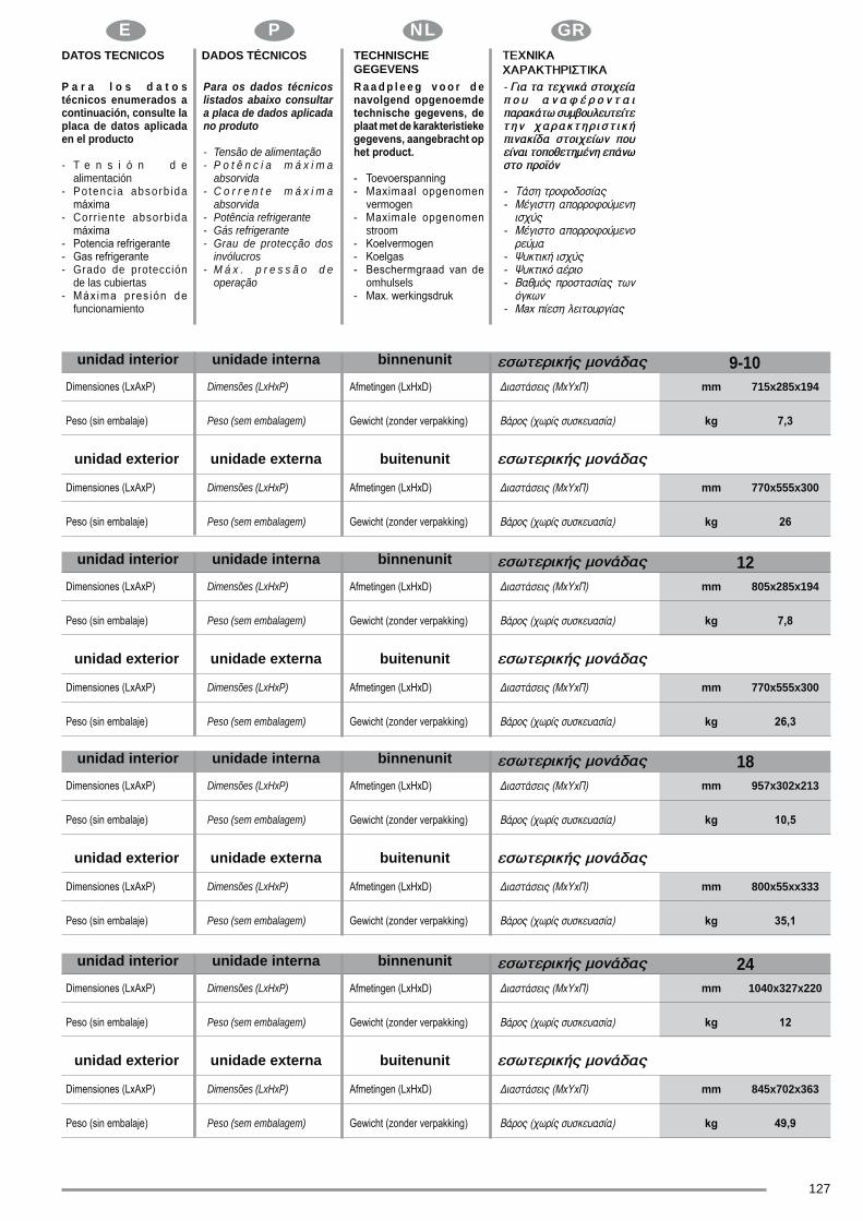
E GR
127
P NLE P NL GRDATOS TECNICOS DADOS TÉCNICOS TECHNISCHE
GEGEVENSP a r a l o s d a t o s técnicos enumerados a continuación, consulte la placa de datos aplicada en el producto
- T e n s i ó n d e alimentación- Po tenc ia absorb ida
- Corr iente absorbida
- Grado de protección de las cubiertas
funcionamiento
Para os dados técnicos listados abaixo consultar a placa de dados aplicada no produto
- Tensão de alimentação- P o t ê n c i a m á x i m a absorvida- C o r r e n t e m á x i m a absorvida- Potência refrigerante- Gás refrigerante- Grau de protecção dos invólucros- M á x . p r e s s ã o d e operação
R a a d p l e e g v o o r d e navolgend opgenoemde
stroom
omhulsels
mm 715x285x194
Dimensões (LxHxP)
Peso (sem embalagem)
9-10binnenunitunidade internaunidad interior
buitenunitunidade externaunidad exterior
mm 770x555x300Dimensões (LxHxP)
Peso (sem embalagem)
mm 805x285x194
Dimensões (LxHxP)
Peso (sem embalagem)
12binnenunitunidade internaunidad interior
buitenunitunidade externaunidad exterior
mm 770x555x300
Dimensões (LxHxP)
Peso (sem embalagem)
mm 957x302x213
Dimensões (LxHxP)
Peso (sem embalagem)
18binnenunitunidade internaunidad interior
buitenunitunidade externaunidad exterior
mm 800x55xx333
Dimensões (LxHxP)
Peso (sem embalagem)
mm 1040x327x220
Dimensões (LxHxP)
Peso (sem embalagem)
24binnenunitunidade internaunidad interior
buitenunitunidade externaunidad exterior
mm 845x702x363
Dimensões (LxHxP)
Peso (sem embalagem)

GB F D
128
II GB F DOPERATIONAL LIMITSCONDIZIONI LIMITE DI
FUNZIONAMENTOCONDITIONS LIMITES DE FONCTIONNEMENT
GRENZBETRIEBSBE-DIN-GUNGEN
Temperature di esercizio massime in raffreddamento
Temperature di esercizio minime in raffreddamento
Temperature di esercizio massime in riscaldamento
Temperature di esercizio minime in riscaldamento
A Temp. ambiente internoB Temp. ambiente esterno
Max operating temp. during cooling
Minimum operating temp. during cooling
Max operating temperature during heating
Minimum operating tempe-rature during heating
A Internal room temp.B External ambient temp.
Max. Betriebstemperaturen in
Min. Betriebstemperaturen
Max. Betriebstemperaturen
Min. Betriebstemperaturen
A Raumtemp. innenB Umgebungstemp. außen
A B
DB 32°C DB 50°C
DB 17°C DB -15°C
DB 30°C DB 30°C
DB0°C DB -15°C
mini-mums en refroidissement
-
A B

E GR
129
P NLE P NL GRCONDICIONES LÍMITE DE FUNCIONAMIENTO
CONDIÇÕES LIMITES DE FUNCIONAMENTO
LIMIETVOORWAARDEN WERKING
Temperaturas de funcio-
Temperaturas de fun-
Temperaturas de funcio-
calefacciónTemperaturas de fun-
calefacción A Temp. ambiente interiorB
Temperaturas máximas de funcionamento durante o arrefecimentoTemperaturas mínimas de funcionamento durante o arrefecimentoTemperaturas máximas de funcionamento durante o aquecimentoTemperaturas mínimas de funcionamento durante o aquecimento
A Temp. ambiente internoB Temp. ambiente externo
-
-
A B
A B
DB 32°C DB 50°C
DB 17°C DB -15°C
DB 30°C DB 30°C
DB0°C DB -15°C

GB F D
130
I
GB
I
MALFUNCTIONS
Unit does not start
Unit not cooling or heating (Cooling/ hea-ting models only) room very well while air
WHAT SHOULD BE DONE?
Wait for power to be restored.
Check that plug is securely in wall receptacle.
Replace the fuse.
Replace the battery.
Wait or cancel timer setting.
Set temperature correctly. For detailed method
Close the doors or windows.
unit.
Wait.
CAUSE
Power cut
Unit may have become unplugged.
Fuse may have blown.
Battery in Remote controller may have been exhausted.
The time you have set with timer is incorrect.
Inappropriate temperature setting.
Doors or Windows are open.
Air inlet or outlet of indoor or outdoor unit has been blocked.
Compressor 3 minutes protection has been activated.
If the trouble has not been corrected, please contact a local dealer or the nearest customer service center. Be sure to inform them of the detailed malfunctions and unit model.
Notes: Do not attempt to repair the unit yourself.
TROUBLESHOOTING TIPS Malfunctions and Solutions
Stop the air conditioner immediately if one of the following faults occur. Disconnect the power and contact the nearest customer service center.
Trouble
If one of the following codes appears on the display: E0,E1,E2,E3,E5,EC,P0,P1,P2,P4,F1,F2,F3,F5,E4,F4.
Fuse blows frequently or circuit breaker trips frequently.
Other objects or water penetrate the air conditioner.
The remote controller won’t work or works abnormally.
MALFUNZIONAMENTI
riscalda bene l’ambiente (solamente per
mentre dell’aria esce dal condizionatore.
COSA OCCORRE FARE?
Sostituire il fusibile.
Sostituire le batterie.
Attendere o annullare l’impostazione del timer.
Impostare la temperatura in modo corretto. Per la procedura
l’apparecchiatura.
Attendere.
CAUSA
Interruzione di corrente
E’ scattato un fusibile.
Le batterie del telecomando possono essere esaurite.
L’ora impostata con il timer può non essere corretta.
Errata impostazione della temperatura.
interna o esterna sono bloccate.
compressore.
-namento e sul modello dell’apparecchiatura.
SUGGERIMENTI PER L’ELIMINAZIONE GUASTI Malfunzionamenti e Soluzioni
Problema
Il telecomando non funziona o funziona in modo anomalo.

E GR
131
P NL
F
D
DYSFONCTIONNEMENTS
L’appareil ne démarre pas
-
que de l’air sort du climatiseur.
QUE FAIRE?
Remplacer le fusible.
Remplacer les piles.
-
Fermer les portes ou les fenêtres.
l’appareil.
Attendre.
CAUSE
Coupure de courant
ne pas être correcte.
La protection de 3 minutes du compresseur s’est
proche.
BETRIEBSSTÖRUNGEN
Das Gerät startet nicht.
Das Gerät kühlt oder heizt den Raum nicht wirksam (nur bei den Modellen Kühlung/Heizung), während Luft aus der Klimaanla-ge tritt.
BEHELFE
Wiederherstellung der Stromversorgung abwarten.
Sicherstellen, dass der Netzstecker eingeführt wurde.
Wechseln Sie die Schmelzsicherung aus.
Wechseln Sie die Batterien aus.
Warten Sie oder annullieren Sie die Timer-Einstellung.Stellen Sie die Temperatur auf korrekte Weise ein. Beachten Sie
Schließen Sie Türen oder Fenster.
Entfernen Sie die Verstopfung und starten Sie das Gerät neu.
Warten Sie ab.
URSACHE
Stromausfall
Die Einheit wurde von der Stromversorgung getrennt.
Eine Schmelzsicherung wurde ausgelöst.
Die Batterien der Fernsteuerung sind mögli-cherweise verbraucht.Die mit dem Timer eingestellte Uhrzeit ist mögli-cherweise nicht korrekt.
Fehlerhafte Temperatureinstellung.
Türen oder Fenster sind offen.
Der Lufteinlass oder der Luftauslass der Inne-neinheit oder Außeneinheit ist blockiert.
Der 3-Minuten-Schutz des Kompressors wurde aktiviert.
Wenn das Problem nicht behoben wurde, nehmen Sie Kontakt zum örtlichen Händler oder mit der nächsten Kundendienstsstelle auf. Machen Sie detaillierte Anhaben zur Betriebsstörung und zum Modell des Geräts.
Hinweise: Versuchen Sie nicht, das Gerät alleine zu reparieren.
HINWEISE ZU FEHLERBEHEBUNG, Störungen und LösungenStellern Sie beim Eintreten einer der folgenden Störungen die Klimaanlage unverzüglich ab. Trennen Sie die elektrische Stromversorgung und nehmen Sie Kontakt mit der nächsten Kundendienststelle auf.
Problem
Wenn am Display einer der folgenden Codes erscheint: E0,E1,E2,E3,E5,EC,P0,P1,P2,P4,F1,F2,F3,F5,E4,F4.
Wasser oder sonstige Gegenstände sind in die Klimaanlage gelangt.
Die Fernbedienung funktioniert nicht oder nicht wie vorgesehen.

GB F D
132
I
E
P
MAU FUNCIONAMENTO
O aparelho não arranca
O aparelho não arrefece ou não aquece bem o ambiente (somente nos modelos com arrefecimento/aquecimento) enquanto sai ar do aparelho.
O QUE FAZER?
Aguardar que seja restabelecida a corrente eléctrica.
Substituir o fusível.
Substituir as pilhas.
Aguardar ou anular a programação do temporizador.
Programar a temperatura correctamente. Para o modo de
Fechar as portas ou as janelas.
Eliminar primeiro os entupimentos, depois acender novamente o aparelho.
Aguardar.
CAUSA
Interrupção de corrente
A unidade desligou-se da corrente eléctrica.
Queimou-se um fusível.
As pilhas do telecomando podem estar descar-regadas.A hora programada no temporizador poderá não estar correcta.Programação errada da temperatura.
As portas ou janelas estão abertas.
As tomadas de entrada ou de saída do ar das unidades, interna ou externa, estão entupidas.
Accionou-se a protecção de 3 minutos do compressor.
Se o problema não estiver resolvido, contactar o seu Revendedor local ou o Serviço de Assistência Técnica mais próximo. Fornecer informações pormenorizadas sobre o mau funcionamento e sobre o modelo de aparelho.
Nota: Não tentar reparar o aparelho sozinho.
CONSELHOS PARA A RESOLUÇÃO DE AVARIAS - Problemas de funcionamento e Soluções
de Assistência Técnica mais próximo.
Problema
Se no display aparece um dos seguintes códigos: E0,E1,E2,E3,E5,EC,P0,P1,P2,P4,F1,F2,F3,F5,E4,F4.
Os fusíveis queimam-se frequentemente ou o interruptor automático intervém muitas vezes.
Entrou água ou objectos dentro do aparelho de ar condicionado.
O telecomando não funciona ou funciona de modo anormal.
DISFUNCIONES
El aparato no se enciende.
El aparato no enfría o no calienta bien el ambiente (solamente en los modelos con
aire del acondicionador.
¿QUÉ SE DEBE HACER?
-
Espere.
CAUSA
Interrupción de corriente.
La unidad se ha desconectado de la corriente.
Las tomas de entrada o salida del aire de las uni-
compresor.
SUGERENCIAS PARA LA REPARACIÓN DE AVERÍAS - Problemas y soluciones
más cercano.
Problema
El control remoto no funciona o funciona en modo anómalo.

E GR
133
P NL
NL
GR
ONGEMAKKEN
De apparatuur gaat niet van start.
-ving niet goed (alleen voor de modellen met
WAT TE DOEN?
Sluit deuren en ramen.
Wachten.
OORZAAK
De deuren of de ramen staan open.
WENKEN VOOR HET VERHELPEN VAN DEFECTEN Storingen en oplossingen
Probleem


260
08
1A