as ge 3. - patentimages.storage.googleapis.com · as ge 3. an ram woo ?o6 ... 374 - 4/4-r 378 442...
TRANSCRIPT

United States Patent (19) 11 4,262,302 Sexton (45) Apr. 14, 1981
(54) VIDEO DISPLAY PROCESSOR HAVING AN 4,116,444 9/1978 Mayer - - - - - - - - - - - - - E - - - - - - - - - - - - - 340/745
INTEGRAL COMPOSITE WIDEO 4, 19,955 10/1978 Nichols ................................ 340/706 GENERATOR 4,129,853 2/1978 Hara ..................................... 340/707
4,139,838 2/1979 Inose .................................... 340/703 (75) Inventor: Joe F. Sexton, Houston, Tex. 4, 155,095 5/1979 Kirschner ............................ 340/703 73 Assignee: Texas Instruments Incorporated Primary Examiner-Benedict V. Safourek
- Assistant Examiner-Michael A. Masinick (21) Appl. No.: 17,865 Attorney, Agent, or Firm-Robert D. Marshall, Jr.; Leo y, Ag (22 Filed: Mar. 5, 1979 N. Heiting; Melvin S. Sharp (51) Int. Cl. ............................................... H04N 9/12 57 ABSTRACT 52 U.S. Cl. ..................... ........ 358/10; 350/30; 350/81 A digital computing system is disclosed having a mono (58) Field of Search ....................... 358/10, 81, 82,22, lithic microprocessor, a versatile input/output subsys
358/30, 340/70, 708, 726, 721, 745, 704 tem, a multi-medium capability. In the memory subsys 56 Ref Cited tem, a balanced mix of dynamic RAM, P-channel MOS (56) eferences Cite ROM and N-channel MOS ROM are included to mini
U.S. PATENT DOCUMENTS mize cost without sacrificing performance. In the video 3,749,823 7/973 Warner ........................ i......... 388/81 display subsystem, a monolithic video display processor 3,76,607 9/1973 Hanseman ... ... 358/8 performs all RAM access functions, in addition to com 3,89,792 6/1975 Kimura ....... ... 340/726 posite video generation. The resultant composite video 3.98,039 /1975 Clark ..., 340/730 signal, which may include audio and external video : 7 E. a 3.f information, can be applied directly to a video monitor
E. E. ... 358/10 or RF modulated for use by a television receiver. 4,107,664 8/1978 Marino ................................. 340/731 4,107.665 8/1978 Mayer .................................. 340/706 24 Claims, 14 Drawing Figures
73 32 8O aga
cPUS St. REGISTER control NTERFACE CONTROL REGISTERS
as ge 3. an RAM
WOO ?O6
RAM RESET/EXTERNAL SYNC
EXTERNAL WEDEO COMPOSITE WIDEO 7é te 2


U.S. Patent Apr. 14, 1981 Sheet 2 of 9 4,262,302
AO) A56
ROW SUBTRACT AND ROW COUNT DISPLACEMENT COMPARE
Aa2 90, sag /62 56 ---
NAME NAME RAM SPRITE LATCH CONTROL STACK
/73 COLUMN SPRITE COLUMN 39 /46 DOWN DISPLACEMENT COUNTER CONTROL 36ENFER
/92 COLUMN 53 /34 SPRITE /O2a /O2 CONTROL
SPRITE SHIFT PATTERN 26 EGISTER SHIFT PATTERN /32 AO4 REGISTER
56 4; 3 - 4 53 SRITES. 86. PRORTY EAERN PATTERN COLOR REGISTER SELECTOR REGISTERS COLORS
/23 A79, 3
7s 3O 34 - - - - -
CPU CPU ADDRESS 24O | fiftRFACE PATTERN NAME
A26 - - - - - TABLE BASE
PATTERN COLOR - R TABLE BASE A32
2 pattern generator - - - - - - s TABLE BASE A38
RAM T SPRITE NAME /54 A. CONTROL TABLE BASE ea-wo
Afg, 4. - - - - - SPRITE GENERATOR 2 8 TABLE BASE --
WO4 DEFAULT COLOR 328 - - - - R
- - 8 COMMAND REGISTER 204 PRORITY -
SELECTOR STATUS REGISTER

U.S. Patent Apr. 14, 1981 Sheet 3 of 9 4,262,302
AO /74 NO YES
/72 Yes A34 No /76
PATTERN NAME R. No ->NAME AC- UNST ACK SERE NCD,
A3O /6O
PATTERN COOR CODE SPRITE COLUMN DISP. f/3 -be -> PATTERN COLOR RE -SPRITE DOWN
COUNTER
A36
PAERN NE
PATTERN shift reg.
f4O
CPU = MOD4 (CPU+1)
set
/94
SPRTE COLOR CODE -SPRE COLOR REG,
/36
A42
YES st cpu N
ACCESS NO
A44
A5O
OVERLAY CONTROL
L Fech Sore ROW D SPACEMEN
/39
OFFSET = ROW COUNT - ROW DISPLACEMENT
/90
SPR NAME ->NAME LATCH
A94
A46 NO Spre LNE -->
\ NCREMEN SPRITE SH 1 FT REG.
SPRITE NO. /93
A52
ME
SET CPU ACCESS
Fetch sprite
ROW OSPACE 2OO
RESE SOP W6O A53 S FAG
No NO 1stop YES s CODE 2 e 2O2
N CEAR SPRte NO.
YES SET
- STOP FLAG Afg. 5
(66
STACK sPRTE No.

U.S. Patent Apr. 14, 1981 Sheet 4 of 9 4,262,302
FROM FROM DECSON PROCESSING BLOCK 58 BLOCK 90
2O6
TO
OFFSET = ROW COUNT -ROW DISPLACEMENT
DECSON BLOCK 20
Wo OSE By 2
A94
SPRE ENE --> SPRITE SHIFT REG.
224
<C> FASE TRE 226
ADo 6 O OFFSE
223
SPRE LINE sprTE SHIFT REG.
Afg, 7 TO PROCESSING BLOCK 98
To A/9. 6 PROCESSING BLOCK 64


U.S. Patent Apr. 14, 1981 Sheet 6 of 9 4,262,302
PRIORITY SELECTOR
DSPLAY f04 ACTIVE
A92 937 294 232 /Q2.5 SPRITE - - - r O COLOR
- 276 23O REGISTER SPRITE 273 SHIFT D COLOR REGISTE VA 296 ?ECODER
Tot, 1 295 296 /7 FOREGROUND A34 269 C COLOR - - - - 236 294, 292 REGISTER
29O COLOR SEERN f ED DECODER REGISTER 5O2 VA-306 Og T-J) - 3/6 34 S BASROUND
/O2c Y 270 32 REGISTER 3O4. 3O81 - COLOR
ED 3/O DECODER VA MO6 6éault (32O COLOR
3/9 REGISTER
A. COLOR A/g, 9 DECODER ly 326 WO6
274 324
COLOR PHASE GENERATOR f/O
$3 - A. 94A A
sh 947 356 3.35 342 546 35O 3.54

U.S. Patent Apr. 14, 1981 Sheet 7 of 9 4,262,302
BLA 96. g COLOR SELECT cologicope AND WIDEO MIXER 37O 6 472 AO6
ooo oC NTENSTY
oo (i. o o ox BANKING COLOR to HS DECODEFoo 470
H. : Hist £NABLE UU U te 96/ f/4 37Ob
374 - 4/4-r 378 442 448 229 469 EXTERNAL
aoa 360 l a? victo as III ago, 416 4/8 IPOSITE
VIDEO 444 Yaaa I 62
409 - 398 400 all x
386 390
454 ya 452 NA 236 439 Afg, //

U.S. Patent Apr. 14, 1981 Sheet 8 of 9 4,262,302
llllllllllllllll LLL LI'll r u rul Ull
YELLOW - in in-- - - - - - RED - - - - - - - - - -
MAGENA - - - - in - 4--- BLUE- p- p r ? -
L. L. L - GREEN - - l-Hi l-H -
Hy
SEESA- s 'l-HH-----
Intensity 'l------is BLANK-4-m-H acama
H SYNC ----- 'l-HH
BURST -- Hi-H h -44-8-4 42O 1A
WHITE WDEO - if t i? 4/O
t-f Y - COLOR A
COLOR 426 fiete, 4. r 14, it BLACK-e - 44O i.
CLEAR -- L" - RS k-BLANKING ->
Afg, (2 HORIZONTAL SYNC- e

U.S. Patent Apr. 14, 1981 Sheet 9 of 9 4,262,302
52 49es 490 76 5O2
ADDRESS LATCH
NPUT BUFFER
473
5Os
Afg, 3 OUTPUT CPU 4--. E.
498 46O GENERATE REAY
ARESS -- outPU
ATCH
SHF
AddRESS COUNER
ENABE
out PUT UEr
ARESS --> AddRESS ACH
AA -- dup Ut
LATCH
CAD
Addres S COUNER
494 NCREMENT SHF
OGGE ". ADDRESS NO ADRESS COUNER COUNER
496
ENABLE OUPUT Burfer
Afg, 14
4,262,302
WDEO. DISPLAY PROCESSOR HAVING AN INTEGRAL COMPOSTE WIDEO GENERATOR
CROSS REFERENCE TO RELATED APPLICATIONS
The subject matter disclosed herein is related to the subject matter disclosed in the co-pending U.S. patent application Ser. No. 018,540 entitled "Video Display Processor", filed on Mar. 8, 1980 by the inventors thereof, David A. Ackley, Gerald D. Rogers, Peter H. Macourek and Karl M. Guttag, and assigned to the assignee of the present invention.
BACKGROUND OF THE INVENTION 1. Field of the Invention This invention relates generally to composite video
signal generating devices and, more particularly, but not by way of limitation, to a monolithic video display processor having an integral composite video genera to,
2. Prior Art Statement Although numerous systems have been proposed for
digitally generating composite video signals containing desired display patterns, such systems have generally produced only monochromatic displays, or produced separate chrominance and luminance signals for appli cation to conventional chroma and video, modulators. For example, the systems disclosed in U.S. Pat. Nos. 4,107,665, 4, 16,444, and 4,129,858 appear to be mono chromatic, while the circuit disclosed in U.S. Pat. No. 4,119,955 requires a separate chroma and video modula tor device. Other systems of general interest are shown in U.S. Pat. Nos. 3,345,458, 3,891,792, 3,918,039, 4,034,990, 4,081,797, and 4,107,664.
SUMMARY OF THE INVENTION
in a monolithic video display processor for providing a composite video signal for application to a video dis play unit, a video generator includes a color phase gen erator responsive to a color reference signal for provid ing a phase-shifted color phase signal, a voltage divider providing first and second reference voltages, and a gating network for gating the first and second reference voltages in an alternating manner in phase with the color phase signal to a mixer transistor for output as the composite video signal. The first and second reference voltages are selected to have a potential difference pro portional to a predetermined chrominance value and an average potential proportional to a predetermined iumi nance value so that the composite video signal provided by the mixer transistor digitally approximates the com posite video signal for a selected color. The voltage divider also provides reference voltages proportional to standard blanking, sync and color burst levels for selec tive gating via the gating network to the mixer transis tor for digitally approximately the synchronizing por tions of the composite video signal.
It is an object of the present invention to provide a video generator which is integral with a monolithic video display processor. s Another object of the present invention is to provide
a video generator having a single voltage divider net work which provides all reference voltage levels neces sary to produce a composite video signal.
Yet another object of the present invention is to pro vide a video generator for efficiently generating a com posite video signal consisting of blanking, raster-scan
5
O
5
25
30
45
50
55
65
2 synchronizing, color synchronizing, and color picture information portions.
Still another object of the present invention is to provide a video generator which is simple and economi cal to manufacture, yet reliable and versatile in opera tion. Other objects and advantages of the present invention
will be apparent from the following detailed specifica tion, when read in conjunction with the accompanying drawings which illustrate the preferred embodiment of the invention.
BRIEF DESCRIPTION OF THE DRAWINGS FIG. 1 is a schematic representation of a digital com
puting system incorporating the preferred embodiment of the present invention.
FIG. 2 is a block diagram of the video display proces sor shown in FIG. I.
FIG. 3 is a block diagram generally illustrating the operation of the overlay control portion of the video display processor. FIG. 4 is a schematic representation of the register
control and control register portions of the video dis play processor. FIG. 5 is a logic diagram generally depicting, in con
junction with FIG. 3, the operation of the overlay con trol portion of the video display processor. FIG. 6 is an alternative form of a portion of the logic
diagram F.G. 5. FIG. 7 is an alternative form for one other portion of
the logic diagram of FIG. 5. FIG. 8 is a logic diagram illustrating the operation of
the RAM control portion of the video display proces S.
FIG. 9 is a schematic representation of the priority selector portion of the video display processor. FIG. 10 is a schematic representation of the color
phase generator portion of the video display processor. FIG. 11 is a schematic representation of the color
decoder and video mixer portions of the video display processor. FIG. 12 is a multi-waveform diagram illustrating the
operation of the video generator portion of the video display processor. FIG. 13 is a block diagram of the slow ROM shown
in FIG. . . FIG. 14 is a logic diagram illustrating the operation
of the slow ROM shown in FIG. 13. GENERAL SYSTEM DESCRIPTION
Shown in FIG. 1 is a digital computing system 10 incorporating the preferred embodiment of the present invention. In general, the digital computing system 10 is comprised of a central processing unit (CPU) i2, a memory subsystem 14, an input/output subsystem 16, and a video display subsystem 18. The CPU 12, which may be a monolithic microprocessor such as the Texas Instruments 9985, operates in a conventional manner under the control of digital control programs stored in the memory subsystems 14, usually in response to pro cessing requests initiated via the input/output subsys tem 16. In the input/output subsystem 16, an IAO con trol unit 20, which may be a monolithic integrated cir cuit such as the Texas Instruments 9901, operates in a conventional manner to interface a CPU communica tion bus 22 to an I/O bus 24 connected to one or more I/O unites 20. By way of example, the I/O units 26, may

4,262,302 3
be such conventional devices as the following: input devices, including a keyboard 26, a plurality of hand held units 30, and various types of remote sensors 32; output devices, such as speech synthesizer unit 34 and a hard copy printer 36; and bidirectional input and output devices such as a magnetic disk unit 38, a magnetic tape unit 40, and a communication modem 42.
In the memory subsystem 14, it is frequently desirable to combine a quantity of read only memory (ROM) with a quantity of read/write, random access memory 10 (RAM). In such configuration, support programs, such as a suitable operating system and a desired assembler or complier, are stored in the ROM, while user programs and volatile data are stored in the ram. In this form, the relatively static programs and data are maintained in the relatively less expensive ROM, so that only the rela tively transient programs and data need be stored in the generally more expensive RAM.
In the preferred form shown in FIG. 1, the memory subsystem 14 is also configured to take advantage of the low cost of relatively slow ROM and of dynamic RAM, without substantially degrading the performance of the CPU 12. More particularly, in the ROM portion of the memory subsystem 14, a relatively limited amount of fast ROM 44, preferably of the N-channel MOS type, such as the Texas Instruments 4732, is directly con nected to the CPU 12 via a CPU memory bus 46, while a larger amount of relatively slow ROM 48, preferably of the P-channel MOS type, such as the Texas Instru ments 0430, is connected to the CPU 12 via a bus buffer 50, such as the Texas Instruments 74LS245, interposed between the CPU memory bus 46 and an auxiliary bus 52. By providing each device comprising the slow ROM 48 is assigned a unique ROM address page num ber, as in the 0430, an additional plurality of such de vices may be incorporated to form a ROM library mod ule 54 for connection to the auxiliary bus 52 via a suit able plug-in type port.
In the RAM portion of the memory subsystem 14, a block of dynamic RAM 56, preferably of the N-channel MOS type, such as the Texas Instruments 4027, is con nected via a RAM bus 58 to the CPU memory bus 46 via a video display processor (VDP) 60. More particu larly, the VDP 60 is constructed to provide, in addition to other functions to be described below, an auto-incre menting address counter capability, similar to that in corporated in the devices comprising the slow ROM 48. In addition, the VDP 60 provides for the periodic re freshing of the contents of the various devices compris ing the ram 56. Thus, the CPU 12 is relieved of the burden of supplying addresses for each of a series of sequential accesses to the RAM 56, and of the consider able overhead normally associated with the periodic refreshing of dynamic random access memory.
In the video display subsystem 18, the VDP 60 may be activated by the CPU 12 via the CPU memory bus 46 to generate all video, control and synchronization sig nals necessary for the display on a raster-scanned televi sion unit of a set of display data previously generated by the CPU 2 and stored in the RAM 56. The resultant composite video signal is provided via a signal path 62 for application either to a dedicated monitor unit or to a conventional RF modulator 64 before application to a conventional television receiver. In the preferred form, a sound generator 66, such as the Texas Instruments 9919, is connected to the CPU 12 via the auxiliary bus 52 and provides a CPU-controlled audio signal which may be applied to an auxiliary speaker 68 via a signal
15
20
25
30
35
45
50
55
60
65
4. path 70 or to the RF modulator 64 via a signal path 72 for mixing with the composite video signal provided by the VDP 60. To facilitate system initialization and synchroniza
tion, it is preferred that the VDP 60 respond to a manual reset or an external synchronization signal on a signal path 74, by placing the various control portions thereof in a known state. Similarly, it is considered desirable that the VDP 60 be capable of receiving an externally produced, composite video signal via a signal path 76, and mixing the external video signal with the internally generated composite video signal for output via the signal path 62. For example, it may be desirable in some circumstances to combine the composite video signal generated by the VDP 60 with a composite video signal produced via an auxiliary television camera or derived from a broadcast television signal. In such a configura tion, the VDP may be conveniently synchronized with the external video source by extracting in a conven tional manner appropriate synchronizing portions of the external video signal on the signal path 76 for applica tion to the VDP 60 via the signal path 74. As will be readily apparent to those skilled in the art, the external video input and synchronization capability of the VDP 60 also facilitates the chaining of two or more VDP 69 devices, to greatly enhance the data display and anima tion capabilities of the digital computing system 10. GENERAL DESCRIPTION OF THE VIDEO
DISPLAY PROCESSOR Shown in FIG. 2 is a block diagram of the circuit
comprising the video display processor 60 shown in FIG. 1. In general, the VDP 60 is constructed to oper ate in both a RAM controller mode and in a video controller mode, with substantial simultaneity occuring between these modes. In addition, much of the circuitry for accomplishing the RAM controller functions may be conveiently employed, together with additional cir cuitry, for accomplishing the video controller func tions. In this manner, substantial savings in time and circuitry are realized.
In general, a CPU interface 78 response to access requests from the CPU 12 via the CPU memory bus 46. When a CPU access request is initially received, the CPU interface 78 transfers the selected RAM address to a register control 80 via a register bus 82 for storage in a particular one of a set of control registers 84. In the case of a write request, the CPU interface 78 then latches the write data from the CPU memory bus 46 into a CPU data register 86 via a VDP address and data bus 80, and initiates a CPU write access request for service by a RAM control 90. In response to the write request, the RAM control 90 will retrieve the RAM address from the control registers 84 via the register control 80, and pass the RAM address to the RAM 56 via the RAM bus 58. Thereafter, the RAM control 90 will transfer the write data from the CPU data register 86 to the ram 56 via the RAM bus 58. In the case of a read request, the CPU interface 78 will simply initiate a CPU read access request for service by the RAM con trol 90. As in the case of a write request, the RAM control 90 then transfers the RAM address from the control registers 84 to the RAM 56. Thereafter, the RAM control 90 cooperates with the RAM 56 to latch the read data provided by the RAM 56 via the RAM bus 58 into the CPU data register 86. When the CPU 12 calls for the data, the CPU interface 78 transfers the read data provided by the CPU data register 80 on the

4,262,302 5
VDP address and data bus 88 to the CPU 12 via the CPU memory bus 46. As soon as a write request has been serviced, the
RAM control 90 will automatically increment the RAM address contained in the control registers 84, so that a subsequent CPU write access request can be made into the next sequential address location in the RAM 56 merely by transferring the write data from the CPU 12 into the CPU data register 80 via the CPU interface 78. Similarly, the RAM control 90 will automatically incre ment the RAM address contained in the control regis ters 84 after a read request has been serviced, so that a subsequent CPU read access request can be made from the next sequential address location in the RAM 56 as soon as the CPU interface 78 has completed the transfer of the preceeding read data to the CPU 12. Thus, the CPU 12 spends a minimum amount of time waiting for a data transfer after an access request is issued. When VDP register access request is received, the
CPU interface 78 transfers the address of the particular one of the set of control registers 84 to the register control 82 via the register bus 82. In the case of a regis ter write request, the CPU interface 78 transfers the write data from the CPU memory bus 46 to the register bus 82, for subsequent latching into the selected control register 84 via the register control 80. In the case of a register read request, the register control 80 connects the selected control register 84 to the register bus 82, with the CPU interface 78 subsequently connecting the register bus 82 to the CPU memory bus 46. When the VDP 60 is operating in the RAM control
ler mode only, the RAM control 90 operates in a con ventional manner to periodically access each of the refresh segments in the RAM 56. Thus, RAM contents are protected in the event that the CPU 12 fails to exer cise each of the refresh segments through normal RAM acceSSes.
In the video controller mode, the VDP 60 generates a composite video signal in accordance with a set of control parameters established in the control registers 84, using a set of display data arrays stored in the RAM 56. In general, the composite video signal, when dis played on a suitable video display unit, produces a video display comprised of M columns of N rows of individ ual, discrete video display elements or pixels. For con venience of information display, however, the (MXN) pixels may be considered as being logically associated into smaller contiguous groups or blocks which may be configured or defined to form discernible characters or 'patterns,' as in conventional character generators. In addition, however, the preferred form of the VDP 60 accomodates a plurality of mobile blocks of "sprites' which may be freely moved relative to the fixed display image by defining or selecting a particular column U and row V at which the upper left corner of the sprite is to be displayed. Thus, VDP 60 generates the compos ite video signal in synchronization with the instanta neous column X and row Y position of the faster scan so as to display either the fixed patterns or the mobile sprites, as appropriate.
In the preferred form, the VDP 60 operates in a CPU selected one of three distinct video display modes: pat tern graphics, multicolor, and text. Briefly, in the pat tern graphics mode, the VDP 60 generates a 32 column, 24 row image of patterns (8x8 pixels) selected from a pattern generator table (256 pattern definition blocks) according to a pattern name table (768 pattern names), and, in addition, superimposes up to 32 of the mobile
10
15
20
25
30
35
40
45
50
55
60
65
6 patterns or sprites (8x8 pixels) selected from a sprite generator table (256 sprite definition blocks) according to a sprite name table (32 sprite descriptor blocks) which also defines the displacement of each sprite rela tive to the pattern image. In the multicolor mode, the VDP 60 generates a 32 column, 6 row image of color patterns (2X8 blocks of 4x4 pixels each) selected from a pattern color table (1536 elements) according to a pattern name table (192 pattern names), with up to 32 of the sprites being generated in substantially the same manner as in the pattern graphics mode. In the text mode, the VDP 60 generates a 40 column, 24 row image of patterns (6X8 pixels) selected from a pattern genera tor table (256 pattern definition blocks) according to a pattern name table (960 pattern names). In each of the three video display modes, the VDP 60 provides a se lection of 16 distinct colors, including white, gray, black and a special transparent state to be described in greater detail below. Since the operation of the VDP 60 in the multicolor and text modes is substantially the same as in the pattern graphics mode, except for the differences noted above, the discussion hereinafter will be directed primarily to the detailed operation in the pattern graphics mode.
During system initialization and as required thereaf ter, the VDP 60, operating in the memory controller mode, cooperates with the CPU 12 to establish in the RAM 56 the various display data arrays appropriate for a selected one of the three video display modes. For example, to enable the VDP 60 to operate in the pattern graphics mode, the CPU 12 should store in the RAM 56 the various pattern and sprite tables relied upon by the VDP 60. In particular, the pattern generator table is comprised plurality of consecutive pattern definition blocks, each consisting of 8, 8-bit bytes, which define the bit patterns for each individual pattern, as in con ventional character generators. In contrast, the pattern name table consists of a row-by-column ordered array of patterned names which map the pattern definition blocks into each of the 32 columns of 24 rows of pat terms comprising a full screen video pattern image. In addition, a pattern color table establishes a pair of video color codes associated with each of 32 contiguous sets of 8 pattern definition blocks of the pattern generator table, with each of the video color codes corresponding to a particular one of the sixteen available colors. Thus, the pattern generator table, and the pattern color table represent an ordered array whereby the individual bits comprising a pattern definition block map the video color codes assigned via the pattern color table into each of the M columns of N rows of pexels comprising a full screen video pattern image. In a similar manner, the sprite generator table is comprised of a plurality of consecutive sprite definition blocks, each consisting of 3, 8-bit bytes, which define particular bit patterns for each of the patterns to be utilized as sprites. The sprite name table, on the other hand, is comprised of 32, 4-byte sprite descriptor blocks which define the particular column displacement U and row displacement V for the display of the particular sprite relative to the video pattern image, where 1 SUSM and is VSN. In addi tion, each of the sprite descriptor blocks in the sprite name table contains a sprite name which refers to a particular one of the sprite definition blocks in the sprite generator table, as well as a video color code which establishes the particular one of the sixteen available colors that the active portion of the sprite is to assume. Thus, the sprite name table and the sprite generator
4,262,302 7
table represent an ordered array whereby the individual bits comprising a sprite definition block map the video color code assigned via the sprite descriptor block into the Scolumns of Trows of pixels comprising a particu lar video sprite image, where 1s SSM and 1STsN. To promote uniformity of reference, the dimensions of the pattern and sprite image relative to the pattern image are considered herein in terms of individual pix els, since the format of the various tables in the RAM 56 are generally related to the particular number of rows
5
10 and columns of discrete symbols of characters charac teristic of the selected video display mode.
In general, a sequence control 92 operates in a con ventional manner to maintain a cyclic column count X and a cyclic row count Y indicative of the time sequen tial position of the raster scan of the video display unit. As will be clear to those skilled in the art, only a portion of the total raster scan period is devoted to actively displaying patterns on the video display unit, since a portion of each row of horizontal scan is devoted to horizontal retrace, while a number of complete row or horizontal scans are required to perform vertical retrace and related synchronization. However, at least during the active display period, the sequence control 92 makes the column count X and the row count Y available via the VDP address and data bus 88. The sequence control 92 also provides a color reference signal having a fre quency related to the NTSC 3.5/MHZ carrier, via a signal path 94, and a set of sync signals of substantially conventional form via a sync bus 96. In response to the reset/external sync signal on the signal path 74, the sequence control 92 clears the column and row counts, and generally synchronizes the color reference signal and the sync signals with the external source. In the
15
20
25
30
preferred form, the sequence control 92 is comprised of 35 a clock circuit of conventional form, and a pair of con trol programmable logic arrays (PLA's) for providing a various control signals via a control bus 98 depending on the current column and row counts. An overlay control 100, responsive to the column and
row counts, periodically requests the RAM control 90 to retrieve selected portions of the pattern and sprite tables from the RAM 56. As the display data is provided by the RAM 56 via the RAM bus 58, the overlay con trol 100 receives the pattern data, and provides a first pattern signal via a pattern bus 102, comprising the bit in the pattern generator table which maps the pixel in the column (X-U-1) of the row (Y-V-- 1) of the video sprite image when UsX<(U--S) and Vs Y ((V+T). In addition, the overlay control 100 receives the video color codes assigned to each pattern and sprite during the display thereof. In other words, the overlay control 100 processes the pattern data arrays so as to provide the proper bit patterns for each of the selected patterns during the entire period that the display is active, but processes the sprite data arrays so as to provide the proper bit patterns for each of the selected sprites only during that portion of the active display period speci fied for the display thereof. Each of the first and second pattern signals, and the
associated video color codes, are applied to a priority selector 104 via the pattern bus 102. In response to receiving only the first pattern signal, the priority selec tor 104 will select a respective one of the video color codes associated with the first pattern signal, depending upon the current digital value thereof. On the other hand, in response to receiving the second pattern signal, whether or not the first pattern signal is also being re
40
45
50
55
60
65
8 ceived, the priority selector 104 will select the video color code associated with the second pattern signal. If neither the first nor second pattern signals is being re ceived, the priority selector 104 will generally select a default video color code provided by one of the control registers 84 via a default color bus 106. If, as in the preferred form, the overlay control 100 provides a sec ond pattern signal for each of a plurality of active sprites, the priority selector 104 will select the second pattern signal corresponding to the sprite image having the highest priority, according to a predetermined prio ritized ordering of the available sprite images. For ex ample, assuming that the overlay control 100 can simul taneously provide a second pattern signal for each of four different sprites representing four out of the prior ity ordered set of 32 sprites, the priority selector 104 will select the second pattern signal which corresponds to the one of the four sprites having the highest priority. In each case, the video color code corresponding to the current selected pattern signal is provided via a color bus 108 as a video control signal. A color phase generator 110, which forms a portion
of a composite video generator 112, receives the color reference signal provided by the sequence control 92 via signal path 94, and generates the six NTSC color phase signals, each phase shifted by a predetermined amount relative to the color reference signal. In a color decoder 114, the video color codes, comprising the video control signal provided by priority selector 104 via the color bus 108, are decoded, and applied to a video mixer 116, together with the color phase signals provided by the coder phase generator 110. In the video mixer 116, each of the video color codes decoded via the color decoder 114 selectively couples a complimen tary pair of the color phase signals to a gating network (described hereinafter) to generate the information por tion of a composite video signal for output via the signal path 62. In addition, the video signal for output via the signal path 62. In addition, the video mixer 116 receives the sync signals provided by the sequence control 92 via the sync bus 96, and generates the standard horizontal, vertical and color burst portions of the composite video signal in response thereto. In the preferred form, the video mixer 116 may be placed in an external video mode wherein an external video signal received via the signal path 76 is selectively merged with the internally generated composite video signal for output via the signal path 62. DESCRIPTION OF THE OVERLAY CONTROL
Shown in FIG. 3 is a block diagram generally illus trating the operation of the overlay control 100 (FIG. 2), generally in accordance with the logic diagram shown in FIG. 5, using the information stored by the CPU 12 in the control registers 84 shown in FIG. 4. More particularly, the overlay control 00 is generally responsive to the column and row counts provided by the sequence control 92. Thus, if the column count X and the row count Y indicate that the raster scan is positioned at the start of one of the horizontal rows in the active display range, the overlay control 100 will enter a pattern processing procedure 118 (decision block 120) and request the RAM control 90 to load the pattern name associated with the current column and row counts from the pattern name table into a name latch 122 (processing block 124). In response to this VDP access request, the RAM control 90 concatenates a pattern name table base address stored in a pattern
4,262,302 name table base register 126 (FIG.4), the current row count Y, and the current column count X to derive a RAM address for output to the RAM56. For example, in the pattern graphics mode, the upper five bits of the row count Y and the upper five bits of the column count X provide access to each of the 788 pattern names.
After the pattern name is latched into the name latch 122, the overlay control 100 will request the RAM control 90 to load a pair of the video color codes from the pattern color table into a pair of pattern color regis ters 128 (processing block 30). In response to this VDP access request, the RAM control 90 concentrates a pattern color table base address stored in a pattern color table base register 132 (FIG. 4), with a suitable high order portion of the pattern name to derive a RAM address for output to the RAM 56. For example, in the preferred form, the upper five bits of the pattern name provide access to a respective one of 32 pairs of video color codes for each consecutive set or eight pattern names in the pattern name table. In the preferred form, one of the video color codes assigned to a particular pattern defines the color of the foreground or informa tion portion of the pattern image, while the other one of
10 tive of the particular byte in the sprite descriptor block which defines the row displacement V, to derive a RAM address for output to the RAM 56. For example, in the preferred form, the row displacement V is con
O
15
20
the video color codes defines the color of the back ground or constant portion of the pattern image.
After the pattern video color codes are loaded into the pattern color registers 128, the overlay control 100 will request the RAM control 90 to load a particular one of the eight bytes or pattern lines from the pattern generator table into a pattern shift register 134 (process ing block 136). In response to this VDP access request, the RAM control 90 concatenates a pattern generator table base address, stored in a pattern generator table base register. 138 (FIG. 4), the pattern name stored in
25
30
tained in the first byte of the sprite descriptor block for each of the sprites defined in the sprite name table.
In a subtract and compare 156, the overlay control 100 compares the retrieved row displacement V against a predetermined stop code (decision block 158) which, if present, indicates that all subsequent entries in the sprite name table are to be ignored or otherwise not processed. Although substantially any value outside the active row count range may be employed, the preferred embodiment utilizes the stop code value 208, which is outside the active display range of 0-192 but within the total row count range of 0-255. Thus, a substantial number of RAM access cycles may be made available for use by the CPU 12 when it is desired to utilize less than the 32 available sprites.
If the row displacement V is not equal to the stop code, the subtract and compare 156 will determine whether, the current row count Y is within the desired display range of the current sprite number (decision block 160). If the current row count Y is within the display range for the current sprite number (see FIG. 6), the overlay control 100 will stack the current sprite number into a first-in, first-out sprite stack 162 (process ing block 164).
If the row displacement V is equal to the stop code (decision block 158) of if the sprite stack 162 is full (decision block 166) after the current sprite number has been entered therein (processing block 164), the stop flag referred to above is set (processing block 168). Thereafter, or if either the sprite stack 162 is not full
the name latch. 122, and a suitable low-order portion of 3 (decision block 166) after the current sprite number has the current row count Y, to derive a RAM address for output to the RAM 56. For example, in the preferred form, the lower three bits of the row. count Y provide access to a particular one of the eight bit pattern bytes comprising the pattern definition block selected via the pattern name. . - - - .
After loading, the pattern shift register 134 will suc cessively provide each consecutive bit of the pattern line in response to a column control signal applied thereto via the signal path98a by the sequence control 45 92 in synchronization with the columnar movement of the raster scan within the active display range. Thus, the second pattern signal on the signal path 102a will
40
been has been entered therein (see processing block 104) or if the current row count Y is not within the display range of the current sprite number (decision block 160), the overlay control 100 again examines the current column and row counts (decision block 120). On the other hand, if the CPU access index has a
value of 3 (decision block 142), or if the stop flag has been set (decision block 144), the overlay control 100 sets a CPU access flag (processing block 170), indicat ing that a RAM access cycle has been dedicated for the use of the CPU 12, it required. Thereafter, the overlay
comprise a time-sequential, digital representation of the full screen, pattern image as the raster scan is traversing
...the active display range. After the pattern line is loaded into the pattern shift
register 134, the overlay control 100 will increment, modulo 4, an internal CPU access index (processing block 140). If the resultant value of the CPU access index is not equal to 3 (decision block 142), and if a stop flag has not been set (decision block 144) in the manner described hereinafter, the overlay control 100 will enter a sprite preprocessing procedure 146 and increment a current sprite number maintained in a spriter counter 148 (processing block 150). Thereafter, the overlay control 100 will request the RAM control 90 to fetch the row displacement V for the current sprite number from the sprite name table (processing block 152). In response to this VDP access request, the RAM control 90 concatenates a sprite name table base address stored in a sprite name table base register 154 (FIG. 4), the current sprite number, and an attribute number indica
50
control 100 again examines the current column and row counts (decision block 120).
If the column count X and the row count Y indicate that the raster scan is positioned between the end of one horizontal row and the start of the next horizontal row
55
in the active display range, the overlay control 100 will enter a sprite post processing procedure 172 (decision block 120). If the sprite stack 162 is not empty (decision block 174), the overlay control 100 will unstack the "top" or first-in sprite number (processing block 176). The overlay control 100 will then request the ram con trol 90 to load the column displacement U for the par
60
65
ticular sprite number from the sprite name table into a sprite down counter 178 (processing block 180). In response to this VDP access request, the RAM control 90 concatenates the sprite name table base address stored in the sprite name table base register 154 (FIG. 4), the particular sprite number, and an attribute number indicative of the particular byte in the sprite descriptor block which defines, the column displacement U, to derive a RAM address for output to the RAM 56. For example, in the preferred form, the column displace

4,262,302 11
ment U, to derive a RAM address for output to the RAM 56. for example, in the preferred form, the col umn displacement U is contained in the second byte of the sprite descriptor block for each of the sprites de fined in the sprite name table.
After the column displacement U is loaded into the sprite down counter 178, the overlay control 100 will request the ram control 90 to load the video color code for the particular sprite number from the sprite name table into a sprite color register 182 (processing block 10 184). In response to this VDP access request, the RAM control 90 concatenates the sprite name table base ad dress stored in the sprite name table base register 154 (FIG. 4), the particular sprite number, and an attribute number indicative of the particular byte in the sprite descriptor block which defines the video color code, to derive a RAM access for output to the RAM 56, For example, in the preferred form, the video color code is contained in the fourth byte of the sprite descriptor block for each of the sprites defined in the sprite name table.
After the sprite video color code is loaded into the sprite color register 182, the overlay control 100 will request the RAM control 90 to fetech the row displace ment V for the particular sprite number from the sprite name table (processing block 180). In response to this VDP access request the RAM control 90 concatenates the sprite name table base address stored in the sprite name table base register 154 (FIG. 4), the particular sprite number, and the attribute number for the particu lar byte in the sprite descriptor block which defines the row displacement V, to derive a RAM address for out put to the RAM 56.
In the subtract and compare 156, the overlay control 100 will compute an offset by subtracting the retrieved row displacement V from the current row count Y (processing block 188). The overlay control 100 will then request the RAM control 90 to load the sprite name for the particular sprite number from the sprite name table into the name latch 122 (processing block 190). In response to this VDP access request, the RAM control 90 concatenates the sprite name table base ad dress stored in the sprite name table base register 154 (FIG. 4), the particular sprite number, and an attribute number indicative of the particular byte in the sprite descriptor block which defines the sprite name, to de rive a RAM address for output to the RAM 56. For example, in the preferred form, the sprite name is con tained in the third byte of the sprite name table.
After the sprite name has been loaded into the name latch 122, the overlay control 100 will request the RAM control 90 to load one or more (see FIG. 7) of the bytes or sprite lines from the sprite generator table into a sprite shift register 192 (processing block 194). In re sponse to this VDP access request, the RAM control 90 concatenates a sprite generator table base address stored in the sprite name table base register 154 (FIG. 4), the particular sprite number, and the attribute number for the particular byte in the sprite descriptor block which defines the row displacement V, to derive a RAM ad dress for output to the RAM 56.
After the sprite line is loaded into the sprite shift register 192, the overlay control 100 will set the CPU access flag (processing block 198), indicating that a RAM access cycle has been dedicated for the use of the CPU 12, if required. Thereafter, the overlay control 100 again examines the contents of the sprite stack 162 (de cision block 174).
15
20
25
30
35
45
50
55
65
12 If the sprite stack 162 is empty (decision block 174),
the overlay control 100 will reset the stop flag (process ing block 200), thereby enabling the sprite preprocess ing procedure 146 (see decision block 144). The overlay control 100 also clears the sprite number contained in the sprite counter 148 (processing block 202), m for subsequent use by the sprite preprocessing procedure 146. Thereafter, the overlay control 100 again examines the current column and row counts (decision block 120).
After the raster-scan has reentered the active display range, the sprite downcounter 178 will successively decrement the column displacement contained therein in response to the column control signal provided by the sequence control 92 via the signal path 134. After decrementing to zero, the sprite downcounter 178 will couple the column control signal to the sprite shift reg ister 192. In response to the column control signal, the sprite shift register 192 will successively provide each consecutive bit of the sprite line. Thus, the first pattern signal on the signal path 102b will comprise a time sequential, digital representation of the particular sprite image only during the portion of the raster scan selected for the display of the sprite.
In the preferred embodiment, the set of sprites de fined in the sprite name table may be displayed in a selected one of up to four distinct "sizes." For example, the CPU 12 may reset a MAG bit in a command register 204 (see FIG. 4) to request the overlay control 100 to map each bit in a sprite definition block into a single display pixel, or set the MAG bit to request the overlay control 100 to map each of the bits in the sprite defini tion block into a 2X2 block of display pixels. Similarly, the CPU 12 may reset a SIZE bit in the command regis ter 204 to request the overlay control 100 to construct each sprite as an 8x8 pattern of display pixels using 8 consecutive 8-bit bytes as a sprite descriptor block, or set the SIZE bit to request the overlay control 100 to construct each sprite as a 10x16 pattern of display pixels using 32 consecutive 8-bit bytes as a sprite de scriptor block. If the CPU 12 sets both the MAG and SIZE bits, the overlay control 100 will construct each sprite a a 16x16 pattern of 2x2 blocks of pixels using 32 of the 8-bit bytes as a sprite descriptor block. In comparison to the standard or default sprite image, the SIZE bit alone quadruples sprite image area with no loss in detail resolution, while the MAG bit alone qua druples sprite image area although with a 4-fold loss in detail resolution. Thus, the effective display range for each sprite will generally be a function of the selected dimensional characteristics (see decision block 160 of FIG. 5). For example, in the sprite preprocessing procedure
146, the overlay control 100 determines whether the current row count Y is within the display range for each of the sprites defined in the sprite name table (see deci sion block 160). In making this determination, the over lay control 100 will compute an offset by subtracting the row displacement V for a particular sprite number from the current row count Y (processing block 206 of FIG. 6). If the computed offset is less than zero (deci sion block 208, the row count Y has not yet reached the specified row displacement van the overlay control 100 may return to examine the current column and row counts (decision block 120 of FIG. 5). However, if the computed offset is greater than seven (decision block 210), the current row count Y is clearly within the
4,262,302 13
display range for the particular sprite number in the sprite stack 162 (see processing block 164 of FIG. 5).
If the computed offset is greater than 7 (decision block 210) and neither the SIZE nor the MAG bit is set (decision block 212), then the current row count Y is beyond the display range of the particular sprite number and the overlay control 100 may return to examine the current column and row counts (decision 120 of FIG. 5). However, if either the SIZE or the MAG bit is set (decision block 212), and if the computed offset is not greater than 15 (decision block 214), then the current row count Y is within the expanded display range of the current sprite number and the overlay control 100 will proceed to stack the current sprite number in the sprite stack 162 (see processing block 64 of FIG. 5). On the other hand, if the computed offset is greater than 15 (decision block 214) and if both the SIZE and the MAG bits are not set (decision block 216), the current row count Y is beyond the expanded range of the particular sprite and the overlay control 100 can return to examine the current column and row counts (see decision block 120 of FIG. 5). Similarly, if both the SIZE and the MAG bits are set (decision block 216) but the computed offset is greater than 31 (decision block 218), the current row count Y is beyond the maximum display range of the particular sprite and the overlay control 100 can return to examine to current coiumn and row counts (see decision block 120 of FIG. 5). Of course, if both the SIZE and the MAG bits are set (decision block 216), and the computed offset is not greater than 3 (decision block 28), then the current row count Y is within the maximum display range for the particular sprite and the overlay control 100 will proceed to stack the particular sprite number in the sprite stack 162 (see processing block 64 of FIG. 5).
In the sprite post processing procedure 172, if the MAG bit is round to be set (decision block 220 of FIG. 7) when the sprite shift register 192 is to be loaded (decision block 194 of FIG. 5), the overlay control 100 will divide the computed offset (see processing block 188 of FIG. 5) by 2 (processing block 222 of FIG. 7) before requesting the RAM control 90 to load one of the bytes or sprite lines from the sprite generator table into the sprite shift register 192 (processing block 194 of FIGS. 5 and 7). Thus, each byte of a particular sprite definition block is accessed for each of two consecutive rows of the sprite image. On the other hand, if the SIZE bit is set (decision block 224 of FIG. 7), the overlay control 100 will add 16 to the computed offset (process ing block 226) and request the RAM control 90 to load a second byte or sprite pattern line from the upper half of the 32-byte sprite definition block (processing block 228). Of course, if the MAG bit is also set (decision block 220), then the computed offset has already been adjusted (processing block 222) to allow two consecu tive accesses to each of the bytes in the upper half of the expanded sprite definition block. Of course, the sprite shift register 192 (see FIG. 3) is constructed to accomo date up to 16 bits or 2 sprite lines from a sprite definition block. Further, the sprite shift register 192 should be responsive to only every other column control signal coupled thereto via the sprite downcounter 178, so that each bit of the sprite line will be provided as the first pattern signal during the movement of the faster scan across two column locations.
In summary, the overlay control 100 processes con secutive portions of the pattern arrays during the period that the raster scan traverses each row within the active
5
10
5
20
25
30
35
40
45
50
55
65
14 display range, so that the pattern data for the particular row is available for immediate display. Substantially simultaneously, the overlay control 100 preprocesses the sprite arrays to select those sprites which are to be displayed on the following row. During the intervening horizontal retrace interval, the overlay control 100 processes only those portions of the sprite arrays associ ated with the selected sprites, so that the sprite data will be available when the raster scan reaches the appropri ate column location in the new row. In this manner, the overlay control 100 is able to perform all necessary pattern and sprite processing functions while still allow ing the CPU 12 to have periodic access to the RAM 56.
DESCRIPTION OF THE RAM CONTROL
Shown in FIG. 8 is a logic diagram illustration the general operation of the RAM control 90 shown in FIG. 2. More particularly, the RAM control 90 is gen erally responsive to the row count Y provided by the sequence control 92 via the VDP address and data bus 88. Thus, for example, if the current row count Y indi cates that the raster scan is positioned in the active display range (decision block 230 of FIG. 8) and if the CPU access flag (see processing block 170 of FIG. 5) is set (decision block 232 of FIG. 8), the RAM control 90 will reset the CPU access flag (processing block 234). If a CPU access request has been initiated via the CPU interface 78 (decision block 236), the RAM control 90 will perform a CPU access procedure 238. Otherwise, the RAM control 90 will return to examine the current row count Y (decision block 230).
In the CPU access procedure 238, the RAM control 90 will transfer the RAM address, initially stored in a CPU address register 240 (FIG. 4) via the CPU inter face 78, to the RAM 56 via the RAM bus 58 (processing block 244), the RAM control 90 will place the ram CONTrol 56 in the read state and provide appropriate control signals to latch the data provided by the RAM 56 into the CPU data register 86 (processing block 246). On the other hand, if the CPU access request is a write, the RAM control 90 will place the RAM 56 in a write state and will transfer the data contained in the CPU data register 86 to the RAM bus 58 for storage in the RAM 56 (processing block 248). In either case, the RAM control 90 will then automatically increment the RAM address contained in the CPU address register 240 (processing block 250). Thereafter, the RAM con trol 90 will again examine the current row count Y (decision block 230).
If the row count Y indicates that the raster scan is within the active display range (decision block 230) and the CPU access flag is not set (decision block 232), but a VDP access request is pending (decision block 252), the RAM control 90 will construct the appropriate RAM address in the manner describing above, and issue the RAM address, together with appropriate RAM control signals, on the RAM bus 38 (processing block 254). Thereafter, the RAM control 90 will provide appropriate control signals to latch the data provided by the RAM 56 into the appropriate register (process ing block 256). Thereafter, and if no VDP access re quest is pending (decision block 252), the RAM control 90 again examines the current row count Y (decision block 230). When the current row count Y indicates that the
raster scan is outside the active display range (decision block 230), but has not yet reached the end of a grame or screen (decision block 258), the RAM control 90 will

4,262,302 15
enter a refresh procedure 260. In the refresh procedure 260, the RAM control 90 performs the necessary RAM accesses to assure that the contents of the RAM 56 are periodically refreshed. More particularly, the RAM control 90 will issue a refresh address (processing block 262), using an internal refresh counter, each time the refresh procedure 260 is performed. Thereafter, the RAM control 90 will increment the refresh counter (processing block 264) by an appropriate amount se lected to sequentially address each of the refresh seg
6 provided by the sprite color register 182 via the signal path 102b to the color decoder 114 via the color bus
8. In the preferred form of the present invention, the
sprite selector portion 268 also includes an OR gate 282 , which provides an output signal for application to the
10 ments of the RAM 6. The RAM control 90 will then determine if a CPU access request is pending (decision block 236). When the current row count Y indicates that the
raster scan is outside the active display range (decision block 230), and has just reached the end of a frame or screen (decision block 258), the RAM control 90 will cooperate with the CPU interface 78 to interrupt the CPU 12 in an appropriate manner (processing block 266). Thereafter, the RAM control 90 will perform the refresh procedure 260. DESCRIPTION OF THE PRIORITY SELECTOR
Shown in FIG. 9 is a schematic representation of the circuit comprising the priority selector 104 shown in FIG. 2. The priority selector 104 is comprised primarily of a sprite selector portion 268, a pattern foreground selector portion 270, a pattern background selector portion 272, and a default selector portion 274. In the sprite selector portion 268, an AND gate 276 receives the second pattern signal provided by the sprite shift register 192 via the signal path 102a. The AND gate 276 also receives a display active control signal provided by the sequence control 92 via the signal path 98a, when the column and row counts indicate that the raster san is within the active display range. As will be clear to those skilled in the art, the AND gate 276 will provide a sprite select signal in a "high' state for application to a sprite color gate 278 via a signal path 280 only if both the second pattern signal and the display active control signal are in the "high” state. Thus, for example, the sprite select signal will be in the “low” state when the display active control signal on the signal path 98a is in the "low" state indicative of the raster scan being out side the active display range. Similarly, the sprite select signal will be in the “low” state when the second pat tern signal on the signal path 102a has a digital value of "Zero' indicative of an inactive pixel in the correspond ing portion of the video sprite image. In response to receiving the sprite select signal in the "high' state, the sprite color gate 278 will transfer the video color code provided by the sprite color register 182 via the signal path 102b to the color decoder 114 via the color bus 108.
In the preferred form of the present invention, the sprite selector portion 268 also includes an OR gate 282 which provides an output signal for application to the AND gate 278 via a signal path 284 indicative of the state of the video color code provided by the sprite color register 182 via the signal path 102b. In particular, the OR gate 282 will provide an output signal in the "high' state via the signal path 284 when the video color code received from the sprite color register 182 via the signal path 102b has a digital value other than "Zero' indicative of an inactive pixel in the correspond ing portion of the video sprite image. In response to receiving the sprite select signal in the "high' state, the sprite color gate 278 will transfer the video color code
15
25
30
35
40
45
50
55
60
65
AND gate 276 via a signal path 284 indicative of the state of the video color code provided by the sprite color register 182 via the signal path 102b. In particular, the OR gate 282 will provide an output signal in the "high' state via the signal path 284 when the video color code received from the sprite color register 182 via the signal path 102b has a digital value other than "zero.' On the other hand, the OR gate 282 will pro vide an output signal in the "low' state when the video color code received via the signal path 102b has a digital value of "zero." In the latter case, the AND gate 276 will provide the sprite select signal in the "low" state and the sprite color gate 278 will not transfer the video color code from the signal 102b to the color bus 108. Thus, a sprite video color code having the digital value of "zero' effectively results in a clear or transparent state upon mapping into a particular pixel of the sprite image.
In the pattern foreground selector portion 270, an AND gate 286 receives the first pattern signal provided by the pattern shift register 134 via the signal path 102c. The AND gate 286 also receives the display active control signal provided by the sequence control 92 via the signal path 98a. In addition, the AND gate 286 receives the logical complement of the sprite select signal provided by the AND gate 276 via an inverter 288 interposed between the signal path 280 and a signal path 290. As will be clear to those skilled in the art, the AND gate 286 will provide a foreground select signal in a "high' state for application to a foreground color gate 292 via a signal path 294 only if both the first pattern signal and the display active control signal are in the "high' state and the sprite select signal is in the “low” state. Thus, for example, the foreground select signal will be in the “low” state when the display active con trol signal on the signal path 98a is in the “low” state indicative of the raster scan being outside the active display range. Similarly, the pattern select signal will be in the “low” state when the first pattern signal on the signal path 102c has a digital value of "zero' indicative of an inactive pixel in the corresponding portion of the video pattern image. In addition, however, the fore ground select signal will be in the "low" state when the sprite select signal on the signal path 280 is in the "high' state indicating that the sprite is active at the particular pixel. In other words, the foreground select portion 270 is overridden or inhibited when the sprite select portion 268 is active, so that the sprite image is effectively "su perimposed' on the pattern image. On the other hand, if the sprite selector portion 268 is inactive but the pattern foreground selector portion 270 is active, theofore ground color gate 292 will respond to the foreground select signal in the "high" state by transferring the video color code provided by the foreground portion of the pattern color register 128 via the signal path 02d to the color decoder 14 via the color but 08. As in the sprite selector portion 268, the preferred
form of the pattern foreground selector portion 270 also includes an OR gate 296 which provides an output signal for application to the AND gate 286 via a signal path 298 indicative of the state of the video color code provided by the foreground portion of the pattern color

4,262,302 17 register 128 via the signal path 102d. In particular, the OR gate 296 will provide an output signal in the "high" state via the signal path 298 when the video color code received from the foreground portion of pattern color register 128 via the signal path 102d has a digital value other than "zero." In the latter case, the AND gate 286 will provide the foreground select signal in the "low" state and the foreground color gate 292 will not transfer the video color code from the signal path 102d to the color bus 108. Thus, a pattern foreground video color code having the digital value of "zero" effectively re sults in a clear or transparent state upon mapping into a particular pixel of the pattern image.
In the pattern background selector portion 272, an AND gate 300 receives the logical inverse of the first pattern signal provided by the pattern shift register 102d via an inverter 302 interposed between the signal path 102d and a signal path 304. The AND gate 300 also receives the display active control signal provided by the sequence contro 92 via the signal path98a. As in the pattern foreground selector portion 270, the AND gate 300 receives the logical inverse of the sprite select signal provided by the inverter 288 via the signal path 290. In addition, however, the AND gate 300 receives the logical inverse of the pattern foreground select signal via an inverter 306 interposed between the signal path 294 and a signal path 308. As will be clear to those skilled in the art, the AND gate 300 will provide a background select signal in a "high" state for applica tion to a background color gate 310 via a signal path 312 only if (1) the display active control signal is in the "high" state, (2) the first pattern signal is in the "low" state, (3) the sprite select signal is in the "low" state, and (4) the foreground select signal is in the "low" state. Thus, for example, the background select signal will be in the "low" state when the display active control signal on the signal path 98a is in the "low" state indicative of the raster scan being outside the active display, range. Similarly, the background select signal will be in the "low" state when the first pattern signal on the signal path 102d has a digital value of "one" indicative of an active pixel in the corresponding portion of the video pattern image. In addition however, the background select signal will be in the "low" state when either the Sprite select signal on the signal path 280 or the fore ground select signal on the signal path 294 is in the "high" state. In other words, the background select signal will be in the "high" state only when the sprite Select portion 268 and the pattern foreground select portion 270 are both inactive but the raster scan is in the active display range. In response to receiving the back ground select signal in the "high" state, the background color gate 310 will transfer the video color code pro vided by the background portion of the pattern color register, 128 via the signal path 102d to the color de coder 114 via the color bus 108.
In the preferred form, the background selector por tion 272 also includes an OR gate 314 which provides an output signal for application to the AND gate 300 via a signal path 316 indicative of the state of the video color code provided by the background portion of the pattern color register 128 via the signal path 102d. In particular, the OR gate 314 will provide an output signal in the "high" state via the signal path 316 when: the video color code received from the background portion of the pattern color register 128 via the signal path 102d has a digital value other than "zero." On the other hand, the OR gate 314 will provide an output signal in the "low"
5
10
15
20
25
30
35
40
45
50
18 state when the video color code received via the signal path 102d has a digital value of "zero." In the latter case, the AND gate 300 will provide the background select signal in the "low" state and the background color gate 310 will not transfer the video color code from the signal path 102d to the color bus 108. Thus, a pattern background video color code having the digital value of "zero" effectively results in a clear or transpar ent state upon mapping into a particular pixel of the pattern image.
In the default selector portion 274, an AND gate 318 receives the display active control signal provided by the sequence control 92 via the signal path 98a. As in the pattern background selector portion 272, the AND gate 318 receives the logical inverse of the sprite select signal provided by the inverter 288 via the signal path 290, and the logical inverse of the foreground select signal provided by the inverter 306 via the signal path 308. In addition, however, the AND gate 318 also re ceives the logical inverse of the background select sig nal via an inverter 320 interposed between the signal path 312 and a signal path 322. As will be clear to those skilled in the art, the AND gate 318 will provide a default select signal in a "high' state for application to a default color gate 324 via a signal path 326 only if (1) the display active control signal is in the "high' state, (2) the sprite select signal is in the "low" state, (3) the foreground select signal is in the "low" state, and (4) the background select signal is in the "low" state. Thus, for example, the default select signal will be in the "low" state when the display active control signal on the sig nal path98a is in the "low" state indicative of the raster scan being outside the active display range. Similarly, the sprite select signal. will be in the "low" state when any one of the sprite select, foreground select, or back ground select signals on the signal paths 280, 294, and 312, respectively, has a digital value of "zero" indica tive of inactive pixels in each of the corresponding portions of the sprite or pattern images. In other words, the default select signal will be in the "high" state only when the sprite selector portion 268, the pattern fore ground selector portion 270, and the pattern back ground selector portion 272 are each inactive but the raster scan is in the active display range. In response to receiving the default select signal in the "high" state, the default color gate 324 will transfer the video color code stored in a default color register 328 (see FIG. 4) and provided via the default color bus 106 to the color decoder 114 via the color bus 108.
In summary, the priority selector 104 is responsive to each of the first and second pattern signals provided by the overlay control 100 when the display active control signal provided by the sequence control 92 indicates that the raster scan is in the active display range. In
55
60
65
particular, the priority selector 104 will transfer a non transparent sprite video color code from the sprite color register 182 to the color decoder 114 when the second pattern signal indicates. that the sprite is active at the current pixel. On the other hand, when the second pat tern signal indicates that the sprite is inactive but the first pattern signal indicates that the pattern is active at the current pixel, the priority selector 104 will transfer a non-transparent foreground video color code from the foreground portion of the pattern color register 128 to the color decoder 114. If the first and second pattern signals indicate that both the sprite and pattern are inactive at the current sprite, the priority selector 104 will transfer a non-transparent background video color

4,262,302 19
code from the background portion of the pattern color register 128 to the color decoder 114. If no other non transparent video color code is selected for display, as in a border area, the priority selector 104 will transfer a default video color code from the default color register 328 to the color decoder 114.
DESCRIPTION OF THE COLOR PHASE GENERATOR
Shown in FIG. 10 is a schematic representation of the 10 circuit comprising the color phase generator 110 shown in FIG. 2. In general, the color phase generator 110 is responsive to the color reference signal provided by the sequence control 92 via the signal path 94 (see FIG. 2). In the preferred form, the sequence control 92 provides the color reference signal as a pair of complementary clock signals, d1 and d3, having a frequency of 10,738.635 MHz or three times the NTSC 3.57 MHz color carrier (see FIG. 12). In response to the color reference signal, the color phase generator 110 provides six color phase signals having the NTSC 3.57 MHz color carrier frequency, but shifted in phase by a prede termined number of degrees to approximate the six NTSC standard color reference signals for the colors yellow, red, magenta, blue, cyan, and green.
In the preferred form, the color phase generator 110 comprises a 3-stage ring counter, with each stage pro viding interlaced complementary outputs. In particular, the color phase generator 110 is comprised of a first state 330, a second 332, a third state 334, and a feedback network 336. In the first stage 330, an inverter 338 has the input thereof connected to the output of the feed back network 336 via a gate transistor 340 in phase with the 01 clock signal connected to the gate thereof via the signal path 94a. The inverter 338 has the output thereof connected to the input of an inverter 342 via a gate transistor 344 in phase with the 03 clock signal con nected to the gate thereof via the signal path94b. In the second state 332, an inverter 346 has the input thereof connected to the output of the inverter 342 of the first stage 330 in a gate transistor 348 in phase with the d1 clock signal connected to the gate thereof via the signal path 94a. The inverter 346 has the output thereof con nected to the input of an inverter 350 via a gate transis tor 352 in phase with the d3 clock signal connected to the gate thereof via the signal path 94b. In the third stage 334, an an inverter 354 has the input thereof con nected to the output of the inverter 350 of the second stage 332 via a gate transistor 356 in phase with the bl clock signal connected to the gate thereof via the signal path 94a. The inverter 354 has the output thereof con nected to the input of an inverter 358 via a gate transis tor 360 in phase with the d3 clock signal connected to the gate thereof via the signal path 94b. In the feedback network 336, a NOR gate 362 has one input thereof connected to the output of the inverter 342 of the first stage 330, one other input thereof connected to the output thereof connected to the input of the inverter 338 of the first stage 330 via the gate transistor 340. As will be clear to those skilled in the art, the color
phase generator 110 is constructed so that one and only one of the inverters 338, 346, and 354 will provide an output signal in a "low" state during each cycle of the dol clock signal. Similarly, one and only one of the inverters 342, 350 and 358 will provide an output signal in a "high" state during each cycle of the d3 clock signal. Thus, by inverting the output of the inverters 342, 350 and 358 via inverters 364, 366 and 368, respec
S
20
25
30
35
40
45
50
55
65
20 tively, a set of six color reference signals is obtained wherein two and only two of the color reference signals are in the "low" state during each half cycle of the d1 and db3 clock signals. For convenience of reference, the outputs of the inverters 338,364,346, 366, 354 and 368 have been designated in FIGS. 10 and 11 by an appro priate one of the six NTSC standard colors, i.e. yellow, red, magenta, blue, cyan, and green. DESCRIPTION OF THE COLOR DECODER
AND VIDEO MIXER
Shown in FIG. 11 is a schematic representation of the color decoder 114 and the video mixer 116 shown in FIG. 2. As appropriate, reference will be made to the waveform diagrams shown in FIG. 12 to illustrate the operation of the color decoder 114 and the video mixer 116.
In general, the color decoder 114 receives a color select portion of the video color code provided by the priority, selector 104 via the color bus 108. In the pre ferred form, the color select portion of the video color code is comprised of three color select bits. In response to each unique combination of the three color select bits, the color decoder 114 provides an output signal in a "high' state via a particular color select line 370. For example, as in a conventional 3-to-8-line decoder, the color decoder 114 will provide an output signal in the "high" state via a color select line 370a response to receiving a color select bit pattern of "Oll'. Similarly, the color decoder 114 will provide an output signal in the "high' state via a color select line 370b in response to receiving a color select bit pattern of "111". In re sponse to receiving a color select bit pattern of "000", the color decoder 114 will provide an output signal in the "high' state via a color select line 370c.
In general, the video mixer 116 operates in a color generation mode, a sync generation mode, or an exter nal video mode, depending upon the state of the sync signals provided by the sequence control 92 via the signal path 96. In the color generation mode, a gating network 372 selectively couples reference voltages pro vided by a voltage divider 374 to the gate of a mixer transistor 376, generally in phase with a complementary pair of the color reference signals provided by the color phase generator 110. In the preferred form, a digital value of "011" in the color select portion of the video color code represents the colors cyan or red, depending upon the digital value of an intensity portion of the video color code. Thus, for example, in response to receiving a signal in the "high" state on the color select line 370a, an AND gate 378 will simultaneously connect an upper cyan reference voltage at a tappoint 380 of the voltage divider 374 to a high intensity transistor 382 via a gate transistor 384, and a lower cyan reference voltage at a tap point 386 of the voltage divider 374 to a low intensity transistor 388 via a gate transistor 390, in phase with the cyan color reference signal provided by the inverter 354 of the color phase generator 110. In a simi lar manner, an AND gate 392 will simultaneously con nect an upper red reference voltage at a tap point 394 of the voltage divider 374 to the low intensity transistor 388 via a gate transistor 396, and a lower red reference voltage at a tap point 398 of the voltage divider 374 to the high intensity transistor 382 via a gate transistor 400, but in phase with the red color reference signal pro vided by the inverter 364 of the color phase generator 110.

4,262,302 21
In the preferred form, the high intensity transistor 382 is controlled by an intensity bit portion of the video color code provided by the priority selector 104 via the color bus 108. On the other hand, the low intensity transistor 388 is controlled by the logical inverse of the intensity bit via an inverter 402. Thus, the upper cyan reference voltage and the lower red reference voltage will be connected to the gate of the mixer transistor 376 in an alternating manner generally in phase with the cyan and red reference signals, respectively, when the intensity bit of the video color code on the color bus 108 is in the "high' state. In contrast, the lower cyan refer ence voltage and the upper red reference voltage will be connected to the gate of the mixer transistor 376 in an alternating manner in phase with the cyan and red color reference signals, respectively, when the intensity bit of the video control code on the color bus 108 is in the "low" state.
in the preferred form, the upper cyan reference volt age and the lower red reference voltage are selected to have a potential difference 404 proportional to the chro minance value characteristic of the color cyan and an average potential proportional to a medium luminance value, so that the signal applied to the gate of the mixer transistor 376 via the high intensity transistor 382 will produce a composite video signal on the signal path 62 which digitally approximates the standard video wave form for the color cyan as at 406 in FIG. 12. In a similar manner, the lower cyan reference voltage and the upper red reference voltage are selected to have a potential difference 408 proportional to the chrominance value characteristic of the color red and an average potential proportional to a relatively low luminance value, so that the signal applied to the gate of the mixer transistor 376 via the low intensity transistor 388 will produce a com posite video signal on the signal path 62 which digitally approximates the standard video waveform for the color dark red, as at 410 in FIG. 12. Similar configura tions of AND gates and gate transistors are provided for each of the color select lines 370 associated with the video color codes having a color select portion other than "000' and "1 '. As will be clear to those skilled in the art, the video
waveforms corresponding to the colors white and gray have a fixed juminance value and no chrominance value. In the preferred form, a digital value of "111" in the color select portion of the video color code repre sents the colors white or gray, depending upon the digital value of the intensity portion of the video color code. Accordingly, the output signal provided by the color decoder 114 via the color select line 370b is en ployed to simultaneously connect a white reference voltage at a tap point 412 of the voltage divider 374 to the high intensity transistor 382 via a gate transistor 414, and a gray reference voltage at a tap point 416 of the voltage divider 374 to the low intensity transistor 388 via a gate transistor 418. If the white reference voltage is selected to be proportional to the luminance value of the color white, the signal applied to the gate of the mixer transistor 376 via the high intensity transistor 382 will produce a composite video signal on the signal path 62 which digitally approximates the video waveform for the color white, as at 420 in FIG. 12. Similarly, if the gray reference voltage is selected to be proportional to the luminance value for the color gray, the signal ap plied to the gate of the mixer transistor 376 via the low intensity transistor 388 will produce a composite video signal on the signal path 62 which digitally approxi
5
10
5
20
25
30
35
40
45
50
55
60
65
22 mates the video waveform for the color gray (not shown in FIG. 12). As in the case of the colors white and gray, the color
black has a fixed luminance value, and no chrominance value. In the preferred form, a digital value of "000" in the color select portion of the video color code repre sents the color black or the transparent state, depending upon the digital value of the intensity bit portion of the video color code. Accordingly, the output signal pro vided by the color decoder 114 via the color select line 370c is employed to connect a black reference voltage at a tap point 422 of the voltage divider 374 to the high intensity transistor 382 via a gate transistor 424. Thus, if the intensity bit is in the "high" state, the signal applied to the gate of the mixer transistor 376 via the high inten sity transistor 382 will produce a composite video signal via the signal path 62 which digitally approximates the video waveform for the color black, as at 426 in FIG. 12. On the other hand, if the intensity bit is in the "low" state, an AND gate 428 will connect the black reference voltage gated via the gate transitor 424 to the gate of the mixer transistor 376 via a gate transistor 430, and the composite video signal on the signal path 62 will digi tally approximate the video waveform for the color black, as at 432 in FIG. 12.
In the sync generation mode, the gating network 372 selectively couples reference voltages provided by the voltage divider 374 to the gate of the mixer transistor 376, generally in response to the sync signals provided by the sequence control 92 via the signal path 96. For example, in response to receiving a sync signal in the "high" state via a signal path 96a, and AND gate 434 will connect a sync reference voltage at a tap point 436 of the voltage divider 374 to the gate of the mixer tran sistor 376 via a gate transistor 438. If the sync reference voltage is selected to be proportional to the standard sync value, the signal applid to the gate of the mixer transistor 374 will produce a composite video signal on the signal path 62 which digitally approximates the video waveform for a horizontal sync pulse, as at 440 in F.G. 12.
In response to receiving a burst signal in the "high' state on the signal path Ta, an AND gate 442 will con nect an upper burst reference voltage at a tap point 444 of the voltage divider 374 to the gate of the mixer tran sistor 376 via a gate transistor 446, in phase with the yellow color reference signal provided by the inverter 338 of the color phase generator 110. In a similar man ner, an AND gate 448 will connect a lower burst refer ence voltage at a tap point 450 of the voltage divider 374 to the gate of the mixer transistor 376 via a gate transistor 452, but in phase with the blue color reference signal provided by the inverter 366 of the color phase generator 110. Thus, the upper burst reference voltage and the lower burst reference voltage will be connected to the gate of the mixer transistor 376 in an alternating manner generally in phase with the yellow and blue color reference signals. By selecting the upper and lower burst reference voltages to have a potential dif ference 454 proportional to the peak-to-peak value characteristic of the NTSC color burst and an average potential proportional to the standard blanking level, the signal applied to the gate of the mixer, transistor 376 will produce a composite video signal on the signal path 62 which digitally approximates the standard video waveform for the color burst, as at 456 in F.G. 12.
In response to receiving a blanking signal in the “high" state via a signal path 96c, an inverter 458 will

4,262,302 23
provide an output signal in the "low" state for applica tion to a NOR gate 460. The NOR gate 460 also re ceives the sync and burst signals provided by the se quence control 92 via the signal paths 96a and 96b, respectively. As will be clear to those skilled in the art, the NOR gate 460 will provide an output signal in the "high' state only when the blanking signal is in the "high' state and both the sync and burst signals are simultaneously in the “low” state. Thus the NOR gate 460 will connect the black reference voltage at the tap 10 point 422 of the voltage divider 374 to the gate of the mixer transistor 376 via a gate transistor 462 only during those portions of the normal blanking interval not dedi cated to the horizontal sync pulse and the color burst. Since the black reference voltage has been selected to have potential proportional to the standard blanking level, the signal applied to the gate of the mixer transis tor 376 via the gate transistor 462 will produce a com posite video signal on the signal path 62 which digitally approximates the standard video waveform for the blanking interval, as at 464 in FIG. 12. The blanking signal on the signal path 96c is also applied to the color decoder 114, so that the output signal on each of the color select lines 370 is in the "low' state during the blanking interval.
In the external video mode, an inverter 466 will pro vide an output signal in the "low" state for application to each of the AND gates 434, 442 and 448, in response to receiving an external video enable signal provided by the sequence control 92 via a signal path 96d. The exter nal video enable signal on the signal path 96d is also applied to the NOR gate 460. As a result, the output signals provided by the AND gates 434, 442 and 448, and by the NOR gate 460 remain in the "low" state during the entire blanking interval, thereby inhibiting the generation of the composite video signal in this interval. Instead, an AND gate 468, responsive to the external video enable signal on the signal path 96d and the blanking signal on the signal path96c via an OR gate 470, connects an external video signal received via the signal path 76 to the gate of the mixer transistor 376 via a gate transistor 472. Assuming that the sequence con trol 92 has been synchronized in a conventional manner with the external source of the external video signal, the resultant composite video signal on the signal path 62 will have blanking, sync and burst levels proportional to those contained in the external video signal.
In addition to substituting the synchronizing portions of the external video signal for the internally generated values, the preferred form of the video mixer 116 also passes the information portion of the external video signal when the video color code provided by the prior ity selector 104 corresponds to the transparent state. In particular, the output signal provided by the inverter 466 is also connected to the AND gate 428 to maintain the output signal provided thereby in the “low” state when the external video enable signal on the signal path 96d is in the "high" state. Thus, the cooperative gating of the black reference voltage via the gate transistors 424 and 430 is suppressed. Instead, an AND gate 474 responsive to the color select line 370c and the logic inverse of the intensity bit provided by the inverter 402, will provide an output signal in the "high' state via the OR gate 470 to enable the AND gate 468 when the external video enable signal is also in the "high" state. As a result, the AND gate 468 will connect the external video signal on the signal path 76 to the gate of the mixer transistor 376 via the gate transistor 472. In other
15
20
25
30
35
45
50
55
24 words, a video color code corresponding to the trans parent state will result in a composite video signal on the signal path 62 with a digital waveform approximat ing the color black (as at 426 in FIG. 12) when the video mixer 116 is not in the external video mode, but in a composite video signal substantially the same as the external video signal on the signal path 76 when the video mixer 116 is in the external video mode.
DESCRIPTION OF THE ROM
Shown in FIG. 13 is a block diagram illustrating the operation of each discrete device comprising the slow ROM 48 (FIG. 1), generally in accordance with the logic diagram shown in FIG. 14. In general, the ROM 48 is responsive to ROM access requests provided by the CPU 12 via the memory bus 46, and coupled to the auxiliary bus 52 via the bus buffer 50. In particular, the CPU 12 may write a new address into an address counter 476 in the ROM 48, read the address currently in the address counter 476, or read the data contained in a ROM array 478 at the address contained in the address counter 476. In the preferred form, the ROM array 478 contains 6144 8-bit bytes of processing information, each of which is sequentially or randomly addressable via the lower 13 bits of a 16 bit address. The upper 3 bits of the 16 bit address comprise a page designation which specifies a desired one of eight individual devices com prising the ROM 48, in the manner set forth below.
In response to receiving a write (decision block 480) address (decision block 482) ROM access request from the CPU 12 generally via the auxiliary bus 52, a se quence control 484 prepares to receive the first 8 of the 16 bits comprising the new address by shifting the ad dress bits contained in the lower 8 bit positions of the address counter 476 into the upper 8 bit positions thereof (processing block 486). When the first 8 address bits of the new address become available on the auxil iary bus 52, the sequence control 484 enables an input buffer 488 and loads the first 8 address bits into the lower 8 bit positions of the address counter 476 via an input bus 490 (processing block 492). To “remember' that the first 8 bits of the new address have already been loaded, the sequence control 484 toggles an internal flag (processing block 494). If, as a result, the flag is in the set state (decision block 496), the sequence control 484 will generate a ready signal (processing block 498) for application to the CPU 12 via the auxiliary bus 52, indi cating that the ROM 48 is ready to receive the second 8 bits of the address. Upon receiving a second write (decision block 480)
address (decision block 482) ROM access request, the sequence control 484 will shift the first 8 bits of the new address from the lower 8 bit positions of the address counter 476 into the upper 8 bit positions thereof (pro cessing block 486). When the second 8 bits of the new
- address are provided by the CPU 12 via the auxiliary
60
65
bus 52, the sequence control 484 will enable the input buffer 488 and load the second 8 bits of the new address into the lower 8 bit positions in the address counter 476 via the input bus 490 (processing block 492). If, after the flag has been toggled a second time (processing block 494), the flag is in the reset state (decision block 496), the sequence control 484 will perform an auto-incre menting procedure 500.
In the auto-incrementing procedure 500, the sequence control 484 will load the address currently contained in the address counter 476 into an address latch 502 (pro cessing block 504). The sequence control 484 will then
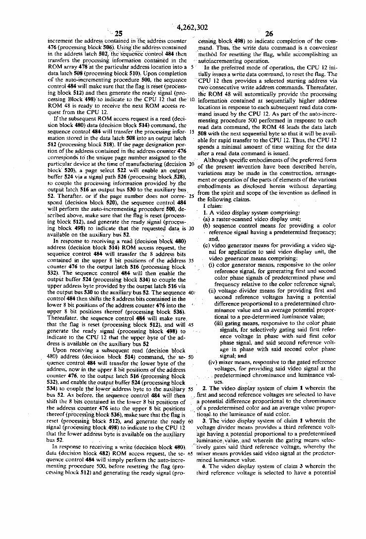
25 increment the address contained in the address counter 476 (processing block 506). Using the address contained in the address latch 502, the sequence control 484 then transfers the processing information contained in the ROM array 478 at the particular address location into a data latch 508 (processing block 510). Upon completion of the auto-incrementing procedure 500, the sequence control 484 will make sure that the flag is reset (process ing block 512) and then generate the ready signal (pro cessing Block 498) to indicate to the CPU 12 that the ROM 48 is ready to receive the next ROM access re quest from the CPU 12.
If the subsequent ROM access request is a read (deci sion block 480) data (decision block 514) command, the sequence control 484 will transfer the processing infor mation stored in the data latch 508 into an output latch 512 (processing block 518). If the page designation por tion of the address contained in the address counter 476 corresponds to the unique page number assigned to the particular device at the time of manufacturing (decision block 520), a page select 522 will enable an output buffer 524 via a signal path 526 (processing block,528), to couple the processing information provided by the output latch 516 an output bus 530 to the auxiliary bus, 52. Therafter, or if the page number does not corre spond (decision block 520), the sequence control 484 will perform the auto-incrementing procedure 500, de scribed above, make sure that the flag is reset (process ing block 512), and generate the ready signal (process ing block 498) to indicate that the requested data is available on the auxiliary bus 52. . . .
In response to receiving a read (decision block 480) address (decision block 514) ROM access request, the sequence control 484 will transfer the 8 address bits contained in the upper 8 bit positions of the address counter 476 to the output latch 516 (processing block 532). The sequence control 484 will then enable the output buffer 524 (processing block 534) to couple the upper address byte provided by the output latch 516 via the output bus 530 to the auxiliary bus 52. The sequence control 484 then shifts the 8 address bits contained in the lower 8 bit positions of the address counter 476 into the upper 8 bit positions thereof (processing block 536). Thereafater, the sequence control 484 will make sure, that the flag is reset (processing block 512), and will generate the ready signal (processing block 498) to indicate to the CPU 12 that the upper byte of the ad dress is available on the auxiliary bus 52. Upon receiving a subsequent read (decision block
480) address (decision block 514) command, the se quence control 484 will transfer the lower byte of the address, now in the upper 8 bit positions of the address counter 476, to the output latch 516 (processing block 532), and enable the output buffer 524 (processing block 534) to couple the lower address byte to the auxiliary bus 52. As before, the sequence control 484 will then
4,262,302 26 cessing block 498) to indicate completion of the com mand. Thus, the write data command is a convenient method for resetting the flag, while accomplishing an autoincrementing operation.
In the preferred mode of operation, the CPU 12 ini tially issues a write data command, to reset the flag. The CPU 12 then provides a selected starting address via
O.
15
20
two consecutive write address commands. Thereafater, the ROM 48 will automtically provide the processing information contained at sequentially higher address locations in response to each subsequent read data com mand issued by the CPU 12. As part of the auto-incre menting procedure 500 performed in response to each read data command, the ROM 48 leads the data latch 508 with the next sequential byte so that it will be avail able for rapid transfer to the CPU 12. Thus, the CPU 12 spends a minimal amount of time waiting for the data after a read data command is issued. Although specific embodiments of the preferred form
of the present invention have been described herein, variations may be made in the construction, arrange ment or operation of the parts of elements of the various
25
35
45
50
55
embodiments as disclosed herein without departing from the spirit and scope of the invention as defined in the following claims,
I claim: 1. A video display system comprising: (a) a raster-scanned video display unit; (b) sequence control means for providing a color
reference signal having a predetermind frequency; and,
(c) video generator means for providing a video sig nal for application to said video display unit, the video generator means comprising:
- (i) color generator means, responsive to the color reference signal, for generating first and second color phase signals of predetermined phase and frequency relative to the color reference signal;
(ii) voltage divider means for providing first and second reference voltages having a potential difference proportional to a predetermined chro minance value and an average potential propor tional to a pre-determined luminance value; (iii) gating means, responsive to the color phase
signals, for selectively gating said first refer ence voltage in phase with said first color phase signal, and said second reference volt age in phase with said second color phase signal; and
(iv) mixer means, responsive to the gated reference voltages, for providing said video signal at the predetermined chrominance and luminance val
S.
2. The video display system of claim 1 wherein the first and second reference voltages are selected to have
shift the 8 bits contained in the lower 8 bit positions of the address counter 476 into the upper 8 bit positions thereof (processing block 536), make sure that the flag is reset (processing block 512), and generate the ready signal (processing block 498) to indicate to the CPU 12 that the lower address byte is available on the auxiliary bis S2.
In response to receiving a write (decision block 480). data (decision block 482) ROM access request, the se quence control 484 will simply perform the auto-incre menting procedure 500, before resetting the flag (pro cessing block 512) and generating the ready signal (pro
a potential difference proportional to the chrominance of a predetermined color and an average value propor tional to the luminance of said color.
60 3. The video display system of claim 1 wherein the voltage divider means provides a third reference volt age having a potential proportional to a predetermined luminance, value, and wherein the gating means selec tively gates said third reference voltage, whereby the
65 mixer means provides said video signal at the predeter mined luminance value.
4. The video display system of claim 3 wherein the third reference voltage is selected to have a potential

27 proportional to the luminance value of a predetermined one of the colors white, gray and black.
5. The video display system of claim 3 wherein the third reference voltage has a potential proportional to the luminance value of one of the blanking and sync levels.
6. The video display system of claims 1 or 5 wherein the first and second reference voltages are selected to have a potential difference proportional to the peak-to peak value of the color burst and an average potential proportional to the blanking level.
7. The video display processor of claim 6 wherein the gating means selectively gates an external video signal, whereby the mixer means provides said video signal at the level of said external video signal.
8. The video display processor of claim 7 wherein the sequence control means provides a composite sync signal of predetermined form and duration relative to the color reference signal, and wherein the gating means selectively gates in response to said composite sync signal.
9. The video display system of claims 2 or 4 further comprising: selector means for providing a color select signal indicative of said predetermined color; and, wherein the gating means selectively gates in response to said color select signal.
10. The video display system of claim 9 wherein the selector means provide a color select signal indicative of a transparent state and wherein the gating means selectively gates an external video signal in response to the color select signal indicative of said transparent state, whereby the mixer means provides said video signal at the level of said external video signal.
11. The video display system of claim 1 wherein the gating means selectively gates an external video signal, whereby the mixer means provides said video signal at the level of said external video signal.
12. The video display system of claim 11 wherein the sequence control means provide a composite sync sig nal of predetermined form and duration relative to the color reference signal, and wherein the gating means selectively gates in response to said composite sync signal.
13. A video display processor comprising: (a) sequence control means for providing a color
reference signal having a predetermined frequency; and,
(b) video generator means for providing a video sig nal, said video generator means comprising: (i) color phase generator means, responsive to the
color reference signal, for generating first and second color phase signals of predetermined phase and frequency relative to the color refer ence signal;
(ii) voltage divider means for providing first and second reference voltages having a potential difference proportional to a predetermined chro minance value and an average potential propor tional to a predetermined luminance value;
(iii) gating means, responsive to the color phase signals, for selectively gating said first reference. voltage in phase with said first color phase sig
4,262,302
10
15
20
25
30
35
45
50
55
28 nal, and said second reference voltage in phase with said second color phase signal;
(iv) mixer means, responsive to the gated reference voltages, for providing said video signal at the predetermined chrominance and luminance val U.S.
14. The video display processor of claim 13 wherein the first and second reference voltages are selected to have a potential difference proportional to the chromi nance of a predetermind color and an average value proportional to the luminance of said color.
15. The video display processor of claim 13 wherein the voltage divider means provides a third reference voltage having a potential proportional to a predeter mined luminance value, and wherein the gating means selectively gates said third reference voltage, whereby the mixer means provides said video signal at the prede termined luminance value.
16. The video display processor of claim 15 wherein the third reference voltage is selected to have a poten tial proportional to the luminance value of a predeter mined one of the colors white, gray and black.
17. The video display processor of claim 15 wherein the third reference voltage has a potential proportional to the luminance value of one of the blanking and sync levels.
18. The video display processor of claims 13 and 17 wherein the first and second reference voltages are selected to have a potential difference proportional to the peak-to-peak value of the color burst and an average potential proportional to the blanking level.
19. The video display processor of claim 18 wherein the gating means selectively gates an external video signal, whereby the mixer means provides said video signal at the level of said external video signal.
20. The video display processor claim 19 wherein the sequence control means provides a composite sync signal of predetermined form and duration relative to the color reference signal, and wherein the gating means selectively gates in response to said composite sync signal.
21. The video display processor of claims 14 or 16 further comprising: selector means for providing a color select signal indicative of said predetermined color; and, wherein the gating means selectively gates in response to said color select signal.
22. The video display processor of claim 22 wherein the selector means provides a color select signal indica tive of a transparent state and wherein the gating means selectively gates an external video signal in response to the color select signal indicative of said transparent state, whereby the mixer means provides said video signal at the level of said external video signal.
23. The video display processor of claim 13 wherein the gating means selectively gates, an external video signal, whereby the mixer means provides said video signal at the level of said external video signal.
24. The video display processor of claim 23 wherein the sequence control means provides a composite sync signal of predetermined form and duration relative to the color reference signal, and wherein the gating means selectively gates in response to said composite snyc signal.
65