as124599 up the ante: increase the reliability of your ... · common challenges related to curtain...
TRANSCRIPT

Page 1
AS124599
Up the Ante: Increase the Reliability of Your Revit Model with Better Modeling Habits Josh Moore, Design Applications Manager Perkins+Will Justin Benjamin, Design Applications Manager Perkins+Will
Description Many designers often feel it can be difficult to create models that accurately express their design intent, often trying to “beat Revit into submission”. This often leads to poor modeling habits and in some cases, a complete lack of necessary modeled geometry, causing coordination issues. In this course, we will discuss common challenges encountered when modeling various types of building elements, and discuss some tips & tricks for overcoming them. We will find some solutions are “hidden” right within Revit, and others may be solved with creative modeling “hacks” and techniques. We will discuss modeling tips that overcome common challenges related to curtain wall and stairs/railings as well as discuss families/content created that enable special workflows related code compliance, site plans, and hybrid detailing. All of these techniques, can contribute to increased model reliability, better coordinated designs, and overall increased efficiency and project profits.
Learning Objectives • Identify some of the most common modeling challenges that occur on design projects
and ways to overcome them • Identify the pros and cons of various modeling and documentation workflows • Discover specific processes and family creation techniques that enable more
coordinated workflows • Increase the value and reliability of their company's BIM Models

Page 2
Speakers Josh Moore is a design applications manager at Perkins+Will, where he is responsible for the development, training and support of digital design tools. He is regularly engaged by design teams and leadership for his expertise in executing successful BIM projects. While at Perkins+Will, his efforts have focused on implementing and improving Revit content and workflows and providing and managing automation solutions. He is passionate about understanding the process of architecture and translating it into practical and successful uses of design technology. Josh earned a bachelor’s degree in architecture in 2007, and is a CSI Construction Document Technologist and a Revit Certified Professional. He has spent more than 12 years in the architectural industry and enjoys visual scripting with the Dynamo
extension. Josh has spoken at Autodesk University and Midwest-U and resides in Rowlett, Texas, with his wife and 4 children.
Justin Benjamin has been the Design Applications Manager in Perkins+Will Washington, DC office for over 4 years. He has an additional eight years of experience in the architecture and engineering industry (combining his design studio experience with design applications expertise). He has been Autodesk Revit Architecture Certified Professional and guided project teams through their required applications in all phases from programming through construction. Justin also has extensive expertise in Building Information Modeling and Computer-aided Facility Management systems. He works with various types of clients in integrating models and data within their organizations. In addition, Justin teaches Construction Documents at Marymount University as an adjunct professor.
Justin has spoken at Autodesk University and Midwest-U and resides in Washington, DC, with his wife and 2 puppies.

Page 3
INTRODUCTION As with many things in Revit, there are many methods you could use to approach the same modeling task. This course will provide insight into various modeling conditions and ways you can add value to the model, workflows, and ultimately your project. In doing this, we wanted to establish a few other general comments to consider. Before we get started, we want to also recognize that because there are so many ways to accomplish things in Revit, we don’t pretend to know every good and perfect way. From experience, we have attempted to provide a meaning approach to discussing some of the issues and ways we have found they can be solved. “JUST BECAUSE YOU CAN, DOESN’T MEAN YOU SHOULD.”
While we are modeling more and more to satisfy various project needs which may include things like model as a deliverable, 3D design coordination and clash detection, Augmented and Virtual Reality, etc., there are certainly cases/conditions where you should consider if it’s really necessary to model the object at a high level of detail. It is advised that you spend time with your project team to identify and develop, at a minimum, a level of development/detail matrix and BIM uses document to help inform everyone on the team the expected outcomes. At Perkins+Will, we highly encourage the use of BIM Excecution Planning to help identify these things.
CHOOSE THE RIGHT MODELING METHOD/WORKFLOW FOR YOUR TASK/PROJECT. When it is necessary to go to additional detail in the modeling exercise or workflow, take a few extra minutes and weigh the pros and cons of each method and pick the one best suited for your project.
Is there already a known best practice?
In some cases, the choice may be obvious, as it may be a known best practice or workflow. Scour the web, look and learn from other people that may have already tried what you are doing. That said; challenge what is “known”. New versions of Revit often change what was previously known as a best practice, giving us better ways to creatively solve problems.
What is the expertise of the Project Team? Can the team that is going to be working on the project manage the effort? If not, an elevated model/workflow may cause more harm later than it does good. You may consider doing a targeted training to help elevate the skillset of the staff.

Page 4
Are you prepared and able to support the additional effort? If you are proposing additional modeling or more advanced workflows, you should plan to be available to troubleshoot problems/challenges as they arise. For example, some of our projects heavily use Model groups to manage repetition and as you likely know, groups can be very finicky when best practices are not followed. Inevitably,
someone on the team will make a mistake, which can cause downstream workflow issues. When those issues arise, someone should have the expertise and knowledge to solve the problem and train the team member(s) what to do in the future, instead of the team deciding they “hate groups”. Certainly, groups have their pros and cons, but as the example in this case, when they are used in the right circumstances and in the right ways, they can work well and add value to the coordination and change management of your project.
MODELING AND DETAILING The model/detail relationship in Revit is, when done thoughtfully, one of the best ways you can increase the value and reliability of your project models. The techniques we are going to describe in this section are commonly referred to as “Hybrid Detailing”. To start, we want to provide a few thoughts/tips for your consideration.
MODEL ONLY - TOP AND BOTTOM OF EXTERIOR WALL AT ENTRY
Designers often have very negative feelings toward certain workflows often because they had a very poor experience on a project and vowed “to never do it again”. This is very
unfortunate and can be solved when teams are properly trained and mentored in those more
advanced methods/processes.

Page 5
MODEL & DETAIL ITEMS/ANNOTATIONS - MAGENTA ITEMS ARE ADDED COMPONENTS

Page 6
DRAFTING VIEWS VS. LIVE MODEL VIEWS One of the biggest decisions a modeler has to make on a project is whether he/she will use the model to base the details or simply draw in drafting views. There are certainly pros and cons to both methods. Here are some general tips to follow that we believe add the most value and reliability to the model.
Use the Model whenever possible, especially in atypical and/or project specific details
• Value is less risk and better execution of the design intent • Challenge is learning curve for project teams and producing detail item
families that “embellish” the model, without adversely covering it. • Drafting views do not pick up changes to items like linked model updates, grid
location changes, etc. • Drafting views are still very useful for things like typical details. They are also
very easy to transfer between projects. • If you have a detail library of drafting views, consider copying and pasting
relevant notes, components, etc. to a live view in your project. This saves time and effort in embellishing the live view but also gains the benefit the drafting view as a starting point in a library.
When using the model as the basis of the detail, do not turn off the model All too often, we find staff that started out with good intensions, but in the end, could not get the drawing the way they wanted so they turned off parts or the entire model. Here are a few tips to help with that. Use Cut Line Styles in Visibility Graphics Overrides. This is a little gem in the Visibility/Graphics Overrides dialog box that I find most people seem to completely ignore. When I found it, it was one part of the process of creating a better hybrid detail.
CUT LINE STYLES OFF CUT LINE STYLES ON

Page 7
Notice the subtle but important difference, especially around the mortar joint repeating detail component. Be sure to play with the “Core Layer Clean-up” drop down, along with the “Common Edge Style” subcategory for system families like walls, roofs, floors, and ceilings. The one challenge with this method is that you will need a filter for floors bring the structural layer lineweight back to where it needs to be. See “using filters” further down in this section
Use Detail custom component families that only mask parts of the model. For example, use a special mortar joint family that masks out the line work of the model, instead of covering the entire thing.
REPEATING DETAIL COMPONENT OF MASONRY MORTAR JOINT ONLY, WITH MASKING REGIONS AT EACH SIDE TO HID THE VERTICAL LINES OF THE BRICK LAYER PROPERLY
Unlock the bottom/top of portions of the wall assembly. This is a fantastic way to extend only portions of the wall assembly up or down, such as a brick ledge or exterior
Family View, masking regions highlighted

Page 8
material needing to stop short at a soffit. Unlocked layers must be adjacent. This solves several problems with drawing graphics and model completeness.
SET THE PREVIEW TO “SECTION”, CLICK MODIFY, SELECT THE BOTTOM LINE OF A LAYER AND CLICK THE PADLOCK TO LOCK/UNLOCK THE LAYER.
Coordinate and get corrected models from consultants. For architect’s, this is often true with the structural consultant with regard to exterior detailing and the MEP consultant with Reflected ceiling plans. Instead of your first response being to just turn off the model, consider leaving it on so you can see it clearly incorrect. Screenshot the issue, and send it to other party for review and correction. This may seem like an obvious part of the coordination process, but unfortunately, designers often get hung up on the drawing looking perfect in the short term, so they turn off the model and then forget to turn it back on. We have found that leaving the incorrect model on often allows mistakes to be caught, especially in later phases of the design process and is a constant reminder to the entire team of issues that need to resolved. If the linked models are turned off, it will be much less evident and you lose the benefit of using BIM to help identify those issues when you fake the components in from the other disciplines. Utilize filters and line work tool to accomplish graphic overrides. There are so many things filters can be used for. With regard to Modeling and Detailing, filters are a fantastic way to reduce or even eliminate the need to overriding linked models to “Custom” in Visibility Graphics. I have found and seen so many issues and inconsistent graphics when staff have to set their graphic overrides per model, in multiple places. And while there is certainly a time and place to use custom visibility graphics overrides at the model level, it is much less necessary that what I see done by most Revit users. For example, in many cases, I find staff override the linked model to “Custom” just to turn off its level and grids. This is usually the “gateway” to it staying this way the rest of the project. To handle levels and grids, use a filter. If your company has a naming standard, it’s very easy to use a filter to get all grids/level that don’t contain, for example, a company prefix. Then turn them off. Have you or your staff ever been in a situation where you are trying to override objects from a linked model, and unable to do so from the host view settings? So, naturally, you can fix this, just set the model override to custom and it all works! Ugh, I cringe at this, because a simple filter would solve this problem. The issue is that your model doesn’t contain all the subcategories that are in the linked model, and any objects assigned to

Page 9
those subcategories can’t get overridden by the host view graphics overrides. But….a filter, even when not technically filtering anything within the category, automatically overrides all aspects of the category, including subcategories!
WALL SWEEPS AND REVEALS Wall articulation is common to the design process and there are several tools in Revit to accomplish this. Here are a few tips to be aware of/follow when modeling this content. Sweeps and Reveals – Pick Side Matters. When placing sweeps and reveals, it is important to realize that the pick side of the wall matters. This can be the cause of sweeps not cleaning up properly and is so simple to avoid (See ppt presentation for GIF) Consider stacked walls for sweeps and reveals that are generally continuous. There is an incredible amount of opportunity with stacked walls and I highly encourage their use, especially with exterior modeling of vertically compound wall assemblies. While we don’t have time to take about all of the various benefits of stacked walls, it was pertinent to mention their use with regard to hybrid detailing For example, when trying to set corbel masonry like brick or cast stone, setting the brick back with a revel cuts the face of the wall out, but doesn’t add the same dimension in the air gap space of the wall. While it may seem minor, I imagine countless hours of people that, want to use a live model/hybrid detail approach, faking in the masonry units rear face when it can be avoided entirely with doing the masonry unit insets/outsets with stacked walls. Embed Detail Components in Profiles. This is a game changer for detailing, especially exterior detailing. When done appropriately, you can embed parametric detail components into parametric profiles that allow your staff to not have to embellish the same things over and over again. There are numerous examples of this, but a few include cast stone window head and sills, parapet copings, and curtain wall mullions.
You might ask, “So what’s the point, I thought this class was about better modeling, not detailing.” Well, when you create families that embed the detailing into the model, you create an avenue for staff to
spend less time detailing and more time modeling. If you start creating these sorts of families and workflows for your firm, you will increase the time your staff has to produce the BIM, as well as increase
coordination and reduce risk exposure of your projects.
Page 10
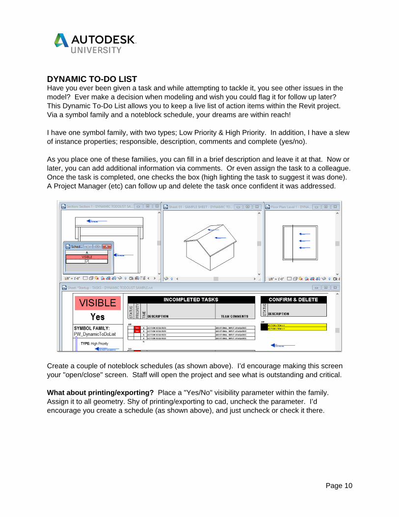
DYNAMIC TO-DO LIST Have you ever been given a task and while attempting to tackle it, you see other issues in the model? Ever make a decision when modeling and wish you could flag it for follow up later? This Dynamic To-Do List allows you to keep a live list of action items within the Revit project. Via a symbol family and a noteblock schedule, your dreams are within reach! I have one symbol family, with two types; Low Priority & High Priority. In addition, I have a slew of instance properties; responsible, description, comments and complete (yes/no). As you place one of these families, you can fill in a brief description and leave it at that. Now or later, you can add additional information via comments. Or even assign the task to a colleague. Once the task is completed, one checks the box (high lighting the task to suggest it was done). A Project Manager (etc) can follow up and delete the task once confident it was addressed.
Create a couple of noteblock schedules (as shown above). I’d encourage making this screen your "open/close" screen. Staff will open the project and see what is outstanding and critical. What about printing/exporting? Place a "Yes/No" visibility parameter within the family. Assign it to all geometry. Shy of printing/exporting to cad, uncheck the parameter. I’d encourage you create a schedule (as shown above), and just uncheck or check it there.

Page 11
CODE COMPLIANCE As noted in the image below, Perkins+Will automates occupancy calculations (tabluarly and via tags in plan), plumbing fixture calculations, path of travel and (for a little sizzle), we add a color scheme.
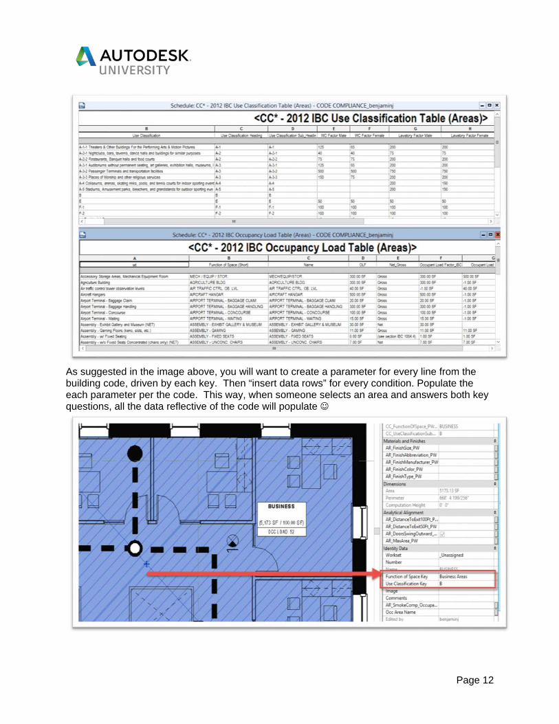
All this is possible via a new occupancy area scheme, (2) key schedules (reflective of IBC) and dynamo script. Occupancy Area Scheme Considering all the new parameters and key schedules, it is best to create a new area scheme. Once the scheme is created, create area plans looking at said scheme for each floor! Key Schedules Give yourself sometime on this next effort. You will want to create (2) key schedules looking at this new area scheme; Function of Space and Use Classification Key.
Page 12
As suggested in the image above, you will want to create a parameter for every line from the building code, driven by each key. Then “insert data rows” for every condition. Populate the each parameter per the code. This way, when someone selects an area and answers both key questions, all the data reflective of the code will populate
Page 13
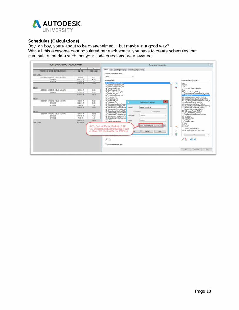
Schedules (Calculations) Boy, oh boy, youre about to be overwhelmed… but maybe in a good way? With all this awesome data populated per each space, you have to create schedules that manipulate the data such that your code questions are answered.

Page 14
Dynamo Script Since we cannot push keyed values into tags, we have to utilize Dynamo to calculate what is already being shown in the schedules. Not super complicated, but keep in mind, this isn’t dynamic with your model.

Page 15
You will need to run this script shy of printing to ensure the data is up too date. There are tools that can help automate this (like Clarity). Railings & Worksets We use the railing tool to identify path of travel. Simply modify the balusters to look like a dash and arrow. You can create a tag that looks at the railings length

Page 16
Keep in mind, this railing will want to show everywhere. Create a workset that is off by default in all views. Turn it on only in the life safety views. Assign all railings to that workset and you are off and running! Color Scheme Nothing complicated here… Just create a color scheme looking at the code compliance parameters. Id highly encourage you not to look at colors, but patterns (permit reviewer won't be printing out color copies of your sheets).

Page 17
STAIRS AND RAILINGS This, without a doubt, is one of the hardest things to learn and master in Revit. First, there are just so many combinations and permutations of the two, and dealing with all of the codes and requirements related to them can be daunting. On top of that, the geometry of the objects can be decently complex. In general, we find that designers can spend a lot of time designing and commenting stairs and railings, and more specifically, grand stairs. Often times, the effort in the modeling part of these stairs is because they will show up in Renderings/walkthroughs and we can use the 3D model to validate our design and ensure everything is coordinated. On top of that, boy is it nice not having to draft the stair section like we use to in AutoCAD. When it is modeled thoroughly and correctly, there is a lot less “faking” that have to happen. While we could do an entire class on stairs and railings, we want to get a head start for this class and assume most of our audience already know the basics and have tried doing some custom stairs and railings before. So, let’s get started with our General tips and then move into a few more specific modeling challenges, primarily focused around railings. Use stair by component. This feature has been around for several releases of Revit, but it was a great leap forward in the customization ability of stairs. In Revit 2018, the stairs (and railings) got even better with the improvements to multi-story stairs, and the bug fixes for situations where railings were modified and slopes in other areas of railings were messed up. So, for those that may still be clinging to “Stair by Sketch”, keep those skills for a rainy day (still necessary in some conditions), and embrace stair by component. Modify stringer profile and its connections to the floor. Important to show/see the correct stringer profile in your model/drawings? It can be changed easily!
MODIFYING THE STRINGER TO CUT FLUSH TO THE GROUND
Use Handrails, Toprails, and associated features of railings. This is a no brainer, and one of the best changes that occurred with railings. Gone are days of custom/hacked balusters with the handrail extensions embedded. Handrails, in particular, have a ton of features/options, that can really add a lot of value to your model and teams, primarily in terms of coordinated drawings and efficiencies. It’s a very common problem to see designers not modifying the handrails/ guardrails, and in more complex stair conditions, not doing so can cause busts in plan.

Page 18
For example, when a door needs to move, leading into the stairwell, it can be an issue if it is moved too close to the railing extensions. Correctly modeled railings should show in plan, which is a visual cue to the design team when needing to make changes. Use the railing “Place on Host” tool. Sometimes, with railings and stairs it can be faster to start over with a “default” placement of the railing then to try to figure out what is out of what with the sketch that is causing it to host oddly or not at all. The place on Host tool only works when there is not already railings hosted to the stair. But the beauty in the tool is that it automatically regenerates a default configuration for the railing type of your choosing
RAILING TRANSITIONS Transitions between one railing and another can be very tricky to look correctly. I find that there are two common reasons that designers have trouble with this. First, there is a geometry problem with the design. For a railing to meet with another at a floor level, the up side of the stair needs to be offset at least one tread length, unless you are ok with having jogs in the continuity of the railing. This is due to the height requirements of the railings and the way they slope. Second, Revit still doesn’t seem to have optimize algorithms for “tight” geometric turns and connections, that a fabricator may not have issue with actually building. In this case, you can do a little “finessing” but you are somewhat at the mercy of the software in these cases. That said, I find these much fewer than many designers are actually aware, due to issues described above. Here are a few examples of various railing transitions and how to deal with them.
Railing Transition at Floor Level The primary “trick” with this is in the sketch. Turning the two railings back toward one another at when they are not sloping, and running towards each, parallel.
Guardrail to Handrail Only Transition Often times, when we first start working not he stair, we have a generic railing that was generated when the stair was created. Once it is necessary to begin modifying that railing to what it actually needs to be, you can invoke some simple yet very effective methods to get what you want quickly. One of those methods is a simple copy and paste to same place. Instead of trying to create a brand new railing by sketching and hosting from scratch, you can copy and paste the existing railing on top of itself, and then inverse edit their sketches. This allows for situations where a position of the railing needs to be handrail only (against a wall for example) and the rest may still required a guardrail.

Page 19
TWO RAILINGS, ON TWO DIFFERENT STAIRS, NEED TO MEET PROPERLY AT THE FLOOR
FINISHED PRODUCT, TURNING EACH RAILING BACK TOWARDS THE OTHER AT THE FLOOR
Split Sketch to Place Posts where you want them. It is very common to want to place posts for a railing in specific places. There maybe architecturally relevant elements that the railing should related and line up with. There is actually a very simple way to do this using the corner posts. In the type properties, you can set the value for “Use Corner Posts” to “Each Segment End”. In doing so, each place there is an end of sketch line, Revit will place a corner post. Yep, that’s right. Dust off the “split Element” tool and go to town placing your posts exactly where you want them.
RAILING WITH NO BALUSTER PATTERN SET

Page 20
RAILING, AFTER SPLITTING THE SKETCH LINE WHERE THE POSTS SHOULD GO
PANELIZED RAILINGS Glass and panelized railing systems is something I think every designer that has worked on stairs has struggled with. It is extremely unfortunate that we still do not have a really good method for doing this efficiently in Revit. The most common 3 methods we see are Using Custom Balusters, Model-in-Place, and a custom family. Each method has it’s pros and cons. Custom balusters require A LOT of effort, for every stair. First of all, you need the custom baluster family, which can be a bear to build. Then you have to split the railing by each run and calculate the required panel width per run, make the associated baluster type and assign it to an associated railing type. Been there, done that…super tedious and really annoying when the stair changes length or slope and the entire thing has to be recalculated. Model-in-place has similar problems to Custom in place balusters, but require less calculating and little to no duplicate railing types. I advise teams to use the parts of the railing tool that work well, such as the handrail, top rail, and balusters, and then model-in-place the glass panels. While this is still time consuming, I find that it is much easier for most staff, and sometimes easier is better. Lastly, custom family. This where we want to spend most of our time as there is a lot of potential here. The biggest down side to the custom family is having the know-how to put a somewhat complex family together to get it working with arrays, nested families, and lots of formulas necessary to make it work. That said, you are in luck as we are including a custom guardrail family in this classes data set! It took about 2 days of development and testing but we
Page 21
are very excited to share it with you. It is certainly not all encompassing or perfect, but a great start and hopefully an example to inspire you to add additional functionality or even work on your own version(s).
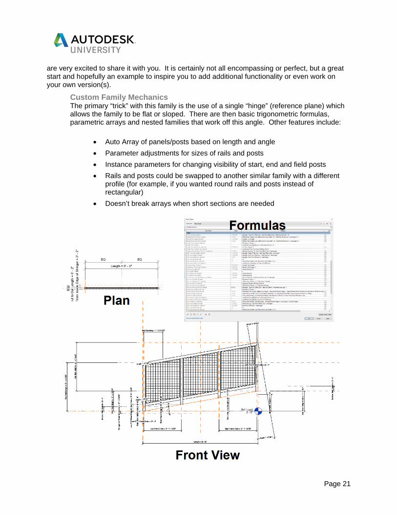
Custom Family Mechanics The primary “trick” with this family is the use of a single “hinge” (reference plane) which allows the family to be flat or sloped. There are then basic trigonometric formulas, parametric arrays and nested families that work off this angle. Other features include:
• Auto Array of panels/posts based on length and angle • Parameter adjustments for sizes of rails and posts • Instance parameters for changing visibility of start, end and field posts • Rails and posts could be swapped to another similar family with a different
profile (for example, if you wanted round rails and posts instead of rectangular)
• Doesn’t break arrays when short sections are needed

Page 22
Placing the Family It takes a little getting used, primarily due to the challenges with seeing all of the railing/stair in plan. We advise creating a few “working” views, such as a 3D, section/elevation and plan to help. In the plan view, raise the cut plane so you can see the top of the stair. In a typical switch back stair, measure the angle of the base level to the stringer and apply that to the “angle” parameter of the custom railing. Next use the grips to adjust the ends of the railing. We recommend using a combination of elevation, plan and 3D view to ensure this is in the correct place. Because the rails, panels and posts are nested generic models, they can be joined with each other, which, specifically for the rails, can make much more graphically accurate. The family is intended only for the guardrail. For the handrail, use an actual railing type that is set to handrail only. Lastly, there is a really cool opportunity with a few constraints and global parameters to make the railings respond to slight adjustments in slope to the stair similar to the way a built-in railing would.
SIMPLE EXAMPLE OF CUSTOM FAMILY PLACED AGAINST A WALL

Page 23
CUSTOM FAMILY, WITH ANGLE ADJUSTED. SEE PPT PRESENTATION FOR ADDITIONAL GIF OF FAMILY IN ACTION
AUTOCAD FILE MANAGEMENT We find so many designers using Revit end up spending a lot of time “monkeying” around with CAD files. This is still inevitable as we often still have consultants like Civil that use .dwg format, not to mention it is very common still to receive .dwg files from our clients when we start projects. Besides the time issue, models often suffer performance issues due to CAD files that are no optimized. I see this issue so much on projects, and this is really the crux of including this tip in the scope of this class. When the model doesn’t perform well, it causes all sorts of issues with reliability. Thus, one of the most common things a designer would need to do is clean-up the CAD file. There are several common reasons this might need to occur: CAD file has linework in 3D dimensions. Keep in mind, that in certain cases such as creating a toposurface, you’ll need the 3D linework. However, in most cases, it just causes graphical or performance issues in the model. CAD file has geometry very far from zero. Admittedly, this isn’t always the most easy thing to clean up. The process we will describe later in this section can help, but at the end of the day, each time you receive updates from the consultant (often civil), you’ll have the same problem to deal with. I have found, this is really only a problem if you plan to show the CAD File all the time in your drawings. In my experience, I felt it faster, specifically with Civil files, to bring in the CAD file as is (properly exported from Civil 3D), and use it only as a reference for coordination, I.e., a on a work set that is off by default. I made it a habit to draw/model the site for my projects in Revit, which was also useful because there were many times that design changes were initiated

Page 24
by the architect, affecting the site design. Making those changes to the architectural site plan, and then sending that back to the civil consultant is super useful. File size is really big. Sometimes, you get a CAD file that is very large, and it can be difficult, on the surface, to understand why. Rather than spending a lot of time in CAD trying to figure it out, the workflow we describe below can fix this without a lot of effort.
CAD CLEANUP WORKFLOW This is a very simple workflow that can fix a number of issues with CAD files, without designers have to remember all of the commands to do the cleanup work in AutoCAD itself. The workflow is simple: 1) Link in the CAD file to a new drafting view in the model. 2) Export the view as a new CAD file. Save it with a prefix or suffix so you still have the
original in record. That’s it! It’s really that easy to do, and you’ll find it will fix many of the issues that plague CAD file performance in Revit. Keep in mind, if there are proxy objects or other types of geometries that often come from CAD files associated with Civil 3D, you’ll need to ask the owner of the CAD file to export it properly.
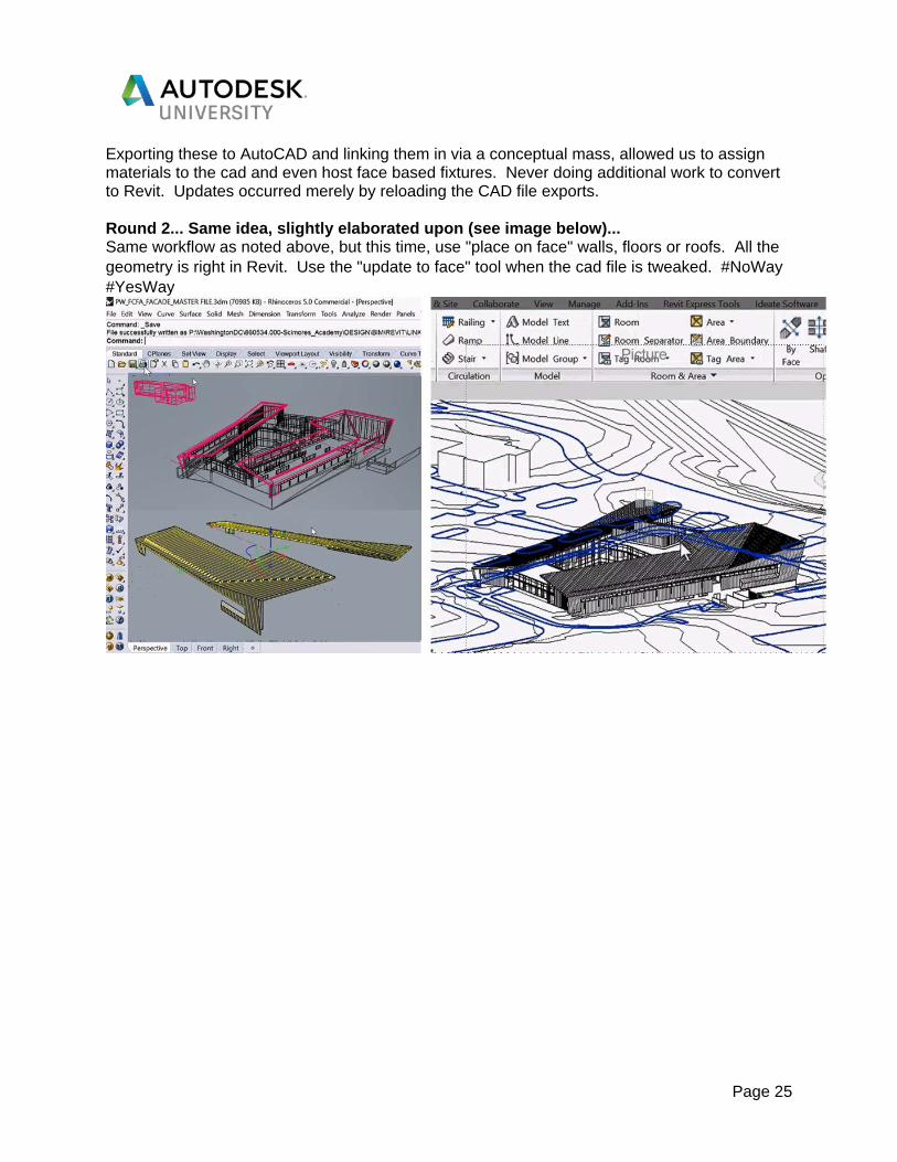
RHINO TO REVIT Okay okay. I am not saying this is a preferred method. Though, it does have its purpose. Below is an excellent use of the workflow :)
As suggested above, there was a ceiling condition we wanted to "play" with... Utilizing Rhino/Grasshopper, we were able to shoot out dozens of possible scenarios in a minute.
Page 25
Exporting these to AutoCAD and linking them in via a conceptual mass, allowed us to assign materials to the cad and even host face based fixtures. Never doing additional work to convert to Revit. Updates occurred merely by reloading the CAD file exports. Round 2... Same idea, slightly elaborated upon (see image below)... Same workflow as noted above, but this time, use "place on face" walls, floors or roofs. All the geometry is right in Revit. Use the "update to face" tool when the cad file is tweaked. #NoWay #YesWay

Page 26
CURTAIN WALLS Curtain walls can be another challenging item to get modeled correctly. And while we could certainly do a deep dive into all of the really fun things you can do with Curtain Wall by face, adaptive components, etc. we thought we would stick with some modeling tips and tricks that would benefit what we feel is probably the majority of cases designers are using the curtain wall tools in Revit.
Tips and Tricks There are two very simple things you can leverage in Revit to make your experience with Curtain wall better. Disallow the joins at each end, especially when grouping. If you have ever run across a situation where a group with curtain wall in it is misbehaving, there is a good chance an instance of that group is trying to “grow” to join to an adjacent wall, causing the group instance to be different and break. Right clicking on the “blue dot” that you use to stretch the curtain wall length, and selecting “Disallow Join” is a huge life saver here. However, keep in mind, that were glass joins at a corner (which we will discuss more below), you’ll want to leave it set to “Allow Join” in order for the mullions to clean up properly. Use the built-in mullion and panel selection tools. This is a life saver and I’m constantly surprise when I train new staff, how many seasoned Revit users don’t know about this option. I can’t tell you how long and how many times I fought with Revit to simply select the bottom row of panels of a very long curtain wall element, in order to just change the panel type to Spandrel. Don’t take this one for granted, you may be surprise how many staff at your firm don’t know about this simple right click option. Group Curtain Wall for repitive types. One of the simpliest ways to make your life much easier is by taking a little time, earlier in the project to think about the design and which openings are or likely are the same. As much as many people have a negative feeling towards groups, this makes so much sense and provides a lot model value in terms of accuracy. This is especially useful for interior types, which tend to be very repititve, but also applies to buildings that have repitive exterior openings. Change management is much easier, and you can also pair the grouping with what we call “Super Legends” at Perkins+Will, which is basically a few previous phases in the project file that get used to place geometry for “smarter” legends. For example, Groups are not recognized by regular legends, so doing “Glazing Type Elevations” has to be done with other methods and each one of them have their own pitfalls.

Page 27
Using a “Super Legend”, you can take the groups you are already using for change management, place them in the previous phase, and demo them before “Existing” phase of the project. That way they won’t schedule or show up, but you get the full benefit of a building element that is tied directly to the actually model. Avoid Edit Profile. In general, I advise my project teams to use other creative modeling methods for all walls, but in my humble opinion, this is even more important for curtain walls. I find many people struggling through geometry issues with mullions because they edited profile for various reasons. One of those is whey you have a single glazing system that changes shape. In
this case, you can do two separate curtain wall elements, and group them together as one. Another situation I find designers wanting to edit profile is when there is a door that needs to go to the ground, but the rest of the system sits on a curb. In this case, there are a few ways to handle it but one of the easiest ways is to actually nest the “wall” that is used for the curb as a curtain panel. Then the system is actually going to the ground, with no edit profile necessary.
Glass Corners Oh boy…there are so many various ways and opinions on how to do this. I am going to share 2 methods we thing work best and are the most flexible.

Page 28
Method 1: Use Corner Mullion. This is my favorite method. The corner will auto adjust if the angle changes and the mullions clean up well in most cases. However, like any “hack”, there are a few downsides. First, there will be some additional lines at the corner and a line weight issue, since we are using a mullion as glass (assuming your mullions are thicker line weight than the glass). Additionally, technically the category of the geometry will be incorrect and you will need to place additional geometry (family or model-in-place) for situations where you want a curtain wall mullion behind the glazed corner. I have found that staff take to this method because there is very little extra effort to get it to work in most cases.
LEFT: METHOD 1 RIGHT: METHOD 2
Method 2: Use a Custom Panel. This is a great method as well and has its own set of pros and cons. First, if the family is built properly, it can show the corner mullion automatically and its overall easy to use. However, as with the first method, it has a few downsides. It is a little effort up front to set up the family if you don’t already have one. Additionally, the offset from the center, if you want the glass to be in a different plane and still clean up properly at the corner can be tricky. Lastly, you would need to build in some offsets in the family for extending the mullion only, so there is the appearance it is continuous through the horizontal mullions.

Page 29
Issues with the wall. To wrap up Glass corners, we could leave out the issue almost everyone has likely run into, which is when the embedded curtain wall does not properly cut the wall at the corner. There are many methods to resolving this, but we find the easiest method is to use a custom family to cut the wall with the family. This is especially useful when the wall extends above and below the glazing system. Unfortunately, this seems to be a bug in the revit software, and has been for a long time. It would be a good idea to have a method in place as your firm where all staff are dealing with this issue similarly, as it can be difficult to figure out when every is doing it differently.
REVIT MODEL ANALYTICS This is another area that does not specifically relate to modeling itself, but can be pivotal, especially for BIM manager types of people, that need to have a better picture into the health of the models in their firm. When we talk about increasing the reliability
of our Revit models, one of the most obvious things that comes to mind is model performance. None of the other stuff really matters if, at the end of the day, you cannot efficiently and effectively work in the model. At Perkins+Will, we have been gathering data, on a large-scale basis from our Revit models, through various trial methods, across the firm, for over a year. We have millions of data points across many model health metrics. To give you a picture of what this might look like for your firm, I want to go a little deeper on the process.
GETTING STARTED The best way to get started is start collecting data. You could do this a number of ways, but the easiest way is to use a dynamo script and have project data written out to an Excel file. You can easily write multiple projects out to excel files, all in the same folder on your network, and then have dynamo parse through all those files to generate an “averages” Excel file.

Page 30
It is very simple, as shown in the dynamo screenshot above, for most basic metrics, to start gathering data about a Revit model, simply by counting the number of certain types of things. The screenshot actually shows 5 of the metrics listed below and as you can see it’s a very small amount of nodes it takes to get this data. But before you can start collecting the data, you have to decide what data metrics you want/need to collect. Here is a list of “metrics” you should consider: Model Size # of Model Group Instances # of Model Group Types # of Detail Group Instances # of Detail Group Types # of Unused Groups # of Worksets Area of Rooms (Total SF) # of Rooms # of Unplaced Rooms # of Unenclosed Rooms # of Loaded Families
#/% of Unused Families # of In-place Families # of Duplicate Elements # of Revit Linked Models # of CAD Imports # of CAD Links # of Images # of Design Options # of Views # of Sheets # of Views with no View Template
# of Views not on Sheets # of Views with Depth Clipping Disabled # of Unused Materials # of Fill Patterns # of Dimension Styles # of Line Patterns # of Line Styles # of Reference Planes # of Room Separation Lines # of Model Lines # of Warnings (Revit 2018)
Once you have decided on the metrics you want and built your dynamo script, you can start executing it. To start with, you could have your teams execute it with Dynamo player. One of the teams weekly tasks, as they are doing model maintenance, might be to run the dynamo script with dynamo player. To make the data readily accessible to the teams, you could even have the dynamo script update a custom annotation family like the image below. We will discuss in a little more detail later about how to normalize your data into customized “Health values” per your firms peformance standards/needs, and this logic can be built into the family by way of formulas to give your staff a relative performance metric of their project to firm targets/baselines.

Page 31
TAKING YOUR DATA TO THE NEXT LEVEL At some point in this process, you will realize the need and benefit of automating this process and aggregating the data in a more nimble way, namely to a database and output via dashboards. SQL Server and Power BI. At Perkins+Will, we actually wrote a custom dynamo node that allowed the dynamo script to run and write to an cloud based Azure SQL server. We then used Power BI to connect to this data, and build Dashboards to visualize the data.
SAMPLE POWER BI DASBHOARD
When visualizing the data, you want to consider several factors. First, you need a “current” snapshot of the data. In the sample dashboard above, this is the top section of data points, and the actual value associated with that metric. This is very useful to provide a better starting point for project teams that may be having model performance issues. What used to sometimes take a few hours or more to manually inspect and find troublesome issues, the dashboard may be able expose in just a few minutes, or at least give you a better starting point. Second, you want to be able to see trending, or showing certain metrics over time. This is a fantastic way to find “bad habits” or things that, as an office or firm, seem to be consistently problematic. At Perkins+Will’s Dallas office, we are piloting a local office program called “Digital Health+Wellness”, where we are using the aggregated data to identify a few areas of model health we want to improve across all the projects in the office. Simplified dashboards or manually creating infographics can be used to quickly communicate specific information to staff and stakeholders, such as the graphic below.

Page 32
Complete Automation. Taking things one step further, once you have the SQL server and Dashboard ready, you can use tools like Imaginit Clarity to completely automate the process of runs on Revit models, across your firm. Clarity is capable of opening Dynamo scripts and executing them on Revit models, as often as you feel necessary, take a sequence of steps like the image below, and automating it all.
Complete(r) Automation. And finally, if you are going to use clarity anyway, you could cut out Dynamo as a “Middle man”. Clarity has built in Performance Advisor and Model Metrics tasks which can pull out all of the data points and more in the list we provided earlier in this section. You can use Power BI or other data visualization software like Tablaeu and connect it directly to your firm’s Clarity Database. Additionally, staff can visualize their projects data right within the clarity interface. We have been collaborating with Imaginit on improvements to this process and I look forward to seeing how this evolves in the coming year.

Page 33
CREATING A PROJECT/MODEL HEALTH VALUE One of the things I realized very quickly in working with this process was the need to normalize the data points into Health values, based on some logic and formula’s that made sense based on how Perkins+Will works and what we know in general about how certain metrics affect file performance. This became especially evident as I realize that simply adding the metric values themselves together skewed the Health value for certain projects. For example, projects with a few thousand duplicate element may appear healthier than projects with less duplicate elements but 20 imported CAD files. We suggest creating an excel file where you house the following information about each metric: Metric Name Target Priority Factor Normalization Formula (Power BI or otherwise). To the right is an example of one data point, “Unplaced Families”, and how we are using this normalization process to create a overall Model Health Value. The formula is shown in 3 rows to provide a little more clarification on how the logic works. The basic premise in the normalization for most metrics is that if we create a target value for each metric, and a priority factor, that for every 10% over the target value, we add a value of 1 to the “health” value for that metric.
We can then sum all of the Metric Health values into one Health value, and display it on a slider or “Red, Yellow, Green” scale. The screenshot at the beginning of this section showed a vertical bar on the left; another example would be a dial like the image to the left. Doing this can give you (and staff) a simple, intuitive way to get a rough order of magnitude on project model health. It can be used proactively or reactively depending on how you decide to implement it.