as/400e series - ibm · pdf fileas/400e series ibm lan, ... ethernet topologies ... chapter 6....
TRANSCRIPT

AS/400e series IBM
LAN, Frame-Relay and ATM SupportVersion 4
SC41-5404-01


AS/400e series IBM
LAN, Frame-Relay and ATM SupportVersion 4
SC41-5404-01

Note
Before using this information and the product it supports, be sure to read the information in “Notices” on page xvii.
Second Edition (February 1998)
This edition replaces SC41-5404-00. This edition applies only to reduced instruction set computer (RISC) systems.
Copyright International Business Machines Corporation 1997, 1998. All rights reserved.Note to U.S. Government Users — Documentation related to restricted rights — Use, duplication or disclosure is subject torestrictions set forth in GSA ADP Schedule Contract with IBM Corp.

Contents
Notices . . . . . . . . . . . . . . . . . . . . . . . . . . . . . . . . . . . . . . . . . xviiTrademarks . . . . . . . . . . . . . . . . . . . . . . . . . . . . . . . . . . . . . . xviii
About LAN, Frame-Relay and ATM Support (SC41-5404-01) . . . . . . . . . xixWho should read this book . . . . . . . . . . . . . . . . . . . . . . . . . . . . . . xixConventions and terminology used in this book . . . . . . . . . . . . . . . . . . xxAS/400 Operations Navigator . . . . . . . . . . . . . . . . . . . . . . . . . . . . . xxPrerequisite and related information . . . . . . . . . . . . . . . . . . . . . . . . . xxiInformation available on the World Wide Web . . . . . . . . . . . . . . . . . . . xxiHow to send your comments . . . . . . . . . . . . . . . . . . . . . . . . . . . . . xxii
| Summary of changes for LAN, Frame-Relay and ATM Support . . . . . . xxiii
Introduction
Chapter 1. Introduction to local area networks . . . . . . . . . . . . . . . . 1-1Local area network standards . . . . . . . . . . . . . . . . . . . . . . . . . . . . 1-1
Token-ring networks . . . . . . . . . . . . . . . . . . . . . . . . . . . . . . . . 1-3Ethernet networks . . . . . . . . . . . . . . . . . . . . . . . . . . . . . . . . . . 1-5
| Asynchronous transfer mode networks . . . . . . . . . . . . . . . . . . . . . . 1-8Frame-relay networks . . . . . . . . . . . . . . . . . . . . . . . . . . . . . . . . 1-8Wireless networks . . . . . . . . . . . . . . . . . . . . . . . . . . . . . . . . . 1-11Distributed data interface networks . . . . . . . . . . . . . . . . . . . . . . . 1-11
Chapter 2. AS/400 implementation of local area networks . . . . . . . . . 2-1Local area network concepts . . . . . . . . . . . . . . . . . . . . . . . . . . . . . 2-1Acknowledged service . . . . . . . . . . . . . . . . . . . . . . . . . . . . . . . . . 2-2Unacknowledged service . . . . . . . . . . . . . . . . . . . . . . . . . . . . . . . 2-2Assigning a physical address . . . . . . . . . . . . . . . . . . . . . . . . . . . . . 2-3
Finding a physical address . . . . . . . . . . . . . . . . . . . . . . . . . . . . . 2-3Note for mixed environments . . . . . . . . . . . . . . . . . . . . . . . . . . . 2-3
Assigning a logical address . . . . . . . . . . . . . . . . . . . . . . . . . . . . . . 2-4Service access points . . . . . . . . . . . . . . . . . . . . . . . . . . . . . . . . 2-4
Establishing the connection . . . . . . . . . . . . . . . . . . . . . . . . . . . . . . 2-6Dial mode . . . . . . . . . . . . . . . . . . . . . . . . . . . . . . . . . . . . . . 2-6Answer mode . . . . . . . . . . . . . . . . . . . . . . . . . . . . . . . . . . . . 2-7Dial initiation . . . . . . . . . . . . . . . . . . . . . . . . . . . . . . . . . . . . . 2-7Unsuccessful connections . . . . . . . . . . . . . . . . . . . . . . . . . . . . . 2-7Exchange identifier (XID) . . . . . . . . . . . . . . . . . . . . . . . . . . . . . . 2-8Data link role . . . . . . . . . . . . . . . . . . . . . . . . . . . . . . . . . . . . . 2-9
Automatic creation of APPC controllers on LANs . . . . . . . . . . . . . . . . . 2-9Performance tuning parameters . . . . . . . . . . . . . . . . . . . . . . . . . . 2-10
LANCNNTMR and LANCNNRTY parameters . . . . . . . . . . . . . . . . . 2-11LANRSPTMR and LANFRMRTY parameters . . . . . . . . . . . . . . . . . 2-11LANACKTMR and LANACKFRQ parameters . . . . . . . . . . . . . . . . . 2-12LANINACTMR parameter . . . . . . . . . . . . . . . . . . . . . . . . . . . . 2-13LANMAXOUT parameter . . . . . . . . . . . . . . . . . . . . . . . . . . . . . 2-13LANWDWSTP parameter . . . . . . . . . . . . . . . . . . . . . . . . . . . . 2-14LANACCPTY parameter . . . . . . . . . . . . . . . . . . . . . . . . . . . . . 2-14
Copyright IBM Corp. 1997, 1998 iii

LAN bridge frame size considerations . . . . . . . . . . . . . . . . . . . . . 2-14Relationship of LAN parameters to token-ring network architecture . . . . 2-15
Token-ring networks
Chapter 3. Token-ring networks . . . . . . . . . . . . . . . . . . . . . . . . . . 3-1Token-ring physical environment . . . . . . . . . . . . . . . . . . . . . . . . . . . 3-1
Ring configuration . . . . . . . . . . . . . . . . . . . . . . . . . . . . . . . . . . 3-2Early token release . . . . . . . . . . . . . . . . . . . . . . . . . . . . . . . . . 3-2
Token-ring physical address format . . . . . . . . . . . . . . . . . . . . . . . . . 3-3Bridged LAN addressing considerations . . . . . . . . . . . . . . . . . . . . . 3-5Functional addresses . . . . . . . . . . . . . . . . . . . . . . . . . . . . . . . . 3-5
Frame size considerations for token-ring networks . . . . . . . . . . . . . . . . 3-5General frame size considerations . . . . . . . . . . . . . . . . . . . . . . . . 3-6LAN bridge frame size considerations . . . . . . . . . . . . . . . . . . . . . . 3-6
Chapter 4. Token-Ring Network Configuration Examples . . . . . . . . . . 4-1Creating the Token-Ring Network Line Description . . . . . . . . . . . . . . . . 4-1Example of AS/400-to-AS/400 Configuration . . . . . . . . . . . . . . . . . . . . 4-3Example of a Token-Ring Network-to-Personal Computer Configuration . . . . 4-6Configuring Different Service Access Points . . . . . . . . . . . . . . . . . . . . 4-7Example of Token-Ring Network-to-System/36 Using APPC Configuration . . 4-7
System/36 Configuration CNFIGICF Displays . . . . . . . . . . . . . . . . . . 4-9Example of Token-Ring Network-to-3745 Host Configuration . . . . . . . . . 4-18
The Physical Configuration for the Host System . . . . . . . . . . . . . . . 4-18The Logical Configuration for the Host System . . . . . . . . . . . . . . . . 4-19
Example of Configuring Parallel Connections to the Host System . . . . . . . 4-21Configuring Physical and Logical Parallel Connections for the Host System 4-22
Example of Token-Ring Network-to-3174 Model 1L Gateway Configuration . 4-24Example of the 3174 Model 1L Subsystem Control Unit Configuration . . 4-24Model/Attach Display . . . . . . . . . . . . . . . . . . . . . . . . . . . . . . . 4-24Local SNA Display . . . . . . . . . . . . . . . . . . . . . . . . . . . . . . . . 4-25Token-Ring Gateway Display . . . . . . . . . . . . . . . . . . . . . . . . . . 4-25Ring Address Assignment Display . . . . . . . . . . . . . . . . . . . . . . . 4-25Ring Transmission Definition Display . . . . . . . . . . . . . . . . . . . . . . 4-26Example of the NCP/VTAM Configuration . . . . . . . . . . . . . . . . . . . 4-27
Example of Token-Ring Network-to-3174 Subsystem Control UnitConfiguration . . . . . . . . . . . . . . . . . . . . . . . . . . . . . . . . . . . . 4-28
Ethernet networks
Chapter 5. Ethernet networks . . . . . . . . . . . . . . . . . . . . . . . . . . . 5-1Ethernet physical environment . . . . . . . . . . . . . . . . . . . . . . . . . . . . 5-1
Ethernet topologies . . . . . . . . . . . . . . . . . . . . . . . . . . . . . . . . . 5-1Ethernet physical address format . . . . . . . . . . . . . . . . . . . . . . . . . . 5-4
| Ethernet group addresses . . . . . . . . . . . . . . . . . . . . . . . . . . . . . 5-5Bridged LAN addressing considerations . . . . . . . . . . . . . . . . . . . . . 5-5
Ethernet standard (ETHSTD) parameter considerations . . . . . . . . . . . . . 5-5Ethernet frame size considerations . . . . . . . . . . . . . . . . . . . . . . . . . 5-6
Bridged LAN frame size considerations . . . . . . . . . . . . . . . . . . . . . 5-6
Chapter 6. Ethernet network configuration examples . . . . . . . . . . . . 6-1
iv OS/400 LAN, Frame-Relay and ATM Support V4R2

AS/400 system to an Ethernet line . . . . . . . . . . . . . . . . . . . . . . . . . . 6-1Client Access considerations . . . . . . . . . . . . . . . . . . . . . . . . . . . . . 6-5APPC controller description for Client Access . . . . . . . . . . . . . . . . . . . 6-6
DOS Client Access configuration . . . . . . . . . . . . . . . . . . . . . . . . . 6-6OS/2 Client Access considerations . . . . . . . . . . . . . . . . . . . . . . . . 6-7Client Access address conversion considerations . . . . . . . . . . . . . . . 6-8
Token-ring-to-Ethernet bridge configuration example . . . . . . . . . . . . . . . 6-8Address conversion for Ethernet bridged environment . . . . . . . . . . . . 6-10Configuring the 3174 controller . . . . . . . . . . . . . . . . . . . . . . . . . 6-12Configuring the FBSS controller . . . . . . . . . . . . . . . . . . . . . . . . . 6-17Creating the network controller and devices for TCP/IP . . . . . . . . . . . 6-21Client Access configuration considerations . . . . . . . . . . . . . . . . . . 6-21
| ATM networks
| Chapter 7. Asynchronous transfer mode networks . . . . . . . . . . . . . . 7-1| What is LAN emulation? . . . . . . . . . . . . . . . . . . . . . . . . . . . . . . . . 7-1| LAN emulation service . . . . . . . . . . . . . . . . . . . . . . . . . . . . . . . 7-1| LAN emulation client . . . . . . . . . . . . . . . . . . . . . . . . . . . . . . . . 7-2| LAN emulation protocol summary . . . . . . . . . . . . . . . . . . . . . . . . . 7-4| ATM address . . . . . . . . . . . . . . . . . . . . . . . . . . . . . . . . . . . . . . 7-5| ATM switching . . . . . . . . . . . . . . . . . . . . . . . . . . . . . . . . . . . . . 7-5| Signaling and interim local management interface standards . . . . . . . . . . 7-6| LAN emulation standards . . . . . . . . . . . . . . . . . . . . . . . . . . . . . . . 7-6| Industry compatibility standards . . . . . . . . . . . . . . . . . . . . . . . . . . . 7-6| Summary of AS/400 ATM capabilities . . . . . . . . . . . . . . . . . . . . . . . . 7-6| Commands and line descriptions for configuration . . . . . . . . . . . . . . . . . 7-8| Network interface commands . . . . . . . . . . . . . . . . . . . . . . . . . . . 7-8| ATM network interface parameters . . . . . . . . . . . . . . . . . . . . . . . . 7-8| Virtual circuit connections . . . . . . . . . . . . . . . . . . . . . . . . . . . . . 7-9| ATM line description parameters . . . . . . . . . . . . . . . . . . . . . . . . 7-10| ATM problem determination instructions . . . . . . . . . . . . . . . . . . . . . 7-13| Finding ATM errors . . . . . . . . . . . . . . . . . . . . . . . . . . . . . . . . 7-13| Internal system failure scenario . . . . . . . . . . . . . . . . . . . . . . . . . 7-13| ATM performance tips, security, and network management . . . . . . . . . . 7-16| Performance tips for an emulated LAN . . . . . . . . . . . . . . . . . . . . . 7-16| OS/400 system security considerations . . . . . . . . . . . . . . . . . . . . 7-17| Network security . . . . . . . . . . . . . . . . . . . . . . . . . . . . . . . . . . 7-17| Network management . . . . . . . . . . . . . . . . . . . . . . . . . . . . . . 7-17
| Chapter 8. ATM network configuration examples . . . . . . . . . . . . . . . 8-1| Configuration considerations unique to LAN emulation . . . . . . . . . . . . . . 8-1| Overview: Configuring an ATM network . . . . . . . . . . . . . . . . . . . . . . . 8-1| Identifying the adapter . . . . . . . . . . . . . . . . . . . . . . . . . . . . . . . 8-2| Configuring AS/400 Ethernet LAN emulation client . . . . . . . . . . . . . . . . 8-2| Defining the network (example 1) . . . . . . . . . . . . . . . . . . . . . . . . . 8-3| Creating the network interface (example 1) . . . . . . . . . . . . . . . . . . . 8-3| Creating the line description (example 1) . . . . . . . . . . . . . . . . . . . . 8-7| Displaying the configuration objects (example 1) . . . . . . . . . . . . . . . 8-10| Configuring an AS/400 token-ring LAN emulation client . . . . . . . . . . . . . 8-16| Defining the network (example 2) . . . . . . . . . . . . . . . . . . . . . . . . 8-16| Creating the network interface (example 2) . . . . . . . . . . . . . . . . . . 8-17| Creating the line description (example 2) . . . . . . . . . . . . . . . . . . . 8-19
Contents v

| Displaying the configuration objects (example 2) . . . . . . . . . . . . . . . 8-23| Configuring AS/400 Ethernet LAN emulation client with PVC . . . . . . . . . 8-28| Defining the network (example 3) . . . . . . . . . . . . . . . . . . . . . . . . 8-29| Creating the network interface (example 3) . . . . . . . . . . . . . . . . . . 8-29| Creating the line description (example 3) . . . . . . . . . . . . . . . . . . . 8-32| Displaying the configuration objects (example 3) . . . . . . . . . . . . . . . 8-36
Frame-relay networks
Chapter 9. Frame-relay networks . . . . . . . . . . . . . . . . . . . . . . . . . 9-1Frame-relay physical environment . . . . . . . . . . . . . . . . . . . . . . . . . . 9-1
SNA direct configurations . . . . . . . . . . . . . . . . . . . . . . . . . . . . . 9-3IP direct configurations . . . . . . . . . . . . . . . . . . . . . . . . . . . . . . . 9-4Internetwork Packet Exchange (IPX) direct configurations . . . . . . . . . . . 9-4Bridged frame-relay configurations . . . . . . . . . . . . . . . . . . . . . . . . 9-4Connecting systems without a frame-relay network . . . . . . . . . . . . . . 9-4
Frame-relay configuration objects . . . . . . . . . . . . . . . . . . . . . . . . . . 9-5Frame-relay addressing considerations . . . . . . . . . . . . . . . . . . . . . . . 9-6
Data link connection identifiers (DLCIs) . . . . . . . . . . . . . . . . . . . . . 9-6Frame-relay adapter addresses . . . . . . . . . . . . . . . . . . . . . . . . . . 9-7
Frame-relay protocol headers and frame formats . . . . . . . . . . . . . . . . . 9-7Frame-relay core services (FRCS) frame format . . . . . . . . . . . . . . . . 9-8Frame-relay protocol headers and frame formats . . . . . . . . . . . . . . . . 9-8
Frame-relay frame size considerations . . . . . . . . . . . . . . . . . . . . . . 9-11Additional MAXFRAME parameter considerations . . . . . . . . . . . . . . 9-12
Frame-relay performance tuning parameters . . . . . . . . . . . . . . . . . . . 9-13Local management interface (LMI) . . . . . . . . . . . . . . . . . . . . . . . . . 9-14
LMIMODE parameter . . . . . . . . . . . . . . . . . . . . . . . . . . . . . . . 9-14POLLITV and FULLINQITV parameters . . . . . . . . . . . . . . . . . . . . 9-15LMI exchanges . . . . . . . . . . . . . . . . . . . . . . . . . . . . . . . . . . 9-15
Chapter 10. Frame-relay network configuration examples . . . . . . . . . 10-1SNA direct frame-relay configuration examples . . . . . . . . . . . . . . . . . 10-1
SNA direct connection of two AS/400 systems . . . . . . . . . . . . . . . . 10-1SNA direct connection using a modem eliminator . . . . . . . . . . . . . . 10-5SNA direct connection to host system . . . . . . . . . . . . . . . . . . . . . 10-6
Bridged frame-relay configuration examples . . . . . . . . . . . . . . . . . . . 10-7Bridged connections to remote token-ring networks . . . . . . . . . . . . . 10-8Bridged connection to an Ethernet network . . . . . . . . . . . . . . . . . 10-10
Wireless networks
Chapter 11. Wireless IOP LANs . . . . . . . . . . . . . . . . . . . . . . . . . 11-1Wireless network physical environment . . . . . . . . . . . . . . . . . . . . . . 11-1
AS/400 wireless LAN adapter . . . . . . . . . . . . . . . . . . . . . . . . . . 11-2Wireless network site survey . . . . . . . . . . . . . . . . . . . . . . . . . . 11-3
Wireless network configuration . . . . . . . . . . . . . . . . . . . . . . . . . . . 11-3Wireless configuration objects . . . . . . . . . . . . . . . . . . . . . . . . . . 11-3Wireless configuration CL command summary . . . . . . . . . . . . . . . . 11-5Resource name parameters . . . . . . . . . . . . . . . . . . . . . . . . . . . 11-5Wireless network addressing parameters . . . . . . . . . . . . . . . . . . . 11-6Downloading configuration data to the wireless adapter . . . . . . . . . . . 11-8
vi OS/400 LAN, Frame-Relay and ATM Support V4R2

Wireless network physical address format . . . . . . . . . . . . . . . . . . . 11-11PTC polling parameters . . . . . . . . . . . . . . . . . . . . . . . . . . . . . . 11-12Problem determination for wireless networks . . . . . . . . . . . . . . . . . . 11-12
Chapter 12. Wireless IOP LAN configuration examples . . . . . . . . . . 12-1Configuration for PTC connections on a wireless IOP LAN . . . . . . . . . . . 12-1
Line description and extended wireless line member configuration . . . . . 12-1Controller description and extended wireless controller member
configuration . . . . . . . . . . . . . . . . . . . . . . . . . . . . . . . . . . . 12-3PTC and bar code entry configuration . . . . . . . . . . . . . . . . . . . . . 12-5Device descriptions used by PTC configurations . . . . . . . . . . . . . . . 12-9
DDI networks
Chapter 13. DDI networks . . . . . . . . . . . . . . . . . . . . . . . . . . . . 13-1DDI physical environment . . . . . . . . . . . . . . . . . . . . . . . . . . . . . . 13-1
IBM 8240 FDDI concentrator . . . . . . . . . . . . . . . . . . . . . . . . . . 13-2Dual-homing stations . . . . . . . . . . . . . . . . . . . . . . . . . . . . . . . 13-3
DDI physical address format . . . . . . . . . . . . . . . . . . . . . . . . . . . . 13-3Frame size considerations for DDI networks . . . . . . . . . . . . . . . . . . . 13-3Token rotation time (TKNRTTTIME parameter) . . . . . . . . . . . . . . . . . 13-3
Chapter 14. DDI network configuration examples . . . . . . . . . . . . . . 14-1Configuration example for connecting two AS/400 systems . . . . . . . . . . 14-1
Configuration on AS/400 system SYSTEM1 . . . . . . . . . . . . . . . . . . 14-1Configuration on AS/400 system SYSTEM2 . . . . . . . . . . . . . . . . . . 14-2
Appendixes
Appendix A. LAN link test . . . . . . . . . . . . . . . . . . . . . . . . . . . . A-1Running the LAN link test . . . . . . . . . . . . . . . . . . . . . . . . . . . . . . A-1
Link tests for remote stations . . . . . . . . . . . . . . . . . . . . . . . . . . A-1Link test for local adapters . . . . . . . . . . . . . . . . . . . . . . . . . . . . A-3Link test adapter address considerations . . . . . . . . . . . . . . . . . . . A-3
Link test completion codes . . . . . . . . . . . . . . . . . . . . . . . . . . . . . A-4| Verify communications command . . . . . . . . . . . . . . . . . . . . . . . . . A-4| Failures during the ATM verify communications test . . . . . . . . . . . . . A-9
Appendix B. LAN communications trace . . . . . . . . . . . . . . . . . . . B-1Procedure for tracing data exchanged at vary on time . . . . . . . . . . . . . B-1Starting the trace . . . . . . . . . . . . . . . . . . . . . . . . . . . . . . . . . . . B-2Trace filters for high-speed communications . . . . . . . . . . . . . . . . . . . B-3
| Trace filter options for DDI, token-ring, and Ethernet lines . . . . . . . . . B-3Trace options for frame-relay lines and network interfaces . . . . . . . . . B-5Analyzing data flows on the physical interface . . . . . . . . . . . . . . . . B-6
Appendix C. AS/400 LAN manager support . . . . . . . . . . . . . . . . . C-1Token-ring network LAN manager support . . . . . . . . . . . . . . . . . . . . C-1
LAN manager support activation considerations . . . . . . . . . . . . . . . C-3Specifying LAN manager operations . . . . . . . . . . . . . . . . . . . . . . . . C-3
Token-ring network lines . . . . . . . . . . . . . . . . . . . . . . . . . . . . . C-3DDI lines . . . . . . . . . . . . . . . . . . . . . . . . . . . . . . . . . . . . . . C-5
Contents vii

Using the LAN manager . . . . . . . . . . . . . . . . . . . . . . . . . . . . . . . C-6Working with LAN adapter information . . . . . . . . . . . . . . . . . . . . . C-7Display LAN adapter profile . . . . . . . . . . . . . . . . . . . . . . . . . . . C-8Display LAN status . . . . . . . . . . . . . . . . . . . . . . . . . . . . . . . . C-10
Appendix D. Address considerations for bridged environments . . . . . D-1Examples of address views . . . . . . . . . . . . . . . . . . . . . . . . . . . . . D-1
Configuration records for AS/400 system on token-ring network . . . . . . D-2Configuration records for AS/400 system on Ethernet network . . . . . . . D-2
Token-ring-to-Ethernet address conversion . . . . . . . . . . . . . . . . . . . . D-3Example of converting an address . . . . . . . . . . . . . . . . . . . . . . . D-4
| Appendix E. ATM network error codes and cause codes . . . . . . . . . E-1| ATM network error codes . . . . . . . . . . . . . . . . . . . . . . . . . . . . . . E-1| ATM network cause codes . . . . . . . . . . . . . . . . . . . . . . . . . . . . . E-6| UNI 3.0 . . . . . . . . . . . . . . . . . . . . . . . . . . . . . . . . . . . . . . . E-6| UNI 3.1 . . . . . . . . . . . . . . . . . . . . . . . . . . . . . . . . . . . . . . . E-9
Bibliography . . . . . . . . . . . . . . . . . . . . . . . . . . . . . . . . . . . . . X-1AS/400 books . . . . . . . . . . . . . . . . . . . . . . . . . . . . . . . . . . . . . X-1Other AS/400 printed information . . . . . . . . . . . . . . . . . . . . . . . . . X-2Communications controllers . . . . . . . . . . . . . . . . . . . . . . . . . . . . . X-2Communications protocols . . . . . . . . . . . . . . . . . . . . . . . . . . . . . X-2RISC System/6000 . . . . . . . . . . . . . . . . . . . . . . . . . . . . . . . . . . X-3Systems Network Architecture (SNA) hosts . . . . . . . . . . . . . . . . . . . . X-3IBM 3172 Interconnect Controller . . . . . . . . . . . . . . . . . . . . . . . . . X-3IBM 6611 Network Processor . . . . . . . . . . . . . . . . . . . . . . . . . . . . X-3IBM 8229 LAN Bridge . . . . . . . . . . . . . . . . . . . . . . . . . . . . . . . . X-3IBM 8271 Nways Ethernet LAN Switch . . . . . . . . . . . . . . . . . . . . . . X-3IBM 8272 Nways Token-Ring LAN Switch . . . . . . . . . . . . . . . . . . . . X-4IBM 8240 FDDI Concentrator . . . . . . . . . . . . . . . . . . . . . . . . . . . . X-4AS/400 wireless networks . . . . . . . . . . . . . . . . . . . . . . . . . . . . . . X-4Other printed information . . . . . . . . . . . . . . . . . . . . . . . . . . . . . . X-4
Index . . . . . . . . . . . . . . . . . . . . . . . . . . . . . . . . . . . . . . . . . . X-5
viii OS/400 LAN, Frame-Relay and ATM Support V4R2
Figures
0-1. Types of AS/400 Displays . . . . . . . . . . . . . . . . . . . . . . . . . xx0-2. AS/400 Operations Navigator Display . . . . . . . . . . . . . . . . . . . xxi1-1. OSI, SNA, TCP/IP, and IPX Architecture Models . . . . . . . . . . . . 1-21-2. AS/400 Support of Local Area Networks (Data Link Layer View) . . . 1-21-3. Token Format (Access Control Byte) . . . . . . . . . . . . . . . . . . . 1-31-4. Token-Ring Frame Format and Frame Status Byte Fields . . . . . . . 1-41-5. Token-Ring Network with a Switching Hub . . . . . . . . . . . . . . . . 1-51-6. IEEE 802.3 Frame Format . . . . . . . . . . . . . . . . . . . . . . . . . 1-71-7. Ethernet Version 2 Frame Format . . . . . . . . . . . . . . . . . . . . . 1-71-8. Ethernet Version 2 Frame Format with Encapsulated SNA Data . . . 1-71-9. Frame-Relay Frame Format . . . . . . . . . . . . . . . . . . . . . . . . 1-9
1-10. AS/400 Implementation of Frame-Relay Networking . . . . . . . . . . 1-91-11. Example of a Bridged Frame-Relay Network Connection . . . . . . 1-101-12. FDDI Standards, Including Station Management . . . . . . . . . . . 1-111-13. DDI Frame Format . . . . . . . . . . . . . . . . . . . . . . . . . . . . . 1-12
2-1. Relationship Between Service Access Points . . . . . . . . . . . . . . 2-53-1. Multistation Access Unit . . . . . . . . . . . . . . . . . . . . . . . . . . . 3-13-2. Token-Ring Adapter Cable . . . . . . . . . . . . . . . . . . . . . . . . . 3-13-3. Early Token Release on the IBM Token-Ring Network . . . . . . . . . 3-23-4. Token-Ring MAC Destination Address Format . . . . . . . . . . . . . . 3-33-5. Token-Ring MAC Source Address Format . . . . . . . . . . . . . . . . 3-43-6. Token-Ring Functional Address Format . . . . . . . . . . . . . . . . . 3-54-1. Token-Ring Network Configurations . . . . . . . . . . . . . . . . . . . . 4-14-2. Prompt Displays for TOKENRING1 Token-Ring Line Description . . . 4-24-3. Prompt Displays for TRLANS3X Controller Description . . . . . . . . . 4-34-4. Prompt Display for TRLANS36 Controller Description . . . . . . . . . 4-84-5. Prompt Displays for TRLANS36D Device Description . . . . . . . . . 4-94-6. Prompt Display for SSP-ICF Configuration Member Definition . . . . . 4-94-7. Prompt Display for Configuration Member Type . . . . . . . . . . . . 4-104-8. Prompt Display for Configuration Member Type . . . . . . . . . . . . 4-104-9. Prompt Display for SNA Line Member Attributes . . . . . . . . . . . 4-11
4-10. Prompt Display for Remote System Selection . . . . . . . . . . . . . 4-114-11. Prompt Display for Remote System Attributes . . . . . . . . . . . . . 4-124-12. Prompt Display for Remote System Attributes . . . . . . . . . . . . . 4-124-13. Prompt Display for SSP-ICF Configuration Member Definition . . . . 4-134-14. Prompt Display for Configuration Member Type . . . . . . . . . . . . 4-134-15. Prompt Display for SNA Configuration Member Type . . . . . . . . . 4-134-16. Prompt Display for SNA Subsystem Member Selection . . . . . . . 4-144-17. Prompt Display for SNA Subsystem Member Definition . . . . . . . 4-144-18. Prompt Display for Remote Location Selection . . . . . . . . . . . . 4-154-19. Prompt Display for Remote Location Definition . . . . . . . . . . . . 4-154-20. Prompt Display for Session Group Selection . . . . . . . . . . . . . . 4-164-21. Prompt Display for Session Group Definition . . . . . . . . . . . . . . 4-164-22. Prompt Display for APPC and APPN Session Group Additional
Options . . . . . . . . . . . . . . . . . . . . . . . . . . . . . . . . . . . 4-174-23. Prompt Display for 3174 Gateway Attachment to Host Processor . 4-244-24. Prompt Display for Local SNA . . . . . . . . . . . . . . . . . . . . . . 4-254-25. Prompt Display for Token-Ring Gateway . . . . . . . . . . . . . . . . 4-254-26. Prompt Display for Ring Address Assignment . . . . . . . . . . . . . 4-264-27. Prompt Display for Ring Transmission Definition . . . . . . . . . . . 4-27
Copyright IBM Corp. 1997, 1998 ix
4-28. Prompt Display for TRLAN3174 Controller Description . . . . . . . . 4-284-29. Prompt Display for TRLAN3279 Display Device Description . . . . . 4-294-30. Prompt Display for TRLAN3287 Printer Device Description . . . . . 4-294-31. Prompt Display for Token-Ring Network . . . . . . . . . . . . . . . . 4-30
5-1. Ethernet Attachment Using Coaxial Cable . . . . . . . . . . . . . . . . 5-25-2. Example of Ethernet Network Star Topology with a Switching Hub . 5-35-3. Ethernet Physical Address Format . . . . . . . . . . . . . . . . . . . . 5-46-1. AS/400 Ethernet Network . . . . . . . . . . . . . . . . . . . . . . . . . . 6-16-2. Prompt Displays for ETHLINE Line Description . . . . . . . . . . . . . 6-26-3. Prompt Displays for APPC1 Controller Description . . . . . . . . . . . 6-46-4. AS/400 Ethernet Bridged Environment . . . . . . . . . . . . . . . . . . 6-96-5. Prompt Display for Ethernet Network . . . . . . . . . . . . . . . . . . 6-126-6. Prompt Display for FBSSETHCTL Controller Description . . . . . . 6-166-7. Prompt Display for FBSS Functional Customization Areas . . . . . . 6-176-8. Prompt Display for FBSS LAN and Communication Configuration . 6-176-9. Prompt Display for FBSS Communication Configuration . . . . . . . 6-18
6-10. Prompt Display for FBSS SNA Parameters for User Applications . . 6-186-11. Prompt Display for FBSS Communication Configuration . . . . . . . 6-186-12. Prompt Display for FBSS Communication Servers . . . . . . . . . . 6-186-13. Prompt Display for FBSS SSCP Names . . . . . . . . . . . . . . . . 6-196-14. Prompt Display for FBSS Token Ring Communications . . . . . . . 6-196-15. Prompt Display for FBSS Session-Id and LU Assignments . . . . . 6-206-16. Prompt Display for FBSS LU Assignments for Display Emulators . . 6-20
| 7-1. LAN Emulation Service and Clients in an ATM Network . . . . . . . . 7-3| 7-2. LAN Emulation Clients Use the LAN Emulation Service to Connect . 7-3| 7-3. LAN Emulation Protocol . . . . . . . . . . . . . . . . . . . . . . . . . . . 7-4| 7-4. Work with Configuration Status Display . . . . . . . . . . . . . . . . . 7-14| 7-5. Display Messages Display . . . . . . . . . . . . . . . . . . . . . . . . 7-14| 7-6. Additional Message Information Display 1 of 2 . . . . . . . . . . . . 7-15| 7-7. Additional Message Information Display 2 of 2 . . . . . . . . . . . . 7-15| 8-1. Work with Communications Resources Display . . . . . . . . . . . . . 8-2| 8-2. AS/400 Ethernet LAN Emulation Client (Example 1) . . . . . . . . . . 8-3| 8-3. Create NWI ATM (Example 1) Display 1 of 4 . . . . . . . . . . . . . . 8-4| 8-4. Create NWI ATM (Example 1) Display 2 of 4 . . . . . . . . . . . . . . 8-5| 8-5. Create NWI ATM (Example 1) Display 3 of 4 . . . . . . . . . . . . . . 8-6| 8-6. Create NWI ATM (Example 1) Display 4 of 4 . . . . . . . . . . . . . . 8-6| 8-7. Create Line Description (Example 1) Display 1 of 5 . . . . . . . . . . 8-7| 8-8. Create Line Description (Example 1) Display 2 of 5 . . . . . . . . . . 8-8| 8-9. Create Line Description (Example 1) Display 3 of 5 . . . . . . . . . . 8-9| 8-10. Create Line Description (Example 1) Display 4 of 5 . . . . . . . . . . 8-9| 8-11. Create Line Description (Example 1) Display 5 of 5 . . . . . . . . . 8-10| 8-12. Display NWI Description (Example 1) Display 1 of 2 . . . . . . . . . 8-11| 8-13. Display NWI Description (Example 1) Display 2 of 2 . . . . . . . . . 8-11| 8-14. Display Line Description (Example 1) Display 1 of 8 . . . . . . . . . 8-12| 8-15. Display Line Description (Example 1) Display 2 of 8 . . . . . . . . . 8-12| 8-16. Display Line Description (Example 1) Display 3 of 8 . . . . . . . . . 8-13| 8-17. Display Line Description (Example 1) Display 4 of 8 . . . . . . . . . 8-13| 8-18. Display Line Description (Example 1) Display 5 of 8 . . . . . . . . . 8-14| 8-19. Display Line Description (Example 1) Display 6 of 8 . . . . . . . . . 8-14| 8-20. Display Line Description (Example 1) Display 7 of 8 . . . . . . . . . 8-15| 8-21. Display Line Description (Example 1) Display 8 of 8 . . . . . . . . . 8-15| 8-22. AS/400 16M LAN Emulation Client (Example 2) . . . . . . . . . . . . 8-16| 8-23. Create NWI ATM (Example 2) Display 1 of 4 . . . . . . . . . . . . . 8-17| 8-24. Create NWI ATM (Example 2) Display 2 of 4 . . . . . . . . . . . . . 8-18
x OS/400 LAN, Frame-Relay and ATM Support V4R2

| 8-25. Create NWI ATM (Example 2) Display 3 of 4 . . . . . . . . . . . . . 8-18| 8-26. Create NWI ATM (Example 2) Display 4 of 4 . . . . . . . . . . . . . 8-19| 8-27. Create Line Description (Example 2) Display 1 of 4 . . . . . . . . . 8-20| 8-28. Create Line Description (Example 2) Display 2 of 4 . . . . . . . . . 8-21| 8-29. Create Line Description (Example 2) Display 3 of 4 . . . . . . . . . 8-22| 8-30. Create Line Description (Example 2) Display 4 of 4 . . . . . . . . . 8-22| 8-31. Display NWI Description (Example 2) Display 1 of 2 . . . . . . . . . 8-23| 8-32. Display NWI Description (Example 2) Display 2 of 2 . . . . . . . . . 8-23| 8-33. Display Line Description (Example 2) Display 1 of 8 . . . . . . . . . 8-24| 8-34. Display Line Description (Example 2) Display 2 of 8 . . . . . . . . . 8-25| 8-35. Display Line Description (Example 2) Display 3 of 8 . . . . . . . . . 8-25| 8-36. Display Line Description (Example 2) Display 4 of 8 . . . . . . . . . 8-26| 8-37. Display Line Description (Example 2) Display 5 of 8 . . . . . . . . . 8-26| 8-38. Display Line Description (Example 2) Display 6 of 8 . . . . . . . . . 8-27| 8-39. Display Line Description (Example 2) Display 7 of 8 . . . . . . . . . 8-27| 8-40. Display Line Description (Example 2) Display 8 of 8 . . . . . . . . . 8-28| 8-41. AS/400 Ethernet LAN Emulation Client (Example 4) . . . . . . . . . 8-28| 8-42. Create NWI ATM (Example 3) Display 1 of 4 . . . . . . . . . . . . . 8-29| 8-43. Create NWI ATM (Example 3) Display 2 of 4 . . . . . . . . . . . . . 8-30| 8-44. Create NWI ATM (Example 3) Display 3 of 4 . . . . . . . . . . . . . 8-31| 8-45. Create NWI ATM (Example 3) Display 4 of 4 . . . . . . . . . . . . . 8-31| 8-46. Create Line Description (Example 3) Display 1 of 6 . . . . . . . . . 8-32| 8-47. Create Line Description (Example 3) Display 2 of 6 . . . . . . . . . 8-33| 8-48. Create Line Description (Example 3) Display 3 of 6 . . . . . . . . . 8-34| 8-49. Create Line Description (Example 3) Display 4 of 6 . . . . . . . . . 8-34| 8-50. Create Line Description (Example 3) Display 5 of 6 . . . . . . . . . 8-35| 8-51. Create Line Description (Example 3) Display 6 of 6 . . . . . . . . . 8-35| 8-52. Display NWI Description (Example 3) Display 1 of 2 . . . . . . . . . 8-36| 8-53. Display NWI Description (Example 3) Display 2 of 2 . . . . . . . . . 8-36| 8-54. Display Line Description (Example 3) Display 1 of 7 . . . . . . . . . 8-37| 8-55. Display Line Description (Example 3) Display 2 of 7 . . . . . . . . . 8-37| 8-56. Display Line Description (Example 3) Display 3 of 7 . . . . . . . . . 8-38| 8-57. Display Line Description (Example 3) Display 4 of 7 . . . . . . . . . 8-38| 8-58. Display Line Description (Example 3) Display 5 of 7 . . . . . . . . . 8-39| 8-59. Display Line Description (Example 3) Display 6 of 7 . . . . . . . . . 8-39| 8-60. Display Line Description (Example 3) Display 7 of 7 . . . . . . . . . 8-40
9-1. Example of a Frame-Relay Network . . . . . . . . . . . . . . . . . . . . 9-39-2. Example of Objects Configured for Frame-Relay Communications . . 9-69-3. Example of DLCI Assignments for PVC Connections . . . . . . . . . . 9-79-4. Frame-Relay Frame Format . . . . . . . . . . . . . . . . . . . . . . . . 9-89-5. Frame Format for Frame-Relay Core Services (FRCS) . . . . . . . . 9-89-6. Formats for the Frame-Relay Protocol Header . . . . . . . . . . . . . 9-99-7. Display NWI Description Display . . . . . . . . . . . . . . . . . . . . . 9-16
10-1. SNA Direct Connection between Minneapolis and Madison Systems 10-110-2. Prompt Display for Create Network Interface Description (Frame
Relay) . . . . . . . . . . . . . . . . . . . . . . . . . . . . . . . . . . . . 10-210-3. Prompt Display for Create Line Description (Frame Relay) . . . . . 10-310-4. Prompt Display for Create Controller Description (APPC) . . . . . . 10-410-5. Configuration for the Madison AS/400 System . . . . . . . . . . . . . 10-510-6. SNA Direct Connection Using a Modem Eliminator . . . . . . . . . . 10-510-7. Configuration on SYSTEM1 System . . . . . . . . . . . . . . . . . . . 10-510-8. Configuration on SYSTEM2 System . . . . . . . . . . . . . . . . . . . 10-610-9. SNA Direct Connection to 3745 Host Controller . . . . . . . . . . . . 10-6
10-10. Configuration for the AS/400 System . . . . . . . . . . . . . . . . . . 10-7
Figures xi

10-11. Bridged Connections to Remote Token-Ring Networks . . . . . . . . 10-810-12. Network Interface Description for Bridged LAN Connections . . . . 10-810-13. Bridged Configuration through 6611 Network Processor . . . . . . . 10-910-14. Bridged Configuration through RouteXpander/2. . . . . . . . . . . . 10-1010-15. Bridged Configuration to the Ethernet Network . . . . . . . . . . . 10-1010-16. Bridged Configuration to the Ethernet Network . . . . . . . . . . . 10-1111-1. Example of a Single-Cell Wireless Network . . . . . . . . . . . . . . 11-111-2. Example of a Multiple-Cell Wireless Network . . . . . . . . . . . . . 11-211-3. Commands Used for PTC and LAN Wireless Configurations . . . . 11-411-4. Resource Names Used for Wireless Configurations . . . . . . . . . 11-611-5. Relationship of Addressing Parameters to Wireless Adapter . . . . 11-711-6. Relationship of PTC Configuration Objects and Initialization Source
Files . . . . . . . . . . . . . . . . . . . . . . . . . . . . . . . . . . . . 11-1112-1. Prompt Display for CRTLINWLS Command . . . . . . . . . . . . . . 12-212-2. Prompt Display for ADDEWLM Command . . . . . . . . . . . . . . . 12-312-3. Prompt Display for CRTCTLLWS Command . . . . . . . . . . . . . . 12-412-4. Prompt Display for ADDEWCM Command . . . . . . . . . . . . . . . 12-512-5. Prompt Display for ADDEWCPTCE Command . . . . . . . . . . . . 12-612-6. Prompt Display for ADDEWCBCDE Command . . . . . . . . . . . . 12-813-1. Example of DDI Network with Single- and Dual-Attached Stations . 13-214-1. Prompt Displays for CRTLINDDI Command . . . . . . . . . . . . . . 14-1A-1. Verify a Communications Line Display . . . . . . . . . . . . . . . . . A-2A-2. Verify Controller Information Display . . . . . . . . . . . . . . . . . . A-2A-3. Verify Controller Information Display for Local Adapter Test . . . . . A-3
| A-4. Verify Communications, Display 1 of 8 . . . . . . . . . . . . . . . . . A-5| A-5. Verify Communications Display, 2 of 8 . . . . . . . . . . . . . . . . . A-5| A-6. Verify Communications, Display 3 of 8 . . . . . . . . . . . . . . . . . A-6| A-7. Verify Communications, Display 4 of 8 . . . . . . . . . . . . . . . . . A-6| A-8. Verify Communications, Display 5 of 8 . . . . . . . . . . . . . . . . . A-7| A-9. Verify Communications, Display 6 of 8 . . . . . . . . . . . . . . . . . A-7| A-10. Verify Communications, Display 7 of 8 . . . . . . . . . . . . . . . . . A-8| A-11. Verify Communications, Display 8 of 8 . . . . . . . . . . . . . . . . . A-8
B-1. Start Trace Display . . . . . . . . . . . . . . . . . . . . . . . . . . . . B-2| B-2. Select Trace Options Display . . . . . . . . . . . . . . . . . . . . . . B-4| B-3. Format Trace Data Display . . . . . . . . . . . . . . . . . . . . . . . . B-5
B-4. Select Trace Options Display for Frame-Relay NWI . . . . . . . . . B-6B-5. Format Trace Data Display for Frame-Relay NWI . . . . . . . . . . . B-6B-6. System Service Tools (SST) Display . . . . . . . . . . . . . . . . . . B-7B-7. Start a Service Tool Display . . . . . . . . . . . . . . . . . . . . . . . B-7B-8. Work with Communications Trace Display . . . . . . . . . . . . . . . B-8B-9. Start Trace Display . . . . . . . . . . . . . . . . . . . . . . . . . . . . B-8
B-10. Active Communications Trace Display . . . . . . . . . . . . . . . . . B-9B-11. Stopped Communications Trace Display . . . . . . . . . . . . . . . . B-9B-12. Format Trace Data Display . . . . . . . . . . . . . . . . . . . . . . . . B-10B-13. Format Trace Data Complete Display . . . . . . . . . . . . . . . . . . B-10B-14. Communications Trace Data Excerpt. Part 1 of 2. . . . . . . . . . . B-11B-15. Communications Trace Data Excerpt. Part 2 of 2. . . . . . . . . . . B-12
C-1. Turning Off LAN Manager in the CRTLINTRN Display for Token Ring C-2C-2. Turning Off LAN Manager in the CHGLINTRN Display for Token Ring C-2C-3. Work with LAN Adapters Display . . . . . . . . . . . . . . . . . . . . C-7C-4. Display Adapter Profile Display for Token-Ring Network Adapter . . C-8C-5. Display Adapter Profile Display for DDI Adapter . . . . . . . . . . . . C-9C-6. Display LAN Status Display . . . . . . . . . . . . . . . . . . . . . . . C-10D-1. Bridged LAN Addressing . . . . . . . . . . . . . . . . . . . . . . . . . D-2
xii OS/400 LAN, Frame-Relay and ATM Support V4R2

D-2. An Example of Token-Ring Address Conversion . . . . . . . . . . . D-4
Figures xiii

xiv OS/400 LAN, Frame-Relay and ATM Support V4R2

Tables
1-1. ANSI and CCITT Standards for Frame-Relay Networks . . . . . . . . 1-92-1. SSAPs Automatically Created Using SSAP (*SYSGEN) . . . . . . . . 2-52-2. Summary of LAN Controller Description Performance Parameters . 2-102-3. AS/400 LAN Parameters . . . . . . . . . . . . . . . . . . . . . . . . . 2-153-1. Token-Ring Adapter and Largest MAXFRAME Value . . . . . . . . . . 3-6
| 5-1. ETHSTD Parameter Effect on Frame Types Sent by AS/400 System 5-55-2. Maximum Frame Size Based On ETHSTD Parameter . . . . . . . . . 5-66-1. Addresses from AS/400 View . . . . . . . . . . . . . . . . . . . . . . . 6-56-2. Addresses from Personal Computer View . . . . . . . . . . . . . . . . 6-66-3. Address Mapping . . . . . . . . . . . . . . . . . . . . . . . . . . . . . 6-10
| 7-1. Summary of AS/400 ATM Support Capabilities . . . . . . . . . . . . . 7-7| 7-2. Network Interface Parameters . . . . . . . . . . . . . . . . . . . . . . . 7-9| 7-3. Line Description Parameters . . . . . . . . . . . . . . . . . . . . . . . 7-10| 7-4. ATM Performance Tips . . . . . . . . . . . . . . . . . . . . . . . . . . 7-16
9-1. 2666 High-Speed Communications IOP . . . . . . . . . . . . . . . . . 9-19-2. 2629-2699 and 2809-2721 High-Speed Communications IOP . . . . . 9-29-3. Format Fields for the Frame-Relay Protocol Header . . . . . . . . . . 9-99-4. Lengths for 802.2, Remote LAN, and Frame-Relay Headers . . . . 9-129-5. Maximum Frame Size Limits for Connection Types . . . . . . . . . . 9-139-6. *CALC Values for Controller Description Performance Parameters . 9-14
11-1. PTC Polling Parameters . . . . . . . . . . . . . . . . . . . . . . . . 11-12A-1. LAN Link Test Completion Codes . . . . . . . . . . . . . . . . . . . . A-4C-1. LAN Manager Message Logging for Token-Ring Network Lines . . C-4C-2. Token-Ring Network Manager Terminology . . . . . . . . . . . . . . C-5C-3. LAN Manager Message Logging for DDI Lines . . . . . . . . . . . . C-6D-1. Addresses from AS/400 1 View . . . . . . . . . . . . . . . . . . . . . D-2D-2. Addresses from AS/400 2 View . . . . . . . . . . . . . . . . . . . . . D-3D-3. Example Conversion Table . . . . . . . . . . . . . . . . . . . . . . . . D-4
| E-1. ATM Network Error Codes . . . . . . . . . . . . . . . . . . . . . . . . E-1| E-2. UNI 3.0 Network Cause Codes . . . . . . . . . . . . . . . . . . . . . E-6| E-3. UNI 3.1 Network Cause Codes . . . . . . . . . . . . . . . . . . . . . E-9
Copyright IBM Corp. 1997, 1998 xv

xvi OS/400 LAN, Frame-Relay and ATM Support V4R2

Notices
This information was developed for products and services offered in the U.S.A. IBMmay not offer the products, services, or features discussed in this document inother countries. Consult your local IBM representative for information on the pro-ducts and services currently available in your area. Any reference to an IBMproduct, program, or service is not intended to state or imply that only that IBMproduct, program, or service may be used. Any functionally equivalent product,program, or service that does not infringe any IBM intellectual property right may beused instead. However, it is the user's responsibility to evaluate and verify the oper-ation of any non-IBM product, program, or service.
IBM may have patents or pending patent applications covering subject matterdescribed in this document. The furnishing of this document does not give you anylicense to these patents. You can send license inquiries, in writing, to:
IBM Director of LicensingIBM Corporation500 Columbus AvenueThornwood, NY 10594U.S.A.
The following paragraph does not apply to the United Kingdom or any othercountry where such provisions are inconsistent with local law: INTERNA-TIONAL BUSINESS MACHINES CORPORATION PROVIDES THIS PUBLICATION“AS IS” WITHOUT WARRANTY OF ANY KIND, EITHER EXPRESS OR IMPLIED,INCLUDING, BUT NOT LIMITED TO, THE IMPLIED WARRANTIES OFNON-INFRINGEMENT, MERCHANTABILITY OR FITNESS FOR A PARTICULARPURPOSE. Some states do not allow disclaimer of express or implied warranties incertain transactions, therefore, this statement may not apply to you.
This information could include technical inaccuracies or typographical errors.Changes are periodically made to the information herein; these changes will beincorporated in new editions of the publication. IBM may make improvementsand/or changes in the product(s) and/or the program(s) described in this publicationat any time without notice.
Licensees of this program who wish to have information about it for the purpose ofenabling: (i) the exchange of information between independently created programsand other programs (including this one) and (ii) the mutual use of the informationwhich has been exchanged, should contact:
IBM CorporationSoftware Interoperability Coordinator3605 Highway 52 NRochester, MN 55901-7829U.S.A.
Such information may be available, subject to appropriate terms and conditions,including in some cases, payment of a fee.
Copyright IBM Corp. 1997, 1998 xvii

The licensed program described in this information and all licensed material avail-able for it are provided by IBM under terms of the IBM Customer Agreement or anyequivalent agreement between us.
TrademarksThe following terms are trademarks of International Business Machines Corporationin the United States, or other countries, or both:
Advanced 36Advanced Peer-to-Peer NetworkingAPPNAIXApplication System/400AS/400AS/400eCallPath/400Client AccessEnterprise System/9000ES/9000IBMLAN Server/400LPDANwaysNetViewOperating System/2OS/2Operating System/400OS/400Personal System/2PS/2RISC System/6000RS/6000System/36System/38System/370System/390VTAM400
Microsoft, Windows, Windows NT, and the Windows 95 logo are registered trade-marks of Microsoft Corporation.
UNIX is a registered trademark in the United States and other countries licensedexclusively through X/Open Company Limited.
Other company, product, and service names may be trademarks or service marksof others.
xviii OS/400 LAN, Frame-Relay and ATM Support V4R2

About LAN, Frame-Relay and ATM Support (SC41-5404-01)
This book provides information needed to use the AS/400 support for the followingnetwork types:
� IBM token-ring networks
� Ethernet networks, including IEEE 802.3 and Ethernet Version 2 networks
� Asynchronous transfer mode (ATM) networks
� Wireless networks
� Frame-relay networks, including the use of these networks for local areanetwork interconnection and for wide area networking.
� Distributed data interface (DDI) networks. Throughout this book, the terms dis-tributed data interface and DDI are used to refer to the AS/400 support for bothfiber distributed data interface (FDDI) and shielded twisted pair distributed datainterface (SDDI) networks.
The terms local area network and LAN are used to refer generally to token-ring,DDI, Ethernet, ATM, wireless, and frame-relay networks. References to Ethernetsupport, when discussing the actual data transmitted on the network, should beunderstood to also apply to the AS/400 support for wireless networks, Wirelessdata is sent and received using the same Ethernet frame formats as are supportedfor cabled Ethernet networks.
This book includes discussion of the various network standards, the AS/400 func-tions used for problem determination, and network management.
This book should be used in conjunction with the Communications Configurationbook, to configure your local area network. After configuration is complete, thisbook can be used to improve network performance.
This book does not include information about using the File Server IOP or LANServer/400.
Who should read this bookThis book is intended for the programmer who must understand the AS/400 imple-mentation of local area networks. This book also can be used by the system admin-istrator to improve local area network configuration and performance.
You should be familiar with general communications concepts and communicationsconfiguration on the AS/400 system. For more information on AS/400 communi-cations configuration, see the Communications Configuration book. For more infor-mation about using the File Server IOP and LAN Server/400, see the OS/2 WarpServer for AS/400 Administration book.
Copyright IBM Corp. 1997, 1998 xix

Conventions and terminology used in this bookThe AS/400 displays in this book could be shown as they are presented throughGraphical Access for AS/400, which is part of Client Access on the personal com-puter. The example displays in this book could also be shown without GraphicalAccess for AS/400 available. Figure 0-1 shows both types of displays.
Figure 0-1. Types of AS/400 Displays
AS/400 Operations NavigatorAS/400 Operations Navigator is a powerful graphical interface for Windows 95/NTclients. With AS/400 Operations Navigator, you can use your Windows 95/NT skillsto manage and administer your AS/400 systems. You can work with databaseadministration, file systems, Internet network administration, users, and usergroups. You can even schedule regular system backups and display your hardwareand software inventory. Figure 0-2 on page xxi shows an example of the display.
xx OS/400 LAN, Frame-Relay and ATM Support V4R2

Figure 0-2. AS/400 Operations Navigator Display
IBM recommends that you use this new interface. It is simple to use and has greatonline information to guide you.
You can access the AS/400 Operations Navigator from the Client Access folder bydouble-clicking the AS/400 Operations Navigator icon. You can also drag this iconto your desktop for even quicker access.
While we develop this interface, you will still need to use the familiar AS/400 “greenscreens” to do some of your tasks. You can find information to help you in thisbook and online.
Prerequisite and related informationFor information about Advanced 36 publications, see the Advanced 36 InformationDirectory, SC21-8292, in the AS/400 Softcopy Library.
For information about other AS/400 publications (except Advanced 36), see eitherof the following:
� The Publications Reference, SC41-5003, in the AS/400 Softcopy Library.
� The AS/400 online library is available on the World Wide Web at the followinguniform resource locator (URL) address:
http://as4ððbks.rochester.ibm.com/
For a list of related publications, see the “Bibliography” on page X-1.
Information available on the World Wide WebIn addition to the AS/400 online library on the World Wide Web, you can accessother information from the AS/400 Technical Studio at the following URL address:
http://www.as4ðð.ibm.com/techstudio
About LAN, Frame-Relay and ATM Support (SC41-5404-01) xxi

How to send your commentsYour feedback is important in helping to provide the most accurate and high-qualityinformation. If you have any comments about this book or any other AS/400 doc-umentation, fill out the readers' comment form at the back of this book.
� If you prefer to send comments by mail, use the readers' comment form withthe address that is printed on the back. If you are mailing a readers' commentform from a country other than the United States, you can give the form to thelocal IBM branch office or IBM representative for postage-paid mailing.
� If you prefer to send comments by FAX, use either of the following numbers:
– United States and Canada: 1-800-937-3430
– Other countries: 1-507-253-5192
� If you prefer to send comments electronically, use this network ID:
– IBMMAIL, to IBMMAIL(USIB56RZ)
Be sure to include the following:
� The name of the book.
� The publication number of the book.
� The page number or topic to which your comment applies.
xxii OS/400 LAN, Frame-Relay and ATM Support V4R2

| Summary of changes for LAN, Frame-Relay and ATM Support
| Asynchronous transfer mode networks: A discussion on asynchronous transfer| mode (ATM) has been added, including ATM concepts and terms, ATM| network configuration examples, and ATM problem determination. For| information, see “Asynchronous transfer mode networks” on page 1-8,| “ATM networks” on page 6-23 and Appendix E, “ATM network error| codes and cause codes” on page E-1.
| Rearranged networking protocols chapters: The chapters in LAN, Frame-Relay| and ATM Support are rearranged to reflect networking protocol prefer-| ences.
| Ethernet group address: Information on Ethernet group addresses is included.| See “Ethernet group addresses” on page 5-5.
| Ethernet standard (ETHSTD) parameter considerations: A table showing the| frame type received from the network, ETHSTD value, and frame type| sent by the AS/400 is included in the Ethernet Standard (ETHSTD)| Parameter Considerations section. See Table 5-1 on page 5-5.
| LAN communications trace updates: Information on LAN communications trace| is updated. See Appendix B, “LAN communications trace” on page B-1.
| Verify communications (VFYCMN) command: An example of using the Verify| Communications (VFYCMN) command to verify that the IOP, IOA,| licensed internal code, cabling, and network switch are operational and| configured properly is included in Appendix A, LAN Link Test. See| “Verify communications command” on page A-4.
| Miscellaneous changes: AS/400 systems, displays, and network device names| are updated throughout the book.
| A vertical line (|) to the left of the text indicates a change or addition.
Copyright IBM Corp. 1997, 1998 xxiii

xxiv OS/400 LAN, Frame-Relay and ATM Support V4R2

Introduction
Chapter 1. Introduction to local area networks . . . . . . . . . . . . . . . . 1-1Local area network standards . . . . . . . . . . . . . . . . . . . . . . . . . . . . 1-1
Token-ring networks . . . . . . . . . . . . . . . . . . . . . . . . . . . . . . . . 1-3Ethernet networks . . . . . . . . . . . . . . . . . . . . . . . . . . . . . . . . . . 1-5
| Asynchronous transfer mode networks . . . . . . . . . . . . . . . . . . . . . . 1-8Frame-relay networks . . . . . . . . . . . . . . . . . . . . . . . . . . . . . . . . 1-8Wireless networks . . . . . . . . . . . . . . . . . . . . . . . . . . . . . . . . . 1-11Distributed data interface networks . . . . . . . . . . . . . . . . . . . . . . . 1-11
Chapter 2. AS/400 implementation of local area networks . . . . . . . . . 2-1Local area network concepts . . . . . . . . . . . . . . . . . . . . . . . . . . . . . 2-1Acknowledged service . . . . . . . . . . . . . . . . . . . . . . . . . . . . . . . . . 2-2Unacknowledged service . . . . . . . . . . . . . . . . . . . . . . . . . . . . . . . 2-2Assigning a physical address . . . . . . . . . . . . . . . . . . . . . . . . . . . . . 2-3
Finding a physical address . . . . . . . . . . . . . . . . . . . . . . . . . . . . . 2-3Note for mixed environments . . . . . . . . . . . . . . . . . . . . . . . . . . . 2-3
Assigning a logical address . . . . . . . . . . . . . . . . . . . . . . . . . . . . . . 2-4Service access points . . . . . . . . . . . . . . . . . . . . . . . . . . . . . . . . 2-4
Establishing the connection . . . . . . . . . . . . . . . . . . . . . . . . . . . . . . 2-6Dial mode . . . . . . . . . . . . . . . . . . . . . . . . . . . . . . . . . . . . . . 2-6Answer mode . . . . . . . . . . . . . . . . . . . . . . . . . . . . . . . . . . . . 2-7Dial initiation . . . . . . . . . . . . . . . . . . . . . . . . . . . . . . . . . . . . . 2-7Unsuccessful connections . . . . . . . . . . . . . . . . . . . . . . . . . . . . . 2-7Exchange identifier (XID) . . . . . . . . . . . . . . . . . . . . . . . . . . . . . . 2-8Data link role . . . . . . . . . . . . . . . . . . . . . . . . . . . . . . . . . . . . . 2-9
Automatic creation of APPC controllers on LANs . . . . . . . . . . . . . . . . . 2-9Performance tuning parameters . . . . . . . . . . . . . . . . . . . . . . . . . . 2-10
LANCNNTMR and LANCNNRTY parameters . . . . . . . . . . . . . . . . . 2-11LANRSPTMR and LANFRMRTY parameters . . . . . . . . . . . . . . . . . 2-11LANACKTMR and LANACKFRQ parameters . . . . . . . . . . . . . . . . . 2-12LANINACTMR parameter . . . . . . . . . . . . . . . . . . . . . . . . . . . . 2-13LANMAXOUT parameter . . . . . . . . . . . . . . . . . . . . . . . . . . . . . 2-13LANWDWSTP parameter . . . . . . . . . . . . . . . . . . . . . . . . . . . . 2-14LANACCPTY parameter . . . . . . . . . . . . . . . . . . . . . . . . . . . . . 2-14LAN bridge frame size considerations . . . . . . . . . . . . . . . . . . . . . 2-14Relationship of LAN parameters to token-ring network architecture . . . . 2-15
Copyright IBM Corp. 1997, 1998

OS/400 LAN, Frame-Relay and ATM Support V4R2

Chapter 1. Introduction to local area networks
A LAN (local area network) is a communications system that allows interconnectionand the sharing of resources between independent devices within a moderatelysized geographic area.
This chapter introduces the types of local area networks that are supported by theAS/400 system, and discusses the architectures and standards on which they arebased. The AS/400 system supports the following types of local area networks:
� Token-ring networks
� Ethernet networks
| � Asynchronous transfer mode (ATM) emulated local and wide area networks
� Frame-relay networks
� Frame-relay wide area networks
� Wireless networks
� DDI (distributed data interface) networks
The communications standards discussed in this chapter are defined by severalstandards organizations. The names of the standards, and of the organizations, areabbreviated as follows:
ANSI American National Standards Institute
ITU-T 1 International Telecommunications Union—Telecommunications Stand-ardization Sector. This organization formerly was known as CCITT(Consultative Committee, International Telegraph and Telephone).Future standards issued by this organization will bear the ITU-T desig-nation rather than CCITT.
IEEE Institute of Electrical and Electronics Engineers
ISO International Organization for Standardization
Local area network standardsThe AS/400 system supports communications using Systems Network Architecture(SNA), open systems interconnection (OSI), Transmission Control Protocol/InternetProtocol (TCP/IP), and Internetwork Packet Exchange** (IPX**) support. Thesecommunications architectures are often represented as hierarchical models asshown in Figure 1-1. The architectures represented by these models define thefunctions performed at each layer.
1
Copyright IBM Corp. 1997, 1998 1-1

┌────────────────────┐ ┌───────────────────────┐ ┌────────────────┐
│ │ │ │ │ │
│ Application Layer │ │ Transaction Services │ │ │
├────────────────────┤ ├───────────────────────┤ │ │
│ │ │ │ │ │
│ Presentation Layer │ │ Presentation Services │ │ Application │
├────────────────────┤ ├───────────────────────┤ │ │
│ │ │ │ ├────────────────┤ ┌──────────────────────┐
│ Session Layer │ │ Data Flow Control │ │ │ │ │
├────────────────────┤ ├───────────────────────┤ │ │ │ SPX Protocol │
│ │ │ │ │ Transport │ │ MPTN │
│ Transport Layer │ │ Transmission Control │ │ │ │ │
├────────────────────┤ ├───────────────────────┤ ├────────────────┤ ├──────────────────────┤
│ │ │ │ │ │ │ IPX Protocol │
│ Network Layer │ │ Path Control │ │ Internet │ │ RIP, SAP, NLSP │
├────────────────────┤ ├───────────────────────┤ ├────────────────┤ │ │
│ │ │ │ │ │ ├──────────────────────┤
│ Data Link Layer │ │ Data Link Control │ │ Network Access │ │ Medium Access │
├────────────────────┤ ├───────────────────────┤ ├────────────────┤ │ Protocols: Token-Ring│
│ │ │ │ │ │ │ Frame Relay, Ethernet│
│ Physical Layer │ │ Physical Control │ │ Hardware │ │ and X.25 │
└────────────────────┘ └───────────────────────┘ └────────────────┘ └──────────────────────┘
OSI SNA TCP/IP IPX
Figure 1-1. OSI, SNA, TCP/IP, and IPX Architecture Models
Each model describes system functions starting from the electromechanical inter-face used by the system (physical layer) to the interface used for communicationbetween application programs (application layer). Local area network standardsdeal principally with the data link layer (layer 2) of the OSI model or the equivalentlayer described by the SNA and TCP/IP models. Figure 1-2 shows the local areanetwork standards supported by the AS/400 system at the data link layer of the OSImodel.
┌─────────────────────────────────────────────────────────────┬─────────────┐
│ │ │
│ │ │
│ IEEE 8ð2.2 Logical Link Control (LLC) │ │
│ │ │
│ │ │
├───────────────┬──────────────┬───────────────┬──────────────┤ │
│ │ │ │ │ │
│ │ │ │ │ │
│ ANSI T1.618 │ IEEE 8ð2.5 │ ANSI X3T9.5 │ IEEE 8ð2.3 │ Ethernet │
│ CCITT Q.922 │ ISO 88ð2-5 │ ISO 9314 │ ISO 88ð2-3 │ Version 2 │
│ Frame Relay │ Token Ring │ FDDI MAC │ CSMA/CD │ │
│ MAC │ MAC │ │ MAC │ │
│ │ │ │ │ │
│ │ │ │ │ │
└───────────────┴──────────────┴───────────────┴──────────────┴─────────────┘
Figure 1-2. AS/400 Support of Local Area Networks (Data Link Layer View)
Except for Ethernet Version 2, the supported LAN types divide the data link layerinto two sublayers:
Logical Link Control (LLC) Provides connection and disconnection of logical links,data flow control, flow-related error detection, and recovery.
Medium Access Control (MAC) Provides the interface between the LLC sublayerand the physical layer. The MAC sublayer is responsible for frametransmission and reception, adapter address and frame format recogni-tion, and frame validity-related error detection.
The following topics provide overviews of the local area network and frame relaysupport provided by the AS/400 system. For more information about local area
1-2 OS/400 LAN, Frame-Relay and ATM Support V4R2

network standards and related IBM products, see the Token-Ring Network Architec-ture Reference, Local Area Network Concepts and Products, and FDDI Conceptsand Products.
Token-ring networksA token-ring network is a LAN that uses the IEEE 802.5 standard for a token-passing ring MAC protocol and its physical attachments. Stations in a token-ringnetwork are physically connected, usually in a star-wired ring topology, to a wiringconcentrator such as the IBM 8228 Multistation Access Unit. The concentratorserves as a logical ring around which data is transmitted at 4 million or 16 millionbits per second (Mbps). Each station is connected to the concentrator, typically byshielded twisted pair (STP) cabling.
Token-ring operationThe token controls access to the ring. A single bit, called the token bit, is used toindicate whether the token is free or in use (see Figure 1-3).
┌───────┬───┬───┬───────┐ Access Control Byte
│ P P P │ T │ M │ R R R │
└───────┴───┴───┴───────┘ P = Priority bits
T = Token
M = Monitor
R = Reservation bits
Figure 1-3. Token Format (Access Control Byte)
As the token circulates on the ring, each station examines the frame. If a stationhas no data to transmit when it receives a free token, it simply passes it on to thenext station on the ring. When a station with data to transmit receives a free token,it sets the token bit to 1 (indicating that the token is in use), appends its data, andsends the frame onto the ring.
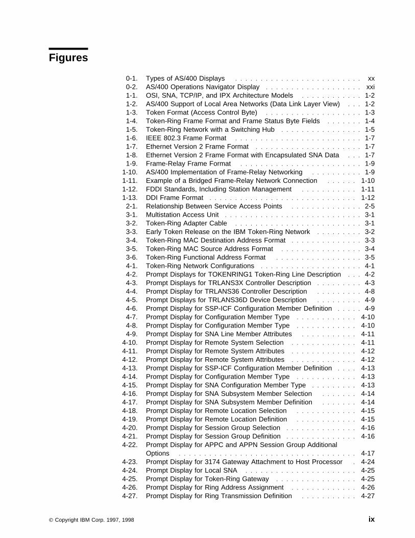
Each downstream station examines the transmitted frame to determine whether it isthe station intended to receive the frame. When a station recognizes its address inan incoming frame, it sets the address recognized bit in the frame status field andcopies the frame. If the frame is successfully copied, the receiving station also setsthe frame copied bit (see Figure 1-4).
Chapter 1. Introduction to local area networks 1-3
┌────┬────┬────┬────┬────┬─────────────┬─────┬────┬────┐
│ SD │ AC │ FC │ DA │ SA │ Information │ FCS │ ED │ FS │
└────┴────┴────┴────┴────┴─────────────┴─────┴────┴────┘
│ │
SD = Starting Delimiter │ │
AC = Access Control │ │
FC = Frame Control (MAC or LLC frame type) │ │
DA = Destination Address │ │
SA = Source Address │ │
FCS = Frame Check Sequence │ │
ED = Ending Delimiter ┌────────────┘ │
FS = Frame Status │ │
│ │
6 6
Frame Status Byte Fields: ┌─────────────────┐
│ A C r r A C r r │
A = Address recognized └─────────────────┘
C = Frame copied
r = Reserved
Figure 1-4. Token-Ring Frame Format and Frame Status Byte Fields
The receiving station also transmits the frame. The frame circulates until it returnsto the station that originally sent it. The original sending station removes the token,verifies that the frame was copied by the receiving station, and sends out a newfree token.
Full-duplex token ringIn full-duplex token ring , also called DTR (dedicated token ring) , switching hubsenable stations to send and receive data on the network simultaneously (seeFigure 1-5 on page 1-5). A token-ring switching hub divides the network intosmaller segments. When a station transmits its data packet, the token-ring switchreads the packet’s destination address information and forwards the data directly tothe receiving station. The switch then establishes a dedicated connection betweenthe two stations, enabling data to be transmitted and received at the same time. Infull-duplex token ring, the token-passing protocol is suspended. The network ineffect becomes a ’tokenless‘ token ring. Full-duplex token ring provides increasedsending and receiving bandwidth for connected stations, improving network per-formance.
For more information on token-ring switches, see the IBM LAN Bridge and SwitchGuide, SB24-5000, and Local Area Network Concepts and Products: LAN Architec-ture, SG24-4753-00.
1-4 OS/400 LAN, Frame-Relay and ATM Support V4R2

Figure 1-5. Token-Ring Network with a Switching Hub
See Chapter 3, “Token-ring networks” on page 3-1 for more information abouttoken-ring networks. See Chapter 4, “Token-Ring Network Configuration Examples”on page 4-1 for examples of token-ring network configurations.
Ethernet networksAn Ethernet network is a LAN that uses the Carrier Sense Multiple Access withCollision Detection (CSMA/CD) protocol to provide fair media access for competingstations. The MAC mechanism that is embedded in each station’s Ethernet inter-face determines access to the shared media. The AS/400 system supports twotypes of Ethernet networks:
� Ethernet Version 2: This standard is defined by Digital Equipment Corpo-ration**, Intel Corporation**, and the Xerox Corporation**(DIX).
� IEEE 802.3 standard
Half-duplex EthernetGenerally, multiple stations in an Ethernet network share a single data path. There-fore, only one station may transmit data at a time. This is called half-duplexEthernet. When a station has data to send, it checks the media to determine if it isavailable (no other stations are transmitting). When the media is available, thestation begins to transmit data in the form of an Ethernet frame . The station thenchecks for collisions during the transmission. A collision occurs when two or morestations begin transmitting at the same time. If a collision is detected, both transmit-ting stations stop transmitting and wait a random length of time before transmittingagain.
Chapter 1. Introduction to local area networks 1-5

See “Ethernet frame formats” on page 1-6 for a description of the frame formatsused in the various Ethernet environments.
Full-duplex EthernetFull-duplex Ethernet enables stations to simultaneously send and receive data onthe network, eliminating collisions. This is accomplished through the use of a full-duplex LAN switch. Ethernet switching splits a large Ethernet segment into smallersegments. Full-duplex Ethernet requires the following:
� Twisted-pair cable transmission medium
� Ethernet network interface cards
� A full-duplex LAN switch
Full-duplex Ethernet provides a dedicated, 10 Mbps sending and 10 Mbps receivingbandwidth for data transmission. Ethernet switches are discussed in greater detailin “Switching hubs” on page 5-3.
Fast EthernetFast Ethernet is a recently established standard (IEEE 802.3u) that increasesEthernet operating speeds from 10 Mbps to 100 Mbps, half or full duplex. AS/400Ethernet adapters support 100BASE-TX network devices that use category 5shielded and unshielded twisted-pair (STP, UTP) cable.
AutonegotiationThe autonegotiation function provides automatic self-configuration of 10BASE-Tand 100BASE-TX Ethernet network devices to optimize operation. Inautonegotiation, devices transmit information about their linespeed (10 Mbps or 100Mbps) and duplex mode (half duplex or full duplex), to the hub in the form ofEthernet fast-link pulses . The hub reads the fast-link pulses, determines thedevices’ maximum common linespeed and duplex mode, and automatically self-configures the link mode.
Note: No autonegotiation occurs when the user sets both speed and duplex tovalues other than *AUTO. Selecting *AUTO for both duplex and speedstarts autonegotiation initially at 100 Mbps full duplex. If you select *AUTOfor linespeed and *FULL for duplex, autonegotiation occurs with 100Mbpsfull duplex and 10Mbps full duplex as the indicated capabilities. Selecting10M (Mbps) linespeed and *AUTO duplex autonegotiates with 10 Mbps fullduplex and 10 Mbps half duplex as the indicated capabilities.
If the hub does not support autonegotiation, the AS/400 will detect the linespeedand default accordingly. However, the AS/400 cannot detect duplex, and alwaysdefaults to half duplex. This may not be the correct default configuration in allinstances. When this occurs, verify the correct duplex parameter, and reconfigure.
Ethernet frame formatsEthernet IEEE 802.3 support: IEEE 802.3 Ethernet frames contain a logical linkcontrol (LLC) header. The LLC header is used by the IEEE 802.3 layer to supportacknowledged (connection-oriented) service over an Ethernet network. Acknowl-edged service provides a link-level connection between communicating systemsand includes frame sequencing, flow control, and error recovery capabilities. IEEE802.3 frames can also be used for LLC unacknowledged (connectionless) servicesfor protocol stacks such as TCP/IP.
1-6 OS/400 LAN, Frame-Relay and ATM Support V4R2

Figure 1-6 shows the frame format used for IEEE 802.3 Ethernet networks.
┌────┬────┬────┬──────┬─────────────────────┬─────┐
│ │ │ │ │ LLC Information │ │
│ SD │ DA │ SA │ Len │ header field │ FCS │
└────┴────┴────┴──────┴─────────────────────┴─────┘
SD = Starting Delimiter 1 byte
DA = Destination Address 6 bytes
SA = Source Address 6 bytes
Len = Length 2 bytes
LLC header, information field 46-15ðð bytes
FCS = Frame Check Sequence 4 bytes
Figure 1-6. IEEE 802.3 Frame Format
Ethernet Version 2 support: The AS/400 system supports unacknowledgedservice using Ethernet Version 2 at the data link control level. Unacknowledgedservice supports the sending and receiving of frames only; no support is providedfor flow control, sequencing, or error recovery. If these functions are needed, ahigher-level protocol must provide them.
Figure 1-7 shows the frame format used for Ethernet Version 2 networks.
┌────┬────┬────┬──────┬─────────────────────┬─────┐
│ │ │ │ │ │ │
│ SD │ DA │ SA │ Type │ Information field │ FCS │
└────┴────┴────┴──────┴─────────────────────┴─────┘
SD = Starting Delimiter 1 byte
DA = Destination Address 6 bytes
SA = Source Address 6 bytes
Type = Type 2 bytes
Information field 46-15ðð bytes
FCS = Frame Check Sequence 4 bytes
Figure 1-7. Ethernet Version 2 Frame Format
SNA support is provided over Ethernet Version 2 by placing the IEEE 802.2 logicallink control (LLC) header and data into the Ethernet Version 2 frame. A specialEthernet type field (hex 80D5) is used to indicate that the Version 2 frame containsthe LLC header. Although the AS/400 system does support SNA over EthernetVersion 2, IEEE 802.3 is recommended for SNA communications.
Figure 1-8 shows the frame format used for SNA data transmitted over EthernetVersion 2 networks.
┌────┬────┬────┬──────┬───────────────────────────┬─────┐
│ │ │ │ Type │ --- Information field --- │ │
│ SD │ DA │ SA │ 8ðD5 │ Len Pad LLC header Data │ FCS │
└────┴────┴────┴──────┴───────────────────────────┴─────┘
SD = Starting Delimiter 1 byte
DA = Destination Address 6 bytes
SA = Source Address 6 bytes
Len = Length 2 bytes
Pad = Pad 1 byte
LLC header, information field 46-1493 bytes
FCS = Frame Check Sequence 4 bytes
Figure 1-8. Ethernet Version 2 Frame Format with Encapsulated SNA Data
Chapter 1. Introduction to local area networks 1-7

See Chapter 5, Ethernet networks for more information about Ethernet networks.“Ethernet standard (ETHSTD) parameter considerations” on page 5-5 describeshow the frame type sent by the AS/400 system is determined. See Chapter 6,Ethernet network configuration examples for examples of Ethernet configurations.
| Asynchronous transfer mode networks| Asynchronous transfer mode (ATM) is a communications technology that incor-| porates the following features:
| � Network switches. ATM switch-based networks provide varying node access| speeds, easy scalability, and dedicated bandwidth. Bandwidth refers to trans-| mission capacity, utilization, or requirements. It is measured in units of bits per| second (bps), or megabits per second (Mbps).
| � Small, fixed length cells. Each cell is a 53-byte data unit that consists of two| parts: A 48-byte payload for data and voice traffic and a 5-byte header that| contains information needed to route the cell to its proper destination (virtual| circuit information). ATM cells are the fundamental unit of ATM transmissions.| The network can easily adjust the flow pattern of such small cells. It can mix| cells from many sources and route individual cells to different destinations.
| � Negotiated service connections. The network negotiates requirements for| each connection, which include traffic characteristics, peak and average cell| rates, and quality of service.
| On the AS/400, LAN emulation over ATM extends your local area network (LAN) to| other locations. ATM adds flexibility to, and improves throughput over, existing LAN| technologies.
| See Chapter 7, “Asynchronous transfer mode networks” on page 7-1 for more| information about ATM networks. See Chapter 8, “ATM network configuration| examples” on page 8-1 for examples of ATM network configurations.
Frame-relay networksFrame relay is a protocol that defines how frames are routed through a fast-packetnetwork based on the address field in the frame. Frame relay takes advantage ofthe reliability of data communications networks to minimize the error checking doneby the network nodes. This provides a packet-switching protocol similar to, butmuch faster than, X.25.
The high speed that can be obtained through frame-relay networks makes it wellsuited for wide area network (WAN) connectivity. Frame relay is commonly used toconnect two or more LAN bridges over large distances.
Figure 1-9 shows the frame format used by frame-relay networks. Detailed informa-tion about frame-relay frame formats and protocol headers is given in Chapter 9,“Frame-relay networks” on page 9-1.
1-8 OS/400 LAN, Frame-Relay and ATM Support V4R2

┌───┬────┬───────────────────┬─────┬───┐
│ │ │ │ │ │
│ F │ QA │ Information Field │ FCS │ F │
└───┴────┴───────────────────┴─────┴───┘
F = HDLC or Q.922 flag
QA = HDLC or Q.922 address field (2 bytes)
FCS = HDLC or Q.922 frame check sequence (2 bytes)
Figure 1-9. Frame-Relay Frame Format
Frame-relay network architecture is based on the integrated systems digital network(ISDN) packet-mode bearer services. Table 1-1 shows the standards, eitherpending or approved, that are used to define the services and the user-to-networkinterface of frame-relay networks.
The AS/400 implementation of frame-relay network support uses protocol headersas defined in the TCP/IP Request for Comment 1490 (RFC-1490). See “Frame-relay protocol headers and frame formats” on page 9-7 for more information.
Frame-relay networks achieve their greater efficiency by minimizing the errorchecking done by nodes within the network. AS/400 frame-relay support uses IEEE802.2 logical link control to provide flow control and error recovery functions (seeFigure 1-10).
Table 1-1. ANSI and CCITT Standards for Frame-Relay Networks
ANSI Standard Equivalent CCITT Standard
T1.606, Frame Relay Bearer Services(FRBS) Architectural Framework
I.233, ISDN Frame Mode Bearer Service
T1.618, FRBS Core Aspects Q.922, ISDN Extended Data Link (LAP-E)
T1.617, FRBS Signaling Q.933, Frame Mode Bearer Services(FMBS) Signaling
T1.606 Addendum 1, FRBS CongestionManagement
I.370, ISDN FMBS Congestion Manage-ment
┌───────────────────────────────────────┐
│ │
│ Logical Link Control (LLC) │
│ IEEE 8ð2.2 / ISO 88ð2.2 │
├───────────────────────────────────────┤
│ │
│ Frame Relay Core Services (MAC) │
│ ANSI T1.618 / CCITT Q.922 │
└───────────────────────────────────────┘
┌───────────────────────────────────────┐
│ │
│ Physical Layer │
│ X.21, V.35, or EIA RS-449/V.36 │
└───────────────────────────────────────┘
Figure 1-10. AS/400 Implementation of Frame-Relay Networking
As indicated in Figure 1-10, the connection between the AS/400 system and theframe-relay network can be made using X.21, V.35, or RS-449 physical interfaces.See “Frame-relay physical environment” on page 9-1 for further information.
Chapter 1. Introduction to local area networks 1-9

Direct and bridged frame-relay network configurationsThe AS/400 system provides support for the following types of frame-relay networkconnection:
Frame-relay direct: Allows communications using SNA, TCP/IP, or InternetworkPacket Exchange** (IPX) data over a frame-relay network at speeds of up to 2.048Mbps. This support allows a network of systems to communicate using the frame-relay network as a backbone, without the need for multiple leased T1 lines. Thisfunction is also known as boundary network node (BNN) support.
Bridged frame-relay network: Allows the AS/400 system to communicate over aframe-relay network through a remote bridge, such as the IBM 6611 NetworkProcessor or RouteXpander/2 using IPX communications, that is attached to atoken-ring, Ethernet, or DDI network. Bridged frame-relay connections allow theAS/400 system to communicate with stations on the remote LAN as if they wereattached locally to the LAN medium. This function is also known as boundaryaccess node (BAN) support.
Figure 1-11 shows an example of a bridged frame-relay connection. In thisexample, AS/400 System A communicates through the frame-relay network and thebridge to AS/400 System B. Bridged frame-relay connections support SNA, TCP/IPand IPX data communications.
Figure 1-11. Example of a Bridged Frame-Relay Network Connection
See Chapter 9, “Frame-relay networks” on page 9-1 for more information aboutframe-relay networks. See Chapter 10, “Frame-relay network configurationexamples” on page 10-1 for examples of bridged and direct frame-relay configura-tions.
1-10 OS/400 LAN, Frame-Relay and ATM Support V4R2

Wireless networksA wireless network is a LAN using a Carrier Sense Multiple Access with CollisionAvoidance (CSMA/CA) protocol to provide media access to competing stations.AS/400 wireless communications uses spread-spectrum, direct sequence radio inthe 2.4 gigahertz (GHz) band to provide connectivity between the AS/400 wirelessLAN adapter and remote stations. Remote stations can be portable transactioncomputers (PTCs) running 5250 emulation or LAN-connected systems equippedwith compatible wireless adapters.
Wireless network support uses the Ethernet frame formats described under“Ethernet frame formats” on page 1-6. See Chapter 5, “Ethernet networks” onpage 5-1 for more information about considerations for Ethernet data. SeeChapter 11, “Wireless IOP LANs” on page 11-1 for more information aboutwireless networks. See Chapter 12, “Wireless IOP LAN configuration examples” onpage 12-1 for information about wireless network configuration and configurationexamples.
Distributed data interface networksA distributed data interface (DDI) network is a LAN based on the ANSI X3T9.5standard. Stations, concentrators, and bridges in a DDI network are physically con-nected to one or both of a pair of counter-rotating rings operating at 100 Mbps.
Note: The term DDI is used to represent all LAN types based on the fiber distrib-uted data interface (FDDI) specifications, regardless of the medium (opticalfiber, copper, or shielded twisted pair). Figure 1-12 shows the standardsused to define DDI networks at the physical and data link layers of the OSImodel.
┌───────────────────────────────────────┐
│ │
│ Logical Link Control (LLC) │
│ IEEE 8ð2.2 / ISO 88ð2.2 │
├───────────────────────────────────────┤ ┌────────────┐
│ │ │ │
│ Medium Access Control (MAC) │ │ │
│ ANSI X3.139 / ISO 9314-2 │ │ Station │
└───────────────────────────────────────┘ │ Management │
│ (SMT) │
┌───────────────────────────────────────┐ │ │
│ │ │ │
│ Physical Layer Protocol (PHY) │ │ │
│ ANSI X3.148 / ISO 9314-1 │ │ │
├───────────────────────────────────────┤ │ │
│ │ │ │
│ Physical Layer Medium Dependent (PMD) │ │ │
│ ANSI X3.166 / ISO 9314-3 │ │ │
└───────────────────────────────────────┘ └────────────┘
Figure 1-12. FDDI Standards, Including Station Management
DDI networks allow devices to be attached to one or both of the rings. Normally,only the primary ring in a DDI network is active. The secondary ring is used tomaintain the network when a dual-access station or a concentrator becomes inac-tive.
Figure 1-13 on page 1-12 shows the frame format that is used for DDI networks.
Chapter 1. Introduction to local area networks 1-11
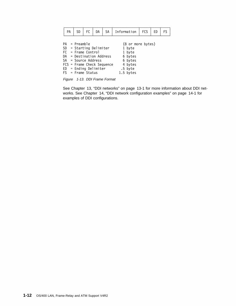
┌────┬────┬────┬────┬────┬─────────────┬─────┬────┬────┐
│ PA │ SD │ FC │ DA │ SA │ Information │ FCS │ ED │ FS │
└────┴────┴────┴────┴────┴─────────────┴─────┴────┴────┘
PA = Preamble (8 or more bytes)
SD = Starting Delimiter 1 byte
FC = Frame Control 1 byte
DA = Destination Address 6 bytes
SA = Source Address 6 bytes
FCS = Frame Check Sequence 4 bytes
ED = Ending Delimiter .5 byte
FS = Frame Status 1.5 bytes
Figure 1-13. DDI Frame Format
See Chapter 13, “DDI networks” on page 13-1 for more information about DDI net-works. See Chapter 14, “DDI network configuration examples” on page 14-1 forexamples of DDI configurations.
1-12 OS/400 LAN, Frame-Relay and ATM Support V4R2

Chapter 2. AS/400 implementation of local area networks
This chapter discusses general considerations for AS/400 local area networksupport, including local area network lines configured for bridged frame-relay net-works. See Chapter 9, “Frame-relay networks” on page 9-1 for more informationabout both bridged and direct frame-relay considerations.
| For more information about token-ring, Ethernet, ATM, wireless, and DDI networks,| see the discussions of these network types in “Token-ring networks” on page 2-17,| “Ethernet networks” on page 4-31, “ATM networks” on page 6-23, “Wireless| networks” on page 10-13, and “DDI networks” on page 12-11 of this book.
The following topics are discussed in this chapter:
� Acknowledged and unacknowledged services
� Physical and logical addresses (adapter addresses and SAP values)
� Establishing connections
� Exchange identifiers (XIDs)
� LAN performance tuning parameters
Local area network conceptsThe following discussion is intended to provide an understanding of some basiclocal area network concepts, how these concepts affect the configuration of yourlocal area network line description and associated controller descriptions, and howthey affect performance of the logical links to remote stations.
The AS/400 system allows you to attach to token-ring, Ethernet, wireless, and DDInetworks using the appropriate LAN adapter. Connections to these networks canalso be established using a frame-relay network connection to a bridge on a remotelocal area network. The AS/400 system can communicate using either SystemsNetwork Architecture (SNA) or non-SNA protocols with other systems, controllers,and personal computers attached to that network. These systems, controllers, andpersonal computers are commonly referred to as stations .
In addition to the stations that support SNA protocols (acknowledged service 1
), you can communicate with additional systems, personal computers, and control-lers using non-SNA protocols (unacknowledged service 2
). Acknowledged service is discussed in “Acknowledged service” on page 2-2 andunacknowledged service is discussed in “Unacknowledged service” on page 2-2.
1 Acknowledged service provides functions such as sequencing, flow control, and error recovery.
2 Unacknowledged service allows for data transfer without the establishment of a data link connection.
Copyright IBM Corp. 1997, 1998 2-1

Acknowledged serviceSNA requires the use of a logical link control (LLC) layer for acknowledged servicesas provided by the IEEE 802.2 standard. The LLC layer governs the assembling oftransmission frames and their exchange between stations. For token-ring, IEEE802.3 Ethernet, and DDI networks, the use of the LLC layer is standard. EthernetVersion 2 does not define an LLC layer and requires special processing to run SNAover Ethernet Version 2. For information on LLC over Ethernet Version 2, seeChapter 5, “Ethernet networks” on page 5-1.
SNA connections between your AS/400 system and other systems, personal com-puters, or controllers use LLC acknowledged service. LLC acknowledged servicemaintains, at the data link control layer of the system, a logical link between twonodes on the local area network. This service also provides ensured, end-to-enddelivery of data by use of sequence numbers and acknowledgements. It supportsflow control between two nodes, and, through the use of timers and retries, pro-vides an efficient way of transferring data between those nodes.
These connections are logically switched, similar to the switched virtual circuitsupport for X.25 packet-switching networks available on the AS/400 system. Thismeans, for example, that a personal computer can connect to an AS/400 system,disconnect from that AS/400 system, and then make a connection to anothersystem. Similarly, you can configure more than one local area network linedescription with which these controller descriptions are associated. This allows youto make connections with a station over more than one adapter at different times.
Unacknowledged serviceLLC unacknowledged service does not guarantee delivery of data frames from onedata link control layer to another data link control layer. The receiving layer doesnot reply with an acknowledgement that the data has been received, and unac-knowledged services do not require a connection at the data link layer. The UserDatagram Protocol (UDP) layer of TCP/IP and user-defined communicationssupport are examples of LLC unacknowledged services.
TCP/IP and user-defined communications can be configured using any of the localarea network line descriptions supported by the AS/400 system. Line descriptionsused for unacknowledged services must specify appropriate service access pointsin the SSAP list (SSAP parameter). SSAP values used for LLC unacknowledgedservices must be in the range 02 through FE and be divisible by 2. For TCP/IP,specify AA.
For unacknowledged services, a network controller and device are configured foruse with the Ethernet or token-ring line. These objects can be created using theCreate Controller Description (Network) (CRTCTLNET) and Create DeviceDescription (Network) (CRTDEVNET) commands. Normally, the network controllerand device are automatically created. Each line used to provide an unacknowl-edged service (such as TCP/IP) can have only one network controller active at atime.
See the TCP/IP Configuration and Reference book for information on how to con-figure your system for TCP/IP. The System API Reference book contains informa-tion on how to configure your system for user-defined communications.
2-2 OS/400 LAN, Frame-Relay and ATM Support V4R2
Assigning a physical addressEvery system, controller, or personal computer is attached to a local area networkby an adapter. Each adapter is identified in the network by its 6-byte mediumaccess control (MAC) 3
address (12 hexadecimal characters), simply referred to as an adapter address .No two adapters may have the same address in the same network. Each adapter isassigned a unique address when it is manufactured. This address is referred to asthe preset address , burned-in address, or universally administered address. Youcan use the preset address or assign an address yourself when you configure thelocal area network line description, which contains information describing a partic-ular communications line that is attached to the system.
To minimize configuration problems in the future, you should consider assigningyour own address. If you assign your own address, and the adapter on your systemneeds to be replaced, you can replace that adapter and assign it the same adapteraddress. This avoids configuring other units again that currently communicate withyour system over that adapter. If you use the preset address and the adapterneeds to be replaced, the new adapter has its own unique preset address.Restrictions prevent you from assigning an address that can also be imprintedduring manufacturing. You cannot assign the preset address of the replacedadapter to the new adapter.
The frame-relay adapter is not assigned a preset address. If LAN line descriptionsare created for use in a bridged frame-relay environment, you must assign anadapter address to each line description that you create. This address is used bythe bridge to recognize the AS/400 system in the network.
Finding a physical addressIn general, all systems, controllers, and personal computers in a network mustknow the address of the adapter to communicate with it. If you are using a localarea network, you need to know the address of your adapter so that you can con-figure the remote units with which you wish to establish connections.
To find the preset address (if you specified the preset address, ADPTADR(*ADPT),on the CRTLINTRN, CRTLINDDI, CRTLINETH, or CRTLINWLS command) or theaddress you assigned when you configured the line, enter the Display LineDescription (DSPLIND) command after your line description has been successfullyvaried on.
Note for mixed environmentsIf your system is used in a mixed environment where connections exist betweenEthernet and token-ring or DDI networks, you must pay special attention to howphysical-level addresses are assigned. Ethernet addresses are represented differ-ently than addresses used for token-ring and DDI networks. See Appendix D,“Address considerations for bridged environments” on page D-1 for informationabout address conversions for bridged connections between networks using dif-ferent address types. See “Token-ring physical address format” on page 3-3 and
3 Medium access control is a method of determining which device has access to the transmission medium at any time.
Chapter 2. AS/400 implementation of local area networks 2-3

“Ethernet physical address format” on page 5-4 for descriptions of these addressformats.
Assigning a logical addressAssociated with each adapter address is a set of logical addresses known asservice access points (SAPs). SAPs are used to route data with the sameadapter address to the correct station or application program, thus allowing multiplecommunications paths between independent application programs on thesesystems. The SAP addresses are 1-byte hexadecimal values, several of which aredefined for particular functions:
04 SNA
12 ASCII LAN printing
AA TCP/IP
C8 High performance routing (HPR)
Other valid values of SNA service access points range from hex 04 to hex 9C andmust be divisible by 4 (that is, end with 0, 4, 8, C). User-defined communicationsprotocols can use any SAP from 02-FE, divisible by 2.
Data is sent from a source service access point (SSAP) to a destination serviceaccess point (DSAP). You can specify up to 24 SSAPs for your LAN adapter whenyou configure the line description. Another alternative is to let the system automat-ically create SSAPs. See Table 2-1 on page 2-5 for information about automat-ically created SSAP values.
Service access pointsWhen you configure the controller descriptions that represent the remote system,controller, or personal computer that you will be communicating with, you are askedto specify the source service access points (SSAP) from which the data will besent and the destination service access point (DSAP) for which the data wasintended. The SSAP in the controller description must be one of the SSAPs speci-fied in the local area network line description with which this controller description isassociated. That is, the local area network line description must contain the com-plete list of SSAPs used by the controllers that include that local area network linedescription in their switched line list (SWTLINLST) parameter.
To configure the remote station, remember that the SSAP in the controllerdescription, which represents that station, must match that unit’s configured DSAPand vice versa. For example, if your controller description uses an SSAP of 04 andthe description on the remote unit uses an SSAP of 08, you must configure yourcontroller description with a DSAP of 08 and the remote unit with a DSAP of 04.Figure 2-1 on page 2-5 shows the relationship between the source service accesspoint and the destination service access point.
2-4 OS/400 LAN, Frame-Relay and ATM Support V4R2

System A
┌───────────┐
│ │
│ SSAP ð4 ──────┐ System B
│ │ │ ┌───────────┐
│ │ │ │ │
│ DSAP ð8 %─────┼─────── SSAP ð8 │
│ │ │ │ │
└───────────┘ │ │ │
└──────5 DSAP ð4 │
│ │
└───────────┘
Figure 2-1. Relationship Between Service Access Points
Up to 24 unique SSAPs can be specified. If the default (*SYSGEN) is used whencreating a LAN line description, up to four SSAPs are automatically created.Table 2-1 shows the SSAPs that are automatically created, depending on the typeof line description.
For SNA, the default of hex 04 is often sufficient. This is the default on all of thecreate controller description commands, and is the most commonly configured onremote units. Some cases where alternative service access points should be usedare:
� The remote system is configured such that its SSAP or DSAP is not hex 04. Inthis case, configure your controller description’s SSAP with the remote system’sDSAP and your controller description’s DSAP with the remote system’s SSAP.Ensure that the SSAP configured in your controller description is included in thelist of SSAPs you configured in each of the local area network line descriptionsthis controller has listed in its switched line list (SWTLINLST) parameter.
� You want parallel station-to-station connections between adapters. This may bedesirable if you want to link two application programs that require different con-troller descriptions.
� If you wish to use both an APPC and multinode APPN connection to the samehost system, parallel connections, which require multiple SAPs, are alsorequired. An example of this type of network is a AS/400 system as an interme-diate APPN node to the host system, but you have existing application pro-
Table 2-1. SSAPs Automatically Created Using SSAP (*SYSGEN)
Line Type SSAP Values
Token Ring and DDI Lines 04, 12, AA, C8
Frame Relay Lines 04, AA, C8
Ethernet and Wireless Lines
ETHSTD(*IEE8023) 04, 12, AA, C8
ETHSTD(*ALL) 04, 12, AA, C8
ETHSTD(*ETHV2) 04, C8
SSAP Assignments:
04 SNA
12 ASCII LAN printing
AA TCP/IP
C8 High performance routing (HPR)
Chapter 2. AS/400 implementation of local area networks 2-5

grams that use System/38 communications files and must use a host controllerdescription with APPN(*NO).
� You want to use the high performance routing (HPR) support. See the APPNSupport book for information about HPR.
� You want station-to-station connections to the same adapters. For example,you may want to configure multiple SAPs to test an application program on asingle system.
See “Configuring Different Service Access Points” on page 4-7 for an example ofusing different service access points to establish two parallel station-to-station con-nections between two adapters.
As previously mentioned, all adapter addresses in the network must be unique. Fur-thermore, because the DSAP, SSAP, and remote adapter address uniquelydescribe a connection to another station on the ring, all combinations of these threepieces of information must be unique for any controller that is varied on. Thesethree pieces uniquely identify a connection to another station on the ring. Thesystem enforces this uniqueness by not allowing two controller descriptions with thesame remote adapter address, DSAP, and SSAP, to be varied on at the same time.
Establishing the connectionThe AS/400 local area network support is logically switched; that is, the attachmentto the network is permanent, such as a nonswitched synchronous data link control(SDLC) line, but a station-to-station connection may be configured as either dial oranswer. Because the support is logically switched, you can configure as many con-troller descriptions as you wish. All descriptions are available for connection, but thenumber of varied-on or active controller descriptions allowed is based on the valuespecified for the MAXCTL parameter on the LAN line description. In the controllerdescriptions, you can specify more than one local area network line description inthe SWTLINLST parameter. This allows you to dial stations using a differentadapter address, if you like, or answer an incoming call from a remote system overtwo different adapters. This support provides more flexibility in connecting to yourAS/400 system.
Most units use what is known as last-one-up-on-the-network-calls-out logic. Thismeans that the systems attempt polling for a specified period of time before fallingback into answer mode. This is the same approach that is taken by the AS/400system for controller descriptions that are configured as *DIAL on their initial con-nection (INLCNN) parameter.
Dial modeIf you choose *DIAL for the initial connection (INLCNN) parameter on the controllerdescription, this system attempts to poll the remote station to determine if anyremote device on the line is ready to transmit, when the controller description isvaried on. The frequency and persistence of this polling is configured on the con-troller description; the LAN connection retry (LANCNNRTY) value defines howmany times the remote station is polled and the LAN connection timer(LANCNNTMR) value defines the amount of time between each poll. If the remotestation answers the poll within LANCNNRTY-times-LANCNNTMR tenths ofseconds, establishing a connection proceeds. If not, an inquiry message, CPA58E0or CPA57EF, is sent to the system operator message queue indicating that a con-
2-6 OS/400 LAN, Frame-Relay and ATM Support V4R2

nection attempt failed, and the system automatically puts the controller descriptionin answer mode.
If you choose:
� The retry option, the system again attempts to contact the remote station.
� The cancel reply, the controller description remains in a vary on pending statewaiting to answer a polling attempt by the remote station.
Answer modeSimilarly, other systems and controllers may attempt to establish a connection assoon as they are turned on, varied on, or the system has been loaded. Examples ofthis include the System/36 and the 3174 Subsystem Control Unit. If this systemdoes not respond, the units listed previously go into answer mode. The 3725 Com-munication Controller also can be configured to either attempt establishing a con-nection, or simply wait for this system to try to contact it. Controller descriptionsdescribing these systems should be configured as *DIAL on the INLCNN param-eter. If the remote system is ready, the AS/400 system answers the poll. If not, theAS/400 system goes into answer mode, and the remote station contacts the pollingsystem when it is varied on or turned on. Having both sides attempting to dial orpoll simultaneously does not prevent the connection from being established. Callcontention is resolved by architected retry sequences.
Dial initiationIf *DIAL was specified for INLCNN, the dial initiation parameter is allowed. Thisparameter allows you to determine when the call is made to the other system.
If you specify *IMMED, the call occurs immediately after the controller is varied on.*DELAY delays the dial to allow you to control when the call is made. *LINKTYPEis the default value and it determines when the dial connection is made by the typeof link.
Note: For LAN connections *LINKTYPE is treated as *IMMED.
Unsuccessful connectionsWhen using a controller description configured as INLCNN(*DIAL) and if no con-nection is established, a CPA58E0 Controller not replying or CPA57EF Contactnot successful message can occur; this is not unusual. It may mean that theremote system or controller is not varied on or turned on. If the remote unit is in astate where it should be answering a poll from this system and successful contactis not being established, check the configuration on both sides to ensure that theadapter addresses, DSAP parameter, and SSAP parameter are correctly specified.You may also want to check and make sure that both the adapter for this systemand the remote station are wired into the network correctly.
When using a controller description configured as INLCNN(*ANS), it is possible toreceive the message CPI591A, Controller on line varied off or not
recognized by local system. This message results when polling by a remotestation does not satisfy the following conditions:
� The adapter address, DSAP, and SSAP match those configured for a varied oncontroller description.
Chapter 2. AS/400 implementation of local area networks 2-7

� The local area network line description this poll used is contained in theswitched line list.
If you have such a controller description, ensure that the adapter address is correctand that the local area network line description on which this polling occurred islisted in the SWTLINLST parameter. Also, make sure the controller is varied on andnot in the recovery pending or recovery cancel state by using the Work with Config-uration Status (WRKCFGSTS) command.
If the connection is of the answer type (*ANS for the INLCNN parameter), thesystem waits for the remote unit to poll. When the remote unit begins polling, anattempt to establish a connection is made.
Initial connection (INLCNN) parameterController descriptions for personal computers or Personal System/2* workstationsrunning OS/400 and using DOS should specify *ANS for the INLCNN parameter.These systems will not answer a connection attempt started by an AS/400 system.Systems running OS/400 and using the OS/2* Communications Manager willanswer calls from the AS/400 system.
Check the error log to see if an error was logged for a line description with asystem reference code of AF06 if the following occurred:
� The remote station is polling the AS/400 system
� The message, indicating the system is being polled, does not appear in thesystem operator message queue
� The connection is not established
You can check the error log by using the Start SST (STRSST) command. This maymean the remote station was sending to a DSAP that was not configured in theSSAP list on your local area network line description. If the AF06 reference code isabsent, the error still may have occurred. Check the adapter addresses, SSAPs,and DSAPs to verify the connection.
Exchange identifier (XID)To establish a connection, exchange identifiers (XIDs) are exchanged between thesystem and the remote unit.
For APPC and host controllers, a Format 3 exchange identifier (XID) is used toallow the remote station to properly identify the AS/400 system. Typically, theAS/400 system and other IBM systems conduct an initial poll with NULL XIDs todetermine if the remote station is active on the network. If the station does notrespond to the poll within the specified time period, another XID can be sent to thestation. Typically, XID exchanges continue and a link is established.
Local exchange identifier (LCLEXCHID) parameterThe local exchange identifier (LCLEXCHID) parameter is used to identify theAS/400 system to the host system. This parameter is specified on the host con-troller description.
If *LIND is specified for the LCLEXCHID parameter, then the LCLEXCHID value isretrieved from the EXCHID value specified on the line description. If another valueis specified, it overrides what was specified for EXCHID on the line description. For
2-8 OS/400 LAN, Frame-Relay and ATM Support V4R2

example, if parallel connections are required between an AS/400 system and anSNA host system, then you need to override the EXCHID value. See “Example ofConfiguring Parallel Connections to the Host System” on page 4-21 for an exampleof parallel connections to the host.
Exchange identifier (EXCHID) parameterThe exchange identifier (EXCHID) parameter on the controller description specifiesthe block number and node identifier of the remote system. This parameter can beused to allow the local AS/400 system to identify the remote station.
If the EXCHID value is configured on the AS/400 controller description, the BLOCKidentifier and the node identifier from the remote station are compared to the con-figured value before a connection is established. If no EXCHID is specified, nocheck is made. This check is optional because the remote unit has already beenidentified by its adapter address, SSAP, and DSAP.
Refer to the topic “LANCNNTMR and LANCNNRTY parameters” on page 2-11 forinformation on polling the remote system or controller.
Data link roleLocal area network controller descriptions are always created with a data link role(ROLE parameter) of negotiable (*NEG). This means that any time a connectionattempt is made to a remote unit, the systems determine their role to be primary orsecondary by using an algorithm specified in the SNA Format and Protocol Refer-ence book. Because the local area network uses a balanced and duplex 4
protocol, this role is simply a matter of which system is chosen to send the SetAsynchronous Balanced Mode-Extended (SABME) command to the other station.
Automatic creation of APPC controllers on LANsWhen local area network lines are configured with the option to create APPC con-trollers automatically (AUTOCRTCTL(*YES) is specified), the connection establish-ment and exchange identifier processing is handled differently on incoming calls. Ifa controller description with a matching adapter address, SSAP, and DSAP isvaried on when an incoming call is received, the system processes the incomingcall request as was described in “Establishing the connection” on page 2-6.
If the system does not have a controller description that is varied on and the line isconfigured as AUTOCRTCTL(*YES), the system will accept the call. After theremote system sends an exchange identifier, the system then causes a controllerdescription to be created and varied on. The system dynamically determines theadapter address, SSAP, DSAP, RMTNETID, and RMTCPNAME used for the auto-matically created controller description based on the incoming call and theexchange identifier sent by the adjacent system. If a model controller is varied onfor this line, the parameters, such as timers and retry limits, are copied from themodel controller and used for the automatically created controller.
4 The duplex protocol allows either station to send at any time at the link level. Polling is not necessary to transfer information.
Chapter 2. AS/400 implementation of local area networks 2-9

Automatic creation of controller descriptions is supported for locally attached LANsand bridged frame-relay configurations; it is not supported for SNA direct frame-relay configurations.
For more information on automatically creating controllers on LANs, see the APPNSupport book.
Performance tuning parametersWhen the controller descriptions are created, any type of local area network linecan be specified in the switched line list (SWTLINLST parameter). At run time (dialor answer), the system can attach this LAN controller to any type of LAN linedescription. The first line description in the list that has the correct status isselected.
Because the AS/400 system does not know the type of line description that thecontroller will be attached to, you can specify values for parameters that do notapply to the environment you are using. Only at run time does the AS/400 systemrecognize that certain parameters are not needed for a particular environment. TheAS/400 system ignores these parameters. For example, if you specify a value forthe LANACCPTY parameter and you use Ethernet, the AS/400 system simplyignores that value.
SNA controller descriptions (APPC, SNA host, remote work station, finance, andretail) all have parameters that describe the behavior for the station. These param-eters are the LANxxxxxx parameters, and are used for all local area network types.
If *CALC (the default) is specified for the LANxxxxxx parameters, the AS/400system uses the values shown in Table 2-2. These values can be displayed byusing the DSPCTLD command when the controller is active.
| Note: Different values are calculated for lines that are attachedto frame-relay| network interfaces. See “Frame-relay performance tuning parameters” on| page 9-13 for additional information.
Table 2-2 (Page 1 of 2). Summary of LAN Controller Description Performance Parameters
Parameter Function *CALC Value Page
LANCNNTMR Sets wait time for polling remote stationduring connection establishment.
7 seconds 2-11
LANCNNRTY Sets number of poll retries sent to remotestation during connection establishment.
10 2-11
LANRSPTMR Sets wait time for frame retransmission. 1 second 2-11
LANFRMRTY Sets number of frame retransmissionattempts.
10 2-11
LANACKTMR Sets wait time for acknowledgement toremote station.
0.1 second 2-12
LANACKFRQ Sets number of frames received beforesending acknowledgement.
1 2-12
LANINACTMR Sets wait time for requesting responsefrom remote station.
10 seconds 2-13
2-10 OS/400 LAN, Frame-Relay and ATM Support V4R2

Table 2-2 (Page 2 of 2). Summary of LAN Controller Description Performance Parameters
Parameter Function *CALC Value Page
LANMAXOUT Sets number of outstanding framesallowed before requesting acknowledge-ment from remote station.
2 2-13
LANWDWSTP Provides an alternative value equivalent tothe LANMAXOUT parameter for useduring periods of network congestion. Thesystem provides an algorithm for returningthe effective maximum outstanding framesvalue to that specified by theLANMAXOUT parameter as congestionsubsides.
*NONE 2-14
LANACCPTY Sets priority of the station. Stations withhigher priority have greater access to thetoken. (Used for token-ring only.)
0 2-14
LANCNNTMR and LANCNNRTY parametersThe LAN connection timer (LANCNNTMR) and the LAN connection retry(LANCNNRTY) parameters work together on the AS/400 system to define the fre-quency and persistence of polling the remote system or controller for the purposeof establishing a connection. The LANCNNTMR specifies, in tenths of seconds,how long to wait before sending an exchange identifier (XID) or the Set Asynchro-nous Balanced Mode-Extended (SABME) command again. The LANCNNRTY spec-ifies how often this polling occurs when the LANCNNTMR has ended. When thevalue specified for the LANCNNRTY parameter is reached and no response isreceived from the remote station, the following occurs:
� The user is notified that contact with the station was unsuccessful.
� The system places the controller description in answer mode.
� If retry is the answer to the inquiry, the AS/400 system attempts to establishconnection again.
The defaults for these parameters are intended for use on a single local areanetwork. If a bridge is being used to communicate with a remote station on aremote network, you may want to consider increasing the values of theLANCNNTMR and LANCNNRTY parameters because a bridge may slow down linetraffic enough for the timer to expire before the station is able to respond. Linetraffic is the number of transmissions and the amount of data sent.
LANRSPTMR and LANFRMRTY parametersThe LAN response timer (LANRSPTMR) and the LAN frame retry (LANFRMRTY)parameters work together to determine how soon and how often a frame of data istransmitted again. Frames of data need to be transmitted again when one of thefollowing occurs:
� A previous frame of data was lost or damaged.
� The remote station is so busy that it cannot copy or respond to the frame.
� The remote station is waiting to acknowledge the frame with an informationframe of its own.
Chapter 2. AS/400 implementation of local area networks 2-11

Refer to the topic “LANACKTMR and LANACKFRQ parameters” on page 2-12 forinformation about the LAN acknowledgement timer (LANACKTMR) parameter.
The LANRSPTMR parameter defines the time interval, in tenths of seconds, thatthe system waits before transmitting a frame to the remote station again. TheLANFRMRTY value specifies how many times the frame is transmitted again beforethe system notifies the user that an error occurred and the logical link to the remotestation is disconnected.
The defaults for these parameters are intended for use on a single local areanetwork. If a bridge is being used to communicate with a remote station on a dif-ferent local area network, you may want to consider increasing the values on boththe local and remote systems, because a bridge may slow down traffic enough forthe timer to end before the station is able to respond.
If the values chosen are too small, performance may be slower. Either too manyframes are transmitted when acknowledgements are received after theLANRSPTMR ends or the logical link to the remote station may be disconnected. Ifthe values are too large, the notification that a logical link failed may not be imme-diate.
LANACKTMR and LANACKFRQ parametersThe LAN acknowledgement timer (LANACKTMR) and the LAN acknowledgementfrequency (LANACKFRQ) parameters work together to determine how often anacknowledgement is sent to the remote station. The LANACKTMR parameter speci-fies how long the system waits before sending an acknowledgement to a receivedframe. This allows the system, if it has any data to send to the remote controller, touse that frame to acknowledge the received frame. Similarly, the LANACKFRQparameter specifies the maximum number of frames the system can receive beforeacknowledgement is sent to the remote station, independent of timers or havingdata to send. The system has a greater chance of sending a frame of data thatincludes an acknowledgement of the received frame if the LANACKFRQ value islarge.
The values specified for the LANACKFRQ and LANACKTMR parameters musteither both be zero or both be nonzero.
Large values may be desirable because unnecessary acknowledgements sendadditional frames and can contribute to heavier traffic on the LAN. If you are on anetwork where frame traffic is a problem, you may wish to increase either or both ofthese values.
However, in most cases where frame traffic is not a problem, and data tends toflow only one way on the logical link (file transfer), large values for these parame-ters introduce unnecessary delay in sending acknowledgements and slow responsetimes.
The LAN acknowledgement values should be chosen with careful consideration forthe response timer and maximum outstanding frame count of the remote station.For example, if LANACKTMR is set longer than the response timer of the remotestation, and the local system does not regularly have data to send to the remotestation, the remote response timer ends and transmits the frame again.
2-12 OS/400 LAN, Frame-Relay and ATM Support V4R2

Similarly, if LANACKFRQ is set larger than the remote station’s maximum out-standing frame count (LANMAXOUT), the remote station continuously waits foracknowledgement of the frames it has outstanding, while the local system waits formore frames of data. This can lead to poor performance for this logical linkbecause more frames are being transmitted than actually necessary, and theremote station may wait longer than necessary before transmitting data again.
The LANACKFRQ parameter should be set less than or equal to the LANMAXOUTvalue for the remote station. If the local station LANACKFRQ parameter is smaller,the remote station LANMAXOUT value should be evenly divisible by theLANACKFRQ value.
LANINACTMR parameterThe LAN inactivity timer (LANINACTMR) parameter is used to determine how longthe system should wait before requesting a response from the remote station. Thisrequest is made to determine if the remote station is still on the ring or if the logicallink is disconnected. If the value is set too small, unnecessary traffic is created,which may lead to a performance throughput problem. If it is set too large, thesystem may not determine that the logical link is inoperable as quick as when thevalue is smaller. This timer is sensitive to whether the remote station is on thesame local area network or not. If it is across a bridge, this value may need to beincreased. If the value is set to 0 (no time-out), you may not be informed if thelogical link is inoperable until a data transfer attempt occurs.
LANMAXOUT parameterThe LAN maximum outstanding data frames (LANMAXOUT) parameter specifieshow many unacknowledged frames the system can have outstanding to the remotestation without waiting for an acknowledgement. This parameter is highly sensitiveto the ability of the remote station to copy and acknowledge frames, based on buf-fering capabilities and processing resource.
For optimal performance, it is essential to specify appropriate values for theLANMAXOUT and LAN acknowledgement frequency (LANACKFRQ) parameters onboth the sending and receiving stations.
Some of the variables affecting which LANMAXOUT and LANACKFRQ valuesprovide the best performance are:
� The characteristics of the application
� The amount of data being sent
� The rate that the application can present and accept data
� The data blocking characteristics
� The LAN adapter type
� The processing unit model
� The utilization of the line, the adapter, and the processing unit
� The internal buffering capabilities
In most environments, *CALC (LANACKFRQ=1 and LANMAXOUT=2) offers thebest performance. However, for some environments, changing these values mayprovide a significant performance improvement.
Chapter 2. AS/400 implementation of local area networks 2-13

You can change the LANMAXOUT and LANACKFRQ values to determine if per-formance improves. The following guidelines can be used as starting values whichyou can then change to determine the best values:
� For a large transfer environment when the frame size is:
– 1994 bytes or less, use LANACKFRQ=4 and LANMAXOUT=8.
– Between 1994 and 8156 bytes, use LANACKFRQ=2 and LANMAXOUT=4.
� For a mixed environment with both interactive and large transfer activity, followthe guidelines for a large transfer environment but keep LANACKFRQ=*CALC.
� When communicating with a PS/2* system Model 50 or above, follow the guide-lines for a large transfer environment but keep LANACKFRQ=*CALC.
� If you decide to change the values from *CALC for LANACKFRQ andLANMAXOUT, here are some guidelines for determining new values:
– LANACKFRQ should be about half the size of LANMAXOUT.
– LANACKFRQ should be the same on sending and receiving systems.
– LANMAXOUT should be the same on sending and receiving systems.
Note: If the LANACKFRQ and LANMAXOUT values are changed without a notice-able performance improvement, change the values back to *CALC.
LANWDWSTP parameterThe LAN window step (LANWDWSTP) parameter is used to determine whether thenumber of outstanding frames (those sent without receiving an acknowledgementfrom the remote system) should be reduced during periods of network congestion.If the value set is too small (or *NONE), congestion takes longer to subside. Formore information on network congestion, see the discussion of the dynamic windowalgorithm in the Token-Ring Network Architecture Reference.
LANACCPTY parameterThe LAN access priority (LANACCPTY) parameter is set in each frame beforebeing sent on the ring. This priority determines which tokens can be captured andused to send the frame. The greater the access priority value, the more tokens thestation can capture and the greater chance the frame will be sent. This is impor-tant if the ring that your system is attached to is heavily used (not many free tokensavailable) and your application program needs priority treatment.
The adapters on most systems send a priority of 0, which is the default forLANACCPTY on the create controller commands. If your station requires more pri-ority (for example, a personal computer which requires access to the token ring),you should set the LANACCPTY parameter to a greater value. This parameter isused only for token-ring network connections.
LAN bridge frame size considerationsIf a frame is being transmitted to a station that resides on a different LAN, theframe must be copied and transmitted again by a bridge. If the bridge is not config-ured to support a frame size as large as that configured on the line description, theframe will be discarded. The frame may also be discarded if the frame size config-ured on a line description used for a bridged frame relay configuration is not sup-ported by the network.
2-14 OS/400 LAN, Frame-Relay and ATM Support V4R2

For SNA in the token-ring environment, the system originating the connection isinformed of the frame size supported by the bridge, and will automatically retry withthat frame size. The CPF5908 message Controller contacted that is sent to theQSYSOPR message queue gives the effective maximum frame size for that con-nection.
If it is not possible to configure the bridge to support larger frame sizes, you mayneed to adjust one of the following to a value acceptable to the bridge:
� MAXFRAME parameter on the controller description
� SSAP MAXFRAME parameter on the line description
� MAXFRAME parameter on the line description (except Ethernet lines)
If an adjustment is made, it is recommended that the MAXFRAME value on thecontroller description be adjusted.
Relationship of LAN parameters to token-ring network architectureTable 2-3 shows how the AS/400 LAN controller description parameters relate tothe parameters described in the IBM Token-Ring Network Architecture Reference.
Table 2-3 (Page 1 of 2). AS/400 LAN Parameters. Relationship of LAN ControllerDescription Parameters to Parameters Used in the IBM Token-Ring Network ArchitectureReference.
AS/400Parameter
ShortTerm Short Description
LANCNNTMR CT1 Connection Timer T1 (for link establishment)
LANCNNRTY CN2 Connection Retry Count N2 (for link establishment)
LANRSPTMR T1 Response timer (waiting for remote acknowledgement)
LANFRMRTY N2 Retry count (maximum number of resends on T1 expiration)
LANACKTMR T2 Receiver acknowledgement timer
LANACKFRQ N3 Acknowledgement frequency—must send acknowledgementafter receiving N3 I-format frames (data frames)
LANINACTMR Ti Inactivity Timer (poll remote on expiration)
LANMAXOUT TW(k)
Maximum number of outstanding I-Format LLC protocol dataunits (data frames)
LANWDWSTP Nw Dynamic Window Step
MAXFRAMEon line andcontrollerdescriptions
N11 Maximum number of octets (bytes) in the information field.2
Chapter 2. AS/400 implementation of local area networks 2-15

Table 2-3 (Page 2 of 2). AS/400 LAN Parameters. Relationship of LAN ControllerDescription Parameters to Parameters Used in the IBM Token-Ring Network ArchitectureReference.
AS/400Parameter
ShortTerm Short Description
Note: TW may be referred to as MAXOUT because TW is perceived as the MAXimumOUTstanding frames transmitted to the other end. Similarly, N3 may be referredto as MAXIN because it is perceived as the MAXimum INbound frames receivedbefore sending an acknowledgement to the originator of the frames.
1. N1 is the maximum length of an LLC Protocol Data Unit. The effective MAXFRAMEvalue is the length excluding the LLC header. The LLC header is 3 to 4 bytes long.The setting of N1 on the AS/400 LAN adapter is the effective MAXFRAME + 4.
2. For AS/400 Version 1 Release 3 and later, the effective MAXFRAME for the con-troller description is not necessarily the same as the MAXFRAME value on the con-troller description. Because LAN controller descriptions are logically switched, theeffective MAXFRAME is the smallest of:
� The controller description MAXFRAME value.
� The line description MAXFRAME value.
� The SSAP maximum frame size on the line description.
The effective maximum frame size may be set to a smaller value if the AS/400system must communicate with the remote station through a source-routing bridgethat requires a smaller frame size. For more information about source-routing bridgeframe sizes, see the IBM Token-Ring Architecture Reference.
2-16 OS/400 LAN, Frame-Relay and ATM Support V4R2

Token-ring networks
Chapter 3. Token-ring networks . . . . . . . . . . . . . . . . . . . . . . . . . . 3-1Token-ring physical environment . . . . . . . . . . . . . . . . . . . . . . . . . . . 3-1
Ring configuration . . . . . . . . . . . . . . . . . . . . . . . . . . . . . . . . . . 3-2Early token release . . . . . . . . . . . . . . . . . . . . . . . . . . . . . . . . . 3-2
Token-ring physical address format . . . . . . . . . . . . . . . . . . . . . . . . . 3-3Bridged LAN addressing considerations . . . . . . . . . . . . . . . . . . . . . 3-5Functional addresses . . . . . . . . . . . . . . . . . . . . . . . . . . . . . . . . 3-5
Frame size considerations for token-ring networks . . . . . . . . . . . . . . . . 3-5General frame size considerations . . . . . . . . . . . . . . . . . . . . . . . . 3-6LAN bridge frame size considerations . . . . . . . . . . . . . . . . . . . . . . 3-6
Chapter 4. Token-Ring Network Configuration Examples . . . . . . . . . . 4-1Creating the Token-Ring Network Line Description . . . . . . . . . . . . . . . . 4-1Example of AS/400-to-AS/400 Configuration . . . . . . . . . . . . . . . . . . . . 4-3Example of a Token-Ring Network-to-Personal Computer Configuration . . . . 4-6Configuring Different Service Access Points . . . . . . . . . . . . . . . . . . . . 4-7Example of Token-Ring Network-to-System/36 Using APPC Configuration . . 4-7
System/36 Configuration CNFIGICF Displays . . . . . . . . . . . . . . . . . . 4-9Example of Token-Ring Network-to-3745 Host Configuration . . . . . . . . . 4-18
The Physical Configuration for the Host System . . . . . . . . . . . . . . . 4-18The Logical Configuration for the Host System . . . . . . . . . . . . . . . . 4-19
Example of Configuring Parallel Connections to the Host System . . . . . . . 4-21Configuring Physical and Logical Parallel Connections for the Host System 4-22
Example of Token-Ring Network-to-3174 Model 1L Gateway Configuration . 4-24Example of the 3174 Model 1L Subsystem Control Unit Configuration . . 4-24Model/Attach Display . . . . . . . . . . . . . . . . . . . . . . . . . . . . . . . 4-24Local SNA Display . . . . . . . . . . . . . . . . . . . . . . . . . . . . . . . . 4-25Token-Ring Gateway Display . . . . . . . . . . . . . . . . . . . . . . . . . . 4-25Ring Address Assignment Display . . . . . . . . . . . . . . . . . . . . . . . 4-25Ring Transmission Definition Display . . . . . . . . . . . . . . . . . . . . . . 4-26Example of the NCP/VTAM Configuration . . . . . . . . . . . . . . . . . . . 4-27
Example of Token-Ring Network-to-3174 Subsystem Control UnitConfiguration . . . . . . . . . . . . . . . . . . . . . . . . . . . . . . . . . . . . 4-28
Copyright IBM Corp. 1997, 1998

OS/400 LAN, Frame-Relay and ATM Support V4R2

Chapter 3. Token-ring networks
This chapter discusses token-ring network configuration and considerations.
Token-ring physical environmentFigure 3-1 shows the multistation access unit (MAU), which is the token-ring hard-ware needed to connect your device to a token ring. Each multistation access unitallows up to eight attached devices to have access to a ring. You can attach mul-tiple multistation access units together for additional resources on the same tokenring. All adapters on the token ring must run at the same speed, either 4 Mbps or16 Mbps.
Figure 3-1. Multistation Access Unit
Figure 3-2 shows the necessary adapter cable to attach the IBM Token-RingNetwork Adapter to the IBM Token-Ring Network. This adapter cable has a nine-pinD connector at the system end and a token-ring modular plug at the cabling end.You can purchase this IEEE 802.5-compliant cable from any vendor. IBM TokenRing uses baseband transmission at a rate of 4 Mbps or 16 Mbps.
9876
54321
R S L N 7 4 3 - 2
Figure 3-2. Token-Ring Adapter Cable
Copyright IBM Corp. 1997, 1998 3-1

Ring configurationThe actual wiring of your network may have some bearing on performance. Ringsmay be linked together by adapters, which are called bridges. When this systemattempts to establish a connection to a station, a frame is sent first around the localring, and if no response is received, it is then sent to all rings that are connected bybridges to this system. If a station on a connected ring answers the poll, the routinginformation that the response carries is used in all subsequent transmissions to theremote station. Thus, only one route is ever used (source routing) when communi-cating with a station on a remote ring. Because all acknowledgements and retriesare end to end, these bridges may become congested. This congestion can causeproblems for your logical links if the correct values are not chosen for the timerparameters of the controller descriptions.
Notes:
1. The number of bridges through which token-ring frames can be routed is limitedby the size of the routing information (RI) field in the token-ring frame. Themaximum of 18 bytes allowed for the RI field supports routing through up toseven bridges.
2. More than one multistation access unit can be used in a single-ring network.They are linked together by wiring relays, not by bridges, and thus still consti-tute a single ring.
Early token releaseThe early token release (ELYTKNRLS parameter), available only with the 16 Mbpstoken-ring network, is used to reduce the time another adapter on the same ringhas to wait for a free token. For early token release, the transmitting adapterreleases a free token after sending its frame. The following figure demonstrates theconcept of early token release.
Figure 3-3. Early Token Release on the IBM Token-Ring Network
If early token release is not used and the frame is shorter than the ring length, afree token is not released until the transmitting adapter sees the header of its trans-
3-2 OS/400 LAN, Frame-Relay and ATM Support V4R2

mitted frame. If the frame is shorter than the ring length, the ring is idle for thedifference in time of the lengths. Early token release removes this idle time.
Token-ring physical address formatEvery system, controller, or personal computer that is attached to a local areanetwork has a physical address for its attachment adapter. This physical level iscalled the medium access control (MAC), and the IEEE architecture has defined the48-bit (or 6-byte) MAC address formats to be used for IEEE 802.5 token-ring LANs.
Figure 3-4 and Figure 3-5 define how the MAC addresses are displayed on theAS/400 system for the token-ring LAN. The order of bit transmission on the mediumstarts with byte 0, bit 0 and ends with byte 5, bit 7. This order of transmission iscalled most significant bit because the most significant bit of each byte is trans-mitted first.
Figure 3-4. Token-Ring MAC Destination Address Format
� Bit 0 of byte 0 (called the I/G bit) indicates whether the destination address isan individual address , an address associated with a particular station on thenetwork, (B'0'), or group address , a multidestination address associated withone or more stations on the network, (B'1').
� Bit 1 of byte 0 (called the U/L bit) indicates whether the address is universallyadministered (B'0') or locally administered (B'1').
� Bit 0 of byte 2 (called the functional address indicator (FAI)) indicates whethera locally administered group address is a functional address (B'0') or a groupaddress (B'1').
Chapter 3. Token-ring networks 3-3

Figure 3-5. Token-Ring MAC Source Address Format
� Source addresses are always individual addresses. Bit 0 of byte 0 is set to 1when a routing information field is present in the frame. It is set to 0 when norouting information field is present.
� Bit 1 of byte 0 is used to indicate whether the address is universally adminis-tered or locally administered as in the destination address.
The above indicators are an integral part of each station address and must be con-sidered during address recognition.
Note the following:
� Byte 0, bit 0 = 0. This assignment controls the values of the local adapteraddress (ADPTADR parameter on the CRTLINTRN command) to the range ofhex 7FFFFFFFFFFF and below. The remaining addresses (when byte 0, bit 0 =1) are group addresses.
� Locally assigned addresses with byte 0, bit 1 = 1, are further restricted tovalues in the range hex 400000000000 to hex 7FFFFFFFFFFF. IEEErestrictions preclude the use of adapter preset addresses with values in therange of hex 000000000000 to hex 3FFFFFFFFFFF.
Other remote systems may have further restrictions on specifying the adapteraddress. For example, if your AS/400 system is communicating with FBSS con-troller, the locally assigned address is restricted to the range of hex400000000000 to hex 400099999999. Only characters 0 through 9 are per-mitted.
Note: If you choose to assign your own address, ensure that the last 4 bytes(8 hexadecimal characters) are unique in the local area network. This isrequired by some adapters.
3-4 OS/400 LAN, Frame-Relay and ATM Support V4R2

Bridged LAN addressing considerationsIt is very important to note that MAC addresses are always displayed in the aboveformat on all AS/400 token-ring configuration displays even if they representstations on other LAN media, such as Ethernet stations reached through bridges.Refer to “Ethernet physical address format” on page 5-4 for more information onbridged LAN considerations.
Functional addresses| Functional addresses are bit-specific group addresses in a token-ring network. All| functional addresses are locally administered. Functional addresses can be| assigned using the FCNADR parameter on the CRTLINTRN command, or may be| dynamically added by a TCP/IP multicast application. IP multicast addresses are| mapped to the token-ring functional address C00000040000. See the TCP/IP Con-| figuration and Referencebook for more information on IP and multicast.
For an address to be a functional address, the destination address must have bothbit 0 and 1 of byte 0 set to 1, all the bits in byte 1 should be set to 0, and bit 0 ofbyte 2 set to 0. The remaining 7 bits of byte 2 and the 8 bits in byte 3, 4, and 5 areused to identify the specific functional address. This allows up to 31 functionaladdresses to be defined.
Byte ð Byte 1 Byte 2 Byte 3 Byte 4 Byte 5
┌────┬────┐ ┌────┬────┐ ┌────┬────┐ ┌────┬────┬────┬────┬────┬────┐
│11ðð│ðððð│ │ðððð│ðððð│ │ðxxx│xxxx│ │xxxx│xxxx│xxxx│xxxx│xxxx│xxxx│
└────┴────┘ └────┴────┘ └─┬──┴────┘ └────┴────┴────┴────┴────┴───┬┘
└─────────── 31 functional addresses ──┘
Figure 3-6. Token-Ring Functional Address Format
Note: Each x, when set to 1, represents a functional address.
For more information on functional addresses, see the Communications Configura-tion book, and the Token-Ring Architecture Reference.
For converting a token-ring functional address to an Ethernet group address, see“Token-ring-to-Ethernet address conversion” on page D-3.
Frame size considerations for token-ring networksData is transmitted to remote stations in frames, the basic unit of transmission forall data. Frame size indicates how large each transmission is.
A token-ring network provides an environment with few errors. Therefore, datatransmission is more efficient if data is sent in as large a frame as possible. Thelargest frame size the AS/400 system sends (the MAXFRAME parameter on theCRTLINTRN command) can be set in any range from 265 through 16393.
Depending on the token-ring LAN adapter you are using, the maximum frame sizewill vary.
Chapter 3. Token-ring networks 3-5

The maximum value may not always be possible. For example, the station to whichyou are transmitting may not be able to accept as large a frame that configured onthe AS/400 system token-ring line description. Typically, the largest frame size sup-ported by both the AS/400 system and the remote station is exchanged in XIDswhile establishing the connection, and the smaller of the frame sizes is then usedby both the AS/400 system and the remote station. If this negotiation is not done, aframe reject (FRMR) condition results, and the message CPA58E2 is sent to theQSYSOPR message queue.
For example, when the AS/400 system is connected to a System/390 through a3174 gateway on a token ring, maximum frame size is not negotiated. The 3174uses a format 0 XID that provides no maximum frame size negotiation. Themaximum frame size specified for the AS/400 system must be configured to matchthat of the 3174 gateway.
If the maximum frame size must be changed, use the appropriate change controllerdescription command to change the AS/400 value, or change the maximum framesize in the remote system configuration.
Table 3-1. Token-Ring Adapter and Largest MAXFRAME Value
Resource Type
Largest MAXFRAME Value
Line Speed 16 Mbps Line Speed 4 Mbps
2619, 2626, 6149, 2724 16393 4060
9175 4060 4060
6134, 2636 8156 4060
6034, 6160 N/A 1994 (default)
Note: Type WRKHDWRSC \CMN to view the LAN adapter (resource) types.
General frame size considerationsOn token-ring lines, the MAXFRAME parameter defines the maximum frame size tobe used on that line. Maximum frame size can also be configured for each SAPassociated with the line description. In addition, a controller description also has aMAXFRAME size. When the connection process begins, the frame size is thesmaller of the three values: line MAXFRAME, SSAP MAXFRAME, or the controllerMAXFRAME. However, the frame size may become even smaller because of theXID negotiations or bridge considerations.
LAN bridge frame size considerationsIf a frame is being transmitted to a station that resides on a different LAN, theframe must be copied and transmitted again by a bridge. If the bridge is not config-ured to support a frame size as large as that configured on the token-ring orEthernet line description, the frame will be discarded. For SNA in the token-ringenvironment, the system originating the connection is informed of the frame sizesupported by the bridge, and will automatically retry with that frame size. TheCPF5908 message Controller contacted that is sent to the QSYSOPR messagequeue gives the effective maximum frame size for that connection.
If it is not possible to configure the bridge to support larger frame sizes, you mayneed to adjust one of the following to a value acceptable to the bridge:
� MAXFRAME parameter on the controller description
3-6 OS/400 LAN, Frame-Relay and ATM Support V4R2

� SSAP MAXFRAME parameter on the line description
� MAXFRAME parameter on the line description
If an adjustment is made, it is recommended that the MAXFRAME value on thecontroller description be adjusted.
Chapter 3. Token-ring networks 3-7

3-8 OS/400 LAN, Frame-Relay and ATM Support V4R2
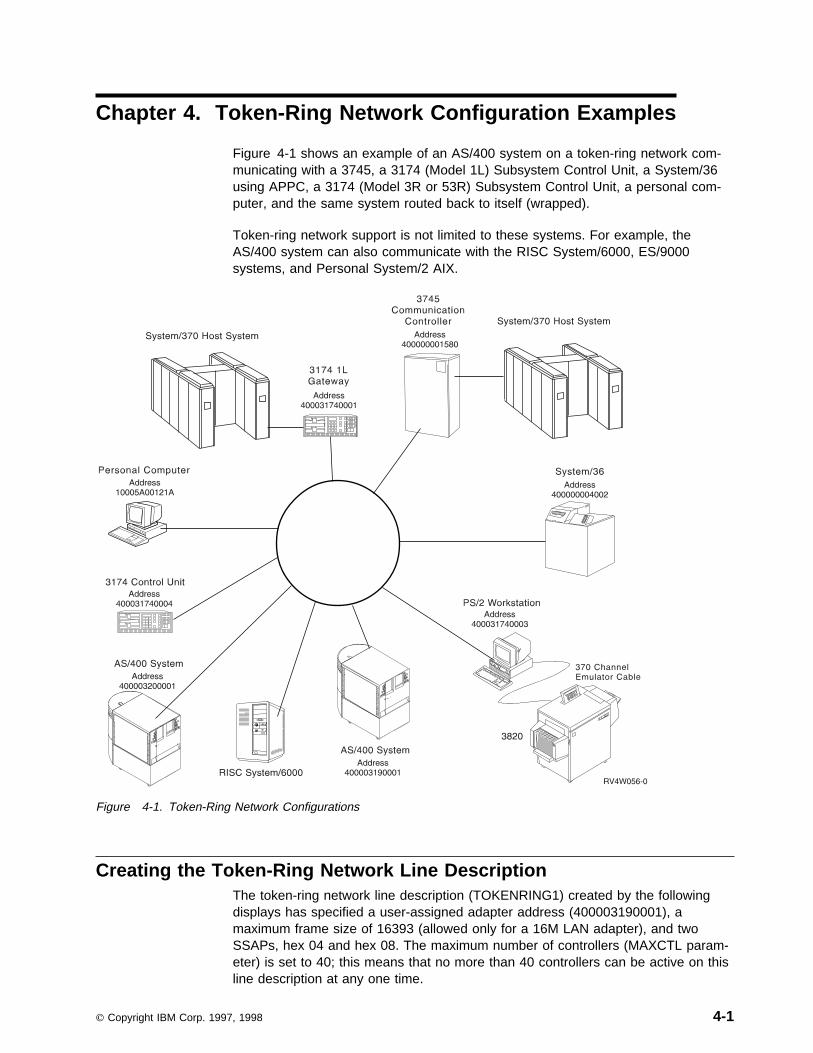
Chapter 4. Token-Ring Network Configuration Examples
Figure 4-1 shows an example of an AS/400 system on a token-ring network com-municating with a 3745, a 3174 (Model 1L) Subsystem Control Unit, a System/36using APPC, a 3174 (Model 3R or 53R) Subsystem Control Unit, a personal com-puter, and the same system routed back to itself (wrapped).
Token-ring network support is not limited to these systems. For example, theAS/400 system can also communicate with the RISC System/6000, ES/9000systems, and Personal System/2 AIX.
Figure 4-1. Token-Ring Network Configurations
Creating the Token-Ring Network Line DescriptionThe token-ring network line description (TOKENRING1) created by the followingdisplays has specified a user-assigned adapter address (400003190001), amaximum frame size of 16393 (allowed only for a 16M LAN adapter), and twoSSAPs, hex 04 and hex 08. The maximum number of controllers (MAXCTL param-eter) is set to 40; this means that no more than 40 controllers can be active on thisline description at any one time.
Copyright IBM Corp. 1997, 1998 4-1

à ð Create Line Desc (Token-Ring) (CRTLINTRN)
Type choices, press Enter.
Line description . . . . . . . . > TOKENRING1 Name
Resource name . . . . . . . . . > CMNð1 .1/ Name, \NWID, \NWSD
Online at IPL . . . . . . . . . \YES \YES, \NO
Vary on wait . . . . . . . . . . \NOWAIT \NOWAIT, 15-18ð (1 second)
Maximum controllers . . . . . . 4ð 1-256
Line speed . . . . . . . . . . . > 16M 4M, 16M, \NWI
Maximum frame size . . . . . . . > 16393 265-16393, 265, 521, 1ð33...
Local adapter address . . . . . > 4ðððð319ððð1 4ððððððððððð-7FFFFFFFFFFF...
Exchange identifier . . . . . . > ð56ððððð.2/ ð56ððððð-ð56FFFFF, \SYSGEN
More...F3=Exit F4=Prompt F5=Refresh F12=Cancel F13=How to use this display
F24=More keys
á ñ
à ð Create Line Desc (Token-Ring) (CRTLINTRN)
Type choices, press Enter.
SSAP list:.3/Source service access point . > ð4 ð2-FE, \SYSGEN
SSAP maximum frame . . . . . . > \MAXFRAME \MAXFRAME, 265-16393
SSAP type . . . . . . . . . . > \CALC \CALC, \NONSNA, \SNA
Source service access point . > ð8 ð2-FE
SSAP maximum frame . . . . . . \MAXFRAME \MAXFRAME, 265-16393
SSAP type . . . . . . . . . . \CALC \CALC, \NONSNA, \SNA
+ for more values
Text 'description' . . . . . . . > 'Token-ring line description'
Additional Parameters
Network controller . . . . . . . Name
TRLAN manager logging level . . \OFF \OFF, \MIN, \MED, \MAX
More...F3=Exit F4=Prompt F5=Refresh F12=Cancel F13=How to use this display
F24=More keys
á ñ
Figure 4-2. Prompt Displays for TOKENRING1 Token-Ring Line Description
Considerations for specifying the CRTLINTRN command:
| .1/ For lines attached to network server descriptions (NWSDs), the resource| value is *NWSD. This is for IPCS support. See the appropriate IPCS| manual to learn more about token-ring lines attached on IPCS. For an| example of *NWI for resource name, see “Bridged connections to| remote token-ring networks” on page 10-8. (Difference in versions? The| resource name for V4R7 or before will use LIN012 to make the con-| nection to the adapter. For V4R1 or later, use the actual resource name| of the port to which the line will connect).
4-2 OS/400 LAN, Frame-Relay and ATM Support V4R2

.2/ The exchange identifier (EXCHID) parameter is the block number andnode identifier of the local AS/400 system.
.3/ The source service access point (SSAP) specifies the logical channeladdresses used to route incoming data from the token ring to the correctuser. The hex 08 SSAP is used in a controller description, so it must beincluded in the TOKENRING1 line description.
Example of AS/400-to-AS/400 ConfigurationThe APPC controller description, created using the following prompt display,describes another AS/400 system at adapter address 400003200001. TheTOKENRING1 line description created in “Creating the Token-Ring Network LineDescription” on page 4-1 is used for the SWTLINLST parameter. The SSAP of hex08 is one of the SSAPs included in the SSAP list in the line description,TOKENRING1.
à ðCreate Ctl Desc (APPC) (CRTCTLAPPC)
Type choices, press Enter.
Controller description . . . . . > TRLANS3X Name
Link type . . . . . . . . . . . > \LAN \ANYNW, \FAX, \FR, \IDLC...
Online at IPL . . . . . . . . . \YES \YES, \NO
APPN-capable . . . . . . . . . . \YES \YES, \NO
Switched line list . . . . . . . > TOKENRING1 Name
+ for more values
Maximum frame size . . . . . . . \LINKTYPE 265-16393, 256, 265, 512...
Remote network identifier . . . \NETATR Name, \NETATR, \NONE, \ANY
Remote control point . . . . . . > LANAPPN2.1/ Name, \ANY
Exchange identifier . . . . . . ðððððððð-FFFFFFFF
Initial connection . . . . . . . \DIAL \DIAL, \ANS
Dial initiation . . . . . . . . \LINKTYPE \LINKTYPE, \IMMED, \DELAY
LAN remote adapter address . . . > 4ðððð32ðððð1.2/ððððððððððð1-FFFFFFFFFFFF APPN CP session support . . . . \YES \YES, \NO
APPN node type . . . . . . . . . \ENDNODE \ENDNODE, \LENNODE...
APPN transmission group number 1 1-2ð, \CALC
More...F3=Exit F4=Prompt F5=Refresh F12=Cancel F13=How to use this display
F24=More keys
á ñ
Figure 4-3 (Part 1 of 3). Prompt Displays for TRLANS3X Controller Description
Chapter 4. Token-Ring Network Configuration Examples 4-3
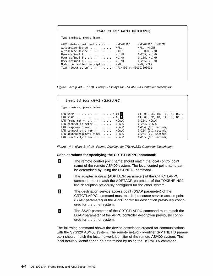
à ðCreate Ctl Desc (APPC) (CRTCTLAPPC)
Type choices, press Enter.
APPN minimum switched status . . \VRYONPND \VRYONPND, \VRYON
Autocreate device . . . . . . . \ALL \ALL, \NONE
Autodelete device . . . . . . . 144ð 1-1ðððð, \NO
User-defined 1 . . . . . . . . . \LIND ð-255, \LIND
User-defined 2 . . . . . . . . . \LIND ð-255, \LIND
User-defined 3 . . . . . . . . . \LIND ð-255, \LIND
Model controller description . . \NO \NO, \YES
Text 'description' . . . . . . . > 'AS/4ðð at 4ðððð32ðððð1'
Figure 4-3 (Part 2 of 3). Prompt Displays for TRLANS3X Controller Description
à ðCreate Ctl Desc (APPC) (CRTCTLAPPC)
Type choices, press Enter.
LAN DSAP . . . . . . . . . . . . > ð4.3/ ð4, ð8, ðC, 1ð, 14, 18, 1C...
LAN SSAP . . . . . . . . . . . . > ð8.4/ ð4, ð8, ðC, 1ð, 14, 18, 1C...
LAN frame retry . . . . . . . . \CALC ð-254, \CALC
LAN connection retry . . . . . . \CALC ð-254, \CALC
LAN response timer . . . . . . . \CALC ð-254 (ð.1 seconds)
LAN connection timer . . . . . . \CALC ð-254 (ð.1 seconds)
LAN acknowledgement timer . . . \CALC ð-254 (ð.1 seconds)
LAN inactivity timer . . . . . . \CALC ð-255 (ð.1 seconds)
Figure 4-3 (Part 3 of 3). Prompt Displays for TRLANS3X Controller Description
Considerations for specifying the CRTCTLAPPC command:
.1/ The remote control point name should match the local control pointname of the remote AS/400 system. The local control point name canbe determined by using the DSPNETA command.
.2/ The adapter address (ADPTADR parameter) of the CRTCTLAPPCcommand must match the ADPTADR parameter of the TOKENRING2line description previously configured for the other system.
.3/ The destination service access point (DSAP parameter) of theCRTCTLAPPC command must match the source service access point(SSAP parameter) of the APPC controller description previously config-ured for the other system.
.4/ The SSAP parameter of the CRTCTLAPPC command must match theDSAP parameter of the APPC controller description previously config-ured for the other system.
The following command shows the device description created for communicationswith the SYS320 AS/400 system. The remote network identifier (RMTNETID param-eter) should match the local network identifier of the remote AS/400 system. Thelocal network identifier can be determined by using the DSPNETA command.
4-4 OS/400 LAN, Frame-Relay and ATM Support V4R2

CRTDEVAPPC DEVD(TRLANS3XD) RMTLOCNAME(SYS32ð) LCLLOCNAME(SYS319) +
RMTNETID(LANAPPN1) CTL(TRLANS3X) MODE(BLANK) +
TEXT('APPC device for SYS32ð')
The following commands can be used to configure another AS/400 system commu-nicate with this AS/400 system.
CRTLINTRN LIND(TOKENRING2) RSRCNAME(LINð11) LINESPEED(16M) +
MAXFRAME(16393) ADPTADR(4ðððð32ðððð1) EXCHID(ð56ððððð) +
SSAP((ð4 \MAXFRAME \CALC) (ð8 \MAXFRAME \CALC)) +
TEXT('Line description for 4ðððð32ðððð1')
The adapter address (ADPTADR parameter) specified for the CRTLINTRNcommand must match the ADPTADR parameter of the APPC controller descriptionpreviously configured for the other system.
The following command shows the creation of the APPC controller description.
CRTCTLAPPC CTLD(TRLANS3X2) LINKTYPE(\LAN) SWTLINLST(TOKENRING2) +
RMTCPNAME(LANAPPN).1/ ADPTADR(4ðððð319ððð1).2/ +DSAP(ð8).3/ SSAP(ð4).4/ TEXT('AS/4ðð at 4ðððð32ðððð1')
Considerations for specifying the CRTCTLAPPC command:
.1/ The remote control point name should match the local control pointname of the remote AS/400 system. The local control point name canbe determined by using the DSPNETA command.
.2/ The adapter address (ADPTADR parameter) of the CRTCTLAPPCcommand must match the ADPTADR parameter of the TOKENRING1line description previously configured for the other system.
.3/ The destination service access point (DSAP parameter) of theCRTCTLAPPC command must match the source service access point(SSAP parameter) of the APPC controller description previously config-ured for the other system.
.4/ The SSAP parameter of the CRTCTLAPPC command must match theDSAP parameter of the APPC controller description previously config-ured for the other system.
The following command shows the device description created for communicationswith the SYS319 AS/400 system. The remote network identifier should match thelocal network identifier of the remote AS/400 system. The local network identifiercan be determined by using the DSPNETA command.
CRTDEVAPPC DEVD(TRLANS3XD2) RMTLOCNAME(SYS319) LCLLOCNAME(SYS32ð) +
RMTNETID(LANAPPN) CTL(TRLANS3X2) MODE(BLANK) +
TEXT('APPC device for SYS319')
Chapter 4. Token-Ring Network Configuration Examples 4-5

Example of a Token-Ring Network-to-Personal Computer ConfigurationThe APPC controller description created by the Create Controller Description(APPC) (CRTCTLAPPC) command describes a personal computer that usesOS/400. Notice its adapter address (a preset address assigned by the adaptermanufacturer) and the fact that it is an APPN controller, because APPN(*YES) isthe default.
Notice that no device is created along with the controller. The system creates adevice description for your use the first time a connection is made to the personalcomputer. For more information on automatically creating controller descriptions,see the discussion of the AUTOCRTCTL line description parameter in the Commu-nications Configuration book. It is recommended that OS/400 automatically create acontroller and device description for you.
CRTCTLAPPC CTLD(TRLANPC) LINKTYPE(\LAN) SWTLINLST(TOKENRING1) +
RMTCPNAME(PCð1) ADPTADR(1ððð5Aðð121A) CPSSN(\NO).1/ +SWTDSC(\NO).2/ TEXT('Controller for PC on TOKENRING1')
Considerations for specifying the CRTCTLAPPC command:
.1/ By specifying the APPN CP session support (CPSSN parameter) as*NO, the automatic disconnect feature can be used.
.2/ The switched disconnect (SWTDSC) parameter is ignored unlessCPSSN(*NO) is specified. These values indicate that the automatic dis-connect feature is being used.
For more information on configuring the OS/400, refer to the appropriate OS/400documentation.
When installing OS/400 on a personal computer, the location name for the personalcomputer must be set to the value specified as the remote control point name(RMTCPNAME) for the APPC controller description for this personal computer. Thisvalue must be unique for each personal computer in the token-ring network.
The system name is the local control point name (LCLCPNAME) specified in theChange Network Attributes (CHGNETA) command.
The system token-ring address must be set to the ADPTADR parameter of theTOKENRING1 line description.
The first part of the RTLN entry of the OS/400 configuration file, CONFIG.PCS,must match the RMTNETID parameter value on the AS/400 CRTCTLAPPCcommand. It is recommended that the value match what is specified as the currentlocal network identifier in the network attributes. APPN is the default value. TheOS/400 documentation contains information for tailoring the configuration record ofyour personal computer to match the local network identifier on your system.
Note: To change the value for the RTLN entry in the CONFIG.PCS file, you mustuse an editor.
It is recommended that you begin the name of the APPC controllers, whichdescribe the personal computers you attach to the ring, with the letters PC. Thisallows you to display the status of the personal computers using the Work with
4-6 OS/400 LAN, Frame-Relay and ATM Support V4R2

Configuration Status (WRKCFGSTS) command. See the Communications Manage-ment book for more information on the WRKCFGSTS command.
Configuring Different Service Access PointsThe following APPC controller and device descriptions allow you to connect fromthe AS/400 system back to the same AS/400 system. You may wish to do this totest an application within your system before testing it over the network to a dif-ferent system. This example also shows how different service access points areconfigured in the controller descriptions. Notice that the SSAP for TRLANCTL1 andthe DSAP for TRLANCTL2 correspond, as do the DSAP for TRLANCTL1 and theSSAP for TRLANCTL2. This example has one controller description as a *DIAL andthe other as *ANS.
Notice that because both controllers are communicating through the same adapter,they both list the adapter address that was listed when creating TOKENRING1.Data actually goes out and around the ring for token-ring. However, when Ethernetis used, there is an internal wrap in the input/output processor. This is the caseonly in a wrapped situation.
You can configure the controller and device descriptions using a CL program or CLcommands as demonstrated here, or you can configure these objects through con-figuration displays as shown previously in this chapter.
CRTCTLAPPC CTLD(TRLANCTL1) LINKTYPE(\LAN) APPN(\NO)
SWTLINLST(TOKENRING1) ADPTADR(4ðððð319ððð1)
DSAP(ð4) SSAP(ð8)
TEXT('AS/4ðð at address 4ðððð319ððð1, DSAP ð4')
CRTDEVAPPC DEVD(TRLANDEV1) RMTLOCNAME(SOURCE)
LCLLOCNAME(TARGET) CTL(TRLANCTL1)
MODE(BLANK) APPN(\NO)
CRTCTLAPPC CTLD(TRLANCTL2) LINKTYPE(\LAN) APPN(\NO)
INLCNN(\ANS) SWTLINLST(TOKENRING1)
ADPTADR(4ðððð319ððð1) DSAP(ð8) SSAP(ð4)
TEXT('AS/4ðð at address 4ðððð319ððð1, DSAP ð8')
CRTDEVAPPC DEVD(TRLANDEV2) RMTLOCNAME(TARGET)
LCLLOCNAME(SOURCE) CTL(TRLANCTL2)
MODE(BLANK) APPN(\NO)
Example of Token-Ring Network-to-System/36 Using APPCConfiguration
The following APPC controller description describes a system that uses adapteraddress 400000004002. The TOKENRING1 line description created in “Creatingthe Token-Ring Network Line Description” on page 4-1 is used for the SWTLINLSTparameter. The SSAP and DSAP parameters are not included because the defaultsof DSAP(04) and SSAP(04) are used. See the APPN Support book for configura-tion examples using APPN.
Chapter 4. Token-Ring Network Configuration Examples 4-7
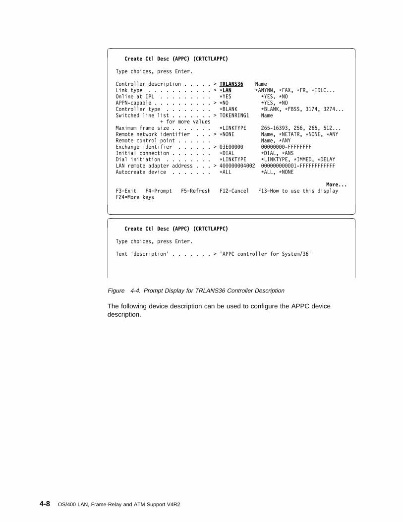
à ðCreate Ctl Desc (APPC) (CRTCTLAPPC)
Type choices, press Enter.
Controller description . . . . . > TRLANS36 Name
Link type . . . . . . . . . . . > \LAN \ANYNW, \FAX, \FR, \IDLC...
Online at IPL . . . . . . . . . \YES \YES, \NO
APPN-capable . . . . . . . . . . > \NO \YES, \NO
Controller type . . . . . . . . \BLANK \BLANK, \FBSS, 3174, 3274...
Switched line list . . . . . . . > TOKENRING1 Name
+ for more values
Maximum frame size . . . . . . . \LINKTYPE 265-16393, 256, 265, 512...
Remote network identifier . . . > \NONE Name, \NETATR, \NONE, \ANY
Remote control point . . . . . . Name, \ANY
Exchange identifier . . . . . . > ð3Eððððð ðððððððð-FFFFFFFF
Initial connection . . . . . . . \DIAL \DIAL, \ANS
Dial initiation . . . . . . . . \LINKTYPE \LINKTYPE, \IMMED, \DELAY
LAN remote adapter address . . . > 4ððððððð4ðð2 ððððððððððð1-FFFFFFFFFFFF
Autocreate device . . . . . . . \ALL \ALL, \NONE
More...F3=Exit F4=Prompt F5=Refresh F12=Cancel F13=How to use this display
F24=More keys
á ñ
à ðCreate Ctl Desc (APPC) (CRTCTLAPPC)
Type choices, press Enter.
Text 'description' . . . . . . . > 'APPC controller for System/36'
Figure 4-4. Prompt Display for TRLANS36 Controller Description
The following device description can be used to configure the APPC devicedescription.
4-8 OS/400 LAN, Frame-Relay and ATM Support V4R2

à ðCreate Device Desc (APPC) (CRTDEVAPPC)
Type choices, press Enter.
Device description . . . . . . . > TRLANS36D Name
Remote location . . . . . . . . > SYSTEM36 Name
Online at IPL . . . . . . . . . \YES \YES, \NO
Local location . . . . . . . . . > AS4ðð Name, \NETATR
Remote network identifier . . . > \NONE Name, \NETATR, \NONE
Attached controller . . . . . . > TRLANS36 Name
Mode . . . . . . . . . . . . . . > BLANK Name, \NETATR
+ for more values
Message queue . . . . . . . . . QSYSOPR Name, QSYSOPR
Library . . . . . . . . . . . \LIBL Name, \LIBL, \CURLIB
APPN-capable . . . . . . . . . . > \NO \YES, \NO
Single session:
Single session capable . . . . \NO \NO, \YES
Number of conversations . . . 1-512
Location password . . . . . . . \NONE
Secure location . . . . . . . . \NO \NO, \YES
More...F3=Exit F4=Prompt F5=Refresh F12=Cancel F13=How to use this display
F24=More keys
á ñ
à ðCreate Device Desc (APPC) (CRTDEVAPPC)
Type choices, press Enter.
Text 'description' . . . . . . . > 'APPC device for System 36'
Figure 4-5. Prompt Displays for TRLANS36D Device Description
System/36 Configuration CNFIGICF DisplaysA System/36 user must fill in the following displays to configure an APPC sub-system member and token-ring line member to communicate with the AS/400system previously configured. To get to the first display, use the CNFIGICFcommand.
à ð 1.ð SSP-ICF CONFIGURATION MEMBER DEFINITION W2
1. Configuration member name . . . . . . . . . . . . . . . . . TRNLINA
2. Library name . . . . . . . . . . . . . . . . . . . . . . . . CNFIGLIB
3. Select one of the following:
1. Create new member
2. Edit existing member
3. Create new member from existing member
4. Remove a member
5. Review a member
Option . . . . . . . . . . . . . . . . . . . . . . . . . 1-5 1
Figure 4-6. Prompt Display for SSP-ICF Configuration Member Definition
Chapter 4. Token-Ring Network Configuration Examples 4-9
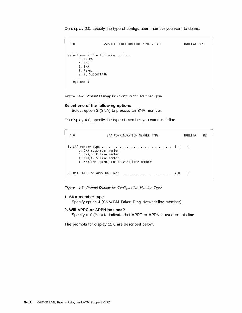
On display 2.0, specify the type of configuration member you want to define.
à ð 2.ð SSP-ICF CONFIGURATION MEMBER TYPE TRNLINA W2
Select one of the following options:
1. INTRA
2. BSC
3. SNA
4. Async
5. PC Support/36
Option: 3
Figure 4-7. Prompt Display for Configuration Member Type
Select one of the following options:Select option 3 (SNA) to process an SNA member.
On display 4.0, specify the type of member you want to define.
à ð 4.ð SNA CONFIGURATION MEMBER TYPE TRNLINA W2
1. SNA member type . . . . . . . . . . . . . . . . . . . . 1-4 4
1. SNA subsystem member
2. SNA/SDLC line member
3. SNA/X.25 line member
4. SNA/IBM Token-Ring Network line member
2. Will APPC or APPN be used? . . . . . . . . . . . . . . Y,N Y
Figure 4-8. Prompt Display for Configuration Member Type
1. SNA member typeSpecify option 4 (SNA/IBM Token-Ring Network line member).
2. Will APPC or APPN be used?Specify a Y (Yes) to indicate that APPC or APPN is used on this line.
The prompts for display 12.0 are described below.
4-10 OS/400 LAN, Frame-Relay and ATM Support V4R2

à ð 12.ð SNA LINE MEMBER ATTRIBUTES TRNLINA W2
6. Local system's station XID in hexadecimal. . . . . . . . . . ððððð
7. Source service access point (SSAP) value . . . . . . . . . . ð4
Cmd5-Restart CNFIGICF Cmd7-End
Cmd19-Cancel COPR IBM Corp. 1986
á ñ
Figure 4-9. Prompt Display for SNA Line Member Attributes
Note: Item 7 on display 12.0, SNA Line Member Attributes, describes theSystem/36 SSAP. This must be equal to the DSAP parameter on the APPCcontroller description on the AS/400 system.
On display 12.5, select the remote systems that this subsystem communicates with.If the protocol is primary or the line type is switched, up to 32 remote systems canbe defined.
If no remote systems have been defined, only option 1 (Create) is shown.
à ð12.5 REMOTE SYSTEM SELECTION TRNLINA W2
1. Select from the following options:
1-Create 3-Create From Existing 5-Review
2-Edit 4-Remove
Option . . . . . . . . . . . . . . . . . . . . . . . . . . .
2. Remote system name . . . . . . . . . . . . . . . . . . . . .
3. Existing remote system name . . . . . . . . . . . . . . . .
--------------------------------------------------------------------------------
OPTION REMOTE SYSTEM OPTION REMOTE SYSTEM OPTION REMOTE SYSTEM
AS4ðð
Figure 4-10. Prompt Display for Remote System Selection
1. Select from the following options:Specify option 1 (Create).
2. Remote system nameSpecify the name (up to 8 characters) by which the remote system is known inthe line member. This value should match the AS/400 network attributes controlpoint name, which you can display using the DSPNETA command.
On display 13.0, define the characteristics for the remote system selected ondisplay 12.5.
Chapter 4. Token-Ring Network Configuration Examples 4-11

à ð 13.ð REMOTE SYSTEM ATTRIBUTES TRNLINA W2
Remote system AS/4ðð
1. Remote system type . . . . . . . . . . . . . . . . . . . . . 2
2-Peer
3. Remote system's block ID in hexadecimal. . . . . . . . . . . ð56
4. Remote system's station XID in hexadecimal . . . . . . . . . ððððð
Figure 4-11. Prompt Display for Remote System Attributes
1. Remote system typeSpecify option 2 (Peer) for the remote system type.
3. Remote system’s block ID in hexadecimalSpecify the 3-hexadecimal character block identifier of the remote system. Thisvalue can be from 000 to FFF and must be the same as the value assigned tothe remote system by SNA. This is the XID that System/36 expects from theAS/400 system. This must equal the EXCHID parameter on the TOKENRING1line description. Set this value to 056.
4. Remote system’s station XID in hexadecimalSpecify the exchange identifier (XID) used to identify the remote system. Thisidentifier is 5 hexadecimal characters from 00000 through FFFFF. This is theXID that System/36 expects from the AS/400 system. This must equal theEXCHID parameter on the TOKENRING1 line description. Set this value to00000.
Display 13.5 is shown if you selected option 4 (IBM Token-Ring Network) for theSNA member type on display 4.0.
à ð 13.5 REMOTE SYSTEM ATTRIBUTES TRNLINA W2
Remote system AS/4ðð
1. Remote adapter address . . . . . . . . . . . . . . . . . . . 4ðððð319ððð1
2. Destination service access point (DSAP) value . . . . . . . ð4
Figure 4-12. Prompt Display for Remote System Attributes
Remote adapter addressSpecify the hexadecimal adapter address for this remote system for anSNA/IBM Token-Ring Network line member. Valid addresses are hex0000000000001 through hex 7FFFFFFFFFFF. This must equal the ADPTADRparameter on the TOKENRING1 line description on the AS/400 system. Theremote adapter address is 400003190001.
Destination service access point DSAP valueSpecify the hexadecimal logical channel address used for routing at the remotesystem for an SNA/IBM Token-Ring Network. This value must be nonzero,divisible by 4, and must match the remote system’s source service access point
4-12 OS/400 LAN, Frame-Relay and ATM Support V4R2

(SSAP). Valid values are hex 04 through hex EC. This must equal the SSAPparameter on the APPC controller description on the AS/400 system. Set thisvalue to 04.
à ð 1.ð SSP-ICF CONFIGURATION MEMBER DEFINITION W2
1. Configuration member name . . . . . . . . . . . . . . . . . TRNSBSA
2. Library name . . . . . . . . . . . . . . . . . . . . . . . . CNFIGLIB
3. Select one of the following:
1. Create new member
2. Edit existing member
3. Create new member from existing member
4. Remove a member
5. Review a member
Option . . . . . . . . . . . . . . . . . . . . . . . . . 1-5 1
Figure 4-13. Prompt Display for SSP-ICF Configuration Member Definition
On display 2.0, specify the type of configuration member you want to define.
à ð 2.ð SSP-ICF CONFIGURATION MEMBER TYPE TRNSBSA W2
Select one of the following options:
1. INTRA
2. BSC
3. SNA
4. Async
5. PC Support/36
Option: 3
Figure 4-14. Prompt Display for Configuration Member Type
Select one of the following options:Select option 3 (SNA) to process an SNA member.
On display 4.0, specify the type of member you want to define.
à ð 4.ð SNA CONFIGURATION MEMBER TYPE TRNSBSA W2
1. SNA member type . . . . . . . . . . . . . . . . . . . . 1-4 1
1. SNA subsystem member
2. SNA/SDLC line member
3. SNA/X.25 line member
4. SNA/IBM Token-Ring Network line member
Figure 4-15. Prompt Display for SNA Configuration Member Type
Chapter 4. Token-Ring Network Configuration Examples 4-13

1. SNA member typeSpecify option 1 (SNA subsystem member).
On display 21.0, select the type of subsystem for which you want to create a sub-system member. Also, enter the name of the line member (previously defined) thatyou will use with this subsystem member.
à ð21.ð SNA SUBSYSTEM MEMBER SELECTION TRNSBSA W2
1. Select subsystem type from the following options:
1. Peer
2. SNA Upline
3. SNA 327ð
4. Finance
5. SNA MSRJE
6. APPC
7. APPN
Option . . . . . . . . . . . . . . . . . . . . . . . . . 1-7 6
2. Line member name . . . . . . . . . . . . . . . . . . . . . . TRNLINA
Figure 4-16. Prompt Display for SNA Subsystem Member Selection
1. Select subsystem type from the following options:Specify option 6 (APPC) to indicate that the subsystem used is APPC.
2. Line member nameSpecify the name of the line member with which this subsystem member isassociated. The line member name is specified on display 1.0 during linemember configuration (TRNLINA).
The prompt on display 22.0 is described as follows:
à ð22.ð SUBSYSTEM MEMBER DEFINITION TRNSBSA W2
1. Local location name . . . . . . . . . . . . . . . . . . . . . SYSTEM36
Figure 4-17. Prompt Display for SNA Subsystem Member Definition
1. Local location nameSpecify the local location name as SYSTEM36.
On display 29.0, select the remote locations that this subsystem communicateswith.
4-14 OS/400 LAN, Frame-Relay and ATM Support V4R2

à ð29.ð REMOTE LOCATION SELECTION TRNSBSA W2
1. Select from the following options:
1-Create 3-Create From Existing 5-Review
2-Edit 4-Remove
Option . . . . . . . . . . . . . . . . . . . . . . . . . . . 1
2. Remote location name . . . . . . . . . . . . . . . . . . . . AS4ðð
3. Remote system name . . . . . . . . . . . . . . . . . . . . . AS4ðð
3. Existing location name . . . . . . . . . . . . . . . . . . .
--------------------------------------------------------------------------------
OPTION REMOTE SYSTEM OPTION REMOTE SYSTEM OPTION REMOTE SYSTEM
Figure 4-18. Prompt Display for Remote Location Selection
On display 30.0, enter whether or not you want to activate communications with theremote location at the time this subsystem is enabled.
à ð 3ð.ð REMOTE LOCATION DEFINITION TRNSBSA W2
Remote system AS4ðð Remote location AS4ðð
1. Activate location at ENABLE? . . . . . . . . . . . . . . Y,N Y
2. Send alerts to this location? . . . . . . . . . . . . . Y,N N
Figure 4-19. Prompt Display for Remote Location Definition
1. Activate location at ENABLE?Specify whether or not you want the subsystem, as soon as it is enabled, toallow communications with this remote location. Specify a Y (Yes), which is thedefault, to indicate that communications can start without having to specify thename of the remote location on an ENABLE procedure command.
2. Send alerts to this location?Specify whether or not you want alerts sent. Specify an N (No) if you do notwant alerts sent to this location.
Note: A separate location needs to be defined to send alerts to the remotesystem named AS400.
Display 42.0 lists the session groups that are defined for this remote location. Youcan create a new session group, edit an existing session group, remove a sessiongroup, create a new session group from an existing session group, or review asession group. In addition, you can specify the name of the session group that is tobe used as the default.
System/36 has a default session group of *BLANK, and the AS/400 system has adefault mode of BLANK.
Chapter 4. Token-Ring Network Configuration Examples 4-15

à ð 42.ð SESSION GROUP SELECTION TRNSBSA W2
Remote system AS4ðð Remote location AS4ðð
1. Select from the following options:
5-Review
Option . . . . . . . . . . . . . . . . . . . . . . . . . . .
2. Session group name . . . . . . . . . . . . . . . . . . . . .
4. Default session group name . . . . . . . . . . . . . . . . . \BLANK
--------------------------------------------------------------------------------
OPTION SESSION GROUP
\BLANK
Figure 4-20. Prompt Display for Session Group Selection
1. Select from the following options:Option 5 (Review) displays an existing session group. The configurationmember cannot be changed.
2. Session group nameEach session group name must be unique within the remote location.
4. Default session group nameSpecify that the default session group name is used by the APPC subsystemwhenever a local application program does not specifically provide a sessiongroup name at the start of a session. The default session group name must bea session group name already configured for this remote location.
Display 43.0 is the first of a set of displays that you use to define the sessiongroups. The remote system name, remote location name, and session group nameare shown for reference.
à ð 43.ð APPC and APPN SESSION GROUP DEFINITION TRNSBSA W2
Remote system AS4ðð Remote location AS4ðð
Session group \BLANK
1. Session group type . . . . . . . . . . . . . . . . . . . . . 1
1-Interactive 2-Batch
2. Maximum session limit . . . . . . . . . . . . . . . .1 - 64 ð8
3. Number of locally controlled sessions . . . . . . . .ð - ð8 ð4
4. Number of pre-established sessions . . . . . . . . . .ð - ð4 ð1
Figure 4-21. Prompt Display for Session Group Definition
1. Session group typeSpecify whether or not the sessions are used for batch or interactive communi-cations. This is used to select defaults at the local system for display 44.0.Type a 1 (Interactive) if the record exchange is in both directions, meaning thatthe systems alternate sending and receiving.
4-16 OS/400 LAN, Frame-Relay and ATM Support V4R2

2. Maximum session limitSpecify the maximum number of sessions that are allowed for this sessiongroup. The maximum number of sessions for all session groups in a singleremote location is 64. The default is 8.
3. Number of locally controlled sessionsSpecify the number of locally controlled sessions that are requested for thissession group. The range of available sessions is shown and the default isone-half of the maximum session limit. This value is actually negotiated with theremote system when the data link is established. Therefore, the number speci-fied here is not a guaranteed value.
4. Number of pre-established sessionsSpecify the number of sessions established and kept active while communi-cations with the remote location is active. The default is 1 if the line type isnonswitched or switched without automatic disconnect. The default is 0 if theline type is switched with automatic disconnect.
Note: All values specified in this session group are the default values.
On display 44.0, define additional options that can affect performance for thissession group. The remote system name, remote location name, and session groupname are shown for reference.
à ð 44.ð APPC AND APPN SESSION GROUP ADDITIONAL OPTIONS TRNSBSA W2
Remote system AS4ðð Remote location AS4ðð
Session group \BLANK
1. Receive pacing value . . . . . . . . . . . . . . . . . .1-63 ð7
2. Maximum receive RU size . . . . . . . . . . . . . . .8-16384 ð4ð96
3. Acquire remotely controlled sessions? . . . . . . . . . Y,N N
Figure 4-22. Prompt Display for APPC and APPN Session Group Additional Options
1. Receive pacing valueSpecify that 7 request units (RUs) may be sent from the remote location withoutan intervening pacing response. The default is 7 if the type of session group isinteractive.
2. Maximum receive RU sizeSpecify that the maximum RU size (in bytes) that can be received by the APPCsubsystem is 1024. The default is 1024 if the type of session group is interac-tive.
3. Acquire remotely controlled sessions?If there are no locally controlled sessions available, this prompt determineswhether or not the subsystem attempts to acquire a session controlled by theremote system.
Note: All values specified in this session group are the default values.
Chapter 4. Token-Ring Network Configuration Examples 4-17

Example of Token-Ring Network-to-3745 Host ConfigurationThe following host controller description is used to configure the connection to a3745 controller at adapter address 400000001580. The SSAP and DSAP parame-ters are not included because the defaults of DSAP(04) and SSAP(04) are used.
CRTCTLHOST CTLD(TRLANHOST) LINKTYPE(\LAN) +
SWTLINLST(TOKENRING1).1/ RMTCPNAME(LANAPPN).2/ +LCLEXCHID(\LIND).3/ ADPTADR(4ðððððððð158ð) +NODETYPE(\LENNODE) TEXT('3745 controller')
Considerations for specifying the CRTCTLHOST command:
.1/ The TOKENRING1 line description created in “Creating the Token-RingNetwork Line Description” on page 4-1 is used for the switched line list(SWTLINLST parameter).
.2/ The remote control point name (RMTCPNAME parameter) should matchthe local control point on the remote system. On the AS/400 system,you can verify this name by using the Display Network Attributes(DSPNETA) command.
On the host system, the local control point name is the SSCPNAME thatis specified in the VTAM* Start Option list.
.3/ The local exchange identifier (LCLEXCHID) parameter is used to identifythe AS/400 system to the host system.
The following device description commands are used to configure an emulationdisplay and printer, and a distributed host command facility (DHCF) device.
CRTDEVHOST DEVD(TRLANEML) LOCADR(ð1) RMTLOCNAME(HOST) +
CTL(TRLANHOST) APPTYPE(\EML) +
TEXT('327ð emulation over TOKENRING1')
CRTDEVHOST DEVD(TRLANPRT) LOCADR(ðC) RMTLOCNAME(HOST) +
CTL(TRLANHOST) APPTYPE(\EML) EMLDEV(3287) +
TEXT('327ð printer emulation over TOKENRING1')
CRTDEVDSP DEVD(TRLANDHCF) DEVCLS(\RMT) TYPE(3277) MODEL(\DHCF) +
LOCADR(ð2) CTL(TRLANHOST) TEXT('DHCF over TOKENRING1')
The Physical Configuration for the Host SystemThis is the network control program generation (NCP GEN) for the GROUP andLINE macroinstructions created by the system administrator to provide forconnectivity between the AS/400 system and the 3745 Communication Controller.This NCP GEN is valid on Network Control Program (NCP) Version 4.2 and VirtualTelecommunications Access Method (VTAM) Version 3.1.1. Different NCP or VTAMlevels may require different parameters.
4-18 OS/400 LAN, Frame-Relay and ATM Support V4R2

R1Gðð6P GROUP ECLTYPE=PHYSICAL
R1ð8ðP LINE ADDRESS=(ð8ð,FULL),LOCADD=(4ððððððð158ð),PORTADD=ð1,ISTA\
TUS=INACTIVE
R1ð8ðPA PU ADDR=ð1,ISTATUS=INACTIVE
R1ð8ðPA1 LU LOCADDR=ð,
LUDR=NO
R1Gðð6L GROUP ECLTYPE=LOGICAL,
PHYPORT=8ð
R1ð8ððð LINE
R1ð8ðððA PU MAXLU=32
R1ð8ðð1 LINE
R1ð8ðð1A PU MAXLU=32
R1ð8ðð2 LINE
R1ð8ðð2A PU MAXLU=32
R1ð8ðð3 LINE
R1ð8ðð3A PU MAXLU=32
R1ð8ðð4 LINE
R1ð8ðð4A PU MAXLU=32
R1ð8ðð5 LINE
R1ð8ðð5A PU MAXLU=32
R1ð8ðð6 LINE
R1ð8ðð6A PU MAXLU=32
R1ð8ðð7 LINE
R1ð8ðð7A PU MAXLU=32
Note: The location address (LOCADD) parameter on the LINE statement definesthe adapter address of the 3745 Communication Controller, in this case400000001580. This value must match the value specified for the adapteraddress (ADPTADR) parameter on the Create Controller (SNA Host)(CRTCTLHOST) command on the AS/400 configuration.
The Logical Configuration for the Host SystemThis is the NCP GEN for the switched major node created by the system adminis-trator to provide for connectivity between the AS/400 system and 3745 Communi-cation Controller. This GEN is valid on Network Control Program (NCP) Version 4.2and Virtual Telecommunications Access Method (VTAM) Version 3.1.1. DifferentNCP or VTAM levels may require different parameters.
Chapter 4. Token-Ring Network Configuration Examples 4-19
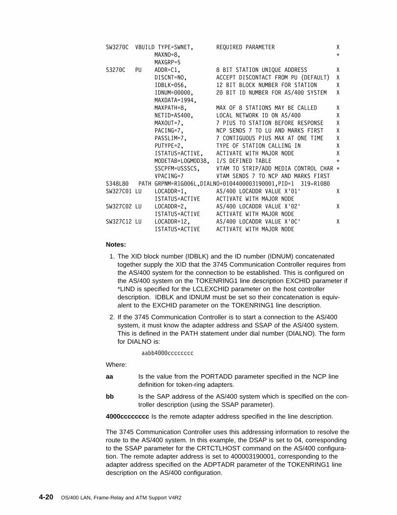
SW327ðC VBUILD TYPE=SWNET, REQUIRED PARAMETER X
MAXNO=8, \
MAXGRP=5
S327ðC PU ADDR=C1, 8 BIT STATION UNIQUE ADDRESS X
DISCNT=NO, ACCEPT DISCONTACT FROM PU (DEFAULT) X
IDBLK=ð56, 12 BIT BLOCK NUMBER FOR STATION X
IDNUM=ððððð, 2ð BIT ID NUMBER FOR AS/4ðð SYSTEM X
MAXDATA=1994,
MAXPATH=8, MAX OF 8 STATIONS MAY BE CALLED X
NETID=AS4ðð, LOCAL NETWORK ID ON AS/4ðð X
MAXOUT=7, 7 PIUS TO STATION BEFORE RESPONSE X
PACING=7, NCP SENDS 7 TO LU AND MARKS FIRST X
PASSLIM=7, 7 CONTIGUOUS PIUS MAX AT ONE TIME X
PUTYPE=2, TYPE OF STATION CALLING IN X
ISTATUS=ACTIVE, ACTIVATE WITH MAJOR NODE X
MODETAB=LOGMOD38, I/S DEFINED TABLE \
SSCPFM=USSSCS, VTAM TO STRIP/ADD MEDIA CONTROL CHAR \
VPACING=7 VTAM SENDS 7 TO NCP AND MARKS FIRST
S348L8ð PATH GRPNM=R1Gðð6L,DIALNO=ð1ð44ðððð319ððð1,PID=1 319-R1ð8ð
SW327Cð1 LU LOCADDR=1, AS/4ðð LOCADDR VALUE X'ð1' X
ISTATUS=ACTIVE ACTIVATE WITH MAJOR NODE
SW327Cð2 LU LOCADDR=2, AS/4ðð LOCADDR VALUE X'ð2' X
ISTATUS=ACTIVE ACTIVATE WITH MAJOR NODE
SW327C12 LU LOCADDR=12, AS/4ðð LOCADDR VALUE X'ðC' X
ISTATUS=ACTIVE ACTIVATE WITH MAJOR NODE
Notes:
1. The XID block number (IDBLK) and the ID number (IDNUM) concatenatedtogether supply the XID that the 3745 Communication Controller requires fromthe AS/400 system for the connection to be established. This is configured onthe AS/400 system on the TOKENRING1 line description EXCHID parameter if*LIND is specified for the LCLEXCHID parameter on the host controllerdescription. IDBLK and IDNUM must be set so their concatenation is equiv-alent to the EXCHID parameter on the TOKENRING1 line description.
2. If the 3745 Communication Controller is to start a connection to the AS/400system, it must know the adapter address and SSAP of the AS/400 system.This is defined in the PATH statement under dial number (DIALNO). The formfor DIALNO is:
aabb4ðððcccccccc
Where:
aa Is the value from the PORTADD parameter specified in the NCP linedefinition for token-ring adapters.
bb Is the SAP address of the AS/400 system which is specified on the con-troller description (using the SSAP parameter).
4000cccccccc Is the remote adapter address specified in the line description.
The 3745 Communication Controller uses this addressing information to resolve theroute to the AS/400 system. In this example, the DSAP is set to 04, correspondingto the SSAP parameter for the CRTCTLHOST command on the AS/400 configura-tion. The remote adapter address is set to 400003190001, corresponding to theadapter address specified on the ADPTADR parameter of the TOKENRING1 linedescription on the AS/400 configuration.
4-20 OS/400 LAN, Frame-Relay and ATM Support V4R2

Notes:
1. Because NCP SAP cannot be specified or changed, it is always 04. Therefore,on the AS/400 controller description, the DSAP is always 04.
2. For bb on the DIALNO operand, only values of two decimal digit numbersbetween 04-94 may be specified.
Example of Configuring Parallel Connections to the Host SystemThe following SNA host controller descriptions, SWTRNCTL1A and SWTRNA002,set up parallel connections between an AS/400 system and a host system. Thisexample configures two link-to-link connections through a 3745 communicationscontroller to a host system. Each link-to-link connection has a separate instance oflogical link control and a separate band width. As a result, it is possible for one linkto be varied on and active if the other link goes down. Parallel connections allowyou to establish an additional 254 device description per controller description.
CRTCTLHOST CTLD(SWTRNCTL1A) LINKTYPE(\LAN) APPN(\NO) +
SWTLINLST(TRNBGOUT).1/ LCLEXCHID(ð56Aðð1A).2/ +ADPTADR(4ððððððð1592) DSAP(ð4).3/ SSAP(ð8).4/ +TEXT('Controller for XID ðð56Aðð1A')
The following panels establish the second controller description for the instance thatruns in parallel to the controller description SWTRNCTL1A.
CRTCTLHOST CTLD(SWTRNAðð2A) LINKTYPE(\LAN) APPN(\NO) +
SWTLINLST(TRNBGOUT).1/ LCLEXCHID(ð56Aðð2A).2/ +ADPTADR(4ððððððð1592) DSAP(ð4).3/ SSAP(ð4).4/ +TEXT('Controller for XID ðð56Aðð2A')
Considerations for specifying the CRTCTLHOST commands for a parallelconnection:
.1/ Both controller descriptions specify the same line description forswitched line list (SWTLINLST) parameter.
.2/ Local exchange identifiers (LCLEXCHID) must be specified to establisha parallel connection to the host.
.3/ The DSAP (remote SAP) for the 3745 communication controller must be04. (Note that the DSAPs are the same on SWTRNCTL1A andSWTRNA002A.)
.4/ The SSAP value 04 has to be on the line TRNBGOUT. (Note that theSSAPs are different on SWTRNCTL1A and SWTRNA002A.)
The following commands are used to create the device descriptions for controllerdescriptions SWTRNCTL1A and SWTRNA002A.
Chapter 4. Token-Ring Network Configuration Examples 4-21

CRTDEVDSP DEVD(DSPAðð1Að2) DEVCLS(\RMT) TYPE(3279) MODEL(ð) +
LOCADR(ð2) CTL(SWTRNCTL1A) APPTYPE(\NRF) +
TEXT('NRF device for XID ð56Aðð1A, LOCADDR ð2')
CRTDEVDSP DEVD(DSPAðð1Að3) DEVCLS(\RMT) TYPE(3279) MODEL(ð) +
LOCADR(ð3) CTL(SWTRNCTL1A) APPTYPE(\NRF) +
TEXT('NRF device for XID ð56Aðð1A, LOCADDR ð3')
CRTDEVHOST DEVD(EMLAðð1Að4) LOCADR(ð4) RMTLOCNAME(SWXIDAð4) +
CTL(SWTRNCTL1A) APPTYPE(\EML) +
TEXT('Emulation display for XID ð56Aðð1A, LOCADDR ð4')
CRTDEVPRT DEVD(PRTAðð1Að5) DEVCLS(\RMT) TYPE(3287) MODEL(ð) +
LOCADR(ð5) CTL(SWTRNCTL1A) APPTYPE(\NRF) +
LOGON('LOGON APPLID(NRF2Að7) LOGMODE(SCSTRYR)') +
TEXT('NRF printer for XID ð56Aðð1A, LOCADDR ð5')
CRTDEVDSP DEVD(DSPAðð2Að2) DEVCLS(\RMT) TYPE(3279) MODEL(ð) +
LOCADR(ð2) CTL(SWTRNAðð2A) APPTYPE(\NRF) +
TEXT('NRF device for XID ð56Aðð2A, LOCADDR ð2')
CRTDEVHOST DEVD(EMLAðð2Að4) LOCADR(ð4) RMTLOCNAME(SWXIDBð4) +
CTL(SWTRNAðð2A) APPTYPE(\EML) +
TEXT('Emulation display for XID ð56Aðð2A, LOCADDR ð4')
CRTDEVPRT DEVD(PRTAðð2Að5) DEVCLS(\RMT) TYPE(3287) MODEL(ð) +
LOCADR(ð5) CTL(SWTRNAðð2A) APPTYPE(\NRF) +
LOGON('LOGON APPLID(NRF2Að7) LOGMODE(SCSTRYR)') +
TEXT('NRF printer for XID ð56Aðð2A, LOCADDR ð5')
Configuring Physical and Logical Parallel Connections for the HostSystem
This is the NCP GEN created by the system administrator to provide forconnectivity between the AS/400 system and 3745 Communication Controller. ThisGEN is valid on Network Control Program (NCP) Version 5.4 and Virtual Telecom-munications Access Method (VTAM) Version 3.3. Different NCP or VTAM levelsmay require different parameters.SWXID VBUILD TYPE=SWNET, THIS IS A SWITCHED MAJOR NODE X
MAXNO=64, MAXIMUM DIALNO PARAMETERS X
MAXGRP=64 MAXIMUM NUMBER OF LINE GROUPS
\\\\\\\\\\\\\\\\\\\\\\\\\\\\\\\\\\\\\\\\\\\\\\\\\\\\\\\\\\\\\\\\\\\\\\
\
\ DEFINE ONE PU FOR EACH XID AND CTLD DEFINED AT AS/4ðð
\ XIDS ARE DEFINED INDIVIDUALLY AT THE AS/4ðð, AND MUST MATCH BOTH
\ IDBLK AND IDNUM VALUES IN THE PU MACRO
\
\\\\\\\\\\\\\\\\\\\\\\\\\\\\\\\\\\\\\\\\\\\\\\\\\\\\\\\\\\\\\\\\\\\\\\
SWXIDA PU ADDR=ð1, NOT CHECKED IF TOKEN RING DEFINITION X
DISCNT=NO, ACCEPT DISCONTACT FROM AS/4ðð X
IDBLK=ð56, .1/ 12 BIT BLOCK NUMBER FOR AS/4ðð X
IDNUM=Aðð1A, .2/ 2ð BIT ID FOR THIS PU (AS/4ðð CTLD) X
MAXDATA=1994, MAX FOR 4M TOKEN RING X
MAXPATH=1, ONLY NEED ONE PATH STATEMENT X
MAXOUT=7, 7 PIUS TO DEVICE BEFORE RESPONSE X
NETID=APPN, NETID OF AS/4ðð (IF DIFFERENT) X
PACING=ð, PACING CAN BE ANY ACCEPTABLE VALUE X
PASSLIM=7, 7 CONTIGUOUS PIUS MAX AT ONE TIME X
PUTYPE=2, TYPE OF DEVICE CALLING IN X
ISTATUS=ACTIVE, ACTIVATE WITH MAJOR NODE X
MODETAB=LOGMOD38, ANY VALID LOGMODE TABLE \
SSCPFM=USSSCS, VTAM TO STRIP/ADD MEDIA CONTROL CHAR \
4-22 OS/400 LAN, Frame-Relay and ATM Support V4R2

VPACING=ð VPACING CAN BE ANY ACCEPTABLE VALUE
\
\ NOTE: MUST HAVE ENOUGH LOGICAL TOKEN RING LINES DEFINED TO ALLOW
\ ALL PUS TO BE DIALLED IN/OUT AT ONCE
\
PATHA PATH GRPNM=R3Gð92L,DIALNO=ð5ð84ððð71ð32ðð4.3/\
\ SAME NUMBER OF LUS ON HOST AS DEVICES ON AS/4ðð
\
SWXIDAð1 LU LOCADDR=1, FIRST AVAILABLE LOCAL ADDRESS X
ISTATUS=ACTIVE ACTIVATE WITH MAJOR NODE
SWXIDAð2 LU LOCADDR=2, FIRST AVAILABLE LOCAL ADDRESS X
ISTATUS=ACTIVE ACTIVATE WITH MAJOR NODE
SWXIDAð3 LU LOCADDR=3, FIRST AVAILABLE LOCAL ADDRESS X
ISTATUS=ACTIVE ACTIVATE WITH MAJOR NODE
SWXIDAð4 LU LOCADDR=4, FIRST AVAILABLE LOCAL ADDRESS X
ISTATUS=ACTIVE ACTIVATE WITH MAJOR NODE
SWXIDAð5 LU LOCADDR=5, FIRST AVAILABLE LOCAL ADDRESS X
ISTATUS=ACTIVE ACTIVATE WITH MAJOR NODE
SWXIDAð6 LU LOCADDR=6, FIRST AVAILABLE LOCAL ADDRESS X
ISTATUS=ACTIVE ACTIVATE WITH MAJOR NODE
\\\\\\\\\\\\\\\\\\\\\\\\\\\\\\\\\\\\\\\\\\\\\\\\\\\\\\\\\\\\\\\\\\\\\\
\
\ DEFINE ONE PU FOR EACH XID AND CTLD DEFINED AT AS/4ðð
\ XIDS ARE DEFINED INDIVIDUALLY AT THE AS/4ðð, AND MUST MATCH BOTH
\ IDBLK AND IDNUM VALUES IN THE PU MACRO, AND MUST BE UNIQUE IN THE
\ NETWORK
\ ADDR VALUE MUST BE UNIQUE IN THE SWITCHED MAJOR NODE
\
\\\\\\\\\\\\\\\\\\\\\\\\\\\\\\\\\\\\\\\\\\\\\\\\\\\\\\\\\\\\\\\\\\\\\\
SWXIDB PU ADDR=ð2, NOT CHECKED IF TOKEN RING DEFINITION X
DISCNT=NO, ACCEPT DISCONTACT FROM AS/4ðð X
IDBLK=ð56, .1/ 12 BIT BLOCK NUMBER FOR AS/4ðð X
IDNUM=Aðð2A, .2/ 2ð BIT ID FOR THIS PU (AS/4ðð CTLD) X
MAXDATA=1994, MAX FOR 4M TOKEN RING X
MAXPATH=1, ONLY NEED ONE PATH STATEMENT X
MAXOUT=7, 7 PIUS TO DEVICE BEFORE RESPONSE X
NETID=APPN, NETID OF AS/4ðð (IF DIFFERENT) X
PACING=ð, PACING CAN BE ANY ACCEPTABLE VALUE X
PASSLIM=7, 7 CONTIGUOUS PIUS MAX AT ONE TIME X
PUTYPE=2, TYPE OF DEVICE CALLING IN X
ISTATUS=ACTIVE, ACTIVATE WITH MAJOR NODE X
MODETAB=LOGMOD38, ANY VALID LOGMODE TABLE \
SSCPFM=USSSCS, VTAM TO STRIP/ADD MEDIA CONTROL CHAR \
VPACING=ð VPACING CAN BE ANY ACCEPTABLE VALUE
\
\ NOTE: SHOULD HAVE ENOUGH LOGICAL TOKEN RING LINES DEFINED TO ALLOW
\ ALL PUS TO BE DIALLED IN/OUT AT ONCE
\ LABEL ON PATH MACRO MUST BE UNIQUE, IF SPECIFIED
\
PATHB PATH GRPNM=R3Gð92L,DIALNO=ð5ð44ððð71ð32ðð4.3/\
\ SAME NUMBER OF LUS ON HOST AS DEVICES ON AS/4ðð
\
SWXIDBð1 LU LOCADDR=1, FIRST AVAILABLE LOCAL ADDRESS X
ISTATUS=ACTIVE ACTIVATE WITH MAJOR NODE
SWXIDBð2 LU LOCADDR=2, FIRST AVAILABLE LOCAL ADDRESS X
ISTATUS=ACTIVE ACTIVATE WITH MAJOR NODE
SWXIDBð3 LU LOCADDR=3, FIRST AVAILABLE LOCAL ADDRESS X
ISTATUS=ACTIVE ACTIVATE WITH MAJOR NODE
SWXIDBð4 LU LOCADDR=4, FIRST AVAILABLE LOCAL ADDRESS X
ISTATUS=ACTIVE ACTIVATE WITH MAJOR NODE
SWXIDBð5 LU LOCADDR=5, FIRST AVAILABLE LOCAL ADDRESS X
ISTATUS=ACTIVE ACTIVATE WITH MAJOR NODE
SWXIDBð6 LU LOCADDR=6, FIRST AVAILABLE LOCAL ADDRESS X
ISTATUS=ACTIVE ACTIVATE WITH MAJOR NODE
\\\\\\\\\\\\\\\\\\\\\\\\\\\\\\\\\\\\\\\\\\\\\\\\\\\\\\\\\\\\\\\\\\\\\\
\
\ REPEAT AS THE PREVIOUS DEFINITIONS AS NEEDED
\
\\\\\\\\\\\\\\\\\\\\\\\\\\\\\\\\\\\\\\\\\\\\\\\\\\\\\\\\\\\\\\\\\\\\\\
Considerations for NCP GENs for parallel connections to a host system:
.1/ .2/ The concatenation of IDBLK and IDNUM must match the value specifiedfor the LCLEXCHID parameter in the AS/400 controller description.
Chapter 4. Token-Ring Network Configuration Examples 4-23

.3/ In the DIALNO operand, the fist two digits specify the PORTADDR onthe NCP line definition, the second two digits specify the SSAP on thecontroller description on the AS/400 system, and the remaining digitsspecify the adapter address on the AS/400 line description.
Example of Token-Ring Network-to-3174 Model 1L GatewayConfiguration
The following host controller description describes a 3174 Model 1L SubsystemControl Unit. The 3174 Model 1L is used to attach an ES/9000 host system to thetoken ring. In this example, the 3174 Control Unit is used as a gateway to bridgetwo systems with different network architectures. This configuration does notrequire a 3745 Communications Controller.
The 3174 1L is configured to use an adapter address of 400031740001. TheTOKENRING1 line description created in “Creating the Token-Ring Network LineDescription” on page 4-1 is used for the SWTLINLST parameter. The SSAP andDSAP parameters are not included because the defaults of DSAP(04) andSSAP(04) are used.
CRTCTLHOST CTLD(TRLANHOST2) LINKTYPE(\LAN) +
SWTLINLST(TRNLINE) RMTCPNAME(\ANY) +
ADPTADR(4ððð3174ððð1) TEXT('3174 Gateway')
Although the following device description example is not specific to token-ring net-works, you can use it to configure an emulation display.
CRTDEVHOST DEVD(TRLANEML2) LOCADR(ð1) RMTLOCNAME(HOST2) +
CTL(TRLANHOST2) APPTYPE(\EML) +
TEXT('327ð emulation for Host2')
Example of the 3174 Model 1L Subsystem Control Unit ConfigurationThese displays must be filled in during customization of the 3174 Model 1L. Seethe 3174 Subsystem Control Unit Customizing Guide for more information.
Model/Attach DisplayThis display contains information about the attachment of the 3174 gateway to thehost processor.
à ð________ Model/Attach ________
99 - Identification
1ðð - ð1L
1ð1 - 5
Figure 4-23. Prompt Display for 3174 Gateway Attachment to Host Processor
Item 100 is the 3174 model designation, 01L.
4-24 OS/400 LAN, Frame-Relay and ATM Support V4R2
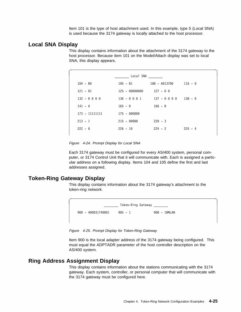
Item 101 is the type of host attachment used. In this example, type 5 (Local SNA)is used because the 3174 gateway is locally attached to the host processor.
Local SNA DisplayThis display contains information about the attachment of the 3174 gateway to thehost processor. Because item 101 on the Model/Attach display was set to localSNA, this display appears.
à ð________ Local SNA ________
1ð4 - Bð 1ð5 - B1 1ð8 - Að137ðð 116 - ð
121 - ð1 125 - ðððððððð 127 - ð ð
132 - ð ð ð ð 136 - ð ð ð 1 137 - ð ð ð ð 138 - ð
141 - A 165 - ð 166 - B
173 - 11111111 175 - ðððððð
213 - 1 215 - ððððð 22ð - 3
222 - ð 226 - 1ð 224 - 2 225 - 4
Figure 4-24. Prompt Display for Local SNA
Each 3174 gateway must be configured for every AS/400 system, personal com-puter, or 3174 Control Unit that it will communicate with. Each is assigned a partic-ular address on a following display. Items 104 and 105 define the first and lastaddresses assigned.
Token-Ring Gateway DisplayThis display contains information about the 3174 gateway’s attachment to thetoken-ring network.
à ð________ Token-Ring Gateway ________
9ðð - 4ððð3174ððð1 9ð5 - 1 9ð8 - IBMLAN
Figure 4-25. Prompt Display for Token-Ring Gateway
Item 900 is the local adapter address of the 3174 gateway being configured. Thismust equal the ADPTADR parameter of the host controller description on theAS/400 system.
Ring Address Assignment DisplayThis display contains information about the stations communicating with the 3174gateway. Each system, controller, or personal computer that will communicate withthe 3174 gateway must be configured here.
Chapter 4. Token-Ring Network Configuration Examples 4-25
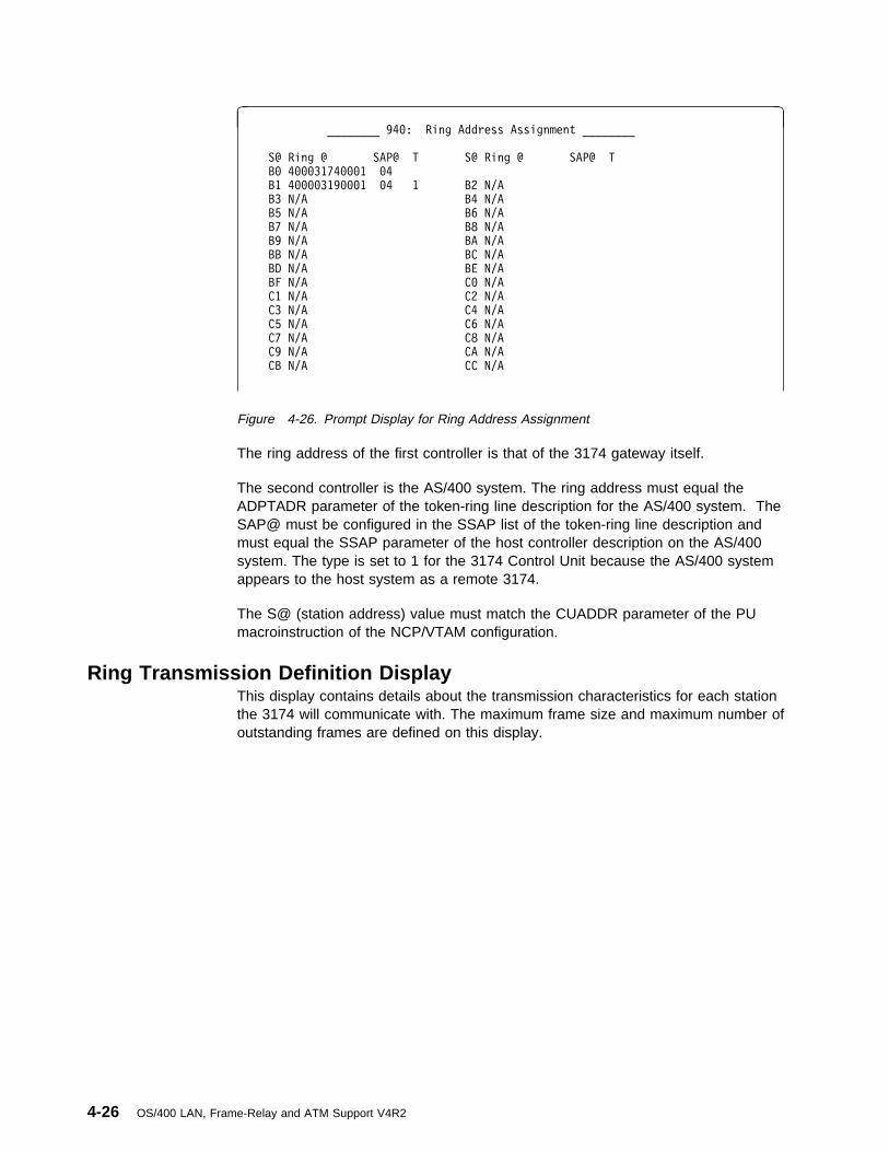
à ð________ 94ð: Ring Address Assignment ________
S@ Ring @ SAP@ T S@ Ring @ SAP@ T
Bð 4ððð3174ððð1 ð4
B1 4ðððð319ððð1 ð4 1 B2 N/A
B3 N/A B4 N/A
B5 N/A B6 N/A
B7 N/A B8 N/A
B9 N/A BA N/A
BB N/A BC N/A
BD N/A BE N/A
BF N/A Cð N/A
C1 N/A C2 N/A
C3 N/A C4 N/A
C5 N/A C6 N/A
C7 N/A C8 N/A
C9 N/A CA N/A
CB N/A CC N/A
Figure 4-26. Prompt Display for Ring Address Assignment
The ring address of the first controller is that of the 3174 gateway itself.
The second controller is the AS/400 system. The ring address must equal theADPTADR parameter of the token-ring line description for the AS/400 system. TheSAP@ must be configured in the SSAP list of the token-ring line description andmust equal the SSAP parameter of the host controller description on the AS/400system. The type is set to 1 for the 3174 Control Unit because the AS/400 systemappears to the host system as a remote 3174.
The S@ (station address) value must match the CUADDR parameter of the PUmacroinstruction of the NCP/VTAM configuration.
Ring Transmission Definition DisplayThis display contains details about the transmission characteristics for each stationthe 3174 will communicate with. The maximum frame size and maximum number ofoutstanding frames are defined on this display.
4-26 OS/400 LAN, Frame-Relay and ATM Support V4R2

à ð________ 941: Ring Transmission Definition ________
S@ Ring @ SAP@ F W S@ Ring @ SAP@ F W
Bð 4ððð3174ððð1 ð4 2 4
B1 4ðððð319ððð1 ð4 2 4 B2 N/A
B3 N/A B4 N/A
B5 N/A B6 N/A
B7 N/A B8 N/A
B9 N/A BA N/A
BB N/A BC N/A
BD N/A BE N/A
BF N/A Cð N/A
C1 N/A C2 N/A
C3 N/A C4 N/A
C5 N/A C6 N/A
C7 N/A C8 N/A
C9 N/A CA N/A
CB N/A CC N/A
Figure 4-27. Prompt Display for Ring Transmission Definition
The values in column F are frame sizes. The value 2 corresponds to an informationframe size of 1033. The MAXFRAME parameter on the host controller descriptionon the AS/400 system should equal this.
The S@ (station address) value must match the CUADDR parameter of the PUmacroinstruction of the NCP/VTAM configuration.
Example of the NCP/VTAM ConfigurationThis is the NCP GEN for the local controller created by the system administrator toprovide for connectivity between the AS/400 system and the 3174 gateway. ThisGEN is valid on Network Control Program (NCP) Version 4.2 and Virtual Telecom-munications Access Method (VTAM) Version 3.1.1. Different NCP or VTAM levelsmay require different parameters.
R13B1 VBUILD TYPE=LOCAL
R13BðA PU CUADDR=3B1, X
DISCNT=(NO,F), X
ISTATUS=ACTIVE, X
PUTYPE=2, X
SPAN=(SYSPGMR), X
SSCPFM=USSSCS, X
VPACING=7
R13B1ð2 LU DLOGMOD=P6ES2, X
ENCR=NONE, X
ISTATUS=ACTIVE, X
LOCADDR=2, X
LOGAPPL=SAMON, X
MODETAB=LOGMOD38, X
SPAN=(SYSPGMR), X
SSCPFM=USSSCS, X
VPACING=7
The last two characters in the CUADDR parameter must match the Control UnitAddress on the Ring Address Assignment and the Ring Transmission Definition dis-plays of the 3174 1L configuration.
Chapter 4. Token-Ring Network Configuration Examples 4-27

Example of Token-Ring Network-to-3174 Subsystem Control UnitConfiguration
The remote work station controller description, created by the following displays,describes a 3174 (Model 3R or 53R) Subsystem Control Unit capable of attachingto a token-ring network. It uses adapter address 400031740004. TheTOKENRING1 line description created in “Creating the Token-Ring Network LineDescription” on page 4-1 is used for the SWTLINLST parameter.
à ð Create Ctl Desc (Remote WS) (CRTCTLRWS)
Type choices, press Enter.
Controller description . . . . . > TRLAN3174 Name
Controller type . . . . . . . . > 3174 3174, 3274, 5251, 5294...
Controller model . . . . . . . . > ð ð, 1, ððð1, 2, ððð2, 12, ðð12
Link type . . . . . . . . . . . > \LAN \IDLC, \LAN, \NONE, \SDLC...
Online at IPL . . . . . . . . . \YES \YES, \NO
Switched line list . . . . . . . > TOKENRING1 Name
+ for more values
Maximum frame size . . . . . . . \LINKTYPE 265-1994, 256, 261, 265...
Exchange identifier . . . . . . ðð1ððððð-FFFFFFFF
Initial connection . . . . . . . \DIAL \DIAL, \ANS
Dial initiation . . . . . . . . \LINKTYPE \LINKTYPE, \IMMED, \DELAY
LAN remote adapter address . . . > 4ððð3174ððð4 ððððððððððð1-FFFFFFFFFFFF
Autocreate device . . . . . . . \ALL \ALL, \NONE
Text 'description' . . . . . . . > 'RWS controller for 3174'
More...F3=Exit F4=Prompt F5=Refresh F12=Cancel F13=How to use this display
F24=More keys
á ñ
Figure 4-28. Prompt Display for TRLAN3174 Controller Description
Note: When tailoring the 3174 Control Unit that this controller description repres-ents, you must set the maximum frame parameter greater than or equal tothe MAXFRAME parameter on the TOKENRING1 line description to whichthis controller is attached.
Although the following device description examples are not specific to a token-ringnetwork, you can use them to configure a 3279 display and a 3287 printer capableof attaching to a 3174.
4-28 OS/400 LAN, Frame-Relay and ATM Support V4R2

à ð Create Device Desc (Display) (CRTDEVDSP)
Type choices, press Enter.
Device description . . . . . . . > TRLAN3279 Name
Device class . . . . . . . . . . > \RMT \LCL, \RMT, \VRT, \SNPT
Device type . . . . . . . . . . > 3279 31ð1, 3151, 3161, 3162...
Device model . . . . . . . . . . > ð ð, 1, 2, 4, 11, 12, 23...
Local location address . . . . . > ð2 ðð-FE
Online at IPL . . . . . . . . . \YES \YES, \NO
Attached controller . . . . . . > TRLAN3174 Name
Keyboard language type . . . . . \SYSVAL \SYSVAL, AGB, AGI, ALI...
Drop line at signoff . . . . . . \YES \YES, \NO
Application type . . . . . . . . \NONE \NONE, \NRF, \CTLSSN...
Text 'description' . . . . . . . > '3279 attached to 3174'
Figure 4-29. Prompt Display for TRLAN3279 Display Device Description
à ð Create Device Desc (Printer) (CRTDEVPRT)
Type choices, press Enter.
Device description . . . . . . . > TRNLAN3287 Name
Device class . . . . . . . . . . > \RMT \LCL, \RMT, \VRT, \SNPT, \LAN
Device type . . . . . . . . . . > 3287 3287, 3812, 4ð19, 42ð1...
Device model . . . . . . . . . . > ð ð, 1, 2, 3, 4, 1ð, 13, 3ð1...
Local location address . . . . . > ð3 ðð-FE
Online at IPL . . . . . . . . . \YES \YES, \NO
Attached controller . . . . . . > TRLAN3174 Name
Separator program . . . . . . . \NONE Name, \NONE
Library . . . . . . . . . . . Name, \LIBL, \CURLIB
Printer error message . . . . . \INQ \INQ, \INFO
Message queue . . . . . . . . . QSYSOPR Name, QSYSOPR
Library . . . . . . . . . . . \LIBL Name, \LIBL, \CURLIB
Application type . . . . . . . . \NONE \NONE, \NRF, \DEVINIT...
Text 'description' . . . . . . . > '3287 attached to 3174'
Figure 4-30. Prompt Display for TRLAN3287 Printer Device Description
The following display is used during customization of a 3174 Control Unit.
Chapter 4. Token-Ring Network Configuration Examples 4-29

à ð------------ Token-Ring Network ------------
1ð6 - 4ððð 3174 ððð4 1ð7 - 4ððð ð319 ððð1 1ð8 - ð324ððð 116 - ð
121 - ð1 125 - ðððððððð 127 - ð ð
132 - ð ð ð ð 136 - 1 1 1 1 137 - ð ð ð ð 138 - ð
141 - A 165 - 1 166 - C
173 - ðððððððð 175 - ðððððð
213 - 1 215 - ððððð 22ð - 3
38ð - 1994 381 - 7 382 - 1994 383 - 4
Figure 4-31. Prompt Display for Token-Ring Network
Item 106, the adapter address of the 3174 Control Unit, must match the ADPTADRparameter on the Create Controller Description (Remote Work Station)(CRTCTLRWS) command.
Item 107 is the adapter address of the AS/400 system that this 3174 Control Unitconnects with. This must be equal to the adapter address (ADPTADR) parameteron the TOKENRING1 line description.
Item 380 is the largest frame the 3174 Control Unit can accept. This should be setto 1994 so that the AS/400 system can send the largest possible frame to the 3174Control Unit.
Item 382 is the largest frame the 3174 Control Unit sends. This can be no largerthan the MAXFRAME parameter on the TOKENRING1 line description.
4-30 OS/400 LAN, Frame-Relay and ATM Support V4R2

Ethernet networks
Chapter 5. Ethernet networks . . . . . . . . . . . . . . . . . . . . . . . . . . . 5-1Ethernet physical environment . . . . . . . . . . . . . . . . . . . . . . . . . . . . 5-1
Ethernet topologies . . . . . . . . . . . . . . . . . . . . . . . . . . . . . . . . . 5-1Ethernet physical address format . . . . . . . . . . . . . . . . . . . . . . . . . . 5-4
| Ethernet group addresses . . . . . . . . . . . . . . . . . . . . . . . . . . . . . 5-5Bridged LAN addressing considerations . . . . . . . . . . . . . . . . . . . . . 5-5
Ethernet standard (ETHSTD) parameter considerations . . . . . . . . . . . . . 5-5Ethernet frame size considerations . . . . . . . . . . . . . . . . . . . . . . . . . 5-6
Bridged LAN frame size considerations . . . . . . . . . . . . . . . . . . . . . 5-6
Chapter 6. Ethernet network configuration examples . . . . . . . . . . . . 6-1AS/400 system to an Ethernet line . . . . . . . . . . . . . . . . . . . . . . . . . . 6-1Client Access considerations . . . . . . . . . . . . . . . . . . . . . . . . . . . . . 6-5APPC controller description for Client Access . . . . . . . . . . . . . . . . . . . 6-6
DOS Client Access configuration . . . . . . . . . . . . . . . . . . . . . . . . . 6-6OS/2 Client Access considerations . . . . . . . . . . . . . . . . . . . . . . . . 6-7Client Access address conversion considerations . . . . . . . . . . . . . . . 6-8
Token-ring-to-Ethernet bridge configuration example . . . . . . . . . . . . . . . 6-8Address conversion for Ethernet bridged environment . . . . . . . . . . . . 6-10Configuring the 3174 controller . . . . . . . . . . . . . . . . . . . . . . . . . 6-12Configuring the FBSS controller . . . . . . . . . . . . . . . . . . . . . . . . . 6-17Creating the network controller and devices for TCP/IP . . . . . . . . . . . 6-21Client Access configuration considerations . . . . . . . . . . . . . . . . . . 6-21
Copyright IBM Corp. 1997, 1998

OS/400 LAN, Frame-Relay and ATM Support V4R2

Chapter 5. Ethernet networks
This chapter discusses considerations for Ethernet network configurations anddescribes some aspects of Ethernet hardware.
Ethernet physical environmentThe Ethernet topology defines its physical environment. Topology refers to themanner in which network devices are interconnected. Examples of devices includeservers, PCs, printers, repeaters, switches, and routers.
Ethernet topologiesEthernet networks are configured in two general topologies: bus and star.
Bus topologyIn a bus topology, the network devices connect in series to a transmission medium,called a bus . Examples of bus technology include 10BASE2 and 10BASE5. Whena station transmits data on the bus, transmission occurs in both directions. Thetransmitted data is received by all other stations that are attached on the bus.Because all stations on a bus share a common transmission link, only one stationcan transmit at a time. This is called half-duplex Ethernet . A break at any point inthe bus usually will disrupt the entire segment.
Figure 5-1 on page 5-2 shows an example of the hardware that is used to set upan Ethernet bus-topology network using coaxial cable. A device called a transceiveris part of or is attached to the coaxial cable. A transceiver cable connects theAS/400 controller to the transceiver, which transmits and receives data. You canpurchase your IEEE 802.3-compliant transceiver cable, transceiver, and cable fromany vendor.
Note: IEEE 802.3 and Ethernet Version 2.0 standards specify that complianttransceiver must support the signal-quality-error function. Although AS/400Ethernet adapters can use transceivers with or without the signal-quality-error function, it is recommended that this function be active. If a cable ortransceiver failure occurs, and this support is not active, the AS/400 systemmay not be able to isolate the failure to the cable or transceiver. In thiscase, a general application-generated message appears. The messagestates that a controller has lost contact, or a time-out to the host connectionhas occurred.
Ethernet uses baseband transmission at a rate of 10 Mbps.
Copyright IBM Corp. 1997, 1998 5-1

C o n t r o l l e r
C o n n e c t o r
T r a n s c e i v e r
C a b l e
C o n n e c t o r
T r a n s c e i v e r
T a p
C o a x i a l C a b l e
R S L N 7 2 8 - 2
Figure 5-1. Ethernet Attachment Using Coaxial Cable
Bus configuration: The Carrier Sense Multiple Access with CollisionDetection (CSMA/CD) protocol regulates access to the medium on Ethernet net-works. On Ethernet networks that are configured in a bus topology, multiplestations share the transmission medium. When a station has data to send, it listensto the transmission medium to determine if it is available (no other stations aretransmitting). If it is available, it begins to transmit. The station continues to listenduring the transmission to determine if a collision occurs. A collision occurs whentwo or more stations begin transmitting at about the same time. If a collision occurs,the transmitting station stops its transmission, and waits a random length of timebefore it attempts to transmit again.
The load on the Ethernet bus will have some effect on performance. At light loads,very few collisions will occur, and performance will be good. As the load on the busincreases, the chance of a collision also increases. Increased collisions will result indegraded performance. Under extreme circumstances, heavy loads can causesevere performance problems.
Star topologyIn an Ethernet star topology , a point-to-point link (segment) connects each stationto a central hub. The hub consists of either a switch or a repeater (see Figure 5-2on page 5-3). Ethernet switching hubs divide the network into separate collisiondomains. If one segment experiences a break, it generally does not effect the restof the network. An Ethernet network that employs repeater hubs is a single trans-mission domain, and is subject to collisions. Hubs help extend Ethernet networksby providing multiple Ethernet ports.
5-2 OS/400 LAN, Frame-Relay and ATM Support V4R2

Figure 5-2. Example of Ethernet Network Star Topology with a Switching Hub
Repeater hubs: Repeater hubs link together multiple Ethernet media segments ofvarious types to create a larger network that operates as a single Ethernet LAN.Repeater hubs provide signal amplification and retiming. This allows network seg-ments to be extended a greater distance. The repeater receives the transmitteddata, amplifies it, and forwards it to all the linked segments. Ethernet segmentsthat are linked by repeater hubs operate at half duplex. Multiple stations mustshare the transmission medium and available network bandwidth. Segments thatare linked by a repeater hub are susceptible to collisions.
Switching hubs: Switches divide a set of Ethernet media systems into multipleLANs, which are linked together by the switching hubs. When a station transmitsdata, the switch reads the destination address information and forwards the data toits destination segment. Stations that are linked by Ethernet switches can send andreceive data simultaneously, using the entire medium bandwidth. This is called full-duplex Ethernet . Ethernet switches eliminate the possibility of collisions, and alsoimprove network performance. Ethernet switches permit you to extend themaximum size of the network, without exceeding the maximum wire length,attached device count, or number of repeaters for a network segment.
For more information on Ethernet switches, see the IBM LAN Bridge and SwitchGuide, SB24-5000, and Local Area Network Concepts and Products: LAN Architec-ture, SG24-4753.
Chapter 5. Ethernet networks 5-3

Ethernet physical address formatAs mentioned in Chapter 2, “AS/400 implementation of local area networks” onpage 2-1, every system, controller, or personal computer that is attached to a localarea network has a physical address for its attachment adapter. This physical levelis called the MAC (medium access control). The IEEE architecture defines the48-bit (6-byte) MAC address formats to be used for IEEE 802.3 Ethernet LANs.Figure 5-3 defines how the MAC addresses are displayed on the AS/400 systemfor the Ethernet LAN. The order of bit transmission on the medium starts with byte0, bit 7 through bit 0, then byte 1, from bit 7 through bit 0, until byte 5, bit 0 isreached. This order of transmission is called least significant bit because the leastsignificant bit is transmitted first. This ordering for Ethernet differs from the orderingfor token ring, which starts with byte 0, bit 0 through bit 7 and ends with byte 5, bit7.
The following figure describes the preferred IEEE format.
Figure 5-3. Ethernet Physical Address Format
� Bit 7 of byte 0 (called the I/G bit) indicates whether the destination address isan individual address (B'0') or group address (B'1').
� Bit 6 of byte 0 (called the U/L bit) indicates whether the address is universallyadministered (B'0') or locally administered (B'1').
The above indicators are an integral part of each station address.
Note the following:
� Byte 0, bit 7 = 0. This assignment controls the values of the local adapteraddress (ADPTADR parameter on the CRTLINETH command) to the range ofindividual addresses where byte 0 must be even numbers.
� Byte 0, bit 6 =1 further restricts locally assigned addresses resulting in theaddress range of hex 020000000000 through hex FEFFFFFFFFFF. The seconddigit must be 2, 6, A, or E.
� IEEE standards reserve a range of adapter addresses for use as presetaddresses. This results in byte 0, bit 6 = 0 occupying the remaining evenvalues in the range of hex 000000000000 to FFFFFFFFFFFF.
5-4 OS/400 LAN, Frame-Relay and ATM Support V4R2

| Ethernet group addresses| An Ethernet group address is an address to which a subset of nodes on the| Ethernet will respond in addition to their local adapter address. Assign group| addresses by using the GRPADR parameter on the CRTLINETH command.| Dynamically add group addresses by using a TCP/IP multicast application. A 4-byte| IP multicast address is mapped to a 6-byte Ethernet group address by placing the| low-order 23 bits of the IP multicast address into the low-order 23 bits of the| Ethernet group address 01005E000000. For example, the IP multicast address| 224.255.0.2 maps to 01005E7F002. See the TCP/IP Configuration and Reference| book for more information on multicast.
Bridged LAN addressing considerationsIt is important to note that MAC addresses are always displayed in the aboveformat for AS/400 Ethernet configuration displays even if they represent stations onother LAN media, such as token-ring stations reached through bridges. The formatof token-ring MAC addresses is described under “Token-ring physical addressformat” on page 3-3.
Ethernet standard (ETHSTD) parameter considerationsThe type of Ethernet frames sent by the AS/400 system is determined on the typeof frames received from the network and on the value specified for the Ethernetstandard (ETHSTD) parameter on the line description. The AS/400 system cansend Ethernet frames in any of the following formats:
� IEEE 802.3
� Ethernet Version 2 (DIX)
� Ethernet Version 2 with encapsulated SNA data
Table 5-1 shows the frame type sent by the AS/400 system, based on the type offrame received from the network and the value specified for the ETHSTD param-eter.
| Table 5-1. ETHSTD Parameter Effect on Frame Types Sent by AS/400 System
| Frame Type Received| ETHSTD Value| Frame Type Sent
| IEEE 802.3, SNA or| non-SNA| *IEEE8023| IEEE 802.3
| *ETHV2| Not sent
| *ALL1| IEEE 802.3
| Ethernet Version 2,| non-SNA| *IEEE8023| Not sent
| *ETHV2| Version 2
| *ALL1| Version 2
| Ethernet Version 2, SNA| *IEEE8023| IEEE 802.3
| *ETHV2| Version 2, encapsulated SNA
| *ALL1| IEEE 802.3
| 1When *ALL is configured as the ETHSTD value, all TCP/IP multicast packets will be| sent as both 802.3 and Version 2 frames.
Chapter 5. Ethernet networks 5-5

See “Ethernet frame formats” on page 1-6 for more information about frameformats.
Ethernet frame size considerationsEthernet line descriptions do not have a maximum frame size (MAXFRAME)parameter. However, maximum frame sizes can be configured for each SAP asso-ciated with the line description. In addition, a controller description also has aMAXFRAME size. When the connection process begins, the frame size is thesmaller of the three values: line description maximum frame size (see Table 5-2),SSAP MAXFRAME, or the controller MAXFRAME. However, the frame size maybecome even smaller because of the XID negotiations or bridge considerations.
The system determines the maximum frame size for the line description based onthe value specified for the Ethernet standard (ETHSTD) parameter as shown inTable 5-2.
Table 5-2. Maximum Frame Size Based On ETHSTD Parameter
ETHSTD Param-eter Value Frame type
Maximum FrameSize
*ALL IEEE 802.3 1496
Ethernet Version 2 1500
*IEEE8023 IEEE 802.3 1496
*ETHV2 Ethernet Version 2, SNA data 1493
Ethernet Version 2, non-SNA data 1500
Bridged LAN frame size considerationsIf a frame is being transmitted to a station that resides on a different LAN, theframe must be copied and transmitted again by a bridge. If the bridge is not config-ured to support a frame size as large as that configured on the token-ring orEthernet line description, the frame will be discarded.
In the Ethernet environment, no indication of a smaller frame size is received. Thiscondition is detected when a connection is being established with the remotesystem and a CPA57A1 message is sent to the QSYSOPR message queue.
If it is not possible to configure the bridge to support larger frame sizes, you mayneed to adjust one of the following to a value acceptable to the bridge:
� MAXFRAME parameter on the controller description
� SSAP MAXFRAME parameter on the line description
If an adjustment is made, it is recommended that the MAXFRAME value on thecontroller description be adjusted.
5-6 OS/400 LAN, Frame-Relay and ATM Support V4R2

Chapter 6. Ethernet network configuration examples
Figure 6-1 demonstrates a possible Ethernet network.
Figure 6-1. AS/400 Ethernet Network
The following configuration example covers two connections. The first part of theexample shows how to run APPC to the same system over a single connection tothe Ethernet network. The AS/400 system with a single connection to the Ethernetnetwork can be useful in the initial testing of a connection, configuration, or applica-tion program. The adapter card handles the case where the destination address isthe same as the source address.
The second part of this example shows the addressing considerations that musttake place for Client Access and the AS/400 system to communicate over anEthernet network.
For more information on TCP/IP configuration, see the TCP/IP Configuration andReference book.
AS/400 system to an Ethernet lineThe AS/400 system on the Ethernet network in this example uses the following linedescription to communicate.
Copyright IBM Corp. 1997, 1998 6-1

à ðCreate Line Desc (Ethernet) (CRTLINETH)
Type choices, press Enter.
Line description . . . . . . . . > ETHLINE Name
Resource name . . . . . . . . . > CMNð1 .1/ Name, \NWID, \NWSD
Online at IPL . . . . . . . . . \YES \YES, \NO
Vary on wait . . . . . . . . . . \NOWAIT \NOWAIT, 15-18ð (1 second)
Local adapter address . . . . . > ð2ðð71ð32ððð.2/ð2ðððððððððð-FEFFFFFFFFFF... Exchange identifier . . . . . . \SYSGEN ð56ððððð-ð56FFFFF, \SYSGEN
Ethernet standard . . . . . . . \ALL.3/ \ETHV2, \IEEE8ð23, \ALL
Line speed . . . . . . . . . . . 1ðM Character value, 1ðM, 1ððM...
Duplex . . . . . . . . . . . . . \HALF Character value, \HALF...
SSAP list:
Source service access point . > ð4 ð2-FE, \SYSGEN
SSAP maximum frame . . . . . . \MAXFRAME \MAXFRAME, 265-1496, 265...
SSAP type . . . . . . . . . . \CALC \CALC, \NONSNA, \SNA
Source service access point . > ð8.4/ ð2-FE
SSAP maximum frame . . . . . . \MAXFRAME \MAXFRAME, 265-1496, 265...
SSAP type . . . . . . . . . . \CALC \CALC, \NONSNA, \SNA
+ for more values
Text 'description' . . . . . . . > 'ETHLINE line description'
More...F3=Exit F4=Prompt F5=Refresh F1ð=Additional parameters F12=Cancel
F13=How to use this display F24=More keys
á ñ
à ðCreate Line Desc (Ethernet) (CRTLINETH)
Type choices, press Enter.
User-defined 3 . . . . . . . . . 128 ð-255
Autocreate controller . . . . . \NO \YES, \NO
Autodelete controller . . . . . 144ð 1-1ðððð (minutes), \NONE
Recovery limits:
Count limit . . . . . . . . . 2 ð-99, \SYSVAL
Time interval . . . . . . . . 5 ð-12ð minutes
Authority . . . . . . . . . . . \LIBCRTAUT Name, \LIBCRTAUT, \CHANGE...
á ñ
Figure 6-2. Prompt Displays for ETHLINE Line Description
Considerations for specifying the CRTLINETH command:
.1/ For lines that are attached to Network Server Descriptions (NWSD) theresource value is *NWSD. This is for IPCS support. See the appropriateIPCS manual to learn more about Ethernet lines that are attached onIPCS. For an example of *NWI for resource name, see “Bridged con-nections to remote token-ring networks” on page 10-8.
.2/ This address is used to transmit and receive on the local area network.Specify either the preset address that is assigned to the card by themanufacturer or an address that is assigned by the user. All controllersthat want to communicate with the AS/400 system must use this value intheir configurations for the remote adapter address.
.3/ The Ethernet standard (ETHSTD) parameter cannot be changed on theCHGLINETH command. See “Ethernet standard (ETHSTD) parameterconsiderations” on page 5-5 for information about specifying theETHSTD parameter.
6-2 OS/400 LAN, Frame-Relay and ATM Support V4R2

.4/ To run APPC to the same system over one connection to the Ethernetnetwork, an additional SNA SAP value must be defined in the linedescription. This is necessary to provide a unique LAN address in theform of SSAP/DSAP/MAC address.
The following controller descriptions are used to run APPC to the same systemover one connection.
Chapter 6. Ethernet network configuration examples 6-3

à ðCreate Ctl Desc (APPC) (CRTCTLAPPC)
Type choices, press Enter.
Controller description . . . . . > APPC1 Name
Link type . . . . . . . . . . . > \LAN \ANYNW, \FAX, \FR, \IDLC...
Online at IPL . . . . . . . . . \YES \YES, \NO
APPN-capable . . . . . . . . . . > \NO \YES, \NO
Controller type . . . . . . . . \BLANK \BLANK, \FBSS, 3174, 3274...
Switched line list . . . . . . . > ETHLINE.1/ Name
+ for more values
Maximum frame size . . . . . . . \LINKTYPE 265-16393, 256, 265, 512...
Remote network identifier . . . \NETATR Name, \NETATR, \NONE, \ANY
Remote control point . . . . . . Name, \ANY
Exchange identifier . . . . . . ðððððððð-FFFFFFFF
Initial connection . . . . . . . \DIAL \DIAL, \ANS
Dial initiation . . . . . . . . \LINKTYPE \LINKTYPE, \IMMED, \DELAY
LAN remote adapter address . . . > ð2ðð71ð32ððð.2/ððððððððððð1-FFFFFFFFFFFF Autocreate device . . . . . . . \ALL \ALL, \NONE
More...F3=Exit F4=Prompt F5=Refresh F12=Cancel F13=How to use this display
F24=More keys
á ñ
à ðCreate Ctl Desc (APPC) (CRTCTLAPPC)
Type choices, press Enter.
Text 'description' . . . . . . . > 'APPC1 controller attached to ETHLINE'
à ðCreate Ctl Desc (APPC) (CRTCTLAPPC)
Type choices, press Enter.
Switched disconnect . . . . . . \YES \YES, \NO
Disconnect timer:
Minimum connect timer . . . . 17ð ð-65535 seconds
Disconnection delay timer . . 3ð ð-65535 seconds
SDLC poll priority . . . . . . . \NO \NO, \YES
SDLC poll limit . . . . . . . . ð ð-4
SDLC out limit . . . . . . . . . \POLLLMT ð-4, \POLLLMT
SDLC connect poll retry . . . . \CALC ð-65534, \CALC, \NOMAX
SDLC NDM poll timer . . . . . . \CALC \CALC, ð-3ððð (ð.1 seconds)
LAN DSAP . . . . . . . . . . . . ð4.3/ ð4, ð8, ðC, 1ð, 14, 18, 1C...
LAN SSAP . . . . . . . . . . . . > ð8.4/ ð4, ð8, ðC, 1ð, 14, 18, 1C...
LAN frame retry . . . . . . . . \CALC ð-254, \CALC
LAN connection retry . . . . . . \CALC ð-254, \CALC
LAN response timer . . . . . . . \CALC ð-254 (ð.1 seconds)
LAN connection timer . . . . . . \CALC ð-254 (ð.1 seconds)
LAN acknowledgement timer . . . \CALC ð-254 (ð.1 seconds)
More...F3=Exit F4=Prompt F5=Refresh F12=Cancel F13=How to use this display
F24=More keys
á ñ
Figure 6-3. Prompt Displays for APPC1 Controller Description
Considerations for specifying the CRTCTLAPPC command:
6-4 OS/400 LAN, Frame-Relay and ATM Support V4R2

.1/ Note that both the controller descriptions specify ETHLINE as theswitched line list value. The line description that is specified for thisparameter must exist before being specified.
.2/ The adapter address (ADPTADR parameter) specifies the address ofthe remote controller. Because this example is testing a connection toitself, the adapter address on the line description and the remoteadapter address are the same. This is not the case if two remotesystems are communicating.
.3/ The LAN destination service access point (DSAP parameter) is thelogical address with which this controller communicates. This value mustequal the LAN source service access point in the remote controller con-figuration.
.4/ The LAN source service access point (SSAP parameter) is the logicaladdress that this system sends with any data to a remote system. Thisvalue must match the DSAP of the remote controller.
The preceding discussion of the CRTCTLAPPC command also relates to theAPPC2 controller configuration below.
CRTCTLAPPC CTLD(APPC2) LINKTYPE(\LAN) APPN(\NO) SWTLINLST(ETHLINE) +
ADPTADR(ð2ðð71ð32ððð) DSAP(ð8) SSAP(ð4) +
TEXT('AS/4ðð at address ð2ðð71ð32ððð, DSAP ð8')
The following displays show the creation of the APPC device descriptions that areneeded to complete the configuration. The remote location name (RMTLOCNAMEparameter) is the name of the device with which your system is communicating.Note that the remote location name on device APPC1 matches the local locationname on APPC2.
CRTDEVAPPC DEVD(APPC1) RMTLOCNAME(APPC2) LCLLOCNAME(APPC1) +
CTL(APPC1) APPN(\NO) TEXT('Device for APPC2 controller')
CRTDEVAPPC DEVD(APPC2) RMTLOCNAME(APPC1) LCLLOCNAME(APPC2) +
CTL(APPC2) APPN(\NO) TEXT('Device for APPC1 controller')
Client Access considerationsWhen you are using Client Access and the AS/400 system in an Ethernet network,you need to be aware of the Ethernet physical address format. This address formatis discussed in “Ethernet physical address format” on page 5-4. Client Access usesthe same addressing format as the token-ring physical address format, which is dis-cussed in “Token-ring physical address format” on page 3-3.
Because these two address formats are in reversed bit order, the configured phys-ical addresses will appear in reversed bit order when viewed on each system. Forthe following example, the addresses are viewed as follows:
Table 6-1 (Page 1 of 2). Addresses from AS/400 View
AS/400 View Address
AS/400 Address 020071032000
Chapter 6. Ethernet network configuration examples 6-5

The following figure illustrates the addresses when viewed from the personal com-puter.
Client Access considerations for environments other than those that are describedin this example are discussed in “Client Access configuration considerations” onpage 6-21.
Table 6-1 (Page 2 of 2). Addresses from AS/400 View
AS/400 View Address
Personal Computer using Client Access 02000A000010
Table 6-2. Addresses from Personal Computer View
Personal Computer View Address
Personal Computer Address 400050000008
AS/400 System 40008EC00400
APPC controller description for Client AccessThe APPC controllers and devices that are needed to communicate with the per-sonal computer that is running Client Access can be created automatically. Auto-matic configuration is highly recommended when using Client Access. For moreinformation on automatic creation of configuration objects, see the Local DeviceConfiguration book.
The following controller description demonstrates the configuration parameters thatneed to correspond with values in the Client Access configuration.
CRTCTLAPPC CTLD(PCSUPPORT) LINKTYPE(\LAN) SWTLINLST(ETHLINE) +
RMTNETID(RPC) RMTCPNAME(PCðð4) +
ADPTADR(ð2ðððAðððð1ð).1/ +
TEXT('APPC controller description for Client Access')
Consideration for specifying the CRTCTLAPPC command:
.1/ The adapter address that is specified in the controller description mustcorrespond to the address of the personal computer that is using ClientAccess, which is specified in the CONFIG.SYS file. Notice that theaddress has been converted because the personal computer representslocally administered addresses in token-ring format.
DOS Client Access configurationWhen using DOS Client Access to communicate in an Ethernet network, youshould be aware of two files: CONFIG.SYS, and CONFIG.PCS. These two filesdesignate the address of the personal computer that is using Client Access, andthe address of the remote system with which to communicate.
The following is an example of the CONFIG.SYS file, which identifies the localaddress of the personal computer.
6-6 OS/400 LAN, Frame-Relay and ATM Support V4R2

BREAK=ON
FILES=15
device=C:\ether\dxmaðmod.sys
device=C:\ether\dxmeðmod.sys 4ððð5ðððððð8 .1/DEVICE=C:\PCS\EIMPCS.SYS
DEVICE=C:\PCS\ECYDDX.SYS
.1/ Notice that the personal computer identifies itself as adapter address400050000008. The adapter address is used to transmit and receive onthe local area network. Notice that this adapter address is converted to02000A000010 when the personal computer sends the address in aframe. Because the personal computer represents locally administeredaddressing in token-ring format, conversion of addresses is necessary.
For more information on address conversion, see “Token-ring-to-Ethernet addressconversion” on page D-3. For more information on valid addresses, see the dis-cussion of the ADPTADR parameter in the Communications Configuration book. Allremote systems must use the adapter address value (or converted equivalent ifusing the 8229 LAN Bridge) in its configuration for the remote adapter address.
The next example is of the CONFIG.PCS file, which identifies the remote controlpoint name (RTLN), the remote system address (TRLI), and the maximum framesize that is allowed (TRMF).
SFLR 1,I,QIWSFLR
RTLN RPC.PCðð4
TRLI RCHSX4ðð,4ððð8ECðð4ðð .1/RTYP ITRN
TRMF 15ðð .2/MDEF 1,1
MMRI 6ð
MTIM 6ð
.1/ The address that is given in the TRLI entry of the CONFIG.PCS file cor-responds to the adapter address of the AS/400 line description. Becausethe personal computer represents locally administered addressing intoken-ring format, conversion of addresses is necessary.
.2/ The TRMF value specifies the maximum frame size on the personalcomputer. For Ethernet, the maximum is 1500. The AS/400 value of*CALC on the SSAP parameter of the line description corresponds tothis value.
OS/2 Client Access considerationsWhen using OS/2 Client Access to communicate in an Ethernet network, youshould be aware of the locations of the different LAN addresses.
The personal computer LAN adapter address 400050000008 should be entered onthe OS/2 configuration menu Local LAN Adapter Address. This field is the OS/2equivalent of the entry in DOS CONFIG.SYS: Device=c:\ether\dxmeðmod.sys
4ðð5ðððððð8.
The AS/400 LAN adapter address 40008EC00400 should be entered in the LANdestination address field on the OS/2 configuration menu 5250 Work StationFeature LAN Defaults. This field is the OS/2 equivalent of the TRLI field in the DOS
Chapter 6. Ethernet network configuration examples 6-7

CONFIG.PCS file. The address corresponds to the adapter address of the AS/400line description. Because the personal computer represents locally administeredaddressing in token-ring format, conversion of addresses is necessary.
Client Access address conversion considerationsThe example of Client Access demonstrated the configuration when using a locallyadministered address on the personal computer. Because this address is repres-ented in token-ring format, the address conversion is necessary.
If the personal computer is configured to use the preset adapter address of theEthernet adapter card in the personal computer itself, no address conversion isnecessary when creating the controller description on the AS/400 system. Noaddress conversion is needed because the address already corresponds to the per-sonal computer preset adapter address. However, the addresses in the TRLI entry,which corresponds to the address of the AS/400 line description, must always beconverted.
Token-ring-to-Ethernet bridge configuration exampleFigure 6-4 on page 6-9 demonstrates a token-ring and an Ethernet network that iscommunicating through an 8229 LAN Bridge. The following configuration exampleshows AS/400 System 1, which is using the ETHERNET1 line description to com-municate with the 3174 Control Unit and its attached devices.
6-8 OS/400 LAN, Frame-Relay and ATM Support V4R2

Figure 6-4. AS/400 Ethernet Bridged Environment
AS/400 System 1 is using the same line description to communicate with AS/400System 2 on the token ring. AS/400 System 2 uses its own token-ring linedescription (TOKEN) to communicate with AS/400 System 1. AS/400 System 1 andAS/400 System 2 communicate using APPN. AS/400 System 3 uses the ETHNETline description to communicate with the FBSS controller and the 3745 communi-cations controller on the token ring.
Chapter 6. Ethernet network configuration examples 6-9

Address conversion for Ethernet bridged environmentTable 6-3 demonstrates the address conversion for the configuration that is shownin Figure 6-4 on page 6-9. A configuration example that shows the address con-version follows this topic.
Table 6-3. Address Mapping
System TOKEN Address ETHERNET1 Address
AS/400 1 on ETHERNET1 400003200001 0200C0040080
AS/400 2 on TOKEN 400010050001 020008A00080
3174 Control Unit 400031740004 02008C2E0020
3745 CommunicationsController 400000001590 02000000A809
AS/400 3 on ETHNET 400000200099 020000040099
FBSS Controller 400011111111 020088888888
Creating the ETHERNET1 line descriptionThis Ethernet line description connects AS/400 System 1 to the Ethernet network inFigure 6-4 on page 6-9.
CRTLINETH LIND(ETHERNET1) RSRCNAME(LIN121) +
ADPTADR(ð2ððCðð4ðð8ð).1/ +
ETHSTD(\ALL).2/ TEXT('ETHERNET1 line description')
Considerations for specifying the CRTLINETH command:
.1/ The adapter address is used to transmit and receive on the local areanetwork. Either the preset address that is assigned to the card by themanufacturer, or an address that is assigned by the user, can be speci-fied. This adapter address is converted to 400003200001 after it hasgone through the 8229 LAN Bridge to the token-ring network. For moreinformation on address conversion, see “Token-ring-to-Ethernet addressconversion” on page D-3.
For more information on valid addresses, see the ADPTADR parameterdescription in the Communications Configuration book. All remotesystems must use the adapter address value (or converted equivalent ifusing the 8229 LAN Bridge) in its configuration for the remote adapteraddress.
.2/ The Ethernet standard (ETHSTD) parameter cannot be changed on theCHGLINETH command. When ETHSTD(*ALL) is configured, the AS/400system sends SNA data in IEEE 802.3 frames.
Creating the CTL3174 remote work station controller descriptionThe following controller description associates the 3174 Control Unit with theETHERNET1 line description.
CRTCTLRWS CTLD(CTL3174) TYPE(3174) MODEL(ð) LINKTYPE(\LAN) +
SWTLINLST(ETHERNET1).1/ MAXFRAME(1496).2/ + ADPTADR(ð2ðð8C2Eðð2ð).3/ +
TEXT('3174 controller description')
6-10 OS/400 LAN, Frame-Relay and ATM Support V4R2

Considerations for specifying the CRTCTLRWS command:
.1/ The ETHERNET1 line description must exist before this value can bespecified for the switched line list (SWTLINLST parameter). When thisvalue is specified in the AS/400 controller description, the 3174 con-troller is recognized by AS/400 System 1 on the Ethernet network.
.2/ The maximum frame size (MAXFRAME parameter) for this controller isconfigured as 1496 because the remote system is on the other side ofthe bridge. The largest information field that can pass through the 8229LAN Bridge is 1496 bytes.
.3/ The LAN remote adapter address (ADPTADR parameter) is the addressthe AS/400 system will send data to when it communicates with theremote controller. This adapter address is converted to 400031740004after it has gone through the 8229 LAN Bridge to the token-ring network.Refer to Figure 4-31 on page 4-30 to see this address configured onthe 3174 Control Unit.
For more information on address conversion, see “Token-ring-to-Ethernet addressconversion” on page D-3. All remote systems must use the adapter address value(or converted equivalent if using the 8229 LAN Bridge) in its configuration for theremote adapter address.
Creating the DEV3277, DEV3279, and DEV3287 devicedescriptionsThe following device descriptions associate 3277, 3278, and 3279 display stationsand a 3287 printer with the 3174 controller description. Notice that all the devicedescriptions that are created here name CTL3174 as the attached controller. All ofthe following device descriptions have the same considerations for specifying theCRTDEVDSP and CRTDEVPRT commands.
CRTDEVDSP DEVD(DEV3277) DEVCLS(\RMT) TYPE(3277) MODEL(ð) +
LOCADR(ð4).1/ CTL(CTL3174) +TEXT('3277 display attached to 3174')
CRTDEVDSP DEVD(DEV3278) DEVCLS(\RMT) TYPE(3278) MODEL(ð) +
LOCADR(ð5).1/ CTL(CTL3174) +TEXT('3278 display attached to 3174')
CRTDEVDSP DEVD(DEV3279) DEVCLS(\RMT) TYPE(3279) MODEL(ð) +
LOCADR(ð2).1/ CTL(CTL3174) +TEXT('3279 display attached to 3174')
CRTDEVPRT DEVD(DEV3287) DEVCLS(\RMT) TYPE(3287) MODEL(ð) +
LOCADR(ð3).1/ CTL(CTL3174) +TEXT('3287 printer attached to 3174')
Considerations for specifying CRTDEVDSP and CRTDEVPRT commands:
.1/ The location address must be unique for each device that is attached tothe same controller. For more information on valid values, see the dis-cussion on the LOCADR parameter in the Communications Configura-tion book.
Chapter 6. Ethernet network configuration examples 6-11

Configuring the 3174 controllerThe following display is used during customization of a 3174 Control Unit.
à ð------------ Local Area Network ------------
1ð6 - 4ððð 3174 ððð4 1ð7 - 4ððð ð32ð ððð1 1ð8 - ð324ððð 116 - ð
121 - ð1 125 - ðððððððð 127 - ð ð
132 - ð ð ð ð 136 - 1 1 1 1 137 - ð ð ð ð 138 - ð
141 - A 165 - 1 166 - C
173 - ðððððððð 175 - ðððððð
213 - 1 215 - ððððð 22ð - 3
38ð - 2ð42 381 - 7 382 - 1496 383 - 4
Figure 6-5. Prompt Display for Ethernet Network
Item 106, the adapter address of the 3174 Control Unit, must match the convertedform of the ADPTADR parameter on the Create Controller Description (RemoteWork Station) (CRTCTLRWS) command. This adapter address is converted to02008C2E0020 when it has gone through the 8229 LAN Bridge to the Ethernetnetwork. Refer to “Creating the CTL3174 remote work station controller description”on page 6-10 to see this address configured on the AS/400 system.
Item 107 is the adapter address of the AS/400 system to which this 3174 ControlUnit is connected. This must match the converted form of the adapter address(ADPTADR) parameter on the ETHERNET1 line description. This adapter addressis converted to 0200C0040080 when it has gone through the 8229 LAN Bridge tothe Ethernet network.
Item 380 is the largest frame the 3174 Control Unit can accept. This should be setto 2042 so that the AS/400 system can send the largest possible frame to the 3174Control Unit.
Item 382 is the largest frame the 3174 Control Unit sends. This can be no largerthan the SSAP maximum frame size on the ETHERNET1 line description. It shouldnot be larger than the largest frame that the 8229 LAN Bridge can pass.
Creating the APPNETH APPC controller descriptionThe following display shows the controller description needed to use APPNbetween two AS/400 systems: One on the Ethernet line description that wascreated previously, and the other on a token-ring system. This controllerdescription automatically creates the necessary device descriptions when the con-troller is varied on because APPN is used.
CRTCTLAPPC CTLD(APPNETH) LINKTYPE(\LAN) SWTLINLST(ETHERNET1).1/ +MAXFRAME(1496).2/ RMTCPNAME(S1ððððð5).3/ +
ADPTADR(ð2ððð8Aððð8ð).4/ +
TEXT('APPN controller for token-ring-to-Ethernet')
6-12 OS/400 LAN, Frame-Relay and ATM Support V4R2

Considerations for specifying the CRTCTLAPPC command:
.1/ Notice that the previously created ETHERNET1 line description is speci-fied as the switched line list (SWTLINLST parameter). When this valueis specifyied in the AS/400 controller description, the controller can rec-ognize the AS/400 1 on the Ethernet network.
.2/ The maximum frame size (MAXFRAME parameter) for this controller isconfigured as 1496 because the remote system is on the other side ofthe bridge. The largest information field that can pass through the 8229LAN Bridge is 1496 bytes.
.3/ The remote control point name (RMTCPNAME parameter) and remotenetwork identifier (RMTNETID parameter) describe the adjacent systemcontrol point name and network identifier for APPN. These values mustmatch the network attributes of the remote system. For more informa-tion, see the discussion of the RMTCPNAME parameter in the Commu-nications Configuration book.
.4/ The LAN remote adapter address (ADPTADR parameter) is the addressto which the AS/400 system sends data when it communicates with theremote controller. This adapter address is converted to 400010050001after it has gone through the 8229 LAN Bridge to the token-ring network.This value matches the adapter address of the AS/400 system on thetoken-ring line in “Creating the TOKEN token-ring line description.”
For more information on address conversion, see “Token-ring-to-Ethernet addressconversion” on page D-3. All remote systems must use the adapter address value(or converted equivalent if using the 8229 LAN Bridge) in its configuration for theremote adapter address.
Creating the TOKEN token-ring line descriptionThe following line description describes the token-ring line on the AS/400 System 2.
CRTLINTRN LIND(TOKEN) RSRCNAME(LINð31) ADPTADR(4ððð1ðð5ððð1).1/ +TEXT('Token-ring line for APPN to Ethernet')
Considerations for specifying the CRTLINTRN command:
.1/ The LAN remote adapter address (ADPTADR parameter) is the addressto which the AS/400 system sends data when it communicates with theremote controller. Either the preset address that is assigned to the cardby the manufacturer, or an address that is assigned by the user, can bespecified. This adapter address is converted to 020008A00080, whichmatches the address configured on the APPNETH controller in “Creatingthe APPNETH APPC controller description” on page 6-12, after it hasgone through the 8229 LAN Bridge to the Ethernet network.
For more information on address conversion, see “Token-ring-to-Ethernet addressconversion” on page D-3. All remote systems must use the adapter address value(or converted equivalent if using the 8229 LAN Bridge) in its configuration for theremote adapter address.
Chapter 6. Ethernet network configuration examples 6-13

Creating the APPNTRLAN APPC controller descriptionThe following controller description is used with the token-ring line description forthe AS/400 system that is running APPN over the token ring. This controllerdescription automatically creates APPC device descriptions for use when the con-troller is varied on.
CRTCTLAPPC CTLD(APPNTRLAN) LINKTYPE(\LAN) SWTLINLST(TOKEN) +
MAXFRAME(1496).1/ RMTCPNAME(SYSAS4ðð) +INLCNN(\ANS) ADPTADR(4ðððð32ðððð1).2/ +TEXT('APPC controller attached to TOKEN')
Considerations for specifying the CRTCTLAPPC command:
.1/ The maximum frame size (MAXFRAME parameter) for this controller isconfigured as 1496 because the remote system is on the other side ofthe 8229 LAN Bridge. The largest information field that can pass throughthe 8229 LAN Bridge is 1496 bytes.
.2/ The LAN remote adapter address (ADPTADR parameter) is the addressto which the AS/400 system sends data when it communicates with theremote controller. This adapter address is converted to 0200C0040080,which matches the adapter address of the ETHERNET1 line descriptionon AS/400 System 1 (see “Creating the ETHERNET1 line description”on page 6-10) after it has gone through the 8229 LAN Bridge to theEthernet network.
For more information on address conversion, see “Token-ring-to-Ethernet addressconversion” on page D-3. All remote systems must use the adapter address value(or converted equivalent if using the 8229 LAN Bridge) in its configuration for theremote adapter address.
Creating the ETHNET Ethernet line descriptionThe following Ethernet line description is for the 9404 System Unit on the Ethernetnetwork.
CRTLINETH LIND(ETHNET) RSRCNAME(LIN131) ADPTADR(ð2ððððð4ðð99).1/ +ETHSTD(\ALL).2/ TEXT('Ethernet line description')
Considerations for specifying the CRTLINETH command:
.1/ The local adapter address (ADPTADR parameter) is the address theAS/400 system uses when it sends data to the remote controller. Thisadapter address is converted to 400000200099 after it has gone throughthe 8229 LAN Bridge to the token-ring network. Notice that this addressmatches the address for the 3745 communications controller in “Cre-ating the ETHCTL SNA host controller description” on page 6-15.
.2/ The Ethernet standard (ETHSTD) parameter cannot be changed on theCHGLINETH command. When ETHSTD(*ALL) is configured, the AS/400system sends SNA data in IEEE 802.3 frames.
For more information on address conversion, see “Token-ring-to-Ethernet addressconversion” on page D-3.
The ES/9000 host system requires the DIALNO VTAM parameter if the host systemcalls out. For this example, the DIALNO is 0304400000200099, where:
6-14 OS/400 LAN, Frame-Relay and ATM Support V4R2

� 03 is the NCP port number
� 04 is the source service access point
� 400000200099 is the AS/400 adapter address
The adapter address must match the adapter address (or its converted equivalent ifa 8229 LAN Bridge is used) on the AS/400 system.
The LINE macroinstruction for the ES/9000 system must also be specified asfollows:
� ECLTYPE=PHYSICAL.
� PORTADD=03: This must be the same value as the NCP port address speci-fied in the DIALNO parameter.
� LOCADDR=400000001590: This value is the adapter address of the 3745 com-munications controller. This value must match the adapter address (or its con-verted equivalent if the 8229 LAN Bridge is used) on the AS/400 controllerdescription.
Creating the ETHCTL SNA host controller descriptionThe following SNA host controller description is used by AS/400 system 3 to com-municate with the 3745 communications controller on the token ring.
CRTCTLHOST CTLD(ETHCTL) LINKTYPE(\LAN) SWTLINLST(ETHNET).1/ +MAXFRAME(1496).2/ RMTCPNAME(R1CDRM) +
LCLEXCHID(ð56Aðð1A) ADPTADR(ð2ððððððA8ð9).3/NODETYPE(\LENNODE) TEXT('SNA host controller on Ethernet line')
Considerations for specifying the CRTCTLHOST command:
.1/ For this example, notice that the value that is specified for the switchedline list is ETHNET, which is the Ethernet line description that wascreated for the AS/400 System 3.
.2/ The maximum frame size (MAXFRAME parameter) for this controller isconfigured as 1496 because the remote system is on the other side ofthe 8229 LAN Bridge. The largest information field that can pass throughthe 8229 LAN Bridge is 1496 bytes.
.3/ The LAN remote adapter address (ADPTADR parameter) is the addressto which the AS/400 system sends data when it communicates with theremote controller. This adapter address is converted to 400000001590after it has gone through the 8229 LAN Bridge to the token-ring network.Notice that this address matches the configuration in “Creating theETHNET Ethernet line description” on page 6-14.
For more information on address conversion, see “Token-ring-to-Ethernet addressconversion” on page D-3. All remote systems must use the adapter address value(or converted equivalent, if using the 8229 LAN Bridge) in its configuration for theremote adapter address.
Chapter 6. Ethernet network configuration examples 6-15

Creating the ETHAPN1 APPC device descriptionThe following APPC device description is an example of a device that is associatedwith the ETHCTL SNA host controller that was created previously. This APPCdevice description is created automatically and is shown here to illustrate parametervalues.
CRTDEVAPPC DEVD(ETHAPN1) RMTLOCNAME(CICS) LCLLOCNAME(SWHSAð1) +
CTL(ETHCTL) TEXT('Automatically created by QLUS')
Creating the FBSSETHCTL finance controller descriptionThe following finance controller is attached to the 9404 System Unit on the Ethernetnetwork in Figure 6-4 on page 6-9.
à ðCreate Ctl Desc (Finance) (CRTCTLFNC)
Type choices, press Enter.
Controller description . . . . . > FBSSETHCTL Name
Controller type . . . . . . . . > \FBSS \FBSS, 3694, 47ð1, 47ð2...
Controller model . . . . . . . . > ð ð
Link type . . . . . . . . . . . > \LAN \LAN, \SDLC, \X25
Online at IPL . . . . . . . . . \YES \YES, \NO
Switched line list . . . . . . . > ETHNET.1/ Name
+ for more values
Maximum frame size . . . . . . . > 521 265-1ð33, 256, 265, 512...
Exchange identifier . . . . . . > ð5712345.2/ ðððððððð-FFFFFFFF
Initial connection . . . . . . . \DIAL \DIAL, \ANS
LAN remote adapter address . . . > ð2ðð88888888.3/ððððððððððð1-FFFFFFFFFFFF Text 'description' . . . . . . . > 'FBSS controller through 82ð9 bridge'
Figure 6-6. Prompt Display for FBSSETHCTL Controller Description
Considerations for specifying the CRTCTLFNC command:
.1/ For this example, notice that the value that is specified for the switchedline list is ETHNET, the Ethernet line description created for AS/400System 3.
.2/ The exchange identifier on the AS/400 system must match the SNA XIDblock number and identification number on the FBSS controller as isshown in Figure 6-14 on page 6-19.
.3/ The LAN remote adapter address (ADPTADR parameter) is the addressto which the AS/400 system sends data when it communicates with theremote controller. This adapter address is converted to 400011111111after it has gone through the 8229 LAN Bridge to the Ethernet network.
For more information on address conversion, see “Token-ring-to-Ethernet addressconversion” on page D-3. All remote systems must use the adapter address value(or converted equivalent, if using the 8229 LAN Bridge) in its configuration for theremote adapter address.
6-16 OS/400 LAN, Frame-Relay and ATM Support V4R2

Creating the EFBSSLAN2, EFBSSLAN3, and EFBSS278A devicedescriptionsThe following device descriptions for both the finance and display station devicesare attached to the FBSSETHCTL finance controller.
CRTDEVFNC DEVD(EFBSSLAN2) TYPE(\FNCICF) LOCADR(ð2) +
RMTLOCNAME(EFBSS2) CTL(FBSSETHCTL) +
TEXT('ICF finance device at LU address ð2')
CRTDEVFNC DEVD(EFBSSLAN3) TYPE(\FNCICF) LOCADR(ð3) +
RMTLOCNAME(EFBSS3) CTL(FBSSETHCTL) MAXLENRU(4ð96) +
TEXT('ICF finance device at LU address ð3')
CRTDEVDSP DEVD(EFBSS3277A) DEVCLS(\RMT) TYPE(3277) MODEL(ð) +
LOCADR(ð7) CTL(FBSSETHCTL) +
TEXT('3277 attached to FBSS at LU address ð7')
Configuring the FBSS controllerThe following displays show the configuration of an FBSS controller. The high-lighted option on each display is the option you should select to configure yourfinance controller to communicate with the AS/400 system as in this example.
à ðMENðððð FINANCIAL BRANCH SYSTEM SERVICES
Functional Customization Areas
General System Customization
Communication Profiles and Emulators
Data Management and System Profiles
Banking Devices Customization
LAN and Communication ConfigurationLAN Building and Distribution
DOS Access
FBSS Back-up and Start-up Options
Figure 6-7. Prompt Display for FBSS Functional Customization Areas
à ðMEN5ððð FINANCIAL BRANCH SYSTEM SERVICES
LAN and Communication Configuration
LAN Configuration
LAN and Communication Configuration
LAN Variable Data Generation
Figure 6-8. Prompt Display for FBSS LAN and Communication Configuration
Chapter 6. Ethernet network configuration examples 6-17

à ðMEN52ðð FINANCIAL BRANCH SYSTEM SERVICES
Communication Configuration
SNA Parameters for User Applications
FBSS Communication Configuration
Figure 6-9. Prompt Display for FBSS Communication Configuration
à ðCOMBID FINANCIAL BRANCH SYSTEM SERVICES
SNA Parameters for User Applications
PC Server ................ B1
Session initialization ... Application only Application or Host
BID command management ... SNA Server Application
Figure 6-10. Prompt Display for FBSS SNA Parameters for User Applications
à ðMEN52ðð FINANCIAL BRANCH SYSTEM SERVICES
Communication Configuration
SNA Parameters for User Applications
FBSS Communication Configuration
Figure 6-11. Prompt Display for FBSS Communication Configuration
à ðCOMVER FINANCIAL BRANCH SYSTEM SERVICES
Communication Servers
Path ......: C:\FNC\FBSSCUS\ Configuration ......: LANð1
PC Server ................... B1
Data Link Control ........... TRDLC .1/
Number of buffers ........... 16
Figure 6-12. Prompt Display for FBSS Communication Servers
6-18 OS/400 LAN, Frame-Relay and ATM Support V4R2

Consideration for specifying Communication Servers:
.1/ The data link control field of the FBSS controller must match the linktype that is configured on the AS/400 system. For this example,LINKTYPE(*LAN) must be specified on the AS/400 controllerdescription.
à ðCOMVER FINANCIAL BRANCH SYSTEM SERVICES
SSCP Names
Path ......: C:\FNC\FBSSCUS\ Configuration ......: LANð1
PC Server..: B1
SSCP nameð1 ...... X' '.1/ SSCP nameð2 ...... X' '
SSCP nameð3 ...... X' ' SSCP nameð4 ...... X' '
SSCP nameð5 ...... X' ' SSCP nameð6 ...... X' '
SSCP nameð7 ...... X' ' SSCP nameð8 ...... X' '
SSCP nameð9 ...... X' ' SSCP name1ð ...... X' '
SSCP name11 ...... X' ' SSCP name12 ...... X' '
SSCP name13 ...... X' ' SSCP name14 ...... X' '
SSCP name15 ...... X' ' SSCP name16 ...... X' '
Figure 6-13. Prompt Display for FBSS SSCP Names
Consideration for specifying SSCP Names:
.1/ If the SSCP name is used on the FBSS controller, the value that isspecified for the AS/400 system SSCPID parameter must match.
à ðCOMTOK FINANCIAL BRANCH SYSTEM SERVICES
Token Ring Communications
Path ......: C:\FNC\FBSSCUS\ Configuration ......: LANð1
PC Server..: B1
Service access point for PC ............... X'ð4' .1/Service access point for Host/37xx/47ðð ... X'ð4' .2/PC address ................................ X'11111111'
Host/37xx/47ðð address .................... X'ðð2ððð99'.3/SNA XID Block number ...................... X'ð57'.4/SNA XID Identification number ............. X'12345' .5/
Figure 6-14. Prompt Display for FBSS Token Ring Communications
Considerations for specifying Token Ring Communications:
.1/ The value for the service access point for PC must match the destina-tion service access point (DSAP parameter) value in the controllerdescription on the AS/400 system.
.2/ The value for the service access point for Host/37xx/4700 must matchthe source service access point (SSAP parameter) value in the con-troller description on the AS/400 system.
.3/ The value for the Host/37xx/4700 address must match the convertedform of the last 8 digits of the remote LAN adapter address that is speci-fied on the ETHNET line description. The first 4 digits of the address(4000) are automatically included. See “Creating the ETHNET Ethernet
Chapter 6. Ethernet network configuration examples 6-19

line description” on page 6-14 for the configuration of the linedescription on the AS/400 system.
.4/ The SNA XID block number is a hexadecimal number to indicate thetype of system to the host system.
.5/ The SNA XID identification number is a 5-digit hexadecimal number.The identification block number and the identification number are con-catenated; the result forms the SNA exchange identifier (EXCHIDparameter) on the AS/400 controller description.
à ðCOMSLU FINANCIAL BRANCH SYSTEM SERVICES
Session-Id and LU Assignments
Path ......: C:\FNC\FBSSCUS\ Configuration ......: LANð1
PC Server..: B1 Data Link Control ..: TRDLC
Circuit type .......: Switched Permanent Not applicable
<---------------------Application Session IDs------------>
__________________________________________________________________________
| PC Served | ð1| ð2| ð3| ð4| ð5| ð6| ð7| ð8| ð9| 1ð| 11| 12| 13| 14| 15|
| B1 | ðð3 |
| B1 | ðð2 |
| | |
| | |
__________________________________________________________________________
<--------------Host Logical Unit Numbers---------------->
Figure 6-15. Prompt Display for FBSS Session-Id and LU Assignments
The logical units that are specified for the FBSS controller must match those thatare defined for the AS/400 system. The logical units on the FBSS controller and theLOCADR parameter on the AS/400 system must match. The logical unit identifiermust be unique.
à ðCOMEMU FINANCIAL BRANCH SYSTEM SERVICES
LU Assignments for Display Emulators
Path ......: C:\FNC\FBSSCUS\ Configuration ......: LANð1
PC Server..: B1 Data Link Control ..: TRDLC
Circuit type .......: Switched Permanent Not applicable
__________________________________________________________________________
| PC Served | Emu327ð1 | Emu327ð2 | Emu327ð3 | Emu327ð4 | Emu327ð5 |
| B1 | ðð7 |
| | |
| | |
| | |
_________________________________________________________________________
<---------------Host Logical Unit Numbers-------------->
Figure 6-16. Prompt Display for FBSS LU Assignments for Display Emulators
6-20 OS/400 LAN, Frame-Relay and ATM Support V4R2

Creating the network controller and devices for TCP/IPOne network controller and device are adequate for communications with allTCP/IP systems in the Ethernet network. This configuration is done automaticallyby TCP/IP. For more information on TCP/IP configuration, see the TCP/IP Config-uration and Reference book.
Client Access configuration considerationsThe environment that the personal computer and AS/400 system exist in deter-mines the address conversion that must be done. The following discussion demon-strates when address conversion is done.
Personal computer on a token-ring and AS/400 system in anEthernet networkWhen you are using Client Access with a personal computer on a token ring andthe AS/400 system on an Ethernet network, address conversion considerations (asdiscussed in “Client Access configuration considerations”) always apply. Addressconversion in this environment is not dependent on whether a locally administeredaddress or the personal computer adapter burned-in address is used.
Personal computer in an Ethernet network and AS/400 systemon a token-ring networkWhen using Client Access with a personal computer on an Ethernet network andthe AS/400 system on a token ring, some special attention must be given toaddresses. Because locally administered addresses on the personal computer arein token-ring format, the address is converted to Ethernet format when the personalcomputer sends the address. Because the address passes through an 8229 LANBridge, which then converts the address to the token-ring format, no conversion isnecessary.
However, if the preset adapter address for the personal computer is used, addressconversion considerations do apply. In this case, the AS/400 controller descriptionmust have the converted form of the personal computer preset address.
For DOS, the TRLI entry in the CONFIG.PCS file contains the address of theAS/400 line. Because the TRLI entry must be in token-ring format, no address con-version is necessary for this part of the configuration.
For OS/2 Client Access, the address is in the LAN destination address field on theWork Station Feature LAN Defaults menu.
Chapter 6. Ethernet network configuration examples 6-21

6-22 OS/400 LAN, Frame-Relay and ATM Support V4R2

| ATM networks
| Chapter 7. Asynchronous transfer mode networks . . . . . . . . . . . . . . 7-1| What is LAN emulation? . . . . . . . . . . . . . . . . . . . . . . . . . . . . . . . . 7-1| LAN emulation service . . . . . . . . . . . . . . . . . . . . . . . . . . . . . . . 7-1| LAN emulation client . . . . . . . . . . . . . . . . . . . . . . . . . . . . . . . . 7-2| LAN emulation protocol summary . . . . . . . . . . . . . . . . . . . . . . . . . 7-4| ATM address . . . . . . . . . . . . . . . . . . . . . . . . . . . . . . . . . . . . . . 7-5| ATM switching . . . . . . . . . . . . . . . . . . . . . . . . . . . . . . . . . . . . . 7-5| Signaling and interim local management interface standards . . . . . . . . . . 7-6| LAN emulation standards . . . . . . . . . . . . . . . . . . . . . . . . . . . . . . . 7-6| Industry compatibility standards . . . . . . . . . . . . . . . . . . . . . . . . . . . 7-6| Summary of AS/400 ATM capabilities . . . . . . . . . . . . . . . . . . . . . . . . 7-6| Commands and line descriptions for configuration . . . . . . . . . . . . . . . . . 7-8| Network interface commands . . . . . . . . . . . . . . . . . . . . . . . . . . . 7-8| ATM network interface parameters . . . . . . . . . . . . . . . . . . . . . . . . 7-8| Virtual circuit connections . . . . . . . . . . . . . . . . . . . . . . . . . . . . . 7-9| ATM line description parameters . . . . . . . . . . . . . . . . . . . . . . . . 7-10| ATM problem determination instructions . . . . . . . . . . . . . . . . . . . . . 7-13| Finding ATM errors . . . . . . . . . . . . . . . . . . . . . . . . . . . . . . . . 7-13| Internal system failure scenario . . . . . . . . . . . . . . . . . . . . . . . . . 7-13| ATM performance tips, security, and network management . . . . . . . . . . 7-16| Performance tips for an emulated LAN . . . . . . . . . . . . . . . . . . . . . 7-16| OS/400 system security considerations . . . . . . . . . . . . . . . . . . . . 7-17| Network security . . . . . . . . . . . . . . . . . . . . . . . . . . . . . . . . . . 7-17| Network management . . . . . . . . . . . . . . . . . . . . . . . . . . . . . . 7-17
| Chapter 8. ATM network configuration examples . . . . . . . . . . . . . . . 8-1| Configuration considerations unique to LAN emulation . . . . . . . . . . . . . . 8-1| Overview: Configuring an ATM network . . . . . . . . . . . . . . . . . . . . . . . 8-1| Identifying the adapter . . . . . . . . . . . . . . . . . . . . . . . . . . . . . . . 8-2| Configuring AS/400 Ethernet LAN emulation client . . . . . . . . . . . . . . . . 8-2| Defining the network (example 1) . . . . . . . . . . . . . . . . . . . . . . . . . 8-3| Creating the network interface (example 1) . . . . . . . . . . . . . . . . . . . 8-3| Creating the line description (example 1) . . . . . . . . . . . . . . . . . . . . 8-7| Displaying the configuration objects (example 1) . . . . . . . . . . . . . . . 8-10| Configuring an AS/400 token-ring LAN emulation client . . . . . . . . . . . . . 8-16| Defining the network (example 2) . . . . . . . . . . . . . . . . . . . . . . . . 8-16| Creating the network interface (example 2) . . . . . . . . . . . . . . . . . . 8-17| Creating the line description (example 2) . . . . . . . . . . . . . . . . . . . 8-19| Displaying the configuration objects (example 2) . . . . . . . . . . . . . . . 8-23| Configuring AS/400 Ethernet LAN emulation client with PVC . . . . . . . . . 8-28| Defining the network (example 3) . . . . . . . . . . . . . . . . . . . . . . . . 8-29| Creating the network interface (example 3) . . . . . . . . . . . . . . . . . . 8-29| Creating the line description (example 3) . . . . . . . . . . . . . . . . . . . 8-32| Displaying the configuration objects (example 3) . . . . . . . . . . . . . . . 8-36
Copyright IBM Corp. 1997, 1998

OS/400 LAN, Frame-Relay and ATM Support V4R2

| Chapter 7. Asynchronous transfer mode networks
| This chapter describes the following asynchronous transfer mode (ATM) topics:
| � ATM terms and concepts
| � ATM standards
| � AS/400 ATM capabilities
| � AS/400 ATM commands, line descriptions, and parameters
| � AS/400 ATM problem determination
| � AS/400 ATM network management (performance and security)
| On the AS/400, LAN emulation over asynchronous transfer mode (ATM) extends| your local area network (LAN) to other locations. ATM adds flexibility to, and| improves throughput over, existing LAN technologies.
| What is LAN emulation?| LAN emulation allows devices that are connected to an ATM network to use the| network as if it was an Ethernet-type or token-ring type LAN. It enables devices| such as hosts, desktop computers, bridges, hubs, and routers with ATM interfaces| to communicate, by means of an ATM switch, with devices on existing LANs. LAN| emulation allows you to migrate existing LANs to an ATM environment. LAN emu-| lation is similar to the operation of traditional LANs, and makes an ATM connection| that is transparent to your existing LAN applications. A bridge extends your ATM| LAN emulation network to communicate with devices on a traditional token-ring or| Ethernet LAN.
| LAN emulation service| LAN emulation service is the set of functions that coordinates connections| between LAN emulation clients. It consists of the LAN emulation configuration| server, the LAN emulation server, and the LAN emulation broadcast and unknown| server. With LAN emulation service, an emulated LAN imitates the interface of tra-| ditional LANs. An emulated LAN is a group of ATM-attached devices with the| shared-media characteristics of a traditional LAN. An emulated LAN is similar to a| group of LAN stations that are attached to a single LAN segment. Each emulated| LAN within an ATM network is a separate LAN emulation domain .
| The AS/400 does not provide LAN emulation services. Therefore, these must reside| in another device within the ATM network. Typically, this would be in a network| switch such as the IBM 8260, or in a stand-alone device such as the IBM 2210| Multi-protocol Switched Services (MSS) product.
| LAN emulation configuration server| The LAN emulation configuration server (LECS) provides configuration services| to the clients. Only one LAN emulation configuration server may reside within the| entire ATM network. The configuration server provides the clients with the ATM| address of an appropriate LAN emulation server to become part of an emulated| LAN. In this manner, the client need not have the ATM address of the server. It| uses the LAN emulation configuration server to provide this address and dynam-| ically create a LAN domain.
Copyright IBM Corp. 1997, 1998 7-1

| The LAN emulation configuration server may also provide some measure of secu-| rity within the emulated LAN by controlling which clients to recognize and configure.| The configuration server may refuse to configure the client, thereby preventing it| from joining an emulated LAN.
| The LAN emulation configuration server is not required for an emulated LAN to| function properly. While it does make configuration of LAN emulation clients easier,| they also may be configured to contact the LAN emulation server directly. This| function is useful if the LAN emulation configuration server meets any of the fol-| lowing conditions:
| � It is not present in the ATM network
| � It is not functioning properly
| � It does not recognize the LAN emulation client (LEC)
| The LEC is configured to not use the LAN emulation configuration server by| entering *NO for the Use LECS Address parameter on the CRTLINETH,| CHGLINETH, CRTLINTRN and CHGLINTRN commands. See Chapter 8, “ATM| network configuration examples” on page 8-1 and “ATM line description| parameters” on page 7-10 for more information.
| LAN emulation server| The LAN emulation server (LES) provides ATM address resolution and control-| related services to its clients. Each LES is associated with one LAN emulation| domain. The LES recognizes the clients that are either connected to or defined in| its domain. The LES then translates LAN destinations to ATM addresses at the| request of the clients. It also provides control services, as a part of maintaining a| LAN environment.
| Membership in an emulated LAN does not depend on the physical location of each| device. You determine membership in a domain by specifying which LAN emulation| server to associate with your clients. You can group your devices into a domain| that is based on criteria you select. These devices may be connected at any point| in the ATM network.
| Broadcast and unknown server| The broadcast and unknown server (BUS) provides frame forwarding and| broadcast-related services to the clients. Each LAN emulation domain must contain| a BUS. It provides broadcast services and frame forwarding services that are| essential to a LAN environment.
| LAN emulation client| In an emulated LAN, a LAN emulation client is the access point where devices on| the LAN use remote applications and data (see Figure 7-1 on page 7-3). A single| LAN emulation client may serve as the ATM connection point for many devices or| sessions. The LAN emulation client initiates the functions of the LAN protocol,| either token-ring or Ethernet, over the ATM network. AS/400 allows one LAN emu-| lation client on each input/output processor (IOP).
7-2 OS/400 LAN, Frame-Relay and ATM Support V4R2

| Figure 7-1. LAN Emulation Service and Clients in an ATM Network
| A LAN emulation client uses the following LAN emulation services to find another| client's ATM address:
| � LAN emulation server
| � LAN emulation broadcast and unknown server
| Figure 7-2 shows the relationship between the LAN emulation service and the LAN| emulation clients. The LAN emulation server matches LAN destinations to 20-digit| ATM addresses for LAN emulation clients. The LAN emulation client uses the| network as if it were a LAN. It does this by contacting the ATM address that corre-| lates with the LAN destination with which it is attempting to exchange information.
| Figure 7-2. LAN Emulation Clients Use the LAN Emulation Service to Connect
Chapter 7. Asynchronous transfer mode networks 7-3

| Enabling the LAN emulation client| Enable the LAN emulation client (LEC) by creating the line description (Ethernet or| token-ring). In ATM, all line descriptions represent the LAN emulation client. To| enable the LEC with switched virtual circuits (SVCs), select *SVC as the access| type parameter for the Create Line Ethernet (CRTLINETH) or Create Line Token| Ring (CRTLINTRN) command. See Chapter 8, “ATM network configuration| examples” on page 8-1 and “ATM line description parameters” on page 7-10 for| more information.
| LAN emulation protocol summary| Figure 7-3 shows the connections from an AS/400 LAN emulation client to the LAN| emulation service. The solid lines represent the following connections:
| � The data direct connection between the AS/400 LAN emulation client and| another LAN emulation client
| � The control direct connection between the LAN emulation client and the LAN| emulation server
| Figure 7-3. LAN Emulation Protocol
| LAN emulation client 1 (LEC 1) uses the LAN emulation service to connect with the| LAN emulation client 2 (LEC 2):
| 1. LEC 1 finds the address of the LAN emulation server from the LAN emulation| configuration server.
| 2. LEC 1 calls the LAN emulation server through the control direct connection and| requests to join the emulated LAN.
| 3. The LAN emulation server may optionally make the control-distribute con-| nection.
7-4 OS/400 LAN, Frame-Relay and ATM Support V4R2

| 4. LEC 1 calls the broadcast and unknown server to make the multicast-send con-| nection.
| 5. The broadcast and unknown server makes the multicast-forward connection.| LEC 1 then requests the ATM address of LEC 2, which is already a member of| the emulated LAN.
| 6. Now that LEC 1 has received the appropriate ATM address from the LAN emu-| lation server, it can make a data-direct connection to LEC 2.
| Note: The LAN emulation service may be in a switch, a bridge, a router, a| hub, or some other device. Also, except for the incoming multicast-| forward and control-distribute links, the connections from LEC 2 to the| LAN emulation service are not shown.
| AS/400 supports one LAN emulation client within an input/output processor card.| Additional cards in the AS/400 allow numerous clients to operate within a single| system. Each card requires a unique LAN medium access control (MAC) address.
| ATM address| An ATM address is a 20-digit hexadecimal number that uniquely identifies an end| system in an ATM network. When the AS/400 receives the 13-digit network prefix| from the switch, it registers an ATM address. For LAN emulation, a 6-digit LAN| medium access control (MAC) address is added to a 1-digit selector byte. The| 13-byte network prefix, 6-byte LAN MAC address, and selector byte combine to| create the full ATM address.
| Note: Each AS/400 ATM adapter has a unique preset MAC address. The user| has the option of using the preset address, or of assigning an address when| each line is configured. See “Assigning a physical address” on page 2-3,| “Functional addresses” on page 3-5, “Ethernet physical address format” on| page 5-4, and LPS: Integration Services for FSIOP for additional informa-| tion.
| End systems use the selector byte to resolve multiple entities within a single| adapter card. The ATM switch does not use the selector byte and passes it| unchanged when it completes the connection to the called party.
| Before a LAN emulation client can send data to another client, it needs the ATM| address of that client. To get the ATM address, it provides the remote client's 48-bit| LAN medium-access control (MAC) address to the LAN emulation server. The LAN| emulation server resolves the 20-digit ATM address that correlates with the MAC| address, and returns the ATM address to the LAN emulation client. The LAN emu-| lation client then uses the ATM address to contact and exchange data with the| remote client.
| ATM switching| ATM LAN emulation connects LAN clients at multi-megabit per second speeds over| distances that previously were made possible only with a wide area network| (WAN). LAN emulation makes client connections as they are needed, without con-| figuring the physical path between the end systems. Switching is what makes this| happen. Switching is the mechanism by which the network completes connections| from one device to another.
Chapter 7. Asynchronous transfer mode networks 7-5

| The ATM Forum defines the Q.93B and Q.2931 signaling protocols to govern how| this exchange takes place. The ATM Forum is a worldwide organization that aims| to promote ATM within the industry and the end-user community. IBM is a member| of the ATM Forum.
| Signaling and interim local management interface standards| AS/400 supports the following standards of interoperability that are defined by the| ATM Forum: user-to-network interface (UNI) 3.0 and UNI 3.1. The signaling and| interim (or in some instances, integrated) local management interface (ILMI) code| carries out these standards. For signaling, the standards specify how end systems| and the switch create and manage calls. For ILMI, the standard specifies how end| systems register ATM addresses with the switch. You may configure the AS/400 to| use the same UNI standard as the switch. Use the CRTNWIATM and| CHGNWIATM commands to specify the UNI version. See Chapter 8, “ATM| network configuration examples” on page 8-1 and “ATM network interface| parameters” on page 7-8 for additional information.
| LAN emulation standards| AS/400 supports ATM Forum-compliant LAN emulation Version 1.0 only.
| Industry compatibility standards| The University of New Hampshire Interoperability Lab provides an environment to| test interoperability with equipment from many different vendors. The following| AS/400 licensed internal code has been tested at the lab:
| � Interim Local Management Interface (ILMI)
| � ATM Adaptation Layer (QSAAL -- Q.2931)
| � Signalling (Q.93B)
| � Medium Access Control (MAC)
| � LAN Emulation Client (LEC) and Logical Link Control (LLC)
| Summary of AS/400 ATM capabilities| The following table summarizes the AS/400 ATM support capabilities. Further infor-| mation on how to enable or disable these options is in Chapter 8, “ATM network| configuration examples” on page 8-1, “ATM network interface parameters” on| page 7-8, and “ATM line description parameters” on page 7-10.
7-6 OS/400 LAN, Frame-Relay and ATM Support V4R2

| Table 7-1 (Page 1 of 2). Summary of AS/400 ATM Support Capabilities
| Category| Capability| Short description
| Hardware| 2809| PCI LAN/WAN/Workstation Input/Output| Processor| 2810| High-speed Communications Input/Output| Processor| 2811| 25 Mbps (UTP-3) Input/Output Adapter| 2812| 45 Mbps (DS-3) Input/Output Adapter| 2815| 155 Mbps (UTP-5) Input/Output Adapter| 2816| 155 Mbps (Multi-mode fiber) Input/Output| Adapter| 2818| 155 Mbps (Single-mode fiber) Input/Output| Adapter| 2819| 34 Mbps (E3) Input/Output Adapter| Physical interface| 25 Mbps UTP| 25 megabits per second over UTP| category-3, RJ-45 connector.| 34 Mbps Coax| 34 megabits per second over coaxial cable,| BNC connector| 45 Mbps Coax| 45 megabits per second over coaxial cable,| BNC connector| 155 Mbps UTP| 155 megabits per second over UTP| category-5, RJ-45 connector| 155 Mbps SMF| 155 megabits per second over single-mode| fiber, SC connector| 155 Mbps MM| 155 megabits per second over multi-mode| fiber, SC connector.| ATM Forum stand-| ards| LANE 1.0| LAN emulation Version 1.0, LAN emulation| client only. The LAN emulation client does| not support the full LAN emulation client| management specification. AS/400 does not| support LAN emulation configuration server,| LAN emulation server or broadcast and| unknown server. These functions, also know| as the LAN emulation service, must be pro-| vided by an external device in the ATM| network.| UNI 3.0| AS/400 supports switched virtual circuits| (SVC) and permanent virtual circuits (PVC)| over the ATM user-to-network interface| (UNI) version 3.0| UNI 3.1| AS/400 supports switched virtual circuits| (SVC) and permanent virtual circuits (PVC)| over the ATM user to network interface| (UNI) version 3.1| LAN emulation client| support| Lines| AS/400 supports one line description for| each LAN emulation client and one LAN| emulation client per card.| Controllers| AS/400 supports 256 SNA controllers for| each line description. The line description| supports TCP/IP and SNA simultaneously.| Connections| The AS/400 LEC supports switched virtual| circuits (SVC) or permanent virtual circuits| (PVC) through a network switch, or a direct| connection between two AS/400 systems| without a network switch.
Chapter 7. Asynchronous transfer mode networks 7-7

| Table 7-1 (Page 2 of 2). Summary of AS/400 ATM Support Capabilities
| Category| Capability| Short description
| LAN protocols| Ethernet version 2| TCP/IP and APPC/APPN/HPR devices are| supported.| 802.3| Both TCP/IP and APPC/APPN devices are| supported.| 802.5| Both TCP/IP and APPC/APPN devices are| supported.
| Commands and line descriptions for configuration| This topic lists the commands that affect the configuration objects, and describes| the configuration objects that you need for ATM.
| Network interface commands| The network interface (NWI) describes everything that is common across the ATM| physical interface. Each AS/400 Communication IOP (2809 or 2810) may have one| network interface attached. A single line description—that defines a client con-| nection that uses switched virtual circuits, permanent virtual circuits or direct| connections—can be attached to each NWI. The following are commands for ATM| NWIs:
| Create Network Interface ATM (CRTNWIATM) Command This command creates| a network interface for ATM. See “ATM network interface parameters” to| view the network interface parameters.
| Change Network Interface ATM (CHGNWIATM) Command This command| changes an existing network interface for ATM.
| Display Network Interface Description (DSPNWID) Command This command| displays the network interface description for ATM.
| ATM network interface parameters| The ATM network interface uses the following parameters:
7-8 OS/400 LAN, Frame-Relay and ATM Support V4R2

| Table 7-2. Network Interface Parameters
| Parameter| Description
| Maximum Point-to-| Multipoint End| Systems| (MAXPMPSYS)
| This is the maximum number of end systems that can attach to a| multipoint connection. This field currently is not used for LAN emu-| lation.
| Network Switch| Time-out| (NETSWTOUT)
| The network switch time-out is the maximum amount of time (in| minutes) to allow for the initial connection with the ATM switch. If| the switch cannot be contacted within this time period, the network| interface will fail to vary on, and an error will be posted.
| Network Type| (NETTYPE)| Network type is the interface standard that is used by the ATM| network. It may be UNI 3.0, UNI 3.1, *AUTO, or *PVCONLY.| *PVCONLY may be used when the attached line description has an| access type of *PVC. However, it must be used when the attached| line description has an access type of *DIRECT.
| Note: Since *PVCONLY does not use signaling protocols, prob-| lems such as disconnected cables will not be detected.
| Physical Layer| Options| (PHYLYROPT)
| The physical layer options identify characteristics when you attach| to specific ATM network implementations. Do not use this field| unless directed to by your AS/400 service provider.
| Maximum Switched| Virtual Connections| (SVCCNN)
| This is the maximum number of connections that may be active at| one time for all entities that are associated with the network inter-| face.
| Virtual circuit connections| Ethernet and token-ring line descriptions define a LAN emulation client with| switched virtual circuit (SVC) connections, direct connections, or permanent virtual| circuit (PVC) connections that use AS/400 ATM input/output adapters. See| Table 7-1 on page 7-7 for input/output adapter information.
| For both types of LANs, the access type parameter determines the capabilities of| that line description with one of the following values.
| *SVC The *SVC value allows applications to exploit ATM through a LAN emu-| lation client that uses switched virtual circuit connections. SVCs are| created through a switch as they are needed, and are dropped when| they no longer are required.
| *DIRECT A direct connection is AS/400 card-to-card cabling that is always present| and does not go through a switch. In this case, two AS/400 cards are| plugged directly to each other through an ATM crossover cable. The| crossover cable connects the cards' transmit lines to each other's| receive lines. Note, however, that this crossover cable is different from| the cable that is used for traditional Ethernet or token-ring local area| networks. This type of connection uses LAN emulation frames, but no| LAN emulation server or broadcast and unknown server, since only two| clients may be connected.
| *PVC A PVC is a specifically defined connection through an ATM switch that| is always present. Therefore, LAN emulation does not have to make a| call through the switch. PVCs require you to configure all physical paths| to other LAN emulation clients in your ATM switch. This type of con-
Chapter 7. Asynchronous transfer mode networks 7-9

| nection uses no ATM LAN emulation server or BUS. It does, however,| use LAN emulation clients.
| Ethernet line description commands| The Ethernet line description describes the LAN emulation client that uses| AS/400 ATM IOAs. The following commands either create or change your Ethernet| connection.
| Create Ethernet Line Description (CRTLINETH) Command This command| creates an Ethernet line description for ATM when you set the network| interface type parameter to *ATM.
| Change Ethernet Line Description (CHGLINETH) Command This command| changes an existing Ethernet line description.
| Token-ring line description commands| The token-ring line description describes the LAN emulation client that uses| AS/400 ATM IOAs. The following commands either create or change your token-| ring connection:
| Create Token-Ring Line Description (CRTLINTRN) Command This command| creates a token-ring line description for ATM when you set the network| interface type parameter to *ATM.
| Change Token-Ring Line Description (CHGLINTRN) Command This command| changes an existing token-ring line description.
| ATM line description parameters| The following list identifies parameters that are used within ATM line descriptions:
| Table 7-3 (Page 1 of 4). Line Description Parameters
| Parameter| Description
| ATM Access Type| (ACCTYPE)| This is the type of entity that you wish to create within this line| description. This may be a client entity using switched virtual con-| nections (*SVC), permanent virtual connections (*PVC) or direct| connections (*DIRECT).
| ARP Retry Timer| (ARPRTYTMR)| This is the amount of time needed to wait for a response to an| address resolution protocol (ARP) request. It is a display-only field.
| ARP Cache Aging| Timer| (ARTPCCHAGE)
| This is the amount of time an ARP entry remains in a client's ARP| table without refresh or verification. If the entry is not used within| this period, the entry is removed and requires an additional ARP if| a frame is sent to that client. It is a display-only field.
| ARP Retry Count| (ARPRTYCNT)| If no response is received from an ARP request, this is the number| of times an ARP is retried. It is a display-only field.
7-10 OS/400 LAN, Frame-Relay and ATM Support V4R2

| Table 7-3 (Page 2 of 4). Line Description Parameters
| Parameter| Description
| Emulated LAN Name| (EMLLANNAME)| This specifies the emulated LAN name. When the line type is| *SVC, this is the name of the emulated LAN to join. Specify a| maximum of 32 characters. Specify *NONE if you do not want the| emulated LAN name to be used.
| Note: This field is case sensitive, and values may be entered in| uppercase, lowercase, or mixed case. However, lowercase| or mixed-case values must be contained within quotes. If| they are not, the value will be converted to uppercase.| Values contained within quotes are passed to the server as| entered. Therefore, the emulated LAN name must match| the name that is used by the server. If *NONE is specified,| the AS/400 will not include an emulated LAN name when| sending a request to join an emulated LAN.
| Last Contacted LAN| Emulation Server| (LSTCONTLES)
| If the client (line description) is currently varied on, this is the| address of the LAN emulation server to which the client is currently| connected. If the client (line description) is not varied on, this is the| address of the LAN emulation server to which the client was last| connected. It is a display-only field.
| LEC Disconnect| Time Out| (LECDSCTIMO)
| This value specifies the number of minutes, from 1-30, that a LAN| emulation client waits before disconnecting an idle virtual circuit| connection to another client. Specifying *NOMAX causes the LEC| to wait indefinitely, with no disconnect.
| LEC Frame Size| (LECFRAME)| This specifies the LAN emulation client (LEC) frame size that can| be transmitted and received on this line description. This value| should match the frame size parameter of the LAN emulation| server to which this line will connect.
| Note: This value must be at least 20 bytes more than the value| specified in Maximum frame size.
| LES ATM Address| (LESATMADR)| This is the address of the LAN emulation server that the client con-| tacts to join an emulated LAN. Specifying an address of all zeroes| is equivalent to specifying *NONE. See also USELECS.
| Note: A value of *NONE requires that the USE LECS parameter| is specified as *YES.
| Network prefix
| This is the network prefix of the switch to which the remote server| is attached. To determine the network prefix, refer either to the con-| figuration of the LAN emulation server used, or to the configuration| of the switch to which the LAN emulation server is attached. This is| 26 hexadecimal characters in length.
| End system identifier
| You may refer to the configuration of the LAN emulation server that| you use to determine the end system identifier. This is 12| hexadecimal characters in length.
| Selector byte
| You may refer to the configuration of the LAN emulation server that| you use to determine the selector byte. This is 2 hexadecimal char-| acters in length.
Chapter 7. Asynchronous transfer mode networks 7-11

| Table 7-3 (Page 3 of 4). Line Description Parameters
| Parameter| Description
| Local Adapter| Address (ADPTADR)| This is the LAN medium access control (MAC) address used by the| line description. It is also used as the 12 hexadecimal-digit end-| system identifier (ESID) in the local ATM address. Each adapter is| assigned a unique, preset address when it is manufactured. Use| the preset address, or assign an address when you configure the| line description. To change the local ATM address, you must| change the local adapter address. For Ethernet, the valid range is| 020000000000-7EFFFFFFFFFF. The valid range for token-ring is| 400000000000-7FFFFFFFFFF.
| Local ATM Address| (LCLATMADR)| The local ATM address is specified in the description for the entity.| This is the ATM address of the connection for the client.
| Network prefix
| The network prefix is obtained by interrogating the switch. Typically,| each switch has a unique network prefix. This is 26 hexadecimal| characters in length, and is a display-only field.
| End system identifier
| The end system identifier will be the same as the local adapter| address. This is 12 hexadecimal characters in length, and is a| display-only field.
| Selector byte
| The selector byte identifies the unique ATM address of each entity| that resides within one resource. It is 2 hexadecimal characters in| length, and is a display-only field.
| Note: For AS/400 token-ring LAN emulation clients, the selector| byte value is always a hexadecimal "13". Ethernet clients| have a value of hexadecimal "03".
| Maximum Address| Resolution Protocol| Entries| (MAXARPENT)
| This is the maximum number of LAN emulation ARP entries that| the client maintains. It is a display-only field.
| Maximum Frame| Size (MAXFRAME)| This specifies the maximum frame size for this line. Typically, this| value is 4060 for a LEC frame size of 4544, and 16393 for a LEC| frame size of 18190.
| Note: This value must be at least 20 bytes less than the value| specified in LEC frame size.
| Network Interface| Type (NWITYPE)| The network interface type must be set to *ATM to attach the line| description to an ATM network interface.
| Reported Emulated| LAN Name| This shows the emulated LAN name that was returned by the LAN| emulation server. This only is a Display Line Description| (DSPLIND) parameter.
7-12 OS/400 LAN, Frame-Relay and ATM Support V4R2

| Table 7-3 (Page 4 of 4). Line Description Parameters
| Parameter| Description
| Use LECS Address| (USELECS)| If *YES, this client attempts to contact the LAN emulation configura-| tion server to obtain the LAN emulation server address. If *NO, the| client uses the LES ATM address to identify the appropriate LAN| emulation server.
| Note: If Use LECS address is specified as *YES, and there is an| error when the AS/400 client attempts to connect to the| LECS, the client will use the Last Contacted LES Address| to attempt to connect with the LAN emulation server. If| there is no value for Last Contacted LES Address, the client| will attempt to connect with the LAN emulation server speci-| fied in the line description by the LES ATM Address before| reporting a failure.
| ATM problem determination instructions| The following instructions are in addition to information that is available in either the| AS/400 Service Functions book or the Communications Management book.
| Finding ATM errors| When you investigate errors, look in the job log queue that is associated with the| job that runs the ATM adapter. You can find the error in the QSYSOPR message| queue. You also can find solutions to errors by tracking their reference codes.
| The Print Error Log command, QSYSOPR message queue, and job log are three| ways to find error codes.
| 1. Enter the Print Error Log (PRTERRLOG) command and press F4 to prompt the| command parameters. Enter *ANZLOG in the type of log data list. Additional| fields show the time when the error occurred. Enter the date and the default| values for the other fields to print the log report. Enter the Work with All| Spooled Files (WRKSPLF) command to view the printed report.
| 2. Check the QSYSOPR message queue to view logged system errors. Enter the| Display Messages (DSPMSG) command. Look for any errors that are associ-| ated with the ATM function that you used.
| 3. Check the job log for errors that were logged as the job ran.
| Note: When *PVCONLY value is specified in the Network Type (NETTYPE) ATM| network interface parameter, problems such as disconnected cables will not| be detected, since *PVCONLY does not use signalling protocols. See| Table 7-2 on page 7-9 for additional information.
| Internal system failure scenario| This topic explains line failures and what actions you can take to resolve these| problems. Typically, messages will contain an eight-character hexadecimal error| code that indicates the problem. The error code is found in the technical description| of the message.
| For example, consider the failure of a line under an ATM interface as is shown by| the ATMLIN description on the following display:
Chapter 7. Asynchronous transfer mode networks 7-13

| à| ð| Work with Configuration Status S1ð7ð4ð9
| 11/21/97 13:35:47
| Position to . . . . . Starting characters
| Type options, press Enter.
| 1=Vary on 2=Vary off 5=Work with job 8=Work with description
| 9=Display mode status 13=Work with APPN status...
| Opt Description Status -------------Job--------------| __ ATMNWI ACTIVE
| __ ATMLIN RCYPND
| __ ATMLINET RCYPND
| __ ATMLITCP RCYPND
| Bottom| Parameters or command
| ===>
| F3=Exit F4=Prompt F12=Cancel F23=More options F24=More keys
| á| ñ
| Figure 7-4. Work with Configuration Status Display
| To view the logged system error, do the following:
| 1. Enter DSPMSG QYSYOPR on the command line.
| 2. Locate the "Internal system failure on line ATMLIN." message.
| à| ð| Display Messages| System: S1ð7ð4ð9
| Queue . . . . . : QSYSOPR Program . . . . : \DSPMSG
| Library . . . : QSYS Library . . . :
| Severity . . . : 6ð Delivery . . . : \HOLD
| Type reply (if required), press Enter.
| line running.
| Device QPADEVððð1 no longer communicating.
| Adapter has inserted or left the ring on line TSTLAN2.
| Adapter has inserted or left the ring on line TSTLAN2.
| Adapter has inserted or left the ring on line TSTLAN2.
| Adapter has inserted or left the ring on line TSTLAN2.
| Adapter has inserted or left the ring on line TSTLAN2.
| Device QPADEVððð1 no longer communicating.
| Device QPADEVððð1 no longer communicating.
| Network interface ATMNWI varied on successfully.
| Line ATMLIN failed. Automatic recovery started.
| Internal system failure on line ATMLIN. (C G R)
| Reply . . .
| Bottom
| F3=Exit F11=Remove a message F12=Cancel
| F13=Remove all F16=Remove all except unanswered F24=More keys
| á| ñ
| Figure 7-5. Display Messages Display
| 3. Place the cursor on the message.
| 4. Press the help function key to view the help message.
7-14 OS/400 LAN, Frame-Relay and ATM Support V4R2

| Here, message CPA59F1 shows as an Internal system failure on line ATMLIN.
| à| ð| Additional Message Information
| Message ID . . . . . . : CPA59F1 Severity . . . . . . . : 99
| Message type . . . . . : Inquiry
| Date sent . . . . . . : ð8/ð5/96 Time sent . . . . . . : 13:34:ð5
| Message . . . . : Internal system failure on line ATMLIN. (C G R)
| Cause . . . . . : The following may have caused the problem:
| -- OS/4ðð Licensed Program not working correctly.
| -- Vertical Licensed Internal Code not working correctly.
| -- I/O card Licensed Internal Code not working correctly.
| Recovery . . . : Reply to the message.
| -- Type C to cancel recovery. This informs any application waiting for an
| operation that recovery has been canceled.
| -- Type G to start the automatic communications recovery defined by the
| systems communications recovery limit (CMNRCYLMT) for line ATMLIN.
| -- Type R to retry the operation.
| -- Use the Vary Configuration (VRYCFG) command to vary off line ATMLIN, then
| More...
| Type reply below, then press Enter.
| Reply . . . .
| F3=Exit F6=Print F9=Display message details F12=Cancel
| F21=Select assistance level
| á| ñ
| Figure 7-6. Additional Message Information Display 1 of 2
| 5. For more specific information on ATMLIN, page down to the technical| description where the error code of "X'1EC0800D'" is displayed.
| à| ð| Additional Message Information
| Message ID . . . . . . : CPA59F1 Severity . . . . . . . : 99
| Message type . . . . . : Inquiry
| vary on the network interface.
| -- Report the problem (ANZPRB command).
| Possible choices for replying to message . . . . . . . . . . . . . . . :
| C -- Cancel recovery and inform any applications that are waiting for an
| operation that the recovery has been canceled.
| G -- Start the automatic communications recovery again as defined by the
| communications recovery limit (CMNRCYLMT) parameter configured for line
| ATMLIN.
| R -- Try the operation one more time.
| Technical description . . . . . . . . : The error log identifier is
| X'8ðððð4BC'. The error code is X'1ECð8ððD': internal system failure. If
| line ATMLIN is X.25, the X.25 cause code is: \N (X.25 cause code not
| More...
| Type reply below, then press Enter.
| Reply . . . .
| F3=Exit F6=Print F9=Display message details F12=Cancel
| F21=Select assistance level
| á| ñ
| Figure 7-7. Additional Message Information Display 2 of 2
Chapter 7. Asynchronous transfer mode networks 7-15

| The error code is important to determine corrective actions or problem isolation.| Additional information on specific error codes may be found in “ATM network error| codes” on page E-1.
| Error codes for ATM| Many of the messages concerning the operation of ATM contain error codes that| aid in problem analysis. Error codes are listed in “ATM network error codes” on| page E-1. If your code is not listed in the error code table, please contact your| service representative.
| ATM performance tips, security, and network management| This topic describes AS/400 ATM LAN emulation performance, network security,| and network management.
| Performance tips for an emulated LAN| End-user performance varies with the asynchronous transfer mode (ATM) network| topology, applications used, system loading and configuration, network speed, and| numerous other variables. However, in general, emulated LAN performance over an| ATM network is faster than the performance of a traditional LAN of the same type.
| To maximize performance of the emulated LAN over an ATM network, consider the| following factors:
| Table 7-4 (Page 1 of 2). ATM Performance Tips
| Higher-speed con-| nections| Connection speeds between the LAN emulation clients and the| network switch determine the fastest rate that data may be trans-| ferred. Higher-speed connections, such as a 155 Mbps connection,| enable more data to travel in a given period of time than a 25 Mbps| connection. Note, however, that the maximum transfer rate will be| limited by the slowest connection. For example, a client using a| 155 Mbps connection to the switch, which is sending data to a| client using a 25 Mbps connection, will be limited to the 25 Mbps| that the second client is using.
| Larger data packets| Each frame must be processed, either before being sent out or| after being received on the ATM interface. The frame processing| overhead is effectively constant regardless of the amount of data in| the frame. Therefore, a 16 kB frame incurs the same amount of| processing overhead as a 1.5 kB frame but contains far more data.| If the emulated LAN does not bridge to a traditional LAN, you can| increase performance by using an emulated LAN topology with| larger data units.
| Larger frame sizes| The maximum frame size defined in the line description determines| the amount of application data that is transferred in each frame.| Increasing this enables more data to be sent in each frame,| thereby increasing throughput. Frame size will be limited by data| packet size, which must be large enough to contain the frame. See| Chapter 8, “ATM network configuration examples” on page 8-1 for| additional information on configuring line descriptions to maximize| frame size.
7-16 OS/400 LAN, Frame-Relay and ATM Support V4R2

| Table 7-4 (Page 2 of 2). ATM Performance Tips
| Larger record sizes| Larger record sizes incur less processing overhead than smaller| record sizes. This will improve throughput, especially during large| transfers. For smaller transfers that are close to the data packet| size, this will have little or no effect.
| Discarded frames| When the network becomes overloaded or "saturated" frames may| be discarded due to the overutilization of resources, either in the| network switch or in the clients. Duplicate frames must then be sent| which will reduce overall throughput. If devices are discarding| frames, decreasing frame size may alleviate this problem. The| communications line trace facility may be used to determine if| frames are being discarded. See “Analyzing data flows on the| physical interface” on page B-6 for further information on obtaining| trace information.
| Smaller networks| If the client has insufficient resources to maintain all required con-| nections, it will drop connections to one client in order to connect| with another. This causes additional overhead in setting up and| releasing connections. Typically, this is not a factor in performance| because most clients have ample resources. However, if one client| acts as a server to the network, (for example, a file server), this| could be a problem when serving a large number of users. AS/400| supports a maximum of 512 active clients.
| OS/400 system security considerations| ATM, operating under either a token-ring LAN or an Ethernet LAN, has the same| security protections as a normal token-ring LAN or Ethernet LAN. OS/400 security| provides these security protections. AS/400 ATM LAN emulation has no special| protections or considerations.
| Network security| ATM communications have no defined standardized security protocols. ATM LAN| emulation support does not add any additional proprietary security mechanisms.| Therefore, you need to consider this when you assess the overall security of the| ATM network. In this respect, the security of the ATM network would be analogous| to that of an unencrypted wide area network (WAN) connection.
| Network management| The AS/400 ATM LAN emulation currently does not support network management| as it is defined by the ATM Forum LAN emulation client management specification.
Chapter 7. Asynchronous transfer mode networks 7-17

7-18 OS/400 LAN, Frame-Relay and ATM Support V4R2

| Chapter 8. ATM network configuration examples
| This chapter provides configuration examples to help you with the initial setup of| your asynchronous transfer mode (ATM) network. This chapter also provides an| introduction to common elements of AS/400 ATM LAN emulation. To understand| these examples, you should be familiar with general AS/400 configurations, which| include Ethernet and token-ring local area networks.
| Configuration considerations unique to LAN emulation| AS/400 ATM uses LAN emulation to operate like a traditional LAN. Therefore, the| basics of ATM configurations are similar to other AS/400 LAN configurations.| However, you also need to consider the following before you configure your ATM| network as an Ethernet or token-ring local area network:
| � The network interface contains information to configure the general aspects of| the ATM network (everything that is common across the ATM physical inter-| face.)
| � The line description defines the LAN emulation client (LEC) that uses the| AS/400 ATM input/output adapters (IOAs.) The LEC will connect to other ATM| devices by using switched virtual circuit (SVC) connections, permanent virtual| circuit (PVC) connections, or direct connections.
| � Controller descriptions and device descriptions for an ATM network are identical| to those that are used in traditional Ethernet and token-ring networks. See| Chapter 4, “Token-Ring Network Configuration Examples” on page 4-1 and| Chapter 6, “Ethernet network configuration examples” on page 6-1 for addi-| tional information on configuring controllers and devices.
| Note: The creation of a network interface requires that you use the Create| Network Interface ATM (CRTNWIATM) command. Create the line| descriptions by using the create commands for either Ethernet or token-ring| lines (CRTLINETH or CRTLINTRN.)
| Overview: Configuring an ATM network| Use the following steps to configure your ATM network:
| 1. Using the Create Network Interface ATM (CRTNWIATM) command, specify the| general ATM network, which includes the following:
| � Network interface type
| � Maximum number of connections that can be active at one time
| � Maximum amount of time allowed for retrying connections to the switch
| 2. Using the Create Line Ethernet (CRTLINETH) or Create Line Token-Ring| (CRTLINTRN) commands, define the type of entity to start on the network, as| well as its characteristics, including the following:
| � The client connection type; either SVC, PVC or direct
| � Whether the client should use the LAN emulation configuration server
| � The LAN emulation server (LES) ATM address
Copyright IBM Corp. 1997, 1998 8-1

| � The connection definitions (protocol, speed, and so on)
| � The time-out values
| Identifying the adapter| Before you configure your ATM network, you must identify the ATM adapter. To| display the communication resources, enter the Work with Hardware Resource| (WRKHDWRSC) command and *CMN as the value. Figure 8-1 is an example of| the display that is shown when you enter this command.
| à| ð| Work with Communication Resources| System: SYSNAMxxx
| Type options, press Enter.
| 5=Work with configuration descriptions 7=Display resource detail
| Opt Resource Type Status Text| CCð1 2619 Operational Combined function IOP
| LINð1 2619 Operational LAN Adapter
| CMNð1 2619 Operational Token-Ring Port
| LINð2 6ð5A Operational Virtual Controller
| CCð3 281ð Operational Comm Processor
| LINð3 2816 Operational LAN Adapter
| CMNð3 2816 Operational 155 Mbps ATM Port
| Bottom| F3=Exit F5=Refresh F6=Print F12=Cancel
| á| ñ
| Figure 8-1. Work with Communications Resources Display
| In this example, the ATM I/O processor (IOP) card has a type number of 2810. The| ATM I/O adapter (IOA) card has a type number of 2816. Locate the associated port| under the 2816 adapter. This is the resource that you need to enter when you con-| figure the network interface (in this case, it is CMN03.)
| Note: A list of supported ATM cards and their type numbers may be found in| Table 7-1 on page 7-7.
| Configuring AS/400 Ethernet LAN emulation client| This topic describes the configuration of an Ethernet LAN emulation client on| AS/400. The line description defines a single end device in the ATM network, as is| shown in Figure 8-2 on page 8-3. The LAN emulation client allows this AS/400 to| exchange data with any other LAN emulation client in the emulated LAN, as if it| was a device in an Ethernet LAN.
8-2 OS/400 LAN, Frame-Relay and ATM Support V4R2

| Figure 8-2. AS/400 Ethernet LAN Emulation Client (Example 1)
| Defining the network (example 1)| This configuration example describes how to create an ATM LAN emulation client| that conforms to the following specifications:
| � ATM should function without intervention after an IPL sequence.
| � The ATM LEC should attach to an ATM switch that uses an ATM interface that| conforms to the UNI 3.0 standard.
| � The ATM LEC should use switched virtual connections.
| � The emulated LAN will have a maximum of 128 stations (or clients.)
| � The ATM switch is located outside the building but within the campus of this| company, so the latency to the switch should be minimal.
| � The ATM LEC will not use locally administered addresses.
| � The ATM LEC should join an Ethernet emulated LAN that uses both Ethernet| Version 2 and IEEE 802.3, with an emulated LAN name of ETHERNET1
| � The ATM LEC should use the LAN emulation configuration server (LECS) to| find the proper LAN emulation server (LES.)
| � The ATM network demonstrates occasional congestion and contains several| emulated LANs. Therefore, inactive connections to other clients should be| dropped to free resources in the network.
| Creating the network interface (example 1)| 1. To determine the correct resource name for the ATM port, enter the Work with| Hardware Resource (WRKHDWRSC) command, and specify *CMN as the| value, on the AS/400 Main Menu selection or command line. Figure 8-1 on| page 8-2 shows the communication resources.
| 2. Enter the Create Network Interface ATM (CRTNWIATM) command. Press the| Enter key. Figure 8-3 on page 8-4 shows an example of this display.
Chapter 8. ATM network configuration examples 8-3

| à| ð| Create NWI ATM (CRTNWIATM)
| Type choices, press Enter.
| Network interface description . __________ Name
| Resource name . . . . . . . . . __________ Name
| Online at IPL . . . . . . . . . \YES \YES, \NO
| Vary on wait . . . . . . . . . . \NOWAIT \NOWAIT, 15-18ð seconds
| Network type . . . . . . . . . . \UNI3ð____ \AUTO, \UNI3ð, \UNI31...
| Text 'description' . . . . . . . \BLANK______________________________________
| ______
| Bottom| F3=Exit F4=Prompt F5=Refresh F1ð=Additional parameters F12=Cancel
| F13=How to use this display F24=More keys
| Parameter NWID required. +
| á| ñ
| Figure 8-3. Create NWI ATM (Example 1) Display 1 of 4
| 3. Enter an appropriate network interface description name.
| 4. Enter an appropriate ATM resource name.
| 5. Accept the default for Online at IPL (*YES.)
| 6. Specify the network type as *UNI30 (*AUTO, *UNI31, and *PVCONLY are addi-| tional valid values.) The ATM switch specifies which of the two UNI standards| that it uses. If PVC connections are to be used, or a direct connection between| two AS/400 systems is to be used, specify *PVCONLY. See “Signaling and| interim local management interface standards” on page 7-6 for more informa-| tion.
| Figure 8-4 on page 8-5 shows an example of this display.
| Press F10 for additional parameters.
8-4 OS/400 LAN, Frame-Relay and ATM Support V4R2

| à| ð| Create NWI ATM (CRTNWIATM)
| Type choices, press Enter.
| Network interface description . LOSANGELES Name
| Resource name . . . . . . . . . CMNð3_____ Name
| Online at IPL . . . . . . . . . \YES \YES, \NO
| Vary on wait . . . . . . . . . . \NOWAIT \NOWAIT, 15-18ð seconds
| Network type . . . . . . . . . . \UNI3ð____ \AUTO, \UNI3ð, \UNI31...
| Text 'description' . . . . . . . Los Angeles ATM system______________________
| ______
| Bottom| F3=Exit F4=Prompt F5=Refresh F1ð=Additional parameters F12=Cancel
| F13=How to use this display F24=More keys
| Parameter NWID required. +
| á| ñ
| Figure 8-4. Create NWI ATM (Example 1) Display 2 of 4
| 7. Leave the default for Maximum PMP end systems as zero. This field defines| the maximum number of leaves that are created within a multipoint tree. The| LAN emulation client creates only point-to-point connections and does not use| this value.
| 8. For the number of switched virtual connections, type 132 (128 direct con-| nections to other clients, plus 4 connections to servers.)
| 9. Specify the amount of time (in minutes) for the network switch time-out. In this| case, the default of 2 minutes is adequate since we are expecting minimal| latency to the switch.
| 10. Leave the physical layer options as *NONE. The ATM network may require a| specific value for compatibility reasons, but this should be done only as| instructed by your hardware or software service provider.
| Page down to see the remaining fields.
Chapter 8. ATM network configuration examples 8-5

| à| ð| Create NWI ATM (CRTNWIATM)
| Type choices, press Enter.
| Network interface description . > LOSANGELES Name
| Resource name . . . . . . . . . > CMNð3_____ Name
| Online at IPL . . . . . . . . . \YES \YES, \NO
| Vary on wait . . . . . . . . . . \NOWAIT \NOWAIT, 15-18ð seconds
| Network type . . . . . . . . . . \UNI3ð____ \AUTO, \UNI3ð, \UNI31...
| Text 'description' . . . . . . . > 'Los Angeles ATM system'____________________
| ______
| Additional Parameters
| Maximum PMP end systems . . . . ð_____ ð-2ð48
| Switched virtual connections . . 132_______ 16-2ð64
| Network switch timeout . . . . . 2____ \NOMAX, 1-3ð minutes
| Physical layer options . . . . . \NONE \NONE, ðððð-FFFF
| Attached lines . . . . . . . . . __________ Name
| + for more values __________
| More...| F3=Exit F4=Prompt F5=Refresh F12=Cancel F13=How to use this display
| F24=More keys
| á| ñ
| Figure 8-5. Create NWI ATM (Example 1) Display 3 of 4
| 11. The recovery limits and authority fields may be left as defaulted.
| à| ð| Create NWI ATM (CRTNWIATM)
| Type choices, press Enter.
| Recovery limits:
| Count limit . . . . . . . . . 2______ ð-99, \SYSVAL
| Time interval . . . . . . . . 5_____ ð-12ð minutes
| Authority . . . . . . . . . . . \LIBCRTAUT Name, \LIBCRTAUT, \CHANGE...
| Bottom| F3=Exit F4=Prompt F5=Refresh F12=Cancel F13=How to use this display
| F24=More keys
| á| ñ
| Figure 8-6. Create NWI ATM (Example 1) Display 4 of 4
| After you press the Enter key, a message appears on the AS/400 Main Menu| display that verifies that you created the network interface description properly.
8-6 OS/400 LAN, Frame-Relay and ATM Support V4R2

| Creating the line description (example 1)| Next, create the line description to define the LAN emulation client.
| 1. Enter the Create Line Description (Ethernet) (CRTLINETH) command to create| the line description (in this case, an Ethernet client). Press Enter.
| 2. Enter an appropriate name for the line description.
| 3. Specify the resource name as *NWID, and press Enter.
| à| ð| Create Line Desc (Ethernet) (CRTLINETH)
| Type choices, press Enter.
| Line description . . . . . . . . LALINE____ Name
| Resource name . . . . . . . . . \NWID_____ Name, \NWID, \NWSD
| Bottom| F3=Exit F4=Prompt F5=Refresh F1ð=Additional parameters F12=Cancel
| F13=How to use this display F24=More keys
| Parameter LIND required. +
| á| ñ
| Figure 8-7. Create Line Description (Example 1) Display 1 of 5
| 4. Specify Online at IPL as *YES. Specifying *NO requires the line description to| be varied on manually after IPL.
| 5. Enter the attached NWI name which is the name of the network interface| description that was just created with the CRTNWIATM command.
| 6. Specify the NWI type as *ATM.
| Press the Enter key to display the next set of parameters.
Chapter 8. ATM network configuration examples 8-7

| à| ð| Create Line Desc (Ethernet) (CRTLINETH)
| Type choices, press Enter.
| Line description . . . . . . . . > LALINE____ Name
| Resource name . . . . . . . . . > \NWID_____ Name, \NWID, \NWSD
| Online at IPL . . . . . . . . . \YES \YES, \NO
| Vary on wait . . . . . . . . . . \NOWAIT \NOWAIT, 15-18ð seconds
| Attached NWI . . . . . . . . . . LOSANGELES Name, \NONE
| NWI type . . . . . . . . . . . . \ATM \FR, \ATM
| Bottom| F3=Exit F4=Prompt F5=Refresh F1ð=Additional parameters F12=Cancel
| F13=How to use this display F24=More keys
| á| ñ
| Figure 8-8. Create Line Description (Example 1) Display 2 of 5
| 7. Here the adapter address is entered as *ADPT to use the burned-in address.| To use a locally administered address, enter your own address in the| 020000000000 to 7EFFFFFFFFFF hex range. See “Assigning a physical| address” on page 2-3, “Token-ring physical address format” on page 3-3, and| “Ethernet physical address format” on page 5-4 for additional information on| LAN adapter addresses.
| 8. Specify the Ethernet version that is appropriate for this line. In this example,| use *ALL as the Ethernet standard.
| 9. Specify the ATM access type as *SVC. This line will now use switched virtual| circuits to connect with other devices. Permanent virtual circuits or direct con-| nections are also valid choices. However, *DIRECT access typerequires an| NWI network type of *PVCONLY.
| Press the F10 key to show the additional parameters.
8-8 OS/400 LAN, Frame-Relay and ATM Support V4R2

| à| ð| Create Line Desc (Ethernet) (CRTLINETH)
| Type choices, press Enter.
| Line description . . . . . . . . > LALINE____ Name
| Resource name . . . . . . . . . > \NWID_____ Name, \NWID, \NWSD
| Online at IPL . . . . . . . . . \YES \YES, \NO
| Vary on wait . . . . . . . . . . \NOWAIT \NOWAIT, 15-18ð seconds
| Attached NWI . . . . . . . . . . > LOSANGELES Name, \NONE
| NWI type . . . . . . . . . . . . > \ATM \FR, \ATM
| Local adapter address . . . . . \ADPT_______ ð2ðððððððððð-7EFFFFFFFFFF...
| Exchange identifier . . . . . . \SYSGEN_ ð56ððððð-ð56FFFFF, \SYSGEN
| Ethernet standard . . . . . . . \ALL_____ \ETHV2, \IEEE8ð23, \ALL
| SSAP list: __
| Source service access point . \SYSGEN ð2-FE, \SYSGEN
| SSAP maximum frame . . . . . . ________ \MAXFRAME, 265-1496, 265...
| SSAP type . . . . . . . . . . _______ \CALC, \NONSNA, \SNA, \HPR
| + for more values __
| ATM access type . . . . . . . . \SVC___ \SVC, \DIRECT, \PVC
| Bottom| F3=Exit F4=Prompt F5=Refresh F1ð=Additional parameters F12=Cancel
| F13=How to use this display F24=More keys
| á| ñ
| Figure 8-9. Create Line Description (Example 1) Display 3 of 5
| 10. Specify *YES for the Use LECS field. The client uses the LAN emulation con-| figuration server to obtain the ATM address of the appropriate LAN emulation| server for its emulated LAN. However, this requires the services of a LAN emu-| lation configuration server to be available somewhere within the ATM network.
| Press Page Down to show the next panel.
| à| ð| Create Line Desc (Ethernet) (CRTLINETH)
| Type choices, press Enter.
| Line description . . . . . . . . > LALINE____ Name
| Resource name . . . . . . . . . > \NWID_____ Name, \NWID, \NWSD
| Online at IPL . . . . . . . . . \YES \YES, \NO
| Vary on wait . . . . . . . . . . \NOWAIT \NOWAIT, 15-18ð seconds
| Attached NWI . . . . . . . . . . > LOSANGELES Name, \NONE
| NWI type . . . . . . . . . . . . > \ATM \FR, \ATM
| Local adapter address . . . . . \ADPT_______ ð2ðððððððððð-7EFFFFFFFFFF...
| Exchange identifier . . . . . . \SYSGEN_ ð56ððððð-ð56FFFFF, \SYSGEN
| Ethernet standard . . . . . . . \ALL_____ \ETHV2, \IEEE8ð23, \ALL
| SSAP list: __
| Source service access point . \SYSGEN ð2-FE, \SYSGEN
| SSAP maximum frame . . . . . . ________ \MAXFRAME, 265-1496, 265...
| SSAP type . . . . . . . . . . _______ \CALC, \NONSNA, \SNA, \HPR
| + for more values __
| ATM access type . . . . . . . . \SVC___ \SVC, \DIRECT, \PVC
| Use LECS address . . . . . . . . \YES \YES, \NO
| More...| F3=Exit F4=Prompt F5=Refresh F12=Cancel F13=How to use this display
| F24=More keys
| á| ñ
| Figure 8-10. Create Line Description (Example 1) Display 4 of 5
Chapter 8. ATM network configuration examples 8-9

| 11. No LES ATM address is required when you specify *YES for the Use LECS| field. In this example, the LES ATM address is specified as *NONE.
| 12. The emulated LAN name should be ETHERNET1. The LAN emulation client| uses this value to request connection to the emulated LAN with this name. If| the LAN emulation configuration server cannot find an emulated LAN by this| name, it will determine any suitable substitute. It will direct the LEC to that LAN| emulation server.
| 13. Set the LEC disconnect time to 5 minutes and allow the LEC to free inactive| connections after that period.
| Press the Enter key to create the line description.
| à| ð| Create Line Desc (Ethernet) (CRTLINETH)
| Type choices, press Enter.
| LES ATM address:
| Network prefix . . . . . . . . \NONE___________________________
| End system identifier . . . . ____________ Hexadecimal value
| Selector byte . . . . . . . . __ Hexadecimal value
| Emulated LAN name . . . . . . . ETHERNET1_______________________
| LEC disconnect time out . . . . 5_____ \NOMAX, 1-3ð minutes
| Text 'description' . . . . . . . Los Angeles Ethernet LAN Emulation Client___
| __
| Additional Parameters
| Network controller . . . . . . . __________ Name
| Group address . . . . . . . . . \NONE_______ ð1ðððððððððð-FDFFFFFFFFFF...
| + for more values ____________
| Maximum controllers . . . . . . 4ð____ 1-256
| Error threshold level . . . . . \OFF \OFF, \MIN, \MED, \MAX
| More...| F3=Exit F4=Prompt F5=Refresh F12=Cancel F13=How to use this display
| F24=More keys
| á| ñ
| Figure 8-11. Create Line Description (Example 1) Display 5 of 5
| Displaying the configuration objects (example 1)| You can display the network interface and line descriptions by using the Display| Network Interface Description (DSPNWID) command, and the Display Line| Description (DSPLIND) command.
| 1. Enter the Display Network Interface Description (DSPNWID) command to view| the network interface.
8-10 OS/400 LAN, Frame-Relay and ATM Support V4R2

| à| ð| Display Network Interface Description (ATM) SYSNAMxx
| 11/21/97 12:2ð:ð1
| Network interface description . . : LOSANGELES
| Category of NWI . . . . . . . . . : \ATM
| Option . . . . . . . . . . . . . . : \BASIC
| Resource names . . . . . . . . . . : CMNð3
| Online at IPL . . . . . . . . . . : \YES
| Vary on wait . . . . . . . . . . . : \NOWAIT
| Network type . . . . . . . . . . . : \UNI3ð
| Maximum PMP end systems . . . . . : ð
| Switched virtual connections . . . : 132
| Network switch timeout . . . . . . : 2
| Physical layer options . . . . . . : \NONE
| Recovery limits:
| Count limit . . . . . . . . . . : 2
| Time interval . . . . . . . . . : 5
| Text . . . . . . . . . . . . . . . :
| Bottom| Press Enter to continue.
| F3=Exit F11=Display keywords F12=Cancel
| á| ñ
| Figure 8-12. Display NWI Description (Example 1) Display 1 of 2
| à| ð| Display Network Interface Description (ATM) SYSNAMxx
| 11/21/97 12:2ð:ð1
| Network interface description . . : LOSANGELES
| Category of NWI . . . . . . . . . : \ATM
| Option . . . . . . . . . . . . . . : \LINELIST
| Attached lines . . . . . . . . . . :
| --------------------Attached lines---------------------| LALINE
| Bottom| Press Enter to continue.
| F3=Exit F11=Display keywords F12=Cancel
| á| ñ
| Figure 8-13. Display NWI Description (Example 1) Display 2 of 2
| 2. Enter the Display Line Description (DSPLIND) command to view the line| description.
| Note that the local adapter address contains a valid value, not *ADPT. When| the line has been varied on, the actual adapter address that is used will be| displayed in this field. The ATM address fields contain actual values after vary| on, as well.
Chapter 8. ATM network configuration examples 8-11

| à| ð| Display Line Description SYSNAMxx
| 11/21/97 12:17:21
| Line description . . . . . . . . . : LALINE
| Option . . . . . . . . . . . . . . : \BASIC
| Category of line . . . . . . . . . : \ELAN
| Resource name . . . . . . . . . . : \NWID
| Online at IPL . . . . . . . . . . : \YES
| Vary on wait . . . . . . . . . . . : \NOWAIT
| Attached NWI . . . . . . . . . . . : LOSANGELES
| NWI type . . . . . . . . . . . . . : \ATM
| Local adapter address . . . . . . : ðð2ð35E2412F
| Exchange identifier . . . . . . . : ð563FD5ð
| Ethernet standard . . . . . . . . : \ALL
| Maximum controllers . . . . . . . : 4
| Generate test frame . . . . . . . : \YES
| ATM access type . . . . . . . . . : \SVC
| Use LECS address . . . . . . . . . : \YES
| More...| Press Enter to continue.
| F3=Exit F11=Display keywords F12=Cancel
| á| ñ
| Figure 8-14. Display Line Description (Example 1) Display 1 of 8
| à| ð| Display Line Description SYSNAMxx
| 11/21/97 12:17:21
| Line description . . . . . . . . . : LALINE
| Option . . . . . . . . . . . . . . : \BASIC
| Category of line . . . . . . . . . : \ELAN
| Local ATM address:
| Network prefix . . . . . . . . . : 47ððð58ðFFE1ððððððF21511FC
| End system identifier . . . . . : ðð2ð35E2412F
| LEC selector byte . . . . . . . : ð3
| LES ATM address:
| Network prefix . . . . . . . . . : 47ððð58ðFFE1ððððððF21511FC
| End system identifier . . . . . : ðððð77865AðE
| Selector byte . . . . . . . . . : 2ð
| Last contacted LES ATM address:
| Network prefix . . . . . . . . . : 47ððð58ðFFE1ððððððF21511FC
| End system identifier . . . . . : ðððð77865AðE
| Selector byte . . . . . . . . . : 2ð
| Emulated LAN name . . . . . . . . : ETHERNET1
| More...| Press Enter to continue.
| F3=Exit F11=Display keywords F12=Cancel
| á| ñ
| Figure 8-15. Display Line Description (Example 1) Display 2 of 8
8-12 OS/400 LAN, Frame-Relay and ATM Support V4R2

| à| ð| Display Line Description SYSNAMxx
| 11/21/97 12:17:21
| Line description . . . . . . . . . : LALINE
| Option . . . . . . . . . . . . . . : \BASIC
| Category of line . . . . . . . . . : \ELAN
| Reported emulated LAN name . . . . : ETHERNET1
| LEC disconnect time out . . . . . : 5
| Maximum ARP entries . . . . . . . : 512
| Text . . . . . . . . . . . . . . . : \BLANK
| Bottom| Press Enter to continue.
| F3=Exit F11=Display keywords F12=Cancel
| á| ñ
| Figure 8-16. Display Line Description (Example 1) Display 3 of 8
| à| ð| Display Line Description SYSNAMxx
| 11/21/97 12:17:21
| Line description . . . . . . . . . : LALINE
| Option . . . . . . . . . . . . . . : \ACTSWTCTL
| Category of line . . . . . . . . . : \ELAN
| --------------Active Switched Controllers--------------
| (No active switched controllers attached)
| Bottom| Press Enter to continue.
| F3=Exit F11=Display keywords F12=Cancel
| á| ñ
| Figure 8-17. Display Line Description (Example 1) Display 4 of 8
Chapter 8. ATM network configuration examples 8-13

| à| ð| Display Line Description SYSNAMxx
| 11/21/97 12:17:21
| Line description . . . . . . . . . : LALINE
| Option . . . . . . . . . . . . . . : \SSAP
| Category of line . . . . . . . . . : \ELAN
| ----Source Service Access Points----- ----Source Service Access Points-----| SSAP Maximum Frame Type SSAP Maximum Frame Type | ð4 \MAXFRAME \SNA
| 12 \MAXFRAME \NONSNA
| AA \MAXFRAME \NONSNA
| C8 \MAXFRAME \HPR
| Bottom| Press Enter to continue.
| F3=Exit F11=Display keywords F12=Cancel
| á| ñ
| Figure 8-18. Display Line Description (Example 1) Display 5 of 8
| à| ð| Display Line Description SYSNAMxx
| 11/21/97 12:17:21
| Line description . . . . . . . . . : LALINE
| Option . . . . . . . . . . . . . . : \GRPADR
| Category of line . . . . . . . . . : \ELAN
| ---------------Group Addresses----------------
| (No group addresses found)
| Bottom| Press Enter to continue.
| F3=Exit F11=Display keywords F12=Cancel
| á| ñ
| Figure 8-19. Display Line Description (Example 1) Display 6 of 8
8-14 OS/400 LAN, Frame-Relay and ATM Support V4R2

| à| ð| Display Line Description SYSNAMxx
| 11/21/97 12:17:21
| Line description . . . . . . . . . : LALINE
| Option . . . . . . . . . . . . . . : \APPN
| Category of line . . . . . . . . . : \ELAN
| Link speed . . . . . . . . . . . . : 1ðM
| Cost/connect time . . . . . . . . : ð
| Cost/byte . . . . . . . . . . . . : ð
| Security for line . . . . . . . . : \NONSECURE
| Propagation delay . . . . . . . . : \LAN
| User-defined 1 . . . . . . . . . . : 128
| User-defined 2 . . . . . . . . . . : 128
| User-defined 3 . . . . . . . . . . : 128
| Autocreate controller . . . . . . : \NO
| Bottom| Press Enter to continue.
| F3=Exit F11=Display keywords F12=Cancel
| á| ñ
| Figure 8-20. Display Line Description (Example 1) Display 7 of 8
| à| ð| Display Line Description SYSNAMxx
| 11/21/97 12:17:21
| Line description . . . . . . . . . : LALINE
| Option . . . . . . . . . . . . . . : \TMRRTY
| Category of line . . . . . . . . . : \ELAN
| LEC cache aging time . . . . . . . : 3ðð
| ARP retry timer . . . . . . . . . : 1
| ARP retry count . . . . . . . . . : 1
| Recovery limits:
| Count limit . . . . . . . . . . : 2
| Time interval . . . . . . . . . : 5
| Bottom| Press Enter to continue.
| F3=Exit F11=Display keywords F12=Cancel
| á| ñ
| Figure 8-21. Display Line Description (Example 1) Display 8 of 8
| At this point, ATM is configured and can be varied on. You now can attach con-| troller descriptions to the line description, if the following conditions have been met:
| � All attachments to an appropriate ATM switch have been made
| � The switch is properly configured
Chapter 8. ATM network configuration examples 8-15

| Use the line descriptions as you would use any other token-ring or Ethernet line| description.
| Configuring an AS/400 token-ring LAN emulation client| This topic describes the configuration of a token-ring LAN emulation client on| AS/400. The line description defines a single end device in the ATM network, as is| shown in Figure 8-22. The LAN emulation client allows AS/400 to exchange data| with any other LAN emulation client in the emulated LAN, as if it was a device in a| token-ring LAN.
| Figure 8-22. AS/400 16M LAN Emulation Client (Example 2)
| Defining the network (example 2)| Again, this configuration will provide connection to an ATM network with a set of| specific requirements.
| � This system provides a test bench for new technology, so ATM should not be| operational after an IPL sequence unless specifically varied on.
| � Attach to an ATM switch by using the UNI 3.1 standard.
| � Use switched virtual connections.
| � Join a token-ring emulated LAN.
| � Consider performance an impartation aspect of the planned testing. This means| that the largest frame size possible should be used.
| � The emulated LAN will have a minimum number of clients. However, since the| test network will have ample resources, no limitation on the number of clients is| necessary.
| � The ATM test network is relatively small so minimum delays are expected| between the system and the switch. Such a simple network does not require| the services of a LECS.
| � Use locally administered addresses to prevent confusion with production| network addresses.
| � Since this ATM network testing causes no contention for resources, an average| amount of time should be allowed before the LEC drops inactive connections to| other clients.
8-16 OS/400 LAN, Frame-Relay and ATM Support V4R2

| Creating the network interface (example 2)| 1. To determine the correct resource name for the ATM port, enter the Work with| Hardware Resource (WRKHDWRSC) command, with *CMN as the value, on| the AS/400 Main Menu selection or command line. Figure 8-1 on page 8-2| shows the communication resources.
| 2. Enter the Create Network Interface ATM (CRTNWIATM) command. Press the| Enter key. Figure 8-23 shows an example of this display.
| à| ð| Create NWI ATM (CRTNWIATM)
| Type choices, press Enter.
| Network interface description . __________ Name
| Resource name . . . . . . . . . __________ Name
| Online at IPL . . . . . . . . . \YES \YES, \NO
| Vary on wait . . . . . . . . . . \NOWAIT \NOWAIT, 15-18ð seconds
| Network type . . . . . . . . . . \UNI3ð____ \AUTO, \UNI3ð, \UNI31...
| Text 'description' . . . . . . . \BLANK______________________________________
| ______
| Bottom| F3=Exit F4=Prompt F5=Refresh F1ð=Additional parameters F12=Cancel
| F13=How to use this display F24=More keys
| Parameter NWID required. +
| á| ñ
| Figure 8-23. Create NWI ATM (Example 2) Display 1 of 4
| 3. Enter an appropriate network interface description name.
| 4. Enter an appropriate ATM resource name.
| 5. Online at IPL should be *NO. A value of *NO requires the user or operator to| specifically vary on the network interface.
| 6. Specify the network type as *UNI31.
| Press F10 for additional parameters.
Chapter 8. ATM network configuration examples 8-17

| à| ð| Create NWI ATM (CRTNWIATM)
| Type choices, press Enter.
| Network interface description . TESTSYS___ Name
| Resource name . . . . . . . . . CMNð3_____ Name
| Online at IPL . . . . . . . . . \NO_ \YES, \NO
| Vary on wait . . . . . . . . . . \NOWAIT \NOWAIT, 15-18ð seconds
| Network type . . . . . . . . . . \UNI31____ \AUTO, \UNI3ð, \UNI31...
| Text 'description' . . . . . . . Test system ATM connection__________________
| ______
| Bottom| F3=Exit F4=Prompt F5=Refresh F1ð=Additional parameters F12=Cancel
| F13=How to use this display F24=More keys
| Parameter NWID required. +
| á| ñ
| Figure 8-24. Create NWI ATM (Example 2) Display 2 of 4
| 7. Leave the default for Maximum PMP end systems as zero.
| 8. Accept the default for switched virtual connections as 516.
| 9. Specify the amount of time (in minutes) for the network switch time-out. In this| case the minimum of 1 minute is used.
| 10. Leave the physical layer options as *NONE.
| Press Page Down to see the next panel.
| à| ð| Create NWI ATM (CRTNWIATM)
| Type choices, press Enter.
| Network interface description . > TESTSYS___ Name
| Resource name . . . . . . . . . > CMNð3_____ Name
| Online at IPL . . . . . . . . . \NO_ \YES, \NO
| Vary on wait . . . . . . . . . . \NOWAIT \NOWAIT, 15-18ð seconds
| Network type . . . . . . . . . . \UNI31____ \AUTO, \UNI3ð, \UNI31...
| Text 'description' . . . . . . . > 'Test system ATM connection'________________
| ______
| Additional Parameters
| Maximum PMP end systems . . . . ð_____ ð-2ð48
| Switched virtual connections . . 516________ 16-2ð64
| Network switch timeout . . . . . 1_____ \NOMAX, 1-3ð minutes
| Physical layer options . . . . . \NONE \NONE, ðððð-FFFF
| Attached lines . . . . . . . . . __________ Name
| + for more values __________
| More...| F3=Exit F4=Prompt F5=Refresh F12=Cancel F13=How to use this display
| F24=More keys
| á| ñ
| Figure 8-25. Create NWI ATM (Example 2) Display 3 of 4
8-18 OS/400 LAN, Frame-Relay and ATM Support V4R2

| 11. Set the recovery limits to minimum values to eliminate retries and identify prob-| lems immediately.
| 12. The authority fields may be left as defaulted.
| à| ð| Create NWI ATM (CRTNWIATM)
| Type choices, press Enter.
| Recovery limits:
| Count limit . . . . . . . . . ð______ ð-99, \SYSVAL
| Time interval . . . . . . . . ð_____ ð-12ð minutes
| Authority . . . . . . . . . . . \LIBCRTAUT Name, \LIBCRTAUT, \CHANGE...
| Bottom| F3=Exit F4=Prompt F5=Refresh F12=Cancel F13=How to use this display
| F24=More keys
| á| ñ
| Figure 8-26. Create NWI ATM (Example 2) Display 4 of 4
| After you press Enter, a message appears on the AS/400 Main Menu display that| verifies that you created the network interface description properly.
| Creating the line description (example 2)| Next, create the line description to define the LAN emulation client.
| 1. Enter the Create Line Description (Token-Ring) (CRTLINTRN) command to| create the line description, and press Enter.
| 2. Enter an appropriate name for the line description.
| 3. Specify the resource name as *NWID and the NWI type as *ATM, and press| Enter.
Chapter 8. ATM network configuration examples 8-19

| à| ð| Create Line Desc (Token-Ring) (CRTLINTRN)
| Type choices, press Enter.
| Line description . . . . . . . . TESTLINE__ Name
| Resource name . . . . . . . . . \NWID_____ Name, \NWID, \NWSD
| NWI type . . . . . . . . . . . . \ATM \FR, \ATM
| Bottom| F3=Exit F4=Prompt F5=Refresh F1ð=Additional parameters F12=Cancel
| F13=How to use this display F24=More keys
| Parameter LIND required. +
| á| ñ
| Figure 8-27. Create Line Description (Example 2) Display 1 of 4
| 4. Specify Online at IPL as *NO.
| 5. Enter the attached NWI name, which is the name of the network interface| description that is created with the CRTNWIATM command (TESTSYS in this| example.)
| 6. Because performance measurements will be made with this line, for maximum| throughput, set the maximum frame size to the largest value that is allowed| (16393).
| Note: This value must be at least 20 bytes less than the specified LEC frame| size.
| 7. Enter the LEC frame size. In this example, set the LEC frame size to the| largest value that is allowed (18190).
| 8. Specify the adapter address as 4000000000FF for testing purposes.
| Press Page Down to show the next page.
8-20 OS/400 LAN, Frame-Relay and ATM Support V4R2

| à| ð| Create Line Desc (Token-Ring) (CRTLINTRN)
| Type choices, press Enter.
| Line description . . . . . . . . > TESTLINE__ Name
| Resource name . . . . . . . . . > \NWID_____ Name, \NWID, \NWSD
| NWI type . . . . . . . . . . . . > \ATM \FR, \ATM
| Online at IPL . . . . . . . . . \NO_ \YES, \NO
| Vary on wait . . . . . . . . . . \NOWAIT \NOWAIT, 15-18ð seconds
| Maximum controllers . . . . . . 4ð____ 1-256
| Attached NWI . . . . . . . . . . TESTSYS___ Name, \NONE
| Maximum frame size . . . . . . . 16393_ 265-16393, 265, 521, 1ð33...
| LEC frame size . . . . . . . . . 1819ð_ 1516, 4544,9234, 1819ð
| Local adapter address . . . . . 4ðððððððððFF 4ððððððððððð-7FFFFFFFFFFF...
| Exchange identifier . . . . . . \SYSGEN_ ð56ððððð-ð56FFFFF, \SYSGEN
| SSAP list: __
| Source service access point . \SYSGEN ð2-FE, \SYSGEN
| SSAP maximum frame . . . . . . _________ \MAXFRAME, 265-16393
| SSAP type . . . . . . . . . . _______ \CALC, \NONSNA, \SNA, \HPR
| + for more values __
| More...| F3=Exit F4=Prompt F5=Refresh F1ð=Additional parameters F12=Cancel
| F13=How to use this display F24=More keys
| á| ñ
| Figure 8-28. Create Line Description (Example 2) Display 2 of 4
| Page down to show the next screen.
| 9. Specify the ATM access type as *SVC.
| Press F10 to show the additional parameters.
| 10. Specify *NO for the Use LECS field.
| 11. The LES ATM address is required when you specify *NO for the Use LECS| field. Determine the correct LES ATM address by consulting the configuration| of the LES to which this client will attach.
| 12. Here the emulated LAN name of TOKENRINGEMULATION has been used.
| 13. Leave the LEC disconnect time as the default (20 minutes).
| Press Page Down to scroll to the next panel.
Chapter 8. ATM network configuration examples 8-21

| à| ð| Create Line Desc (Token-Ring) (CRTLINTRN)
| Type choices, press Enter.
| ATM access type . . . . . . . . \SVC___ \SVC, \DIRECT, \PVC
| Use LECS address . . . . . . . . \NO_ Character value
| LES ATM address:
| Network prefix . . . . . . . . 47ððð58ðFFE1ððððððF21511FC______
| End system identifier . . . . ðððð77865AðE Hexadecimal value
| Selector byte . . . . . . . . 23 Hexadecimal value
| Emulated LAN name . . . . . . . TOKENRINGEMULATION______________| LEC disconnect time out . . . . 2ð____ \NOMAX, 1-3ð minutes
| Text 'description' . . . . . . . Test system token-ring LAN emulation client_
| ______
| Additional Parameters
| Network controller . . . . . . . __________ Name
| Activate LAN manager . . . . . . \YES \YES, \NO
| TRLAN manager logging level . . \OFF \OFF, \MIN, \MED, \MAX
| More...| F3=Exit F4=Prompt F5=Refresh F12=Cancel F13=How to use this display
| F24=More keys
| á| ñ
| Figure 8-29. Create Line Description (Example 2) Display 3 of 4
| 14. Press Enter to create the line description.
| à| ð| Create Line Desc (Token-Ring) (CRTLINTRN)
| Type choices, press Enter.
| TRLAN manager mode . . . . . . . \OBSERVING__ \OBSERVING, \CONTROLLING
| Log configuration changes . . . \LOG__ \LOG, \NOLOG
| Token-ring inform of beacon . . \YES \YES, \NO
| Functional address . . . . . . . \NONE_______ \NONE, Cðððððððððð1...
| + for more values ____________
| Early token release . . . . . . \LINESPEED \YES, \NO, \LINESPEED
| Error threshold level . . . . . \OFF \OFF, \MIN, \MED, \MAX
| Link speed . . . . . . . . . . . 16M____ \MIN, 12ðð, 24ðð, 48ðð...
| Cost/connect time . . . . . . . ð_____ ð-255
| Cost/byte . . . . . . . . . . . ð_____ ð-255
| Security for line . . . . . . . \NONSECURE \NONSECURE, \PKTSWTNET...
| Propagation delay . . . . . . . \LAN______ \MIN, \LAN, \TELEPHONE...
| User-defined 1 . . . . . . . . . 128___ ð-255
| User-defined 2 . . . . . . . . . 128___ ð-255
| User-defined 3 . . . . . . . . . 128___ ð-255
| Autocreate controller . . . . . \NO_ \YES, \NO
| More...| F3=Exit F4=Prompt F5=Refresh F12=Cancel F13=How to use this display
| F24=More keys
| á| ñ
| Figure 8-30. Create Line Description (Example 2) Display 4 of 4
8-22 OS/400 LAN, Frame-Relay and ATM Support V4R2

| Displaying the configuration objects (example 2)| You can display the network interface and line descriptions by using the Display| Network Interface Description (DSPNWID) command, and the Display Line| Description (DSPLIND) command.
| 1. Enter the Display Network Interface Description (DSPNWID) command to view| the network interface.
| à| ð| Display Network Interface Description (ATM) SYSNAMxx
| 11/21/97 12:2ð:ð1
| Network interface description . . : TESTSYS
| Category of NWI . . . . . . . . . : \ATM
| Option . . . . . . . . . . . . . . : \BASIC
| Resource names . . . . . . . . . . : CMNð3
| Online at IPL . . . . . . . . . . : \NO
| Vary on wait . . . . . . . . . . . : \NOWAIT
| Network type . . . . . . . . . . . : \UNI31
| Maximum PMP end systems . . . . . : ð
| Switched virtual connections . . . : 516
| Network switch timeout . . . . . . : 1
| Physical layer options . . . . . . : \NONE
| Recovery limits:
| Count limit . . . . . . . . . . : ð
| Time interval . . . . . . . . . : ð
| Text . . . . . . . . . . . . . . . :
| Bottom| Press Enter to continue.
| F3=Exit F11=Display keywords F12=Cancel
| Already at bottom of area.
| á| ñ
| Figure 8-31. Display NWI Description (Example 2) Display 1 of 2
| à| ð| Display Network Interface Description (ATM) SYSNAMxx
| 11/21/97 12:2ð:ð1
| Network interface description . . : TESTSYS
| Category of NWI . . . . . . . . . : \ATM
| Option . . . . . . . . . . . . . . : \LINELIST
| Attached lines . . . . . . . . . . :
| --------------------Attached lines---------------------| TESTLINE
| Bottom| Press Enter to continue.
| F3=Exit F11=Display keywords F12=Cancel
| á| ñ
| Figure 8-32. Display NWI Description (Example 2) Display 2 of 2
Chapter 8. ATM network configuration examples 8-23

| 2. Enter the Display Line Description (DSPLIND) command to view the line| description.
| à| ð| Display Line Description SYSNAMxx
| 11/21/97 1ð:3ð:52
| Line description . . . . . . . . . : TESTLINE
| Option . . . . . . . . . . . . . . : \BASIC
| Category of line . . . . . . . . . : \TRLAN
| Resource name . . . . . . . . . . : \NWID
| Online at IPL . . . . . . . . . . : \NO
| Vary on wait . . . . . . . . . . . : \NOWAIT
| Maximum controllers . . . . . . . : 4ð
| Attached NWI . . . . . . . . . . . : TESTSYS
| NWI type . . . . . . . . . . . . . : \ATM
| Maximum frame size . . . . . . . . : 16393
| LEC frame size . . . . . . . . . . : 1819ð
| Local adapter address . . . . . . : 4ðððððððððFF
| Exchange identifier . . . . . . . : ð56FA17ð
| ATM access type . . . . . . . . . : \SVC
| Use LECS address . . . . . . . . . : \NO
| More...| Press Enter to continue.
| F3=Exit F11=Display keywords F12=Cancel
| á| ñ
| Figure 8-33. Display Line Description (Example 2) Display 1 of 8
| Note that in Figure 8-34 on page 8-25 the Local ATM address and the Last| contacted LES ATM address display as *NONE. The local ATM address will be| valid only while the line is varied on. The Last contacted LES ATM address will| display a valid value only after the line has been varied on, and this client has| successfully joined an emulated LAN.
8-24 OS/400 LAN, Frame-Relay and ATM Support V4R2

| à| ð| Display Line Description SYSNAMxx
| 11/21/97 1ð:3ð:52
| Line description . . . . . . . . . : TESTLINE
| Option . . . . . . . . . . . . . . : \BASIC
| Category of line . . . . . . . . . : \TRLAN
| Local ATM address:
| Network prefix . . . . . . . . . : \NONE
| LES ATM address:
| Network prefix . . . . . . . . . : 47ððð58ðFFE1ððððððF21511FC
| End system identifier . . . . . : ðððð77865AðE
| Selector byte . . . . . . . . . : 23
| Last contacted LES ATM address:
| Network prefix . . . . . . . . . : \NONE
| Emulated LAN name . . . . . . . . : \NONE
| LEC disconnect time out . . . . . : 2ð
| Maximum ARP entries . . . . . . . : 512
| Text . . . . . . . . . . . . . . . : \BLANK
| Bottom| Press Enter to continue.
| F3=Exit F11=Display keywords F12=Cancel
| á| ñ
| Figure 8-34. Display Line Description (Example 2) Display 2 of 8
| à| ð| Display Line Description SYSNAMxx
| 11/21/97 12:18:33
| Line description . . . . . . . . . : TESTLINE
| Option . . . . . . . . . . . . . . : \BASIC
| Category of line . . . . . . . . . : \TRLAN
| Emulated LAN name . . . . . . . . : TESTLINE
| LEC disconnect time out . . . . . : 2ð
| MTU size . . . . . . . . . . . . . : 1819ð
| Maximum ARP entries . . . . . . . : 512
| Text . . . . . . . . . . . . . . . : \BLANK
| Bottom| Press Enter to continue.
| F3=Exit F11=Display keywords F12=Cancel
| á| ñ
| Figure 8-35. Display Line Description (Example 2) Display 3 of 8
Chapter 8. ATM network configuration examples 8-25

| à| ð| Display Line Description SYSNAMxx
| 11/21/97 12:18:33
| Line description . . . . . . . . . : TESTLINE
| Option . . . . . . . . . . . . . . : \ACTSWTCTL
| Category of line . . . . . . . . . : \TRLAN
| --------------Active Switched Controllers--------------
| (No active switched controllers attached)
| Bottom| Press Enter to continue.
| F3=Exit F11=Display keywords F12=Cancel
| á| ñ
| Figure 8-36. Display Line Description (Example 2) Display 4 of 8
| à| ð| Display Line Description SYSNAMxx
| 11/21/97 12:18:33
| Line description . . . . . . . . . : TESTLINE
| Option . . . . . . . . . . . . . . : \SSAP
| Category of line . . . . . . . . . : \TRLAN
| ----Source Service Access Points----- ----Source Service Access Points-----| SSAP Maximum Frame Type SSAP Maximum Frame Type | ð4 \MAXFRAME \SNA
| 12 \MAXFRAME \NONSNA
| AA \MAXFRAME \NONSNA
| C8 \MAXFRAME \HPR
| Bottom| Press Enter to continue.
| F3=Exit F11=Display keywords F12=Cancel
| á| ñ
| Figure 8-37. Display Line Description (Example 2) Display 5 of 8
8-26 OS/400 LAN, Frame-Relay and ATM Support V4R2

| à| ð| Display Line Description SYSNAMxx
| 11/21/97 12:18:33
| Line description . . . . . . . . . : TESTLINE
| Option . . . . . . . . . . . . . . : \APPN
| Category of line . . . . . . . . . : \TRLAN
| Link speed . . . . . . . . . . . . : 16M
| Cost/connect time . . . . . . . . : ð
| Cost/byte . . . . . . . . . . . . : ð
| Security for line . . . . . . . . : \NONSECURE
| Propagation delay . . . . . . . . : \LAN
| User-defined 1 . . . . . . . . . . : 128
| User-defined 2 . . . . . . . . . . : 128
| User-defined 3 . . . . . . . . . . : 128
| Autocreate controller . . . . . . : \NO
| Bottom| Press Enter to continue.
| F3=Exit F11=Display keywords F12=Cancel
| á| ñ
| Figure 8-38. Display Line Description (Example 2) Display 6 of 8
| à| ð| Display Line Description SYSNAMxx
| 11/21/97 12:18:33
| Line description . . . . . . . . . : TESTLINE
| Option . . . . . . . . . . . . . . : \TMRRTY
| Category of line . . . . . . . . . : \TRLAN
| LEC cache aging time . . . . . . . : 3ðð
| ARP retry timer . . . . . . . . . : 1
| ARP retry count . . . . . . . . . : 1
| Recovery limits:
| Count limit . . . . . . . . . . : 1
| Time interval . . . . . . . . . : 1
| Bottom| Press Enter to continue.
| F3=Exit F11=Display keywords F12=Cancel
| á| ñ
| Figure 8-39. Display Line Description (Example 2) Display 7 of 8
Chapter 8. ATM network configuration examples 8-27

| à| ð| Display Line Description SYSNAMxx
| 11/21/97 12:18:33
| Line description . . . . . . . . . : TESTLINE
| Option . . . . . . . . . . . . . . : \FCNADR
| Category of line . . . . . . . . . : \TRLAN
| ---------------------Functional Addresses----------------------
| (No functional addresses found)
| Bottom| Press Enter to continue.
| F3=Exit F11=Display keywords F12=Cancel
| á| ñ
| Figure 8-40. Display Line Description (Example 2) Display 8 of 8
| You have now completed configuring this LAN emulation client. At this point you| may configure controller descriptions and attach them to this line description.
| Configuring AS/400 Ethernet LAN emulation client with PVC| This topic describes the configuration of an Ethernet LAN emulation client on| AS/400. The line description defines a single end device in the ATM network, as is| shown in Figure 8-41. The LAN emulation client allows AS/400 to exchange data| with any other LAN emulation client in the emulated LAN, as if it was a device in an| Ethernet LAN.
| Figure 8-41. AS/400 Ethernet LAN Emulation Client (Example 4)
8-28 OS/400 LAN, Frame-Relay and ATM Support V4R2

| Defining the network (example 3)| This configuration example will create an ATM LAN emulation client with the fol-| lowing characteristics:
| � ATM should function without intervention after an IPL sequence.
| � Attach to an ATM switch but use permanent virtual circuits (PVCs.)
| � The emulated LAN will have a maximum of 2 stations (or clients.)
| � The ATM switch is located on the premises of the service provider.
| � Use Ethernet LAN emulation supporting both Ethernet Version 2 and IEEE| 802.3.
| � The LAN emulation configuration server (LECS) is not required for PVC con-| nections.
| � The ATM network connects only two clients so this client should maintain any| inactive connections.
| Creating the network interface (example 3)| 1. To determine the correct resource name for the ATM port, enter the Work with| Hardware Resource (WRKHDWRSC) command, and *CMN as the value, on| the AS/400 Main Menu selection or command line. Figure 8-1 on page 8-2| shows the communication resources.
| 2. Enter the Create Network Interface ATM (CRTNWIATM) command. Press the| Enter key. Figure 8-42 shows an example of this display.
| à| ð| Create NWI ATM (CRTNWIATM)
| Type choices, press Enter.
| Network interface description . __________ Name
| Resource name . . . . . . . . . __________ Name
| Online at IPL . . . . . . . . . \YES \YES, \NO
| Vary on wait . . . . . . . . . . \NOWAIT \NOWAIT, 15-18ð seconds
| Network type . . . . . . . . . . \UNI3ð____ \AUTO, \UNI3ð, \UNI31...
| Text 'description' . . . . . . . \BLANK______________________________________
| ______
| Bottom| F3=Exit F4=Prompt F5=Refresh F1ð=Additional parameters F12=Cancel
| F13=How to use this display F24=More keys
| Parameter NWID required. +
| á| ñ
| Figure 8-42. Create NWI ATM (Example 3) Display 1 of 4
| 3. Enter an appropriate network interface description name.
| 4. Enter an appropriate ATM resource name.
| 5. Accept the default for Online at IPL (*YES.)
Chapter 8. ATM network configuration examples 8-29

| 6. Specify the network type as *PVCONLY.
| Figure 8-43 shows an example of this display.
| Press F10 for additional parameters.
| à| ð| Create NWI ATM (CRTNWIATM)
| Type choices, press Enter.
| Network interface description . PVCNWI____ Name
| Resource name . . . . . . . . . CMNð3_____ Name
| Online at IPL . . . . . . . . . \yes \YES, \NO
| Vary on wait . . . . . . . . . . \NOWAIT \NOWAIT, 15-18ð seconds
| Network type . . . . . . . . . . \PVCONLY__ \AUTO, \UNI3ð, \UNI31...
| Text 'description' . . . . . . . PVC NWI_____________________________________
| ______
| Bottom| F3=Exit F4=Prompt F5=Refresh F1ð=Additional parameters F12=Cancel
| F13=How to use this display F24=More keys
| Parameter NWID required. +
| á| ñ
| Figure 8-43. Create NWI ATM (Example 3) Display 2 of 4
| 7. Specify the Maximum PMP end systems as zero.
| 8. Set the switched virtual connections to 16, the minimum.
| 9. For a network type of *PVCONLY the network switch time-out serves no func-| tion.
| 10. Leave the physical layer options as *NONE.
| Page down to see remaining fields.
8-30 OS/400 LAN, Frame-Relay and ATM Support V4R2

| à| ð| Create NWI ATM (CRTNWIATM)
| Type choices, press Enter.
| Network interface description . > PVCNWI____ Name
| Resource name . . . . . . . . . > CMNð3_____ Name
| Online at IPL . . . . . . . . . > \YES \YES, \NO
| Vary on wait . . . . . . . . . . \NOWAIT \NOWAIT, 15-18ð seconds
| Network type . . . . . . . . . . > \PVCONLY__ \AUTO, \UNI3ð, \UNI31...
| Text 'description' . . . . . . . > 'PVC NWI'___________________________________
| ______
| Additional Parameters
| Maximum PMP end systems . . . . ð_____ ð-2ð48
| Switched virtual connections . . 16_________ 16-2ð64
| Network switch timeout . . . . . 2_____ \NOMAX, 1-3ð minutes
| Physical layer options . . . . . \NONE \NONE, ðððð-FFFF
| Attached lines . . . . . . . . . __________ Name
| + for more values __________
| More...| F3=Exit F4=Prompt F5=Refresh F12=Cancel F13=How to use this display
| F24=More keys
| á| ñ
| Figure 8-44. Create NWI ATM (Example 3) Display 3 of 4
| 11. The recovery limits and authority fields may be left as defaulted.
| à| ð| Create NWI ATM (CRTNWIATM)
| Type choices, press Enter.
| Recovery limits:
| Count limit . . . . . . . . . 2______ ð-99, \SYSVAL
| Time interval . . . . . . . . 5_____ ð-12ð minutes
| Authority . . . . . . . . . . . \LIBCRTAUT Name, \LIBCRTAUT, \CHANGE...
| Bottom| F3=Exit F4=Prompt F5=Refresh F12=Cancel F13=How to use this display
| F24=More keys
| á| ñ
| Figure 8-45. Create NWI ATM (Example 3) Display 4 of 4
| After you press Enter, a message appears on the AS/400 Main Menu display,| which verifies that you created the network interface description properly.
Chapter 8. ATM network configuration examples 8-31

| Creating the line description (example 3)| Next, create the line description to define the LAN emulation client.
| 1. Enter the Create Line Description (Ethernet) (CRTLINETH) command to create| the line description (in this case, an Ethernet client.) Press the Enter key.
| 2. Enter an appropriate name for the line description.
| 3. Specify the resource name as *NWID. Press the Enter key.
| à| ð| Create Line Desc (Ethernet) (CRTLINETH)
| Type choices, press Enter.
| Line description . . . . . . . . PVCLINE___ Name
| Resource name . . . . . . . . . \NWID_____ Name, \NWID, \NWSD
| Bottom| F3=Exit F4=Prompt F5=Refresh F1ð=Additional parameters F12=Cancel
| F13=How to use this display F24=More keys
| Parameter LIND required. +
| á| ñ
| Figure 8-46. Create Line Description (Example 3) Display 1 of 6
| 4. Specify Online at IPL as *YES.
| 5. Enter the attached NWI name, which is the name of the network interface| description that was just created — PVCNWI.
| 6. Specify the NWI type as *ATM.
| Press the Enter key to display the next set of parameters.
8-32 OS/400 LAN, Frame-Relay and ATM Support V4R2

| à| ð| Create Line Desc (Ethernet) (CRTLINETH)
| Type choices, press Enter.
| Line description . . . . . . . . > PVCLINE___ Name
| Resource name . . . . . . . . . > \NWID_____ Name, \NWID, \NWSD
| Online at IPL . . . . . . . . . \YES \YES, \NO
| Vary on wait . . . . . . . . . . \NOWAIT \NOWAIT, 15-18ð seconds
| Attached NWI . . . . . . . . . . PVCNWI____ Name, \NONE
| NWI type . . . . . . . . . . . . \ATM \FR, \ATM
| Bottom| F3=Exit F4=Prompt F5=Refresh F1ð=Additional parameters F12=Cancel
| F13=How to use this display F24=More keys
| á| ñ
| Figure 8-47. Create Line Description (Example 3) Display 2 of 6
| 7. Accept the default of *ADPT to use the burned-in address.
| 8. Specify the Ethernet version as *ALL.
| 9. Specify the ATM access type as *PVC. This line will now use permanent virtual| circuits to connect with other devices. Permanent virtual circuits require speci-| fying each path through the network by configuring each network switch that is| traversed.
| Press the Enter key to show additional parameters and then press Page Down| to see the next panel.
Chapter 8. ATM network configuration examples 8-33

| à| ð| Create Line Desc (Ethernet) (CRTLINETH)
| Type choices, press Enter.
| Line description . . . . . . . . > PVCLINE___ Name
| Resource name . . . . . . . . . > \NWID_____ Name, \NWID, \NWSD
| Online at IPL . . . . . . . . . > \NO_ \YES, \NO
| Vary on wait . . . . . . . . . . \NOWAIT \NOWAIT, 15-18ð seconds
| Attached NWI . . . . . . . . . . > PVCNWI____ Name, \NONE
| NWI type . . . . . . . . . . . . > \ATM \FR, \ATM
| Local adapter address . . . . . \ADPT_______ ð2ðððððððððð-7EFFFFFFFFFF...
| Exchange identifier . . . . . . \SYSGEN_ ð56ððððð-ð56FFFFF, \SYSGEN
| Ethernet standard . . . . . . . \ALL_____ \ETHV2, \IEEE8ð23, \ALL
| SSAP list: __
| Source service access point . \SYSGEN ð2-FE, \SYSGEN
| SSAP maximum frame . . . . . . _________ \MAXFRAME, 265-1496, 265...
| SSAP type . . . . . . . . . . _______ \CALC, \NONSNA, \SNA, \HPR
| + for more values __
| ATM access type . . . . . . . . \PVC___ \SVC, \DIRECT, \PVC
| Bottom| F3=Exit F4=Prompt F5=Refresh F1ð=Additional parameters F12=Cancel
| F13=How to use this display F24=More keys
| á| ñ
| Figure 8-48. Create Line Description (Example 3) Display 3 of 6
| 10. Enter the virtual path identifier (VPI) and virtual circuit identifier (VCI) for this| PVC. The VPI and VCI are determined as a result of configuring the network| switch to which this AS/400 attaches.
| Press F10 to show the remaining parameters.
| à| ð| Create Line Desc (Ethernet) (CRTLINETH)
| Type choices, press Enter.
| PVC identifiers:
| Virtual path identifier . . . ð_____ ð-7
| Virtual circuit identifier . . 64_________ 32-4ð95
| Text 'description' . . . . . . . PVC line_____________________________________
| ______
| Bottom| F3=Exit F4=Prompt F5=Refresh F1ð=Additional parameters F12=Cancel
| F13=How to use this display F24=More keys
| á| ñ
| Figure 8-49. Create Line Description (Example 3) Display 4 of 6
| 11. Default values are acceptable for the remaining parameters.
| Press the Enter key to create the line description.
8-34 OS/400 LAN, Frame-Relay and ATM Support V4R2

| à| ð| Create Line Desc (Ethernet) (CRTLINETH)
| Type choices, press Enter.
| PVC identifiers:
| Virtual path identifier . . . > ð_____ ð-7
| Virtual circuit identifier . . > 64_________ 32-4ð95
| Text 'description' . . . . . . . > 'PVC line'__________________________________
| ______
| Additional Parameters
| Network controller . . . . . . . __________ Name
| Group address . . . . . . . . . \NONE_______ ð1ðððððððððð-FDFFFFFFFFFF...
| + for more values ____________
| Maximum controllers . . . . . . 4ð____ 1-256
| Error threshold level . . . . . \OFF \OFF, \MIN, \MED, \MAX
| Generate test frame . . . . . . \YES \YES, \NO
| Link speed . . . . . . . . . . . 1ðM____ \MIN, 12ðð, 24ðð, 48ðð...
| Cost/connect time . . . . . . . ð_____ ð-255
| More...| F3=Exit F4=Prompt F5=Refresh F12=Cancel F13=How to use this display
| F24=More keys
| á| ñ
| Figure 8-50. Create Line Description (Example 3) Display 5 of 6
| à| ð| Create Line Desc (Ethernet) (CRTLINETH)
| Type choices, press Enter.
| Cost/byte . . . . . . . . . . . ð_____ ð-255
| Security for line . . . . . . . \NONSECURE \NONSECURE, \PKTSWTNET...
| Propagation delay . . . . . . . \LAN______ \LAN, \MIN, \TELEPHONE...
| User-defined 1 . . . . . . . . . 128___ ð-255
| User-defined 2 . . . . . . . . . 128___ ð-255
| User-defined 3 . . . . . . . . . 128___ ð-255
| Autocreate controller . . . . . \NO_ \YES, \NO
| Autodelete controller . . . . . 144ð__ 1-1ðððð (minutes), \NONE
| Recovery limits:
| Count limit . . . . . . . . . 2______ ð-99, \SYSVAL
| Time interval . . . . . . . . 5_____ ð-12ð minutes
| Authority . . . . . . . . . . . \LIBCRTAUT Name, \LIBCRTAUT, \CHANGE...
| Bottom| F3=Exit F4=Prompt F5=Refresh F12=Cancel F13=How to use this display
| F24=More keys
| á| ñ
| Figure 8-51. Create Line Description (Example 3) Display 6 of 6
Chapter 8. ATM network configuration examples 8-35

| Displaying the configuration objects (example 3)| Display the network interface and line descriptions by using the Display Network| Interface Description (DSPNWID) command, and the Display Line Description| (DSPLIND) command.
| 1. Enter the Display Network Interface Description (DSPNWID) command to view| the network interface.
| à| ð| Display Network Interface Description (ATM) SYSNAMxx
| 11/21/97 14:ð5:ð6
| Network interface description . . : PVCNWI
| Category of NWI . . . . . . . . . : \ATM
| Option . . . . . . . . . . . . . . : \BASIC
| Resource names . . . . . . . . . . : CMNð3
| Online at IPL . . . . . . . . . . : \YES
| Vary on wait . . . . . . . . . . . : \NOWAIT
| Network type . . . . . . . . . . . : \PVCONLY
| Maximum PMP end systems . . . . . : ð
| Switched virtual connections . . . : 16
| Network switch timeout . . . . . . : 2
| Physical layer options . . . . . . : \NONE
| Recovery limits:
| Count limit . . . . . . . . . . : 2
| Time interval . . . . . . . . . : 5
| Text . . . . . . . . . . . . . . . : PVC NWI
| Bottom| Press Enter to continue.
| F3=Exit F11=Display keywords F12=Cancel
| á| ñ
| Figure 8-52. Display NWI Description (Example 3) Display 1 of 2
| à| ð| Display Network Interface Description (ATM) SYSNAMxx
| 11/21/97 14:ð5:ð6
| Network interface description . . : PVCNWI
| Category of NWI . . . . . . . . . : \ATM
| Option . . . . . . . . . . . . . . : \LINELIST
| Attached lines . . . . . . . . . . :
| --------------------Attached lines---------------------| PVCLINE
| Bottom| Press Enter to continue.
| F3=Exit F11=Display keywords F12=Cancel
| á| ñ
| Figure 8-53. Display NWI Description (Example 3) Display 2 of 2
8-36 OS/400 LAN, Frame-Relay and ATM Support V4R2

| 2. Enter the Display Line Description (DSPLIND) command to view the line| description.
| à| ð| Display Line Description SYSNAMxx
| 11/21/97 14:ð5:28
| Line description . . . . . . . . . : PVCLINE
| Option . . . . . . . . . . . . . . : \BASIC
| Category of line . . . . . . . . . : \ELAN
| Resource name . . . . . . . . . . : \NWID
| Online at IPL . . . . . . . . . . : \YES
| Vary on wait . . . . . . . . . . . : \NOWAIT
| Attached NWI . . . . . . . . . . . : PVCNWI
| NWI type . . . . . . . . . . . . . : \ATM
| Local adapter address . . . . . . : \ADPT
| Exchange identifier . . . . . . . : ð563FD5ð
| Ethernet standard . . . . . . . . : \ALL
| Maximum controllers . . . . . . . : 4ð
| Generate test frame . . . . . . . : \YES
| ATM access type . . . . . . . . . : \PVC
| LEC frame size . . . . . . . . . . : 1516
| More...| Press Enter to continue.
| F3=Exit F11=Display keywords F12=Cancel
| á| ñ
| Figure 8-54. Display Line Description (Example 3) Display 1 of 7
| à| ð| Display Line Description SYSNAMxx
| 11/21/97 14:ð5:28
| Line description . . . . . . . . . : PVCLINE
| Option . . . . . . . . . . . . . . : \BASIC
| Category of line . . . . . . . . . : \ELAN
| PVC identifiers:
| Virtual path identifier . . . . : ð
| Virtual circuit identifier . . . : 64
| Text . . . . . . . . . . . . . . . : PVC line
| Bottom| Press Enter to continue.
| F3=Exit F11=Display keywords F12=Cancel
| á| ñ
| Figure 8-55. Display Line Description (Example 3) Display 2 of 7
Chapter 8. ATM network configuration examples 8-37

| à| ð| Display Line Description SYSNAMxx
| 11/21/97 14:ð5:28
| Line description . . . . . . . . . : PVCLINE
| Option . . . . . . . . . . . . . . : \ACTSWTCTL
| Category of line . . . . . . . . . : \ELAN
| --------------Active Switched Controllers--------------
| (No active switched controllers attached)
| Bottom| Press Enter to continue.
| F3=Exit F11=Display keywords F12=Cancel
| á| ñ
| Figure 8-56. Display Line Description (Example 3) Display 3 of 7
| à| ð| Display Line Description SYSNAMxx
| 11/21/97 14:ð5:28
| Line description . . . . . . . . . : PVCLINE
| Option . . . . . . . . . . . . . . : \SSAP
| Category of line . . . . . . . . . : \ELAN
| ----Source Service Access Points----- ----Source Service Access Points-----| SSAP Maximum Frame Type SSAP Maximum Frame Type | ð4 1496 \SNA
| 12 1496 \NONSNA
| AA 1496 \NONSNA
| C8 1496 \HPR
| Bottom| Press Enter to continue.
| F3=Exit F11=Display keywords F12=Cancel
| á| ñ
| Figure 8-57. Display Line Description (Example 3) Display 4 of 7
8-38 OS/400 LAN, Frame-Relay and ATM Support V4R2

| à| ð| Display Line Description SYSNAMxx
| 11/21/97 14:ð5:28
| Line description . . . . . . . . . : PVCLINE
| Option . . . . . . . . . . . . . . : \GRPADR
| Category of line . . . . . . . . . : \ELAN
| ---------------Group Addresses----------------
| (No group addresses found)
| Bottom| Press Enter to continue.
| F3=Exit F11=Display keywords F12=Cancel
| á| ñ
| Figure 8-58. Display Line Description (Example 3) Display 5 of 7
| à| ð| Display Line Description SYSNAMxx
| 11/21/97 14:ð5:28
| Line description . . . . . . . . . : PVCLINE
| Option . . . . . . . . . . . . . . : \APPN
| Category of line . . . . . . . . . : \ELAN
| Link speed . . . . . . . . . . . . : 1ðM
| Cost/connect time . . . . . . . . : ð
| Cost/byte . . . . . . . . . . . . : ð
| Security for line . . . . . . . . : \NONSECURE
| Propagation delay . . . . . . . . : \LAN
| User-defined 1 . . . . . . . . . . : 128
| User-defined 2 . . . . . . . . . . : 128
| User-defined 3 . . . . . . . . . . : 128
| Autocreate controller . . . . . . : \NO
| Bottom| Press Enter to continue.
| F3=Exit F11=Display keywords F12=Cancel
| á| ñ
| Figure 8-59. Display Line Description (Example 3) Display 6 of 7
Chapter 8. ATM network configuration examples 8-39

| à| ð| Display Line Description SYSNAMxx
| 11/21/97 14:ð5:28
| Line description . . . . . . . . . : PVCLINE
| Option . . . . . . . . . . . . . . : \TMRRTY
| Category of line . . . . . . . . . : \ELAN
| Recovery limits:
| Count limit . . . . . . . . . . : 2
| Time interval . . . . . . . . . : 5
| Bottom| Press Enter to continue.
| F3=Exit F11=Display keywords F12=Cancel
| á| ñ
| Figure 8-60. Display Line Description (Example 3) Display 7 of 7
| ATM is configured and can be varied on.
8-40 OS/400 LAN, Frame-Relay and ATM Support V4R2

Frame-relay networks
Chapter 9. Frame-relay networks . . . . . . . . . . . . . . . . . . . . . . . . . 9-1Frame-relay physical environment . . . . . . . . . . . . . . . . . . . . . . . . . . 9-1
SNA direct configurations . . . . . . . . . . . . . . . . . . . . . . . . . . . . . 9-3IP direct configurations . . . . . . . . . . . . . . . . . . . . . . . . . . . . . . . 9-4Internetwork Packet Exchange (IPX) direct configurations . . . . . . . . . . . 9-4Bridged frame-relay configurations . . . . . . . . . . . . . . . . . . . . . . . . 9-4Connecting systems without a frame-relay network . . . . . . . . . . . . . . 9-4
Frame-relay configuration objects . . . . . . . . . . . . . . . . . . . . . . . . . . 9-5Frame-relay addressing considerations . . . . . . . . . . . . . . . . . . . . . . . 9-6
Data link connection identifiers (DLCIs) . . . . . . . . . . . . . . . . . . . . . 9-6Frame-relay adapter addresses . . . . . . . . . . . . . . . . . . . . . . . . . . 9-7
Frame-relay protocol headers and frame formats . . . . . . . . . . . . . . . . . 9-7Frame-relay core services (FRCS) frame format . . . . . . . . . . . . . . . . 9-8Frame-relay protocol headers and frame formats . . . . . . . . . . . . . . . . 9-8
Frame-relay frame size considerations . . . . . . . . . . . . . . . . . . . . . . 9-11Additional MAXFRAME parameter considerations . . . . . . . . . . . . . . 9-12
Frame-relay performance tuning parameters . . . . . . . . . . . . . . . . . . . 9-13Local management interface (LMI) . . . . . . . . . . . . . . . . . . . . . . . . . 9-14
LMIMODE parameter . . . . . . . . . . . . . . . . . . . . . . . . . . . . . . . 9-14POLLITV and FULLINQITV parameters . . . . . . . . . . . . . . . . . . . . 9-15LMI exchanges . . . . . . . . . . . . . . . . . . . . . . . . . . . . . . . . . . 9-15
Chapter 10. Frame-relay network configuration examples . . . . . . . . . 10-1SNA direct frame-relay configuration examples . . . . . . . . . . . . . . . . . 10-1
SNA direct connection of two AS/400 systems . . . . . . . . . . . . . . . . 10-1SNA direct connection using a modem eliminator . . . . . . . . . . . . . . 10-5SNA direct connection to host system . . . . . . . . . . . . . . . . . . . . . 10-6
Bridged frame-relay configuration examples . . . . . . . . . . . . . . . . . . . 10-7Bridged connections to remote token-ring networks . . . . . . . . . . . . . 10-8Bridged connection to an Ethernet network . . . . . . . . . . . . . . . . . 10-10
Copyright IBM Corp. 1997, 1998

OS/400 LAN, Frame-Relay and ATM Support V4R2

Chapter 9. Frame-relay networks
This chapter discusses the physical environment, frame formats, and configurationconsiderations for frame-relay networks.
Frame-relay physical environmentThe equipment that is used to attach to a frame-relay network (such as an AS/400system) is referred to as the terminal equipment (TE). A frame-relay network nodeis referred to as a frame handler (FH).
The connection from the TE to the FH is normally made through a data service unit(DSU) and channel service unit (CSU) pair. The DSU/CSU converts the TE phys-ical interface to the FH interface that is used by the frame-relay network.
The AS/400 system supports three physical interface types for attachment to theDSU/CSU:
� EIA RS-449, CCITT V.36
� CCITT X.21
� CCITT V.35
The physical interface (INTERFACE parameter) and data transmission rate(LINESPEED parameter) are both specified using the CRTNWIFR command. Thetype of physical interface that is specified depends on the cable that isused.Table 9-1 and Table 9-2 on page 9-2 list the supported physical interfaces,cable lengths, NWI (network interface) clock parameters and the maximum datatransmission speed available for each interface.
Table 9-1. 2666 High-Speed Communications IOP
PhysicalInterface Cable Length NWI Clock Parameter
Maximum DataTransmissionRate
*RS-449 20 ft. (6.1 m) *MODEM, *LOOP1 2048000 bps
80 ft. (24.4 m) *MODEM 64000 bps
*LOOP1 2048000 bps
150 ft. (45.7 m) *MODEM 64000 bps
*LOOP1 2048000 bps
*V.35 20 ft. (6.1 m) *MODEM, *LOOP1 2048000 bps
80 ft (24.4 m) *MODEM, *LOOP1 64000 bps
*X.21 20 ft. (6.1 m) *MODEM 2048000 bps
Copyright IBM Corp. 1997, 1998 9-1

Notes:
1. *LOOP requires DCE support for looped clocking.
2. Data transmission rates greater than 512000 bps may require *LOOP or*INVERT clocking.
3. The 150 ft. (45.7 m) RS-449 cable is available only for the 2809-2721 PCI con-figuration.
On frame-relay-supported hardware, the value that is specified for the INTERFACEparameter must match the physical interface and cable that are attached to theIOA.
The CLOCK parameter on the CRTNWIFR command specifies the method bywhich the clocking function is provided for the network interface. Possible valuesare:
*MODEM The default value. The modem provides the clocking.
*LOOP Indicates that the data circuit-terminating equipment (DCE) receivedclock is looped back to the DCE on the data terminal equipment (DTE)transmit clock. This value can be used to improve high-speed datatransmission, but is valid only if supported by the modem.
*INVERT The transmit clock provided by the modem DCE is inverted before use.Use this option when experiencing problems with high-speed data trans-mission, and the modem (DCE) does not support looped clocking. Thevalid interfaces for *INVERT are *X.21, *V.35, and *RS-449.
Table 9-2. 2629-2699 and 2809-2721 High-Speed Communications IOP. (2629-2699LAN/WAN/Workstation IOP—Two-Line WAN IOA and 2809-2721 PCILAN/WAN/Workstation IOP—PCI Two-Line WAN IOA)
PhysicalInterface Cable Length
NWI ClockParameter
Maximum DataTransmissionRate
*RS-449
20 ft. (6.1 m)
*MODEM,*LOOP1,*INVERT 2048000 bps2
50 ft. (15.2 m)
80 ft. (24.4 m)
150 ft. (45.7 m)3 *MODEM 64000 bps
50 ft. (15.2 m)
80 ft. (24.4 m)
150 ft. (45.7 m)3 *LOOP1 2048000 bps2
*V.3520 ft. (6.1 m)
50 ft. (15.2 m)
*MODEM,*LOOP1,*INVERT 2048000 bps2
80 ft. (24.4 m)
*MODEM,*LOOP1,*INVERT 64000 bps
*X.21 20 ft. (6.1 m) *MODEM 2048000 bps2
50 ft. (15.2 m)*MODEM,*INVERT 64000 bps
9-2 OS/400 LAN, Frame-Relay and ATM Support V4R2

\ \ \ \ \ \ \ \
\ Frame Relay Network \
SNA
\ DLCI 22 ┌──┐ \ Direct ┌───────┐
┌ ─ ─ ─ ─ ─ ─ ─ ┤FH├─────────────┤AS/4ðð │
\ │ └──┘ \ └───────┘
│ SNA ┌─────────┐
\ │ DLCI 23 ┌──┐ \ Direct │5494 │
├ ─ ─ ─ ─ ─ ─ ─ ┤FH├─────────────┤conroller│
\ │ └──┘ \ └─────────┘
┌ ─ ─ ─ ─ ─ ─ ─ ─ ┐│ SNA
│┌───────┐ \ ┌──┐ ││ DLCI 24 ┌──┐ \ Direct ┌───────┐
│AS/4ðð ├────┤FH├──┼ ─ ─ ─ ─ ─ ─ ─ ┤FH├─────────────┤NCP │
│└───────┘ \ └──┘ ││ └──┘ \ │3745 │
└ ─ ─ ┬ ─ ─ ─ ─ ─ ┘│ └───────┘
\ │ \ ┌─────┐
│ │ │TR ├── 5494
\ │ DLCI 24 ┌──┐ \ ┌───────┐ │LAN │
│ ├ ─ ─ ─ ─ ─ ─ ─ ┤FH├────┤TR ├──┤ ├── RS/6ððð
\ │ └──┘ \ │Bridge │ │ ├── S/36
│ │ └───────┘ │ │
\ │ \ │ ├── AS/4ðð
│ │ └─────┘
\ │ \
│ │ ┌──────── PC
\ │ DLCI 25 ┌──┐ \ ┌────────┐ │
│ ├ ─ ─ ─ ─ ─ ─ ─ ┤FH├────┤Ethernet│ │──────── OEM
\ │ └──┘ \ │Bridge │ │
│ │ └────────┘ └──────── AS/4ðð
\ │ \
│ │
\ │ \ ┌─────┐
│ │ │TRN ├── PS/2
\ │ DLCI 26 ┌──┐ \ ┌───────┐ │LAN │
│ ├ ─ ─ ─ ─ ─ ─ ─ ┤FH├────┤IPX ├──┤ ├── RS/6ððð
\ │ └──┘ \ │Router │ │ ├── OEM
│ │ └───────┘ │ │
\ │ \ │ ├── AS/4ðð
│ │ └─────┘
\ │ \
│ │
\ │ \ ┌─────┐
│ │ │EN ├── PS/2
\ │ DLCI 27 ┌──┐ \ ┌───────┐ │LAN │
│ ├ ─ ─ ─ ─ ─ ─ ─ ┤FH├────┤IP ├──┤ │
\ │ └──┘ \ │Router │ │ ├── OEM
│ │ └───────┘ │ │
│ │ ├── AS/4ðð
│ │ └─────┘
│ │
\ │ \ ┌─────┐
│ │ │EN ├── PS/2
\ │ DLCI 28 ┌──┐ \ ┌───────┐ │LAN │
│ └ ─ ─ ─ ─ ─ ─ ─ ┤FH├────┤IPX ├──┤ │
\ └──┘ \ │Router │ │ ├── OEM
│ └───────┘ │ │
│ \ \ \ \ \ \ \ \ \ \ │ ├── AS/4ðð
│ └─────┘
│ Physical Interface
┌ ─ ─ ┴ ─ ─ ─ ─ ─ ─ ─ ─ ─ ─ ─ ─ ─ ─ ─ ─┐
│ AS/4ðð │
┌────┐ ┌───┬───┐ ┌────┐
││ TE ├──────────┤DSU│CSU├──────┤ FH │ │
│ │ EIA 449 │ │ │ T1 │ │
│└────┘ V.36 └───┴───┘ └────┘ │
V.35
│ X.21
└ ─ ─ ─ ─ ─ ─ ─ ─ ─ ─ ─ ─ ─ ─ ─ ─ ─ ─ ─┘
Figure 9-1. Example of a Frame-Relay Network
SNA direct configurationsThe AS/400 system allows frame-relay connections to remote systems that supportthe SNA direct format that is defined by Frame-Relay Forum IA 3.1. In this format,SNA data is encapsulated within the frame-relay packets.
Figure 9-1 shows an example of SNA direct connections to a remote AS/400system, a 5494 Remote Control Unit, and to a 3745 Communications Controller, onDLCIs 22, 23 and 24. The frame format used for SNA direct connections isdescribed under “Frame-relay protocol headers and frame formats” on page 9-7.
Chapter 9. Frame-relay networks 9-3
For more information on configuring a 5494 Remote Control Unit in a frame-relayenvironment, see the 5494 Remote Control Unit User’s Guide and the 5494Remote Control Unit Planning Guide.
IP direct configurationsThe AS/400 system allows frame-relay connections to remote systems that supportthe IP direct format that is defined by Frame-Relay Forum IA 3.1. In this format,TCP/IP data is encapsulated within the frame-relay packets.
Figure 9-1 on page 9-3 shows an example of an IP direct connection to a remoteLAN on DLCI 27. The frame format used for IP direct connections is describedunder “Frame-relay protocol headers and frame formats” on page 9-7.
Internetwork Packet Exchange (IPX) direct configurationsThe AS/400 system allows frame-relay connections to routers that support the IPXdirect format that is defined by Frame-Relay Forum IA 3.1. In this format, IPX datais encapsulated within the frame-relay packets.
Figure 9-1 on page 9-3 shows an example of an IPX direct connection to a remoteLAN on DLCI 26 and DLCI 28. The frame format that is used for IPX direct con-nections is described under “Frame-relay protocol headers and frame formats” onpage 9-7.
For more information about IPX support, see the Internetwork Packet Exchange(IPX) Support book.
Bridged frame-relay configurationsThe AS/400 system allows frame-relay connections to remote local area networksthat support the bridged frame-relay formats as it is defined by Frame-Relay ForumIA 3.1. Bridges that support these formats include the IBM 6611 Network Processorand the RouteXpander/2.
Note: The AS/400 system can be used to bridge APPN networks, and the inte-grated frame-relay support may eliminate the need for a bridge between theAS/400 system and the frame-relay network. However, the AS/400 systemdoes not provide a complete, integrated bridging function.
Bridged frame-relay connections support both SNA and TCP/IP data traffic byencapsulating the token-ring, Ethernet, or DDI frames within the frame-relay packet.
Figure 9-1 on page 9-3 shows an example of bridged frame-relay connections toremote systems on DLCIs 24, 25, and 26. The frame formats used for bridgedframe-relay connections are described under “Frame-relay protocol headers andframe formats” on page 9-7.
Connecting systems without a frame-relay networkFrame-relay connections can be established without a frame-relay network, similarto the X.25 DTE-to-DTE mode. This type of configuration supports both SNA directand bridged frame-relay formats.
For example, by configuring one of a pair of AS/400 systems as a frame handler(LMIMODE(*FH) on the network interface description) and the other as terminalequipment (LMIMODE(*TE)), the two systems can be connected using a modem
9-4 OS/400 LAN, Frame-Relay and ATM Support V4R2

eliminator or a high-speed communications line. In this configuration, the systemconfigured as the FH responds to LMI polls received from the TE and reports thestatus of PVCs configured on the FH system.
See “Local management interface (LMI)” on page 9-14 for more information aboutLMI modes.
Frame-relay configuration objectsThe configuration objects used for frame-relay communications include thefollowing:
Network Interface Description: The network interface description (NWI) definesthe characteristics of the physical connection, including:
� The physical interface used
� LMI mode
� LMI timer and retry values
� DLCI numbers assigned to the virtual connections
One network interface description is created for each frame-relay port(IOP) by using the Create Network Interface Description (Frame Relay)(CRTNWIFR) command.
Line Descriptions: The line description defines the logical connection to thenetwork. Up to 256 line descriptions can be attached to each frame-relay network interface. One line description must be created for eachDLCI used. The following CL commands can be used to create linedescriptions attached to frame-relay network interface descriptions:
CRTLINFR SNA direct connections to remote systems, such as theAS/400 system, 3745 Communications Controller, or othersystems that support the SNA direct format
CRTLINTRN Bridged token-ring network connections
CRTLINDDI Bridged DDI network connections
CRTLINETH Bridged Ethernet network connections
Controller Descriptions: The controller description is used to define the remotesystem or controller. Up to 256 controller descriptions can be attachedto each line description. However, the network interface description islimited to support of no more than 256 active controllers; controllerdescriptions are normally spread across a number of line descriptions.The following CL commands can be used to create controllerdescriptions for frame-relay communications:
CRTCTLAPPCAPPC controllers are used to represent systems that supportAPPC or APPN communications. AS/400 systems and per-sonal computers are typically represented by APPC control-lers.
CRTCTLHOSTSNA host controllers are used to represent controllers suchas the 3745 controller running NCP.
Chapter 9. Frame-relay networks 9-5

The value specified for the LINKTYPE parameter on the controllerdescription determines the type of line description to which the controllercan be attached:
� Controller descriptions that specify LINKTYPE(*FR) can attach onlyto frame-relay line descriptions.
� Controller descriptions that specify LINKTYPE(*LAN) can attach totoken-ring, DDI, or Ethernet lines.
Both APPC and SNA host controllers can be configured asAPPN(*YES). If the controllers configured as APPN(*NO), APPC or SNAhost device descriptions must also be created for each session that theremote system will support.
Figure 9-2 shows an example of objects configured for frame-relay communi-cations, including the network interface, line descriptions (LINDs), and controllerdescriptions (CTLDs).
┌─────────────────────────────────────────────────────────────────────┐
│ │
│ Frame Relay Network Interface Description │
│ │
└───────┬─────────────────┬─────────────────┬─────────────────┬───────┘
│ │ │ │
┌───────┴───────┐ ┌───────┴───────┐ ┌───────┴───────┐ ┌───────┴───────┐
│ │ │ │ │ │ │ │
│ Frame Relay │ │ Token-Ring │ │ DDI LIND │ │ Ethernet │
│ LIND │ │ LIND │ │ │ │ LIND │
│ │ │ │ │ │ │ │
└───┬────────┬──┘ └───┬────────┬──┘ └───┬────────┬──┘ └───┬────────┬──┘
│ │ │ │ │ │ │ │
┌───┴──┐ ┌───┴──┐ ┌───┴──┐ ┌───┴──┐ ┌───┴──┐ ┌───┴──┐ ┌───┴──┐ ┌───┴──┐
│ APPC │ │ HOST │ │ APPC │ │ APPC │ │ APPC │ │ HOST │ │ APPC │ │ APPC │
│ CTLD │ │ CTLD │ │ CTLD │ │ CTLD │ │ CTLD │ │ CTLD │ │ CTLD │ │ CTLD │
│ │ │ │ │ │ │ │ │ │ │ │ │ │ │ │
└──────┘ └──────┘ └──────┘ └──────┘ └──────┘ └──────┘ └──────┘ └──────┘
Figure 9-2. Example of Objects Configured for Frame-Relay Communications
Frame-relay addressing considerationsFrame-relay addressing is provided through data link connection identifiers and, forbridged connections, LAN adapter addresses.
Data link connection identifiers (DLCIs)Data link connection identifiers (DLCIs) are used to identify the logical connectionsbetween nodes.
A single physical connection to the frame-relay network is used to support multiplelogical, or virtual, connections. Each virtual connection, called a permanent virtualcircuit (PVC), is identified by a DLCI number assigned by the frame-relay network.The AS/400 system supports up to 256 virtual circuits for each physical connection.
The DLCI number used to identify a virtual circuit is assigned by the frame-relaynetwork provider, usually at subscription time. The DLCI number applies only to theconnection between nodes (TE-to-FH or FH-to-FH). Figure 9-3 shows an exampleof DLCI assignments for a frame-relay connection.
9-6 OS/400 LAN, Frame-Relay and ATM Support V4R2

┌────┐ DLCI ð ┌────┐ (LMI) ┌────┐ DLCI ð ┌────┐
│ ├──────────┤ │- - - - - - - - -│ ├──────────┤ │
│ TE │ │ FH │ │ FH │ │ TE │
│ │ │ │ │ │ │ │
│ │ DLCI 23 │ │ DLCI 28 │ │ DLCI 24 │ │
│ ├──────────┤ ├─────────────────┤ ├──────────┤ │
│ │ │ │ │ │ │ │
└────┘ └────┘ └────┘ └────┘
Figure 9-3. Example of DLCI Assignments for PVC Connections
DLCI values are configured for the AS/400 system by specifying the NWIDLCIparameter on the line description commands (for frame-relay and bridged LAN linedescriptions) or by specifying the DLCI number and line description name on thethe DLCI parameter of the CRTNWIFR command.
| The AS/400 system uses DLCI 0 for the local management interface (LMI). This| corresponds to the ANSI Annex-D standard. The LMI is used to manage the phys-| ical and virtual connections between the terminal equipment (TE) and the frame| handler (FH). DLCIs 1 through 1018 can be used to identify logical connections to| remote TEs.
See “Local management interface (LMI)” on page 9-14 for more information aboutthe LMI.
Frame-relay adapter addressesThe frame-relay communications IOP is not given a preset (burned-in) adapteraddress. This address must be specified for the local adapter address (ADPTADRparameter) on token-ring, DDI, and Ethernet line descriptions used for bridgedframe-relay connections. The frame-relay adapter address is configured the sameas for locally attached LAN lines. The local adapter address is not required for SNAdirect configurations.
The remote adapter address (ADPTADR parameter on the controller description)must be configured to match the adapter address of the remote system.
SNA direct frames do not include adapter addresses. The SNA direct frames do notneed to be configured for frame-relay line descriptions or for controllers that specifyLINKTYPE(*FR).
Frame-relay protocol headers and frame formatsThe frame-relay network routes frames through the network by examining the DLCIfield and then routing the frame to an outgoing link. It is assumed that the networkwill deliver frames to the remote TE in the same sequence as they were providedto the network by the local TE.
At each node within the frame-relay network, the frame format and size arechecked and the frame check sequence (FCS) is verified. If the frame is valid, theDLCI and FCS are replaced and the frame is routed to the next node. If the frameis invalid or damaged, it is discarded. The network node provides no error recovery.
Chapter 9. Frame-relay networks 9-7

The following topics describe the frame format used for frame-relay communi-cations, including the various protocol headers used for SNA direct, IP direct,bridged LAN, address resolution protocol (ARP), and LMI frames.
Frame-relay core services (FRCS) frame formatFigure 9-4 shows the basic frame format used for frame-relay communications.
┌───┬────┬───────────────────┬─────┬───┐
│ │ │ │ │ │
│ F │ QA │ Information Field │ FCS │ F │
└───┴────┴───────────────────┴─────┴───┘
F = HDLC or Q.922 flag
QA = HDLC or Q.922 address field (2 bytes)
FCS = HDLC or Q.922 frame check sequence (2 bytes)
Figure 9-4. Frame-Relay Frame Format
The frame-relay core services (FRCS) portion of the frame is used to route theframe through the frame-relay network. The frame structure is based on the CCITTQ.922 protocol. Figure 9-5 shows the FRCS frame format and the fields within the2-byte Q.922 address field (QA). The protocol headers used within the frame aredescribed under “Frame-relay protocol headers and frame formats.”
DLCIð = DLCI high order bits (6 bits)
DLCI1 = DLCI low order bits (4 bits)
C/R = Command/Response bit (not used)
EAð/1 = Extended address indicators
CC = Congestion control (3 bits)
┌─────────────────┬───┬───┬────────────┬─────────┬───┐
│ DLCIð │C/R│EAð│ DLCI1 │ CC │EA1│
└─────────────────┴───┴───┴────────────┴─────────┴───┘
& &
│ │
│ │
└───────────┐ ┌───────────────────────────────────┘
│ │
│ │
┌───┬────┬───────────────────┬─────┬───┐
│ F │ QA │ Information Field │ FCS │ F │
└───┴────┴───────────────────┴─────┴───┘
│ │
│ │
└─────────────┐ └─────────────────────────────────┐
│ │
│ │
6 6
┌───────────────────────────────────────┐
│ Protocol Header and Information Field │
└───────────────────────────────────────┘
Figure 9-5. Frame Format for Frame-Relay Core Services (FRCS)
Frame-relay protocol headers and frame formatsFrame-relay protocol headers are used by the end nodes (TEs) to provide routingfor frames, assure data integrity, and to perform recovery when frames are cor-rupted or lost. AS/400 frame-relay support uses protocol headers that is defined inFrame-Relay Forum IA 3.1.
Figure 9-6 shows the protocol header formats used by the AS/400 system for SNAdirect, bridged LAN, and LMI connections. These headers and information fields(protocol data units or IP packets) are contained in the information field of theframe-relay core services frame (see “Frame-relay core services (FRCS) frame
9-8 OS/400 LAN, Frame-Relay and ATM Support V4R2

format”). Table 9-3 on page 9-9 describes the protocol header fields shown inFigure 9-6.
SNA Direct Frame Format┌───┬───────┬────┬────┬───────┬────────┬──────┬─────────────────────────────────────────────────┐
│ C │ NLPID │ L2 │ L3 │ DSAP │ SSAP │ Ctl │ Information Field (FID2 PDU) │
└───┴───────┴────┴────┴───────┴────────┴──────┴─────────────────────────────────────────────────┘
IP Direct Frame Format┌───┬───────┬───────────────────────────────────────────────────────────────────────────────────┐
│ C │ NLPID │ IP Packet │
└───┴───────┴───────────────────────────────────────────────────────────────────────────────────┘
IPX Direct Frame Format┌───┬───────┬─────┬─────┬───────────────────────────────────────────────────────────────────────┐
│ C │ NLPID │ OUI │ PID │ IP Packet │
└───┴───────┴─────┴─────┴───────────────────────────────────────────────────────────────────────┘
High Performance Routing (HPR) Frame Format┌───┬───────┬────┬────┬─────────────────────────────────────────────────────────────────────────┐
│ C │ NLPID │ L2 │ L3 │ HPR Network Layer Protocol │
└───┴───────┴────┴────┴─────────────────────────────────────────────────────────────────────────┘
Bridged Token-Ring and DDI LAN Frame Format (Frame Relay Forum IA3.1)┌───┬─────┬───────┬─────┬─────┬────┬────┬────┬────┬────┬──────┬──────┬─────┬────────────────────┐
│ C │ PAD │ NLPID │ OUI │ PID │ AC │ FC │ DA │ SA │ RI │ DSAP │ SSAP │ Ctl │ Information Field │
└───┴─────┴───────┴─────┴─────┴────┴────┴────┴────┴────┴──────┴──────┴─────┴────────────────────┘
Bridged IEEE 802.3 Ethernet LAN Frame Format (Frame Relay Forum IA3.1)┌───┬─────┬───────┬─────┬─────┬────┬────┬────┬────┬─────┬──────┬──────┬─────┬───────────────────┐
│ C │ PAD │ NLPID │ OUI │ PID │ AC │ FC │ DA │ SA │ Lth │ DSAP │ SSAP │ Ctl │ Information Field │
└───┴─────┴───────┴─────┴─────┴────┴────┴────┴────┴─────┴──────┴──────┴─────┴───────────────────┘
Bridged Ethernet Version 2 LAN Frame Format (Frame Relay Forum IA3.1)┌───┬─────┬───────┬─────┬─────┬────┬────┬──────┬────────────────────────────────────────────────┐
│ C │ PAD │ NLPID │ OUI │ PID │ DA │ SA │ Type │ Information Field │
└───┴─────┴───────┴─────┴─────┴────┴────┴──────┴────────────────────────────────────────────────┘
LMI Messages Frame Format┌───┬────┬──────┬──────┬────────────────────────────────────────────────────────────────────────┐
│ C │ PD │ Null │ Type │ LMI Information Elements │
└───┴────┴──────┴──────┴────────────────────────────────────────────────────────────────────────┘
Address Resolution Protocol (ARP) Format┌───┬───────┬─────┬─────┬───────────────────────────────────────────────────────────────────────┐
│ C │ NLPID │ OUI │ PID │ ARP Packet │
└───┴───────┴─────┴─────┴───────────────────────────────────────────────────────────────────────┘
Figure 9-6. Formats for the Frame-Relay Protocol Header
Table 9-3 (Page 1 of 3). Format Fields for the Frame-Relay Protocol Header
Field Description Values/Notes
C Q.922 (HDLC) control field
PAD Pad characters Pad characters (hex 00) are permitted between the control field andthe NLPID field. Pad characters are used for boundary alignment.
NLPID Network-level protocol identifier 08 CCITT Q.931 (SNA direct and HPR)
80 IEEE Subnetwork Access Protocol (SNAP) for bridgedLAN connections
CC Internet protocol (IP) direct.
PD Protocol discriminator LMI frames use hex 08
OUI Organization-unique identifier 0080C2 IEEE 802.1
000000 ARP and IPX
Chapter 9. Frame-relay networks 9-9

Table 9-3 (Page 2 of 3). Format Fields for the Frame-Relay Protocol Header
Field Description Values/Notes
PID Protocol identifier The AS/400 system supports the following formats not using framecheck sequence (FCS):
0007 Ethernet
0009 Token-ring network
000A DDI network
0806 ARP
8137 Internetwork Packet Exchange (IPX)
The AS/400 system provides receive-only support for the followingformats using FCS:
0001 Ethernet
0003 Token-ring network
0004 DDI network
L2 Layer 2 protocol For AS/400 systems using SNA direct connections, 4C80 is placedin the L2 field.
Byte 1
4C IEEE 802.2 (ISO 8802/2)
4E Q.922 (IDLC)
46 LAP-B (X.25)
4A HDLC NRM (SDLC)
51 ISO 7776
70 Without IEEE 802.2 (ISO 8802/2) header
Byte 2
80 Undefined
81 MAC address included (IEEE 802.2, ISO 8802/2) orHDLC address included (ISO 7776)
L3 Layer 3 protocol For AS/400 systems using SNA direct connections, 7082 is placedin the L3 field.
Byte 1
66 CCITT X.25
67 ISO 8208 (X.25 PLC)
70 User-specified
Byte 2
81 SNA subarea (FID4)
82 SNA peripheral (FID2)
83 APPN (FID2)
85 HPR Network Layer Protocol (FID5)
Information field AS/400 support for SNA direct frame relay connections requires theinformation field to contain a FID2 protocol data unit (PDU).
Information fields sent over bridged connections may contain FID2PDUs or Internet Protocol (IP) packets.
9-10 OS/400 LAN, Frame-Relay and ATM Support V4R2

Table 9-3 (Page 3 of 3). Format Fields for the Frame-Relay Protocol Header
Field Description Values/Notes
Other Protocol Header Field Abbreviations:
AC Access control
FC Frame control
DA Destination address
SA Source address
RI Routing information
Lth Length
Type Ethernet type
DSAP Destination service access point
SSAP Source service access point
Ctl IEEE 802.2 control field
Frame-relay frame size considerationsThe frame-relay network provider will define and usually establish a tariff for theframe information field size provided. This size is referred to as N203. The N203value is used to determine the value specified for the AS/400 maximum frame size(MAXFRAME parameter).
The MAXFRAME parameter specifies the maximum protocol data unit (PDU) thatcan be transmitted or received. The AS/400 system supports MAXFRAME valuesfrom 262 to 8192 bytes. The common N203 frame size that must be supported byall networks and attached equipment is 1600 bytes.
The MAXFRAME value configured must take into account the amount of overheadrequired for the various line types and their associated protocol headers. The lengthof these headers varies, depending on the type of frame-relay connection. Forexample, bridged connections typically require a longer header than that used forSNA direct since these headers must include source and destination adapteraddresses. DDI and token-ring connections also include up to 18 bytes of routinginformation.
Table 9-4 shows the number of bytes required for the various frame-relay headertypes.
Chapter 9. Frame-relay networks 9-11

Table 9-4. Lengths for 802.2, Remote LAN, and Frame-Relay Headers
Connection Typeand Protocol
802.2LLCHeader
Remote LAN Headers Frame Relay HeadersTotalBytesRI AC/AF Type/Length DA/SA C/NLPID OUI/PID L2/L3
SNA direct 4 2 4 10
IP direct 2 2
IPX direct 2 2
HPR 2 4 6
Bridged token-ring 4 18 2 12 3 5 44
Bridged DDI 4 18 2 12 3 5 44
Bridged IEEE802.3 4 2 12 3 5 26
Bridged EthernetV2 2 12 3 5 22
Abbreviations Used:
RI Routing information
AC/FC Access control (AC) and frame control (FC)
DA/SA Destination address (DA) and source address (SA)
C/NLPID Q.922 control field (C), Network Level Protocol Identifier (NLPID), and optional PAD
OUI/PID Organization Unique ID (OUI) and Protocol Identifier (PID)
L2/L3 Layer 2 (L2) and Layer 3 (L3) Protocol
Figure 9-6 on page 9-9 shows the formats used by these protocol headers.
The MAXFRAME value configured for the line description should be equal to theN203 value subscribed to from the network minus the total length of the header forthe connection type and protocol shown in Table 9-4. For example:
� If the N203 subscription is 1600 and you are configuring for SNA direct commu-nications, the MAXFRAME value specified on the CRTLINFR command shouldbe set to 1590 (1600 − 10 bytes).
� If the N203 subscription is 8192 and you are configuring a bridged frame relayconnection to a token-ring network, the MAXFRAME value specified on theCRTLINTRN command should be set to 8148 (8192 − 44 bytes).
Additional MAXFRAME parameter considerationsThe maximum frame size specified on the AS/400 system must be based on thefollowing:
� N203 value (see “Frame-relay frame size considerations” on page 9-11)
� Maximum frame size supported by the protocol or connection type
� Maximum frame size supported by the remote station
The minimum of these values, minus the adjustment for the protocol header, isused to configure the MAXFRAME parameter for frame-relay connections.Table 9-5 on page 9-13 shows the maximum frame size limits for supported con-nection types.
9-12 OS/400 LAN, Frame-Relay and ATM Support V4R2

The maximum frame size used for a connection can be configured at several levelsof the AS/400 configuration:
Line Description MAXFRAME ParameterThe maximum frame size used for an individual PVC (DLCI) is specifiedon the MAXFRAME parameter of the frame-relay, token-ring, or DDI linedescription.
The MAXFRAME parameter cannot be configured on Ethernet linedescriptions. Ethernet LANs normally use a frame size of 1500 bytes.An N203 value of 1600 is recommended for Ethernet connections toaccommodate the standard 1500-byte frame size. For an N203 valueless than 1600, the maximum frame size must be configured on the linedescription SSAP parameter or on the controller description.
Line Description SSAP ParameterThe maximum frame size for an individual SSAP can be specified forthe maximum frame size element of the line description SSAP param-eter.
Controller Description MAXFRAME ParameterMaximum frame size for connections to individual remote stations canbe specified on the controller description MAXFRAME parameter.
The AS/400 system uses the smallest of the above values when selecting themaximum frame size used for connection to the remote station. For SNA con-nections, the frame size may also be negotiated downward based on the XIDexchange with the remote station.
Table 9-5. Maximum Frame Size Limits for Connection Types
Connection Type Maximum Frame Size (MAXFRAME Parameter) Limits
SNA direct 8182
IP direct 81901
IPX direct 81901
HPR 81861
Bridged token-ring 8148
Bridged DDI 4444
Bridged Ethernet 1496 for ETHSTD(*IEEE8023)
1500 for non-SNA data using ETHSTD(*ETHV2)
1493 for SNA data using ETHSTD(*ETHV2)
1At this time, the largest value allowed for the MAXFRAME parameter on the CRTLINFRcommand is 8182.
Frame-relay performance tuning parametersAPPC and SNA host controller descriptions allow specification of a group ofLANxxxxxx parameters to provide performance tuning capabilities for both LAN andframe-relay connections. Because frame-relay networks operate at slower speedsthan local area networks, it may be necessary to adjust some of these parameterswhen the controller description is used for frame-relay connections.
Chapter 9. Frame-relay networks 9-13

If *CALC (the default) is specified for the LANxxxxxx parameters, the AS/400system will automatically use the values recommended for frame-relay connections.These values are adjusted to allow for network delays; they may be reduced whenusing a high speed network running at J1/T1/E1 speeds. Reducing these valuesallows quicker error detection but also reduces the time allowed for error recovery.
The values chosen by the system can be displayed by using the DSPCTLDcommand when the controller is active. Table 9-6 shows the values used for frame-relay connections when *CALC is specified for the LANxxxxxx parameters.
Table 9-6. *CALC Values for Controller Description Performance Parameters
Parameter Function *CALC Value
LANCNNTMR Sets wait time for polling remote station 20 seconds
LANCNNRTY Sets number of poll retries sent to remote station 10
LANRSPTMR Sets wait time for frame retransmission 20 seconds
LANFRMRTY Sets number of frame retransmission attempts 10
LANACKTMR Sets wait time for acknowledgement to remotestation
1 second
LANACKFRQ Sets number of frames received before sendingacknowledgement
1
LANINACTMR Sets wait time for requesting response from remotestation
25 seconds
LANMAXOUT Sets number of outstanding frames allowed beforerequesting acknowledgement from remote station
2
LANWDWSTP Provides an alternative value equivalent to theLANMAXOUT parameter for use during periods ofnetwork congestion. The system provides an algo-rithm for returning the effective maximum out-standing frames value to that specified by theLANMAXOUT parameter as congestion subsides.
*NONE
Local management interface (LMI)The local management interface (LMI) is used to exchange status informationbetween the frame-relay network (or the frame handler system) and systemsattached to the network (terminal equipment). The LMI uses DLCI 0 to provide ver-ification of the physical connection and status for logical connections.
LMIMODE parameterThe LMIMODE parameter on the network interface description is used to specifythe type of LMI exchange done by the AS/400 system. The AS/400 system can beconfigured as the terminal equipment (*TE), as the frame handler (*FH), or it canbe configured to exchange no LMI information (*NONE).
Use the default value, LMIMODE(*TE), when connecting to a frame-relay network.When connection is made without a network (using a modem eliminator or non-switched line), the AS/400 system can be configured as a frame handler(LMIMODE(*FH)). In this configuration, the AS/400 system responds to LMI mes-sages as an FH.
9-14 OS/400 LAN, Frame-Relay and ATM Support V4R2

POLLITV and FULLINQITV parametersThe polling interval (POLLITV) and full inquiry interval (FULLINQITV) parametersare used to control the exchange of information over the LMI.
� The POLLITV parameter represents the frame-relay T391 timer. The POLLITVparameter sets the interval at which the TE sends a status inquiry message tothe FH. POLLITV can be set to any value between 5 and 30 seconds; thedefault value is 10 seconds.
� The FULLINQITV parameter represents the frame-relay N391 count. TheFULLINQITV parameter sets the interval at which the TE requests full statusfrom the FH. The FULLINQITV parameter can be set to any value between 1and 255 cycles; the default value is 6.
LMI exchangesThe POLLITV and FULLINQITV parameters are used to control the keep-alive andPVC status exchanges over the LMI.
Keep-alive exchangeThe keep-alive exchange is used to maintain contact between the TE and FH. Itconsists of an exchange of sequenced messages.
At intervals specified by the POLLITV parameter, the TE sends Status Inquiry mes-sages to the FH. The FH is expected to respond with a Status message thatincludes the correct sequence number (both Status Inquiry and Status messagesinclude sequence numbers).
PVC status exchangeAfter the number of Status Inquiry messages specified by the FULLINQITV param-eter have completed, the TE requests a full status from the FH. The FH respondswith a Status message that includes a list of the PVCs (DLCIs) assigned to thephysical connection and the status of each PVC.
You can use the Display Network Interface Description (DSPNWID) command toshow the PVC status reported by the network (see Figure 9-7).
Chapter 9. Frame-relay networks 9-15

à ðDisplay NWI Description (Frame Relay) SYSNAMxx
ð3/13/97 15:35:5ð
Network interface description . . : FR1
Category of NWI . . . . . . . . . : \FR
Option . . . . . . . . . . . . . . : \DLCIENTRY
Data link connection ID . . . . . :
Active or DLCI Attached DLCI Number Line Status 16 FR1ETH1 ACTIVE
17 FR1DDI1 ACTIVE
18 FR1DIR1 ACTIVE
19 FR1TRN1 AVAILABLE
Bottom Press Enter to continue.
F3=Exit F5=Refresh F11=Display keywords F12=Cancel
á ñ
Figure 9-7. Display NWI Description Display
9-16 OS/400 LAN, Frame-Relay and ATM Support V4R2

Chapter 10. Frame-relay network configuration examples
This chapter provides examples of SNA direct and bridged frame-relay configura-tions.
SNA direct frame-relay configuration examplesThis topic includes configuration examples of SNA direct connections. The exam-ples include:
� Connecting two AS/400 systems over a frame-relay network
� Connecting two AS/400 systems using a modem eliminator
� Connecting an AS/400 system to a 3745 host controller over a frame-relaynetwork
SNA direct connection of two AS/400 systemsIn the example shown in Figure 10-1, an AS/400 system in Minneapolis is con-nected to an AS/400 system in Madison over a frame-relay network. The twosystems have an APPN connection configured on the frame-relay DLCI. Note thatthe frame-relay link in Minneapolis has much more traffic and is operating at1536000 bps. The link in Madison is operating at 64000 bps. The frame-relaynetwork allows for this difference in subscriptions at the two sites.
\ \ \ \ \
┌─────────────┐ \ \ ┌─────────────┐
│ │ \ \ │ │
│ Minneapolis │ Frame Relay │ Madison │
│ AS/4ðð ├───────────\ Network \─────────────┤ AS/4ðð │
│ TE│ DLCI 23 DLCI 21 │TE │
└─────────────┘ \ \ └─────────────┘
\ \
\ \ \ \ \
Figure 10-1. SNA Direct Connection between Minneapolis and Madison Systems
The Minneapolis connection to the network uses DLCI 23; in Madison, the DLCInumber is 21. If a frame-relay network is being used, the DLCI numbers have onlylocal (TE-to-FH) significance and may be different on the two interfaces. Thenetwork is responsible for setting up the connection between the DLCIs at adminis-tration time.
If more than one APPC connection is required between the two sites, additionalSSAP and DSAP values would need to be defined on the lines, and the additionalcontrollers would need different SSAP/DSAP combinations.
Configuration for the AS/400 system in MinneapolisFigure 10-2 on page 10-2 shows the prompt display for the CRTNWIFR commandused to create the network interface description on the Minneapolis system.
Copyright IBM Corp. 1997, 1998 10-1

à ð Create Network Interface Desc (CRTNWIFR)
Type choices, press Enter.
Network interface description . > FRMINNEAP Name
Resource name . . . . . . . . . > LIN211 Name
Online at IPL . . . . . . . . . > \YES \YES, \NO
Vary on wait . . . . . . . . . . > \NOWAIT \NOWAIT, 15-18ð (1 second)
Data link connection ID:
DLCI number . . . . . . . . . \NONE 1-1ð18, \NONE
Line description . . . . . . . Name
+ for more values
NRZI data encoding . . . . . . . \NO \NO, \YES
Physical interface . . . . . . . \RS449V36.1/ \RS449V36, \V35, \X21
Clocking . . . . . . . . . . . . \MODEM \MODEM, \LOOP, \INVERT
Line speed . . . . . . . . . . . 1536ððð.1/ 56ððð-2ð48ððð, 56ððð...
LMI mode . . . . . . . . . . . . \TE.2/ \TE, \FH, \NONE
Polling interval . . . . . . . . 1ð 5-3ð
Full inquiry interval . . . . . 6 1-255
More...F3=Exit F4=Prompt F5=Refresh F1ð=Additional parameters F12=Cancel
F13=How to use this display F24=More keys
á ñ
à ð Create Network Interface Desc (CRTNWIFR)
Type choices, press Enter.
Text 'description' . . . . . . . > 'Frame relay NWI at Minneapolis'
Figure 10-2. Prompt Display for Create Network Interface Description (Frame Relay)
.1/ The INTERFACE and LINESPEED parameter values must match thenetwork subscription.
.2/ Specify LMIMODE(*TE) when communicating over a frame-relaynetwork. The LMI uses DLCI 0.
Figure 10-3 on page 10-3 shows the prompt display for the CRTLINFR commandused to create the frame-relay line description on the Minneapolis system.
10-2 OS/400 LAN, Frame-Relay and ATM Support V4R2

à ðCreate Line Desc (FR) (CRTLINFR)
Type choices, press Enter.
Line description . . . . . . . . > FRMADISON Name
Attached nonswitched NWI . . . . > FRMINNEAP Name, \NONE
DLC identifier . . . . . . . . . > 23.1/ 1-1ð18, \NONE
Online at IPL . . . . . . . . . \YES \YES, \NO
Vary on wait . . . . . . . . . . \NOWAIT \NOWAIT, 15-18ð (1 second)
Maximum controllers . . . . . . 4ð 1-256
Maximum frame size . . . . . . . 159ð.2/ 265-8182, 159ð
Exchange identifier . . . . . . > ð56ð13ðð ð56ððððð-ð56FFFFF, \SYSGEN
SSAP list:
Source service access point . \SYSGEN ð2-FE, \SYSGEN
SSAP maximum frame . . . . . . \MAXFRAME, 265-8182
SSAP type . . . . . . . . . . \CALC, \NONSNA, \SNA
+ for more values
Text 'description' . . . . . . . > 'Frame relay DLCI to Madison Branch'
BottomF3=Exit F4=Prompt F5=Refresh F1ð=Additional parameters F12=Cancel
F13=How to use this display F24=More keys
á ñ
Figure 10-3. Prompt Display for Create Line Description (Frame Relay)
.1/ The DLCI specified for the line must match the network subscription.
.2/ The maximum frame size is 1600. Because ten bytes of overhead areneeded for frame-relay SNA direct addresses, a frame size of 1590 isconfigured for the MAXFRAME parameter.
Figure 10-4 on page 10-4 shows the prompt display for the CRTCTLAPPCcommand used to create the APPC controller description on the Minneapolissystem.
Chapter 10. Frame-relay network configuration examples 10-3

à ðCreate Ctl Desc (APPC) (CRTCTLAPPC)
Type choices, press Enter.
Controller description . . . . . > FRMADISON Name
Link type . . . . . . . . . . . > \FR.1/ \ANYNW, \FAX, \FR, \IDLC...
Online at IPL . . . . . . . . . \YES \YES, \NO
APPN-capable . . . . . . . . . . \YES \YES, \NO
Switched line list . . . . . . . > FRMADISON Name
+ for more values
Maximum frame size . . . . . . . \LINKTYPE 265-16393, 256, 265, 512...
Remote network identifier . . . \NETATR Name, \NETATR, \NONE, \ANY
Remote control point . . . . . . > MADISON Name, \ANY
Exchange identifier . . . . . . > ð5633966 ðððððððð-FFFFFFFF
Initial connection . . . . . . . \DIAL \DIAL, \ANS
Dial initiation . . . . . . . . \LINKTYPE \LINKTYPE, \IMMED, \DELAY
APPN CP session support . . . . \YES \YES, \NO
APPN node type . . . . . . . . . \ENDNODE \ENDNODE, \LENNODE...
APPN transmission group number 1 1-2ð, \CALC
APPN minimum switched status . . \VRYONPND \VRYONPND, \VRYON
More...F3=Exit F4=Prompt F5=Refresh F12=Cancel F13=How to use this display
F24=More keys
á ñ
à ðCreate Ctl Desc (APPC) (CRTCTLAPPC)
Type choices, press Enter.
Autocreate device . . . . . . . \ALL \ALL, \NONE
Autodelete device . . . . . . . 144ð 1-1ðððð, \NO
User-defined 1 . . . . . . . . . \LIND ð-255, \LIND
User-defined 2 . . . . . . . . . \LIND ð-255, \LIND
User-defined 3 . . . . . . . . . \LIND ð-255, \LIND
Text 'description' . . . . . . . > 'APPN frame relay connection to Madison'
Figure 10-4. Prompt Display for Create Controller Description (APPC)
.1/ LINKTYPE(*FR) is specified for SNA direct connections.
Note: The default values for SSAP and DSAP are both 04. These values mustmatch the remote system. If more controllers are to be created using thesame line description (DLCI), they must specify a unique SSAP/DSAP pair.This may require more SAPs to be configured on the frame-relay linedescription.
Configuration for the AS/400 system in MadisonThe following commands can be used to create the frame-relay configuration forthe AS/400 system in Madison.
10-4 OS/400 LAN, Frame-Relay and ATM Support V4R2

CRTNWIFR NWID(FRMADISON) RSRCNAME(LIN121) NRZI(\NO) INTERFACE(\RS449V36) +
CLOCK(\MODEM) LINESPEED(64ððð) LMIMODE(\TE) +
TEXT('Frame Relay NWI in Madison')
CRTLINFR LIND(FRMINNEAP) NWI(FRMADISON) NWIDLCI(21) MAXFRAME(159ð) +
EXCHID(ð5633966) TEXT('Frame Relay DLCI to Minneapolis +
Branch')
CRTCTLAPPC CTLD(FRMINNEAP) LINKTYPE(\FR) SWTLINLST(FRMINNEAP) +
RMTCPNAME(MINNEAP) EXCHID(ð56ð13ðð) DSAP(ð4) SSAP(ð4) +
TEXT('APPN Connection to Minneapolis Central Office')
CRTDEVAPPC DEVD(FRMINNEAP) RMTLOCNAME(MINNEAP) CTL(FRMINNEAP) +
LOCADR(ðð) TEXT('APPC connection to AS/4ðð in Minneapolis')
Figure 10-5. Configuration for the Madison AS/400 System
SNA direct connection using a modem eliminatorThe following example shows the configuration of two AS/400 systems for SNAdirect frame-relay communications without a frame-relay network.
In the example that is shown in Figure 10-6, AS/400 system SYSTEM1 connects toAS/400 system SYSTEM2 through an X.21 modem eliminator. The modem elimi-nator operates at a speed of 1.536 Mbps. One data link connection identifier (DLCI)is defined between the two systems. Both SYSTEM1 and SYSTEM2 are defined asAPPN end nodes. You must create the APPC controller descriptions, but the devicedescriptions creates automatically.
LMIMODE(\NONE)
┌──────────┐ ┌────────────┐ ┌──────────┐
│ SYSTEM1 │ │ X.21 modem │ │ SYSTEM2 │
│ AS/4ðð ├─────────┤ eliminator ├─────────┤ AS/4ðð │
│ │ │ │ │ │
└──────────┘ └────────────┘ └──────────┘
(DLCI 31)
Figure 10-6. SNA Direct Connection Using a Modem Eliminator
Configuration for the SYSTEM1 systemUse the following commands to configure the SYSTEM1 AS/400 system.
CRTNWIFR NWID(SYSTEM1) RSRCNAME(LIN3ð1) INTERFACE(\X21).1/ +LINESPEED(1536ððð).1/ LMIMODE(\NONE).2/ +TEXT('Frame relay connection through modem eliminator')
CRTLINFR LIND(SYSTEM2FR) NWI(SYSTEM1) NWIDLCI(31).3/ MAXCTL(4ð) +MAXFRAME(159ð).4/ EXCHID(ð561ð441) LINKSPEED(1536ððð).5/ +TEXT('Frame Relay direct line to SYSTEM1')
CRTCTLAPPC CTLD(SYSTEM2FR) LINKTYPE(\FR).6/ APPN(\YES) +SWTLINLST(SYSTEM1FR) RMTNETID(\NETATR) +
RMTCPNAME(SYSTEM1) EXCHID()56ððð33) DSAP(ð4).7/ SSAP(ð4) +TEXT('FR direct controller for SYSTEM1')
Figure 10-7. Configuration on SYSTEM1 System
Chapter 10. Frame-relay network configuration examples 10-5

.1/ The INTERFACE and LINESPEED parameter values must matchmodem eliminator.
.2/ LMIMODE is *NONE, meaning that the systems will not exchange LMIdata. The LMI is not needed for attachments without a network.
.3/ The DLCI used for the line must match the DLCI configured on theremote system for this connection. If multiple lines are configured, allDLCIs must match the remote system.
.4/ The maximum frame size is 1600. Because ten bytes of overhead areneeded for frame-relay SNA direct addresses, a frame size of 1590 isconfigured for the MAXFRAME parameter.
.5/ APPN link speed (LINKSPEED parameter) is set according to the speedspecified on the NWI.
.6/ LINKTYPE(*FR) is specified for SNA direct connections.
.7/ SSAP is 04 and DSAP is 04. These values must match the values spec-ified for the remote system. If more controllers are to be created usingthe same line description (DLCI), they must specify a uniqueSSAP/DSAP pair. This may require more SAPs to be configured on theframe-relay line description.
Configuration for the SYSTEM2 systemUse the following commands to configure the SYSTEM2 AS/400 system.
CRTNWIFR NWID(SYSTEM2) RSRCNAME(LIN291) +
INTERFACE(\X21) LINESPEED(1536ððð) LMIMODE(\NONE) +
TEXT('Frame Relay Interconnect through modem eliminator')
CRTLINFR LIND(SYSTE1FR) NWI(SYSTEM2) NWIDLCI(31) MAXCTL(4ð) +
MAXFRAME(159ð) EXCHID(ð56ððð33) LINKSPEED(1536ððð) +
TEXT('Frame Relay direct line to SYSTEM1')
CRTCTLAPPC CTLD(SYSTE1FR) LINKTYPE(\FR) APPN(\YES) +
SWTLINLST(STSTE1FR) RMTNETID(\NETATR) +
RMTCPNAME(SYSTEM2) EXCHID(ð561ð441) DSAP(ð4) SSAP(ð4) +
TEXT('FR direct controller for SYSTEM2')
Figure 10-8. Configuration on SYSTEM2 System
SNA direct connection to host systemThe following example shows the configuration of an AS/400 system for frame-relaycommunications with a 3745 Host Controller. As shown in Figure 10-9, the 3745 isproviding frame-relay network (frame handler) function, and the AS/400 is config-ured as a TE.
┌──────────┐ ┌──────────┐ ┌──────────────┐
│ │ │ │ │ │
│ AS/4ðð ├───────────┤ 3745 ├───────┤ System/39ð │
│ TE│ DLCI 26 │FH │ │ │
└──────────┘ └──────────┘ └──────────────┘
Figure 10-9. SNA Direct Connection to 3745 Host Controller
A 64000 bps V.35 line is between the AS/400 and the 3745. The AS/400 systemmay also have DLCI connections to multiple 3745s, 6611s, and RouteXpanders
10-6 OS/400 LAN, Frame-Relay and ATM Support V4R2

through the 3745. However, these configurations are not shown as part of thisexample.
There is a single PVC connection between the AS/400 and the host system. Thisconnection supports a 3270 emulation device used to access applications on thehost. It also includes a distributed host command facility (DHCF) session.
Configuration for the AS/400 systemThe following commands are used to configure the AS/400 system using an SNAdirect connection with the 3745 and the host system.
CRTNWIFR NWID(FR3745) RSRCNAME(LIN121) +
INTERFACE(\V35).1/ LINESPEED(64ððð).1/ +LMIMODE(\TE).2/ TEXT('Frame relay connection to 3745')
CRTLINFR.3/ LIND(FR3745) NWI(FR3745) NWIDLCI(26).4/ +EXCHID(ð5636759) TEXT('DLCI connection to the host')
CRTCTLHOST CTLD(FRHOST) LINKTYPE(\FR) APPN(\NO) +
SWTLINLST(FR3745) MAXFRAME(8182) +
SSCPID(ð5ððððððððð1) SWTDSC(\YES) +
TEXT('Remote Host system')
CRTDEVDSP DEVD(FRDHCF) DEVCLS(\RMT) TYPE(3277) +
MODEL(\DHCF) LOCADR(ð2) CTL(FRHOST) +
TEXT('Remote host system dhcf device')
CRTDEVHOST DEVD(FREML) LOCADR(ð1) RMTLOCNAME(HOSTSYS) +
CTL(FRHOST) APPTYPE(\EML) +
TEXT('Emulation device to remote host')
Figure 10-10. Configuration for the AS/400 System
.1/ The INTERFACE and LINESPEED parameters must match the charac-teristics of the line to the 3745.
.2/ The LMI mode is *TE (the default), which means that the AS/400 actsas the terminal equipment. The 3745 must be configured as the framehandler (FH) using ANSI Annex D (DLCI 0).
.3/ By creating a frame-relay line description (CRTLINFR), you are indi-cating that the DLCI you are configuring is connected to another device.The device supports the frame-relay SNA direct frame format ofRFC-1490, such as the 3745.
.4/ The DLCI used for the line must match the DLCI assigned in the config-uration of the 3745.
Bridged frame-relay configuration examplesThis topic includes configuration examples of bridged frame-relay connections. Theexamples include:
� Connecting an AS/400 system on a frame-relay network to systems on tworemote token-ring networks. The 6611 Network Processor and PS/2-basedRouteXpander/2 are used as bridges between the frame-relay network and theremote LANs.
Chapter 10. Frame-relay network configuration examples 10-7

� Connecting an AS/400 system to an Ethernet LAN using a 6611 NetworkProcessor. The 6611 is used both as the frame-relay frame handler and as abridge.
The configurations of the 6611 and the RouteXpander/2 are not included, but somegeneral considerations for configuring them are provided.
Bridged connections to remote token-ring networksThe following examples show the configuration of an AS/400 system for frame-relaycommunications with devices on two different token-ring networks. One token-ringnetwork is connected using a 6611 Network Processor as a bridge. The other isconnected using a RouteXpander/2.
The T1 connection into the frame-relay network is configured using two DLCIs,each providing a link to one of the bridges. DLCI 32 defines a PVC to theRouteXpander/2 and DLCI 33 defines a PVC to the 6611. (See Figure 10-11.)
\ \ \ \
\ \ ┌──────────────────┐
┌──────────┐ DLCI 32 │ │
│ ├───────────\ Frame Relay \─────┤ RouteXpander/2 │
│ AS/4ðð │ Network │ │
│ ├───────────\ \ └──────┬───────────┘
└──────────┘ DLCI 33 │
\ \ │
\ \ \ \ │
┬ │
│ ┌ ─ ─ ─ ┴ ─ ─ ┐
│
┌ ─ ─ ─ ─ ─ ─ ┐ ┌─────┴────┐ │ Token-Ring │
│ │ Network
│ Token-Ring ├────┤ 6611 │ │ │
Network │ │
│ │ └──────────┘ └ ─ ─ ─ ─ ─ ─ ┘
└ ─ ─ ─ ─ ─ ─ ┘
Figure 10-11. Bridged Connections to Remote Token-Ring Networks
The source route bridging protocol is implemented on both bridges in this configura-tion. Both SNA APPC/APPN and TCP/IP traffic are possible in these configurations.The TCP/IP configuration for lines ROUTE6611 and ROUTEEX is done similarly tothe way all token-ring network lines are configured for TCP/IP on the AS/400system.
Creating the frame-relay network interface descriptionThe following command is used to configure the AS/400 system connection to theframe-relay network.
CRTNWIFR NWID(FRMRLY) RSRCNAME(LINð31) INTERFACE(\RS449V36).1/ +LINESPEED(1536ððð).1/ LMIMODE(\TE).2/ +TEXT('T1 link to frame relay network')
Figure 10-12. Network Interface Description for Bridged LAN Connections
.1/ Values specified for the INTERFACE and LINESPEED parameters mustmatch the frame-relay services supplied by the network provider.
10-8 OS/400 LAN, Frame-Relay and ATM Support V4R2

.2/ LMI mode is *TE, which means that the AS/400 system exchanges infor-mation with the network on DLCI 0. If the network does not support theLMI on DLCI 0, then the LMIMODE parameter must be configured to*NONE, and the network provider must configure the frame-relay switchto not perform LMI functions on the line.
Bridged roken-ring configuration through the 6611 networkprocessorThe following commands are used to configure the AS/400 connection to a remotetoken-ring network through a 6611 Network Processor. This configuration can beused to communicate using either SNA or TCP/IP data.
CRTLINTRN.1/ LIND(ROUTE6611) RSRCNAME(\NWID) NWI(FRMRLY) +NWIDLCI(33).2/ LINESPEED(\NWI) MAXFRAME(8148).3/ +ADPTADR(4ðððððð3676ð).4/ EXCHID(ð563676ð) +AUTOCRTCTL(\YES).5/ TEXT('DLCI to the 6611')
ADDTCPIFC.6/ INTNETADR('59.1.2.222') LIND(ROUTE6611)
CRTCTLAPPC CTLD(PC3) LINKTYPE(\LAN) SWTLINLST(ROUTE6611) +
RMTNETID(APPN) RMTCPNAME(PC3) ADPTADR(4ðððððð51718) +
TEXT('PC3 on 6611 Token Ring Network')
CRTDEVAPPC DEVD(PC3) RMTLOCNAME(PC3) LCLLOCNAME(SYS32ð) CTL(PC3) +
TEXT('PC3 on 6611 Token Ring Network')
CRTCTLAPPC CTLD(PC4) LINKTYPE(\LAN) SWTLINLST(ROUTE6611) +
RMTNETID(APPN) RMTCPNAME(PC4) ADPTADR(4ððððð564318) +
TEXT('PC4 on 6611 Token Ring Network')
CRTDEVAPPC DEVD(PC4) RMTLOCNAME(PC4) LCLLOCNAME(SYS32ð) CTL(PC4) +
TEXT('PC4 on 6611 Token Ring Network')
Figure 10-13. Bridged Configuration through 6611 Network Processor
.1/ By creating a token-ring line (CRTLINTRN), you are indicating that theDLCI for which you are configuring connects to a token-ring bridge. Thebridge provides RFC-1490 bridging and performs source route bridging.
.2/ The DLCI configured for the line must match that which is supplied bythe network provider. At administration time, the network provider mustestablish a PVC connection to the location of the bridge. If more thanone bridge is being connected, multiple DLCIs and token ring linedescriptions need to be configured.
.3/ The MAXFRAME values for each line may be different. The valuesselected must take into account the maximum size supported by thenetwork and the maximum size supported by the bridge. See “Frame-relay frame size considerations” on page 9-11 for information aboutdetermining a frame size to configure in the line descriptions.
.4/ An adapter address (ADPTADR) must be generated for each linedescription that is configured for bridging over frame-relay. The frame-relay adapter does not have a preset address.
.5/ AUTOCRTCTL is configured so that any devices that dial in to theAS/400 will have controller and device descriptions automaticallycreated.
Chapter 10. Frame-relay network configuration examples 10-9

.6/ The ADDTCPIFC command is used to define a new interface to theTCP/IP configuration.
Note: If the 6611 Network Processor is used to pass TCP/IP data from a frame-relay network to a token-ring or Ethernet network, you must ensure that the6611 does not filter data for SAP AA. Filtering for SAP AA must be turnedoff on both the frame-relay port and on the token-ring or Ethernet port.
Bridged token-ring configuration through RouteXpander/2The following commands are used to configure the AS/400 connection to a remotetoken-ring network through a RouteXpander/2. This configuration can be used tocommunicate using either SNA or TCP/IP data.
CRTLINTRN LIND(ROUTEEX) RSRCNAME(\NWID) NWI(FRMRLY) NWIDLCI(32) +
LINESPEED(\NWI) MAXFRAME(4ð52) ADPTADR(4ðððððð36759) +
EXCHID(ð5636759) AUTOCRTCTL(\YES) +
TEXT('DLCI to RouteXpander/2')
ADDTCPIFC INTNETADR('59.1.2.211') LIND(ROUTEEX)
CRTCTLAPPC CTLD(PC1) LINKTYPE(\LAN) SWTLINLST(ROUTEEX) RMTNETID(RPC) +
RMTCPNAME(PC1) ADPTADR(4ðððððð496ð5) TEXT('PC1 on +
RouteXpander/2 Token Ring Network')
CRTDEVAPPC DEVD(PC1) RMTLOCNAME(PC1) LCLLOCNAME(SYS32ð) CTL(PC1) +
TEXT('PC1 on RouteXpander/2 Token Ring Network')
CRTCTLAPPC CTLD(PC2) LINKTYPE(\LAN) SWTLINLST(ROUTEEX) RMTNETID(RPC) +
RMTCPNAME(PC2) ADPTADR(4ðððððð476ð5) TEXT('PC2 on +
RouteXpander/2 Token Ring Network')
CRTDEVAPPC DEVD(PC2) RMTLOCNAME(PC2) LCLLOCNAME(SYS32ð) CTL(PC2) +
TEXT('PC2 on RouteXpander/2 Token Ring Network')
Figure 10-14. Bridged Configuration through RouteXpander/2.
Bridged connection to an Ethernet networkThe following example shows the configuration of an AS/400 system for frame-relaycommunications with devices on an Ethernet network. The Ethernet LAN is con-nected using a 6611 bridge and transparent bridging. The bridge is connected tothe AS/400 using a T1 link.
As shown in Figure 10-15, no frame-relay network exists in the connection betweenthe AS/400 and the 6611. In this example, the AS/400 is providing the framehandler (FH), or DCE function; the 6611 bridge is the terminal equipment (TE).Both SNA APPC/APPN and TCP/IP traffic are possible in this configuration. TheTCP/IP configuration for line ETHER6611 is done similarly to the way all Ethernetlines are configured for TCP/IP on the AS/400.
┌──────────┐ ┌──────────┐ │ Ethernet LAN │
│ │ T1 Link │ │ │ │
│ AS/4ðð ├─────────────┤ 6611 ├────┴────┬─────┬─────┴────
│ │ (DLCI 2ð) │ │ │ │
└──────────┘ └──────────┘ │ │
Figure 10-15. Bridged Configuration to the Ethernet Network
10-10 OS/400 LAN, Frame-Relay and ATM Support V4R2

Bridged configuration to the Ethernet networkThe following commands are used to configure the AS/400 connection to theEthernet network through a 6611 Network Processor. This configuration can beused to communicate using either SNA or TCP/IP data.
CRTNWIFR NWID(FRT1) RSRCNAME(LIN231) NRZI(\YES).1/ +INTERFACE(\RS449V36).2/ LINESPEED(1536ððð).2/ +
LMIMODE(\FH).3/ +
TEXT('Network Interface for T1 link to Ethernet Bridge')
CRTLINETH.4/LIND(ETHER6611) RSRCNAME(\NWID) NWI(FRT1)NWIDLCI(2ð).5/ ADPTADR(ð2ððððð36759).6/ +EXCHID(ð5636759) LINKSPEED(1536ððð) AUTOCRTCTL(\YES).7/ +TEXT('DLCI to the 6611 Ethernet LAN')
ADDTCPIFC.8/ INTNETADR('59.1.2.2ð1') LIND(ETHER6611)
CRTCTLAPPC CTLD(PC5) LINKTYPE(\LAN) SWTLINLST(ETHER6611) RMTNETID(RPC) +
RMTCPNAME(PC5) ADPTADR(ð2ððððð434ð5) TEXT('PC5 on +
6611 Ethernet Network')
CRTDEVAPPC DEVD(PC5) RMTLOCNAME(PC5) LCLLOCNAME(SYS32ð) CTL(PC5) +
TEXT('PC5 on 6611 Ethernet Network')
CRTCTLAPPC CTLD(PC6) LINKTYPE(\LAN) SWTLINLST(ETHER6611) RMTNETID(RPC) +
RMTCPNAME(PC6) ADPTADR(4ððððð4554ð5) TEXT('PC6 on +
6611 Ethernet Network')
CRTDEVAPPC DEVD(PC6) RMTLOCNAME(PC6) LCLLOCNAME(SYS32ð) CTL(PC6) +
TEXT('PC6 on 6611 Ethernet Network')
Figure 10-16. Bridged Configuration to the Ethernet Network
.1/ NRZI(*YES) must be configured when communicating directly with a6611 without a frame-relay network (such as on a T1 link). The 6611must also be configured to use NRZI.
.2/ The INTERFACE and LINESPEED parameters must match the charac-teristics of the T1 line being used.
.3/ The LMI mode is *FH, which means that the AS/400 acts as the framehandler and the 6611 acts as the terminal equipment. LMI is exchangedon DLCI 0.
.4/ By creating an Ethernet line (CRTLINETH), you are indicating that theDLCI for which you are configuring connects to an Ethernet bridge. TheEthernet bridge has implemented RFC-1490 bridging and performstransparent bridging.
.5/ The AS/400 system is communicating with the 6611 bridge on DLCI 20.
Note: If the 6611 Network Processor is used to pass TCP/IP data froma frame-relay network to a token-ring or Ethernet network, youmust ensure that the 6611 does not filter data for SAP AA. Fil-tering for SAP AA must be turned off on both the frame-relayport and on the token-ring or Ethernet port.
Chapter 10. Frame-relay network configuration examples 10-11

.6/ An adapter address (ADPTADR) must be generated for each linedescription that is configured for bridging over frame relay. The frame-relay adapter does not have a preset address.
.7/ AUTOCRTCTL is configured so that any devices that dial in to theAS/400 will have controller and device descriptions automaticallycreated.
.8/ The ADDTCPIFC command is used to define a new interface to theTCP/IP configuration.
10-12 OS/400 LAN, Frame-Relay and ATM Support V4R2

Wireless networks
Chapter 11. Wireless IOP LANs . . . . . . . . . . . . . . . . . . . . . . . . . 11-1Wireless network physical environment . . . . . . . . . . . . . . . . . . . . . . 11-1
AS/400 wireless LAN adapter . . . . . . . . . . . . . . . . . . . . . . . . . . 11-2Wireless network site survey . . . . . . . . . . . . . . . . . . . . . . . . . . 11-3
Wireless network configuration . . . . . . . . . . . . . . . . . . . . . . . . . . . 11-3Wireless configuration objects . . . . . . . . . . . . . . . . . . . . . . . . . . 11-3Wireless configuration CL command summary . . . . . . . . . . . . . . . . 11-5Resource name parameters . . . . . . . . . . . . . . . . . . . . . . . . . . . 11-5Wireless network addressing parameters . . . . . . . . . . . . . . . . . . . 11-6Downloading configuration data to the wireless adapter . . . . . . . . . . . 11-8
Wireless network physical address format . . . . . . . . . . . . . . . . . . . 11-11PTC polling parameters . . . . . . . . . . . . . . . . . . . . . . . . . . . . . . 11-12Problem determination for wireless networks . . . . . . . . . . . . . . . . . . 11-12
Chapter 12. Wireless IOP LAN configuration examples . . . . . . . . . . 12-1Configuration for PTC connections on a wireless IOP LAN . . . . . . . . . . . 12-1
Line description and extended wireless line member configuration . . . . . 12-1Controller description and extended wireless controller member
configuration . . . . . . . . . . . . . . . . . . . . . . . . . . . . . . . . . . . 12-3PTC and bar code entry configuration . . . . . . . . . . . . . . . . . . . . . 12-5Device descriptions used by PTC configurations . . . . . . . . . . . . . . . 12-9
Copyright IBM Corp. 1997, 1998

OS/400 LAN, Frame-Relay and ATM Support V4R2

Chapter 11. Wireless IOP LANs
This chapter describes the wireless network physical environment and general con-siderations for configuring a wireless network.
Wireless network physical environmentWireless communications is based on the propagation of radio waves between abase, or access point, and wireless workstations. The area in which wireless com-munications takes place, called a cell , can be understood as a sphere, with theaccess point typically at its center. The actual location of the access point inrelation to the cell, and the shape of the cell itself, is dependent on a number offactors:
� Antenna type (omni-directional or directional radiation pattern)
� Antenna location with respect to surfaces that either absorb or reflect radiowaves
� Surfaces within the cell that either absorb or reflect radio waves
� Radio frequency noise
There are two types of wireless networks:
Single Cell NetworkIn a single cell network, wireless devices communicate with the AS/400 system(or an external access point connected to the AS/400 system) within a singlecell. The wireless devices can be stationary or mobile, but must remain withinthe area of the cell.
Figure 11-1 shows an example of a single cell wireless network.
Figure 11-1. Example of a Single-Cell Wireless Network
Multiple Cell NetworkA multiple cell network consists of a number of cells, each containing an accesspoint, with each access point able to communicate with one or more other cells.In this configuration, data is transmitted from a wireless device to an accesspoint, then routed, possibly through a number of other access points, to the
Copyright IBM Corp. 1997, 1998 11-1

AS/400 system. Multiple cell networks allow mobile users to move from thearea of one cell to another while maintaining communications with the base.
Figure 11-2 shows an example of a multiple cell wireless network using anAS/400 system and three 2480 Model RS Access Points. Two of the accesspoints communicate with the AS/400 system using a wired RS-485 bus; thethird uses a radio frequency connection to the AS/400 system.
Figure 11-2. Example of a Multiple-Cell Wireless Network
AS/400 wireless LAN adapterThe 2668 Wireless LAN Adapter includes a coaxial connector used to attach anantenna cable for radio frequency communications and an RS-485 port for wiredconnections to external access points. The adapter can be configured to use wired,radio frequency, or both wired and radio frequency communications. Each 2668adapter is packaged with a 2663 Input/Output Attachment Processor.
The wireless adapter can be configured to use a data rate of 1 Mbps or 2 Mbps.This data rate is shared among all active network nodes.
11-2 OS/400 LAN, Frame-Relay and ATM Support V4R2

Wireless network site surveyBefore the wireless network is installed, a site survey must be performed. The sitesurvey is used to determine the characteristics of the area in which the network willoperate, what equipment is necessary, and where the equipment (such as accesspoints) will be located.
See the IBM AS/400 Wireless LAN Installation and Planning Guide, G571-0303, formore information about wireless network concepts.
Wireless network configurationTwo types of wireless network configuration are used by the AS/400 system.
� 5250 emulation sessions (LU7 data) for portable transaction computers (PTCs)
� LAN connections to PS/2 and AS/400 systems
Both types of connections can be configured and run concurrently.
Figure 11-3 on page 11-4 shows the commands used to configure PTC- andLAN-type connections. See “Wireless configuration objects” for more informationabout these commands.
Wireless configuration objectsThe objects used to configure wireless networks include line, controller, and devicedescriptions and a set of extended configuration objects. The following list providesa brief explanation of the function of each configuration object and the name of theCL command used to create the object.
Objects used for both LAN and PTC configurationsWireless Line Description (CRTLINWLS)
Specifies characteristics of the wireless LAN, including the resourcename of the 2668 wireless adapter and the names of the source file andmember used to store configuration data for the wireless adapter.
Extended Wireless Line Member (ADDEWLM)Specifies the adapter configuration, radio frequency, data rate, andaddressing information for the wireless adapter.
Objects used for PTC configurations onlyLocal Work Station Controller Description (CRTCTLLWS)
Specifies the resource name of the 266A virtual controller and thesource file and member used to store configuration data for PTC con-nections. The 266A virtual workstation controller represents the 5250emulation function of the 2668 adapter.
Extended Wireless Controller Member (ADDEWCM)Specifies the destination ID of the wireless adapter.
Extended Wireless Controller PTC Entry (ADDEWCPTCE)Specifies the characteristics of a group of PTCs, including display char-acteristics and addressing information.
Extended Wireless Controller Bar Code Entry (ADDEWCBCDE)Specifies the bar code scanning characteristics of PTCs included in thebar code group.
Chapter 11. Wireless IOP LANs 11-3

┌────────────┐
│ │
│ CRTLINWLS │
│ │
└─────┬──────┘
│
┌─────┴──────┐
│ │
│ ADDEWLM │
│ │
└───┬───┬─┬──┘
│ │ │
PTC Configuration │ │ │ LAN Configurations
┌─────────────────────┐ │ │ │ ┌────────────────────────────┐
│ │ │ │ │ │ │
│ ┌────────────┐ │ │ │ │ │ ┌────────────┐ │
│ │ │ │ │ │ │ │ │ │ │
│ │ CRTCTLLWS │%─────┼───┘ │ └─┼────────5│ CRTCTLAPPC │ │
│ │ │ │ │ │ │ │ │
│ └──────────┬─┘ │ │ │ └───────┬────┘ │
│ │ │ │ │ │ │
│ ┌─────┴──────┐ │ │ │ ┌───┴────────┐ │
│ │ │ │ │ │ │ │ │
│ │ ADDEWCM │ │ │ │ SNA Data │ CRTDEVAPPC │ │
│ │ │ │ │ │ │ │ │
│ └─────┬──────┘ │ │ │ └────────────┘ │
│ │ │ │ │ │
│ ┌─────┴──────┐ │ │ └────────────────────────────┘
│ │ │ │ │
│ │ ADDEWCPTCE │ │ │
│ │ │ │ │
│ └─────┬──────┘ │ │
│ │ │ │ ┌────────────────────────────┐
│ ┌─────┴──────┐ │ │ │ │
│ │ │ │ │ │ ┌────────────┐ │
│ │ ADDEWCBCDE │ │ │ │ │ │ │
│ │ │ │ └───┼────────5│ CRTCTLNET │ │
│ └────────────┘ │ │ │ │ │
│ │ │ └───────┬────┘ │
│ ┌────────────┐ │ │ │ │
│ │ │ │ │ ┌───┴────────┐ │
│ │ CRTDEVDSP │ │ │ │ │ │
│ │ │ │ │ TCP/IP Data │ CRTDEVNET │ │
│ └────────────┘ │ │ │ │ │
│ │ │ └────────────┘ │
└─────────────────────┘ └────────────────────────────┘
Figure 11-3. Commands Used for PTC and LAN Wireless Configurations
Display Device Description (CRTDEVDSP)Device descriptions are automatically created for PTCs when communi-cations is established with the wireless adapter. The device descriptionsappear as 3476 display devices locally attached to the 266A virtual con-troller.
In addition to the commands listed above, configuration for LAN (non-PTC) con-nections use the same APPC and network controller and device descriptions usedfor wired networks. See Ethernet networks for more information about using theseobjects.
Extended configuration objectsThe following are considered extended configuration objects:
� Extended Wireless Line Member
� Extended Wireless Controller Member
� Extended Wireless Controller PTC Entry
� Extended Wireless Controller Bar Code Entry
Configuration data contained in these objects is downloaded to the wireless adapterwhen the AS/400 line and controller descriptions are varied on. See “Downloadingconfiguration data to the wireless adapter” on page 11-8 for more information.
11-4 OS/400 LAN, Frame-Relay and ATM Support V4R2

Wireless configuration CL command summaryThe following is a summary of the CL commands used to configure wireless net-works. Controller and device descriptions used for LAN-type connections are notincluded in this list.
CRTLINWLS Create Line Description (Wireless)
CHGLINWLS Change Line Description (Wireless)
DSPLIND Display Line Description
ADDEWLM Add Extended Wireless Line Member
CHGEWLM Change Extended Wireless Line Member
DSPEWLM Display Extended Wireless Line Member
CRTCTLLWS Create Controller Description (Local Work Station)
CHGCTLLWS Change Controller Description (Local Work Station)
DSPCTLD Display Controller Description
ADDEWCM Add Extended Wireless Controller Member
CHGEWCM Change Extended Wireless Controller Member
DSPEWCM Display Extended Wireless Controller Member
ADDEWCPTCE Add Extended Wireless Controller PTC Entry
CHGEWCBCDE Change Extended Wireless Controller PTC Entry
DSPEWCBCDE Display Extended Wireless Controller PTC Entry
RMVEWCBCDE Remove Extended Wireless Controller PTC Entry
ADDEWCBCDE Add Extended Wireless Controller Bar Code Entry
CHGEWCBCDE Change Extended Wireless Controller Bar Code Entry
DSPEWCBCDE Display Extended Wireless Controller Bar Code Entry
RMVEWCBCDE Remove Extended Wireless Controller Bar Code Entry
Resource name parametersResource name (RSRCNAME) parameters are used to associate configurationobjects with the hardware in the system rack. All wireless configurations mustspecify a resource name on the CRTLINWLS command. PTC configurations mustspecify a second resource name on the CRTCTLLWS command. Figure 11-4shows how the resource names associated with the wireless LAN adapter are usedby the configuration commands.
Chapter 11. Wireless IOP LANs 11-5

┌────────────────────┐ ┌──────────────────────┐
│ │ │ │
│ CRTLINWLS │ │ CRTCTLLWS TYPE(266A) │
│ RSRCNAME(LINxxx) │%──┐ │ RSRCNAME(CTLxx) │%──┐
│ │ │ │ │ │
└────────────────────┘ │ └──────────────────────┘ │
│ │
│ │
┌────────────────┐ │ ┌────────────────┐ │
│ │ │ │ │ │
│ WRKHDWRSC \CMN ├───┘ │ WRKHDWRSC \LWS ├───┘
│ │ │ │
└────────────────┘ └────────────────┘
& &
│ │
│ │
┌───────────┴────────────────┬───────────────────┴────────┐
│ │ │
│ │ 266A Virtual WSC │
│ │ │
│ └────────────────────────────┤
│ │
│ 2668 Wireless LAN Adapter │
│ │
└─────────────────────────────────────────────────────────┘
Figure 11-4. Resource Names Used for Wireless Configurations
CRTLINWLSThe RSRCNAME parameter on the line description describes thelocation of the 2668 Wireless LAN Adapter. Use the WRKHDWRSC*CMN command to find the resource name for the 2668 Wireless Con-nection. The resource name specified for the line description should bein the form LINxxx, where xxx are three numeric digits.
On the Work with Communications Resources display, this value isindented under entries for the 2663 Combined Function IOP (CMBxx)and the 2668 LAN Adapter (LINxx).
CRTCTLLWSThe RSRCNAME parameter on the local work station controllerdescription represents the virtual controller attachment to the PTCs. Usethe WRKHDWRSC *LWS command to find the resource name for the266A Virtual Controller. The resource name specified for the controllerdescription should be in the form CTLxx, where xx are two numericdigits.
On the Work with Local Work Station Resources display, this value isindented under an entry for the 2663 Combined Function IOP (CMBxx).If no 266A controller is listed, vary on the line description and try theWRKHDWRSC *LWS command again.
Wireless network addressing parametersWireless network configurations use a number of addressing parameters to identifydifferent functions of the 2668 wireless adapter and the 266A virtual workstationcontroller.
Figure 11-5 shows the relationship of the ADPTADR, HOPID, TXPADR, andTXPPORT parameters to the AS/400 Wireless LAN Adapter. These parameters arediscussed in the following topics.
11-6 OS/400 LAN, Frame-Relay and ATM Support V4R2

┌──────────────────────────┐
│ │
│ CRTLINWLS │
│ ADPTADR(aaaaaaaaaaaa)%─┼─┐
│ │ │
└──────────────────────────┘ │
│
┌────────────────────────┐ │ ┌─────────────────┐
│ │ │ │ │
│ ADDEWLM │ │ │ ADDEWCM │
│ HOPID(hhhhhhhhhhhh)%─┼─┐ │ ┌──┼──5TXPADR(tttt) │
│ │ │ │ │ │ TXPPORT(pp)%──┼───┐
└────────────────────────┘ │ │ │ │ │ │
│ │ │ └─────────────────┘ │
│ │ │ │
│ │ │ │
┌──────────────────────┼─┼────────┬──┼────────────────────────┼─┐
│ │ │ │ │ │ │
│ 2668 Wireless │ │ │ │ 266A Virtual │ │
│ LAN Adapter │ │ │ │ Workstation Controller │ │
│ │ │ │ │ │ │
│ │ │ │ │ ┌────┐ ┌────┐ │ │
│ │ │ │ └─┤tttt│ │ pp ├─┘ │
│ │ │ │ └────┘ └────┘ │
│ │ │ └─────────────────────────────┤
│ │ │ │
│ │ │ ┌────────────┐ │
│ │ └─┤aaaaaaaaaaaa│ End Node Address │
│ │ └────────────┘ │
│ │ │
│ │ │
│ │ ┌────────────┐ │
│ └───┤hhhhhhhhhhhh│ Access Point Address │
│ └────────────┘ │
└───────────────────────────────────────────────────────────────┘
Figure 11-5. Relationship of Addressing Parameters to Wireless Adapter
ADPTADR and HOPID parametersThe local adapter address (ADPTADR parameter) on the Create Line Description(Wireless) (CRTLINWLS) command and the hop identifier (HOPID parameter) onthe Add Extended Wireless Line Member (ADDEWLM) command are both 12-digithexadecimal adapter addresses. However, these parameters represent differentfunctions of the wireless adapter:
ADPTADRThe ADPTADR parameter represents the 2668 Wireless LAN Adapter.This value is used as the destination address for all devices in thenetwork that want to communicate with the AS/400 system. The defaultvalue, *ADPT, uses the preset address assigned by the manufacturer.
HOPIDThe HOPID parameter on the ADDEWLM command represents the localaccess point function of the wireless adapter. The default value for thisparameter, *ADPT, generates an address based on the value specifiedfor the ADPTADR parameter.
This value is not used as a destination address. Depending on whetherthis wireless adapter is the root node of the network, data received atthe HOPID address is either passed up to the local destination address(identified by the ADPTADR parameter) or relayed to another accesspoint. The ROOT parameter on the ADDEWLM command specifieswhether this adapter serves as a root node or as a repeater.
See “Ethernet physical address format” on page 5-4 for information about the phys-ical address format used for wireless networks.
Chapter 11. Wireless IOP LANs 11-7

TXPADR and TXPPORT parametersThe destination ID (TXPADR) and transport port (TXPPORT) parameters on theAdd Extended Wireless Controller Member (ADDEWCM) command are used toidentify the 266A virtual workstation controller in PTC configurations:
TXPADRThe TXPADR parameter is a four-digit hexadecimal address that is usedto identify the 266A controller to the network.
TXPPORTThe TXPPORT parameter specifies the application being run on thePTCs communicating with the 266A controller.
Downloading configuration data to the wireless adapterConfiguration data specified using the extended configuration commands is storedin source files on the AS/400 system. This data is downloaded to the wirelessadapter when the line and controller descriptions are varied on.
The line description, controller description, and each of the extended configurationcommands includes initialization file (INZFILE) and initialization member (INZMBR)parameters to identify where the information is stored. The following topics describehow to specify the INZFILE and INZMBR parameters, and how to use theQZXCINZ initialization program.
INZFILE and INZMBR parametersTwo source files are supplied with the AS/400 system, QEWLSRC and QEWCSRC.These files are used to store extended configuration information:
QEWLSRCExtended wireless line member source file. QEWLSRC stores informa-tion specified on the extended wireless line member (xxxEWLM) com-mands. The source file and source member names specified for theextended wireless line member must match the names specified for thewireless line description. This information is downloaded to the wirelessadapter when the line description is varied on.
QEWCSRCExtended wireless controller member source file. QEWCSRC storesinformation specified on the extended wireless controller (xxxEWCM),PTC entry (xxxEWCPTCE), and bar code entry (xxxEWCBCDE) com-mands. The source file and source member names specified for theextended configuration objects must match the names specified for thelocal work station controller description. This information is downloadedto the wireless adapter when the controller description is varied on.
The name you specify on the INZMBR command is the name of the sourcemember within the source file. If the member does not exist, the system creates amember with that name in the specified source file.
Specify the same INZMBR name for all of the extended wireless controller com-mands used for a given configuration. For example, if the controller descriptionspecifies INZFILE(QEWCSRC) and INZFILE(EWC001), you must specify thesesame names for the extended wireless controller member, PTC entry, and bar codeentry commands.
11-8 OS/400 LAN, Frame-Relay and ATM Support V4R2

If the QZXCINZ initialization program is specified on the INZPGM parameter, thenames of the initialization source file and source member are passed to thecommand called by the program. See “QZXCINZ initialization program” onpage 11-9 for more information about using QZXCINZ.
Notes:
1. If the INZFILE and INZMBR parameters are not specified, system-defineddefaults are used by the wireless adapter.
2. Configuration data created using the extended configuration commands is vali-dated by the system when the line or controller description is varied on. Iferrors are found, the vary on operation fails.
If configuration data is created using a method other than using the extendedconfiguration commands, the data is downloaded to the adapter without vali-dation.
QZXCINZ initialization programThe wireless line description commands (CRTLINWLS and CHGLINWLS) and localwork station controller commands (CRTCTLLWS and CHGCTLLWS) each includean initialization program parameter, INZPGM. The IBM-supplied initializationprogram, QZXCINZ, can be specified for both line and controller description com-mands.
QZXCINZ causes the system to automatically prompt for the related extendedwireless line or controller member command, depending on which command calledthe QZXCINZ program. For example, if the CRTLINWLS command is run withINZPGM(QZXCINZ), a prompt display for the ADDEWLM command will be shownautomatically. The INZFILE and INZMBR names specified on the CRTLINWLScommand are passed through QZXCINZ and filled in on the ADDEWLM promptdisplay.
Notes:
1. The extended wireless line and controller member commands (xxxEWLM andxxxEWCM) do not require the use of QZXCINZ. These commands can be rundirectly from the command line.
2. If you specify an initialization program, you must also specify file and membernames for the INZFILE and INZMBR parameters.
3. The extended wireless controller PTC entry and bar code entry commands arenot called by QZXCINZ. When specifying these commands you must ensurethat the source file and source member names specified match those specifiedfor the controller description and extended wireless controller member.
Example of configuration object and source file relationshipsFigure 11-6 on page 11-11 shows an example of the relationship between the con-figuration objects and initialization source files used to create a PTC configuration.Most of the commands used in this example (boxes at the left in Figure 11-6)specify initialization source files and source members used to store wireless config-uration data:
CRTLINWLSThe CRTLINWLS command is specified withINZFILE(QGPL/QEWLSRC) and INZMBR(EWL021). When the line
Chapter 11. Wireless IOP LANs 11-9

description (WLSLIN) is varied on, the contents of member EWL021 insource file QEWLSRC are downloaded to the wireless adapter.
When the CRTLINWLS command is run, initialization program QZXCINZcalls the prompt display for the ADDEWLM command.
ADDEWLMThe source file and source member names specified on theCRTLINWLS command are passed to the ADDEWLM command byQZXCINZ. Configuration information specified on the ADDEWLMcommand is stored in member EWL021, in file QEWLSRC.
CRTCTLLWSThe CRTCTLLWS command is specified withINZFILE(QGPL/QEWCSRC) and INZMBR(EWC021). When the con-troller description (WLSCTL) is varied on, the contents of memberEWC021 in source file QEWCSRC are downloaded to the wirelessadapter.
When the CRTCTLLWS command is run, initialization programQZXCINZ calls the prompt display for the ADDEWCM command.
ADDEWCMThe source file and source member names specified on theCRTCTLLWS command are passed to the ADDEWCM command byQZXCINZ. Configuration information specified on the ADDEWCMcommand is stored in member EWC021, in file QEWCSRC.
ADDEWCPTCEThe source file and source member names specified on theCRTCTLLWS command must also be specified on the ADDEWCPTCEcommand. Information specified on the ADDEWCPTCE command isappended to the data specified by the ADDEWCM command in sourcemember EWC021. The ADDEWCPTCE command also includes thename of a bar code group used to describe the bar code scanning char-acteristics of the PTCs.
ADDEWCBCDEThe source file and source member names specified on theCRTCTLLWS command must also be specified on the ADDEWCBCDEcommand. Information specified on the ADDEWCBCDE command isappended to the data in source member EWC021.
CRTDEVDSPThe last of the PTC configuration objects, the device description, isautomatically created when communications with the PTCs begins.Device descriptions are created as TYPE(3476) display devices
11-10 OS/400 LAN, Frame-Relay and ATM Support V4R2

┌───────────────────────────────────┐
│ │
│ CRTLINWLS LIND(WLSLIN) │
│ INZFILE(QGPL/QEWLSRC) │ ┌─────────┐ ┌────────────────────┐
│ INZMBR(EWLð21) │ │ │ │ │
│ INZPGM(QZXCINZ) ────────┼───5│ QZXCINZ │ │ INZFILE(QEWLSRC) │
│ │ │ │ │ │
└───────────────────────────────────┘ └────┬────┘ │ ┌────────────────┐ │
│ │ │ │ │
6 ┌───┼5│ INZMBR(EWLð21) │ │
┌───────────────────────────────┐ │ │ │ │ │
│ │ │ │ └────┬───────────┘ │
│ ADDEWLM INZFILE(QGPL/QEWLSRC) ├────┘ │ │ │
│ INZMBR(EWLð21) │ │ │ │
│ │ │ │ │
└───────────────────────────────┘ └──────┼─────────────┘
│
│
6
┌───────────────────┐
│ │
│ 2668 Wireless │
│ LAN Adapter │
│ │
├───────────────────┤
│ │
│ 266A Virtual WSC │%──┐
│ │ │
└───────────────────┘ │
┌───────────────────────────────────┐ │
│ │ │
│ CRTCTLLWS CTLD(WLSCTL) │ │
│ TYPE(266A) │ │
│ INZFILE(QGPL/QEWCSRC) │ ┌─────────┐ ┌────────────────────┐ │
│ INZMBR(EWCð21) │ │ │ │ │ │
│ INZPGM(QZXCINZ) ────────┼───5│ QZXCINZ │ │ INZFILE(QEWCSRC) │ │
│ │ │ │ │ │ │
└───────────────────────────────────┘ └────┬────┘ │ ┌────────────────┐ │ │
│ │ │ │ │ │
6 ┌───┼5│ INZMBR(EWCð21) ├─┼──┘
┌───────────────────────────────┐ │ │ │ │ │
│ │ │ │ └────────────────┘ │
│ ADDEWCM INZFILE(QGPL/QEWCSRC) ├────┘ │ & & │
│ INZMBR(EWCð21) │ │ │ │ │
│ │ │ │ │ │
└───────────────────────────────┘ └───┼────┼───────────┘
│ │
│ │
┌───────────────────────────────┐ │ │
│ │ │ │
│ ADDEWCPTCE PTCGRP(PTCð21) │ │ │
│ INZFILE(QGPL/QEWCSRC) ├────────────┘ │
│ INZMBR(EWCð21) │ │
┌───┼──────── BCDGRP(BCDð21) │ │
│ │ │ │
│ └───────────────────────────────┘ │
│ │
│ │
│ ┌───────────────────────────────┐ │
│ │ │ │
└──5│ ADDEWCBCDE BCDGRP(BCDð21) │ │
│ INZFILE(QGPL/QEWCSRC) ├─────────────────┘
│ INZMBR(EWCð21) │
│ │
└───────────────────────────────┘
┌───────────────────────────────┐
│ │
│ CRTDEVDSP DEVCLS(\LCL) │
│ TYPE(3476) │
│ │
└───────────────────────────────┘
Figure 11-6. Relationship of PTC Configuration Objects and Initialization Source Files
Wireless network physical address formatThe AS/400 wireless LAN adapter uses the same 48-bit adapter address formatthat is used for Ethernet adapters. See “Ethernet physical address format” onpage 5-4 for more information.
Chapter 11. Wireless IOP LANs 11-11

PTC polling parameters The ADDEWCPTCE and CHGEWCPTCE commands include a group of parame-ters used to define the polling characteristics of PTCs in the PTC group. Pollingintervals are adjusted to conserve battery power when the PTCs are not transmit-ting data.
Table 11-1 lists the PTC polling parameters and the value used when *DEV, thedefault value, is specified for these parameters.
The following list describes how these parameters are used in a sequence ofpolling events:
1. When a transaction is started, polling is suspended for the length of time speci-fied on the POLLDLY parameter.
2. When POLLDLY expires, polling resumes at the fast poll interval specified onthe POLL parameter.
3. After the number of polls specified by the POLLDECAY parameter, the pollingrate is reduced to half the fast poll rate.
4. Poll decay continues until the polling interval is reduced to the value specifiedby the SLOWPOLL parameter.
Table 11-1. PTC Polling Parameters
Parameter Function *DEV Value
POLL Sets the fast poll interval for the PTC. This intervalis used when the poll delay (POLLDLY) valueexpires.
125 millisec-onds (ms)
POLLDLY Sets the length of time that polling is suspendedfollowing the start of a transaction or transmissionof an acknowledged datagram.
0 ms
POLLDECAY Controls the poll decay process. POLLDECAYspecifies the number of times the PTC polls at agiven rate before slowing to half that rate.
2
SLOWPOLL Sets the polling interval used to maintain the radiofrequency link when the PTC is powered on but notactively sending or receiving data.
200 ms
Problem determination for wireless networksThe link test and wireless network management utility (WNMU) options on theVerify Communications (VFYCMN) command can be used to check connectionsbetween wireless network nodes. WNMU can also be used to display the networktopology and analyze the activity on the network.
See Appendix A, “LAN link test” on page A-1 for information about link test.
11-12 OS/400 LAN, Frame-Relay and ATM Support V4R2

Chapter 12. Wireless IOP LAN configuration examples
This chapter provides an example of a wireless input/output processor local areanetwork configuration. See Chapter 11, “Wireless IOP LANs” on page 11-1 forgeneral information about wireless networks and configuration considerations. Seethe CL Reference for detailed descriptions of the extended wireless configurationcommands.
Configuration for PTC connections on a wireless IOP LANThe following example shows the prompt displays used to configure the AS/400system for wireless communications with a number of portable transaction com-puters (PTCs). This example creates the following configuration objects:
� Wireless line description (CRTLINWLS command)
� Extended wireless line member (ADDEWLM command)
� Local work station controller (CRTCTLLWS command)
� Extended wireless controller member (ADDEWCM command)
� Extended wireless controller PTC entry (ADDEWCPTCE command)
� Extended wireless controller bar code entry (ADDEWCBCDE command)
The CRTLINWLS and CRTCTLLWS commands both require you to specifyresource names that identify the location of the wireless IOP LAN adapter in theAS/400 system rack. You should determine the resource names before configuringthe line and controller descriptions. See “Resource name parameters” onpage 11-5 for detailed information.
Some configuration information, such as PTC and bar code entry information, mustbe coordinated with the configuration for the PTC devices. See the documentationfor the PTC device for information about defining PTC display and bar code scan-ning characteristics.
Network nodes between the AS/400 wireless adapter and the PTCs (such as 2480Access Points) are not configured at the AS/400 system and are not identified byany of the AS/400 configuration objects. See the documentation for the accesspoints for information about their configuration.
Line description and extended wireless line member configurationFigure 12-1 shows the prompt displays used to create the wireless line description.
Copyright IBM Corp. 1997, 1998 12-1

à ðCreate Line Desc (Wireless) (CRTLINWLS)
Type choices, press Enter.
Line description . . . . . . . . > WLSLIN Name
Resource name . . . . . . . . . > LIN241 .1/ Name
Online at IPL . . . . . . . . . \YES \YES, \NO
Vary on wait . . . . . . . . . . \NOWAIT \NOWAIT, 15-18ð (1 second)
Local adapter address . . . . . > ð24ð96ðð4ðð2.2/ð2ðððððððððð-FEFFFFFFFFFF... Exchange identifier . . . . . . \SYSGEN ð56ððððð-ð56FFFFF, \SYSGEN
Ethernet standard . . . . . . . \ALL \ETHV2, \IEEE8ð23, \ALL
SSAP list:
Source service access point . \SYSGEN ð2-FE, \SYSGEN
SSAP maximum frame . . . . . . \MAXFRAME, 265-1496, 265...
SSAP type . . . . . . . . . . \CALC, \NONSNA, \SNA
+ for more values
Initialization source file . . . > QEWLSRC.3/ Name, \NONE
Library . . . . . . . . . . . \LIBL Name, \LIBL, \CURLIB
Initialization source member . . > EWLð21.3/ Name, \NONE
More...F3=Exit F4=Prompt F5=Refresh F1ð=Additional parameters F12=Cancel
F13=How to use this display F24=More keys
á ñ
à ðCreate Line Desc (Wireless) (CRTLINWLS)
Type choices, press Enter.
Initialization program . . . . . > QZXCINZ.4/ Name, \NONE
Library . . . . . . . . . . . \LIBL Name, \LIBL, \CURLIB
Text 'description' . . . . . . . > 'Wireless line description'
Figure 12-1. Prompt Display for CRTLINWLS Command
.1/ Use the WRKHDWRSC *CMN command to find the resource name forthe 2668 Wireless Connection.
.2/ This address, sometimes called the node address or NID, is used tosend and receive data on the wireless LAN. You can use the presetaddress assigned to the card by the manufacturer (*ADPT) or specify anadapter address.
.3/ Specify the initialization source file and source member that will containwireless configuration data associated with the line description and linemember. Information contained in the specified source member is down-loaded to the wireless adapter when the line description is varied on.
.4/ By specifying the QZXCINZ initialization program on the CRTLINWLScommand, the AS/400 system will automatically prompt for the AddExtended Wireless Line Member command.
Figure 12-2 shows the prompt display for the ADDEWLM command. TheADDEWLM command is prompted automatically because the QZXCINZ initializationprogram was specified on the CRTLINWLS command. The values specified for the
12-2 OS/400 LAN, Frame-Relay and ATM Support V4R2

initialization source file and source member are passed to the ADDEWLMcommand by QZXCINZ.
à ðAdd Wireless Line Member (ADDEWLM)
Type choices, press Enter.
Initialization source member . . > EWLð21 Name
Additional Parameters
Initialization source file name. QEWLSRC Name, QEWLSRC
Library . . . . . . . . . . . \LIBL Name, \LIBL, \CURLIB
Adapter configuration . . . . . \ALL \ALL, \RADIO, \WIRED
Hop indentifier . . . . . . . . \ADPT.1/ ð2ðððððððððð-FEFFFFFFFFFF...
Root or repeater cell. . . . . . \YES.2/ \YES, \NO
Frequency . . . . . . . . . . . > 2.3/ 1, 2, 3, 4, 5
Data rate . . . . . . . . . . . 2M 2M, 1M
Radio system indentifier . . . . ððððð2.4/ ððððð2-FFFFFE
Text 'description' . . . . . . . > 'Extended wireless line member'
BottomF3=Exit F4=Prompt F5=Refresh F12=Cancel F13=How to use this display
F24=More keys
á ñ
Figure 12-2. Prompt Display for ADDEWLM Command
.1/ The hop identifier specifies the internal access point address for thisAS/400 wireless LAN adapter. The default value, *ADPT, generates anaddress based on the adapter address (ADPTADR parameter) specifiedon the wireless line description.
.2/ Specify *YES if the AS/400 is to serve as the root node of the wirelessnetwork.
.3/ Specify the center frequency that is used for radio communicationswithin the wireless network. 2 indicates that a center frequency of 2.442GHz is used.
.4/ The radio system identifier (SYSID parameter) is used as a networkidentifier to exclude radio transmissions from adjacent wireless networksusing different system identifiers. All nodes in this wireless network mustspecify the same SYSID (or SID) value.
Controller description and extended wireless controller memberconfiguration
Figure 12-3 shows the prompt displays for the CRTCTLLWS command.
Chapter 12. Wireless IOP LAN configuration examples 12-3

à ðCreate Ctl Desc (Local WS) (CRTCTLLWS)
Type choices, press Enter.
Controller description . . . . . > WLSCTL Name
Controller type . . . . . . . . > 266A.1/ 2637, 2638, 2661, 6ð4ð...
Controller model . . . . . . . . > 1 1, ððð1
Resource name . . . . . . . . . > CTL22.2/ Name Online at IPL . . . . . . . . . \YES \YES, \NO
Initialization source file . . . > QEWCSRC.3/ Name, \NONE
Library . . . . . . . . . . . \LIBL Name, \LIBL, \CURLIB
Initialization source member . . > EWCð21.3/ Name, \NONE
Initialization program . . . . . > QZXCINZ.4/ Name, \NONE
Library . . . . . . . . . . . \LIBL Name, \LIBL, \CURLIB
Text 'description' . . . . . . . > 'Wireless controller description'
BottomF3=Exit F4=Prompt F5=Refresh F1ð=Additional parameters F12=Cancel
F13=How to use this display F24=More keys
á ñ
Figure 12-3. Prompt Display for CRTCTLLWS Command
.1/ Specify 266A for the controller type.
.2/ Use the WRKHDWRSC *LWS command to determine the resourcename for the 266A Virtual Controller.
.3/ Specify the initialization source file and source member that will containwireless configuration data associated with the controller description,extended wireless controller member, PTC and bar code entries. Infor-mation contained in the specified source member is downloaded to thewireless adapter when the controller description is varied on.
.4/ By specifying the QZXCINZ initialization program on the CRTCTLLWScommand, the AS/400 system will automatically prompt for the AddExtended Wireless Controller Member command.
Figure 12-4 shows the prompt display for the ADDEWCM command. TheADDEWCM command is prompted automatically because the QZXCINZ initializa-tion program was specified on the CRTCTLLWS command. The values specifiedfor the initialization source file and source member are passed to the ADDEWCMcommand by QZXCINZ.
12-4 OS/400 LAN, Frame-Relay and ATM Support V4R2

à ðAdd Wireless Ctl Member (ADDEWCM)
Type choices, press Enter.
Initialization source member . . > EWCð21 Name
Additional Parameters
Initialization source file . . . QEWCSRC Name, QEWCSRC
Library . . . . . . . . . . . \LIBL Name, \LIBL, \CURLIB
Destination ID . . . . . . . . . > 4ðð1.1/ 4ðð1-4FFE
Transport port . . . . . . . . . ð.2/ ð-15
Text 'description' . . . . . . . > 'Extended wireless controller member'
BottomF3=Exit F4=Prompt F5=Refresh F12=Cancel F13=How to use this display
F24=More keys
á ñ
Figure 12-4. Prompt Display for ADDEWCM Command
.1/ The destination ID is used to identify this wireless adapter to thewireless network.
.2/ The transport port number is used to define the application running onthe PTC. Port 0 indicates that the application is 5250 emulation.
PTC and bar code entry configurationPTC and bar code entries define the characteristics of PTCs and the bar codescanning capabilities of those PTCs.
The QZXCINZ initialization program does not automatically prompt for theseentries. You must ensure that the initialization source file and source membernames specified for the PTC and bar code entry commands match the namesspecified on the controller description.
Figure 12-5 on page 12-6 shows the prompt displays for the ADDEWCPTCEcommand. This PTC entry defines the characteristics for a group of PTC configuredwith addresses 0001 through 0020.
Chapter 12. Wireless IOP LAN configuration examples 12-5

à ðAdd EWC PTC Entry (ADDEWCPTCE)
Type choices, press Enter.
PTC group name . . . . . . . . . > PTCð21 Initialization source member . . > EWCð21.1/ Name
Additional Parameters
Initialization source file . . QEWCSRC.1/ Name, QEWCSRC
Library . . . . . . . . . . . \LIBL Name, \LIBL
PTC ID range: .2/Begin id . . . . . . . . . . . > ððð1 ððð1-1ð22
End id . . . . . . . . . . . . > 1ð22 ððð1-1ð22
Intensity . . . . . . . . . . . \NORMAL \NORMAL, \INVERSE
Status line . . . . . . . . . . \YES \YES, \NO
Cursor type . . . . . . . . . . \UNDERLINE \UNDERLINE, \BLOCK
Inactivity timer . . . . . . . . \DEV ð-9999, \DEV
Backlight timer . . . . . . . . \DEV ð-9999, \DEV
Backlight key . . . . . . . . . \ON \ON, \OFF
More...F3=Exit F4=Prompt F5=Refresh F12=Cancel F13=How to use this display
F24=More keys
á ñ
Figure 12-5 (Part 1 of 3). Prompt Display for ADDEWCPTCE Command
à ðAdd EWC PTC Entry (ADDEWCPTCE)
Type choices, press Enter.
Bypass exit . . . . . . . . . . \YES \YES, \NO
Automatic run . . . . . . . . . \YES \YES, \NO
Printer . . . . . . . . . . . . \SYSTEM \SYSTEM, \PTC
Wand type . . . . . . . . . . . \NONE \NONE, \PENCIL, \LASER...
Wand pecking rate . . . . . . . \DEV \DEV, 2, 4, 8, 16, 32, 48
Laser read timer . . . . . . . . \DEV \DEV, 144ð, 288ð, 432ð, 576ð
Barcode function keys . . . . . \OFF \OFF, \ON
Auto Enter . . . . . . . . . . . \OFF \OFF, \ON
Cursor location . . . . . . . . \HOLD \HOLD, \FIRST
Short scan . . . . . . . . . . . \YES \YES, \NO
Scan end of file . . . . . . . . \YES \YES, \NO
Fast poll interval . . . . . . . \DEV ð-9999, \DEV
Fast poll delay. . . . . . . . . \DEV ð-9999, \DEV
Fast poll decay. . . . . . . . . \DEV ð-255, \DEV
Slow poll interval . . . . . . . \DEV ð-99999, \DEV
More...F3=Exit F4=Prompt F5=Refresh F12=Cancel F13=How to use this display
F24=More keys
á ñ
Figure 12-5 (Part 2 of 3). Prompt Display for ADDEWCPTCE Command
12-6 OS/400 LAN, Frame-Relay and ATM Support V4R2

à ðAdd EWC PTC Entry (ADDEWCPTCE)
Type choices, press Enter.
Destination hops: .3/Destination ID . . . . . . . . > 4ðð1 4ðð1-4FFE
Frequency . . . . . . . . . . > 2 1, 2, 3, 4, 5, 9ðð, 9ðð1...
Data rate . . . . . . . . . . > 2M 1M, 2M, \NONE
Radio system identifier . . . > ððððð2 ððððð2-FFFFFE
+ for more values
Barcode group name . . . . . . . > BCDð21.4/+ for more values
Text 'description' . . . . . . . > 'PTC entry PTCð21'
BottomF3=Exit F4=Prompt F5=Refresh F12=Cancel F13=How to use this display
F24=More keys
á ñ
Figure 12-5 (Part 3 of 3). Prompt Display for ADDEWCPTCE Command
.1/ Specify the initialization source file and source member used to storethe information in this PTC entry. These names must match the namesspecified on the CRTCTLLWS and ADDEWCM commands. Informationcontained in the specified source member is downloaded to the wirelessadapter when the controller description is varied on.
.2/ Specify the range of PTC addresses for which this PTC entry is used.Characteristics defined in this PTC entry are applied to all PTCs withaddresses within the specified range.
.3/ The destination hop parameter consists of four elements used to specifythe addresses of systems with which the PTCs in this group attempt tocommunicate. This parameter allows up to eight destinations to be spec-ified. If the PTC is unable to contact the first destination listed, itattempts to contact the next destination on the list.
For networks using one or more AS/400 wireless LAN adapters as rootnodes, the values specified for this parameter must match the followingvalues at the destination AS/400 system:
� Destination ID must match the value specified for the extendedwireless controller member on the host system.
� Frequency, Data rate, and Radio system identifier must match thevalues specified on the extended wireless line member on the hostsystem.
Normally, address information for the primary destination is programmedinto the PTC. This parameter is optional.
.4/ Specify the name of the bar code entry used to define bar code scan-ning capabilities for this group of PTCs. Up to 6 bar code group namescan be specified for each PTC entry.
Chapter 12. Wireless IOP LAN configuration examples 12-7

Figure 12-6 shows the prompt displays for the ADDEWCBCDE command.
à ðAdd EWC Barcode Entry (ADDEWCBCDE)
Type choices, press Enter.
Barcode group name . . . . . . . > BCDð21.1/ Initialization source member . . > EWCð21.2/ Name
Additional Parameters
Initialization source file . . . QEWCSRC.2/ Name, QEWCSRC
Library . . . . . . . . . . . \LIBL Name, \LIBL, \CURLIB
Barcode type . . . . . . . . . . > \PLESSEY
Label length . . . . . . . . . . 32 ð-64
First check digit . . . . . . . \NO \NO, \YES
Second check digit . . . . . . . \NO \NO, \YES
All zeros . . . . . . . . . . . \NO \NO, \YES
Alpha display . . . . . . . . . \NO \NO, \YES
Add on 2 . . . . . . . . . . . . \NO \NO, \YES
Add on 5 . . . . . . . . . . . . \NO \NO, \YES
System 1 UPC-E . . . . . . . . . \NO \NO, \YES
More...F3=Exit F4=Prompt F5=Refresh F12=Cancel F13=How to use this display
F24=More keys
á ñ
Figure 12-6 (Part 1 of 2). Prompt Display for ADDEWCBCDE Command
à ðAdd EWC Barcode Entry (ADDEWCBCDE)
Type choices, press Enter.
System ð UPC-E . . . . . . . . . \NO \NO, \YES
UPC-E . . . . . . . . . . . . . \NO \NO, \YES
EAN 13 . . . . . . . . . . . . . \NO \NO, \YES
Extended Character Set . . . . . \NO \NO, \YES
Add on . . . . . . . . . . . . . \BIDIRECTIONAL
Drop begin . . . . . . . . . . . ð ð-64
Drop end . . . . . . . . . . . . ð ð-64
Text 'description' . . . . . . . > 'Bar code entry BCDð21'
BottomF3=Exit F4=Prompt F5=Refresh F12=Cancel F13=How to use this display
F24=More keys
á ñ
Figure 12-6 (Part 2 of 2). Prompt Display for ADDEWCBCDE Command
.1/ The bar code group name specified must match one of the bar codegroup names specified in the PTC entry.
12-8 OS/400 LAN, Frame-Relay and ATM Support V4R2

.2/ Specify the initialization source file and source member used to storethe information in this bar code entry. These names must match thenames specified on the ADDEWCPTCE command containing the nameof this bar code group. Information contained in the specified sourcemember is downloaded to the wireless adapter when the controllerdescription is varied on.
Device descriptions used by PTC configurationsDevice descriptions associated with the PTCs are automatically created when com-munications begins. Device descriptions created are for TYPE(3476) displaydevices. Up to 49 device descriptions (representing 5250 emulation sessions) canbe attached to each local work station controller.
If device descriptions are not created when PTCs attempt to connect to the AS/400system, use the Display System Value (DSPSYSVAL command) to verify that theQAUTOCFG system value is set to 1.
Chapter 12. Wireless IOP LAN configuration examples 12-9

12-10 OS/400 LAN, Frame-Relay and ATM Support V4R2

DDI networks
Chapter 13. DDI networks . . . . . . . . . . . . . . . . . . . . . . . . . . . . 13-1DDI physical environment . . . . . . . . . . . . . . . . . . . . . . . . . . . . . . 13-1
IBM 8240 FDDI concentrator . . . . . . . . . . . . . . . . . . . . . . . . . . 13-2Dual-homing stations . . . . . . . . . . . . . . . . . . . . . . . . . . . . . . . 13-3
DDI physical address format . . . . . . . . . . . . . . . . . . . . . . . . . . . . 13-3Frame size considerations for DDI networks . . . . . . . . . . . . . . . . . . . 13-3Token rotation time (TKNRTTTIME parameter) . . . . . . . . . . . . . . . . . 13-3
Chapter 14. DDI network configuration examples . . . . . . . . . . . . . . 14-1Configuration example for connecting two AS/400 systems . . . . . . . . . . 14-1
Configuration on AS/400 system SYSTEM1 . . . . . . . . . . . . . . . . . . 14-1Configuration on AS/400 system SYSTEM2 . . . . . . . . . . . . . . . . . . 14-2
Copyright IBM Corp. 1997, 1998

OS/400 LAN, Frame-Relay and ATM Support V4R2

Chapter 13. DDI networks
This chapter describes the DDI physical environment and general considerations forconfiguring a DDI network.
DDI physical environmentA DDI network consists of stations connected using optical fiber or shielded twistedpair (STP) media to form a physically closed loop. DDI allows many attachmentunits, including stations, concentrators, and bridges. These can be attached invarious ways allowing a tree topology.
DDI uses two rings:
� The primary ring, similar to the main ring of a token-ring network.
� The secondary ring, similar to the backup ring path of a token-ring network.
A fiber DDI (FDDI) ring consists of two fibers, one for transmitting and one forreceiving. Each fiber is equivalent to a pair of copper conductors used on ashielded twisted pair DDI (SDDI) ring.
Unlike token-ring networks, DDI networks allow devices to be attached to one orboth of the rings and do not require attachment through a concentrator such as thetoken-ring multistation access unit (MAU). DDI networks identify two classes ofdevices, depending on how the device is attached to the rings.
Dual-Attached (Class A)Stations or concentrators that are directly attached to both the primaryand secondary ring.
Single-Attached (Class B)Stations or concentrators that are directly attached to only one ring orthat are attached through a concentrator.
The AS/400 DDI adapters allow the system to function as either a single- or dual-attached station.
Normally, only the primary ring in a DDI network is active. The secondary ring isused to maintain the network when a dual access station or concentrator becomesinactive.
Figure 13-1 on page 13-2 shows an example of a DDI network using both single-and dual-attached stations.
Copyright IBM Corp. 1997, 1998 13-1

┌──────────┐ ┌──────────┐
│ │ │ │
│ AS/4ðð │ │ RS/6ððð │
┌───────┤ ├────┤ ├──────┐
│┌──────┤ ├────┤ ├─────┐│
││ └──────────┘ └──────────┘ ││
││ ││
┌────────┴┴┐ ┌┴┴────────┐
│ │ FDDI Backbone │ │
│ RS/6ððð │ Dual-Attached Stations │ AS/4ðð │
│ │ │ │
│ │ │ │
└────────┬┬┘ └┬┬────────┘
││ ││
││ ││
││ ││
││ ││
││ ││
┌────────┴┴┐ ││
│ │ ││
│ AS/4ðð │ ││
│ │ ││
│ │ ┌──────────┐ ┌┴┴────────┐
└────────┬┬┘ │ ├────────────┤ │
││ │ 824ð ├────────────┤ 3172 │
│└──────────────┤ │ │ │
└───────────────┤ │ │ │
└──┬─┬─┬───┘ └─────┬────┘
│ │ │ │
Single-Attached ┌──────────┘ │ └────────────┐ │
Stations │ │ │ │
│ │ │ │
┌─────┴────┐ ┌────┴─────┐ ┌─────┴────┐ │ ┌──────────┐
│ │ │ │ │ │ │ │ │
│ PS/2 │ │ PS/2 │ │ AS/4ðð │ └───┤ ES/9ððð │
│ │ │ │ │ │ │ │
│ │ │ │ │ │ │ │
└──────────┘ └──────────┘ └──────────┘ └──────────┘
Figure 13-1. Example of DDI Network with Single- and Dual-Attached Stations
IBM 8240 FDDI concentratorThe IBM 8240 FDDI Concentrator is a single media access control (MAC)concentrator that allows attachment of up to 24 devices using either copper ormultimode optical fiber. The 8240 FDDI Concentrator contains the followingmodules:
Concentrator Control (CC) ModuleThe CC Module contains the electronics that:
� Control access to the network for attaching devices.
� Perform error recovery.
Ring Attachment (RA) ModuleThe RA Module allows the 8240 Concentrator as a dual-attached stationto an FDDI ring topology or as a dual-attached or single-attached stationto other concentrators using multimode optical fiber.
Device Attachment (DA) ModulesUp to six DA Modules can be installed in the 8240 Concentrator. Twotypes of DA Module are supported:
� The Optical Fiber Cable Device Attachment Module is used fordevices connected to the network using multimode optical fibercabling.
� The Copper Device Attachment Module is used for devices attachedusing shielded twisted pair wiring.
13-2 OS/400 LAN, Frame-Relay and ATM Support V4R2

Each DA Module allows attachment of up to four devices.
8240 Concentrators can be installed in either ring or tree topologies. Wheninstalled in a tree topology, 8240s can be configured as dual-attachedconcentrators.
See the FDDI Network Introduction and Planning Guide for detailed informationabout the 8240 FDDI Concentrator and how to use it in various network topologies.
Dual-homing stationsThe AS/400 DDI adapter allows the system to be connected to an FDDIconcentrator in a dual-homing configuration. In this configuration, both adapter ports(A and B) are connected to the master ports on the concentrator. The B port con-nection is identified as the primary connection; the A port is identified as the sec-ondary connection.
The dual-homing station operates like a single-attached (Class B) station, exceptthat the secondary connection is available as a backup to the primary connection.The connection automatically switches from primary to secondary if a problem isdetected in the primary connection.
DDI physical address formatThe AS/400 DDI adapters use the same 48-bit adapter address format that is usedfor token-ring adapters. See “Token-ring physical address format” on page 3-3 formore information.
Frame size considerations for DDI networksData is transmitted to remote stations in frames, the basic unit of transmission forall data. Frame size indicates how large each transmission is.
A DDI network provides an environment with few errors. Therefore, data trans-mission is more efficient if data is sent in as large a frame as possible. The largestframe size that can be sent by the AS/400 system is specified by the MAXFRAMEparameter on the CRTLINDDI command. The MAXFRAME parameter can be set toany value in the range 265 through 4444. The default value is 4105.
Note: DDI frame sizes are sometimes described in terms of symbols . A symbolrepresents half of a byte (four bits); 4105 bytes is equivalent to 8210symbols.
Except for the allowed range of frame sizes, frame size considerations for DDI net-works are the same as those for token-ring networks. See “Frame size consider-ations for token-ring networks” on page 3-5 for more information.
Token rotation time (TKNRTTTIME parameter)The token rotation time (TKNRTTTIME) parameter on the CRTLINDDI commandrepresents the target token rotation timer (TTRT) in the FDDI architecture. TheTTRT value is used to control ring scheduling: the longer the TTRT value, the moreframes that can be transmitted by a station at one time. Possible values for the
Chapter 13. DDI networks 13-3

TKNRTTTIME parameter are *CALC (the default) or any value from 4 through 167milliseconds.
A claim token process is used to negotiate the target token rotation time used by allstations on the ring. When the ring is initialized, the lowest TTRT value bid bystations on the ring is the value that is used.
The default value for the TKNRTTTIME parameter, *CALC, normally sets the timerto 167 milliseconds. This value should provide good ring utilization but may not beappropriate for some applications that require frequent, short transmissions from alarge number of stations.
Unless changing the TKNRTTTIME value is specifically required, use *CALC. If anapplication requires a shorter target rotation time, the TKNRTTTIME value shouldbe lowered only on the machine running the application.
13-4 OS/400 LAN, Frame-Relay and ATM Support V4R2

Chapter 14. DDI network configuration examples
This chapter provides an example of a DDI configuration for two AS/400 systems.
Configuration example for connecting two AS/400 systemsIn the following example, two AS/400 systems, SYSTEM1 and SYSTEM2, aredirectly linked using either FDDI or SDDI cables. Both SYSTEM1 and SYSTEM2are defined as APPN end nodes.
Because the line descriptions specify AUTOCRTCTL(*YES), only one APPC con-troller description needs to be created as APPN(*YES). The other system automat-ically creates the corresponding APPC controller description as APPN(*YES). Sincethe APPC controller descriptions are APPN(*YES), the device descriptions arecreated automatically.
Considerations for controller descriptions attached to DDI lines are essentially thesame as those attached to token-ring network lines. See Chapter 3, “Token-ringnetworks” on page 3-1 and Chapter 4, “Token-Ring Network ConfigurationExamples” on page 4-1 for information about configuring controller descriptions.
Configuration on AS/400 system SYSTEM1Figure 14-1 shows the prompt displays used to create the line description onsystem SYSTEM1.
à ðCreate Line Desc (DDI) (CRTLINDDI)
Type choices, press Enter.
Line description . . . . . . . . > SYSTE1DDI Name
Resource name . . . . . . . . . > CMNð2 .1/ Name, \NWID
Online at IPL . . . . . . . . . \YES \YES, \NO
Vary on wait . . . . . . . . . . \NOWAIT \NOWAIT, 15-18ð (1 second)
Maximum controllers . . . . . . 4ð 1-256
Maximum frame size . . . . . . . 41ð5 265-4444
Logging level . . . . . . . . . \OFF \OFF, \ERRORS, \ALL
Local manager mode . . . . . . . \OBSERVING \OBSERVING, \NONE
Local adapter address . . . . . > 4ððð7ððð8ðð1 4ððððððððððð-7FFFFFFFFFFF...
Exchange identifier . . . . . . \SYSGEN ð56ððððð-ð56FFFFF, \SYSGEN
SSAP list:
Source service access point . \SYSGEN ð2-FE, \SYSGEN
SSAP maximum frame . . . . . . 265-4444, \MAXFRAME
SSAP type . . . . . . . . . . \CALC, \NONSNA, \SNA
+ for more values
More...F3=Exit F4=Prompt F5=Refresh F12=Cancel F13=How to use this display
F24=More keys
á ñ
Figure 14-1 (Part 1 of 2). Prompt Displays for CRTLINDDI Command
Copyright IBM Corp. 1997, 1998 14-1

à ðCreate Line Desc (DDI) (CRTLINDDI)
Type choices, press Enter.
Text 'description' . . . . . . . > 'DDI line on SYSTEM1'
Additional Parameters
Network controller . . . . . . . Name
Group address . . . . . . . . . \NONE 8ððððððððððð-FFFFFFFFFFFE...
+ for more values
Token rotation time . . . . . . \CALC 4-167, \CALC
Link speed . . . . . . . . . . . \MAX \MIN, 12ðð, 24ðð, 48ðð...
Cost/connect time . . . . . . . ð ð-255
Cost/byte . . . . . . . . . . . ð ð-255
Security for line . . . . . . . \NONSECURE \NONSECURE, \PKTSWTNET...
Propagation delay . . . . . . . \LAN \PKTSWTNET, \LAN, \MIN...
User-defined 1 . . . . . . . . . 128 ð-255
User-defined 2 . . . . . . . . . 128 ð-255
More...F3=Exit F4=Prompt F5=Refresh F12=Cancel F13=How to use this display
F24=More keys
á ñ
Figure 14-1 (Part 2 of 2). Prompt Displays for CRTLINDDI Command
Considerations for specifying the CRTLINDDI command:
.1/ For an example of *NWI for resource name, see “Bridged connections toremote token-ring networks” on page 10-8.
Configuration on AS/400 system SYSTEM2The following commands are used to create the DDI configuration on systemSYSTEM2.
CRTLINDDI LIND(SYSTE2DDI) RSRCNAME(LIN441) +
ADPTADR(4ððð7ððð8ðð2) AUTOCRTCTL(\YES) +
TEXT('DDI Line On SYSTEM2')
CRTCTLAPPC CTLD(SYSTEM2) LINKTYPE(\LAN) +
SWTLINLST(SYSTE2DDI) +
RMTNETID(\NETATR) RMTCPNAME(SYSTEM1) +
ADPTADR(4ððð7ððð8ðð1) +
TEXT('Controller description for DDI to SYSTEM1')
14-2 OS/400 LAN, Frame-Relay and ATM Support V4R2

Appendixes
Copyright IBM Corp. 1997, 1998

OS/400 LAN, Frame-Relay and ATM Support V4R2

Appendix A. LAN link test
The link test option on the Verify Communications (VFYCMN) command allows youto test connectivity between the AS/400 system and remote stations on the localarea network (See “Verify communications command” on page A-4 for an exampleof the Verify Communications procedure). The link test can be used to verify thatthe adapter address, SSAP, and DSAP values configured for local area networkcontroller descriptions are accessible for a specified line description. The link testcan also be used to ensure that the local AS/400 LAN adapter is connected to thenetwork.
Before running the link test, the token-ring, DDI, Ethernet, or wireless linedescription must be created and varied on. The connection to a specific controllerdescription can be tested, but a controller description is not required. No controllerdescription needs to be varied on to perform the link test.
Running the LAN link testTo run the link test, determine the name of the line description and the controllerdescription (if any) that will be used in the test. Use the Vary Configuration(VRYCFG) or Work with Configuration Status (WRKCFGSTS) command to vary onthe line description. Then type VFYCMN to begin the verification procedure. Selectthe link test option and specify the name of the line description on the appropriatedisplays.
The values you specify on the Verify a Communications Line and Verify ControllerInformation displays depend on the type of link test you choose to run.
When the link test is complete you will be shown a display containing completioncodes for each of the parameters tested (see “Link test completion codes” onpage A-4).
Link tests for remote stationsLink tests for remote stations can be run with or without a controller description.The link test can be used to verify that a connection can be made between theAS/400 system and a remote station based on the following parameters:
ADPTADR LAN remote adapter address
DSAP LAN destination service access point
SSAP LAN source service access point
LANCNNTMR LAN connection timer
LANCNNRTY LAN connection retry
Each of these values can be entered directly on the Verify Controller Informationdisplay (see Figure A-2 on page A-2). Values used for the remote adapteraddress, SSAP, and DSAP can be taken from an existing controller description byspecifying a controller name on the Verify a Local Area Network Line display (seeFigure A-1 on page A-2). Any of the following methods can be used to test theconnection to a remote station.
Copyright IBM Corp. 1997, 1998 A-1

Existing controller descriptionTo test the connection to a remote station for which the controller description hasalready been created, type the name of the controller description on the Verify aCommunications Line display (see Figure A-1). Parameter values from the speci-fied controller description will be shown on the next display, Verify Controller Infor-mation (see Figure A-2). Press Enter to run the link test.
Referenced controller descriptionTo test the connection to a remote station for which the controller description hasnot yet been created, you can run the link test using some of the parameter valuesspecified in an existing controller description. Type the name of the referenced con-troller description on the Verify a Communications Line display (see Figure A-1).Parameter values from the referenced controller description will be shown on theVerify Controller Information display (Figure A-2). Change the controller name to*NONE and the LAN remote adapter address to the adapter address of the stationyou want to test.
No controller descriptionThe connection to a remote station can also be tested without referring to any con-troller description. Type *NONE in the controller description field on the Verify aCommunications Line display (see Figure A-1). Specify the adapter address andother parameters shown on the Verify Controller Information display (Figure A-2).
à ðVerify a Local Area Network (LAN) Line
To test a Local Area Network controller:
Type choice, press Enter.
Controller to be tested . . . . . . . . . . . . \NONE
If a specific remote address is to be tested and no controller
is configured, select \NONE.
Figure A-1. Verify a Communications Line Display
à ðVerify Controller Information
Please verify or update the following controller information.
Line name . . . . . . . . . . .
Controller . . . . . . . . . . .
LAN remote adapter address . . . \SELF, valid addr
DSAP (Destination SAP) . . . . . ð4 ðð to FE
SSAP (Source SAP) . . . . . . . ð4 \A, ð2 to FE
LANCNNTMR . . . . . . . . . . . ð3 1-25 seconds
LANCNNRTY . . . . . . . . . . . ðð3 1-254
Figure A-2. Verify Controller Information Display
A-2 OS/400 LAN, Frame-Relay and ATM Support V4R2

Link test for local adaptersThe connection between the LAN adapter on the local AS/400 system and thenetwork also also be tested.
� For DDI and token-ring adapters, the local adapter test verifies that the LANadapter can be accessed from the network.
� For Ethernet adapters, the local adapter test sends a test frame internally. TheEthernet bus is not tested.
| � For ATM adapters, the local adapter test verifies that the input/output adapter| and network switch can be accessed from the network (through an Ethernet or| a token-ring LEC line). See “Verify communications command” on page A-4 for| an example.
Local adapterTo test the connection between the local system and the network, type *NONE inthe controller description field on the Verify a Communications Line display (seeFigure A-1 on page A-2). Then specify *SELF as the LAN remote adapter addresson the Verify Controller Information display (see Figure A-3).
à ðVerify Controller Information
Please verify or update the following controller information.
Line name . . . . . . . . . . . TOKENRING1
Controller . . . . . . . . . . . \NONE
LAN remote adapter address . . . > \SELF \SELF, valid addr
DSAP (Destination SAP) . . . . . > ðð ðð to FE
SSAP (Source SAP) . . . . . . . > \A \A, ð2 to FE
LANCNNTMR . . . . . . . . . . . > 7 1-25 seconds
LANCNNRTY . . . . . . . . . . . > 1ð 1-254
Figure A-3. Verify Controller Information Display for Local Adapter Test
Link test adapter address considerationsThe following restrictions exist for the adapter address specified for LAN link tests:
� Broadcast addresses cannot be specified.
� Adapter addresses of remote stations accessed using bridges betweenEthernet and token-ring or Ethernet and DDI networks must be converted usingthe procedure described under “Token-ring-to-Ethernet address conversion” onpage D-3.
Appendix A. LAN link test A-3

Link test completion codesThe LAN link test provides a set of hexadecimal completion codes to indicatewhether or not the remote adapter and SAP values can be reached from theAS/400 system. Table A-1 lists the completion codes, their meanings, and possiblerecoveries.
Table A-1. LAN Link Test Completion Codes
Code Meaning Recovery
00000000 Parameter value found and valid None
???????? Link test timed out. The parametercannot be reached using the sup-plied values. Possible causesinclude the following:
1. Remote adapter address isincorrect.
2. Remote SAP (DSAP) value isincorrect.
3. LAN connection timer(LANCNNTMR parameter) orboth LANCNNTMR and LANconnection retry (LANCNNRTYparameter) values are not largeenough.
4. Remote adapter is not attachedto the network or is attached toa network other than thatrepresented by the linedescription.
5. Bridges between the AS/400system and the remote adapterare unable to transmit the testframe.
Possible recoveries include the fol-lowing. Verify the values specifiedfor the link test and change thevalues as indicated. Then run thelink test again.
1. Verify the remote adapteraddress (controller descriptionADPTADR parameter).
2. Verify the remote SAP (con-troller description DSAP param-eter).
3. Increase the values specifiedfor the LANCNNTMR or forboth LANCNNTMR andLANCNNRTY parameters.
4. Verify that the remote adapteris attached to the samenetwork as the line description.
5. Check the bridge and networkconfigurations.
FFFFFFFF Parameter value was not found.This completion code may indicatethat the local SAP (SSAP param-eter on the controller description) isnot included in the SSAP list for theassociated line description.
Change the value specified and runthe link test again.
Anyothervalues
Link test not run. No recovery available. Record thecompletion code for the next levelof support.
| Verify communications command| The verify communications command allows you to verify that the IOP, IOA,| licensed internal code, cabling and network switch are all operational and config-| ured properly. In the following example, the verify communications command is per-| formed for an ATM network.
| 1. Enter the Verify Communications (VFYCMN) command and press Enter.
| 2. Specify option 2 (*NWI - Network Interface Description) and press Enter.
A-4 OS/400 LAN, Frame-Relay and ATM Support V4R2

| à| ð| AJCUNM2ð Verify Communications/Local Area Networks
| You have different configurations on your system that require
| diagnostics to be run against different object types.
| Please choose the object type you plan to run verify
| communications against.
| 1. \LIN - Network Line Description
| 2. \NWI - Network Interface Description
| Selection
| 2
| F3=Exit
| á| ñ
| Figure A-4. Verify Communications, Display 1 of 8
| 3. Specify an ATM network interface description to test and press Enter.
| à| ð| AJCUNMð9 Select Network Interface Description to Test
| Type choice, press Enter.
| NWID to test . . . . . . . . ATMNWI____
| ATMNWI
| Bottom| F3=Exit
| á| ñ
| Figure A-5. Verify Communications Display, 2 of 8
| 4. Verify Communications for ATM objects does not support hardware tests. To| perform hardware tests follow the instructions on this panel. Press Enter to con-| tinue with Verify Communications.
Appendix A. LAN link test A-5

| à| ð| AJCUJð47 Problem Analysis
| Hardware tests for this resource are supported under system service
| tools. Perform the following after exiting:
| Vary off the resource.
| From the command line enter the following command:
| STRSST
| Select Start a service tool.
| Select Hardware service manager.
| Display Logical hardware resources.
| Display System bus resources.
| Display Resources associated with IOP.
| Select verify on __________ to be tested.
| Press enter to continue
| F3=Exit
| á| ñ
| Figure A-6. Verify Communications, Display 3 of 8
| 5. Specify option 1 (Link test) and press Enter.
| à| ð| AJCULD1C Select a Communications Test
| Type choice, press Enter
| 1. Link test
| Selection
| 1
| F3=Exit
| á| ñ
| Figure A-7. Verify Communications, Display 4 of 8
| 6. Specify the ATM line description to be tested and press Enter.
A-6 OS/400 LAN, Frame-Relay and ATM Support V4R2

| à| ð| AJCUAK23 Verify Communications/Local Area Network (LAN)
| You have chosen to run link test on a network interface.
| Please choose a specific line attached to the
| network interface to test.
| Type choice, press Enter. ATMLINE
| Line to test . . . . . . . . ATMLINE___
| F3=Exit
| á| ñ
| Figure A-8. Verify Communications, Display 5 of 8
| 7. Specify the ATM controller description to be tested and press Enter.
| à| ð| AJCULD1H Verify a Local Area Network (LAN) line
| To test a Local Area Network controller:
| Type choice, press Enter,
| Controller to be tested . . . . . . ATMCTL____ \NONE
| If a specific remote address is to be tested and no controller
| is configured, select \NONE.
| F3=Exit
| á| ñ
| Figure A-9. Verify Communications, Display 6 of 8
| 8. Verify that the information that is entered so far. If it is correct, press Enter.
Appendix A. LAN link test A-7

| à| ð| AJCULD1J Verify Controller information
| Please verify or update the following controller information.
| Line name . . . . . . . . . . . . . . ATMLINE
| Controller . . . . . . . . . . . . . . ATMCTL
| LAN remote adapter address . . . . . . 4ðððððð83435 \SELF, valid addr
| DSAP (Destination SAP) . . . . . . . . ð4 ðð to FE
| SSAP (Source SAP) . . . . . . . . . . ð4 \A, ð2 to FE
| LANCNNTMR . . . . . . . . . . . . . . ð3 1-25 seconds
| LANCNNRTY . . . . . . . . . . . . . . ðð3 1-254
| F3=Exit
| á| ñ
| Figure A-10. Verify Communications, Display 7 of 8
| 9. This panel shows that the SSAP was found, so the link test has been suc-| cessful.
| à| ð| AJCULD1K Verify a Local Area Network (LAN) Line
| Following are the results of the Link test you selected.
| SSAP . . . . . . . . . . . . . : ðððððððð
| Remote adapter address . . . . : ????????
| DSAP . . . . . . . . . . . . . :
| Legend:
| x'ðððððððð' = Found
| x'????????' = Timed out
| x'FFFFFFFF' = Not found
| any other = Not tested
| F3=Exit F12=Cancel
| á| ñ
| Figure A-11. Verify Communications, Display 8 of 8
| You have now verified that the ATM connection is properly configured and opera-| tional through the entire network.
A-8 OS/400 LAN, Frame-Relay and ATM Support V4R2

| Failures during the ATM verify communications test| Failures during the verify communications test may be caused by a number of prob-| lems. The LAN emulation configuration server (LECS), LAN emulation server (LES),| or ATM network switch may be one of the following:
| � Configured improperly
| � Not operational
| � Not reachable
| A cable may be unplugged, reversed, or broken between the AS/400 adapter card| and the ATM network switch. The AS/400 configuration may be incorrect or incom-| plete. The AS/400 input/output processor or adapter card may have failed. Finally,| an internal code failure may have occurred.
| For additional information on diagnosing such problems see “Finding ATM errors”| on page 7-13 and “Analyzing data flows on the physical interface” on page B-6.
Appendix A. LAN link test A-9

A-10 OS/400 LAN, Frame-Relay and ATM Support V4R2
Appendix B. LAN communications trace
This appendix discusses communications trace functions available for local areanetwork lines, as well as for frame-relay line and network interface descriptions.Communications traces can be used to collect and format data that is exchangedbetween the AS/400 system and remote systems, controllers, or personal com-puters. Trace data then can be displayed or printed for analysis and diagnosis ofcommunications errors. Before running a communications trace, you can run thelink test that is described in Appendix A, LAN link test to ensure that the remotestation can be accessed by the AS/400 system.
Communications trace functions can be accessed using either CL commands orthrough the system service tools (SST) menu interface. This appendix uses theSST displays to describe communications trace functions. See AS/400 LicensedInternal Code Diagnostic Aids - Volume 1 for more information about running com-munications traces using SST.
The following CL commands can be used to provide communications trace func-tions similar to those that are provided by SST. See the CL Reference book forcomplete descriptions of the following commands:
STRCMNTRC Start Communications Trace
ENDCMNTRC End Communications Trace
PRTCMNTRC Print Communications Trace
CHKCMNTRC Check Communications Trace
DLTCMNTRC Delete Communications Trace
Procedure for tracing data exchanged at vary on timeThe purpose of running a communications trace most often is to collect data that isexchanged with a remote station when a configuration object is varied on.
For example, if a personal computer attached to the AS/400 system on a DDI linecannot communicate with the AS/400 system, you might use a communicationstrace to diagnose the problem. Using SST, the following procedure could be usedto trace data exchanged with the personal computer when the controller descriptionrepresenting it is varied on. (This example assumes that the DDI line description isalready varied on.)
1. Use the STRSST command to show the System Service Tools display. Choosethe option to start a service tool.
2. Choose the option on the Start a Service Tool display to work with communi-cations traces.
3. On the Work with Communications Traces display, press F6 to start a trace.
4. Specify the trace parameters shown on the Start Trace display shown in“Starting the trace” on page B-2. See “Starting the trace” on page B-2 for moreinformation about these parameters. Press Enter to continue to the nextdisplay.
5. On the Select Trace Options display (shown in Figure B-2 on page B-4),choose the type of data you want to trace. In this example, you might choose
Copyright IBM Corp. 1997, 1998 B-1

to trace only data sent to and received from the controller associated with thepersonal computer. After selecting the option to trace data for a remote con-troller, another display prompts for the name of the controller to trace. Enter thename of the controller and then press Enter to return to the Work with Commu-nications Traces display.
See “Trace filters for high-speed communications” on page B-3 for more infor-mation about the Select Trace Options displays.
6. The trace status shown on the Work with Communications Traces displayshould now be waiting. The trace cannot begin until the controller being tracedis varied on. Press F3 to return to the Start a Service Tool display, and thenpress F16 to return to the System Service Tools display. Press F10 to show theCommand Entry display, and use the Vary Configuration (VRYCFG) or Workwith Configuration Status (WRKCFGSTS) command to vary on the controllerdescription for the personal computer.
7. Return to the Work with Communications Traces display. The trace statusshould be active or stopped, depending on the buffer size selected and whetherthe trace was specified to stop or wrap when the buffer is full. Use F5 torefresh the trace status.
8. When the trace is stopped, use option 6 to format and print the trace data.
Starting the traceStarting the trace shows the Start Trace display used for SST communicationstraces. The Start Trace display allows you to control the size and use of the tracebuffer and to select whether inbound or outbound data (or both) is traced.
à ð Start Trace
Type choices, press Enter.
Configuration object . . . . . . . FDDILINE
Type . . . . . . . . . . . . . . 1 1=Line, 2=Network interface
3=Network server
Trace description . . . . . . . . FDDI line trace
Buffer size (in kilobytes) . . . . 7 1=128, 2=256, 3=2ð48, 4=4ð96
5=6144, 6=8192, 7=16384
Stop on buffer full . . . . . . . Y Y=Yes, N=No
Data direction . . . . . . . . . 3 1=Sent, 2=Received, 3=Both
Number of bytes to trace:
Beginning bytes . . . . . . . . \CALC Value, \CALC
Ending bytes . . . . . . . . . \CALC Value, \CALC
F3=Exit F5=Refresh F12=Cancel
á ñ
Figure B-1. Start Trace Display
B-2 OS/400 LAN, Frame-Relay and ATM Support V4R2
Configuration objectSpecify the name of the line, network interface, or network serverdescription to trace.
TypeSpecify whether the traced object is a line or a network interfacedescription.
Trace descriptionThe trace description is optional but can be helpful in identifying tracedata if many traces or many variations of a trace are run.
Buffer sizeSpecify the amount of storage the system should allocate for the tracebuffer. For high-speed communications types such as DDI, fast Ethernetand frame relay, a large buffer size is recommended.
Stop on buffer fullThis value determines whether collected trace data is overwritten withlater data once the trace buffer is filled. To trace data exchanged whenan attached controller is varied on, select Y to stop the trace when thebuffer is full.
Data directionDetermines whether data sent, data received, or both, are traced. Forexample, select 3 to trace both the data sent from the AS/400 system tothe remote station and the responses of the remote station to theAS/400 system.
Number of bytes to traceThis field allows you to specify the number of bytes traced from thebeginning of each frame. For local area network lines, the beginningbytes value must be at least 72.
The default value, *CALC, determines the number of bytes to tracebased on the protocol header length plus the frame size specified in theline or network interface description.
The ending bytes value is ignored for local area network lines, frame-relay lines, and network interface descriptions.
Trace filters for high-speed communicationsThe high data rates of DDI, frame-relay, token-ring and fast Ethernet communi-cations can cause the trace buffer to fill very quickly. AS/400 communications tracesupport provides dynamic filtering options to save buffer space, and to excludeunwanted trace data. Formatting options also can be specified to limit the amountof data that is shown in the spooled file output of the trace.
| Trace filter options for DDI, token-ring, and Ethernet lines| Trace data for DDI, token-ring and supported Ethernet line descriptions can be fil-| tered to include only frames sent to or received from a specified:
| � Controller
| � Remote MAC (adapter) address
| � Remote SAP
Appendix B. LAN communications trace B-3
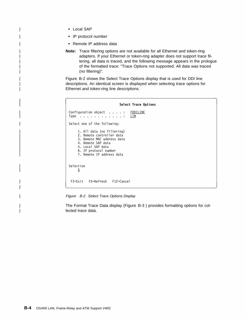
| � Local SAP
| � IP protocol number
| � Remote IP address data
| Note: Trace filtering options are not available for all Ethernet and token-ring| adapters. If your Ethernet or token-ring adapter does not support trace fil-| tering, all data is traced, and the following message appears in the prologue| of the formatted trace: "Trace Options not supported. All data was traced| (no filtering)".
| Figure B-2 shows the Select Trace Options display that is used for DDI line| descriptions. An identical screen is displayed when selecting trace options for| Ethernet and token-ring line descriptions.
| à| ð| Select Trace Options
| Configuration object . . . . : FDDILINE
| Type . . . . . . . . . . . . : LIN
| Select one of the following:
| 1. All data (no filtering)
| 2. Remote controller data
| 3. Remote MAC address data
| 4. Remote SAP data
| 5. Local SAP data
| 6. IP protocol number
| 7. Remote IP address data
| Selection
| 1
| F3=Exit F5=Refresh F12=Cancel
| á| ñ
| Figure B-2. Select Trace Options Display
| The Format Trace Data display (Figure B-3 ) provides formatting options for col-| lected trace data.
B-4 OS/400 LAN, Frame-Relay and ATM Support V4R2

| à| ð| Format Trace Data
| Configuration object . . . . : FDDILINE
| Type . . . . . . . . . . . . : LINE
| Type choices, press Enter.
| Controller . . . . . . . . . . \ALL \ALL, name
| Data representation . . . . . 3 1=ASCII, 2=EBCDIC, 3=\CALC
| Format RR, RNR commands . . . N Y=Yes, N=No
| Format Broadcast data . . . . Y Y=Yes, N=No
| Format MAC or SMT data only . N Y=Yes, N=No
| Format UI data only . . . . . N Y=Yes, N=No
| Format SNA data only . . . . . N Y=Yes, N=No
| Format TCP/IP data only . . . N Y=Yes, N=No
| Format IPX data only . . . . N Y=Yes, N=No
| F3=Exit F5=Refresh F12=Cancel
| á| ñ
| Figure B-3. Format Trace Data Display
Trace options for frame-relay lines and network interfacesCommunications trace data for frame-relay-network interfaces can be filtered toexclude local management interface (LMI) data or to include only LMI data.Figure B-4 shows the Select Trace Options display for a frame-relay network inter-face description.
A trace can be started either for the frame-relay network interface or for a singleline attached to the network interface, but not both. Only one active communi-cations trace is allowed on the frame-relay I/O adapter.
Running a communications trace on a frame-relay network interface without filteringcollects trace data for all lines (DLCIs) attached to the network interface and canquickly fill the trace buffer. Use the option to trace only LMI data to trace data usingDLCI 0 (the DLCI reserved for LMI data). Use the option to exclude LMI data totrace all other data on DLCIs attached to the network interface. To trace data usinga particular DLCI, run the communications trace on the line description corre-sponding to that DLCI.
Appendix B. LAN communications trace B-5

à ðSelect Trace Options
Configuration object . . . . : FRNWI1
Type . . . . . . . . . . . . : NWI
Select one of the following:
1. All data
2. Exclude LMI data
3. Only LMI data
Figure B-4. Select Trace Options Display for Frame-Relay NWI
The Format Trace Data display (Figure B-5 ) provides options similar to those onthe Select Trace Options display but is used to format data already collected.
à ðFormat Trace Data
Configuration object . . . . : FRNWI1 Type . . . . . . . . . . . . : NWI
Type choices, press Enter.
Line . . . . . . . . . . . . . \ALL \ALL, name
Exclude LMI data . . . . . . . N Y=Yes, N=No
Format LMI data only . . . . . N Y=Yes, N=No
Figure B-5. Format Trace Data Display for Frame-Relay NWI
Analyzing data flows on the physical interfaceFor more in-depth analysis of the data transmitted and received by an ATMadapter, you may obtain more detailed information by tracing the data on the phys-ical interface. The following example shows how to start, stop, format and view acommunications trace.
1. Enter the Start System Service Tools (STRSST) command.
2. Select option 1 (Start a service tool).
B-6 OS/400 LAN, Frame-Relay and ATM Support V4R2

à ðSystem Service Tools (SST)
Select one of the following:
1. Start a service tool
2. Work with active service tools
3. Work with disk units
4. Work with diskette data recovery
Selection
1
F3=Exit F1ð=Command entry F12=Cancel
á ñ
Figure B-6. System Service Tools (SST) Display
3. Select option 3 (Work with communications trace)
à ðStart a Service Tool
Warning: Incorrect use of this service tool can cause damage
to data in this system. Contact your service representative
for assistance.
Select one of the following:
1. Product activity log
2. Trace Licensed Internal Code
3. Work with communications trace
4. Display/Alter/Dump
5. Licensed Internal Code log
6. Main storage dump manager
7. Hardware service manager
Selection
3
F3=Exit F12=Cancel F16=SST menu
á ñ
Figure B-7. Start a Service Tool Display
4. Press F6 (Start trace).
Appendix B. LAN communications trace B-7

à ð Work with Communications Traces
Type options, press Enter.
2=Stop trace 4=Delete trace 6=Format and print trace
7=Display message 8=Restart trace
Configuration
Opt Object Type Trace Description Protocol Trace Status
(No active traces)
F3=Exit F5=Refresh F6=Start trace F1ð=Change size
F11=Display buffer size F12=Cancel
á ñ
Figure B-8. Work with Communications Trace Display
5. Enter the name of the configuration object (in this case tsteth1), the type ofobject (1 - line), the trace description, buffer size, and data direction.
6. Press Enter to start the trace.
à ð Start Trace
Type choices, press Enter.
Configuration object . . . . . . . tsteth1___
Type . . . . . . . . . . . . . . 1 1=Line, 2=Network interface
3=Network server
Trace description . . . . . . . . Test trace__________
Buffer size (in kilobytes) . . . . 4 1=128, 2=256, 3=2ð48, 4=4ð96
5=6144, 6=8192, 7=16384
Stop on buffer full . . . . . . . n Y=Yes, N=No
Data direction . . . . . . . . . 3 1=Sent, 2=Received, 3=Both
Number of bytes to trace:
Beginning bytes . . . . . . . . \CALC Value, \CALC
Ending bytes . . . . . . . . . \CALC Value, \CALC
F3=Exit F5=Refresh F12=Cancel
á ñ
Figure B-9. Start Trace Display
7. After the trace has run for an appropriate length of time, use option 2 (Stoptrace) to stop the trace.
B-8 OS/400 LAN, Frame-Relay and ATM Support V4R2

à ð Work with Communications Traces
Type options, press Enter.
2=Stop trace 4=Delete trace 6=Format and print trace
7=Display message 8=Restart trace
Configuration Opt Object Type Trace Description Protocol Trace Status 2 TSTETH1 LINE TEST TRACE ETHERNET ACTIVE
F3=Exit F5=Refresh F6=Start trace F1ð=Change size
F11=Display buffer size F12=Cancel
á ñ
Figure B-10. Active Communications Trace Display
8. Select option 6 (Format and print trace) to format the trace data.
à ð Work with Communications Traces
Type options, press Enter.
2=Stop trace 4=Delete trace 6=Format and print trace
7=Display message 8=Restart trace
Configuration Opt Object Type Trace Description Protocol Trace Status 6 TSTETH1 LINE TEST TRACE ETHERNET STOPPED
F3=Exit F5=Refresh F6=Start trace F1ð=Change size
F11=Display buffer size F12=Cancel
Trace buffer wrappedá ñ
Figure B-11. Stopped Communications Trace Display
9. For this example, the defaults for formatting the trace are acceptable. PressEnter to format the trace.
Appendix B. LAN communications trace B-9

à ð Format Trace Data
Configuration object . . . . : TSTETH1
Type . . . . . . . . . . . . : LINE
Type choices, press Enter.
Controller . . . . . . . . . . \ALL______ \ALL, name
Data representation . . . . . 3 1=ASCII, 2=EBCDIC, 3=\CALC
Format RR, RNR commands . . . N Y=Yes, N=No
Format Broadcast data . . . . Y Y=Yes, N=No
Format UI data only . . . . . N Y=Yes, N=No
Format SNA data only . . . . . N Y=Yes, N=No
Format TCP/IP data only . . . N Y=Yes, N=No
Format IPX data only . . . . N Y=Yes, N=No
Select Ethernet data . . . . . 3 1=8ð2.3, 2=ETHV2, 3=Both
F3=Exit F5=Refresh F12=Cancel
á ñ
Figure B-12. Format Trace Data Display
10. When formatting of the trace data completes, you will be returned to the FormatTrace Data panel with an appropriate message to confirm the formatting iscomplete. You may now press F3 repeatedly to exit System Service Tools.
à ð Format Trace Data
Configuration object . . . . : TSTETH1
Type . . . . . . . . . . . . : LINE
Type choices, press Enter.
Controller . . . . . . . . . . \ALL______ \ALL, name
Data representation . . . . . 3 1=ASCII, 2=EBCDIC, 3=\CALC
Format RR, RNR commands . . . N Y=Yes, N=No
Format Broadcast data . . . . Y Y=Yes, N=No
Format UI data only . . . . . N Y=Yes, N=No
Format SNA data only . . . . . N Y=Yes, N=No
Format TCP/IP data only . . . N Y=Yes, N=No
Format IPX data only . . . . N Y=Yes, N=No
Select Ethernet data . . . . . 3 1=8ð2.3, 2=ETHV2, 3=Both
F3=Exit F5=Refresh F12=Cancel
Format of trace data completeá ñ
Figure B-13. Format Trace Data Complete Display
11. The trace data may be viewed by entering the Work with Spooled Files(WRKSPLF) command, finding the entry just created and displaying that entry.An excerpt of the previous trace is included below.
B-10 OS/400 LAN, Frame-Relay and ATM Support V4R2

The communications line trace is intended for use by individuals with extensiveknowledge of communications protocols. The analysis of such information isbeyond the scope of this book.
COMMUNICATIONS TRACE Title: TEST TRACE ð7/25/97 11:32:28 Page: 1
Trace Description . . . . . : TEST TRACE
Configuration object . . . . : TSTETH1
Type . . . . . . . . . . . . : 1 1=Line, 2=Network Interface
3=Network server
Object protocol . . . . . . : ETHERNET
Start date/Time . . . . . . : ð7/25/97 11:31:21.961
End date/Time . . . . . . . : ð7/25/97 11:31:4ð.ð51
Bytes collected . . . . . . : 4193526
Buffer size (in kilobytes) . : 4 1=128, 2=256, 3=2ð48, 4=4ð96
5=6144, 6=8192, 7=16384
Data direction . . . . . . . : 3 1=Sent, 2=Received, 3=Both
Stop on buffer full . . . . : N Y=Yes, N=No
Number of bytes to trace
Beginning bytes . . . . . : \CALC Value, \CALC
Ending bytes . . . . . . : \CALC Value, \CALC
Select Trace Options:
---------------------
Remote Controller . . . . . : Name, \ALL
Remote MAC Address . . . . . : Value, \ALL
Remote SAP . . . . . . . . . : Value, \ALL
Local SAP . . . . . . . . . : Value, \ALL
IP Identifier . . . . . . . : Value, \ALL
Remote IP Address . . . . . : Value, \ALL
Format Options:
---------------
Controller name . . . . . . : \ALL \ALL, name
Data representation . . . . : 3 1=ASCII, 2=EBCDIC, 3=\CALC
Format SNA data only . . . . : N Y=Yes, N=No
Format RR, RNR commands . . : N Y=Yes, N=No
Format TCP/IP data only . . : N Y=Yes, N=No
Format IPX data only . . : N Y=Yes, N=No
Format UI data only . . . . : N Y=Yes, N=No
Select Ethernet data . . . . : 3 1=8ð2.3, 2=ETHV2, 3=Both
Format Broadcast data . . . : Y Y=Yes, N=No
COMMUNICATIONS TRACE Title: TEST TRACE ð7/25/97 11:32:28 Page: 2
Record Number . . . . Number of record in trace buffer (decimal)
S/R . . . . . . . . . S=Sent R=Received M=Modem Change
Data Length . . . . . Amount of data in record (decimal)
Record Status . . . . Status of record
Record Timer . . . . Time stamp. Based on communications hardware, the time
stamp will be either:
1. 1ð microsecond resolution time of day
(HH:MM:SS.NNNNN) based on the system time when the
trace was stopped
2. 1ðð millisecond resolution relative timer with
decimal times ranging from ð to 6553.5 seconds
Data Type . . . . . . EBCDIC data, ASCII data or Blank=Unknown
Controller name . . . Name of controller associated with record
Command . . . . . . . Command/Response information
Number sent . . . . . Count of records sent
Number received . . . Count of records received
Poll/Final . . . . . ON=Poll for Commands, Final for Responses
Destination MAC Address . . . . Physical address of destination
Source MAC Address . . . . . . Physical address of source
DSAP . . . . . . . . Destination Service Access Point
SSAP . . . . . . . . Source Service Access Point
Frame Format . . . . 8ð2.3 (IEEE Standard 8ð2.3) or ETHV2
(Ethernet Version 2)
Commands/Responses:
------------------
I . . . . . . . . Information
RR . . . . . . . . Receive Ready
RNR . . . . . . . Receive Not Ready
REJ . . . . . . . Reject
UI . . . . . . . . Unnumbered Information
UA . . . . . . . . Unnumbered Acknowledgment
DISC . . . . . . . Disconnect/Request Disconnect
TEST . . . . . . . Test
SIM . . . . . . . Set Initialization Mode
FRMR . . . . . . . Frame Reject
DM . . . . . . . . Disconnected Mode
XID . . . . . . . Exchange ID
SABME . . . . . . Set Asynchronous Balanced Mode Extended
\\\\\ . . . . . . Command/Response Not Valid
VPI . . . . . . . . . Virtual Path Indentifier (decimal)
VCI . . . . . . . . . Virtual Channel Identifier (decimal)
LEHDR . . . . . . . . Lan Emulation Header
COMMUNICATIONS TRACE Title: TEST TRACE ð7/25/97 11:32:28 Page: 2
\\\ COMMUNICATIONS TRACE INFORMATION MESSAGES \\\
Trace buffer wrapped
\\\ END TRACE INFORMATION MESSAGES \\\
Figure B-14. Communications Trace Data Excerpt. Part 1 of 2.
Appendix B. LAN communications trace B-11
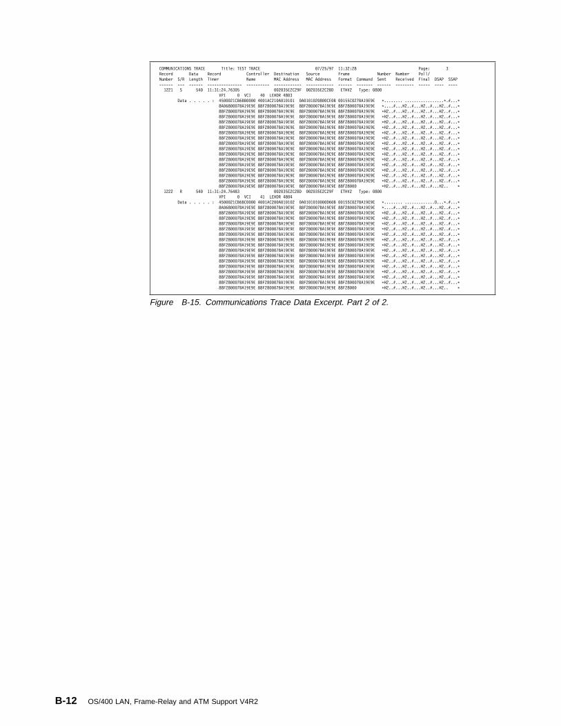
COMMUNICATIONS TRACE Title: TEST TRACE ð7/25/97 11:32:28 Page: 3
Record Data Record Controller Destination Source Frame Number Number Poll/
Number S/R Length Timer Name MAC Address MAC Address Format Command Sent Received Final DSAP SSAP
------ --- ------ --------------- ---------- ------------ ------------ ------ ------- ------ -------- ----- ---- ----
1221 S 54ð 11:31:24.763ð5 ðð2ð35E2C29F ðð2ð35E2C2BD ETHV2 Type: ð8ðð
VPI ð VCI 4ð LEHDR 48ð3
Data . . . . . : 45ððð21CB6BBðððð 4ðð1AC21ðAð1ð1ð1 ðAð1ð1ð2ð8ððCEðB ðð155Cð27BA19E9E \........ .................\.#...\
8Að68ððð7BA19E9E 88F28ððð7BA19E9E 88F28ððð7BA19E9E 88F28ððð7BA19E9E \....#...H2..#...H2..#...H2..#...\
88F28ððð7BA19E9E 88F28ððð7BA19E9E 88F28ððð7BA19E9E 88F28ððð7BA19E9E \H2..#...H2..#...H2..#...H2..#...\
88F28ððð7BA19E9E 88F28ððð7BA19E9E 88F28ððð7BA19E9E 88F28ððð7BA19E9E \H2..#...H2..#...H2..#...H2..#...\
88F28ððð7BA19E9E 88F28ððð7BA19E9E 88F28ððð7BA19E9E 88F28ððð7BA19E9E \H2..#...H2..#...H2..#...H2..#...\
88F28ððð7BA19E9E 88F28ððð7BA19E9E 88F28ððð7BA19E9E 88F28ððð7BA19E9E \H2..#...H2..#...H2..#...H2..#...\
88F28ððð7BA19E9E 88F28ððð7BA19E9E 88F28ððð7BA19E9E 88F28ððð7BA19E9E \H2..#...H2..#...H2..#...H2..#...\
88F28ððð7BA19E9E 88F28ððð7BA19E9E 88F28ððð7BA19E9E 88F28ððð7BA19E9E \H2..#...H2..#...H2..#...H2..#...\
88F28ððð7BA19E9E 88F28ððð7BA19E9E 88F28ððð7BA19E9E 88F28ððð7BA19E9E \H2..#...H2..#...H2..#...H2..#...\
88F28ððð7BA19E9E 88F28ððð7BA19E9E 88F28ððð7BA19E9E 88F28ððð7BA19E9E \H2..#...H2..#...H2..#...H2..#...\
88F28ððð7BA19E9E 88F28ððð7BA19E9E 88F28ððð7BA19E9E 88F28ððð7BA19E9E \H2..#...H2..#...H2..#...H2..#...\
88F28ððð7BA19E9E 88F28ððð7BA19E9E 88F28ððð7BA19E9E 88F28ððð7BA19E9E \H2..#...H2..#...H2..#...H2..#...\
88F28ððð7BA19E9E 88F28ððð7BA19E9E 88F28ððð7BA19E9E 88F28ððð7BA19E9E \H2..#...H2..#...H2..#...H2..#...\
88F28ððð7BA19E9E 88F28ððð7BA19E9E 88F28ððð7BA19E9E 88F28ððð7BA19E9E \H2..#...H2..#...H2..#...H2..#...\
88F28ððð7BA19E9E 88F28ððð7BA19E9E 88F28ððð7BA19E9E 88F28ððð7BA19E9E \H2..#...H2..#...H2..#...H2..#...\
88F28ððð7BA19E9E 88F28ððð7BA19E9E 88F28ððð7BA19E9E 88F28ððð7BA19E9E \H2..#...H2..#...H2..#...H2..#...\
88F28ððð7BA19E9E 88F28ððð7BA19E9E 88F28ððð7BA19E9E 88F28ððð \H2..#...H2..#...H2..#...H2.. \
1222 R 54ð 11:31:24.76483 ðð2ð35E2C2BD ðð2ð35E2C29F ETHV2 Type: ð8ðð
VPI ð VCI 41 LEHDR 48ð4
Data . . . . . : 45ððð21CB6BCðððð 4ðð1AC2ððAð1ð1ð2 ðAð1ð1ð1ððððD6ðB ðð155Cð27BA19E9E \........ .............O...\.#...\
8Að68ððð7BA19E9E 88F28ððð7BA19E9E 88F28ððð7BA19E9E 88F28ððð7BA19E9E \....#...H2..#...H2..#...H2..#...\
88F28ððð7BA19E9E 88F28ððð7BA19E9E 88F28ððð7BA19E9E 88F28ððð7BA19E9E \H2..#...H2..#...H2..#...H2..#...\
88F28ððð7BA19E9E 88F28ððð7BA19E9E 88F28ððð7BA19E9E 88F28ððð7BA19E9E \H2..#...H2..#...H2..#...H2..#...\
88F28ððð7BA19E9E 88F28ððð7BA19E9E 88F28ððð7BA19E9E 88F28ððð7BA19E9E \H2..#...H2..#...H2..#...H2..#...\
88F28ððð7BA19E9E 88F28ððð7BA19E9E 88F28ððð7BA19E9E 88F28ððð7BA19E9E \H2..#...H2..#...H2..#...H2..#...\
88F28ððð7BA19E9E 88F28ððð7BA19E9E 88F28ððð7BA19E9E 88F28ððð7BA19E9E \H2..#...H2..#...H2..#...H2..#...\
88F28ððð7BA19E9E 88F28ððð7BA19E9E 88F28ððð7BA19E9E 88F28ððð7BA19E9E \H2..#...H2..#...H2..#...H2..#...\
88F28ððð7BA19E9E 88F28ððð7BA19E9E 88F28ððð7BA19E9E 88F28ððð7BA19E9E \H2..#...H2..#...H2..#...H2..#...\
88F28ððð7BA19E9E 88F28ððð7BA19E9E 88F28ððð7BA19E9E 88F28ððð7BA19E9E \H2..#...H2..#...H2..#...H2..#...\
88F28ððð7BA19E9E 88F28ððð7BA19E9E 88F28ððð7BA19E9E 88F28ððð7BA19E9E \H2..#...H2..#...H2..#...H2..#...\
88F28ððð7BA19E9E 88F28ððð7BA19E9E 88F28ððð7BA19E9E 88F28ððð7BA19E9E \H2..#...H2..#...H2..#...H2..#...\
88F28ððð7BA19E9E 88F28ððð7BA19E9E 88F28ððð7BA19E9E 88F28ððð7BA19E9E \H2..#...H2..#...H2..#...H2..#...\
88F28ððð7BA19E9E 88F28ððð7BA19E9E 88F28ððð7BA19E9E 88F28ððð7BA19E9E \H2..#...H2..#...H2..#...H2..#...\
88F28ððð7BA19E9E 88F28ððð7BA19E9E 88F28ððð7BA19E9E 88F28ððð7BA19E9E \H2..#...H2..#...H2..#...H2..#...\
88F28ððð7BA19E9E 88F28ððð7BA19E9E 88F28ððð7BA19E9E 88F28ððð7BA19E9E \H2..#...H2..#...H2..#...H2..#...\
88F28ððð7BA19E9E 88F28ððð7BA19E9E 88F28ððð7BA19E9E 88F28ððð \H2..#...H2..#...H2..#...H2.. \
Figure B-15. Communications Trace Data Excerpt. Part 2 of 2.
B-12 OS/400 LAN, Frame-Relay and ATM Support V4R2

Appendix C. AS/400 LAN manager support
The AS/400 LAN manager is part of the OS/400 licensed program that providesbasic LAN management functions for token-ring and DDI networks. The LANmanager monitors the status of the network and attached stations and providesproblem determination information. The AS/400 LAN manager provides this supportfor the locally attached ring only.
AS/400 LAN manager support includes the following:
� Analysis and reporting of error conditions, such as beaconing. 1
� Alerts the network central site of errors causing performance degradation andbeaconing conditions.
� Operational functions, such as:
– Displaying ring configuration
– Displaying network status
– Displaying adapter profiles
– Adapter name support
– Setting the level of error reporting and logging
For token-ring networks, the LAN manager uses the ring error monitor (REM) andconfiguration report server (CRS) functions. LAN manager support for DDI networksuses FDDI Station Management (SMT), versions 6.2 through 7.3. The AS/400 LANmanager does not support management of LAN Server-connected LANs or ofremote LANs attached through frame-relay connections.
Token-ring network LAN manager supportYou can turn on and turn off AS/400 LAN manager support on token-ring linesusing the ACTLANMGR (Activate LAN Manager) parameter in the token-ring linedescription. Figure C-1 on page C-2 and Figure C-2 on page C-2 show examplesof AS/400 line description screen displays. See “LAN manager support activationconsiderations” on page C-3 for further information.
ACTLANMGR Activate LAN Manager. This parameter provides the option ofturning on or turning off LAN manager support for the line. Specifying*NO disables the REM and CRS functions, and no error information issent to the history log queue (QHST) and the system operator queue(QSYSOPR). Setting ACTLANMGR to *NO may increase network proc-essing performance.
Note: ACTLANMGR must be set to *YES when RSRCNAME(*NWID)is specified.
Figure C-1 shows an example of the Create Line Description (CRTLINTRN) displayfor token ring. Set ACTLANMGR to *NO to turn off the LAN manager.
1 Beaconing is a repeated message sent in a token-ring network to indicate an adapter is not receiving a normal signal because ofa serious error, such as a line break or power failure.
Copyright IBM Corp. 1997, 1998 C-1

à ðCreate Line Desc (Token-Ring) (CRTLINTRN)
Additional Parameters
Network controller . . . . . . . Name
Activate LAN manager . . . . . . \NO \YES, \NO TRLAN manager logging level . . \OFF \OFF, \MIN, \MED, \MAX
TRLAN manager mode . . . . . . . \OBSERVING \OBSERVING, \CONTROLLING
Log configuration changes . . . \LOG \LOG, \NOLOG
Token-ring inform of beacon . . \YES \YES, \NO
Functional address . . . . . . . \NONE \NONE, Cðððððððððð1...
+ for more values
Early token release . . . . . . \LINESPEED \YES, \NO, \LINESPEED
Error threshold level . . . . . \OFF \OFF, \MIN, \MED, \MAX
Link speed . . . . . . . . . . . 4M \MIN, 12ðð, 24ðð, 48ðð...
More...
F3=Exit F4=Prompt F5=Refresh F12=Cancel F13=How to use this display
F24=More keys
á ñ
Figure C-1. Turning Off LAN Manager in the CRTLINTRN Display for Token Ring
Figure C-2 shows an example of the Change Line Description (CHGLINTRN)display for a token-ring line. Set ACTLANMGR to *NO to turn off LAN Managersupport for token-ring line TRN01.
à ðChange Line Desc (Token-Ring) (CHGLINTRN)
Type choices, press Enter.
Line description . . . . . . . . > TRNð1 Name
Resource name . . . . . . . . . TRNð1 Name, \SAME, \NWID, \NWSD
Online at IPL . . . . . . . . . \NO \SAME, \YES, \NO
Vary on wait . . . . . . . . . . \NOWAIT \NOWAIT, 15-18ð seconds
Maximum controllers . . . . . . 4ð 1-256, \SAME
Line speed . . . . . . . . . . . 16M \SAME, 4M, 16M, \NWI
Duplex . . . . . . . . . . . . . \HALF Character value, \SAME...
Maximum frame size . . . . . . . 1994 265-16393, \SAME, 265, 521...
Activate LAN manager . . . . . . \NO \SAME, \YES, \NO TRLAN manager logging level . . \OFF \SAME, \OFF, \MIN, \MED, \MAX
TRLAN manager mode . . . . . . . \CONTROLLING \SAME, \OBSERVING...
Log configuration changes . . . \LOG \SAME, \LOG, \NOLOG
Token-ring inform of beacon . . \NO \SAME, \YES, \NO
Local adapter address . . . . . \ADPT 4ððððððððððð-7FFFFFFFFFFF...
Functional address . . . . . . . \SAME \SAME, \NONE, Cðððððððððð1...
+ for more values
More...
F3=Exit F4=Prompt F5=Refresh F12=Cancel F13=How to use this display
F24=More keys
á ñ
Figure C-2. Turning Off LAN Manager in the CHGLINTRN Display for Token Ring
C-2 OS/400 LAN, Frame-Relay and ATM Support V4R2

LAN manager support activation considerationsIf the token-ring line supports LAN Manager, consider setting ACTLANMGR to*YES if:
� No other token-ring management is available in your installation
� No other token-ring line on an AS/400 system monitors the ring
� Problems are actively occurring on the ring
� Equipment that is attached on the token ring is being changed
Consider setting ACTLANMGR to *NO on a token-ring line if:
� Other lines on the current or another AS/400 system attach to the same token-ring line and have an active LAN Manager
� Hardware already on the ring provides LAN Manager support adequate tomonitor the ring stations on the token ring
� The AS/400 system is a 9401 or 9402 model
� Your system has a multifunction input/output processor (IOP) supporting morethan one token-ring attachment, and it has become a bottleneck
Note: When ACTLANMGR is set to *NO, the TRNLOGLVL, TRNMGRMODE,LOGCFGCHG and TRNINFBCN parameters are ignored (see “SpecifyingLAN manager operations”).
Specifying LAN manager operationsThe level of support provided by the AS/400 LAN Manager is specified usingseveral parameters on the token-ring and DDI line descriptions.
Token-ring network linesThe Create Line Description (Token-Ring) (CRTLINTRN) command allows you tospecify a number of parameters used to control error reporting on the ring. Afterthe line description has been created, these parameters can be changed using theChange Line Description (Token-Ring) (CHGLINTRN) command.
TRNLOGLVLTRLAN Manager logging level. This parameter is used to change thelevel of error logging on the ring. The logging levels supported by theTRNLOGLVL parameter are *OFF, *MIN, *MED, and *MAX.
Table C-1 shows the messages logged by the AS/400 LAN Manager forvarious error conditions when TRNLOGLVL is set to *MIN, *MED, and*MAX. The TRNLOGLVL value listed is the minimum value required forthe message to be logged. For example, messages listed as requiring aminimum TRNLOGLVL value of *MED will also be listed if theTRNLOGLVL value specified is *MAX.
Appendix C. AS/400 LAN manager support C-3

TRNMGRMODETRLAN Manager mode. The line description can be configured to serveas a controlling (*CONTROLLING) or observing (*OBSERVING) networkmanager. Only one adapter (line description) configured as a controllingnetwork manager can be active on the ring at one time.
The controlling network manager tracks configuration changes on thering and can remove other adapters from the ring. Changes are trackedthrough the nearest active upstream neighbor (NAUN) reports on thering.
LOGCFGCHGLog configuration changes. If LOGCFGCHG(*LOG) is specified on theline description, the network manager on the line logs all changes inQHST. These changes include one of the following:
� Whenever a station joins the ring, for example, when a workstationis powered on.
� Whenever a station leaves the ring, for example, when a workstationis powered off.
If LOGCFGCHG(*NOLOG) is specified, no changes are tracked.
Table C-1. LAN Manager Message Logging for Token-Ring Network Lines
Event or Condition Message
MinimumTRNLOGLVLValue
Recoverable errors increasing CPF8B01 *MIN
Excessive recoverable errors CPF8B03 *MIN
Frequency mismatch errors CPF8B05 *MED
Frame copied errors CPF8B06 *MED
Receive congestion errors CPF8B07 *MED
Lost frame errors CPF8B08 *MED
Token errors CPF8B09 *MED
Ring monitor errors CPF8B10 *MAX
Poll failure CPF8B11 *MAX
Recoverable error report CPF8B12 *MAX 1
Excessive recoverable errors CPF8B13 *MIN
Recoverable errors increasing CPF8B14 *MIN
Received invalid ring error monitor (REM)data CPF8B21 *MIN
Received invalid configuration reportserver (CRS) data CPF8B22 *MIN
Receiver congestion table full CPF8B25 *MIN
Receiver congestion CPF8B26 *MIN
1CPF8B12 messages may also be logged when TRNLOGLVL(*MED) is specified.CPF8B12 is logged with one or more of messages CPF8B03 and CPF8B05—CPF8B09when the number of errors reported by these messages exceeds the error threshold forthe adapter.
C-4 OS/400 LAN, Frame-Relay and ATM Support V4R2

TRNINFBCNToken-ring inform of beacon. To send beaconing information to thehistory log (QHST), specify *YES for this parameter. If you specify *NO,the information is not logged.
Ring error problems reported to QHST are logged as messages. Manyproblems are also logged to the system operator message queue(QSYSOPR). Errors on the ring considered serious enough to affect per-formance and other errors that cause beaconing are logged to QHST asalertable messages. Alertable messages may cause an alert to bereported to a network operator at a problem management (alert) focalpoint.
IBM Personal Computer LAN managerThe IBM LAN Manager provides network management functions for the personalcomputer that are similar to those of the AS/400 LAN Manager. Table C-2 lists theterminology used by the PC LAN Manager to describe soft (recoverable) errorlevels and the equivalent logging level values specified for the AS/400TRNLOGLVL parameter.
Table C-2. Token-Ring Network Manager Terminology
LAN Manager ErrorLogging Level Equivalent AS/400 TRNLOGLVL Parameter Value
Full *MAX (maximum)
Limited *MIN or *MED (minimum or medium)
None *OFF
Reset No similar parameter
DDI linesThe Create Line Description (DDI) (CRTLINDDI) command allows you to specify anumber of parameters used to control error reporting on the ring. After the linedescription has been created, these parameters can be changed using the ChangeLine Description (DDI) (CHGLINDDI) command.
LOGLVLLog level. This parameter is used to change the level of error logging onthe ring. The logging levels supported by the LOGLVL parameter are*OFF, *ERRORS, and *ALL. *ERRORS logs only ring error messages.*ALL logs both error and informational messages.
Table C-3 shows the messages logged by the AS/400 LAN manager forvarious error conditions when LOGLVL is set to *ERRORS or *ALL. TheLOGLVL value listed is the minimum value required for the message tobe logged. For example, messages listed as requiring a minimumLOGLVL value of *ERRORS will also be listed if the LOGLVL valuespecified is *ALL.
Appendix C. AS/400 LAN manager support C-5

LCLMGRMODELocal manager mode. This parameter specifies whether the local station(line description) serves as an observing LAN Manager (*OBSERVING)or not (*NONE). If *OBSERVING is specified, this station can retrieveinformation about all other adapters on the network. If *NONE is speci-fied, the local LAN Manager function can supply information about thelocal adapter only.
Table C-3. LAN Manager Message Logging for DDI Lines
Event or Condition MessageMinimumLOGLVL Value
Duplicate address CPF8B95 *ERRORS
Elasticity buffer condition CPF8B97 *ERRORS
Frame error condition CPF8B90 *ERRORS
Frame not copied condition CPF8B85 *ERRORS
Link error rate (LER) alarm CPF8B92 *ALL
MAC path change event CPF8BC0 *ALL
Neighbor change event CPF8BB3 *ALL
Peer wrap condition CPF8B9A *ERRORS
Port path change event CPF8BA4 *ERRORS
Undesirable connection CPF8BA8 *ALL
Using the LAN managerYou can use menus, prompt displays, or CL commands to perform AS/400 LANManager functions. The following commands provide the CL interface to the AS/400LAN Manager.
ADDLANADPI Add LAN Adapter Information
CHGLANADPI Change LAN Adapter Information
DSPLANADPP Display LAN Adapter Profile
DSPLANSTS Display LAN Status
RMVLANADPT Remove LAN Adapter
RMVLANADPI Remove LAN Adapter Information
RNMLANADPI Rename LAN Adapter Information
WRKLANADPT Work with LAN Adapters
The Work with LAN Adapters display shown in Figure C-3 provides access to all ofthe functions of the commands listed above.
For token-ring lines, the Work with LAN Adapters display also includes Option 14(Remove adapter) if the following are true:
� The line description specified is a token-ring line specified withTRNMGRMODE(*CONTROLLING)
� The user has authority to use the RMVLANADPT command
C-6 OS/400 LAN, Frame-Relay and ATM Support V4R2
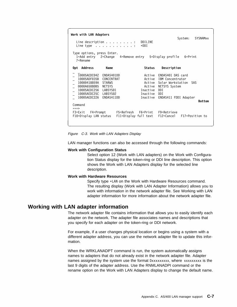
à ðWork with LAN Adapters System: SYSNAMxx
Line description . . . . . . . . : DDILINE
Line type . . . . . . . . . . . : \DDI
Type options, press Enter.
1=Add entry 2=Change 4=Remove entry 5=Display profile 6=Print
7=Rename
Opt Address Name Status Description
1ððð5AEDCð42 ENDAS4ð1DD Active ENDAS4ð1 DAS card
1ððð5ADFð35B CONCENTRAT Active IBM Concentrator
1ðððð418859A STARWS Active Solar Workstation SAS
ððððA65ð8ðB5 NETSYS Active NETSYS System
1ððð5AEDC256 LABSYSð1 Inactive DDI
1ððð5AEDC25C LABSYSð2 Inactive DDI
1ððð5AEDC226 ENDAS411DD Inactive ENDAS411 FDDI Adapter
Bottom Command
===>
F3=Exit F4=Prompt F5=Refresh F6=Print F9=Retrieve
F1ð=Display LAN status F11=Display full text F12=Cancel F17=Position to
á ñ
Figure C-3. Work with LAN Adapters Display
LAN manager functions can also be accessed through the following commands:
Work with Configuration StatusSelect option 12 (Work with LAN adapters) on the Work with Configura-tion Status display for the token-ring or DDI line description. This optionshows the Work with LAN Adapters display for the selected linedescription.
Work with Hardware ResourcesSpecify type \LAN on the Work with Hardware Resources command.The resulting display (Work with LAN Adapter Information) allows you towork with information in the network adapter file. See Working with LANadapter information for more information about the network adapter file.
Working with LAN adapter informationThe network adapter file contains information that allows you to easily identify eachadapter on the network. The adapter file associates names and descriptions thatyou specify for each adapter on the token-ring or DDI network.
For example, if a user changes physical location or begins using a system with adifferent adapter address, you can use the network adapter file to update this infor-mation.
When the WRKLANADPT command is run, the system automatically assignsnames to adapters that do not already exist in the network adapter file. Adapternames assigned by the system use the format Dxxxxxxxxx, where xxxxxxxxx is thelast 9 digits of the adapter address. Use the RNMLANADPI command or therename option on the Work with LAN Adapters display to change the default name.
Appendix C. AS/400 LAN manager support C-7

Use the WRKLANADPT, ADDLANADPI, CHGLANADPI, RNMLANADPI, andRMVLANADPI commands to update the network adapter file. Note that removingLAN adapter information does not remove (de-insert) that adapter from the network.
Display LAN adapter profileYou can display the adapter profile from the Work with LAN Adapters display byselecting option 5 (Display profile) or by using the Display LAN Adapter Profile(DSPLANADPP) command. If the specified adapter does not exist in the networkadapter file when the DSPLANADPP command is run, the system automaticallysupplies a default name for the adapter. If the upstream or downstream adaptersdo not exist in the network adapter file, the system supplies default names for theseadapters also.
Figure C-4 shows an example of the Display Adapter Profile displays for a token-ring network adapter.
à ðDisplay Adapter Profile System: SYSNAMxx
Product ID . . . . . . . . . . . . . : ðCAFððððððð1ðð7466ððð32A3347ð1683347
Licensed internal code . . . . . . . : FðFðFðC1F6F4F1F1F74ð
Group address . . . . . . . . . . . : Cððð8ððððððð
Adapter address . . . . . . . . . . : 4ððð7Að1Dð3E
Adapter name . . . . . . . . . . . . : Dð7Að1Dð3E
Adapter description . . . . . . . . :
NAUN address . . . . . . . . . . . . : 4ððððððð1591
NAUN name . . . . . . . . . . . . . : Dððððð1591
NAUN description . . . . . . . . . . :
Functional Function Address Ring Error Monitor Cðððððððððð8
Configuration Report Server Cððððððððð1ð
Bottom Press Enter to continue.
F3=Exit F5=Refresh F6=Print F12=Cancel
á ñ
Figure C-4. Display Adapter Profile Display for Token-Ring Network Adapter
Figure C-5 shows an example of the Display Adapter Profile displays for a DDIadapter. Blank entries indicate that the value either cannot be retrieved by the LANmanager or are not supported by the displayed adapter. The entry for Last setstation address is always blank when the Station set count is zero.
C-8 OS/400 LAN, Frame-Relay and ATM Support V4R2

à ðDisplay LAN Adapter Profile System: SYSNAMxx
Line information:
Line description . . . . . . . . . . . . : DDILINE
Line type . . . . . . . . . . . . . . . . : \DDI
Adapter information:
Address . . . . . . . . . . . . . . . . . : 1ððð5AEDCð42
Name . . . . . . . . . . . . . . . . . . : ENDAS4ð1DD
Description . . . . . . . . . . . . . . . : ENDAS4ð1 DAS card
Neighbor information:
Upstream address . . . . . . . . . . . . : 1ððð5ADFð35B
Upstream name . . . . . . . . . . . . . . : CONCENTRAT
Description . . . . . . . . . . . . . . . : IBM Concentrator
Downstream address . . . . . . . . . . . : ððððA65ð8ðB5
Downstream name . . . . . . . . . . . . . : NETSYS
Description . . . . . . . . . . . . . . . : NETSYS System
More...F3=Exit F5=Refresh F6=Print F12=Cancel
á ñ
Figure C-5 (Part 1 of 4). Display Adapter Profile Display for DDI Adapter
à ðDisplay LAN Adapter Profile System: SYSNAMxx
Station states:
Operating State . . . . . . . . . . . . . : Thru
Ring connection:
Operational
Port A connection . . . . . . . . . . . . : Active
Port B connection . . . . . . . . . . . . : Active
Station Connection . . . . . . . . . . . : In
Station Configuration . . . . . . . . . . : Thru
Peer wrap . . . . . . . . . . . . . . . . : Off
Figure C-5 (Part 2 of 4). Display Adapter Profile Display for DDI Adapter
à ðDisplay LAN Adapter Profile System: SYSNAMxx
Additional information:
Non-master port count . . . . . . . . . . : 2
Master port count . . . . . . . . . . . . : ð
Port A physical media type . . . . . . . : Unspecified
Port B physical media type . . . . . . . : Unspecified
Supported SMT versions . . . . . . . . . : ðððð2
Universal adapter address . . . . . . . . : 1ððð5AEDCð42
Manufacturer information . . . . . . . . :
Figure C-5 (Part 3 of 4). Display Adapter Profile Display for DDI Adapter
Appendix C. AS/400 LAN manager support C-9

à ðDisplay LAN Adapter Profile System: SYSNAMxx
Station status:
Status reporting . . . . . . . . . . . . : On
MAC total frames received . . . . . . . . : ðððððð1318
MAC frames copied . . . . . . . . . . . . : ðððððð1318
MAC frames transmitted . . . . . . . . . : ððððððð239
MAC frames lost . . . . . . . . . . . . . : ðððððððððð
MAC frame errors . . . . . . . . . . . . : ðððððððððð
MAC frame error threshold . . . . . . . . : ððððð
MAC frame error ratio . . . . . . . . . . : ððððð
Port A LEM count . . . . . . . . . . . . : ðððððððððð
Port A LER alarm threshold . . . . . . . : 1.ðE-ð8
Port A LER cutoff threshold . . . . . . . : 1.ðE-ð7
Port A LER estimate . . . . . . . . . . . : 1.ðE-15
Port B LEM count . . . . . . . . . . . . : ðððððððððð
Port B LER alarm threshold . . . . . . . : 1.ðE-ð8
Port B LER cutoff threshold . . . . . . . : 1.ðE-ð7
Port B LER estimate . . . . . . . . . . . : 1.ðE-15
Station set count . . . . . . . . . . . . : ðððððððððð
Last set station address . . . . . . . . :
BottomF3=Exit F5=Refresh F6=Print F12=Cancel
á ñ
Figure C-5 (Part 4 of 4). Display Adapter Profile Display for DDI Adapter
Display LAN statusYou can display the status of the network from the Work with LAN Adapters displayby pressing F10 (Display LAN status) or by using the Display LAN Status(DSPLANSTS) command.
Figure C-6 shows an example of the Display LAN Status display for a DDI network.
à ðDisplay LAN Status
System: SYSNAMxx
Line description . . . . . . . . . . . : DDILINE
Ring status . . . . . . . . . . . . . : Operational
Figure C-6. Display LAN Status Display
C-10 OS/400 LAN, Frame-Relay and ATM Support V4R2

Appendix D. Address considerations for bridgedenvironments
MAC addresses are always displayed in the physical address format for the DDI,token ring, or Ethernet environment even if they represent stations on other LANmedia. Refer to “Token-ring physical address format” on page 3-3 for the format oftoken-ring and DDI MAC addresses or to “Ethernet physical address format” onpage 5-4 for the format of Ethernet MAC addresses.
Because MAC address formats are in a different bit order, the configured physicaladdresses will appear in reversed bit order when viewed from different LAN typeson opposite sides of the 8209 LAN Bridge. “Token-ring-to-Ethernet addressconversion” on page D-3 provides a conversion table for determining the equivalentaddresses.
Note: If you are using the same LAN types on both sides of a series of bridges,no address conversion is necessary. For example, an AS/400 system in anEthernet network communicating with another AS/400 system in an Ethernetnetwork across a token ring and two LAN Bridges does not need to convertaddresses.
Examples of address viewsConsider the following example of different address views.
Copyright IBM Corp. 1997, 1998 D-1

Figure D-1. Bridged LAN Addressing
Configuration records for AS/400 system on token-ring networkWhen System 1 in Figure D-1 is being configured, the addresses of the varioussystems in the network are viewed as being in token-ring addressing format of mostsignificant bit. The following figure demonstrates System 1 viewpoint.
Table D-1. Addresses from AS/400 1 View
AS/400 1 View Address
Local Address (System 1) 400003190001
Remote AS/400 System (System 2) 400003190002
PS/2 Address 11005A00121A
RS/6000 Address 11005A00131C
Configuration records for AS/400 system on Ethernet networkWhen System 2 in Figure D-1 is being configured, the addresses of the varioussystems in the network are viewed as being in Ethernet addressing format of leastsignificant bit. The following figure demonstrates System 2 viewpoint.
D-2 OS/400 LAN, Frame-Relay and ATM Support V4R2

Table D-2. Addresses from AS/400 2 View
AS/400 2 View Address
Local Address (System 2) 0200C0980040
Remote AS/400 System (System 1) 0200C0980080
PS/2 Address 88005A004858
RS/6000 Address 88005A00C838
Token-ring-to-Ethernet address conversionThe bit order of the 48-bit (12-hexadecimal digits) IEEE MAC address is reversedbetween the token-ring and Ethernet LANs. Some protocols that use this MACaddress may not adjust for the inverted bits when communicating between LANs.Therefore, you must manually convert the address bit order. Use the following pro-cedure and Table D-3 on page D-4 to convert an address. For an example of howto convert an address, see “Example of converting an address” on page D-4.
1. Write the 12-hexadecimal-digit MAC address.
Note: Separate the 12-hexadecimal digits into pairs. Use the first character ofeach pair as the row coordinate and the second character as thecolumn coordinate.
2. Locate a bit order inverted pair in Table D-3 on page D-4.
3. Combine the 6 pairs into a 12-hexadecimal-digit address.
Appendix D. Address considerations for bridged environments D-3

Table D-3. Example Conversion Table
2ndChar →(Column)1st Char↓ (Row) 0 1 2 3 4 5 6 7 8 9 A B C D E F
0 00 80 40 C0 20 A0 60 E0 10 90 50 D0 30 B0 70 F0
1 08 88 48 C8 28 A8 68 E8 18 98 58 D8 38 B8 78 F8
2 04 84 44 C4 24 A4 64 E4 14 94 54 D4 34 B4 74 F4
3 0C 8C 4C CC 2C AC 6C EC 1C 9C 5C DC 3C BC 7C FC
4 02 82 42 C2 22 A2 62 E2 12 92 52 D2 32 B2 72 F2
5 0A 8A 4A CA 2A AA 6A EA 1A 9A 5A DA 3A BA 7A FA
6 06 86 46 C6 26 A6 66 E6 16 96 56 D6 36 B6 76 F6
7 0E 8E 4E CE 2E AE 6E EE 1E 9E 5E DE 3E BE 7E FE
8 01 81 41 C1 21 A1 61 E1 11 91 51 D1 31 B1 71 F1
9 09 89 49 C9 29 A9 69 E9 19 99 59 D9 39 B9 79 F9
A 05 85 45 C5 25 A5 65 E5 15 95 55 D5 35 B5 75 F5
B 0D 8D 4D CD 2D AD 6D ED 1D 9D 5D DD 3D BD 7D FD
C 03 83 43 C3 23 A3 63 E3 13 93 53 D3 33 B3 73 F3
D 0B 8B 4B CB 2B AB 6B EB 1B 9B 5B DB 3B BB 7B FB
E 07 87 47 C7 27 A7 67 E7 17 97 57 D7 37 B7 77 F7
F 0F 8F 4F CF 2F AF 6F EF 1F 9F 5F DF 3F BF 7F FF
Example of converting an addressFigure D-2 shows how token-ring address 10005A4DBC96 is converted into a bit-inverted Ethernet address of 08005AB23D69.
C o n v e r s i o n T a b l e
R C 9 P 0 5 7 - 2
Figure D-2. An Example of Token-Ring Address Conversion
For more examples of converting adapter addresses for bridged configurations, see“Token-ring-to-Ethernet bridge configuration example” on page 6-8.
D-4 OS/400 LAN, Frame-Relay and ATM Support V4R2

| Appendix E. ATM network error codes and cause codes
| This appendix describes AS/400 ATM network error codes and cause codes.
| ATM network error codes| The LAN emulation software may report the following ATM network error codes:
| Table E-1 (Page 1 of 6). ATM Network Error Codes
| Error| Code| Technical Description
| 1EC08001| A failure occurred during the JOIN request. The LAN emulation server reported| the cause of the failure as "unknown".
| 1EC08002| The LEC attempted to create a connection to the LES and the call setup failed.| The LEC received no response from the LES within the timeout period. The| line description may contain an incorrect LES ATM address or the LES may be| inoperative. Check the LES ATM address in the line description for accuracy| and ensure the LES is powered on and operational.
| 1EC08003| The LEC attempted to create a connection to the LES and the call setup failed.| The LEC received an error response from the switch. Use the network cause| code to determine the source of the error and its remedy.
| 1EC08004| The LEC sent an ARP (address resolution protocol) to the LES to determine| the address of the BUS. The LES responded to the request but did not return| the address of the BUS to the LEC. The problem resides in either the LES or| the BUS.
| 1EC0800A| The LEC sent an ARP (address resolution protocol) to the LES to determine| the address of the BUS. The LES did not respond to the LEC within the| timeout period. The problem resides in the LES.
| 1EC0800D| The AS/400 Licensed Internal Code failed during a vary-on of the line. You| should contact your service provider.
| 1EC0800E| The LEC attempted to create a connection to the BUS and the call setup| failed. The LEC received no response from the BUS within the timeout period.| This may be due to an inoperative BUS, or due to an incorrect BUS address| received from the LES. The problem resides either in the LES or the BUS.
| 1EC0800F| The LEC attempted to create a connection to the LECS and the call setup| failed. Either the LEC received an error response from the switch, or it| received no response from the LECS within the timeout period. The problem| resides in either the switch or the LECS. Use the network cause code to deter-| mine the source of the error and its remedy.
| 1EC08011| The LEC attempted to register its ATM address with the switch. The switch| returned an error and the address was not registered. This could be due to a| number of reasons. There may be a problem with the switch. Another device| may have already registered this address with the switch. A licensed internal| code failure may have occurred. Check to ensure that no other device has reg-| istered the same ATM address as the AS/400 LEC. If this is not the case,| contact your service provider for assistance.
Copyright IBM Corp. 1997, 1998 E-1

| Table E-1 (Page 2 of 6). ATM Network Error Codes
| Error| Code| Technical Description
| 1EC08020| The connection from the LAN Emulation Client (LEC) to the BUS was| unexpectedly cleared. Use the network cause code to determine the reason for| the failure and its remedy. If no network cause code was returned, the reasons| may be either a timeout waiting for a response, the loss of the physical con-| nection or the call was cleared due to other errors within the AS/400 ATM soft-| ware.
| 1EC08021| The connection from the LAN Emulation Client (LEC) to the LES was| unexpectedly cleared. Use the network cause code to determine the reason for| the failure and its remedy. If no network cause code was returned, the reasons| may be either a timeout waiting for a response, the loss of the physical con-| nection or the call was cleared due to other errors within the AS/400 ATM soft-| ware.
| 1EC08101| The version of LAN emulation in use by the LAN emulation server does not| match that of the AS/400 LAN emulation client. The AS/400 supports only ATM| Forum LAN Emulation standard 1.0. If possible, change the LES configuration| to use this standard. Otherwise, the AS/400 can not connect with this LES.
| 1EC0810F| The version of LAN emulation in use by the LAN emulation configuration| server does not match that of the AS/400 LAN emulation client. The AS/400| supports only ATM Forum LAN Emulation standard 1.0. If possible, change the| LECS configuration to use this standard. Otherwise, the AS/400 can not| connect with this LECS. Directly configuring the AS/400 LEC to use a specific| LAN emulation server provides an alternative to using the LECS. Do this by| changing the line description to *NO in the Use LECS address parameter field| and entering a valid ATM address in the LES ATM address parameter fields.
| 1EC08201| This LEC sent a JOIN request to the LAN emulation server with parameters| that are incompatible with the emulated LAN the LES controls. Consult the| LES configuration to determine appropriate values and change the values on| the AS/400 line description to acceptable alternatives. If no acceptable values| can be found, the AS/400 LEC cannot connect with this LES.
| 1EC0820F| This LEC sent a JOIN request to the LAN emulation server with parameters| that are either not valid or are incompatible with the emulated LAN the LES| controls. Consult the LES configuration to determine appropriate values and| change the values on the AS/400 line description to acceptable alternatives. If| no acceptable values can be found, the AS/400 LEC cannot connect with this| LES. If acceptable alternatives are used but the LEC still returns this error, a| problem may exist in the AS/400 ATM software. In such a case, contact your| service provider for further assistance.
| 1EC08401| The LEC attempted to JOIN an emulated LAN using a LAN MAC address| already in use by another device. The LAN emulation server will not allow two| devices to register with the same address. Either this LEC or the other device| must change their MAC (local adapter) address in order for both to JOIN this| emulated LAN.
| 1EC08501| The LEC attempted to JOIN an emulated LAN using an ATM address already| in use by another device. The LAN emulation server will not allow two devices| to register with the same address. Either this LEC or the other device must| change their ATM address in order for both to JOIN this emulated LAN.
| 1EC08601| The LAN emulation server denied a JOIN request due to insufficient resources| within the LES. Typically, this indicates the LES currently serves its maximum| number of clients. Either increase the resources available to the LES (number| of virtual connections, storage available, and so forth), or direct a portion of the| clients from this LES to another.
E-2 OS/400 LAN, Frame-Relay and ATM Support V4R2

| Table E-1 (Page 3 of 6). ATM Network Error Codes
| Error| Code| Technical Description
| 1EC0860F| The LAN emulation configuration server denied a CONFIGURE request due to| insufficient resources within the LECS. Typically, this indicates the LECS cur-| rently serves its maximum number of clients. Try waiting a short period of time| and trying again.
| 1EC08701| The LES has denied access to the AS/400 LEC for security reasons. If the| LES has a configuration table, add the LEC to the table. Also, some LES| implementations require that the LEC contact the LECS first before contacting| the LES. In this case, change the line description parameter Use LECS| address from *NO to *YES to contact the LECS.
| 1EC0870F| The LECS has denied access to the AS/400 LEC for security reasons. If the| LECS has a configuration table, add the LEC to the table. Directly configuring| the AS/400 LEC to use a specific LAN emulation server provides an alternative| to using the LECS. Do this by changing the line description to *NO in the Use| LECS Address parameter field and entering a valid ATM address in the LES| ATM Address parameter fields.
| 1EC08901| The LEC attempted to register a LAN address during a JOIN request that the| LAN emulation server considers invalid. This includes broadcast, multicast| group or functional addresses. For Ethernet/802.3, the valid range for LAN| addresses is '020000000000' to '7EFFFFFFFFFF' in hexadecimal. The valid| range for token-ring/802.5 is '400000000000' to '7FFFFFFFFFFF' in| hexadecimal.
| 1EC0890F| The LEC sent a CONFIGURE request with a LAN address the LAN emulation| configuration server considers invalid. This includes broadcast, multicast group| or functional addresses. For Ethernet/802.3, the valid range for LAN addresses| is '020000000000' to '7EFFFFFFFFFF' in hexadecimal. The valid range for| token-ring/802.5 is '400000000000' to '7FFFFFFFFFFF' in hexadecimal.| Directly configuring the AS/400 LEC to use a specific LAN emulation server| provides an alternative to using the LECS. Do this by changing the line| description to *NO in the Use LECS Address parameter field and entering a| valid ATM address in the LES ATM Address parameter fields.
| 1EC08A01| This LEC sent a JOIN request to the LAN emulation server with an ATM| address format that does not match the format in use by the LES. Since the| AS/400 supports only one format it can not be changed. If possible, change| the LES ATM address format to match that of the AS/400 client. Otherwise, the| AS/400 LEC can not connect with this LES.
| 1EC08A0F| This LEC sent a CONFIGURE request to the LAN emulation configuration| server with an ATM address format that does not match the format in use by| the LECS. Since the AS/400 supports only one format it can not be changed. If| possible, change the LECS ATM address format to match that of the AS/400| client. Otherwise, the AS/400 LEC can not connect with this LECS. Directly| configuring the AS/400 LEC to use a specific LAN emulation server provides| an alternative to using the LECS. Do this by changing the line description to| *NO in the Use LECS Address parameter field and entering a valid ATM| address in the LES ATM Address parameter fields.
| 1EC08B01| The LEC attempted to JOIN an emulated LAN using a maximum frame size| larger than that supported by the LAN emulation server. The LLC maximum| frame size must be less than or equal to the LAN emulation frame size of the| LES. Use the CHGLINTRN command to change the maximum frame size on| the token-ring line description for the LEC. The maximum frame size on| Ethernet line descriptions are not configurable and, in this case, either the LES| frame size must change or the AS/400 LEC cannot connect with this LES.
Appendix E. ATM network error codes and cause codes E-3

| Table E-1 (Page 4 of 6). ATM Network Error Codes
| Error| Code| Technical Description
| 1EC08E01| The LEC attempted to JOIN an emulated LAN using either an unsupported| LEC frame size or a LEC frame size that is smaller than that of the LES. The| LEC frame size may be one of only four values: 1516, 4544, 9234 or 18190.| Either change the LES LAN emulation frame size or verify which frame size| that the LES is using and use the CHGLINTRN command to change the line| speed on the token-ring line description to the same size as the LES. For a| 16M line speed the LEC frame size used is 18190, and for a 4M line speed the| LEC frame size used id 4544. The LEC frame size of Ethernet line descriptions| is not configurable and, if the LES frame size cannot be changed to 1516, the| AS/400 LEC cannot connect with this LES.
| 1EC08E0F| The LEC sent a CONFIGURE request to the LECS. The LEC received a valid| response with a good status value. However, the maximum frame size| returned by the LECS is greater than that of the client's configured LEC frame| size. Either change the LECS configuration to point to a LES with a LAN emu-| lation frame size that matches that of this client or verify which frame size that| the LECS is returning and use the CHGLINTRN command to change the line| speed on the token-ring line description to the same size as the LES. For a| 16M line speed the LEC frame size used is 18190, and for a 4M line speed the| LEC frame size used id 4544. The LEC frame size of Ethernet line descriptions| is not configurable and, if the LECS cannot be altered to configure the client to| an acceptable LES, the AS/400 LEC cannot connect useing the LECS. Directly| configuring the AS/400 LEC to use a specific LAN emulation server provides| an alternative to using the LECS. Do this by changing the line description to| *NO in the Use LECS Address parameter field and entering a valid ATM| address in the LES ATM Address parameter fields.
| 1EC08F0F| The LEC sent a CONFIGURE request to the LECS. The LEC received a valid| response with a status value of "unknown". This could be due to an LECS con-| figuration problem, or due to an LECS failure. Directly configuring the AS/400| LEC to use a specific LAN emulation server provides an alternative to using| the LECS. Do this by changing the line description to *NO in the Use LECS| Address parameter field and entering a valid ATM address in the LES ATM| Address parameter fields.
| 1EC0940F| The LEC sent a CONFIGURE request to the LAN emulation configuration| server but the LECS did not recognize the client. Some possible reasons for| this include: the client has not been entered into a configuration table in the| LECS; the client does not match a configuration for any LES registered with| the LECS; the client does not match configuration parameters required by the| LECS. This may be resolved by either changing the line description parame-| ters to values acceptable to the LECS or changing the LECS configuration to| recognize the client. Directly configuring the AS/400 LEC to use a specific LAN| emulation server provides an alternative to using the LECS. Do this by| changing the line description to *NO in the Use LECS Address parameter field| and entering a valid ATM address in the LES ATM Address parameter fields.
| 1EC0950F| The LEC sent a CONFIGURE request to the LAN emulation configuration| server but the LECS returned an error status. Possible reasons for the error| are a problem with the LECS configuration, conflicting information in the CON-| FIGURE request that prevented the LECS from identifying an appropriate LES| for this client, or a LECS failure. Changing the LECS configuration may elimi-| nate the problem. Directly configuring the AS/400 LEC to use a specific LAN| emulation server provides an alternative to using the LECS. Do this by| changing the line description to *NO in the Use LECS Address parameter field| and entering a valid ATM address in the LES ATM Address parameter fields.
E-4 OS/400 LAN, Frame-Relay and ATM Support V4R2

| Table E-1 (Page 5 of 6). ATM Network Error Codes
| Error| Code| Technical Description
| 1EC0960F| The LEC sent a CONFIGURE request to the LAN emulation configuration| server but the LECS can not configure the client based on the information in| the request. This may be resolved by either changing the line description| parameters to values acceptable to the LECS or changing the LECS configura-| tion to recognize the client. Directly configuring the AS/400 LEC to use a spe-| cific LAN emulation server provides an alternative to using the LECS. Do this| by changing the line description to *NO in the Use LECS Address parameter| field and entering a valid ATM address in the LES ATM Address parameter| fields.
| 33001D90| The interim local management interface (ILMI) attempted to contact the| network switch but received no response within the timeout period. The| problem most likely arises from an unconnected ATM cable, an inoperative| network switch, a wrap connector on the ATM cable or a hardware problem| with the input-output adapter (IOA).
| 33001DA0
| 53001D90| The interim local management interface (ILMI) lost contact with the network| switch. The problem most likely arises from a disconnected ATM cable, a| network switch failure or a hardware problem with the input-output adapter| (IOA).
| A5550000| through| A555FFFF
| The ATM card Licensed Internal Code failed. You should contact your service| provider.
| A5AA0000| through| A5AAFFFF
| The ATM card Licensed Internal Code failed. You should contact your service| provider.
| A5DD0000| through| A5DDFFFF
| The ATM card Licensed Internal Code failed. You should contact your service| provider.
| A5E10000| through| A5E1FFFF
| The ATM card Licensed Internal Code failed. You should contact your service| provider.
| A5E20000| through| A5E2FFFF
| The ATM card Licensed Internal Code failed. You should contact your service| provider.
| A5EE0000| through| A5EEFFFF
| The ATM card Licensed Internal Code failed. You should contact your service| provider.
| A5F10000| through| A5F1FFFF
| The ATM card Licensed Internal Code failed. You should contact your service| provider.
| A5F20000| through| A5F2FFFF
| The ATM card Licensed Internal Code failed. You should contact your service| provider.
| A5F30000| through| A5F3FFFF
| The ATM card Licensed Internal Code failed. You should contact your service| provider.
| A5F50000| through| A5F5FFFF
| The ATM card Licensed Internal Code failed. You should contact your service| provider.
Appendix E. ATM network error codes and cause codes E-5

| Table E-1 (Page 6 of 6). ATM Network Error Codes
| Error| Code| Technical Description
| A5F70000| through| A5F7FFFF
| The ATM card Licensed Internal Code failed. You should contact your service| provider.
| A5F90000| through| A5F9FFFF
| The ATM card Licensed Internal Code failed. You should contact your service| provider.
| A5FA0000| through| A5FAFFFF
| The ATM card Licensed Internal Code failed. You should contact your service| provider.
| A5FC0000| through| A5FCFFFF
| The ATM card Licensed Internal Code failed. You should contact your service| provider.
| ATM network cause codes| The LAN emulation software may report a network cause code when an error| occurs.
| UNI 3.0| The following information is taken from the ATM Forum User Network Interface| Standard, version 3.0:
| Table E-2 (Page 1 of 4). UNI 3.0 Network Cause Codes
| Cause| Code| (Decimal)
| Cause| Code| (Hex)| Meaning| Technical Description
| 1| 1| Unallocated (unas-| signed) number| This cause indicates that the called party cannot be| reached because, although the number is in a valid| format, it is not currently assigned (allocated).| 2| 2| No route to specified| transit network| This cause indicates that the equipment sending this| cause has received a request to route the call through a| particular network which it does not recognize. The equip-| ment sending the cause does not recognize the transit| network either because the transit network does not exist| or because that particular transit network, while it does| exist, does not serve the equipment which is sending this| cause. This cause is supported on a network-dependent| basis.| 3| 3| No route to destination| This cause indicates that the called party cannot be| reached because the network through which the call has| been routed does not serve the destination desired.| 10| 0A| VPCI/VCI unacceptable| This cause indicates that the virtual channel most recently| identified is not acceptable to the sending entity for use in| this call.| 17| 11| User busy| This cause is used to indicate that the called party is| unable to accept another call because the user busy con-| dition has been encountered. This cause value may be| generated by the called user or by the network.
E-6 OS/400 LAN, Frame-Relay and ATM Support V4R2

| Table E-2 (Page 2 of 4). UNI 3.0 Network Cause Codes
| Cause| Code| (Decimal)
| Cause| Code| (Hex)| Meaning| Technical Description
| 18| 12| No user responding| This cause is used when a called party does not respond| to a call establishment message with a connect indication| within the prescribed period of time allocated.| 21| 15| Call rejected| This cause indicates that the equipment sending this| cause does not wish to accept this call, although it could| have accepted the call because the equipment sending| this cause is neither busy nor incompatible.| 22| 16| Number changed| This cause is returned to a calling party when the called| party number indicated by the calling user is no longer| assigned. The new called party number may optionally be| included in the diagnostic field. If a network does not| support this capability, cause number 1 "unassigned| (unallocated) number", should be used.| 23| 17| User rejects all calls with| calling line identification| restriction (CLIR)
| This caused is returned by the called party when the call| is offered without calling party number information and the| called party requires this information.| 27| 1B| Destination out of order| This cause indicates that the destination indicated by the| user cannot be reached because the interface to the des-| tination is not functioning correctly. The term "not func-| tioning correctly" indicates that a signalling message was| unable to be delivered to the remove user; for example, a| physical layer of SAAL failure at the remote user, user| equipment off-line.| 28| 1C| Invalid number format| (address incomplete)| This cause indicates that the called user cannot be| reached because the called party number is not in a valid| format or is not complete.| 30| 1E| Response to STATUS| ENQUIRY| This cause is included in the STATUS message when the| reason for generating the STATUS message was the prior| receipt of a STATUS ENQUIRY message.| 31| 1F| Normal, unspecified| This cause is used to report a normal event only when no| other cause in the normal class applies.| 35| 23| Requested VPCI/VCI not| available| This cause indicates that the requested VPCI/VCI is not| available.| 38| 26| Network out of order (not| used in UNI 3.0)| This cause indicates that the network is not functioning| correctly and that the condition is likely to last a relatively| long period of time; for example, immediately re-| attempting the call is not likely to be successful.| 41| 29| Temporary failure| This cause indicates that the network is not functioning| correctly and that the condition is not likely to last a long| period of time; for example, the user may wish to try| another call attempt immediately.| 43| 2B| Access information dis-| carded| This cause indicates that the network could not deliver| access information to the remote user as requested: ATM| adaptation layer parameters; broadband low layer infor-| mation; broadband high layer information; or sub-address| as indicated in the diagnostic.| 45| 2D| No VPCI/VCI available| This cause indicates that there is no appropriate| VPCI/VCI presently available to handle the call.| 47| 2F| Resource unavailable,| unspecified| This cause is used to report a resource unavailable event| only when no other cause in the resource unavailable| class applies.| 49| 31| Quality of Service una-| vailable| This cause is used to report that the requested Quality of| Service cannot be provided.
Appendix E. ATM network error codes and cause codes E-7

| Table E-2 (Page 3 of 4). UNI 3.0 Network Cause Codes
| Cause| Code| (Decimal)
| Cause| Code| (Hex)| Meaning| Technical Description
| 51| 33| User cell rate not avail-| able| This cause is used to report that the requested ATM User| Cell Rate is unobtainable.| 57| 39| Bearer capability not| authorized.| This cause indicates that the user has requested a bearer| capability which is implemented by the equipment which| generated this cause but the user is not authorized to| use.| 58| 3A| Bearer capability not| presently available| This cause indicates that the user requested a bearer| capability which is implemented by the equipment which| generated the cause but which is not available at the| time.| 63| 3F| Service of option not| available, unspecified| This cause is used to report a service or option not avail-| able event only when no other cause in the service or| option no available class applies.| 65| 41| Bearer capability not| implemented| This cause indicates that the equipment sending this| cause does not support the bearer capability requested.| 73| 49| Unsupported combina-| tion of traffic parameters| This cause indicates that the combination of traffic param-| eters contain in the ATM user cell rate information| element is not supported.| 81| 51| Invalid call reference| value| This cause indicates that the equipment sending this| cause has received a message with a call reference| which is not currently in use on the user-network inter-| face.| 82| 52| Identified channel does| not exist| This cause indicates that the equipment sending this| cause has received a request to use a channel not acti-| vated on the interface for a call.| 88| 58| Incompatible destination| This cause indicates that the equipment sending this| cause has received a request to establish a call which| has Broadband low layer information, Broadband high| layer information, or other compatibility attributes which| cannot be accommodated.| 89| 59| Invalid endpoint refer-| ence| This cause indicates that the equipment sending this| cause has received a message with an endpoint refer-| ence which is currently not in use on the user-network| interface.| 91| 5B| Invalid transit network| selection| This cause indicates that a transit network identification| was received which is of an incorrect format as defined in| Annex D.| 92| 5C| Too many pending add| party requests| This cause indicates a temporary condition when the| calling party sends an add party message but the network| is unable to accept another add party message because| its queues are full.| 93| 5D| AAL parameters cannot| be supported| This cause indicates that the equipment sending this| cause has received a request to establish a call which| has ATM adaptation layer parameters which cannot be| accommodated.| 96| 60| Mandatory information| element is missing| This cause indicates that the equipment sending this| cause has received a message which is missing an infor-| mation element which must be present in the message| before the message can be processed.| 97| 61| Message type non-| existent or not imple-| mented
| This cause indicates that the equipment sending this| cause has received a message with a message type it| does not recognize either because this is a message not| defined or defined but not implemented by the equipment| sending this cause.
E-8 OS/400 LAN, Frame-Relay and ATM Support V4R2

| Table E-2 (Page 4 of 4). UNI 3.0 Network Cause Codes
| Cause| Code| (Decimal)
| Cause| Code| (Hex)| Meaning| Technical Description
| 99| 63| Information element non-| existent or not imple-| mented
| This cause indicates that the equipment sending this| cause has received a message which includes information| elements not recognized because the information element| identifiers are not defined or are defined but not imple-| mented by the equipment sending the cause. This cause| indicates that the information elements were discarded.| However, the information element is not required to be| present in the message in order for the equipment| sending this cause to process the message.| 100| 64| Invalid information| element contents| This cause indicates that the equipment sending this| cause has received an information element which it has| implemented; however, one or more of the fields in the| information element are coded in such a way which has| not been implemented by the equipment ending this| cause.| 101| 65| Message not compatible| with call state| this cause indicates that a message has been received| which is incompatible with the call state.| 102| 66| Recovery on timer expiry| This cause indicates that a procedure has been initiated| by the expiry of a timer in association with error handling| procedures.| 104| 68| incorrect message length| This cause is used to report in inconsistent message| length.| 111| 6F| Protocol error, unspeci-| fied| This cause is used to report a protocol error event only| when no other cause in the protocol error class applies.
| UNI 3.1| The following information was taken from the ATM Forum User Network Interface| Standard, version 3.1:
| Table E-3 (Page 1 of 4). UNI 3.1 Network Cause Codes
| Cause| Code| (Decimal)
| Cause| Code| (Hex)| Meaning| Technical Description
| 1| 1| Unallocated (unas-| signed) number| This cause indicates that the called party cannot be| reached because, although the number is in a valid format,| it is not currently assigned (allocated).| 2| 2| No route to specified| transit network| This cause indicates that the equipment sending this| cause has received a request to route the call through a| particular network that it does not recognize. The equip-| ment sending the cause does not recognize the transit| network either because the transit network does not exist,| or because that particular transit network, while it does| exist, does not serve the equipment that is sending this| cause. This cause is supported on a network-dependent| basis.| 3| 3| No route to destination| This cause indicates that the called party cannot be| reached because the network through which the call has| been routed does not serve the destination desired.| 10| 0A| VPCI/VCI unacceptable| This cause indicates that the virtual channel most recently| identified is not acceptable to the sending entity for use in| this call.
Appendix E. ATM network error codes and cause codes E-9

| Table E-3 (Page 2 of 4). UNI 3.1 Network Cause Codes
| Cause| Code| (Decimal)
| Cause| Code| (Hex)| Meaning| Technical Description
| 16| 10| Normal call clearing| This cause indicates that the call is being cleared because| one of the users involved in the call has requested that the| call be cleared.| 17| 11| User busy| This cause is used to indicate that the called party is| unable to accept another call because the user busy con-| dition has been encountered. This cause value may be| generated by the called user or by the network.| 18| 12| No user responding| This cause is used when a called party does not respond| to a call establishment message with a connect indication| within the prescribed period of time allocated.| 21| 15| Call rejected| This cause indicates that the equipment sending this| cause does not wish to accept this call, although it could| have accepted the call because the equipment sending| this cause is neither busy nor incompatible.| 22| 16| Number changed| This cause is returned to a calling party when the called| party number indicated by the calling user is no longer| assigned. The new called party number may optionally be| included in the diagnostic field. If a network does not| support this capability, cause number 1, "unassigned| (unallocated) number", should be used.| 23| 17| User rejects all calls| with calling line identifi-| cation restriction (CLIR)
| This cause is returned by the called party when the call is| offered without calling party number information, and the| called party requires this information.| 27| 1B| Destination out of order| This cause indicates that the destination indicated by the| user cannot be reached because the interface to the desti-| nation is not functioning correctly. The term "not func-| tioning correctly" indicates that a signalling message was| unable to be delivered to the remote user. An example is a| physical layer of SAAL failure at the remote user, user| equipment off-line.| 28| 1C| Invalid number format| (address incomplete)| This cause indicates that the called user cannot be| reached because the called party number is not in a valid| format or is not complete.| 30| 1E| Response to STATUS| ENQUIRY| This cause is included in the STATUS message when the| reason for generating the STATUS message was the prior| receipt of a STATUS ENQUIRY message.| 31| 1F| Normal, unspecified| This cause is used to report a normal event only when no| other cause in the normal class applies.| 35| 23| Requested VPCI/VCI| not available| This cause indicates that the requested VPCI/VCI is not| available.| 38| 26| Network out of order| (not used in UNI 3.0)| This cause indicates that the network is not functioning| correctly, and that the condition is likely to last a relatively| long period of time. For example, immediately re-| attempting the call is not likely to be successful.| 41| 29| Temporary failure| This cause indicates that the network is not functioning| correctly and that the condition is not likely to last a long| period of time. For example, the user may wish to try| another call attempt immediately.| 43| 2B| Access information dis-| carded| This cause indicates that the network could not deliver| access information to the remote user as requested.| Examples are ATM adaptation layer parameters,| broadband low layer information, broadband high layer| information, or sub-address as indicated in the diagnostic.
E-10 OS/400 LAN, Frame-Relay and ATM Support V4R2

| Table E-3 (Page 3 of 4). UNI 3.1 Network Cause Codes
| Cause| Code| (Decimal)
| Cause| Code| (Hex)| Meaning| Technical Description
| 45| 2D| No VPCI/VCI available| This cause indicates that there is no appropriate VPCI/VCI| presently available to handle the call.| 47| 2F| Resource unavailable,| unspecified| This cause is used to report a resource unavailable event| only when no other cause in the resource unavailable| class applies.| 49| 31| Quality of Service una-| vailable| This cause is used to report that the requested Quality of| Service cannot be provided.| 51| 33| User cell rate not avail-| able| This cause is used to report that the requested ATM User| Cell Rate is unobtainable.| 57| 39| Bearer capability not| authorized.| This cause indicates that the user has requested a bearer| capability that is implemented by the equipment that gen-| erated this cause, but which the user is not authorized to| use.| 58| 3A| Bearer capability not| presently available| This cause indicates that the user requested a bearer| capability that is implemented by the equipment that gen-| erated the cause, but that is not available at the time.| 63| 3F| Service of option not| available, unspecified| This cause is used to report a service or option not avail-| able event only when no other cause in the service or| option not available class applies.| 65| 41| Bearer capability not| implemented| This cause indicates that the equipment sending this| cause does not support the bearer capability requested.| 73| 49| Unsupported combina-| tion of traffic parameters| This cause indicates that the combination of traffic param-| eters contained in the ATM user cell rate information| element is not supported.| 81| 51| Invalid call reference| value| This cause indicates that the equipment sending this| cause has received a message with a call reference that is| not currently in use on the user-network interface.| 82| 52| Identified channel does| not exist| This cause indicates that the equipment sending this| cause has received a request to use a channel not acti-| vated on the interface for a call.| 88| 58| Incompatible destination| This cause indicates that the equipment sending this| cause has received a request to establish a call that has| Broadband low layer information, Broadband high layer| information, or other compatibility attributes that cannot be| accommodated.| 89| 59| Invalid endpoint refer-| ence| This cause indicates that the equipment sending this| cause has received a message with an endpoint reference| that is currently not in use on the user-network interface.| 91| 5B| Invalid transit network| selection| This cause indicates that a transit network identification| was received that is of an incorrect format as defined in| Annex D.| 92| 5C| Too many pending add| party requests| This cause indicates a temporary condition when the| calling party sends an add party message, but the network| is unable to accept another add party message because| its queues are full.| 93| 5D| AAL parameters cannot| be supported| This cause indicates that the equipment sending this| cause has received a request to establish a call that has| ATM adaptation layer parameters that cannot be accom-| modated.| 96| 60| Mandatory information| element is missing| This cause indicates that the equipment sending this| cause has received a message that is missing an informa-| tion element that must be present in the message before| the message can be processed.
Appendix E. ATM network error codes and cause codes E-11

| Table E-3 (Page 4 of 4). UNI 3.1 Network Cause Codes
| Cause| Code| (Decimal)
| Cause| Code| (Hex)| Meaning| Technical Description
| 97| 61| Message type non-| existent or not imple-| mented
| This cause indicates that the equipment sending this| cause has received a message with a message type it| does not recognize, either because this is a message not| defined, or because it is defined but not implemented by| the equipment sending this cause.| 99| 63| Information element| non-existent or not| implemented
| This cause indicates that the equipment sending this| cause has received a message that includes information| elements that are not recognized because the information| element identifiers are not defined or, because they are| defined but not implemented by the equipment sending the| cause. This cause indicates that the information elements| were discarded. However, the information element is not| required to be present in the message in order for the| equipment sending this cause to process the message.| 100| 64| Invalid information| element contents| This cause indicates that the equipment sending this| cause has received an information element that it has| implemented. However, one or more of the fields in the| information element are coded in such a way that has not| been implemented by the equipment sending this cause.| 101| 65| Message not compatible| with call state| This cause indicates that a message has been received| that is incompatible with the call state.| 102| 66| Recovery on timer| expiry| This cause indicates that a procedure has been initiated| by the expiry of a timer in association with error handling| procedures.| 104| 68| Incorrect message| length| This cause reports an inconsistent message length.
| 111| 6F| Protocol error, unspeci-| fied| This cause reports a protocol error event only when no| other cause in the protocol error class applies.
E-12 OS/400 LAN, Frame-Relay and ATM Support V4R2

Bibliography
The publications provide additional information abouttopics described or referred to in this book.
AS/400 books� APPN Support, SC41-5407, provides the informa-
tion necessary to define and use advanced peer-to-peer networking (APPN).
� APPC Programming, SC41-5443, provides the infor-mation necessary to write application programs thatuse advanced program-to-program communications(APPC) support.
� DSNX Support, SC41-5409, provides information forconfiguring an AS/400 system to use the remotemanagement support (distributed host commandfacility), the change management support (distrib-uted systems node executive), and the problemmanagement support (alerts).
� SNA Distribution Services, SC41-5410, provides thesystem operator or system administrator with infor-mation about configuring a network for SNA distrib-ution services (SNADS) and VM/MVS bridge.Object distribution and the system distribution direc-tory are also discussed.
� Finance Communications Programming,SC41-5449, provides the information necessary todefine the OS/400 finance communications supportand to write application programs that use thesupport.
� ICF Programming, SC41-5442, provides the infor-mation needed to write application programs thatuse AS/400 communications and the ICF file. It alsocontains examples of communications programsand describes return codes.
� Communications Management, SC41-5406, con-tains information on working with communicationssupport, such as working with configuration status,error recovery, performance, aggregate line speed,and subsystem storage.
� Communications Configuration, SC41-5401, con-tains general configuration information, includingdetailed descriptions of network server, networkinterface, line, controller, device, mode, class-of-service, and NetBios descriptions, configurationlists, and connection lists.
� SNA Upline Facility Programming, SC41-5446, con-tains the programming information for using theSystems Network Architecture (SNA) upline facilitywith the AS/400 system. This guide describes how
to set up the upline facility, how to write applicationprograms for the SNA upline facility, and the returncodes that the SNA upline facility can send to aprogram.
� Remote Work Station Support, SC41-5402, providesconcepts, examples, and information on preparingfor and configuring 5250 display station pass-through and SNA pass-through. It also containsinformation about using 3270-type remote attach-ment, 5250-type remote work station controllers,SNA Primary LU 2 Support (SPLS), network routingfacility, and the distributed host command facility(DHCF).
� CL Reference, SC41-5722, provides a description ofthe AS/400 control language (CL) and its com-mands.
� Publications Reference, SC41-5003, lists books inthe AS/400 library and lists tasks that are describedin the books.
� System Operation, SC41-4203, explains how to usethe system unit control panel, send and receivemessages, respond to error messages, start andstop the system, use the display station keyboardfunction keys, control devices, and also process andmanage jobs on the system.
� System API Reference, SC41-5801, provides theinformation necessary to define and use user-defined communications.
� TCP/IP Configuration and Reference, SC41-5420.Provides information for configuring and using theAS/400 TCP/IP support. The applications includedare Network Status (NETSTAT), Packet InterNetGroper (PING), TELNET, File Transfer Protocol(FTP), Simple Mail Transfer Protocol (SMTP), lineprinter requester (LPR), and line printer daemon(LPD). The TCP and UDP Pascal applicationprogram interface (API) is also discussed.
� Internetwork Packet Exchange (IPX) Support,SC41-5400, provides information about configuringand using the AS/400 Internetwork PacketExchange (IPX) Support.
� OS/2 Warp Server for AS/400 Administration,SC41-5423, provides information about the OS/2Warp Server licensed program. OS/2 Warp Serverprovides fast file serving using the file serverinput/output processor (IOP). This informationincludes how to plan your network to use theAS/400 system as a file server, how to install andconfigure OS/2 Warp Server, and how to use theOS/2 Warp Server file system.
Copyright IBM Corp. 1997, 1998 X-1

Other AS/400 printed information
The following books contain detailed information youmay find helpful. The information contained in thesebooks has not been submitted to any formal IBM testand is distributed on an ‘as is’ basis without any war-ranty either expressed or implied. These books arewritten for a specific release and modification level ofthe Operating System/400* licensed program and maynot describe all the functions available on your AS/400system.
� AS/400 Communications Configurations, Tips, andTechniques Newsletter, GC21-8180
� AS/400 Communications Definitions Examples,GG24-3449
� AS/400 Communications Definitions Examples II,GG24-3763
� AS/400 Communications Definitions Examples III,GG24-4386
� AS/400 Communications Highlights Newsletter,GC21-8179
� AS/400 Office in a DIA/SNADS Network,GG24-3268
� AS/400—System/370 Connectivity, GG24-3336
� AS/400, System/38, and PS/2 as T2.1 Nodes in aSubarea Network, GG24-3420
� AS/400 TCP/IP Configuration and Operation,GG24-3442
� Examples of Advanced Program-to-Program Com-munications Between the Application System/400and CICS, GC21-8183
� Management of AS/400 in SNA Subarea NetworkUsing Netview Products, GG24-3289
� Managing Multiple AS/400s in a Peer Network,GG24-3614
� S3/X and AS/400 APPN Nodes Using the SNA/LENSubarea Network, GG24-3288
Communications controllers
The following books contain information about commu-nications controllers.
� Financial Branch System Services Application Pro-gramming, SC19-5174
� Financial Branch System Services Installation, Plan-ning, and Administration Guide, SC19-5173
� Retail Communications Programming
� 3174 Establishment Controller Planning Guide, Con-figuration Support A and S, Release 5, GA27-3844
� 3174 Establishment Controller Planning Guide, Con-figuration Support B, Release 1, GA27-3862
� 3174 Establishment Controller Utilities Guide, Con-figuration Support A and S, Release 5, GA27-3853
� 4700 Finance Communications System ControllerProgramming Library: Communications Program-ming, GC31-2068
� 4700 Finance Communications System ControllerProgramming Library: Control Program Generation,GC31-2071
� 4700 Finance Communications System ControllerProgramming Library: General Controller Program-ming, GC31-2066
� 4700 Finance Communications System ControllerProgramming Library (Volume 6), GC31-2071
� 4700 Finance Communications System ControllerProgramming Library: Work Station Programming,GC31-2069
� 4700 Finance Communications System: SubsystemOperating Procedures, GC31-2032
� 5294 Control Unit Setup Procedure, GA21-9369
� 5394 Remote Control Unit Setup Guide, GA27-3804
� 5394 Remote Control Unit User’s Guide,GA27-3852
� 5394 Remote Control Unit Type 2.1 Node SupportRPQ 8Q0775, SC30-3531
� 5494 Remote Control Unit Planning Guide,GA27-3936
� 5494 Remote Control Unit User’s Guide,GA27-3960
� 5494 Remote Control Unit Attachment to SubareaNetwork RPQ 8Q0932, SC30-3566
Communications protocols
The following books provide information about commu-nications protocols and local area network architectures:
� SNA Format and Protocol Reference ArchitectureLogic for LU Type 6.2, SC30-3269
� SNA Format and Protocol Reference ArchitectureLogic for Type 2.1 Nodes, SC30-3422
� SNA Format and Protocol Reference Manual: Archi-tectural Logic, SC30-3112
� SNA Format and Protocol Reference: SNA NetworkInterconnection, SC30-3339
� SNA Formats, GA27-3136
� SNA: Sessions between Logical Units, GC20-1868
� SNA Transaction Programmer’s Reference Manualfor LU Type 6.2, GC30-3084
X-2 OS/400 LAN, Frame-Relay and ATM Support V4R2

� Systems Network Architecture Concepts and Pro-ducts, GC30-3072
� Systems Network Architecture Distribution Services(SNADS) Reference, SC30-3098
� Systems Network Architecture File Services Refer-ence, SC31-6807
� Systems Network Architecture Management Ser-vices Reference, SC30-3346
� Systems Network Architecture Technical Overview,GC30-3073
� IBM Local Area Network Technical Reference,SC30-3383
� Supplement to the Local Area Network TechnicalReference, SD21-0049
� Token-Ring Network Architecture Reference,SC30-3374
� Token-Ring Network Problem Determination GuideKit, SX27-3710
� Local Area Networks Concepts and Products,GG24-3178
� FDDI Concepts and Products, GG24-3865
� FDDI Network Introduction and Planning Guide,GA27-3892
RISC System/6000
The following books provide information on connectingyour AS/400 system to a RISC System/6000* system.
� AIX AS/400 Connection Program User’s Guide,SB35-4069
� AIX Communications Programming Concepts forRISC System/6000, SC23-2206
� Communications Concepts and Procedures forRISC System/6000, SC23-2203
� RISC System/6000 Communications ConnectivityOverview, GC23-2190
� AS/400 and RS/6000 Connectivity, GG24-4039
Systems Network Architecture(SNA) hosts
The following books provide detailed information aboutthe SNA communications controllers and the networkprograms. Refer to these books for network-dependentinformation.
� ACF/NCP/VS NCP (System Support Program)General Information, SC30-3058
� ACF/NCP/VS SSP Installation, SC30-3142
� Network Control Program Resource Definition Ref-erence, SC30-3254
IBM 3172 Interconnect Controller� IBM 3172 Interconnect Controller Planning Guide,
GA27-3867
� IBM 3172 Interconnect Controller Operator’s Guide,GA27-3860
� IBM 3172 Interconnect Controller Installation andService Guide, GA27-3861
� Interconnect Controller Program, Version 1.0.,User’s Guide, GA27-3867
IBM 6611 Network Processor� The IBM 6611 Network Processor, GG24-3870
� IBM 6611 Network Processor: Introduction andPlanning Guide, GK2T-0334
� IBM 6611 Network Processor: Installation andService Guide, GA27-3941
� IBM 6611 Network Processor: Network Manage-ment Reference, GC30-3567
� IBM 6611 Network Processor: Operations PocketGuide, GX27-3909
� IBM Multiprotocol Network Program: User's Guide,SC30-3559
IBM 8229 LAN Bridge� 8229 LAN Bridge Customer Information, SA21-9994
� 8229 LAN Bridge: Service Information, SY31-9077
� 8229 LAN Bridge Attachment Module Guide for theIBM Token-Ring Network, GA27-3915
� 8229 LAN Bridge Attachment Module Guide forEthernet and IEEE 802.3 LANs, GA27-3891
IBM 8271 Nways Ethernet LANSwitch� IBM 8271 Nways Ethernet LAN Switch,
G224-4425-00
� 8271 Nways Ethernet LAN Switch Planning andInstallation Guide, GA27-4984-01
Bibliography X-3

IBM 8272 Nways Token-Ring LANSwitch� 8272 Nways Token-Ring LAN Switch,
GA27-4982-01
� 8272 Nways Token-Ring LAN Switch Model 108Planning and Installation Guide, GA27-4982-02
IBM 8240 FDDI Concentrator� FDDI Concepts and Products, GG24-3865
� FDDI Network Introduction and Planning Guide,GA27-3892
� IBM 8240 FDDI Concentrator Customer SetupInstruction, GA17-0235
� IBM 8240 FDDI Concentrator Service Guide,SY17-0014
� IBM 8240 FDDI Concentrator Maintenance FacilityUser’s Guide, GA17-0237
AS/400 wireless networks� AS/400 Wireless LAN Installation and Planning
Guide, G571-0303
� AS/400 Wireless Ethernet LAN Access Point User’sManual, G571-0323
� AS/400 Wireless RS-485 LAN Access Point User’sManual, G571-0324
� AS/400 Wireless LAN Industry Standard AdapterUser’s Manual, G571-0325
� AS/400 Wireless LAN Micro Channel ArchitectureAdapter User’s Manual, G571-0326
� 2482 AS/400 Wireless Portable Transaction Com-puter User’s Manual, G571-0319
� 2483 AS/400 Wireless Portable Transaction Com-puter User’s Manual, G571-0320
� 2484 AS/400 Wireless Portable Transaction Com-puter User’s Manual, G571-0321
� AS/400 5250 Emulation for Portable TransactionComputers User’s Guide, G571-0322
� An Introduction to Wireless Technology, GG24-4465
� AS/400 Wireless LAN Products Family: Configura-tion Examples, Tips and Techniques, GG24-4392
Other printed information
The following books provide detailed information aboutvarious communications standards.
� American National Standards Institute/Institute ofElectrical and Electronics Engineers 802.3a, b, d, c,1988, Information Processing Systems — LocalArea Networks: Supplements to Carrier Sense Mul-tiple Access with Collision Detection.
� American National Standards Institute/Institute ofElectrical and Electronics Engineers 802.3u, 1995,Standards for Local and Metropolitan AreaNetworks: Supplement to Carrier Sense MutlipleAccess with Collision Detection (CSMA/CD) AccessMethod and Physical Layer Specifications.
� The International Telegraph and TelephoneConsultative Committee, Red Book, Volume VIII -Facscicle VIII.3, Data Communications NetworksInterfaces, Recommendations X.20 - X.32, VIIIthPlenary Assembly, Malaga-Torremolinos, October8-19, 1984.
� International Organization for Standardization8802/2, 1989, Institute of Electrical and ElectronicsEngineers 802.2, 1989, Information ProcessingSystems — Local Area Networks: Logical LinkControl.
� International Organization for Standardization8802/3, 1990, American National StandardsInstitute/Institute of Electrical and Electronics Engi-neers 802.3, 1990, Information Processing Systems— Local Area Networks: Carrier Sense MultipleAccess with Collision detection (CSMA/CD) accessmethod and Physical Layer Specifications.
� International Standard 8802/5, 1990, Institute ofElectrical and Electronics Engineers 802.5, 1989,Standards for Local Area Networks: Token RingAccess Method and Physical Layer Specifications.
� Request for Comments (RFC) 1294: MultiprotocolInterconnect over Frame Relay
X-4 OS/400 LAN, Frame-Relay and ATM Support V4R2

Index
Special Characters*DIRECT value 7-9*PVC value 7-9*SVC 7-4*SVC value 7-9
Numerics100 BASE-TX 1-62668 wireless lan adapter 11-23174 controller
configuring 6-12Ethernet network configuration 6-10
3174 gatewaymaximum frame size considerations 3-6token-ring network configuration 4-24
3174 Model 1L Subsystem Control Unitconfiguration 4-24CUADDR parameter 4-26PU macroinstruction 4-26
3174 Subsystem Control Unittoken-ring network configuration 4-28
3270 emulation device descriptiontoken-ring network
example 4-183745 controller
token-ring networkexample 4-18
token-ring network configuration 4-184700 finance controller books X-25250 emulation session 11-35250 work station controller books X-25494 Remote Control Unit 9-46611 Network Processor
bridged frame-relay configurationTCP/IP considerations 10-10
8229 LAN Bridgeaddress conversion D-3addressing D-1
Ethernet-to-token-ring D-2addressing example D-2
8229 LAN Bridge books X-38229 LAN Bridge configuration example 6-88240 FDDI Concentrator
description 13-28240 FDDI Concentrator books X-48271 Nways Ethernet LAN Switch books X-38272 Nways Token-Ring LAN Switch books X-4
Aaccess priority
LANACCPTY (LAN access priority) parameter 2-14acknowledged service
definition 2-1description 2-2
Activate LAN Manager parameterACTLANMGR (Activate LAN Manager)
parameter C-1ACTLANMGR parameter C-1, C-2adapter
identifying 8-2number of SNA connections supported 2-2
adapter addressbridged LAN configuration
Ethernet network 5-5token-ring network 3-5
definition 2-3link test A-3logical 2-4physical 2-3verifying using link test A-1
adapter address (ADPTADR) parameterEthernet network 5-4frame-relay network 9-7local area network 2-3token-ring network 3-4wireless network 11-7
adapter cabletoken-ring network 3-1
Add Extended Wireless Controller Bar Code Entry(ADDEWCBCDE) command
prompt display 12-8Add Extended Wireless Controller Member
(ADDEWCM) commandprompt display 12-4
Add Extended Wireless Controller PTC Entry(ADDEWCPTCE) command
prompt display 12-5Add Extended Wireless Line Member (ADDEWLM)
commandprompt display 12-2
ADDEWCBCDE (Add Extended Wireless Controller BarCode Entry) command
prompt display 12-8ADDEWCBCDE command 11-3ADDEWCM (Add Extended Wireless Controller
Member) commandprompt display 12-4
ADDEWCM command 11-3
Copyright IBM Corp. 1997, 1998 X-5

ADDEWCPTCE (Add Extended Wireless Controller PTCEntry) command
prompt display 12-5ADDEWCPTCE command 11-3ADDEWLM (Add Extended Wireless Line Member)
commandprompt display 12-2
ADDEWLM command 11-3address
adapter 2-3ATM 7-5medium access control (MAC) 2-3preset 2-3
address conversionconsiderations for Client Access 6-8Ethernet bridged environment 6-10token-ring to Ethernet D-3
address conversion table D-3address format
DDI (distributed data interface) network 13-3token-ring network 3-3wireless network 11-11
address recognized bit 1-3addressing considerations
8229 LAN bridge D-1frame-relay network 9-6
ADPTADR (adapter address) parameterEthernet network 5-4frame-relay network 9-7local area network 2-3token-ring network 3-4wireless network 11-7
advanced program-to-program communications (APPC)controller description
Client Access 6-6Annex-D standard 9-7ANSI 1-1answer mode 2-7APPC (advanced program-to-program communication)
controller descriptionClient Access 6-6
APPC controller descriptionprompt display 6-3
AS/400number of SNA connections supported 2-2
AS/400 ATM summary 7-6AS/400 books X-1AS/400 implementation of local area networks 2-1AS/400 support for frame-relay network 1-10AS/400 system on Ethernet network
configuration records D-2AS/400 system on token-ring network
configuration records D-2AS/400 Wireless LAN books X-4AS/400-to-AS/400
token-ring network configuration 4-3
assigninga physical address 2-3logical address
destination service access point 2-4service access point (SAP) 2-4
physical addressadapter address 2-3local area network 2-3
asynchronous transfer modeadapter, identifying an 8-2address 7-5ATM Forum 7-5commands 7-8configuration
examples 8-1configuration objects 7-8definition 1-8, 7-1descriptions of error codes E-1descriptions of network cause codes E-6fixed-length cells 1-8, 7-1input/output adapters 7-9interim local management interface (ILMI) 7-6introduction to 1-8, 7-1LAN emulation 7-1line description 7-9negotiated service connection 1-8, 7-1network interface commands 7-8network switches 1-8, 7-1signaling 7-6summary of AS/400 ATM support 7-6switching 7-5
Asynchronous Transfer Mode Network configurationexamples 8-1
ATM address 7-1, 7-2, 7-5definition 7-2, 7-5LAN emulation client 7-2
ATM Forum 7-5definition 7-5
ATM switching 7-5autocreate controller (AUTOCRTCTL) parameter
APPC controllers on LANs 2-9AUTOCRTCTL (autocreate controller) parameter
APPC controllers on LANs 2-9autonegotiation
definition 1-6
BBAN support 1-10bandwidth
definition 1-8, 7-1beaconing
definition C-1bibliography X-1bit transmission order
token-ring network 3-3
X-6 OS/400 LAN, Frame-Relay and ATM Support V4R2
BNN support 1-10books
4700 finance controllers X-25250 work station controllers X-28229 LAN Bridge X-38240 FDDI Concentrator X-48271 Nways Ethernet LAN Switch X-38272 Nways Token-Ring LAN Switch X-4AS/400 printed information X-2AS/400 system X-1AS/400 Wireless LAN X-4communications standards X-4Financial Branch System Services X-2general communications X-2IBM 3172 Interconnect Controller X-3IBM 6611 Network Processor X-3Retail Communications Programmer's Guide X-2RISC System/6000 X-3SNA hosts X-3
boundary access node (BAN) support 1-10boundary network node (BNN) support 1-10bridge
definition 2-3bridge configuration
token-ring-to-Ethernet example 6-8bridged environment
address conversion for Ethernet 6-10bridged Ethernet configuration
frame-relay networkconfiguration example 10-10
bridged frame-relay network support 1-10bridged LAN configuration
Ethernet networkaddressing considerations 5-5frame size considerations 5-6
frame-relay networkdescription 9-4
token-ring networkaddressing considerations 3-5frame size considerations 3-6
bridged LAN considerationsdescription D-1frame size 5-6
bridged token-ring configurationframe-relay network
configuration example 10-8broadcast and unknown server 7-2
definition 7-2
Ccapabilities, summary of 7-6Carrier Sense Multiple Access with Collision Avoidance
(CSMA/CA) protocol 1-11cause codes, network E-6
celldefinition 1-8, 7-1, 11-1
Change Line Description (CHGLINTRN)parameter C-2
Change Network Attributes (CHGNETA) command 4-6channel service unit (CSU) 9-1CHGLINETH command 7-10CHGLINTRN command 7-10CHGLINTRN parameter C-2CHGNETA (Change Network Attributes) command 4-6CHGNWIATM command 7-6, 7-8client
configuring 8-2, 8-16, 8-28Ethernet 8-2, 8-28with *PVC 8-28with *SVC 8-2, 8-16
Client Accessaddress conversion considerations 6-8APPC controller description 6-6configuration
considerations 6-21DOS 6-6
considerationsOS/2 6-5, 6-7
Client Access-to-Ethernet networkRTLN parameter 6-7TRLI parameter 6-7TRMF parameter 6-7
client, LAN emulation 7-2CLOCK (clocking) parameter 9-2clocking (CLOCK) parameter 9-2CNFIGICF displays
APPC and APPN Session Group AdditionalOptions 4-17
APPC and APPN Session Group Definition 4-16Remote System Attributes 4-11Remote System Selection 4-11Session Group Selection 4-15SNA Configuration Member Type 4-10SNA Line Member Attributes 4-10SSP-ICF Configuration Member Definition 4-9SSP-ICF Configuration Member Type 4-10
codesinternal adapter error E-1network cause E-6
collisiondefinition 1-5, 5-2
command, CLAdd Extended Wireless Controller Bar Code Entry
(ADDEWCBCDE) 11-5Add Extended Wireless Controller Member
(ADDEWCM) 11-5Add Extended Wireless Controller Member PTC
Entry (ADDEWCPTCE) 11-5Add Extended Wireless Line Member
(ADDEWLM) 11-5
Index X-7
command, CL (continued)ADDEWCBCDE (Add Extended Wireless Controller
Bar Code Entry) 11-5ADDEWCM (Add Extended Wireless Controller
Member) 11-5ADDEWCPTCE (Add Extended Wireless Controller
Member PTC Entry) 11-5ADDEWLM (Add Extended Wireless Line
Member) 11-5Change Network Attributes (CHGNETA) 4-6CHGNETA (Change Network Attributes) 4-6Create Controller Description (Network)
(CRTCTLNET) 2-2Create Controller Description (Wireless)
(CRTCTLLWS) 11-5Create Line Description (Ethernet) (CRTLINETH)
command 5-4Create Line Description (Wireless)
(CRTLINWLS) 11-5CRTCTLLWS (Create Controller Description (Local
Work Station) 11-5CRTCTLNET (Create Controller Description
(Network)) 2-2CRTLINETH (Create Line Description (Ethernet))
command 5-4CRTLINWLS (Create Line Description
(Wireless) 11-5Display LAN Adapter Profile (DSPLANADPP) C-8Display LAN Status (DSPLANSTS) C-10DSPLANADPP (Display LAN Adapter Profile) C-8DSPLANSTS (Display LAN Status) C-10list of LAN manager commands C-6
commands 7-8CHGLINETH (change Ethernet line
description) 7-10CHGLINTRN (change token-ring line
description) 7-10CHGNWIATM (change network interface ATM) 7-6,
7-8CRTLINETH (create Ethernet line description) 7-10CRTLINETH (create line Ethernet) 7-4CRTLINTRN (create line token-ring) 7-4CRTLINTRN (create token-ring line
description) 7-10CRTNWIATM (create network interface ATM) 7-6,
7-8Ethernet line description 7-10network interface 7-8token-ring line description 7-10
commands and line descriptions 7-8communications line trace B-6communications standards X-4communications standards organizations 1-1communications trace
DDI line B-3frame-relay NWI B-5
communications trace (continued)using system service tools (SST) B-1
completion codesLAN link test A-4
CONFIG.PCSEthernet configuration 6-7
CONFIG.PCS fileRTLN entry 4-6
CONFIG.SYS 6-6configuration
adapter address problems 2-3considerations 8-1DOS Client Access 6-6example
NCP/VTAM 4-27objects
displaying 8-10, 8-23, 8-36line description 8-1network interface 8-1
parametersline description 7-10network interface 7-8
server 7-1verifying using link test A-1
configuration considerationsClient Access 6-21
configuration example3174 controller 6-103174 gateway 4-243174 model 1L Subsystem Control Unit 4-243174 Subsystem Control Unit 4-283745 controller 4-188229 LAN Bridge D-2addressing considerations for 8229 LAN Bridge D-2APPC device description in Ethernet network 6-5AS/400-to-AS/400 4-3DDI (distributed data interface) network 14-1Ethernet line description 6-1Ethernet network configuration 6-1, 6-10Ethernet network line description 6-10FBSS controller 6-17frame-relay network
bridged Ethernet configuration 10-10bridged token-ring configuration 10-8SNA direct connection 10-1SNA direct connection to host system 10-6SNA direct connection using modem
eliminator 10-5personal computer 4-6System/36 4-7token-ring network
personal computer configuration example 4-6service access points, configuring 4-7
token-ring network configuration 4-3, 4-6, 4-7, 4-18,4-24, 4-28
token-ring network line description 4-1
X-8 OS/400 LAN, Frame-Relay and ATM Support V4R2

configuration example (continued)token-ring-to-Ethernet bridge 6-8wireless line member
extended wireless controller member 12-4line description 12-2local work station controller description 12-3
wireless network 12-1bar code entry 12-8line description 12-1PTC entry 12-5
configuration objects 7-8configuration records for AS/400 system
on Ethernet network D-2on token-ring network D-2
configuration report server (CRS)CRS (configuration report server) C-1
configuring3174 controller 6-12
configuring a networkoverview of steps 8-1
connectionanswer mode 2-7
connection-oriented service 2-2See also acknowledged service
connectionless service 2-2See also unacknowledged service
considerations 2-3, 8-18229 LAN Bridge D-1assigning a logical address 2-4bridged LAN D-1Client Access 6-5Client Access address conversion 6-8Client Access configuration 6-21data link role 2-8exchange identifiers 2-8network management 7-17network security 7-17OS/2 Client Access 6-7system security 7-17
controller description (network)creating 2-2
controller description parameterLAN table 2-15
convertingaddress from token-ring-to-Ethernet D-3an address from token-ring-to-Ethernet
example D-4Create Controller Description (Local Work Station)
(CRTCTLLWS) commandprompt display 12-3
Create Controller Description (Network) (CRTCTLNET)command 2-2
Create Line Description (CRTLINTRN) parameter C-1Create Line Description (Ethernet) (CRTLINETH)
command 5-4
Create Line Description (Token-Ring) (CRTLINTRN)command
prompt display 4-1Create Line Description (Wireless) (CRTLINWLS)
commandprompt display 12-1
creatingnetwork controller and devices for TCP/IP 6-21
creating a line descriptionexample 1 8-7example 2 8-19example 3 8-32
creating a network interfaceexample 1 8-3example 2 8-17example 3 8-29
CRTCTLAPPC 9-6CRTCTLAPPC (Create Controller Description (APPC))
commandprompt display 6-3
CRTCTLHOST 9-6CRTCTLLWS (Create Controller Description (Local
Work Station)) commandprompt display 12-3
CRTCTLLWS command 11-3CRTCTLNET (Create Controller Description (Network))
command 2-2CRTCTLRWS (Create Controller Description (Remote
Work Station)) commandprompt display 6-10
CRTDEVDSP command 11-3CRTLINDDI 9-6CRTLINETH 9-6CRTLINETH (Create Line Description (Ethernet))
command 5-4prompt display 6-1
CRTLINETH command 7-4, 7-10CRTLINFR 9-6CRTLINTRN 9-6CRTLINTRN (Create Line Description (Token-Ring))
commandprompt display 4-1
CRTLINTRN command 7-4, 7-10CRTLINWLS (Create Line Description (Wireless))
commandprompt display 12-1
CRTLINWLS command 11-3CRTNWIATM command 7-6, 7-8CSMA/CA protocol 1-11
Ddata link connection identifier (DLCI) 9-6data link role
local area network 2-8
Index X-9

data link role (ROLE) parameter 2-9data service unit (DSU) 9-1DDI (distributed data interface) line
communications trace B-3DDI (distributed data interface) network
8240 FDDI Concentrator 13-2configuration example 14-1definition 1-11dual-homing station 13-3FDDI standards 1-11frame format 1-11overview 1-11performance
frame size considerations 13-3physical address format 13-3physical environment 13-1token rotation time 13-3
defining the network 8-16example 1 8-3example 3 8-29
definitionsasynchronous transfer mode 1-8, 7-1ATM address 7-5ATM Forum 7-5bandwidth 1-8, 7-1broadcast and unknown server 7-2cell 1-8, 7-1emulated LAN 7-1Ethernet line description 7-10LAN emulation 7-1LAN emulation configuration server 7-1LAN emulation domain 7-1LAN emulation server 7-2LAN emulation service 7-1line description parameters 7-10network interface parameters 7-8switching 7-5token-ring line description 7-10
destination id (TXPADR parameter) 11-8destination service access point (DSAP)
assigning a logical address 2-4definition 2-4
DHCF display device descriptiontoken-ring network
example 4-18dial initiation (DIALINIT) parameter 2-7DIALINIT (dial initiation) parameter 2-7DIALNO VTAM parameter
Ethernet network configuration 6-15direct frame-relay support 1-10display
Installing OS/400 4-6Local SNA 4-25Model/Attach 4-24Ring Address Assignment 4-25Ring Transmission Definition 4-26
display (continued)Token-Ring Gateway 4-25Token-Ring Network 4-29
display device description (CRTDEVDSP) 11-3Display LAN Adapter Profile (DSPLANADPP)
command C-8Display LAN Status (DSPLANSTS) command C-10displaying configuration objects
example 1 8-10example 2 8-23example 3 8-36
distributed data interface 1-11See also DDI (distributed data interface)
DIX Ethernet Version 2 support 1-7DLC identifier (DLCI) parameter 9-7DLC identifier (NWIDLCI) parameter 9-7DLCI (data link connection identifier) 9-7DLCI (DLC identifier) parameter 9-7domain 7-1DOS Client Access configuration 6-6DSAP (destination service access point)
definition 2-4DSPLANADPP (Display LAN Adapter Profile)
command C-8DSPLANSTS (Display LAN Status) command C-10DTR (dedicated token ring)
dedicated token ring (DTR) 1-4dual-homing station 13-3duplex
definition 2-9
Eearly token release (ELYTKNRLS) parameter 3-2ELYTKNRLS (early token release) parameter 3-2emulated LAN
definition 7-1domain 7-1performance tips 7-16
enablingLAN emulation client 7-4
error codesdescriptions of E-1in messages 7-16
error reportingreference codes 7-13
errorsfinding 7-13
EthernetLAN emulation 7-1line description 7-9token-ring address conversion D-3
Ethernet bridged environmentaddress conversion 6-10
Ethernet bus topologydefinition 5-1
X-10 OS/400 LAN, Frame-Relay and ATM Support V4R2

Ethernet fast-link pulse 1-6Ethernet frame 1-6Ethernet IEEE 802.3
frame format 1-6Ethernet IEEE 802.3 support 1-6Ethernet line B-3Ethernet line description
prompt display 6-1Ethernet network
AS/400 system on a token ring 6-21AS/400 system on a token-ring personal computer in
an Ethernet network 6-21bridged LAN configuration
addressing considerations 5-5frame size considerations 5-6
configuration example3174 controller 6-10Ethernet line description 6-1remote work station controller description 6-10
configuration records for AS/400 system D-2definition 1-5frame size considerations 5-6frame type considerations 5-5maximum frame size 5-6overview 1-5performance
bus configuration 5-2personal computer on a token ring and AS/400
system 6-21physical address format 5-4
Ethernet repeater 5-3Ethernet standard (ETHSTD) parameter
effect on frame types sent and received 5-5effect on maximum frame size 5-6
Ethernet star topologydefinition 5-2
Ethernet switch 5-3Ethernet topology
definition 5-1Ethernet Version 2
frame format 1-7frame format for encapsulated SNA data 1-7support 1-7
ETHSTD (Ethernet standard) parametereffect on frame types sent and received 5-5effect on maximum frame size 5-6SSAP value 2-5
example3174 Model 1L Subsystem Control Unit
Configuration 4-248229 LAN Bridge D-2Ethernet-to-token-ring D-2FBSS controller 6-17NCP/VTAM configuration 4-27token-ring network
3270 emulation device description 4-18DHCF display device description 4-18
example (continued)token-ring network (continued)
NCP generation for 3745 controller 4-18token-ring network-to-personal computer configura-
tion 4-6token-ring-to-Ethernet D-2token-ring-to-Ethernet address conversion D-4token-ring-to-Ethernet bridge configuration 6-8
examples*PVC 8-29*SVC 8-3, 8-16configuring an Ethernet client 8-2, 8-28configuring token-ring client 8-16creating a line description 8-7, 8-19creating a network interface 8-3, 8-17, 8-29description of 8-3, 8-29Ethernet 8-3, 8-29example 1 8-3example 3 8-29internal system failure 7-13token-ring 8-16
exchange identifier (EXCHID) parameter 2-9exchange identifier (XID)
local area network 2-8exchange identifier parameter
format 3 2-8EXCHID (exchange identifier) parameter 2-9extended configuration objects 11-4extended wireless controller bar code entry 11-4extended wireless controller bar code entry
(ADDEWCBCDE) 11-3extended wireless controller member 11-4extended wireless controller member
(ADDEWCM) 11-3extended wireless controller PTC entry 11-4extended wireless controller PTC entry
(ADDEWCPTCE) 11-3extended wireless line member 11-4extended wireless line member (ADDEWLM) 11-3
Ffast Ethernet
definition 1-6FBSS (Financial Branch System Services) controller
adapter address restrictions 3-4FBSS configuration example 6-17FCNADR (functional address) parameter 3-5FDDI 1-11
See also DDI (distributed data interface)fiber distributed data interface 1-11
See also DDI (distributed data interface)Financial Branch System Services books X-2finding errors 7-13fixed-length cells 1-8, 7-1
Index X-11

format 3 XID 2-8frame 1-5frame copied bit 1-3frame format
DDI network 1-11Ethernet IEEE 802.3 network 1-6Ethernet Version 2 network 1-7frame-relay network 9-7, 9-8SNA data over Ethernet Version 2 network 1-7token-ring network 1-3
frame reject (FRMR) condition 3-6frame size considerations
bridged LAN 5-6DDI (distributed data interface) network
performance 13-3Ethernet network 5-6frame-relay network 9-11LAN bridge 2-14N203 value 9-11token-ring network
3174 gateway 3-6description 3-6format 0 XID 3-6performance 3-5
frame-relay core services (FRCS)frame format 9-8
frame-relay networkadapter address
description 9-7addressing considerations 9-6bridged Ethernet configuration
configuration example 10-10bridged LAN configuration
description 9-4bridged token-ring configuration
configuration example 10-8clocking 9-2communications trace B-5configuration objects 9-5connection using modem eliminator
description 9-4data link connection identifier (DLCI) 9-6definition 1-8frame format 9-7, 9-8frame size considerations 9-11frame-relay core services (FRCS)
frame format 9-8Internetwork Packet Exchange direct configuration
description 9-4IP direct configuration
description 9-4IPX direct configuration 9-4LMI exchanges 9-15local management interface (LMI)
description 9-14N203 value 9-11
frame-relay network (continued)overview 1-8performance tuning parameters
description 9-13physical environment 9-1physical interface 9-1protocol header
format 9-8SNA direct configuration
description 9-3SNA direct connection
configuration example 10-1SNA direct connection to host system
configuration example 10-6SNA direct connection using modem eliminator
configuration example 10-5frame-relay network standards 1-9FRCS (frame-relay core services)
frame format 9-8FRMR (frame reject) condition 3-6full inquiry interval (FULLINQITV) parameter 9-15full-duplex Ethernet 5-3
definition 1-6full-duplex token ring 1-4FULLINQITV (full inquiry interval) parameter 9-15functional address 3-5functional address (FCNADR) parameter 3-5
Ggeneral communications books X-2
Hhalf-duplex Ethernet 5-1
definition 1-5history log queue (QHST)
QHST (history log queue) C-1hop identifier (HOPID) parameter 11-7HOPID (hop identifier) parameter 11-7
IIBM 3172 Interconnect Controller books X-3IBM 6611 Network Processor books X-3IBM LAN Manager
logging level terminology C-5identifying the adapter 8-2IEEE 1-1IEEE 802.3 standard
description 1-6implementation of local area networks
AS/400 2-1industry compatibility standards 7-6initial connection (INLCNN) parameter 2-6
X-12 OS/400 LAN, Frame-Relay and ATM Support V4R2

Initial Connection paramter 2-8initialization file (INZFILE parameter)
wireless network configuration 11-8initialization member (INZFILE parameter)
wireless network configuration 11-8INLCNN (initial connection) parameter 2-6INLCNN parameter 2-8input/output adapters 7-9installing
OS/400 on a token-ring network 4-6INTERFACE (physical interface) parameter 9-1interim local management interface (ILMI) 7-6internal system failure
example 7-13Internetwork Packet Exchange
direct configurationdescription 9-4
frame-relay networkbridge configuration 9-4
interoperability and standardsindustry compatibility 7-6LAN emulation 7-6user to network interface (UNI) standard 7-6
INVERT parameter 9-2INZFILE (initialization file) parameter
wireless network configuration 11-8INZMBR (initialization member) parameter
wireless network configuration 11-8IP direct configuration
description 9-4IPX bridged configuration
frame-relay networkbridge LAN configuration 9-4
IPX direct configurationdescription 9-4
ISO 1-1ITU-T 1-1
Jjob log 7-13joblog 7-13
LLAN
definition 1-1LAN (local area network)
AS/400 implementation 2-1assigning a logical address 2-4assigning a physical address 2-3automatic creation of APPC controllers 2-10concepts 2-1connection establishment
OS/400 2-8considerations
assigning 2-3
LAN (local area network) (continued)considerations (continued)
unacknowledged service 2-2data link role 2-8exchange identifiers 2-8physical address 2-3standards 1-1
LAN access priority (LANACCPTY) parameter 2-14LAN acknowledgement frequency (LANACKFRQ)
parameter 2-12LAN acknowledgement timer (LANACKTMR)
parameter 2-12LAN adapter
number of SNA connections supported 2-2LAN adapter profile
DSPLANADPP (Display LAN Adapter Profile)command C-8
LAN bridge addressing8229 D-1
LAN communications tracedescription B-1using system service tools (SST) B-1
LAN connection retry (LANCNNRTY parameter) 2-11LAN connection retry (LANCNNRTY) parameter 2-6LAN connection timer (LANCNNTMR) parameter 2-6,
2-11LAN considerations, bridged D-1LAN emulation 7-6
ATM address 7-1, 7-2broadcast and unknown server 7-2client 7-2configuration considerations 8-1configuration example 8-2, 8-16, 8-28configuration server 7-1, 7-2definition 7-1emulated LAN 7-1enabling the client 7-4error codes, descriptions of E-1Ethernet 7-1server 7-2standards 7-6token-ring 7-1what is? 7-1
LAN emulation client 7-2LAN emulation configuration server
definition 7-1LAN emulation domain
definition 7-1LAN emulation protocol summary 7-4LAN emulation server 7-2
definition 7-2LAN emulation service 7-1
definition 7-1LAN emulation standards 7-6LAN frame retry (LANFRMRTY) parameter 2-11
Index X-13

LAN inactivity timer (LANINACTMR) parameter 2-13LAN link test
adapter address considerations A-3completion codes A-4description A-1local adapters A-3remote stations A-1running A-1
LAN managercommand summary C-6description C-1logging level terminology C-5
LAN maximum outstanding data frames (LANMAXOUT)parameter 2-13
LAN parameter tableLAN parameters 2-15
LAN response timer (LANRSPTMR) parameter 2-11LAN status
DSPLANSTS (Display LAN Status) command C-10LAN switch 1-6LAN window step (LANWDWSTP) parameter 2-14LANACCPTY (LAN access priority) parameter 2-14LANACKFRQ (LAN acknowledgement frequency)
parameter 2-12LANACKTMR (LAN acknowledgement timer)
parameter 2-12LANCNNRTY (LAN connection retry) parameter 2-6,
2-11LANCNNTMR (LAN connection timer) parameter 2-6,
2-11LANFRMRTY (LAN frame retry) parameter 2-11LANINACTMR (LAN inactivity timer) parameter 2-13LANMAXOUT (LAN maximum outstanding data frames)
parameter 2-13LANRSPTMR (LAN response timer) parameter 2-11LANWDWSTP (LAN window step) parameter 2-14LCLEXCHID (local exchange identifier) parameter 2-8LCLMGRMODE (local manager mode) parameter C-5line description
creating 8-7, 8-19, 8-32Ethernet 7-9, 7-10LAN emulation client 7-9parameters 7-10permanent virtual circuit (PVC) 7-9switched virtual circuit (SVC) 7-9token-ring 7-9, 7-10
line description commandtoken-ring 7-10
Line Descriptions 9-5LINE macroinstruction
Ethernet network configuration 6-15line speed (LINESPEED) parameter
frame-relay network 9-1line trace B-6line traffic
definition 2-11
LINESPEED (line speed) parameterframe-relay network 9-1
link testadapter address considerations A-3completion codes A-4description A-1local adapters A-3remote stations A-1running A-1
LLC layer 2-2LMI (local management interface)
description 9-14LMIMODE (local management interface)
parameter 9-14local adapters
LAN link test A-3local area network (LAN)
AS/400 implementation 2-1assigning a logical address 2-4assigning a physical address 2-3automatic creation of APPC controllers 2-10concepts 2-1connection establishment
OS/400 2-8considerations
assigning 2-3unacknowledged service 2-2
data link role 2-8definition 1-1exchange identifiers 2-8standards 1-1
local exchange identifier (LCLEXCHID) parameter 2-8local management interface (LMI)
description 9-14local management interface (LMIMODE)
parameter 9-14local manager mode (LCLMGRMODE) parameter C-5Local SNA display 4-25local work station controller description
(CRTCTLLWS) 11-3log configuration changes (LOGCFGCHG)
parameter C-3log level (LOGLVL) parameter C-5LOGCFGCHG (log configuration changes)
parameter C-3logical adapter address 2-4logical address
assigning 2-4Logical Link Control (LLC)
definition 1-2logical link control (LLC) layer
acknowledged services 2-2LOGLVL (log level) parameter C-5LOOP parameter 9-2
X-14 OS/400 LAN, Frame-Relay and ATM Support V4R2

MMAC (medium access control) address
definition 2-3Ethernet D-1
MAC address formatDDI (distributed data interface) network 13-3token-ring network 3-3wireless network 11-11
management, network 7-16MAU (multistation access unit) 3-1MAXCTL (maximum controllers) parameter 2-6MAXFRAME (maximum frame size) parameter
considerations 9-12DDI (distributed data interface) network 13-3frame-relay network 9-11token-ring network 3-5
maximum controllers (MAXCTL) parameter 2-6maximum frame size
SSAP (SSAP list) parameterEthernet network 5-6token-ring network 3-6
maximum frame size (MAXFRAME) parameterDDI (distributed data interface) network 13-3frame-relay network 9-11token-ring network 3-5
maximum frame size (TRMF) parameterClient Access 6-7
maximum number of frames beforeacknowledgement 2-12
maximum source service access point 2-4Medium Access Control (MAC)
definition 1-2medium access control (MAC) address
definition 2-3Ethernet D-1
model controller 2-9Model/Attach display 4-24modem eliminator connection
frame-relay networkdescription 9-4
modem eliminator, SNA direct connectionframe-relay network
configuration example 10-5MODEM parameter 9-2multiple cell network 11-1multiprotocol environment 2-3multistation access unit (MAU) 3-1
NN203 value
frame-relay network frame size 9-11NCP generation
LINE macroinstructionLOCADD parameter 4-18
NCP generation (continued)PU macroinstruction
IDBLK parameter 4-19IDNUM parameter 4-19
token-ring networkexample 4-18
NCP generation for 3745 controllertoken-ring network
example 4-18NCP/VTAM configuration 4-27negotiated service connection 1-8, 7-1network
cause codes, descriptions of E-6configuring 8-1management considerations 7-17overview of steps 8-1security considerations 7-17switches 1-8, 7-1
network controller and devices for TCP/IP 6-21network interface
commands 7-8creating 8-3, 8-17, 8-29display 8-10, 8-23, 8-36
Network Interface Description (NWI) 9-5network interface parameters 7-8Notices xviiNULL exchange identifier 2-8NWIDLCI (DLC identifier) parameter 9-7
OOS/2 Client Access considerations 6-7OS/2 Communications Manager 2-8OS/400
RMTCPNAME parameter 4-6unsuccessful connections 2-8
OS/400 security considerations 7-17other AS/400 printed information X-2overview of steps
configuring a network 8-1
Pparameters
line description 7-10network interface 7-8
performanceaccess priority 2-14acknowledgement frequency
LANACKTMR (LAN acknowledgement timer)parameter 2-12
bridge considerations 2-13DDI (distributed data interface) network
frame size considerations 13-3emulated LAN 7-16Ethernet bus configuration 5-2
Index X-15

performance (continued)frame retransmission parameters 2-12inactivity timer 2-13LANxxxxxx parameters 2-10network congestion 2-14outstanding frames 2-13polling parameters 2-11reducing outstanding frames 2-14token-ring network
early token release 3-2frame size considerations 3-5ring configuration 3-2
performance tips for an emulated LAN 7-16performance tuning parameters
frame-relay network 9-13permanent virtual circuit (PVC) 7-9personal computer
token-ring network configuration 4-6personal computer in Ethernet network and AS/400
system in token-ring network 6-21personal computer in token-ring network and AS/400
system an Ethernet network 6-21physical adapter address 2-3physical address
assigning 2-3finding 2-3
physical address formatDDI (distributed data interface) network 13-3Ethernet network 5-4token-ring network 3-3wireless network 11-11
physical environmentDDI (distributed data interface) network 13-1frame-relay network 9-1token-ring network 3-1wireless network 11-1
physical interface (INTERFACE) parameter 9-1polling 2-6
setting frequency 2-11setting number of retries 2-11wireless network 11-12
polling interval (POLLITV) parameter 9-15POLLITV (polling interval) parameter 9-15preset adapter address
Ethernet network 5-4preset address 2-3
definition 2-3problem determination
ATM adapter 7-13descriptions of error codes E-1descriptions of network cause codes E-6error reporting 7-13licensed internal code 7-13line traces B-6
protocol headerframe-relay network 9-8
PRTERRLOG 7-13
QQHST history log
ring error logging C-3QSYSOPR 7-13QSYSOPR message queue
ring error logging C-3QZXCINZ initialization program 11-9
Rreference codes
joblog 7-13PRTERRLOG 7-13QSYSOPR 7-13
remote control point name (RMTCPNAME)parameter 4-6
remote control point name (RTLN) parameterClient Access 6-7
remote stationsLAN link test A-1
remote system address (TRLI) parameterClient Access 6-7
remote work station controller descriptionprompt display 6-10
resource name (RSRCNAME) parameterdetermining for wireless network
local work station controller description 11-5wireless line description 11-5
Ring Address Assignment display 4-25ring configuration 3-2ring error monitor (REM)
REM (ring error monitor) C-1Ring Transmission Definition display 4-26RISC System/6000 books X-3RMTCPNAME (remote control point name)
parameter 4-6ROLE (data link role) parameter 2-9RSRCNAME (resource name) parameter
determining for wireless networklocal work station controller description 11-5wireless line description 11-5
RTLN (remote control point name) parameterClient Access 6-7token-ring network configuration 4-6
SSABME (Set Asynchronous Balanced Mode-Extended)
command 2-9SAP (service access point)
assigning a logical address 2-4configuration example for 2-4configuring 4-7
X-16 OS/400 LAN, Frame-Relay and ATM Support V4R2

SAP (service access point) (continued)definition 2-4relationship between 2-5specifying alternative service access points
parallel station-to-station connections 2-5SSAP or DSAP is not hex 04 2-5
specifying SSAP and DSAP values 2-4TCP/IP values 2-4token-ring network
configuration example 4-7user-defined values 2-4
SDDI 1-11See also DDI (distributed data interface)
security considerationsnetwork 7-17system 7-17
serverbroadcast and unknown 7-2LAN emulation 7-2LAN emulation configuration 7-1
serviceLAN emulation 7-1
service access point (SAP)assigning a logical address 2-4configuration example for 2-4configuring 4-7definition 2-4relationship between 2-5specifying alternative service access points
parallel station-to-station connections 2-5SSAP or DSAP is not hex 04 2-5
specifying SSAP and DSAP values 2-4TCP/IP values 2-4token-ring network
configuration example 4-7user-defined values 2-4
Set Asynchronous Balanced Mode-Extended (SABME)command 2-9
shielded twisted pair distributed data interface 1-11See also DDI (distributed data interface)
signaling 7-6single cell network
wireless network 11-1SNA books X-3SNA connections
number supported per LAN adapter 2-2SNA direct configuration
description 9-3SNA direct connection
frame-relay networkconfiguration example 10-1
SNA direct connection to host systemframe-relay network
configuration example 10-6source service access point (SSAP)
definition 2-4
source service access point (SSAP) (continued)maximum 2-4SWTLINLST (switched line list) parameter 2-4value
Systems Network Architecture 2-5Transmission Control Protocol/Internet
Protocol 2-5SSAP (source service access point)
definition 2-4maximum 2-4SWTLINLST (switched line list) parameter 2-4value
Systems Network Architecture 2-5Transmission Control Protocol/Internet
Protocol 2-5SSAP (SSAP list) parameter
Ethernet networkmaximum frame size 5-6
token-ring networkmaximum frame size 3-6
SST (system service tools)communications trace using B-1
standardsindustry compatibility 7-6LAN emulation 7-6local area network (LAN) 1-1signaling and interim local management
interface 7-6standards books X-4station
definition 2-1station-to-station connection 2-5, 2-6summary of capabilities 7-6switched disconnect (SWTDSC) parameter 4-6switching
ATM 7-5definition 7-5
SWTDSC (switched disconnect) parameter 4-6SWTLINLST (switched line list) parameter 2-4system operator message queue (QSYSOPR)
QSYSOPR (system operator message queue) C-1system service tools (SST)
communications trace using B-1System/36
CNFIGICF displaysAPPC and APPN Session Group Additional
Options 4-17APPC and APPN Session Group Definition 4-16Remote System Attributes 4-11Remote System Selection 4-11Session Group Selection 4-15SNA Configuration Member Type 4-10SNA Line Member Attributes 4-10SSP-ICF Configuration Member Definition 4-9SSP-ICF Configuration Member Type 4-10
token-ring network configuration 4-7
Index X-17
Systems Network Architecture (SNA)SSAP value 2-5
TTCP/IP (Transmission Control Protocol/Internet Pro-
tocol)6611 Network Processor
SAP filter 10-10network controller and devices 6-21service access point values 2-4SSAP value 2-5use of unacknowledged service 2-2
TCP/IP protocol 2-2TKNRTTTIME (token rotation time) parameter 13-3token 1-3token bit 1-3token ring
Ethernet address conversion D-3personal computer in Ethernet network and AS/400
system 6-21token ring and AS/400 system in Ethernet
network 6-21token rotation time (TKNRTTTIME) parameter 13-3token-ring
*DIRECT 7-9*PVC 7-9*SVC 7-9LAN emulation 7-1line description 7-9, 7-10
Token-Ring Gateway display 4-25token-ring inform of beacon (TRNINFBCN)
parameter C-3token-ring line description 7-10token-ring network
3174 Model 1L Subsystem Control Unit configurationexample
Local SNA display 4-25Model/Attach display 4-24NCP/VTAM 4-27Ring Address Assignment display 4-25Ring Transmission Definition display 4-26Token-Ring Gateway display 4-25
3174 Subsystem Control Unit configuration exampleToken-Ring Network display 4-29
adapter cable 3-1bridged LAN configuration
addressing considerations 3-5frame size considerations 3-6
configuration 4-27configuration example
3174 gateway 4-243174 Subsystem Control Unit 4-283270 emulation device description 4-183745 controller 4-18AS/400-to-AS/400 4-3DHCF display device description 4-18
token-ring network (continued)configuration example (continued)
NCP generation for 3745 controller 4-18personal computer 4-6service access points, configuring 4-7System/36 4-7token-ring network line description 4-1token-ring network to personal computer 4-6
configuration records for AS/400 system D-2definition 1-3frame format 1-3frame size considerations 3-6functional address 3-5order of bit transmission 3-3overview 1-3performance
early token release 3-2frame size considerations 3-5
personal computer configuration examplecontroller description 4-6Installing OS/400 display 4-6
physical address format 3-3physical environment 3-1ring configuration 3-2
Token-Ring Network display 4-29token-ring network line description
prompt display 4-1token-ring network to personal computer
configuration example 4-6token-ring switch 1-4token-ring-to-Ethernet bridge configuration
example 6-8trace B-6
data exchanged at vary on time B-1DDI line B-3frame-relay NWI B-5starting B-2
trace filtersDDI (distributed data interface) line B-3for high-speed communications B-3frame-relay NWI B-5
transceiverIEEE 802.3 5-1
Transmission Control Protocol/Internet Protocol(TCP/IP)
network controller and devices 6-21SSAP value 2-5use of unacknowledged service 2-2
transport port (TXPPORT parameter) 11-8TRLAN manager logging level (TRNLOGLVL) param-
eter C-3TRLAN manager mode (TRNMGRMODE)
parameter C-3TRLI (remote system address) parameter
Client Access 6-7
X-18 OS/400 LAN, Frame-Relay and ATM Support V4R2
TRMF (maximum frame size) parameterClient Access 6-7
TRNINFBCN (token-ring inform of beacon)parameter C-3
TRNLOGLVL (TRLAN manager logging level) param-eter C-3
TRNMGRMODE (TRLAN manager mode)parameter C-3
troubleshootingcommunications line trace B-6
TXPADR (destination ID) parameter 11-8TXPPORT (transport port) parameter 11-8
Uunacknowledged service
definition 2-1user-defined communications 2-2
unsuccessful connectionconnection 2-7
user to network interface (UNI) standard 7-6user-defined communications
service access point values 2-4use of unacknowledged service 2-2
VVerify Communications (VFYCMN) command
link test for local area network A-1Verify Communications Command A-4VFYCMN (Verify Communications) command
link test for local area network A-1virtual circuit connections 7-9
Wwhat is LAN emulation? 7-1wireless IOP LAN 11-1wireless LAN adapter 11-2wireless line description (CRTLINWLS) 11-3wireless network 11-1
addressing parameters 11-6CL command summary 11-5configuration 11-3configuration example 12-1configuration objects 11-3definition 1-11INZFILE and INZMBR parameters 11-8overview 1-11physical address format 11-11physical environment 11-1polling parameters 11-12PTC configuration
initialization program 11-9QZXCINZ program 11-9
single cell network 11-1
wireless network (continued)site survey 11-3
work with hardware resource 8-2WRKHDWRSC 8-2
XXID (exchange identifier) 2-8
Index X-19

Communicating Your Comments to IBM
AS/400e seriesLAN, Frame-Relay and ATM SupportVersion 4
Publication No. SC41-5404-01
If you especially like or dislike anything about this book, please use one of the methodslisted below to send your comments to IBM. Whichever method you choose, make sure yousend your name, address, and telephone number if you would like a reply.
Feel free to comment on specific errors or omissions, accuracy, organization, subject matter,or completeness of this book. However, the comments you send should pertain to only theinformation in this manual and the way in which the information is presented. To requestadditional publications, or to ask questions or make comments about the functions of IBMproducts or systems, you should talk to your IBM representative or to your IBM authorizedremarketer.
When you send comments to IBM, you grant IBM a nonexclusive right to use or distributeyour comments in any way it believes appropriate without incurring any obligation to you.
If you are mailing a readers' comment form (RCF) from a country other than the UnitedStates, you can give the RCF to the local IBM branch office or IBM representative forpostage-paid mailing.
� If you prefer to send comments by mail, use the RCF at the back of this book.
� If you prefer to send comments by FAX, use this number:
– United States and Canada: 1-800-937-3430– Other countries: 1-507-253-5192
� If you prefer to send comments electronically, use this network ID:
– IBMMAIL(USIB56RZ) – [email protected]
Make sure to include the following in your note:
� Title and publication number of this book� Page number or topic to which your comment applies.

Readers' Comments — We'd Like to Hear from You
AS/400e seriesLAN, Frame-Relay and ATM SupportVersion 4
Publication No. SC41-5404-01
Overall, how satisfied are you with the information in this book?
How satisfied are you that the information in this book is:
Please tell us how we can improve this book:
Thank you for your responses. May we contact you? Ø Yes Ø No
When you send comments to IBM, you grant IBM a nonexclusive right to use or distribute your commentsin any way it believes appropriate without incurring any obligation to you.
Name Address
Company or Organization
Phone No.
Very
Satisfied Satisfied Neutral DissatisfiedVery
Dissatisfied
Overall satisfaction Ø Ø Ø Ø Ø
Very
Satisfied Satisfied Neutral DissatisfiedVery
Dissatisfied
Accurate Ø Ø Ø Ø ØComplete Ø Ø Ø Ø ØEasy to find Ø Ø Ø Ø ØEasy to understand Ø Ø Ø Ø ØWell organized Ø Ø Ø Ø ØApplicable to your tasks Ø Ø Ø Ø Ø

Cut or FoldAlong Line
Cut or FoldAlong Line
Readers' Comments — We'd Like to Hear from YouSC41-5404-01 IBM
Fold and Tape Please do not staple Fold and Tape
NO POSTAGENECESSARYIF MAILED IN THEUNITED STATES
BUSINESS REPLY MAILFIRST-CLASS MAIL PERMIT NO. 40 ARMONK, NEW YORK
POSTAGE WILL BE PAID BY ADDRESSEE
IBM CORPORATIONATTN DEPT 542 IDCLERK3605 HWY 52 NROCHESTER MN 55901-7829
Fold and Tape Please do not staple Fold and Tape
SC41-5404-01


IBM
Printed in the United States of Americaon recycled paper containing 10%recovered post-consumer fiber.
SC41-54ð4-ð1

Spine information:
IBM AS/400e series LAN, Frame-Relay and ATM Support Version 4